Embed Size (px)
Citation preview
" Use or disclosure of data contained on this page is subject to the restrictions on the title page of this document"
Radiation Hardened FPGA Technology for Space Applications
Leonard Rockett1, Dinu Patel1, Steven Danziger1, J.J. Wang2, and Brian Cronquist2
¹BAE Systems, 9300 Wellington Road, Manassas, VA 20110-41222Actel Corporation, 2061 Stierlin Court, Mountain View, CA 94043-4655
November 27, 2007
RHAX250-S effort supported by the Defense Threat Reduction Agency
"Use, duplication, or disclosure of this sheet is subject to the restrictions on the title page of this document."
RHFPGA Programs at BAE SYSTEMS
• RH FPGA Roadmap• RH FPGA Technologies
• ONO• M2M
• RH FPGA Program Status Review• Restart RH1020/RH1280 FPGA Program • RHAX FPGA Demonstration and Qualification Program
• Summary and Outlook
" Use or disclosure of data contained on this page is subject to the restrictions on the title page of this document"
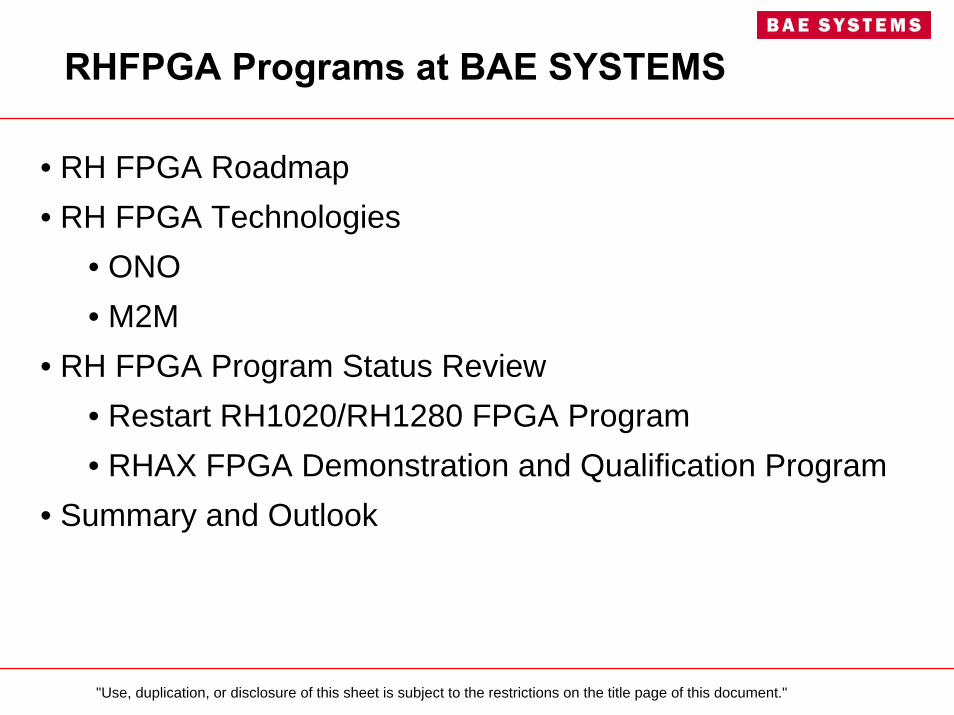
Radiation Hardened FPGA Roadmap
Rad Hard FPGA Product• Heritage: Actel ONO RH1280 and RH1020
• Anti-fuse technology, non-volatile• 0.8µm RH CMOS, 5V Supply• In production since 1996, over 25,000 shipped
• M2M Anti-fuse Technology:• 250K-gate (RHAX250-S)• RH15 CMOS, 1.5V Core / 3.3V I/O• Flight Orders in 2008
• ≥3M-gate, re-programmable, non-volatile• Radiation Hardened, high speed • RH15 CMOS, 1.5V Core / 3.3V I/O• Projected qualification starts in 2009
Past
Present
Future
BAE Supporting RHFPGA Needs for RHOC requirements
"Use, duplication, or disclosure of this sheet is subject to the restrictions on the title page of this document."
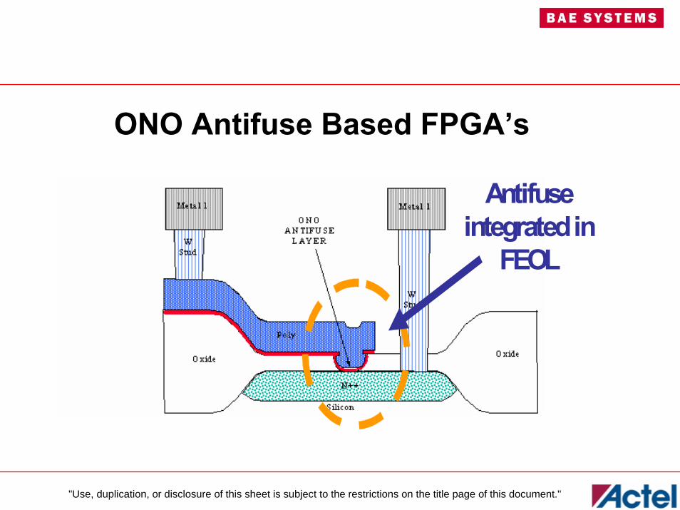
ONO Antifuse Based FPGA’s
Antifuseintegrated in
FEOL
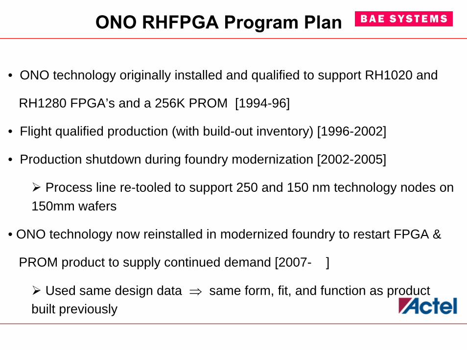
ONO RHFPGA Program Plan
• ONO technology originally installed and qualified to support RH1020 and
RH1280 FPGA’s and a 256K PROM [1994-96]
• Flight qualified production (with build-out inventory) [1996-2002]
• Production shutdown during foundry modernization [2002-2005]
Process line re-tooled to support 250 and 150 nm technology nodes on 150mm wafers
• ONO technology now reinstalled in modernized foundry to restart FPGA &
PROM product to supply continued demand [2007- ]
Used same design data ⇒ same form, fit, and function as product built previously
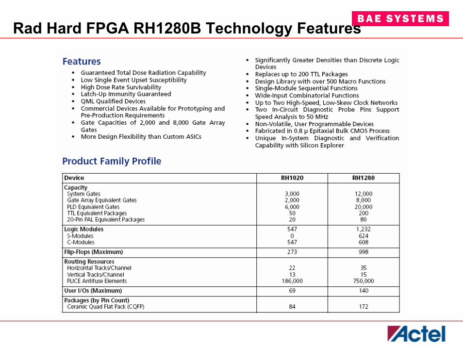
Rad Hard FPGA RH1280B Technology Features
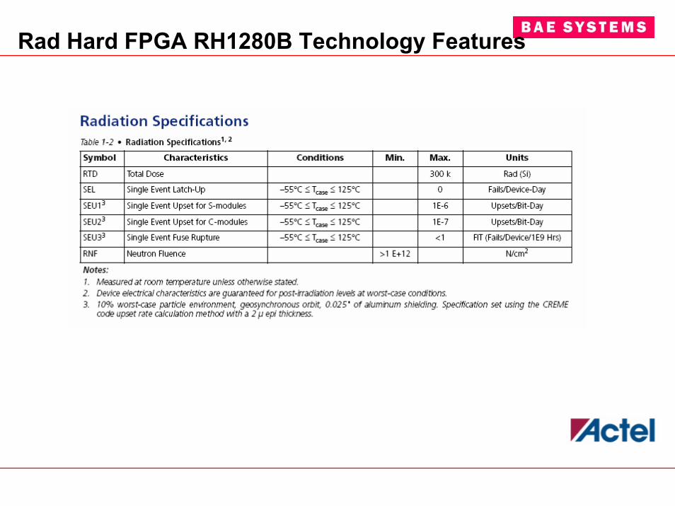
Rad Hard FPGA RH1280B Technology Features
"Use, duplication, or disclosure of this sheet is subject to the restrictions on the title page of this document."
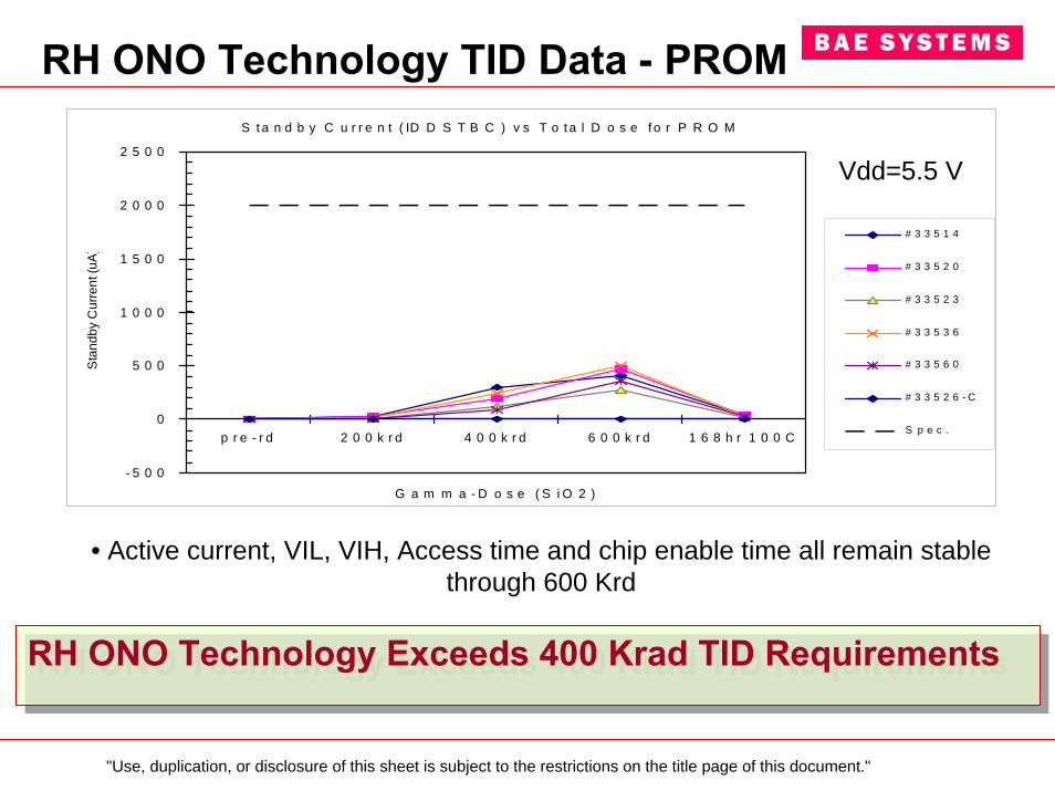
RH ONO Technology TID Data - PROMS t a n d b y C u r r e n t ( ID D S T B C ) v s T o t a l D o s e f o r P R O M
- 5 0 0
0
5 0 0
1 0 0 0
1 5 0 0
2 0 0 0
2 5 0 0
p r e - r d 2 0 0 k r d 4 0 0 k r d 6 0 0 k r d 1 6 8 h r 1 0 0 C
G a m m a - D o s e ( S i O 2 )
Sta
ndby
Cur
rent
(uA
)
# 3 3 5 1 4
# 3 3 5 2 0
# 3 3 5 2 3
# 3 3 5 3 6
# 3 3 5 6 0
# 3 3 5 2 6 - C
S p e c .
Vdd=5.5 V
• Active current, VIL, VIH, Access time and chip enable time all remain stable through 600 Krd
RH ONO Technology Exceeds 400 Krad TID RequirementsRH ONO Technology Exceeds 400 Krad TID Requirements
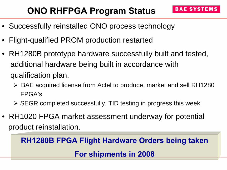
ONO RHFPGA Program Status • Successfully reinstalled ONO process technology
• Flight-qualified PROM production restarted
• RH1280B prototype hardware successfully built and tested, additional hardware being built in accordance with qualification plan.
BAE acquired license from Actel to produce, market and sell RH1280 FPGA’sSEGR completed successfully, TID testing in progress this week
• RH1020 FPGA market assessment underway for potential product reinstallation.
RH1280B FPGA Flight Hardware Orders being taken
For shipments in 2008
"Use, duplication, or disclosure of this sheet is subject to the restrictions on the title page of this document."
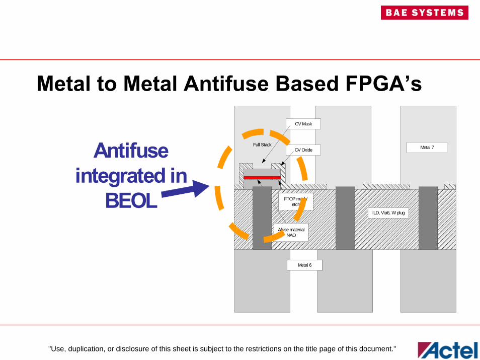
Metal to Metal Antifuse Based FPGA’s
Full StackCV Oxide
Metal 6
ILD, Via6, W plug
Metal 7
FTOP mask/etch
CV Mask
Afuse materialNAO
Antifuseintegrated in
BEOL
" Use or disclosure of data contained on this page is subject to the restrictions on the title page of this document"
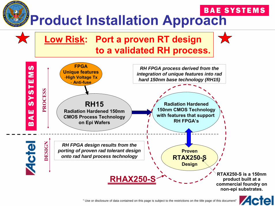
Product Installation Approach
RH15Radiation Hardened 150nmCMOS Process Technology
on Epi Wafers
Radiation Hardened150nm CMOS Technologywith features that support
RH FPGA’s
FPGAUnique features-High Voltage Tx
- Anti-fuse
PRO
CE
SSD
ESI
GN
ProvenRTAX250-S
Design
RH FPGA process derived from the integration of unique features into rad hard 150nm base technology (RH15)
RH FPGA design results from the porting of proven rad tolerant design
onto rad hard process technology
RHAX250-SRTAX250-S is a 150nm
product built at a commercial foundry on
non-epi substrates.
Low Risk: Port a proven RT design to a validated RH process.
" Use or disclosure of data contained on this page is subject to the restrictions on the title page of this document"
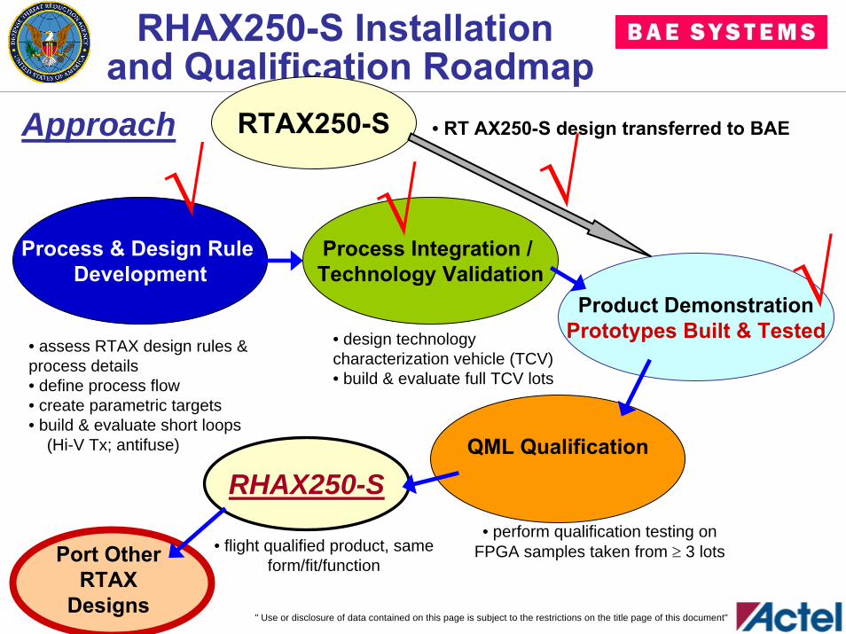
RHAX250-S Installation and Qualification Roadmap
RTAX250-S
RHAX250-S
Process & Design Rule Development
• assess RTAX design rules & process details• define process flow• create parametric targets• build & evaluate short loops
(Hi-V Tx; antifuse)
Process Integration / Technology Validation
• design technology characterization vehicle (TCV)• build & evaluate full TCV lots
Product DemonstrationPrototypes Built & Tested
• RT AX250-S design transferred to BAE
QML Qualification
• perform qualification testing on FPGA samples taken from ≥ 3 lots• flight qualified product, same
form/fit/function
Approach
Port Other RTAX
Designs
√ √√√
" Use or disclosure of data contained on this page is subject to the restrictions on the title page of this document"
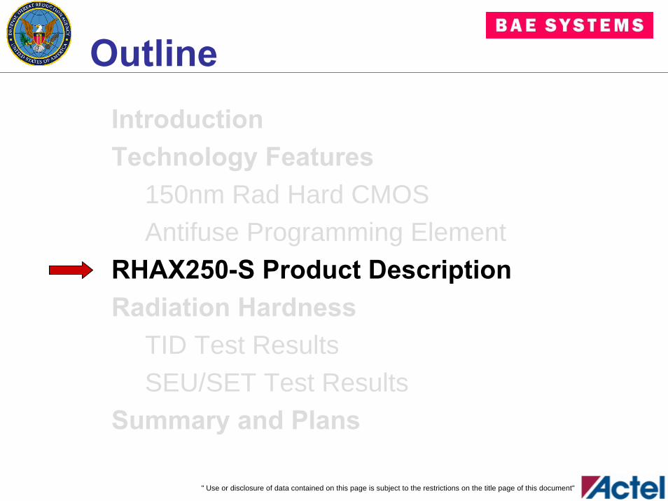
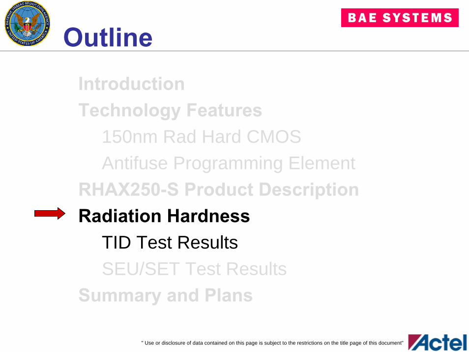
OutlineIntroductionTechnology Features
150nm Rad Hard CMOSAntifuse Programming Element
RHAX250-S Product DescriptionRadiation Hardness
TID Test ResultsSEU/SET Test Results
Summary and Plans
" Use or disclosure of data contained on this page is subject to the restrictions on the title page of this document"
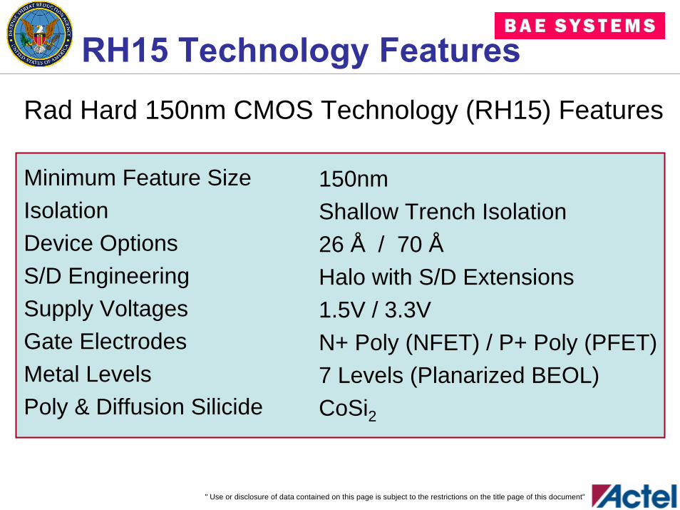
RH15 Technology FeaturesRad Hard 150nm CMOS Technology (RH15) Features
Minimum Feature SizeIsolationDevice OptionsS/D EngineeringSupply VoltagesGate ElectrodesMetal LevelsPoly & Diffusion Silicide
150nmShallow Trench Isolation26 Å / 70 ÅHalo with S/D Extensions1.5V / 3.3VN+ Poly (NFET) / P+ Poly (PFET)7 Levels (Planarized BEOL)CoSi2
" Use or disclosure of data contained on this page is subject to the restrictions on the title page of this document"
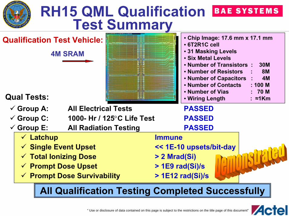
RH15 QML Qualification Test Summary
• Chip Image: 17.6 mm x 17.1 mm • 6T2R1C cell• 31 Masking Levels• Six Metal Levels• Number of Transistors : 30M• Number of Resistors : 8M• Number of Capacitors : 4M• Number of Contacts : 100 M• Number of Vias : 70 M• Wiring Length : ≈1Km
Qualification Test Vehicle:4M SRAM
Group A: All Electrical Tests PASSEDGroup C: 1000- Hr / 125°C Life Test PASSEDGroup E: All Radiation Testing PASSED
Latchup ImmuneSingle Event Upset << 1E-10 upsets/bit-dayTotal Ionizing Dose > 2 Mrad(Si)Prompt Dose Upset > 1E9 rad(Si)/sPrompt Dose Survivability > 1E12 rad(Si)/s
All Qualification Testing Completed Successfully
Qual Tests:
" Use or disclosure of data contained on this page is subject to the restrictions on the title page of this document"
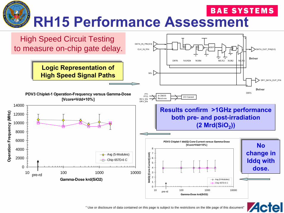
RH15 Performance Assessment
PDV3 Chiplet-1 Operation-Frequency versus Gamma-Dose [Vcore=Vdd+10%]
0
2000
4000
6000
8000
10000
12000
14000
10 100 1000 10000
Gamma-Dose krd(SiO2)
Ope
ratio
n Fr
eque
ncy
(MH
z)
Avg (5-Modules)
Chip 657D-6 C
pre-rd
Results confirm >1GHz performance both pre- and post-irradiation
(2 Mrd(SiO2))
Logic Representation of High Speed Signal Paths
PDV3 Chiplet-1 Idd(Q) Core-Current versus Gamma-Dose [Vcore=Vdd+10%]
0
1
2
3
4
5
6
7
8
10 100 1000 10000
Gamma-Dose krd(SiO2)
Idd(
Q) [
Cor
e-C
urre
nt] (
mA
)
Avg (5-Modules)
Chip 657D-5 C
pre-rd
ADDF>
14
>
DATA_IN_P/N(3:0)
CLK_IN_P/N DATA_OUT_P/N(3:0)
DFF_DATA_OUT_P/N
4-CMOSReceivers I/O Control
PTIPTO
RCV_ENDRV_EN
SEL
NAND4 NOR4 MUX2 XOR2DFFS MUX2Driver
Driver DFFS
No change in Iddq with
dose.
High Speed Circuit Testing to measure on-chip gate delay.
" Use or disclosure of data contained on this page is subject to the restrictions on the title page of this document"
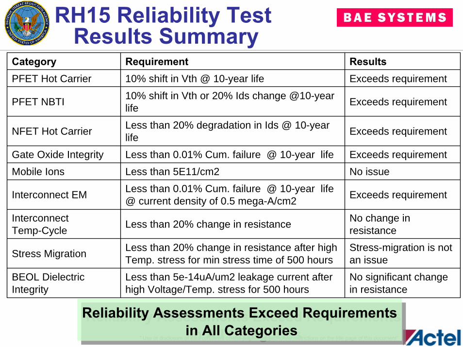
RH15 Reliability Test Results Summary
Category Requirement ResultsPFET Hot Carrier 10% shift in Vth @ 10-year life Exceeds requirement
PFET NBTI 10% shift in Vth or 20% Ids change @10-year life Exceeds requirement
NFET Hot Carrier Less than 20% degradation in Ids @ 10-year life Exceeds requirement
Gate Oxide Integrity Less than 0.01% Cum. failure @ 10-year life Exceeds requirementMobile Ions Less than 5E11/cm2 No issue
Interconnect EM Less than 0.01% Cum. failure @ 10-year life @ current density of 0.5 mega-A/cm2 Exceeds requirement
InterconnectTemp-Cycle Less than 20% change in resistance No change in
resistance
Stress Migration Less than 20% change in resistance after high Temp. stress for min stress time of 500 hours
Stress-migration is not an issue
BEOL Dielectric Integrity
Less than 5e-14uA/um2 leakage current after high Voltage/Temp. stress for 500 hours
No significant change in resistance
Reliability Assessments Exceed Requirementsin All Categories
Reliability Assessments Exceed Requirementsin All Categories
" Use or disclosure of data contained on this page is subject to the restrictions on the title page of this document"
OutlineIntroductionTechnology Features
150nm Rad Hard CMOSAntifuse Programming Element
RHAX250-S Product DescriptionRadiation Hardness
TID Test ResultsSEU/SET Test Results
Summary and Plans
" Use or disclosure of data contained on this page is subject to the restrictions on the title page of this document"
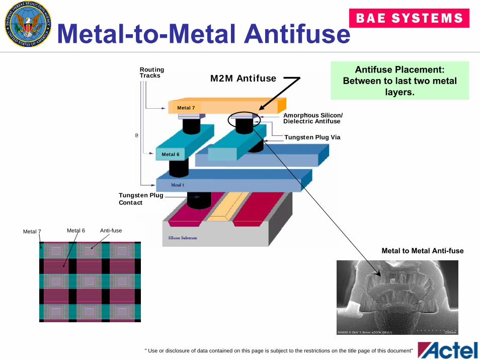
Metal-to-Metal Antifuse
RoutingTracks
Amorphous Silicon/Dielectric Antifuse
Tungsten Plug Via
Tungsten PlugContact
Metal 7
Metal 6
M2M Antifuse
Metal to Metal Anti-fuse
Metal 7 Metal 6 Anti-fuse
Antifuse Placement: Between to last two metal
layers.
" Use or disclosure of data contained on this page is subject to the restrictions on the title page of this document"
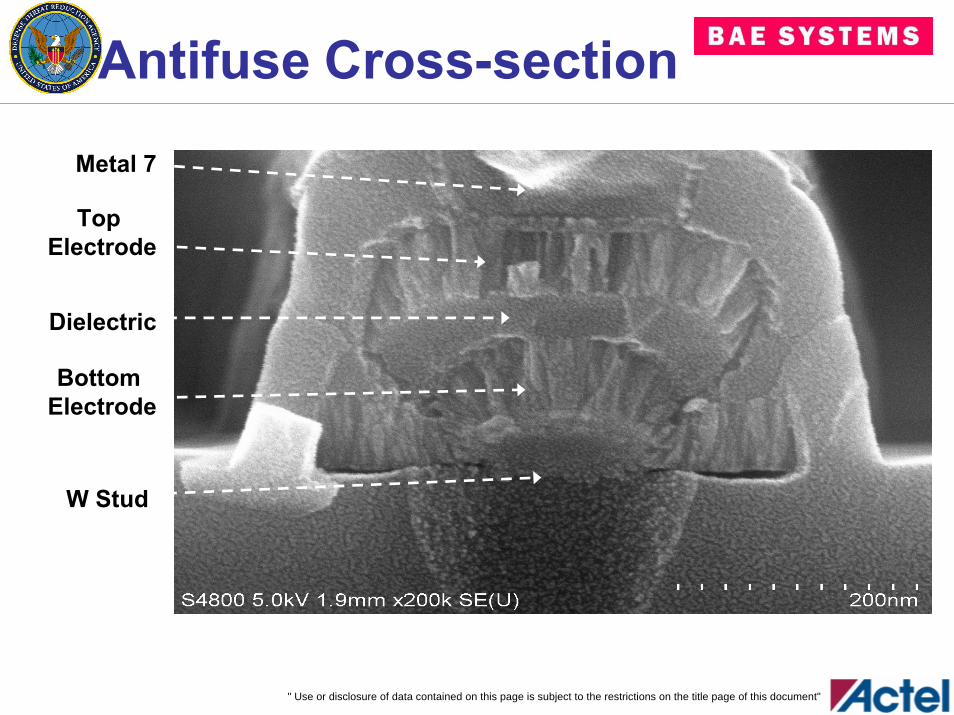
Antifuse Cross-section
Metal 7
Top Electrode
Bottom Electrode
Dielectric
W Stud
" Use or disclosure of data contained on this page is subject to the restrictions on the title page of this document"
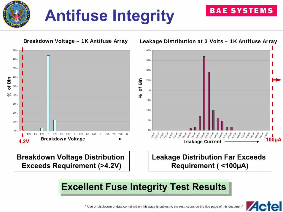
Antifuse IntegrityBreakdown Voltage - 1K Anti-fuse Array
0%
10%
20%
30%
40%
50%
60%
70%
80%
90%
4 4.25 4.5 4.75 5 5.25 5.5 5.75 6 6.25 6.5 6.75 7 7.25 7.5 7.75 8
Breakdown Voltage
% in
Bin
3
4.2V
Breakdown Voltage – 1K Antifuse Array
Breakdown Voltage
% o
f B
in
Leakage Distribution at 3 Volts - 1K Anti-fuse Array
0%
5%
10%
15%
20%
25%
30%
35%
40%
1.0E
-07
3.0E
-07
5.0E
-07
7.0E
-07
9.0E
-07
1.1E
-06
1.3E
-06
1.5E
-06
1.7E
-06
1.9E
-06
2.1E
-06
2.3E
-06
2.5E
-06
2.7E
-06
2.9E
-06
3.1E
-06
3.3E
-06
3.5E
-06
3.7E
-06
3.9E
-06
4.1E
-06
4.3E
-06
4.5E
-06
4.7E
-06
4.9E
-06
5.0E
-06
Leakage Current%
in B
in100µA
% o
f B
inLeakage Current
Leakage Distribution at 3 Volts – 1K Antifuse Array
Breakdown Voltage Distribution Exceeds Requirement (>4.2V)
Leakage Distribution Far Exceeds Requirement ( <100µA)
Excellent Fuse Integrity Test ResultsExcellent Fuse Integrity Test Results
" Use or disclosure of data contained on this page is subject to the restrictions on the title page of this document"
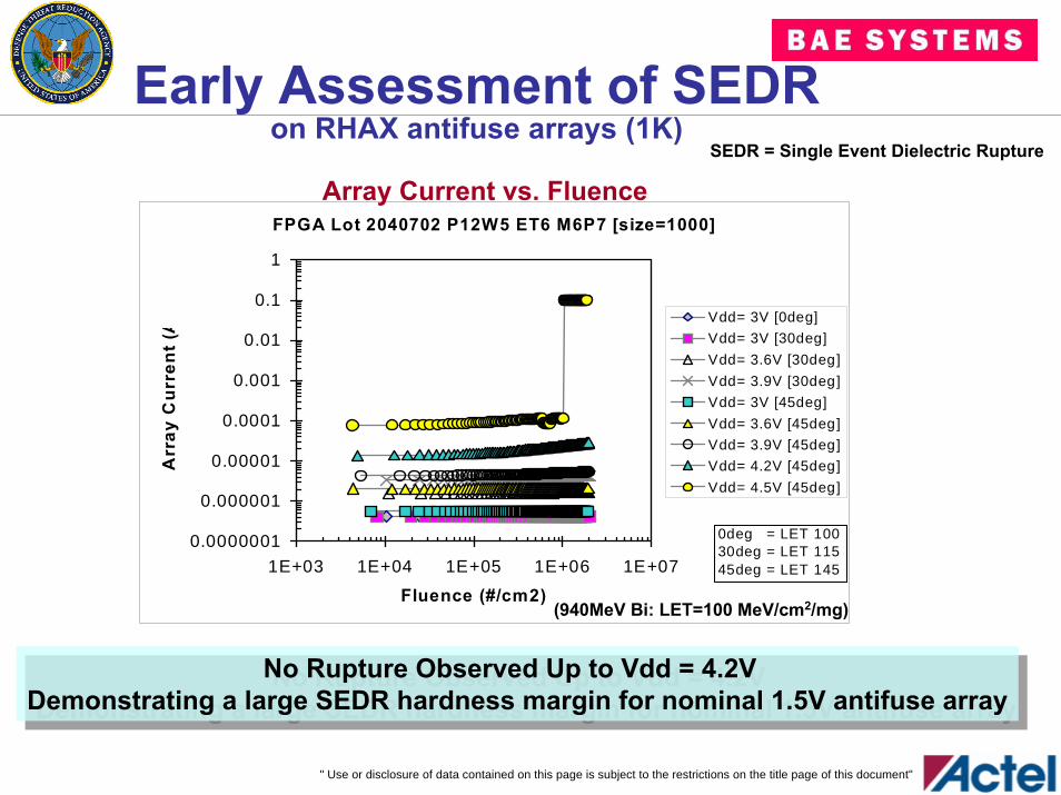
Early Assessment of SEDRon RHAX antifuse arrays (1K)
SEDR = Single Event Dielectric Rupture
FPGA Lot 2040702 P12W5 ET6 M6P7 [size=1000]
0.0000001
0.000001
0.00001
0.0001
0.001
0.01
0.1
1
1E+03 1E+04 1E+05 1E+06 1E+07
Fluence (#/cm2)
Arr
ay C
urre
nt (A
Vdd= 3V [0deg]Vdd= 3V [30deg]Vdd= 3.6V [30deg]Vdd= 3.9V [30deg]Vdd= 3V [45deg]Vdd= 3.6V [45deg]Vdd= 3.9V [45deg]Vdd= 4.2V [45deg]Vdd= 4.5V [45deg]
0deg = LET 10030deg = LET 11545deg = LET 145
(940MeV Bi: LET=100 MeV/cm2/mg)
Array Current vs. Fluence
No Rupture Observed Up to Vdd = 4.2V Demonstrating a large SEDR hardness margin for nominal 1.5V antifuse array
No Rupture Observed Up to Vdd = 4.2V Demonstrating a large SEDR hardness margin for nominal 1.5V antifuse array
" Use or disclosure of data contained on this page is subject to the restrictions on the title page of this document"
OutlineIntroductionTechnology Features
150nm Rad Hard CMOSAntifuse Programming Element
RHAX250-S Product DescriptionRadiation Hardness
TID Test ResultsSEU/SET Test Results
Summary and Plans
" Use or disclosure of data contained on this page is subject to the restrictions on the title page of this document"
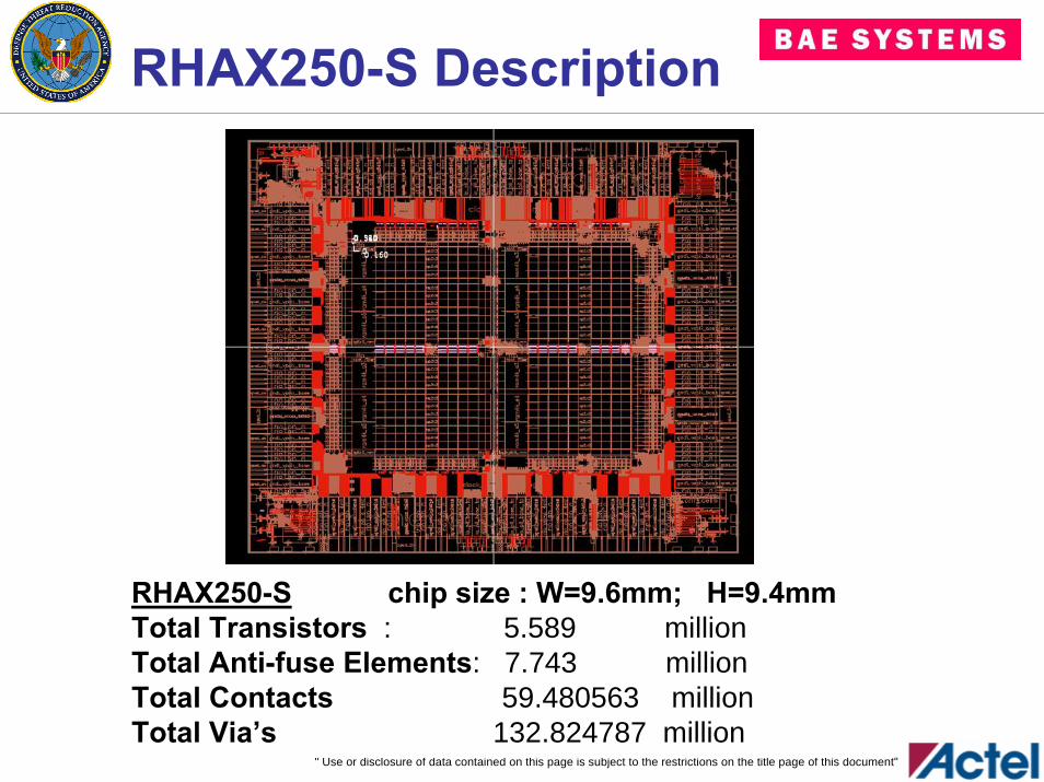
RHAX250-S Description
RHAX250-S chip size : W=9.6mm; H=9.4mmTotal Transistors : 5.589 millionTotal Anti-fuse Elements: 7.743 millionTotal Contacts 59.480563 millionTotal Via’s 132.824787 million
" Use or disclosure of data contained on this page is subject to the restrictions on the title page of this document"
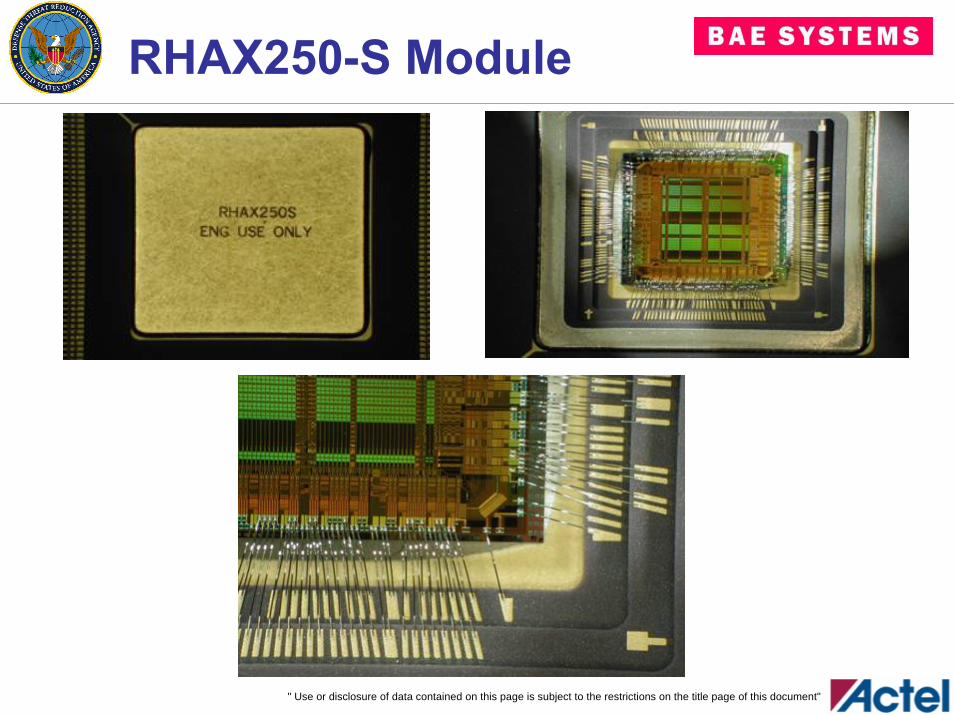
RHAX250-S Module
" Use or disclosure of data contained on this page is subject to the restrictions on the title page of this document"
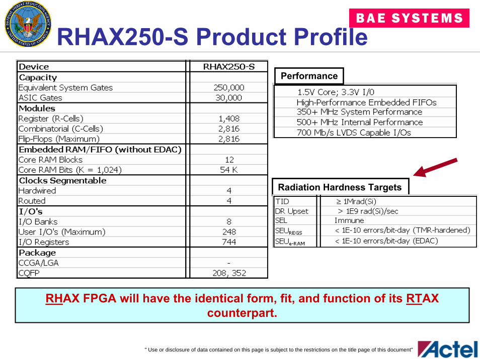
RHAX250-S Product ProfilePerformance
Radiation Hardness Targets
RHAX FPGA will have the identical form, fit, and function of its RTAX counterpart.
" Use or disclosure of data contained on this page is subject to the restrictions on the title page of this document"
OutlineIntroductionTechnology Features
150nm Rad Hard CMOSAntifuse Programming Element
RHAX250-S Product DescriptionRadiation Hardness
TID Test ResultsSEU/SET Test Results
Summary and Plans
" Use or disclosure of data contained on this page is subject to the restrictions on the title page of this document"
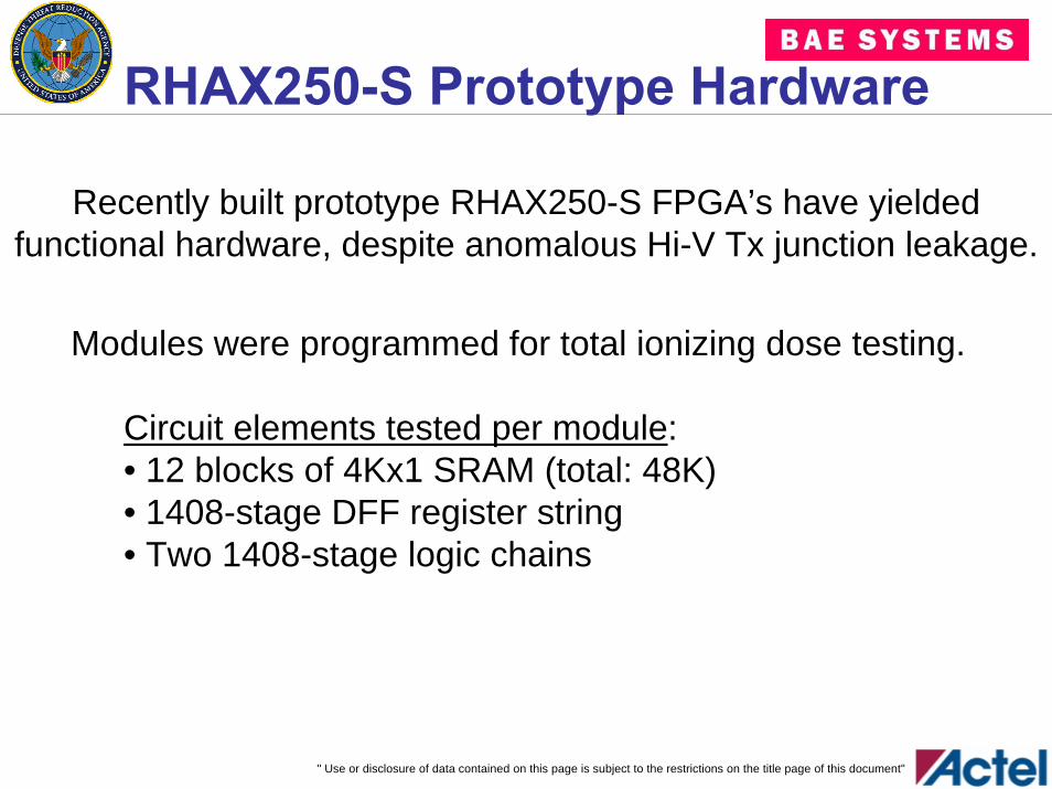
RHAX250-S Prototype Hardware
Recently built prototype RHAX250-S FPGA’s have yielded functional hardware, despite anomalous Hi-V Tx junction leakage.
Modules were programmed for total ionizing dose testing.
Circuit elements tested per module:• 12 blocks of 4Kx1 SRAM (total: 48K)• 1408-stage DFF register string• Two 1408-stage logic chains
" Use or disclosure of data contained on this page is subject to the restrictions on the title page of this document"
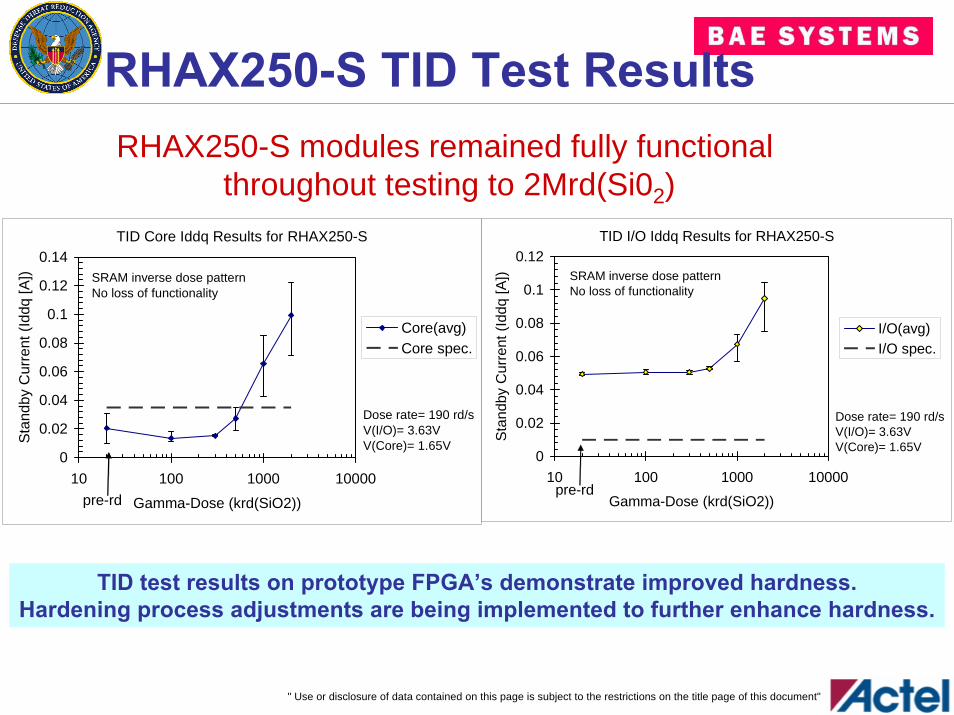
RHAX250-S TID Test ResultsRHAX250-S modules remained fully functional
throughout testing to 2Mrd(Si02)TID Core Iddq Results for RHAX250-S
0
0.02
0.04
0.06
0.08
0.1
0.12
0.14
10 100 1000 10000
Gamma-Dose (krd(SiO2))
Stan
dby
Cur
rent
(Idd
q [A
])
Core(avg)Core spec.
pre-rd
SRAM inverse dose patternNo loss of functionality
Dose rate= 190 rd/sV(I/O)= 3.63VV(Core)= 1.65V
TID I/O Iddq Results for RHAX250-S
0
0.02
0.04
0.06
0.08
0.1
0.12
10 100 1000 10000
Gamma-Dose (krd(SiO2))S
tand
by C
urre
nt (I
ddq
[A])
I/O(avg)I/O spec.
pre-rd
SRAM inverse dose patternNo loss of functionality
Dose rate= 190 rd/sV(I/O)= 3.63VV(Core)= 1.65V
TID test results on prototype FPGA’s demonstrate improved hardness.Hardening process adjustments are being implemented to further enhance hardness.
" Use or disclosure of data contained on this page is subject to the restrictions on the title page of this document"
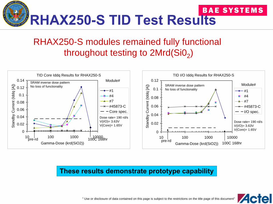
RHAX250-S TID Test ResultsRHAX250-S modules remained fully functional
throughout testing to 2Mrd(Si02)
TID I/O Iddq Results for RHAX250-S
0
0.02
0.04
0.06
0.08
0.1
0.12
10 100 1000 10000
Gamma-Dose (krd(SiO2))S
tand
by C
urre
nt (I
ddq
[A])
#1#4#7#45873-CI/O spec.
pre-rd
SRAM inverse dose patternNo loss of functionality
Dose rate= 190 rd/sV(I/O)= 3.63VV(Core)= 1.65V
Module#
100C 168hr
TID Core Iddq Results for RHAX250-S
0
0.02
0.04
0.06
0.08
0.1
0.12
0.14
10 100 1000 10000
Gamma-Dose (krd(SiO2))
Sta
ndby
Cur
rent
(Idd
q [A
])
#1#4#7#45873-CCore spec.
pre-rd
SRAM inverse dose patternNo loss of functionality
Dose rate= 190 rd/sV(I/O)= 3.63VV(Core)= 1.65V
Module#
100C 168hr
These results demonstrate prototype capability
" Use or disclosure of data contained on this page is subject to the restrictions on the title page of this document"
OutlineIntroductionTechnology Features
150nm Rad Hard CMOSAntifuse Programming Element
RHAX250-S Product DescriptionRadiation Hardness
TID Test ResultsSEU/SET Test Results
Summary and Plans
" Use or disclosure of data contained on this page is subject to the restrictions on the title page of this document"
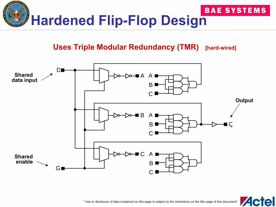
Hardened Flip-Flop Design
Uses Triple Modular Redundancy (TMR) [hard-wired]
G
A
BC
A
BC
A
BC
D
B
A
C
Q
Shared data input
Output
Shared enable
" Use or disclosure of data contained on this page is subject to the restrictions on the title page of this document"
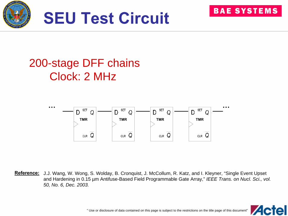
SEU Test Circuit
……
TMR TMR TMR TMR
200-stage DFF chainsClock: 2 MHz
J.J. Wang, W. Wong, S. Wolday, B. Cronquist, J. McCollum, R. Katz, and I. Kleyner, “Single Event Upset and Hardening in 0.15 µm Antifuse-Based Field Programmable Gate Array,” IEEE Trans. on Nucl. Sci., vol. 50, No. 6, Dec. 2003.
Reference:
" Use or disclosure of data contained on this page is subject to the restrictions on the title page of this document"
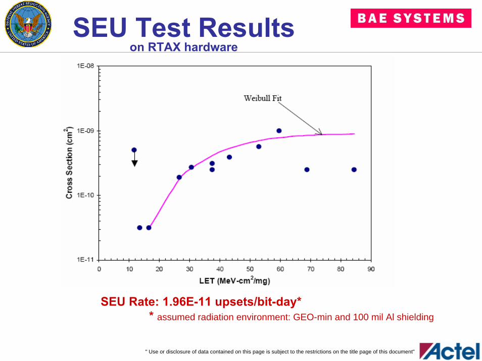
SEU Test Resultson RTAX hardware
SEU Rate: 1.96E-11 upsets/bit-day** assumed radiation environment: GEO-min and 100 mil Al shielding
" Use or disclosure of data contained on this page is subject to the restrictions on the title page of this document"
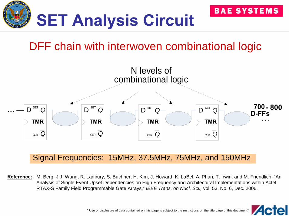
SET Analysis CircuitDFF chain with interwoven combinational logic
Signal Frequencies: 15MHz, 37.5MHz, 75MHz, and 150MHz
Q
QSET
CLR
D
Q
QSET
CLR
D
Q
QSET
CLR
D
Q
QSET
CLR
D
N levels of combinational logic
700 o
N levels ofcombinational logic
700 D-FFs…TMR TMR TMR TMR
… - 800
M. Berg, J.J. Wang, R. Ladbury, S. Buchner, H. Kim, J. Howard, K. LaBel, A. Phan, T. Irwin, and M. Friendlich, “An Analysis of Single Event Upset Dependencies on High Frequency and Architectural Implementations within Actel RTAX-S Family Field Programmable Gate Arrays,” IEEE Trans. on Nucl. Sci., vol. 53, No. 6, Dec. 2006.
Reference:
" Use or disclosure of data contained on this page is subject to the restrictions on the title page of this document"
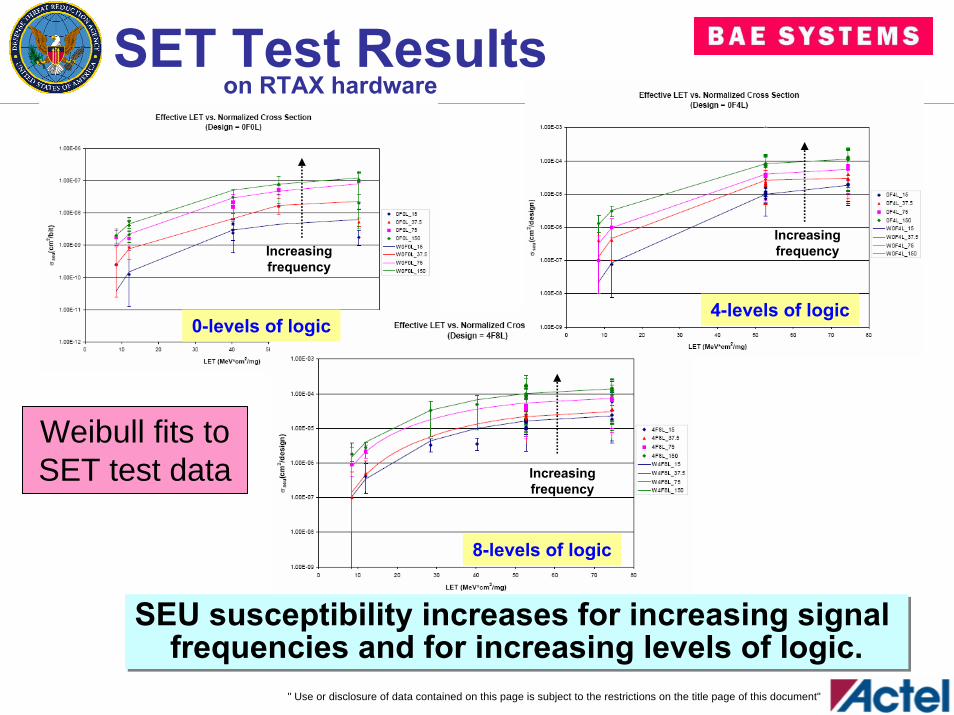
SET Test Resultson RTAX hardware
0-levels of logic
8-levels of logic
Increasingfrequency
Increasingfrequency
4-levels of logic
Increasingfrequency
Weibull fits to SET test data
SEU susceptibility increases for increasing signal frequencies and for increasing levels of logic.
SEU susceptibility increases for increasing signal frequencies and for increasing levels of logic.
" Use or disclosure of data contained on this page is subject to the restrictions on the title page of this document"
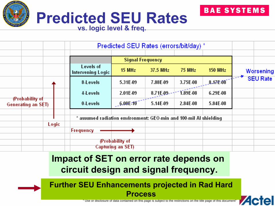
Predicted SEU Ratesvs. logic level & freq.
Impact of SET on error rate depends on circuit design and signal frequency.
Further SEU Enhancements projected in Rad Hard Process
" Use or disclosure of data contained on this page is subject to the restrictions on the title page of this document"
OutlineIntroductionTechnology Features
150nm Rad Hard CMOSAntifuse Programming Element
RHAX250-S Product DescriptionRadiation Hardness
TID Test ResultsSEU/SET Test Results
Summary and Plans
" Use or disclosure of data contained on this page is subject to the restrictions on the title page of this document"
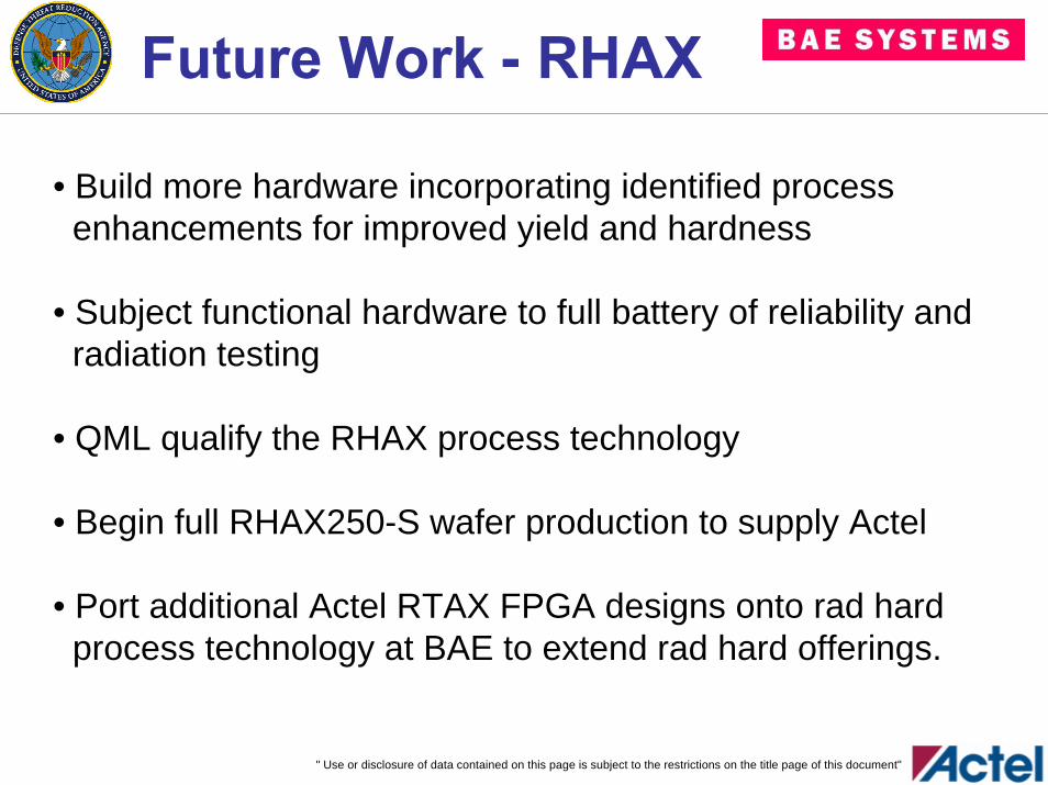
Future Work - RHAX
• Build more hardware incorporating identified process enhancements for improved yield and hardness
• Subject functional hardware to full battery of reliability and radiation testing
• QML qualify the RHAX process technology
• Begin full RHAX250-S wafer production to supply Actel
• Port additional Actel RTAX FPGA designs onto rad hard process technology at BAE to extend rad hard offerings.
" Use or disclosure of data contained on this page is subject to the restrictions on the title page of this document"
Summary• BAE and Actel are continuing their >12 year collaboration as rad hard FPGA suppliers.
• Next generation rad hard product is being built and tested.
• Total dose test results on RHAX250-S hardware demonstrates improved hardness over RTAX250-S.
• Single-event effects test results demonstrates product design’s high tolerance.
• Electrical, radiation, and reliability testing is on-going.
• Full flight-qualified production to begin by yearend.
" Use or disclosure of data contained on this page is subject to the restrictions on the title page of this document"
Acknowledgements
The authors gratefully acknowledge the support for this effort provided by the Defense Threat Reduction Agency
under contract DTRA01-03-D-0007 / 0004.

" Use or disclosure of data contained on this page is subject to the restrictions on the title page of this document"
Electronics & Integrated Solutions
We Protect Those Who Protect Us®