Embed Size (px)
Citation preview
Sun Microsystems, Inc.www.sun.com
Submit comments about this document at: http://www.sun.com/hwdocs/feedback
Sun StorageTek™ 6540 ArrayRack Ready Site Preparation and
Installation Support Guide
Part No. 819-6136-10 July 2006

PleaseRecycle
Copyright 2006 Sun Microsystems, Inc., 4150 Network Circle, Santa Clara, California 95054, U.S.A. All rights reserved.
Sun Microsystems, Inc. has intellectual property rights relating to technology that is described in this document. In particular, and without limitation, these intellectual property rights may include one or more of the U.S. patents listed at http://www.sun.com/patents and one or more additional patents or pending patent applications in the U.S. and in other countries.
This document and the product to which it pertains are distributed under licenses restricting their use, copying, distribution, and decompilation. No part of the product or of this document may be reproduced in any form by any means without prior written authorization of Sun and its licensors, if any.
Third-party software, including font technology, is copyrighted and licensed from Sun suppliers.
Parts of the product may be derived from Berkeley BSD systems, licensed from the University of California. UNIX is a registered trademark in the U.S. and in other countries, exclusively licensed through X/Open Company, Ltd.
Sun, Sun Microsystems, the Sun logo, Java, AnswerBook2, docs.sun.com, Sun StorEdge, Sun StorageTek, and Solaris are trademarks or registered trademarks of Sun Microsystems, Inc. in the U.S. and in other countries.
All SPARC trademarks are used under license and are trademarks or registered trademarks of SPARC International, Inc. in the U.S. and in other countries. Products bearing SPARC trademarks are based upon an architecture developed by Sun Microsystems, Inc.
The OPEN LOOK and Sun™ Graphical User Interface was developed by Sun Microsystems, Inc. for its users and licensees. Sun acknowledges the pioneering efforts of Xerox in researching and developing the concept of visual or graphical user interfaces for the computer industry. Sun holds a non-exclusive license from Xerox to the Xerox Graphical User Interface, which license also covers Sun’s licensees who implement OPEN LOOK GUIs and otherwise comply with Sun’s written license agreements.
U.S. Government Rights—Commercial use. Government users are subject to the Sun Microsystems, Inc. standard license agreement and applicable provisions of the FAR and its supplements.
DOCUMENTATION IS PROVIDED "AS IS" AND ALL EXPRESS OR IMPLIED CONDITIONS, REPRESENTATIONS AND WARRANTIES, INCLUDING ANY IMPLIED WARRANTY OF MERCHANTABILITY, FITNESS FOR A PARTICULAR PURPOSE OR NON-INFRINGEMENT, ARE DISCLAIMED, EXCEPT TO THE EXTENT THAT SUCH DISCLAIMERS ARE HELD TO BE LEGALLY INVALID.
Copyright 2006 Sun Microsystems, Inc., 4150 Network Circle, Santa Clara, Californie 95054, États-Unis. Tous droits réservés.
Sun Microsystems, Inc. possède les droits de propriété intellectuels relatifs à la technologie décrite dans ce document. En particulier, et sans limitation, ces droits de propriété intellectuels peuvent inclure un ou plusieurs des brevets américains listés sur le site http://www.sun.com/patents, un ou les plusieurs brevets supplémentaires ainsi que les demandes de brevet en attente aux les États-Unis et dans d’autres pays.
Ce document et le produit auquel il se rapporte sont protégés par un copyright et distribués sous licences, celles-ci en restreignent l’utilisation, la copie, la distribution, et la décompilation. Aucune partie de ce produit ou document ne peut être reproduite sous aucune forme, par quelque moyen que ce soit, sans l’autorisation préalable et écrite de Sun et de ses bailleurs de licence, s’il y en a.
Tout logiciel tiers, sa technologie relative aux polices de caractères, comprise, est protégé par un copyright et licencié par des fournisseurs de Sun.
Des parties de ce produit peuvent dériver des systèmes Berkeley BSD licenciés par l’Université de Californie. UNIX est une marque déposée aux États-Unis et dans d’autres pays, licenciée exclusivement par X/Open Company, Ltd.
Sun, Sun Microsystems, le logo Sun, Java, AnswerBook2, docs.sun.com, Sun StorEdge, Sun StorageTek, et Solaris sont des marques de fabrique ou des marques déposées de Sun Microsystems, Inc. aux États-Unis et dans d’autres pays.
Toutes les marques SPARC sont utilisées sous licence et sont des marques de fabrique ou des marques déposées de SPARC International, Inc. aux États-Unis et dans d’autres pays. Les produits portant les marques SPARC sont basés sur une architecture développée par Sun Microsystems, Inc.
L’interface utilisateur graphique OPEN LOOK et Sun™ a été développée par Sun Microsystems, Inc. pour ses utilisateurs et licenciés. Sun reconnaît les efforts de pionniers de Xerox dans la recherche et le développement du concept des interfaces utilisateur visuelles ou graphiques pour l’industrie informatique. Sun détient une license non exclusive de Xerox sur l’interface utilisateur graphique Xerox, cette licence couvrant également les licenciés de Sun implémentant les interfaces utilisateur graphiques OPEN LOOK et se conforment en outre aux licences écrites de Sun.
LA DOCUMENTATION EST FOURNIE "EN L’ÉTAT" ET TOUTES AUTRES CONDITIONS, DÉCLARATIONS ET GARANTIES EXPRESSES OU TACITES SONT FORMELLEMENT EXCLUES DANS LA LIMITE DE LA LOI APPLICABLE, Y COMPRIS NOTAMMENT TOUTE GARANTIE IMPLICITE RELATIVE À LA QUALITÉ MARCHANDE, À L’APTITUDE À UNE UTILISATION PARTICULIÈRE OU À L’ABSENCE DE CONTREFAÇON.
iii
Contents
Preface vii
1. Planning for the Installation 1
Customer Obligations 1
Safety Information 2
Handling Precautions 2
Secure Installation Requirements 3
Placement of a Sun Product 3
General Installation Requirements 4
Site Wiring and Power Requirements 5
2. Cabinet and Environmental Specifications 7
Cabinet Specifications 7
Cabinet Parts 8
Cabinet Height 9
Cabinet Width 9
Cabinet Depth 10
Weight 11
Cabinet Placement 12
Seismic Anchorage 13

iv Sun StorageTek 6540 Rack Ready Site Preparation and Installation Support Guide • July 2006
Cabinet Markings and Tray Placement 13
Use of Mounting Flanges 14
Mounting Flange Holes 14
Mounting Flange Cage Nuts 15
Rail Kits 16
Environmental Requirements 17
Temperature, Humidity, and Altitude 17
Airflow and Heat Dissipation 18
Power Requirements 19
Power Redundancy 20
3. Sun StorageTek 6540 Array Installation Requirements 23
Physical Requirements 24
Dimensions and Weight 24
Environmental Requirements 25
Electrical Requirements 26
Site Wiring and Power 26
Power Cords and Receptacles 26
Power Input 26
Calculating Current 27
Single Power Cord and Multiple Cabinet Environments 27
Tray Installation 28
Stack-up and Cabling 28
Controller Tray Check-up 28
Expansion Tray Check-up 29
A. Configuration Worksheets 31
Index 35
v
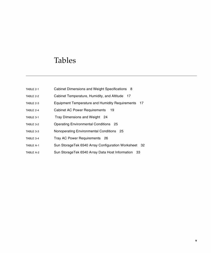
Tables
TABLE 2-1 Cabinet Dimensions and Weight Specifications 8
TABLE 2-2 Cabinet Temperature, Humidity, and Altitude 17
TABLE 2-3 Equipment Temperature and Humidity Requirements 17
TABLE 2-4 Cabinet AC Power Requirements 19
TABLE 3-1 Tray Dimensions and Weight 24
TABLE 3-2 Operating Environmental Conditions 25
TABLE 3-3 Nonoperating Environmental Conditions 25
TABLE 3-4 Tray AC Power Requirements 26
TABLE A-1 Sun StorageTek 6540 Array Configuration Worksheet 32
TABLE A-2 Sun StorageTek 6540 Array Data Host Information 33

vi Sun StorageTek 6540 Rack Ready Site Preparation and Installation Support Guide • July 2006
vii
Preface
The Sun StorageTek™ 6540 Array Rack Ready Site Preparation and Installation Support Guide describes the customer facilities and system requirements for installing the Sun StorageTek™ 6540 Array into a customer-supplied cabinet. This document is intended to provide guidelines and requirements, which should be followed when planning a customer installation.
Before You Read This BookBefore you begin to install the 6540 Array, read the regulatory and safety requirements described in the following manual:
� Sun StorageTek 6540 Array Regulatory and Safety Compliance Manual
How This Book Is OrganizedChapter 1 describes the requirements for preparing the customer site for installation of the Sun StorageTek 6540 Array.
Chapter 2 describes the physical, environmental, and electrical requirements for the cabinet in which the Sun StorageTek 6540 Array is installed.
Chapter 3 describes the physical, environmental, and electrical requirements for the Sun StorageTek 6540 Array.
Appendix A provides worksheets to help you gather the information you need to complete the installation.
viii Sun StorageTek 6540 Rack Ready Site Preparation and Installation Support Guide • July 2006
About This DocumentThis document describes site preparation guidelines to be considered when installing rack-ready components into a standard 19-inch EIA-compliant customer supplied cabinet.
This installation guide assumes a working knowledge of the hardware components and basic installation skills. It also assumes that prior system planning and site preparation has been performed. To ensure safe and proper operation of the system, and ease of maintenance, all of these requirements must be met before beginning the installation.
Intended ReadersThe information in this guide is intended for Sun territory and account executives, account team, and service representatives involved with rack ready cabinet installation, maintenance, and conversions. This guide allows customers and Sun support personnel to install, maintain, repair, and upgrade equipment installed into a customer provided cabinet.
Readers must be familiar with computer system operation, SAN hardware functionality, SAN cabling techniques, and physical cabinet installation. In addition, they should understand disk array, Redundant Array of Independent Disks (RAID), network, and Fibre Channel technologies.
Web AddressFor web sites related to the product described in this document, refer to the Product Release Notes.
Preface ix
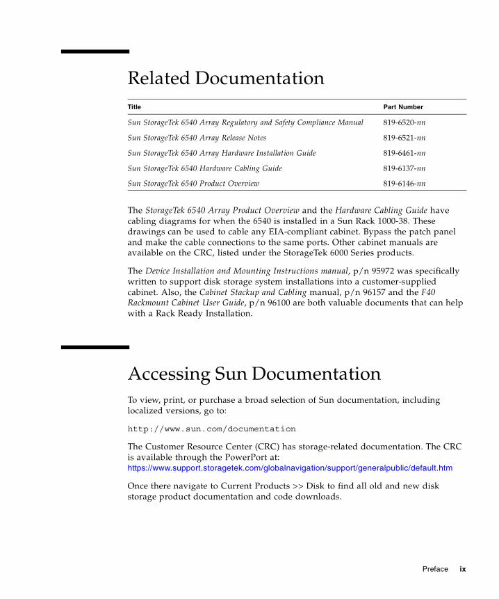
Related Documentation
The StorageTek 6540 Array Product Overview and the Hardware Cabling Guide have cabling diagrams for when the 6540 is installed in a Sun Rack 1000-38. These drawings can be used to cable any EIA-compliant cabinet. Bypass the patch panel and make the cable connections to the same ports. Other cabinet manuals are available on the CRC, listed under the StorageTek 6000 Series products.
The Device Installation and Mounting Instructions manual, p/n 95972 was specifically written to support disk storage system installations into a customer-supplied cabinet. Also, the Cabinet Stackup and Cabling manual, p/n 96157 and the F40 Rackmount Cabinet User Guide, p/n 96100 are both valuable documents that can help with a Rack Ready Installation.
Accessing Sun Documentation To view, print, or purchase a broad selection of Sun documentation, including localized versions, go to:
http://www.sun.com/documentation
The Customer Resource Center (CRC) has storage-related documentation. The CRC is available through the PowerPort at: https://www.support.storagetek.com/globalnavigation/support/generalpublic/default.htm
Once there navigate to Current Products >> Disk to find all old and new disk storage product documentation and code downloads.
Title Part Number
Sun StorageTek 6540 Array Regulatory and Safety Compliance Manual 819-6520-nn
Sun StorageTek 6540 Array Release Notes 819-6521-nn
Sun StorageTek 6540 Array Hardware Installation Guide 819-6461-nn
Sun StorageTek 6540 Hardware Cabling Guide 819-6137-nn
Sun StorageTek 6540 Product Overview 819-6146-nn

x Sun StorageTek 6540 Rack Ready Site Preparation and Installation Support Guide • July 2006
Note – The engineering web pages (http://gandalf.stortek.com/ctp/) provide older legacy documents only, and serves as a backup to the CRC. Documents on CD and the Product (software and documentation) CD are two other methods for getting information, but the documents on these CDs will not have any updates that get released afterwards, so periodically check the CRC for the latest information.
Contacting Sun Technical Support Technical questions not covered here?
Go to http://www.sun.com/service/contacting
Call Centers
There are currently three call centers (Newark, Broomfield, and Burlington). The phone number to reach these technical support sites is:
(United States): 1-800-USA-4SUN (872-4786)
(Canada): 1-800-722-4SUN (4786)
View Phone Tree at http://www.sun.com/service/phonetree/index.html
Using UNIX CommandsThis document does not contain information on basic UNIX® commands and procedures such as shutting down the system, booting the system, and configuring devices. Refer to the following for this information:
� Software documentation that you received with your system
� Solaris™ Operating System documentation, which is at
http://docs.sun.com
Preface xi
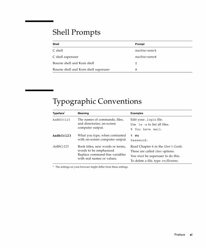
Shell Prompts
Typographic Conventions
Shell Prompt
C shell machine-name%
C shell superuser machine-name#
Bourne shell and Korn shell $
Bourne shell and Korn shell superuser #
Typeface*
* The settings on your browser might differ from these settings.
Meaning Examples
AaBbCc123 The names of commands, files, and directories; on-screen computer output.
Edit your.login file.
Use ls -a to list all files.% You have mail.
AaBbCc123 What you type, when contrasted with on-screen computer output.
% su
Password:
AaBbCc123 Book titles, new words or terms, words to be emphasized. Replace command-line variables with real names or values.
Read Chapter 6 in the User’s Guide.These are called class options.You must be superuser to do this.To delete a file, type rm filename.
xii Sun StorageTek 6540 Rack Ready Site Preparation and Installation Support Guide • July 2006
Third-Party Web SitesSun is not responsible for the availability of third-party web sites mentioned in this document. Sun does not endorse and is not responsible or liable for any content, advertising, products, or other materials that are available on or through such sites or resources. Sun will not be responsible or liable for any actual or alleged damage or loss caused by or in connection with the use of or reliance on any such content, goods, or services that are available on or through such sites or resources.
Sun Welcomes Your CommentsSun is interested in improving its documentation and welcomes your comments and suggestions. You can submit your comments by going to:
http://www.sun.com/hwdocs/feedback
Please include the title and part number of your document with your feedback:
Sun StorageTek 6540 Rack Ready Site Preparation and Installation Support Guide, part number 819-6136-10
1
CHAPTER 1
Planning for the Installation
This chapter describes the requirements for preparing the customer site for Sun StorageTek 6540 Array Rack Ready installations into a customer-supplied cabinet. It contains the following sections:
� “Customer Obligations” on page 1
� “Safety Information” on page 2
� “General Installation Requirements” on page 4
� “Site Wiring and Power Requirements” on page 5
Customer ObligationsThe customer is obliged to inform Sun Microsystems, Inc. of any and all ordinances and regulations that might affect the installation. The customer is responsible for meeting all government codes and regulations concerning facilities. The customer is also required to do the following:
� Comply with all local, national, and international codes covered in this specification. The subjects covered include fire and safety, building, and electrical codes.
� Document and inform Sun Microsystems, Inc. of any deviations from this specification.
2 Sun StorageTek 6540 Rack Ready Site Preparation and Installation Support Guide • July 2006
Safety InformationInstall the Sun StorageTek 6540 Array in accordance with the local safety codes and regulations at the facility site. Make sure that the safety precautions in the Sun StorageTek 6540 Array Regulatory and Safety Compliance Manual have been read.
The following sections contain additional safety information for the local facility:
� “Handling Precautions” on page 2
� “Secure Installation Requirements” on page 3
� “Placement of a Sun Product” on page 3
Note – Do not make modifications to the equipment. Sun Microsystems, Inc. is not responsible for regulatory compliance of a modified Sun product.
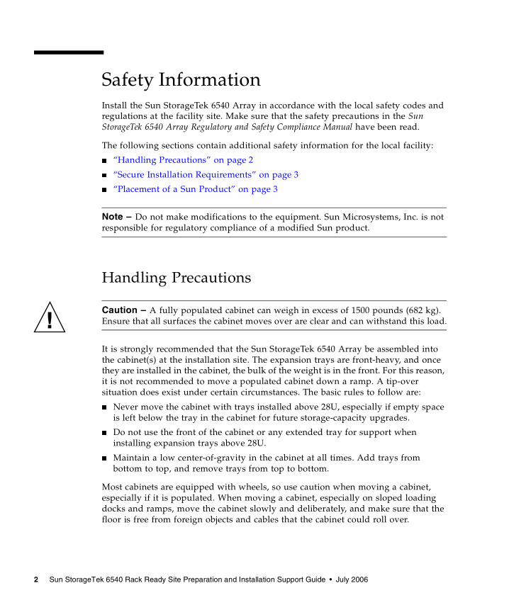
Handling Precautions
Caution – A fully populated cabinet can weigh in excess of 1500 pounds (682 kg). Ensure that all surfaces the cabinet moves over are clear and can withstand this load.
It is strongly recommended that the Sun StorageTek 6540 Array be assembled into the cabinet(s) at the installation site. The expansion trays are front-heavy, and once they are installed in the cabinet, the bulk of the weight is in the front. For this reason, it is not recommended to move a populated cabinet down a ramp. A tip-over situation does exist under certain circumstances. The basic rules to follow are:
� Never move the cabinet with trays installed above 28U, especially if empty space is left below the tray in the cabinet for future storage-capacity upgrades.
� Do not use the front of the cabinet or any extended tray for support when installing expansion trays above 28U.
� Maintain a low center-of-gravity in the cabinet at all times. Add trays from bottom to top, and remove trays from top to bottom.
Most cabinets are equipped with wheels, so use caution when moving a cabinet, especially if it is populated. When moving a cabinet, especially on sloped loading docks and ramps, move the cabinet slowly and deliberately, and make sure that the floor is free from foreign objects and cables that the cabinet could roll over.
Chapter 1 Planning for the Installation 3
Caution – Use a minimum of two or three people to move the cabinet. Wear gloves and protective footwear to avoid injury. Employ more personnel as needed, especially down ramps. A heavy cabinet can twist and turn, pinning you against the wall. Avoid moving a cabinet on a ramp with more than a 10 degree incline/decline.
Secure Installation RequirementsTo minimize personnel injury in the event of a seismic occurrence, ensure that the cabinet is securely fastened to a rigid structure extending from the floor to the ceiling, or from the walls, of the room in which the cabinet is located.
Ensure that the cabinet is on a level surface. At each corner, on the base of the cabinet, should be adjustable nonskid pads. Extend these pads to prevent the cabinet from rolling. Do not use these pads to level the cabinet.
Placement of a Sun Product Allow enough room surrounding the cabinet for access to the cabinet. A minimum amount of clearance must be maintained to ensure adequate cooling and to provide access to the system components for status monitoring and maintenance.
Caution – Do not block or cover the openings of the Sun product. Never place a Sun product near a radiator or heat register. Failure to follow these guidelines can cause overheating and affect the reliability of the Sun product.
Air cools the system components from front to back. Air enters at the front, circulates, and is expelled at the back of the cabinet. Ensure that front and back door clearances are maintained to provide sufficient cooling. See Chapter 2 for more specifications.
4 Sun StorageTek 6540 Rack Ready Site Preparation and Installation Support Guide • July 2006
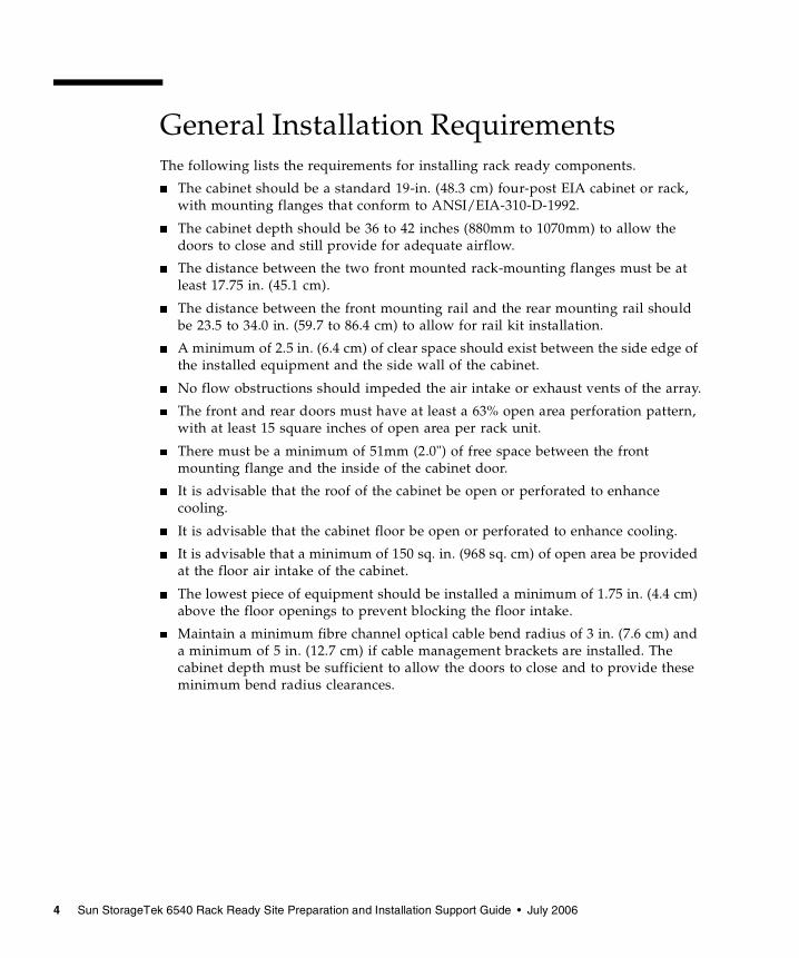
General Installation Requirements The following lists the requirements for installing rack ready components.
� The cabinet should be a standard 19-in. (48.3 cm) four-post EIA cabinet or rack, with mounting flanges that conform to ANSI/EIA-310-D-1992.
� The cabinet depth should be 36 to 42 inches (880mm to 1070mm) to allow the doors to close and still provide for adequate airflow.
� The distance between the two front mounted rack-mounting flanges must be at least 17.75 in. (45.1 cm).
� The distance between the front mounting rail and the rear mounting rail should be 23.5 to 34.0 in. (59.7 to 86.4 cm) to allow for rail kit installation.
� A minimum of 2.5 in. (6.4 cm) of clear space should exist between the side edge of the installed equipment and the side wall of the cabinet.
� No flow obstructions should impeded the air intake or exhaust vents of the array.
� The front and rear doors must have at least a 63% open area perforation pattern, with at least 15 square inches of open area per rack unit.
� There must be a minimum of 51mm (2.0") of free space between the front mounting flange and the inside of the cabinet door.
� It is advisable that the roof of the cabinet be open or perforated to enhance cooling.
� It is advisable that the cabinet floor be open or perforated to enhance cooling.
� It is advisable that a minimum of 150 sq. in. (968 sq. cm) of open area be provided at the floor air intake of the cabinet.
� The lowest piece of equipment should be installed a minimum of 1.75 in. (4.4 cm) above the floor openings to prevent blocking the floor intake.
� Maintain a minimum fibre channel optical cable bend radius of 3 in. (7.6 cm) and a minimum of 5 in. (12.7 cm) if cable management brackets are installed. The cabinet depth must be sufficient to allow the doors to close and to provide these minimum bend radius clearances.

Chapter 1 Planning for the Installation 5
Site Wiring and Power Requirements The AC power distribution unit in the cabinet should use common industrial wiring. Consider the following information when preparing the cabinet installation site.
� AC power source – The AC power source must provide the correct voltage, current, and frequency specified on the equipment’s model and serial number label.
� Earth ground – Site wiring must include an earth ground connection to the AC power source.
� Circuit overloading – Power circuits and associated circuit breakers must provide sufficient power and overload protection. To prevent possible damage to the AC power distribution boxes and other components in the cabinet, use an external, independent power source that is isolated from large switching loads (such as air conditioning motors, elevator motors, and factory loads).
� Power interruptions – The cabinet and equipment will withstand the following applied voltage interruptions (with or without an integrated uninterruptible power supply [UPS]):
� Input transient – 50% of nominal voltage
� Duration – one-half cycle
� Maximum frequency – once every ten seconds
� Power failures – If a total power failure occurs, when power is restored the trays within the cabinet automatically perform a power-up recovery.

6 Sun StorageTek 6540 Rack Ready Site Preparation and Installation Support Guide • July 2006
7
CHAPTER 2
Cabinet and Environmental Specifications
This chapter describes the physical, environmental, and electrical requirements for a cabinet similar to the 1000-38 cabinet. The following topics are in this chapter.
� “Cabinet Specifications” on page 7
� “Environmental Requirements” on page 17
� “Power Requirements” on page 19
To ensure safe and proper operation of the system, and ease of maintenance, make sure that all of these cabinet requirements are met before using the 6540 array.
Cabinet SpecificationsThis section describes the physical, electrical, and environmental requirements for a typical 40U 19-inch rackmount cabinet.
� Footprint: 600 mm (23.6 in.) width by 880 mm (34.6 in.) depth without door600 mm (23.6 in.) width by 960 mm (37.8 in.) depth with doors
� Base Height: 120 mm (4.7 in.)
� Top Member Height: 50 mm (2.0 in.)
� Overall Cabinet Height: 1940 mm (76.4 inches) with 40U of internal vertical space. Packaged height is: 2054 mm (80.87 in.)
� PDU with power cord: Integrated, two or four per cabinet
� Line Cord* for each 30 amp PDU (dual configuration):Volts: 200-240 Frequency: 50-60 HzAmps: 24 Max Phase: Single
8 Sun StorageTek 6540 Rack Ready Site Preparation and Installation Support Guide • July 2006
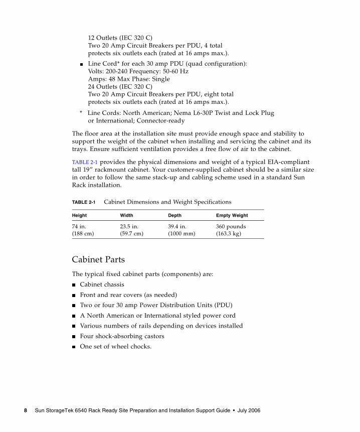
12 Outlets (IEC 320 C)Two 20 Amp Circuit Breakers per PDU, 4 totalprotects six outlets each (rated at 16 amps max.).
� Line Cord* for each 30 amp PDU (quad configuration):Volts: 200-240 Frequency: 50-60 HzAmps: 48 Max Phase: Single24 Outlets (IEC 320 C) Two 20 Amp Circuit Breakers per PDU, eight totalprotects six outlets each (rated at 16 amps max.).
* Line Cords: North American; Nema L6-30P Twist and Lock Plugor International; Connector-ready
The floor area at the installation site must provide enough space and stability to support the weight of the cabinet when installing and servicing the cabinet and its trays. Ensure sufficient ventilation provides a free flow of air to the cabinet.
TABLE 2-1 provides the physical dimensions and weight of a typical EIA-compliant tall 19” rackmount cabinet. Your customer-supplied cabinet should be a similar size in order to follow the same stack-up and cabling scheme used in a standard Sun Rack installation.
Cabinet Parts
The typical fixed cabinet parts (components) are:
� Cabinet chassis
� Front and rear covers (as needed)
� Two or four 30 amp Power Distribution Units (PDU)
� A North American or International styled power cord
� Various numbers of rails depending on devices installed
� Four shock-absorbing castors
� One set of wheel chocks.
TABLE 2-1 Cabinet Dimensions and Weight Specifications
Height Width Depth Empty Weight
74 in.(188 cm)
23.5 in.(59.7 cm)
39.4 in. (1000 mm)
360 pounds (163.3 kg)
Chapter 2 Cabinet and Environmental Specifications 9
Cabinet Height
Cabinet design is described based on EIA-STD-310-D, which describes usable cabinet space in terms of a vertical modular unit-called a ’U’. One U equals 44.45 mm or 1.75 inches of internal vertical space.
Standard equipment racks come in a variety of heights from small units around 356mm (14") high that can provide 8U of equipment space to 2223mm (87.5") high or 50U of equipment space. Customized racks can be even taller.
For safety, access, air flow and other design considerations, it is recommended that the height of the cabinet to be used is no more than 1880mm (74") high or 42U of equipment space.
Caution – Fully-populated expansion trays have the bulk of their weight in the front; therefore, it is important to remember that tall cabinets will be front-heavy, and have a potential for tip-over. It is recommended that the top-most trays be removed before moving a cabinet. Also tip-over prevention legs must be used before extending trays.
ADVERTENCIA: Para asegurar de que el centro de gravedad del armario se encuentre en un nivel seguro durante su transporte o desplazamiento, se requiere que:
� la instalación se efectúe en una configuración de 1 x 8 como máximo (sin dispositivos serie B o serie D por encima de 28U)
� no existan espacios vacíos en la parte inferior del armario
� el armario sea desplazado por una pendiente no superior a 10 grados
Cabinet Width
Equipment racks come in a variety of widths from 19 inches to 24 inches. System design considerations in this document are for a 19-inch rack configuration only as defined in the Electronic Industries Association (EIA) and American National Standards Institute (ANSI) standard ANSI/EIA-310-D-1992 Cabinets, Racks, Panels, and Associated Equipment.
Not all equipment racks are built to EIA-310-D specifications, so verify that the cabinet about to used is compliant. Accessories and rail kits may not install successfully in equipment racks that are not EIA-310-D compliant.
10 Sun StorageTek 6540 Rack Ready Site Preparation and Installation Support Guide • July 2006
Cabinet Depth
Equipment racks come in a variety of depths from 800mm to slightly over 1000mm. The depth of the equipment to be installed must be considered to ensure adequate room in the back for cable management, as well as clearance in the front for proper air flow. See FIGURE 2-1.
When installing equipment into an 800mm cabinet, ensure that there is sufficient room for cable management and that cables or other parts do not extend out the back of the cabinet and prevent the door from closing properly.
There must be a minimum of 51mm (2.0") of free space between the front mounting flange and the inside of the cabinet door. This space is required for clearance of the equipment and to ensure the door does not prevent proper air flow to the equipment.
FIGURE 2-1 Cabinet Depth Recommendations
Chapter 2 Cabinet and Environmental Specifications 11
Weight
The weight of a fully loaded cabinet can vary well above 545 kg (1200 lbs), especially when adding newer disk drive trays and disk controller trays to existing equipment.
It is the responsibility of the customer to ensure that the infrastructure (sub-floor) is capable of supporting a fully loaded cabinet. The cabinet must be able to properly support the specified weight of all of the equipment installed in the rack.
Caution – Make sure to prevent an unbalanced condition that could cause the cabinet to become unstable and tip over. Always install heaviest devices at the bottom of the cabinet, and graduate to the lightest component on top.
When reconfiguring the equipment in a cabinet, always remove equipment installed in the top of the cabinet first. Removal of equipment (starting from the top) should always involve two or more people, and whenever possible, use a mechanical lifting device to lift or lower equipment. Always place the heaviest devices in the bottom of the cabinet first.
Always follow the manufacturer’s guidelines for positioning, supporting or fastening any equipment in the cabinet.
If the cabinet will be moved, make sure that the cabinet’s center-of-gravity is at a safe transport level while moving. This usually requires that:
� no front-heavy trays are installed above 28U
� no empty spaces exist in the lowest portion of the cabinet
� no more than a 10 degree ramp is to be used when transporting the cabinet.
The total weight of a populated cabinet depends on the number and type of trays installed in the cabinet. Chapter three lists the weight of a typical empty cabinet and the maximum weight of each component. Use these weights to estimate the total weight of your system, based on the number of trays installed in the cabinet. Record the total weight in an easy-to-find place to reference when checking floor load or elevator weight restrictions.
12 Sun StorageTek 6540 Rack Ready Site Preparation and Installation Support Guide • July 2006
Cabinet Placement Service clearances should be maintained that are similar to the following.
Front access: 91.5 cm (36 inches)
Back (rear) access: 76.2 cm (30 inches)
If you are installing the cabinet on a raised floor (with data and power cables underneath), the back of the cabinet (cable entry area) should be positioned over the floor tile cutout supplied to route power cords and data cables. See FIGURE 2-2.
FIGURE 2-2 Cabinet Placement Clearances
Note – The distance between the back of the cabinet and the customer’s power source connectors should be 2.4 meters (8 feet) or less.
Regulatory agencies require the control of emissions, and this is especially important when the Sun StorageTek 6540 storage system is in place.
Caution – A front and rear door are required to be installed, and closed, when the equipment is not being serviced. The rear door must remain physically attached and closed (unless being serviced).
Follow basic procedures outlined in the appropriate installation manuals for removing devices. Extender legs or tip-prevention (outrigger) legs are required to enable personnel to slide out and remove or reinstall equipment as well as service equipment and to perform maintenance.
Chapter 2 Cabinet and Environmental Specifications 13
Caution – Make sure that all devices and cables that will be removed and reinstalled in the cabinet are identified in such a way as to ensure that they go back in the same order that they were originally in (so the host and controllers will communicate to the same devices as before).
Seismic Anchorage
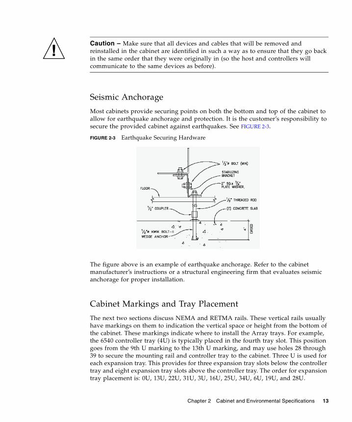
Most cabinets provide securing points on both the bottom and top of the cabinet to allow for earthquake anchorage and protection. It is the customer’s responsibility to secure the provided cabinet against earthquakes. See FIGURE 2-3.
FIGURE 2-3 Earthquake Securing Hardware
The figure above is an example of earthquake anchorage. Refer to the cabinet manufacturer’s instructions or a structural engineering firm that evaluates seismic anchorage for proper installation.
Cabinet Markings and Tray Placement
The next two sections discuss NEMA and RETMA rails. These vertical rails usually have markings on them to indication the vertical space or height from the bottom of the cabinet. These markings indicate where to install the Array trays. For example, the 6540 controller tray (4U) is typically placed in the fourth tray slot. This position goes from the 9th U marking to the 13th U marking, and may use holes 28 through 39 to secure the mounting rail and controller tray to the cabinet. Three U is used for each expansion tray. This provides for three expansion tray slots below the controller tray and eight expansion tray slots above the controller tray. The order for expansion tray placement is: 0U, 13U, 22U, 31U, 3U, 16U, 25U, 34U, 6U, 19U, and 28U.
14 Sun StorageTek 6540 Rack Ready Site Preparation and Installation Support Guide • July 2006
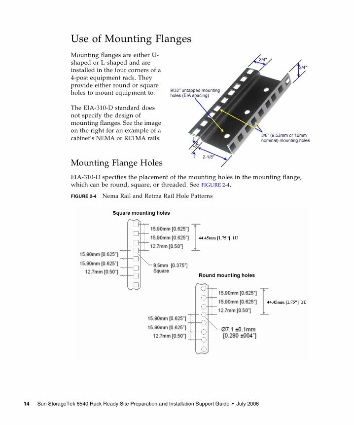
Use of Mounting FlangesMounting flanges are either U-shaped or L-shaped and are installed in the four corners of a 4-post equipment rack. They provide either round or square holes to mount equipment to.
The EIA-310-D standard does not specify the design of mounting flanges. See the image on the right for an example of a cabinet’s NEMA or RETMA rails.
Mounting Flange Holes
EIA-310-D specifies the placement of the mounting holes in the mounting flange, which can be round, square, or threaded. See FIGURE 2-4.
FIGURE 2-4 Nema Rail and Retma Rail Hole Patterns
Chapter 2 Cabinet and Environmental Specifications 15
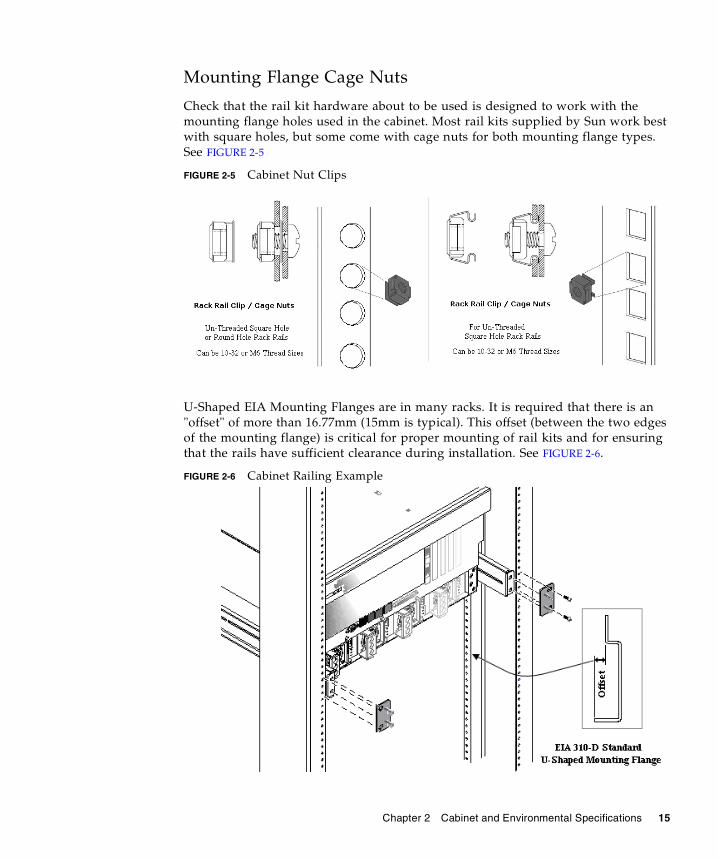
Mounting Flange Cage Nuts
Check that the rail kit hardware about to be used is designed to work with the mounting flange holes used in the cabinet. Most rail kits supplied by Sun work best with square holes, but some come with cage nuts for both mounting flange types. See FIGURE 2-5
FIGURE 2-5 Cabinet Nut Clips
U-Shaped EIA Mounting Flanges are in many racks. It is required that there is an "offset" of more than 16.77mm (15mm is typical). This offset (between the two edges of the mounting flange) is critical for proper mounting of rail kits and for ensuring that the rails have sufficient clearance during installation. See FIGURE 2-6.
FIGURE 2-6 Cabinet Railing Example
16 Sun StorageTek 6540 Rack Ready Site Preparation and Installation Support Guide • July 2006
Racks installed with L-shaped EIA Mounting Flanges typically provide a clearance of 22mm for the rail kit assembly.
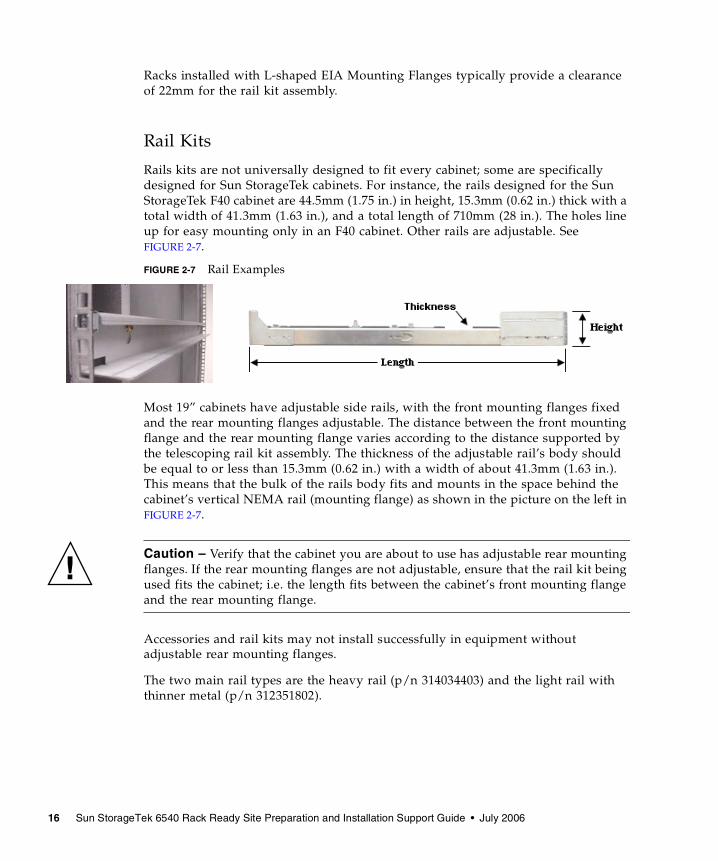
Rail Kits
Rails kits are not universally designed to fit every cabinet; some are specifically designed for Sun StorageTek cabinets. For instance, the rails designed for the Sun StorageTek F40 cabinet are 44.5mm (1.75 in.) in height, 15.3mm (0.62 in.) thick with a total width of 41.3mm (1.63 in.), and a total length of 710mm (28 in.). The holes line up for easy mounting only in an F40 cabinet. Other rails are adjustable. See FIGURE 2-7.
FIGURE 2-7 Rail Examples
Most 19” cabinets have adjustable side rails, with the front mounting flanges fixed and the rear mounting flanges adjustable. The distance between the front mounting flange and the rear mounting flange varies according to the distance supported by the telescoping rail kit assembly. The thickness of the adjustable rail’s body should be equal to or less than 15.3mm (0.62 in.) with a width of about 41.3mm (1.63 in.). This means that the bulk of the rails body fits and mounts in the space behind the cabinet’s vertical NEMA rail (mounting flange) as shown in the picture on the left in FIGURE 2-7.
Caution – Verify that the cabinet you are about to use has adjustable rear mounting flanges. If the rear mounting flanges are not adjustable, ensure that the rail kit being used fits the cabinet; i.e. the length fits between the cabinet’s front mounting flange and the rear mounting flange.
Accessories and rail kits may not install successfully in equipment without adjustable rear mounting flanges.
The two main rail types are the heavy rail (p/n 314034403) and the light rail with thinner metal (p/n 312351802).

Chapter 2 Cabinet and Environmental Specifications 17
Environmental RequirementsThis section describes the environmental conditions that are prerequisite to installing a cabinet.
Temperature, Humidity, and Altitude
TABLE 2-2 lists operating and nonoperating temperature, relative humidity, and altitude ranges for a typical cabinet.
Table 2-4 lists the acceptable temperature and humidity ranges in which the Sun StorageTek 6540 array is designed to operate. Better reliability is obtained when equipment is operated at nominal temperatures (air-conditioned environments).
TABLE 2-3 Equipment Temperature and Humidity Requirements
TABLE 2-2 Cabinet Temperature, Humidity, and Altitude
Specification Operating Nonoperating
Temperature 41°F to 95°F (5°C to 35°C)
-40°F to 150.8°F (-40°C to -66°C)
Relative humidity (RH) 20% to 80% noncondensing
5% to 95% noncondensing
Altitude 0 to 9,840 feet (0 to 3 km)
0 to 39,370 feet 0 to 12 km))
Specification Operating Nonoperating
Temperature Operating range 32°F to 104°F (0°C to 40°C)
- Maximum rate of change 18°F (10°C) per hour
Storage range 14°F to 149°F (-10°C to 65°C)
- Maximum rate of change 27°F (15°C) per hour
Relative humidity (RH),noncondensing
Transit range -40°F to 149°F (-40°C to 65°C)
- Maximum rate of change 36°F (20°C) per hour
Operating range 20% to 80%
Storage range 10% to 93%
18 Sun StorageTek 6540 Rack Ready Site Preparation and Installation Support Guide • July 2006
Caution – If the system is to be operated at an altitude between 3280 ft. to 10,000 ft. (1000 m to 3048 m) above sea level, lower the environmental temperature 3.3°F (1.7°C) for every 3280 ft. (1000 m) above sea level.
Airflow and Heat Dissipation
The ideal method for cooling equipment in a cabinet is to control the room ambient temperature and use rack cabinet doors that have a 63% or higher Free Air Ratio. Under these conditions, additional fan packs on the rack cabinet are usually not necessary. Recommended airflow ranges are listed below. Cabinet airflow should be front to back. Allow at least 30 inches in front of the cabinet, and at least 24 inches behind the cabinet, for service clearance, proper ventilation, and heat dissipation.
Caution – In order to achieve proper airflow, both the front and rear doors need approximately 63% open-area perforations (holes). This percentage refers to the ratio of open space, by way of holes or slots, to closed area within an airflow inlet or outlet. This is commonly referred to as the Free Area Ratio, or FAR. 63% FAR translates into approximately 33 holes in an area that is 25mm square.
Recommended Total System Volumetric Airflow per U � 1U 32 -36 CFM / U
� 2U 39 - 45 CFM / U
� 4U 38 - 40 CFM / U
� 5U 45 - 50 CFM / U
� 7U 25 - 43 CFM / U
Most rack-ready equipment today requires front-to-back cooling, therefore, enclosed cabinets should provide front-to-back cooling as well. While some racks have fans mounted on the top of the enclosure, it’s better to have them mounted directly to the rear door so the air is pulled through the chassis from front to back.
Transit range 5% to 95%
Maximum dew point 79°F (26°C)
Maximum gradient 10% per hour
Specification Operating Nonoperating
Chapter 2 Cabinet and Environmental Specifications 19
Thermal loads increase as new equipment is installed, and the cooling capability of the enclosed cabinet needs to scale as well. Fan packs, which force ambient air from the front of the cabinet through the back of the cabinet enclosure, aid the internal equipment fans in removing heat from the array.
Power RequirementsThe AC power sources must provide the correct voltage, current, and frequency specified on the Sun StorageTek 6540 Array model and serial number label. A typical cabinet is expected to run within the limits shown in TABLE 2-4.
TABLE 2-4 Cabinet AC Power Requirements
Parameter Requirements
Nominal voltages 200 to 240 VAC
Operating voltage 180 to 240 VAC
Frequency range 47 to 63 Hz
Current 32A (2X 16A) maximum
AC power plug NEMA L6-20P (North American)IEC 309 16A 3 Position (International)
AC power receptacle NEMA L6-20R (North American)IEC 309 16A 3 Position (International)
Power cords Redundant and independent power sources are highly recommended to avoid a loss of power to the whole array. Use power cords in pairs to separate power circuits whenever possible.
20 Sun StorageTek 6540 Rack Ready Site Preparation and Installation Support Guide • July 2006
Power Redundancy
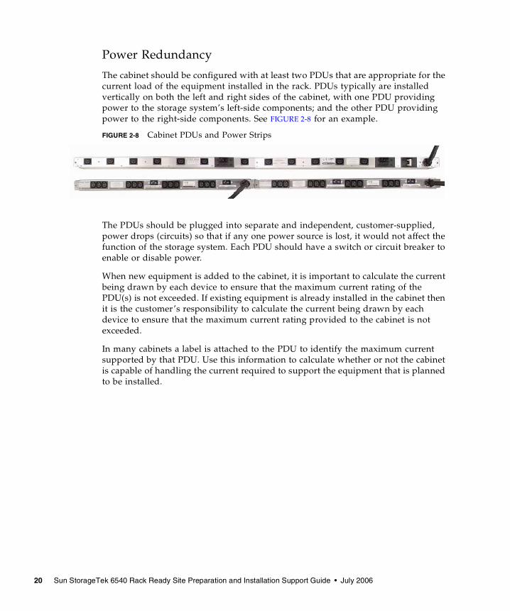
The cabinet should be configured with at least two PDUs that are appropriate for the current load of the equipment installed in the rack. PDUs typically are installed vertically on both the left and right sides of the cabinet, with one PDU providing power to the storage system’s left-side components; and the other PDU providing power to the right-side components. See FIGURE 2-8 for an example.
FIGURE 2-8 Cabinet PDUs and Power Strips
The PDUs should be plugged into separate and independent, customer-supplied, power drops (circuits) so that if any one power source is lost, it would not affect the function of the storage system. Each PDU should have a switch or circuit breaker to enable or disable power.
When new equipment is added to the cabinet, it is important to calculate the current being drawn by each device to ensure that the maximum current rating of the PDU(s) is not exceeded. If existing equipment is already installed in the cabinet then it is the customer’s responsibility to calculate the current being drawn by each device to ensure that the maximum current rating provided to the cabinet is not exceeded.
In many cabinets a label is attached to the PDU to identify the maximum current supported by that PDU. Use this information to calculate whether or not the cabinet is capable of handling the current required to support the equipment that is planned to be installed.

Chapter 2 Cabinet and Environmental Specifications 21
The particular label shown here identifies that each outlet is rated at 10 amps. This means that any installed device using that outlet can not draw more than 10 amps of current. This label also identifies that the PDU is split up into two 16-amp zones protected by a circuit breaker. If the PDU was to have one 10 amp device and three 2 amp devices plugged in, the other outlets in the zone must remain vacant. Another example might be six 2.2 amp devices plugged into this zone. This would result in 13.2 amps of total current draw, which is under the 16 amps per zone requirement.
Total current draw should not exceed 80% of the rated (30 amps) current draw for the PDU. The label (on the right) identifies that the entire PDU has already been derated to 24 amps to meet this requirement.
For more on calculating current, see “Calculating Current” on page 27.
Additional Cabinet-related Information
There are multiple ways of getting information. It can be found on the:
� software and document product CD
� Customer Resource Center (CRC)
� Documents on CD
� engineering web pages located at: http://gandalf.stortek.com/ctp/
Cabinet information can be found on the CRC by going to Current Products >> Disk and looking for the Sun StorageTek 6000 Series header. Click on 6540 Array, and look for the title: CBNT Cabinet, Cabling, and cabinet-related manuals.

22 Sun StorageTek 6540 Rack Ready Site Preparation and Installation Support Guide • July 2006
23
CHAPTER 3
Sun StorageTek 6540 Array Installation Requirements
This chapter describes the physical, environmental, and electrical requirements for the Sun StorageTek 6540 Array. It contains the following sections:
� “Physical Requirements” on page 24
� “Environmental Requirements” on page 25
� “Electrical Requirements” on page 26
� “Tray Installation” on page 28
24 Sun StorageTek 6540 Rack Ready Site Preparation and Installation Support Guide • July 2006
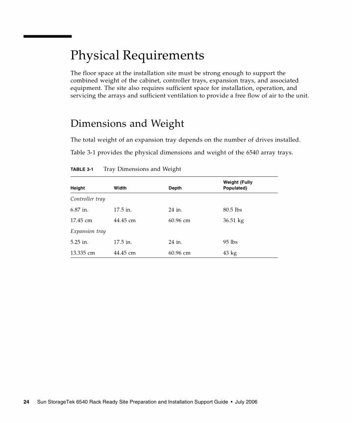
Physical RequirementsThe floor space at the installation site must be strong enough to support the combined weight of the cabinet, controller trays, expansion trays, and associated equipment. The site also requires sufficient space for installation, operation, and servicing the arrays and sufficient ventilation to provide a free flow of air to the unit.
Dimensions and WeightThe total weight of an expansion tray depends on the number of drives installed.
Table 3-1 provides the physical dimensions and weight of the 6540 array trays.
TABLE 3-1 Tray Dimensions and Weight
Height Width DepthWeight (Fully Populated)
Controller tray
6.87 in. 17.5 in. 24 in. 80.5 lbs
17.45 cm 44.45 cm 60.96 cm 36.51 kg
Expansion tray
5.25 in. 17.5 in. 24 in. 95 lbs
13.335 cm 44.45 cm 60.96 cm 43 kg
Chapter 3 Sun StorageTek 6540 Array Installation Requirements 25
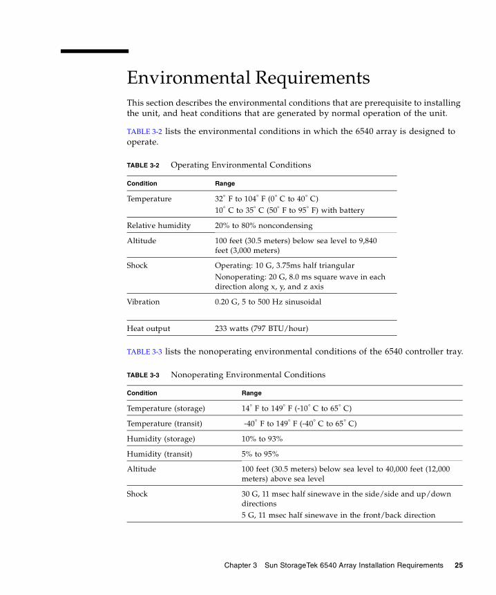
Environmental RequirementsThis section describes the environmental conditions that are prerequisite to installing the unit, and heat conditions that are generated by normal operation of the unit.
TABLE 3-2 lists the environmental conditions in which the 6540 array is designed to operate.
TABLE 3-3 lists the nonoperating environmental conditions of the 6540 controller tray.
TABLE 3-2 Operating Environmental Conditions
Condition Range
Temperature 32° F to 104° F (0° C to 40° C)10° C to 35° C (50° F to 95° F) with battery
Relative humidity 20% to 80% noncondensing
Altitude 100 feet (30.5 meters) below sea level to 9,840 feet (3,000 meters)
Shock Operating: 10 G, 3.75ms half triangularNonoperating: 20 G, 8.0 ms square wave in each direction along x, y, and z axis
Vibration 0.20 G, 5 to 500 Hz sinusoidal
Heat output 233 watts (797 BTU/hour)
TABLE 3-3 Nonoperating Environmental Conditions
Condition Range
Temperature (storage) 14° F to 149° F (-10° C to 65° C)
Temperature (transit) -40° F to 149° F (-40° C to 65° C)
Humidity (storage) 10% to 93%
Humidity (transit) 5% to 95%
Altitude 100 feet (30.5 meters) below sea level to 40,000 feet (12,000 meters) above sea level
Shock 30 G, 11 msec half sinewave in the side/side and up/down directions5 G, 11 msec half sinewave in the front/back direction
26 Sun StorageTek 6540 Rack Ready Site Preparation and Installation Support Guide • July 2006
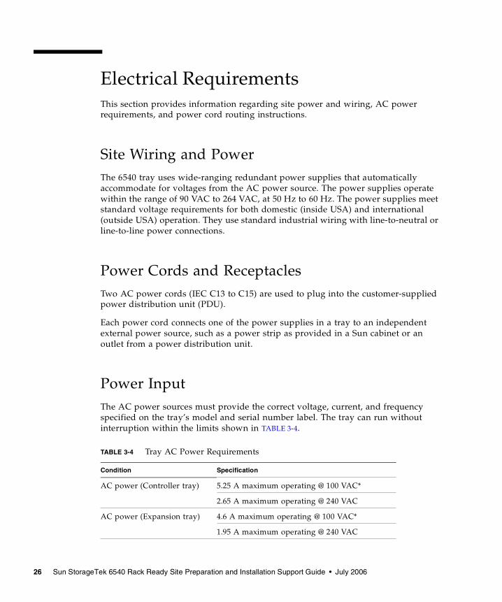
Electrical RequirementsThis section provides information regarding site power and wiring, AC power requirements, and power cord routing instructions.
Site Wiring and PowerThe 6540 tray uses wide-ranging redundant power supplies that automatically accommodate for voltages from the AC power source. The power supplies operate within the range of 90 VAC to 264 VAC, at 50 Hz to 60 Hz. The power supplies meet standard voltage requirements for both domestic (inside USA) and international (outside USA) operation. They use standard industrial wiring with line-to-neutral or line-to-line power connections.
Power Cords and ReceptaclesTwo AC power cords (IEC C13 to C15) are used to plug into the customer-supplied power distribution unit (PDU).
Each power cord connects one of the power supplies in a tray to an independent external power source, such as a power strip as provided in a Sun cabinet or an outlet from a power distribution unit.
Power InputThe AC power sources must provide the correct voltage, current, and frequency specified on the tray’s model and serial number label. The tray can run without interruption within the limits shown in TABLE 3-4.
TABLE 3-4 Tray AC Power Requirements
Condition Specification
AC power (Controller tray) 5.25 A maximum operating @ 100 VAC*
2.65 A maximum operating @ 240 VAC
AC power (Expansion tray) 4.6 A maximum operating @ 100 VAC*
1.95 A maximum operating @ 240 VAC
Chapter 3 Sun StorageTek 6540 Array Installation Requirements 27
* A 240VAC power source is the only recommended source for the 6540 Array.
Calculating Current Power calculations should use the current ratings at the 240 VAC source. To calculate for a 1x10, use the current ratings of 2.65 + (10 x 1.95), which equals 22.15 amps. Each additional expansion tray would add another 2 amps, so a 1x12 takes the current up to 26 amps. A 1x12 is typically the most that can fit into any one cabinet (40U of vertical space is required). This means that a 30-amp source from the customer could safety supply power to one side of the 6540 Array’s trays. The other side of the trays would need another independent (redundant) 30-amp source to supply power to the trays, so if any one power source was lost, the 6540 Array would continue to operate.
If the customer-supplied cabinet has circuit breakers on its PDU or power strip, then the calculations have to consider the amps drawn by each device plugged in. This helps to ensure that actual current drawn doesn’t come close to meeting or exceeding the trip-current. For example a power strip with a 10 amp breaker could receive 2.65 + 1.95 + 1.95 for approximately 7.7 amps. Remember that current can vary under certain conditions, so some margin of safety in case the VAC input voltage drops is required.
Note – Make sure that the whole array has power supplied to it, and that one source is not supplying both sides of any one tray.
Single Power Cord and Multiple Cabinet Environments
Customers who are unique cabinet configurations should consult with a certified electrician. Typically special AC power distribution systems can be provided to supply power to a 6540 Array.
A single AC power source could be employed, however, as a minimum it may require the use a 50-amp breaker running 240 VAC. Also internal breakers may have to employed that don’t exceed 50% of the rating—whether supplying power to one device or one cabinet. It is recommended that current calculations consider everything that is plugged into that one line, and not exceed the 50% of the rating. This is done to protect the 6540 array from losing power during low-voltage conditions.
28 Sun StorageTek 6540 Rack Ready Site Preparation and Installation Support Guide • July 2006
Tray Installation The following section will help you install the Sun StorageTek 6540 Array into a customer-supplied cabinet.
Stack-up and CablingIt is recommended that the trays are stacked in the cabinet exactly as they would have been if shipped with the Sun Rack 1000-38, as stated in “Cabinet Markings and Tray Placement” on page 13. This will help you use the supplemental manuals that show how the trays are arranged in the cabinet and how the drive interface cables are connected from the controller tray to the expansion trays.
Refer to the Hardware Cabling Guide to see how to stack-up the trays and how to route the FC cables. Refer to the Hardware Installation Guide for information about applying power, adding expansion trays, and using a cabinet with a patch panel (or cabling a two-cabinet configuration).
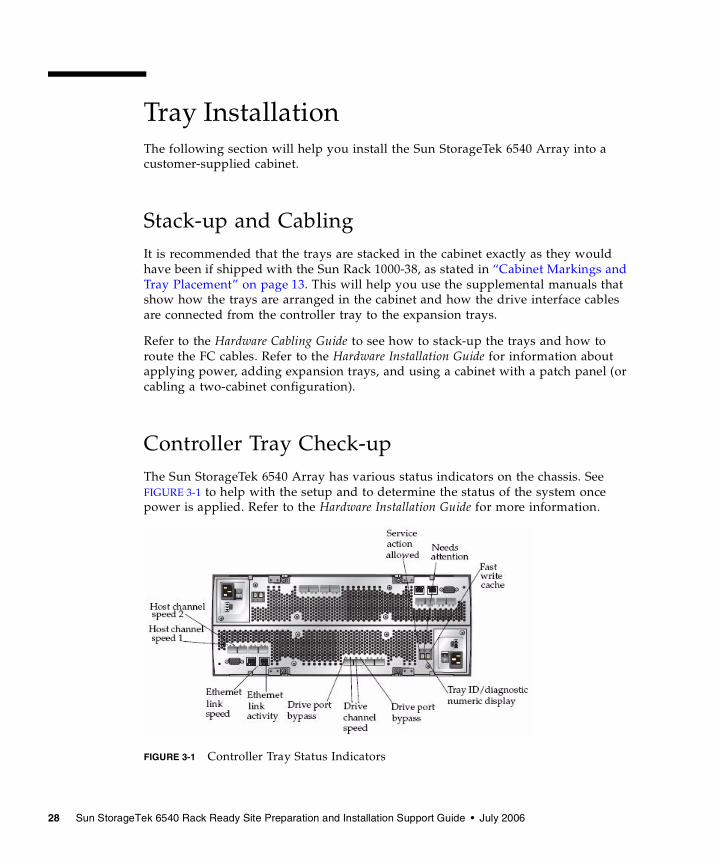
Controller Tray Check-up The Sun StorageTek 6540 Array has various status indicators on the chassis. See FIGURE 3-1 to help with the setup and to determine the status of the system once power is applied. Refer to the Hardware Installation Guide for more information.
FIGURE 3-1 Controller Tray Status Indicators
Chapter 3 Sun StorageTek 6540 Array Installation Requirements 29
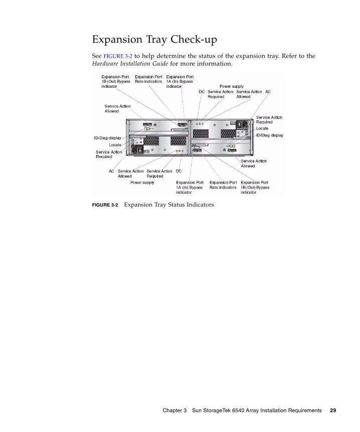
Expansion Tray Check-up See FIGURE 3-2 to help determine the status of the expansion tray. Refer to the Hardware Installation Guide for more information.
FIGURE 3-2 Expansion Tray Status Indicators

30 Sun StorageTek 6540 Rack Ready Site Preparation and Installation Support Guide • July 2006
31
APPENDIX A
Configuration Worksheets
Use the worksheets in this appendix to help you collect the information you need to perform the installation. Two worksheets are provided:
� “Sun StorageTek 6540 Array Configuration Worksheet” on page 32
� “Sun StorageTek 6540 Array Data Host Information” on page 33

32 Sun StorageTek 6540 Rack Ready Site Preparation and Installation Support Guide • July 2006
TABLE A-1 lists the information you need to configure the array.
TABLE A-1 Sun StorageTek 6540 Array Configuration Worksheet
Controller A MAC address:
Controller B MAC address:
Controller A IP address:
Controller B IP address:
Management host IP address:
Network mask:
Name server domain name:
IP address of the domain nameserver (DNS):
Gateway IP address:
Email notification address:
Appendix A Configuration Worksheets 33
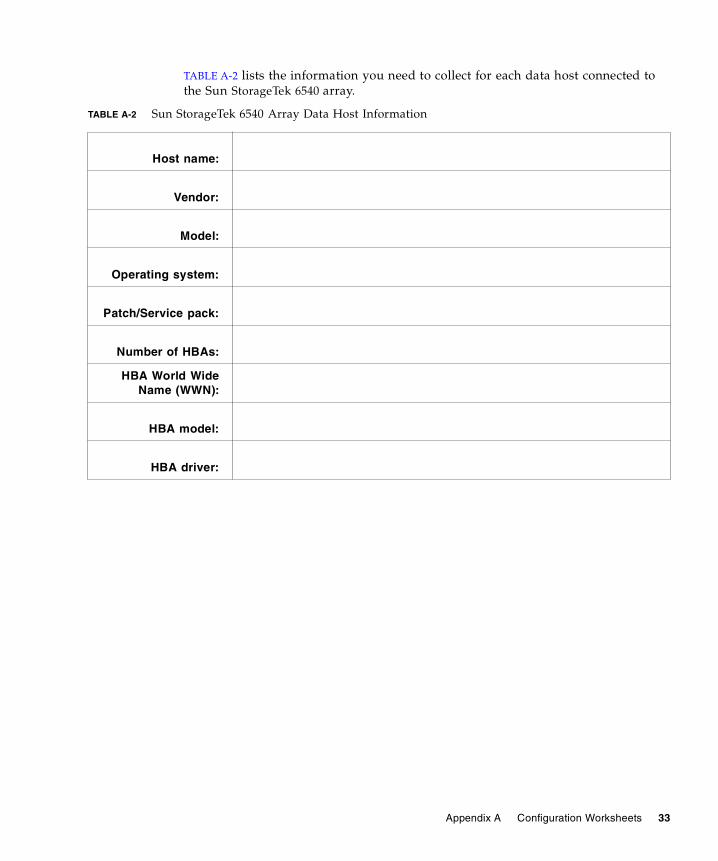
TABLE A-2 lists the information you need to collect for each data host connected to the Sun StorageTek 6540 array.
TABLE A-2 Sun StorageTek 6540 Array Data Host Information
Host name:
Vendor:
Model:
Operating system:
Patch/Service pack:
Number of HBAs:
HBA World WideName (WWN):
HBA model:
HBA driver:

34 Sun StorageTek 6540 Rack Ready Site Preparation and Installation Support Guide • July 2006
35
Index
Numerics6540 array
environmental requirements, 25
AAC power, 26airflow, 18altitude requirements, 17, 25array
installation planning fordata host information, 33
array tray dimensions, 24
Ccabinet
airflow, 18area requirements, 24clearance, 18dimensions, 8handling, 2placement, 3, 12power requirements, 19site wiring requirements, 5temperature, humidity, altitude, 17
cabinet markings, 13calculating weight, 11call centers, xclearances, 18controller tray position, 13controller tray status lights, 28cooling, 3
current calculations, 21, 27customer responsibilities, 1
Ddocumentation, ix
Eearth ground, 5environmental requirements
6540 array, 25expansion tray positions, 13expansion tray status lights, 29
Ffinding documentation, ix, 21
Ggetting help, x
Hhandling precautions, 2hardware
installation planning, 31placement, 3, 24
heat output, 25humidity, 17, 25
Iinstallation
hardware, 31secure, 3
36 Sun StorageTek 6540 Rack Ready Site Preparation and Installation Support Guide • July 2006
installation requirements, 4installing trays, 28
LLEDs, 28, 29locating information, ix, 21
Ooperating temperature, 25
Ppower
failure, 5interruptions, 5source (AC), 5tray AC requirements, 26
power cords, 26power redundancy, 20power requirements, 5power requirements, cabinet, 19power source, 26power supplies
operating range, 26wiring, 26
Rrack ready requirements, 4redundancy, 20
Ssafety precautions, 2
handling, 2shock, 25site wiring requirements, cabinet, 5status lights
controller tray, 28expansion tray, 29
Ttechnical support, xtemperature, 17temperature requirements, 17tray installation, 28tray placement, 13tray weight, 11
UU markings, 13
Vvibration, 25
Wweight
cabinet, 11controller tray, 24expansion tray, 24
worksheetconfiguration, 32data host, 33