Embed Size (px)
Citation preview

AD41 Dry Air Unit Instruction Manual v1.1
Page 1
TABLE OF CONTENTS
SPECIFICATION................................................................................................................. 2
INTRODUCTION................................................................................................................. 3
QUIETER RUNNING......................................................................................................... 3
REDUCED MAINTENANCE ............................................................................................... 3
ENHANCED FUNCTIONALITY ........................................................................................... 3
REMOTE OPERATION ..................................................................................................... 3
MODE OF OPERATION ..................................................................................................... 3
USING THE AD41 .............................................................................................................. 4
REMOTE OPERATION....................................................................................................... 5
MAINTENANCE AND TROUBLE SHOOTING................................................................... 5
PRECAUTIONS................................................................................................................ 5
ROUTINE MAINTENANCE................................................................................................. 5Compressor Delivery Filter......................................................................................... 5Compressor .............................................................................................................. 6
CHECKING THE DRY AIR OUTPUT .................................................................................... 6
FAULTS ......................................................................................................................... 6
FACTORY OVERHAUL/SERVICE ..................................................................................... 6
LIST OF APPENDICES ...................................................................................................... 7
APPENDIX 1 - GENERAL CIRCUIT DIAGRAM ................................................................. 8
APPENDIX 2 - CONTROL BOARD CIRCUIT DIAGRAM................................................... 9
APPENDIX 3 - COMPRESSOR DELIVERY FILTER REPLACEMENT............................ 10
APPENDIX 4 - COMPRESSOR SERVICE........................................................................ 11
DISMANTLING .............................................................................................................. 11
COMPRESSOR ............................................................................................................. 11
ASSEMBLY .................................................................................................................. 12
DRYING DOWN............................................................................................................. 12
AD41 Dry Air Unit Instruction Manual v1.1
Page 2
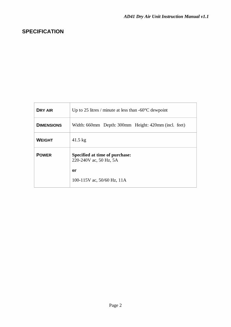
SPECIFICATION
DRY AIR Up to 25 litres / minute at less than -60°C dewpoint
DIMENSIONS Width: 660mm Depth: 300mm Height: 420mm (incl. feet)
WEIGHT 41.5 kg
POWER Specified at time of purchase:220-240V ac, 50 Hz, 5A
or
100-115V ac, 50/60 Hz, 11A

AD41 Dry Air Unit Instruction Manual v1.1
Page 3
INTRODUCTION
The AD41 is a development of the AD31 Dry Air Unit that has seen a total service life of more thanone million hours. The new benefits are:
QUIETER RUNNING
Brand new casing that incorporates extra soundproofing and a more convoluted cooling air path toreduce the operating noise level.
REDUCED MAINTENANCE
By building in larger filters it has been possible to achieve longer service intervals. An integralhourmeter gives an instant and accurate indication of total runtime. When service is needed thecomponents are quick and easy to access.
ENHANCED FUNCTIONALITY
The AD41 now features a dedicated microcontroller to give long term accuracy of the timing cycles,comprehensive status indication at all times and automatic stall-free restart after a power failure.
REMOTE OPERATION
With an optional Remote Control Module, the AD41 may be situated up to 60 metres away frompoint of use of the dry air, The Remote Control Module indicates the operational status, dry airflowrate and allows the AD41 on/off to be controlled.
Alternatively, the EXT port can be used to control or monitor the AD41 from other equipment.
MODE OF OPERATION
This stand-alone unit, draws in atmospheric air and converts it to dry air. The dry air has a dewpointof better than -60°C and a variable flowrate up to a maximum of 25 litres/minute.
The AD41 Flow Scheme (Fig 1) shows the air is compressed to 3.5 bar pressure and passed, via aparticle filter, to a factory-sealed, twin-column pressure-swing adsorption dryer. An oil-freecompressor is employed to avoid contamination of the molecular sieve drying agent by lubricatingoil.
At any one time, pressurised air is dried by passing it up one of the columns. Simultaneously, afraction of this dry air is bled back down the other column at low pressure to purge it of watervapour. After a pre-set time, the action of the two columns is reversed by means of electricallyoperated change over valves.
The pressurised dry air passes through a filter/regulator to remove pressure pulses during columnswitching and limit the maximum output pressure. The output flowrate is controlled by the userwith a built-in needle valve and flowmeter.

AD41 Dry Air Unit Instruction Manual v1.1
Page 4
Fig 1 AD41 Flow Scheme
USING THE AD41
If the AD41 has not been used for some time it is advisable to run the unit overnight to establish thecorrect moisture gradient within the drying columns. This should be done before connecting anymoisture-sensitive equipment to the DRY AIR output.
To avoid overheating, the AD41 should be located away from sources of heat and in a positionwhere it can draw a supply of cool air through the high level inlet at the end of the quiet box. DONOT OBSTRUCT THE COOLING AIR GRILLS AT EACH END OF THE UNIT.
1. Connect the DRY AIR output to your equipment using 8mm OD nylon tube to minimisepressure drop in the connecting tube. In Cryostream Cooler applications use the reducingcoupling supplied to connect 8mm tube to 6mm tube: the total length of 6mm OD tube should belimited to 3 metres.
2. To obtain dry air, connect the AD41 to the appropriate electricity supply - the POWER lampshould light.
3. Switch on the AD41. At this point, the RUN lamp should flash for 4 seconds after which youwill hear the compressor start and the RUN lamp will light continuously.
4. Set the required dry air flowrate with the needle valve on the flowmeter. When using the AD41with the Cryostream Cooler, use between five and ten litres per minute.
Note: As the AD41 warms up from cold the flowrate may require adjusting. Once the unit is warmthe flowrate will stay constant.
AD41 Dry Air Unit Instruction Manual v1.1
Page 5
REMOTE OPERATION
In certain circumstances it may not be convenient to have the AD41 in the room where the dry air isbeing used. In this case, the AD41 may be located in another room.
An optional Remote Control Module is available to control and monitor the AD41 at the point ofuse of dry air. The Remote unit duplicates the valved flowmeter, ON/OFF switch and the POWER,RUN & FAULT lamps. The practical limit to the distance between the AD41 and the RemoteControl Module is 60 metres.
Note: When the Remote Control Module is installed the ON/OFF switch on the AD41 acts as amaster switch and must be set to ON to allow the remote ON/OFF switch to function.
Consult APPENDIX 5 - REMOTE CONTROL MODULE for installation details of the Remoteoption.
MAINTENANCE AND TROUBLE SHOOTING
The AD41 is designed to be a low-maintenance unit. A useful indication that the unit is functioningcorrectly is that a brief hiss can be heard at regular (one minute) intervals as the air valves switch theaction of the columns.
When the AD41 is used with the Cryostream Cooler to provide the dry air shield for the nitrogen gasstream, a deterioration in the dryness of the dry air will show up as frost forming evenly all aroundthe cold nitrogen stream delivery nozzle.
PRECAUTIONS
If you have not used the AD41 for some time it may be necessary to run the unit overnight to drydown the columns.
ROUTINE MAINTENANCE
The AD41 is designed to run for 9,000 hours before needing any maintenance. However, localconditions may accelerate wear of components or clogging of filters. Routine or preventativemaintenance may be carried out by users, utilising a qualified technician. The following items mayrequire attention.
Compressor Delivery Filter
Eventually the Compressor Delivery Filter will become clogged with the finer particles of room dirtand the wear products from the compressor. The symptoms will be a deterioration in the dryness ofthe dry air and, as the blockage gets worse, a reduction in the maximum dry air flowrate.
For details of the filter replacement see Appendix 3.
AD41 Dry Air Unit Instruction Manual v1.1
Page 6
Compressor
At some stage (usually longer than 9,000 hours) the plastic piston ring in the compressor will wearout. The eventual failure of the piston seal is a very sudden process and the dryness of the dry airwill deteriorate rapidly, also the maximum flowrate of dry air will drop below 25 litres/minute(perhaps less than 10 litres/minute).
This situation requires the compressor to be serviced. See Appendix 4.
CHECKING THE DRY AIR OUTPUT
Note: Make sure to run the AD41 overnight before checking the dry air output, this will give thedrying columns a chance to dry down.
The residual water vapour content of the AD41 dry air output may be measured with a suitablehygrometer calibrated down to -70°C dewpoint. Allow at least 10 minutes for the reading to reachequilibrium.
FAULTS
Note: If any trips are activated the cause should be determined, preferably by a qualified technician,before restarting the unit.
A rear panel fuse (1A, 220-240V or 2A, 100-115V) protects the transformer that drives the powersupply, control board, indicator lamps, cooling fan and solenoid valves.
A rear panel circuit breaker operates if the compressor draws excessive current - push the blackbutton in to reset.
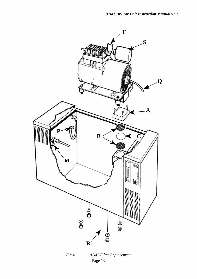
A manual reset thermal switch operates if the temperature inside the quiet box rises excessively forany reason. If an overheat occurs the HOT! lamp will flash until the thermal switch is reset. Thethermal switch is mounted in the compressor compartment (see Fig 4 (M)) - press the red button toreset.
FACTORY OVERHAUL/SERVICE
After extended running you may consider it desirable for the AD41 to have a complete factoryservice and full recommissioning procedure. Please contact your agent or Oxford Cryosystems todiscuss this type of service if required.

AD41 Dry Air Unit Instruction Manual v1.1
Page 7
LIST OF APPENDICES
APPENDIX 1 General Circuit Diagram
APPENDIX 2 Control Board Circuit Diagram
APPENDIX 3 Compressor Delivery Filter Replacement
APPENDIX 4 Compressor Service
AD41 Dry Air Unit Instruction Manual v1.1
Page 8
APPENDIX 1 - GENERAL CIRCUIT DIAGRAM

AD41 Dry Air Unit Instruction Manual v1.1
Page 9
APPENDIX 2 - CONTROL BOARD CIRCUIT DIAGRAM

AD41 Dry Air Unit Instruction Manual v1.1
Page 10
APPENDIX 3 - COMPRESSOR DELIVERY FILTER REPLACEMENT
Refer to Fig 4 Page 13
1. Switch off the AD41 and disconnect the electrical power.
2. Remove the AD41 top cover by lifting the four white plastic plugs and unscrewing the four M5socket caphead screws with the 4mmA/F hexagon balldriver provided.
3. The Compressor Delivery Filter (A) is a square grey unit mounted just under the top cover nearthe control panel end of the AD41. Unscrew the four M6 socket caphead screws on the lid ofthe filter with the 5mmA/F hexagon key provided.
4. Lift off the lid and disconnect the 8mm nylon tube if necessary. Lift out the top anodisedaluminium mesh (B), the filter disc (C) and the bottom anodised aluminium mesh (B).
5. Discard the dirty filter disc and clean the meshes.
6. Clean the sealing 'O' ring on the lid and the part of the body on which it seals.
7. Fit one mesh into the filter body, lay a new filter disc on top of the mesh with an equal overlap allround and fit the second mesh on top. Re-connect the 8mm nylon tube, replace the filter lid andtighten down the four M6 socket caphead screws evenly in sequence.
8. Run the AD41 overnight to dry down the columns.

AD41 Dry Air Unit Instruction Manual v1.1
Page 11
APPENDIX 4 - COMPRESSOR SERVICE
Note: This work should be carried out by a qualified mechanical and electrical technician.
These instructions are for use with an AD41 Compressor Service Kit comprising:-
1. One piston/cylinder assembly
2. One relief/dump valve
3. One inlet filter unit
4. One delivery filter disc
DISMANTLING
Please refer to Fig 4 Page 13.
1. Switch off the AD41 and disconnect the electrical power and the dry air output.
2. Remove the AD41 top cover by lifting the four white plastic plugs and unscrewing the four M5socket caphead screws with the 4mmA/F hexagon balldriver provided.
3. Disconnect the blue compressor delivery hose coupling (P) at the brass fitting on thecompressor. Disconnect the compressor power cable (Q) at the plug-in connector (the plug maybe held in place with a cable tie).
4. Unscrew the four nuts (R) (in recesses underneath the cabinet) securing the compressor rubbermounts to the base of the cabinet. NOTE THE POSITION OF ALL WASHERS AND LOCKWASHERS. Carefully lift the compressor out of the quiet box.
COMPRESSOR
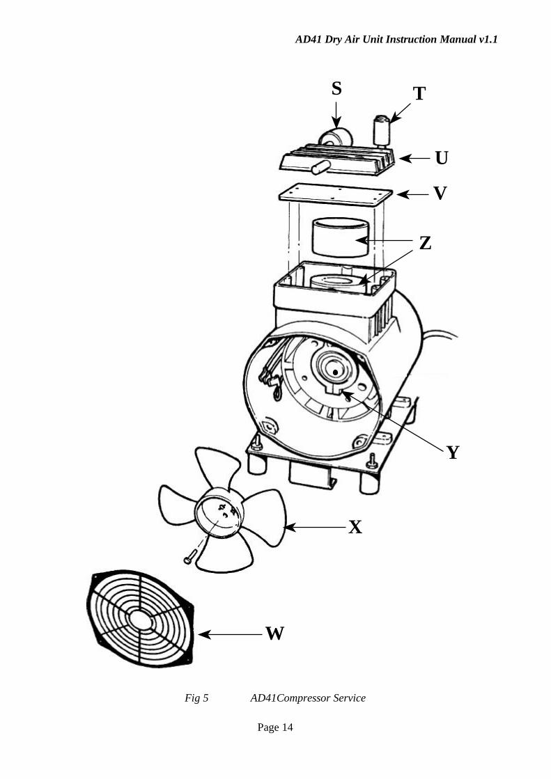
Please refer to Fig 5 Page 14.
1. Remove the inlet filter cannister (S) which should unscrew by hand from the brass fitting on thecompressor.
2. Remove the cylindrical brass relief/dump valve (T) (use a thin spanner) - unscrew the completevalve assembly leaving just the elbow fitting screwed into the cylinder head.
3. Make alignment marks with a marker pen on the compressor cylinder head (U), valve plate (V)and body to enable correct re-assembly.
4. Remove the cylinder head (U) and valve plate (V) (six screws).
5. Remove the plastic grill (W) from the front of the crankcase (four screws) and the plastic fan (X)(one screw and two washers.) - NOTE THE CORRECT ORIENTATION OF THE FAN ONTHE END OF THE MOTOR SHAFT.

AD41 Dry Air Unit Instruction Manual v1.1
Page 12
6. Release the piston connecting rod clamp screw (Y) (socket caphead screw accessed through ahole in the side of the crankcase) and remove the worn piston and cylinder - NOTE THEALIGNMENT OF THE PISTON ASSEMBLY ON THE BEARING. Check the motorbearings and especially the big end bearing for wear which may cause premature failure.
7. Fit the new piston and cylinder (Z) (use the original clamp screw (Y) with thread lockingcompound).
8. Refit the valve plate and cylinder head (tighten opposing screws in sequence to avoid distortingthe cylinder head).
9. Refit the plastic fan (X) (using the screw, spring washer and plain washer with thread lockingcompound). Refit the plastic grill (W) (check that none of the cables which have been disturbedtouches the fan or other moving parts).
10. Fit the new compressor relief/dump valve (T) and bonded sealing washer using a thin spanner(ensure that the new valve is supplied “pre-set - ready to use”). TAKE CARE NOT TO ALTERTHE SETTING OF THE RELIEF/DUMP VALVE.
11. Fit the new inlet filter (S) firmly by hand.
ASSEMBLY
Please refer to Fig 4 Page 13.
1. Refit the compressor into the cabinet (replace all nuts and washers correctly) - do not allow thecompressor rubber mounts to rotate as the securing nuts are being tightened.
2. Reconnect the blue compressor delivery hose coupling (P) at the brass fitting on the compressorand reconnect the compressor power cable (Q) at the plug in connection.
3. Fit a new element in the delivery filter (as described in Appendix 3).
4. Fit the top cover securing screws and plastic plugs.
DRYING DOWN
After a service the drying columns are likely to be wet. Run the AD41 for at least 24 hours to drythe columns down before using the AD41 as a dry air supply.
AD41 Dry Air Unit Instruction Manual v1.1
Page 13
B
A
C
R
T
S
Q
P
M
Fig 4 AD41 Filter Replacement
AD41 Dry Air Unit Instruction Manual v1.1
Page 14
X
W
Y
Z
V
TS
U
Fig 5 AD41Compressor Service