Embed Size (px)
Citation preview

Quick Start GuideLIQ-QSG-225, Rev L
May 2017
Rosemount™ 225
Toroidal Conductivity Sensor
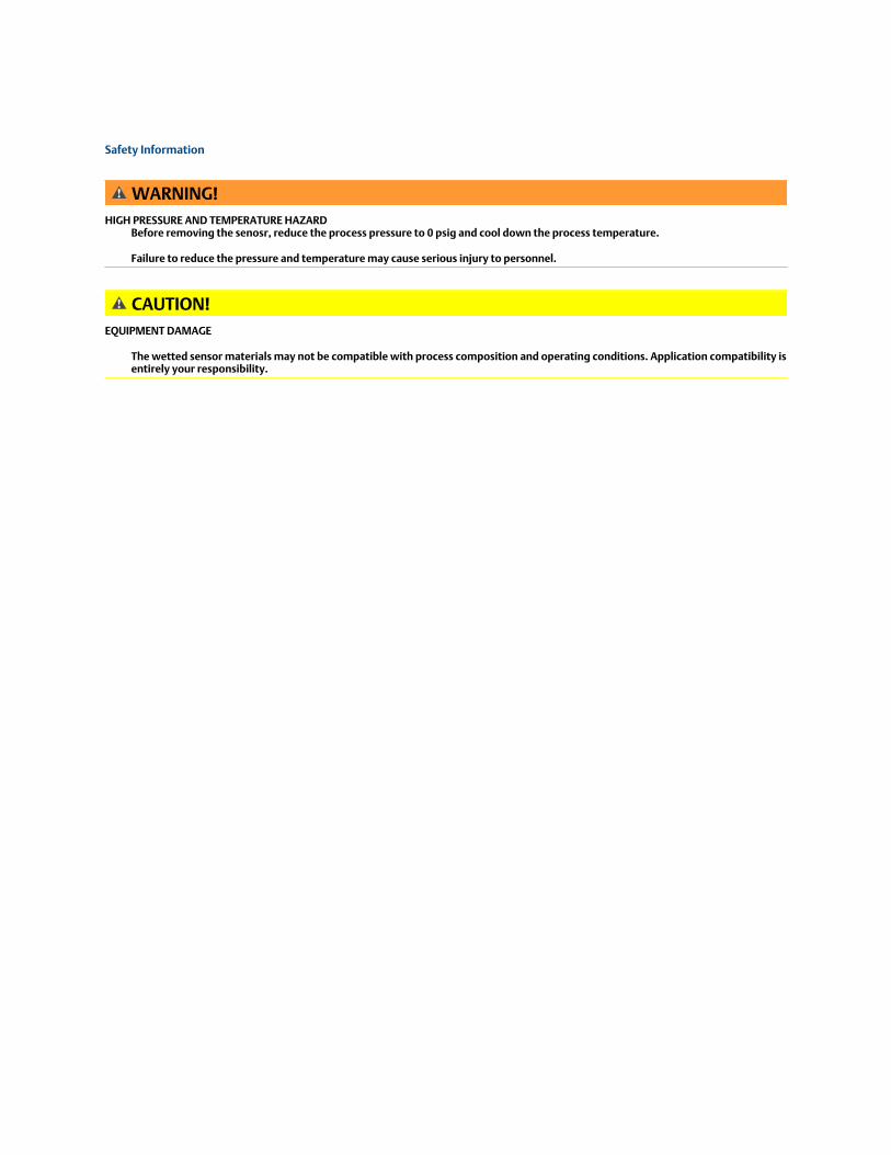
Safety Information
WARNING!HIGH PRESSURE AND TEMPERATURE HAZARD
Before removing the senosr, reduce the process pressure to 0 psig and cool down the process temperature.
Failure to reduce the pressure and temperature may cause serious injury to personnel.
CAUTION!EQUIPMENT DAMAGE
The wetted sensor materials may not be compatible with process composition and operating conditions. Application compatibility isentirely your responsibility.
Contents
Chapter 1 Description and Specifications ..........................................................................................11.1 General .......................................................................................................................................... 11.2 Unpacking and Inspection .............................................................................................................. 11.3 Specifications .................................................................................................................................1
Chapter 2 Install ...............................................................................................................................32.1 Installing the sensor ....................................................................................................................... 32.2 Wiring the Sensor ...........................................................................................................................4
Chapter 3 Calibration ..................................................................................................................... 113.1 Sensor calibration .........................................................................................................................113.2 Calibrating against a Standard Solution ........................................................................................ 113.3 Calibrating against a Referee - in-Process ..................................................................................... 133.4 Calibrating against a Referee - Grab Sample ................................................................................. 14
Chapter 4 Troubleshooting ............................................................................................................ 174.1 Maintaining the sensor .................................................................................................................174.2 Troubleshooting .......................................................................................................................... 17
Chapter 5 Accessories .................................................................................................................... 21
Chapter 6 Return of Materials .........................................................................................................23
Contents
Rosemount 225 Sensors i

Contents
ii Quick Start Guide
1 Description and Specifications
1.1 GeneralRosemount 225 toroidal conductivity sensors are intended to be used in manypharmaceutical and food and beverage applications where a sanitary design is required.These corrosion and fouling resistant sensors are ideal for measuring the concentration ofCIP solutions, detecting product/water interfaces, checking product quality, andmonitoring eleuents in chromatographic separations.
1.2 Unpacking and Inspection1. Inspect the shipping container. If it is damaged, contact the shipper immediately for
instructions.
2. If there is no apparent damage, remove the sensor.
3. Ensure that all items shown on the packing list are present. If items are missing,contact your local Customer Care representative.
4. Save the shipping container and packaging.
They can be reused to return the sensor to the factory in case of damage.
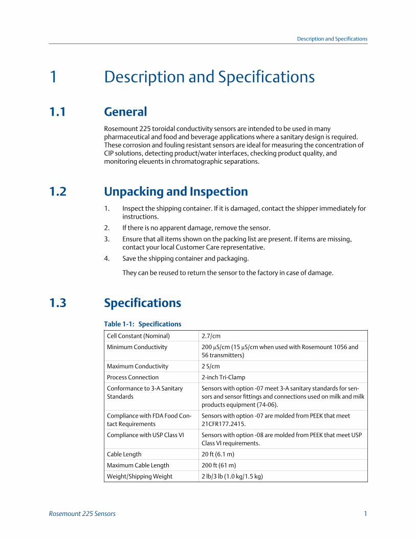
1.3 Specifications
SpecificationsTable 1-1:
Cell Constant (Nominal) 2.7/cm
Minimum Conductivity 200 µS/cm (15 µS/cm when used with Rosemount 1056 and56 transmitters)
Maximum Conductivity 2 S/cm
Process Connection 2-inch Tri-Clamp
Conformance to 3-A SanitaryStandards
Sensors with option -07 meet 3-A sanitary standards for sen-sors and sensor fittings and connections used on milk and milkproducts equipment (74-06).
Compliance with FDA Food Con-tact Requirements
Sensors with option -07 are molded from PEEK that meet21CFR177.2415.
Compliance with USP Class VI Sensors with option -08 are molded from PEEK that meet USPClass VI requirements.
Cable Length 20 ft (6.1 m)
Maximum Cable Length 200 ft (61 m)
Weight/Shipping Weight 2 lb/3 lb (1.0 kg/1.5 kg)
Description and Specifications
Rosemount 225 Sensors 1
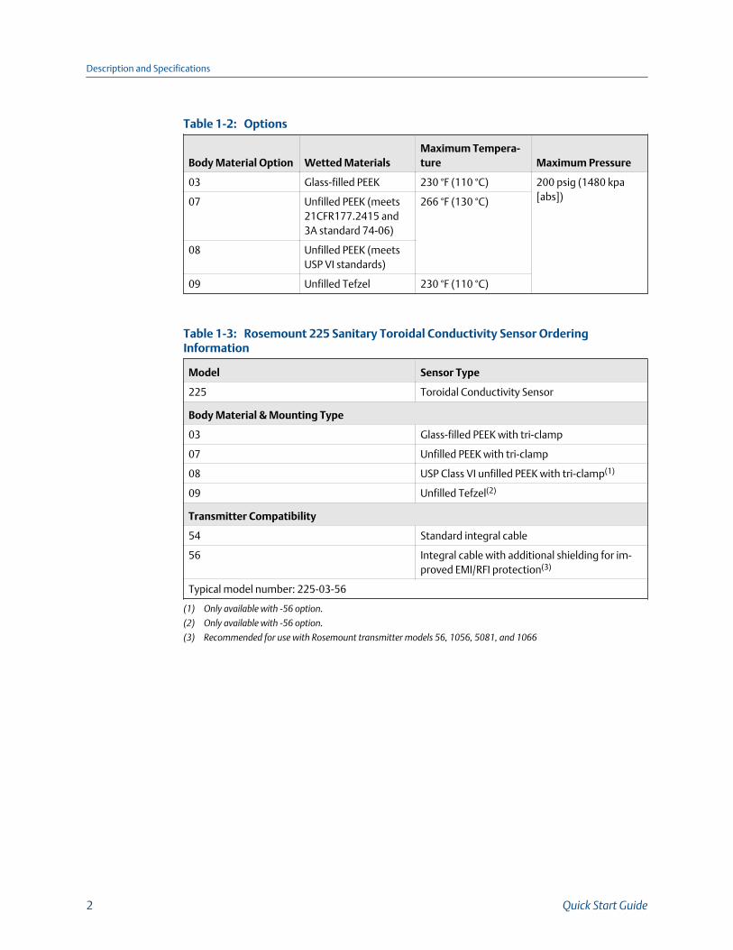
OptionsTable 1-2:
Body Material Option Wetted MaterialsMaximum Tempera-ture Maximum Pressure
03 Glass-filled PEEK 230 °F (110 °C) 200 psig (1480 kpa[abs])07 Unfilled PEEK (meets
21CFR177.2415 and3A standard 74-06)
266 °F (130 °C)
08 Unfilled PEEK (meetsUSP VI standards)
09 Unfilled Tefzel 230 °F (110 °C)
Rosemount 225 Sanitary Toroidal Conductivity Sensor OrderingInformationTable 1-3:
Model Sensor Type
225 Toroidal Conductivity Sensor
Body Material & Mounting Type
03 Glass-filled PEEK with tri-clamp
07 Unfilled PEEK with tri-clamp
08 USP Class VI unfilled PEEK with tri-clamp(1)
09 Unfilled Tefzel(2)
Transmitter Compatibility
54 Standard integral cable
56 Integral cable with additional shielding for im-proved EMI/RFI protection(3)
Typical model number: 225-03-56
(1) Only available with -56 option.
(2) Only available with -56 option.
(3) Recommended for use with Rosemount transmitter models 56, 1056, 5081, and 1066
Description and Specifications
2 Quick Start Guide
2 Install
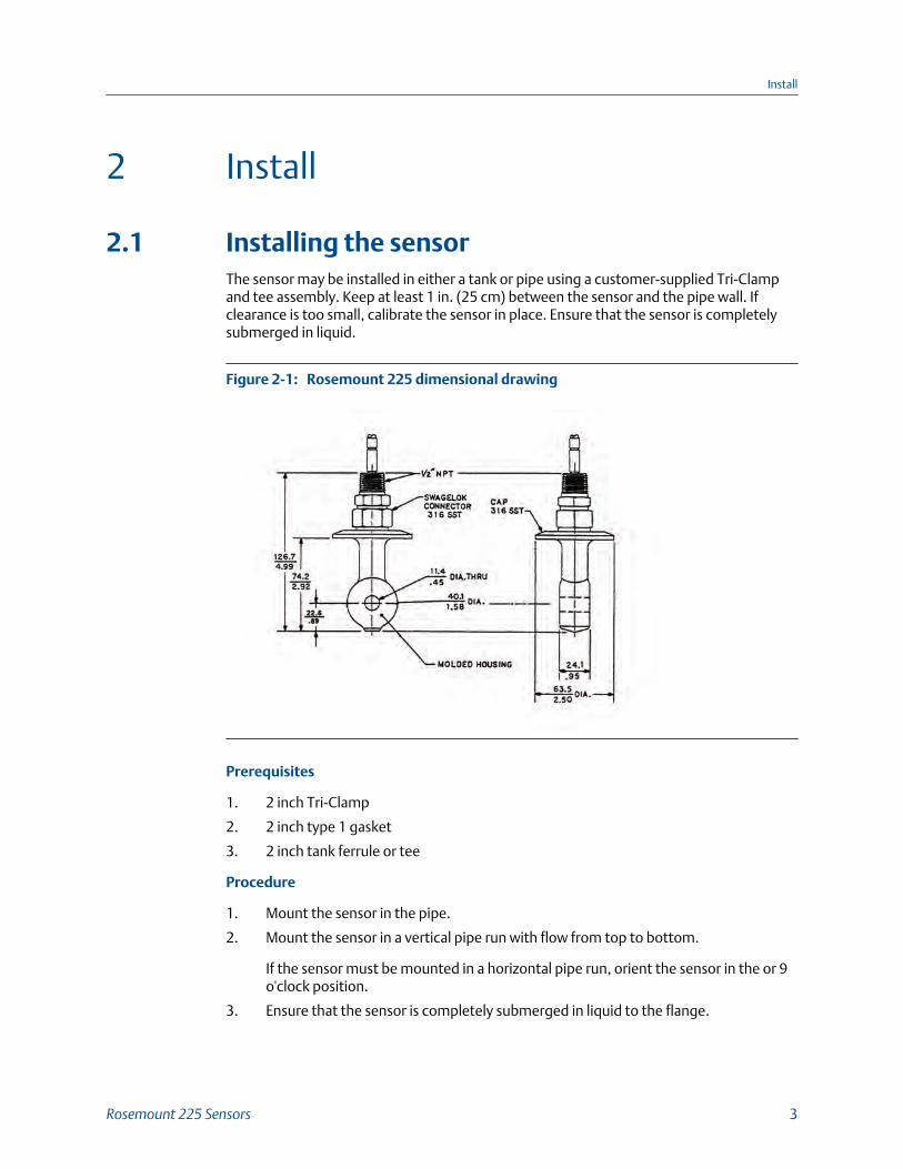
2.1 Installing the sensorThe sensor may be installed in either a tank or pipe using a customer-supplied Tri-Clampand tee assembly. Keep at least 1 in. (25 cm) between the sensor and the pipe wall. Ifclearance is too small, calibrate the sensor in place. Ensure that the sensor is completelysubmerged in liquid.
Rosemount 225 dimensional drawingFigure 2-1:
Prerequisites
1. 2 inch Tri-Clamp
2. 2 inch type 1 gasket
3. 2 inch tank ferrule or tee
Procedure
1. Mount the sensor in the pipe.
2. Mount the sensor in a vertical pipe run with flow from top to bottom.
If the sensor must be mounted in a horizontal pipe run, orient the sensor in the or 9o'clock position.
3. Ensure that the sensor is completely submerged in liquid to the flange.
Install
Rosemount 225 Sensors 3
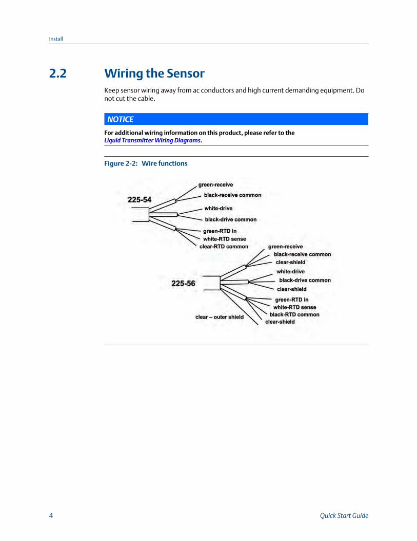
2.2 Wiring the SensorKeep sensor wiring away from ac conductors and high current demanding equipment. Donot cut the cable.
NOTICE
For additional wiring information on this product, please refer to the Liquid Transmitter Wiring Diagrams.
Wire functionsFigure 2-2:
Install
4 Quick Start Guide
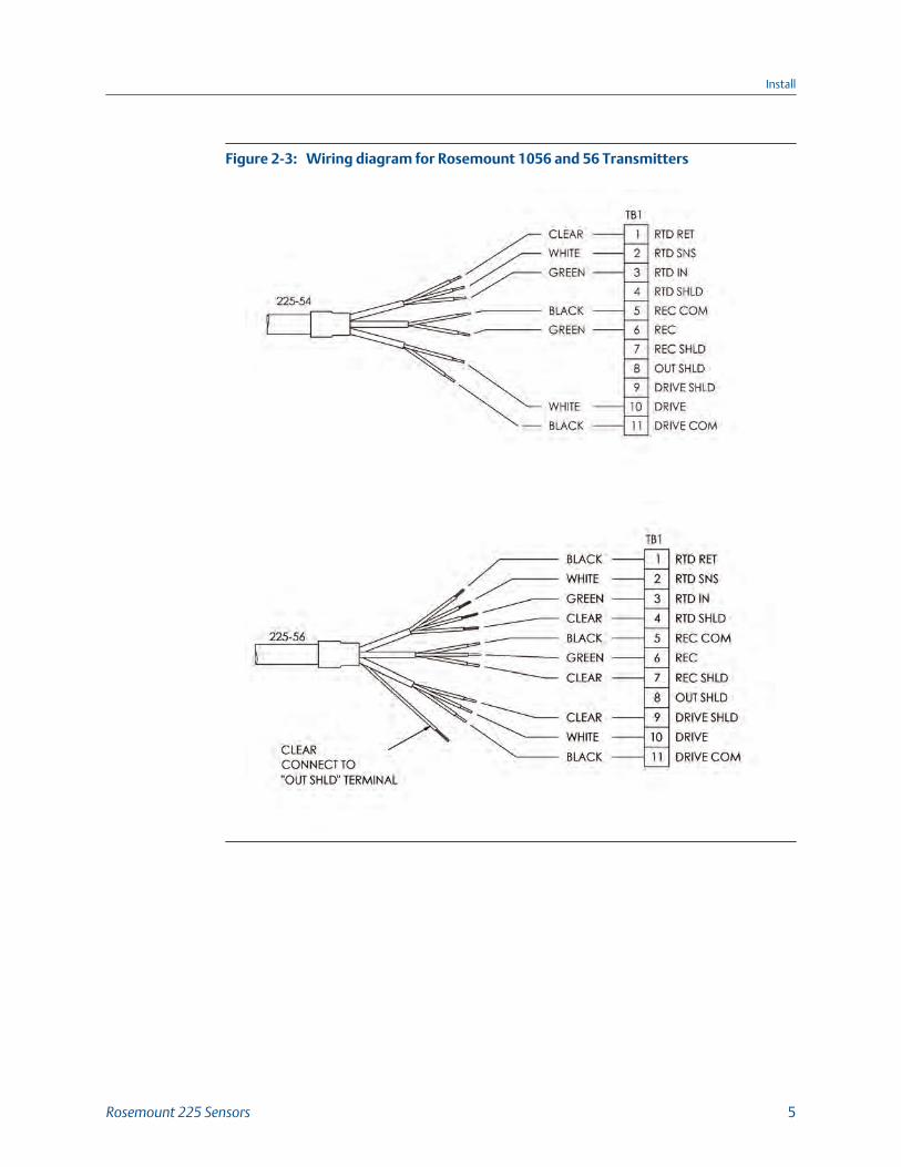
Wiring diagram for Rosemount 1056 and 56 TransmittersFigure 2-3:
Install
Rosemount 225 Sensors 5
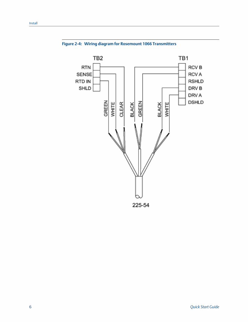
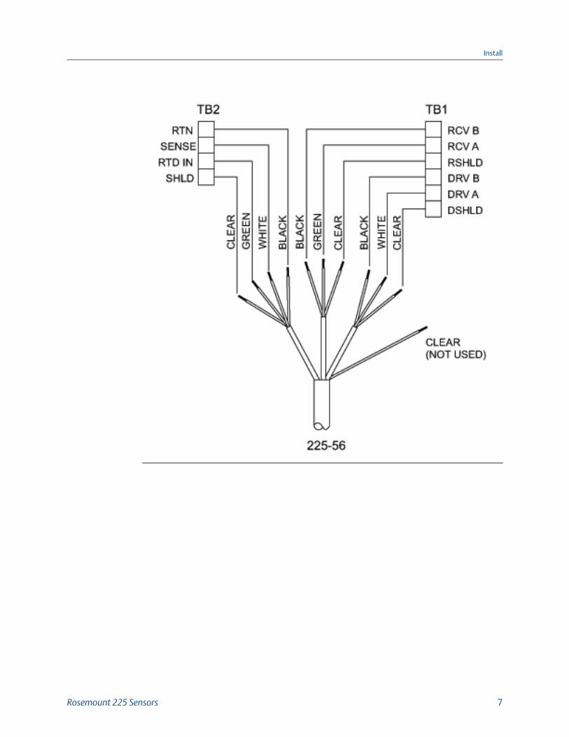
Wiring diagram for Rosemount 1066 TransmittersFigure 2-4:
Install
6 Quick Start Guide
Install
Rosemount 225 Sensors 7
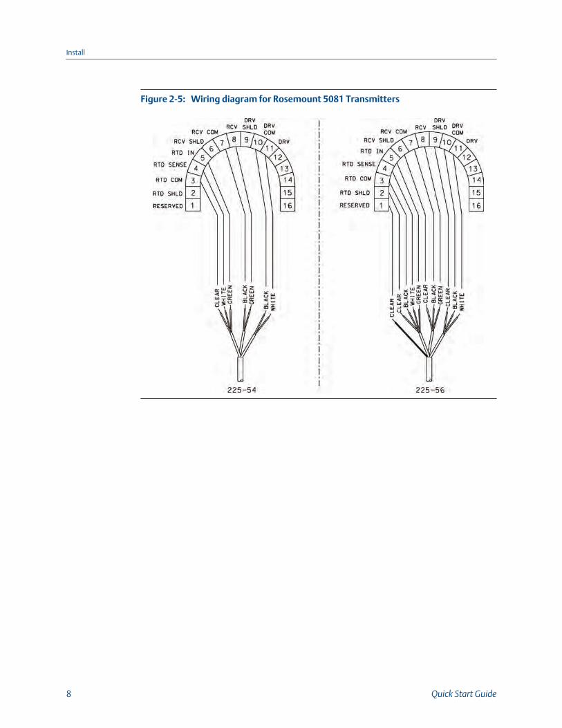
Wiring diagram for Rosemount 5081 TransmittersFigure 2-5:
Install
8 Quick Start Guide
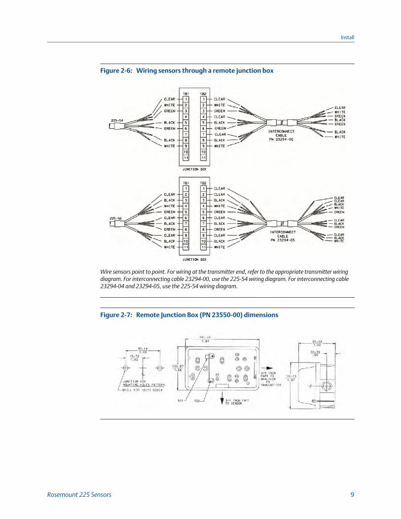
Wiring sensors through a remote junction boxFigure 2-6:
Wire sensors point to point. For wiring at the transmitter end, refer to the appropriate transmitter wiringdiagram. For interconnecting cable 23294-00, use the 225-54 wiring diagram. For interconnecting cable23294-04 and 23294-05, use the 225-54 wiring diagram.
Remote Junction Box (PN 23550-00) dimensionsFigure 2-7:
Install
Rosemount 225 Sensors 9

Install
10 Quick Start Guide
3 Calibration
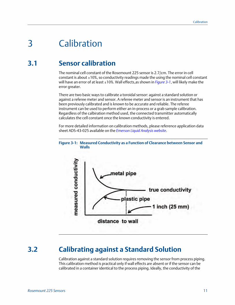
3.1 Sensor calibrationThe nominal cell constant of the Rosemount 225 sensor is 2.7/cm. The error in cellconstant is about ±10%, so conductivity readings made the using the nominal cell constantwill have an error of at least ±10%. Wall effects,as shown in Figure 3-1, will likely make theerror greater.
There are two basic ways to calibrate a toroidal sensor: against a standard solution oragainst a referee meter and sensor. A referee meter and sensor is an instrument that hasbeen previously calibrated and is known to be accurate and reliable. The refereeinstrument can be used to perform either an in-process or a grab sample calibration.Regardless of the calbiration method used, the connected transmitter automaticallycalculates the cell constant once the known conductivity is entered.
For more detailed information on calibration methods, please reference application datasheet ADS-43-025 available on the Emerson Liquid Analysis website.
Measured Conductivity as a Function of Clearance between Sensor andWalls
Figure 3-1:
3.2 Calibrating against a Standard SolutionCalibration against a standard solution requires removing the sensor from process piping.This calibration method is practical only if wall effects are absent or if the sensor can becalibrated in a container identical to the process piping. Ideally, the conductivity of the
Calibration
Rosemount 225 Sensors 11
standard used should be close to the middle of the range that the sensor will be used in.Generally, toroidal conductivity sensors have good linearity, and so standards greater than5000 µS/cm at 77 °F (25 °C) may also be used.
1. Remove the sensor from the pipe.
2. Fill a container with the standard solution.
If wall effects are absent in the process installation, use a sufficiently large containerfor calibration to ensure that wall effects are absent. To check for wall effects, fill thecontainer with solution and place the sensor in the center, submerged at least 3/4 ofthe way up the stem. Note the reading. Then move the sensor small distances fromthe center and note the reading in each position. The readings should not change.
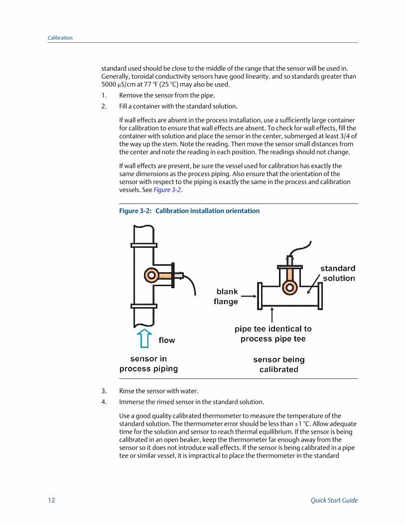
If wall effects are present, be sure the vessel used for calibration has exactly thesame dimensions as the process piping. Also ensure that the orientation of thesensor with respect to the piping is exactly the same in the process and calibrationvessels. See Figure 3-2.
Calibration installation orientationFigure 3-2:
3. Rinse the sensor with water.
4. Immerse the rinsed sensor in the standard solution.
Use a good quality calibrated thermometer to measure the temperature of thestandard solution. The thermometer error should be less than ±1 °C. Allow adequatetime for the solution and sensor to reach thermal equilibrium. If the sensor is beingcalibrated in an open beaker, keep the thermometer far enough away from thesensor so it does not introduce wall effects. If the sensor is being calibrated in a pipetee or similar vessel, it is impractical to place the thermometer in the standard
Calibration
12 Quick Start Guide
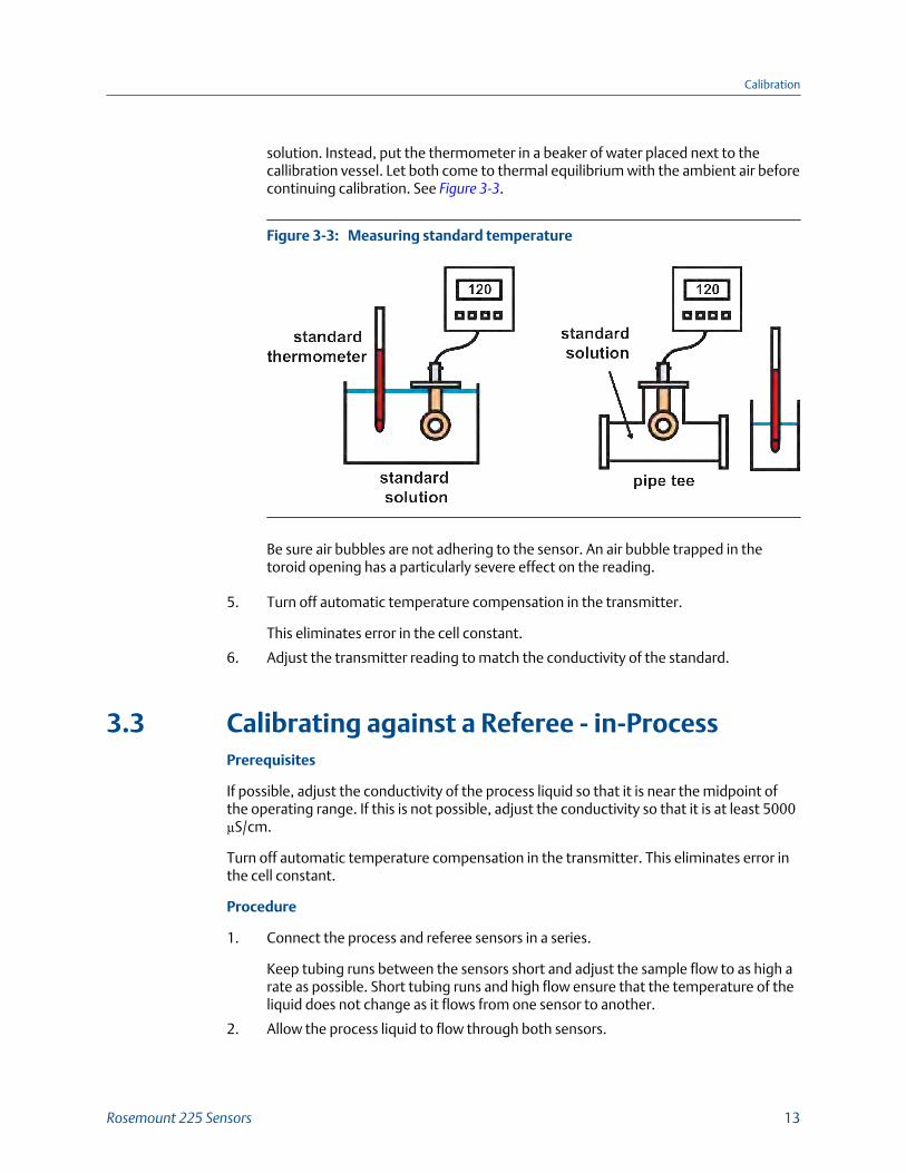
solution. Instead, put the thermometer in a beaker of water placed next to thecallibration vessel. Let both come to thermal equilibrium with the ambient air beforecontinuing calibration. See Figure 3-3.
Measuring standard temperatureFigure 3-3:
Be sure air bubbles are not adhering to the sensor. An air bubble trapped in thetoroid opening has a particularly severe effect on the reading.
5. Turn off automatic temperature compensation in the transmitter.
This eliminates error in the cell constant.
6. Adjust the transmitter reading to match the conductivity of the standard.
3.3 Calibrating against a Referee - in-ProcessPrerequisites
If possible, adjust the conductivity of the process liquid so that it is near the midpoint ofthe operating range. If this is not possible, adjust the conductivity so that it is at least 5000µS/cm.
Turn off automatic temperature compensation in the transmitter. This eliminates error inthe cell constant.
Procedure
1. Connect the process and referee sensors in a series.
Keep tubing runs between the sensors short and adjust the sample flow to as high arate as possible. Short tubing runs and high flow ensure that the temperature of theliquid does not change as it flows from one sensor to another.
2. Allow the process liquid to flow through both sensors.
Calibration
Rosemount 225 Sensors 13
Orient the referee sensor so that the air bubbles always have an easy escape pathand cannot get trapped. Tap and hold the flow cell in different positions to allowbubbles to escape.
Wait for readings to stabilize before starting the calibration.
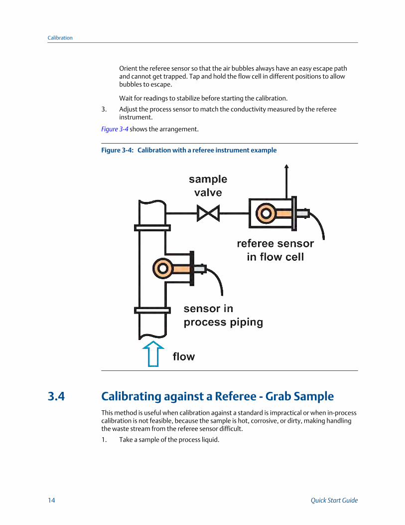
3. Adjust the process sensor to match the conductivity measured by the refereeinstrument.
Figure 3-4 shows the arrangement.
Calibration with a referee instrument exampleFigure 3-4:
3.4 Calibrating against a Referee - Grab SampleThis method is useful when calibration against a standard is impractical or when in-processcalibration is not feasible, because the sample is hot, corrosive, or dirty, making handlingthe waste stream from the referee sensor difficult.
1. Take a sample of the process liquid.
Calibration
14 Quick Start Guide
Take the sample from a point as close to the process sensor as possible. Be sure thesample is representative of what the sensor is measuring. If possible, adjust theconductivity of the process liquid so that it is near the midpoint of the operatingrange. If that is not possible, adjust the conductivity so that it is at least 5000 µS/cm.
2. Connect the process and referee sensors.
Keep temperature compensation with the transmitter turned on. Confirm that thetemperature measurements in both process and referee instruments are accurate,ideally to within ±0.5 °C.
3. Place the sensors in the grab sample.
Wait until the readings are stable before starting the calibration.
4. Adjust the reading from the process analyzer to match the conductivity measuredby the referee sensor.
Calibration
Rosemount 225 Sensors 15

Calibration
16 Quick Start Guide
4 Troubleshooting
4.1 Maintaining the sensor
WARNING!
TOXIC LIQUIDSBe sure the sensor has been cleaned of process liquid before handling.
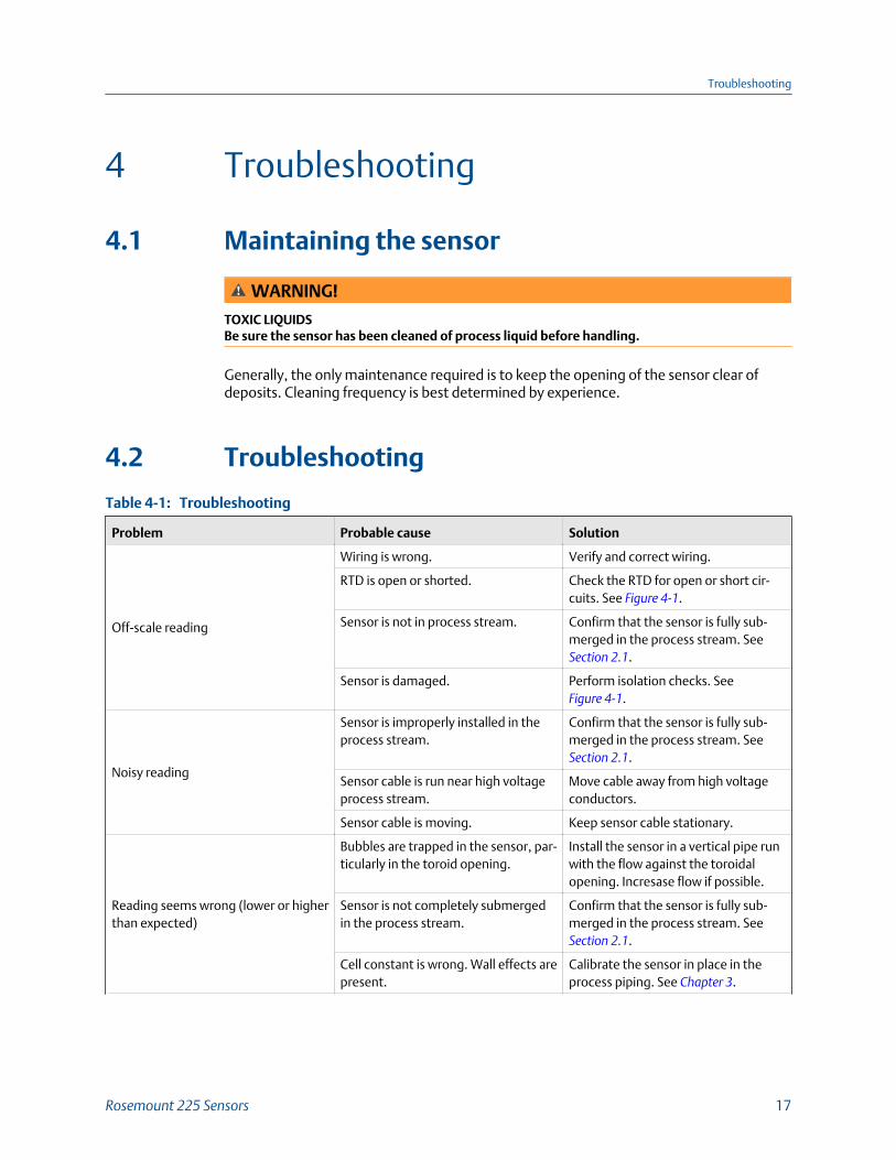
Generally, the only maintenance required is to keep the opening of the sensor clear ofdeposits. Cleaning frequency is best determined by experience.
4.2 Troubleshooting
TroubleshootingTable 4-1:
Problem Probable cause Solution
Off-scale reading
Wiring is wrong. Verify and correct wiring.
RTD is open or shorted. Check the RTD for open or short cir-cuits. See Figure 4-1.
Sensor is not in process stream. Confirm that the sensor is fully sub-merged in the process stream. See Section 2.1.
Sensor is damaged. Perform isolation checks. See Figure 4-1.
Noisy reading
Sensor is improperly installed in theprocess stream.
Confirm that the sensor is fully sub-merged in the process stream. See Section 2.1.
Sensor cable is run near high voltageprocess stream.
Move cable away from high voltageconductors.
Sensor cable is moving. Keep sensor cable stationary.
Reading seems wrong (lower or higherthan expected)
Bubbles are trapped in the sensor, par-ticularly in the toroid opening.
Install the sensor in a vertical pipe runwith the flow against the toroidalopening. Incresase flow if possible.
Sensor is not completely submergedin the process stream.
Confirm that the sensor is fully sub-merged in the process stream. See Section 2.1.
Cell constant is wrong. Wall effects arepresent.
Calibrate the sensor in place in theprocess piping. See Chapter 3.
Troubleshooting
Rosemount 225 Sensors 17
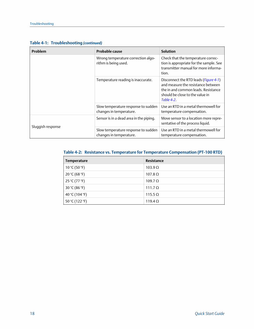
Troubleshooting (continued)Table 4-1:
Problem Probable cause Solution
Wrong temperature correction algo-rithm is being used.
Check that the temperature correc-tion is appropriate for the sample. Seetransmitter manual for more informa-tion.
Temperature reading is inaccurate. Disconnect the RTD leads (Figure 4-1)and measure the resistance betweenthe in and common leads. Resistanceshould be close to the value in Table 4-2.
Slow temperature response to suddenchanges in temperature.
Use an RTD in a metal thermowell fortemperature compensation.
Sluggish response
Sensor is in a dead area in the piping. Move sensor to a location more repre-sentative of the process liquid.
Slow temperature response to suddenchanges in temperature.
Use an RTD in a metal thermowell fortemperature compensation.
Resistance vs. Temperature for Temperature Compensation (PT-100 RTD)Table 4-2:
Temperature Resistance
10 °C (50 °F) 103.9 Ω
20 °C (68 °F) 107.8 Ω
25 °C (77 °F) 109.7 Ω
30 °C (86 °F) 111.7 Ω
40 °C (104 °F) 115.5 Ω
50 °C (122 °F) 119.4 Ω
Troubleshooting
18 Quick Start Guide
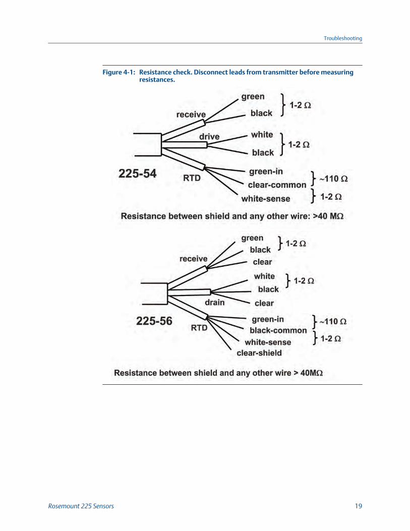
Resistance check. Disconnect leads from transmitter before measuringresistances.
Figure 4-1:
Troubleshooting
Rosemount 225 Sensors 19

Troubleshooting
20 Quick Start Guide
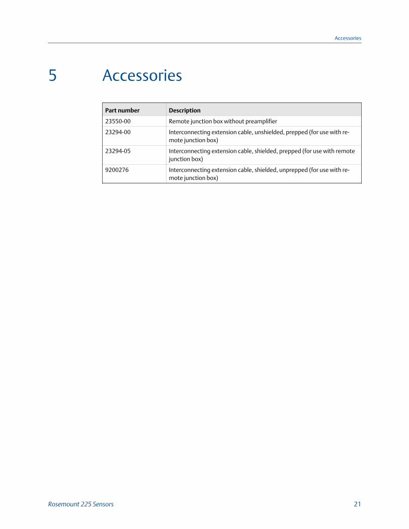
5 Accessories
Part number Description
23550-00 Remote junction box without preamplifier
23294-00 Interconnecting extension cable, unshielded, prepped (for use with re-mote junction box)
23294-05 Interconnecting extension cable, shielded, prepped (for use with remotejunction box)
9200276 Interconnecting extension cable, shielded, unprepped (for use with re-mote junction box)
Accessories
Rosemount 225 Sensors 21

Accessories
22 Quick Start Guide
6 Return of Materials
For repair and warranty inquiries, please contact Rosemount Customer Care to obtain aReturn Material Authorization (RMA) number. Drain the sensor of fluids before shipping itback to Rosemount.
Return of Materials
Rosemount 225 Sensors 23
LIQ-QSG-225
Rev L
2017
www.Emerson.com/RosemountLiquidAnalysisEmerson Automation Solutions8200 Market BlvdChanhassen, MN 55317Toll Free +1 800 999 9307F +1 952 949 [email protected]/RosemountLiquidAnalysis
EUROPEEmerson Automation SolutionsNeuhofstrasse 19a P.O. Box 1046CH-6340 BaarSwitzerlandT + 41 (0) 41 768 6111F + 41 (0) 41 768 [email protected]/RosemountLiquidAnalysis
MIDDLE EAST AND AFRICAEmerson Automation SolutionsEmerson FZEJebel Ali Free ZoneDubai, United Arab Emirates, P.O. Box 17033T +971 4 811 8100F +971 4 886 [email protected]/RosemountLiquidAnalysis
ASIA-PACIFICEmerson Automation Solutions1 Pandan CrescentSingapore 128461SingaporeT +65 777 8211F +65 777 [email protected]/RosemountLiquidAnalysis
©2017 Rosemount. All rights reserved.
The Emerson logo is a trademark and service mark of EmersonElectric Co. Rosemount is a mark of one of the Emerson family ofcompanies. All other marks are the property of their respectiveowners. The contents of this publication are presented forinformation purposes only, and, while effort has been made toensure their accuracy, they are not to be construed as warranties orguarantees, expressed or implied, regarding the products orservices described herein or their use or applicability. All sales aregoverned by our terms and conditions, which are available onrequest. We reserve the right to modify or improve the designs orspecifications of our products at any time without notice.