Embed Size (px)
Citation preview

Quick Start Guide00825-0100-4007, Rev HA
January 2020
Rosemount™ 3051 Pressure Transmitterand Rosemount 3051CF Series FlowMeters
with 4-20 mA HART® Revision 5 and 7Protocol
Scan here for product documentationand drawings.
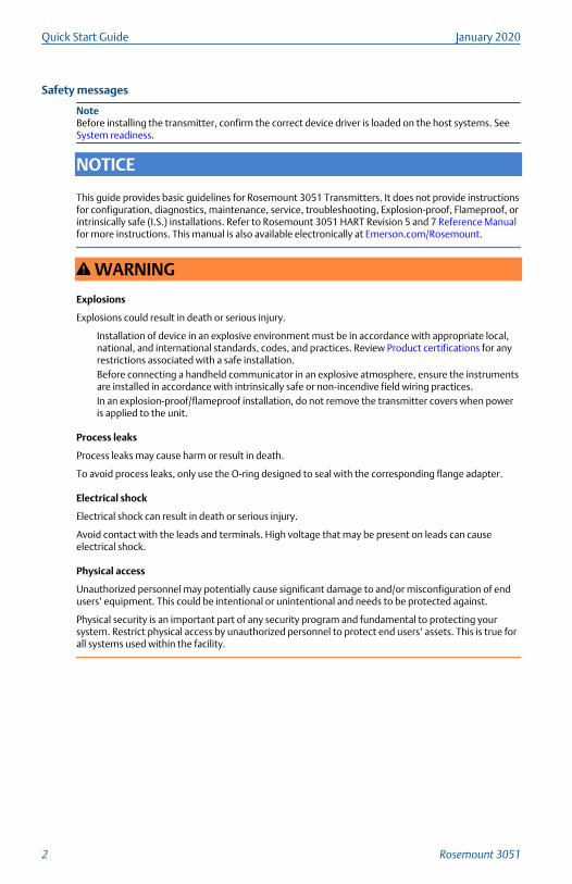
Safety messages
NoteBefore installing the transmitter, confirm the correct device driver is loaded on the host systems. SeeSystem readiness.
NOTICE
This guide provides basic guidelines for Rosemount 3051 Transmitters. It does not provide instructionsfor configuration, diagnostics, maintenance, service, troubleshooting, Explosion-proof, Flameproof, orintrinsically safe (I.S.) installations. Refer to Rosemount 3051 HART Revision 5 and 7 Reference Manualfor more instructions. This manual is also available electronically at Emerson.com/Rosemount.
WARNING
Explosions
Explosions could result in death or serious injury.
Installation of device in an explosive environment must be in accordance with appropriate local,national, and international standards, codes, and practices. Review Product certifications for anyrestrictions associated with a safe installation.Before connecting a handheld communicator in an explosive atmosphere, ensure the instrumentsare installed in accordance with intrinsically safe or non-incendive field wiring practices.In an explosion-proof/flameproof installation, do not remove the transmitter covers when poweris applied to the unit.
Process leaks
Process leaks may cause harm or result in death.
To avoid process leaks, only use the O-ring designed to seal with the corresponding flange adapter.
Electrical shock
Electrical shock can result in death or serious injury.
Avoid contact with the leads and terminals. High voltage that may be present on leads can causeelectrical shock.
Physical access
Unauthorized personnel may potentially cause significant damage to and/or misconfiguration of endusers’ equipment. This could be intentional or unintentional and needs to be protected against.
Physical security is an important part of any security program and fundamental to protecting yoursystem. Restrict physical access by unauthorized personnel to protect end users’ assets. This is true forall systems used within the facility.
Quick Start Guide January 2020
2 Rosemount 3051
CAUTION
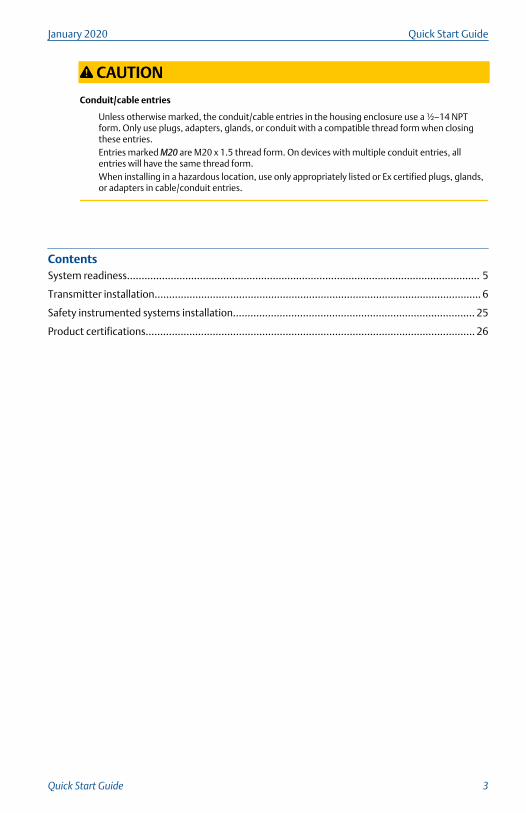
Conduit/cable entries
Unless otherwise marked, the conduit/cable entries in the housing enclosure use a ½–14 NPTform. Only use plugs, adapters, glands, or conduit with a compatible thread form when closingthese entries.Entries marked M20 are M20 x 1.5 thread form. On devices with multiple conduit entries, allentries will have the same thread form.When installing in a hazardous location, use only appropriately listed or Ex certified plugs, glands,or adapters in cable/conduit entries.
ContentsSystem readiness......................................................................................................................... 5
Transmitter installation................................................................................................................ 6
Safety instrumented systems installation................................................................................... 25
Product certifications................................................................................................................. 26
January 2020 Quick Start Guide
Quick Start Guide 3

Quick Start Guide January 2020
4 Rosemount 3051
1 System readiness
1.1 Confirm HART Revision capability• If using HART based control or asset management systems, confirm the
HART capability of those systems prior to transmitter installation. Not allsystems are capable of communicating with HART Revision 7 protocol.This transmitter can be configured for either HART Revision 5 or 7.
• For instructions on how to change the HART Revision of your transmitter,see Switch HART Revision mode.
1.2 Confirm correct device driver• Verify the latest Device Driver (DD/DTM™) is loaded on your systems to
ensure proper communications.
• Download the latest DD at Emerson.com or FieldCommGroup.org
• In the Browse by Member dropdown menu, select Rosemount businessunit of Emerson™.
• Select desired product.
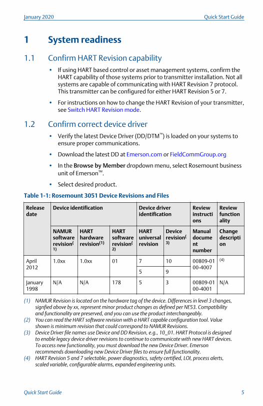
Table 1-1: Rosemount 3051 Device Revisions and Files
Releasedate
Device identification Device driveridentification
Reviewinstructions
Reviewfunctionality
NAMURsoftwarerevision(
1)
HARThardwarerevision(1)
HARTsoftwarerevision(
2)
HARTuniversalrevision
Devicerevision(
3)
Manualdocumentnumber
Changedescription
April2012
1.0xx 1.0xx 01 7 10 00809-0100-4007
(4)
5 9
January1998
N/A N/A 178 5 3 00809-0100-4001
N/A
(1) NAMUR Revision is located on the hardware tag of the device. Differences in level 3 changes,signfied above by xx, represent minor product changes as defined per NE53. Compatibilityand functionality are preserved, and you can use the product interchangeably.
(2) You can read the HART software revision with a HART capable configuration tool. Valueshown is minimum revision that could correspond to NAMUR Revisions.
(3) Device Driver file names use Device and DD Revision, e.g., 10_01. HART Protocol is designedto enable legacy device driver revisions to continue to communicate with new HART devices.To access new functionality, you must download the new Device Driver. Emersonrecommends downloading new Device Driver files to ensure full functionality.
(4) HART Revision 5 and 7 selectable, power diagnostics, safety certified, LOI, process alerts,scaled variable, configurable alarms, expanded engineering units.
January 2020 Quick Start Guide
Quick Start Guide 5
2 Transmitter installation
2.1 Mount the transmitter
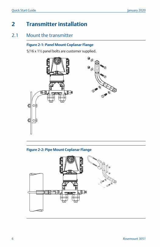
Figure 2-1: Panel Mount Coplanar Flange
5/16 x 1½ panel bolts are customer supplied.
Figure 2-2: Pipe Mount Coplanar Flange
Quick Start Guide January 2020
6 Rosemount 3051
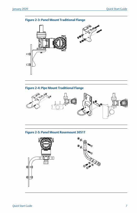
Figure 2-3: Panel Mount Traditional Flange
Figure 2-4: Pipe Mount Traditional Flange
Figure 2-5: Panel Mount Rosemount 3051T
January 2020 Quick Start Guide
Quick Start Guide 7

Figure 2-6: Pipe Mount Rosemount 3051T
Quick Start Guide January 2020
8 Rosemount 3051
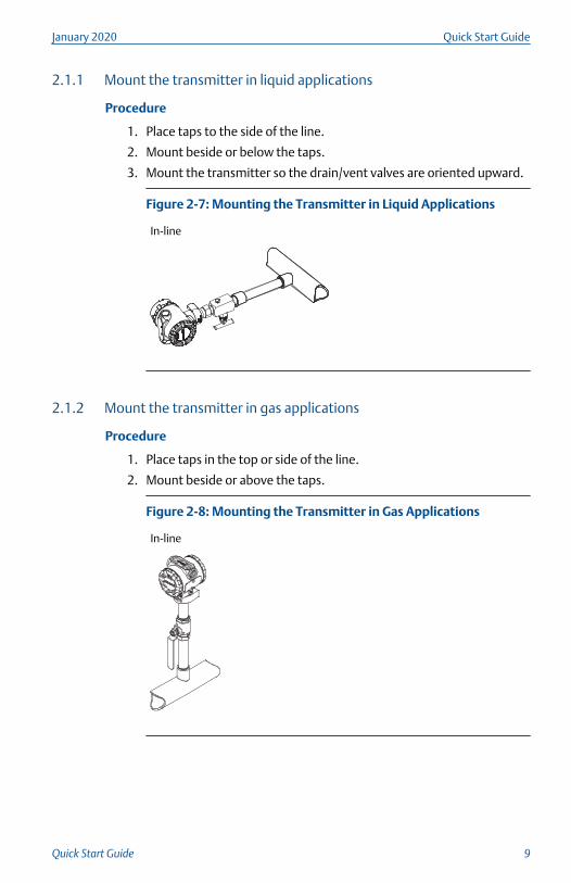
2.1.1 Mount the transmitter in liquid applications
Procedure
1. Place taps to the side of the line.
2. Mount beside or below the taps.
3. Mount the transmitter so the drain/vent valves are oriented upward.
Figure 2-7: Mounting the Transmitter in Liquid Applications
In-line
2.1.2 Mount the transmitter in gas applications
Procedure
1. Place taps in the top or side of the line.
2. Mount beside or above the taps.
Figure 2-8: Mounting the Transmitter in Gas Applications
In-line
January 2020 Quick Start Guide
Quick Start Guide 9
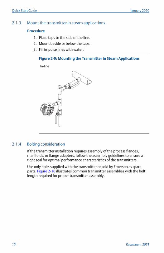
2.1.3 Mount the transmitter in steam applications
Procedure
1. Place taps to the side of the line.
2. Mount beside or below the taps.
3. Fill impulse lines with water.
Figure 2-9: Mounting the Transmitter in Steam Applications
In-line
2.1.4 Bolting consideration
If the transmitter installation requires assembly of the process flanges,manifolds, or flange adapters, follow the assembly guidelines to ensure atight seal for optimal performance characteristics of the transmitters.
Use only bolts supplied with the transmitter or sold by Emerson as spareparts. Figure 2-10 illustrates common transmitter assemblies with the boltlength required for proper transmitter assembly.
Quick Start Guide January 2020
10 Rosemount 3051
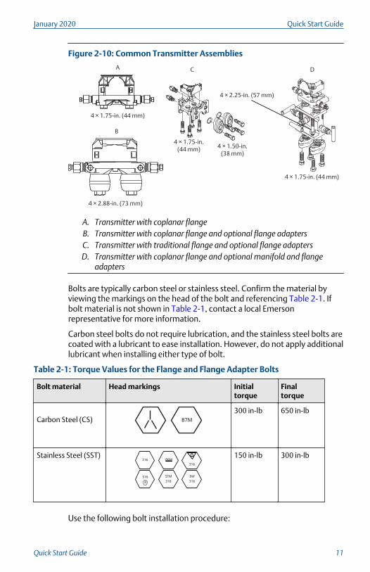
Figure 2-10: Common Transmitter Assemblies
B
4 × 2.88-in. (73 mm)
A
4 × 1.75-in. (44 mm)
C
4 × 1.75-in. (44 mm)
4 × 1.50-in. (38 mm)
D
4 × 1.75-in. (44 mm)
4 × 2.25-in. (57 mm)
A. Transmitter with coplanar flangeB. Transmitter with coplanar flange and optional flange adaptersC. Transmitter with traditional flange and optional flange adaptersD. Transmitter with coplanar flange and optional manifold and flange
adapters
Bolts are typically carbon steel or stainless steel. Confirm the material byviewing the markings on the head of the bolt and referencing Table 2-1. Ifbolt material is not shown in Table 2-1, contact a local Emersonrepresentative for more information.
Carbon steel bolts do not require lubrication, and the stainless steel bolts arecoated with a lubricant to ease installation. However, do not apply additionallubricant when installing either type of bolt.
Table 2-1: Torque Values for the Flange and Flange Adapter Bolts
Bolt material Head markings Initialtorque
Finaltorque
Carbon Steel (CS) B7M
300 in-lb 650 in-lb
Stainless Steel (SST)316
316
316
SW
316
STM316
R
B8M
150 in-lb 300 in-lb
Use the following bolt installation procedure:
January 2020 Quick Start Guide
Quick Start Guide 11
Procedure
1. Use the fingers to tighten the bolts.
2. Torque the bolts to the initial torque value using a crossing pattern.
See Table 2-1 for initial torque value.
3. Torque the bolts to the final torque value using the same crossingpattern.
See Table 2-1 for final torque value.
4. Verify the flange bolts are protruding through the sensor modulebolt holes before applying pressure.
2.1.5 O-rings with flange adapters
WARNING
Failure to install proper flange adapter O-rings may cause process leaks,which can result in death or serious injury. The two flange adapters aredistinguished by unique O-ring grooves. Only use the O-ring that is designedfor its specific flange adapter, as shown below.
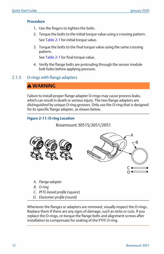
Figure 2-11: O-ring Location
A
B
CD
Rosemount 3051S/3051/2051
A. Flange adapterB. O-ringC. PFTE-based profile (square)D. Elastomer profile (round)
Whenever the flanges or adapters are removed, visually inspect the O-rings.Replace them if there are any signs of damage, such as nicks or cuts. If youreplace the O-rings, re-torque the flange bolts and alignment screws afterinstallation to compensate for seating of the PTFE O-ring.
Quick Start Guide January 2020
12 Rosemount 3051
2.1.6 Environmental seal for housing
For NEMA® 4X, IP66, and IP68 requirements, use thread sealing (PTFE) tapeor paste on male threads of conduit to provide a water and dust tight seal.Consult factory if other ingress protection ratings are required.
For M20 threads, install conduit plugs to full thread engagement or untilmechanical resistance is met.
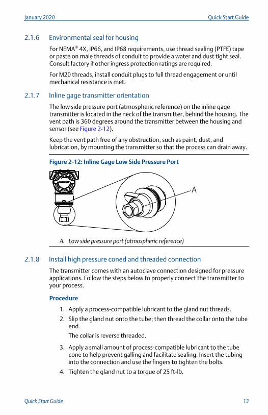
2.1.7 Inline gage transmitter orientation
The low side pressure port (atmospheric reference) on the inline gagetransmitter is located in the neck of the transmitter, behind the housing. Thevent path is 360 degrees around the transmitter between the housing andsensor (see Figure 2-12).
Keep the vent path free of any obstruction, such as paint, dust, andlubrication, by mounting the transmitter so that the process can drain away.
Figure 2-12: Inline Gage Low Side Pressure Port
A
A. Low side pressure port (atmospheric reference)
2.1.8 Install high pressure coned and threaded connection
The transmitter comes with an autoclave connection designed for pressureapplications. Follow the steps below to properly connect the transmitter toyour process.
Procedure
1. Apply a process-compatible lubricant to the gland nut threads.
2. Slip the gland nut onto the tube; then thread the collar onto the tubeend.
The collar is reverse threaded.
3. Apply a small amount of process-compatible lubricant to the tubecone to help prevent galling and facilitate sealing. Insert the tubinginto the connection and use the fingers to tighten the bolts.
4. Tighten the gland nut to a torque of 25 ft-lb.
January 2020 Quick Start Guide
Quick Start Guide 13
NoteA weep hole has been designed into the transmitter for safety andleak detection. If fluid begins to leak from the weep hole, isolate theprocess pressure, disconnect the transmitter, and reseal until theleak is resolved.
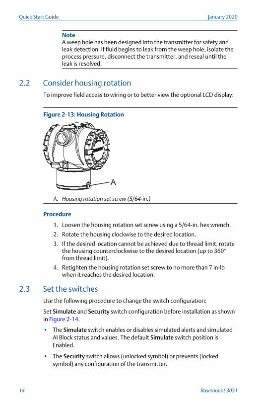
2.2 Consider housing rotationTo improve field access to wiring or to better view the optional LCD display:
Figure 2-13: Housing Rotation
A
A. Housing rotation set screw (5/64-in.)
Procedure
1. Loosen the housing rotation set screw using a 5/64-in. hex wrench.
2. Rotate the housing clockwise to the desired location.
3. If the desired location cannot be achieved due to thread limit, rotatethe housing counterclockwise to the desired location (up to 360°from thread limit).
4. Retighten the housing rotation set screw to no more than 7 in-lbwhen it reaches the desired location.
2.3 Set the switchesUse the following procedure to change the switch configuration:
Set Simulate and Security switch configuration before installation as shownin Figure 2-14.
• The Simulate switch enables or disables simulated alerts and simulatedAI Block status and values. The default Simulate switch position isEnabled.
• The Security switch allows (unlocked symbol) or prevents (lockedsymbol) any configuration of the transmitter.
Quick Start Guide January 2020
14 Rosemount 3051
— Default Security is Off (unlocked symbol).
— You can enable or disable the Security switch in the software.
Procedure
1. If the transmitter is installed, secure the loop and remove power.
2. Remove the housing cover opposite the field terminal side. Do notremove the instrument cover in explosive atmospheres when thecircuit is live.
3. Slide the Security and Simulate switches into the preferred position.
4. Replace the housing cover.
NoteEmerson recommends tightening the cover until there is no gap betweenthe cover and the housing.
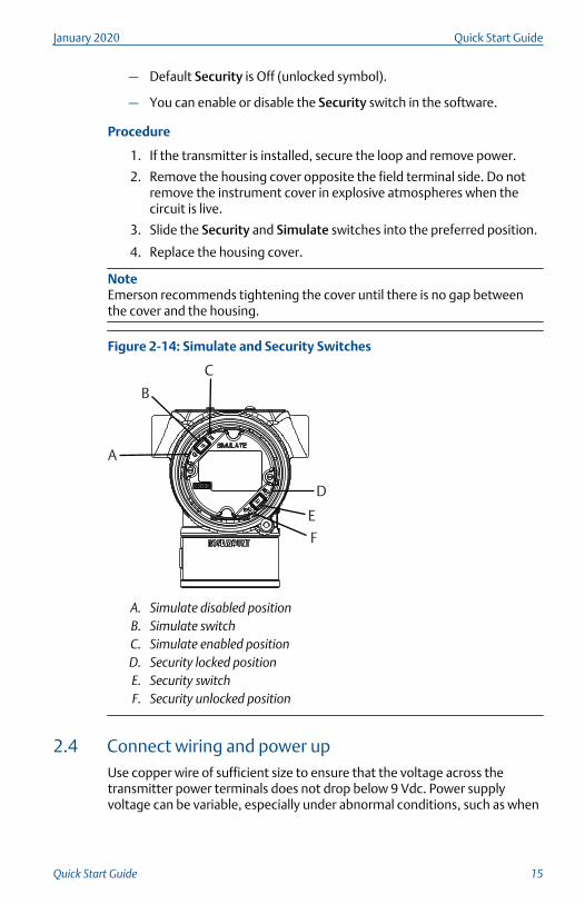
Figure 2-14: Simulate and Security Switches
C
A
B
D
E
F
A. Simulate disabled positionB. Simulate switchC. Simulate enabled positionD. Security locked positionE. Security switchF. Security unlocked position
2.4 Connect wiring and power upUse copper wire of sufficient size to ensure that the voltage across thetransmitter power terminals does not drop below 9 Vdc. Power supplyvoltage can be variable, especially under abnormal conditions, such as when
January 2020 Quick Start Guide
Quick Start Guide 15
operating on battery backup. Emerson recommends a minimum of 12 Vdcunder normal operating conditions and shielded twisted pair Type A cable.
Procedure
1. To power the transmitter, connect the power leads to the terminalsindicated on the terminal block label.
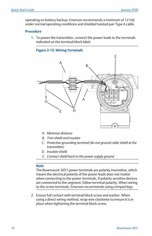
Figure 2-15: Wiring Terminals
DP
A
A
DE
B
C
A. Minimize distanceB. Trim shield and insulateC. Protective grounding terminal (do not ground cable shield at the
transmitter)D. Insulate shieldE. Connect shield back to the power supply ground
NoteThe Rosemount 3051 power terminals are polarity insensitive, whichmeans the electrical polarity of the power leads does not matterwhen connecting to the power terminals. If polarity sensitive devicesare connected to the segment, follow terminal polarity. When wiringto the screw terminals, Emerson recommends using crimped legs.
2. Ensure full contact with terminal block screw and washer. Whenusing a direct wiring method, wrap wire clockwise to ensure it is inplace when tightening the terminal block screw.
Quick Start Guide January 2020
16 Rosemount 3051
NoteEmerson does not recommend using a pin or ferrule wire terminal, asthe connection may be more susceptible to loosening over time orunder vibration.
2.4.1 Ground signal wiring
Do not run signal wiring in conduit or open trays with power wiring or nearheavy electrical equipment. Emerson provides grounding terminations onthe outside of the electronics housing and inside the terminal compartment.Use these grounds when transient protect terminal blocks are installed or tofulfill local regulations.
Procedure
1. Remove the field terminals housing cover.
2. Connect the wiring pair and ground as indicated in Figure 2-15.
a) Trim the cable shield as short as practical and insulate fromtouching the transmitter housing.
NoteDo not ground the cable shield at the transmitter; if the cableshield touches the transmitter housing, it can create groundloops and interfere with communications.
b) Continuously connect the cable shields to the power supplyground.
c) Connect the cable shields for the entire segment to a singlegood earth ground at the power supply.
NoteImproper grounding is the most frequent cause of poorsegment communications.
3. Replace the housing cover. Emerson recommends tightening thecover until there is no gap between the cover and the housing.
4. Plug and seal unused conduit connections.
2.4.2 Power supply
The transmitter requires between 9 and 32 Vdc (9 and 30 Vdc for intrinsicsafety and 9 and 17.5 Vdc for FISCO intrinsic safety) to operate and providecomplete functionality.
January 2020 Quick Start Guide
Quick Start Guide 17
2.4.3 Power conditioner
A Fieldbus segment requires a power conditioner to isolate the power supplyfilter and decouple the segment from other segments attached to the samepower supply.
2.4.4 Grounding
Signal wiring of the Fieldbus segment cannot be grounded. Grounding outone of the signal wires will shut down the entire Fieldbus segment.
2.4.5 Shield wire ground
To protect the Fieldbus segment from noise, grounding techniques forshield wire require a single grounding point for shield wire to avoid creatinga ground loop. Connect the cable shields for the entire segment to a singlegood earth ground at the power supply.
2.4.6 Signal termination
For every Fieldbus segment, install a terminator at the beginning and end ofeach segment.
2.4.7 Locating devices
Frequently, different personnel install, configure, and commission devicesover time. A Locate Device capability uses the LCD display (when installed)to assist personnel in finding the desired device.
From the device Overview screen, select the Locate Device button. Thislaunches a method allowing you to display a Find me message or enter acustom message to display on the device LCD display.
When you exit the Locate Device method, the device LCD displayautomatically returns to normal operation.
NoteSome hosts do not support Locate Device in the DD.
2.5 Verifying configurationVerify the configuration using any HART capable configuration tool or LOIoption code M4.
This section includes configuration instructions for a Field Communicatorand LOI. See Rosemount 3051 Reference Manual for instruction onconfiguring with AMS Device Manager.
Quick Start Guide January 2020
18 Rosemount 3051
2.5.1 Verify configuration with a Field Communicator
You must install a Rosemount 3051 DD on the Field Communicator to verifyconfiguration.
Table 2-2 shows Fast Key sequences for the latest DD. For Fast Keysequences using legacy DD's, contact your local Emerson representative.
NoteEmerson recommends installing the latest DD to access the completefunctionality. Visit Emerson.com/Field-Communicator for information onupdating the DD library.
Verify device configuration using the Fast Key sequences in Table 2-2.
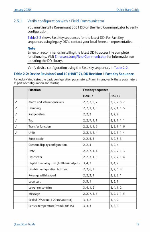
Table 2-2: Device Revision 9 and 10 (HART 7), DD Revision 1 Fast Key Sequence
A check (✓) indicates the basic configuration parameters. At minimum, verify these parametersas part of configuration and startup.
Function Fast Key sequence
HART 7 HART 5
✓ Alarm and saturation levels 2, 2, 2, 5, 7 2, 2, 2, 5, 7
✓ Damping 2, 2, 1, 1, 5 2, 2, 1, 1, 5
✓ Range values 2, 2, 2 2, 2, 2
✓ Tag 2, 2, 7, 1, 1 2, 2, 7, 1, 1
✓ Transfer function 2, 2, 1, 1, 6 2, 2, 1, 1, 6
✓ Units 2, 2, 1, 1, 4 2, 2, 1, 1, 4
Burst mode 2, 2, 5, 3 2, 2, 5, 3
Custom display configuration 2, 2, 4 2, 2, 4
Date 2, 2, 7, 1, 4 2, 2, 7, 1, 3
Descriptor 2, 2, 7, 1, 5 2, 2, 7, 1, 4
Digital to analog trim (4-20 mA output) 3, 4, 2 3, 4, 2
Disable configuration buttons 2, 2, 6, 3 2, 2, 6, 3
Rerange with keypad 2, 2, 2, 1 2, 2, 2, 1
Loop test 3, 5, 1 3, 5, 1
Lower sensor trim 3, 4, 1, 2 3, 4, 1, 2
Message 2, 2, 7, 1, 6 2, 2, 7, 1, 5
Scaled D/A trim (4-20 mA output) 3, 4, 2 3, 4, 2
Sensor temperature/trend (3051S) 3, 3, 3 3, 3, 3
January 2020 Quick Start Guide
Quick Start Guide 19
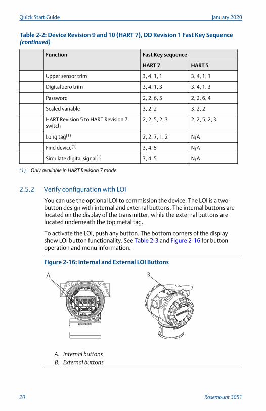
Table 2-2: Device Revision 9 and 10 (HART 7), DD Revision 1 Fast Key Sequence(continued)
Function Fast Key sequence
HART 7 HART 5
Upper sensor trim 3, 4, 1, 1 3, 4, 1, 1
Digital zero trim 3, 4, 1, 3 3, 4, 1, 3
Password 2, 2, 6, 5 2, 2, 6, 4
Scaled variable 3, 2, 2 3, 2, 2
HART Revision 5 to HART Revision 7switch
2, 2, 5, 2, 3 2, 2, 5, 2, 3
Long tag(1) 2, 2, 7, 1, 2 N/A
Find device(1) 3, 4, 5 N/A
Simulate digital signal(1) 3, 4, 5 N/A
(1) Only available in HART Revision 7 mode.
2.5.2 Verify configuration with LOI
You can use the optional LOI to commission the device. The LOI is a two-button design with internal and external buttons. The internal buttons arelocated on the display of the transmitter, while the external buttons arelocated underneath the top metal tag.
To activate the LOI, push any button. The bottom corners of the displayshow LOI button functionality. See Table 2-3 and Figure 2-16 for buttonoperation and menu information.
Figure 2-16: Internal and External LOI Buttons
A B
A. Internal buttonsB. External buttons
Quick Start Guide January 2020
20 Rosemount 3051
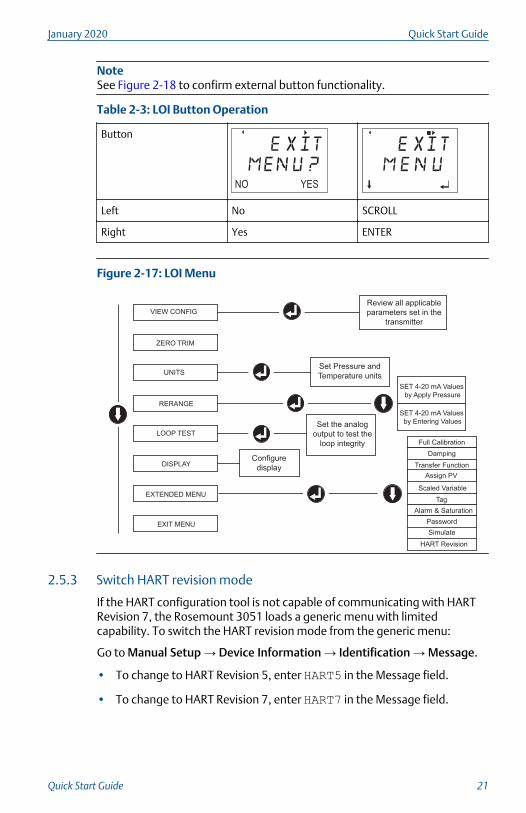
NoteSee Figure 2-18 to confirm external button functionality.
Table 2-3: LOI Button Operation
Button
Left No SCROLL
Right Yes ENTER
Figure 2-17: LOI Menu
Assign PV
HART Revision
2.5.3 Switch HART revision mode
If the HART configuration tool is not capable of communicating with HARTRevision 7, the Rosemount 3051 loads a generic menu with limitedcapability. To switch the HART revision mode from the generic menu:
Go to Manual Setup → Device Information → Identification → Message.
• To change to HART Revision 5, enter HART5 in the Message field.
• To change to HART Revision 7, enter HART7 in the Message field.
January 2020 Quick Start Guide
Quick Start Guide 21
NoteSee Table 2-2 to change HART revision when the correct device driver isloaded.
2.6 Trim the transmitterEmerson calibrates the devices at the factory. Once they are installed,Emerson recommends performing a zero trim on gage and differentialpressure transmitters to eliminate error due to mounting position or staticpressure effects. You can perform a zero trim using either a FieldCommunicator or configuration buttons.
For instructions on trimming the transmitter with AMS Device Manager, seethe Rosemount 3051 HART Revision 5 and 7 Reference Manual.
NoteWhen performing a zero trim, ensure that the equalization valve is open andall wet legs are filled to the correct level.
CAUTION
Emerson does not recommend zeroing an absolute transmitter, Rosemount3051CA or 3051TA models.
Choose your trim procedure.
1. Analog zero trim: Sets the analog output to 4 mA.• Also referred to as rerange, it sets the lower range value (LRV)
equal to the measured pressure.
• The display and digital HART output remains unchanged.
2. Digital zero trim: Recalibrates the sensor zero.• The LRV is unaffected. The pressure value will be zero (on display
and HART output). 4 mA point may not be zero.
• This requires that the factory calibrated zero pressure is within arange of 3% of the URL (0 + 3% x URL).
Example
URV = 250 inH2O
Applied Zero Pressure = +0.03 x 250 inH2O = +7.5 inH2O (compared tofactory settings). The transmitter will reject values outside this range.
2.6.1 Trim with a Field Communicator
Procedure
1. Connect the Field Communicator.
Quick Start Guide January 2020
22 Rosemount 3051
See Connect wiring and power up for instructions.
2. Follow the HART menu to perform the desired zero trim.
Table 2-4: Zero Trim Fast Keys
Analog zero (set 4 mA) Digital zero
Fast Key Sequence 3, 4, 2 3, 4, 1, 3
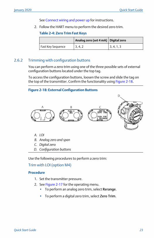
2.6.2 Trimming with configuration buttons
You can perform a zero trim using one of the three possible sets of externalconfiguration buttons located under the top tag.
To access the configuration buttons, loosen the screw and slide the tag onthe top of the transmitter. Confirm the functionality using Figure 2-18.
Figure 2-18: External Configuration Buttons
A B C
D
A. LOIB. Analog zero and spanC. Digital zeroD. Configuration buttons
Use the following procedures to perform a zero trim:
Trim with LOI (option M4)
Procedure
1. Set the transmitter pressure.
2. See Figure 2-17 for the operating menu.• To perform an analog zero trim, select Rerange.
• To perform a digital zero trim, select Zero Trim.
January 2020 Quick Start Guide
Quick Start Guide 23
Trim with analog Zero and Span (option D4)
Procedure
1. Set the transmitter pressure.
2. Press and hold the Zero button for two seconds to perform an analogzero trim.
Quick Start Guide January 2020
24 Rosemount 3051
3 Safety instrumented systems installation
For safety certified installations, refer to the Rosemount 3051 HART Revision5 and 7 Reference Manual for installation procedure and systemrequirements.
January 2020 Quick Start Guide
Quick Start Guide 25
4 Product certifications
Rev 2.8
4.1 European directive informationA copy of the EU Declaration of Conformity can be found at the end of theQuick Start Guide. The most recent revision of the EU Declaration ofConformity can be found at Emerson.com/Rosemount.
4.2 Ordinary location certificationAs standard, the transmitter has been examined and tested to determinethat the design meets the basic electrical, mechanical, and fire protectionrequirements by a nationally recognized test laboratory (NRTL) as accreditedby the Federal Occupational Safety and Health Administration (OSHA).
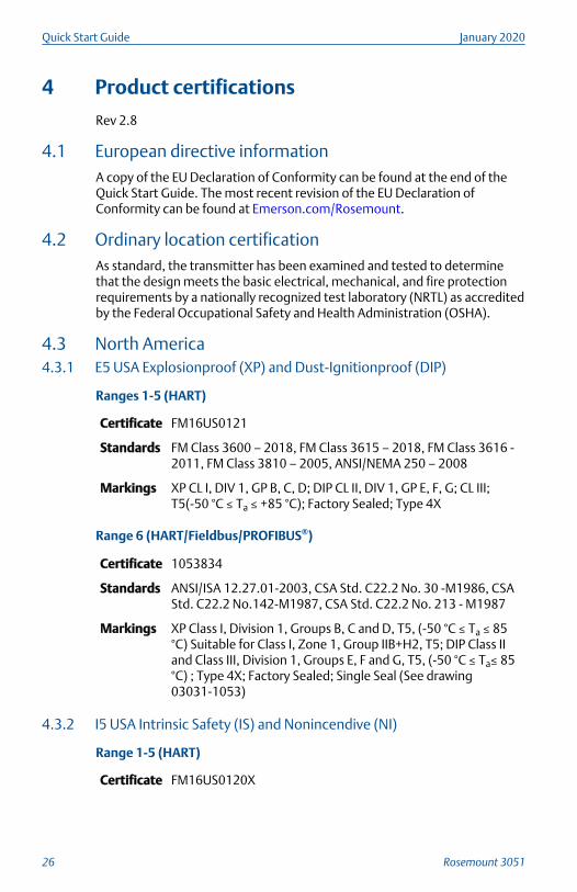
4.3 North America4.3.1 E5 USA Explosionproof (XP) and Dust-Ignitionproof (DIP)
Ranges 1-5 (HART)
Certificate FM16US0121
Standards FM Class 3600 – 2018, FM Class 3615 – 2018, FM Class 3616 -2011, FM Class 3810 – 2005, ANSI/NEMA 250 – 2008
Markings XP CL I, DIV 1, GP B, C, D; DIP CL II, DIV 1, GP E, F, G; CL III;T5(-50 °C ≤ Ta ≤ +85 °C); Factory Sealed; Type 4X
Range 6 (HART/Fieldbus/PROFIBUS®)
Certificate 1053834
Standards ANSI/ISA 12.27.01-2003, CSA Std. C22.2 No. 30 -M1986, CSAStd. C22.2 No.142-M1987, CSA Std. C22.2 No. 213 - M1987
Markings XP Class I, Division 1, Groups B, C and D, T5, (-50 °C ≤ Ta ≤ 85°C) Suitable for Class I, Zone 1, Group IIB+H2, T5; DIP Class IIand Class III, Division 1, Groups E, F and G, T5, (-50 °C ≤ Ta≤ 85°C) ; Type 4X; Factory Sealed; Single Seal (See drawing03031-1053)
4.3.2 I5 USA Intrinsic Safety (IS) and Nonincendive (NI)
Range 1-5 (HART)
Certificate FM16US0120X
Quick Start Guide January 2020
26 Rosemount 3051

Standards FM Class 3600 - 2011, FM Class 3610 - 2010, FM Class 3611 -2004, FM Class 3810 - 2005, ANSI/NEMA 250 - 2008
Markings IS CL I, DIV 1, GP A, B, C, D; CL II, DIV 1, GP E, F, G; Class III; DIV1 when connected per Rosemount drawing 03031-1019; NI CL1, DIV 2, GP A, B, C, D; T4 (–50 °C ≤ Ta ≤ +70 °C) [HART], T4 (–50 °C ≤ Ta ≤ +60 °C) [Fieldbus/PROFIBUS]; Type 4X
Special Conditions for Safe Use (X):
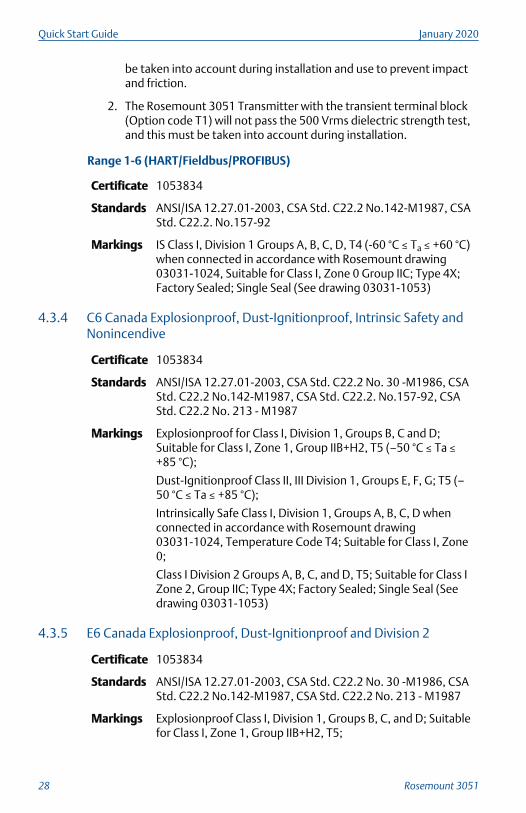
1. The Rosemount 3051 Transmitter housing contains aluminum and isconsidered a potential risk of ignition by impact or friction. Care mustbe taken into account during installation and use to prevent impactand friction.
2. The Rosemount 3051 Transmitter with the transient terminal block(Option code T1) will not pass the 500 Vrms dielectric strength test,and this must be taken into account during installation.
Range 1-6 (HART/Fieldbus/PROFIBUS)
Certificate 1053834
Standards ANSI/ISA 12.27.01-2003, CSA Std. C22.2 No.142-M1987, CSAStd. C22.2. No.157-92
Markings IS Class I, II, III, Division 1 Groups A, B, C, D, E, F, and G whenconnected in accordance with Rosemount drawing03031-1024, Suitable for Class I, Zone 0 Group IIC; Class I,Division 2, Groups A, B, C, and D; NIFW; Suitable for Class I,Zone 2, Group IIC;HART: T4 (–60 °C ≤ Ta ≤ +70 °C), T5 (–60 °C ≤ Ta ≤ +40 °C)
Fieldbus/PROFIBUS: T4 (–60 °C ≤ Ta ≤ +60 °C)
Type 4X
4.3.3 IE USA FISCO
Range 1-5 (HART)
Certificate FM16US0120X
Standards FM Class 3600 - 2011, FM Class 3610 - 2010, FM Class 3611 -2004, FM Class 3810 - 2005
Markings IS CL I, DIV 1, GP A, B, C, D when connected per Rosemountdrawing 03031-1019 (–50 °C ≤ Ta ≤ +60 °C); Type 4X
Special Conditions for Safe Use (X):
1. The Rosemount 3051 Transmitter housing contains aluminum and isconsidered a potential risk of ignition by impact or friction. Care must
January 2020 Quick Start Guide
Quick Start Guide 27
be taken into account during installation and use to prevent impactand friction.
2. The Rosemount 3051 Transmitter with the transient terminal block(Option code T1) will not pass the 500 Vrms dielectric strength test,and this must be taken into account during installation.
Range 1-6 (HART/Fieldbus/PROFIBUS)
Certificate 1053834
Standards ANSI/ISA 12.27.01-2003, CSA Std. C22.2 No.142-M1987, CSAStd. C22.2. No.157-92
Markings IS Class I, Division 1 Groups A, B, C, D, T4 (-60 °C ≤ Ta ≤ +60 °C)when connected in accordance with Rosemount drawing03031-1024, Suitable for Class I, Zone 0 Group IIC; Type 4X;Factory Sealed; Single Seal (See drawing 03031-1053)
4.3.4 C6 Canada Explosionproof, Dust-Ignitionproof, Intrinsic Safety andNonincendive
Certificate 1053834
Standards ANSI/ISA 12.27.01-2003, CSA Std. C22.2 No. 30 -M1986, CSAStd. C22.2 No.142-M1987, CSA Std. C22.2. No.157-92, CSAStd. C22.2 No. 213 - M1987
Markings Explosionproof for Class I, Division 1, Groups B, C and D;Suitable for Class I, Zone 1, Group IIB+H2, T5 (–50 °C ≤ Ta ≤+85 °C);
Dust-Ignitionproof Class II, III Division 1, Groups E, F, G; T5 (–50 °C ≤ Ta ≤ +85 °C);
Intrinsically Safe Class I, Division 1, Groups A, B, C, D whenconnected in accordance with Rosemount drawing03031-1024, Temperature Code T4; Suitable for Class I, Zone0;
Class I Division 2 Groups A, B, C, and D, T5; Suitable for Class IZone 2, Group IIC; Type 4X; Factory Sealed; Single Seal (Seedrawing 03031-1053)
4.3.5 E6 Canada Explosionproof, Dust-Ignitionproof and Division 2
Certificate 1053834
Standards ANSI/ISA 12.27.01-2003, CSA Std. C22.2 No. 30 -M1986, CSAStd. C22.2 No.142-M1987, CSA Std. C22.2 No. 213 - M1987
Markings Explosionproof Class I, Division 1, Groups B, C, and D; Suitablefor Class I, Zone 1, Group IIB+H2, T5;
Quick Start Guide January 2020
28 Rosemount 3051
Dust-Ignitionproof for Class II and Class III, Division 1, GroupsE, F, and G; T5 (–50 °C ≤ Ta ≤ +85 °C);
Class I, Division 2, Groups A, B, C, and D; T5; Suitable for Class IZone 2, Group IIC; Type 4X; Factory Sealed; Single Seal (Seedrawing 03031-1053)
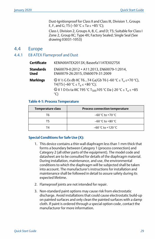
4.4 Europe4.4.1 E8 ATEX Flameproof and Dust
Certificate KEMA00ATEX2013X; Baseefa11ATEX0275X
StandardsUsed
EN60079-0:2012 + A11:2013, EN60079-1:2014,EN60079-26:2015, EN60079-31:2009
Markings II ½ G Ex db IIC T6...T4 Ga/Gb T6 (–60 °C ≤ Ta ≤+70 °C),T4/T5 (–60 °C ≤ Ta ≤ +80 °C);
II 1 D Ex ta IIIC T95 °C T500105 °C Da (-20 °C ≤ Ta ≤ +85°C)
Table 4-1: Process Temperature
Temperature class Process connection temperature
T6 –60 °C to +70 °C
T5 –60 °C to +80 °C
T4 –60 °C to +120 °C
Special Conditions for Safe Use (X):
1. This device contains a thin wall diaphragm less than 1 mm thick thatforms a boundary between Category 1 (process connection) andCategory 2 (all other parts of the equipment). The model code anddatasheet are to be consulted for details of the diaphragm material.During installation, maintenance, and use, the environmentalconditions to which the diaphragm will be subjected shall be takeninto account. The manufacturer's instructions for installation andmaintenance shall be followed in detail to assure safety during itsexpected lifetime.
2. Flameproof joints are not intended for repair.
3. Non-standard paint options may cause risk from electrostaticdischarge. Avoid installations that could cause electrostatic build-upon painted surfaces and only clean the painted surfaces with a dampcloth. If paint is ordered through a special option code, contact themanufacturer for more information.
January 2020 Quick Start Guide
Quick Start Guide 29
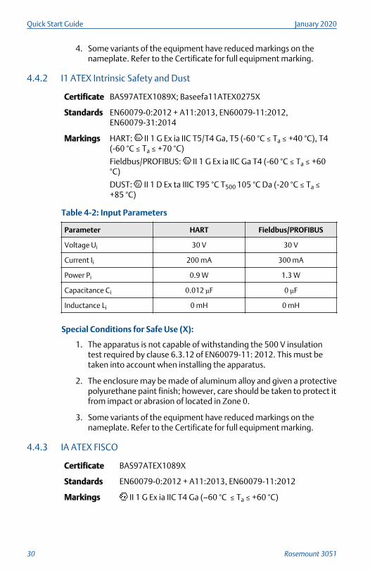
4. Some variants of the equipment have reduced markings on thenameplate. Refer to the Certificate for full equipment marking.
4.4.2 I1 ATEX Intrinsic Safety and Dust
Certificate BAS97ATEX1089X; Baseefa11ATEX0275X
Standards EN60079-0:2012 + A11:2013, EN60079-11:2012,EN60079-31:2014
Markings HART: II 1 G Ex ia IIC T5/T4 Ga, T5 (-60 °C ≤ Ta ≤ +40 °C), T4(-60 °C ≤ Ta ≤ +70 °C)
Fieldbus/PROFIBUS: II 1 G Ex ia IIC Ga T4 (-60 °C ≤ Ta ≤ +60°C)
DUST: II 1 D Ex ta IIIC T95 °C T500 105 °C Da (-20 °C ≤ Ta ≤+85 °C)
Table 4-2: Input Parameters
Parameter HART Fieldbus/PROFIBUS
Voltage Ui 30 V 30 V
Current Ii 200 mA 300 mA
Power Pi 0.9 W 1.3 W
Capacitance Ci 0.012 µF 0 µF
Inductance Li 0 mH 0 mH
Special Conditions for Safe Use (X):
1. The apparatus is not capable of withstanding the 500 V insulationtest required by clause 6.3.12 of EN60079-11: 2012. This must betaken into account when installing the apparatus.
2. The enclosure may be made of aluminum alloy and given a protectivepolyurethane paint finish; however, care should be taken to protect itfrom impact or abrasion of located in Zone 0.
3. Some variants of the equipment have reduced markings on thenameplate. Refer to the Certificate for full equipment marking.
4.4.3 IA ATEX FISCO
Certificate BAS97ATEX1089X
Standards EN60079-0:2012 + A11:2013, EN60079-11:2012
Markings II 1 G Ex ia IIC T4 Ga (–60 °C ≤ Ta ≤ +60 °C)
Quick Start Guide January 2020
30 Rosemount 3051
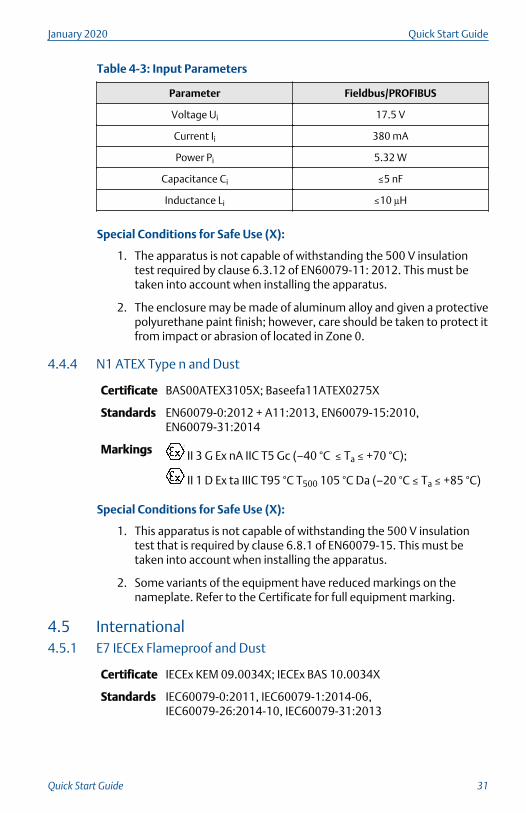
Table 4-3: Input Parameters
Parameter Fieldbus/PROFIBUS
Voltage Ui 17.5 V
Current Ii 380 mA
Power Pi 5.32 W
Capacitance Ci ≤5 nF
Inductance Li ≤10 µH
Special Conditions for Safe Use (X):
1. The apparatus is not capable of withstanding the 500 V insulationtest required by clause 6.3.12 of EN60079-11: 2012. This must betaken into account when installing the apparatus.
2. The enclosure may be made of aluminum alloy and given a protectivepolyurethane paint finish; however, care should be taken to protect itfrom impact or abrasion of located in Zone 0.
4.4.4 N1 ATEX Type n and Dust
Certificate BAS00ATEX3105X; Baseefa11ATEX0275X
Standards EN60079-0:2012 + A11:2013, EN60079-15:2010,EN60079-31:2014
Markings II 3 G Ex nA IIC T5 Gc (–40 °C ≤ Ta ≤ +70 °C);
II 1 D Ex ta IIIC T95 °C T500 105 °C Da (–20 °C ≤ Ta ≤ +85 °C)
Special Conditions for Safe Use (X):
1. This apparatus is not capable of withstanding the 500 V insulationtest that is required by clause 6.8.1 of EN60079-15. This must betaken into account when installing the apparatus.
2. Some variants of the equipment have reduced markings on thenameplate. Refer to the Certificate for full equipment marking.
4.5 International4.5.1 E7 IECEx Flameproof and Dust
Certificate IECEx KEM 09.0034X; IECEx BAS 10.0034X
Standards IEC60079-0:2011, IEC60079-1:2014-06,IEC60079-26:2014-10, IEC60079-31:2013
January 2020 Quick Start Guide
Quick Start Guide 31
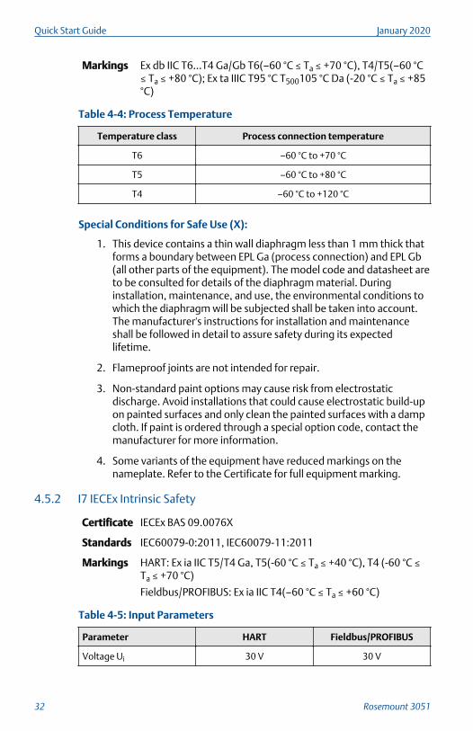
Markings Ex db IIC T6…T4 Ga/Gb T6(–60 °C ≤ Ta ≤ +70 °C), T4/T5(–60 °C≤ Ta ≤ +80 °C); Ex ta IIIC T95 °C T500105 °C Da (-20 °C ≤ Ta ≤ +85°C)
Table 4-4: Process Temperature
Temperature class Process connection temperature
T6 –60 °C to +70 °C
T5 –60 °C to +80 °C
T4 –60 °C to +120 °C
Special Conditions for Safe Use (X):
1. This device contains a thin wall diaphragm less than 1 mm thick thatforms a boundary between EPL Ga (process connection) and EPL Gb(all other parts of the equipment). The model code and datasheet areto be consulted for details of the diaphragm material. Duringinstallation, maintenance, and use, the environmental conditions towhich the diaphragm will be subjected shall be taken into account.The manufacturer's instructions for installation and maintenanceshall be followed in detail to assure safety during its expectedlifetime.
2. Flameproof joints are not intended for repair.
3. Non-standard paint options may cause risk from electrostaticdischarge. Avoid installations that could cause electrostatic build-upon painted surfaces and only clean the painted surfaces with a dampcloth. If paint is ordered through a special option code, contact themanufacturer for more information.
4. Some variants of the equipment have reduced markings on thenameplate. Refer to the Certificate for full equipment marking.
4.5.2 I7 IECEx Intrinsic Safety
Certificate IECEx BAS 09.0076X
Standards IEC60079-0:2011, IEC60079-11:2011
Markings HART: Ex ia IIC T5/T4 Ga, T5(-60 °C ≤ Ta ≤ +40 °C), T4 (-60 °C ≤Ta ≤ +70 °C)
Fieldbus/PROFIBUS: Ex ia IIC T4(–60 °C ≤ Ta ≤ +60 °C)
Table 4-5: Input Parameters
Parameter HART Fieldbus/PROFIBUS
Voltage Ui 30 V 30 V
Quick Start Guide January 2020
32 Rosemount 3051
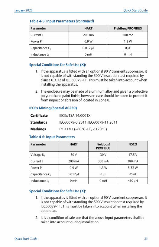
Table 4-5: Input Parameters (continued)
Parameter HART Fieldbus/PROFIBUS
Current Ii 200 mA 300 mA
Power Pi 0.9 W 1.3 W
Capacitance Ci 0.012 µF 0 µF
Inductance Li 0 mH 0 mH
Special Conditions for Safe Use (X):
1. If the apparatus is fitted with an optional 90 V transient suppressor, itis not capable of withstanding the 500 V insulation test required byclause 6.3.12 of IEC 60079-11. This must be taken into account wheninstalling the apparatus.
2. The enclosure may be made of aluminum alloy and given a protectivepolyurethane paint finish; however, care should be taken to protect itfrom impact or abrasion of located in Zone 0.
IECEx Mining (Special A0259)
Certificate IECEx TSA 14.0001X
Standards IEC60079-0:2011, IEC60079-11:2011
Markings Ex ia I Ma (–60 °C ≤ Ta ≤ +70 °C)
Table 4-6: Input Parameters
Parameter HART Fieldbus/PROFIBUS
FISCO
Voltage Ui 30 V 30 V 17.5 V
Current Ii 200 mA 300 mA 380 mA
Power Pi 0.9 W 1.3 W 5.32 W
Capacitance Ci 0.012 µF 0 µF <5 nF
Inductance Li 0 mH 0 mH <10 µH
Special Conditions for Safe Use (X):
1. If the apparatus is fitted with an optional 90 V transient suppressor, itis not capable of withstanding the 500 V insulation test required byIEC60079-11. This must be taken into account when installing theapparatus.
2. It is a condition of safe use that the above input parameters shall betaken into account during installation.
January 2020 Quick Start Guide
Quick Start Guide 33
3. It is a condition of manufacture that only the apparatus fitted withhousing, covers, and sensor module housing made out of stainlesssteel are used in Group 1 applications.
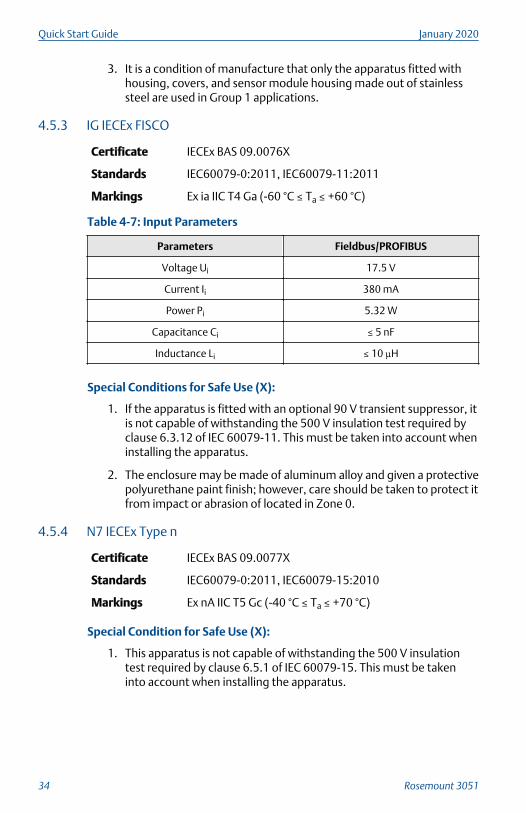
4.5.3 IG IECEx FISCO
Certificate IECEx BAS 09.0076X
Standards IEC60079-0:2011, IEC60079-11:2011
Markings Ex ia IIC T4 Ga (-60 °C ≤ Ta ≤ +60 °C)
Table 4-7: Input Parameters
Parameters Fieldbus/PROFIBUS
Voltage Ui 17.5 V
Current Ii 380 mA
Power Pi 5.32 W
Capacitance Ci ≤ 5 nF
Inductance Li ≤ 10 µH
Special Conditions for Safe Use (X):
1. If the apparatus is fitted with an optional 90 V transient suppressor, itis not capable of withstanding the 500 V insulation test required byclause 6.3.12 of IEC 60079-11. This must be taken into account wheninstalling the apparatus.
2. The enclosure may be made of aluminum alloy and given a protectivepolyurethane paint finish; however, care should be taken to protect itfrom impact or abrasion of located in Zone 0.
4.5.4 N7 IECEx Type n
Certificate IECEx BAS 09.0077X
Standards IEC60079-0:2011, IEC60079-15:2010
Markings Ex nA IIC T5 Gc (-40 °C ≤ Ta ≤ +70 °C)
Special Condition for Safe Use (X):
1. This apparatus is not capable of withstanding the 500 V insulationtest required by clause 6.5.1 of IEC 60079-15. This must be takeninto account when installing the apparatus.
Quick Start Guide January 2020
34 Rosemount 3051
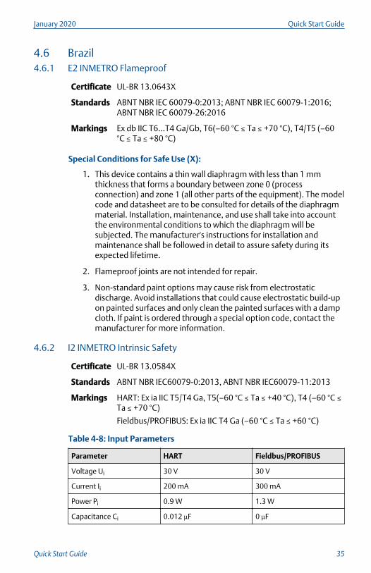
4.6 Brazil4.6.1 E2 INMETRO Flameproof
Certificate UL-BR 13.0643X
Standards ABNT NBR IEC 60079-0:2013; ABNT NBR IEC 60079-1:2016;ABNT NBR IEC 60079-26:2016
Markings Ex db IIC T6…T4 Ga/Gb, T6(–60 °C ≤ Ta ≤ +70 °C), T4/T5 (–60°C ≤ Ta ≤ +80 °C)
Special Conditions for Safe Use (X):
1. This device contains a thin wall diaphragm with less than 1 mmthickness that forms a boundary between zone 0 (processconnection) and zone 1 (all other parts of the equipment). The modelcode and datasheet are to be consulted for details of the diaphragmmaterial. Installation, maintenance, and use shall take into accountthe environmental conditions to which the diaphragm will besubjected. The manufacturer's instructions for installation andmaintenance shall be followed in detail to assure safety during itsexpected lifetime.
2. Flameproof joints are not intended for repair.
3. Non-standard paint options may cause risk from electrostaticdischarge. Avoid installations that could cause electrostatic build-upon painted surfaces and only clean the painted surfaces with a dampcloth. If paint is ordered through a special option code, contact themanufacturer for more information.
4.6.2 I2 INMETRO Intrinsic Safety
Certificate UL-BR 13.0584X
Standards ABNT NBR IEC60079-0:2013, ABNT NBR IEC60079-11:2013
Markings HART: Ex ia IIC T5/T4 Ga, T5(–60 °C ≤ Ta ≤ +40 °C), T4 (–60 °C ≤Ta ≤ +70 °C)
Fieldbus/PROFIBUS: Ex ia IIC T4 Ga (–60 °C ≤ Ta ≤ +60 °C)
Table 4-8: Input Parameters
Parameter HART Fieldbus/PROFIBUS
Voltage Ui 30 V 30 V
Current Ii 200 mA 300 mA
Power Pi 0.9 W 1.3 W
Capacitance Ci 0.012 µF 0 µF
January 2020 Quick Start Guide
Quick Start Guide 35
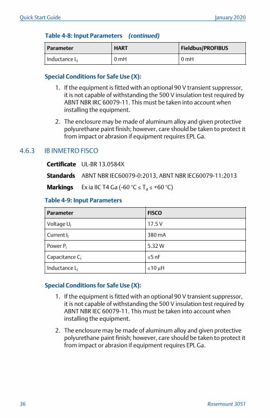
Table 4-8: Input Parameters (continued)
Parameter HART Fieldbus/PROFIBUS
Inductance Li 0 mH 0 mH
Special Conditions for Safe Use (X):
1. If the equipment is fitted with an optional 90 V transient suppressor,it is not capable of withstanding the 500 V insulation test required byABNT NBR IRC 60079-11. This must be taken into account wheninstalling the equipment.
2. The enclosure may be made of aluminum alloy and given protectivepolyurethane paint finish; however, care should be taken to protect itfrom impact or abrasion if equipment requires EPL Ga.
4.6.3 IB INMETRO FISCO
Certificate UL-BR 13.0584X
Standards ABNT NBR IEC60079-0:2013, ABNT NBR IEC60079-11:2013
Markings Ex ia IIC T4 Ga (-60 °C ≤ Ta ≤ +60 °C)
Table 4-9: Input Parameters
Parameter FISCO
Voltage Ui 17.5 V
Current Ii 380 mA
Power Pi 5.32 W
Capacitance Ci ≤5 nF
Inductance Li ≤10 µH
Special Conditions for Safe Use (X):
1. If the equipment is fitted with an optional 90 V transient suppressor,it is not capable of withstanding the 500 V insulation test required byABNT NBR IEC 60079-11. This must be taken into account wheninstalling the equipment.
2. The enclosure may be made of aluminum alloy and given protectivepolyurethane paint finish; however, care should be taken to protect itfrom impact or abrasion if equipment requires EPL Ga.
Quick Start Guide January 2020
36 Rosemount 3051
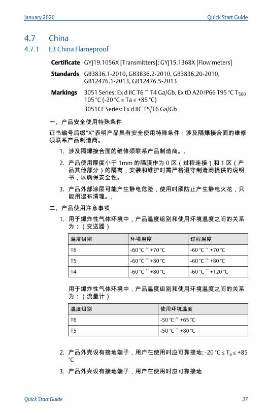
4.7 China4.7.1 E3 China Flameproof
Certificate GYJ19.1056X [Transmitters]; GYJ15.1368X [Flow meters]
Standards GB3836.1-2010, GB3836.2-2010, GB3836.20-2010,GB12476.1-2013, GB12476.5-2013
Markings 3051 Series: Ex d IIC T6 ~ T4 Ga/Gb, Ex tD A20 IP66 T95 °C T500105 °C (-20 °C ≤ Ta ≤ +85 °C)
3051CF Series: Ex d IIC T5/T6 Ga/Gb
一、产品安全使用特殊条件
证书编号后缀“X”表明产品具有安全使用特殊条件:涉及隔爆接合面的维修须联系产品制造商。
1. 涉及隔爆接合面的维修须联系产品制造商。.
2. 产品使用厚度小于 1mm 的隔膜作为 0 区(过程连接)和 1 区(产品其他部分)的隔离,安装和维护时需严格遵守制造商提供的说明书,以确保安全性。
3. 产品外部涂层可能产生静电危险,使用时须防止产生静电火花,只能用湿布清理。.
二、产品使用注意事项
1. 用于爆炸性气体环境中,产品温度组别和使用环境温度之间的关系为:(变送器)
温度组别 环境温度 过程温度
T6 -60 °C ~ +70 °C -60 °C ~ +70 °C
T5 -60 °C ~ +80 °C -60 °C ~ +80 °C
T4 -60 °C ~ +80 °C -60 °C ~ +120 °C
用于爆炸性气体环境中,产品温度组别和使用环境温度之间的关系为:(流量计)
温度组别 使用环境温度
T6 -50 °C ~ +65 °C
T5 -50 °C ~ +80 °C
2. 产品外壳设有接地端子,用户在使用时应可靠接地; -20 °C ≤ Ta ≤ +85°C
3. 产品外壳设有接地端子,用户在使用时应可靠接地
January 2020 Quick Start Guide
Quick Start Guide 37
4. 安装现场应不存在对产品外壳有腐蚀作用的有害气体。
5. 现场安装时,电缆引入口须选用国家指定的防爆检验机构按检验认可、具有 Ex dⅡC,Ex tD A20 IP66 防爆等级的电缆引入装置或堵封件,冗余电缆引入口须用堵封件有效密封。
6. 用于爆炸性气体环境中,现场安装、使用和维护必须严格遵守“断电后开盖!”的警告语。用于爆炸性粉尘环境中,现场安装、使用和维护必须严格遵守“爆炸性粉尘场所严禁开盖!”的警告语。
7. 用于爆炸性粉尘环境中,产品外壳表面需保持清洁,以防粉尘堆积,但严禁用压缩空气吹扫。
8. 用户不得自行更换该产品的零部件,应会同产品制造商共同解决运行中出现的故障,以杜绝损坏现象的发生。
9. 产品的安装、使用和维护应同时遵守产品使用说明书、GB3836.13-2013“爆炸性环境 第 13 部分:设备的修理、检修、修复和改造”、GB/T3836.15-2017“爆炸性环境 第 15 部分:电气装置的设计、选型和安装”、GB/T3836.16-2017“爆炸性环境 第 16 部分:电气装置的检查与维护”、GB50257-2014“电气装置安装工程爆炸和火灾危险环境电力装置施工及验收规范”和 GB15577-2007“粉尘防爆安全规程” GB12476.2-2010“可燃性粉尘环境用电气设备 第 1部分:用外壳和限制表面温度保护的电气设备 第 2 节 电气设备的选择、安装和维护”的有关规定。
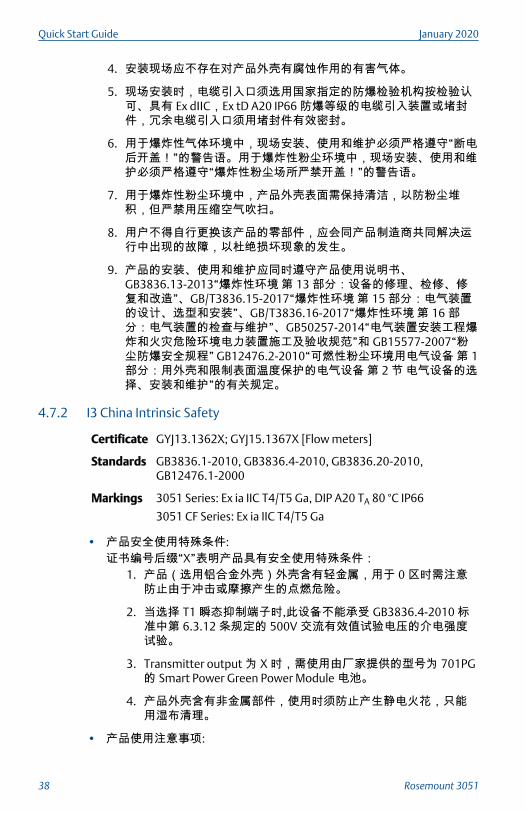
4.7.2 I3 China Intrinsic Safety
Certificate GYJ13.1362X; GYJ15.1367X [Flow meters]
Standards GB3836.1-2010, GB3836.4-2010, GB3836.20-2010,GB12476.1-2000
Markings 3051 Series: Ex ia IIC T4/T5 Ga, DIP A20 TA 80 °C IP66
3051 CF Series: Ex ia IIC T4/T5 Ga
• 产品安全使用特殊条件:证书编号后缀“X”表明产品具有安全使用特殊条件:
1. 产品(选用铝合金外壳)外壳含有轻金属,用于 0 区时需注意防止由于冲击或摩擦产生的点燃危险。
2. 当选择 T1 瞬态抑制端子时,此设备不能承受 GB3836.4-2010 标准中第 6.3.12 条规定的 500V 交流有效值试验电压的介电强度试验。
3. Transmitter output 为 X 时,需使用由厂家提供的型号为 701PG的 Smart Power Green Power Module 电池。
4. 产品外壳含有非金属部件,使用时须防止产生静电火花,只能用湿布清理。
• 产品使用注意事项:
Quick Start Guide January 2020
38 Rosemount 3051
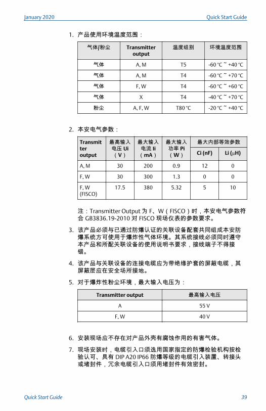
1. 产品使用环境温度范围:
气体/粉尘 Transmitteroutput
温度组别 环境温度范围
气体 A, M T5 -60 °C ~ +40 °C
气体 A, M T4 -60 °C ~ +70 °C
气体 F, W T4 -60 °C ~ +60 °C
气体 X T4 -40 °C ~ +70 °C
粉尘 A, F, W T80 °C -20 °C ~ +40 °C
2. 本安电气参数:
Transmitteroutput
最高输入电压 Ui(V)
最大输入电流 Ii(mA)
最大输入功率 Pi(W)
最大内部等效参数
Ci (nF) Li (µH)
A, M 30 200 0.9 12 0
F, W 30 300 1.3 0 0
F, W(FISCO)
17.5 380 5.32 5 10
注:Transmitter Output 为 F、W(FISCO)时,本安电气参数符合 GB3836.19-2010 对 FISCO 现场仪表的参数要求。
3. 该产品必须与已通过防爆认证的关联设备配套共同组成本安防爆系统方可使用于爆炸性气体环境。其系统接线必须同时遵守本产品和所配关联设备的使用说明书要求,接线端子不得接错。
4. 该产品与关联设备的连接电缆应为带绝缘护套的屏蔽电缆,其屏蔽层应在安全场所接地。
5. 对于爆炸性粉尘环境,最大输入电压为:
Transmitter output 最高输入电压
A 55 V
F, W 40 V
6. 安装现场应不存在对产品外壳有腐蚀作用的有害气体。
7. 现场安装时,电缆引入口须选用国家指定的防爆检验机构按检验认可、具有 DIP A20 IP66 防爆等级的电缆引入装置、转接头或堵封件,冗余电缆引入口须用堵封件有效密封。
January 2020 Quick Start Guide
Quick Start Guide 39
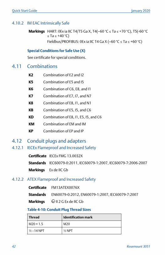
8. 对于爆炸性粉尘环境,现场安装、使用和维护必须严格遵守“爆炸性粉尘场所严禁开盖!”的警告语。
9. 用户不得自行更换该产品的零部件,应会同产品制造商共同解决运行中出现的故障,以杜绝损坏现象的发生。
10. 安装现场确认无可燃性粉尘存在时方可维修。
11. 产品的安装、使用和维护应同时遵守产品使用说明书、GB3836.13-2013 “爆炸性环境 第 13 部分:设备的修理、检修、修复和改造”、GB3836.15-2000“爆炸性气体环境用电气设备 第15 部分:危险场所电气安装(煤矿除外)”、GB3836.16-2006“爆炸性气体环境用电气设备 第 16 部分:电气装置的检查和维护(煤矿除外)”、GB3836.18-2010“爆炸性环境 第 18 部分:本质安全系统”和 GB50257-2014“电气装置安装工程爆炸和火灾危险环境电力装置施工及验收规范”, GB50527-1996 “电气装置安装工程爆炸和火灾危险环境电气装置施工验收规范”以及GB15577-2007 “粉尘防爆安全规程”、GB12476.2-2006 “可燃性粉尘环境用电气设备 第 1 部分:用外壳和限制表面温度保护的电气设备 第 2 节:电气设备的选择、安装和维护”的有关规定。
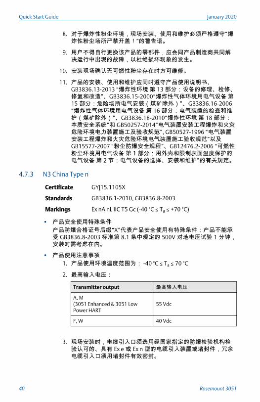
4.7.3 N3 China Type n
Certificate GYJ15.1105X
Standards GB3836.1-2010, GB3836.8-2003
Markings Ex nA nL IIC T5 Gc (-40 °C ≤ Ta ≤ +70 °C)
• 产品安全使用特殊条件产品防爆合格证号后缀“X”代表产品安全使用有特殊条件:产品不能承受 GB3836.8-2003 标准第 8.1 条中规定的 500V 对地电压试验 1 分钟,安装时需考虑在内。
• 产品使用注意事项1. 产品使用环境温度范围为: -40 °C ≤ Ta ≤ 70 °C
2. 最高输入电压:
Transmitter output 最高输入电压
A, M(3051 Enhanced & 3051 LowPower HART
55 Vdc
F, W 40 Vdc
3. 现场安装时,电缆引入口须选用经国家指定的防爆检验机构检验认可的、具有 Ex e 或 Ex n 型的电缆引入装置或堵封件,冗余电缆引入口须用堵封件有效密封。
Quick Start Guide January 2020
40 Rosemount 3051
4. 安装现场确认无可燃性气体存在时方可维修。
5. 用户不得自行更换该产品的零部件,应会同产品制造商共同解决运行中出现的故障,以杜绝损坏现象的发生。
6. 产品的安装、使用和维护应同时遵守产品使用说明书、GB3836.13-2013“爆炸性环境 第 13 部分:设备的修理、检修、修复和改造”、GB3836.15-2000“爆炸性气体环境用电气设备 第15 部分:危险场所电气安装(煤矿除外)”、GB3836.16-2006“爆炸性气体环境用电气设备 第 16 部分:电气装置的检查和维护(煤矿除外)” 、GB50257-1996“电气装置安装工程爆炸和火灾危险环境电力装置施工及验收规范”的有关规定。
4.8 Japan4.8.1 E4 Japan Flameproof
Certificate TC20577, TC20578, TC20583, TC20584 [HART]; TC20579,TC20580, TC20581, TC20582 [Fieldbus]
Markings Ex d IIC T5
4.9 Republic of Korea4.9.1 EP Republic of Korea Flameproof
Certificate 11-KB4BO-0188X [Mfg Singapore]
Markings Ex d IIC T6…T4
4.9.2 IP Republic of Korea Intrinsic Safety
Certificate 13-KB4BO-0203X [HART – Mfg USA], 13-KB4BO-0204X[Fieldbus – Mfg USA], 10-KB4BO-0138X [HART – MfgSingapore], 13-KB4BO-0206X [Fieldbus – Mfg Singapore]
Markings Ex ia IIC T5/T4 (HART); Ex ia IIC T4 (Fieldbus)
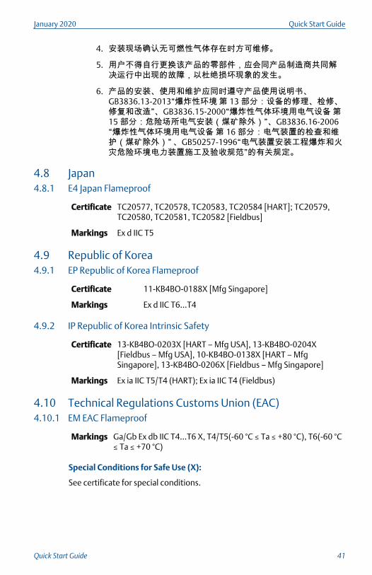
4.10 Technical Regulations Customs Union (EAC)4.10.1 EM EAC Flameproof
Markings Ga/Gb Ex db IIC T4…T6 X, T4/T5(-60 °C ≤ Ta ≤ +80 °C), T6(-60 °C≤ Ta ≤ +70 °C)
Special Conditions for Safe Use (X):
See certificate for special conditions.
January 2020 Quick Start Guide
Quick Start Guide 41
4.10.2 IM EAC Intrinsically Safe
Markings HART: 0Ex ia IIC T4/T5 Ga X, T4(–60 °C ≤ Ta ≤ +70 °C), T5(-60 °C≤ Ta ≤ +40 °C)
Fieldbus/PROFIBUS: 0Ex ia IIC T4 Ga X (–60 °C ≤ Ta ≤ +60 °C)
Special Conditions for Safe Use (X)
See certificate for special conditions.
4.11 Combinations
K2 Combination of E2 and I2
K5 Combination of E5 and I5
K6 Combination of C6, E8, and I1
K7 Combination of E7, I7, and N7
K8 Combination of E8, I1, and N1
KB Combination of E5, I5, and C6
KD Combination of E8, I1, E5, I5, and C6
KM Combination of EM and IM
KP Combination of EP and IP
4.12 Conduit plugs and adapters4.12.1 IECEx Flameproof and Increased Safety
Certificate IECEx FMG 13.0032X
Standards IEC60079-0:2011, IEC60079-1:2007, IEC60079-7:2006-2007
Markings Ex de IIC Gb
4.12.2 ATEX Flameproof and Increased Safety
Certificate FM13ATEX0076X
Standards EN60079-0:2012, EN60079-1:2007, IEC60079-7:2007
Markings II 2 G Ex de IIC Gb
Table 4-10: Conduit Plug Thread Sizes
Thread Identification mark
M20 × 1.5 M20
½ –14 NPT ½ NPT
Quick Start Guide January 2020
42 Rosemount 3051
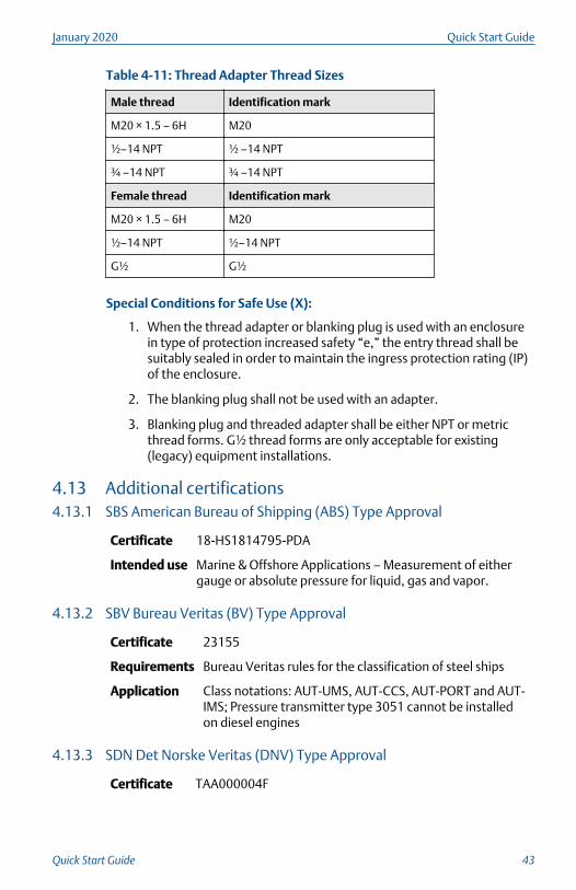
Table 4-11: Thread Adapter Thread Sizes
Male thread Identification mark
M20 × 1.5 – 6H M20
½–14 NPT ½ –14 NPT
¾ –14 NPT ¾ –14 NPT
Female thread Identification mark
M20 × 1.5 – 6H M20
½–14 NPT ½–14 NPT
G½ G½
Special Conditions for Safe Use (X):
1. When the thread adapter or blanking plug is used with an enclosurein type of protection increased safety “e,” the entry thread shall besuitably sealed in order to maintain the ingress protection rating (IP)of the enclosure.
2. The blanking plug shall not be used with an adapter.
3. Blanking plug and threaded adapter shall be either NPT or metricthread forms. G½ thread forms are only acceptable for existing(legacy) equipment installations.
4.13 Additional certifications4.13.1 SBS American Bureau of Shipping (ABS) Type Approval
Certificate 18-HS1814795-PDA
Intended use Marine & Offshore Applications – Measurement of eithergauge or absolute pressure for liquid, gas and vapor.
4.13.2 SBV Bureau Veritas (BV) Type Approval
Certificate 23155
Requirements Bureau Veritas rules for the classification of steel ships
Application Class notations: AUT-UMS, AUT-CCS, AUT-PORT and AUT-IMS; Pressure transmitter type 3051 cannot be installedon diesel engines
4.13.3 SDN Det Norske Veritas (DNV) Type Approval
Certificate TAA000004F
January 2020 Quick Start Guide
Quick Start Guide 43
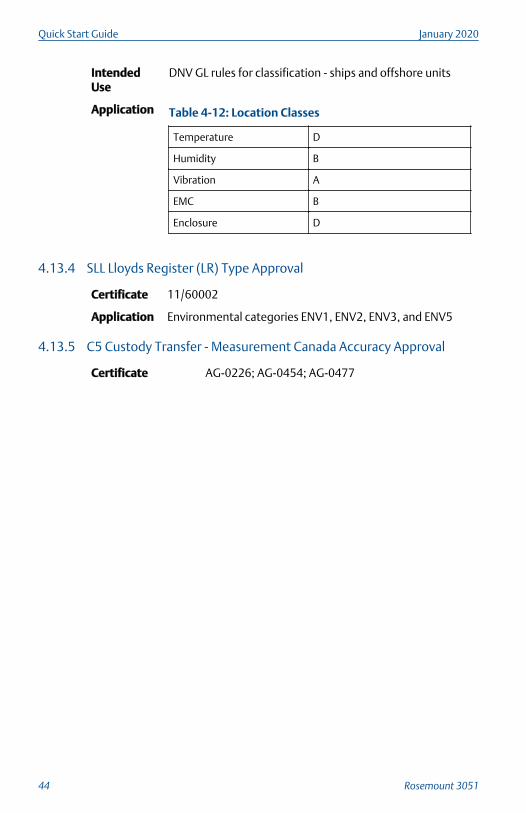
IntendedUse
DNV GL rules for classification - ships and offshore units
Application Table 4-12: Location Classes
Temperature D
Humidity B
Vibration A
EMC B
Enclosure D
4.13.4 SLL Lloyds Register (LR) Type Approval
Certificate 11/60002
Application Environmental categories ENV1, ENV2, ENV3, and ENV5
4.13.5 C5 Custody Transfer - Measurement Canada Accuracy Approval
Certificate AG-0226; AG-0454; AG-0477
Quick Start Guide January 2020
44 Rosemount 3051
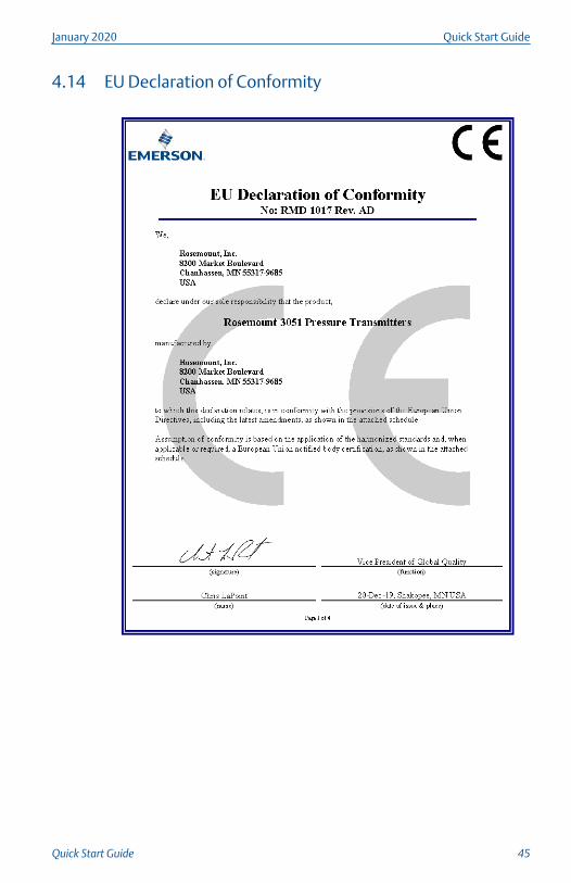
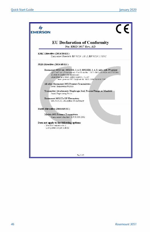
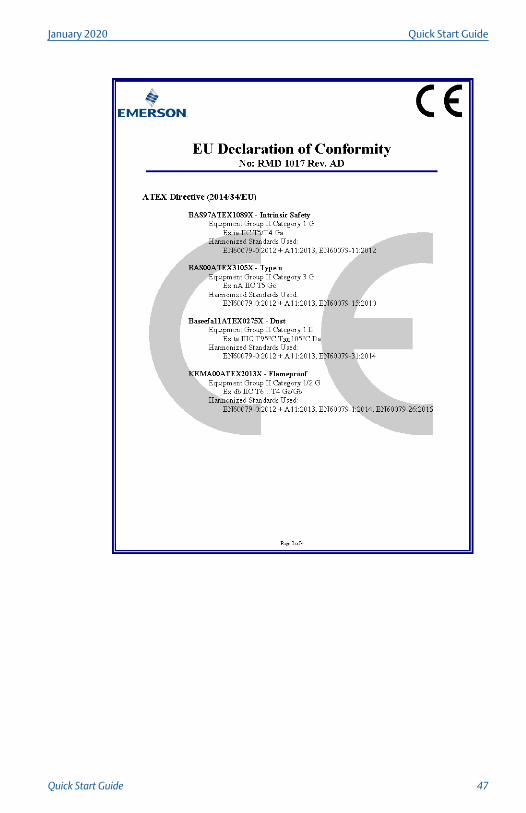
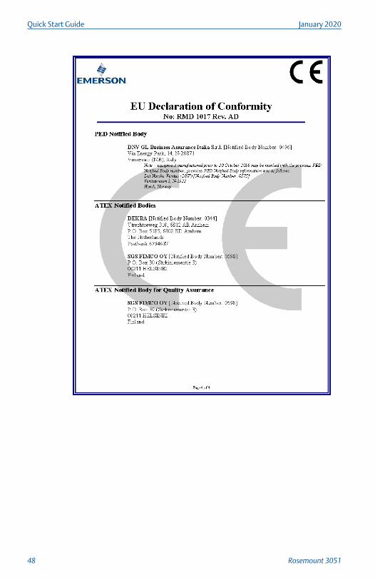
4.14 EU Declaration of Conformity
January 2020 Quick Start Guide
Quick Start Guide 45
Quick Start Guide January 2020
46 Rosemount 3051
January 2020 Quick Start Guide
Quick Start Guide 47
Quick Start Guide January 2020
48 Rosemount 3051
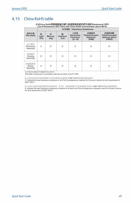
4.15 China RoHS tableChina RoHS Rosemount 3051
List of Rosemount 3051 Parts with China RoHS Concentration above MCVs
Part Name
/ Hazardous Substances
Lead(Pb)
Mercury(Hg)
Cadmium(Cd)
Hexavalent Chromium
(Cr +6)
Polybrominated biphenyls
(PBB)
Polybrominated diphenyl ethers
(PBDE)
Electronics Assembly
X O O O O O
Housing Assembly
O O O O
Sensor Assembly
X O O O O
SJ/T11364This table is proposed in accordance with the provision of SJ/T11364.
O: GB/T 26572O: Indicate that said hazardous substance in all of the homogeneous materials for this part is below the limit requirement ofGB/T 26572.
X: GB/T 26572X: Indicate that said hazardous substance contained in at least one of the homogeneous materials used for this part is above the limit requirement of GB/T 26572.
O
O
O
January 2020 Quick Start Guide
Quick Start Guide 49

Quick Start Guide January 2020
50 Rosemount 3051

January 2020 Quick Start Guide
Quick Start Guide 51

*00825-0100-4007*Quick Start Guide
00825-0100-4007, Rev. HAJanuary 2020
Global HeadquartersEmerson Automation Solutions6021 Innovation Blvd.Shakopee, MN 55379, USA
+1 800 999 9307 or +1 952 906 8888
+1 952 204 8889
North America Regional OfficeEmerson Automation Solutions8200 Market Blvd.Chanhassen, MN 55317, USA
+1 800 999 9307 or +1 952 906 8888
+1 952 204 8889
Latin America Regional OfficeEmerson Automation Solutions1300 Concord Terrace, Suite 400Sunrise, FL 33323, USA
+1 954 846 5030
+1 954 846 5121
Europe Regional OfficeEmerson Automation Solutions EuropeGmbHNeuhofstrasse 19a P.O. Box 1046CH 6340 BaarSwitzerland
+41 (0) 41 768 6111
+41 (0) 41 768 6300
Asia Pacific Regional OfficeEmerson Automation Solutions1 Pandan CrescentSingapore 128461
+65 6777 8211
+65 6777 0947
Middle East and Africa Regional OfficeEmerson Automation SolutionsEmerson FZE P.O. Box 17033Jebel Ali Free Zone - South 2Dubai, United Arab Emirates
+971 4 8118100
+971 4 8865465
Linkedin.com/company/Emerson-Automation-Solutions
Twitter.com/Rosemount_News
Facebook.com/Rosemount
Youtube.com/user/RosemountMeasurement
©2020 Emerson. All rights reserved.
Emerson Terms and Conditions of Sale areavailable upon request. The Emerson logo is atrademark and service mark of Emerson ElectricCo. Rosemount is a mark of one of the Emersonfamily of companies. All other marks are theproperty of their respective owners.