Embed Size (px)
Citation preview

Quick Start Guide00825-0100-4100, Rev CB
June 2016
4100_0100_RevCB.fm Page 1 Tuesday, June 14, 2016 6:44 AM
Rosemount 3051 Pressure Transmitter and Rosemount 3051CF DP Flowmeterswith WirelessHART® Protocol
June 2016Quick Start Guide
4100_0100_RevCB.fm Page 2 Tuesday, June 14, 2016 6:44 AM
NOTICEThis guide provides basic guidelines for Rosemount 3051 Wireless Transmitters. It does not provide instructions for configuration, diagnostics, maintenance, service, troubleshooting or Intrinsically Safe (I.S.) installations. Refer to the Rosemount 3051 Wireless Reference Manual (document number 00809-0100-4100) for more instruction. This manual is also available electronically on www.rosemount.com.
Explosions could result in death or serious injury.
Installation of this transmitter in an explosive environment must be in accordance with the appropriate local, national, and international standards, codes, and practices. Review the approvals section of the 3051 reference manual for any restrictions associated with a safe installation. Before connecting a HART®-based communicator in an explosive atmosphere, make sure the instruments
in the loop are installed in accordance with intrinsically safe or non-incendive field wiring practices.
Process leaks may cause harm or result in death. To avoid process leaks, only use the o-ring designed to seal with the corresponding flange adapter.
Electrical shock can result in death or serious injury. Avoid contact with the leads and the terminals. High voltage that may be present on leads can cause
electrical shock.
NOTICEShipping considerations for wireless products.
The unit was shipped to you without the power module installed. Remove the power module prior to shipping the unit.Each power module contains one “D” size primary lithium-thionyl chloride battery. Primary lithium batteries are regulated in transportation by the U.S. Department of Transportation, and are also covered by IATA (International Air Transport Association), ICAO (International Civil Aviation Organization), and ARD (European Ground Transportation of Dangerous Goods). It is the responsibility of the shipper to ensure compliance with these or any other local requirements. Consult current regulations and requirements before shipping.
ContentsWireless considerations . . . . . . . . . . . . . . . . 3Mount the transmitter . . . . . . . . . . . . . . . . . . 4Connect the power module . . . . . . . . . . . . 8Trim the transmitter . . . . . . . . . . . . . . . . . . . . 8
Verify transmitter configuration . . . . . . .10Troubleshooting . . . . . . . . . . . . . . . . . . . . . . .13Product Certifications . . . . . . . . . . . . . . . . .14
2
Quick Start GuideJune 2016
4100_0100_RevCB.fm Page 3 Tuesday, June 14, 2016 6:44 AM
Wireless considerations
Power up sequenceThe power module should not be installed on any wireless device until the Smart Wireless Gateway is installed and functioning properly. This transmitter uses the green power module (order model number 701PGNKF). Wireless devices should also be powered up in order of proximity from the Smart Wireless Gateway, beginning with the closest. This will result in a simpler and faster network installation. Enable Active Advertising on the Gateway to ensure that new devices join the network faster. For more information, see the Smart Wireless Gateway Manual (document number 00809-0200-4420).
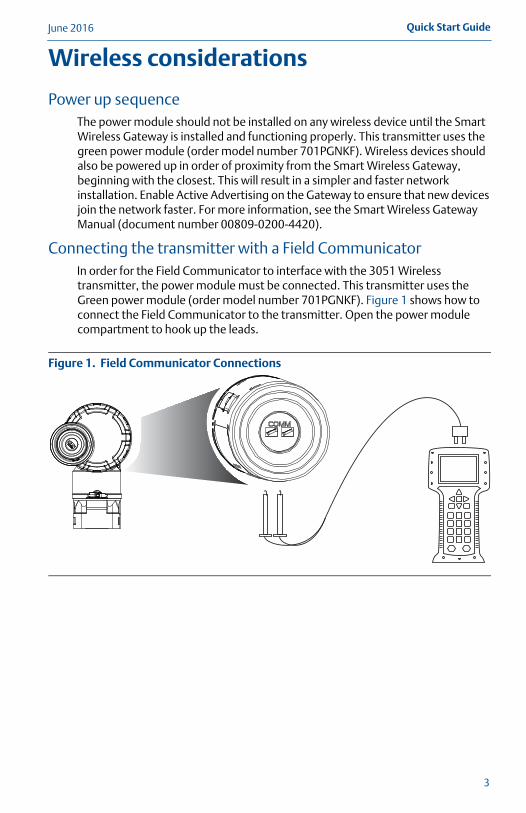
Connecting the transmitter with a Field CommunicatorIn order for the Field Communicator to interface with the 3051 Wireless transmitter, the power module must be connected. This transmitter uses the Green power module (order model number 701PGNKF). Figure 1 shows how to connect the Field Communicator to the transmitter. Open the power module compartment to hook up the leads.
Figure 1. Field Communicator Connections
3
June 2016Quick Start Guide
4100_0100_RevCB.fm Page 4 Tuesday, June 14, 2016 6:44 AM
4
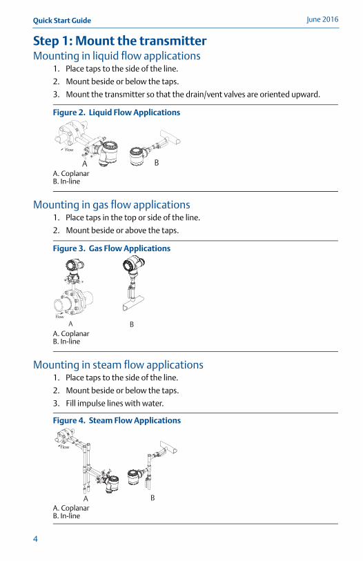
Step 1: Mount the transmitterMounting in liquid flow applications
1. Place taps to the side of the line.
2. Mount beside or below the taps.
3. Mount the transmitter so that the drain/vent valves are oriented upward.
Figure 2. Liquid Flow Applications
A. CoplanarB. In-line
Mounting in gas flow applications1. Place taps in the top or side of the line.
2. Mount beside or above the taps.
Figure 3. Gas Flow Applications
A. CoplanarB. In-line
Mounting in steam flow applications1. Place taps to the side of the line.
2. Mount beside or below the taps.
3. Fill impulse lines with water.
Figure 4. Steam Flow Applications
A. CoplanarB. In-line
B
Flow
A
AFlow
B
Flow
A B
Quick Start GuideJune 2016
4100_0100_RevCB.fm Page 5 Tuesday, June 14, 2016 6:44 AM
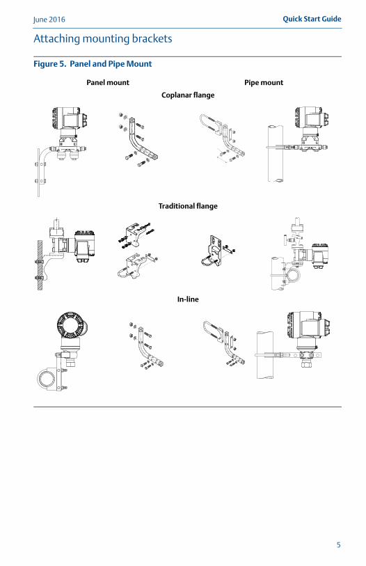
Attaching mounting brackets
Figure 5. Panel and Pipe Mount
Panel mount Pipe mount
Coplanar flange
Traditional flange
In-line
5
June 2016Quick Start Guide
4100_0100_RevCB.fm Page 6 Tuesday, June 14, 2016 6:44 AM
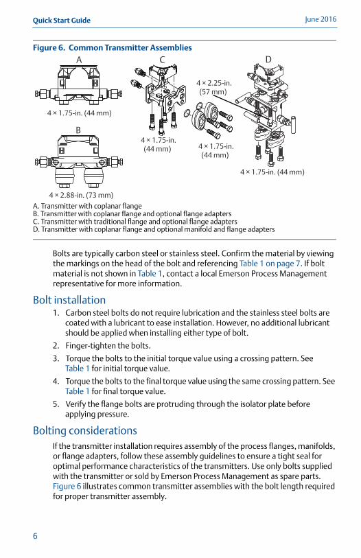
Figure 6. Common Transmitter Assemblies
A. Transmitter with coplanar flangeB. Transmitter with coplanar flange and optional flange adaptersC. Transmitter with traditional flange and optional flange adaptersD. Transmitter with coplanar flange and optional manifold and flange adapters
Bolts are typically carbon steel or stainless steel. Confirm the material by viewing the markings on the head of the bolt and referencing Table 1 on page 7. If bolt material is not shown in Table 1, contact a local Emerson Process Management representative for more information.
Bolt installation1. Carbon steel bolts do not require lubrication and the stainless steel bolts are
coated with a lubricant to ease installation. However, no additional lubricant should be applied when installing either type of bolt.
2. Finger-tighten the bolts.
3. Torque the bolts to the initial torque value using a crossing pattern. See Table 1 for initial torque value.
4. Torque the bolts to the final torque value using the same crossing pattern. See Table 1 for final torque value.
5. Verify the flange bolts are protruding through the isolator plate before applying pressure.
Bolting considerationsIf the transmitter installation requires assembly of the process flanges, manifolds, or flange adapters, follow these assembly guidelines to ensure a tight seal for optimal performance characteristics of the transmitters. Use only bolts supplied with the transmitter or sold by Emerson Process Management as spare parts. Figure 6 illustrates common transmitter assemblies with the bolt length required for proper transmitter assembly.
A
B
C D
4 × 1.75-in. (44 mm)
4 × 1.75-in. (44 mm)
4 × 2.88-in. (73 mm)
4 × 1.75-in. (44 mm)
4 × 1.75-in. (44 mm)
4 × 2.25-in. (57 mm)
6
Quick Start GuideJune 2016
4100_0100_RevCB.fm Page 7 Tuesday, June 14, 2016 6:44 AM
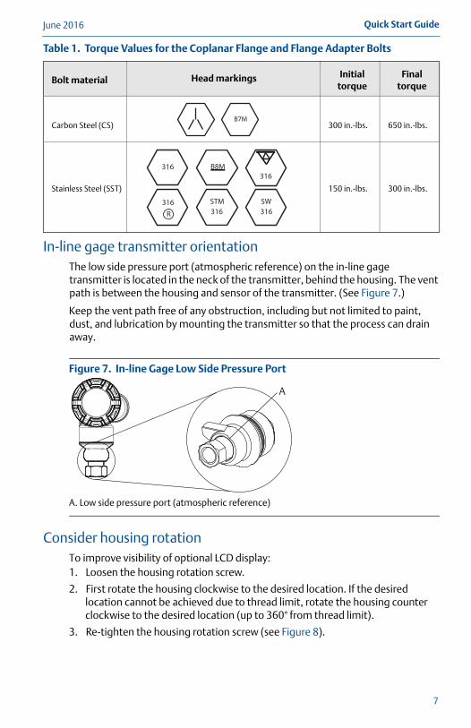
Table 1. Torque Values for the Coplanar Flange and Flange Adapter Bolts
In-line gage transmitter orientationThe low side pressure port (atmospheric reference) on the in-line gage transmitter is located in the neck of the transmitter, behind the housing. The vent path is between the housing and sensor of the transmitter. (See Figure 7.)
Keep the vent path free of any obstruction, including but not limited to paint, dust, and lubrication by mounting the transmitter so that the process can drain away.
Figure 7. In-line Gage Low Side Pressure Port
A. Low side pressure port (atmospheric reference)
Consider housing rotationTo improve visibility of optional LCD display:1. Loosen the housing rotation screw.
2. First rotate the housing clockwise to the desired location. If the desired location cannot be achieved due to thread limit, rotate the housing counter clockwise to the desired location (up to 360° from thread limit).
3. Re-tighten the housing rotation screw (see Figure 8).
Bolt material Head markings Initial torque
Final torque
Carbon Steel (CS) 300 in.-lbs. 650 in.-lbs.
Stainless Steel (SST) 150 in.-lbs. 300 in.-lbs.
B7M
316316
316SW
316STM316
R
B8M
A
7
June 2016Quick Start Guide
4100_0100_RevCB.fm Page 8 Tuesday, June 14, 2016 6:44 AM
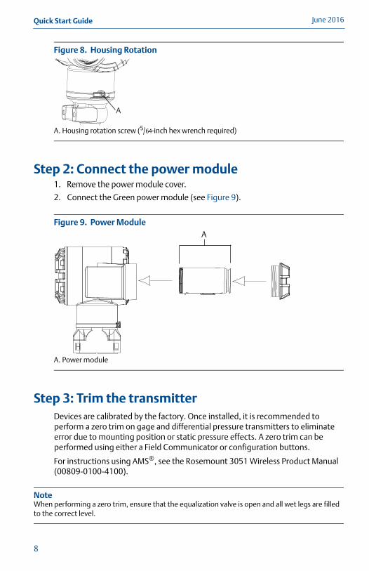
Figure 8. Housing Rotation
A. Housing rotation screw (5/64-inch hex wrench required)
Step 2: Connect the power module1. Remove the power module cover.
2. Connect the Green power module (see Figure 9).
Figure 9. Power Module
A. Power module
Step 3: Trim the transmitterDevices are calibrated by the factory. Once installed, it is recommended to perform a zero trim on gage and differential pressure transmitters to eliminate error due to mounting position or static pressure effects. A zero trim can be performed using either a Field Communicator or configuration buttons.
For instructions using AMS®, see the Rosemount 3051 Wireless Product Manual (00809-0100-4100).
NoteWhen performing a zero trim, ensure that the equalization valve is open and all wet legs are filled to the correct level.
A
A
8
Quick Start GuideJune 2016
4100_0100_RevCB.fm Page 9 Tuesday, June 14, 2016 6:44 AM
Trimming with a Field Communicator1. Equalize or vent the transmitter and connect Field Communicator.
2. At the menu, input the HART Fast Key sequence.
3. Follow the commands to perform a zero trim.
For connecting with a Field Communicator, refer to Figure 1 on page 3.
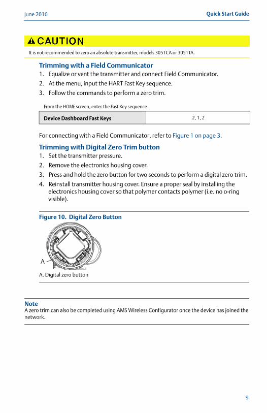
Trimming with Digital Zero Trim button1. Set the transmitter pressure.
2. Remove the electronics housing cover.
3. Press and hold the zero button for two seconds to perform a digital zero trim.
4. Reinstall transmitter housing cover. Ensure a proper seal by installing the electronics housing cover so that polymer contacts polymer (i.e. no o-ring visible).
Figure 10. Digital Zero Button
A. Digital zero button
NoteA zero trim can also be completed using AMS Wireless Configurator once the device has joined the network.
It is not recommended to zero an absolute transmitter, models 3051CA or 3051TA.
From the HOME screen, enter the Fast Key sequence
Device Dashboard Fast Keys 2, 1, 2
Digital Z
eroTri
m
A
9
June 2016Quick Start Guide
4100_0100_RevCB.fm Page 10 Tuesday, June 14, 2016 6:44 AM
Step 4: Verify transmitter configurationOperation can be verified in four locations: At the device via the Local Display (LCD). By using the Field Communicator. Via the Smart Wireless Gateway’s integrated web interface. Via AMS Wireless Configurator.
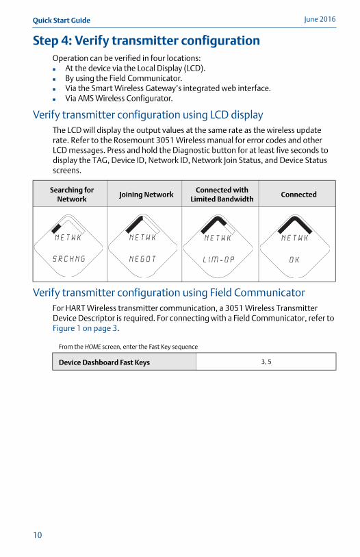
Verify transmitter configuration using LCD displayThe LCD will display the output values at the same rate as the wireless update rate. Refer to the Rosemount 3051 Wireless manual for error codes and other LCD messages. Press and hold the Diagnostic button for at least five seconds to display the TAG, Device ID, Network ID, Network Join Status, and Device Status screens.
Verify transmitter configuration using Field CommunicatorFor HART Wireless transmitter communication, a 3051 Wireless Transmitter Device Descriptor is required. For connecting with a Field Communicator, refer to Figure 1 on page 3.
Searching for Network
Joining NetworkConnected with
Limited BandwidthConnected
From the HOME screen, enter the Fast Key sequence
Device Dashboard Fast Keys 3, 5
N E T w K
S R C H N G
n e t w k
N E G O T
n e t w k
L I M - O P
n e t w k
O K
10
Quick Start GuideJune 2016
4100_0100_RevCB.fm Page 11 Tuesday, June 14, 2016 6:44 AM
Verify transmitter configuration using Smart Wireless GatewayIn the Gateway’s integrated web interface, navigate to the Explorer > Status page. This page will show whether the device has joined the network and if it is communicating properly.
NoteIt may take several minutes for the device to join the network. See Smart Wireless Gateway Quick Start Guide (document number 00825-0200-4420) for more information.
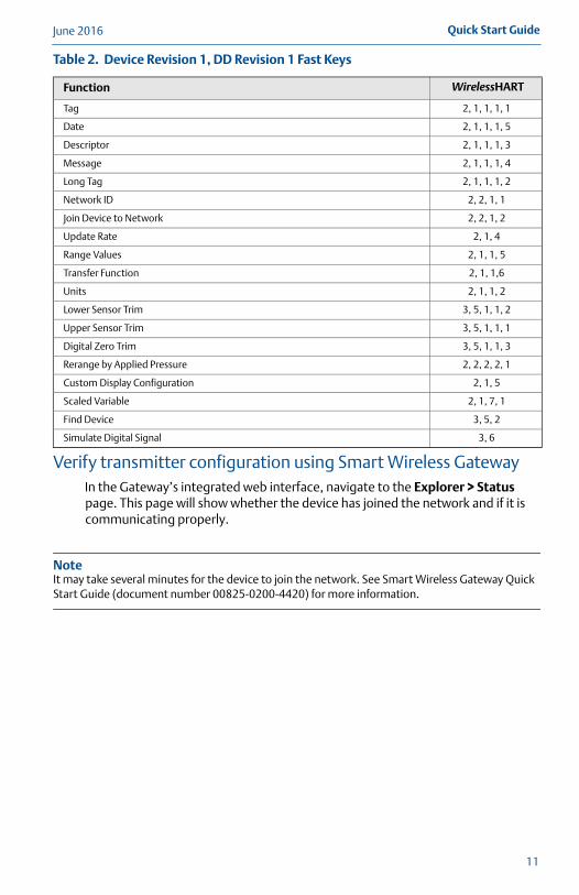
Table 2. Device Revision 1, DD Revision 1 Fast Keys
Function WirelessHART
Tag 2, 1, 1, 1, 1
Date 2, 1, 1, 1, 5
Descriptor 2, 1, 1, 1, 3
Message 2, 1, 1, 1, 4
Long Tag 2, 1, 1, 1, 2
Network ID 2, 2, 1, 1
Join Device to Network 2, 2, 1, 2
Update Rate 2, 1, 4
Range Values 2, 1, 1, 5
Transfer Function 2, 1, 1,6
Units 2, 1, 1, 2
Lower Sensor Trim 3, 5, 1, 1, 2
Upper Sensor Trim 3, 5, 1, 1, 1
Digital Zero Trim 3, 5, 1, 1, 3
Rerange by Applied Pressure 2, 2, 2, 2, 1
Custom Display Configuration 2, 1, 5
Scaled Variable 2, 1, 7, 1
Find Device 3, 5, 2
Simulate Digital Signal 3, 6
11
June 2016Quick Start Guide
4100_0100_RevCB.fm Page 12 Tuesday, June 14, 2016 6:44 AM
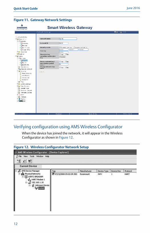
Figure 11. Gateway Network Settings
Verifying configuration using AMS Wireless ConfiguratorWhen the device has joined the network, it will appear in the Wireless Configurator as shown in Figure 12.
Figure 12. Wireless Configurator Network Setup
12
Quick Start GuideJune 2016
4100_0100_RevCB.fm Page 13 Tuesday, June 14, 2016 6:44 AM
Troubleshooting
If the device has not joined to the network after power up, verify the correct configuration of the Network ID and Join Key. Verify that Active Advertising has been enabled on the Smart Wireless Gateway. The Network ID and Join Key in the device must match the Network ID and Join Key of the Gateway.
The Network ID and Join Key may be obtained from the Smart Wireless Gateway on the Setup > Network > Settings page on the web interface (see Figure 11 on page 12). The Network ID and Join Key may be changed in the wireless device by using the following Fast Key sequence. See the manual for further troubleshooting (document number 00809-0100-4100).
From the HOME screen, enter the Fast Key sequence
Device Dashboard Fast Keys 3, 5
13
June 2016Quick Start Guide
4100_0100_RevCB.fm Page 14 Tuesday, June 14, 2016 6:44 AM
Product CertificationsRev 1.0
European Directive InformationA copy of the EC Declaration of Conformity can be found at the end of the Quick Start Guide. The most recent revision of the EC Declaration of Conformity can be found at www.rosemount.com.
Telecommunication ComplianceAll wireless devices require certification to ensure that they adhere to regulations regarding the use of the RF spectrum. Nearly every country requires this type of product certification.
Emerson is working with governmental agencies around the world to supply fully compliant products and remove the risk of violating country directives or laws governing wireless device usage.
FCC and ICThis device complies with Part 15 of the FCC Rules. Operation is subject to the following conditions: This device may not cause harmful interference. This device must accept any interference received, including interference that may cause undesired operation. This device must be installed to ensure a minimum antenna separation distance of 20 cm from all persons.
Ordinary Location Certification from FM ApprovalsAs standard, the transmitter has been examined and tested to determine that the design meets the basic electrical, mechanical, and fire protection requirements by FM Approvals, a nationally recognized test laboratory (NRTL) as accredited by the Federal Occupational Safety and Health Administration (OSHA).
Installing in North AmericaThe US National Electrical Code (NEC) and the Canadian Electrical Code (CEC) permit the use of Division marked equipment in Zones and Zone marked equipment in Divisions. The markings must be suitable for the area classification, gas, and temperature class. This information is clearly defined in the respective codes.
14
Quick Start GuideJune 2016
4100_0100_RevCB.fm Page 15 Tuesday, June 14, 2016 6:44 AM
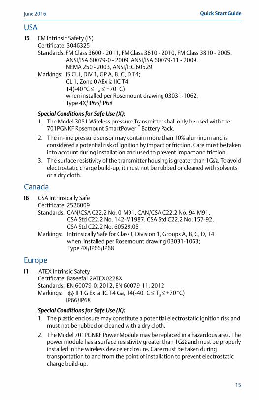
USAI5 FM Intrinsic Safety (IS)
Certificate: 3046325Standards: FM Class 3600 - 2011, FM Class 3610 - 2010, FM Class 3810 - 2005,
ANSI/ISA 60079-0 - 2009, ANSI/ISA 60079-11 - 2009, NEMA 250 - 2003, ANSI/IEC 60529
Markings: IS CL I, DIV 1, GP A, B, C, D T4;CL 1, Zone 0 AEx ia IIC T4;T4(-40 °C ≤ Ta ≤ +70 °C) when installed per Rosemount drawing 03031-1062; Type 4X/IP66/IP68
Special Conditions for Safe Use (X):1. The Model 3051 Wireless pressure Transmitter shall only be used with the
701PGNKF Rosemount SmartPower™ Battery Pack.
2. The in-line pressure sensor may contain more than 10% aluminum and is considered a potential risk of ignition by impact or friction. Care must be taken into account during installation and used to prevent impact and friction.
3. The surface resistivity of the transmitter housing is greater than 1GΩ. To avoid electrostatic charge build-up, it must not be rubbed or cleaned with solvents or a dry cloth.
CanadaI6 CSA Intrinsically Safe
Certificate: 2526009Standards: CAN/CSA C22.2 No. 0-M91, CAN/CSA C22.2 No. 94-M91,
CSA Std C22.2 No. 142-M1987, CSA Std C22.2 No. 157-92, CSA Std C22.2 No. 60529:05
Markings: Intrinsically Safe for Class I, Division 1, Groups A, B, C, D, T4 when installed per Rosemount drawing 03031-1063;
Type 4X/IP66/IP68
EuropeI1 ATEX Intrinsic Safety
Certificate: Baseefa12ATEX0228XStandards: EN 60079-0: 2012, EN 60079-11: 2012Markings: II 1 G Ex ia IIC T4 Ga, T4(-40 °C ≤ Ta ≤ +70 °C)
IP66/IP68
Special Conditions for Safe Use (X):1. The plastic enclosure may constitute a potential electrostatic ignition risk and
must not be rubbed or cleaned with a dry cloth.
2. The Model 701PGNKF Power Module may be replaced in a hazardous area. The power module has a surface resistivity greater than 1GΩ and must be properly installed in the wireless device enclosure. Care must be taken during transportation to and from the point of installation to prevent electrostatic charge build-up.
15
June 2016Quick Start Guide
4100_0100_RevCB.fm Page 16 Tuesday, June 14, 2016 6:44 AM
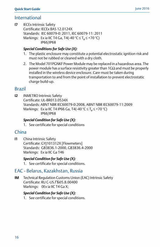
InternationalI7 IECEx Intrinsic Safety
Certificate: IECEx BAS 12.0124XStandards: IEC 60079-0: 2011, IEC 60079-11: 2011Markings: Ex ia IIC T4 Ga, T4(-40 °C ≤ Ta ≤ +70 °C)
IP66/IP68
Special Conditions for Safe Use (X):1. The plastic enclosure may constitute a potential electrostatic ignition risk and
must not be rubbed or cleaned with a dry cloth.
2. The Model 701PGNKF Power Module may be replaced in a hazardous area. The power module has a surface resistivity greater than 1GΩ and must be properly installed in the wireless device enclosure. Care must be taken during transportation to and from the point of installation to prevent electrostatic charge build-up.
BrazilI2 INMETRO Intrinsic Safety
Certificate: UL-BR013.0534XStandards: ABNT NBR IEC60079-0:2008, ABNT NBR IEC60079-11:2009Markings: Ex ia IIC T4 IP66 Ga, T4(-40 °C ≤ Ta ≤ +70 °C)
IP66/IP68
Special Condition for Safe Use (X):1. See certificate for special conditions
ChinaI1 China Intrinsic Safety
Certificate: GYJ101312X [Flowmeters]Standards: GB3836.1-2000, GB3836.4-2000Markings: Ex ia IIC Ga T46
Special Condition for Safe Use (X):1. See certificate for special conditions.
EAC - Belarus, Kazakhstan, RussiaIM Technical Regulation Customs Union (EAC) Intrinsic Safety
Certificate: RU C-US.ГБ05.B.00400Markings: 0Ex ia IIC T4 Ga X;
Special Condition for Safe Use (X):1. See certificate for special conditions.
16
Quick Start GuideJune 2016
4100_0100_RevCB.fm Page 17 Tuesday, June 14, 2016 6:44 AM
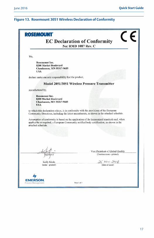
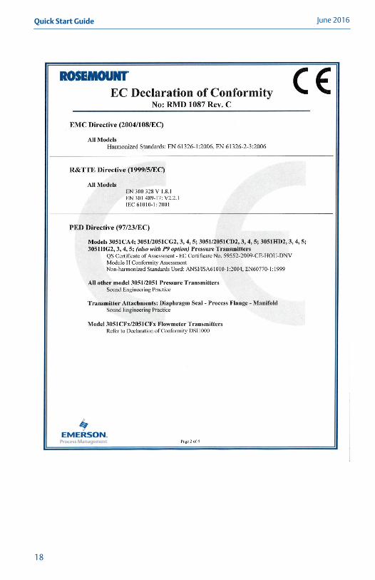
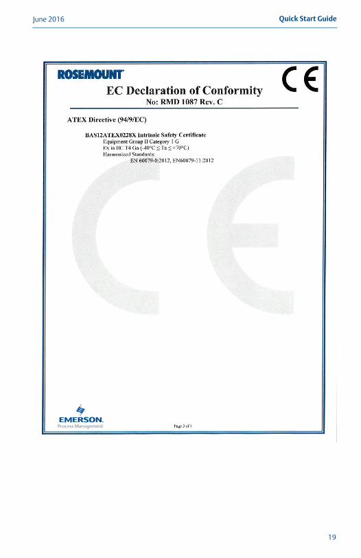
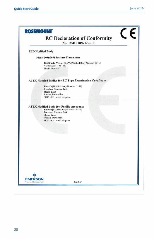
Figure 13. Rosemount 3051 Wireless Declaration of Conformity
17
June 2016Quick Start Guide
4100_0100_RevCB.fm Page 18 Tuesday, June 14, 2016 6:44 AM
18
Quick Start GuideJune 2016
4100_0100_RevCB.fm Page 19 Tuesday, June 14, 2016 6:44 AM
19
June 2016Quick Start Guide
4100_0100_RevCB.fm Page 20 Tuesday, June 14, 2016 6:44 AM
20
Quick Start GuideJune 2016
4100_0100_RevCB.fm Page 21 Tuesday, June 14, 2016 6:44 AM
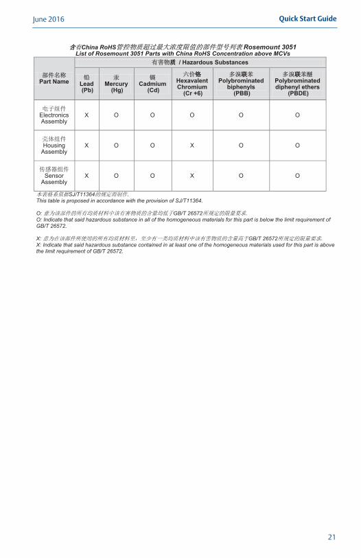
China RoHS Rosemount 3051List of Rosemount 3051 Parts with China RoHS Concentration above MCVs
Part Name
/ Hazardous Substances
Lead(Pb)
Mercury(Hg)
Cadmium(Cd)
Hexavalent Chromium
(Cr +6)
Polybrominated biphenyls
(PBB)
Polybrominated diphenyl ethers
(PBDE)
Electronics Assembly
X O O O O O
Housing Assembly
X O O X O O
Sensor Assembly
X O O X O O
SJ/T11364This table is proposed in accordance with the provision of SJ/T11364.
O: GB/T 26572O: Indicate that said hazardous substance in all of the homogeneous materials for this part is below the limit requirement ofGB/T 26572.
X: GB/T 26572X: Indicate that said hazardous substance contained in at least one of the homogeneous materials used for this part is above the limit requirement of GB/T 26572.
21
Quick Start Guide00825-0100-4100, Rev CB
June 2016
*00825-0100-4100*
Global HeadquartersEmerson Process Management 6021 Innovation BlvdShakopee, MN 55379, USA
+1 800 999 9307 or +1 952 906 8888+1 952 949 7001 [email protected]
North America Regional OfficeEmerson Process Management 8200 Market Blvd.Chanhassen, MN 55317, USA
+1 800 999 9307 or +1 952 906 8888
+1 952 949 7001
Latin America Regional OfficeEmerson Process Management 1300 Concord Terrace, Suite 400Sunrise, Florida, 33323, USA
+1 954 846 5030
+1 954 846 5121
Europe Regional OfficeEmerson Process Management Europe GmbHNeuhofstrasse 19a P.O. Box 1046CH 6340 BaarSwitzerland
+41 (0) 41 768 6111
+41 (0) 41 768 6300
Asia Pacific Regional OfficeEmerson Process Management Asia Pacific Pte Ltd1 Pandan CrescentSingapore 128461
+65 6777 8211
+65 6777 0947 [email protected]
Middle East and Africa Regional OfficeEmerson Process Management Emerson FZE P.O. Box 17033,Jebel Ali Free Zone - South 2Dubai, United Arab Emirates
+971 4 8118100
+971 4 [email protected]
Standard Terms and Conditions of Sale can be found at: www.Emerson.com/en-us/pages/Terms-of-Use.aspx.The Emerson logo is a trademark and service mark of Emerson Electric Co.Rosemount, and Rosemount logotype are registered trademarks of Rosemount Inc.HART and WirelessHART are registered trademarks of FieldComm Group.AMS is a registered trademark of Emerson Electric Co.SmartPower is a trademark of Rosemount Inc.All other marks are the property of their respective owners.© 2016 Rosemount Inc. All rights reserved.
4100_0100_RevCB.fm Page 22 Tuesday, June 14, 2016 6:44 AM