Embed Size (px)
Citation preview
Quick Start Guide00825-0200-4728, Rev GB
August 2017
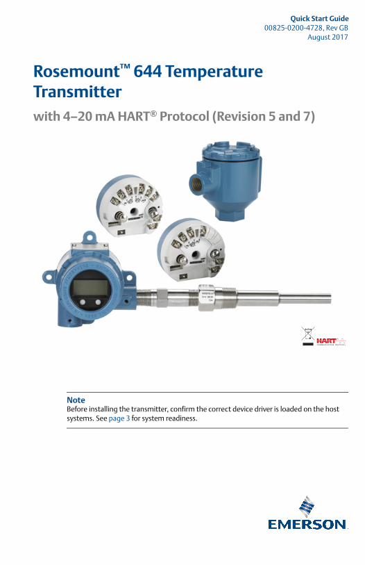
Rosemount™ 644 Temperature Transmitter
NoteBefore installing the transmitter, confirm the correct device driver is loaded on the host systems. See page 3 for system readiness.
with 4–20 mA HART® Protocol (Revision 5 and 7)
August 2017Quick Start Guide
NOTICEThis guide provides basic guidelines for Rosemount 644 Transmitters. It does not provide instructions for configuration, diagnostics, maintenance, service, troubleshooting, explosion-proof, flameproof, or intrinsically safe (I.S.) installations. Refer to the Rosemount 644 Reference Manual for more instruction. The manual and this guide is also available electronically on Emerson.com/Rosemount.
Explosions could result in death or serious injury.
Installation of this transmitter in an explosive environment must be in accordance with the appropriate local, national, and international standards, codes, and practices. Review the approvals section of the Rosemount 644 Reference Manual for any restrictions associated with a safe installation.
Before connecting a HART-based communicator in an explosive atmosphere, make sure the instruments in the loop are installed in accordance with intrinsically safe or non-incendive field wiring practices.
Electrical shock can result in death or serious injury.
Avoid contact with the leads and the terminals. High voltage may be present on leads, which can cause electrical shock.
Conduit/cable entries
Unless marked, the conduit/cable entries in the transmitter housing use a 1/2–14 NPT thread form. Entries marked “M20” are M20 � 1.5 thread form. On devices with multiple conduit entries, all entries will have the same thread form. Only use plugs, adapters, glands, or conduit with a compatible thread form when closing these entries.
When installing in a hazardous location, use only appropriately listed or Ex certified plugs, adapters, or glands in cable/conduit entries.
ContentsSystem readiness . . . . . . . . . . . . . . . . . . . . . . . . . 3Transmitter installation . . . . . . . . . . . . . . . . . . . 3
Safety instrumented systems . . . . . . . . . . . . . 17Product Certifications . . . . . . . . . . . . . . . . . . . . 18
2
Quick Start GuideAugust 2017
1.0 System readiness
1.1 Confirm HART Revision capability If using HART based control or asset management systems, confirm the
HART capability of those systems prior to transmitter installation. Not all systems are capable of communicating with HART Revision 7 Protocol. This transmitter can be configured for either HART Revision 5 or 7.
For instructions on how to change the HART Revision of your transmitter, see “Verify configuration” on page 4.
1.2 Confirm correct device driver 1. Verify the latest Device Driver files are loaded on your systems to ensure
proper communications.
2. Download the latest Device Driver at Emerson.com/Device-Install-Kits/Device-Install-Kit-Search
Rosemount 644 Transmitter device revisions and files
Table 1 provides the information necessary to ensure the correct Device Driver files and documentation are being used.
2.0 Transmitter installation
2.1 Set the alarm switchSet the Rosemount 644 Transmitter alarm switch before putting the device into operation.1. Set the loop to manual (if applicable) and disconnect the power
2. Remove the LCD display by detaching from the transmitter (if applicable).
3. Set the switch to the desired position (H indicates High, L indicated Low).
4. Reattach the LCD display to the transmitter (if applicable).
5. Reattach the housing cover. Ensure covers must be fully engages to meet explosion-proof requirements.
Table 1. Rosemount 644 Device Revisions and Files
Software date
NAMUR software revision
HART software revision
HART universal revision(1)
1. NAMUR software revision is located on the hardware tag of the device. HART software revision can be read using a HART communication tool.
Device revision(2)
2. Device Driver file names use Device and DD Revision, e.g. 10_01. HART Protocol is designed to enable legacy device driver revisions to continue to communicate with new HART devices. To access new functionality, the new Device Driver must be downloaded. It is recommended to download new Device Driver files to ensure full functionality.
Manual document number
Changes to software(3)
3. HART Revision 5 and 7 Selectable, Dual Sensor support, Safety Certified, Advanced Diagnostics (if ordered), Enhanced Accuracy and Stability (if ordered).
June 2012 1.1.1 35 8
00809-0100-4728 See Footnote 3 for list of changes.7 9
3
August 2017Quick Start Guide
6. Apply power and set the loop to automatic control (if applicable).
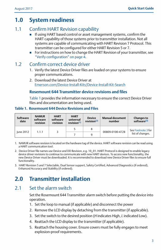
Figure 1. Alarm Switch Placement
A. Alarm switch
NoteIf using an LCD display, remove the display by detaching it from the top of the device, set the switch to the desired position, reattach the LCD display, and reattach the housing cover. Enclosure covers must be fully engaged to meet explosion-proof requirements.
2.2 Verify configurationVerify the configuration of the Rosemount 644 Transmitter device upon receiving your transmitter using any HART-compliant configuration tool. See the Rosemount 644 Reference Manual for configuration instructions using AMS Device Manager.
The Rosemount 644 Transmitter communicates using the Field Communicator (communication requires a loop resistance between 250 and 1100 ohms). Do not operate when power is below 12 Vdc at the transmitter terminal. See Rosemount 644 Reference Manual and Field Communicator Reference Manual for more information.
Verify configuration with a Field Communicator
A Rosemount 644 DD (Device Descriptor) must be installed on the Field Communicator to verify the configuration. Fast Key sequences for the latest DD are shown in Table 2 on page 5. For Fast Key sequences using legacy DD's, contact your local Emerson™ representative.
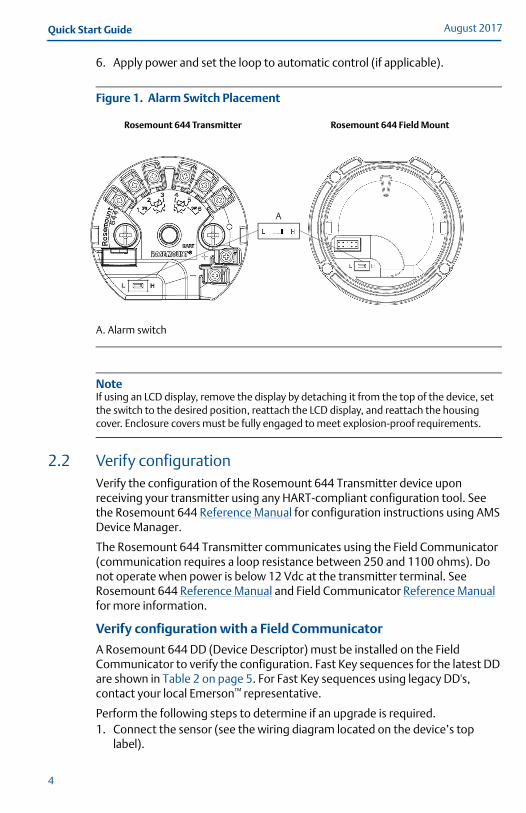
Perform the following steps to determine if an upgrade is required.1. Connect the sensor (see the wiring diagram located on the device’s top
label).
Rosemount 644 Transmitter Rosemount 644 Field Mount
A
4
Quick Start GuideAugust 2017
5
2. Connect the bench power supply to the power terminals (“+” or “–”).
3. Connect a Field Communicator to the loop across a loop resistor or at the power/signal terminals on the transmitter.
4. The following message will appear if the communicator has a previous version of the DDs:
Device Description Not Installed…The Device Description for manufacturer 0x26 model 0x2618 dev rev 8/9 is not installed on the System Card…see Programming Utility for details on Device Description updates…Do you wish to proceed in forward compatibility mode?
If this notice does not appear, the latest DD is installed. If the latest version is not available, the communicator will communicate properly, however, when the transmitter is configured to utilize advanced transmitter features, there will be trouble communicating and a prompt to turn off the communicator will display. To prevent this from happening, upgrade to the latest DD or answer NO to the question and default to the generic transmitter functionality.
NoteEmerson recommends installing the latest DD to access the complete functionality. Visit Emerson.com/Field-Communicator for information on updating the DD Library.
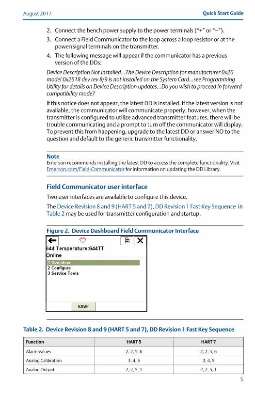
Field Communicator user interface
Two user interfaces are available to configure this device.
The Device Revision 8 and 9 (HART 5 and 7), DD Revision 1 Fast Key Sequence in Table 2 may be used for transmitter configuration and startup.
Figure 2. Device Dashboard Field Communicator Interface
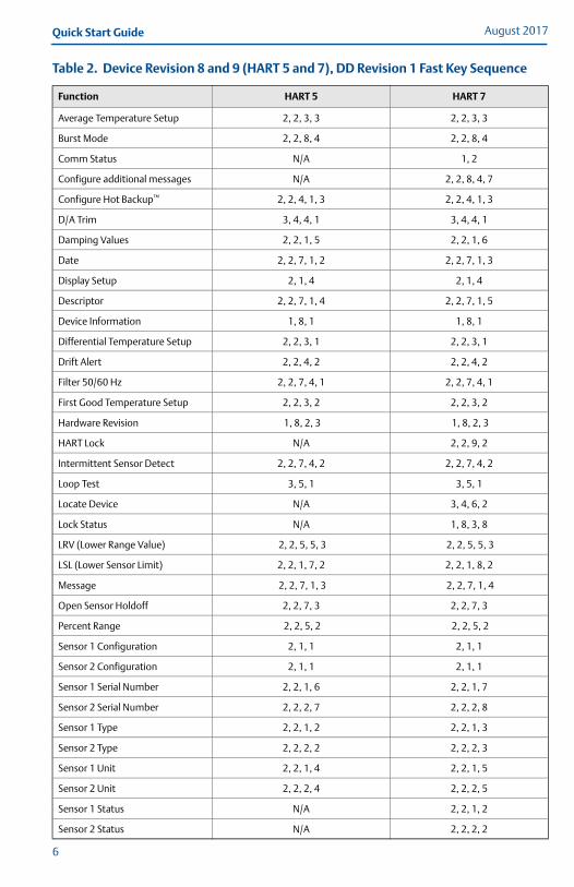
Table 2. Device Revision 8 and 9 (HART 5 and 7), DD Revision 1 Fast Key Sequence
Function HART 5 HART 7
Alarm Values 2, 2, 5, 6 2, 2, 5, 6
Analog Calibration 3, 4, 5 3, 4, 5
Analog Output 2, 2, 5, 1 2, 2, 5, 1
August 2017Quick Start Guide
6
Average Temperature Setup 2, 2, 3, 3 2, 2, 3, 3
Burst Mode 2, 2, 8, 4 2, 2, 8, 4
Comm Status N/A 1, 2
Configure additional messages N/A 2, 2, 8, 4, 7
Configure Hot Backup™ 2, 2, 4, 1, 3 2, 2, 4, 1, 3
D/A Trim 3, 4, 4, 1 3, 4, 4, 1
Damping Values 2, 2, 1, 5 2, 2, 1, 6
Date 2, 2, 7, 1, 2 2, 2, 7, 1, 3
Display Setup 2, 1, 4 2, 1, 4
Descriptor 2, 2, 7, 1, 4 2, 2, 7, 1, 5
Device Information 1, 8, 1 1, 8, 1
Differential Temperature Setup 2, 2, 3, 1 2, 2, 3, 1
Drift Alert 2, 2, 4, 2 2, 2, 4, 2
Filter 50/60 Hz 2, 2, 7, 4, 1 2, 2, 7, 4, 1
First Good Temperature Setup 2, 2, 3, 2 2, 2, 3, 2
Hardware Revision 1, 8, 2, 3 1, 8, 2, 3
HART Lock N/A 2, 2, 9, 2
Intermittent Sensor Detect 2, 2, 7, 4, 2 2, 2, 7, 4, 2
Loop Test 3, 5, 1 3, 5, 1
Locate Device N/A 3, 4, 6, 2
Lock Status N/A 1, 8, 3, 8
LRV (Lower Range Value) 2, 2, 5, 5, 3 2, 2, 5, 5, 3
LSL (Lower Sensor Limit) 2, 2, 1, 7, 2 2, 2, 1, 8, 2
Message 2, 2, 7, 1, 3 2, 2, 7, 1, 4
Open Sensor Holdoff 2, 2, 7, 3 2, 2, 7, 3
Percent Range 2, 2, 5, 2 2, 2, 5, 2
Sensor 1 Configuration 2, 1, 1 2, 1, 1
Sensor 2 Configuration 2, 1, 1 2, 1, 1
Sensor 1 Serial Number 2, 2, 1, 6 2, 2, 1, 7
Sensor 2 Serial Number 2, 2, 2, 7 2, 2, 2, 8
Sensor 1 Type 2, 2, 1, 2 2, 2, 1, 3
Sensor 2 Type 2, 2, 2, 2 2, 2, 2, 3
Sensor 1 Unit 2, 2, 1, 4 2, 2, 1, 5
Sensor 2 Unit 2, 2, 2, 4 2, 2, 2, 5
Sensor 1 Status N/A 2, 2, 1, 2
Sensor 2 Status N/A 2, 2, 2, 2
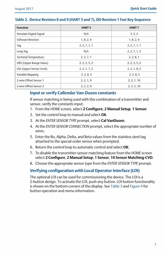
Table 2. Device Revision 8 and 9 (HART 5 and 7), DD Revision 1 Fast Key Sequence
Function HART 5 HART 7
Quick Start GuideAugust 2017
Input or verify Callendar Van-Dusen constants
If sensor matching is being used with this combination of a transmitter and sensor, verify the constants input.1. From the HOME screen, select 2 Configure, 2 Manual Setup, 1 Sensor.
2. Set the control loop to manual and select OK.
3. At the ENTER SENSOR TYPE prompt, select Cal VanDusen.
4. At the ENTER SENSOR CONNECTION prompt, select the appropriate number of wires.
5. Enter the Ro, Alpha, Delta, and Beta values from the stainless steel tag attached to the special-order sensor when prompted.
6. Return the control loop to automatic control and select OK.
7. To disable the transmitter-sensor matching feature from the HOME screen select 2 Configure, 2 Manual Setup, 1 Sensor, 10 Sensor Matching-CVD.
8. Choose the appropriate sensor type from the ENTER SENSOR TYPE prompt.
Verifying configuration with Local Operator Interface (LOI)
The optional LOI can be used for commissioning the device. The LOI is a 2-button design. To activate the LOI, push any button. LOI button functionality is shown on the bottom corners of the display. See Table 3 and Figure 4 for button operation and menu information.
Simulate Digital Signal N/A 3, 5, 2
Software Revision 1, 8, 2, 4 1, 8, 2, 4
Tag 2, 2, 7, 1, 1 2, 2, 7, 1, 1
Long Tag N/A 2, 2, 7, 1, 2
Terminal Temperature 2, 2, 7, 1 2, 2, 8, 1
URV (Upper Range Value) 2, 2, 5, 5, 2 2, 2, 5, 5, 2
USL (Upper Sensor Limit) 2, 2, 1, 7, 2 2, 2, 1, 8, 2
Variable Mapping 2, 2, 8, 5 2, 2, 8, 5
2-wire Offset Sensor 1 2, 2, 1, 9 2, 2, 1, 10
2-wire Offset Sensor 2 2, 2, 2, 9 2, 2, 2, 10
Table 2. Device Revision 8 and 9 (HART 5 and 7), DD Revision 1 Fast Key Sequence
Function HART 5 HART 7
7
August 2017Quick Start Guide
8
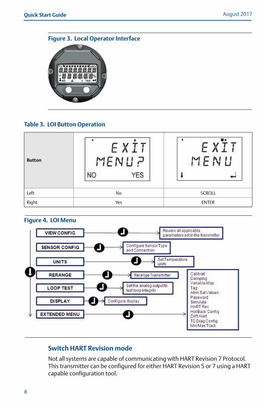
Figure 3. Local Operator Interface
Figure 4. LOI Menu
Switch HART Revision mode
Not all systems are capable of communicating with HART Revision 7 Protocol. This transmitter can be configured for either HART Revision 5 or 7 using a HART capable configuration tool.
Table 3. LOI Button Operation
Button
Left No SCROLL
Right Yes ENTER
Quick Start GuideAugust 2017
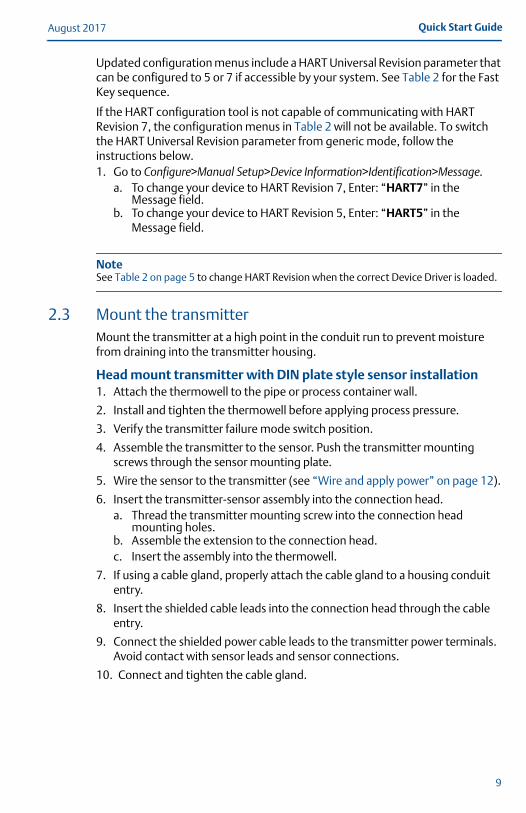
Updated configuration menus include a HART Universal Revision parameter that can be configured to 5 or 7 if accessible by your system. See Table 2 for the Fast Key sequence.
If the HART configuration tool is not capable of communicating with HART Revision 7, the configuration menus in Table 2 will not be available. To switch the HART Universal Revision parameter from generic mode, follow the instructions below.1. Go to Configure>Manual Setup>Device Information>Identification>Message.
a. To change your device to HART Revision 7, Enter: “HART7” in the Message field.
b. To change your device to HART Revision 5, Enter: “HART5” in the Message field.
NoteSee Table 2 on page 5 to change HART Revision when the correct Device Driver is loaded.
2.3 Mount the transmitterMount the transmitter at a high point in the conduit run to prevent moisture from draining into the transmitter housing.
Head mount transmitter with DIN plate style sensor installation1. Attach the thermowell to the pipe or process container wall.
2. Install and tighten the thermowell before applying process pressure.
3. Verify the transmitter failure mode switch position.
4. Assemble the transmitter to the sensor. Push the transmitter mounting screws through the sensor mounting plate.
5. Wire the sensor to the transmitter (see “Wire and apply power” on page 12).
6. Insert the transmitter-sensor assembly into the connection head. a. Thread the transmitter mounting screw into the connection head
mounting holes. b. Assemble the extension to the connection head. c. Insert the assembly into the thermowell.
7. If using a cable gland, properly attach the cable gland to a housing conduit entry.
8. Insert the shielded cable leads into the connection head through the cable entry.
9. Connect the shielded power cable leads to the transmitter power terminals. Avoid contact with sensor leads and sensor connections.
10. Connect and tighten the cable gland.
9
August 2017Quick Start Guide
10
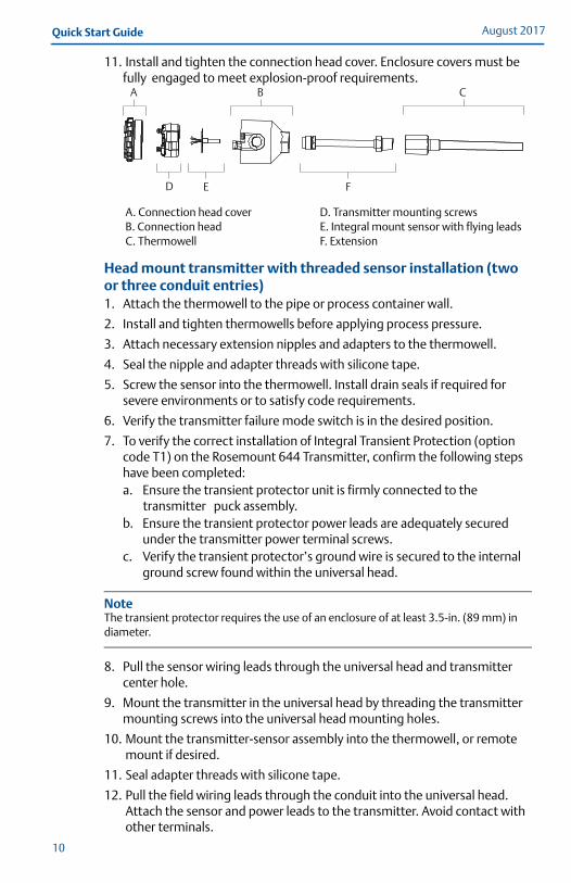
11. Install and tighten the connection head cover. Enclosure covers must be fully engaged to meet explosion-proof requirements.
Head mount transmitter with threaded sensor installation (two or three conduit entries)1. Attach the thermowell to the pipe or process container wall.
2. Install and tighten thermowells before applying process pressure.
3. Attach necessary extension nipples and adapters to the thermowell.
4. Seal the nipple and adapter threads with silicone tape.
5. Screw the sensor into the thermowell. Install drain seals if required for severe environments or to satisfy code requirements.
6. Verify the transmitter failure mode switch is in the desired position.
7. To verify the correct installation of Integral Transient Protection (option code T1) on the Rosemount 644 Transmitter, confirm the following steps have been completed:a. Ensure the transient protector unit is firmly connected to the
transmitter puck assembly.b. Ensure the transient protector power leads are adequately secured
under the transmitter power terminal screws.c. Verify the transient protector’s ground wire is secured to the internal
ground screw found within the universal head.
NoteThe transient protector requires the use of an enclosure of at least 3.5-in. (89 mm) in diameter.
8. Pull the sensor wiring leads through the universal head and transmitter center hole.
9. Mount the transmitter in the universal head by threading the transmitter mounting screws into the universal head mounting holes.
10. Mount the transmitter-sensor assembly into the thermowell, or remote mount if desired.
11. Seal adapter threads with silicone tape.
12. Pull the field wiring leads through the conduit into the universal head. Attach the sensor and power leads to the transmitter. Avoid contact with other terminals.
A. Connection head coverB. Connection headC. Thermowell
D. Transmitter mounting screwsE. Integral mount sensor with flying leadsF. Extension
A B C
D E F
Quick Start GuideAugust 2017
11
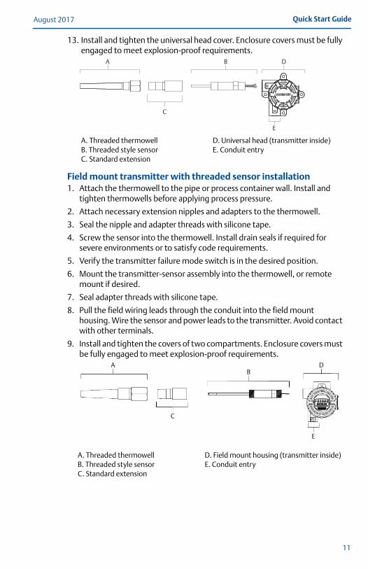
13. Install and tighten the universal head cover. Enclosure covers must be fully engaged to meet explosion-proof requirements.
Field mount transmitter with threaded sensor installation1. Attach the thermowell to the pipe or process container wall. Install and
tighten thermowells before applying process pressure.
2. Attach necessary extension nipples and adapters to the thermowell.
3. Seal the nipple and adapter threads with silicone tape.
4. Screw the sensor into the thermowell. Install drain seals if required for severe environments or to satisfy code requirements.
5. Verify the transmitter failure mode switch is in the desired position.
6. Mount the transmitter-sensor assembly into the thermowell, or remote mount if desired.
7. Seal adapter threads with silicone tape.
8. Pull the field wiring leads through the conduit into the field mount housing. Wire the sensor and power leads to the transmitter. Avoid contact with other terminals.
9. Install and tighten the covers of two compartments. Enclosure covers must be fully engaged to meet explosion-proof requirements.
A. Threaded thermowellB. Threaded style sensorC. Standard extension
D. Universal head (transmitter inside)E. Conduit entry
A. Threaded thermowellB. Threaded style sensorC. Standard extension
D. Field mount housing (transmitter inside)E. Conduit entry
A
C
B D
E
A
C
BD
E
August 2017Quick Start Guide
2.4 Wire and apply power
Wire the sensor to the transmitter
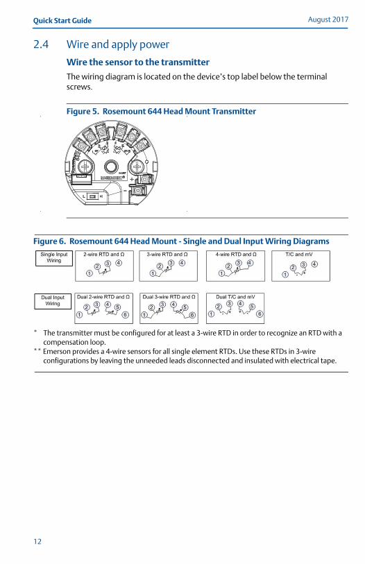
The wiring diagram is located on the device’s top label below the terminal screws.
Figure 5. Rosemount 644 Head Mount Transmitter
Figure 6. Rosemount 644 Head Mount - Single and Dual Input Wiring Diagrams
* The transmitter must be configured for at least a 3-wire RTD in order to recognize an RTD with a compensation loop.
** Emerson provides a 4-wire sensors for all single element RTDs. Use these RTDs in 3-wire configurations by leaving the unneeded leads disconnected and insulated with electrical tape.
12
Quick Start GuideAugust 2017
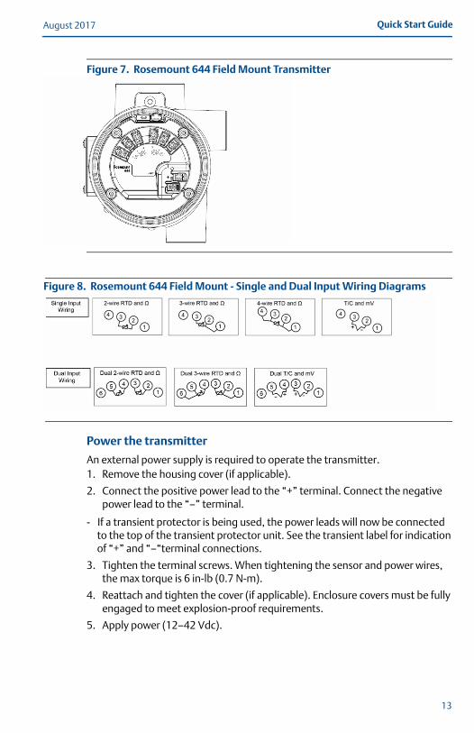
Figure 7. Rosemount 644 Field Mount Transmitter
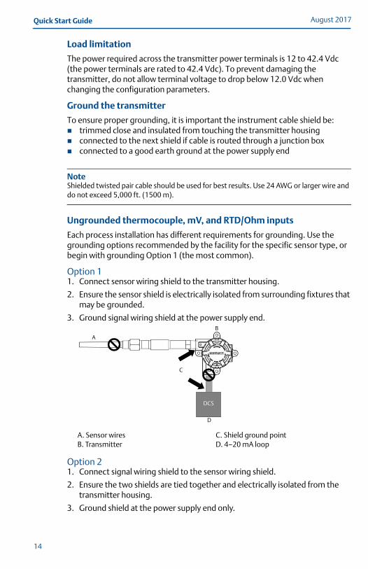
Figure 8. Rosemount 644 Field Mount - Single and Dual Input Wiring Diagrams
Power the transmitter
An external power supply is required to operate the transmitter.1. Remove the housing cover (if applicable).
2. Connect the positive power lead to the “+” terminal. Connect the negative power lead to the “–” terminal.
- If a transient protector is being used, the power leads will now be connected to the top of the transient protector unit. See the transient label for indication of “+” and “–“terminal connections.
3. Tighten the terminal screws. When tightening the sensor and power wires, the max torque is 6 in-lb (0.7 N-m).
4. Reattach and tighten the cover (if applicable). Enclosure covers must be fully engaged to meet explosion-proof requirements.
5. Apply power (12–42 Vdc).
13
August 2017Quick Start Guide
Load limitation
The power required across the transmitter power terminals is 12 to 42.4 Vdc (the power terminals are rated to 42.4 Vdc). To prevent damaging the transmitter, do not allow terminal voltage to drop below 12.0 Vdc when changing the configuration parameters.
Ground the transmitter
To ensure proper grounding, it is important the instrument cable shield be: trimmed close and insulated from touching the transmitter housing connected to the next shield if cable is routed through a junction box connected to a good earth ground at the power supply end
NoteShielded twisted pair cable should be used for best results. Use 24 AWG or larger wire and do not exceed 5,000 ft. (1500 m).
Ungrounded thermocouple, mV, and RTD/Ohm inputs
Each process installation has different requirements for grounding. Use the grounding options recommended by the facility for the specific sensor type, or begin with grounding Option 1 (the most common).
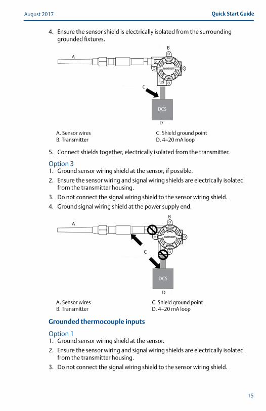
Option 11. Connect sensor wiring shield to the transmitter housing.
2. Ensure the sensor shield is electrically isolated from surrounding fixtures that may be grounded.
3. Ground signal wiring shield at the power supply end.
Option 21. Connect signal wiring shield to the sensor wiring shield.
2. Ensure the two shields are tied together and electrically isolated from the transmitter housing.
3. Ground shield at the power supply end only.
A. Sensor wiresB. Transmitter
C. Shield ground pointD. 4–20 mA loop
A
B
C
DCS
D
14
Quick Start GuideAugust 2017
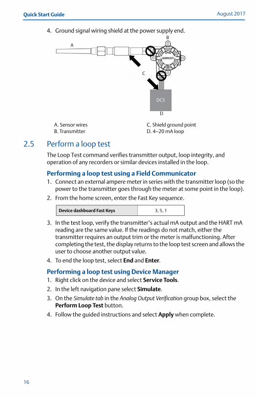
4. Ensure the sensor shield is electrically isolated from the surrounding grounded fixtures.
5. Connect shields together, electrically isolated from the transmitter.
Option 31. Ground sensor wiring shield at the sensor, if possible.
2. Ensure the sensor wiring and signal wiring shields are electrically isolated from the transmitter housing.
3. Do not connect the signal wiring shield to the sensor wiring shield.
4. Ground signal wiring shield at the power supply end.
Grounded thermocouple inputs
Option 11. Ground sensor wiring shield at the sensor.
2. Ensure the sensor wiring and signal wiring shields are electrically isolated from the transmitter housing.
3. Do not connect the signal wiring shield to the sensor wiring shield.
A. Sensor wiresB. Transmitter
C. Shield ground pointD. 4–20 mA loop
A. Sensor wiresB. Transmitter
C. Shield ground pointD. 4–20 mA loop
A
B
C
D
DCS
DCS
AB
C
D
15
August 2017Quick Start Guide
4. Ground signal wiring shield at the power supply end.
2.5 Perform a loop testThe Loop Test command verifies transmitter output, loop integrity, and operation of any recorders or similar devices installed in the loop.
Performing a loop test using a Field Communicator1. Connect an external ampere meter in series with the transmitter loop (so the
power to the transmitter goes through the meter at some point in the loop).
2. From the home screen, enter the Fast Key sequence.
3. In the test loop, verify the transmitter’s actual mA output and the HART mA reading are the same value. If the readings do not match, either the transmitter requires an output trim or the meter is malfunctioning. After completing the test, the display returns to the loop test screen and allows the user to choose another output value.
4. To end the loop test, select End and Enter.
Performing a loop test using Device Manager1. Right click on the device and select Service Tools.
2. In the left navigation pane select Simulate.
3. On the Simulate tab in the Analog Output Verification group box, select the Perform Loop Test button.
4. Follow the guided instructions and select Apply when complete.
A. Sensor wiresB. Transmitter
C. Shield ground pointD. 4–20 mA loop
Device dashboard Fast Keys 3, 5, 1
DCS
A
B
C
D
16
Quick Start GuideAugust 2017
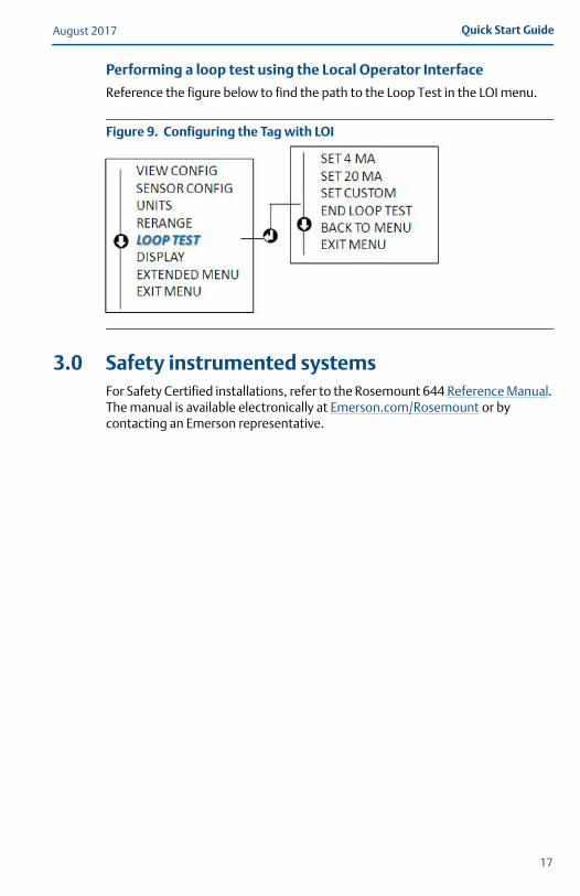
Performing a loop test using the Local Operator Interface
Reference the figure below to find the path to the Loop Test in the LOI menu.
Figure 9. Configuring the Tag with LOI
3.0 Safety instrumented systemsFor Safety Certified installations, refer to the Rosemount 644 Reference Manual. The manual is available electronically at Emerson.com/Rosemount or by contacting an Emerson representative.
17
August 2017Quick Start Guide
4.0 Product CertificationsRev 2.0
4.1 European Directive InformationA copy of the EU Declaration of Conformity can be found at the end of the Quick Start Guide. The most recent revision of the EU Declaration of Conformity can be found at Emerson.com/Rosemount.
4.2 Ordinary Location Certification As standard, the transmitter has been examined and tested to determine that the design meets the basic electrical, mechanical, and fire protection requirements by a nationally recognized test laboratory (NRTL) as accredited by the Federal Occupational Safety and Health Administration (OSHA).
4.3 North AmericaThe US National Electrical Code® (NEC) and the Canadian Electrical Code (CEC) permit the use of Division marked equipment in Zones and Zone marked equipment in Divisions.The markings must be suitable for the area classification, gas, and temperature class.This information is clearly defined in the respective codes.
USAE5 USA Explosionproof, Non-Incendive, Dust-Ignitionproof
Certificate: [XP & DIP]: 3006278; [NI]: 3008880 & 3044581Standards: FM Class 3600: 2011, FM Class 3615: 2006, FM Class 3616: 2011, FM Class
3810: 2005, NEMA®-250: 250: 2003, ANSI/IEC 60529: 2004Markings: XP CL I, DIV 1, GP B, C, D; DIP CL II/III, GP E, F, G; (–50 °C ≤ Ta ≤ +85 °C); Type
4X; See I5 description for Non-Incendive markings.
I5 USA Intrinsic Safety and Non-IncendiveCertificate: 3008880 [Headmount Fieldbus/PROFIBUS®, Railmount HART]Standards: FM Class 3600: 2011, FM Class 3610: 2010, FM Class 3611: 2004, FM Class
3810: 2005, NEMA – 250: 1991Markings: IS CL I/II/III, DIV I, GP A, B, C, D, E, F, G; NI CL I, DIV 2, GP A, B, C, D
Special Conditions for Safe Use (X):1. When no enclosure option is selected, the Rosemount 644 Transmitter shall be
installed in an enclosure meeting the requirements of ANSI/ISA S82.01 and S82.03 or other applicable ordinary location standards.
2. Option code K5 is only applicable with Rosemount J5 Universal Head (M20 � 1.5) or Rosemount J6 Universal Head (1/2–14 NPT) enclosure.
3. An enclosure option must be selected to maintain a Type 4X rating.
Certificate: 3044581 [Headmount HART]Standards: FM Class 3600: 2011, FM Class 3610: 2010, FM Class 3611: 2004, FM Class
3810: 2005, ANSI/NEMA – 250: 1991, ANSI/IEC 60529: 2004; ANSI/ISA 60079-0: 2009; ANSI/ISA 60079-11: 2009
Markings: [No Enclosure]: IS CL I, DIV I, GP A, B, C, D T4; CL I ZONE 0 AEx ia IIC T4 Ga; NI CL I, DIV 2, GP A, B, C, D T5[With Enclosure]: IS CL I/II/III, DIV 1, GP A, B, C, D, E, F, G; NI CL I, DIV 2, GP A, B, C, D
18
Quick Start GuideAugust 2017
Special Conditions for Safe Use (X):1. When no enclosure option is selected, the Rosemount 644 Transmitter shall be
installed in a final enclosure meeting type of protection IP20 and meeting the requirements of ANSI/ISA 61010-1 and ANSI/ISA 60079-0.
2. The Rosemount 644 Transmitter optional housings may contain aluminum and is considered a potential risk of ignition by impact or friction. Care must be taken during installation and use to prevent impact and friction.
CanadaI6 Canada Intrinsic Safety and Division 2
Certificate: 1091070Standards: CAN/CSA C22.2 No. 0-10, CSA Std C22.2 No. 25-1966, CAN/CSA-C22.2 No.
94-M91, CSA Std C22.2 No. 142-M1987, CAN/CSA-C22.2 No. 157-92, CSA Std C22.2 No. 213-M1987, C22.2 No 60529-05
Markings: [HART] IS CL I GP A, B, C, D T4/T6; CL I, ZONE 0 IIC; CL I, DIV 2, GP A, B, C, D[Fieldbus/PROFIBUS] IS CL I GP A, B, C, D T4; CL I, ZONE 0 IIC; CL I, DIV 2,GP A, B, C, D
K6 Canada Explosionproof, Dust-Ignitionproof, Intrinsic Safety and Division 2Certificate: 1091070Standards: CAN/CSA C22.2 No. 0-10, CSA Std C22.2 No. 25-1966, CSA Std. C22.2 No.
30-M1986, CAN/CSA-C22.2 No. 94-M91, CSA Std C22.2 No. 142-M1987, CAN/CSA-C22.2 No. 157-92, CSA Std C22.2 No. 213-M1987, C22.2 No 60529-05
Markings: CL I/II/III, DIV 1, GP B, C, D, E, F, G;See I6 description for Intrinsic Safety and Division 2 markings.
EuropeE1 ATEX Flameproof
Certificate: FM12ATEX0065XStandards: EN 60079-0: 2012+A11:2013, EN 60079-1: 2014, EN 60529:1991 +A1:2000Markings: II 2 G Ex db IIC T6…T1 Gb, T6(–50 °C ≤ Ta ≤ +40 °C), T5…T1(–50 °C ≤ Ta ≤
+60 °C); See Table 4 for process temperatures.
Special Conditions for Safe Use (X):1. See certificate for ambient temperature range.2. The non-metallic label may store an electrostatic charge and become a source of
ignition in Group III environments.3. Guard the LCD display cover against impact energies greater than 4 joules.4. Flameproof joints are not intended for repair.5. A suitable certified Ex d or Ex tb enclosure is required to be connected to temperature
probes with Enclosure option “N”.6. Care shall be taken by the end user to ensure that the external surface temperature on
the equipment and the neck of DIN Style Sensor probe does not exceed 130 °C.7. Non-standard paint options may cause risk from electrostatic discharge. Avoid
installations that cause electrostatic build-up on painted surfaces, and only clean the painted surfaces with a damp cloth. If paint is ordered through a special option code, contact the manufacturer for more information.
19
August 2017Quick Start Guide
I1 ATEX Intrinsic SafetyCertificate: [Headmount HART]: Baseefa12ATEX0101X
[Headmount Fieldbus/PROFIBUS]: Baseefa03ATEX0499X[Railmount HART]: BAS00ATEX1033X
Standards: EN 60079-0: 2012, EN 60079-11: 2012Markings: [HART]: II 1 G Ex ia IIC T6…T4 Ga;
[Fieldbus/PROFIBUS]: II 1 G Ex ia IIC T4 Ga;See Table 5 for entity parameters and temperature classifications.
Special Conditions for Safe Use (X):1. The equipment must be installed in an enclosure which affords it a degree of
protection of at least IP20 in accordance with the requirements of IEC 60529. Non-metallic enclosures must have a surface resistance of less than 1GΩ; light alloy or zirconium enclosures must be protected from impact and friction when installed in a Zone 0 environment.
2. When fitted with the Transient Protector Assembly, the equipment is not capable of withstanding the 500 V test as defined in Clause 6.3.13 of EN 60079-11:2012. This must be taken into account during installation.
N1 ATEX Type n – with enclosureCertificate: BAS00ATEX3145Standards: EN 60079-0: 2012, EN 60079-15: 2010Markings: II 3 G Ex nA IIC T5 Gc (–40 °C ≤ Ta ≤ +70 °C)
NC ATEX Type n – without enclosureCertificate: [Headmount Fieldbus/PROFIBUS, Railmount HART]: Baseefa13ATEX0093X
[Headmount HART]: Baseefa12ATEX0102UStandards: EN 60079-0: 2012, EN 60079-15: 2010Markings: [Headmount Fieldbus/PROFIBUS, Railmount HART]: II 3 G Ex nA IIC T5 Gc
(–40 °C ≤ Ta ≤ +70 °C) [Headmount HART]: II 3 G Ex nA IIC T6…T5 Gc; T6(–60 °C ≤ Ta ≤ +40 °C); T5(–60 °C ≤ Ta ≤ +85 °C)
Special Conditions for Safe Use (X):1. The Rosemount 644 Transmitter must be installed in a suitably certified enclosure
such that it is afforded a degree of protection of at least IP54 in accordance with IEC 60529 and EN 60079-15.
2. When fitted with the Transient Protector Assembly, the equipment is not capable of withstanding the 500 V test. This must be taken into account during installation.
ND ATEX DustCertificate: FM12ATEX0065XStandards: EN 60079-0: 2012+A1:2013, EN 60079-31: 2014, EN 60529:1991 +A1:2000Markings: II 2 D Ex tb IIIC T130 °C Db, (–40 °C ≤ Ta ≤ +70 °C); IP66;
See Table 4 for process temperatures.
Special Conditions for Safe Use (X):1. See certificate for ambient temperature range.2. The non-metallic label may store an electrostatic charge and become a source of
ignition in Group III environments.3. Guard the LCD display cover against impact energies greater than 4 joules.4. Flameproof joints are not intended for repair.
20
Quick Start GuideAugust 2017
5. A suitable certified Ex d or Ex tb enclosure is required to be connected to temperature probes with Enclosure option "N".
6. Care shall be taken by the end user to ensure that the external surface temperature on the equipment and the neck of DIN Style Sensor probe does not exceed 130 °C.
7. Non-Standard Paint options may cause risk from electrostatic discharge. Avoid installations that cause electrostatic build-up on painted surfaces, and only clean the painted surfaces with a damp cloth. If paint is ordered through a special option code, contact the manufacturer for more information
InternationalE7 IECEx Flameproof
Certificate: IECEx FMG 12.0022XStandards: IEC 60079-0: 2011, IEC 60079-1: 2014Markings: Ex db IIC T6…T1 Gb, T6(–50 °C ≤ Ta ≤ +40 °C), T5…T1(–50 °C ≤ Ta ≤ +60 °C);
See Table 4 for process temperatures.
Special Conditions of Certification (X):1. See certificate for ambient temperature range.2. The non-metallic label may store an electrostatic charge and become a source of
ignition in Group III environments.3. Guard the LCD display cover against impact energies greater than 4 joules.4. Flameproof joints are not intended for repair.5. A suitable certified Ex d or Ex tb enclosure is required to be connected to temperature
probes with Enclosure option “N”.6. Care shall be taken by the end user to ensure that the external surface temperature on
the equipment and the neck of DIN Style Sensor probe does not exceed 130 °C.7. Non-Standard Paint options may cause risk from electrostatic discharge. Avoid
installations that cause electrostatic build-up on painted surfaces, and only clean the painted surfaces with a damp cloth. If paint is ordered through a special option code, contact the manufacturer for more information.
I7 IECEx Intrinsic SafetyCertificate: [Headmount HART]: IECEx BAS 12.0069X
[Headmount Fieldbus/PROFIBUS, Railmount HART]: IECEx BAS 07.0053XStandards: IEC 60079-0: 2011, IEC 60079-11: 2011Markings: Ex ia IIC T6…T4 Ga;
See Table 5 for Entity Parameters and Temperature Classifications.
Special Conditions of Certification (X):1. The equipment must be installed in an enclosure which affords it a degree of
protection of at least IP20 in accordance with the requirements of IEC 60529. Non-metallic enclosures must have a surface resistance of less than 1GΩ; light alloy or zirconium enclosures must be protected from impact and friction when installed in a Zone 0 environment.
2. When fitted with the Transient Protector Assembly, the equipment is not capable of withstanding the 500 V test as defined in Clause 6.3.13 of IEC 60079-11:2011. This must be taken into account during installation.
N7 IECEx Type n – with enclosureCertificate: IECEx BAS 07.0055Standards: IEC 60079-0: 2011, IEC 60079-15: 2010Markings: Ex nA IIC T5 Gc (–40 °C ≤ Ta ≤ +70 °C)
21
August 2017Quick Start Guide
22
NG IECEx Type n – without enclosureCertificate: [Headmount Fieldbus/PROFIBUS, Railmount HART]: IECEx BAS 13.0053X
[Headmount HART]: IECEx BAS 12.0070UStandards: IEC 60079-0: 2011, IEC 60079-15: 2010Markings: [Headmount Fieldbus/PROFIBUS, Railmount HART]: Ex nA IIC T5 Gc (–40 °C ≤
Ta ≤ +70 °C)[Headmount HART]: Ex nA IIC T6…T5 Gc; T6(–60 °C ≤ Ta ≤ +40 °C); T5(–60 °C ≤ Ta ≤ +85 °C)
Special Conditions of Certification (X):1. The Rosemount 644 Transmitter must be installed in a suitably certified enclosure
such tat it is afforded a degree of protection of at least IP54 in accordance with IEC 60529 and IEC 60079-15.
2. When fitted with the Transient Protector Assembly, the equipment is not capable of withstanding the 500 V test. This must be taken into account during installation.
NK IECEx DustCertificate: IECEx FMG 12.0022XStandards: IEC 60079-0: 2011, IEC 60079-31: 2013Markings: Ex tb IIIC T130 °C Db, (–40 °C ≤ Ta ≤ +70 °C); IP66;
See Table 4 for process temperatures.
Special Conditions of Certification (X):1. See certificate for ambient temperature range.2. The non-metallic label may store an electrostatic charge and become a source of
ignition in Group III environments.3. Guard the LCD display cover against impact energies greater than 4 joules.4. Flameproof joints are not intended for repair.5. A suitable certified Ex d or Ex tb enclosure is required to be connected to temperature
probes with Enclosure option “N”.6. Care shall be taken by the end user to ensure that the external surface temperature on
the equipment and the neck of DIN Style Sensor probe does not exceed 130 °C.7. Non-Standard Paint options may cause risk from electrostatic discharge. Avoid
installations that cause electrostatic build-up on painted surfaces, and only clean the painted surfaces with a damp cloth. If paint is ordered through a special option code, contact the manufacturer for more information.
BrazilE2 INMETRO Flameproof and Dust
Certificate: UL-BR 13.0535XStandards: ABNT NBR IEC 60079-0:2008 + Corrigendum 1:2011, ABNT NBR IEC
60079-1:2009 + Corrigendum 1:2011, ABNT NBR IEC 60079-31:2011Markings: Ex d IIC T6…T1* Gb; T6…T1*: (–50 °C ≤ Ta ≤ +40 °C), T5…T1*: (–50 °C ≤ Ta ≤
+60 °C) Ex tb IIIC T130 °C; IP66; (-40 °C ≤ Ta ≤ +70 °C)
Special Conditions for Safe Use (X):1. See product description for ambient temperature limits and process temperature
limits.2. The non-metallic label may store an electrostatic charge and become a source of
ignition in Group III environments. 3. Guard the LCD display cover against impact energies greater than 4 joules. 4. Consult the manufacturer if dimensional information on the flameproof joints is
necessary.
Quick Start GuideAugust 2017
I2 INMETRO Intrinsic SafetyCertificate: [Fieldbus]: UL-BR 15.0264X
[HART]: UL-BR 14.0670XStandards: ABNT NBR IEC 60079-0:2008 + Corrigendum 1:2011, ABNT NBR IEC
60079-11:2011Markings: [Fieldbus]: Ex ia IIC T* Ga (–60 °C ≤ Ta ≤ +** °C)
[HART]: Ex ia IIC T* Ga (–60 °C ≤ Ta ≤ +** °C)See Table 5 for entity parameters and temperature classifications.
Special Conditions for Safe Use (X):1. The apparatus must be installed in an enclosure which affords it a degree of protection
of at least IP20.2. Non-metallic enclosures must have a surface resistance of less than 1 GΩ; light alloy or
zirconium enclosures must be protected from impact and friction when installed in a zone 0 environment.
3. When fitted with the Transient Protector Assembly, the equipment is not capable of withstanding the 500 V test as defined on ABNT NBR IEC 60079-11. This must be taken into account during installation.
4. When fitted with the Transient Protector Assembly, the equipment is not capable of withstanding the 500 V test as defined on ABNT NBR IEC 60079-11. This must be taken into account during installation.
ChinaE3 China Flameproof
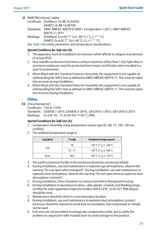
Certificate: GYJ16.1192XStandards: GB3836.1-2010, GB3836.2-2010, GB12476.1-2013, GB12476.5-2013Markings: Ex d IIC T6…T1; Ex tD A21 T130 °C; IP66
Special Conditions for Safe Use (X):1. Temperature Assembly using temperature sensor type 65, 68, 75, 183, 185 are
certified.2. The ambient temperature range is:
3. The earth connection facility in the enclosure should be connected reliably.4. During installation, use and maintenance in explosive gas atmospheres, observe the
warning “Do not open when energized”. During installation, use and maintenance in explosive dust atmosphere, observe the warning “Do not open when an explosive dust atmosphere is present”.
5. During installation, there should be no mixture harmful to flameproof housing.6. During installation in hazardous location, cable glands, conduits and blanking plugs,
certified by state-appointed inspection bodies with Ex d IIC, Ex tD A21 IP66 degree, should be used.
7. Maintenance should be done in a non-hazardous location.8. During installation, use and maintenance in explosive dust atmosphere, product
enclosure should be cleaned to avoid dust accumulation, but compressed air should not be used.
9. End users are not permitted to change any components inside, but to settle the problem in conjunction with manufacturer to avoid damage to the product.
Gas/dust T code Ambient temperature
GasT6 –50 °C ≤ Ta ≤ +40 °C
T5…T1 –50 °C ≤ Ta ≤ +60 °C
Dust N/A –40 °C ≤ Ta ≤ +70 °C
23
August 2017Quick Start Guide
10. During installation, use and maintenance of this product, observe the following standards:GB3836.13-2013 “Electrical apparatus for explosive gas atmospheres Part 13: Repair and overhaul for apparatus used in explosive gas atmospheres”GB3836.15-2000 “Electrical apparatus for explosive gas atmospheres Part 15: Electrical installations in hazardous area (other than mines)”GB3836.16-2006 “Electrical apparatus for explosive gas atmospheres Part 16: Inspection and maintenance of electrical installation (other than mines)”GB50257-2014 “Code for construction and acceptance of electric device for explosion atmospheres and fire hazard electrical equipment installation engineering”.GB15577-2007 “Safe regulation for explosive dust atmospheres”GB12476.2-2010 “Electrical apparatus for use in the presence of combustible dust Part 1-2: Electrical apparatus protected by enclosures and surface temperature limitation-Selection, installation and maintenance”
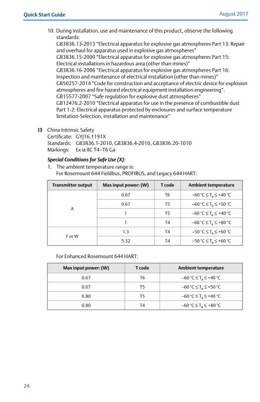
I3 China Intrinsic SafetyCertificate: GYJ16.1191XStandards: GB3836.1-2010, GB3836.4-2010, GB3836.20-1010Markings: Ex ia IIC T4~T6 Ga
Special Conditions for Safe Use (X):1. The ambient temperature range is:
For Rosemount 644 Fieldbus, PROFIBUS, and Legacy 644 HART:
For Enhanced Rosemount 644 HART:
Transmitter output Max input power: (W) T code Ambient temperature
A
0.67 T6 –60 °C ≤ Ta ≤ +40 °C
0.67 T5 –60 °C ≤ Ta ≤ +50 °C
1 T5 –60 °C ≤ Ta ≤ +40 °C
1 T4 –60 °C ≤ Ta ≤ +80 °C
F or W1.3 T4 –50 °C ≤ Ta ≤ +60 °C
5.32 T4 –50 °C ≤ Ta ≤ +60 °C
Max input power: (W) T code Ambient temperature
0.67 T6 –60 °C ≤ Ta ≤ +40 °C
0.67 T5 –60 °C ≤ Ta ≤ +50 °C
0.80 T5 –60 °C ≤ Ta ≤ +40 °C
0.80 T4 –60 °C ≤ Ta ≤ +80 °C
24
Quick Start GuideAugust 2017
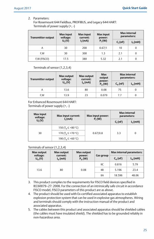
2. Parameters:For Rosemount 644 Fieldbus, PROFIBUS, and Legacy 644 HART: Terminals of power supply (+, -)
Terminals of sensor (1,2,3,4)
For Enhanced Rosemount 644 HART:Terminals of power supply (+, -)
Terminals of sensor (1,2,3,4)
3. This product complies to the requirements for FISCO field devices specified in IEC60079–27: 2008. For the connection of an intrinsically safe circuit in accordance FISCO model, FISCO parameters of this product are as above.
4. The product should be used with Ex-certified associated apparatus to establish explosion protection system that can be used in explosive gas atmospheres. Wiring and terminals should comply with the instruction manual of the product and associated apparatus.
5. The cables between this product and associated apparatus should be shielded cables (the cables must have insulated shield). The shielded has to be grounded reliably in non-hazardous area.
Transmitter outputMax input
voltage:Ui (V)
Max input current:Ii (mA)
Max input power:Pi (W)
Max internal parameters:
Ci (nF) Li (mH)
A 30 200 0.67/1 10 0
F,W 30 300 1.3 2.1 0
F,W (FISCO) 17.5 380 5.32 2.1 0
Transmitter outputMax output
voltage:Uo (V)
Max output current:Io (mA)
Max output power:Po (W)
Max internal parameters:
Co (nF) Lo (mH)
A 13.6 80 0.08 75 0
F,W 13.9 23 0.079 7.7 0
Max input voltage:
Ui (V)
Max input current:Ii (mA)
Max input power:Pi (W)
Max internal parameters:
Ci (nF) Li (mH)
30
150 (Ta ≤ +80 °C)
0.67/0.8 3.3 0170 (Ta ≤ +70 °C)
190 (Ta ≤ +60 °C)
Max output voltage:
Uo (V)
Max output current:Io (mA)
Max output power:Po (W)
Gas groupMax internal parameters:
Co (nF) Lo (mH)
13.6 80 0.08
IIC 0.816 5.79
IIB 5.196 23.4
IIA 18.596 48.06
25
August 2017Quick Start Guide
6. End users are not permitted to change any components insides, but to settle the problem in conjunction with manufacturer to avoid damage to the product.
7. During installation, use and maintenance of this product, observe the following standards:GB3836.13-2013 “Electrical apparatus for explosive gas atmospheres Part 13: Repair and overhaul for apparatus used in explosive gas atmospheres”GB3836.15-2000 “Electrical apparatus for explosive gas atmospheres Part 15: Electrical installations in hazardous area (other than mines)”GB3836.16-2006 “Electrical apparatus for explosive gas atmospheres Part 16: Inspection and maintenance of electrical installation (other than mines)”GB3836.18-2010 “Explosive Atmospheres” Part 18: Intrinsically safe systemsGB50257-2014 “Code for construction and acceptance of electric device for explosion atmospheres and fire hazard electrical equipment installation engineering”.
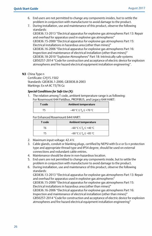
N3 China Type nCertificate: GYJ15.1502Standards: GB3836.1-2000, GB3836.8-2003Markings: Ex nA IIC T5/T6 Gc
Special Conditions for Safe Use (X):1. The relation among T code, ambient temperature range is as following:
For Rosemount 644 Fieldbus, PROFIBUS, and Legacy 644 HART:
For Enhanced Rosemount 644 HART:
2. Maximum input voltage: 42.4 V.3. Cable glands, conduit or blanking plugs, certified by NEPSI with Ex e or Ex n protection
type and appropriate thread type and IP54 degree, should be used on external connections and redundant cable entries.
4. Maintenance should be done in non-hazardous location.5. End users are not permitted to change any components inside, but to settle the
problem in conjunction with manufacturer to avoid damage to the product.6. During installation, use and maintenance of this product, observe the following
standards:GB3836.13-2013 “Electrical apparatus for explosive gas atmospheres Part 13: Repair and overhaul for apparatus used in explosive gas atmospheres”GB3836.15-2000 “Electrical apparatus for explosive gas atmospheres Part 15: Electrical installations in hazardous area (other than mines)”GB3836.16-2006 “Electrical apparatus for explosive gas atmospheres Part 16: Inspection and maintenance of electrical installation (other than mines)”GB50257-2014 “Code for construction and acceptance of electric device for explosion atmospheres and fire hazard electrical equipment installation engineering”
T code Ambient temperature
T5 –40 °C ≤ Ta ≤ +70 °C
T code Ambient temperature
T6 –60 °C ≤ Ta ≤ +40 °C
T5 –60 °C ≤ Ta ≤ +85 °C
26
Quick Start GuideAugust 2017
27
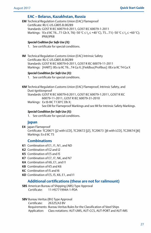
EAC – Belarus, Kazakhstan, RussiaEM Technical Regulation Customs Union (EAC) Flameproof
Certificate: RU C-US.GB05.B.00289Standards: GOST R IEC 60079-0-2011, GOST IEC 60079-1-2011Markings: 1Ex d IIC T6…T1 Gb X, T6(–50 °C ≤ Ta ≤ +40 °C), T5…T1(–50 °C ≤ Ta ≤ +60 °C);
IP66/IP68
Special Codition for Safe Use (X):1. See certificate for special conditions.
IM Technical Regulation Customs Union (EAC) Intrinsic SafetyCertificate: RU C-US.GB05.B.00289Standards: GOST R IEC 60079-0-2011, GOST R IEC 60079-11-2011Markings: [HART]: 0Ex ia IIC T6…T4 Ga X; [Fieldbus/Profibus]: 0Ex ia IIC T4 Ga X
Special Condition for Safe Use (X):1. See certificate for special conditions.
KM Technical Regulation Customs Union (EAC) Flameproof, Intrinsic Safety, and Dust-IgnitionproofStandards: GOST R IEC 60079-0:2011, GOST IEC 60079-1:2011, GOST R IEC
60079-11-2011, GOST R IEC 60079-31-2010Markings: Ex tb IIIC T130°C Db X;
See EM for Flameproof Markings and see IM for Intrinsic Safety Markings.
Special Condition for Safe Use (X):1. See certificate for special conditions.
JapanE4 Japan Flameproof
Certificate: TC20671 [J2 with LCD], TC20672 [J2], TC20673 [J6 with LCD], TC20674 [J6]Markings: Ex d IIC T5
CombinationsK1 Combination of E1, I1, N1, and NDK2 Combination of E2 and I2K5 Combination of E5 and I5K7 Combination of E7, I7, NK, and N7KA Combination of K6, E1, and I1KB Combination of K5 and K6KC Combination of I5 and I6KD Combination of E5, I5, K6, E1, and I1
Additional certifications (these are not for railmount)SBS American Bureau of Shipping (ABS) Type Approval
Certificate: 11-HS771994A-1-PDA
SBV Bureau Veritas (BV) Type ApprovalCertificate: 26325/A3 BVRequirements: Bureau Veritas Rules for the Classification of Steel ShipsApplication: Class notations: AUT-UMS, AUT-CCS, AUT-PORT and AUT-IMS
August 2017Quick Start Guide
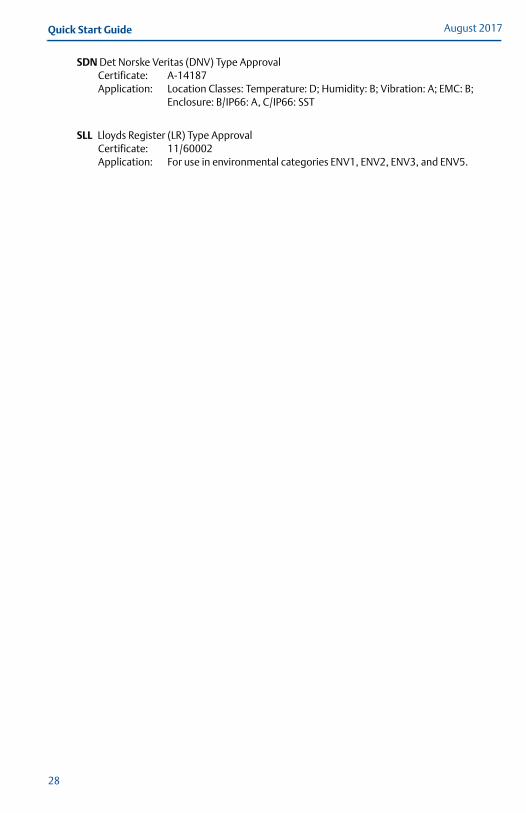
SDN Det Norske Veritas (DNV) Type ApprovalCertificate: A-14187Application: Location Classes: Temperature: D; Humidity: B; Vibration: A; EMC: B;
Enclosure: B/IP66: A, C/IP66: SST
SLL Lloyds Register (LR) Type ApprovalCertificate: 11/60002Application: For use in environmental categories ENV1, ENV2, ENV3, and ENV5.
28
Quick Start GuideAugust 2017
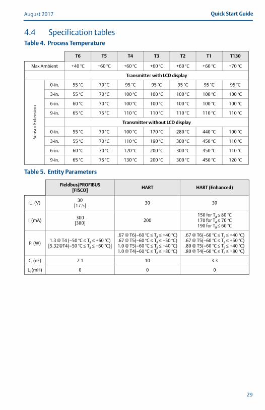
4.4 Specification tablesTable 4. Process Temperature
T6 T5 T4 T3 T2 T1 T130
Max Ambient +40 °C +60 °C +60 °C +60 °C +60 °C +60 °C +70 °C
Transmitter with LCD display
Sens
or E
xten
sion
0-in. 55 °C 70 °C 95 °C 95 °C 95 °C 95 °C 95 °C
3-in. 55 °C 70 °C 100 °C 100 °C 100 °C 100 °C 100 °C
6-in. 60 °C 70 °C 100 °C 100 °C 100 °C 100 °C 100 °C
9-in. 65 °C 75 °C 110 °C 110 °C 110 °C 110 °C 110 °C
Transmitter without LCD display
0-in. 55 °C 70 °C 100 °C 170 °C 280 °C 440 °C 100 °C
3-in. 55 °C 70 °C 110 °C 190 °C 300 °C 450 °C 110 °C
6-in. 60 °C 70 °C 120 °C 200 °C 300 °C 450 °C 110 °C
9-in. 65 °C 75 °C 130 °C 200 °C 300 °C 450 °C 120 °C
Table 5. Entity Parameters
Fieldbus/PROFIBUS[FISCO] HART HART (Enhanced)
Ui (V) 30[17.5] 30 30
Ii (mA) 300[380] 200
150 for Ta ≤ 80 °C170 for Ta ≤ 70 °C190 for Ta ≤ 60 °C
Pi (W) 1.3 @ T4 (–50 °C ≤ Ta ≤ +60 °C)[5.32@T4(–50 °C ≤ Ta ≤ +60 °C)]
.67 @ T6(–60 °C ≤ Ta ≤ +40 °C)
.67 @ T5(–60 °C ≤ Ta ≤ +50 °C)1.0 @ T5(–60 °C ≤ Ta ≤ +40 °C)1.0 @ T4(–60 °C ≤ Ta ≤ +80 °C)
.67 @ T6(–60 °C ≤ Ta ≤ +40 °C)
.67 @ T5(–60 °C ≤ Ta ≤ +50 °C)
.80 @ T5(–60 °C ≤ Ta ≤ +40 °C)
.80 @ T4(–60 °C ≤ Ta ≤ +80 °C)
Ci (nF) 2.1 10 3.3
Li (mH) 0 0 0
29
August 2017Quick Start Guide
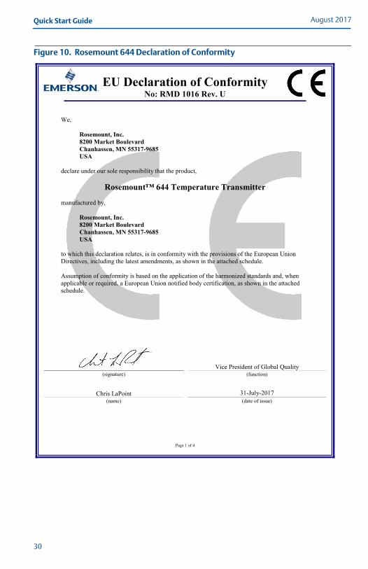
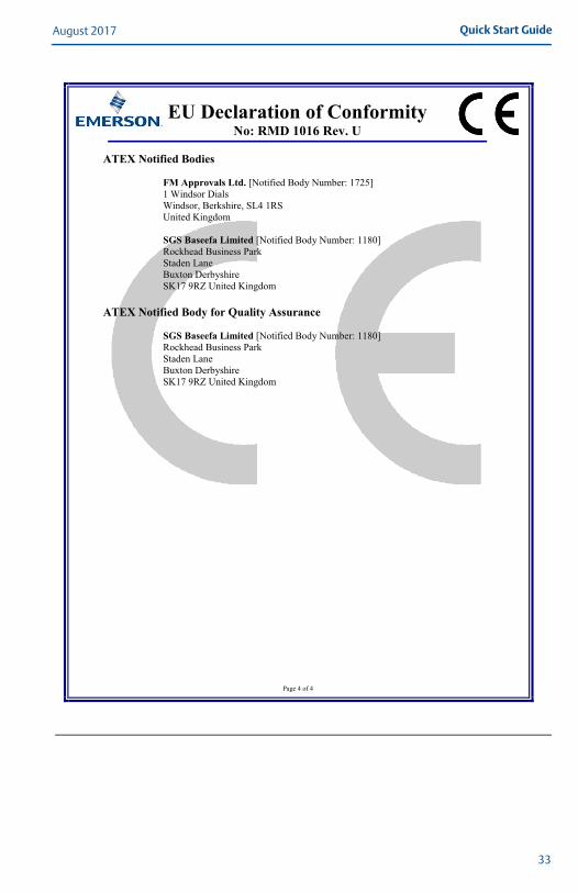
Figure 10. Rosemount 644 Declaration of Conformity
EU Declaration of ConformityNo: RMD 1016 Rev. U
Page 1 of 4
We,
Rosemount, Inc.8200 Market BoulevardChanhassen, MN 55317-9685USA
declare under our sole responsibility that the product,
Rosemount™ 644 Temperature Transmitter
manufactured by,
Rosemount, Inc.8200 Market BoulevardChanhassen, MN 55317-9685USA
to which this declaration relates, is in conformity with the provisions of the European Union
Directives, including the latest amendments, as shown in the attached schedule.
Assumption of conformity is based on the application of the harmonized standards and, when
applicable or required, a European Union notified body certification, as shown in the attached
schedule.
(signature)
Vice President of Global Quality(function)
Chris LaPoint(name)
31-July-2017
(date of issue)
30
Quick Start GuideAugust 2017
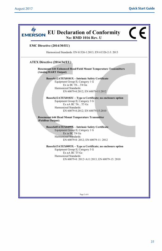
EU Declaration of ConformityNo: RMD 1016 Rev. U
Page 2 of 4
EMC Directive (2014/30/EU)
Harmonized Standards: EN 61326-1:2013, EN 61326-2-3: 2013
ATEX Directive (2014/34/EU)
Rosemount 644 Enhanced Head/Field Mount Temperature Transmitters(Analog/HART Output)
Baseefa12ATEX0101X – Intrinsic Safety CertificateEquipment Group II, Category 1 G
Ex ia IIC T6…T4 Ga
Harmonized Standards:
EN 60079-0:2012; EN 60079-11:2012
Baseefa12ATEX0102U – Type n Certificate; no enclosure optionEquipment Group II, Category 3 G
Ex nA IIC T6…T5 Gc
Harmonized Standards:
EN 60079-0:2012; EN 60079-15:2010
Rosemount 644 Head Mount Temperature Transmitter(Fieldbus Output)
Baseefa03ATEX0499X – Intrinsic Safety CertificateEquipment Group II, Category 1 G
Ex ia IIC T4 Ga
Harmonized Standards:
EN 60079-0: 2012; EN 60079-11: 2012
Baseefa13ATEX0093X – Type n Certificate; no enclosure optionEquipment Group II, Category 3 G
Ex nA IIC T5 Gc
Harmonized Standards:
EN 60079-0: 2012+A11:2013; EN 60079-15: 2010
31
August 2017Quick Start Guide
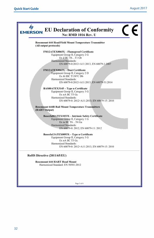
EU Declaration of ConformityNo: RMD 1016 Rev. U
Page 3 of 4
Rosemount 644 Head/Field Mount Temperature Transmitter (All output protocols)
FM12ATEX0065X – Flameproof CertificateEquipment Group II, Category 2 G
Ex d IIC T6…T1 Gb
Harmonized Standards:
EN 60079-0:2012+A11:2013, EN 60079-1:2007
FM12ATEX0065X – Dust CertificateEquipment Group II, Category 2 D
Ex tb IIIC T130°C Db
Harmonized Standards:
EN 60079-0:2012+A11:2013, EN 60079-31:2014
BAS00ATEX3145 – Type n CertificateEquipment Group II, Category 3 G
Ex nA IIC T5 Gc
Harmonized Standards:
EN 60079-0: 2012+A11:2013; EN 60079-15: 2010
Rosemount 644R Rail Mount Temperature Transmitters (HART Output)
Baseefa00ATEX1033X – Intrinsic Safety CertificateEquipment Group II, Category 1 G
Ex ia IIC T6…T4 Ga
Harmonized Standards:
EN 60079-0: 2012; EN 60079-11: 2012
Baseefa13ATEX0093X – Type n CertificateEquipment Group II, Category 3 G
Ex nA IIC T5 Gc
Harmonized Standards:
EN 60079-0: 2012+A11:2013; EN 60079-15: 2010
RoHS Directive (2011/65/EU)
Rosemount 644 HART Head MountHarmonized Standard: EN 50581:2012
32
Quick Start GuideAugust 2017
EU Declaration of ConformityNo: RMD 1016 Rev. U
Page 4 of 4
ATEX Notified Bodies
FM Approvals Ltd. [Notified Body Number: 1725]
1 Windsor Dials
Windsor, Berkshire, SL4 1RS
United Kingdom
SGS Baseefa Limited [Notified Body Number: 1180]
Rockhead Business Park
Staden Lane
Buxton Derbyshire
SK17 9RZ United Kingdom
ATEX Notified Body for Quality Assurance
SGS Baseefa Limited [Notified Body Number: 1180]
Rockhead Business Park
Staden Lane
Buxton Derbyshire
SK17 9RZ United Kingdom
33
August 2017Quick Start Guide
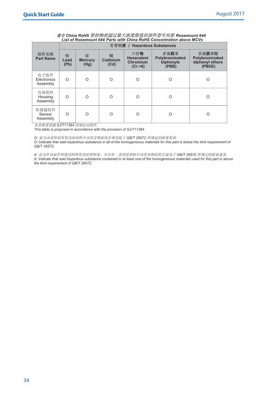
China RoHS Rosemount 644
List of Rosemount 644 Parts with China RoHS Concentration above MCVs
Part Name
Hazardous Substances
Lead (Pb)
Mercury (Hg)
Cadmium (Cd)
Hexavalent Chromium
(Cr +6)
Polybrominated biphenyls
(PBB)
Polybrominated diphenyl ethers
(PBDE)
Electronics Assembly
O O O
O
O O
Housing Assembly
O
O
O O O O
Sensor Assembly
O O O O O O
SJ/T11364This table is proposed in accordance with the provision of SJ/T11364. O: GB/T 26572 O: Indicate that said hazardous substance in all of the homogeneous materials for this part is below the limit requirement of GB/T 26572. X: GB/T 26572 X: Indicate that said hazardous substance contained in at least one of the homogeneous materials used for this part is above the limit requirement of GB/T 26572.
34

Quick Start GuideAugust 2017
35

Global HeadquartersEmerson Automation Solutions6021 Innovation Blvd.Shakopee, MN 55379, USA
+1 800 999 9307 or +1 952 906 8888+1 952 949 7001 [email protected]
North America Regional OfficeEmerson Automation Solutions8200 Market Blvd.Chanhassen, MN 55317, USA
+1 800 999 9307 or +1 952 906 8888
+1 952 949 7001
Latin America Regional OfficeEmerson Automation Solutions1300 Concord Terrace, Suite 400Sunrise, FL 33323, USA
+1 954 846 5030
+1 954 846 5121
Linkedin.com/company/Emerson-Automation-Solutions
Twitter.com/Rosemount_News
Facebook.com/Rosemount
Youtube.com/user/RosemountMeasurement
Google.com/+RosemountMeasurement
Standard Terms and Conditions of Sale can be found on the Terms and Conditions of Sale page.The Emerson logo is a trademark and service mark of Emerson Electric Co.Hot Backup, Rosemount, and Rosemount logotype are trademarks of Emerson.HART is a registered trademark of FieldComm Group.PROFIBUS is a registered trademark of PROFINET International (PI).NEMA is a registered trademark and service mark of the National Electrical Manufacturers Association.National Electrical Code is a registered trademark of National Fire Protection Association, Inc.All other marks are the property of their respective owners.© 2017 Emerson. All rights reserved.
Europe Regional OfficeEmerson Automation SolutionsNeuhofstrasse 19a P.O. Box 1046CH 6340 BaarSwitzerland
+41 (0) 41 768 6111
+41 (0) 41 768 6300
Asia Pacific Regional OfficeEmerson Automation Solutions1 Pandan CrescentSingapore 128461
+65 6777 8211
+65 6777 0947 [email protected]
Middle East and Africa Regional OfficeEmerson Automation SolutionsEmerson FZE P.O. Box 17033Jebel Ali Free Zone - South 2Dubai, United Arab Emirates
+971 4 8118100
+971 4 [email protected]
Quick Start Guide00825-0200-4728, Rev GB
August 2017
*00825-0200-4728*