Embed Size (px)
Citation preview

Qualification and Process Control of
Computed Radiography Systems
Muzibur Khan, Mike Brothers, Trent Gillis
Structures & Materials Performance Laboratory
Aerospace Research Centre
June 2019
Outline of Presentation
2
Film vs Digital Radiography
Introduction of Computed Radiography (CR)
Qualification & Process Control of CR (ASTM E2445)
CR for High Resolution Applications
Summary
Objectives of the Study
3
Qualification of CR systems in accordance with ASTM E2445 standards
Investigation of EPS concepts for aluminum alloy
Baseline EPS performance of CR system/Imaging Plates
Estimation of minimum, range, linearity of exposure
Developing process control of CR imaging applications
To ensuring a high degree of repeatability of inspection results
Investigation of CR for high resolution applications
Background: Film vs Digital Radiography
4
Film for NDT applications is gradually diminishing (time, cost,
hazardous chemical, lack of digital advantage)
Digital Radiography (DR/CR) allow faster/easier image acquisition
DR/CR Widespread application still poses significant challenges
Initial cost of system, Steep learning curve
Lack of procedure to choose parameters
Lack of demonstrated system performance
Performance assessment required (If CR/DR can effectively provide
equal or better performance than the existing film-based technology)
Computed Radiography (CR)
5
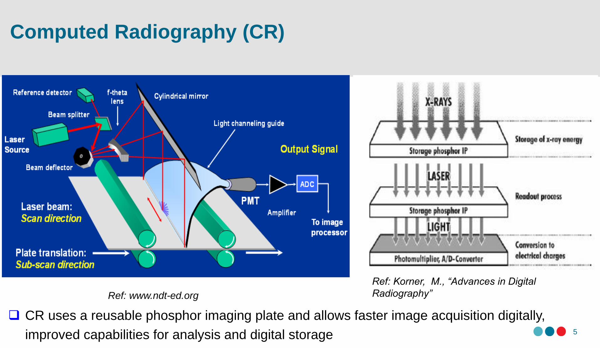
CR uses a reusable phosphor imaging plate and allows faster image acquisition digitally,
improved capabilities for analysis and digital storage
Ref: www.ndt-ed.org
Ref: Korner, M., “Advances in Digital
Radiography”
Contrast in CR
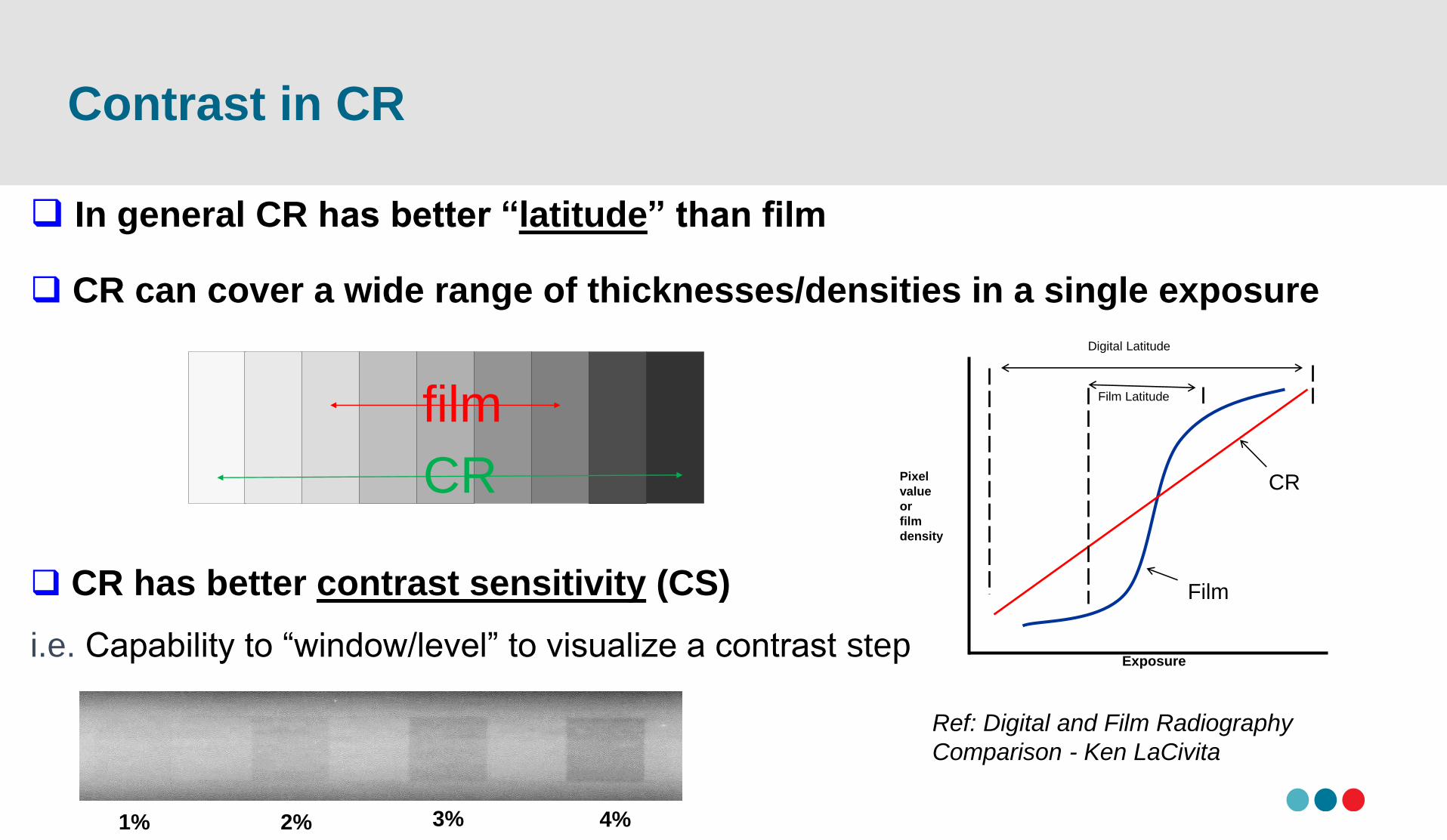
In general CR has better “latitude” than film
CR can cover a wide range of thicknesses/densities in a single exposure
CR has better contrast sensitivity (CS)
i.e. Capability to “window/level” to visualize a contrast step
CR
film
1% 2% 3% 4%
Section 1 – The Image
Plate
Film Latitude
Film
Digital Latitude
CR
Exposure
Pixel
value
or
film
density
Ref: Digital and Film Radiography
Comparison - Ken LaCivita
Primary Metrics for Image Quality in CR
7
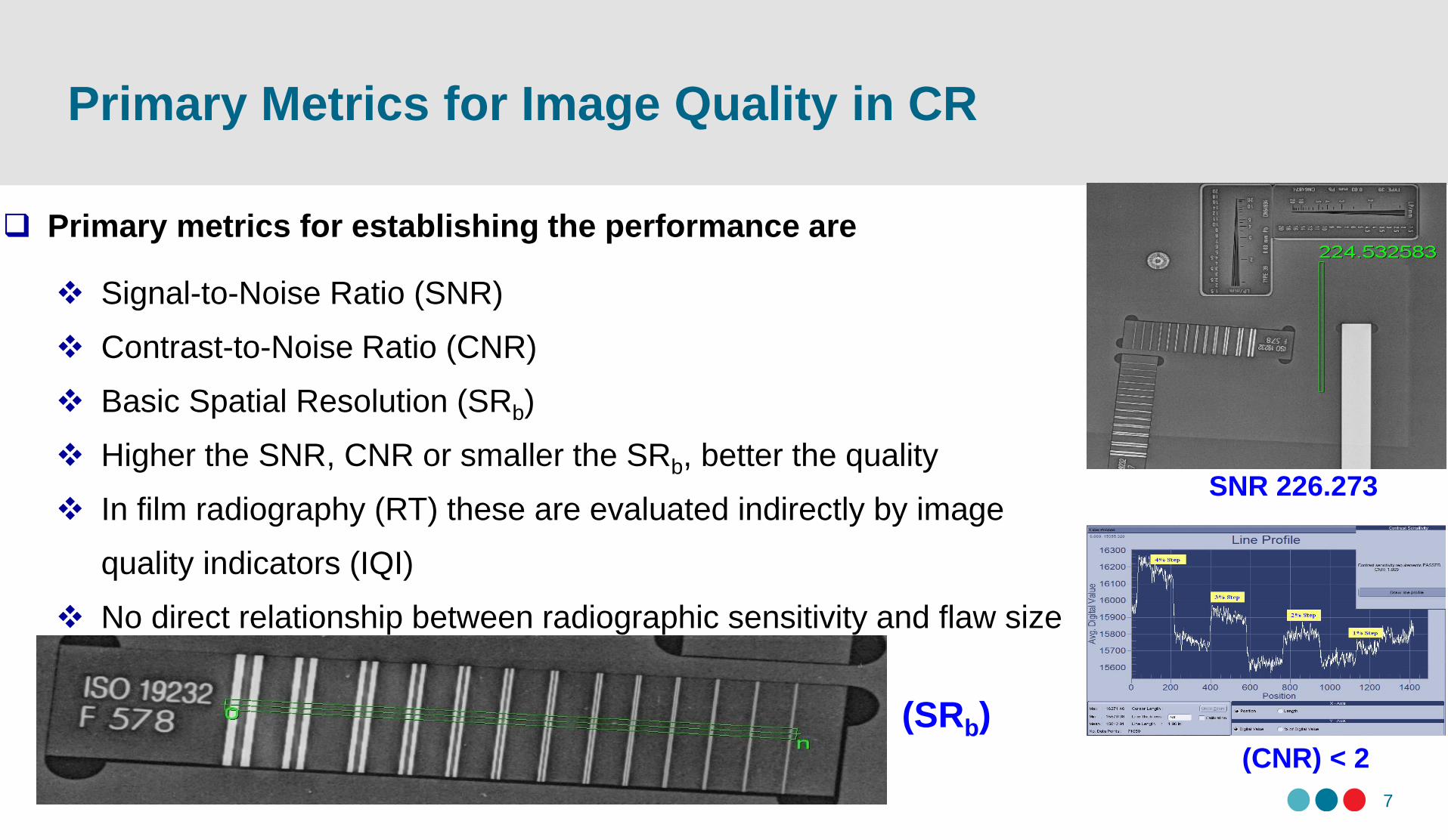
Primary metrics for establishing the performance are
Signal-to-Noise Ratio (SNR)
Contrast-to-Noise Ratio (CNR)
Basic Spatial Resolution (SRb)
Higher the SNR, CNR or smaller the SRb, better the quality
In film radiography (RT) these are evaluated indirectly by image
quality indicators (IQI)
No direct relationship between radiographic sensitivity and flaw size
SNR 226.273
(CNR) < 2
(SRb)
NRC Computed Radiography
8
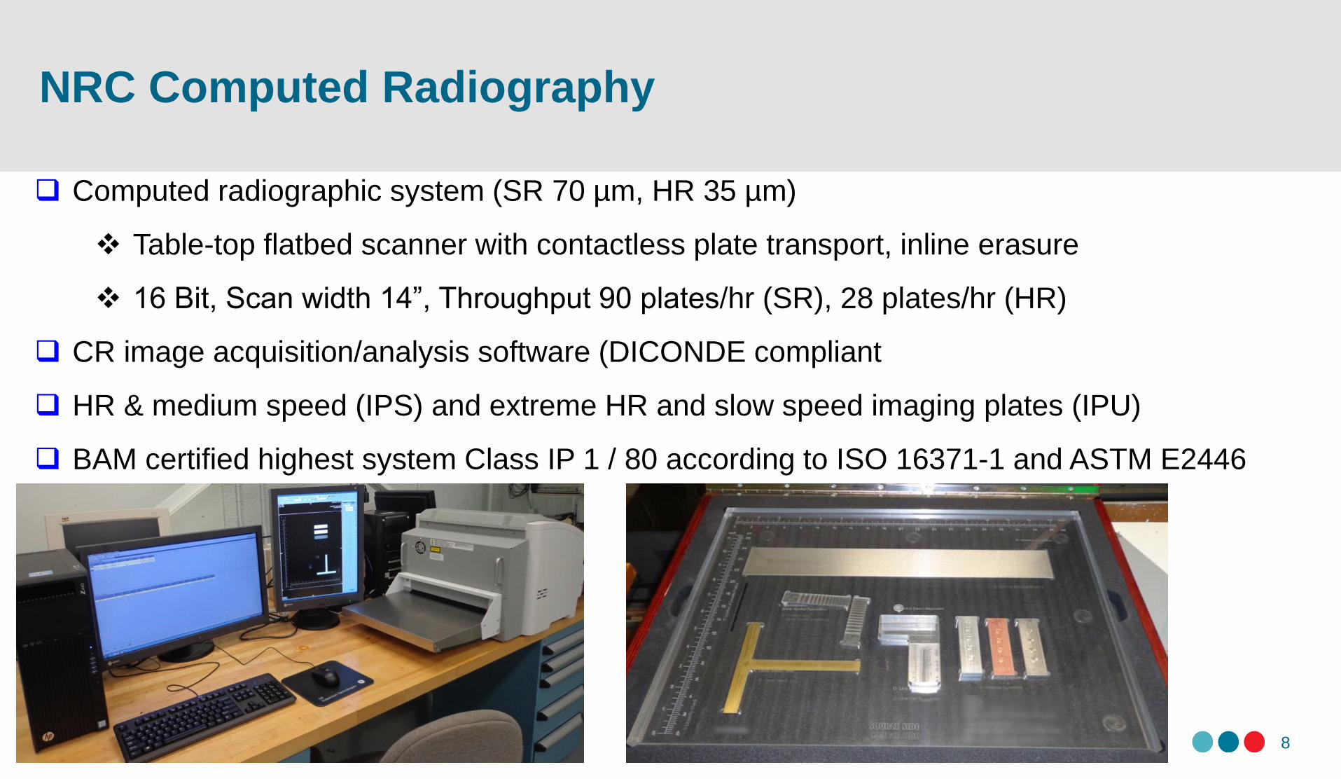
Computed radiographic system (SR 70 µm, HR 35 µm)
Table-top flatbed scanner with contactless plate transport, inline erasure
16 Bit, Scan width 14”, Throughput 90 plates/hr (SR), 28 plates/hr (HR)
CR image acquisition/analysis software (DICONDE compliant
HR & medium speed (IPS) and extreme HR and slow speed imaging plates (IPU)
BAM certified highest system Class IP 1 / 80 according to ISO 16371-1 and ASTM E2446
ASTM E 2445M-14 (Phantom)(Practice for Qualification and Long Term Stability of CR Systems)
9
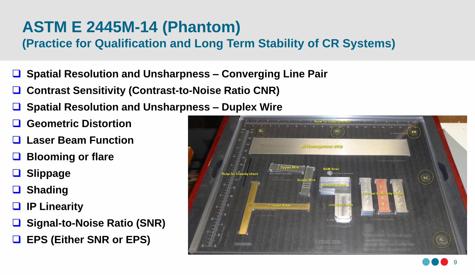
Spatial Resolution and Unsharpness – Converging Line Pair
Contrast Sensitivity (Contrast-to-Noise Ratio CNR)
Spatial Resolution and Unsharpness – Duplex Wire
Geometric Distortion
Laser Beam Function
Blooming or flare
Slippage
Shading
IP Linearity
Signal-to-Noise Ratio (SNR)
EPS (Either SNR or EPS)
Basic Spatial Resolution (SRB) (Duplex Wire Gauge)
10
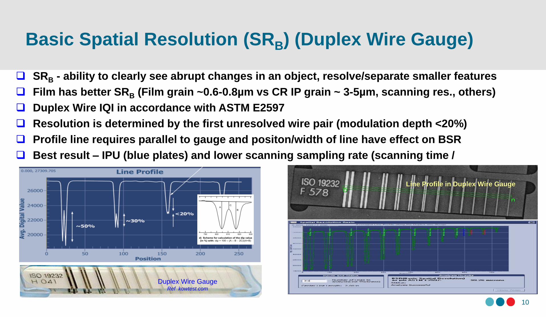
SRB - ability to clearly see abrupt changes in an object, resolve/separate smaller features
Film has better SRB (Film grain ~0.6-0.8µm vs CR IP grain ~ 3-5µm, scanning res., others)
Duplex Wire IQI in accordance with ASTM E2597
Resolution is determined by the first unresolved wire pair (modulation depth <20%)
Profile line requires parallel to gauge and positon/width of line have effect on BSR
Best result – IPU (blue plates) and lower scanning sampling rate (scanning time /
exposure)Line Profile in Duplex Wire Gauge
Duplex Wire GaugeRef kowtest.com
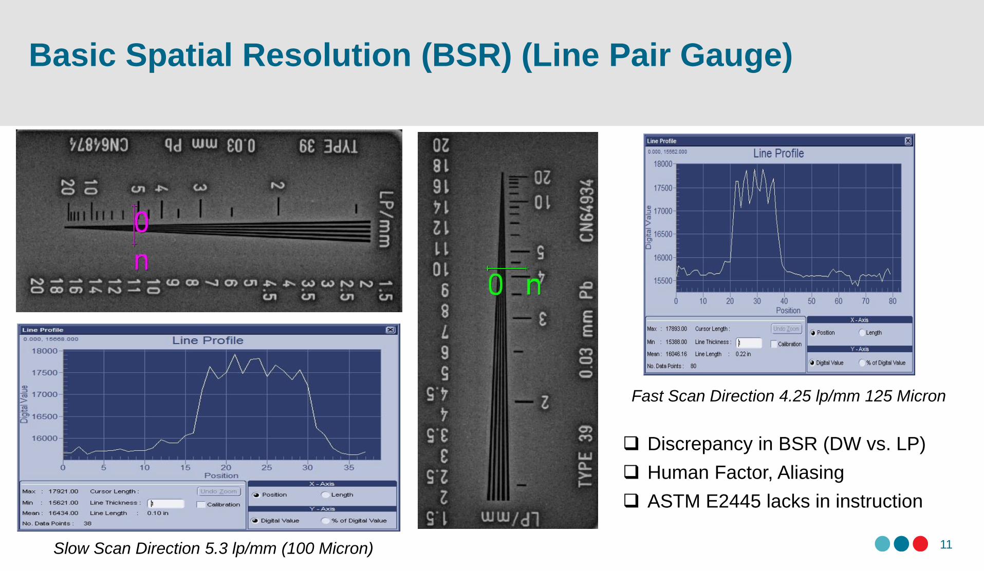
Basic Spatial Resolution (BSR) (Line Pair Gauge)
11
Fast Scan Direction 4.25 lp/mm 125 Micron
Slow Scan Direction 5.3 lp/mm (100 Micron)
Discrepancy in BSR (DW vs. LP)
Human Factor, Aliasing
ASTM E2445 lacks in instruction
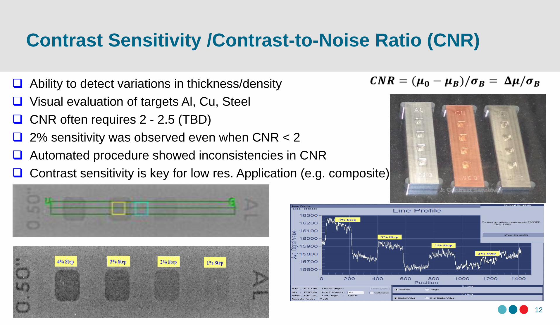
Contrast Sensitivity /Contrast-to-Noise Ratio (CNR)
12
Ability to detect variations in thickness/density
Visual evaluation of targets Al, Cu, Steel
CNR often requires 2 - 2.5 (TBD)
2% sensitivity was observed even when CNR < 2
Automated procedure showed inconsistencies in CNR
Contrast sensitivity is key for low res. Application (e.g. composite)
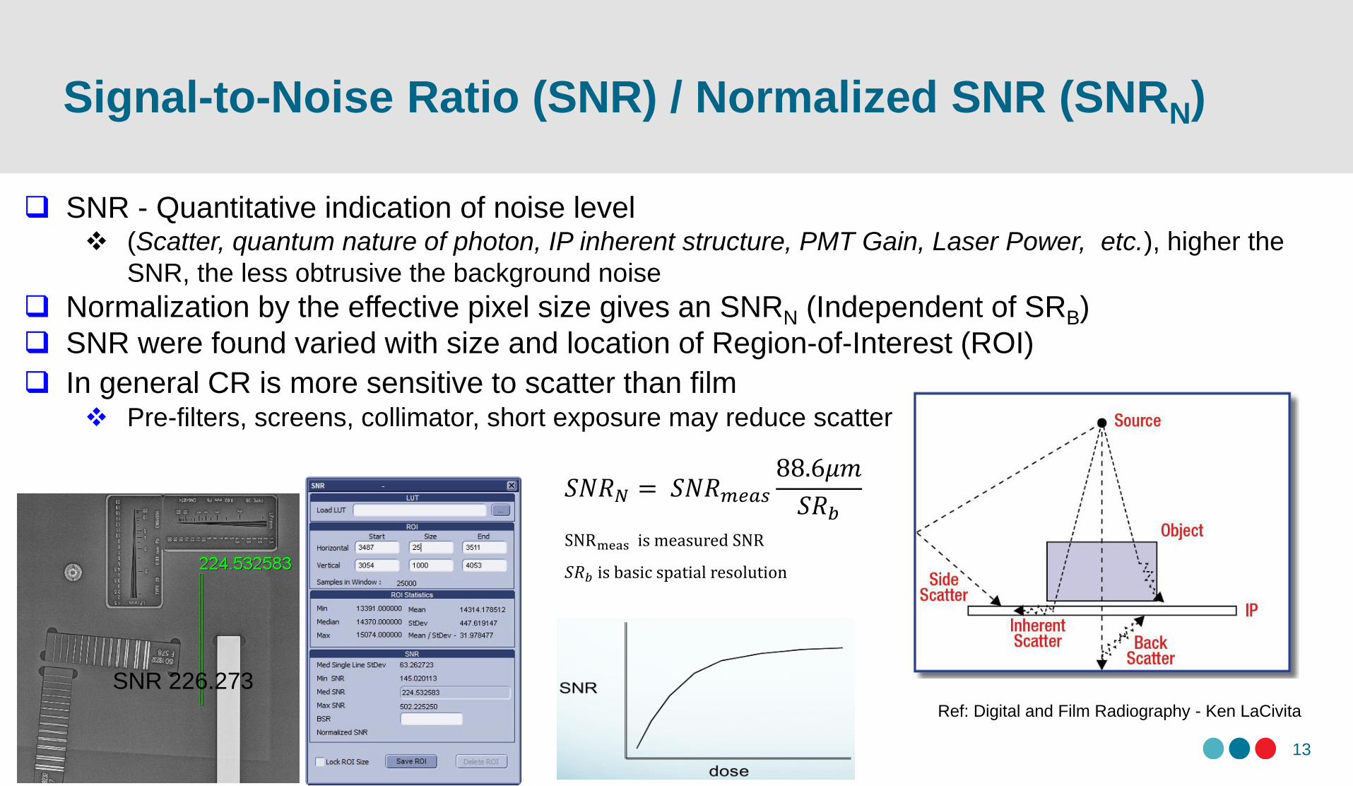
Signal-to-Noise Ratio (SNR) / Normalized SNR (SNRN)
13
SNR 226.273
SNR - Quantitative indication of noise level (Scatter, quantum nature of photon, IP inherent structure, PMT Gain, Laser Power, etc.), higher the
SNR, the less obtrusive the background noise
Normalization by the effective pixel size gives an SNRN (Independent of SRB)
SNR were found varied with size and location of Region-of-Interest (ROI)
In general CR is more sensitive to scatter than film Pre-filters, screens, collimator, short exposure may reduce scatter
Ref: Digital and Film Radiography - Ken LaCivita
is measured SNR
is basic spatial resolution
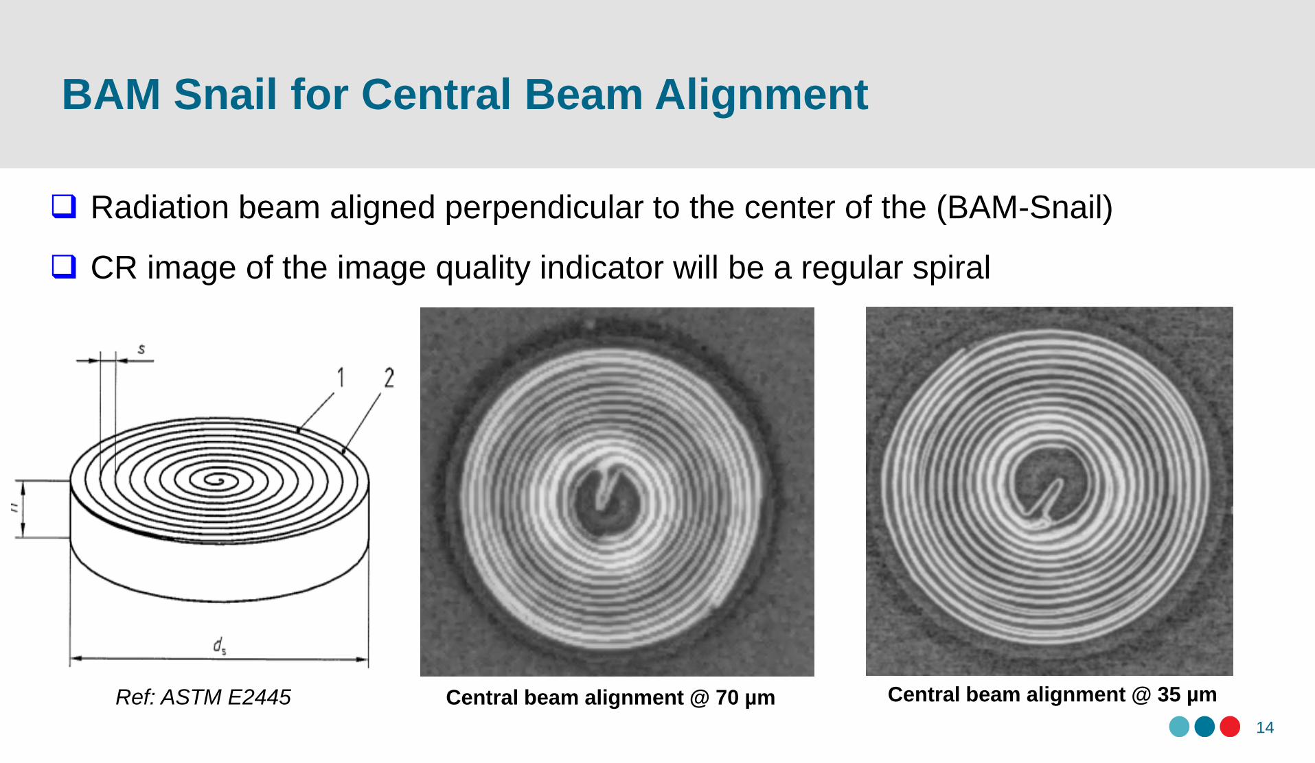
BAM Snail for Central Beam Alignment
14
Radiation beam aligned perpendicular to the center of the (BAM-Snail)
CR image of the image quality indicator will be a regular spiral
Central beam alignment @ 70 µm Central beam alignment @ 35 µmRef: ASTM E2445
Laser Beam Jitter
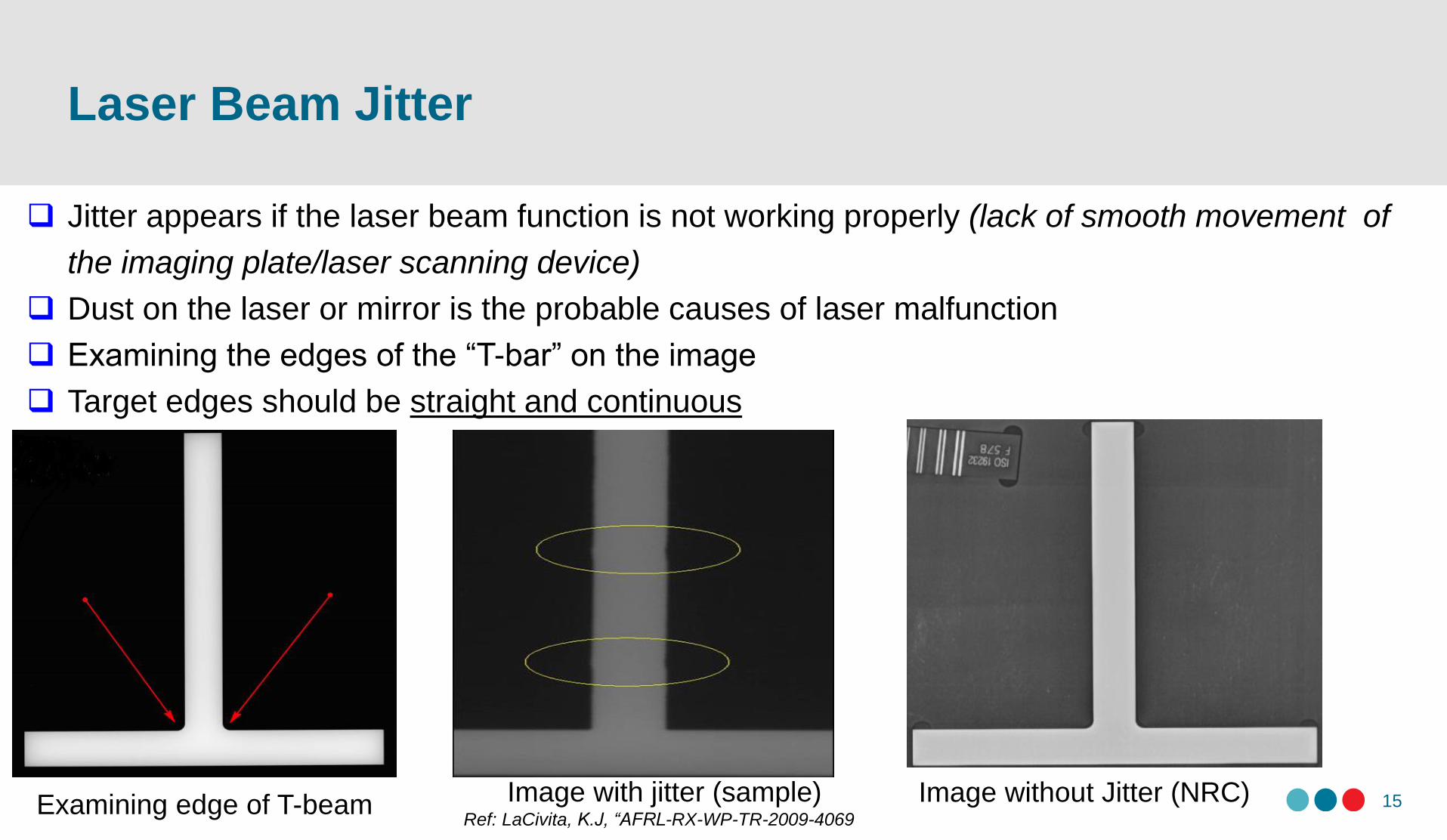
15Image without Jitter (NRC)Image with jitter (sample)Ref: LaCivita, K.J, “AFRL-RX-WP-TR-2009-4069
Jitter appears if the laser beam function is not working properly (lack of smooth movement of
the imaging plate/laser scanning device)
Dust on the laser or mirror is the probable causes of laser malfunction
Examining the edges of the “T-bar” on the image
Target edges should be straight and continuous
Examining edge of T-beam
Geometric Distortion
16
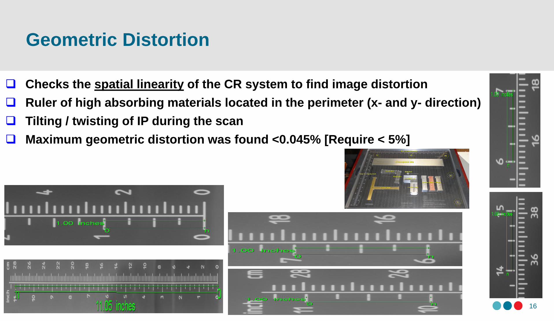
Checks the spatial linearity of the CR system to find image distortion
Ruler of high absorbing materials located in the perimeter (x- and y- direction)
Tilting / twisting of IP during the scan
Maximum geometric distortion was found <0.045% [Require < 5%]
Shading Effect
17
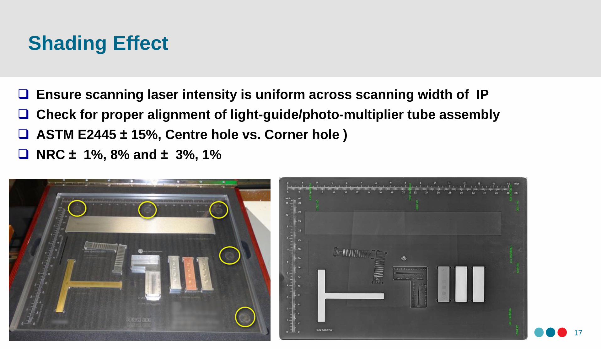
Ensure scanning laser intensity is uniform across scanning width of IP
Check for proper alignment of light-guide/photo-multiplier tube assembly
ASTM E2445 ± 15%, Centre hole vs. Corner hole )
NRC ± 1%, 8% and ± 3%, 1%
Scan Column Dropout
18
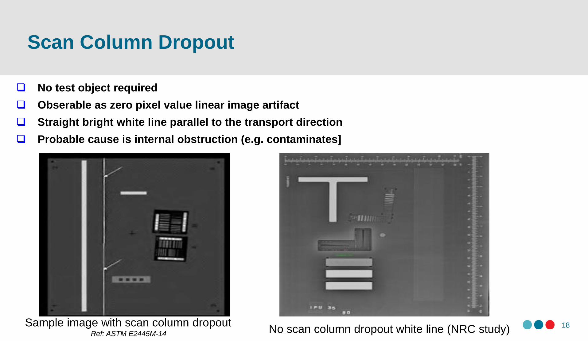
No test object required
Obserable as zero pixel value linear image artifact
Straight bright white line parallel to the transport direction
Probable cause is internal obstruction (e.g. contaminates]
Sample image with scan column dropoutRef: ASTM E2445M-14 No scan column dropout white line (NRC study)
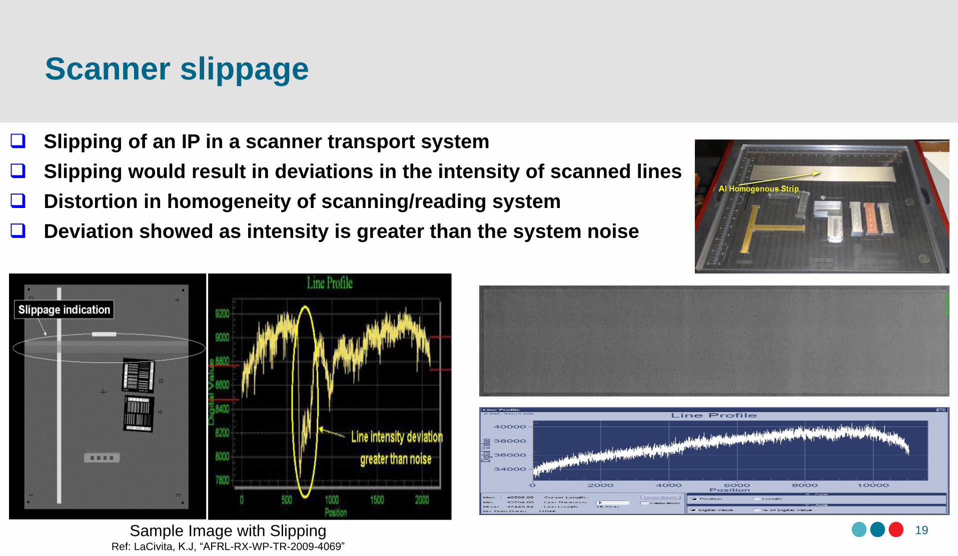
Scanner slippage
19
Slipping of an IP in a scanner transport system
Slipping would result in deviations in the intensity of scanned lines
Distortion in homogeneity of scanning/reading system
Deviation showed as intensity is greater than the system noise
Sample Image with SlippingRef: LaCivita, K.J, “AFRL-RX-WP-TR-2009-4069”
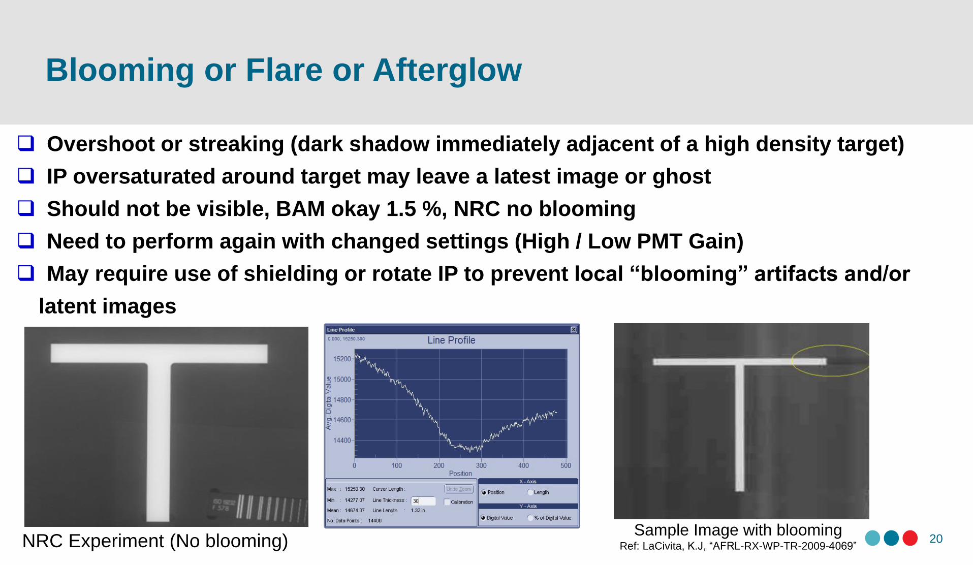
Blooming or Flare or Afterglow
20
Overshoot or streaking (dark shadow immediately adjacent of a high density target)
IP oversaturated around target may leave a latest image or ghost
Should not be visible, BAM okay 1.5 %, NRC no blooming
Need to perform again with changed settings (High / Low PMT Gain)
May require use of shielding or rotate IP to prevent local “blooming” artifacts and/or
latent images
NRC Experiment (No blooming)Sample Image with blooming
Ref: LaCivita, K.J, “AFRL-RX-WP-TR-2009-4069”
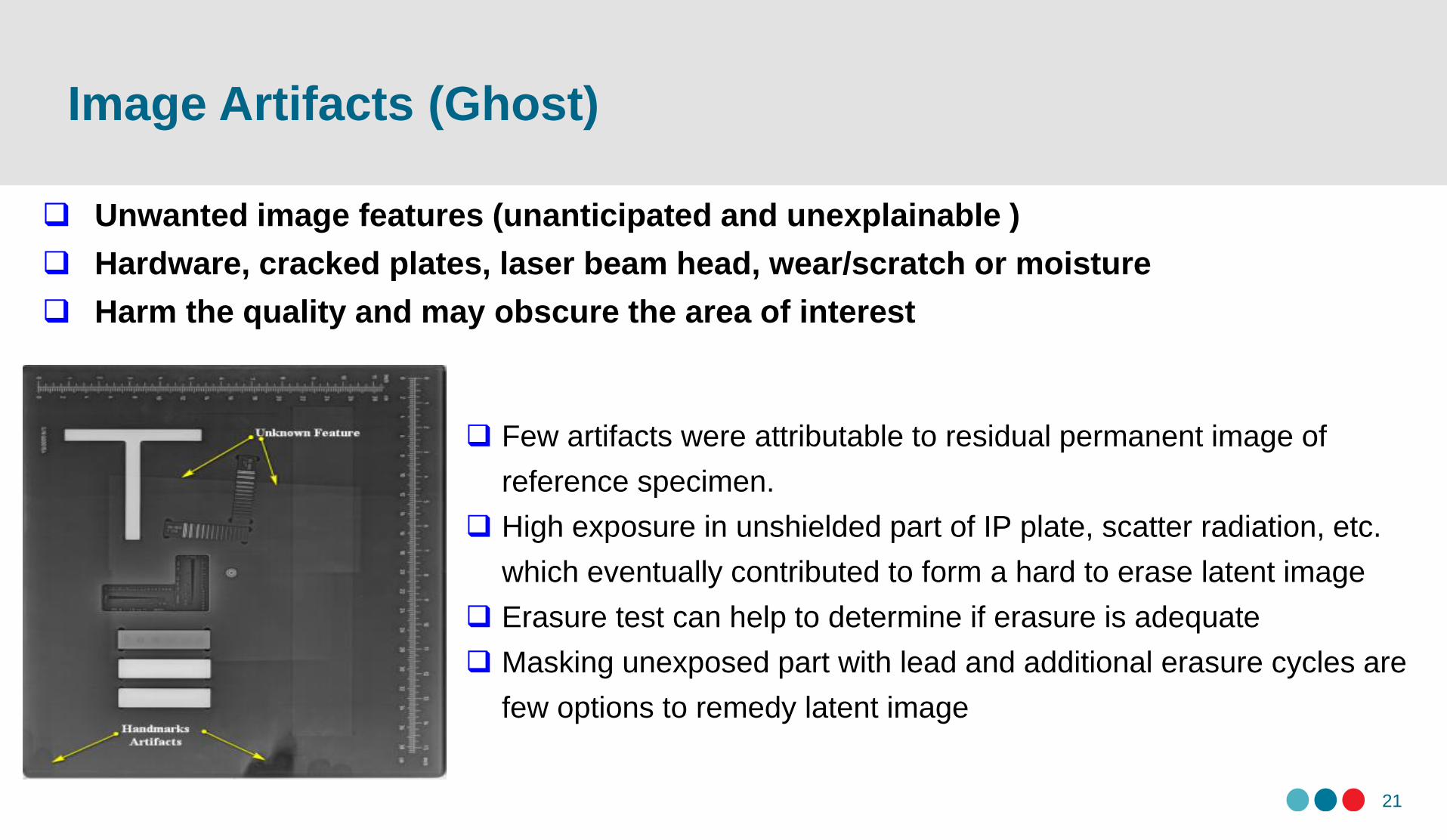
Image Artifacts (Ghost)
21
Unwanted image features (unanticipated and unexplainable )
Hardware, cracked plates, laser beam head, wear/scratch or moisture
Harm the quality and may obscure the area of interest
Few artifacts were attributable to residual permanent image of
reference specimen.
High exposure in unshielded part of IP plate, scatter radiation, etc.
which eventually contributed to form a hard to erase latent image
Erasure test can help to determine if erasure is adequate
Masking unexposed part with lead and additional erasure cycles are
few options to remedy latent image
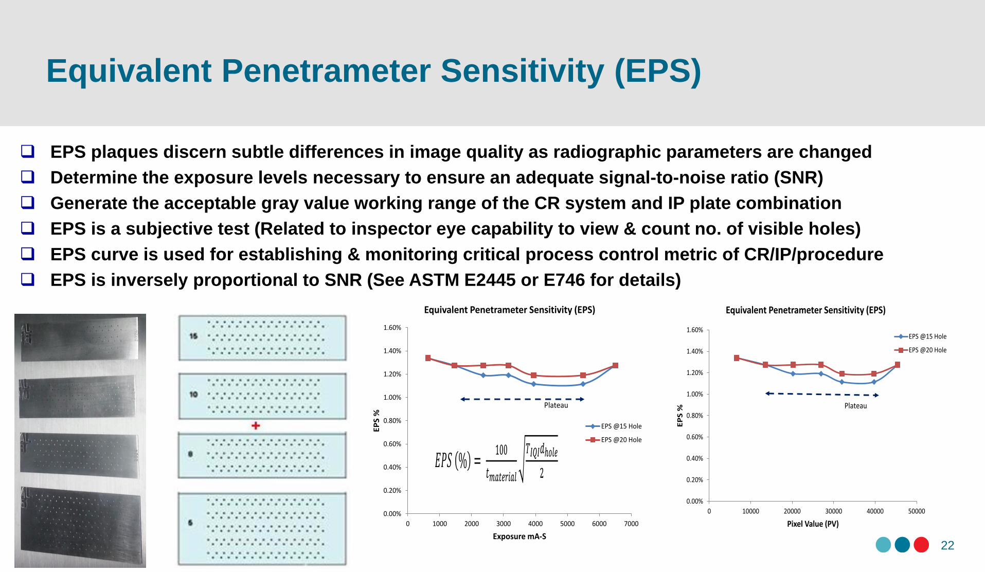
Equivalent Penetrameter Sensitivity (EPS)
22
EPS plaques discern subtle differences in image quality as radiographic parameters are changed
Determine the exposure levels necessary to ensure an adequate signal-to-noise ratio (SNR)
Generate the acceptable gray value working range of the CR system and IP plate combination
EPS is a subjective test (Related to inspector eye capability to view & count no. of visible holes)
EPS curve is used for establishing & monitoring critical process control metric of CR/IP/procedure
EPS is inversely proportional to SNR (See ASTM E2445 or E746 for details)
0.00%
0.20%
0.40%
0.60%
0.80%
1.00%
1.20%
1.40%
1.60%
0 1000 2000 3000 4000 5000 6000 7000
EP
S %
Exposure mA-S
Equivalent Penetrameter Sensitivity (EPS)
EPS @15 Hole
EPS @20 Hole
Plateau
0.00%
0.20%
0.40%
0.60%
0.80%
1.00%
1.20%
1.40%
1.60%
0 10000 20000 30000 40000 50000
EP
S %
Pixel Value (PV)
Equivalent Penetrameter Sensitivity (EPS)
EPS @15 Hole
EPS @20 Hole
Plateau
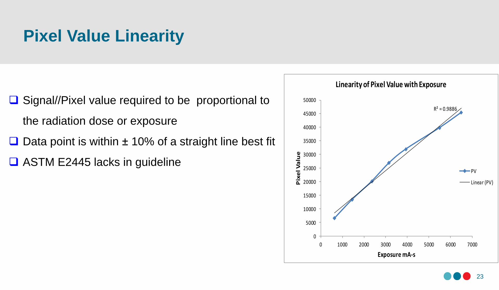
Pixel Value Linearity
23
R² = 0.9886
0
5000
10000
15000
20000
25000
30000
35000
40000
45000
50000
0 1000 2000 3000 4000 5000 6000 7000
Pix
el V
alu
e
Exposure mA-s
Linearity of Pixel Value with Exposure
PV
Linear (PV)
Signal//Pixel value required to be proportional to
the radiation dose or exposure
Data point is within ± 10% of a straight line best fit
ASTM E2445 lacks in guideline
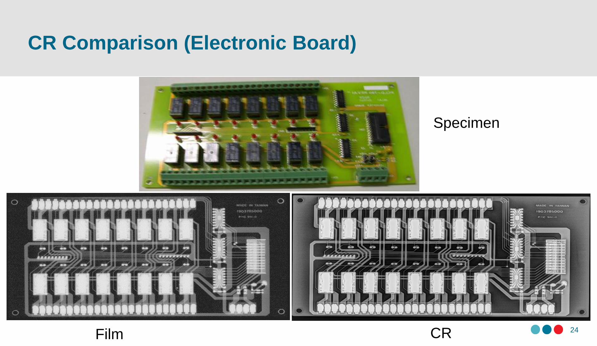
24Film CR
Specimen
CR Comparison (Electronic Board)
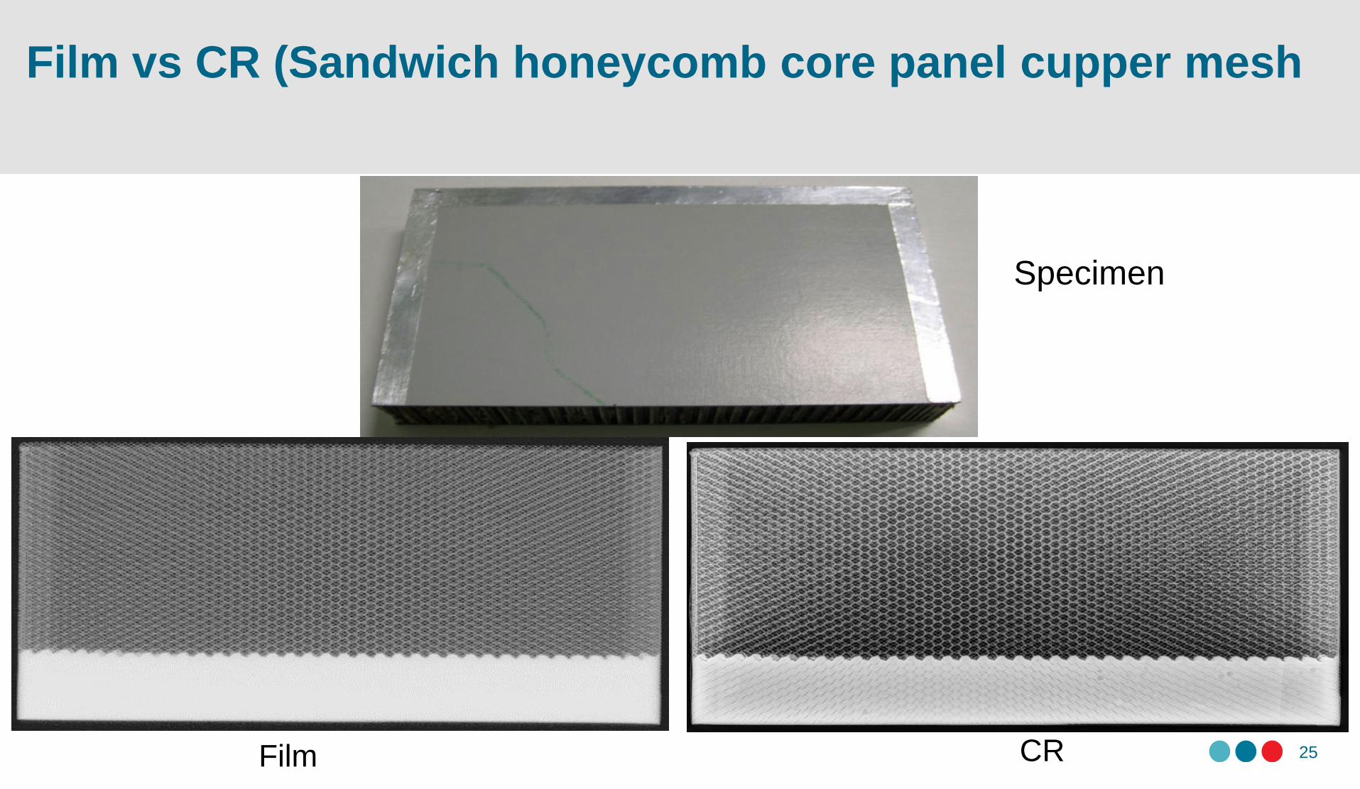
25Film CR
Specimen
Film vs CR (Sandwich honeycomb core panel cupper mesh
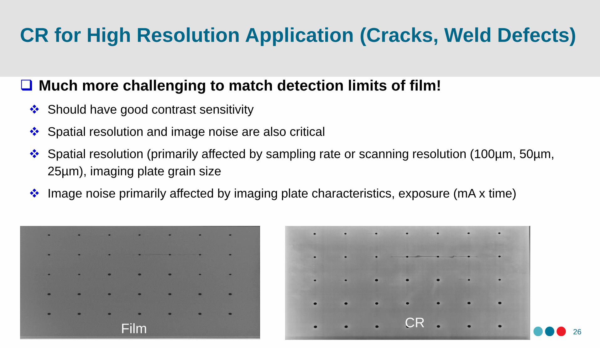
CR for High Resolution Application (Cracks, Weld Defects)
26
Much more challenging to match detection limits of film!
Should have good contrast sensitivity
Spatial resolution and image noise are also critical
Spatial resolution (primarily affected by sampling rate or scanning resolution (100µm, 50µm,
25µm), imaging plate grain size
Image noise primarily affected by imaging plate characteristics, exposure (mA x time)
Film CR
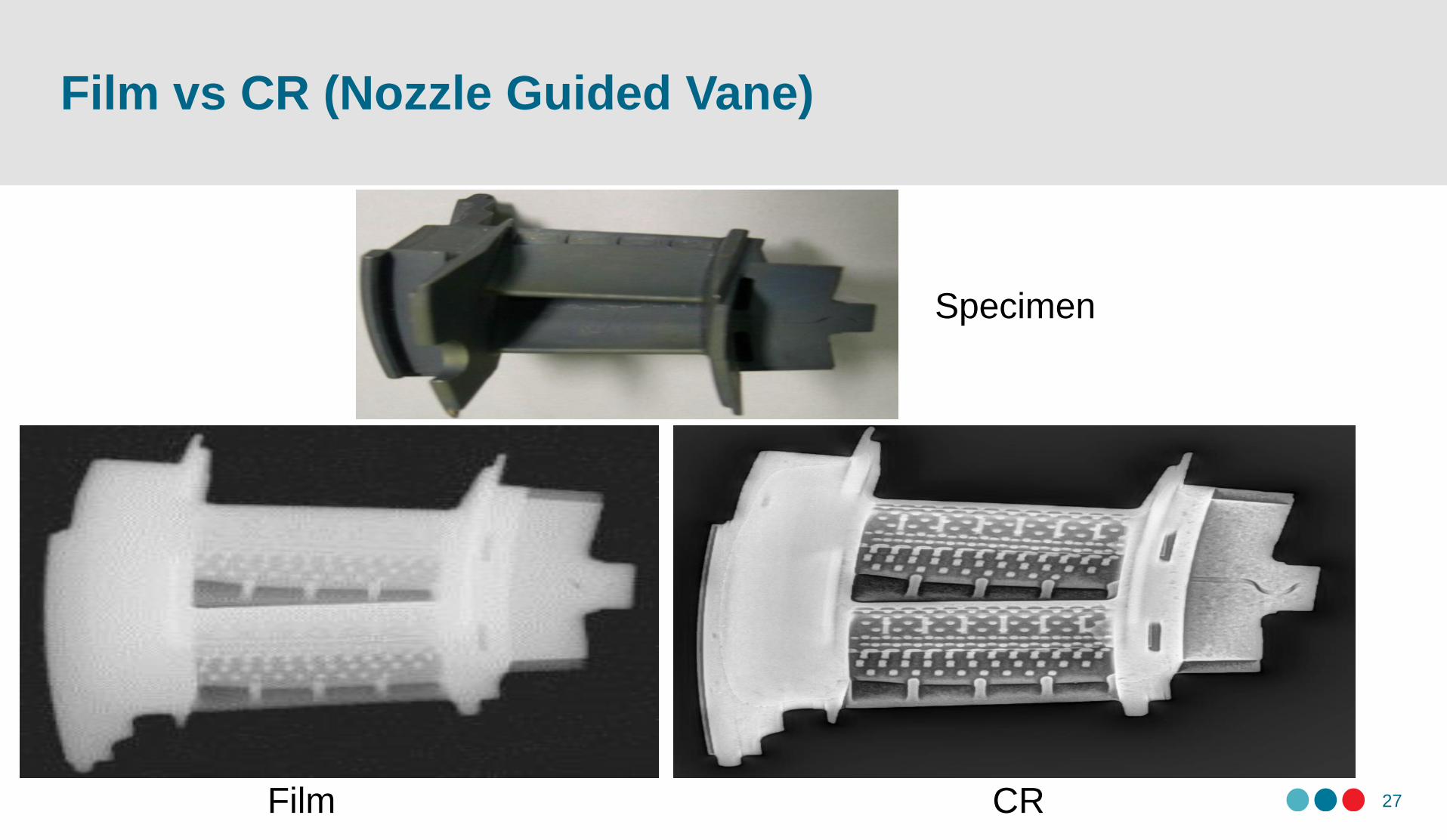
27Film CR
Specimen
Film vs CR (Nozzle Guided Vane)
Summary
28
SNRN exceeded the ASTM highest system class (130 IP special)
Resolution, contrast, SNR, shading, beam alignment, jitter, slippage, geometric
distortion etc.) met the current ASTM requirements
SNR or EPS improves with exposure up to certain point.
Best image resolution – blue plates & lower scanning resolution
Ghosting-like artifacts were observed which required engineering judgement to
overcome
EPS curve is not typical but identify min. exposure (key requirement)
CR image is not the same as film, many variables affect image quality and many
unique phenomena need to consider

Thank you!
Contact:
Muzibur Khan
SMPL, Aerospace Research Centre
National Research Council of Canada
Email: [email protected]
Tel: 613-990-4733