Embed Size (px)
Citation preview
Application of Computed Radiography (CR) for Characterization of
Historical Documents
Marko RAKVIN 1, Andreja DRAGOJEVIĆ
2, Damir MARKUČIČ
1
1 Faculty of mechanical engineering and naval architecture, University of Zagreb; Zagreb, Croatia
Phone: +385 1 6168 364, Fax: +385 1 6168 466; e-mail: [email protected], [email protected] 2 Croatian conservation institute; Zagreb, Croatia; E-mail: [email protected]
Abstract
Watermarks and paper structure are significant properties of historical documents that allow historians and
restorers possibility of dating where and when a particular paper was produced. Because of the document content
(text, graphics etc.), it is sometimes difficult or even impossible to determine the layout of the watermark and
paper structure using only light transmission technique. In that case, radiography can be used as an alternative
method. In this paper the possibilities of using computer radiography (CR) for watermark extraction and paper
structure characterization as well as advantages and disadvantages over conventional film radiography are
discussed. Optimization of CR radiographic parameters (selection of imaging plates and radiation sources) for
low-voltage X-ray and electron transmission technique was conducted and the results were compared to light
transmission technique findings.
Keywords: cultural heritage, computed radiography, electron radiography, watermark, paper structure, imaging
plate
1. Introduction
From the beginning of paper production outside the Arabic world in the 13-th century,
European paper manufacturers were adding characteristic watermarks into the paper as a
guarantee of quality and sign of recognition for their products. Watermarks were fabricated in
the way that metal wire formed symbol was placed on the paper making sieve, so after the
linen pulp was oozed, pressed and dried, on the location where metal wire symbol was
positioned paper was thinner. Because of that, watermarks can be seen if viewed under the
bright light. Research in the field of filigranology showed that every manufacturer used
specific symbols for watermarks, as well as sieve construction, in a certain time period.
Identifying the watermark and sieve construction allows historians to date when and where
the paper was manufactured.
Common techniques that are used to identify paper watermarks are: transmitted light
photography, photosensitive paper technique, low voltage (soft) X-ray, beta radiography,
electron transmission radiography. The advantage of using electron emission radiography for
watermark identification is that, unlike transmitted light photography and low voltage
radiography, content of the paper (text, graphics ect.) do not reveal on the radiogram enabling
reliable identification of features of interest. Conventionally, “classic” slow AgBr industrial
radiographic film is used for this purpose.
Today, AgBr film are increasingly being replaced by variety of radiographic techniques that
produce digital radiographic image based on various detector and readout technologies [1]. In
the paper, the possibility of using electron transmission and low voltage X-ray computed
radiography (CR) using industrial unmodified BaFBr imaging plates was investigated.
Previous research demonstrated that BaFBr imaging plates with absence of protective
overcoat polymer layer can be used as a detector for investigation of paintings with electron
transmission radiography [2]. Due to the properties and construction of imaging plates,
exposure times and intensifying effect of radiographic lead foils differs from those obtained
when using radiographic film. To date, images on radiographic films still achieve better
spatial resolution than that obtained by imaging plates, but imaging plates have far greater
dynamic range allowing more information to be seen on a single digital radiographic image.
11th European Conference on Non-Destructive Testing (ECNDT 2014), October 6-10, 2014, Prague, Czech RepublicM
ore
Info
at O
pen
Acc
ess
Dat
abas
e w
ww
.ndt
.net
/?id
=16
682
For this reason, in order to achieve adequate image quality for watermark and paper
characterisation, exposures were done on two types of imaging plates and varying radiation
sources. Some of the presumed benefits of using computed radiography instead of classic film
radiography for watermark identification and paper characterisation also include less exposure
dose, no need for darkroom environment and computer aided interpretation and analysis of
the resulting digital radiograms.
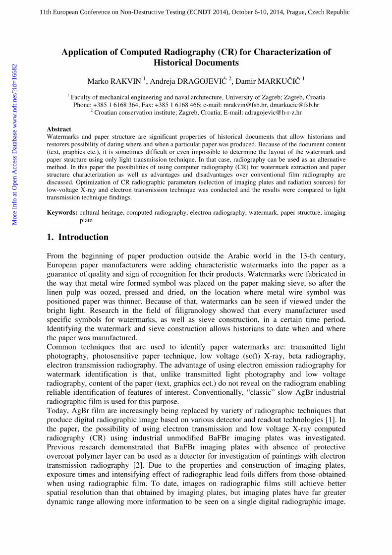
Research was obtained on a copper etching artwork that shows a saint St. Vasily on front side
(Figure 1a) and a text written in old-slavic language on the back side. Dimensions of the paper
are 348 mm x 220 mm and the thickness is 0.17 mm. Given that the artwork startled a lot of
different information such as Greek letters on the graphics and old-slavic text on the back, it
was interesting to investigate the origin of the paper as an information carrier.
a) b)
Figure 1. Inspected document a) front side – copper etching artwork; b) back side
2. Radiography of paper and artwork
The most common approaches for paper and artwork radiography are:
• low voltage (soft) X-ray radiography,
• beta radiography and
• electron transmission radiography.
2.1 Low voltage X-ray radiography
Low voltage radiography of paper is based on variation of absorption of X-rays of different
areas of paper due to variations in paper thickness, density or compositions. Since these
variations are usually very small low voltage X-rays are used to obtain sufficient radiographic
contrast on the radiogram. Use of 4 to 7 kV X-rays in combination with slow radiographic
film is recommended [3]. Metallic pigments that are present as a design on a paper will also
be visible on the radiogram. If film cassette is used, such low energy radiation will create an
unwanted image of the cassette on the radiogram. For that reason, radiation sensor must be in
direct contact with test object. This is often a problem when using radiographic film as a
detector, because of the light contamination risk of the film. Accordingly, exposures must be
done under darkroom safelight environmental conditions. In case of computed radiography,
when imaging plates are used as a detector, because of their lesser sensitivity to visible light,
exposures can be done under subdued light conditions. Also, imaging plates are more
sensitive to low energy radiation than radiographic film, making them potentially particularly
suitable for this kind of application.
2.2 Beta radiography
Beta radiography technique uses “beta-plates” as a source of beta particles radiation. They
consist of radioactive isotope 14
Cembedded in a thin sheet of polymethyl methacrylate. 14
C
isotope emits only beta particles of relatively low energy (150 keV) that are sufficient to
penetrate approximately 250 mm of air, 0,3 mm of skin or a sheet of paper [4]. Such plate is
positioned in direct contact over examined paper and the radiogram is recorded on a
radiographic film. Activity of such plate is very low, in order of 100 mCi/g, so exposure times
are relatively long. Exposure times are long, almost reaching 8 hours. Thin layers of organic
and metallic pigments usually do not appear on the radiograph, leaving the resulting image
free of paper design content. Results that are obtained by this technique are unsurpassed when
it comes to resulting image quality of the watermark and sieve footprint. Electron
transmission radiography is possible substitution for this method.
2.3 Electron transmission radiography
Since quantum dose efficiency of conventional radiographic films decreases with photon
energy increase, radiographic lead foils in direct contact with detector are used to enhance it
when high energy X-rays or gamma radiation (over 100 keV) is used as a radiation source [5].
When such lead foil is exposed to X-ray or gamma photons it undergoes an internal
photoelectric effect. As a result, there is an increased amount of “free” electrons inside the Pb
foil. Surface photoelectrons that are able to escape the foil and exceed to the detector, irradiate
it, and this results in signal intensifying
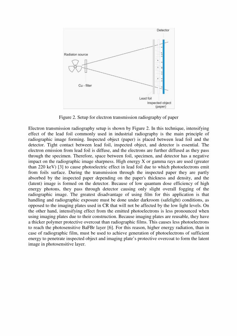
Figure 2. Setup for electron transmission radiography of paper
Electron transmission radiography setup is shown by Figure 2. In this technique, intensifying
effect of the lead foil commonly used in industrial radiography is the main principle of
radiographic image forming. Inspected object (paper) is placed between lead foil and the
detector. Tight contact between lead foil, inspected object, and detector is essential. The
electron emission from lead foil is diffuse, and the electrons are further diffused as they pass
through the specimen. Therefore, space between foil, specimen, and detector has a negative
impact on the radiographic image sharpness. High energy X or gamma rays are used (greater
than 220 keV) [3] to cause photoelectric effect in lead foil due to which photoelectrons emit
from foils surface. During the transmission through the inspected paper they are partly
absorbed by the inspected paper depending on the paper's thickness and density, and the
(latent) image is formed on the detector. Because of low quantum dose efficiency of high
energy photons, they pass through detector causing only slight overall fogging of the
radiographic image. The greatest disadvantage of using film for this application is that
handling and radiographic exposure must be done under darkroom (safelight) conditions, as
opposed to the imaging plates used in CR that will not be affected by the low light levels. On
the other hand, intensifying effect from the emitted photoelectrons is less pronounced when
using imaging plates due to their construction. Because imaging plates are reusable, they have
a thicker polymer protective overcoat than radiographic films. This causes less photoelectrons
to reach the photosensitive BaFBr layer [6]. For this reason, higher energy radiation, than in
case of radiographic film, must be used to achieve generation of photoelectrons of sufficient
energy to penetrate inspected object and imaging plate’s protective overcoat to form the latent
image in photosensitive layer.
3. Experimental setup
To explore the capabilities of using conventional industrial CR system for paper watermark
identification and characterization, two radiographic techniques were employed:
• low-voltage (soft) X-ray transmission radiography and
• electron transmission radiography.
For low-voltage X-ray transmission technique industrial small focus X-ray tube was used and
for electron transmission radiography conventional industrial X-ray tube and radioactive
isotope 192
Ir were employed in combination with Kodak Industrex Flex general GP (general
purpose) and XL Blue (high resolution) imaging plates for industrial application. Exposures
were done under the dim light (20 lux). Standard cassettes for imaging plates were not used.
In ordered to provide sufficient contact between inspected object and detector when electron
emission radiography was preformed, 5 mm acrylic polymer plate was placed on top of the
lead foil.
Equipment used for the experiment and radiographic parameters are stated in Table 1.
Table1. Equipment and radiographic parameters
Technique Low-voltage X-ray
transmission
Electron transmission
radiography
Radiation source ISOVOLT 160 M2-small
focus 0.4
Baltospot GM 300 D
Ir 192
Detector (Imaging plates)
Kodak Industrex Flex GP & XL Blue (350mm x 430 mm);
no cassette
CR Scanner / scanning
parameters
VMI 5100CR /
Laser power - 15 J/m2; Scanning resolution – 50 µm ;
Photomultiplier tube voltage – 5.25 V
Source energy / Radiographic
exposure / Source to detector
distance (SDD)
4 kV; 12 mA/min / 800 mm
300 kV; 18 mA/min /
700 mm
222 GBq; 12.5 min / 700 mm
Lead foil - 0,027 mm
Filtration 1 mm Be (inherent) 3 mm Be (inherent) + 12 mm
Cu
Software Starrview 7 ; Isee!
Scanned xry files were exported as 16 bit tif files and processed by means of image analysis
software ISee!.
4. Results
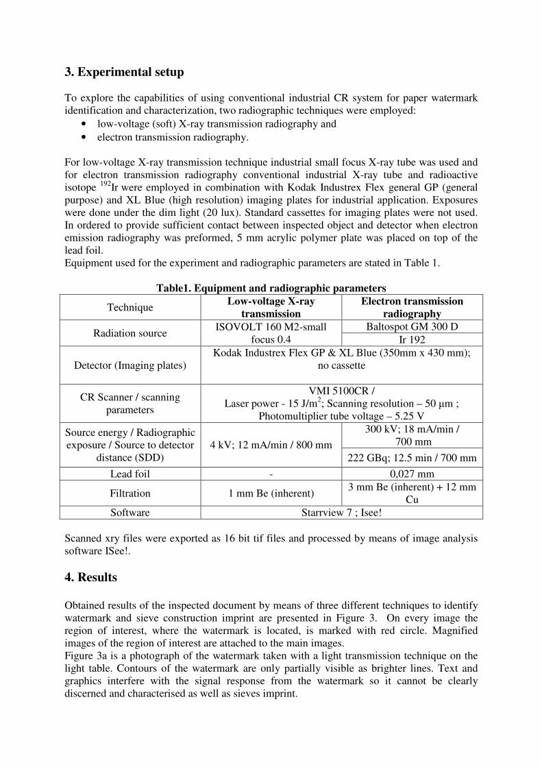
Obtained results of the inspected document by means of three different techniques to identify
watermark and sieve construction imprint are presented in Figure 3. On every image the
region of interest, where the watermark is located, is marked with red circle. Magnified
images of the region of interest are attached to the main images.
Figure 3a is a photograph of the watermark taken with a light transmission technique on the
light table. Contours of the watermark are only partially visible as brighter lines. Text and
graphics interfere with the signal response from the watermark so it cannot be clearly
discerned and characterised as well as sieves imprint.
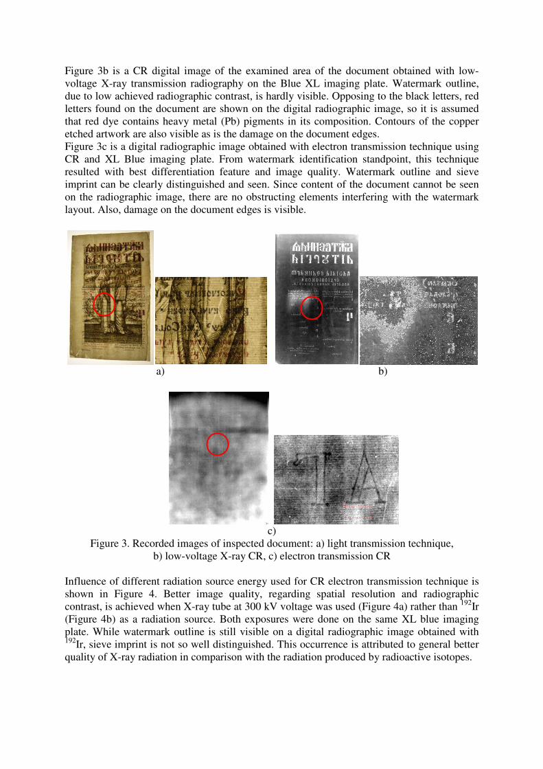
Figure 3b is a CR digital image of the examined area of the document obtained with low-
voltage X-ray transmission radiography on the Blue XL imaging plate. Watermark outline,
due to low achieved radiographic contrast, is hardly visible. Opposing to the black letters, red
letters found on the document are shown on the digital radiographic image, so it is assumed
that red dye contains heavy metal (Pb) pigments in its composition. Contours of the copper
etched artwork are also visible as is the damage on the document edges.
Figure 3c is a digital radiographic image obtained with electron transmission technique using
CR and XL Blue imaging plate. From watermark identification standpoint, this technique
resulted with best differentiation feature and image quality. Watermark outline and sieve
imprint can be clearly distinguished and seen. Since content of the document cannot be seen
on the radiographic image, there are no obstructing elements interfering with the watermark
layout. Also, damage on the document edges is visible.
a) b)
c)
Figure 3. Recorded images of inspected document: a) light transmission technique,
b) low-voltage X-ray CR, c) electron transmission CR
Influence of different radiation source energy used for CR electron transmission technique is
shown in Figure 4. Better image quality, regarding spatial resolution and radiographic
contrast, is achieved when X-ray tube at 300 kV voltage was used (Figure 4a) rather than 192
Ir
(Figure 4b) as a radiation source. Both exposures were done on the same XL blue imaging
plate. While watermark outline is still visible on a digital radiographic image obtained with 192
Ir, sieve imprint is not so well distinguished. This occurrence is attributed to general better
quality of X-ray radiation in comparison with the radiation produced by radioactive isotopes.
a) b)
Figure 4. Influence of radiation source on image quality for electron transmission CR:
a) X-ray tube (300 kV), b) 192
Ir
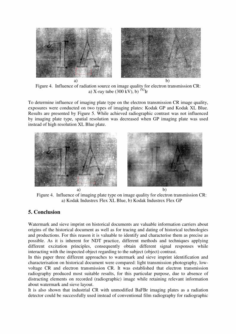
To determine influence of imaging plate type on the electron transmission CR image quality,
exposures were conducted on two types of imaging plates: Kodak GP and Kodak XL Blue.
Results are presented by Figure 5. While achieved radiographic contrast was not influenced
by imaging plate type, spatial resolution was decreased when GP imaging plate was used
instead of high resolution XL Blue plate.
a) b)
Figure 4. Influence of imaging plate type on image quality for electron transmission CR:
a) Kodak Industrex Flex XL Blue, b) Kodak Industrex Flex GP
5. Conclusion
Watermark and sieve imprint on historical documents are valuable information carriers about
origins of the historical document as well as for tracing and dating of historical technologies
and productions. For this reason it is valuable to identify and characterise them as precise as
possible. As it is inherent for NDT practice, different methods and techniques applying
different excitation principles, consequently obtain different signal responses while
interacting with the inspected object regarding to the subject (object) contrast.
In this paper three different approaches to watermark and sieve imprint identification and
characterisation on historical document were compared: light transmission photography, low-
voltage CR and electron transmission CR. It was established that electron transmission
radiography produced most suitable results, for this particular purpose, due to absence of
distracting elements on recorded (radiographic) image while retaining relevant information
about watermark and sieve layout.
It is also shown that industrial CR with unmodified BaFBr imaging plates as a radiation
detector could be successfully used instead of conventional film radiography for radiographic
testing of paper documents with low-voltage X-ray transmission technique and electron
transmission technique.
From all preformed techniques and parameter variations carried out in this research, best
image quality was obtained by means of electron transmission computed radiography using
high resolution imaging plates (Kodak XL Blue) as a radiation detector in combination with
high energy X-ray tube as a radiation source.
Acknowledgement
Procurement of the VMI 5100 CR system at the Laboratory for NDT at Faculty of Mechanical
Engineering and Naval Architecture, University of Zagreb was funded by Ministry of
Science, Education and Sports within the research project #1201767-1763, “Reliability of
non-destructive testing methods”.
We are thankful to the Aeronautical Technical Center in Velika Gorica and ZIT d.o.o. for
providing an X and gamma ray sources for the exposure of test samples.
References
1.M Körner, C.H. Weber, S. Wirth, K.J. Pfeifer, M.F. Reiser and M. Treitl, Advances in
Digital Radiography: Physical Principles and System Overview, RadioGraphics, Vol.
27, No 3, pp 675–686, 2007.
2.O. Schalm, L. Vanbiervliet, P. Willems and P. De Schepper, Radiography of paintings:
Limitations of transmission radiography and exploration of emission radiography
using phosphor imaging plates, Studies in Conservation, Vol. 59, No. 1, pp 10-23,
2014.
3.C. F. Bridgman, Radiography of paper, Studies in Conservation, Vol. 10, No. 1,
pp. 8-17, 1965.
4.T. Inada, K. Kawashima, K. Hoshino, and H. Matsuzawa, Energy Spectra of Electrons
Emerging from Lead Exposed to 320 kVp White X-rays, Japanese Journal of Applied
Physics, Vol. 2, No.2, pp 99–105, 1963.
5.R.A. Quinn and C.A. Sigl, Radiography in Modern Industry. Rochaester, NY: Eastman
Kodak Company, pp 168–172, 1980.
6.J. Beckmann, S. Rachny, U. Zscherpel and U. Ewert, Improved Procedure for Computed
Radiography - A Comparative Study on Welded Tube Sections by Film Radiography
and Computed Radiography, 17th World Conference on Nondestructive Testing,
Shanghai, China, 2008
7.N. Ash, Recording watermarks by beta-radiography and other means. In: The Book and
Paper Group Annual, vol.1. American Institute for Conservation of Historic and
Artistic Works, Washington, 1982
8.J. Lang, and A. Middleton, Radiography of Cultural Heritage, 2nd ed. Oxford: Elsevier
Butterworth-Heinemann, 2005.