Embed Size (px)
Citation preview
Punching Shear Behaviour of FRP-Reinforced
Concrete Interior Slab-Column Connections
By
Ahmed A. Gouda Sayed
A thesis submitted to the Faculty of Graduate Studies of
The University of Manitoba
In partial fulfillment of the requirements of the degree of
DOCTOR OF PHILOSOPHY
Department of Civil Engineering
Faculty of Engineering
University of Manitoba
Winnipeg, Manitoba, Canada
Copyright @ 2015 by Ahmed A. Gouda Sayed
Abstract
i
ABSRTACT
Flat slab-column connections are common elements in reinforced concrete (RC) structures such
as parking garages. In cold weather regions, these structures are exposed to de-icing salts and
aggressive environments. Using fiber reinforced polymer (FRP) bars instead of steel in such
structures will overcome the corrosion problems associated with steel reinforcement. However,
the available literature shows few studies to evaluate the behaviour of FRP-RC interior slab-
column connections tested mainly under concentric loads, which seldom occurs in a real
building. The main objectives of this research are to deal with this gap by investigating the
behaviour of full-scale glass (G) FRP-RC interior slab-column connections subjected to eccentric
load and to provide design recommendations for such type of connections.
This study consisted of two phases, experimental and analytical. The experimental phase
included the construction and testing of ten full-scale interior slab-column connections. The
parameters investigated in the experimental phase were flexural reinforcement ratio, concrete
compressive strength, type of the reinforcement, moment-to-shear ratio and the spacing between
the shear stud reinforcement. Test results revealed that increasing the GFRP reinforcement ratio
or the concrete strength increased the connection capacity. Moreover, compared to the control
steel-RC specimen, the GFRP-RC connection with similar reinforcement rigidity showed
comparable capacity and deflection at failure. Also, increasing the moment-to-shear ratio
resulted in a reduction in the vertical load capacity, while using the shear stud reinforcement
enhanced the strength up to 23%. In the analytical phase, a 3-D finite element model (FEM) was
constructed using specialized software. The constructed FEM was able to predict the
experimental results within a reasonable accuracy. The verified FEM was then used to conduct a
Abstract
ii
parametric study to evaluate the effects of perimeter-to-depth ratio, column aspect ratio, slab
thickness and a wide range of flexural reinforcement ratio. The numerical results showed that
increasing the reinforcement ratio increased the connection capacity. In addition, increasing the
perimeter-to-depth ratio and slab thickness reduced the punching shear stresses at failure, while,
the effect of the column rectangularity diminished for a ratio greater than three. Moreover, the
results showed prominent agreement with the experimental results from literature.

Acknowledgements
iii
ACKNOWLEDGEMENTS
Whatever I am going to write in this paragraph will not be enough to express my gratitude and
sincere appreciation to my supervisor Dr. Ehab El-Salakawy Ph.D., P.Eng., Professor and
Canada Research Chair (CRC) in Durability and Modernization of Civil Structures in the
Department of Civil Engineering at the University of Manitoba. I especially appreciate the
information and advices he has provided, as well as the experiences he has shared with me. His
assistance has been invaluable to me during this research.
The financial support provided by the University of Manitoba through the UMGF award and by
the Natural Science and Engineering Research Council of Canada (NSERC) through Discovery
and Canada Research Chairs programs is gratefully appreciated. The ribbed-deformed GFRP
reinforcement, generously provided by Schoeck Canada Inc., is greatly appreciated. Also, the
help provided by the technical staff of the W.R. McQuade Structures Laboratory at the
University of Manitoba is acknowledged.
In addition, I would like to thank my colleagues in the CRC research group, especially Dr.
Mohamed Hasaballa, P.Eng. and Mr. Karam Mahmoud for their encouragement and support.
Last, but not the least, I would like to express my sincere gratitude to my dear mother, my father,
my beloved wife and my two sisters for all what they have done for me.
Table of Contents
iv
TABLE OF CONTENTS
ABSTRACT ................................................................................................................................ i
ACKNOWLEDGEMENTS ................................................................................................... .. iii
TABLE OF CONTENTS .......................................................................................................... iv
LIST OF NOTATIONS ............................................................................................................ xi
LIST OF TABLES .................................................................................................................. xvi
LIST OF FIGURES ............................................................................................................... xvii
CHAPTER 1: INTRODUCATION
1.1 BACKGROUND ..................................................................................................................1
1.2 PROBLEM DEFINITION ....................................................................................................2
1.3 SCOPE OF WORK ...............................................................................................................4
1.4 OBJECTIVES AND AIMS OF THE PRESENT STUDY ...................................................4
1.5 METHODOLOGY AND APPROACH ...............................................................................5
1.6 THESIS ORGANIZATION..................................................................................................6
CHAPTER 2: LITERATURE REIVEW
2.1 INTRODUCTION ................................................................................................................8
2.2 PROPERTIES OF FRP REINFORCEMENT .......................................................................9
2.2.1 Physical Properties .........................................................................................................10
2.2.2 Mechanical Properties ....................................................................................................10
2.3 TYPES OF FAILURE OF CONCRETE FLAT PLATES ..................................................13
2.3.1 Flexural Failure .............................................................................................................13
Table of Contents
v
2.3.2 Punching Shear Failure ..................................................................................................15
2.4 BUILDING CODE REQUIREMENTS ..............................................................................16
2.4.1 Canadian Code for Steel-reinforced Concrete Structures (CAN/CSA-A23.3-14) ........17
2.4.1.1 Punching shear stresses calculations ........................................................................17
2.4.1.1.1 Calculation of shear stresses for concentric punching .....................................17
2.4.1.1.2 Calculation of shear stresses for eccentric punching .......................................18
2.4.1.2 Calculations of the punching shear resistance of flat plate ......................................23
2.4.1.2.1 Shear stress resistance without shear reinforcement........................................23
2.4.1.2.2 Shear stress resistance with stud shear reinforcement .....................................24
2.4.2 ACI Code for Steel-Reinforced Concrete Structures (ACI 318-14) ..............................25
2.4.2.1 Punching shear stresses calculations ........................................................................25
2.4.2.2 Calculations of the punching shear resistance of flat plate ......................................26
2.4.2.2.1 Shear stress resistance without shear reinforcement........................................26
2.4.2.2.2 Shear stress resistance with stud shear reinforcement .....................................26
2.4.3 European Code Requirements (EN/1992-1-1 2004) ......................................................27
2.4.3.1 Punching shear stresses calculations ........................................................................27
2.4.3.2 Calculations of the punching shear resistance of flat plate ......................................30
2.4.4 JSCE 2007 (Japan Society of Civil Engineering 2007) .................................................31
2.4.5 Punching Shear Resistance of Flat Plates Reinforced with FRP Bars
According to Different Codes ..........................................................................................35
2.4.5.1 Canadian code CSA-S806-12 ...................................................................................35
2.4.5.2 ACI guidline (ACI 440.1 R-06) ................................................................................36
2.4.5.3 JSCE 1997 (Japan society of civil engineering 1997) ..............................................37
Table of Contents
vi
2.5 RESEARCH ON STEEL-REINFORCED CONCRETE SLAB-COLUMN
CONNECTIONS ............................................................................................................... 37
2.5.1 Effect of Connection Geometry .....................................................................................38
2.5.1.1 Effect of column aspect ratio ...................................................................................38
2.5.1.2 Effect of critical shear perimeter-to-depth ratio ......................................................38
2.5.1.3 Effect of span-to-depth ratio ....................................................................................39
2.5.2 Effect of Concrete Compressive Strength ......................................................................40
2.5.3 Effect of Concrete Tensile Strength ...............................................................................41
2.5.4 Shear Reinforcement ......................................................................................................42
2.5.4.1 Effect of stirrups and bent bars ................................................................................42
2.5.4.2 Effect of shear stud reinforcement ...........................................................................43
2.5.4.3 Effect of shear heads ................................................................................................44
2.5.5 Effect of Flexural Reinforcement ..................................................................................45
2.5.5.1 Effect of reinforcement ratio ....................................................................................46
2.5.5.2 Effect of reinforcement arrangement .......................................................................47
2.5.5.3 Effect of yield strength of the reinforcement ..........................................................48
2.6 RESEARCHES ON FRP-REINFORCED SLAB-COLUMN CONNECTIONS ...............48
2.6.1 Effect of FRP Flexural Reinforcement Ratio .................................................................49
2.6.2 Effect of FRP Flexural Reinforcement Arrangement ....................................................54
2.6.3 Effect of using FRP Shear Reinforcement .....................................................................56
2.6.4 Effect of Concrete Compressive Strength ......................................................................57
CHAPTER 3: EXPERIMENTAL PROGRAM
3.1 INTRODUCTION ...............................................................................................................58
Table of Contents
vii
3.2 EXPERIMENTAL STUDY.................................................................................................59
3.2.1 Material Properties .........................................................................................................64
3.2.1.1 Concrete ...................................................................................................................64
3.2.1.2 Reinforcement ..........................................................................................................64
3.2.2 Design Concepts of Test Specimens ..............................................................................67
3.2.3 Details of Tested Specimens ..........................................................................................68
3.2.4 Fabrication of Test Specimens .......................................................................................74
3.2.5 Test Set-up and Loading Procedures .............................................................................76
3.2.6 Instrumentation ...............................................................................................................78
3.2.6.1 Load cells .................................................................................................................78
3.2.6.2 Linear variable displacement transducers (LVDTs) ................................................79
3.2.6.3 Strain gauges ............................................................................................................79
CHAPTER 4: RESULTS AND DISCUSSION
4.1 INTRODUCTION ...............................................................................................................82
4.2 SERIES I-THE EFFECTS OF REINFORCEMENT RATIO, BAR MATERIAL AND TYPE
AND CONCRETE COMPRESSIVE STRENGTH …………….……….………………82
4.2.1 Cracking and Failure Mode of Specimens of Series I ...................................................83
4.2.2 Deflection of Specimens of Series I ...............................................................................85
4.2.3 Strains in Specimens of Series I.....................................................................................92
4.2.4 Yield-line Pattern ...........................................................................................................98
4.2.5 Ultimate Strength of Specimens of Series I ...................................................................99
4.2.6 Predicated Punching Loads for the GFRP Specimens of Series I ...............................102
Table of Contents
viii
4.3 SERIES II AND III-THE EFFECTS OF MOMENT-TO-SHEAR RATIO AND SHEAR
REINFORCEMENT ……………………….…………….…………………...………….…...106
4.3.1 Cracking and Failure Mode of Specimens of Series II and III ....................................106
4.3.2 Deflection of Specimens of Series II and III ...............................................................108
4.3.3 Strains in Specimens of Series II and III .....................................................................113
4.3.4 Ultimate Strength of Specimens of Series II and III ....................................................120
4.3.5 Predicated Punching Capacity of Specimens of Series II and III ................................122
4.3.5.1 Slabs without shear reinforcement of specimens of Series II and III .....................122
4.3.5.2 Slabs with shear reinforcement ...............................................................................123
4.3.5.2.1 Based on the CSA/S806-12 and CSA/A23.3-14 provisions ................................124
4.3.5.2.2 Based on the ACI -40.1R-06 and ACI-318-14 provisions ..................................125
CHAPTER 5: NUMERICAL ANALYSIS
5.1 INTRODUCTION .............................................................................................................127
5.2 MATERIAL PROPERTIES AND ELEMENTS TYPES..................................................128
5.2.1 Reinforcement Bars .....................................................................................................128
5.2.2 Concrete Material.........................................................................................................129
5.2.3 Stress and Strain ...........................................................................................................129
5.3 CONCEPTS OF MATERIAL MODEL CC3DNonLinCementitious2 .............................130
5.3.1 Stress-Strain Relations for Concrete ............................................................................131
5.3.1.1 Equivalent uniaxial law ...........................................................................................131
5.3.2 Cracking .......................................................................................................................134
Table of Contents
ix
5.3.3 Parameters of Constitutives Model ..............................................................................135
5.4 BEARING PLATES ..........................................................................................................135
5.5 REINFORCEMENT-CONCRETE INTERFACE.............................................................136
5.6 MODEL GEOMTRY AND BOUNDARY CONDITIONS ..............................................139
5.7 SOLUTION CONTROLS .................................................................................................141
5.8 MODEL VERIFICATION ................................................................................................142
5.9 SUMMARY .......................................................................................................................145
CHAPTER 6: PARAMETIC STUDY
6.1 INTRODUCTION .............................................................................................................146
6.2 FLEXURAL REINFORCEMENT RATIO .......................................................................147
6.2.1 Load-Deflection Response ...........................................................................................147
6.2.2 Load-Strain Relatioship ...............................................................................................149
6.2.3 Ultimate Capacity ........................................................................................................150
6.3 EFFECT OF SHEAR PERIMETER-TO-DEPTH RATIO ...............................................153
6.3.1 Load-Deflection Response ...........................................................................................154
6.3.2 Load-Strain Relationship .............................................................................................155
6.3.3 Ultimate Capacity ........................................................................................................156
6.4 EFFECT OF COLUMN ASPECT RATIO........................................................................159
6.4.1 Load-Deflection Response ...........................................................................................160
6.4.2 Load-Strain Relationship .............................................................................................162
6.4.3 Ultimate Capacity ........................................................................................................162
6.5 EFFECT OF SLAB THICKNESS .....................................................................................165
Table of Contents
x
6.5.1 Load-Deflection Response ...........................................................................................165
6.5.2 Load-Strain Relationship .............................................................................................165
6.5.3 Ultimate Capacity ........................................................................................................167
CHAPTER 7: SUMMARY, CONCLUSIONS AND RECOMENDATIONS
7.1 SUMMARY .......................................................................................................................169
7.2 CONCLUSIONS................................................................................................................170
7.2.1 Conclusions From the Experimental Phase ..................................................................170
7.2.2 Conclusions From the Unmerical Phase .......................................................................172
7.3 RECOMMENDATIONS ...................................................................................................174
7.3.1 Recommendations for Designers .................................................................................174
7.3.2 Recommendations for Future Work ..............................................................................174
REFERENCES .......................................................................................................................176
APPENDIX A - DESIGN OF TEST SPECIMENS ........................................................... A-1
APPENDIX B - SERVICEABILITY REQUIREMENTS .................................................B-1
APPENDIX C- PUNCHING SHEAR CAPACITIY OF THE SPECIMENS ..................C-1
APPENDIX D- FLEXURAL CAPACITIY OF THE SPECIMENS ................................ D-1
List of Tables
xi
LIST OF NOTATIONS
Ac the area of concrete according to the definition of Ned (mm2)
Avs cross sectional areas of the shear studs along the critical shear perimeter (at d/2 from
the column face) (mm2)
b1 width of the critical section for shear measured in the direction of the span for which
moments are determined (mm)
b2 width of the critical section for shear measured in the direction perpendicular to b1
(mm)
bo the critical shear perimeter (at d/2 from the column face) (mm)
bp the critical perimeter according to BS 8110-97 (mm)
c depth of neutral axis for the cracked transformed section (mm)
C the side length of the square column (mm)
C1 the column dimension parallel to the eccentricity of the load (mm)
C2 the column dimension perpendicular to the eccentricity of the load (mm)
CRd,C calibration factor
C** distance from the centroid of the connection to the point where the shear stress is
calculated (mm)
d the effective flat plate depth (mm)
dℓ a length increment of the perimeter (mm)
D material stiffness matrix (MPa)
D1 the diameter of the circular column (mm)
D.L. factored dead load (kN/m2)
e eccentricity (mm)
e1 the distance of dℓ from the axis about which the moment M acts (mm)
epar the eccentricity parallel to the slab edge resulting from a moment about an axis
perpendicular to the slab edge (mm)
Ec the modulus of elasticity of the concrete (MPa)
E1 secant elastic modulus at the peak stress (MPa)
EF modulus of elasticity of longitudinal FRP reinforcement (MPa)
List of Tables
xii
Efrv elastic modulus for the shear studs (MPa)
EO initial elastic modulus (MPa)
ES elastic modulus of steel (MPa)
f c'
compressive strength of concrete (MPa)
fc'ef
effective concrete compressive strength (MPa)
fck the characteristic concrete cylinder strength (MPa)
ff stress of the FRP reinforcement (MPa)
ffrv specified stress in the FRP-studs (MPa)
fpcd the design compressive strength of concrete (MPa)
ft concrete tensile strength (MPa)
ft'ef
maximum tensile stresses (MPa)
fy the yielding strength of the steel reinforcement (MPa)
Gf fracture energy needed to create a unit area of stress-free crack (MN/m)
Jc property of the critical shear section of slabs analogous to the polar moment of
inertia (mm4)
Jcy property of the critical shear section of slabs analogous to the polar moment of
inertia along y-axis (mm4)
Jcx property of the critical shear section of slabs analogous to the polar moment of
inertia along x-axis (mm4)
k coefficient dependents on the ratio between the column dimensions
k1 the coefficient considering the effects of axial forces on the stress distribution
k2 the maximum ratio of the average compressive stress to the characteristic cube
concrete strength fcu, corresponding to the concrete strain εcu
ℓ typical distance between the columns (mm)
Ld band size which defined as the projection of the element on the failure plane (mm)
L.L. factored live load (kN/m2)
Mcr cracking moment (kN.m/m)
Mn flexural capacity of the slab in the direction of moment transfer (kN.m/m)
List of Tables
xiii
MP plastic moment (kN.m/m)
Mx unbalanced moment around the x-axis (kN.m)
My unbalanced moment around the y-axis (kN.m)
N constant taken equal to 5/6 for fc/ in MPa, bo in mm and d in mm
NEd the longitudinal forces across the full bay for interior columns and the longitudinal
force across the control section for edge columns (N)
nf ratio of modulus of elasticity of FRP bars to modulus of elasticity of concrete
q* total shear stress at a point (MPa)
q** shear stress at a point due to the effect of the unbalanced moment (MPa)
s stress vector (MPa)
S spacing between the shear studs (mm)
s1 bond slippage (MPa)
t bond stresses (MPa)
tmax the maximum bond strength of the steel bar embedded in concrete (MPa)
u the peripheral length of the column (mm)
Ui the length of the control perimeter being considered (mm)
U1 the length of the basic control perimeter (2.0 d from the column faces) (mm)
up the peripheral length of the design cross-section at d/2 from the column face (mm)
V the factored shear force (N)
Vc punching shear capacity (N)
VED punching shear stresses (MPa) according to European code
Vexp. failure load (kN)
vf the total stresses at a point (MPa)
VF uniform factored shear stresses (MPa)
Vflex. flexural capacity (kN)
VJ the nominal shear strength provided by concrete (N) according to the Japanese
standard
List of Tables
xiv
Vnorm. normalized failure load (kN)
vr ultimate punching shear stress resistance for concrete (MPa)
VRd,C the shear resistance of concrete (MPa) according to European code
vs the factored shear resistance provided by the shear studs (MPa)
w total factored load (kN/m2)
W1 factor function of the perimeter Ui
wc the crack opening at the complete release of stress (mm)
wd plastic displacement (mm)
x normalized strain
(X)f combined depth of the compression zone (mm)
(Xf)f the depth of the flexural section (mm)
Xs the depth of the shear section (mm)
αs
4.0 for interior column, 3.0 for edge column, and 2.0 for corner column in CSA
standards and 40 for interior column, 30 for edge column and 20 for corner column
in ACI codes.
βc the ratio of long side to short side of the column
βd coefficient to consider effect of effective depth on shear capacity
βp coefficient to consider effect of effective reinforcement ratio defined as the average
values for the reinforcement in two directions
βr factor represents the effect of the loaded area
γb safety factor
γxy the engineering shear strain
γv fraction of the unbalanced moment transferred by eccentricity
γvy fraction of the unbalanced moment transferred by eccentricity in the direction of y-
axis
γvx fraction of the unbalanced moment transferred by eccentricity in the direction of x-
axis
ɛ strain vector
εc strain at the peak stress fc/ef
List of Tables
xv
εcu the specified value of concrete strain (0.0035)
εd the strain at the complete release of the stresses
εf strain of the FRP flexural reinforcement
εfrv strain of the GFRP shear studs
ɛx strain in (x) direction
ɛy strain in (y) direction
λ factor to account for low-density concrete (1.0 for normal weight concrete)
ρ longitudinal reinforcement ratio
ρF longitudinal reinforcement ratio for FRP
ρfb balanced reinforcement ratio
σc normal concrete stresses (MPa)
σcef
concrete compressive strength (MPa)
σ1 & σ2 principle stresses (MPa)
σx normal stress in the (x) direction (MPa)
σy normal stress in the (y) direction (MPa)
ϕ resistance factor applied to a specified material property or to the resistance of a
member
τxy shear stress in plane (xy) (MPa)
θ the mean angle of the failure surface (degree)
List of Tables
xvi
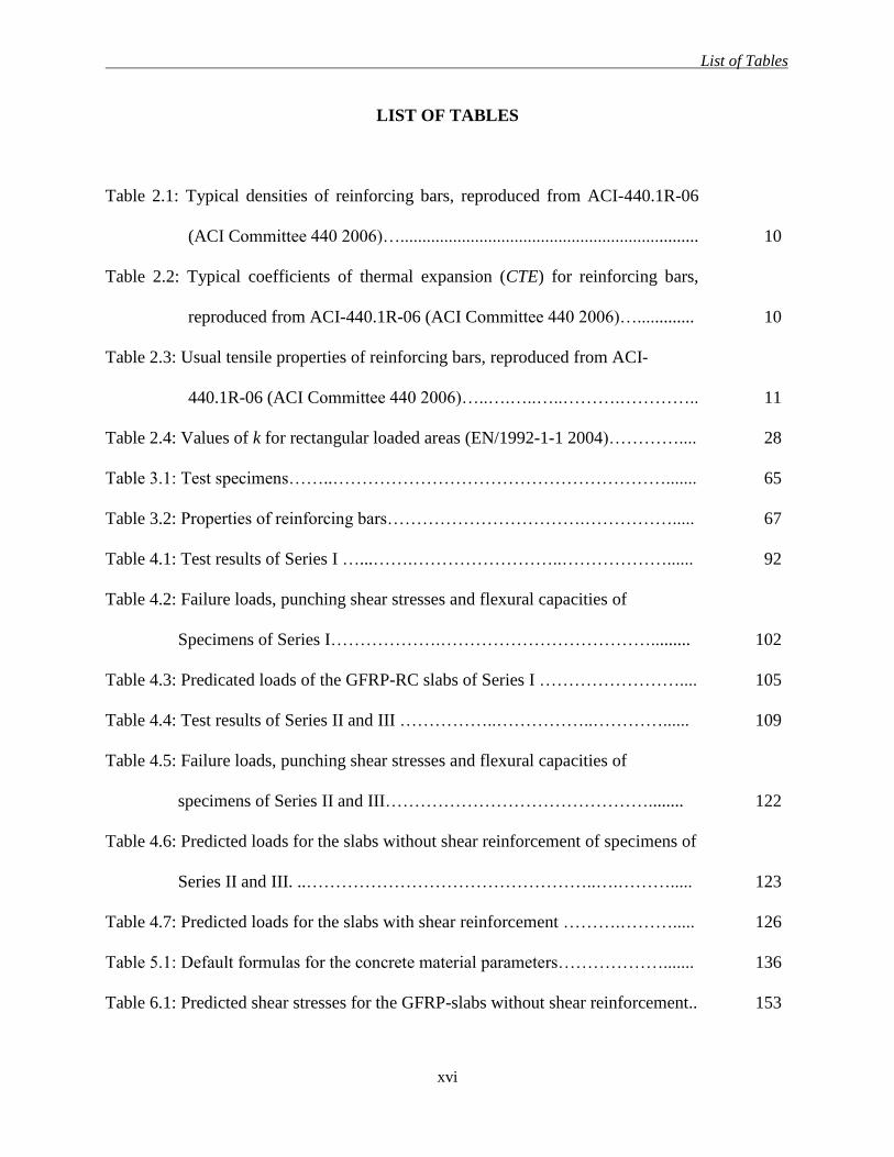
LIST OF TABLES
Table 2.1: Typical densities of reinforcing bars, reproduced from ACI-440.1R-06
(ACI Committee 440 2006)….................................................................... 10
Table 2.2: Typical coefficients of thermal expansion (CTE) for reinforcing bars,
reproduced from ACI-440.1R-06 (ACI Committee 440 2006)…............. 10
Table 2.3: Usual tensile properties of reinforcing bars, reproduced from ACI-
440.1R-06 (ACI Committee 440 2006)…..….…..…..……….………….. 11
Table 2.4: Values of k for rectangular loaded areas (EN/1992-1-1 2004)………….... 28
Table 3.1: Test specimens……..…………………………………………………....... 65
Table 3.2: Properties of reinforcing bars…………………………….……………..... 67
Table 4.1: Test results of Series I …...…….……………………..………………...... 92
Table 4.2: Failure loads, punching shear stresses and flexural capacities of
Specimens of Series I……………….………………………………......... 102
Table 4.3: Predicated loads of the GFRP-RC slabs of Series I …………………….... 105
Table 4.4: Test results of Series II and III ……………..……………..…………...... 109
Table 4.5: Failure loads, punching shear stresses and flexural capacities of
specimens of Series II and III………………………………………........ 122
Table 4.6: Predicted loads for the slabs without shear reinforcement of specimens of
Series II and III. ..…………………………………………..….………..... 123
Table 4.7: Predicted loads for the slabs with shear reinforcement ……….………..... 126
Table 5.1: Default formulas for the concrete material parameters………………....... 136
Table 6.1: Predicted shear stresses for the GFRP-slabs without shear reinforcement.. 153
List of Figures
xvii
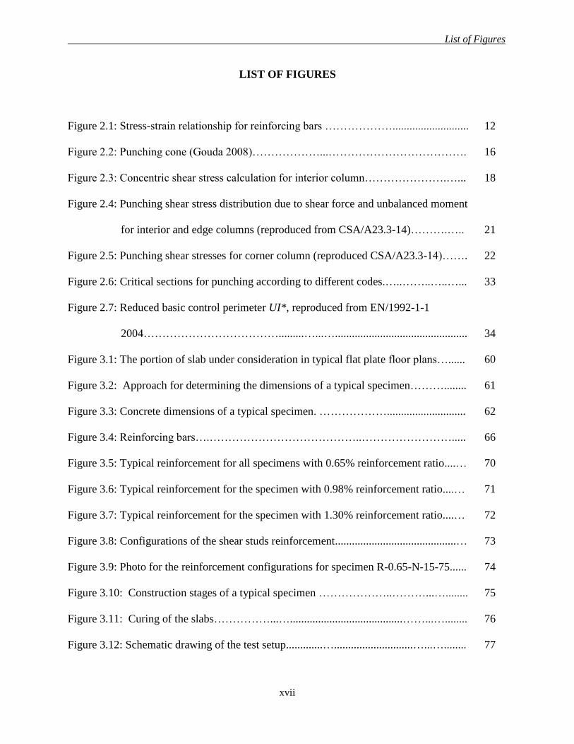
LIST OF FIGURES
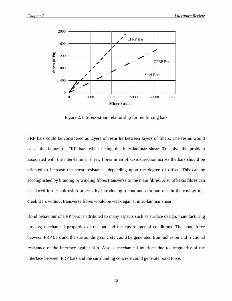
Figure 2.1: Stress-strain relationship for reinforcing bars ………………........................... 12
Figure 2.2: Punching cone (Gouda 2008)………………...………………………………. 16
Figure 2.3: Concentric shear stress calculation for interior column………………….…... 18
Figure 2.4: Punching shear stress distribution due to shear force and unbalanced moment
for interior and edge columns (reproduced from CSA/A23.3-14)……….….. 21
Figure 2.5: Punching shear stresses for corner column (reproduced CSA/A23.3-14)……. 22
Figure 2.6: Critical sections for punching according to different codes.…..……..…..…... 33
Figure 2.7: Reduced basic control perimeter UI*, reproduced from EN/1992-1-1
2004……………………………….........…...…............................................... 34
Figure 3.1: The portion of slab under consideration in typical flat plate floor plans…...... 60
Figure 3.2: Approach for determining the dimensions of a typical specimen………........ 61
Figure 3.3: Concrete dimensions of a typical specimen. ………………............................ 62
Figure 3.4: Reinforcing bars….…………………………………..……………………..... 66
Figure 3.5: Typical reinforcement for all specimens with 0.65% reinforcement ratio....… 70
Figure 3.6: Typical reinforcement for the specimen with 0.98% reinforcement ratio....… 71
Figure 3.7: Typical reinforcement for the specimen with 1.30% reinforcement ratio....… 72
Figure 3.8: Configurations of the shear studs reinforcement...........................................… 73
Figure 3.9: Photo for the reinforcement configurations for specimen R-0.65-N-15-75...... 74
Figure 3.10: Construction stages of a typical specimen ………………..………...…........ 75
Figure 3.11: Curing of the slabs……………...…........................................……...…........ 76
Figure 3.12: Schematic drawing of the test setup.............…............................…...…........ 77

List of Figures
xviii
Figure 3.13: Photo for the test setup……...........………..……........................................... 78
Figure 3.14: Typical arrangement of LVDTs..…………….. …………….......................... 80
Figure 3.15: Typical arrangement of the flexure reinforcement strain gauges.................... 80
Figure 3.16: Strain gauges layout for the shear reinforcement…….…………................... 81
Figure 4.1: Crack patterns on the tension face of the slab at failure for specimens of
Series I………...................................................................................................
88
Figure 4.2: Load-deflection relationship of specimens of Series I …...………….............. 89
Figure 4.3: Deflection-profiles for specimen G-0.65-N-15-XX at the centrelines of the
slab.................................................................................................................... 90
Figure 4.4: Relation between the reinforcement ratio and the post cracking stiffness for
the GFRP-slabs with NSC in Series I................................................................ 91
Figure 4.5: Cumulative energy of Specimens of Series I..................................................... 91
Figure 4.6: Load- strain relationship of Specimens of Series I............................................ 95
Figure 4.7: Strain profiles for tension reinforcement at the centreline of specimen G-
0.65-N-15-XX................................................................................................... 96
Figure 4.8: Strain profiles for tension reinforcement at the centreline of specimen G-
0.98-N-15-XX................................................................................................... 96
Figure 4.9: Strain profiles for tension reinforcement at the centreline of specimen G-
1.30-N-15-XX................................................................................................... 97
Figure 4.10: Strain profiles for tension reinforcement at the centreline of specimen G-
0.65-H-15-XX.................................................................................................. 97
Figure 4.11: Strain profiles for tension reinforcement at the centreline of specimen S-
0.65-N-15-XX.................................................................................................. 98
List of Figures
xix
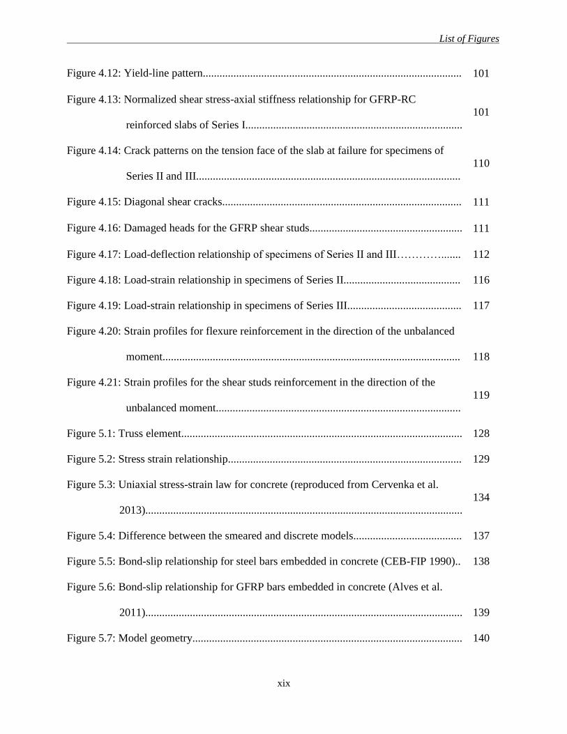
Figure 4.12: Yield-line pattern............................................................................................. 101
Figure 4.13: Normalized shear stress-axial stiffness relationship for GFRP-RC
reinforced slabs of Series I..............................................................................
101
Figure 4.14: Crack patterns on the tension face of the slab at failure for specimens of
Series II and III...............................................................................................
110
Figure 4.15: Diagonal shear cracks...................................................................................... 111
Figure 4.16: Damaged heads for the GFRP shear studs....................................................... 111
Figure 4.17: Load-deflection relationship of specimens of Series II and III…………....... 112
Figure 4.18: Load-strain relationship in specimens of Series II.......................................... 116
Figure 4.19: Load-strain relationship in specimens of Series III......................................... 117
Figure 4.20: Strain profiles for flexure reinforcement in the direction of the unbalanced
moment........................................................................................................... 118
Figure 4.21: Strain profiles for the shear studs reinforcement in the direction of the
unbalanced moment........................................................................................
119
Figure 5.1: Truss element..................................................................................................... 128
Figure 5.2: Stress strain relationship.................................................................................... 129
Figure 5.3: Uniaxial stress-strain law for concrete (reproduced from Cervenka et al.
2013)..................................................................................................................
134
Figure 5.4: Difference between the smeared and discrete models....................................... 137
Figure 5.5: Bond-slip relationship for steel bars embedded in concrete (CEB-FIP 1990).. 138
Figure 5.6: Bond-slip relationship for GFRP bars embedded in concrete (Alves et al.
2011).................................................................................................................. 139
Figure 5.7: Model geometry................................................................................................. 140
List of Figures
xx
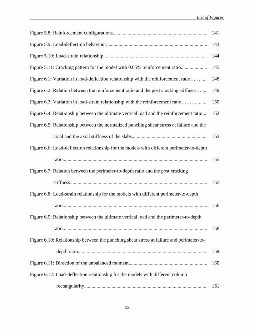
Figure 5.8: Reinforcement configurations........................................................................... 141
Figure 5.9: Load-deflection behaviour................................................................................. 143
Figure 5.10: Load-strain relationship................................................................................... 144
Figure 5.11: Cracking pattern for the model with 0.65% reinforcement ratio..................... 145
Figure 6.1: Variation in load-deflection relationship with the reinforcement ratio……..... 148
Figure 6.2: Relation between the reinforcement ratio and the post cracking stiffness….... 149
Figure 6.3: Variation in load-strain relationship with the reinforcement ratio………........ 150
Figure 6.4: Relationship between the ultimate vertical load and the reinforcement ratio... 152
Figure 6.5: Relationship between the normalized punching shear stress at failure and the
axial and the axial stiffness of the slabs............................................................ 152
Figure 6.6: Load-deflection relationship for the models with different perimeter-to-depth
ratio.................................................................................................................... 155
Figure 6.7: Relation between the perimeter-to-depth ratio and the post cracking
stiffness.............................................................................................................. 155
Figure 6.8: Load-strain relationship for the models with different perimeter-to-depth
ratio.................................................................................................................... 156
Figure 6.9: Relationship between the ultimate vertical load and the perimeter-to-depth
ratio.................................................................................................................... 158
Figure 6.10: Relationship between the punching shear stress at failure and perimeter-to-
depth ratio....................................................................................................... 159
Figure 6.11: Direction of the unbalanced moment............................................................... 160
Figure 6.12: Load-deflection relationship for the models with different column
rectangularity.................................................................................................. 161
List of Figures
xxi
Figure 6.13: Relation between the column aspect ratio and the post cracking
stiffness........................................................................................................... 161
Figure 6.14: Load-strain relationship for the models with different column aspect ratio.... 163
Figure 6.15: Relationship between the ultimate vertical load and the column aspect
ratio................................................................................................................. 164
Figure 6.16: Relationship between the punching shear stress at failure and the column
rectangularity……………………………….….………….…………..……. 164
Figure 6.17: Load-deflection relationship for the models with different slab
thickness…….................................................................................................. 166
Figure 6.18: Relation between the slab thickness and the post cracking
stiffness........................................................................................................... 166
Figure 6.19: Load-strain relationship for the models with different slab thickness……..... 167
Figure 6.20: Relationship between the ultimate vertical load and the slab
thickness.......................................................................................................... 168
Figure 6.21: Relationship between the punching shear stress at failure and the slab
thickness ……………………………….…….….………….………………. 168
Chapter 1 Introduction
1
CHAPTER 1
INTRODUCTION
1.1 BACKGROUND
Corrosion of steel reinforcement is one of the major problems facing the civil engineering
industry, which affects or limits the life expectancy of any concrete building. Much research has
been conducted to overcome this problem. One of the leading methods that have been found to
overcome the corrosion problem is to replace the traditional steel reinforcing bars with fibre-
reinforced polymer (FRP) bars.
The FRP reinforcement have many advantages over ordinary steel reinforcement such as light
weight (FRP bars have a density ranging from one-sixth to one-fourth that of steel (ACI
Committee 440 2006)), which reduces the cost of transportation and handling. Also, FRPs have
high tensile strength which is approximately twice to triple the yielding stress of steel as well as
high resistance to corrosion and many types of salts. However, the behaviour of FRP bars differs
from that of steel in many ways. For example, FRP bars have perfectly linear-elastic behaviour
up to failure with no yielding, and therefore, FRP bars do not exhibit ductile behaviour in
concrete structures. Furthermore, FRP bars have relatively low modulus of elasticity; for
instance, in case of GFRP bars, it is approximately one fourth to one third that of steel. In
addition, FRP bars have different bond characteristics compared to steel. For example, sand-
coated GFRP bars have adhesion and friction bond which uniformly distribute the bond stresses
along the embedded length, while steel deformed bars have mainly mechanical bond through
bearing on the deformation. Consequently, concrete members reinforced with sand-coated GFRP
Chapter 1 Introduction
2
bars would have less average crack spacing compared to concrete members reinforced with the
steel ones.
A flat plate structural system is composed of slab rested, directly, on columns. This system has
many applications in the construction industry due to its numerous advantages, which include the
simplified formwork, reduced storey heights and its ability to sustain heavy loads. A large
number of reinforced concrete (RC) parking garages in North America are constructed using flat
plates supported directly on columns. These structures are subjected to severe environmental
conditions, such as freeze-thaw cycles and de-icing salts, which may cause corrosion of steel and
limit the life expectancy of the building. Using FRP bars as internal reinforcement in such
structure would overcome the corrosion problem associated with the steel bars. On the other
hand, the lack of experimental and analytical studies on the behaviour of flat plate systems
reinforced with FRP bars limits the knowledge and the full understanding of the behaviour of
such plates.
1.2 PROBLEM DEFINITION
Punching shear failure in flat slab-column connections is a main concern for the designers, since
it is sudden and brittle. This failure occurs due to the high transverse shear stresses caused by
shear force and unbalanced moment transfers from the slab to the columns. This combination of
shear and unbalanced moment is unavoidable at slab-column connections, even under gravity
loads only, due to unsymmetrical loading or/and unequal spans in addition to the effect of lateral
loads, if any. Prevention of punching shear failure of slab-column connections depends on
accurate calculations of shear stresses produced by the shear forces and the unbalanced moments
transferred to the columns. Also, the design and detailing of slab-column connections are critical
to ensure the satisfactory performance of flat plate structures.
Chapter 1 Introduction
3
The shear resistance of an RC member is composed of two components. The first is the shear
resistance provided by concrete and the second is the shear resistance provided by shear
reinforcement, if any. The concrete resistance for shear stresses is influenced by the properties of
the flexural reinforcement. After cracking and due to the relatively-low modulus of elasticity of
the FRP bars compared to steel, FRP-RC members are expected to have wider cracks and smaller
depth to neutral axis. As a result, the shear resistance provided by both aggregate interlock and
un-cracked concrete is smaller. Also, FRP bars are uni-directional materials (anisotropic) with
relatively low strength and stiffness in the transverse direction compared to those in the
longitudinal direction. This property results in smaller dowel force and consequently less
contribution to shear resistance (ACI Committee 440 2006) compared to steel-RC structures.
Consequently, it is expected that shear resistance of FRP-RC members, in general, will be less
than their counterparts reinforced with steel. Therefore, it is not valid to directly use the code
equations for concrete members reinforced with steel bars for those reinforced with FRP bars.
Recently, the Canadian Standard Association (CSA) published an updated version of the FRP
design code, CSA/S806-12 (CSA 2012). This new version introduces three equations to predict
the punching shear capacity of FRP-RC slab-column connections; however the code does not
include any provision for slab-column connections reinforced with shear reinforcement.
Up to date, there is no research conducts to evaluate the behaviour of full-scale interior slab-
column connections reinforced with GFRP bars under eccentric load, the available literature is
dealing mainly with FRP-RC interior slab-column connections subjected to concentric load. The
research program described herein is designed to partially fill this gap.
Chapter 1 Introduction
4
1.3 SCOPE OF WORK
This research study focused on studying the behaviour of full-scale isolated interior slab-column
connections reinforced with glass FRP bars. Glass FRP bars are currently of interest to the
infrastructure owners, FRP manufacturers and the construction industry in general due to their
lower cost compared to the other types of FRP bars (carbon and aramid). As such, only GFRP
bars were employed in this study. The specimen represented the zone of negative moment
around an interior column isolated from a multi-story, multi-bay building (prototype) with
columns equally spaced at 6.5 m in both directions. The slabs were assumed to be simply-
supported at the lines of contra flexure around an interior column. Also, the slabs were
reinforced in flexure with GFRP bars, with and without GFRP shear reinforcement, while the
columns for all specimens were adequately reinforced with steel bars and stirrups to prevent
premature failure. In addition, all specimens were subjected simultaneously to shear force and
unbalanced moment throughout the test. Furthermore, no earthquake or wind loads were
considered in this research, the unbalanced moment is due to the effect of the gravity loads only.
1.4 OBJECTIVES AND AIMS OF THE PRESENT STUDY
This study investigated the behaviour of isolated interior slab-column connections reinforced
with GFRP bars subjected simultaneously to shear and unbalanced moment. The behaviour of
these concrete slab-column connections was investigated analytically and experimentally.
The main objectives of this research were to:
1- Investigate the behaviour and shear capacity of GFRP-RC interior slab-column
connections subjected to eccentric load.
2- Provide recommendations for designers and researchers regarding the analysis and the
design of GFRP-RC flat slab-column connections.
Chapter 1 Introduction
5
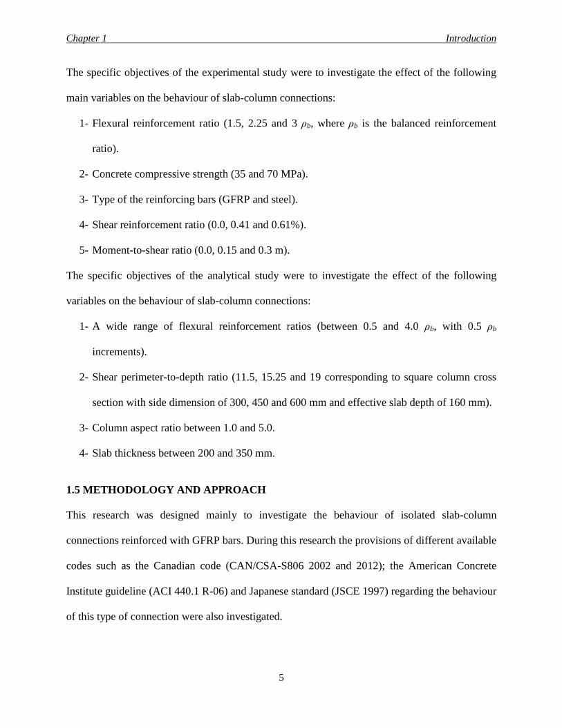
The specific objectives of the experimental study were to investigate the effect of the following
main variables on the behaviour of slab-column connections:
1- Flexural reinforcement ratio (1.5, 2.25 and 3 ρb, where ρb is the balanced reinforcement
ratio).
2- Concrete compressive strength (35 and 70 MPa).
3- Type of the reinforcing bars (GFRP and steel).
4- Shear reinforcement ratio (0.0, 0.41 and 0.61%).
5- Moment-to-shear ratio (0.0, 0.15 and 0.3 m).
The specific objectives of the analytical study were to investigate the effect of the following
variables on the behaviour of slab-column connections:
1- A wide range of flexural reinforcement ratios (between 0.5 and 4.0 ρb, with 0.5 ρb
increments).
2- Shear perimeter-to-depth ratio (11.5, 15.25 and 19 corresponding to square column cross
section with side dimension of 300, 450 and 600 mm and effective slab depth of 160 mm).
3- Column aspect ratio between 1.0 and 5.0.
4- Slab thickness between 200 and 350 mm.
1.5 METHODOLOGY AND APPROACH
This research was designed mainly to investigate the behaviour of isolated slab-column
connections reinforced with GFRP bars. During this research the provisions of different available
codes such as the Canadian code (CAN/CSA-S806 2002 and 2012); the American Concrete
Institute guideline (ACI 440.1 R-06) and Japanese standard (JSCE 1997) regarding the behaviour
of this type of connection were also investigated.
Chapter 1 Introduction
6
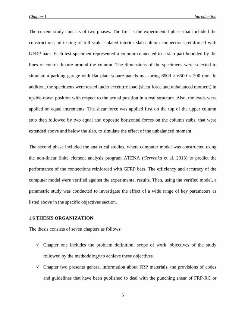
The current study consists of two phases. The first is the experimental phase that included the
construction and testing of full-scale isolated interior slab-column connections reinforced with
GFRP bars. Each test specimen represented a column connected to a slab part-bounded by the
lines of contra-flexure around the column. The dimensions of the specimens were selected to
simulate a parking garage with flat plate square panels measuring 6500 × 6500 × 200 mm. In
addition, the specimens were tested under eccentric load (shear force and unbalanced moment) in
upside-down position with respect to the actual position in a real structure. Also, the loads were
applied on equal increments. The shear force was applied first on the top of the upper column
stub then followed by two equal and opposite horizontal forces on the column stubs, that were
extended above and below the slab, to simulate the effect of the unbalanced moment.
The second phase included the analytical studies, where computer model was constructed using
the non-linear finite element analysis program ATENA (Cervenka et al. 2013) to predict the
performance of the connections reinforced with GFRP bars. The efficiency and accuracy of the
computer model were verified against the experimental results. Then, using the verified model, a
parametric study was conducted to investigate the effect of a wide range of key parameters as
listed above in the specific objectives section.
1.6 THESIS ORGANIZATION
The thesis consists of seven chapters as follows:
Chapter one includes the problem definition, scope of work, objectives of the study
followed by the methodology to achieve these objectives.
Chapter two presents general information about FRP materials, the provisions of codes
and guidelines that have been published to deal with the punching shear of FRP-RC or
Chapter 1 Introduction
7
steel-RC slab-column connections, In addition to relevant research related to the
punching shear behaviour of slab-column connections reinforced either with steel or FRP
bars.
Chapter three deals with the experimental part of the research and presents the
description of the test specimens (dimensions and reinforcement details), the details of
the instrumentation that was used to monitor the behaviour of the specimens (LVDTs,
strain gauges for the reinforcement and concrete and PI-gauges), as well as the test set-up
and procedure.
Chapter four provides the analysis and discussion for the experimental phase in terms of
cracking, mode of failure, ultimate strength, deflections in the slabs, strains in the
reinforcement and concrete and comparison to relevant codes
Chapter five presents an over view of the finite element (FE) software that was used in
the analytical phase, (Cervenka et al. 2013), as well as the construction and verification
of the numerical model.
Chapter six deals with the analysis and discussion of the parametric study, conducted
using the verified FE model, in terms of deflections of the slabs, strains in the reinforcing
bars and ultimate capacity.
Chapter seven presents the conclusions that were drawn from the experimental and the
numerical phases, in addition to the recommendations for the future work.
Chapter 2 Literature Review
8
CHAPTER 2
LITERATURE REVIEW
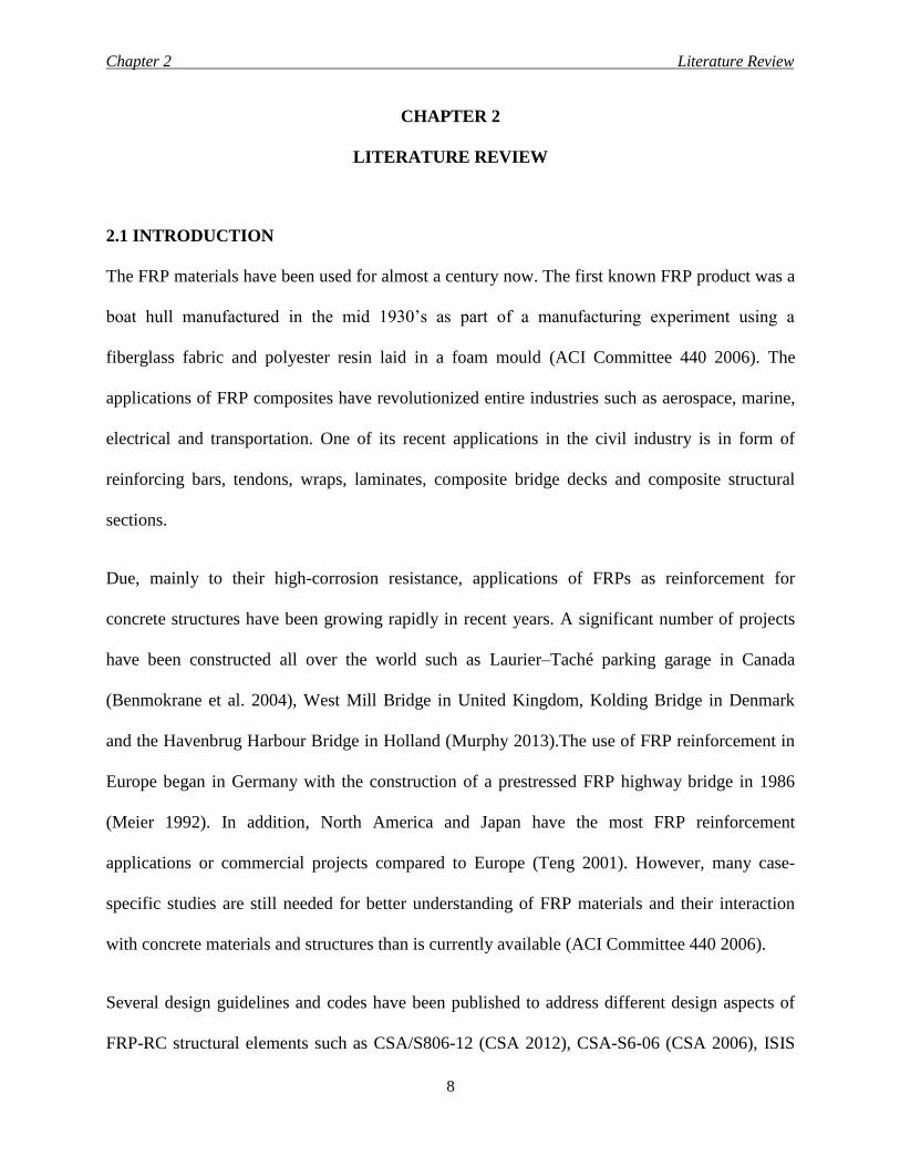
2.1 INTRODUCTION
The FRP materials have been used for almost a century now. The first known FRP product was a
boat hull manufactured in the mid 1930’s as part of a manufacturing experiment using a
fiberglass fabric and polyester resin laid in a foam mould (ACI Committee 440 2006). The
applications of FRP composites have revolutionized entire industries such as aerospace, marine,
electrical and transportation. One of its recent applications in the civil industry is in form of
reinforcing bars, tendons, wraps, laminates, composite bridge decks and composite structural
sections.
Due, mainly to their high-corrosion resistance, applications of FRPs as reinforcement for
concrete structures have been growing rapidly in recent years. A significant number of projects
have been constructed all over the world such as Laurier–Taché parking garage in Canada
(Benmokrane et al. 2004), West Mill Bridge in United Kingdom, Kolding Bridge in Denmark
and the Havenbrug Harbour Bridge in Holland (Murphy 2013).The use of FRP reinforcement in
Europe began in Germany with the construction of a prestressed FRP highway bridge in 1986
(Meier 1992). In addition, North America and Japan have the most FRP reinforcement
applications or commercial projects compared to Europe (Teng 2001). However, many case-
specific studies are still needed for better understanding of FRP materials and their interaction
with concrete materials and structures than is currently available (ACI Committee 440 2006).
Several design guidelines and codes have been published to address different design aspects of
FRP-RC structural elements such as CSA/S806-12 (CSA 2012), CSA-S6-06 (CSA 2006), ISIS
Chapter 2 Literature Review
9
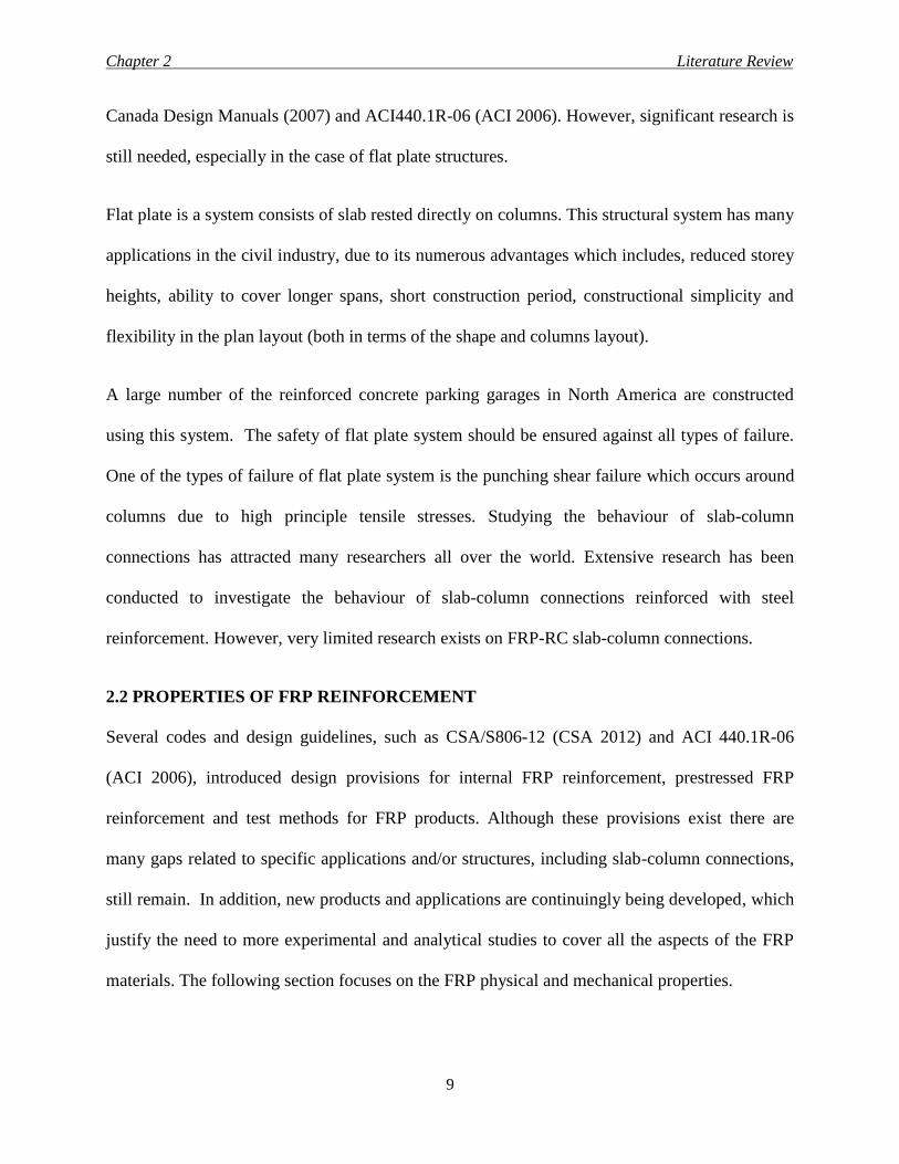
Canada Design Manuals (2007) and ACI440.1R-06 (ACI 2006). However, significant research is
still needed, especially in the case of flat plate structures.
Flat plate is a system consists of slab rested directly on columns. This structural system has many
applications in the civil industry, due to its numerous advantages which includes, reduced storey
heights, ability to cover longer spans, short construction period, constructional simplicity and
flexibility in the plan layout (both in terms of the shape and columns layout).
A large number of the reinforced concrete parking garages in North America are constructed
using this system. The safety of flat plate system should be ensured against all types of failure.
One of the types of failure of flat plate system is the punching shear failure which occurs around
columns due to high principle tensile stresses. Studying the behaviour of slab-column
connections has attracted many researchers all over the world. Extensive research has been
conducted to investigate the behaviour of slab-column connections reinforced with steel
reinforcement. However, very limited research exists on FRP-RC slab-column connections.
2.2 PROPERTIES OF FRP REINFORCEMENT
Several codes and design guidelines, such as CSA/S806-12 (CSA 2012) and ACI 440.1R-06
(ACI 2006), introduced design provisions for internal FRP reinforcement, prestressed FRP
reinforcement and test methods for FRP products. Although these provisions exist there are
many gaps related to specific applications and/or structures, including slab-column connections,
still remain. In addition, new products and applications are continuingly being developed, which
justify the need to more experimental and analytical studies to cover all the aspects of the FRP
materials. The following section focuses on the FRP physical and mechanical properties.
Chapter 2 Literature Review
10
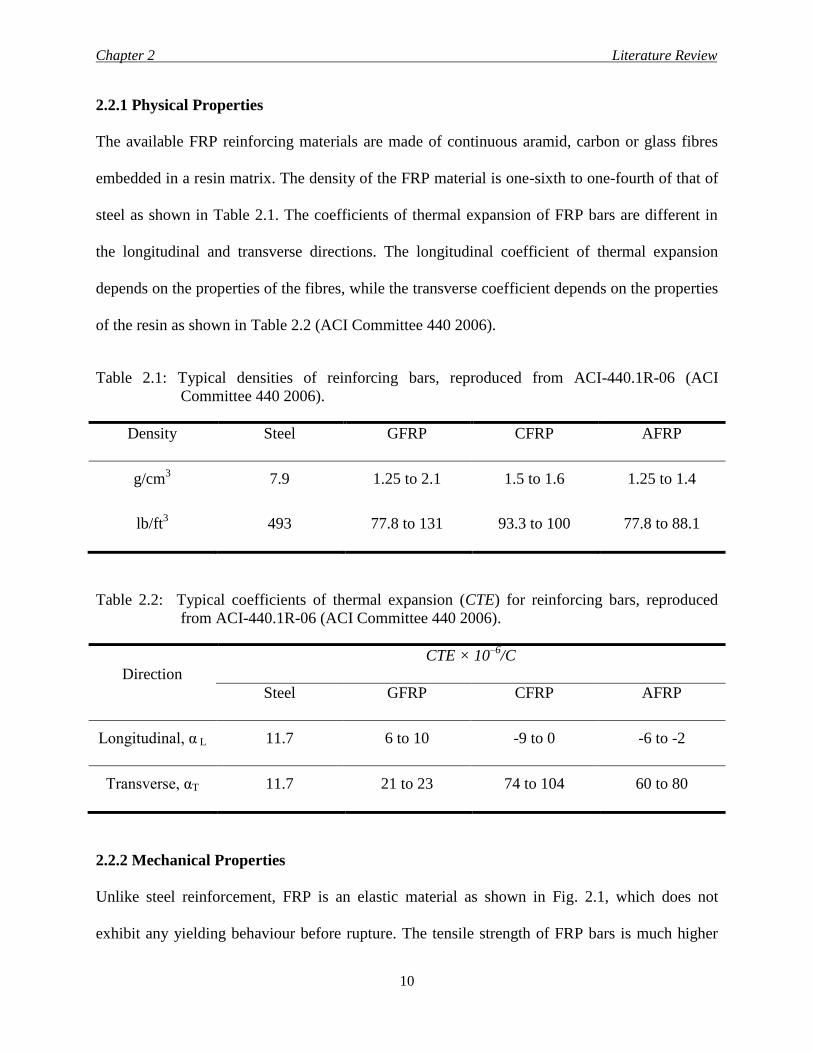
2.2.1 Physical Properties
The available FRP reinforcing materials are made of continuous aramid, carbon or glass fibres
embedded in a resin matrix. The density of the FRP material is one-sixth to one-fourth of that of
steel as shown in Table 2.1. The coefficients of thermal expansion of FRP bars are different in
the longitudinal and transverse directions. The longitudinal coefficient of thermal expansion
depends on the properties of the fibres, while the transverse coefficient depends on the properties
of the resin as shown in Table 2.2 (ACI Committee 440 2006).
Table 2.1: Typical densities of reinforcing bars, reproduced from ACI-440.1R-06 (ACI
Committee 440 2006).
Density Steel GFRP CFRP AFRP
g/cm3
lb/ft3
7.9
493
1.25 to 2.1
77.8 to 131
1.5 to 1.6
93.3 to 100
1.25 to 1.4
77.8 to 88.1
Table 2.2: Typical coefficients of thermal expansion (CTE) for reinforcing bars, reproduced
from ACI-440.1R-06 (ACI Committee 440 2006).
Direction
CTE × 10–6
/C
Steel GFRP CFRP AFRP
Longitudinal, α L 11.7 6 to 10 -9 to 0 -6 to -2
Transverse, αT 11.7 21 to 23 74 to 104 60 to 80
2.2.2 Mechanical Properties
Unlike steel reinforcement, FRP is an elastic material as shown in Fig. 2.1, which does not
exhibit any yielding behaviour before rupture. The tensile strength of FRP bars is much higher
Chapter 2 Literature Review
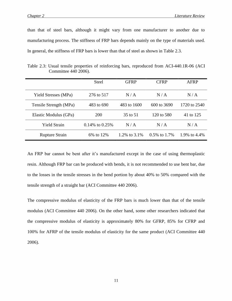
11
than that of steel bars, although it might vary from one manufacturer to another due to
manufacturing process. The stiffness of FRP bars depends mainly on the type of materials used.
In general, the stiffness of FRP bars is lower than that of steel as shown in Table 2.3.
Table 2.3: Usual tensile properties of reinforcing bars, reproduced from ACI-440.1R-06 (ACI
Committee 440 2006).
Steel GFRP CFRP AFRP
Yield Stresses (MPa) 276 to 517 N / A N / A N / A
Tensile Strength (MPa) 483 to 690 483 to 1600 600 to 3690 1720 to 2540
Elastic Modulus (GPa) 200 35 to 51 120 to 580 41 to 125
Yield Strain 0.14% to 0.25% N / A N / A N / A
Rupture Strain 6% to 12% 1.2% to 3.1% 0.5% to 1.7% 1.9% to 4.4%
An FRP bar cannot be bent after it’s manufactured except in the case of using thermoplastic
resin. Although FRP bar can be produced with bends, it is not recommended to use bent bar, due
to the losses in the tensile stresses in the bend portion by about 40% to 50% compared with the
tensile strength of a straight bar (ACI Committee 440 2006).
The compressive modulus of elasticity of the FRP bars is much lower than that of the tensile
modulus (ACI Committee 440 2006). On the other hand, some other researchers indicated that
the compressive modulus of elasticity is approximately 80% for GFRP, 85% for CFRP and
100% for AFRP of the tensile modulus of elasticity for the same product (ACI Committee 440
2006).
Chapter 2 Literature Review
12
Figure 2.1: Stress-strain relationship for reinforcing bars
FRP bars could be considered as layers of resin lie between layers of fibers. The resins would
cause the failure of FRP bars when facing the inter-laminar shear. To solve the problem
associated with the inter-laminar shear, fibres in an off-axis direction across the bars should be
oriented to increase the shear resistance, depending upon the degree of offset. This can be
accomplished by braiding or winding fibres transverse to the main fibres. Also off-axis fibres can
be placed in the pultrusion process by introducing a continuous strand mat in the roving/ mat
creel. Bars without transverse fibres would be weak against inter-laminar shear.
Bond behaviour of FRP bars is attributed to many aspects such as surface design, manufacturing
process, mechanical properties of the bar and the environmental conditions. The bond force
between FRP bars and the surrounding concrete could be generated from adhesion and frictional
resistance of the interface against slip. Also, a mechanical interlock due to irregularity of the
interface between FRP bars and the surrounding concrete could generate bond force.
0
400
800
1200
1600
2000
0 5000 10000 15000 20000 25000
Str
ess
(MP
a)
Micro-Strain
Steel Bar
GFRP Bar
CFRP Bar
Chapter 2 Literature Review
13
Environmental conditions such as the presence of water, acidic or saline solutions as well as the
alkaline ones might have effect on the durability of FRP bars in terms of tensile capacity, bond
and stiffness. The mechanical properties of FRP bars can be enhanced, deteriorated or even
remain the same depending on the type of FRP bars and exposure conditions and material (ACI
Committee 440 2006).
2.3 TYPES OF FAILURE OF CONCRETE FLAT PLATES
A reinforced concrete flat plate structure has to be checked against all types of failure which can
be classified as (1) Flexural failure and (2) Punching shear failure.
2.3.1 Flexural Failure
Flexural failure occurs mainly due to bending moments, which induce compressive stresses in
one side of the slab and tensile stresses in the opposite one. In design principles it is usually
assumed that the reinforcing bars are resisting all tensile stresses while concrete is resisting all
the compressive ones. Concrete sections reinforced with steel bars are commonly under-
reinforced to prevent crushing of concrete before yielding of steel. The in-elastic yielding of the
steel provides a ductile behaviour to the reinforced concrete members. This kind of ductile
behaviour is not readily available for FRP-RC elements due to the linear-elastic behaviour of
FRP materials up to failure without yielding plateau. For FRP-RC elements, deformability is the
corresponding term to ductility. Deformability is a concept to quantify the deformation
characteristic by providing a comparison between the level of safety between ultimate and
service states (ISIS Canada 2007).
Chapter 2 Literature Review
14
i- Tension failure
This failure occurs when the reinforcing bars in tension side reach their design failure strain
before concrete reaches its ultimate compressive strain.
For steel bars, the design failure strain is defined as the yield strain. Yielding of the flexural
reinforcement has a negative effect on the punching shear capacity of the slab-column
connection, due to the cracks produced with it. The width and the depth of the crack have a
significant influence on the shear capacity of the connection, as the shear transferred within the
cracked areas will be small. Also, this failure gives enough warning before it takes place, which
makes codes, such as the Canadian standard (CSA/A23.3-14), allow this type of failure.
For FRP bars, the design failure strain is defined as the rupture strain. The FRP is an elastic
material up to failure. If the rupture of FRP bars takes place before crushing of concrete,
extensive cracking and significant deflection could be expected due to the large rupture strain of
the FRP bars. These cracks would reduce the effective cross section area that resists the punching
shear capacity; and, subsequently, sudden and very brittle failure may occur.
ii- Balanced failure
This failure occurs when the concrete reaches its ultimate compressive strain at the same time
that reinforcing bars in tension side reach their design failure strain. This kind of failure seldom
occurs in practice.
iii- Compression failure
This failure occurs when the concrete crushes while the reinforcing bars have a strain level
smaller than the design failure strain.
Chapter 2 Literature Review
15
For steel bars, the reinforcing bars will not reach their yield strain which result in small cracking
and significant effective cross section areas to resist the punching shear capacity. However, this
type of failure takes place without much warning, thus all design codes avoid it.
On the other hand, the Canadian code CAS/S806-12 (CSA 2012) for FRP-RC members
recommends having failure due to concrete crushing before the reinforcing bars reach their
ultimate strain. In this type of failure, FRP-RC members exhibit deformability due to plastic
behaviour of concrete, which is preferable.
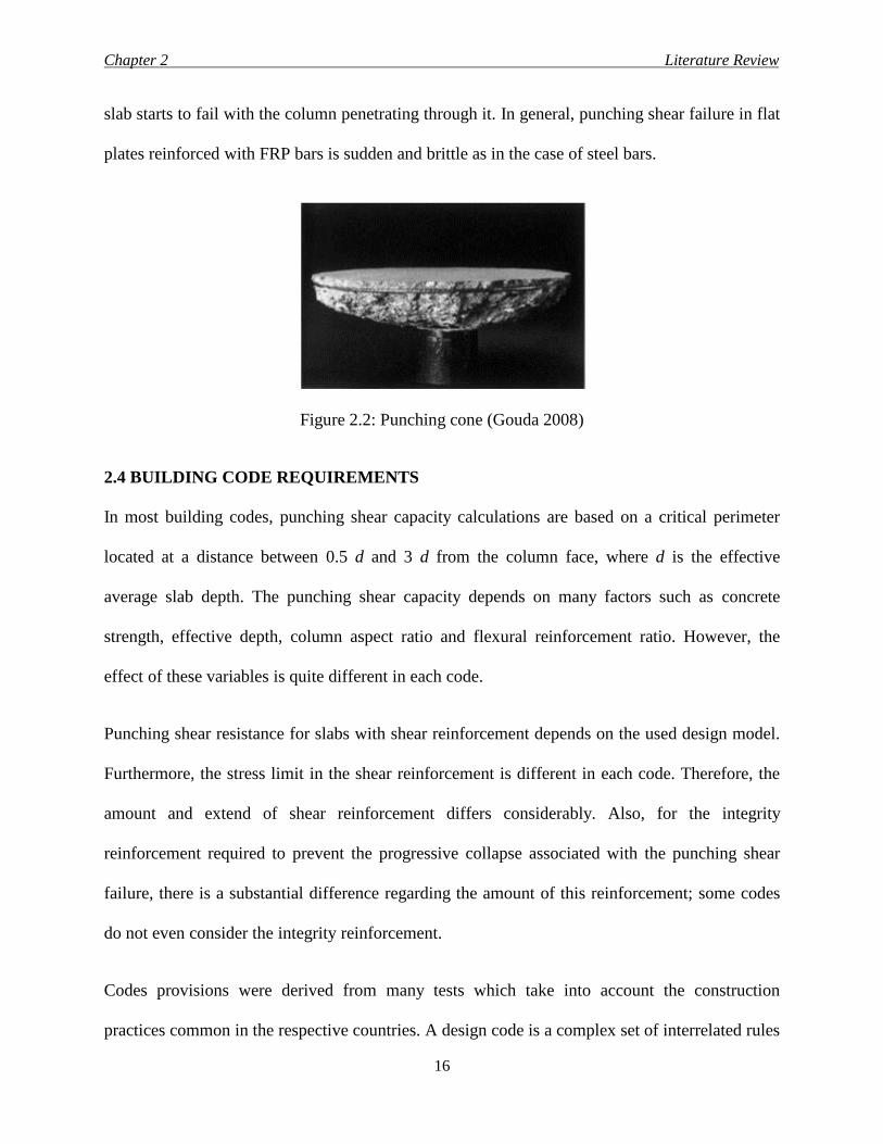
2.3.2 Punching Shear Failure
There are two shear failure mechanisms that may be encountered in flat plate systems. The first
is the one-way shear similar to that in beams. This type of shear failure is normally not critical
and rarely happens in flat plate systems. The second is the two-way shear in which the failure
surrounds the column forming a cone shape as shown in Fig. 2.2. Normally, the stresses resulting
from the two-way shear are much higher than those resulting from the one-way shear. Two-way
shear failure mechanism is usually encountered in flat plate and footings. Punching shear failure
occurs due to shear force in addition to unbalanced moment transfers between the slab and
columns. The combination of shear and unbalanced moment is unavoidable even under gravity
loads only due to many reasons, such as unsymmetrical loading. Prevention of punching failure
of slab-column connections depends on an accurate calculation of shear stresses induced by
shear force and unbalanced moment transfers to the columns.
Punching shear failure begins with radial cracks extending from the column followed by
tangential cracks around the column region. As the load increases to the ultimate capacity, the
Chapter 2 Literature Review
16
slab starts to fail with the column penetrating through it. In general, punching shear failure in flat
plates reinforced with FRP bars is sudden and brittle as in the case of steel bars.
Figure 2.2: Punching cone (Gouda 2008)
2.4 BUILDING CODE REQUIREMENTS
In most building codes, punching shear capacity calculations are based on a critical perimeter
located at a distance between 0.5 d and 3 d from the column face, where d is the effective
average slab depth. The punching shear capacity depends on many factors such as concrete
strength, effective depth, column aspect ratio and flexural reinforcement ratio. However, the
effect of these variables is quite different in each code.
Punching shear resistance for slabs with shear reinforcement depends on the used design model.
Furthermore, the stress limit in the shear reinforcement is different in each code. Therefore, the
amount and extend of shear reinforcement differs considerably. Also, for the integrity
reinforcement required to prevent the progressive collapse associated with the punching shear
failure, there is a substantial difference regarding the amount of this reinforcement; some codes
do not even consider the integrity reinforcement.
Codes provisions were derived from many tests which take into account the construction
practices common in the respective countries. A design code is a complex set of interrelated rules
Chapter 2 Literature Review
17
and guidelines that have been calibrated over time to give acceptable results. In the UK the high
punching shear capacity is linked to the extent of the shear reinforcement. The comparatively
high punching shear resistance without shear reinforcement provided by North American codes
should be seen together with the required integrity reinforcement. Therefore engineers should be
very careful in applying individual provisions from different codes in a design.
Consideration of practical aspects should be given as the safety of structures depends as well on
the quality of construction – the skill of workmanship and the pressure of time and costs. This
may be a point in favour of flat plate without shear reinforcement. Otherwise, shear elements
prefabricated from welded fabric which reduces the problems of installation or specific systems
such as, shear studs may be of advantage.
2.4.1 Canadian Code for Steel-reinforced Concrete structures (CAN/CSA-A23.3-14)
2.4.1.1 Punching shear stresses calculations
The Canadian code considers two cases in the calculation of the punching shear stresses. The
first is the case of concentric loading (shear force only). The second case is due to shear force in
addition to some amount of unbalanced moment that should be transferred to columns from the
slab.
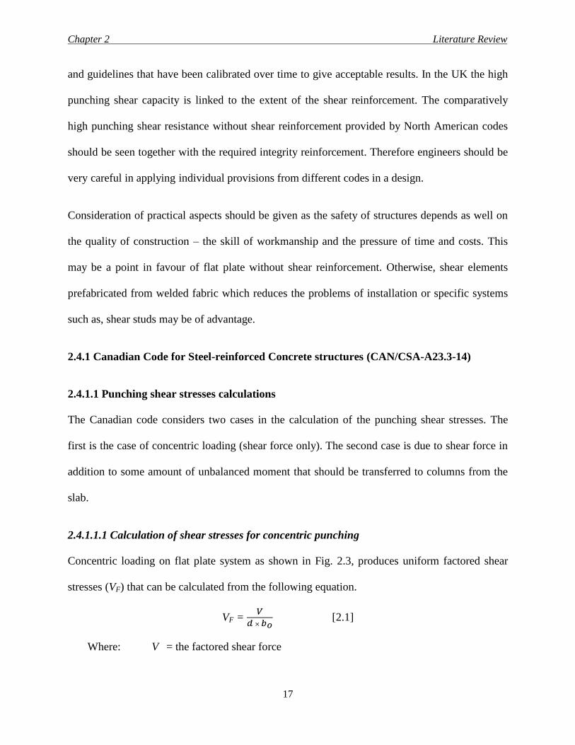
2.4.1.1.1 Calculation of shear stresses for concentric punching
Concentric loading on flat plate system as shown in Fig. 2.3, produces uniform factored shear
stresses (VF) that can be calculated from the following equation.
VF = 𝑉
𝑑 × 𝑏𝑜 [2.1]
Where: V = the factored shear force
Chapter 2 Literature Review
18
bo = the critical shear perimeter (at d/2 from the column face)
d = the effective flat plate depth
Practically, the case of concentric loading is rarely encountered in real structures.
Figure 2.3: Concentric shear stress calculations for interior column
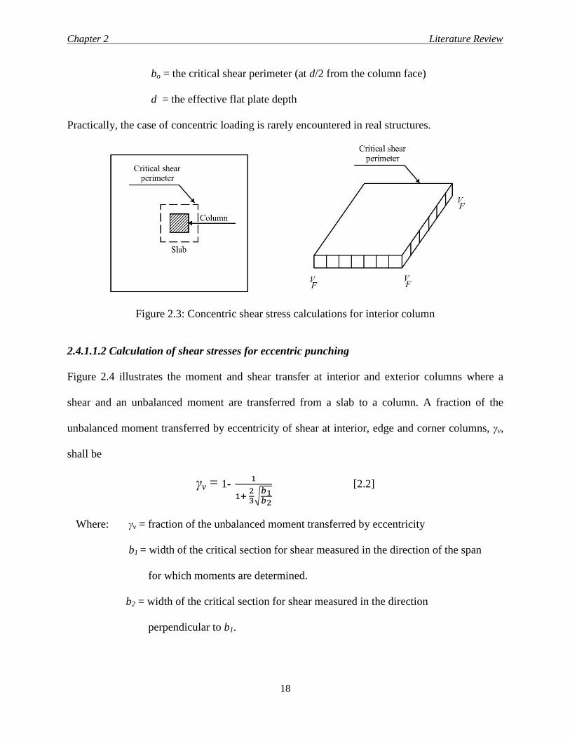
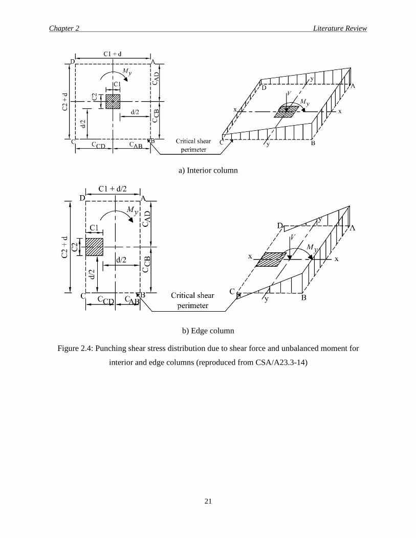
2.4.1.1.2 Calculation of shear stresses for eccentric punching
Figure 2.4 illustrates the moment and shear transfer at interior and exterior columns where a
shear and an unbalanced moment are transferred from a slab to a column. A fraction of the
unbalanced moment transferred by eccentricity of shear at interior, edge and corner columns, γv,
shall be
γv = 1- 1
1+ 23
√𝑏1𝑏2
[2.2]
Where: γv = fraction of the unbalanced moment transferred by eccentricity
b1 = width of the critical section for shear measured in the direction of the span
for which moments are determined.
b2 = width of the critical section for shear measured in the direction
perpendicular to b1.
Chapter 2 Literature Review
19
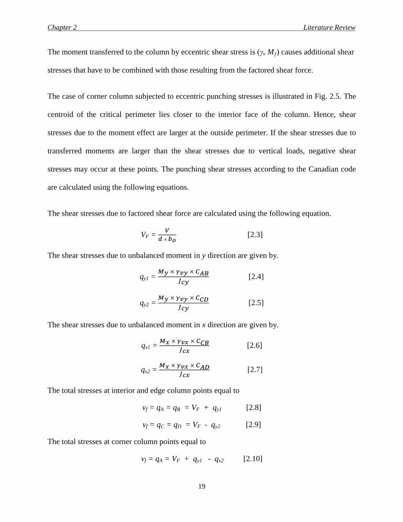
The moment transferred to the column by eccentric shear stress is (γv Mƒ) causes additional shear
stresses that have to be combined with those resulting from the factored shear force.
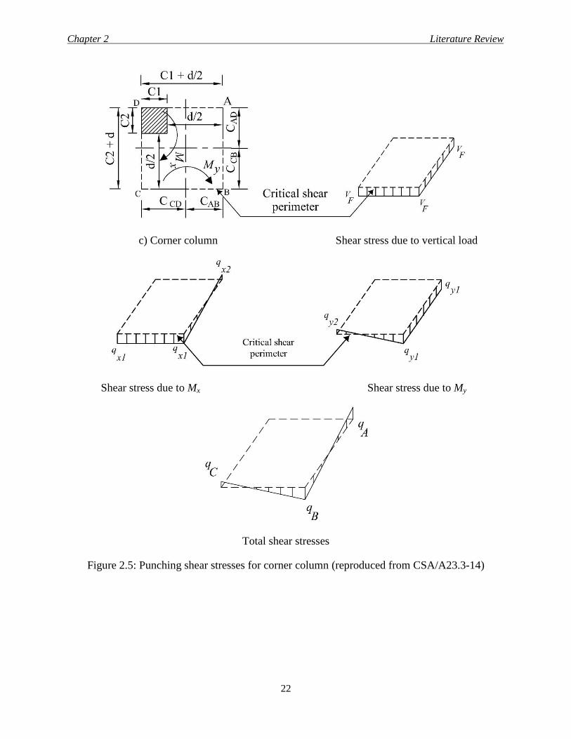
The case of corner column subjected to eccentric punching stresses is illustrated in Fig. 2.5. The
centroid of the critical perimeter lies closer to the interior face of the column. Hence, shear
stresses due to the moment effect are larger at the outside perimeter. If the shear stresses due to
transferred moments are larger than the shear stresses due to vertical loads, negative shear
stresses may occur at these points. The punching shear stresses according to the Canadian code
are calculated using the following equations.
The shear stresses due to factored shear force are calculated using the following equation.
VF = 𝑉
𝑑 × 𝑏𝑜 [2.3]
The shear stresses due to unbalanced moment in y direction are given by.
qy1 = 𝑀𝑦 × 𝛾𝑣𝑦 × 𝐶𝐴𝐵
𝐽𝑐𝑦 [2.4]
qy2 = 𝑀𝑦 × 𝛾𝑣𝑦 × 𝐶𝐶𝐷
𝐽𝑐𝑦 [2.5]
The shear stresses due to unbalanced moment in x direction are given by.
qx1 = 𝑀𝑥 × 𝛾𝑣𝑥 × 𝐶𝐶𝐵
𝐽𝑐𝑥 [2.6]
qx2 = 𝑀𝑥 × 𝛾𝑣𝑥 × 𝐶𝐴𝐷
𝐽𝑐𝑥 [2.7]
The total stresses at interior and edge column points equal to
vf = qA = qB = VF + qy1 [2.8]
vf = qC = qD = VF - qy2 [2.9]
The total stresses at corner column points equal to
vf = qA = VF + qy1 - qx2 [2.10]
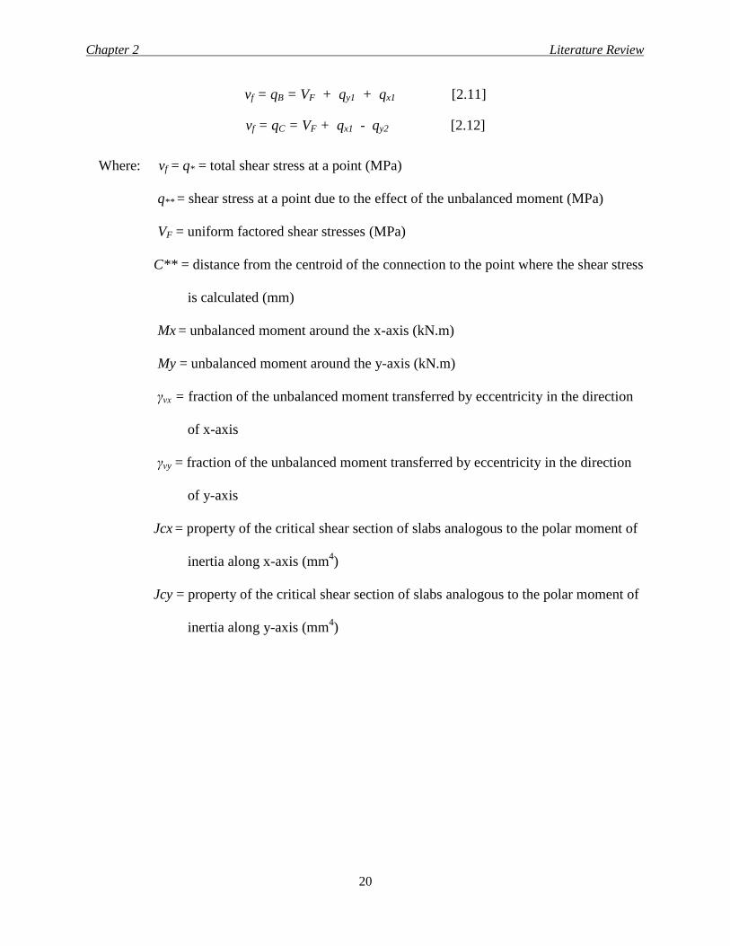
Chapter 2 Literature Review
20
vf = qB = VF + qy1 + qx1 [2.11]
vf = qC = VF + qx1 - qy2 [2.12]
Where: vf = q* = total shear stress at a point (MPa)
q** = shear stress at a point due to the effect of the unbalanced moment (MPa)
VF = uniform factored shear stresses (MPa)
C** = distance from the centroid of the connection to the point where the shear stress
is calculated (mm)
Mx = unbalanced moment around the x-axis (kN.m)
My = unbalanced moment around the y-axis (kN.m)
γνx = fraction of the unbalanced moment transferred by eccentricity in the direction
of x-axis
γνy = fraction of the unbalanced moment transferred by eccentricity in the direction
of y-axis
Jcx = property of the critical shear section of slabs analogous to the polar moment of
inertia along x-axis (mm4)
Jcy = property of the critical shear section of slabs analogous to the polar moment of
inertia along y-axis (mm4)
Chapter 2 Literature Review
21
a) Interior column
b) Edge column
Figure 2.4: Punching shear stress distribution due to shear force and unbalanced moment for
interior and edge columns (reproduced from CSA/A23.3-14)
Chapter 2 Literature Review
22
c) Corner column Shear stress due to vertical load
Shear stress due to Mx Shear stress due to My
Total shear stresses
Figure 2.5: Punching shear stresses for corner column (reproduced from CSA/A23.3-14)
Chapter 2 Literature Review
23
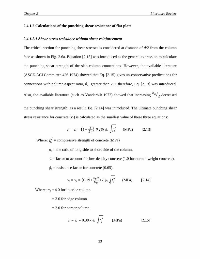
2.4.1.2 Calculations of the punching shear resistance of flat plate
2.4.1.2.1 Shear stress resistance without shear reinforcement
The critical section for punching shear stresses is considered at distance of d/2 from the column
face as shown in Fig. 2.6a. Equation [2.15] was introduced as the general expression to calculate
the punching shear strength of the slab-column connections. However, the available literature
(ASCE-ACI Committee 426 1974) showed that Eq. [2.15] gives un-conservative predications for
connections with column-aspect ratio, 𝛽𝑐, greater than 2.0; therefore, Eq. [2.13] was introduced.
Also, the available literature (such as Vanderbilt 1972) showed that increasing 𝑏𝑜
𝑑⁄ decreased
the punching shear strength; as a result, Eq. [2.14] was introduced. The ultimate punching shear
stress resistance for concrete (vr) is calculated as the smallest value of these three equations:
vr = vc = (1+ 2
𝛽𝑐) 0.19λ ϕc √𝑓𝑐
/ (MPa) [2.13]
Where: 𝑓𝐶/ = compressive strength of concrete (MPa)
βc = the ratio of long side to short side of the column.
λ = factor to account for low-density concrete (1.0 for normal weight concrete).
ϕc = resistance factor for concrete (0.65).
vr = vc = (0.19+𝛼𝑠𝑑
𝑏𝑜) λ ϕc √𝑓𝑐
/ (MPa) [2.14]
Where: αs = 4.0 for interior column
= 3.0 for edge column
= 2.0 for corner column
vr = vc = 0.38 λ ϕc √𝑓𝑐/ (MPa) [2.15]
Chapter 2 Literature Review
24
The value of √𝑓𝑐/ used in the above equations shall not exceed 8 MPa, If the effective depth, d,
used in two-way shear calculations exceeds 300 mm, the value of vc obtained shall be multiplied
by 1300/(1000+d).
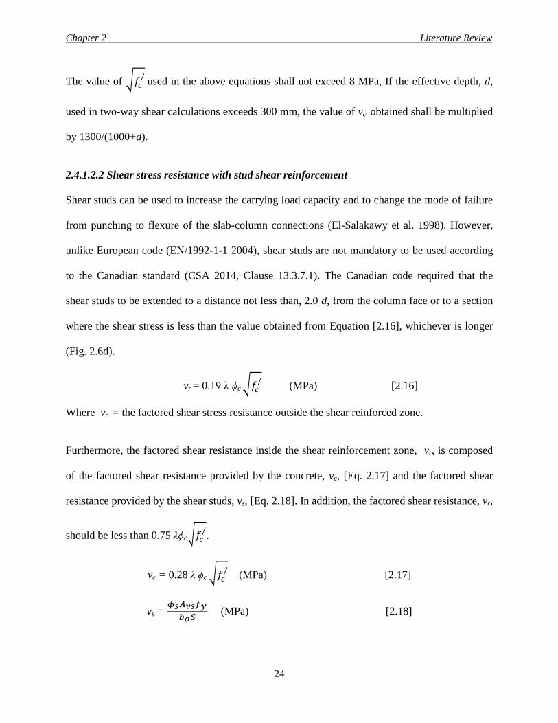
2.4.1.2.2 Shear stress resistance with stud shear reinforcement
Shear studs can be used to increase the carrying load capacity and to change the mode of failure
from punching to flexure of the slab-column connections (El-Salakawy et al. 1998). However,
unlike European code (EN/1992-1-1 2004), shear studs are not mandatory to be used according
to the Canadian standard (CSA 2014, Clause 13.3.7.1). The Canadian code required that the
shear studs to be extended to a distance not less than, 2.0 d, from the column face or to a section
where the shear stress is less than the value obtained from Equation [2.16], whichever is longer
(Fig. 2.6d).
vr = 0.19 λ ϕc √𝑓𝑐/ (MPa) [2.16]
Where vr = the factored shear stress resistance outside the shear reinforced zone.
Furthermore, the factored shear resistance inside the shear reinforcement zone, vr, is composed
of the factored shear resistance provided by the concrete, vc, [Eq. 2.17] and the factored shear
resistance provided by the shear studs, vs, [Eq. 2.18]. In addition, the factored shear resistance, vr,
should be less than 0.75 λϕc√𝑓𝑐/.
vc = 0.28 λ ϕc √𝑓𝑐/ (MPa) [2.17]
vs = 𝜙𝑠𝐴𝑣𝑠𝑓𝑦
𝑏𝑜𝑆 (MPa) [2.18]
Chapter 2 Literature Review
25
Where: 𝜙𝑠 = resistance factor
𝐴𝑣𝑠 = cross sectional areas of the shear studs along the critical shear perimeter (at d/2
from the column face)
𝑏𝑜 = critical shear perimeter (at d/2 from the column face)
𝑆 = spacing between the shear studs
𝑓𝑦= the yielding strength of the shear studs
The distance between the column face and the first line of the shear studs shall not be greater
than 0.4 d (Clause 13.3.8.6). Also, the spacing, S, between the lines of the shear studs should be
based on the value of the shear stresses, vf, calculated at 0.5 d from the column face (Clause
13.3.8.6).
S≤ 0.75𝑑 when vf ≤ 0.56 𝜆𝜙𝑐√𝑓𝑐/ (MPa) [2.19]
S≤ 0.5𝑑 when vf > 0.56 𝜆𝜙𝑐√𝑓𝑐/ (MPa) [2.20]
2.4.2 ACI Code for Steel-Reinforced Concrete Structures (ACI 318-14)
2.4.2.1 Punching shear stresses calculations
The equations that calculate the punching shear stresses in the ACI 318 and CSA/A23.3 codes
are similar, Eq. [2.1] through [2.12].
Chapter 2 Literature Review
26
2.4.2.2 Calculations of the punching shear resistance of flat plates
2.4.2.2.1 Shear resistance without shear reinforcement
The critical section for punching shear stresses is considered at distance of d/2 from the column
faces as shown in Fig. 2.6a. The nominal punching shear stress resistance for concrete (vc) is
calculated as the smallest value of the following three equations.
vc = 0.083 (2+ 4
𝛽𝑐) λ√𝑓𝑐
/ (MPa) [2.21]
Where: 𝑓𝐶/ = compressive strength of concrete (MPa)
βc = the ratio of long side to short side of the column.
λ = modification factor reflecting the reduced mechanical properties of lightweight
concrete, all relative to normal weight concrete of the same compressive strength.
vc = 0.083 (2+ 𝛼𝑠𝑑
𝑏𝑜) λ√𝑓𝑐
/ (MPa) [2.22]
Where αs = 40 for interior column, 30 for edge column and 20 for corner column
bo = the critical shear perimeter (at d/2 from the column face)
vc = 0.33 λ√𝑓𝑐/ (MPa) [2.23]
2.4.2.2.2 Shear resistance with stud shear reinforcement
The shear reinforcement shall be extended to a distance where the shear stress is less than the
value obtained be Equation [2.24].
0.17 𝜆 √𝑓𝑐/ (MPa) [2.24]
Chapter 2 Literature Review
27
Also, the contribution of the concrete for the shear resistance shall be less than the value
obtained from Equation [2.25], while the corresponding one for shear studs should be calculated
from Equation [2.26].
vc = 0.25 𝜆 √𝑓𝑐/ (MPa) [2.25]
vs = 𝜙𝑠𝐴𝑣𝑠𝑓𝑦
𝑏𝑜𝑆 (MPa) [2.26]
vc + vs ≤ 0.66 𝜆 𝜙√𝑓𝑐/ (MPa) [2.27]
Where 𝜙 = resistance factor
The distance between the column face and the first line of the shear studs shall not be greater
than 0.5 d. Also, the spacing, S, between the lines of the shear studs shall be based on the value
of the shear stresses, vf, calculated at 0.5 d from the column face.
S≤ 0.75𝑑 when vf ≤ 0.5 𝜆 𝜙√𝑓𝑐/ (MPa) [2.28]
S≤ 0.5𝑑 when vf > 0.5 𝜆 𝜙√𝑓𝑐/ (MPa) [2.29]
2.4.3 European Code Requirements (EN/1992-1-1 2004)
2.4.3.1 Punching shear stresses calculations
The Euro code calculates the punching shear stresses from Equation [2.30] regardless the type of
the connection.
VED = 𝛽 × 𝑉
𝑑 × 𝑈𝑖 (MPa) [2.30]
Where: VED = punching shear stresses (MPa). V = factored shear force (N)
d = the mean effective depth of the slab (mm), which may be taken as (dy + dz)/2
and dy, dz are the effective depths in the y- and z- directions of the control section

Chapter 2 Literature Review
28
Ui = the length of the control perimeter being considered.
𝛽 is calculated from Equation [2.31]
𝛽 = 1+ 𝐾 × 𝑀 × 𝑈1
𝑉 × 𝑊1 [2.31]
Where U1 = the length of the basic control perimeter (2.0 d from the column faces).
k = coefficient dependents on the ratio between the column dimensions C1 and C2,
as provided in Table 2.4.
Table 2.4: Values of k for rectangular loaded areas (EN/1992-1-1 2004)
C1/C2 ≪ 0.5 1.0 2.0 ≫ 3.0
k 0.45 0.6 0.7 0.8
W1 = function of the perimeter Ui as shown in Equation [2.32]
W1 = ∫ |𝑒1|𝑈𝑖
0× dℓ [2.32]
Where dℓ = a length increment of the perimeter.
e1 = the distance of dℓ from the axis about which the moment M acts.
For a rectangular column:
W1= 𝐶12
2 + C1 × C2+ 4 × C2 × d+16 × d
2+2 × π × d × C1 [2.33]
Where: C1 = the column dimension parallel to the eccentricity of the load
C2 = the column dimension perpendicular to the eccentricity of the load
For interior circular columns β follows from:
𝛽 = 1+ 0.6 × 𝜋 × 𝑒
𝐷1+4𝑑 [2.34]
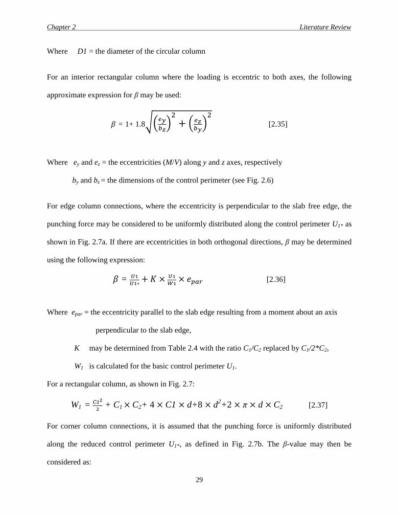
Chapter 2 Literature Review
29
Where D1 = the diameter of the circular column
For an interior rectangular column where the loading is eccentric to both axes, the following
approximate expression for β may be used:
𝛽 = 1+ 1.8√(𝑒𝑦
𝑏𝑧)
2+ (𝑒𝑧
𝑏𝑦)
2 [2.35]
Where ey and ez = the eccentricities (M/V) along y and z axes, respectively
by and bz = the dimensions of the control perimeter (see Fig. 2.6)
For edge column connections, where the eccentricity is perpendicular to the slab free edge, the
punching force may be considered to be uniformly distributed along the control perimeter U1* as
shown in Fig. 2.7a. If there are eccentricities in both orthogonal directions, β may be determined
using the following expression:
𝛽 = 𝑈1
𝑈1∗+ 𝐾 × 𝑈1
𝑊1× 𝑒𝑝𝑎𝑟 [2.36]
Where epar = the eccentricity parallel to the slab edge resulting from a moment about an axis
perpendicular to the slab edge,
K may be determined from Table 2.4 with the ratio C1/C2 replaced by C1/2*C2,
W1 is calculated for the basic control perimeter U1.
For a rectangular column, as shown in Fig. 2.7:
W1 = 𝐶22
2 + C1 × C2+ 4 × C1 × d+8 × d
2+2 × π × d × C2 [2.37]
For corner column connections, it is assumed that the punching force is uniformly distributed
along the reduced control perimeter U1*, as defined in Fig. 2.7b. The β-value may then be
considered as:
Chapter 2 Literature Review
30
𝛽 = 𝑈1
𝑈1∗ [2.38]
2.4.3.2 Calculations of the punching shear resistance of flat plates
According to the Euro code the critical section for the punching shear stresses is taken at distance
of 2.0 d from the column faces whether the column section is rectangular or circular as shown in
Fig. 2.6b. The punching shear strength (VRd,C) is calculated by the following equation:
VRd,C = CRd,C K (100 ρ1 fck )1/3
+ k1 ϭcp ≥ (0.035K3/2
fck1/2
+ k1 ϭcp) (MPa) [2.39]
Where VRd,C is the shear resistance of concrete in MPa
fck is the characteristic concrete cylinder strength in MPa
K = 1 + √200
𝑑 ≤ 2.0 d in mm [2.40]
ρ1 = √ 𝜌1𝑦 + 𝜌1𝑧 ≤ 0.02 [2.41]
ρ1y + ρ1z relate to the bonded tension steel in y and z directions, respectively. The values ρ1y and
ρ1z should be calculated as mean values taking into account a slab width equal to the column
width plus 3.0 d from each side.
σcp = (σcy + σcz)/2
Where σcy and σcz are the normal concrete stresses in the critical section in y and z directions,
respectively, (MPa, positive if compression): σcy = 𝑁𝐸𝑑,𝑦
𝐴𝑐𝑦 and σcz =
𝑁𝐸𝑑,𝑧𝐴𝑐𝑧
Chapter 2 Literature Review
31
NEd,y and NEd,z are the longitudinal forces across the full bay for interior columns and the
longitudinal force across the control section for edge columns, respectively. The force may be
from a load or prestressing action.
Ac is the area of concrete according to the definition of Ned. The recommended value for the
calibration factor (CRd,C) is 0.18/γc and the coefficient considering the effects of axial forces on
the stress distribution (k1) is 0.1.
2.4.4 JSCE 2007 (Japan Society of Civil Engineers 2007)
According to the Japanese standard the critical section for the punching shear stresses is taken as
circular section at distance of 0.5 d from the column face whether the column section is
rectangular or circular. The punching shear strength (VJ) is calculated by the following
equations:
VJ = 𝛽𝑑𝛽𝑝𝛽𝑟𝑓𝑝𝑐𝑑𝑢𝑝𝑑
𝛾𝑏 × 1
𝛼 (N) [2.42]
βd = √1000
𝑑
4≤ 1.5 [2.43]
βp = √100 𝜌3 ≤ 1.5 [2.44]
βr = 1+ 1
1+0.25𝑢/𝑑 [2.45]
fpcd = 0.2√𝑓𝑐/
≤ 1.2 [2.46]
α = 1 + 1.5 × ex+ey
√𝑏𝑥𝑏𝑦 [2.47]
Where: VJ = the nominal shear strength provided by concrete
βd = coefficient to consider effect of effective depth on shear capacity

Chapter 2 Literature Review
32
βr = factor represents the effect of the loaded area
βp = coefficient to consider effect of effective reinforcement ratio defined as the average
values for the reinforcement in two directions
d = the effective slab depth (mm)
fpcd = the design compressive strength of concrete (MPa)
𝑢𝑝 = the peripheral length of the design cross-section at d/2 from the column face (mm)
ρ = longitudinal reinforcement ratio
u = the peripheral length of the column (mm)
γb = safety factor (1.3)
ex and ey = the load eccentricity in the two orthogonal directions
bx and by = the dimensions of the critical section in the two orthogonal directions
The review of the above building codes indicates that the North American codes (ACI 318 and
CSA/A23.3) do not reflect the influence of the reinforcement ratio on the punching shear
capacity of flat slabs. In the meantime, the European and Japanese codes address the influence of
the flexural reinforcement ratio, mostly by a 1/3 power function. Also, North American codes
use the square root for the concrete compressive stress to predict the punching shear capacity of
the structural members, but some researchers prefer the use of the cubic root, because it gave a
good agreement with their test results as shown in section 2.5.2 of this thesis.
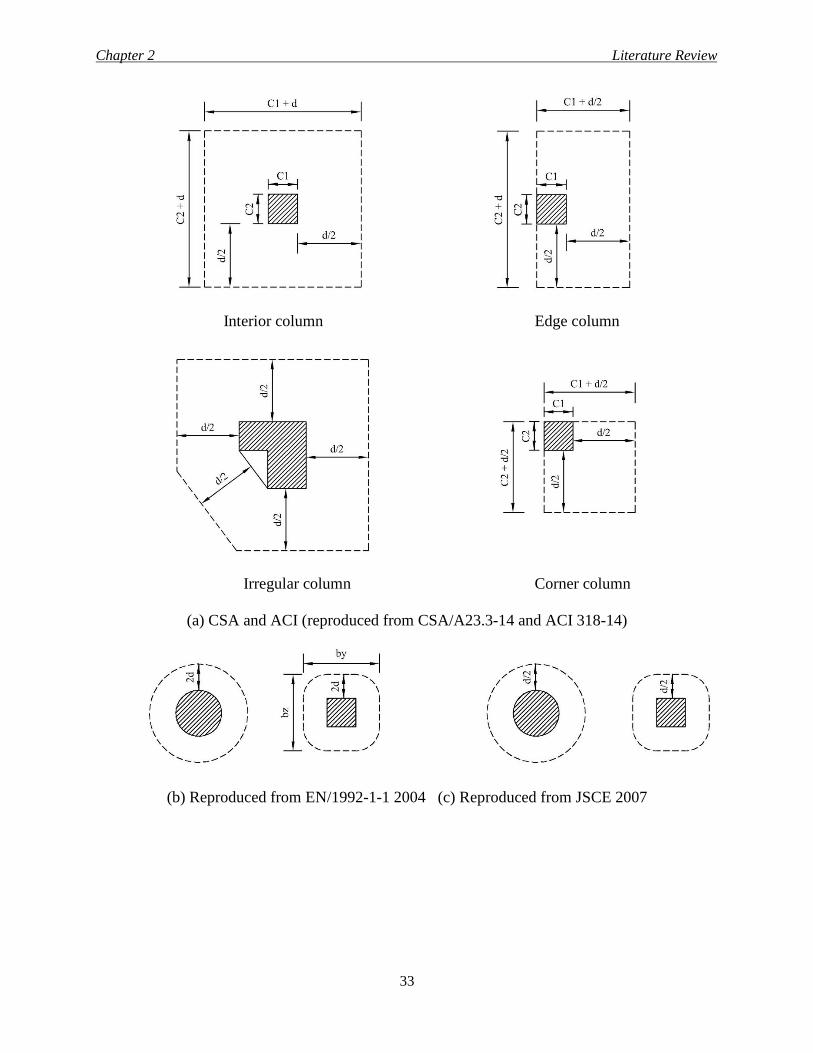
Chapter 2 Literature Review
33
Interior column Edge column
Irregular column Corner column
(a) CSA and ACI (reproduced from CSA/A23.3-14 and ACI 318-14)
(b) Reproduced from EN/1992-1-1 2004 (c) Reproduced from JSCE 2007
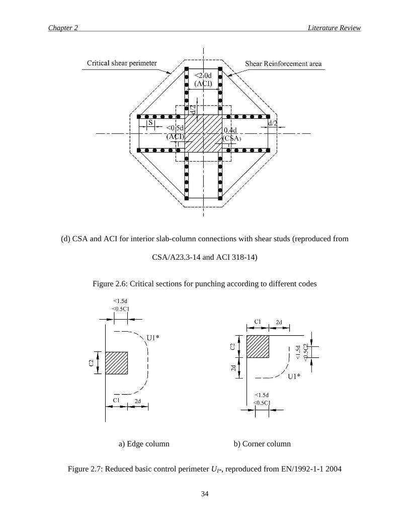
Chapter 2 Literature Review
34
(d) CSA and ACI for interior slab-column connections with shear studs (reproduced from
CSA/A23.3-14 and ACI 318-14)
Figure 2.6: Critical sections for punching according to different codes
a) Edge column b) Corner column
Figure 2.7: Reduced basic control perimeter UI*, reproduced from EN/1992-1-1 2004
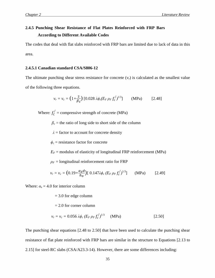
Chapter 2 Literature Review
35
2.4.5 Punching Shear Resistance of Flat Plates Reinforced with FRP Bars
According to Different Available Codes
The codes that deal with flat slabs reinforced with FRP bars are limited due to lack of data in this
area.
2.4.5.1 Canadian standard CSA/S806-12
The ultimate punching shear stress resistance for concrete (vr) is calculated as the smallest value
of the following three equations.
vr = vc = (1+2
𝛽𝑐) [0.028 λϕc(EF ρF 𝑓𝑐
/)1/3
] (MPa) [2.48]
Where: 𝑓𝐶/ = compressive strength of concrete (MPa)
βc = the ratio of long side to short side of the column
λ = factor to account for concrete density
ϕc = resistance factor for concrete
EF = modulus of elasticity of longitudinal FRP reinforcement (MPa)
ρF = longitudinal reinforcement ratio for FRP
vr = vc = (0.19+𝛼𝑠𝑑
𝑏𝑜)[ 0.147λϕc (EF ρF 𝑓𝑐
/)1/3
] (MPa) [2.49]
Where: αs = 4.0 for interior column
= 3.0 for edge column
= 2.0 for corner column
vr = vc = 0.056 λϕc (EF ρF 𝑓𝑐/)1/3
(MPa) [2.50]
The punching shear equations [2.48 to 2.50] that have been used to calculate the punching shear
resistance of flat plate reinforced with FRP bars are similar in the structure to Equations [2.13 to
2.15] for steel-RC slabs (CSA/A23.3-14). However, there are some differences including:
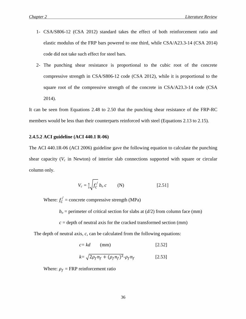
Chapter 2 Literature Review
36
1- CSA/S806-12 (CSA 2012) standard takes the effect of both reinforcement ratio and
elastic modulus of the FRP bars powered to one third, while CSA/A23.3-14 (CSA 2014)
code did not take such effect for steel bars.
2- The punching shear resistance is proportional to the cubic root of the concrete
compressive strength in CSA/S806-12 code (CSA 2012), while it is proportional to the
square root of the compressive strength of the concrete in CSA/A23.3-14 code (CSA
2014).
It can be seen from Equations 2.48 to 2.50 that the punching shear resistance of the FRP-RC
members would be less than their counterparts reinforced with steel (Equations 2.13 to 2.15).
2.4.5.2 ACI guideline (ACI 440.1 R-06)
The ACI 440.1R-06 (ACI 2006) guideline gave the following equation to calculate the punching
shear capacity (Vc in Newton) of interior slab connections supported with square or circular
column only.
Vc = 4
5√𝑓𝐶
/ bo c (N) [2.51]
Where: 𝑓𝐶/ = concrete compressive strength (MPa)
bo = perimeter of critical section for slabs at (d/2) from column face (mm)
c = depth of neutral axis for the cracked transformed section (mm)
The depth of neutral axis, c, can be calculated from the following equations:
c= kd (mm) [2.52]
k= √2𝜌𝑓𝑛𝑓 + (𝜌𝑓𝑛𝑓)2-𝜌𝑓𝑛𝑓 [2.53]
Where: 𝜌𝑓 = FRP reinforcement ratio
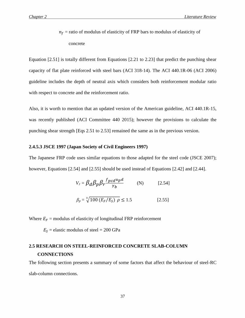
Chapter 2 Literature Review
37
𝑛𝑓 = ratio of modulus of elasticity of FRP bars to modulus of elasticity of
concrete
Equation [2.51] is totally different from Equations [2.21 to 2.23] that predict the punching shear
capacity of flat plate reinforced with steel bars (ACI 318-14). The ACI 440.1R-06 (ACI 2006)
guideline includes the depth of neutral axis which considers both reinforcement modular ratio
with respect to concrete and the reinforcement ratio.
Also, it is worth to mention that an updated version of the American guideline, ACI 440.1R-15,
was recently published (ACI Committee 440 2015); however the provisions to calculate the
punching shear strength [Eqs 2.51 to 2.53] remained the same as in the previous version.
2.4.5.3 JSCE 1997 (Japan Society of Civil Engineers 1997)
The Japanese FRP code uses similar equations to those adapted for the steel code (JSCE 2007);
however, Equations [2.54] and [2.55] should be used instead of Equations [2.42] and [2.44].
VJ = 𝛽𝑑𝛽𝑝𝛽𝑟𝑓𝑝𝑐𝑑𝑢𝑝𝑑
𝛾𝑏 (N) [2.54]
βp = √100 (𝐸𝐹 𝐸𝑆)⁄ 𝜌3
≤ 1.5 [2.55]
Where 𝐸𝐹 = modulus of elasticity of longitudinal FRP reinforcement
𝐸𝑆 = elastic modulus of steel = 200 GPa
2.5 RESEARCH ON STEEL-REINFORCED CONCRETE SLAB-COLUMN
CONNECTIONS
The following section presents a summary of some factors that affect the behaviour of steel-RC
slab-column connections.
Chapter 2 Literature Review
38
2.5.1 Effect of Connection Geometry
Extensive research has been carried out to study the effect of the following parameters on the
punching shear behaviour.
1- Column aspect ratio
2- Critical shear perimeter-to-depths ratio (Σo /d)
3- Span-to-depth ratio (L/d) of the slab
2.5.1.1 Effect of column aspect ratio
Sherif et al. (2005) tested 5 half-scale edge slab-column connections with overall dimensions of
1000-mm long × 1200-mm wide × 120-mm deep. One of the investigated parameters was the
column aspect ratio. It varied between 1.0 and 2.5. The authors compared the obtained results to
test results from literature as well as to ACI 318-02 code (ACI Committee 318 2002) and
concluded the following.
As the column aspect ratio increased from 1.0 to 2.5, the ductility (deflection at the failure load
divided by the deflection at yielding) of the connection increased from 1.13 to 1.53
(approximately 26%). Based on the literature, it was also found that ACI code equations
overestimated the punching load capacity for the interior slab-column connections as its
rectangularity goes above 3, while it is in a good agreement with the edge slab-column
connections regardless the value of the column aspect ratio.
2.5.1.2 Effect of critical shear perimeter-to-depth ratio
As the column cross section increases, the perimeter that resists the shear force increases,
which leads to higher resistance. Marzouk and Hussein (1992) tested two identical steel-RC
interior slab-column connections under concentric load. The only different between the two
Chapter 2 Literature Review
39
specimens was the side length of the square central column (220 and 300 mm). Increasing the
perimeter-to-depth from 17.2 to 20.6 (20%) resulted in 10% increase in the punching shear
capacity.
Also, Sherif et al. (2005) investigated the behaviour of 5 half-scale edge slab-column
connections with perimeter-to-depth ratio ranged from 6.5 to 11.0. In addition, test results from
literature were presented to discuss the effect of perimeter-to-depth ratio on the behaviour of
other types of connections. Also, the test results were compared with the predications of the ACI
318-02 code (ACI 2002) and the following was concluded.
1- A decrease in the failure punching shear stress was found when the Σo/d ratio was
increased.
2- For a 20% decrease in Σo/d ratio (from 11.0 to 8.75), the ductility of the connection
decreased by approximately 26%. Also, no yielding was observed at all in the tension
reinforcement when the ratio (Σo/d) reached 6.5, indicating an extreme brittle failure.
3- Based on literature, it was found that for interior slab-column connections with Σo/d ratios
greater than 17, the ACI 318-02 code (ACI Committee 318 2002) provisions overestimated
the punching strength. However, the code was conservative for the edge slab-column
connections regardless the value of the Σo/d.
2.5.1.3 Effect of span-to-depth ratio
Lovrovich and McLean (1990) studied ten circular slabs including five with shear reinforcement.
The slab thickness was kept constant at 100 mm. The support diameter varied to produce
different span-to-depth ratio of 2, 4, 6, 8 and 12.
The following points were concluded from the test results:
1- For reinforced concrete slabs of constant thickness, the punching shear strength increased
Chapter 2 Literature Review
40
as the span-to-depth ratio decreased below 6.0. The strength might be increased due to the
development of compression struts forming an arch mechanism in the slabs and in-plane
compressive forces resulting from friction at the support.
2- The addition of shear reinforcement had a significant effect on the punching shear strength
of the slab specimens. The specimens with shear reinforcement showed more ductile
behaviour than those specimens without shear reinforcement. Adequate anchorage of the
shear reinforcement greatly enhanced the shear strength of the specimens with large span-
to-depth ratios. However, shear reinforcement was less effective in the specimens with a
span to depth ratio of 2.0 due to steeper failure cracks.
3- Shear cracking initiated at lower loads for the specimens with large span-to-depth ratios.
The estimated shear cracking load was approximately the same for the specimens with
constant span-to-depth ratios.
4- The observed punching shear strengths were much greater than the values permitted by the
ACI 318-83 code (ACI Committee 318 1983). This was especially true for the specimens
with either shear reinforcement or small span-to-depth ratios.
2.5.2 Effect of Concrete Compressive Strength
Marzouk et al. (1998) tested six slabs with compressive strength varying from 35 to 75 MPa; the
test result showed 7 to 15% increase in the shear strength when the concrete compressive
strength was increased by 114%. Also, it was reported that the ACI 318-95 code (ACI
Committee 318 1995) underestimated the punching shear capacity for connections made of high
strength concrete by 20 to 25%.
Gardner (1990) studied 30 circular specimens with different compressive strength ranged from
14 to 56 MPa and different flexural reinforcement ratios ranged from 0.5 to 5.0%. Also, the test
Chapter 2 Literature Review
41
results were compared with different codes. It was concluded that the cubic root relationship
between shear strength and concrete strength gave more accurate results than the square root
relationship currently used by ACI 318-83 (ACI Committee 318 1983) and CSA-A23.3-M84)
codes. Marzouk and Hussein (1992) confirmed the results of Gardner. According to Marzouk
and Hussein (1992) test results, using the cubic root of the concrete compressive strength to
predict the punching resistance of the slab-column connections generally yielded better results
than the square root expression used in North American codes.
2.5.3 Effect of Concrete Tensile Strength
Punching shear strength of slab-column connections is expected to increase by increasing the
tensile strength of concrete. Mcharg et al. (2000) studied six interior slab-column specimens
that contained steel fiber reinforced concrete (SFRC), divided into three series. Series 1 had no
fiber, while the second and the third contained 0.5% fiber volume. In Series 2, the fiber was
around the column up to a distance of 3.3 times the slab thickness from the column faces and
over the entire depth of the slab. In addition, for Series 3 the fiber was over the entire area of
the slab and placed only in the top of the slab over a thickness equal to the top cover plus one
bar diameter. The test results showed the following.
1- The increase in punching shear resistance due to the presence of SFRC in the slab around
the column was 38%.
2- Providing SFRC cover resulted in an increase in punching shear resistance and better
crack control. The crack widths of the specimens were 25 and 20% smaller inside and
outside the immediate column region, respectively.
3- Providing steel fiber volume of 0.5% enhanced the overall behaviour of the specimens in
terms of ductility, strain, greater post-cracking stiffness and smaller crack widths at
Chapter 2 Literature Review
42
service load level.
Yang et al. (2010) studied four interior slab-column specimens. The connections consisted of
2300 × 2300 × 150 mm flat plate with 225-mm square column stubs extended 300 mm above
and below the slab. One of the test parameter was using SFRC (0.5% by volume) in the slab
around the column region (up to distance from the column faces equal to 3.33 times the slab
thickness). It was concluded that the presence of steel fibers led to 51% increase in the
punching shear capacity. Also, using steel fibers improved crack control due to the ability of
the steel fibers to transfer tension across cracks.
2.5.4 Shear Reinforcement
To avoid adding drop panels, beams or column heads, shear capacity of slab may be increased
by using shear reinforcement. Transverse reinforcement can be classified in the following three
categories.
1- Stirrups and bent bars.
2- Shear studs.
3- Shear heads.
2.5.4.1 Effect of stirrups and bent bars
Broms (2000) studied seven specimens, all of them had the same dimensions and approximately
the same flexural capacity but with different reinforcement. The main purpose of the study was
to eliminate the punching failure mode of flat plate. According to the authors, this could happen
by describing a reinforcement system that allows a flat plate to form plastic hinges at the
columns and in the mid spans with no tendency for brittle punching failure. The described bent
bar and stirrup combination is easy to fabricate and install in a stable way. For a typical flat plate
Chapter 2 Literature Review
43
structure, eight stirrup cages at each column are normally sufficient. The extra cost (including
labor cost) as compared to a conventional brittle flat plate without any shear reinforcement is
assessed at less than 1.5% of the total cost for the slab.
Park et al. (2007) tested 8 interior slab-column specimens. Four of these specimens contained
lattice bars. The lattice reinforcement was composed of top and bottom bars and inclined web
bars that are weld-connected to each other. The inclined web bars acted as shear reinforcement.
This lattice reinforcement, which was composed of the welded web bars and longitudinal bars,
could work as a truss system. The 4 specimens that contained the lattice reinforcement did not
have any other type of reinforcement, while the other 4 specimens contained the conventional
flexural steel bars. The specimens consisted of a central stub column and a square slab with a
length of 1800 mm. The thickness of the specimens was 120 or 160 mm. The column stub height
was 400 mm above the slab and 100-mm below it with different cross section dimensions. The
test results showed that the punching shear strength and deformation capacity of the specimens
reinforced with the lattice bars was increased by 1.4 and 9.2 times those of the unreinforced
specimens, respectively.
2.5.4.2 Effect of shear stud reinforcements
Shear studs in form of round bars, fully anchored at the top and bottom by steel plates, are
getting more and more popular because of their ease of placement and reasonable cost. El-
Salakawy et al. (1998) studied eight large-scale reinforced concrete flat plate edge connections.
The tests were designed to study the effect of high moment-to-shear ratio on the punching shear
behaviour of slab-column edge connections. One of the test perimeters was the shear
reinforcement. In the specimens with shear reinforcement, the shear studs were arranged in six
strips around the column, two at each side.
Chapter 2 Literature Review
44
The following was concluded from the test results:
1- For the specimens with shear reinforcement, the change in failure mechanism due to higher
moment was observed (from a ductile flexural failure in specimens subjected to (M/V) =
0.3 to a more brittle punching-flexural failure in specimens subjected to (M/V) = 0.66. This
was due to the higher shear stresses (M/V) = 0.66), which exceeded the punching shear
capacity of the slab outside the shear-reinforced zone.
2- Shear studs increased the stiffness of the connections (smaller deflections at service loads).
3- Shear studs increased the capacity and the ductility of the connections.
Mokhtar et al. (1985) tested eight full-size interior slab-column connections subjected to
concentric loads. One specimen had no shear reinforcement, while the remaining seven were
reinforced against punching shear by shear studs. The test results confirmed that using shear
stud reinforcement greatly increased the strength and the ductility of the slab-column
connection. The enhancement in the shear resistance of the slabs varied between 24 and 43%
with respect to the slab without shear stud reinforcement and depending on the configuration
used for the shear studs in each specimen. In addition to that Elgabry and Ghali (1987) tested
five full-scale reinforced concrete flat-plate connections with interior columns subjected to
moment transfer. One specimen had no shear reinforcement and the remaining four contained
various arrangements of stud-shear. The enhancement in the shear strength of the specimens
with shear studs varied between 0 and 200% depended on the configuration used for the shear
reinforcement.
2.5.4.3 Effect of shear heads
Marzouk and Jiang (1997) tested two slabs; one without shear reinforcement and the other with
T-headed shear reinforcement. The slab, with T-headed shear reinforcement, exhibited 15%
Chapter 2 Literature Review
45
increase in the ultimate load capacity compared to the reference slab without shear
reinforcement. In addition, it was found that punching shear failure can be controlled, eliminated
and transformed into flexural failure for high-strength concrete plates by appropriately using of
T-headed shear reinforcement with the flexural reinforcement. In addition, the test results were
compared with the limits specified by ACI 318-89 code (ACI Committee 318 1989) and it was
found that the code values are adequate for high strength concrete plates reinforced with shear
reinforcement.
Rizk et al. (2011) tested five interior square slab-column connections with thickness varied
between 300 and 400 mm and side dimension of 2650 mm. One of the specimens served as
control, while, the others contained T-headed shear reinforcement (shear reinforcement ratio of
approximately 0.68%). A concentric load was applied on the slabs through 400 × 400 mm
column stubs. The test results showed the following.
1- The punching failure mode changed to a ductile flexure failure due to the presence of the
shear reinforcement with a reinforcement ratio of approximately 0.68%.
2- The structural behaviour of the specimens could be enhanced by adding shear
reinforcement.
2.5.5 Effect of Flexural Reinforcement
Flexural steel reinforcement has significant effect on the punching shear capacity of flat plate
system; this effect can be summarized in the following three points.
1- Effect of reinforcement ratio,
2- Effect of reinforcement arrangement,
3- Effect of yield strength of the flexural reinforcement.
Chapter 2 Literature Review
46
2.5.5.1 Effect of reinforcement ratio
Much research has been conducted to study the effect of steel reinforcement ratio on the
punching shear strength of the slab-column connections. In general, it has been found that as
the steel reinforcement ratio increased the stresses along the punching cone and the load
carrying capacity of slab-column connections also increased. Ozden et al. (2006) studied 26 half-
scale reinforced concrete flat plates. The slab plates had 1500-mm diameter circular geometry
and 120-mm thickness with 200-mm square central column extended above and below the slab.
The specimens were supported along the perimeter by uniformly spaced tie rods, placed 600-mm
away from the centre of the column stub. One of the test perimeters was the reinforcement ratio,
which varied between 0.73 and 2.25%. The test results showed that increasing the plate flexure
reinforcement ratio resulted in an increase in the punching shear capacity of the plate, but the
rate of the enhancement in load carrying capacity was far lower than the increase in the flexural
reinforcement ratio. For instance, 10 and 20% increase in the punching capacity was reported for
50% increase in the flexural capacity in normal and high strength concrete, respectively. Also,
the test results were compared with the CSA/A23.3-04 (CSA 2004) and it was found that the
code punching shear capacity predictions provided conservative estimates for concentrically
loaded slabs and good predictions for eccentrically loaded slabs.
Vanderbilt (1972) tested 15 slab-column connections with slab thickness of 51 mm. The test
parameters included the effect of reinforcement ratio. Based on the test results, it was found that
the stresses at punching increased with increasing the reinforcement ratio. Also, the average
increase in the punching shear stress resulted from doubling the reinforcement ratio (from 1.3 to
2.6%) was 22%.
Chapter 2 Literature Review
47
Marzouk and Hussein (2002) found similar results, where 17 interior slab-column connections
were tested. One of the test parameters was the slab reinforcement ratio ranging between 0.6 to
2.4% with slab thickness of 120 and 150 mm and a concrete compressive strength of 75 MPa.
The test results showed a total increase of 63% in the punching capacity for the 150-mm thick
slab when the reinforcement ratio was increased by threefold. For the 120-mm thick slab, the
increase was 78% with an increase in reinforcement ratio from 0.9 to 2.3%.
Richart (1948) investigated 128 test specimens, where footings supported on a bed of springs
were tested. The slab thickness varied between 250 to 460 mm. Based on the test results and an
extensive mathematical work to reach to the best power function for the reinforcement ratio that
could fit the experimental results, a recommendation has been made for using the one third
power function for the reinforcement ratio. In addition, other researchers obtained similar results
(Regan and Bræstrup 1985; Gardner 1990; Takahashi et al. 1992; Sherif and Dilger 2000; Dilger
2000).
2.5.5.2 Effect of reinforcement arrangement
It is well-established that concentrating the flexural reinforcement inside the slab in the area
around the column can be used to control the width and depth of cracks, which can be used also
to enhance the punching shear capacity of the slab. On the other hand, it appears from the
available literature that concentrating the flexural reinforcement in the vicinity of the column
seems to lead to a small increase in the punching shear strength only if the reduced bar spacing
does not lead to a reduction in the bond strength along the bars. Moe (1961) investigated the
effect of concentrated the flexural reinforcement within a narrow band around the column
through two series of tests. In the test, the slab reinforcement ratio was kept constant. The test
result showed no effect from concentrating the flexural reinforcement on the punching shear
Chapter 2 Literature Review
48
capacity. Elstner and Hognestad (1956), Regan (1986) and Hawkins et al. (1974) reached a
similar conclusion. Alexander and Simmonds (1992) attributed these test results to bond failure.
Mcharg et al. (2000) supported the explanation of Alexander and Simmonds (1992); where 14%
increase in the punching strength of the connection was found when the flexural reinforcement is
banded in the vicinity of the column.
2.5.5.3 Effect of yield strength of reinforcement
Sherif and Dilger (1996) studied the effect of yield strength of the reinforcement on the punching
shear capacity of slab-column connections based on the work reported in literature (Moe 1961;
Base 1968). The authors concluded that the yield strength of the reinforcement has no apparent
influence on the punching resistance. On the other side, Hawkins and Mitchell (1979) reported
that yielding of the reinforcement bars has a significant effect on the punching shear capacity of
the slab-column connections. The authors attributed that to the loss of strength due to loss of
membrane action around the connection as result for the yielding of the reinforcement. Also, if
the slab steel bars yield significantly, then it might be difficult to differentiate between punching
and flexural failures.
2.6 RESEARCHES ON FRP AS REINFORCEMENT FOR SLAB-COLUMN
CONNECTIONS
Due to the different in properties between steel and FRP bars a significant amount of research
has been conducted to study the behaviour of concrete structures reinforced with FRP bars.
However, not much was carried out on FRP-RC slab-column connections. In the following
section a discussion will be offered to evaluate the different parameters that affect the behaviour
of the FRP bars as internal reinforcements in the concrete members, depending on the available
research in the literature.
Chapter 2 Literature Review
49
2.6.1 Effect of FRP Flexural Reinforcement Ratio
The FRP bars have relatively low modulus of elasticity compared to the conventional steel bars,
as a result, the shear strength of the slabs reinforcement with FRP bars are expected to be lower,
especially after cracking, due to the wider cracks and reduced depth to neutral axis. In addition,
due to the high strength of FRP bars, the behaviour of FRP-RC slab is controlled primarily by
shear rather than flexure. Ospina et al. (2003) tested three interior slab-column connections
with overall dimensions of 2150 × 2150 × 155 mm with column stub extended above and
blew the slab for 250 mm and square cross section with side length of 250 mm. One of the
slabs was reinforced with 0.73% conventional steel bars as reference. The other two were
reinforced with 0.73 and 1.46% GFRP bars. The test results showed that for the slabs
reinforced with GFRP bars, an increase in the tension mat stiffness led to a stiffer response in
the elastic-cracked stage. The slab with reinforcement ratio of 1.46% failed at a higher load of
approximately 125% with respect to the one with lower reinforcement ratio but the strength gain
is not linearly related to the stiffness increase. Also, the deflection at ultimate reduced as the
stiffness of tension mat increased. In addition, the test results were compared with different
codes and the authors concluded that the design provisions in ACI 318-99 (ACI Committee 318
1999) and BS 8110-97 (British Standard 1997) cannot be used directly to predict the punching
capacity of the slabs reinforced with FRP reinforcing bars. Neither of these standards adequately
accounts for the elastic stiffness of the reinforcing mat. Dulude et al. (2010) found similar
results, where 40% increase in the load carrying capacity was found when the reinforcement
ratio was increased from 0.34 to 0.73% in GFRP-RC interior slab-column connections.
Hussein et al. (2004) studied four interior slab-column connections with different reinforcement
ratios varying between 1.05 and 1.67%. The test results showed 10% increase in the ultimate
Chapter 2 Literature Review
50
load for the slab with 1.67% reinforcement ratio with respect to the one with 1.05%. However,
this percentage was 14% for the slab with reinforcement ratio of 1.18% compared to the one with
1.05%.
Matthys and Taerwe (2000) investigated the effect of different reinforcement ratios by testing 17
square slabs with a side length of 1000 mm and a total slab depth of 120 or 150 mm. The test
specimens were subdivided in three series. The first series included steel-RC reference slabs
(series R). The second series contained different type of carbon FRP (CFRP) grids (series C/ CS).
The third series included a hybrid type of FRP comprising both glass and carbon. The test
results were compared with different codes such as Euro code (EN/1992-1-1 2004), the Japanese
Society of Civil Engineers – JSCE (JSCE 1997) and ACI 318-95 (ACI Committee 318 1995) and
the following was concluded:
1- For FRP-RC slabs with similar flexural strength as the steel-RC reference slabs, the
obtained punching load and stiffness in the cracked state were considerably less. However,
for the FRP-reinforced slabs with an increased reinforcement ratio or an increased slab
depth (flexural stiffness in the fully cracked state comparable to the reference slabs), the
behaviour of the slabs were comparable to the steel-reinforced reference slabs.
2- The calculation of the mean punching failure load according to empirical-based
expressions (such as most codes equations) gave fairly good predictions but with an
underestimation for the slabs with FRP reinforcement (low modulus of elasticity). The
latter aspect was solved by introduced the equivalent reinforcement ratio (ρ.Ef/Es)
3- Evaluation of the design punching capacity according to the codes equations, taking into
account the modification (ρ.Ef/Es), showed sufficient safety (mean global safety factor of
about 1.9 to 2.6) for all investigated codes.
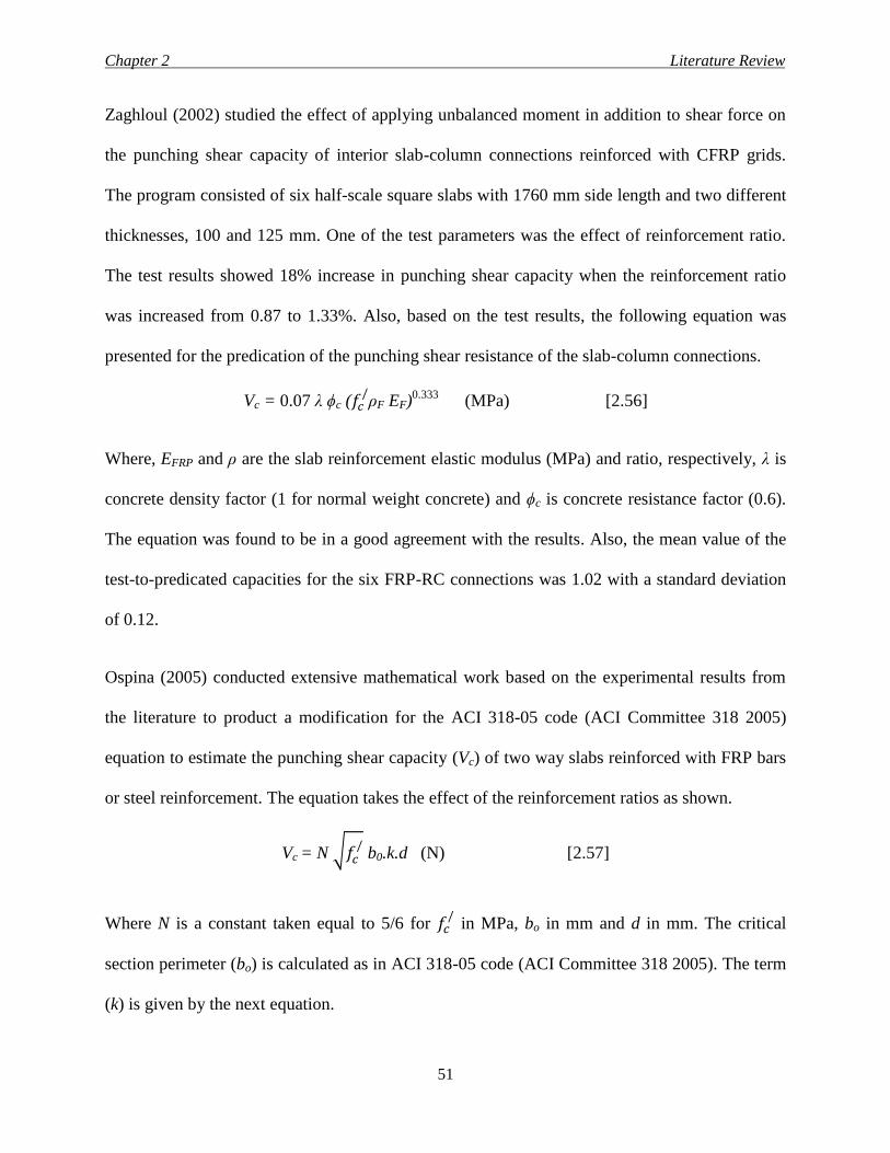
Chapter 2 Literature Review
51
Zaghloul (2002) studied the effect of applying unbalanced moment in addition to shear force on
the punching shear capacity of interior slab-column connections reinforced with CFRP grids.
The program consisted of six half-scale square slabs with 1760 mm side length and two different
thicknesses, 100 and 125 mm. One of the test parameters was the effect of reinforcement ratio.
The test results showed 18% increase in punching shear capacity when the reinforcement ratio
was increased from 0.87 to 1.33%. Also, based on the test results, the following equation was
presented for the predication of the punching shear resistance of the slab-column connections.
Vc = 0.07 λ ϕc (𝑓𝑐/ρF EF)
0.333 (MPa) [2.56]
Where, EFRP and ρ are the slab reinforcement elastic modulus (MPa) and ratio, respectively, λ is
concrete density factor (1 for normal weight concrete) and ϕc is concrete resistance factor (0.6).
The equation was found to be in a good agreement with the results. Also, the mean value of the
test-to-predicated capacities for the six FRP-RC connections was 1.02 with a standard deviation
of 0.12.
Ospina (2005) conducted extensive mathematical work based on the experimental results from
the literature to product a modification for the ACI 318-05 code (ACI Committee 318 2005)
equation to estimate the punching shear capacity (Vc) of two way slabs reinforced with FRP bars
or steel reinforcement. The equation takes the effect of the reinforcement ratios as shown.
Vc = N √𝑓𝑐/ b0.k.d (N) [2.57]
Where N is a constant taken equal to 5/6 for 𝑓𝑐/ in MPa, bo in mm and d in mm. The critical
section perimeter (bo) is calculated as in ACI 318-05 code (ACI Committee 318 2005). The term
(k) is given by the next equation.
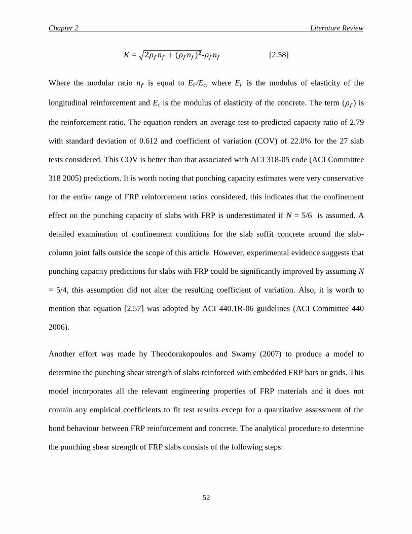
Chapter 2 Literature Review
52
K = √2𝜌𝑓𝑛𝑓 + (𝜌𝑓𝑛𝑓)2-𝜌𝑓𝑛𝑓 [2.58]
Where the modular ratio 𝑛𝑓 is equal to EF/Ec, where EF is the modulus of elasticity of the
longitudinal reinforcement and Ec is the modulus of elasticity of the concrete. The term (𝜌𝑓) is
the reinforcement ratio. The equation renders an average test-to-predicted capacity ratio of 2.79
with standard deviation of 0.612 and coefficient of variation (COV) of 22.0% for the 27 slab
tests considered. This COV is better than that associated with ACI 318-05 code (ACI Committee
318 2005) predictions. It is worth noting that punching capacity estimates were very conservative
for the entire range of FRP reinforcement ratios considered, this indicates that the confinement
effect on the punching capacity of slabs with FRP is underestimated if N = 5/6 is assumed. A
detailed examination of confinement conditions for the slab soffit concrete around the slab-
column joint falls outside the scope of this article. However, experimental evidence suggests that
punching capacity predictions for slabs with FRP could be significantly improved by assuming N
= 5/4, this assumption did not alter the resulting coefficient of variation. Also, it is worth to
mention that equation [2.57] was adopted by ACI 440.1R-06 guidelines (ACI Committee 440
2006).
Another effort was made by Theodorakopoulos and Swamy (2007) to produce a model to
determine the punching shear strength of slabs reinforced with embedded FRP bars or grids. This
model incorporates all the relevant engineering properties of FRP materials and it does not
contain any empirical coefficients to fit test results except for a quantitative assessment of the
bond behaviour between FRP reinforcement and concrete. The analytical procedure to determine
the punching shear strength of FRP slabs consists of the following steps:
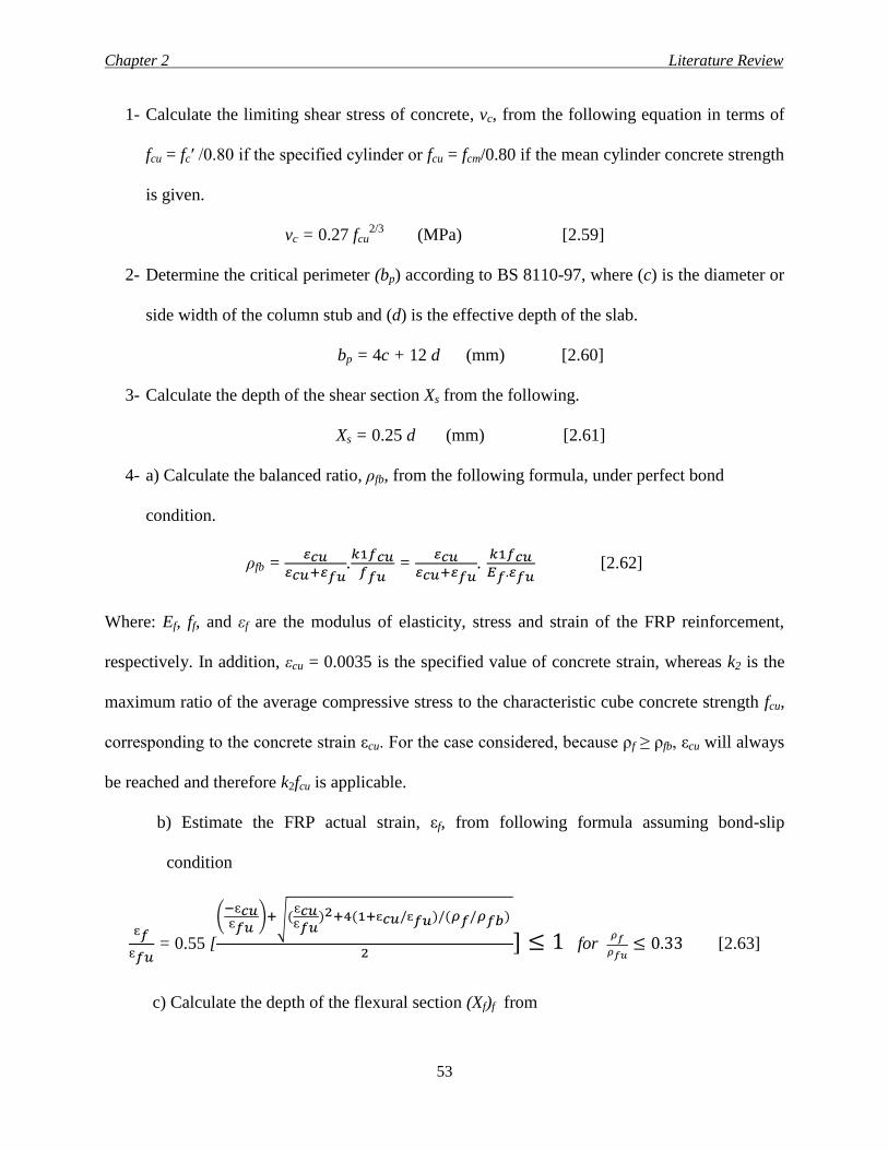
Chapter 2 Literature Review
53
1- Calculate the limiting shear stress of concrete, vc, from the following equation in terms of
fcu = fc′ /0.80 if the specified cylinder or fcu = fcm/0.80 if the mean cylinder concrete strength
is given.
vc = 0.27 fcu2/3
(MPa) [2.59]
2- Determine the critical perimeter (bp) according to BS 8110-97, where (c) is the diameter or
side width of the column stub and (d) is the effective depth of the slab.
bp = 4c + 12 d (mm) [2.60]
3- Calculate the depth of the shear section Xs from the following.
Xs = 0.25 d (mm) [2.61]
4- a) Calculate the balanced ratio, ρfb, from the following formula, under perfect bond
condition.
ρfb = 𝜀𝑐𝑢
𝜀𝑐𝑢+𝜀𝑓𝑢.𝑘1𝑓𝑐𝑢
𝑓𝑓𝑢 =
𝜀𝑐𝑢𝜀𝑐𝑢+𝜀𝑓𝑢
. 𝑘1𝑓𝑐𝑢𝐸𝑓.𝜀𝑓𝑢
[2.62]
Where: Ef, ff, and εf are the modulus of elasticity, stress and strain of the FRP reinforcement,
respectively. In addition, εcu = 0.0035 is the specified value of concrete strain, whereas k2 is the
maximum ratio of the average compressive stress to the characteristic cube concrete strength fcu,
corresponding to the concrete strain εcu. For the case considered, because ρf ≥ ρfb, εcu will always
be reached and therefore k2fcu is applicable.
b) Estimate the FRP actual strain, εf, from following formula assuming bond-slip
condition
ɛ𝑓
ɛ𝑓𝑢 = 0.55 [
(−ɛ𝑐𝑢ɛ𝑓𝑢
)+√(ɛ𝑐𝑢ɛ𝑓𝑢
)2+4(1+ɛ𝑐𝑢/ɛ𝑓𝑢)/(𝜌𝑓/𝜌𝑓𝑏)
2] ≤ 1 for
𝜌𝑓
𝜌𝑓𝑢≤ 0.33 [2.63]
c) Calculate the depth of the flexural section (Xf)f from
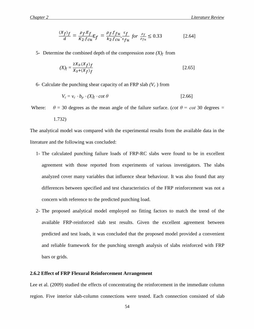
Chapter 2 Literature Review
54
(𝑋𝑓)𝑓
𝑑 =
𝜌𝑓.𝐸𝑓
𝐾2.𝑓𝑐𝑢ɛ𝑓 =
𝜌𝑓.𝑓𝑓𝑢
𝑘2.𝑓𝑐𝑢.
ɛ𝑓
ɛ𝑓𝑢 for
𝜌𝑓
𝜌𝑓𝑢≤ 0.33 [2.64]
5- Determine the combined depth of the compression zone (X)f from
(X)f = 2𝑋𝑠.(𝑋𝑓)𝑓
𝑋𝑠+(𝑋𝑓)𝑓 [2.65]
6- Calculate the punching shear capacity of an FRP slab (Vc ) from
Vc = vc ⋅ bp ⋅ (X)f ⋅ cot θ [2.66]
Where: θ = 30 degrees as the mean angle of the failure surface. (cot θ = cot 30 degrees =
1.732)
The analytical model was compared with the experimental results from the available data in the
literature and the following was concluded:
1- The calculated punching failure loads of FRP-RC slabs were found to be in excellent
agreement with those reported from experiments of various investigators. The slabs
analyzed cover many variables that influence shear behaviour. It was also found that any
differences between specified and test characteristics of the FRP reinforcement was not a
concern with reference to the predicted punching load.
2- The proposed analytical model employed no fitting factors to match the trend of the
available FRP-reinforced slab test results. Given the excellent agreement between
predicted and test loads, it was concluded that the proposed model provided a convenient
and reliable framework for the punching strength analysis of slabs reinforced with FRP
bars or grids.
2.6.2 Effect of FRP Flexural Reinforcement Arrangement
Lee et al. (2009) studied the effects of concentrating the reinforcement in the immediate column
region. Five interior slab-column connections were tested. Each connection consisted of slab
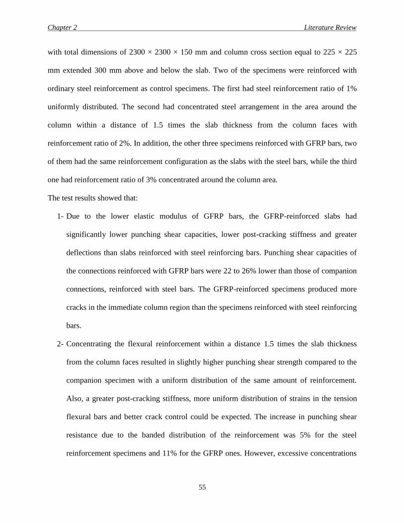
Chapter 2 Literature Review
55
with total dimensions of 2300 × 2300 × 150 mm and column cross section equal to 225 × 225
mm extended 300 mm above and below the slab. Two of the specimens were reinforced with
ordinary steel reinforcement as control specimens. The first had steel reinforcement ratio of 1%
uniformly distributed. The second had concentrated steel arrangement in the area around the
column within a distance of 1.5 times the slab thickness from the column faces with
reinforcement ratio of 2%. In addition, the other three specimens reinforced with GFRP bars, two
of them had the same reinforcement configuration as the slabs with the steel bars, while the third
one had reinforcement ratio of 3% concentrated around the column area.
The test results showed that:
1- Due to the lower elastic modulus of GFRP bars, the GFRP-reinforced slabs had
significantly lower punching shear capacities, lower post-cracking stiffness and greater
deflections than slabs reinforced with steel reinforcing bars. Punching shear capacities of
the connections reinforced with GFRP bars were 22 to 26% lower than those of companion
connections, reinforced with steel bars. The GFRP-reinforced specimens produced more
cracks in the immediate column region than the specimens reinforced with steel reinforcing
bars.
2- Concentrating the flexural reinforcement within a distance 1.5 times the slab thickness
from the column faces resulted in slightly higher punching shear strength compared to the
companion specimen with a uniform distribution of the same amount of reinforcement.
Also, a greater post-cracking stiffness, more uniform distribution of strains in the tension
flexural bars and better crack control could be expected. The increase in punching shear
resistance due to the banded distribution of the reinforcement was 5% for the steel
reinforcement specimens and 11% for the GFRP ones. However, excessive concentrations
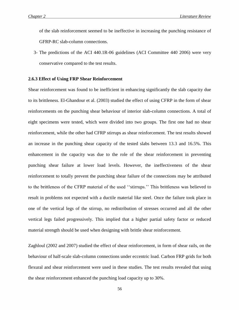
Chapter 2 Literature Review
56
of the slab reinforcement seemed to be ineffective in increasing the punching resistance of
GFRP-RC slab-column connections.
3- The predictions of the ACI 440.1R-06 guidelines (ACI Committee 440 2006) were very
conservative compared to the test results.
2.6.3 Effect of Using FRP Shear Reinforcement
Shear reinforcement was found to be inefficient in enhancing significantly the slab capacity due
to its brittleness. El-Ghandour et al. (2003) studied the effect of using CFRP in the form of shear
reinforcements on the punching shear behaviour of interior slab-column connections. A total of
eight specimens were tested, which were divided into two groups. The first one had no shear
reinforcement, while the other had CFRP stirrups as shear reinforcement. The test results showed
an increase in the punching shear capacity of the tested slabs between 13.3 and 16.5%. This
enhancement in the capacity was due to the role of the shear reinforcement in preventing
punching shear failure at lower load levels. However, the ineffectiveness of the shear
reinforcement to totally prevent the punching shear failure of the connections may be attributed
to the brittleness of the CFRP material of the used ‘‘stirrups.’’ This brittleness was believed to
result in problems not expected with a ductile material like steel. Once the failure took place in
one of the vertical legs of the stirrup, no redistribution of stresses occurred and all the other
vertical legs failed progressively. This implied that a higher partial safety factor or reduced
material strength should be used when designing with brittle shear reinforcement.
Zaghloul (2002 and 2007) studied the effect of shear reinforcement, in form of shear rails, on the
behaviour of half-scale slab-column connections under eccentric load. Carbon FRP grids for both
flexural and shear reinforcement were used in these studies. The test results revealed that using
the shear reinforcement enhanced the punching load capacity up to 30%.
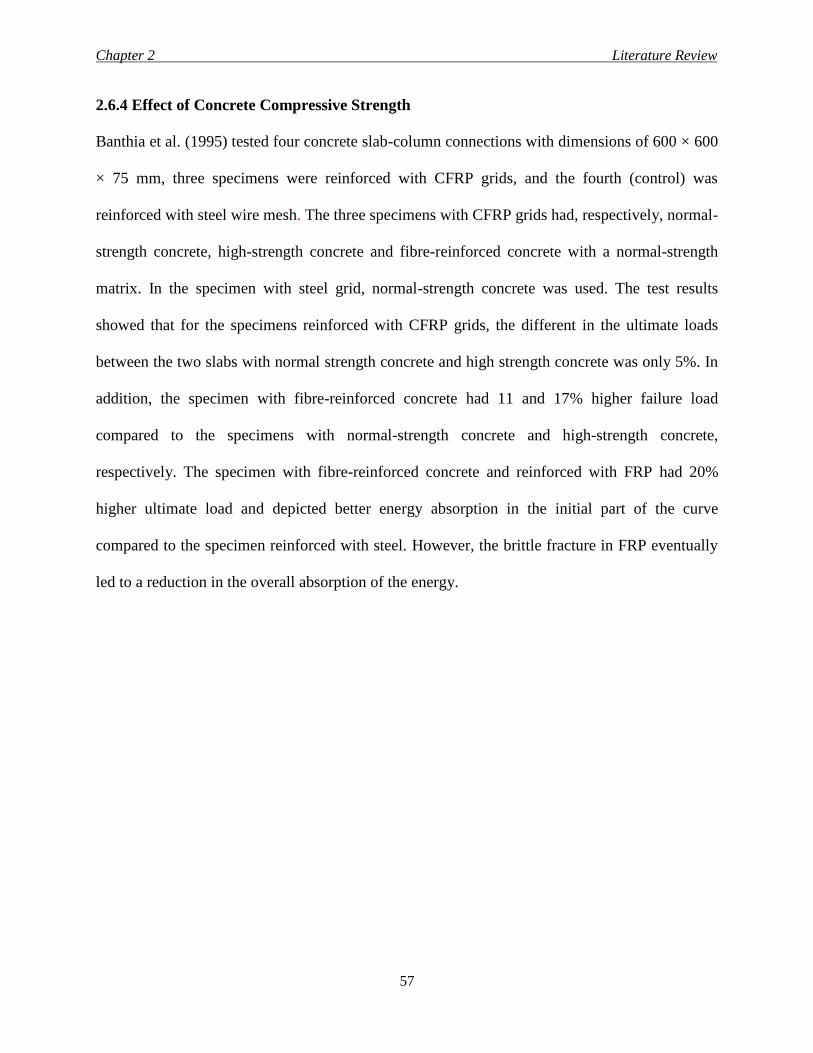
Chapter 2 Literature Review
57
2.6.4 Effect of Concrete Compressive Strength
Banthia et al. (1995) tested four concrete slab-column connections with dimensions of 600 × 600
× 75 mm, three specimens were reinforced with CFRP grids, and the fourth (control) was
reinforced with steel wire mesh. The three specimens with CFRP grids had, respectively, normal-
strength concrete, high-strength concrete and fibre-reinforced concrete with a normal-strength
matrix. In the specimen with steel grid, normal-strength concrete was used. The test results
showed that for the specimens reinforced with CFRP grids, the different in the ultimate loads
between the two slabs with normal strength concrete and high strength concrete was only 5%. In
addition, the specimen with fibre-reinforced concrete had 11 and 17% higher failure load
compared to the specimens with normal-strength concrete and high-strength concrete,
respectively. The specimen with fibre-reinforced concrete and reinforced with FRP had 20%
higher ultimate load and depicted better energy absorption in the initial part of the curve
compared to the specimen reinforced with steel. However, the brittle fracture in FRP eventually
led to a reduction in the overall absorption of the energy.
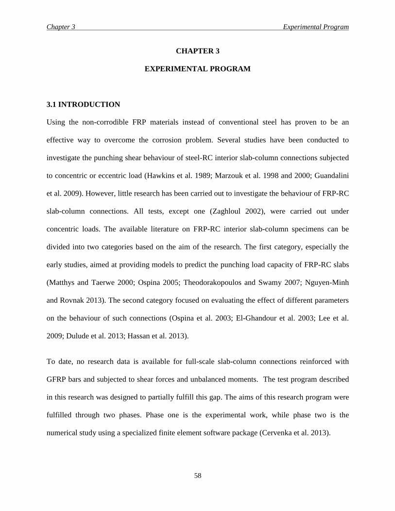
Chapter 3 Experimental Program
58
CHAPTER 3
EXPERIMENTAL PROGRAM
3.1 INTRODUCTION
Using the non-corrodible FRP materials instead of conventional steel has proven to be an
effective way to overcome the corrosion problem. Several studies have been conducted to
investigate the punching shear behaviour of steel-RC interior slab-column connections subjected
to concentric or eccentric load (Hawkins et al. 1989; Marzouk et al. 1998 and 2000; Guandalini
et al. 2009). However, little research has been carried out to investigate the behaviour of FRP-RC
slab-column connections. All tests, except one (Zaghloul 2002), were carried out under
concentric loads. The available literature on FRP-RC interior slab-column specimens can be
divided into two categories based on the aim of the research. The first category, especially the
early studies, aimed at providing models to predict the punching load capacity of FRP-RC slabs
(Matthys and Taerwe 2000; Ospina 2005; Theodorakopoulos and Swamy 2007; Nguyen-Minh
and Rovnak 2013). The second category focused on evaluating the effect of different parameters
on the behaviour of such connections (Ospina et al. 2003; El-Ghandour et al. 2003; Lee et al.
2009; Dulude et al. 2013; Hassan et al. 2013).
To date, no research data is available for full-scale slab-column connections reinforced with
GFRP bars and subjected to shear forces and unbalanced moments. The test program described
in this research was designed to partially fulfill this gap. The aims of this research program were
fulfilled through two phases. Phase one is the experimental work, while phase two is the
numerical study using a specialized finite element software package (Cervenka et al. 2013).
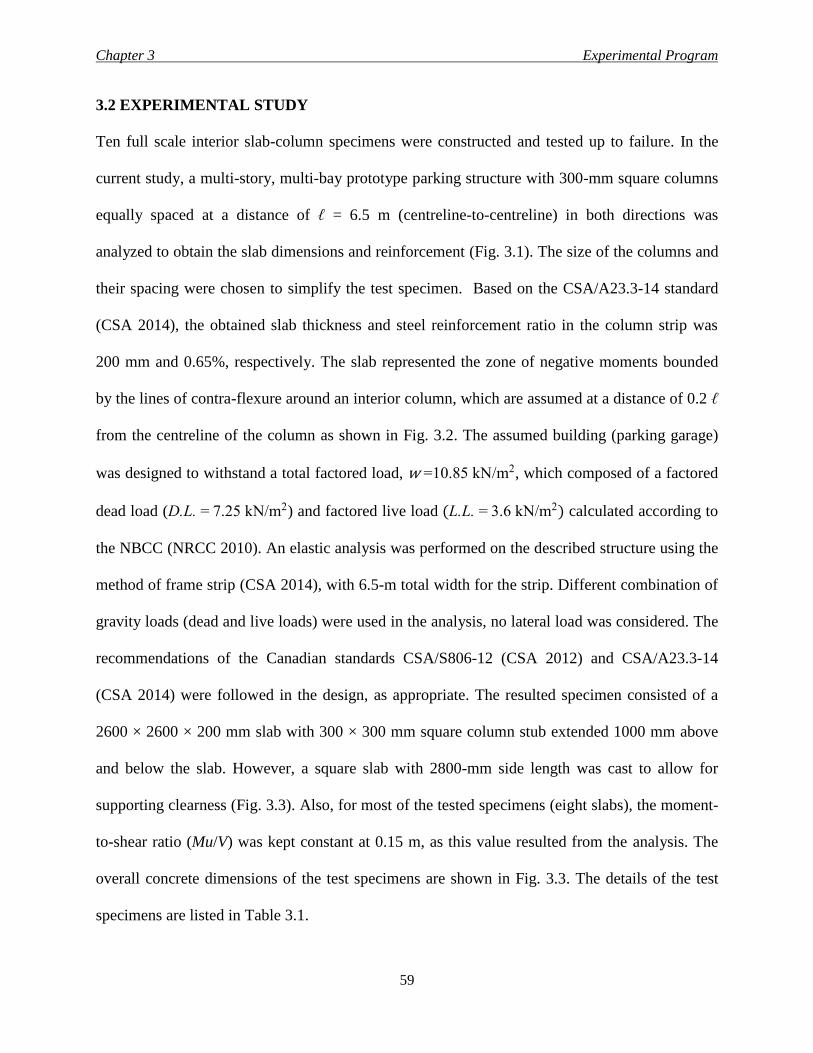
Chapter 3 Experimental Program
59
3.2 EXPERIMENTAL STUDY
Ten full scale interior slab-column specimens were constructed and tested up to failure. In the
current study, a multi-story, multi-bay prototype parking structure with 300-mm square columns
equally spaced at a distance of ℓ = 6.5 m (centreline-to-centreline) in both directions was
analyzed to obtain the slab dimensions and reinforcement (Fig. 3.1). The size of the columns and
their spacing were chosen to simplify the test specimen. Based on the CSA/A23.3-14 standard
(CSA 2014), the obtained slab thickness and steel reinforcement ratio in the column strip was
200 mm and 0.65%, respectively. The slab represented the zone of negative moments bounded
by the lines of contra-flexure around an interior column, which are assumed at a distance of 0.2 ℓ
from the centreline of the column as shown in Fig. 3.2. The assumed building (parking garage)
was designed to withstand a total factored load, w =10.85 kN/m2, which composed of a factored
dead load (D.L. = 7.25 kN/m2) and factored live load (L.L. = 3.6 kN/m2) calculated according to
the NBCC (NRCC 2010). An elastic analysis was performed on the described structure using the
method of frame strip (CSA 2014), with 6.5-m total width for the strip. Different combination of
gravity loads (dead and live loads) were used in the analysis, no lateral load was considered. The
recommendations of the Canadian standards CSA/S806-12 (CSA 2012) and CSA/A23.3-14
(CSA 2014) were followed in the design, as appropriate. The resulted specimen consisted of a
2600 × 2600 × 200 mm slab with 300 × 300 mm square column stub extended 1000 mm above
and below the slab. However, a square slab with 2800-mm side length was cast to allow for
supporting clearness (Fig. 3.3). Also, for most of the tested specimens (eight slabs), the moment-
to-shear ratio (Mu/V) was kept constant at 0.15 m, as this value resulted from the analysis. The
overall concrete dimensions of the test specimens are shown in Fig. 3.3. The details of the test
specimens are listed in Table 3.1.
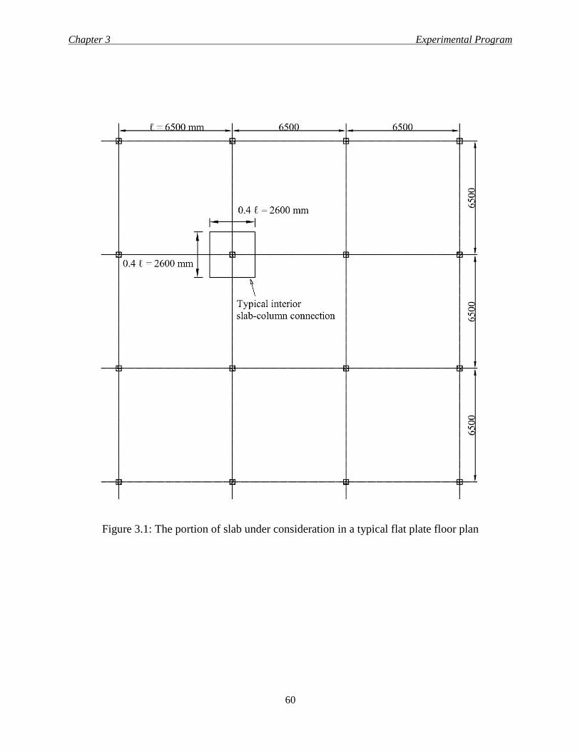
Chapter 3 Experimental Program
60
Figure 3.1: The portion of slab under consideration in a typical flat plate floor plan
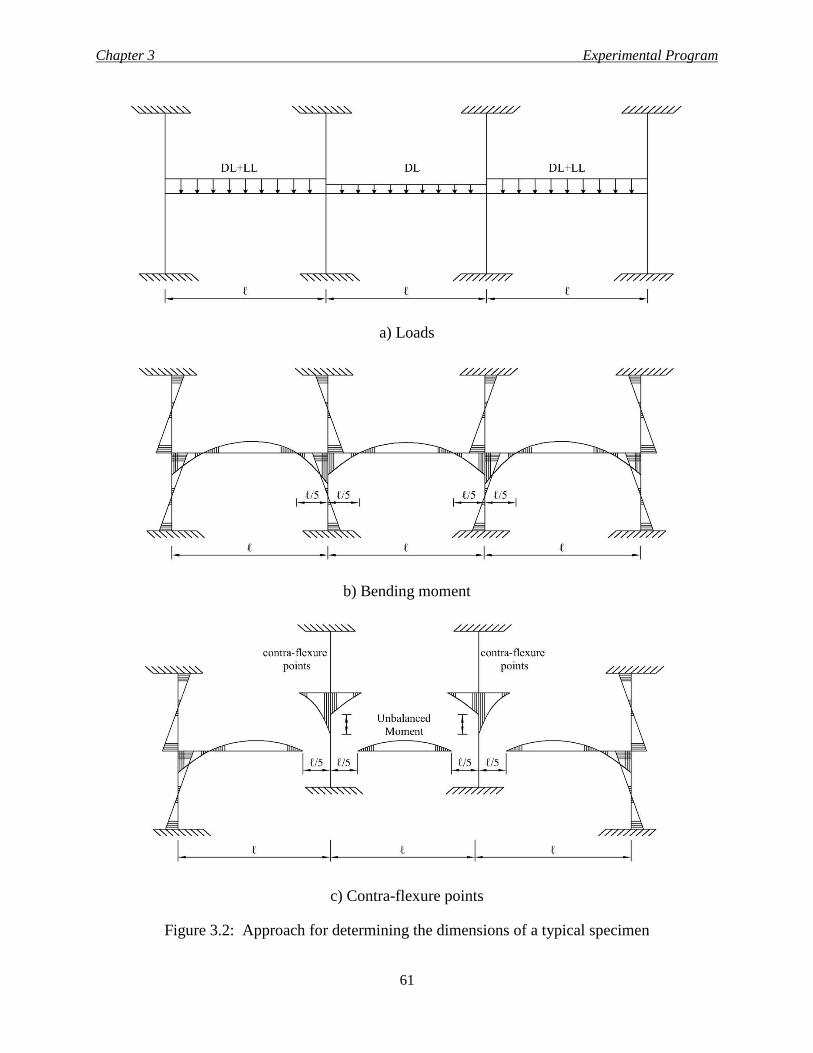
Chapter 3 Experimental Program
61
a) Loads
b) Bending moment
c) Contra-flexure points
Figure 3.2: Approach for determining the dimensions of a typical specimen
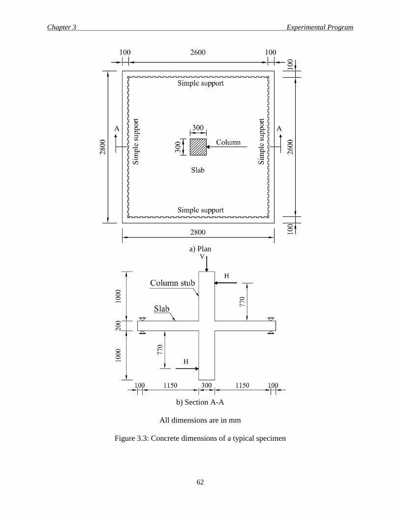
Chapter 3 Experimental Program
62
a) Plan
b) Section A-A
All dimensions are in mm
Figure 3.3: Concrete dimensions of a typical specimen
Chapter 3 Experimental Program
63
Each specimen designation is composed of five symbols the first is a character stands for the
type of the material used for the flexure reinforcing bars (“G” represents sand-coated GFRP bars,
while “S” stands for steel material and “R” represents ribbed-deformed GFRP bars). The second
is a number describes the flexure reinforcement ratio (0.65, 0.98 and 1.30%). The third is a
character symbolizes for the concrete compressive strength (“N” and “H” for normal and high
strength concrete, respectively). The fourth is a number stands for the moment-to-shear ratio (00,
15 and 30 for Mu/V of 0.0, 0.15 and 0.3 m, respectively). The last part indicates the spacing of
the shear studs, if any, as a ratio of the average effective slab depth, d, which equals to 160 mm
(50 and 75 stand for shear reinforcement with 0.5 d and 0.75 d studs spacing, respectively, while
characters “XX” mean no shear reinforcement was provided). For instance, G-0.65-N-15-XX
describes a specimen reinforced in flexure with sand-coated bars without shear studs, with 0.65%
flexure reinforcement ratio, cast using normal strength concrete (35 MPa) and subjected to 0.15-
m moment-to-shear ratio.
As listed in Table 3.1, five parameters were investigated:
1- Flexural reinforcement ratio (1.5, 2.25 and 3 ρb, where ρb is the balanced reinforcement
ratio).
2- Concrete compressive strength (35 and 70 MPa).
3- Moment-to-shear ratio (0.0, 0.15 and 0.3 m).
4- Type of the reinforcing bars (GFRP and steel).
5- Shear reinforcement ratio (0.0, 0.41 and 0.61%).
For comparison purposes, the specimens were divided into three series. Series I contained five
specimens (G-0.65-N-15-XX, G-0.98-N-15-XX, G-1.30-N-15-XX, S-0.65-N-15-XX and G-
0.65-H-15-XX) to evaluate the effects of reinforcement ratio, bar material in addition to the
Chapter 3 Experimental Program
64
concrete compressive strength on the behaviour of slab-column connections. Series II comprised
three connections (G-0.65-N-00-XX, G-065-N-15-XX and G-0.65-N-30-XX) to study the effect
of moment-to-shear ratio. Series III included three specimens (R-0.65-N-15-XX, R-0.65-N-15-
75 and R-0.65-N-15-50) to examine the shear reinforcement effect.
3.2.1 Material Properties
3.2.1.1 Concrete
All test slabs were constructed using normal-weight, ready-mixed concrete with a targeted 28-
day concrete compressive strength of 35 and 70 MPa and a maximum aggregate size of 19 mm.
All test prototypes were cast and wet-cured in the laboratory for 7 days. On the day of testing,
the actual concrete compressive and tensile strengths (Table 3.1) were determined based on the
average value of compressive and tensile splitting tests carried out on standard cylinders of 100 ×
200 mm and 150 × 300 mm, respectively.
3.2.1.2 Reinforcement
Steel bars, sand-coated (Pultrall Inc. 2013) and ribbed-deformed GFRP bars (Schoeck Canada
Inc. 2013) were used as slab reinforcement. Standard tests, according to CSA/G30.18-09 and
CSA/S806-12, Annex C, were carried out to determine the mechanical properties of the steel and
the GFRP reinforcing bars, respectively. Size No. 12 ribbed-deformed, double-headed, 170-mm
long bars were used as shear studs in the slabs with transvers reinforcement (R-0.65-N-15-75 and
R-0.65-N-15-50). According to the manufacturer, the heads of these shear studs were made of
polymer concrete with a compressive strength of 90 MPa and an allowable design strain in the
GFRP stud of 2175 µε (130-MPa tensile strength).The properties of the used GFRP and steel
bars are listed in Table 3.2. Also, Fig. 3.4 shows a photo for the reinforcing bars.
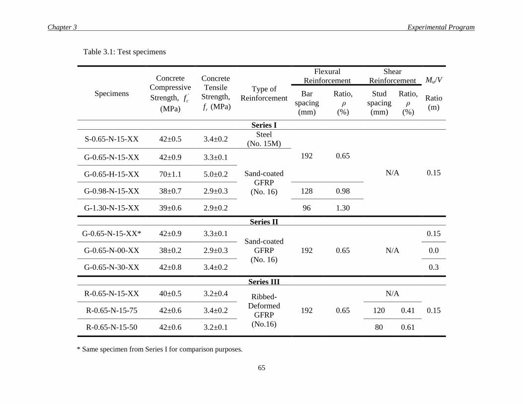
Chapter 3 Experimental Program
65
Table 3.1: Test specimens
Specimens
Concrete
Compressive
Strength, '
cf
(MPa)
Concrete
Tensile
Strength,
rf (MPa)
Type of
Reinforcement
Flexural
Reinforcement
Shear
Reinforcement Mu/V
Ratio
(m)
Bar
spacing
(mm)
Ratio,
ρ
(%)
Stud
spacing
(mm)
Ratio,
ρ
(%)
Series I
S-0.65-N-15-XX 42±0.5 3.4±0.2 Steel
(No. 15M)
192 0.65
N/A 0.15
G-0.65-N-15-XX 42±0.9 3.3±0.1
Sand-coated
GFRP
(No. 16)
G-0.65-H-15-XX 70±1.1 5.0±0.2
G-0.98-N-15-XX 38±0.7 2.9±0.3 128 0.98
G-1.30-N-15-XX 39±0.6 2.9±0.2 96 1.30
Series II
G-0.65-N-15-XX* 42±0.9 3.3±0.1 Sand-coated
GFRP
(No. 16)
192 0.65 N/A
0.15
G-0.65-N-00-XX 38±0.2 2.9±0.3 0.0
G-0.65-N-30-XX 42±0.8 3.4±0.2 0.3
Series III
R-0.65-N-15-XX 40±0.5 3.2±0.4 Ribbed-
Deformed
GFRP
(No.16)
192 0.65
N/A
0.15 R-0.65-N-15-75 42±0.6 3.4±0.2 120 0.41
R-0.65-N-15-50 42±0.6 3.2±0.1 80 0.61
* Same specimen from Series I for comparison purposes.
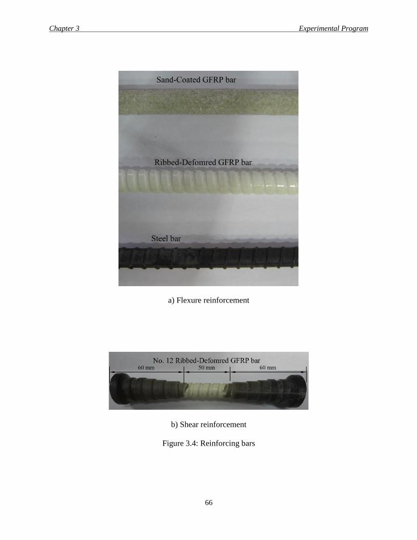
Chapter 3 Experimental Program
66
a) Flexure reinforcement
b) Shear reinforcement
Figure 3.4: Reinforcing bars
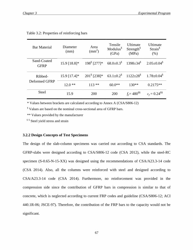
Chapter 3 Experimental Program
67
Table 3.2: Properties of reinforcing bars
Bar Material Diameter
(mm)
Area
(mm2)
Tensile
Modulus§
(GPa)
Ultimate
Strength§
(MPa)
Ultimate
Strain§
(%)
Sand-Coated
GFRP 15.9 [18.8]* 198
§ [277]* 68.0±0.3
§ 1398±34
§ 2.05±0.04
§
Ribbed-
Deformed GFRP
15.9 [17.4]* 201§ [238]* 63.1±0.2
§ 1122±28
§ 1.78±0.04
§
12.0 ** 113 ** 60.0** 130** 0.2175**
Steel 15.9 200 200 fy= 480§§
ɛy = 0.24§§
* Values between brackets are calculated according to Annex A (CSA/S806-12)
§ Values are based on the nominal cross-sectional area of GFRP bars.
** Values provided by the manufacturer
§ § Steel yield stress and strain
3.2.2 Design Concepts of Test Specimens
The design of the slab-column specimens was carried out according to CSA standards. The
GFRP-slabs were designed according to CSA/S806-12 code (CSA 2012), while the steel-RC
specimen (S-0.65-N-15-XX) was designed using the recommendations of CSA/A23.3-14 code
(CSA 2014). Also, all the columns were reinforced with steel and designed according to
CSA/A23.3-14 code (CSA 2014). Furthermore, no reinforcement was provided in the
compression side since the contribution of GFRP bars in compression is similar to that of
concrete, which is neglected according to current FRP codes and guideline (CSA/S806-12; ACI
440.1R-06; JSCE-97). Therefore, the contribution of the FRP bars to the capacity would not be
significant.
Chapter 3 Experimental Program
68
In addition, an elastic analysis was performed on a parking garage as mentioned earlier. That
analysis resulted for moment-to-shear ratio of 0.15 m to be applied on the specimens. Eight
specimens were tested with that ratio. In addition, specimen G-0.65-N-00-XX was tested under
concentric load and that ratio for specimen G-0.65-N-30-XX was 0.3 m.
3.2.3 Details of Test Specimens
All test slabs were reinforced in flexure with one orthogonal assembly of GFRP bars placed in
the tension side. The available equipment’s allowed only for testing the specimens in a reverse
position with respect to the actual position of a real building. Consequently, the tension
reinforcement was set in the soffit of the slabs in the both orthogonal directions. A total of nine
slabs were reinforced with GFRP bars, six with sand-coated GFRP bars and three with ribbed-
deformed GFRP bars, in addition to one slab reinforced with conventional steel bars. Slabs G-
0.65-N-15-XX, G-0.65-H-15-XX, G-0.65-N-00-XX and G-0.65-N-30-XX were reinforced with
no. 16 sand-coated GFRP bar with spacing of 192 mm. Also, slabs G-0.98-N-15-XX and G-1.30-
N-15-XXwere reinforced with the same type and size of bars, but with different spacing of 128
and 96 mm, respectively. In addition, slabs R-0.65-N-15-XX, R-0.65-N-15-75 and R-0.65-N-15-
50 had number 16 ribbed-deformed GFRP bars with a spacing of 192 mm. Moreover, the control
steel-RC slab (S-0.65-N-15-XX) was reinforced with number 15M steel bars at a spacing of 192
mm.
Two slabs had been provided with shear reinforcement (shear studs). The spacing and
arrangement of the transverse reinforcement in slabs R-0.65-N-15-75 and R-0.65-N-15-50 were
obtained according to the requirements of the Canadian Standards CSA/A23.3-14 (CSA 2014),
since there is no provision for the shear stud reinforcement in any FRP code (CSA/S806-12; ACI
440.1R-06; JSCE-97). The distance between the column face and the first line of shear studs
Chapter 3 Experimental Program
69
was 0.4 d (64 mm) to satisfy the requirements of Clause 13.3.8.6. Whereas, the spacing between
the other rows was 0.5 d (80 mm) for specimen R-0.65-N-15-50 and 0.75 d (120 mm) for
specimen R-0.65-N-15-75. Also, the shear reinforcement was extended to a distance of 3.4 d
from the column faces for both specimens.
The columns for all specimens were heavily reinforced with 4 No. 20M steel bars and No. 10M
stirrups every 150 mm to prevent premature failure. The reinforcement details of the specimens
are shown in Figures 3.5 to 3.9.
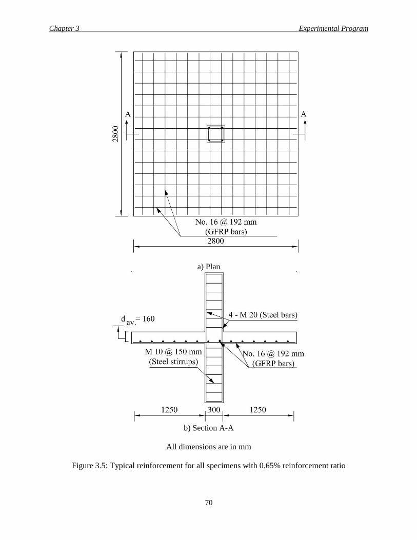
Chapter 3 Experimental Program
70
a) Plan
b) Section A-A
All dimensions are in mm
Figure 3.5: Typical reinforcement for all specimens with 0.65% reinforcement ratio
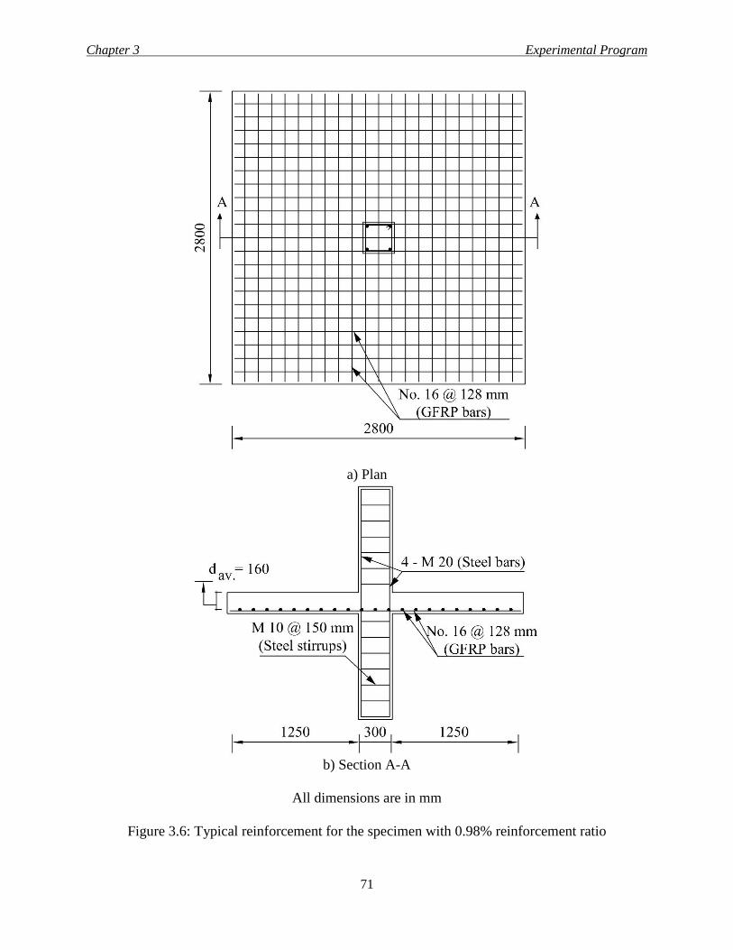
Chapter 3 Experimental Program
71
a) Plan
b) Section A-A
All dimensions are in mm
Figure 3.6: Typical reinforcement for the specimen with 0.98% reinforcement ratio
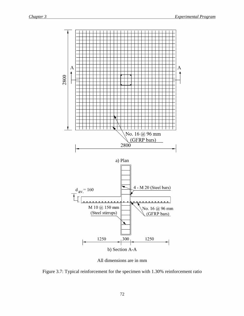
Chapter 3 Experimental Program
72
a) Plan
b) Section A-A
All dimensions are in mm
Figure 3.7: Typical reinforcement for the specimen with 1.30% reinforcement ratio
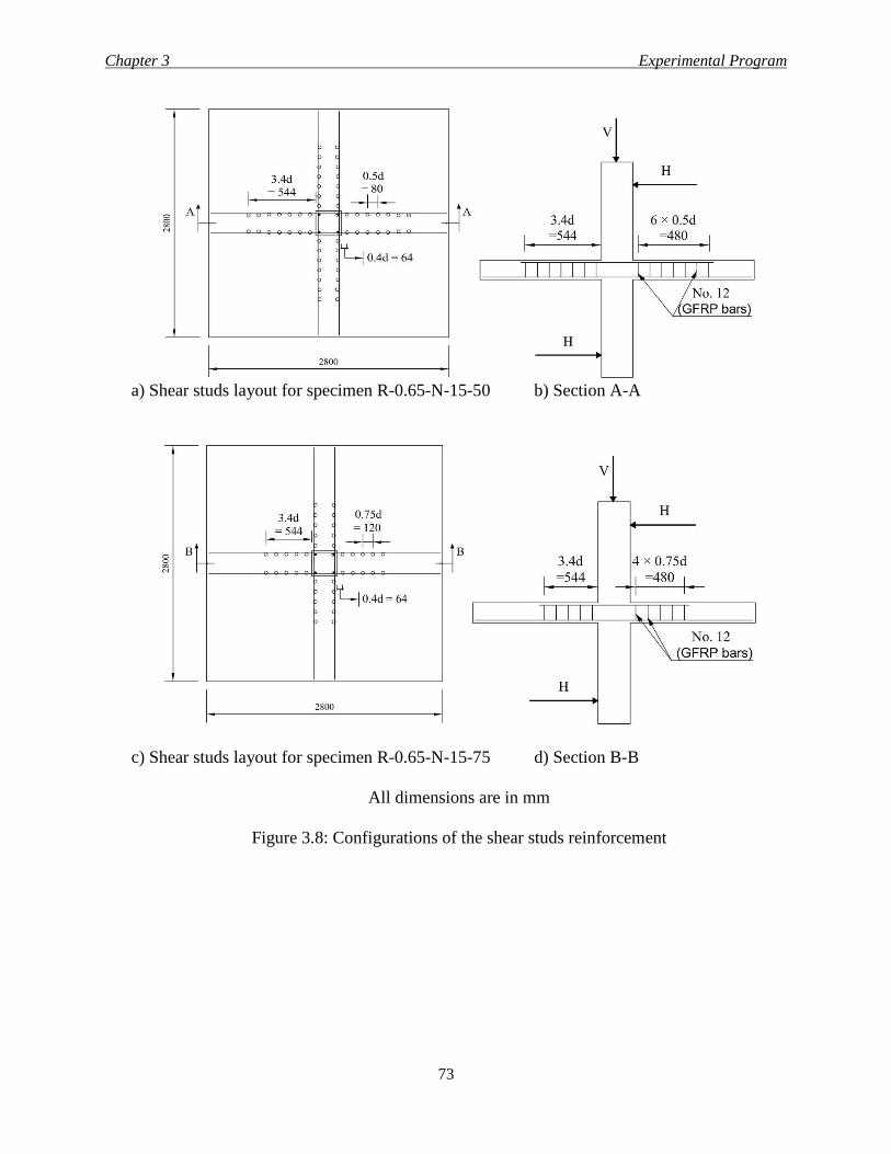
Chapter 3 Experimental Program
73
a) Shear studs layout for specimen R-0.65-N-15-50 b) Section A-A
c) Shear studs layout for specimen R-0.65-N-15-75 d) Section B-B
All dimensions are in mm
Figure 3.8: Configurations of the shear studs reinforcement
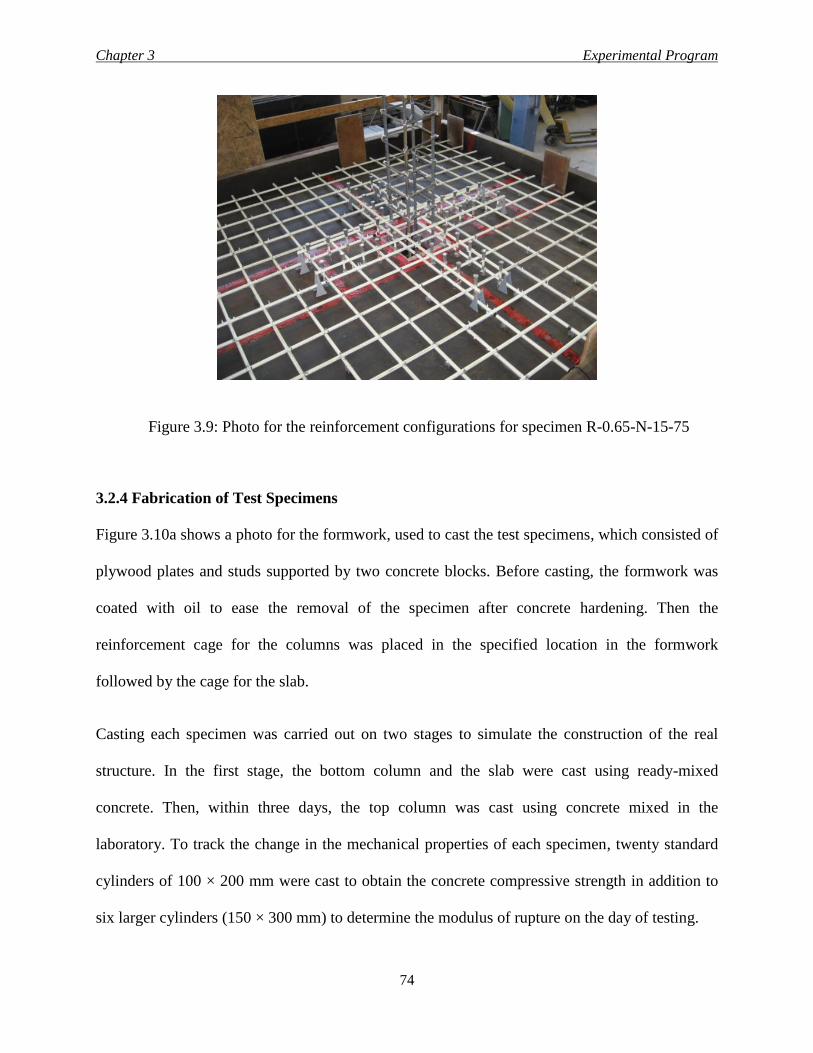
Chapter 3 Experimental Program
74
Figure 3.9: Photo for the reinforcement configurations for specimen R-0.65-N-15-75
3.2.4 Fabrication of Test Specimens
Figure 3.10a shows a photo for the formwork, used to cast the test specimens, which consisted of
plywood plates and studs supported by two concrete blocks. Before casting, the formwork was
coated with oil to ease the removal of the specimen after concrete hardening. Then the
reinforcement cage for the columns was placed in the specified location in the formwork
followed by the cage for the slab.
Casting each specimen was carried out on two stages to simulate the construction of the real
structure. In the first stage, the bottom column and the slab were cast using ready-mixed
concrete. Then, within three days, the top column was cast using concrete mixed in the
laboratory. To track the change in the mechanical properties of each specimen, twenty standard
cylinders of 100 × 200 mm were cast to obtain the concrete compressive strength in addition to
six larger cylinders (150 × 300 mm) to determine the modulus of rupture on the day of testing.
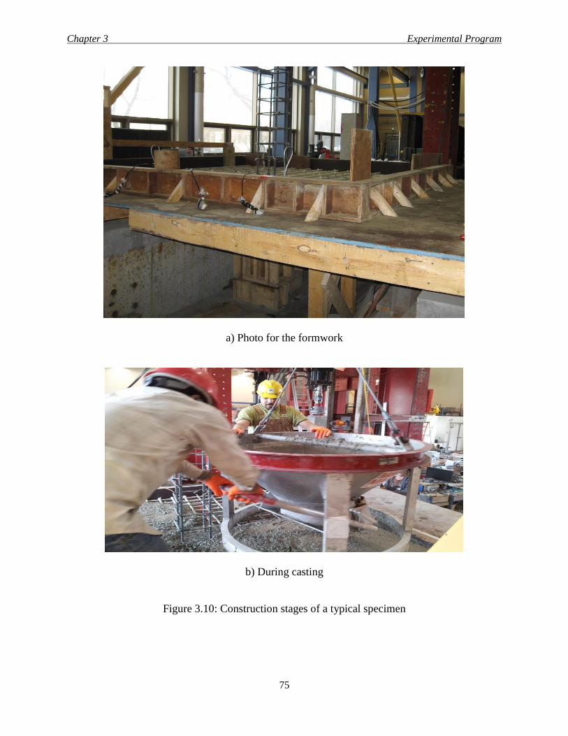
Chapter 3 Experimental Program
75
a) Photo for the formwork
b) During casting
Figure 3.10: Construction stages of a typical specimen
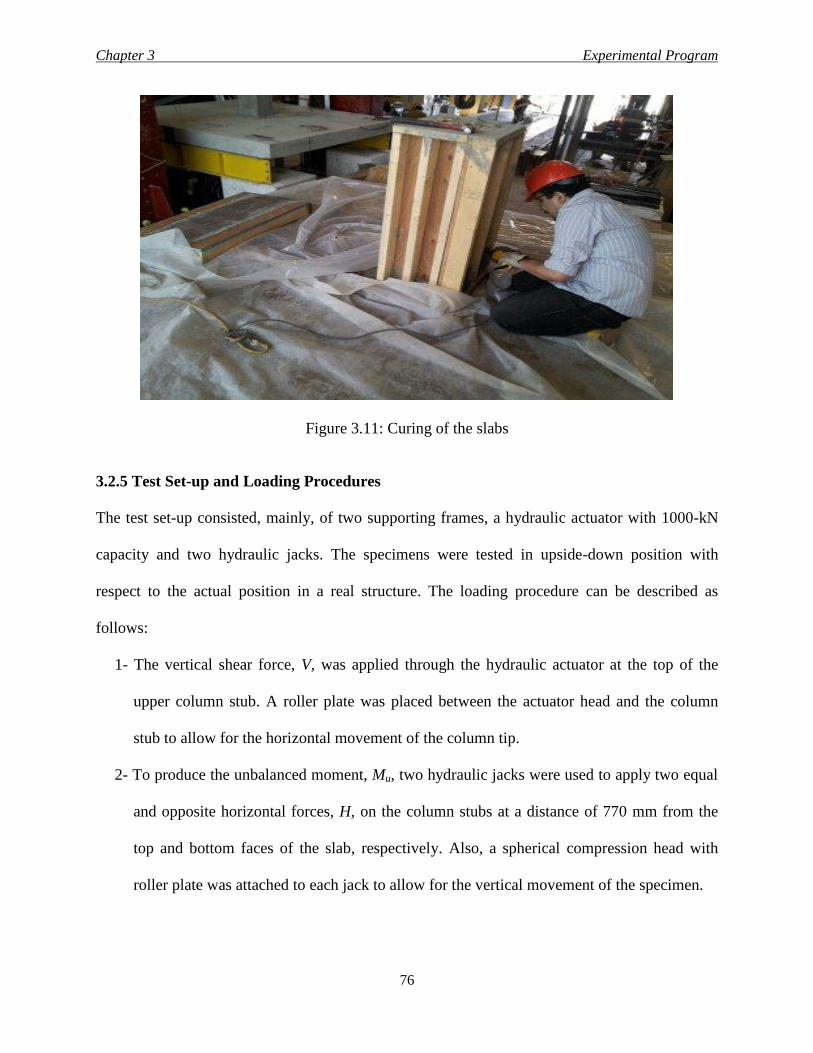
Chapter 3 Experimental Program
76
Figure 3.11: Curing of the slabs
3.2.5 Test Set-up and Loading Procedures
The test set-up consisted, mainly, of two supporting frames, a hydraulic actuator with 1000-kN
capacity and two hydraulic jacks. The specimens were tested in upside-down position with
respect to the actual position in a real structure. The loading procedure can be described as
follows:
1- The vertical shear force, V, was applied through the hydraulic actuator at the top of the
upper column stub. A roller plate was placed between the actuator head and the column
stub to allow for the horizontal movement of the column tip.
2- To produce the unbalanced moment, Mu, two hydraulic jacks were used to apply two equal
and opposite horizontal forces, H, on the column stubs at a distance of 770 mm from the
top and bottom faces of the slab, respectively. Also, a spherical compression head with
roller plate was attached to each jack to allow for the vertical movement of the specimen.
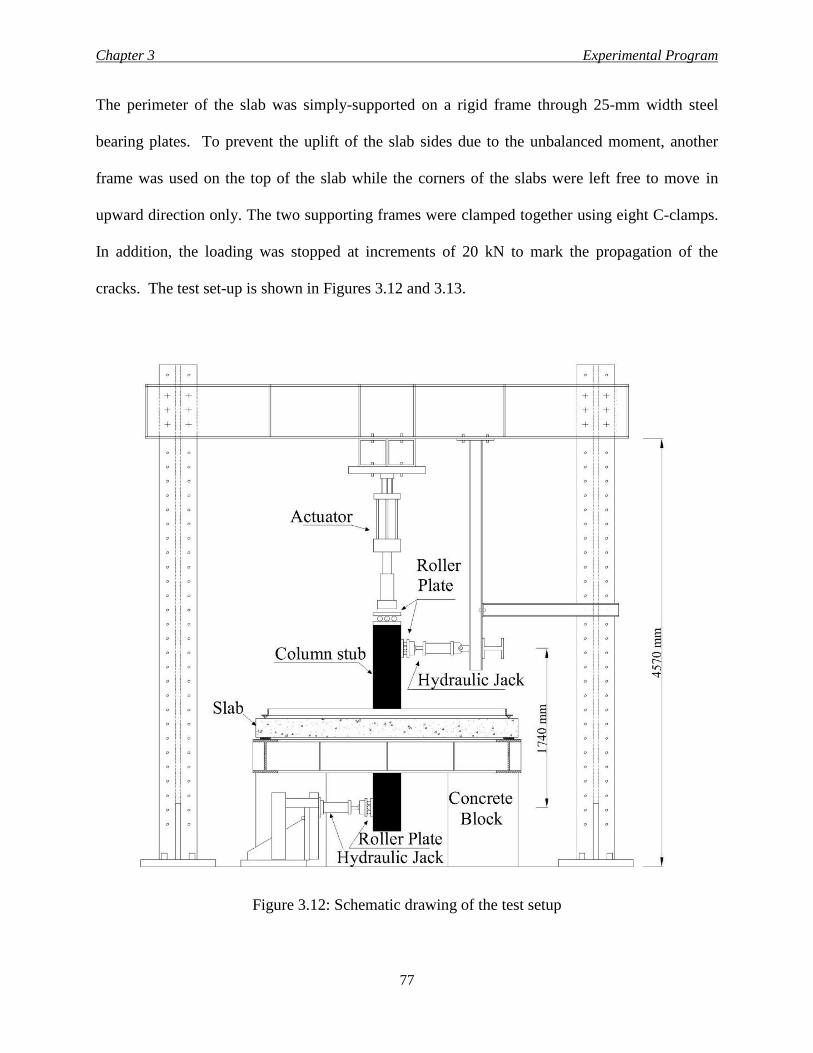
Chapter 3 Experimental Program
77
The perimeter of the slab was simply-supported on a rigid frame through 25-mm width steel
bearing plates. To prevent the uplift of the slab sides due to the unbalanced moment, another
frame was used on the top of the slab while the corners of the slabs were left free to move in
upward direction only. The two supporting frames were clamped together using eight C-clamps.
In addition, the loading was stopped at increments of 20 kN to mark the propagation of the
cracks. The test set-up is shown in Figures 3.12 and 3.13.
Figure 3.12: Schematic drawing of the test setup
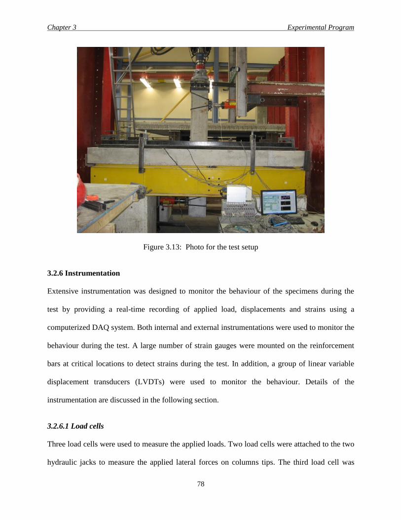
Chapter 3 Experimental Program
78
Figure 3.13: Photo for the test setup
3.2.6 Instrumentation
Extensive instrumentation was designed to monitor the behaviour of the specimens during the
test by providing a real-time recording of applied load, displacements and strains using a
computerized DAQ system. Both internal and external instrumentations were used to monitor the
behaviour during the test. A large number of strain gauges were mounted on the reinforcement
bars at critical locations to detect strains during the test. In addition, a group of linear variable
displacement transducers (LVDTs) were used to monitor the behaviour. Details of the
instrumentation are discussed in the following section.
3.2.6.1 Load cells
Three load cells were used to measure the applied loads. Two load cells were attached to the two
hydraulic jacks to measure the applied lateral forces on columns tips. The third load cell was
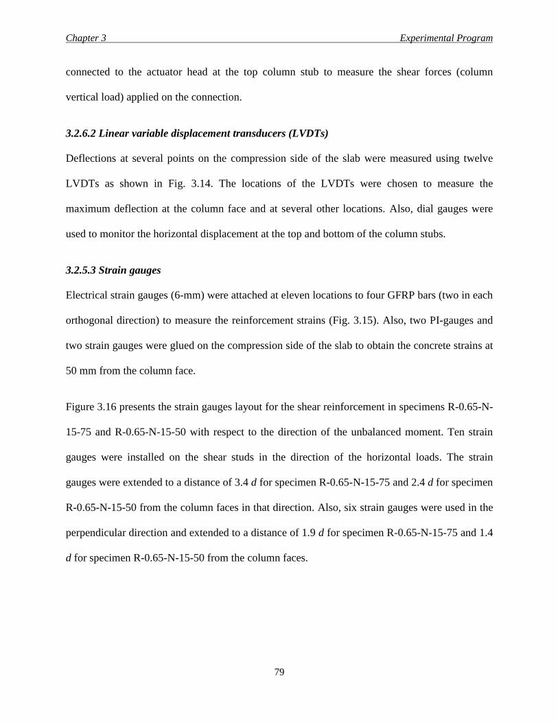
Chapter 3 Experimental Program
79
connected to the actuator head at the top column stub to measure the shear forces (column
vertical load) applied on the connection.
3.2.6.2 Linear variable displacement transducers (LVDTs)
Deflections at several points on the compression side of the slab were measured using twelve
LVDTs as shown in Fig. 3.14. The locations of the LVDTs were chosen to measure the
maximum deflection at the column face and at several other locations. Also, dial gauges were
used to monitor the horizontal displacement at the top and bottom of the column stubs.
3.2.5.3 Strain gauges
Electrical strain gauges (6-mm) were attached at eleven locations to four GFRP bars (two in each
orthogonal direction) to measure the reinforcement strains (Fig. 3.15). Also, two PI-gauges and
two strain gauges were glued on the compression side of the slab to obtain the concrete strains at
50 mm from the column face.
Figure 3.16 presents the strain gauges layout for the shear reinforcement in specimens R-0.65-N-
15-75 and R-0.65-N-15-50 with respect to the direction of the unbalanced moment. Ten strain
gauges were installed on the shear studs in the direction of the horizontal loads. The strain
gauges were extended to a distance of 3.4 d for specimen R-0.65-N-15-75 and 2.4 d for specimen
R-0.65-N-15-50 from the column faces in that direction. Also, six strain gauges were used in the
perpendicular direction and extended to a distance of 1.9 d for specimen R-0.65-N-15-75 and 1.4
d for specimen R-0.65-N-15-50 from the column faces.
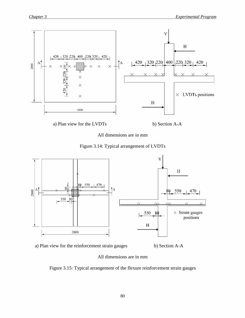
Chapter 3 Experimental Program
80
a) Plan view for the LVDTs b) Section A-A
All dimensions are in mm
Figure 3.14: Typical arrangement of LVDTs
a) Plan view for the reinforcement strain gauges b) Section A-A
All dimensions are in mm
Figure 3.15: Typical arrangement of the flexure reinforcement strain gauges
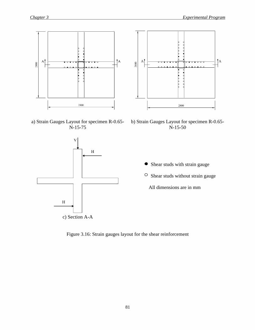
Chapter 3 Experimental Program
81
a) Strain Gauges Layout for specimen R-0.65-
N-15-75
b) Strain Gauges Layout for specimen R-0.65-
N-15-50
Shear studs with strain gauge
Shear studs without strain gauge
All dimensions are in mm
c) Section A-A
Figure 3.16: Strain gauges layout for the shear reinforcement
Chapter 4 Results and Discussion
82
CHAPTER 4
EXPERIMENTAL RESULTS AND DISCUSSION
4.1 INTRODUCTION
This chapter presents the analysis and the discussion of the experimental work described in
Chapter 3. The specimens were tested under vertical shear force and two equal and opposite
horizontal loads to simulate the effect of the unbalanced moment. The behaviour of the slab-
column connections was carefully monitored through the test. Deflection of the slabs, strains in
both reinforcing bars and concrete were measured and recorded at different locations.
The complete analysis for the test specimens was presented in terms of cracking pattern, ultimate
capacity, vertical load-deflection curve, deflection profiles, strain profiles in the direction of the
unbalanced moment and vertical load-strain curve in the reinforcing bars and on the compression
side of the slabs. Furthermore, the test results were compared with the provisions of different
codes such as the Canadian standard CSA/S806-12 (CSA 2012) and the American guideline ACI
440.1R-06 (ACI 2006).
4.2 SERIES I - THE EFFECTS OF REINFORCEMENT RATIO, BAR MATERIAL AND
TYPE AND CONCRETE COMPRESSIVE STRENGTH
According to the Canadian standard CSA/S806-12 (CSA 2012), any concrete section reinforced
with FRP bars has to be over-reinforced. Also, 60 MPa is the maximum concrete compressive
strength allowed by the code to be used in the punching shear equations (2.48, 2.49 and 2.50 in
Chapter 2). Moreover, the code limits the maximum strain in the GFRP bars at service load stage
to be less than 25% of the ultimate strain of the bars to control crack width. In the meantime, the
American guideline ACI 440.1R-06 (ACI 2006) allows for tension and compression failures.
Chapter 4 Results and Discussion
83
Also, at the service stage, the American guideline limits the maximum strain in the GFRP bars to
be less than 20% of the ultimate strain of the bars (Clause 8.4.1) and the guideline has no
apparent limits for the concrete compressive strength.
4.2.1 Cracking and Failure Mode of Specimens of Series I
Figure 4.1 shows the cracking pattern on the tension face of the test slabs at failure. All
specimens exhibited similar behaviour in terms of cracking pattern. At load levels between 110
and 140 kN, the first flexural crack appeared on the tension side of the slabs at the region of
maximum bending moment around the column. The crack emanated from the corner of the
column and traveled to the edge of the slab. At a higher load level (140 to 160 kN), cracks
started to propagate from the column face toward the slab edge in the direction of the unbalanced
moment, i.e., the direction of the greater depth. With further loading, additional radial cracks
initiated in the slab with different angles of inclinations. The first circumferential crack that
appeared in the vicinity of the column formed at a load level between 180 and 240 kN, which is
approximately half the capacity of the specimens. After that loading stage, the rate of formation
of new cracks decreased significantly and the existing cracks grew wider. That formation of
cracking pattern is known as “star-burst” pattern of radial cracks, interspersed with orthogonal or
circumferential cracks and the main cause of it is the concentration of the negative flexure
stresses around the column periphery (Paret et al. 2010). Furthermore, Fig. 4.1 shows that more
damage occurred in the slab (upper side of the photos) in the direction of the unbalanced moment
as a result of the additional tensile stresses developed due to moment transfer.
At failure, all specimens exhibited a brittle punching shear failure with the column and a part of
the slab penetrated through the slab thickness. This was observed regardless of the reinforcement
Chapter 4 Results and Discussion
84
ratio and type. The punching failure surface was defined by a wide and deep crack around the
column perimeter as shown in Fig. 4.1.
Increasing the reinforcement ratio from 0.65% (G-0.65-N-15-XX) to 0.98% (G-0.98-N-15-XX)
or 1.3% (G-1.30-N-15-XX) resulted in a wider failure surface. This wider surface was due to the
enhancement of the restraint in the plane of the slab as a result of the increased flexural
reinforcement. Moreover, increasing the reinforcement ratio for the specimens reinforced with
GFRP bars resulted in more cracks but with less crack spacing. This is attributed mainly to the
reduced bar spacing and the distribution of stresses on more bars (Hutchinson and Wang 2009)
with the increased reinforcement ratio. In addition, many researchers reported that crack width
and spacing are directly proportional to the spacing between slab reinforcing bars and to the
concrete cover thickness (Frosch 1999). Therefore, increasing the reinforcement ratio by
increasing the bars diameter and keeping the spacing the same, might not have the same effect on
the crack pattern observed in the current study, however further investigation is still needed to
address this issue. Furthermore, specimen G-0.65-N-15-XX had smaller crack spacing compared
to specimen S-0.65-N-15-XX at the same load level. The difference is related to the surface
texture of the reinforcement, where GFRP sand-coated bars have uniformly distributed bond
stresses due to adhesion and friction (Alves 2011), while steel deformed bars have mainly
mechanical bond through bearing on the bar ribs.
Compared to specimen G-0.65-N-15-XX, the failure area around the column for specimen G-
0.65-H-15-XX with high strength concrete (HSC) showed more damage. This is due to the
brittleness of the HSC, which caused different interior damage patterns (cracks propagate
through the course aggregate particles) compared to normal strength concrete (NSC).
Chapter 4 Results and Discussion
85
4.2.2 Deflection of Specimens of Series I
The deflection characteristics were similar for all test specimens. Figure 4.2a shows the
maximum measured deflection in the slabs at 50 mm from the column face. In general, the load-
deflection curve can be divided into two phases. The first phase represents the behaviour of the
uncracked specimens, which depends mainly on the mechanical properties of the concrete;
therefore the GFRP-RC slabs with NSC (G-0.65-N-15-XX, G-0.98-N-15-XX and G-1.30-N-15-
XX) showed comparable behaviour. The second phase illustrates the post-cracking behaviour up
to failure, which is a function of the axial rigidity of reinforcement, ρE. Hence, the slabs with
different axial rigidity (G-0.65-N-15-XX, G-0.98-N-15-XX, G-1.30-N-15-XX and S-0.65-N-15-
XX) exhibited different behaviour in the post cracking stage.
In this research, the service load (NBCC 2010) was calculated assuming dead loads acting on the
area carried by the column in the prototype structure (6.5 × 6.5 m) and live load acting on half of
that area to account for the effect of the unbalanced moment and to address the loading cases that
were used in the current study as shown in Fig. 3.2a. The service load was 295 kN with an
associated unbalanced moment of 44.25 kN.m.
Specimen G-0.65-N-15-XX showed larger deflections with reference to specimen S-0.65-N-15-
XX, due to the lower modulus of elasticity of the GFRP bars compared to that of steel. At service
load level, specimen G-0.65-N-15-XX showed 206% higher deflection compared to specimen S-
0.65-N-15-XX. At failure, this percentage decreased to only 42% due to the lower capacity of G-
0.65-N-15-XX. Also, this can be attributed to the decrease in the post-cracking stiffness of the
steel-RC slab, S-0.65-N-15-XX, before failure as a result of steel yielding around the column
face at approximately 86% of the failure load. Compared to steel-RC control specimen, the
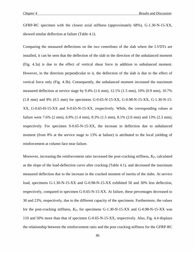
Chapter 4 Results and Discussion
86
GFRP-RC specimen with the closest axial stiffness (approximately 68%), G-1.30-N-15-XX,
showed similar deflection at failure (Table 4.1).
Comparing the measured deflections on the two centrelines of the slab where the LVDTs are
installed, it can be seen that the deflection of the slab in the direction of the unbalanced moment
(Fig. 4.3a) is due to the effect of vertical shear force in addition to unbalanced moment.
However, in the direction perpendicular to it, the deflection of the slab is due to the effect of
vertical force only (Fig. 4.3b). Consequently, the unbalanced moment increased the maximum
measured deflection at service stage by 9.4% (1.6 mm), 12.1% (1.5 mm), 10% (0.9 mm), 10.7%
(1.8 mm) and 8% (0.5 mm) for specimens G-0.65-N-15-XX, G-0.98-N-15-XX, G-1.30-N-15-
XX, G-0.65-H-15-XX and S-0.65-N-15-XX, respectively. While, the corresponding values at
failure were 7.6% (2 mm), 6.9% (1.4 mm), 8.3% (1.5 mm), 8.1% (2.6 mm) and 13% (2.3 mm),
respectively. For specimen S-0.65-N-15-XX, the increase in deflection due to unbalanced
moment (from 8% at the service stage to 13% at failure) is attributed to the local yielding of
reinforcement at column face near failure.
Moreover, increasing the reinforcement ratio increased the post-cracking stiffness, KP, calculated
as the slope of the load-deflection curve after cracking (Table 4.1), and decreased the maximum
measured deflection due to the increase in the cracked moment of inertia of the slabs. At service
load, specimens G-1.30-N-15-XX and G-0.98-N-15-XX exhibited 50 and 30% less deflection,
respectively, compared to specimen G-0.65-N-15-XX. At failure, these percentages decreased to
30 and 23%, respectively, due to the different capacity of the specimens. Furthermore, the values
for the post-cracking stiffness, KP, for specimens G-1.30-N-15-XX and G-0.98-N-15-XX was
110 and 50% more than that of specimen G-0.65-N-15-XX, respectively. Also, Fig. 4.4 displays
the relationship between the reinforcement ratio and the post cracking stiffness for the GFRP-RC
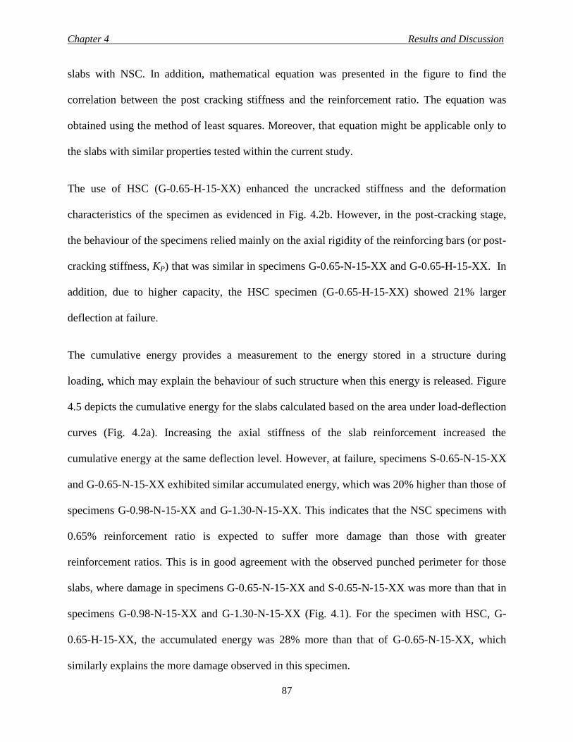
Chapter 4 Results and Discussion
87
slabs with NSC. In addition, mathematical equation was presented in the figure to find the
correlation between the post cracking stiffness and the reinforcement ratio. The equation was
obtained using the method of least squares. Moreover, that equation might be applicable only to
the slabs with similar properties tested within the current study.
The use of HSC (G-0.65-H-15-XX) enhanced the uncracked stiffness and the deformation
characteristics of the specimen as evidenced in Fig. 4.2b. However, in the post-cracking stage,
the behaviour of the specimens relied mainly on the axial rigidity of the reinforcing bars (or post-
cracking stiffness, KP) that was similar in specimens G-0.65-N-15-XX and G-0.65-H-15-XX. In
addition, due to higher capacity, the HSC specimen (G-0.65-H-15-XX) showed 21% larger
deflection at failure.
The cumulative energy provides a measurement to the energy stored in a structure during
loading, which may explain the behaviour of such structure when this energy is released. Figure
4.5 depicts the cumulative energy for the slabs calculated based on the area under load-deflection
curves (Fig. 4.2a). Increasing the axial stiffness of the slab reinforcement increased the
cumulative energy at the same deflection level. However, at failure, specimens S-0.65-N-15-XX
and G-0.65-N-15-XX exhibited similar accumulated energy, which was 20% higher than those of
specimens G-0.98-N-15-XX and G-1.30-N-15-XX. This indicates that the NSC specimens with
0.65% reinforcement ratio is expected to suffer more damage than those with greater
reinforcement ratios. This is in good agreement with the observed punched perimeter for those
slabs, where damage in specimens G-0.65-N-15-XX and S-0.65-N-15-XX was more than that in
specimens G-0.98-N-15-XX and G-1.30-N-15-XX (Fig. 4.1). For the specimen with HSC, G-
0.65-H-15-XX, the accumulated energy was 28% more than that of G-0.65-N-15-XX, which
similarly explains the more damage observed in this specimen.
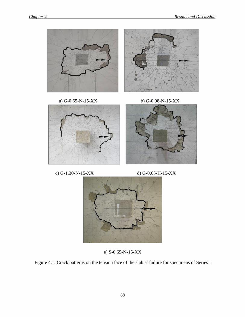
Chapter 4 Results and Discussion
88
a) G-0.65-N-15-XX b) G-0.98-N-15-XX
c) G-1.30-N-15-XX d) G-0.65-H-15-XX
e) S-0.65-N-15-XX
Figure 4.1: Crack patterns on the tension face of the slab at failure for specimens of Series I
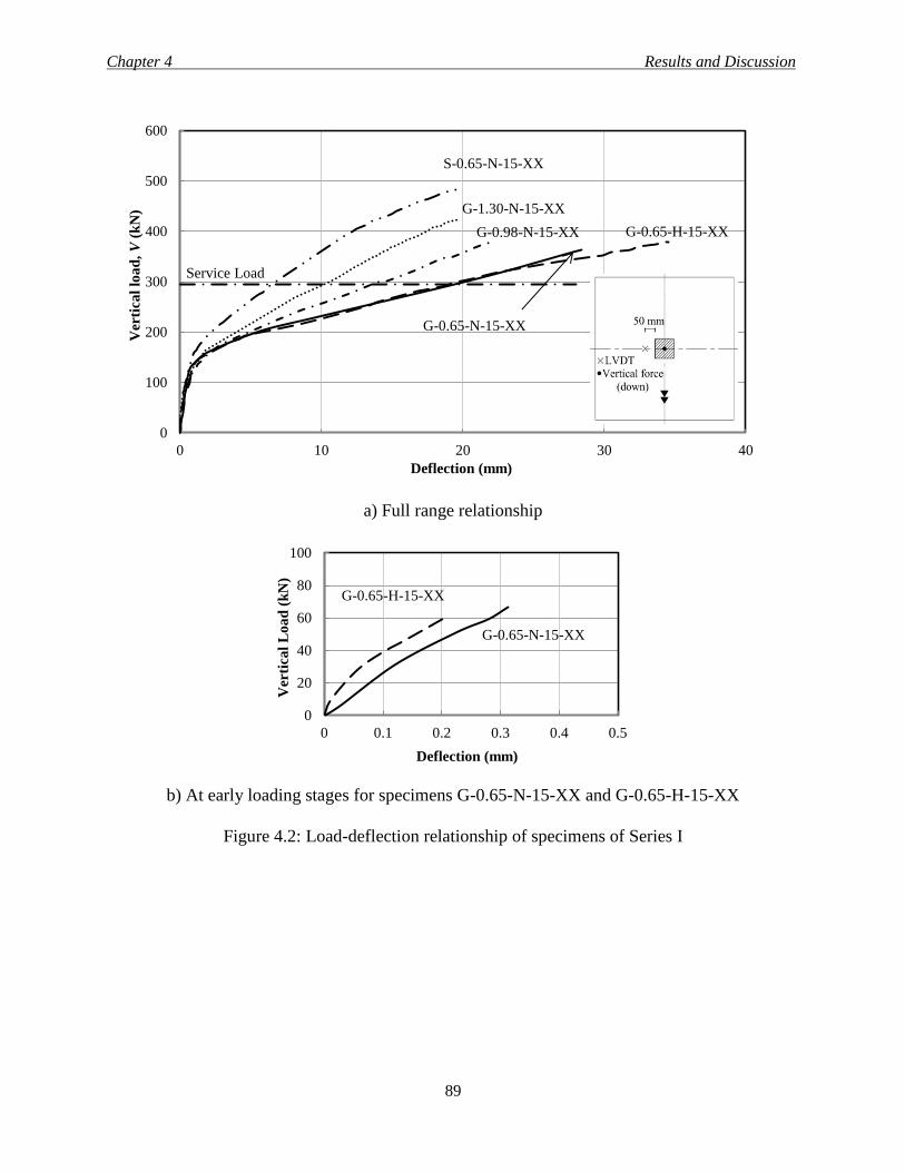
Chapter 4 Results and Discussion
89
a) Full range relationship
b) At early loading stages for specimens G-0.65-N-15-XX and G-0.65-H-15-XX
Figure 4.2: Load-deflection relationship of specimens of Series I
0
100
200
300
400
500
600
0 10 20 30 40
Ver
tica
l lo
ad
, V
(k
N)
Deflection (mm)
Service Load
G-0.65-N-15-XX
G-0.98-N-15-XX
G-1.30-N-15-XX
S-0.65-N-15-XX
G-0.65-H-15-XX
0
20
40
60
80
100
0 0.1 0.2 0.3 0.4 0.5
Ver
tica
l L
oa
d (
kN
)
Deflection (mm)
G-0.65-N-15-XX
G-0.65-H-15-XX

Chapter 4 Results and Discussion
90
(a) In the direction of the unbalanced moment
(b) In the direction perpendicular to the unbalanced moment
Figure 4.3: Deflection-profiles for specimen G-0.65-N-15-XX at the centrelines of the slab
-30
-25
-20
-15
-10
-5
0
-1400 -1050 -700 -350 0 350 700 1050 1400D
efle
ctio
n (
mm
)
Distance from centre line of the slab (mm)
100% of failure loadService load75% of failure load50% of failure load25% of failure load
Co
ulm
n
-30
-25
-20
-15
-10
-5
0
-1400 -1050 -700 -350 0 350 700 1050 1400
Def
lect
ion
(m
m)
Distance from centre line of the slab (mm)
100% of failure loadService load75% of failure load50% of failure load25% of failure load
Co
ulm
n
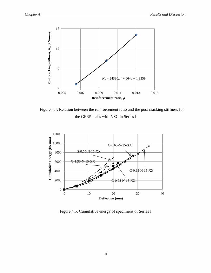
Chapter 4 Results and Discussion
91
Figure 4.4: Relation between the reinforcement ratio and the post cracking stiffness for
the GFRP-slabs with NSC in Series I
Figure 4.5: Cumulative energy of specimens of Series I
6
9
12
15
0.005 0.007 0.009 0.011 0.013 0.015
Po
st c
ra
ckin
g s
tiff
nes
s, K
P (
kN
/mm
)
Reinforcement ratio, ρ
KP = 24330𝜌2 + 664ρ + 1.3559
0
2000
4000
6000
8000
10000
12000
0 10 20 30 40
Cu
mu
lati
ve
En
erg
y (
kN
.mm
)
Deflection (mm)
S-0.65-N-15-XX
G-0.65-N-15-XX
G-0.65-H-15-XX
G-0.98-N-15-XX
G-1.30-N-15-XX
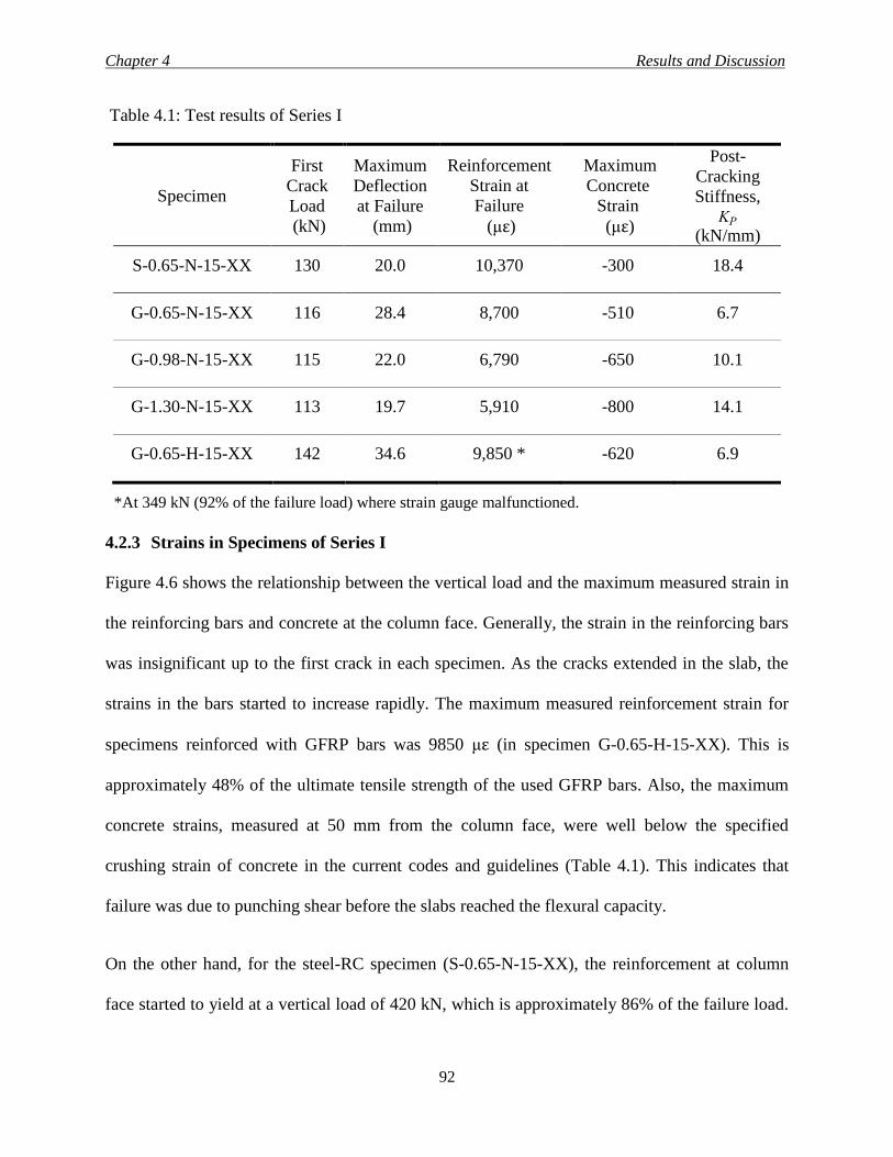
Chapter 4 Results and Discussion
92
Table 4.1: Test results of Series I
Specimen
First
Crack
Load
(kN)
Maximum
Deflection
at Failure
(mm)
Reinforcement
Strain at
Failure
(με)
Maximum
Concrete
Strain
(με)
Post-
Cracking
Stiffness, KP
(kN/mm)
S-0.65-N-15-XX 130 20.0 10,370 -300 18.4
G-0.65-N-15-XX 116 28.4 8,700 -510 6.7
G-0.98-N-15-XX 115 22.0 6,790 -650 10.1
G-1.30-N-15-XX 113 19.7 5,910 -800 14.1
G-0.65-H-15-XX 142 34.6 9,850 * -620 6.9
*At 349 kN (92% of the failure load) where strain gauge malfunctioned.
4.2.3 Strains in Specimens of Series I
Figure 4.6 shows the relationship between the vertical load and the maximum measured strain in
the reinforcing bars and concrete at the column face. Generally, the strain in the reinforcing bars
was insignificant up to the first crack in each specimen. As the cracks extended in the slab, the
strains in the bars started to increase rapidly. The maximum measured reinforcement strain for
specimens reinforced with GFRP bars was 9850 με (in specimen G-0.65-H-15-XX). This is
approximately 48% of the ultimate tensile strength of the used GFRP bars. Also, the maximum
concrete strains, measured at 50 mm from the column face, were well below the specified
crushing strain of concrete in the current codes and guidelines (Table 4.1). This indicates that
failure was due to punching shear before the slabs reached the flexural capacity.
On the other hand, for the steel-RC specimen (S-0.65-N-15-XX), the reinforcement at column
face started to yield at a vertical load of 420 kN, which is approximately 86% of the failure load.
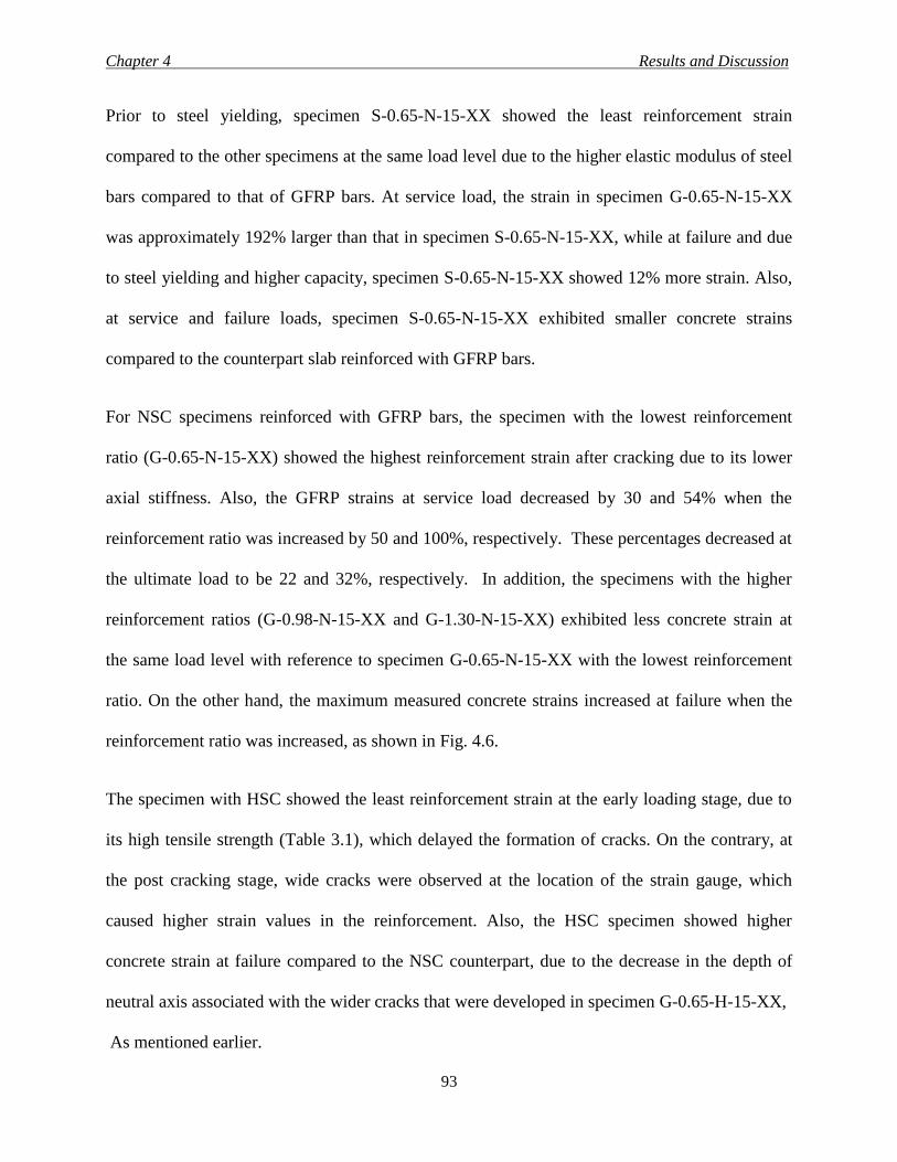
Chapter 4 Results and Discussion
93
Prior to steel yielding, specimen S-0.65-N-15-XX showed the least reinforcement strain
compared to the other specimens at the same load level due to the higher elastic modulus of steel
bars compared to that of GFRP bars. At service load, the strain in specimen G-0.65-N-15-XX
was approximately 192% larger than that in specimen S-0.65-N-15-XX, while at failure and due
to steel yielding and higher capacity, specimen S-0.65-N-15-XX showed 12% more strain. Also,
at service and failure loads, specimen S-0.65-N-15-XX exhibited smaller concrete strains
compared to the counterpart slab reinforced with GFRP bars.
For NSC specimens reinforced with GFRP bars, the specimen with the lowest reinforcement
ratio (G-0.65-N-15-XX) showed the highest reinforcement strain after cracking due to its lower
axial stiffness. Also, the GFRP strains at service load decreased by 30 and 54% when the
reinforcement ratio was increased by 50 and 100%, respectively. These percentages decreased at
the ultimate load to be 22 and 32%, respectively. In addition, the specimens with the higher
reinforcement ratios (G-0.98-N-15-XX and G-1.30-N-15-XX) exhibited less concrete strain at
the same load level with reference to specimen G-0.65-N-15-XX with the lowest reinforcement
ratio. On the other hand, the maximum measured concrete strains increased at failure when the
reinforcement ratio was increased, as shown in Fig. 4.6.
The specimen with HSC showed the least reinforcement strain at the early loading stage, due to
its high tensile strength (Table 3.1), which delayed the formation of cracks. On the contrary, at
the post cracking stage, wide cracks were observed at the location of the strain gauge, which
caused higher strain values in the reinforcement. Also, the HSC specimen showed higher
concrete strain at failure compared to the NSC counterpart, due to the decrease in the depth of
neutral axis associated with the wider cracks that were developed in specimen G-0.65-H-15-XX,
As mentioned earlier.
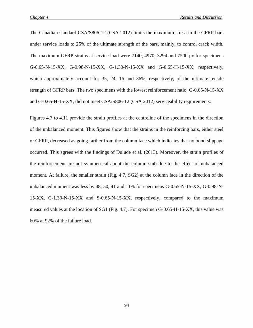
Chapter 4 Results and Discussion
94
The Canadian standard CSA/S806-12 (CSA 2012) limits the maximum stress in the GFRP bars
under service loads to 25% of the ultimate strength of the bars, mainly, to control crack width.
The maximum GFRP strains at service load were 7140, 4970, 3294 and 7500 με for specimens
G-0.65-N-15-XX, G-0.98-N-15-XX, G-1.30-N-15-XX and G-0.65-H-15-XX, respectively,
which approximately account for 35, 24, 16 and 36%, respectively, of the ultimate tensile
strength of GFRP bars. The two specimens with the lowest reinforcement ratio, G-0.65-N-15-XX
and G-0.65-H-15-XX, did not meet CSA/S806-12 (CSA 2012) serviceability requirements.
Figures 4.7 to 4.11 provide the strain profiles at the centreline of the specimens in the direction
of the unbalanced moment. This figures show that the strains in the reinforcing bars, either steel
or GFRP, decreased as going farther from the column face which indicates that no bond slippage
occurred. This agrees with the findings of Dulude et al. (2013). Moreover, the strain profiles of
the reinforcement are not symmetrical about the column stub due to the effect of unbalanced
moment. At failure, the smaller strain (Fig. 4.7, SG2) at the column face in the direction of the
unbalanced moment was less by 48, 50, 41 and 11% for specimens G-0.65-N-15-XX, G-0.98-N-
15-XX, G-1.30-N-15-XX and S-0.65-N-15-XX, respectively, compared to the maximum
measured values at the location of SG1 (Fig. 4.7). For specimen G-0.65-H-15-XX, this value was
60% at 92% of the failure load.
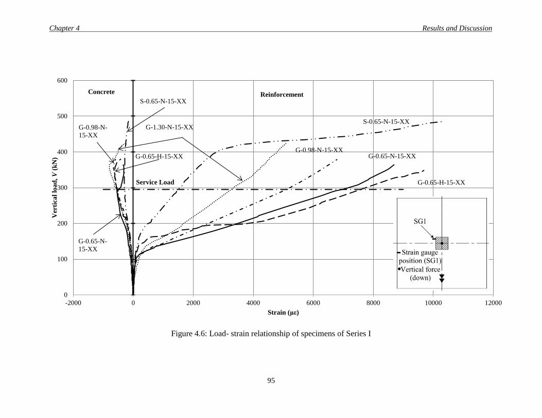
Chapter 4 Results and Discussion
95
Figure 4.6: Load- strain relationship of specimens of Series I
0
100
200
300
400
500
600
-2000 0 2000 4000 6000 8000 10000 12000
Ver
tica
l lo
ad
, V
(k
N)
Strain (με)
S-0.65-N-15-XX
G-0.65-N-15-XX G-0.98-N-15-XX
G-1.30-N-15-XX
G-0.65-H-15-XX Service Load
S-0.65-N-15-XX
G-0.65-N-
15-XX
G-0.98-N-
15-XX
G-0.65-H-15-XX
Reinforcement Concrete
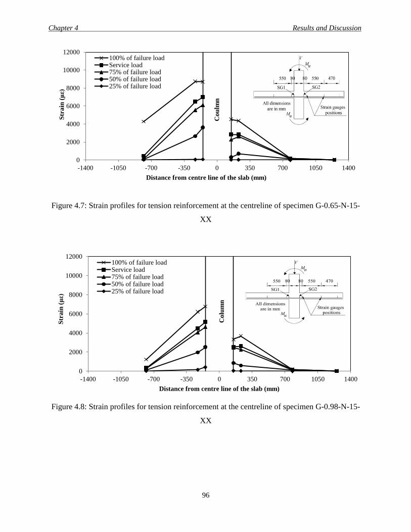
Chapter 4 Results and Discussion
96
Figure 4.7: Strain profiles for tension reinforcement at the centreline of specimen G-0.65-N-15-
XX
Figure 4.8: Strain profiles for tension reinforcement at the centreline of specimen G-0.98-N-15-
XX
0
2000
4000
6000
8000
10000
12000
-1400 -1050 -700 -350 0 350 700 1050 1400
Str
ain
(με)
Distance from centre line of the slab (mm)
100% of failure loadService load75% of failure load50% of failure load25% of failure load
Co
ulm
n
0
2000
4000
6000
8000
10000
12000
-1400 -1050 -700 -350 0 350 700 1050 1400
Str
ain
(με)
Distance from centre line of the slab (mm)
100% of failure loadService load75% of failure load50% of failure load25% of failure load
Co
lum
n
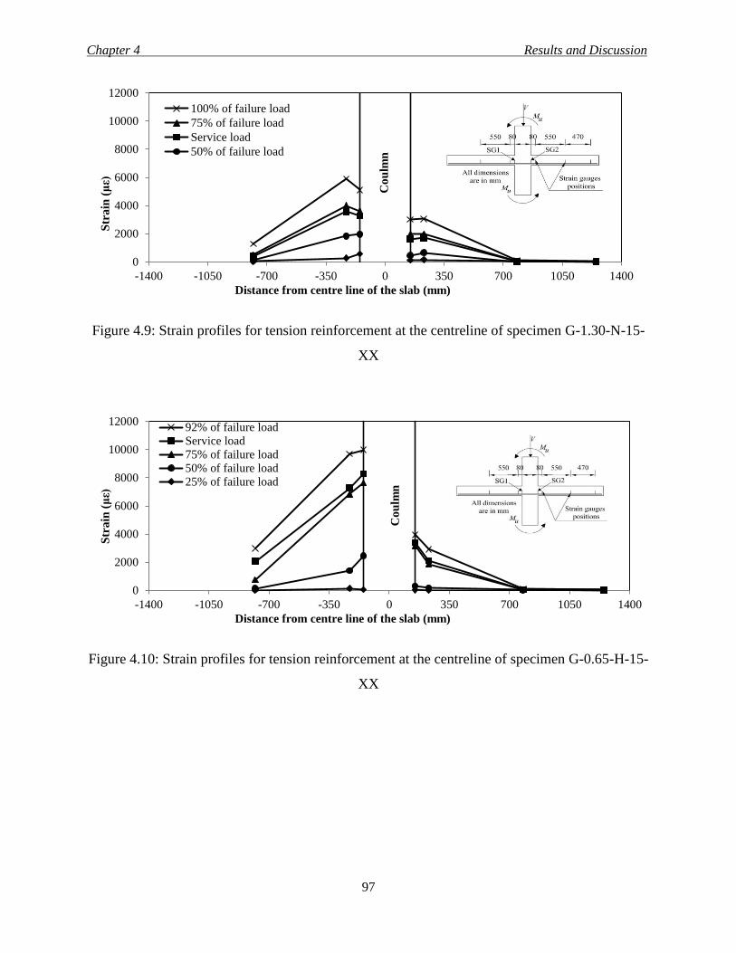
Chapter 4 Results and Discussion
97
Figure 4.9: Strain profiles for tension reinforcement at the centreline of specimen G-1.30-N-15-
XX
Figure 4.10: Strain profiles for tension reinforcement at the centreline of specimen G-0.65-H-15-
XX
0
2000
4000
6000
8000
10000
12000
-1400 -1050 -700 -350 0 350 700 1050 1400
Str
ain
(με)
Distance from centre line of the slab (mm)
100% of failure load
75% of failure load
Service load
50% of failure load
Co
ulm
n
0
2000
4000
6000
8000
10000
12000
-1400 -1050 -700 -350 0 350 700 1050 1400
Str
ain
(με)
Distance from centre line of the slab (mm)
92% of failure load
Service load75% of failure load50% of failure load
25% of failure load
Co
ulm
n
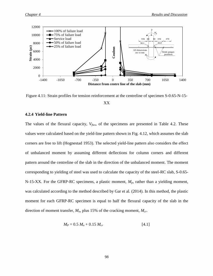
Chapter 4 Results and Discussion
98
Figure 4.11: Strain profiles for tension reinforcement at the centreline of specimen S-0.65-N-15-
XX
4.2.4 Yield-line Pattern
The values of the flexural capacity, Vflex, of the specimens are presented in Table 4.2. These
values were calculated based on the yield-line pattern shown in Fig. 4.12, which assumes the slab
corners are free to lift (Hognestad 1953). The selected yield-line pattern also considers the effect
of unbalanced moment by assuming different deflections for column corners and different
pattern around the centreline of the slab in the direction of the unbalanced moment. The moment
corresponding to yielding of steel was used to calculate the capacity of the steel-RC slab, S-0.65-
N-15-XX. For the GFRP-RC specimens, a plastic moment, Mp, rather than a yielding moment,
was calculated according to the method described by Gar et al. (2014). In this method, the plastic
moment for each GFRP-RC specimen is equal to half the flexural capacity of the slab in the
direction of moment transfer, Mn, plus 15% of the cracking moment, Mcr.
MP = 0.5 Mn + 0.15 Mcr [4.1]
0
2000
4000
6000
8000
10000
12000
-1400 -1050 -700 -350 0 350 700 1050 1400
Str
ain
(με)
Distance from centre line of the slab (mm)
100% of failure load75% of failure loadService load50% of failure load25% of failure load
Co
ulm
n
Chapter 4 Results and Discussion
99
Comparing the calculated flexural capacity of the specimens, Vflex, to the experimental failure
loads shows that all specimens failed in punching shear. The mean value for the specimens
reinforced with GFRP bars is 𝑉𝑛𝑜𝑟𝑚. 𝑉𝑓𝑙𝑒𝑥.⁄ = 0.62 ± 0.05 (COV = 7.3%).
4.2.5 Ultimate Strength of Specimens of Series I
To account for the variation of the concrete compressive strength of the specimens, the failure
loads were multiplied by '423
cf as shown in Table 4.2, where 42 MPa is the concrete
compressive strength for two of the four NSC specimens. Also, the cubic root of the concrete
strength was used instead of the square root, commonly used in these cases; to follow the
provisions of the Canadian standard CSA/S806-12 (CSA 2012). In addition, test results showed
that specimen G-0.65-N-15-XX had 25% lower capacity than its counterpart specimen S-0.65-N-
15-XX with same reinforcement ratio. However, specimen G-1.30-N-15-XX with double
reinforcement ratio had 10% lower capacity compared to S-0.65-N-15-XX. This was expected
due to the smaller dowel resistance and the relatively-low modulus of elasticity of GFRP bars
compared to that of steel (𝐸𝐹 𝐸𝑆 = 0.34 ⁄ ). These GFRP properties caused wider cracks and
smaller depth to neutral axis in the GFRP-RC specimen, which in turn, reduced the shear
resistance provided by both aggregate interlock and un-cracked concrete.
Furthermore, increasing the reinforcement ratio of the slabs by 50 and 100% increased the
capacity of the specimens by 7.7 and 20%, respectively. The specimens with the higher
reinforcement ratios showed lower strain in the reinforcement, which in turn, decreased the crack
width and increased the depth to neutral axis leading to an enhancement in the shear capacity. On
the other hand, increasing the concrete compressive strength had less effect on the capacity of the
specimens. The specimen with high strength concrete, H-0.65-N-15-XX, had a slightly higher
Chapter 4 Results and Discussion
100
ultimate load (4.6%) than its counterpart with NSC (N-0.65-N-15-XX). This is in good
agreement with results reported by other researchers, where, Hassan et al. (2013) found 7%
increase in the punching load when the concrete compressive strength was increased by 98% for
FRP-RC slabs tested under concentric load. In addition, Marzouk et al. (1998) reported similar
results for steel-RC slabs, where increasing the concrete compressive strength by 114%
enhanced the ultimate loads by 8% and 5% for concentric and eccentric load, respectively.
Figure 4.13 depicts the relationship between the axial stiffness of the slabs reinforced with GFRP
bars (G-0.65-N-15-XX, G-0.98-N-15-XX, G-1.30-N-15-XX and G-0.65-H-15-XX) and the
normalized shear stresses. The latter was obtained by dividing the ultimate punching shear
stresses, calculated at 0.5 d (80 mm) from the column face, by the cubic root of the concrete
compressive strength for each specimen. Increasing the axial stiffness of the slab reinforcement
by 100%, from 442 to 884 MPa, increased the average normalized shear stresses by 27%, from
0.46 to 0.58. Moreover, using the method of least squares, the following interpolation equation is
introduced to find the mathematical correlation between the normalized punching shear stresses
and the axial stiffness of the GFRP-RC slabs.
𝜈𝑢 √𝑓𝑐′3⁄ = 0.0551 (EF ρF)
0.35 [4.2]
The normalized punching shear stress is found to be proportional to the axial stiffness of the slab
to the power of 0.35, with a slope (constant) value in the interpolation equation of 0.055. This
result is in very good agreement with the punching shear equation of the Canadian code
CSA/S806-12 provisions [Eq. 2.50]. Eq. [4.2] was verified against the experimental results of
slabs tested under concentric loads (Hassan et al. 2013). The obtained results were
Vexp. VPre.⁄ = 1.06±0.08 (COV = 7.5%). This ratio was Vexp. VCSA.⁄ = 1.17±0.06 (COV = 5.1%)
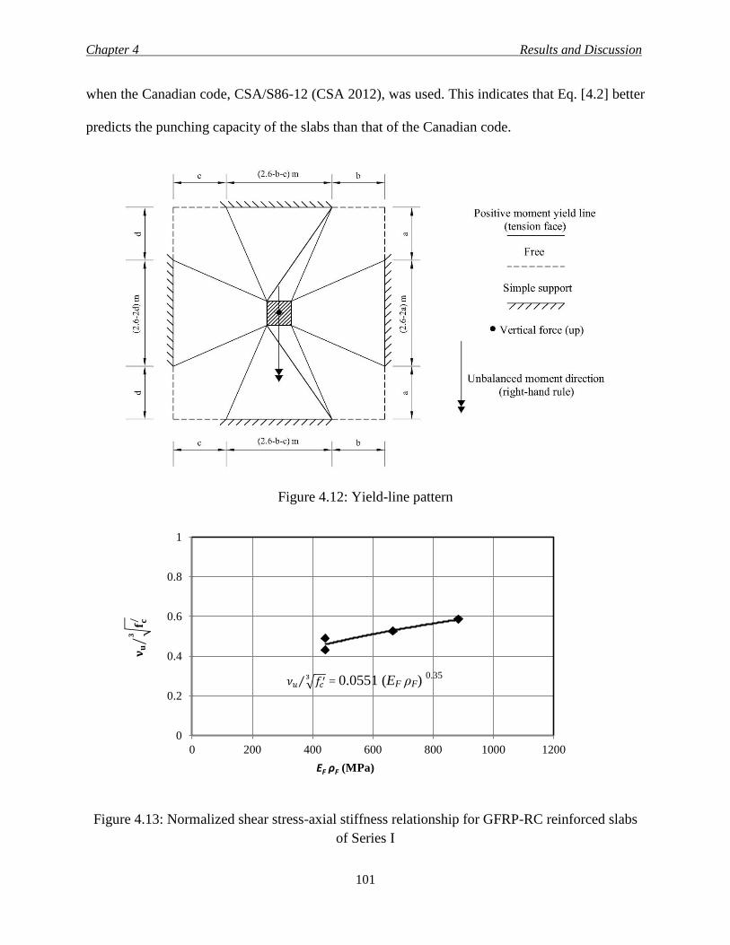
Chapter 4 Results and Discussion
101
when the Canadian code, CSA/S86-12 (CSA 2012), was used. This indicates that Eq. [4.2] better
predicts the punching capacity of the slabs than that of the Canadian code.
Figure 4.12: Yield-line pattern
Figure 4.13: Normalized shear stress-axial stiffness relationship for GFRP-RC reinforced slabs
of Series I
0
0.2
0.4
0.6
0.8
1
0 200 400 600 800 1000 1200
EF ρF (MPa)
𝛎𝐮
𝐟 𝐜/𝟑
⁄
𝜈𝑢 √𝑓𝑐′3⁄ = 0.0551 (EF ρF)
0.35
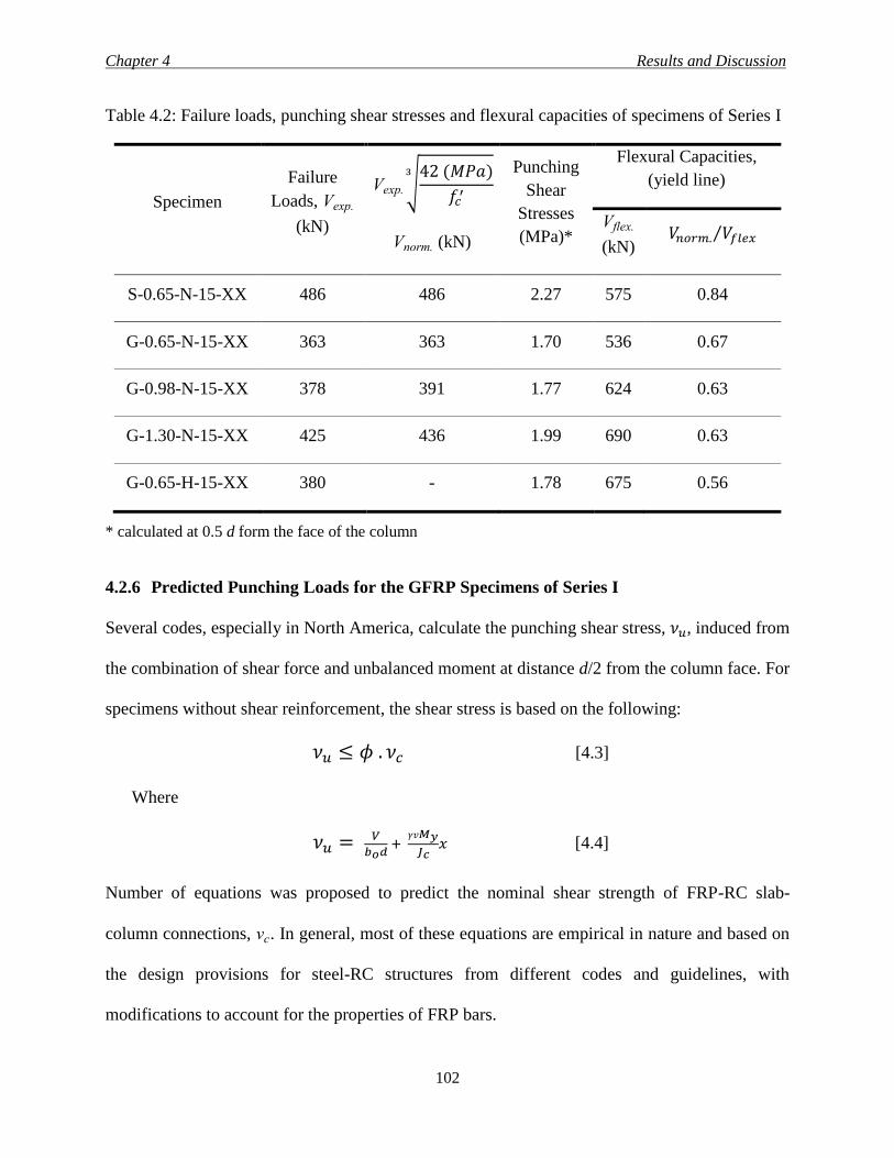
Chapter 4 Results and Discussion
102
Table 4.2: Failure loads, punching shear stresses and flexural capacities of specimens of Series I
Specimen
Failure
Loads, Vexp.
(kN)
Vexp. √42 (𝑀𝑃𝑎)
𝑓𝑐′
3
Vnorm. (kN)
Punching
Shear
Stresses
(MPa)*
Flexural Capacities,
(yield line)
Vflex.
(kN) 𝑉𝑛𝑜𝑟𝑚. 𝑉𝑓𝑙𝑒𝑥⁄
S-0.65-N-15-XX 486 486 2.27 575 0.84
G-0.65-N-15-XX 363 363 1.70 536 0.67
G-0.98-N-15-XX 378 391 1.77 624 0.63
G-1.30-N-15-XX 425 436 1.99 690 0.63
G-0.65-H-15-XX 380 - 1.78 675 0.56
* calculated at 0.5 d form the face of the column
4.2.6 Predicted Punching Loads for the GFRP Specimens of Series I
Several codes, especially in North America, calculate the punching shear stress, 𝜈𝑢, induced from
the combination of shear force and unbalanced moment at distance d/2 from the column face. For
specimens without shear reinforcement, the shear stress is based on the following:
𝜈𝑢 ≤ 𝜙 . 𝜈𝑐 [4.3]
Where
𝜈𝑢 = 𝑉
𝑏𝑜𝑑 +
𝛾𝑣𝑀𝑦
𝐽𝑐𝑥 [4.4]
Number of equations was proposed to predict the nominal shear strength of FRP-RC slab-
column connections, vc. In general, most of these equations are empirical in nature and based on
the design provisions for steel-RC structures from different codes and guidelines, with
modifications to account for the properties of FRP bars.
Chapter 4 Results and Discussion
103
The predicted values in the current study were obtained from four sources. The first is the
Canadian standard for FRP-RC structures CSA/S806-12 (Section 2.4.5.1); the second is the
American guideline ACI 440.1R-06 (Section 2.4.5.2), the third is the Japanese code JSCE-1997
(Section 2.4.5.3). The last one is the equation proposed by Zaghloul (2002) (Section 2.6.1). Since
the latter is the only research that studied the effect of the unbalanced moment, it may be
beneficial to compare the predicted values, using Zaghloul’ s equation [Eq. 2.56], to the
punching loads of the slabs tested in the current study.
For the ACI code equation, a modification has been made to account for the eccentric load. The
shear stress for each specimen was calculated by dividing the ultimate capacity obtained from the
equation [Eq. 2.51] by the effective depth, d, and the perimeter of the critical section calculated
at 0.5 d from the column faces. The outcome stress was used to calculate the eccentric load for
the specimen.
The predicted values for the punching shear capacity of the FRP-RC test specimens and the
ratios to the actual failure loads are given in Table 4.3. All material resistance and strength
factors in the equations were set equal to unity. In general, the CSA/S806-12 standard (CSA
2012) and JSCE code (JSCE 1997) gave reasonable estimate to the experimental failure loads of
the test specimens with an average of Vexp. VCSA.⁄ = 1.10±0.03 (COV = 2.7%) and
Vexp. VJSCE.⁄ = 1.13±0.07 (COV = 6.2%), respectively. However, the ACI 440.1R-06 (ACI 2006)
predictions were more conservative with an average of Vexp. VACI.⁄ = 1.93±0.12 (COV = 6.2%).
On the other hand, Zaghloul’s equation (2002) overestimated the capacity of the specimens by an
average of Vexp. VZ.⁄ = 0.86±0.04 (COV = 4.65%).
Chapter 4 Results and Discussion
104
The ACI code equation highly underestimated the punching loads of the specimens. The
equation included the effect of the reinforcement ratio and the elastic modulus of the reinforcing
bars in calculating the depth to neutral axis, and subsequently, the compute of the punching
capacity of the specimens. Whereas, the direct implementation of the axial stiffness of the
specimens showed very good predication of the failure loads as in the case of CSA/S806-12 code
(CSA 2012) and that might be one of the reasons for the conservative prediction of the ACI
equation. Similar to CSA/S806-12, Zaghloul’s equation (2002) included the axial stiffness of the
reinforcing bars and the concrete compressive strength to the power of 0.333. However, the
predicted values overestimated the actual failure loads. This might be due to size effect since
Zaghloul’ s equation was based on tests that were carried out on half-scale specimens.
Although, JSCE code (JSCE 1997) gave close conservative prediction to the failure loads of the
specimens. The HSC specimen (G-0.65-H-0.15-XX) showed exactly the same predicted
punching load for the corresponding one with NSC (G-0.65-N-0.15-XX) due to the limitation of
the concrete compressive strength through the factor fpcd.
It should be noted that the predicted capacity for the HSC specimen using CSA/S806-12 was
based on the 60 MPa limit. However, using the actual concrete strength of the HSC specimen (70
MPa) yielded better results with Vexp. VCSA.⁄ = 1.01. This is in good agreement with the results of
other researchers (Hassan et al. 2013). So, it seems that the concrete compressive strength limit
set by the CSA/S806-12 code (CSA 2012) could be extended. However, further investigation is
still needed to confirm this issue.
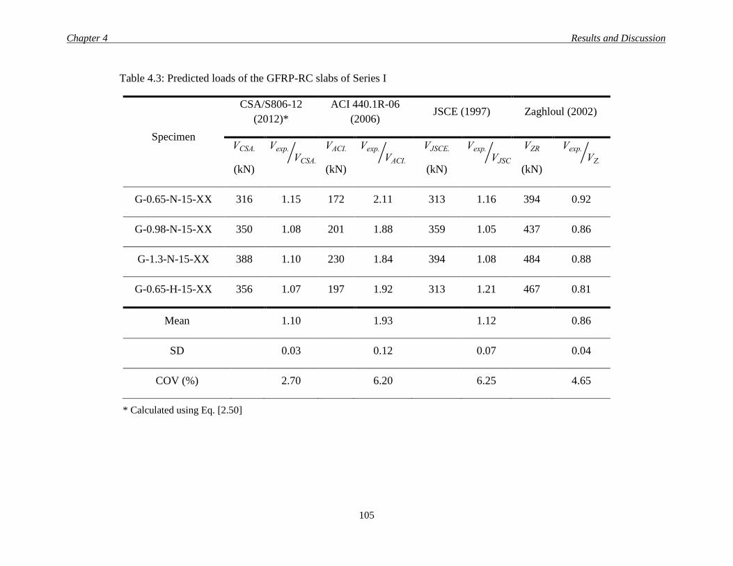
Chapter 4 Results and Discussion
105
Table 4.3: Predicted loads of the GFRP-RC slabs of Series I
Specimen
CSA/S806-12
(2012)*
ACI 440.1R-06
(2006) JSCE (1997) Zaghloul (2002)
VCSA.
(kN)
Vexp.
VCSA.⁄
VACI.
(kN)
Vexp.
VACI.⁄
VJSCE.
(kN)
Vexp.
VJSCE.⁄
VZR
(kN)
Vexp.
VZ.⁄
G-0.65-N-15-XX 316 1.15 172 2.11 313 1.16 394 0.92
G-0.98-N-15-XX 350 1.08 201 1.88 359 1.05 437 0.86
G-1.3-N-15-XX 388 1.10 230 1.84 394 1.08 484 0.88
G-0.65-H-15-XX 356 1.07 197 1.92 313 1.21 467 0.81
Mean 1.10 1.93 1.12 0.86
SD 0.03 0.12 0.07 0.04
COV (%) 2.70 6.20 6.25 4.65
* Calculated using Eq. [2.50]
Chapter 4 Results and Discussion
106
4.3 SERIES II AND III-THE EFFECT OF MOMENT-TO-SHEAR RATIO AND SHEAR
REINFORCEMENT
Up to date, no research data on the effect of moment-to-shear ratio or the presence of shear stud
reinforcement on the behaviour of full-scale GFRP-RC slab-column connections. This research
partially filled this gap. Four specimens G-0.65-N-15-XX, R-0.65-N-15-XX, R-0.65-N-15-75
and R-0.65-N-15-50 were tested with 0.15-m moment-to-shear ratio, while, that ratio was 0.3
and 0.0 m for specimens G-0.65-N-30-XX and G-0.65-N-00-XX, respectively.
4.3.1 Cracking and Failure Mode of Specimens of Series II and III
Approximately the same cracking pattern and sequences described in Section 4.2.1 are applicable
here also. The cracking load was between 28 and 36% of the ultimate capacity of the tested slabs
as listed in Table 4.4. The first crack started from the corner of the column and extended toward
the corner of the slab then followed by similar radial cracks initiated from the column face and
continued to the slab edges in the direction of the horizontal forces, i.e., direction of the
unbalanced moment. With the increasing load, other radial cracks with different orientations
spread in the slabs. At approximately 50% of the ultimate capacity of the slab, the first peripheral
crack appeared connecting the radial cracks together. All specimens failed in punching shear,
where the column penetrated through the slab thickness. Photos for the tested slabs at failure are
shown in Fig. 4.14. It was observed that the unbalanced moment caused more damage to half of
the tension side of the slab (the top part of the photos) compared to the other half, which was
more pronounced in the slab with 0.3-m moment-to-shear ratio (G-0.65-N-30-XX).
To investigate the propagation of the diagonal shear cracks that led to failure of the slabs, a
specimen from each series (G-0.65-N-00-XX and R-0.65-N-15-50) was sawed at the column
face as shown in Fig. 4.15. The main diagonal shear crack extended from the column face up to
Chapter 4 Results and Discussion
107
the level of the flexure reinforcement in slab G-0.65-N-00-XX then propagated along the
reinforcing mat (horizontal splitting crack) before punching out on the tension face. This is a
typical failure crack for slabs without shear reinforcement as reported by other researchers
(Hassan et al. 2013). Meanwhile, the failure shear crack traveled, directly, to the extreme tension
side in case of slab R-0.65-N-15-50. The difference in behaviour between the two slabs can be
attributed to the presence of shear studs that arrested the propagation of the diagonal shear cracks
and forced the failure plane to occur closer to the column face. The unbalanced moment has no
effect on that difference since specimen R-0.65-N-15-50 was sawed in the direction
perpendicular to the moment. For slab G-0.65-N-00-XX, the average inclination angle with the
horizontal axes, measured at the slab mid-depth, was 42o. However, this angle was only 37
o in
slab R-0.65-N-15-50, which support the above explanation. This is in good agreement with the
findings of previous studies for both FRP-RC (Zaghloul 2002) and steel-RC slabs (Vaz et al.
2009).
The slabs that had shear studs (R-0.65-N-15-50 and R-0.65-N-15-75) failed inside the shear
reinforcement zone. Also, it was noticed that the heads for the shear studs, at all investigated
locations, were damaged as shown in Fig. 4.16. In addition, at approximately 90 to 95% of the
failure load, the measured strain in some of the shear studs started to decrease, which indicates a
probable slippage due to local failure at the locations of these shear studs. Consequently, the
failure of the slabs could be initiated due to the damage occurred in the shear stud heads.
Moreover, slabs R-0.65-N-15-XX and G-0.65-N-15-XX showed similar cracking pattern, which
indicates that there was no significant effect of the surface texture of GFRP bars on the slab
cracking. Also, Fig. 4.14 shows that the distribution of cracks in the slabs with ribbed-deformed
GFRP bars (R-0.65-N-15-XX, R-0.65-N-15-50 and R-0.65-N-15-75) was similar, however,
Chapter 4 Results and Discussion
108
using the shear studs seem to increase the cracks density, which might be due to the higher
capacity of the slabs with transverse reinforcement. In addition, increasing the moment-to-shear
ratio decreased the failure surface and the crack spacing as shown in Fig. 4.14. This reduction
was due to the concentration of the stresses associated with the unbalanced moment near the
column face. These observations are in good agreement with test results of previous studies
(Marzouk et al. 2000; Zaghloul 2002).
4.3.2 Deflection of Specimens of Series II and III
Figure 4.17 shows the maximum deflection in the slabs measured at 50 mm from the column
face versus vertical load. The typical load-deflection relationship includes two stages. The first
stage represents the behaviour of the uncracked concrete, while the second stage represents the
reduced flexural stiffness of the cracked slabs. The load-deflection curves for the six specimens
were similar up to the first crack. After initiation of cracks, the behaviour was affected by the
moment-to-shear ratio as well as the shear reinforcement. Increasing the moment-to-shear ratio
decreased the post cracking flexural stiffness (Kp), calculated as the slope of the load-deflection
curve after cracking, which in turn increased the deflection at the same load level. Increasing the
moment-to-shear ratio from zero to 0.15 and 0.3 m decreased the post cracking stiffness by 6 and
18%, respectively. Furthermore, in the post cracking stage, the increase in deflection at the same
load level was 9 and 37% when the moment-to-shear ratio was increased from zero to 0.15 and
to 0.3 m, respectively.
The presence of the shear studs increased the post-cracking stiffness of the slabs (Table 4.4) and,
slightly, reduced the deflection at the same load level, especially for slab R-0.65-N-15-50. This
might be attributed to the ability of the shear studs to control the propagation of the diagonal
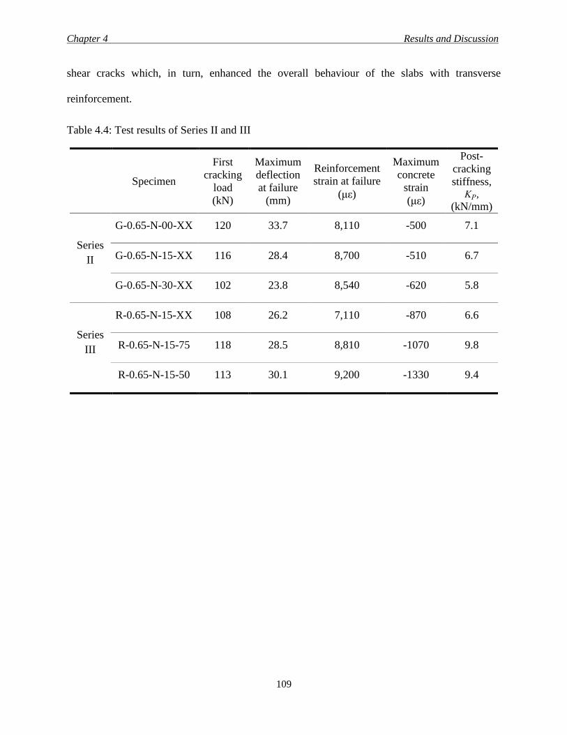
Chapter 4 Results and Discussion
109
shear cracks which, in turn, enhanced the overall behaviour of the slabs with transverse
reinforcement.
Table 4.4: Test results of Series II and III
Specimen
First
cracking
load
(kN)
Maximum
deflection
at failure
(mm)
Reinforcement
strain at failure
(με)
Maximum
concrete
strain
(με)
Post-
cracking
stiffness, KP,
(kN/mm)
Series
II
G-0.65-N-00-XX 120 33.7 8,110 -500 7.1
G-0.65-N-15-XX 116 28.4 8,700 -510 6.7
G-0.65-N-30-XX 102 23.8 8,540 -620 5.8
Series
III
R-0.65-N-15-XX 108 26.2 7,110 -870 6.6
R-0.65-N-15-75 118 28.5 8,810 -1070 9.8
R-0.65-N-15-50 113 30.1 9,200 -1330 9.4
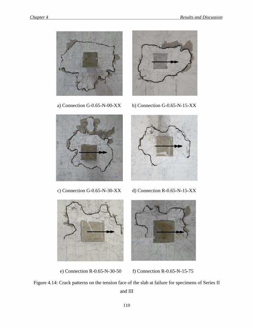
Chapter 4 Results and Discussion
110
a) Connection G-0.65-N-00-XX b) Connection G-0.65-N-15-XX
c) Connection G-0.65-N-30-XX d) Connection R-0.65-N-15-XX
e) Connection R-0.65-N-30-50 f) Connection R-0.65-N-15-75
Figure 4.14: Crack patterns on the tension face of the slab at failure for specimens of Series II
and III
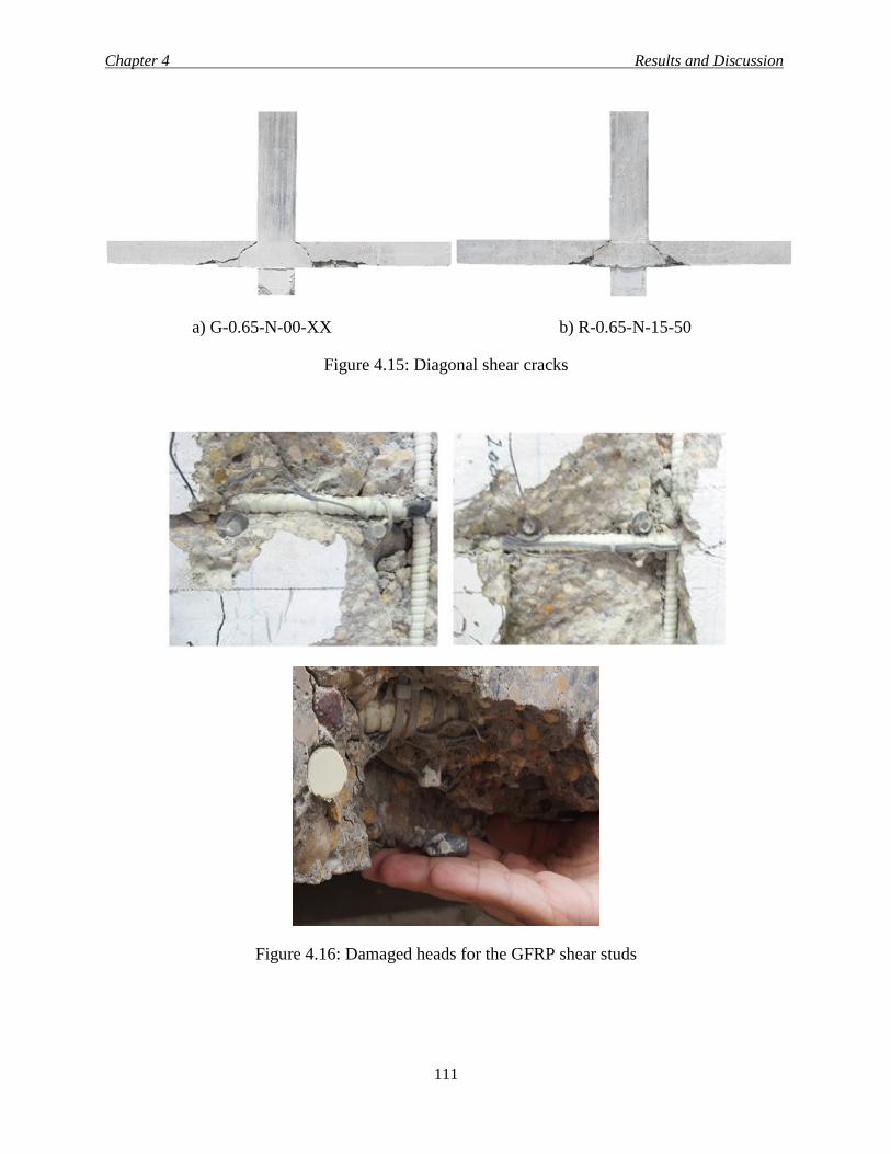
Chapter 4 Results and Discussion
111
a) G-0.65-N-00-XX b) R-0.65-N-15-50
Figure 4.15: Diagonal shear cracks
Figure 4.16: Damaged heads for the GFRP shear studs
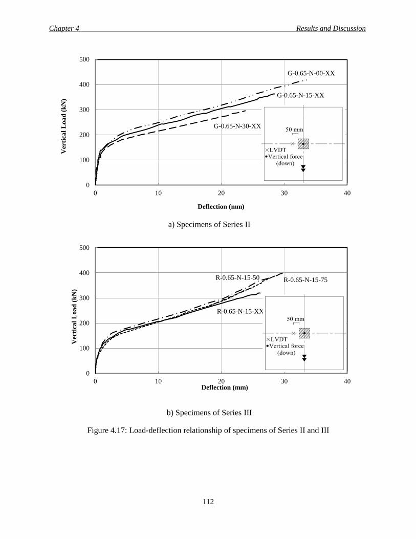
Chapter 4 Results and Discussion
112
a) Specimens of Series II
b) Specimens of Series III
Figure 4.17: Load-deflection relationship of specimens of Series II and III
0
100
200
300
400
500
0 10 20 30 40
Ver
tica
l L
oa
d (
kN
)
Deflection (mm)
G-0.65-N-15-XX
G-0.65-N-00-XX
G-0.65-N-30-XX
0
100
200
300
400
500
0 10 20 30 40
Ver
tica
l L
oa
d (
kN
)
Deflection (mm)
R-0.65-N-15-XX
R-0.65-N-15-50 R-0.65-N-15-75
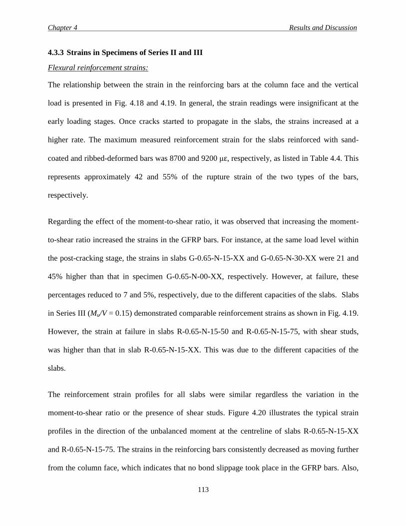
Chapter 4 Results and Discussion
113
4.3.3 Strains in Specimens of Series II and III
Flexural reinforcement strains:
The relationship between the strain in the reinforcing bars at the column face and the vertical
load is presented in Fig. 4.18 and 4.19. In general, the strain readings were insignificant at the
early loading stages. Once cracks started to propagate in the slabs, the strains increased at a
higher rate. The maximum measured reinforcement strain for the slabs reinforced with sand-
coated and ribbed-deformed bars was 8700 and 9200 με, respectively, as listed in Table 4.4. This
represents approximately 42 and 55% of the rupture strain of the two types of the bars,
respectively.
Regarding the effect of the moment-to-shear ratio, it was observed that increasing the moment-
to-shear ratio increased the strains in the GFRP bars. For instance, at the same load level within
the post-cracking stage, the strains in slabs G-0.65-N-15-XX and G-0.65-N-30-XX were 21 and
45% higher than that in specimen G-0.65-N-00-XX, respectively. However, at failure, these
percentages reduced to 7 and 5%, respectively, due to the different capacities of the slabs. Slabs
in Series III (Mu/V = 0.15) demonstrated comparable reinforcement strains as shown in Fig. 4.19.
However, the strain at failure in slabs R-0.65-N-15-50 and R-0.65-N-15-75, with shear studs,
was higher than that in slab R-0.65-N-15-XX. This was due to the different capacities of the
slabs.
The reinforcement strain profiles for all slabs were similar regardless the variation in the
moment-to-shear ratio or the presence of shear studs. Figure 4.20 illustrates the typical strain
profiles in the direction of the unbalanced moment at the centreline of slabs R-0.65-N-15-XX
and R-0.65-N-15-75. The strains in the reinforcing bars consistently decreased as moving further
from the column face, which indicates that no bond slippage took place in the GFRP bars. Also,
Chapter 4 Results and Discussion
114
due to the unbalanced moment, the reinforcement strains had higher values in the direction of
moment application. For example, at failure, the reinforcement strain at location SG1 (Fig. 4.20)
was 48, 89 and 48% higher than that at location SG 2 (Fig. 4.20) for slabs G-0.65-N-15-XX, G
G-0.65-N-30-XX and R-0.65-N-15-XX, respectively. This percentage was 14% for slab R-0.65-
N-15-75 at 94% of the ultimate load (strain gauge SG2 malfunctioned at 360 kN vertical load).
The largest difference in strains around the column was observed for slab G-0.65-N-30-XX since
this slab was tested under the highest moment-to-shear ratio (Mu/V = 0.3 m).
Concrete strains:
The maximum measured concrete strains for the slabs listed in Table 4.4 indicate that the
specimens did not fail in flexure due to concrete crushing. Figures 4.18 and 4.19 depict the
relation between the vertical load and the concrete strain measured at the column face. Increasing
the moment-to-shear ratio increased the measured concrete strain. The maximum measured strain
in slabs G-0.65-N-15-XX and G-0.65-N-30-XX increased by 2 and 24%, respectively, compared
to slab G-0.65-N-00-XX tested under a concentric load.
For the slabs of Series III, the concrete strains were quite similar up to a vertical load of 200 kN,
which represents 62, 52 and 50% of the failure load of slabs R-0.65-N-15-XX, R-0.65-N-15-75
and R-0.65-N-15-50, respectively. Afterwards, the concrete strains in the slabs with transverse
reinforcement (R-0.65-N-15-50 and R-0.65-N-15-75) increased rapidly. The maximum measured
compressive strain in slabs R-0.65-N-15-50 and R-0.65-N-15-75 were 53 and 23% higher than
that of the slab without transverse reinforcement (R-0.65-N-15-XX).
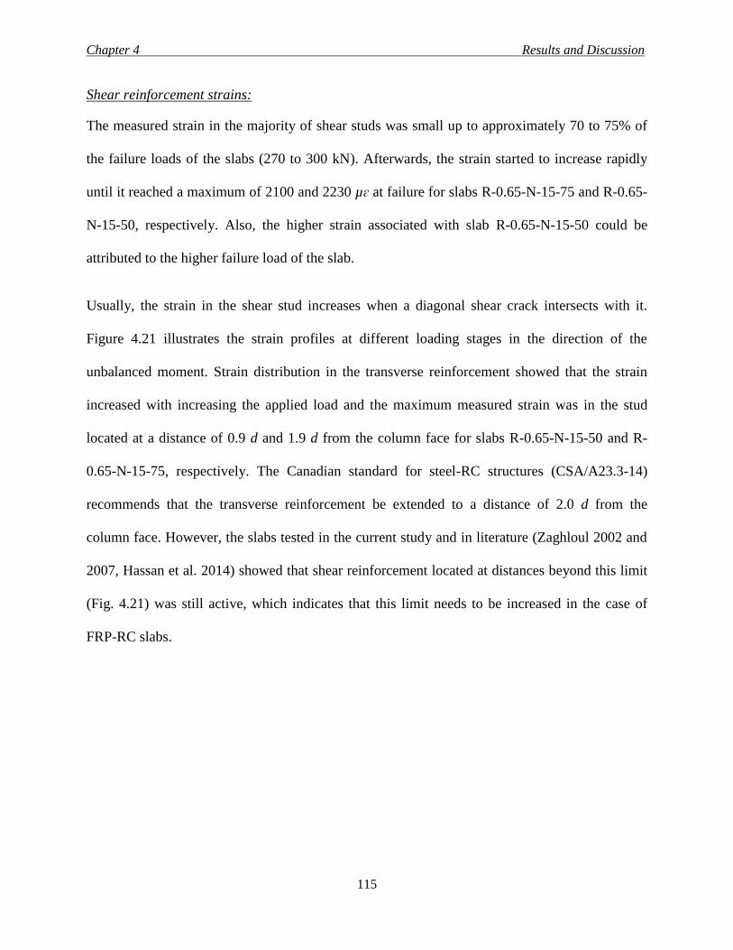
Chapter 4 Results and Discussion
115
Shear reinforcement strains:
The measured strain in the majority of shear studs was small up to approximately 70 to 75% of
the failure loads of the slabs (270 to 300 kN). Afterwards, the strain started to increase rapidly
until it reached a maximum of 2100 and 2230 µɛ at failure for slabs R-0.65-N-15-75 and R-0.65-
N-15-50, respectively. Also, the higher strain associated with slab R-0.65-N-15-50 could be
attributed to the higher failure load of the slab.
Usually, the strain in the shear stud increases when a diagonal shear crack intersects with it.
Figure 4.21 illustrates the strain profiles at different loading stages in the direction of the
unbalanced moment. Strain distribution in the transverse reinforcement showed that the strain
increased with increasing the applied load and the maximum measured strain was in the stud
located at a distance of 0.9 d and 1.9 d from the column face for slabs R-0.65-N-15-50 and R-
0.65-N-15-75, respectively. The Canadian standard for steel-RC structures (CSA/A23.3-14)
recommends that the transverse reinforcement be extended to a distance of 2.0 d from the
column face. However, the slabs tested in the current study and in literature (Zaghloul 2002 and
2007, Hassan et al. 2014) showed that shear reinforcement located at distances beyond this limit
(Fig. 4.21) was still active, which indicates that this limit needs to be increased in the case of
FRP-RC slabs.
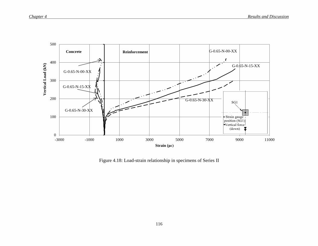
Chapter 4 Results and Discussion
116
Figure 4.18: Load-strain relationship in specimens of Series II
0
100
200
300
400
500
-3000 -1000 1000 3000 5000 7000 9000 11000
Ver
tica
l L
oa
d (
kN
)
Strain (μϵ)
G-0.65-N-00-XX
G-0.65-N-15-XX
G-0.65-N-30-XX
G-0.65-N-15-XX
G-0.65-N-00-XX
G-0.65-N-30-XX
Reinforcement Concrete
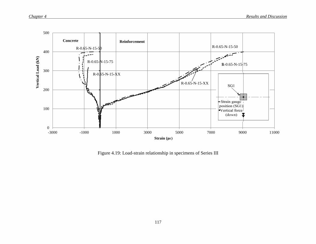
Chapter 4 Results and Discussion
117
Figure 4.19: Load-strain relationship in specimens of Series III
0
100
200
300
400
500
-3000 -1000 1000 3000 5000 7000 9000 11000
Ver
tica
l L
oa
d (
kN
)
Strain (μϵ)
R-0.65-N-15-75
Reinforcement Concrete
5
R-0.65-N-15-XX
R-0.65-N-15-75
R-0.65-N-15-50 R-0.65-N-15-50
R-0.65-N-15-XX
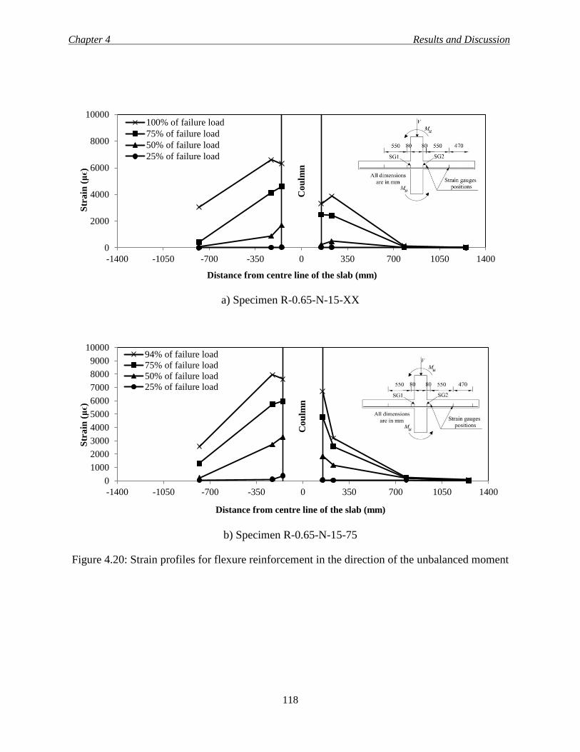
Chapter 4 Results and Discussion
118
a) Specimen R-0.65-N-15-XX
b) Specimen R-0.65-N-15-75
Figure 4.20: Strain profiles for flexure reinforcement in the direction of the unbalanced moment
0
2000
4000
6000
8000
10000
-1400 -1050 -700 -350 0 350 700 1050 1400
Str
ain
(μϵ)
Distance from centre line of the slab (mm)
100% of failure load
75% of failure load
50% of failure load
25% of failure load
Co
ulm
n
0
1000
2000
3000
4000
5000
6000
7000
8000
9000
10000
-1400 -1050 -700 -350 0 350 700 1050 1400
Str
ain
(μϵ)
Distance from centre line of the slab (mm)
94% of failure load
75% of failure load
50% of failure load
25% of failure load
Co
ulm
n
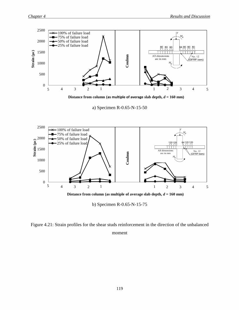
Chapter 4 Results and Discussion
119
a) Specimen R-0.65-N-15-50
b) Specimen R-0.65-N-15-75
Figure 4.21: Strain profiles for the shear studs reinforcement in the direction of the unbalanced
moment
0
500
1000
1500
2000
2500S
tra
in (μϵ)
Distance from column (as multiple of average slab depth, d = 160 mm)
100% of failure load75% of failure load50% of failure load25% of failure load
Co
ulm
n
3 5 1 2 3 5 1 2 4 4
0
500
1000
1500
2000
2500
Str
ain
(μϵ)
Distance from column (as multiple of average slab depth, d = 160 mm)
100% of failure load
75% of failure load
50% of failure load
25% of failure load
Co
ulm
n
1 2 3 4 1 2 3 5 4 5
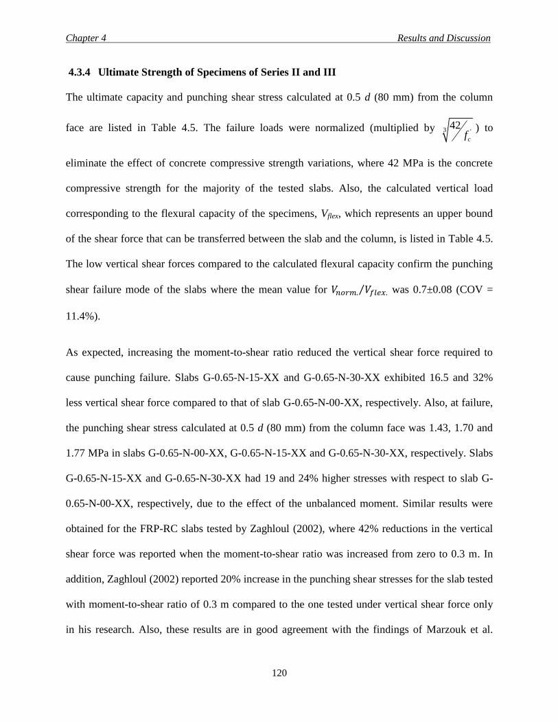
Chapter 4 Results and Discussion
120
4.3.4 Ultimate Strength of Specimens of Series II and III
The ultimate capacity and punching shear stress calculated at 0.5 d (80 mm) from the column
face are listed in Table 4.5. The failure loads were normalized (multiplied by 3 '42
cf) to
eliminate the effect of concrete compressive strength variations, where 42 MPa is the concrete
compressive strength for the majority of the tested slabs. Also, the calculated vertical load
corresponding to the flexural capacity of the specimens, Vflex, which represents an upper bound
of the shear force that can be transferred between the slab and the column, is listed in Table 4.5.
The low vertical shear forces compared to the calculated flexural capacity confirm the punching
shear failure mode of the slabs where the mean value for 𝑉𝑛𝑜𝑟𝑚. 𝑉𝑓𝑙𝑒𝑥.⁄ was 0.7±0.08 (COV =
11.4%).
As expected, increasing the moment-to-shear ratio reduced the vertical shear force required to
cause punching failure. Slabs G-0.65-N-15-XX and G-0.65-N-30-XX exhibited 16.5 and 32%
less vertical shear force compared to that of slab G-0.65-N-00-XX, respectively. Also, at failure,
the punching shear stress calculated at 0.5 d (80 mm) from the column face was 1.43, 1.70 and
1.77 MPa in slabs G-0.65-N-00-XX, G-0.65-N-15-XX and G-0.65-N-30-XX, respectively. Slabs
G-0.65-N-15-XX and G-0.65-N-30-XX had 19 and 24% higher stresses with respect to slab G-
0.65-N-00-XX, respectively, due to the effect of the unbalanced moment. Similar results were
obtained for the FRP-RC slabs tested by Zaghloul (2002), where 42% reductions in the vertical
shear force was reported when the moment-to-shear ratio was increased from zero to 0.3 m. In
addition, Zaghloul (2002) reported 20% increase in the punching shear stresses for the slab tested
with moment-to-shear ratio of 0.3 m compared to the one tested under vertical shear force only
in his research. Also, these results are in good agreement with the findings of Marzouk et al.
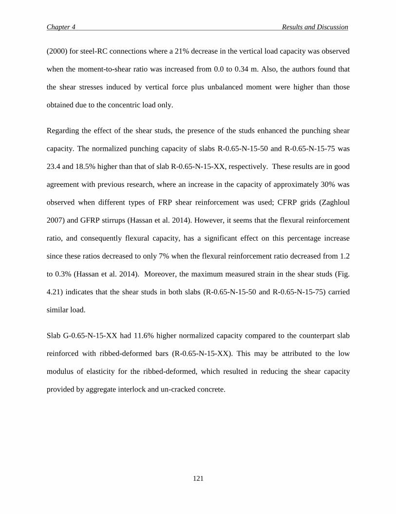
Chapter 4 Results and Discussion
121
(2000) for steel-RC connections where a 21% decrease in the vertical load capacity was observed
when the moment-to-shear ratio was increased from 0.0 to 0.34 m. Also, the authors found that
the shear stresses induced by vertical force plus unbalanced moment were higher than those
obtained due to the concentric load only.
Regarding the effect of the shear studs, the presence of the studs enhanced the punching shear
capacity. The normalized punching capacity of slabs R-0.65-N-15-50 and R-0.65-N-15-75 was
23.4 and 18.5% higher than that of slab R-0.65-N-15-XX, respectively. These results are in good
agreement with previous research, where an increase in the capacity of approximately 30% was
observed when different types of FRP shear reinforcement was used; CFRP grids (Zaghloul
2007) and GFRP stirrups (Hassan et al. 2014). However, it seems that the flexural reinforcement
ratio, and consequently flexural capacity, has a significant effect on this percentage increase
since these ratios decreased to only 7% when the flexural reinforcement ratio decreased from 1.2
to 0.3% (Hassan et al. 2014). Moreover, the maximum measured strain in the shear studs (Fig.
4.21) indicates that the shear studs in both slabs (R-0.65-N-15-50 and R-0.65-N-15-75) carried
similar load.
Slab G-0.65-N-15-XX had 11.6% higher normalized capacity compared to the counterpart slab
reinforced with ribbed-deformed bars (R-0.65-N-15-XX). This may be attributed to the low
modulus of elasticity for the ribbed-deformed, which resulted in reducing the shear capacity
provided by aggregate interlock and un-cracked concrete.
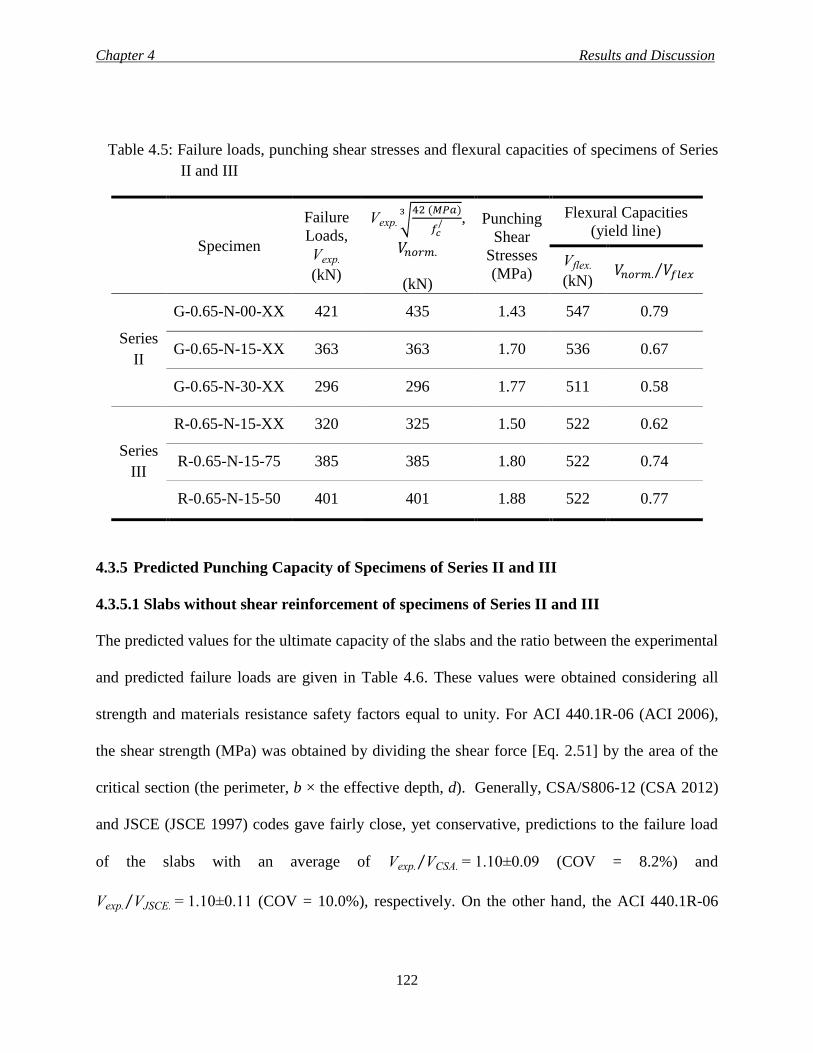
Chapter 4 Results and Discussion
122
Table 4.5: Failure loads, punching shear stresses and flexural capacities of specimens of Series
II and III
Specimen
Failure
Loads,
Vexp.
(kN)
Vexp. √42 (𝑀𝑃𝑎)
𝑓𝑐/
3,
𝑉𝑛𝑜𝑟𝑚.
(kN)
Punching
Shear
Stresses
(MPa)
Flexural Capacities
(yield line)
Vflex.
(kN) 𝑉𝑛𝑜𝑟𝑚. 𝑉𝑓𝑙𝑒𝑥⁄
Series
II
G-0.65-N-00-XX 421 435 1.43 547 0.79
G-0.65-N-15-XX 363 363 1.70 536 0.67
G-0.65-N-30-XX 296 296 1.77 511 0.58
Series
III
R-0.65-N-15-XX 320 325 1.50 522 0.62
R-0.65-N-15-75 385 385 1.80 522 0.74
R-0.65-N-15-50 401 401 1.88 522 0.77
4.3.5 Predicted Punching Capacity of Specimens of Series II and III
4.3.5.1 Slabs without shear reinforcement of specimens of Series II and III
The predicted values for the ultimate capacity of the slabs and the ratio between the experimental
and predicted failure loads are given in Table 4.6. These values were obtained considering all
strength and materials resistance safety factors equal to unity. For ACI 440.1R-06 (ACI 2006),
the shear strength (MPa) was obtained by dividing the shear force [Eq. 2.51] by the area of the
critical section (the perimeter, b × the effective depth, d). Generally, CSA/S806-12 (CSA 2012)
and JSCE (JSCE 1997) codes gave fairly close, yet conservative, predictions to the failure load
of the slabs with an average of Vexp. VCSA.⁄ = 1.10±0.09 (COV = 8.2%) and
Vexp. VJSCE.⁄ = 1.10±0.11 (COV = 10.0%), respectively. On the other hand, the ACI 440.1R-06
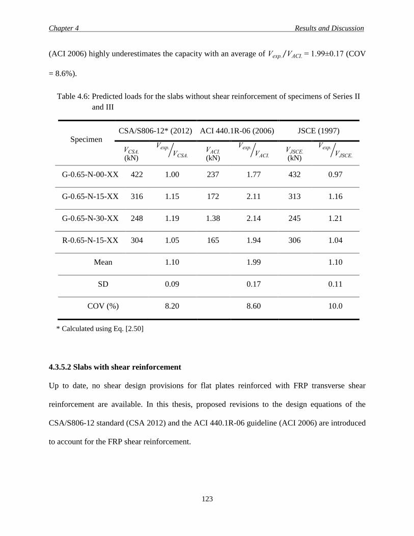
Chapter 4 Results and Discussion
123
(ACI 2006) highly underestimates the capacity with an average of Vexp. VACI.⁄ = 1.99±0.17 (COV
= 8.6%).
Table 4.6: Predicted loads for the slabs without shear reinforcement of specimens of Series II
and III
Specimen CSA/S806-12* (2012) ACI 440.1R-06 (2006) JSCE (1997)
VCSA. (kN)
Vexp.
VCSA.⁄ VACI.
(kN)
Vexp.
VACI.⁄ VJSCE.
(kN)
Vexp.
VJSCE.⁄
G-0.65-N-00-XX 422 1.00 237 1.77 432 0.97
G-0.65-N-15-XX 316 1.15 172 2.11 313 1.16
G-0.65-N-30-XX 248 1.19 1.38 2.14 245 1.21
R-0.65-N-15-XX 304 1.05 165 1.94 306 1.04
Mean 1.10 1.99 1.10
SD 0.09 0.17 0.11
COV (%) 8.20 8.60 10.0
* Calculated using Eq. [2.50]
4.3.5.2 Slabs with shear reinforcement
Up to date, no shear design provisions for flat plates reinforced with FRP transverse shear
reinforcement are available. In this thesis, proposed revisions to the design equations of the
CSA/S806-12 standard (CSA 2012) and the ACI 440.1R-06 guideline (ACI 2006) are introduced
to account for the FRP shear reinforcement.
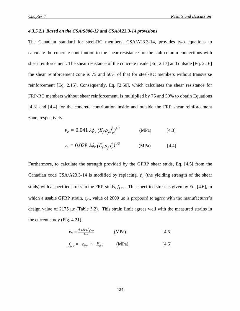
Chapter 4 Results and Discussion
124
4.3.5.2.1 Based on the CSA/S806-12 and CSA/A23.3-14 provisions
The Canadian standard for steel-RC members, CSA/A23.3-14, provides two equations to
calculate the concrete contribution to the shear resistance for the slab-column connections with
shear reinforcement. The shear resistance of the concrete inside [Eq. 2.17] and outside [Eq. 2.16]
the shear reinforcement zone is 75 and 50% of that for steel-RC members without transverse
reinforcement [Eq. 2.15]. Consequently, Eq. [2.50], which calculates the shear resistance for
FRP-RC members without shear reinforcement, is multiplied by 75 and 50% to obtain Equations
[4.3] and [4.4] for the concrete contribution inside and outside the FRP shear reinforcement
zone, respectively.
vc = 0.041 λϕc (Ef ρf f
c
')
1/3 (MPa) [4.3]
vc = 0.028 λϕc (Ef ρf f
c
')
1/3 (MPa) [4.4]
Furthermore, to calculate the strength provided by the GFRP shear studs, Eq. [4.5] from the
Canadian code CSA/A23.3-14 is modified by replacing, 𝑓𝑦 (the yielding strength of the shear
studs) with a specified stress in the FRP-studs, 𝑓𝑓𝑟𝑣. This specified stress is given by Eq. [4.6], in
which a usable GFRP strain, εfrv, value of 2000 με is proposed to agree with the manufacturer’s
design value of 2175 με (Table 3.2). This strain limit agrees well with the measured strains in
the current study (Fig. 4.21).
vS = 𝜙𝑠𝐴𝑣𝑠𝑓𝑓𝑟𝑣
𝑏 𝑆 (MPa) [4.5]
ffrv = εfrv × Efrv (MPa) [4.6]
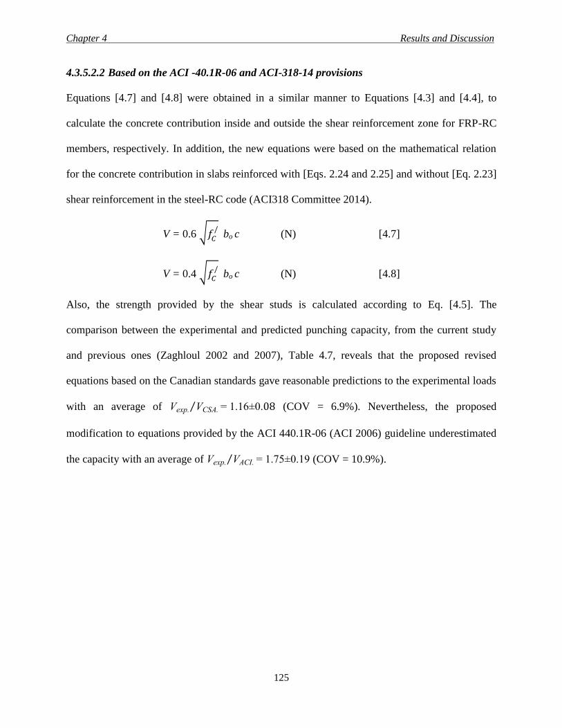
Chapter 4 Results and Discussion
125
4.3.5.2.2 Based on the ACI -40.1R-06 and ACI-318-14 provisions
Equations [4.7] and [4.8] were obtained in a similar manner to Equations [4.3] and [4.4], to
calculate the concrete contribution inside and outside the shear reinforcement zone for FRP-RC
members, respectively. In addition, the new equations were based on the mathematical relation
for the concrete contribution in slabs reinforced with [Eqs. 2.24 and 2.25] and without [Eq. 2.23]
shear reinforcement in the steel-RC code (ACI318 Committee 2014).
V = 0.6 √𝑓𝐶/ bo c (N) [4.7]
V = 0.4 √𝑓𝐶/ bo c (N) [4.8]
Also, the strength provided by the shear studs is calculated according to Eq. [4.5]. The
comparison between the experimental and predicted punching capacity, from the current study
and previous ones (Zaghloul 2002 and 2007), Table 4.7, reveals that the proposed revised
equations based on the Canadian standards gave reasonable predictions to the experimental loads
with an average of Vexp. VCSA.⁄ = 1.16±0.08 (COV = 6.9%). Nevertheless, the proposed
modification to equations provided by the ACI 440.1R-06 (ACI 2006) guideline underestimated
the capacity with an average of Vexp. VACI.⁄ = 1.75±0.19 (COV = 10.9%).
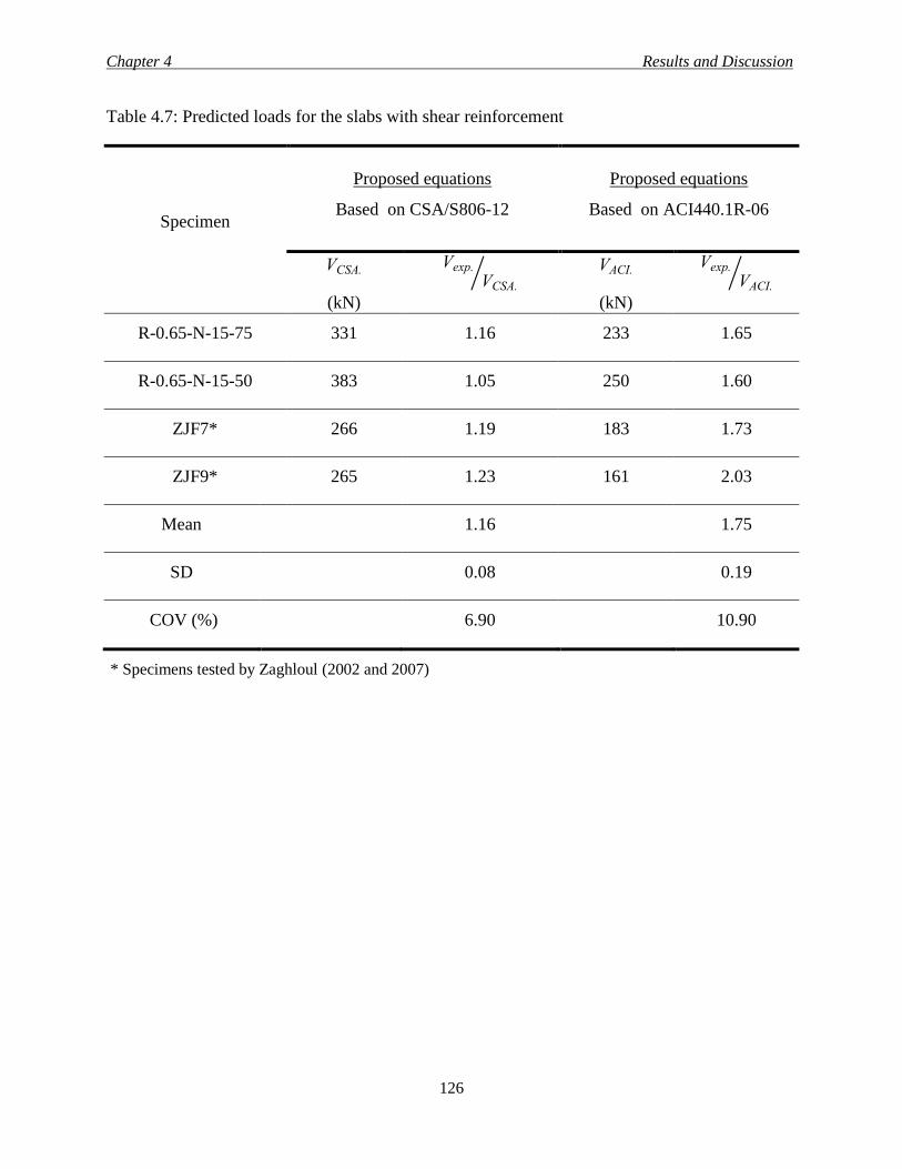
Chapter 4 Results and Discussion
126
Table 4.7: Predicted loads for the slabs with shear reinforcement
Specimen
Proposed equations
Based on CSA/S806-12
Proposed equations
Based on ACI440.1R-06
VCSA.
(kN)
Vexp.
VCSA.⁄
VACI.
(kN)
Vexp.
VACI.⁄
R-0.65-N-15-75 331 1.16 233 1.65
R-0.65-N-15-50 383 1.05 250 1.60
ZJF7* 266 1.19 183 1.73
ZJF9* 265 1.23 161 2.03
Mean 1.16 1.75
SD 0.08 0.19
COV (%) 6.90 10.90
* Specimens tested by Zaghloul (2002 and 2007)
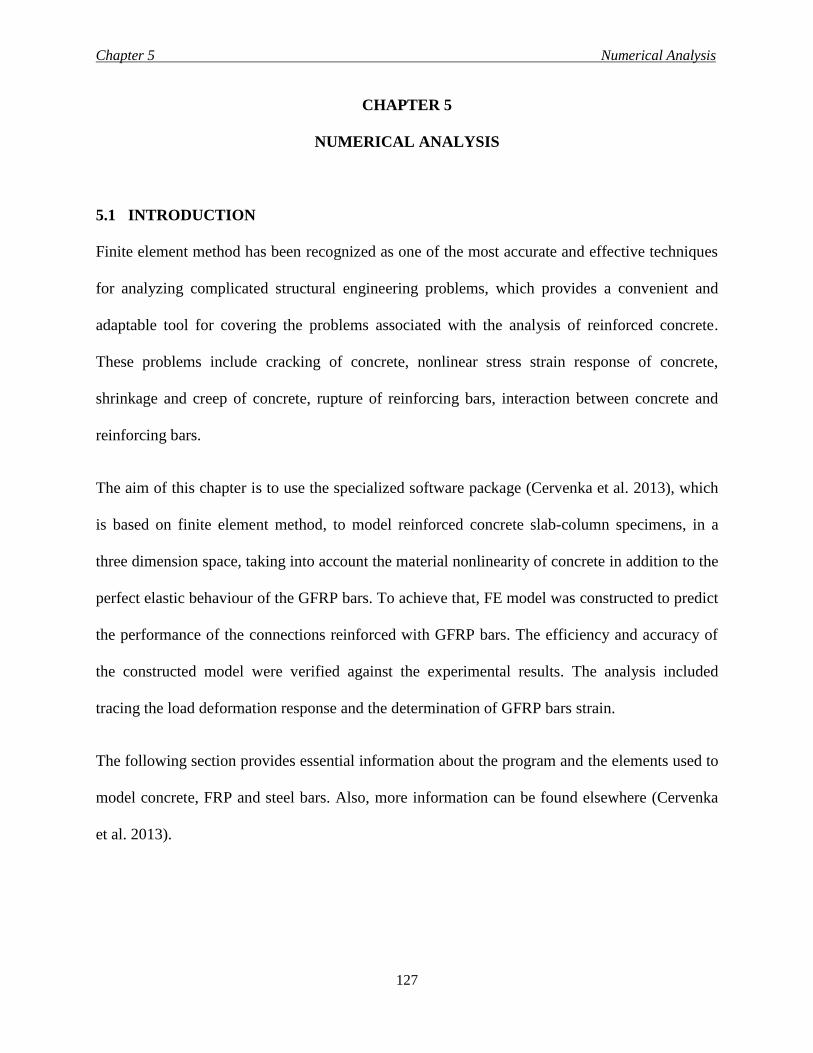
Chapter 5 Numerical Analysis
127
CHAPTER 5
NUMERICAL ANALYSIS
5.1 INTRODUCTION
Finite element method has been recognized as one of the most accurate and effective techniques
for analyzing complicated structural engineering problems, which provides a convenient and
adaptable tool for covering the problems associated with the analysis of reinforced concrete.
These problems include cracking of concrete, nonlinear stress strain response of concrete,
shrinkage and creep of concrete, rupture of reinforcing bars, interaction between concrete and
reinforcing bars.
The aim of this chapter is to use the specialized software package (Cervenka et al. 2013), which
is based on finite element method, to model reinforced concrete slab-column specimens, in a
three dimension space, taking into account the material nonlinearity of concrete in addition to the
perfect elastic behaviour of the GFRP bars. To achieve that, FE model was constructed to predict
the performance of the connections reinforced with GFRP bars. The efficiency and accuracy of
the constructed model were verified against the experimental results. The analysis included
tracing the load deformation response and the determination of GFRP bars strain.
The following section provides essential information about the program and the elements used to
model concrete, FRP and steel bars. Also, more information can be found elsewhere (Cervenka
et al. 2013).
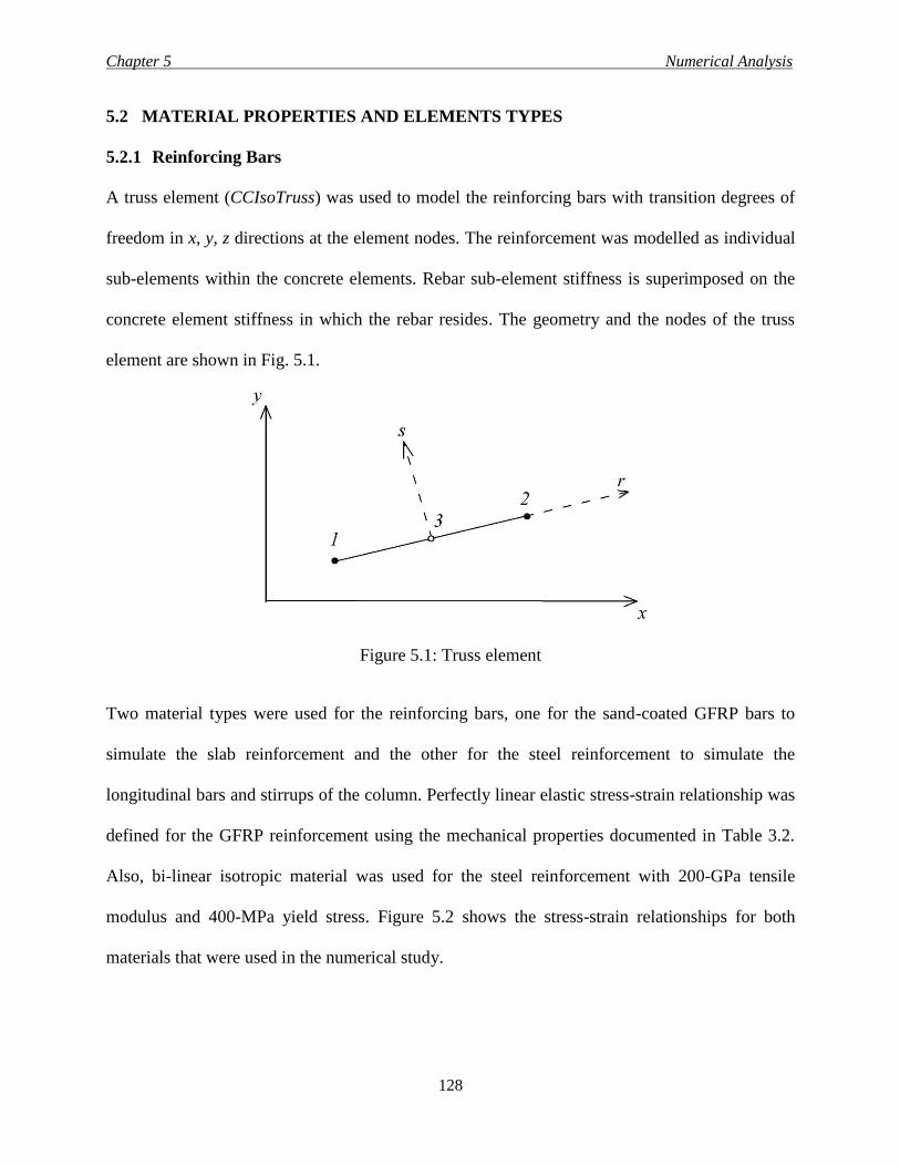
Chapter 5 Numerical Analysis
128
5.2 MATERIAL PROPERTIES AND ELEMENTS TYPES
5.2.1 Reinforcing Bars
A truss element (CCIsoTruss) was used to model the reinforcing bars with transition degrees of
freedom in x, y, z directions at the element nodes. The reinforcement was modelled as individual
sub-elements within the concrete elements. Rebar sub-element stiffness is superimposed on the
concrete element stiffness in which the rebar resides. The geometry and the nodes of the truss
element are shown in Fig. 5.1.
Figure 5.1: Truss element
Two material types were used for the reinforcing bars, one for the sand-coated GFRP bars to
simulate the slab reinforcement and the other for the steel reinforcement to simulate the
longitudinal bars and stirrups of the column. Perfectly linear elastic stress-strain relationship was
defined for the GFRP reinforcement using the mechanical properties documented in Table 3.2.
Also, bi-linear isotropic material was used for the steel reinforcement with 200-GPa tensile
modulus and 400-MPa yield stress. Figure 5.2 shows the stress-strain relationships for both
materials that were used in the numerical study.
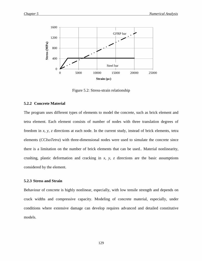
Chapter 5 Numerical Analysis
129
Figure 5.2: Stress-strain relationship
5.2.2 Concrete Material
The program uses different types of elements to model the concrete, such as brick element and
tetra element. Each element consists of number of nodes with three translation degrees of
freedom in x, y, z directions at each node. In the current study, instead of brick elements, tetra
elements (CCIsoTetra) with three-dimensional nodes were used to simulate the concrete since
there is a limitation on the number of brick elements that can be used.. Material nonlinearity,
crushing, plastic deformation and cracking in x, y, z directions are the basic assumptions
considered by the element.
5.2.3 Stress and Strain
Behaviour of concrete is highly nonlinear, especially, with low tensile strength and depends on
crack widths and compressive capacity. Modeling of concrete material, especially, under
conditions where extensive damage can develop requires advanced and detailed constitutive
models.
0
400
800
1200
1600
0 5000 10000 15000 20000 25000
Str
ess
(MP
a)
Strain (μϵ)
Steel bar
GFRP bar
Chapter 5 Numerical Analysis
130
The mathematical correlations of the constitutive relations are considered in the plane stress
state. The following equation of equilibrium in a material point describes the stiffness of the
constitutive model.
s = D ɛ [5.1]
Where:
s = stress vector {
𝜎𝑥
𝜎𝑦
𝜏𝑥𝑦
} , ɛ = strain vector {
ɛ𝑥
ɛ𝑦
𝛾𝑥𝑦
} and D = material stiffness matrix
The components of the stress vectors are σx, σy, τxy. In addition, the corresponding ones for the
strain vector are ɛx, ɛy, γxy.
Where:
σx = normal stress in the (x) direction, σy = normal stress in the (y) direction,
τxy = shear stress in plane (xy), ɛx = strain in (x) direction,
ɛy = strain in (y) direction, γxy = the engineering shear strain.
The program divides the material stiffness matrix (D) into two components, one represents the
concrete contribution (Dc) and the other is for the reinforcement (Ds) and the same for the stress
vector (S), a component for the concrete (Sc) and another one for the reinforcement (Ss).
5.3 CONCEPTS OF MATERIAL MODEL CC3DNonLinCementitious2
In this study, a built-in fracture-plastic constitutive model called CC3DNonLinCementitious2 is
used to define the concrete. The fracture model employs Rankine failure criterion, while the
plastic model is based on Menétrey-Willam failure surface (Cervenka et al. 2013). This fracture-
plastic model was developed to combine both fracture and plastic models into a single model that
can use plasticity to simulate concrete crushing and fracture mechanics to simulate cracking.
Chapter 5 Numerical Analysis
131
This model accounts for material nonlinearity, crushing, plastic deformation and cracking in x, y,
z directions. The main features of that model are as follows.
1- Non-linearity in compression including softening and hardening.
2- Cracking of concrete in tension based on the non-linearity fracture mechanics.
3- Biaxial strength failure criterion.
4- Reducing the compressive strength after cracking
5- Tension stiffening effect
6- Reduction of the stiffness in shear after cracking.
According to the model a nonlinear elastic approach is used to derive the material stiffness
matrix. That elastic approach is coming from stress-strain formula called the equivalent uniaxial
law. A detailed description of the approach will be given in the next section.
5.3.1 Stress-Strain Relations for Concrete
5.3.1.1 Equivalent uniaxial law
The diagram for the equivalent uniaxial stress-strain for concrete is shown in Fig. 5.3. Effective
stress, σef, and the equivalent uniaxial strain, ɛeq, represent the behaviour of the concrete in the
stress-strain state. The equivalent uniaxial strain is described as the strain, which would be
produced by the stress σi, in a uniaxial test with modulus Ei, associated with the direction i. This
definition means that the damage is caused only by the governing stress σi, which is the principle
stress. Also, concrete behaviour is assumed to be perfectly elastic in the uncracked zone. In
addition, the tangent modulus that used to build the stiffness matrix for the concrete, for the
iterative trials, is defined as the slope of the stress-strain curve at a given strain and it’s always
with a positive sign.
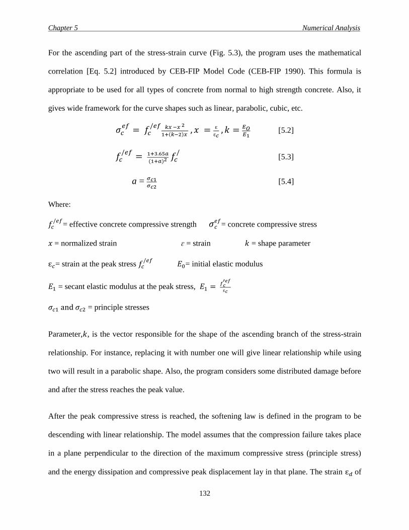
Chapter 5 Numerical Analysis
132
For the ascending part of the stress-strain curve (Fig. 5.3), the program uses the mathematical
correlation [Eq. 5.2] introduced by CEB-FIP Model Code (CEB-FIP 1990). This formula is
appropriate to be used for all types of concrete from normal to high strength concrete. Also, it
gives wide framework for the curve shapes such as linear, parabolic, cubic, etc.
𝜎𝑐𝑒𝑓
= 𝑓𝑐/𝑒𝑓 𝑘𝑥 −𝑥 2
1+(𝑘−2)𝑥 , 𝑥 = ɛ
ɛ𝑐 , 𝑘 = 𝐸𝑂
𝐸1 [5.2]
𝑓𝑐/𝑒𝑓
= 1+3.65𝑎
(1+𝑎)2 𝑓𝑐/ [5.3]
a = 𝜎𝑐1𝜎𝑐2
[5.4]
Where:
𝑓𝑐/𝑒𝑓
= effective concrete compressive strength 𝜎𝑐𝑒𝑓
= concrete compressive stress
𝑥 = normalized strain ɛ = strain 𝑘 = shape parameter
ɛ𝑐= strain at the peak stress 𝑓𝑐/𝑒𝑓
𝐸0= initial elastic modulus
𝐸1 = secant elastic modulus at the peak stress, 𝐸1 = 𝑓𝑐′𝑒𝑓
ɛ𝑐
𝜎𝑐1 and 𝜎𝑐2 = principle stresses
Parameter,𝑘, is the vector responsible for the shape of the ascending branch of the stress-strain
relationship. For instance, replacing it with number one will give linear relationship while using
two will result in a parabolic shape. Also, the program considers some distributed damage before
and after the stress reaches the peak value.
After the peak compressive stress is reached, the softening law is defined in the program to be
descending with linear relationship. The model assumes that the compression failure takes place
in a plane perpendicular to the direction of the maximum compressive stress (principle stress)
and the energy dissipation and compressive peak displacement lay in that plane. The strain ɛ𝑑 of
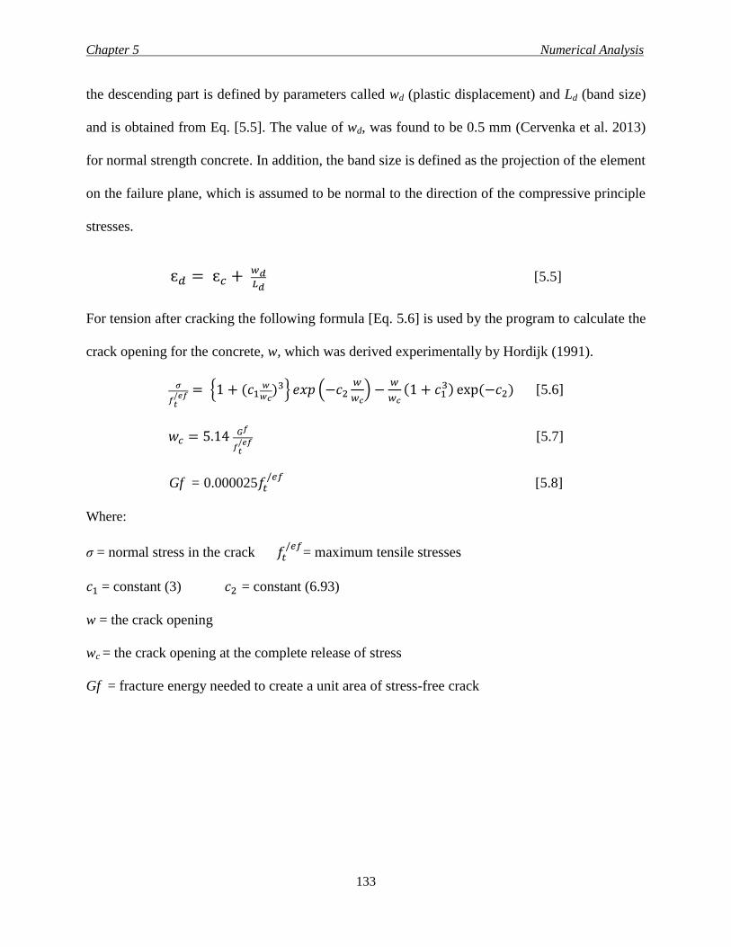
Chapter 5 Numerical Analysis
133
the descending part is defined by parameters called wd (plastic displacement) and Ld (band size)
and is obtained from Eq. [5.5]. The value of wd, was found to be 0.5 mm (Cervenka et al. 2013)
for normal strength concrete. In addition, the band size is defined as the projection of the element
on the failure plane, which is assumed to be normal to the direction of the compressive principle
stresses.
ɛ𝑑 = ɛ𝑐 + 𝑤𝑑𝐿𝑑
[5.5]
For tension after cracking the following formula [Eq. 5.6] is used by the program to calculate the
crack opening for the concrete, w, which was derived experimentally by Hordijk (1991).
𝜎
𝑓𝑡/𝑒𝑓 = {1 + (𝑐1
𝑤
𝑤𝑐)3} 𝑒𝑥𝑝 (−𝑐2
𝑤
𝑤𝑐) −
𝑤
𝑤𝑐(1 + 𝑐1
3) exp(−𝑐2) [5.6]
𝑤𝑐 = 5.14 𝐺𝑓
𝑓𝑡/𝑒𝑓 [5.7]
Gf = 0.000025𝑓𝑡/𝑒𝑓
[5.8]
Where:
σ = normal stress in the crack 𝑓𝑡/𝑒𝑓
= maximum tensile stresses
𝑐1 = constant (3) 𝑐2 = constant (6.93)
w = the crack opening
wc = the crack opening at the complete release of stress
Gf = fracture energy needed to create a unit area of stress-free crack
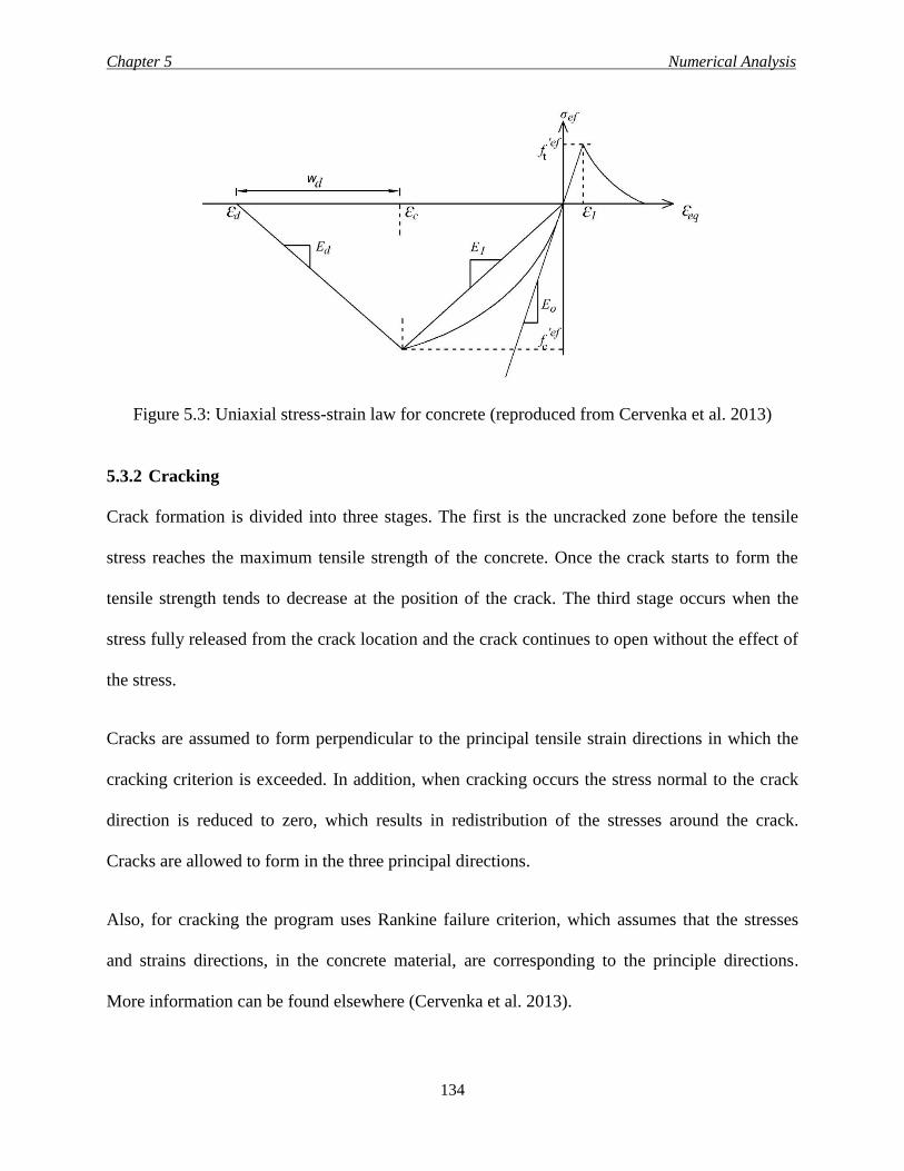
Chapter 5 Numerical Analysis
134
Figure 5.3: Uniaxial stress-strain law for concrete (reproduced from Cervenka et al. 2013)
5.3.2 Cracking
Crack formation is divided into three stages. The first is the uncracked zone before the tensile
stress reaches the maximum tensile strength of the concrete. Once the crack starts to form the
tensile strength tends to decrease at the position of the crack. The third stage occurs when the
stress fully released from the crack location and the crack continues to open without the effect of
the stress.
Cracks are assumed to form perpendicular to the principal tensile strain directions in which the
cracking criterion is exceeded. In addition, when cracking occurs the stress normal to the crack
direction is reduced to zero, which results in redistribution of the stresses around the crack.
Cracks are allowed to form in the three principal directions.
Also, for cracking the program uses Rankine failure criterion, which assumes that the stresses
and strains directions, in the concrete material, are corresponding to the principle directions.
More information can be found elsewhere (Cervenka et al. 2013).
Chapter 5 Numerical Analysis
135
5.3.3 Parameters of Constitutive Model
Table 5.1 summarizes the constants and equations used by CC3DNonLinCementitious2 material
model to calculate the different parameters that are required for the analysis. All of that constants
and equations are default by the program. Also, the program leaves the choice for the user to
change these values. In the current study these numbers were not changed, except for the tensile
strength to meet with numbers obtained experimentally.
5.4 BEARING PLATES
For supports and loading, steel plates were used. The main purpose for those plates was to
distribute and transfer the stresses to the different elements of the slab-column model. A tetra
element (CCIsoTetra) with three translations degrees of freedom in x, y, z directions at each node
was used to simulate those plates. Also, the material used for the plates was linear-elastic with
200-GPa modulus of elasticity and 0.3 Poisson’s ratio.
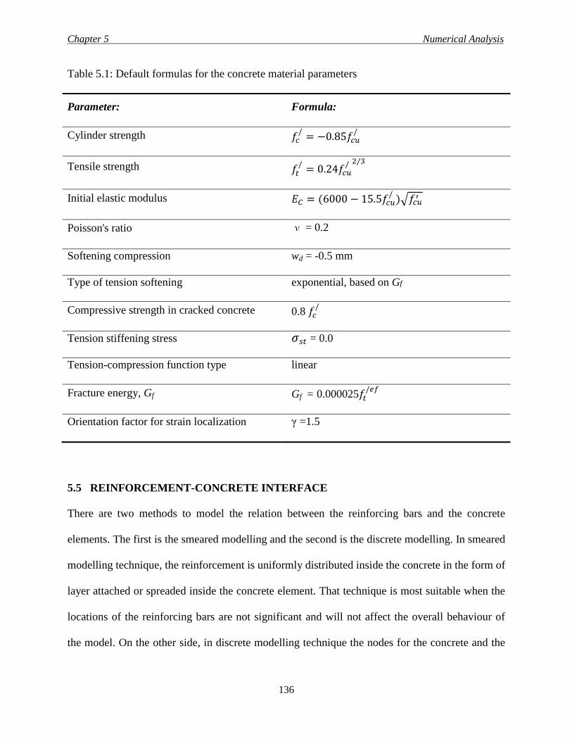
Chapter 5 Numerical Analysis
136
Table 5.1: Default formulas for the concrete material parameters
Parameter: Formula:
Cylinder strength 𝑓𝑐/
= −0.85𝑓𝑐𝑢/
Tensile strength 𝑓𝑡/
= 0.24𝑓𝑐𝑢/ 2/3
Initial elastic modulus 𝐸𝐶 = (6000 − 15.5𝑓𝑐𝑢/
)√𝑓𝑐𝑢′
Poisson's ratio ν = 0.2
Softening compression wd = -0.5 mm
Type of tension softening exponential, based on Gf
Compressive strength in cracked concrete 0.8 𝑓𝑐/
Tension stiffening stress 𝜎𝑠𝑡 = 0.0
Tension-compression function type linear
Fracture energy, Gf Gf = 0.000025𝑓𝑡/𝑒𝑓
Orientation factor for strain localization γ =1.5
5.5 REINFORCEMENT-CONCRETE INTERFACE
There are two methods to model the relation between the reinforcing bars and the concrete
elements. The first is the smeared modelling and the second is the discrete modelling. In smeared
modelling technique, the reinforcement is uniformly distributed inside the concrete in the form of
layer attached or spreaded inside the concrete element. That technique is most suitable when the
locations of the reinforcing bars are not significant and will not affect the overall behaviour of
the model. On the other side, in discrete modelling technique the nodes for the concrete and the
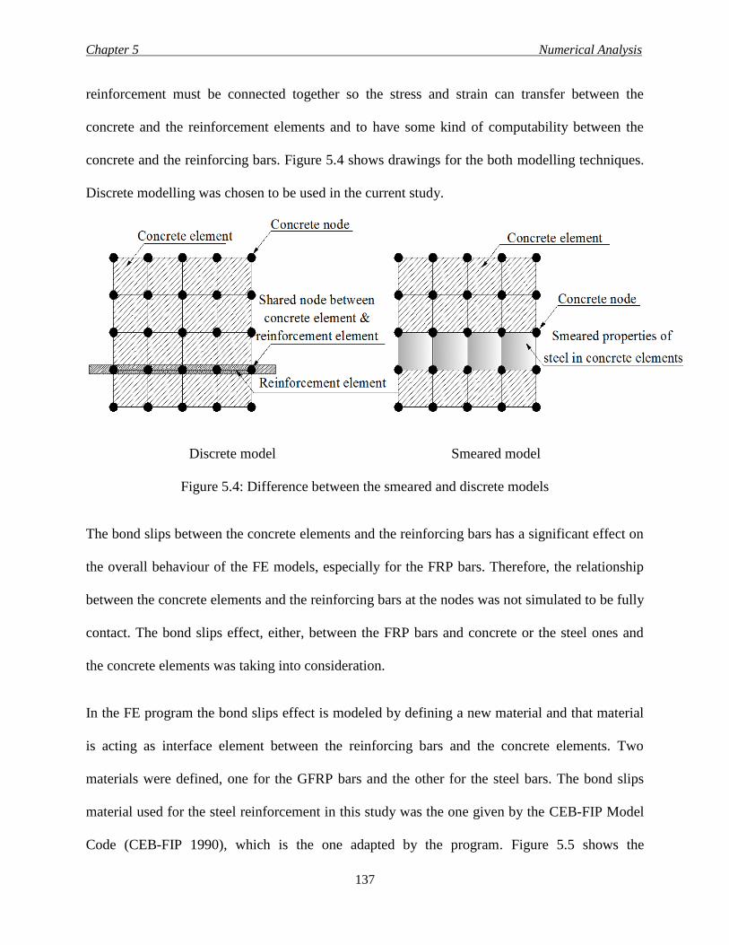
Chapter 5 Numerical Analysis
137
reinforcement must be connected together so the stress and strain can transfer between the
concrete and the reinforcement elements and to have some kind of computability between the
concrete and the reinforcing bars. Figure 5.4 shows drawings for the both modelling techniques.
Discrete modelling was chosen to be used in the current study.
Discrete model Smeared model
Figure 5.4: Difference between the smeared and discrete models
The bond slips between the concrete elements and the reinforcing bars has a significant effect on
the overall behaviour of the FE models, especially for the FRP bars. Therefore, the relationship
between the concrete elements and the reinforcing bars at the nodes was not simulated to be fully
contact. The bond slips effect, either, between the FRP bars and concrete or the steel ones and
the concrete elements was taking into consideration.
In the FE program the bond slips effect is modeled by defining a new material and that material
is acting as interface element between the reinforcing bars and the concrete elements. Two
materials were defined, one for the GFRP bars and the other for the steel bars. The bond slips
material used for the steel reinforcement in this study was the one given by the CEB-FIP Model
Code (CEB-FIP 1990), which is the one adapted by the program. Figure 5.5 shows the
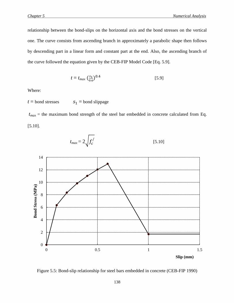
Chapter 5 Numerical Analysis
138
relationship between the bond-slips on the horizontal axis and the bond stresses on the vertical
one. The curve consists from ascending branch in approximately a parabolic shape then follows
by descending part in a linear form and constant part at the end. Also, the ascending branch of
the curve followed the equation given by the CEB-FIP Model Code [Eq. 5.9].
t = tmax (𝑠10.6
)0.4 [5.9]
Where:
t = bond stresses 𝑠1 = bond slippage
tmax = the maximum bond strength of the steel bar embedded in concrete calculated from Eq.
[5.10].
tmax = 2√𝑓𝑐/ [5.10]
Figure 5.5: Bond-slip relationship for steel bars embedded in concrete (CEB-FIP 1990)
0
2
4
6
8
10
12
14
0 0.5 1 1.5
Bo
nd
Str
ess
(MP
a)
Slip (mm)
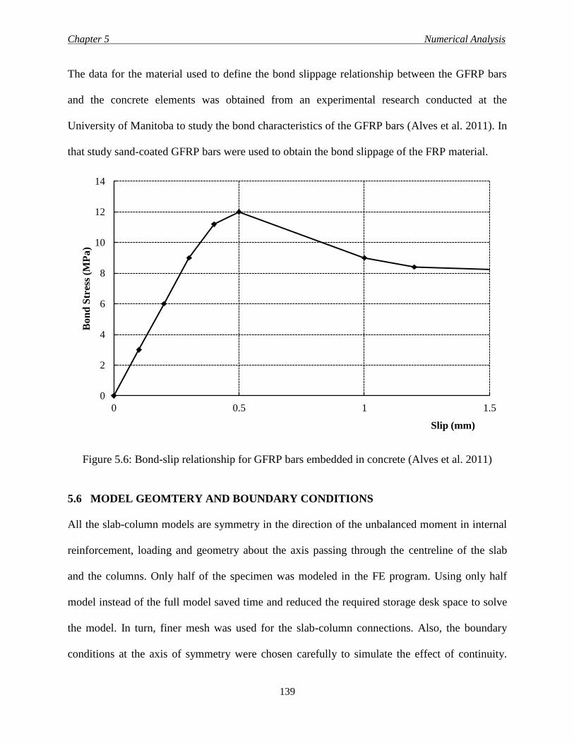
Chapter 5 Numerical Analysis
139
The data for the material used to define the bond slippage relationship between the GFRP bars
and the concrete elements was obtained from an experimental research conducted at the
University of Manitoba to study the bond characteristics of the GFRP bars (Alves et al. 2011). In
that study sand-coated GFRP bars were used to obtain the bond slippage of the FRP material.
Figure 5.6: Bond-slip relationship for GFRP bars embedded in concrete (Alves et al. 2011)
5.6 MODEL GEOMTERY AND BOUNDARY CONDITIONS
All the slab-column models are symmetry in the direction of the unbalanced moment in internal
reinforcement, loading and geometry about the axis passing through the centreline of the slab
and the columns. Only half of the specimen was modeled in the FE program. Using only half
model instead of the full model saved time and reduced the required storage desk space to solve
the model. In turn, finer mesh was used for the slab-column connections. Also, the boundary
conditions at the axis of symmetry were chosen carefully to simulate the effect of continuity.
0
2
4
6
8
10
12
14
0 0.5 1 1.5
Bon
d S
tres
s (M
Pa
)
Slip (mm)
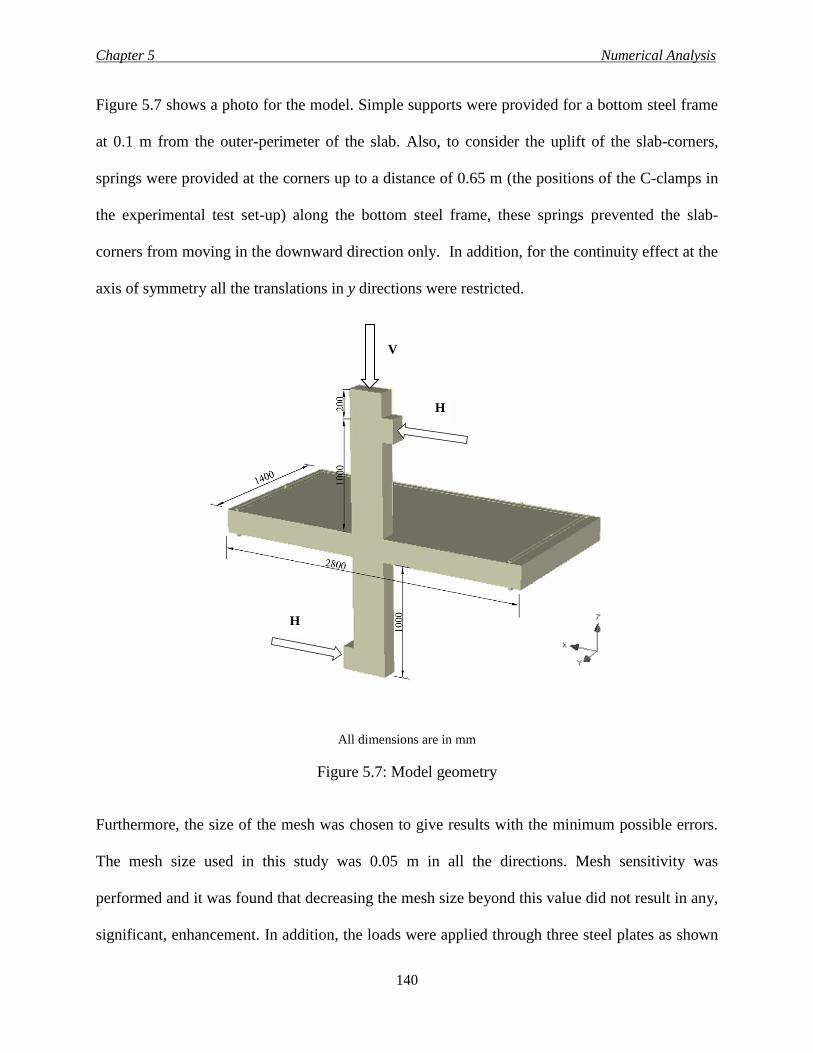
Chapter 5 Numerical Analysis
140
Figure 5.7 shows a photo for the model. Simple supports were provided for a bottom steel frame
at 0.1 m from the outer-perimeter of the slab. Also, to consider the uplift of the slab-corners,
springs were provided at the corners up to a distance of 0.65 m (the positions of the C-clamps in
the experimental test set-up) along the bottom steel frame, these springs prevented the slab-
corners from moving in the downward direction only. In addition, for the continuity effect at the
axis of symmetry all the translations in y directions were restricted.
All dimensions are in mm
Figure 5.7: Model geometry
Furthermore, the size of the mesh was chosen to give results with the minimum possible errors.
The mesh size used in this study was 0.05 m in all the directions. Mesh sensitivity was
performed and it was found that decreasing the mesh size beyond this value did not result in any,
significant, enhancement. In addition, the loads were applied through three steel plates as shown
V
H
H
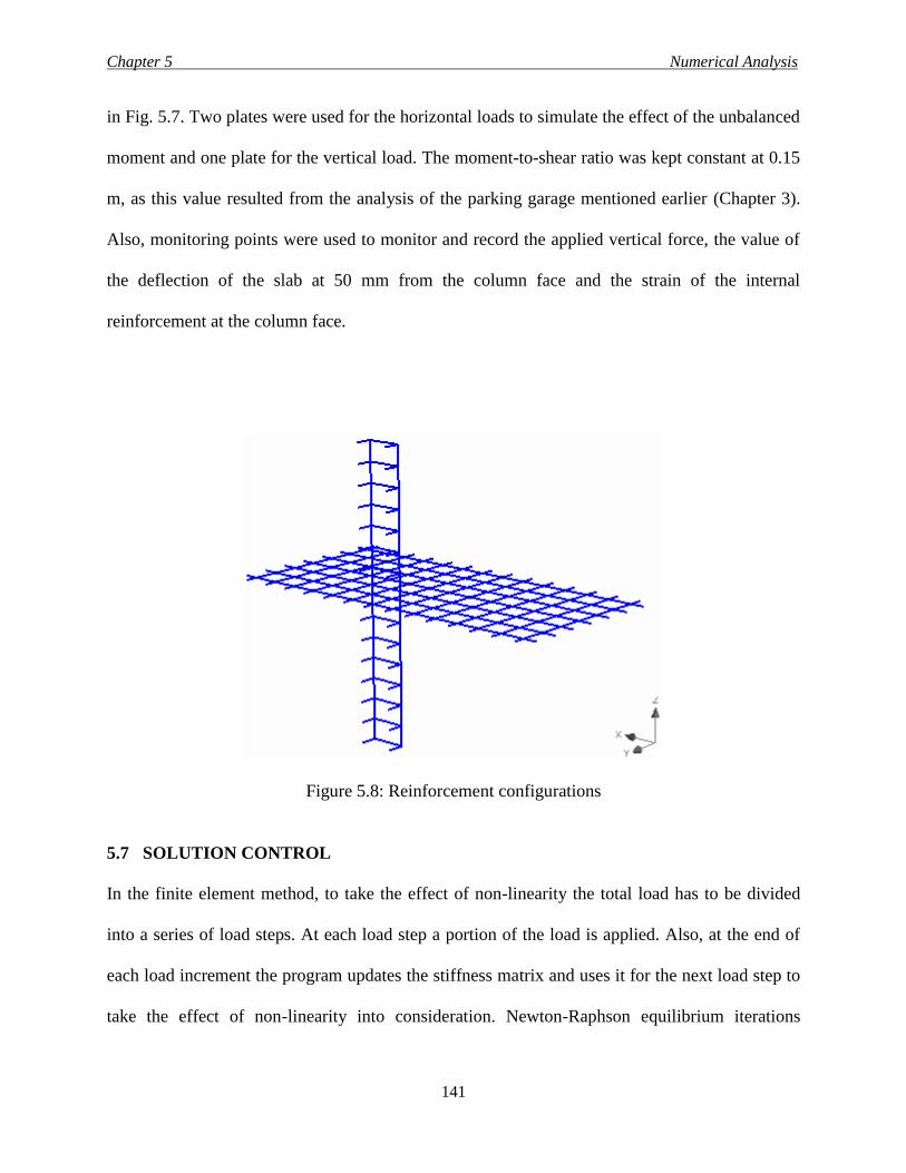
Chapter 5 Numerical Analysis
141
in Fig. 5.7. Two plates were used for the horizontal loads to simulate the effect of the unbalanced
moment and one plate for the vertical load. The moment-to-shear ratio was kept constant at 0.15
m, as this value resulted from the analysis of the parking garage mentioned earlier (Chapter 3).
Also, monitoring points were used to monitor and record the applied vertical force, the value of
the deflection of the slab at 50 mm from the column face and the strain of the internal
reinforcement at the column face.
Figure 5.8: Reinforcement configurations
5.7 SOLUTION CONTROL
In the finite element method, to take the effect of non-linearity the total load has to be divided
into a series of load steps. At each load step a portion of the load is applied. Also, at the end of
each load increment the program updates the stiffness matrix and uses it for the next load step to
take the effect of non-linearity into consideration. Newton-Raphson equilibrium iterations
Chapter 5 Numerical Analysis
142
technique was chosen to be the solver. This technique provides a pre-tolerance limit to be
defined and if the convergence reaches within that tolerance the program will procedure to the
next load step, otherwise, other iterations will be assumed. To achieve that, the program
calculates the out-of-balance load vector, which is defined as the differences between the applied
loads and the forces obtained from the element stresses. Convergence will occur if the out-of-
balance load vector is within the pre-tolerance limit.
5.8 MODEL VERIFICATION
The results from the FE models were verified against the experimental results obtained from the
slab-column connections tested in the experimental part of the research. Four specimens were
chosen for the verification process, connections G-0.65-N-15-XX, G-0.98-N-15-XX, G-1.30-N-
15-XX and G-0.65-H-15-XX. All the slabs in the specimens were reinforced with sand-coated
GFRP bars while all the column were reinforced with steel bars and stirrups. The comparison
was performed with respect to the load- deflection curve, the tensile strains in the GFRP bars and
the failure loads.
Figure 5.9 shows the relationship between the deflection on the horizontal axis and the vertical
load on the vertical axis for the experimental and FEM results. It can be seen that the model was
able to predict the load-deflection response of the experimental results with good accurate. Also,
the model was able to predict the reduction in the stiffness after cracking as shown in the figure.
In the last, the model failed within 2 to 5% less than the experimental failure loads.
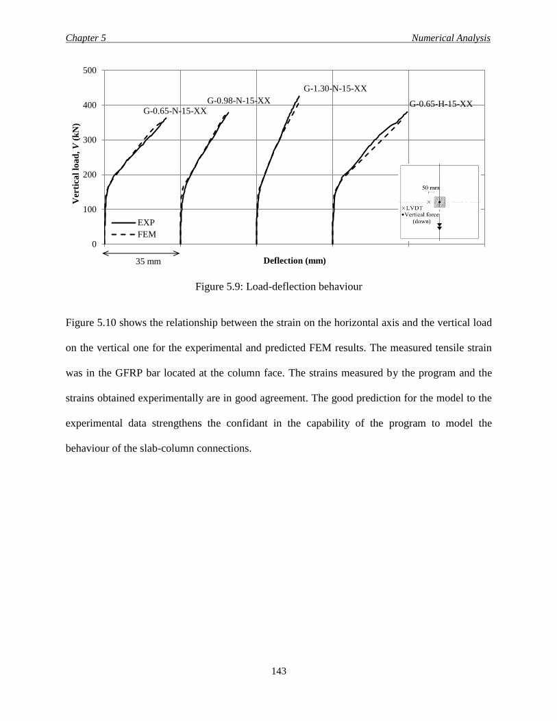
Chapter 5 Numerical Analysis
143
Figure 5.9: Load-deflection behaviour
Figure 5.10 shows the relationship between the strain on the horizontal axis and the vertical load
on the vertical one for the experimental and predicted FEM results. The measured tensile strain
was in the GFRP bar located at the column face. The strains measured by the program and the
strains obtained experimentally are in good agreement. The good prediction for the model to the
experimental data strengthens the confidant in the capability of the program to model the
behaviour of the slab-column connections.
0
100
200
300
400
500V
erti
cal
loa
d, V
(k
N)
Deflection (mm)
EXP
FEM
G-0.65-N-15-XX G-0.98-N-15-XX
G-1.30-N-15-XX
G-0.65-H-15-XX
35 mm
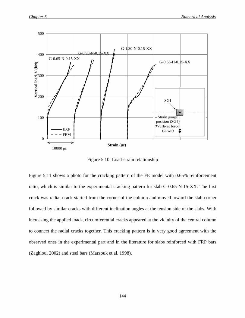
Chapter 5 Numerical Analysis
144
Figure 5.10: Load-strain relationship
Figure 5.11 shows a photo for the cracking pattern of the FE model with 0.65% reinforcement
ratio, which is similar to the experimental cracking pattern for slab G-0.65-N-15-XX. The first
crack was radial crack started from the corner of the column and moved toward the slab-corner
followed by similar cracks with different inclination angles at the tension side of the slabs. With
increasing the applied loads, circumferential cracks appeared at the vicinity of the central column
to connect the radial cracks together. This cracking pattern is in very good agreement with the
observed ones in the experimental part and in the literature for slabs reinforced with FRP bars
(Zaghloul 2002) and steel bars (Marzouk et al. 1998).
0
100
200
300
400
500V
erti
cal
loa
d, V
(k
N)
Strain (μɛ)
EXP
FEM
G-0.65-N-0.15-XX
G-0.98-N-0.15-XX
G-1.30-N-0.15-XX
G-0.65-H-0.15-XX
10000 μɛ
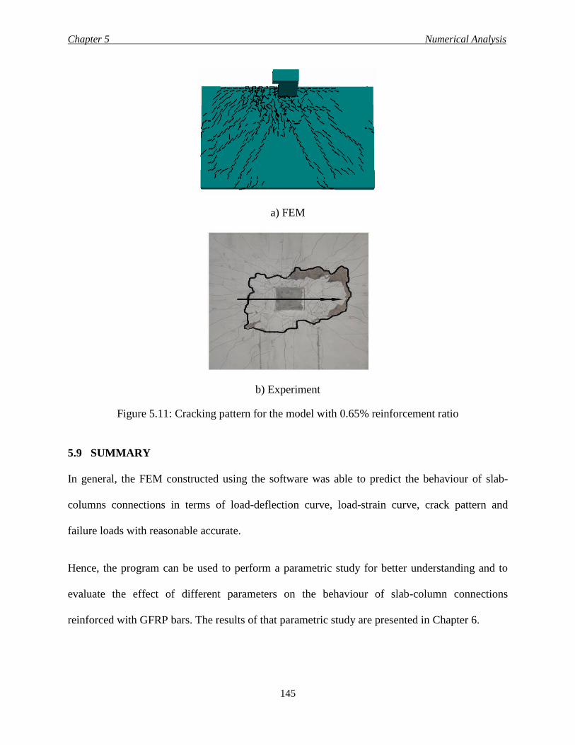
Chapter 5 Numerical Analysis
145
a) FEM
b) Experiment
Figure 5.11: Cracking pattern for the model with 0.65% reinforcement ratio
5.9 SUMMARY
In general, the FEM constructed using the software was able to predict the behaviour of slab-
columns connections in terms of load-deflection curve, load-strain curve, crack pattern and
failure loads with reasonable accurate.
Hence, the program can be used to perform a parametric study for better understanding and to
evaluate the effect of different parameters on the behaviour of slab-column connections
reinforced with GFRP bars. The results of that parametric study are presented in Chapter 6.
Chapter 6 Parametric Study
146
CHAPTER 6
PARAMETRIC STUDY
6.1 INTRODUCTION
Finite element method is the process of subdividing all systems into their individual components,
or elements, whose behaviour is really understood then rebuilding the original system from such
components to use a finite number of well-defined components. The FEM has been used widely
to study the effect of different parameters on the behaviour of concrete structure elements,
mainly, to overcome the financial problems associated with casting and testing full scale
specimens in the lab.
This part of the research investigated the effect of four main parameters on the behaviour of slab-
column connections reinforced with GFRP bars using the verified model described in Chapter 5.
The discussed parameters were 1) a wide range of flexural reinforcement ratios (between 0.5 ρb
and 4.0 ρb, with 0.5 ρb increments). 2) shear perimeter-to-depth ratio (11.5, 15.25 and 19
corresponding to square column cross section with side dimension of 300, 450 and 600 mm and
effective slab depth of 160 mm. 3) column aspect ratios (between 1.0 and 5.0). 4) slab thickness
(between 200 and 350 mm).
The analytical study was based on the materials properties and geometry of specimen G-0.65-N-
15-XX, which was verified in the previous chapter. Specimen G-0.65-N-15-XX is the control
sand-coated GFRP specimen in the experimental part in the current research.
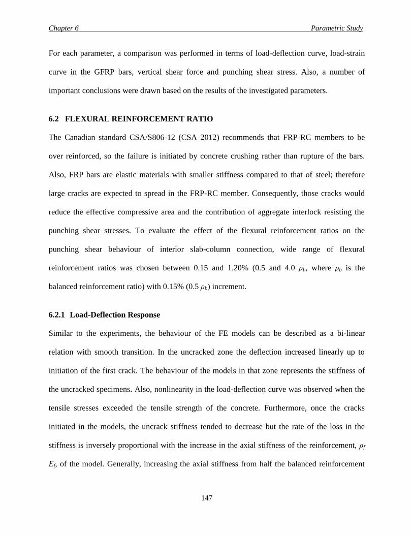
Chapter 6 Parametric Study
147
For each parameter, a comparison was performed in terms of load-deflection curve, load-strain
curve in the GFRP bars, vertical shear force and punching shear stress. Also, a number of
important conclusions were drawn based on the results of the investigated parameters.
6.2 FLEXURAL REINFORCEMENT RATIO
The Canadian standard CSA/S806-12 (CSA 2012) recommends that FRP-RC members to be
over reinforced, so the failure is initiated by concrete crushing rather than rupture of the bars.
Also, FRP bars are elastic materials with smaller stiffness compared to that of steel; therefore
large cracks are expected to spread in the FRP-RC member. Consequently, those cracks would
reduce the effective compressive area and the contribution of aggregate interlock resisting the
punching shear stresses. To evaluate the effect of the flexural reinforcement ratios on the
punching shear behaviour of interior slab-column connection, wide range of flexural
reinforcement ratios was chosen between 0.15 and 1.20% (0.5 and 4.0 ρb, where ρb is the
balanced reinforcement ratio) with 0.15% (0.5 ρb) increment.
6.2.1 Load-Deflection Response
Similar to the experiments, the behaviour of the FE models can be described as a bi-linear
relation with smooth transition. In the uncracked zone the deflection increased linearly up to
initiation of the first crack. The behaviour of the models in that zone represents the stiffness of
the uncracked specimens. Also, nonlinearity in the load-deflection curve was observed when the
tensile stresses exceeded the tensile strength of the concrete. Furthermore, once the cracks
initiated in the models, the uncrack stiffness tended to decrease but the rate of the loss in the
stiffness is inversely proportional with the increase in the axial stiffness of the reinforcement, ρf
Ef, of the model. Generally, increasing the axial stiffness from half the balanced reinforcement
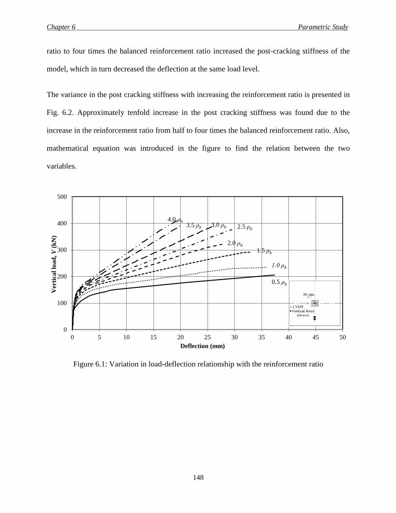
Chapter 6 Parametric Study
148
ratio to four times the balanced reinforcement ratio increased the post-cracking stiffness of the
model, which in turn decreased the deflection at the same load level.
The variance in the post cracking stiffness with increasing the reinforcement ratio is presented in
Fig. 6.2. Approximately tenfold increase in the post cracking stiffness was found due to the
increase in the reinforcement ratio from half to four times the balanced reinforcement ratio. Also,
mathematical equation was introduced in the figure to find the relation between the two
variables.
Figure 6.1: Variation in load-deflection relationship with the reinforcement ratio
0
100
200
300
400
500
0 5 10 15 20 25 30 35 40 45 50
Ver
tica
l lo
ad
, V
(k
N)
Deflection (mm)
0.5 ρb
1.0 ρb
1.5 ρb
2.0 ρb
2.5 ρb 3.0 ρb 3.5 ρb
4.0 ρb
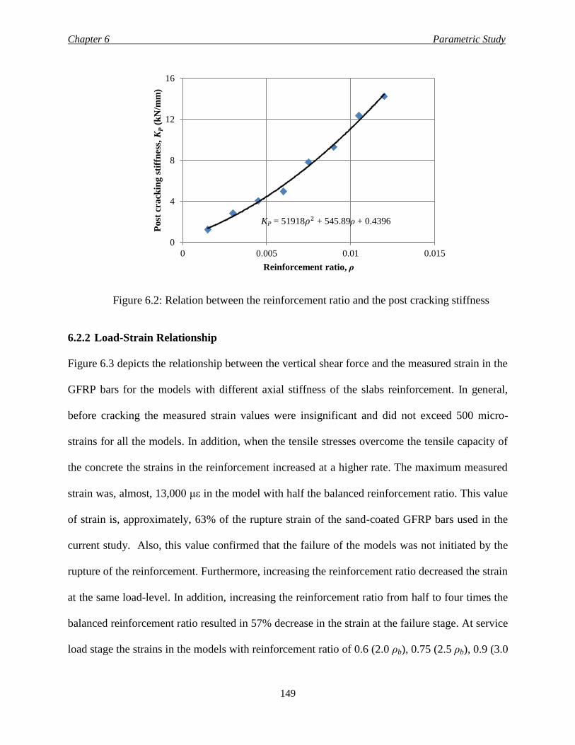
Chapter 6 Parametric Study
149
Figure 6.2: Relation between the reinforcement ratio and the post cracking stiffness
6.2.2 Load-Strain Relationship
Figure 6.3 depicts the relationship between the vertical shear force and the measured strain in the
GFRP bars for the models with different axial stiffness of the slabs reinforcement. In general,
before cracking the measured strain values were insignificant and did not exceed 500 micro-
strains for all the models. In addition, when the tensile stresses overcome the tensile capacity of
the concrete the strains in the reinforcement increased at a higher rate. The maximum measured
strain was, almost, 13,000 με in the model with half the balanced reinforcement ratio. This value
of strain is, approximately, 63% of the rupture strain of the sand-coated GFRP bars used in the
current study. Also, this value confirmed that the failure of the models was not initiated by the
rupture of the reinforcement. Furthermore, increasing the reinforcement ratio decreased the strain
at the same load-level. In addition, increasing the reinforcement ratio from half to four times the
balanced reinforcement ratio resulted in 57% decrease in the strain at the failure stage. At service
load stage the strains in the models with reinforcement ratio of 0.6 (2.0 ρb), 0.75 (2.5 ρb), 0.9 (3.0
0
4
8
12
16
0 0.005 0.01 0.015
Po
st c
ra
ckin
g s
tiff
nes
s, K
P (
kN
/mm
)
Reinforcement ratio, ρ
KP = 51918𝜌2 + 545.89ρ + 0.4396
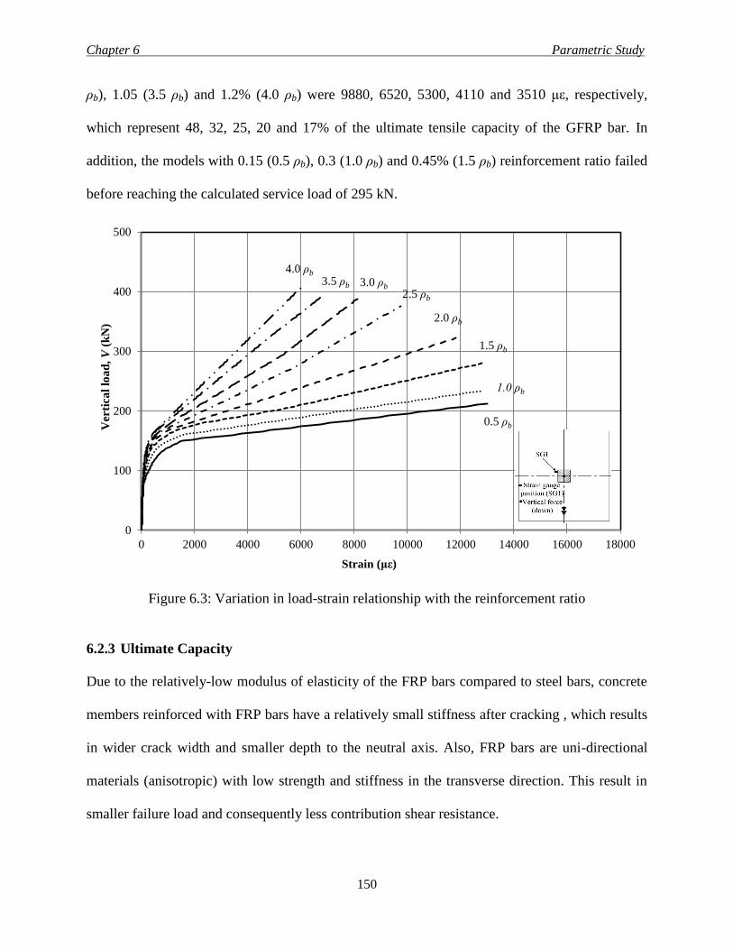
Chapter 6 Parametric Study
150
ρb), 1.05 (3.5 ρb) and 1.2% (4.0 ρb) were 9880, 6520, 5300, 4110 and 3510 με, respectively,
which represent 48, 32, 25, 20 and 17% of the ultimate tensile capacity of the GFRP bar. In
addition, the models with 0.15 (0.5 ρb), 0.3 (1.0 ρb) and 0.45% (1.5 ρb) reinforcement ratio failed
before reaching the calculated service load of 295 kN.
Figure 6.3: Variation in load-strain relationship with the reinforcement ratio
6.2.3 Ultimate Capacity
Due to the relatively-low modulus of elasticity of the FRP bars compared to steel bars, concrete
members reinforced with FRP bars have a relatively small stiffness after cracking , which results
in wider crack width and smaller depth to the neutral axis. Also, FRP bars are uni-directional
materials (anisotropic) with low strength and stiffness in the transverse direction. This result in
smaller failure load and consequently less contribution shear resistance.
0
100
200
300
400
500
0 2000 4000 6000 8000 10000 12000 14000 16000 18000
Ver
tica
l lo
ad
, V
(k
N)
Strain (με)
0.5 ρb
1.0 ρb
1.5 ρb
2.0 ρb
2.5 ρb 3.0 ρb 3.5 ρb
4.0 ρb
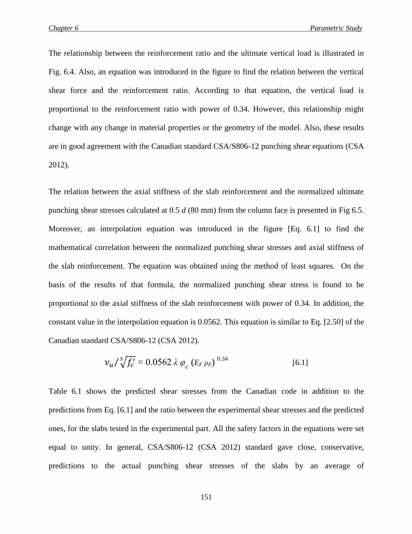
Chapter 6 Parametric Study
151
The relationship between the reinforcement ratio and the ultimate vertical load is illustrated in
Fig. 6.4. Also, an equation was introduced in the figure to find the relation between the vertical
shear force and the reinforcement ratio. According to that equation, the vertical load is
proportional to the reinforcement ratio with power of 0.34. However, this relationship might
change with any change in material properties or the geometry of the model. Also, these results
are in good agreement with the Canadian standard CSA/S806-12 punching shear equations (CSA
2012).
The relation between the axial stiffness of the slab reinforcement and the normalized ultimate
punching shear stresses calculated at 0.5 d (80 mm) from the column face is presented in Fig 6.5.
Moreover, an interpolation equation was introduced in the figure [Eq. 6.1] to find the
mathematical correlation between the normalized punching shear stresses and axial stiffness of
the slab reinforcement. The equation was obtained using the method of least squares. On the
basis of the results of that formula, the normalized punching shear stress is found to be
proportional to the axial stiffness of the slab reinforcement with power of 0.34. In addition, the
constant value in the interpolation equation is 0.0562. This equation is similar to Eq. [2.50] of the
Canadian standard CSA/S806-12 (CSA 2012).
𝜈𝑢 √𝑓𝑐′3⁄ = 0.0562 λ φ
c (EF ρF)
0.34 [6.1]
Table 6.1 shows the predicted shear stresses from the Canadian code in addition to the
predictions from Eq. [6.1] and the ratio between the experimental shear stresses and the predicted
ones, for the slabs tested in the experimental part. All the safety factors in the equations were set
equal to unity. In general, CSA/S806-12 (CSA 2012) standard gave close, conservative,
predictions to the actual punching shear stresses of the slabs by an average of
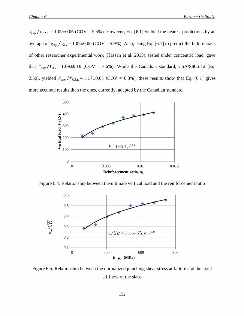
Chapter 6 Parametric Study
152
νexp. ν CSA.⁄ = 1.09±0.06 (COV = 5.5%). However, Eq. [6.1] yielded the nearest predictions by an
average of νexp. ν6.1⁄ = 1.02±0.06 (COV = 5.9%). Also, using Eq. [6.1] to predict the failure loads
of other researcher experimental work (Hassan et al. 2013), tested under concentric load, gave
that Vexp. V6.1⁄ = 1.09±0.10 (COV = 7.6%). While the Canadian standard, CSA/S806-12 [Eq.
2.50], yielded Vexp. VCSA.⁄ = 1.17±0.08 (COV = 6.8%). these results show that Eq. [6.1] gives
more accurate results than the ones, currently, adapted by the Canadian standard.
Figure 6.4: Relationship between the ultimate vertical load and the reinforcement ratio
Figure 6.5: Relationship between the normalized punching shear stress at failure and the axial
stiffness of the slabs
0
100
200
300
400
500
0 0.005 0.01 0.015
Ver
tica
l lo
ad
, V
(k
N)
Reinforcement ratio, ρF
0.1
0.2
0.3
0.4
0.5
0.6
0 300 600 900
EF ρF (MPa)
V = 1862.3 𝜌𝐹0.34
𝝂𝒖
√𝒇𝒄′
𝟑⁄
𝜈𝑢 √𝑓𝑐′3⁄ = 0.0562 (EF ρF)
0.34
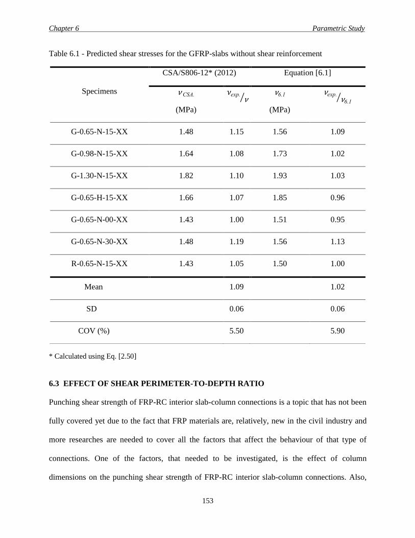
Chapter 6 Parametric Study
153
Table 6.1 - Predicted shear stresses for the GFRP-slabs without shear reinforcement
Specimens
CSA/S806-12* (2012) Equation [6.1]
ν CSA.
(MPa)
𝜈exp.ν CSA.
⁄ ν6.1
(MPa)
νexp.ν6.1
⁄
G-0.65-N-15-XX 1.48 1.15 1.56 1.09
G-0.98-N-15-XX 1.64 1.08 1.73 1.02
G-1.30-N-15-XX 1.82 1.10 1.93 1.03
G-0.65-H-15-XX 1.66 1.07 1.85 0.96
G-0.65-N-00-XX 1.43 1.00 1.51 0.95
G-0.65-N-30-XX 1.48 1.19 1.56 1.13
R-0.65-N-15-XX 1.43 1.05 1.50 1.00
Mean 1.09 1.02
SD 0.06 0.06
COV (%) 5.50 5.90
* Calculated using Eq. [2.50]
6.3 EFFECT OF SHEAR PERIMETER-TO-DEPTH RATIO
Punching shear strength of FRP-RC interior slab-column connections is a topic that has not been
fully covered yet due to the fact that FRP materials are, relatively, new in the civil industry and
more researches are needed to cover all the factors that affect the behaviour of that type of
connections. One of the factors, that needed to be investigated, is the effect of column
dimensions on the punching shear strength of FRP-RC interior slab-column connections. Also,
Chapter 6 Parametric Study
154
the effect of the unbalanced moment gives more complexity to the punching shear problem. That
unbalanced moment can occur due to different loading pattern and/or different span lengths.
Also, the available literature shows that Zaghloul (2002) studied the effect of the unbalanced
moment on half-scale interior slab-column connections reinforced with carbon FRP grids. In the
current research three specimens with different square column cross sections were chosen to
evaluate the effect of shear perimeter-to-depth ratio on the behaviour of such connection. Shear
perimeter-to-depth ratio of 11.5, 15.25 and 19 corresponding to square column cross section with
side dimension of 300, 450 and 600 mm was investigated. The effective slab depth and
reinforcement ratio were 160 mm and 0.65%, respectively.
6.3.1 Load-Deflection Response
Figure 6.6 presents the relation between the vertical load and the measured deflection at 50 mm
from the column face. Generally, the behaviour of the models is similar to that illustrated earlier
in the “flexural reinforcement ratio” section. The specimen with perimeter-to-depth ratio of 11.5
experienced the lowest failure load and post cracking stiffness. Also, as the dimensions of the
column increased, considerable improvement was observed in the failure load and the deflection
at the same load level. At the service load stage, increasing the perimeter-to-depth ratio from
11.5 to 19 resulted in 33% reduction in the deflection. In addition, it seems that increasing the
column cross section increased the degree of nonlinearity of the model at failure. Furthermore,
the post cracking stiffness increased as evidence in Fig. 6.7. This is due to that the increase in the
dimensions of the column increased the overall stiffness of the connection. Moreover, an
equation was presented in Fig. 6.7 to find the mathematical correlation between the post cracking
stiffness and the perimeter-to-depth ratio.
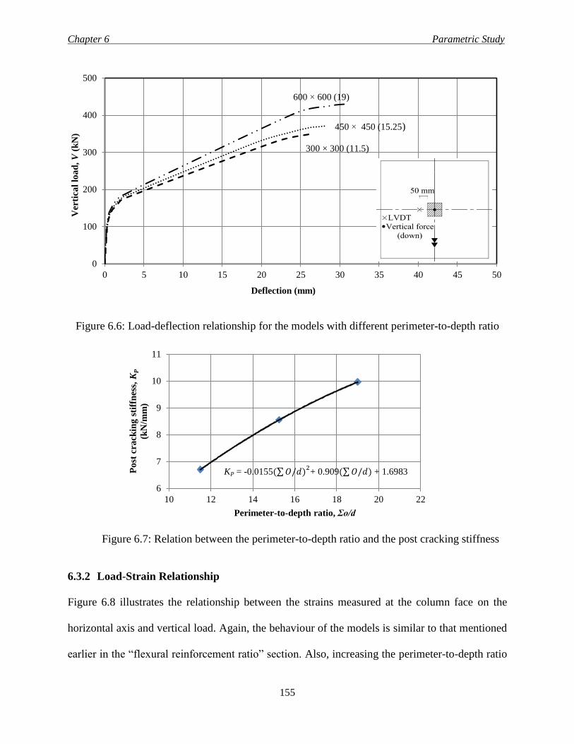
Chapter 6 Parametric Study
155
Figure 6.6: Load-deflection relationship for the models with different perimeter-to-depth ratio
Figure 6.7: Relation between the perimeter-to-depth ratio and the post cracking stiffness
6.3.2 Load-Strain Relationship
Figure 6.8 illustrates the relationship between the strains measured at the column face on the
horizontal axis and vertical load. Again, the behaviour of the models is similar to that mentioned
earlier in the “flexural reinforcement ratio” section. Also, increasing the perimeter-to-depth ratio
0
100
200
300
400
500
0 5 10 15 20 25 30 35 40 45 50
Ver
tica
l lo
ad
, V
(k
N)
Deflection (mm)
450 × 450 (15.25)
600 × 600 (19)
6
7
8
9
10
11
10 12 14 16 18 20 22
Po
st c
ra
ckin
g s
tiff
nes
s, K
P
(kN
/mm
)
Perimeter-to-depth ratio, Σo/d
300 × 300 (11.5)
KP = -0.0155(∑ 𝑂/𝑑)2+ 0.909(∑ 𝑂/𝑑) + 1.6983
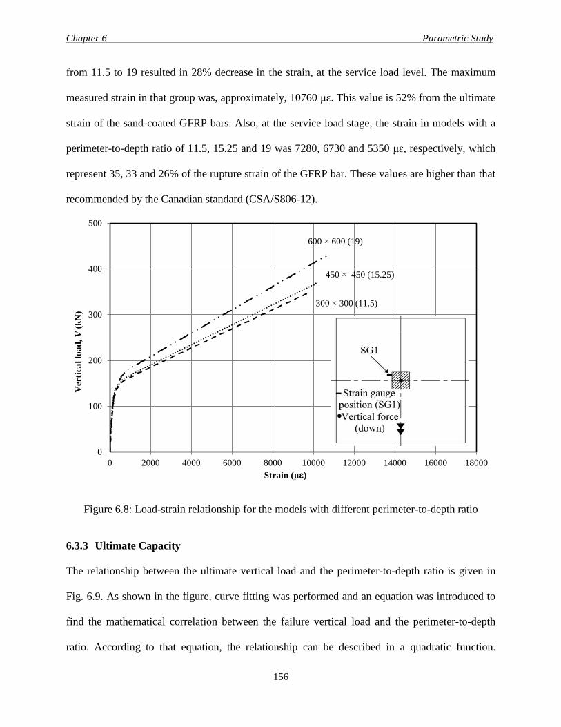
Chapter 6 Parametric Study
156
from 11.5 to 19 resulted in 28% decrease in the strain, at the service load level. The maximum
measured strain in that group was, approximately, 10760 μɛ. This value is 52% from the ultimate
strain of the sand-coated GFRP bars. Also, at the service load stage, the strain in models with a
perimeter-to-depth ratio of 11.5, 15.25 and 19 was 7280, 6730 and 5350 μɛ, respectively, which
represent 35, 33 and 26% of the rupture strain of the GFRP bar. These values are higher than that
recommended by the Canadian standard (CSA/S806-12).
Figure 6.8: Load-strain relationship for the models with different perimeter-to-depth ratio
6.3.3 Ultimate Capacity
The relationship between the ultimate vertical load and the perimeter-to-depth ratio is given in
Fig. 6.9. As shown in the figure, curve fitting was performed and an equation was introduced to
find the mathematical correlation between the failure vertical load and the perimeter-to-depth
ratio. According to that equation, the relationship can be described in a quadratic function.
0
100
200
300
400
500
0 2000 4000 6000 8000 10000 12000 14000 16000 18000
Ver
tica
l lo
ad
, V
(k
N)
Strain (μɛ)
300 × 300 (11.5)
450 × 450 (15.25)
600 × 600 (19)
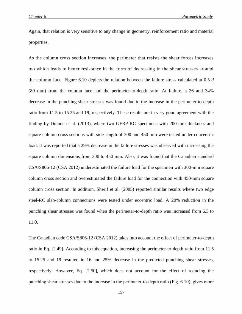
Chapter 6 Parametric Study
157
Again, that relation is very sensitive to any change in geometry, reinforcement ratio and material
properties.
As the column cross section increases, the perimeter that resists the shear forces increases
too which leads to better resistance in the form of decreasing in the shear stresses around
the column face. Figure 6.10 depicts the relation between the failure stress calculated at 0.5 d
(80 mm) from the column face and the perimeter-to-depth ratio. At failure, a 26 and 34%
decrease in the punching shear stresses was found due to the increase in the perimeter-to-depth
ratio from 11.5 to 15.25 and 19, respectively. These results are in very good agreement with the
finding by Dulude et al. (2013), where two GFRP-RC specimens with 200-mm thickness and
square column cross sections with side length of 300 and 450 mm were tested under concentric
load. It was reported that a 29% decrease in the failure stresses was observed with increasing the
square column dimensions from 300 to 450 mm. Also, it was found that the Canadian standard
CSA/S806-12 (CSA 2012) underestimated the failure load for the specimen with 300-mm square
column cross section and overestimated the failure load for the connection with 450-mm square
column cross section. In addition, Sherif et al. (2005) reported similar results where two edge
steel-RC slab-column connections were tested under eccentric load. A 20% reduction in the
punching shear stresses was found when the perimeter-to-depth ratio was increased from 6.5 to
11.0.
The Canadian code CSA/S806-12 (CSA 2012) takes into account the effect of perimeter-to-depth
ratio in Eq. [2.49]. According to this equation, increasing the perimeter-to-depth ratio from 11.5
to 15.25 and 19 resulted in 16 and 25% decrease in the predicted punching shear stresses,
respectively. However, Eq. [2.50], which does not account for the effect of reducing the
punching shear stresses due to the increase in the perimeter-to-depth ratio (Fig. 6.10), gives more
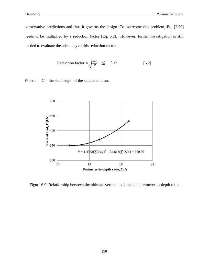
Chapter 6 Parametric Study
158
conservative predictions and thus it governs the design. To overcome this problem, Eq. [2.50]
needs to be multiplied by a reduction factor [Eq. 6.2]. However, further investigation is still
needed to evaluate the adequacy of this reduction factor.
Reduction factor = √300
𝐶 ≤ 1.0 [6.2]
Where: C = the side length of the square column.
Figure 6.9: Relationship between the ultimate vertical load and the perimeter-to-depth ratio
300
350
400
450
500
10 14 18 22
Ver
tica
l lo
ad
, V
(k
N)
Perimeter-to-depth ratio, Σo/d
V = 1.4933(∑ 𝑂/𝑑)2 – 34.613(∑ 𝑂/𝑑) + 550.56
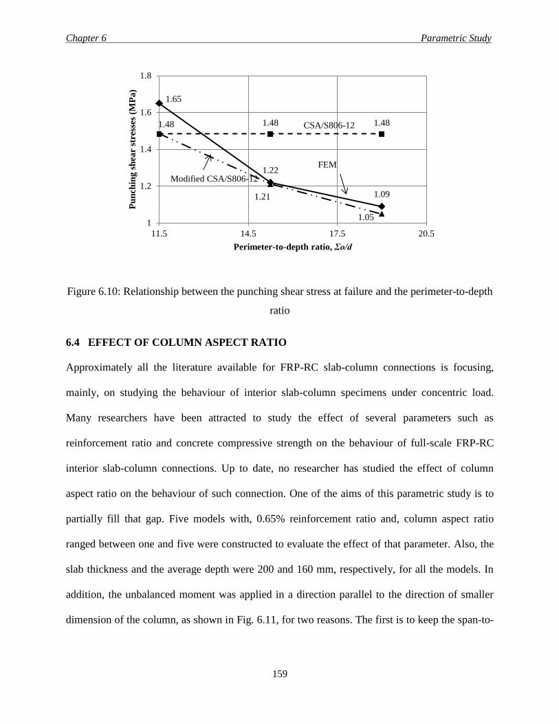
Chapter 6 Parametric Study
159
Figure 6.10: Relationship between the punching shear stress at failure and the perimeter-to-depth
ratio
6.4 EFFECT OF COLUMN ASPECT RATIO
Approximately all the literature available for FRP-RC slab-column connections is focusing,
mainly, on studying the behaviour of interior slab-column specimens under concentric load.
Many researchers have been attracted to study the effect of several parameters such as
reinforcement ratio and concrete compressive strength on the behaviour of full-scale FRP-RC
interior slab-column connections. Up to date, no researcher has studied the effect of column
aspect ratio on the behaviour of such connection. One of the aims of this parametric study is to
partially fill that gap. Five models with, 0.65% reinforcement ratio and, column aspect ratio
ranged between one and five were constructed to evaluate the effect of that parameter. Also, the
slab thickness and the average depth were 200 and 160 mm, respectively, for all the models. In
addition, the unbalanced moment was applied in a direction parallel to the direction of smaller
dimension of the column, as shown in Fig. 6.11, for two reasons. The first is to keep the span-to-
1.65
1.22
1.09
1.48 1.48 1.48
1.21
1.05 1
1.2
1.4
1.6
1.8
11.5 14.5 17.5 20.5
Pu
nch
ing
sh
ear
stre
sses
(M
Pa
)
Perimeter-to-depth ratio, Σo/d
CSA/S806-12
Modified CSA/S806-12
FEM
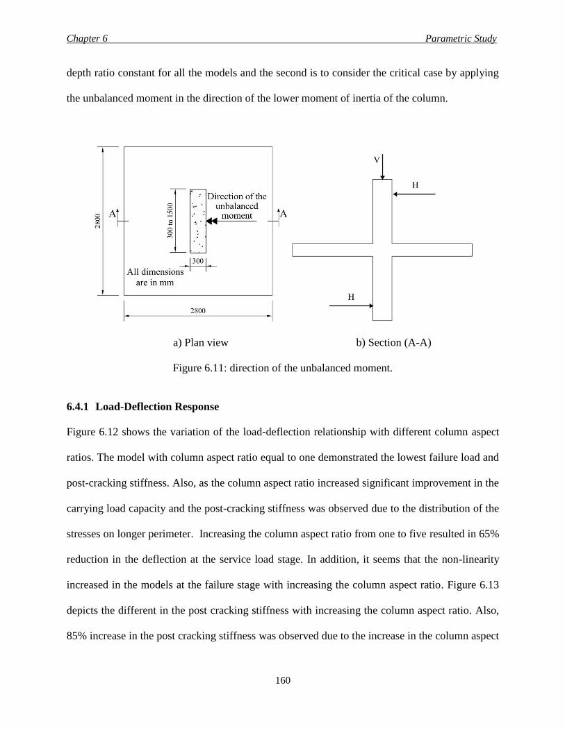
Chapter 6 Parametric Study
160
depth ratio constant for all the models and the second is to consider the critical case by applying
the unbalanced moment in the direction of the lower moment of inertia of the column.
a) Plan view b) Section (A-A)
Figure 6.11: direction of the unbalanced moment.
6.4.1 Load-Deflection Response
Figure 6.12 shows the variation of the load-deflection relationship with different column aspect
ratios. The model with column aspect ratio equal to one demonstrated the lowest failure load and
post-cracking stiffness. Also, as the column aspect ratio increased significant improvement in the
carrying load capacity and the post-cracking stiffness was observed due to the distribution of the
stresses on longer perimeter. Increasing the column aspect ratio from one to five resulted in 65%
reduction in the deflection at the service load stage. In addition, it seems that the non-linearity
increased in the models at the failure stage with increasing the column aspect ratio. Figure 6.13
depicts the different in the post cracking stiffness with increasing the column aspect ratio. Also,
85% increase in the post cracking stiffness was observed due to the increase in the column aspect
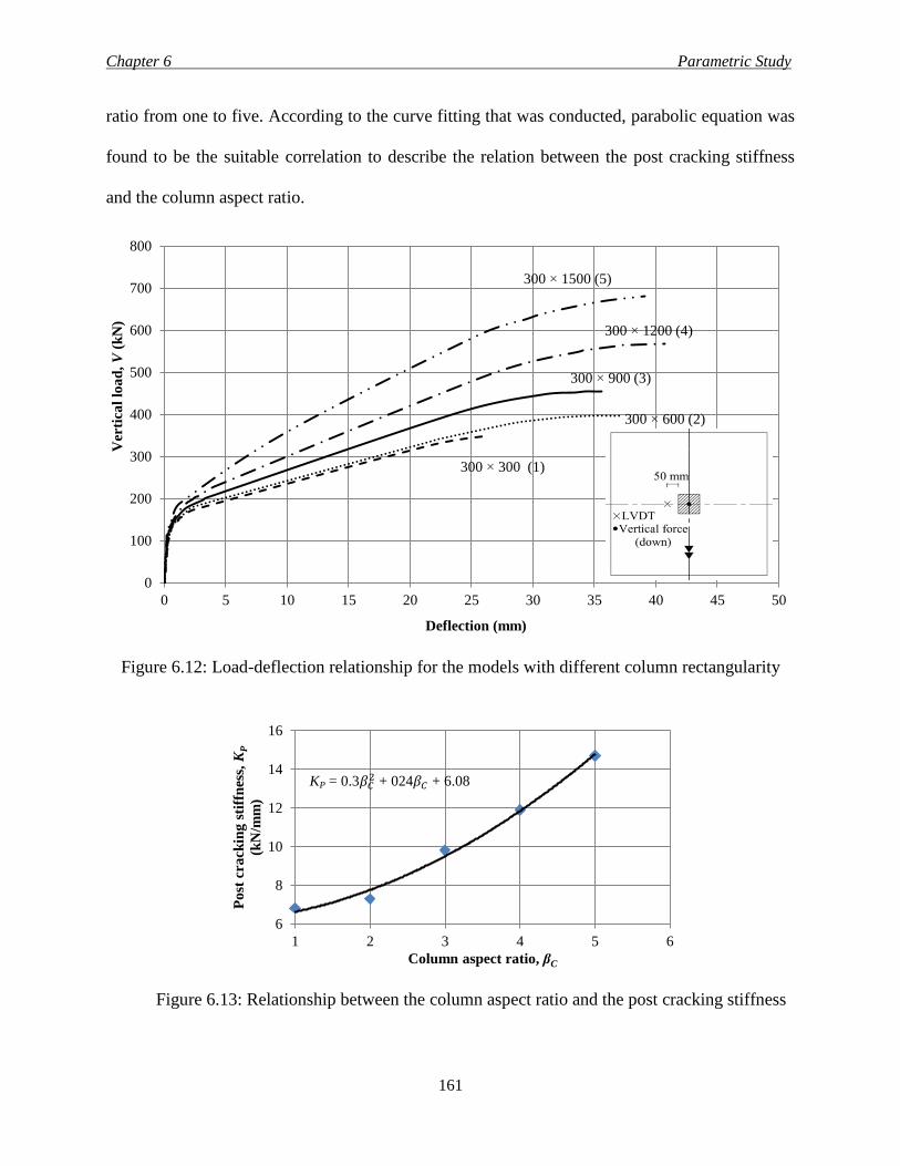
Chapter 6 Parametric Study
161
ratio from one to five. According to the curve fitting that was conducted, parabolic equation was
found to be the suitable correlation to describe the relation between the post cracking stiffness
and the column aspect ratio.
Figure 6.12: Load-deflection relationship for the models with different column rectangularity
Figure 6.13: Relationship between the column aspect ratio and the post cracking stiffness
0
100
200
300
400
500
600
700
800
0 5 10 15 20 25 30 35 40 45 50
Ver
tica
l lo
ad
, V
(k
N)
Deflection (mm)
300 × 600 (2)
300 × 900 (3)
300 × 1200 (4)
300 × 1500 (5)
300 × 300 (1)
6
8
10
12
14
16
1 2 3 4 5 6
Po
st c
ra
ckin
g s
tiff
nes
s, K
P
(kN
/mm
)
Column aspect ratio, βC
KP = 0.3𝛽𝐶2 + 024𝛽𝐶 + 6.08
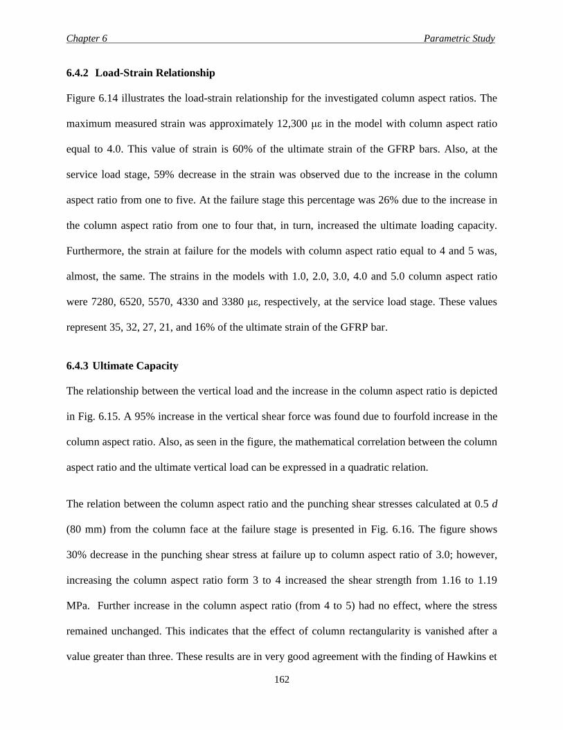
Chapter 6 Parametric Study
162
6.4.2 Load-Strain Relationship
Figure 6.14 illustrates the load-strain relationship for the investigated column aspect ratios. The
maximum measured strain was approximately 12,300 με in the model with column aspect ratio
equal to 4.0. This value of strain is 60% of the ultimate strain of the GFRP bars. Also, at the
service load stage, 59% decrease in the strain was observed due to the increase in the column
aspect ratio from one to five. At the failure stage this percentage was 26% due to the increase in
the column aspect ratio from one to four that, in turn, increased the ultimate loading capacity.
Furthermore, the strain at failure for the models with column aspect ratio equal to 4 and 5 was,
almost, the same. The strains in the models with 1.0, 2.0, 3.0, 4.0 and 5.0 column aspect ratio
were 7280, 6520, 5570, 4330 and 3380 με, respectively, at the service load stage. These values
represent 35, 32, 27, 21, and 16% of the ultimate strain of the GFRP bar.
6.4.3 Ultimate Capacity
The relationship between the vertical load and the increase in the column aspect ratio is depicted
in Fig. 6.15. A 95% increase in the vertical shear force was found due to fourfold increase in the
column aspect ratio. Also, as seen in the figure, the mathematical correlation between the column
aspect ratio and the ultimate vertical load can be expressed in a quadratic relation.
The relation between the column aspect ratio and the punching shear stresses calculated at 0.5 d
(80 mm) from the column face at the failure stage is presented in Fig. 6.16. The figure shows
30% decrease in the punching shear stress at failure up to column aspect ratio of 3.0; however,
increasing the column aspect ratio form 3 to 4 increased the shear strength from 1.16 to 1.19
MPa. Further increase in the column aspect ratio (from 4 to 5) had no effect, where the stress
remained unchanged. This indicates that the effect of column rectangularity is vanished after a
value greater than three. These results are in very good agreement with the finding of Hawkins et
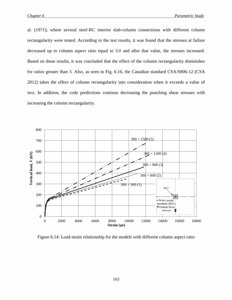
Chapter 6 Parametric Study
163
al. (1971); where several steel-RC interior slab-column connections with different column
rectangularity were tested. According to the test results, it was found that the stresses at failure
decreased up to column aspect ratio equal to 3.0 and after that value, the stresses increased.
Based on these results, it was concluded that the effect of the column rectangularity diminishes
for ratios greater than 3. Also, as seen in Fig. 6.16, the Canadian standard CSA/S806-12 (CSA
2012) takes the effect of column rectangularity into consideration when it exceeds a value of
two. In addition, the code predictions continue decreasing the punching shear stresses with
increasing the column rectangularity.
Figure 6.14: Load-strain relationship for the models with different column aspect ratio
0
100
200
300
400
500
600
700
800
0 2000 4000 6000 8000 10000 12000 14000 16000 18000
Ver
tica
l lo
ad
, V
(k
N)
Strain (με)
300 × 600 (2)
300 × 900 (3)
300 × 1200 (4)
300 × 1500 (5)
300 × 300 (1)
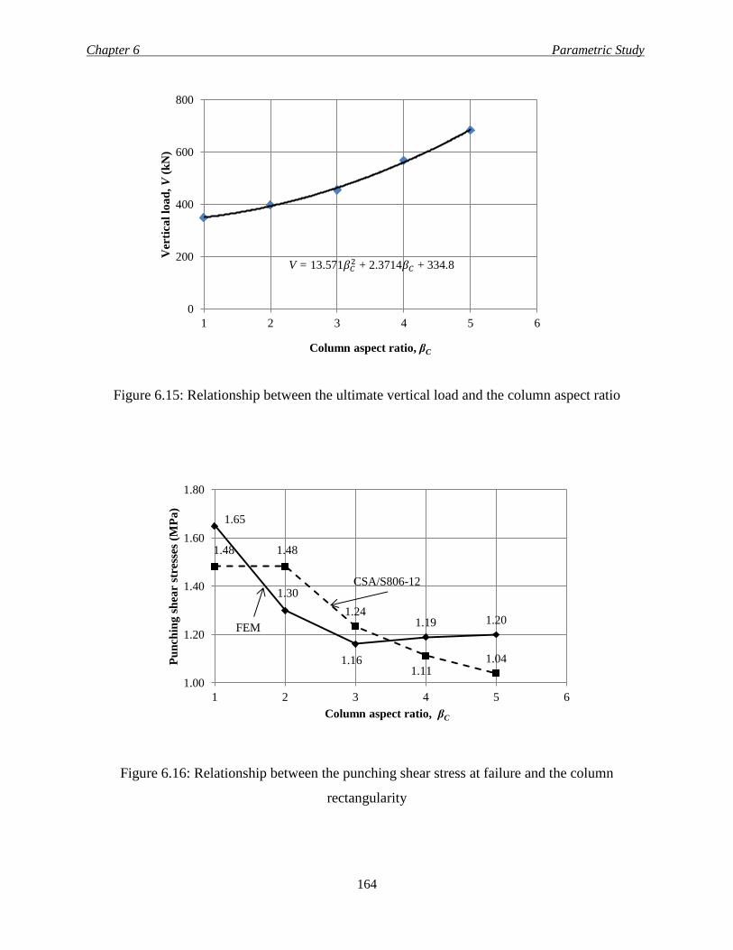
Chapter 6 Parametric Study
164
Figure 6.15: Relationship between the ultimate vertical load and the column aspect ratio
Figure 6.16: Relationship between the punching shear stress at failure and the column
rectangularity
0
200
400
600
800
1 2 3 4 5 6
Ver
tica
l lo
ad
, V
(k
N)
Column aspect ratio, βC
1.65
1.30
1.16
1.19 1.20
1.48 1.48
1.24
1.11 1.04
1.00
1.20
1.40
1.60
1.80
1 2 3 4 5 6
Pu
nch
ing
sh
ear
stre
sses
(M
Pa
)
Column aspect ratio, βC
CSA/S806-12
FEM
V = 13.571𝛽𝐶2 + 2.3714𝛽𝐶 + 334.8
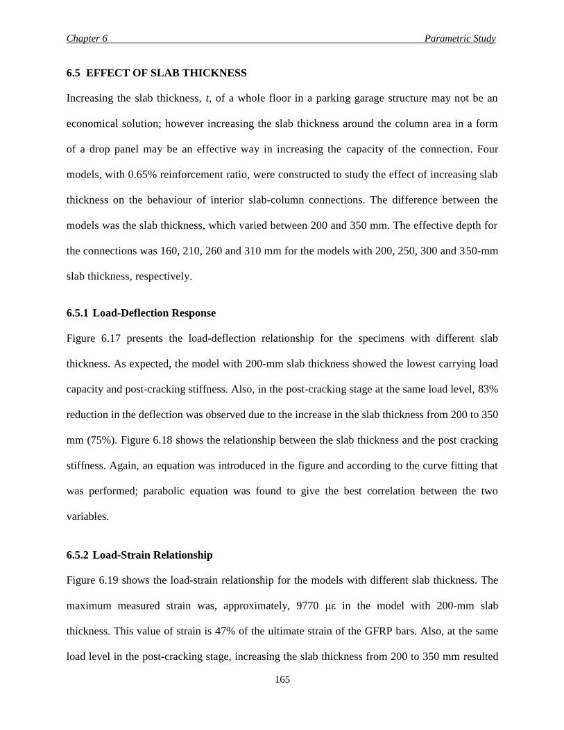
Chapter 6 Parametric Study
165
6.5 EFFECT OF SLAB THICKNESS
Increasing the slab thickness, t, of a whole floor in a parking garage structure may not be an
economical solution; however increasing the slab thickness around the column area in a form
of a drop panel may be an effective way in increasing the capacity of the connection. Four
models, with 0.65% reinforcement ratio, were constructed to study the effect of increasing slab
thickness on the behaviour of interior slab-column connections. The difference between the
models was the slab thickness, which varied between 200 and 350 mm. The effective depth for
the connections was 160, 210, 260 and 310 mm for the models with 200, 250, 300 and 350-mm
slab thickness, respectively.
6.5.1 Load-Deflection Response
Figure 6.17 presents the load-deflection relationship for the specimens with different slab
thickness. As expected, the model with 200-mm slab thickness showed the lowest carrying load
capacity and post-cracking stiffness. Also, in the post-cracking stage at the same load level, 83%
reduction in the deflection was observed due to the increase in the slab thickness from 200 to 350
mm (75%). Figure 6.18 shows the relationship between the slab thickness and the post cracking
stiffness. Again, an equation was introduced in the figure and according to the curve fitting that
was performed; parabolic equation was found to give the best correlation between the two
variables.
6.5.2 Load-Strain Relationship
Figure 6.19 shows the load-strain relationship for the models with different slab thickness. The
maximum measured strain was, approximately, 9770 με in the model with 200-mm slab
thickness. This value of strain is 47% of the ultimate strain of the GFRP bars. Also, at the same
load level in the post-cracking stage, increasing the slab thickness from 200 to 350 mm resulted
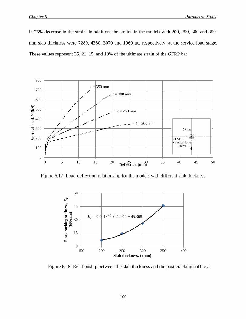
Chapter 6 Parametric Study
166
in 75% decrease in the strain. In addition, the strains in the models with 200, 250, 300 and 350-
mm slab thickness were 7280, 4380, 3070 and 1960 με, respectively, at the service load stage.
These values represent 35, 21, 15, and 10% of the ultimate strain of the GFRP bar.
Figure 6.17: Load-deflection relationship for the models with different slab thickness
Figure 6.18: Relationship between the slab thickness and the post cracking stiffness
0
100
200
300
400
500
600
700
800
0 5 10 15 20 25 30 35 40 45 50
Ver
tica
l lo
ad
, V
(k
N)
Deflection (mm)
t = 200 mm
t = 250 mm
t = 300 mm
t = 350 mm
0
15
30
45
60
150 200 250 300 350 400
Po
st c
ra
ckin
g s
tiff
nes
s, K
P
(kN
/mm
)
Slab thickness, t (mm)
KP = 0.0013𝑡2- 0.4494t + 45.368
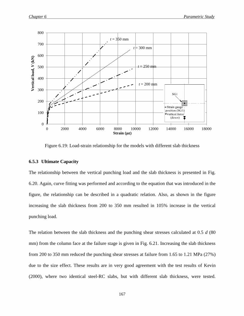
Chapter 6 Parametric Study
167
Figure 6.19: Load-strain relationship for the models with different slab thickness
6.5.3 Ultimate Capacity
The relationship between the vertical punching load and the slab thickness is presented in Fig.
6.20. Again, curve fitting was performed and according to the equation that was introduced in the
figure, the relationship can be described in a quadratic relation. Also, as shown in the figure
increasing the slab thickness from 200 to 350 mm resulted in 105% increase in the vertical
punching load.
The relation between the slab thickness and the punching shear stresses calculated at 0.5 d (80
mm) from the column face at the failure stage is given in Fig. 6.21. Increasing the slab thickness
from 200 to 350 mm reduced the punching shear stresses at failure from 1.65 to 1.21 MPa (27%)
due to the size effect. These results are in very good agreement with the test results of Kevin
(2000), where two identical steel-RC slabs, but with different slab thickness, were tested.
0
100
200
300
400
500
600
700
800
0 2000 4000 6000 8000 10000 12000 14000 16000 18000
Ver
tica
l lo
ad
, V
(k
N)
Strain (με)
t = 300 mm
t = 350 mm
t = 250 mm
t = 200 mm
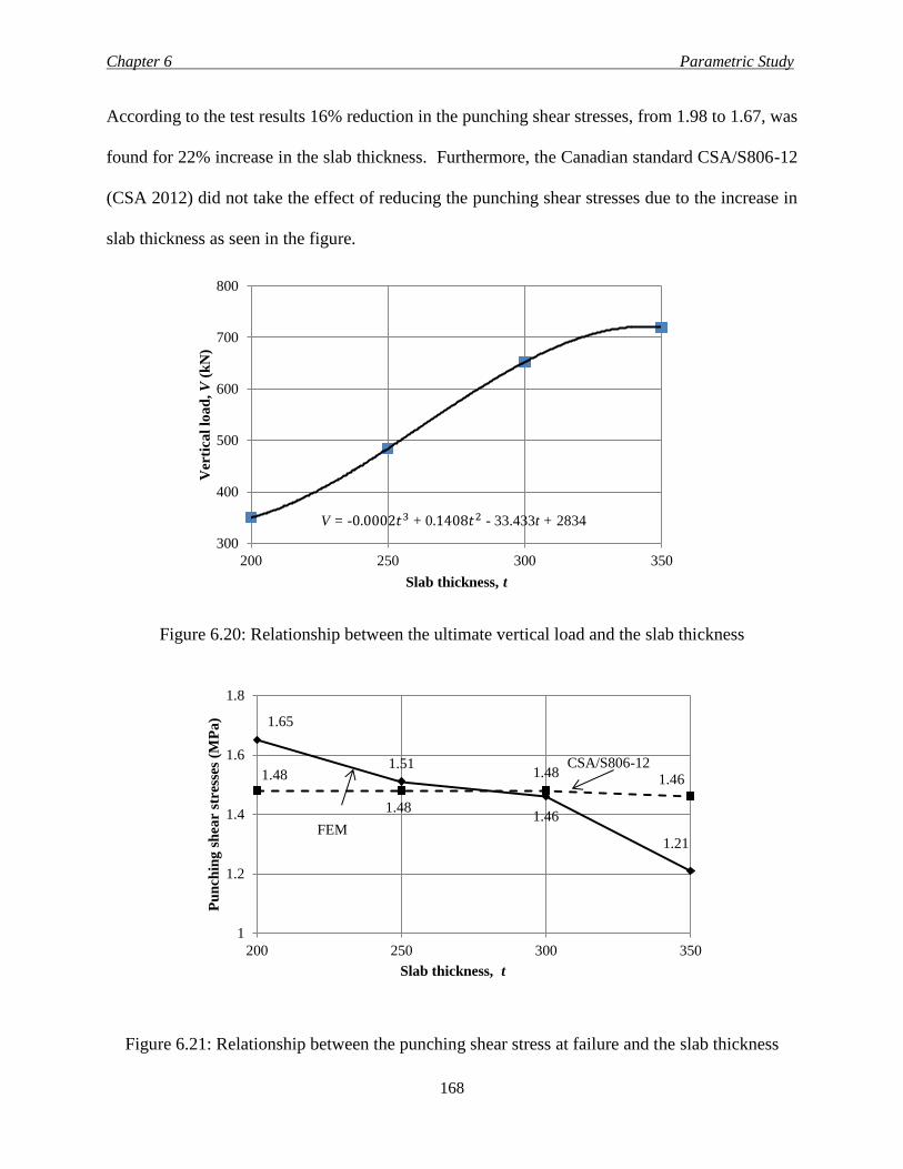
Chapter 6 Parametric Study
168
According to the test results 16% reduction in the punching shear stresses, from 1.98 to 1.67, was
found for 22% increase in the slab thickness. Furthermore, the Canadian standard CSA/S806-12
(CSA 2012) did not take the effect of reducing the punching shear stresses due to the increase in
slab thickness as seen in the figure.
Figure 6.20: Relationship between the ultimate vertical load and the slab thickness
Figure 6.21: Relationship between the punching shear stress at failure and the slab thickness
300
400
500
600
700
800
200 250 300 350
Ver
tica
l lo
ad
, V
(k
N)
Slab thickness, t
V = -0.0002𝑡3 + 0.1408𝑡2 - 33.433t + 2834
1.65
1.51
1.46
1.21
1.48
1.48
1.48 1.46
1
1.2
1.4
1.6
1.8
200 250 300 350
Pu
nch
ing
sh
ear
stre
sses
(M
Pa
)
Slab thickness, t
CSA/S806-12
FEM
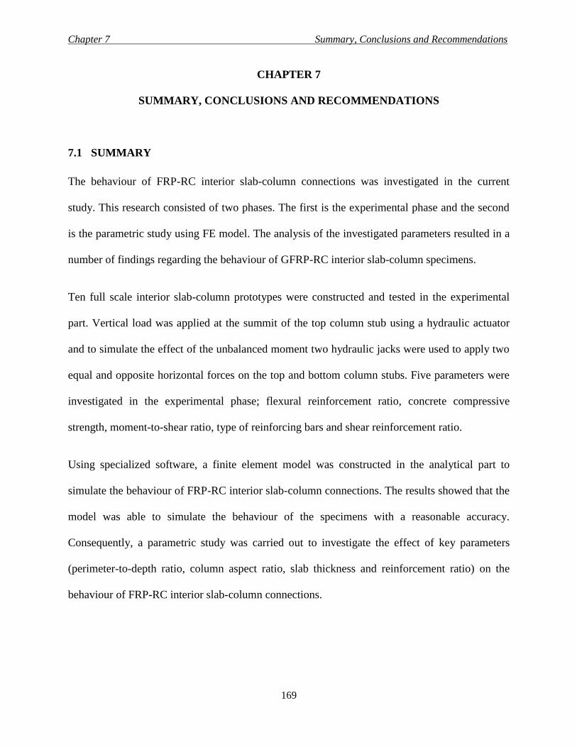
Chapter 7 Summary, Conclusions and Recommendations
169
CHAPTER 7
SUMMARY, CONCLUSIONS AND RECOMMENDATIONS
7.1 SUMMARY
The behaviour of FRP-RC interior slab-column connections was investigated in the current
study. This research consisted of two phases. The first is the experimental phase and the second
is the parametric study using FE model. The analysis of the investigated parameters resulted in a
number of findings regarding the behaviour of GFRP-RC interior slab-column specimens.
Ten full scale interior slab-column prototypes were constructed and tested in the experimental
part. Vertical load was applied at the summit of the top column stub using a hydraulic actuator
and to simulate the effect of the unbalanced moment two hydraulic jacks were used to apply two
equal and opposite horizontal forces on the top and bottom column stubs. Five parameters were
investigated in the experimental phase; flexural reinforcement ratio, concrete compressive
strength, moment-to-shear ratio, type of reinforcing bars and shear reinforcement ratio.
Using specialized software, a finite element model was constructed in the analytical part to
simulate the behaviour of FRP-RC interior slab-column connections. The results showed that the
model was able to simulate the behaviour of the specimens with a reasonable accuracy.
Consequently, a parametric study was carried out to investigate the effect of key parameters
(perimeter-to-depth ratio, column aspect ratio, slab thickness and reinforcement ratio) on the
behaviour of FRP-RC interior slab-column connections.
Chapter 7 Summary, Conclusions and Recommendations
170
7.2 CONCLUSIONS
The following conclusions were drawn based on the discussion presented in Chapters 4 and 6.
7.2.1 Conclusions From the Experimental Phase
Series I:
1- All slabs exhibited a brittle punching shear failure. However, the axial stiffness of slab
reinforcement significantly affects the punching shear capacity and maximum deflections.
Compared to the control steel-RC slab (ρs Es), specimens G-0.65-N-15-XX (0.34 ρs Es), G-
0.98-N-15-XX (0.51 ρs Es) and G-1.30-N-15-XX (0.68 ρs Es), showed 25, 20 and 10% lower
capacity, respectively. Similarly, at service load level, the maximum deflection was
increased by 206, 100 and 52%, respectively.
2- Increasing concrete compressive strength slightly enhanced the punching shear capacity of
the GFRP-RC specimens. Increasing the concrete compressive strength by 67% increased the
punching load and deflection at failure by 4.6 and 21%, respectively.
3- The unbalanced moment increased the deflection and strain in the reinforcing bars. The
increase in the deflection for the GFRP-RC specimens varied between 9-12% and 7-8% at
service and ultimate stages, respectively. Whereas, the corresponding values for the steel-RC
slab were 8 and 13%, respectively.
4- The CSA/S806-12 standard (CSA 2012) and JSCE code (JSCE 1997) gave close predictions
to the experimental loads of the test slabs with an average of Vexp. VCSA.⁄ = 1.10±0.03 (COV
= 2.7%) and Vexp. VJSCE.⁄ = 1.13±0.07 (COV = 6.2%), respectively. However, the ACI
440.1R-06 guideline (ACI 2006) yielded more conservative predictions with an average of
Vexp. VACI.⁄ = 1.93±0.12 (COV = 6.20 %). On the other hand, Zaghloul’s equation (2002)
overestimated the capacity of the slabs by an average of Vexp. VZ.⁄ = 0.86±0.04 (COV =
Chapter 7 Summary, Conclusions and Recommendations
171
4.65%). Even though using the proposed equation [Eq. 4.2] yielded closer results to the
punching capacity of slabs tested under both concentric and eccentric loads, the CSA
equation [Eq. 2.50] may be considered acceptable in its current format.
5- When the actual concrete compressive strength was used, the predicted capacity for the HSC
slab using CSA/S806-12 code (CSA 2012) yielded better results with Vexp. VCSA.⁄ = 1.01.
Therefore, it may be beneficial to extend the 60 MPa limit currently specified by the code.
However, further investigation is still needed to confirm this issue.
Series II and III:
6- All test slabs failed in punching shear characterized by a penetration of the column with part
of the slab through the slab thickness.
7- Increasing the moment-to-shear ratio increased the deflection and reinforcement strain. On
the other hand, increasing the moment-to-shear ratio resulted in a reduction in the vertical
load capacity. A 17 and 32% reduction in the vertical shear force was observed when the
moment-to-shear ratio was increased from 0.0 to 0.15 and 0.3 m, respectively.
8- The presence of GFRP shear studs increased the post-cracking stiffness, deflection at failure,
and the load carrying capacity. The punching load capacity increased by approximately 18
and 23% in slabs with 0.75 d and 0.5 d stud spacing, respectively, compared to slab without
shear studs. However, the GFRP shear studs did not prevent the punching shear failure.
9- The Canadian standard for steel-RC slabs, CSA/A23.3-14 (CSA 2014), requires that the
shear reinforcement to be extended to a distance not less than 2.0 d form the column face.
Based on the results reported in the current study and in literature (Zaghloul 2002 and 2007;
Hassan et al. 2014), it seems that this limit needs to be extended in the case of GFRP-RC
slabs. However, further investigation is still needed to quantify the adequate extent.
Chapter 7 Summary, Conclusions and Recommendations
172
10- For the slabs without shear reinforcement, the Canadian CSA/S806-12 (CSA 2012) and
Japanese JSCE-97 (JSCE 1997) standards yielded close, yet conservative, predictions to the
slab capacity with Vexp. VCSA.⁄ = 1.10±0.09 (COV = 8.2%) and Vexp. VJSCE.⁄ = 1.10±0.11
(COV = 10.0%), respectively. On the other hand, the American guideline ACI 440.1R-06
(ACI 2006) highly underestimated the capacity with Vexp. VACI.⁄ = 1.99±0.17 (COV = 8.6%).
11- For the slabs with shear stud reinforcement, the proposed equations based on revising the
current provisions of the CSA/S806-12 (CSA 2012) showed good agreement with the
experimental failure loads, with Vexp. VCSA.⁄ = 1.16±0.08 (COV = 6.9%); nevertheless, the
proposed strain limit needs further investigation. On the other hand, the proposed
modification to the American guideline ACI 440.1R-06 (ACI 2006) equations, overestimated
the punching capacity of the slabs, with Vexp. VACI.⁄ = 1.75±0.19 (COV = 10.9%), which is
considered in good agreement with the trend of the American guideline provisions.
7.2.2 Conclusions From the Numerical Phase
1- The constructed model was able to predict the behaviour of the slab-column connections in
terms of ultimate capacity, load-deflection curve and load-strain curve with a reasonable
accuracy. The average experimental-to-FEM shear strength ratio was approximately 1.03. In
addition, Eq. [6.1] resulted from the parametric study is similar to that adapted by the
Canadian standards, CSA/S806-12 (CSA 2012) [Eq. 2.50], which emphasis the accuracy of
the finite element model.
2- Increasing the reinforcement ratio from half to four times the balanced reinforcement ratio
reduced the strain and deflection. Furthermore, a 93% increase in the the shear strength of the
slabs was observed due to the increase in the reinforcement ratio by sevenfold, from 0.15 (0.5
ρb) to 1.2% (4.0 ρb).
Chapter 7 Summary, Conclusions and Recommendations
173
3- For the models with the same slab thickness (200 mm) and reinforcement ratio (0.65%),
deflection and strains decreased due to the increase in the side length of the square column.
In addition, the test results showed 26 and 34% decrease in the punching shear stresses at
failure due to 33 and 65% increase in the perimeter-to-depth ratio, respectively. Moreover, a
modification factor for the current governing equation [Eq. 2.50] in the Canadian standard
CSA/S806-12 (CSA 2012) was introduced [Eq. 6.2] to consider this effect; however, further
investigation is still needed to address this issue.
4- Considerable enhancement in the post-cracking stiffness can be noticed due to the increase in
column aspect ratio. In addition, increasing the column aspect ratio from one to five, in
models with identical slab thickness (200 mm) and reinforcement ratio (0.65%), resulted in
95% increase in the punching strength.
5- The effect of column rectangularity vanished after a value greater than three, which agrees
with the results reported in the literature for the steel-RC slabs.
6- Increasing the slab thickness increased the carrying load capacity of the connections. Also,
105% increase in the vertical shear force was found due to the increase in the slab thickness
from 200 to 350 mm (75%) in slabs with 0.65% reinforcement ratio.
7- At service load stage, increasing the reinforcement ratio, slab thickness and column
dimensions reduced the strain and deflection at the same load level. Furthermore, the models
with 0.9, 1.05 and 1.2% reinforcement ratio and the same side length for the square column
(300 mm) in addition to the ones with 0.65% reinforcement ratio and different column aspect
ratio of 4.0 and 5.0, satisfied the Canadian standard CSA/S806-12 (CSA 2012) serviceability
limits. Also, the models with 250, 300 and 350-mm slab thickness, and constant
Chapter 7 Summary, Conclusions and Recommendations
174
reinforcement ratio (0.65%) and column aspect ratio (1.0), met the CSA/S806-12 (CSA
2012) serviceability limits.
7.3 RECOMMENDATIONS
7.3.1 Recommendations for Designers
1- In general, the Canadian standard for FRP-RC structures, CSA/S806-12 (CSA 2012), can
adequately predict the punching shear capacity of interior GFRP-RC slab-column
connections without shear reinforcement and subjected to eccentric loading.
2- The equations proposed in this study, based on modifying the Canadian standard CSA/S806-
12 (CSA 2012), can reasonably predict the carrying load capacity of the slabs with shear
stud reinforcement. However, the allowable strain limit needs further investigations
especially for different GFRP products.
7.3.2 Recommendation for Future Work
1- The current study is limited to interior slab-column connections. In addition, experimental
and analytical studies are needed to investigate the behaviour of edge and corner slab-
column connections.
2- The experimental and analytical work was carried out under the effect of static loads only.
The effect of dynamic load should also be investigated for better understanding for the
behaviour of that type of connections.
3- Since the current study was conducted using GFRP bars. Other studies should be executed to
investigate the behaviour of the slab-column connections reinforced with different types of
bars, such as CFRP and AFRP.
4- More variables are needed to be investigated such as the effect of openings.

Chapter 7 Summary, Conclusions and Recommendations
175
5- The effect of high strength concrete and shear reinforcement need more investigations
especially with higher reinforcement ratio.
References
176
REFERENCES
ACI Committee 318. (2014) “Building Code Requirements for Structural Concrete and
Commentary.” ACI 318-14, American Concrete Institute, Farmington Hills, MI, 524 p.
ACI Committee 318. (2008). "Building Code Requirements for Structural Concrete.” ACI 318-
08 and Commentary, American Concrete Institute, Detroit, MI, 417 p.
ACI Committee 318. (2005). "Building Code Requirements for Structural Concrete.” ACI 318-
05 and Commentary, American Concrete Institute, Detroit, MI, 436 p.
ACI Committee 318. (2002). "Building Code Requirements for Structural Concrete.” ACI 318-
02 and Commentary, American Concrete Institute, Detroit, MI, 430 p.
ACI Committee 318. (1995). "Building Code Requirements for Structural Concrete.” ACI 318-
95 and Commentary, American Concrete Institute, Detroit, MI, 369 p
ACI Committee 318. (1989). "Building Code Requirements for Structural Concrete.” ACI 318-
89 and Commentary, American Concrete Institute, Detroit, MI.
ACI Committee 318. (1983). "Building Code Requirements for Structural Concrete.” ACI 318-
83 and Commentary, American Concrete Institute, Detroit, MI, 111 p.
ACI Committee 440. (2015). "Guide for the Design and Construction of Concrete Reinforced
with FRP Bars.” ACI 440.1R-15, American Concrete Institute, Farmington Hills, MI, 83 p.
ACI Committee 440. (2007). "State-of-the-Art Report on Fiber Reinforced Polymer (FRP)
Reinforcement for Concrete Structures.” American Concrete Institute, Detroit, MI, 228 p.
ACI Committee 440. (2006). "Guide for the Design and Construction of Concrete Reinforced
with FRP Bars.” ACI 440.1R-06, American Concrete Institute, Farmington Hills, MI, 44 p.
References
177
ACI Committee 440. (2002). "Guide for the Design and Construction of Externally Bonded FRP
Systems for Strengthening Concrete Structures.” ACI 440.2R-02, American Concrete
Institute, Detroit, MI, 45 p.
Alexander, S. D. B. and Simmonds, S. H. (1992). “Tests of Column-Flat Plate Connections.”
ACI Structural Journal, 89 (5): 495-502.
Alves, J., El-Ragaby, A. and El-Salakawy, E. (2011). ”Durability of GFRP Bars’ Bond to
Concrete under Different Loading and Environmental Conditions.” ASCE Journal of
Composites for Construction, 15(3): 249–262.
ASCE-ACI Committee 426. (1974). “The Shear Strength of Reinforced Concrete Members -
Slabs,” ASCE Journal Proceedings, 100 (8): 1543-1591.
Banthia, N., Al-Asaly, M. and Ma, S. (1995). “Behavior of Concrete Slabs Reinforced with
Fiber-Reinforced Plastic Grid.” ASCE Journal of Material in Civil Engineering, 7(4): 252-
257.
Benmokrane, B., El-Salakawy, E.F., Cherrak, Z. and Wiseman, A. (2004). “Fibre Reinforced
Polymer Composite Bars for the Structural Concrete Slabs of a Public Works and
Government Services Canada Parking Garage.” Canadian Journal of Civil Engineering,
31: 732-748.
Broms, C. E. (2000). “Elimination of Flat Plate Punching Failure Mode.” ACI Structural
Journal, 97(1): 94-101.
Canadian Standards Association (CSA). (2014). “Design of Concrete Structures.” CAN/CSA
A23.3-14, Canadian Standards Association, Mississauga, Ontario.
References
178
Canadian Standards Association (CSA). (2012). “Design and Construction of Building
Components with Fibre-Reinforced Polymers.” CAN/CSA S806-12, Canadian Standards
Association, Mississauga, Ontario.
Canadian Standards Association (CSA). (2006). “Canadian Highway Bridge Design Code.”
CAN/ CHBDC S6-06, Canadian Standards Association, Mississauga, Ontario.
Canadian Standards Association (CSA). (2004). “Design of Concrete Structures.” CAN/CSA
A23.3-04, Canadian Standards Association, Mississauga, Ontario.
Canadian Standards Association (CSA). (1984). “Design of Concrete Structures.” CAN/CSA
A23.3-M84, Canadian Standards Association, Mississauga, Ontario, 281 P.
CEB-FIP. (1990). “Model code for concrete structures.” Comité Européen du béton, Paris
France.
Cervenka, V., Jendele, L. and Cervenka, J. (2013). “ATENA Program Documentation Part 1:
Theory.” Cervenka Consulting Ltd., Prague, Czech Republic.
Dilger, W.H. (2000) “Flat Slab-Column Connections.” Progress in Structural Engineering and
Materials, 2 (3): 386-399.
Dulude, C., Hassan, M., Ahmed, E. and Benmokrane, B. (2013). “Punching Shear Behavior of
Flat Slabs Reinforced with Glass Fiber-Reinforced Polymer Bars.” ACI Structural Journal,
110 (5): 723-734.
Dulude C., Ahmed, E. and Benmokrane, B. (2010). “Punching Shear Strength of Concrete Flat
Slabs Reinforced with GFRP Bars.” 2nd International Structures Specialty Conference,
Canadian Society of Civil Engineering (CSCE), ST-29:1-9, Winnipeg, Manitoba.
References
179
Elgabry, A. A. and Ghali, A. (1987). “Tests on Concrete Slab-Column Connections with Stud-
Shear Reinforcement Subjected to Shear-Moment Transfer.” ACI Structural Journal, 84
(5): 433-442.
El-Ghandour, A. W., Pilakoutas, K. and Waldron, P. (2003). “Punching Shear Behaviour of
Fibres Reinforced Polymers Reinforced Concrete Flat Slabs: Experimental Study.” ASCE
Journal of Composites for Construction, 7 (3): 258–265.
El-Gamal, S., Benmokrane, B., El-Salakawy, E., Cousin, P. and Wiseman, A. (2009). “Durability
and Structural Performance of Carbon Fibre Reinforced Polymer – Reinforced Concrete
Parking Garage Slabs.” Canadian Journal of Civil Engineering, 36: 617-627.
El-Salakawy, E. F., Polak, M. A. and Soliman, M. H. (1999). “Reinforced Concrete Slab-
Column Edge Connections with Openings.” ACI Structural Journal, 96 (1): 79-87.
El-Salakawy, E.F., Polak, M.A. and Soliman, M.H. (1998). “Slab-column Edge Connections
Subjected to High Moments.” Canadian Journal of Civil Engineering, 25: 526-538.
Elstner, R.C. and Hognestad, E. (1956). “Shearing Strength of Reinforced Concrete Slabs.” ACI
Structural Journal, 53 (1): 29-58.
European Committee for Standardization, EN/1992-1-1. (2004)." Design of Concrete Structures,
Part 1-1: General Rules and Rules for Buildings.” British Standards, London, United
Kingdom.
Frosch, R. (1999). “Another Look at Cracking and Crack Control in Reinforced Concrete.” ACI
Structural Journal, 96 (3): 437-442.
Gar, S.P., Mander, J.B., Head, M. and Hurlebaus, S. (2014). “FRP Slab Capacity Using Yield
Line Theory.” ASCE Journal of Composites for Construction, 18 (6): 04014021.
References
180
Gardner, N. J. (1990). “Relationship of the Punching Shear Capacity of Reinforced Concrete
Slabs with Concrete Strength.” ACI Structural Journal, 87 (1): 66-71.
Ghali, A., Elmarsri, M. Z. and Dilger, W. (1976). “Punching of Flat Plates under Static and
Dynamic Horizontal Farces.” ACI Structural Journal, 73 (10): 566-572.
Gouda, A. A. (2008) “Analysis of Flat Slab with Opening Made Before and After Casting
Strengthened using FRP Sheets.” Master’s Thesis, Helwan University, Cairo, Egypt, 294 p.
Guandalini, S., Burdet, O. L. and Muttoni, A. (2009). “Punching Tests of Slabs with Low
Reinforcement Ratios.” ACI Structural Journal, 106 (1): 87-95.
Hassan, M., Ahmed, E. and Benmokrane, B. (2014). "Punching Shear Behavior of Two-Way
Slabs Reinforced with FRP Shear Reinforcement." ASCE Journal of Composites for
Construction, 10.1061/(ASCE)CC.1943-5614.0000493 , 04014030.
Hassan, M., Ahmed, E. and Benmokrane, B. (2013). “Punching-Shear Strength of Normal and
High-Strength Two-Way Concrete Slabs Reinforced with GFRP Bars.” ASCE Journal of
Composites for Construction, 17 (6): 04013003.
Hawkins, N.M., Bao, A. and Yamazaki, J. (1989). “Moment Transfer from Concrete Slabs to
Columns.” ACI Structural Journal, 86 (6):705-716.
Hawkins, N.M. and Mitchell, D. (1979). “Progressive Collapse of Flat Plate Structures.” ACI
Journal Proceedings, 76 (7): 775-808.Hawkins, N.M., Criswell, M.E. and Roll, F.
(1974). “Shear Strength of Slabs without Shear Reinforcement,” ACI Special Publication,
SP-30, 42: 677-720.
Hawkins, N. M., Fallsen, H. B. and Hinojosa, R.C. (1971). “Influence of column rectangularity
on the behaviour of flat plate structures.” ACI Special Publication, SP-06, 30: 127-146.
References
181
Hognestad, E. (1953). “Yield-Line Theory for the Ultimate Flexural Strength of Reinforced
Concrete Slabs.” ACI Structural Journal, 49 (3): 637-656.
Hordijk, D.A. (1991). “Local Approach to Fatigue of Concrete.” PhD thesis, Delft University of
Technology, Netherlands, ISBN 90/9004519-8.
Hussein, A., Rashid, E. and Benmokrane, B. (2004). “Two–Way Concrete Slabs Reinforced with
GFRP Bars.” Advanced Composite Materials in Bridges and Structures Conference,
Calgary, Alberta, July 20 – 23.
Hutchinson, T. and Wang, T. (2009). “Evaluation of Crack Spacing in Reinforced Concrete
Shear Wall.” Journal of Structural Engineering, 135: 499-508.
ISIS Canada. (2007). “Reinforcing Concrete Structures with Fibre Reinforced Polymers.” ISIS
Canada Corporation, Winnipeg, Manitoba.
Japan Society of Civil Engineers (JSCE). (2007). “Standard Specifications for Concrete
Structures.” Concrete Committee, Yotsuya 1-chome, Shinjuku-ku, Tokyo, Japan.
Japan Society of Civil Engineers (JSCE). (1997). “Recommendation for Design and
Construction of Concrete Structures Using Continuous Fibre Reinforcing Materials.”
Concrete Engineering, Series 23, A. Machida, ed., Tokyo, Japan.
Kevin, K. (2000). “Influence of Size on Punching Shear Strength of Concrete Slabs,” Master’s
Thesis, McGill University, Montreal, QC, Canada, 92 pp.
Lee, J.H., Yoon, Y. S., Cook, W. D. and Mitchell, D. (2009). “Improving Punching Shear
Behavior of Glass Fiber-Reinforced Polymer Reinforced Slabs.” ACI Structural Journal,
106 (4): 427-434.
References
182
Li, K. K. L. (2000). “Influence of Size on Punching Shear Strength of Concrete Slabs.” Master’ s
Thesis, Department of Civil Engineering and Applied Mechanics, McGill University,
Montreal, Canada.
Lim, F. K. and Rangan, B. V. (1995). “Studies on Concrete Slabs with Stud Reinforcement in the
Vicinity of Edge and Corner Columns.” ACI Structural Journal, 92 (5): 515-525.
Lovrovich, J. S. and McLean D. I. (1990). “Punching Shear Behaviour of Slabs with Varying
Span-Depth Ratios.” ACI Structural Journal, 87 (5): 507-512.
Marzouk, H., Osman, M. and Helmy, S. (2000). “Behavior of high-strength lightweight
aggregate concrete slabs under column load and Unbalanced Moment.” ACI Structural
Journal, 97 (3): 860-866.
Marzouk, H., Emam, M. and Hilal, M. S. (1998). “Effect of High-Strength Concrete Slab on the
Behaviour of Slab-Column Connections.” ACI Structural Journal, 95 (3): 227-237.
Marzouk, H. and Jiang, D. (1997). “Experimental Investigation on Shear Enhancement Types for
High-Strength Concrete Plates.” ACI Structural Journal, 94 (1): 49-58.
Marzouk, H. and Hussein, A. (1992). “Experimental Investigation on the Behaviour of High-
Strength Concrete Slabs.” ACI Structural Journal, 88 (6): 701-713.
Matthys, S. and Taerwe, L. (2000). “Concrete Slabs Reinforced with FRP Grids. II: Punching
Resistance.” ASCE Journal of Composites for Construction, 4 (3): 154-161.
Mcharg, P. I., Cook, W. T., Mitchell, D. and Yoon, Y. (2000). “Improved Transmission of High-
Strength Concrete Column Loads through Normal Strength Concrete Slabs.” ACI
Structural Journal, 97 (1): 157-165.
References
183
McHarg, P.J., Cook, W.D., Mitchell, D. and Yoon, Y. S. (2000). “Benefits of Concentrated Slab
Reinforcement and Steel Fibers on Performance of Slab-Column Connections.” ACI
Structural Journal, 97 (2): 225-234.
Mclean, D. I., Phan, L. T., Lew, H. S. and White, R. N. (1990). “Punching Shear Behaviour of
Lightweight Concrete Slabs and Shells.” ACI Structural Journal, 87 (4): 386-392.
Meier, U. (1992). ” Carbon Fiber Reinforced Polymers: Modern Materials in Bridge
Engineering.” Structural Engineering International, Journal of the International
Association for Bridge and Structural Engineering, 2 (1): 7–12.
Moe, J. (1961). “Shearing Strength of Reinforced Concrete Slabs and Footings under
Concentrated Loads.” Journal of Portland Cement Association, Research and Development
Laboratories, Bulletin, D47, 130p.
Mokhtar, A. S., Ghali, A., and Dilger, W. (1985). “Stud Shear Reinforcement for Flat Concrete
Plates.” ACI Structural Journal, 82 (5): 676-683.
Murphy, N. (2013). “Feasibility Analysis of a Fiber Reinforced Polymer Bridge.” Master’s
Thesis, KTH Royal Institute of Technology, Stockholm, Sweden, 142 p.
National Research Council of Canada, (NRCC). (2010). “National Building Code of Canada.”
National Research Council of Canada (NRCC), Ottawa, Ontario, Vol. 2.
Nguyen-Minh, L. and Rovnak, M. (2013). “Punching Shear Resistance of Interior GFRP
Reinforced Slab-Column Connections.” ASCE Journal of Composites for Construction, 17
(1): 2-13.
Ospina, C. E. (2005). “Alternative Model for Concentric Punching Capacity Evaluation of
Reinforced Concrete Two-Way Slabs.” Concrete International, 27 (9): 53-57.
References
184
Ospina, C. E., Alexander, S. D. B. and Cheng, J. J. R. (2003). “Punching of Two-Way Concrete
Slabs with Fiber- Reinforced Polymer Reinforcing Bars or Grids.” ACI Structural Journal,
100 (5): 589-598.
Ozden, S., Ersoy, U. and Ozturan, T. (2006). “Punching Shear Tests of Normal- and High-
Strength Concrete Flat Plates.” Canadian Journal of Civil Engineering, 33:1389-1400.
Paret, T., Searer, G., Rosenboom, O. and Pandya, K. (2010). “Radial Cracking in Reinforced
Concrete Flat Plate Slabs.” Structures Congress, pp. 1959-1970.
Park, H.G., Ahn, K.S., Choi, K.K. and Chung, L. (2007). “Lattice Shear Reinforcement for Slab-
Column Connections.” ACI Structural Journal, 104 (3): 294-303.
Pultrall Inc. (2013). “V-RODTM
– Technical Data Sheet.” ADS Composites Group Inc., Thetford
Mines, Quebec, Canada, http:// www.pultrall.com.
Regan, P.E. (1986). “Symmetric Punching of Reinforced Concrete Slabs,” Magazine of Concrete
Research, 38 (136): 115-128.
Regan, P.E. and Bræstrup, M.W. (1985) “Punching Shear in Reinforced Concrete.” Comité
Euro-International du Béton, Bulletin d'Information, No. 168, 232p.
Richart, F.E. (1948) “Reinforced Concrete Wall and Column Footings, Part 2.” ACI Structural
Journal, 45 (3): 237-260.
Rizk, E., Marzouk, H. and Hussein, A. (2011). “Punching Shear of Thick Plates with and without
Shear Reinforcement.” ACI Structural Journal, 108 (5): 581-591.
Sherif, A.G., Emara, M.B., Ibrahim, A.H. and Magd, S.A. (2005). “Effect of the Column
Dimensions on the Punching Shear Strength of Edge Column-Slab Connections.” ACI
Special Publication, SP-232, 10: 175-192.
References
185
Sherif, A.G. and Dilger, W.H. (2000) “Punching Failure of a Full Scale High Strength Concrete
Flat Slab.” International Workshop on Punching Shear Capacity on RC Slabs, Stockholm,
Sweden, pp 235-243.
Sherif, A.G. and Dilger, W. H. (1996). “Critical Review of the CSA A23.3-94 Punching Shear
Strength Provisions for Interior Columns.” Canadian Journal of Civil Engineering, 23
(5): 998-1011.
Schoeck Canada Inc. (2013). Deformed GFRP COMBARTM
– Technical Data Sheet.
http://www.schoeck-combar.com, Germany.
Takahashi, Y., Kakuta, Y. and Sato, Y. (1992). “Experimental Study on Shear Failure of
Concrete Slabs Reinforced with Grid-Shaped FRP Bars,” Japan Concrete Institute, (14):
267-272.
Teng, J. G. (2001) “FRP Composites in Civil Engineering.” Proceedings of the International
Conference on FRP Composites in Civil Engineering, Hong Kong, China.
Theodorakopoulos, D. D. and Swamy, N. (2007). “Analytical Model to Predict Punching Shear
Strength of FRP-Reinforced Concrete Flat Slabs." ACI Structural Journal, 104 (3): 257-
266.
Vanderbilt, M. D. (1972). ” Shear Strength of Continuous Plates.” ASCE Journal of Composites
for Construction, 8 (5): 961-973.
Vaz, A. P. R., Gomes, R. B. and Shehata, L. C. D. (2009). “Study on Minimum Shear
Reinforcement of Flat Slabs.” IBRACON, 2 (1): 01–24.
Yang, J., Yoon, Y., Cook, W. D. and Mitchell, D. (2010). “Punching Shear Behavior of Two-
Way Slabs Reinforced with High-Strength Steel.” ACI Structural Journal, 107 (4): 468-
475.
References
186
Zaghloul, A. (2007). “Punching Shear Strength of Interior and Edge Column Slab Connections in
CFRP Reinforced Flat Plate Structures Transferring Shear and Moment.” Ph.D. Thesis,
Carleton University, Ottawa, ON.
Zaghloul, A.E.R. and Razaqpur, A.G. (2004). “Punching Shear Strength of Concrete Flat Plates
Reinforced with CFRP Grids.” Advanced Composite Materials in Bridges and Structures
Conference, Calgary, Alberta, July 20 – 23.
Zaghloul, A. (2002). “Behaviour and Strength of CFRP-Reinforced Flat Plate Interior Column
Connections Subjected to Shear and Unbalanced Moments.” Master’s Thesis, Carleton
University, Ottawa, ON, Canada.

Appendix A
A-1
APPENDIX A
DESIGN OF TEST SPECIMENS
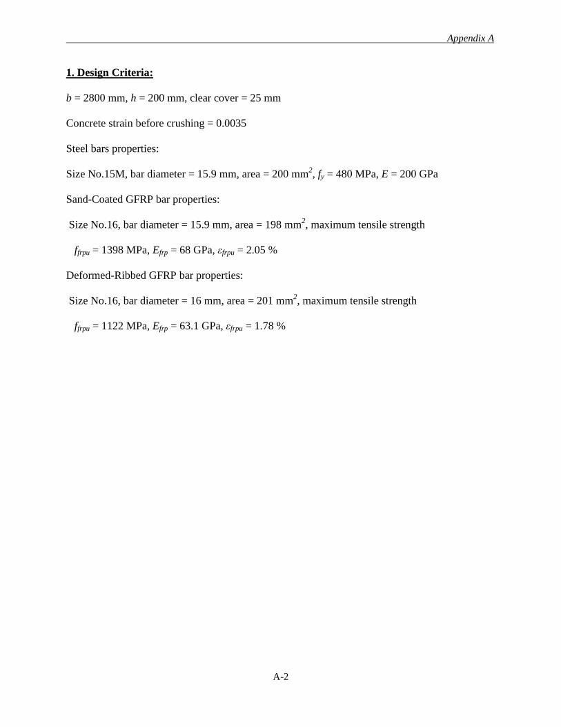
Appendix A
A-2
1. Design Criteria:
b = 2800 mm, h = 200 mm, clear cover = 25 mm
Concrete strain before crushing = 0.0035
Steel bars properties:
Size No.15M, bar diameter = 15.9 mm, area = 200 mm2, fy = 480 MPa, E = 200 GPa
Sand-Coated GFRP bar properties:
Size No.16, bar diameter = 15.9 mm, area = 198 mm2, maximum tensile strength
ffrpu = 1398 MPa, Efrp = 68 GPa, εfrpu = 2.05 %
Deformed-Ribbed GFRP bar properties:
Size No.16, bar diameter = 16 mm, area = 201 mm2, maximum tensile strength
ffrpu = 1122 MPa, Efrp = 63.1 GPa, εfrpu = 1.78 %
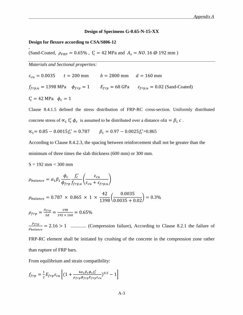
Appendix A
A-3
Design of Specimens G-0.65-N-15-XX
Design for flexure according to CSA/S806-12 .
(Sand-Coated, 𝜌𝐹𝑅𝑃 = 0.65% , fc′ = 42 MPa and 𝐴𝑠 = 𝑁𝑂. 16 @ 192 mm )
Materials and Sectional properties:
𝜀𝑐𝑢 = 0.0035 𝑡 = 200 mm 𝑏 = 2800 mm 𝑑 = 160 mm
𝑓𝑓𝑟𝑝,𝑢 = 1398 MPa 𝜙𝑓𝑟𝑝 = 1 𝐸𝑓𝑟𝑝 = 68 GPa 𝜀𝑓𝑟𝑝,𝑢 = 0.02 (Sand-Coated)
fc′ = 42 MPa 𝜙𝑐 = 1
Clause 8.4.1.5 defined the stress distribution of FRP-RC cross-section. Uniformly distributed
concrete stress of ∝1 fc′ 𝜙𝑐 is assumed to be distributed over a distance of𝑎 = 𝛽1 𝑐 .
∝1= 0.85 − 0.0015𝑓𝑐′ = 0.787 𝛽1 = 0.97 − 0.0025𝑓𝑐
′=0.865
According to Clause 8.4.2.3, the spacing between reinforcement shall not be greater than the
minimum of three times the slab thickness (600 mm) or 300 mm.
S = 192 mm < 300 mm
𝜌𝑏𝑎𝑙𝑎𝑛𝑐𝑒 = 𝛼1𝛽1
𝜙𝑐
𝜙𝑓𝑟𝑝
𝑓𝑐′
𝑓𝑓𝑟𝑝,𝑢(
𝜀𝑐𝑢
𝜀𝑐𝑢 + 𝜀𝑓𝑟𝑝,𝑢)
𝜌𝑏𝑎𝑙𝑎𝑛𝑐𝑒 = 0.787 × 0.865 × 1 × 42
1398(
0.0035
0.0035 + 0.02) = 0.3%
𝜌𝑓𝑟𝑝 =𝐴𝑓𝑟𝑝
𝑆𝑑=
198
192 × 160= 0.65%
𝜌𝑓𝑟𝑝
𝜌𝑏𝑎𝑙𝑎𝑛𝑐𝑒= 2.16 > 1 ............. (Compression failure), According to Clause 8.2.1 the failure of
FRP-RC element shall be initiated by crushing of the concrete in the compression zone rather
than rupture of FRP bars.
From equilibrium and strain compatibility:
𝑓𝑓𝑟𝑝 =1
2𝐸𝑓𝑟𝑝𝜀𝑐𝑢 [(1 +
4𝛼1𝛽1𝜙𝑐𝑓𝑐′
𝜌𝑓𝑟𝑝𝜙𝑓𝑟𝑝𝐸𝑓𝑟𝑝𝜀𝑐𝑢)0.5 − 1]
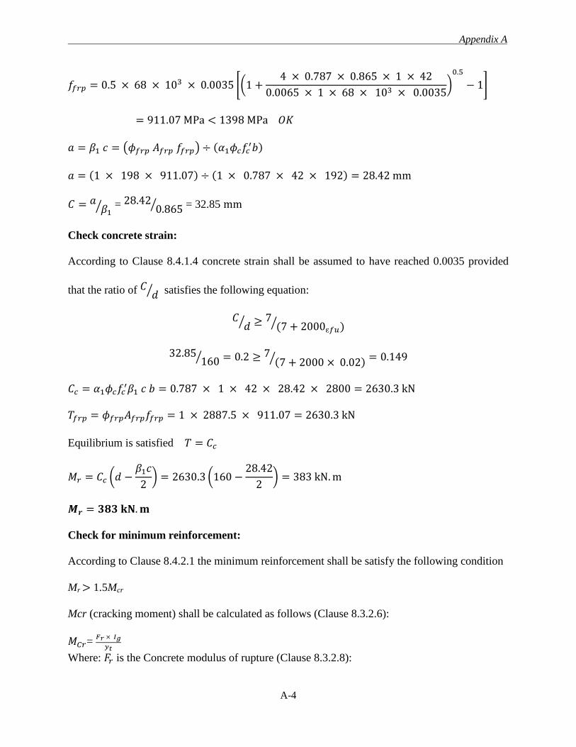
Appendix A
A-4
𝑓𝑓𝑟𝑝 = 0.5 × 68 × 103 × 0.0035 [(1 +4 × 0.787 × 0.865 × 1 × 42
0.0065 × 1 × 68 × 103 × 0.0035)
0.5
− 1]
= 911.07 MPa < 1398 MPa 𝑂𝐾
𝑎 = 𝛽1 𝑐 = (𝜙𝑓𝑟𝑝 𝐴𝑓𝑟𝑝 𝑓𝑓𝑟𝑝) ÷ (𝛼1𝜙𝑐𝑓𝑐′𝑏)
𝑎 = (1 × 198 × 911.07) ÷ (1 × 0.787 × 42 × 192) = 28.42 mm
𝐶 = 𝑎𝛽1
⁄ = 28.420.865⁄ = 32.85 mm
Check concrete strain:
According to Clause 8.4.1.4 concrete strain shall be assumed to have reached 0.0035 provided
that the ratio of 𝐶 𝑑⁄ satisfies the following equation:
𝐶𝑑⁄ ≥ 7
(7 + 2000ɛ𝑓𝑢)⁄
32.85160⁄ = 0.2 ≥ 7
(7 + 2000 × 0.02)⁄ = 0.149
𝐶𝑐 = 𝛼1𝜙𝑐𝑓𝑐′𝛽1 𝑐 𝑏 = 0.787 × 1 × 42 × 28.42 × 2800 = 2630.3 kN
𝑇𝑓𝑟𝑝 = 𝜙𝑓𝑟𝑝𝐴𝑓𝑟𝑝𝑓𝑓𝑟𝑝 = 1 × 2887.5 × 911.07 = 2630.3 kN
Equilibrium is satisfied 𝑇 = 𝐶𝑐
𝑀𝑟 = 𝐶𝑐 (𝑑 −𝛽1𝑐
2) = 2630.3 (160 −
28.42
2) = 383 kN. m
𝑴𝒓 = 𝟑𝟖𝟑 𝐤𝐍. 𝐦
Check for minimum reinforcement:
According to Clause 8.4.2.1 the minimum reinforcement shall be satisfy the following condition
Mr > 1.5Mcr
Mcr (cracking moment) shall be calculated as follows (Clause 8.3.2.6):
𝑀𝐶𝑟= 𝐹𝑟 × 𝐼𝑔
𝑦𝑡
Where: 𝐹𝑟 is the Concrete modulus of rupture (Clause 8.3.2.8):
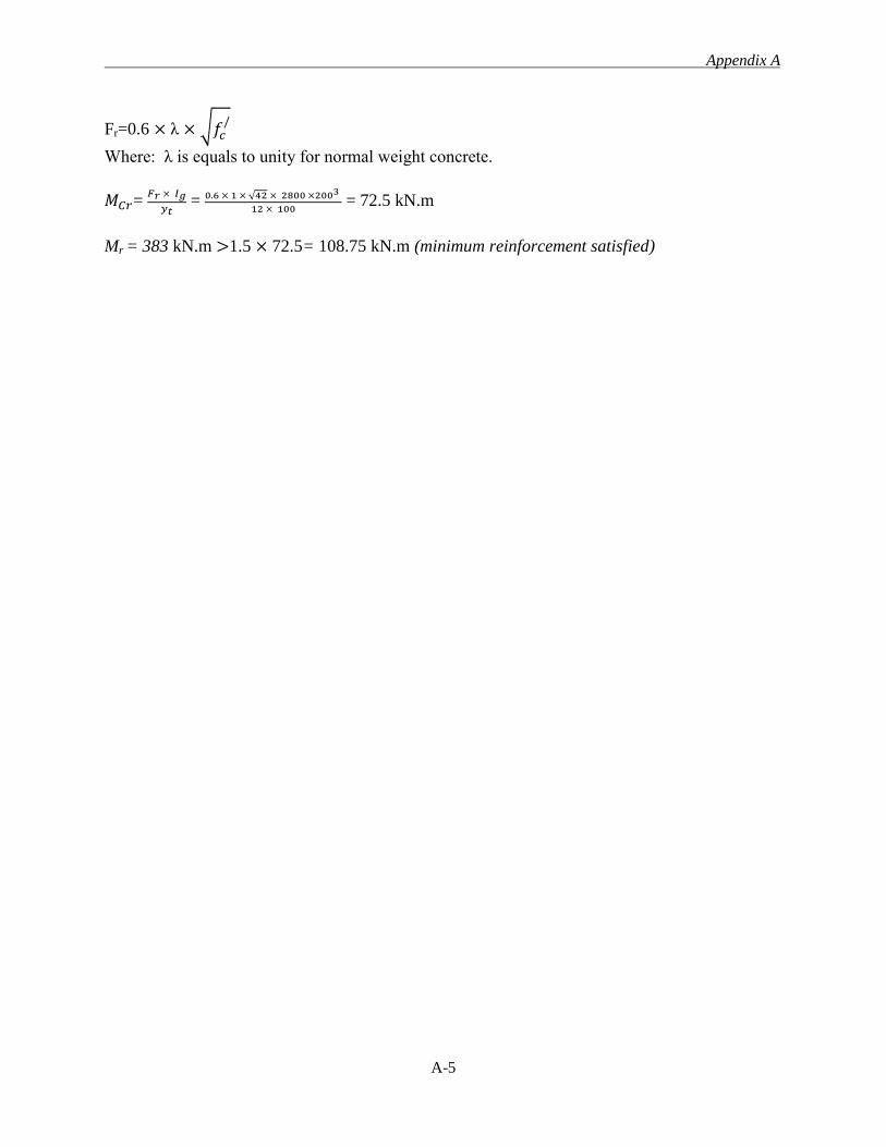
Appendix A
A-5
Fr=0.6 × λ × √𝑓𝑐/
Where: λ is equals to unity for normal weight concrete.
𝑀𝐶𝑟= 𝐹𝑟 × 𝐼𝑔
𝑦𝑡 = 0.6 × 1 × √42 × 2800 ×2003
12 × 100 = 72.5 kN.m
Mr = 383 kN.m >1.5 × 72.5= 108.75 kN.m (minimum reinforcement satisfied)
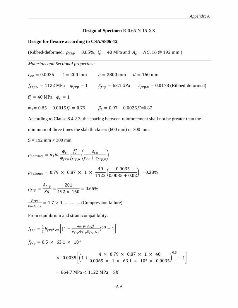
Appendix A
A-6
Design of Specimen R-0.65-N-15-XX
Design for flexure according to CSA/S806-12
(Ribbed-deformed, 𝜌𝐹𝑅𝑃 = 0.65%, fc′ = 40 MPa and 𝐴𝑠 = 𝑁𝑂. 16 @ 192 mm )
Materials and Sectional properties:
𝜀𝑐𝑢 = 0.0035 𝑡 = 200 mm 𝑏 = 2800 mm 𝑑 = 160 mm
𝑓𝑓𝑟𝑝,𝑢 = 1122 MPa 𝜙𝑓𝑟𝑝 = 1 𝐸𝑓𝑟𝑝 = 63.1 GPa 𝜀𝑓𝑟𝑝,𝑢 = 0.0178 (Ribbed-deformed)
fc′ = 40 MPa 𝜙𝑐 = 1
∝1= 0.85 − 0.0015𝑓𝑐′ = 0.79 𝛽1 = 0.97 − 0.0025𝑓𝑐
′=0.87
According to Clause 8.4.2.3, the spacing between reinforcement shall not be greater than the
minimum of three times the slab thickness (600 mm) or 300 mm.
S = 192 mm < 300 mm
𝜌𝑏𝑎𝑙𝑎𝑛𝑐𝑒 = 𝛼1𝛽1
𝜙𝑐
𝜙𝑓𝑟𝑝
𝑓𝑐′
𝑓𝑓𝑟𝑝,𝑢(
𝜀𝑐𝑢
𝜀𝑐𝑢 + 𝜀𝑓𝑟𝑝,𝑢)
𝜌𝑏𝑎𝑙𝑎𝑛𝑐𝑒 = 0.79 × 0.87 × 1 × 40
1122(
0.0035
0.0035 + 0.02) = 0.38%
𝜌𝑓𝑟𝑝 =𝐴𝑓𝑟𝑝
𝑆𝑑=
201
192 × 160= 0.65%
𝜌𝑓𝑟𝑝
𝜌𝑏𝑎𝑙𝑎𝑛𝑐𝑒= 1.7 > 1 ............. (Compression failure)
From equilibrium and strain compatibility:
𝑓𝑓𝑟𝑝 =1
2𝐸𝑓𝑟𝑝𝜀𝑐𝑢 [(1 +
4𝛼1𝛽1𝜙𝑐𝑓𝑐′
𝜌𝑓𝑟𝑝𝜙𝑓𝑟𝑝𝐸𝑓𝑟𝑝𝜀𝑐𝑢)0.5 − 1]
𝑓𝑓𝑟𝑝 = 0.5 × 63.1 × 103
× 0.0035 [(1 +4 × 0.79 × 0.87 × 1 × 40
0.0065 × 1 × 63.1 × 103 × 0.0035)
0.5
− 1]
= 864.7 MPa < 1122 MPa 𝑂𝐾
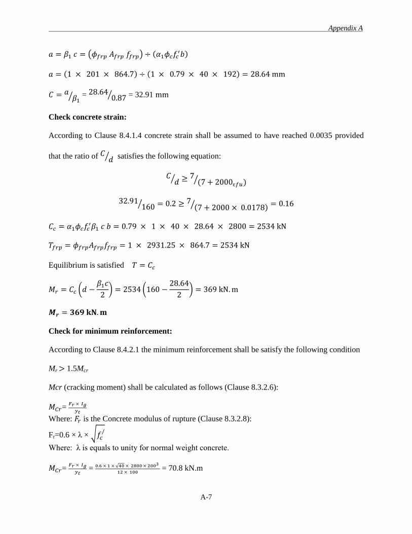
Appendix A
A-7
𝑎 = 𝛽1 𝑐 = (𝜙𝑓𝑟𝑝 𝐴𝑓𝑟𝑝 𝑓𝑓𝑟𝑝) ÷ (𝛼1𝜙𝑐𝑓𝑐′𝑏)
𝑎 = (1 × 201 × 864.7) ÷ (1 × 0.79 × 40 × 192) = 28.64 mm
𝐶 = 𝑎𝛽1
⁄ = 28.640.87⁄ = 32.91 mm
Check concrete strain:
According to Clause 8.4.1.4 concrete strain shall be assumed to have reached 0.0035 provided
that the ratio of 𝐶 𝑑⁄ satisfies the following equation:
𝐶𝑑⁄ ≥ 7
(7 + 2000ɛ𝑓𝑢)⁄
32.91160⁄ = 0.2 ≥ 7
(7 + 2000 × 0.0178)⁄ = 0.16
𝐶𝑐 = 𝛼1𝜙𝑐𝑓𝑐′𝛽1 𝑐 𝑏 = 0.79 × 1 × 40 × 28.64 × 2800 = 2534 kN
𝑇𝑓𝑟𝑝 = 𝜙𝑓𝑟𝑝𝐴𝑓𝑟𝑝𝑓𝑓𝑟𝑝 = 1 × 2931.25 × 864.7 = 2534 kN
Equilibrium is satisfied 𝑇 = 𝐶𝑐
𝑀𝑟 = 𝐶𝑐 (𝑑 −𝛽1𝑐
2) = 2534 (160 −
28.64
2) = 369 kN. m
𝑴𝒓 = 𝟑𝟔𝟗 𝐤𝐍. 𝐦
Check for minimum reinforcement:
According to Clause 8.4.2.1 the minimum reinforcement shall be satisfy the following condition
Mr > 1.5Mcr
Mcr (cracking moment) shall be calculated as follows (Clause 8.3.2.6):
𝑀𝐶𝑟= 𝐹𝑟 × 𝐼𝑔
𝑦𝑡
Where: 𝐹𝑟 is the Concrete modulus of rupture (Clause 8.3.2.8):
Fr=0.6 × λ × √𝑓𝑐/
Where: λ is equals to unity for normal weight concrete.
𝑀𝐶𝑟= 𝐹𝑟 × 𝐼𝑔
𝑦𝑡 = 0.6 × 1 × √40 × 2800 × 2003
12 × 100 = 70.8 kN.m

Appendix A
A-8
Mr = 369 kN.m >1.5 × 70.8 = 106.2 kN.m (minimum reinforcement satisfied)
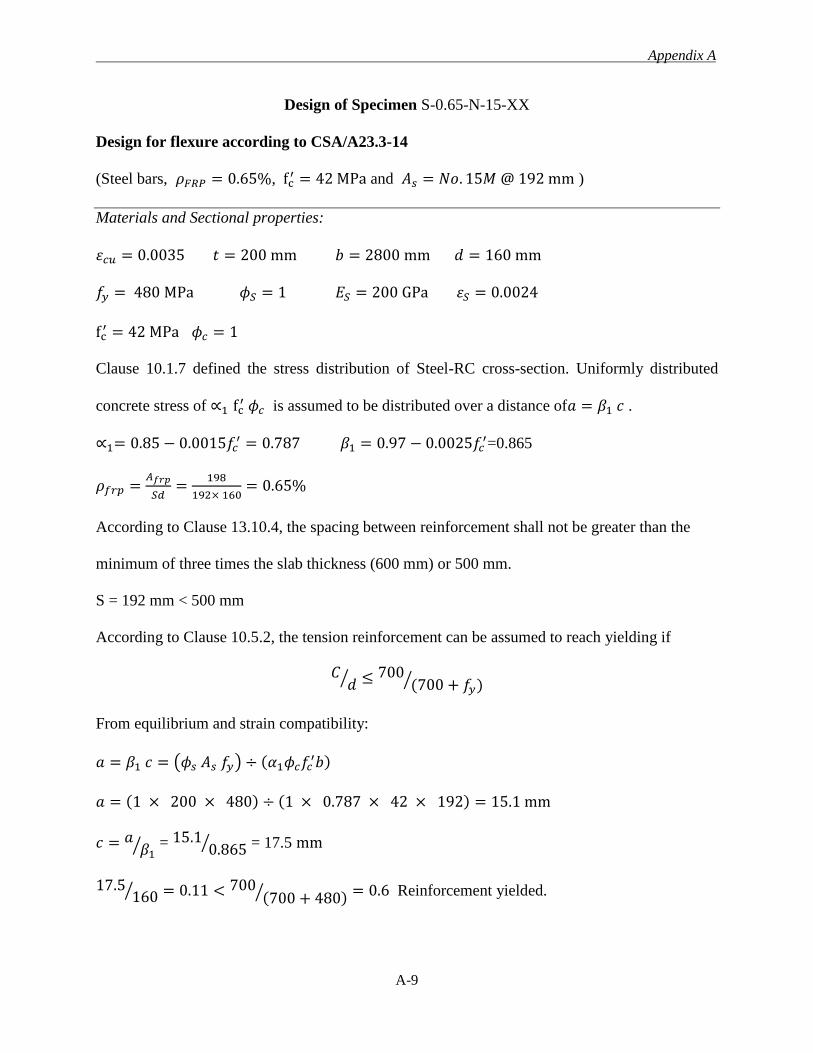
Appendix A
A-9
Design of Specimen S-0.65-N-15-XX
Design for flexure according to CSA/A23.3-14
(Steel bars, 𝜌𝐹𝑅𝑃 = 0.65%, fc′ = 42 MPa and 𝐴𝑠 = 𝑁𝑜. 15𝑀 @ 192 mm )
Materials and Sectional properties:
𝜀𝑐𝑢 = 0.0035 𝑡 = 200 mm 𝑏 = 2800 mm 𝑑 = 160 mm
𝑓𝑦 = 480 MPa 𝜙𝑆 = 1 𝐸𝑆 = 200 GPa 𝜀𝑆 = 0.0024
fc′ = 42 MPa 𝜙𝑐 = 1
Clause 10.1.7 defined the stress distribution of Steel-RC cross-section. Uniformly distributed
concrete stress of ∝1 fc′ 𝜙𝑐 is assumed to be distributed over a distance of𝑎 = 𝛽1 𝑐 .
∝1= 0.85 − 0.0015𝑓𝑐′ = 0.787 𝛽1 = 0.97 − 0.0025𝑓𝑐
′=0.865
𝜌𝑓𝑟𝑝 =𝐴𝑓𝑟𝑝
𝑆𝑑=
198
192× 160= 0.65%
According to Clause 13.10.4, the spacing between reinforcement shall not be greater than the
minimum of three times the slab thickness (600 mm) or 500 mm.
S = 192 mm < 500 mm
According to Clause 10.5.2, the tension reinforcement can be assumed to reach yielding if
𝐶𝑑⁄ ≤ 700
(700 + 𝑓𝑦)⁄
From equilibrium and strain compatibility:
𝑎 = 𝛽1 𝑐 = (𝜙𝑠 𝐴𝑠 𝑓𝑦) ÷ (𝛼1𝜙𝑐𝑓𝑐′𝑏)
𝑎 = (1 × 200 × 480) ÷ (1 × 0.787 × 42 × 192) = 15.1 mm
𝑐 = 𝑎𝛽1
⁄ = 15.10.865⁄ = 17.5 mm
17.5160⁄ = 0.11 < 700
(700 + 480)⁄ = 0.6 Reinforcement yielded.

Appendix A
A-10
𝑀𝑟 = ϕsAsfy (𝑑 −𝛽1𝑐
2) = 1 × 2916.67 × 480 (160 −
15.1
2) = 213 kN. m
𝑴𝒓 = 𝟐𝟏𝟑 𝐤𝐍. 𝐦

Appendix B
B-1
APPENDIX B
SERVICEABILITY REQUIREMENTS
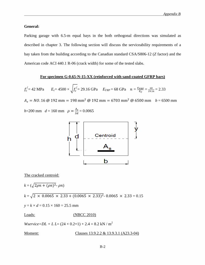
Appendix B
B-2
General:
Parking garage with 6.5-m equal bays in the both orthogonal directions was simulated as
described in chapter 3. The following section will discuss the serviceability requirements of a
bay taken from the building according to the Canadian standard CSA/S806-12 (Z factor) and the
American code ACI 440.1 R-06 (crack width) for some of the tested slabs.
For specimen G-0.65-N-15-XX (reinforced with sand-coated GFRP bars)
𝑓𝑐/= 42 MPa Ec= 4500 × √𝑓𝑐
/= 29.16 GPa EFRP = 68 GPa 𝑛 = 𝐸𝐹𝑅𝑃
𝐸𝐶 = 68
29.16 = 2.33
𝐴𝑠 = 𝑁𝑂. 16 @ 192 mm = 198 mm2 @ 192 mm = 6703 mm2 @ 6500 mm b = 6500 mm
h=200 mm d = 160 mm 𝜌 =𝐴𝑠
𝑆𝑑 = 0.0065
The cracked centroid:
k = (√2𝜌𝑛 + (𝜌𝑛)2- 𝜌𝑛)
k = √2 × 0.0065 × 2.33 + (0.0065 × 2.33)2- 0.0065 × 2.33 = 0.15
y = k × d = 0.15 × 160 = 25.5 mm
Loads: (NBCC 2010)
Wservice=DL + L L= (24 × 0.2+1) + 2.4 = 8.2 kN / m2
Moment: Clauses 13.9.2.2 & 13.9.3.1 (A23.3-04)
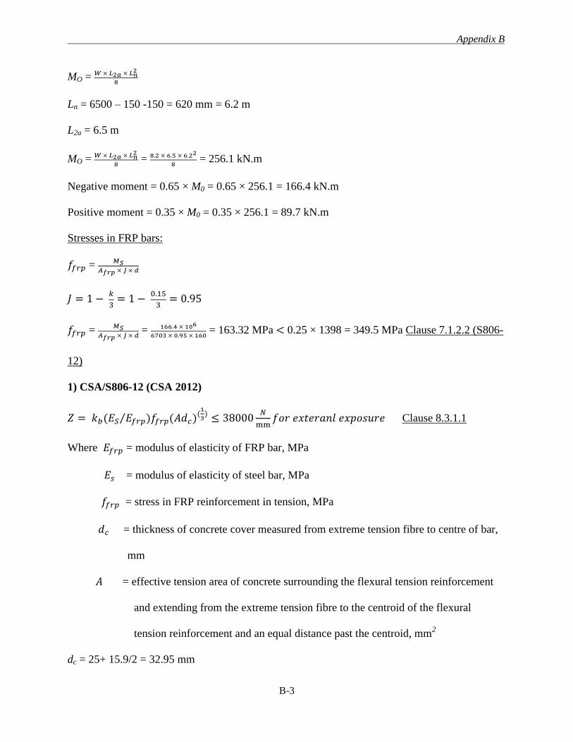
Appendix B
B-3
MO = 𝑊 × 𝐿2𝑎 × 𝐿𝑛2
8
Ln = 6500 – 150 -150 = 620 mm = 6.2 m
L2a = 6.5 m
MO = 𝑊 × 𝐿2𝑎 × 𝐿𝑛2
8 = 8.2 × 6.5 × 6.22
8 = 256.1 kN.m
Negative moment = 0.65 × M0 = 0.65 × 256.1 = 166.4 kN.m
Positive moment = 0.35 × M0 = 0.35 × 256.1 = 89.7 kN.m
Stresses in FRP bars:
𝑓𝑓𝑟𝑝 = 𝑀𝑆
𝐴𝑓𝑟𝑝 × 𝐽 × 𝑑
𝐽 = 1 − 𝑘
3= 1 −
0.15
3= 0.95
𝑓𝑓𝑟𝑝 = 𝑀𝑆
𝐴𝑓𝑟𝑝 × 𝐽 × 𝑑 = 166.4 × 10⁶
6703 × 0.95 × 160 = 163.32 MPa < 0.25 × 1398 = 349.5 MPa Clause 7.1.2.2 (S806-
12)
1) CSA/S806-12 (CSA 2012)
𝑍 = 𝑘𝑏(𝐸𝑆 𝐸𝑓𝑟𝑝)𝑓𝑓𝑟𝑝(𝐴𝑑𝑐)(1
3)⁄ ≤ 38000
𝑁
mm𝑓𝑜𝑟 𝑒𝑥𝑡𝑒𝑟𝑎𝑛𝑙 𝑒𝑥𝑝𝑜𝑠𝑢𝑟𝑒 Clause 8.3.1.1
Where 𝐸𝑓𝑟𝑝 = modulus of elasticity of FRP bar, MPa
𝐸𝑠 = modulus of elasticity of steel bar, MPa
𝑓𝑓𝑟𝑝 = stress in FRP reinforcement in tension, MPa
𝑑𝑐 = thickness of concrete cover measured from extreme tension fibre to centre of bar,
mm
𝐴 = effective tension area of concrete surrounding the flexural tension reinforcement
and extending from the extreme tension fibre to the centroid of the flexural
tension reinforcement and an equal distance past the centroid, mm2
dc = 25+ 15.9/2 = 32.95 mm
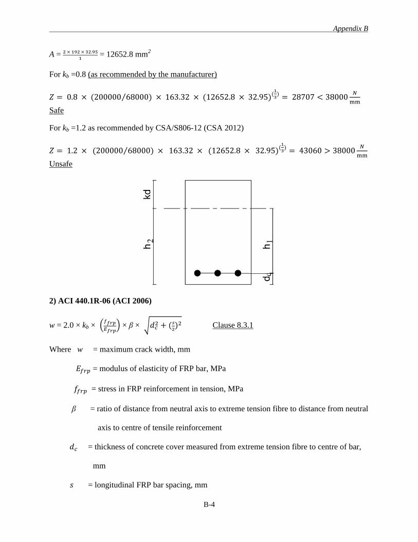
Appendix B
B-4
A = 2 × 192 × 32.95
1 = 12652.8 mm
2
For kb =0.8 (as recommended by the manufacturer)
𝑍 = 0.8 × (200000 68000) × 163.32 × (12652.8 × 32.95)(1
3)⁄ = 28707 < 38000
𝑁
mm
Safe
For kb =1.2 as recommended by CSA/S806-12 (CSA 2012)
𝑍 = 1.2 × (200000 68000) × 163.32 × (12652.8 × 32.95)(1
3)⁄ = 43060 > 38000
𝑁
mm
Unsafe
2) ACI 440.1R-06 (ACI 2006)
w = 2.0 × kb × (𝑓𝑓𝑟𝑝
𝐸𝑓𝑟𝑝) × β × √𝑑𝑐
2 + (𝑠
2)2 Clause 8.3.1
Where w = maximum crack width, mm
𝐸𝑓𝑟𝑝 = modulus of elasticity of FRP bar, MPa
𝑓𝑓𝑟𝑝 = stress in FRP reinforcement in tension, MPa
β = ratio of distance from neutral axis to extreme tension fibre to distance from neutral
axis to centre of tensile reinforcement
𝑑𝑐 = thickness of concrete cover measured from extreme tension fibre to centre of bar,
mm
𝑠 = longitudinal FRP bar spacing, mm
Appendix B
B-5
For kb =0.8
w= 2.0 × 0.8 × 163.32
68000 × 174.5
141.55 × √32.952 + (192
2)2 = 0.48 mm < 0.5 mm safe
For kb =1.2
w= 2.0 × 1.2 × 163.32
68000 × 174.5
141.55 × √32.952 + (192
2)2 = 0.72 mm > 0.5 mm Unsafe
For kb =1.4 as recommended by ACI 440.1 R-06 (ACI 2006)
w= 2.0 × 1.4 × 163.32
68000 × 174.5
141.55 × √32.952 + (192
2)2 = 0.84 mm > 0.5 mm Unsafe
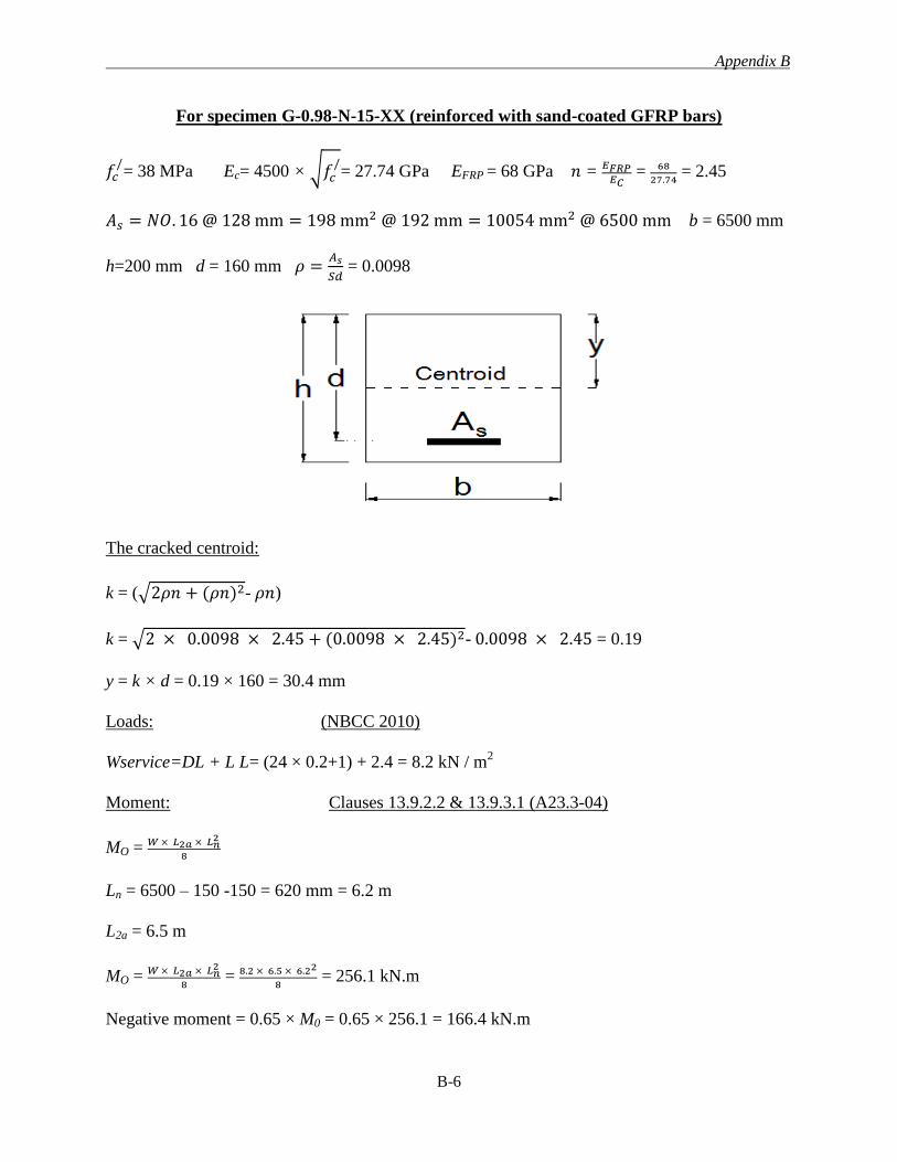
Appendix B
B-6
For specimen G-0.98-N-15-XX (reinforced with sand-coated GFRP bars)
𝑓𝑐/= 38 MPa Ec= 4500 × √𝑓𝑐
/= 27.74 GPa EFRP = 68 GPa 𝑛 = 𝐸𝐹𝑅𝑃
𝐸𝐶 = 68
27.74 = 2.45
𝐴𝑠 = 𝑁𝑂. 16 @ 128 mm = 198 mm2 @ 192 mm = 10054 mm2 @ 6500 mm b = 6500 mm
h=200 mm d = 160 mm 𝜌 =𝐴𝑠
𝑆𝑑 = 0.0098
The cracked centroid:
k = (√2𝜌𝑛 + (𝜌𝑛)2- 𝜌𝑛)
k = √2 × 0.0098 × 2.45 + (0.0098 × 2.45)2- 0.0098 × 2.45 = 0.19
y = k × d = 0.19 × 160 = 30.4 mm
Loads: (NBCC 2010)
Wservice=DL + L L= (24 × 0.2+1) + 2.4 = 8.2 kN / m2
Moment: Clauses 13.9.2.2 & 13.9.3.1 (A23.3-04)
MO = 𝑊 × 𝐿2𝑎 × 𝐿𝑛2
8
Ln = 6500 – 150 -150 = 620 mm = 6.2 m
L2a = 6.5 m
MO = 𝑊 × 𝐿2𝑎 × 𝐿𝑛2
8 = 8.2 × 6.5 × 6.22
8 = 256.1 kN.m
Negative moment = 0.65 × M0 = 0.65 × 256.1 = 166.4 kN.m
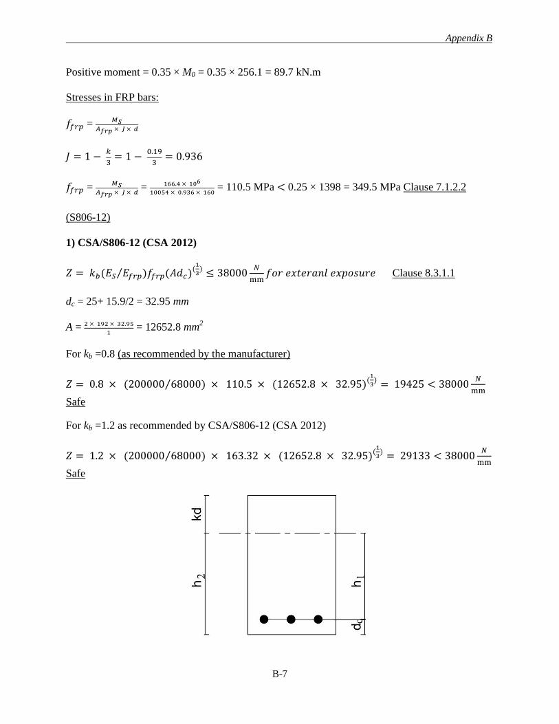
Appendix B
B-7
Positive moment = 0.35 × M0 = 0.35 × 256.1 = 89.7 kN.m
Stresses in FRP bars:
𝑓𝑓𝑟𝑝 = 𝑀𝑆
𝐴𝑓𝑟𝑝 × 𝐽 × 𝑑
𝐽 = 1 − 𝑘
3= 1 −
0.19
3= 0.936
𝑓𝑓𝑟𝑝 = 𝑀𝑆
𝐴𝑓𝑟𝑝 × 𝐽 × 𝑑 = 166.4 × 10⁶
10054 × 0.936 × 160 = 110.5 MPa < 0.25 × 1398 = 349.5 MPa Clause 7.1.2.2
(S806-12)
1) CSA/S806-12 (CSA 2012)
𝑍 = 𝑘𝑏(𝐸𝑆 𝐸𝑓𝑟𝑝)𝑓𝑓𝑟𝑝(𝐴𝑑𝑐)(1
3)⁄ ≤ 38000
𝑁
mm𝑓𝑜𝑟 𝑒𝑥𝑡𝑒𝑟𝑎𝑛𝑙 𝑒𝑥𝑝𝑜𝑠𝑢𝑟𝑒 Clause 8.3.1.1
dc = 25+ 15.9/2 = 32.95 mm
A = 2 × 192 × 32.95
1 = 12652.8 mm
2
For kb =0.8 (as recommended by the manufacturer)
𝑍 = 0.8 × (200000 68000) × 110.5 × (12652.8 × 32.95)(1
3)⁄ = 19425 < 38000
𝑁
mm
Safe
For kb =1.2 as recommended by CSA/S806-12 (CSA 2012)
𝑍 = 1.2 × (200000 68000) × 163.32 × (12652.8 × 32.95)(1
3)⁄ = 29133 < 38000
𝑁
mm
Safe
Appendix B
B-8
2) ACI 440.1 R-06 (ACI 2006)
w = 2.0 × kb × (𝑓𝑓𝑟𝑝
𝐸𝑓𝑟𝑝) × β × √𝑑𝑐
2 + (𝑠
2)2 Clause 8.3.1
For kb =0.8
w= 2.0 × 0.8 × 110.5
68000 × 169.6
136.65 × √32.952 + (128
2)2 = 0.23 mm < 0.5 mm safe
For kb =1.2
w= 2.0 × 1.2 × 110.5
68000 × 169.6
136.65 × √32.952 + (128
2)2 = 0.35 mm < 0.5 mm safe
For kb =1.4 as recommended by ACI 440.1 R-06 (ACI 2006)
w= 2.0 × 1.4 × 110.5
68000 × 169.6
136.65 × √32.952 + (128
2)2= 0.4 mm < 0.5 mm safe
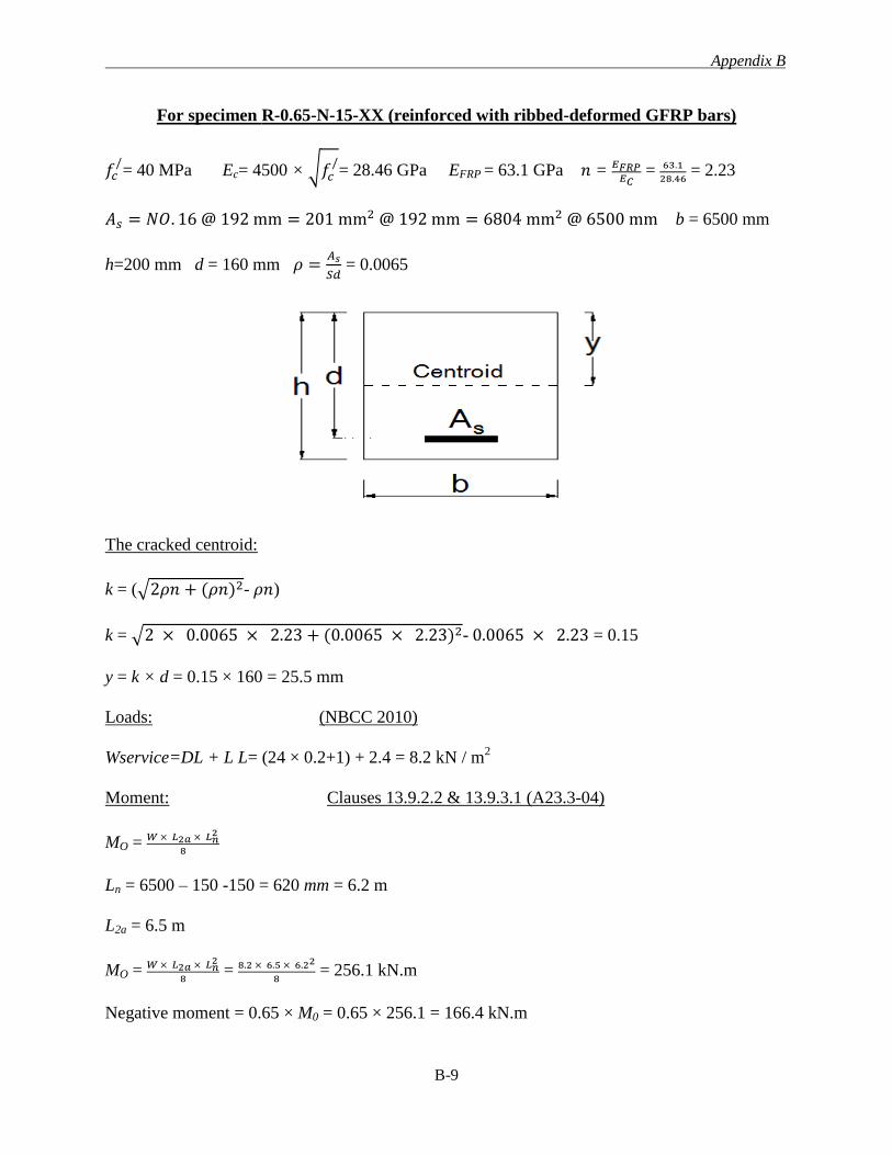
Appendix B
B-9
For specimen R-0.65-N-15-XX (reinforced with ribbed-deformed GFRP bars)
𝑓𝑐/= 40 MPa Ec= 4500 × √𝑓𝑐
/= 28.46 GPa EFRP = 63.1 GPa 𝑛 = 𝐸𝐹𝑅𝑃
𝐸𝐶 = 63.1
28.46 = 2.23
𝐴𝑠 = 𝑁𝑂. 16 @ 192 mm = 201 mm2 @ 192 mm = 6804 mm2 @ 6500 mm b = 6500 mm
h=200 mm d = 160 mm 𝜌 =𝐴𝑠
𝑆𝑑 = 0.0065
The cracked centroid:
k = (√2𝜌𝑛 + (𝜌𝑛)2- 𝜌𝑛)
k = √2 × 0.0065 × 2.23 + (0.0065 × 2.23)2- 0.0065 × 2.23 = 0.15
y = k × d = 0.15 × 160 = 25.5 mm
Loads: (NBCC 2010)
Wservice=DL + L L= (24 × 0.2+1) + 2.4 = 8.2 kN / m2
Moment: Clauses 13.9.2.2 & 13.9.3.1 (A23.3-04)
MO = 𝑊 × 𝐿2𝑎 × 𝐿𝑛2
8
Ln = 6500 – 150 -150 = 620 mm = 6.2 m
L2a = 6.5 m
MO = 𝑊 × 𝐿2𝑎 × 𝐿𝑛2
8 = 8.2 × 6.5 × 6.22
8 = 256.1 kN.m
Negative moment = 0.65 × M0 = 0.65 × 256.1 = 166.4 kN.m
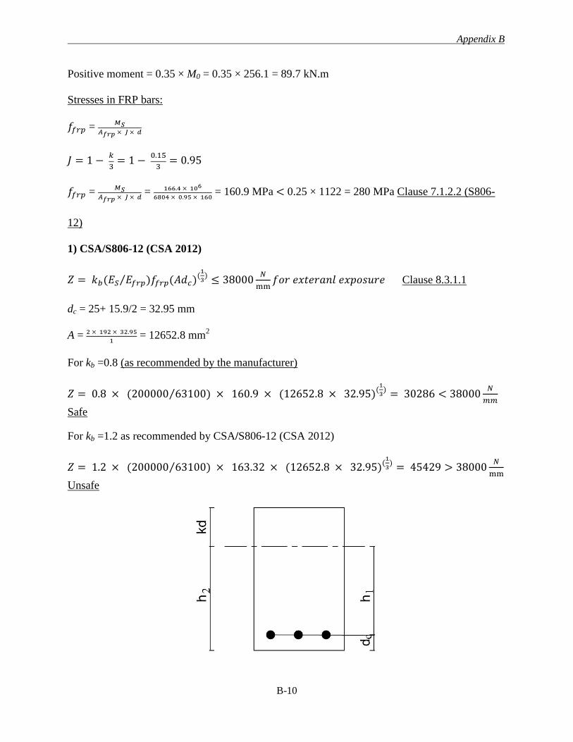
Appendix B
B-10
Positive moment = 0.35 × M0 = 0.35 × 256.1 = 89.7 kN.m
Stresses in FRP bars:
𝑓𝑓𝑟𝑝 = 𝑀𝑆
𝐴𝑓𝑟𝑝 × 𝐽 × 𝑑
𝐽 = 1 − 𝑘
3= 1 −
0.15
3= 0.95
𝑓𝑓𝑟𝑝 = 𝑀𝑆
𝐴𝑓𝑟𝑝 × 𝐽 × 𝑑 = 166.4 × 10⁶
6804 × 0.95 × 160 = 160.9 MPa < 0.25 × 1122 = 280 MPa Clause 7.1.2.2 (S806-
12)
1) CSA/S806-12 (CSA 2012)
𝑍 = 𝑘𝑏(𝐸𝑆 𝐸𝑓𝑟𝑝)𝑓𝑓𝑟𝑝(𝐴𝑑𝑐)(1
3)⁄ ≤ 38000
𝑁
mm𝑓𝑜𝑟 𝑒𝑥𝑡𝑒𝑟𝑎𝑛𝑙 𝑒𝑥𝑝𝑜𝑠𝑢𝑟𝑒 Clause 8.3.1.1
dc = 25+ 15.9/2 = 32.95 mm
A = 2 × 192 × 32.95
1 = 12652.8 mm
2
For kb =0.8 (as recommended by the manufacturer)
𝑍 = 0.8 × (200000 63100) × 160.9 × (12652.8 × 32.95)(1
3)⁄ = 30286 < 38000
𝑁
𝑚𝑚
Safe
For kb =1.2 as recommended by CSA/S806-12 (CSA 2012)
𝑍 = 1.2 × (200000 63100) × 163.32 × (12652.8 × 32.95)(1
3)⁄ = 45429 > 38000
𝑁
mm
Unsafe
Appendix B
B-11
2) ACI 440.1R-06 (ACI 2006)
w = 2.0 × kb × (𝑓𝑓𝑟𝑝
𝐸𝑓𝑟𝑝) × β × √𝑑𝑐
2 + (𝑠
2)2 Clause 8.3.1
For kb =0.8
w= 2.0 × 0.8 × 160.9
63100 × 174.5
141.55 × √32.952 + (192
2)2 = 0.5 mm safe
For kb =1.2
w= 2.0 × 1.2 × 160.9
63100 × 174.5
141.55 × √32.952 + (192
2)2 = 0.75 mm > 0.5 mm Unsafe
For kb =1.4 as recommended by ACI 440.1 R-06 (ACI 2006)
w= 2.0 × 1.4 × 160.9
63100 × 174.5
141.55 × √32.952 + (192
2)2 = 0.875 mm > 0.5 mm Unsafe
Appendix C
C-1
APPENDIX C
PUNCHING SHEAR CAPACITIY OF THE TEST SPECIMENS
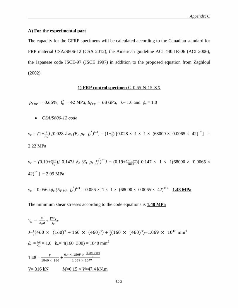
Appendix C
C-2
A) For the experimental part
The capacity for the GFRP specimens will be calculated according to the Canadian standard for
FRP material CSA/S806-12 (CSA 2012), the American guideline ACI 440.1R-06 (ACI 2006),
the Japanese code JSCE-97 (JSCE 1997) in addition to the proposed equation from Zaghloul
(2002).
1) FRP control specimen G-0.65-N-15-XX
𝜌𝐹𝑅𝑃 = 0.65%, fc′ = 42 MPa, 𝐸𝑓𝑟𝑝 = 68 GPa, λ= 1.0 and ϕc = 1.0
CSA/S806-12 code
vc = (1+ 2
𝛽𝐶) [0.028 λ ϕc (EF ρF 𝑓𝑐
/)1/3
] = (1+2
1) [0.028 × 1 × 1 × (68000 × 0.0065 × 42)
1/3] =
2.22 MPa
vc = (0.19+𝛼𝑠𝑑
𝑏𝑜)[ 0.147λ ϕc (EF ρF 𝑓𝑐
/)1/3
] = (0.19+4 × 160
1840)[ 0.147 × 1 × 1(68000 × 0.0065 ×
42)1/3
] = 2.09 MPa
vc = 0.056 λϕc (EF ρF 𝑓𝑐/)1/3
= 0.056 × 1 × 1 × (68000 × 0.0065 × 42)1/3
= 1.48 MPa
The minimum shear stresses according to the code equations is 1.48 MPa
𝜈𝑐 = 𝑉
𝑏𝑜𝑑 +
𝛾𝑀𝑦
𝐽𝑐𝑥
J=1
6(460 × (160)3 + 160 × (460)3) + 1
2(160 × (460)3)=1.069 × 1010 mm4
βc = 𝐶2
𝐶1 = 1.0 bo= 4(160+300) = 1840 mm
2
1.48 = 𝑉
1840 × 160 +
0.4 × 150𝑉 × (160+300)
2
1.069 × 10¹⁰
V= 316 kN M=0.15 × V=47.4 kN.m
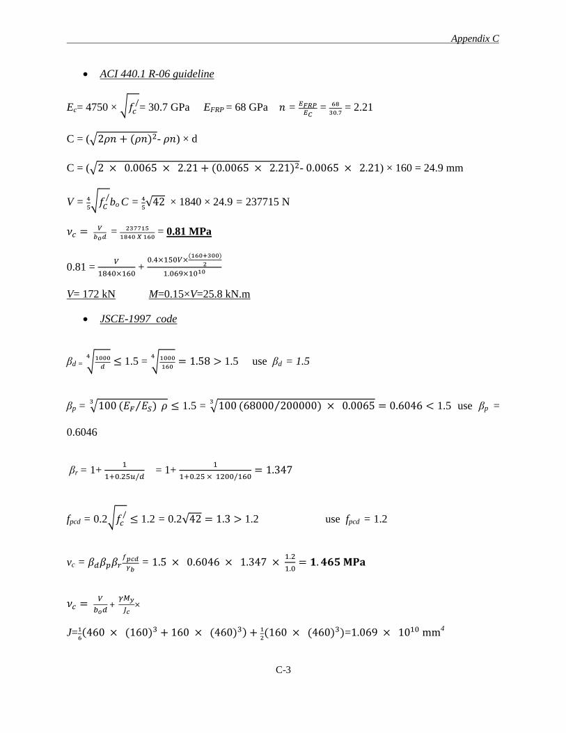
Appendix C
C-3
ACI 440.1 R-06 guideline
Ec= 4750 × √𝑓𝑐/= 30.7 GPa EFRP = 68 GPa 𝑛 = 𝐸𝐹𝑅𝑃
𝐸𝐶 = 68
30.7 = 2.21
C = (√2𝜌𝑛 + (𝜌𝑛)2- 𝜌𝑛) × d
C = (√2 × 0.0065 × 2.21 + (0.0065 × 2.21)2- 0.0065 × 2.21) × 160 = 24.9 mm
V = 4
5√𝑓𝐶
/bo C = 4
5√42 × 1840 × 24.9 = 237715 N
𝜈𝑐 = 𝑉
𝑏𝑜𝑑 = 237715
1840 𝑋 160 = 0.81 MPa
0.81 = 𝑉
1840×160 +
0.4×150𝑉×(160+300)
2
1.069×10¹⁰
V= 172 kN M=0.15×V=25.8 kN.m
JSCE-1997 code
βd = √1000
𝑑
4≤ 1.5 = √1000
160
4= 1.58 > 1.5 use βd = 1.5
βp = √100 (𝐸𝐹 𝐸𝑆)⁄ 𝜌3
≤ 1.5 = √100 (68000 200000)⁄ × 0.00653
= 0.6046 < 1.5 use βp =
0.6046
βr = 1+ 1
1+0.25𝑢/𝑑 = 1+
1
1+0.25 × 1200/160= 1.347
fpcd = 0.2√𝑓𝑐/
≤ 1.2 = 0.2√42 = 1.3 > 1.2 use fpcd = 1.2
vc = 𝛽𝑑𝛽𝑝𝛽𝑟𝑓𝑝𝑐𝑑
𝛾𝑏 = 1.5 × 0.6046 × 1.347 ×
1.2
1.0= 𝟏. 𝟒𝟔𝟓 𝐌𝐏𝐚
𝜈𝑐 = 𝑉
𝑏𝑜𝑑 +
𝛾𝑀𝑦
𝐽𝑐×
J=1
6(460 × (160)3 + 160 × (460)3) + 1
2(160 × (460)3)=1.069 × 1010 mm4
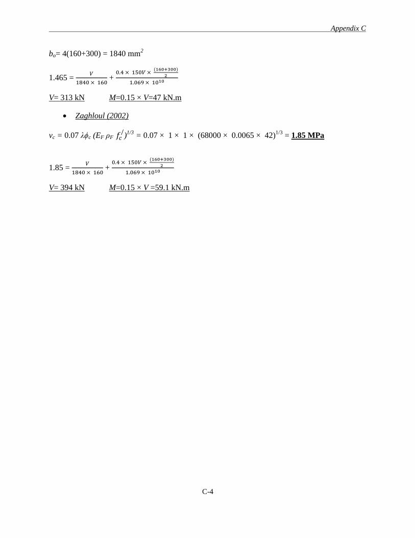
Appendix C
C-4
bo= 4(160+300) = 1840 mm2
1.465 = 𝑉
1840 × 160 +
0.4 × 150𝑉 × (160+300)
2
1.069 × 10¹⁰
V= 313 kN M=0.15 × V=47 kN.m
Zaghloul (2002)
vc = 0.07 λϕc (EF ρF 𝑓𝑐/)1/3
= 0.07 × 1 × 1 × (68000 × 0.0065 × 42)1/3
= 1.85 MPa
1.85 = 𝑉
1840 × 160 +
0.4 × 150𝑉 × (160+300)
2
1.069 × 10¹⁰
V= 394 kN M=0.15 × V =59.1 kN.m

Appendix C
C-5
2) Specimen R-0.65-N-15-75
𝜌𝐹𝑅𝑃 = 0.65%, fc′ = 42 MPa, 𝐸𝑓𝑟𝑝 = 63.1 GPa, λ= 1.0 and ϕc = 1.0
Proposed equation based on CSA/S806-12 code
Inside the shear reinforcement zone
vc = 0.041 λϕc (EF ρF 𝑓𝑐/)1/3
= 0.041 × 1 × 1 × (63100 × 0.0065 × 42)1/3
= 1.06 MPa
vs = 𝜙𝑠𝐴𝑣𝑠𝑓𝑓𝑟𝑝𝑣
𝑏𝑜𝑆= 1 × (8 × 113) × (0.002 × 60000) 1840 × 120⁄ = 0.49 MPa
vr = vc + vs = 1.06 + 0.49 = 1.55 MPa
𝜈𝑐 = 𝑉
𝑏𝑜𝑑 +
𝛾𝑀𝑦
𝐽𝑐𝑋
1.55 = 𝑉
1840 × 160 +
0.4 × 150𝑉 × (160+300)
2
1.069 × 10¹⁰
V= 331 kN M=0.15 × V =49.65 kN.m
Outside the shear reinforcement zone
vc = 0.028 λϕc (EF ρF 𝑓𝑐/)1/3
= 0.028 × 1 × 1 × (63100 × 0.0065 × 42)1/3
= 0.72 MPa
The punching shear stresses calculations at distance of 3.9 d from the column faces (3.9 ×
160=624 mm) are shown in the next few lines.
J =𝑑
3∑ 𝑙𝑖(𝑦𝑖
2 + 𝑦𝑖 × 𝑦𝑗 + 𝑦𝑗2)
= 160
3((2 × 300 × (1502+ (-150 × 150) + (−1502))) + (2 × 300 × (7742 + 774 × 774 + 7742) +
(4 × 624 × √2 × (1502+150 × 774 + 7742)) = 1.971 × 10¹¹
bo= 4(624 × √2+300) = 4729.87 mm
vc = 𝑉
𝑏𝑜𝑑 +
𝛾𝑀𝑦
𝐽𝑐𝑋
0.72 = 𝑉
4729.87 × 160 + 0.4 ×
150𝑉 × (774)
1.971 × 10¹¹
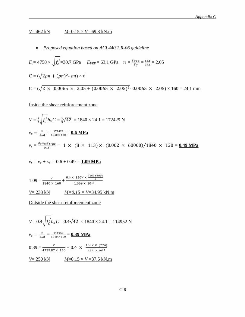
Appendix C
C-6
V= 462 kN M=0.15 × V =69.3 kN.m
Proposed equation based on ACI 440.1 R-06 guideline
Ec= 4750 × √𝑓𝑐/=30.7 GPa EFRP = 63.1 GPa 𝑛 = 𝐸𝐹𝑅𝑃
𝐸𝐶 = 63.1
29.1 = 2.05
C = (√2𝜌𝑛 + (𝜌𝑛)2- 𝜌𝑛) × d
C = (√2 × 0.0065 × 2.05 + (0.0065 × 2.05)2- 0.0065 × 2.05) × 160 = 24.1 mm
Inside the shear reinforcement zone
V = 3
5√𝑓𝐶
/bo C = 3
5√42 × 1840 × 24.1 = 172429 N
vc = 𝑉
𝑏𝑜𝑑 = 172429
1840 × 160 = 0.6 MPa
vs = 𝜙𝑠𝐴𝑣𝑠𝑓𝑓𝑟𝑝𝑣
𝑏𝑜𝑆= 1 × (8 × 113) × (0.002 × 60000) 1840 × 120⁄ = 0.49 MPa
vr = vc + vs = 0.6 + 0.49 = 1.09 MPa
1.09 = 𝑉
1840 × 160 +
0.4 × 150𝑉 × (160+300)
2
1.069 × 10¹⁰
V= 233 kN M=0.15 × V=34.95 kN.m
Outside the shear reinforcement zone
V =0.4√𝑓𝐶/bo C =0.4√42 × 1840 × 24.1 = 114952 N
vc = 𝑉
𝑏𝑜𝑑 = 114952
1840 × 160 = 0.39 MPa
0.39 = 𝑉
4729.87 × 160 + 0.4 ×
150𝑉 × (774)
1.971 × 10¹¹
V= 250 kN M=0.15 × V =37.5 kN.m
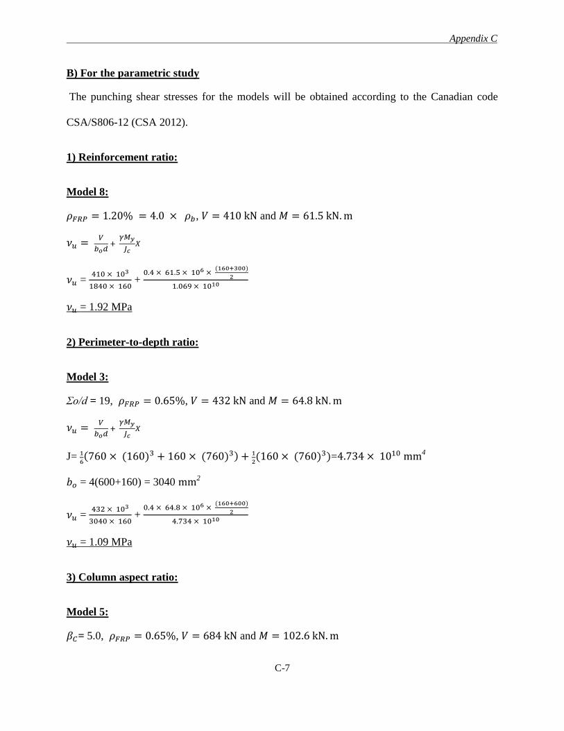
Appendix C
C-7
B) For the parametric study
The punching shear stresses for the models will be obtained according to the Canadian code
CSA/S806-12 (CSA 2012).
1) Reinforcement ratio:
Model 8:
𝜌𝐹𝑅𝑃 = 1.20% = 4.0 × 𝜌𝑏, 𝑉 = 410 kN and 𝑀 = 61.5 kN. m
𝜈𝑢 = 𝑉
𝑏𝑜𝑑 +
𝛾𝑀𝑦
𝐽𝑐𝑋
𝜈𝑢 = 410 × 103
1840 × 160 +
0.4 × 61.5 × 106 × (160+300)
2
1.069 × 10¹⁰
𝜈𝑢 = 1.92 MPa
2) Perimeter-to-depth ratio:
Model 3:
Σo/d = 19, 𝜌𝐹𝑅𝑃 = 0.65%, 𝑉 = 432 kN and 𝑀 = 64.8 kN. m
𝜈𝑢 = 𝑉
𝑏𝑜𝑑 +
𝛾𝑀𝑦
𝐽𝑐𝑋
J= 1
6(760 × (160)3 + 160 × (760)3) + 1
2(160 × (760)3)=4.734 × 1010 mm4
𝑏𝑜 = 4(600+160) = 3040 mm2
𝜈𝑢 = 432 × 103
3040 × 160 +
0.4 × 64.8 × 106 × (160+600)
2
4.734 × 10¹⁰
𝜈𝑢 = 1.09 MPa
3) Column aspect ratio:
Model 5:
𝛽𝐶= 5.0, 𝜌𝐹𝑅𝑃 = 0.65%, 𝑉 = 684 kN and 𝑀 = 102.6 kN. m
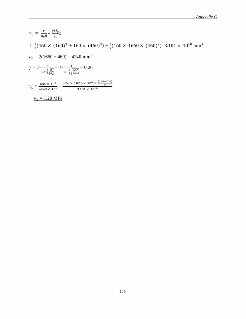
Appendix C
C-8
𝜈𝑢 = 𝑉
𝑏𝑜𝑑 +
𝛾𝑀𝑦
𝐽𝑐𝑋
J= 1
6(460 × (160)3 + 160 × (460)3) + 1
2(160 × 1660 × (460)2)=3.101 × 1010 mm4
𝑏𝑜 = 2(1660 + 460) = 4240 mm2
𝛾 = 1- 1
1+ 23
√𝑏1𝑏2
= 1- 1
1+ 23
√460
1660
= 0.26
𝜈𝑢 = 684 × 103
4240 × 160 +
0.26 × 102.6 × 106 × (160+300)
2
3.101 × 10¹⁰
𝜈𝑢 = 1.20 MPa
Appendix D
D-1
APPENDIX D
FLEXURAL CAPACITIY OF THE SPECIMENS
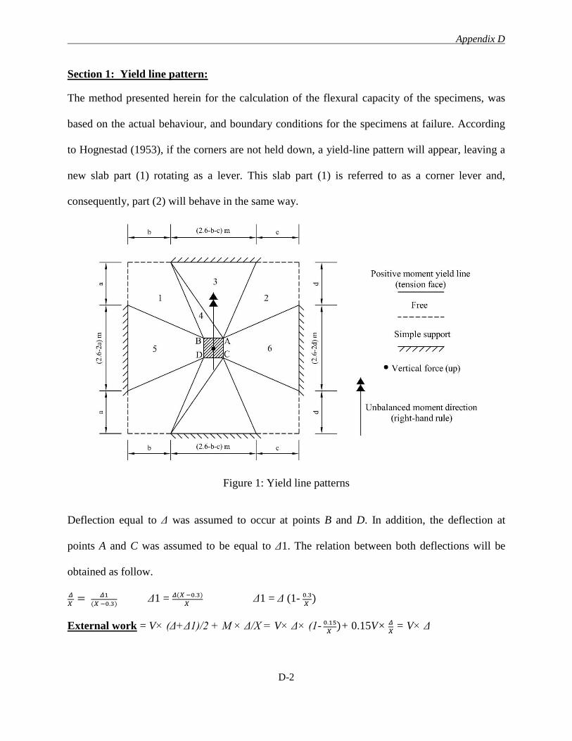
Appendix D
D-2
Section 1: Yield line pattern:
The method presented herein for the calculation of the flexural capacity of the specimens, was
based on the actual behaviour, and boundary conditions for the specimens at failure. According
to Hognestad (1953), if the corners are not held down, a yield-line pattern will appear, leaving a
new slab part (1) rotating as a lever. This slab part (1) is referred to as a corner lever and,
consequently, part (2) will behave in the same way.
Figure 1: Yield line patterns
Deflection equal to Δ was assumed to occur at points B and D. In addition, the deflection at
points A and C was assumed to be equal to Δ1. The relation between both deflections will be
obtained as follow.
𝛥
𝑋 = 𝛥1
(𝑋 −0.3) Δ1 = 𝛥(𝑋 −0.3)
𝑋 Δ1 = Δ (1- 0.3
𝑋 )
External work = V× (Δ+Δ1)/2 + M × Δ/X = V× Δ× (1- 0.15
𝑋 )+ 0.15V× 𝛥
𝑋 = V× Δ
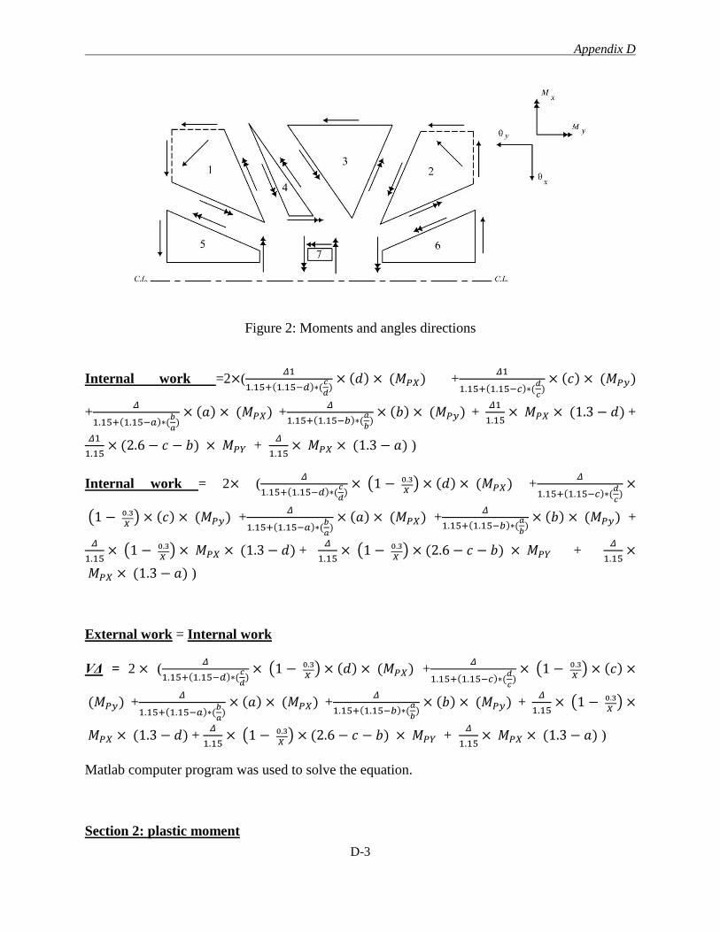
Appendix D
D-3
Figure 2: Moments and angles directions
Internal work =2×(𝛥1
1.15+(1.15−𝑑)∗(𝑐
𝑑)
× (𝑑) × (𝑀𝑃𝑋) +𝛥1
1.15+(1.15−𝑐)∗(𝑑
𝑐)
× (𝑐) × (𝑀𝑃𝑦)
+𝛥
1.15+(1.15−𝑎)∗(𝑏
𝑎)
× (𝑎) × (𝑀𝑃𝑋) +𝛥
1.15+(1.15−𝑏)∗(𝑎
𝑏)
× (𝑏) × (𝑀𝑃𝑦) + 𝛥1
1.15× 𝑀𝑃𝑋 × (1.3 − 𝑑) +
𝛥1
1.15× (2.6 − 𝑐 − 𝑏) × 𝑀𝑃𝑌 +
𝛥
1.15× 𝑀𝑃𝑋 × (1.3 − 𝑎) )
Internal work = 2× (𝛥
1.15+(1.15−𝑑)∗(𝑐
𝑑)
× (1 − 0.3
𝑋 ) × (𝑑) × (𝑀𝑃𝑋) +
𝛥
1.15+(1.15−𝑐)∗(𝑑
𝑐)
×
(1 − 0.3
𝑋 ) × (𝑐) × (𝑀𝑃𝑦) +
𝛥
1.15+(1.15−𝑎)∗(𝑏
𝑎)
× (𝑎) × (𝑀𝑃𝑋) +𝛥
1.15+(1.15−𝑏)∗(𝑎
𝑏)
× (𝑏) × (𝑀𝑃𝑦) +
𝛥
1.15× (1 − 0.3
𝑋 ) × 𝑀𝑃𝑋 × (1.3 − 𝑑) +
𝛥
1.15× (1 − 0.3
𝑋 ) × (2.6 − 𝑐 − 𝑏) × 𝑀𝑃𝑌 +
𝛥
1.15×
𝑀𝑃𝑋 × (1.3 − 𝑎) )
External work = Internal work
VΔ = 2 × (𝛥
1.15+(1.15−𝑑)∗(𝑐
𝑑)
× (1 − 0.3
𝑋 ) × (𝑑) × (𝑀𝑃𝑋) +
𝛥
1.15+(1.15−𝑐)∗(𝑑
𝑐)
× (1 − 0.3
𝑋 ) × (𝑐) ×
(𝑀𝑃𝑦) +𝛥
1.15+(1.15−𝑎)∗(𝑏
𝑎)
× (𝑎) × (𝑀𝑃𝑋) +𝛥
1.15+(1.15−𝑏)∗(𝑎
𝑏)
× (𝑏) × (𝑀𝑃𝑦) + 𝛥
1.15× (1 − 0.3
𝑋 ) ×
𝑀𝑃𝑋 × (1.3 − 𝑑) + 𝛥
1.15× (1 − 0.3
𝑋 ) × (2.6 − 𝑐 − 𝑏) × 𝑀𝑃𝑌 +
𝛥
1.15× 𝑀𝑃𝑋 × (1.3 − 𝑎) )
Matlab computer program was used to solve the equation.
Section 2: plastic moment
Appendix D
D-4
1) The steel specimen (S-0.65-N-15-XX):
Mx = 80 kN. m/m
My= 72 kN. m/m
Vflex = 575 kN > Vactual = 486 kN (the specimen failed in shear).
𝑽𝒂𝒄𝒕. 𝑽𝒇𝒍𝒆𝒙.⁄ = 𝟎. 𝟖𝟒 < 𝟏
The plastic moment for the GFRP specimens was calculated according to the method described
by Gar et.al (2014) using equation number [1]. Also, it’s worth to mention that, the authors did
not mention anything about the strain either for the concrete or the FRP bars. In addition the
flexure capacity, Vflex, in Gar et.al (2014) paper ranged from 100 to 858 kN.
MP = 0.5 Mn + 0.15 Mcr [Eq. 1]
Where:
MP = the plastic moment per unit width
Mn = the moment capacity per unit width
Mcr = the cracking moment per unit width
2) FRP control specimen (G-0.65-N-15-XX):
Mx = 76.5 kN. m/m
My = 65.9 kN. m/m
Vflex = 536 kN > Vactual = 363 kN (the specimen failed in punching shear).
𝑽𝒂𝒄𝒕. 𝑽𝒇𝒍𝒆𝒙.⁄ = 𝟎. 𝟔𝟕 < 𝟏