Embed Size (px)
Citation preview

Accepted Manuscript
A new test method for investigating punching shear strength in Ultra High Per-
formance Fibre Reinforced Concrete (UHPFRC) slabs
A.M.T. Hassan, G.H. Mahmud, S.W. Jones, C. Whitford
PII: S0263-8223(15)00508-5
DOI: http://dx.doi.org/10.1016/j.compstruct.2015.06.044
Reference: COST 6543
To appear in: Composite Structures
Please cite this article as: Hassan, A.M.T., Mahmud, G.H., Jones, S.W., Whitford, C., A new test method for
investigating punching shear strength in Ultra High Performance Fibre Reinforced Concrete (UHPFRC) slabs,
Composite Structures (2015), doi: http://dx.doi.org/10.1016/j.compstruct.2015.06.044
This is a PDF file of an unedited manuscript that has been accepted for publication. As a service to our customers
we are providing this early version of the manuscript. The manuscript will undergo copyediting, typesetting, and
review of the resulting proof before it is published in its final form. Please note that during the production process
errors may be discovered which could affect the content, and all legal disclaimers that apply to the journal pertain.
A new test method for investigating punching shear strength in Ultra High Performance
Fibre Reinforced Concrete (UHPFRC) slabs
A.M.T. Hassana,
, G.H. Mahmudb, S.W. Jones
b, C. Whitford
b.
a Department of Civil Engineering, Architecture and Building, Coventry University,
Coventry CV1 3FP, UK b School of Engineering, University of Liverpool, Liverpool L69 3GQ, UK
Abstract
Punching shear capacity of Ultra High Performance Fibre Reinforced Concrete (UHPFRC)
slabs has been the subject of a number of studies. There is, however, only limited information
available on this parameter of UHPFRC without conventional reinforcement. This is due to
the complexity of punching shear behaviour within concrete and is also limited by the lack of
suitable test methods currently available. Therefore, in this study, attempts to design a novel
testing method to measure the punching shear capacity of the concrete was carried out. The
designed test arrangement was employed to carry out an extensive experimental study on
UHPFRC slabs subjected to punching shear failure. From the results obtained, the
relationship between the punching shear load and the angle of the shear plane, the critical
value of the basic control perimeter and failure mode were studied. The experimental study
undertaken here provides significant insight into the punching shear capacity of UHPFRC
slabs. The results illustrate and highlight many of the advantages of using UHPFRC
compared to normal concrete in structural designs. The novel punching shear test presented
here has established itself as a suitable procedure for testing UHPFRC and potentially, other
fibre reinforced composites.
Keywords: Punching shear load and angle, Basic control perimeter, Punching shear failure
behaviour, UHPFRC.
--------------------
Corresponding author. Tel: 02476887950
E-mail address: [email protected] (A.M.T. Hassan)
1. Introduction
The high tensile and compressive properties of UHPFRC have been well reported [1-4]. The
improved properties of this concrete has allowed structural members to be built with complex
forms, lower volume of conventional steel reinforcement or maybe none, and lower
maintenance costs. The improved tensile behaviour of UHPFRC can be exploited to enhance
the shear resistance of its structural members, particularly in highway bridge applications.
Structural failures of highway bridge structures are not common under static loading.
However, in highway bridges, beam and slab failure usually occur in two common forms,
direct flexural and/or punching shear. The direct flexural failure typically occurs in beam or
slab members and is associated with overall bending. This type of failure arises from the
formation of diagonal tension cracks in the region of maximum bending moment and extends
across the entire width of the member. However, punching shear failure is a more localised
effect associated with thin slabs or two-way slab-column members when subjected to a
highly concentrated load. Punching shear failure occurs when the principal stress across the
critical surface of the section exceeds the tensile strength of the concrete due to applied
loading and failure occurs with limited warning. An example of this type of complete failure
is seen in Figure 1. Failure occurs with the potential diagonal crack following the surface of a
truncated cone around the load. The failure surface extends from the bottom of the member
diagonally upward to the top surface. For a normal concrete slab, the angle of inclination of
the failure surface ranges approximately from 20 to 45 degrees depending on the amount of
shear reinforcement [5]. However, very little information on this parameter is available for
UHPFRC.
The actual behaviour of concrete members in shear is complex and difficult to analyse
theoretically. Shear failure usually results from a combination of shearing forces and bending
moments. The current codes of practise such as Eurocodes and ACI have proposed
reasonably simplified procedures for the analysis and design of conventional concrete
members for punching shear resistance. These guidelines are based on results from many
experimental investigations [6]. However, these design equations have limitations and not
suitable when it comes to UHPFRC. The design equations do not fully take into account the
increase in the punching shear capacity of UHPFRC given the improved compressive and/or
tensile strengths associated with the concrete.
Since becoming commercially available, ultra high performance fibre reinforced concrete has
been used in construction under many different commercial names such as Ductal®, compact
reinforced composite, reactive powder concrete, and ultra-high performance concrete
(UHPC) [7-11]. In the last few years, UHPFRC has become popular in construction and a
number of optimised UHPFRC sections have been proposed for highway bridge applications,
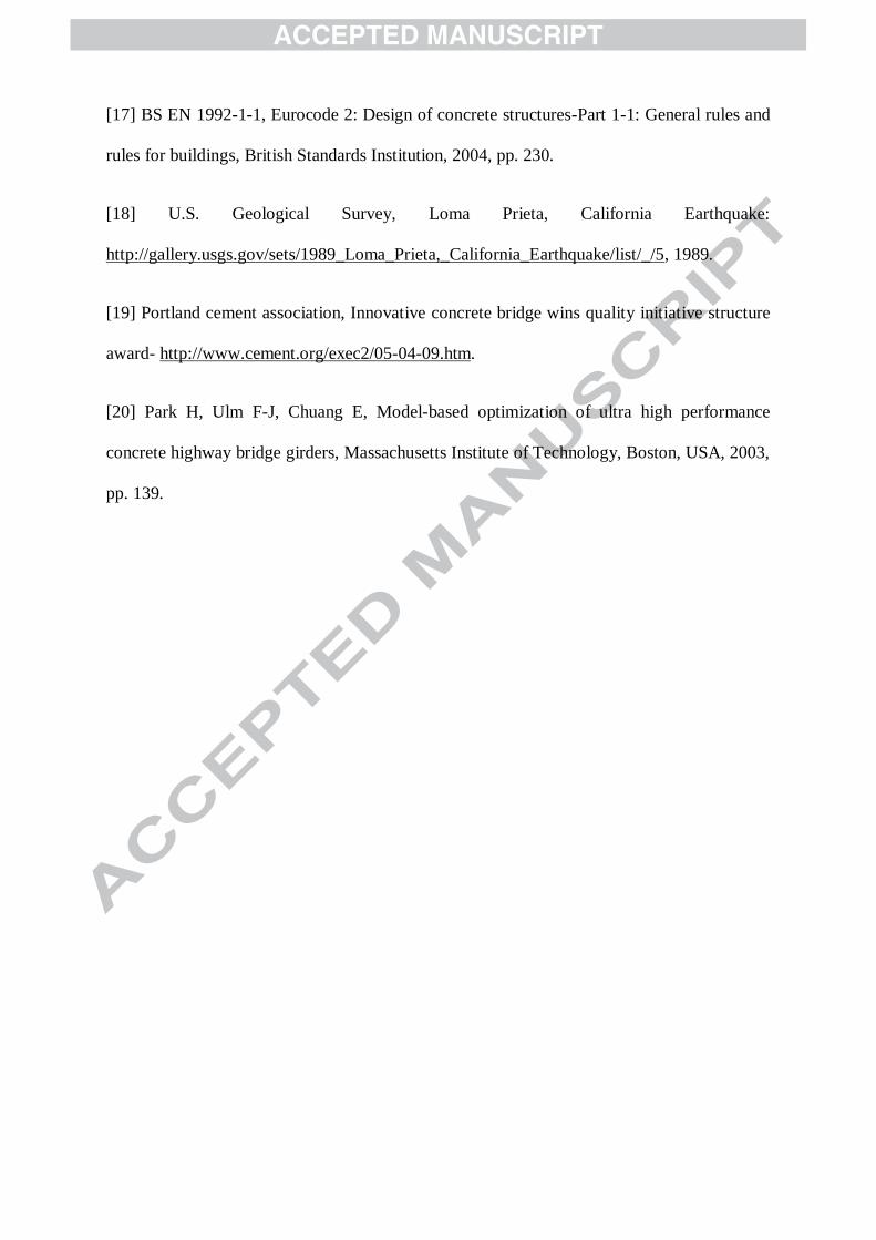
see Figure 2.
Such bridge girders appear to have been optimised to the limit. However, knowledge of the
structural behaviour of these girders, in particular, the shear strength without steel
reinforcement is very limited. So far, punching shear capacity of UHPFRC has been the
subject of a number of studies [12-14]. However, difficulties in determining this property
have been reported due to the occurrence of flexural failure prior to punching shear during
testing [12-14]. Therefore, specific knowledge of the shear strength in isolation from the
effects of flexural damage is required to contribute towards the design of UHPFRC in
construction. However, very little information is available on this property due to the
complexity of punching shear behaviour of UHPFRC and also due to lack of a suitable
testing methodology. Therefore, in this study, a novel testing method has been designed to
accurately measure the punching shear behaviour of UHPFRC. Detailed experimental
investigations on the punching shear behaviour of UHPFRC slabs without steel reinforcement
subjected to high concentrated load were carried out. Various parameters ranging from the
relationship between punching shear load ( rdV ) and angle ( ), the critical value of the basic
control perimeter ( u ) to the failure mode were investigated.
2. Experimental studies
In this study, a series of cube and slab specimens were cast and tested. The cube specimens
were tested to obtain density and compressive strength measurements at 28 days. The slab
specimens were also tested at 28 days to obtain punching shear behaviour. In this section, the
development of the punching shear test method and the experimental study are presented.
This include, test development, mix composition, specimen preparation and test setup
arrangements.
2.1 Test Development
A number of trial tests were conducted to characterise the punching shear capacity of the
concrete with minimum influence of bending stress. The trial tests were performed and
modified throughout the experimental program until the final test setup was developed. It
must be noted that there are no existing standards for measuring the punching shear capacity
of UHPFRC slabs or the test method described here. The experimental investigation was
divided into three phases, as discussed below.
In the first phase, preliminary tests were carried out on rectangular slabs of 300x300x30 mm
in length, width and depth, respectively. The size of the specimens was kept small due to the
high cost of the material. However, large enough so that punching shear failure could occur
during testing. The specimens were supported on two different boundary conditions, simply
supported on four edges and circular hollow steel rings with various diameters. The load was
applied to the centre of the specimen using a 50 mm diameter steel indenter. The small
loaded area was used to enhance the possibilities of punching shear failure. From the results
obtained in this phase, it was observed that the influence of flexural failure was not only
present but quite significant. The flexural failure was far more pronounced in the simply
supported specimens as opposed to those with circular supports. A combination of flexural
and shear failure was observed from the results of this phase.
In the literature, fixed boundary conditions was reported to improve the possibility of
punching shear failure of thin UHPFRC slabs [12, 13]. This is due to the reduction of the

maximum bending moment in the region of punching shear. However, the influence of
flexural stress was still reported to be significant. Therefore, this study took a different
approach to develop a test setup that can minimise the effect of flexural failure on punching
shear tests.
The second phase was to increase the thickness of the slab specimens to 60 mm and
incorporate an initial notch, similar to notched beam specimens in bending tests. Circular
notches of 30 mm depth of different diameters were introduced at the centre of the
specimens, as shown in Figure 3. There were two purposes to this design: 1. to provide a
notch which initiates a shear plane along a predefined path and cause punching failure; 2.
provide increased flexural stiffness in the slab. Various notch diameters from the inside edge
of the notches ranging from 55.5 mm to 162 mm were introduced which provided a wide
range of punching shear angles relative to the applied load. In this phase, the circular
boundary condition was used.
This method forced the failure of the slabs at the notch positions. Results obtained in this
phase appeared to be promising, but inconsistent. The influence of flexural and hoop stresses
were present, and so an improvement in the test setup was required. Figure 3, provides a
schematic indicating the test setup at this stage.
In the third and final phase, the flexural and hoop stress effects were reduced significantly.
This was achieved by increasing the depth of the shear notches and using an improved
supporting arrangement. The specimen’s total thickness was increased from 60 mm to 90
mm. The initial notch depth was increased from 30 mm to 60 mm and the effective slab
thickness was kept at 30 mm. The depth of the notches was increased to minimise flexural
stress before the occurrence of punching shear failure. In addition, the specimens were
supported close to the perimeter of their notches using circular steel tubes of various
diameters. The inside diameter of each support was equal or smaller than 1.30 times the
diameter of the notch. The various sizes of circular boundary condition was used to minimise
warping and hoop stress as had been encountered in the preliminary stages of the tests. The
results obtained from this phase were predominately punching shear failure and the objective
of the investigations was achieved as demonstrated in the results and discussion section. The
final test setup is shown in Figure 4.
2.2 UHPFRC mix
The mix proportion adopted in this study is summarised in Table 1 [15]. In the mix, Portland
cement (CEM 1) with a strength class 52.5 N was used. Two types of supplementary
cementitious materials were used; ground granulated blast-furnace slag (GGBS) and silica
fume (SF) supplied by Appleby Group Ltd and Elkem Materials, respectively.
The chemical, physical and mechanical properties of the cement, GGBS and SF used in the
mix can be found elsewhere [3]. The aggregate, silica sand was supplied by WBB Minerals
UK, with an average particle size of 270 microns. A polycarboxylate-based superplasticiser

known as Structuro 11180 was supplied by FOSROC Ltd. The steel fibres were straight high
carbon steel with a tensile strength of 2000 MPa, 13 mm in length and 0.20 mm in diameter,
supplied by Bekaert Ltd.
For the mixing process, materials were weighed and placed in a horizontal pan mixer in the
order: silica fume, cement, GGBS, and silica sand. The materials were firstly dry mixed for 5
minutes before water and superplasticiser were added. The materials were mixed for a further
10 minutes until the dry powder mix transformed into a wet paste concrete. At this stage,
steel fibres were slowly added by hand to the wet concrete paste in the mixer. The concrete
was mixed for a further 2 minutes to ensure proper dispersion of fibres in the mix after which
the specimens were cast. The specimens were compacted on a vibrating table for nearly 1
minute. After compaction, all the specimens were covered with damp hessian and polythene
sheets, and kept at laboratory temperature (approximately 20 o
C) for 24 h. In total, 22
rectangular slabs and 9 cube specimens were cast. Once initial setting has occurred,
demoulding took place at approximately 24 h. All the specimens were submersed in a curing
tank in an elevated temperature of 90oC for the next 48 h and finally kept at laboratory
temperature until testing.
2.3 Specimen preparations
In the third phase, the dimensions of the slab specimens were mm in length,
width and depth, respectively. The cube specimens were the standard size of 100 mm.
Prior to introducing the shear notches, the trowel side of the slab specimens were ground to
provide an even surface for notching, as shown in Figure 5. Soon after grinding, a
mechanically secured pillar drill with diamond core bits of various diameters were used to
introduce the shear notches to the underside of each specimen in the centre, as shown in
Figure 6. The width of the notches was approximately 4 mm to 4.5 mm. Table 2 summarises
the notch diameters, support diameters and thickness, basic control perimeter and the
punching shear angles of the specimens.
2.4 Test setup
The specimens were tested using a 300 kN Zwick testing machine. The load was applied at
the centre and opposite side to the notches using a 50 mm diameter steel indenter. The test
was conducted under displacement control at a rate of 0.1mm/min up until a vertical
deflection ( rd ) of 9.5 mm was recorded. For deflection measurements, an LVDT was
positioned under the specimen in line with the centre of the load indenter. For each notch
size, three or more specimens were tested and punching shear load against deflection data
was acquired digitally. Figure 7 shows the test setup in the testing rig.
After each test, the failed specimen was removed from the testing rig and checked visually to
investigate any signs of flexural failure. Finally, the specimen was placed back into the
loading rig and reloaded again to cause total failure. In this way, the punching shear cone of
the specimen was forced through and investigations on the modes of failure and fibre
distribution in the concrete were carried out.
3. Results and Discussion
3.1 Load vs defection
The mean compressive strength and density of the concrete at 28 days were 166.2 MPa and
2450 kg/m3, respectively. The test results for the slab specimens presented here were
obtained from the developed test method (final phase) described in Section 2.3. The full test
results of this phase is summarised in Table 3.
At the beginning of each test, concrete crushing was observed, in particular, for slab
specimens with the smallest notch diameters (55.5 and 81.5 mm) as they were exhibiting
higher punching shear loads. The loads versus vertical deflections for both test results are
presented in Figures 8 and 9, respectively. In both figures, concrete crushing is apparent as
the initial elastic stiffness of the test results experience a dip in the beginning of each test,
however, this seemed to be insignificant on the final test results.
In Figure 8, the load increases in a linear rate until the maximum punching shear load is
achieved and failure occurs with limited warning. This finding is consistent with typical
punching shear failure for normal concrete. Specimens with a perimeter distance of 0.53d
(Figure 9) experienced crack formation before the maximum load was reached and one
ductile failure was also reported. The load-deflection response indicates failure of the matrix
before the peak strength was reached and fibre contribution starts just before total failure.
Five out of the six tested specimens failed in a brittle manner, hence failure mode was
considered brittle.
The load versus vertical deflections for the remaining specimens with basic perimeter
distances of 1.02, 1.38, 1.62 and 1.87d are presented in Figures 10 to 13, respectively. In all
these figures, the load increases in a linear manner until approximately 90% of the maximum
punching shear load. Subsequently, strain hardening occurs for a short period until the
maximum load is reached. In these tests, the specimens were able to sustain reducing load
after their peak strength and continued to deform in a ductile manner, similar to a typical
UHPFRC flexural failure [4].
3.2 Punching shear load vs angle
Figure 14 provides the relationship between the punching shear load and the failure angle
within the concrete. The ultimate punching shear load increases with greater punching shear
angles. This is as expected because the greater the angle of shearing, the greater the
proportion of the force that is resisted by shear strength as opposed to tensile strength. This
behaviour is known as shear support enhancement. It describes that the punching shear
capacity of the concrete increases with the increase of the punching shear angle due to extra
enhancement from the compression struts provided by the concrete. As expected, the
punching shear load is the smallest at a basic control perimeter of approximately 2d (28.2o).

3.3 Failure behaviour
The failure behaviour of specimens with perimeter distances of 0.09 and 0.53d was very
similar to the punching shear failure of conventional concrete, i.e. brittle with limited
warning. For UHPFRC, an improvement in ductility was expected due to the presence of
steel fibres in the concrete. However, this was not seen for specimens with a basic control
perimeter of 0.09d, while little was reported for specimens of 0.53d. The abrupt and brittle
failure of these tests resulted from a number of factors, and these can be summarised as
follows:
The steep punching shear angles,
The lack of random fibre distribution along the shear line failure, hence lack of fibre
bridging effect,
Confined shear crack patterns, and
The high intensity of shear stress close to the loading plate.
The punching shear angles in the tests were 84.8 and 62.3, respectively. At such steep
angles, random fibre orientation along the shear plane is not likely to be achieved. In
addition, the number of fibres resisting the shear load for both sets of specimens is small,
relative to their small punching shear areas. It is possible that the tensile load transferred from
the fibres to the concrete prior to immediate failure of the specimen is also very small. As a
result, most of the steel fibres along the shear plane experienced direct shear failure with
minimal fibre bridging effect, and the matrix alone was more likely to resist most of the shear
load up until failure. Hence, failure occurred when diagonal tension or combined action of
shear and direct stress exceed the tensile strength of the concrete and resulted in the
occurrence of confined diagonal shear cracks. Another factor could be due to the high
intensity of the shear stress in the region close to the loading plate (smaller basic control
perimeters). The brittle failure behaviour for almost all the specimens in Figures 8 and 9 is a
result of the combination of all the factors described above.
The conical punching shear failure shapes of specimens with basic control perimeters of
0.09d and 0.53d are shown in Figure 15. It is evident that failure had occurred when shear
cracks have initiated and radiated outwards from the point of the applied load to the shear
notches on the tension side of the specimen forming a radiated failure cone. From these
cones, a mixture of failed fibres and fibre pull-out behaviour were observed, in particular,
specimens with basic control perimeters of 0.09d.
The load-deflection curves presented in Figures 10 to 13 indicate ductile failure behaviour for
all the specimens tested and total failure did not happen suddenly. Deformation of
approximately 0.5 mm and greater with multiple cracking occurred before maximum load
was reached. This type of failure for concrete slabs without conventional reinforcement is
different to typical punching shear failure reported for normal concrete [16]. To ensure the
results obtained here are actually punching shear failure, the failed specimens were examined
individually. In Figure 16, the failure behaviour of some of the tested specimens is shown,
and the shape of the truncated cone failure is very similar to a typical punching shear failure
that has being demonstrated in the literature for normal concrete [17] and those shown in
Figure 15. The stub punching of the load indenter for all the tests and the crack pattern at the
loaded face over a small area with a diameter almost the same of the loading indenter are a
clear indication of typical punching shear failure. From Figures 15 and 16, it is evident that
the test setup has caused the occurrence of punching shear failure of all the tests.
Furthermore, the punching of the load indenter through the slab and the truncated cone failure
shape were observed for every tested specimen in this study. Results from this study proves
that the novel punching shear test presented here is as a suitable procedure for testing
UHPFRC and potentially other fibre reinforced composite slabs with minimal flexural
influence.
Furthermore, the variations in failure behaviour for specimens in Figures 8 and 9 to those in
10 to 13 are down to the significant differences in the punching shear angles, punching shear
areas, fibre distribution, and the fibre bridging effect in each of the tests. With smaller
punching shear angles and greater punching shear areas, the number of steel fibres bridging
the shear crack surfaces increase in the failure region. As a result, greater fibre pull-out forces
are transferred across the cracks once the maximum load is reached. Hence, the fibre bridging
effect after formation of microcracks becomes more effective and results in ductile failure.
The considerably improved ductile behaviour reported for specimens with a basic control
perimeter of 1.02d and above is significant in structural design and such behaviour can be
exploited for structures where punching shear failure is imminent and the option of heavy
shear reinforcement is limited in the member, i.e. thin UHPFRC highway bridge decks. This
ductile behaviour can be used in UHPFRC design to reduce the basic control perimeter by
half (1.02d) compared to what has been specified in EC2 for conventional concrete (2d).
4. Conclusions
In this study, an extensive experimental programme was carried out to develop a novel
testing method to study the punching shear behaviour of UHPFRC slabs with minimal
flexural influence. Results obtained here were used to investigate the relationship between
punching shear load and angle, the critical value of the basic control perimeter and the failure
behaviour of the concrete under a concentrated load. The following conclusions can be drawn
from the results:
The ultimate punching shear load was found to increase with greater punching shear
angle due to the extra enhancement from the compression struts in the concrete. This
behaviour is known as shear support enhancement. The punching shear load was
found to be the smallest at a punching shear angle of 28.2o (basic control perimeter of
approximately 2d). This is in close agreement to what has been reported for normal
concrete [17].
From the examination of the failure modes of the tests, all the slabs failed with a
truncated cone shaped on the supported side and a stub punching on the loaded side.
This failure mode is similar to the typical punching shear failure reported for normal
concrete [6], and validates the accuracy of the test method developed in this study.
The failure behaviour for UHPFRC slab specimens with punching shear angles equal
to and greater than 62o (basic control perimeter of 0.53d and smaller) were found to
be brittle, similar to the typical punching shear failure behaviour for normal concrete
[6]. However, the failure behaviour changed to a ductile mode for specimens with
punching shear angles equal to and smaller than 45o (basic control perimeter of 1.02
and greater), similar to its typical flexural failure reported in the literature [4].
The improved ductility of these tests resulted from the fibre bridging effect along the
shear planes in the concrete. As a result, the slab specimens could undergo greater
deflection after the maximum load was attained. Such ductile behaviour is the
preferred failure mechanism for slabs in concrete designs.
The findings reported here on the punching shear failure behaviour of UHPFRC slabs
with no shear reinforcement are significant. The results illustrate a reduction of the
basic control perimeter for UHPFRC slabs by half compared to what is specified in
EC2 for conventional concrete. This improved ductility of the concrete in punching
shear failure with its high tensile strength can be exploited to limit shear
reinforcement in UHPFRC slab members to 1d when required. This behaviour is
beneficial in the design of structures where punching shear failure is imminent and the
option of heavy shear reinforcement is limited in the member, i.e. thin UHPFRC
highway bridge decks.
Acknowledgments
The authors gratefully acknowledge the financial support from the Engineering and Physical
and Science Research Council, UK for their support of this study through a DTA award.
References
[1] P. Richard, M.H. Cheyrezy, Reactive powder concretes with high ductility and 200 - 800
Mpa compressive strength, American Concrete Institute, 144 (1994) 507-518.
[2] B.A. Graybeal, Characterization of the behavior of ultra-high performance concrete,
University of Maryland, Maryland, United States, 2005, pp. 360.
[3] S.L. Yang, S.G. Millard, M.N. Soutsos, S.J. Barnett, T.T. Le, Influence of aggregate and
curing regime on the mechanical properties of ultra-high performance fibre reinforced
concrete (UHPFRC), Construction and Building Materials, 23 (2009) 2291-2298.
[4] G.H. Mahmud, Z. Yang, A.M.T. Hassan, Experimental and numerical studies of size
effects of Ultra High Performance Steel Fibre Reinforced Concrete (UHPFRC) beams,
Construction and Building Materials, 48 (2013) 1027-1034.
[5] A.H. Nilson, D. Darwin, C.W. Dolan, Design of concrete structures, McGraw Hill, 13th
Edition2003.
[6] W.H. Mosley, R. Hulse, J.H. Bungey, Reinforced concrete design to Eurocode 2, Palgrave
MacMillan. 7th Edition2012.
[7] M. Andrade, M. Frias, B. Aarup, Durability of ultra-high strength concrete: Compact
reinforced composite, BHP96 Fourth International Symposium on Utilisation on High
Strength/High Performance ConcreteParis, France, 1996, pp. 529-534.
[8] N. Roux, C. Andrade, M. Sanjuan, Experimental study of durability of reactive powder
concretes, Journal of Materials in Civil Engineering, 8 (1996) 1-6.
[9] G. Orange, J. Dugat, P. Acker, Ductal®: New ultra high performance concretes. Damage
resistance and micromechanical analysis, Fifth International RILEM Symposium on Fibre-
Reinforced Concrete (FRC), 2000, pp. 781-790.
[10] P. Rossi, Ultra-high performance fibre reinforced concretes (UHPFRC): an overview, In
Proceeding Fifth RILEM Symposium on Fibre-Reinforced Concretes (FRC) - BEFIB' 2000,
2000, pp. 87-100.
[11] B. Aarup, CRC–Applications of fibre reinforced high performance concrete, Concrete
Plant International CPI, (2007) 1-10.
[12] D.K. Harris, C.L. Roberts-Wollmann, Characterization of punching shear capacity of
thin ultra-high performance concrete slabs, Proceedings of the International Symposium on
Ultra High Performance Concrete, Kassel University Press GmbH, Kassel, Germany, 2008,
pp. 727-734.
[13] C. Joh, H. Hwang, E. Choi, J.J. Park, B.-S. Kim, Punching shear strength estimation of
UHPC slabs, Proceedings of the International Symposium on Ultra High Performance
Concrete, Kassel University Press GmbH, Kassel, Germany, 2008, pp. 719-726.
[14] L. Moreillon, J. Nseir, R. Suter, Shear and flexural strength of thin UHPC slabs,
Proceedings of Hipermat 2012, 3rd International Symposium on UHPC and Nanotechnology
for High Performance Construction Materials, Kassel University Press GmbH, Kassel,
Germany, 2012, pp. 748-756.
[15] T. Le, Ultra high performance fibre reinforced concrete paving flags, University of
Liverpool, Liverpool, United Kingdom, 2008, pp. 387.
[16] A.M. Neville, Properties of concrete, Prentice Hall, 5th Edition2012.
[17] BS EN 1992-1-1, Eurocode 2: Design of concrete structures-Part 1-1: General rules and
rules for buildings, British Standards Institution, 2004, pp. 230.
[18] U.S. Geological Survey, Loma Prieta, California Earthquake:
http://gallery.usgs.gov/sets/1989_Loma_Prieta,_California_Earthquake/list/_/5, 1989.
[19] Portland cement association, Innovative concrete bridge wins quality initiative structure
award- http://www.cement.org/exec2/05-04-09.htm.
[20] Park H, Ulm F-J, Chuang E, Model-based optimization of ultra high performance
concrete highway bridge girders, Massachusetts Institute of Technology, Boston, USA, 2003,
pp. 139.

List of Figures
Figure 1: Failure of the Struve Slough Bridge due to Loma Prieta Earthquake, USA [18].
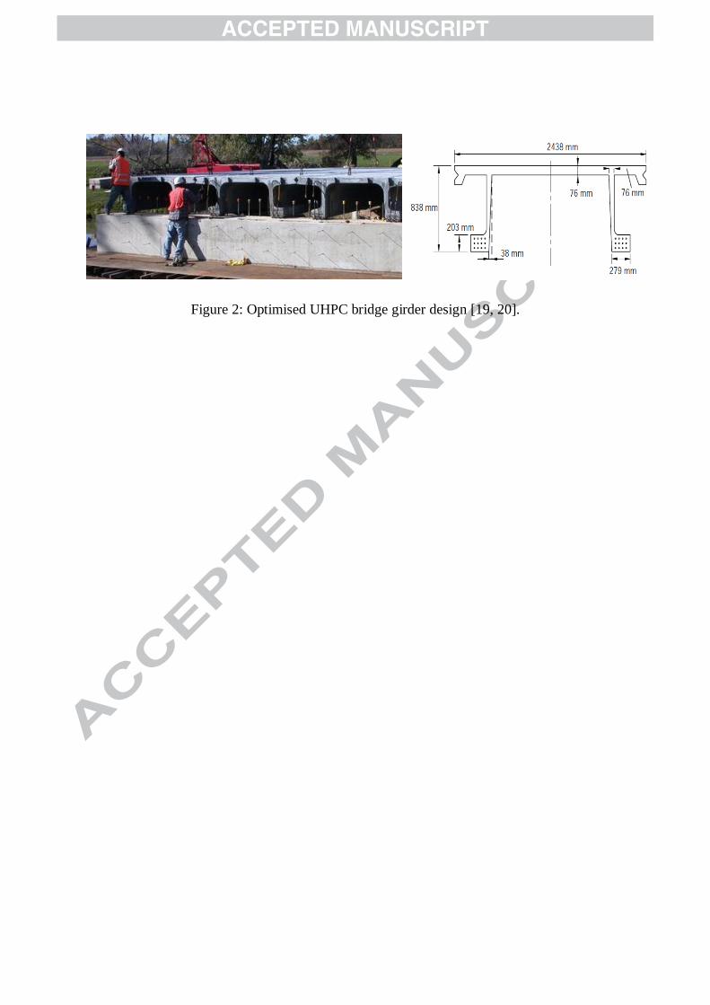
Figure 2: Optimised UHPC bridge girder design [19, 20].
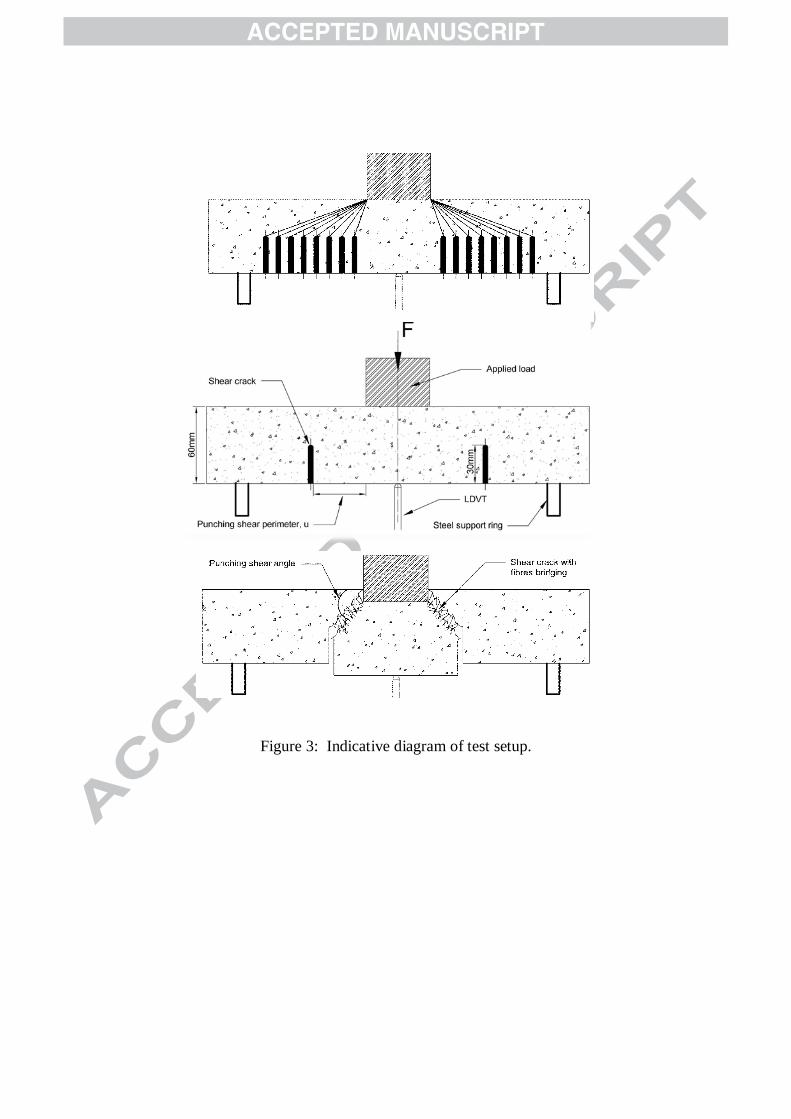
Figure 3: Indicative diagram of test setup.
Figure 4: The final test setup: (a) Section view, and (b) Plan view.
(a)
(b)

Figure 5: Specimen before and after grinding
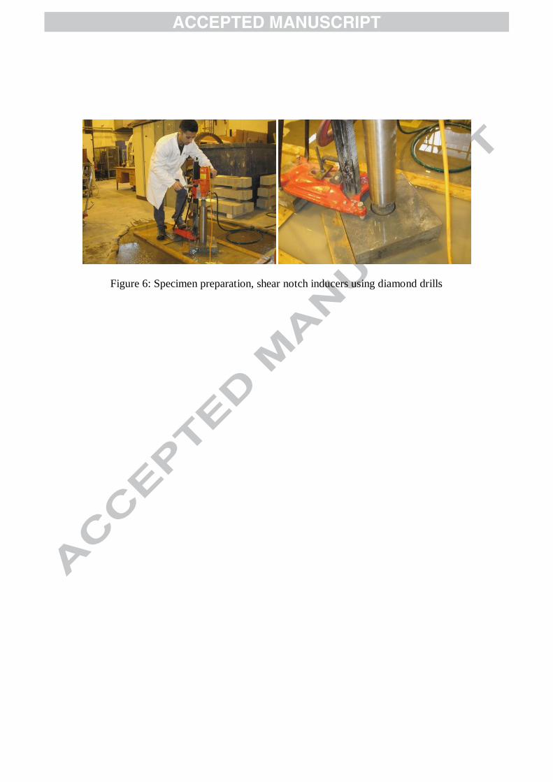
Figure 6: Specimen preparation, shear notch inducers using diamond drills
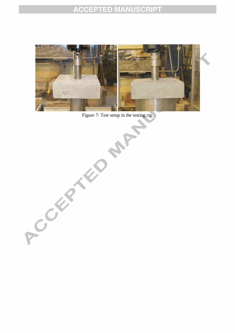
Figure 7: Test setup in the testing rig.
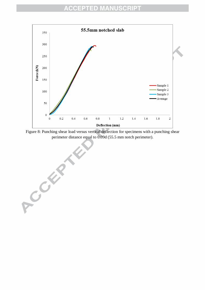
Figure 8: Punching shear load versus vertical deflection for specimens with a punching shear
perimeter distance equal to 0.09d (55.5 mm notch perimeter).
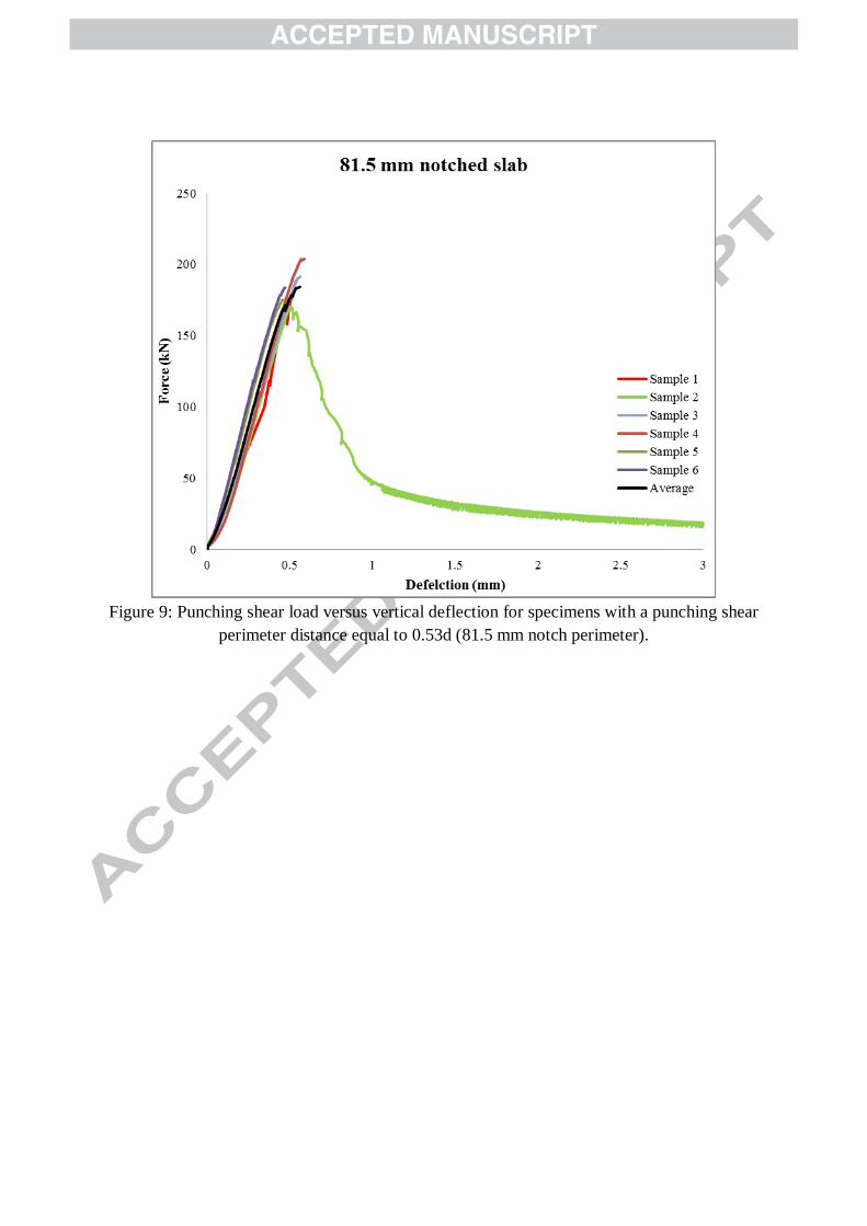
Figure 9: Punching shear load versus vertical deflection for specimens with a punching shear
perimeter distance equal to 0.53d (81.5 mm notch perimeter).
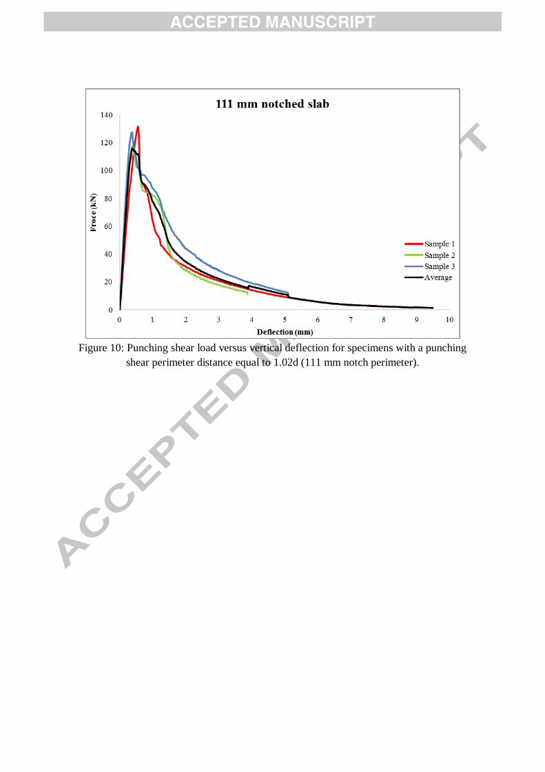
Figure 10: Punching shear load versus vertical deflection for specimens with a punching
shear perimeter distance equal to 1.02d (111 mm notch perimeter).
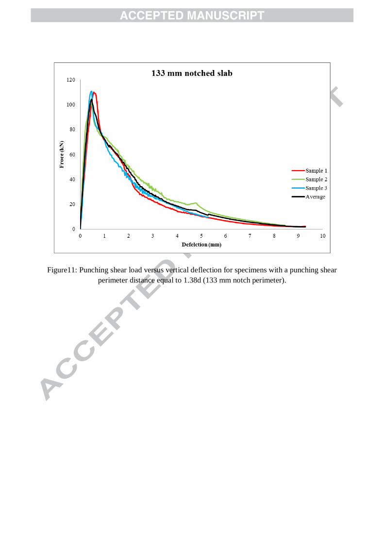
Figure11: Punching shear load versus vertical deflection for specimens with a punching shear
perimeter distance equal to 1.38d (133 mm notch perimeter).
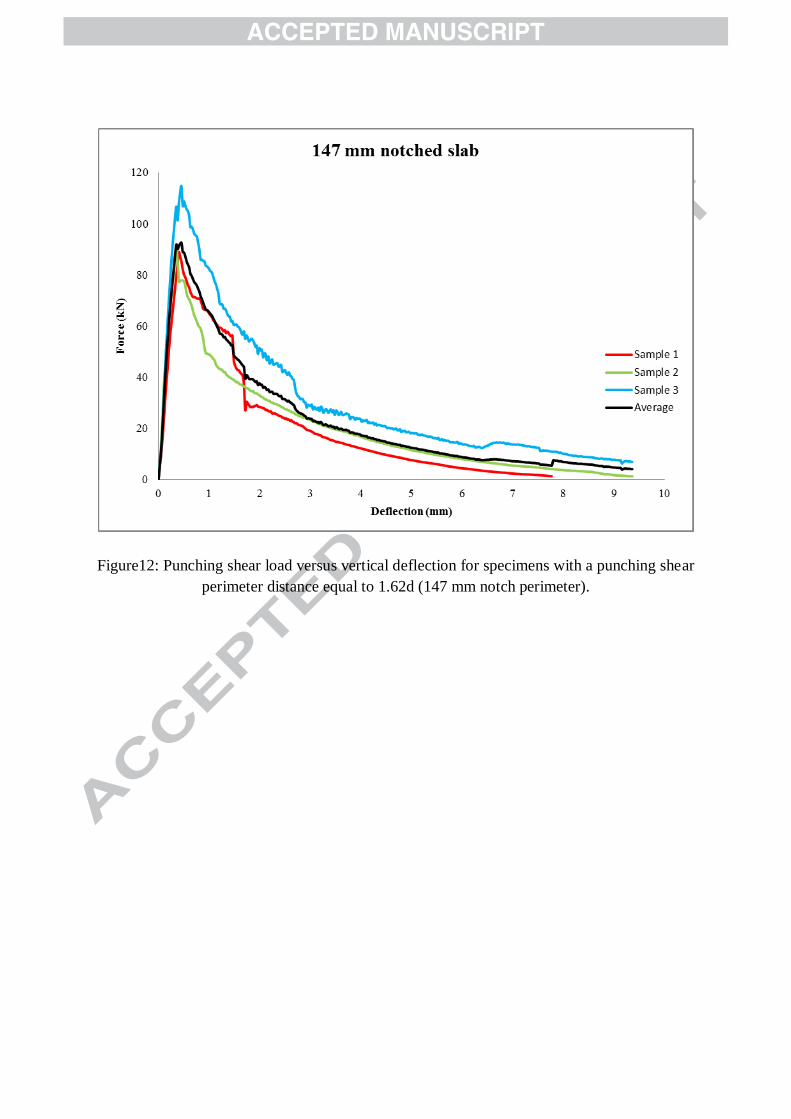
Figure12: Punching shear load versus vertical deflection for specimens with a punching shear
perimeter distance equal to 1.62d (147 mm notch perimeter).
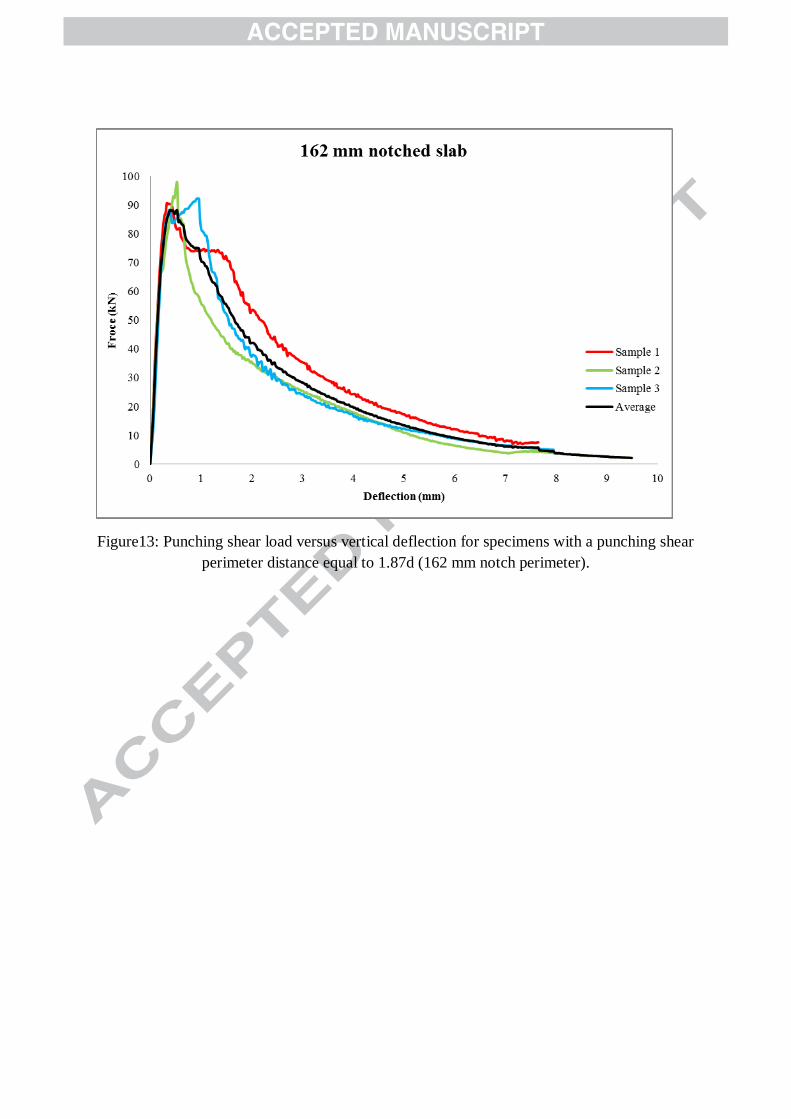
Figure13: Punching shear load versus vertical deflection for specimens with a punching shear
perimeter distance equal to 1.87d (162 mm notch perimeter).
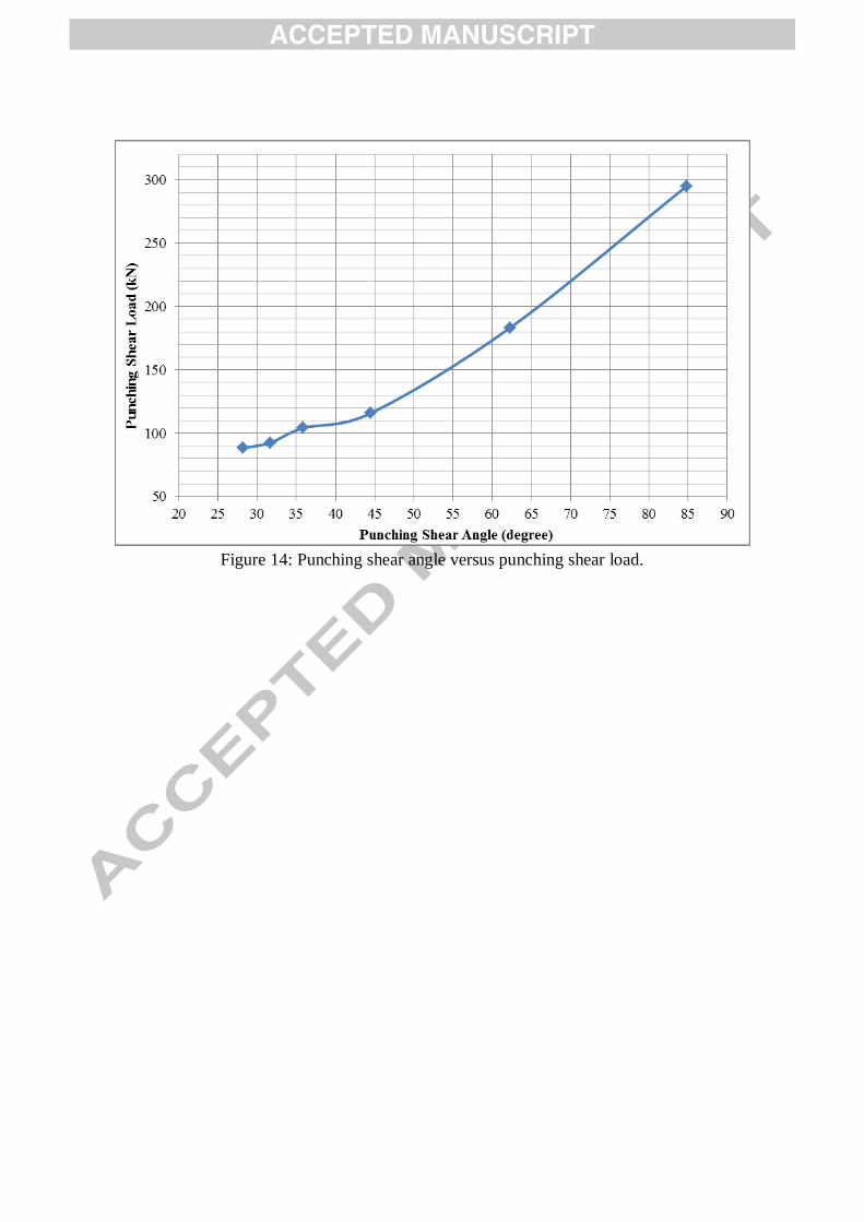
Figure 14: Punching shear angle versus punching shear load.
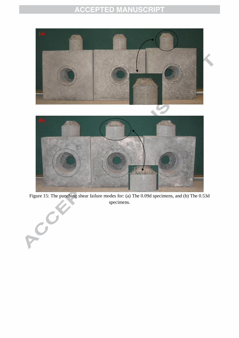
Figure 15: The punching shear failure modes for: (a) The 0.09d specimens, and (b) The 0.53d
specimens.
(a)
(b)
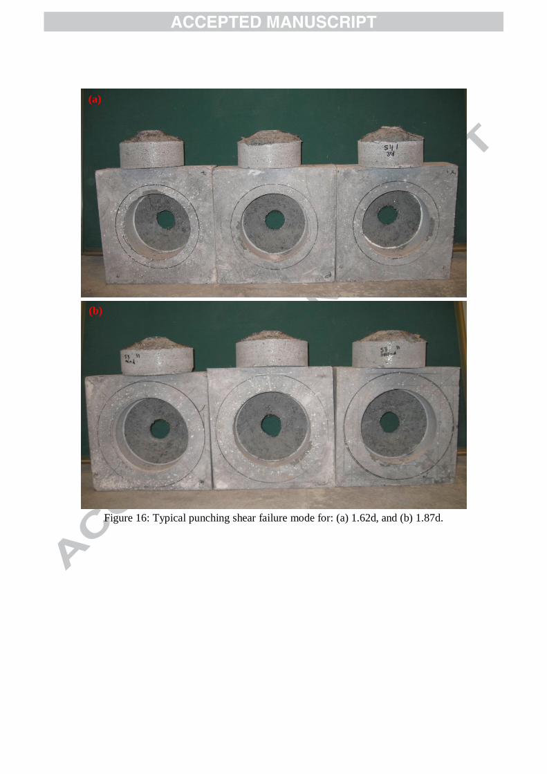
Figure 16: Typical punching shear failure mode for: (a) 1.62d, and (b) 1.87d.
(a)
(b)
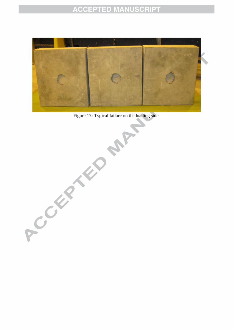
Figure 17: Typical failure on the loading side.

List of Tables
Table 1: Mix design for UHPFRC.
Material (kg/m3)
Cement (CEM1: 52.5N)
GGBS
Silica fume
Silica sand (average size 0.27 mm)
Superplasticisers
Water
Steel fibre (2% volume)
657
418
119
1051
40
185
157

Table 2: Summary of slab specimens and support arrangements in the third phase
Notch diameter
(mm)
Support, inside-
diameter (mm)
Support thickness
(mm)
Basic control
perimeter
Punching shear
angle (degree)
55.5 60 8 0.09d 84.8
81.5 98 8 0.53d 62.3
111 143 12.5 1.02d 44.5
133 150 8 1.38d 35.9
147 173 10 1.62d 31.7
162 194 12.5 1.87d 28.2

Table 3: Phase three test results.
Notch diameter (mm) u (degrees) rdV (kN) rd (mm) Failure mode
55.5 0.09d 84.8 294.86 0.762 Brittle
81.5 0.53d 62.3 183.26 0.561 Brittle1
111 1.02d 44.5 115.79 0.379 Ductile
133 1.38d 35.9 104.18 0.479 Ductile
147 1.62d 31.7 92.58 0.453 Ductile
162 1.87d 28.2 88.27 0.405 Ductile
1 Out of six specimens, five brittle and one ductile failure was reported.