Embed Size (px)
Citation preview
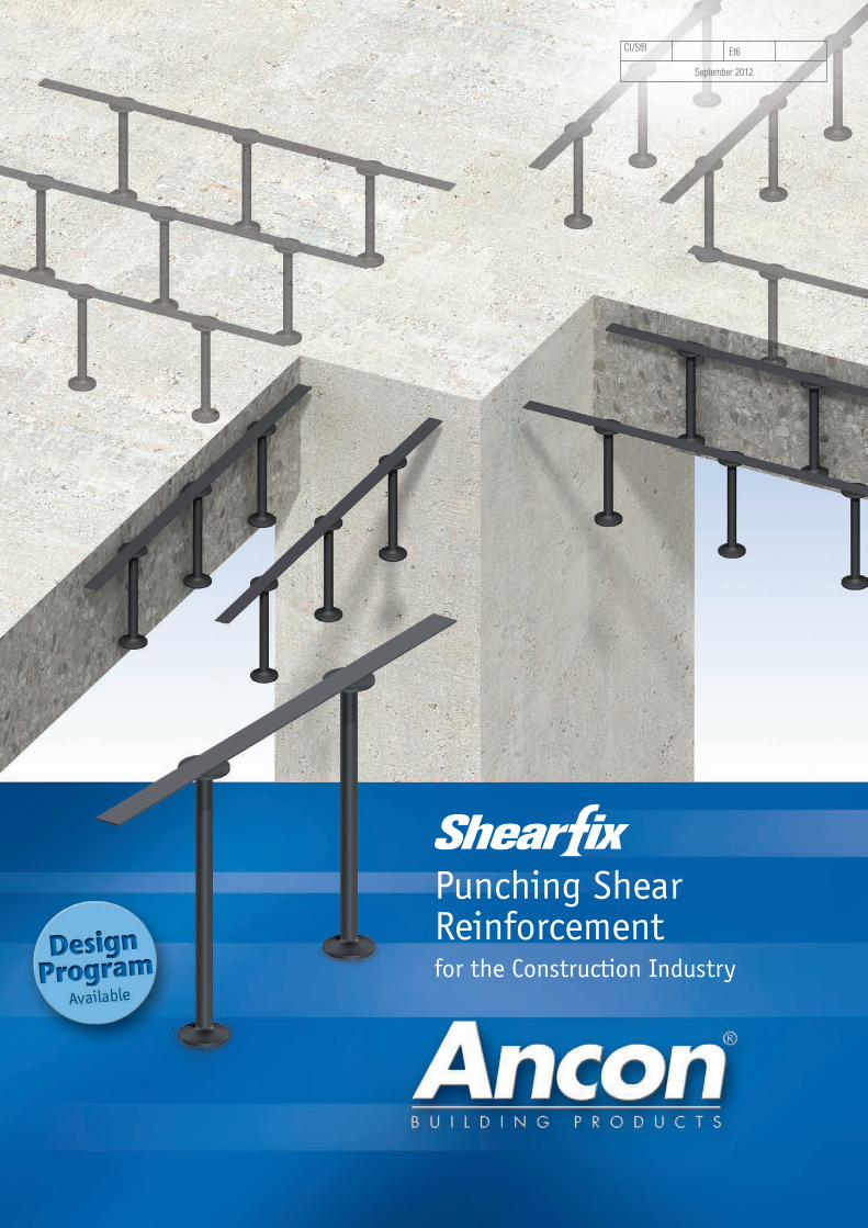
Punching ShearReinforcementfor the Construction Industry
CI/SfB Et6
September 2012
22 Tel: 1300 304 320 www.ancon.com.au
Ancon designs and manufactures high integrity steel products for
the construction industry. Through continuous programmes of
new product development, inward investment and employee
advancement, the company is committed to maintaining the
highest level of customer service within a dynamic and
challenging industry.
Masonry Support Systems
Windposts and Lintels
Wall Ties and Restraint Fixings
Channel and Bolt Fixings
Tension and Compression Systems
Stainless Steel Fabrications
Flooring and Formed Sections
Shear Load Connectors
Stainless Steel Reinforcement
Reinforcing Bar Couplers
Reinforcement Continuity Systems
Punching Shear Reinforcement
Precast Concrete Accessories
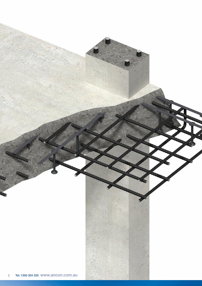
Used within a slab to provide additionalreinforcement around columns, Ancon Shearfixis the ideal solution to the design andconstruction problems associated withpunching shear. The system consists of double-headed studs welded to flat rails, positionedaround the column head or base.
Punching Shear 4
The Shearfix Solution 4
Comparison with Shear Links 4
Sizes and Configurations 5
Product Identification 5
Project Management 5
Design Program 6-7
Design Information 8
Calculation Method 9
Typical Arrangements 10
Installation Procedure 10
Applications 11
Other Ancon Products 11
3
Punching Shear Reinforcement
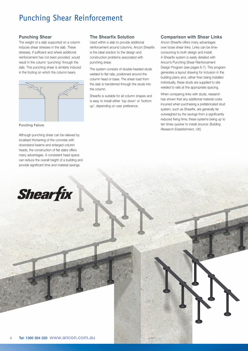
Punching ShearThe weight of a slab supported on a columninduces shear stresses in the slab. Thesestresses, if sufficient and where additionalreinforcement has not been provided, wouldresult in the column ‘punching’ through theslab. This punching shear is similarly inducedin the footing on which the column bears.
The Shearfix SolutionUsed within a slab to provide additionalreinforcement around columns, Ancon Shearfixis the ideal solution to the design andconstruction problems associated withpunching shear.
The system consists of double-headed studswelded to flat rails, positioned around thecolumn head or base. The shear load fromthe slab is transferred through the studs intothe column.
Shearfix is suitable for all column shapes andis easy to install either ‘top down’ or ‘bottomup’, depending on user preference.
Although punching shear can be relieved bylocalised thickening of the concrete withdownstand beams and enlarged columnheads, the construction of flat slabs offersmany advantages. A consistent head spacecan reduce the overall height of a building andprovide significant time and material savings.
Punching Failure
Comparison with Shear LinksAncon Shearfix offers many advantagesover loose shear links. Links can be time-consuming to both design and install.A Shearfix system is easily detailed withAncon’s Punching Shear ReinforcementDesign Program (see pages 6-7). This programgenerates a layout drawing for inclusion in thebuilding plans and, rather than being installedindividually, these studs are supplied to sitewelded to rails at the appropriate spacing.
When comparing links with studs, researchhas shown that any additional material costsincurred when purchasing a prefabricated studsystem, such as Shearfix, are generally faroutweighed by the savings from a significantlyreduced fixing time; these systems being up toten times quicker to install (source: BuildingResearch Establishment, UK).
4 Tel: 1300 304 320 www.ancon.com.au
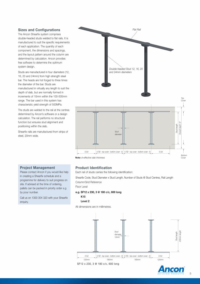
Sizes and ConfigurationsThe Ancon Shearfix system comprisesdouble-headed studs welded to flat rails. It ismanufactured to suit the specific requirementsof each application. The quantity of eachcomponent, the dimensions and spacings,and the layout pattern around the column aredetermined by calculation. Ancon providesfree software to determine the optimumsystem design.
Studs are manufactured in four diameters (12,16, 20 and 24mm) from high strength steelbar. The heads are hot forged to three timesthe diameter of the bar. Studs aremanufactured in virtually any length to suit thedepth of slab, but are normally formed inincrements of 10mm within the 100-500mmrange. The bar used in this system hascharacteristic yield strength of 500MPa.
The studs are welded to the rail at the centresdetermined by Ancon’s software or a designcalculation. The rail performs no structuralfunction but ensures stud alignment andpositioning within the slab.
Shearfix rails are manufactured from strips ofsteel, 20mm wide.
Double-headed Stud 12, 16, 20and 24mm diameters
Flat Rail
0.5d 0.7(D - top cover - bottom cover - 5) 0.7(D - top cover - bottom cover - 5) 0.5d
TopCover
BottomCover
Studdiameter
Stud
leng
th
Ove
rall
dept
h ‘D
’
Note: d=effective slab thickness
0.5d
120mm
0.7(D - top cover - bottom cover - 5)
180mm
0.7(D - top cover - bottom cover - 5)
180mm
0.5d
120mm
Studdiameter12mm
Stud
leng
th
230m
m le
ngth
SF12 x 230, 3 @ 180 c/c, 600 long
Product IdentificationEach rail of studs carries the following identification:
Shearfix Code, Stud Diameter x Stud Length, Number of Studs @ Stud Centres, Rail Length
Column/Grid Reference
Floor Level
e.g. SF12 x 230, 3 @ 180 c/c, 600 long
K15
Level 2
All dimensions are in millimetres.
Project ManagementPlease contact Ancon if you would like helpin creating a Shearfix schedule and aprogramme for delivery to suit progress onsite. If advised at the time of ordering,pallets can be packed in priority order e.gby pour number.
Call us on 1300 304 320 with your Shearfixenquiry.
5
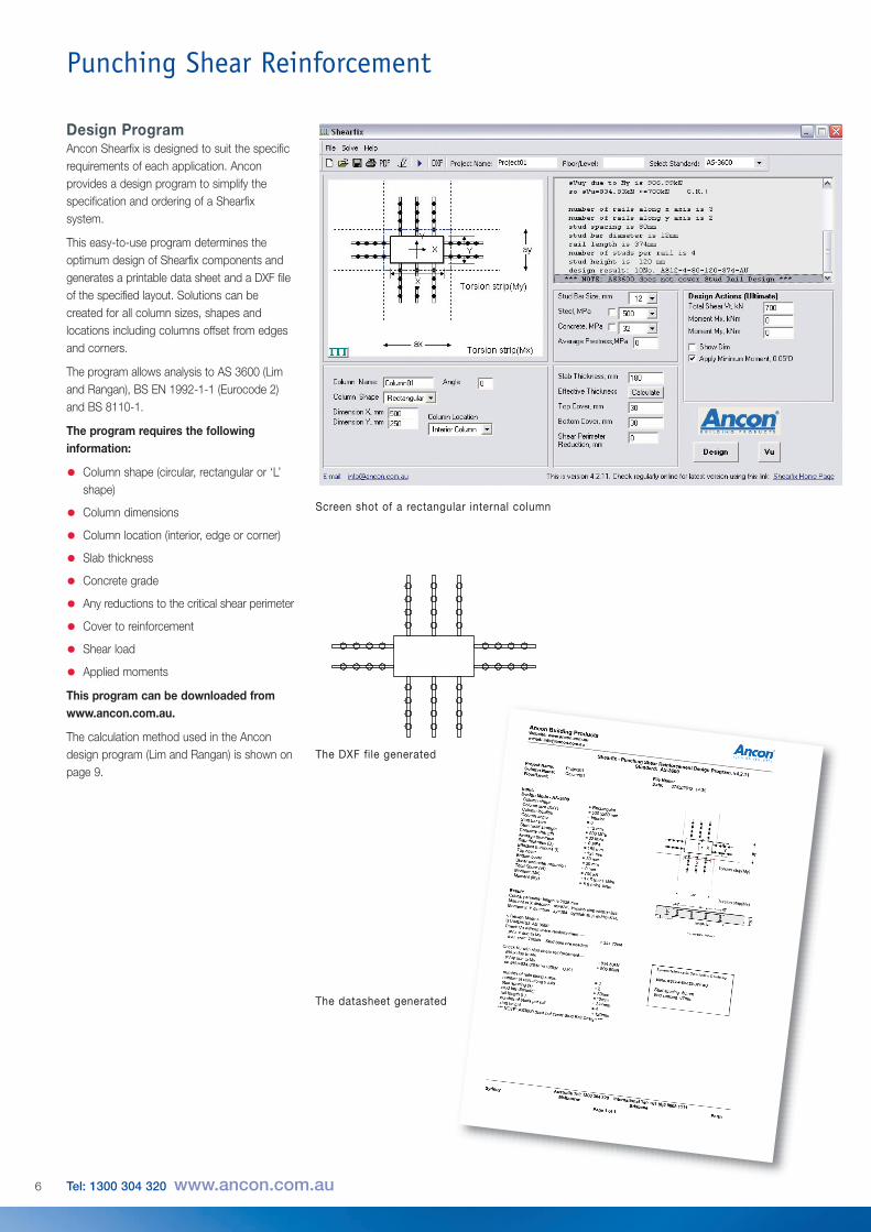
Design ProgramAncon Shearfix is designed to suit the specificrequirements of each application. Anconprovides a design program to simplify thespecification and ordering of a Shearfixsystem.
This easy-to-use program determines theoptimum design of Shearfix components andgenerates a printable data sheet and a DXF fileof the specified layout. Solutions can becreated for all column sizes, shapes andlocations including columns offset from edgesand corners.
The program allows analysis to AS 3600 (Limand Rangan), BS EN 1992-1-1 (Eurocode 2)and BS 8110-1.
The program requires the followinginformation:
• Column shape (circular, rectangular or ‘L’shape)
• Column dimensions
• Column location (interior, edge or corner)
• Slab thickness
• Concrete grade
• Any reductions to the critical shear perimeter
• Cover to reinforcement
• Shear load
• Applied moments
This program can be downloaded fromwww.ancon.com.au.
The calculation method used in the Ancondesign program (Lim and Rangan) is shown onpage 9.
Punching Shear Reinforcement
Screen shot of a rectangular internal column
The datasheet generated
The DXF file generated
6 Tel: 1300 304 320 www.ancon.com.au
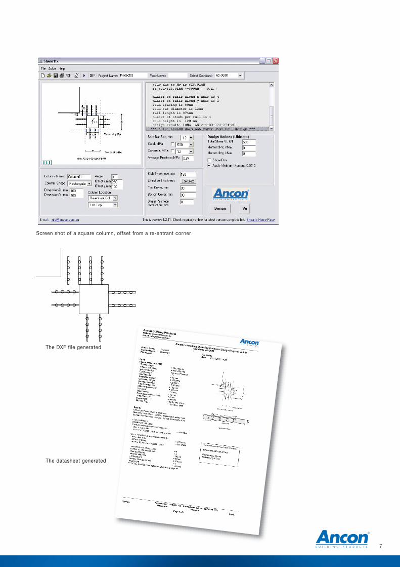
Screen shot of a square column, offset from a re-entrant corner
The datasheet generated
The DXF file generated
7
Ineffective shearperimeter
Opening
Any opening within 2.5b0 of criticalshear perimeter must be considered
Punching Shear Reinforcement
Design InformationThe analysis follows the specifications in thestandard AS 3600: 2009 clause 9.2, but themajor part of the design is based on theresearch presented by F K Lim and B VRangan. Please note that AS 3600: 2009 doesnot have a specific clause on shear studdesign. Therefore the software is based on aresearch paper. We strongly recommend theshear stud design is verified against analternate standard such as BS EN 1992-1-1(Eurocode 2) or BS 8110.
The shear capacity of the slab is checkedagainst the design shear forces at the criticalshear perimeter (refer to AS 3600: 2009 forfurther details on determining the critical shearperimeter) and if required Shearfix studs aredesigned to increase the shear capacity of theslab.
The first stud is positioned 0.5d from the faceof the column, i.e. along critical shearperimeter, with the spacing between individualstuds taken at 0.7 (D - top cover - bottomcover - 5) with a maximum limit of 500mm.The Shearfix Program designs the rails, firstlyat 0.7 (D - top cover - bottom cover - 5) andthen checks the shear capacity of the slab.If the shear capacity of the slab is still belowthe design shear force, the program will thenreduce the spacing until the shear capacityof the slab exceeds the design shear force.The maximum spacing between parallel railsis 600mm or D whichever is less.
The number of studs along a rail is determinedby positioning the last stud 2.5d from thecolumn face, and then spacing the studsbetween the first and the last.
If more than one rail is required for each sideof the column, rails should be placed at thecorner of the column in the torsion strip.
A check is carried out for over reinforcement -if this check fails, a warning message statesthat failure due to punching shear is possibleand an increase in slab thickness will berequired.
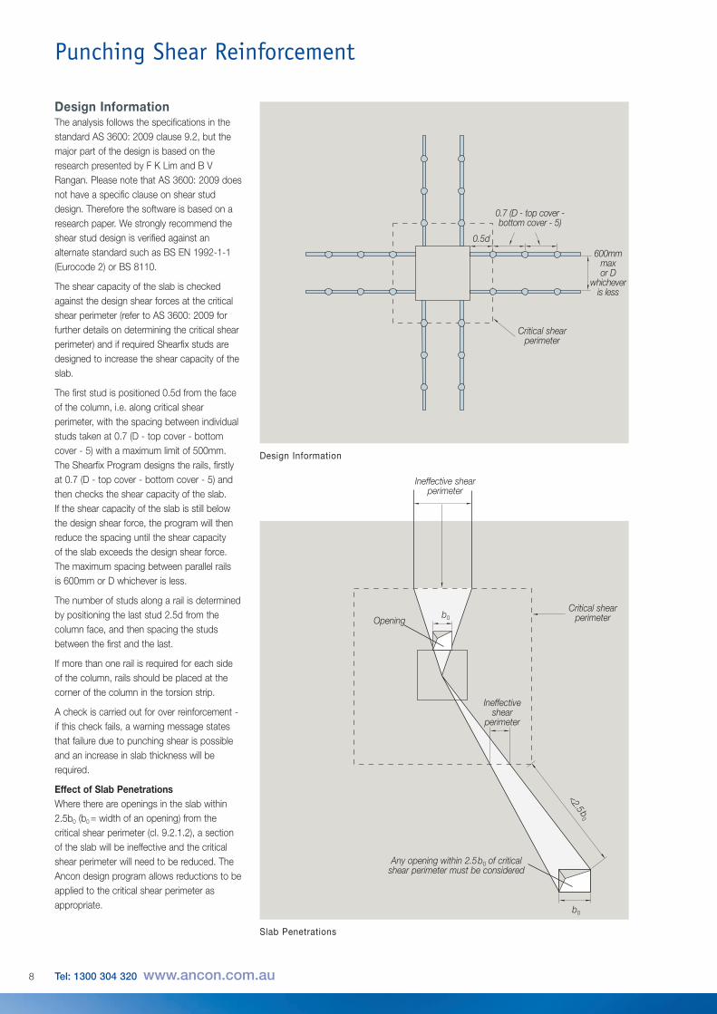
Effect of Slab PenetrationsWhere there are openings in the slab within2.5b0 (b0 = width of an opening) from thecritical shear perimeter (cl. 9.2.1.2), a sectionof the slab will be ineffective and the criticalshear perimeter will need to be reduced. TheAncon design program allows reductions to beapplied to the critical shear perimeter asappropriate.
Design Information
Slab Penetrations
0.5d
0.7 (D - top cover -bottom cover - 5)
Critical shearperimeter
600mmmax or D
whicheveris less
b0
b0
<2.5b0
Ineffective shear
perimeter
Critical shearperimeter
8 Tel: 1300 304 320 www.ancon.com.au
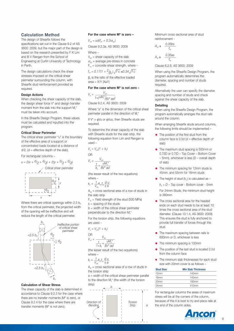
Calculation MethodThe design of Shearfix follows thespecifications set out in the Clause 9.2 of AS3600: 2009, but the major part of the design isbased on the research presented by F K Limand B V Rangan from the School ofEngineering at Curtin University of Technologyin Perth.
The design calculations check the shearstresses imposed on the critical shearperimeter surrounding the column, withShearfix stud reinforcement provided asrequired.
Design ActionsWhen checking the shear capacity of the slab,the design shear force V* and design transfermoment from the slab into the support Mv*must be taken into account.
In the Shearfix Design Program, these valuesmust be calculated and inputted into theprogram.
Critical Shear PerimeterThe critical shear perimeter “u” is the boundaryof the effective area of a support orconcentrated loads located at a distance ofd/2, (d = effective depth of the slab).
For rectangular columns –
u = 2(x + d/2 + d/2) + 2(y + d/2 + d/2)
Where there are critical openings within 2.5 b0
from the critical perimeter, the projected widthof the opening will be ineffective and willreduce the length of the critical perimeter.
Calculation of Shear StressThe shear capacity of the slab is determined inaccordance to Clause 9.2.3 for the case wherethere are no transfer moments (M* is zero), orClause 9.2.4 for the case where there aretransfer moments (M* is not zero).
For the case where M* is zero –
Vuo = ud(fcv + 0.3σcp )
Clause 9.2.3a, AS 3600: 2009
Where –Vuo = shear capacity of the slabσcp = average pre-stress in concreteFcv = concrete shear strength, where –
fcv = 0.17(1 + 2 βh) f' c ≤0.34 f' c
βh is the ratio of the effective loadedarea = X/Y (X≥Y)
For the case where M* is not zero –
Vu =
Clause 9.2.4, AS 3600: 2009
Where “a” is the dimension of the critical shearperimeter parallel in the direction of Mv*
If V* > φVu or φVuo, then Shearfix studs arerequired.
To determine the shear capacity of the slabwith Shearfix studs for the slab strip, thefollowing equation from Lim and Rangan isused –
Vu = Vuo(1 + kt )
OR
Vu =
(the lesser result of the two equations)where –
ks =
Avs = cross sectional area of a row of studs inthe slab stripFvy = Yield strength of the stud (500 MPa)s = spacing of the studsb = width of the critical shear perimeterperpendicular to the direction Mv*
For the torsion strip, the following equationsare used –
Vu = Vuo(1 + kt )
ORVu1 =
(the lesser result of the two equations)where –
kt =
Avt = cross sectional area of a row of studs inthe torsion stripa = width of the critical shear perimeter parallelto the direction Mv* (the width of the torsionstrip)
Vuo
1+(uMv*8V* ad)
Vuo
1 +uMv*
ks 8V* ad
1 Avsfvyd u
Vuo s b
Vuo
1 +uMv*
1+kt 8V* ad
1 Avtfvyd u
Vuo s a
b
aTorsionStrip
Direction ofBending
Minimum cross sectional area of studreinforcement -
Avs ≥
Avt ≥
Clause 8.2.8, AS 3600: 2009
When using the Shearfix Design Program, theprogram automatically determines thediameter, spacing and number of studsrequired.
Alternatively the user can specify the diameter,spacing and number of studs and checkagainst the shear capacity of the slab.
DetailingWhen using the Shearfix Design Program, theprogram automatically arranges the stud railsaround the column.
When arranging Shearfix studs around columns,the following limits should be implemented –
• The position of the first stud from thecolumn face is 0.5d (d = effective depth ofslab)
• The maximum stud spacing is 500mm or0.75D or 0.7(D – Top Cover – Bottom Cover– 5mm), whichever is less (D – overall depthof slab)
• The minimum spacing for 12mm studs is 45mm, and 55mm for 16mm studs
• The height of stud (hs ) is calculated as –
hs = D – Top cover - Bottom cover - 5mm
For 24mm Studs, the minimum stud heightis 360mm
• The cross sectional area for the headedends on each stud needs to be at least 10times the cross sectional area of the studdiameter. (Clause 13.1.4, AS 3600: 2009).This ensures the stud is fully anchored toprovide full transfer of forces through thestud.
• The maximum spacing between rails is 600mm or D, whichever is less
• The minimum spacing is 100mm
• The position of the last stud is located 2.5dfrom the column face
• The minimum slab thicknesses for each studsize with 20mm cover is as follows –
For rectangular columns the areas of maximumstress will be at the corners of the column,because of this it is best to try and place rails atthe end of the column sides.
Ineffective portionof critical shear
perimeter
b0
b0
Critical shear perimeter
d/2
d/2
d/2
d/2
<2.5 b0
<2.5 b0
x
y
0.35bsfvy
0.35asfvy
Stud Size Min Slab Thickness12mm 140mm
16mm 140mm
20mm 180mm
24mm 410mm
9
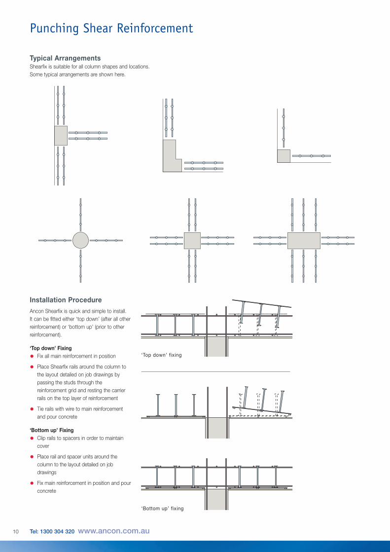
Installation ProcedureAncon Shearfix is quick and simple to install.It can be fitted either ‘top down’ (after all otherreinforcement) or ‘bottom up’ (prior to otherreinforcement).
‘Top down’ Fixing
• Fix all main reinforcement in position
• Place Shearfix rails around the column tothe layout detailed on job drawings bypassing the studs through thereinforcement grid and resting the carrierrails on the top layer of reinforcement
• Tie rails with wire to main reinforcementand pour concrete
‘Bottom up’ Fixing
• Clip rails to spacers in order to maintaincover
• Place rail and spacer units around thecolumn to the layout detailed on jobdrawings
• Fix main reinforcement in position and pourconcrete
‘Top down’ fixing
‘Bottom up’ fixing
Punching Shear Reinforcement
Typical ArrangementsShearfix is suitable for all column shapes and locations.Some typical arrangements are shown here.
10 Tel: 1300 304 320 www.ancon.com.au
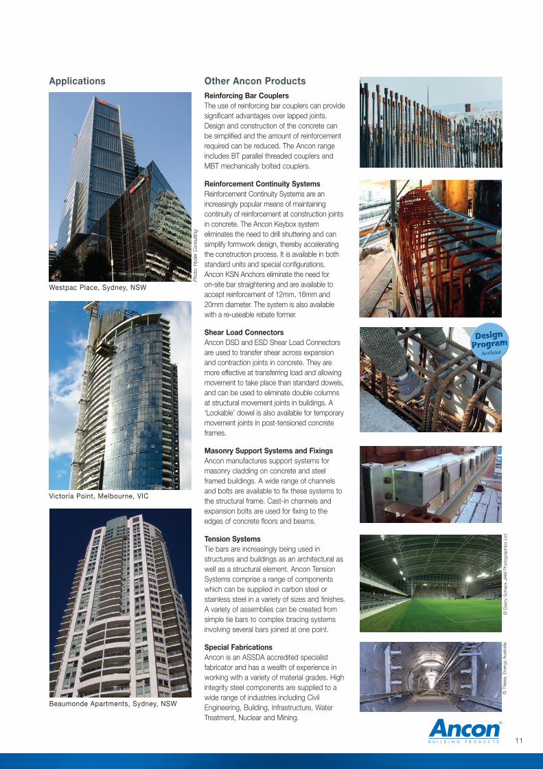
Other Ancon ProductsReinforcing Bar CouplersThe use of reinforcing bar couplers can providesignificant advantages over lapped joints.Design and construction of the concrete canbe simplified and the amount of reinforcementrequired can be reduced. The Ancon rangeincludes BT parallel threaded couplers andMBT mechanically bolted couplers.
Reinforcement Continuity SystemsReinforcement Continuity Systems are anincreasingly popular means of maintainingcontinuity of reinforcement at construction jointsin concrete. The Ancon Keybox systemeliminates the need to drill shuttering and cansimplify formwork design, thereby acceleratingthe construction process. It is available in bothstandard units and special configurations.Ancon KSN Anchors eliminate the need foro n-site bar straightening and are available toaccept reinforcement of 12mm, 16mm and20mm diameter. The system is also availablewith a re-useable rebate former.
Shear Load ConnectorsAncon DSD and ESD Shear Load Connectorsare used to transfer shear across expansionand contraction joints in concrete. They aremore effective at transferring load and allowingmovement to take place than standard dowels,and can be used to eliminate double columnsat structural movement joints in buildings. A‘Lockable’ dowel is also available for temporarymovement joints in post-tensioned concreteframes.
Masonry Support Systems and FixingsAncon manufactures support systems formasonry cladding on concrete and steelframed buildings. A wide range of channelsand bolts are available to fix these systems tothe structural frame. Cast-in channels andexpansion bolts are used for fixing to theedges of concrete floors and beams.
Tension SystemsTie bars are increasingly being used instructures and buildings as an architectural aswell as a structural element. Ancon TensionSystems comprise a range of componentswhich can be supplied in carbon steel orstainless steel in a variety of sizes and finishes.A variety of assemblies can be created fromsimple tie bars to complex bracing systemsinvolving several bars joined at one point.
Special FabricationsAncon is an ASSDA accredited specialistfabricator and has a wealth of experience inworking with a variety of material grades. Highintegrity steel components are supplied to awide range of industries including CivilEngineering, Building, Infrastructure, WaterTreatment, Nuclear and Mining.
Applications
Beaumonde Apartments, Sydney, NSW
Westpac Place, Sydney, NSW
Victoria Point, Melbourne, VIC
Phot
o: H
yder
Con
sulti
ng
11
© T
hies
s, E
nerg
y A
ustr
alia
© D
arcy
Sch
ack
JAM
Pho
togr
aphi
cs L
td

© Ancon Building Products 2012
The construction applications and details provided in this literatureare indicative only. In every case, project working details should beentrusted to appropriately qualified and experienced persons.
Whilst every care has been exercised in the preparation of thisdocument to ensure that any advice, recommendations orinformation is accurate, no liability or responsibility of any kind isaccepted in respect of Ancon Building Products.
With a policy of continuous product development Ancon BuildingProducts reserves the right to modify product design andspecification without due notice.
These products are available from:
Ancon Building Products7-9 Second AvenueSunshineMelbourneVIC 3020AustraliaTel: 1300 304 320Fax: +61 (0) 3 9311 1777
Ancon Building Products82 Chisholm CrescentKewdalePerthWA 6105AustraliaTel: 1300 304 320Fax: +61 (0) 8 9453 2300
Ancon Building Products114 Kurrajong AvenueMount DruittSydneyNSW 2770AustraliaTel: 1300 304 320Fax: +61 (0) 2 9675 3390
Ancon Building Products4/15 Terrace PlaceMurarrieBrisbaneQLD 4172AustraliaTel: 1300 304 320Fax: +61 (0) 7 3395 6693
International Enquiries: +61 (0) 2 8808 1111Email: [email protected]: www.ancon.com.au
Overseas Offices:
Ancon Building ProductsSheffieldUnited Kingdomwww.ancon.co.uk
Ancon Building Products GesmbHViennaAustriawww.ancon.at
Ancon (Schweiz) AGRied bei KerzersSwitzerlandwww.ancon.ch
Ancon GmbHNurembergGermanywww.anconbp.de
Ancon (Middle East) FZEDubaiUnited Arab Emirateswww.ancon.ae
Masonry Support Systems
Windposts and Lintels
Wall Ties and Restraint Fixings
Channel and Bolt Fixings
Tension and Compression Systems
Stainless Steel Fabrications
Flooring and Formed Sections
Shear Load Connectors
Stainless Steel Reinforcement
Reinforcing Bar Couplers
Reinforcement Continuity Systems
Punching Shear Reinforcement
Precast Concrete Accessories