Embed Size (px)
Citation preview

Publication
Authors
EEL 6935 – Spring 2014
1 of 44
Low-Frequency Versatile Wireless Power Transfer
Jonathan David
2013 IEEE International Conference on Communications, pp.4373,4378, 9-13 June 2013
Osman Salem, Alexey Guerassimov, and Ahmed Mehaoua University of Paris Descartes – LIPADE Division of ITCE, POSTECH, Korea
Anthony Marcus and Borko Furht,Department of Computer and Electrical Engineering and Computer Science, Florida Atlantic University

2 of 44
The Need for Improvement Non-rechargeable batteries only support implants with extremely low power consumption Pacemaker must be replaced every 5-8 years by
invasive surgery, battery occupies 90% of device volume RF radiation hazard and tissue absorption are
concerns in wireless power technologies An accurate impedance matching network is
required for efficient power delivery Power scavenged by bio-surroundings is still only
in the nano-watt range

3 of 44
The Need for Improvement Cardiac pacemakers
Retina prostheses (emerging technology) Brain-computer interfaces Drug delivery systems Smart orthopedic implants
4 of 44
The Solution Use of a low-frequency electrical power transfer
technology Wireless power transfer has existed, however medical
trials have used devices operating in the GHz range

5 of 44
How does it work? Magnetic field is generated by rotating permanent
magnets An inductive coil at the receiving end is charged
6 of 44
What are the advantages? Radiation hazard completely avoided Resistance instead of reactance dominates the
impedance of the coil due to the low frequency Resistance is less likely to change based on the
application More materials can be used for the receiving coil The magnetic field can penetrate various materials
7 of 44
STRONGER MAGNETS COMPENSATE FOR
LOWER FREQUENCY!

8 of 44
Design of Rotor and Coil Magnetization of disk magnets is perpendicular to the surface
Polarization on the head is alternated to create an alternating magnetic field
Diameter of the coil matters Too small and some magnetic
flux is lost Too large and multiple magnets
will affect coil

9 of 44
Design of Rotor and Coil

10 of 44
Delivered Power Power delivered to the implant from the external
source is reduced mainly by three forces Power consumed to rotate magnets Drag caused by induced current in receiving coil Power lost due to conversion from AC to DC
11 of 44
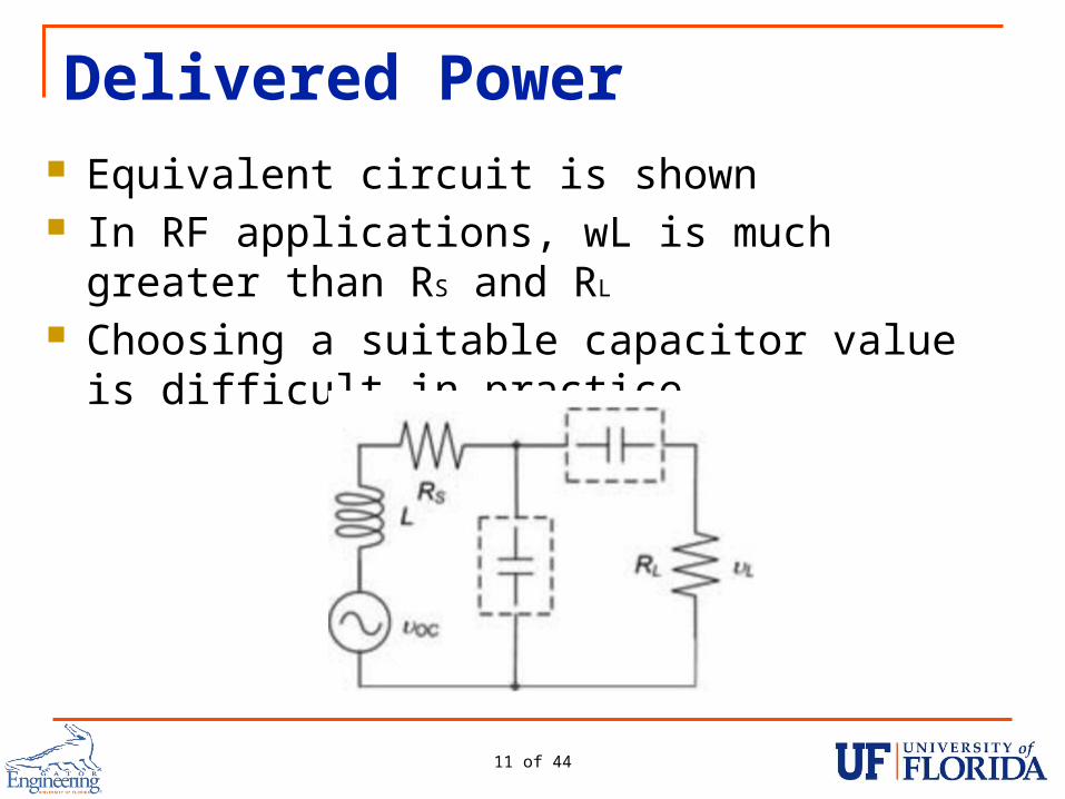
Delivered Power Equivalent circuit is shown In RF applications, wL is much greater than RS
and RL
Choosing a suitable capacitor value is difficult in practice

12 of 44
INDUCTANCE AND CAPACITANCE NEGLIGIBLE!

13 of 44
Efficiency Characterized by the ratio of delivered AC
power at the load to the total power consumed by the DC motor Motor in study consumes 1.445W, with a current of
0.170A Extra power consumed is due to the receiving coil
Efficiency can be hurt by external factors Human body (replicated with saline solution in studies) External housing (medical grade stainless steel,
aluminum)

14 of 44
Efficiency

15 of 44
Results

16 of 44
Results

17 of 44
NEGLIGIBLE POWER LOSSES
18 of 44
Drawbacks Device is bulky due to the size of the antenna No wireless communication transfer through
power delivery system RF power transfer has this capability

19 of 44
Shortfalls of the Study Many different materials could have been used to
evaluate power transfer Study seemed to be very basic No comparison against efficiency of RF power
transmission

20 of 44
Conclusions Low-frequency wireless power transfer provides
an efficient way to power medical implants Coupling circuitry is not needed Will work in a variety of conditions Unfortunately, resulting device is large due to
receiving coil size Unknown how it compares to RF technologies

21 of 44
QUESTIONS?
Publication
Authors
EEL 6935 – Spring 2014
22 of 44
Near-Threshold OOK-Transmitter with Noise-Cancelling Receiver
Jonathan David
2013 IEEE International Conference on Communications, pp.1720,1724, 9-13 June 2013
Mai Abdelhakim, Leonard E. Lightfoot, Jian Ren, Tongtong LiDepartment of Electrical & Computer Engineering, Michigan State UniversityAir Force Research Laboratory, Wright-Patterson Air Force Base

23 of 44
The Need for Improvement Power consumption is a highly critical requirement for future wireless body-area network sensors
Of all the circuit components on system-on-chip designs, the wireless transceiver usually consumes the most power (70-80%)
Design considerations make development of an energy efficient WBAN difficult
Reliability and noise immunity are key requirements aside from power consumption

24 of 44
The Need for Improvement Body absorption can affect the signal-to-noise ratio of the transceiver
Noisy blocks (like the ADC or a switching power supply) in the SoC can increase bit-error rates Affects OOK, which has difficulty discerning between
coupling noise and small-signal data inputs

25 of 44
The Solution Introduce a MICS (402-405MHz) transciever that
operates in the near threshold domain (~.65V) Remains energy efficient by using high frequency and
low voltage Noise sensitivity reduced by using a super-
regenerative oscillator Noise injections appears common-mode

26 of 44
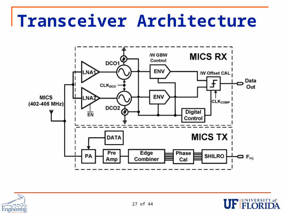
Transceiver Architecture OOK (on-off keying) is used
Simple, highly sensitive, and low-power Received signal
Sent through low-noise amplifier and DCO Structure referred to as a super regenerative receiver
A replica SRR is used to mitigate on-chip noise Generates common-mode reference envelope for comparisons
Envelope detector receives signal from SRR Signal output at a maximum of -16 dBm
27 of 44
Transceiver Architecture

28 of 44
Near-Threshold Transmitter Uses sub-harmonic injection locking and edge combining
Eliminates the use of a PLL Power hungry Slow settling time Prevents use of aggressive duty cycling

29 of 44
Sub-Harmonic Injection Locking Sub-harmonic injection occurs when an incident frequency is a sub-harmonic of the oscillator free-running frequency
Used for frequency synthesis and phase lock As the division ratio increases, the noise rejection
ability decreases

30 of 44
Near-Threshold Operation Improves energy efficiency Increases signal to noise ratio, resulting in larger
oscillator phase noise

31 of 44
Spur Suppression Injected signal is typically a square wave, which
consists of large harmonic content The N-th harmonic locks the oscillator, while other
harmonics appear on the output as spurs Decreasing the locking range reduces the SNR of
the spurs Decreasing the locking range decreases the loop
bandwidth Easier to lose lock Time to lock on a signal is increased

32 of 44
Spur Suppression
33 of 44
Super-Regeneration Exploits the non-linear gain at the startup of an LC
oscillator Exponential time-dependent gain is achieved for a
short period of time, resulting in a large magnitude regardless of the input signal Workings of this are not immediately obvious
To properly take advantage of this, a very high-Q filter is needed
Luckily, the SRR “tank” circuit can be tuned to create this filter!

34 of 44
Super-Regeneration Simplified, the digitally controlled oscillator is set in
Q-enhancement mode to select a band of interest Conductance of the DCO is switched from + to -,
which increases the tank current Increased tank current achieved super-
regeneration, and the selected signal is amplified

35 of 44
Super-Regeneration
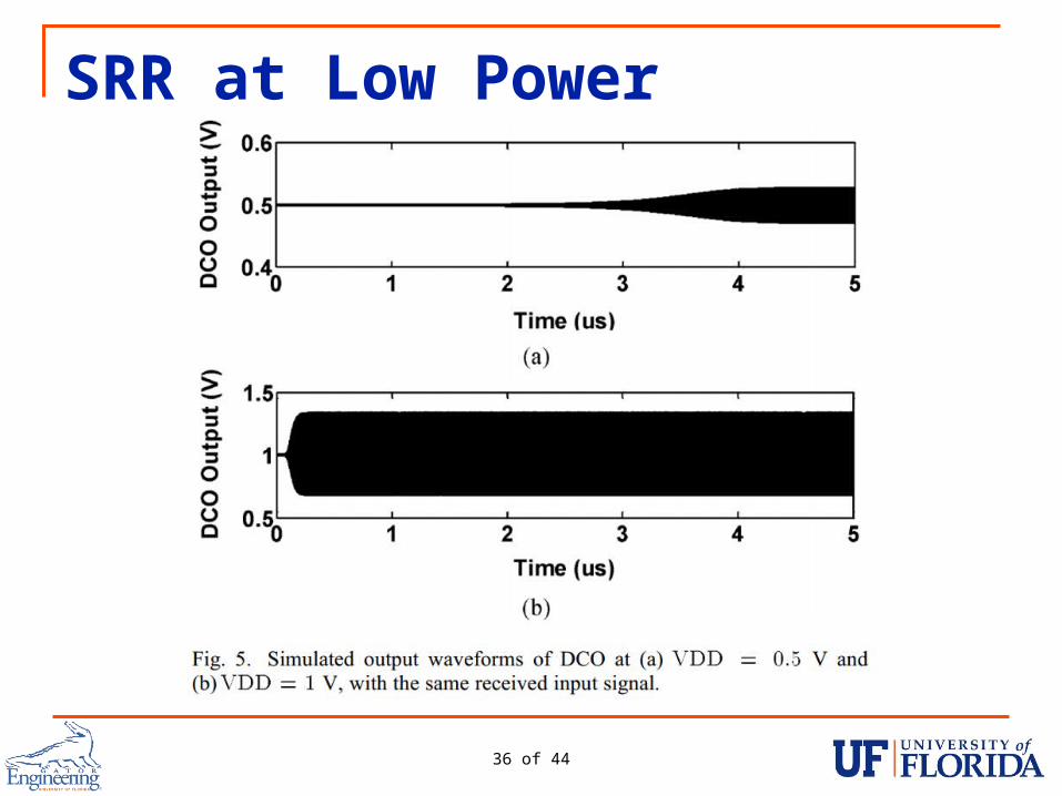
36 of 44
SRR at Low Power

37 of 44
Results
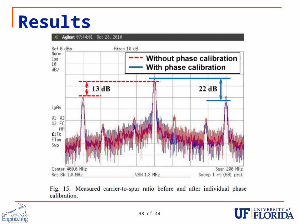
38 of 44
Results
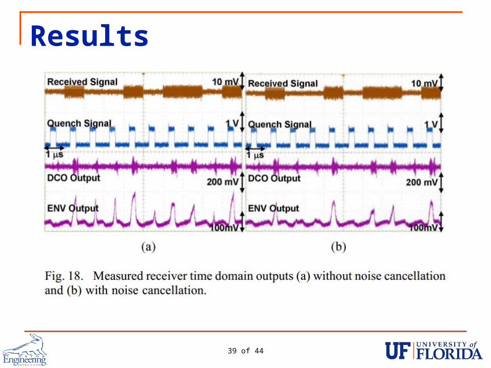
39 of 44
Results

40 of 44
Results

41 of 44
Shortfalls of the Study Operation at close to threshold voltage renders
circuitry very susceptible to voltage spikes Locking range of sub-harmonic injection when
compared to a PLL
42 of 44
Conclusions A low-power, noise-cancelling transceiver is
possible with the proposed device Sub-harmonic injection locking provides a viable,
low-power alternative for a PLL Super-regeneration allows for low-power
amplification Received data is accurate Is operating at such a low voltage dangerous?

43 of 44
QUESTIONS?
44 of 44
THANK YOU!


![[PPT]Cellular Phones as Embedded Systems - University of · Web viewDistributed and Reconfigurable Architecture for Flight Control System EEL 6935 - Embedded Systems Dept. of Electrical](https://img.pdfslide.us/doc/110x75/5aa528437f8b9a1d728cc8f4/pptcellular-phones-as-embedded-systems-university-of-viewdistributed-and.jpg)