Embed Size (px)
Citation preview
Complex Upset Mitigation Applied to a Re-Configurable Embedded Processor
EEL 6935
Lu Hao
Wenqian Wu
Outline
• Issues of SRAM-based FPGA used for space application
• Upset mitigation solutions
• Resource usage and performance analysis
• Summary
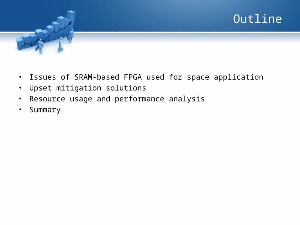
System on Programmable Chip
• Soft-core processor implemented in SRAM based FPGA is very attractive to spacecraft designer. A complete computer system can be created on a single FPGA chip.
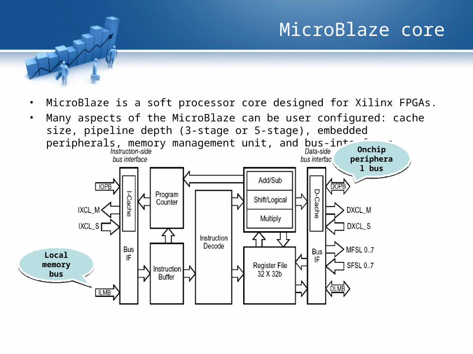
MicroBlaze core
• MicroBlaze is a soft processor core designed for Xilinx FPGAs. • Many aspects of the MicroBlaze can be user configured: cache size, pipeline depth
(3-stage or 5-stage), embedded peripherals, memory management unit, and bus-interfaces.
Local memory
bus
Local memory
bus
Onchip peripheral
bus
Onchip peripheral
bus
Space application issues
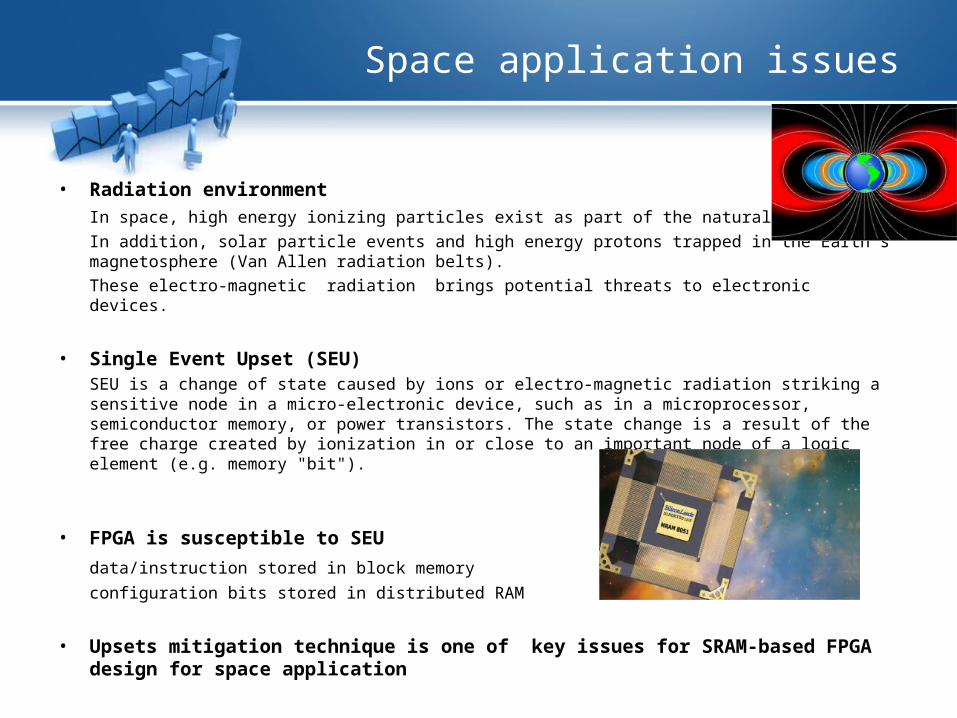
• Radiation environment
In space, high energy ionizing particles exist as part of the natural background.
In addition, solar particle events and high energy protons trapped in the Earth's magnetosphere (Van Allen radiation belts).
These electro-magnetic radiation brings potential threats to electronic devices.
• Single Event Upset (SEU)SEU is a change of state caused by ions or electro-magnetic radiation striking a sensitive node in a micro-electronic device, such as in a microprocessor, semiconductor memory, or power transistors. The state change is a result of the free charge created by ionization in or close to an important node of a logic element (e.g. memory "bit").
• FPGA is susceptible to SEU
data/instruction stored in block memory
configuration bits stored in distributed RAM
• Upsets mitigation technique is one of key issues for SRAM-based FPGA design for space application
Proposed upset mitigation
• To ensure reliable space application based on SRAM-FPGA, the author
investigates 3 level of upset mitigation: – Functional-block design triplication– Continuous external configuration scrubbing– Independent internal BRAM scrubbing (also triplicated)
Tool, device and environment
• Tools:
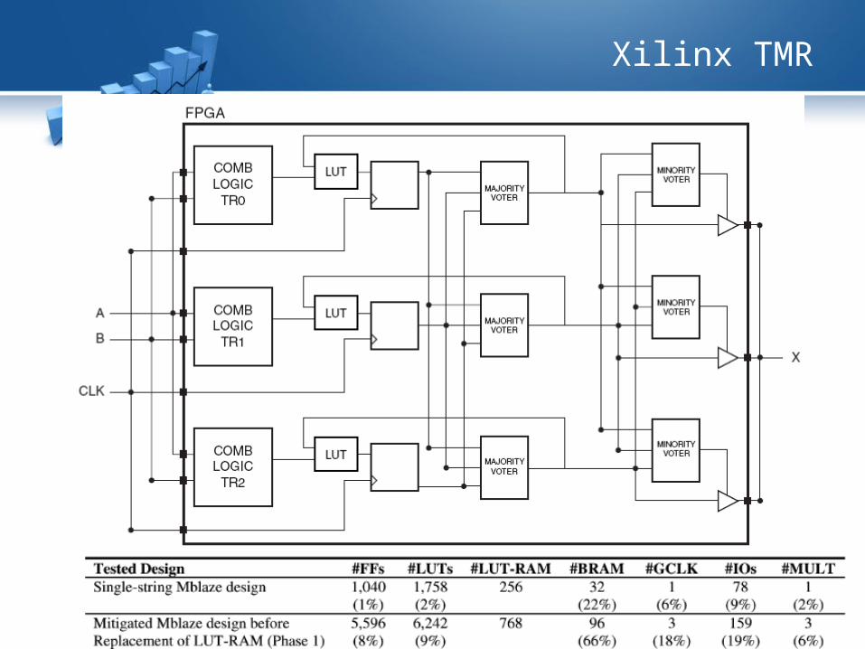
Xilinx TMR: easily trade off maximum radiation effect immunity against area, pinout, and board layout consideration.
• Device:Xilinx Virtex II XQR2 V6000 FPGA
• Program running in MicroBlaze:Integer-based FFT
• Test environment:Crocker Nuclear Laboratory at University of California at Davis using a proton beam of 63.3 MeV.
• Test boradTwo FPGAs, one is device under test (DUT), the other is service FPGA
DUT and Service FPGA
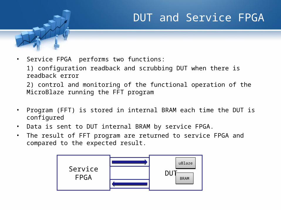
• Service FPGA performs two functions:
1) configuration readback and scrubbing DUT when there is readback error
2) control and monitoring of the functional operation of the MicroBlaze running the FFT program
• Program (FFT) is stored in internal BRAM each time the DUT is configured• Data is sent to DUT internal BRAM by service FPGA.• The result of FFT program are returned to service FPGA and compared to the
expected result.
Service FPGA DUT
uBlazeuBlaze
BRAMBRAM
Upset Mitigation
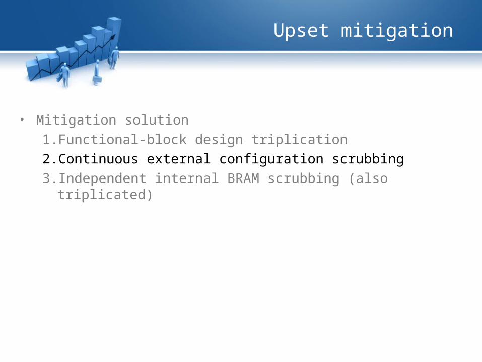
• Mitigation solution
1. Functional-block design triplication
2. Continuous external configuration scrubbing
3. Independent internal BRAM scrubbing (also triplicated)
TMR
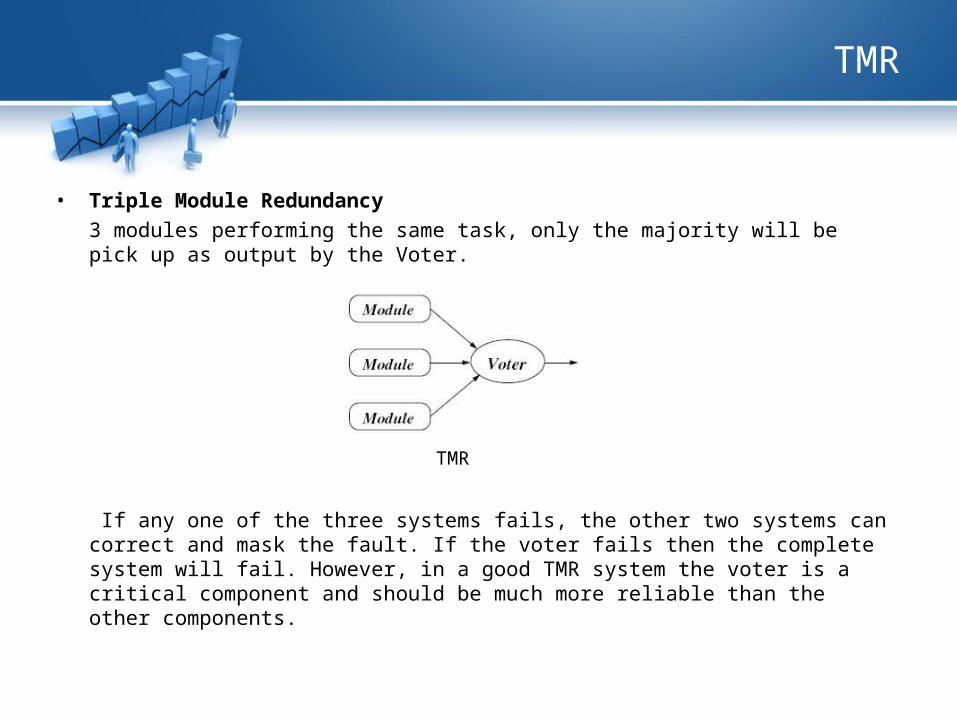
• Triple Module Redundancy
3 modules performing the same task, only the majority will be pick up as output by the Voter.
If any one of the three systems fails, the other two systems can correct and mask the fault. If the voter fails then the complete system will fail. However, in a good TMR system the voter is a critical component and should be much more reliable than the other components.
TMR
Xilinx TMR
Upset mitigation
• Mitigation solution
1. Functional-block design triplication
2. Continuous external configuration scrubbing
3. Independent internal BRAM scrubbing (also triplicated)
External Configuration Scrubbing
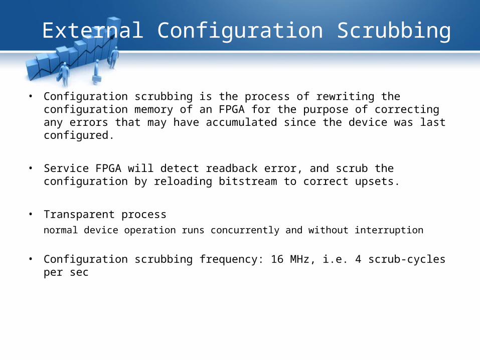
• Configuration scrubbing is the process of rewriting the configuration memory of an FPGA for the purpose of correcting any errors that may have accumulated since the device was last configured.
• Service FPGA will detect readback error, and scrub the configuration by reloading bitstream to correct upsets.
• Transparent process
normal device operation runs concurrently and without interruption
• Configuration scrubbing frequency: 16 MHz, i.e. 4 scrub-cycles per sec
Upset mitigation
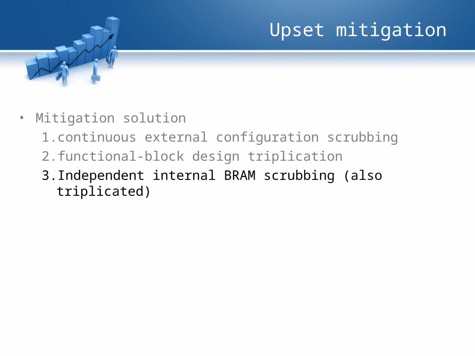
• Mitigation solution
1. continuous external configuration scrubbing
2. functional-block design triplication
3. Independent internal BRAM scrubbing (also triplicated)
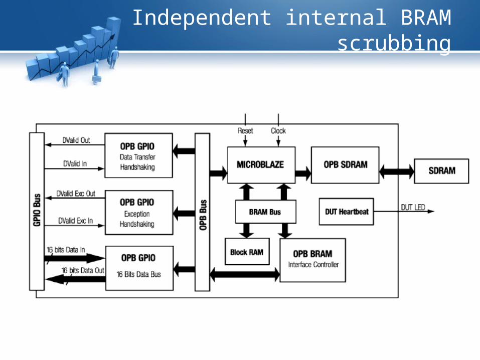
Independent internal BRAM scrubbing
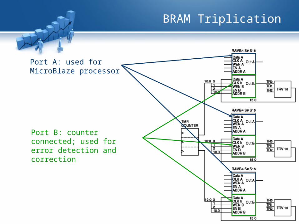
BRAM Triplication
Port B: counter connected; used for error detection and correction
Port A: used for MicroBlaze processor
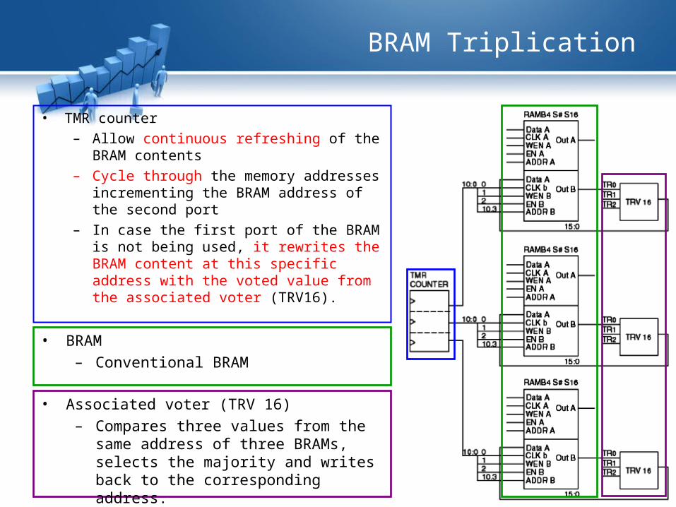
BRAM Triplication
• TMR counter– Allow continuous refreshing of the BRAM
contents – Cycle through the memory addresses
incrementing the BRAM address of the second port
– In case the first port of the BRAM is not being used, it rewrites the BRAM content at this specific address with the voted value from the associated voter (TRV16).
• BRAM– Conventional BRAM
• Associated voter (TRV 16)– Compares three values from the same
address of three BRAMs, selects the majority and writes back to the corresponding address.
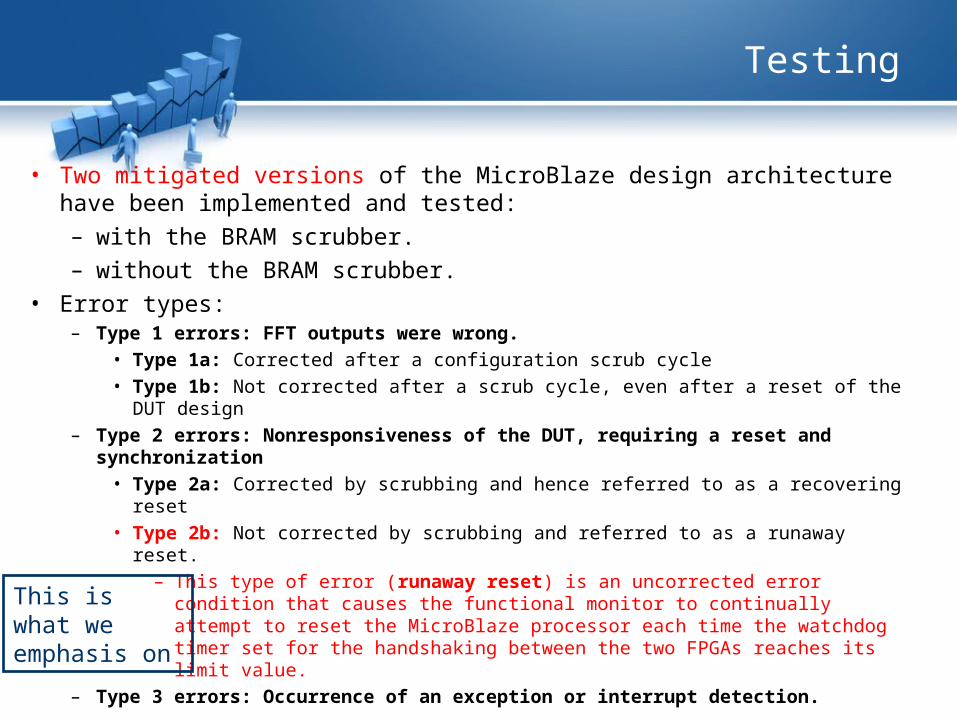
Testing
• Two mitigated versions of the MicroBlaze design architecture have been implemented and tested: – with the BRAM scrubber.– without the BRAM scrubber.
• Error types:– Type 1 errors: FFT outputs were wrong.
• Type 1a: Corrected after a configuration scrub cycle• Type 1b: Not corrected after a scrub cycle, even after a reset of the DUT design
– Type 2 errors: Nonresponsiveness of the DUT, requiring a reset and synchronization
• Type 2a: Corrected by scrubbing and hence referred to as a recovering reset• Type 2b: Not corrected by scrubbing and referred to as a runaway reset.
– This type of error (runaway reset) is an uncorrected error condition that causes the functional monitor to continually attempt to reset the MicroBlaze processor each time the watchdog timer set for the handshaking between the two FPGAs reaches its limit value.
– Type 3 errors: Occurrence of an exception or interrupt detection.
This is what we emphasis on
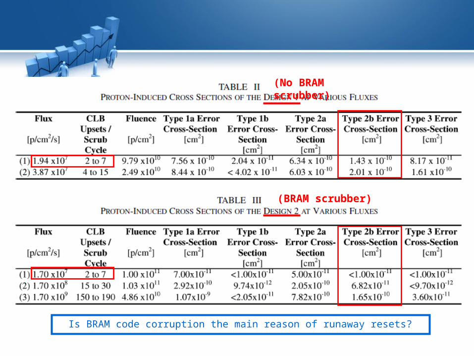
Is BRAM code corruption the main reason of runaway resets?
(No BRAM scrubber)
(BRAM scrubber)
Standalone test
• To make sure that the BRAM code corruption is likely to be the cause of these runaway resets, the BRAM mitigation design has been implemented in standalone mode and tested under proton beams at similar fluxes and at the same facility.
Runaway Resets Caused by BRAM Corruption
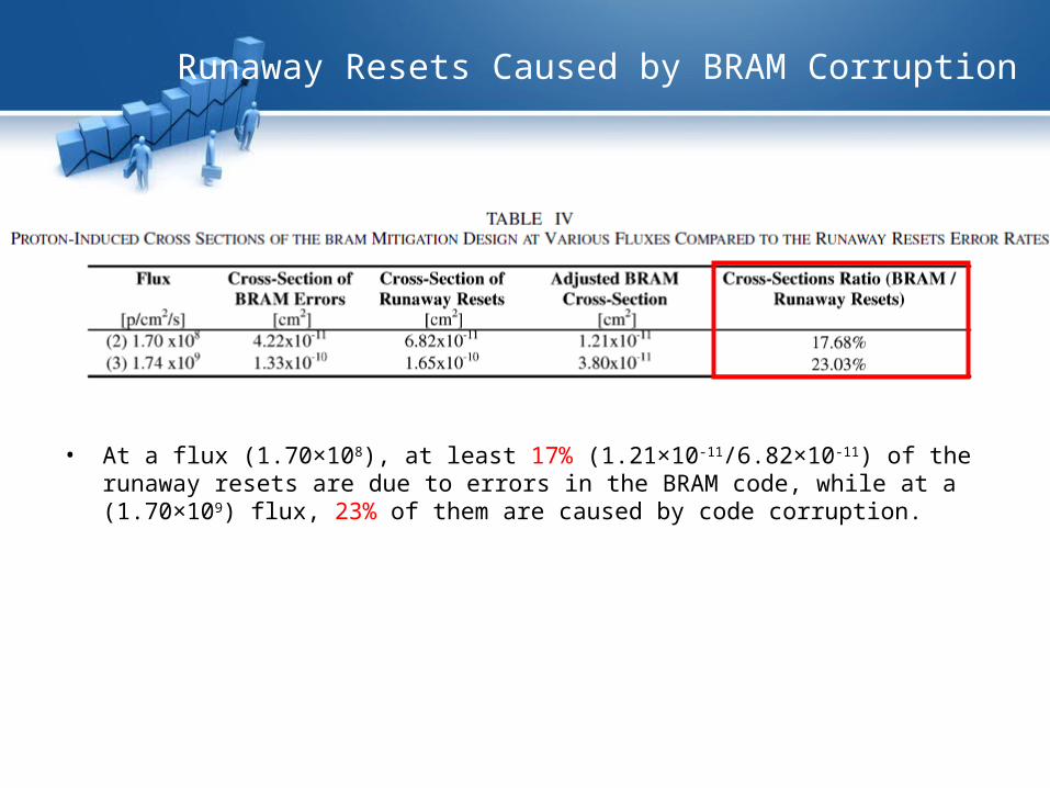
• At a flux (1.70×10⁸), at least 17% (1.21×10⁻¹¹/6.82×10-11) of the runaway resets are due to errors in the BRAM code, while at a (1.70×10⁹) flux, 23% of them are caused by code corruption.
Exceptions Caused by BRAM Runaway Resets
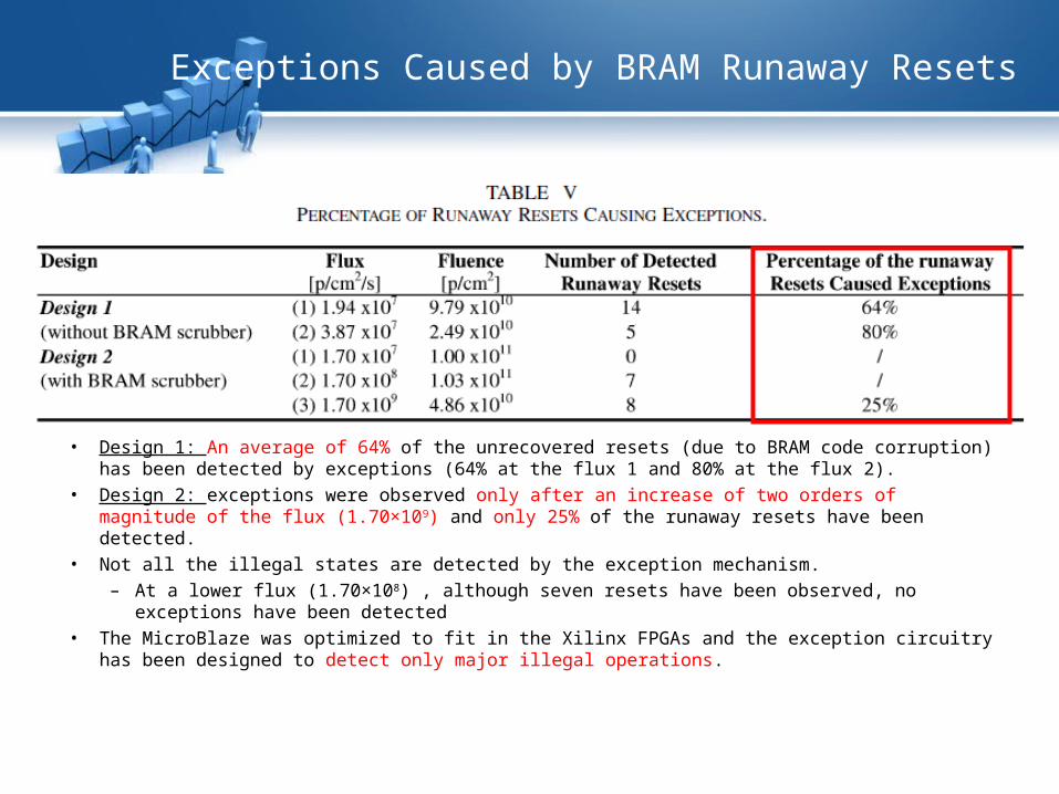
• Design 1: An average of 64% of the unrecovered resets (due to BRAM code corruption) has been detected by exceptions (64% at the flux 1 and 80% at the flux 2).
• Design 2: exceptions were observed only after an increase of two orders of magnitude of the flux (1.70×10⁹) and only 25% of the runaway resets have been detected.
• Not all the illegal states are detected by the exception mechanism. – At a lower flux (1.70×10⁸) , although seven resets have been observed, no exceptions have
been detected• The MicroBlaze was optimized to fit in the Xilinx FPGAs and the exception circuitry has been
designed to detect only major illegal operations.
Conclusion
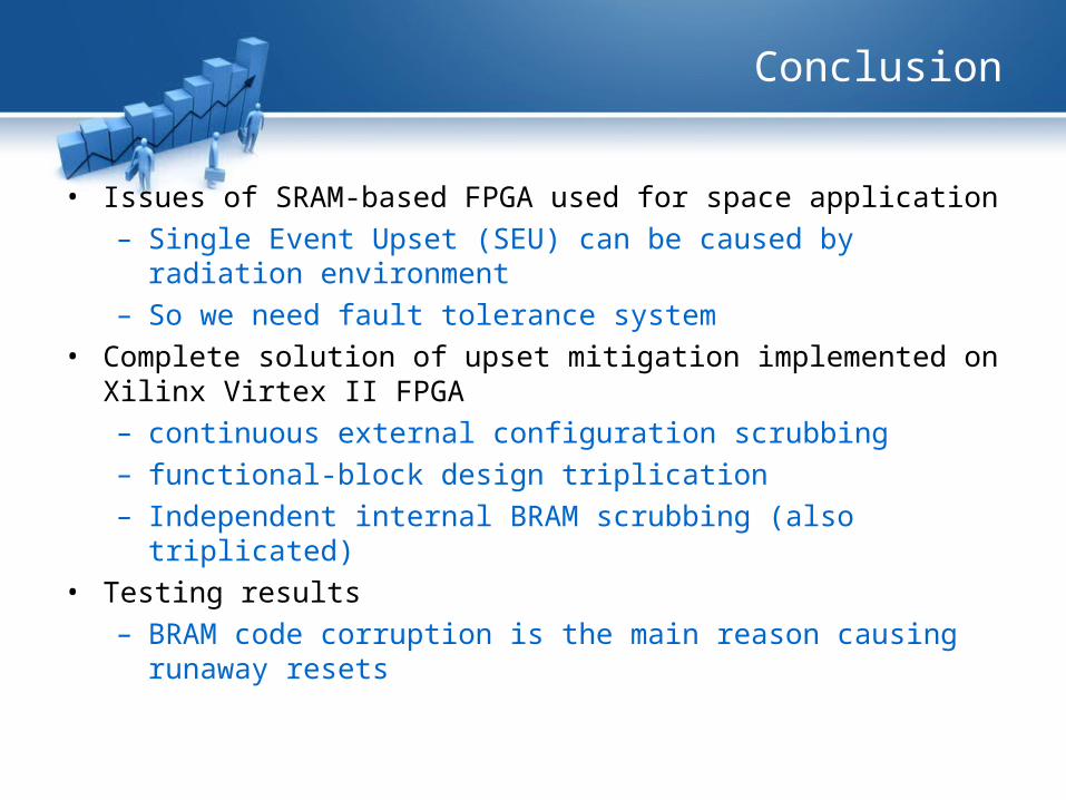
• Issues of SRAM-based FPGA used for space application– Single Event Upset (SEU) can be caused by radiation
environment– So we need fault tolerance system
• Complete solution of upset mitigation implemented on Xilinx Virtex II FPGA– continuous external configuration scrubbing– functional-block design triplication– Independent internal BRAM scrubbing (also triplicated)
• Testing results– BRAM code corruption is the main reason causing runaway
resets
Reference
• [1] F. Lima, C. Carmichael, J. Fabula, R. Padovani, and R. Reis, “A fault injection analysis of virtex FPGA TMR design methodology,” presented at the Radiation and Its Effects on Components and Systems, Sep. 2001.
• [2] F. Lima(de), S. Rezgui, E. F. Cota, M. Lubaszewski, and R. Velazco, “Designing and testing a radiation hardened 8051-like micro-controller,” presented at the Military and Aerospace of Programmable Devices and Technologies Conf., Laurel, MD, Sep. 2000.
• [3] G. Swift et al., “Dynamic testing of xilinx virtex-II field programmable gate array’s (FPGA’s) Input Output Blocks (IOB’s),” IEEE Trans. Nucl. Sci., vol. 51, no. 6, pp. 3469–3474, Dec. 2004.
• [4] C. Carmichael, B. Bridgford, and J. Moore, “Triple module redundancy scheme for static latch-based FPGAs,” presented at the Military and Aerospace of Programmable Devices and Technologies Conf., Laurel, MD, Sep. 2004.
• [5] Triple Module Redundancy Design Techniques for Virtex FPGAs, Xilinx Appl. Note XAPP197, C. Carmichael. (2001, Nov.). [Online]. Available: http://www.xilinx.com/bvdocs/appnotes/xapp197.pdf
• [6] MicroBlaze Processor Reference User Guide, Xilinx, Inc., Aug. 2004. Embedded Development Kit (EDK 6.3), UG081, Version 4.0.
• [7] FFT C Code, T. Roberts and M. Slaney. (1994, Dec.). [Online]. Available: http://www.jjj.de/fft/int_fft.c• [8] TMR Tool User Guide, Xilinx, Inc., UG156, Version 6.2.3 (2004, Sep.). [Online]. Available:
http://support.xilinx.com/products/milaero/ug156.pdf• [9] Triple Module Redundancy Design Techniques for Virtex FPGAs, Nov. 2001. Xilinx Appl. Note 197.

Thanks!
Questions?