Embed Size (px)
Citation preview

ii
BLANK PAGE
ii
Table of Contents
CHAPTER 1 - DRILLING CONTRACTOR PREQUALIFICATION .......................................... 1-1
1.1 PREQUALIFICATION PROCEDURE ................................................................................ 1-1
1.2 CRITERIA FOR PREQUALIFICATION OF DRILLING CONTRACTORS .......................... 1-1
Figure 1.2(b) - Contractor Prequalification Request Form .................................................................. 1-6
1.3 LIST OF PREQUALIFIED DRILLING CONTRACTORS .................................................... 1-9
CHAPTER 2 - DRILLING CONTRACTOR PERFORMANCE EVALUATION ......................... 2-1
2.1 INSTRUCTIONS TO COMPLETE PERFORMANCE REPORTS ...................................... 2-1
Figure 2.1(a) – Contractor Performance Evaluation Form .................................................................. 2-3
2.2 REMOVAL OF DRILLING CONTRACTOR FROM PREQUALIFIED LIST ......................... 2-9
CHAPTER 3 - DRILLING INSPECTION REQUIREMENTS .................................................... 3-1
3.1 MINIMUM REQUIREMENTS FOR DRILLING INSPECTION ............................................ 3-1
3.2 CERTIFICATION POLICIES AND PROCEDURES ........................................................... 3-2
Figure 3.2(b) - Application for Drilling Inspector Examination ............................................................. 3-4
3.3 CERTIFICATION EXAM REQUIREMENTS AND GUIDELINES ....................................... 3-5
3.3.8 List of PennDOT-Certified Drilling Inspectors ............................................................................. 3-7 Figure 3.3 - Drilling Inspector Post-Examination Checklist ................................................................. 3-8
3.4 DUTIES OF INSPECTION FORCES ................................................................................. 3-9
Figure 3.4 - Drilling Inspector‟s Daily Report ..................................................................................... 3-13
3.5 EVALUATION OF DRILLING INSPECTORS .................................................................. 3-15
Figure 3.5 - Inspector Performance Evaluation Form ....................................................................... 3-16
3.6 FIELD LOGS & ENGINEER‟S LOGS .............................................................................. 3-17
3.6.1 Information required on the Inspector‟s Field Log .................................................................... 3-17 3.6.2 Information required on the Engineer‟s Log ............................................................................. 3-18 3.6.3 Standard Descriptors for Soil Samples .................................................................................... 3-20 3.6.4 Standard Descriptors for Rock Core ........................................................................................ 3-28 3.6.5 Standard Descriptors for Rock Core Discontinuities ................................................................ 3-31 3.6.6 Standard Engineer‟s Log .......................................................................................................... 3-37 3.6.7 Standard Engineer‟s Test Pit Log ............................................................................................. 3-43 3.6.8 Graphic Symbols for Soil and Rock Deposits........................................................................... 3-45 3.6.9 Standard Abbreviations for Soil and Rock Descriptors ............................................................ 3-48 3.6.10 Standard Color Graphics for Soil and Rock ........................................................................... 3-49
3.7 CORE BOX PHOTOGRAPHS ........................................................................................ 3-49
3.8 PACKAGING AND LABELING OF SAMPLES ............................................................... 3-49
3.9 SAMPLE QUANTITY AND QUALITY ............................................................................. 3-55
3.10 BACKFILLING AND PLUGGING OF BORINGS ........................................................... 3-59
CHAPTER 4 - SBST CONTRACT ADMINISTRATION ........................................................... 4-1
4.1 PRIORITIES & OBJECTIVES ........................................................................................... 4-1
iii
4.2 CONTRACT MANAGEMENT ............................................................................................ 4-1
4.3 PREPARATION OF PROPOSAL/CONTRACT ................................................................. 4-2
Figure 4.3 - Drilling Contractor Response Form .................................................................................. 4-4
4.4 FACILITATION OF CONTRACT BIDDING........................................................................ 4-5
4.5 ACCELERATED ACQUISITION OF DRILLING & TESTING SERVICES .......................... 4-6
4.6 DEPARTMENT-LET CONTRACTS ................................................................................... 4-7
4.7 ENTRY ONTO RAILROAD RIGHT-OF-WAY .................................................................... 4-8
4.8 CONTRACT SPECIAL PROVISIONS ............................................................................. 4-10
4.9 DISPOSITION OF SOIL AND ROCK SAMPLES, AND PROJECT RECORDS ............... 4-10
4.10 WORK ORDERS AND DISPUTED WORK ................................................................... 4-11
4.11 SUBMISSIONS TO THE DEPARTMENT ...................................................................... 4-11
CHAPTER 5 - SBST CONTRACT DOCUMENTS .................................................................. 5-1
SUBCHAPTER 5A - INSTRUCTIONS TO BIDDERS .............................................................. 5-1
SUBCHAPTER 5B - CONTRACT ATTACHMENTS ................................................................ 5-8
ATTACHMENT I - Schedule of Proposed Borings .............................................................................. 5-9 ATTACHMENT II - Modifications and Additions to Standard Specifications for SBST Contracts..... 5-11 ATTACHMENT III - Schedule for Work on Railroad Right-of-Way ................................................... 5-12 ATTACHMENT IV - Affidavit Accepting Provisions of the Workman‟s Compensation Act .............. 5-13
SUBCHAPTER 5C - FORM OF PROPOSAL ........................................................................ 5-14
SUBCHAPTER 5D - CONTRACT AGREEMENTS ............................................................... 5-24
SUBCHAPTER 5E - STANDARD SPECIFICATIONS FOR SBST CONTRACTS .................. 5-29
SECTION 100 GENERAL PROVISIONS ........................................................................................ 5-31 SECTION 101 - GENERAL INFORMATION AND DEFINITIONS .................................................... 5-31 SECTION 102 - BIDDING REQUIREMENTS AND CONDITIONS ................................................... 5-34 SECTION 103 - GENERAL CONTRACT CONDITIONS AND REQUIREMENTS ........................... 5-35 SECTION 104 - CONTROL AND PERFORMANCE OF WORK ....................................................... 5-45 SECTION 105 - PAYMENT ............................................................................................................... 5-48 SECTION 200 TECHNICAL PROVISIONS ..................................................................................... 5-51 SECTION 201 - MOBILIZATION ....................................................................................................... 5-51 SECTION 202 - STANDARD SOIL BORING, SAMPLING AND TESTING ...................................... 5-52 SECTION 203 - UNDISTURBED SOIL SAMPLING ......................................................................... 5-58 SECTION 204 - ROCK DRILLING AND CORING ............................................................................ 5-60 SECTION 205 - CONCRETE/MASONRY DRILLING AND CORING ............................................... 5-63 SECTION 206 - STANDPIPE PIEZOMETERS ................................................................................. 5-64 SECTION 207 - INCLINOMETER CASINGS .................................................................................... 5-69 SECTION 209 - GROUNDWATER OBSERVATIONS ...................................................................... 5-75 SECTION 210 - BACKFILLING AND PLUGGING BORINGS .......................................................... 5-76 SECTION 211 - TEST PITS .............................................................................................................. 5-78 SECTION 212 - STANDBY FOR BORINGS ..................................................................................... 5-79 SECTION 213 - STORAGE AND PROTECTION OF CORE BOXES .............................................. 5-80 SECTION 214 - RECORDS AND REPORTS ................................................................................... 5-81 SECTION 215 - PACKAGING, PROTECTION AND SHIPMENT OF SAMPLES ............................. 5-86 SECTION 216 - MAINTENANCE AND PROTECTION OF TRAFFIC .............................................. 5-88 SECTION 217 - AUGER BORING FOR BULK SOIL SAMPLES ...................................................... 5-89
iv
SECTION 218 - CONTRACTOR RECALL ........................................................................................ 5-90 SECTION 219 - TEMPORARY POTABLE WATER SUPPLY .......................................................... 5-91
SUBCHAPTER 5F - CONTRACT BONDS ............................................................................ 5-92
SUBCHAPTER 5G - ADDITIONAL BOND FOR LABOR AND MATERIALS ......................... 5-97
SUBCHAPTER 5H - CONTRACT APPENDICES ............................................................... 5-102
APPENDIX A - List of Acronyms ............................................................................................ A1
APPENDIX B - Generic Health and Safety Plan for Remedial Investigation Activities .............. B1
APPENDIX C - UNIFIED and AASHTO Soil Classification System References ....................... C1
APPENDIX D - Field Sheet Summaries of Soil and Rock Descriptors ...................................... D1

v
BLANK PAGE
vi
PURPOSE & SCOPE OF PUBLICATION
A geotechnical subsurface investigation serves to identify and delineate subsurface materials
and conditions relative to the design of proposed highway facilities. The purpose of this
publication is to present the criterion that pertains to the Drilling Contractors working for the
Department or the Department's consultant; and to present criteria defining the requirements
and responsibilities of the geotechnical inspection forces.
This publication provides the specifications, forms, and instructions relative to the following
subsurface investigation topics:
1) Drilling Contractor pre-qualification
2) Drilling Contractor performance evaluation
3) Drilling Inspector requirements (certification and responsibilities)
4) SBST Contract administration
5) SBST Contract standard specifications
Complete administration of the geotechnical subsurface investigation (boring, sampling and
testing) portion of a project is obtained by combining the text in Publication 222, “Geotechnical
Investigation Manual” and Publication 293, “Geotechnical Engineering Manual”. These
publications cover the administration requirements, policies, and procedures of the planning and
execution of subsurface explorations and supersede any conflicting requirements stated in
Publication 15M Policy and Procedure Section 6, “Procedures for Geotechnical Explorations”.
Additional specifications and commentary specific to subsurface explorations for structure
foundations are also located in Publication 15M, Section 10.4, “Soil and Rock Properties”.
Maintenance and updating of this Manual is the responsibility of the Innovation & Support
Services Division. Users may suggest modifications or additions to the current edition of the
manual in writing to the following:
Chief Geotechnical Engineer PennDOT Materials Testing Laboratory 81 Lab Lane Harrisburg PA 17110-2543

vii
BLANK PAGE
1-1
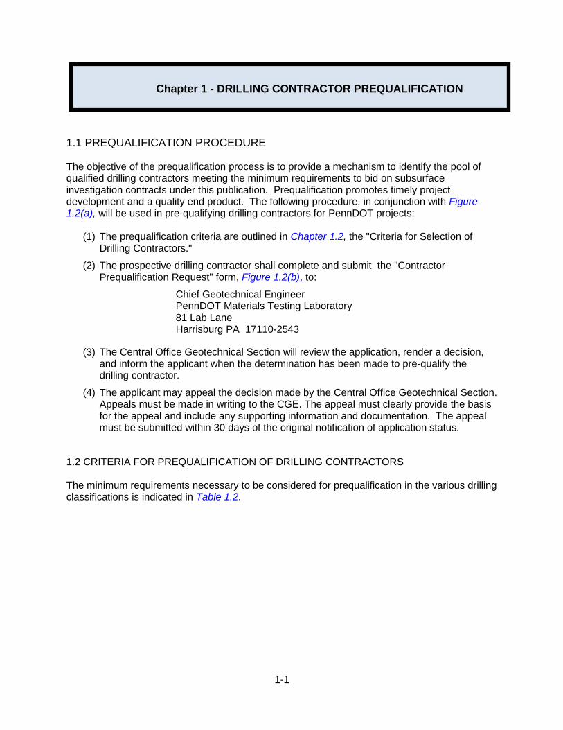
1.1 PREQUALIFICATION PROCEDURE The objective of the prequalification process is to provide a mechanism to identify the pool of qualified drilling contractors meeting the minimum requirements to bid on subsurface investigation contracts under this publication. Prequalification promotes timely project development and a quality end product. The following procedure, in conjunction with Figure 1.2(a), will be used in pre-qualifying drilling contractors for PennDOT projects:
(1) The prequalification criteria are outlined in Chapter 1.2, the "Criteria for Selection of Drilling Contractors."
(2) The prospective drilling contractor shall complete and submit the "Contractor Prequalification Request" form, Figure 1.2(b), to:
Chief Geotechnical Engineer PennDOT Materials Testing Laboratory 81 Lab Lane Harrisburg PA 17110-2543
(3) The Central Office Geotechnical Section will review the application, render a decision, and inform the applicant when the determination has been made to pre-qualify the drilling contractor.
(4) The applicant may appeal the decision made by the Central Office Geotechnical Section. Appeals must be made in writing to the CGE. The appeal must clearly provide the basis for the appeal and include any supporting information and documentation. The appeal must be submitted within 30 days of the original notification of application status.
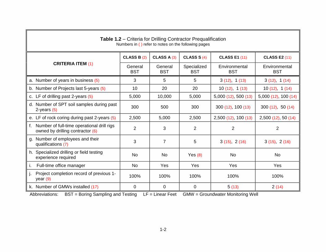
1.2 CRITERIA FOR PREQUALIFICATION OF DRILLING CONTRACTORS The minimum requirements necessary to be considered for prequalification in the various drilling classifications is indicated in Table 1.2.
Chapter 1 - DRILLING CONTRACTOR PREQUALIFICATION
1-2
Abbreviations: BST = Boring Sampling and Testing LF = Linear Feet GMW = Groundwater Monitoring Well
Table 1.2 – Criteria for Drilling Contractor Prequalification
Numbers in ( ) refer to notes on the following pages
CRITERIA ITEM (1)
CLASS B (2) CLASS A (3) CLASS S (4) CLASS E1 (11) CLASS E2 (11)
General BST
General BST
Specialized BST
Environmental BST
Environmental BST
a. Number of years in business (5) 3 5 5 3 (12), 1 (13) 3 (12), 1 (14)
b. Number of Projects last 5-years (5) 10 20 20 10 (12), 1 (13) 10 (12), 1 (14)
c. LF of drilling past 2-years (5) 5,000 10,000 5,000 5,000 (12), 500 (13) 5,000 (12), 100 (14)
d. Number of SPT soil samples during past 2-years (5)
300 500 300 300 (12), 100 (13) 300 (12), 50 (14)
e. LF of rock coring during past 2-years (5) 2,500 5,000 2,500 2,500 (12), 100 (13) 2,500 (12), 50 (14)
f. Number of full-time operational drill rigs owned by drilling contractor (6)
2 3 2 2 2
g. Number of employees and their qualifications (7)
3 7 5 3 (15), 2 (16) 3 (15), 2 (16)
h. Specialized drilling or field testing experience required
No No Yes (8) No No
i. Full-time office manager No Yes Yes Yes Yes
j. Project completion record of previous 1-year (9)
100% 100% 100% 100% 100%
k. Number of GMWs installed (17) 0 0 0 5 (13) 2 (14)

1-3
Criteria Notes for Table 1.2 (Page 1 of 2) (1) Table presents minimum requirements: any exceptions must be approved by the
Department in writing. (2) Class B - Capable of providing typical boring, sampling and testing, including Standard
Penetration Testing (SPT), disturbed and undisturbed soil sampling, auger sampling, rock coring, and installation of piezometers and slope inclinometers. No full-time office manager required.
(3) Class A - Same capabilities as Class B, but requires a greater level of experience and a
full-time office manager. (4) Class S - Special Class capable of specialized drilling, testing or sampling generally not
available from Class B or Class A drilling contractors. See Note (8) for special requirements.
(5) Experience of employees may be substituted for required minimum criteria for Items a, b,
c, d, and e provided a detailed resume of related experience is submitted to the Department for approval. If employee experience is accepted, the drilling contractor will be temporarily classified for a probationary period of two (2) years prior to being placed on the permanent list.
(6) Supply detailed list of equipment and accessories. (7) Provide resumes for drillers and office manager. (8) Specialized drilling or field testing experience includes work such as Horizontal drilling
(HZD), Inclined drilling (IND), Offshore drilling requiring a barge (OSD), Cone penetration testing (CPT), Dilatometer testing (DMT), Pressure meter testing (PMT), Vane shear testing (VST), Borehole geophysical testing (BGT), or other testing. Special class qualification can be obtained for limited areas of testing and experience. Approval will be limited to the specific area(s) of expertise for which the drilling contractor can demonstrate satisfactory experience.
(9) Completion is defined as completing a project in a timely manner to the satisfaction of the
owner: must provide letters of reference. Completion history includes both Environmental and General drilling projects.
(10) The Department will maintain a "Performance Report" for each contractor. This report will
be updated at the end of each project. Companies without Department experience are to provide letters of reference demonstrating satisfactory performance with other agencies.
(11) Class E1 and E2 - Experience must include drilling under Health and Safety Plans
(HASP) prepared as required in 29 CFR 1910.120 (OSHA) Hazardous Waste Operations and Emergency Response. Class E1 must include experience drilling under personnel protection Levels D and C. Class E2 must include experience drilling under personal protection Levels D, C, and B.

1-4
Criteria Notes for Table 1.2 (Page 2 of 2)
(12) May be tabulated from any projects completed by the firm during this period. (13) Must include only projects completed under a HASP. (14) Must include only projects completed under a HASP using Level B with positive pressure,
full-face piece self-contained breathing apparatus (SCBA) or positive pressure supplied air respirator with escape SCBA personnel protection, approved by the National Institute for Occupational Safety and Health (NIOSH).
(15) Total employees with or without OSHA health and safety training. (16) Individuals must possess mandatory forty (40) hour training in health and safety for
hazardous waste operations and emergency response with current certificate. This must include enrollment in a medical surveillance program as per 29 CFR 1910.120 (OSHA) Hazardous Waste Operations and Emergency Response.
(17) Groundwater monitoring wells (GMWs) are to collect geological data, groundwater data,
chemical data on soil and water, and provide for long-term monitoring capabilities.
1-5
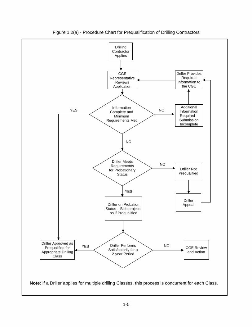
Figure 1.2(a) - Procedure Chart for Prequalification of Drilling Contractors Note: If a Driller applies for multiple drilling Classes, this process is concurrent for each Class.
Drilling Contractor
Applies
CGE Representative
Reviews Application
Information Complete and
Minimum Requirements Met
Driller Meets Requirements
for Probationary Status
Driller on Probation Status – Bids projects
as if Prequalified
Driller Performs Satisfactorily for a
2-year Period
Driller Approved as Prequalified for
Appropriate Drilling Class
CGE Review and Action
Driller Appeal
Driller Not Prequalified
Additional Information Required – Submission Incomplete
Driller Provides Required
Information to the CGE
NO
YES NO
NO
NO
YES
YES

1-6
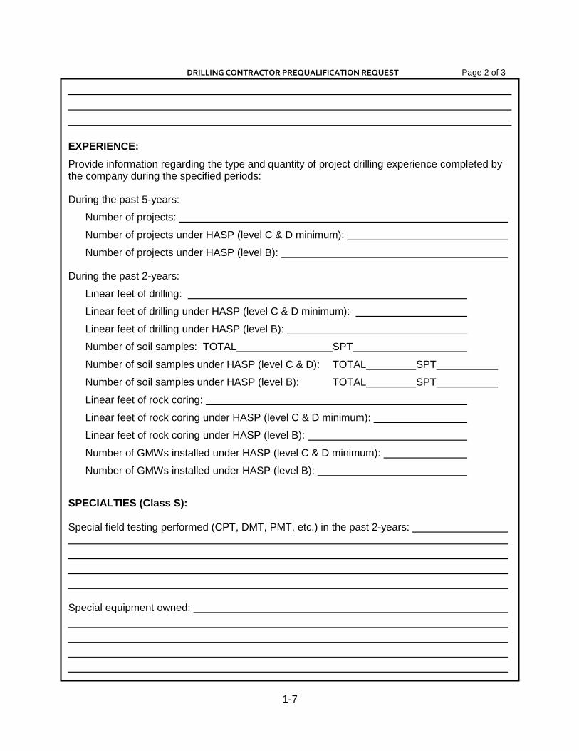
Figure 1.2(b) - Contractor Prequalification Request Form
See "Criteria for Prequalification of Drilling Contractors", Chapter 1.2 of Publication 222 for information required in this submission. Use standard letter-size sheets to provide any
additional information that cannot be accommodated on this form.
DRILLING CONTRACTOR PREQUALIFICATION REQUEST PennDOT Innovation & Support Services Division – Geotechnical Section Page 1 of 3
COMPANY:
Name of Company:
Owner(s) Name(s) and Title(s):
Address:
Phone: Fax:
Email Address:
Class Requested (B, A, S, E1, E2):
Primary Nature of Business:
Number of Years in Drilling Business:
Number of Years in Environmental Drilling Business:
Date Company Started:
EQUIPMENT:
Number, Description & Capabilities of full-time operational drill rigs owned:
Other sampling and testing equipment owned:
PERSONNEL:
Full-Time Office Manager:
Phone: List of full-time employees, their specific work functions and their qualifications including education, experience, major projects, areas of expertise, Certified 40-hr. OSHA training course, 8-hr. OSHA Supervisory training course, employee medical monitoring program:
1-7
DRILLING CONTRACTOR PREQUALIFICATION REQUEST Page 2 of 3
EXPERIENCE:
Provide information regarding the type and quantity of project drilling experience completed by the company during the specified periods:
During the past 5-years:
Number of projects:
Number of projects under HASP (level C & D minimum):
Number of projects under HASP (level B):
During the past 2-years:
Linear feet of drilling:
Linear feet of drilling under HASP (level C & D minimum):
Linear feet of drilling under HASP (level B):
Number of soil samples: TOTAL SPT
Number of soil samples under HASP (level C & D): TOTAL SPT
Number of soil samples under HASP (level B): TOTAL SPT
Linear feet of rock coring:
Linear feet of rock coring under HASP (level C & D minimum):
Linear feet of rock coring under HASP (level B):
Number of GMWs installed under HASP (level C & D minimum):
Number of GMWs installed under HASP (level B):
SPECIALTIES (Class S): Special field testing performed (CPT, DMT, PMT, etc.) in the past 2-years:
Special equipment owned:

1-8
DRILLING CONTRACTOR PREQUALIFICATION REQUEST Page 3 of 3
Specialized drilling experience (inclined, horizontal, offshore, monitoring wells, etc.). Include
project, owner, and date:
REPORTS, RECORDS AND REFERENCES:
List of projects completed in past 2-years:
(include name of owner, address, phone, date completed, delays)
Discuss SAFETY RECORD, claims and/or OSHA violations and measures to correct violations or deficiencies.
For Class E1 and E2 drilling, personnel must have training as per OSHA 29 CFR 1910.120 and
medical monitoring. Enclose a copy of the OSHA 40-hour training certificate and any other
pertinent documents or certifications for applicable personnel.
I am familiar with the Department's contract specifications and am aware that a
guarantee shall be required for all contracts. This guarantee is in the form of a Cashier's
check, a Treasurer's check or a Certified check (not less than 10% of the amount of the
bid) and is attached to every bid or proposal submitted.
Attest:
(Date) (Company)
By: (Signature) (Signature)
(Print Name) (Print Name)
1-9
1.3 LIST OF PREQUALIFIED DRILLING CONTRACTORS A current listing of prequalified drilling contractors is maintained by the Central Office Geotechnical Section, and can be accessed at: ftp://ftp.dot.state.pa.us/public/pdf/bocm_mtd_lab/publications/pub_222/publication%20222.pdf
It is the responsibility of each pre-qualified drilling contractor to ensure their contact information is kept up-to-date with the Department. The required contact information includes:
Company name
Mailing address
Phone number
Fax number
Name of primary contact
Email address of primary contact
Contact information updates should be sent to the Central Office Geotechnical Section at the address shown Chapter 1.1. The Department will make periodic (annually or bi-annually) notifications via email to all certified drillers. For any contractor not responding to the email solicitation, a follow-up phone call may be attempted by the Department. Any contractor that cannot be contacted will be removed from the certification list.

1-10
BLANK PAGE

2-1
2.1 INSTRUCTIONS TO COMPLETE PERFORMANCE REPORTS The procedural flowchart for Drilling Contractor performance evaluation is presented in Figure 2.1(a). 2.1.1 Consultant Contracts
1. The Project Geotechnical Manager (PGM) and project Inspector(s) will be responsible
for preparing the “Performance Report for Drilling Contractors”. 2. The project PGM/PGE will discuss the Drilling Contractor's evaluation with the DGE prior
to completing the Performance Report. 3. The Consultant will send a copy of the report to the Drilling Contractor for their review. 4. The Consultant will send the Performance Report to the DGE for review. 5. If the Performance Report is satisfactory, no action is needed. If the Performance Report
is unsatisfactory and the DGE rejects the rating due to insufficient documentation, the Consultant will be notified of the deficiencies. If the Performance Report is unsatisfactory and the DGE concurs, it will be submitted to the CGE for review.
6. If the CGE rejects the rating, it will be returned to the DGE and Consultant with the
deficiencies identified. If the CGE approves the rating it will be returned to the DGE and Consultant with the necessary action defined.
7. Information for the CGE will be sent to the following address:
Chief Geotechnical Engineer PennDOT Materials Testing Laboratory 81 Lab Lane Harrisburg PA 17110-2543
2.1.2 Department Contracts
1. The DGE and project inspector(s) will complete the “Performance Report for Drilling Contractors”.
2. The DGE will send a copy of the Performance Report to the Drilling Contractor for their
review. 3. If the Performance Report is satisfactory, no action is needed. If the Performance Report
is unsatisfactory and the DGE rejects the rating due to insufficient documentation, the
Chapter 2 - DRILLING CONTRACTOR PERFORMANCE EVALUATION
2-2
Consultant will be notified of the deficiencies. If the Performance Report is unsatisfactory, and the DGE concurs, it will be submitted to the CGE for review.
4. If the CGE rejects the rating, it will be returned to the DGE and Consultant with the
deficiencies identified. If the CGE approves the rating it will be returned to the DGE and Consultant with the necessary action defined.
5. Information for the CGE will be sent to the following address:
Chief Geotechnical Engineer PennDOT Materials Testing Laboratory 81 Lab Lane Harrisburg PA 17110-2543
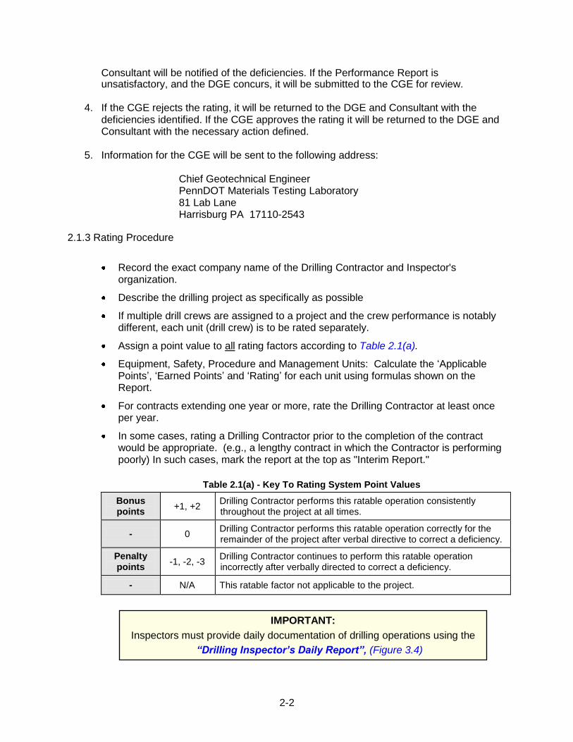
2.1.3 Rating Procedure
Record the exact company name of the Drilling Contractor and Inspector's organization.
Describe the drilling project as specifically as possible
If multiple drill crews are assigned to a project and the crew performance is notably different, each unit (drill crew) is to be rated separately.
Assign a point value to all rating factors according to Table 2.1(a).
Equipment, Safety, Procedure and Management Units: Calculate the „Applicable Points‟, „Earned Points‟ and „Rating‟ for each unit using formulas shown on the Report.
For contracts extending one year or more, rate the Drilling Contractor at least once per year.
In some cases, rating a Drilling Contractor prior to the completion of the contract would be appropriate. (e.g., a lengthy contract in which the Contractor is performing poorly) In such cases, mark the report at the top as "Interim Report."
Table 2.1(a) - Key To Rating System Point Values
Bonus points
+1, +2 Drilling Contractor performs this ratable operation consistently throughout the project at all times.
- 0 Drilling Contractor performs this ratable operation correctly for the remainder of the project after verbal directive to correct a deficiency.
Penalty points
-1, -2, -3 Drilling Contractor continues to perform this ratable operation incorrectly after verbally directed to correct a deficiency.
- N/A This ratable factor not applicable to the project.
IMPORTANT:
Inspectors must provide daily documentation of drilling operations using the
“Drilling Inspector’s Daily Report”, (Figure 3.4)
s, and thorough documentation and clarification for each “zero or less” rating.
2-3
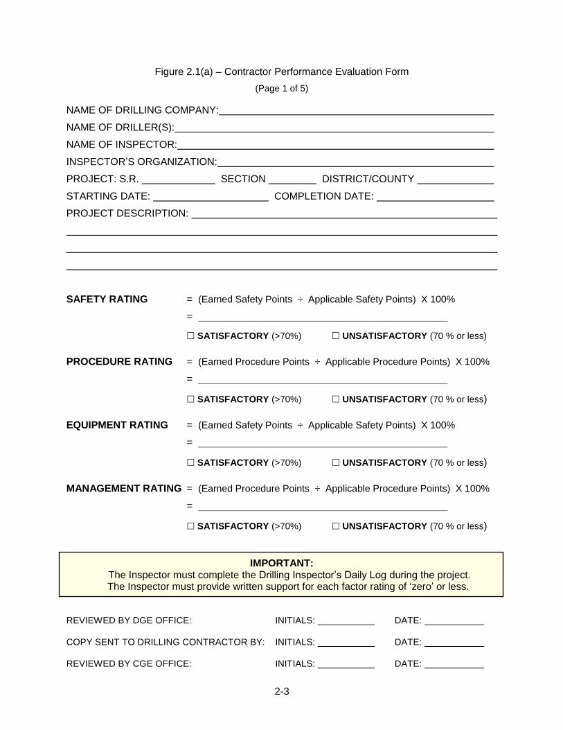
Figure 2.1(a) – Contractor Performance Evaluation Form
(Page 1 of 5)
NAME OF DRILLING COMPANY:
NAME OF DRILLER(S):
NAME OF INSPECTOR:
INSPECTOR‟S ORGANIZATION:
PROJECT: S.R. SECTION DISTRICT/COUNTY
STARTING DATE: COMPLETION DATE:
PROJECT DESCRIPTION:
SAFETY RATING = (Earned Safety Points ÷ Applicable Safety Points) X 100%
=
SATISFACTORY (>70%) UNSATISFACTORY (70 % or less)
PROCEDURE RATING = (Earned Procedure Points ÷ Applicable Procedure Points) X 100%
=
SATISFACTORY (>70%) UNSATISFACTORY (70 % or less)
EQUIPMENT RATING = (Earned Safety Points ÷ Applicable Safety Points) X 100%
=
SATISFACTORY (>70%) UNSATISFACTORY (70 % or less)
MANAGEMENT RATING = (Earned Procedure Points ÷ Applicable Procedure Points) X 100%
=
SATISFACTORY (>70%) UNSATISFACTORY (70 % or less)
IMPORTANT: The Inspector must complete the Drilling Inspector‟s Daily Log during the project. The Inspector must provide written support for each factor rating of „zero‟ or less.
REVIEWED BY DGE OFFICE: INITIALS: DATE:
COPY SENT TO DRILLING CONTRACTOR BY: INITIALS: DATE:
REVIEWED BY CGE OFFICE: INITIALS: DATE:
2-4
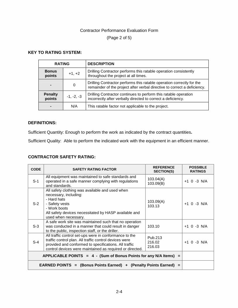
Contractor Performance Evaluation Form
(Page 2 of 5) KEY TO RATING SYSTEM:
RATING DESCRIPTION
Bonus points
+1, +2 Drilling Contractor performs this ratable operation consistently throughout the project at all times.
- 0 Drilling Contractor performs this ratable operation correctly for the remainder of the project after verbal directive to correct a deficiency.
Penalty points
-1, -2, -3 Drilling Contractor continues to perform this ratable operation incorrectly after verbally directed to correct a deficiency.
- N/A This ratable factor not applicable to the project.
DEFINITIONS: Sufficient Quantity: Enough to perform the work as indicated by the contract quantities. Sufficient Quality: Able to perform the indicated work with the equipment in an efficient manner.
CONTRACTOR SAFETY RATING:
CODE SAFETY RATING FACTOR REFERENCE SECTION(S)
POSSIBLE RATINGS
S-1 All equipment was maintained to safe standards and operated in a safe manner complying with regulations and standards.
103.04(A) 103.09(B)
+1 0 -3 N/A
S-2
All safety clothing was available and used when necessary, including: - Hard hats - Safety vests - Work boots All safety devices necessitated by HASP available and used when necessary.
103.09(A) 103.13
+1 0 -3 N/A
S-3 A safe work site was maintained such that no operation was conducted in a manner that could result in danger to the public, inspection staff, or the driller.
103.10 +1 0 -3 N/A
S-4
All traffic control set-ups were in conformance to the traffic control plan. All traffic control devices were provided and conformed to specifications. All traffic control devices were maintained as required or directed.
Pub.213 216.02 216.03
+1 0 -3 N/A
APPLICABLE POINTS = 4 - (Sum of Bonus Points for any N/A Items) =
EARNED POINTS = (Bonus Points Earned) + (Penalty Points Earned) =
2-5
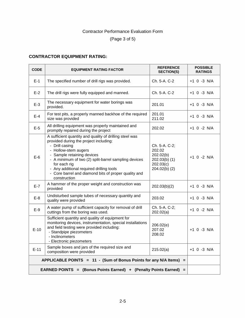
Contractor Performance Evaluation Form
(Page 3 of 5)
CONTRACTOR EQUIPMENT RATING:
CODE EQUIPMENT RATING FACTOR REFERENCE SECTION(S)
POSSIBLE RATINGS
E-1 The specified number of drill rigs was provided. Ch. 5-A. C-2 +1 0 -3 N/A
E-2 The drill rigs were fully equipped and manned. Ch. 5-A. C-2 +1 0 -3 N/A
E-3 The necessary equipment for water borings was provided.
201.01 +1 0 -3 N/A
E-4 For test pits, a properly manned backhoe of the required size was provided
201.01 211.02
+1 0 -3 N/A
E-5 All drilling equipment was properly maintained and promptly repaired during the project
202.02 +1 0 -2 N/A
E-6
A sufficient quantity and quality of drilling steel was provided during the project including:
- Drill casing - Hollow-stem augers - Sample retaining devices - A minimum of two (2) split-barrel sampling devices
for each rig - Any additional required drilling tools - Core barrel and diamond bits of proper quality and
construction
Ch. 5-A. C-2; 202.02 202.02(b) 202.03(b) (1) 202.03(c) 204.02(b) (2)
+1 0 -2 N/A
E-7 A hammer of the proper weight and construction was provided
202.03(b)(2) +1 0 -3 N/A
E-8 Undisturbed sample tubes of necessary quantity and quality were provided
203.02 +1 0 -3 N/A
E-9 A water pump of sufficient capacity for removal of drill cuttings from the boring was used.
Ch. 5-A. C-2; 202.02(a)
+1 0 -2 N/A
E-10
Sufficient quantity and quality of equipment for monitoring devices, instrumentation, special installations and field testing were provided including: - Standpipe piezometers - Inclinometers - Electronic piezometers
206.02(e) 207.02 208.02
+1 0 -3 N/A
E-11 Sample boxes and jars of the required size and composition were provided
215.02(a) +1 0 -3 N/A
APPLICABLE POINTS = 11 - (Sum of Bonus Points for any N/A Items) =
EARNED POINTS = (Bonus Points Earned) + (Penalty Points Earned) =
2-6
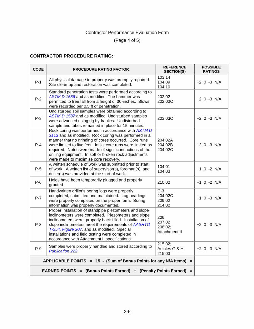
Contractor Performance Evaluation Form
(Page 4 of 5)
CONTRACTOR PROCEDURE RATING:
CODE PROCEDURE RATING FACTOR REFERENCE SECTION(S)
POSSIBLE RATINGS
P-1 All physical damage to property was promptly repaired. Site clean-up and restoration was completed.
103.14 104.09 104.10
+2 0 -3 N/A
P-2
Standard penetration tests were performed according to ASTM D 1586 and as modified. The hammer was permitted to free fall from a height of 30-inches. Blows were recorded per 0.5 ft of penetration.
202.02 202.03C
+2 0 -3 N/A
P-3
Undisturbed soil samples were obtained according to ASTM D 1587 and as modified. Undisturbed samples were advanced using rig hydraulics. Undisturbed sample and tubes remained in place for 15 minutes.
203.03C +2 0 -3 N/A
P-4
Rock coring was performed in accordance with ASTM D 2113 and as modified. Rock coring was performed in a manner that no grinding of cores occurred. Core runs were limited to five feet. Initial core runs were limited as required. Notes were made of significant actions of the drilling equipment. In soft or broken rock adjustments were made to maximize core recovery.
204.02A 204.02B 204.02C
+2 0 -3 N/A
P-5 A written schedule of work was submitted prior to start of work. A written list of supervisor(s), foreman(s), and driller(s) was provided at the start of work.
104.01 104.03
+1 0 -2 N/A
P-6 Holes have been temporarily plugged and properly grouted
210.02 +1 0 -2 N/A
P-7
Handwritten driller‟s boring logs were properly completed, submitted and maintained. Log headings were properly completed on the proper form. Boring information was properly documented.
C-3 204.02C 209.02 214.02
+1 0 -3 N/A
P-8
Proper installation of standpipe piezometers and slope inclinometers were completed. Piezometers and slope inclinometers were properly back-filled. Installation of slope inclinometers meet the requirements of AASHTO T-254, Figure 207, and as modified. Special installations and field testing were completed in accordance with Attachment II specifications.
206 207.02 208.02; Attachment II
+2 0 -3 N/A
P-9 Samples were properly handled and stored according to Publication 222.
215.02; Articles G & H 215.03
+2 0 -3 N/A
APPLICABLE POINTS = 15 - (Sum of Bonus Points for any N/A Items) =
EARNED POINTS = (Bonus Points Earned) + (Penalty Points Earned) =
2-7
Contractor Performance Evaluation Form
(Page 5 of 5)
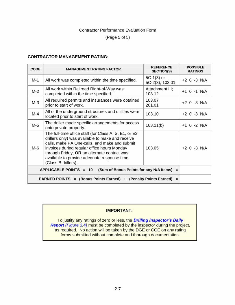
CONTRACTOR MANAGEMENT RATING:
CODE MANAGEMENT RATING FACTOR REFERENCE SECTION(S)
POSSIBLE RATINGS
M-1 All work was completed within the time specified. 5C-1(3) or 5C-2(3); 103.01
+2 0 -3 N/A
M-2 All work within Railroad Right-of-Way was completed within the time specified.
Attachment III; 103.12
+1 0 -1 N/A
M-3 All required permits and insurances were obtained prior to start of work.
103.07 201.01
+2 0 -3 N/A
M-4 All of the underground structures and utilities were located prior to start of work.
103.10 +2 0 -3 N/A
M-5 The driller made specific arrangements for access onto private property.
103.11(b) +1 0 -2 N/A
M-6
The full-time office staff (for Class A, S, E1, or E2 drillers only) was available to make and receive calls, make PA One-calls, and make and submit invoices during regular office hours Monday through Friday, OR an alternate contact was available to provide adequate response time (Class B drillers).
103.05 +2 0 -3 N/A
APPLICABLE POINTS = 10 - (Sum of Bonus Points for any N/A Items) =
EARNED POINTS = (Bonus Points Earned) + (Penalty Points Earned) =
IMPORTANT:
To justify any ratings of zero or less, the Drilling Inspector’s Daily Report (Figure 3.4) must be completed by the inspector during the project,
as required. No action will be taken by the DGE or CGE on any rating forms submitted without complete and thorough documentation.
2-8
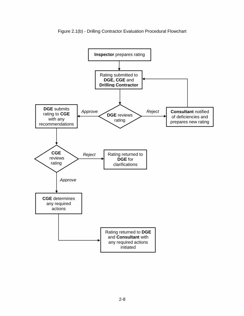
Figure 2.1(b) - Drilling Contractor Evaluation Procedural Flowchart
Inspector prepares rating
Rating submitted to DGE, CGE and
Drilling Contractor
Rating returned to DGE for
clarifications
DGE reviews rating
Reject
Rating returned to DGE and Consultant with any required actions
initiated
CGE determines any required
actions
Consultant notified of deficiencies and prepares new rating
Approve DGE submits rating to CGE
with any recommendations
CGE reviews
rating
Reject
Approve
2-9
2.2 REMOVAL OF DRILLING CONTRACTOR FROM PREQUALIFIED LIST
Any unsatisfactory rating recieved on any of the four Contractor rating factors (Equipment, Procedure, Safety or Management) will be reviewed by the CGE.
During the review process, the Drilling Contractor shall provide an explanation to the CGE as to the reason for the unsatisfactory rating and shall demonstrate his plan for upgrading the rating to a satisfactory level.
Upon review, the CGE will decide if the Drilling Contractor is to be placed on “Notice” status.
A “Notice” status is to be a minimum duration of one year. During this period, the Drilling Contractor is permitted to bid on Department work.
To be removed from “Notice” status, the Drilling Contractor must successfully work at least one Department project while on “Notice”. This work must demonstrate that the contractor has corrected any previous deficiencies related to the “Unsatisfactory” performance rating. This work shall earn a “Satisfactory” performance rating and include a minimum of 15 m (50 feet) of SPT soil sampling and 15 m (50 feet) of rock coring.
If a Drilling Contractor receives an unsatisfactory rating while on “Notice”, the CGE shall review the rating to decide if the Drilling Contractor should be removed from the pre-qualified list.
In the event a Drilling Contractor is removed from the pre-qualified list, the company will not be permitted to apply for pre-qualification for a time period deemed appropriate by the CGE, but not exceeding three years.

2-10
BLANK PAGE
3-1
3.1 MINIMUM REQUIREMENTS FOR DRILLING INSPECTION All inspection will be the responsibility of the Project Geotechnical Manager (P.E. or P.G.). One full-time, certified Inspector shall be assigned to each operating drill rig. It is not reasonable to expect an Inspector to visually monitor and accurately log the operation of two or more drilling rigs that are operating simultaneously. Projects drilled under Department contracts will be inspected by District personnel or the District's representative. District drilling Inspectors must be certified drilling Inspectors. District employees needing to become certified must be tested and certified by the CGE, or through other arrangements (such as testing by a neighboring District) as approved by the CGE. Projects drilled under Consultant design contracts will normally be inspected by Consultant personnel. Consultant projects can be inspected by Department forces provided the Department Inspector is certified and the DGE is a licensed P.E. or P.G. in the Commonwealth. In addition, the DGE must review the core boxes and check and initial the final Engineer‟s Logs. For projects where the geotechnical Consultant (or a subsidiary company thereof) is also a Drilling Contractor, the Consultant may be permitted to provide the project drilling services and to inspect the work performed by their own Driller. See Chapter 4.5 for more clarification on the requirements for this case. The following minimum qualifications must be met by all drilling Inspectors:
Speaks, writes, reads and understands the English language fluently.
Has prior drilling inspection experience on a minimum of three (3) drilling projects (Department or private), with minimum logging experience of 60 m (200 feet) of Standard Penetration Testing (footage from auger advance may not be included) and 30 m (100 feet) of rock coring.
Is knowledgeable of general drilling practices and the following references: o Publication 213 (Temporary Traffic Control Guidelines) o Publication 222 (Geotechnical Investigation Manual) o Publication 293 (Geotechnical Engineering Manual) o A copy of the boring contract for the project o A rock identification text (e.g., the Audubon Society Field Guide to North
American Rocks and Minerals, the Smithsonian Handbook of Rocks and Minerals, or other reference suitable for identification of PA rocks)
Be able to: traverse rough, steep terrain; cope with inclement weather conditions; deal with potential natural hazards such as snakes, ticks, bees and poison ivy; work safely in the vicinity of live traffic and open bodies of water.
Chapter 3 - DRILLING INSPECTION REQUIREMENTS
3-2
Understands the general geotechnical design principles involved in the anticipated construction, and the anticipated laboratory testing.
Successfully passed both parts of the Department‟s Drilling Inspector Examination and possess a valid drilling inspector certification issued by the Department.
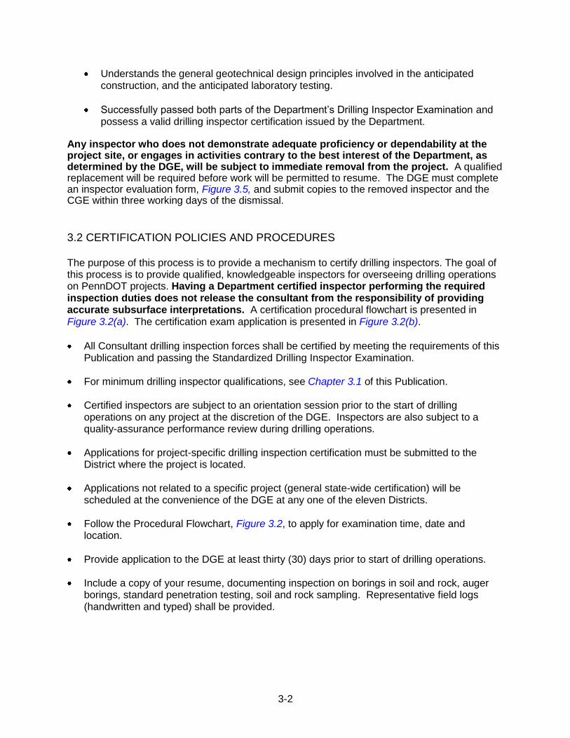
Any inspector who does not demonstrate adequate proficiency or dependability at the project site, or engages in activities contrary to the best interest of the Department, as determined by the DGE, will be subject to immediate removal from the project. A qualified replacement will be required before work will be permitted to resume. The DGE must complete an inspector evaluation form, Figure 3.5, and submit copies to the removed inspector and the CGE within three working days of the dismissal.
3.2 CERTIFICATION POLICIES AND PROCEDURES
The purpose of this process is to provide a mechanism to certify drilling inspectors. The goal of this process is to provide qualified, knowledgeable inspectors for overseeing drilling operations on PennDOT projects. Having a Department certified inspector performing the required inspection duties does not release the consultant from the responsibility of providing accurate subsurface interpretations. A certification procedural flowchart is presented in Figure 3.2(a). The certification exam application is presented in Figure 3.2(b).
All Consultant drilling inspection forces shall be certified by meeting the requirements of this Publication and passing the Standardized Drilling Inspector Examination.
For minimum drilling inspector qualifications, see Chapter 3.1 of this Publication.
Certified inspectors are subject to an orientation session prior to the start of drilling operations on any project at the discretion of the DGE. Inspectors are also subject to a quality-assurance performance review during drilling operations.
Applications for project-specific drilling inspection certification must be submitted to the District where the project is located.
Applications not related to a specific project (general state-wide certification) will be scheduled at the convenience of the DGE at any one of the eleven Districts.
Follow the Procedural Flowchart, Figure 3.2, to apply for examination time, date and location.
Provide application to the DGE at least thirty (30) days prior to start of drilling operations.
Include a copy of your resume, documenting inspection on borings in soil and rock, auger borings, standard penetration testing, soil and rock sampling. Representative field logs (handwritten and typed) shall be provided.
3-3
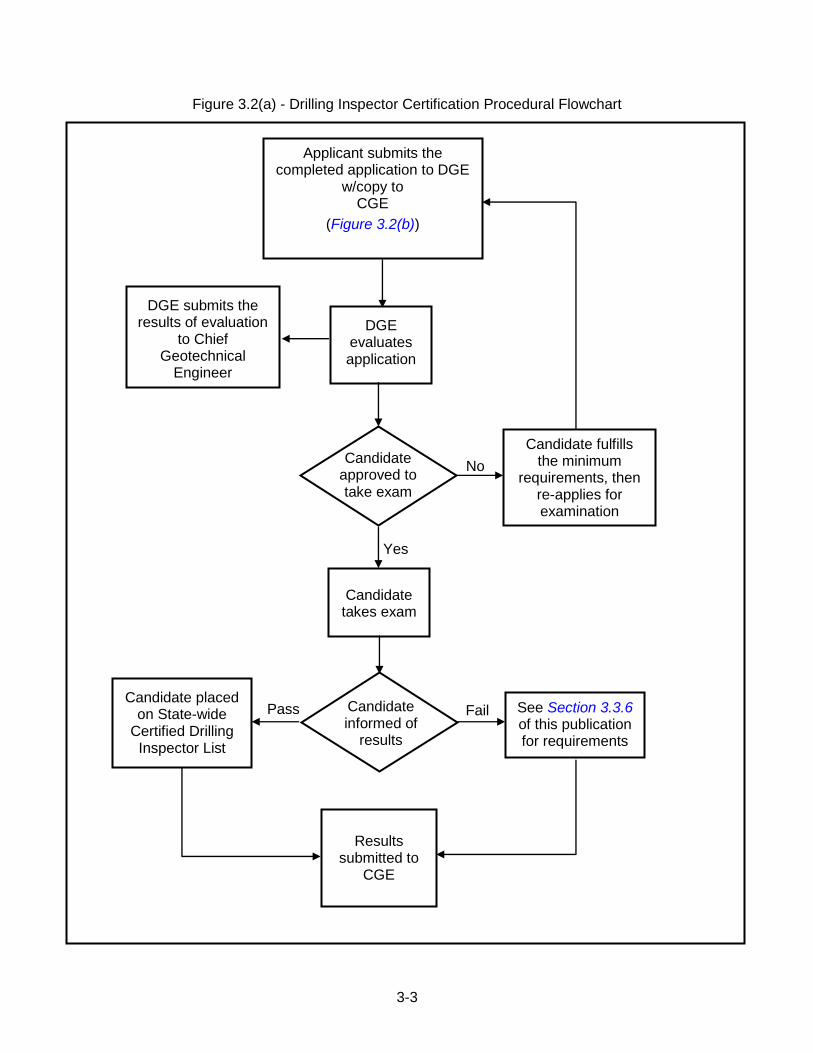
Figure 3.2(a) - Drilling Inspector Certification Procedural Flowchart
Applicant submits the completed application to DGE
w/copy to CGE
(Figure 3.2(b))
DGE evaluates application
Candidate fulfills the minimum
requirements, then re-applies for examination
Candidate approved to take exam
Yes
No
Candidate takes exam
Candidate informed of
results
Pass Fail See Section 3.3.6 of this publication for requirements
Candidate placed on State-wide
Certified Drilling Inspector List
Results
submitted to CGE
DGE submits the results of evaluation
to Chief Geotechnical
Engineer
(Figure 2.2)

3-4
Figure 3.2(b) - Application for Drilling Inspector Examination
DRILLING INSPECTOR EXAM APPLICATION - PennDOT Innovation & Support Services Division - Geotechnical Section
(This section is to be completed by the APPLICANT)
Instructions: Complete this application and submit one copy each along with your resume and required documentation, to the District Geotechnical Engineer (DGE) at the District you are applying, and to the PennDOT Chief Geotechnical Engineer, at: 81 Lab Lane, Harrisburg, PA 17110-2543.
Applicant Information: (Please print or type)
Name Company
Phone Street Address
E-mail City, State, Zip
Is this application for a retest of a previous examination at this or any other District? Yes No
Is this application relative to a specific Department Project? Yes No
If Yes: District County SR Section
Note 1: If the application is for a specific Department project, then the application for drilling inspector examination must be submitted to the District indicated.
Note 2: If the application is non-project specific, the application may be submitted to any Engineering District, with the examination scheduled at the convenience of the DGE.
/ / Applicant Signature Date
(This section is to be completed by the DGE)
Yes No* Applicant‟s resume and documentation enclosed?
Applicant meets prerequisites of Publication 222?
Application form completed?
Applicant signature provided?
* A “No” response to any one of the above items will result in the application being denied.
Applicant is approved to take exam?
Comments: Date: / / Time: Location: / /
DGE signature Date
3-5
3.3 CERTIFICATION EXAM REQUIREMENTS AND GUIDELINES 3.3.1 Written Examination (Part-1 and Part-2)
The written examination is open-book and divided into two subject areas, Drilling Operations, Duties and Technical Knowledge (Part-1) and Traffic Control (Part-2).
There is a 105-minute time limit for the written test.
Part-1 consists of 34 questions and covers all required duties and knowledge including geology, soil and rock identification, drilling operations, logging of borings, inspection duties, and PennDOT guidelines/requirements.
Part-2 consists of 6 questions and covers temporary traffic control procedures and requirements.
3.3.2 Rock & Soil Sample Identification Examination (Part-3)
Open Book
16 to 20 soil/rock identifications (minimum of 6 soil IDs and 10 rock IDs)
There is a 60-minute time limit for the standard 16 sample test, with 5 additional minutes allotted for any additional sample
Physical descriptions based on Publication 222 requirements
All candidates must be able to perform the following:
- Use Publication 222 - Use the AASHTO and Unified (USCS) soil classification systems, and cross
reference as necessary - Identify different rock and soil types found in Pennsylvania - Distinguish between siltstone, claystone, and shale - Distinguish between carbonate and non-carbonate rocks - Distinguish between sedimentary, igneous, and metamorphic rocks - Distinguish between clay, silt, sand, and gravel
3.3.3 Required References, Identification and Tools
Technical references (see Chapter 3.1, 3rd bullet), and other pertinent geologic references.
Driver‟s license
Black pen, pencil, eraser, calculator
10% HCl acid solution, pocket knife, hand lens, common hardwood dowel (not oak), copper pipe or penny, common steel nail, steel file
NOTE : None of the above materials will be supplied by the Department to take the exam. Failure to bring any of the above materials will result in failure of the exam, and will require the candidate to follow re-examination procedures.
3-6
3.3.4 Examination Rules
Communication with any other applicant or source (including cell phone or texting) during the examination is prohibited, except with the DGE or their designate. Prohibited communications will result in immediate failure of the exam.
Required examination references, publications or other required items will not be supplied at the test site. Failure to bring required examination materials will result in their forfeit of the exam. These candidates must reapply to take the exam.
Sharing of examination items or references between applicants is not permitted.
Examination materials or answers may not be removed from the test site in any form. 3.3.5 Pass/Fail Requirements
A procedural flowchart for Pass/Fail requirements is presented in Figure 3.2(a).
To be placed on the statewide approved drilling inspectors list, candidates must demonstrate overall aptitude by meeting minimum scoring requirements for both the Written and Sample Identification portions of the examination
For Part-1 of the exam, a minimum score of 75% is required to pass.
For Part-2 of the exam, a minimum 5 correct responses out of a total of 6 are required. If less than five of the questions are completed successfully, the candidate fails the entire exam, regardless of the overall exam score.
For Part-3 of the exam, a minimum score of 75% is required to pass. At the discretion of the CGE or DGE, partial credit can be given for any sample identification description.
3.3.6 Failure of Examinations
The following requirements must be completed prior to re-application for drill inspector.
Work on three documented drilling inspection projects. At least one of the three projects must be on a Department project as an apprentice. Apprenticeship is at no additional cost to the Department. Total footage requirements are as defined in Chapter 3.1.
3.3.7 Examination Results
The DGE shall inform both the candidate and the CGE of examination results in writing (email is acceptable) within three working days of the exam.
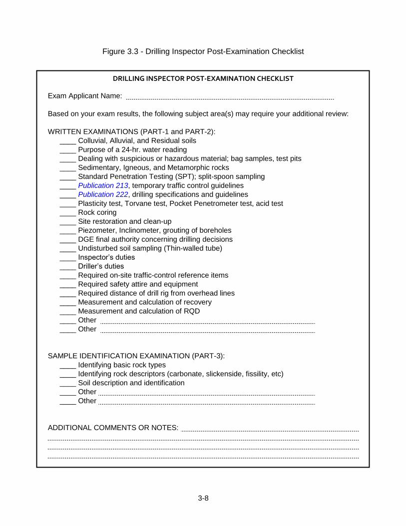
The Drilling Inspector Post-Examination Checklist (Figure 3.3) shall be completed to indicate any areas of weakness exhibited on the exam. The list shall be completed by the DGE whether the candidate passes or fails. This list should be reviewed by the candidate in preparation for inspection duties or reapplication, if necessary.
3-7
The CGE will mail a certificate to a candidate that successfully passes the certification exam. The certification number and contact in formation of the newly-certified inspector will be included on the current listing of all PennDOT certified drilling inspectors maintained by the CGE‟s office.
3.3.8 List of PennDOT-Certified Drilling Inspectors A current listing of all PennDOT certified drilling Inspectors is maintained by the CGE‟s office and is accessible on-line at:
ftp://ftp.dot.state.pa.us/public/pdf/bocm_mtd_lab/publications/pub_222/publication%20222.pdf
Once certified, the drilling inspector is responsible to promptly notify the CGE‟s office of any needed update of their personal contact information. See the on-line certified inspectors list for contact information in order to report personal contact information changes. The Department will make periodic (annually or bi-annually) notifications via email to all certified inspectors. For any inspector not responding to the email solicitation, a follow-up phone call may be attempted by the Department. Any inspector that cannot be contacted will be removed from the certification list. Only those inspectors that are listed on the on-line certification list are considered to hold a current and valid certification.
3-8
Figure 3.3 - Drilling Inspector Post-Examination Checklist
DRILLING INSPECTOR POST-EXAMINATION CHECKLIST
Exam Applicant Name:
Based on your exam results, the following subject area(s) may require your additional review:
WRITTEN EXAMINATIONS (PART-1 and PART-2):
____ Colluvial, Alluvial, and Residual soils
____ Purpose of a 24-hr. water reading
____ Dealing with suspicious or hazardous material; bag samples, test pits
____ Sedimentary, Igneous, and Metamorphic rocks
____ Standard Penetration Testing (SPT); split-spoon sampling
____ Publication 213, temporary traffic control guidelines
____ Publication 222, drilling specifications and guidelines
____ Plasticity test, Torvane test, Pocket Penetrometer test, acid test
____ Rock coring
____ Site restoration and clean-up
____ Piezometer, Inclinometer, grouting of boreholes
____ DGE final authority concerning drilling decisions
____ Undisturbed soil sampling (Thin-walled tube)
____ Inspector‟s duties
____ Driller‟s duties
____ Required on-site traffic-control reference items
____ Required safety attire and equipment
____ Required distance of drill rig from overhead lines
____ Measurement and calculation of recovery
____ Measurement and calculation of RQD
____ Other
____ Other
SAMPLE IDENTIFICATION EXAMINATION (PART-3):
____ Identifying basic rock types
____ Identifying rock descriptors (carbonate, slickenside, fissility, etc)
____ Soil description and identification
____ Other
____ Other
ADDITIONAL COMMENTS OR NOTES:
3-9
3.4 DUTIES OF INSPECTION FORCES The general duties of a drilling inspector include:
Verify the testing and sampling procedures are performed correctly.
Ensure the depth of each sample is known and recorded correctly.
Describe soil and rock samples correctly. 3.4.1 Prior To the Start of Drilling Operations
The PGM is responsible to notify the DGE of the planned start-date of drilling and to forward to the DGE a copy of the Drilling Contractor‟s submission providing applicable information required by Sections 104.01, 104.03, 104.08, and 104.09. The inspector is responsible to:
Have a copy of the “Intent to Enter” letter available at the site and provide information on all affected property owners to the Drilling Contractor (name, address, telephone number, etc.).
Determine the apparent adequacy of the Drilling Contractor‟s drilling equipment. If any equipment appears faulty or questionable, the inspector should discuss this with the driller and the PGM/PGE, if warranted.
Determine the adequacy of the Drilling Contractor‟s equipment for temporary maintenance and protection of traffic.
Determine if the Drilling Contractor has contacted all utilities and that all utilities are clearly marked in the field.
Visually confirm all plan locations of borings, test pits and instruments are clearly staked according to plans or instructions. Note if any locations appear to be within 100 feet of any domestic water supply wells or spring boxes and if so, confirm that the contractor has the proper provisions as specified in Section 219.
Conduct field view of the site and understand what work is to be done. Note any environmental sensitive areas and if any temporary traffic control will be needed.
Study all documents, reports, and any other previous borings that were done at the site or nearby sites.
Have a list of emergency phone numbers, hospitals, and maps available at the site.
Study the drilling contract and all attachments, as applicable.
Be familiar with the subsurface investigation plan.
Understand the information to be gathered, its purpose in design and use for lab testing
3-10
3.4.2 During Drilling Operations
The PGM/PGE is responsible to keep the DGE promptly informed of any issues or problems.
The inspector‟s responsibilities include:
Complete the Drilling Inspector’s Daily Report, Figure 3.4.
Keep daily drilling quantity records/summaries, and review quantities with the driller each day work is completed.
Label all samples and core boxes.
Visually identify the staked locations of borings and test pits and compare to the plans or other instructions given by PGE. Notify the PGE if any discrepancies are found or suspected.
Ensure that the operations are performed according to the terms of the work and all relevant publications and guidelines.
Log test borings and test pits in accordance with Chapter 3.6.
Document instrument installations, including, but not limited to, types, locations, installation procedures and any problems encountered during installation.
Record any instructions given to the contractor including date, time, to whom, and the driller's response and whether or not actual work was performed as per the instructions.
Maintain any records required by this publication or the DGE.
Record in detail any events or situations that may later result in litigation or a claim against the Department.
Confirm and have the contractor make necessary field adjustments of the work zone traffic control set-up using PennDOT Publication 213, Temporary Traffic Control Guidelines.
Act as a responsible representative of the Department at all times.
Assist to resolve any issues with the driller, motorists, and/or property owners during field operations. Communicate clearly and be professional and courteous.
Perform other related duties as directed or required.
Promptly report any unexpected findings or problems to the PGM/PGE.
Have the following available at the jobsite:
- All required technical references (Chapter 3.1, 3rd bullet) and other pertinent geologic references
- Driver‟s license
- Black pen, pencil, eraser, calculator
- 10% HCl acid solution
- Pocket knife, hand lens, common hardwood dowel (not oak), copper pipe or penny, common steel nail, steel file,

3-11
- PennDOT Drilling Inspector Certification Number
3-12
3.4.3 Daily Drilling Quantity Summaries
Using the Drilling Inspector’s Daily Report (Figure 3.4), the inspector will maintain and update daily a record for each drill rig, of the work completed including footage of drilling in soil and rock. The record will document the quantity of each pay item listed in the Form of Proposal completed during the day. The record will also indicate, for each day, the driller's name, the helper's name and the hours worked. The Inspector and the Driller shall review and sign the record daily to indicate agreement with the quantities listed as complete, and note any disagreement with the listed quantities. Provide data as needed to facilitate accurate documentation of the work on the record. One copy of the record will be made available to the PGM/PGE at the end of each work day, or weekly if agreed to by the PGM/PGE.
3-13
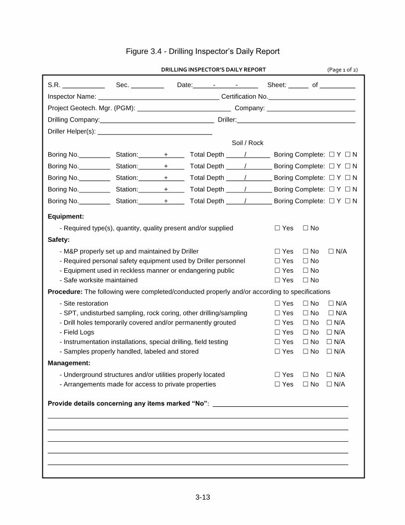
Figure 3.4 - Drilling Inspector‟s Daily Report
DRILLING INSPECTOR’S DAILY REPORT (Page 1 of 2)
S.R. . Sec. . Date: - - . Sheet: . of
Inspector Name: Certification No.
Project Geotech. Mgr. (PGM): . Company:
Drilling Company: Driller:
Driller Helper(s):
Soil / Rock
Boring No. . Station: + . Total Depth / . Boring Complete: Y N
Boring No. . Station: + . Total Depth / Boring Complete: Y N
Boring No. . Station: + . Total Depth / Boring Complete: Y N
Boring No. . Station: + . Total Depth / Boring Complete: Y N
Boring No. . Station: + . Total Depth / Boring Complete: Y N
Equipment:
- Required type(s), quantity, quality present and/or supplied Yes No
Safety:
- M&P properly set up and maintained by Driller Yes No N/A
- Required personal safety equipment used by Driller personnel Yes No
- Equipment used in reckless manner or endangering public Yes No
- Safe worksite maintained Yes No
Procedure: The following were completed/conducted properly and/or according to specifications
- Site restoration Yes No N/A
- SPT, undisturbed sampling, rock coring, other drilling/sampling Yes No N/A
- Drill holes temporarily covered and/or permanently grouted Yes No N/A
- Field Logs Yes No N/A
- Instrumentation installations, special drilling, field testing Yes No N/A
- Samples properly handled, labeled and stored Yes No N/A
Management:
- Underground structures and/or utilities properly located Yes No N/A
- Arrangements made for access to private properties Yes No N/A
Provide details concerning any items marked “No”:

3-14
DRILLING INSPECTOR’S DAILY REPORT (Page 2 of 2)
S.R. . Sec. . Date: - - . Sheet: . of
Inspector Name :
Project Geotech. Mgr. (PGM): . Company:
Provide details concerning any items marked “No” (continued):
Verbal Directives:
Corrective Actions:
Unusual events or conditions:
Site Visitors:
Inspector Signature: Date:
Driller Signature: Date:
Note: Signature by Driller does not imply agreement or concurrence with Inspector‟s log, rather only that
an opportunity has been provided to review and, if appropriate, discuss follow-up actions.
3-15
3.5 EVALUATION OF DRILLING INSPECTORS 3.5.1 Evaluation Procedure
All drilling inspectors should be formally evaluated by the DGE (or a qualified representative of the DGE staff) on every project for performance of inspection duties using the “Inspector Performance Evaluation Form”, Figure 3.5. Evaluations can be based on delivered product. For better quality assurance, evaluations should be based on an actual site visit during the drilling operations, if possible. If an Inspector is removed during operations due to unacceptable performance, an Inspector evaluation form must be completed by the DGE as indicated in Chapter 3.1. A copy of all completed performance evaluation forms shall be forwarded to the CGE.
3.5.2 Recommended Actions by the DGE
Item number six of the Inspector evaluation form requires the DGE to recommend one of the following based on the inspector‟s performance.
Certification - Inspector performance is „Satisfactory‟ to „Excellent‟ and individual should remain a statewide certified inspector.
Probationary Certification - An overall performance of „Unsatisfactory‟ can result in a certified inspector to be placed on probationary certification status. An Inspector placed on probationary certification remains on the statewide approved list, however an additional documented „Unsatisfactory‟ or „Unacceptable‟ performance during probation may result in de-certification. The minimum duration of probationary certification is one year. In addition, the Inspector must inspect at least one project and receive a „Satisfactory‟ or better performance rating to be removed from probationary status.
De-Certification - The CGE may revoke an Inspector‟s certification if blatantly uncooperative, unsafe, or incompetent performance is thoroughly documented and receives an „Unacceptable‟ rating. De-certification may also occur if the Inspector receives an „Unsatisfactory‟ or „Unacceptable‟ rating while on probationary status. The individual may apply for re-certification after a one year waiting period and the performance issue(s) prompting the de-certification have been resolved to the satisfaction of the CGE.
The CGE may take independent actions if the situation warrants. Prior to a CGE making a final determination of 'Probationary Certification' or 'Decertification,' the Inspector shall be provided with written notice of the CGE's intent to make such a determination and be provided with an opportunity to meet with the CGE and present any mitigating evidence or facts relevant to the CGE's determination. The CGE's written determination shall be considered the Department's final determination and shall be appealable to the Secretary, in accordance with the Administrative Agency Law, 2 Pa. C.S. § 101 seq. The CGE will promptly notify all DGE‟s of any Inspector who has been placed on probationary status, or who has been de-certified.
3-16
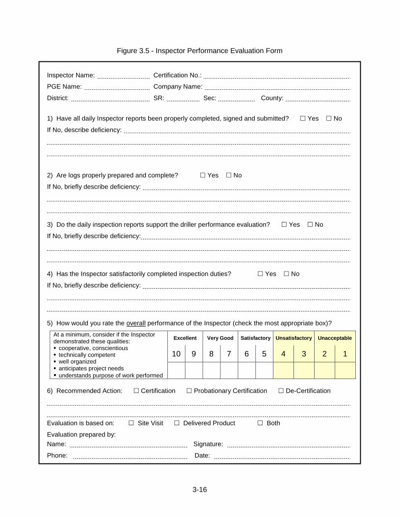
Figure 3.5 - Inspector Performance Evaluation Form
Inspector Name: Certification No.:
PGE Name: Company Name:
District: SR: Sec: County:
1) Have all daily Inspector reports been properly completed, signed and submitted? Yes No
If No, describe deficiency:
2) Are logs properly prepared and complete? Yes No
If No, briefly describe deficiency:
3) Do the daily inspection reports support the driller performance evaluation? Yes No
If No, briefly describe deficiency:
4) Has the Inspector satisfactorily completed inspection duties? Yes No
If No, briefly describe deficiency:
5) How would you rate the overall performance of the Inspector (check the most appropriate box)?
At a minimum, consider if the Inspector demonstrated these qualities: cooperative, conscientious technically competent well organized anticipates project needs
understands purpose of work performed
Excellent Very Good Satisfactory Unsatisfactory Unacceptable
10 9 8 7 6 5 4 3 2 1
6) Recommended Action: Certification Probationary Certification De-Certification
Evaluation is based on: Site Visit Delivered Product Both
Evaluation prepared by:
Name: Signature:
Phone: Date:
3-17
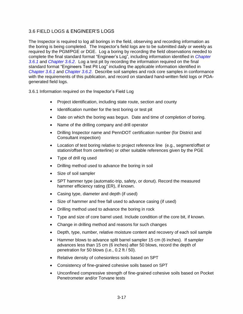
3.6 FIELD LOGS & ENGINEER‟S LOGS The Inspector is required to log all borings in the field, observing and recording information as the boring is being completed. The Inspector‟s field logs are to be submitted daily or weekly as required by the PGM/PGE or DGE. Log a boring by recording the field observations needed to complete the final standard format “Engineer‟s Log”, including information identified in Chapter 3.6.1 and Chapter 3.6.2. Log a test pit by recording the information required on the final standard format “Engineers Test Pit Log” including the applicable information identified in Chapter 3.6.1 and Chapter 3.6.2. Describe soil samples and rock core samples in conformance with the requirements of this publication, and record on standard hand-written field logs or PDA-generated field logs.
3.6.1 Information required on the Inspector‟s Field Log
Project identification, including state route, section and county
Identification number for the test boring or test pit
Date on which the boring was begun. Date and time of completion of boring.
Name of the drilling company and drill operator
Drilling Inspector name and PennDOT certification number (for District and Consultant inspection)
Location of test boring relative to project reference line (e.g., segment/offset or station/offset from centerline) or other suitable references given by the PGE
Type of drill rig used
Drilling method used to advance the boring in soil
Size of soil sampler
SPT hammer type (automatic-trip, safety, or donut). Record the measured hammer efficiency rating (ER), if known.
Casing type, diameter and depth (if used)
Size of hammer and free fall used to advance casing (if used)
Drilling method used to advance the boring in rock
Type and size of core barrel used. Include condition of the core bit, if known.
Change in drilling method and reasons for such changes
Depth, type, number, relative moisture content and recovery of each soil sample
Hammer blows to advance split barrel sampler 15 cm (6 inches). If sampler advances less than 15 cm (6 inches) after 50 blows, record the depth of penetration for 50 blows (i.e., 0.2 ft / 50).
Relative density of cohesionless soils based on SPT
Consistency of fine-grained cohesive soils based on SPT
Unconfined compressive strength of fine-grained cohesive soils based on Pocket Penetrometer and/or Torvane tests
3-18
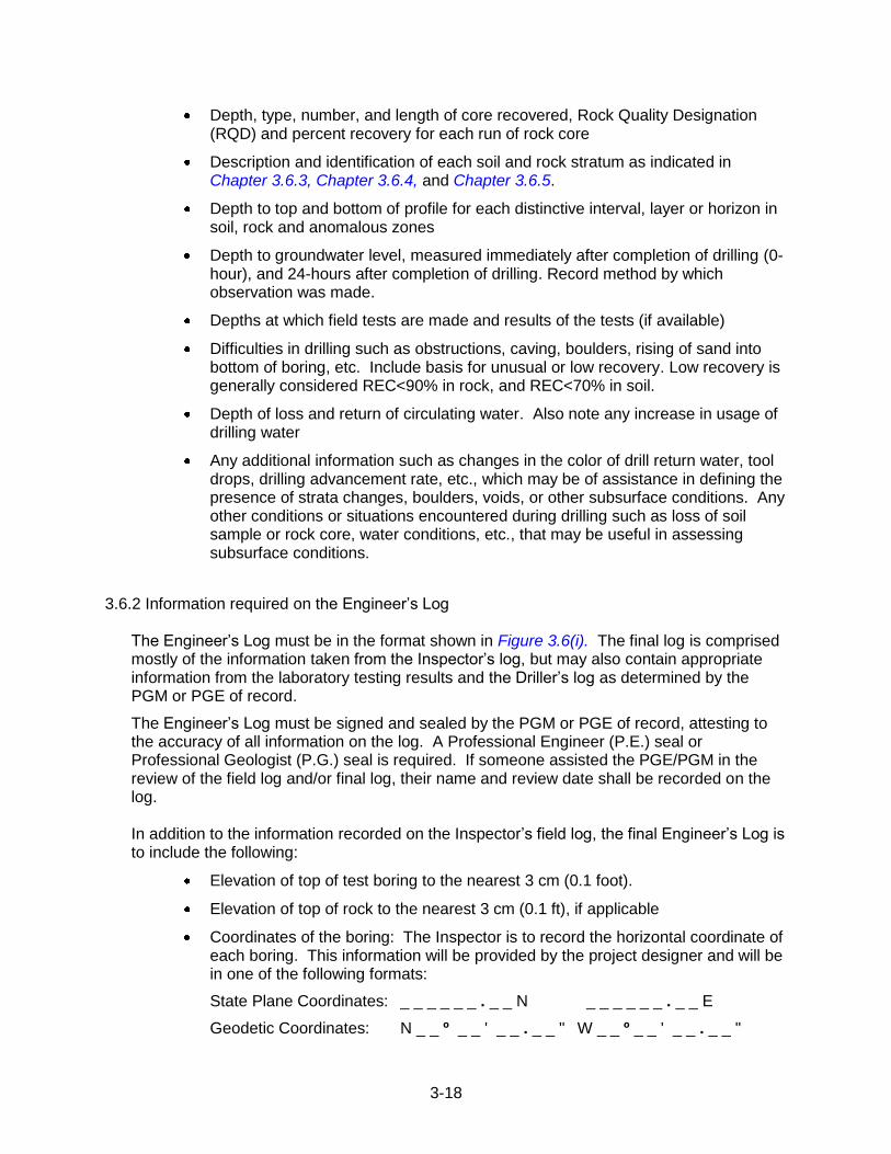
Depth, type, number, and length of core recovered, Rock Quality Designation (RQD) and percent recovery for each run of rock core
Description and identification of each soil and rock stratum as indicated in Chapter 3.6.3, Chapter 3.6.4, and Chapter 3.6.5.
Depth to top and bottom of profile for each distinctive interval, layer or horizon in soil, rock and anomalous zones
Depth to groundwater level, measured immediately after completion of drilling (0-hour), and 24-hours after completion of drilling. Record method by which observation was made.
Depths at which field tests are made and results of the tests (if available)
Difficulties in drilling such as obstructions, caving, boulders, rising of sand into bottom of boring, etc. Include basis for unusual or low recovery. Low recovery is generally considered REC<90% in rock, and REC<70% in soil.
Depth of loss and return of circulating water. Also note any increase in usage of drilling water
Any additional information such as changes in the color of drill return water, tool drops, drilling advancement rate, etc., which may be of assistance in defining the presence of strata changes, boulders, voids, or other subsurface conditions. Any other conditions or situations encountered during drilling such as loss of soil sample or rock core, water conditions, etc., that may be useful in assessing subsurface conditions.
3.6.2 Information required on the Engineer‟s Log
The Engineer‟s Log must be in the format shown in Figure 3.6(i). The final log is comprised mostly of the information taken from the Inspector‟s log, but may also contain appropriate information from the laboratory testing results and the Driller‟s log as determined by the PGM or PGE of record.
The Engineer‟s Log must be signed and sealed by the PGM or PGE of record, attesting to the accuracy of all information on the log. A Professional Engineer (P.E.) seal or Professional Geologist (P.G.) seal is required. If someone assisted the PGE/PGM in the review of the field log and/or final log, their name and review date shall be recorded on the log. In addition to the information recorded on the Inspector‟s field log, the final Engineer‟s Log is to include the following:
Elevation of top of test boring to the nearest 3 cm (0.1 foot).
Elevation of top of rock to the nearest 3 cm (0.1 ft), if applicable
Coordinates of the boring: The Inspector is to record the horizontal coordinate of each boring. This information will be provided by the project designer and will be in one of the following formats:
State Plane Coordinates: _ _ _ _ _ _ . _ _ N _ _ _ _ _ _ . _ _ E
Geodetic Coordinates: N _ _ º _ _ ' _ _ . _ _ " W _ _ º _ _ ' _ _ . _ _ "
3-19
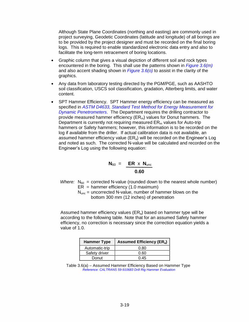
Although State Plane Coordinates (northing and easting) are commonly used in project surveying, Geodetic Coordinates (latitude and longitude) of all borings are to be provided by the project designer and must be recorded on the final boring logs. This is required to enable standardized electronic data entry and also to facilitate the long-term retracement of boring locations.
Graphic column that gives a visual depiction of different soil and rock types encountered in the boring. This shall use the patterns shown in Figure 3.6(m) and also accent shading shown in Figure 3.6(o) to assist in the clarity of the graphics.
Any data from laboratory testing directed by the PGM/PGE, such as AASHTO soil classification, USCS soil classification, gradation, Atterberg limits, and water content.
SPT Hammer Efficiency. SPT Hammer energy efficiency can be measured as specified in ASTM D4633, Standard Test Method for Energy Measurement for Dynamic Penetrometers. The Department requires the drilling contractor to provide measured hammer efficiency (ERm) values for Donut hammers. The Department is currently not requiring measured ERm values for Auto-trip hammers or Safety hammers; however, this information is to be recorded on the log if available from the driller. If actual calibration data is not available, an assumed hammer efficiency value (ERa) will be recorded on the Engineer‟s Log and noted as such. The corrected N-value will be calculated and recorded on the Engineer‟s Log using the following equation:
N60 = ER x Nunc
0.60
Where: N60 = corrected N-value (rounded down to the nearest whole number) ER = hammer efficiency (1.0 maximum)
Nunc = uncorrected N-value, number of hammer blows on the bottom 300 mm (12 inches) of penetration
Assumed hammer efficiency values (ERa) based on hammer type will be according to the following table. Note that for an assumed Safety hammer efficiency, no correction is necessary since the correction equation yields a value of 1.0.
Hammer Type Assumed Efficiency (ERa)
Automatic-trip 0.80
Safety driver 0.60
Donut 0.45
Table 3.6(a) – Assumed Hammer Efficiency Based on Hammer Type Reference: CALTRANS 59-910683 Drill Rig Hammer Evaluation
3-20
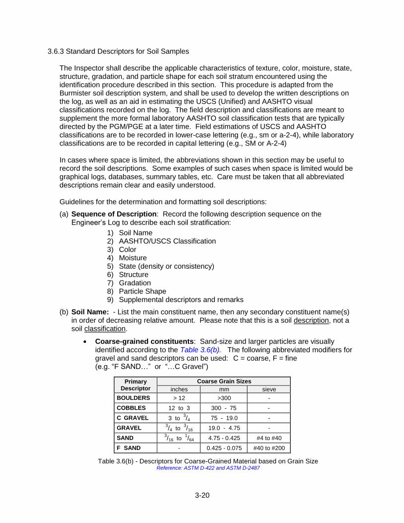
3.6.3 Standard Descriptors for Soil Samples
The Inspector shall describe the applicable characteristics of texture, color, moisture, state, structure, gradation, and particle shape for each soil stratum encountered using the identification procedure described in this section. This procedure is adapted from the Burmister soil description system, and shall be used to develop the written descriptions on the log, as well as an aid in estimating the USCS (Unified) and AASHTO visual classifications recorded on the log. The field description and classifications are meant to supplement the more formal laboratory AASHTO soil classification tests that are typically directed by the PGM/PGE at a later time. Field estimations of USCS and AASHTO classifications are to be recorded in lower-case lettering (e.g., sm or a-2-4), while laboratory classifications are to be recorded in capital lettering (e.g., SM or A-2-4) In cases where space is limited, the abbreviations shown in this section may be useful to record the soil descriptions. Some examples of such cases when space is limited would be graphical logs, databases, summary tables, etc. Care must be taken that all abbreviated descriptions remain clear and easily understood. Guidelines for the determination and formatting soil descriptions:
(a) Sequence of Description: Record the following description sequence on the Engineer‟s Log to describe each soil stratification:
1) Soil Name 2) AASHTO/USCS Classification 3) Color 4) Moisture 5) State (density or consistency) 6) Structure 7) Gradation 8) Particle Shape 9) Supplemental descriptors and remarks
(b) Soil Name: - List the main constituent name, then any secondary constituent name(s) in order of decreasing relative amount. Please note that this is a soil description, not a soil classification.
Coarse-grained constituents: Sand-size and larger particles are visually identified according to the Table 3.6(b). The following abbreviated modifiers for gravel and sand descriptors can be used: C = coarse, F = fine (e.g. “F SAND…” or “…C Gravel”)
Primary Descriptor
Coarse Grain Sizes
inches mm sieve
BOULDERS > 12 >300 -
COBBLES 12 to 3 300 - 75 -
C GRAVEL 3 to 3/4 75 - 19.0 -
GRAVEL 3/4 to
3/16 19.0 - 4.75 -
SAND 3/16 to
1/64 4.75 - 0.425 #4 to #40
F SAND - 0.425 - 0.075 #40 to #200
Table 3.6(b) - Descriptors for Coarse-Grained Material based on Grain Size Reference: ASTM D-422 and ASTM D-2487
3-21
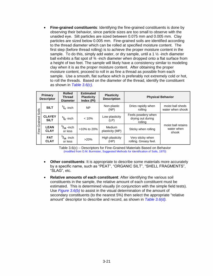
Fine-grained constituents: Identifying the fine-grained constituents is done by observing their behavior, since particle sizes are too small to observe with the unaided eye. Silt particles are sized between 0.075 mm and 0.005 mm. Clay particles are sized below 0.005 mm. Fine-grained soils are identified according to the thread diameter which can be rolled at specified moisture content. The first step (before thread rolling) is to achieve the proper moisture content in the sample. To do this, simply add water, or dry sample, until a 1 ½ -inch diameter ball exhibits a flat spot of ¾ -inch diameter when dropped onto a flat surface from a height of two feet. The sample will likely have a consistency similar to modeling clay when it is as the proper moisture content. After obtaining the proper moisture content, proceed to roll in as fine a thread as possible from each sample. Use a smooth, flat surface which is preferably not extremely cold or hot, to roll the threads. Based on the diameter of the thread, identify the constituent as shown in Table 3.6(c).
Primary Descriptor
Rolled Thread
Diameter
Estimated Plasticity Index (PI)
Plasticity Description
Physical Behavior
Fin
e-G
rain
ed
So
ils SILT
1/4 -inch
NP
Non-plastic (NP)
Dries rapidly when rolling
moist ball sheds water when shook
CLAYEY SILT
1/8 -inch < 10%
Low plasticity (LP)
Feels powdery when drying out during
rolling moist ball retains
water when shook
LEAN CLAY
1/16 -inch
or less >10% to 20%
Medium plasticity (MP)
Sticky when rolling
FAT CLAY
1/16 -inch
or less >20%
High plasticity (HP)
Very sticky when rolling. Greasy feel.
Table 3.6(c) – Descriptors for Fine-Grained Materials Based on Behavior (modified from D.M. Burmister, Suggested Methods for Identification of Soils, 1970)
Other constituents: It is appropriate to describe some materials more accurately by a specific name, such as “PEAT”, “ORGANIC SILT”, “SHELL FRAGMENTS”, “SLAG”, etc.
Relative amounts of each constituent: After identifying the various soil constituents in the sample, the relative amount of each constituent must be estimated. This is determined visually (in conjunction with the simple field tests). Use Figure 3.6(b) to assist in the visual determination of the amount of secondary constituents (to the nearest 5%) then select the appropriate “relative amount” descriptor to describe and record, as shown in Table 3.6(d).
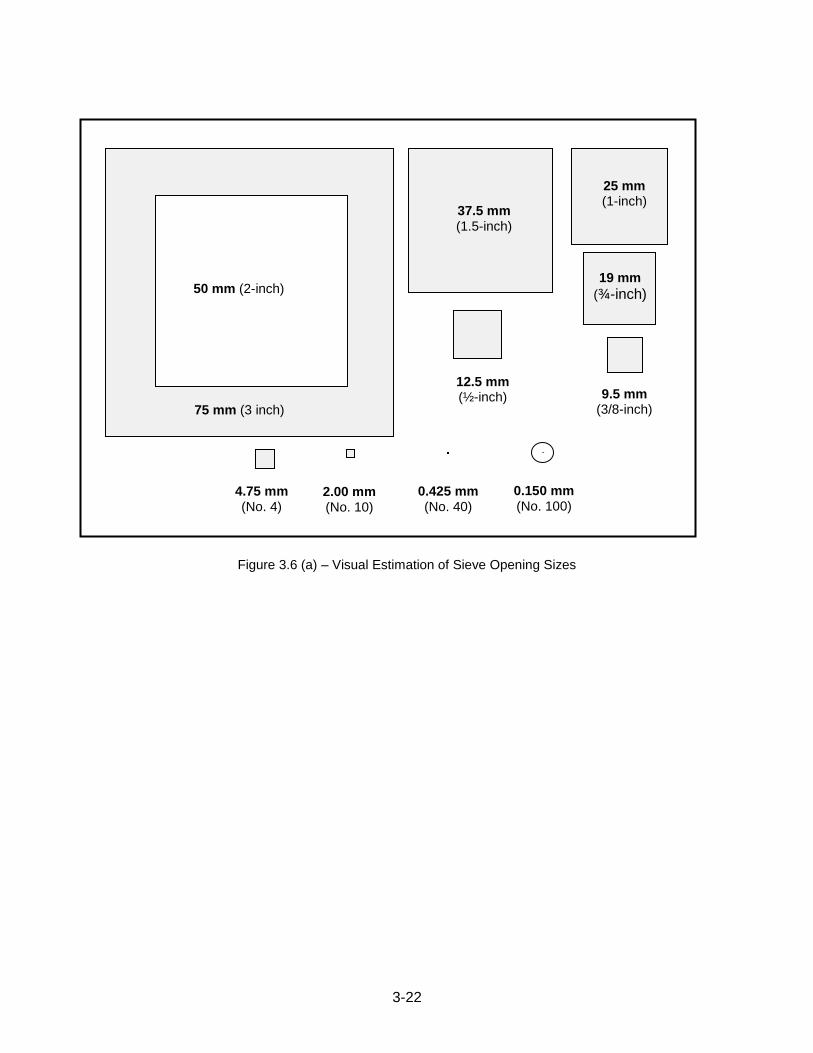
3-22
Figure 3.6 (a) – Visual Estimation of Sieve Opening Sizes
75 mm (3 inch)
50 mm (2-inch)
37.5 mm (1.5-inch)
25 mm (1-inch)
19 mm
(¾-inch)
12.5 mm (½-inch)
9.5 mm (3/8-inch)
4.75 mm (No. 4)
2.00 mm (No. 10)
0.425 mm (No. 40)
0.150 mm (No. 100)
3-23
Figure 3.6(b) - Comparison chart for visual estimation of coarse fragments (modified from Terry and Chilingar, 1955)
Descriptor Relative Amount
(based on total sample volume)
trace 0 to 10%
little 10 to 20%
some 20 to 35%
and 35 to 50%
Table 3.6(d) - Descriptors for Relative Amounts
(c) Soil AASHTO/USCS Classification: The Inspector shall estimate in the field the AASHTO and Unified soil classifications on each soil strata encountered, and record the corresponding symbols, using lower-case letters, onto the field log. The results of any laboratory testing completed to formally determine the soil classifications shall also be recorded on the final Engineer‟s Log and identified as such by using capitalized symbols. Place symbols within parentheses when included in a complete written description as shown in Chapter 3.6 (l).
(d) Soil Color: Describe the basic color of each soil and modify if necessary, by adjectives such as light, dark, mottled, or banded. Use the standard colors shown in Table 3.6(e). Color is useful for correlating strata between borings, and for interpreting the relative amounts of organic matter in the mineral soil and for classifying soils. Light soils (e.g., white, light gray, yellow) are typically low in organic matter; medium soils (brown) are
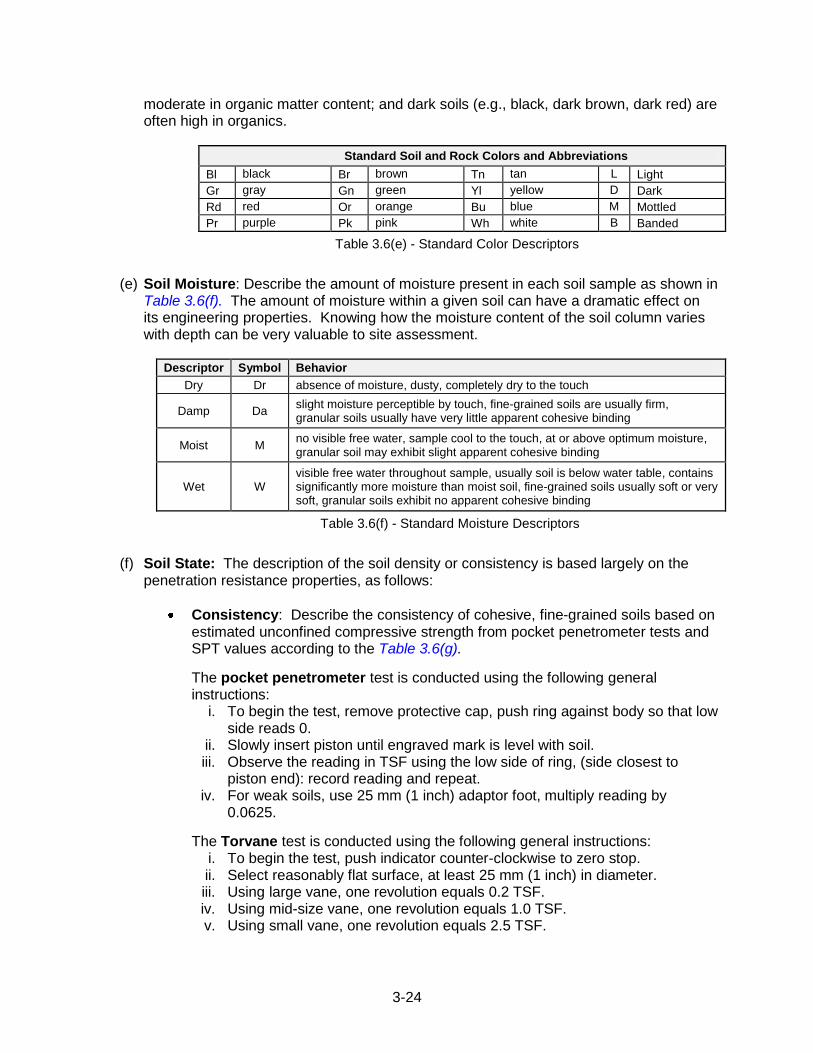
3-24
moderate in organic matter content; and dark soils (e.g., black, dark brown, dark red) are often high in organics.
Standard Soil and Rock Colors and Abbreviations
Bl black Br brown Tn tan L Light
Gr gray Gn green Yl yellow D Dark
Rd red Or orange Bu blue M Mottled
Pr purple Pk pink Wh white B Banded
Table 3.6(e) - Standard Color Descriptors
(e) Soil Moisture: Describe the amount of moisture present in each soil sample as shown in Table 3.6(f). The amount of moisture within a given soil can have a dramatic effect on its engineering properties. Knowing how the moisture content of the soil column varies with depth can be very valuable to site assessment.
Descriptor Symbol Behavior
Dry Dr absence of moisture, dusty, completely dry to the touch
Damp Da slight moisture perceptible by touch, fine-grained soils are usually firm, granular soils usually have very little apparent cohesive binding
Moist M no visible free water, sample cool to the touch, at or above optimum moisture, granular soil may exhibit slight apparent cohesive binding
Wet W visible free water throughout sample, usually soil is below water table, contains significantly more moisture than moist soil, fine-grained soils usually soft or very soft, granular soils exhibit no apparent cohesive binding
Table 3.6(f) - Standard Moisture Descriptors
(f) Soil State: The description of the soil density or consistency is based largely on the penetration resistance properties, as follows:
Consistency: Describe the consistency of cohesive, fine-grained soils based on estimated unconfined compressive strength from pocket penetrometer tests and SPT values according to the Table 3.6(g).
The pocket penetrometer test is conducted using the following general instructions:
i. To begin the test, remove protective cap, push ring against body so that low side reads 0.
ii. Slowly insert piston until engraved mark is level with soil. iii. Observe the reading in TSF using the low side of ring, (side closest to
piston end): record reading and repeat. iv. For weak soils, use 25 mm (1 inch) adaptor foot, multiply reading by
0.0625.
The Torvane test is conducted using the following general instructions: i. To begin the test, push indicator counter-clockwise to zero stop. ii. Select reasonably flat surface, at least 25 mm (1 inch) in diameter. iii. Using large vane, one revolution equals 0.2 TSF. iv. Using mid-size vane, one revolution equals 1.0 TSF. v. Using small vane, one revolution equals 2.5 TSF.
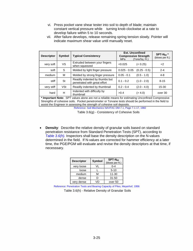
3-25
vi. Press pocket vane shear tester into soil to depth of blade; maintain constant vertical pressure while turning knob clockwise at a rate to develop failure within 5 to 10 seconds.
vii. After failure develops, release remaining spring tension slowly. Pointer will indicate maximum shear value until manually reset.
Descriptor Symbol Typical Consistency Est. Unconfined
Compressive Strength MPa (Tons/Sq. Ft.)
SPT-N60 * (blows per ft.)
very soft VS Extruded between your fingers when squeezed
<0.025 (< 0.25) <2
soft S Molded by light finger pressure 0.025 - 0.05 (0.25 - 0.5) 2-4
medium M Molded by strong finger pressure 0.05 - 0.1 (0.5 - 1.0) 4-8
stiff St Readily indented by thumbs but penetrated with great effort
0.1 - 0.2 (1.0 - 2.0) 8-15
very stiff VSt Readily indented by thumbnail 0.2 - 0.4 (2.0 - 4.0) 15-30
hard H Indented with difficulty by thumbnail
>0.4 (> 4.0) over 30
* Important Note: SPT values alone are not a reliable means for estimating Unconfined Compressive
Strengths of cohesive soils. Pocket penetrometer or Torvane tests should be performed in the field to assist the Engineer in assessing the strength of cohesive soil deposits.
Reference: Soil Mechanics NAVFAC DM-7.1, Page 7.1-17, 1982
Table 3.6(g) - Consistency of Cohesive Soils
Density: Describe the relative density of granular soils based on standard penetration resistance from Standard Penetration Tests (SPT), according to Table 3.6(h). Inspectors shall base the density description on the N-values determined in the field. If N-values are corrected for hammer efficiency at a later time, the PGE/PGM will evaluate and revise the density descriptors at that time, if necesssary.
Descriptor Symbol SPT-N60
(blows per ft.)
very loose VL 0-4
loose L 5-10
medium M 11-30
dense D 31-50
very dense VD over 50
Reference: Penetration Tests and Bearing Capacity of Piles, Meyerhof, 1956
Table 3.6(h) - Relative Density of Granular Soils
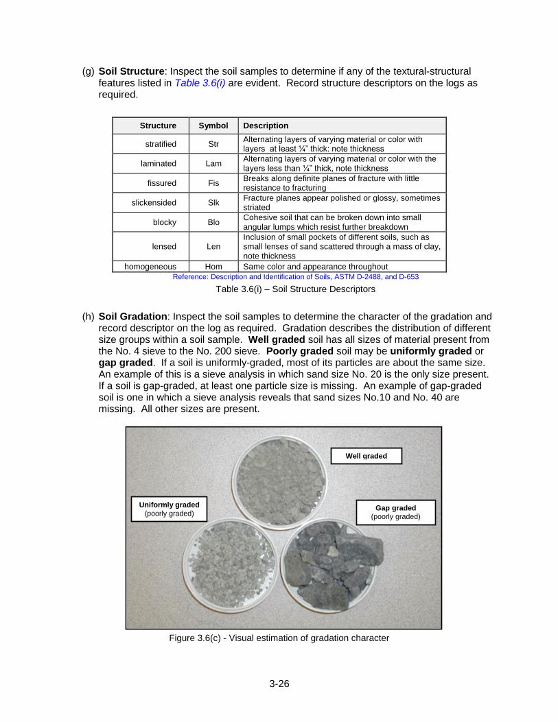
3-26
(g) Soil Structure: Inspect the soil samples to determine if any of the textural-structural features listed in Table 3.6(i) are evident. Record structure descriptors on the logs as required.
Structure Symbol Description
stratified Str Alternating layers of varying material or color with layers at least ¼” thick: note thickness
laminated Lam Alternating layers of varying material or color with the layers less than ¼” thick, note thickness
fissured Fis Breaks along definite planes of fracture with little resistance to fracturing
slickensided Slk Fracture planes appear polished or glossy, sometimes striated
blocky Blo Cohesive soil that can be broken down into small angular lumps which resist further breakdown
lensed Len Inclusion of small pockets of different soils, such as small lenses of sand scattered through a mass of clay, note thickness
homogeneous Hom Same color and appearance throughout
Reference: Description and Identification of Soils, ASTM D-2488, and D-653
Table 3.6(i) – Soil Structure Descriptors
(h) Soil Gradation: Inspect the soil samples to determine the character of the gradation and record descriptor on the log as required. Gradation describes the distribution of different size groups within a soil sample. Well graded soil has all sizes of material present from the No. 4 sieve to the No. 200 sieve. Poorly graded soil may be uniformly graded or gap graded. If a soil is uniformly-graded, most of its particles are about the same size. An example of this is a sieve analysis in which sand size No. 20 is the only size present. If a soil is gap-graded, at least one particle size is missing. An example of gap-graded soil is one in which a sieve analysis reveals that sand sizes No.10 and No. 40 are missing. All other sizes are present.
Figure 3.6(c) - Visual estimation of gradation character
Well graded
Gap graded (poorly graded)
Uniformly graded
(poorly graded)
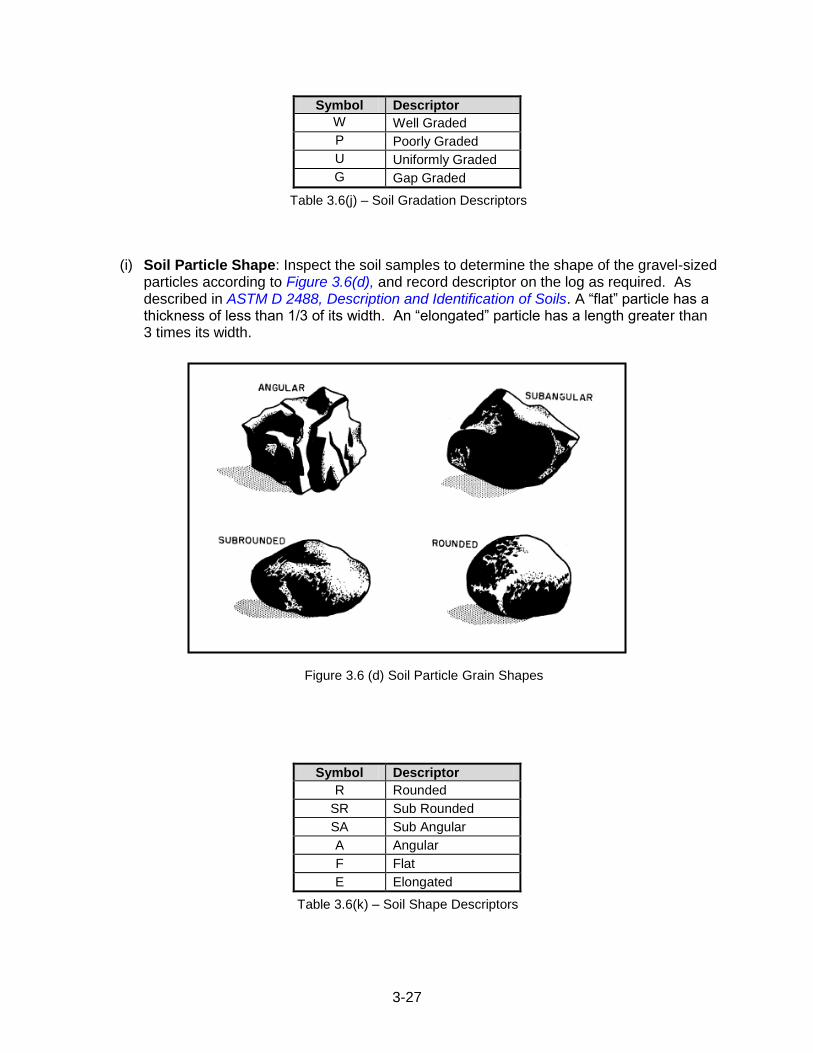
3-27
Symbol Descriptor
W Well Graded
P Poorly Graded
U Uniformly Graded
G Gap Graded
Table 3.6(j) – Soil Gradation Descriptors
(i) Soil Particle Shape: Inspect the soil samples to determine the shape of the gravel-sized particles according to Figure 3.6(d), and record descriptor on the log as required. As described in ASTM D 2488, Description and Identification of Soils. A “flat” particle has a thickness of less than 1/3 of its width. An “elongated” particle has a length greater than 3 times its width.
Symbol Descriptor
R Rounded
SR Sub Rounded
SA Sub Angular
A Angular
F Flat
E Elongated
Table 3.6(k) – Soil Shape Descriptors
Figure 3.6 (d) Soil Particle Grain Shapes
3-28
(j) Supplemental Descriptions: Descriptive terms regarding the structure, origin, or other important characteristic of the sample may be included at the end of the constituent description. Place terms within parentheses (e.g., “…trace F Sand, tan, moist, loose, (fill material)”.
(k) Capitalization: When descriptions are written without abbreviation, capitalize the entire primary constituent for coarse-grained soil (see Table 3.6(b)), and for fine-grained soil (see Table 3.6(c)). Capitalize secondary constituents. Do not capitalize color, moisture, state, structure, gradation, or particle shape. Place any supplemental descriptor(s) within parentheses, and locate in the description sequence where most appropriate, usually following the standard descriptors.
(l) Examples of soil descriptions:
F SAND, some SILT, trace GRAVEL, (a-2-4, sm), brown, moist, medium dense, poorly graded, (fill)
CLAYEY SILT some GRAVEL (sandstone fragments), trace SAND, (a-6, cl-ml), mottled light gray and yellow, wet, soft, well graded, (trace roots)
F SAND, some LEAN CLAY, (a-3, sp-sc) dark gray, moist, medium dense, poorly graded, (trace shell fragments)
GRAVEL, some SILT, (a-2-5, gm), reddish brown, dry, loose, poorly graded
SAND, some GRAVEL, little SILT, (a-2-4, sm), light brown, moist, dense, homogeneous, well graded, rounded, (slight petroleum odor)
or, shorthand nomenclature:
S, some G, little SI, (a-2-4, sm), L Br, M, D, Hom, WG, R, (slight petroleum odor)
3.6.4 Standard Descriptors for Rock Core
Describe the characteristics for each rock stratum encountered according to the sequence
shown in Figure 3.6 (f). The general (overall) rock deposit is described first, followed by the
characteristics of any discontinuities of significance. For example, avoid giving a wide-
ranging description for a rock unit as “very hard to soft”, rather, define the dominant
character or the rock as “hard” with the subsequent description of the discontinuities or
weathered zones as “soft”. Detailed guidance for describing discontinuities is found in
Chapter 3.6.5.
A complete full-word description is to be written in the description column. Symbols
(abbreviations) for various descriptors have been established to aid in recording descriptions
when space is limited. Use descriptive symbols only when necessary. When
measurements are taken for a property such as RQD, the numerical values should always
be recorded in the columns provided.
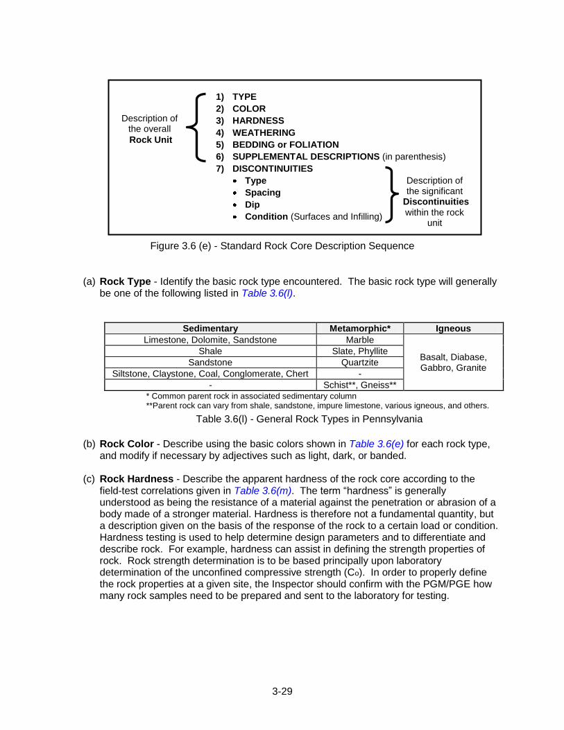
3-29
1) TYPE
2) COLOR
3) HARDNESS
4) WEATHERING
5) BEDDING or FOLIATION
6) SUPPLEMENTAL DESCRIPTIONS (in parenthesis)
7) DISCONTINUITIES
Type
Spacing
Dip
Condition (Surfaces and Infilling)
Figure 3.6 (e) - Standard Rock Core Description Sequence
(a) Rock Type - Identify the basic rock type encountered. The basic rock type will generally
be one of the following listed in Table 3.6(l).
Sedimentary Metamorphic* Igneous
Limestone, Dolomite, Sandstone Marble
Basalt, Diabase, Gabbro, Granite
Shale Slate, Phyllite
Sandstone Quartzite
Siltstone, Claystone, Coal, Conglomerate, Chert -
- Schist**, Gneiss** * Common parent rock in associated sedimentary column **Parent rock can vary from shale, sandstone, impure limestone, various igneous, and others.
Table 3.6(l) - General Rock Types in Pennsylvania
(b) Rock Color - Describe using the basic colors shown in Table 3.6(e) for each rock type, and modify if necessary by adjectives such as light, dark, or banded.
(c) Rock Hardness - Describe the apparent hardness of the rock core according to the
field-test correlations given in Table 3.6(m). The term “hardness” is generally understood as being the resistance of a material against the penetration or abrasion of a body made of a stronger material. Hardness is therefore not a fundamental quantity, but a description given on the basis of the response of the rock to a certain load or condition. Hardness testing is used to help determine design parameters and to differentiate and describe rock. For example, hardness can assist in defining the strength properties of rock. Rock strength determination is to be based principally upon laboratory determination of the unconfined compressive strength (Co). In order to properly define the rock properties at a given site, the Inspector should confirm with the PGM/PGE how many rock samples need to be prepared and sent to the laboratory for testing.
Description of the overall
Rock Unit
Description of the significant
Discontinuities within the rock
unit
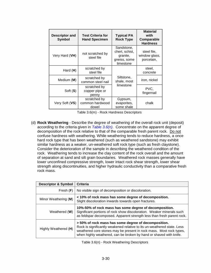
3-30
Descriptor and Symbol
Test Criteria for Hand Specimen
Typical PA Rock Type
Material with
Comparable Hardness
Very Hard (VH) not scratched by
steel file
Sandstone, chert, schist,
granite, gneiss, some
limestone
steel file, window glass,
porcelain,
Hard (H) scratched by
steel file
Siltstone, shale, most limestone
steel, concrete
Medium (M) scratched by
common steel nail iron, nickel
Soft (S) scratched by
copper pipe or penny
PVC, fingernail
Very Soft (VS) scratched by
common hardwood dowel
Gypsum, evaporites, some shale
chalk
Table 3.6(m) - Rock Hardness Descriptors
(d) Rock Weathering - Describe the degree of weathering of the overall rock unit (deposit) according to the criteria given in Table 3.6(n). Concentrate on the apparent degree of decomposition of the rock relative to that of the comparable fresh parent rock. Do not confuse hardness with weathering. While weathering tends to reduce hardness, a once hard rock type that has been weathered (such as weathered sandstone) may exhibit similar hardness as a weaker, un-weathered soft rock type (such as fresh claystone). Consider the deterioration of the sample in describing the weathered condition of the rock. Weathering tends to increase the clay content of the rock overall and the amount of separation at sand and silt grain boundaries. Weathered rock masses generally have lower unconfined compressive strength, lower intact rock shear strength, lower shear strength along discontinuities, and higher hydraulic conductivity than a comparative fresh rock mass.
Descriptor & Symbol Criteria
Fresh (F) No visible sign of decomposition or discoloration.
Minor Weathering (M) < 10% of rock mass has some degree of decomposition. Slight discoloration inwards towards open fractures.
Weathered (W) 10%-50% of rock mass has some degree of decomposition. Significant portions of rock show discoloration. Weaker minerals such as feldspar decomposed. Apparent strength less than fresh parent rock.
Highly Weathered (H)
> 50% of rock mass has some degree of decomposition. Rock is significantly weakened relative to its un-weathered state. Less weathered core stones may be present in rock mass. Most rock types, when highly weathered, can be broken by hand or shaved with knife.
Table 3.6(n) - Rock Weathering Descriptors
3-31
(e) Rock Bedding or Foliation– Observe and record the bedding thickness according to Table 3.6(o) and dip angle according to Table 3.6(p). If bedding is not apparent or indistinct, note as such. For metamorphic rock formations where bedding is not evident, structural foliations such as cleavage may be described. Knowing the orientation of foliations with platy, layered, or planar aspects may be very useful in understanding the structural character of a rock formation.
(f) Supplemental Descriptions - If applicable, describe any helpful identifying or descriptive factors, i.e., unit RQD = 50%, vuggy, or petroleum odor. Place any supplemental descriptors within parentheses, and locate in the description sequence where most appropriate, usually following the standard descriptors.
(g) Rock Discontinuities - Describe discontinuities according to Chapter 3.6.5.
(h) Capitalization: Capitalize the entire rock type. Do not capitalize descriptors for color, hardness, weathering, or bedding. Place other observations within parenthesis. Capitalize first letter of discontinuity descriptions.
3.6.5 Standard Descriptors for Rock Core Discontinuities
The test boring Inspector shall observe and record descriptions of the following applicable characteristics of major or significant discontinuities in the rock core: type, spacing, dip, and condition. The condition description may include characteristics of the surface roughness as well as the infilling thickness, constituents, and hardness. The test boring Inspector shall adequately describe these features using the descriptions outlined in this section. For additional guidance pertaining to describing rock cores, see the PennDOT Publication 293, Geotechnical Engineering Manual, and the U.S. Department of the Interior, Bureau of Reclamation (USBR), Engineering Geology Field Manual, 2001.
Identifying and describing the structure of rock masses is an important part of the test boring inspection and Engineer‟s Log. Rock bedding or discontinuities often create planes or surfaces within the rock mass which have considerably different engineering properties than the intact parent rock specimens tested in the laboratory. Accordingly, discontinuities can control the properties and behavior of rock masses.
3-32
Definitions of terms describing rock structure:
Bedding/Foliation: For the purposes of the boring log description, bedding planes define the interface of rock deposits having notable or significant differences in character. The contacts between rock bodies of different lithologies are considered bedding planes, and described separately from other types of rock discontinuities discussed below. Bedding description is to be in accordance to Figure 3.6(f). Structural foliations (such as cleavage) which are planar or layered, are characteristics of metamorphic rocks which can be structurally similar to the bedding features in sedimentary rocks.
Discontinuity: For the purposes of the boring log description, a discontinuity shall be a collective term used for joints, fractures, shears, and faults.
Fracture: A term used to describe an irregular or non-planar break in geologic material, excluding shears and shear zones. Additional fracture terminology is provided in Figure 3.6(f).
Shear: A structural break where differential movement has taken place along a surface is termed a shear. Shearing is sometimes characterized by a slickenside or gouge. Often, the shear direction, amount of displacement, and continuity may not be known because of limited exposures or observations.
Fault: A shear with significant continuity that can be correlated between observations is a fault. Faults demonstrate high spatial continuity, and therefore occur over significant portions of given sites, foundation areas, or regions. The observed fault feature may be a segment of a fault or fault zone, as defined in the literature. The designation of a shear as a fault or fault zone is a site-specific determination.
Shear/Fault Zone: A shear or fault that exhibits significant width when measured perpendicular to the plane of the shear or fault. The zone may consist of multiple slickensides, gouge, striations, breccia, or many related faults or shears together with fractured and crushed rock between the shears or faults, or any combination of these. In the literature, many fault zones are referred to as faults.
(a) Discontinuity Type: Use a single description, or range of descriptors, to describe the
discontinuities observed over the length of the reported fracture density. Refer to the Figure 3.6(e) for detailed criteria concerning discontinuity types.
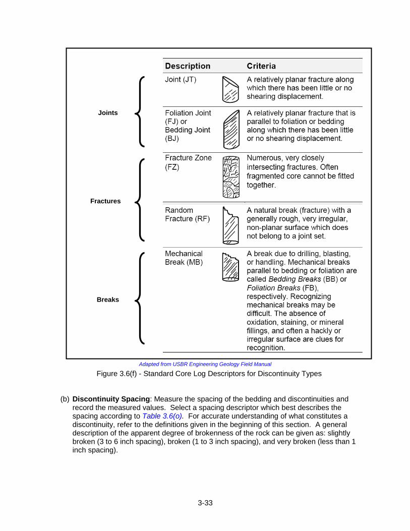
3-33
Adapted from USBR Engineering Geology Field Manual
Figure 3.6(f) - Standard Core Log Descriptors for Discontinuity Types
(b) Discontinuity Spacing: Measure the spacing of the bedding and discontinuities and record the measured values. Select a spacing descriptor which best describes the spacing according to Table 3.6(o). For accurate understanding of what constitutes a discontinuity, refer to the definitions given in the beginning of this section. A general description of the apparent degree of brokenness of the rock can be given as: slightly broken (3 to 6 inch spacing), broken (1 to 3 inch spacing), and very broken (less than 1 inch spacing).
Joints
Fractures
Breaks
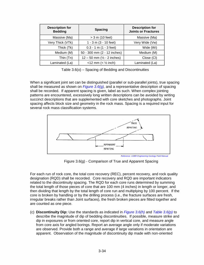
3-34
Description for Bedding
Spacing Description for
Joints or Fractures
Massive (Ma) > 3 m (10 feet) Massive (Ma)
Very Thick (VTk) 1 - 3 m (3 - 10 feet) Very Wide (Vw)
Thick (Tk) 0.3 - 1 m (1 - 3 feet) Wide (Wi)
Medium (M) 50 - 300 mm (2 - 12 inches) Medium (M)
Thin (Tn) 12 – 50 mm (½ - 2 inches) Close (Cl)
Laminated (La) <12 mm (< ½ inch) Laminated (La)
Table 3.6(o) – Spacing of Bedding and Discontinuities When a significant joint set can be distinguished (parallel or sub-parallel joints), true spacing shall be measured as shown on Figure 3.6(g), and a representative description of spacing shall be recorded. If apparent spacing is given, label as such. When complex jointing patterns are encountered, excessively long written descriptions can be avoided by writing succinct descriptions that are supplemented with core sketches and photographs. Joint spacing affects block size and geometry in the rock mass. Spacing is a required input for several rock mass classification systems.
Reference: USBR Engineering Geology Field Manual
Figure 3.6(g) - Comparison of True and Apparent Spacing For each run of rock core, the total core recovery (REC), percent recovery, and rock quality designation (RQD) shall be recorded. Core recovery and RQD are important indicators related to the discontinuity spacing. The RQD for each core runs determined by summing the total length of those pieces of core that are 100 mm (4 inches) in length or longer, and then dividing that length by the total length of core run and multiplying by 100 percent. If the core is broken by handling or by the drilling process (i.e., the fracture surfaces are fresh, irregular breaks rather than Joint surfaces), the fresh broken pieces are fitted together and are counted as one piece. (c) Discontinuity Dip: Use the standards as indicated in Figure 3.6(h) and Table 3.6(p) to
describe the magnitude of dip of bedding discontinuities. If possible, measure strike and dip in exposures or from oriented core, report dip in vertical core, and measure angle from core axis for angled borings. Report an average angle only if moderate variations are observed. Provide both a range and average if large variations in orientation are apparent. Observation of the magnitude of discontinuity dip made with non-oriented
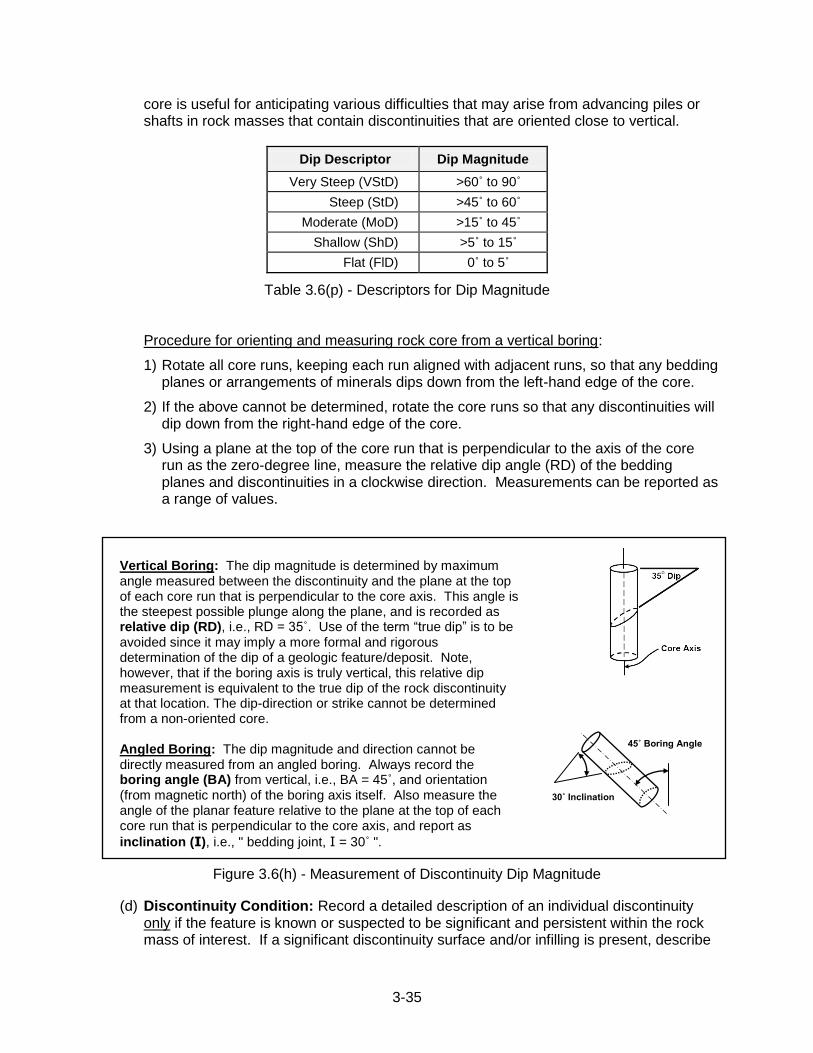
3-35
core is useful for anticipating various difficulties that may arise from advancing piles or shafts in rock masses that contain discontinuities that are oriented close to vertical.
Dip Descriptor Dip Magnitude
Very Steep (VStD) >60˚ to 90˚
Steep (StD) >45˚ to 60˚
Moderate (MoD) >15˚ to 45˚
Shallow (ShD) >5˚ to 15˚
Flat (FlD) 0˚ to 5˚
Table 3.6(p) - Descriptors for Dip Magnitude
Procedure for orienting and measuring rock core from a vertical boring:
1) Rotate all core runs, keeping each run aligned with adjacent runs, so that any bedding planes or arrangements of minerals dips down from the left-hand edge of the core.
2) If the above cannot be determined, rotate the core runs so that any discontinuities will dip down from the right-hand edge of the core.
3) Using a plane at the top of the core run that is perpendicular to the axis of the core run as the zero-degree line, measure the relative dip angle (RD) of the bedding planes and discontinuities in a clockwise direction. Measurements can be reported as a range of values.
Vertical Boring: The dip magnitude is determined by maximum angle measured between the discontinuity and the plane at the top of each core run that is perpendicular to the core axis. This angle is the steepest possible plunge along the plane, and is recorded as relative dip (RD), i.e., RD = 35˚. Use of the term “true dip” is to be avoided since it may imply a more formal and rigorous determination of the dip of a geologic feature/deposit. Note, however, that if the boring axis is truly vertical, this relative dip measurement is equivalent to the true dip of the rock discontinuity at that location. The dip-direction or strike cannot be determined from a non-oriented core. Angled Boring: The dip magnitude and direction cannot be directly measured from an angled boring. Always record the boring angle (BA) from vertical, i.e., BA = 45˚, and orientation (from magnetic north) of the boring axis itself. Also measure the angle of the planar feature relative to the plane at the top of each core run that is perpendicular to the core axis, and report as
inclination (I), i.e., " bedding joint, I = 30˚ ".
Figure 3.6(h) - Measurement of Discontinuity Dip Magnitude
(d) Discontinuity Condition: Record a detailed description of an individual discontinuity only if the feature is known or suspected to be significant and persistent within the rock mass of interest. If a significant discontinuity surface and/or infilling is present, describe
30˚ Inclination
45˚ Boring Angle
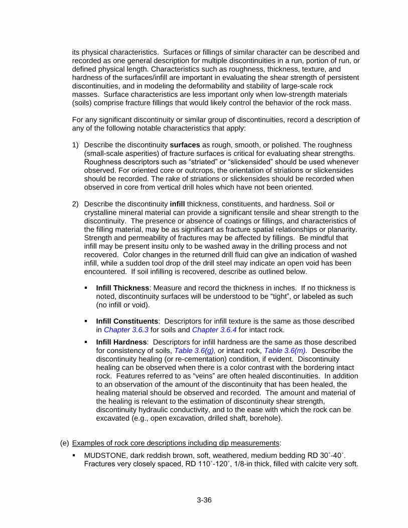
3-36
its physical characteristics. Surfaces or fillings of similar character can be described and recorded as one general description for multiple discontinuities in a run, portion of run, or defined physical length. Characteristics such as roughness, thickness, texture, and hardness of the surfaces/infill are important in evaluating the shear strength of persistent discontinuities, and in modeling the deformability and stability of large-scale rock masses. Surface characteristics are less important only when low-strength materials (soils) comprise fracture fillings that would likely control the behavior of the rock mass.
For any significant discontinuity or similar group of discontinuities, record a description of any of the following notable characteristics that apply:
1) Describe the discontinuity surfaces as rough, smooth, or polished. The roughness
(small-scale asperities) of fracture surfaces is critical for evaluating shear strengths. Roughness descriptors such as “striated” or “slickensided” should be used whenever observed. For oriented core or outcrops, the orientation of striations or slickensides should be recorded. The rake of striations or slickensides should be recorded when observed in core from vertical drill holes which have not been oriented.
2) Describe the discontinuity infill thickness, constituents, and hardness. Soil or
crystalline mineral material can provide a significant tensile and shear strength to the discontinuity. The presence or absence of coatings or fillings, and characteristics of the filling material, may be as significant as fracture spatial relationships or planarity. Strength and permeability of fractures may be affected by fillings. Be mindful that infill may be present insitu only to be washed away in the drilling process and not recovered. Color changes in the returned drill fluid can give an indication of washed infill, while a sudden tool drop of the drill steel may indicate an open void has been encountered. If soil infilling is recovered, describe as outlined below.
Infill Thickness: Measure and record the thickness in inches. If no thickness is noted, discontinuity surfaces will be understood to be “tight”, or labeled as such (no infill or void).
Infill Constituents: Descriptors for infill texture is the same as those described in Chapter 3.6.3 for soils and Chapter 3.6.4 for intact rock.
Infill Hardness: Descriptors for infill hardness are the same as those described for consistency of soils, Table 3.6(g), or intact rock, Table 3.6(m). Describe the discontinuity healing (or re-cementation) condition, if evident. Discontinuity healing can be observed when there is a color contrast with the bordering intact rock. Features referred to as “veins” are often healed discontinuities. In addition to an observation of the amount of the discontinuity that has been healed, the healing material should be observed and recorded. The amount and material of the healing is relevant to the estimation of discontinuity shear strength, discontinuity hydraulic conductivity, and to the ease with which the rock can be excavated (e.g., open excavation, drilled shaft, borehole).
(e) Examples of rock core descriptions including dip measurements:
MUDSTONE, dark reddish brown, soft, weathered, medium bedding RD 30˚-40˚. Fractures very closely spaced, RD 110˚-120˚, 1/8-in thick, filled with calcite very soft.
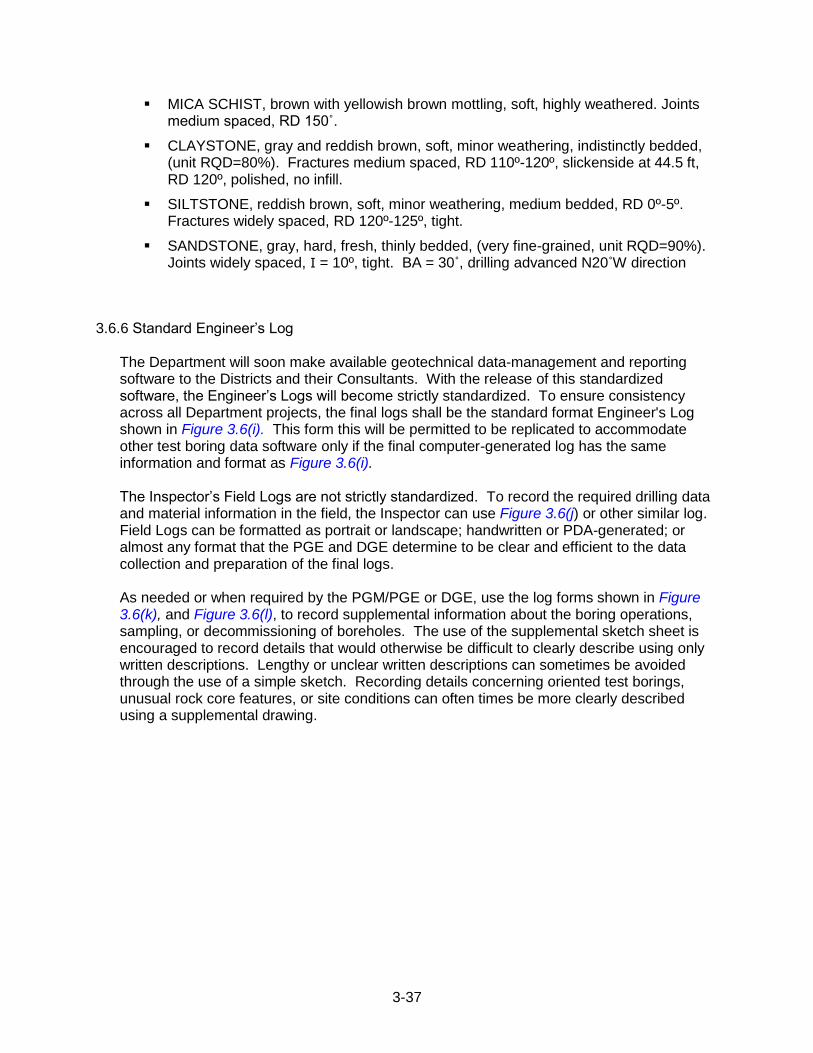
3-37
MICA SCHIST, brown with yellowish brown mottling, soft, highly weathered. Joints medium spaced, RD 150˚.
CLAYSTONE, gray and reddish brown, soft, minor weathering, indistinctly bedded, (unit RQD=80%). Fractures medium spaced, RD 110º-120º, slickenside at 44.5 ft, RD 120º, polished, no infill.
SILTSTONE, reddish brown, soft, minor weathering, medium bedded, RD 0º-5º. Fractures widely spaced, RD 120º-125º, tight.
SANDSTONE, gray, hard, fresh, thinly bedded, (very fine-grained, unit RQD=90%). Joints widely spaced, I = 10º, tight. BA = 30˚, drilling advanced N20˚W direction
3.6.6 Standard Engineer‟s Log The Department will soon make available geotechnical data-management and reporting software to the Districts and their Consultants. With the release of this standardized software, the Engineer‟s Logs will become strictly standardized. To ensure consistency across all Department projects, the final logs shall be the standard format Engineer's Log shown in Figure 3.6(i). This form this will be permitted to be replicated to accommodate other test boring data software only if the final computer-generated log has the same information and format as Figure 3.6(i). The Inspector‟s Field Logs are not strictly standardized. To record the required drilling data and material information in the field, the Inspector can use Figure 3.6(j) or other similar log. Field Logs can be formatted as portrait or landscape; handwritten or PDA-generated; or almost any format that the PGE and DGE determine to be clear and efficient to the data collection and preparation of the final logs. As needed or when required by the PGM/PGE or DGE, use the log forms shown in Figure 3.6(k), and Figure 3.6(l), to record supplemental information about the boring operations, sampling, or decommissioning of boreholes. The use of the supplemental sketch sheet is encouraged to record details that would otherwise be difficult to clearly describe using only written descriptions. Lengthy or unclear written descriptions can sometimes be avoided through the use of a simple sketch. Recording details concerning oriented test borings, unusual rock core features, or site conditions can often times be more clearly described using a supplemental drawing.
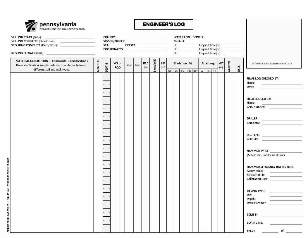
3-38
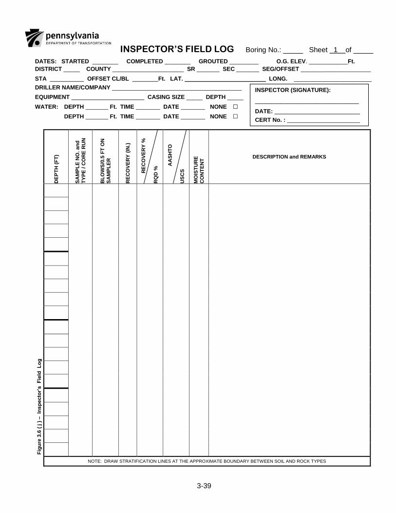
3-39
INSPECTOR’S FIELD LOG Boring No.: _____ Sheet 1 of _____
DATES: STARTED ________ COMPLETED ________ GROUTED _________ O.G. ELEV. ____________Ft.
DISTRICT _____ COUNTY ______________________ SR _______ SEC _______ SEG/OFFSET _______
STA OFFSET CL/BL Ft. LAT. _________________________ LONG. ________________________
DRILLER NAME/COMPANY ________________________________________
EQUIPMENT CASING SIZE _____ DEPTH _____
WATER: DEPTH Ft. TIME DATE NONE □
DEPTH Ft. TIME DATE NONE □
F
igu
re 3
.6 (
j )
– In
sp
ecto
r’s F
ield
L
og
DE
PT
H (
FT
)
SA
MP
LE
NO
. an
d
TY
PE
/ C
OR
E R
UN
BL
OW
S/0
.5 F
T O
N
SA
MP
LE
R
RE
CO
VE
RY
(IN
.)
R
EC
OV
ER
Y %
RQ
D %
AA
SH
TO
U
SC
S
MO
IST
UR
E
CO
NT
EN
T DESCRIPTION and REMARKS
NOTE: DRAW STRATIFICATION LINES AT THE APPROXIMATE BOUNDARY BETWEEN SOIL AND ROCK TYPES
INSPECTOR (SIGNATURE):
________________________________
DATE:
CERT No. :
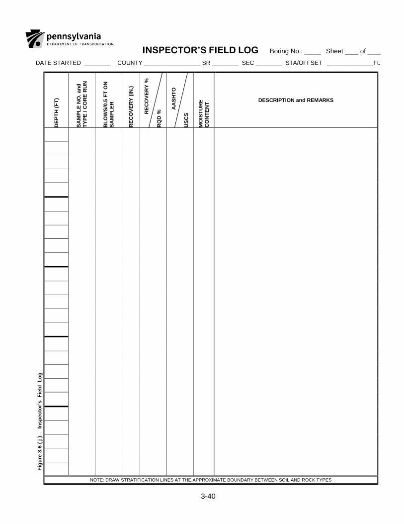
3-40
INSPECTOR’S FIELD LOG Boring No.: _____ Sheet ____ of ____
DATE STARTED ________ COUNTY _________________ SR ________ SEC ________ STA/OFFSET ______________Ft.
F
igu
re 3
.6 (
j )
– In
sp
ecto
r’s F
ield
L
og
DE
PT
H (
FT
)
SA
MP
LE
NO
. an
d
TY
PE
/ C
OR
E R
UN
BL
OW
S/0
.5 F
T O
N
SA
MP
LE
R
RE
CO
VE
RY
(IN
.)
R
EC
OV
ER
Y %
RQ
D %
A
AS
HT
O
US
CS
MO
IST
UR
E
CO
NT
EN
T DESCRIPTION and REMARKS
NOTE: DRAW STRATIFICATION LINES AT THE APPROXIMATE BOUNDARY BETWEEN SOIL AND ROCK TYPES
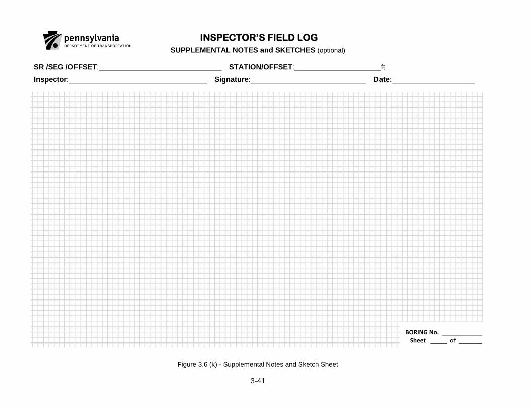
3-41
INSPECTOR’S FIELD LOG
SUPPLEMENTAL NOTES and SKETCHES (optional)
SR /SEG /OFFSET: STATION/OFFSET: ft
Inspector: Signature: Date:
BORING No. ____________ Sheet _____ of _______
Figure 3.6 (k) - Supplemental Notes and Sketch Sheet
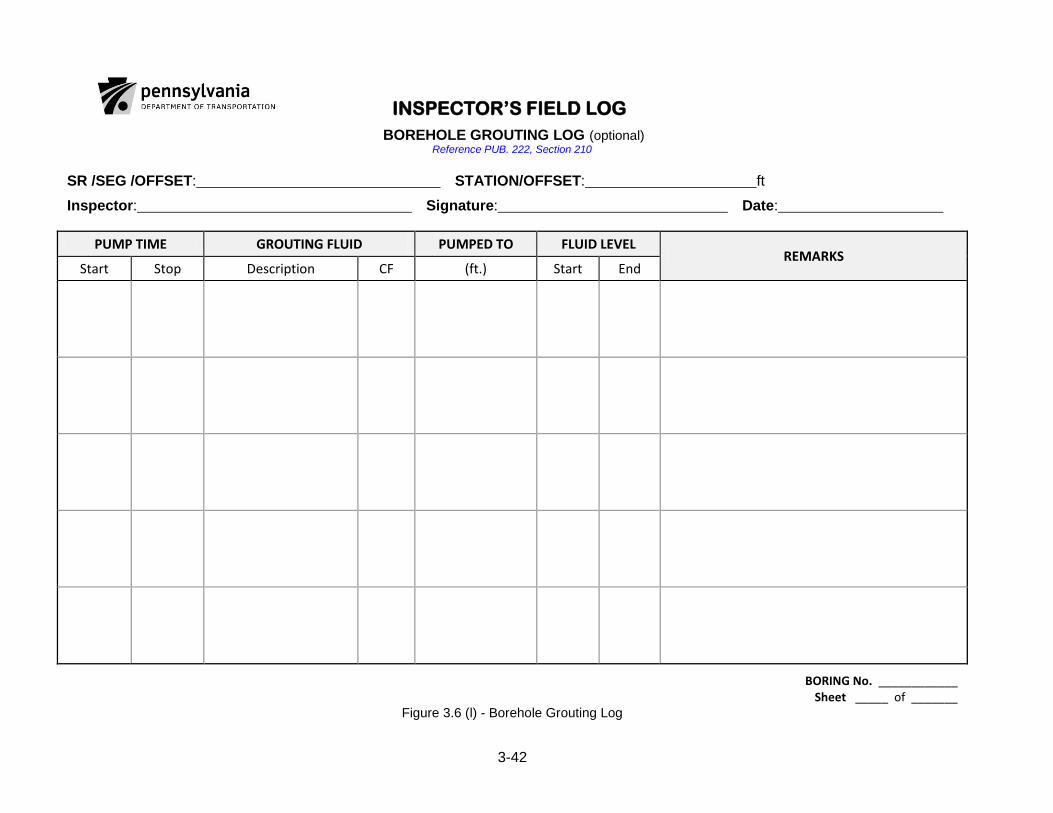
3-42
INSPECTOR’S FIELD LOG
BOREHOLE GROUTING LOG (optional) Reference PUB. 222, Section 210
SR /SEG /OFFSET: STATION/OFFSET: ft
Inspector: Signature: Date:
PUMP TIME GROUTING FLUID PUMPED TO FLUID LEVEL REMARKS
Start Stop Description CF (ft.) Start End
BORING No. ____________ Sheet _____ of _______
Figure 3.6 (l) - Borehole Grouting Log

3-43
3.6.7 Standard Engineer‟s Test Pit Log
The following information shall be provided on the Engineer‟s Test Pit Log:
Professional Engineer or Professional Geologist seal, signed and dated, of the project geotechnical manager (PGM) of record, attesting to the accuracy of all information on the log.
Project identification, including state route, section and county
Test pit identification number
Coordinates, northing and easting or latitude and longitude
Date of excavation
Name of Drilling Inspector (District's or Engineer's Representative)
Elevation of top of test pit
Location of the test pit relative to project reference line (e.g., segment, offset, and offset from centerline) or other suitable reference points
Type of and size of excavation equipment used
Ease of excavation
Caving of sides
Seepage amount and elevation
Depth to top and bottom of profile for each soil type
Depth, type and condition of rock (if encountered)
Relative density or consistency of soils
Pocket penetrometer or Torvane test results
Moisture condition of soils
Presence of boulders
Reason for stopping excavation (e.g., caving sides, difficult excavation, limit of reach of backhoe, etc.)
Included with the log, provide digital photographs (minimum 8-megapixal resolution, .jpg format) of each test pit, with location information (project number, station, test pit number, depths, etc.) clearly identified in photograph. A sufficient number of photographs shall be provided to clearly identify all details.
Use the standard Engineer's Test Pit Log as shown on Figure 3.6(m).
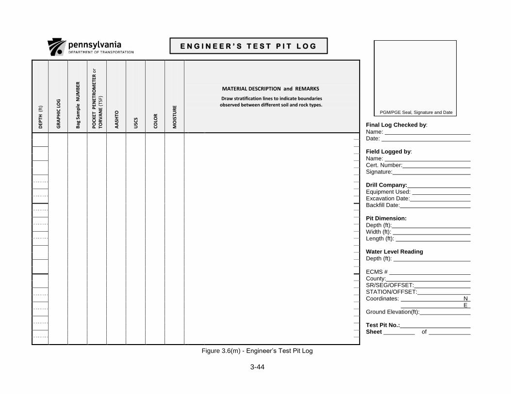
3-44
PGM/PGE Seal, Signature and Date
Final Log Checked by:
Name: Date: Field Logged by:
Name: Cert. Number: Signature: Drill Company:
Equipment Used: Excavation Date: Backfill Date: Pit Dimension:
Depth (ft): Width (ft): Length (ft): Water Level Reading
Depth (ft): ECMS # County: SR/SEG/OFFSET: STATION/OFFSET: Coordinates: N E Ground Elevation(ft): Test Pit No.: Sheet of
Figure 3.6(m) - Engineer‟s Test Pit Log
DEP
TH (
ft)
GR
AP
HIC
LO
G
Bag
Sam
ple
NU
MB
ER
PO
CK
ET P
ENET
RO
MET
ER o
r
TOR
VA
NE
(TSF
)
AA
SHTO
USC
S
CO
LOR
MO
ISTU
RE
MATERIAL DESCRIPTION and REMARKS
Draw stratification lines to indicate boundaries observed between different soil and rock types.
E N G I N E E R ’ S T E S T P I T L O G
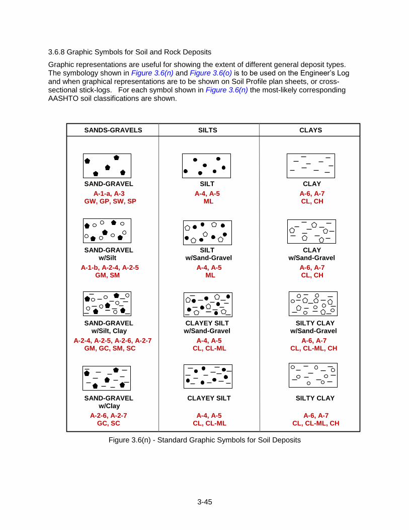
3-45
3.6.8 Graphic Symbols for Soil and Rock Deposits
Graphic representations are useful for showing the extent of different general deposit types. The symbology shown in Figure 3.6(n) and Figure 3.6(o) is to be used on the Engineer‟s Log and when graphical representations are to be shown on Soil Profile plan sheets, or cross-sectional stick-logs. For each symbol shown in Figure 3.6(n) the most-likely corresponding AASHTO soil classifications are shown.
SANDS-GRAVELS SILTS CLAYS
SAND-GRAVEL SILT CLAY
A-1-a, A-3 A-4, A-5 A-6, A-7 GW, GP, SW, SP ML CL, CH
SAND-GRAVEL SILT CLAY w/Silt w/Sand-Gravel w/Sand-Gravel
A-1-b, A-2-4, A-2-5 A-4, A-5 A-6, A-7 GM, SM ML CL, CH
SAND-GRAVEL CLAYEY SILT SILTY CLAY w/Silt, Clay w/Sand-Gravel w/Sand-Gravel
A-2-4, A-2-5, A-2-6, A-2-7 A-4, A-5 A-6, A-7 GM, GC, SM, SC CL, CL-ML CL, CL-ML, CH
SAND-GRAVEL CLAYEY SILT SILTY CLAY w/Clay
A-2-6, A-2-7 A-4, A-5 A-6, A-7 GC, SC CL, CL-ML CL, CL-ML, CH
Figure 3.6(n) - Standard Graphic Symbols for Soil Deposits
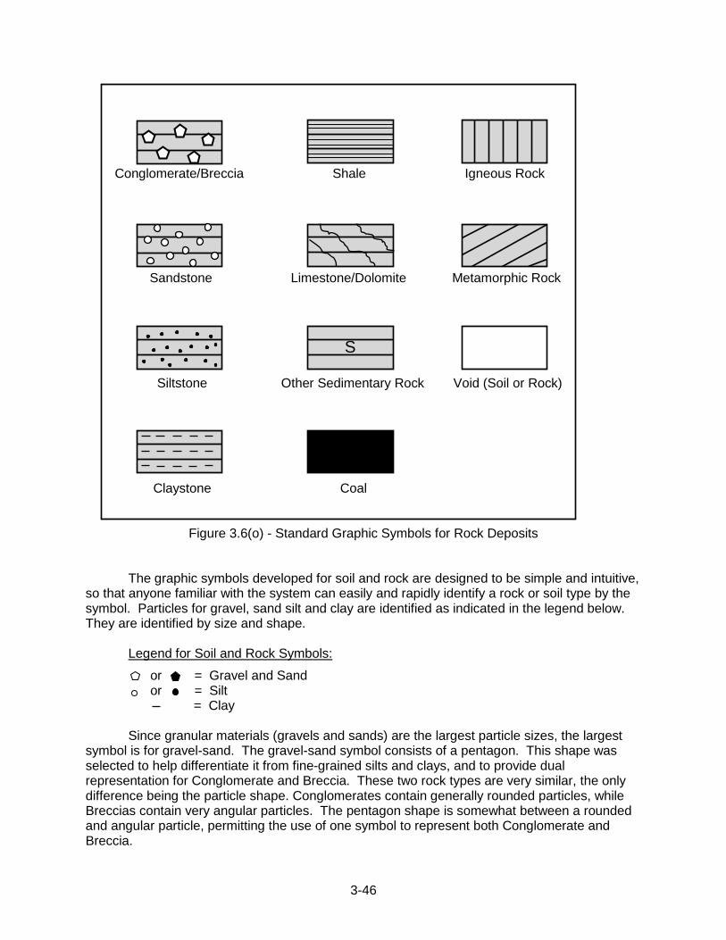
3-46
Conglomerate/Breccia Shale Igneous Rock
Sandstone Limestone/Dolomite Metamorphic Rock
Siltstone Other Sedimentary Rock Void (Soil or Rock)
Claystone Coal
Figure 3.6(o) - Standard Graphic Symbols for Rock Deposits
The graphic symbols developed for soil and rock are designed to be simple and intuitive, so that anyone familiar with the system can easily and rapidly identify a rock or soil type by the symbol. Particles for gravel, sand silt and clay are identified as indicated in the legend below. They are identified by size and shape.
Legend for Soil and Rock Symbols:
or = Gravel and Sand or = Silt = Clay Since granular materials (gravels and sands) are the largest particle sizes, the largest
symbol is for gravel-sand. The gravel-sand symbol consists of a pentagon. This shape was selected to help differentiate it from fine-grained silts and clays, and to provide dual representation for Conglomerate and Breccia. These two rock types are very similar, the only difference being the particle shape. Conglomerates contain generally rounded particles, while Breccias contain very angular particles. The pentagon shape is somewhat between a rounded and angular particle, permitting the use of one symbol to represent both Conglomerate and Breccia.
S
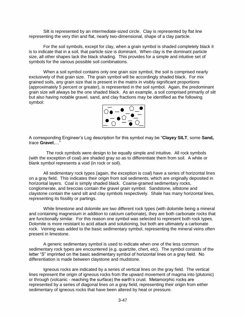
3-47
Silt is represented by an intermediate-sized circle. Clay is represented by flat line representing the very thin and flat, nearly two-dimensional, shape of a clay particle.
For the soil symbols, except for clay, when a grain symbol is shaded completely black it
is to indicate that in a soil, that particle size is dominant. When clay is the dominant particle size, all other shapes lack the black shading. This provides for a simple and intuitive set of symbols for the various possible soil combinations.
When a soil symbol contains only one grain size symbol, the soil is comprised nearly
exclusively of that grain size. The grain symbol will be accordingly shaded black. For mix grained soils, any grain size that is present in the matrix in visibly significant proportions (approximately 5 percent or greater), is represented in the soil symbol. Again, the predominant grain size will always be the one shaded black. As an example, a soil comprised primarily of silt but also having notable gravel, sand, and clay fractions may be identified as the following symbol:
A corresponding Engineer‟s Log description for this symbol may be “Clayey SILT, some Sand, trace Gravel,…”
The rock symbols were design to be equally simple and intuitive. All rock symbols (with the exception of coal) are shaded gray so as to differentiate them from soil. A white or blank symbol represents a void (in rock or soil).
All sedimentary rock types (again, the exception is coal) have a series of horizontal lines on a gray field. This indicates their origin from soil sediments, which are originally deposited in horizontal layers. Coal is simply shaded black. Coarse-grained sedimentary rocks, conglomerate, and breccias contain the gravel grain symbol. Sandstone, siltstone and claystone contain the sand silt and clay symbols respectively. Shale has many horizontal lines, representing its fissility or partings.
While limestone and dolomite are two different rock types (with dolomite being a mineral
and containing magnesium in addition to calcium carbonate), they are both carbonate rocks that are functionally similar. For this reason one symbol was selected to represent both rock types. Dolomite is more resistant to acid attack and solutioning, but both are ultimately a carbonate rock. Veining was added to the basic sedimentary symbol, representing the mineral veins often present in limestone.
A generic sedimentary symbol is used to indicate when one of the less common
sedimentary rock types are encountered (e.g. quartzite, chert, etc). The symbol consists of the letter “S” imprinted on the basic sedimentary symbol of horizontal lines on a gray field. No differentiation is made between claystone and mudstone.
Igneous rocks are indicated by a series of vertical lines on the gray field. The vertical
lines represent the origin of igneous rocks from the upward movement of magma into (plutonic) or through (volcanic - reaching the surface) the earth‟s crust. Metamorphic rocks are represented by a series of diagonal lines on a gray field, representing their origin from either sedimentary of igneous rocks that have been altered by heat or pressure.
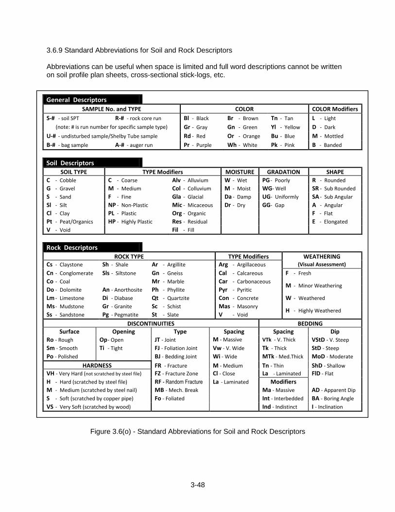
3-48
3.6.9 Standard Abbreviations for Soil and Rock Descriptors Abbreviations can be useful when space is limited and full word descriptions cannot be written on soil profile plan sheets, cross-sectional stick-logs, etc.
General Descriptors
SAMPLE No. and TYPE COLOR COLOR Modifiers
S-# - soil SPT R-# - rock core run Bl - Black Br - Brown Tn - Tan L - Light
(note: # is run number for specific sample type) Gr - Gray Gn - Green Yl - Yellow D - Dark
U-# - undisturbed sample/Shelby Tube sample Rd - Red Or - Orange Bu - Blue M - Mottled
B-# - bag sample A-# - auger run Pr - Purple Wh - White Pk - Pink B - Banded
Soil Descriptors SOIL TYPE TYPE Modifiers MOISTURE GRADATION SHAPE
C - Cobble C - Coarse Alv - Alluvium W - Wet PG - Poorly R - Rounded
G - Gravel M - Medium Col - Colluvium M - Moist WG- Well SR - Sub Rounded
S - Sand F - Fine Gla - Glacial Da - Damp UG- Uniformly SA - Sub Angular
Sl - Silt NP - Non-Plastic Mic - Micaceous Dr - Dry GG- Gap A - Angular
Cl - Clay PL - Plastic Org - Organic F - Flat
Pt - Peat/Organics HP - Highly Plastic Res - Residual E - Elongated
V - Void Fil - Fill
Rock Descriptors ROCK TYPE TYPE Modifiers WEATHERING
Cs - Claystone Sh - Shale Ar - Argillite Arg - Argillaceous (Visual Assessment)
Cn - Conglomerate Sls - Siltstone Gn - Gneiss Cal - Calcareous F - Fresh
Co - Coal Mr - Marble Car - Carbonaceous M - Minor Weathering
Do - Dolomite An - Anorthosite Ph - Phyllite Pyr - Pyritic
Lm - Limestone Di - Diabase Qt - Quartzite Con - Concrete W - Weathered
Ms - Mudstone Gr - Granite Sc - Schist Mas - Masonry H - Highly Weathered
Ss - Sandstone Pg - Pegmatite St - Slate V - Void
DISCONTINUITIES BEDDING Surface Opening Type Spacing Spacing Dip
Ro - Rough Op - Open JT - Joint M - Massive
Wide VTk - V. Thick VStD - V. Steep
Sm - Smooth Ti - Tight FJ - Foliation Joint Vw - V. Wide Tk - Thick StD - Steep
Po - Polished BJ - Bedding Joint Wi - Wide MTk - Med.Thick MoD - Moderate
HARDNESS FR - Fracture M - Medium Tn - Thin ShD - Shallow
VH - Very Hard (not scratched by steel file) FZ - Fracture Zone Cl - Close La - Laminated FlD - Flat
H - Hard (scratched by steel file) RF - Random Fracture La - Laminated Modifiers
M - Medium (scratched by steel nail) MB - Mech. Break Ma - Massive AD - Apparent Dip
S - Soft (scratched by copper pipe) Fo - Foliated Int - Interbedded BA - Boring Angle
VS - Very Soft (scratched by wood) Ind - Indistinct I - Inclination
Figure 3.6(o) - Standard Abbreviations for Soil and Rock Descriptors
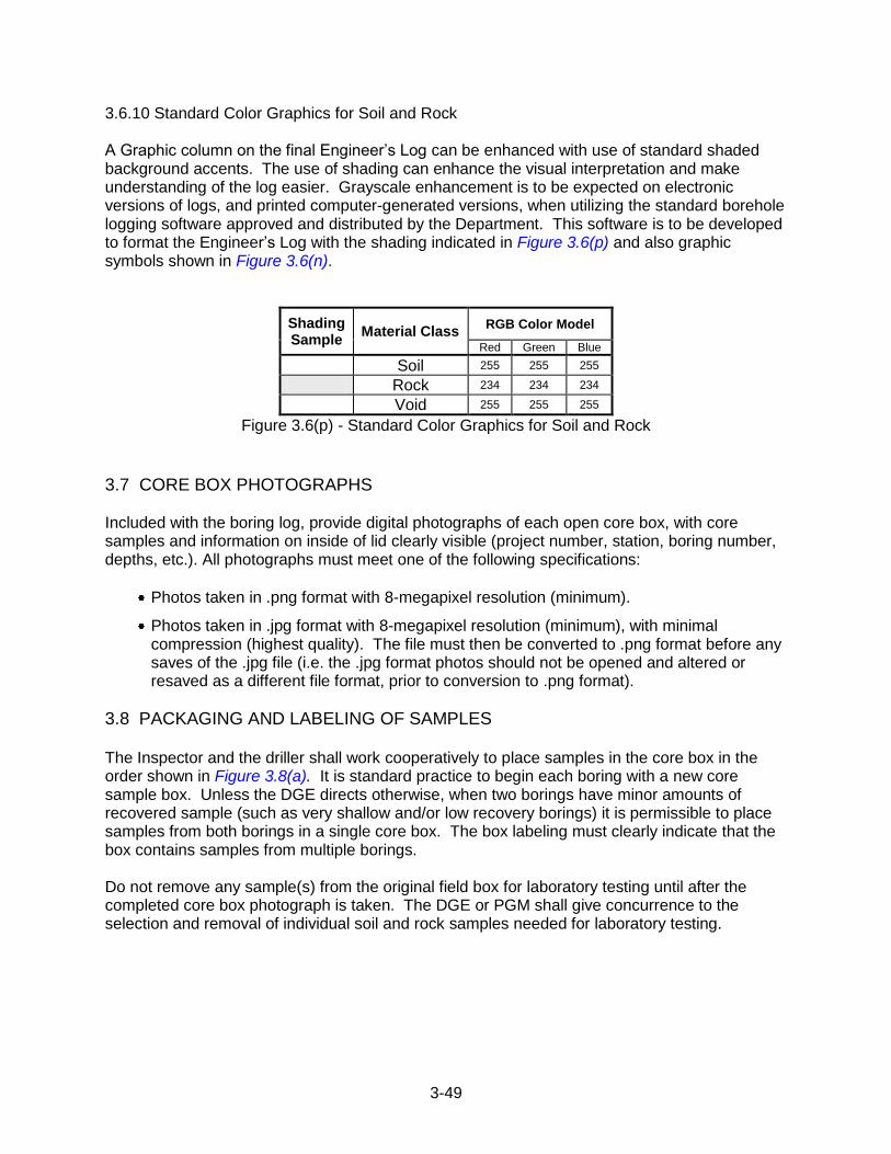
3-49
3.6.10 Standard Color Graphics for Soil and Rock A Graphic column on the final Engineer‟s Log can be enhanced with use of standard shaded background accents. The use of shading can enhance the visual interpretation and make understanding of the log easier. Grayscale enhancement is to be expected on electronic versions of logs, and printed computer-generated versions, when utilizing the standard borehole logging software approved and distributed by the Department. This software is to be developed to format the Engineer‟s Log with the shading indicated in Figure 3.6(p) and also graphic symbols shown in Figure 3.6(n).
Shading Sample
Material Class RGB Color Model
Red Green Blue
Soil 255 255 255
Rock 234 234 234
Void 255 255 255
Figure 3.6(p) - Standard Color Graphics for Soil and Rock
3.7 CORE BOX PHOTOGRAPHS Included with the boring log, provide digital photographs of each open core box, with core samples and information on inside of lid clearly visible (project number, station, boring number, depths, etc.). All photographs must meet one of the following specifications:
Photos taken in .png format with 8-megapixel resolution (minimum).
Photos taken in .jpg format with 8-megapixel resolution (minimum), with minimal compression (highest quality). The file must then be converted to .png format before any saves of the .jpg file (i.e. the .jpg format photos should not be opened and altered or resaved as a different file format, prior to conversion to .png format).
3.8 PACKAGING AND LABELING OF SAMPLES
The Inspector and the driller shall work cooperatively to place samples in the core box in the order shown in Figure 3.8(a). It is standard practice to begin each boring with a new core sample box. Unless the DGE directs otherwise, when two borings have minor amounts of recovered sample (such as very shallow and/or low recovery borings) it is permissible to place samples from both borings in a single core box. The box labeling must clearly indicate that the box contains samples from multiple borings. Do not remove any sample(s) from the original field box for laboratory testing until after the completed core box photograph is taken. The DGE or PGM shall give concurrence to the selection and removal of individual soil and rock samples needed for laboratory testing.
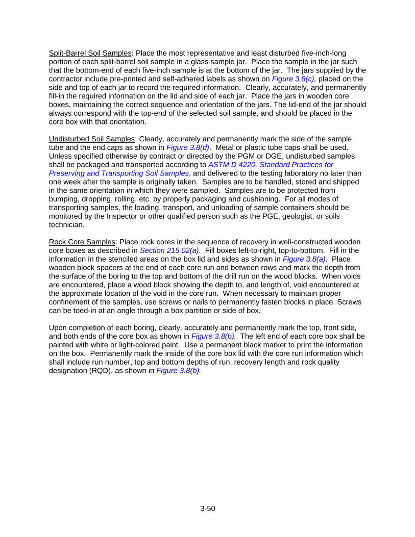
3-50
Split-Barrel Soil Samples: Place the most representative and least disturbed five-inch-long portion of each split-barrel soil sample in a glass sample jar. Place the sample in the jar such that the bottom-end of each five-inch sample is at the bottom of the jar. The jars supplied by the contractor include pre-printed and self-adhered labels as shown on Figure 3.8(c), placed on the side and top of each jar to record the required information. Clearly, accurately, and permanently fill-in the required information on the lid and side of each jar. Place the jars in wooden core boxes, maintaining the correct sequence and orientation of the jars. The lid-end of the jar should always correspond with the top-end of the selected soil sample, and should be placed in the core box with that orientation. Undisturbed Soil Samples: Clearly, accurately and permanently mark the side of the sample tube and the end caps as shown in Figure 3.8(d). Metal or plastic tube caps shall be used. Unless specified otherwise by contract or directed by the PGM or DGE, undisturbed samples shall be packaged and transported according to ASTM D 4220, Standard Practices for Preserving and Transporting Soil Samples, and delivered to the testing laboratory no later than one week after the sample is originally taken. Samples are to be handled, stored and shipped in the same orientation in which they were sampled. Samples are to be protected from bumping, dropping, rolling, etc. by properly packaging and cushioning. For all modes of transporting samples, the loading, transport, and unloading of sample containers should be monitored by the Inspector or other qualified person such as the PGE, geologist, or soils technician. Rock Core Samples: Place rock cores in the sequence of recovery in well-constructed wooden core boxes as described in Section 215.02(a). Fill boxes left-to-right, top-to-bottom. Fill in the information in the stenciled areas on the box lid and sides as shown in Figure 3.8(a). Place wooden block spacers at the end of each core run and between rows and mark the depth from the surface of the boring to the top and bottom of the drill run on the wood blocks. When voids are encountered, place a wood block showing the depth to, and length of, void encountered at the approximate location of the void in the core run. When necessary to maintain proper confinement of the samples, use screws or nails to permanently fasten blocks in place. Screws can be toed-in at an angle through a box partition or side of box. Upon completion of each boring, clearly, accurately and permanently mark the top, front side, and both ends of the core box as shown in Figure 3.8(b). The left end of each core box shall be painted with white or light-colored paint. Use a permanent black marker to print the information on the box. Permanently mark the inside of the core box lid with the core run information which shall include run number, top and bottom depths of run, recovery length and rock quality designation (RQD), as shown in Figure 3.8(b).
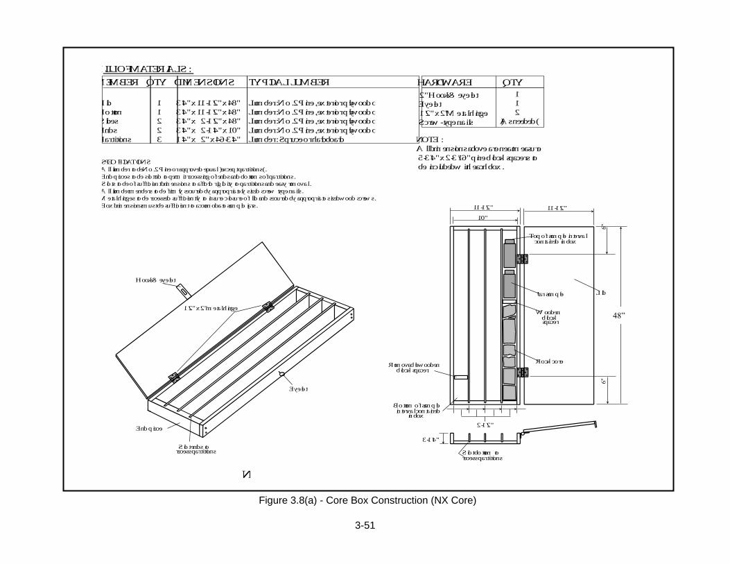
3-51
Lid
Bottom
Sides
Ends
Partitions
1
1
2
2
3
3/4"x11-1/2"x48"
3/4"x11-1/2"x48"
3/4"x 2-1/2"x48"
3/4"x 2-1/4"x10"
1/4"x 2" x46-3/4"
Lumber: No. 2Pine, exterior plywoodor OSB*
Lumber: No. 2Pine, exterior plywoodor OSB*
Lumber: No. 2Pine, exterior plywoodor OSB*
Lumber: No. 2Pine, exterior plywoodor OSB*
Lumber: Spruceorhardboard
MEMBER QTY DIMENSIONS TYPICALLUMBER
BILLOFMATERIALS:
HARDWARE QTY
2" Hook&eyelet
Eyelet
1/2" x2" Metal hinge
Screw-typenails
1
1
2
(As needed)
NOTE:
All dimensionsaboveareneat measure
5-3/4"x2-3/16"pineblockspacers to
be includedwitheachbox.SPECIFICATIONS
All lumber tobeNo. 2Pine or approvedequal (except partitions).
Endpieces tobeslotted topermit recessingof endsandbottomsof partitions.
Slots tobeof sufficient dimensions toaffordrigidity topartitionsandeasyremoval.
All lumber menbers tobefirmlysecuredbyappropriatelysizedscrewtypenails.
Metal hinges toberecessed sufficiently toinsureclosure of lidandsecuredbyappropriatesizedwoodscrews.
Box dimensions must besufficient toaccomodatesample jars.
Hook &eyelet
1/2" x2" metal hinge
Endpiece
Slot ends torecesspartitions
Eyelet
Top of sample interval
LidJar sample
Removable woodenblockspacer
contained in box
Bottomofsampleinterval contained
inbox
11-1/2"
10"
11-1/2"
Woodenblockspacer
Rockcore
2-1/2"
3-1/4"
Slot bottomtorecesspartitionsFIGURE215(a)
NXCOREBOXCONSTRUCTION
*OrientedStrandBoard
Figure 3.8(a) - Core Box Construction (NX Core)
48”
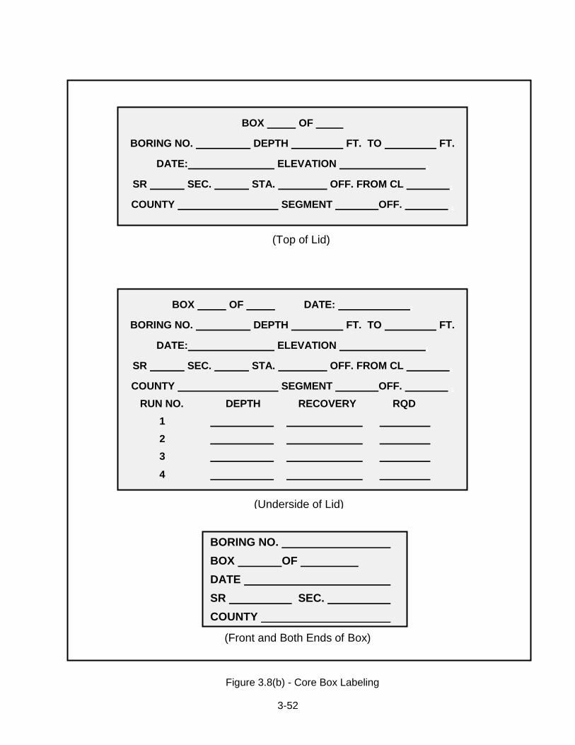
3-52
(Front and Both Ends of Box)
BOX OF
BORING NO. DEPTH FT. TO FT.
DATE: ELEVATION .
SR SEC. STA. OFF. FROM CL .
COUNTY SEGMENT OFF. .
(Top of Lid)
BOX OF DATE: .
BORING NO. DEPTH FT. TO FT.
DATE: ELEVATION .
SR SEC. STA. OFF. FROM CL .
COUNTY SEGMENT OFF. .
RUN NO. DEPTH RECOVERY RQD
1
2
3
4
(Underside of Lid)
BORING NO.
BOX OF
DATE
SR SEC.
COUNTY
Figure 3.8(b) - Core Box Labeling
3-53
(Top of Jar)
SR SEC. COUNTY
STA. OFFSET FROM CL
BORING NO. SAMPLE NO.
DEPTH FROM TO
RECOVERY
BLOWS/ 0.5 FT
DATE
(Side of Jar)
BORING NO.
SAMPLE NO.
DEPTH TO
RECOVERY
BLOWS/ 0.5 FT
Figure 3.8(c) - Sample Jar Labeling
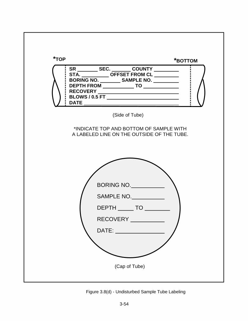
3-54
*TOP *BOTTOM
BORING NO.
SAMPLE NO.
DEPTH TO
RECOVERY
DATE:
(Cap of Tube)
SR SEC. COUNTY STA. OFFSET FROM CL BORING NO. SAMPLE NO. DEPTH FROM TO RECOVERY BLOWS / 0.5 FT
DATE
(Side of Tube)
*INDICATE TOP AND BOTTOM OF SAMPLE WITH A LABELED LINE ON THE OUTSIDE OF THE TUBE.
Figure 3.8(d) - Undisturbed Sample Tube Labeling

3-55
3.9 SAMPLE QUANTITY AND QUALITY Inspectors who examine, package, and transport soil, rock, and water samples have an
important role in ensuring the quality of the laboratory test results. When performing field
investigations, the test boring Inspector shall be familiar with the procedures contained within
this Publication and should also review applicable AASHTO and ASTM standards, such as the
following:
AASHTO R13 - Standard Practice for Conducting Geotechnical Subsurface Investigations
ASTM D 653 - Terminology Relating to Soil, Rock, and Contained Fluids
ASTM D 1452 - Soil Investigation and Sampling by Auger Boring
ASTM D 1586 - Test Method for Penetration Test and Split-Barrel Sampling of Soils
ASTM D 1587 - Practice for Thin-Walled Tube Sampling of Soils
ASTM D 3550 - Practice for Ring-Lined Barrel Sampling of Soils
ASTM D 4220 - Standard Practices for Preserving and Transporting Soil Samples
ASTM D 5434 - Field Logging of Subsurface Explorations of Soil and Rock
ASTM D 6032 - Test Method for Determining Rock Quality Designation (RQD) of Rock Core
ASTM D 6151 - Practice for Using Hollow-Stem Augers for Geotechnical Exploration and Soil Sampling
Prior to drilling: The Inspector shall seek clear instruction from the PGM or PGE as to the
number and type of laboratory tests that are anticipated for a given project. The PGM or PGE
typically makes the final selection of samples for lab testing once drilling is complete. For this
reason, it is important that adequate quantity of materials have been recovered during the
drilling operations.
During drilling: The Inspector and drilling contractor share in the responsibility to obtain the
sufficient quality and quantity of sample material needed for testing. There are a variety of
standard laboratory tests for soil and rock materials. To assist in this, Table 3.9(a) and Table
3.9(b) list guidelines for sample requirements for some of the more common individual
laboratory tests. The minimum sample size needed to properly prepare a lab specimen of soil
can be dependent upon the gradation of the soil. Depending upon the actual gradation of the
soil, a larger or smaller quantity of material than is listed may actually be needed to prepare the
specimen. Table 3.9(c) lists soil sample sizes for common suites of tests that will provide
sufficient soil material to permit the laboratory technician to properly prepare and run the tests.
If the drilling contractor cannot retrieve the amount of material listed, or if conditions differ than
what was anticipated, the drilling Inspector shall contact the PGM or PGE for additional
guidance on obtaining adequate sample quantities.
After drilling: The drilling Inspector shall conduct a quality check of his/her field notes and
observations once back in the office. Sample descriptions and identifications shall be reviewed
and revised as necessary to ensure that they are in compliance with the procedures presented
in this section. Descriptors of sample properties that are subject to change due to time or
environment, such as moisture or RQD, shall not be revised. Samples that are to be stored for
laboratory testing or other purposes shall be inventoried to ensure correct labeling and
accounting.
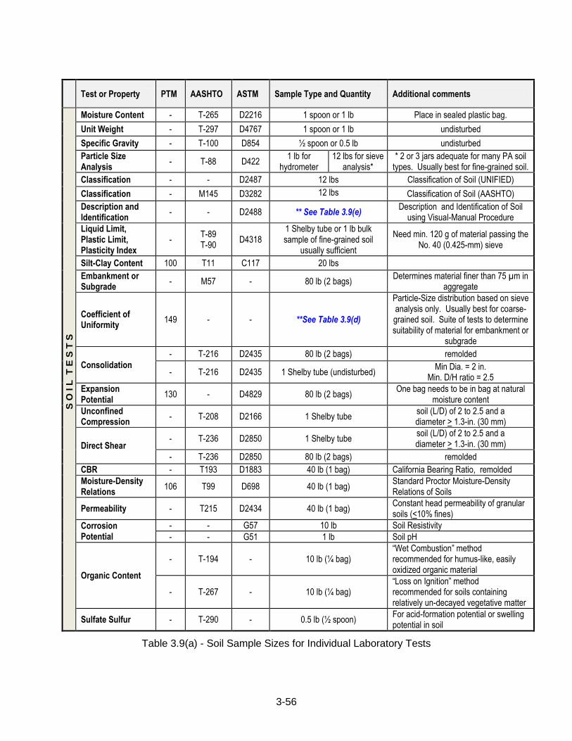
3-56
Test or Property PTM AASHTO ASTM Sample Type and Quantity Additional comments
S O
I L
T
E S
T S
Moisture Content - T-265 D2216 1 spoon or 1 lb Place in sealed plastic bag.
Unit Weight - T-297 D4767 1 spoon or 1 lb undisturbed
Specific Gravity - T-100 D854 ½ spoon or 0.5 lb undisturbed
Particle Size Analysis
- T-88 D422 1 lb for
hydrometer 12 lbs for sieve
analysis* * 2 or 3 jars adequate for many PA soil
types. Usually best for fine-grained soil.
Classification - - D2487 12 lbs Classification of Soil (UNIFIED)
Classification - M145 D3282 12 lbs Classification of Soil (AASHTO)
Description and Identification
- - D2488 ** See Table 3.9(e) Description and Identification of Soil
using Visual-Manual Procedure
Liquid Limit, Plastic Limit, Plasticity Index
- T-89 T-90
D4318 1 Shelby tube or 1 lb bulk sample of fine-grained soil
usually sufficient
Need min. 120 g of material passing the No. 40 (0.425-mm) sieve
Silt-Clay Content 100 T11 C117 20 lbs
Embankment or Subgrade
- M57 - 80 lb (2 bags) Determines material finer than 75 µm in
aggregate
Coefficient of Uniformity
149 - - **See Table 3.9(d)
Particle-Size distribution based on sieve analysis only. Usually best for coarse-grained soil. Suite of tests to determine suitability of material for embankment or
subgrade
Consolidation
- T-216 D2435 80 lb (2 bags) remolded
- T-216 D2435 1 Shelby tube (undisturbed) Min Dia. = 2 in.
Min. D/H ratio = 2.5
Expansion Potential
130 - D4829 80 lb (2 bags) One bag needs to be in bag at natural
moisture content
Unconfined Compression
- T-208 D2166 1 Shelby tube soil (L/D) of 2 to 2.5 and a diameter > 1.3-in. (30 mm)
Direct Shear - T-236 D2850 1 Shelby tube
soil (L/D) of 2 to 2.5 and a diameter > 1.3-in. (30 mm)
- T-236 D2850 80 lb (2 bags) remolded
CBR - T193 D1883 40 lb (1 bag) California Bearing Ratio, remolded
Moisture-Density Relations
106 T99 D698 40 lb (1 bag) Standard Proctor Moisture-Density Relations of Soils
Permeability - T215 D2434 40 lb (1 bag) Constant head permeability of granular soils (<10% fines)
Corrosion Potential
- - G57 10 lb Soil Resistivity
- - G51 1 lb Soil pH
Organic Content
- T-194 - 10 lb (¼ bag) “Wet Combustion” method recommended for humus-like, easily oxidized organic material
- T-267 - 10 lb (¼ bag) “Loss on Ignition” method recommended for soils containing relatively un-decayed vegetative matter
Sulfate Sulfur - T-290 - 0.5 lb (½ spoon) For acid-formation potential or swelling potential in soil
Table 3.9(a) - Soil Sample Sizes for Individual Laboratory Tests
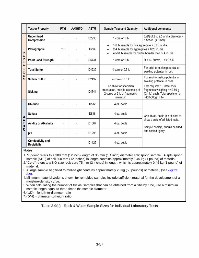
3-57
Test or Property PTM AASHTO ASTM Sample Type and Quantity Additional comments
R O
C K
T
E S
T S
Unconfined Compression
- - D2938 1 core or 1 lb (L/D) of 2 to 2.5 and a diameter > 1.875 in. (47 mm)
Petrographic 518 - C294
1-2 lb sample for fine aggregate < 0.25 in. dia.
2-4 lb sample for aggregates > 0.25 in. dia.
40-80 lb sample for cobble/boulder matl. > 4 in. dia.
Point Load Strength - - D5731 1 core or 1 lb D = +/- 50mm, L = >0.5 D
Total Sulfur - - D4239 ½ core or 0.5 lb For acid-formation potential or swelling potential in rock
Sulfide Sulfur - - D2492 ½ core or 0.5 lb For acid-formation potential or swelling potential in coal
Slaking - - D4644
To allow for specimen preparation, provide a sample of
2 cores or 2 lb of fragments, minimum
Test requires 10 intact rock fragments weighing ~ 40-60 g (0.1 lb) each. Total specimen of ~450-500g (1 lb)
W A
T E
R
Chloride - - D512 4 oz. bottle
One 16 oz. bottle is sufficient to allow a suite of all listed tests. Sample bottle(s) should be filled and sealed tightly.
Sulfate - - D516 4 oz. bottle
Acidity or Alkalinity - - D1067 4 oz. bottle
pH - - D1293 4 oz. bottle
Conductivity and Resistivity
- - D1125 4 oz. bottle
Notes:
1. “Spoon” refers to a 300 mm (12 inch) length of 35 mm (1.4 inch) diameter split spoon sample. A split-spoon sample (SPT) of soil 300 mm (12 inches) in length contains approximately 0.45 kg (1 pound) of material.
2. “Core” refers to a NQ-size rock core 75 mm (3 inches) in length, which is approximately 0.45 kg (1 pound) of material.
3. A large sample bag filled to mid-height contains approximately 23 kg (50 pounds) of material, (see Figure 3.9).
4. Minimum material weights shown for remolded samples include sufficient material for the development of a moisture-density curve.
5. When calculating the number of triaxial samples that can be obtained from a Shelby tube, use a minimum sample length equal to three times the sample diameter.
6. (L/D) = length-to-diameter ratio 7. (D/H) = diameter-to-height ratio
Table 3.9(b) - Rock & Water Sample Sizes for Individual Laboratory Tests
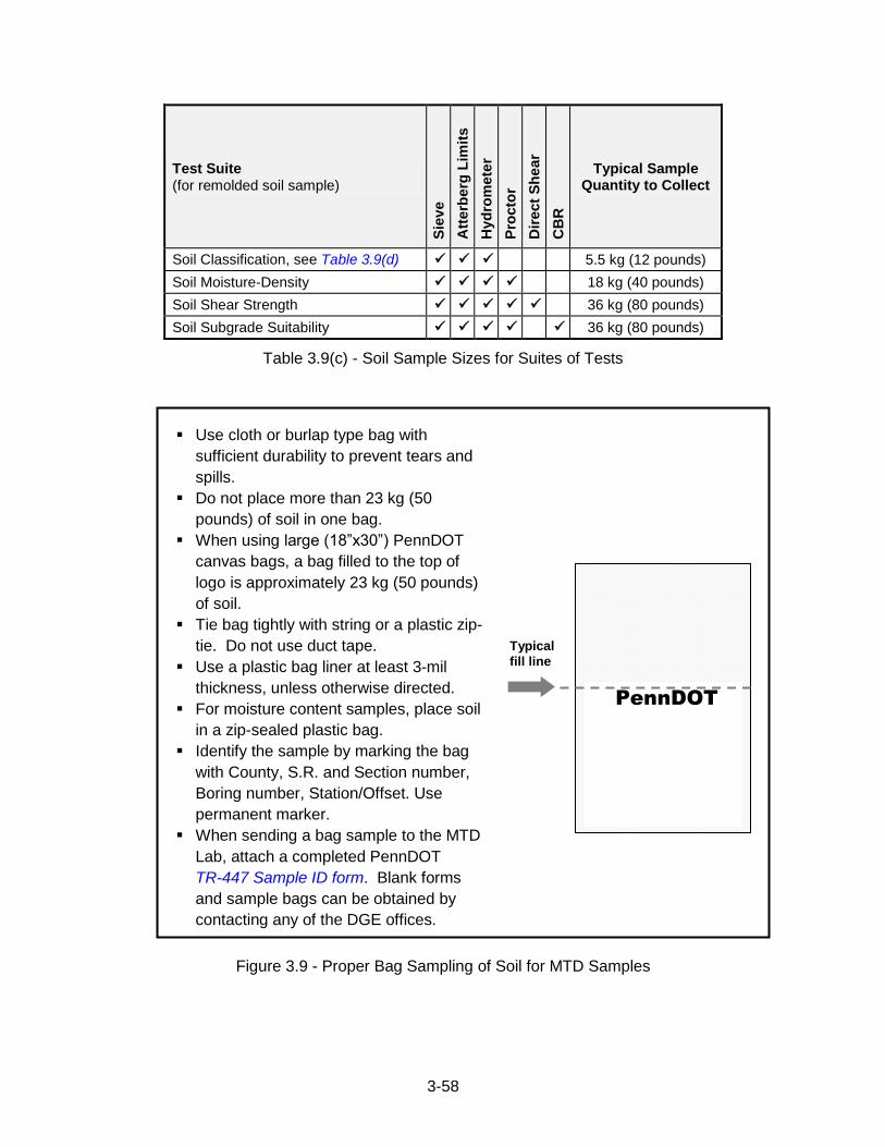
3-58
PennDOT
Test Suite (for remolded soil sample)
Sie
ve
Att
erb
erg
Lim
its
Hyd
rom
ete
r
Pro
cto
r
Dir
ect
Sh
ear
CB
R
Typical Sample Quantity to Collect
Soil Classification, see Table 3.9(d) 5.5 kg (12 pounds)
Soil Moisture-Density 18 kg (40 pounds)
Soil Shear Strength 36 kg (80 pounds)
Soil Subgrade Suitability 36 kg (80 pounds)
Table 3.9(c) - Soil Sample Sizes for Suites of Tests
Use cloth or burlap type bag with
sufficient durability to prevent tears and
spills.
Do not place more than 23 kg (50
pounds) of soil in one bag.
When using large (18”x30”) PennDOT
canvas bags, a bag filled to the top of
logo is approximately 23 kg (50 pounds)
of soil.
Tie bag tightly with string or a plastic zip-
tie. Do not use duct tape.
Use a plastic bag liner at least 3-mil
thickness, unless otherwise directed.
For moisture content samples, place soil
in a zip-sealed plastic bag.
Identify the sample by marking the bag
with County, S.R. and Section number,
Boring number, Station/Offset. Use
permanent marker.
When sending a bag sample to the MTD
Lab, attach a completed PennDOT
TR-447 Sample ID form. Blank forms
and sample bags can be obtained by
contacting any of the DGE offices.
Figure 3.9 - Proper Bag Sampling of Soil for MTD Samples
Typical
fill line
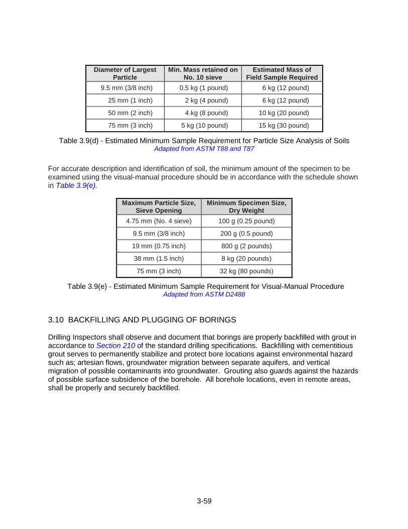
3-59
Diameter of Largest Particle
Min. Mass retained on No. 10 sieve
Estimated Mass of Field Sample Required
9.5 mm (3/8 inch) 0.5 kg (1 pound) 6 kg (12 pound)
25 mm (1 inch) 2 kg (4 pound) 6 kg (12 pound)
50 mm (2 inch) 4 kg (8 pound) 10 kg (20 pound)
75 mm (3 inch) 5 kg (10 pound) 15 kg (30 pound)
Table 3.9(d) - Estimated Minimum Sample Requirement for Particle Size Analysis of Soils Adapted from ASTM T88 and T87
For accurate description and identification of soil, the minimum amount of the specimen to be examined using the visual-manual procedure should be in accordance with the schedule shown in Table 3.9(e).
Maximum Particle Size, Sieve Opening
Minimum Specimen Size, Dry Weight
4.75 mm (No. 4 sieve) 100 g (0.25 pound)
9.5 mm (3/8 inch) 200 g (0.5 pound)
19 mm (0.75 inch) 800 g (2 pounds)
38 mm (1.5 inch) 8 kg (20 pounds)
75 mm (3 inch) 32 kg (80 pounds)
Table 3.9(e) - Estimated Minimum Sample Requirement for Visual-Manual Procedure Adapted from ASTM D2488
3.10 BACKFILLING AND PLUGGING OF BORINGS Drilling Inspectors shall observe and document that borings are properly backfilled with grout in accordance to Section 210 of the standard drilling specifications. Backfilling with cementitious grout serves to permanently stabilize and protect bore locations against environmental hazard such as; artesian flows, groundwater migration between separate aquifers, and vertical migration of possible contaminants into groundwater. Grouting also guards against the hazards of possible surface subsidence of the borehole. All borehole locations, even in remote areas, shall be properly and securely backfilled.

4-1
4.1 PRIORITIES & OBJECTIVES
The PGM should remain aware of the overall objectives of the SBST contract, and make
appropriate efforts to ensure that the following priorities and objectives are met:
Proper Scope. Obtain adequate information to establish all design parameters with
sufficient reliability and to address all subsurface problems that may arise in design or
construction.
Proper Communication. Ensure that the following Department personnel (as
appropriate) are promptly informed of any conditions that may result in a change in the
contract, or any unusual conditions that are encountered during exploration:
- District Geotechnical Engineer
- District Bridge Engineer (or Plans Engineer if no structure work is involved)
- District Environmental Manager
- Liaison Engineer or Project Manager
Proper Documentation. The subsurface conditions determined by the operations are
fully and accurately described in the logs and records.
4.2 CONTRACT MANAGEMENT Projects drilled under Department contracts will be inspected by District personnel or the District's representative. Projects drilled under Consultant design contracts will normally be inspected by Consultant personnel. Consultant-designed projects can be inspected by Department forces provided the Department inspector is certified and the DGE is a licensed P.E. or P.G. in the Commonwealth. In addition, the DGE must review the core boxes and check and initial the final Engineer‟s Logs. For projects where the geotechnical Consultant (or a subsidiary company thereof) is also a Drilling Contractor, the Consultant may be permitted to provide the project drilling services and to inspect the work performed by their own Driller. See Chapter 4.5 for more clarification on the requirements for this case. All inspection will be the responsibility of the PGM. One full-time, certified inspector shall be assigned to each drill rig. Any supervisor or inspector who does not demonstrate adequate proficiency or dependability at
the project site, or engages in activities contrary to the best interest of the Department, as
determined by the DGE, will be subject to removal from the project. A qualified replacement will
be required before work will be permitted to resume. The DGE must complete a written
evaluation (Figure 3.5) of the Inspector, within three working days of removal. Upon completion,
the evaluation must be submitted to the removed Inspector, with a copy to the CGE.
Chapter 4 - SBST CONTRACT ADMINISTRATION
4-2
4.3 PREPARATION OF PROPOSAL/CONTRACT Prepare a draft subsurface investigation plan and submit to the DGE for approval. The plan must include the proposed types, depths and locations of all borings, and the preliminary laboratory testing plan. A proposal/contract for undertaking the necessary field work shall be prepared using the current SBST Contract. Submit the proposal/contract to the DGE for review and acceptance as directed. Preparation of the Proposal shall include the following items:
(a) Property Owners. Send notice to all affected property owners as detailed in Subchapter 5E, Section 103.11.
(b) Railroad Right-of Way. Consider entry onto railroad right-of-way.
(c) Overhead Utilities. The requirements for working near overhead utilities are discussed in Section 103.09(b) of the Standard Specifications for SBST. When any part of the drill rig, including drill steel, is proposed to be located within 6 m (20 feet) of overhead power lines, the PGM/DGE shall contact the utility owner to determine the voltage in the line in order to ensure that the clearance distance requirement of Section 103.09(b) is met. In situations where clearance between overhead lines and drill equipment is less than required in Section 103.09(b), the PGM/DGE must coordinate this work with the appropriate utility company. Specific directions and necessary special provision(s) and pay item(s) to conduct this work must be prepared by the PGM/DGE and included in the contract.
(d) Methane and Carbon Monoxide Gases. The requirements for working where methane gas or carbon monoxide gas may be encountered are discussed in Section 103.09(c) of the Standard Specifications for SBST. In situations where it is suspected that methane or carbon monoxide gas may be encountered (e.g., where deep mines are likely to be encountered, where drilling in the vicinity of deep mines, or where mineable coal seams may be encountered) the PGM/DGE must include specific direction for methane and carbon monoxide monitoring in the contract. Typically, monitoring requirements are included in the schedule of drilling, and monitoring is incidental to the cost of drilling; however, special provisions or pay items may be warranted in certain situations where an atypical level of monitoring is needed. During the subsurface investigation, if an elevated concentration of methane or carbon monoxide is encountered which prevents drilling and grouting of boreholes, the PGM/DGE should be prepared to provide direction to the drilling contractor. The PGM/DGE may contact PA-DEP personnel, the CGE, and/or others for technical assistance.
(e) Anticipating the Method of Advancing Soil Borings. The PGE shall consider if a specific method of advancing soil borings is required or preferred, based on the anticipated site conditions. The Attachment I, Schedule of Proposed Boring, should typically indicate the anticipated method of hole advance for soil borings will be “Advanced by means selected by Contractor”. By doing this, the Contractor is responsible to select the most effective means/methods to accomplish the work. If the method does not work he will have to modify his methods. If, when preparing the contract, the PGE decides a specific method of boring advancement is needed, that method should be specified (i.e., hollow-stem auger, drive casing). Hollow-stem
4-3
augers are the commonly preferred choice of boring advancement; however other options such as steel casing are occasionally employed. In some cases, augers cannot successfully advance – like cobbles/boulders, fills with obstructions, very dense tills, limestone ledges, cap rock above mine voids, etc.
(f) Contract Documents. Prepare the SBST Contract documents in accordance with the investigation plan approved by the Department. Prepare a plan of the foundation layout indicating the location of the test borings and other pertinent information.
(g) Cost Estimate. Prepare an Engineers Estimate of the cost of the work.
(h) Letter of Interest. Prepare a draft letter of interest advertising solicitation of bids for the subsurface investigation contract. Inform potential bidders in the letter that a reply is required by the date indicated in the letter of interest, and advise that all replies must be sent back to the email address indicated using the response form supplied in the email (Figure 4.3). Except for cases as noted in Chapter 4.5, the letter is to be sent by email to all Drilling Contractors on the current list of PennDOT Prequalified Drilling Contractors. Include a copy of Figure 4.3, Letter of Interest, with the email to each prequalified Drilling Contractor. Include the following in the letter:
Provide the anticipated type of borings, samples, and field tests with approximate quantities.
Provide the location of the holes (water or land).
State whether or not Maintenance and Protection of Traffic drawings will be provided or required.
State whether any boring or test pit locations are within 30 m (100 feet) of any domestic water supply well or spring box, and if so include the appropriate as required by Section 219.
State whether the railroad requires safety training prior to entry on its right-of-way; anticipated dates for bid opening and Notice to Proceed;
Attach a map that would allow anyone unfamiliar with the area to find the project.
Describe any other pertinent information.
(i) Cover Letter. Prepare a draft of the letter to be used to transmit the SBST Contract documents to the Drilling Contractors who respond to item (e). Include in the letter the county, state route, and section numbers of the project; the date, time and location of the mandatory pre-bid meeting (if required); the date, time and location of the bid opening; and a reminder to follow the instructions in the Instructions to Bidders.
(j) Contract Documents. Prepare and transmit the contract documents to the drilling contractors expressing interest. The cover letter and accompanying contract documents must be sent by way of certified mail or hand-delivery.
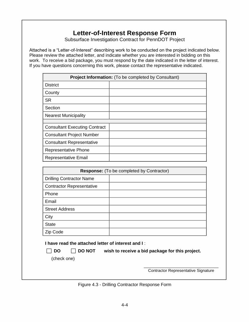
4-4
Letter-of-Interest Response Form Subsurface Investigation Contract for PennDOT Project
Attached is a “Letter-of-Interest” describing work to be conducted on the project indicated below. Please review the attached letter, and indicate whether you are interested in bidding on this work. To receive a bid package, you must respond by the date indicated in the letter of interest. If you have questions concerning this work, please contact the representative indicated.
Project Information: (To be completed by Consultant)
District
County
SR
Section
Nearest Municipality
Consultant Executing Contract
Consultant Project Number
Consultant Representative
Representative Phone
Representative Email
Contractor Representative Signature
Figure 4.3 - Drilling Contractor Response Form
Response: (To be completed by Contractor)
Drilling Contractor Name
Contractor Representative
Phone
Street Address
City
State
Zip Code
I have read the attached letter of interest and I :
DO DO NOT wish to receive a bid package for this project.
(check one)
4-5
4.4 FACILITATION OF CONTRACT BIDDING The PGM shall ensure that the following requirements are completed during the bid process:
(a) Pre-Bid Meeting. Conduct the mandatory pre-bid meeting unless indicated
otherwise by the DGE. At this time all borings shall be staked on the project. Pre-bid meeting minutes must be sent to all contractors that attended the pre-bid meeting. Minutes may be sent via certified mail, email (with read receipt verification), or hand delivered). Sufficient time must be given to allow contractors to receive and review pre-bid meeting minutes prior to bidding date.
(b) Bid Opening. Attend the bid opening at the project District office, if practical.
Alternately, bids may be opened at the consultant engineer‟s office, provided that the DGE or representative is present. Check the bid documents for completeness, correctness of quantities, and cost tabulations. Tabulate the bid results. Determine the low bidder. Obtain concurrence of the District Office in writing on the acceptability of the low bidder.
(c) Contractor Notification. Notify all bidders of the results; send each a tabulation of
the bids. Return all proposal guarantees except those of the two lowest bidders. Notify the lowest bidder to complete the forms in the bid package and furnish the required Contract Bond, Additional Bond for labor and Material, and insurance certificates. Notify the second lowest bidder that his/her proposal guarantee will be held until the lowest bidder completes the necessary paperwork.
(d) Notice to Proceed. Review the lowest bidder‟s submissions for completeness. The
insurance certificate shall name the Commonwealth of Pennsylvania as co-insured. When all submissions are complete, return the proposal guarantees and issue a Notice to Proceed. Notice to Proceed should clearly state the day on which the time charges will begin.
(e) DGE Notification. Provide the DGE a copy of all correspondence at the time it is
sent out. Only one copy of the advertisement letter is needed. Furnish a copy of all pages in the bidding package in which the contractor has filled in information, and copies of the bonds and insurance certificates.
(f) Statewide Notification. Contracts let by the Department shall be advertised in either
the Engineering and Construction Management System (ECMS); or the Supplier Relationship Management (SRM) system, as appropriate.
(g) CGE Notification. Upon award of contract to successful bidder the PGM (Consultant
for consultant contracts, DGE for department contracts) must submit a completed copy of the “Form Of Proposal” (Sub-Chapter 5C) to the CGE to the address below. This includes work performed under provisions of Chapter 4.5. Include the completed copy of Figure 4.3, Drilling Contractor Response Form for the successful bidder (or entity performing work when using Chapter 4.5).
Chief Geotechnical Engineer Innovation & Support Services Division PennDOT Materials Testing Laboratory 81 Lab Lane Harrisburg PA 17110-2543
4-6
4.5 ACCELERATED ACQUISITION OF DRILLING & TESTING SERVICES
4.5.1 Acquisition of Drilling & Sampling Bid solicitation for drilling services during both Preliminary Engineering and Final Design may be simplified for consultant-designed projects where the Engineer‟s cost estimate for drilling is $30,000, or less. In such cases, the District has the option to direct the project geotechnical consultant to obtain drilling services as follows:
(a) The Consultant or sub-Consultant may perform the drilling services with their own forces if they (or their owned subsidiary doing the drilling) are a PennDOT Prequalified Drilling Contractor. In such cases, the DGE shall conduct a quality assurance field review of the drilling operations and complete a Drilling Inspector Performance Evaluation Form, Figure 3.5, and also a Performance Report for Drilling Contractors, Figure 2.1(a). The DGE shall provide written concurrence to the Project Manager that the unit prices for drilling services are reasonable and competitive. If concurrence on reasonable and competitive unit prices cannot be reached, then follow the method described in Chapter 4.5.1(b), below.
(b) If the Consultant or sub-Consultant is not a PennDOT Prequalified Drilling Contractor, the drilling services may be provided by soliciting written quotes from at least three (3) PennDOT Prequalified Drilling Contractors. The DGE must consider the contractors as viable and likely to submit a bid for the work. In this case, „viable‟ is defined as a driller who regularly performs services for Department projects and is located geographically such that it is reasonable to expect that they could competitively provide the required services and would have an expectation of being interested in pursuing this work under normal procedures. At least two bids should be received to justify a choice of a firm. In rare cases where only one bid is received, written documentation shall be on record showing at least two other viable firms were solicited but chose not to bid the work. The DGE shall provide written concurrence of the bid award to the Project Manager and indicate that the low-bid unit prices are reasonable and competitive.
If the Engineer‟s cost estimate for drilling is more than $30,000, the Consultant shall prepare and send a letter of interest advertising solicitation of bids for the subsurface investigation contract to all Contractors on the current list of PennDOT Prequalified Drilling Contractors. The Consultant (or the Consultant‟s subsidiary) may not bid on the contract or perform drilling services with their own forces.
In all cases, the drilling and field testing services provided must follow the technical and performance provisions of this publication.
4.5.2 Acquisition of Laboratory Testing Laboratory testing of soil and rock materials collected during the subsurface investigation must be performed by an AASHTO Materials Reference Laboratory (AMRL) that is accredited for each test method to be conducted (except where AMRL does not certify a specified test method). Proof of accreditations must accompany any Price Proposal. The laboratory test results must be reviewed and attested by a Professional Engineer registered in the state of Pennsylvania.

4-7
According to the PennDOT Policy and Procedures for the Administration of Consultant Agreements, Publication 93, Chapter 3.6.7, laboratory testing is considered a “non-professional service”. The laboratory testing may be performed by the prime consultant‟s AMRL certified laboratory. A project Price Proposal must be submitted by the consultant, and must include a schedule of unit prices (per test) for the laboratory tests proposed. The DGE shall review the Price Proposal and provide written concurrence to the Project Manager indicating the proposed unit costs are fair and reasonable. If fair and reasonable unit costs are not evident, obtain three written quotes or documented telephone quotes to justify a choice of laboratory testing provider. Sample transport costs and administrative costs shall be considered in the justification. Accordingly, it is usually most efficient (considering direct-costs and logistics) for the administering geotechnical consultant to perform the laboratory testing services with their own forces, provided they meet the AMRL certification requirements. If needed, more than one laboratory may be used to perform the AMRL certified tests for a project.
4.6 DEPARTMENT-LET CONTRACTS Drilling contracts executed directly by a PennDOT District or County office must use the appropriate processes to procure drilling services and follow the technical and performance provisions of this publication (including Attachment II). Purchasers and Project Managers should include a requirement in procurement documents that vendors providing drilling services must appear on the approved list in Publication 222. ECMS - PennDOT‟s Engineering and Construction Management System (ECMS) may be used for planned drilling services for design and construction projects only.
Examples:
geotechnical test boring, sampling and testing,
pavement coring, sampling and testing
bridge design and replacement
highway design and construction SRM - The appropriate Supplier Relationship Management (SRM) End User Procedure, based on annual purchasing thresholds, should be followed to obtain on-call drilling services. On-call drilling services may be used for work not covered by an ECMS contract.
Examples:
emergency repairs to highways and bridges due to rock slides or landslides
occasions when drilling is needed while performing maintenance operations
drilling projects to be completed prior to establishment of a specific ECMS contract
When using SRM for drilling services, the SRM purchasing and bid documents must provide clear specifications regarding the scope of work and geographic coverage area. It is acceptable to have multiple SRM Contracts or POs (purchasing documents), if a clear distinction is made as to what work or geographic area is covered by each purchasing document; however, there shall not be any overlap of work or geographic areas, if multiple purchasing documents are in place. Duplicate purchasing documents with no discernable difference in how work is assigned to multiple vendors under the same or similar contract are not acceptable. Districts and Counties should ensure compliance with PennDOT Procurement Directive 10-02 whenever drilling services are needed. If necessary, purchasers should contact the Bureau of Office Services, Procurement Help Desk at 717-346-9900 to discuss such contracts. All drilling work completed under contract must be inspected by a certified drilling Inspector.

4-8
4.7 ENTRY ONTO RAILROAD RIGHT-OF-WAY 4.7.1 Temporary Railroad Right-Of-Entry Permit/Agreement
Entry onto Railroad right-of-way (property) may be required for construction activities as well as inspection, maintenance, survey, soil borings, engineering studies, etc. Therefore, in order to gain entry onto Railroad property a Department‟s contractor and/or his subcontractors or a Department‟s consultant and/or their sub-consultants may be required to enter into a temporary Railroad Right-of-Entry (ROE) permit/ agreement with the Railroad. Because Railroad ROE permits/agreements have been determined to be a contract and they are not in compliance with the Commonwealth Attorneys Act, the Department cannot sign such documents. Only the Department‟s contractor or consultant who is performing the required work activities on the Railroad‟s property can sign a ROE permit/agreement. Refer to the latest edition of Publication 371, Chapter 7, Section 7.03 “Entry onto Railroad Property”.
4.7.2 Department Scope of Work Details and Method of Payment The following activities may be required by the Department‟s District Grade Crossing Engineer/Administrator (DGCE/A), District Project Manager (DPM), or District Liaison Engineer (DLE) regarding scope of work details and method of payment for design consultant projects. (a) The DGCE/A, DPE, or DLE shall consult the Railroad to determine any special
requirements that the Railroad may have in order for the Department‟s contractor or consultant to gain access onto Railroad property.
(b) Information obtained shall include but not be limited to Railroad insurance requirements, ROE permit/agreement fees, copies of applicable permits, time required to process permit, required safety training, Railroad specifications, and if necessary, associated flagging costs and necessary arrangements for flagging protection.
(c) The DGCE/A, DPM, or DLE shall insure that all applicable Railroad ROE requirements
are contained within the Department‟s scope of work/contract for the project.
(d) The scope of work shall detail the method of payment for design consultant projects. If the method of payment is not included in the original consultant agreement, it shall be processed as a supplement.
(e) For District in-house projects where geotechnical explorations are to be performed by
Department personnel, the DPM, DLE, or DGE shall notify the DGCE/A so as to obtain all necessary Railroad ROE requirements and procedures, and method of payment prior to entry onto Railroad Right-Of-Way. Note that the Department cannot sign Railroad ROE permits/agreements, but if the Railroad requires a permit/agreement to be entered into with the Department, consult with the Department‟s Office of Chief Counsel before proceeding further.
(f) The DPM, DLE, DGE, or DGCE/A shall make provisions for reimbursement of Railroad
costs based on Department guidelines and procedures.
4-9
4.7.3 Consultant/Contractor ROE Requirements and Method of Payment The following activities may be required by the Department‟s consultant or contractor, including any sub-consultants or sub-contractors, (Applicant) in order to obtain a Temporary Railroad ROE permit/agreement and method of payment:
(a) Contact Railroad to determine any special requirements the Railroad may have. (b) The consultant‟s technical and price proposal shall address all procedures required by
the Railroad in order to obtain the necessary Temporary Railroad ROE permit/agreement and method of payment for Railroad invoices, permit fees, etc. This shall include, but not be limited to, ROE permit/agreement procedures with associated costs with Railroad turnaround time for processing permits/agreements, Railroad insurance, flagging costs, Railroad safety training, and required notifications to Railroad prior to entry onto Railroad right-of-way.
(d) Information for each individual entry by Applicant shall be supplied to the Railroad in
accordance with their specification and/or permit requirements when applying for the ROE permit. This shall include scope of work, exact location of the entry, estimated cost of work to be performed on the railroad property, distance from the outermost track where the activities will take place, anticipated date of entry, number of people, and length of time.
(e) Applicant shall obtain a copy of the Railroad‟s Temporary ROE permit/agreement. The
Applicant shall submit the completed and signed permit/agreement, with applicable supporting documentation and permit fees to the Railroad for execution. The Railroad shall forward the executed ROE permit/agreement to the Applicant. The Railroad will advise the Applicant of any necessary modifications required based upon Railroad‟s policies and procedures.
(f) Prior to entry onto Railroad ROW an executed ROE permit/agreement must be in the possession of the Applicant.
(g) Railroad will submit invoices directly to the Applicant for services rendered and payment shall be made by Applicant in accordance with Railroad‟s procedures.
4.7.4 Entry onto Railroad Right-Of-Way
Prior to entry onto the Railroad Right-Of-Way (ROW) for the geotechnical exploration the following activities are required:
(a) Determine an exact scheduled starting date and ending date for the entry onto
Railroad ROW.
(b) Incorporate these dates in the letter seeking bidder interest and the proposal.
(c) Where District policy allows an alternative to a defined schedule, note the desired method of scheduling in the letter seeking bidder interest and in the proposal.
(d) Notify the District of the scheduled starting date at least thirty (30) days before the
start date and provide the Railroad the required notice in accordance with Railroad‟s specifications and/or permit requirements.
4-10
(e) Comply with the Railroad‟s required safety training prior to entering. (f) Maintain an independent record of personnel making entry, date of entry, purpose of
entry, railroad personnel and equipment present and their activities, etc. review and countersign railroad time sheet(s) daily; do not countersign if there is a disagreement - notify the District. Forward a copy of the time sheet(s) to the District within fifteen (15) days of their receipt.
4.8 CONTRACT SPECIAL PROVISIONS The standard specifications for SBST as shown in the test boring contract document shall apply to all subsurface investigation work performed for the Department including work performed under an Engineering and Construction Management System (ECMS) or Supplier Relationship Management (SRM) contract. If changes are required for a specific job, they shall be handled in a similar manner to special provisions and included in Attachment II of the test boring contract. The attachment is referred to as Modifications and Additions to Standard Specifications for SBST. It is in this section that modifications to the specifications can be made (which might include changes of method of payment, deletion of sections, modification of work, etc.) to suit various situations which may arise.
4.9 DISPOSITION OF SOIL AND ROCK SAMPLES, AND PROJECT RECORDS
Upon completion of drilling operations (or periodically during the drilling operations for larger projects), arrange for the contractor to deliver all samples and core boxes to the location designated in the SBST Contract (Subchapter 5A, Article H). If the designated location is not the District's storage facility, arrange for delivery to the District facility, after work (logging and lab testing) with the materials has been completed. Any delivery to a District facility requires a seventy-two (72) hour notice, and must be accompanied by a PennDOT Form No. TR-440, Chain of Custody for Subsurface Boring Sample Boxes. Sample specimens selected for laboratory testing shall be removed from the core boxes prior to delivery to the District's long-term storage facility. Accessing specimens from core boxes which have already been placed in long-term storage should only be done under unusual circumstances and will require coordination with the DGE. In all cases, when a soil or rock sample is taken from a core box for testing, a durable spacer (e.g., glass sample jar or foam “swim noodle”) shall be used to fill the space created. A written description of the sample and purpose for removal shall be placed in the glass jar, or securely fastened to the spacer. 4.9.1 Disposition of Test Boring Samples
Test boring samples from the soils investigation may be discarded after six (6) months have elapsed following the acceptance of the “Notification of Final Quantities and Contract Settlement Amount” by the Contractor, provided the Contractor has not notified the Department of any rejection, exception, or intention to file a claim relating to any matter. In the event of a claim, intent to file a claim, rejection, or exception either by the Contractor or the Department, the samples must be kept until authorization is received from the Office of Chief Counsel to discard.
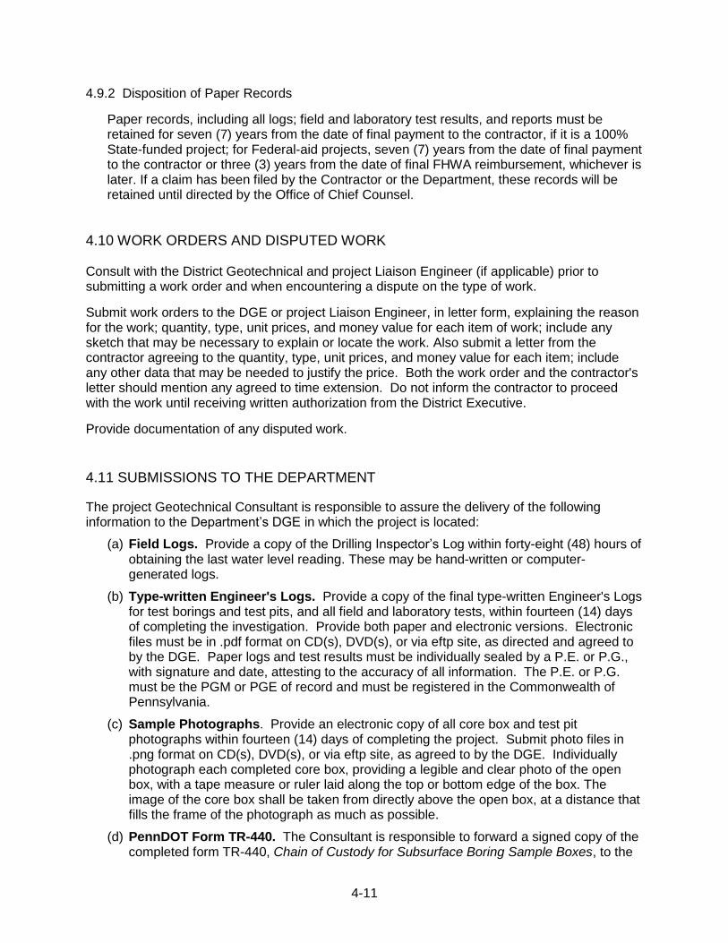
4-11
4.9.2 Disposition of Paper Records
Paper records, including all logs; field and laboratory test results, and reports must be retained for seven (7) years from the date of final payment to the contractor, if it is a 100% State-funded project; for Federal-aid projects, seven (7) years from the date of final payment to the contractor or three (3) years from the date of final FHWA reimbursement, whichever is later. If a claim has been filed by the Contractor or the Department, these records will be retained until directed by the Office of Chief Counsel.
4.10 WORK ORDERS AND DISPUTED WORK Consult with the District Geotechnical and project Liaison Engineer (if applicable) prior to submitting a work order and when encountering a dispute on the type of work.
Submit work orders to the DGE or project Liaison Engineer, in letter form, explaining the reason for the work; quantity, type, unit prices, and money value for each item of work; include any sketch that may be necessary to explain or locate the work. Also submit a letter from the contractor agreeing to the quantity, type, unit prices, and money value for each item; include any other data that may be needed to justify the price. Both the work order and the contractor's letter should mention any agreed to time extension. Do not inform the contractor to proceed with the work until receiving written authorization from the District Executive.
Provide documentation of any disputed work.
4.11 SUBMISSIONS TO THE DEPARTMENT The project Geotechnical Consultant is responsible to assure the delivery of the following information to the Department‟s DGE in which the project is located:
(a) Field Logs. Provide a copy of the Drilling Inspector‟s Log within forty-eight (48) hours of obtaining the last water level reading. These may be hand-written or computer-generated logs.
(b) Type-written Engineer's Logs. Provide a copy of the final type-written Engineer's Logs for test borings and test pits, and all field and laboratory tests, within fourteen (14) days of completing the investigation. Provide both paper and electronic versions. Electronic files must be in .pdf format on CD(s), DVD(s), or via eftp site, as directed and agreed to by the DGE. Paper logs and test results must be individually sealed by a P.E. or P.G., with signature and date, attesting to the accuracy of all information. The P.E. or P.G. must be the PGM or PGE of record and must be registered in the Commonwealth of Pennsylvania.
(c) Sample Photographs. Provide an electronic copy of all core box and test pit photographs within fourteen (14) days of completing the project. Submit photo files in .png format on CD(s), DVD(s), or via eftp site, as agreed to by the DGE. Individually photograph each completed core box, providing a legible and clear photo of the open box, with a tape measure or ruler laid along the top or bottom edge of the box. The image of the core box shall be taken from directly above the open box, at a distance that fills the frame of the photograph as much as possible.
(d) PennDOT Form TR-440. The Consultant is responsible to forward a signed copy of the completed form TR-440, Chain of Custody for Subsurface Boring Sample Boxes, to the
4-12
DGE within seven (7) days of delivery of boxes to the PennDOT storage facility. The Consultant shall attach to the TR-440 an itemized, signed listing of all core boxes delivered. Blank TR-440 forms can be obtained by contacting the DGE office.
(e) Other Records. Provide a copy of any correspondence, records, notes, tabular forms, etc. developed during the investigation, and any other information that the Department considers necessary for its records. Provide files on paper, CD(s), DVD(s), or via eftp site, as directed by the DGE.
The Consultant shall submit the following electronic files on CD(s) or DVD(s) to the Department‟s CGE within fourteen (14) days of completion of the investigation, testing, or report:
(a) Logs and Material Tests. Include all Engineer‟s Logs, field testing results, and laboratory testing results. Files must be in .pdf format.
(b) Sample Photographs. Include all test pit and core box photographs. Files must be in .png format.
(c) Cover letter. Include paper cover letter and electronic file on disk that lists the full contents of the disk(s). Letter must be in .doc or .pdf format. Letter must be sealed by a P.E. or P.G., with signature and date, attesting to the accuracy of all information. The P.E. or P.G. must be the must be the PGM or PGE of record and must be a licensed professional engineer or licensed professional geologist in the Commonwealth of Pennsylvania.
5-1
SUBCHAPTER 5A - INSTRUCTIONS TO BIDDERS
Chapter 5 - SBST CONTRACT DOCUMENTS
5-2
INSTRUCTIONS TO BIDDERS
SUBSURFACE BORING, SAMPLING, AND TESTING CONTRACT
For
_________________________________________
_________________________________________
_________________________________________
Issued by
_________________________________________
_________________________________________
_________________________________________
Dated
ARTICLE A - GENERAL Section A-1 - The following instructions are for the information and guidance of Contractors submitting a proposal for the subject Subsurface Boring, Sampling and Testing Contract. Section A-2 - Definitions. The term "PGM" referred to in the Contract Documents is the party issuing these Instructions to Bidders and is under contract with the Pennsylvania Department of Transportation (hereinafter referred to as the "Department") in regard to the completion of the subject Subsurface Boring, Sampling, and Testing Contract. If issued by the Department, the Department will also be considered as the PGM. All other parties are as defined in the Standard Specifications for Subsurface Boring, Sampling, and Testing. Section A-3 - The Contract Documents shall consist of the Instructions to Bidders; the Form of Proposal; the Contract Agreement; the Standard Specifications for Subsurface Boring, Sampling, and Testing; the Plan and Location of Borings; the Attachments; and all subsequent addenda and modifications. These documents are essential parts of this Contract and are intended to be complementary and to describe and provide for the complete Work. A requirement occurring in one document is as binding as though occurring in all. In case of discrepancy, the document requiring the most demanding and costly alternative for the Contractor shall be given priority when bidding.
5-3
ARTICLE B - LOCATION OF BORINGS
Section B-1 - The test boring locations for the subject Subsurface Boring, Sampling,
and Testing Contract are indicated in the attached plans entitled, "Plan and Location of Borings,
_________________________________________________________”, prepared by
_____________________________________________________________________ and
dated ____________________________.
ARTICLE C - SCOPE OF WORK Section C-1 - The estimated work item quantities for this test boring program are set forth in the Schedule of Proposed Borings, Attachment I and in the Form of Proposal. These quantities are estimates only. The quantities stipulated in the Form of Proposal have been issued for the purpose of comparing bids and, as such, are subject to change by the PGM. The approximate locations of the test borings are presented in the Plan and Location of Borings referenced in Section B-1 above. The actual locations and depths of undisturbed soil samples, special field tests, and/or borehole instrumentation will be determined by the PGM during the course of the drilling operations. Section C-2 - The Contractor will be required to provide no fewer than ________ and no more than _______ fully equipped, operating and manned drilling machines per work shift for work on this Contract with a minimum full-time crew of two persons per rig, including one qualified driller and one helper. The PGM and/or Contractor may request additional rigs if mutually agreeable. The maximum recall time will not exceed six (6) months. Section C-3 - The original handwritten driller's field log for each boring must be submitted to the PGM at the completion of the boring.
5-4
ARTICLE D - SUBMISSION AND COMPARISON OF PROPOSALS
Section D-1 - Submit two (2) copies (both copies with original signatures) of the executed Form
of Proposal and Contract Agreement to:
Commonwealth of Pennsylvania Department of Transportation District ________________ ___________________________ ___________________________ ___________________________
before _________ a.m., p.m. prevailing time, on ____________________________. Proposals will be opened and read at __________ a.m., p.m. of the same day in the District Office of the Department. Seal the proposal in an envelope plainly marked with the Bidder's name and address, and as follows:
BID DOCUMENTS:
SUBSURFACE BORING, SAMPLING, AND TESTING CONTRACT FOR _____________________________________________ _____________________________________________ _____________________________________________
To be Opened: _______________________________
At ____________ a.m., p.m. Section D-2 - Enclose a proposal guaranty of ten (10) percent of the PROPOSED TOTAL COST OF CONTRACT, but not less than $50.00, with the proposal as a guaranty that in the event the proposal is accepted and a Contract awarded, the Contract will be duly executed and its performance duly secured by the required Contract Bond and Additional Bond for Labor and Materials. The proposal guaranty shall be in the form of a Cashier's Check, a Treasurer's Check, a Certified Check, a Letter of Credit, or a Proposal Guaranty Bond with surety made out to ______________________, in the amount specified after the words "Amount of Proposal Guaranty" as shown in the Form of Proposal. Where the bidder does not comply with his proposal and does not provide a Contract Bond and an Additional Bond for Labor and Materials within a period of thirty (30) calendar days, if award is made to him, the proceeds of the Cashier's, Treasurer's, or Certified check or Proposal Guaranty Bond submitted as a proposal guaranty with his proposal will be forfeited to the use of the PGM as liquidated damages. All proposal guarantees will be returned when the successful Contractor has executed a contract and has submitted a Contract Bond and an Additional Bond for Labor and Materials. Section D-3 - Execute and return with the proposal "Affidavit Accepting Provisions of the Workmen's Compensation Act" which is described in Article J-3 and is included as Attachment IV of these Instructions to Bidders. Section D-4 - The bidder to whom the Contract is awarded will be required to execute a "Contract Bond," covering satisfactory performance of the work contracted, in the penal sum of
5-5
1/2 (50%) of the amount of the Contract, and an "Additional Bond for Labor and Materials," covering the prompt payment in full for utility services rendered and for all materials furnished and/or labor supplied or performed in the prosecution of the work, also in the penal sum of 1/2 (50%) of the amount of the Contract. Both bonds must also be executed by a corporate surety satisfactory to the PGM. The same surety must execute both bonds and should any surety upon such bonds become unsatisfactory to the PGM, the Contractor must promptly furnish such additional security as may be required from time to time to protect the interests of the PGM, the Department and of persons, firms or corporations supplying utility services, materials, and/or labor in the prosecution of the work contemplated by the Contract. The cost of these bonds shall be entered as the Fee for Contract Bond and Additional Bond for Labor and Materials presented in the Form of Proposal.
Section D-5 - The PGM reserves the right to reject any and all bids, to waive technical defects and to accept or reject any part of any bid, if in the PGM‟s judgment, the PGM's and Department's best interests will be served thereby. In acting on proposals, cash discounts will not be considered. Section D-6 - The proposal as made will be deemed an offer which may be accepted by the PGM at any time within sixty (60) days after bids are opened. When the proposal has been accepted by the PGM, the Contract Agreement will be executed by the PGM and the successful bidder shall be the "Contractor." No other Contract Documents will be executed by the PGM. ARTICLE E - EQUAL EMPLOYMENT OPPORTUNITY AND NON-DISCRIMINATION Section E-1 - The Contractor shall abide by the requirements for equal employment opportunity and non-discrimination set forth in Publication 408, Appendix C, Designated Special Provisions 10, 11 and 12 (DSP 10, 11 & 12). ARTICLE F - DISADVANTAGED BUSINESS ENTERPRISES Section F-1 - In connection with the performance of the Contract, the Contractor will be required to take affirmative action in regard to utilization of disadvantaged business enterprises and will use his best efforts to ensure that disadvantaged business enterprises will have the maximum practicable opportunity to compete for subcontract work under this Contract. The Contractor shall execute and submit with the proposal the requirements set forth in Publication 408, Appendix C - Designated Special Provisions 7 and 10 (DSP 7 & 10) ARTICLE G - IDENTIFICATION OF SAMPLES AND DOCUMENTS Section G-1 - All samples, reports and other documents obtained or prepared as a part of this Contract will include the following identification on the label, front cover, or title page in addition to other information required in the Standard Specifications for Subsurface Boring, Sampling and Testing: ____________________________________________________________________________ ____________________________________________________________________________
5-6
ARTICLE H - DISPOSITION OF SAMPLES Section H-1 - The contractor is required to remove, at his expense, all samples and core boxes from the job site at the end of each work shift and provide storage until such time as they are delivered by the contractor to the designated locations. The storage facilities must conform to the requirements set forth in the Standard Specifications for Subsurface Boring, Sampling, and Testing, Section 215, Packaging, Protection and Shipment of Samples. After completion of all test borings, the Contractor will be required to deliver, at his expense, all soil samples and rock core boxes to: ____________________________________________________________________________ ____________________________________________________________________________ ____________________________________________________________________________ Section H-2 - After completion of all test borings, and during the delivery procedures, each party responsible for identification and custody of the core boxes is required to fill out the appropriate section of the PennDOT Form No. TR-440, "Chain of Custody for Subsurface Boring Sample Boxes". The PGM will be responsible to provide this form to the successful low bidder at the beginning of the project. The forms can be obtained from the PennDOT District office. ARTICLE I - MANDATORY PRE-BID MEETING Unless otherwise specified by the DGE, a drilling project requires a mandatory pre-bid field meeting. Only PennDOT pre-qualified drilling contractors that attend the mandatory pre-bid meeting may bid on the project. When the pre-bid meeting requirement is waived by the DGE, any PennDOT pre-qualified drilling contractor may bid on the project.
A representative of the PGM will be available to accompany the bidders on a field view of the
project area on __________________________, at _________ a.m., p.m. prevailing time. The
meeting location will be at _______________________________________. If you plan to
attend this field view, please signify so by calling _____________________________________,
at ____________________, before ____________________________________________.
Pre-bid minutes and agenda will be provided to the drillers in attendance, no later than five (5)
working days before the bid opening. Pre-bid minutes will be an addendum to the Contract.
5-7
ARTICLE J - INSURANCE AND LIABILITY Section J-1 - Limits of Coverage. The Contractor must procure and/or maintain at its expense the insurance coverage stipulated in the Standard Specifications for Subsurface Boring, Sampling, and Testing, all with limitations of not less than:
TYPE OF COVERAGE LIMITS OF LIABILITY
REQUIRED MINIMUM COVERAGE
Bodily Injury Aggregate $1,000,000
Property Damage Aggregate $1,000,000
Automobile Liability (Bodily Injury) Aggregate $1,000,000
Automobile Liability (Property Damage) Aggregate $1,000,000
Workmen's Compensation As Required By Applicable Law
Employer's Liability Aggregate $1,000,000
Umbrella Liability (Bodily Injury and Property Damage Combined)
Aggregate $1,000,000
Section J-2 - Additional Insurers. The PGM, _______________________________________, and the Department shall be named as additional insured under the above said Bodily Injury and Property Damage Insurance policies by endorsement thereto and such insurance shall be primary to any other insurance maintained by the PGM or the Department. Section J-3 - Workmen's Compensation. Execute and return with the proposal the "Affidavit Accepting Provisions of the Workmen's Compensation Act" which is included as Attachment IV to these Instructions to Bidders, to signify acceptance of the provisions of the Workmen's Compensation Act. ARTICLE K - MODIFICATIONS TO THE STANDARD SPECIFICATIONS FOR SUBSURFACE BORING, SAMPLING, AND TESTING Section K-1 - Attachment II to these instructions defines specific modifications or additions to be included as part of the Standard Specifications for Subsurface Boring, Sampling, and Testing for this Contract. ARTICLE L -SCHEDULE FOR WORK ON RAILROAD RIGHT-OF-WAY Section L-1 - Attachment III to these instructions explains the requirements for a defined schedule for work on Railroad Right-of-Way. Borings and drilling quantities to be completed within the Railroad Right-of-Way should be included with the defined schedule.
5-8
SUBCHAPTER 5B - CONTRACT ATTACHMENTS
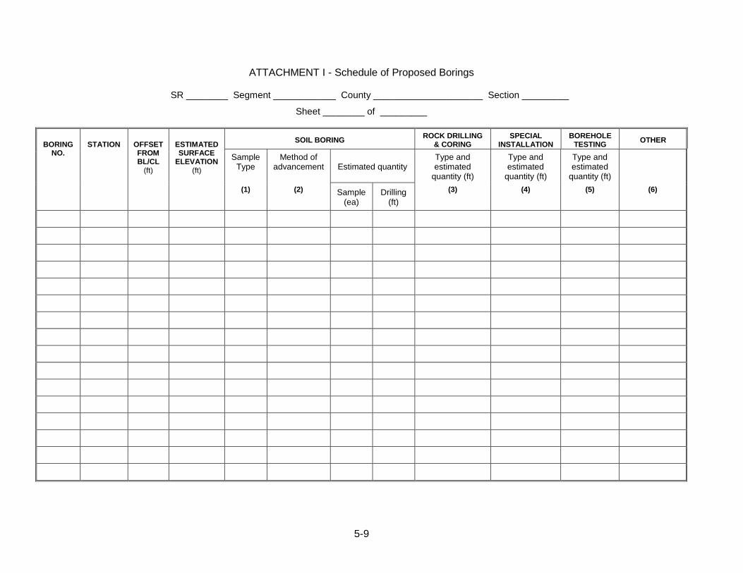
5-9
ATTACHMENT I - Schedule of Proposed Borings
SR ________ Segment ____________ County _____________________ Section _________
Sheet ________ of _________
BORING
NO.
STATION
OFFSET FROM BL/CL
(ft)
ESTIMATED SURFACE
ELEVATION (ft)
SOIL BORING ROCK DRILLING
& CORING SPECIAL
INSTALLATION BOREHOLE
TESTING OTHER
Sample Type
Method of advancement
Estimated quantity
Type and estimated
quantity (ft)
Type and estimated
quantity (ft)
Type and estimated
quantity (ft)
(1) (2) Sample (ea)
Drilling (ft)
(3) (4) (5) (6)
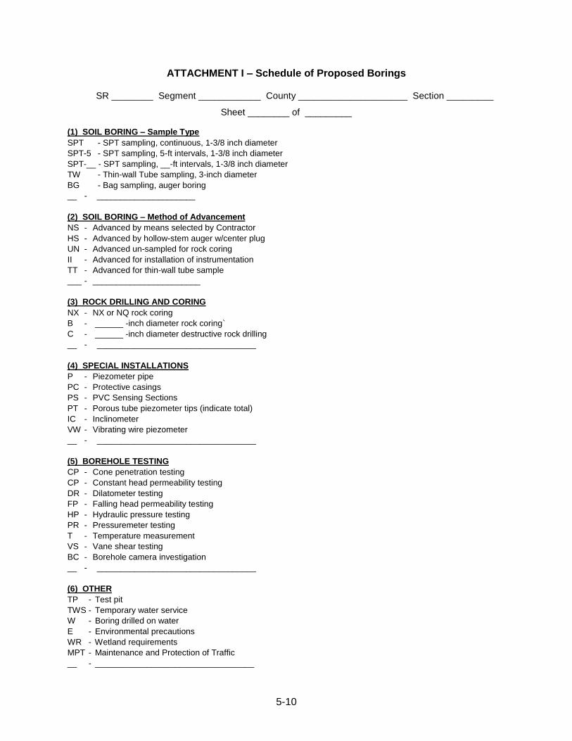
5-10
ATTACHMENT I – Schedule of Proposed Borings
SR ________ Segment ____________ County _____________________ Section _________
Sheet ________ of _________ (1) SOIL BORING – Sample Type
SPT - SPT sampling, continuous, 1-3/8 inch diameter
SPT-5 - SPT sampling, 5-ft intervals, 1-3/8 inch diameter
SPT-__ - SPT sampling, __-ft intervals, 1-3/8 inch diameter
TW - Thin-wall Tube sampling, 3-inch diameter
BG - Bag sampling, auger boring
__ - _____________________
(2) SOIL BORING – Method of Advancement
NS - Advanced by means selected by Contractor
HS - Advanced by hollow-stem auger w/center plug
UN - Advanced un-sampled for rock coring
II - Advanced for installation of instrumentation
TT - Advanced for thin-wall tube sample
___ - _______________________
(3) ROCK DRILLING AND CORING
NX - NX or NQ rock coring
B - ______ -inch diameter rock coring`
C - ______ -inch diameter destructive rock drilling
__ - __________________________________
(4) SPECIAL INSTALLATIONS
P - Piezometer pipe
PC - Protective casings
PS - PVC Sensing Sections
PT - Porous tube piezometer tips (indicate total)
IC - Inclinometer
VW - Vibrating wire piezometer
__ - __________________________________
(5) BOREHOLE TESTING
CP - Cone penetration testing
CP - Constant head permeability testing
DR - Dilatometer testing
FP - Falling head permeability testing
HP - Hydraulic pressure testing
PR - Pressuremeter testing
T - Temperature measurement
VS - Vane shear testing
BC - Borehole camera investigation
__ - __________________________________
(6) OTHER
TP - Test pit
TWS - Temporary water service
W - Boring drilled on water
E - Environmental precautions
WR - Wetland requirements
MPT - Maintenance and Protection of Traffic
__ - __________________________________
5-11
ATTACHMENT II - Modifications and Additions to Standard Specifications for SBST Contracts
If necessary, any project-specific modifications or additions to the standard specifications are located here.
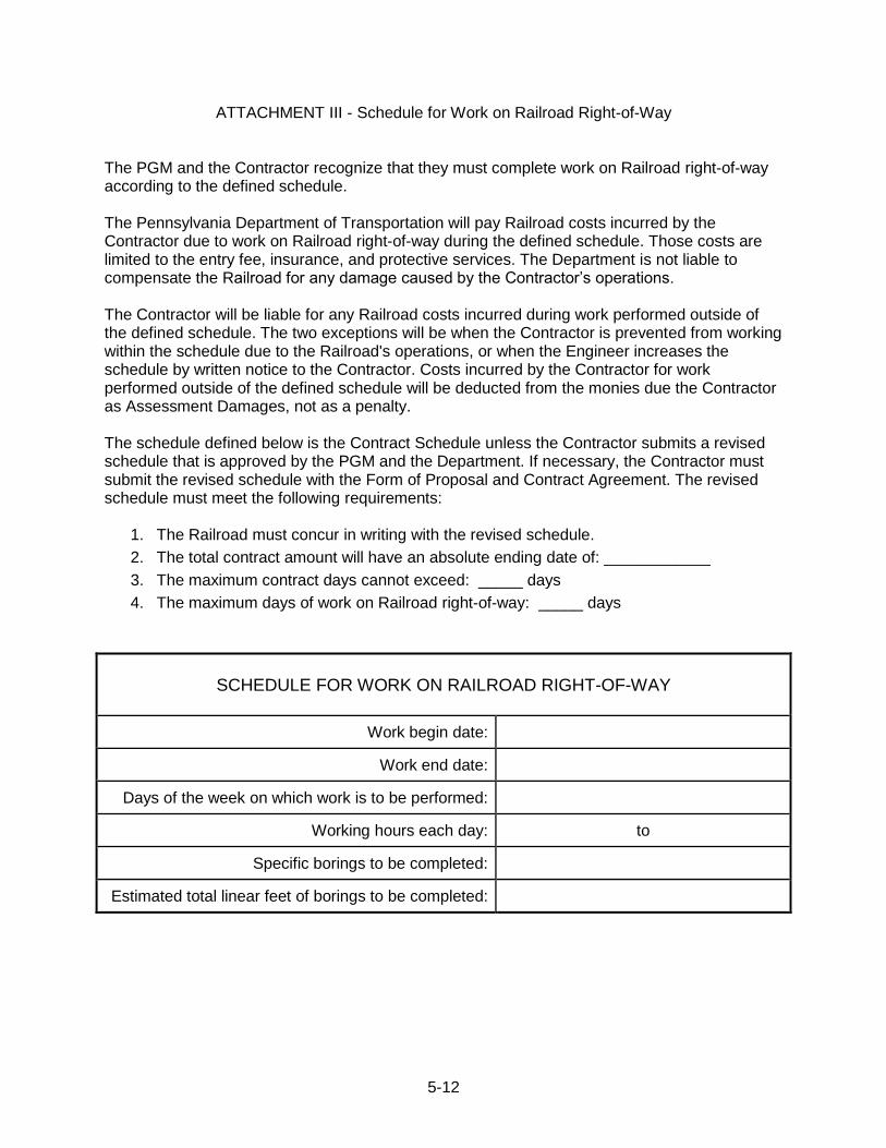
5-12
ATTACHMENT III - Schedule for Work on Railroad Right-of-Way The PGM and the Contractor recognize that they must complete work on Railroad right-of-way according to the defined schedule. The Pennsylvania Department of Transportation will pay Railroad costs incurred by the Contractor due to work on Railroad right-of-way during the defined schedule. Those costs are limited to the entry fee, insurance, and protective services. The Department is not liable to compensate the Railroad for any damage caused by the Contractor‟s operations. The Contractor will be liable for any Railroad costs incurred during work performed outside of the defined schedule. The two exceptions will be when the Contractor is prevented from working within the schedule due to the Railroad's operations, or when the Engineer increases the schedule by written notice to the Contractor. Costs incurred by the Contractor for work performed outside of the defined schedule will be deducted from the monies due the Contractor as Assessment Damages, not as a penalty. The schedule defined below is the Contract Schedule unless the Contractor submits a revised schedule that is approved by the PGM and the Department. If necessary, the Contractor must submit the revised schedule with the Form of Proposal and Contract Agreement. The revised schedule must meet the following requirements:
1. The Railroad must concur in writing with the revised schedule.
2. The total contract amount will have an absolute ending date of: ____________
3. The maximum contract days cannot exceed: _____ days
4. The maximum days of work on Railroad right-of-way: _____ days
SCHEDULE FOR WORK ON RAILROAD RIGHT-OF-WAY
Work begin date:
Work end date:
Days of the week on which work is to be performed:
Working hours each day: to
Specific borings to be completed:
Estimated total linear feet of borings to be completed:
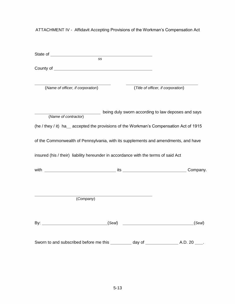
5-13
ATTACHMENT IV - Affidavit Accepting Provisions of the Workman‟s Compensation Act State of ss County of (Name of officer, if corporation) (Title of officer, if corporation) being duly sworn according to law deposes and says (Name of contractor) (he / they / it) ha accepted the provisions of the Workman‟s Compensation Act of 1915 of the Commonwealth of Pennsylvania, with its supplements and amendments, and have insured (his / their) liability hereunder in accordance with the terms of said Act with its Company. (Company) By: (Seal) (Seal) Sworn to and subscribed before me this day of A.D. 20 .
5-14
SUBCHAPTER 5C - FORM OF PROPOSAL
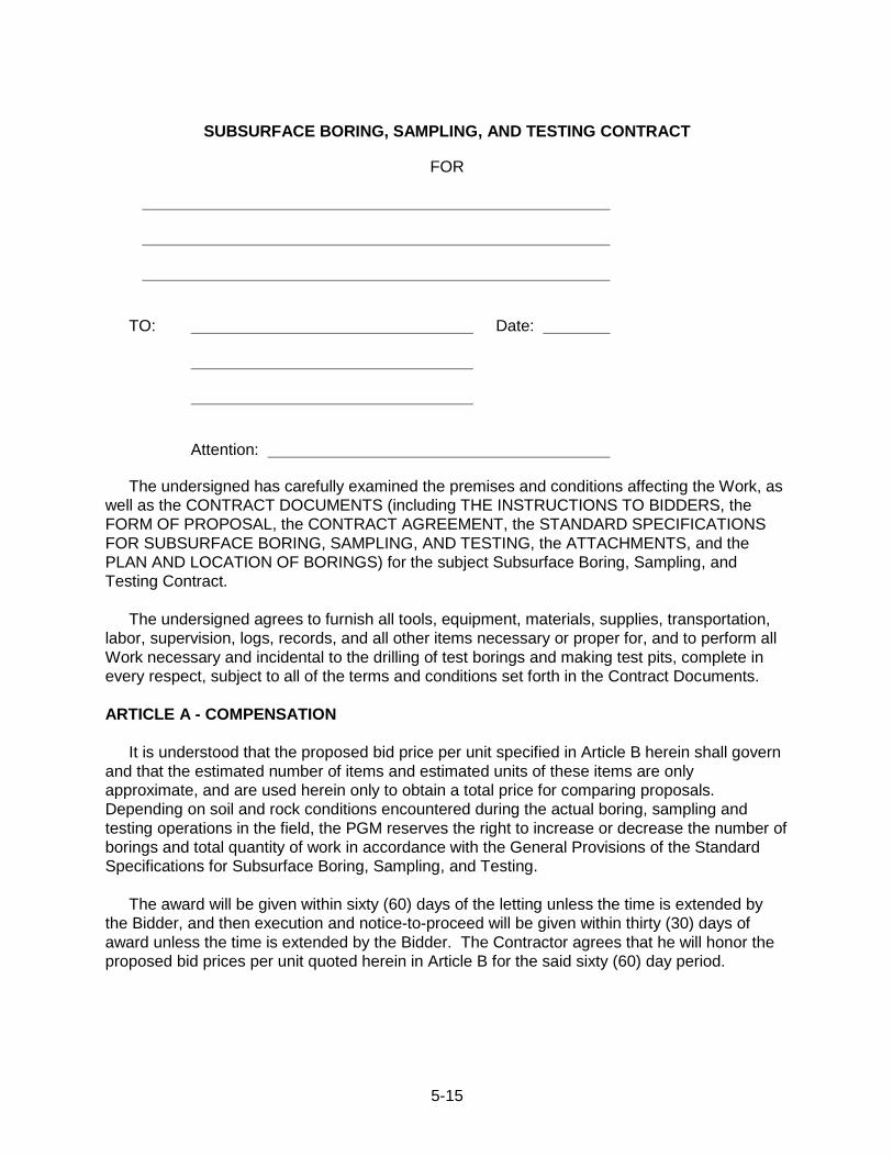
5-15
SUBSURFACE BORING, SAMPLING, AND TESTING CONTRACT
FOR
TO: Date:
Attention:
The undersigned has carefully examined the premises and conditions affecting the Work, as
well as the CONTRACT DOCUMENTS (including THE INSTRUCTIONS TO BIDDERS, the
FORM OF PROPOSAL, the CONTRACT AGREEMENT, the STANDARD SPECIFICATIONS
FOR SUBSURFACE BORING, SAMPLING, AND TESTING, the ATTACHMENTS, and the
PLAN AND LOCATION OF BORINGS) for the subject Subsurface Boring, Sampling, and
Testing Contract.
The undersigned agrees to furnish all tools, equipment, materials, supplies, transportation,
labor, supervision, logs, records, and all other items necessary or proper for, and to perform all
Work necessary and incidental to the drilling of test borings and making test pits, complete in
every respect, subject to all of the terms and conditions set forth in the Contract Documents.
ARTICLE A - COMPENSATION
It is understood that the proposed bid price per unit specified in Article B herein shall govern
and that the estimated number of items and estimated units of these items are only
approximate, and are used herein only to obtain a total price for comparing proposals.
Depending on soil and rock conditions encountered during the actual boring, sampling and
testing operations in the field, the PGM reserves the right to increase or decrease the number of
borings and total quantity of work in accordance with the General Provisions of the Standard
Specifications for Subsurface Boring, Sampling, and Testing.
The award will be given within sixty (60) days of the letting unless the time is extended by
the Bidder, and then execution and notice-to-proceed will be given within thirty (30) days of
award unless the time is extended by the Bidder. The Contractor agrees that he will honor the
proposed bid prices per unit quoted herein in Article B for the said sixty (60) day period.
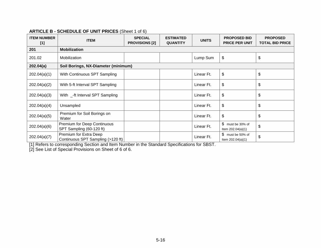
5-16
ARTICLE B - SCHEDULE OF UNIT PRICES (Sheet 1 of 6)
ITEM NUMBER
[1] ITEM
SPECIAL
PROVISIONS [2]
ESTIMATED
QUANTITY UNITS
PROPOSED BID
PRICE PER UNIT
PROPOSED
TOTAL BID PRICE
201 Mobilization
201.02 Mobilization Lump Sum $ $
202.04(a) Soil Borings, NX-Diameter (minimum)
202.04(a)(1) With Continuous SPT Sampling Linear Ft. $ $
202.04(a)(2) With 5-ft Interval SPT Sampling Linear Ft. $ $
202.04(a)(3) With _-ft Interval SPT Sampling Linear Ft. $ $
202.04(a)(4) Unsampled Linear Ft. $ $
202.04(a)(5) Premium for Soil Borings on
Water Linear Ft. $ $
202.04(a)(6) Premium for Deep Continuous
SPT Sampling (60-120 ft) Linear Ft.
$ must be 30% of
Item 202.04(a)(1) $
202.04(a)(7) Premium for Extra Deep
Continuous SPT Sampling (>120 ft) Linear Ft.
$ must be 50% of
Item 202.04(a)(1) $
[1] Refers to corresponding Section and Item Number in the Standard Specifications for SBST. [2] See List of Special Provisions on Sheet of 6 of 6.
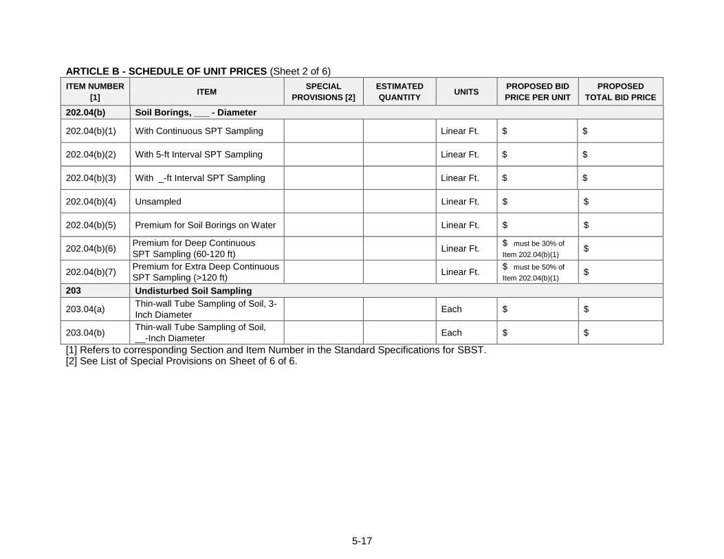
5-17
ARTICLE B - SCHEDULE OF UNIT PRICES (Sheet 2 of 6)
ITEM NUMBER
[1] ITEM
SPECIAL
PROVISIONS [2]
ESTIMATED
QUANTITY UNITS
PROPOSED BID
PRICE PER UNIT
PROPOSED
TOTAL BID PRICE
202.04(b) Soil Borings, ___ - Diameter
202.04(b)(1) With Continuous SPT Sampling Linear Ft. $ $
202.04(b)(2) With 5-ft Interval SPT Sampling Linear Ft. $ $
202.04(b)(3) With _-ft Interval SPT Sampling Linear Ft. $ $
202.04(b)(4) Unsampled Linear Ft. $ $
202.04(b)(5) Premium for Soil Borings on Water Linear Ft. $ $
202.04(b)(6) Premium for Deep Continuous
SPT Sampling (60-120 ft) Linear Ft.
$ must be 30% of
Item 202.04(b)(1) $
202.04(b)(7) Premium for Extra Deep Continuous
SPT Sampling (>120 ft) Linear Ft.
$ must be 50% of
Item 202.04(b)(1) $
203 Undisturbed Soil Sampling
203.04(a) Thin-wall Tube Sampling of Soil, 3-
Inch Diameter Each $ $
203.04(b) Thin-wall Tube Sampling of Soil,
__-Inch Diameter Each $ $
[1] Refers to corresponding Section and Item Number in the Standard Specifications for SBST. [2] See List of Special Provisions on Sheet of 6 of 6.
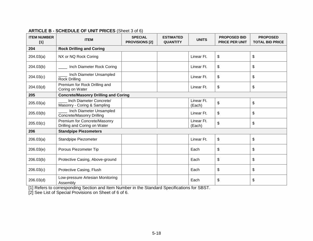
5-18
ARTICLE B - SCHEDULE OF UNIT PRICES (Sheet 3 of 6)
ITEM NUMBER
[1] ITEM
SPECIAL
PROVISIONS [2]
ESTIMATED
QUANTITY UNITS
PROPOSED BID
PRICE PER UNIT
PROPOSED
TOTAL BID PRICE
204 Rock Drilling and Coring
204.03(a) NX or NQ Rock Coring Linear Ft. $ $
204.03(b) ____ Inch Diameter Rock Coring Linear Ft. $ $
204.03(c) ____ Inch Diameter Unsampled Rock Drilling
Linear Ft. $ $
204.03(d) Premium for Rock Drilling and Coring on Water
Linear Ft. $ $
205 Concrete/Masonry Drilling and Coring
205.03(a) ____ Inch Diameter Concrete/ Masonry - Coring & Sampling
Linear Ft.
(Each) $ $
205.03(b) ____ Inch Diameter Unsampled Concrete/Masonry Drilling
Linear Ft. $ $
205.03(c) Premium for Concrete/Masonry Drilling and Coring on Water
Linear Ft.
(Each) $ $
206 Standpipe Piezometers
206.03(a) Standpipe Piezometer Linear Ft. $ $
206.03(e) Porous Piezometer Tip Each $ $
206.03(b) Protective Casing, Above-ground Each $ $
206.03(c) Protective Casing, Flush Each $ $
206.03(d) Low-pressure Artesian Monitoring
Assembly Each $ $
[1] Refers to corresponding Section and Item Number in the Standard Specifications for SBST. [2] See List of Special Provisions on Sheet of 6 of 6.
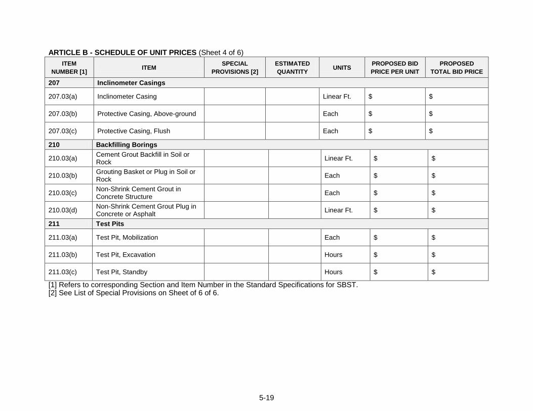
5-19
ARTICLE B - SCHEDULE OF UNIT PRICES (Sheet 4 of 6)
ITEM
NUMBER [1] ITEM
SPECIAL
PROVISIONS [2]
ESTIMATED
QUANTITY UNITS
PROPOSED BID
PRICE PER UNIT
PROPOSED
TOTAL BID PRICE
207 Inclinometer Casings
207.03(a) Inclinometer Casing Linear Ft. $ $
207.03(b) Protective Casing, Above-ground Each $ $
207.03(c) Protective Casing, Flush Each $ $
210 Backfilling Borings
210.03(a) Cement Grout Backfill in Soil or Rock
Linear Ft. $ $
210.03(b) Grouting Basket or Plug in Soil or Rock
Each $ $
210.03(c) Non-Shrink Cement Grout in Concrete Structure
Each $ $
210.03(d) Non-Shrink Cement Grout Plug in Concrete or Asphalt
Linear Ft. $ $
211 Test Pits
211.03(a) Test Pit, Mobilization Each $ $
211.03(b) Test Pit, Excavation Hours $ $
211.03(c) Test Pit, Standby Hours $ $
[1] Refers to corresponding Section and Item Number in the Standard Specifications for SBST. [2] See List of Special Provisions on Sheet of 6 of 6.
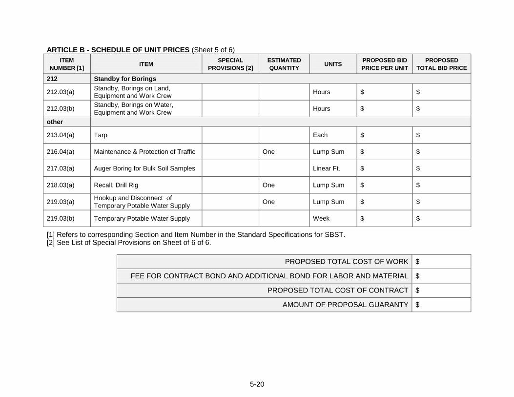
5-20
ARTICLE B - SCHEDULE OF UNIT PRICES (Sheet 5 of 6)
ITEM
NUMBER [1] ITEM
SPECIAL
PROVISIONS [2]
ESTIMATED
QUANTITY UNITS
PROPOSED BID
PRICE PER UNIT
PROPOSED
TOTAL BID PRICE
212 Standby for Borings
212.03(a) Standby, Borings on Land, Equipment and Work Crew
Hours $ $
212.03(b) Standby, Borings on Water,
Equipment and Work Crew Hours $ $
other
213.04(a) Tarp Each $ $
216.04(a) Maintenance & Protection of Traffic One Lump Sum $ $
217.03(a) Auger Boring for Bulk Soil Samples Linear Ft. $ $
218.03(a) Recall, Drill Rig One Lump Sum $ $
219.03(a) Hookup and Disconnect of
Temporary Potable Water Supply One Lump Sum $ $
219.03(b) Temporary Potable Water Supply Week $ $
[1] Refers to corresponding Section and Item Number in the Standard Specifications for SBST. [2] See List of Special Provisions on Sheet of 6 of 6.
PROPOSED TOTAL COST OF WORK $
FEE FOR CONTRACT BOND AND ADDITIONAL BOND FOR LABOR AND MATERIAL $
PROPOSED TOTAL COST OF CONTRACT $
AMOUNT OF PROPOSAL GUARANTY $
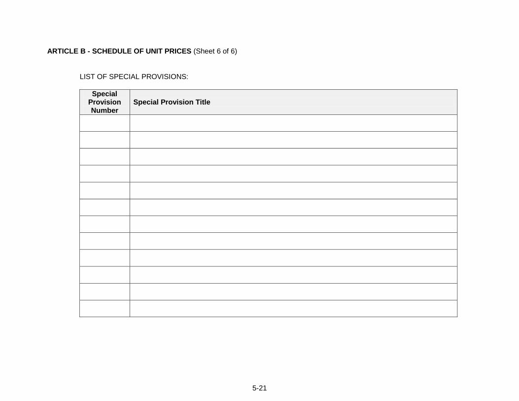
5-21
ARTICLE B - SCHEDULE OF UNIT PRICES (Sheet 6 of 6)
LIST OF SPECIAL PROVISIONS:
Special Provision Number
Special Provision Title
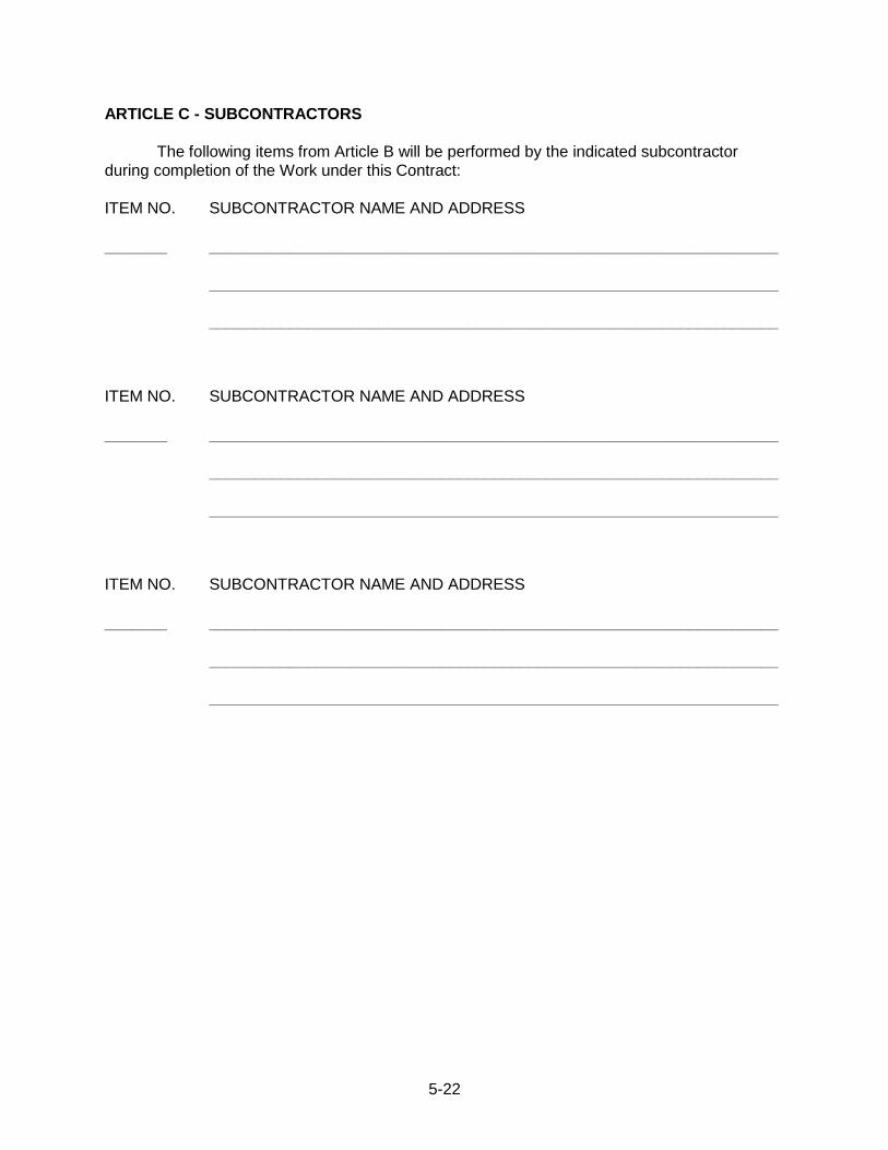
5-22
ARTICLE C - SUBCONTRACTORS
The following items from Article B will be performed by the indicated subcontractor
during completion of the Work under this Contract:
ITEM NO. SUBCONTRACTOR NAME AND ADDRESS
_______ ________________________________________________________________
________________________________________________________________
________________________________________________________________
ITEM NO. SUBCONTRACTOR NAME AND ADDRESS
_______ ________________________________________________________________
________________________________________________________________
________________________________________________________________
ITEM NO. SUBCONTRACTOR NAME AND ADDRESS
_______ ________________________________________________________________
________________________________________________________________
________________________________________________________________
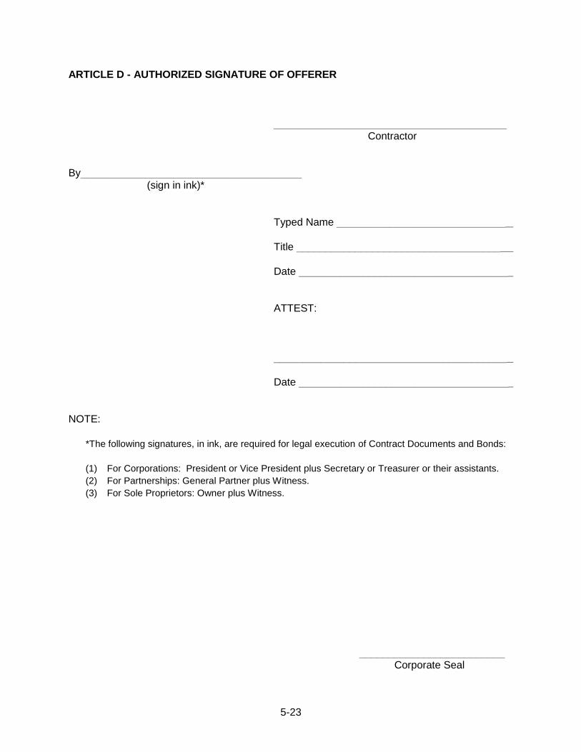
5-23
ARTICLE D - AUTHORIZED SIGNATURE OF OFFERER
________________________________________
Contractor
By______________________________________
(sign in ink)*
Typed Name _____________________________
Title ___________________________________
Date ____________________________________
ATTEST:
________________________________________
Date ____________________________________
NOTE:
*The following signatures, in ink, are required for legal execution of Contract Documents and Bonds:
(1) For Corporations: President or Vice President plus Secretary or Treasurer or their assistants.
(2) For Partnerships: General Partner plus Witness.
(3) For Sole Proprietors: Owner plus Witness.
_________________________
Corporate Seal

5-24
SUBCHAPTER 5D - CONTRACT AGREEMENTS
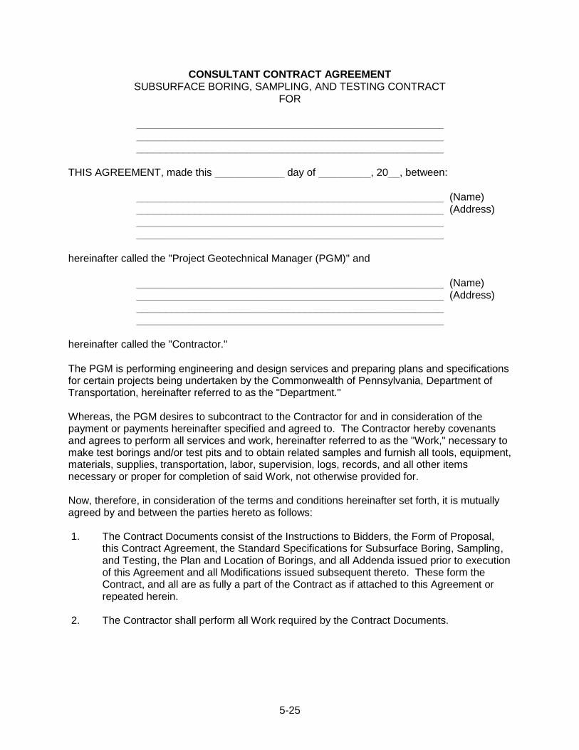
5-25
CONSULTANT CONTRACT AGREEMENT
SUBSURFACE BORING, SAMPLING, AND TESTING CONTRACT
FOR
_____________________________________________________
_____________________________________________________ _____________________________________________________
THIS AGREEMENT, made this ____________ day of _________, 20__, between:
_____________________________________________________ (Name)
_____________________________________________________ (Address)
_____________________________________________________
_____________________________________________________
hereinafter called the "Project Geotechnical Manager (PGM)" and
_____________________________________________________ (Name) _____________________________________________________ (Address)
_____________________________________________________
_____________________________________________________
hereinafter called the "Contractor."
The PGM is performing engineering and design services and preparing plans and specifications for certain projects being undertaken by the Commonwealth of Pennsylvania, Department of Transportation, hereinafter referred to as the "Department." Whereas, the PGM desires to subcontract to the Contractor for and in consideration of the payment or payments hereinafter specified and agreed to. The Contractor hereby covenants and agrees to perform all services and work, hereinafter referred to as the "Work," necessary to make test borings and/or test pits and to obtain related samples and furnish all tools, equipment, materials, supplies, transportation, labor, supervision, logs, records, and all other items necessary or proper for completion of said Work, not otherwise provided for. Now, therefore, in consideration of the terms and conditions hereinafter set forth, it is mutually agreed by and between the parties hereto as follows: 1. The Contract Documents consist of the Instructions to Bidders, the Form of Proposal,
this Contract Agreement, the Standard Specifications for Subsurface Boring, Sampling, and Testing, the Plan and Location of Borings, and all Addenda issued prior to execution of this Agreement and all Modifications issued subsequent thereto. These form the Contract, and all are as fully a part of the Contract as if attached to this Agreement or repeated herein.
2. The Contractor shall perform all Work required by the Contract Documents.

5-26
3. The Work to be performed under this Contract shall be completed within _________ calendar days from the date of notice from the PGM to proceed with the Work. The completion date may be extended with the prior written permission of the PGM for additional or extra work directed by the PGM which is in excess of the Work defined in the Contract Documents, or for suspensions directed by the PGM.
4. The PGM shall pay the Contractor for the Work completed and accepted in accordance
with the Unit Prices or Lump Sums stipulated in the Contractor's Form of Proposal dated ______________.
5. Payment for the completed Work will be made by the PGM in accordance with the terms
and conditions for such compensation as stipulated in the Form of Proposal. 6. If the date of signature of this Agreement by either party is different than that first written
above, the latest date of signature shall apply to the provisions of this Contract. IN WITNESS WHEREOF, the parties hereto have caused these presents to be executed, attested and ensealed by their proper officials, pursuant to due and legal action authorizing the same to be done, the day and year first above written.
PGM Contractor
By ________________________________ By __________________________________
(sign in ink) (sign in ink)
Typed Name ________________________ Typed Name __________________________
Title _____________________________ Title _______
Date ______________________________ Date ________________________________
Attest: ___________________________ Attest: _____________________________
Date ______________________________ Date ________________________________
NOTE:
*The following signatures, in ink, are required for legal execution of Contract Documents and Bonds:
(1) For Corporations: President or Vice President plus Secretary or Treasurer or their assistants.
(2) For Partnerships: General Partner plus Witness.
(3) For Sole Proprietors: Owner plus Witness.
_________________________
Corporate Seal
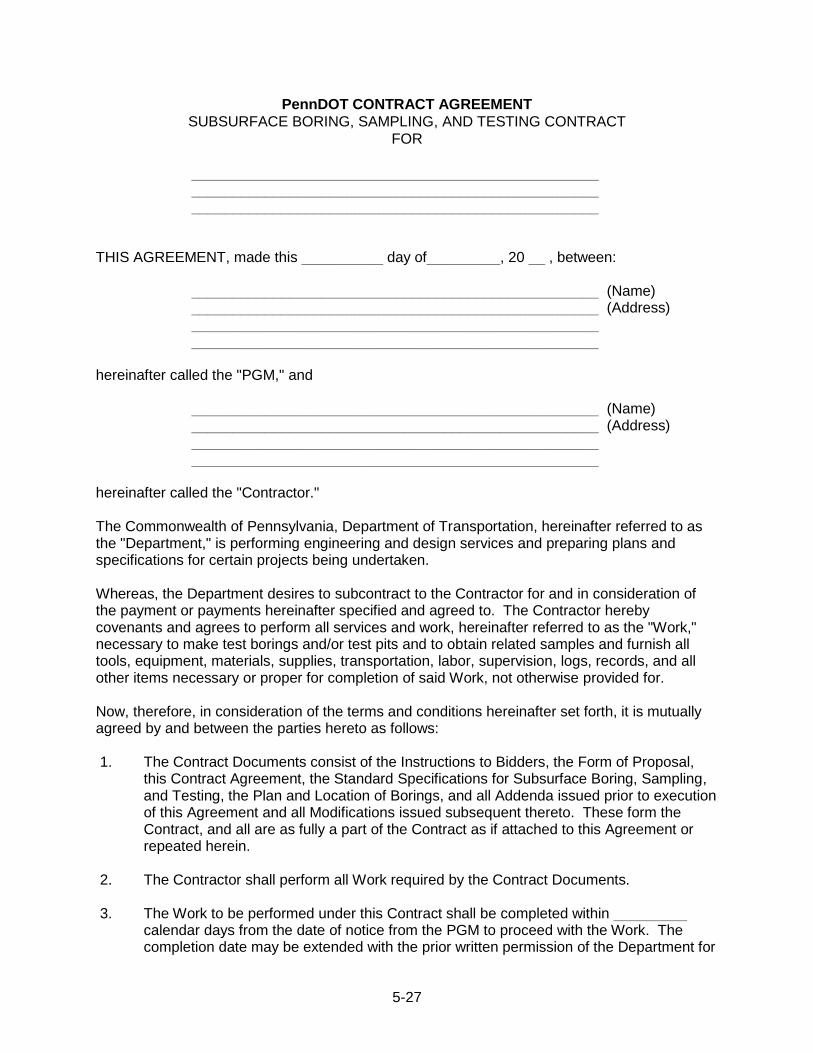
5-27
PennDOT CONTRACT AGREEMENT
SUBSURFACE BORING, SAMPLING, AND TESTING CONTRACT
FOR
__________________________________________________ __________________________________________________ __________________________________________________
THIS AGREEMENT, made this __________ day of_________, 20 __ , between:
__________________________________________________ (Name) __________________________________________________ (Address) __________________________________________________ __________________________________________________
hereinafter called the "PGM," and
__________________________________________________ (Name) __________________________________________________ (Address) __________________________________________________ __________________________________________________
hereinafter called the "Contractor." The Commonwealth of Pennsylvania, Department of Transportation, hereinafter referred to as the "Department," is performing engineering and design services and preparing plans and specifications for certain projects being undertaken. Whereas, the Department desires to subcontract to the Contractor for and in consideration of the payment or payments hereinafter specified and agreed to. The Contractor hereby covenants and agrees to perform all services and work, hereinafter referred to as the "Work," necessary to make test borings and/or test pits and to obtain related samples and furnish all tools, equipment, materials, supplies, transportation, labor, supervision, logs, records, and all other items necessary or proper for completion of said Work, not otherwise provided for. Now, therefore, in consideration of the terms and conditions hereinafter set forth, it is mutually agreed by and between the parties hereto as follows: 1. The Contract Documents consist of the Instructions to Bidders, the Form of Proposal,
this Contract Agreement, the Standard Specifications for Subsurface Boring, Sampling, and Testing, the Plan and Location of Borings, and all Addenda issued prior to execution of this Agreement and all Modifications issued subsequent thereto. These form the Contract, and all are as fully a part of the Contract as if attached to this Agreement or repeated herein.
2. The Contractor shall perform all Work required by the Contract Documents. 3. The Work to be performed under this Contract shall be completed within _________
calendar days from the date of notice from the PGM to proceed with the Work. The completion date may be extended with the prior written permission of the Department for

5-28
additional or extra work directed by the Department which is in excess of the Work defined in the Contract Documents, or for suspensions directed by the Department.
4. The Department shall pay the Contractor for the Work completed and accepted in
accordance with the Unit Prices or Lump Sums stipulated in the Contractor's Form of Proposal dated _____________.
5. Payment for the completed Work will be made by the Department in accordance with the
terms and conditions for such compensation as stipulated in the Form of Proposal. 6. If the date of signature of this Agreement by either party is different than that first written
above, the latest date of signature shall apply to the provisions of this Contract. IN WITNESS WHEREOF, the parties hereto have caused these presents to be executed, attested and ensealed by their proper officials, pursuant to due and legal action authorizing the same to be done, the day and year first above written. _____________________________________ _____________________________________ Department Contractor Typed Name _________________________ Typed Name __________________________ Title ______________________________ Title _______________________________ Date ________________________________ Date ________________________________ ATTEST: ____________________________ ATTEST: _____________________________ ____________________________________ _____________________________________ Date _______________________________ Date ________________________________ Approved as to Legality and Form By __________________________________
Date ________________________________ NOTE: *The following signatures, in ink, are required for legal execution of Contract Documents and Bonds:
(1) For Corporations: President or Vice President plus Secretary or Treasurer or their assistants.
(2) For Partnerships: General Partner plus Witness.
(3) For Sole Proprietors: Owner plus Witness.
__________________________ Corporate Seal
5-29
SUBCHAPTER 5E - STANDARD SPECIFICATIONS FOR SBST CONTRACTS
5-30
STANDARD SPECIFICATIONS FOR
SUBSURFACE BORING, SAMPLING, AND TESTING
TABLE OF CONTENTS
SECTION 100 - GENERAL PROVISIONS
Section
101 GENERAL INFORMATION AND DEFINITIONS
102 BIDDING REQUIREMENTS AND CONDITIONS
103 GENERAL CONTRACT CONDITIONS AND REQUIREMENTS
104 CONTROL AND PERFORMANCE OF WORK
105 PAYMENT
SECTION 200 - TECHNICAL AND WORK PROVISIONS
Section
201 MOBILIZATION
202 STANDARD SOIL BORING, SAMPLING AND TESTING
203 UNDISTURBED SOIL SAMPLING
204 ROCK DRILLING AND CORING
205 CONCRETE/MASONRY DRILLING AND CORING
206 STANDPIPE PIEZOMETERS
207 INCLINOMETER CASINGS
209 GROUND WATER OBSERVATIONS
210 BACKFILLING AND PLUGGING BORINGS
211 TEST PITS
212 STANDBY FOR BORINGS
213 STORAGE AND PROTECTION OF CORE BOXES
214 RECORDS AND REPORTS
215 PACKAGING, PROTECTION & SHIPMENT OF SAMPLES
216 MAINTENANCE AND PROTECTION OF TRAFFIC
217 AUGER BORING FOR BULK SOIL SAMPLES
218 CONTRACTOR RECALL
219 TEMPORARY POTABLE WATER SUPPLY
5-31
SECTION 100 GENERAL PROVISIONS
SECTION 101 - GENERAL INFORMATION AND DEFINITIONS
101.01 GENERAL – The following stipulations, requirements and descriptions of Work are hereby defined and described as the STANDARD SPECIFICATIONS FOR SUBSURFACE BORING, SAMPLING, AND TESTING, and all shall apply to the Contract unless specifically waived in the Instructions to Bidders.
These specifications are generally written in the imperative mood. In sentences using the imperative mood, the subject, "the Contractor," is implied. Also implied in this language are "shall," "shall be," or similar words and phrases. In the Technical sections, the subject may also be a Vendor, Fabricator, or Manufacturer, who may be supplying material, products, or equipment for use on the project. The word "will" generally pertains to decisions or actions of the Department and/or Project Geotechnical Manager (PGM).
In these specifications or on the drawings, the following words or similar words refer to actions of the Department and/or PGM, unless otherwise stated: "directed," "required," "permitted," "ordered," designated," "prescribed." Also, the words "approved," "accepted," "acceptable," "satisfactory," "considered," or words with similar intent, mean by or to the Department and/or PGM, subject in each case to the final determination of the Secretary, and subject to further review, as permitted by law or permitted elsewhere in these specifications.
In these specifications, reference to a subsection of the specifications includes all general requirements of the section of which the subsection is a part.
In these specifications, the words "or equal," referring to a product, material, or process, mean "equal as determined by the Department and/or PGM."
In these specifications, the words, "as indicated," or "indicated" mean "as indicated or indicated in the prepared Contract Documents."
101.02 POINTS NOT COVERED BY STANDARD SPECIFICATIONS – Any aspects of the work not clearly defined by these specifications will be governed by the rules of the best prevailing practice for that class of work. 101.03 DEFINITIONS ADDITIONAL WORK – Work, of a type already provided by the contract and for which the contract has established a unit price. AWARD – The Department's and/or PGM's written acceptance of a proposal. BIDDER – Any individual, firm, partnership, corporation or a joint venture, submitting a proposal for the work contemplated and acting either directly or through an authorized representative. CONTRACT DOCUMENTS – Includes the Instructions to Bidders; the Form of Proposal; the Standard Specifications for Subsurface Boring, Sampling, and Testing; the Plan and Location of Borings; and the Contract Agreement.
5-32
CONTRACT TIME –The duration specified in the Contract Agreement, commencing with the date of Notice-to-Proceed, over which the work is to be completed. CONTRACTOR – A person, persons or corporation who has agreed to perform the work by his signature on the Contract Agreement. Also, the Contractor's authorized representative at the site of the work. CONTRACTOR‟S REPRESENTATIVE – Individual authorized by the Contractor to be in charge of the work. DEPARTMENT – Pennsylvania Department of Transportation. ENGINEERING DISTRICT – Geographic division of the Department for the purposes of management, design, construction, and maintenance. ENGINEER‟S REPRESENTATIVE – The individual authorized by the Engineer to administer the Subsurface Boring, Sampling and Testing Contract (SBSTC). EXTRA WORK – Work arising from additions to the list of contract work items and work having no quantity and/or price included in the contract, which is determined by the PGM to be necessary or desirable to complete the project. FIELD SUPERVISOR – The individual authorized by the Contractor to be in charge for Work completed on-site. IN WRITING – Communication between parties delivered or sent, and received, in the form of a written letter, telegram, or mail-a-gram. INSPECTOR – Person representing the PGM during drilling at the site and responsible for assuring that all work is completed according to the requirements and specifications of the contract. LOCAL TRAFFIC – Vehicular traffic that originates or terminates within the project limits. NOTICE-TO-PROCEED – Written notice, issued by the Engineer, to authorize the Contractor to commence work. NOTICE-TO-PROCEED DATE – The date, established in writing by the Department, on which work is to begin. POTABLE WATER – Water for human consumption that meets the biological and chemical standards of 25 PA Code § Chapter 109, Safe Drinking Water Act PROJECT GEOTECHNICAL MANAGER (PGM) – The person, persons or corporation under contract with the Department at the site of the work. For purposes of the Contract, the authorized representative of the organization which has entered into the Contract with the Contractor. PROPOSAL – The offer of a bidder, on the Form of Proposal, to perform the work at the prices bid or predetermined.
5-33
ROCK – For the work described in this publication, rock is defined as indurated mass of mineral aggregates that cannot normally be excavated by manual methods alone and that cannot be satisfactorily penetrated and sampled by standard soil boring and sampling techniques. SECRETARY – The Secretary of Transportation or a Deputy Secretary of Transportation of Pennsylvania. SOIL – For the work described in this publication, defined as unconsolidated material derived from physical, chemical and biological degradation of rock that can normally be excavated by manual methods alone and that can be satisfactorily penetrated and sampled by standard soil boring and sampling techniques. SUBCONTRACTOR – Any individual, partnership, firm, corporation, or joint venture, who/which undertakes, with prior consent of the Department, part of all of the work under the terms of the contract, with and responsible to the prime Contractor by virtue of an agreement. SURETY – A corporate body, which is bound with and for the Contractor, for the satisfactory performance of the Contractor's work and for the prompt payment in full for material, labor, equipment rentals, and utility services, as provided in the bonds. TRAFFIC CONTROL PLAN – A developed method or scheme for safely and efficiently moving traffic through or around a highway work zone in accordance with 67 Pa Code, Chapter 212. WORK – The furnishing of all tools, equipment, materials, supplies, transportation, labor, supervision, logs, records, and all things necessary or incidental to compliance with the requirements of the Contract Documents.
5-34
SECTION 102 - BIDDING REQUIREMENTS AND CONDITIONS 102.01 INTERPRETATION OF APPROXIMATE ESTIMATE OF QUANTITIES - The estimates of quantities, shown in the Instructions to Bidders and Form of Proposal are approximate and are shown only as a basis for the calculation upon which the contract award is to be made. The Department and PGM do not assume any responsibility that the estimated quantities will actually be required, nor will the Contractor be allowed to plead misunderstanding or deception because of the quantity estimates or because of the character of the work, the location, or other conditions. The Department and/or PGM reserve the right to increase, to decrease, or to omit any of the quantities of work. An increase or decrease of the quantities of the items will not be sufficient grounds for granting an increase in the unit prices bid. 102.02 INSPECTION OF SITE BY BIDDER - It is expected that the bidder will visit the site and thoroughly acquaint himself with local conditions relative to the prosecution of the work required by the Contract, such as handling and storage of materials and equipment, working conditions, availability of water and other supplies, transportation, access to individual boring locations, etc. Failure to make such inspection will not relieve the successful bidder of his responsibility for properly estimating the cost of satisfactorily performing all work required by the Contract Documents within the time set forth in the Contract Agreement.
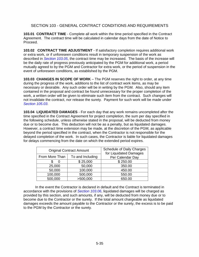
5-35
SECTION 103 - GENERAL CONTRACT CONDITIONS AND REQUIREMENTS 103.01 CONTRACT TIME - Complete all work within the time period specified in the Contract Agreement. The contract time will be calculated in calendar days from the date of Notice to Proceed. 103.02 CONTRACT TIME ADJUSTMENT - If satisfactory completion requires additional work or extra work, or if unforeseen conditions result in temporary suspension of the work as described in Section 103.05, the contract time may be increased. The basis of the increase will be the daily rate of progress previously anticipated by the PGM for additional work, a period mutually agreed to by the PGM and Contractor for extra work, or the period of suspension in the event of unforeseen conditions, as established by the PGM. 103.03 CHANGES IN SCOPE OF WORK – The PGM reserves the right to order, at any time during the progress of the work, additions to the list of contract work items, as may be necessary or desirable. Any such order will be in writing by the PGM. Also, should any item contained in the proposal and contract be found unnecessary for the proper completion of the work, a written order will be given to eliminate such item from the contract. Such changes will not invalidate the contract, nor release the surety. Payment for such work will be made under Section 105.03. 103.04 LIQUIDATED DAMAGES - For each day that any work remains uncompleted after the time specified in the Contract Agreement for project completion, the sum per day specified in the following schedule, unless otherwise stated in the proposal, will be deducted from money due or to become due. This deduction will not be as a penalty, but as liquidated damages. However, a contract time extension may be made, at the discretion of the PGM, as applicable beyond the period specified in the contract, when the Contractor is not responsible for the delayed completion of the work. In such cases, the Contractor is liable for liquidated damages for delays commencing from the date on which the extended period expires.
Original Contract Amount Schedule of Daily Charges for Liquidated Damages
Per Calendar Day From More Than To and Including
$ 0 $ 25,000 $ 250.00
25,000 50,000 350.00
50,000 100,000 450.00
100,000 500,000 550.00
500,000 >500,000 650.00
In the event the Contractor is declared in default and the Contract is terminated in
accordance with the provisions of Section 103.06, liquidated damages will be charged as provided by this section, and such amounts, if any, will be deducted from money due or to become due to the Contractor or the surety. If the total amount chargeable as liquidated damages exceeds the amount payable to the Contractor or the surety, the excess is to be paid to the PGM by the Contractor or the surety.
5-36
103.05 SUSPENSION OF WORK – Work may be suspended by the PGM, wholly or in part, for the following reasons:
failure to carry out orders;
failure to perform any provisions of the contract; or
unforeseen conditions not anticipated in estimating the contract time required for the completion of the work.
Written notification will be given of the action to be undertaken and the reason for the
actions. After receipt of notice of suspension, take all reasonable steps to minimize the further incurrence of costs or expenses under the Contract. Payment will be made for the work actually accomplished up to date of suspension, and accepted by the PGM, at the unit prices set forth in the Form of Proposal. Payment will also be made for any minimum and reasonable costs and expenses agreed to by the DGE, the PGM and Contractor in writing that may be required to permit the maintenance of equipment in standby condition so that services may be resumed if conditions so warrant in the opinion of the DGE. 103.06 TERMINATION OF CONTRACT –
(a) Termination Due to Delay, Neglect, or Default. The Contractor may be declared in default for the following reasons:
failure to complete work within the time specified in the Contract Agreement;
failure to perform the work with sufficient labor, equipment, or material to insure the completion of the specified work in accordance with the contract terms;
unsatisfactory performance of the work;
failure or refusal to remove material or remove and replace any work rejected as defective or unsatisfactory;
insolvency or bankruptcy;
commission of any act of bankruptcy or insolvency;
assignment made for the benefit of creditors;
failure or refusal within ten (10) days after written notice by the PGM, to make payment or show cause why payment should not be made, of any amounts due for material furnished, labor supplied or performed, for equipment rentals, or for utility services rendered, as covered by the Additional Bond for Labor and Materials;
failure to protect, to repair, or to make good any damage or injury to property; and/or
work not carried on in an acceptable manner for any cause.
The PGM, after giving ten (10) days written notice of default will have the power and
authority, without violating the contract, to:
declare the Contractor in default;
take the completion of the work out of the hands of the Contractor
appropriate or use any or all materials assembled for the project;
enter into a contract or contracts with others for the completion of the work; or
5-37
use such other methods that will be expedient for the completion of the contract in a satisfactory manner.
(b) Termination for Convenience. With approval from the DGE, the PGM, after giving ten
(10) days' written notice, will have the power and authority, without violating the contract, to cause termination of the contract for the convenience of the PGM and the Department.
(c) Payment. Subsequent to contract termination, payment will be made at the unit prices specified in the Form of Proposal for work completed and accepted by the PGM. No other payment will be made.
(d) Disposition of Documents and Samples. In the event of termination for any reason, all
finished or unfinished documents, all soil and rock samples, and other materials, at the option of the PGM become the property of the Department.
(e) Completion of Work Terminated Due to Default. In the event of default and contract
termination, the PGM may have the work required under the contract completed in such manner as, in the PGM's judgment, will best serve the interests of the Department. The Contractor will be liable for and shall pay to the PGM any excess in cost expended over and above the cost specified in the Form of Proposal, as well as any expenses caused the PGM and Department, by the failure of the Contractor to comply with the terms of the Contract. 103.07 LAWS, ORDINANCES, REGULATIONS AND PERMITS - Comply with all laws, ordinances, rules and regulations of the Federal and State governments, or of any political subdivision thereof, which are applicable to the work to be performed under the Contract. Obtain all permits and licenses necessary to the prosecution of the work, except for work on railroad property, as described in Section 103.11, at no additional cost to the PGM or Department. 103.08 PATENTS AND PERMITS - Pay all royalties and indemnify and save harmless the PGM and the Department from any claims for infringement by the reason of the use of any patented designs, device, material or process to be performed or used under the Contract. 103.09 SAFE PRACTICES IN DRILLING -
(a) Responsibility. Follow generally accepted drilling practices and be responsible for all matters dealing with safety in performing the work, including safety of all persons and property during performance of the work, employees and any and all employees of subcontractors which may perform work. This requirement will apply continuously regardless of time or place, and will in no way be altered because the PGM gives general directions as to the location where samples should be taken. Additionally, the drilling contractor should not perform any work that the drill operator considers unsafe. In the event of any disputes, these must be addressed with the DGE. This does not relieve the contractor of the responsibility to thoroughly inspect the site, and come prepared to the job with equipment necessary to conduct work in a safe manner, as per Section 102.02. Pre-bid meetings are the primary mechanism that potentially unsafe drilling conditions that were not recognized by the PGM or the Department, can be identified by drilling contractors. If a pre-bid meeting is not conducted, such conditions must be addressed by the contractor to the PGM prior to bid, or any costs associated with mitigating the unsafe conditions may be the responsibility of the contractor.

5-38
(b) Occupational Safety and Health Regulations. Comply at all times with applicable Federal, State, and local laws, provisions, and policies governing safety and health, including the Federal Construction Safety Act (Public Law 91-54), Federal Register Chapter XVII, Part 1910 “Occupational Safety and Health Standards” and Part 1926 “Occupational Safety and Health Regulations for Construction” of Title 29 Code of Federal Regulations, and subsequent publications updating these regulations.
(c) Deep Mine Safety Monitoring Equipment. Borings which intercept deep mines or coal may encounter methane gas and/or carbon monoxide gas during the drilling and grouting process. Provide a monitor for the measurement of methane, carbon monoxide, and oxygen. Provide a monitor with a minimum range of measurement as follows: methane from 100 ppm (0.01%) to 50,000 ppm (5.0%); carbon monoxide from 10 ppm (0.001%) to 1,000 ppm (0.10%). Provide an operating monitor at the location of each boring where deep mines are known or suspected of being encountered; where indicated in the contract; or as directed by the PGM. Obtain readings directly above the boring and within 12 inches of the boring opening. Maintain monitors in good operating condition, including calibration, for the life of the project. Have a monitor available to the PGM for inspection of the boring and any previously drilled holes on the project.
Repair or replace monitors within twenty-four (24) hours of notice from the PGM and /or DGE. Drilling of borings in deep mined areas will not be permitted if the monitor is not present and operating as specified.
If methane above 12,500 ppm (1.25%) or carbon monoxide above 10 ppm (0.001%) is detected immediately stop work and allow the boring to naturally vent. If after 24 hours or more methane above 12,500 ppm or carbon monoxide above 10 ppm is detected, employ industry standard methods to vent the borehole. Drilling may continue if venting reduces the methane to below 12,500 ppm and carbon monoxide below 10 ppm. If after venting for at least 24 hours the methane remains between 12,500 ppm and 25,000 ppm or carbon monoxide remains between 10 ppm and 30 ppm, grout the boring. If at any time methane above 25,000 ppm (2.5%) or carbon monoxide above 30 ppm (0.003%) is detected, evacuate the area and contact the PGM.
(d) Environmental Drilling under Class E1 or E2. A site specific Health and Safety Plan (HASP) will provide a health and safety program to cover specific work practices to assure employee health and safety. A generic HASP is provided as an Appendix to Publication 222 to be used in developing the site specific HASP. The written HASP is for systematic identification of known or suspected site hazards and identification of employee response to those hazards.
The HASP shall communicate hazards to employees for their awareness and protection. Site characterization is a continuous process. After the completion of each phase of assessment, information is obtained and evaluated to define the potential hazards. All site personnel should be constantly alert for new information about site conditions. The contractor is responsible for compliance with the site specific HASP. The contractor may develop his own HASP but it must equal or exceed the prior established site HASP. The HASP must be reviewed and accepted by the Department’s Environmental Manager prior to the commencement of work on the site. The contractor is responsible for all employees and subcontractor's employees on the project site.
The contractor must provide OSHA certified personnel who have completed a 40-hour health and safety training course or current 8-hour refresher training. There must also be an established Medical Monitoring Program. Documentation of all health and safety training must be provided to the Department prior to initiating work on the project.
Periodic air monitoring of the breathing zone, borehole, and background shall be performed during all work operations. The PGM‟s Health and Safety Officer shall be responsible for this monitoring and to initiate upgrade.

5-39
It is the responsibility of the contractor to inform his employees of all potential hazards related to this work as per 29 CRF 1910,1200 Hazard Communication Standard and to be responsible for supplying all equipment and materials to perform the services specified in this document at Personal Protection Equipment (PPE) Levels D, C, or B. Unless specified otherwise, Level D PPE, as discussed in the HASP, shall be considered the minimum work level acceptable for those areas of the project site designated by the PGM.
(e) Encountering Contaminated Material. If the drilling contractor, Inspector or PGM encounters potentially contaminated material not previously suspected, during any phase of the geotechnical investigations, the operation must be halted in a safe and controlled manner, and the PGM shall immediately contact the DGE. The DGE should contact the District Environmental Manager.
In such cases, the drilling contractor is required to secure the site until appropriate personnel can enter the site to complete decontamination efforts. Securing the site includes containerizing all suspected contaminated materials including the suspected samples, fluids used to clean the sampling devices, and any materials (towels, gloves, etc.) used in the containment process. If securing these materials cannot be performed in a manner that provides reasonable safety to the drilling personnel, or the suspected contaminated material is causing physical distress (e.g. due to odors), then the area should be guarded at a safe distance until properly equipped personnel arrive to containerize the materials and secure the site.
Due to the potential for encountering contaminated material, the drilling contractor shall have available for every project, at least one 55-gallon drum, incidental to the project, to containerize contaminated material for initial site securing. As many sites do not allow for safe and secure storage, the contractor shall provide additional provisions for sitting a trailer, providing a fenced area, or other temporary measures to securely store the drum, as required. The method of storing the drum must provide secure, lockable, containment.
If necessary, containerized materials may be transported off-site prior to receipt of analyses. This material may be relocated to the closest appropriate Department maintenance facility, only as a last resort. This option must be coordinated with and approved by the Department. The responsible Department maintenance facility official must be notified before any potentially contaminated samples are transported to the facility. The PGE/PGM (Project Geotechnical Engineer/Project Geotechnical Manager), or DGE if an in-house project, will make the appropriate arrangements to contact a company permitted to transport the hazardous material as required. All geotechnical samples obtained from a suspected waste site will require proper labeling in addition to those specified in Section 215 of this publication.
Under no circumstances should site workers perform activities they are not trained and capable of performing, or that compromise personal safety. 103.10 LOCATION OF UTILITIES AND UNDERGROUND STRUCTURES – The Contractor shall be responsible for knowing the location of all underground utilities, overhead utilities, pipes, cables and underground structures that his employees could potentially come in contact with while on-site. It shall be the Contractor‟s responsibility to perform the work under the safest possible conditions, and to employ the necessary precautions to avoid these features during completion of boring, sampling and testing operations.
a) Underground Utilities. If it is established that the location of a boring is such as to
cause interference with an underground facility or structure, advise the PGM. At his discretion, the PGM may designate a new location for the boring or authorize its omission.
Before the work begins, comply with the Pennsylvania Utility Line Protection Act, Act No.121 of the General Assembly of Pennsylvania, 2008 as amended or superseded, which
5-40
defines the procedures for notification to Public Utilities prior to excavation, drilling or demolition work by use of powered equipment or explosives. The law requires the use of the PA One-Call Sytem to locate all utilities. In addition, the Contractor must coordinate with the public or private land owners to locate non-public underground utilities such as buried electric lines, communication cables, drainage pipes, etc. The boring location(s) shall be adequately offset where the hole location(s) conflicts with utilities and other structures in the project area including those not covered by the PA One-Call system (as indicated above). PA One-Call contact information is as follows:
PA One-Call Phone: dial 8-1-1 or call 1-800-242-1776
On-line: pa1call.org
b) Aboveground Utilities. In order to determine the required minimum distance to stay
away from overhead power lines, the PGM shall contact the utility company to determine voltage in the line. For voltage to ground of 50kV or less, the minimum clearance between overhead power lines and any part of the drill rig, including any drill steel, is 10 feet. For voltages to ground over 50kV, the minimum clearance distance is 10 feet plus 4 inches for every 10kV over 50kV. For overhead lines not containing power (i.e., cable, telephone, etc.) the minimum clearance between the lines and any part of the drill rig, including drill steel, is 10 feet. In situations where clearance between overhead lines and drill equipment is less than required above, the requirements of 1910.333(c) of the OSHA regulations indicated above must be followed. Any work in these conditions must be coordinated by the PGM with Contractor and the appropriate utility company(ies). The Contractor shall arrange with the public utility to shield adjacent overhead power lines, as required, at no additional cost to the Engineer or Department. 103.11 WORK ON PUBLIC AND PRIVATE PROPERTY -
(a) Permission for Access. General permission to enter public or private property on which borings or test pits are located, or over which access is required, will be obtained by the PGM. The PGM will provide a copy of the “Notice of Intent to Enter” (NOITE) letter to the driller awarded the contract (at the time of awarding the bid).
If access is denied to any property for which general permission to enter has been obtained, notify the PGM in writing and send a copy of such notification to the property owner.
Obtain prior approval from the PGM before entering any property within the work area. Any cost incurred, including but not limited to property damage, delays, or down time caused by entering any property without prior approval of the PGM, shall be borne solely by the Contractor.
(b) Arrangements for Access. Make specific arrangements for property access (including schedule, access route, etc.) with the owners of properties on which borings are located or over which access is required with respect to any work thereon. A representative of the PGM and the Contractor may contact property owners as necessary. Property owner information (name, address, telephone number, etc.) will be provided by the PGM. 103.12 WORK ON RAILROAD RIGHT-OF-WAY
(a) Permit for Access. The PGM will obtain the permits, insurances and railroad personnel necessary to gain access to railroad right-of-way on which borings or test pits are located or over which access is required.
5-41
(b) Schedule for Access. The permit described under Section 103.12(a) must describe all entries required, including entry by sub-contractors. The PGM will provide the following information in Attachment III to the Instructions to Bidders prior to entry onto railroad right-of-way:
Schedule for Work to be done on the Railroad's Right-of-way
Work to begin on:
Work to end on:
Days of week on which work is to be performed:
Working time per day:
Specific borings to be completed;
Distance from each boring to centerline of nearest track:
Estimated total linear feet to be completed:
Work must start on the day stated. The Department will be assessed charges for railroad personnel and equipment required to monitor the work from the day scheduled for work to begin. In the event work does not begin on the day scheduled, any costs billed by the railroad will be back charged to the Contractor.
(c) Assessment Damages. Contractor will be liable for any railroad costs incurred for work that is performed outside of the schedule defined under Section 103.12(b). Exceptions will be granted only when the railroad's operations prevent work from being completed within the schedule, or when the PGM increases the schedule by written notice. Railroad costs that are incurred for work that is performed outside of the schedule will be deducted from the monies due, not as a penalty, but as Assessment Damages. 103.13 PROTECTION OF WORK, PERSONS AND PROPERTY - Provide and maintain any barricades, lights or other safety devices necessitated by hazardous conditions or required by local authority at no additional cost to the PGM or Department.
The Contractor shall take all necessary precautions to prevent or minimize discharge of water on any roadway. Perform sweeping and salting operations of the work during drilling operations, as necessary, to prevent icy, wet, slippery, or dusty conditions which could pose undue hazards or inconvenience to property owners, pedestrians, or vehicular traffic, at no additional cost to the PGM or Department. 103.14 INJURY TO PERSONS AND DAMAGE TO PROPERTY - Promptly repair all physical damage to property resulting either directly or indirectly from the SBST operations.
Upon completion of the work, furnish satisfactory evidence that all claims arising from injury to persons or damage to property resulting from the boring, sampling and testing operations have been resolved. The acceptability of evidence that claims have been resolved will be determined by the PGM. 103.15 INSURANCE AND LIABILITY
(a) General. Obtain and pay for such insurance as will protect the Department and the PGM from claims under the Workmen's Compensation Act and from any other claims for damages for personal injury including death, or for damages to property, both real and personal, which may arise from operations under the Contract, whether such operations be by the Contractor or by anyone directly or indirectly employed by the Contractor.

5-42
(b) Coverage. Effect and maintain for the duration of the Contract the following insurance in companies or through agents, with minimum limits of coverage as specified in the Instructions to Bidders, at no additional cost to the PGM or Department:
(1) WORKMEN'S COMPENSATION INSURANCE including Employers' Liability Insurance in accordance with the laws of the Commonwealth of Pennsylvania.
(2) GENERAL LIABILITY INSURANCE for Bodily Injury and Property Damage,
including explosion, collapse, and underground hazards coverage. (3) AUTOMOBILE INSURANCE for Bodily Injury and Property Damage covering all
automotive vehicles owned or hired by the Contractor and used on this Contract not otherwise so covered by insurance, and including automatic coverage for additions to the schedule of vehicles.
(c) Certificates of Insurance. Deliver to the PGM, before starting the work, certificates
from insurance companies or their agents, in duplicate, stating that such insurance is in force and will not be canceled during the conduct of the work without thirty (30) days written notice to the PGM. The certificate of liability insurance will include as additional named insurers, the PGM and the Department, in respect to the work to be performed by the Contractor.
(d) Additional Taxes and Insurance. Report and pay all Old Age Benefit and Social Security Taxes and other insurance as required by State and Federal Laws.
(e) Reduction of Coverage. In the event that, during the course of the work, the above limits of coverage should be reduced for any reason, the PGM and/or the Department reserve the right to terminate the Contract without waiving any other rights it may have under the law. Such termination will be effected by giving written notice thereof to the Contractor, in accordance with Section 103.06.
(f) Liability. In no event will the PGM or the Department, their officers, employees, or
representatives be liable in any way for consequential damages of any kind. By signature on the Contract Agreement, the PGM and the Department are released from any liability for damage to property howsoever caused in connection with the performance of the work to the extent coverage is in force for such damage under a physical damage insurance policy. If any of the physical damage insurance policies do not permit release of other persons or firms from liability before a loss, obtain endorsement to such policies from the respective insurance carriers as may be necessary to affect a waiver of the right of subrogation by such insurance carriers against the PGM and the Department.
(g) Indemnification. Without limiting any other provision of the Contract Agreement, fully indemnify, save harmless, and at the PGM's request, defend the PGM and its subsidiaries, affiliated companies, agents and employees, and the Department and its officers, agents and employees, from and against any and all suits, actions, legal proceedings, claims, demands, damages, costs and expenses of whatsoever kind or character, including but not limited to attorneys' fees and expenses, arising out of or by reason of:
(1) any liability or obligation in any manner caused or occasioned or claimed to be caused or occasioned by, any act, omission, fault, or negligence of the Contractor or anyone acting on his behalf, including but not limited to vendors, their sub-contractors and sub vendors, and the employees and agents of any of the
5-43
foregoing, in connection with or incident to the Contract Agreement or the work to be performed hereunder; and/or
(2) any injuries (including death) or damage to any person or entity employed by or
acting on the Contractor's behalf under the Contract Agreement. 103.16 EQUAL OPPORTUNITY AND NON-DISCRIMINATION – In connection with the execution of the Contract, do not discriminate against any employee or applicant for employment because of race, religion, color, sex, or national origin consistent with the Commonwealth of Pennsylvania Nondiscrimination Clause. Take affirmative action to ensure that applicants are employed, and that employees are treated during employment, without regard to their race, religion, color, sex, or national origin.
Comply with the Regulations of the U.S. Department of Transportation relative to non-discrimination in federally assisted programs of the Department of Transportation (Title 15, Code of Federal Regulations, Part 89). 103.17 INTEREST OF PUBLIC OFFICIALS – No member, official, or employee of the Department or of another state or local public body during his tenure or for one year thereafter is permitted to have any interest, direct or indirect, in the Contract or the proceeds thereof. 103.18 INTEREST OF MEMBERS OF CONGRESS – No Member of or Delegate to the Congress of the United States is permitted to have any share or part of this Contract or to any benefit arising therefrom. 103.19 SUBLETTING OR ASSIGNMENT OF CONTRACTS – Do not sublet, sell, transfer, assign, or otherwise dispose of the contract or any portion or rights, title, or interest, without the written consent of the PGM.
If consent is given, subletting a portion of the contract will be permitted. However, do not sublet a portion equal to, or exceeding 50 percent (50%), of the original total contract price. "Specialty Items," as identified in the proposal, may be performed by subcontract. The cost of any specialty items performed by subcontract may be deducted from the original total contract price before computing the amount of work permitted to be performed by subcontract. Subcontracts or transfer of contract will not release Contractor liability under the contract and bonds. 103.20 DISSEMINATION OF INFORMATION - Any reports, information, data, etc., given to or prepared or assembled under this Contract may not be made available to any individual or organization without prior written approval of the Department. 103.21 PUBLICATION, REPRODUCTION AND USE OF MATERIAL - No material produced in whole or in part under this Contract will be subject to copyright in the United States or in any other country. The Department will have unrestricted authority to publish, disclose, distribute, and otherwise use, in whole or in part, any reports, data, or other materials prepared under this Contract. 103.22 AUDIT, INSPECTION OF RECORDS, AND OWNERSHIP OF MATERIALS - Permit the authorized representatives of the Commonwealth of Pennsylvania to inspect and audit all data and records relating to performance of work under the Contract. Retain records for a period of at least three (3) years after completion of the Contract. At the end of three (3) years, provide the records to the Department or obtain written permission from the Department to dispose of the records.

5-44
Provide free access of the duly authorized representatives of the Department at all reasonable times to such books and records and the right to examine and audit the same and to make such transcripts there from as necessary to allow inspection of all work data, documents, proceedings, and activities.
Documents, drawings, design data, and reports used or prepared in the performance of this Contract belong to and become the property of the Department in perpetuity. 103.23 CONTINGENT FEES - If requested by the PGM, provide a sworn affidavit certifying that no company or person other than a bona fide employee was retained to solicit or secure the Contract, and that no payment or agreement to pay has been made to any company or person other than a bona fide employee, any fee, gifts, or any other consideration contingent on or resulting from the award of the Contract. 103.24 GOVERNING LAW - The Contract will be governed by the laws of the Commonwealth of Pennsylvania, and applicable federal and local laws as they may from time to time be in effect. 103.25 MISCELLANEOUS PROVISIONS
(a) Construction Bidding. Neither the Contractor nor its member companies or their affiliated companies may bid on or perform any direct construction work in connection with this project.
(b) Clean Air Act of 1970. Comply with all orders, applicable standards or regulations issued pursuant to the Clean Air Act of 1970.
5-45
SECTION 104 - CONTROL AND PERFORMANCE OF WORK 104.01 SUPERVISION, PERSONNEL AND MANNER OF PROSECUTION OF WORK - Designate in writing, at the beginning of work, a competent field supervisor or foreman who will be present at the site of the work at all times and will be responsible for supervision and performance of the work. Directions given him by the PGM will be binding on the Contractor, and such directions will be confirmed in writing when so requested. Any driller who begins work under the Contract must continue to work on the project until its completion, unless the PGM requests his transfer in writing. A driller may not be transferred without the written approval of the PGM.
Prosecute the work in a manner that will promote rapidity in execution, secure safety of life and property and satisfy the objectives of the project in accordance with the Contract Documents. 104.02 INSPECTION OF WORK - Perform no work unless the representative of the PGM is present unless the work is off the roadway and requires no traffic control, and does not involve work that must be witnessed and logged by the Inspector. In such case, prior written authorization from the PGM is required. Provide full opportunity at all times for inspection of the work by the PGM. Immediately remedy any work not completed in accordance with the Contract Documents to the satisfaction of the Contract Documents and the PGM at no additional cost to the PGM or Department. 104.03 WORK PLAN AND SCHEDULE - Submit a Work Plan in writing to the PGM a minimum of seven (7) calendar days prior to beginning the Work on-site. The Work Plan must include, as a minimum:
(a) The name and phone number of the Contractor‟s Representative and Field Supervisor
(b) The dates on which on-site Work will begin and end.
(c) The days-of-the-week and hours-of-the-day on which Work will be performed.
(d) Estimated dates during which major specialty tasks (such as installation of instruments or performance of field tests) will be performed.
(e) A list of any boring(s) that need to be moved to avoid interference with underground or overhead utilities (see Section 103.10)
(f) A Traffic Control Plan, if required (see Section 216.03)
104.04 LOCATION OF BORINGS AND SURVEY - The PGM will establish in the field suitable points, lines, marks, locations and elevations as required to locate test borings and/or test pits. Where possible, borings are to be located a minimum of 30 m (100 feet) from domestic water supply wells. If borings must be located within the 30 m (100 feet) distance then those locations should be indicated on the Plan and Location of Borings and discussed at the pre-bid meeting. Do not drill any borings within a radius of 3 m (10 feet) from any domestic water supply well or spring box. Furnish, without additional compensation, such labor, temporary structures and materials as may be required by the PGM to establish and maintain such points, lines, marks, locations and elevations.
The approximate locations of the required borings and/or test pits are indicated on the Plan and Location of Borings. The exact location of the individual borings will be determined and staked by the pre-bid meeting. If boring locations have not been approved by the pre-bid meeting then the borings will be placed as close as possible to the expected locations. These borings will be identified as approximate locations.
5-46
The final locations of some borings may be modified in the field by the PGM, depending upon topographic features and subsurface conditions encountered during progress of the work.
Borings on land may be offset from the designated location by the PGM to avoid surface obstructions or impracticable working conditions. Test borings on water shall be located within a radius of five (5) feet from the designated locations. 104.05 NUMBER AND DEPTH OF BORINGS - The number of borings required is indicated in the Instructions to Bidders and on the Plan and Location of Borings. The final number of borings may be increased or decreased at the discretion of the PGM, in accordance with Section 103.03.
Extend all borings to the depths, elevations or conditions specified in the Instructions to Bidders, unless the PGM specifically directs other-wise in the field. 104.06 SEQUENCE OF BORINGS - The PGM reserves the right to designate the sequence in which borings will be made. Any such specific sequencing must be provided in Attachment II of the bid document. 104.07 ABANDONED BORINGS - No payment will be made for any boring which has been abandoned before reaching the depth, elevation or condition specified on the Plan and Location of Borings and/or in the Instructions to Bidders, unless the PGM approves and accepts the borings as being completed.
Afford the PGM the opportunity to measure the depth of any boring and to inspect samples of materials recovered before abandonment and removal of casing and drilling equipment. 104.08 WATER FOR DRILLING OPERATIONS - Make necessary arrangements with appropriate private property owners or governmental agencies for use of water supplies while drilling. Any expense incurred including the cost of hauling water therefore must be reflected in the Proposed Bid Prices Per Unit for borings presented in the Form of Proposal. No additional payment will be made by the PGM or the Department for water required for drilling operations.
Use only potable water for drilling water if drilling operations are conducted within 30 m (100 feet) of domestic water supply wells or spring boxes. Portable water should be supplied in a clean container free of debris and/or foreign matter
Wetlands that can be used as a source of drilling water will be noted in Attachment II. The Department will provide a Wetland Usage Plan; detailing access, procedure of water removal, and recharge and restoration of disturbed areas.
Areas that may be wetlands but are not noted as such cannot be used without Department approval. The Department must be notified prior to using such areas. The Department will determine whether the wetland can be used as a source of water. Revision to the above plan, as noted above, will be provided for areas determined to be wetlands from which water can be obtained. Allow sufficient time for the Department's review in the scheduling of operation so that the allowable contract time is not exceeded. 104.09 RESTORATION OF DISTURBED AREAS - Restore ground areas disturbed by personnel and equipment as nearly as possible to their original condition. Any agreement to modify the restoration to original-condition is strictly an agreement between the Contractor and the property owner and is to be at no additional cost to the Department. Prior to starting the work, submit repair methods for PennDOT facilities to the Department. Exercise particular care in the restoration of property such as shrubs, lawns, fences, walls, gardens, and pavements which are damaged, and restore all property to its original or like-original condition before
5-47
leaving the site. No additional payment will be made by the PGM or the Department for restoration of disturbed areas. 104.10 PROTECTION OF ENVIRONMENT – During all phases of work, the Contractor shall conduct his operations to minimize: 1) the disturbance of trees and other forms of vegetation; 2) the use of excavation equipment to construct access roads, sumps; 3) discharges into waterways. The Contractor shall restrict his activities to the immediate vicinity of the boring locations as much as practicable. The Contractor shall not excavate or bench into any existing hillside or embankment slope, accept as necessary and approved by the Engineer. The use of trees for winching, within the existing right-of-way, is discouraged but not prohibited. If winching using trees is necessary, use only trees of sufficient size to prevent uprooting or related damage. Protect tree limbs and bark from damage using rubber matting, etc. The use of guide rail posts to assist in winching is not permitted. 104.11 SITE CLEANUP – After completing field operations, promptly remove all equipment mobilized and material brought to the site and restore the site to its original condition, as described under Section 104.09. The work will not be considered complete until site cleanup has been completed and accepted by the PGM.

5-48
SECTION 105 - PAYMENT 105.01 GENERAL - Perform all work for the compensation set forth in the Form of Proposal except as noted under Section 105.03. The compensation thus set forth includes the cost of all insurance, bonds, and other incidentals, as well as all taxes and premiums payable under Federal, State, and Local laws applicable to labor, materials, supplies furnished, or work performed.
The basis of measurement and payment is as set forth under the Technical Provisions of these Standard Specifications for Subsurface Boring, Sampling, and Testing, or as specified in the Form of Proposal, with the latter taking precedence. 105.02 UNIT PRICES - Except for lump sum prices which are fixed and invariable, the proposed bid price per unit specified in the Form of Proposal will govern. The estimated quantities of these items are only approximate as indicated under Section 102.02. Depending on soil and rock conditions established during the actual boring operations in the field, the PGM reserves the right to increase or decrease the number of borings and total units of work. If the final quantities are greater or less than the estimated units listed in the Form of Proposal, additions to or deductions from the indicated proposed total price will be made based upon the proposed bid price per unit, except as noted in Section 103.03 for changes in scope of work which will be paid for as indicated in Section 105.03 as additional or extra work. 105.03 ADDITIONAL WORK AND EXTRA WORK
(a) Additional Work. This includes only the following:
work of the type already provided for in the contract and
work for which there is a contract price.
Perform all such work only when authorized in writing by the PGM, as stated in subparagraph (c). All additional work will be paid at the contract price and in the same manner as if it had been included in the original contract.
(b) Extra Work. This includes only the following:
work arising from changes described in Section 103.03 which results in a significant increase or decrease in the cost of performing that work or
work, having no quantity and/or price included in the contract, which is determined by the PGM to be necessary or desirable to complete the project.
Perform all such work only when authorized in writing by the PGM, as stated in
subparagraph (c). All extra work will be paid only as stated in subparagraph (c).
(c) General. Additional work and extra work must be authorized in writing by the PGM prior to its performance. Compensation will be limited to the work authorized in writing and actually performed. Work performed prior to written authorization will be at the Contractor's risk.
A work order identifying the work to be done and the price to be paid will be processed prior to or during the performance of the work. To avoid interrupting the project, written authorization to perform work under this section will be in the form of a letter, email, or other writing from the PGM, issued within a reasonable length of time. The writing will set forth the work to be done and will state whether the work is to be paid as additional work and/or extra work.
5-49
If the work is to be paid as additional work, the PGM's writing will refer to the contract price for that work.
If the work is to be paid as extra work and is such that a reasonable price therefore can be negotiated, the PGM and Contractor will agree on a price and the PGM's writing will refer to the negotiated price for that work.
Payment for additional work and/or extra work is accepted as payment in full for all profit and for all equipment, labor, material, field overhead, home office and general administrative expenses, and every other expense incurred as a result of the additional and/or extra work.
No claims for additional compensation of any kind arising out of or relating to such work can be asserted against the PGM and/or Department.
(d) Disputes. In the event of a disagreement with the PGM as to whether work is:
original contract work or additional work,
original contract work or extra work, or
additional work or extra work, the following shall be done:
(1) Notify the DGE immediately of such disagreement and confirm the disagreement in writing to the DGE within ten (10) days. Upon notification to the DGE of such disagreement, records will be kept daily of all labor, equipment and materials used in the disputed work. Review for accuracy and sign all such records at the end of each day or at the beginning of the next business day. Report to the DGE in writing within ten (10) days of such review all disagreements with such records. Failure to review and sign the records on a daily basis or to report in writing disagreements therewith will provide an irrefutable presumption that such records are accurate.
Disputes concerning all such work will be resolved by the District Executive and payment will be made on the basis determined by the District Executive. (2) In the event of a disagreement with the District Executive the party under contract with the Department shall then have six (6) months to file his claim with the Board of Claims as provided in 72 P.S. 4651.
105.04 INVOICING – Submit monthly invoices to the PGM for work completed and accepted each month during the course of the Contract. Ten (10) percent of each invoice will be withheld pending final completion and acceptance of the work and acceptance of all records required by the Contract Documents. Submit monthly and final invoices only for work completed and accepted by the PGM. Provide as a minimum, the following information in each invoice:
(1) Boring number and actual depth drilled in soil and in rock for each boring completed during the invoice period.
(2) Total units of each bid item completed and accepted during the invoice period together with the bid price per unit for each bid item and an extension of the total cost for each.
(3) The amount of payment requested, the amount retained (ten percent), and the net amount of payment.
5-50
In addition, provide in each invoice a cumulative total of the following as of the beginning and end of the invoice period:
(4) The completed and accepted units for each of the bid items.
(5) The amount of payment, the amount retained (ten percent), and the net amount of payment.
105.05 PAYMENT OF RETAINAGE – Upon completion and acceptance of the work by the PGM and acceptance of all documents and records, submit to the PGM satisfactory evidence that all claims arising from boring, sampling and testing operations under the Contract have been satisfactorily resolved. The ten (10) percent withheld from invoices will not be released until this evidence has been received by the PGM.
5-51
SECTION 200 TECHNICAL PROVISIONS
SECTION 201 - MOBILIZATION 201.01 DESCRIPTION - This work consists of: movement to the site of all necessary
personnel and equipment required to complete borings, including winches, bulldozers, trucks; set up of all equipment, tools, personnel and materials necessary to complete the work required by the Contract; removal of equipment, personnel and excess materials at the completion of the work; obtaining the required permits, insurance; restoration of disturbed areas, site cleanup; and any initial items required to start the work. When borings are scheduled to be conducted on water, Mobilization includes items such as stable working platforms, barges, boats, ramps, and any equipment, personnel, materials necessary solely to complete required boring(s) on bodies of water.
Movement between borings is not considered Mobilization but is to be included in the per-
foot price for advancing the boring. Costs related to accessing boring locations such as vegetation clearing/removal, site leveling, and guiderail removal is not considered Mobilization but is to be included in the per-foot price for advancing the boring.
201.02 MEASUREMENT AND PAYMENT
(a) Mobilization. Lump Sum.
Payment for the general Mobilization item will be made according to the following schedule:
A partial payment for Mobilization will be approved when the value of work completed and accepted is equal to 10% of the total contract bid amount less the Mobilization bid amount. That is, when: $ work completed = 0.10 x ($ total bid – $ mobilization bid). The partial payment will be determined as the lesser of the following:
70% of the Mobilization bid
8% of the Total contract bid
Upon satisfactory completion of all work, pay the remaining amount of the Mobilization item.
5-52
SECTION 202 - STANDARD SOIL BORING, SAMPLING AND TESTING 202.01 DESCRIPTION - This work consists of making soil borings to determine the true nature, arrangement and thickness of soil strata and any other materials as they exist in the ground; obtaining from each boring representative disturbed samples of the soil coming from each stratum as it exists in the ground; and performing standard penetration tests (SPT) at the depth of each representative disturbed sample; and advancing unsampled borings through soil. 202.02 PROCEDURES FOR ADVANCING BORINGS IN SOIL
(a) General. Advance borings in soil using the methods discussed below. The method used shall be selected by the Contractor unless a specific method is indicated otherwise in the Contract. Methods other than those listed below may not be used unless approved by the PGM or DGE.
Regardless of the method used to advance the boring in soil, provide equipment with the minimum inside diameter (I.D.) necessary to permit required field testing, sampling, instrumentation installation, etc. Advance augers/casing to the depth or elevation required. Do not advance augers/casing to a depth greater than the depth at which testing or sampling is to be done.
Maintain all drilling equipment in good working order at all times throughout the duration of the work. If, in the opinion of the PGM, the equipment supplied is inadequate for proper completion of boring, sampling and testing operations, or installation of instrumentation, replace the equipment immediately with suitable equipment at no additional cost to the Department.
At all times during advancement of the boring through soil, maintain the water level inside the hole at or above the level of water outside of the hole. When necessary and particularly when drilling through very soft cohesive soil or cohesionless sand, maintain the hole full with water or at a level sufficiently higher than the ground water level at all times before, between and after sampling operation to reduce the possibility of soil entering the hole (e.g., blow-in, sanding in, soil heave, etc.). Additional measures to prevent blow-in, including increasing the density of the drill water by adding bentonite or drilling mud to the water, may be necessary if approved by the PGM.
After completing each boring, including required ground water level readings, backfill in accordance with Section 210 or as otherwise indicated in the Contract or by the PGM. Do not backfill borings in a mine fire area until after completion of any temperature monitoring program.
(b) Advancement methods
(1) Continuous Flight Hollow-Stem Augers. Continuous flight hollow-stem augers are only permitted to be used with a center (pilot) bit assembly (center rod, plug and bit) that prevents material from entering the augers as they are being advanced. Removal of material from inside the augers using water or any other method in lieu of a center bit assembly is not permitted. If while using a center bit assembly material enters the augers, water or other methods may be used if approved by the PGM. The center bit assembly must be used at all times when advancing the borings to the required sampling or testing interval. Once the augers reach the required sampling or testing depth, the center bit assembly is removed to permit insertion of necessary sampling or testing equipment.
5-53
(2) Threaded Flush-Joint Steel Casing. Steel casing must be threaded, flush joint and of sufficient strength to maintain an open hole. The casing may be advanced by drilling or driving. Once the casing is advanced to the sampling or testing depth, disturbed material inside the casing must be removed to the sampling or testing depth (i.e., bottom of casing). Various methods, which typically include the use of water, may be used to remove disturbed material from inside of the casing; however, bottom discharge wash bits are not permissible, nor are any other methods that disturb the soil at the top of the sampling or testing interval.
(3) Solid Flight Helical Augers. Solid flight helical augers are permitted to be used to collect bulk soil samples, and to advance boring to the top of bedrock when sampling, testing or rock coring is NOT required, or as otherwise permitted by the PGM. Solid stem augers are not permitted to be used to advance a boring in soil when sampling, testing, rock coring, instrumentation installation, or any other procedure requiring an open hole is needed.
See Section 217 for requirements for bulk soil sampling with solid flight augers. When solid flight augers are used to estimate top of bedrock, advance augers until refusal is encountered or as directed by the PGM.
202.03 PROCEDURES FOR STANDARD SOIL SAMPLING AND TESTING
(a) General. Conduct penetration tests and obtain split-barrel samples in accordance with ASTM D 1586, Standard Test Method for Penetration Test (SPT) and Split-Barrel Sampling of Soils, except as modified in these specifications. Conduct continuous SPT unless specified otherwise, with the top of the first sample at the ground (soil) surface. For structure borings, provide continuous SPT to top of rock, unless otherwise directed by the DGE.
(b) Equipment. For equipment not specified herein, meet the requirements of ASTM D-1586.
(1) Split-Barrel Sampling Device. Provide, for each drill rig, at least two, 50 mm (2 inch) outside diameter split-barrel samplers with inside diameters of 35 mm (1-3/8 inch) at least 600 mm (24 inch) long. Provide other diameter split-barrel samplers if specified. The inside of each split barrel must be flush with the inside of the drive shoe. Other split-barrel samplers are permitted only with the prior written approval of the PGM.
The bottom of the sampler must be sharpened to form a cutting edge at its inside circumference. Maintain the beveled edge of the drive shoe in good condition and, if worn, reshape the edge to the requirements of ASTM D-1586. Replace the drive shoe of the sampler if damaged in such a manner as to cause projections within the interior surface of the shoe. Provide a minimum of two drive shoes in good condition for each sampling device.
Furnish a complete description of the sampler, giving inside and outside diameters, length of barrel and check valve used.
Fasten the sampler to its drive pipe by a connection embodying a check valve arranged so as to permit the ready escape of water entrapped above the soil sample as the spoon is driven down into the soil, but which will close as the soil sample and sampler are withdrawn, thus preventing the development of hydraulic pressure on top of the soil sample.
5-54
Install a spring-type sample retainer in the tip of the sampler when necessary to prevent loss of the sample. If the standard split-barrel sampler fails to recover a soil sample on the second trial, as in granular soils, use a sampler with a flap valve or sand trap, or other approved device, to recover the sample. Do not use trap doors of the flap type protruding at any point into the inside diameter of the sampler without prior approval of the PGM.
(2) Hammer. Provide a solid rigid metallic hammer having a mass of 63.5 kg + or – 0.9 kg (140 pounds + or – 2 pounds), with a hammer drop system meeting the requirements of ASTM D1586, Standard Test Method for Standard Penetration Test (SPT) and Split-Barrel Sampling of Soils, which can apply blows at a rate of 20 to 40 blows/minute. Automatic-trip, Safety, and Donut hammers are permitted. Automatic-trip and Safety hammers are expected to have an efficiency rating (ER) of not less than 60%. If a Donut hammer is to be used, the Contractor shall provide a hammer efficiency calibration of the hammer performed within the previous 12 months. Hammer efficiency calibration is to be measured as specified in ASTM D4633, Standard Test Method for Energy Measurement for Dynamic Penetrometers.
(c) Procedure. After cleaning the boring to remove all loose materials, remove the center bit
assembly from the hollow stem auger. Gently lower the split barrel sampler to the
bottom of the hole. If, due to insufficient cleaning, the sampler remains more than six (6)
inches above the specified sampling depth, remove the sampler and provide additional
cleaning. Drive the sampler with the guided hammer into undisturbed soil below the
bottom of the boring. Permit the hammer to fall freely through a height of 760 mm (30
inches). The guide must be marked to facilitate easy measurement of the hammer drop.
Observe and record the number of blows required to drive the sampler each 150 mm (6
inch) increment for a total penetration of 450 mm (18 inches). Do not overdrive the
sampler. Clearly record the number of blows for each 150 mm (6 inches) of
penetration. Cumulative blows will not be accepted. Record the actual amount of
penetration to the nearest 30 mm (0.1 feet). Remove the sampler and advance the
casing to the next scheduled sampling depth, or as directed by the PGM.
Drive the sampler with blows from the 63.5 kg (140 pound) hammer following the refusal
criteria is Figure 202(a).
If a soil sample is lost or is found unsatisfactory as to size or condition, make a second
attempt to obtain a satisfactory soil sample before advancing the boring to a lower
elevation. Wash samples will not be accepted.
Immediately upon removal from the hole, carefully disassemble the sampler and record
the soil description and amount of sample recovery. Remove the most representative
and least disturbed portion of the sample, measuring 125 mm (5 inches) in length, and
place into an air-tight glass jar of the dimensions specified in Section 215. Do not push
or wedge additional material into the sample jar. Where a change in strata occurs within
the spoon sampler, place a sample of each material in a separate jar. Record the depth
of the change. Securely fasten the lid of each jar. If the length of sample recovered is
insufficient to provide a sample 125 mm (5 inches) long, place the entire sample in the
sample jar.
Describe soil samples in accordance with Section 213. Record boring, sampling and
testing data in accordance with Section 214. Package, label, ship and store the samples
in accordance with the requirements of Section 215.
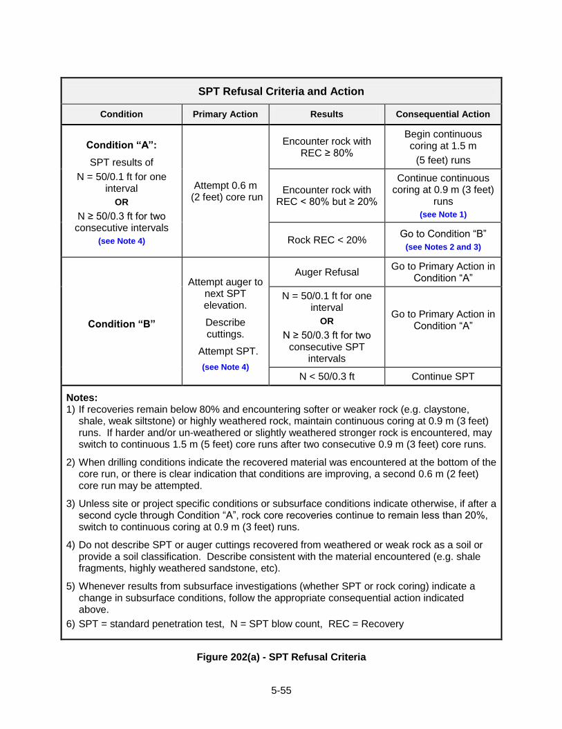
5-55
SPT Refusal Criteria and Action
Condition Primary Action Results Consequential Action
Condition “A”:
SPT results of
N = 50/0.1 ft for one interval
OR
N ≥ 50/0.3 ft for two consecutive intervals
(see Note 4)
Attempt 0.6 m (2 feet) core run
Encounter rock with REC ≥ 80%
Begin continuous coring at 1.5 m
(5 feet) runs
Encounter rock with REC < 80% but ≥ 20%
Continue continuous coring at 0.9 m (3 feet)
runs
(see Note 1)
Rock REC < 20% Go to Condition “B”
(see Notes 2 and 3)
Condition “B”
Attempt auger to next SPT elevation.
Describe cuttings.
Attempt SPT.
(see Note 4)
Auger Refusal Go to Primary Action in
Condition “A”
N = 50/0.1 ft for one interval
OR
N ≥ 50/0.3 ft for two consecutive SPT
intervals
Go to Primary Action in Condition “A”
N < 50/0.3 ft Continue SPT
Notes: 1) If recoveries remain below 80% and encountering softer or weaker rock (e.g. claystone,
shale, weak siltstone) or highly weathered rock, maintain continuous coring at 0.9 m (3 feet) runs. If harder and/or un-weathered or slightly weathered stronger rock is encountered, may switch to continuous 1.5 m (5 feet) core runs after two consecutive 0.9 m (3 feet) core runs.
2) When drilling conditions indicate the recovered material was encountered at the bottom of the core run, or there is clear indication that conditions are improving, a second 0.6 m (2 feet) core run may be attempted.
3) Unless site or project specific conditions or subsurface conditions indicate otherwise, if after a second cycle through Condition “A”, rock core recoveries continue to remain less than 20%, switch to continuous coring at 0.9 m (3 feet) runs.
4) Do not describe SPT or auger cuttings recovered from weathered or weak rock as a soil or provide a soil classification. Describe consistent with the material encountered (e.g. shale fragments, highly weathered sandstone, etc).
5) Whenever results from subsurface investigations (whether SPT or rock coring) indicate a change in subsurface conditions, follow the appropriate consequential action indicated above.
6) SPT = standard penetration test, N = SPT blow count, REC = Recovery
Figure 202(a) - SPT Refusal Criteria
5-56
202.04 MEASUREMENT AND PAYMENT
(a) Soil Borings, NX-Diameter (minimum):
(1) With Continuous SPT Sampling. Linear Foot.
(2) With 5-ft Interval SPT Sampling. Linear Foot.
(3) With _-ft Interval SPT Sampling. Linear Foot.
(4) Unsampled. Linear Foot.
(5) Premium for Soil Borings on Water. Linear Foot.
(6) Premium for Deep Continuous SPT Sampling (60-120 ft). Linear Foot
(7) Premium for Extra Deep Continuous SPT Sampling (>120 ft). Linear Foot
(b) Soil Borings, -Diameter:
(1) With Continuous SPT Sampling. Linear Foot.
(2) With 5-ft Interval SPT Sampling. Linear Foot.
(3) With _-ft Interval SPT Sampling. Linear Foot.
(4) Unsampled. Linear Foot.
(5) Premium for Soil Borings on Water. Linear Foot.
(6) Premium for Deep Continuous SPT Sampling (60-120 ft). Linear Foot
(7) Premium for Extra Deep Continuous SPT Sampling (>120 ft). Linear Foot Payment will be made at the proposed bid price per meter (linear foot) for the actual meter (linear foot) of soil borings completed and accepted by the PGM. Soil borings located on land will be measured from the ground surface to the depth at which rock was encountered, as determined by the PGM, and through any zone in which soil boring and sampling is resumed below a zone of rock drilling or coring. The PGM's identification of rock will be based on SPT refusal and successful initiation of rock coring procedures. Soil borings located on water will be measured from the bed of the body of water, with no payment for depth of water penetrated.
The payment per meter (linear foot) will be considered full payment for all costs associated with the soil boring and standard sampling and testing, including all required labor, equipment, and materials, and all logging, labeling, shipping and storage of soil samples.
The premium per meter (linear foot) for borings on water will be paid in addition to the bid price per meter (linear foot) of similar land borings and will be considered full payment for all costs associated with performing the operation on a body of water, including all required specialized labor, equipment and materials.
The premium for soil borings on water will be paid for the borings noted as such in Attachment 1, Schedule of Proposed Borings.
The premium per meter (linear foot) for deep and extra-deep SPT sampling will be paid in addition to the unit bid price for Item Numbers 202.04(a)(3) and 202.04(b)(3), test borings with continuous SPT sampling. The premium is based on the depth of the soil boring and is a percentage of the contract bid unit price for standard depth Soil Borings With Continuous Split-Barrel Sampling. The premium schedule is indicated in the Table 202(a). The total amount paid for the items specified above, at the depth intervals indicated in the schedule, is determined by multiplying the contract unit price bid for Soil Borings With Continuous SPT Sampling (on land) by the multiplier corresponding to the appropriate depth interval. No depth premium will be paid for borings bid as non-continuous SPT sampling.

5-57
SPT DEPTH INTERVAL DEPTH PREMIUM MULTIPLIER*
Standard (0 to 60 feet) 0% none
Deep (60 to 120 feet) 30% 0.3
Extra Deep (>120 feet) 50% 0.5
*To determine the additional payment per linear foot for the Items and Depth Intervals indicated
Table 202(a) – Depth Premium Schedule for Continuous SPT Sampling
5-58
SECTION 203 - UNDISTURBED SOIL SAMPLING 203.01 DESCRIPTION - This work consists of recovering undisturbed soil samples from soil borings. 203.02 EQUIPMENT - Use equipment specified in ASTM D 1587, Standard Practice for Thin-Walled Tube Sampling of Soils for Geotechnical Purposes, or as directed by the PGM. Provide thin-walled tubes of 16-gauge seamless brass or hard aluminum, or 16- or 18-gauge seamless steel, with a minimum total length of 30 inches and with outside diameter of 3 inches, unless otherwise indicated by the PGM. Use only new, clean, un-corroded tubes removed from the manufactures‟ packaging at the job site. Used sample tubes are not permitted. All equipment will be subject to inspection and approval. Provide all sample tubes with a machine-prepared, sharp cutting edge having a flat bevel to the outside wall of the tube and drawn in to provide an inside clearance beyond the cutting edge of 0.015 inch + 0.005 inch. 203.03 PROCEDURE - Obtain samples in accordance with the procedures of ASTM D 1587, unless otherwise specified herein or by the PGM.
(a) Location. Complete each standard soil boring as specified. Do not attempt undisturbed samples in these borings. Drill an unsampled soil boring in accordance with Section 202.02(b) approximately 3 to 5 feet away from the standard soil boring to a depth specified by the PGM.
(b) Method. Recover undisturbed soil samples by means of special thin-walled tube samplers. When the sampling depth is reached, remove all loose and disturbed materials to the bottom of the casing, hollow-stem auger or open boring. Clean out the last 6 inches above the intended top of the sample with a standard clean-out auger, a clean-out auger with sludge barrel or other means approved by the PGM. Clean out in such a manner that the soil immediately above the top of sample is as nearly undisturbed as possible. Connect the sampling device to the drilling rod, lower slowly to the bottom of the hole, and advance into the soil for a distance of 6 inches less than the total length of the sampling tube. If obstructions, such as gravel particles, prevent the full penetration of the sampler, obtain undisturbed soil samples of a lesser length with approval of the PGM.
Advance thin-walled metal tubes in a continuous downward motion at a rate of 3 to 5 seconds/ft. using the rig hydraulics without rotation, or otherwise as specified, approved or directed by the PGM. Do not drive the sampler unless the character of the soil is such that driving with the hammer is absolutely necessary and is approved by the PGM.
Permit the sampler and sample tube with its contained soil sample to remain in place for a minimum of 15 minutes. After this time period, rotate the drill rod through two complete revolutions to shear the soil immediately below the sample. Carefully remove the tube containing the sample from the boring and detach from the driving head or remove from the sampling device. Do not extrude the sample from the tube.
Remove the disturbed material in the upper end of the tube and measure the sample recovery. Remove ½-inch to 2 inches of material from the lower end of the tube for use in sample description. Completely fill the lower end of the tube, and at least 2 inches in the upper end of the tube immediately above the sample with a hot (melted) sealing wax consisting of paraffin wax, beeswax, microcrystalline wax, or some combination of these wax types. Tightly pack the remaining space in the upper end of the tube with paper, cloth or other approved material. Close the ends of the tube with snug-fitting metal or plastic caps and secure caps in place with adhesive or friction tape. Dip the ends of the tube in hot wax several times to provide an air-tight seal.
5-59
During sampling in very soft soils, if directed by the PGM use a weighted drilling mud, to maintain a pressure on the soil as nearly equal as possible to that existing before the drilling operations.
(c) Records. Record each undisturbed sampling tube in accordance with Section 214. The boring number for the sample shall be the standard soil boring number with the addition of the suffix "A". A separate, complete boring log shall be prepared for each boring made for obtaining samples, whether or not samples are successfully obtained. Package, label, ship, and store samples in accordance with Section 103.
203.04 MEASUREMENT AND PAYMENT
(a) Thin-wall Tube Sampling of Soil, 3-Inch Diameter. Each.
(b) Thin-wall Tube Sampling of Soil, __-Inch Diameter. Each.
Payment will be made in addition to payment for linear feet of unsampled soil boring, at the proposed bid price per unit for each sample successfully removed and accepted by the PGM. Payment will not be made for drilling the interval of the undisturbed sample unless the interval is actually drilled for obtaining additional samples below the initial sample. The payment per sample will be considered full payment for all costs associated with obtaining the sample, including all required labor, equipment and materials, and all logging, packaging, labeling, shipping and storage of samples. No payment will be made for damaged samples or uncollected samples due to Contractor negligence, error, or improper sampling technique. This determination will be made by the PGM. In the event of a failed sample attempt due to Contractor negligence, additional boring or a new unsampled hole may be required to attempt another undisturbed tube sample. No payment will be made for this additional unsampled soil boring.
5-60
SECTION 204 - ROCK DRILLING AND CORING 204.01 DESCRIPTION - This work consists of securing intact samples of rock from borings by diamond core drilling to determine the true nature, arrangement and thickness of rock strata and discontinuities as they exist in the ground, and of advancing unsampled borings through rock. 204.02 PROCEDURES FOR ADVANCING BORINGS IN ROCK
(a) General. Perform rock coring in accordance with ASTM D 2113, Standard Practice for Rock Core Drilling and Sampling of Rock for Site Investigation, except as modified by these specifications, to obtain rock core of the size indicated where the soil boring has refused further penetration by split-barrel sampling. Drill each boring to the final boring depth indicated, or to the depths directed by the PGM. Sample soft or decomposed rock with a driven sampler in accordance with Section 202 when possible.
(b) Equipment. If not specified herein, meet the requirements of ASTM D 2113.
(1) Drill. Use a core drill having hydraulic feed-type mechanisms. Maintain the drill in an efficient and safe operating condition.
(2) Core Barrel. Use a Series "M" swivel-type or better, double-tube core barrel with
a diamond bit and a reaming shell, or a wire-line core barrel with a diamond bit. Maintain the core barrel and bit in efficient operating condition, and replace if damaged or worn. A split inner barrel shall be used on borings, unless otherwise directed by the PGM.
(3) Drill Rods. Provide drill rods having an inside diameter that will permit flow of
drilling fluid through the rods in a quantity sufficient to provide an upward velocity of the fluid between the rod and the hole wall so as to remove the cuttings effectively. Do not drill with drill rods that are not straight.
(4) When directed by the PGM, re-circulate all drill water. Use only potable water for
drill water when drilling operations are within 30 m (100 feet) of any domestic water supply well or spring box.
(c) Procedure for Rock Coring. Make all test borings through appropriate size casing or
hollow-stem augers installed to the bottom of soil borings. Advance the casing or hollow-stem augers to rock and seal into the rock surface to prevent seepage from or sloughing of soil overburden into the bore hole to be cored. Follow length of core runs as prescribed in Figure 202(a).
When coring rock, including shale, claystone and coal, control the speed of the drill and
the drilling pressure, amount and pressure of water, and length of run to give the maximum possible recovery from the rock being drilled. Maximum length of first coring run is two (2) feet. Do not permit grinding of core. Maintain and observe pressure gauges to detect any blocking of core in barrels, and at any suspicion that such is occurring, remove the barrel from the hole and remove the core. Do not continue coring until care has been taken to see that the core barrel, bit and other equipment are in satisfactory operating condition. If poor recovery is experienced due to failure to consider the above factors, redrill the hole at no additional cost.
5-61
If soft or broken rock formations are encountered that cause broken pieces of rock to fall into the hole and cause unsatisfactory coring, or if voids of any type including mined-out coal seams or limestone caverns are encountered that endanger the continued downward progress of the boring, ream and case the hole with flush-joint casing to a point below the broken or open formation. Use a size of flush-joint casing which will permit securing of the specified core size. Repeat this procedure as many times as necessary to keep the hole clean. The use of standard wire line tools of the specified size is a preferred alternative procedure.
Make individual drill runs in the coring operation of not more than 5 feet. Where soft or
broken rocks are encountered or anticipated, reduce the length of runs as indicated in Figure 202(a), or less as directed by the PGM, to reduce the core loss and keep core disturbance to a minimum. Make every effort to obtain maximum core recovery and record in the boring log all significant actions of the bit and reasons for loss of core.
Discontinue core drilling if, in the opinion of the PGM, observations of the barrel indicate
that softer materials have been encountered, and standard split spoon sampling may be resumed. When drilling in carbonate formations, if soil filled voids are encountered, attempt a split-spoon sample to determine the nature of the material contained in the void.
Failure to comply with the foregoing procedures when ample warning of unusual
subsurface conditions has been received in advance, will constitute justification for the PGM or DGE to require redrilling of any boring from which core recovery is unsatisfactory, at no additional cost. When, in the opinion of the PGM, the rock is in either a soft or broken condition, take precautions to keep the core intact as much as possible. Where rock coring with a split inner barrel is specified, dismantle the core barrel horizontally and push the core into a trough or remove the core with equal care by means approved by the PGM/PGE.
Exercise particular care in recording water losses, artesian pressures, rod jerks, changes
in rate of advancement or any other unusual coring experiences which will supplement the core record and further document the nature and extent of fracturing or voids. Mark fractures and their estimated widths in the core boxes and clearly indicate the location of voids.
Immediately upon recovery of the core barrel from the hole, carefully remove the rock
core sample from the barrel, place the rock in core boxes in accordance with Section 215. Describe the rock samples, measure the rock recovery, and prepare the field logs of each rock boring in accordance with Section 214.
After completing each rock boring, install groundwater monitoring according to Section
209, backfill in accordance with Section 210. Package, label, ship and prepare the rock core for storage in accordance with Section
213 and Section 215.
(d) Procedure for Unsampled Rock Drilling. Where it is necessary to advance a rock boring without securing rock core, such as for installing piezometers, slope indicator casing or other field installations, or for performing field tests at a predetermined depth, advance the boring by methods described in Section 204.02 (c), air rotary methods, or by using a tricone roller bit. After completing each unsampled rock boring, backfill in accordance with Section 210.
5-62
204.03 MEASUREMENT AND PAYMENT
(a) NX or NQ Rock Coring. Linear Foot. (b) ________ -Inch Diameter Rock Coring. Linear Foot. (c) ________ -Inch Diameter Unsampled Rock Drilling. Linear Foot. (d) Premium for Rock Drilling and Coring on Water. Linear Foot.
Payment will be made at the proposed bid price per linear foot for the actual linear feet of
rock coring completed and accepted by the PGM. Rock borings located on land will be measured from the depth at which rock was encountered, as determined by the PGM, to the bottom of the rock boring as determined by the PGM. Rock borings located on bodies of water or waterways will be measured in the same manner.
The payment per linear foot will be considered full payment for all costs associated with
rock coring and drilling, including all required labor, equipment and materials, and all logging, packaging, labeling, shipping and storage of rock core.
The premium per linear foot for rock drilling and coring on water will be paid in addition to
the bid price per linear foot for rock drilling and coring of the same size on land, and will be considered full payment for all additional costs associated solely with performing the operations on a body of water or waterway, including all required specialized labor, equipment and materials.
The premium for rock drilling and coring on water will be paid for the borings noted as
such in Attachment 1, Schedule of Proposed Borings.
5-63
SECTION 205 - CONCRETE/MASONRY DRILLING AND CORING 205.01 DESCRIPTION - This work consists of securing intact samples of Portland cement concrete/masonry from borings in pavements or structures by diamond core drilling, and of advancing unsampled borings through Portland cement concrete or masonry. 205.02 PROCEDURES FOR ADVANCING BORINGS IN CONCRETE/MASONRY
(a) General. Perform concrete or masonry coring in accordance with ASTM C 42, Standard Method of Obtaining and Testing Drilled Cores and Sawed Beams of Concrete, except as modified by these specifications to obtain concrete or masonry cores of the size and length indicated.
(b) Equipment. Use a diamond core drill to obtain the required concrete or masonry specimen.
(c) Procedure for Concrete/Masonry Coring. Obtain concrete or masonry core samples by the procedure specified under Section 204.02 (c) for rock coring or other methods approved by the PGM. After completing each boring, backfill in accordance with Section 210.
(d) Procedure for Unsampled Concrete/Masonry Drilling. Where it is necessary to advance a boring through concrete or masonry without securing concrete or masonry core, such as for instrumentation installations or for performing field tests at a predetermined depth, advance the boring by methods described in Section 204.02 (d). After completing each unsampled boring, backfill in accordance with Section 210. 205.03 MEASUREMENT AND PAYMENT
(a) _____ -Inch Diameter Concrete/Masonry Coring and Sampling. Linear Foot.(Each)
(b) _____ -Inch Diameter Unsampled Concrete/Masonry Drilling. Linear Foot.
(c) Premium for Concrete/Masonry Drilling and Coring on Water. Linear Foot. (Each)
Payment will be made at the proposed bid price per linear foot for the actual linear feet of
borings through concrete or masonry completed and accepted by the PGM. Borings through concrete or masonry located on land will be measured from the top of concrete/masonry to the bottom of concrete/ masonry, as determined by the PGM. Borings through concrete/ masonry drilled from locations on bodies of water or waterways will be measured in the same manner.
The payment per linear foot will be considered full payment for all costs associated with
concrete or masonry coring and drilling, including all required labor, equipment and materials, and all logging, packaging, labeling, shipping and storage of concrete or masonry core. The premium per linear foot for concrete/masonry drilling and coring on water will be paid in addition to the bid price per linear foot for concrete/masonry drilling and coring of the same size on land, and will be considered full payment for all additional costs associated solely with performing the operations on a body of water or waterway, including all required specialized labor, equipment and materials.
The premium for concrete/masonry drilling and coring on water will be paid for the
borings noted as such in Attachment 1, Schedule of Proposed Borings.
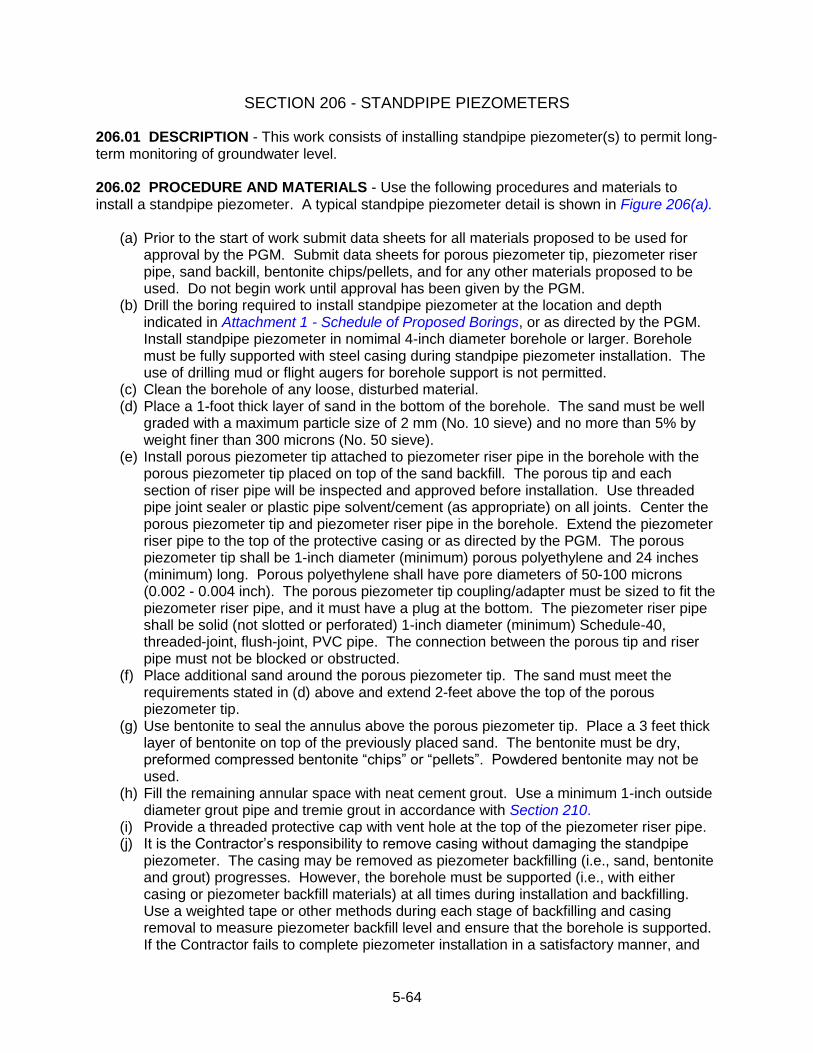
5-64
SECTION 206 - STANDPIPE PIEZOMETERS 206.01 DESCRIPTION - This work consists of installing standpipe piezometer(s) to permit long-term monitoring of groundwater level. 206.02 PROCEDURE AND MATERIALS - Use the following procedures and materials to install a standpipe piezometer. A typical standpipe piezometer detail is shown in Figure 206(a).
(a) Prior to the start of work submit data sheets for all materials proposed to be used for approval by the PGM. Submit data sheets for porous piezometer tip, piezometer riser pipe, sand backill, bentonite chips/pellets, and for any other materials proposed to be used. Do not begin work until approval has been given by the PGM.
(b) Drill the boring required to install standpipe piezometer at the location and depth indicated in Attachment 1 - Schedule of Proposed Borings, or as directed by the PGM. Install standpipe piezometer in nomimal 4-inch diameter borehole or larger. Borehole must be fully supported with steel casing during standpipe piezometer installation. The use of drilling mud or flight augers for borehole support is not permitted.
(c) Clean the borehole of any loose, disturbed material. (d) Place a 1-foot thick layer of sand in the bottom of the borehole. The sand must be well
graded with a maximum particle size of 2 mm (No. 10 sieve) and no more than 5% by weight finer than 300 microns (No. 50 sieve).
(e) Install porous piezometer tip attached to piezometer riser pipe in the borehole with the porous piezometer tip placed on top of the sand backfill. The porous tip and each section of riser pipe will be inspected and approved before installation. Use threaded pipe joint sealer or plastic pipe solvent/cement (as appropriate) on all joints. Center the porous piezometer tip and piezometer riser pipe in the borehole. Extend the piezometer riser pipe to the top of the protective casing or as directed by the PGM. The porous piezometer tip shall be 1-inch diameter (minimum) porous polyethylene and 24 inches (minimum) long. Porous polyethylene shall have pore diameters of 50-100 microns (0.002 - 0.004 inch). The porous piezometer tip coupling/adapter must be sized to fit the piezometer riser pipe, and it must have a plug at the bottom. The piezometer riser pipe shall be solid (not slotted or perforated) 1-inch diameter (minimum) Schedule-40, threaded-joint, flush-joint, PVC pipe. The connection between the porous tip and riser pipe must not be blocked or obstructed.
(f) Place additional sand around the porous piezometer tip. The sand must meet the requirements stated in (d) above and extend 2-feet above the top of the porous piezometer tip.
(g) Use bentonite to seal the annulus above the porous piezometer tip. Place a 3 feet thick layer of bentonite on top of the previously placed sand. The bentonite must be dry, preformed compressed bentonite “chips” or “pellets”. Powdered bentonite may not be used.
(h) Fill the remaining annular space with neat cement grout. Use a minimum 1-inch outside diameter grout pipe and tremie grout in accordance with Section 210.
(i) Provide a threaded protective cap with vent hole at the top of the piezometer riser pipe. (j) It is the Contractor‟s responsibility to remove casing without damaging the standpipe
piezometer. The casing may be removed as piezometer backfilling (i.e., sand, bentonite and grout) progresses. However, the borehole must be supported (i.e., with either casing or piezometer backfill materials) at all times during installation and backfilling. Use a weighted tape or other methods during each stage of backfilling and casing removal to measure piezometer backfill level and ensure that the borehole is supported. If the Contractor fails to complete piezometer installation in a satisfactory manner, and
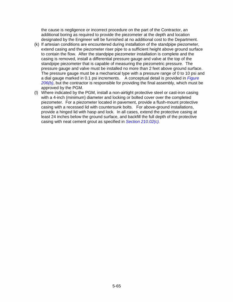
5-65
the cause is negligence or incorrect procedure on the part of the Contractor, an additional boring as required to provide the piezometer at the depth and location designated by the Engineer will be furnished at no additional cost to the Department.
(k) If artesian conditions are encountered during installation of the standpipe piezometer, extend casing and the piezometer riser pipe to a sufficient height above ground surface to contain the flow. After the standpipe piezometer installation is complete and the casing is removed, install a differential pressure gauge and valve at the top of the standpipe piezometer that is capable of measuring the piezometric pressure. The pressure gauge and valve must be installed no more than 2 feet above ground surface. The pressure gauge must be a mechanical type with a pressure range of 0 to 10 psi and a dial gauge marked in 0.1 psi increments. A conceptual detail is provided in Figure 206(b), but the contractor is responsible for providing the final assembly, which must be approved by the PGM.
(l) Where indicated by the PGM, install a non-airtight protective steel or cast-iron casing with a 4-inch (minimum) diameter and locking or bolted cover over the completed piezometer. For a piezometer located in pavement, provide a flush-mount protective casing with a recessed lid with countersunk bolts. For above-ground installations, provide a hinged lid with hasp and lock. In all cases, extend the protective casing at least 24 inches below the ground surface, and backfill the full depth of the protective casing with neat cement grout as specified in Section 210.02(c).
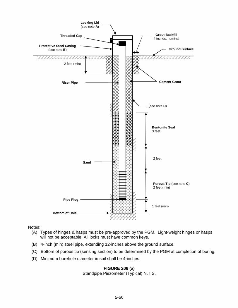
5-66
Notes:
(A) Types of hinges & hasps must be pre-approved by the PGM. Light-weight hinges or hasps will not be acceptable. All locks must have common keys.
(B) 4-inch (min) steel pipe, extending 12-inches above the ground surface.
(C) Bottom of porous tip (sensing section) to be determined by the PGM at completion of boring.
(D) Minimum borehole diameter in soil shall be 4-inches.
FIGURE 206 (a) Standpipe Piezometer (Typical) N.T.S.
Sand
Locking Lid
(see note A)
Threaded Cap
Riser Pipe
2 feet (min)
Cement Grout
Ground Surface
Bottom of Hole
Bentonite Seal 3 feet
2 feet
Porous Tip (see note C) 2 feet (min)
1 feet (min)
Pipe Plug
Grout Backfill 4 inches, nominal
Protective Steel Casing (see note B)
(see note D)
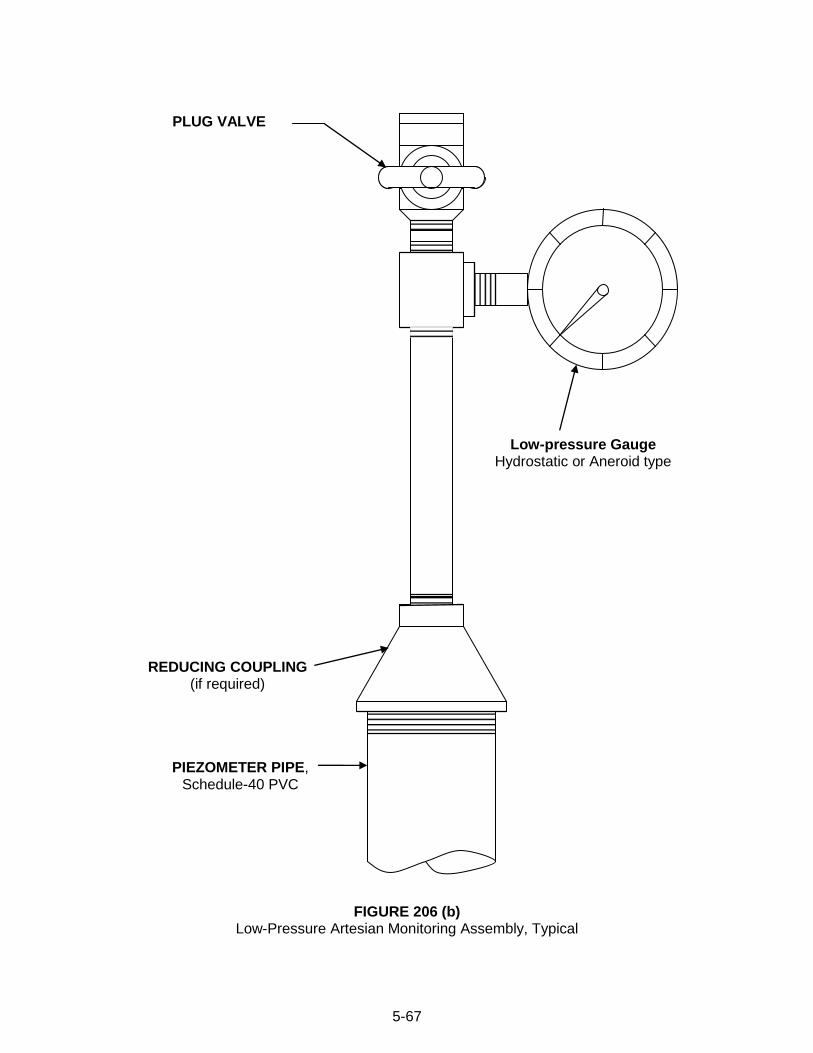
5-67
FIGURE 206 (b) Low-Pressure Artesian Monitoring Assembly, Typical
PLUG VALVE
REDUCING COUPLING (if required)
Low-pressure Gauge Hydrostatic or Aneroid type
PIEZOMETER PIPE, Schedule-40 PVC
5-68
206.03 MEASUREMENT AND PAYMENT
(a) Standpipe Piezometer Linear Foot.
(b) Porous Piezometer Tip Each.
(c) Protective Casing, Above-ground Each.
(d) Protective Casing, Flush Each.
(e) Low-Pressure Artesian Monitoring Assembly Each.
Piezometer pipe will be measured from the top of the pipe to the top of the porous tip.
The payment per linear foot for piezometer pipe installed and accepted will be considered full payment for all costs associated with installation of piezometer in the boring, including all required labor, equipment and materials, but excluding the costs associated with boring advancement, porous tip, piezometer pressure gauge, protective steel casing, and grouting the boring below the bottom of the piezometer, which will be paid for separately. The payment for non-shrink grout below the bottom of the piezometer will be per Section 210.03(a) when additional borehole depth was directed by the PGM.
When installing standpipe piezometer, the cost for additional reaming the boring through bedrock to accommodate the PVC pipe, if required, will be incidental to the cost of PVC pipe.
For each above-ground casing installations, a Master Lock® No. 3 (or equivalent) padlock shall be supplied with labeled keys to the PGM or DGE, and others as needed. The cost of each padlock will be considered incidental to the unit price of the Protective Casing.
5-69
SECTION 207 - INCLINOMETER CASINGS
207.01 DESCRIPTION - This work consists of installing inclinometer casing in a boring to permit monitoring of lateral movement of the ground. 207.02 PROCEDURE AND MATERIALS – Use the following procedures and materials to install inclinometer casing. A typical inclinometer casing detail is shown in Figure 207(a). For procedures and materials not specified herein, use the requirements specified in ASTM D 6230 - 98, “Standard Test Method for Monitoring Ground Movement Using Probe-Type Inclinometers”.
(a) MATERIAL APPROVAL - Prior to the start of work, submit data sheets for all materials proposed to be used for approval by the PGM. Submit data sheets for inclinometer casing, couplings, telescoping sections/couplings, top and bottom caps, grout valves/adapters and for any other material that is proposed to be used. Do not begin work until approval has been given by the PGM.
(b) BOREHOLE ADVANCEMENT - Drill the inclinometer boring at the location indicated in Attachment 1 - Schedule of Proposed Borings, or as directed by the PGM. Drill in accordance with Sections 202, 204 and/or 205 to the depth indicated or as directed by the PGM.
(c) BOREHOLE SIZE – Provide a nominal 4-inch or larger diameter borehole through soil, and nominal 3-inch or larger diameter borehole through rock.
(d) BOREHOLE MAINTENANCE - Borehole through soil must be fully supported with augers, steel casing or drilling mud during inclinometer casing installation.
(e) BOREHOLE CLEANING - Remove any loose, disturbed material from the borehole before installation of the inclinometer casing. As directed, flush the borehole with clean water until the return water is clear.
(f) CASING INSTALLATION - Orient the casing such that one set of casing grooves is aligned with the expected direction of maximum lateral ground movement. Lower casing into the borehole, adding clean water inside the casing as needed to overcome buoyancy. Do not apply pressure to the top of the casing as this may alter the profile of the casing and cause it to “snake”. Do not twist the inclinometer casing from the top as this can cause the grooves of the inclinometer casing to spiral. Install the inclinometer casing to a minimum of 10 feet into rock or 20 feet below the zone of suspected movement, as directed by the PGM.
(g) CASING ASSEMBLY - Provide ABS plastic inclinometer casing having a 2.75-inch outside diameter, four machined longitudinal grooves equally spaced around the inside circumference. Use self-aligning, flush casing with ABS plastic top and bottom caps. Connect casing sections using either integral/built-in couplings or flush ABS plastic couplings. Connect casing sections and top and bottom caps in accordance with manufacturer‟s recommendations.
(h) TELESCOPING CASING SECTIONS - When indicated or directed by the PGM, provide ABS plastic telescoping sections/couplings that are compatible with the casing to permit settlement or heave of the casing. The number and location of telescoping sections/couplings will be provided by the PGM. Connect telescoping sections/couplings in accordance with manufacturer‟s recommendations. Install all telescoping sections fully extended. To prevent premature compression when using telescoping casing and couplings, do not allow the casing to rest on the bottom of the borehole until backfilling is
5-70
complete, and grout has set (if applicable). If placing casing in a water-filled hole, it may be necessary to load the casing with clean water to provide the necessary ballast to lower the casing.
(i) GROUT ADAPTER - The use of fabricated grout valves placed at the bottom of the casing will be permitted. Flushing of the casing may be required if a ball-check type valve is used. When a grout adapter or grout valve is used at the bottom of the casing to grout the borehole, provide an adapter or valve that is compatible with the casing and that is recommended by the manufacturer. Connect adapter/valve in accordance with manufacturer‟s recommendations.
(j) CASING ACCEPTANCE - After the inclinometer casing has been installed in the borehole but prior to backfilling, allow the PGM to inspect the inclinometer casing either visually and/or with a dummy probe or other device.
(k) CASING BACKFILL - Once the PGM has accepted the inclinometer casing, tremie grout the annular space between the borehole and inclinometer casing with cement grout. Whenever possible, backfill the installation before or during removal of the casing or hollow stem augers. Use one of the grout mixes as specified in Section 210.02(b). Grout through either the grout valve/adapter connected to a grout tube going down inside the inclinometer casing, or a minimum 1-inch diameter grout pipe placed at the bottom of the boring inserted outside the inclinometer casing. Place grout in accordance with Section 210. Where the bottom of the inclinometer casing is more than 5 feet above the bottom of the boring, backfill the lower portion of the boring by tremie grouting and allowing it to set at least twelve (12) hours, or backfill as approved or directed by the DGE. Use grout mixture as specified in Section 210.02(c). When groundwater measurements are required use sand backfill (do not use grout backfill).
(l) AUGER/CASING REMOVAL - The Contractor is responsible to remove augers/casing without raising, twisting, or damaging the inclinometer casing. Do not twist or rotate the augers/casing to remove. Only use the direct-pull method. The augers/casing may be removed as grouting progresses, however, the open borehole in soil zones must be supported (i.e., with either augers/casing or grout) at all times during installation and backfilling. Use a weighted tape or other methods during grouting and auger/casing removal to measure piezometer backfill level and ensure that the borehole is supported. If the Contractor fails to complete inclinometer casing installation in a satisfactory manner, and the cause is negligence or incorrect procedure on the part of the Contractor, an additional boring as required to provide the inclinometer casing at the depth and location designated by the Engineer will be furnished at no additional cost to the Department.
(m) PROTECTIVE STEEL CASING - Install protective casing and locking cap as indicated or as directed by the PGM. If indicated or directed, install a steel or cast-iron protective casing over the completed inclinometer casing. Set the bottom of the protective casing at least 2 feet below the ground surface, and backfill the full depth of the protective casing with grout as specified in Section 210.02(c). For above-ground installations, Figure 207(c), extend the 4-inch diameter (minimum) protective casing 2 feet above the surrounding ground surface, and provide a lockable steel lid with lock and key. Installations above the ground surface must have the inclinometer casing extend a minimum of 2 inches above the top of the protective casing unless the protective casing has a minimum diameter of 10 inches. For installations in roadway or shoulder pavements, install a flush steel casing with well-fitting and secure steel lid. Install lid at grade level, and having a minimum diameter of 10 inches, and secured with bolts or equivalent means. Refer to Figure 207(c) for typical installation detail. In all cases
5-71
where a minimum 10 inch diameter protective casing is used, the top of the ABS plastic inclinometer casing shall be a maximum of 2 inches below the top of the protective steel casing. The protective casing assembly must be able to withstand any external loads and traffic wheel loads without being dislodged or damaged.
207.03 MEASUREMENT AND PAYMENT
(a) Inclinometer Casing Linear Foot. (b) Protective Casing, Above-ground Each. (c) Protective Casing, Flush Each.
The payment per linear foot for inclinometer casing installed and accepted will be
considered full payment for all costs associated with installation of inclinometer casing in the borehole, including all required labor, equipment and materials, but excluding the costs associated with boring advancement, protective casing and grouting the boring below the bottom of the inclinometer casing, which will be paid for separately. Inclinometer casing will be measured inside the casing from the top of the casing to the top of the bottom cap.
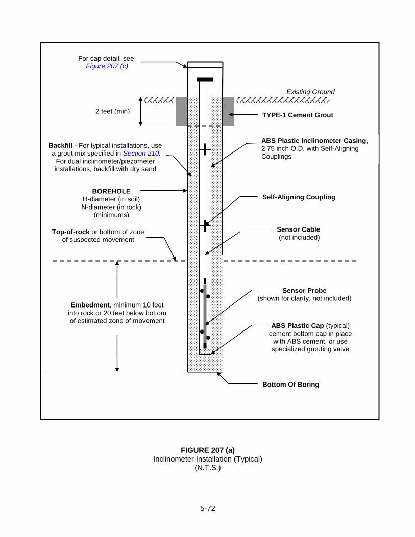
5-72
FIGURE 207 (a) Inclinometer Installation (Typical)
(N.T.S.)
Backfill - For typical installations, use a grout mix specified in Section 210.
For dual inclinometer/piezometer installations, backfill with dry sand
2 feet (min) TYPE-1 Cement Grout
Existing Ground
For cap detail, see Figure 207 (c)
BOREHOLE H-diameter (in soil) N-diameter (in rock)
(minimums)
Sensor Cable (not included)
Sensor Probe (shown for clarity, not included)
ABS Plastic Cap (typical) cement bottom cap in place
with ABS cement, or use specialized grouting valve
ABS Plastic Inclinometer Casing, 2.75 inch O.D. with Self-Aligning Couplings
Embedment, minimum 10 feet into rock or 20 feet below bottom of estimated zone of movement
Bottom Of Boring
Top-of-rock or bottom of zone of suspected movement
Self-Aligning Coupling
●
● ●
●
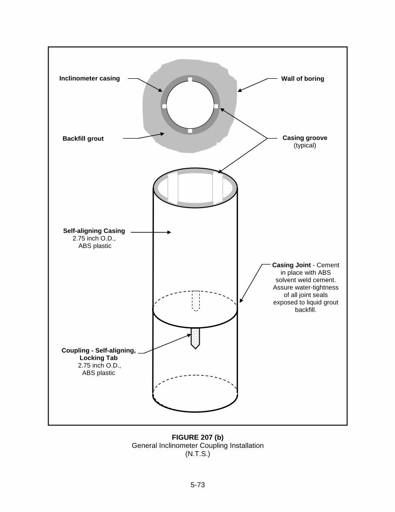
5-73
FIGURE 207 (b)
General Inclinometer Coupling Installation (N.T.S.)
Coupling - Self-aligning, Locking Tab
2.75 inch O.D., ABS plastic
Self-aligning Casing 2.75 inch O.D.,
ABS plastic
Inclinometer casing
Backfill grout Casing groove (typical)
Wall of boring
Casing Joint - Cement in place with ABS
solvent weld cement. Assure water-tightness
of all joint seals exposed to liquid grout
backfill.
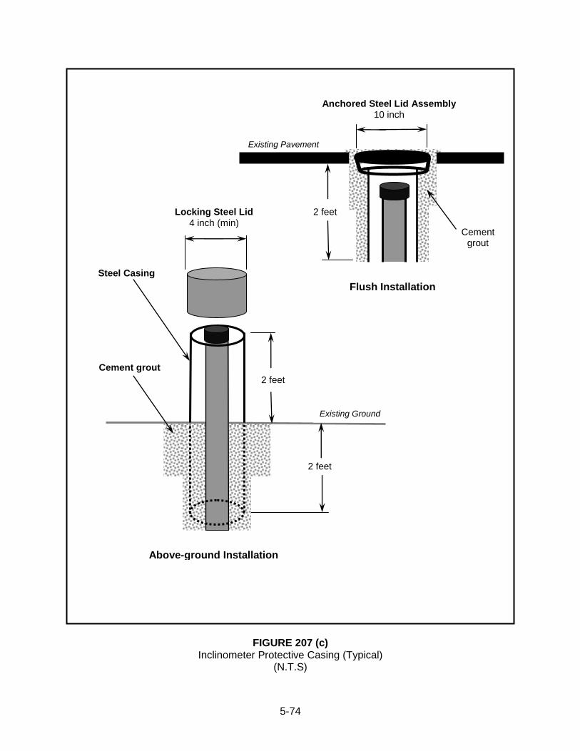
5-74
FIGURE 207 (c)
Inclinometer Protective Casing (Typical) (N.T.S)
Above-ground Installation
Locking Steel Lid 4 inch (min)
Anchored Steel Lid Assembly 10 inch
Flush Installation
2 feet
2 feet
Existing Ground
Existing Pavement
Cement grout
Cement grout
2 feet
Steel Casing
5-75
SECTION 209 - GROUNDWATER OBSERVATIONS 209.01 DESCRIPTION - This work consists of observing and measuring groundwater conditions during the subsurface boring, sampling, and testing operations. 209.02 PROCEDURES - Measure groundwater levels and record on the field logs for all completed borings. Measure groundwater levels to the nearest 0.1 ft. using an electronic water level indicator with an audible or visual signal. Record completely in the boring logs any unusual water conditions and depths at which there is a gain or loss of water, or return of water after a loss during boring operations. Record the depths at which water under excess pressure is observed. When water under excess pressure is observed, stop the drilling operation and extend the casing above the ground surface so as to contain the flow of water, or temporarily attach a low-pressure gauge at the top of the boring to permit measurement of water pressure. After allowing the water level or pressure to come to equilibrium, measure and record the height of water above the ground surface or the water pressure at the top of the boring. Measure and record groundwater levels immediately after boring is completed, before pulling casing or removing hollow-stem augers (0-hr reading); and twenty-four hours later (24-hr reading).
If the initial borehole casing is to be pulled prior to obtaining all required groundwater readings, install temporary 1-inch ID (minimum) PVC pipe prior to removal of drill casing or augers to permit the measurement of groundwater levels. Provide a sensing section in the bottom 5 feet consisting of PVC pipe having staggered 1/8-inch wide slots or 3/8-inch diameter holes that are cut at maximum 6-inch center-to-center spacing. This pipe will also be used to tremie grout the hole when closing the boring in accordance with Section 210. Accordingly, do not place a permanent cap or plug on the bottom of the pipe.
If more than one (1) day is required to complete a boring, take groundwater readings at the end of each days operation and immediately prior to the resuming of drilling operations.
When an open-boring process is followed utilizing natural or commercial drilling mud to stabilize the hole, install temporary casing after completion of the hole. After installation of temporary casing, flush the hole thoroughly with clean water at the completion of the boring prior to measuring groundwater levels. After flushing, remove any water from casing and hole by pumping or bailing the temporary casing. After pumping or bailing, allow sufficient time for the groundwater to achieve equilibrium prior to measuring groundwater levels.
209.03 MEASUREMENT AND PAYMENT - No separate measurement or payment for this work.
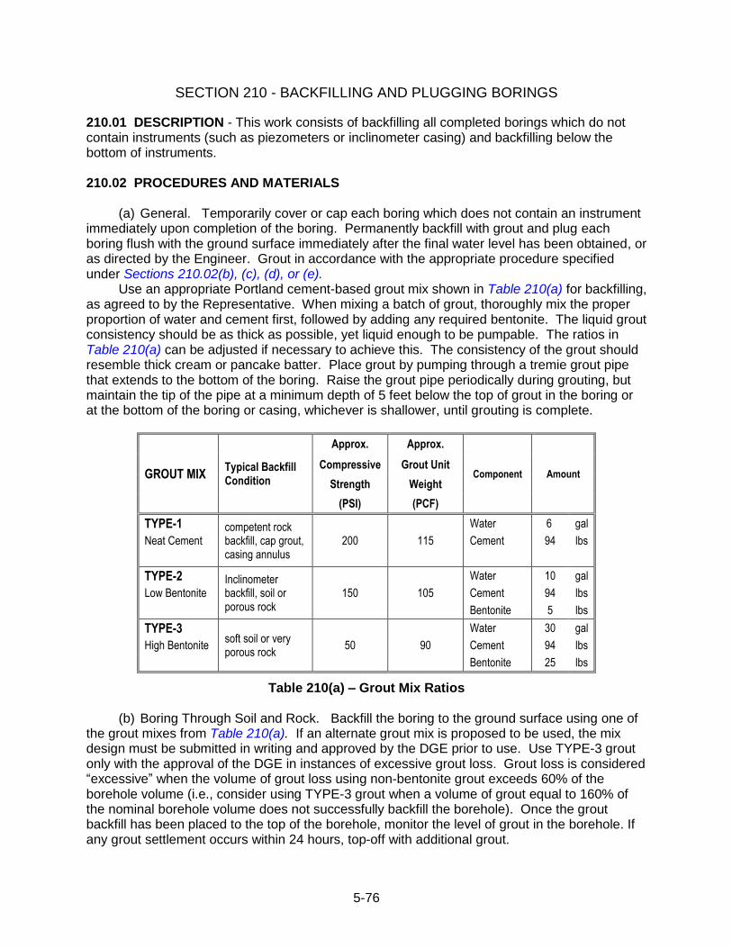
5-76
SECTION 210 - BACKFILLING AND PLUGGING BORINGS 210.01 DESCRIPTION - This work consists of backfilling all completed borings which do not contain instruments (such as piezometers or inclinometer casing) and backfilling below the bottom of instruments. 210.02 PROCEDURES AND MATERIALS
(a) General. Temporarily cover or cap each boring which does not contain an instrument immediately upon completion of the boring. Permanently backfill with grout and plug each boring flush with the ground surface immediately after the final water level has been obtained, or as directed by the Engineer. Grout in accordance with the appropriate procedure specified under Sections 210.02(b), (c), (d), or (e).
Use an appropriate Portland cement-based grout mix shown in Table 210(a) for backfilling, as agreed to by the Representative. When mixing a batch of grout, thoroughly mix the proper proportion of water and cement first, followed by adding any required bentonite. The liquid grout consistency should be as thick as possible, yet liquid enough to be pumpable. The ratios in Table 210(a) can be adjusted if necessary to achieve this. The consistency of the grout should resemble thick cream or pancake batter. Place grout by pumping through a tremie grout pipe that extends to the bottom of the boring. Raise the grout pipe periodically during grouting, but maintain the tip of the pipe at a minimum depth of 5 feet below the top of grout in the boring or at the bottom of the boring or casing, whichever is shallower, until grouting is complete.
GROUT MIX Typical Backfill Condition
Approx. Approx.
Component Amount Compressive Grout Unit
Strength Weight
(PSI) (PCF)
TYPE-1 competent rock backfill, cap grout, casing annulus
200 115
Water 6 gal
Neat Cement Cement 94 lbs
TYPE-2 Inclinometer backfill, soil or porous rock
150 105
Water 10 gal
Low Bentonite Cement 94 lbs
Bentonite 5 lbs
TYPE-3 soft soil or very porous rock
50 90
Water 30 gal
High Bentonite Cement 94 lbs
Bentonite 25 lbs
Table 210(a) – Grout Mix Ratios (b) Boring Through Soil and Rock. Backfill the boring to the ground surface using one of
the grout mixes from Table 210(a). If an alternate grout mix is proposed to be used, the mix design must be submitted in writing and approved by the DGE prior to use. Use TYPE-3 grout only with the approval of the DGE in instances of excessive grout loss. Grout loss is considered “excessive” when the volume of grout loss using non-bentonite grout exceeds 60% of the borehole volume (i.e., consider using TYPE-3 grout when a volume of grout equal to 160% of the nominal borehole volume does not successfully backfill the borehole). Once the grout backfill has been placed to the top of the borehole, monitor the level of grout in the borehole. If any grout settlement occurs within 24 hours, top-off with additional grout.
5-77
(c) Grouting of Protective Casing. Backfill around the outside of the protective casing with a TYPE-1 grout mix as shown in Table 210(a), or an alternative grout mix approved by the DGE.
(d) Boring Through Mine Voids(s) or Limestone Cavern(s). Install a grouting basket or plug in the boring immediately above the top of the mine or cavern, and place a 5 foot plug of Type-A fine aggregate meeting Publication 408, Section 703.1 on top of the basket or plug. Backfill the boring as described in Section 210 (a) and (b).
In the event multiple voids (mines or caverns) are penetrated by a boring, backfill the boring with grout in stages. In the first stage, backfill below the lowest void as described above. In the second stage, backfill the strata between the two lowest voids by supporting a grout basket on a 1-1/4 inch (minimum) diameter pipe with the bottom of the pipe on the bottom of the lowest void and the grout basket located in the rock strata above the lowest void. With the grout basket in place, grout the portion of the boring between the two lowest voids as described above. If NX standard wire line equipment is used to core the rock, extract the NX casing to the top of the zone being backfilled in the second stage and maintain in place until the second stage of grouting is completed.
Allow each stage of grouting to set a minimum of twelve (12) hours before proceeding with the next stage. Perform the third and subsequent stages of grouting as specified for the second stage. Perform the final stage of grouting to the ground surface as specified above for a boring penetrating one mine or cavern.
(e) Boring Through Pavement, Sidewalk, Bridge Deck, Floor Slab or Wall. Backfill the boring with grout as described in Section 210 (a) and (b) to the bottom or back of the pavement, sidewalk, floor slab or wall.
In concrete or asphalt, pavements or slabs, plug the boring at the top with a non-ferrous, non-shrink, fast-setting cement-based grout of a strength and thickness equal to the original structure, pavement or slab. Use grout which exhibits no shrinkage when tested in accordance with ASTM C 827, Standard Test Method for Early Volume Change of Cementitious Mixtures.
In plugging borings through bridge decks, provide temporary support or forming for the plug, acceptable to the DGE.
In concrete structures, grout the boring for the full depth of the boring with a non-ferrous, non-shrink, fast setting cement based grout of a strength equal to the original structure, but not less than 3,000 pounds per square inch. 210.03 MEASUREMENT AND PAYMENT
(a) Cement Grout Backfill in Soil or Rock. Linear Foot (b) Grouting Basket or Plug in Soil or Rock. Each (c) Non-Shrink Cement Grout in Concrete Structure. Linear Foot (d) Non-Shrink Cement Grout Plug in Concrete or Asphalt. Each
Payment made for each listed item, completed and accepted, will be considered full
payment for all costs associated with installing the indicated item, including all required labor, equipment and material. Measurement will be made of the actual units installed and accepted. Measurement of sand-cement grout backfill will be from the top of the grout to the bottom of grout, or from the top of the grout to the top of the grout basket, or plug in a boring penetrating a mine void or limestone cavern.
5-78
SECTION 211 - TEST PITS 211.01 DESCRIPTION - This work consists of providing and operating equipment suitable for excavating and backfilling test pits for subsurface exploration, sampling and testing. 211.02 EQUIPMENT AND PROCEDURES - Provide excavation equipment, such as a backhoe or tracked excavator, capable of excavating to a depth of 10 feet and as specified in the Instructions to Bidders and the Form of Proposal. Excavate the test pit consistent with the applicable OSHA requirements for safe, open excavations. Backfill the test pit in maximum 1-ft lifts, compacting the fill material with the excavator bucket, or as required by contract special provision. The Contractor shall not mobilize the excavation equipment unless directed by the PGM. Provide one qualified and experienced operator for each piece of excavation equipment. Provide equipment with sufficient capacity and power to perform the required work. 211.03 MEASUREMENT AND PAYMENT
(a) Test Pit, Mobilization. Each. (b) Test Pit, Excavation. Hours. (c) Test Pit, Standby. Hours.
The Test Pit, Mobilization pay item will be considered full payment for all costs associated
with the scheduling, delivery, and removal of the test pit excavation equipment from the site.
Payment per-hour for Test Pit, Excavation will be considered full payment for all costs associated with operating the excavator on-site, including the operator and all other required labor, equipment and supplies. Measurement will be made of actual hours on site as required perform the work. No payment will be made for time lost due to equipment failure, or time work is performed which is unauthorized, unacceptable, or unnecessary to meet the required standard to excavate and backfill.
Payment for Test Pit, Standby will be made only when the PGM or representative determines/authorizes the use of Standby time is appropriate. Payment made for hours of Standby will be considered full payment for all costs associated with maintaining the indicated equipment and personnel on site and ready to commence or resume work. Measurement will be made of actual hours on site of each excavator with operator in an ordered or approved state of Standby to the nearest one-half hour. In no case will the Standby time plus work time per day exceed one normal 8-hour work shift unless designated in the Instructions to Bidders and Form of Proposal.

5-79
SECTION 212 - STANDBY FOR BORINGS 212.01 DESCRIPTION - This work consists of maintaining core boring equipment and work forces on site in a state of readiness to commence or resume subsurface exploration, sampling and testing operations during a time period for which temporary suspension or interruption of such work has been ordered or approved. 212.02 PROCEDURE - Maintain equipment and work forces as directed on site in a state that will permit immediate commencement or resumption of exploration, sampling and testing operations. 212.03 MEASUREMENT AND PAYMENT
(a) Standby, Borings on Land, Equipment and Work Crew. Hours (b) Standby, Borings on Water, Equipment and Work Crew. Hours
Payment for Standby will only be made when the Project Geotechnical Manager (PGM) or
representative determines/authorizes the use of Standby time is appropriate. Payment made for hours of Standby will be considered full payment for all costs associated with maintaining the indicated equipment and personnel on site and ready to commence or resume work. For borings on land and borings on water, equipment will include all equipment, materials and supplies necessary to make borings, obtain samples and perform testing specified.
Measurement will be made of actual hours on site of each drill rig with crew in an ordered or approved state of standby to the nearest one-half hour. In no case will the standby time plus work time per day exceed one normal 8-hour work shift unless designated in the Instructions to Bidders and Form of Proposal. Standby time will not be allowed when the Contractor is performing specialized testing such as Vane Shear, Pressuremeter, Cone Penetrometer, Dilatometer, etc.. When the PGM or representative performs testing that requires Contractor delay (such as a Borehole camera survey) Standby will be paid accordingly.
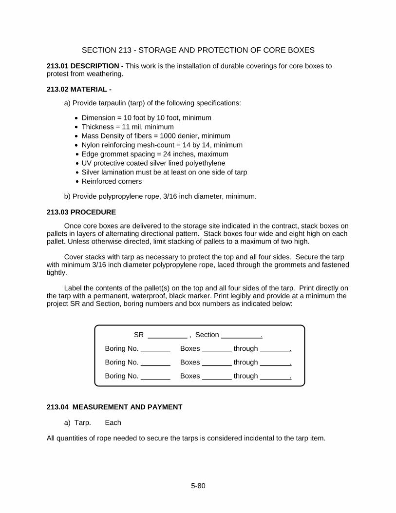
5-80
SECTION 213 - STORAGE AND PROTECTION OF CORE BOXES 213.01 DESCRIPTION - This work is the installation of durable coverings for core boxes to protest from weathering. 213.02 MATERIAL -
a) Provide tarpaulin (tarp) of the following specifications:
Dimension = 10 foot by 10 foot, minimum
Thickness = 11 mil, minimum
Mass Density of fibers = 1000 denier, minimum
Nylon reinforcing mesh-count = 14 by 14, minimum
Edge grommet spacing = 24 inches, maximum
UV protective coated silver lined polyethylene
Silver lamination must be at least on one side of tarp
Reinforced corners
b) Provide polypropylene rope, 3/16 inch diameter, minimum. 213.03 PROCEDURE
Once core boxes are delivered to the storage site indicated in the contract, stack boxes on pallets in layers of alternating directional pattern. Stack boxes four wide and eight high on each pallet. Unless otherwise directed, limit stacking of pallets to a maximum of two high. Cover stacks with tarp as necessary to protect the top and all four sides. Secure the tarp with minimum 3/16 inch diameter polypropylene rope, laced through the grommets and fastened tightly. Label the contents of the pallet(s) on the top and all four sides of the tarp. Print directly on the tarp with a permanent, waterproof, black marker. Print legibly and provide at a minimum the project SR and Section, boring numbers and box numbers as indicated below:
SR , Section .
Boring No. Boxes through .
Boring No. Boxes through .
Boring No. Boxes through . 213.04 MEASUREMENT AND PAYMENT a) Tarp. Each All quantities of rope needed to secure the tarps is considered incidental to the tarp item.
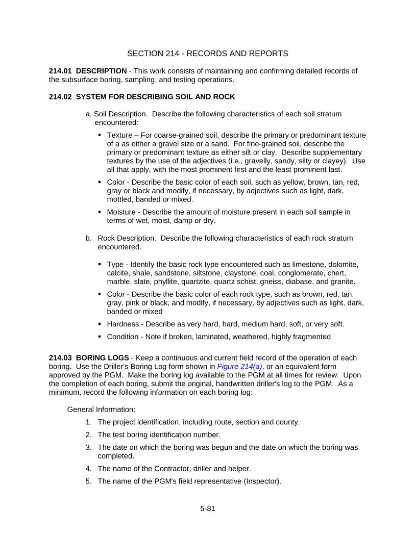
5-81
SECTION 214 - RECORDS AND REPORTS 214.01 DESCRIPTION - This work consists of maintaining and confirming detailed records of the subsurface boring, sampling, and testing operations. 214.02 SYSTEM FOR DESCRIBING SOIL AND ROCK
a. Soil Description. Describe the following characteristics of each soil stratum encountered:
Texture – For coarse-grained soil, describe the primary or predominant texture of a as either a gravel size or a sand. For fine-grained soil, describe the primary or predominant texture as either silt or clay. Describe supplementary textures by the use of the adjectives (i.e., gravelly, sandy, silty or clayey). Use all that apply, with the most prominent first and the least prominent last.
Color - Describe the basic color of each soil, such as yellow, brown, tan, red, gray or black and modify, if necessary, by adjectives such as light, dark, mottled, banded or mixed.
Moisture - Describe the amount of moisture present in each soil sample in terms of wet, moist, damp or dry.
b. Rock Description. Describe the following characteristics of each rock stratum
encountered.
Type - Identify the basic rock type encountered such as limestone, dolomite,
calcite, shale, sandstone, siltstone, claystone, coal, conglomerate, chert, marble, slate, phyllite, quartzite, quartz schist, gneiss, diabase, and granite.
Color - Describe the basic color of each rock type, such as brown, red, tan, gray, pink or black, and modify, if necessary, by adjectives such as light, dark, banded or mixed
Hardness - Describe as very hard, hard, medium hard, soft, or very soft.
Condition - Note if broken, laminated, weathered, highly fragmented
214.03 BORING LOGS - Keep a continuous and current field record of the operation of each boring. Use the Driller's Boring Log form shown in Figure 214(a), or an equivalent form approved by the PGM. Make the boring log available to the PGM at all times for review. Upon the completion of each boring, submit the original, handwritten driller's log to the PGM. As a minimum, record the following information on each boring log:
General Information:
1. The project identification, including route, section and county.
2. The test boring identification number.
3. The date on which the boring was begun and the date on which the boring was completed.
4. The name of the Contractor, driller and helper.
5. The name of the PGM's field representative (Inspector).
5-82
6. The elevation of the top of the test boring (if available).
7. The location of the test boring relative to project reference line (i.e., segment, offset and offset from centerline) or other suitable reference points.
8. The type of drill rig used.
9. The drilling method used to advance the boring in soil.
10. The inside and outside diameter and depth of any casing used.
11. The type and weight of hammer and free fall used to advance the split-barrel sampler, the number of rope turns on the cathead (1-3/4 or 2-1/4), and the diameter of the sampler. Note whether the hammer is automatic (high efficiency) or manual (standard, low efficiency).
12. Hammer Efficiency Rating (ER), if known.
13. The length of the split spoon sampler.
14. The drilling method used to advance the boring in rock.
15. The type and size of core barrel used and bit designation.
Specific Boring, Sampling and Testing Information:
1. The depth, type, number and recovery of each soil sample. Number soil samples sequentially with an “S-” prefix.
2. The blows per 150 mm (6 inches) or less to advance the split-barrel sampler.
3. The length of core run and length of recovered core for each run of rock core. Number rock core runs sequentially with an “R-” prefix.
4. A description of each soil and rock strata encountered, the depth to the top and bottom of each stratum, and discontinuities in each strata.
5. Depth to ground water level, elapsed time after completion of drilling and date on which observation was made.
6. Depths at which undisturbed samples are taken.
7. Difficulties in drilling (obstructions, caving, boulders, rising of sand into bottom of boring, etc.) including the basis for any loss of soil sample or rock core.
8. Depth of loss and/or return of circulating water and increase in usage of drilling water.
9. Any additional information (such as changes in the color of drill return water, tool drops, drilling advancement rate, etc.) which may be of assistance in defining the presence of strata changes, boulders, voids or other subsurface conditions.
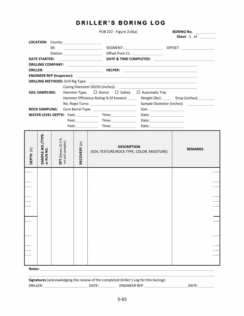
5-83
PUB 222 - Figure 214(a) BORING No. Sheet 1 of
LOCATION: County:
SR: SEGMENT: OFFSET:
Station: Offset from CL:
DATE STARTED: DATE & TIME COMPLETED:
DRILLING COMPANY:
DRILLER: HELPER:
ENGINEER REP (Inspector):
DRILLING METHODS: Drill Rig Type:
Casing Diameter OD/ID (inches):
SOIL SAMPLING: Hammer Type: Donut Safety Automatic Trip
Hammer Efficiency Rating % (if known): Weight (lbs): Drop (inches):
No. Rope Turns: Sample Diameter (inches):
ROCK SAMPLING: Core Barrel Type: Size:
WATER LEVEL DEPTH: Feet: Time: Date:
Feet: Time: Date:
Feet: Time: Date:
DEP
TH (
ft)
SAM
PLE
NO
./T
YP
E o
r R
UN
NO
.
SPT
(blo
ws
/0.5
ft.
o
n s
oil
sam
ple
r)
REC
OV
ERY
(in
)
DESCRIPTION (SOIL TEXTURE/ROCK TYPE, COLOR, MOISTURE)
REMARKS
Notes:
Signatures (acknowledging the review of the completed Driller’s Log for this boring):
DRILLER: DATE: ENGINEER REP. DATE:
D R I L L E R ’ S B O R I N G L O G
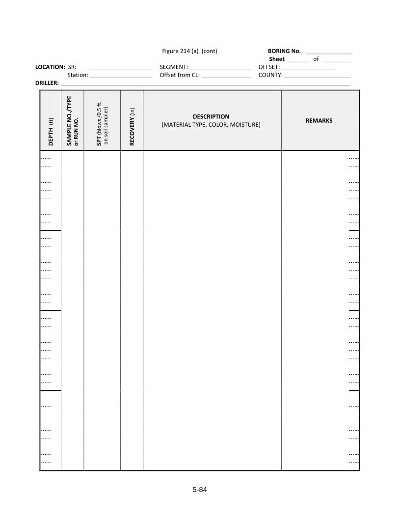
5-84
Figure 214 (a) (cont) BORING No. Sheet _______ of _________
LOCATION: SR: SEGMENT: OFFSET: Station: Offset from CL: COUNTY:
DRILLER:
DEP
TH (
ft)
SAM
PLE
NO
./T
YP
E o
r R
UN
NO
.
SPT
(blo
ws
/0.5
ft.
o
n s
oil
sam
ple
r)
REC
OV
ERY
(in
)
DESCRIPTION (MATERIAL TYPE, COLOR, MOISTURE)
REMARKS
5-85
214.04 DAILY DRILLING QUANTITY SUMMARIES - The Contractor will maintain and update daily a record for each drill rig of the work completed including footage of drilling in soil and rock. The record will document the quantity of each pay item listed in the Form of Proposal completed during the day, and will be summarized weekly. The record will also indicate, for each day, the driller's name, the helper's name and the hours worked. The Driller and Inspector shall review and sign the record daily to indicate agreement with the quantities listed as complete, and note any disagreement with the listed quantities. Provide data to the Inspector/PGM as needed to facilitate accurate documentation of the work on the record. One copy of the record will be made available to the Inspector/PGM at the end of each work day. 214.05 MEASUREMENT AND PAYMENT - No separate measurement or payment for this work.
5-86
SECTION 215 - PACKAGING, PROTECTION AND SHIPMENT OF SAMPLES 215.01 DESCRIPTION - This work consists of packaging, protecting and shipping soil and rock samples in a manner that will facilitate sample identification and minimize the potential for sample disturbance or damage. 215.02 PACKAGING OF SAMPLES
(a) Samples Boxes. Provide new or refurbished wooden core boxes as shown in Figure 215(a) for packaging, shipment and storage of split-barrel soil samples and rock core samples. Boxes must be stenciled in black paint according to Publication 222, Figure 3.8(b). Construct the core boxes and partitions so as to restrain the sample jars and rock cores against shifting during transport. Assist as necessary to properly place core samples in the core boxes. Unless the PGE or DGE directs otherwise, when two borings have minor amounts of recovered sample (such as very shallow and/or low recovery borings) it is permissible to place samples from both borings in a single core box. (b) Sample Jars. Provide new glass sample jars approximately 125 mm (5 inches) high and approximately 50 mm (2 inches) inside diameter at the mouth, and with an inside diameter of not more than 6 mm (¼-inch) larger than that at the mouth. Provide the jars with a metal screw cap containing a rubber or waxed paper gasket. Provide self-adhesive, printed labels placed on the side of each jar to record the required information as shown in Publication 222, Figure 3.8(c). 215.03 PROTECTION AND SHIPMENT OF SAMPLES
(a) Split-Barrel Soil and Rock Core Samples. Provide suitable dry storage for all samples until completion of all required subsurface exploration sampling and testing contract work items. At the completion of work, carefully ship all samples to the location indicated in the Instructions to Bidders, or as directed by the PGM. No payment will be made for boring and sampling operations associated with samples that are damaged or missing as a result of Contractor negligence. (b) Undisturbed Soil Samples. Unless specified otherwise by contract or directed by the PGM or DGE, undisturbed samples shall be packaged and transported according to “Group D” sample procedures given in ASTM D 4220, Standard Practices for Preserving and Transporting Soil Samples. These procedures include protecting the undisturbed soil samples from vibration, impact, bumping, dropping, rolling, etc. by proper packaging and cushioning. Samples are to be handled, stored and shipped in the same orientation in which they were taken. Protect samples from freezing or excessive heat. Metal or plastic tube caps shall be provided and used to seal the sample tubes. Provide wood, metal, or other suitable type of shipping container that adequately cushions and insulates the undisturbed samples. Deliver or ship the undisturbed samples in a timely manner to the location indicated in the Instructions to Bidders, or as directed by the PGM. For all modes of transporting samples, the loading, transport, and unloading of sample containers will be monitored by the Inspector or other qualified person such as the PGE, geologist, or soils technician. No payment will be made for boring and sampling operations associated with samples that are damaged or missing as a result of Contractor negligence. 215.04 MEASUREMENT AND PAYMENT - No separate measurement or payment for this work.
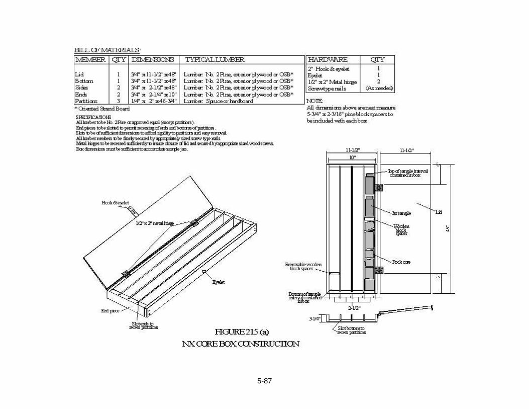
5-87
5-88
SECTION 216 - MAINTENANCE AND PROTECTION OF TRAFFIC 216.01 DESCRIPTION - This work consists of maintaining and protecting traffic in and adjacent to the area where subsurface exploration, sampling and testing operations are being performed. 216.02 MATERIAL - Furnish material and traffic control devices necessary for the maintenance and protection of traffic, and conforming to the Traffic Control Plan and national Manual on Uniform Traffic Control Devices (MUTCD), 67 Pa. Code, Chapter 212, and Publication 213. 216.03 PROCEDURES - Comply with the requirements of Section 103.13 and 67 Pa. Code, Chapter 212. Install and maintain the traffic control devices as required or directed. Schedule operations to permit movement of traffic with minimum interference. If traffic interruptions become too frequent, cease operations in the area concerned, as directed. Take satisfactory remedial action to correct the situation before continuing operations. Provide personnel, equipment, and material in accordance with Pennsylvania Department of Transportation Publication 408 and 67 Pa. Code, Chapter 212, Publication 213 to control traffic through work zones and to provide safety for the work force. Submit traffic control plan for approval. 216.04 MEASUREMENT AND PAYMENT (a) Maintenance and Protection of Traffic. Lump Sum. This item will be measured and paid for at the lump sum bid price upon completion of the project.
5-89
SECTION 217 - AUGER BORING FOR BULK SOIL SAMPLES 217.01 DESCRIPTION - This work consists of obtaining bulk soil samples for laboratory testing, using auger tools to advance the boring and obtain the required sample. 217.02 PROCEDURES FOR ADVANCING AUGER BORINGS
(a) General. Perform auger boring and sampling as per ASTM D 1452, except where modified by this specification.
(b) Equipment. Use solid flight helical augers having a diameter from 150 mm (6 inches) to 400 mm (16 inches), or other equipment as approved by the PGM.
(c) Procedure. Advance the augers to the top of the sampling depth specified by the PGM. Remove the augers and clean the flights as necessary to ensure a subsequent representative sample. Return the augers to the previous depth, advance the augers to the bottom of the sample depth indicated, remove the augers, and take the soil sample directly from the auger flights. Samples should consist of a minimum 22.5 kg (50 pounds) of soil, and are to be placed in a plastic lined canvas sample bag. If required, continue the procedure to obtain additional samples from depths indicated or specified by the PGM.
Mark the sample bag with the S.R. number, Section number, Boring number, Station and Offset, and the exact depths at which the sample was obtained. Use a permanent marker when identifying the information on the sample bag. In addition, place a representative sample in a jar of the type indicated in Section 215.02(b), label the jar as per Figure 215(c), and store the jars in a sample box described in Figure 215.02(a).
Use of casing will be required if the boring collapses upon removal of the augers, below the ground water elevation, or where specified by the PGM. The inside diameter of the casing must by larger than the diameter of the augers used. Advance the casing to the depth indicated, clean the casing using the auger (or other approved method), and reinsert the auger to take the sample as per the previous paragraph. 217.03 MEASUREMENT AND PAYMENT (a) Auger Boring Linear Foot Linear feet payment includes all labor and materials involved with bagged bulk samples.
5-90
SECTION 218 - CONTRACTOR RECALL
218.01 DESCRIPTION – The Contractor may be subject to a recall in order to complete additional test borings or test pits after the original Contract work is completed, approved, and the Contractor has demobilized. The possible recall will be within six (6) months of demobilization. The Contractor will have three (3) weeks to mobilize the drill rig or excavator needed, as agreed on through negotiation. 218.02 PROCEDURE – It will be the responsibility of the Contractor to renew the Insurance certificate and verify that all utilities remain clear. The contract Bond and Additional Bond for Labor and Materials will be held by the PGM for the duration of the recall. All unit prices shall remain in effect for the duration of the recall. 218.03 MEASUREMENT AND PAYMENT (a) Recall, Drill Rig Lump Sum. For Contactor recall requiring an additional Test Pit(s), the unit prices for Test Pit Mobilization, Item 211.03(a), and Test Pit Excavation, Item 211.03(b), will be applicable for payment for test pit work.
5-91
SECTION 219 - TEMPORARY POTABLE WATER SUPPLY 219.01 DESCRIPTION Provide temporary potable water service to any impacted landowner when directed by the Representative (PGM). 219.02 MATERIALS Provide all necessary equipment such as supply truck, storage tank, piping, parts, connections and valves to connect to the landowner‟s water supply system. Provide storage tank of sufficient volume. Protect storage tank from freezing and pressurize if necessary. 219.03 PROCEDURE The PGM will immediately notify the Contractor of any landowner having a water supply potentially impacted by drilling. Within 8 hours of direction from the PGM, provide a sufficient quantity of potable bottled water to the affected landowner. Provide sufficient quantities of bottled water for each permanent resident in the impacted dwelling, sufficient defined as one gallon per day of drinking water for each individual and five gallons per day for cooking and personal hygiene per each impacted dwelling. Within 36 hours of direction from the PGM/PGE, install a functioning temporary water service and supply at least 375 L (100 gallons) of water per day per resident affected. Maintain continuous operation of the temporary water system until directed by the PGM that adverse effects are abated or within the limits defined in the contract, whichever is sooner. Notify the PGM and the impacted landowner prior to connection and disconnection of the temporary water service. It is the responsibility of the Contractor to provide suitable/reliable temporary potable water service (i.e. supply) that replaces the impacted landowner‟s water supply well due to negative impacts from drilling operations. 219.04 MEASUREMENT AND PAYMENT (a) Hookup and Disconnect of Temporary Potable Water Supply. Lump Sum The lump sum payment includes all bottled water supplied, and the hookup and disconnect of the temporary supply. (b) Temporary Potable Water Supply. Week A unit payment will be made for each week (consecutive 7 days), and any remaining portion thereof, that the temporary pressurized water supply is connected and functioning. Payment includes all quantities of pressurized water supplied.

5-92
SUBCHAPTER 5F - CONTRACT BONDS
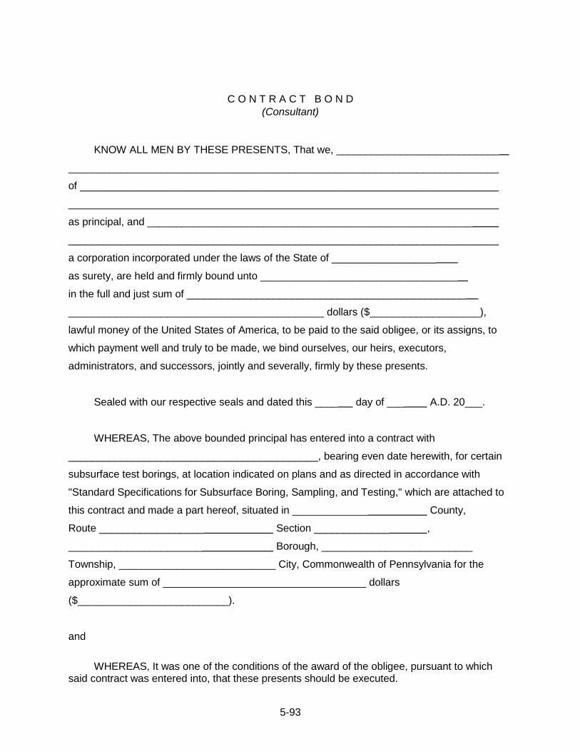
5-93
C O N T R A C T B O N D
(Consultant)
KNOW ALL MEN BY THESE PRESENTS, That we, ____________________________
__________________________________________________________________________
of ________________________________________________________________________
__________________________________________________________________________
as principal, and ________________________________________________________
__________________________________________________________________________
a corporation incorporated under the laws of the State of __________________
as surety, are held and firmly bound unto __________________________________
in the full and just sum of ________________________________________________
____________________________________________ dollars ($___________________),
lawful money of the United States of America, to be paid to the said obligee, or its assigns, to
which payment well and truly to be made, we bind ourselves, our heirs, executors,
administrators, and successors, jointly and severally, firmly by these presents.
Sealed with our respective seals and dated this ____ day of ___ A.D. 20___.
WHEREAS, The above bounded principal has entered into a contract with
___________________________________________, bearing even date herewith, for certain
subsurface test borings, at location indicated on plans and as directed in accordance with
"Standard Specifications for Subsurface Boring, Sampling, and Testing," which are attached to
this contract and made a part hereof, situated in _____________ County,
Route __________________ Section _____________ ,
_______________________ Borough, __________________________
Township, ___________________________ City, Commonwealth of Pennsylvania for the
approximate sum of ___________________________________ dollars
($__________________________).
and
WHEREAS, It was one of the conditions of the award of the obligee, pursuant to which
said contract was entered into, that these presents should be executed.

5-94
NOW, THEREFORE, The condition of this obligation is such that if the above bounded principal as contractor shall in all respects comply with and perform the terms and conditions of said contract, and his, their, or its obligations thereunder, including the specifications therein referred to and made a part thereof, and such alterations as may be made in said specifications as therein provided for, and shall well and truly, and in a manner satisfactory to the obligee, complete the work contracted for, and shall save harmless the obligee from any expense incurred through the failure of said contractor to complete the work as specified, or for any damages growing out of the carelessness of said contractor or his, their, or its servants, and shall save and keep harmless the said obligee against and from all losses to it from any cause whatever, including patent, trademark, and copyright infringements, in the manner of constructing said section of roadway; and shall, on the completion of the contract in an acceptable manner, file with the Department of Transportation an Application for Release of Final Payments, which application shall set forth, inter alia, that all claims for labor and materials used in connection with the execution of the contract have been satisfactorily settled, said application to be executed by a duly authorized representative of the company appearing as surety; then this obligation to be void, otherwise to remain in full force and virtue.
It is further provided that any alterations which may be made in the terms of the contract or in the work to be done under it or the giving by the obligee of any extension of time for the performance of the contract or any other forbearance on the part of either the obligee or the principal to the other shall not in any way release the principal and the surety or sureties or either or any of them, their heirs, executors, administrators, successors, or assigns, from their liability hereunder, notice to the surety or sureties of any such alteration, extension, or forbearance being hereby waived.
________________________________
(Company)
Attest: By
___________________________________(SEAL) __________________________(SEAL)
(Authorized Officer)
________________________________
(Surety Company)
Attest: By
___________________________________(SEAL) ________________________________
(Title)
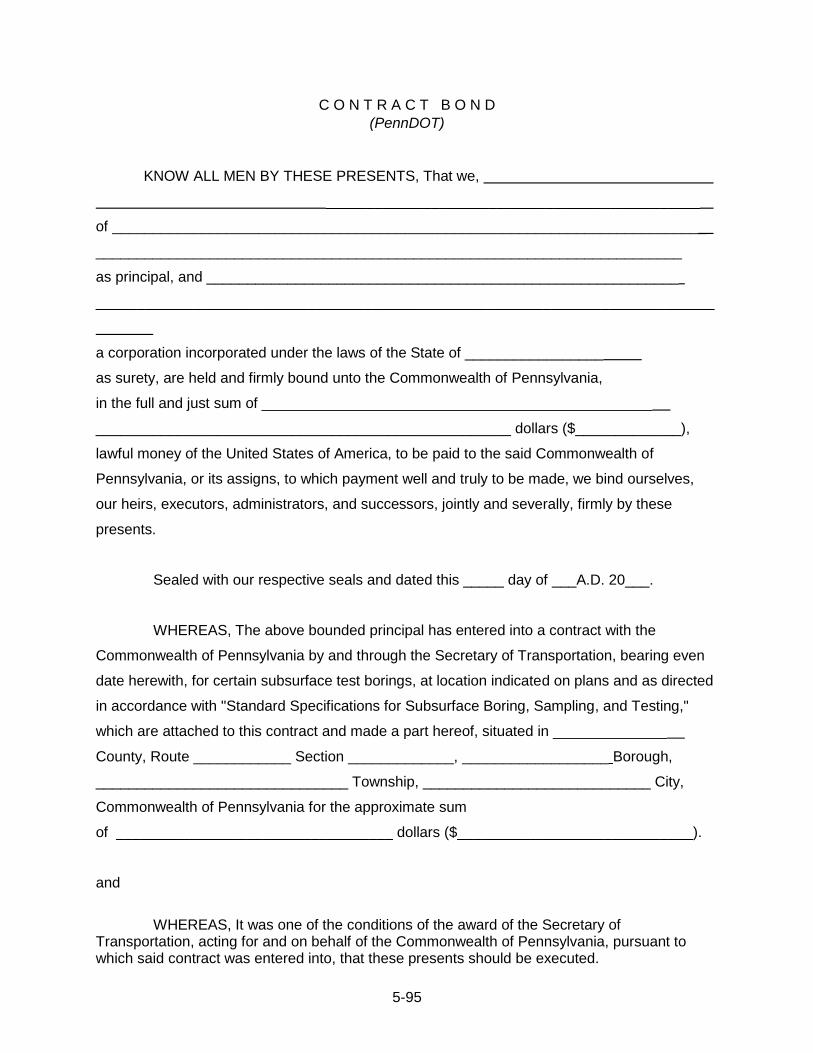
5-95
C O N T R A C T B O N D
(PennDOT)
KNOW ALL MEN BY THESE PRESENTS, That we,
______________________________________________
of _________________________________________________________________________
________________________________________________________________________
as principal, and __________________________________________________________
____________________________________________________________________________
a corporation incorporated under the laws of the State of _________________
as surety, are held and firmly bound unto the Commonwealth of Pennsylvania,
in the full and just sum of ________________________________________________
___________________________________________________ dollars ($_____________),
lawful money of the United States of America, to be paid to the said Commonwealth of
Pennsylvania, or its assigns, to which payment well and truly to be made, we bind ourselves,
our heirs, executors, administrators, and successors, jointly and severally, firmly by these
presents.
Sealed with our respective seals and dated this _____ day of ___A.D. 20___.
WHEREAS, The above bounded principal has entered into a contract with the
Commonwealth of Pennsylvania by and through the Secretary of Transportation, bearing even
date herewith, for certain subsurface test borings, at location indicated on plans and as directed
in accordance with "Standard Specifications for Subsurface Boring, Sampling, and Testing,"
which are attached to this contract and made a part hereof, situated in ______________
County, Route ____________ Section _____________, __________________ Borough,
_______________________________ Township, ____________________________ City,
Commonwealth of Pennsylvania for the approximate sum
of __________________________________ dollars ($_____________________________).
and
WHEREAS, It was one of the conditions of the award of the Secretary of
Transportation, acting for and on behalf of the Commonwealth of Pennsylvania, pursuant to which said contract was entered into, that these presents should be executed.
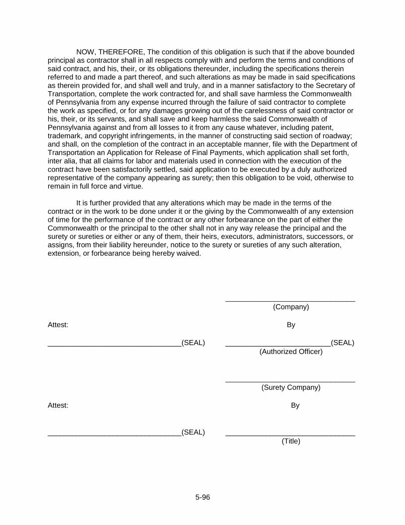
5-96
NOW, THEREFORE, The condition of this obligation is such that if the above bounded principal as contractor shall in all respects comply with and perform the terms and conditions of said contract, and his, their, or its obligations thereunder, including the specifications therein referred to and made a part thereof, and such alterations as may be made in said specifications as therein provided for, and shall well and truly, and in a manner satisfactory to the Secretary of Transportation, complete the work contracted for, and shall save harmless the Commonwealth of Pennsylvania from any expense incurred through the failure of said contractor to complete the work as specified, or for any damages growing out of the carelessness of said contractor or his, their, or its servants, and shall save and keep harmless the said Commonwealth of Pennsylvania against and from all losses to it from any cause whatever, including patent, trademark, and copyright infringements, in the manner of constructing said section of roadway; and shall, on the completion of the contract in an acceptable manner, file with the Department of Transportation an Application for Release of Final Payments, which application shall set forth, inter alia, that all claims for labor and materials used in connection with the execution of the contract have been satisfactorily settled, said application to be executed by a duly authorized representative of the company appearing as surety; then this obligation to be void, otherwise to remain in full force and virtue.
It is further provided that any alterations which may be made in the terms of the contract or in the work to be done under it or the giving by the Commonwealth of any extension of time for the performance of the contract or any other forbearance on the part of either the Commonwealth or the principal to the other shall not in any way release the principal and the surety or sureties or either or any of them, their heirs, executors, administrators, successors, or assigns, from their liability hereunder, notice to the surety or sureties of any such alteration, extension, or forbearance being hereby waived.
________________________________
(Company)
Attest: By
_________________________________(SEAL) __________________________(SEAL)
(Authorized Officer)
________________________________
(Surety Company)
Attest: By
_________________________________(SEAL) ________________________________
(Title)

5-97
SUBCHAPTER 5G - ADDITIONAL BOND FOR LABOR AND MATERIALS
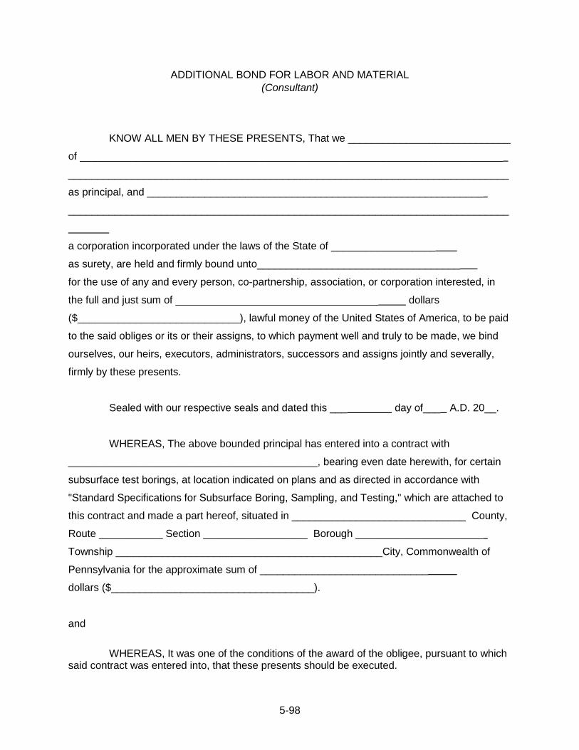
5-98
ADDITIONAL BOND FOR LABOR AND MATERIAL
(Consultant)
KNOW ALL MEN BY THESE PRESENTS, That we ____________________________
of _________________________________________________________________________
____________________________________________________________________________
as principal, and __________________________________________________________
____________________________________________________________________________
a corporation incorporated under the laws of the State of __________________
as surety, are held and firmly bound unto___________________________________
for the use of any and every person, co-partnership, association, or corporation interested, in
the full and just sum of ___________________________________ dollars
($____________________________), lawful money of the United States of America, to be paid
to the said obliges or its or their assigns, to which payment well and truly to be made, we bind
ourselves, our heirs, executors, administrators, successors and assigns jointly and severally,
firmly by these presents.
Sealed with our respective seals and dated this ___ day of___ A.D. 20__.
WHEREAS, The above bounded principal has entered into a contract with
___________________________________________, bearing even date herewith, for certain
subsurface test borings, at location indicated on plans and as directed in accordance with
"Standard Specifications for Subsurface Boring, Sampling, and Testing," which are attached to
this contract and made a part hereof, situated in ______________________________ County,
Route ___________ Section __________________ Borough ______________________
Township ______________________________________________City, Commonwealth of
Pennsylvania for the approximate sum of _____________________________
dollars ($___________________________________).
and
WHEREAS, It was one of the conditions of the award of the obligee, pursuant to which
said contract was entered into, that these presents should be executed.
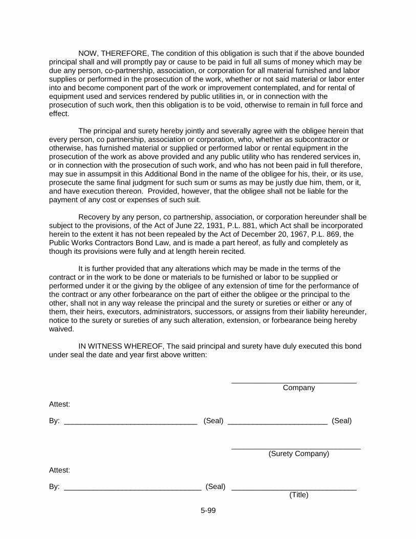
5-99
NOW, THEREFORE, The condition of this obligation is such that if the above bounded principal shall and will promptly pay or cause to be paid in full all sums of money which may be due any person, co-partnership, association, or corporation for all material furnished and labor supplies or performed in the prosecution of the work, whether or not said material or labor enter into and become component part of the work or improvement contemplated, and for rental of equipment used and services rendered by public utilities in, or in connection with the prosecution of such work, then this obligation is to be void, otherwise to remain in full force and effect.
The principal and surety hereby jointly and severally agree with the obligee herein that
every person, co partnership, association or corporation, who, whether as subcontractor or otherwise, has furnished material or supplied or performed labor or rental equipment in the prosecution of the work as above provided and any public utility who has rendered services in, or in connection with the prosecution of such work, and who has not been paid in full therefore, may sue in assumpsit in this Additional Bond in the name of the obligee for his, their, or its use, prosecute the same final judgment for such sum or sums as may be justly due him, them, or it, and have execution thereon. Provided, however, that the obligee shall not be liable for the payment of any cost or expenses of such suit.
Recovery by any person, co partnership, association, or corporation hereunder shall be subject to the provisions, of the Act of June 22, 1931, P.L. 881, which Act shall be incorporated herein to the extent it has not been repealed by the Act of December 20, 1967, P.L. 869, the Public Works Contractors Bond Law, and is made a part hereof, as fully and completely as though its provisions were fully and at length herein recited.
It is further provided that any alterations which may be made in the terms of the contract or in the work to be done or materials to be furnished or labor to be supplied or performed under it or the giving by the obligee of any extension of time for the performance of the contract or any other forbearance on the part of either the obligee or the principal to the other, shall not in any way release the principal and the surety or sureties or either or any of them, their heirs, executors, administrators, successors, or assigns from their liability hereunder, notice to the surety or sureties of any such alteration, extension, or forbearance being hereby waived.
IN WITNESS WHEREOF, The said principal and surety have duly executed this bond under seal the date and year first above written:
______________________________ Company
Attest: By: ________________________________ (Seal) ________________________ (Seal)
_______________________________ (Surety Company)
Attest: By: _________________________________ (Seal) ______________________________
(Title)
5-100
ADDITIONAL BOND FOR LABOR AND MATERIAL
(PennDOT)
KNOW ALL MEN BY THESE PRESENTS, That we, ___________________________
____________________________________________________________________________
of _________________________________________________________________________
as principal, and __________________________________________________________
____________________________________________________________________________
a corporation incorporated under the laws of the State of __________________ as surety, are
held and firmly bound unto the Commonwealth of Pennsylvania, for the use of any and every
person, co partnership, association, or corporation interested, in the full and just sum
of _________________________________________________________________ dollars
($________________________), lawful money of the United States of America, to be paid to
the said obliges or its or their assigns, to which payment well and truly to be made, we bind
ourselves, our heirs, executors, administrators, successors and assigns jointly and severally,
firmly by these presents.
Sealed with our respective seals and dated this ____day of___ A.D. 20__.
WHEREAS, The above bounded principal has entered into a contract with the
Commonwealth of Pennsylvania by and through the Secretary of Transportation, bearing even
date herewith, for certain subsurface test borings, at location indicated on plans and as directed
in accordance with "Standard Specifications for Subsurface Boring, Sampling, and Testing,"
which are attached to this contract and made a part hereof, situated in ______________
County, Route ______________ Section _________________ Borough _________________
Township ______________________________ City, Commonwealth of Pennsylvania for the
approximate sum of________________ dollars
($_______________________________).
and
WHEREAS, It was one of the conditions of the award of the Secretary of Transportation acting for and on behalf of the Commonwealth of Pennsylvania, pursuant to which said contract was entered into, that these presents should be executed.
5-101
NOW, THEREFORE, The condition of this obligation is such that if the above bounded principal shall and will promptly pay or cause to be paid in full all sums of money which may be due any person, co-partnership, association, or corporation for all material furnished and labor supplies or performed in the prosecution of the work, whether or not said material or labor enter into and become component part of the work or improvement contemplated, and for rental of equipment used and services rendered by public utilities in, or in connection with the prosecution of such work, then this obligation is to be void, otherwise to remain in full force and effect.
The principal and surety hereby jointly and severally agree with the obligee herein that
every person, co partnership, association or corporation, who, whether as subcontractor or otherwise, has furnished material or supplied or performed labor or rental equipment in the prosecution of the work as above provided and any public utility who has rendered services in, or in connection with the prosecution of such work, and who has not been paid in full therefore, may sue in assumpsit in this Additional Bond in the name of the Commonwealth for his, their, or its use, prosecute the same final judgment for such sum or sums as may be justly due him, them, or it, and have execution thereon. Provided, however, that the Commonwealth shall not be liable for the payment of any cost or expenses of such suit.
Recovery by any person, co partnership, association, or corporation hereunder shall be subject to the provisions, of the Act of June 22, 1931, P.L. 881, which Act shall be incorporated herein to the extent it has not been repealed by the Act of December 20, 1967, P.L. 869, the Public Works Contractors Bond Law, and is made a part hereof, as fully and completely as though its provisions were fully and at length herein recited.
It is further provided that any alterations which may be made in the terms of the contract or in the work to be done or materials to be furnished or labor to be supplied or performed under it or the giving by the Commonwealth of any extension of time for the performance of the contract or any other forbearance on the part of either the Commonwealth or the principal to the other, shall not in any way release the principal and the surety or sureties or either or any of them, their heirs, executors, administrators, successors, or assigns from their liability hereunder, notice to the surety or sureties of any such alteration, extension, or forbearance being hereby waived.
IN WITNESS WHEREOF, The said principal and surety have duly executed this bond under seal the date and year first above written: _______________________________ Company Attest: By: ________________________________ (Seal) ____________________________ (Seal) ________________________________
(Surety Company) Attest: By: ________________________________ (Seal)

5-102
SUBCHAPTER 5H - CONTRACT APPENDICES Contract appendices are developed on a project-specific basis and typically include necessary supplemental and supportive information such as:
Project Location Map
Boring Location Plan
Proposed Detour Routes
Required Maintenance and Protection of Traffic Figures

A-1
-------------------------------------------------------------------------------------------------------------------------------
APPENDIX A - List of Acronyms
-------------------------------------------------------------------------------------------------------------------------------
AASHTO American Association of State Highway and Transportation Officials AMRL AASHTO Materials Reference Laboratory. ASTM American Society for Testing and Materials BL Base Line BST Boring, Sampling & Testing CGE Chief Geotechnical Engineer CFR Code of Federal Regulations CD Compact Disc CF Cubic Feet CL Center Line CPT Cone Penetration Testing DGCE/A District Grade Crossing Engineer/Administrator DGE District Geotechnical Engineer DLE District Liaison Engineer DMT Dilatometer Testing DPM District Project Manager DSP Designated Special Provisions DVD Digital Video Disk ECMS Engineering and Construction Management System ER Efficiency Rating FHWA Federal Highway Administration GMW Groundwater Monitoring Well GPS Global Positioning System HASP Health And Safety Plan LAT Latitude LF Linear Foot LONG Longitude MUTCD Manual on Uniform Traffic Control Devices OG Original Ground OSHA Occupational Safety & Health Administration PennDOT Pennsylvania Department of Transportation PE Professional Engineer PG Professional Geologist PGE Project Geotechnical Engineer PGM Project Geotechnical Manager POC Purchase Order Contract PMT Pressuremeter Testing PR Performance Report PUB Publication ROE Right of Entry ROW Right of Way RQD Rock Quality Designation SBST Subsurface Boring, Sampling, and Testing SCBA Self Contained Breathing Apparatus SEC Section SEG Segment SIQAC Subsurface Investigation Quality Assurance Committee SPT Standard Penetration Testing SR State Route STA Station USCS Unified Soil Classification System VST Vane Shear Testing

B-1
-------------------------------------------------------------------------------------------------------------------------------
APPENDIX B - Generic Health and Safety Plan for Remedial Investigation Activities
------------------------------------------------------------------------------------------------------------------------------

B-2
This is a generic Health and Safety Plan (HASP) which can be used by PennDOT as an
example HASP outline for future review of project-specific HASP documents submitted by the
contractor.
Included in the Health and Safety Plan are explicit requirements relative to the site such
as, but not limited to: employee training; personal protective equipment projected for the site;
medical surveillance particular to potential site exposure; frequency and types of air monitoring,
personnel exposure to hazardous substances by zonation of the site operations according to
areas of contamination and procedures for site emergencies; safe work practices and
identification of medical assistance; decontamination procedures to minimize personnel contact
with hazardous substances and equipment thereof; emergency response plan necessary to
effectively handle anticipated emergencies prior to an actual emergency, (e.g., lines of authority,
evacuation, critique, and emergency equipment) confined space entry procedures; and spill
containment procedures should transfer, transport, or disposal of hazardous material be
deemed necessary.

B-3
HASP SIGN-OFF SHEET
The following personnel have read and fully understand the contents of the HASP. NAME DATE COMPANY SIGNATURE _____________ _____________ _________________ _______________ _____________ _____________ _________________ _______________ _____________ _____________ _________________ _______________ _____________ _____________ _________________ _______________ _____________ _____________ _________________ _______________ _____________ _____________ _________________ _______________ _____________ _____________ _________________ _______________ _____________ _____________ _________________ _______________ _____________ _____________ _________________ _______________ _____________ _____________ _________________ _______________ _____________ _____________ _________________ _______________ _____________ _____________ _________________ _______________

B-4
HASP TABLE OF CONTENTS
Section 1 Introduction
1.1 Scope of Work
1.2 Site Description
1.3 Site Map
1.4 Site Communications
1.5 Emergency Signal
Section 2 Organizational Structure
Section 3 Site Health and Safety Risks
Section 4 Work Zones and Site Control
Section 5 Air Monitoring
Section 6 Personal Protective Equipment (PPE)
Section 7 Decontamination
Section 8 Emergency Response
Section 9 Site Security
Section 10 Employee Training and Medical Surveillance
Section 11 Confined Space Entry
Section 12 Chemical Hazards (MSDS sheets)
Section 13 Standard Operating Procedures
B-5
SECTION 1 – INTRODUCTION
This Health and Safety Plan has been prepared for ____________ to be conducted by
____________ field personnel within ____________ . The plan has been prepared in
accordance with 29 CFR 1910.120 Hazardous Waste Operations and Emergency Response,
Final Rule. The information included in this plan has been collected from all available sources
pertaining to potential hazards within ____________ .
1.1 Scope of Work ____________________________________________________________________________ ____________________________________________________________________________ ____________________________________________________________________________ ____________________________________________________________________________ 1.2 Site Description ____________________________________________________________________________ ____________________________________________________________________________ ____________________________________________________________________________ ____________________________________________________________________________ 1.3 Site Map
B-6
1.4 Site Communications ____________________________________________________________________________ ____________________________________________________________________________ ____________________________________________________________________________ ____________________________________________________________________________
1.5 Emergency Signal:
____________________________________________________________________________
____________________________________________________________________________
____________________________________________________________________________
____________________________________________________________________________

B-7
SECTION 2 - ORGANIZATIONAL STRUCTURE
The organizational structure section establishes the specific project chain-of-command and specifies the overall responsibilities of supervisors and employees. The site supervisor (SS) has the responsibility and authority to direct all site waste operations. The site health and safety officer (SSO) has the responsibility/authority to develop and implement the HASP to verify compliance with the plan. This organizational structure shall be made available to all affected employees and shall be reviewed and updated as necessary to reflect the current status of waste site operations. NAME TITLE/POSITION COMPANY ____________________ ____________________ ____________________ ____________________ ____________________ ____________________ ____________________ ____________________ ____________________ ____________________ ____________________ ____________________ ____________________ ____________________ ____________________ ____________________ ____________________ ____________________ ____________________ ____________________ ____________________ ____________________ ____________________ ____________________ ____________________ ____________________ ____________________ ____________________ ____________________ ____________________ ____________________ ____________________ ____________________ ____________________ ____________________ ____________________ ____________________ ____________________ ____________________ ____________________ ____________________ ____________________ ____________________ ____________________ ____________________ ____________________ ____________________ ____________________

B-8
SECTION 3 – SITE HEALTH AND SAFETY RISKS The health and safety risks at the site included chemical hazards listed in Table ____ and physical health hazards involved with heavy sampling equipment. ____________________________________________________________________________ ____________________________________________________________________________ ____________________________________________________________________________ ____________________________________________________________________________ ____________________________________________________________________________ ____________________________________________________________________________ Standard operating procedures listed in Appendix III include machinery and mechanized equipment safety. In addition to these procedures, the following guidelines will be observed during drilling operations.
1. Prior to drilling, adequate site preparation should be performed to accommodate the drill rig and supplies and provide a safe working environment.
2. Overhead and buried utilities must be located prior to start-up of drilling activities.
3. All on-site personnel should stand clear of the drill rig immediately prior to and during starting of the engine.
4. Organic vapor monitoring will be conducted continuously in the workers‟ breathing zone during drilling operations.
5. Immediately following the completion of drilling operations, the entire work area will be monitored to determine if vapor concentrations have returned to background levels. If elevated levels are detected, the source will be determined and the appropriate action will be taken.
B-9
SECTION 4 – WORK ZONES AND SITE CONTROL
Various activities will be conducted throughout the project area in separate work locations. Each work location will have its own work zones. The exclusion zone is the area of anticipated contamination and will be designated as the specific reconnaissance, soil gas survey, sampling, or drilling area. ____________________________________________________________________________ ____________________________________________________________________________ ____________________________________________________________________________ ____________________________________________________________________________ ____________________________________________________________________________ ____________________________________________________________________________ A decontamination station will be established for each work as needed. Support areas will be located in areas free of known contamination where administrative, communication, and other support activities can be freely conducted.
B-10
SECTION 5 – AIR MONITORING AIR MONITORING EQUIPMENT Air monitoring will be conducted during all on-site activities. A flame ionization detector (FID), photoionization detector (PID), and a combustible gas indicator/oxygen meter (CGI) will be utilized for air monitoring. In addition, Drager pump and colimetric tubes will be utilized on an as-needed basis. The FID and PID will monitor for total organic vapors in exclusion zones. These instruments will be calibrated daily and operated by trained personnel only. Readings from these instruments will be used to set appropriate levels of protection for on-site personnel. The CGI will be utilized to monitor combustible gas and oxygen levels in exclusion zones. ____________________________________________________________________________ ____________________________________________________________________________ AIR MONITORING ACTION LEVELS Lower Explosive Limits (LEL) Reading 10-25% LEL
Limit all activities in the area to prevent sparks; proceed with extreme caution. 25% LEL
All personnel will withdraw immediately to the contamination reduction area or another designated safe area.
Oxygen (02) Reading 19.5% 02 and below Air supplied respiratory protective equipment (Level B) is needed (note: LEL‟s are not valid in atmospheres with 0.5% 02)
25% 02 and above All personnel withdraw immediately.
Inorganic/Organic Gases and Vapors Action level depends on TLV/PEL/REL. Consult specific industry reference manual and Table ______. CONDITIONS MODIFYING LEVELS OF PROTECTION Level C 0-50 PPM above background on FID or PID Other (describe) Level B 50-500 PPM above background on FID or PID 02 Less than 19.5%
B-11
SECTION 6 – PERSONAL PROTECTIVE EQUIPMENT PPE
LOCATION ACTIVITY LEVEL OF PROTECTION _________________ ______________________ _______________________ _________________ ______________________ _______________________ _________________ ______________________ _______________________ _________________ ______________________ _______________________ _________________ ______________________ _______________________ _________________ ______________________ _______________________ _________________ ______________________ _______________________ _________________ ______________________ _______________________ PERSONAL PROTECTION EQUIPMENT (PPE)
Level D Hardhat Coveralls Safety boots Gloves (optional) Safety glasses (optional)
Level C
Hardhat Air purifying respirator, full or half-face (with safety glasses) with appropriate cartridges Chemical resistant overalls Chemical resistant gloves, inner, and outer Chemical resistant safety boots with disposable boot covers
Level B
Level B consists of Level C protective equipment plus use of pressure-demand, full facepiece self-contained breathing apparatus (SCBA) or pressure-demand supplied air respirator with escape SCBA.
Levels of protection will be modified as site conditions warrant. These modifications will only be made with the approval of the Project Manager (PM) and the SSO (see Section 5 - Air Monitoring)

B-12
SECTION 7 – DECONTAMINATION All personnel and equipment leaving exclusion zones will be thoroughly decontaminated. The following decontamination equipment will be available: plastic sheeting, collection containers, wash tubs soap, potable and deionized water, acid solvent, and scrub brushes. All boots and gloves will be decontaminated using soap and water solution and scrub brushes. Outer boots, outer gloves, and chemical resistant suit will then be removed. When respirators are used, all respiratory equipment will be decontaminated and sanitized daily. Sampling equipment decontamination consists of washing with soap and water solution, acid rinse (if needed), solvent rinse (if needed), and deionized water rinses to remove contaminants. If heavy equipment is used, decontamination procedures will be implemented to prevent hazardous materials from leaving the site. All decontamination fluids and all disposable clothing will be collected and disposed of in accordance with all applicable federal, state, and local regulations.
B-13
SECTION 8 – EMERGENCY RESPONSE Location of Nearest Telephone: ____________________________________________ Medical Emergency: Ambulance: ________________________________________________________ _______________________________________________________________ Hospital: _________________________________________________________ ______________________________________________________________ Directions to Hospital: ________________________________________________ ________________________________________________________________ ________________________________________________________________ ________________________________________________________________ ________________________________________________________________ EMERGENCY TELEPHONE NUMBERS: AGENCY TELEPHONE __________________________________ ________________________ __________________________________ ________________________ __________________________________ ________________________ __________________________________ ________________________ __________________________________ ________________________ Emergency Signal:
Example: Repeated intervals of three short beeps of an automobile horn will the signal for all on-site personnel to immediately report to the support area.
Emergency Evacuation:
The following emergency evacuation routes and regrouping areas are designated for use in emergency situations. ________________________________________________________________ ________________________________________________________________ ________________________________________________________________ ________________________________________________________________
Decontamination following an emergency evacuation will be directed by the SS and the SSO. In all situations, when an on-site emergency results in evacuation of the site, personnel shall not re-enter until: 1. the conditions created in the emergency have been corrected; 2. the hazards have been reassessed; 3. the HASP has been reviewed; and 4. site personnel have been briefed on any changes in the site safety plan.
B-14
Site Security and Control: See Sections 4 and 9. Emergency Equipment and PPE: In case of an emergency, the following equipment will be maintained on site:
Basic emergency and first aid equipment will be available in the Support Zone or the Contamination Reduction Zone. Such equipment shall include a first aid kit, emergency eyewash, fire extinguishers, and safety-related equipment.
Emergency Identification and Response:
Should any contaminants or suspected hazardous material by encountered on-site which were not identified in the Site Safety Plan, all further on-site activities will be suspended and all on-site personnel evacuated at the discretion of the SS and the SSO.
Information to Report to Emergency Response Agency:
Name of person reporting incident
Location and phone number of person reporting
Nature of emergency, incident
Name of person injured or exposed
Data, time, and location of incident
Action taken. On-site personnel should report as much information as possible concerning the substance to the SS or the SSO. If the substance cannot be identified, the SS and SSO will use whatever resources are available to better characterize the unknown. The SS and SSO should also determine:
appropriate control methods to prevent further spread/release of the hazard;
potential impacts of the substance to on-site personnel, the surrounding population, and the environment;
resources necessary to contain, stabilize, and clean up/remove the hazard;
appropriate authorities to notify. Accidents:
The following standard emergency procedures will be used on-site personnel in the event of an accident. The PM or the SSO shall be notified and will be responsible for ensuring that the appropriate procedures are followed. Personnel injury in the Exclusion Zone. Upon notification of an injury in the Exclusion Zone, the designated emergency signal shall be sounded. All site personnel shall assemble at the Support Zone (Contamination Reduction Zone). The rescue team will enter the Exclusion-Zone (if required) to remove the injured
B-15
person. The SS and the SSO should evaluate the nature of the injury, and the affected person should be decontaminated to the extent possible prior to movement to the Support Zone. Appropriate first aid shall be administered, and contact should be made for an ambulance and with the designated medical facility (if required). No persons shall reenter the Exclusion Zone until the cause of the injury or symptoms are determined. The accident will be documented in the daily log book. Personnel injury in the Support Zone: Upon notification of an injury in the Support Zone, the SS and the SSO will assess the nature of the injury and take appropriate action. If the cause of the injury of loss of the injured person does not affect the performance of the site personnel, operations may continue. If the injury increases the risk to others, the designated emergency signal shall be sounded and all site personnel shall move to the Support Zone/Contamination Reduction Zone for further instructions. Activities on-site will stop until the added risk is removed or minimized. Fire/Explosion: Upon notification of a fire or explosion on-site, the designated emergency signal shall be sounded and all site personnel assembled at decontamination line. The Fire Department shall be alerted and all personnel moved to a safe distance from the involved area. Personal Protection Equipment Failure: If any site worker experiences a failure of alteration of protective equipment that affects protection factor, that person his/her buddy shall immediately leave the Exclusion Zone. Re-entry shall not be permitted until the equipment has been repaired or replaced. Other Equipment Failure: If any other equipment on-site fails to operate properly, the SS and SSO shall be notified and then determine the effect this failure on continuing operations on-site. If the failure affects the safety of personnel or prevents completion of the Work Plan tasks, all personnel shall leave the Exclusion Zone until the situation is evaluated and appropriate actions taken.
Natural Disasters:
Earthquakes, Tornadoes, High Winds, Floods, Thunderstorms: Should any of these events be forecasted or occur, all work activities should be terminated immediately and all personnel should evacuate the site via designated routes.
Emergency Response Follow-Up: Following activation of the Emergency Response Plan, ____________ will submit a written report documenting the incident. The _____________________ field log book will be maintained in such a manner that the report can be prepared from the log book entries. The report may indicate that an update of this plan is necessary.
Emergency Response Pre-Planning:
Prior to commencing on-site work activities, the PM and the SSO will review the Emergency Response Plan with all site personnel.

B-16
SECTION 9 – SITE SECURITY
____________________________________________________________________________
____________________________________________________________________________
____________________________________________________________________________
____________________________________________________________________________
____________________________________________________________________________
____________________________________________________________________________
____________________________________________________________________________
____________________________________________________________________________
____________________________________________________________________________
____________________________________________________________________________
____________________________________________________________________________
____________________________________________________________________________
____________________________________________________________________________
____________________________________________________________________________
____________________________________________________________________________
____________________________________________________________________________
____________________________________________________________________________
____________________________________________________________________________
____________________________________________________________________________
____________________________________________________________________________
____________________________________________________________________________
____________________________________________________________________________
____________________________________________________________________________
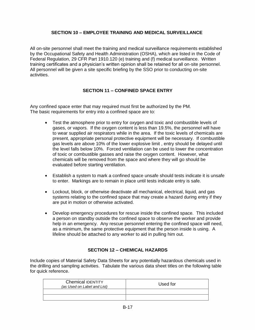
B-17
SECTION 10 – EMPLOYEE TRAINING AND MEDICAL SURVEILLANCE All on-site personnel shall meet the training and medical surveillance requirements established by the Occupational Safety and Health Administration (OSHA), which are listed in the Code of Federal Regulation, 29 CFR Part 1910.120 (e) training and (f) medical surveillance. Written training certificates and a physician‟s written opinion shall be retained for all on-site personnel. All personnel will be given a site specific briefing by the SSO prior to conducting on-site activities.
SECTION 11 – CONFINED SPACE ENTRY Any confined space enter that may required must first be authorized by the PM. The basic requirements for entry into a confined space are to:
Test the atmosphere prior to entry for oxygen and toxic and combustible levels of gases, or vapors. If the oxygen content is less than 19.5%, the personnel will have to wear supplied air respirators while in the area. If the toxic levels of chemicals are present, appropriate personal protective equipment will be necessary. If combustible gas levels are above 10% of the lower explosive limit , entry should be delayed until the level falls below 10%. Forced ventilation can be used to lower the concentration of toxic or combustible gasses and raise the oxygen content. However, what chemicals will be removed from the space and where they will go should be evaluated before starting ventilation.
Establish a system to mark a confined space unsafe should tests indicate it is unsafe to enter. Markings are to remain in place until tests indicate entry is safe.
Lockout, block, or otherwise deactivate all mechanical, electrical, liquid, and gas systems relating to the confined space that may create a hazard during entry if they are put in motion or otherwise activated.
Develop emergency procedures for rescue inside the confined space. This included a person on standby outside the confined space to observe the worker and provide help in an emergency. Any rescue personnel entering the confined space will need, as a minimum, the same protective equipment that the person inside is using. A lifeline should be attached to any worker to aid in pulling him out.
SECTION 12 – CHEMICAL HAZARDS
Include copies of Material Safety Data Sheets for any potentially hazardous chemicals used in the drilling and sampling activities. Tabulate the various data sheet titles on the following table for quick reference.
Chemical IDENTITY
(as Used on Label and List) Used for
B-18
SECTION 13 – STANDARD OPERATING PROCEDURES
GENERAL SAFETY MEASURES
Personal Practices
At the very least, hands and face must be thoroughly washed upon leaving the site and before eating, drinking, breaks, or any other off-site activity. During instances when outer garment decontamination procedures are in effect, entry team members shall thoroughly shower as soon as possible following the removal of protective garments. Such activities as eating, drinking, chewing gum or tobacco, smoking or any other practice which increases the tendency for hand-to-mouth contact, shall be prohibited within contaminated zone(s) and prior to washing hands, and face within the contamination reduction corridor or decontamination reduction corridor or decontamination line. The use of respiratory protective equipment shall be in accordance with currently accepted policies and procedures governing such devices. Air purifying respirator cartridges should be changed at least once each work day on-site. Spent cartridges should be discarded before breaking for lunch and again at the end of each day‟s activities. As a recommended minimum, respirator or gas mask canisters should be discarded at the end of each day‟s activities. More frequent changes shall occur at the first sign of breakthrough based on contaminant warning properties or when indicated by an end of service indicator. In all cases, only NIOSH/MSHA approved respirators shall be used and no canisters shall be used beyond their expiration dates. No excessive facial hair or any other obstruction, which interferes with a satisfactory fit of the mask-to-facepiece seal, is allowed on personnel required to was respiratory protective equipment. Similarly, the wearing of contact lenses is prohibited when wearing respiratory protective devices. The use of medicine and alcohol has the potential to mask the effects from exposure to toxic chemicals. Alcohol, caffeinated products, and certain medications can contribute and exacerbate the effects of heat stress. Prescribed drugs should not be taken by personnel during response activities when the potential for absorption, inhalation, or ingestion of toxic substances exists, unless specifically approved by a qualified physician. Similarly, over-the-counter medications should only be used with a physician‟s approval and in accordance with package limitations and warnings. The intake of alcoholic or caffeinated beverages should be avoided during response activities. Contact with surfaces known or suspected of being contaminated should be avoided during on-site activities. Whenever possible, avoid walking through puddles, mud, or discolored surfaces; kneeling on ground; leaning, sitting or placing equipment, drums, containers, or vehicles on ground.
B-19
Levels of protection shall be established for a given site and shall be based upon the best available information regarding known or suspected hazards associated with the site and the types of activities to be accomplished. Site activities shall then be performed in accordance with those site-specific levels of protection. Changes in the site-specific levels of protection should be made when the level of site specific information improves sufficiently to warrant any change. When sufficient site-specific information is lacking or when the conditions of a site are unknown or in doubt, all site entries and on-site activities will be performed in Level B protection, as a minimum, until the knowledge of site-specific hazards has improved.
GENERAL HOUSEKEEPING
All stairways, passageways, gangways, and access/ways will be kept free of materials, supplies, and obstruction at all times. Loose or light material will not be stored or left on roofs or floors that are not closed in, unless it is safely secured. Tools, materials, extension cords, hoses, or debris will be located so as not to cause tripping or other hazards. Tools, materials, and equipment subject to displacement or falling will be adequately secured. All storage and construction sites will be kept free from the accumulation of combustible materials. Weeds and grass will be kept down. Rubbish, brush, long grass, or other combustible material will be kept from areas where flammable and combustible liquids are stored, handled or processed. All spills of flammable and combustible liquids will be cleaned up immediately.
B-20
FIRE PREVENTION
General
Fires and open flame devices will be controlled by a strict permitting system. Smoking will be prohibited in all areas where flammable, combustible, or similar hazardous materials are stored, except in those locations specifically provided for such purpose and approved by the appointed Project Safety Officer (PSO). All major motorized equipment will be equipped with a fire extinguisher of a type and make approved by the National Board of Fire Underwriters.
Access Fire lanes will be maintained free of obstruction to provide access to all areas.
Material will be stockpiled or staged to minimize the spread of fire internally and to permit access for firefighting. Within 200 ft. of each portable tank or flammable/combustible liquid container stored outdoors, there will be a 13 ft. wide access way for fire control apparatus. Clearance will be maintained around lights and heating units to prevent ignition of combustible materials.
Flammable and Combustible Liquids All tanks, containers, and pumping equipment, portable or stationary, used for the storage of handling of flammable and combustible liquids will be list by UL or FM or approved by the Mine Safety and Health Administration (MSHA). All sources of ignition will be prohibited in areas where flammable liquids are stored, handled, or processed. Suitable NO SMOKING signs will be posted in all such areas. Flashlights and electric lanterns used during handling of flammable liquids will be the type listed by the Underwriters‟ Laboratories or other nationally recognized testing laboratory for use in such hazardous areas. Shipment storage and handling of all flammable liquids will be in containers approved for shipment of such materials and tagged or labeled in accordance with regulations of the U.S. Department of Transportation. Drums, barrels, and other flammable liquid containers will be tightly capped. Safety cans or other portable service containers of flammable liquids having a flashpoint at or below 73 oF will be painted red with a yellow band around the can and/or the name of the contents conspicuously painted or stenciled on the container in yellow. Dispensing systems will be electrically bonded and grounded.
B-21
Storage tanks will be equipped with relief vents. Tank vents will not be located close to open flames, stacks, heating apparatus, or any other source of ignition. Water draw-off valves will be antifreeze type of insulted to prevent freezing. Areas in which flammable or combustible liquids are transferred, in quantities greater than 5 gallons from one tank or container to another will be separated from other operations by 26 ft. or by construction having a fire resistance of at least one (1) hour. Drainage or other means will be provided to control spills. Natural or mechanical ventilation will be provided to maintain the concentration of flammable vapor at or below 10 % of the lower flammable limit. All tanks, hoses, and containers of 5 gallons or less will be kept in metallic contact with flammable liquids while being transferred. Transfer of flammable liquids will not be attempted until containers are electrically interconnected (bonded) and, if necessary, grounded.
Workers will be required to guard carefully against any part of their clothing becoming contaminated with flammable or combustible fluids. They will not be allowed to continue work when their clothing becomes so contaminated.
ELECTRICAL SAFETY
General
All electrical wiring and equipment will be of a type listed by UL or Factory Mutual Engineering Corporation for the specific application.
All installations will comply with the National Electrical Safety Code (NESC), National Electrical Code (NEC) or U.S. Coast Guard Regulations.
All work will be by personnel familiar with code requirements and qualified for the class of work to be performed.
Live parts of wiring or equipment will be guarded to protect all persons or objects from harm.
Electric wire passing through work areas will be covered or elevated to protect it from damage by foot traffic, vehicles, sharp corners, projections, or pinching
Before beginning work, the person in charge will ascertain by inquiry, direct observation, or by instruments, whether any part of an electric power circuit, exposed or concealed, is so located that the performance of the work may bring any person, tool, or machine into physical or electrical contact therewith. Whenever possible, de-energize all equipment and/or circuits before work is started. Additionally, all personnel should adhere to applicable clearance procedures and be protected by grounding.
When it is necessary to work on energized lines and equipment, rubber gloves and other protective equipment or hotline tools meeting the provisions of the American National Standards Institute (ANSI) J-6 series will be used.
B-22
Patched, oil soaked, worn, or frayed electric cords or cables will not be used.
Extension cords or cables will not be fastened with stables hung from nails, or suspended by bare wire.
Portable and semi-portable electrical tools and equipment will be grounded by a multiconductor cord having an identified grounding conductor and a multicontact polarized plug-in receptacle. Semi-portable equipment, floodlights, and work lights will be grounded. The protective ground of such equipment will be maintained during moving unless supply circuits are de-energized.
Driven rod electrodes will have a resistance to ground not to exceed 25 ohms.
Temporary Wiring
Temporary wiring will be guarded, buried, or isolated by elevation to prevent accidental contact by workers or equipment.
Flexible cord sets will be of a type listed by the UL. Flexible cord sets used on construction sites will contain the number of conductors required for the service plus an equipment ground wire. The cords will be Type ST, STO, SJT, SJTO, S, SO, SEO, W, or G.
Exposed empty light sockets and broken bulbs will not be permitted.
Portable electric lighting used in confined wet and/or hazardous locations such as drums, tanks, vessels, and grease pits will be operated at a maximum of 12 volts.
Operations Adjacent to Overhead Lines
Overhead transmission and distribution lines will be carried on towers and poles which provides safe clearance over roadways and structures.
Clearances will be adequate for the movement of vehicles and for the operation of construction equipment.
Ladders, elevated work platforms, manlifts, drill rigs, or any other aerial extensions will be established so there is no possible of accidental contact with any electrical transmission line or device, or lines and devices will be deactivated and certified as such.
HAND AND POWER TOOLS SAFETY
All hand tools will be in good repair and used only for the purpose for which designed.
B-23
Tools having defects that will impair their strength or render them unsafe will be removed from service.
When work is being performed overhead, tools not in use will be secured or placed in holders.
Throwing tools or materials from location to another, from one person to another, or dropping them to lower levels, will not be not be permitted.
Only non-sparking tools will be used in locations where sources of ignition may cause a fire or explosion.
Power tools will be inspected, tested, and determined to be in safe operating condition prior to use. Continued periodic inspections will be made to assure safe operating condition and proper maintenance. Rotating or reciprocating portable power tools will have a constant pressure switch that will shut off the power when the tool is released by the operator. A portable power tool may have a lock-on control provided turn-off can be accomplished by a single motion of the same finger or fingers that turned it on.
Blends of hydraulic fluid used in powered tools will be chosen so that they retain their operating characteristics at the most extreme temperatures to which they will be exposed.
Manufacturers‟ safe operating pressures for hydraulic hoses, valves, pipes, filters, and other fittings will not be exceeded.
All hydraulic or pneumatic tools which are used on or around energized lines or equipment will have non-conducting hoses having adequate strength for the normal operating pressures.
Loose and frayed clothing, loose long hair, dangling jewelry, rings, chains, and wrist watches will not be worn while working with any power tool or machine.
All woodworking tools and machinery will meet applicable requirements of ANSI 01.1, Safety Code for Woodworking Machinery.
MACHINERY AND MECHANIZED EQUIPMENT SAFETY Train personnel in proper operating procedures. Install adequate on-site roads, signs, lights, and devices.
Install appropriate equipment guards and engineering controls on tools and equipment. These include roll-over protective structures, seat belts, emergency shutoff incase of rollover, and backup warning lights and signals.
Provide equipment such as cranes, derricks, and power shovels with signs saying “unlawful to operate this equipment within 10 ft of all power lines”.

B-24
Use equipment and tools that are intrinsically safe and not capable of sparking, and pneumatically and hydraulically driven equipment.
Where portable electric tools and appliances can be used, (i.e., where there is no potential for flammable or explosive conditions), use three-wire grounded extension cords to prevent electric shocks.
In hydraulic power tools, use fire-resistant fluid that is capable of retaining its operating characteristics at the most extreme temperatures. At the start of each work day inspect brakes, hydraulic lines, light signals, fire extinguishers, fluid levels, steering, and splash protection. Keep all non-essential people out of the work area. Prohibit loose-fitting clothing or loose long hair around moving machinery. Keep cabs free of all non-essential items and secure all loose items. Do not exceed the rated load capacity of a vehicle. Instruct equipment operators to report to their supervisor(s) any abnormalities such as equipment failure, oozing liquids, unusual odors, etc. When an equipment operator must negotiate in tight quarters, provide a second person to ensure adequate clearance. Have a signalman direct backing as necessary. All on-site internal combustion engines should have spark arrestors that meet requirements for hazardous atmospheres. Refuel in safe areas. Do not fuel engines while vehicle is running. Prohibit ignition sources near a fuel area. Lower all blades and buckets to the ground and set parking breaks before shutting off the vehicle. Implement an ongoing maintenance program for all tools and equipment. Inspect all tools and moving equipment regularly to ensure that parts are secured and intact with no evidence of cracks or areas of weakness that the equipment turns smoothly with no evidence of wobble, and that is operating according to manufacturer‟s specifications. Promptly repair or replace any defective items. Keep maintenance and repair logs. Store tools in clean, secure areas so that they will not be damaged, lost, or stolen. Keep all heavy equipment that is used in the Exclusion Zone in that zone until the job is done. Completely decontaminate such equipment before moving it into the clean zone.
B-25
MEDICAL AND FIRST AID PROCEDURES Prior to start of work, arrangements will be made for medical facilities, ambulance service, and medical personnel to be available for prompt attention to the injured and consultation on occupational health. Communication and transportation to effectively care for injured workers will be provided. Where any part of the body may be exposed to toxic or corrosive materials drenching and/or flushing activities will be provided in the work area for immediate emergency use. On activities requiring a first aid station or an infirmary, the facilities and equipment will be determined by the proximity and quality of available medical services and will be in accordance with the recommendation of a licensed physician. Alternate facilities which provide the quantity and quality of services outlined in this operating practice may be utilized if approved.
POTABLE WATER AND SANITARY FACILTIES
General
An adequate supply of drinking water will be supplied from sources approved by federal, state, or local health authorities. Drinking water will be dispensed by means which prevent contamination between source and the consumer. The common cup is prohibited. A sanitary container for the paper cups and a waste receptacle for the used cups will be provided. Containers for drinking water will be clearly marked as to contents and not used for other purposes. There will not be any cross-connection, open or potential, between a system furnishing potable water and a system furnishing non-potable water.
Washing Facilities
Washing facilities will be provided as needed to maintain healthful and sanitary conditions. Each washing facility will be maintained in a sanitary condition and provided with water, soap, individual means of drying, and metal-covered receptacles for waste.

C-1
-------------------------------------------------------------------------------------------------------------------------------
APPENDIX C - UNIFIED and AASHTO Soil Classification System References
------------------------------------------------------------------------------------------------------------------------------
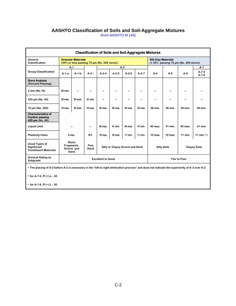
C-2
AASHTO Classification of Soils and Soil-Aggregate Mixtures (from AASHTO M 145)
Classification of Soils and Soil-Aggregate Mixtures
General Classification
Granular Materials (35% or less passing 75 µm (No. 200 sieve))
Silt-Clay Materials (> 35% passing 75 µm (No. 200 sieve))
Group Classification
A-1 A-2 A-7
A-1-a A-1-b A-3 a A-2-4 A-2-5 A-2-6 A-2-7 A-4 A-5 A-6 A-7-5 A-7-6
Sieve Analysis (Percent Passing):
2 mm (No.10) 50 max. -- -- -- -- -- -- -- -- -- --
425 µm (No. 40) 30 max. 50 max. 51 min. -- -- -- -- -- -- -- --
75 µm (No. 200) 15 max. 25 max. 10 max. 35 max. 35 max. 35 max. 35 max. 36 min. 36 min. 36 min. 36 min.
Characteristics of fraction passing 425 µm (No. 40):
Liquid Limit -- -- 40 max. 41 min. 40 max. 41 min. 40 max. 41 min. 40 max. 41 min.
Plasticity Index 6 max. N.P. 10 max. 10 max. 11 min. 11 min. 10 max. 10 max. 11 min. 11 min. b,c
Usual Types of Significant Constituent Materials
Stone Fragments, Gravel, and
Sand
Fine Sand
Silty or Clayey Gravel and Sand Silty Soils Clayey Soils
General Rating as Subgrade
Excellent to Good Fair to Poor
a The placing of A-3 before A-2 is necessary in the “left to right elimination process” and does not indicate the superiority of A-3 over A-2
b for A-7-5, PI < LL - 30
c for A-7-6, PI > LL - 30
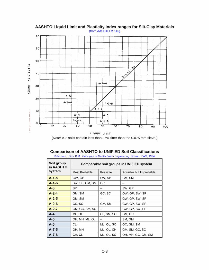
C-3
AASHTO Liquid Limit and Plasticity Index ranges for Silt-Clay Materials (from AASHTO M 145)
(Note: A-2 soils contain less than 35% finer than the 0.075 mm sieve.)
Comparison of AASHTO to UNIFIED Soil Classifications Reference: Das, B.M. Principles of Geotechnical Engineering. Boston: PWS, 1994.
Soil group in AASHTO system
Comparable soil groups in UNIFIED system
Most Probable Possible Possible but Improbable
A-1-a GW, GP SW, SP GM, SM
A-1-b SW, SP, GM, SM GP --
A-3 SP -- SW, GP
A-2-4 GM, SM GC, SC GW, GP, SW, SP
A-2-5 GM, SM -- GW, GP, SW, SP
A-2-6 GC, SC GM, SM GW, GP, SW, SP
A-2-7 GM, GC, SM, SC -- GW, GP, SW, SP
A-4 ML, OL CL, SM, SC GM, GC
A-5 OH, MH, ML, OL -- SM, GM
A-6 CL ML, OL, SC GC, GM, SM
A-7-5 OH, MH ML, OL, CH GM, SM, GC, SC
A-7-6 CH, CL ML, OL, SC OH, MH, GC, GM, SM
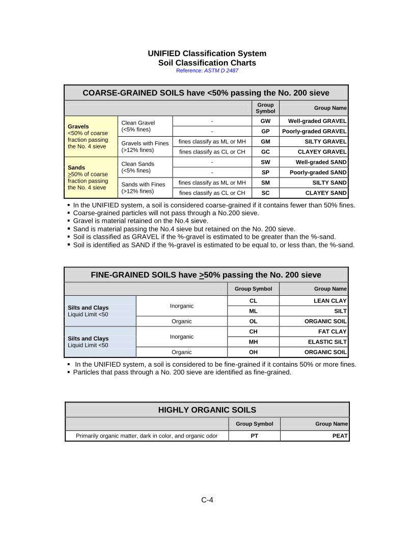
C-4
UNIFIED Classification System Soil Classification Charts
Reference: ASTM D 2487
In the UNIFIED system, a soil is considered coarse-grained if it contains fewer than 50% fines. Coarse-grained particles will not pass through a No.200 sieve. Gravel is material retained on the No.4 sieve.
Sand is material passing the No.4 sieve but retained on the No. 200 sieve. Soil is classified as GRAVEL if the %-gravel is estimated to be greater than the %-sand.
Soil is identified as SAND if the %-gravel is estimated to be equal to, or less than, the %-sand.
In the UNIFIED system, a soil is considered to be fine-grained if it contains 50% or more fines. Particles that pass through a No. 200 sieve are identified as fine-grained.
HIGHLY ORGANIC SOILS
Group Symbol Group Name
Primarily organic matter, dark in color, and organic odor PT PEAT
COARSE-GRAINED SOILS have <50% passing the No. 200 sieve
Group
Symbol Group Name
Gravels <50% of coarse fraction passing the No. 4 sieve
Clean Gravel (<5% fines)
- GW Well-graded GRAVEL
- GP Poorly-graded GRAVEL
Gravels with Fines (>12% fines)
fines classify as ML or MH GM SILTY GRAVEL
fines classify as CL or CH GC CLAYEY GRAVEL
Sands >50% of coarse fraction passing the No. 4 sieve
Clean Sands (<5% fines)
- SW Well-graded SAND
- SP Poorly-graded SAND
Sands with Fines (>12% fines)
fines classify as ML or MH SM SILTY SAND
fines classify as CL or CH SC CLAYEY SAND
FINE-GRAINED SOILS have >50% passing the No. 200 sieve
Group Symbol Group Name
Silts and Clays Liquid Limit <50
Inorganic CL LEAN CLAY
ML SILT
Organic OL ORGANIC SOIL
Silts and Clays Liquid Limit <50
Inorganic CH FAT CLAY
MH ELASTIC SILT
Organic OH ORGANIC SOIL
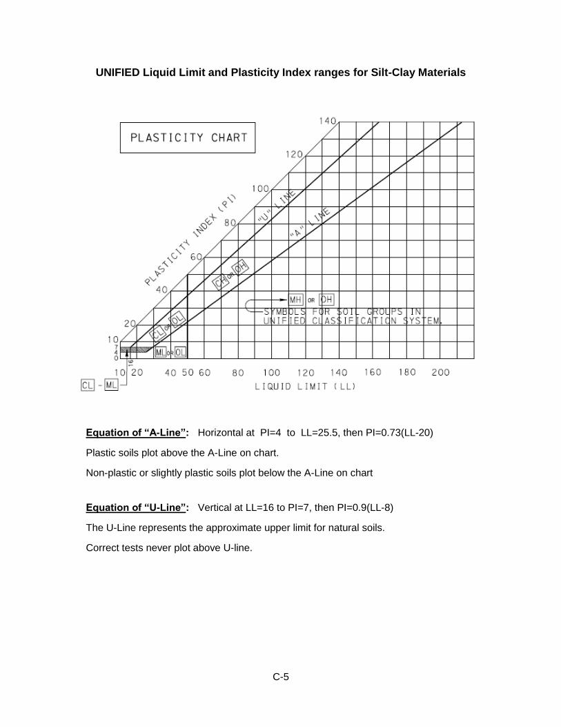
C-5
UNIFIED Liquid Limit and Plasticity Index ranges for Silt-Clay Materials
Equation of “A-Line”: Horizontal at PI=4 to LL=25.5, then PI=0.73(LL-20)
Plastic soils plot above the A-Line on chart.
Non-plastic or slightly plastic soils plot below the A-Line on chart Equation of “U-Line”: Vertical at LL=16 to PI=7, then PI=0.9(LL-8)
The U-Line represents the approximate upper limit for natural soils.
Correct tests never plot above U-line.
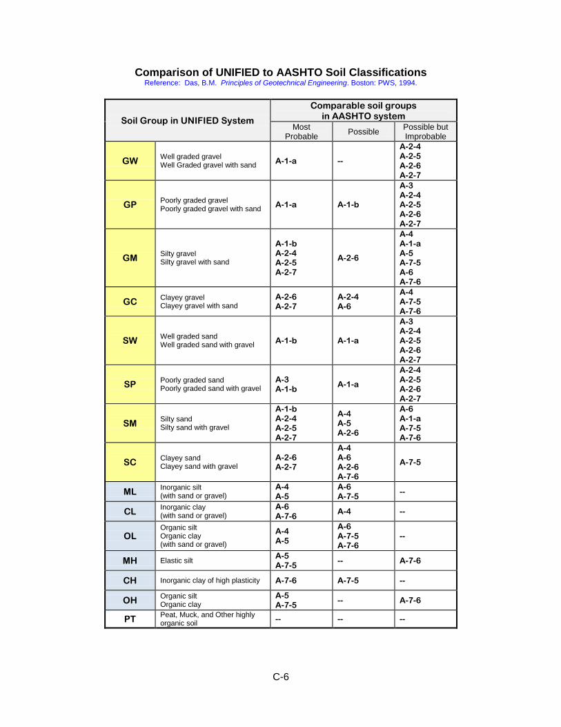
C-6
Comparison of UNIFIED to AASHTO Soil Classifications Reference: Das, B.M. Principles of Geotechnical Engineering. Boston: PWS, 1994.
Soil Group in UNIFIED System
Comparable soil groups in AASHTO system
Most Probable
Possible Possible but Improbable
GW Well graded gravel Well Graded gravel with sand
A-1-a --
A-2-4 A-2-5 A-2-6 A-2-7
GP Poorly graded gravel Poorly graded gravel with sand
A-1-a A-1-b
A-3 A-2-4 A-2-5 A-2-6 A-2-7
GM Silty gravel Silty gravel with sand
A-1-b A-2-4 A-2-5 A-2-7
A-2-6
A-4 A-1-a A-5 A-7-5 A-6 A-7-6
GC Clayey gravel Clayey gravel with sand
A-2-6 A-2-7
A-2-4 A-6
A-4 A-7-5 A-7-6
SW Well graded sand Well graded sand with gravel
A-1-b A-1-a
A-3 A-2-4 A-2-5 A-2-6 A-2-7
SP Poorly graded sand Poorly graded sand with gravel
A-3 A-1-b
A-1-a
A-2-4 A-2-5 A-2-6 A-2-7
SM Silty sand Silty sand with gravel
A-1-b A-2-4 A-2-5 A-2-7
A-4 A-5 A-2-6
A-6 A-1-a A-7-5 A-7-6
SC Clayey sand Clayey sand with gravel
A-2-6 A-2-7
A-4 A-6 A-2-6 A-7-6
A-7-5
ML Inorganic silt (with sand or gravel)
A-4 A-5
A-6 A-7-5
--
CL Inorganic clay (with sand or gravel)
A-6 A-7-6
A-4 --
OL Organic silt Organic clay (with sand or gravel)
A-4 A-5
A-6 A-7-5 A-7-6
--
MH Elastic silt A-5 A-7-5
-- A-7-6
CH Inorganic clay of high plasticity A-7-6 A-7-5 --
OH Organic silt Organic clay
A-5 A-7-5
-- A-7-6
PT Peat, Muck, and Other highly organic soil
-- -- --
D-1
-------------------------------------------------------------------------------------------------------------------------------
APPENDIX D - Field Sheet Summaries of Soil and Rock Descriptors
-------------------------------------------------------------------------------------------------------------------------------
The two pages of this appendix are intended to be an aid to field Inspectors. Making a double-sided laminated copy of these references will make a convenient and durable reference sheet for use during logging of borings.
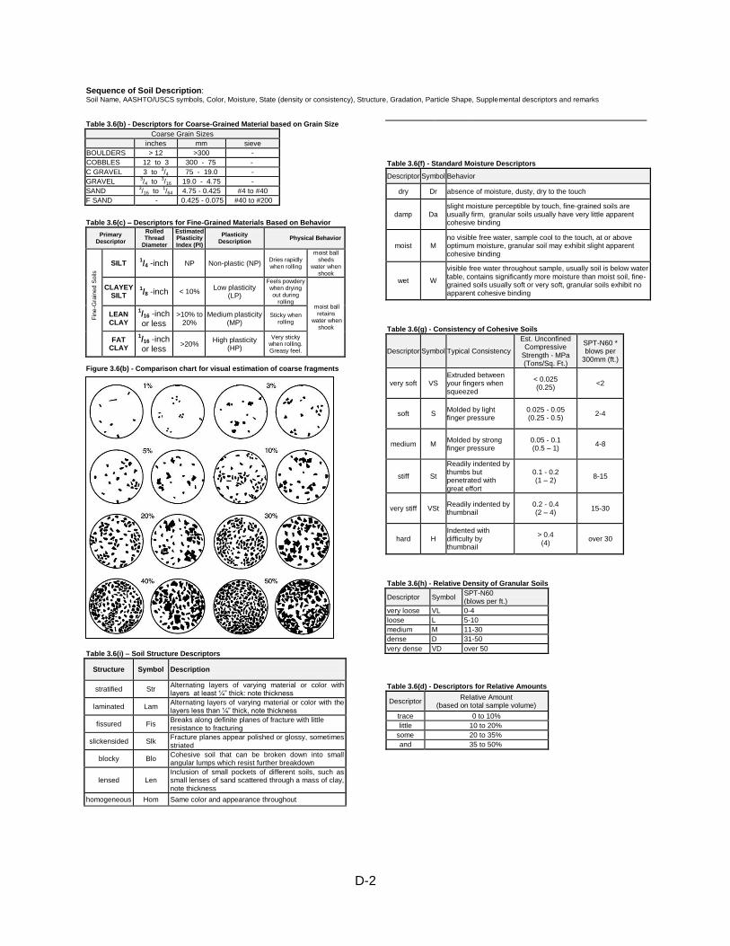
D-2
Sequence of Soil Description: Soil Name, AASHTO/USCS symbols, Color, Moisture, State (density or consistency), Structure, Gradation, Particle Shape, Supplemental descriptors and remarks Table 3.6(b) - Descriptors for Coarse-Grained Material based on Grain Size
Coarse Grain Sizes
inches mm sieve
BOULDERS > 12 >300 -
COBBLES 12 to 3 300 - 75 -
C GRAVEL 3 to 3/4 75 - 19.0 -
GRAVEL 3/4 to
3/16 19.0 - 4.75 -
SAND 3/16 to
1/64 4.75 - 0.425 #4 to #40
F SAND - 0.425 - 0.075 #40 to #200
Table 3.6(c) – Descriptors for Fine-Grained Materials Based on Behavior
Primary Descriptor
Rolled Thread
Diameter
Estimated Plasticity Index (PI)
Plasticity Description
Physical Behavior
Fin
e-G
rain
ed S
oils
SILT 1/4 -inch
NP Non-plastic (NP)
Dries rapidly when rolling
moist ball sheds
water when shook
CLAYEY SILT
1/8 -inch < 10%
Low plasticity (LP)
Feels powdery when drying out during
rolling moist ball
retains water when
shook
LEAN CLAY
1/16 -inch or less
>10% to 20%
Medium plasticity (MP)
Sticky when rolling
FAT CLAY
1/16 -inch or less
>20% High plasticity
(HP)
Very sticky when rolling. Greasy feel.
Figure 3.6(b) - Comparison chart for visual estimation of coarse fragments
Table 3.6(i) – Soil Structure Descriptors
Structure Symbol Description
stratified Str Alternating layers of varying material or color with layers at least ¼” thick: note thickness
laminated Lam Alternating layers of varying material or color with the layers less than ¼” thick, note thickness
fissured Fis Breaks along definite planes of fracture with little resistance to fracturing
slickensided Slk Fracture planes appear polished or glossy, sometimes striated
blocky Blo Cohesive soil that can be broken down into small angular lumps which resist further breakdown
lensed Len Inclusion of small pockets of different soils, such as small lenses of sand scattered through a mass of clay, note thickness
homogeneous Hom Same color and appearance throughout
Table 3.6(f) - Standard Moisture Descriptors
Descriptor Symbol Behavior
dry Dr absence of moisture, dusty, dry to the touch
damp Da slight moisture perceptible by touch, fine-grained soils are usually firm, granular soils usually have very little apparent cohesive binding
moist M no visible free water, sample cool to the touch, at or above optimum moisture, granular soil may exhibit slight apparent cohesive binding
wet W
visible free water throughout sample, usually soil is below water table, contains significantly more moisture than moist soil, fine-grained soils usually soft or very soft, granular soils exhibit no apparent cohesive binding
Table 3.6(g) - Consistency of Cohesive Soils
Descriptor Symbol Typical Consistency
Est. Unconfined Compressive
Strength - MPa (Tons/Sq. Ft.)
SPT-N60 * blows per
300mm (ft.)
very soft VS Extruded between your fingers when squeezed
< 0.025 (0.25)
<2
soft S Molded by light finger pressure
0.025 - 0.05 (0.25 - 0.5)
2-4
medium M Molded by strong finger pressure
0.05 - 0.1 (0.5 – 1)
4-8
stiff St
Readily indented by thumbs but penetrated with great effort
0.1 - 0.2 (1 – 2)
8-15
very stiff VSt Readily indented by thumbnail
0.2 - 0.4 (2 – 4)
15-30
hard H Indented with difficulty by thumbnail
> 0.4 (4)
over 30
Table 3.6(h) - Relative Density of Granular Soils
Descriptor Symbol SPT-N60 (blows per ft.)
very loose VL 0-4
loose L 5-10
medium M 11-30
dense D 31-50
very dense VD over 50
Table 3.6(d) - Descriptors for Relative Amounts
Descriptor Relative Amount
(based on total sample volume)
trace 0 to 10%
little 10 to 20%
some 20 to 35%
and 35 to 50%
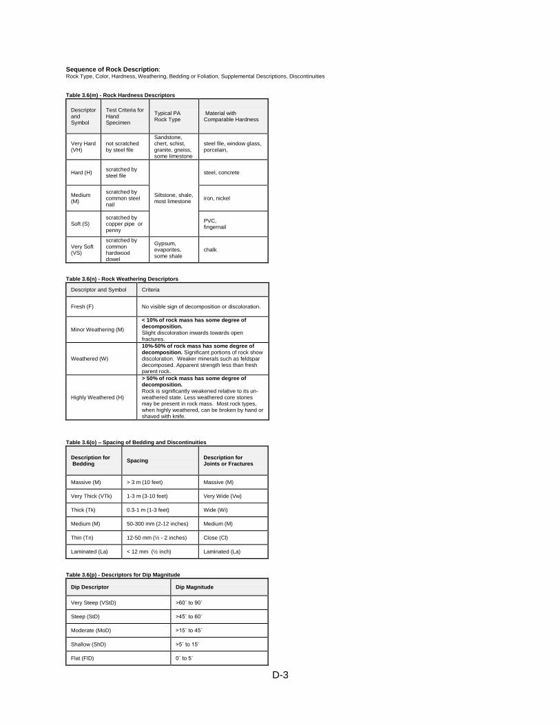
D-3
Sequence of Rock Description: Rock Type, Color, Hardness, Weathering, Bedding or Foliation, Supplemental Descriptions, Discontinuities Table 3.6(m) - Rock Hardness Descriptors
Descriptor and Symbol
Test Criteria for Hand Specimen
Typical PA Rock Type
Material with Comparable Hardness
Very Hard (VH)
not scratched by steel file
Sandstone, chert, schist, granite, gneiss, some limestone
steel file, window glass, porcelain,
Hard (H) scratched by steel file
Siltstone, shale, most limestone
steel, concrete
Medium (M)
scratched by common steel nail
iron, nickel
Soft (S) scratched by copper pipe or penny
PVC, fingernail
Very Soft (VS)
scratched by common hardwood dowel
Gypsum, evaporites, some shale
chalk
Table 3.6(n) - Rock Weathering Descriptors
Descriptor and Symbol Criteria
Fresh (F) No visible sign of decomposition or discoloration.
Minor Weathering (M)
< 10% of rock mass has some degree of decomposition. Slight discoloration inwards towards open fractures.
Weathered (W)
10%-50% of rock mass has some degree of decomposition. Significant portions of rock show discoloration. Weaker minerals such as feldspar decomposed. Apparent strength less than fresh parent rock.
Highly Weathered (H)
> 50% of rock mass has some degree of decomposition. Rock is significantly weakened relative to its un-weathered state. Less weathered core stones may be present in rock mass. Most rock types, when highly weathered, can be broken by hand or shaved with knife.
Table 3.6(o) – Spacing of Bedding and Discontinuities
Description for Bedding
Spacing Description for Joints or Fractures
Massive (M) > 3 m (10 feet) Massive (M)
Very Thick (VTk) 1-3 m (3-10 feet) Very Wide (Vw)
Thick (Tk) 0.3-1 m (1-3 feet) Wide (Wi)
Medium (M) 50-300 mm (2-12 inches) Medium (M)
Thin (Tn) 12-50 mm (½ - 2 inches) Close (Cl)
Laminated (La) < 12 mm (½ inch) Laminated (La)
Table 3.6(p) - Descriptors for Dip Magnitude
Dip Descriptor Dip Magnitude
Very Steep (VStD) >60˚ to 90˚
Steep (StD) >45˚ to 60˚
Moderate (MoD) >15˚ to 45˚
Shallow (ShD) >5˚ to 15˚
Flat (FlD) 0˚ to 5˚

Access online at: http://www.dot.state.pa.us/Internet/Bureaus/pdBCM.nsf
www.state.pa.us PUB 222 (6-12)