Embed Size (px)
Citation preview

InstructionManual
Yokogawa Electric Corporation
Model EJA118W, EJA118N andEJA118Y Diaphragm SealedDifferential Pressure Transmitters[Style: S2]
IM 1C22H1-01E
IM 1C22H1-01E10th Edition

Blank Page
i
CONTENTS
IM 1C22H1-01EFD No. IM 1C22H1-01E10th Edition: Feb. 2000(YK)All Rights Reserved, Copyright © 1995, Yokogawa Electric Corporation
CONTENTS
1. INTRODUCTION............................................................................................ 1-1
WARRANTY .................................................................................................. 1-2
2. HANDLING CAUTIONS ................................................................................ 2-1
2.1 Model and Specifications Check ......................................................... 2-12.2 Unpacking ........................................................................................... 2-12.3 Storage ................................................................................................ 2-12.4 Selecting the Installation Location ...................................................... 2-22.5 Pressure Connection ........................................................................... 2-22.6 Waterproofing of Cable Conduit Connections .................................... 2-22.7 Restrictions on Use of Radio Transceiver .......................................... 2-22.8 Insulation Resistance and Dielectric Strength Test ............................ 2-32.9 Installation of Explosion Protected Type ............................................ 2-3
2.9.1 FM Approval ................................................................................. 2-32.9.2 CSA Certification .......................................................................... 2-52.9.3 SAA Certification .......................................................................... 2-62.9.4 CENELEC (KEMA)/IEC (KEMA) Certification .............................. 2-72.9.5 JIS Certification ............................................................................ 2-9
2.10 EMC Conformity Standards ................................................................ 2-9
3. COMPONENT NAMES.................................................................................. 3-1
4. INSTALLATION ............................................................................................. 4-1
4.1 Precautions ......................................................................................... 4-14.2 Mounting the Diaphragm Seals .......................................................... 4-14.3 Transmitter Mounting .......................................................................... 4-24.4 Affixing the Teflon Film ....................................................................... 4-34.5 Rotating Transmitter Section .............................................................. 4-3
5. WIRING .......................................................................................................... 5-1
5.1 Wiring Precautions .............................................................................. 5-15.2 Selecting the Wiring Materials ............................................................ 5-15.3 Connections of External Wiring to Terminal Box ................................ 5-1
5.3.1 Power Supply Wiring Connection ................................................ 5-15.3.2 External Indicator Connection ...................................................... 5-15.3.3 BRAIN TERMINAL BT200 Connection ........................................ 5-25.3.4 Check Meter Connection .............................................................. 5-2
5.4 Wiring .................................................................................................. 5-25.4.1 Loop Configuration ....................................................................... 5-2
(1) General-use Type and Flameproof Type..................................... 5-2(2) Intrinsically Safe Type ................................................................. 5-2
5.4.2 Wiring Installation ......................................................................... 5-3(1) General-use Type and Intrinsically Safe Type............................. 5-3(2) Flameproof Type (JIS) ................................................................ 5-3
5.5 Grounding ............................................................................................ 5-45.6 Power Supply Voltage and Load Resistance ..................................... 5-4
ii
CONTENTS
IM 1C22H1-01E
6. OPERATION .................................................................................................. 6-1
6.1 Preparation for Starting Operation ...................................................... 6-16.2 Zero Point Adjustment ........................................................................ 6-2
6.2.1 When you can obtain Low Range Value from actual measuredvalue of 0% (0 kPa, atmospheric pressure); ............................... 6-2
6.2.2 When you cannot obtain Low Range Value from actualmeasured value of 0%; ................................................................ 6-2
6.3 Starting Operation ............................................................................... 6-36.4 Shutting Down Operation .................................................................... 6-36.5 Setting the Range Using the Range-setting Switch ........................... 6-4
7. BRAIN TERMINAL BT200 OPERATION ..................................................... 7-1
7.1 BT200 Operation Precautions ............................................................. 7-17.1.1 Connecting the BT200 ................................................................. 7-17.1.2 Conditions of Communication Line .............................................. 7-1
7.2 BT200 Operating Procedures ............................................................. 7-17.2.1 Key Layout and Screen Display ................................................... 7-17.2.2 Operating Key Functions .............................................................. 7-2
(1) Alphanumeric Keys and Shift Keys ............................................. 7-2(2) Function Keys ............................................................................. 7-2
7.2.3 Calling Up Menu Addresses Using the Operating Keys .............. 7-37.3 Setting Parameters Using the BT200 ................................................. 7-4
7.3.1 Parameter Summary .................................................................... 7-47.3.2 Parameter Usage and Selection .................................................. 7-67.3.3 Setting Parameters ....................................................................... 7-7
(1) Tag No. Setup ............................................................................. 7-7(2) Calibration Range Setup ............................................................. 7-7(3) Damping Time Constant Setup ................................................... 7-8(4) Output Mode and Integral Indicator Display Mode Setup ........... 7-9(5) Output Signal Low Cut Mode Setup ............................................ 7-9(6) Integral Indicator Scale Setup ................................................... 7-10(7) Unit Setup for Displayed Temperature ...................................... 7-11(8) Unit Setup for Displayed Static Pressure .................................. 7-12(9) Operation Mode Setup .............................................................. 7-12(10) Impulse Line Connection Orientation Setup ............................. 7-12(11) Output Status Display/Setup when a CPU Failure .................... 7-12(12) Output Status Setup when a Hardware Error Occurs ............... 7-12(13) Bi-directional Flow Measurement Setup ................................... 7-13(14) Range Change while Applying Actual Inputs ............................ 7-13(15) Zero Point Adjustment ............................................................... 7-14(16) Test Output Setup ..................................................................... 7-15(17) User Memo Fields ..................................................................... 7-15
7.4 Displaying Data Using the BT200 ..................................................... 7-167.4.1 Displaying Measured Data ......................................................... 7-167.4.2 Display Transmitter Model and Specifications ........................... 7-16
7.5 Self-Diagnostics ................................................................................ 7-167.5.1 Checking for Problems ............................................................... 7-16
(1) Identifying Problems with BT200 .............................................. 7-16(2) Checking with Integral Indicator ................................................ 7-17
7.5.2 Errors and Countermeasures ..................................................... 7-18
iii
CONTENTS
IM 1C22H1-01E
8. MAINTENANCE............................................................................................. 8-1
8.1 Overview ............................................................................................. 8-18.2 Calibration Instruments Selection ....................................................... 8-18.3 Calibration ........................................................................................... 8-18.4 Disassembly and Reassembly ............................................................ 8-3
8.4.1 Replacing the Integral Indicator ................................................... 8-38.4.2 Replacing the CPU Assembly ...................................................... 8-4
8.5 Troubleshooting ................................................................................... 8-58.5.1 Basic Troubleshooting .................................................................. 8-58.5.2 Troubleshooting Flow Charts ....................................................... 8-5
9. GENERAL SPECIFICATIONS ...................................................................... 9-1
9.1 Standard Specifications ...................................................................... 9-19.2 Model and Suffix Codes ...................................................................... 9-39.3 Optional Specifications ........................................................................ 9-69.4 Dimensions .......................................................................................... 9-8
INSTALLATION AND OPERATING PRECAUTIONS FORJIS INTRINSICALLY SAFE EQUIPMENT .......................................... EX-A03E
INSTALLATION AND OPERATING PRECAUTIONS FORJIS FLAMEPROOF EQUIPMENT ....................................................... EX-B03E
Customer Maintenance Parts List
DPharp EJA Series Transmitter Section ............................CMPL 1C22A1-02EModels EJA118W, EJA118N, and EJA118Y Diaphragm Sealed
Differential Pressure Transmitter ............................. CMPL 1C22H1-01E
REVISION RECORD

Blank Page
IM 1C22H1-01E1-1
1. INTRODUCTION
1. INTRODUCTIONThank you for purchasing the DPharp electronicpressure transmitter.
The DPharp Pressure Transmitters are preciselycalibrated at the factory before shipment. To ensurecorrect and efficient use of the instrument, please readthis manual thoroughly and fully understand how tooperate the instrument before operating it.
j Regarding This Manual• This manual should be passed on to the end user.
• The contents of this manual are subject to changewithout prior notice.
• All rights reserved. No part of this manual may bereproduced in any form without Yokogawa’s writtenpermission.
• Yokogawa makes no warranty of any kind withregard to this manual, including, but not limited to,implied warranty of merchantability and fitness for aparticular purpose.
• If any question arises or errors are found, or if anyinformation is missing from this manual, pleaseinform the nearest Yokogawa sales office.
• The specifications covered by this manual arelimited to those for the standard type under thespecified model number break-down and do notcover custom-made instruments.
• Please note that changes in the specifications,construction, or component parts of the instrumentmay not immediately be reflected in this manual atthe time of change, provided that postponement ofrevisions will not cause difficulty to the user from afunctional or performance standpoint.
NOTE
For FOUNDATION Fieldbus and HART protocolversions, please refer to IM 1C22T2-01E and IM1C22T1-01E respectively, in addition to this IM.
j Safety Precautions• For the protection and safety of the operator and the
instrument or the system including the instrument,please be sure to follow the instructions on safetydescribed in this manual when handling this instru-ment. In case the instrument is handled in contradic-tion to these instructions, Yokogawa does notguarantee safety.
• For the intrinsically safe equipment andexplosionproof equipment, in case the instrument isnot restored to its original condition after any repairor modification undertaken by the customer,intrinsically safe construction or explosionproofconstruction is damaged and may cause dangerouscondition. Please contact Yokogawa for any repairor modification required to the instrument.
• The following safety symbol marks are used in thisManual:
WARNING
Indicates a potentially hazardous situation which,if not avoided, could result in death or seriousinjury.
CAUTION
Indicates a potentially hazardous situation which,if not avoided, may result in minor or moderateinjury. It may also be used to alert againstunsafe practices.
IMPORTANT
Indicates that operating the hardware or softwarein this manner may damage it or lead to systemfailure.
NOTE
Draws attention to information essential forunderstanding the operation and features.
IM 1C22H1-01E1-2
1. INTRODUCTION
WARRANTY• The warranty shall cover the period noted on the
quotation presented to the purchaser at the time ofpurchase. Problems occurred during the warrantyperiod shall basically be repaired free of charge.
• In case of problems, the customer should contact theYokogawa representative from which the instrumentwas purchased, or the nearest Yokogawa office.
• If a problem arises with this instrument, pleaseinform us of the nature of the problem and thecircumstances under which it developed, includingthe model specification and serial number. Anydiagrams, data and other information you caninclude in your communication will also be helpful.
• Responsible party for repair cost for the problemsshall be determined by Yokogawa based on ourinvestigation.
• The Purchaser shall bear the responsibility for repaircosts, even during the warranty period, if themalfunction is due to:
- Improper and/or inadequate maintenance by thepurchaser.
- Failure or damage due to improper handling, use orstorage which is out of design conditions.
- Use of the product in question in a location notconforming to the standards specified byYokogawa, or due to improper maintenance of theinstallation location.
- Failure or damage due to modification or repair byany party except Yokogawa or an approvedrepresentative of Yokogawa.
- Malfunction or damage from improper relocationof the product in question after delivery.
- Reason of force majeure such as fires, earthquakes,storms/floods, thunder/lightening, or other naturaldisasters, or disturbances, riots, warfare, orradioactive contamination.
WARNING
• Instrument installed in the process is underpressure. Never loosen or tighten the flangebolts as it may cause dangerous spouting ofprocess fluid.
• Since the accumulated process fluid may betoxic or otherwise harmful, take appropriatecare to avoid contact with the body, or inhala-tion of vapors even after dismounting theinstrument from the process line for mainte-nance.
CAUTION
This instrument is tested and certified as intrinsi-cally safe type or explosionproof type. Pleasenote that the construction of the instrument,installation, external wiring, maintenance orrepair is strictly restricted, and non-observanceor negligence of this restriction would result indangerous condition.
IM 1C22H1-01E2-1
2. HANDLING CAUTIONS
2. HANDLING CAUTIONS
This chapter describes important cautions regardinghow to handle the transmitter. Read carefully beforeusing the transmitter.
The EJA Series pressure transmitters are thoroughlytested at the factory before shipment. When thetransmitter is delivered, visually check them to makesure that no damage occurred during shipment.
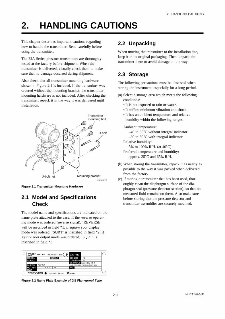
Also check that all transmitter mounting hardwareshown in Figure 2.1 is included. If the transmitter wasordered without the mounting bracket, the transmittermounting hardware is not included. After checking thetransmitter, repack it in the way it was delivered untilinstallation.
Mounting bracketU-bolt nut
U-bolt
Transmittermounting bolt
F0201.EPS
Figure 2.1 Transmitter Mounting Hardware
2.1 Model and SpecificationsCheck
The model name and specifications are indicated on thename plate attached to the case. If the reverse operat-ing mode was ordered (reverse signal), ‘REVERSE’will be inscribed in field *1; if square root displaymode was ordered, ‘SQRT’ is inscribed in field *2; ifsquare root output mode was ordered, ‘SQRT’ isinscribed in field *3.
Figure 2.2 Name Plate Example of JIS Flameproof Type
2.2 UnpackingWhen moving the transmitter to the installation site,keep it in its original packaging. Then, unpack thetransmitter there to avoid damage on the way.
2.3 StorageThe following precautions must be observed whenstoring the instrument, especially for a long period.
(a) Select a storage area which meets the followingconditions:• It is not exposed to rain or water.• It suffers minimum vibration and shock.• It has an ambient temperature and relative
humidity within the following ranges.
Ambient temperature:–40 to 85°C without integral indicator–30 to 80°C with integral indicator
Relative humidity:5% to 100% R.H. (at 40°C)
Preferred temperature and humidity:approx. 25°C and 65% R.H.
(b) When storing the transmitter, repack it as nearly aspossible to the way it was packed when deliveredfrom the factory.
(c) If storing a transmitter that has been used, thor-oughly clean the diaphragm surface of the dia-phragm seal (pressure-detector section), so that nomeasured fluid remains on them. Also make surebefore storing that the pressure-detector andtransmitter assemblies are securely mounted.
IM 1C22H1-01E2-2
2. HANDLING CAUTIONS
2.4 Selecting the InstallationLocation
The transmitter is designed to withstand severeenvironmental conditions. However, to ensure stableand accurate operation for years, observe the followingprecautions when selecting an installation location.
(a) Ambient TemperatureAvoid locations subject to wide temperaturevariations or a significant temperature gradient. Ifthe location is exposed to radiant heat from plantequipments, provide adequate thermal insulationand/or ventilation.
(b) Ambient AtmosphereAvoid installing the transmitter in a corrosiveatmosphere. If the transmitter must be installed in acorrosive atmosphere, there must be adequateventilation as well as measures to prevent intrusionor stagnation of rain water in conduits.
(c) Shock and VibrationSelect an installation site suffering minimum shockand vibration (although the transmitter is designedto be relatively resistant to shock and vibration).
(d) Installation of Explosion-protected TransmittersExplosion-protected transmitters can be installed inhazardous areas according to the types of gases forwhich they are certified. See Subsection 2.9“Installation of Explosion Protected Type Transmit-ters.”
2.5 Pressure Connection
WARNING
• Instrument installed in the process is underpressure. Never loosen or tighten the flangebolts to avoid the dangerous spouting ofprocess fluid.
• Since the accumulated process fluid may betoxic or otherwise harmful, take appropriatecare to avoid contact with the skin, eyes orbody, or inhalation of vapors even after dis-mounting the instrument from process line formaintenance.
The following precautions must be observed in order tosafely operate the transmitter under pressure.
(a) Never apply a pressure higher than the specifiedmaximum working pressure.
(b) Never loosen or tighten the bolts securing thediaphragm seal flanges when the assembly is underpressure. Do it after releasing the process pressureif required.
2.6 Waterproofing of CableConduit Connections
Apply a non-hardening sealant to the threads towaterproof the transmitter cable conduit connections.(See Figure 5.4.2a, 5.4.2b and 5.4.2d.)
2.7 Restrictions on Use of RadioTransceiver
IMPORTANT
Although the transmitter has been designed toresist high frequency electrical noise, if a radiotransceiver is used near the transmitter or itsexternal wiring, the transmitter may be affectedby high frequency noise pickup. To test for sucheffects, bring the transceiver in use slowly from adistance of several meters from the transmitter,and observe the measurement loop for noiseeffects. Thereafter, always use the transceiveroutside the area affected by noise.
IM 1C22H1-01E2-3
2. HANDLING CAUTIONS
2.8 Insulation Resistance andDielectric Strength Test
Since the transmitter has undergone insulation resis-tance and dielectric strength tests at the factory beforeshipment, normally these tests are not required.However, if required, observe the following precau-tions in the test procedures.
(a) Do not perform such tests more frequently than isabsolutely necessary. Even test voltages that do notcause visible damage to the insulation may degradethe insulation and reduce safety margins.
(b) Never apply a voltage exceeding 500 V DC (100 VDC with an internal lightning protector) for theinsulation resistance test, nor a voltage exceeding500 V AC (100 V AC with an internal lightningprotector) for the dielectric strength test.
(c) Before conducting these tests, disconnect all signallines from the transmitter terminals. Perform thetests in the following procedure:
• Insulation Resistance Test1) Short-circuit the + and – SUPPLY terminals in the
terminal box.2) Turn OFF the insulation tester. Then connect the
insulation tester plus (+) lead wire to the shortedSUPPLY terminals and the minus (–) leadwire tothe grounding terminal.
3) Turn ON the insulation tester power and measurethe insulation resistance. The voltage should beapplied short as possible to verify that the insula-tion resistance is at least 20 MΩ.
4) After completing the test and being very careful notto touch exposed conductors disconnect theinsulation tester and connect a 100 kΩ resistorbetween the grounding terminal and the short-circuiting SUPPLY terminals. Leave this resistorconnected at least one second to discharge anystatic potential. Do not touch the terminals while itis discharging.
• Dielectric Strength Test1) Short-circuit the + and – SUPPLY terminals in the
terminal box.2) Turn OFF the dielectric strength tester. Then
connect the tester between the shorted SUPPLYterminals and the grounding terminal. Be sure toconnect the grounding lead of the dielectric strengthtester to the ground terminal.
3) Set the current limit on the dielectric strength testerto 10 mA, then turn ON the power and graduallyincrease the test voltage from ‘0’ to the specifiedvoltage.
4) When the specified voltage is reached, hold it forone minute.
5) After completing this test, slowly decrease thevoltage to avoid any voltage surges.
2.9 Installation of ExplosionProtected Type
NOTE
For FOUNDATION Fieldbus explosion protectedtype, please refer to IM 1C22T2-01E.
WARNING
To pressure the safety of explosionproof equip-ment requires great care during mounting,wiring, and piping. Safety requirements alsoplace restrictions on maintenance and repairactivities. Please read the following sections verycarefully.
2.9.1 FM Approval
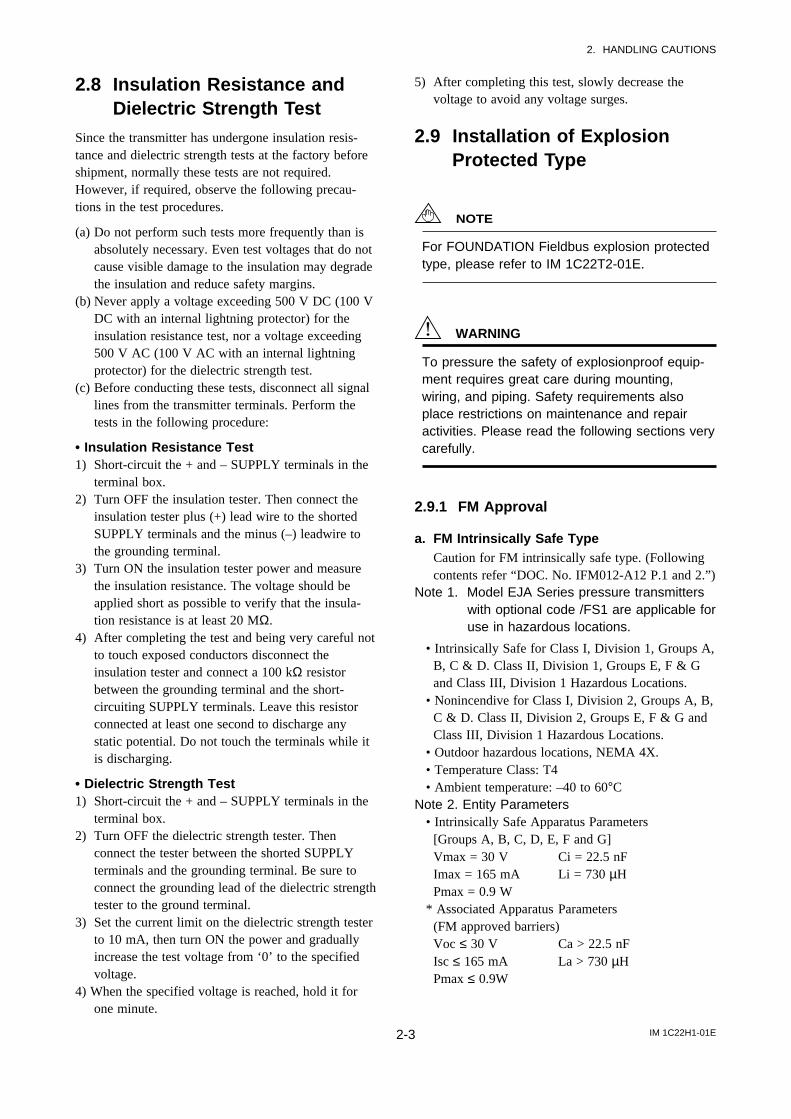
a. FM Intrinsically Safe TypeCaution for FM intrinsically safe type. (Followingcontents refer “DOC. No. IFM012-A12 P.1 and 2.”)
Note 1. Model EJA Series pressure transmitterswith optional code /FS1 are applicable foruse in hazardous locations.
• Intrinsically Safe for Class I, Division 1, Groups A,B, C & D. Class II, Division 1, Groups E, F & Gand Class III, Division 1 Hazardous Locations.
• Nonincendive for Class I, Division 2, Groups A, B,C & D. Class II, Division 2, Groups E, F & G andClass III, Division 1 Hazardous Locations.
• Outdoor hazardous locations, NEMA 4X.• Temperature Class: T4• Ambient temperature: –40 to 60°C
Note 2. Entity Parameters• Intrinsically Safe Apparatus Parameters
[Groups A, B, C, D, E, F and G]Vmax = 30 V Ci = 22.5 nFImax = 165 mA Li = 730 µHPmax = 0.9 W
* Associated Apparatus Parameters(FM approved barriers)Voc ≤ 30 V Ca > 22.5 nFIsc ≤ 165 mA La > 730 µHPmax ≤ 0.9W
IM 1C22H1-01E2-4
2. HANDLING CAUTIONS
• Intrinsically Safe Apparatus Parameters[Groups C, D, E, F and G]Vmax = 30 V Ci = 22.5 nFImax = 225 mA Li = 730 µHPmax = 0.9 W
* Associated Apparatus Parameters(FM approved barriers)Voc ≤ 30 V Ca > 22.5 nFIsc ≤ 225 mA La > 730 µHPmax ≤ 0.9 W
• Entity Installation RequirementsVmax ≥ Voc or Vt, Imax ≥ Isc or It,Pmax (IS Apparatus) ≥ Pmax (Barrier)Ca ≥ Ci + Ccable, La ≥ Li + Lcable
Note 3. Installation• Barrier must be installed in an enclosure that meets
the requirements of ANSI/ISA S82.01.• Control equipment connected to barrier must not use
or generate more than 250 V rms or V dc.• Installation should be in accordance with ANSI/ISA
RP12.6 “Installation of Intrinsically Safe Systems forHazardous (Classified) Locations” and the NationalElectric Code (ANSI/NFPA 70).
• The configuration of associated apparatus must beFMRC Approved.
• Dust-tight conduit seal must be used when installedin a Class II, III, Group E, F and G environments.
• Associated apparatus manufacturer’s installationdrawing must be followed when installing thisapparatus.
• The maximum power delivered from the barriermust not exceed 0.9 W.
• Note a warning label worded “SUBSTITUTION OFCOMPONENTS MAY IMPAIR INTRINSICSAFETY,” and “INSTALL IN ACCORDANCEWITH DOC. No. IFM012-A12 P.1 and 2.”
Note 4. Maintenance and Repair• The instrument modification or parts replacement by
other than authorized representative of YokogawaElectric Corporation is prohibited and will voidFactory Mutual Intrinsically safe and NonincendiveApproval.
F0203.EPS
Class I, II, III, Division 1,Groups A, B, C, D, E, F, G
EJA Series Pressure Transmitters
EJA Series Pressure Transmitters
Safety Barrier
Supply
Supply
Hazardous Location Nonhazardous Location
Hazardous Location Nonhazardous Location
General PurposeEquipment
+
–
+
–
+
–
+
–
+
–
+
–
[Intrinsically Safe]
Class I, II, Division 2,Groups A, B, C, D, E, F, GClass III, Division 1.
Not UseSafety Barrier
[Nonincendive]
General PurposeEquipment
b. FM Explosionproof TypeCaution for FM explosionproof type.
Note 1. Model EJA Series differential, gauge,and absolute pressure transmitters withoptional code /FF1 are applicable foruse in hazardous locations.
• Explosionproof for Class I, Division 1, Groups B,C and D.
• Dust-ignitionproof for Class II/III, Division 1,Groups E, F and G.
• Outdoor hazardous locations, NEMA 4X.• Temperature Class: T6• Ambient Temperature: –40 to 60°C• Supply Voltage: 42 V dc max.• Output signal: 4 to 20 mA
Note 2. Wiring• All wiring shall comply with National Electrical
Code ANSI/NEPA70 and Local Electrical Codes.• When installed in Division 1, “FACTORY
SEALED, CONDUIT SEAL NOT REQUIRED.”Note 3. Operation
• Keep the “CAUTION” nameplate attached to thetransmitter.CAUTION: OPEN CIRCUIT BEFORE REMOV-ING COVER. FACTORY SEALED, CONDUITSEAL NOT REQUIRED. INSTALL IN ACCOR-DANCE WITH THE INSTRUCTION MANUALIM 1C22.
• Take care not to generate mechanical sparkingwhen accessing to the instrument and peripheraldevices in a hazardous location.
IM 1C22H1-01E2-5
2. HANDLING CAUTIONS
Note 4. Maintenance and Repair• The instrument modification or parts replacement
by other than authorized representative ofYokogawa Electric Corporation is prohibited andwill void Factory Mutual Explosionproof Approval.
c. FM Intrinsically Safe Type/FMExplosionproof TypeModel EJA Series pressure transmitters withoptional code /FU1 can be selected the type ofprotection (FM Intrinsically Safe or FMExplosionproof) for use in hazardous locations.
Note 1. For the installation of this transmitter,once a particular type of protection isselected, any other type of protectioncannot be used. The installation must bein accordance with the description aboutthe type of protection in this instructionmanual.
Note 2. In order to avoid confusion, unnecessarymarking is crossed out on the label otherthan the selected type of protection whenthe transmitter is installed.
2.9.2 CSA Certification
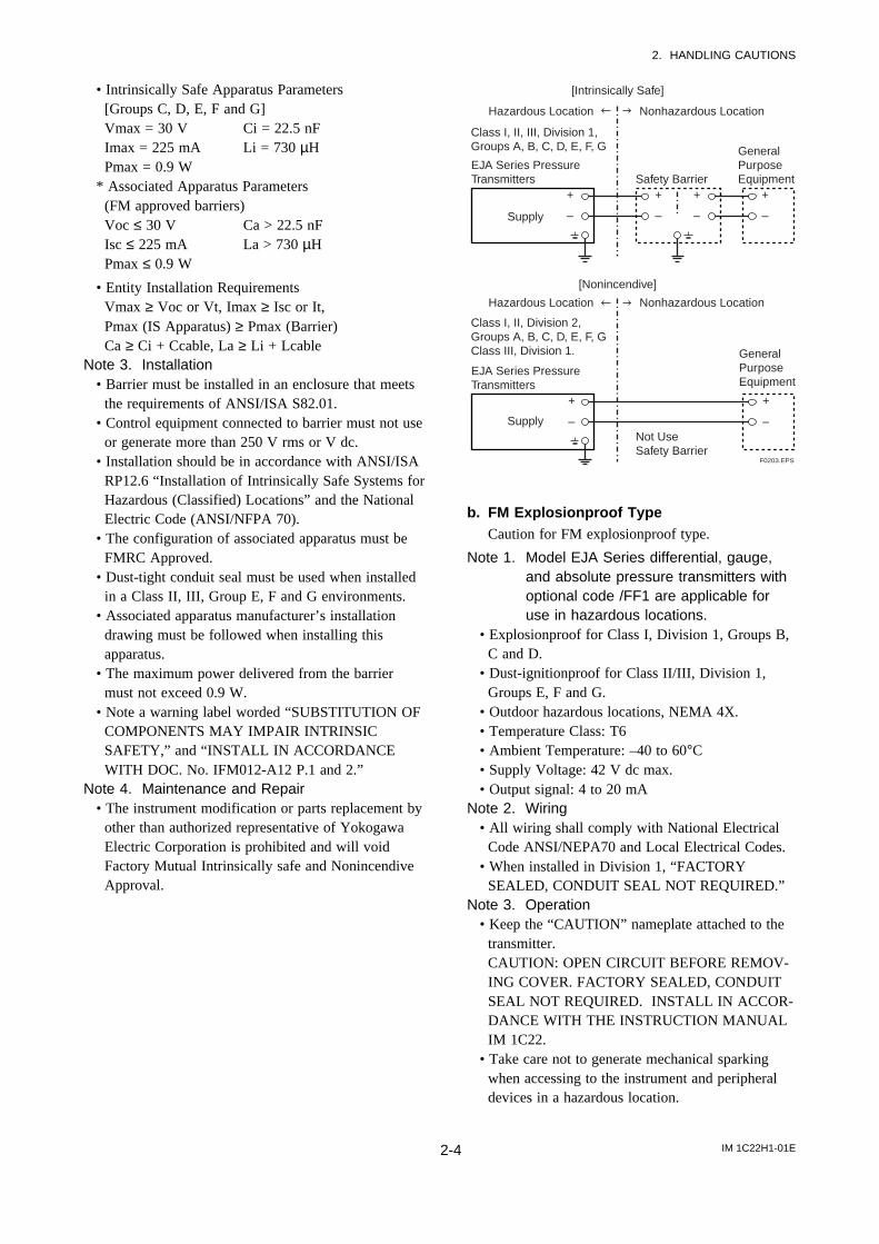
a. CSA Intrinsically Safe TypeCaution for CSA Intrinsically safe type. (Followingcontents refer to “DOC No. ICS003-A12 P.1-1 andP.1-2.”)
Note 1. Model EJA Series differential, gauge, andabsolute pressure transmitters withoptional code /CS1 are applicable for usein hazardous locations
• Intrinsically Safe for Class I, Division 1, Groups A,B, C & D. Class II, Division 1, Groups E, F & Gand Class III, Division 1 Hazardous Locations.
• Nonincendive for Class I, Division 2, Groups A, B,C & D, Class II, Division 2, Groups F & G, andClass III, Hazardous Locations. (not use SafetyBarrier)
• Encl. “Type 4X”• Temperature Class: T4• Ambient temperature: –40 to 60°C• Process Temperature: 120°C max.
Note 2. Entity Parameters• Intrinsically safe ratings are as follows:
Maximum Input Voltage (Vmax) = 30 VMaximum Input Current (Imax) = 165 mAMaximum Input Power (Pmax) = 0.9 WMaximum Internal Capacitance (Ci) = 22.5 nFMaximum Internal Inductance (Li) = 730 µH
* Associated apparatus (CSA certified barriers)Maximum output voltage (Voc) ≤ 30 VMaximum output current (Isc) ≤ 165 mAMaximum output power (Pmax) ≤ 0.9 W
Note 3. Installation• All wiring shall comply with Canadian Electrical
Code Part I and Local Electrical Codes.• The instrument modification or parts replacement
by other than authorized representative ofYokogawa Electric Corporation and YokogawaCorporation of America is prohibited and will voidCanadian Standards Intrinsically safe andnonincendive Certification.
F0204.EPS
Class I, II, III, Division 1,Groups A, B, C, D, E, F, G
EJA Series Pressure Transmitters
EJA Series Pressure Transmitters
Safety Barrier
Supply
Supply
Hazardous Location Nonhazardous Location
Hazardous Location Nonhazardous Location
General PurposeEquipment
+
–
+
–
+
–
+
–
+
–
+
–
[Intrinsically Safe]
Class I, II, Division 2,Groups A, B, C, D, E, F, GClass III
Not UseSafety Barrier
[Nonincendive]
General PurposeEquipment
b. CSA Explosionproof TypeCaution for CSA explosionproof type.
Note 1. Model EJA Series differential, gauge, andabsolute pressure transmitters withoptional code /CF1 are applicable for usein hazardous locations:
• Explosionproof for Class I, Division 1, Groups B,C and D.
• Dust-ignitionproof for Class II/III, Division 1,Groups E, F and G.
• Encl “Type 4X”• Temperature Class: T6, T5, and T4• Process Temperature: 85°C (T6), 100°C (T5), and
120°C (T4)• Ambient Temperature: –40 to 80°C• Supply Voltage: 42 V dc max.• Output Signal: 4 to 20 mA
IM 1C22H1-01E2-6
2. HANDLING CAUTIONS
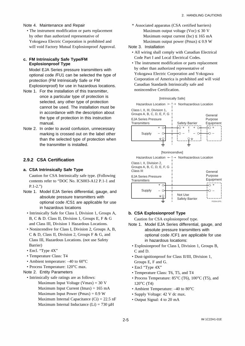
Note 2. Wiring• All wiring shall comply with Canadian Electrical
Code Part I and Local Electrical Codes.• In hazardous location, wiring shall be in conduit as
shown in the figure.CAUTION: SEAL ALL CONDUITSWITHIN 50 cm OF THE ENCLOSURE.UN SCELLEMENT DOIT ÊTREINSTALLÉ À MOINS DE 50 cm DUBÎTIER.
• When installed in Division 2, “SEALS NOTREQUIRED.”
Note 3. Operation• Keep the “CAUTION” label attached to the
transmitter.CAUTION: OPEN CIRCUIT BEFOREREMOVING COVER.OUVRIR LE CIRCUIT AVANTD´NLEVER LE COUVERCLE.
• Take care not to generate mechanical sparkingwhen accessing to the instrument and peripheraldevices in a hazardous location.
Note 4. Maintenance and Repair• The instrument modification or parts replacement
by other than authorized representative ofYokogawa Electric Corporation and YokogawaCorporation of America is prohibited and will voidCanadian Standards Explosionproof Certification.
Non-hazardous Location Equipment
42 V DC Max. 4 to 20 mA DC Signal
Non-Hazardous Locations
Hazardous Locations Division 1
Non-Hazardous Locations
Hazardous Locations Division 2
50 cm Max.
Sealing FittingConduit
EJA Series
Non-hazardous Location Equipment
42 V DC Max. 4 to 20 mA DC Signal
Sealing Fitting
EJA SeriesF0205.EPS
c. CSA Intrinsically Safe Type/CSAExplosionproof TypeModel EJA Series pressure transmitters withoptional code /CU1 can be selected the type ofprotection (CSA Intrinsically Safe or CSAExplosionproof) for use in hazardous locations.
Note 1. For the installation of this transmitter,once a particular type of protection isselected, any other type of protectioncannot be used. The installation must bein accordance with the description aboutthe type of protection in this instructionmanual.
Note 2. In order to avoid confusion, unnecessarymarking is crossed out on the label otherthan the selected type of protection whenthe transmitter is installed.
2.9.3 SAA Certification
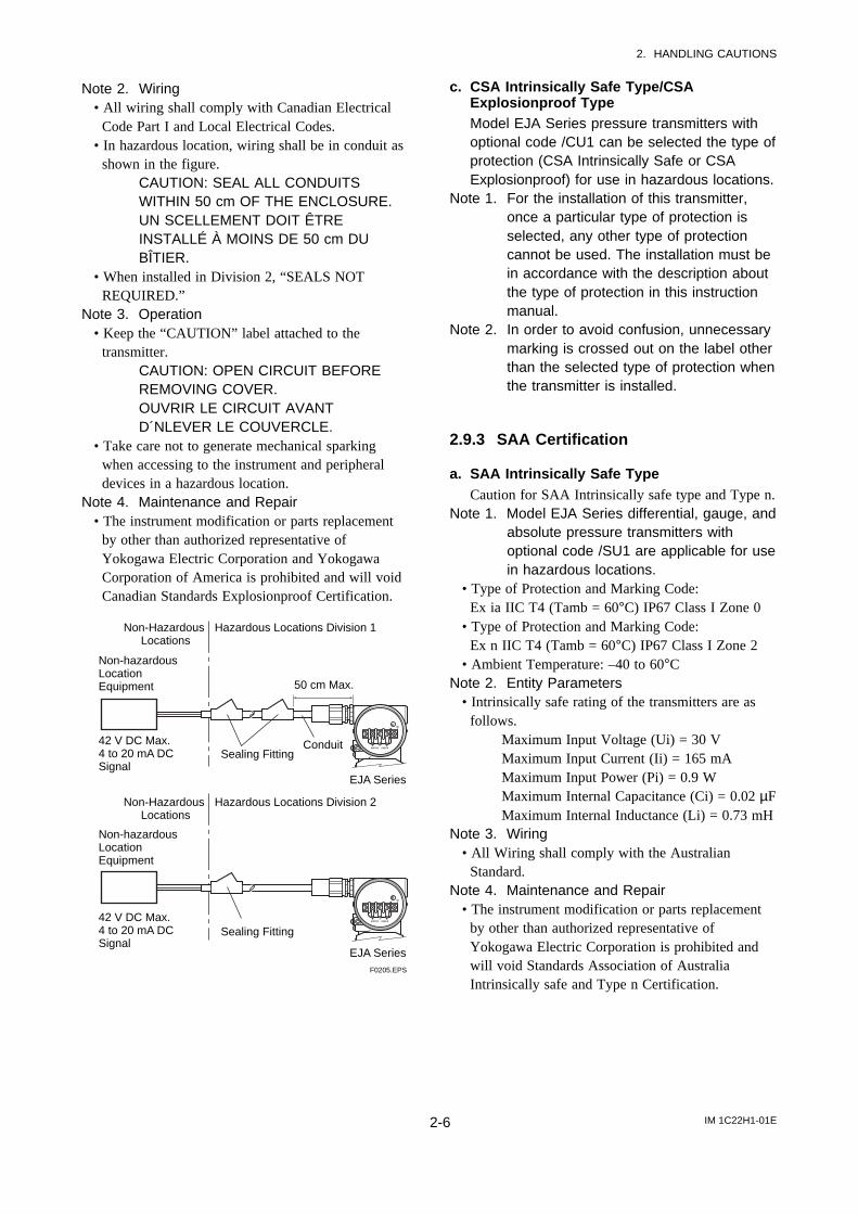
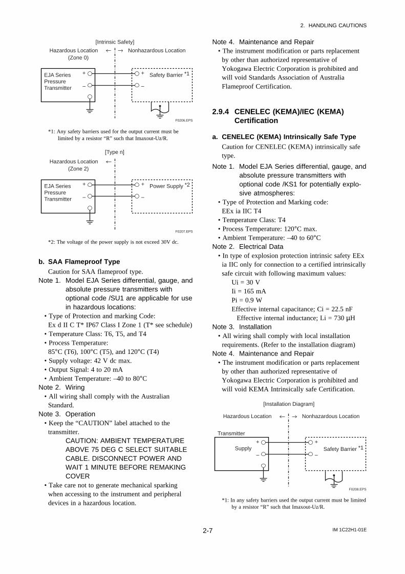
a. SAA Intrinsically Safe TypeCaution for SAA Intrinsically safe type and Type n.
Note 1. Model EJA Series differential, gauge, andabsolute pressure transmitters withoptional code /SU1 are applicable for usein hazardous locations.
• Type of Protection and Marking Code:Ex ia IIC T4 (Tamb = 60°C) IP67 Class I Zone 0
• Type of Protection and Marking Code:Ex n IIC T4 (Tamb = 60°C) IP67 Class I Zone 2
• Ambient Temperature: –40 to 60°CNote 2. Entity Parameters
• Intrinsically safe rating of the transmitters are asfollows.
Maximum Input Voltage (Ui) = 30 VMaximum Input Current (Ii) = 165 mAMaximum Input Power (Pi) = 0.9 WMaximum Internal Capacitance (Ci) = 0.02 µFMaximum Internal Inductance (Li) = 0.73 mH
Note 3. Wiring• All Wiring shall comply with the Australian
Standard.Note 4. Maintenance and Repair
• The instrument modification or parts replacementby other than authorized representative ofYokogawa Electric Corporation is prohibited andwill void Standards Association of AustraliaIntrinsically safe and Type n Certification.
IM 1C22H1-01E2-7
2. HANDLING CAUTIONS
(Zone 0)
EJA SeriesPressureTransmitter
Safety Barrier *1
Hazardous Location Nonhazardous Location
+
–
+
–
[Intrinsic Safety]
F0206.EPS
*1: Any safety barriers used for the output current must belimited by a resistor “R” such that Imaxout-Uz/R.
[Type n]
(Zone 2)
EJA SeriesPressureTransmitter
Power Supply *2
Hazardous Location
+
–
+
–
F0207.EPS
*2: The voltage of the power supply is not exceed 30V dc.
b. SAA Flameproof TypeCaution for SAA flameproof type.
Note 1. Model EJA Series differential, gauge, andabsolute pressure transmitters withoptional code /SU1 are applicable for usein hazardous locations:
• Type of Protection and marking Code:Ex d II C T* IP67 Class I Zone 1 (T* see schedule)
• Temperature Class: T6, T5, and T4• Process Temperature:
85°C (T6), 100°C (T5), and 120°C (T4)• Supply voltage: 42 V dc max.• Output Signal: 4 to 20 mA• Ambient Temperature: –40 to 80°C
Note 2. Wiring• All wiring shall comply with the Australian
Standard.Note 3. Operation
• Keep the “CAUTION” label attached to thetransmitter.
CAUTION: AMBIENT TEMPERATUREABOVE 75 DEG C SELECT SUITABLECABLE. DISCONNECT POWER ANDWAIT 1 MINUTE BEFORE REMAKINGCOVER
• Take care not to generate mechanical sparkingwhen accessing to the instrument and peripheraldevices in a hazardous location.
Note 4. Maintenance and Repair• The instrument modification or parts replacement
by other than authorized representative ofYokogawa Electric Corporation is prohibited andwill void Standards Association of AustraliaFlameproof Certification.
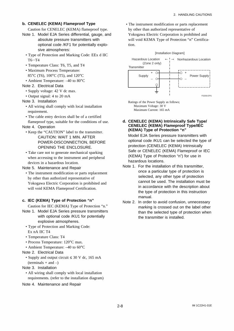
2.9.4 CENELEC (KEMA)/IEC (KEMA)Certification
a. CENELEC (KEMA) Intrinsically Safe TypeCaution for CENELEC (KEMA) intrinsically safetype.
Note 1. Model EJA Series differential, gauge, andabsolute pressure transmitters withoptional code /KS1 for potentially explo-sive atmospheres:
• Type of Protection and Marking code:EEx ia IIC T4
• Temperature Class: T4• Process Temperature: 120°C max.• Ambient Temperature: –40 to 60°C
Note 2. Electrical Data• In type of explosion protection intrinsic safety EEx
ia IIC only for connection to a certified intrinsicallysafe circuit with following maximum values:
Ui = 30 VIi = 165 mAPi = 0.9 WEffective internal capacitance; Ci = 22.5 nF
Effective internal inductance; Li = 730 µHNote 3. Installation
• All wiring shall comply with local installationrequirements. (Refer to the installation diagram)
Note 4. Maintenance and Repair• The instrument modification or parts replacement
by other than authorized representative ofYokogawa Electric Corporation is prohibited andwill void KEMA Intrinsically safe Certification.
Transmitter
Supply Safety Barrier *1
Nonhazardous Location
[Installation Diagram]
Hazardous Location
+
–
+
–
F0208.EPS
*1: In any safety barriers used the output current must be limitedby a resistor “R” such that Imaxout-Uz/R.
IM 1C22H1-01E2-8
2. HANDLING CAUTIONS
b. CENELEC (KEMA) Flameproof TypeCaution for CENELEC (KEMA) flameproof type.
Note 1. Model EJA Series differential, gauge, andabsolute pressure transmitters withoptional code /KF1 for potentially explo-sive atmospheres:
• Type of Protection and Marking Code: EEx d IICT6···T4
• Temperature Class: T6, T5, and T4• Maximum Process Temperature:
85°C (T6), 100°C (T5), and 120°C• Ambient Temperature: –40 to 80°C
Note 2. Electrical Data• Supply voltage: 42 V dc max.• Output signal: 4 to 20 mA
Note 3. Installation• All wiring shall comply with local installation
requirement.• The cable entry devices shall be of a certified
flameproof type, suitable for the conditions of use.Note 4. Operation
• Keep the “CAUTION” label to the transmitter.CAUTION: WAIT 1 MIN. AFTERPOWER-DISCONNECTION, BEFOREOPENING THE ENCLOSURE.
• Take care not to generate mechanical sparkingwhen accessing to the instrument and peripheraldevices in a hazardous location.
Note 5. Maintenance and Repair• The instrument modification or parts replacement
by other than authorized representative ofYokogawa Electric Corporation is prohibited andwill void KEMA Flameproof Certification.
c. IEC (KEMA) Type of Protection “n”Caution for IEC (KEMA) Type of Protection “n.”
Note 1. Model EJA Series pressure transmitterswith optional code /KU1 for potentiallyexplosive atmospheres.
• Type of Protection and Marking Code:Ex nA IIC T4
• Temperature Class: T4• Process Temperature: 120°C max.• Ambient Temperature: –40 to 60°C
Note 2. Electrical Data• Supply and output circuit ≤ 30 V dc, 165 mA
(terminals + and –)Note 3. Installation
• All wiring shall comply with local installationrequirements. (refer to the installation diagram)
Note 4. Maintenance and Repair
• The instrument modification or parts replacementby other than authorized representative ofYokogawa Electric Corporation is prohibited andwill void KEMA Type of Protection “n” Certifica-tion.
Power Supply
(Zone 2 only)Transmitter
Supply
Nonhazardous Location
[Installation Diagram]
Hazardous Location
+
–
+
–
F0209.EPS
Ratings of the Power Supply as follows;Maximum Voltage: 30 VMaximum Current: 165 mA
d. CENELEC (KEMA) Intrinsically Safe Type/CENELEC (KEMA) Flameproof Type/IEC(KEMA) Type of Protection “n”Model EJA Series pressure transmitters withoptional code /KU1 can be selected the type ofprotection (CENELEC (KEMA) IntrinsicallySafe or CENELEC (KEMA) Flameproof or IEC(KEMA) Type of Protection “n”) for use inhazardous locations.
Note 1. For the installation of this transmitter,once a particular type of protection isselected, any other type of protectioncannot be used. The installation must bein accordance with the description aboutthe type of protection in this instructionmanual.
Note 2. In order to avoid confusion, unnecessarymarking is crossed out on the label otherthan the selected type of protection whenthe transmitter is installed.
IM 1C22H1-01E2-9
2. HANDLING CAUTIONS
2.9.5 JIS Certification
JIS Flameproof and Intrinsically Safe Type
The model EJA Series pressure transmitters withoptional code /JF1 and /JS1, which have obtainedcertification according to technical criteria for explo-sion-protected construction of electric machinery andequipment(Standards Notification No. 556 from theJapanese Ministry of Labor) conforming to IECstandards, are designed for hazardous areas whereexplosive gases and/or inflammable vapors may bepresent. [JIS Flameproof Type(optional code /JF1)allows installation in Division 1 and 2 areas, and JISIntrinsically Safe Type(optional code /JS1) allowsinstallation in Division 0, 1, and 2 areas.]
To observe the safety of flameproof equipment requiresgreat care during mounting, wiring, and piping. Safetyrequirements also place restrictions on maintenanceand repair activities. Users absolutely must read“Installation and Operating Precautions for JIS Intrinsi-cally Safe Equipment and Flameproof Equipment” atthe end of this manual.
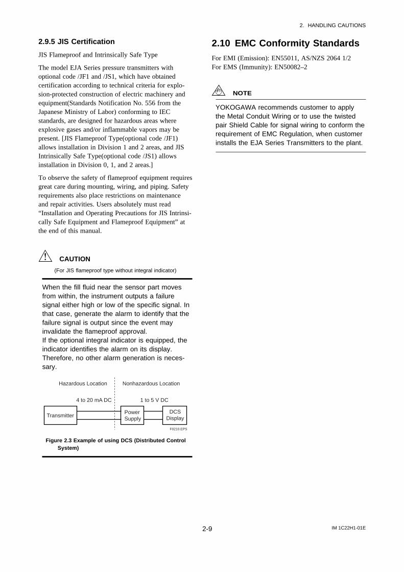
CAUTION
(For JIS flameproof type without integral indicator)
When the fill fluid near the sensor part movesfrom within, the instrument outputs a failuresignal either high or low of the specific signal. Inthat case, generate the alarm to identify that thefailure signal is output since the event mayinvalidate the flameproof approval.If the optional integral indicator is equipped, theindicator identifies the alarm on its display.Therefore, no other alarm generation is neces-sary.
Transmitter
Hazardous Location Nonhazardous Location
PowerSupply
DCSDisplay
4 to 20 mA DC 1 to 5 V DC
F0210.EPS
Figure 2.3 Example of using DCS (Distributed ControlSystem)
2.10 EMC Conformity StandardsFor EMI (Emission): EN55011, AS/NZS 2064 1/2For EMS (Immunity): EN50082–2
NOTE
YOKOGAWA recommends customer to applythe Metal Conduit Wiring or to use the twistedpair Shield Cable for signal wiring to conform therequirement of EMC Regulation, when customerinstalls the EJA Series Transmitters to the plant.
IM 1C22H1-01E3-1
3. COMPONENT NAMES
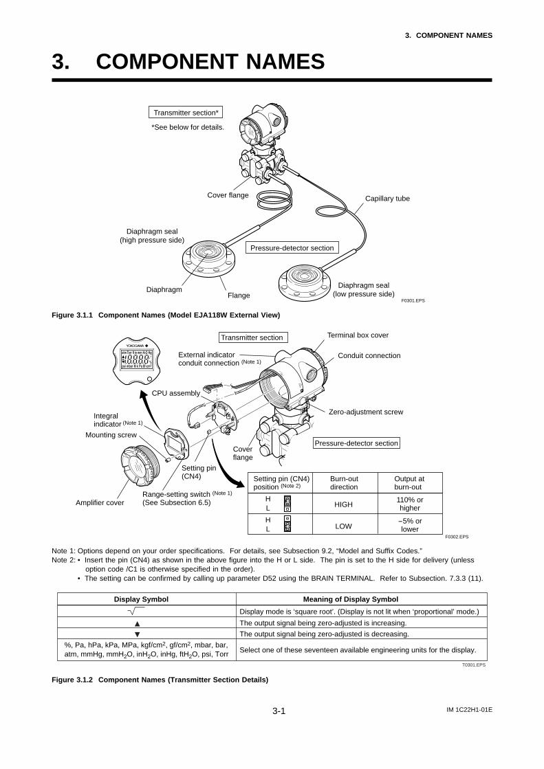
3. COMPONENT NAMES
Transmitter section*
*See below for details.
Pressure-detector section
Cover flange
Diaphragm seal(high pressure side)
Diaphragm seal(low pressure side)
DiaphragmFlange
Capillary tube
F0301.EPS
Figure 3.1.1 Component Names (Model EJA118W External View)
F0302.EPS
Transmitter section
Integralindicator (Note 1)
Mounting screw
Range-setting switch (Note 1)
(See Subsection 6.5)Amplifier cover
Cover flange
Zero-adjustment screw
Conduit connection
Terminal box cover
Pressure-detector section
Setting pin (CN4)position (Note 2)
Burn-outdirection
Output atburn-out
HL
HL
HIGH
LOW
110% orhigher
-5% orlower
External indicatorconduit connection (Note 1)
CPU assembly
Setting pin(CN4)
Note 1: Options depend on your order specifications. For details, see Subsection 9.2, “Model and Suffix Codes.”Note 2: • Insert the pin (CN4) as shown in the above figure into the H or L side. The pin is set to the H side for delivery (unless
option code /C1 is otherwise specified in the order).• The setting can be confirmed by calling up parameter D52 using the BRAIN TERMINAL. Refer to Subsection. 7.3.3 (11).
Display Symbol
%, Pa, hPa, kPa, MPa, kgf/cm2, gf/cm2, mbar, bar, atm, mmHg, mmH2O, inH2O, inHg, ftH2O, psi, Torr
Meaning of Display Symbol
Display mode is ‘square root’. (Display is not lit when ‘proportional’ mode.)
The output signal being zero-adjusted is increasing.
The output signal being zero-adjusted is decreasing.
Select one of these seventeen available engineering units for the display.
T0301.EPS
Figure 3.1.2 Component Names (Transmitter Section Details)
IM 1C22H1-01E4-1
4. INSTALLATION
4. INSTALLATION
4.1 Precautionsj Before installing the transmitter, read the cautionary
notes in Section 2.4, “Selecting the InstallationLocation.” For additional information on theambient conditions allowed at the installationlocation, refer to Subsection 9.1 “Standard Specifi-cations.”
IMPORTANT
• When welding piping during construction, takecare not to allow welding currents to flowthrough the transmitter.
• Do not step on this instrument after installation.
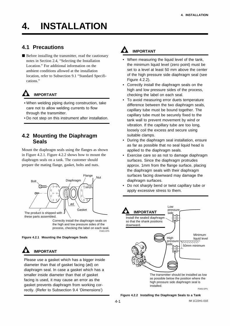
4.2 Mounting the DiaphragmSeals
Mount the diaphragm seals using the flanges as shownin Figure 4.2.1. Figure 4.2.2 shows how to mount thediaphragm seals on a tank. The customer shouldprepare the mating flange, gasket, bolts and nuts.
NutFlange
Diaphragm
ød
Gasket
F0401.EPS
Bolt
The product is shipped withthese parts assembled.
Correctly install the diaphragm seals onthe high and low pressure sides of theprocess, checking the label on each seal.
Figure 4.2.1 Mounting the Diaphragm Seals
IMPORTANT
Please use a gasket which has a bigger insidediameter than that of gasket facing (ød) ondiaphragm seal. In case a gasket which has asmaller inside diameter than that of gasketfacing is used, it may cause an error as thegasket prevents diaphragm from working cor-rectly. (Refer to Subsection 9.4 ‘Dimensions’)
IMPORTANT
• When measuring the liquid level of the tank,the minimum liquid level (zero point) must beset to a level at least 50 mm above the centerof the high pressure side diaphragm seal (seeFigure 4.2.2).
• Correctly install the diaphragm seals on thehigh and low pressure sides of the process,checking the label on each seal.
• To avoid measuring error duets temperaturedifference between the two diaphragm seals,capillary tube must be bound together. Thecapillary tube must be securely fixed to thetank wall to prevent movement by wind orvibration. If the capillary tube are too long,loosely coil the excess and secure usingsuitable clamps.
• During the diaphragm seal installation, ensureas far as possible that no seal liquid head isapplied to the diaphragm seals.
• Exercise care so as not to damage diaphragmsurfaces. Since the diaphragm protrudesapprox. 1mm from the flange surface, placingthe diaphragm seals with their diaphragmsurfaces facing downward may damage thediaphragm surfaces.
• Do not sharply bend or twist capillary tube orapply excessive stress to them.
F0402.EPS
Low pressure side
Highpressureside 50mm minimum
Minimum liquid level
The transmitter should be installed as lowas possible below the position where thehigh pressure side diaphragm seal isinstalled.
IMPORTANTInstall the sealed diaphragm so that the shank positions downward.
Figure 4.2.2 Installing the Diaphragm Seals to a Tank
IM 1C22H1-01E4-2
4. INSTALLATION
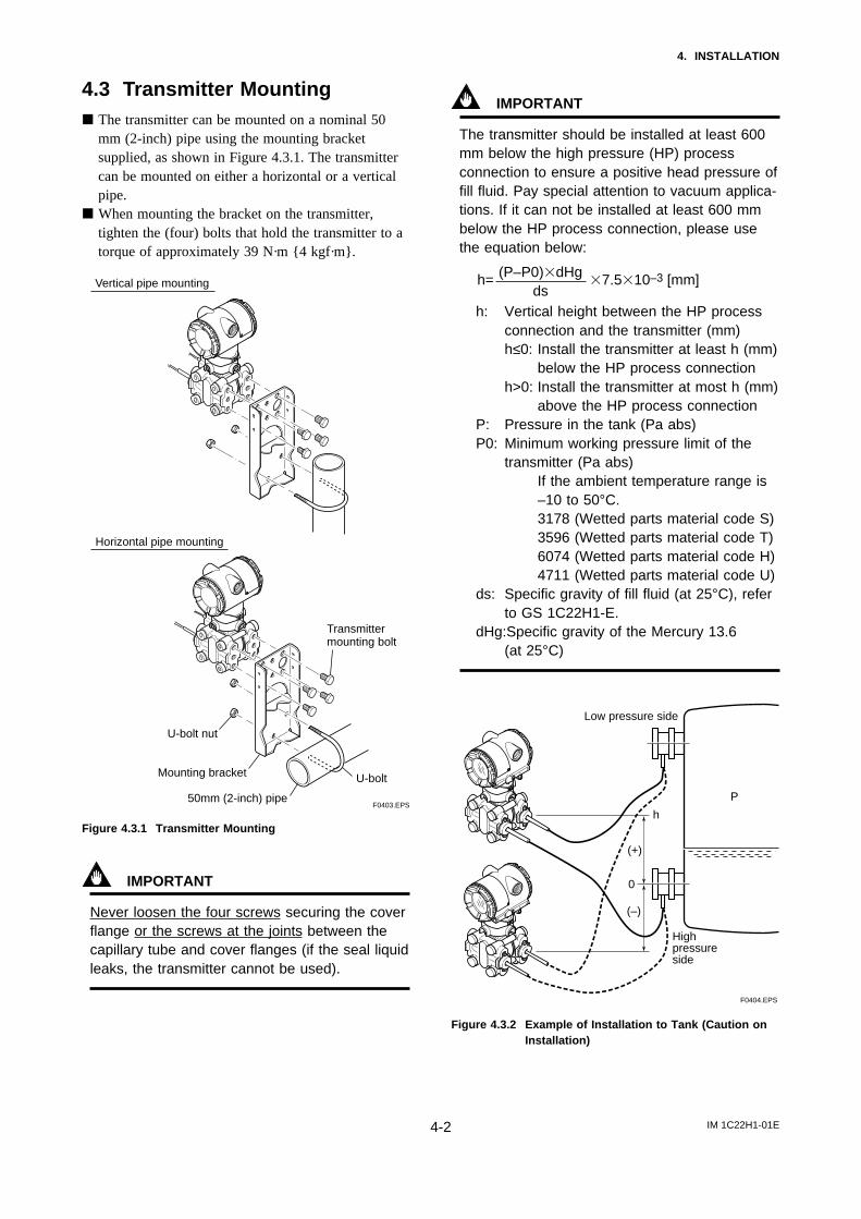
4.3 Transmitter Mountingj The transmitter can be mounted on a nominal 50
mm (2-inch) pipe using the mounting bracketsupplied, as shown in Figure 4.3.1. The transmittercan be mounted on either a horizontal or a verticalpipe.
j When mounting the bracket on the transmitter,tighten the (four) bolts that hold the transmitter to atorque of approximately 39 N·m 4 kgf·m.
Horizontal pipe mounting
Vertical pipe mounting
Transmittermounting bolt
U-bolt nut
Mounting bracket
50mm (2-inch) pipe
U-bolt
F0403.EPS
Figure 4.3.1 Transmitter Mounting
IMPORTANT
Never loosen the four screws securing the coverflange or the screws at the joints between thecapillary tube and cover flanges (if the seal liquidleaks, the transmitter cannot be used).
IMPORTANT
The transmitter should be installed at least 600mm below the high pressure (HP) processconnection to ensure a positive head pressure offill fluid. Pay special attention to vacuum applica-tions. If it can not be installed at least 600 mmbelow the HP process connection, please usethe equation below:
h= 37.5310–3 [mm](P–P0)3dHgds
h: Vertical height between the HP processconnection and the transmitter (mm)h≤0: Install the transmitter at least h (mm)
below the HP process connectionh>0: Install the transmitter at most h (mm)
above the HP process connectionP: Pressure in the tank (Pa abs)P0: Minimum working pressure limit of the
transmitter (Pa abs)If the ambient temperature range is–10 to 50°C.3178 (Wetted parts material code S)3596 (Wetted parts material code T)6074 (Wetted parts material code H)4711 (Wetted parts material code U)
ds: Specific gravity of fill fluid (at 25°C), referto GS 1C22H1-E.
dHg:Specific gravity of the Mercury 13.6(at 25°C)
F0404.EPS
P
h
Low pressure side
0
Highpressureside
(+)
(–)
Figure 4.3.2 Example of Installation to Tank (Caution onInstallation)
IM 1C22H1-01E4-3
4. INSTALLATION
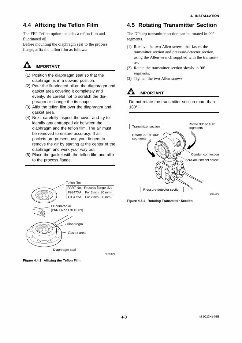
4.4 Affixing the Teflon FilmThe FEP Teflon option includes a teflon film andfluorinated oil.Before mounting the diaphragm seal to the processflange, affix the teflon film as follows:
IMPORTANT
(1) Position the diaphragm seal so that thediaphragm is in a upward position.
(2) Pour the fluorinated oil on the diaphragm andgasket area covering it completely andevenly. Be careful not to scratch the dia-phragm or change the its shape.
(3) Affix the teflon film over the diaphragm andgasket area.
(4) Next, carefully inspect the cover and try toidentify any entrapped air between thediaphragm and the teflon film. The air mustbe removed to ensure accuracy. If airpockets are present, use your fingers toremove the air by starting at the center of thediaphragm and work your way out.
(5) Place the gasket with the teflon film and affixto the process flange.
Teflon film
Diaphragm
Fluorinated oil[PART No.: F9145YN]
Gasket area
Diaphragm seal
PART No.F9347XAF9347YA
Process flange sizeFor 3inch (80 mm)For 2inch (50 mm)
F0405.EPS
Figure 4.4.1 Affixing the Teflon Film
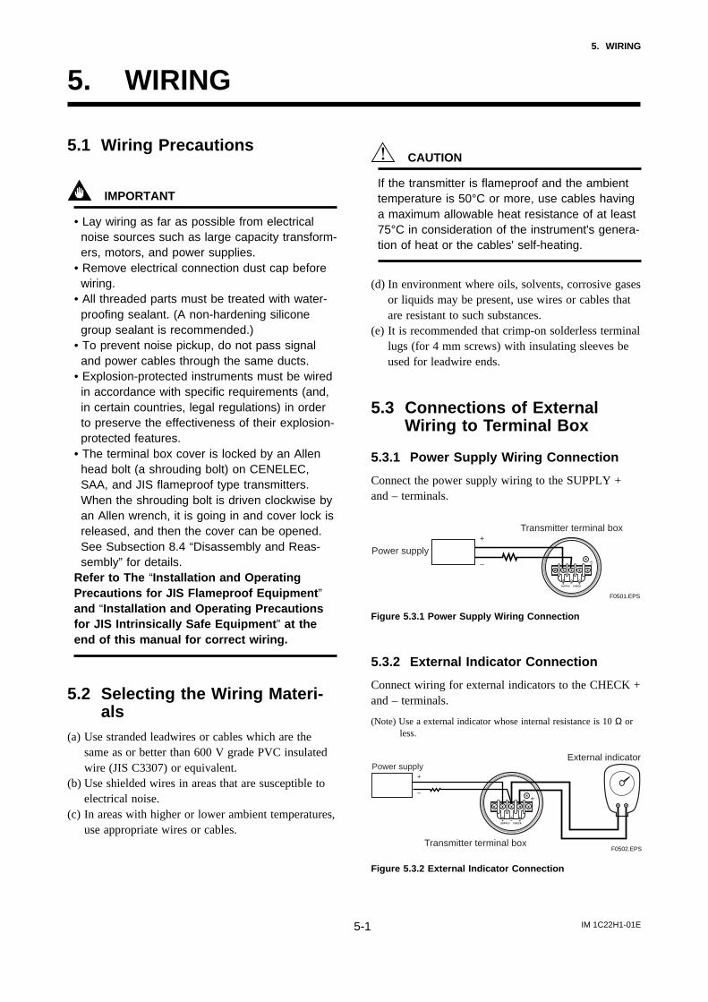
4.5 Rotating Transmitter SectionThe DPharp transmitter section can be rotated in 90°segments.
(1) Remove the two Allen screws that fasten thetransmitter section and pressure-detector section,using the Allen wrench supplied with the transmit-ter.
(2) Rotate the transmitter section slowly in 90°segments.
(3) Tighten the two Allen screws.
IMPORTANT
Do not rotate the transmitter section more than180°.
F0406.EPS
Rotate 90° or 180° segments
Rotate 90° or 180° segments
Transmitter section
Pressure-detector section
Conduit connection
Zero-adjustment screw
Figure 4.5.1 Rotating Transmitter Section
IM 1C22H1-01E5-1
5. WIRING
5. WIRING
5.1 Wiring Precautions
IMPORTANT
• Lay wiring as far as possible from electricalnoise sources such as large capacity transform-ers, motors, and power supplies.
• Remove electrical connection dust cap beforewiring.
• All threaded parts must be treated with water-proofing sealant. (A non-hardening siliconegroup sealant is recommended.)
• To prevent noise pickup, do not pass signaland power cables through the same ducts.
• Explosion-protected instruments must be wiredin accordance with specific requirements (and,in certain countries, legal regulations) in orderto preserve the effectiveness of their explosion-protected features.
• The terminal box cover is locked by an Allenhead bolt (a shrouding bolt) on CENELEC,SAA, and JIS flameproof type transmitters.When the shrouding bolt is driven clockwise byan Allen wrench, it is going in and cover lock isreleased, and then the cover can be opened.See Subsection 8.4 “Disassembly and Reas-sembly” for details.
Refer to The “Installation and OperatingPrecautions for JIS Flameproof Equipment ”and “Installation and Operating Precautionsfor JIS Intrinsically Safe Equipment ” at theend of this manual for correct wiring.
5.2 Selecting the Wiring Materi-als
(a) Use stranded leadwires or cables which are thesame as or better than 600 V grade PVC insulatedwire (JIS C3307) or equivalent.
(b) Use shielded wires in areas that are susceptible toelectrical noise.
(c) In areas with higher or lower ambient temperatures,use appropriate wires or cables.
CAUTION
If the transmitter is flameproof and the ambienttemperature is 50°C or more, use cables havinga maximum allowable heat resistance of at least75°C in consideration of the instrument's genera-tion of heat or the cables' self-heating.
(d) In environment where oils, solvents, corrosive gasesor liquids may be present, use wires or cables thatare resistant to such substances.
(e) It is recommended that crimp-on solderless terminallugs (for 4 mm screws) with insulating sleeves beused for leadwire ends.
5.3 Connections of ExternalWiring to Terminal Box
5.3.1 Power Supply Wiring Connection
Connect the power supply wiring to the SUPPLY +and – terminals.
Power supply–
+Transmitter terminal box
F0501.EPS
Figure 5.3.1 Power Supply Wiring Connection
5.3.2 External Indicator Connection
Connect wiring for external indicators to the CHECK +and – terminals.
(Note) Use a external indicator whose internal resistance is 10 Ω orless.
Transmitter terminal box
External indicator
F0502.EPS
Power supply
–
+
Figure 5.3.2 External Indicator Connection
IM 1C22H1-01E5-2
5. WIRING
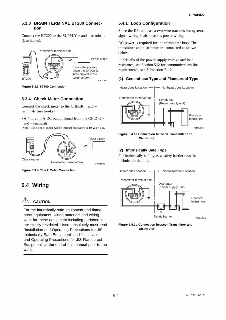
5.3.3 BRAIN TERMINAL BT200 Connec-tion
Connect the BT200 to the SUPPLY + and – terminals(Use hooks).
Transmitter terminal box
BT200F0503.EPS
Power supply–
+
Ignore the polaritysince the BT200 isAC-coupled to theterminal box.
Figure 5.3.3 BT200 Connection
5.3.4 Check Meter Connection
Connect the check meter to the CHECK + and –terminals (use hooks).
• A 4 to 20 mA DC output signal from the CHECK +and – terminals.
(Note) Use a check meter whose internal resistance is 10 Ω or less.
Transmitter terminal boxF0504.EPS
Power supply
–
+
Check meter
Figure 5.3.4 Check Meter Connection
5.4 Wiring
CAUTION
For the intrinsically safe equipment and flame-proof equipment, wiring materials and wiringwork for these equipment including peripheralsare strictly restricted. Users absolutely must read“Installation and Operating Precautions for JISIntrinsically Safe Equipment” and “Installationand Operating Precautions for JIS FlameproofEquipment” at the end of this manual prior to thework.
5.4.1 Loop Configuration
Since the DPharp uses a two-wire transmission system,signal wiring is also used as power wiring.
DC power is required for the transmitter loop. Thetransmitter and distributor are connected as shownbelow.
For details of the power supply voltage and loadresistance, see Section 5.6; for communications linerequirements, see Subsection 7.1.2.
(1) General-use Type and Flameproof Type
Hazardous Location Nonhazardous Location
Transmitter terminal boxDistributor (Power supply unit)
Receiver instrument
F0505.EPS
Figure 5.4.1a Connection between Transmitter andDistributor
(2) Intrinsically Safe TypeFor intrinsically safe type, a safety barrier must beincluded in the loop.
Hazardous Location Nonhazardous Location
Transmitter terminal boxDistributor (Power supply unit)
Receiver instrument
Safety barrierF0506.EPS
Figure 5.4.1b Connection between Transmitter andDistributor
IM 1C22H1-01E5-3
5. WIRING
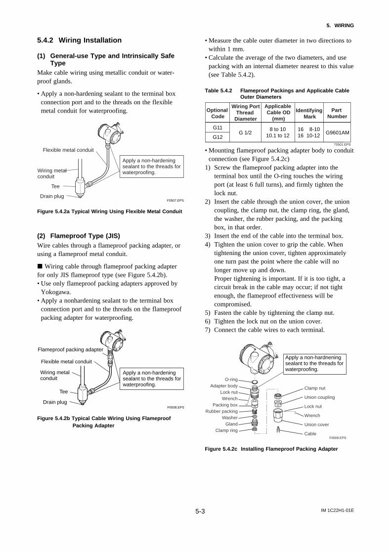
5.4.2 Wiring Installation
(1) General-use Type and Intrinsically SafeType
Make cable wiring using metallic conduit or water-proof glands.
• Apply a non-hardening sealant to the terminal boxconnection port and to the threads on the flexiblemetal conduit for waterproofing.
F0507.EPS
Flexible metal conduit
Wiring metalconduit
Tee
Drain plug
Apply a non-hardeningsealant to the threads forwaterproofing.
Figure 5.4.2a Typical Wiring Using Flexible Metal Conduit
(2) Flameproof Type (JIS)Wire cables through a flameproof packing adapter, orusing a flameproof metal conduit.
j Wiring cable through flameproof packing adapterfor only JIS flameproof type (see Figure 5.4.2b).• Use only flameproof packing adapters approved by
Yokogawa.• Apply a nonhardening sealant to the terminal box
connection port and to the threads on the flameproofpacking adapter for waterproofing.
Flameproof packing adapter
Flexible metal conduit
Wiring metalconduit
Tee
Drain plug
Apply a non-hardeningsealant to the threads forwaterproofing.
F0508.EPS
Figure 5.4.2b Typical Cable Wiring Using FlameproofPacking Adapter
• Measure the cable outer diameter in two directions towithin 1 mm.
• Calculate the average of the two diameters, and usepacking with an internal diameter nearest to this value(see Table 5.4.2).
Table 5.4.2 Flameproof Packings and Applicable CableOuter Diameters
T0501.EPS
G9601AM8 to 10
10.1 to 1216 8-1016 10-12G 1/2
G11
G12
Optional Code
Wiring PortThread
Diameter
Applicable Cable OD
(mm)
Identifying Mark
Part Number
• Mounting flameproof packing adapter body to conduitconnection (see Figure 5.4.2c)
1) Screw the flameproof packing adapter into theterminal box until the O-ring touches the wiringport (at least 6 full turns), and firmly tighten thelock nut.
2) Insert the cable through the union cover, the unioncoupling, the clamp nut, the clamp ring, the gland,the washer, the rubber packing, and the packingbox, in that order.
3) Insert the end of the cable into the terminal box.4) Tighten the union cover to grip the cable. When
tightening the union cover, tighten approximatelyone turn past the point where the cable will nolonger move up and down.Proper tightening is important. If it is too tight, acircuit break in the cable may occur; if not tightenough, the flameproof effectiveness will becompromised.
5) Fasten the cable by tightening the clamp nut.6) Tighten the lock nut on the union cover.7) Connect the cable wires to each terminal.
O-ringAdapter body
Lock nutWrench
Packing boxRubber packing
WasherGland
Clamp ring
Clamp nut
Union coupling
Lock nut
Wrench
Union cover
Cable
Apply a non-hardneningsealant to the threads forwaterproofing.
F0509.EPS
Figure 5.4.2c Installing Flameproof Packing Adapter
IM 1C22H1-01E5-4
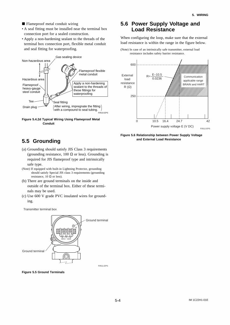
5. WIRING
j Flameproof metal conduit wiring• A seal fitting must be installed near the terminal box
connection port for a sealed construction.• Apply a non-hardening sealant to the threads of the
terminal box connection port, flexible metal conduitand seal fitting for waterproofing.
F0510.EPS
Non-hazardous area
Hazardous area
Flameproofheavy-gaugesteel conduit
Tee
Drain plug
Seal fitting
Gas sealing device
Flameproof flexiblemetal conduit
Apply a non-hardeningsealant to the threads ofthese fittings forwaterproofing
After wiring, impregnate the fittingwith a compound to seal tubing.
Figure 5.4.2d Typical Wiring Using Flameproof MetalConduit
5.5 Grounding(a) Grounding should satisfy JIS Class 3 requirements
(grounding resistance, 100 Ω or less). Grounding isrequired for JIS flameproof type and intrinsicallysafe type.
(Note) If equipped with built-in Lightning Protector, groundingshould satisfy Special JIS class 3 requirements (groundingresistance, 10 Ω or less).
(b) There are ground terminals on the inside andoutside of the terminal box. Either of these termi-nals may be used.
(c) Use 600 V grade PVC insulated wires for ground-ing.
Ground terminal
Ground terminal
Transmitter terminal box
F0511.EPS
Figure 5.5 Ground Terminals
5.6 Power Supply Voltage andLoad Resistance
When configuring the loop, make sure that the externalload resistance is within the range in the figure below.
(Note) In case of an intrinsically safe transmitter, external loadresistance includes safety barrier resistance.
600
250
0 10.5 16.4 24.7 42
External load
resistanceR (Ω)
Power supply voltage E (V DC)F0512.EPS
Communication applicable range BRAIN and HART
R= E–10.50.0236
Figure 5.6 Relationship between Power Supply Voltageand External Load Resistance
IM 1C22H1-01E6-1
6. OPERATION
6. OPERATION
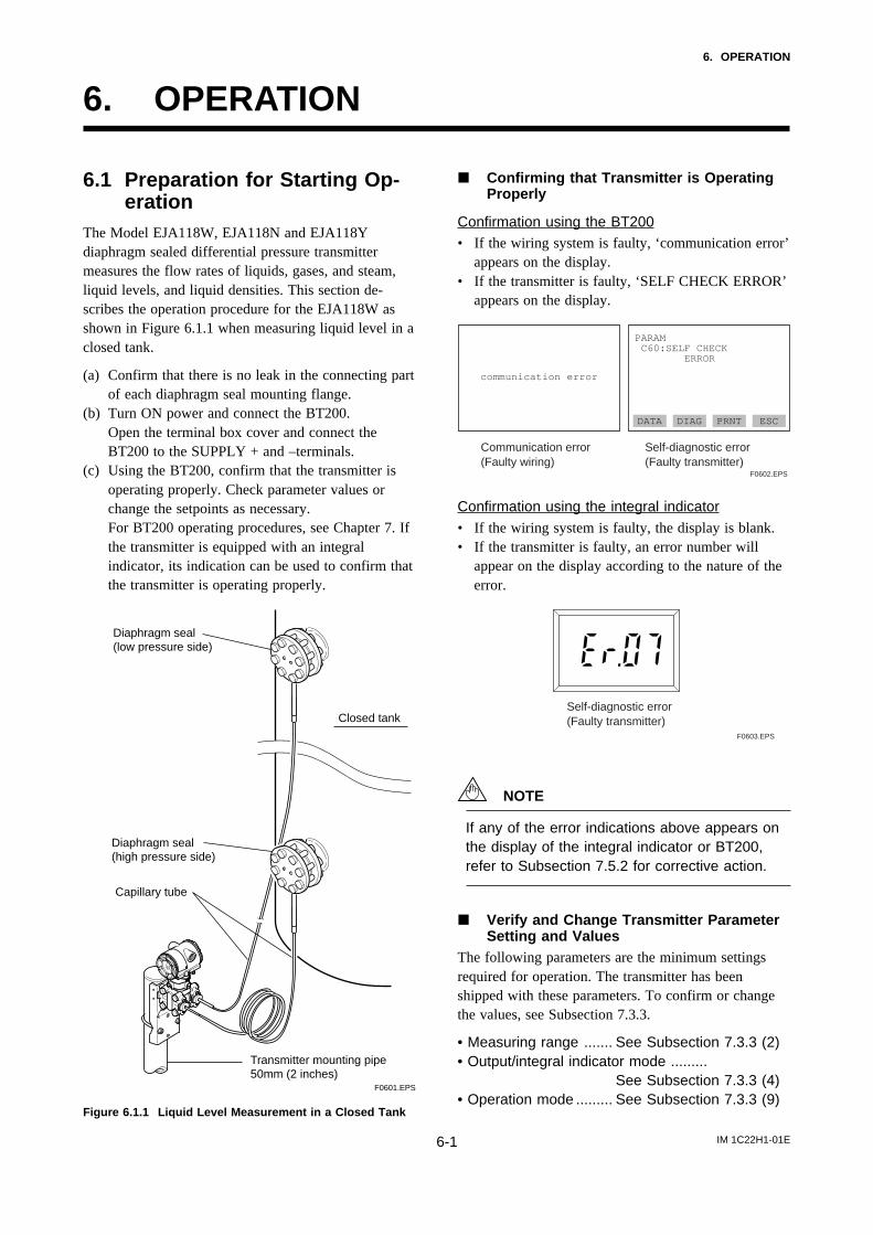
6.1 Preparation for Starting Op-eration
The Model EJA118W, EJA118N and EJA118Ydiaphragm sealed differential pressure transmittermeasures the flow rates of liquids, gases, and steam,liquid levels, and liquid densities. This section de-scribes the operation procedure for the EJA118W asshown in Figure 6.1.1 when measuring liquid level in aclosed tank.
(a) Confirm that there is no leak in the connecting partof each diaphragm seal mounting flange.
(b) Turn ON power and connect the BT200.Open the terminal box cover and connect theBT200 to the SUPPLY + and –terminals.
(c) Using the BT200, confirm that the transmitter isoperating properly. Check parameter values orchange the setpoints as necessary.For BT200 operating procedures, see Chapter 7. Ifthe transmitter is equipped with an integralindicator, its indication can be used to confirm thatthe transmitter is operating properly.
Closed tank
F0601.EPS
Transmitter mounting pipe50mm (2 inches)
Capillary tube
Diaphragm seal(high pressure side)
Diaphragm seal(low pressure side)
Figure 6.1.1 Liquid Level Measurement in a Closed Tank
j Confirming that Transmitter is OperatingProperly
Confirmation using the BT200• If the wiring system is faulty, ‘communication error’
appears on the display.• If the transmitter is faulty, ‘SELF CHECK ERROR’
appears on the display.
Communication error (Faulty wiring)
Self-diagnostic error(Faulty transmitter)
communication error
PARAM C60:SELF CHECK ERROR
DATA DIAG PRNT ESC
F0602.EPS
Confirmation using the integral indicator• If the wiring system is faulty, the display is blank.• If the transmitter is faulty, an error number will
appear on the display according to the nature of theerror.
Self-diagnostic error(Faulty transmitter)
F0603.EPS
NOTE
If any of the error indications above appears onthe display of the integral indicator or BT200,refer to Subsection 7.5.2 for corrective action.
j Verify and Change Transmitter ParameterSetting and Values
The following parameters are the minimum settingsrequired for operation. The transmitter has beenshipped with these parameters. To confirm or changethe values, see Subsection 7.3.3.
• Measuring range ....... See Subsection 7.3.3 (2)• Output/integral indicator mode .........
See Subsection 7.3.3 (4)• Operation mode ......... See Subsection 7.3.3 (9)
IM 1C22H1-01E6-2
6. OPERATION
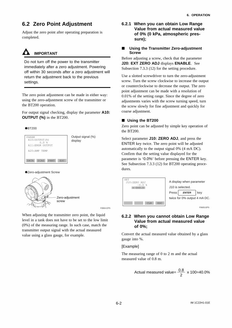
6.2 Zero Point AdjustmentAdjust the zero point after operating preparation iscompleted.
IMPORTANT
Do not turn off the power to the transmitterimmediately after a zero adjustment. Poweringoff within 30 seconds after a zero adjustment willreturn the adjustment back to the previoussettings.
The zero point adjustment can be made in either way:using the zero-adjustment screw of the transmitter orthe BT200 operation.
For output signal checking, display the parameter A10:OUTPUT (%) in the BT200.
Output signal (%)display
PARAM A10:OUTPUT(%) 0.0 % A11:ENGR OUTPUT
A20:AMP TEMP
DATA DIAG PRNT ESC
F0604.EPS
Zero-adjustmentscrew
dBT200
dZero-adjustment Screw
When adjusting the transmitter zero point, the liquidlevel in a tank does not have to be set to the low limit(0%) of the measuring range. In such case, match thetransmitter output signal with the actual measuredvalue using a glass gauge, for example.
6.2.1 When you can obtain Low RangeValue from actual measured valueof 0% (0 kPa, atmospheric pres-sure);
j Using the Transmitter Zero-adjustmentScrew
Before adjusting a screw, check that the parameterJ20: EXT ZERO ADJ displays ENABLE . SeeSubsection 7.3.3 (12) for the setting procedure.
Use a slotted screwdriver to turn the zero-adjustmentscrew. Turn the screw clockwise to increase the outputor counterclockwise to decrease the output. The zeropoint adjustment can be made with a resolution of0.01% of the setting range. Since the degree of zeroadjustments varies with the screw turning speed, turnthe screw slowly for fine adjustment and quickly forcoarse adjustment.
j Using the BT200Zero point can be adjusted by simple key operation ofthe BT200.
Select parameter J10: ZERO ADJ , and press theENTER key twice. The zero point will be adjustedautomatically to the output signal 0% (4 mA DC).Confirm that the setting value displayed for theparameter is ‘0.0%’ before pressing the ENTER key.See Subsection 7.3.3 (12) for BT200 operating proce-dures.
A display when parameter
J10 is selected.
Press key
twice for 0% output 4 mA DC.
SET J10:ZERO ADJ –0.0 % + 000.0
CLR ESC
F0605.EPS
6.2.2 When you cannot obtain Low RangeValue from actual measured valueof 0%;
Convert the actual measured value obtained by a glassgauge into %.
[Example]
The measuring range of 0 to 2 m and the actualmeasured value of 0.8 m.
0.82
Actual measured value= x 100=40.0%
IM 1C22H1-01E6-3
6. OPERATION
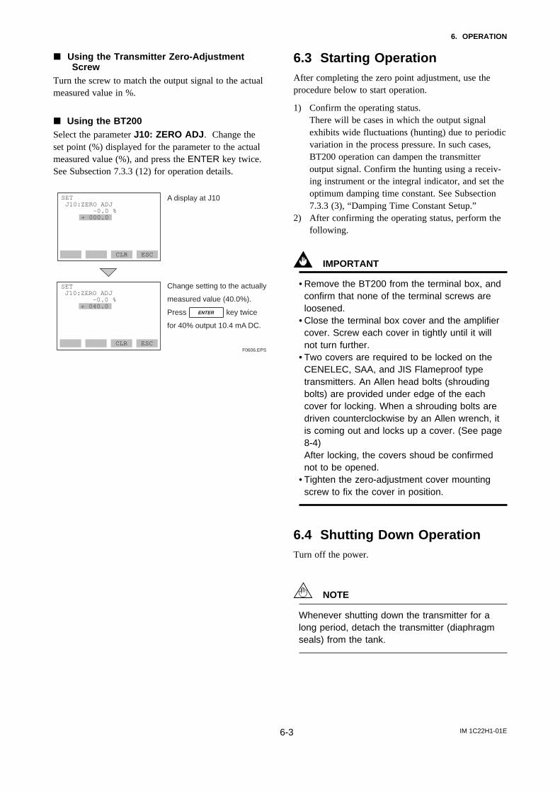
j Using the Transmitter Zero-AdjustmentScrew
Turn the screw to match the output signal to the actualmeasured value in %.
j Using the BT200Select the parameter J10: ZERO ADJ . Change theset point (%) displayed for the parameter to the actualmeasured value (%), and press the ENTER key twice.See Subsection 7.3.3 (12) for operation details.
Change setting to the actually
measured value (40.0%).
Press key twice
for 40% output 10.4 mA DC.
SET J10:ZERO ADJ –0.0 % + 040.0
CLR ESCF0606.EPS
A display at J10SET J10:ZERO ADJ –0.0 % + 000.0
CLR ESC
6.3 Starting OperationAfter completing the zero point adjustment, use theprocedure below to start operation.
1) Confirm the operating status.There will be cases in which the output signalexhibits wide fluctuations (hunting) due to periodicvariation in the process pressure. In such cases,BT200 operation can dampen the transmitteroutput signal. Confirm the hunting using a receiv-ing instrument or the integral indicator, and set theoptimum damping time constant. See Subsection7.3.3 (3), “Damping Time Constant Setup.”
2) After confirming the operating status, perform thefollowing.
IMPORTANT
• Remove the BT200 from the terminal box, andconfirm that none of the terminal screws areloosened.
• Close the terminal box cover and the amplifiercover. Screw each cover in tightly until it willnot turn further.
• Two covers are required to be locked on theCENELEC, SAA, and JIS Flameproof typetransmitters. An Allen head bolts (shroudingbolts) are provided under edge of the eachcover for locking. When a shrouding bolts aredriven counterclockwise by an Allen wrench, itis coming out and locks up a cover. (See page8-4)After locking, the covers shoud be confirmednot to be opened.
• Tighten the zero-adjustment cover mountingscrew to fix the cover in position.
6.4 Shutting Down OperationTurn off the power.
NOTE
Whenever shutting down the transmitter for along period, detach the transmitter (diaphragmseals) from the tank.
IM 1C22H1-01E6-4
6. OPERATION
6.5 Setting the Range Using theRange-setting Switch
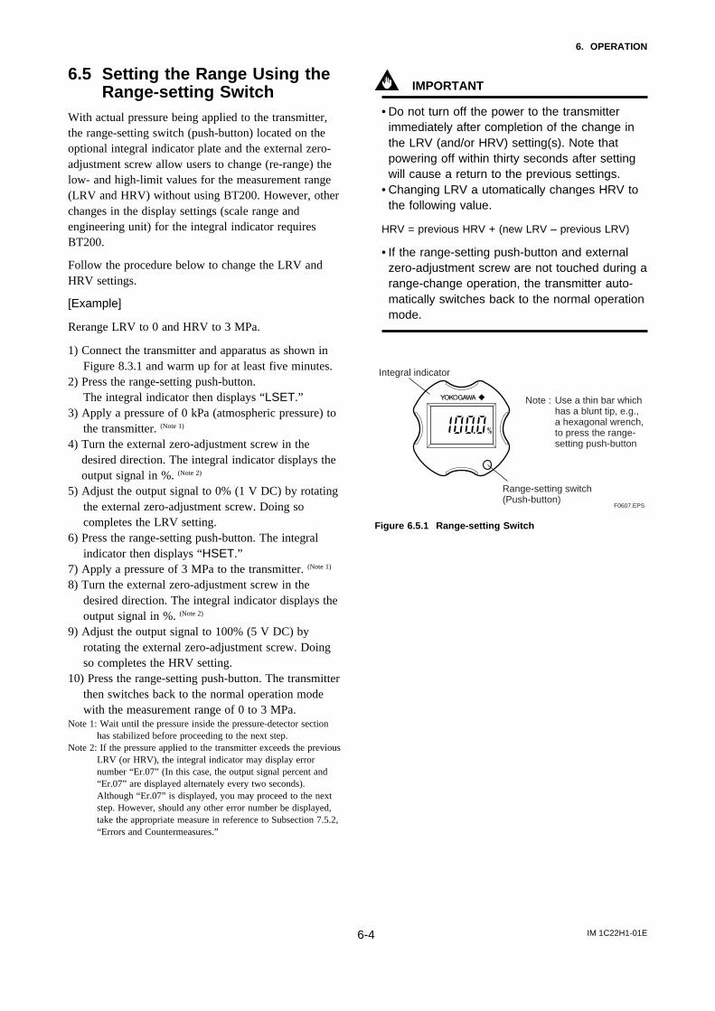
With actual pressure being applied to the transmitter,the range-setting switch (push-button) located on theoptional integral indicator plate and the external zero-adjustment screw allow users to change (re-range) thelow- and high-limit values for the measurement range(LRV and HRV) without using BT200. However, otherchanges in the display settings (scale range andengineering unit) for the integral indicator requiresBT200.
Follow the procedure below to change the LRV andHRV settings.
[Example]
Rerange LRV to 0 and HRV to 3 MPa.
1) Connect the transmitter and apparatus as shown inFigure 8.3.1 and warm up for at least five minutes.
2) Press the range-setting push-button.The integral indicator then displays “LSET.”
3) Apply a pressure of 0 kPa (atmospheric pressure) tothe transmitter. (Note 1)
4) Turn the external zero-adjustment screw in thedesired direction. The integral indicator displays theoutput signal in %. (Note 2)
5) Adjust the output signal to 0% (1 V DC) by rotatingthe external zero-adjustment screw. Doing socompletes the LRV setting.
6) Press the range-setting push-button. The integralindicator then displays “HSET.”
7) Apply a pressure of 3 MPa to the transmitter. (Note 1)
8) Turn the external zero-adjustment screw in thedesired direction. The integral indicator displays theoutput signal in %. (Note 2)
9) Adjust the output signal to 100% (5 V DC) byrotating the external zero-adjustment screw. Doingso completes the HRV setting.
10) Press the range-setting push-button. The transmitterthen switches back to the normal operation modewith the measurement range of 0 to 3 MPa.
Note 1: Wait until the pressure inside the pressure-detector sectionhas stabilized before proceeding to the next step.
Note 2: If the pressure applied to the transmitter exceeds the previousLRV (or HRV), the integral indicator may display errornumber “Er.07” (In this case, the output signal percent and“Er.07” are displayed alternately every two seconds).Although “Er.07” is displayed, you may proceed to the nextstep. However, should any other error number be displayed,take the appropriate measure in reference to Subsection 7.5.2,“Errors and Countermeasures.”
IMPORTANT
• Do not turn off the power to the transmitterimmediately after completion of the change inthe LRV (and/or HRV) setting(s). Note thatpowering off within thirty seconds after settingwill cause a return to the previous settings.
• Changing LRV a utomatically changes HRV tothe following value.
HRV = previous HRV + (new LRV – previous LRV)
• If the range-setting push-button and externalzero-adjustment screw are not touched during arange-change operation, the transmitter auto-matically switches back to the normal operationmode.
F0607.EPS
Integral indicator
Range-setting switch(Push-button)
Note : Use a thin bar which has a blunt tip, e.g., a hexagonal wrench, to press the range-setting push-button
Figure 6.5.1 Range-setting Switch
IM 1C22H1-01E7-1
7. BRAIN TERMINAL BT200 OPERATION
7. BRAIN TERMINAL BT200OPERATION
The DPharp is equipped with BRAIN communicationscapabilities, so that range changes, Tag No. setup,monitoring of self-diagnostic results, and zero pointadjustment can be handled by remote control viaBT200 BRAIN TERMINAL or CENTUM CS console.This section describes procedures for setting param-eters using the BT200. For details concerning theBT200, see IM 1C0A10-E, “BT200 User’s Manual.”
7.1 BT200 Operation Precautions
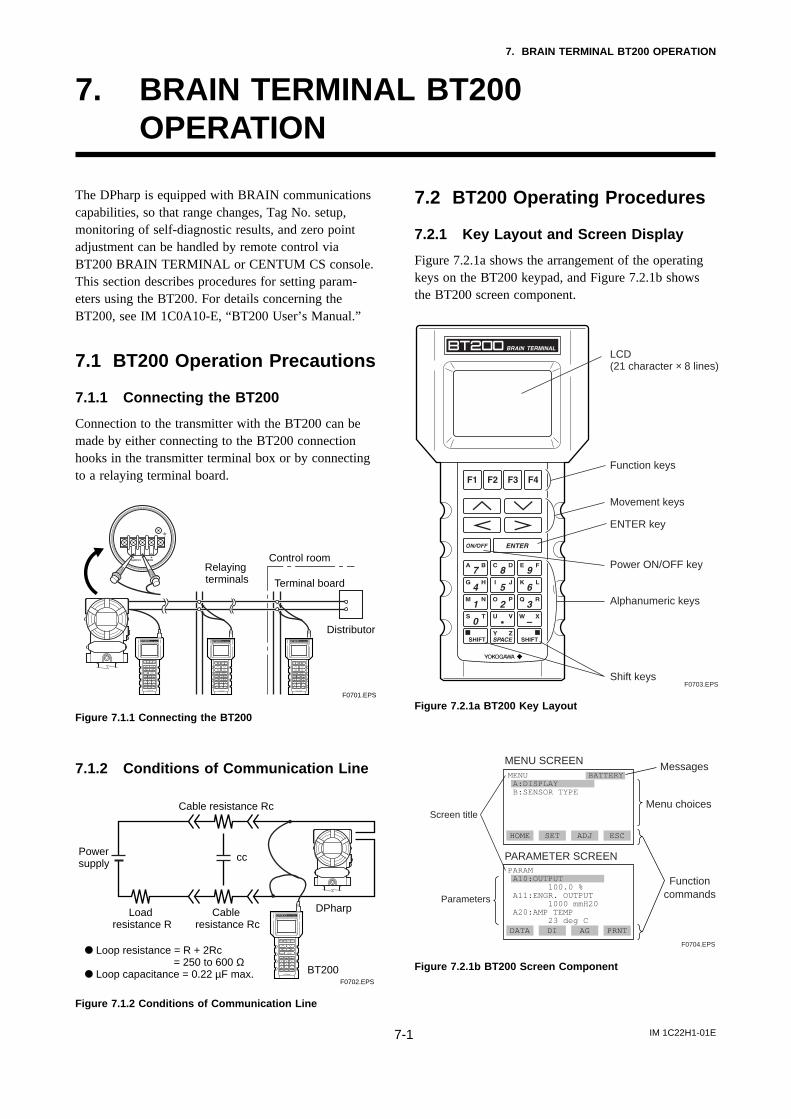
7.1.1 Connecting the BT200
Connection to the transmitter with the BT200 can bemade by either connecting to the BT200 connectionhooks in the transmitter terminal box or by connectingto a relaying terminal board.
Relaying terminals
Distributor
Control room
Terminal board
F0701.EPS
Figure 7.1.1 Connecting the BT200
7.1.2 Conditions of Communication Line
DPharp
BT200
Cable resistance Rc
Cable resistance Rc
Load resistance R
ccPower supply
d Loop resistance = R + 2Rc = 250 to 600 Ω
d Loop capacitance = 0.22 µF max.F0702.EPS
Figure 7.1.2 Conditions of Communication Line
7.2 BT200 Operating Procedures
7.2.1 Key Layout and Screen Display
Figure 7.2.1a shows the arrangement of the operatingkeys on the BT200 keypad, and Figure 7.2.1b showsthe BT200 screen component.
F0703.EPS
LCD(21 character × 8 lines)
Movement keys
Power ON/OFF key
Function keys
ENTER key
Alphanumeric keys
Shift keys
Figure 7.2.1a BT200 Key Layout
PARAM A10:OUTPUT 100.0 % A11:ENGR. OUTPUT 1000 mmH20 A20:AMP TEMP 23 deg C
Menu choices
MessagesMENU SCREEN
Screen title
MENU A:DISPLAY B:SENSOR TYPE
BATTERY
HOME SET ADJ ESC
Functioncommands
PARAMETER SCREEN
Parameters
DATA DI AG PRNT
F0704.EPS
Figure 7.2.1b BT200 Screen Component
IM 1C22H1-01E7-2
7. BRAIN TERMINAL BT200 OPERATION
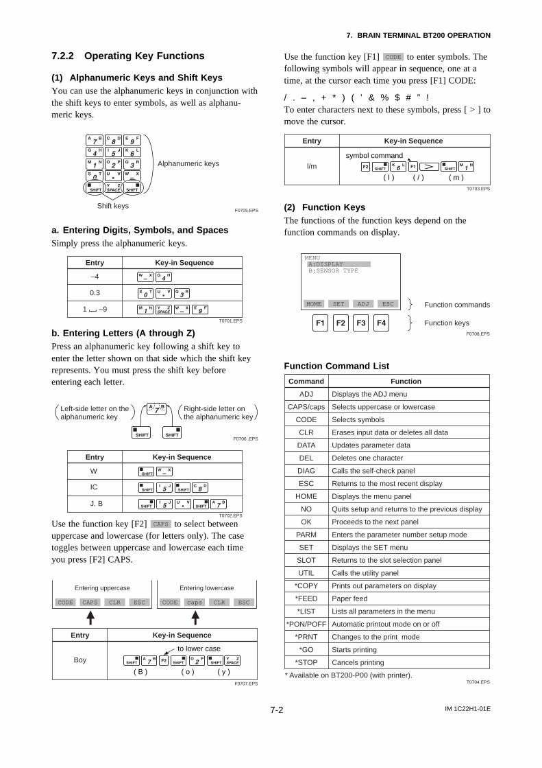
7.2.2 Operating Key Functions
(1) Alphanumeric Keys and Shift KeysYou can use the alphanumeric keys in conjunction withthe shift keys to enter symbols, as well as alphanu-meric keys.
Shift keys
Alphanumeric keys
F0705.EPS
a. Entering Digits, Symbols, and SpacesSimply press the alphanumeric keys.
Entry Key-in Sequence
–4
0.3
1 –9
T0701.EPS
b. Entering Letters (A through Z)Press an alphanumeric key following a shift key toenter the letter shown on that side which the shift keyrepresents. You must press the shift key beforeentering each letter.
Left-side letter on the alphanumeric key
Right-side letter on the alphanumeric key
F0706 .EPS
Entry Key-in Sequence
W
IC
J. B
T0702.EPS
Use the function key [F2] CAPS to select betweenuppercase and lowercase (for letters only). The casetoggles between uppercase and lowercase each timeyou press [F2] CAPS.
Entry
Boy
Key-in Sequence
F0707.EPS
CODE CAPS CLR ESC
Entering uppercase
CODE caps CLR ESC
Entering lowercase
( B ) ( y )( o )
to lower case
Use the function key [F1] CODE to enter symbols. Thefollowing symbols will appear in sequence, one at atime, at the cursor each time you press [F1] CODE:
/ . – , + * ) ( ’ & % $ # ” !To enter characters next to these symbols, press [ > ] tomove the cursor.
( / )
Entry
l/m
Key-in Sequence
T0703.EPS
( m )( I )
symbol command
(2) Function KeysThe functions of the function keys depend on thefunction commands on display.
MENU A:DISPLAY B:SENSOR TYPE
HOME SET ADJ ESC Function commands
Function keysF0708.EPS
Function Command List
Command Function
ADJ Displays the ADJ menu
Selects uppercase or lowercase
Selects symbols
Erases input data or deletes all data
Updates parameter data
Deletes one character
Calls the self-check panel
Returns to the most recent display
Displays the menu panel
Quits setup and returns to the previous display
Proceeds to the next panel
Enters the parameter number setup mode
Displays the SET menu
Returns to the slot selection panel
Calls the utility panel
Prints out parameters on display
Paper feed
Lists all parameters in the menu
Automatic printout mode on or off
Changes to the print mode
Starts printing
Cancels printing
CAPS/caps
CODE
CLR
DATA
DEL
DIAG
ESC
HOME
NO
OK
PARM
SET
SLOT
UTIL
*COPY
*FEED
*LIST
*PON/POFF
*PRNT
*GO
*STOP
* Available on BT200-P00 (with printer).T0704.EPS
IM 1C22H1-01E7-3
7. BRAIN TERMINAL BT200 OPERATION
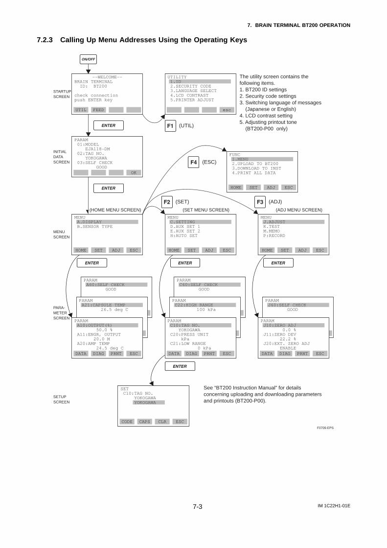
7.2.3 Calling Up Menu Addresses Using the Operating Keys
DATA DIAG PRNT ESC
PARAM A60:SELF CHECK GOOD
CODE CAPS CLR ESC
––WELCOME––BRAIN TERMINAL ID: BT200
check connection push ENTER key
UTIL FEED esc
PARAM 01:MODEL EJA118-DM 02:TAG NO. YOKOGAWA 03:SELF CHECK GOOD
OK
STARTUPSCREEN
MENUSCREEN
SETUPSCREEN
INITIAL DATA SCREEN
PARA-METER SCREEN
(HOME MENU SCREEN) (SET MENU SCREEN) (ADJ MENU SCREEN)
See “BT200 Instruction Manual” for details concerning uploading and downloading parameters and printouts (BT200-P00).
(UTIL)
(SET)
(ESC)
HOME SET ADJ ESC
(ADJ)
The utility screen contains the following items.1. BT200 ID settings2. Security code settings3. Switching language of messages (Japanese or English)4. LCD contrast setting5. Adjusting printout tone (BT200-P00 only)
FUNC 1.MENU 2.UPLOAD TO BT200 3.DOWNLOAD TO INST 4.PRINT ALL DATA
HOME SET ADJ ESC
MENU A.DISPLAY B.SENSOR TYPE
HOME SET ADJ ESC
MENU C.SETTING D.AUX SET 1 E.AUX SET 2 H:AUTO SET
HOME SET ADJ ESC
MENU J.ADJUST K.TEST M.MEMO P:RECORD
DATA DIAG PRNT ESC
DATA DIAG PRNT ESCDATA DIAG PRNT ESC DATA DIAG PRNT ESC
PARAM C60:SELF CHECK GOOD
PARAM C22:HIGH RANGE 100 kPa
DATA DIAG PRNT ESC
PARAM J60:SELF CHECK GOOD
PARAM J10:ZERO ADJ 0.0 % J11:ZERO DEV 22.2 % J20:EXT. ZERO ADJ ENABLE
SET C10:TAG NO. YOKOGAWA YOKOGAWA
F0709.EPS
DATA DIAG PRNT ESC
PARAM A10:OUTPUT(%) 50.0 % A11:ENGR, OUTPUT 20.0 M A20:AMP TEMP 24.5 deg C
DATA DIAG PRNT ESC
PARAM C10:TAG NO. YOKOGAWA C20:PRESS UNIT kPa C21:LOW RANGE 0 kPa
PARAM A21:CAPSULE TEMP 26.5 deg C
UTILITY 1.ID 2.SECURITY CODE 3.LANGUAGE SELECT 4.LCD CONTRAST 5.PRINTER ADJUST
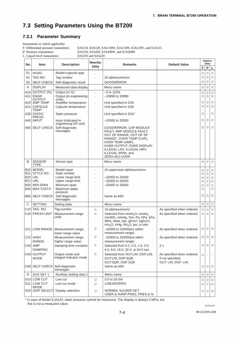
IM 1C22H1-01E7-4
7. BRAIN TERMINAL BT200 OPERATION
7.3 Setting Parameters Using the BT200
7.3.1 Parameter Summary
Instruments to which applicable:F: Differential pressure transmitters EJA110, EJA120, EJA118W, EJA118N, EJA118Y, and EJA115P: Pressure transmitters EJA310, EJA430, EJA438W, and EJA438NL: Liquid level transmitters EJA210 and EJA220
No. Description
Model+capsule typeTag number
Applica-bility
P LF
0102
T0705.EPS
Rewrita-bility
16 alphanumerics
GOOD/ERROR
RemarksItem
MODEL
TAG NO.
Self-diagnostic result
—
—
—03 SELF CHECK
Measured data displayA
–5 to 110%
Menu nameDISPLAY
Output (in %)A10 OUTPUT (%)–19999 to 19999Output (in engineering
units)A11 ENGR.
OUTPUTUnit specified in D30Amplifier temperatureA20 AMP TEMPUnit specified in D30Capsule temperatureA21 CAPSULE
TEMP
—
Sensor typeB
16 uppercase alphanumerics
Menu nameSENSOR TYPE
Model+spanB10 MODEL
—
Style numberB11 STYLE NO.–32000 to 32000Lower range-limitB20 LRL–32000 to 32000Upper range-limitB21 URL–32000 to 32000Minimum spanB30 MIN SPAN
—
—
—
—
—
Unit specified in D31*Static pressureA30 STATIC PRESS
–32000 to 32000Input (indicated in engineering DP unit)
A40 INPUT
GOOD/ERROR, CAP MODULE FAULT, AMP MODULE FAULT, OUT OF RANGE, OUT OF SP RANGE*, OVER TEMP (CAP),OVER TEMP (AMP), OVER OUTPUT, OVER DISPLAY, ILLEGAL LRV, ILLEGAL HRV, ILLEGAL SPAN, and ZERO ADJ OVER
Self-diagnostic messages
A60 SELF CHECK
—
—
—
—
—
—
—
* In case of Model EJA120, static pressure cannot be measured. The display is always 0 MPa, but this is not a measured value.
Maximum atatic pressure
B40
Same as A60
MAX STAT.P.
Self-diagnostic messages
—
—B60 SELF CHECK
Setting dataC
16 alphanumerics
Menu nameSETTING
Tag numberC10 TAG. NO.Selected from mmH2O, mmAq, mmWG, mmHg, Torr, Pa, hPa, kPa, MPa, mbar, bar, gf/cm2, kgf/cm2, inH2O, inHg, ftH2O, psi, or atm
Measurement rangeunits
C20 PRESS UNIT
–32000 to 32000(but within measurement range)
Measurement range, lower range value
C21 LOW RANGE
—
Self-diagnostic messages
C60 Same as A60SELF CHECK —
—
—
—
–32000 to 32000(but within measurement range)
Measurement range, higher range value
C22 HIGH RANGE
Selected from 0.2, 0.5, 1.0, 2.0, 4.0, 8.0, 16.0, 32.0, or 64.0 sec.
Damping time constantC30 AMP DAMPING
Selected from OUT:LIN; DSP:LIN,OUT:LIN; DSP:SQR, OUT:SQR; DSP:SQR
Output mode and integral indicator mode
C40 OUTPUT MODE
0.0 to 20.0%LINEAR/ZERO
Low cutD10 LOW CUTLow cut modeD11 LOW CUT
MODENORMAL %/USER SET,USER & %/INP PRES, PRES & %
Display selectionD20 DISP SELECT
—
Auxiliary setting data 1D Menu nameAUX SET 1 —
Default Value
As specified when ordered.As specified when ordered.
As specified when ordered.
As specified when ordered.
2 s
As specified when ordered.If not specified, OUT: LIN; DSP: LIN.
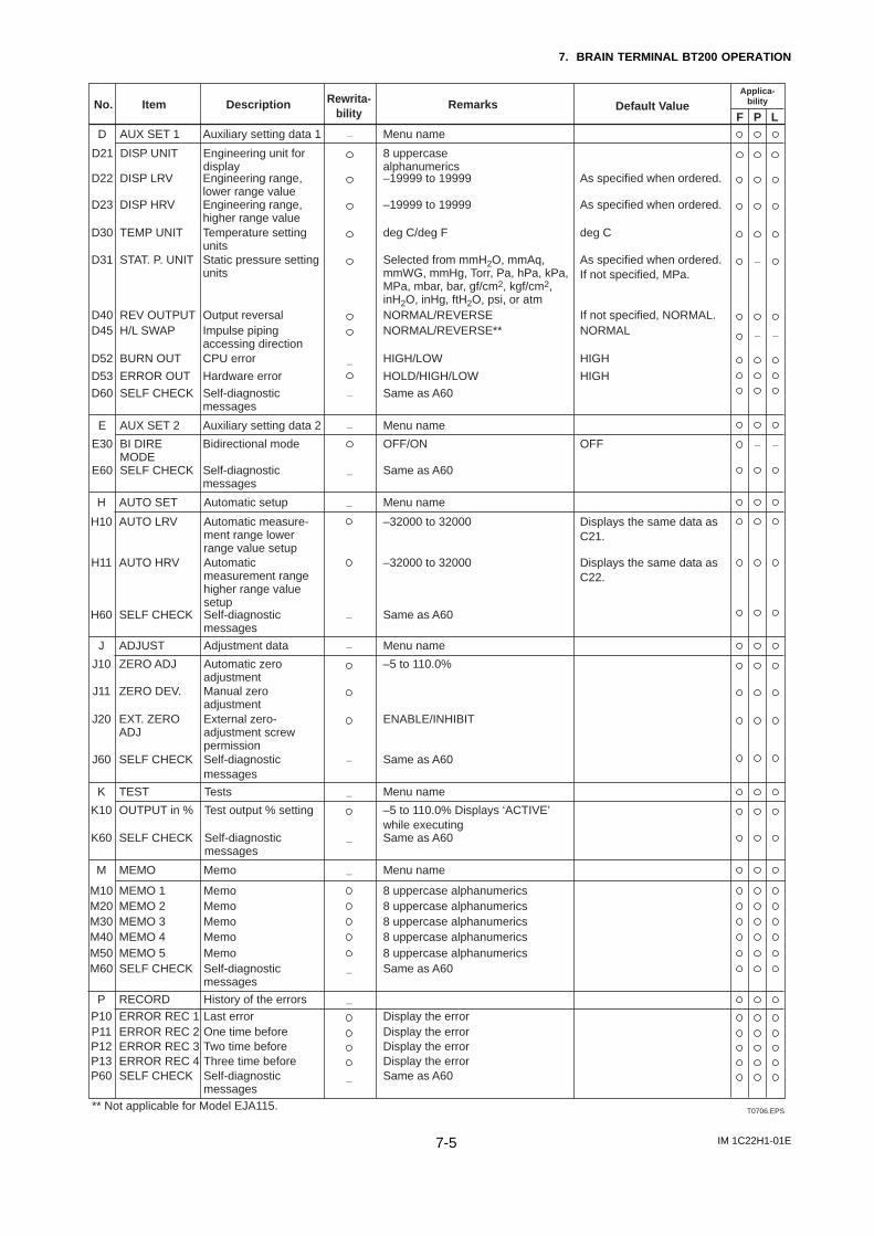
IM 1C22H1-01E7-5
7. BRAIN TERMINAL BT200 OPERATION
T0706.EPS
Auxiliary setting data 1D Menu nameAUX SET 1 —
NORMAL/REVERSENORMAL/REVERSE**
Output reversalD40 REV OUTPUTImpulse piping accessing direction
D45 H/L SWAP
—HIGH/LOWCPU errorD52 BURN OUT
–19999 to 19999Engineering range, lower range value
D22 DISP LRV
–19999 to 19999Engineering range, higher range value
D23 DISP HRV
deg C/deg FTemperature setting units
D30 TEMP UNIT
Selected from mmH2O, mmAq, mmWG, mmHg, Torr, Pa, hPa, kPa, MPa, mbar, bar, gf/cm2, kgf/cm2, inH2O, inHg, ftH2O, psi, or atm
Static pressure setting units
D31 STAT. P. UNIT
Hardware errorD53
Same as A60
HOLD/HIGH/LOWERROR OUT
Self-diagnostic messages
—D60 SELF CHECK
Auxiliary setting data 2E
OFF/ON
Menu nameAUX SET 2
Bidirectional modeE30 BI DIRE MODE
Same as A60Self-diagnostic messages
E60 SELF CHECK
—
—
No. Description RemarksItem
Menu nameAutomatic setupH AUTO SET —
Adjustment dataJ
–5 to 110.0%
Menu nameADJUST
Automatic zero adjustment
J10 ZERO ADJ
—
—
—
—
—
—
—
—
—
Manual zero adjustment
J11 ZERO DEV.
ENABLE/INHIBITExternal zero-adjustment screw permission
J20 EXT. ZERO ADJ
Same as A60Self-diagnostic messages
J60 SELF CHECK
Display the errorHistory of the errorsRECORDLast errorP10
P11ERROR REC 1
Display the errorOne time beforeERROR REC 2P12 Display the errorTwo time beforeERROR REC 3
Menu nameTestsK TEST
–5 to 110.0% Displays ‘ACTIVE’ while executing
Test output % settingK10 OUTPUT in %
Same as A60Self-diagnostic messages
K60 SELF CHECK
Menu nameMemoM
P
MEMO
8 uppercase alphanumericsMemoM10 MEMO 18 uppercase alphanumericsMemoM20 MEMO 28 uppercase alphanumerics
P13 Display the errorThree time beforeERROR REC 4P60 Same as A60Self-diagnostic
messagesSELF CHECK
MemoM30 MEMO 38 uppercase alphanumericsMemoM40 MEMO 48 uppercase alphanumericsMemoM50 MEMO 5Same as A60Self-diagnostic
messagesM60 SELF CHECK
–32000 to 32000Automatic measure-ment range lower range value setup
H10 AUTO LRV
–32000 to 32000Automatic measurement range higher range value setup
H11 AUTO HRV
—
—
—
—
—
Same as A60Self-diagnostic messages
H60 SELF CHECK
Applica-bility
P LF
8 uppercase alphanumerics
Engineering unit for display
D21 DISP UNIT
As specified when ordered.
As specified when ordered.
deg C
As specified when ordered.If not specified, MPa.
If not specified, NORMAL.NORMAL
HIGH
HIGH
OFF
Displays the same data as C21.
Displays the same data as C22.
Rewrita-bility
Default Value
** Not applicable for Model EJA115.
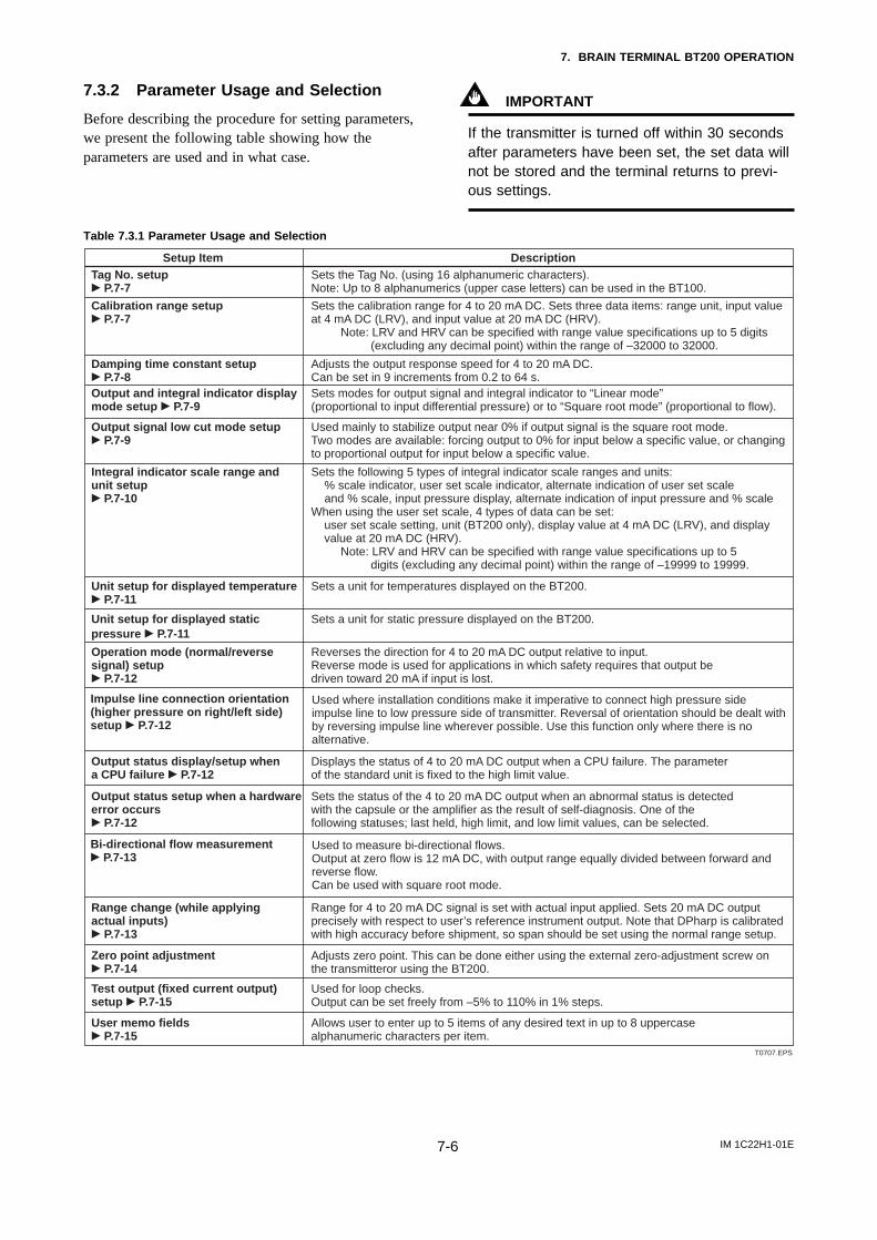
IM 1C22H1-01E7-6
7. BRAIN TERMINAL BT200 OPERATION
7.3.2 Parameter Usage and Selection
Before describing the procedure for setting parameters,we present the following table showing how theparameters are used and in what case.
IMPORTANT
If the transmitter is turned off within 30 secondsafter parameters have been set, the set data willnot be stored and the terminal returns to previ-ous settings.
Table 7.3.1 Parameter Usage and Selection
Setup Item DescriptionTag No. setupc P.7-7
Sets the Tag No. (using 16 alphanumeric characters).Note: Up to 8 alphanumerics (upper case letters) can be used in the BT100.
Calibration range setupc P.7-7
Sets the calibration range for 4 to 20 mA DC. Sets three data items: range unit, input valueat 4 mA DC (LRV), and input value at 20 mA DC (HRV).
Note: LRV and HRV can be specified with range value specifications up to 5 digits (excluding any decimal point) within the range of –32000 to 32000.
Damping time constant setupc P.7-8
Adjusts the output response speed for 4 to 20 mA DC.Can be set in 9 increments from 0.2 to 64 s.
Output and integral indicator display mode setup c P.7-9
Sets modes for output signal and integral indicator to “Linear mode” (proportional to input differential pressure) or to “Square root mode” (proportional to flow).
Output signal low cut mode setupc P.7-9
Used mainly to stabilize output near 0% if output signal is the square root mode.Two modes are available: forcing output to 0% for input below a specific value, or changingto proportional output for input below a specific value.
Integral indicator scale range and unit setupc P.7-10
Sets the following 5 types of integral indicator scale ranges and units: % scale indicator, user set scale indicator, alternate indication of user set scale and % scale, input pressure display, alternate indication of input pressure and % scale
When using the user set scale, 4 types of data can be set: user set scale setting, unit (BT200 only), display value at 4 mA DC (LRV), and display value at 20 mA DC (HRV).
Note: LRV and HRV can be specified with range value specifications up to 5 digits (excluding any decimal point) within the range of –19999 to 19999.
T0707.EPS
Unit setup for displayed temperaturec P.7-11
Sets a unit for temperatures displayed on the BT200.
Unit setup for displayed static pressure c P.7-11
Sets a unit for static pressure displayed on the BT200.
Operation mode (normal/reverse signal) setupc P.7-12
Reverses the direction for 4 to 20 mA DC output relative to input.Reverse mode is used for applications in which safety requires that output be driven toward 20 mA if input is lost.
Output status display/setup when a CPU failure c P.7-12
Displays the status of 4 to 20 mA DC output when a CPU failure. The parameter of the standard unit is fixed to the high limit value.
Output status setup when a hardware error occurs c P.7-12
Sets the status of the 4 to 20 mA DC output when an abnormal status is detected with the capsule or the amplifier as the result of self-diagnosis. One of the following statuses; last held, high limit, and low limit values, can be selected.
Range change (while applying actual inputs)c P.7-13
Range for 4 to 20 mA DC signal is set with actual input applied. Sets 20 mA DC output precisely with respect to user’s reference instrument output. Note that DPharp is calibratedwith high accuracy before shipment, so span should be set using the normal range setup.
Zero point adjustmentc P.7-14
Adjusts zero point. This can be done either using the external zero-adjustment screw onthe transmitteror using the BT200.
Test output (fixed current output) setup c P.7-15
Used for loop checks.Output can be set freely from –5% to 110% in 1% steps.
User memo fieldsc P.7-15
Allows user to enter up to 5 items of any desired text in up to 8 uppercase alphanumeric characters per item.
Used where installation conditions make it imperative to connect high pressure side impulse line to low pressure side of transmitter. Reversal of orientation should be dealt with by reversing impulse line wherever possible. Use this function only where there is no alternative.
Impulse line connection orientation (higher pressure on right/left side) setup c P.7-12
Used to measure bi-directional flows. Output at zero flow is 12 mA DC, with output range equally divided between forward and reverse flow.Can be used with square root mode.
Bi-directional flow measurementc P.7-13
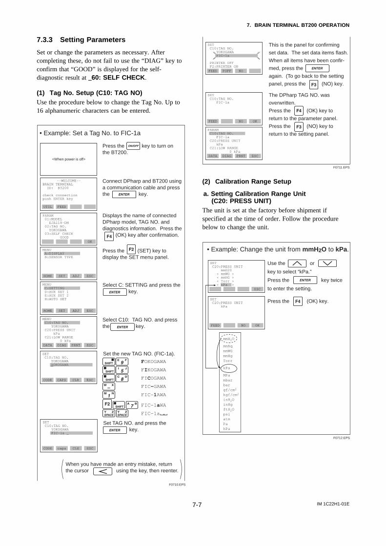
IM 1C22H1-01E7-7
7. BRAIN TERMINAL BT200 OPERATION
7.3.3 Setting Parameters
Set or change the parameters as necessary. Aftercompleting these, do not fail to use the “DIAG” key toconfirm that “GOOD” is displayed for the self-diagnostic result at _60: SELF CHECK .
(1) Tag No. Setup (C10: TAG NO)Use the procedure below to change the Tag No. Up to16 alphanumeric characters can be entered.
Press the key to turn on the BT200.
Connect DPharp and BT200 using a communication cable and press the key.
PARAM 01:MODEL EJA118-DM 02:TAG NO. YOKOGAWA 03:SELF CHECK GOOD
OK
MENU A:DISPLAY B:SENSOR TYPE
HOME SET ADJ ESC
MENU C:SETTING D:AUX SET 1 E:AUX SET 2 H:AUTO SET
HOME SET ADJ ESC
MENU C10:TAG NO. YOKOGAWA C20:PRESS UNIT kPa C21:LOW RANGE 0 kPaDATA DIAG PRNT ESC
<When power is off>
Select C: SETTING and press the key.
Select C10: TAG NO. and pressthe key.
Displays the name of connected DPharp model, TAG NO. and diagnostics information. Press the (OK) key after confirmation.
Press the (SET) key to display the SET menu panel.
––WELCOME––BRAIN TERMINAL ID: BT200
check connection push ENTER key
UTIL FEED
F0710.EPS
SET C10:TAG NO. YOKOGAWA YOKOGAWA
CODE CAPS CLR ESC
When you have made an entry mistake, return the cursor using the key, then reenter.
Set the new TAG NO. (FIC-1a).
FOKOGAWA
FIKOGAWA
FICOGAWA
FIC-GAWA
FIC-1AWA
FIC-1aWA
FIC-1a
Set TAG NO. and press the key.
SET C10:TAG NO. YOKOGAWA FIC-1a _
CODE caps CLE ESC
• Example: Set a Tag No. to FIC-1a
SET C10:TAG NO. FIC-1a
FEED NO OK
DATA DIAG PRNT ESC
This is the panel for confirming
set data. The set data items flash.
When all items have been confir-
med, press the
again. (To go back to the setting
panel, press the (NO) key.
SET C10:TAG NO. YOKOGAWA FIC-1a
PRINTER OFF F2:PRINTER ON
PARAM C10:TAG NO. FIC-1a C20:PRESS UNIT kPa C21:LOW RANGE 0 kPa
FEED POFF NO
The DPharp TAG NO. was
overwritten.
Press the (OK) key to
return to the parameter panel.
Press the (NO) key to
return to the setting panel.
F0711.EPS
(2) Calibration Range Setup
a. Setting Calibration Range Unit(C20: PRESS UNIT)
The unit is set at the factory before shipment ifspecified at the time of order. Follow the procedurebelow to change the unit.
mmH2O
mmAqmmWGmmHgTorr
kPa
MPambarbargf/cm2
kgf/cm2
inH2OinHgftH2OpsiatmPahPa
• Example: Change the unit from mmH2O to kPa.
ESC
SET C20:PRESS UNIT kPa
FEED NO OK
SET C20:PRESS UNIT mmH20 < mmWG > < mmHG > < Torr > < kPa >
Use the or
key to select “kPa.”
Press the key twice
to enter the setting.
Press the (OK) key.
F0712.EPS
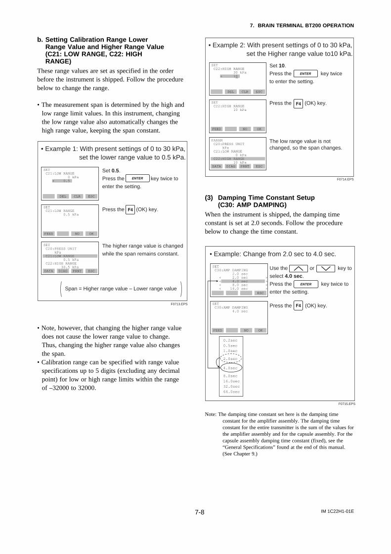
IM 1C22H1-01E7-8
7. BRAIN TERMINAL BT200 OPERATION
b. Setting Calibration Range LowerRange Value and Higher Range Value(C21: LOW RANGE, C22: HIGHRANGE)
These range values are set as specified in the orderbefore the instrument is shipped. Follow the procedurebelow to change the range.
• The measurement span is determined by the high andlow range limit values. In this instrument, changingthe low range value also automatically changes thehigh range value, keeping the span constant.
• Example 1: With present settings of 0 to 30 kPa, set the lower range value to 0.5 kPa.
Span = Higher range value – Lower range value
FEED NO OK
SET C21:LOW RANGE 0.5 kPa
DATA DIAG PRNT ESC
SET C20:PRESS UNIT kPa C21:LOW RANGE 0.5 kPa C22:HIGH RANGE 30.5 kPa
DEL CLR ESC
SET C21:LOW RANGE 0 kPa + 0.5
The higher range value is changed
while the span remains constant.
Set 0.5.
Press the key twice to
enter the setting.
Press the (OK) key.
F0713.EPS
• Note, however, that changing the higher range valuedoes not cause the lower range value to change.Thus, changing the higher range value also changesthe span.
• Calibration range can be specified with range valuespecifications up to 5 digits (excluding any decimalpoint) for low or high range limits within the rangeof –32000 to 32000.
• Example 2: With present settings of 0 to 30 kPa, set the Higher range value to10 kPa.
FEED NO OK
SET C22:HIGH RANGE 10 kPa
DATA DIAG PRNT ESC
PARAM C20:PRESS UNIT kPa C21:LOW RANGE 0 kPa C22:HIGH RANGE 10 kPa
DEL CLR ESC
SET C22:HIGH RANGE 30 kPa + 10
The low range value is not changed, so the span changes.
Set 10.
Press the key twice
to enter the setting.
F0714.EPS
Press the (OK) key.
(3) Damping Time Constant Setup(C30: AMP DAMPING)
When the instrument is shipped, the damping timeconstant is set at 2.0 seconds. Follow the procedurebelow to change the time constant.
• Example: Change from 2.0 sec to 4.0 sec.
ESC
SET C30:AMP DAMPING 4.0 sec
FEED NO OK
SET C30:AMP DAMPING 2.0 sec < 2.0 sec > < 4.0 sec > < 8.0 sec > < 16.0 sec >
Use the or key to
select 4.0 sec.
Press the key twice to
enter the setting.
F0715.EPS
0.2sec
0.5sec
1.0sec
2.0sec
4.0sec
8.0sec
16.0sec
32.0sec
64.0sec
Press the (OK) key.
Note: The damping time constant set here is the damping timeconstant for the amplifier assembly. The damping timeconstant for the entire transmitter is the sum of the values forthe amplifier assembly and for the capsule assembly. For thecapsule assembly damping time constant (fixed), see the“General Specifications” found at the end of this manual.(See Chapter 9.)
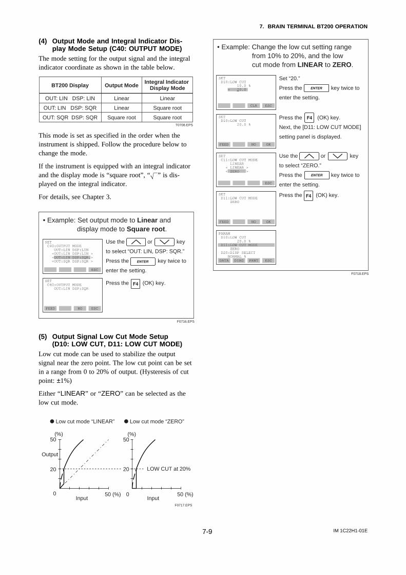
IM 1C22H1-01E7-9
7. BRAIN TERMINAL BT200 OPERATION
(4) Output Mode and Integral Indicator Dis-play Mode Setup (C40: OUTPUT MODE)
The mode setting for the output signal and the integralindicator coordinate as shown in the table below.
BT200 Display Output ModeIntegral Indicator
Display Mode
T0708.EPS
Linear
Linear
Square root
OUT: LIN DSP: LIN
OUT: LIN DSP: SQR
OUT: SQR DSP: SQR
Linear
Square root
Square root
This mode is set as specified in the order when theinstrument is shipped. Follow the procedure below tochange the mode.
If the instrument is equipped with an integral indicatorand the display mode is “square root”, “” is dis-played on the integral indicator.
For details, see Chapter 3.
• Example: Set output mode to Linear and display mode to Square root.
ESC
SET C40:OUTPUT MODE OUT:LIN DSP:SQR
FEED NO ESC
SET C40:OUTPUT MODE OUT:LIN DSP:LIN <OUT:LIN DSP:LIN > <OUT:LIN DSP:SQR.> <OUT:SQR DSP:SQR >
Use the or key
to select “OUT: LIN, DSP: SQR.”
Press the key twice to
enter the setting.
Press the (OK) key.
F0716.EPS
(5) Output Signal Low Cut Mode Setup(D10: LOW CUT, D11: LOW CUT MODE)
Low cut mode can be used to stabilize the outputsignal near the zero point. The low cut point can be setin a range from 0 to 20% of output. (Hysteresis of cutpoint: ±1%)
Either “LINEAR” or “ZERO” can be selected as thelow cut mode.
(%)50
20
0 50 (%)
Output
d Low cut mode “LINEAR”
Input
(%)50
20
0 50 (%)
d Low cut mode “ZERO”
LOW CUT at 20%
InputF0717.EPS
• Example: Change the low cut setting range from 10% to 20%, and the low cut mode from LINEAR to ZERO.
FEED NO OK
SET D11:LOW CUT MODE ZERO
Use the or key
to select “ZERO.”
Press the key twice to
enter the setting.
Press the (OK) key.
F0718.EPS
FEED NO OK
SET D10:LOW CUT 20.0 %
ESC
SET C11:LOW CUT MODE LINEAR < LINEAR > < ZERO >
DATA DIAG PRNT ESC
PARAM D10:LOW CUT 20.0 % D11:LOW CUT MODE ZERO D20:DISP SELECT NORMAL %
CLR ESC
SET D10:LOW CUT 10.0 % + 20.0
Set “20.”
Press the key twice to
enter the setting.
Press the (OK) key.
Next, the [D11: LOW CUT MODE]
setting panel is displayed.
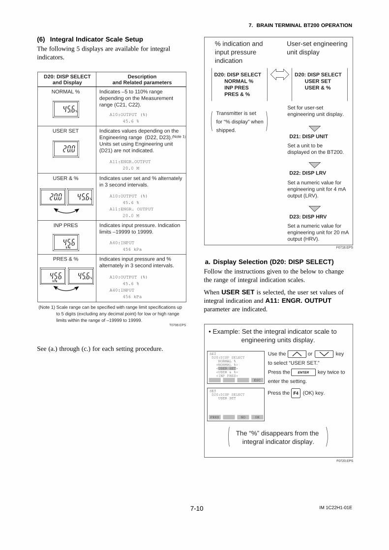
IM 1C22H1-01E7-10
7. BRAIN TERMINAL BT200 OPERATION
(6) Integral Indicator Scale SetupThe following 5 displays are available for integralindicators.
T0708.EPS
D20: DISP SELECTand Display
NORMAL %
USER SET
USER & %
INP PRES
PRES & %
Indicates –5 to 110% range depending on the Measurement range (C21, C22).
Indicates values depending on the Engineering range (D22, D23).(Note 1) Units set using Engineering unit (D21) are not indicated.
Indicates user set and % alternately in 3 second intervals.
Indicates input pressure. Indication limits –19999 to 19999.
Indicates input pressure and % alternately in 3 second intervals.
A10:OUTPUT (%)
45.6 %
Descriptionand Related parameters
A11:ENGR.OUTPUT
20.0 M
A10:OUTPUT (%)
45.6 %
A11:ENGR. OUTPUT
20.0 M
A40:INPUT
456 kPa
A10:OUTPUT (%)
45.6 %
A40:INPUT
456 kPa
(Note 1) Scale range can be specified with range limit specifications up to 5 digits (excluding any decimal point) for low or high range limits within the range of –19999 to 19999.
See (a.) through (c.) for each setting procedure.
% indication and input pressure indication
Transmitter is set
for “% display” when
shipped.
D20: DISP SELECT NORMAL % INP PRES PRES & %
User-set engineering unit display
D20: DISP SELECT USER SET USER & %
D21: DISP UNIT
D22: DISP LRV
D23: DISP HRV
Set for user-set engineering unit display.
Set a unit to be displayed on the BT200.
Set a numeric value for engineering unit for 4 mA output (LRV).
Set a numeric value for engineering unit for 20 mA output (HRV).
F0718.EPS
a. Display Selection (D20: DISP SELECT)Follow the instructions given to the below to changethe range of integral indication scales.
When USER SET is selected, the user set values ofintegral indication and A11: ENGR. OUTPUTparameter are indicated.
• Example: Set the integral indicator scale to engineering units display.
The “%” disappears from the integral indicator display.
ESC
SET D20:DISP SELECT USER SET
FEED NO OK
SET D20:DISP SELECT NORMAL % <NORMAL %> <USER SET> <USER & %> <INP PRES>
Use the or key
to select “USER SET.”
Press the key twice to
enter the setting.
Press the (OK) key.
F0720.EPS
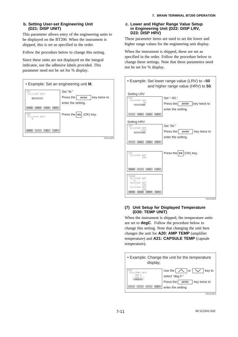
IM 1C22H1-01E7-11
7. BRAIN TERMINAL BT200 OPERATION
b. Setting User-set Engineering Unit(D21: DISP UNIT)
This parameter allows entry of the engineering units tobe displayed on the BT200. When the instrument isshipped, this is set as specified in the order.
Follow the procedure below to change this setting.
Since these units are not displayed on the integralindicator, use the adhesive labels provided. Thisparameter need not be set for % display.
• Example: Set an engineering unit M.
CODE CAPS CLR ESC
SET D21:DISP UNIT M
FEED NO OK
SET D21:DISP UNIT M_
Set “M.”
Press the key twice to
enter the setting.
Press the (OK) key.
F0721.EPS
c. Lower and Higher Range Value Setupin Engineering Unit (D22: DISP LRV,D23: DISP HRV)
These parameter items are used to set the lower andhigher range values for the engineering unit display.
When the instrument is shipped, these are set asspecified in the order. Follow the procedure below tochange these settings. Note that these parameters neednot be set for % display.
• Example: Set lower range value (LRV) to –50 and higher range value (HRV) to 50.
FEED NO OK
SET D23:DISP HRV 50M
Press the (OK) key.
F0722.EPS
DEL CLR ESC
DATA DIAG PRNT ESC
PARAM D21:DISP UNT M D22:DISP LRV – 50M D23:DISP HRV 50M
DEL CLR ESC
SET D22:DISP LRV 0M - 50
Set “–50.”
Press the key twice to
enter the setting.
Setting LRV
Setting HRVSet “50.”
Press the key twice to
enter the setting.
SET D23:DISP HRV 100M + 50
(7) Unit Setup for Displayed Temperature(D30: TEMP UNIT)
When the instrument is shipped, the temperature unitsare set to degC . Follow the procedure below tochange this setting. Note that changing the unit herechanges the unit for A20: AMP TEMP (amplifiertemperature) and A21: CAPSULE TEMP (capsuletemperature).
• Example: Change the unit for the temperature display.
ESC
SET D30:TEMP UNIT deg C < deg C > < deg F >
Use the or key to
select “deg F.”
Press the key twice to
enter the setting.
F0723.EPS
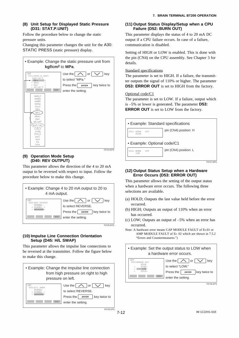
IM 1C22H1-01E7-12
7. BRAIN TERMINAL BT200 OPERATION
(8) Unit Setup for Displayed Static Pressure(D31: STAT.P.UNIT)
Follow the procedure below to change the staticpressure units.Changing this parameter changes the unit for the A30:STATIC PRESS (static pressure) display.
• Example: Change the static pressure unit from kgf/cm2 to MPa.
ESC
SET C31:STAT.P.UNIT kgf/cm^2 < MPa > < mbar > < bar > < gf/cm^2 >
Use the or key
to select “MPa.”
Press the key twice to
enter the setting.
F0724.EPS
mmH2OmmAqmmWGmmHgTorrkPa
MPa
mbarbar
gf/cm2
kgf/cm2
inH2OinHgftH2OpsiatmPahPa
(9) Operation Mode Setup(D40: REV OUTPUT)
This parameter allows the direction of the 4 to 20 mAoutput to be reversed with respect to input. Follow theprocedure below to make this change.
• Example: Change 4 to 20 mA output to 20 to 4 mA output.
ESC
SET D40:REV OUTPUT NORMAL < NORMAL > < REVERSE>
Use the or key
to select REVERSE.
Press the key twice to
enter the setting.
F0725.EPS
(10) Impulse Line Connection OrientationSetup (D45: H/L SWAP)
This parameter allows the impulse line connections tobe reversed at the transmitter. Follow the figure belowto make this change.
• Example: Change the impulse line connection from high pressure on right to high pressure on left.
ESC
SET D45:H/L SWAP NORMAL < NORMAL > < REVERSE>
Use the or key
to select REVERSE.
Press the key twice to
enter the setting.
F0726.EPS
(11) Output Status Display/Setup when a CPUFailure (D52: BURN OUT)
This parameter displays the status of 4 to 20 mA DCoutput if a CPU failure occurs. In case of a failure,communication is disabled.
Setting of HIGH or LOW is enabled. This is done withthe pin (CN4) on the CPU assembly. See Chapter 3 fordetails.
Standard specificationsThe parameter is set to HIGH. If a failure, the transmit-ter outputs the signal of 110% or higher. The parameterD53: ERROR OUT is set to HIGH from the factory.
Optional code/C1The parameter is set to LOW. If a failure, output whichis –5% or lower is generated. The parameter D53:ERROR OUT is set to LOW from the factory.
• Example: Standard specifications
pin (CN4) position: HD52: BURN OUT HIGH
F0727.EPS
• Example: Optional code/C1
pin (CN4) position: LD52: BURN OUT LOW
(12) Output Status Setup when a HardwareError Occurs (D53: ERROR OUT)
This parameter allows the setting of the output statuswhen a hardware error occurs. The following threeselections are available.
(a) HOLD; Outputs the last value held before the erroroccurred.
(b) HIGH; Outputs an output of 110% when an errorhas occurred.
(c) LOW; Outputs an output of –5% when an error hasoccurred.
Note: A hardware error means CAP MODULE FAULT of Er.01 orAMP MODULE FAULT of Er. 02 which are shown in 7.5.2“Errors and Countermeasures.”)
• Example: Set the output status to LOW when a hardware error occurs.
ESC
SET D53:ERROR OUT HIGH < HIGH> < LOW> < HOLD>
Use the or key
to select “LOW.”
Press the key twice to
enter the setting.
F0728.EPS
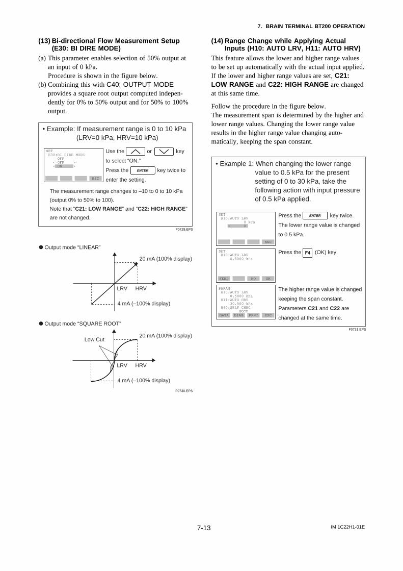
IM 1C22H1-01E7-13
7. BRAIN TERMINAL BT200 OPERATION
(13) Bi-directional Flow Measurement Setup(E30: BI DIRE MODE)
(a) This parameter enables selection of 50% output atan input of 0 kPa.Procedure is shown in the figure below.
(b) Combining this with C40: OUTPUT MODEprovides a square root output computed indepen-dently for 0% to 50% output and for 50% to 100%output.
• Example: If measurement range is 0 to 10 kPa (LRV=0 kPa, HRV=10 kPa)
The measurement range changes to –10 to 0 to 10 kPa
(output 0% to 50% to 100).
Note that “C21: LOW RANGE” and “C22: HIGH RANGE”
are not changed.
ESC
SET E30:BI DIRE MODE OFF < OFF > < ON >
Use the or key
to select “ON.”
Press the key twice to
enter the setting.
F0729.EPS
20 mA (100% display)
4 mA (–100% display)
d Output mode “LINEAR”
LRV HRV
F0730.EPS
20 mA (100% display)Low Cut
4 mA (–100% display)
d Output mode “SQUARE ROOT”
LRV HRV
(14) Range Change while Applying ActualInputs (H10: AUTO LRV, H11: AUTO HRV)
This feature allows the lower and higher range valuesto be set up automatically with the actual input applied.If the lower and higher range values are set, C21:LOW RANGE and C22: HIGH RANGE are changedat this same time.
Follow the procedure in the figure below.The measurement span is determined by the higher andlower range values. Changing the lower range valueresults in the higher range value changing auto-matically, keeping the span constant.
• Example 1: When changing the lower range value to 0.5 kPa for the present
setting of 0 to 30 kPa, take the following action with input pressure of 0.5 kPa applied.
FEED NO OK
SET H10:AUTO LRV 0.5000 kPa
DATA DIAG PRNT ESC
PARAM H10:AUTO LRV 0.5000 kPa H11:AUTO HRV 30.500 kPa H60:SELF CHEC GOOD
ESC
SET H10:AUTO LRV 0 kPa + 0
F0731.EPS
The higher range value is changed
keeping the span constant.
Parameters C21 and C22 are
changed at the same time.
Press the key twice.
The lower range value is changed
to 0.5 kPa.
Press the (OK) key.
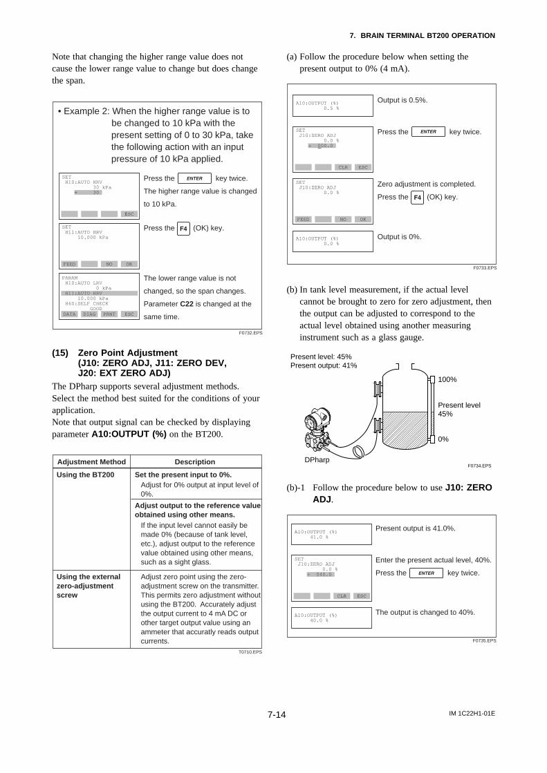
IM 1C22H1-01E7-14
7. BRAIN TERMINAL BT200 OPERATION
Note that changing the higher range value does notcause the lower range value to change but does changethe span.
• Example 2: When the higher range value is to be changed to 10 kPa with the
present setting of 0 to 30 kPa, take the following action with an input pressure of 10 kPa applied.
FEED NO OK
SET H11:AUTO HRV 10.000 kPa
DATA DIAG PRNT ESC
PARAM H10:AUTO LRV 0 kPa H11:AUTO HRV 10.000 kPa H60:SELF CHECK GOOD
ESC
SET H10:AUTO HRV 30 kPa + 30
The lower range value is not
changed, so the span changes.
Parameter C22 is changed at the
same time.
Press the key twice.
The higher range value is changed
to 10 kPa.
Press the (OK) key.
F0732.EPS
(15) Zero Point Adjustment(J10: ZERO ADJ, J11: ZERO DEV,J20: EXT ZERO ADJ)
The DPharp supports several adjustment methods.Select the method best suited for the conditions of yourapplication.Note that output signal can be checked by displayingparameter A10:OUTPUT (%) on the BT200.
Adjustment Method Description
Using the BT200 Set the present input to 0%.
Using the external zero-adjustment screw
Adjust zero point using the zero-adjustment screw on the transmitter.This permits zero adjustment without using the BT200. Accurately adjust the output current to 4 mA DC or other target output value using an ammeter that accuratly reads output currents.
Adjust output to the reference value obtained using other means.
Adjust for 0% output at input level of0%.
If the input level cannot easily be made 0% (because of tank level, etc.), adjust output to the reference value obtained using other means, such as a sight glass.
T0710.EPS
(a) Follow the procedure below when setting thepresent output to 0% (4 mA).
FEED NO OK
SET J10:ZERO ADJ 0.0 %
CLR ESC
SET J10:ZERO ADJ 0.0 % + 000.0
Press the key twice.
Zero adjustment is completed.
Press the (OK) key.
F0733.EPS
Output is 0.5%.A10:OUTPUT (%) 0.5 %
Output is 0%.A10:OUTPUT (%) 0.0 %
(b) In tank level measurement, if the actual levelcannot be brought to zero for zero adjustment, thenthe output can be adjusted to correspond to theactual level obtained using another measuringinstrument such as a glass gauge.
100%
Present level45%
Present level: 45%Present output: 41%
0%
DPharpF0734.EPS
(b)-1 Follow the procedure below to use J10: ZEROADJ .
CLR ESC
SET J10:ZERO ADJ 0.0 % + 040.0
Enter the present actual level, 40%.
Press the key twice.
The output is changed to 40%.
F0735.EPS
Present output is 41.0%.A10:OUTPUT (%) 41.0 %
A10:OUTPUT (%) 40.0 %
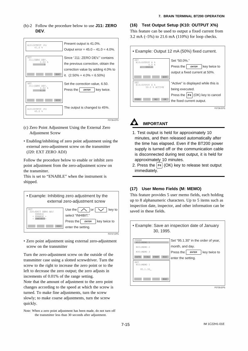
IM 1C22H1-01E7-15
7. BRAIN TERMINAL BT200 OPERATION
(b)-2 Follow the procedure below to use J11: ZERODEV.
ECS
ESC
SET J11:ZERO DEV. 2.50 % 0
Since “J11: ZERO DEV.” contains
the previous correction, obtain the
correction value by adding 4.0% to
it. (2.50% + 4.0% = 6.50%)
Set the correction value, 6.50.
Press the key twice.
F0736.EPS
Present output is 41.0%.
Output error = 45.0 – 41.0 = 4.0%.A10:OUTPUT (%) 41.0 %
The output is changed to 45%.A10:OUTPUT (%) 45.0 %
SET J11:ZERO DEV. 2.50 % 6.50
(c) Zero Point Adjustment Using the External ZeroAdjustment Screw
• Enabling/inhibiting of zero point adjustment using theexternal zero-adjustment screw on the transmitter(J20: EXT ZERO ADJ)
Follow the procedure below to enable or inhibit zeropoint adjustment from the zero-adjustment screw onthe transmitter.This is set to “ENABLE” when the instrument isshipped.
• Example: Inhibiting zero adjustment by the external zero-adjustment screw
ESC
SET J20:EXIT ZERO ADJ ENABLE < ENABLE > < INHIBIT>
Use the or key to
select “INHIBIT.”
Press the key twice to
enter the setting.
F0737.EPS
• Zero point adjustment using external zero-adjustmentscrew on the transmitter
Turn the zero-adjustment screw on the outside of thetransmitter case using a slotted screwdriver. Turn thescrew to the right to increase the zero point or to theleft to decrease the zero output; the zero adjusts inincrements of 0.01% of the range setting.Note that the amount of adjustment to the zero pointchanges according to the speed at which the screw isturned. To make fine adjustments, turn the screwslowly; to make coarse adjustments, turn the screwquickly.
Note: When a zero point adjustment has been made, do not turn offthe transmitter less than 30 seconds after adjustment.
(16) Test Output Setup (K10: OUTPUT X%)This feature can be used to output a fixed current from3.2 mA (–5%) to 21.6 mA (110%) for loop checks.
• Example: Output 12 mA (50%) fixed current.
ESC
SET K10:OUTPUT X % 50.0 % ACTIVE
FEED NO OK
SET K10:OUTPUT X % 0.0 % + 050.0
Set “50.0%.”
Press the key twice to
output a fixed current at 50%.
“Active” is displayed while this is
being executed.
Press the (OK) key to cancel
the fixed current output.
F0738.EPS
IMPORTANT
1. Test output is held for approximately 10minutes, and then released automatically afterthe time has elapsed. Even if the BT200 powersupply is turned off or the communication cableis disconnected during test output, it is held forapproximately 10 minutes.
2. Press the (OK) key to release test outputimmediately.
(17) User Memo Fields (M: MEMO)This feature provides 5 user memo fields, each holdingup to 8 alphanumeric characters. Up to 5 items such asinspection date, inspector, and other information can besaved in these fields.
• Example: Save an inspection date of January 30, 1995.
DATA DIAG PRNT ESC
SET M10:MEMO 1
95.1.30_
ESC
PARAM M10:MEMO 1
M20:MEMO 2
M30:MEMO 3
Set “95.1.30” in the order of year,
month, and day.
Press the key twice to
enter the setting.
F0739.EPS
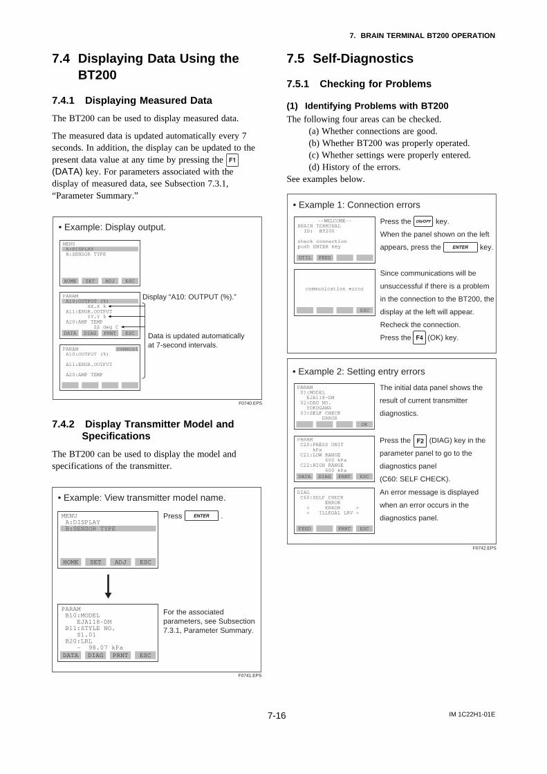
IM 1C22H1-01E7-16
7. BRAIN TERMINAL BT200 OPERATION
7.4 Displaying Data Using theBT200
7.4.1 Displaying Measured Data
The BT200 can be used to display measured data.
The measured data is updated automatically every 7seconds. In addition, the display can be updated to thepresent data value at any time by pressing the (DATA) key. For parameters associated with thedisplay of measured data, see Subsection 7.3.1,“Parameter Summary.”
• Example: Display output.
DATA DIAG PRNT ESC
PARAM A10:OUTPUT (%) A11:ENGR.OUTPUT A20:AMP TEMP
HOME SET ADJ ESC
MENU A:DISPLAY B:SENSOR TYPE
F0740.EPS
Data is updated automatically at 7-second intervals.
Display “A10: OUTPUT (%).”PARAM A10:OUTPUT (%) XX.X % A11:ENGR.OUTPUT YY.Y % A20:AMP TEMP ZZ deg C
communi
7.4.2 Display Transmitter Model andSpecifications
The BT200 can be used to display the model andspecifications of the transmitter.
• Example: View transmitter model name.
HOME SET ADJ ESC
MENU A:DISPLAY B:SENSOR TYPE
DATA DIAG PRNT ESC
PARAM B10:MODEL EJA118-DM B11:STYLE NO. S1.01 B20:LRL – 98.07 kPa
Press .
F0741.EPS
For the associated parameters, see Subsection 7.3.1, Parameter Summary.
7.5 Self-Diagnostics
7.5.1 Checking for Problems
(1) Identifying Problems with BT200The following four areas can be checked. (a) Whether connections are good. (b) Whether BT200 was properly operated. (c) Whether settings were properly entered. (d) History of the errors.See examples below.
• Example 1: Connection errors
ESC
communication error
Press the key.
When the panel shown on the left
appears, press the key.
Since communications will be
unsuccessful if there is a problem
in the connection to the BT200, the
display at the left will appear.
Recheck the connection.
Press the (OK) key.
––WELCOME––BRAIN TERMINAL ID: BT200
check connection push ENTER key
UTIL FEED
• Example 2: Setting entry errors
F0742.EPS
The initial data panel shows the
result of current transmitter
diagnostics.
DATA DIAG PRNT ESC
PARAM C20:PRESS UNIT kPa C21:LOW RANGE 600 kPa C22:HIGH RANGE 600 kPa
FEED PRNT ESC
DIAG C60:SELF CHECK ERROR < ERROR > < ILLEGAL LRV >
Press the (DIAG) key in the
parameter panel to go to the
diagnostics panel
(C60: SELF CHECK).
An error message is displayed
when an error occurs in the
diagnostics panel.
OK
PARAM 01:MODEL EJA118-DM 02:DAG NO. YOKOGAWA 03:SELF CHECK ERROR
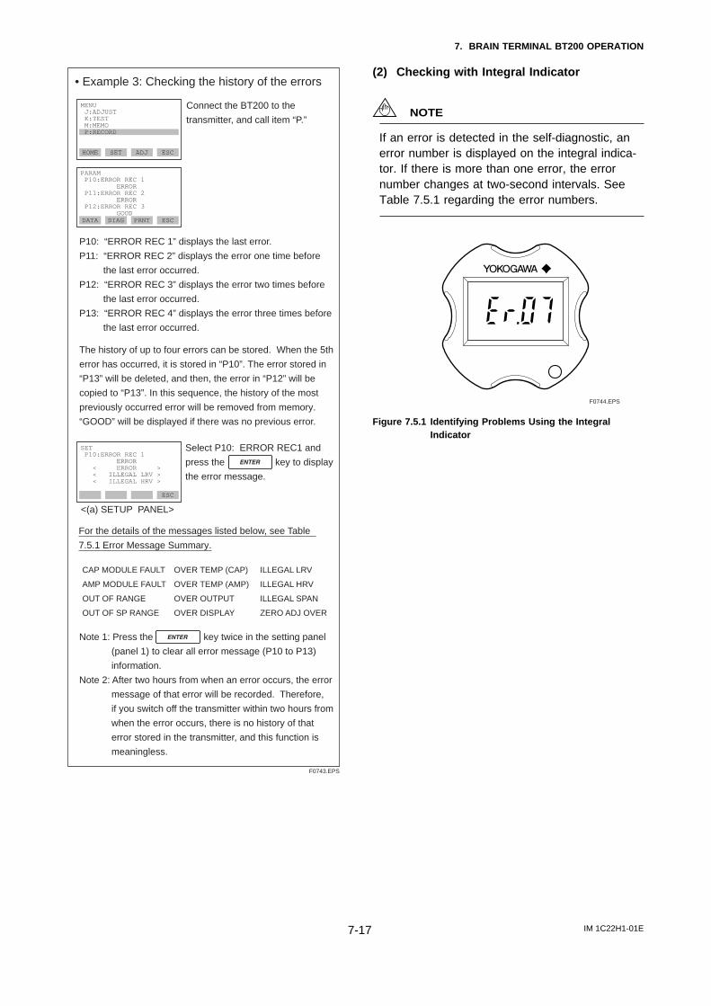
IM 1C22H1-01E7-17
7. BRAIN TERMINAL BT200 OPERATION
• Example 3: Checking the history of the errors
Connect the BT200 to the
transmitter, and call item “P.”
The history of up to four errors can be stored. When the 5th
error has occurred, it is stored in “P10”. The error stored in
“P13” will be deleted, and then, the error in “P12” will be
copied to “P13”. In this sequence, the history of the most
previously occurred error will be removed from memory.
“GOOD” will be displayed if there was no previous error.
F0743.EPS
HOME SET ADJ ESC
MENU J:ADJUST K:TEST M:MEMO P:RECORD
DATA DIAG PRNT ESC
PARAM P10:ERROR REC 1 ERROR P11:ERROR REC 2 ERROR P12:ERROR REC 3 GOOD
For the details of the messages listed below, see Table
7.5.1 Error Message Summary.
ESC
SET P10:ERROR REC 1 ERROR < ERROR > < ILLEGAL LRV > < ILLEGAL HRV >
<(a) SETUP PANEL>
Note 1: Press the key twice in the setting panel
(panel 1) to clear all error message (P10 to P13)
information.
Note 2: After two hours from when an error occurs, the error
message of that error will be recorded. Therefore,
if you switch off the transmitter within two hours from
when the error occurs, there is no history of that
error stored in the transmitter, and this function is
meaningless.
CAP MODULE FAULT
AMP MODULE FAULT
OUT OF RANGE
OUT OF SP RANGE
OVER TEMP (CAP)
OVER TEMP (AMP)
OVER OUTPUT
OVER DISPLAY
ILLEGAL LRV
ILLEGAL HRV
ILLEGAL SPAN
ZERO ADJ OVER
P10: “ERROR REC 1” displays the last error.
P11: “ERROR REC 2” displays the error one time before
the last error occurred.
P12: “ERROR REC 3” displays the error two times before
the last error occurred.
P13: “ERROR REC 4” displays the error three times before
the last error occurred.
Select P10: ERROR REC1 and
press the key to display
the error message.
(2) Checking with Integral Indicator
NOTE
If an error is detected in the self-diagnostic, anerror number is displayed on the integral indica-tor. If there is more than one error, the errornumber changes at two-second intervals. SeeTable 7.5.1 regarding the error numbers.
F0744.EPS
Figure 7.5.1 Identifying Problems Using the IntegralIndicator
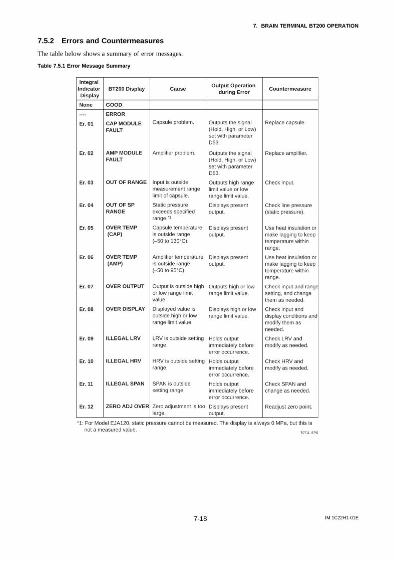
IM 1C22H1-01E7-18
7. BRAIN TERMINAL BT200 OPERATION
7.5.2 Errors and Countermeasures
The table below shows a summary of error messages.
Table 7.5.1 Error Message Summary
Integral Indicator Display
BT200 Display Cause CountermeasureOutput Operation
during Error
None
----
GOOD
ERROR
Er. 01 CAP MODULE FAULT
Er. 02 AMP MODULE FAULT
Er. 03 OUT OF RANGE
Er. 04 OUT OF SP RANGE
Er. 05 OVER TEMP (CAP)
Er. 06 OVER TEMP (AMP)
Er. 07 OVER OUTPUT
Er. 08 OVER DISPLAY
Er. 09 ILLEGAL LRV
Er. 10 ILLEGAL HRV
Er. 11 ILLEGAL SPAN
Er. 12 ZERO ADJ OVER
Static pressure exceeds specified range.*1
Capsule temperature is outside range (–50 to 130°C).
Amplifier temperature is outside range (–50 to 95°C).
Output is outside high or low range limit value.
Displayed value is outside high or low range limit value.
LRV is outside setting range.
HRV is outside setting range.
SPAN is outside setting range.
Zero adjustment is too large.
T0711 .EPS
Capsule problem.
Amplifier problem.
Input is outside measurement range limit of capsule.
Displays present output.
Displays present output.
Displays present output.
Outputs high or low range limit value.
Displays high or low range limit value.
Holds output immediately before error occurrence.
Holds output immediately before error occurrence.
Holds output immediately before error occurrence.
Displays present output.
Outputs the signal (Hold, High, or Low) set with parameter D53.
Outputs the signal (Hold, High, or Low) set with parameter D53.
Outputs high range limit value or low range limit value.
Check line pressure (static pressure).
Use heat insulation or make lagging to keep temperature within range.
Use heat insulation or make lagging to keep temperature within range.
Check input and range setting, and change them as needed.
Check input and display conditions and modify them as needed.
Check LRV and modify as needed.
Check HRV and modify as needed.
Check SPAN and change as needed.
Readjust zero point.
Replace capsule.
Replace amplifier.
Check input.
*1: For Model EJA120, static pressure cannot be measured. The display is always 0 MPa, but this is not a measured value.
IM 1C22H1-01E8-1
8. MAINTENANCE
8. MAINTENANCE
8.1 Overview
WARNING
Since the accumulated process fluid may betoxic or otherwise harmful, take appropriate careto avoid contact with the body, or inhalation ofvapors during draining condensate or ventinggas in transmitter pressure-detector section evenafter dismounting the instrument from processline for maintenance.
Maintenance of the transmitter is easy due to itsmodular construction. This chapter describes theprocedures for calibration, adjustment, and the disas-sembly and reassembly procedures required forcomponent replacement.
Since the transmitters are precision instruments,carefully and thoroughly read the following sectionsfor proper handling during maintenance.
IMPORTANT
• As a rule, maintenance of this transmittershould be implemented in a maintenanceservice shop where the necessary tools areprovided.
• The CPU assembly contains sensitive partsthat may be damaged by static electricity.Exercise care so as not to directly touch theelectronic parts or circuit patterns on the board,for example, by preventing static electrificationby using grounded wrist straps when handlingthe assembly.Also take precautions such as placing a re-moved CPU assembly into a bag with anantistatic coating.
8.2 Calibration InstrumentsSelection
Table 8.2.1 shows the instruments required for calibra-tion. Select instruments that will enable the transmitterto be calibrated or adjusted to the required accuracy.
The calibration instruments should be handled carefullyso as to maintain the specified accuracy.
8.3 CalibrationUse the procedure below to check instrument operationand accuracy during periodic maintenance or trouble-shooting.
1) Connect the instruments as shown in Figure 8.3.1and warm up the instruments for at least fiveminutes.
IMPORTANT
• To adjust the transmitter for highest accuracy,make adjustments with the power supplyvoltage and load resistance including leadwireresistances set close to the conditions underwhich the transmitter is installed.
• If the measurement range 0% point is 0 kPaor shifted in the positive direction (suppressedzero), the reference pressure should beapplied on the high pressure side, as shownin the figure (low pressure side open toatmosphere). If the measurement range 0%point is shifted in the negative direction(elevated zero), the reference pressure shouldbe applied on the low pressure side.
2) Apply reference pressures of 0%, 50%, and 100% ofthe measurement range to the transmitter. Calculatethe errors (differences between digital voltmeterreadings and reference pressures) as the pressure isincreased from 0% to 100% and is decreased from100% to 0%, and confirm that the errors are withinthe required accuracy.
Note: When the output mode is set to SQRT, apply referencepressures of 0, 6.25, 25, 56.25 and 100%, instead.
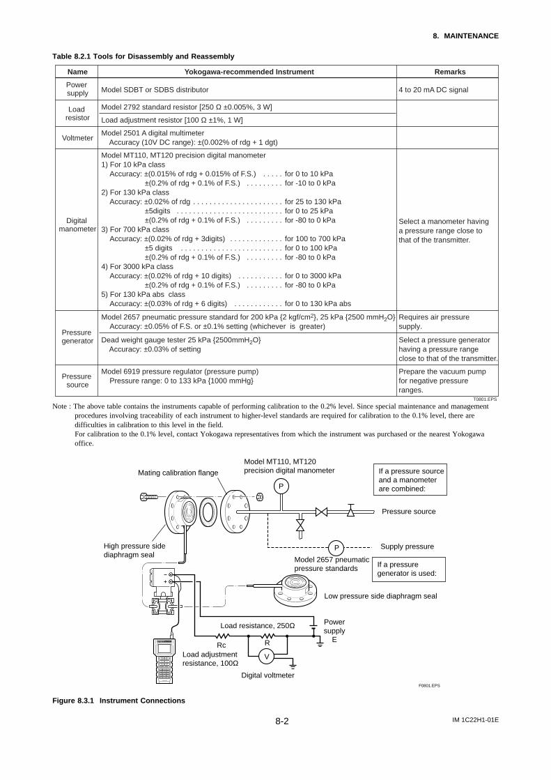
IM 1C22H1-01E8-2
8. MAINTENANCE
Table 8.2.1 Tools for Disassembly and Reassembly
Name RemarksYokogawa-recommended Instrument
Power supply Model SDBT or SDBS distributor
Load resistor
Model 2792 standard resistor [250 Ω ±0.005%, 3 W]
Load adjustment resistor [100 Ω ±1%, 1 W]
VoltmeterModel 2501 A digital multimeter Accuracy (10V DC range): ±(0.002% of rdg + 1 dgt)
Digital manometer
Model MT110, MT120 precision digital manometer1) For 10 kPa class
Accuracy: ±(0.015% of rdg + 0.015% of F.S.)±(0.2% of rdg + 0.1% of F.S.)
2) For 130 kPa classAccuracy: ±0.02% of rdg
±5digits±(0.2% of rdg + 0.1% of F.S.)
3) For 700 kPa classAccuracy: ±(0.02% of rdg + 3digits)
±5 digits ±(0.2% of rdg + 0.1% of F.S.)
4) For 3000 kPa classAccuracy: ±(0.02% of rdg + 10 digits)
±(0.2% of rdg + 0.1% of F.S.) 5) For 130 kPa abs class
Accuracy: ±(0.03% of rdg + 6 digits)
4 to 20 mA DC signal
Select a manometer having a pressure range close to that of the transmitter.
Pressure generator
Model 2657 pneumatic pressure standard for 200 kPa 2 kgf/cm2, 25 kPa 2500 mmH2OAccuracy: ±0.05% of F.S. or ±0.1% setting (whichever is greater)
Requires air pressure supply.
Pressure source
Model 6919 pressure regulator (pressure pump)Pressure range: 0 to 133 kPa 1000 mmHg
Prepare the vacuum pump for negative pressure ranges.
Dead weight gauge tester 25 kPa 2500mmH2O Accuracy: ±0.03% of setting
Select a pressure generator having a pressure range close to that of the transmitter.
T0801.EPS
for 0 to 10 kPafor -10 to 0 kPa
for 25 to 130 kPafor 0 to 25 kPafor -80 to 0 kPa
for 100 to 700 kPafor 0 to 100 kPafor -80 to 0 kPa
for 0 to 3000 kPafor -80 to 0 kPa
for 0 to 130 kPa abs
. . . . . . . . . . . . . .
. . . . . . . . . . . . . . . . . . . . . . . . . . . . . . . . . . . . . . . . . . . . . . . .
. . . . . . . . .
. . . . . . . . . . . . . . . . . . . . . . . . . . . . . . . . . . . . . .
. . . . . . . . .
. . . . . . . . . . . . . . . . . . . .
. . . . . . . . . . . .
Note : The above table contains the instruments capable of performing calibration to the 0.2% level. Since special maintenance and managementprocedures involving traceability of each instrument to higher-level standards are required for calibration to the 0.1% level, there aredifficulties in calibration to this level in the field.For calibration to the 0.1% level, contact Yokogawa representatives from which the instrument was purchased or the nearest Yokogawaoffice.
P
P
V
Mating calibration flange
Load resistance, 250Ω
Model MT110, MT120precision digital manometer
High pressure sidediaphragm seal
Rc R
Load adjustmentresistance, 100Ω
Digital voltmeter
Powersupply
E
Low pressure side diaphragm seal
Model 2657 pneumaticpressure standards
Pressure source
Supply pressure
If a pressuregenerator is used:
If a pressure sourceand a manometerare combined:
F0801.EPS
Figure 8.3.1 Instrument Connections
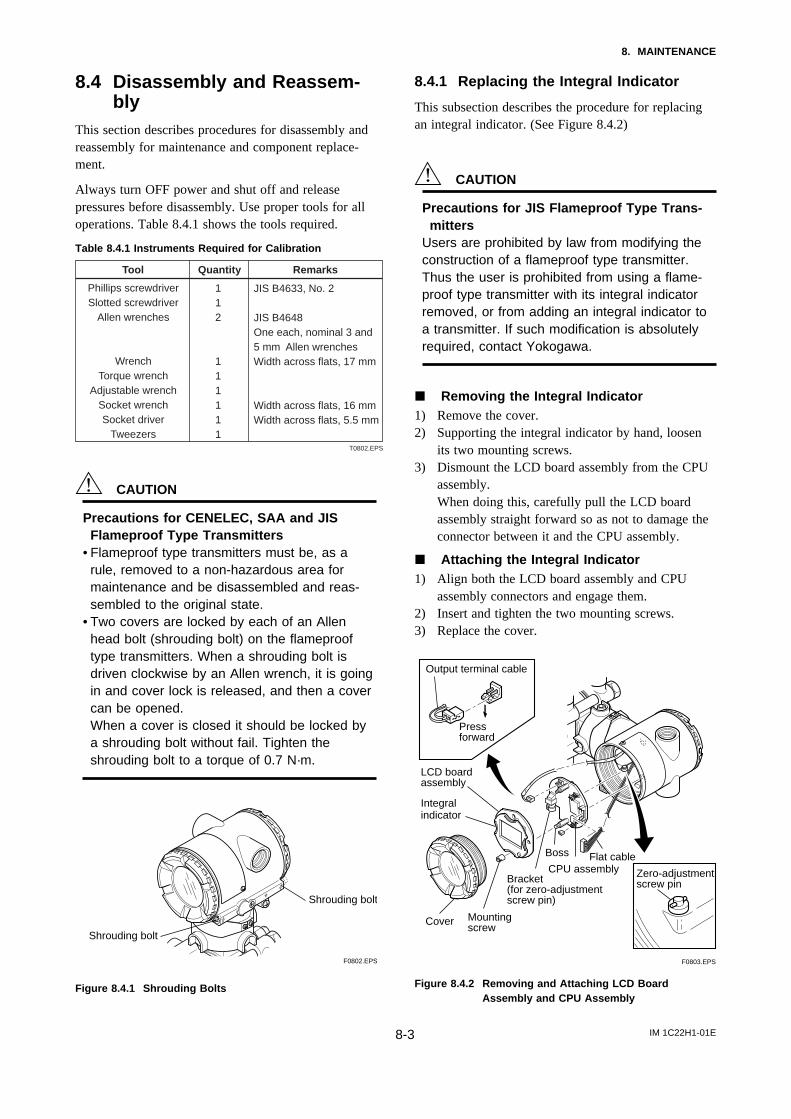
IM 1C22H1-01E8-3
8. MAINTENANCE
8.4 Disassembly and Reassem-bly
This section describes procedures for disassembly andreassembly for maintenance and component replace-ment.
Always turn OFF power and shut off and releasepressures before disassembly. Use proper tools for alloperations. Table 8.4.1 shows the tools required.
Table 8.4.1 Instruments Required for Calibration
Tool RemarksQuantity
Phillips screwdriverSlotted screwdriver
Allen wrenches
WrenchTorque wrench
Adjustable wrenchSocket wrenchSocket driver
Tweezers
JIS B4633, No. 2
JIS B4648One each, nominal 3 and 5 mm Allen wrenchesWidth across flats, 17 mm
Width across flats, 16 mmWidth across flats, 5.5 mm
T0802.EPS
112
111111
CAUTION
Precautions for CENELEC, SAA and JISFlameproof Type Transmitters
• Flameproof type transmitters must be, as arule, removed to a non-hazardous area formaintenance and be disassembled and reas-sembled to the original state.
• Two covers are locked by each of an Allenhead bolt (shrouding bolt) on the flameprooftype transmitters. When a shrouding bolt isdriven clockwise by an Allen wrench, it is goingin and cover lock is released, and then a covercan be opened.When a cover is closed it should be locked bya shrouding bolt without fail. Tighten theshrouding bolt to a torque of 0.7 N·m.
Shrouding bolt
Shrouding bolt
F0802.EPS
Figure 8.4.1 Shrouding Bolts
8.4.1 Replacing the Integral Indicator
This subsection describes the procedure for replacingan integral indicator. (See Figure 8.4.2)
CAUTION
Precautions for JIS Flameproof Type Trans-mitters
Users are prohibited by law from modifying theconstruction of a flameproof type transmitter.Thus the user is prohibited from using a flame-proof type transmitter with its integral indicatorremoved, or from adding an integral indicator toa transmitter. If such modification is absolutelyrequired, contact Yokogawa.
j Removing the Integral Indicator1) Remove the cover.2) Supporting the integral indicator by hand, loosen
its two mounting screws.3) Dismount the LCD board assembly from the CPU
assembly.When doing this, carefully pull the LCD boardassembly straight forward so as not to damage theconnector between it and the CPU assembly.
j Attaching the Integral Indicator1) Align both the LCD board assembly and CPU
assembly connectors and engage them.2) Insert and tighten the two mounting screws.3) Replace the cover.
F0803.EPS
Pressforward
Output terminal cable
LCD board assembly
Integral indicator
Cover
Boss
CPU assemblyFlat cable
Bracket(for zero-adjustment screw pin)
Mounting screw
Zero-adjustmentscrew pin
Figure 8.4.2 Removing and Attaching LCD BoardAssembly and CPU Assembly
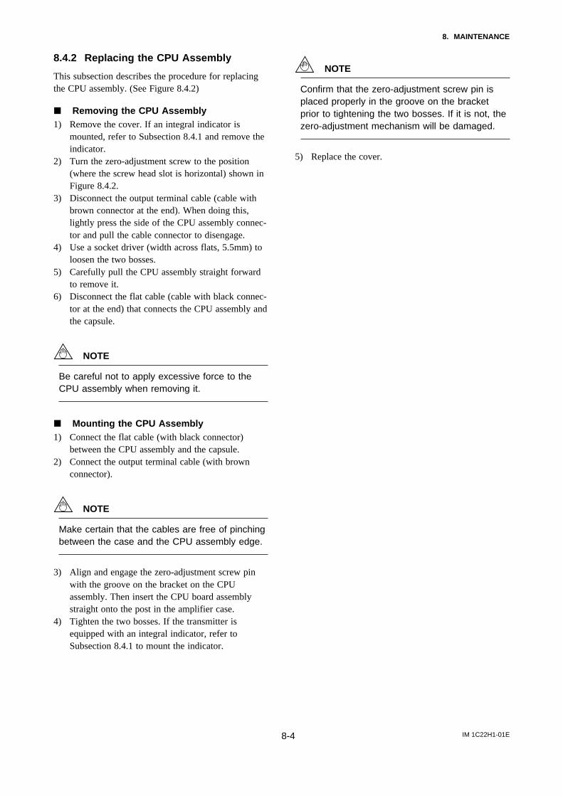
IM 1C22H1-01E8-4
8. MAINTENANCE
8.4.2 Replacing the CPU Assembly
This subsection describes the procedure for replacingthe CPU assembly. (See Figure 8.4.2)
j Removing the CPU Assembly1) Remove the cover. If an integral indicator is
mounted, refer to Subsection 8.4.1 and remove theindicator.
2) Turn the zero-adjustment screw to the position(where the screw head slot is horizontal) shown inFigure 8.4.2.
3) Disconnect the output terminal cable (cable withbrown connector at the end). When doing this,lightly press the side of the CPU assembly connec-tor and pull the cable connector to disengage.
4) Use a socket driver (width across flats, 5.5mm) toloosen the two bosses.
5) Carefully pull the CPU assembly straight forwardto remove it.
6) Disconnect the flat cable (cable with black connec-tor at the end) that connects the CPU assembly andthe capsule.
NOTE
Be careful not to apply excessive force to theCPU assembly when removing it.
j Mounting the CPU Assembly1) Connect the flat cable (with black connector)
between the CPU assembly and the capsule.2) Connect the output terminal cable (with brown
connector).
NOTE
Make certain that the cables are free of pinchingbetween the case and the CPU assembly edge.
3) Align and engage the zero-adjustment screw pinwith the groove on the bracket on the CPUassembly. Then insert the CPU board assemblystraight onto the post in the amplifier case.
4) Tighten the two bosses. If the transmitter isequipped with an integral indicator, refer toSubsection 8.4.1 to mount the indicator.
NOTE
Confirm that the zero-adjustment screw pin isplaced properly in the groove on the bracketprior to tightening the two bosses. If it is not, thezero-adjustment mechanism will be damaged.
5) Replace the cover.
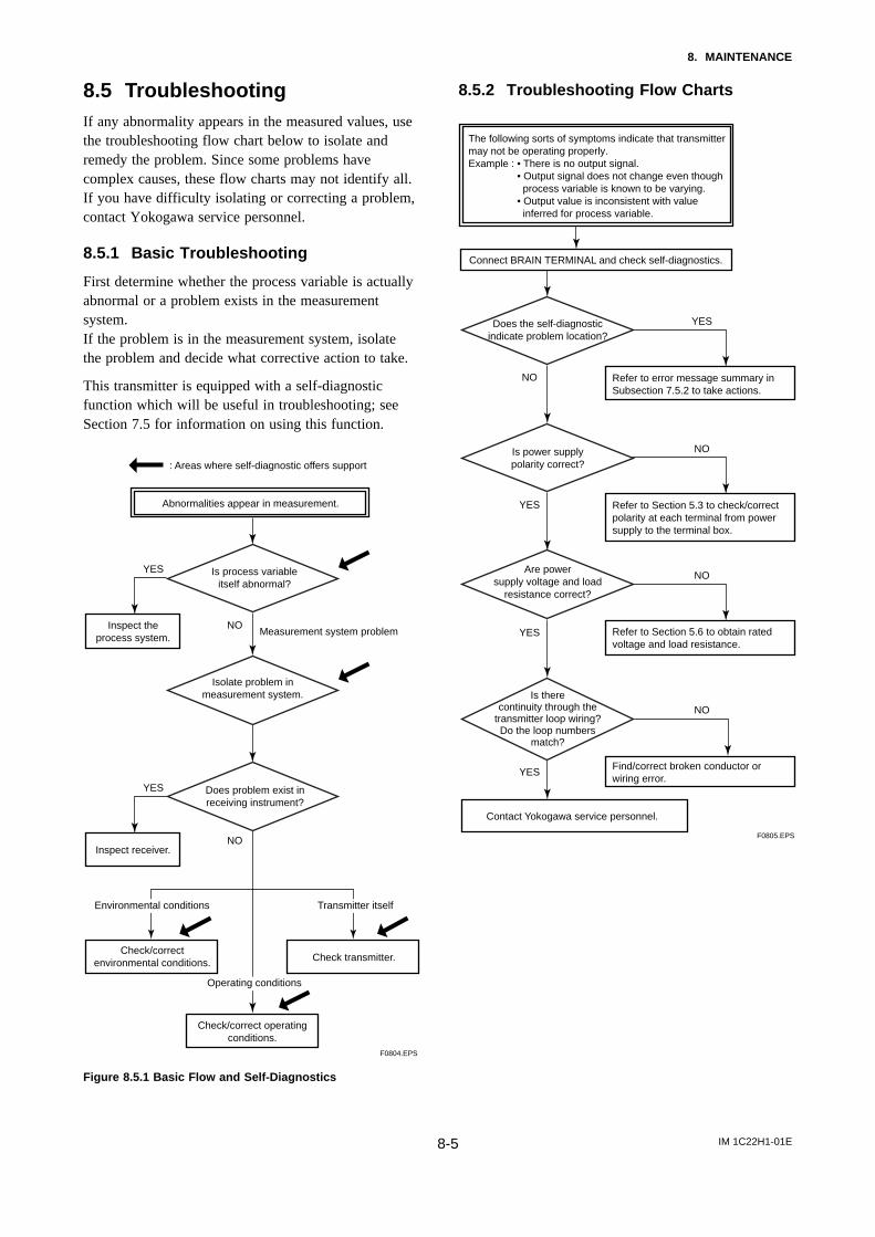
IM 1C22H1-01E8-5
8. MAINTENANCE
8.5 TroubleshootingIf any abnormality appears in the measured values, usethe troubleshooting flow chart below to isolate andremedy the problem. Since some problems havecomplex causes, these flow charts may not identify all.If you have difficulty isolating or correcting a problem,contact Yokogawa service personnel.
8.5.1 Basic Troubleshooting
First determine whether the process variable is actuallyabnormal or a problem exists in the measurementsystem.If the problem is in the measurement system, isolatethe problem and decide what corrective action to take.
This transmitter is equipped with a self-diagnosticfunction which will be useful in troubleshooting; seeSection 7.5 for information on using this function.
Abnormalities appear in measurement.
: Areas where self-diagnostic offers support
Is process variableitself abnormal?
Inspect theprocess system.
Isolate problem inmeasurement system.
Does problem exist inreceiving instrument?
Check/correctenvironmental conditions.
Inspect receiver.
Check transmitter.
Check/correct operatingconditions.
Measurement system problem
F0804.EPS
YES
NO
NO
YES
Environmental conditions
Operating conditions
Transmitter itself
Figure 8.5.1 Basic Flow and Self-Diagnostics
8.5.2 Troubleshooting Flow Charts
Connect BRAIN TERMINAL and check self-diagnostics.
Does the self-diagnosticindicate problem location?
Contact Yokogawa service personnel.
F0805.EPS
The following sorts of symptoms indicate that transmitter may not be operating properly.Example : • There is no output signal. • Output signal does not change even though process variable is known to be varying. • Output value is inconsistent with value inferred for process variable.
Is power supplypolarity correct?
Are powersupply voltage and load
resistance correct?
Refer to error message summary inSubsection 7.5.2 to take actions.
Refer to Section 5.3 to check/correctpolarity at each terminal from powersupply to the terminal box.
Refer to Section 5.6 to obtain rated voltage and load resistance.
Find/correct broken conductor or wiring error.
Is therecontinuity through the
transmitter loop wiring?Do the loop numbers
match?
YES
NO
NO
YES
NO
YES
NO
YES
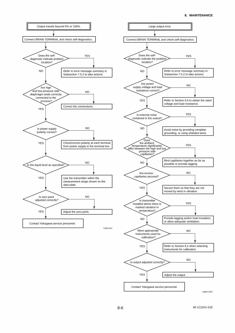
IM 1C22H1-01E8-6
8. MAINTENANCE
Connect BRAIN TERMINAL and check self-diagnostics.
Does the self-diagnostic indicate problem
location?
Contact Yokogawa service personnel.
F0806.EPS
Is power supplypolarity correct?
Are high and low pressure side
diaphragm seals correctly connected to the
process?
Refer to error message summary inSubsection 7.5.2 to take actions.
YES
NO
NO
YES Check/correct polarity at each terminal from power supply to the terminal box.
Use the transmitter within the measurement range shown on the data plate.
Correct the connections.
NO
YES
YES
Adjust the zero point.
NO
NO
YES
Is the liquid level as specified?
Is zero point adjusted correctly?
Output travels beyond 0% or 100%.
Connect BRAIN TERMINAL and check self-diagnostics.
Contact Yokogawa service personnel.
F0807.EPS
Are power supply voltage and load
resistance correct?
Is external noise contained in the outout?
Refer to error message summary inSubsection 7.5.2 to take actions.
Bind capillaries together as far as possible or provide lagging.
Provide lagging and/or heat insulation, or allow adequate ventilation.
Refer to Section 8.2 when selectinginstruments for calibration.
Refer to Section 5.6 to obtain the ratedvoltage and load resistance.
Avoid noise by providing complete grounding, or using shielded wires.
Adjust the output.
Does the ambient
temperature significantly differ between the high and low
pressure sidecapillaries?
Is output adjusted correctly?
Large output error.
Does the self-diagnostic indicate the problem
location?
Is transmitterinstalled where there is
marked variation in temperature?
Are excess capillaries secured?
YES
NO
YES
NO
NO
YES
NO
YES
NO
YES
NO
YES
NO
YES
Secure them so that they are notmoved by wind or vibration.
Were appropriate instruments used for
calibration?
YES
NO
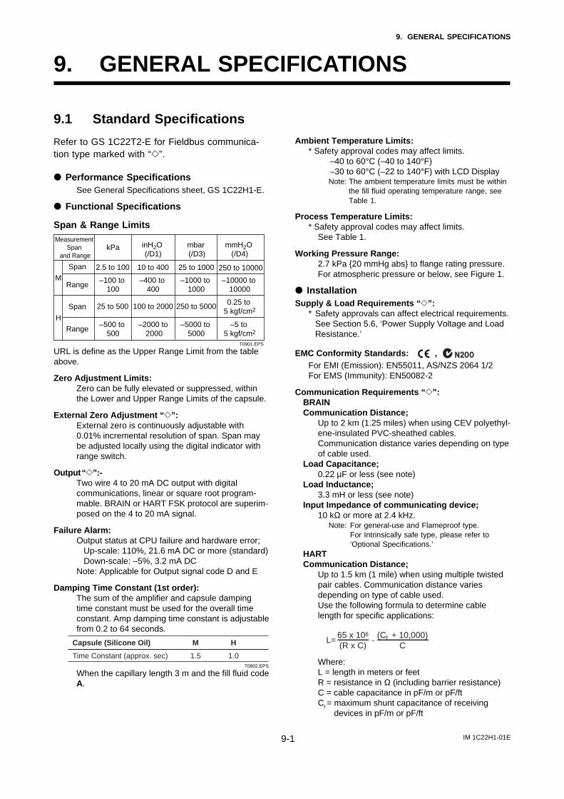
IM 1C22H1-01E9-1
9. GENERAL SPECIFICATIONS
9. GENERAL SPECIFICATIONS
9.1 Standard Specifications
Refer to GS 1C22T2-E for Fieldbus communica-tion type marked with “e”.
d Performance SpecificationsSee General Specifications sheet, GS 1C22H1-E.
d Functional Specifications
Span & Range Limits
M
Measurement Span
and Range
Span
Range
inH2O (/D1)
10 to 400
–400 to 400
mbar (/D3)
mmH2O (/D4)
25 to 1000
–1000 to 1000
250 to 10000
–10000 to 10000
kPa
2.5 to 100
–100 to 100
H
Span
Range
100 to 2000
–2000 to 2000
250 to 5000
–5000 to 5000
0.25 to 5 kgf/cm2
–5 to 5 kgf/cm2
25 to 500
–500 to 500
T0901.EPS
URL is define as the Upper Range Limit from the tableabove.
Zero Adjustment Limits:Zero can be fully elevated or suppressed, withinthe Lower and Upper Range Limits of the capsule.
External Zero Adjustment “ e”:External zero is continuously adjustable with0.01% incremental resolution of span. Span maybe adjusted locally using the digital indicator withrange switch.
Output “ e”:-Two wire 4 to 20 mA DC output with digitalcommunications, linear or square root program-mable. BRAIN or HART FSK protocol are superim-posed on the 4 to 20 mA signal.
Failure Alarm:Output status at CPU failure and hardware error; Up-scale: 110%, 21.6 mA DC or more (standard) Down-scale: –5%, 3.2 mA DCNote: Applicable for Output signal code D and E
Damping Time Constant (1st order):The sum of the amplifier and capsule dampingtime constant must be used for the overall timeconstant. Amp damping time constant is adjustablefrom 0.2 to 64 seconds.
Time Constant (approx. sec) 1.5 1.0
M H
T0902.EPS
Capsule (Silicone Oil)
When the capillary length 3 m and the fill fluid codeA.
Ambient Temperature Limits:* Safety approval codes may affect limits.
–40 to 60°C (–40 to 140°F)–30 to 60°C (–22 to 140°F) with LCD DisplayNote: The ambient temperature limits must be within
the fill fluid operating temperature range, seeTable 1.
Process Temperature Limits:* Safety approval codes may affect limits.
See Table 1.
Working Pressure Range:2.7 kPa 20 mmHg abs to flange rating pressure.For atmospheric pressure or below, see Figure 1.
d InstallationSupply & Load Requirements “ e”:
* Safety approvals can affect electrical requirements.See Section 5.6, ‘Power Supply Voltage and LoadResistance.’
EMC Conformity Standards: , For EMI (Emission): EN55011, AS/NZS 2064 1/2For EMS (Immunity): EN50082-2
Communication Requirements “ e”:BRAINCommunication Distance;
Up to 2 km (1.25 miles) when using CEV polyethyl-ene-insulated PVC-sheathed cables.Communication distance varies depending on typeof cable used.
Load Capacitance;0.22 µF or less (see note)
Load Inductance;3.3 mH or less (see note)
Input Impedance of communicating device;10 kΩ or more at 2.4 kHz.
Note: For general-use and Flameproof type.For Intrinsically safe type, please refer to‘Optional Specifications.’
HARTCommunication Distance;
Up to 1.5 km (1 mile) when using multiple twistedpair cables. Communication distance variesdepending on type of cable used.Use the following formula to determine cablelength for specific applications:
L= -65 x 106
(R x C)(Cf + 10,000)
C
Where:L = length in meters or feetR = resistance in Ω (including barrier resistance)C = cable capacitance in pF/m or pF/ftCf = maximum shunt capacitance of receiving
devices in pF/m or pF/ft
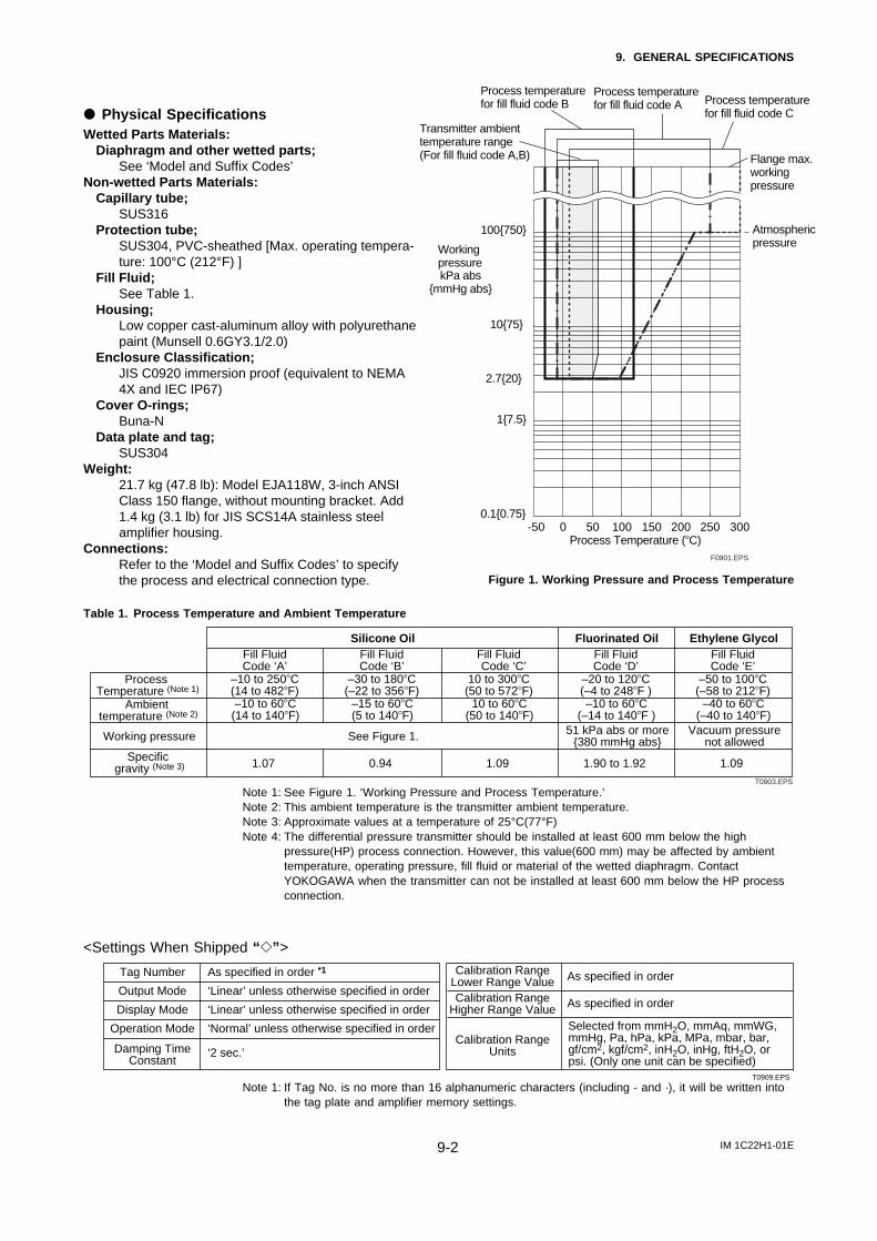
IM 1C22H1-01E9-2
9. GENERAL SPECIFICATIONS
d Physical SpecificationsWetted Parts Materials:
Diaphragm and other wetted parts;See ‘Model and Suffix Codes’
Non-wetted Parts Materials:Capillary tube;
SUS316Protection tube;
SUS304, PVC-sheathed [Max. operating tempera-ture: 100°C (212°F) ]
Fill Fluid;See Table 1.
Housing;Low copper cast-aluminum alloy with polyurethanepaint (Munsell 0.6GY3.1/2.0)
Enclosure Classification;JIS C0920 immersion proof (equivalent to NEMA4X and IEC IP67)
Cover O-rings;Buna-N
Data plate and tag;SUS304
Weight:21.7 kg (47.8 lb): Model EJA118W, 3-inch ANSIClass 150 flange, without mounting bracket. Add1.4 kg (3.1 lb) for JIS SCS14A stainless steelamplifier housing.
Connections:Refer to the ‘Model and Suffix Codes’ to specifythe process and electrical connection type.
Process temperaturefor fill fluid code B
Process temperaturefor fill fluid code A Process temperature
for fill fluid code C
Flange max.workingpressure
Atmosphericpressure
Transmitter ambienttemperature range(For fill fluid code A,B)
Workingpressure
2.720
Process Temperature (8C)
kPa absmmHg abs
100750
0.10.75
17.5
1075
-50 0 50 100 150 200 250 300
F0901.EPS
Figure 1. Working Pressure and Process Temperature
Table 1. Process Temperature and Ambient Temperature
Process Temperature (Note 1)
Ambient temperature (Note 2)
Working pressure
Specific gravity (Note 3)
See Figure 1.
0.941.07 1.09
–10 to 2508C(14 to 4828F)–10 to 608C(14 to 1408F)
–30 to 1808C(–22 to 3568F)
–15 to 608C(5 to 1408F)
10 to 3008C(50 to 5728F)
10 to 608C(50 to 1408F)
–20 to 1208C(–4 to 2488F )–10 to 608C
(–14 to 1408F )
–50 to 1008C(–58 to 2128F)
–40 to 608C(–40 to 1408F)
Fill FluidCode ‘A’
Fill FluidCode ‘B’
Fill Fluid Code ‘C’
Fill FluidCode ‘D’
Fill FluidCode ‘E’
51 kPa abs or more380 mmHg abs
Vacuum pressurenot allowed
1.90 to 1.92 1.09
Silicone Oil Fluorinated Oil Ethylene Glycol
T0903.EPS
Note 1: See Figure 1. ‘Working Pressure and Process Temperature.’Note 2: This ambient temperature is the transmitter ambient temperature.Note 3: Approximate values at a temperature of 25°C(77°F)Note 4: The differential pressure transmitter should be installed at least 600 mm below the high
pressure(HP) process connection. However, this value(600 mm) may be affected by ambienttemperature, operating pressure, fill fluid or material of the wetted diaphragm. ContactYOKOGAWA when the transmitter can not be installed at least 600 mm below the HP processconnection.
<Settings When Shipped “ e” >
Tag Number
Output Mode
Display Mode
Operation Mode
Damping TimeConstant
As specified in order *1
‘Linear’ unless otherwise specified in order
‘2 sec.’
‘Normal’ unless otherwise specified in order
‘Linear’ unless otherwise specified in order
Calibration RangeUnits
As specified in order
As specified in orderCalibration RangeHigher Range Value
Calibration RangeLower Range Value
Selected from mmH2O, mmAq, mmWG, mmHg, Pa, hPa, kPa, MPa, mbar, bar, gf/cm2, kgf/cm2, inH2O, inHg, ftH2O, or psi. (Only one unit can be specified)
T0909.EPS
Note 1: If Tag No. is no more than 16 alphanumeric characters (including - and ·), it will be written intothe tag plate and amplifier memory settings.
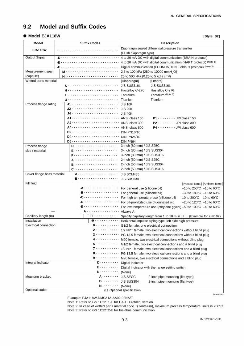
IM 1C22H1-01E9-3
9. GENERAL SPECIFICATIONS
9.2 Model and Suffix Codes
d Model EJA118W [Style: S2]
. . . . . . . . . . . . . . . . . . . . . . . . . . . . . . . . . .
-D . . . . . . . . . . . . . . . . . . . . . . . . . . . . . . . .
-E . . . . . . . . . . . . . . . . . . . . . . . . . . . . . . . .
-F . . . . . . . . . . . . . . . . . . . . . . . . . . . . . . . .
M . . . . . . . . . . . . . . . . . . . . . . . . . . . . .
H . . . . . . . . . . . . . . . . . . . . . . . . . . . . .
S . . . . . . . . . . . . . . . . . . . . . . . . . . . .
H . . . . . . . . . . . . . . . . . . . . . . . . . . . .
T . . . . . . . . . . . . . . . . . . . . . . . . . . . .
U . . . . . . . . . . . . . . . . . . . . . . . . . . . .
J1 . . . . . . . . . . . . . . . . . . . . . . . . . .
J2 . . . . . . . . . . . . . . . . . . . . . . . . . .
J4 . . . . . . . . . . . . . . . . . . . . . . . . . .
A1 . . . . . . . . . . . . . . . . . . . . . . . . . .
A2 . . . . . . . . . . . . . . . . . . . . . . . . . .
A4 . . . . . . . . . . . . . . . . . . . . . . . . . .
D2 . . . . . . . . . . . . . . . . . . . . . . . . . .
D4 . . . . . . . . . . . . . . . . . . . . . . . . . .
D5 . . . . . . . . . . . . . . . . . . . . . . . . . .
D . . . . . . . . . . . . . . . . . . . . . . . .
E . . . . . . . . . . . . . . . . . . . . . . . .
F . . . . . . . . . . . . . . . . . . . . . . . .
A . . . . . . . . . . . . . . . . . . . . . . . .
B . . . . . . . . . . . . . . . . . . . . . . . .
C . . . . . . . . . . . . . . . . . . . . . . . .
A . . . . . . . . . . . . . . . . . . . . . .
B . . . . . . . . . . . . . . . . . . . . . .
-A . . . . . . . . . . . . . . . . . . .
-B . . . . . . . . . . . . . . . . . . .
-C . . . . . . . . . . . . . . . . . . .
-D . . . . . . . . . . . . . . . . . . .
-E . . . . . . . . . . . . . . . . . . .
A . . . . . . . . . . . . . . . . . .
h h . . . . . . . . . . . . .
-9 . . . . . . . . . . . . . .
0 . . . . . . . . . . . . .
2 . . . . . . . . . . . . .
3 . . . . . . . . . . . . .
4 . . . . . . . . . . . . .
5 . . . . . . . . . . . . .
7 . . . . . . . . . . . . .
8 . . . . . . . . . . . . .
9 . . . . . . . . . . . . .
D . . . . . . . . . .
E . . . . . . . . . .
N . . . . . . . . . .
A . . . . . . . . .
B . . . . . . . . .
N . . . . . . . . .
Model Suffix Codes Description
EJA118W
Output Signal
Measurement span(capsule)Wetted parts material
Process flange rating
Process flangesize / material
Cover flange bolts material
Fill fluid
Capillary length (m)InstallationElectrical connection
Integral indicator
Mounting bracket
Optional codes
Diaphragm sealed differential pressure transmitter (Flush diaphragm type)4 to 20 mA DC with digital communication (BRAIN protocol)4 to 20 mA DC with digital communication (HART protocol) (Note 1)
Digital communication (FOUNDATION Fieldbus protocol) (Note 3)
2.5 to 100 kPa 250 to 10000 mmH2O25 to 500 kPa 0.25 to 5 kgf / cm2[Diaphragm] [Others]JIS SUS316L JIS SUS316LHastelloy C-276 Hastelloy C-276Tantalum Tantalum (Note 2)
Titanium TitaniumJIS 10KJIS 20KJIS 40KANSI class 150 P1 . . . . . . . . . . JPI class 150ANSI class 300 P2 . . . . . . . . . . JPI class 300ANSI class 600 P4 . . . . . . . . . . JPI class 600DIN PN10/16DIN PN25/40DIN PN643-inch (80 mm) / JIS S25C3-inch (80 mm) / JIS SUS3043-inch (80 mm) / JIS SUS3162-inch (50 mm) / JIS S25C2-inch (50 mm) / JIS SUS3042-inch (50 mm) / JIS SUS316
JIS SCM435JIS SUS630
[Process temp.] [Ambient temp.] For general use (silicone oil) –10 to 2508C –10 to 608CFor general use (silicone oil) –30 to 1808C –15 to 608CFor high temperature use (silicone oil) 10 to 3008C 10 to 608CFor oil-prohibited use (fluorinated oil) –20 to 1208C –10 to 608CFor low temperature use (ethylene glycol) –50 to 1008C –40 to 608CAlways ASpecify capillary length from 1 to 10 m in h h. (Example for 2 m: 02)Horizontal impulse piping type, left side high pressureG1/2 female, one electrical connection1/2 NPT female, two electrical connections without blind plugPG 13.5 female, two electrical connections without blind plugM20 female, two electrical connections without blind plugG1/2 female, two electrical connections and a blind plug1/2 NPT female, two electrical connections and a blind plugPG 13.5 female, two electrical connections and a blind plugM20 female, two electrical connections and a blind plugDigital indicatorDigital indicator with the range setting switch(None)JIS SECC 2-inch pipe mounting (flat type)JIS SUS304 2-inch pipe mounting (flat type)(None)
/h Optional specificationT0904.EPS
Example: EJA118W-DMSA1A-AA02-92NA/hNote 1: Refer to GS 1C22T1-E for HART Protocol version.Note 2: In case of wetted parts material code T(Tantalum), maximum process temperature limits is 200°C.Note 3: Refer to GS 1C22T2-E for Fieldbus communication.
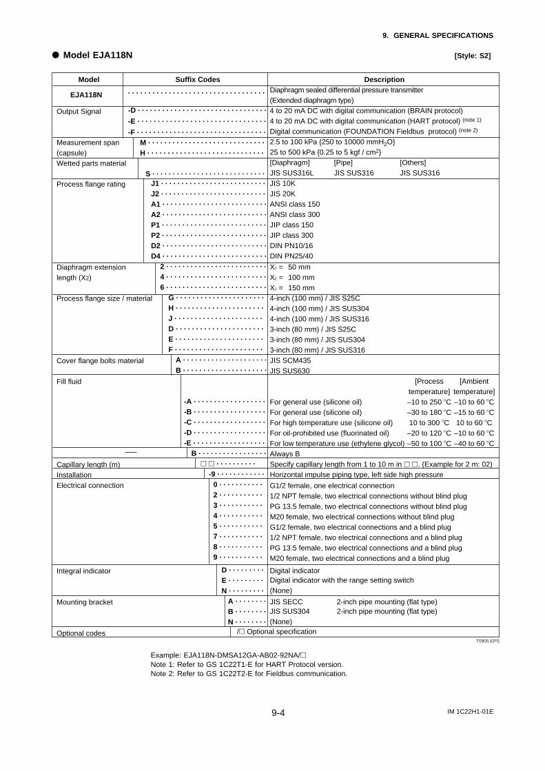
IM 1C22H1-01E9-4
9. GENERAL SPECIFICATIONS
d Model EJA118N [Style: S2]
. . . . . . . . . . . . . . . . . . . . . . . . . . . . . . . . . .
-D . . . . . . . . . . . . . . . . . . . . . . . . . . . . . . . .
-E . . . . . . . . . . . . . . . . . . . . . . . . . . . . . . . .
-F . . . . . . . . . . . . . . . . . . . . . . . . . . . . . . . .
M . . . . . . . . . . . . . . . . . . . . . . . . . . . . .
H . . . . . . . . . . . . . . . . . . . . . . . . . . . . .
S . . . . . . . . . . . . . . . . . . . . . . . . . . . .
J1 . . . . . . . . . . . . . . . . . . . . . . . . . .
J2 . . . . . . . . . . . . . . . . . . . . . . . . . .
A1 . . . . . . . . . . . . . . . . . . . . . . . . . .
A2 . . . . . . . . . . . . . . . . . . . . . . . . . .
P1 . . . . . . . . . . . . . . . . . . . . . . . . . .
P2 . . . . . . . . . . . . . . . . . . . . . . . . . .
D2 . . . . . . . . . . . . . . . . . . . . . . . . . .
D4 . . . . . . . . . . . . . . . . . . . . . . . . . .
2 . . . . . . . . . . . . . . . . . . . . . . . . .
4 . . . . . . . . . . . . . . . . . . . . . . . . .
6 . . . . . . . . . . . . . . . . . . . . . . . . .
G . . . . . . . . . . . . . . . . . . . . . .
H . . . . . . . . . . . . . . . . . . . . . .
J . . . . . . . . . . . . . . . . . . . . . .
D . . . . . . . . . . . . . . . . . . . . . .
E . . . . . . . . . . . . . . . . . . . . . .
F . . . . . . . . . . . . . . . . . . . . . .
A . . . . . . . . . . . . . . . . . . . . .
B . . . . . . . . . . . . . . . . . . . . .
-A . . . . . . . . . . . . . . . . . .
-B . . . . . . . . . . . . . . . . . .
-C . . . . . . . . . . . . . . . . . .
-D . . . . . . . . . . . . . . . . . .
-E . . . . . . . . . . . . . . . . . .
B . . . . . . . . . . . . . . . . .
h h . . . . . . . . . .
-9 . . . . . . . . . . . .
0 . . . . . . . . . . .
2 . . . . . . . . . . .
3 . . . . . . . . . . .
4 . . . . . . . . . . .
5 . . . . . . . . . . .
7 . . . . . . . . . . .
8 . . . . . . . . . . .
9 . . . . . . . . . . .
D . . . . . . . . .
E . . . . . . . . .
N . . . . . . . . .
A . . . . . . . .
B . . . . . . . .
N . . . . . . . .
Model Suffix Codes Description
EJA118N
Output Signal
Measurement span(capsule)Wetted parts material
Process flange rating
Diaphragm extensionlength (X2)
Process flange size / material
Cover flange bolts material
Fill fluid
Capillary length (m)InstallationElectrical connection
Integral indicator
Mounting bracket
Optional codes
Diaphragm sealed differential pressure transmitter (Extended diaphragm type)4 to 20 mA DC with digital communication (BRAIN protocol)4 to 20 mA DC with digital communication (HART protocol) (note 1)
Digital communication (FOUNDATION Fieldbus protocol) (note 2)
2.5 to 100 kPa 250 to 10000 mmH2O25 to 500 kPa 0.25 to 5 kgf / cm2[Diaphragm] [Pipe] [Others]JIS SUS316L JIS SUS316 JIS SUS316JIS 10KJIS 20KANSI class 150ANSI class 300JIP class 150JIP class 300DIN PN10/16DIN PN25/40
X2 = 50 mmX2 = 100 mmX2 = 150 mm4-inch (100 mm) / JIS S25C4-inch (100 mm) / JIS SUS3044-inch (100 mm) / JIS SUS3163-inch (80 mm) / JIS S25C3-inch (80 mm) / JIS SUS3043-inch (80 mm) / JIS SUS316JIS SCM435JIS SUS630
[Process [Ambienttemperature] temperature]
For general use (silicone oil) –10 to 250 8C –10 to 60 8CFor general use (silicone oil) –30 to 180 8C –15 to 60 8CFor high temperature use (silicone oil) 10 to 300 8C 10 to 60 8CFor oil-prohibited use (fluorinated oil) –20 to 120 8C –10 to 60 8CFor low temperature use (ethylene glycol) –50 to 100 8C –40 to 60 8CAlways BSpecify capillary length from 1 to 10 m in h h. (Example for 2 m: 02)Horizontal impulse piping type, left side high pressure
G1/2 female, one electrical connection1/2 NPT female, two electrical connections without blind plugPG 13.5 female, two electrical connections without blind plugM20 female, two electrical connections without blind plugG1/2 female, two electrical connections and a blind plug1/2 NPT female, two electrical connections and a blind plugPG 13.5 female, two electrical connections and a blind plugM20 female, two electrical connections and a blind plug
Digital indicatorDigital indicator with the range setting switch(None)
JIS SECC 2-inch pipe mounting (flat type)JIS SUS304 2-inch pipe mounting (flat type)(None)
/h Optional specificationT0905.EPS
Example: EJA118N-DMSA12GA-AB02-92NA/hNote 1: Refer to GS 1C22T1-E for HART Protocol version.Note 2: Refer to GS 1C22T2-E for Fieldbus communication.
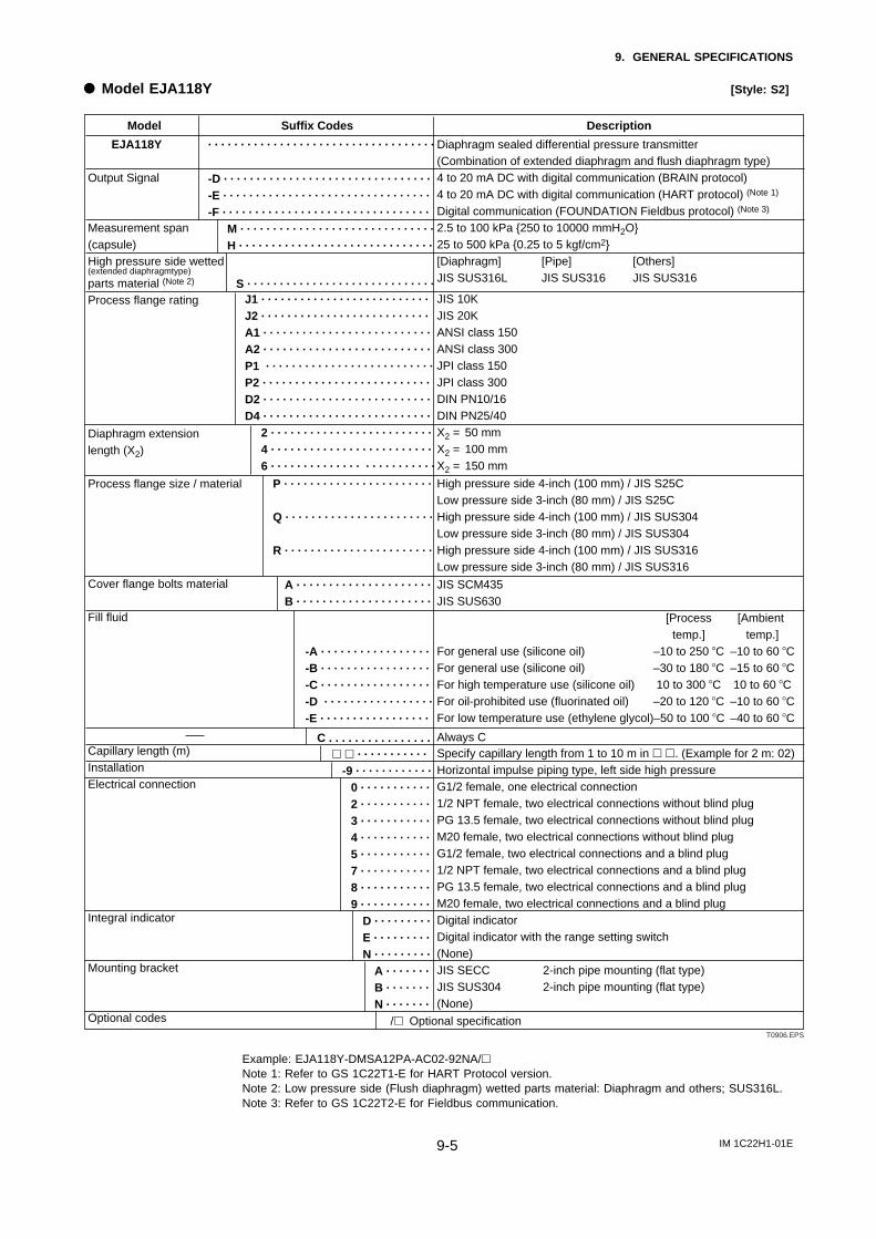
IM 1C22H1-01E9-5
9. GENERAL SPECIFICATIONS
d Model EJA118Y [Style: S2]
. . . . . . . . . . . . . . . . . . . . . . . . . . . . . . . . . . .
-D . . . . . . . . . . . . . . . . . . . . . . . . . . . . . . . .
-E . . . . . . . . . . . . . . . . . . . . . . . . . . . . . . . .
-F . . . . . . . . . . . . . . . . . . . . . . . . . . . . . . . .
M . . . . . . . . . . . . . . . . . . . . . . . . . . . . . .
H . . . . . . . . . . . . . . . . . . . . . . . . . . . . . .
S . . . . . . . . . . . . . . . . . . . . . . . . . . . . .
J1 . . . . . . . . . . . . . . . . . . . . . . . . . .
J2 . . . . . . . . . . . . . . . . . . . . . . . . . .
A1 . . . . . . . . . . . . . . . . . . . . . . . . . .
A2 . . . . . . . . . . . . . . . . . . . . . . . . . .
P1 . . . . . . . . . . . . . . . . . . . . . . . . . .
P2 . . . . . . . . . . . . . . . . . . . . . . . . . .
D2 . . . . . . . . . . . . . . . . . . . . . . . . . .
D4 . . . . . . . . . . . . . . . . . . . . . . . . . .
2 . . . . . . . . . . . . . . . . . . . . . . . . .
4 . . . . . . . . . . . . . . . . . . . . . . . . .
6 . . . . . . . . . . . . . . . . . . . . . . . . .
P . . . . . . . . . . . . . . . . . . . . . . .
Q . . . . . . . . . . . . . . . . . . . . . . .
R . . . . . . . . . . . . . . . . . . . . . . .
A . . . . . . . . . . . . . . . . . . . . .
B . . . . . . . . . . . . . . . . . . . . .
-A . . . . . . . . . . . . . . . . .
-B . . . . . . . . . . . . . . . . .
-C . . . . . . . . . . . . . . . . .
-D . . . . . . . . . . . . . . . . .
-E . . . . . . . . . . . . . . . . .
C . . . . . . . . . . . . . . . .h h . . . . . . . . . . .
-9 . . . . . . . . . . . .
0 . . . . . . . . . . .
2 . . . . . . . . . . .
3 . . . . . . . . . . .
4 . . . . . . . . . . .
5 . . . . . . . . . . .
7 . . . . . . . . . . .
8 . . . . . . . . . . .
9 . . . . . . . . . . .
D . . . . . . . . .
E . . . . . . . . .
N . . . . . . . . .
A . . . . . . .
B . . . . . . .
N . . . . . . .
Model Suffix Codes Description
EJA118Y
Output Signal
Measurement span(capsule)High pressure side wetted (extended diaphragmtype)
parts material (Note 2)
Process flange rating
Diaphragm extensionlength (X2)
Process flange size / material
Cover flange bolts material
Fill fluid
Capillary length (m)InstallationElectrical connection
Integral indicator
Mounting bracket
Optional codes
Diaphragm sealed differential pressure transmitter (Combination of extended diaphragm and flush diaphragm type)4 to 20 mA DC with digital communication (BRAIN protocol)4 to 20 mA DC with digital communication (HART protocol) (Note 1)
Digital communication (FOUNDATION Fieldbus protocol) (Note 3)
2.5 to 100 kPa 250 to 10000 mmH2O25 to 500 kPa 0.25 to 5 kgf/cm2[Diaphragm] [Pipe] [Others]JIS SUS316L JIS SUS316 JIS SUS316
JIS 10KJIS 20KANSI class 150
ANSI class 300
JPI class 150JPI class 300DIN PN10/16DIN PN25/40X2 = 50 mmX2 = 100 mm X2 = 150 mm
High pressure side 4-inch (100 mm) / JIS S25CLow pressure side 3-inch (80 mm) / JIS S25CHigh pressure side 4-inch (100 mm) / JIS SUS304Low pressure side 3-inch (80 mm) / JIS SUS304High pressure side 4-inch (100 mm) / JIS SUS316Low pressure side 3-inch (80 mm) / JIS SUS316
JIS SCM435JIS SUS630
[Process [Ambient temp.] temp.]
For general use (silicone oil) –10 to 250 8C –10 to 60 8CFor general use (silicone oil) –30 to 180 8C –15 to 60 8CFor high temperature use (silicone oil) 10 to 300 8C 10 to 60 8CFor oil-prohibited use (fluorinated oil) –20 to 120 8C –10 to 60 8CFor low temperature use (ethylene glycol)–50 to 100 8C –40 to 60 8C
Always CSpecify capillary length from 1 to 10 m in h h. (Example for 2 m: 02)Horizontal impulse piping type, left side high pressureG1/2 female, one electrical connection1/2 NPT female, two electrical connections without blind plugPG 13.5 female, two electrical connections without blind plugM20 female, two electrical connections without blind plugG1/2 female, two electrical connections and a blind plug1/2 NPT female, two electrical connections and a blind plugPG 13.5 female, two electrical connections and a blind plugM20 female, two electrical connections and a blind plugDigital indicatorDigital indicator with the range setting switch(None)JIS SECC 2-inch pipe mounting (flat type)JIS SUS304 2-inch pipe mounting (flat type)(None)
/h Optional specificationT0906.EPS
Example: EJA118Y-DMSA12PA-AC02-92NA/hNote 1: Refer to GS 1C22T1-E for HART Protocol version.Note 2: Low pressure side (Flush diaphragm) wetted parts material: Diaphragm and others; SUS316L.Note 3: Refer to GS 1C22T2-E for Fieldbus communication.
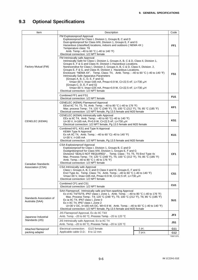
IM 1C22H1-01E9-6
9. GENERAL SPECIFICATIONS
9.3 Optional Specifications
Item Description Code
Factory Mutual (FM)
CSA Explosionproof ApprovalExplosionproof for Class I, Division 1, Groups B, C and DDustignitionproof for Class II/III, Division 1, Groups E, F and G Division2 ‘SEALS NOT REQUIRED’ , Temp. Class : T4, T5, T6 Encl Type 4xMax. Process Temp.: T4; 120 8C (248 8F), T5; 100 8C (212 8F), T6; 85 8C (185 8F)Amb. Temp.:–40 to 80 8C (–40 to 176 8F)
Electrical connection: 1/2 NPT female
CF1
Canadian Standards Association (CSA) CSA Intrinsically safe Approval
Class I, Groups A, B, C and D Class II and III, Groups E, F and GEncl Type 4x, Temp. Class: T4, Amb. Temp.: –40 to 60 8C (–40 to 140 8F)Vmax=30 V, Imax=165 mA, Pmax=0.9 W, Ci=22.5 nF, Li=730 mH
Electrical connection: 1/2 NPT female
CS1
CENELEC (KEMA) Intrinsically safe Approval EEx ia IIC T4, Amb. Temp.: –40 to 60 8C(–40 to 140 8F)Ui=30 V, Ii=165 mA, Pi=0.9 W, Ci=22.5 nF, Li=730 mHElectrical connection: 1/2 NPT female, Pg 13.5 female and M20 female
KS1
FM Intrinsically safe Approval Intrinsically Safe for Class I, Division 1, Groups A, B, C & D, Class II, Division 1, Groups E, F & G and Class III, Division 1 Hazardous Locations.Nonincendive for Class I, Division 2, Groups A, B, C & D, Class II, Division. 2, Groups E, F & G, and Class III, Division 1 Hazardous Locations.Enclosure: “NEMA 4X”, Temp. Class: T4, Amb. Temp.: –40 to 60 8C (–40 to 140 8F)Intrinsically Safe Apparatus Parameters
[Groups A, B, C, D, E, F and G]Vmax=30 V, Imax=165 mA, Pmax=0.9 W, Ci=22.5 nF, Li=730 mH
[Groups C, D, E, F and G] Vmax=30 V, Imax=225 mA, Pmax=0.9 W, Ci=22.5 nF, Li=730 mH
Electrical connection: 1/2 NPT female
FS1
CENELEC (KEMA) Flameproof ApprovalEExd IIC T4, T5, T6, Amb. Temp.: –40 to 80 8C (–40 to 176 8F)Max. process Temp.: T4; 120 8C (248 8F), T5; 100 8C (212 8F), T6; 85 8C (185 8F)
Electrical connection: 1/2 NPT female, Pg 13.5 female and M20 female
KF1
FM Explosionproof Approval Explosionproof for Class I, Division 1, Groups B, C and DDust-ignitionproof for Class II/III, Division 1, Groups E, F and GHazardous (classified) locations, indoors and outdoors ( NEMA 4X )Temperature class: T6
Amb. Temp.:–40 to 60 8C (–40 to 140 8F) Electrical connection: 1/2 NPT female
FF1
Standards Association ofAustralia (SAA) SU1
SAA Flameproof, Intrinsically safe and Non-sparking Approval Ex d IIC T4/T5/T6, IP67 class I, Zone 1, Amb. Temp. : –40 to 80 8C (–40 to 176 8F)
Max. Process Temp.: T4; 120 8C (248 8F), T5; 100 8C (212 8F), T6; 85 8C (185 8F)Ex ia IIC T4, IP67 class I, Zone 0Ex n IIC T4, IP67 class I, Zone 2
Ui=30 V DC, Ii=165 mA DC, Wi=0.9 W, Amb. Temp.: –40 to 60 8C (–40 to 140 8F) Electrical connection: 1/2 NPT female, Pg 13.5 female and M20 female
FU1Combined FF1 and FS1 Electrical connection: 1/2 NPT female
Combined KF1, KS1 and Type N Approval KEMA Type N ApprovalEx nA IIC T4, Amb. Temp.: –40 to 60 8C(–40 to 140 8F)U=30 V, I=165 mA
Electrical connection: 1/2 NPT female, Pg 13.5 female and M20 female
KU1
CENELEC (KEMA)
CU1Combined CF1 and CS1 Electrical connection: 1/2 NPT female
JIS Flameproof Approval, Ex do IIC T4XAmb. Temp. –20 to 60 8C, Process Temp. –20 to 120 8C
JS1JIS Intrinsically safe Approval, Ex ia IIC T4Amb. Temp. –20 to 60 8C, Process Temp. –20 to 120 8C
Japanese IndustrialStandards (JIS)
JF3
Attached flameproofpacking adapter
Electrical connection: G1/2 femaleApplicable cable O.D.: 8 to 12 mm
1 pc.
2 pcs.G11
G12T0907.EPS
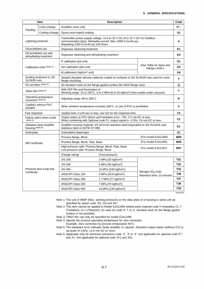
IM 1C22H1-01E9-7
9. GENERAL SPECIFICATIONS
Item Description Code
T0908.EPS
Gold-plated diaphragm
TTeflon film (Note 3) With FEP film and fluorinated oilWorking range: 20 to 150°C, 0 to 2 MPa 0 to 20 kgf/cm2 (Not usable under vacuum)
ROperating temperature correction (Note 4) Adjusting range: 80 to 300°C
VCapillary without PVC sheaths When ambient temperature exceeds 100°C, or use of PVC is prohibited
C1Failure alarm down-scale (Note 5)
Output status at CPU failure and hardware error: –5%, 3.2 mA DC or less.When combining with Optional code F1, output signal is –2.5%, 3.6 mA DC or less.
E1
A1
Stainless steel amplifier housing (Note 6)
Gold-plate
Amplifier housing material: JIS SCS14A stainless steel (equivalent to JIS SUS316 cast stainless steel or ASTM CF-8M)
Update time: 0.125 sec or less, see GS for the response time F1Fast response
Oil-prohibited use
K5Degrease cleansing and dehydrating treatmentOil-prohibited use with dehydrating treatment
YSealant (liquided silicone rubber)is coated on surfaces of JIS SUS630 nuts used for cover flange mounting.
Sealing treatment to JIS SUS630 nuts
Painting
Lightning protector
K1Degrease cleansing treatment
No serration (Note 2) QNo serration work on the flange gasket surface (for ANSI flange only)
ATransmitter power supply voltage: 10.5 to 32 V DC (9 to 32 V DC for Fieldbus communication type) Allowable current: Max. 6000 A (1x40 µs), Repeating 1000 A (1x40 µs) 100 times
Ph
X1
Amplifier cover only
D1
D3
P calibration (psi unit)
bar calibration (bar unit)(See Table for Span and
Range Limits.)Calibration units (Note 1)
D4M calibration (kgf/cm2 unit)
Epoxy resin-baked coating
Color change
Coating change
Pressure test /Leak test Certificate
M05
M06
M07
T31
T32
T33
T36
T37
T38
T39
Mill Certificate
(Test pressure)
2 MPa 20 kgf/cm2
5 MPa 50 kgf/cm2
10 MPa 100 kgf/cm2
3 MPa 29.8 kgf/cm2
7.7 MPa 77 kgf/cm2
7 MPa 70 kgf/cm2
14 MPa 140 kgf/cm2
(Flange rating)
JIS 10K
JIS 20K
JIS 40K
ANSI/JPI Class 150
ANSI/JPI Class 300
ANSI/JPI Class 300
ANSI/JPI Class 600
(For model EJA118W)
(For model EJA118N)
Nitrogen (N2) GasRetention time: 10 minutes
Process flange, Block
Process flange, Block, Pipe, Base
High pressure side: Process flange, Block, Pipe, BaseLow pressure side: Process flange, Block
(For model EJA118Y)
Note 1: The unit of MWP (Max. working pressure) on the data plate of a housing is same unit asspecified by option code “D1, D3 and D4.”
Note 2: This item cannot be applied to Model EJA118W wetted parts material code H (Hastelloy C), T(Tantalum), or U (Titanium). (In case for code H, T or U, serration work on the flange gasketsurface is not possible).
Note 3: Teflon film can only be specified for model EJA118W.Note 4: Specify the process operating temperature for zero correction.
Example: Zero correction by process temperature 90°C.Note 5: The hardware error indicates faulty amplifier or capsule. Standard output status (without /C1) is
up-scale of 110%, 21.6 mA DC or more.Note 6: Applicable only for electrical connection code ‘2’, ‘3’ or ‘4’. Not applicable for optional code Ph
and X1. Not applicable for optional code JF1 and JS1.
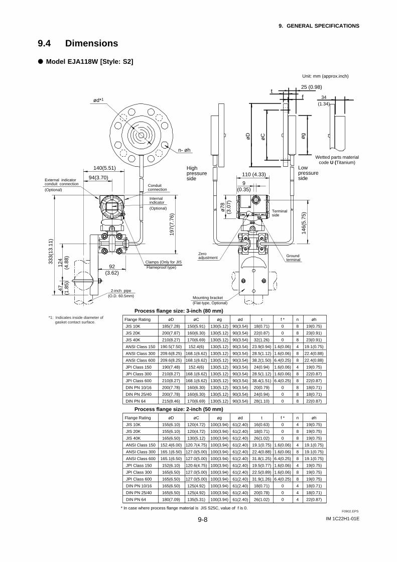
IM 1C22H1-01E9-8
9. GENERAL SPECIFICATIONS
9.4 Dimensions
d Model EJA118W [Style: S2]
Highpressureside
34(1.34)
Wetted parts materialcode U (Titanium)
Lowpressureside
25 (0.98)t
øg
f
øCøD
n- øh
ød*1
333(
13.1
1)
140(5.51)
94(3.70)19
7(7.
76)
92(3.62)
124
(4.8
8)47
(1.8
5)
146(
5.75
)
9(0.35)
110 (4.33)
ø78
(3.0
7)
External indicatorconduit connection
(Optional)
2-inch pipe(O.D. 60.5mm)
Internal indicator
(Optional)
Conduitconnection
Clamps (Only for JIS Flameproof type)
Zeroadjustment Ground
terminal
Mounting bracket(Flat-type, Optional)
Terminalside
Flange Rating
JIS 10K
JIS 20K
JIS 40K
ANSI Class 150
ANSI Class 300
ANSI Class 600
JPI Class 150
JPI Class 300
JPI Class 600
DIN PN 10/16
DIN PN 25/40
DIN PN 64
øD
155(6.10)
155(6.10)
165(6.50)
152.4(6.00)
165.1(6.50)
165.1(6.50)
152(6.10)
165(6.50)
165(6.50)
165(6.50)
165(6.50)
180(7.09)
t
16(0.63)
18(0.71)
26(1.02)
19.1(0.75)
22.4(0.88)
31.8(1.25)
19.5(0.77)
22.5(0.89)
31.9(1.26)
18(0.71)
20(0.78)
26(1.02)
øC
120(4.72)
120(4.72)
130(5.12)
120.7(4.75)
127.0(5.00)
127.0(5.00)
120.6(4.75)
127.0(5.00)
127.0(5.00)
125(4.92)
125(4.92)
135(5.31)
n
4
8
8
4
8
8
4
8
8
4
4
4
øh
19(0.75)
19(0.75)
19(0.75)
19.1(0.75)
19.1(0.75)
19.1(0.75)
19(0.75)
19(0.75)
19(0.75)
18(0.71)
18(0.71)
22(0.87)
øg
100(3.94)
100(3.94)
100(3.94)
100(3.94)
100(3.94)
100(3.94)
100(3.94)
100(3.94)
100(3.94)
100(3.94)
100(3.94)
100(3.94)
ød
61(2.40)
61(2.40)
61(2.40)
61(2.40)
61(2.40)
61(2.40)
61(2.40)
61(2.40)
61(2.40)
61(2.40)
61(2.40)
61(2.40)
f *
0
0
0
1.6(0.06)
1.6(0.06)
6.4(0.25)
1.6(0.06)
1.6(0.06)
6.4(0.25)
0
0
0
Process flange size: 2-inch (50 mm)
Flange Rating
JIS 10K
JIS 20K
JIS 40K
ANSI Class 150
ANSI Class 300
ANSI Class 600
JPI Class 150
JPI Class 300
JPI Class 600
DIN PN 10/16
DIN PN 25/40
DIN PN 64
Process flange size: 3-inch (80 mm)
øD
185(7.28)
200(7.87)
210(8.27)
190.5(7.50)
209.6(8.25)
209.6(8.25)
190(7.48)
210(8.27)
210(8.27)
200(7.78)
200(7.78)
215(8.46)
t
18(0.71)
22(0.87)
32(1.26)
23.9(0.94)
28.5(1.12)
38.2(1.50)
24(0.94)
28.5(1.12)
38.4(1.51)
20(0.79)
24(0.94)
28(1.10)
øC
150(5.91)
160(6.30)
170(6.69)
152.4(6)
168.1(6.62)
168.1(6.62)
152.4(6)
168.1(6.62)
168.1(6.62)
160(6.30)
160(6.30)
170(6.69)
n
8
8
8
4
8
8
4
8
8
8
8
8
øh
19(0.75)
23(0.91)
23(0.91)
19.1(0.75)
22.4(0.88)
22.4(0.88)
19(0.75)
22(0.87)
22(0.87)
18(0.71)
18(0.71)
22(0.87)
øg
130(5.12)
130(5.12)
130(5.12)
130(5.12)
130(5.12)
130(5.12)
130(5.12)
130(5.12)
130(5.12)
130(5.12)
130(5.12)
130(5.12)
ød
90(3.54)
90(3.54)
90(3.54)
90(3.54)
90(3.54)
90(3.54)
90(3.54)
90(3.54)
90(3.54)
90(3.54)
90(3.54)
90(3.54)
f *
0
0
0
1.6(0.06)
1.6(0.06)
6.4(0.25)
1.6(0.06)
1.6(0.06)
6.4(0.25)
0
0
0
* In case where process flange material is JIS S25C, value of f is 0.
Unit: mm (approx.inch)
F0902.EPS
*1: Indicates inside diameter of gasket contact surface.
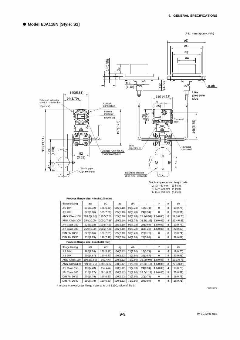
IM 1C22H1-01E9-9
9. GENERAL SPECIFICATIONS
d Model EJA118N [Style: S2]
ø30(1.18) 12
0(4
.72)
X2
14(0
.55)
t f
Lowpressureside
n-øh
øD
øA
øg
øC33
3(13
.11)
140(5.51)
94(3.70)
197(
7.76
)
92(3.62)
124
(4.8
8)47
(1.8
5)
146(
5.75
)
9(0.35)
110 (4.33)
ø78
(3.0
7)
External indicatorconduit connection
(Optional)
2-inch pipe(O.D. 60.5mm)
Internal indicator
(Optional)
Conduitconnection
Clamps (Only for JIS Flameproof type)
Zeroadjustment Ground
terminal
Mounting bracket(Flat-type, Optional)
Terminalside
* In case where process flange material is JIS S25C, value of f is 0.
Flange Rating
JIS 10K
JIS 20K
ANSI Class 150
ANSI Class 300
JPI Class 150
JPI Class 300
DIN PN 10/16
DIN PN 25/40
øD
210(8.72)
225(8.86)
228.6(9.00)
254(10.00)
229(9.02)
254(10.00)
220(8.66)
235(9.25)
t
18(0.71)
24(0.94)
23.9(0.94)
31.8(1.25)
24(0.94)
32(1.26)
20(0.79)
24(0.94)
øC
175(6.89)
185(7.28)
190.5(7.50)
200.2(7.88)
190.5(7.50)
200.2(7.88)
180(7.09)
190(7.48)
n
8
8
8
8
8
8
8
8
øh
19(0.75)
23(0.91)
19.1(0.75)
22.4(0.88)
19(0.75)
22(0.87)
18(0.71)
22(0.87)
øg
155(6.10)
155(6.10)
155(6.10)
155(6.10)
155(6.10)
155(6.10)
155(6.10)
155(6.10)
øA
96(3.78)
96(3.78)
96(3.78)
96(3.78)
96(3.78)
96(3.78)
96(3.78)
96(3.78)
f *
0
0
1.6(0.06)
1.6(0.06)
1.6(0.06)
1.6(0.06)
0
0
Process flange size: 4-inch (100 mm)
Diaphramg extension length code2: X2 = 50 mm (2-inch)4: X2 = 100 mm (4-inch)6: X2 = 150 mm (6-inch)
Flange Rating
JIS 10K
JIS 20K
ANSI Class 150
ANSI Class 300
JPI Class 150
JPI Class 300
DIN PN 10/16
DIN PN 25/40
øD
185(7.28)
200(7.87)
190.5(7.50)
209.6(8.25)
190(7.48)
210(8.27)
200(7.78)
200(7.78)
t
18(0.71)
22(0.87)
23.9(0.94)
28.5(1.12)
24(0.94)
28.5(1.12)
20(0.79)
24(0.94)
øC
150(5.91)
160(6.30)
152.4(6)
168.1(6.62)
152.4(6)
168.1(6.62)
160(6.30)
160(6.30)
n
8
8
4
8
4
8
8
8
øh
19(0.75)
23(0.91)
19.1(0.75)
22.4(0.88)
19(0.75)
22(0.87)
18(0.71)
18(0.71)
øg
130(5.12)
130(5.12)
130(5.12)
130(5.12)
130(5.12)
130(5.12)
130(5.12)
130(5.12)
øA
71(2.80)
71(2.80)
71(2.80)
71(2.80)
71(2.80)
71(2.80)
71(2.80)
71(2.80)
f *
0
0
1.6(0.06)
1.6(0.06)
1.6(0.06)
1.6(0.06)
0
0
Process flange size: 3-inch (80 mm)
Unit : mm (approx.inch)
F0903.EPS
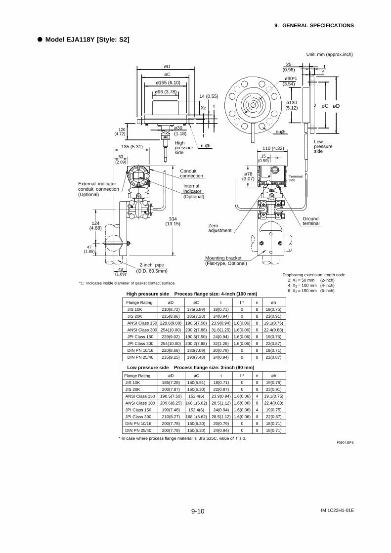
IM 1C22H1-01E9-10
9. GENERAL SPECIFICATIONS
d Model EJA118Y [Style: S2]
Highpressureside
Lowpressureside
ø78(3.07)
Zeroadjustment
Groundterminal
Terminalside
Mounting bracket(Flat-type, Optional)
48(1.89)
124(4.88)
47(1.85)
334(13.15)
135 (5.31)
53(2.09)
External indicatorconduit connection (Optional)
2-inch pipe
Internal indicator(Optional)
Conduitconnection
(O.D. 60.5mm)
15(0.59)
110 (4.33)
n-φh
t25(0.98)
øC
f
øD
ø90(3.54)
ø130(5.12)
øD
ø96 (3.78)
ø155 (6.10)
øC
ø30(1.18)
120(4.72)
tX2
14 (0.55)
f
n-φh
High pressure side Process flange size: 4-inch (100 mm)
Diaphramg extension length code2: X2 = 50 mm (2-inch)4: X2 = 100 mm (4-inch)6: X2 = 150 mm (6-inch)
Low pressure side Process flange size: 3-inch (80 mm)
* In case where process flange material is JIS S25C, value of f is 0.
Flange Rating
JIS 10K
JIS 20K
ANSI Class 150
ANSI Class 300
JPI Class 150
JPI Class 300
DIN PN 10/16
DIN PN 25/40
øD
185(7.28)
200(7.87)
190.5(7.50)
209.6(8.25)
190(7.48)
210(8.27)
200(7.78)
200(7.78)
t
18(0.71)
22(0.87)
23.9(0.94)
28.5(1.12)
24(0.94)
28.5(1.12)
20(0.79)
24(0.94)
øC
150(5.91)
160(6.30)
152.4(6)
168.1(6.62)
152.4(6)
168.1(6.62)
160(6.30)
160(6.30)
n
8
8
4
8
4
8
8
8
øh
19(0.75)
23(0.91)
19.1(0.75)
22.4(0.88)
19(0.75)
22(0.87)
18(0.71)
18(0.71)
f *
0
0
1.6(0.06)
1.6(0.06)
1.6(0.06)
1.6(0.06)
0
0
Flange Rating
JIS 10K
JIS 20K
ANSI Class 150
ANSI Class 300
JPI Class 150
JPI Class 300
DIN PN 10/16
DIN PN 25/40
øD
210(8.72)
225(8.86)
228.6(9.00)
254(10.00)
229(9.02)
254(10.00)
220(8.66)
235(9.25)
t
18(0.71)
24(0.94)
23.9(0.94)
31.8(1.25)
24(0.94)
32(1.26)
20(0.79)
24(0.94)
øC
175(6.89)
185(7.28)
190.5(7.50)
200.2(7.88)
190.5(7.50)
200.2(7.88)
180(7.09)
190(7.48)
n
8
8
8
8
8
8
8
8
øh
19(0.75)
23(0.91)
19.1(0.75)
22.4(0.88)
19(0.75)
22(0.87)
18(0.71)
22(0.87)
f *
0
0
1.6(0.06)
1.6(0.06)
1.6(0.06)
1.6(0.06)
0
0
Unit: mm (approx.inch)
F0904.EPS
*1: Indicates inside diameter of gasket contact surface.
*1
EX-A03E1
INSTALLATION AND OPERATING PRECAUTIONS FOR JIS INTRINSICALLY SAFE EQUIPMENT
INSTALLATION AND OPERATING PRECAUTIONS FORJIS INTRINSICALLY SAFE EQUIPMENT
Apparatus Certified Under Technical Criteria (IEC-compatible Standards)and from “RECOMMENDED PRACTICES for Explosion-Protected Electri-cal Installations in General Industries,” published in 1979
1. GeneralThe following describes precautions on electrical apparatusof intrinsically safe construction (hereinafter referred to asintrinsically safe apparatus).
Following the Labor Safety and Health Laws of Japan, anintrinsically safe apparatus must undergo type tests in order
to be certified by the Technical Institute of Industrial Safety,Inc. These tests are required to satisfy either the technicalcriteria for electrical machinery and equipment in compliancewith explosionproof standards involving inflammable gasesor vapors and for machinery and equipment havingexplosionproof performance (standards notification no. 556
from the Japanese Ministry of Labor) (hereinafter referred toas technical criteria), in conformity with IEC Standards, orthe “Recommended Practice for Explosion-ProtectedElectrical Installations in General Industries,” published in1979. Such a certified apparatus can be used in hazardouslocations where inflammable gases or vapors may be present.
Certified apparatus includes a certification label and anequipment nameplate with the specifications necessary forexplosion requirements as well as precautions on explosion
protection. Please confirm these precautionary items and usethem to meet specification requirements.
For electrical wiring and maintenance servicing, please refer
to “Internal Wiring Rules” in the Electrical InstallationTechnical Standards as well as “USER’S GUIDELINES forElectrical Installations for Explosive Gas Atmospheres inGeneral Industry,” published in 1994.
To meet intrinsically safe requirements, equipment that canbe termed an “intrinsically safe apparatus” must:
(1) be certified by the Technical Institute of IndustrialSafety, Inc. in accordance with the Labor Safety andHealth Laws of Japan and have the appropriate mark ofcertification labeled on its case, and
(2) be used in compliance with the specifications marked onits certification label, equipment nameplate and
precautionary information furnished.
Note: Intrinsically safe apparatus satisfy their performance underspecific conditions. They are not always absolutely safe underevery operational and environmental condition. In other
words, they are not safe products involved with factors suchas chemical reactions, geographical changes or the like otherthan affected by electric energy from the equipment itself.
2. Electrical Apparatus of IntrinsicSafety Type of Explosion-Protected Construction
The intrinsic safety type of explosion-protected constructionis a method of protection applicable to a circuit or part of acircuit in which, under prescribed test conditions, no spark orthermal effect, whether produced normally or accidentally, iscapable of causing a prescribed explosive gas to ignite. Inother words, electrical apparatus of this construction is
intended to suppress electrical energy thereby preventingignition of a given explosive gas atmosphere even thoughspark or high thermal effect occurs in the electric circuitry.
Intrinsically safe electrical apparatus generally compriseintrinsically safe apparatus installed in a hazardous locationand a safety barrier (associated apparatus), installed in a non-hazardous location, aimed at preventing electrical energyfrom flowing into the electric circuitry of intrinsically safeapparatus.
However, battery-operated, portable intrinsically safeapparatus or the like may be used alone.
3. Terminology(1) Intrinsically safe apparatus: Electrical apparatus in which
all the circuits are intrinsically safe circuits.(2) Associated apparatus: Electrical apparatus in which there
are both intrinsically safe circuits and non-intrinsicallysafe circuits that can affect the safety of intrinsically safe
circuits.(3) Safety barrier: A specific type of associated apparatus,
which consists mainly of safety barrier elements, andserves to limit the flow of excessive electrical energy,which is capable of causing ignition of a given explosivegas or vapour of a non-intrinsically safe circuit into
concerned intrinsically safe circuits.(4) Apparatus of category “ia”: Intrinsically safe electrical
apparatus and associated apparatus which are incapableof causing ignition of a given explosive gas or vapourwith the appropriate safety factors such as:
EX-A03E2
INSTALLATION AND OPERATING PRECAUTIONS FOR JIS INTRINSICALLY SAFE EQUIPMENT
— when up to two countable faults are applied and, inaddition,
— when non-countable faults produce an onerouscondition.
(5) Apparatus of category “ib”: Intrinsically safe electricalapparatus and associated apparatus which are incapableof causing ignition of a given explosive gas or vapour,with the appropriate safety factors such as:
— when up to one countable fault is applied and, inaddition,
— when non-countable faults produce an onerouscondition.
(6) Safety rating: A rating to be designated to intrinsicallysafe apparatus as well as associated apparatus and is the
maximum rating allowable for maintaining intrinsicsafety of concerned intrinsically safe circuits.
4. Caution on Combining Intrinsi-cally Safe Apparatus andSafety Barriers
(1) A combination of certified intrinsically safe apparatusand safety barriers needs to satisfy combination
requirements. If intrinsically safe apparatus specifysafety barriers for combination, safety barriers other thanspecified cannot be used (see Note 1 for more details).
(2) Certified intrinsically safe systems specify specific safetybarriers in combination with intrinsically safe apparatus.So safety barriers other than specified cannot be used
(see Note 2 for more details).(3) Other than limitations of combining intrinsically safe
apparatus and safety barriers as given in (1) and (2)above, two or more pieces of apparatus certified underdifferent standards cannot be combined with each other(see Note 3 for more details). In addition, bear in mind
that classifications of explosion protection such as “IIA,”“IIB” and “IIC” and category “ia” and “ib” limit acombination of intrinsically safe apparatus and safetybarriers.For more details, see the “Type Certificate Guide forExplosion-Protected Constructionfor Electrical
Machinery and Equipment,” issued by the JapaneseMinistry of Labour, the Research Institute of IndustrialSafety.
Note 1: Testing ApparatusIntrinsically safe apparatus and safety barriers are assessedindividually to ensure that their safety requirements aresatisfied. Tested and certified intrinsically safe apparatus andsafety barriers incorporate individual certification numbers.A combination of intrinsically safe apparatus and safetybarriers involves the following two limitations:(1) A safety barrier which meets the combination require-
ments by referring to its safety rating and combinationparameters shall be selected.
(2) For pressure transmitters, pH transmitters, temperaturedetectors and the like, safety barriers that can becombined are already specified. Other safety barrierscannot be used.
Note 2: Testing Intrinsically Safe SystemAn assembly (as a system) in which intrinsically safeapparatus and safety barriers are combined is assessed toensure that its safety requirements are satisfied. A tested andcertified system incorporates a certification number(intrinsically safe apparatus and safety barriers have the samecertification number).
Note 3: Impossible Combinations of Apparatus Certified UnderDifferent StandardsIntrinsically safe apparatus certified under technical criteriaand safety barriers certified under the “RecommendedPractice for Explosion-Protected Electrical Installations inGeneral Industries” (1979) and vice versa cannot becombined even if their combination requirements aresatisfied.
5. Installation of Intrinsically SafeApparatus and Safety Barriers
(1) Classification of installation locationIntrinsically safe apparatus may be installed, depending uponapplicable gases, in a hazardous area in Zone 0, 1 or 2 (Note4 below), where the specified gases are present. However,note that apparatus certified under Technical Criteria, in
category “ib” shall be installed only in Zone 1 or 2. Safetybarriers (associated apparatus) that are combined with theseintrinsically safe apparatus shall be installed only in a non-hazardous area. In cases where safety barriers are installed ina hazardous area, they shall be enclosed, for example, in aflameproof enclosure.
Note 4: Hazardous areas are classified in zones based upon thefrequency of the appearance and the duration of an explosivegas atmosphere as follows:Zone 0: An area in which an explosive gas atmosphere is
present continuously or is present for long periods.Zone 1: An area in which an explosive gas atmosphere is
likely to occur in normal operation.Zone 2: An area in which an explosive gas atmosphere is not
likely to occur in normal operation and if it doesoccur it will exist for a short period only.
(2) Ambient temperature limits for intrinsicallysafe apparatus
Intrinsically safe apparatus shall be installed in a locationwhere the ambient temperature ranges from –20° to +40°C(for those certified under Technical Criteria) or –10° to+40°C (for those certified under the “Recommended Practicefor Explosion-Protected Electrical Installations in General
Industries” (1979). However, some field-mounted
EX-A03E3
INSTALLATION AND OPERATING PRECAUTIONS FOR JIS INTRINSICALLY SAFE EQUIPMENT
intrinsically safe apparatus may be used at an ambienttemperature up to 60°C. So, specifications should be checked
before installing intrinsically safe apparatus.
If the intrinsically safe apparatus are exposed to directsunshine or radiant heat from plant facilities, appropriate
thermal protection measures shall be taken.
6. Wiring for Intrinsically SafeCircuits
In intrinsically safe construction, safety shall be maintainedas an intrinsically safe system involving intrinsically safeapparatus and safety barriers connected thereto, and electrical
wiring (through intrinsically safe circuits) interconnectedbetween them. In other words, even when safetyrequirements are maintained individually by intrinsically safeapparatus and safety barriers, they shall not be affected byelectrical or magnetic energy caused by electrical wiring.
To make electrical wiring for intrinsically safe circuits, youmust:
(a) refer to the equipment configuration diagram and makeelectrical wiring properly;
(b) prevent intrinsically safe wiring from being contactedwith non-intrinsically safe wiring, and separate the
intrinsically safe circuit from other electrical circuits;(c) prevent intrinsically safe wiring from being
electrostatically and magnetically affected by non-intrinsically safe wiring;
(d) reduce wiring inductance and capacitance producedbetween the intrinsically safe apparatus and safetybarrier where possible, and use a shorter cable between
the intrinsically safe apparatus and safety barrier thanspecified if the maximum permissible inductance of thecable is specified as operating conditions;
(e) conform to conditions of installation such as wiringmethod, earthing or the like, if any; and
(f) protect the outer sheath of cables from damage with
appropriate measures.
7. Maintenance and Inspection ofIntrinsically Safe Apparatusand Safety Barriers
Maintenance and inspection of intrinsically safe apparatusand safety barriers shall be limited to within the instructions
described in applicable instruction manuals. If other than thisis required, contact the manufacturers. For more information,refer to the “USER’S GUIDELINES for Electrical
Installations for Explosive Gas Atmospheres in GeneralIndustry” issued in 1994 by the Japanese Ministry of Labour,
the Research Institute of Industrial Safety.
(1) Requirements for maintenance personnelMaintenance and inspection of intrinsically safe apparatusand safety barriers shall be conducted by maintenancepersonnel skilled in intrinsically safe construction andinstallation of electrical devices as well as capable ofapplying associated rules.
(2) Maintenance and Inspection(a) Visual inspection
Visually inspect the external connections of intrinsically
safe apparatus and safety barriers, and cables for damageor corrosion as well as other mechanical and structuraldefects.
(b) AdjustmentsZero, span and sensitivity adjustments shall be madewith applicable adjusting potentiometers and mechanical
adjustment screws.These maintenance adjustments shall be made in a non-hazardous location.
CAUTION
If intrinsically safe apparatus and safety barriersrequire maintenance service and checking, agas detector shall be used to ensure that thereis no explosive gas in the location (mainte-nance servicing shall be conducted in a non-hazardous location).
(3) RepairIntrinsically safe apparatus and safety barriers shall berepaired by manufacturers.
(4) Prohibition of modifications and specifica-tion changes
Do not attempt to make modifications or change specifica-
tions which may affect safety.

EX-B03E1
INSTALLATION AND OPERATING PRECAUTIONS FOR JIS FLAMEPROOF EQUIPMENT
INSTALLATION AND OPERATING PRECAUTIONS FORJIS FLAMEPROOF EQUIPMENT
Apparatus Certified Under Technical Criteria(IEC-compatible Standards)
1. GeneralThe following describes precautions on electrical apparatusof flameproof construction (hereinafter referred to asflameproof apparatus) in explosion-protected apparatus.
Following the Labour Safety and Health Laws of Japan,flameproof apparatus is subjected to type tests to meet eitherthe technical criteria for explosionproof electrical machineryand equipment (standards notification no. 556 from theJapanese Ministry of Labour) (hereinafter referred to as
technical criteria), in conformity with the IEC Standards, orthe “Recommended Practice for Explosion-ProtectedElectrical Installations in General Industries,” published in1979. These certified apparatus can be used in hazardouslocations where explosive or inflammable gases or vapoursmay be present.
Certified apparatus includes a certification label and anequipment nameplate with the specifications necessary for
explosion requirements as well as precautions on explosionprotection. Please confirm these precautionary items and usethem to meet specification requirements.
For electrical wiring and maintenance servicing, please referto “Internal Wiring Rules” in the Electrical InstallationTechnical Standards as well as “USER’S GUIDELINES forElectrical Installations for Explosive Gas Atmospheres inGeneral Industry,” published in 1994.
To meet flameproof requirements, equipment that can betermed “flameproof” must:
(1) Be certified by a Japanese public authority in accordancewith the Labour Safety and Health Laws of Japan andhave a certification label in an appropriate location on itscase, and
(2) Be used in compliance with the specifications marked onits certification label, equipment nameplate andprecautionary information furnished.
2. Electrical Apparatus of Flame-proof Type of Explosion-Protected Construction
Electrical apparatus which is of flameproof construction issubjected to a type test and certified by the Japanese Ministryof Labour aiming at preventing explosion caused by electricalapparatus in a factory or any location where inflammablegases or vapours may be present. The flameproof
construction is of completely enclosed type and its enclosureshall endure explosive pressures in cases where explosivegases or vapours entering the enclosure cause explosion. Inaddition, the enclosure construction shall be such that flamecaused by explosion does not ignite gases or vapours outside
the enclosure.
In this manual, the word "flameproof" is applied to theflameproof equipment combined with the types of protection
"e", "o", "i", and "d" as well as flameproof equipment.
3. Terminology
(1) EnclosureAn outer shell of an electrical apparatus, which encloses liveparts and thus is needed to configure explosion-protectedconstruction.
(2) ShroudA component part which is so designed that the fastening ofjoint surfaces cannot be loosened unless a special tool is
used.
(3) Enclosure internal volumeThis is indicated by:— the total internal volume of theflameproof enclosure minus the volume of the internalcomponents essential to equipment functions.
(4) Path length of joint surfaceOn a joint surface, the length of the shortest path throughwhich flame flows from the inside to outside of theflameproof enclosure. This definition cannot be applied tothreaded joints.
(5) Gaps between joint surfacesThe physical distance between two mating surfaces, or
differences in diameters if the mating surfaces are cylindrical.
Note: The permissible sizes of gaps between joint surfaces, the pathlength of a joint surface and the number of joint threads aredetermined by such factors as the enclosure’s internalvolume, joint and mating surface construction, and theexplosion classification of the specified gases and vapours.

EX-B03E2
INSTALLATION AND OPERATING PRECAUTIONS FOR JIS FLAMEPROOF EQUIPMENT
4. Installation of FlameproofApparatus
(1) Installation AreaFlameproof apparatus may be installed, in accordance withapplicable gases, in a hazardous area in Zone 1 or 2, wherethe specified gases are present. Those apparatus shall not beinstalled in a hazardous area in Zone 0.
Note: Hazardous areas are classified in zones based upon thefrequency of the appearance and the duration of an explosivegas atmosphere as follows:Zone 0: An area in which an explosive gas atmosphere is
present continuously or is present for long periods.Zone 1: An area in which an explosive gas atmosphere is
likely to occur in normal operation.Zone 2: An area in which an explosive gas atmosphere is not
likely to occur in normal operation and if it doesoccur it will exist for a short period only.
(2) Environmental ConditionsThe standard environmental condition for the installation offlameproof apparatus is limited to an ambient temperaturerange from –20°C to +40°C (for products certified underTechnical Criteria). However, some field-mounted
instruments may be certified at an ambient temperature up to+60°C as indicated on the instrument nameplates. If theflameproof apparatus are exposed to direct sunshine orradiant heat from plant facilities, appropriate thermalprotection measures shall be taken.
5. External Wiring for FlameproofApparatus
Flameproof apparatus require cable wiring or flameproofmetal conduits for their electrical connections. For cablewiring, cable glands (cable entry devices for flameproof type)to wiring connections shall be attached. For metal conduits,attach sealing fittings as close to wiring connections aspossible and completely seal the apparatus. All non-live
metal parts such as the enclosure shall be securely grounded.For details, see the “USER’S GUIDELINES for ElectricalInstallations for Explosive Gas Atmospheres in GeneralIndustry,” published in 1994.
(1) Cable Wiring• For cable wiring, cable glands (cable entry devices for
flameproof type) specified or supplied with the apparatusshall be directly attached to the wiring connections tocomplete sealing of the apparatus.
• Screws that connect cable glands to the apparatus arethose for G-type parallel pipe threads (JIS B 0202) withno sealing property. To protect the apparatus from
corrosive gases or moisture, apply nonhardening sealantsuch as liquid gaskets to those threads for waterproofing.
• Specific cables shall be used as recommended by the“USER’S GUIDELINES for Electrical Installations for
Explosive Gas Atmospheres in General Industry,”published in 1994.
• In necessary, appropriate protective pipes (conduit orflexible pipes), ducts or trays shall be used forpreventing the cable run (outside the cable glands) fromdamage.
• To prevent explosive atmosphere from being propagatedform Zone 1 or 2 hazardous location to any differentlocation or non-hazardous location through the protectivepipe or duct, apply sealing of the protective pipes in thevicinity of individual boundaries, or fill the ducts withsand appropriately.
• When branch connections of cables, or cable connectionswith insulated cables inside the conduit pipes are made,a flameproof or increased-safety connection box shall beused. In this case, flameproof or increased-safety cableglands meeting the type of connection box must be usedfor cable connections to the box.
(2) Flameproof Metal Conduit Wiring• For the flameproof metal conduit wiring or insulated
wires shall be used as recommended by the USER’SGUIDELINES for Electrical Installations for Explosive
Gas Atmospheres in General Industry, published in1994.
• For conduit pipes, heavy-gauge steel conduitsconforming to JIS C 8305 Standard shall be used.
• Flameproof sealing fittings shall be used in the vicinityof the wiring connections, and those fittings shall be
filled with sealing compounds to complete sealing of theapparatus. In addition, to prevent explosive gases,moisture, or flame caused by explosion form beingpropagated through the conduit, always provide sealingfittings to complete sealing of the conduit in thefollowing locations:
(a) In the boundaries between the hazardous and non-hazardous locations.
(b) In the boundaries where there is a differentclassification of hazardous location.
• For the connections of the apparatus with a conduit pipeor its associated accessories, G-type parallel pipe threads
(JIS B 0202) shall be used to provide a minimum offive-thread engagement to complete tightness. Inaddition, since these parallel threads do not have sealingproperty, nonhardening sealant such as liquid gasketsshall thus be applied to those threads for ensuringwaterproofness.
• If metal conduits need flexibility, use flameproof flexiblefittings.
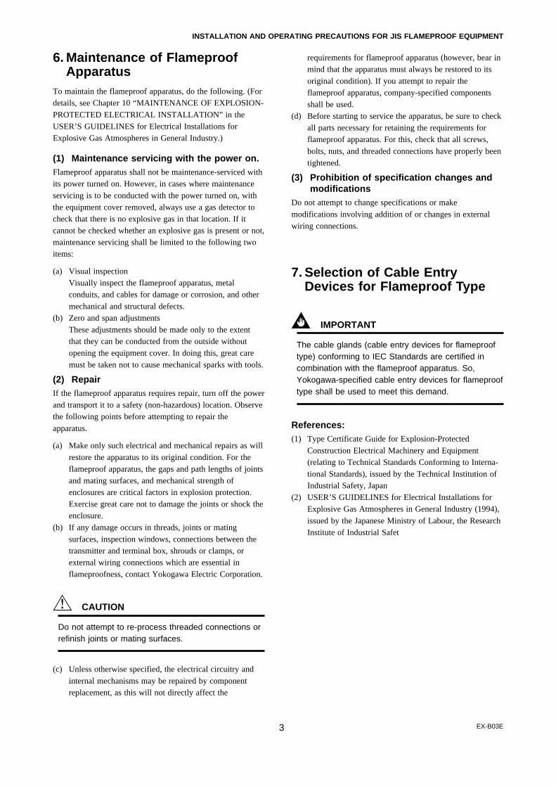
EX-B03E3
INSTALLATION AND OPERATING PRECAUTIONS FOR JIS FLAMEPROOF EQUIPMENT
6. Maintenance of FlameproofApparatus
To maintain the flameproof apparatus, do the following. (Fordetails, see Chapter 10 “MAINTENANCE OF EXPLOSION-
PROTECTED ELECTRICAL INSTALLATION” in theUSER’S GUIDELINES for Electrical Installations forExplosive Gas Atmospheres in General Industry.)
(1) Maintenance servicing with the power on.Flameproof apparatus shall not be maintenance-serviced withits power turned on. However, in cases where maintenance
servicing is to be conducted with the power turned on, withthe equipment cover removed, always use a gas detector tocheck that there is no explosive gas in that location. If itcannot be checked whether an explosive gas is present or not,maintenance servicing shall be limited to the following twoitems:
(a) Visual inspectionVisually inspect the flameproof apparatus, metalconduits, and cables for damage or corrosion, and other
mechanical and structural defects.(b) Zero and span adjustments
These adjustments should be made only to the extentthat they can be conducted from the outside withoutopening the equipment cover. In doing this, great caremust be taken not to cause mechanical sparks with tools.
(2) RepairIf the flameproof apparatus requires repair, turn off the powerand transport it to a safety (non-hazardous) location. Observethe following points before attempting to repair the
apparatus.
(a) Make only such electrical and mechanical repairs as will
restore the apparatus to its original condition. For theflameproof apparatus, the gaps and path lengths of jointsand mating surfaces, and mechanical strength ofenclosures are critical factors in explosion protection.Exercise great care not to damage the joints or shock theenclosure.
(b) If any damage occurs in threads, joints or matingsurfaces, inspection windows, connections between thetransmitter and terminal box, shrouds or clamps, orexternal wiring connections which are essential inflameproofness, contact Yokogawa Electric Corporation.
CAUTION
Do not attempt to re-process threaded connections orrefinish joints or mating surfaces.
(c) Unless otherwise specified, the electrical circuitry and
internal mechanisms may be repaired by componentreplacement, as this will not directly affect the
requirements for flameproof apparatus (however, bear inmind that the apparatus must always be restored to its
original condition). If you attempt to repair theflameproof apparatus, company-specified componentsshall be used.
(d) Before starting to service the apparatus, be sure to checkall parts necessary for retaining the requirements forflameproof apparatus. For this, check that all screws,
bolts, nuts, and threaded connections have properly beentightened.
(3) Prohibition of specification changes andmodifications
Do not attempt to change specifications or make
modifications involving addition of or changes in externalwiring connections.
7. Selection of Cable EntryDevices for Flameproof Type
IMPORTANT
The cable glands (cable entry devices for flameprooftype) conforming to IEC Standards are certified incombination with the flameproof apparatus. So,Yokogawa-specified cable entry devices for flameprooftype shall be used to meet this demand.
References:(1) Type Certificate Guide for Explosion-Protected
Construction Electrical Machinery and Equipment(relating to Technical Standards Conforming to Interna-tional Standards), issued by the Technical Institution ofIndustrial Safety, Japan
(2) USER’S GUIDELINES for Electrical Installations forExplosive Gas Atmospheres in General Industry (1994),
issued by the Japanese Ministry of Labour, the ResearchInstitute of Industrial Safet

Blank Page
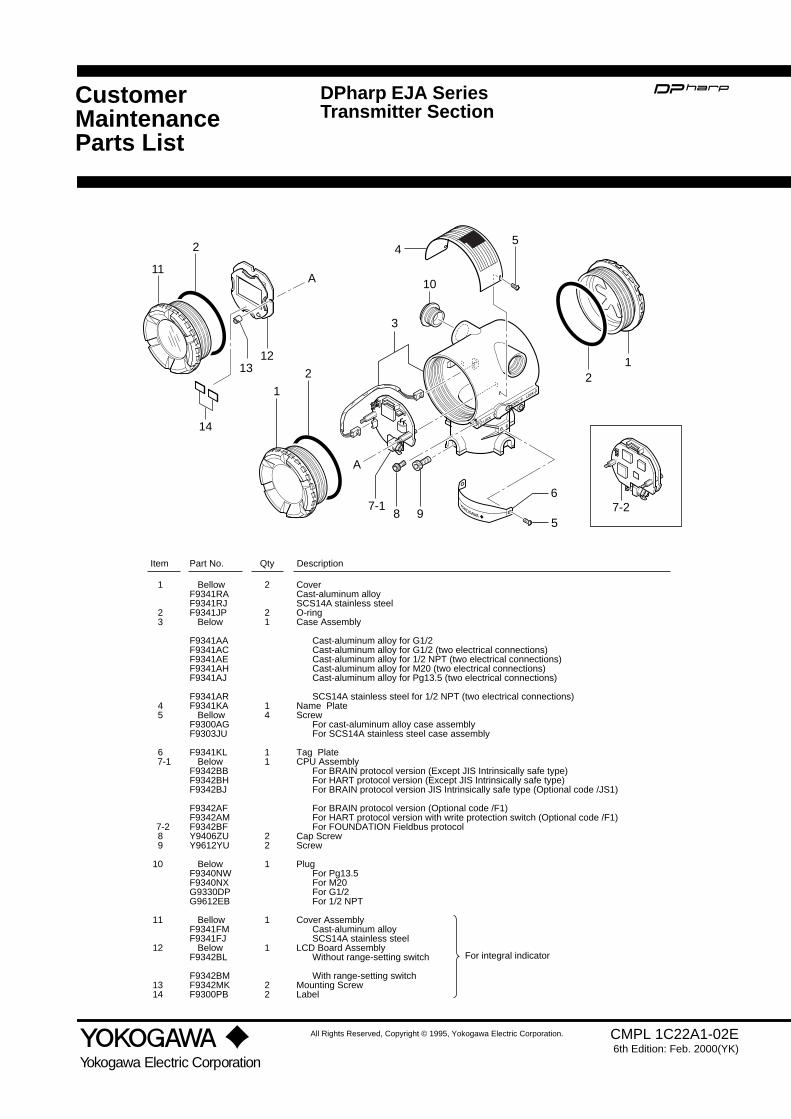
CustomerMaintenanceParts List
All Rights Reserved, Copyright © 1995, Yokogawa Electric Corporation.
Yokogawa Electric Corporation
CMPL 1C22A1-02E6th Edition: Feb. 2000(YK)
DPharp EJA SeriesTransmitter Section
1312
14
2
11A
A
4
10
3
87-1
9
6
5
2
1
5
21
7-2
CoverCast-aluminum alloySCS14A stainless steelO-ringCase Assembly
Cast-aluminum alloy for G1/2Cast-aluminum alloy for G1/2 (two electrical connections)Cast-aluminum alloy for 1/2 NPT (two electrical connections)Cast-aluminum alloy for M20 (two electrical connections)Cast-aluminum alloy for Pg13.5 (two electrical connections)
SCS14A stainless steel for 1/2 NPT (two electrical connections)Name PlateScrew
For cast-aluminum alloy case assemblyFor SCS14A stainless steel case assembly
Tag PlateCPU Assembly
For BRAIN protocol version (Except JIS Intrinsically safe type)For HART protocol version (Except JIS Intrinsically safe type) For BRAIN protocol version JIS Intrinsically safe type (Optional code /JS1)
For BRAIN protocol version (Optional code /F1) For HART protocol version with write protection switch (Optional code /F1)For FOUNDATION Fieldbus protocol
Cap ScrewScrew
PlugFor Pg13.5For M20For G1/2For 1/2 NPT
Cover AssemblyCast-aluminum alloySCS14A stainless steel
LCD Board AssemblyWithout range-setting switch
With range-setting switchMounting ScrewLabel
1
23
45
67-1
7-289
10
11
12
1314
BellowF9341RAF9341RJF9341JP
Below
F9341AAF9341ACF9341AEF9341AHF9341AJ
F9341ARF9341KA
BellowF9300AGF9303JU
F9341KLBelow
F9342BBF9342BHF9342BJ
F9342AFF9342AMF9342BFY9406ZUY9612YU
BelowF9340NWF9340NXG9330DPG9612EB
BellowF9341FMF9341FJ
BelowF9342BL
F9342BMF9342MKF9300PB
2
21
14
11
22
1
1
1
22
Item Part No. DescriptionQty
For integral indicator

2
CMPL 1C22A1-01ESubject to change without notice. Printed in Japan.
Blank Page

CustomerMaintenanceParts List
All Rights Reserved, Copyright © 1995, Yokogawa Electric Corporation.
Yokogawa Electric Corporation
CMPL 1C22H1-01E3rd Edition: Oct. 1999(YK)
Models EJA118W, EJA118N andEJA118YDiaphragm SealedDifferential Pressure Transmitter(Pressure-detector Section)
Model EJA118YModel EJA118N
Model EJA118W
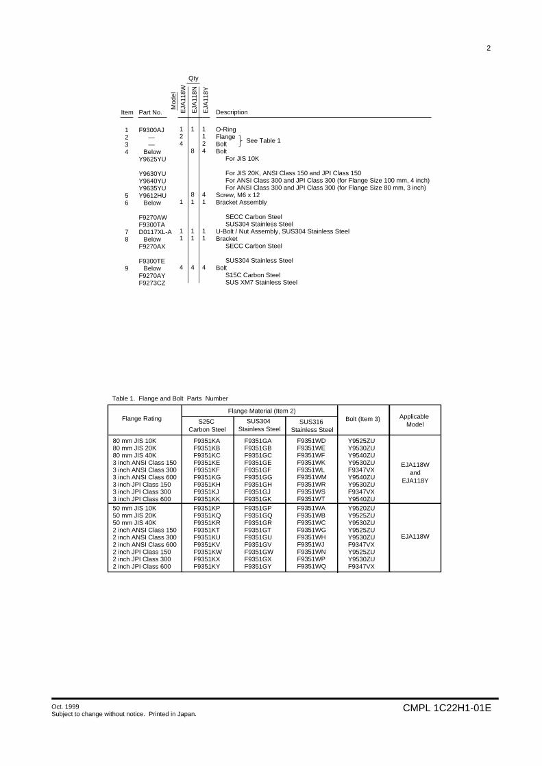
2
CMPL 1C22H1-01EOct. 1999Subject to change without notice. Printed in Japan.
1234
56
78
9
F9300AJ——
BelowY9625YU
Y9630YUY9640YUY9635YUY9612HU
Below
F9270AWF9300TAD0117XL-A
BelowF9270AX
F9300TEBelow
F9270AYF9273CZ
O-RingFlangeBoltBolt
For JIS 10K
For JIS 20K, ANSI Class 150 and JPI Class 150For ANSI Class 300 and JPI Class 300 (for Flange Size 100 mm, 4 inch)For ANSI Class 300 and JPI Class 300 (for Flange Size 80 mm, 3 inch)
Screw, M6 x 12Bracket Assembly
SECC Carbon SteelSUS304 Stainless Steel
U-Bolt / Nut Assembly, SUS304 Stainless SteelBracket
SECC Carbon Steel
SUS304 Stainless SteelBolt
S15C Carbon SteelSUS XM7 Stainless Steel
124
1
11
4
Item Part No. Description
Mod
el
Qty
1
8
81
11
4
1124
41
11
4
EJA
118W
EJA
118N
EJA
118Y
See Table 1
S25C Carbon Steel
SUS304 Stainless Steel
80 mm JIS 10K80 mm JIS 20K80 mm JIS 40K3 inch ANSI Class 1503 inch ANSI Class 3003 inch ANSI Class 6003 inch JPI Class 1503 inch JPI Class 3003 inch JPI Class 60050 mm JIS 10K50 mm JIS 20K50 mm JIS 40K2 inch ANSI Class 1502 inch ANSI Class 3002 inch ANSI Class 6002 inch JPI Class 1502 inch JPI Class 3002 inch JPI Class 600
F9351KAF9351KBF9351KCF9351KEF9351KFF9351KGF9351KHF9351KJF9351KKF9351KPF9351KQF9351KRF9351KTF9351KUF9351KVF9351KWF9351KXF9351KY
F9351GAF9351GBF9351GCF9351GEF9351GFF9351GGF9351GHF9351GJF9351GKF9351GPF9351GQF9351GRF9351GTF9351GUF9351GVF9351GWF9351GXF9351GY
Y9525ZUY9530ZUY9540ZUY9530ZUF9347VXY9540ZUY9530ZUF9347VXY9540ZUY9520ZUY9525ZUY9530ZUY9525ZUY9530ZUF9347VXY9525ZUY9530ZUF9347VX
EJA118Wand
EJA118Y
EJA118W
Table 1. Flange and Bolt Parts Number
Bolt (Item 3)Flange Material (Item 2)
Flange Rating Applicable Model
F9351WDF9351WEF9351WFF9351WKF9351WLF9351WMF9351WRF9351WSF9351WTF9351WAF9351WBF9351WCF9351WGF9351WHF9351WJF9351WNF9351WPF9351WQ
SUS316 Stainless Steel
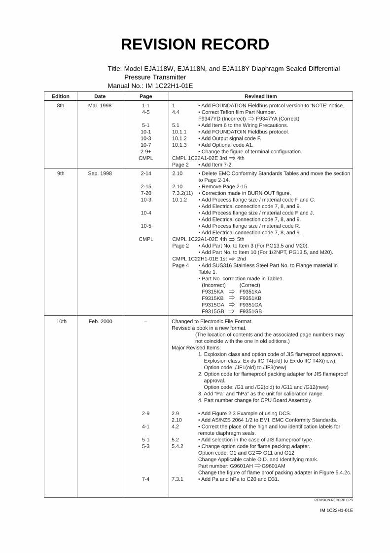
IM 1C22H1-01E
REVISION RECORDTitle: Model EJA118W, EJA118N, and EJA118Y Diaphragm Sealed Differential
Pressure TransmitterManual No.: IM 1C22H1-01E
Edition Date Page Revised Item
8th Mar. 1998 1-14-5
5-110-110-310-72-9+
CMPL
14.4
5.110.1.110.1.210.1.3
CMPL 1C22A1-02E 3rd 4thPage 2
• Add FOUNDATION Fieldbus protcol version to ‘NOTE’ notice.• Correct Teflon film Part Number.F9347YD (Incorrect) F9347YA (Correct)• Add Item 6 to the Wiring Precautions.• Add FOUNDATOIN Fieldbus protocol.• Add Output signal code F.• Add Optional code A1.• Change the figure of terminal configuration.
• Add Item 7-2.
REVISION RECORD.EPS
9th Sep. 1998 2-14
2-157-2010-3
10-4
10-5
CMPL
2.10
2.107.3.2(11)10.1.2
CMPL 1C22A1-02E 4th 5thPage 2
CMPL 1C22H1-01E 1st 2ndPage 4
• Delete EMC Conformity Standards Tables and move the section to Page 2-14.• Remove Page 2-15.• Correction made in BURN OUT figure.• Add Process flange size / material code F and C.• Add Electrical connection code 7, 8, and 9.• Add Process flange size / material code F and J.• Add Electrical connection code 7, 8, and 9.• Add Process flange size / material code R.• Add Electrical connection code 7, 8, and 9.
• Add Part No. to Item 3 (For PG13.5 and M20).• Add Part No. to Item 10 (For 1/2NPT, PG13.5, and M20).
• Add SUS316 Stainless Steel Part No. to Flange material in Table 1.• Part No. correction made in Table1.
(Incorrect) (Correct)F9315KA F9351KAF9315KB F9351KBF9315GA F9351GAF9315GB F9351GB
10th Feb. 2000 –
2-9
4-1
5-15-3
7-4
Changed to Electronic File Format.Revised a book in a new format.
(The location of contents and the associated page numbers may not coincide with the one in old editions.)
Major Revised Items:
2.92.104.2
5.25.4.2
7.3.1
1. Explosion class and option code of JIS flameproof approval.Explosion class: Ex ds IIC T4(old) to Ex do IIC T4X(new).Option code: /JF1(old) to /JF3(new)
2. Option code for flameproof packing adapter for JIS flameproof approval.Option code: /G1 and /G2(old) to /G11 and /G12(new)
3. Add “Pa” and “hPa” as the unit for calibration range.4. Part number change for CPU Board Assembly.
• Add Figure 2.3 Example of using DCS.• Add AS/NZS 2064 1/2 to EMI, EMC Conformity Standards.• Correct the place of the high and low identification labels for remote diaphragm seals.• Add selection in the case of JIS flameproof type.• Change option code for flame packing adapter.Option code: G1 and G2 G11 and G12Change Applicable cable O.D. and Identifying mark.Part number: G9601AH G9601AMChange the figure of flame proof packing adapter in Figure 5.4.2c.• Add Pa and hPa to C20 and D31.
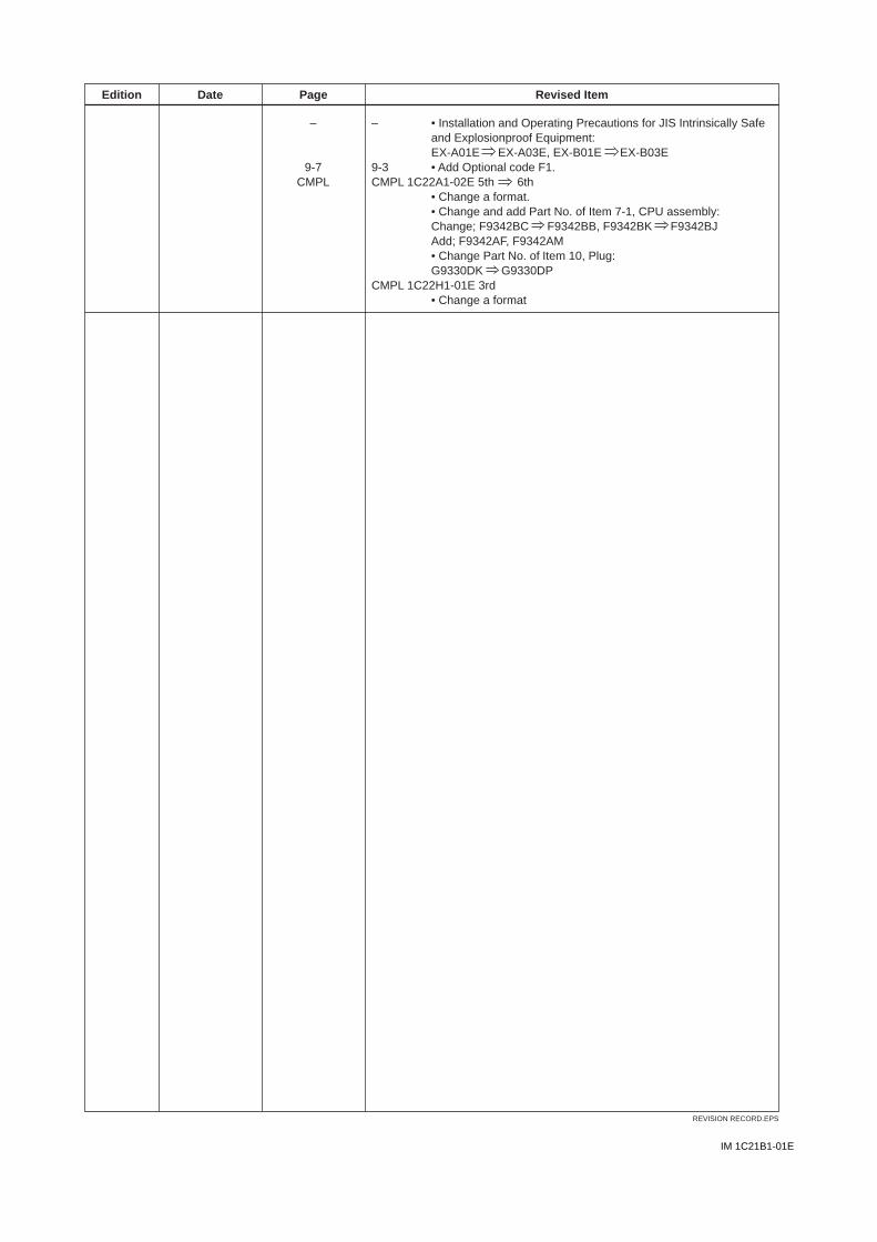
IM 1C21B1-01E
Edition Date Page Revised Item
REVISION RECORD.EPS
–
9-7CMPL
–
9-3CMPL 1C22A1-02E 5th 6th
CMPL 1C22H1-01E 3rd
• Installation and Operating Precautions for JIS Intrinsically Safe and Explosionproof Equipment:EX-A01E EX-A03E, EX-B01E EX-B03E• Add Optional code F1.
• Change a format.• Change and add Part No. of Item 7-1, CPU assembly:Change; F9342BC F9342BB, F9342BK F9342BJAdd; F9342AF, F9342AM• Change Part No. of Item 10, Plug:G9330DK G9330DP
• Change a format