Embed Size (px)
Citation preview

User’sManual
Yokogawa Electric Corporation
Model EJA510A and EJA530AAbsolute Pressure andGauge Pressure Transmitters[Style: S2]
IM 01C21F01-01E
IM 01C21F01-01E8th Edition
i
CONTENTS
IM 01C21F01-01EFD No. IM 01C21F01-01E8th Edition: Oct. 2008(KP)All Rights Reserved, Copyright © 1999, Yokogawa Electric Corporation
CONTENTS
1. INTRODUCTION............................................................................................ 1-1
Regarding This Manual ................................................................................. 1-11.1 For Safe Use of Product ........................................................................ 1-11.2 Warranty ................................................................................................ 1-21.3 ATEX Documentation ............................................................................ 1-3
2. HANDLING CAUTIONS ................................................................................ 2-1
2.1 Model and Specifications Check ......................................................... 2-12.2 Unpacking ........................................................................................... 2-12.3 Storage ................................................................................................ 2-12.4 Selecting the Installation Location ...................................................... 2-12.5 Pressure Connection ........................................................................... 2-22.6 Waterproofing of Cable Conduit Connections .................................... 2-22.7 Restrictions on Use of Radio Transceiver .......................................... 2-22.8 Insulation Resistance and Dielectric Strength Test ............................ 2-22.9 Installation of Explosion Protected Type ............................................ 2-3
2.9.1 FM Approval ................................................................................. 2-32.9.2 CSA Certification .......................................................................... 2-52.9.3 IECEx Certification ....................................................................... 2-62.9.4 CENELEC ATEX (KEMA) Certification ........................................ 2-8
2.10 EMC Conformity Standards .............................................................. 2-102.11 PED (Pressure Equipment Directive) ............................................... 2-102.12 Low Voltage Directive ....................................................................... 2-11
3. COMPONENT NAMES.................................................................................. 3-1
4. INSTALLATION ............................................................................................. 4-1
4.1 Precautions ......................................................................................... 4-14.2 Mounting .............................................................................................. 4-14.3 Rotating Transmitter Section .............................................................. 4-24.4 Changing the Direction of Integral Indicator ....................................... 4-2
5. INSTALLING IMPULSE PIPING ................................................................... 5-1
5.1 Impulse Piping Installation Precautions .............................................. 5-15.1.1 Connecting Impulse Piping to the Transmitter ............................. 5-15.1.2 Routing the Impulse Piping .......................................................... 5-1
5.2 Impulse Piping Connection Examples ................................................ 5-2
6. WIRING .......................................................................................................... 6-1
6.1 Wiring Precautions .............................................................................. 6-16.2 Selecting the Wiring Materials ............................................................ 6-16.3 Connections of External Wiring to Terminal Box ................................ 6-1
6.3.1 Power Supply Wiring Connection ................................................ 6-16.3.2 External Indicator Connection ...................................................... 6-16.3.3 BRAIN TERMINAL BT200 Connection ........................................ 6-16.3.4 Check Meter Connection.............................................................. 6-2
ii
CONTENTS
IM 01C21F01-01E
6.4 Wiring .................................................................................................. 6-26.4.1 Loop Configuration ....................................................................... 6-2
(1) General-use Type and Flameproof Type ...................................... 6-2(2) Intrinsically Safe Type ................................................................... 6-2
6.4.2 Wiring Installation ......................................................................... 6-2(1) General-use Type and Intrinsically Safe Type .............................. 6-2(2) Flameproof Type ........................................................................... 6-3
6.5 Grounding ............................................................................................ 6-36.6 Power Supply Voltage and Load Resistance ..................................... 6-3
7. OPERATION .................................................................................................. 7-1
7.1 Preparation for Starting Operation ...................................................... 7-17.2 Zero Point Adjustment ........................................................................ 7-2
7.2.1 When you can obtain Low Range Value from actualmeasured value of 0% (0 kPa, atmospheric pressure); .............. 7-2
7.2.2 When you cannot obtain Low Range Value from actualmeasured value of 0%; ................................................................ 7-3
7.3 Starting Operation ............................................................................... 7-37.4 Shutting Down Operation .................................................................... 7-37.5 Setting the Range Using the Range-setting Switch ........................... 7-4
8. BRAIN TERMINAL BT200 OPERATION ..................................................... 8-1
8.1 BT200 Operation Precautions ............................................................. 8-18.1.1 Connecting the BT200 ................................................................. 8-18.1.2 Conditions of Communication Line .............................................. 8-1
8.2 BT200 Operating Procedures ............................................................. 8-18.2.1 Key Layout and Screen Display ................................................... 8-18.2.2 Operating Key Functions.............................................................. 8-2
(1) Alphanumeric Keys and Shift Keys .............................................. 8-2(2) Function Keys ............................................................................... 8-2
8.2.3 Calling Up Menu Addresses Using the Operating Keys.............. 8-38.3 Setting Parameters Using the BT200 ................................................. 8-4
8.3.1 Parameter Summary .................................................................... 8-48.3.2 Parameter Usage and Selection .................................................. 8-68.3.3 Setting Parameters ....................................................................... 8-7
(1) Tag No. Setup ............................................................................... 8-7(2) Calibration Range Setup .............................................................. 8-7(3) Damping Time Constant Setup..................................................... 8-8(4) Output Signal Low Cut Mode Setup ............................................. 8-9(5) Change Output Limits ................................................................... 8-9(6) Integral Indicator Scale Setup .................................................... 8-10(7) Unit Setup for Displayed Temperature ........................................ 8-11(8) Operation Mode Setup ............................................................... 8-12(9) Output Status Display/Setup when a CPU Failure ..................... 8-12(10)Output Status Setup when a Hardware Error Occurs................. 8-12(11)Range Change while Applying Actual Inputs .............................. 8-12(12)Zero Point Adjustment ................................................................ 8-13(13)Span Adjustment ........................................................................ 8-14(14)Test Output Setup ....................................................................... 8-15(15)User Memo Fields ...................................................................... 8-15
8.4 Displaying Data Using the BT200 ..................................................... 8-168.4.1 Displaying Measured Data ......................................................... 8-168.4.2 Display Transmitter Model and Specifications ........................... 8-16
iii
CONTENTS
IM 01C21F01-01E
8.5 Self-Diagnostics ................................................................................ 8-168.5.1 Checking for Problems ............................................................... 8-16
(1) Identifying Problems with BT200 ................................................ 8-16(2) Checking with Integral Indicator ................................................. 8-17
8.5.2 Errors and Countermeasures ..................................................... 8-18
9. MAINTENANCE............................................................................................. 9-1
9.1 Overview ............................................................................................. 9-19.2 Calibration Instruments Selection ....................................................... 9-19.3 Calibration ........................................................................................... 9-19.4 Disassembly and Reassembly ............................................................ 9-3
9.4.1 Replacing the Integral Indicator ................................................... 9-39.4.2 Replacing the CPU Board Assembly ........................................... 9-49.4.3 Cleaning and Replacing the Capsule Assembly .......................... 9-5
9.5 Troubleshooting ................................................................................... 9-69.5.1 Basic Troubleshooting .................................................................. 9-69.5.2 Troubleshooting Flow Charts ....................................................... 9-6
10. GENERAL SPECIFICATIONS .................................................................... 10-1
10.1 Standard Specifications .................................................................... 10-110.2 Model and Suffix Codes .................................................................... 10-310.3 Optional Specifications ...................................................................... 10-410.4 Dimensions ........................................................................................ 10-7
Customer Maintenance Parts List
Model EJA510A and EJA530A Absolute and GaugePressure Transmitter ....................................................... CMPL 01C21F01-01E
REVISION RECORD

1-1
1. INTRODUCTION
IM 01C21F01-01E
1. INTRODUCTIONThank you for purchasing the DPharp electronicpressure transmitter.
The DPharp Pressure Transmitters are preciselycalibrated at the factory before shipment. To ensurecorrect and efficient use of the instrument, please readthis manual thoroughly and fully understand how tooperate the instrument before operating it.
Regarding This Manual• This manual should be passed on to the end user.
• The contents of this manual are subject to changewithout prior notice.
• All rights reserved. No part of this manual may bereproduced in any form without Yokogawa’s writtenpermission.
• Yokogawa makes no warranty of any kind withregard to this manual, including, but not limited to,implied warranty of merchantability and fitness for aparticular purpose.
• If any question arises or errors are found, or if anyinformation is missing from this manual, pleaseinform the nearest Yokogawa sales office.
• The specifications covered by this manual arelimited to those for the standard type under thespecified model number break-down and do notcover custom-made instruments.
• Please note that changes in the specifications,construction, or component parts of the instrumentmay not immediately be reflected in this manual atthe time of change, provided that postponement ofrevisions will not cause difficulty to the user from afunctional or performance standpoint.
• Yokogawa assumes no responsibilities for thisproduct except as stated in the warranty.
• If the customer or any third party is harmed by theuse of this product, Yokogawa assumes no responsi-bility for any such harm owing to any defects in theproduct which were not predictable, or for anyindirect damages.
NOTE
For FOUNDATION FieldbusTM, PROFIBUS PA andHART protocol versions, please refer to IM01C22T02-01E, IM 01C22T03-00E and IM01C22T01-01E respectively, in addition to thismanual.
• The following safety symbol marks are used in thismanual:
WARNING
Indicates a potentially hazardous situation which,if not avoided, could result in death or seriousinjury.
CAUTION
Indicates a potentially hazardous situation which,if not avoided, may result in minor or moderateinjury. It may also be used to alert againstunsafe practices.
IMPORTANT
Indicates that operating the hardware or softwarein this manner may damage it or lead to systemfailure.
NOTE
Draws attention to information essential forunderstanding the operation and features.
Direct current
1.1 For Safe Use of ProductFor the protection and safety of the operator and theinstrument or the system including the instrument,please be sure to follow the instructions on safetydescribed in this manual when handling this instru-ment. In case the instrument is handled in contradictionto these instructions, Yokogawa does not guaranteesafety. Please give your attention to the followings.
(a) Installation• The instrument must be installed by an expert
engineer or a skilled personnel. The proceduresdescribed about INSTALLATION are not permittedfor operators.
1-2
1. INTRODUCTION
IM 01C21F01-01E
• In case of high process temperature, care should betaken not to burn yourself because the surface ofbody and case reaches a high temperature.
• The instrument installed in the process is underpressure. Never loosen the process connector bolts toavoid the dangerous spouting of process fluid.
• During draining condensate from the pressure-detector section, take appropriate care to avoidcontact with the skin, eyes or body, or inhalation ofvapors, if the accumulated process fluid may betoxic or otherwise harmful.
• When removing the instrument from hazardousprocesses, avoid contact with the fluid and theinterior of the meter.
• All installation shall comply with local installationrequirement and local electrical code.
(b) Wiring• The instrument must be installed by an expert
engineer or a skilled personnel. The proceduresdescribed about WIRING are not permitted foroperators.
• Please confirm that voltages between the powersupply and the instrument before connecting thepower cables and that the cables are not poweredbefore connecting.
(c) Operation• Wait 10 min. after power is turned off, before
opening the covers.
(d) Maintenance• Please do not carry out except being written to a
maintenance descriptions. When these proceduresare needed, please contact nearest YOKOGAWAoffice.
• Care should be taken to prevent the build up of drift,dust or other material on the display glass andname plate. In case of its maintenance, soft and drycloth is used.
(e) Explosion Protected Type Instrument• Users of explosion proof instruments should refer
first to section 2.9 (Installation of an ExplosionProtected Instrument) of this manual.
• The use of this instrument is restricted to those whohave received appropriate training in the device.
• Take care not to create sparks when accessing theinstrument or peripheral devices in a hazardouslocation.
(f) Modification• Yokogawa will not be liable for malfunctions or
damage resulting from any modification made to thisinstrument by the customer.
1.2 Warranty• The warranty shall cover the period noted on the
quotation presented to the purchaser at the time ofpurchase. Problems occurred during the warrantyperiod shall basically be repaired free of charge.
• In case of problems, the customer should contact theYokogawa representative from which the instrumentwas purchased, or the nearest Yokogawa office.
• If a problem arises with this instrument, pleaseinform us of the nature of the problem and thecircumstances under which it developed, includingthe model specification and serial number. Anydiagrams, data and other information you caninclude in your communication will also be helpful.
• Responsible party for repair cost for the problemsshall be determined by Yokogawa based on ourinvestigation.
• The Purchaser shall bear the responsibility for repaircosts, even during the warranty period, if themalfunction is due to:
- Improper and/or inadequate maintenance by thepurchaser.
- Failure or damage due to improper handling, use orstorage which is out of design conditions.
- Use of the product in question in a location notconforming to the standards specified byYokogawa, or due to improper maintenance of theinstallation location.
- Failure or damage due to modification or repair byany party except Yokogawa or an approvedrepresentative of Yokogawa.
- Malfunction or damage from improper relocationof the product in question after delivery.
- Reason of force majeure such as fires, earthquakes,storms/floods, thunder/lightening, or other naturaldisasters, or disturbances, riots, warfare, orradioactive contamination.
1-3
1. INTRODUCTION
IM 01C21F01-01E
1.3 ATEX DocumentationThis procedure is only applicable to the countries inEuropean Union.
GB
All instruction manuals for ATEX Ex related productsare available in English, German and French. Shouldyou require Ex related instructions in your locallanguage, you are to contact your nearest Yokogawaoffice or representative.
DK
Alle brugervejledninger for produkter relateret tilATEX Ex er tilgængelige på engelsk, tysk og fransk.Skulle De ønske yderligere oplysninger om håndteringaf Ex produkter på eget sprog, kan De rettehenvendelse herom til den nærmeste Yokogawaafdeling eller forhandler.
I
Tutti i manuali operativi di prodotti ATEXcontrassegnati con Ex sono disponibili in inglese,tedesco e francese. Se si desidera ricevere i manualioperativi di prodotti Ex in lingua locale, mettersi incontatto con l’ufficio Yokogawa più vicino o con unrappresentante.
E
Todos los manuales de instrucciones para los productosantiexplosivos de ATEX están disponibles en inglés,alemán y francés. Si desea solicitar las instrucciones deestos artículos antiexplosivos en su idioma local,deberá ponerse en contacto con la oficina o elrepresentante de Yokogawa más cercano.
NL
Alle handleidingen voor producten die te makenhebben met ATEX explosiebeveiliging (Ex) zijnverkrijgbaar in het Engels, Duits en Frans. Neem,indien u aanwijzingen op het gebied vanexplosiebeveiliging nodig hebt in uw eigen taal, contactop met de dichtstbijzijnde vestiging van Yokogawa ofmet een vertegenwoordiger.
SF
Kaikkien ATEX Ex -tyyppisten tuotteiden käyttöhjeetovat saatavilla englannin-, saksan- ja ranskankielisinä.Mikäli tarvitsette Ex -tyyppisten tuotteiden ohjeitaomalla paikallisella kielellännne, ottakaa yhteyttälähimpään Yokogawa-toimistoon tai -edustajaan.
P
Todos os manuais de instruções referentes aos produtosEx da ATEX estão disponíveis em Inglês, Alemão eFrancês. Se necessitar de instruções na sua línguarelacionadas com produtos Ex, deverá entrar emcontacto com a delegação mais próxima ou com umrepresentante da Yokogawa.
F
Tous les manuels d’instruction des produits ATEX Exsont disponibles en langue anglaise, allemande etfrançaise. Si vous nécessitez des instructions relativesaux produits Ex dans votre langue, veuillez biencontacter votre représentant Yokogawa le plus proche.
D
Alle Betriebsanleitungen für ATEX Ex bezogeneProdukte stehen in den Sprachen Englisch, Deutschund Französisch zur Verfügung. Sollten Sie dieBetriebsanleitungen für Ex-Produkte in IhrerLandessprache benötigen, setzen Sie sich bitte mitIhrem örtlichen Yokogawa-Vertreter in Verbindung.
S
Alla instruktionsböcker för ATEX Ex (explosionssäkra)produkter är tillgängliga på engelska, tyska ochfranska. Om Ni behöver instruktioner för dessaexplosionssäkra produkter på annat språk, skall Nikontakta närmaste Yokogawakontor eller representant.
GR
ATEX Ex , . Ex
Yokogawa .
1-4
1. INTRODUCTION
IM 01C21F01-01E
LT
LV
PL
EST
SLO
H
BG
RO
M
CZ
SK
IM 01C21F01-01E2-1
2. HANDLING CAUTIONS
2. HANDLING CAUTIONS
This chapter describes important cautions regardinghow to handle the transmitter. Read carefully beforeusing the transmitter.
The EJA-A Series pressure transmitters are thoroughlytested at the factory before shipment. When thetransmitter is delivered, visually check them to makesure that no damage occurred during shipment.
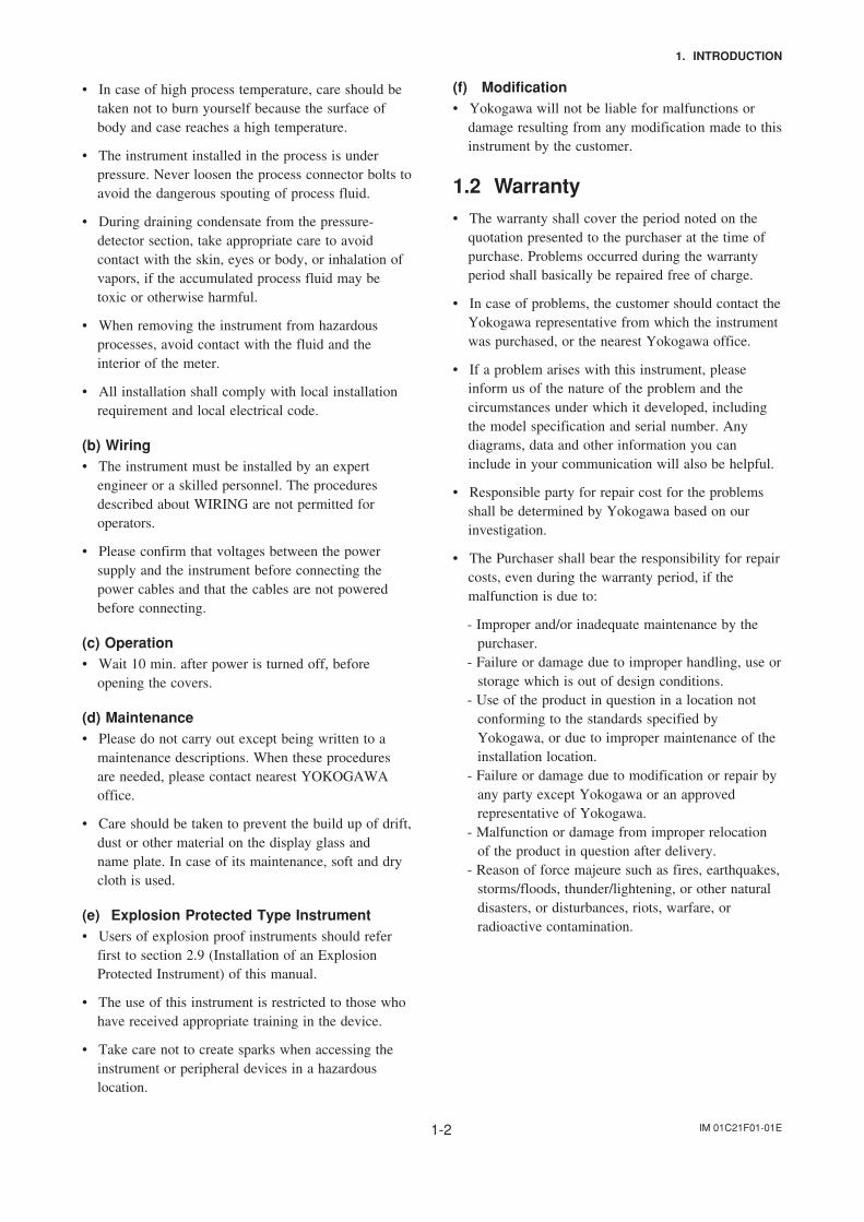
Also check that all transmitter mounting hardwareshown in Figure 2.1.1 is included. If the transmitterwas ordered without the mounting bracket, the trans-mitter mounting hardware is not included. Afterchecking the transmitter, repack it in the way it wasdelivered until installation.
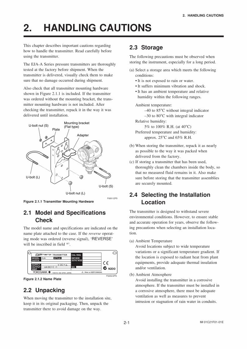
U-bolt nut (S)Plate
U-bolt nut (L)
U-bolt (L)
Mounting bracket(Flat type)
F0201.EPS
Adapter
U-bolt (S)
Figure 2.1.1 Transmitter Mounting Hardware
2.1 Model and SpecificationsCheck
The model name and specifications are indicated on thename plate attached to the case. If the reverse operat-ing mode was ordered (reverse signal), ‘REVERSE’will be inscribed in field *1.
F0202.EPS
: Refer to USER'S MANUAL
Figure 2.1.2 Name Plate
2.2 UnpackingWhen moving the transmitter to the installation site,keep it in its original packaging. Then, unpack thetransmitter there to avoid damage on the way.
2.3 StorageThe following precautions must be observed whenstoring the instrument, especially for a long period.
(a) Select a storage area which meets the followingconditions:• It is not exposed to rain or water.• It suffers minimum vibration and shock.• It has an ambient temperature and relative
humidity within the following ranges.
Ambient temperature:–40 to 85°C without integral indicator–30 to 80°C with integral indicator
Relative humidity:5% to 100% R.H. (at 40°C)
Preferred temperature and humidity:approx. 25°C and 65% R.H.
(b) When storing the transmitter, repack it as nearlyas possible to the way it was packed whendelivered from the factory.
(c) If storing a transmitter that has been used,thoroughly clean the chambers inside the body, sothat no measured fluid remains in it. Also makesure before storing that the transmitter assembliesare securely mounted.
2.4 Selecting the InstallationLocation
The transmitter is designed to withstand severeenvironmental conditions. However, to ensure stableand accurate operation for years, observe the follow-ing precautions when selecting an installation loca-tion.
(a) Ambient TemperatureAvoid locations subject to wide temperaturevariations or a significant temperature gradient. Ifthe location is exposed to radiant heat from plantequipments, provide adequate thermal insulationand/or ventilation.
(b) Ambient AtmosphereAvoid installing the transmitter in a corrosiveatmosphere. If the transmitter must be installed ina corrosive atmosphere, there must be adequateventilation as well as measures to preventintrusion or stagnation of rain water in conduits.
IM 01C21F01-01E2-2
2. HANDLING CAUTIONS
(c) Shock and VibrationSelect an installation site suffering minimum shockand vibration (although the transmitter is designedto be relatively resistant to shock and vibration).
(d) Installation of Explosion-protected TransmittersExplosion-protected transmitters can be installed inhazardous areas according to the types of gases forwhich they are certified. See Subsection 2.9“Installation of Explosion Protected Type Transmit-ters.”
2.5 Pressure Connection
WARNING
• Instrument installed in the process is underpressure. Never loosen the process connectionpart to avoid the dangerous spouting of processfluid.
• During draining condensate from the capsuleassembly, take appropriate care to avoidcontact with the skin, eyes or body, or inhala-tion of vapors, if the accumulated process fluidmay be toxic or otherwise harmful.
The following precautions must be observed in order tosafely operate the transmitter under pressure.
(a) Make sure that the process connection part istightened firmly.
(b) Make sure that there are no leaks in the impulsepiping.
(c) Never apply a pressure higher than the specifiedmaximum working pressure.
2.6 Waterproofing of CableConduit Connections
Apply a non-hardening sealant to the threads towaterproof the transmitter cable conduit connections.(See Figure 6.4.2a, 6.4.2b and 6.4.2c.)
2.7 Restrictions on Use of RadioTransceiver
IMPORTANT
Although the transmitter has been designed toresist high frequency electrical noise, if a radiotransceiver is used near the transmitter or itsexternal wiring, the transmitter may be affected
by high frequency noise pickup. To test for sucheffects, bring the transceiver in use slowly from adistance of several meters from the transmitter,and observe the measurement loop for noiseeffects. Thereafter, always use the transceiveroutside the area affected by noise.
2.8 Insulation Resistance andDielectric Strength Test
Since the transmitter has undergone insulation resis-tance and dielectric strength tests at the factory beforeshipment, normally these tests are not required.However, if required, observe the following precau-tions in the test procedures.
(a) Do not perform such tests more frequently than isabsolutely necessary. Even test voltages that do notcause visible damage to the insulation may degradethe insulation and reduce safety margins.
(b) Never apply a voltage exceeding 500 V DC (100 VDC with an internal lightning protector) for theinsulation resistance test, nor a voltage exceeding500 V AC (100 V AC with an internal lightningprotector) for the dielectric strength test.
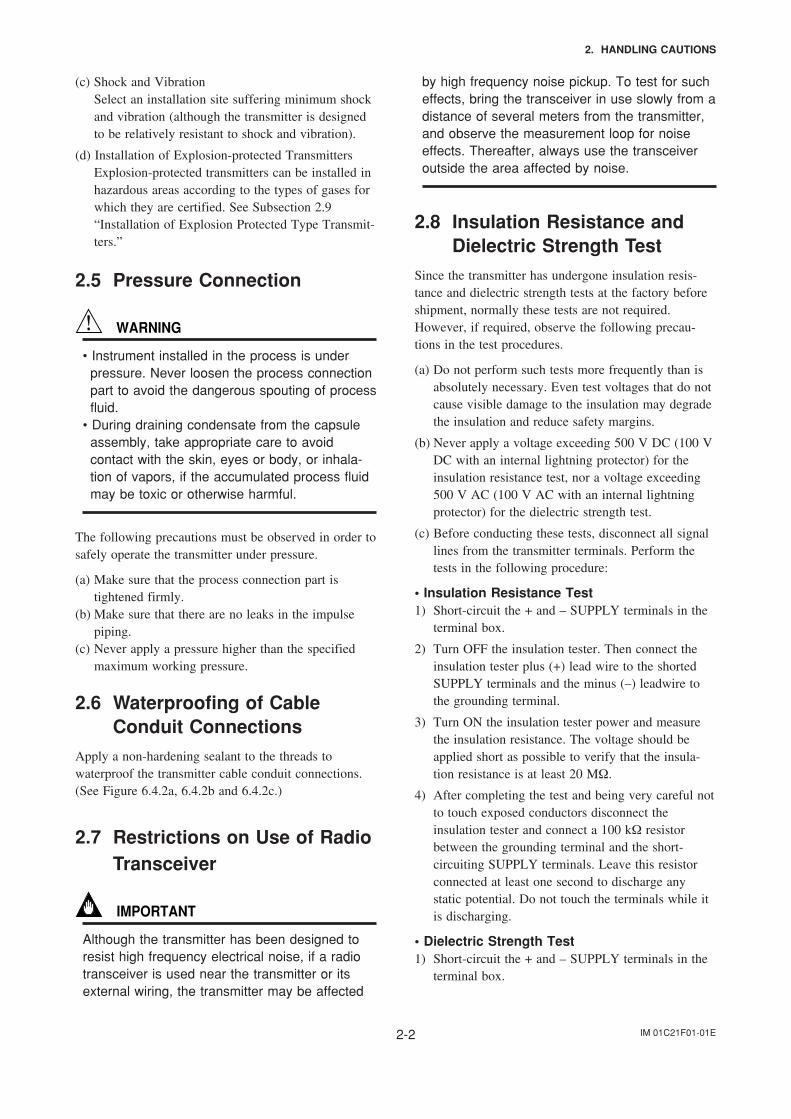
(c) Before conducting these tests, disconnect all signallines from the transmitter terminals. Perform thetests in the following procedure:
• Insulation Resistance Test1) Short-circuit the + and – SUPPLY terminals in the
terminal box.
2) Turn OFF the insulation tester. Then connect theinsulation tester plus (+) lead wire to the shortedSUPPLY terminals and the minus (–) leadwire tothe grounding terminal.
3) Turn ON the insulation tester power and measurethe insulation resistance. The voltage should beapplied short as possible to verify that the insula-tion resistance is at least 20 MΩ.
4) After completing the test and being very careful notto touch exposed conductors disconnect theinsulation tester and connect a 100 kΩ resistorbetween the grounding terminal and the short-circuiting SUPPLY terminals. Leave this resistorconnected at least one second to discharge anystatic potential. Do not touch the terminals while itis discharging.
• Dielectric Strength Test1) Short-circuit the + and – SUPPLY terminals in the
terminal box.
IM 01C21F01-01E2-3
2. HANDLING CAUTIONS
2) Turn OFF the dielectric strength tester. Thenconnect the tester between the shorted SUPPLYterminals and the grounding terminal. Be sure toconnect the grounding lead of the dielectric strengthtester to the ground terminal.
3) Set the current limit on the dielectric strength testerto 10 mA, then turn ON the power and graduallyincrease the test voltage from ‘0’ to the specifiedvoltage.
4) When the specified voltage is reached, hold it forone minute.
5) After completing this test, slowly decrease thevoltage to avoid any voltage surges.
2.9 Installation of ExplosionProtected Type
In this section, further requirements and differencesand for explosionproof type instrument are described.For explosionproof type instrument, the description inthis chapter is prior to other description in this usersmanual.
For the intrinsically safe equipment and explosionproofequipment, in case the instrument is not restored to itsoriginal condition after any repair or modificationundertaken by the customer, intrinsically safeconstruction or explosionproof construction is damagedand may cause dangerous condition. Please contactYokogawa for any repair or modification required tothe instrument.
NOTE
For FOUNDATION Fieldbus and PROFIBUS PAexplosion protected type, please refer to IM01C22T02-01E and IM 01C22T03-00E respec-tively.
CAUTION
This instrument is tested and certified as intrinsi-cally safe type or explosionproof type. Pleasenote that the construction of the instrument,installation, external wiring, maintenance orrepair is strictly restricted, and non-observanceor negligence of this restriction would result indangerous condition.
WARNING
To preserve the safety of explosionproof equip-ment requires great care during mounting,wiring, and piping. Safety requirements alsoplace restrictions on maintenance and repairactivities. Please read the following sections verycarefully.
2.9.1 FM Approval
a. FM Intrinsically Safe TypeCaution for FM intrinsically safe type. (Followingcontents refer “DOC. No. IFM012-A12 P.1 and 2.”)
Note 1. Model EJA Series pressure transmitterswith optional code /FS1 are applicable foruse in hazardous locations.
• Applicable Standard: FM3600, FM3610, FM3611,FM3810, ANSI/NEMA250
• Intrinsically Safe for Class I, Division 1, Groups A,B, C & D. Class II, Division 1, Groups E, F & Gand Class III, Division 1 Hazardous Locations.
• Nonincendive for Class I, Division 2, Groups A, B,C & D. Class II, Division 2, Groups E, F & G andClass III, Division 1 Hazardous Locations.
• Outdoor hazardous locations, NEMA 4X.• Temperature Class: T4• Ambient temperature: –40 to 60°C
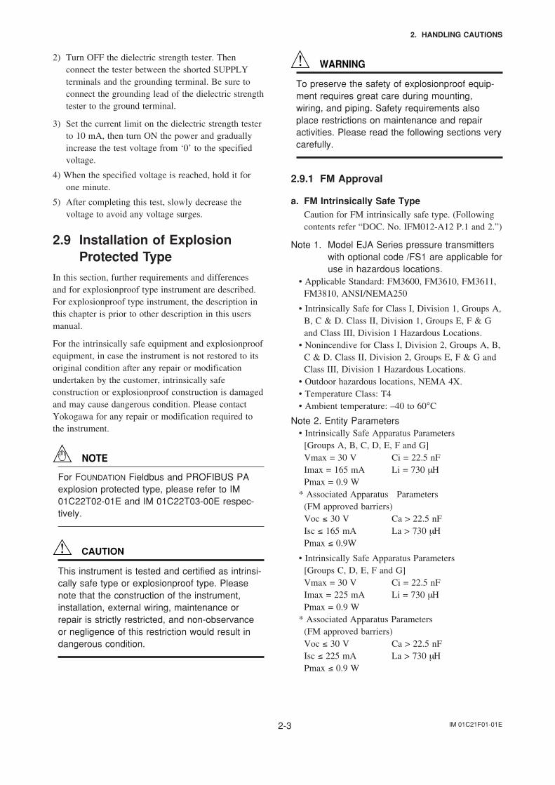
Note 2. Entity Parameters• Intrinsically Safe Apparatus Parameters
[Groups A, B, C, D, E, F and G]Vmax = 30 V Ci = 22.5 nFImax = 165 mA Li = 730 µHPmax = 0.9 W
* Associated Apparatus Parameters(FM approved barriers)Voc ≤ 30 V Ca > 22.5 nFIsc ≤ 165 mA La > 730 µHPmax ≤ 0.9W
• Intrinsically Safe Apparatus Parameters[Groups C, D, E, F and G]Vmax = 30 V Ci = 22.5 nFImax = 225 mA Li = 730 µHPmax = 0.9 W
* Associated Apparatus Parameters(FM approved barriers)Voc ≤ 30 V Ca > 22.5 nFIsc ≤ 225 mA La > 730 µHPmax ≤ 0.9 W
IM 01C21F01-01E2-4
2. HANDLING CAUTIONS
• Entity Installation RequirementsVmax ≥ Voc or Vt, Imax ≥ Isc or It,Pmax (IS Apparatus) ≥ Pmax (Barrier)Ca ≥ Ci + Ccable, La ≥ Li + Lcable
Note 3. Installation• Barrier must be installed in an enclosure that meets
the requirements of ANSI/ISA S82.01.• Control equipment connected to barrier must not use
or generate more than 250 V rms or V dc.• Installation should be in accordance with ANSI/ISA
RP12.6 “Installation of Intrinsically Safe Systems forHazardous (Classified) Locations” and the NationalElectric Code (ANSI/NFPA 70).
• The configuration of associated apparatus must beFMRC Approved.
• Dust-tight conduit seal must be used when installedin a Class II, III, Group E, F and G environments.
• Associated apparatus manufacturer’s installationdrawing must be followed when installing thisapparatus.
• The maximum power delivered from the barriermust not exceed 0.9 W.
• Note a warning label worded “SUBSTITUTION OFCOMPONENTS MAY IMPAIR INTRINSICSAFETY,” and “INSTALL IN ACCORDANCEWITH DOC. No. IFM012-A12 P.1 and 2.”
Note 4. Maintenance and Repair• The instrument modification or parts replacement by
other than authorized representative of YokogawaElectric Corporation is prohibited and will voidFactory Mutual Intrinsically safe and NonincendiveApproval.
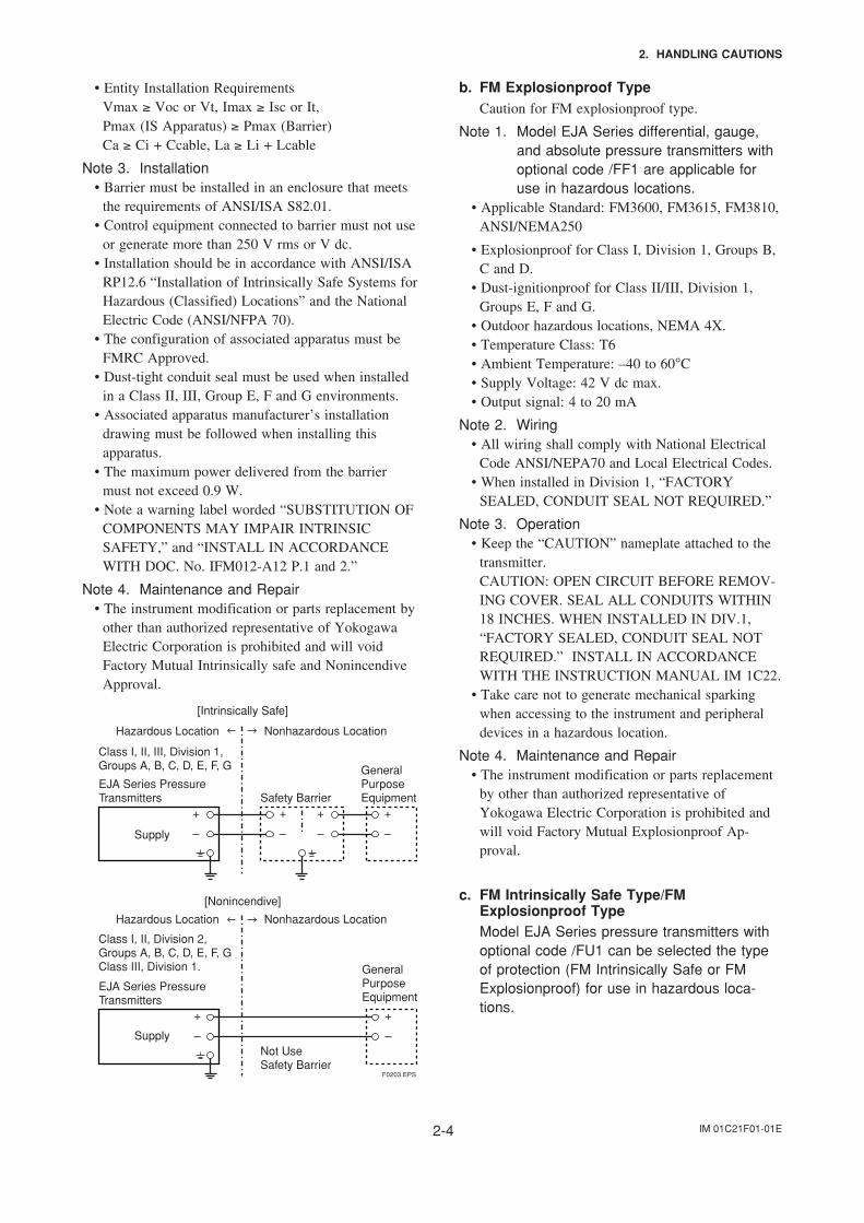
F0203.EPS
Class I, II, III, Division 1,Groups A, B, C, D, E, F, G
EJA Series Pressure Transmitters
EJA Series Pressure Transmitters
Safety Barrier
Supply
Supply
Hazardous Location Nonhazardous Location
Hazardous Location Nonhazardous Location
General PurposeEquipment
+
–
+
–
+
–
+
–
+
–
+
–
[Intrinsically Safe]
Class I, II, Division 2,Groups A, B, C, D, E, F, GClass III, Division 1.
Not UseSafety Barrier
[Nonincendive]
General PurposeEquipment
b. FM Explosionproof TypeCaution for FM explosionproof type.
Note 1. Model EJA Series differential, gauge,and absolute pressure transmitters withoptional code /FF1 are applicable foruse in hazardous locations.
• Applicable Standard: FM3600, FM3615, FM3810,ANSI/NEMA250
• Explosionproof for Class I, Division 1, Groups B,C and D.
• Dust-ignitionproof for Class II/III, Division 1,Groups E, F and G.
• Outdoor hazardous locations, NEMA 4X.• Temperature Class: T6• Ambient Temperature: –40 to 60°C• Supply Voltage: 42 V dc max.• Output signal: 4 to 20 mA
Note 2. Wiring• All wiring shall comply with National Electrical
Code ANSI/NEPA70 and Local Electrical Codes.• When installed in Division 1, “FACTORY
SEALED, CONDUIT SEAL NOT REQUIRED.”
Note 3. Operation• Keep the “CAUTION” nameplate attached to the
transmitter.CAUTION: OPEN CIRCUIT BEFORE REMOV-ING COVER. SEAL ALL CONDUITS WITHIN18 INCHES. WHEN INSTALLED IN DIV.1,“FACTORY SEALED, CONDUIT SEAL NOTREQUIRED.” INSTALL IN ACCORDANCEWITH THE INSTRUCTION MANUAL IM 1C22.
• Take care not to generate mechanical sparkingwhen accessing to the instrument and peripheraldevices in a hazardous location.
Note 4. Maintenance and Repair• The instrument modification or parts replacement
by other than authorized representative ofYokogawa Electric Corporation is prohibited andwill void Factory Mutual Explosionproof Ap-proval.
c. FM Intrinsically Safe Type/FMExplosionproof TypeModel EJA Series pressure transmitters withoptional code /FU1 can be selected the typeof protection (FM Intrinsically Safe or FMExplosionproof) for use in hazardous loca-tions.
IM 01C21F01-01E2-5
2. HANDLING CAUTIONS
Note 1. For the installation of this transmitter,once a particular type of protection isselected, any other type of protectioncannot be used. The installation must bein accordance with the description aboutthe type of protection in this instructionmanual.
Note 2. In order to avoid confusion, unnecessarymarking is crossed out on the label otherthan the selected type of protection whenthe transmitter is installed.
2.9.2 CSA Certification
a. CSA Intrinsically Safe TypeCaution for CSA Intrinsically safe type. (Followingcontents refer to “DOC No. ICS003-A12 P.1-1 andP.1-2.”)
Note 1. Model EJA Series differential, gauge, andabsolute pressure transmitters withoptional code /CS1 are applicable for usein hazardous locations
Certificate: 1053843• Applicable Standard: C22.2 No.0, No.0.4, No.25,
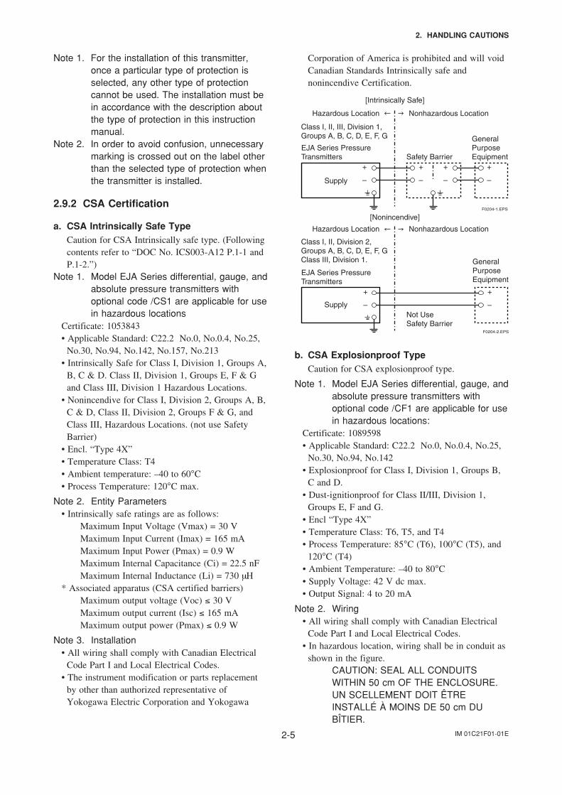
No.30, No.94, No.142, No.157, No.213• Intrinsically Safe for Class I, Division 1, Groups A,
B, C & D. Class II, Division 1, Groups E, F & Gand Class III, Division 1 Hazardous Locations.
• Nonincendive for Class I, Division 2, Groups A, B,C & D, Class II, Division 2, Groups F & G, andClass III, Hazardous Locations. (not use SafetyBarrier)
• Encl. “Type 4X”• Temperature Class: T4• Ambient temperature: –40 to 60°C• Process Temperature: 120°C max.
Note 2. Entity Parameters• Intrinsically safe ratings are as follows:
Maximum Input Voltage (Vmax) = 30 VMaximum Input Current (Imax) = 165 mAMaximum Input Power (Pmax) = 0.9 WMaximum Internal Capacitance (Ci) = 22.5 nFMaximum Internal Inductance (Li) = 730 µH
* Associated apparatus (CSA certified barriers)Maximum output voltage (Voc) ≤ 30 VMaximum output current (Isc) ≤ 165 mAMaximum output power (Pmax) ≤ 0.9 W
Note 3. Installation• All wiring shall comply with Canadian Electrical
Code Part I and Local Electrical Codes.• The instrument modification or parts replacement
by other than authorized representative ofYokogawa Electric Corporation and Yokogawa
Corporation of America is prohibited and will voidCanadian Standards Intrinsically safe andnonincendive Certification.
Class I, II, III, Division 1,Groups A, B, C, D, E, F, G
EJA Series Pressure Transmitters Safety Barrier
Supply
Hazardous Location Nonhazardous Location
General PurposeEquipment
+
–
+
–
+
–
+
–
[Intrinsically Safe]
F0204-1.EPS
F0204-2.EPS
EJA Series Pressure Transmitters
Supply
Hazardous Location Nonhazardous Location
+
–
+
–
Class I, II, Division 2,Groups A, B, C, D, E, F, GClass III, Division 1.
Not UseSafety Barrier
[Nonincendive]
General PurposeEquipment
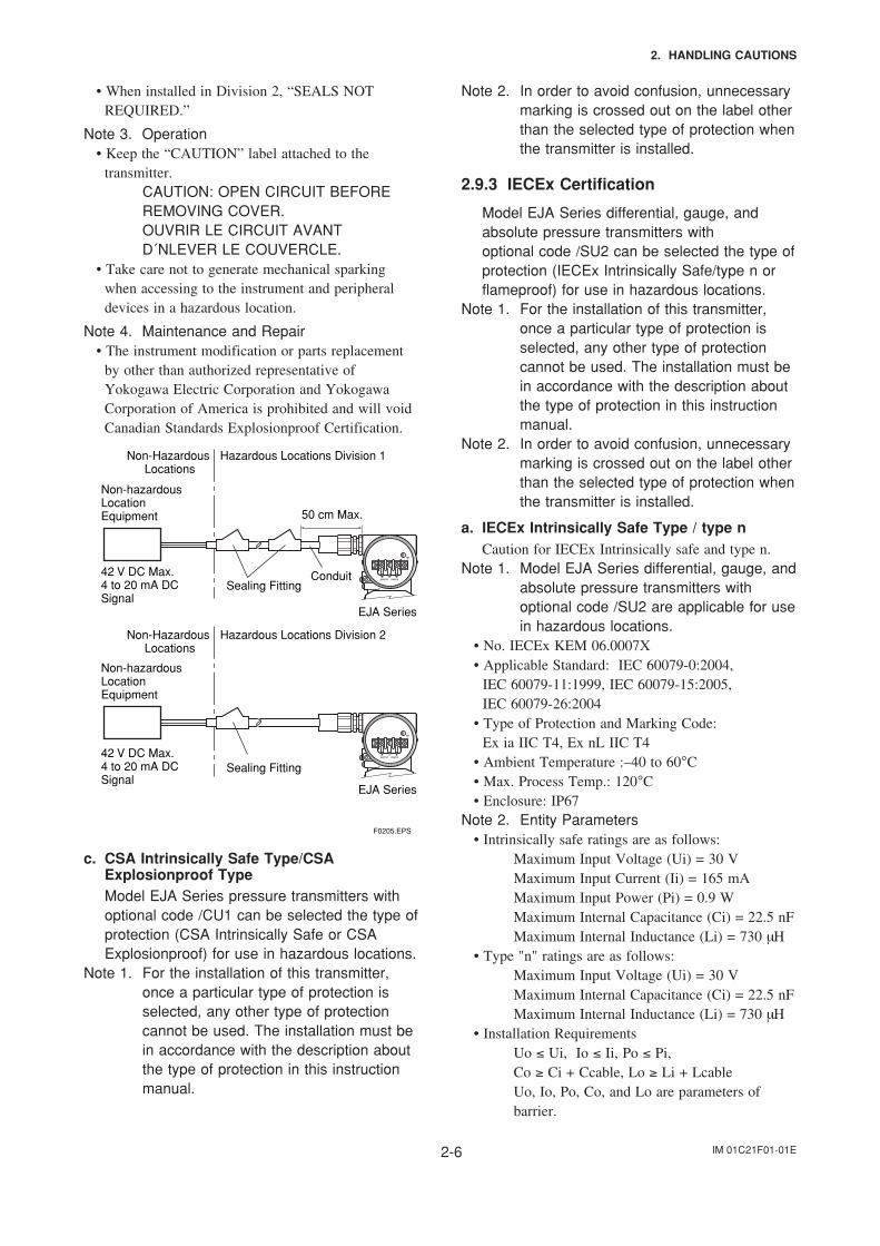
b. CSA Explosionproof TypeCaution for CSA explosionproof type.
Note 1. Model EJA Series differential, gauge, andabsolute pressure transmitters withoptional code /CF1 are applicable for usein hazardous locations:
Certificate: 1089598• Applicable Standard: C22.2 No.0, No.0.4, No.25,
No.30, No.94, No.142• Explosionproof for Class I, Division 1, Groups B,
C and D.• Dust-ignitionproof for Class II/III, Division 1,
Groups E, F and G.• Encl “Type 4X”• Temperature Class: T6, T5, and T4• Process Temperature: 85°C (T6), 100°C (T5), and
120°C (T4)• Ambient Temperature: –40 to 80°C• Supply Voltage: 42 V dc max.• Output Signal: 4 to 20 mA
Note 2. Wiring• All wiring shall comply with Canadian Electrical
Code Part I and Local Electrical Codes.• In hazardous location, wiring shall be in conduit as
shown in the figure.CAUTION: SEAL ALL CONDUITSWITHIN 50 cm OF THE ENCLOSURE.UN SCELLEMENT DOIT ÊTREINSTALLÉ À MOINS DE 50 cm DUBÎTIER.
IM 01C21F01-01E2-6
2. HANDLING CAUTIONS
• When installed in Division 2, “SEALS NOTREQUIRED.”
Note 3. Operation• Keep the “CAUTION” label attached to the
transmitter.CAUTION: OPEN CIRCUIT BEFOREREMOVING COVER.OUVRIR LE CIRCUIT AVANTD´NLEVER LE COUVERCLE.
• Take care not to generate mechanical sparkingwhen accessing to the instrument and peripheraldevices in a hazardous location.
Note 4. Maintenance and Repair• The instrument modification or parts replacement
by other than authorized representative ofYokogawa Electric Corporation and YokogawaCorporation of America is prohibited and will voidCanadian Standards Explosionproof Certification.
Non-hazardous Location Equipment
42 V DC Max. 4 to 20 mA DC Signal
Non-Hazardous Locations
Hazardous Locations Division 1
Non-Hazardous Locations
Hazardous Locations Division 2
50 cm Max.
Sealing FittingConduit
EJA Series
Non-hazardous Location Equipment
42 V DC Max. 4 to 20 mA DC Signal
Sealing Fitting
EJA Series
F0205.EPS
c. CSA Intrinsically Safe Type/CSAExplosionproof TypeModel EJA Series pressure transmitters withoptional code /CU1 can be selected the type ofprotection (CSA Intrinsically Safe or CSAExplosionproof) for use in hazardous locations.
Note 1. For the installation of this transmitter,once a particular type of protection isselected, any other type of protectioncannot be used. The installation must bein accordance with the description aboutthe type of protection in this instructionmanual.
Note 2. In order to avoid confusion, unnecessarymarking is crossed out on the label otherthan the selected type of protection whenthe transmitter is installed.
2.9.3 IECEx Certification
Model EJA Series differential, gauge, andabsolute pressure transmitters withoptional code /SU2 can be selected the type ofprotection (IECEx Intrinsically Safe/type n orflameproof) for use in hazardous locations.
Note 1. For the installation of this transmitter,once a particular type of protection isselected, any other type of protectioncannot be used. The installation must bein accordance with the description aboutthe type of protection in this instructionmanual.
Note 2. In order to avoid confusion, unnecessarymarking is crossed out on the label otherthan the selected type of protection whenthe transmitter is installed.
a. IECEx Intrinsically Safe Type / type nCaution for IECEx Intrinsically safe and type n.
Note 1. Model EJA Series differential, gauge, andabsolute pressure transmitters withoptional code /SU2 are applicable for usein hazardous locations.
• No. IECEx KEM 06.0007X• Applicable Standard: IEC 60079-0:2004, IEC 60079-11:1999, IEC 60079-15:2005, IEC 60079-26:2004• Type of Protection and Marking Code: Ex ia IIC T4, Ex nL IIC T4• Ambient Temperature :–40 to 60°C• Max. Process Temp.: 120°C• Enclosure: IP67
Note 2. Entity Parameters• Intrinsically safe ratings are as follows:
Maximum Input Voltage (Ui) = 30 VMaximum Input Current (Ii) = 165 mAMaximum Input Power (Pi) = 0.9 WMaximum Internal Capacitance (Ci) = 22.5 nFMaximum Internal Inductance (Li) = 730 µH
• Type "n" ratings are as follows:Maximum Input Voltage (Ui) = 30 VMaximum Internal Capacitance (Ci) = 22.5 nFMaximum Internal Inductance (Li) = 730 µH
• Installation RequirementsUo ≤ Ui, Io ≤ Ii, Po ≤ Pi,Co ≥ Ci + Ccable, Lo ≥ Li + LcableUo, Io, Po, Co, and Lo are parameters ofbarrier.
IM 01C21F01-01E2-7
2. HANDLING CAUTIONS
Note 3. Installation• In any safety barreir used output current must be
limited by a resistor 'R' such that Io=Uo/R.• The safety barrier must be IECEx certified.• Input voltage of the safety barrier must be less than
250 Vrms/Vdc.• The instrument modification or parts replacement
by other than authorized representative ofYokogawa Electric Corporation and will voidIECEx Intrinsically safe and type n certification.
• The cable entry devices and blanking elements fortype n shall be of a certified type providing a levelof ingress protection of at least IP54, suitable forthe conditions of use and correctly installed.
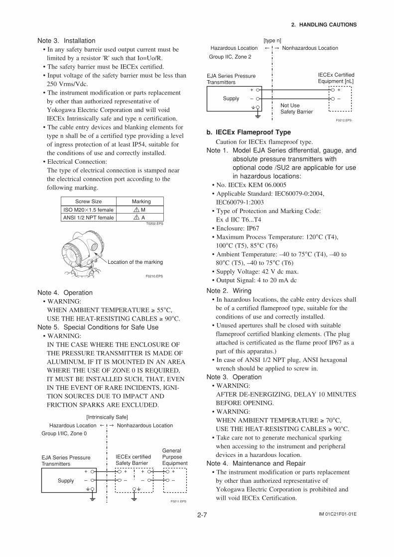
• Electrical Connection: The type of electrical connection is stamped near
the electrical connection port according to thefollowing marking.
T0202.EPS
F0210.EPS
Location of the marking
Note 4. Operation• WARNING: WHEN AMBIENT TEMPERATURE ≥ 55°C,
USE THE HEAT-RESISTING CABLES ≥ 90°C.Note 5. Special Conditions for Safe Use
• WARNING: IN THE CASE WHERE THE ENCLOSURE OF
THE PRESSURE TRANSMITTER IS MADE OFALUMINUM, IF IT IS MOUNTED IN AN AREAWHERE THE USE OF ZONE 0 IS REQUIRED,IT MUST BE INSTALLED SUCH, THAT, EVENIN THE EVENT OF RARE INCIDENTS, IGNI-TION SOURCES DUE TO IMPACT ANDFRICTION SPARKS ARE EXCLUDED.
F0211.EPS
EJA Series Pressure Transmitters
IECEx certifiedSafety Barrier
Supply
Hazardous Location Nonhazardous Location
General PurposeEquipment
+
–
+
–
+
–
+
–
[Intrinsically Safe]
Group I/IIC, Zone 0
F0212.EPS
EJA Series Pressure Transmitters
Supply
Hazardous Location Nonhazardous Location
+
–
+
– Not UseSafety Barrier
[type n]
IECEx Certified Equipment [nL]
Group IIC, Zone 2
b. IECEx Flameproof TypeCaution for IECEx flameproof type.
Note 1. Model EJA Series differential, gauge, andabsolute pressure transmitters withoptional code /SU2 are applicable for usein hazardous locations:
• No. IECEx KEM 06.0005• Applicable Standard: IEC60079-0:2004, IEC60079-1:2003• Type of Protection and Marking Code: Ex d IIC T6...T4• Enclosure: IP67• Maximum Process Temperature: 120°C (T4),
100°C (T5), 85°C (T6)• Ambient Temperature: –40 to 75°C (T4), –40 to
80°C (T5), –40 to 75°C (T6)• Supply Voltage: 42 V dc max.• Output Signal: 4 to 20 mA dc
Note 2. Wiring• In hazardous locations, the cable entry devices shall
be of a certified flameproof type, suitable for theconditions of use and correctly installed.
• Unused apertures shall be closed with suitableflameproof certified blanking elements. (The plugattached is certificated as the flame proof IP67 as apart of this apparatus.)
• In case of ANSI 1/2 NPT plug, ANSI hexagonalwrench should be applied to screw in.
Note 3. Operation• WARNING: AFTER DE-ENERGIZING, DELAY 10 MINUTES
BEFORE OPENING.• WARNING: WHEN AMBIENT TEMPERATURE ≥ 70°C,
USE THE HEAT-RESISTING CABLES ≥ 90°C.• Take care not to generate mechanical sparking
when accessing to the instrument and peripheraldevices in a hazardous location.
Note 4. Maintenance and Repair• The instrument modification or parts replacement
by other than authorized representative ofYokogawa Electric Corporation is prohibited andwill void IECEx Certification.
IM 01C21F01-01E2-8
2. HANDLING CAUTIONS
2.9.4 CENELEC ATEX (KEMA)Certification
(1) Technical Data
a. CENELEC ATEX (KEMA) Intrinsically SafeTypeCaution for CENELEC ATEX (KEMA) Intrinsi-cally safe type.
Note 1. Model EJA Series differential, gauge, andabsolute pressure transmitters withoptional code /KS2 for potentially explo-sive atmospheres:
• No. KEMA 02ATEX1030 X• Applicable Standard: EN50014:1997,
EN50020:1994, EN50284:1999• Type of Protection and Marking code:
EEx ia IIC T4• Temperature Class: T4• Enclosure: IP67• Process Temperature: 120°C max.• Ambient Temperature: –40 to 60°C
Note 2. Electrical Data• In type of explosion protection intrinsic safety EEx
ia IIC only for connection to a certified intrinsicallysafe circuit with following maximum values:
Ui = 30 VIi = 165 mAPi = 0.9 WEffective internal capacitance; Ci = 22.5 nFEffective internal inductance; Li = 730 µH
Note 3. Installation• All wiring shall comply with local installation
requirements. (Refer to the installation diagram)Note 4. Maintenance and Repair
• The instrument modification or parts replacementby other than authorized representative ofYokogawa Electric Corporation is prohibited andwill void KEMA Intrinsically safe Certification.
Note 5. Special Conditions for Safe Use• In the case where the enclosure of the Pressure
Transmitter is made of aluminium, if it is mountedin an area where the use of category 1 G apparatusis required, it must be installed such, that, even inthe event of rare incidents, ignition sources due toimpact and friction sparks are excluded.
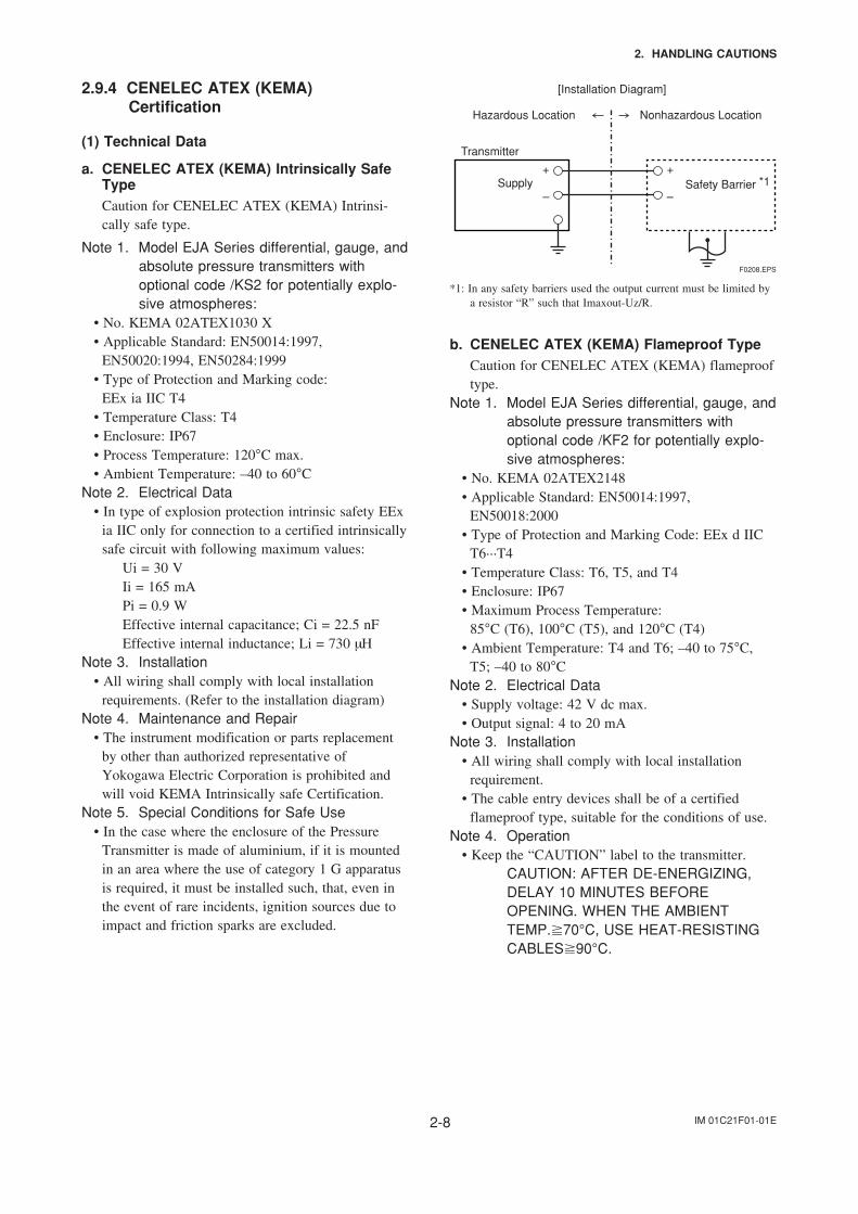
Transmitter
Supply Safety Barrier *1
Nonhazardous Location
[Installation Diagram]
Hazardous Location
+
–
+
–
F0208.EPS
*1: In any safety barriers used the output current must be limited bya resistor “R” such that Imaxout-Uz/R.
b. CENELEC ATEX (KEMA) Flameproof TypeCaution for CENELEC ATEX (KEMA) flameprooftype.
Note 1. Model EJA Series differential, gauge, andabsolute pressure transmitters withoptional code /KF2 for potentially explo-sive atmospheres:
• No. KEMA 02ATEX2148• Applicable Standard: EN50014:1997,
EN50018:2000• Type of Protection and Marking Code: EEx d IIC
T6···T4• Temperature Class: T6, T5, and T4• Enclosure: IP67• Maximum Process Temperature:
85°C (T6), 100°C (T5), and 120°C (T4)• Ambient Temperature: T4 and T6; –40 to 75°C,
T5; –40 to 80°CNote 2. Electrical Data
• Supply voltage: 42 V dc max.• Output signal: 4 to 20 mA
Note 3. Installation• All wiring shall comply with local installation
requirement.• The cable entry devices shall be of a certified
flameproof type, suitable for the conditions of use.Note 4. Operation
• Keep the “CAUTION” label to the transmitter.CAUTION: AFTER DE-ENERGIZING,DELAY 10 MINUTES BEFOREOPENING. WHEN THE AMBIENTTEMP.70°C, USE HEAT-RESISTINGCABLES90°C.
IM 01C21F01-01E2-9
2. HANDLING CAUTIONS
• Take care not to generate mechanical sparkingwhen accessing to the instrument and peripheraldevices in a hazardous location.
Note 5. Maintenance and Repair• The instrument modification or parts replacement
by other than authorized representative ofYokogawa Electric Corporation is prohibited andwill void KEMA Flameproof Certification.
c. CENELEC ATEX (KEMA) Intrinsically SafeType/CENELEC ATEX (KEMA) FlameproofType/ CENELEC ATEX Type n
Model EJA-A Series pressure transmitters withoptional code /KU2 can be selected the type ofprotection CENELEC ATEX (KEMA) IntrinsicallySafe, Flameproof or CENELEC ATEX Type nfor use in hazardous locations.
Note 1. For the installation of this transmitter,once a particular type of protection is selected,any other type of protection cannot be used.The installation must be in accordance with thedescription about the type of protection in thisuser’s manual.
Note 2. In order to avoid confusion, unnecessarymarking is crossed out on the label other thanthe selected type of protection when thetransmitter is installed.
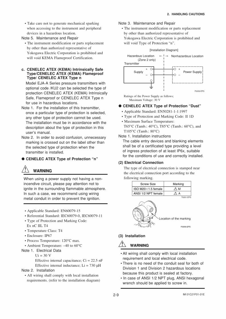
CENELEC ATEX Type of Protection “n”
WARNING
When using a power supply not having a non-incendive circuit, please pay attention not toignite in the surrounding flammable atmosphere.In such a case, we recommend using wiringmetal conduit in order to prevent the ignition.
• Applicable Standard: EN60079-15• Referential Standard: IEC60079-0, IEC60079-11• Type of Protection and Marking Code:
Ex nC IIL T4• Temperature Class: T4• Enclosure: IP67• Process Temperature: 120°C max.• Ambient Temperature: –40 to 60°C
Note 1. Electrical DataUi = 30 VEffective internal capacitance; Ci = 22.5 nFEffective internal inductance; Li = 730 µH
Note 2. Installation• All wiring shall comply with local installation
requirements. (refer to the installation diagram)
Note 3. Maintenance and Repair• The instrument modification or parts replacement
by other than authorized representative ofYokogawa Electric Corporation is prohibited andwill void Type of Protection “n”.
Power Supply
(Zone 2 only)Transmitter
Supply
Nonhazardous Location
[Installation Diagram]
Hazardous Location
+
–
+
–
F0209.EPS
Ratings of the Power Supply as follows;Maximum Voltage: 30 V
CENELEC ATEX Type of Protection “Dust”• Applicable Standard: EN50281-1-1:1997• Type of Protection and Marking Code: II 1D• Maximum Surface Temperature:
T65°C (Tamb.: 40°C), T85°C (Tamb.: 60°C), andT105°C (Tamb.: 80°C)
Note 1. Installation instructionsThe cable entry devices and blanking elementsshall be of a certificated type providing a levelof ingress protection of at least IP6x, suitablefor the conditions of use and correctly installed.
(2) Electrical ConnectionThe type of electrical connection is stamped nearthe electrical connection port according to thefollowing marking.
F0200.EPS
Location of the marking
(3) Installation
WARNING
• All wiring shall comply with local installationrequirement and local electrical code.
• There is no need of the conduit seal for both ofDivision 1 and Division 2 hazardous locationsbecause this product is sealed at factory.
• In case of ANSI 1/2 NPT plug, ANSI hexagonalwrench should be applied to screw in.
IM 01C21F01-01E2-10
2. HANDLING CAUTIONS
(4) Operation
WARNING
• OPEN CIRCUIT BEFORE REMOVINGCOVER. INSTALL IN ACCORDANCE WITHTHIS USER’S MANUAL
• Take care not to generate mechanical sparkingwhen access to the instrument and peripheraldevices in hazardous locations.
(5) Maintenance and Repair
WARNING
The instrument modification or parts replacementby other than authorized Representative ofYokogawa Electric Corporation is prohibited andwill void the certification.
(6) Name Plate
Name plate
: Refer to USER'S MANUAL
Tag plate for flameproof type
Tag plate for intrinsically safe type
Tag plate for type n protection
Tag plate for flameproof, intrinsically safe type, type n protection, and Dust
F0298.EPS
D T65C (Tamb.: 40C), T85C (Tamb.: 60C),and T105C (Tamb.: 80C)
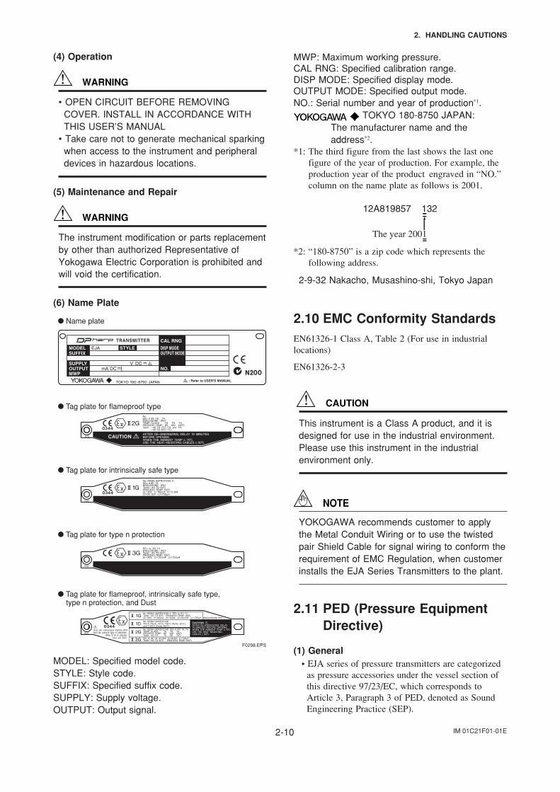
MODEL: Specified model code.STYLE: Style code.SUFFIX: Specified suffix code.SUPPLY: Supply voltage.OUTPUT: Output signal.
MWP: Maximum working pressure.CAL RNG: Specified calibration range.DISP MODE: Specified display mode.OUTPUT MODE: Specified output mode.NO.: Serial number and year of production*1.
TOKYO 180-8750 JAPAN:The manufacturer name and theaddress*2.
*1: The third figure from the last shows the last onefigure of the year of production. For example, theproduction year of the product engraved in “NO.”column on the name plate as follows is 2001.
The year 2001
12A819857 132
*2: “180-8750” is a zip code which represents thefollowing address.
2-9-32 Nakacho, Musashino-shi, Tokyo Japan
2.10 EMC Conformity StandardsEN61326-1 Class A, Table 2 (For use in industriallocations)
EN61326-2-3
CAUTION
This instrument is a Class A product, and it isdesigned for use in the industrial environment.Please use this instrument in the industrialenvironment only.
NOTE
YOKOGAWA recommends customer to applythe Metal Conduit Wiring or to use the twistedpair Shield Cable for signal wiring to conform therequirement of EMC Regulation, when customerinstalls the EJA Series Transmitters to the plant.
2.11 PED (Pressure EquipmentDirective)
(1) General• EJA series of pressure transmitters are categorized
as pressure accessories under the vessel section ofthis directive 97/23/EC, which corresponds toArticle 3, Paragraph 3 of PED, denoted as SoundEngineering Practice (SEP).
IM 01C21F01-01E2-11
2. HANDLING CAUTIONS
• EJA130A, EJA440A, EJA510A, and EJA530A canbe used above 200 bar and therefore considered asa part of a pressure retaining vessel where categorylll, Module H applies. These models with optioncode /PE3 conform to that category.
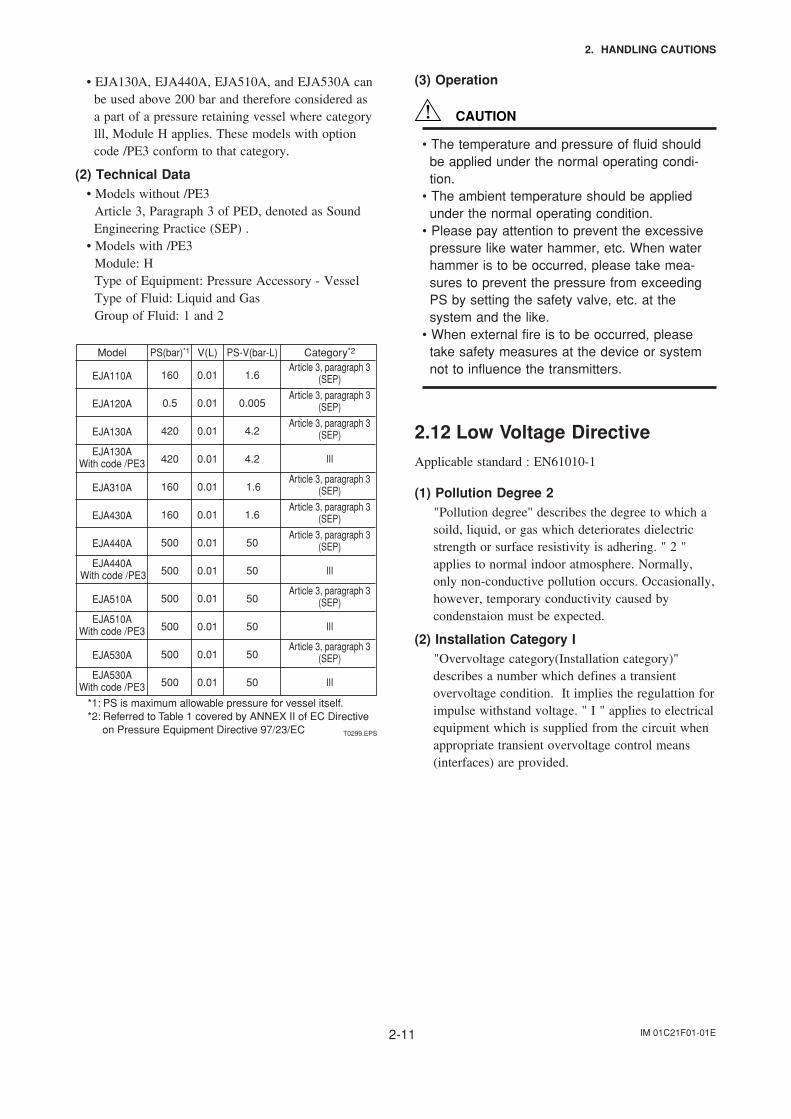
(2) Technical Data• Models without /PE3 Article 3, Paragraph 3 of PED, denoted as Sound
Engineering Practice (SEP) .• Models with /PE3 Module: H Type of Equipment: Pressure Accessory - Vessel Type of Fluid: Liquid and Gas Group of Fluid: 1 and 2
Model
EJA110A
EJA120A
EJA130A
EJA130AWith code /PE3
EJA310A
EJA430A
EJA440A
EJA440A With code /PE3
EJA510A
EJA510AWith code /PE3
EJA530A
EJA530AWith code /PE3
Category*2
Article 3, paragraph 3(SEP)
Article 3, paragraph 3(SEP)
Article 3, paragraph 3(SEP)
III
Article 3, paragraph 3(SEP)
Article 3, paragraph 3(SEP)
Article 3, paragraph 3(SEP)
III
Article 3, paragraph 3(SEP)
III
Article 3, paragraph 3(SEP)
III
PS-V(bar-L)
1.6
0.005
4.2
4.2
1.6
1.6
50
50
50
50
50
50
V(L)
0.01
0.01
0.01
0.01
0.01
0.01
0.01
0.01
0.01
0.01
0.01
0.01
PS(bar)*1
160
0.5
420
420
160
160
500
500
500
500
500
500
*1: PS is maximum allowable pressure for vessel itself.*2: Referred to Table 1 covered by ANNEX II of EC Directive on Pressure Equipment Directive 97/23/EC T0299.EPS
(3) Operation
CAUTION
• The temperature and pressure of fluid shouldbe applied under the normal operating condi-tion.
• The ambient temperature should be appliedunder the normal operating condition.
• Please pay attention to prevent the excessivepressure like water hammer, etc. When waterhammer is to be occurred, please take mea-sures to prevent the pressure from exceedingPS by setting the safety valve, etc. at thesystem and the like.
• When external fire is to be occurred, pleasetake safety measures at the device or systemnot to influence the transmitters.
2.12 Low Voltage DirectiveApplicable standard : EN61010-1
(1) Pollution Degree 2 "Pollution degree" describes the degree to which a
soild, liquid, or gas which deteriorates dielectricstrength or surface resistivity is adhering. " 2 "applies to normal indoor atmosphere. Normally,only non-conductive pollution occurs. Occasionally,however, temporary conductivity caused bycondenstaion must be expected.
(2) Installation Category I "Overvoltage category(Installation category)"
describes a number which defines a transientovervoltage condition. It implies the regulattion forimpulse withstand voltage. " I " applies to electricalequipment which is supplied from the circuit whenappropriate transient overvoltage control means(interfaces) are provided.
IM 01C21F01-01E3-1
3. COMPONENT NAMES
3. COMPONENT NAMES
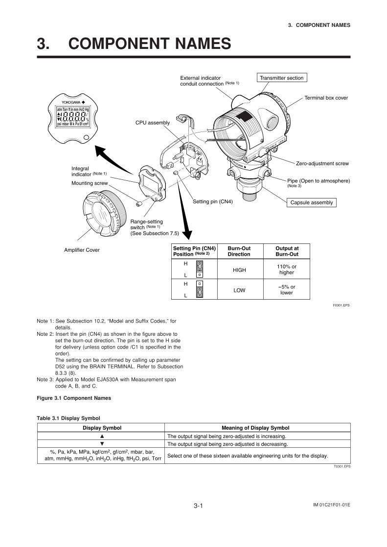
Setting pin (CN4)
Integralindicator (Note 1)
CPU assembly
External indicatorconduit connection (Note 1)
Transmitter section
Terminal box cover
Zero-adjustment screw
Pipe (Open to atmosphere)(Note 3)
Capsule assembly
Mounting screw
Range-settingswitch (Note 1)
(See Subsection 7.5)
Amplifier Cover Setting Pin (CN4)Position (Note 2)
Burn-OutDirection
Output atBurn-Out
H
L
H
L
HIGH
LOW
110% orhigher
-5% orlower
F0301.EPS
Note 1: See Subsection 10.2, “Model and Suffix Codes,” fordetails.
Note 2: Insert the pin (CN4) as shown in the figure above toset the burn-out direction. The pin is set to the H sidefor delivery (unless option code /C1 is specified in theorder).The setting can be confirmed by calling up parameterD52 using the BRAIN TERMINAL. Refer to Subsection8.3.3 (8).
Note 3: Applied to Model EJA530A with Measurement spancode A, B, and C.
Figure 3.1 Component Names
Table 3.1 Display Symbol
Display Symbol
%, Pa, kPa, MPa, kgf/cm2, gf/cm2, mbar, bar, atm, mmHg, mmH2O, inH2O, inHg, ftH2O, psi, Torr
Meaning of Display Symbol
The output signal being zero-adjusted is increasing.
The output signal being zero-adjusted is decreasing.
Select one of these sixteen available engineering units for the display.
T0301.EPS
IM 01C21F01-01E4-1
4. INSTALLATION
4. INSTALLATION
4.1 Precautions
Before installing the transmitter, read the cautionarynotes in Section 2.4, “Selecting the InstallationLocation.” For additional information on the ambientconditions allowed at the installation location, refer toSubsection 10.1 “Standard Specifications.”
IMPORTANT
• When welding piping during construction, takecare not to allow welding currents to flowthrough the transmitter.
• Do not step on this instrument after installation.
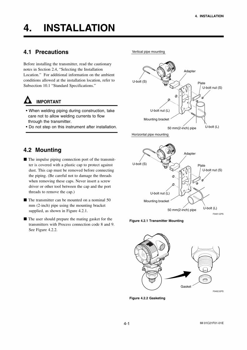
4.2 Mounting
The impulse piping connection port of the transmit-ter is covered with a plastic cap to protect againstdust. This cap must be removed before connectingthe piping. (Be careful not to damage the threadswhen removing these caps. Never insert a screwdriver or other tool between the cap and the portthreads to remove the cap.)
The transmitter can be mounted on a nominal 50mm (2-inch) pipe using the mounting bracketsupplied, as shown in Figure 4.2.1.
The user should prepare the mating gasket for thetransmitters with Process connection code 8 and 9.See Figure 4.2.2.
Horizontal pipe mounting
Vertical pipe mounting
U-bolt nut (L)
Mounting bracket
50 mm(2-inch) pipe
U-bolt (S)
U-bolt (L)
F0401.EPS
U-bolt nut (S)Plate
Adapter
U-bolt nut (L)
Mounting bracket
50 mm(2-inch) pipe U-bolt (L)
U-bolt (S)
U-bolt nut (S)Plate
Adapter
Figure 4.2.1 Transmitter Mounting
GasketF0402.EPS
Figure 4.2.2 Gasketing
IM 01C21F01-01E4-2
4. INSTALLATION
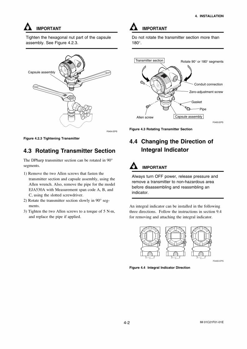
IMPORTANT
Tighten the hexagonal nut part of the capsuleassembly. See Figure 4.2.3.
F0404.EPS
Capsule assembly
Figure 4.2.3 Tightening Transmitter
4.3 Rotating Transmitter Section
The DPharp transmitter section can be rotated in 90°segments.
1) Remove the two Allen screws that fasten thetransmitter section and capsule assembly, using theAllen wrench. Also, remove the pipe for the modelEJA530A with Measurement span code A, B, andC, using the slotted screwdriver.
2) Rotate the transmitter section slowly in 90° seg-ments.
3) Tighten the two Allen screws to a torque of 5 N·m,and replace the pipe if applied.
IMPORTANT
Do not rotate the transmitter section more than180°.
F0403.EPS
Rotate 90° or 180° segmentsTransmitter section
Capsule assembly
Conduit connection
Zero-adjustment screw
Pipe
Gasket
Allen screw
Figure 4.3 Rotating Transmitter Section
4.4 Changing the Direction ofIntegral Indicator
IMPORTANT
Always turn OFF power, release pressure andremove a transmitter to non-hazardous areabefore disassembling and reassmbling anindicator.
An integral indicator can be installed in the followingthree directions. Follow the instructions in section 9.4for removing and attaching the integral indicator.
F0405.EPS
Figure 4.4 Integral Indicator Direction
IM 01C21F01-01E5-1
5. INSTALLING IMPULSE PIPING
5. INSTALLING IMPULSE PIPING
5.1 Impulse Piping InstallationPrecautions
5.1.1 Connecting Impulse Piping to theTransmitter
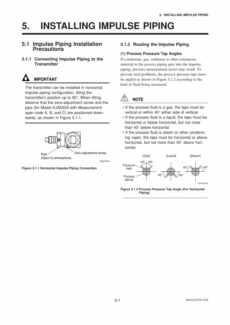
IMPORTANT
The transmitter can be installed in horizontalimpulse piping configuration, tilting thetransmitter's position up to 90°. When tilting,observe that the zero-adjustment screw and thepipe (for Model EJA530A with Measurementspan code A, B, and C) are positioned down-wards, as shown in Figure 5.1.1.
F0503.EPS
Pipe(Open to atmosphere)
Zero-adjustment screw
Figure 5.1.1 Horizontal Impulse Piping Connection
5.1.2 Routing the Impulse Piping
(1) Process Pressure Tap AnglesIf condensate, gas, sediment or other extraneousmaterial in the process piping gets into the impulsepiping, pressure measurement errors may result. Toprevent such problems, the process pressure taps mustbe angled as shown in Figure 5.1.2 according to thekind of fluid being measured.
NOTE
• If the process fluid is a gas, the taps must bevertical or within 45° either side of vertical.
• If the process fluid is a liquid, the taps must behorizontal or below horizontal, but not morethan 45° below horizontal.
• If the process fluid is steam or other condens-ing vapor, the taps must be horizontal or abovehorizontal, but not more than 45° above hori-zontal.
[Gas]
Pressuretaps
Processpiping
[Steam][Liquid]
45°
45°
45° 45°
45°
45°
F0504.EPS
Figure 5.1.2 Process Pressure Tap Angle (For HorizontalPiping)
IM 01C21F01-01E5-2
5. INSTALLING IMPULSE PIPING
(2) Position of Process Pressure Taps andTransmitter
If condensate (or gas) accumulates in the impulsepiping, it should be removed periodically by openingthe drain (or vent) plugs. However, this will generate atransient disturbance in the pressure measurement, andtherefore it is necessary to position the taps and routethe impulse piping so that any extraneous liquid or gasgenerated in the leadlines returns naturally to theprocess piping.
• If the process fluid is a gas, then as a rule thetransmitter must be located higher than the processpressure taps.
• If the process fluid is a liquid or steam, then as arule the transmitter must be located lower than theprocess pressure taps.
(3) Impulse Piping SlopeThe impulse piping must be routed with only anupward or downward slope. Even for horizontalrouting, the impulse piping should have a slope of atleast 1/10 to prevent condensate (or gases) fromaccumulating in the pipes.
(4) Preventing FreezingIf there is any risk that the process fluid in the impulsepiping or transmitter could freeze, use a steam jacket orheater to maintain the temperature of the fluid.
NOTE
After completing the connections, close the valveson the process pressure taps (main valves), thevalves at the transmitter (stop valves), and theimpulse piping drain valves, so that condensate,sediment, dust and other extraneous materialcannot enter the impulse piping.
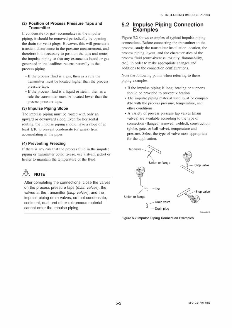
5.2 Impulse Piping ConnectionExamples
Figure 5.2 shows examples of typical impulse pipingconnections. Before connecting the transmitter to theprocess, study the transmitter installation location, theprocess piping layout, and the characteristics of theprocess fluid (corrosiveness, toxicity, flammability,etc.), in order to make appropriate changes andadditions to the connection configurations.
Note the following points when referring to thesepiping examples.
• If the impulse piping is long, bracing or supportsshould be provided to prevent vibration.
• The impulse piping material used must be compat-ible with the process pressure, temperature, andother conditions.
• A variety of process pressure tap valves (mainvalves) are available according to the type ofconnection (flanged, screwed, welded), construction(globe, gate, or ball valve), temperature andpressure. Select the type of valve most appropriatefor the application.
F0505.EPS
Tee
Stop valve
Stop valve
Drain valve
Drain plug
Union or flange
Union or flange
Tap valve
Figure 5.2 Impulse Piping Connection Examples
IM 01C21F01-01E6-1
6. WIRING
6. WIRING
6.1 Wiring Precautions
IMPORTANT
• Lay wiring as far as possible from electricalnoise sources such as large capacity transform-ers, motors, and power supplies.
• Remove electrical connection dust cap beforewiring.
• All threaded parts must be treated with water-proofing sealant. (A non-hardening siliconegroup sealant is recommended.)
• To prevent noise pickup, do not pass signaland power cables through the same ducts.
• Explosion-protected instruments must be wiredin accordance with specific requirements (and,in certain countries, legal regulations) in orderto preserve the effectiveness of their explosion-protected features.
• The terminal box cover is locked by an Allenhead bolt (a shrouding bolt) on CENELEC andIECEx flameproof type transmitters. When theshrouding bolt is driven clockwise by an Allenwrench, it is going in and cover lock is re-leased, and then the cover can be opened byhand. See Subsection 9.4 “Disassembly andReassembly” for details.
6.2 Selecting the Wiring Materi-als
(a) Use stranded leadwires or cables which are thesame as or better than 600 V grade PVC insulatedwire (JIS C3307) or equivalent.
(b) Use shielded wires in areas that are susceptible toelectrical noise.
(c) In areas with higher or lower ambient temperatures,use appropriate wires or cables.
(d) In environment where oils, solvents, corrosive gasesor liquids may be present, use wires or cables thatare resistant to such substances.
(e) It is recommended that crimp-on solderless terminallugs (for 4 mm screws) with insulating sleeves beused for leadwire ends.
6.3 Connections of ExternalWiring to Terminal Box
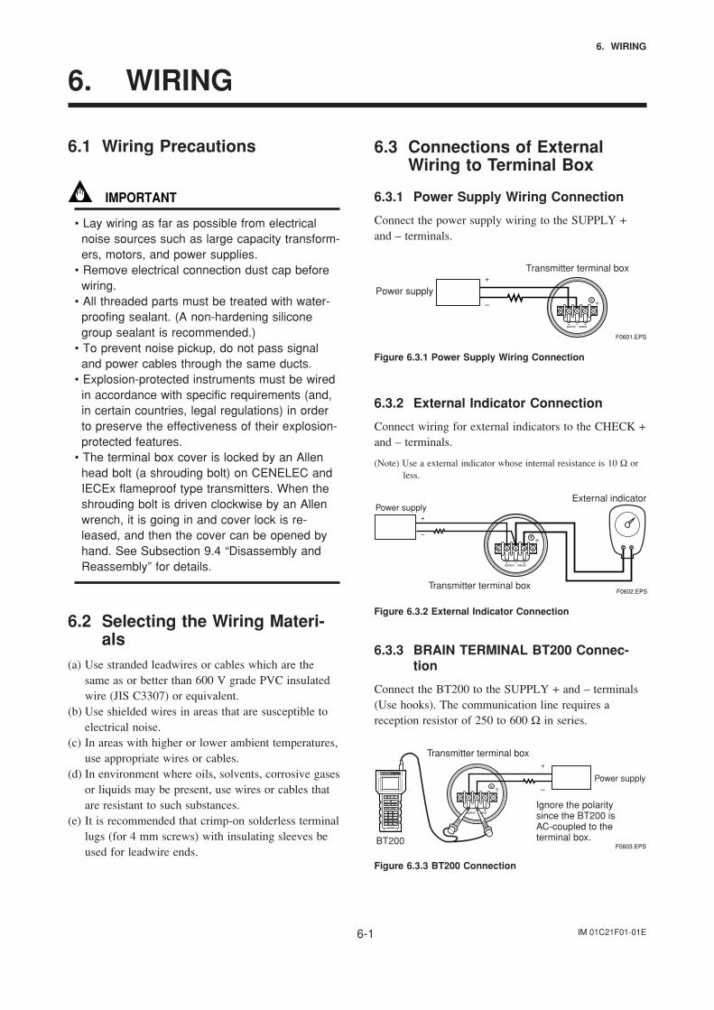
6.3.1 Power Supply Wiring Connection
Connect the power supply wiring to the SUPPLY +and – terminals.
Power supply–
+Transmitter terminal box
F0601.EPS
Figure 6.3.1 Power Supply Wiring Connection
6.3.2 External Indicator Connection
Connect wiring for external indicators to the CHECK +and – terminals.
(Note) Use a external indicator whose internal resistance is 10 Ω orless.
Transmitter terminal box
External indicator
F0602.EPS
Power supply
–
+
Figure 6.3.2 External Indicator Connection
6.3.3 BRAIN TERMINAL BT200 Connec-tion
Connect the BT200 to the SUPPLY + and – terminals(Use hooks). The communication line requires areception resistor of 250 to 600 Ω in series.
Transmitter terminal box
BT200F0603.EPS
Power supply–
+
Ignore the polaritysince the BT200 isAC-coupled to theterminal box.
Figure 6.3.3 BT200 Connection
IM 01C21F01-01E6-2
6. WIRING
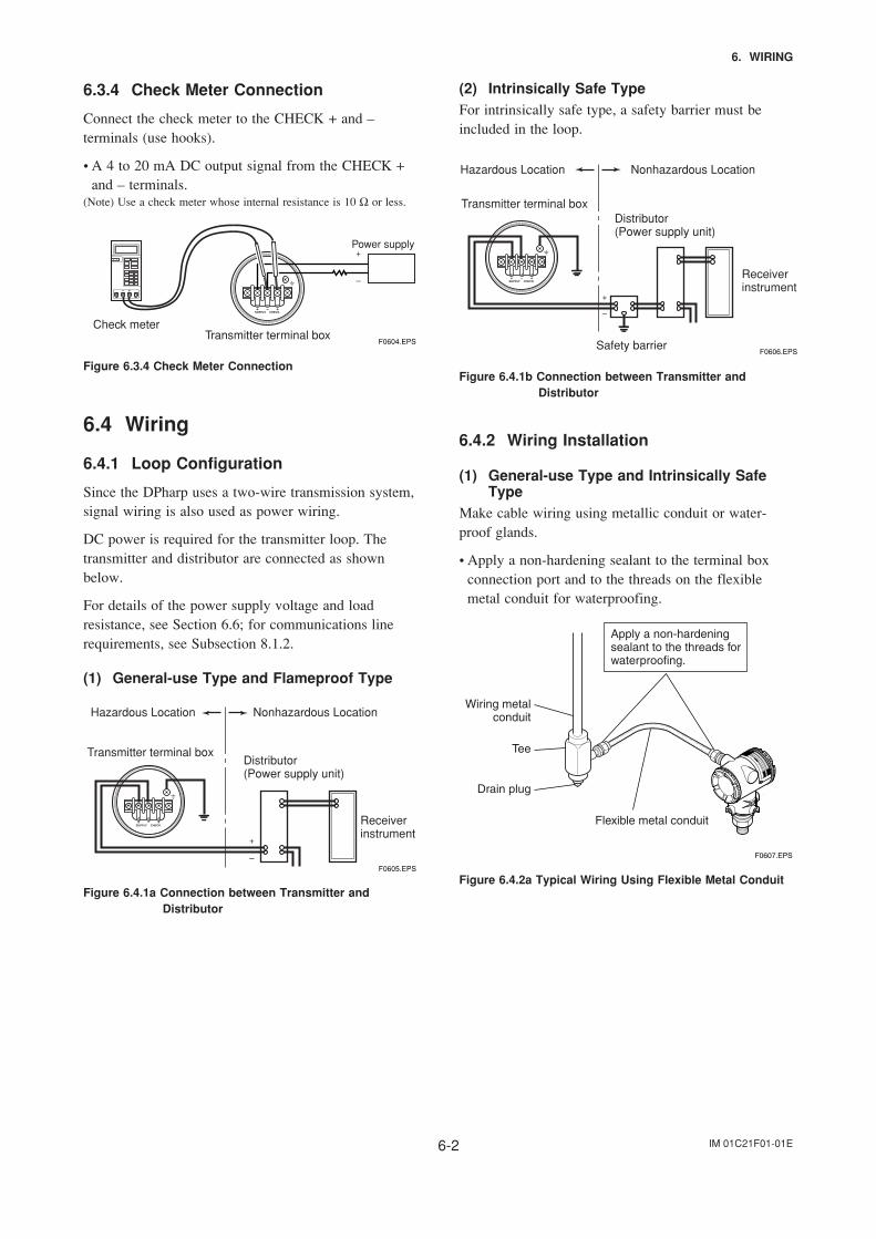
6.3.4 Check Meter Connection
Connect the check meter to the CHECK + and –terminals (use hooks).
• A 4 to 20 mA DC output signal from the CHECK +and – terminals.
(Note) Use a check meter whose internal resistance is 10 Ω or less.
Transmitter terminal boxF0604.EPS
Power supply
–
+
Check meter
Figure 6.3.4 Check Meter Connection
6.4 Wiring
6.4.1 Loop Configuration
Since the DPharp uses a two-wire transmission system,signal wiring is also used as power wiring.
DC power is required for the transmitter loop. Thetransmitter and distributor are connected as shownbelow.
For details of the power supply voltage and loadresistance, see Section 6.6; for communications linerequirements, see Subsection 8.1.2.
(1) General-use Type and Flameproof Type
Hazardous Location Nonhazardous Location
Transmitter terminal boxDistributor (Power supply unit)
Receiver instrument
F0605.EPS–
+
Figure 6.4.1a Connection between Transmitter andDistributor
(2) Intrinsically Safe TypeFor intrinsically safe type, a safety barrier must beincluded in the loop.
Hazardous Location Nonhazardous Location
Transmitter terminal boxDistributor (Power supply unit)
Receiver instrument
Safety barrierF0606.EPS
–
+
Figure 6.4.1b Connection between Transmitter andDistributor
6.4.2 Wiring Installation
(1) General-use Type and Intrinsically SafeType
Make cable wiring using metallic conduit or water-proof glands.
• Apply a non-hardening sealant to the terminal boxconnection port and to the threads on the flexiblemetal conduit for waterproofing.
F0607.EPS
Flexible metal conduit
Wiring metalconduit
Tee
Drain plug
Apply a non-hardeningsealant to the threads forwaterproofing.
Figure 6.4.2a Typical Wiring Using Flexible Metal Conduit
IM 01C21F01-01E6-3
6. WIRING
(2) Flameproof TypeWire cables through a flameproof packing adapter, orusing a flameproof metal conduit.
Wiring cable through flameproof packing adapter.• Apply a nonhardening sealant to the terminal box
connection port and to the threads on the flameproofpacking adapter for waterproofing.
F0608.EPS
Flameproof packing adapter
Flexible metal conduit
Wiring metalconduit
Tee
Drain plug
Apply a non-hardeningsealant to the threads forwaterproofing.
Figure 6.4.2b Typical Cable Wiring Using FlameproofPacking Adapter
Flameproof metal conduit wiring• A seal fitting must be installed near the terminal box
connection port for a sealed construction.• Apply a non-hardening sealant to the threads of the
terminal box connection port, flexible metal conduitand seal fitting for waterproofing.
F0609.EPS
Non-hazardous area
Hazardous area
Flameproofheavy-gaugesteel conduit
Tee
Drain plug
Seal fitting
Gas sealing device
Flameproof flexiblemetal conduit
Apply a non-hardeningsealant to the threads ofthese fittings forwaterproofing
After wiring, impregnate the fittingwith a compound to seal tubing.
Figure 6.4.2c Typical Wiring Using Flameproof MetalConduit
6.5 GroundingGrounding is always required for the proper operationof transmitters. Follow the domestic electrical require-ments as regulated in each country. For a transmitterwith built-in lightning protector, grounding shouldsatisfy ground resistance of 10 or less.
Ground terminals are located on the inside and outsideof the terminal box. Either of these terminals may beused.
Ground terminal(Inside)
Ground terminal(Outside)
Transmitter terminal box
F0610.EPS
Figure 6.5 Ground Terminals
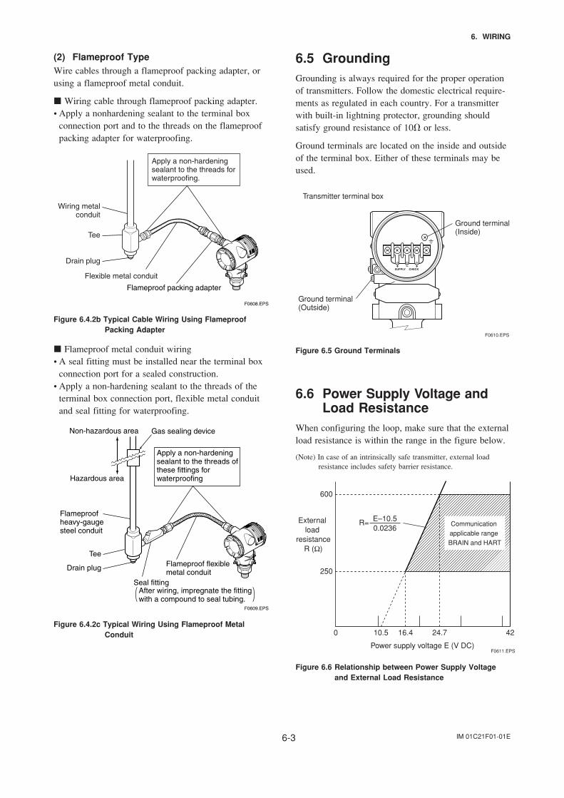
6.6 Power Supply Voltage andLoad Resistance
When configuring the loop, make sure that the externalload resistance is within the range in the figure below.
(Note) In case of an intrinsically safe transmitter, external loadresistance includes safety barrier resistance.
600
250
0 10.5 16.4 24.7 42
External load
resistanceR (Ω)
Power supply voltage E (V DC)F0611.EPS
Communication applicable range BRAIN and HART
R= E–10.50.0236
Figure 6.6 Relationship between Power Supply Voltageand External Load Resistance
IM 01C21F01-01E7-1
7. OPERATION
7. OPERATION
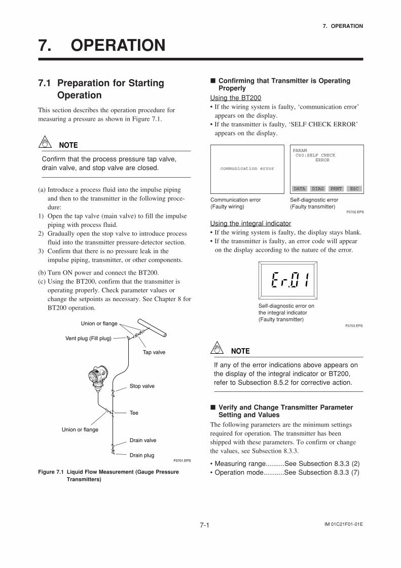
7.1 Preparation for StartingOperation
This section describes the operation procedure formeasuring a pressure as shown in Figure 7.1.
NOTE
Confirm that the process pressure tap valve,drain valve, and stop valve are closed.
(a) Introduce a process fluid into the impulse pipingand then to the transmitter in the following proce-dure:
1) Open the tap valve (main valve) to fill the impulsepiping with process fluid.
2) Gradually open the stop valve to introduce processfluid into the transmitter pressure-detector section.
3) Confirm that there is no pressure leak in theimpulse piping, transmitter, or other components.
(b) Turn ON power and connect the BT200.(c) Using the BT200, confirm that the transmitter is
operating properly. Check parameter values orchange the setpoints as necessary. See Chapter 8 forBT200 operation.
F0701.EPS
Tee
Vent plug (Fill plug)
Union or flange
Drain valve
Drain plug
Stop valve
Union or flange
Tap valve
Figure 7.1 Liquid Flow Measurement (Gauge PressureTransmitters)
Confirming that Transmitter is OperatingProperly
Using the BT200• If the wiring system is faulty, ‘communication error’
appears on the display.• If the transmitter is faulty, ‘SELF CHECK ERROR’
appears on the display.
communication error
PARAM C60:SELF CHECK ERROR
Communication error (Faulty wiring)
Self-diagnostic error(Faulty transmitter)
DATA DIAG PRNT ESC
F0702.EPS
Using the integral indicator• If the wiring system is faulty, the display stays blank.• If the transmitter is faulty, an error code will appear
on the display according to the nature of the error.
Self-diagnostic error on the integral indicator(Faulty transmitter)
F0703.EPS
NOTE
If any of the error indications above appears onthe display of the integral indicator or BT200,refer to Subsection 8.5.2 for corrective action.
Verify and Change Transmitter ParameterSetting and Values
The following parameters are the minimum settingsrequired for operation. The transmitter has beenshipped with these parameters. To confirm or changethe values, see Subsection 8.3.3.
• Measuring range..........See Subsection 8.3.3 (2)• Operation mode...........See Subsection 8.3.3 (7)
IM 01C21F01-01E7-2
7. OPERATION
7.2 Zero Point AdjustmentAdjust the zero point after operating preparation iscompleted.
IMPORTANT
Do not turn off the power to the transmitterimmediately after a zero adjustment. Poweringoff within 30 seconds after a zero adjustment willreturn the adjustment back to the previoussettings.
The zero point adjustment can be made in either way:using the zero-adjustment screw of the transmitter orthe BT200 operation.
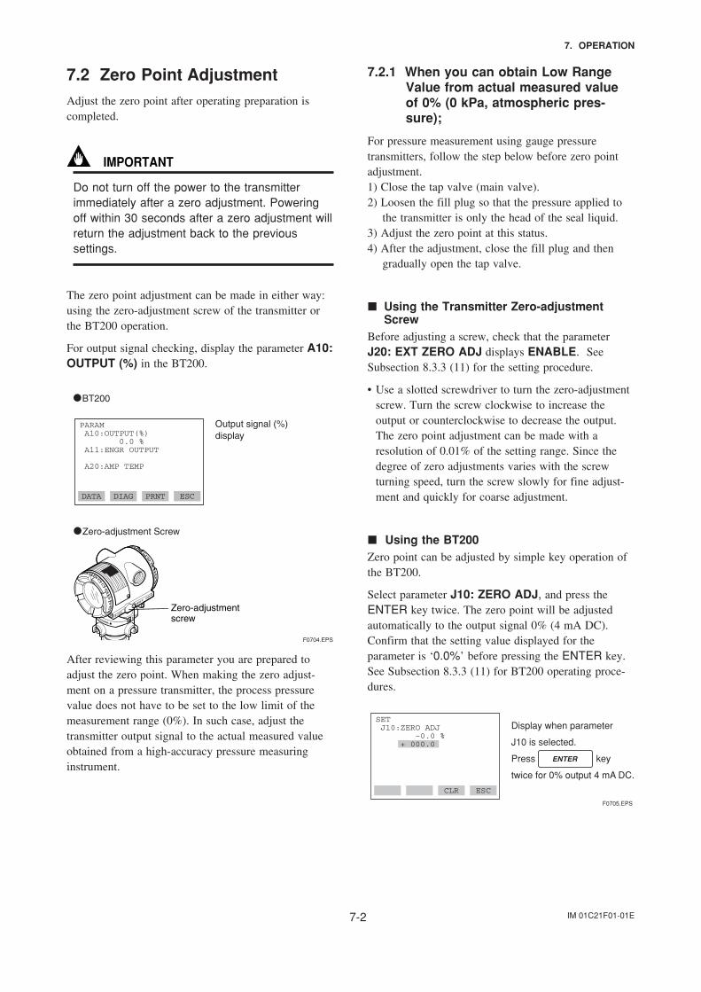
For output signal checking, display the parameter A10:OUTPUT (%) in the BT200.
Output signal (%)display
PARAM A10:OUTPUT(%) 0.0 % A11:ENGR OUTPUT
A20:AMP TEMP
DATA DIAG PRNT ESC
F0704.EPS
Zero-adjustmentscrew
•BT200
•Zero-adjustment Screw
After reviewing this parameter you are prepared toadjust the zero point. When making the zero adjust-ment on a pressure transmitter, the process pressurevalue does not have to be set to the low limit of themeasurement range (0%). In such case, adjust thetransmitter output signal to the actual measured valueobtained from a high-accuracy pressure measuringinstrument.
7.2.1 When you can obtain Low RangeValue from actual measured valueof 0% (0 kPa, atmospheric pres-sure);
For pressure measurement using gauge pressuretransmitters, follow the step below before zero pointadjustment.1) Close the tap valve (main valve).2) Loosen the fill plug so that the pressure applied to
the transmitter is only the head of the seal liquid.3) Adjust the zero point at this status.4) After the adjustment, close the fill plug and then
gradually open the tap valve.
Using the Transmitter Zero-adjustmentScrew
Before adjusting a screw, check that the parameterJ20: EXT ZERO ADJ displays ENABLE. SeeSubsection 8.3.3 (11) for the setting procedure.
• Use a slotted screwdriver to turn the zero-adjustmentscrew. Turn the screw clockwise to increase theoutput or counterclockwise to decrease the output.The zero point adjustment can be made with aresolution of 0.01% of the setting range. Since thedegree of zero adjustments varies with the screwturning speed, turn the screw slowly for fine adjust-ment and quickly for coarse adjustment.
Using the BT200Zero point can be adjusted by simple key operation ofthe BT200.
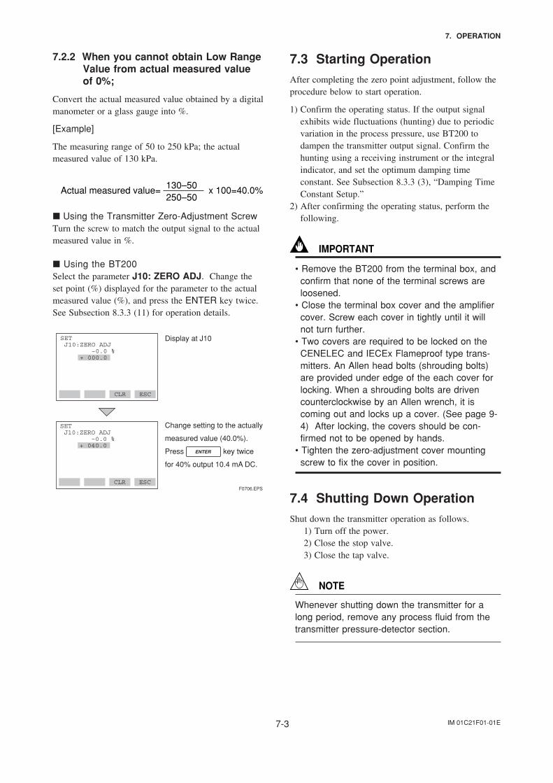
Select parameter J10: ZERO ADJ, and press theENTER key twice. The zero point will be adjustedautomatically to the output signal 0% (4 mA DC).Confirm that the setting value displayed for theparameter is ‘0.0%’ before pressing the ENTER key.See Subsection 8.3.3 (11) for BT200 operating proce-dures.
Display when parameter
J10 is selected.
Press key
twice for 0% output 4 mA DC.
SET J10:ZERO ADJ –0.0 % + 000.0
CLR ESC
F0705.EPS
IM 01C21F01-01E7-3
7. OPERATION
7.2.2 When you cannot obtain Low RangeValue from actual measured valueof 0%;
Convert the actual measured value obtained by a digitalmanometer or a glass gauge into %.
[Example]
The measuring range of 50 to 250 kPa; the actualmeasured value of 130 kPa.
130–50250–50
Actual measured value= x 100=40.0%
Using the Transmitter Zero-Adjustment ScrewTurn the screw to match the output signal to the actualmeasured value in %.
Using the BT200Select the parameter J10: ZERO ADJ. Change theset point (%) displayed for the parameter to the actualmeasured value (%), and press the ENTER key twice.See Subsection 8.3.3 (11) for operation details.
Change setting to the actually
measured value (40.0%).
Press key twice
for 40% output 10.4 mA DC.
SET J10:ZERO ADJ –0.0 % + 040.0
CLR ESCF0706.EPS
Display at J10SET J10:ZERO ADJ –0.0 % + 000.0
CLR ESC
7.3 Starting OperationAfter completing the zero point adjustment, follow theprocedure below to start operation.
1) Confirm the operating status. If the output signalexhibits wide fluctuations (hunting) due to periodicvariation in the process pressure, use BT200 todampen the transmitter output signal. Confirm thehunting using a receiving instrument or the integralindicator, and set the optimum damping timeconstant. See Subsection 8.3.3 (3), “Damping TimeConstant Setup.”
2) After confirming the operating status, perform thefollowing.
IMPORTANT
• Remove the BT200 from the terminal box, andconfirm that none of the terminal screws areloosened.
• Close the terminal box cover and the amplifiercover. Screw each cover in tightly until it willnot turn further.
• Two covers are required to be locked on theCENELEC and IECEx Flameproof type trans-mitters. An Allen head bolts (shrouding bolts)are provided under edge of the each cover forlocking. When a shrouding bolts are drivencounterclockwise by an Allen wrench, it iscoming out and locks up a cover. (See page 9-4) After locking, the covers should be con-firmed not to be opened by hands.
• Tighten the zero-adjustment cover mountingscrew to fix the cover in position.
7.4 Shutting Down OperationShut down the transmitter operation as follows. 1) Turn off the power. 2) Close the stop valve. 3) Close the tap valve.
NOTE
Whenever shutting down the transmitter for along period, remove any process fluid from thetransmitter pressure-detector section.
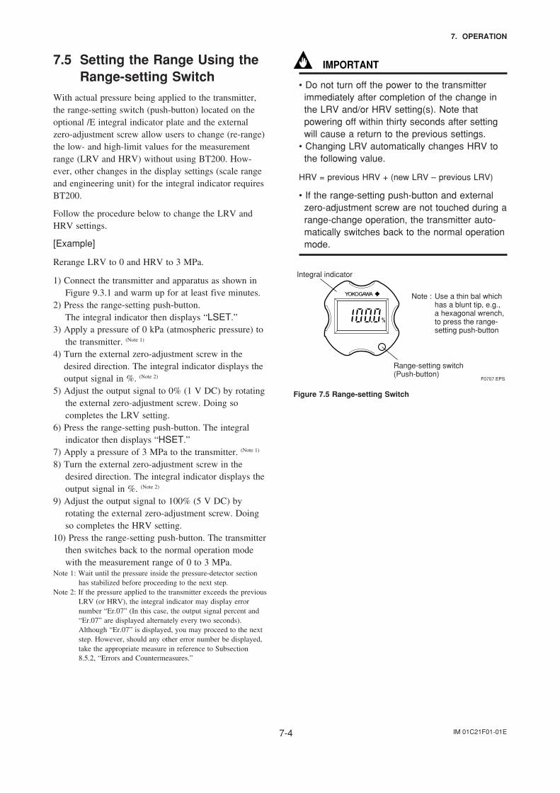
IM 01C21F01-01E7-4
7. OPERATION
7.5 Setting the Range Using theRange-setting Switch
With actual pressure being applied to the transmitter,the range-setting switch (push-button) located on theoptional /E integral indicator plate and the externalzero-adjustment screw allow users to change (re-range)the low- and high-limit values for the measurementrange (LRV and HRV) without using BT200. How-ever, other changes in the display settings (scale rangeand engineering unit) for the integral indicator requiresBT200.
Follow the procedure below to change the LRV andHRV settings.
[Example]
Rerange LRV to 0 and HRV to 3 MPa.
1) Connect the transmitter and apparatus as shown inFigure 9.3.1 and warm up for at least five minutes.
2) Press the range-setting push-button.The integral indicator then displays “LSET.”
3) Apply a pressure of 0 kPa (atmospheric pressure) tothe transmitter. (Note 1)
4) Turn the external zero-adjustment screw in thedesired direction. The integral indicator displays theoutput signal in %. (Note 2)
5) Adjust the output signal to 0% (1 V DC) by rotatingthe external zero-adjustment screw. Doing socompletes the LRV setting.
6) Press the range-setting push-button. The integralindicator then displays “HSET.”
7) Apply a pressure of 3 MPa to the transmitter. (Note 1)
8) Turn the external zero-adjustment screw in thedesired direction. The integral indicator displays theoutput signal in %. (Note 2)
9) Adjust the output signal to 100% (5 V DC) byrotating the external zero-adjustment screw. Doingso completes the HRV setting.
10) Press the range-setting push-button. The transmitterthen switches back to the normal operation modewith the measurement range of 0 to 3 MPa.
Note 1: Wait until the pressure inside the pressure-detector sectionhas stabilized before proceeding to the next step.
Note 2: If the pressure applied to the transmitter exceeds the previousLRV (or HRV), the integral indicator may display errornumber “Er.07” (In this case, the output signal percent and“Er.07” are displayed alternately every two seconds).Although “Er.07” is displayed, you may proceed to the nextstep. However, should any other error number be displayed,take the appropriate measure in reference to Subsection8.5.2, “Errors and Countermeasures.”
IMPORTANT
• Do not turn off the power to the transmitterimmediately after completion of the change inthe LRV and/or HRV setting(s). Note thatpowering off within thirty seconds after settingwill cause a return to the previous settings.
• Changing LRV automatically changes HRV tothe following value.
HRV = previous HRV + (new LRV – previous LRV)
• If the range-setting push-button and externalzero-adjustment screw are not touched during arange-change operation, the transmitter auto-matically switches back to the normal operationmode.
F0707.EPS
Integral indicator
Range-setting switch(Push-button)
Note : Use a thin bal which has a blunt tip, e.g., a hexagonal wrench, to press the range-setting push-button
Figure 7.5 Range-setting Switch
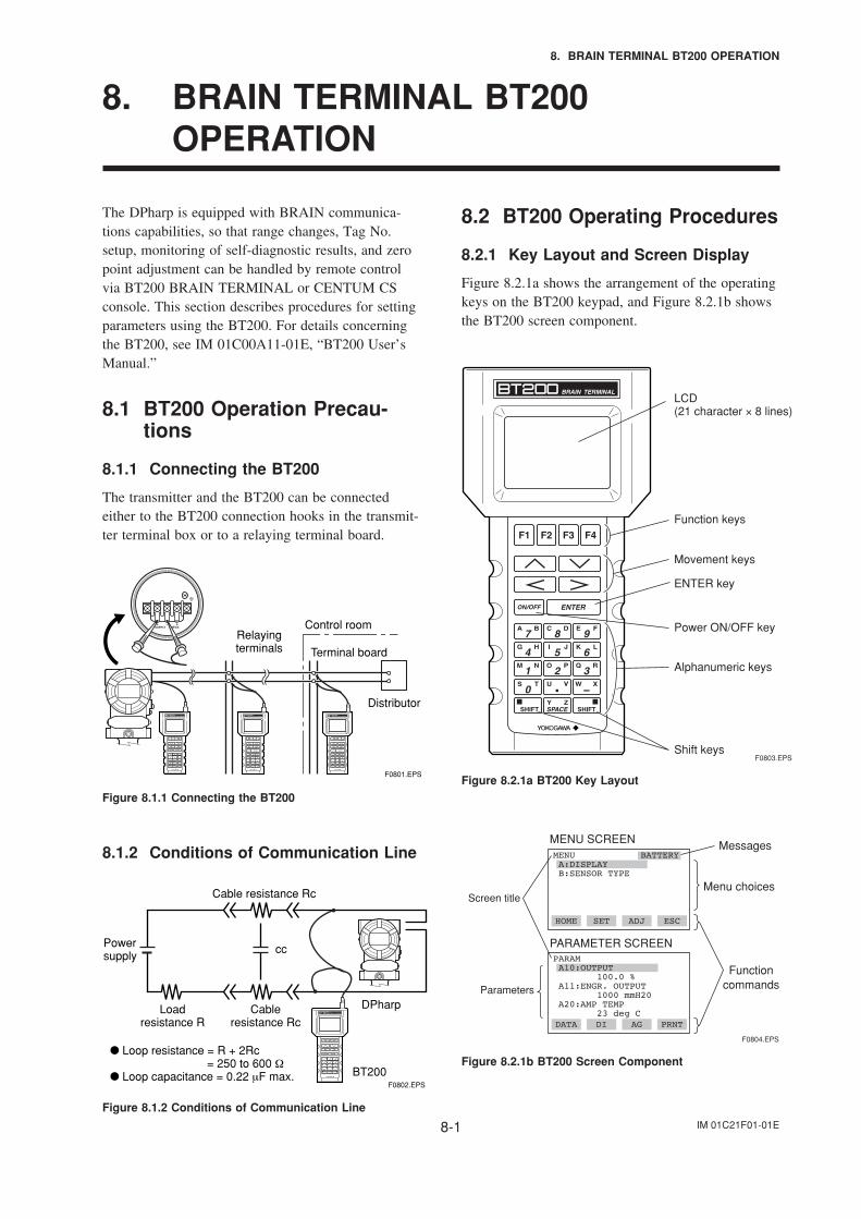
IM 01C21F01-01E8-1
8. BRAIN TERMINAL BT200 OPERATION
8. BRAIN TERMINAL BT200OPERATION
The DPharp is equipped with BRAIN communica-tions capabilities, so that range changes, Tag No.setup, monitoring of self-diagnostic results, and zeropoint adjustment can be handled by remote controlvia BT200 BRAIN TERMINAL or CENTUM CSconsole. This section describes procedures for settingparameters using the BT200. For details concerningthe BT200, see IM 01C00A11-01E, “BT200 User’sManual.”
8.1 BT200 Operation Precau-tions
8.1.1 Connecting the BT200
The transmitter and the BT200 can be connectedeither to the BT200 connection hooks in the transmit-ter terminal box or to a relaying terminal board.
Relaying terminals
Distributor
Control room
Terminal board
F0801.EPS
Figure 8.1.1 Connecting the BT200
8.1.2 Conditions of Communication Line
DPharp
BT200
Cable resistance Rc
Cable resistance Rc
Load resistance R
ccPower supply
Loop resistance = R + 2Rc = 250 to 600 Ω
Loop capacitance = 0.22 µF max.F0802.EPS
Figure 8.1.2 Conditions of Communication Line
8.2 BT200 Operating Procedures
8.2.1 Key Layout and Screen Display
Figure 8.2.1a shows the arrangement of the operatingkeys on the BT200 keypad, and Figure 8.2.1b showsthe BT200 screen component.
F0803.EPS
LCD(21 character × 8 lines)
Movement keys
Power ON/OFF key
Function keys
ENTER key
Alphanumeric keys
Shift keys
Figure 8.2.1a BT200 Key Layout
PARAM A10:OUTPUT 100.0 % A11:ENGR. OUTPUT 1000 mmH20 A20:AMP TEMP 23 deg C
Menu choices
MessagesMENU SCREEN
Screen title
MENU A:DISPLAY B:SENSOR TYPE
BATTERY
HOME SET ADJ ESC
Functioncommands
PARAMETER SCREEN
Parameters
DATA DI AG PRNT
F0804.EPS
Figure 8.2.1b BT200 Screen Component
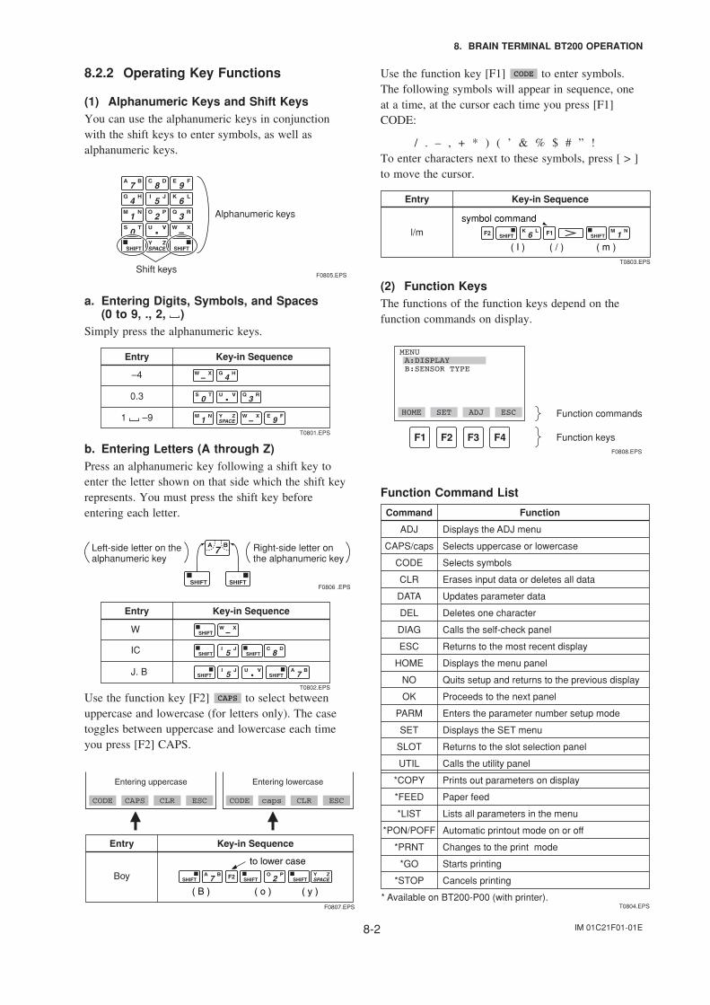
IM 01C21F01-01E8-2
8. BRAIN TERMINAL BT200 OPERATION
8.2.2 Operating Key Functions
(1) Alphanumeric Keys and Shift KeysYou can use the alphanumeric keys in conjunctionwith the shift keys to enter symbols, as well asalphanumeric keys.
Shift keys
Alphanumeric keys
F0805.EPS
a. Entering Digits, Symbols, and Spaces(0 to 9, ., 2, )
Simply press the alphanumeric keys.
Entry Key-in Sequence
–4
0.3
1 –9
T0801.EPS
b. Entering Letters (A through Z)Press an alphanumeric key following a shift key toenter the letter shown on that side which the shift keyrepresents. You must press the shift key beforeentering each letter.
Left-side letter on the alphanumeric key
Right-side letter on the alphanumeric key
F0806 .EPS
Entry Key-in Sequence
W
IC
J. B
T0802.EPS
Use the function key [F2] CAPS to select betweenuppercase and lowercase (for letters only). The casetoggles between uppercase and lowercase each timeyou press [F2] CAPS.
Entry
Boy
Key-in Sequence
F0807.EPS
CODE CAPS CLR ESC
Entering uppercase
CODE caps CLR ESC
Entering lowercase
( B ) ( y )( o )
to lower case
Use the function key [F1] CODE to enter symbols.The following symbols will appear in sequence, oneat a time, at the cursor each time you press [F1]CODE:
/ . – , + * ) ( ’ & % $ # ” !To enter characters next to these symbols, press [ > ]to move the cursor.
( / )
Entry
l/m
Key-in Sequence
T0803.EPS
( m )( I )
symbol command
(2) Function KeysThe functions of the function keys depend on thefunction commands on display.
MENU A:DISPLAY B:SENSOR TYPE
HOME SET ADJ ESC Function commands
Function keysF0808.EPS
Function Command List
Command Function
ADJ Displays the ADJ menu
Selects uppercase or lowercase
Selects symbols
Erases input data or deletes all data
Updates parameter data
Deletes one character
Calls the self-check panel
Returns to the most recent display
Displays the menu panel
Quits setup and returns to the previous display
Proceeds to the next panel
Enters the parameter number setup mode
Displays the SET menu
Returns to the slot selection panel
Calls the utility panel
Prints out parameters on display
Paper feed
Lists all parameters in the menu
Automatic printout mode on or off
Changes to the print mode
Starts printing
Cancels printing
CAPS/caps
CODE
CLR
DATA
DEL
DIAG
ESC
HOME
NO
OK
PARM
SET
SLOT
UTIL
*COPY
*FEED
*LIST
*PON/POFF
*PRNT
*GO
*STOP
* Available on BT200-P00 (with printer).T0804.EPS
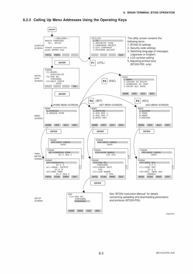
IM 01C21F01-01E8-3
8. BRAIN TERMINAL BT200 OPERATION
8.2.3 Calling Up Menu Addresses Using the Operating Keys
DATA DIAG PRNT ESC
PARAM A60:SELF CHECK GOOD
CODE CAPS CLR ESC
––WELCOME––BRAIN TERMINAL ID: BT200
check connection push ENTER key
UTIL FEED esc
PARAM 01:MODEL EJA510A-DC 02:TAG NO. YOKOGAWA 03:SELF CHECK GOOD
OK
STARTUPSCREEN
MENUSCREEN
SETUPSCREEN
INITIAL DATA SCREEN
PARA-METER SCREEN
(HOME MENU SCREEN) (SET MENU SCREEN) (ADJ MENU SCREEN)
See “BT200 Instruction Manual” for details concerning uploading and downloading parameters and printouts (BT200-P00).
(UTIL)
(SET)
(ESC)
HOME SET ADJ ESC
(ADJ)
The utility screen contains the following items.1. BT200 ID settings2. Security code settings3. Switching language of messages (Japanese or English)4. LCD contrast setting5. Adjusting printout tone (BT200-P00 only)
FUNC 1.MENU 2.UPLOAD TO BT200 3.DOWNLOAD TO INST 4.PRINT ALL DATA
HOME SET ADJ ESC
MENU A.DISPLAY B.SENSOR TYPE
HOME SET ADJ ESC
MENU C.SETTING D.AUX SET 1 E.AUX SET 2 H:AUTO SET
HOME SET ADJ ESC
MENU J.ADJUST K.TEST M.MEMO P:RECORD
DATA DIAG PRNT ESC
DATA DIAG PRNT ESCDATA DIAG PRNT ESC DATA DIAG PRNT ESC
PARAM C60:SELF CHECK GOOD
PARAM C22:HIGH RANGE 100 kPa
DATA DIAG PRNT ESC
PARAM J60:SELF CHECK GOOD
PARAM J10:ZERO ADJ 0.0 % J11:ZERO DEV 22.2 % J20:EXT. ZERO ADJ ENABLE
SET C10:TAG NO. YOKOGAWA YOKOGAWA
F0809.EPS
DATA DIAG PRNT ESC
PARAM A10:OUTPUT(%) 50.0 % A11:ENGR, OUTPUT 20.0 M A20:AMP TEMP 24.5 deg C
DATA DIAG PRNT ESC
PARAM C10:TAG NO. YOKOGAWA C20:PRESS UNIT kPa C21:LOW RANGE 0 kPa
PARAM A21:CAPSULE TEMP 26.5 deg C
UTILITY 1.ID 2.SECURITY CODE 3.LANGUAGE SELECT 4.LCD CONTRAST 5.PRINTER ADJUST
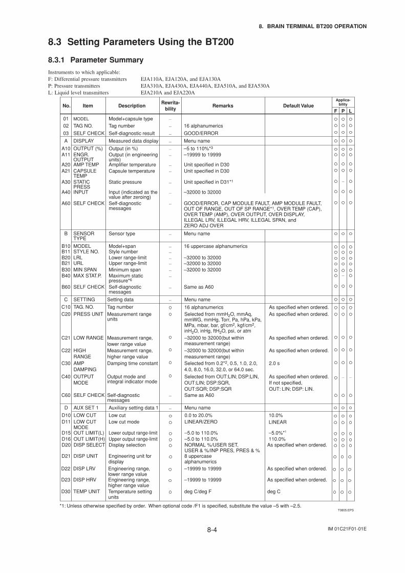
IM 01C21F01-01E8-4
8. BRAIN TERMINAL BT200 OPERATION
8.3 Setting Parameters Using the BT200
8.3.1 Parameter Summary
Instruments to which applicable:F: Differential pressure transmitters EJA110A, EJA120A, and EJA130AP: Pressure transmitters EJA310A, EJA430A, EJA440A, EJA510A, and EJA530AL: Liquid level transmitters EJA210A and EJA220A
No. Description
Model+capsule typeTag number
Applica-bility
P LF
0102
T0805.EPS
Rewrita-bility
16 alphanumerics
GOOD/ERROR
RemarksItem
MODEL
TAG NO.
Self-diagnostic result
—
—
—03 SELF CHECK
Measured data displayA
–5 to 110%*3
Menu nameDISPLAY
Output (in %)A10 OUTPUT (%)–19999 to 19999Output (in engineering
units)A11 ENGR.
OUTPUTUnit specified in D30Amplifier temperatureA20 AMP TEMPUnit specified in D30Capsule temperatureA21 CAPSULE
TEMP
—
Sensor typeB
16 uppercase alphanumerics
Menu nameSENSOR TYPE
Model+spanB10 MODEL
—
Style numberB11 STYLE NO.–32000 to 32000Lower range-limitB20 LRL–32000 to 32000Upper range-limitB21 URL–32000 to 32000Minimum spanB30 MIN SPAN
—
—
—
—
—
Unit specified in D31*1Static pressureA30 STATIC PRESS
–32000 to 32000Input (indicated as the value after zeroing)
A40 INPUT
GOOD/ERROR, CAP MODULE FAULT, AMP MODULE FAULT, OUT OF RANGE, OUT OF SP RANGE*1, OVER TEMP (CAP),OVER TEMP (AMP), OVER OUTPUT, OVER DISPLAY, ILLEGAL LRV, ILLEGAL HRV, ILLEGAL SPAN, and ZERO ADJ OVER
Self-diagnostic messages
A60 SELF CHECK
—
—
—
—
—
—
—
Maximum static pressure*6
B40
Same as A60
MAX STAT.P.
Self-diagnostic messages
—
—B60 SELF CHECK
Setting dataC
16 alphanumerics
Menu nameSETTING
Tag numberC10 TAG. NO.Selected from mmH2O, mmAq, mmWG, mmHg, Torr, Pa, hPa, kPa, MPa, mbar, bar, gf/cm2, kgf/cm2, inH2O, inHg, ftH2O, psi, or atm
Measurement rangeunits
C20 PRESS UNIT
–32000 to 32000(but within measurement range)
Measurement range, lower range value
C21 LOW RANGE
—
Self-diagnostic messages
C60 Same as A60SELF CHECK —
—
—
—
–32000 to 32000(but within measurement range)
Measurement range, higher range value
C22 HIGH RANGE
Selected from 0.2*2, 0.5, 1.0, 2.0, 4.0, 8.0, 16.0, 32.0, or 64.0 sec.
Damping time constantC30 AMP DAMPING
Selected from OUT:LIN; DSP:LIN,OUT:LIN; DSP:SQR, OUT:SQR; DSP:SQR
Output mode and integral indicator mode
C40 OUTPUT MODE
0.0 to 20.0%LINEAR/ZERO
Low cutD10 LOW CUTLow cut modeD11 LOW CUT
MODE
NORMAL %/USER SET,USER & %/INP PRES, PRES & %
Display selectionD20 DISP SELECT
—
Auxiliary setting data 1D Menu nameAUX SET 1 —
Default Value
As specified when ordered.As specified when ordered.
As specified when ordered.
As specified when ordered.
2.0 s
As specified when ordered.If not specified, OUT: LIN; DSP: LIN.
8 uppercase alphanumerics
Engineering unit for display
D21 DISP UNIT
10.0%LINEAR
–5.0 to 110.0%Lower output range-limitD15 OUT LIMIT(L) –5.0%*1
–5.0 to 110.0%Upper output range-limitD16 OUT LIMIT(H) 110.0%
–19999 to 19999Engineering range, lower range value
D22 DISP LRV
–19999 to 19999Engineering range, higher range value
D23 DISP HRV
As specified when ordered.
As specified when ordered.
As specified when ordered.
deg C/deg FTemperature setting units
D30 TEMP UNIT deg C
*1: Unless otherwise specified by order. When optional code /F1 is specified, substitute the value –5 with –2.5.
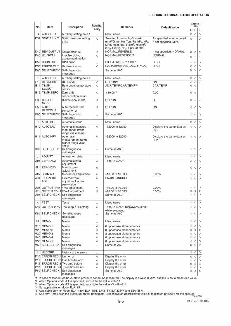
IM 01C21F01-01E8-5
8. BRAIN TERMINAL BT200 OPERATION
T0806.EPS
Auxiliary setting data 1D Menu nameAUX SET 1 —
NORMAL/REVERSENORMAL/REVERSE*4
Output reversalD40 REV OUTPUTImpulse piping accessing direction
D45 H/L SWAP
—HIGH/LOW, –5 to 110%*3CPU errorD52 BURN OUT
Selected from mmH2O, mmAq, mmWG, mmHg, Torr, Pa, hPa, kPa, MPa, mbar, bar, gf/cm2, kgf/cm2, inH2O, inHg, ftH2O, psi, or atm
Static pressure setting units
D31 STAT. P. UNIT
Hardware errorD53
Same as A60
HOLD/HIGH/LOW, –5 to 110%*3ERROR OUT
Self-diagnostic messages
—D60 SELF CHECK
Auxiliary setting data 2E
OFF/ON
Menu nameAUX SET 2
Bidirectional modeE30 BI DIRE MODE
Same as A60Self-diagnostic messages
E60 SELF CHECK
—
—
No. Description RemarksItem
Menu nameAutomatic setupH AUTO SET —
Adjustment dataJ
–5 to 110.0%*3
Menu nameADJUST
Automatic zero adjustment
J10 ZERO ADJ
—
—
—
—
—
—
—
—
—
Manual zero adjustment
J11 ZERO DEV.
ENABLE/INHIBITExternal zero-adjustment screw permission
J20 EXT. ZERO ADJ
Same as A60Self-diagnostic messages
J60 SELF CHECK
Display the errorHistory of the errorsRECORDLast errorP10
P11ERROR REC 1
Display the errorOne time beforeERROR REC 2P12 Display the errorTwo time beforeERROR REC 3
Menu nameTestsK TEST
–5 to 110.0%*3 Displays ‘ACTIVE’ while executing
Test output % settingK10 OUTPUT in %
Same as A60Self-diagnostic messages
K60 SELF CHECK
Menu nameMemoM
P
MEMO
8 uppercase alphanumericsMemoM10 MEMO 18 uppercase alphanumericsMemoM20 MEMO 28 uppercase alphanumerics
P13 Display the errorThree time beforeERROR REC 4P60 Same as A60Self-diagnostic
messagesSELF CHECK
MemoM30 MEMO 38 uppercase alphanumericsMemoM40 MEMO 48 uppercase alphanumericsMemoM50 MEMO 5Same as A60Self-diagnostic
messagesM60 SELF CHECK
–32000 to 32000Automatic measure-ment range lower range value setup
H10 AUTO LRV
–32000 to 32000Automatic measurement range higher range value setup
H11 AUTO HRV
—
—
—
—
—
–10.00 to 10.00% 0.00%
0.00%
Manual span adjustmentJ15 SPAN ADJ
–10.00 to 10.00%4mA adjustmentJ30 OUTPUT 4mA0.00%–10.00 to 10.00%20mA adjustmentJ31 OUTPUT 20mA
Same as A60Self-diagnostic messages
H60 SELF CHECK
Applica-bility
P LF
As specified when ordered.If not specified, MPa.
If not specified, NORMAL.NORMAL
HIGH
HIGH
OFF
OFF/ONAuto-recover from sensor error
E50 AUTO RECOVER
ON
OFF/ON*5DFS modeE10 DFS MODE —ONAMP. TEMP/CAP. TEMP*5Reference temperature
sensorE14 TEMP
SELECT—CAP. TEMP
10.00*5Zero shift conpensation setup
E15 TEMP ZERO —0.00
Displays the same data as C21.
Displays the same data as C22.
Rewrita-bility
Default Value
*1: In case of Model EJA120A, static pressure cannot be measured. The display is always 0 MPa, but this is not a measured value.*2: When Optional code /F1 is specified, substitute the value with 0.1.*3: When Optional code /F1 is specified, substitute the value –5 with –2.5.*4: Not applicable for Model EJA115.*5: Applicable only for Model EJA118W, EJA118N, EJA118Y, EJA438W, and EJA438N.*6: See MWP(max. working pressure) on the nameplate. B40 shows an approximate value of maximum pressure for the capsule.
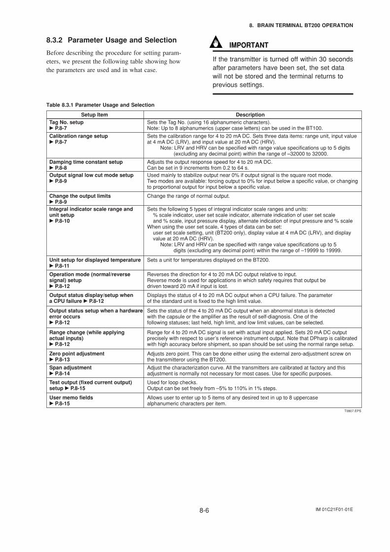
IM 01C21F01-01E8-6
8. BRAIN TERMINAL BT200 OPERATION
8.3.2 Parameter Usage and Selection
Before describing the procedure for setting param-eters, we present the following table showing howthe parameters are used and in what case.
IMPORTANT
If the transmitter is turned off within 30 secondsafter parameters have been set, the set datawill not be stored and the terminal returns toprevious settings.
Table 8.3.1 Parameter Usage and Selection
Setup Item DescriptionTag No. setup P.8-7
Sets the Tag No. (using 16 alphanumeric characters).Note: Up to 8 alphanumerics (upper case letters) can be used in the BT100.
Calibration range setup P.8-7
Sets the calibration range for 4 to 20 mA DC. Sets three data items: range unit, input valueat 4 mA DC (LRV), and input value at 20 mA DC (HRV).
Note: LRV and HRV can be specified with range value specifications up to 5 digits (excluding any decimal point) within the range of –32000 to 32000.
Damping time constant setup P.8-8
Adjusts the output response speed for 4 to 20 mA DC.Can be set in 9 increments from 0.2 to 64 s.
Output signal low cut mode setup P.8-9
Used mainly to stabilize output near 0% if output signal is the square root mode.Two modes are available: forcing output to 0% for input below a specific value, or changingto proportional output for input below a specific value.
Integral indicator scale range and unit setup P.8-10
Sets the following 5 types of integral indicator scale ranges and units: % scale indicator, user set scale indicator, alternate indication of user set scale and % scale, input pressure display, alternate indication of input pressure and % scale
When using the user set scale, 4 types of data can be set: user set scale setting, unit (BT200 only), display value at 4 mA DC (LRV), and display value at 20 mA DC (HRV).
Note: LRV and HRV can be specified with range value specifications up to 5 digits (excluding any decimal point) within the range of –19999 to 19999.
Change the output limits P.8-9
Change the range of normal output.
T0807.EPS
Unit setup for displayed temperature P.8-11
Sets a unit for temperatures displayed on the BT200.
Operation mode (normal/reverse signal) setup P.8-12
Reverses the direction for 4 to 20 mA DC output relative to input.Reverse mode is used for applications in which safety requires that output be driven toward 20 mA if input is lost.
Output status display/setup when a CPU failure P.8-12
Displays the status of 4 to 20 mA DC output when a CPU failure. The parameter of the standard unit is fixed to the high limit value.
Output status setup when a hardware error occurs P.8-12
Sets the status of the 4 to 20 mA DC output when an abnormal status is detected with the capsule or the amplifier as the result of self-diagnosis. One of the following statuses; last held, high limit, and low limit values, can be selected.
Range change (while applying actual inputs) P.8-12
Range for 4 to 20 mA DC signal is set with actual input applied. Sets 20 mA DC output precisely with respect to user’s reference instrument output. Note that DPharp is calibratedwith high accuracy before shipment, so span should be set using the normal range setup.
Zero point adjustment P.8-13
Adjusts zero point. This can be done either using the external zero-adjustment screw onthe transmitteror using the BT200.
Span adjustment P.8-14
Adjust the characterization curve. All the transmitters are calibrated at factory and this adjustment is normally not necessary for most cases. Use for specific purposes.
Test output (fixed current output) setup P.8-15
Used for loop checks.Output can be set freely from –5% to 110% in 1% steps.
User memo fields P.8-15
Allows user to enter up to 5 items of any desired text in up to 8 uppercase alphanumeric characters per item.
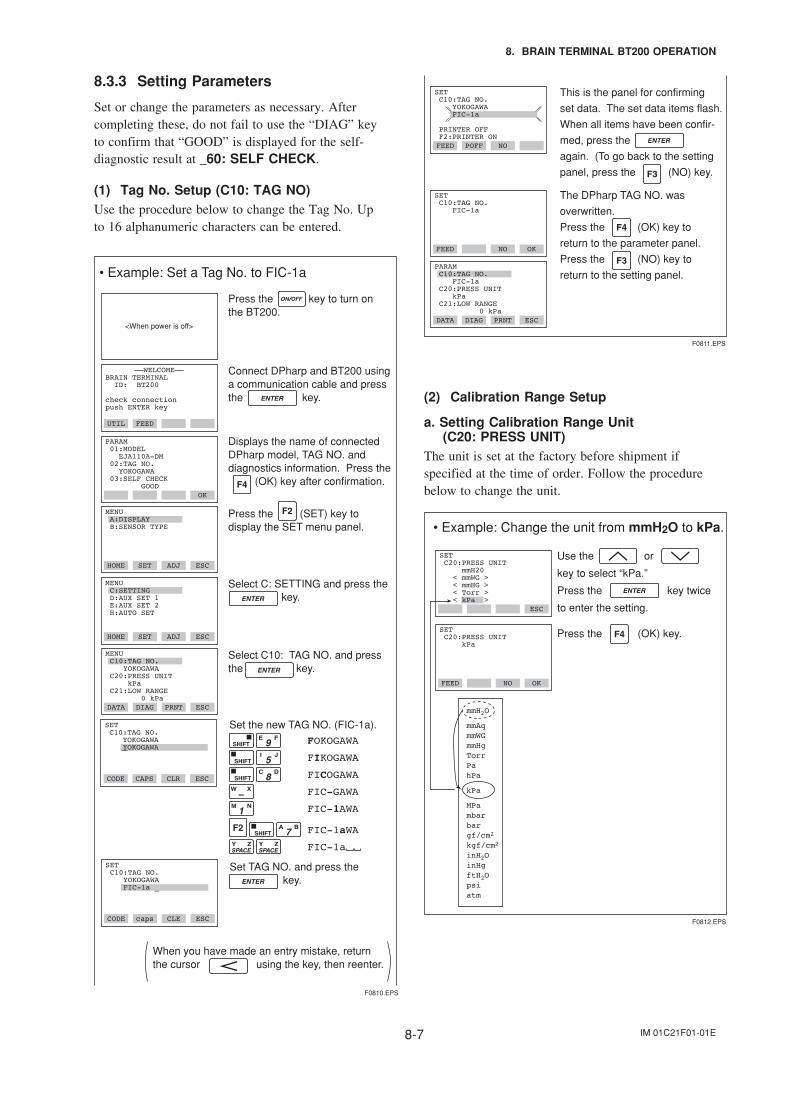
IM 01C21F01-01E8-7
8. BRAIN TERMINAL BT200 OPERATION
8.3.3 Setting Parameters
Set or change the parameters as necessary. Aftercompleting these, do not fail to use the “DIAG” keyto confirm that “GOOD” is displayed for the self-diagnostic result at _60: SELF CHECK.
(1) Tag No. Setup (C10: TAG NO)Use the procedure below to change the Tag No. Upto 16 alphanumeric characters can be entered.
Press the key to turn on the BT200.
Connect DPharp and BT200 using a communication cable and press the key.
PARAM 01:MODEL EJA110A-DM 02:TAG NO. YOKOGAWA 03:SELF CHECK GOOD
OK
MENU A:DISPLAY B:SENSOR TYPE
HOME SET ADJ ESC
MENU C:SETTING D:AUX SET 1 E:AUX SET 2 H:AUTO SET
HOME SET ADJ ESC
MENU C10:TAG NO. YOKOGAWA C20:PRESS UNIT kPa C21:LOW RANGE 0 kPaDATA DIAG PRNT ESC
<When power is off>
Select C: SETTING and press the key.
Select C10: TAG NO. and pressthe key.
Displays the name of connected DPharp model, TAG NO. and diagnostics information. Press the (OK) key after confirmation.
Press the (SET) key to display the SET menu panel.
––WELCOME––BRAIN TERMINAL ID: BT200
check connection push ENTER key
UTIL FEED
F0810.EPS
SET C10:TAG NO. YOKOGAWA YOKOGAWA
CODE CAPS CLR ESC
When you have made an entry mistake, return the cursor using the key, then reenter.
Set the new TAG NO. (FIC-1a).
FOKOGAWA
FIKOGAWA
FICOGAWA
FIC-GAWA
FIC-1AWA
FIC-1aWA
FIC-1a
Set TAG NO. and press the key.
SET C10:TAG NO. YOKOGAWA FIC-1a _
CODE caps CLE ESC
• Example: Set a Tag No. to FIC-1a
SET C10:TAG NO. FIC-1a
FEED NO OK
DATA DIAG PRNT ESC
This is the panel for confirming
set data. The set data items flash.
When all items have been confir-
med, press the
again. (To go back to the setting
panel, press the (NO) key.
SET C10:TAG NO. YOKOGAWA FIC-1a
PRINTER OFF F2:PRINTER ON
PARAM C10:TAG NO. FIC-1a C20:PRESS UNIT kPa C21:LOW RANGE 0 kPa
FEED POFF NO
The DPharp TAG NO. was
overwritten.
Press the (OK) key to
return to the parameter panel.
Press the (NO) key to
return to the setting panel.
F0811.EPS
(2) Calibration Range Setup
a. Setting Calibration Range Unit(C20: PRESS UNIT)
The unit is set at the factory before shipment ifspecified at the time of order. Follow the procedurebelow to change the unit.
mmH2O
mmAqmmWGmmHgTorrPahPa
kPa
MPambarbargf/cm2
kgf/cm2
inH2OinHgftH2Opsiatm
• Example: Change the unit from mmH2O to kPa.
ESC
SET C20:PRESS UNIT kPa
FEED NO OK
SET C20:PRESS UNIT mmH20 < mmWG > < mmHG > < Torr > < kPa >
Use the or
key to select “kPa.”
Press the key twice
to enter the setting.
Press the (OK) key.
F0812.EPS
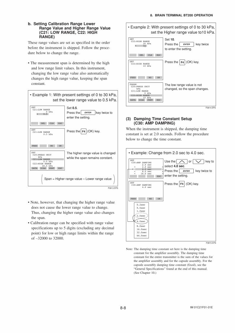
IM 01C21F01-01E8-8
8. BRAIN TERMINAL BT200 OPERATION
b. Setting Calibration Range LowerRange Value and Higher Range Value(C21: LOW RANGE, C22: HIGHRANGE)
These range values are set as specified in the orderbefore the instrument is shipped. Follow the proce-dure below to change the range.
• The measurement span is determined by the highand low range limit values. In this instrument,changing the low range value also automaticallychanges the high range value, keeping the spanconstant.
• Example 1: With present settings of 0 to 30 kPa, set the lower range value to 0.5 kPa.
Span = Higher range value – Lower range value
FEED NO OK
SET C21:LOW RANGE 0.5 kPa
DATA DIAG PRNT ESC
SET C20:PRESS UNIT kPa C21:LOW RANGE 0.5 kPa C22:HIGH RANGE 30.5 kPa
DEL CLR ESC
SET C21:LOW RANGE 0 kPa + 0.5
The higher range value is changed
while the span remains constant.
Set 0.5.
Press the key twice to
enter the setting.
Press the (OK) key.
F0813.EPS
• Note, however, that changing the higher range valuedoes not cause the lower range value to change.Thus, changing the higher range value also changesthe span.
• Calibration range can be specified with range valuespecifications up to 5 digits (excluding any decimalpoint) for low or high range limits within the rangeof –32000 to 32000.
• Example 2: With present settings of 0 to 30 kPa, set the Higher range value to10 kPa.
FEED NO OK
SET C22:HIGH RANGE 10 kPa
DATA DIAG PRNT ESC
PARAM C20:PRESS UNIT kPa C21:LOW RANGE 0 kPa C22:HIGH RANGE 10 kPa
DEL CLR ESC
SET C22:HIGH RANGE 30 kPa + 10
The low range value is not changed, so the span changes.
Set 10.
Press the key twice
to enter the setting.
F0814.EPS
Press the (OK) key.
(3) Damping Time Constant Setup(C30: AMP DAMPING)
When the instrument is shipped, the damping timeconstant is set at 2.0 seconds. Follow the procedurebelow to change the time constant.
• Example: Change from 2.0 sec to 4.0 sec.
ESC
SET C30:AMP DAMPING 4.0 sec
FEED NO OK
SET C30:AMP DAMPING 2.0 sec < 2.0 sec > < 4.0 sec > < 8.0 sec > < 16.0 sec >
Use the or key to
select 4.0 sec.
Press the key twice to
enter the setting.
F0815.EPS
0.2sec
0.5sec
1.0sec
2.0sec
4.0sec
8.0sec
16.0sec
32.0sec
64.0sec
Press the (OK) key.
Note: The damping time constant set here is the damping timeconstant for the amplifier assembly. The damping timeconstant for the entire transmitter is the sum of the values forthe amplifier assembly and for the capsule assembly. For thecapsule assembly damping time constant (fixed), see the“General Specifications” found at the end of this manual.(See Chapter 10.)
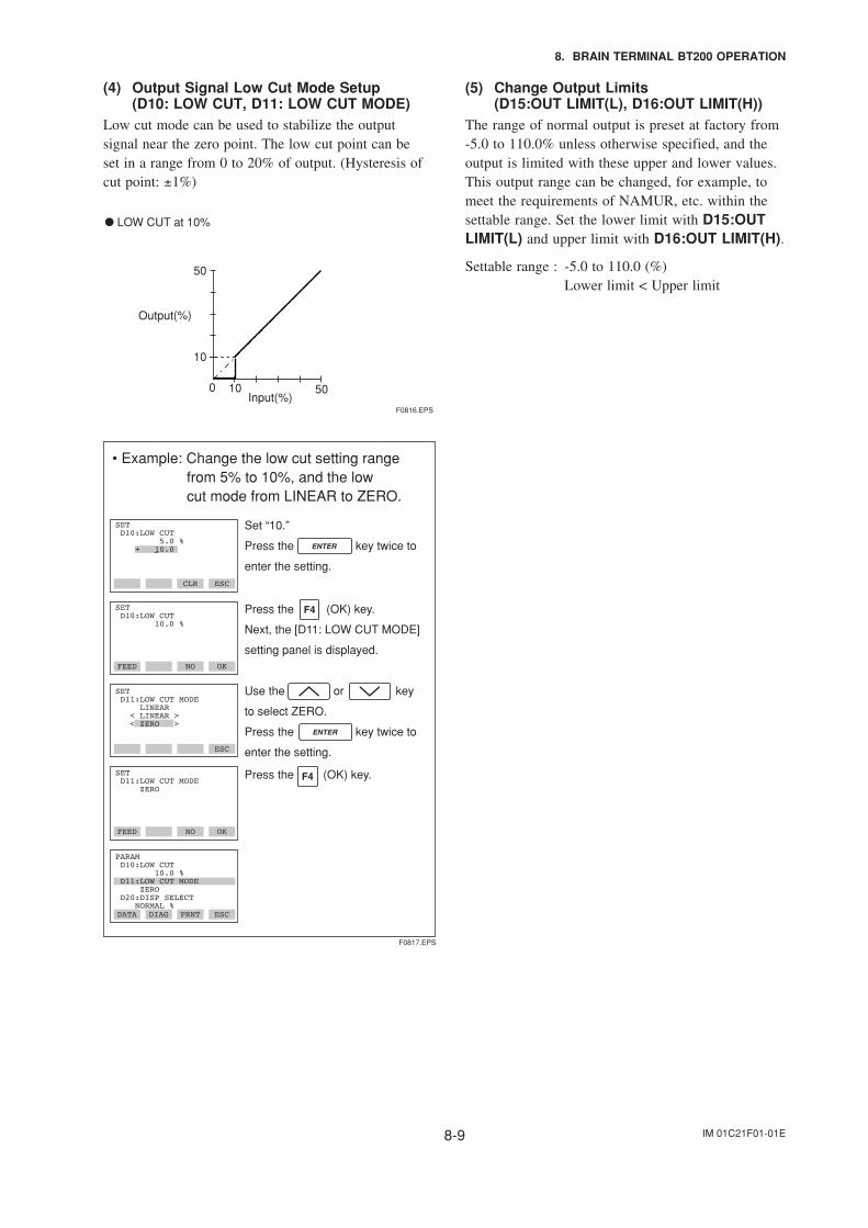
IM 01C21F01-01E8-9
8. BRAIN TERMINAL BT200 OPERATION
(4) Output Signal Low Cut Mode Setup(D10: LOW CUT, D11: LOW CUT MODE)
Low cut mode can be used to stabilize the outputsignal near the zero point. The low cut point can beset in a range from 0 to 20% of output. (Hysteresis ofcut point: ±1%)
(%)
50
10
100 50 Input(%)
Output
LOW CUT at 10%
F0816.EPS
• Example: Change the low cut setting range from 5% to 10%, and the low cut mode from LINEAR to ZERO.
FEED NO OK
SET D11:LOW CUT MODE ZERO
Use the or key
to select ZERO.
Press the key twice to
enter the setting.
Press the (OK) key.
F0817.EPS
FEED NO OK
SET D10:LOW CUT 10.0 %
ESC
SET D11:LOW CUT MODE LINEAR < LINEAR > < ZERO >
DATA DIAG PRNT ESC
PARAM D10:LOW CUT 10.0 % D11:LOW CUT MODE ZERO D20:DISP SELECT NORMAL %
CLR ESC
SET D10:LOW CUT 5.0 % + 10.0
Set “10.”
Press the key twice to
enter the setting.
Press the (OK) key.
Next, the [D11: LOW CUT MODE]
setting panel is displayed.
(5) Change Output Limits(D15:OUT LIMIT(L), D16:OUT LIMIT(H))
The range of normal output is preset at factory from-5.0 to 110.0% unless otherwise specified, and theoutput is limited with these upper and lower values.This output range can be changed, for example, tomeet the requirements of NAMUR, etc. within thesettable range. Set the lower limit with D15:OUTLIMIT(L) and upper limit with D16:OUT LIMIT(H).
Settable range : -5.0 to 110.0 (%)Lower limit < Upper limit
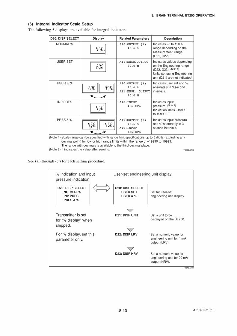
IM 01C21F01-01E8-10
8. BRAIN TERMINAL BT200 OPERATION
(6) Integral Indicator Scale SetupThe following 5 displays are available for integral indicators.
T0808.EPS
D20: DISP SELECT Display Related Parameters
NORMAL %
USER SET
USER & %
INP PRES
PRES & %
Indicates –5 to 110% range depending on the Measurement range (C21, C22).
Indicates values depending on the Engineering range (D22, D23). (Note 1) Units set using Engineering unit (D21) are not indicated.
Indicates user set and % alternately in 3 second intervals.
Indicates input pressure. (Note 2)
Indication limits –19999 to 19999.
Indicates input pressure and % alternately in 3 second intervals.
A10:OUTPUT (%)45.6 %
Description
A11:ENGR.OUTPUT20.0 M
A10:OUTPUT (%)45.6 %
A11:ENGR. OUTPUT20.0 M
A40:INPUT456 kPa
A10:OUTPUT (%)45.6 %
A40:INPUT456 kPa
(Note 1) Scale range can be specified with range limit specifications up to 5 digits (excluding any decimal point) for low or high range limits within the range of –19999 to 19999.The range with decimals is available to the third decimal place.
(Note 2) It indicates the value after zeroing.
See (a.) through (c.) for each setting procedure.
% indication and input pressure indication
Transmitter is set for “% display” when shipped.
D20: DISP SELECT NORMAL % INP PRES PRES & %
User-set engineering unit display
D20: DISP SELECT USER SET USER & %
D21: DISP UNIT
D22: DISP LRV
D23: DISP HRV
Set for user-set engineering unit display.
Set a unit to be displayed on the BT200.
For % display, set this parameter only.
Set a numeric value for engineering unit for 4 mA output (LRV).
Set a numeric value for engineering unit for 20 mA output (HRV).
F0818.EPS
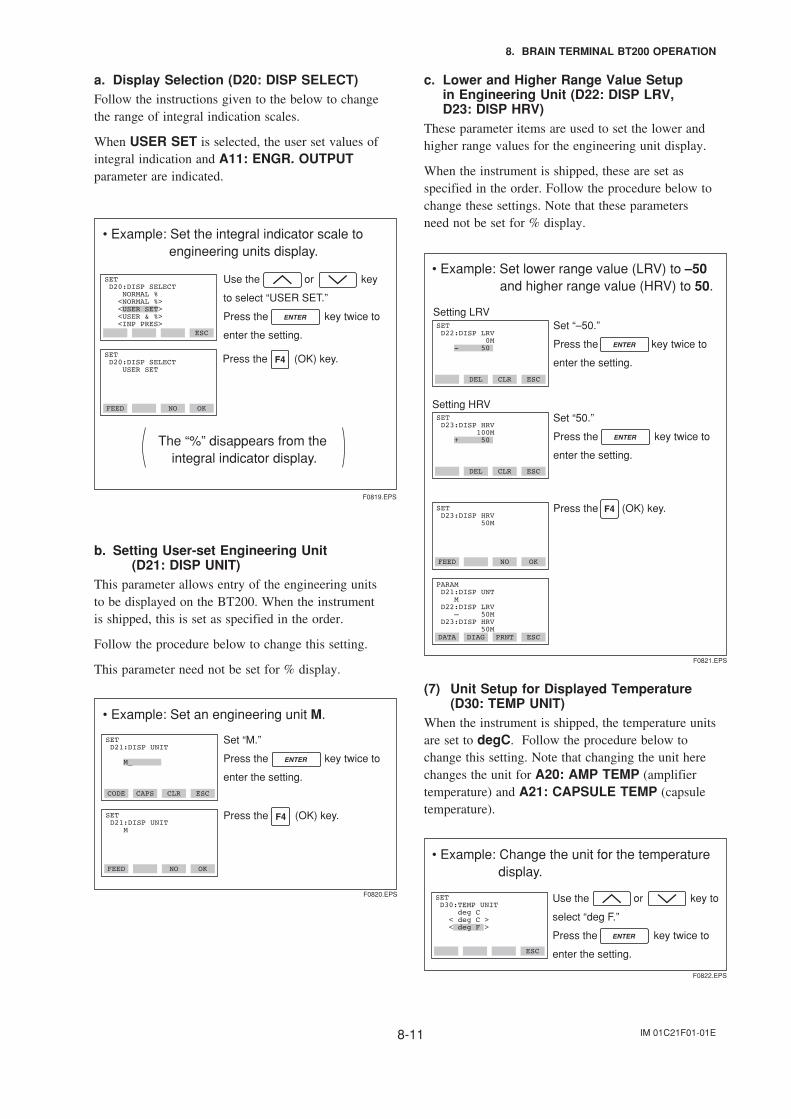
IM 01C21F01-01E8-11
8. BRAIN TERMINAL BT200 OPERATION
a. Display Selection (D20: DISP SELECT)Follow the instructions given to the below to changethe range of integral indication scales.
When USER SET is selected, the user set values ofintegral indication and A11: ENGR. OUTPUTparameter are indicated.
• Example: Set the integral indicator scale to engineering units display.
The “%” disappears from the integral indicator display.
ESC
SET D20:DISP SELECT USER SET
FEED NO OK
SET D20:DISP SELECT NORMAL % <NORMAL %> <USER SET> <USER & %> <INP PRES>
Use the or key
to select “USER SET.”
Press the key twice to
enter the setting.
Press the (OK) key.
F0819.EPS
b. Setting User-set Engineering Unit(D21: DISP UNIT)
This parameter allows entry of the engineering unitsto be displayed on the BT200. When the instrumentis shipped, this is set as specified in the order.
Follow the procedure below to change this setting.
This parameter need not be set for % display.
• Example: Set an engineering unit M.
CODE CAPS CLR ESC
SET D21:DISP UNIT M
FEED NO OK
SET D21:DISP UNIT M_
Set “M.”
Press the key twice to
enter the setting.
Press the (OK) key.
F0820.EPS
c. Lower and Higher Range Value Setupin Engineering Unit (D22: DISP LRV,D23: DISP HRV)
These parameter items are used to set the lower andhigher range values for the engineering unit display.
When the instrument is shipped, these are set asspecified in the order. Follow the procedure below tochange these settings. Note that these parametersneed not be set for % display.
• Example: Set lower range value (LRV) to –50 and higher range value (HRV) to 50.
FEED NO OK
SET D23:DISP HRV 50M
Press the (OK) key.
F0821.EPS
DEL CLR ESC
DATA DIAG PRNT ESC
PARAM D21:DISP UNT M D22:DISP LRV – 50M D23:DISP HRV 50M
DEL CLR ESC
SET D22:DISP LRV 0M - 50
Set “–50.”
Press the key twice to
enter the setting.
Setting LRV
Setting HRVSet “50.”
Press the key twice to
enter the setting.
SET D23:DISP HRV 100M + 50
(7) Unit Setup for Displayed Temperature(D30: TEMP UNIT)
When the instrument is shipped, the temperature unitsare set to degC. Follow the procedure below tochange this setting. Note that changing the unit herechanges the unit for A20: AMP TEMP (amplifiertemperature) and A21: CAPSULE TEMP (capsuletemperature).
• Example: Change the unit for the temperature display.
ESC
SET D30:TEMP UNIT deg C < deg C > < deg F >
Use the or key to
select “deg F.”
Press the key twice to
enter the setting.
F0822.EPS
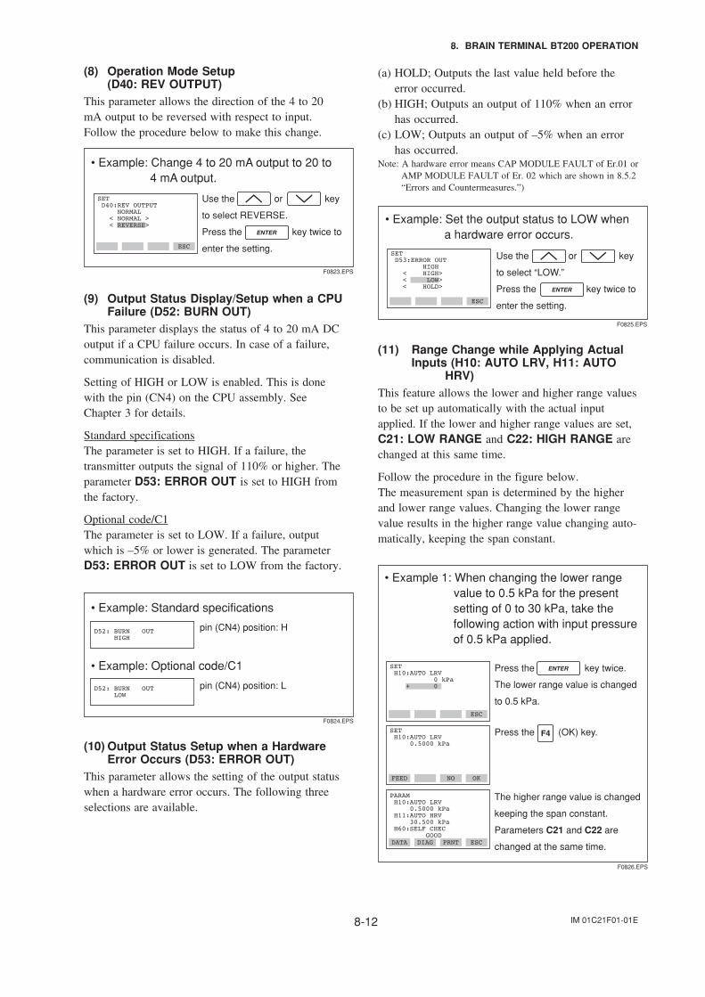
IM 01C21F01-01E8-12
8. BRAIN TERMINAL BT200 OPERATION
(8) Operation Mode Setup(D40: REV OUTPUT)
This parameter allows the direction of the 4 to 20mA output to be reversed with respect to input.Follow the procedure below to make this change.
• Example: Change 4 to 20 mA output to 20 to 4 mA output.
ESC
SET D40:REV OUTPUT NORMAL < NORMAL > < REVERSE>
Use the or key
to select REVERSE.
Press the key twice to
enter the setting.
F0823.EPS
(9) Output Status Display/Setup when a CPUFailure (D52: BURN OUT)
This parameter displays the status of 4 to 20 mA DCoutput if a CPU failure occurs. In case of a failure,communication is disabled.
Setting of HIGH or LOW is enabled. This is donewith the pin (CN4) on the CPU assembly. SeeChapter 3 for details.
Standard specificationsThe parameter is set to HIGH. If a failure, thetransmitter outputs the signal of 110% or higher. Theparameter D53: ERROR OUT is set to HIGH fromthe factory.
Optional code/C1The parameter is set to LOW. If a failure, outputwhich is –5% or lower is generated. The parameterD53: ERROR OUT is set to LOW from the factory.
• Example: Standard specifications
pin (CN4) position: HD52: BURN OUT HIGH
F0824.EPS
• Example: Optional code/C1
pin (CN4) position: LD52: BURN OUT LOW
(10) Output Status Setup when a HardwareError Occurs (D53: ERROR OUT)
This parameter allows the setting of the output statuswhen a hardware error occurs. The following threeselections are available.
(a) HOLD; Outputs the last value held before theerror occurred.
(b) HIGH; Outputs an output of 110% when an errorhas occurred.
(c) LOW; Outputs an output of –5% when an errorhas occurred.
Note: A hardware error means CAP MODULE FAULT of Er.01 orAMP MODULE FAULT of Er. 02 which are shown in 8.5.2“Errors and Countermeasures.”)
• Example: Set the output status to LOW when a hardware error occurs.
ESC
SET D53:ERROR OUT HIGH < HIGH> < LOW> < HOLD>
Use the or key
to select “LOW.”
Press the key twice to
enter the setting.
F0825.EPS
(11) Range Change while Applying ActualInputs (H10: AUTO LRV, H11: AUTO
HRV)This feature allows the lower and higher range valuesto be set up automatically with the actual inputapplied. If the lower and higher range values are set,C21: LOW RANGE and C22: HIGH RANGE arechanged at this same time.
Follow the procedure in the figure below.The measurement span is determined by the higherand lower range values. Changing the lower rangevalue results in the higher range value changing auto-matically, keeping the span constant.
• Example 1: When changing the lower range value to 0.5 kPa for the present
setting of 0 to 30 kPa, take the following action with input pressure of 0.5 kPa applied.
FEED NO OK
SET H10:AUTO LRV 0.5000 kPa
DATA DIAG PRNT ESC
PARAM H10:AUTO LRV 0.5000 kPa H11:AUTO HRV 30.500 kPa H60:SELF CHEC GOOD
ESC
SET H10:AUTO LRV 0 kPa + 0
F0826.EPS
The higher range value is changed
keeping the span constant.
Parameters C21 and C22 are
changed at the same time.
Press the key twice.
The lower range value is changed
to 0.5 kPa.
Press the (OK) key.
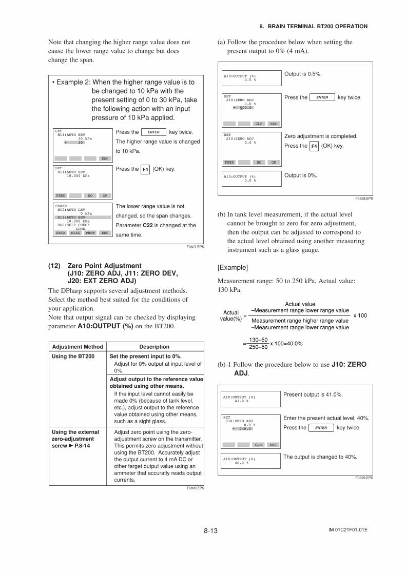
IM 01C21F01-01E8-13
8. BRAIN TERMINAL BT200 OPERATION
Note that changing the higher range value does notcause the lower range value to change but doeschange the span.
• Example 2: When the higher range value is to be changed to 10 kPa with the
present setting of 0 to 30 kPa, take the following action with an input pressure of 10 kPa applied.
FEED NO OK
SET H11:AUTO HRV 10.000 kPa
DATA DIAG PRNT ESC
PARAM H10:AUTO LRV 0 kPa H11:AUTO HRV 10.000 kPa H60:SELF CHECK GOOD
ESC
SET H11:AUTO HRV 30 kPa + 30
The lower range value is not
changed, so the span changes.
Parameter C22 is changed at the
same time.
Press the key twice.
The higher range value is changed
to 10 kPa.
Press the (OK) key.
F0827.EPS
(12) Zero Point Adjustment(J10: ZERO ADJ, J11: ZERO DEV,J20: EXT ZERO ADJ)
The DPharp supports several adjustment methods.Select the method best suited for the conditions ofyour application.Note that output signal can be checked by displayingparameter A10:OUTPUT (%) on the BT200.
Adjustment Method Description
Using the BT200 Set the present input to 0%.
Using the external zero-adjustment screw P.8-14
Adjust zero point using the zero-adjustment screw on the transmitter.This permits zero adjustment without using the BT200. Accurately adjust the output current to 4 mA DC or other target output value using an ammeter that accuratly reads output currents.
Adjust output to the reference value obtained using other means.
Adjust for 0% output at input level of0%.
If the input level cannot easily be made 0% (because of tank level, etc.), adjust output to the reference value obtained using other means, such as a sight glass.
T0809.EPS
(a) Follow the procedure below when setting thepresent output to 0% (4 mA).
FEED NO OK
SET J10:ZERO ADJ 0.0 %
CLR ESC
SET J10:ZERO ADJ 0.0 % + 000.0
Press the key twice.
Zero adjustment is completed.
Press the (OK) key.
F0828.EPS
Output is 0.5%.A10:OUTPUT (%) 0.5 %
Output is 0%.A10:OUTPUT (%) 0.0 %
(b) In tank level measurement, if the actual levelcannot be brought to zero for zero adjustment,then the output can be adjusted to correspond tothe actual level obtained using another measuringinstrument such as a glass gauge.
[Example]
Measurement range: 50 to 250 kPa, Actual value:130 kPa.
Actual value
Actual value(%) x 100
130–50250–50
= x 100=40.0%
–Measurement range lower range valueMeasurement range higher range value
–Measurement range lower range value=
(b)-1 Follow the procedure below to use J10: ZEROADJ.
CLR ESC
SET J10:ZERO ADJ 0.0 % + 040.0
Enter the present actual level, 40%.
Press the key twice.
The output is changed to 40%.
F0829.EPS
Present output is 41.0%.A10:OUTPUT (%) 41.0 %
A10:OUTPUT (%) 40.0 %
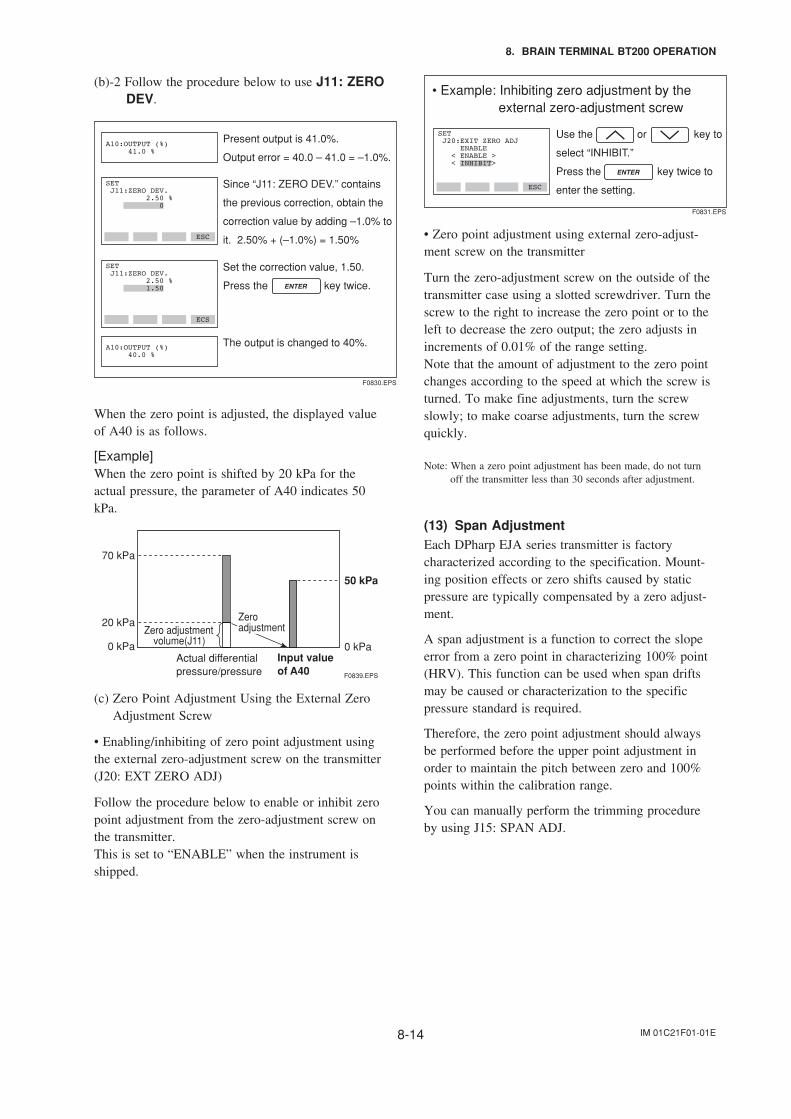
IM 01C21F01-01E8-14
8. BRAIN TERMINAL BT200 OPERATION
(b)-2 Follow the procedure below to use J11: ZERODEV.
ECS
ESC
SET J11:ZERO DEV. 2.50 % 0
Since “J11: ZERO DEV.” contains
the previous correction, obtain the
correction value by adding –1.0% to
it. 2.50% + (–1.0%) = 1.50%
Set the correction value, 1.50.
Press the key twice.
F0830.EPS
Present output is 41.0%.
Output error = 40.0 – 41.0 = –1.0%.A10:OUTPUT (%) 41.0 %
The output is changed to 40%.A10:OUTPUT (%) 40.0 %
SET J11:ZERO DEV. 2.50 % 1.50
When the zero point is adjusted, the displayed valueof A40 is as follows.
[Example]When the zero point is shifted by 20 kPa for theactual pressure, the parameter of A40 indicates 50kPa.
F0839.EPS
70 kPa
20 kPa
0 kPa
Zero adjustmentvolume(J11)
Actual differentialpressure/pressure
Input valueof A40
50 kPa
0 kPa
Zeroadjustment
(c) Zero Point Adjustment Using the External ZeroAdjustment Screw
• Enabling/inhibiting of zero point adjustment usingthe external zero-adjustment screw on the transmitter(J20: EXT ZERO ADJ)
Follow the procedure below to enable or inhibit zeropoint adjustment from the zero-adjustment screw onthe transmitter.This is set to “ENABLE” when the instrument isshipped.
• Example: Inhibiting zero adjustment by the external zero-adjustment screw
ESC
SET J20:EXIT ZERO ADJ ENABLE < ENABLE > < INHIBIT>
Use the or key to
select “INHIBIT.”
Press the key twice to
enter the setting.
F0831.EPS
• Zero point adjustment using external zero-adjust-ment screw on the transmitter
Turn the zero-adjustment screw on the outside of thetransmitter case using a slotted screwdriver. Turn thescrew to the right to increase the zero point or to theleft to decrease the zero output; the zero adjusts inincrements of 0.01% of the range setting.Note that the amount of adjustment to the zero pointchanges according to the speed at which the screw isturned. To make fine adjustments, turn the screwslowly; to make coarse adjustments, turn the screwquickly.
Note: When a zero point adjustment has been made, do not turnoff the transmitter less than 30 seconds after adjustment.
(13) Span AdjustmentEach DPharp EJA series transmitter is factorycharacterized according to the specification. Mount-ing position effects or zero shifts caused by staticpressure are typically compensated by a zero adjust-ment.
A span adjustment is a function to correct the slopeerror from a zero point in characterizing 100% point(HRV). This function can be used when span driftsmay be caused or characterization to the specificpressure standard is required.
Therefore, the zero point adjustment should alwaysbe performed before the upper point adjustment inorder to maintain the pitch between zero and 100%points within the calibration range.
You can manually perform the trimming procedureby using J15: SPAN ADJ.
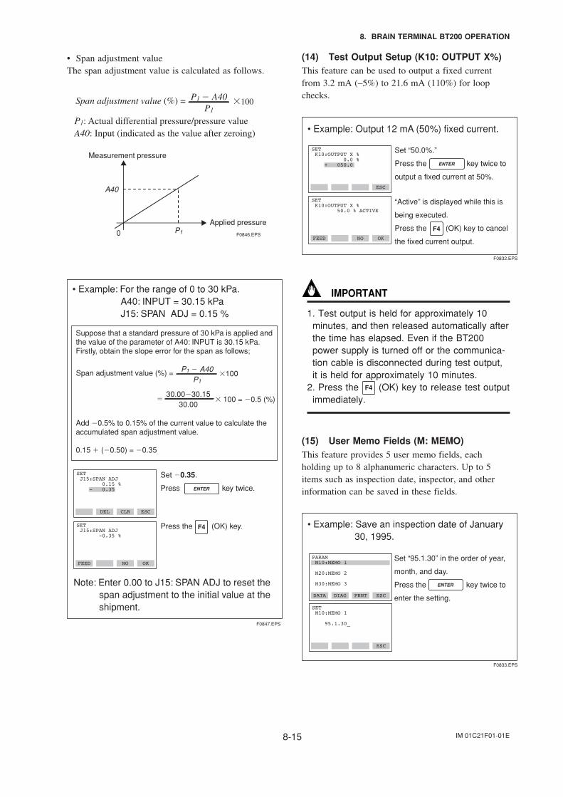
IM 01C21F01-01E8-15
8. BRAIN TERMINAL BT200 OPERATION
• Span adjustment valueThe span adjustment value is calculated as follows.
Span adjustment value (%) =
P1: Actual differential pressure/pressure valueA40: Input (indicated as the value after zeroing)
Measurement pressure
Applied pressure
P1 A40P1
100
A40
P10 F0846.EPS
• Example: For the range of 0 to 30 kPa. A40: INPUT = 30.15 kPa J15: SPAN ADJ = 0.15 %
Suppose that a standard pressure of 30 kPa is applied and the value of the parameter of A40: INPUT is 30.15 kPa.Firstly, obtain the slope error for the span as follows;
Add 0.5% to 0.15% of the current value to calculate the accumulated span adjustment value.
0.15 (0.50) = 0.35
F0847.EPS
FEED NO OK
SET J15:SPAN ADJ -0.35 %
ESCCLRDEL
SET J15:SPAN ADJ 0.15 % - 0.35
Set 0.35.
Press key twice.
Press the (OK) key.
30.0030.1530.00
100 = 0.5 (%)
Span adjustment value (%) =
Note: Enter 0.00 to J15: SPAN ADJ to reset the span adjustment to the initial value at the shipment.
P1 A40P1
100
(14) Test Output Setup (K10: OUTPUT X%)This feature can be used to output a fixed currentfrom 3.2 mA (–5%) to 21.6 mA (110%) for loopchecks.
• Example: Output 12 mA (50%) fixed current.
ESC
SET K10:OUTPUT X % 50.0 % ACTIVE
FEED NO OK
SET K10:OUTPUT X % 0.0 % + 050.0
Set “50.0%.”
Press the key twice to
output a fixed current at 50%.
“Active” is displayed while this is
being executed.
Press the (OK) key to cancel
the fixed current output.
F0832.EPS
IMPORTANT
1. Test output is held for approximately 10minutes, and then released automatically afterthe time has elapsed. Even if the BT200power supply is turned off or the communica-tion cable is disconnected during test output,it is held for approximately 10 minutes.
2. Press the (OK) key to release test outputimmediately.
(15) User Memo Fields (M: MEMO)This feature provides 5 user memo fields, eachholding up to 8 alphanumeric characters. Up to 5items such as inspection date, inspector, and otherinformation can be saved in these fields.
• Example: Save an inspection date of January 30, 1995.
DATA DIAG PRNT ESC
SET M10:MEMO 1
95.1.30_
ESC
PARAM M10:MEMO 1
M20:MEMO 2
M30:MEMO 3
Set “95.1.30” in the order of year,
month, and day.
Press the key twice to
enter the setting.
F0833.EPS
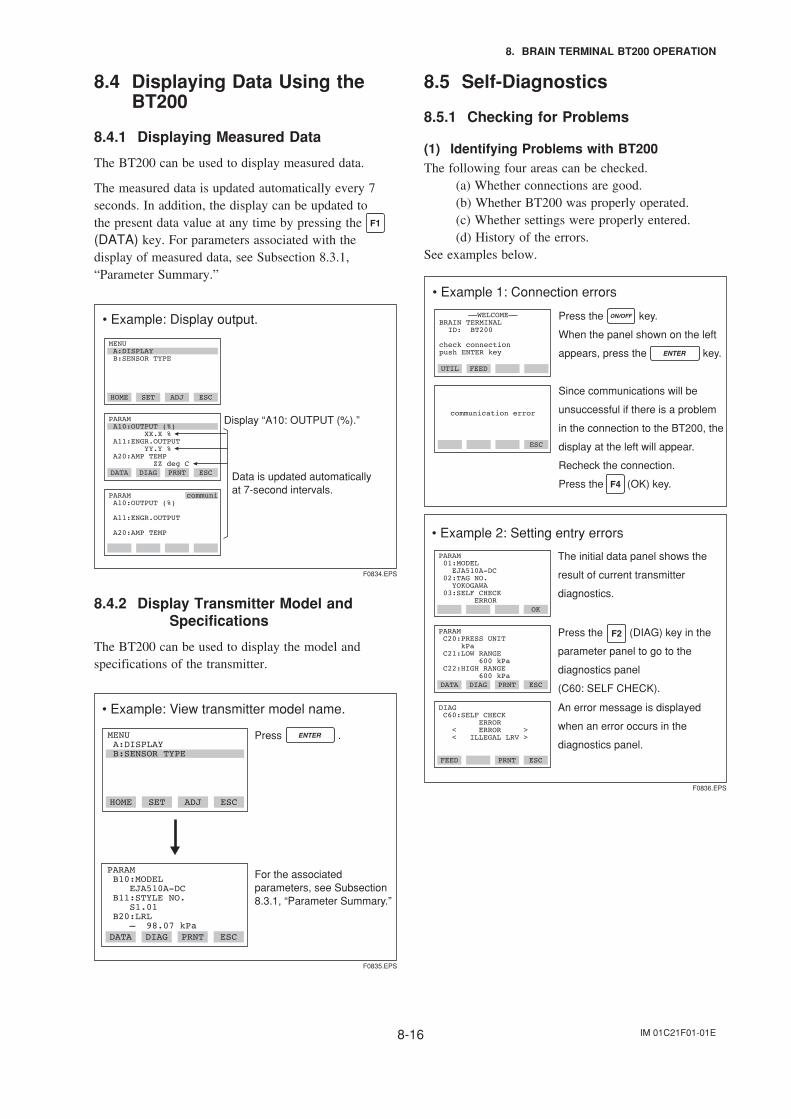
IM 01C21F01-01E8-16
8. BRAIN TERMINAL BT200 OPERATION
8.4 Displaying Data Using theBT200
8.4.1 Displaying Measured Data
The BT200 can be used to display measured data.
The measured data is updated automatically every 7seconds. In addition, the display can be updated tothe present data value at any time by pressing the (DATA) key. For parameters associated with thedisplay of measured data, see Subsection 8.3.1,“Parameter Summary.”
• Example: Display output.
DATA DIAG PRNT ESC
PARAM A10:OUTPUT (%) A11:ENGR.OUTPUT A20:AMP TEMP
HOME SET ADJ ESC
MENU A:DISPLAY B:SENSOR TYPE
F0834.EPS
Data is updated automatically at 7-second intervals.
Display “A10: OUTPUT (%).”PARAM A10:OUTPUT (%) XX.X % A11:ENGR.OUTPUT YY.Y % A20:AMP TEMP ZZ deg C
communi
8.4.2 Display Transmitter Model andSpecifications
The BT200 can be used to display the model andspecifications of the transmitter.
• Example: View transmitter model name.
HOME SET ADJ ESC
MENU A:DISPLAY B:SENSOR TYPE
DATA DIAG PRNT ESC
PARAM B10:MODEL EJA510A-DC B11:STYLE NO. S1.01 B20:LRL – 98.07 kPa
For the associated parameters, see Subsection 8.3.1, “Parameter Summary.”
Press .
F0835.EPS
8.5 Self-Diagnostics
8.5.1 Checking for Problems
(1) Identifying Problems with BT200The following four areas can be checked. (a) Whether connections are good. (b) Whether BT200 was properly operated. (c) Whether settings were properly entered. (d) History of the errors.See examples below.
• Example 1: Connection errors
ESC
communication error
Press the key.
When the panel shown on the left
appears, press the key.
Since communications will be
unsuccessful if there is a problem
in the connection to the BT200, the
display at the left will appear.
Recheck the connection.
Press the (OK) key.
––WELCOME––BRAIN TERMINAL ID: BT200
check connection push ENTER key
UTIL FEED
• Example 2: Setting entry errors
F0836.EPS
The initial data panel shows the
result of current transmitter
diagnostics.
DATA DIAG PRNT ESC
PARAM C20:PRESS UNIT kPa C21:LOW RANGE 600 kPa C22:HIGH RANGE 600 kPa
FEED PRNT ESC
DIAG C60:SELF CHECK ERROR < ERROR > < ILLEGAL LRV >
Press the (DIAG) key in the
parameter panel to go to the
diagnostics panel
(C60: SELF CHECK).
An error message is displayed
when an error occurs in the
diagnostics panel.
OK
PARAM 01:MODEL EJA510A-DC 02:TAG NO. YOKOGAWA 03:SELF CHECK ERROR
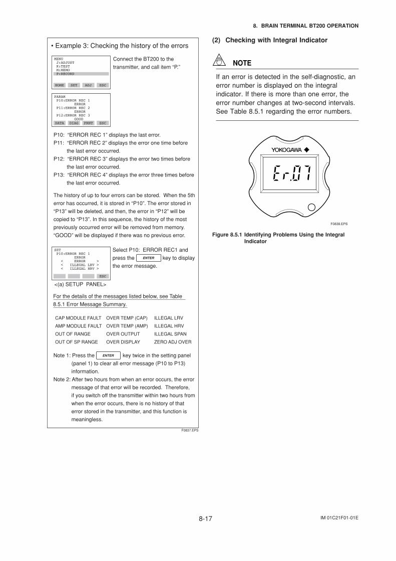
IM 01C21F01-01E8-17
8. BRAIN TERMINAL BT200 OPERATION
• Example 3: Checking the history of the errors
Connect the BT200 to the
transmitter, and call item “P.”
The history of up to four errors can be stored. When the 5th
error has occurred, it is stored in “P10”. The error stored in
“P13” will be deleted, and then, the error in “P12” will be
copied to “P13”. In this sequence, the history of the most
previously occurred error will be removed from memory.
“GOOD” will be displayed if there was no previous error.
F0837.EPS
HOME SET ADJ ESC
MENU J:ADJUST K:TEST M:MEMO P:RECORD
DATA DIAG PRNT ESC
PARAM P10:ERROR REC 1 ERROR P11:ERROR REC 2 ERROR P12:ERROR REC 3 GOOD
For the details of the messages listed below, see Table
8.5.1 Error Message Summary.
ESC
SET P10:ERROR REC 1 ERROR < ERROR > < ILLEGAL LRV > < ILLEGAL HRV >
<(a) SETUP PANEL>
Note 1: Press the key twice in the setting panel
(panel 1) to clear all error message (P10 to P13)
information.
Note 2: After two hours from when an error occurs, the error
message of that error will be recorded. Therefore,
if you switch off the transmitter within two hours from
when the error occurs, there is no history of that
error stored in the transmitter, and this function is
meaningless.
CAP MODULE FAULT
AMP MODULE FAULT
OUT OF RANGE
OUT OF SP RANGE
OVER TEMP (CAP)
OVER TEMP (AMP)
OVER OUTPUT
OVER DISPLAY
ILLEGAL LRV
ILLEGAL HRV
ILLEGAL SPAN
ZERO ADJ OVER
P10: “ERROR REC 1” displays the last error.
P11: “ERROR REC 2” displays the error one time before
the last error occurred.
P12: “ERROR REC 3” displays the error two times before
the last error occurred.
P13: “ERROR REC 4” displays the error three times before
the last error occurred.
Select P10: ERROR REC1 and
press the key to display
the error message.
(2) Checking with Integral Indicator
NOTE
If an error is detected in the self-diagnostic, anerror number is displayed on the integralindicator. If there is more than one error, theerror number changes at two-second intervals.See Table 8.5.1 regarding the error numbers.
F0838.EPS
Figure 8.5.1 Identifying Problems Using the IntegralIndicator
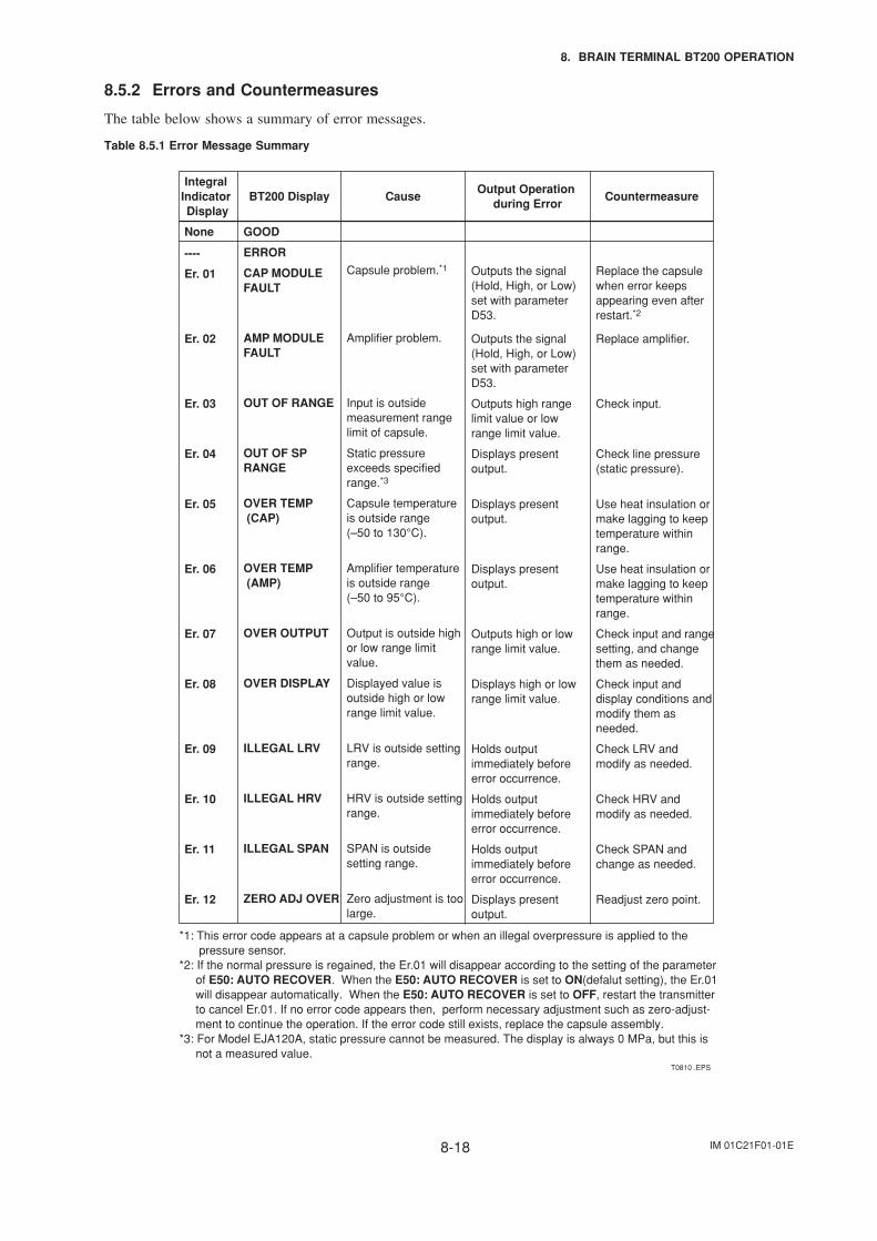
IM 01C21F01-01E8-18
8. BRAIN TERMINAL BT200 OPERATION
8.5.2 Errors and Countermeasures
The table below shows a summary of error messages.
Table 8.5.1 Error Message Summary
Integral Indicator Display
BT200 Display Cause CountermeasureOutput Operation
during Error
None
----
GOOD
ERROR
Er. 01 CAP MODULE FAULT
Er. 02 AMP MODULE FAULT
Er. 03 OUT OF RANGE
Er. 04 OUT OF SP RANGE
Er. 05 OVER TEMP (CAP)
Er. 06 OVER TEMP (AMP)
Er. 07 OVER OUTPUT
Er. 08 OVER DISPLAY
Er. 09 ILLEGAL LRV
Er. 10 ILLEGAL HRV
Er. 11 ILLEGAL SPAN
Er. 12 ZERO ADJ OVER
Static pressure exceeds specified range.*3
Capsule temperature is outside range (–50 to 130°C).
Amplifier temperature is outside range (–50 to 95°C).
Output is outside high or low range limit value.
Displayed value is outside high or low range limit value.
LRV is outside setting range.
HRV is outside setting range.
SPAN is outside setting range.
Zero adjustment is too large.
T0810 .EPS
Capsule problem.*1
Amplifier problem.
Input is outside measurement range limit of capsule.
Displays present output.
Displays present output.
Displays present output.
Outputs high or low range limit value.
Displays high or low range limit value.
Holds output immediately before error occurrence.
Holds output immediately before error occurrence.
Holds output immediately before error occurrence.
Displays present output.
Outputs the signal (Hold, High, or Low) set with parameter D53.
Outputs the signal (Hold, High, or Low) set with parameter D53.
Outputs high range limit value or low range limit value.
Check line pressure (static pressure).
Use heat insulation or make lagging to keep temperature within range.
Use heat insulation or make lagging to keep temperature within range.
Check input and range setting, and change them as needed.
Check input and display conditions and modify them as needed.
Check LRV and modify as needed.
Check HRV and modify as needed.
Check SPAN and change as needed.
Readjust zero point.
Replace the capsule when error keepsappearing even afterrestart.*2
Replace amplifier.
Check input.
*1: This error code appears at a capsule problem or when an illegal overpressure is applied to the pressure sensor. *2: If the normal pressure is regained, the Er.01 will disappear according to the setting of the parameter of E50: AUTO RECOVER. When the E50: AUTO RECOVER is set to ON(defalut setting), the Er.01 will disappear automatically. When the E50: AUTO RECOVER is set to OFF, restart the transmitter to cancel Er.01. If no error code appears then, perform necessary adjustment such as zero-adjust- ment to continue the operation. If the error code still exists, replace the capsule assembly.*3: For Model EJA120A, static pressure cannot be measured. The display is always 0 MPa, but this is not a measured value.
IM 01C21F01-01E9-1
9. MAINTENANCE
9. MAINTENANCE
9.1 Overview
WARNING
Since the accumulated process fluid may betoxic or otherwise harmful, take appropriate careto avoid contact with the body, or inhalation ofvapors even after dismounting the instrumentfrom the process line for maintenance.
Maintenance of the transmitter is easy due to itsmodular construction. This chapter describes theprocedures for calibration, adjustment, and the disas-sembly and reassembly procedures required forcomponent replacement.
Since the transmitters are precision instruments,carefully and thoroughly read the following sectionsfor proper handling during maintenance.
IMPORTANT
• As a rule, maintenance of this transmittershould be implemented in a maintenanceservice shop where the necessary tools areprovided.
• The CPU assembly contains sensitive partsthat may be damaged by static electricity.Exercise care so as not to directly touch theelectronic parts or circuit patterns on the board,for example, by preventing static electrificationby using grounded wrist straps when handlingthe assembly. Also take precautions such asplacing a removed CPU assembly into a bagwith an antistatic coating.
9.2 Calibration Instruments Se-lection
Table 9.2.1 shows the instruments required for calibra-tion. Select instruments that will enable the transmitterto be calibrated or adjusted to the required accuracy.
The calibration instruments should be handled carefullyso as to maintain the specified accuracy.
9.3 Calibration
Use the procedure below to check instrument operationand accuracy during periodic maintenance or trouble-shooting.
1) Connect the instruments as shown in Figure 9.3.1and warm up the instruments for at least fiveminutes.
IMPORTANT
• To adjust the transmitter for highest accuracy,make adjustments with the power supplyvoltage and load resistance including leadwireresistances set close to the conditions underwhich the transmitter is installed.
• If the measurement range 0% point is 0 kPa orshifted in the positive direction (suppressedzero), the reference pressure should be appliedas shown in the figure.If the measurement range 0% point is shifted inthe negative direction (elevated zero), thereference pressure should be applied using avacuum pump.
• Do not perform the calibration procedure untilthe transmitter is at room temperature.
2) Apply reference pressures of 0%, 50%, and 100% ofthe measurement range to the transmitter. Calculatethe errors (differences between digital voltmeterreadings and reference pressures) as the pressure isincreased from 0% to 100% and is decreased from100% to 0%, and confirm that the errors are withinthe required accuracy.
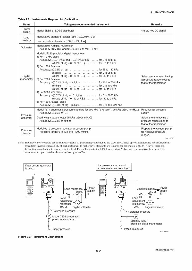
IM 01C21F01-01E9-2
9. MAINTENANCE
Table 9.2.1 Instruments Required for Calibration
Name RemarksYokogawa-recommended Instrument
Power supply Model SDBT or SDBS distributor
Load resistor
Model 2792 standard resistor [250 Ω ±0.005%, 3 W]
Load adjustment resistor [100 Ω ±1%, 1 W]
VoltmeterModel 2501 A digital multimeter Accuracy (10V DC range): ±(0.002% of rdg + 1 dgt)
Digital manometer
Model MT220 precision digital manometer1) For 10 kPa class
Accuracy: ±(0.015% of rdg + 0.015% of F.S.)±(0.2% of rdg + 0.1% of F.S.)
2) For 130 kPa classAccuracy: ±0.02% of rdg
±5digits±(0.2% of rdg + 0.1% of F.S.)
3) For 700 kPa classAccuracy: ±(0.02% of rdg + 3digits)
±5 digits ±(0.2% of rdg + 0.1% of F.S.)
4) For 3000 kPa classAccuracy: ±(0.02% of rdg + 10 digits)
±(0.2% of rdg + 0.1% of F.S.) 5) For 130 kPa abs class
Accuracy: ±(0.03% of rdg + 6 digits)
4 to 20 mA DC signal
Select a manometer having a pressure range close to that of the transmitter.
Pressure generator
Model 7674 pneumatic pressure standard for 200 kPa 2 kgf/cm2, 25 kPa 2500 mmH2OAccuracy: ±0.05% of F.S.
Requires air pressure supply.
Pressure source
Model 6919 pressure regulator (pressure pump)Pressure range: 0 to 133 kPa 1000 mmHg
Prepare the vacuum pump for negative pressure ranges.
Dead weight gauge tester 25 kPa 2500mmH2O Accuracy: ±0.03% of setting
Select the one having a pressure range close to that of the transmitter.
T0901.EPS
for 0 to 10 kPafor -10 to 0 kPa
for 25 to 130 kPafor 0 to 25 kPafor -80 to 0 kPa
for 100 to 700 kPafor 0 to 100 kPafor -80 to 0 kPa
for 0 to 3000 kPafor -80 to 0 kPa
for 0 to 130 kPa abs
. . . . . . . . . . . . . .
. . . . . . . . . . . . . . . . . . . . . . . . . . . . . . . . . . . . . . . . . . . . . . . .
. . . . . . . . .
. . . . . . . . . . . . . . . . . . . . . . . . . . . . . . . . . . . . . .
. . . . . . . . .
. . . . . . . . . . . . . . . . . . . .
. . . . . . . . . . . .
Note: The above table contains the instruments capable of performing calibration to the 0.2% level. Since special maintenance and managementprocedures involving traceability of each instrument to higher-level standards are required for calibration to the 0.1% level, there aredifficulties in calibration to this level in the field. For calibration to the 0.1% level, contact Yokogawa representatives from which theinstrument was purchased or the nearest Yokogawa office.
P
If a pressure generator is used:
Reference pressure
Supply pressure
Model 7674 pneumatic pressure standards
V
RRc
Load resistance,250 Ω
Load adjustment resistance, 100 Ω Digital voltmeter
Power supply E
If a pressure source and a manometer are combined:
Model MT220 precision digital manometer
F0901.EPS
Reference pressure
Pressure source
V
RRc
Load resistance,250 Ω
Load adjustment resistance, 100 Ω Digital voltmeter
Power supply E
P
Figure 9.3.1 Instrument Connections
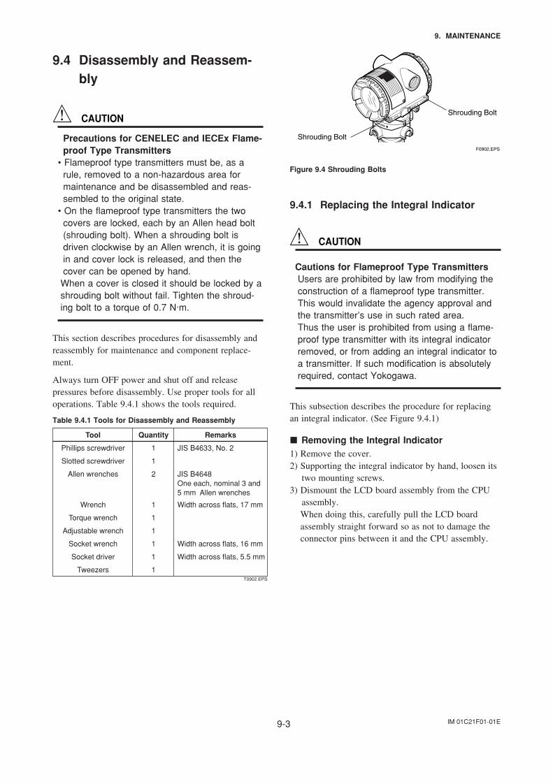
IM 01C21F01-01E9-3
9. MAINTENANCE
9.4 Disassembly and Reassem-bly
CAUTION
Precautions for CENELEC and IECEx Flame-proof Type Transmitters
• Flameproof type transmitters must be, as arule, removed to a non-hazardous area formaintenance and be disassembled and reas-sembled to the original state.
• On the flameproof type transmitters the twocovers are locked, each by an Allen head bolt(shrouding bolt). When a shrouding bolt isdriven clockwise by an Allen wrench, it is goingin and cover lock is released, and then thecover can be opened by hand.
When a cover is closed it should be locked by ashrouding bolt without fail. Tighten the shroud-ing bolt to a torque of 0.7 N·m.
This section describes procedures for disassembly andreassembly for maintenance and component replace-ment.
Always turn OFF power and shut off and releasepressures before disassembly. Use proper tools for alloperations. Table 9.4.1 shows the tools required.
Table 9.4.1 Tools for Disassembly and Reassembly
Tool RemarksQuantity
Phillips screwdriver
Slotted screwdriver
Allen wrenches JIS B4648One each, nominal 3 and 5 mm Allen wrenches
Wrench
Torque wrench
Adjustable wrench
Socket wrench
Socket driver
Tweezers
1
1
2
1
1
1
1
1
1
JIS B4633, No. 2
Width across flats, 17 mm
Width across flats, 16 mm
Width across flats, 5.5 mm
T0902.EPS
Shrouding Bolt
Shrouding Bolt
F0902.EPS
Figure 9.4 Shrouding Bolts
9.4.1 Replacing the Integral Indicator
CAUTION
Cautions for Flameproof Type TransmittersUsers are prohibited by law from modifying theconstruction of a flameproof type transmitter.This would invalidate the agency approval andthe transmitter’s use in such rated area.Thus the user is prohibited from using a flame-proof type transmitter with its integral indicatorremoved, or from adding an integral indicator toa transmitter. If such modification is absolutelyrequired, contact Yokogawa.
This subsection describes the procedure for replacingan integral indicator. (See Figure 9.4.1)
Removing the Integral Indicator1) Remove the cover.2) Supporting the integral indicator by hand, loosen its
two mounting screws.3) Dismount the LCD board assembly from the CPU
assembly.When doing this, carefully pull the LCD boardassembly straight forward so as not to damage theconnector pins between it and the CPU assembly.
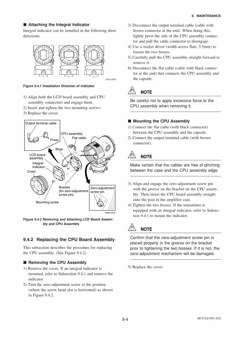
IM 01C21F01-01E9-4
9. MAINTENANCE
Attaching the Integral IndicatorIntegral indicator can be installed in the following threedirections.
F0910.EPS
Figure 9.4.1 Installation Direction of Indicator
1) Align both the LCD board assembly and CPUassembly connectors and engage them.
2) Insert and tighten the two mounting screws.3) Replace the cover.
F0903.EPS
Output terminal cable
LCD board assembly
Integral indicator
Cover
Boss
CPU assemblyFlat cable
Bracket(for zero-adjustment screw pin)
Mounting screw
Zero-adjustmentscrew pin
Press
Figure 9.4.2 Removing and Attaching LCD Board Assem-bly and CPU Assembly
9.4.2 Replacing the CPU Board Assembly
This subsection describes the procedure for replacingthe CPU assembly. (See Figure 9.4.2)
Removing the CPU Assembly1) Remove the cover. If an integral indicator is
mounted, refer to Subsection 9.4.1 and remove theindicator.
2) Turn the zero-adjustment screw to the position(where the screw head slot is horizontal) as shownin Figure 9.4.2.
3) Disconnect the output terminal cable (cable withbrown connector at the end). When doing this,lightly press the side of the CPU assembly connec-tor and pull the cable connector to disengage.
4) Use a socket driver (width across flats, 5.5mm) toloosen the two bosses.
5) Carefully pull the CPU assembly straight forward toremove it.
6) Disconnect the flat cable (cable with black connec-tor at the end) that connects the CPU assembly andthe capsule.
NOTE
Be careful not to apply excessive force to theCPU assembly when removing it.
Mounting the CPU Assembly1) Connect the flat cable (with black connector)
between the CPU assembly and the capsule.2) Connect the output terminal cable (with brown
connector).
NOTE
Make certain that the cables are free of pinchingbetween the case and the CPU assembly edge.
3) Align and engage the zero-adjustment screw pinwith the groove on the bracket on the CPU assem-bly. Then insert the CPU board assembly straightonto the post in the amplifier case.
4) Tighten the two bosses. If the transmitter isequipped with an integral indicator, refer to Subsec-tion 9.4.1 to mount the indicator.
NOTE
Confirm that the zero-adjustment screw pin isplaced properly in the groove on the bracketprior to tightening the two bosses. If it is not, thezero-adjustment mechanism will be damaged.
5) Replace the cover.
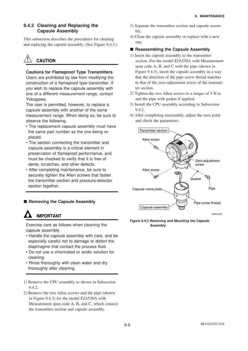
IM 01C21F01-01E9-5
9. MAINTENANCE
9.4.3 Cleaning and Replacing theCapsule Assembly
This subsection describes the procedures for cleaningand replacing the capsule assembly. (See Figure 9.4.3.)
CAUTION
Cautions for Flameproof Type TransmittersUsers are prohibited by law from modifying theconstruction of a flameproof type transmitter. Ifyou wish to replace the capsule assembly withone of a different measurement range, contactYokogawa.The user is permitted, however, to replace acapsule assembly with another of the samemeasurement range. When doing so, be sure toobserve the following.• The replacement capsule assembly must have
the same part number as the one being re-placed.
• The section connecting the transmitter andcapsule assembly is a critical element inpreservation of flameproof performance, andmust be checked to verify that it is free ofdents, scratches, and other defects.
• After completing maintenance, be sure tosecurely tighten the Allen screws that fastenthe transmitter section and pressure-detectorsection together.
Removing the Capsule Assembly
IMPORTANT
Exercise care as follows when cleaning thecapsule assembly.• Handle the capsule assembly with care, and be
especially careful not to damage or distort thediaphragms that contact the process fluid.
• Do not use a chlorinated or acidic solution forcleaning.
• Rinse thoroughly with clean water and drythoroughly after cleaning.
1) Remove the CPU assembly as shown in Subsection9.4.2.
2) Remove the two Allen screws and the pipe (shownin Figure 9.4.3) for the model EJA530A withMeasurement span code A, B, and C, which connectthe transmitter section and capsule assembly.
3) Separate the transmitter section and capsule assem-bly.
4) Clean the capsule assembly or replace with a newone.
Reassembling the Capsule Assembly1) Insert the capsule assembly to the transmitter
section. For the model EJA530A with Measurementspan code A, B, and C with the pipe (shown inFigure 9.4.3), insert the capsule assembly in a waythat the direction of the pipe screw thread matchesto that of the zero-adjustment screw of the transmit-ter section.
2) Tighten the two Allen screws to a torque of 5 N·mand the pipe with gasket if applied.
3) Install the CPU assembly according to Subsection9.4.2.
4) After completing reassembly, adjust the zero pointand check the parameters.
F0904.EPS
Transmitter section
Capsule assembly
Capsule name plate
Pipe screw thread
Zero-adjustment screw
Pipe
Allen screw
Allen screw
Gasket
Figure 9.4.3 Removing and Mounting the CapsuleAssembly
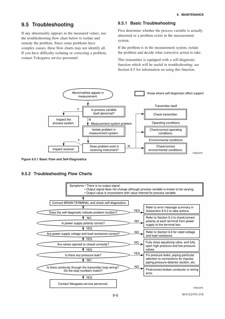
IM 01C21F01-01E9-6
9. MAINTENANCE
9.5 Troubleshooting
If any abnormality appears in the measured values, usethe troubleshooting flow chart below to isolate andremedy the problem. Since some problems havecomplex causes, these flow charts may not identify all.If you have difficulty isolating or correcting a problem,contact Yokogawa service personnel.
9.5.1 Basic Troubleshooting
First determine whether the process variable is actuallyabnormal or a problem exists in the measurementsystem.
If the problem is in the measurement system, isolatethe problem and decide what corrective action to take.
This transmitter is equipped with a self-diagnosticfunction which will be useful in troubleshooting; seeSection 8.5 for information on using this function.
Abnormalities appear inmeasurement.
: Areas where self-diagnostic offers support
Is process variableitself abnormal?
Inspect theprocess system.
Isolate problem inmeasurement system.
Does problem exist inreceiving instrument?
Check/correctenvironmental conditions.Inspect receiver.
Check transmitter.
Check/correct operatingconditions.
Y
Y
NMeasurement system problem
N
Environmental conditions
Operating conditions
Transmitter itself
F0905.EPS
Figure 9.5.1 Basic Flow and Self-Diagnostics
9.5.2 Troubleshooting Flow Charts
Connect BRAIN TERMINAL and check self-diagnostics.
Does the self-diagnostic indicate problem location?
Contact Yokogawa service personnel.F0906.EPS
Symptoms • There is no output signal. • Output signal does not change although process variable is known to be varying. • Output value is inconsistent with value inferred for process variable.
Is power supply polarity correct?
Are power supply voltage and load resistance correct?
Refer to error message summary inSubsection 8.5.2 to take actions.YES
NONO
YES
Refer to Section 6.3 to check/correctpolarity at each terminal from powersupply to the terminal box.
Fix pressure leaks, paying particularattention to connections for impulsepiping,pressure-detector section, etc.
Fully close equalizing valve, and fullyopen high pressure and low pressurevalves.
Refer to Section 6.6 for rated voltage and load resistance.
NO
YESNO
YESYES
NO
Find/correct broken conductor or wiringerror.
NO
YES
Are valves opened or closed correctly?
Is there any pressure leak?
Is there continuity through the transmitter loop wiring? Do the loop numbers match?
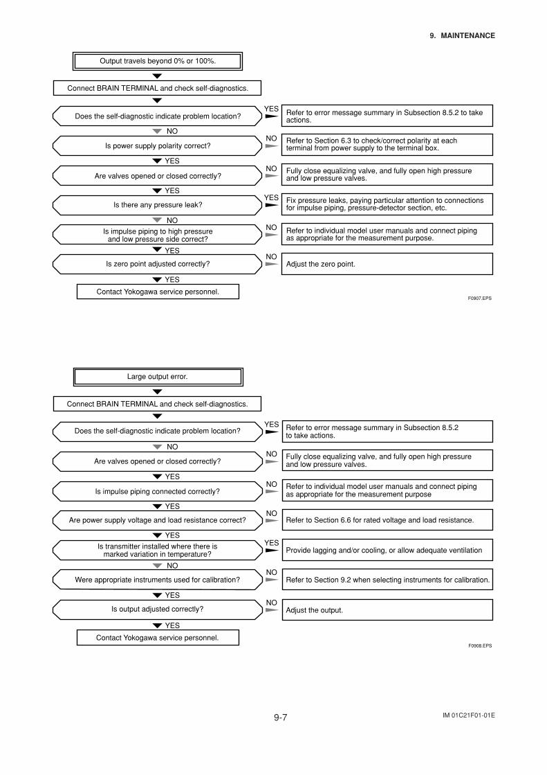
IM 01C21F01-01E9-7
9. MAINTENANCE
Connect BRAIN TERMINAL and check self-diagnostics.
Does the self-diagnostic indicate problem location?
Contact Yokogawa service personnel.F0907.EPS
Is power supply polarity correct?
Are valves opened or closed correctly?
Refer to error message summary in Subsection 8.5.2 to take actions.
YES
NONO
YES
Refer to Section 6.3 to check/correct polarity at eachterminal from power supply to the terminal box.
Refer to individual model user manuals and connect piping as appropriate for the measurement purpose.
Fix pressure leaks, paying particular attention to connections for impulse piping, pressure-detector section, etc.
Fully close equalizing valve, and fully open high pressure and low pressure valves.
NO
YESYES
NO
YES
Adjust the zero point.NO
YES
Is there any pressure leak?
Is impulse piping to high pressureand low pressure side correct?
Is zero point adjusted correctly?
Output travels beyond 0% or 100%.
NO
Connect BRAIN TERMINAL and check self-diagnostics.
Contact Yokogawa service personnel.F0908.EPS
Are valves opened or closed correctly?
Is impulse piping connected correctly?
Refer to error message summary in Subsection 8.5.2 to take actions.
Refer to Section 6.6 for rated voltage and load resistance.
Provide lagging and/or cooling, or allow adequate ventilation
Refer to Section 9.2 when selecting instruments for calibration.
Fully close equalizing valve, and fully open high pressureand low pressure valves.
Refer to individual model user manuals and connect piping as appropriate for the measurement purpose
Adjust the output.
Is transmitter installed where there is marked variation in temperature?
Is output adjusted correctly?
Large output error.
Does the self-diagnostic indicate problem location?
Are power supply voltage and load resistance correct?
Were appropriate instruments used for calibration?
YES
NONO
YESNO
YES
NO
YES
YES
NO
NO
YES
NO
YES
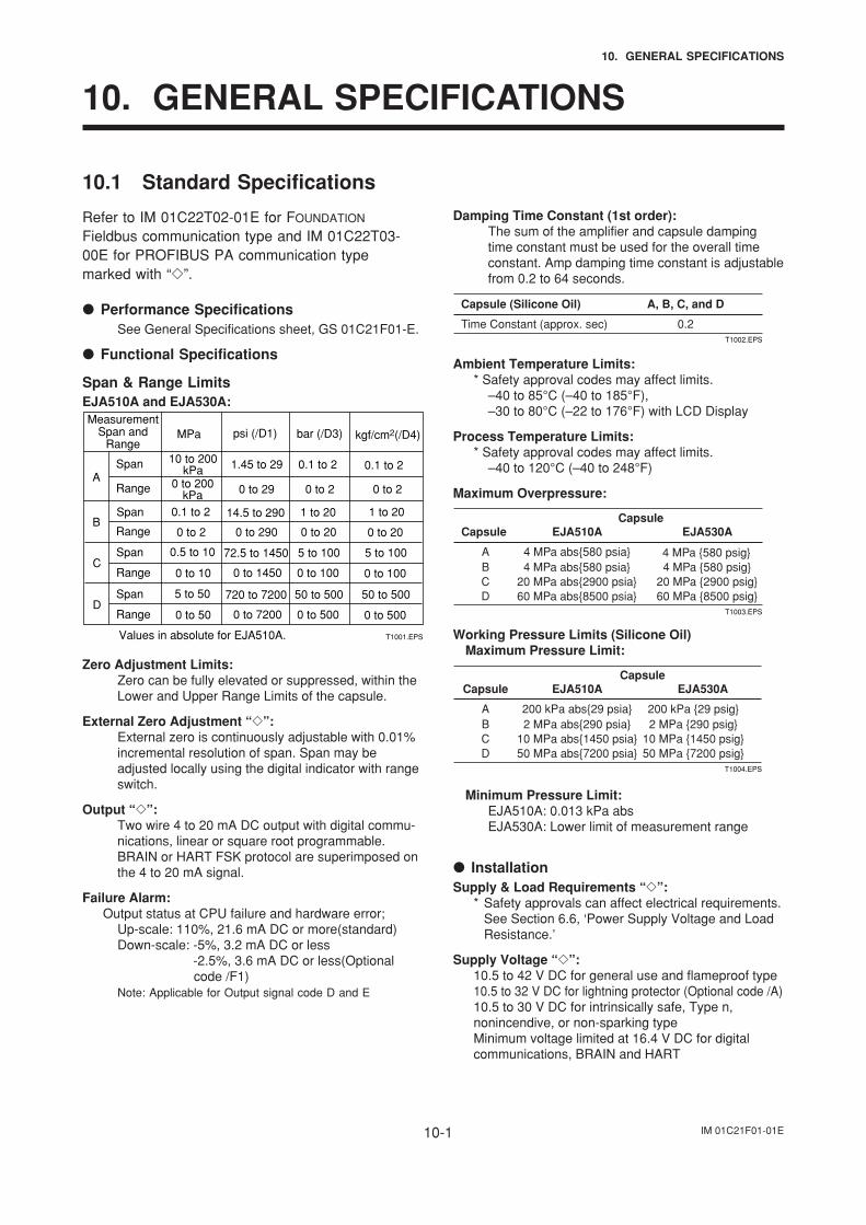
IM 01C21F01-01E10-1
10. GENERAL SPECIFICATIONS
10. GENERAL SPECIFICATIONS
10.1 Standard Specifications
Refer to IM 01C22T02-01E for FOUNDATION
Fieldbus communication type and IM 01C22T03-00E for PROFIBUS PA communication typemarked with “”.
Performance SpecificationsSee General Specifications sheet, GS 01C21F01-E.
Functional Specifications
Span & Range LimitsEJA510A and EJA530A:
A
B
MeasurementSpan and
Range
Span
Range
Span
Range
psi (/D1)
1.45 to 29
0 to 29
14.5 to 290
0 to 290
bar (/D3)
0.1 to 2
kgf/cm2(/D4)
0.1 to 2
0 to 2
1 to 20
0 to 20
0 to 2
1 to 20
0 to 20
MPa
10 to 200kPa
0 to 200kPa
0.1 to 2
0 to 2
72.5 to 14500.5 to 10
0 to 10C
Span
Range 0 to 1450
5 to 100
0 to 100
5 to 100
0 to 100
720 to 72005 to 50
0 to 50D
Span
Range 0 to 7200
50 to 500
0 to 500
50 to 500
0 to 500
T1001.EPSValues in absolute for EJA510A.
Zero Adjustment Limits:Zero can be fully elevated or suppressed, within theLower and Upper Range Limits of the capsule.
External Zero Adjustment “”:External zero is continuously adjustable with 0.01%incremental resolution of span. Span may beadjusted locally using the digital indicator with rangeswitch.
Output “”:Two wire 4 to 20 mA DC output with digital commu-nications, linear or square root programmable.BRAIN or HART FSK protocol are superimposed onthe 4 to 20 mA signal.
Failure Alarm:Output status at CPU failure and hardware error;
Up-scale: 110%, 21.6 mA DC or more(standard)Down-scale: -5%, 3.2 mA DC or less
-2.5%, 3.6 mA DC or less(Optionalcode /F1)
Note: Applicable for Output signal code D and E
Damping Time Constant (1st order):The sum of the amplifier and capsule dampingtime constant must be used for the overall timeconstant. Amp damping time constant is adjustablefrom 0.2 to 64 seconds.
Time Constant (approx. sec) 0.2
A, B, C, and D
T1002.EPS
Capsule (Silicone Oil)
Ambient Temperature Limits:* Safety approval codes may affect limits.
–40 to 85°C (–40 to 185°F),–30 to 80°C (–22 to 176°F) with LCD Display
Process Temperature Limits:* Safety approval codes may affect limits.
–40 to 120°C (–40 to 248°F)
Maximum Overpressure:
A 4 MPa abs580 psia 4 MPa 580 psigB 4 MPa abs580 psia 4 MPa 580 psigC 20 MPa abs2900 psia 20 MPa 2900 psigD 60 MPa abs8500 psia 60 MPa 8500 psig
EJA530AEJA510A
T1003.EPS
Capsule Capsule
Working Pressure Limits (Silicone Oil)Maximum Pressure Limit:
A 200 kPa abs29 psia 200 kPa 29 psigB 2 MPa abs290 psia 2 MPa 290 psigC 10 MPa abs1450 psia 10 MPa 1450 psigD 50 MPa abs7200 psia 50 MPa 7200 psig
EJA530AEJA510A
T1004.EPS
Capsule Capsule
Minimum Pressure Limit:EJA510A: 0.013 kPa absEJA530A: Lower limit of measurement range
InstallationSupply & Load Requirements “”:
* Safety approvals can affect electrical requirements.See Section 6.6, ‘Power Supply Voltage and LoadResistance.’
Supply Voltage “”:10.5 to 42 V DC for general use and flameproof type10.5 to 32 V DC for lightning protector (Optional code /A)10.5 to 30 V DC for intrinsically safe, Type n,nonincendive, or non-sparking typeMinimum voltage limited at 16.4 V DC for digitalcommunications, BRAIN and HART
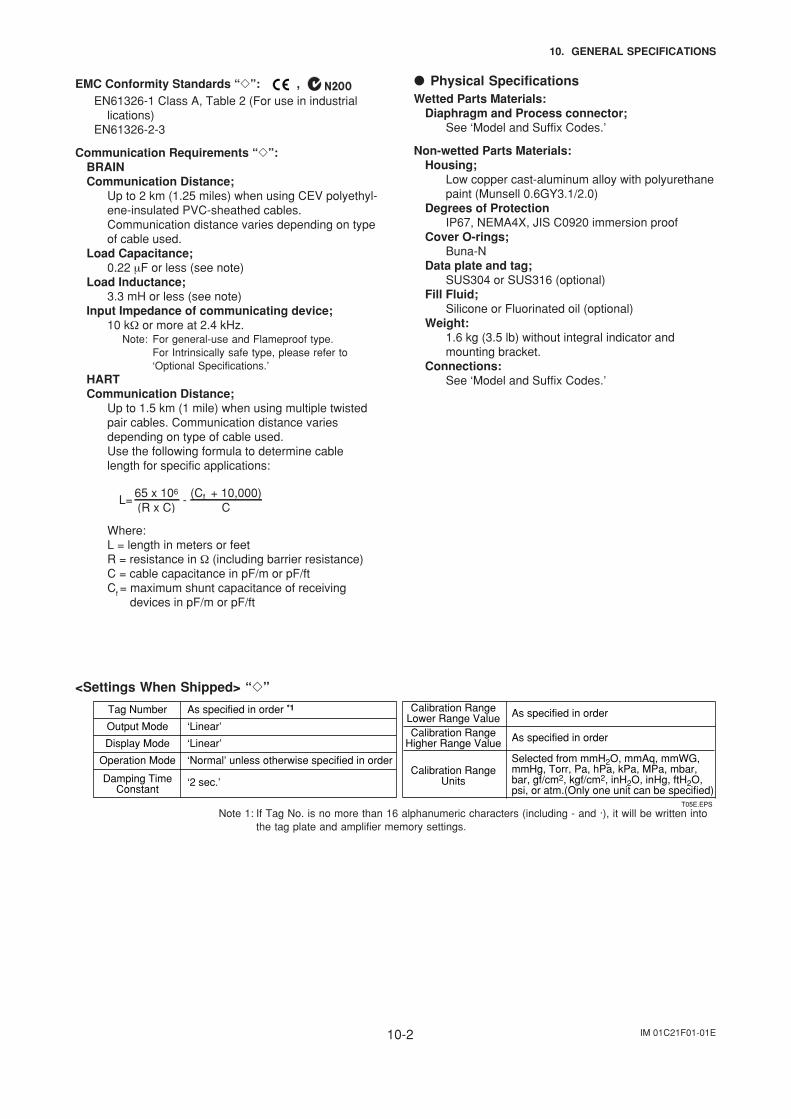
IM 01C21F01-01E10-2
10. GENERAL SPECIFICATIONS
EMC Conformity Standards “”: , EN61326-1 Class A, Table 2 (For use in industrial
lications)EN61326-2-3
Communication Requirements “”:BRAINCommunication Distance;
Up to 2 km (1.25 miles) when using CEV polyethyl-ene-insulated PVC-sheathed cables.Communication distance varies depending on typeof cable used.
Load Capacitance;0.22 µF or less (see note)
Load Inductance;3.3 mH or less (see note)
Input Impedance of communicating device;10 kΩ or more at 2.4 kHz.
Note: For general-use and Flameproof type.For Intrinsically safe type, please refer to‘Optional Specifications.’
HARTCommunication Distance;
Up to 1.5 km (1 mile) when using multiple twistedpair cables. Communication distance variesdepending on type of cable used.Use the following formula to determine cablelength for specific applications:
L= -65 x 106
(R x C)(Cf + 10,000)
C
Where:L = length in meters or feetR = resistance in Ω (including barrier resistance)C = cable capacitance in pF/m or pF/ftCf = maximum shunt capacitance of receiving
devices in pF/m or pF/ft
<Settings When Shipped> “”
Tag Number
Output Mode
Display Mode
Operation Mode
Damping TimeConstant
As specified in order *1
‘Linear’
‘2 sec.’
‘Normal’ unless otherwise specified in order
‘Linear’
Calibration RangeUnits
As specified in order
As specified in order
Selected from mmH2O, mmAq, mmWG, mmHg, Torr, Pa, hPa, kPa, MPa, mbar, bar, gf/cm2, kgf/cm2, inH2O, inHg, ftH2O, psi, or atm.(Only one unit can be specified)
Calibration RangeHigher Range Value
Calibration RangeLower Range Value
T05E.EPS
Note 1: If Tag No. is no more than 16 alphanumeric characters (including - and ·), it will be written intothe tag plate and amplifier memory settings.
Physical SpecificationsWetted Parts Materials:
Diaphragm and Process connector;See ‘Model and Suffix Codes.’
Non-wetted Parts Materials:Housing;
Low copper cast-aluminum alloy with polyurethanepaint (Munsell 0.6GY3.1/2.0)
Degrees of ProtectionIP67, NEMA4X, JIS C0920 immersion proof
Cover O-rings;Buna-N
Data plate and tag;SUS304 or SUS316 (optional)
Fill Fluid;Silicone or Fluorinated oil (optional)
Weight:1.6 kg (3.5 lb) without integral indicator andmounting bracket.
Connections:See ‘Model and Suffix Codes.’
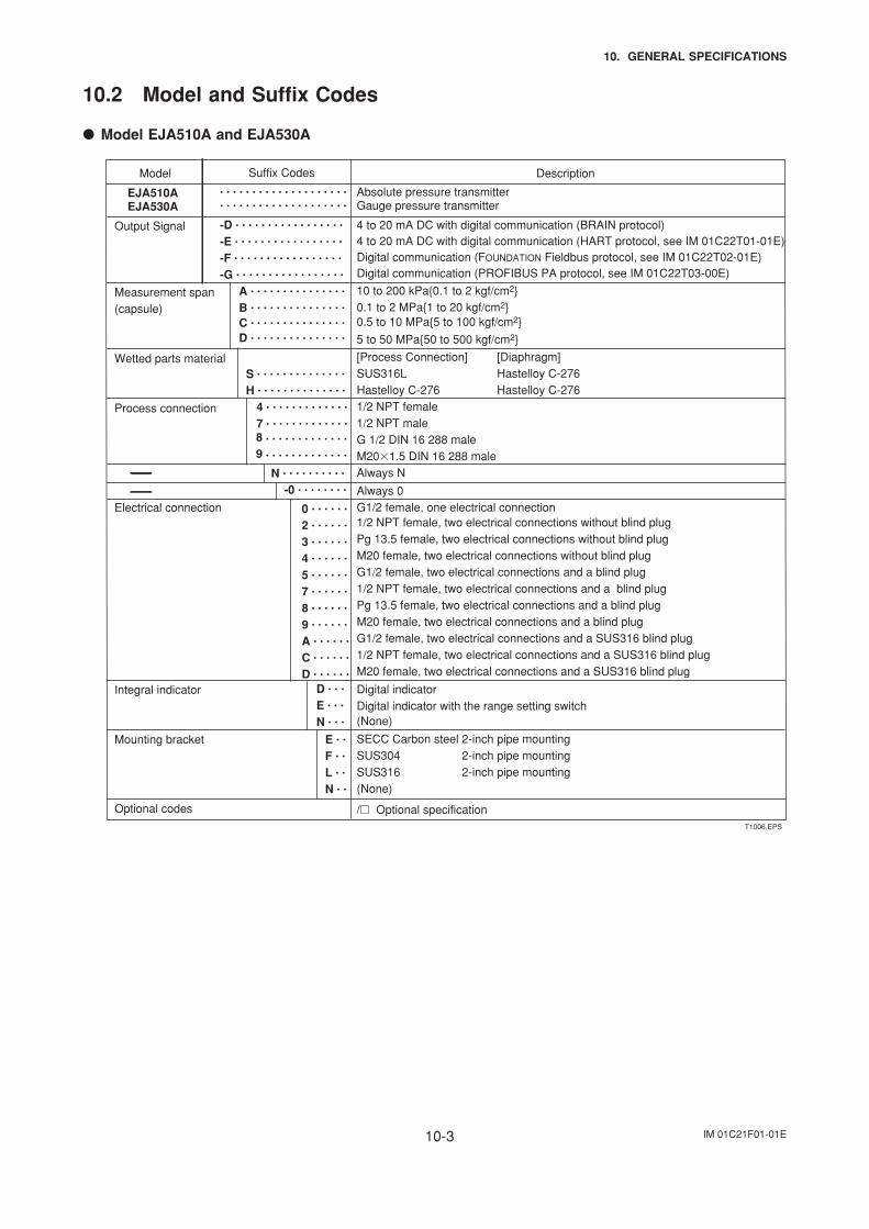
IM 01C21F01-01E10-3
10. GENERAL SPECIFICATIONS
10.2 Model and Suffix Codes
Model EJA510A and EJA530A
. . . . . . . . . . . . . . . . . . . .
. . . . . . . . . . . . . . . . . . . .
-D . . . . . . . . . . . . . . . . .
-E . . . . . . . . . . . . . . . . .
-F . . . . . . . . . . . . . . . . .
-G . . . . . . . . . . . . . . . . .
A . . . . . . . . . . . . . . .
B . . . . . . . . . . . . . . . C . . . . . . . . . . . . . . .
D . . . . . . . . . . . . . . .
S . . . . . . . . . . . . . .
H . . . . . . . . . . . . . .
4 . . . . . . . . . . . . .
7 . . . . . . . . . . . . . 8 . . . . . . . . . . . . .
9 . . . . . . . . . . . . .
N . . . . . . . . . .
-0 . . . . . . . .
0 . . . . . .
2 . . . . . .
3 . . . . . .
4 . . . . . .
5 . . . . . .
7 . . . . . .
8 . . . . . .
9 . . . . . .
A . . . . . .
C . . . . . .
D . . . . . .
D . . .
E . . .
N . . .
E . .
F . .
L . .
N . .
Model Description
EJA510A EJA530A
Output Signal
Measurement span(capsule)
Wetted parts material
Process connection
Electrical connection
Integral indicator
Mounting bracket
Optional codes
Absolute pressure transmitterGauge pressure transmitter
4 to 20 mA DC with digital communication (BRAIN protocol)4 to 20 mA DC with digital communication (HART protocol, see IM 01C22T01-01E)Digital communication (FOUNDATION Fieldbus protocol, see IM 01C22T02-01E)Digital communication (PROFIBUS PA protocol, see IM 01C22T03-00E)
10 to 200 kPa0.1 to 2 kgf/cm20.1 to 2 MPa1 to 20 kgf/cm20.5 to 10 MPa5 to 100 kgf/cm2
5 to 50 MPa50 to 500 kgf/cm2
[Process Connection] [Diaphragm]SUS316L Hastelloy C-276 Hastelloy C-276 Hastelloy C-276 1/2 NPT female1/2 NPT male G 1/2 DIN 16 288 maleM201.5 DIN 16 288 maleAlways N
Always 0G1/2 female, one electrical connection 1/2 NPT female, two electrical connections without blind plug Pg 13.5 female, two electrical connections without blind plug M20 female, two electrical connections without blind plugG1/2 female, two electrical connections and a blind plug1/2 NPT female, two electrical connections and a blind plug Pg 13.5 female, two electrical connections and a blind plug M20 female, two electrical connections and a blind plugG1/2 female, two electrical connections and a SUS316 blind plug1/2 NPT female, two electrical connections and a SUS316 blind plugM20 female, two electrical connections and a SUS316 blind plug
Digital indicatorDigital indicator with the range setting switch(None)
SECC Carbon steel 2-inch pipe mountingSUS304 2-inch pipe mountingSUS316 2-inch pipe mounting(None)
/ Optional specification
Suffix Codes
T1006.EPS
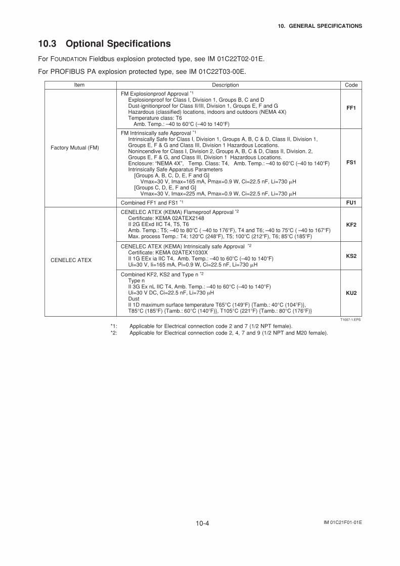
IM 01C21F01-01E10-4
10. GENERAL SPECIFICATIONS
10.3 Optional Specifications
For FOUNDATION Fieldbus explosion protected type, see IM 01C22T02-01E.
For PROFIBUS PA explosion protected type, see IM 01C22T03-00E.
Item Description Code
Factory Mutual (FM)
CENELEC ATEX (KEMA) Intrinsically safe Approval *2
Certificate: KEMA 02ATEX1030X II 1G EEx ia IIC T4, Amb. Temp.: –40 to 60C (–40 to 140F) Ui=30 V, Ii=165 mA, Pi=0.9 W, Ci=22.5 nF, Li=730 H
KS2
FM Intrinsically safe Approval *1
Intrinsically Safe for Class I, Division 1, Groups A, B, C & D, Class II, Division 1, Groups E, F & G and Class III, Division 1 Hazardous Locations. Nonincendive for Class I, Division 2, Groups A, B, C & D, Class II, Division. 2, Groups E, F & G, and Class III, Division 1 Hazardous Locations. Enclosure: “NEMA 4X”, Temp. Class: T4, Amb. Temp.: –40 to 60C (–40 to 140F) Intrinsically Safe Apparatus Parameters [Groups A, B, C, D, E, F and G] Vmax=30 V, Imax=165 mA, Pmax=0.9 W, Ci=22.5 nF, Li=730 H [Groups C, D, E, F and G] Vmax=30 V, Imax=225 mA, Pmax=0.9 W, Ci=22.5 nF, Li=730 H
FS1
CENELEC ATEX (KEMA) Flameproof Approval *2
Certificate: KEMA 02ATEX2148 II 2G EExd IIC T4, T5, T6 Amb. Temp.: T5; –40 to 80C ( –40 to 176F), T4 and T6; –40 to 75C ( –40 to 167F) Max. process Temp.: T4; 120C (248F), T5; 100C (212F), T6; 85C (185F)
KF2
FM Explosionproof Approval *1 Explosionproof for Class I, Division 1, Groups B, C and D Dust-ignitionproof for Class II/III, Division 1, Groups E, F and G Hazardous (classified) locations, indoors and outdoors (NEMA 4X) Temperature class: T6 Amb. Temp.: –40 to 60C (–40 to 140F)
FF1
FU1Combined FF1 and FS1 *1
Combined KF2, KS2 and Type n *2
Type n II 3G Ex nL IIC T4, Amb. Temp.: –40 to 60°C (–40 to 140°F) Ui=30 V DC, Ci=22.5 nF, Li=730 µH Dust II 1D maximum surface temperature T65°C (149F) Tamb.: 40°C (104F), T85°C (185F) Tamb.: 60°C (140F), T105°C (221F) Tamb.: 80°C (176F)
KU2
CENELEC ATEX
T1007-1.EPS
*1: Applicable for Electrical connection code 2 and 7 (1/2 NPT female).*2: Applicable for Electrical connection code 2, 4, 7 and 9 (1/2 NPT and M20 female).
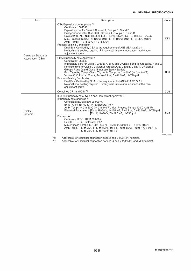
IM 01C21F01-01E10-5
10. GENERAL SPECIFICATIONS
Item Description Code
CSA Explosionproof Approval *1
Certificate: 1089598 Explosionproof for Class I, Division 1, Groups B, C and D Dustignitionproof for Class II/III, Division 1, Groups E, F and G Division2 ‘SEALS NOT REQUIRED’ , Temp. Class: T4, T5, T6 Encl Type 4x Max. Process Temp.: T4; 120C (248F), T5; 100C (212F), T6; 85C (185F) Amb. Temp.: –40 to 80C (–40 to 176F)Process Sealing Certification Dual Seal Certified by CSA to the requirement of ANSI/ISA 12.27.01 No additional sealing required. Primary seal failure annunciation: at the zero adjustment screw
CF1
Canadian Standards Association (CSA) CSA Intrinsically safe Approval *1
Certificate: 1053843 Intrinsically Safe for Class I, Groups A, B, C and D Class II and III, Groups E, F and G Nonincendive for Class I, Division 2, Groups A, B, C and D Class II, Division 2, Groups F and G and Class III (not use Safety Barrier) Encl Type 4x, Temp. Class: T4, Amb. Temp.: –40 to 60C (–40 to 140F) Vmax=30 V, Imax=165 mA, Pmax=0.9 W, Ci=22.5 nF, Li=730 HProcess Sealing Certification Dual Seal Certified by CSA to the requirement of ANSI/ISA 12.27.01 No additional sealing required. Primary seal failure annunciation: at the zero adjustment screw
CS1
IECExScheme SU2
IECEx Intrinsically safe, type n and Flameproof Approval *2Intrinsically safe and type n Certificate: IECEx KEM 06.0007X Ex ia IIC T4, Ex nL IIC T4 Enclosure: IP67 Amb. Temp.: –40 to 60C (–40 to 140F), Max. Process Temp.: 120C (248F) Electrical Parameters: [Ex ia] Ui=30 V, Ii=165 mA, Pi=0.9 W, Ci=22.5 nF, Li=730 H [Ex nL] Ui=30 V, Ci=22.5 nF, Li=730 HFlameproof Certificate: IECEx KEM 06.0005 Ex d IIC T6...T4 Enclosure: IP67 Max.Process Temp.: T4;120C (248F), T5;100C (212F), T6; 85C (185F) Amb.Temp.: –40 to 75C (–40 to 167F) for T4, –40 to 80C (–40 to 176F) for T5, –40 to 75C (–40 to 167F) for T6
CU1Combined CF1 and CS1 *1
T1007-2.EPS
*1: Applicable for Electrical connection code 2 and 7 (1/2 NPT female).*2: Applicable for Electrical connection code 2, 4 and 7 (1/2 NPT and M20 female).
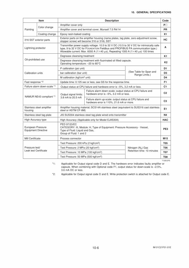
IM 01C21F01-01E10-6
10. GENERAL SPECIFICATIONS
Item Description Code
PaintingColor change
Coating change
Lightning protector
Calibration units
P
X1
HC
A
D1
D3
D4
(See Table for Span and Range Limits.)
Amplifier cover only
PRAmplifier cover and terminal cover, Munsell 7.5 R4/14
Epoxy resin-baked coating
Transmitter power supply voltage: 10.5 to 32 V DC (10.5 to 30 V DC for intrinsically safe type, 9 to 32 V DC for FOUNDATION Fieldbus and PROFIBUS PA communication type.)Allowable current: Max. 6000 A (140 s), Repeating 1000 A (140 s) 100 times
316 SST exterior partsExterior parts on the amplifier housing (name plates, tag plate, zero-adjustment screw, stopper screw) will become 316 or 316L SST.
P calibration (psi unit)
bar calibration (bar unit)
M calibration (kgf/cm2 unit)
Oil-prohibited use
Mill Certificate M15Process connector
Fast response *2 F1Update time: 0.125 sec or less, see GS for the response time.
Stainless steel tag plate N4
HAC
JIS SUS304 stainless steel tag plate wired onto transmitter
Stainless steel amplifierhousing
Amplifier housing material; SCS14A stainless steel (equivalent to SUS316 cast stainless steel or ASTM CF-8M) E1
Degrease cleansing treatment
Degrease cleansing treatment with fluorinated oil filled capsule. Operating temperature: –20 to 80°C
K1
K2
Pressure test/ Leak test Certificate
T05
T06
T07
T08
Nitrogen (N2) GasRetention time: 10 minutes
Test Pressure: 200 kPa (2 kgf/cm2)
Test Pressure: 2 MPa (20 kgf/cm2)
Test Pressure: 10 MPa (100 kgf/cm2)
Test Pressure: 50 MPa (500 kgf/cm2)T1008.EPS
Failure alarm down-scale *1 C1
C2
C3
Output status at CPU failure and hardware error is –5%, 3.2 mA or less.
NAMUR NE43 compliant *1Output signal limits: 3.8 mA to 20.5 mA
Failure alarm down-scale: output status at CPU failure and hardware error is –5%, 3.2 mA or less.
Failure alarm up-scale: output status at CPU failure and hardware error is 110%, 21.6 mA or more.
High Accuracy (Applicable only for Model EJA530A)High Accuracy type
PE3European Pressure Equipment Directive
PED 97/23/ECCATEGORY: III, Module: H, Type of Equipment: Pressure Accessory - Vessel, Type of Fluid: Liquid and Gas,Group of Fluid: 1 and 2
*1: Applicable for Output signal code D and E. The hardware error indicates faulty amplifier orcapsule. When combining with Optional code F1, output status for down-scale is –2.5%,3.6 mA DC or less.
*2: Applicable for Output signal code D and E. Write protection switch is attached for Output code E.
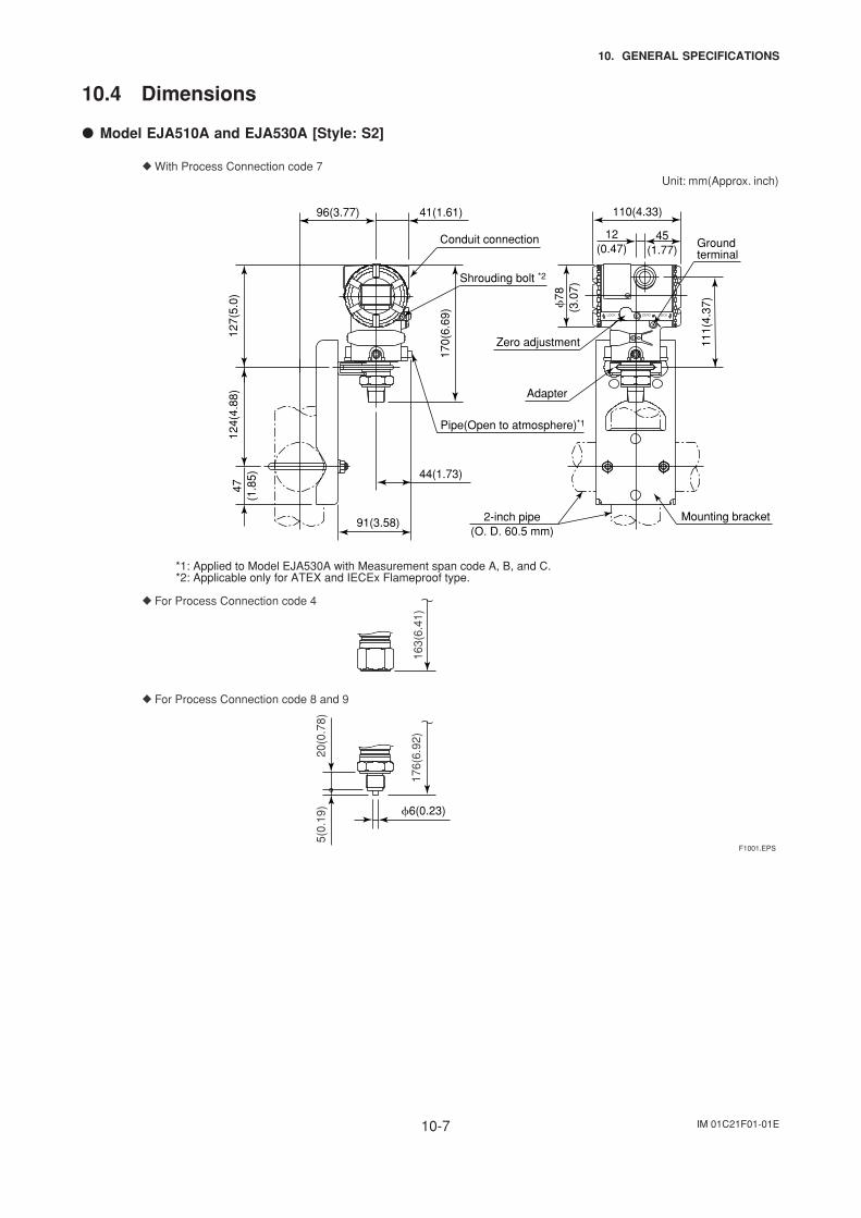
IM 01C21F01-01E10-7
10. GENERAL SPECIFICATIONS
10.4 Dimensions
Model EJA510A and EJA530A [Style: S2]
124(
4.88
)47
(1.8
5)
91(3.58)
44(1.73)
Adapter
Mounting bracket
110(4.33)
12(0.47)
45(1.77)
111(
4.37
)
Groundterminal
Zero adjustment
78
(3.0
7)
With Process Connection code 7Unit: mm(Approx. inch)
163(
6.41
)
For Process Connection code 4
5(0.
19)
20(0
.78)
176(
6.92
)
For Process Connection code 8 and 9
6(0.23)
96(3.77) 41(1.61)
127(
5.0)
170(
6.69
)
Pipe(Open to atmosphere)*1
Conduit connection
*1: Applied to Model EJA530A with Measurement span code A, B, and C. *2: Applicable only for ATEX and IECEx Flameproof type.
F1001.EPS
ZEROLOCK LOCK
2-inch pipe(O. D. 60.5 mm)
Shrouding bolt *2
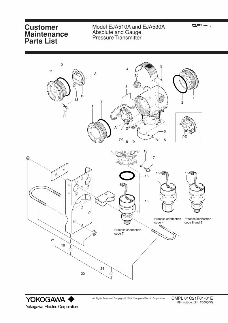
CustomerMaintenanceParts List
All Rights Reserved, Copyright © 1999, Yokogawa Electric Corporation.
Yokogawa Electric Corporation
CMPL 01C21F01-01E6th Edition: Oct. 2008(KP)
Model EJA510A and EJA530AAbsolute and GaugePressure Transmitter
1312
14
2
11A
A
4
10
3
87-1
9
6
5
17
16
15
15 15
2
1
5
21
18
20
21
1922
24
23
Process connectioncode 7
Process connectioncode 4
Process connectioncode 8 and 9
7-2
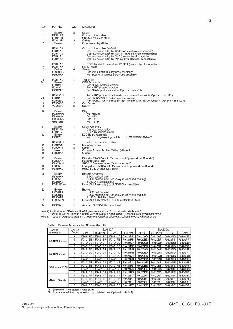
2
CMPL 01C21F01-01EJan. 2008Subject to change without notice. Printed in Japan.
(Note 1) Applicable for BRAIN and HART protocol versions (Output signal code D and E). For FOUNDATION Fieldbus protocol version (Output signal code F), consult Yokogawa local office.(Note 2) In case of Degrease cleansing treatment (Optional code /K1), consult Yokogawa local office.
CoverCast-aluminum alloySCS14A stainless steelO-ringCase Assembly (Note 1)
Cast-aluminum alloy for G1/2Cast-aluminum alloy for G1/2 (two electrical connections)Cast-aluminum alloy for 1/2 NPT (two electrical connections)Cast-aluminum alloy for M20 (two electrical connections)Cast-aluminum alloy for Pg13.5 (two electrical connections)
SCS14A stainless steel for 1/2 NPT (two electrical connections)Name PlateScrew
For cast-aluminum alloy case assemblyFor SCS14A stainless steel case assembly
Tag PlateCPU Assembly
For BRAIN protocol versionFor HART protocol versionFor BRAIN protocol version (Optional code /F1)
For HART protocol version with write protection switch (Optional code /F1) For FOUNDATION Fieldbus protocol versionFor FOUNDATION Fieldbus protocol version with PID/LM function (Optional code /LC1)
Cap ScrewScrew
PlugFor Pg13.5For M20For G1/2For 1/2 NPT
Cover AssemblyCast-aluminum alloySCS14A stainless steel
LCD Board AssemblyWithout range-setting switch
With range-setting switchMounting ScrewLabelCapsule Assembly (See Table 1.)(Note 2)O-ring
Pipe (for EJA530A with Measurement Span code A, B, and C)Polypropylene resinSUS316 Stainless Steel (Optional code /E1)O-ring (for EJA530A with Measurement Span code A, B, and C)Plate, SUS304 Stainless Steel
Bracket AssemblySECC carbon steelSECC carbon steel (for epoxy resin-baked coating)SUS304 stainless steel
U-bolt/Nut Assembly (L), SUS304 Stainless Steel
BracketSECC carbon steelSECC carbon steel (for epoxy resin-baked coating)SUS304 Stainless Steel
U-bolt/Nut Assembly (S), SUS304 Stainless Steel
Adapter, SUS304 Stainless Steel
1
23
45
67-1
7-2
89
10
11
12
13141516
17
18 19
20
21
22
23
24
BellowF9341RAF9341RJF9341JP
Below
F9341AAF9341ACF9341AEF9341AHF9341AJ
F9341ARF9341KA
BellowF9900RGF9900RR
F9341KLBelow
F9342ABF9342ALF9342AF
F9342AMF9342BFF9342BGF9900RPY9612YU
BelowF9340NWF9340NXG9330DKG9612EB
BellowF9341FMF9341FJ
BelowF9342BL
F9342BMF9342MKF9300PB
F9300AJ
BelowF9385XKF9385XMF9385XLF9385XZ
BelowF9385XVF9385XTF9385XUD0117XL-A
BelowF9270AXF9300TNF9300TEF9385XW
F9385XY
2
21
14
11
1
22
1
1
1
2211
1
11
1
1
1
1
1
Item Part No. DescriptionQty
For integral indicator
Capsule Code
ABCDABCDABCDABCD
H, /K2(*2)F9421NPF9421PPF9421QPF9421RPF9421NRF9421PRF9421QRF9421RRF9421NSF9421PSF9421QSF9421RSF9421NTF9421PTF9421QTF9421RT
S(*1)F9421ABF9421BBF9421CBF9421DBF9421ADF9421BDF9421CDF9421DDF9421AEF9421BEF9421CEF9421DEF9421AFF9421BFF9421CFF9421DF
S, /K2(*2)F9421APF9421BPF9421CPF9421DPF9421ARF9421BRF9421CRF9421DRF9421ASF9421BSF9421CSF9421DSF9421ATF9421BTF9421CTF9421DT
S(*1)F9420ABF9420BBF9420CBF9420DBF9420ADF9420BDF9420CDF9420DDF9420AEF9420BEF9420CEF9420DEF9420AFF9420BFF9420CFF9420DF
H(*1)F9421NBF9421PBF9421QBF9421RBF9421NDF9421PDF9421QDF9421RDF9421NEF9421PEF9421QEF9421REF9421NFF9421PFF9421QFF9421RF
S, K2(*2)F9420APF9420BPF9420CPF9420DPF9420ARF9420BRF9420CRF9420DRF9420ASF9420BSF9420CSF9420DSF9420ATF9420BTF9420CTF9420DT
Process connection
1/2 NPT female
1/2 NPT male
G1/2 male (DIN)
M201.5 male
Table 1. Capsule Assembly Part Number (Item 15)
*1: Silicone oil filled capsule (Standard)*2: Fluorinated oil filled capsule (for oil-prohibited use: Optional code /K2)
H(*1)F9420NBF9420PBF9420QBF9420RBF9420NDF9420PDF9420QDF9420RDF9420NEF9420PEF9420QEF9420REF9420NFF9420PFF9420QFF9420RF
H, K2(*2)F9420NPF9420PPF9420QPF9420RPF9420NRF9420PRF9420QRF9420RRF9420NSF9420PSF9420QSF9420RSF9420NTF9420PTF9420QTF9420RT
EJA510A EJA530A
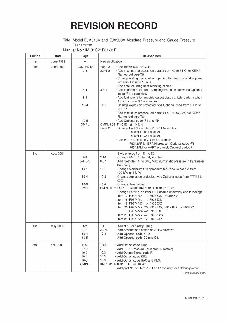
IM 01C21F01-01E
REVISION RECORDTitle: Model EJA510A and EJA530A Absolute Pressure and Gauge Pressure
TransmitterManual No.: IM 01C21F01-01E
Edition Date Page Revised Item
1st June 1999 – New publication
2nd June 2000 CONTENTS2-8
8-4
8-5
10-4
10-5CMPL
Page 32.9.4 b.
8.3.1
10.3
CMPL 1C21F1-01E 1st 2ndPage 2
• Add REVISION RECORD.• Add maximum process temperature of –40 to 75°C for KEMA Flameproof type T6.• Change wating period when opening terminal cover after power off from 1 min. to 10 min.• Add note for using heat-resisting cables.• Add footnote *2 for amp. damping time constant when Optional code /F1 is specified.• Add footnote *3 for low side output status at failure alarm when Optional code /F1 is specified.• Change explosion protected type Optional code from /1 to /11. • Add maximum process temperature of –40 to 75°C for KEMA Flameproof type T6.• Add Optional code /F1 and /N4.
• Change Part No. on Item 7, CPU Assembly.F9342BP F9342ABF9342BQ F9342AL
• Add Part No. on Item 7, CPU Assembly.F9342AF for BRAIN protocol, Optional code /F1F9342AM for HART protocol, Optional code /F1
REVISION RECORD.EPS
3rd Aug. 2001 –2-8
8-4, 8-5
10-1
10-4
10-6CMPL
2.108.3.1
10.1
10.3
10.4CMPL 1C21F1-01E 2nd CMPL 01C21F01-01E 3rd
• Style change from S1 to S2.• Change EMC Conformity number.• Add footnote (*4) to B40, Maximum static pressure in Parameter Summary.• Change Maximum Over pressure for Capsule code A from 400 kPa to 4 MPa.• Change explosion protected type Optional code from /11 to /1.• Change dimensions.
• Change Part No. on Item 15, Capsule Assembly and followings.• Item 17; F9374MS F9385XK, F9385XM• Item 18; F9374MU F9385XL• Item 19; F9374NZ F9385XZ• Item 20; F9374MX F9385XV, F9374NX F9385XT, F9374MW F9385XU• Item 23; F9374MY F9385XW• Item 24; F9374NY F9385XY
4th May 2002 1-22-7
10-410-5
1.12.9.410.3
• Add “1.1 For Safety Using.”• Add descriptions based on ATEX directive.• Add Optional code K2.• Add Optional code C2 and C3.
5th Apr. 2003 2-82-1010-310-410-5
CMPL
2.9.42.1110.210.310.3CMPL 01C21F01-01E 3rd 4th
• Add Option code KU2• Add PED (Pressure Equipment Directive)• Add Output Signal code F.• Add Option code KU2.• Add Option code HAC and PE3.
• Add part No. on Item 7-2, CPU Assembly for fieldbus protocol.
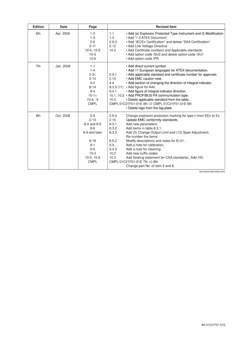
IM 01C21F01-01E
Edition Date Page Revised Item
6th Apr. 2006 1-21-32-62-11
10-4, 10-510-510-6
1.11.32.9.32.1210.3
• Add (e) Explosion Protected Type Instrument and (f) Modification• Add “1.3 ATEX Document”• Add “IECEx Certification” and delete “SAA Certification”• Add Low Voltage Directive• Add Certificate numbers and Applicable standards• Add option code /SU2 and delete option code /SU1• Add option code /PR
7th Jan. 2008 1-11-4
2-3+2-104-2
8-149-4
10-1+10-4, -5CMPL
2.9.12.104.48.3.3 (11)9.4.110.1, 10.210.3CMPL 01C21F01-01E 4th CMPL 01C21F01-01E 5th
• Add direct current symbol.• Add 11 European languages for ATEX documentation.• Add applicable standard and certificate number for appovals.• Add EMC caution note.• Add section of changing the direction of integral indicator.• Add figure for A40.• Add figure of integral indicator direction.• Add PROFIBUS PA communication type.• Delete applicable standard from the table.
• Delete logo from the tag plate.
REVISION RECORD2.EPS
8th Oct. 2008 2-92-10
8-4 and 8-58-6
8-9 and later
8-189-19-5
10-310-5, 10-6
CMPL
2.9.42.108.3.1 8.3.2 8.3.3
8.5.29.3 9.4.3 10.2 10.3 CMPL 01C21F01-01E 7th 8th
Change explosion protection marking for type n from EEx to Ex.Update EMC conformity standards.Add new parameters.Add items in table 8.3.1.Add (5) Change Output Limit and (13) Span Adjustment. Re-number the items.Modify descriptions and notes for Er.01.Add a note for calibration.Add a note for cleaning.Add new suffix codes. Add Sealing statement for CSA.standards., Add /HC.
Change part No .of item 5 and 8.


![User’s Manual Model EJA510A and EJA530A Absolute ...€™s Manual Model EJA510A and EJA530A Absolute Pressure and Gauge Pressure Transmitters [Style: S2] IM 01C21F01-01E IM 01C21F01-01E](https://img.pdfslide.us/doc/110x75/5adcb59c7f8b9a9a768be483/users-manual-model-eja510a-and-eja530a-absolute-s-manual-model-eja510a.jpg)