Embed Size (px)
Citation preview
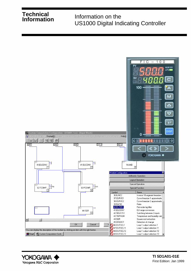
Information on theUS1000 Digital Indicating Controller
TI 5D1A01-01EFirst Edition: Jan 1999
TechnicalInformation
TI 5D1A01-01E 1
IntroductionThis Technical Information gives an outline of the functions of the US1000 Digital Indicating
Controller. For the latest information on this product, please see our home page located at:
http://www.yokogawa.co.jp/MCC/
Structure of Technical Information
This Technical Information introduces the US1000 and its functions under the following
topics:
• Features and outlines • Controller functions and applications
• Custom computation • Communication
• Hardware • Setting up functions • Appendices
Intended Readers
This Technical Information is intended for people who wish to learn about the functions of
the US1000 controller.
Related DocumentsThe following documents all relate to the US1000 Digital Indicating Controller. Read them as
necessary. The codes enclosed in parentheses are their document numbers.
• US1000 Digital Indicating Controller Operation (IM 5D1A01-01E)
Introduces the basic functions and explains the general operation of the US1000.
• US1000 Digital Indicating Controller Functions (IM 5D1A01-02E)
Explains the functions of the US1000 in detail.
• US1000 Digital Indicating Controller Communication Functions (IM 5D1A01-10E)
Explains the communication specifications and commands used when the US1000
communicates with a higher-level computer.
• LL1100 PC-based Parameters Setting Tool (IM 5G1A01-01E)
Explains how to install and operate the LL1100, the software tool which allows you to set the
parameters of the US1000 from a personal computer.
• LL1200 PC-based Custom Computation Building Tool (IM 5G1A11-01E)
Explains how to install and operate the LL1200, the software tool used to create US1000
custom computations on a personal computer. This manual also presents some examples of
custom computation.
• LL1200 PC-based Custom Computation Building Tool User’s Reference (IM 5G1A11-02E)
Explains the functions of the individual computation modules that are used to configure a
custom computation function. Refer to this manual if you are not familiar with the types of
functions available or how these functions work.
2 TI 5D1A01-01E
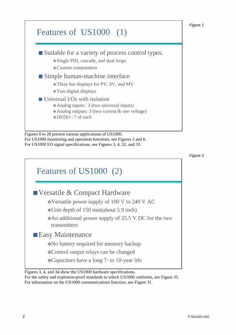
Features of US1000 (1)
Suitable for a variety of process control types. Single PID, cascade, and dual loops Custom computation
Simple human-machine interface Three bar displays for PV, SV, and MV Two digital displays
Universal I/Os with isolation Analog inputs: 3 (two universal inputs) Analog outputs: 3 (two current & one voltage) DI/DO : 7 of each
Figure 1
Figures 8 to 28 present various applications of US1000.For US1000 monitoring and operation functions, see Figures 5 and 6.For US1000 I/O signal specifications, see Figures 3, 4, 32, and 33.
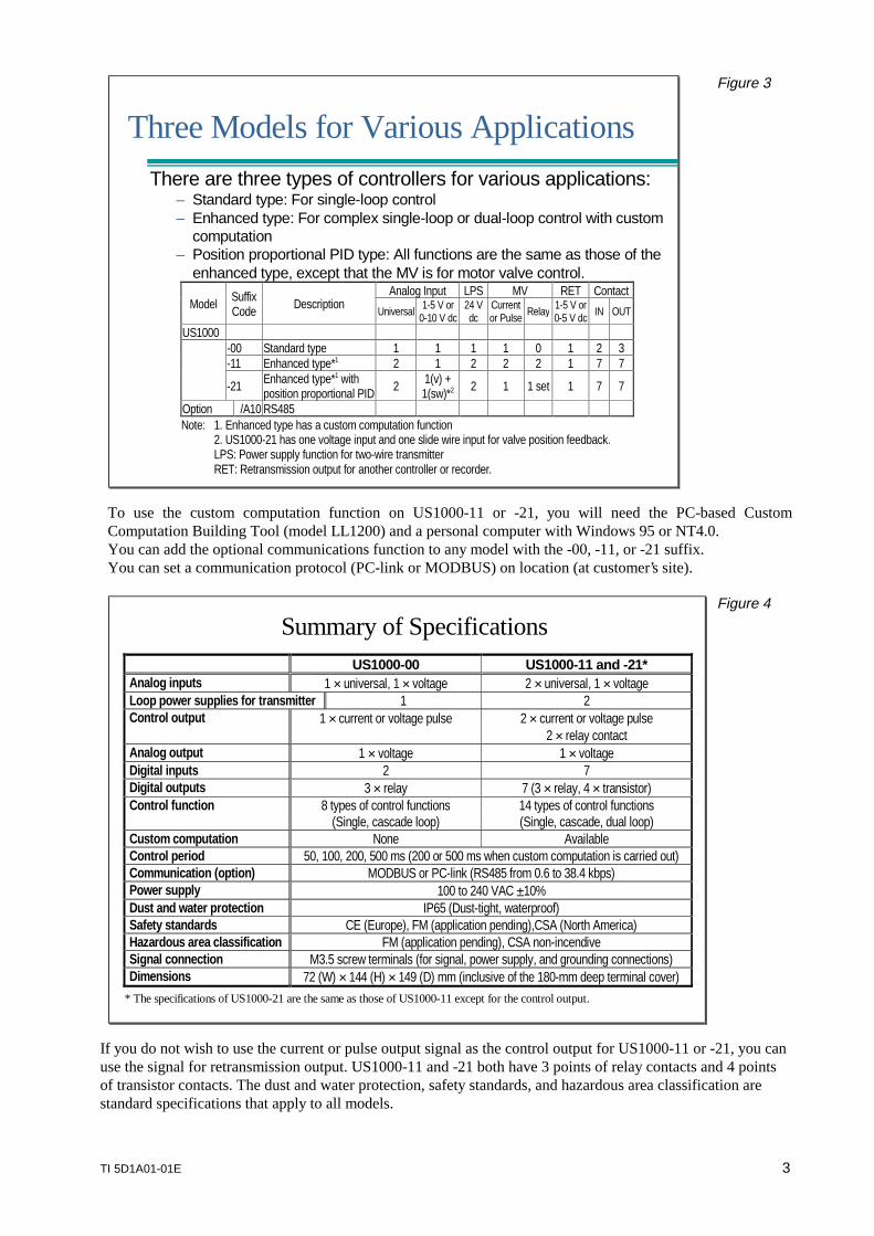
Features of US1000 (2)
Versatile & Compact HardwareVersatile power supply of 100 V to 240 V ACUnit depth of 150 mm(about 5.9 inch)An additional power supply of 25.5 V DC for the two
transmitters
Easy MaintenanceNo battery required for memory backupControl output relays can be changedCapacitors have a long 7- to 10-year life
Figure 2
Figures 3, 4, and 34 show the US1000 hardware specifications.For the safety and explosion-proof standards to which US1000 conforms, see Figure 35.For information on the US1000 communications function, see Figure 31.
TI 5D1A01-01E 3
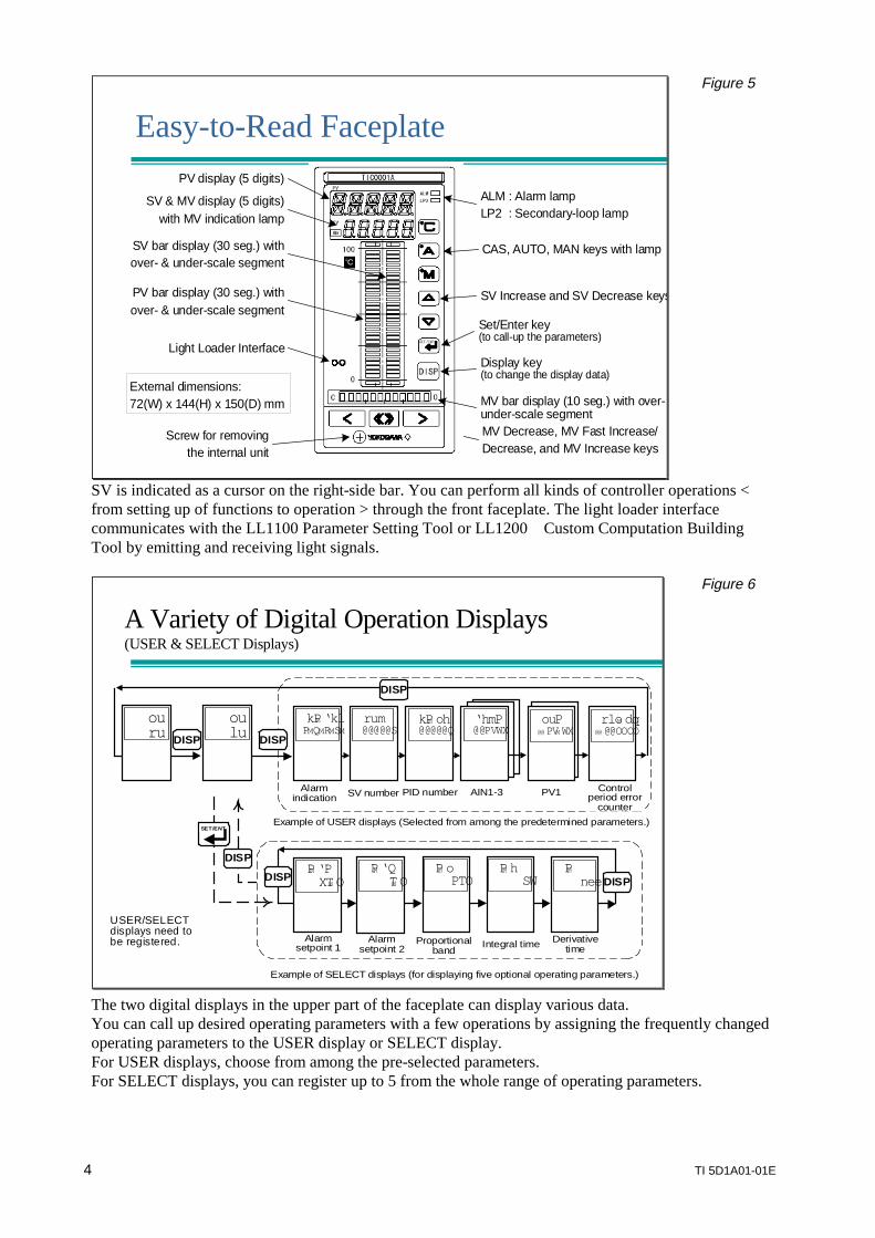
Three Models for Various Applications
There are three types of controllers for various applications:– Standard type: For single-loop control– Enhanced type: For complex single-loop or dual-loop control with custom
computation– Position proportional PID type: All functions are the same as those of the
enhanced type, except that the MV is for motor valve control.Analog Input LPS MV RET Contact
Model SuffixCode Description
Universal 1-5 V or0-10 V dc
24 Vdc
Currentor Pulse Relay 1-5 V or
0-5 V dc IN OUT
US1000-00 Standard type 1 1 1 1 0 1 2 3-11 Enhanced type*1 2 1 2 2 2 1 7 7
-21 Enhanced type*1 withposition proportional PID 2 1(v) +
1(sw)*2 2 1 1 set 1 7 7
Option /A10 RS485Note: 1. Enhanced type has a custom computation function
2. US1000-21 has one voltage input and one slide wire input for valve position feedback.LPS: Power supply function for two-wire transmitterRET: Retransmission output for another controller or recorder.
Figure 3
To use the custom computation function on US1000-11 or -21, you will need the PC-based CustomComputation Building Tool (model LL1200) and a personal computer with Windows 95 or NT4.0.You can add the optional communications function to any model with the -00, -11, or -21 suffix.You can set a communication protocol (PC-link or MODBUS) on location (at customer’s site).
US1000-00 US1000-11 and -21*Analog inputs 1 × universal, 1 × voltage 2 × universal, 1 × voltageLoop power supplies for transmitter 1 2Control output 1 × current or voltage pulse 2 × current or voltage pulse
2 × relay contactAnalog output 1 × voltage 1 × voltageDigital inputs 2 7Digital outputs 3 × relay 7 (3 × relay, 4 × transistor)Control function 8 types of control functions
(Single, cascade loop)14 types of control functions(Single, cascade, dual loop)
Custom computation None AvailableControl period 50, 100, 200, 500 ms (200 or 500 ms when custom computation is carried out)Communication (option) MODBUS or PC-link (RS485 from 0.6 to 38.4 kbps)Power supply 100 to 240 VAC ±10%Dust and water protection IP65 (Dust-tight, waterproof)Safety standards CE (Europe), FM (application pending),CSA (North America)Hazardous area classification FM (application pending), CSA non-incendiveSignal connection M3.5 screw terminals (for signal, power supply, and grounding connections)Dimensions 72 (W) × 144 (H) × 149 (D) mm (inclusive of the 180-mm deep terminal cover)
* The specifications of US1000-21 are the same as those of US1000-11 except for the control output.
Summary of SpecificationsFigure 4
If you do not wish to use the current or pulse output signal as the control output for US1000-11 or -21, you canuse the signal for retransmission output. US1000-11 and -21 both have 3 points of relay contacts and 4 pointsof transistor contacts. The dust and water protection, safety standards, and hazardous area classification arestandard specifications that apply to all models.
4 TI 5D1A01-01E
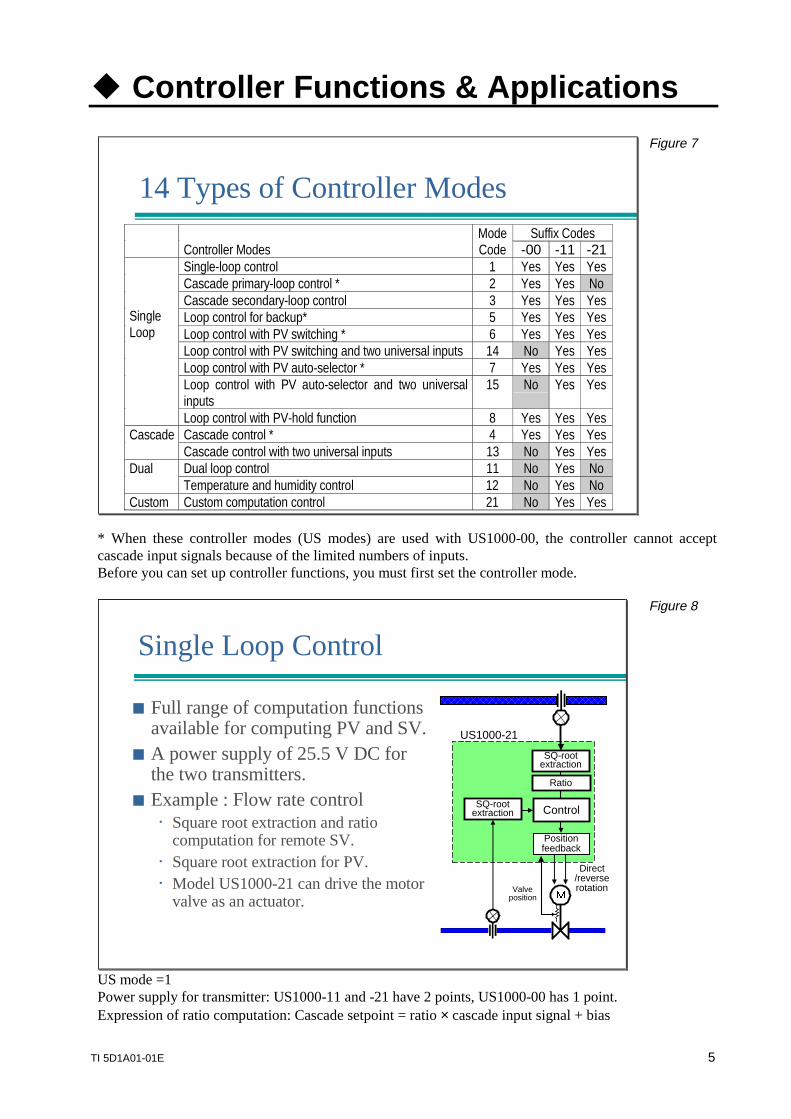
Easy-to-Read FaceplateEasy-to-Read Faceplate
MV Decrease, MV Fast Increase/Decrease, and MV Increase keys
CAS, AUTO, MAN keys with lamp
SV Increase and SV Decrease keys
Set/Enter key(to call-up the parameters)
Display key(to change the display data)
MV bar display (10 seg.) with over- under-scale segment
PV display (5 digits)
SV & MV display (5 digits)with MV indication lamp
PV bar display (30 seg.) withover- & under-scale segment
SV bar display (30 seg.) withover- & under-scale segment
Light Loader Interface
External dimensions:72(W) x 144(H) x 150(D) mm
ALM : Alarm lampLP2 : Secondary-loop lamp
Screw for removingthe internal unit
Figure 5
SV is indicated as a cursor on the right-side bar. You can perform all kinds of controller operations <from setting up of functions to operation > through the front faceplate. The light loader interfacecommunicates with the LL1100 Parameter Setting Tool or LL1200 Custom Computation BuildingTool by emitting and receiving light signals.
A Variety of Digital Operation Displays(USER & SELECT Displays)
Example of USER displays (Selected from among the predetermined parameters.)
Alarmsetpoint 1
Alarmsetpoint 2
Proportionalband
Integral time Derivativetime
SV number PID number PV1 Controlperiod error
counter
ouru
oulu
rum@@@@@S
kPM oh@@@@@Q
rloM dq@@ @@OOOO
PM ‘PXTM O
PM ‘QTM O
PM oPTO
PM hSW
PMnee
DISP DISP
ouP@@ PVM WX
DISP
DISP
SET/ENT
Alarmindication
AIN1-3
Example of SELECT displays (for displaying five optional operating parameters.)
DISP
kPM ‘klPMQMRMSM
‘hmP@@PVWX
USER/SELECTdisplays need tobe registered.
DISP
Figure 6
The two digital displays in the upper part of the faceplate can display various data.You can call up desired operating parameters with a few operations by assigning the frequently changedoperating parameters to the USER display or SELECT display.For USER displays, choose from among the pre-selected parameters.For SELECT displays, you can register up to 5 from the whole range of operating parameters.
TI 5D1A01-01E 5
Controller Functions & Applications
14 Types of Controller ModesSuffix Codes
Controller ModesModeCode -00 -11 -21
Single-loop control 1 Yes Yes YesCascade primary-loop control * 2 Yes Yes NoCascade secondary-loop control 3 Yes Yes YesLoop control for backup* 5 Yes Yes YesLoop control with PV switching * 6 Yes Yes YesLoop control with PV switching and two universal inputs 14 No Yes YesLoop control with PV auto-selector * 7 Yes Yes YesLoop control with PV auto-selector and two universalinputs
15 No Yes Yes
SingleLoop
Loop control with PV-hold function 8 Yes Yes YesCascade control * 4 Yes Yes YesCascadeCascade control with two universal inputs 13 No Yes YesDual loop control 11 No Yes NoDualTemperature and humidity control 12 No Yes No
Custom Custom computation control 21 No Yes Yes
Figure 7
* When these controller modes (US modes) are used with US1000-00, the controller cannot acceptcascade input signals because of the limited numbers of inputs.Before you can set up controller functions, you must first set the controller mode.
Single Loop Control
Valveposition
Direct/reverserotation
SQ-rootextraction
US1000-21
Positionfeedback
SQ-rootextraction
Ratio
Control
Full range of computation functionsavailable for computing PV and SV.
A power supply of 25.5 V DC forthe two transmitters.
Example : Flow rate control Square root extraction and ratio
computation for remote SV. Square root extraction for PV. Model US1000-21 can drive the motor
valve as an actuator.
Figure 8
US mode =1 Power supply for transmitter: US1000-11 and -21 have 2 points, US1000-00 has 1 point.Expression of ratio computation: Cascade setpoint = ratio × cascade input signal + bias
6 TI 5D1A01-01E
RUN/STOP Switching
MAN Selection
STOP
AUTOMAN
RUN
AUTO/MAN AUTO Selection
AIN1
Input type, unit, rangeAnalog input bias & filterSquare root extraction
10-seg. linearizer
AIN3
PV input bias & filter Cascade input filter
Ratio & bias
RS485 DI2 DI1
SV
Control computation
MAN output
Preset output
OUT1A
CAS
PV InputCascade SV or F.F. Input
Communication Contact Inputs
SV rate limitter
MV limitter
+
F.F. filterF.F. bias & gain
Input type, unit, rangeAnalog input bias & filter
Square root extraction
DI3
Control output selector
OUT1R OUT2A OUT2RCurrentor Pulse
ON/OFF Cooling MV
DI7 DI6 DI5 DI4
SV No. Selection
DO1
Power fortransmitter
VoltageDO2 DO3LPS1 OUT3A DO4
Alarm Function
DO7
PVlow2
PVoutput FAIL
LPS2
PVhigh2
PVlow1
PVhigh1
Figure 9
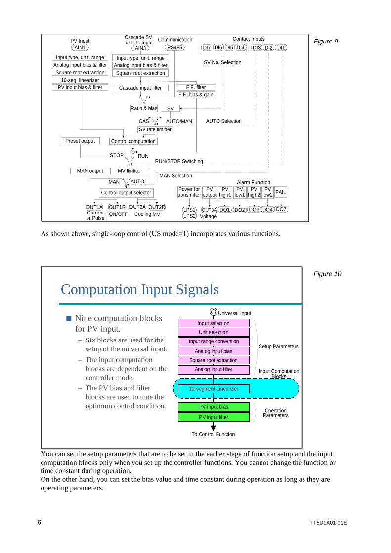
As shown above, single-loop control (US mode=1) incorporates various functions.
Computation Input Signals
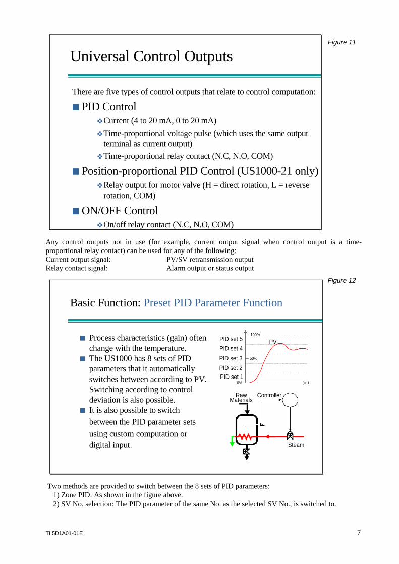
Nine computation blocksfor PV input.– Six blocks are used for the
setup of the universal input.– The input computation
blocks are dependent on thecontroller mode.
– The PV bias and filterblocks are used to tune theoptimum control condition.
Setup Parameters
Analog input filter
Square root extraction
Analog input bias
Input range conversion
Unit selection
PV input bias
10-segment Linearizer
Universal Input
Input selection
PV input filter
To Control Function
OperationParameters
Input ComputationBlocks
Figure 10
You can set the setup parameters that are to be set in the earlier stage of function setup and the inputcomputation blocks only when you set up the controller functions. You cannot change the function ortime constant during operation.On the other hand, you can set the bias value and time constant during operation as long as they areoperating parameters.
TI 5D1A01-01E 7
Universal Control Outputs
There are five types of control outputs that relate to control computation:
PID Control Current (4 to 20 mA, 0 to 20 mA)
Time-proportional voltage pulse (which uses the same outputterminal as current output)
Time-proportional relay contact (N.C, N.O, COM)
Position-proportional PID Control (US1000-21 only) Relay output for motor valve (H = direct rotation, L = reverse
rotation, COM)
ON/OFF Control On/off relay contact (N.C, N.O, COM)
Figure 11
Any control outputs not in use (for example, current output signal when control output is a time-proportional relay contact) can be used for any of the following:Current output signal: PV/SV retransmission outputRelay contact signal: Alarm output or status output
Basic Function: Preset PID Parameter Function
RawMaterials
Steam
Controller
50%
0%
100%
tPID set 1PID set 2
PID set 3
PID set 4
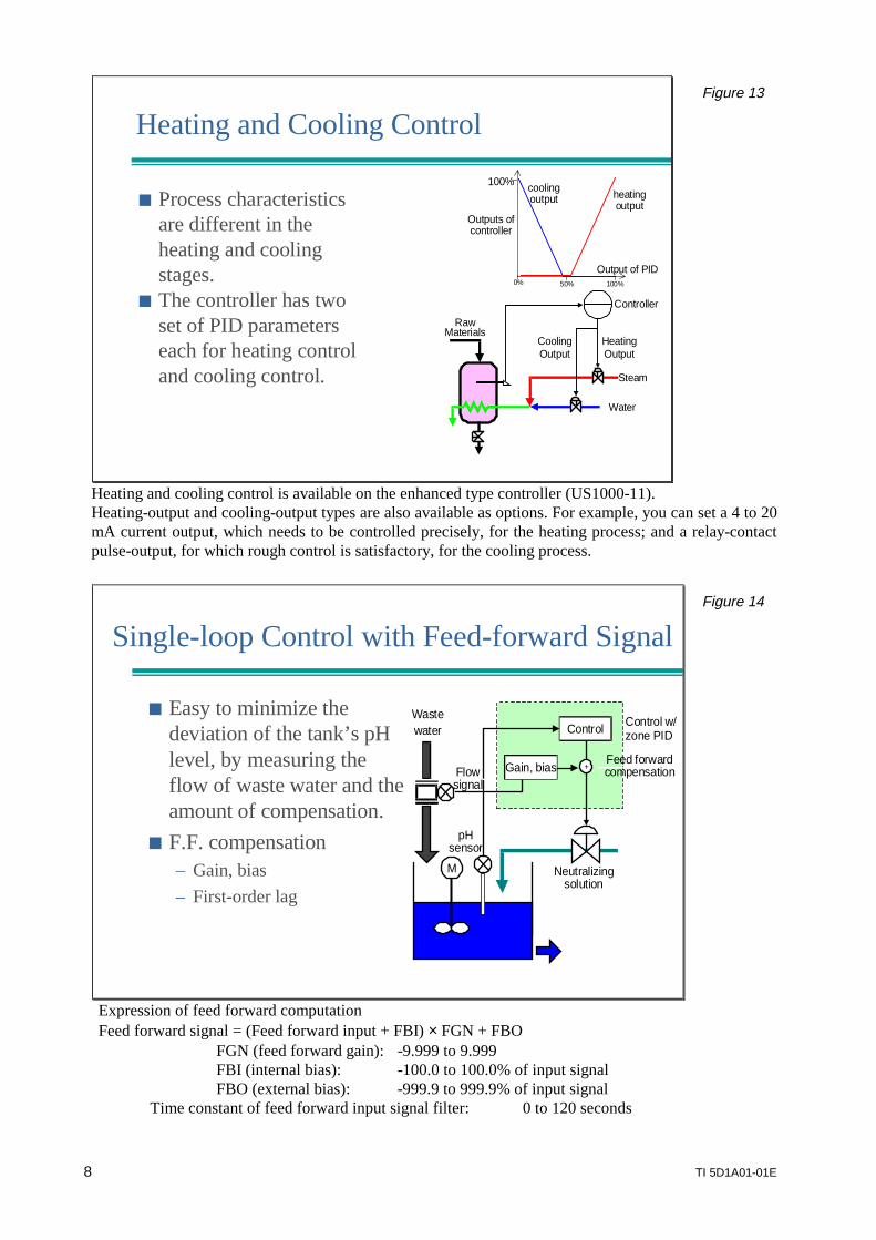
PID set 5 PV Process characteristics (gain) oftenchange with the temperature.
The US1000 has 8 sets of PIDparameters that it automaticallyswitches between according to PV.Switching according to controldeviation is also possible.
It is also possible to switchbetween the PID parameter setsusing custom computation ordigital input.
Figure 12
Two methods are provided to switch between the 8 sets of PID parameters: 1) Zone PID: As shown in the figure above. 2) SV No. selection: The PID parameter of the same No. as the selected SV No., is switched to.
8 TI 5D1A01-01E
Heating and Cooling Control
heatingoutput
coolingoutput
HeatingOutput
RawMaterials
Steam
Water
CoolingOutput
Controller
Output of PID
Outputs ofcontroller
100%
50%0% 100%
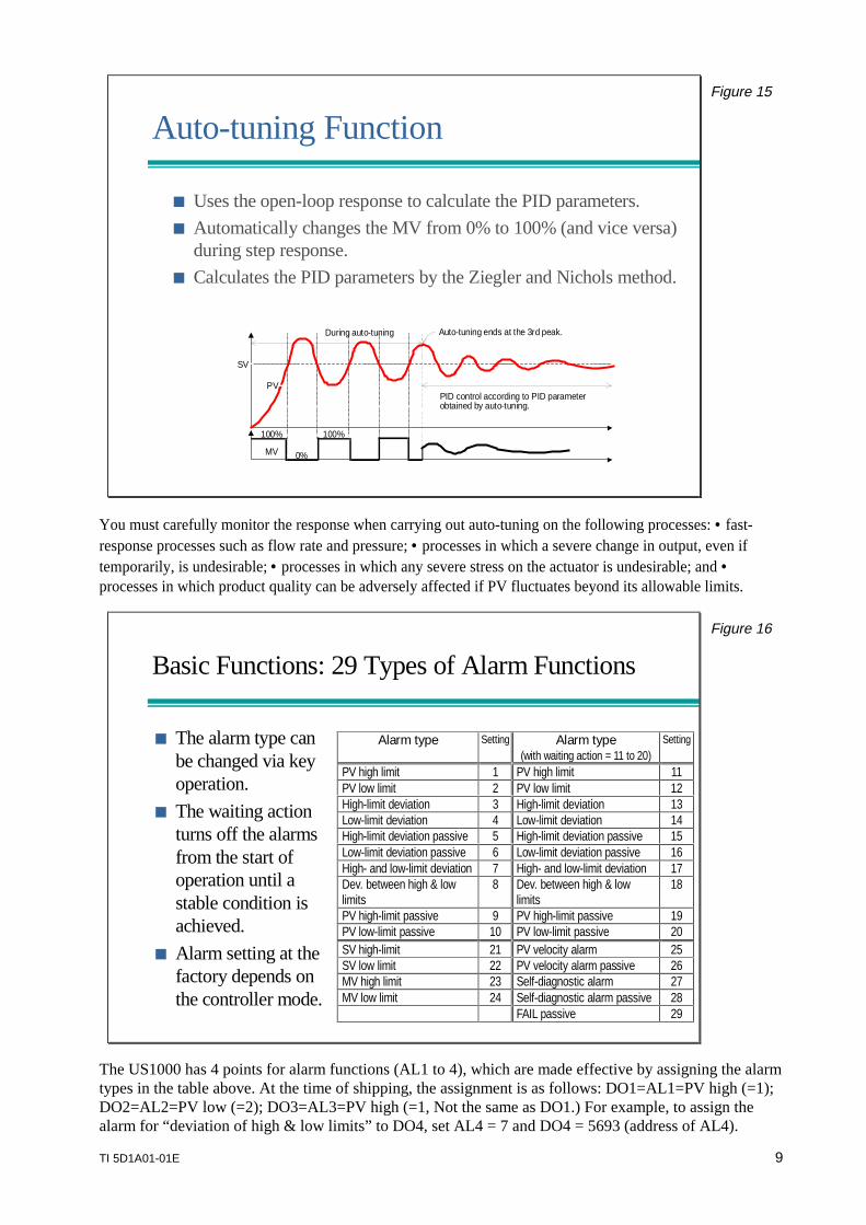
Process characteristicsare different in theheating and coolingstages.
The controller has twoset of PID parameterseach for heating controland cooling control.
Figure 13
Heating and cooling control is available on the enhanced type controller (US1000-11).Heating-output and cooling-output types are also available as options. For example, you can set a 4 to 20mA current output, which needs to be controlled precisely, for the heating process; and a relay-contactpulse-output, for which rough control is satisfactory, for the cooling process.
Single-loop Control with Feed-forward SignalSingle-loop Control with Feed-forward Signal
Easy to minimize thedeviation of the tank’s pHlevel, by measuring theflow of waste water and theamount of compensation.
F.F. compensation– Gain, bias– First-order lag
pHsensor
Control w/zone PID
M
Wastewater
Flowsignal
Neutralizingsolution
+Feed forwardcompensation
Control
Gain, bias
Figure 14
Expression of feed forward computationFeed forward signal = (Feed forward input + FBI) × FGN + FBO
FGN (feed forward gain): -9.999 to 9.999FBI (internal bias): -100.0 to 100.0% of input signalFBO (external bias): -999.9 to 999.9% of input signal
Time constant of feed forward input signal filter: 0 to 120 seconds
TI 5D1A01-01E 9
Auto-tuning FunctionAuto-tuning Function
Uses the open-loop response to calculate the PID parameters. Automatically changes the MV from 0% to 100% (and vice versa)
during step response. Calculates the PID parameters by the Ziegler and Nichols method.
PV
SV
MV
100%
0%
100%
During auto-tuning Auto-tuning ends at the 3rd peak.
PID control according to PID parameterobtained by auto-tuning.
Figure 15
You must carefully monitor the response when carrying out auto-tuning on the following processes: • fast-response processes such as flow rate and pressure; • processes in which a severe change in output, even iftemporarily, is undesirable; • processes in which any severe stress on the actuator is undesirable; and •processes in which product quality can be adversely affected if PV fluctuates beyond its allowable limits.
Basic Functions: 29 Types of Alarm Functions
The alarm type canbe changed via keyoperation.
The waiting actionturns off the alarmsfrom the start ofoperation until astable condition isachieved.
Alarm setting at thefactory depends onthe controller mode.
Alarm type Setting Alarm type(with waiting action = 11 to 20)
Setting
PV high limit 1 PV high limit 11PV low limit 2 PV low limit 12High-limit deviation 3 High-limit deviation 13Low-limit deviation 4 Low-limit deviation 14High-limit deviation passive 5 High-limit deviation passive 15Low-limit deviation passive 6 Low-limit deviation passive 16High- and low-limit deviation 7 High- and low-limit deviation 17Dev. between high & lowlimits
8 Dev. between high & lowlimits
18
PV high-limit passive 9 PV high-limit passive 19PV low-limit passive 10 PV low-limit passive 20SV high-limit 21 PV velocity alarm 25SV low limit 22 PV velocity alarm passive 26MV high limit 23 Self-diagnostic alarm 27MV low limit 24 Self-diagnostic alarm passive 28
FAIL passive 29
Figure 16
The US1000 has 4 points for alarm functions (AL1 to 4), which are made effective by assigning the alarmtypes in the table above. At the time of shipping, the assignment is as follows: DO1=AL1=PV high (=1);DO2=AL2=PV low (=2); DO3=AL3=PV high (=1, Not the same as DO1.) For example, to assign thealarm for “deviation of high & low limits” to DO4, set AL4 = 7 and DO4 = 5693 (address of AL4).
10 TI 5D1A01-01E
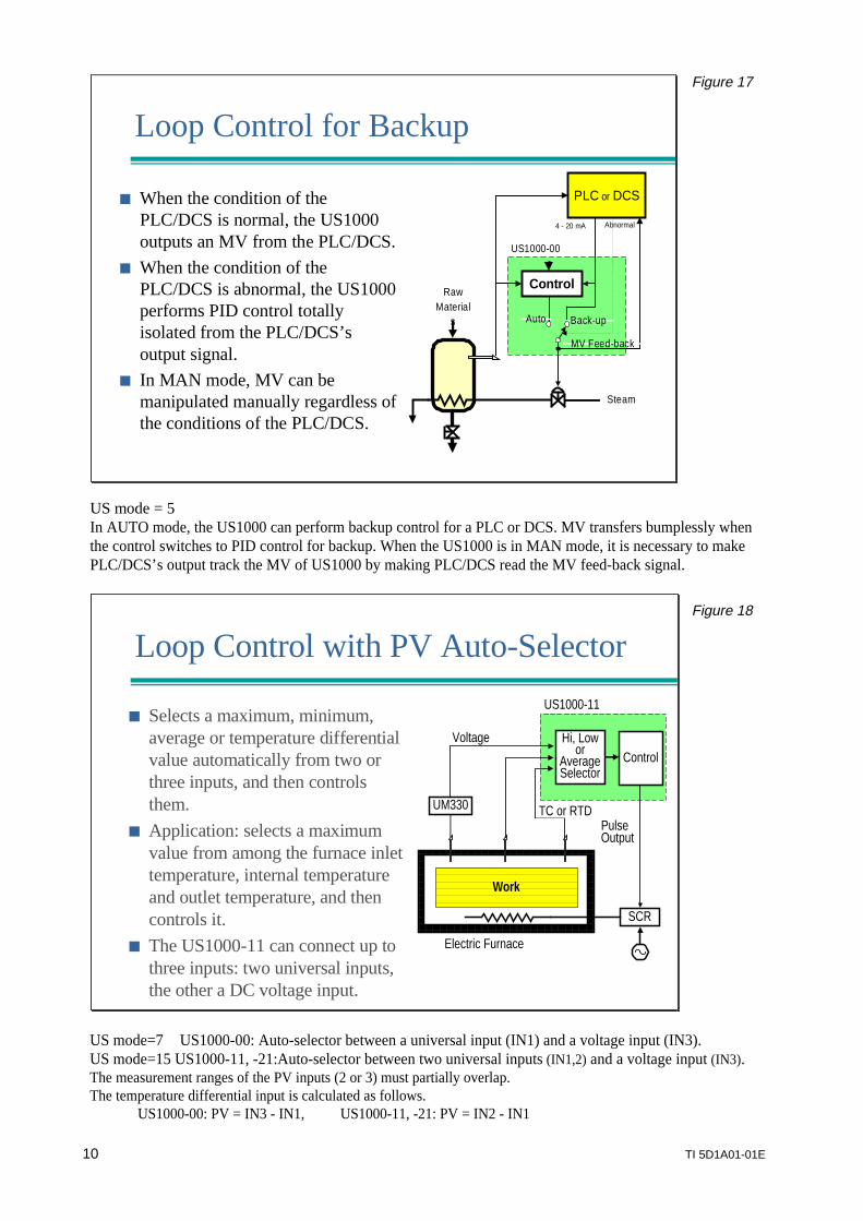
Loop Control for Backup
When the condition of thePLC/DCS is normal, the US1000outputs an MV from the PLC/DCS.
When the condition of thePLC/DCS is abnormal, the US1000performs PID control totallyisolated from the PLC/DCS’soutput signal.
In MAN mode, MV can bemanipulated manually regardless ofthe conditions of the PLC/DCS.
Abnormal4 - 20 mA
US1000-00
Control
Steam
RawMaterial
s
PLC or DCS
Back-upAuto
MV Feed-back
Figure 17
US mode = 5In AUTO mode, the US1000 can perform backup control for a PLC or DCS. MV transfers bumplessly whenthe control switches to PID control for backup. When the US1000 is in MAN mode, it is necessary to makePLC/DCS’s output track the MV of US1000 by making PLC/DCS read the MV feed-back signal.
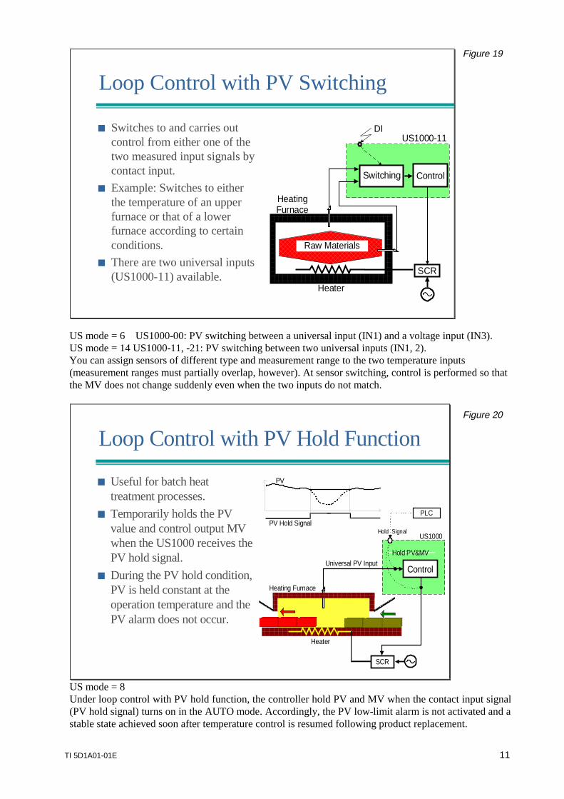
Loop Control with PV Auto-Selector
Selects a maximum, minimum,average or temperature differentialvalue automatically from two orthree inputs, and then controlsthem.
Application: selects a maximumvalue from among the furnace inlettemperature, internal temperatureand outlet temperature, and thencontrols it.
The US1000-11 can connect up tothree inputs: two universal inputs,the other a DC voltage input.
PulseOutput
Electric Furnace
Hi, Lowor
AverageSelector
Work
SCR
UM330
US1000-11
ControlVoltage
TC or RTD
Figure 18
US mode=7 US1000-00: Auto-selector between a universal input (IN1) and a voltage input (IN3).US mode=15 US1000-11, -21:Auto-selector between two universal inputs (IN1,2) and a voltage input (IN3).The measurement ranges of the PV inputs (2 or 3) must partially overlap.The temperature differential input is calculated as follows.
US1000-00: PV = IN3 - IN1, US1000-11, -21: PV = IN2 - IN1
TI 5D1A01-01E 11
Loop Control with PV Switching
Switches to and carries outcontrol from either one of thetwo measured input signals bycontact input.
Example: Switches to eitherthe temperature of an upperfurnace or that of a lowerfurnace according to certainconditions.
There are two universal inputs(US1000-11) available.
Heater
DI
HeatingFurnace
ControlSwitching
SCR
US1000-11
Raw Materials
Figure 19
US mode = 6 US1000-00: PV switching between a universal input (IN1) and a voltage input (IN3).US mode = 14 US1000-11, -21: PV switching between two universal inputs (IN1, 2).You can assign sensors of different type and measurement range to the two temperature inputs(measurement ranges must partially overlap, however). At sensor switching, control is performed so thatthe MV does not change suddenly even when the two inputs do not match.
Loop Control with PV Hold Function
Useful for batch heattreatment processes.
Temporarily holds the PVvalue and control output MVwhen the US1000 receives thePV hold signal.
During the PV hold condition,PV is held constant at theoperation temperature and thePV alarm does not occur.
Heater
Control
SCR
US1000
Universal PV Input
Heating Furnace
PLC
Hold PV&MV
Hold Signal
PV
PV Hold Signal
Figure 20
US mode = 8Under loop control with PV hold function, the controller hold PV and MV when the contact input signal(PV hold signal) turns on in the AUTO mode. Accordingly, the PV low-limit alarm is not activated and astable state achieved soon after temperature control is resumed following product replacement.
12 TI 5D1A01-01E
CascadeSV Fail
Temperature
SVFeedback
FlowControl
Control
Steam
RawMaterials
SV
US1000-00
US1000-00
Control SQRT
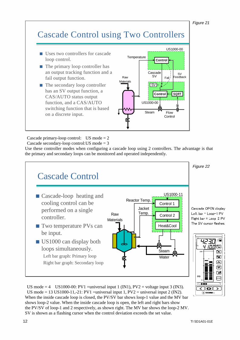
Uses two controllers for cascadeloop control.
The primary loop controller hasan output tracking function and afail output function.
The secondary loop controllerhas an SV output function, aCAS/AUTO status outputfunction, and a CAS/AUTOswitching function that is basedon a discrete input.
Cascade Control using Two Controllers
Figure 21
Cascade primary-loop control: US mode = 2Cascade secondary-loop control:US mode = 3
Use these controller modes when configuring a cascade loop using 2 controllers. The advantage is thatthe primary and secondary loops can be monitored and operated independently.
Cascade Control
Cascade-loop heating andcooling control can beperformed on a singlecontroller.
Two temperature PVs canbe input.
US1000 can display bothloops simultaneously.Left bar graph: Primary loopRight bar graph: Secondary loop
JacketTemp.
Reactor Temp.US1000-11
Steam
Control 1
Control 2
Heat&Cool
Water
RawMaterials
Figure 22
US mode = 4 US1000-00: PV1 =universal input 1 (IN1), PV2 = voltage input 3 (IN3).US mode = 13 US1000-11,-21: PV1 =universal input 1, PV2 = universal input 2 (IN2).
When the inside cascade loop is closed, the PV/SV bar shows loop-1 value and the MV barshows loop-2 value. When the inside cascade loop is open, the left and right bars showthe PV/SV of loop-1 and 2 respectively, as shown right. The MV bar shows the loop-2 MV.SV is shown as a flashing cursor when the control deviation exceeds the set value.
!
TI 5D1A01-01E 13
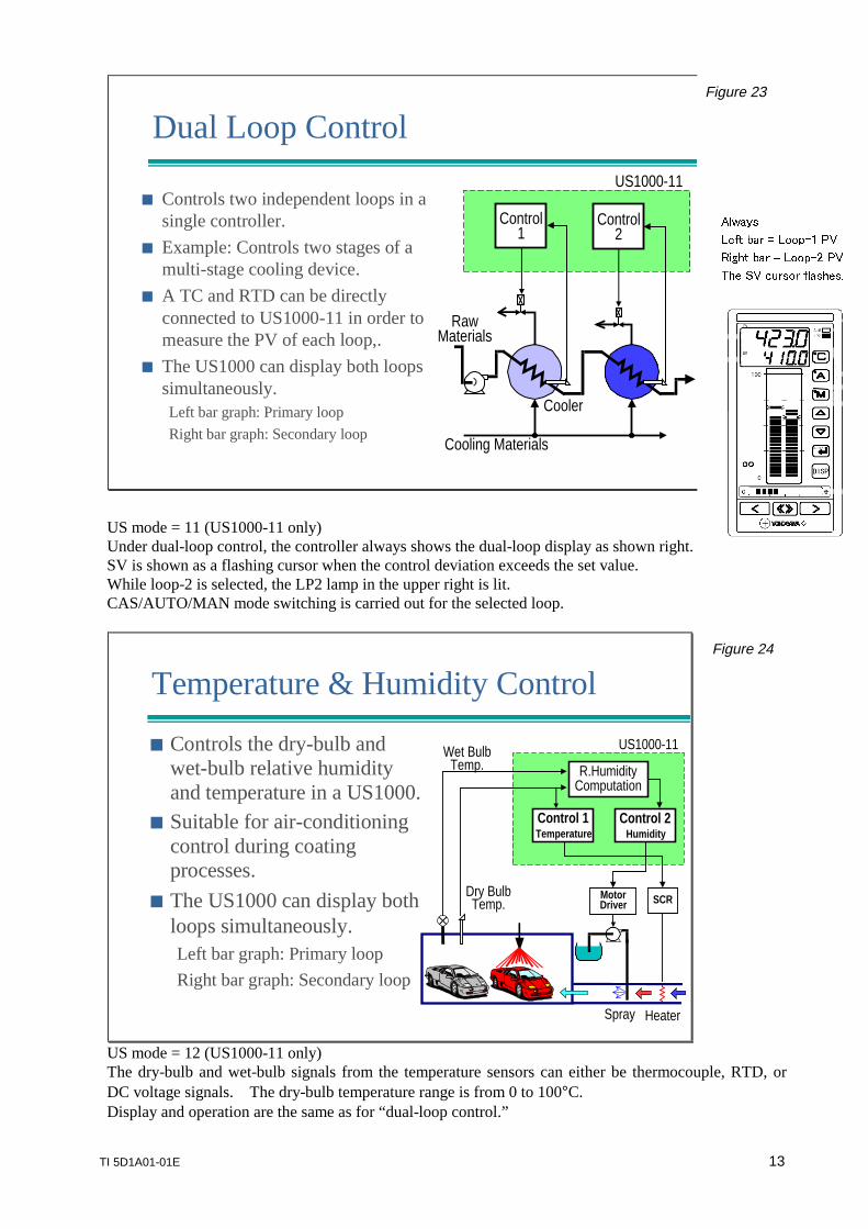
Dual Loop Control
Controls two independent loops in asingle controller.
Example: Controls two stages of amulti-stage cooling device.
A TC and RTD can be directlyconnected to US1000-11 in order tomeasure the PV of each loop,.
The US1000 can display both loopssimultaneously.Left bar graph: Primary loop
Right bar graph: Secondary loop
Cooler
RawMaterials
US1000-11
Cooling Materials
Control1
Control2
Figure 23
US mode = 11 (US1000-11 only)Under dual-loop control, the controller always shows the dual-loop display as shown right.SV is shown as a flashing cursor when the control deviation exceeds the set value.While loop-2 is selected, the LP2 lamp in the upper right is lit.CAS/AUTO/MAN mode switching is carried out for the selected loop.
Temperature & Humidity Control
Controls the dry-bulb andwet-bulb relative humidityand temperature in a US1000.
Suitable for air-conditioningcontrol during coatingprocesses.
The US1000 can display bothloops simultaneously.Left bar graph: Primary loopRight bar graph: Secondary loop
Wet BulbTemp.
Dry BulbTemp.
HeaterSpray
Control 2Humidity
US1000-11
MotorDriver
R.HumidityComputation
SCR
Control 1Temperature
Figure 24
US mode = 12 (US1000-11 only)The dry-bulb and wet-bulb signals from the temperature sensors can either be thermocouple, RTD, orDC voltage signals. The dry-bulb temperature range is from 0 to 100°C.Display and operation are the same as for “dual-loop control.”
14 TI 5D1A01-01E
Custom Computation
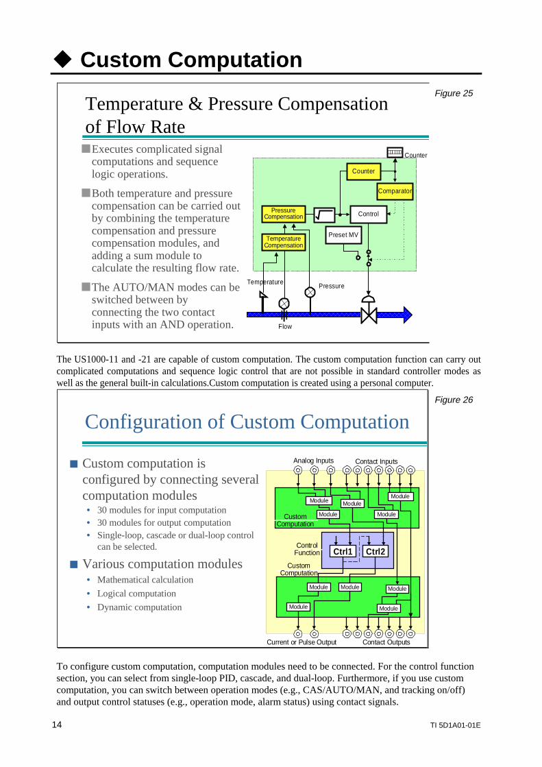
Temperature & Pressure Compensationof Flow RateTemperature & Pressure Compensationof Flow Rate
Temperature
TemperatureCompensation
Counter
Pressure
Flow
PressureCompensation
Comparator
Control
Preset MV
Counter
Executes complicated signalcomputations and sequencelogic operations.
Both temperature and pressurecompensation can be carried outby combining the temperaturecompensation and pressurecompensation modules, andadding a sum module tocalculate the resulting flow rate.
The AUTO/MAN modes can beswitched between byconnecting the two contactinputs with an AND operation.
Figure 25
The US1000-11 and -21 are capable of custom computation. The custom computation function can carry outcomplicated computations and sequence logic control that are not possible in standard controller modes aswell as the general built-in calculations.Custom computation is created using a personal computer.
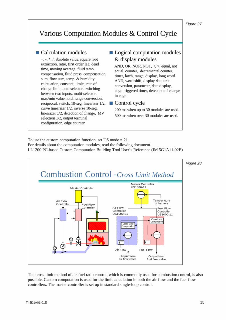
Configuration of Custom Computation
Custom computation isconfigured by connecting severalcomputation modules• 30 modules for input computation• 30 modules for output computation• Single-loop, cascade or dual-loop control
can be selected.
Various computation modules• Mathematical calculation• Logical computation• Dynamic computation
Ctrl2
Module
CustomComputation
ControlFunction Ctrl1
Analog Inputs Contact Inputs
Contact OutputsCurrent or Pulse Output
Module
Module
Module
Module
Module
Module
Module Module
Module
CustomComputation
Figure 26
To configure custom computation, computation modules need to be connected. For the control functionsection, you can select from single-loop PID, cascade, and dual-loop. Furthermore, if you use customcomputation, you can switch between operation modes (e.g., CAS/AUTO/MAN, and tracking on/off)and output control statuses (e.g., operation mode, alarm status) using contact signals.
TI 5D1A01-01E 15
Various Computation Modules & Control Cycle
Calculation modules+, -, * , /, absolute value, square rootextraction, ratio, first order lag, deadtime, moving average, fluid temp.compensation, fluid press. compensation,sum, flow sum, temp. & humiditycalculation, constant, limits, rate ofchange limit, auto selector, switchingbetween two inputs, multi-selector,max/min value hold, range conversion,reciprocal, switch, 10-seg. linearizer 1/2,curve linearizer 1/2, inverse 10-seg.linearizer 1/2, detection of change, MVselection 1/2, output terminalconfiguration, edge counter
Logical computation modules& display modules
AND, OR, NOR, NOT, <, >, equal, notequal, counter, decremental counter,timer, latch, range, display, long wordAND, word shift, display data unitconversion, parameter, data display,edge-triggered timer, detection of changein edge
Control cycle200 ms when up to 30 modules are used.500 ms when over 30 modules are used.
Figure 27
To use the custom computation function, set US mode = 21.For details about the computation modules, read the following document.LL1200 PC-based Custom Computation Building Tool User’s Reference (IM 5G1A11-02E)
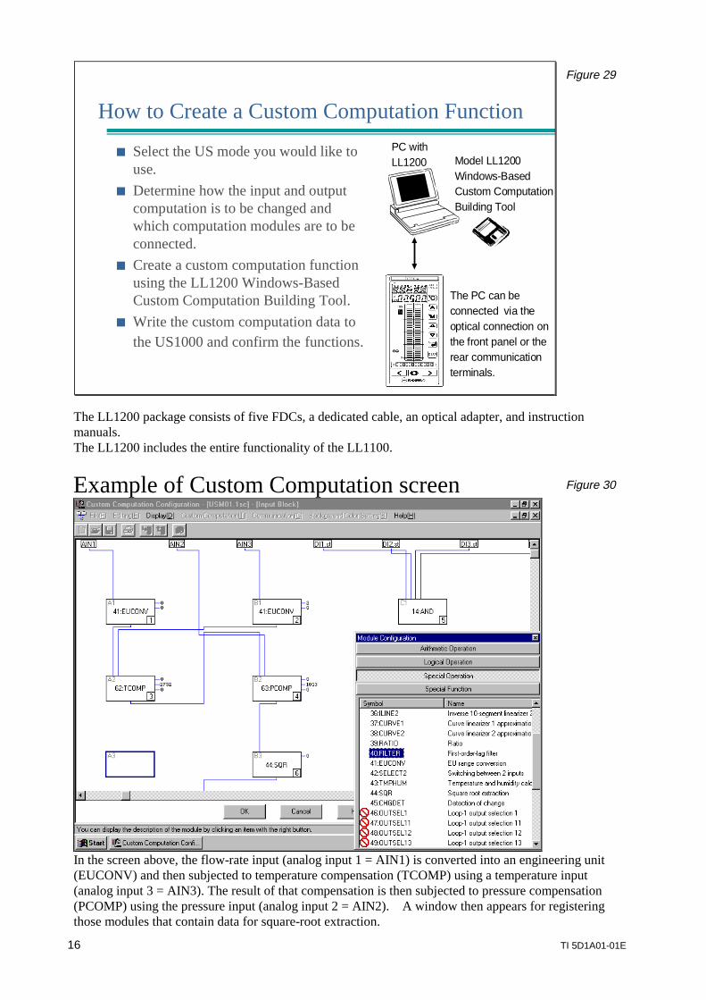
Combustion Control -Cross Limit MethodCombustion Control -Cross Limit Method
Fuel FlowControllerUS1000-11
Air FlowControllerUS1000-21
Cross LimitComputation
Fuel FlowController
Air FlowController
Master Controller
Output fromair flow valve
Temperatureof furnace
Master ControllerUS1000-11
Air Flow Fuel Flow
Output fromfuel flow valve
Cross LimitComputation
Figure 28
The cross-limit method of air-fuel ratio control, which is commonly used for combustion control, is alsopossible. Custom computation is used for the limit calculation in both the air-flow and the fuel-flowcontrollers. The master controller is set up in standard single-loop control.
16 TI 5D1A01-01E
How to Create a Custom Computation Function
Select the US mode you would like touse.
Determine how the input and outputcomputation is to be changed andwhich computation modules are to beconnected.
Create a custom computation functionusing the LL1200 Windows-BasedCustom Computation Building Tool.
Write the custom computation data tothe US1000 and confirm the functions.
PC withLL1200 Model LL1200
Windows-BasedCustom ComputationBuilding Tool
The PC can beconnected via theoptical connection onthe front panel or therear communicationterminals.
Figure 29
The LL1200 package consists of five FDCs, a dedicated cable, an optical adapter, and instructionmanuals.The LL1200 includes the entire functionality of the LL1100.
Example of Custom Computation screen Figure 30
In the screen above, the flow-rate input (analog input 1 = AIN1) is converted into an engineering unit(EUCONV) and then subjected to temperature compensation (TCOMP) using a temperature input(analog input 3 = AIN3). The result of that compensation is then subjected to pressure compensation(PCOMP) using the pressure input (analog input 2 = AIN2). A window then appears for registeringthose modules that contain data for square-root extraction.
TI 5D1A01-01E 17
Communication
Communication with a PC or PLC
US1000 can communicate with a PCor PLC via either the MODBUS orPC-Link Communication Protocol.
MODBUS– RTU (binary) mode, ASCII mode– MODBUS is very popular in the US and
Europe.
PC-Link– YOKOGAWA’s proprietary
communication protocol.– UT/UP controllers can be easily
connected to the same PC-Linkcommunication line.
MODBUS or PC-Link
Up to 31controllers.
Max. 1200 m
PC or PLC
RS232C to RS485 Converter
Figure 31
The MODBUS protocol is supported by many SCADA software products (operation and monitoringsoftware) and PLCs. You can easily connect US1000 to these products or PLCs. If you use the PC-linkprotocol, US1000 can be connected along a communication line of Green Series temperature controllers.
Hardware
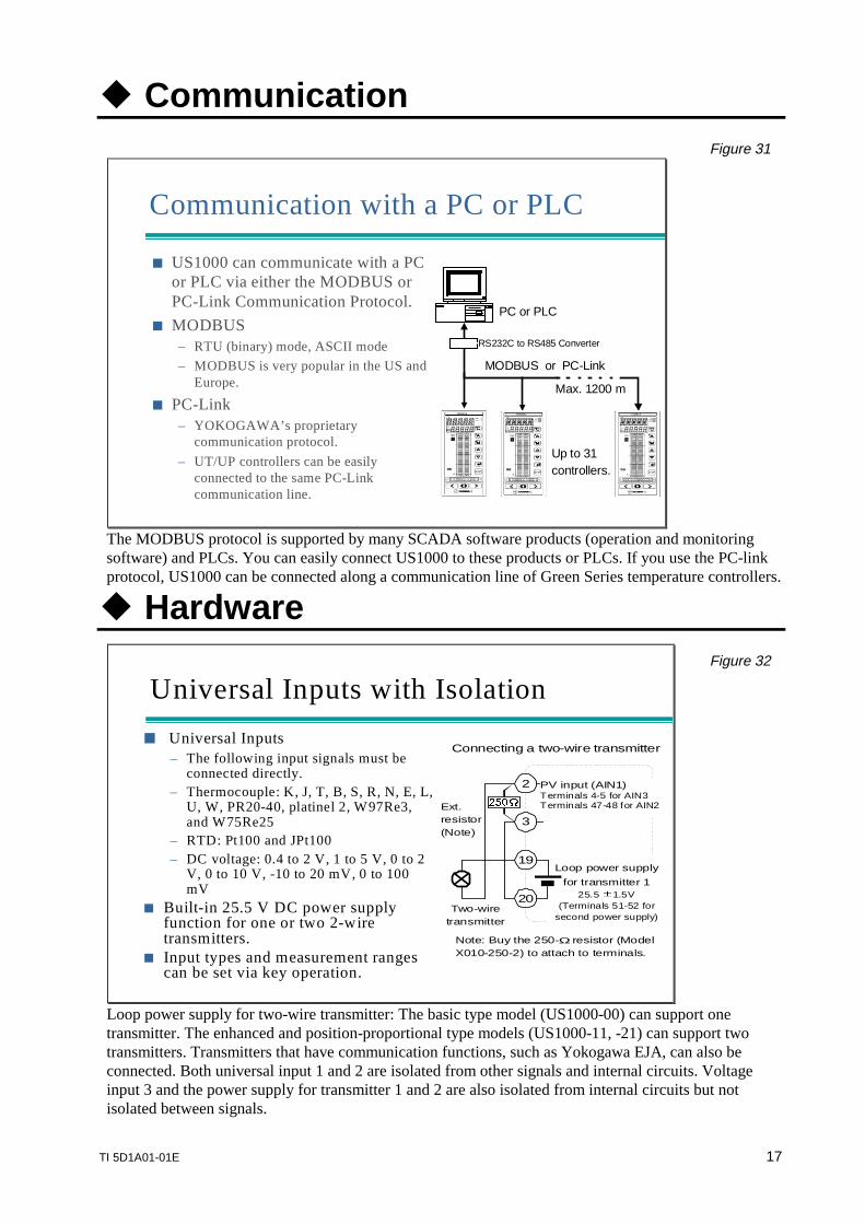
Universal Inputs with Isolation
Universal Inputs– The following input signals must be
connected directly.– Thermocouple: K, J, T, B, S, R, N, E, L,
U, W, PR20-40, platinel 2, W97Re3,and W75Re25
– RTD: Pt100 and JPt100– DC voltage: 0.4 to 2 V, 1 to 5 V, 0 to 2
V, 0 to 10 V, -10 to 20 mV, 0 to 100mV
Built-in 25.5 V DC power supplyfunction for one or two 2-wiretransmitters.
Input types and measurement rangescan be set via key operation.
Loop power supply
for transmitter 125.5 1.5V
(Terminals 51-52 forsecond power supply)
Ext.resistor(Note)
Two-wiretransmitter
20
2
3
PV input (AIN1)Terminals 4-5 for AIN3Terminals 47-48 for AIN2
Connecting a two-wire transmitter
Note: Buy the 250-Ωresistor (ModelX010-250-2) to attach to terminals.
19
Figure 32
Loop power supply for two-wire transmitter: The basic type model (US1000-00) can support onetransmitter. The enhanced and position-proportional type models (US1000-11, -21) can support twotransmitters. Transmitters that have communication functions, such as Yokogawa EJA, can also beconnected. Both universal input 1 and 2 are isolated from other signals and internal circuits. Voltageinput 3 and the power supply for transmitter 1 and 2 are also isolated from internal circuits but notisolated between signals.
18 TI 5D1A01-01E
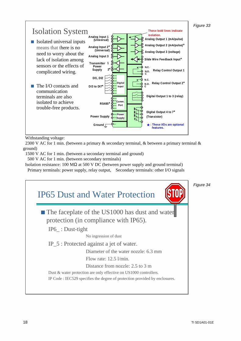
Isolation System Isolated universal inputs
means that there is noneed to worry about thelack of isolation amongsensors or the effects ofcomplicated wiring.
The I/O contacts andcommunicationterminals are alsoisolated to achievetrouble-free products.
DigitalInput
Comm.Port
CN.O.
N.C.
CN.O.
N.C.
PowerSupply
Analog Input 1(Universal)
TransmitterPowerSupply
DI1, DI2
RS485*
Power Supply
Ground
Analog Output 1 (mA/pulse)
Analog Output 2 (mA/pulse)*
Analog Output 3 (voltage)
Slide Wire Feedback Input*
Relay Control Output 1
Relay Control Output 2*
Digital Output 1 to 3 (relay)
Digital Output 4 to 7*(Transistor)
Analog Input 3
Analog Input 2*(Universal)
1
2*
DI3 to DI7*
These bold lines indicateisolation.
* : These I/Os are optional features.
Figure 33
Withstanding voltage: 2300 V AC for 1 min. (between a primary & secondary terminal, & between a primary terminal &ground) 1500 V AC for 1 min. (between a secondary terminal and ground) 500 V AC for 1 min. (between secondary terminals)Isolation resistance: 100 MΩ at 500 V DC (between power supply and ground terminal)
Primary terminals: power supply, relay output, Secondary terminals: other I/O signals
IP65 Dust and Water Protection
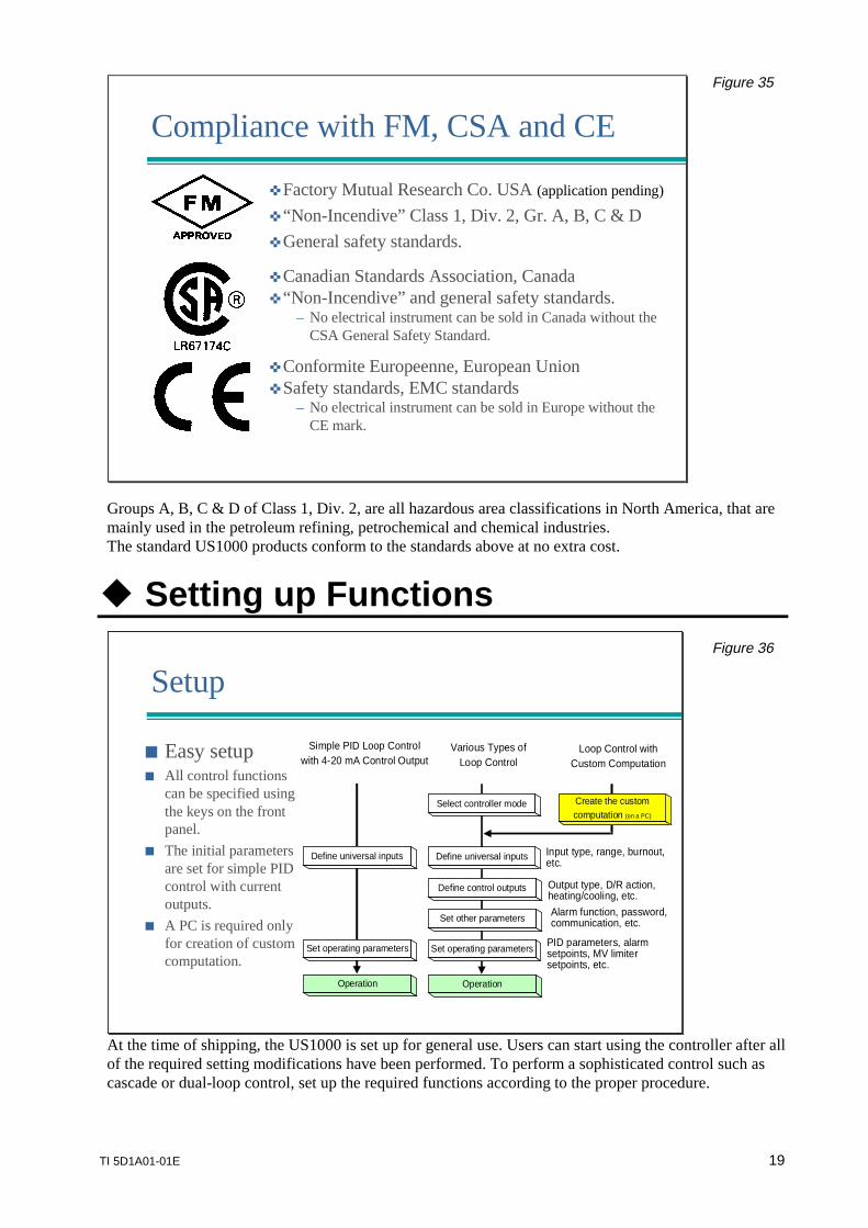
The faceplate of the US1000 has dust and waterprotection (in compliance with IP65).IP6_ : Dust-tight
No ingression of dust
IP_5 : Protected against a jet of water.Diameter of the water nozzle: 6.3 mmFlow rate: 12.5 l/min.Distance from nozzle: 2.5 to 3 m
Dust & water protection are only effective on US1000 controllers.IP Code : IEC529 specifies the degree of protection provided by enclosures.
Figure 34
TI 5D1A01-01E 19
Compliance with FM, CSA and CE
Factory Mutual Research Co. USA (application pending)
“Non-Incendive” Class 1, Div. 2, Gr. A, B, C & D General safety standards.
Canadian Standards Association, Canada “Non-Incendive” and general safety standards.
– No electrical instrument can be sold in Canada without theCSA General Safety Standard.
Conformite Europeenne, European Union Safety standards, EMC standards
– No electrical instrument can be sold in Europe without theCE mark.
Figure 35
Groups A, B, C & D of Class 1, Div. 2, are all hazardous area classifications in North America, that aremainly used in the petroleum refining, petrochemical and chemical industries.The standard US1000 products conform to the standards above at no extra cost.
Setting up Functions
SetupSetup
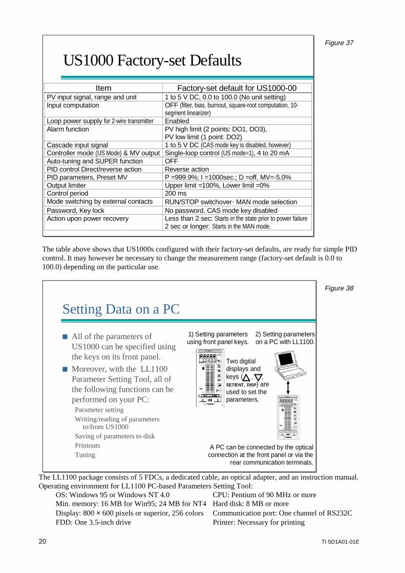
Easy setup All control functions
can be specified usingthe keys on the frontpanel.
The initial parametersare set for simple PIDcontrol with currentoutputs.
A PC is required onlyfor creation of customcomputation.
Simple PID Loop Controlwith 4-20 mA Control Output
Various Types ofLoop Control
Loop Control withCustom Computation
Operation
Define universal inputs
Set operating parameters
Select controller mode
Define control outputs
Set other parameters
Create the customcomputation (on a PC)
Operation
Define universal inputs
Set operating parameters
Input type, range, burnout,etc.
Output type, D/R action,heating/cooling, etc.
Alarm function, password,communication, etc.
PID parameters, alarmsetpoints, MV limitersetpoints, etc.
Figure 36
At the time of shipping, the US1000 is set up for general use. Users can start using the controller after allof the required setting modifications have been performed. To perform a sophisticated control such ascascade or dual-loop control, set up the required functions according to the proper procedure.
20 TI 5D1A01-01E
US1000 Factory-set DefaultsUS1000 Factory-set Defaults
Item Factory-set default for US1000-00PV input signal, range and unit 1 to 5 V DC, 0.0 to 100.0 (No unit setting)Input computation OFF (filter, bias, burnout, square-root computation, 10-
segment linearizer)Loop power supply for 2-wire transmitter EnabledAlarm function PV high limit (2 points: DO1, DO3),
PV low limit (1 point: DO2)Cascade input signal 1 to 5 V DC (CAS mode key is disabled, however)Controller mode (US Mode) & MV output Single-loop control (US mode=1), 4 to 20 mAAuto-tuning and SUPER function OFFPID control Direct/reverse action Reverse actionPID parameters, Preset MV P =999.9%; I =1000sec.; D =off, MV=-5.0%Output limiter Upper limit =100%, Lower limit =0%Control period 200 msMode switching by external contacts RUN/STOP switchoverMAN mode selectionPassword, Key lock No password, CAS mode key disabledAction upon power recovery Less than 2 sec: Starts in the state prior to power failure
2 sec or longer: Starts in the MAN mode.
Figure 37
The table above shows that US1000s configured with their factory-set defaults, are ready for simple PIDcontrol. It may however be necessary to change the measurement range (factory-set default is 0.0 to100.0) depending on the particular use.
Setting Data on a PC
All of the parameters ofUS1000 can be specified usingthe keys on its front panel.
Moreover, with the LL1100Parameter Setting Tool, all ofthe following functions can beperformed on your PC:Parameter settingWriting/reading of parameters
to/from US1000Saving of parameters to diskPrintoutsTuning
A PC can be connected by the opticalconnection at the front panel or via the
rear communication terminals.
1) Setting parametersusing front panel keys.
2) Setting parameterson a PC with LL1100.
Two digitaldisplays andkeys ( , ,SET/ENT, DISP) areused to set theparameters.
Figure 38
The LL1100 package consists of 5 FDCs, a dedicated cable, an optical adapter, and an instruction manual.Operating environment for LL1100 PC-based Parameters Setting Tool:
OS: Windows 95 or Windows NT 4.0 CPU: Pentium of 90 MHz or moreMin. memory: 16 MB for Win95; 24 MB for NT4 Hard disk: 8 MB or moreDisplay: 800 × 600 pixels or superior, 256 colors Communication port: One channel of RS232CFDD: One 3.5-inch drive Printer: Necessary for printing
TI 5D1A01-01E 21
Prevention of Wrong Operation
Password Configuration data can be protected by a password that
restricts access to the setup parameters. Only those who know the four-digit password can access
and change the configuration data.
Key lock security Changes to PID parameters and use of operation keys can
be prohibited using the key lock function. Users can prohibit or allow changes by contact input signals
or parameter setting via communication.
Figure 39
Once you set a password, you must input the password every time you wish to display/change the setupparameters (no password set at shipping). You can however still carry out operation and change theoperation parameter such as PID without the password. If you lose the password, you must return theUS1000 to Yokogawa Engineering Service Corporation for password cancellation. The key lockfunction disables the operation keys and prohibits the display of operating parameter on a menu basis.
Actions upon Power Recovery and During Failure
Upon Power Recovery
The US1000 does not detect powerfailures of less than 20 ms.
Following power failures of less than2 seconds:– Starts in the state prior to power off.
Following power failures of 2 secondsor longer:– HOT => Starts in the state prior topower off.– COLD => Starts in MAN mode andoutputs the preset MV.
During Failure
Display: Indicates the cause of failure.
Output signal:– Analog outputs: Off-scale becomes0% or less– Digital outputs: Open (same as whenpower fails)– Transmitter power supply: Normal
Figure 40
The controller detects an error using a self-diagnosis function and displays the cause of abnormalityon the digital display. For detailed information, read the instruction manual.In the event of failure, the analog output (current/voltage output) shoots down to 0% or undershootspast the 0% level.
22 TI 5D1A01-01E
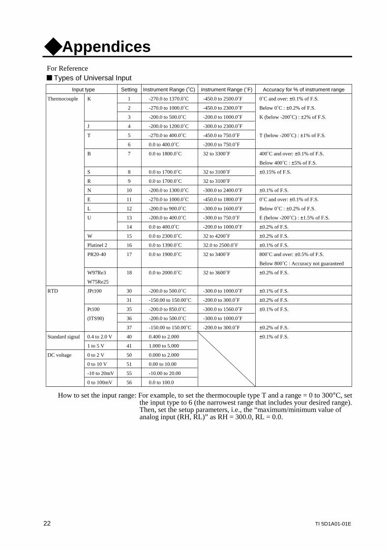
AppendicesFor Reference Types of Universal Input
How to set the input range: For example, to set the thermocouple type T and a range = 0 to 300°C, setthe input type to 6 (the narrowest range that includes your desired range).Then, set the setup parameters, i.e., the “maximum/minimum value ofanalog input (RH, RL)” as RH = 300.0, RL = 0.0.
Input type Setting Instrument Range (˚C) Instrument Range (˚F) Accuracy for % of instrument range
Thermocouple K 1 -270.0 to 1370.0˚C -450.0 to 2500.0˚F 0˚C and over: ±0.1% of F.S.
2 -270.0 to 1000.0˚C -450.0 to 2300.0˚F Below 0˚C : ±0.2% of F.S.
3 -200.0 to 500.0˚C -200.0 to 1000.0˚F K (below -200˚C) : ±2% of F.S.
J 4 -200.0 to 1200.0˚C -300.0 to 2300.0˚F
T 5 -270.0 to 400.0˚C -450.0 to 750.0˚F T (below -200˚C) : ±1% of F.S.
6 0.0 to 400.0˚C -200.0 to 750.0˚F
B 7 0.0 to 1800.0˚C 32 to 3300˚F 400˚C and over: ±0.1% of F.S.
Below 400˚C : ±5% of F.S.
S 8 0.0 to 1700.0˚C 32 to 3100˚F ±0.15% of F.S.
R 9 0.0 to 1700.0˚C 32 to 3100˚F
N 10 -200.0 to 1300.0˚C -300.0 to 2400.0˚F ±0.1% of F.S.
E 11 -270.0 to 1000.0˚C -450.0 to 1800.0˚F 0˚C and over: ±0.1% of F.S.
L 12 -200.0 to 900.0˚C -300.0 to 1600.0˚F Below 0˚C : ±0.2% of F.S.
U 13 -200.0 to 400.0˚C -300.0 to 750.0˚F E (below -200˚C) : ±1.5% of F.S.
14 0.0 to 400.0˚C -200.0 to 1000.0˚F ±0.2% of F.S.
W 15 0.0 to 2300.0˚C 32 to 4200˚F ±0.2% of F.S.
Platinel 2 16 0.0 to 1390.0˚C 32.0 to 2500.0˚F ±0.1% of F.S.
PR20-40 17 0.0 to 1900.0˚C 32 to 3400˚F 800˚C and over: ±0.5% of F.S.
Below 800˚C : Accuracy not guaranteed
W97Re3 18 0.0 to 2000.0˚C 32 to 3600˚F ±0.2% of F.S.
W75Re25
RTD JPt100 30 -200.0 to 500.0˚C -300.0 to 1000.0˚F ±0.1% of F.S.
31 -150.00 to 150.00˚C -200.0 to 300.0˚F ±0.2% of F.S.
Pt100 35 -200.0 to 850.0˚C -300.0 to 1560.0˚F ±0.1% of F.S.
(ITS90) 36 -200.0 to 500.0˚C -300.0 to 1000.0˚F
37 -150.00 to 150.00˚C -200.0 to 300.0˚F ±0.2% of F.S.
Standard signal 0.4 to 2.0 V 40 0.400 to 2.000 ±0.1% of F.S.
1 to 5 V 41 1.000 to 5.000
DC voltage 0 to 2 V 50 0.000 to 2.000
0 to 10 V 51 0.00 to 10.00
-10 to 20mV 55 -10.00 to 20.00
0 to 100mV 56 0.0 to 100.0
TI 5D1A01-01E 23
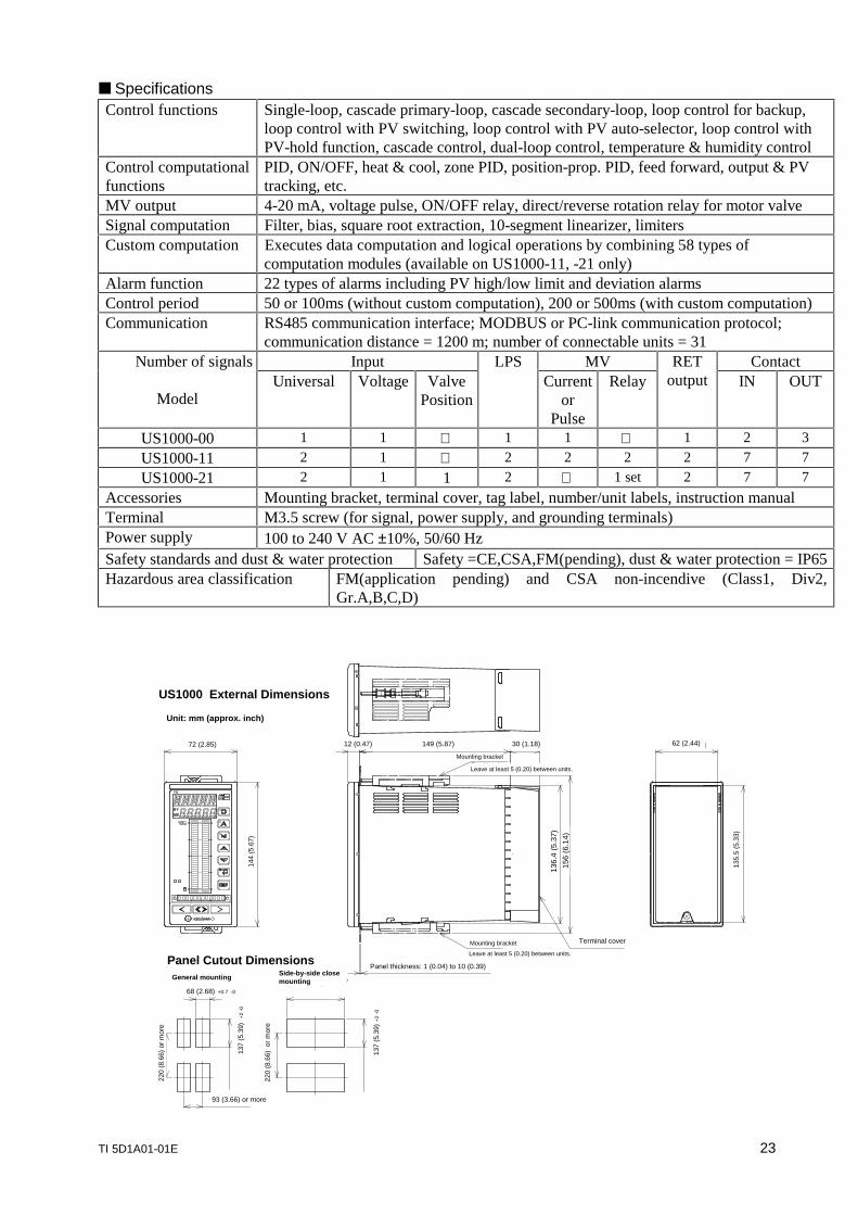
n SpecificationsControl functions Single-loop, cascade primary-loop, cascade secondary-loop, loop control for backup,
loop control with PV switching, loop control with PV auto-selector, loop control withPV-hold function, cascade control, dual-loop control, temperature & humidity control
Control computationalfunctions
PID, ON/OFF, heat & cool, zone PID, position-prop. PID, feed forward, output & PVtracking, etc.
MV output 4-20 mA, voltage pulse, ON/OFF relay, direct/reverse rotation relay for motor valveSignal computation Filter, bias, square root extraction, 10-segment linearizer, limitersCustom computation Executes data computation and logical operations by combining 58 types of
computation modules (available on US1000-11, -21 only)Alarm function 22 types of alarms including PV high/low limit and deviation alarmsControl period 50 or 100ms (without custom computation), 200 or 500ms (with custom computation)Communication RS485 communication interface; MODBUS or PC-link communication protocol;
communication distance = 1200 m; number of connectable units = 31Input MV ContactNumber of signals
ModelUniversal Voltage Valve
Position
LPSCurrent
orPulse
RelayRET
output IN OUT
US1000-00 1 1 æ 1 1 æ 1 2 3
US1000-11 2 1 æ 2 2 2 2 7 7
US1000-21 2 1 1 2 æ 1 set 2 7 7
Accessories Mounting bracket, terminal cover, tag label, number/unit labels, instruction manualTerminal M3.5 screw (for signal, power supply, and grounding terminals)Power supply 100 to 240 V AC ±10%, 50/60 HzSafety standards and dust & water protection Safety =CE,CSA,FM(pending), dust & water protection = IP65Hazardous area classification FM(application pending) and CSA non-incendive (Class1, Div2,
Gr.A,B,C,D)
US1000 External Dimensions
72 (2.85)
144
(5.6
7)
136.
4 (5
.37)
156
(6.1
4)
Panel thickness: 1 (0.04) to 10 (0.39)
Terminal cover
135.
5 (5
.33)
62 (2.44)
Panel Cutout DimensionsGeneral mounting
68 (2.68) +0.7 -0
220
(8.6
6) o
r m
ore
137
(5.3
9)
+2
-0
93 (3.66) or more
Side-by-side closemounting
220
(8.6
6) o
r m
ore
137
(5.3
9) +
2 -0
Unit: mm (approx. inch)
Mounting bracket
Leave at least 5 (0.20) between units.
Unit: mm (approx inch)
12 (0.47) 149 (5.87) 30 (1.18)
Mounting bracket
Leave at least 5 (0.20) between units.
@ @ @
24 TI 5D1A01-01E
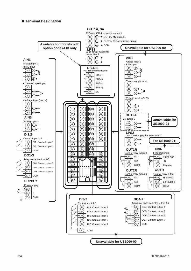
n Terminal Designation
40
31
32
33
34
35
36
37
38
39
25
16
17
18
19
24
23
22
20
21
4
3
1
2
5
9
10
8
7
6
15
11
12
13
14
46
60
51
52
47
48
49
50
55
56
57
58
59
+
–
–
–
• Thermocouple input
1
2
3
A
B
b
• RTD input
1
2
3
+
1
2
3
• Voltage input (mV, V)
17
16 +
+
MV output/ Retransmission output
18
OUT1A: MV output 1
OUT3A: Retransmission output
COM
OUT1A, 3A
20
19 +
Loop power supply fortransmitter 1
LPS1
DI1,2
DO1-3
5
4 +
Analog input 3
AIN3
DI2: Contact input 2
6 DI1: Contact input 1
Contact input 1, 2
COM
7
8
Relay contact output 1-3
Power supply
SUPPLY
DO1: Contact output 1
DO3: Contact output 3
10
12
11
9
COM
DO2: Contact output 2
13
15
14
L
N
GND
38
40
39
36
37
DO4: Contact output 4
COM
DO7: Contact output 7
DO6: Contact output 6
DO5: Contact output 5
Transistor open-collector output 4-7
DO4-7
35 DI7: Contact input 7
32
34
33
31 DI3: Contact input 3
DI6: Contact input 6
DI5: Contact input 5
DI4: Contact input 4
Contact input 3-7
DI3-7
8 COM
AIN1Analog input 1
58
59
60
H (Direct)
COM
L (Reverse)
Control relay output
OUTR
55
57
56
100% side
0% side
IN
Feedback inputFBIN
46
48
47
A
B
b
• RTD input
46
48
47 +
• Thermocouple input
46
48
47 +
• Voltage input (mV, V)
50
49 +
–
–
MV output 2
OUT2A
52
51 +
Loop power supply for transmitter 2LPS2
55
56
57
NC
COM
NO
Control relay output 1OUT1R
58
59
60
NC
COM
NO
Control relay output 2OUT2R
AIN2Analog input 2
RS-485
25 SG
22
24
23
21 SDB(+)
RDA(-)
RDB(+)
SDA(-)
RS-485 communication
Unavailable for US1000-00
Unavailable forUS1000-21
For US1000-21:
Available for models withoption code /A10 only
Unavailable for US1000-00
–
–
–
–

Revision RecordTitle: Information on US1000 Digital Indicating Controller
Manual No.: TI 5D1A01-01E
Edition Date Revised Item
First January 1999 Newly published


![User's Manual PK200 CURRENT-TO-PNEUMATIC CONVERTER [Style…cdn2.us.yokogawa.com/IM21B03D01-01E.pdf · User's Manual PK200 CURRENT-TO-PNEUMATIC CONVERTER [Style:S2] IM 21B03D01-01E](https://img.pdfslide.us/doc/110x75/5a9c19d97f8b9ad96f8e52be/users-manual-pk200-current-to-pneumatic-converter-stylecdn2us-s-manual-pk200.jpg)