Embed Size (px)
Citation preview
proSA®
CHRISTOPH MIETHKE GMBH & CO. KG
Instructions for UseUSA
0297
3
INSTRUCTIONS FOR USE | USA
CONTENT
INDICATION FOR USE 4TECHNICAL DESCRIPTION 4PHYSICS BACKGROUND 5FUNCTION OF THE proSA 6SELECTING THE APPROPRIATE OPENING PRESSURE OF THE proSA 8ACCESSORIES 10Verification Tool 11Masterdisc 11Compass 12Adjustment tool 12Adjustment disc 13Check-mate 13ADJUSTING THE proSA 14READING THE PRESSURE SETTING FROM AN X-RAY IMAGE 16POSSIBLE SHUNT COMPONENTS 18SURGICAL PROCEDURE 18TUBE SYSTEMS 19TESTING VALVE PATENCY 20VALVE TEST PRIOR TO IMPLANTATION 20TEST RESULTS OF PREIMPLANTATION TEST 21PRESSURE-FLOW CHARACTERISTICS 21TEST ON REFLOW SAFETY 22INTERACTIONS WITH PRODUCTS FROM OTHER MANUFACTURERS 22RE-IMPLANTATION 22SAFETY MEASURES 22COMPATIBILITY WITH DIAGNOSTIC PROCEDURES 22MRI INFORMATION 22FUNCTIONAL SAFETY 23STERILISATION 23RESTERILISATION 23REQUIREMENTS OF THE MDD 93/42/EEC 23NOTE ON THE INSTRUCTIONS FOR USE 23MEDICAL PRODUCTS CONSULTANT 24GENERAL INFORMATION 24VARIANTS 25
0297
4 5
| INSTRUCTIONS FOR USE INSTRUCTIONS FOR USE | USA USA
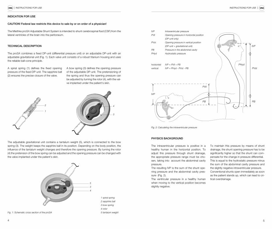
A spiral spring (1) defines the fixed opening pressure of the fixed DP-unit. The sapphire ball (2) ensures the precise closure of the valve.
A bow spring (3) defines the opening pressure of the adjustable DP-unit. The pretensioning of the spring and thus the opening pressure can be adjusted by turning the rotor (4), with the val-ve implanted under the patient‘s skin.
INDICATION FOR USE
CAUTION! Federal law restricts this device to sale by or on order of a physician!
The Miethke proSA Adjustable Shunt System is intended to shunt cerebrospinal fluid (CSF) from the lateral ventricles of the brain into the peritoneum.
TECHNICAL DESCRIPTION
The proSA combines a fixed DP-unit (differential pressure unit) or an adjustable DP-unit with an adjustable gravitational unit (Fig. 1). Each valve unit consists of a robust titanium housing and uses the reliable ball-cone principle.
The adjustable gravitational unit contains a tantalum weight (5), which is connected to the bow spring (3). The weight keeps the sapphire ball in its position. Depending on the body position, the influence of the tantalum weight changes and therefore the opening pressure. By turning the rotor (4) the pretension of the bow spring can be adjusted and the opening pressure can be changed with the valve implanted under the patient‘s skin.
CH
RIS
TOP
H M
IETH
KE
0...4
0
proSA
CHRISTOPH MIETHKE0...40
proSA
IVP
PVli
PB
PHyd
PVst
IVP
PB
Fig. 2: Calculating the intraventricular pressure
horizontal: IVP = PVli + PB
vertical: IVP = PHyd - PVst - PB
IVP Intraventricular pressure
PVli Opening pressure in horizontal position
(DP-unit only)
PVst Opening pressure in vertical position
(DP-unit + gravitational unit)
PB Pressure in the abdominal cavity
PHyd Hydrostatic pressure
PHYSICS BACKGROUND
The intraventricular pressure is positive in a healthy human in the horizontal position. To adjust this pressure through shunt drainage, the appropriate pressure range must be cho-sen, taking into account the abdominal cavity pressure. The resulting IVP is the sum of the shunt ope-ning pressure and the abdominal cavity pres-sure (Fig. 2). The ventricular pressure in a healthy human when moving to the vertical position becomes slightly negative.
To maintain this pressure by means of shunt drainage, the shunt opening pressure has to be significantly higher so that the shunt can com-pensate for the change in pressure differential. This is equal to the hydrostatic pressure minus the sum of the abdominal cavity pressure and the slightly negative intraventricular pressure.Conventional shunts open immediately as soon as the patient stands up, which can lead to cri-tical overdrainage.
1 spiral spring
2 sapphire ball
3 bow spring
4 rotor
5 tantalum weight
4
3
Fig. 1: Schematic cross section of the proSA
2
1
6 7
| INSTRUCTIONS FOR USE INSTRUCTIONS FOR USE | USA USA
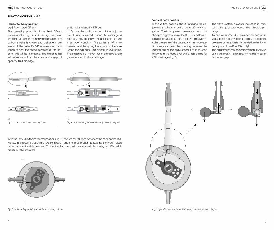
FUNCTION OF THE proSA
Horizontal body position proSA with fixed DP-unitThe operating principle of the fixed DP-unit is illustrated in Fig. 3a and 3b. Fig. 3 a shows the fixed DP-unit in the horizontal position. The ball-cone valve is closed and drainage is pre-vented. If the patient‘s IVP increases and con-tinues to rise, the spring pressure of the ball-cone unit will be overcome. The sapphire ball will move away from the cone and a gap will open for fluid drainage.
proSA with adjustable DP-unitIn Fig. 4a the ball-cone unit of the adjusta-ble DP-unit is closed, hence the drainage is blocked. Fig. 4b shows the adjustable DP-unit in an open condition. The patient‘s IVP is in-creased and the spring force, which otherwise keeps the ball-cone unit closed, is overcome. The sapphire ball moves out of the cone and a gap opens up to allow drainage.
With the proSA in the horizontal position (Fig. 5), the weight (1) does not affect the sapphire ball (2). Hence, in this configuration the proSA is open, and the force brought to bear by the weight does not counteract the fluid pressure. The ventricular pressure is now controlled solely by the differential-pressure valve installed.
Vertical body positionIn the vertical position, the DP-unit and the ad-justable gravitational unit of the proSA work to-gether. The total opening pressure is the sum of the opening pressures of the DP-unit and the ad-justable gravitational unit. If the IVP (intraventri-cular pressure) of the patient and the hydrosta-tic pressure exceed this opening pressure, the closing ball of the gravitational unit is pushed away from the cone seal and a gap opens for CSF-drainage (Fig. 6).
The valve system prevents increases in intra-ventricular pressure above the physiological range.To ensure optimal CSF drainage for each indi-vidual patient in any body position, the opening pressure of the adjustable gravitational unit can be adjusted from 0 to 40 cmH2O. The adjustment can be achieved non-invasively using the proSA Tools, preventing the need for further surgery.
Fig. 6: gravitational unit in vertical body position a) closed b) open
b)a)
Fig. 4: adjustable gravitational unit a) closed, b) open
a)
b)
Fig. 5: adjustable gravitational unit in horizontal position
a)
b)Fig. 3: fixed DP-unit a) closed, b) open
2
1
8 9
| INSTRUCTIONS FOR USE INSTRUCTIONS FOR USE | USA USA
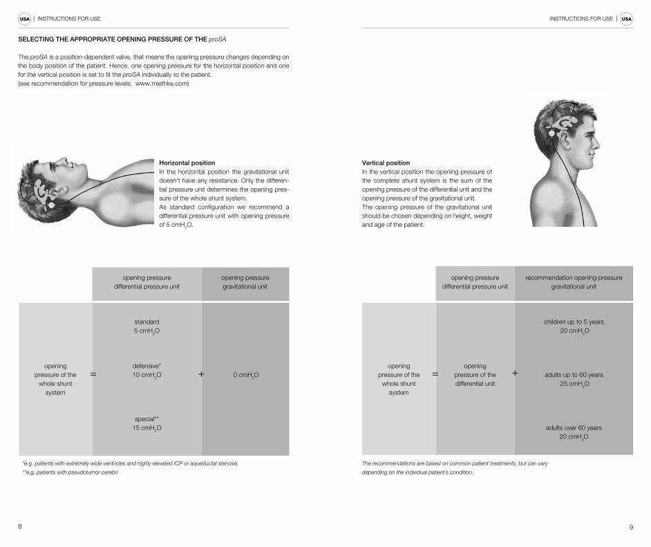
Horizontal positionIn the horizontal position the gravitational unit doesn‘t have any resistance. Only the differen-tial pressure unit determines the opening pres-sure of the whole shunt system. As standard configuration we recommend a differential pressure unit with opening pressure of 5 cmH2O.
SELECTING THE APPROPRIATE OPENING PRESSURE OF THE proSA
The proSA is a position-dependent valve, that means the opening pressure changes depending on the body position of the patient. Hence, one opening pressure for the horizontal position and one for the vertical position is set to fit the proSA individually to the patient.(see recommendation for pressure levels: www.miethke.com)
opening pressuredifferential pressure unit
opening pressuregravitational unit
openingpressure of the
whole shuntsystem
standard5 cmH2O
0 cmH2Odefensive*10 cmH2O
special**15 cmH2O
*e.g. patients with extremely wide ventricles and highly elevated ICP or aqueductal stenosis
**e.g. patients with pseudotumor cerebri
= +
Vertical positionIn the vertical position the opening pressure of the complete shunt system is the sum of the opening pressure of the differential unit and the opening pressure of the gravitational unit. The opening pressure of the gravitational unit should be chosen depending on height, weight and age of the patient.
opening pressuredifferential pressure unit
recommendation opening pressuregravitational unit
openingpressure of the
whole shuntsystem
openingpressure of thedifferential unit
children up to 5 years 20 cmH2O
adults up to 60 years 25 cmH2O
adults over 60 years20 cmH2O
The recommendations are based on common patient treatments, but can vary
depending on the individual patient´s condition.
= +
10 11
| INSTRUCTIONS FOR USE INSTRUCTIONS FOR USE | USA USA
ACCESSORIES
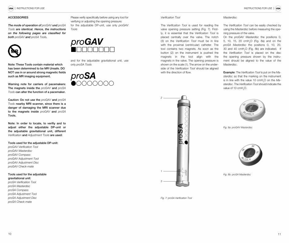
The mode of operation of proGAV und proSA Tools are identical. Hence, the instructions on the following pages are classified for both proGAV and proSA Tools.
Note: These Tools contain material whichhas been determined to be MR Unsafe. DONOT use in or around strong magnetic fieldssuch as MR imaging equipment.
Warning note for carriers of pacemakers: The magnets inside the proGAV and proSA Tools can alter the function of a pacemaker.
Caution: Do not use the proGAV and proSA Tools nearby MRI scanner, since there is a danger of damaging the MRI scanner due to the magnets inside proGAV and proSA Tools.
Note: In order to locate, to verifiy and to adjust either the adjustable DP-unit or the adjustable gravitational unit, different Verification and Adjustment Tools are used:
Tools used for the adjustable DP-unit: proGAV Verification ToolproGAV MasterdiscproGAV CompassproGAV Adjustment ToolproGAV Adjustment DiscproGAV Check-mate
Tools used for the adjustable gravitational unit: proSA Verification ToolproSA MasterdiscproSA CompassproSA Adjustment ToolproSA Adjustment DiscproSA Check-mate
Please verify specifically before using any tool for verifying or adjusting the opening pressure: for the adjustable DP-unit, use only proGAV Tools
and for the adjustable gravitational unit, use only proSA Tools
Verification Tool
The Verification Tool is used for reading the valve opening pressure setting (Fig. 7). First-ly, it is essential that the Verification Tool is placed centrally over the valve. The notch (3) on the Verification Tool must be in line with the proximal (ventricular) catheter. The tool contains two magnets. As soon as the button (2) on the instrument is pushed the magnets in the tool align with the magnets in the valve. The opening pressure is shown on the scale (1). The arrow on the under-side of the Verification Tool should be aligned with the direction of flow.
2
1
3
Fig. 7: proSA Verification Tool
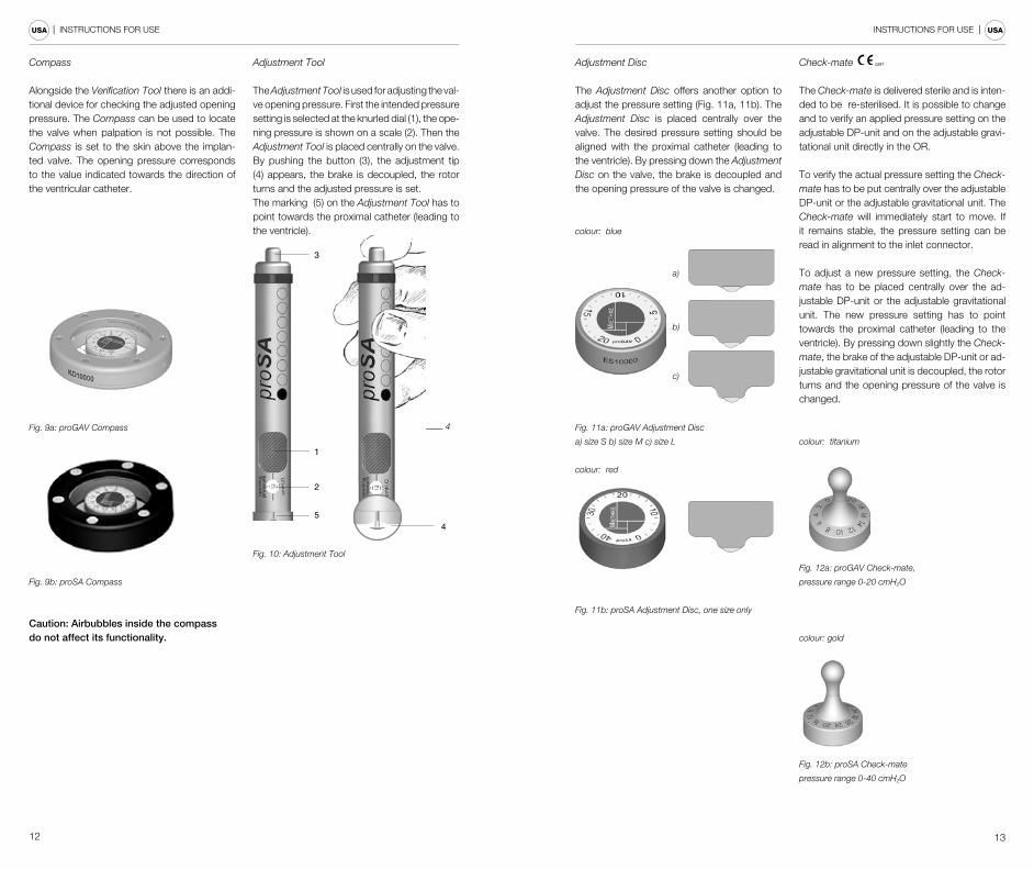
Masterdisc
The Verification Tool can be easily checked by using the Masterdisc before measuring the ope-ning pressure of the valve. On the proGAV Masterdisc the positions 0, 5, 10, 15, 20 cmH2O (Fig. 8a) and on the proSA Masterdisc the positions 0, 10, 20, 30 and 40 cmH2O (Fig. 8b) are indicated. If the Verification Tool is placed on the disc the opening pressure shown by the instru-ment should be aligned to the value of the Masterdisc.
Example: The Verification Tool is put on the Ma-sterdisc so that the marking on the instrument is in line with the value 10 cmH2O on the Ma-sterdisc. The Verification Tool should indicate the value of 10 cmH2O.
Fig. 8a: proGAV Masterdisc
Fig. 8b: proSA Masterdisc
12 13
| INSTRUCTIONS FOR USE INSTRUCTIONS FOR USE | USA USA
Compass
Alongside the Verification Tool there is an addi-tional device for checking the adjusted opening pressure. The Compass can be used to locate the valve when palpation is not possible. The Compass is set to the skin above the implan-ted valve. The opening pressure corresponds to the value indicated towards the direction of the ventricular catheter.
Fig. 9a: proGAV Compass
Fig. 9b: proSA Compass
Caution: Airbubbles inside the compass do not affect its functionality.
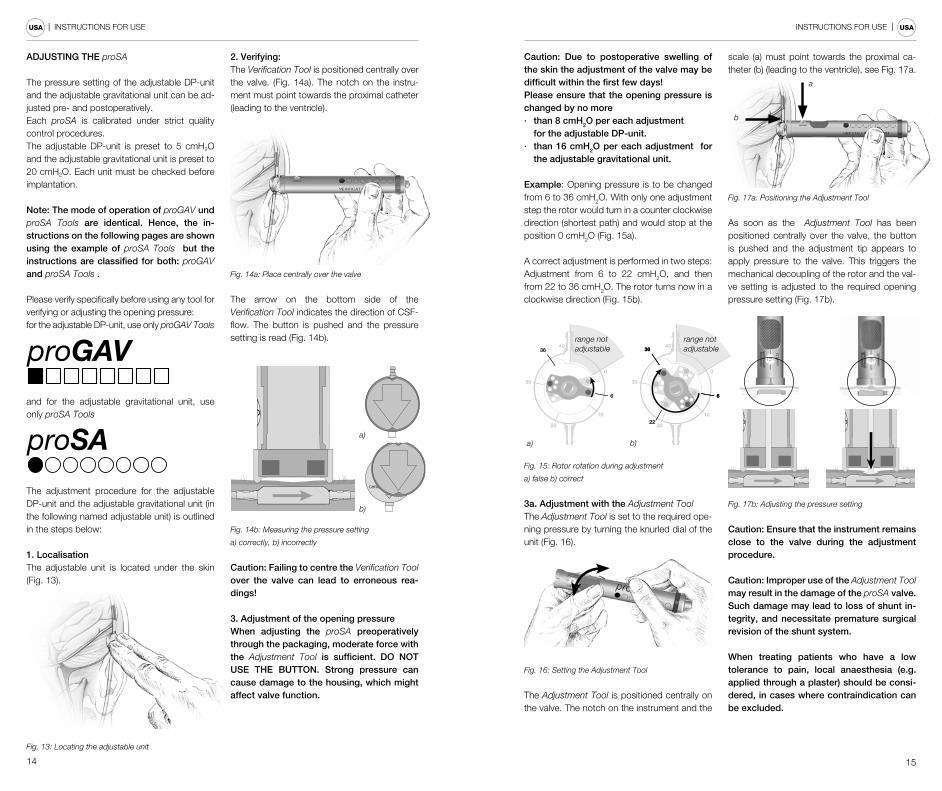
Adjustment Tool
The Adjustment Tool is used for adjusting the val-ve opening pressure. First the intended pressure setting is selected at the knurled dial (1), the ope-ning pressure is shown on a scale (2). Then the Adjustment Tool is placed centrally on the valve. By pushing the button (3), the adjustment tip (4) appears, the brake is decoupled, the rotor turns and the adjusted pressure is set. The marking (5) on the Adjustment Tool has to point towards the proximal catheter (leading to the ventricle).
4
1
3
4
2
5
Fig. 10: Adjustment Tool
Adjustment Disc
The Adjustment Disc offers another option to adjust the pressure setting (Fig. 11a, 11b). The Adjustment Disc is placed centrally over the valve. The desired pressure setting should be aligned with the proximal catheter (leading to the ventricle). By pressing down the Adjustment Disc on the valve, the brake is decoupled and the opening pressure of the valve is changed.
colour: blue
a)
b)
c)
Fig. 11a: proGAV Adjustment Disc
a) size S b) size M c) size L
colour: red
Fig. 11b: proSA Adjustment Disc, one size only
Check-mate
The Check-mate is delivered sterile and is inten-ded to be re-sterilised. It is possible to change and to verify an applied pressure setting on the adjustable DP-unit and on the adjustable gravi-tational unit directly in the OR.
To verify the actual pressure setting the Check-mate has to be put centrally over the adjustable DP-unit or the adjustable gravitational unit. The Check-mate will immediately start to move. If it remains stable, the pressure setting can be read in alignment to the inlet connector.
To adjust a new pressure setting, the Check-mate has to be placed centrally over the ad-justable DP-unit or the adjustable gravitational unit. The new pressure setting has to point towards the proximal catheter (leading to the ventricle). By pressing down slightly the Check-mate, the brake of the adjustable DP-unit or ad-justable gravitational unit is decoupled, the rotor turns and the opening pressure of the valve is changed.
colour: titanium
Fig. 12a: proGAV Check-mate,
pressure range 0-20 cmH2O
colour: gold
Fig. 12b: proSA Check-mate
pressure range 0-40 cmH2O
0297
14 15
| INSTRUCTIONS FOR USE INSTRUCTIONS FOR USE | USA USA
ADJUSTING THE proSA
The pressure setting of the adjustable DP-unit and the adjustable gravitational unit can be ad-justed pre- and postoperatively. Each proSA is calibrated under strict quality control procedures. The adjustable DP-unit is preset to 5 cmH2O and the adjustable gravitational unit is preset to 20 cmH2O. Each unit must be checked before implantation.
Note: The mode of operation of proGAV und proSA Tools are identical. Hence, the in-structions on the following pages are shown using the example of proSA Tools but the instructions are classified for both: proGAV and proSA Tools .
Please verify specifically before using any tool for verifying or adjusting the opening pressure: for the adjustable DP-unit, use only proGAV Tools
and for the adjustable gravitational unit, use only proSA Tools
The adjustment procedure for the adjustable DP-unit and the adjustable gravitational unit (in the following named adjustable unit) is outlined in the steps below:
1. LocalisationThe adjustable unit is located under the skin (Fig. 13).
Fig. 13: Locating the adjustable unit
2. Verifying: The Verification Tool is positioned centrally over the valve. (Fig. 14a). The notch on the instru-ment must point towards the proximal catheter (leading to the ventricle).
Fig. 14a: Place centrally over the valve
The arrow on the bottom side of the Verification Tool indicates the direction of CSF-flow. The button is pushed and the pressure setting is read (Fig. 14b).
Fig. 14b: Measuring the pressure setting
a) correctly, b) incorrectly
CHRISTOPH MIETHKE
0...20p ro G A V
a)
b)
Caution: Failing to centre the Verification Tool over the valve can lead to erroneous rea-dings!
3. Adjustment of the opening pressureWhen adjusting the proSA preoperatively through the packaging, moderate force with the Adjustment Tool is sufficient. DO NOT USE THE BUTTON. Strong pressure can cause damage to the housing, which might affect valve function.
Caution: Due to postoperative swelling of the skin the adjustment of the valve may be difficult within the first few days!Please ensure that the opening pressure is changed by no more · than 8 cmH2O per each adjustment
for the adjustable DP-unit. · than 16 cmH2O per each adjustment for
the adjustable gravitational unit.
Example: Opening pressure is to be changed from 6 to 36 cmH2O. With only one adjustment step the rotor would turn in a counter clockwise direction (shortest path) and would stop at the position 0 cmH2O (Fig. 15a).
A correct adjustment is performed in two steps: Adjustment from 6 to 22 cmH2O, and then from 22 to 36 cmH2O. The rotor turns now in a clockwise direction (Fig. 15b).
10
2022
30
40
0
36
6
36
6
10
20
30
40
0
6
36
a) b)
range not adjustable
range not adjustable
Fig. 15: Rotor rotation during adjustment
a) false b) correct
3a. Adjustment with the Adjustment ToolThe Adjustment Tool is set to the required ope-ning pressure by turning the knurled dial of the unit (Fig. 16).
Fig. 16: Setting the Adjustment Tool
The Adjustment Tool is positioned centrally on the valve. The notch on the instrument and the
scale (a) must point towards the proximal ca-theter (b) (leading to the ventricle), see Fig. 17a.
a
b
Fig. 17a: Positioning the Adjustment Tool
As soon as the Adjustment Tool has been positioned centrally over the valve, the button is pushed and the adjustment tip appears to apply pressure to the valve. This triggers the mechanical decoupling of the rotor and the val-ve setting is adjusted to the required opening pressure setting (Fig. 17b).
Fig. 17b: Adjusting the pressure setting
Caution: Ensure that the instrument remains close to the valve during the adjustment procedure.
Caution: Improper use of the Adjustment Tool may result in the damage of the proSA valve. Such damage may lead to loss of shunt in-tegrity, and necessitate premature surgical revision of the shunt system.
When treating patients who have a low tolerance to pain, local anaesthesia (e.g. applied through a plaster) should be consi-dered, in cases where contraindication can be excluded.
16 17
| INSTRUCTIONS FOR USE INSTRUCTIONS FOR USE | USA USA
3b. Adjustment with the Adjustment DiscCenter the Adjustment Disc over the gravitational unit of the and align the desired pressure setting (b) on top of the disc in direction of the ventricu-lar catheter (c), see Fig. 18a.
b
c
Fig. 18a: Adjustment with the Adjustment Disc
For changing the opening pressure, press down the adjustment disc and release (Fig. 18b). Do not press and turn.
b
c
Fig. 18b: Press down slightly the Adjustment Disc
and release
Finally, remove the Adjustment Disc and con-firm the setting with the Verification Tool.
4. Verifying after adjustmentAfter adjusting the valve by using the Adjustment Tool, it can be verified using the Verification Tool, as described in step 2. If the pressure measured now differs from the intended pressure level, the adjustment procedure has to be repeated from step 3. After adjusting the valve using the Adjust-ment Tool, it can be verified using the Verification Tool and may be confirmed by radiograph (X-ray).
If the pressure configuration of the valve cannot be determined with complete cer-tainly by the Verification Tool, the use of ima-ging techniques is recommended (excluding MRI: danger of artefacts).
MRI examinations must be performed at field strengths no greater than 3.0 tesla.
Caution: If the site of implantation is poorly selected or if the skin over the valve is too thick, an adjustment of the adjustable unit can be difficult or sometimes impossible. The adjustable gravitational unit then be-haves like a gravitational unit with a fixed opening pressure for a given position.
Caution: X-ray confirmation may still be ne-cessary for patients with scalp thicknesses greater than or equal to 5 mm thick.
The following table shows the quantitative in-formation regarding the overall agreement ratesbetween the X-ray and the respective verifi-cation tool for the proSA valve. The maximum deviation from the actual valve readings used were 0, ≤ 1, ≤ 2, > 2 cmH2O. For example at ≤ 2 cmH2O 99.6 % of the measurements made by the proSA VERIFICATION TOOL with the proSA valve deviate not more than ± 2 cmH2O from the actual value of the valve. The agree-ment rates are based on non-clinical testing with readings of 15 valves by 15 clinical users under simulated use conditions, yielding a total of 225 readings with each valve and verification tool or compass.
= 0 cmH2O ≤ 1 cmH2O ≤ 2 cmH2O > 2 cmH2O
proSA VERIFICATION TOOL
proSA Valve
64.4 % 89.8 % 99.6 % 0.4 %
proSA VERIFICATION COMPASS
proSA Valve
64.9 % 96.0 % 99.6 % 0.4%
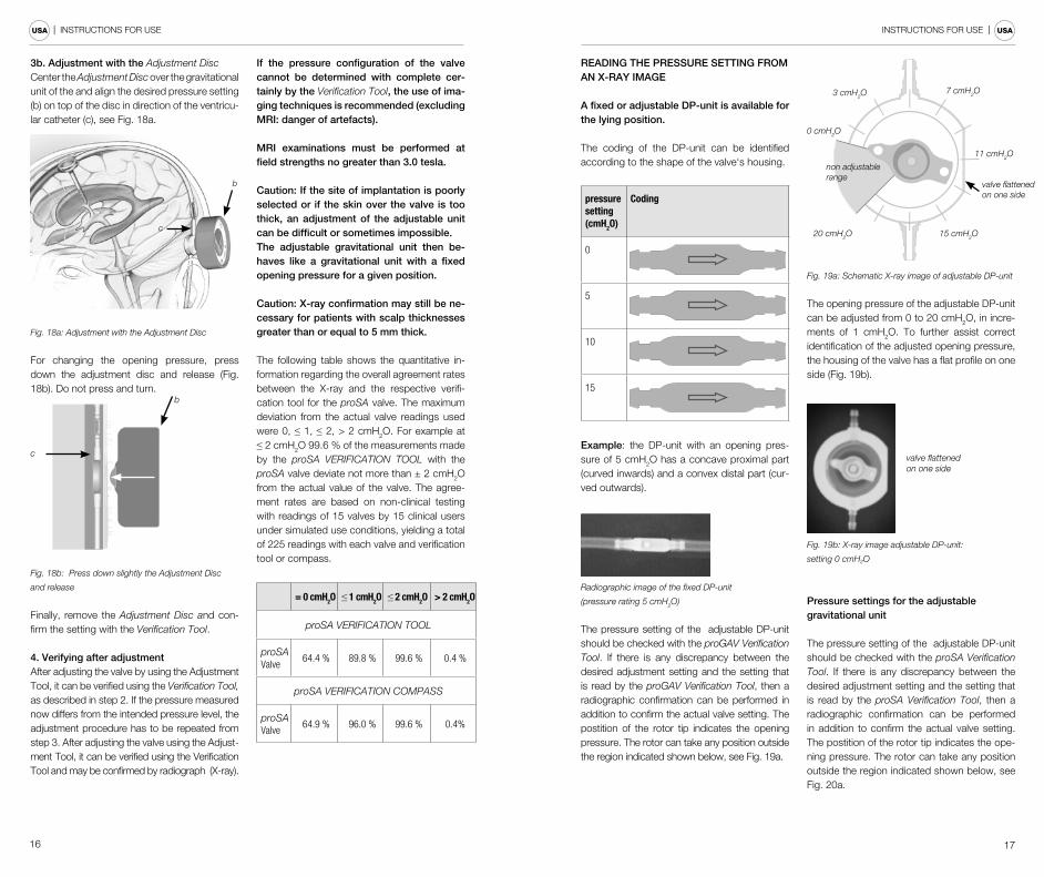
READING THE PRESSURE SETTING FROM AN X-RAY IMAGE
A fixed or adjustable DP-unit is available for the lying position.
The coding of the DP-unit can be identified according to the shape of the valve‘s housing.
pressure setting (cmH2O)
Coding
0
5
10
15
Example: the DP-unit with an opening pres-sure of 5 cmH2O has a concave proximal part (curved inwards) and a convex distal part (cur-ved outwards).
Radiographic image of the fixed DP-unit
(pressure rating 5 cmH2O)
The pressure setting of the adjustable DP-unit should be checked with the proGAV Verification Tool. If there is any discrepancy between the desired adjustment setting and the setting that is read by the proGAV Verification Tool, then a radiographic confirmation can be performed in addition to confirm the actual valve setting. The postition of the rotor tip indicates the opening pressure. The rotor can take any position outside the region indicated shown below, see Fig. 19a.
0 cmH2O
3 cmH2O
20 cmH2O 15 cmH2O
7 cmH2O
11 cmH2O
non adjustable range
valve flattened on one side
Fig. 19a: Schematic X-ray image of adjustable DP-unit
The opening pressure of the adjustable DP-unit can be adjusted from 0 to 20 cmH2O, in incre-ments of 1 cmH2O. To further assist correct identification of the adjusted opening pressure, the housing of the valve has a flat profile on one side (Fig. 19b).
valve flattened on one side
Fig. 19b: X-ray image adjustable DP-unit:
setting 0 cmH2O
Pressure settings for the adjustable gravitational unit
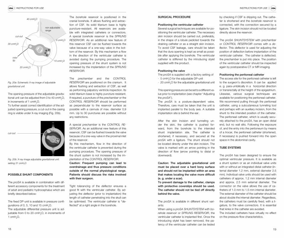
The pressure setting of the adjustable DP-unit should be checked with the proSA Verification Tool. If there is any discrepancy between the desired adjustment setting and the setting that is read by the proSA Verification Tool, then a radiographic confirmation can be performed in addition to confirm the actual valve setting. The postition of the rotor tip indicates the ope-ning pressure. The rotor can take any position outside the region indicated shown below, see Fig. 20a.
18 19
| INSTRUCTIONS FOR USE INSTRUCTIONS FOR USE | USA USA
rotortip
cut-out
30 cmH2O
40 cmH2O
20 cmH2O
10 cmH2O
0 cmH2O
non adjustable range
Fig. 20a: Schematic X-ray image of adjustable
gravitational unit
The opening pressure of the adjustable gravita-tional unit can be adjusted from 0 to 40 cmH2O, in increments of 1 cmH2O.To further assist correct identification of the ad-justed opening pressure, a cut-out in the casing ring is visible under X-ray imaging (Fig. 20b).
cut-out
Fig. 20b: X-ray image adjustable gravitational unit:
setting 31 cmH2O
POSSIBLE SHUNT COMPONENTS
The proSA is available in combination with dif-ferent accessory components for the treatment of adult and pediatric hydrocephalus which are briefly described below:
The fixed DP-unit is available in pressure confi-gurations of 0, 5, 10 and 15 cmH2O.The adjustable differential pressure unit is ad-justable from 0 to 20 cmH2O, in increments of 1 cmH2O.
The borehole reservoir is positioned in the cranial borehole. It allows flushing and extrac-tion of CSF. Its solid titanium base is highly puncture-resistant. All reservoirs are availa-ble with integrated catheters or connectors. A special borehole reservoir is the SPRUNG RESERVOIR. As an additional new feature of this reservoir CSF can be flushed towards the valve because of a one-way valve in the bot-tom of the reservoir. By this mechanism a flow in the direction of the ventricular catheter is avoided during the pumping procedure. The opening pressure of the shunt system is not increased by the implantation of the SPRUNG RESERVOIR.
The prechamber and the CONTROL RESERVOIR are positioned on the craniu m. It allows flushing and extraction of CSF, as well as performing palpatory ventricle inspection. Its solid titanium base is highly puncture-resistant. If required, a puncture of the prechamber or the CONTROL RESERVOIR should be performed as perpendicular to the reservoir surface as possible with a cannula of max. diameter 0,9 mm. Up to 30 punctures are possible without any restrictions.
A special prechamber is the CONTROL RE-SERVOIR. As an additional new feature of this reservoir, CSF can be flushed towards the valve because of a one-way valve in the proximal inlet of the reservoir. By this mechanism, flow in the direction of the ventricular catheter is prevented during the pumping procedure. The opening pressure of the shunt system is not increased by the im-plantation of the CONTROL RESERVOIR.Caution: Frequent pumping can lead to overdrainage and thus pressure conditions outside of the normal physiological range. Patients should discuss the risks involved with their surgeon.
Tight tolerancing of the deflector ensures a good fit with the ventricular catheter. By ad-justing the deflector (prior to implantation) the length of catheter penetrating into the skull can be optimised. The ventricular catheter is “de-flected” at a right angle in the borehole.
SURGICAL PROCEDURE
Positioning the ventricular catheterSeveral surgical techniques are available for po-sitioning the ventricular catheter. The necessary skin incision should be carried out, preferably, in the shape of a lobule pedicled towards the draining catheter or as a straight skin incision. To avoid CSF leakage, care should be taken that the dura opening is kept as small as possi-ble after applying the borehole. The ventricular catheter is stiffened by the introducing stylet supplied with the product.
Positioning the valveThe proSA is supplied with a factory setting of· 5 cmH
2O for the adjustable DP-unit· 20 cmH2O for the adjustable gravitational unit
This opening pressure can be set to a different va-lue prior to implantation (see chapter “Adjusting the proSA”). The proSA is a posture-dependent valve. Therefore, care must be taken that the unit is implanted parallel to the body axis. A suitable implantation site is behind the ear.
After the skin incision and tunneling un-der the skin, the catheter is pushed for-ward, from the borehole to the intended shunt implantation site. The catheter is shortened, if necessary, and secured at the proSA with a ligature. The shunt should not be located directly under the skin incision. The valve is marked with an arrow pointing in the direction of flow (arrow pointing to distal or downward).
Caution: The adjustable gravitational unit must be placed over a hard bony surface and should not be implanted within an area that makes locating the valve more difficult (e. g. under a scar).To prevent damage to the catheter, clamps with protective coverslips should be used. The catheter should not be tied off directly behind the valve.
The proSA is available in different shunt vari-ants:When using a proSA SHUNTSYSTEM with bo-rehole reservoir or SPRUNG RESERVOIR, the ventricular catheter is implanted first. Once the introducing stylet has been removed, the pa-tency of the ventricular catheter can be tested
by checking if CSF is dripping out. The cathe-ter is shortened and the borehole reservoir is connected, with the connection secured by a ligature. The skin incision should not be located directly above the reservoir.
The proSA SHUNTSYSTEM with prechamber or CONTROL RESERVOIR comes with a de-flector. This deflector is used for adjusting the position of deflection before implantation of the ventricular catheter. The catheter is deflected; the prechamber is put into place. The position of the ventricular catheter should be inspected again by postoperative CT or MR imaging.
Positioning the peritoneal catheterThe access site for the peritoneal catheter is left to the surgeon’s discretion. It can be applied e. g. para-umbilically in a horizontal direction or transrectally at the height of the epigastrium.Likewise, various surgical techniques are available for positioning the peritoneal catheter. We recommend pulling through the peritoneal catheter, using a subcutaneous tunneling tool and perhaps with an auxiliary incision, from the shunt to the intended position of the catheter. The peritoneal catheter, which is usually secu-rely attached to the proSA, has an open distal end, but no wall slits. Following the exposure of, and the entry into the peritoneum by means of a trocar, the peritoneal catheter (shortened, if necessary) is pushed forward into the open space in the abdominal cavity.
TUBE SYSTEMS
The proSA has been designed to ensure the optimal ventricular pressure. It is available as a shunt system or as an individual valve units with or without an integrated distal catheter (in-ternal diameter 1.2 mm, external diameter 2.5 mm). Individual valve units should be used with catheters of approx. 1.2 mm internal diameter and approx. 2.5 mm external diameter. The connector on the valve allows the use of ca-theters of 1.0 mm to 1.5 mm internal diameter. The external diameter of the catheter should be about double the internal diameter. Regardless, the catheters must be carefully fixed, with a li-gature, to the valve connectors. It is essential that kinks in the catheter are avoided.The included catheters have virtually no effect on the pressure-flow characteristics.
20 21
| INSTRUCTIONS FOR USE INSTRUCTIONS FOR USE | USA USA
TESTING VALVE PATENCY C
HRI
STO
PH M
IETH
KE0.
..40
proS
A
CHRI
STOP
H M
IETH
KE
0...40
proS
A
isotonic sterile sodium chloride solution
Fig. 21: Patency test
The proSA can be filled most gently by aspiration through a sterile, single-use syringe attached to the distal end of the catheter. The proximal end of the valve is immersed in a sterile, physiological saline solution. The valve is patent if fluid can be extracted in this way (see Fig. 21).
Caution: Applying pressure through the single-use syringe should be avoided, both at the proximal and the distal end. Contamination in the solution used for the test can impair the product’s performance.
VALVE TEST PRIOR TO IMPLANTATION
Each proSA valve has been tested to ensure that the performance specifications given on the label are always met. The dynamic per-formance characteristics of the shunt cannot be tested in a static test performed in the operating room.If the surgeon wishes to verify, prior to implantation, that the shunt meets the specifications given by the manufacturer, the following test can be performed in the operating room.
Caution: Always take care that sterility is maintained and particle contamination is avoided.
Test methodEquipment required for this test:a) sterile fluid reservoir or water bathb) sterile fluid 60-cm water manometer with millimeter grading and three-branch faucet at the basec) sterile syringe, 30 cc to 50 ccd) sterile 5-µ tip filtere) sterile tube adapterf) sterile silicone tube
CH
RIS
TOP
H M
IETH
KE
0...4
0
pro
SA
60 cm
7
2
1a
3
4
45
6
1b
CHRISTOPH MIETHKE
0...40
proSA
0
Fig. 22: Test setup1 proSA a) horizontal, b) vertical2 water bath, 3 constant water level, 4 silicone tube, 5 three-way tap, 6 single-use syringe with syringe filter, 7 manometer
Setting up the equipmenta) Position the manometer and the water bath in such a way that the zero point of the manometer and the fluid level of the water bath are at the same height (Fig. 22).b) Fill the syringe, with the 5-µ tip filter attached, with sterile water
(always use the 5-µ tip filter when topping up the syringe). Remove the tip filter when the syringe is full.c) Connect the syringe, the manometer and the silicone tube. Use the tube adapter if necessary (Fig. 22).d) To release all air from the test assembly, turn the three-way fau-cet as shown in Fig. 23.e) Immerse the silicone tube in the sterile water bath and rinse it with the sterile water from the syringe.
Calibrating the equipmenta) Turn the three-way faucet as shown in Fig. 24 and fill the mano-meter to at least 5 cmH2O.b) With the silicone tube immersed in the water bath, turn the three-way faucet so that the syringe is isolated from the mano-meter (see Fig. 25).c) Allow the water column in the manometer to drop.d) The water column should stop dropping at the zero point. Adjust the zero point of the manometer to fluid level of the water bath, if necessary.e) The manometer has now been calibrated to the zero-level of the water bath. Fixate the manometer to maintain its position in relation to the water bath.
closed
from syringeto the valve
open
Fig. 24
open
to the valve
from syringe
closed
Fig. 25
to the valve
closed
from syringe
Fig. 23
Test procedurePlease note: During the test the shunt must be submerged in the water bath. The zero point of the manometer must be aligned with the water level of the water bath in order to obtain correct results.
a) Connect the sterile shunt to be tested to the already assembled, sterile test equipment.b) Turn the three-way faucet as shown in Fig. 24 and fill the mano-meter to 10 cmH2O above the expected opening pressure. (Exam-ple: For testing a proSA in combination with a fixed DP-unit, having an opening pressure setting of the fixed DP-unit of 5 cmH2O and the adjustable gravitational unit of 25 cmH2O, the manometer is filled to 15 cmH2O with the shunt in the horizontal position and to 40 cmH2O with the shunt in the vertical position).c) Turn the three-way faucet as shown in Fig. 23 so that the ma-nometer is isolatedd) Remove all air from the shunt and the test setup by carefully rinsing it through with sterile water from the syringe.e) Immerse the sterile shunt in the sterile water bath. The distal part of the shunt must be under water to obtain valid test results.
f) Carefully maintain a flow through the shunt and turn the three-way faucet as shown in Fig. 25 to isolate the syringe. As soon as the three-way faucet is in the correct position, the water column should begin to drop.The syringe is now isolated from the valve and it is not necessa-ry anymore to maintain its flow. Repeat steps b) to f) if the water column fails to drop.g) Allow the water level in the manometer to drop for 2 to 2.5 mi-nutes. Read the resulting pressure at the manometer.
TEST RESULTS OF PREIMPLANTATION TEST
The following table shows results, which should be achieved by this method, for some selected pressure levels:
Fixed DP-unit (proSA adjusted to „0“)
opening pressure (cmH2O) acceptable pressure range
0 cmH2O 0-5 cmH2O
5 cmH2O 2-9 cmH2O
10 cmH2O 7-15 cmH2O
15 cmH2O 12-20 cmH2O
Adjustable DP-unit (proSA adjusted to „0“)
opening pressure (cmH2O) acceptable pressure range
0 cmH2O 0-5 cmH2O
10 cmH2O 5-15 cmH2O
20 cmH2O 10-25 cmH2O
proSA (without DP-unit)
opening pressure (cmH2O) acceptable pressure range
0 cmH2O 0-5 cmH2O
10 cmH2O 2-14 cmH2O
20 cmH2O 8-24 cmH2O
30 cmH2O 13-34 cmH2O
40 cmH2O 20-44 cmH2O
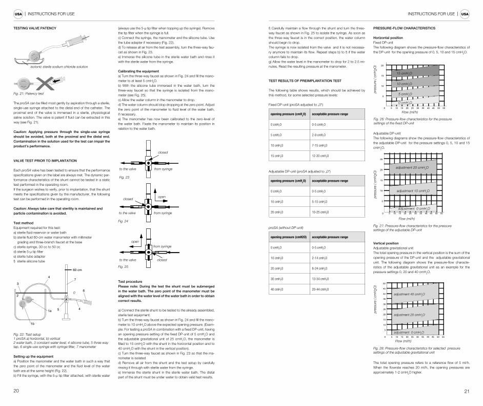
PRESSURE-FLOW CHARACTERISTICS
Horizontal position Fixed DP-unitThe following diagram shows the pressure-flow characteristics of the DP-unit for the opening pressure of 0, 5, 10 and 15 cmH2O.
Fig. 26: Pressure-flow characteristics for the pressure settings of the fixed DP-unit
5
10
10 20 30 400 5 2515 35 45 50 55
15
20
pres
sure
( cm
H2O
)
15 cmH2O
5 cmH2O
10 cmH2O
0 cmH2O
Flow (ml/h)
Adjustable DP-unitThe following diagrams show the pressure-flow characteristics of the adjustable DP-unit for the pressure settings 0, 5, 10 and 15 cmH2O.
Fig. 27: Pressure-flow characteristics for the pressure settings of the adjustable DP-unit
5
10
10 20 30 400 5 2515 35 45 50 55
15
20
25
30
pres
sure
( cm
H2O
)
Flow (ml/h)
adjustment 20 cmH2O
adjustment 10 cmH2O
adjustment 0 cmH2O
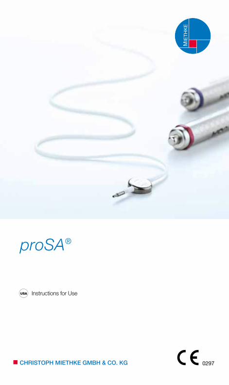
Vertical position Adjustable gravitational unitThe total opening pressure in the vertical position is the sum of the opening pressure of the DP-unit and the adjustable gravitational unit. The following diagram shows the pressure-flow characte-ristics of the adjustable gravitational unit as an example for the pressure settings 0, 20 and 40 cmH2O.
Fig. 28: Pressure-flow characteristics for selected pressure settings of the adjustable gravitational unit
5
10
15
20
25
10 20 30 400 5 2515 35 45 50 55
30
35
40
45
50
adjustment 20 cmH2O
adjustment 0 cmH2O
adjustment 40 cmH2O
pres
sure
( cm
H2O
)
Flow (ml/h)
The total opening pressure refers to a reference flow of 5 ml/h. When the flowrate reaches 20 ml/h, the opening pressures are approximately 1-2 cmH2O higher.
22 23
| INSTRUCTIONS FOR USE INSTRUCTIONS FOR USE | USA USA
TEST ON REFLOW SAFETY
This test is carried out with the same equipment as the pre-implan-tation test. The shunt is carefully filled with sterile saline solution from the syringe before the air is removed from it (Fig. 29). The shunt is connected against the direction of flow (see arrow on the shunt). The outlet of the shunt has to be at the zero level of the manometer. The manometer is filled up to 14 cmH2O (Fig. 30).The three-way faucet is used for unblocking the flow to the shunt and blocking the flow to syringe. In this setup, no more than 2 drops (0.1 cc) per minute should emerge from the proximal part of the shunt (Fig. 31).
Caution: Be careful to maintain sterility and to avoid particle contamination.
Fig. 29
CHRI
STOP
H M
IETH
KE
0...40
proS
A
isotonic sterile sodium chloride solution
14 cm
CH
RIS
TOPH
MIE
THK
E
0...4
0pr
oSA
0-level
closed
open
Fig. 30
14 cm
CH
RIS
TOPH
MIE
THK
E
0...4
0pr
oSA
closed
open
0-level
Fig. 31
Caution: Be careful to maintain sterility and to avoid particle contamination.
INTERACTIONS WITH PRODUCTS FROM OTHER MANUF-ACTURERS
The proSA should not be used under any circumstances in conjunction with hydrostatic valves, as this can bring about ab-normally high ventricular pressure outside of the normal physio-logical range. Hydrostatic valves allow for changes in hydrostatic pressure in the drainage system caused by changes in position. If in doubt, please contact the medical pro duct consultants at Christoph Miethke GmbH & CO. KG.
RE-IMPLANTATION
Under no circumstances should products that have had previ-ously been implanted in a patient be subsequently reimplanted in another, because a successfull decontamination of the device cannot be reached without functional degradation.
SAFETY MEASURES
The patients must be carefully monitored after the implantation. Reddened skin and tension in the area of the drainage tissue could indicate infections at the shunt system. Symptoms such as hea-dache, dizzy spells, mental confusion or vomiting are common oc-currences in cases of shunt dysfunction. Such symptoms, as well as shunt system leakage, necessitate the immediate replacement of the shunt component responsible, or of the entire shunt system.
COMPATIBILITY WITH DIAGNOSTIC PROCEDURES
A patient with the proSA valve may undergo an MRI procedure using an MR system with a static magnetic field of 1.5 and 3.0 tes-la only. MRI and CT examinations can be carried without endange-ring or impairing the functionality of the Shunt. The proSA valve will not change when subjected to an MRI of 1.5T or 3T.The proSA is MR Conditional (ASTM F2503-13). All components are visible via X-ray. The provided catheters are MRI Safe. Reser-voirs, deflectors and connectors are MR Conditional.Caution: When using a magnetic field and simultaneous pres-sing on the valve, the possibility of valve adjustment can not be excluded.
MRI SAFETY INFORMATION
The proSA valve was determined to be MR Con-ditional (ASTM F2503-13). Non-clinical testing has demonstrated the proSA is MR Conditional. It can be scanned safely under the following conditions:
- static magnetic field of 1.5 and 3.0 tesla only- spatial gradient field of 7.2 T/m (720 Gauss/cm)- maximum whole body averaged specific absorption rate (SAR) of 4 W/kg for 15 minutes of scanning.- No local transmit coils should be placed over the implant.
In non-clinical testing, the proSA valve produced a temperature rise of less than 2.5º C at the maximum whole body average spe-cific absorption rate (SAR) of 4 W/kg, as assessed by calorimetry for 15 minutes of MR scanning in a 3.0 tesla MR-scanner Excite, HDx, Software 14X.M5, General Electic Healthcare, Milwaukee, WI; active-shielded, horizontal field scanner.
To confirm that the valve setting has not been altered by exposure to the MRI scanner the pressure setting of the adjustable gravitati-onal unit can be checked with the proSA Verfication Tool.
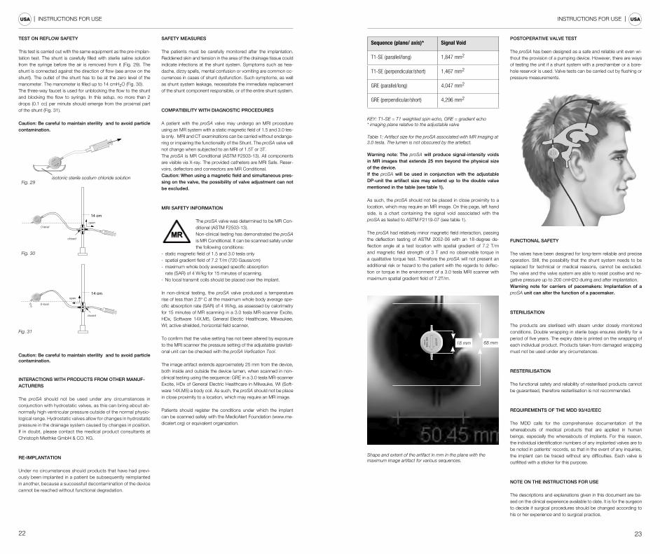
The image artifact extends approximately 25 mm from the device, both inside and outside the device lumen, when scanned in non-clinical testing using the sequence: GRE in a 3.0 tesla MR-scanner Excite, HDx of General Electric Healthcare in Milwauke, WI (Soft-ware 14X.M5) a body coil. As such, the proSA should not be place in close proximity to a location, which may require an MR image.
Patients should register the conditions under which the implant can be scanned safely with the MedicAlert Foundation (www.me-dicalert.org) or equivalent organization.
Sequence (plane/ axis)* Signal Void
T1-SE (parallel/long) 1,847 mm2
T1-SE (perpendicular/short) 1,467 mm2
GRE (parallel/long) 4,047 mm2
GRE (perpendicular/short) 4,296 mm2
KEY: T1-SE = T1 weighted spin echo, GRE = gradient echo* imaging plane relative to the adjustable valve
Table 1: Artifact size for the proSA associated with MR imaging at 3.0 tesla. The lumen is not obscured by the artefact.
Warning note: The proSA will produce signal-intensity voids in MR images that extends 25 mm beyond the physical size of the device. If the proSA will be used in conjunction with the adjustable DP-unit the artifact size may extend up to the double value mentioned in the table (see table 1).
As such, the proSA should not be placed in close proximity to a location, which may require an MR image. On this page, left hand side, is a chart containing the signal void associated with the proSA as tested to ASTM F2119-07 (see table 1).
The proSA had relatively minor magnetic field interaction, passing the deflection testing of ASTM 2052-06 with an 18-degree de-flection angle at a test location with spatial gradient of 7.2 T/m and magnetic field strength of 3 T and no observable torque in a qualitative torque test. Therefore the proSA will not present an additional risk or hazard to the patient with the regards to deflec-tion or torque in the environment of a 3.0 tesla MRI scanner with maximum spatial gradient field of 7.2T/m.
18 mm 68 mm
Shape and extent of the artifact in mm in the plane with the maximum image artifact for various sequences.
POSTOPERATIVE VALVE TEST
The proSA has been designed as a safe and reliable unit even wi-thout the provision of a pumping device. However, there are ways of testing the unit if a shunt system with a prechamber or a bore-hole reservoir is used. Valve tests can be carried out by flushing or pressure measurements.
FUNCTIONAL SAFETY
The valves have been designed for long-term reliable and precise operation. Still, the possibility that the shunt system needs to be replaced for technical or medical reasons, cannot be excluded. The valve and the valve system are able to resist positive and ne-gative pressure up to 200 cmH2O during and after implantation.Warning note for carriers of pacemakers: Implantation of a proSA unit can alter the function of a pacemaker.
STERILISATION
The products are sterilised with steam under closely monitored conditions. Double wrapping in sterile bags ensures sterility for a period of five years. The expiry date is printed on the wrapping of each individual product. Products taken from damaged wrapping must not be used under any circumstances.
RESTERILISATION
The functional safety and reliability of resterilised products cannot be guaranteed, therefore resterilisation is not recommended.
REQUIREMENTS OF THE MDD 93/42/EEC
The MDD calls for the comprehensive documentation of the whereabouts of medical products that are applied in human beings, especially the whereabouts of implants. For this reason, the individual identification numbers of any implanted valves are to be noted in patients‘ records, so that in the event of any inquiries, the implant can be traced without any difficulties. Each valve is outfitted with a sticker for this purpose.
NOTE ON THE INSTRUCTIONS FOR USE
The descriptions and explanations given in this document are ba-sed on the clinical experience available to date. It is for the surgeon to decide if surgical procedures should be changed according to his or her experience and to surgical practice.
24 25
| INSTRUCTIONS FOR USE INSTRUCTIONS FOR USE | USA USA
MEDICAL PRODUCTS CONSULTANT
In compliance with the requirements of the European law MDD 93/42/EEC, the follwing individuals are listed by Christoph Miethke GmbH&Co. KG as medical pro duct consultan-ts, to whom all queries concerning the products should be addressed:
Dipl.-Ing. Christoph Miethke Dipl.-Ing. Roland SchulzMichaela Funk-Neubarth
Christoph Miethke GmbH & Co. KGUlanenweg 214469 Potsdam, GermanyPhone: +49(0) 7000 MIETHKE orPhone: +49(0) 331 620 83 0Fax: +49(0) 331 620 83 40E-mail: [email protected]
Please address any enquiries to:AESCULAP AG Am Aesculap Platz78532 Tuttlingen, GermanyPhone: +49 (0) 7461 95-0Fax: +49 (0) 7461 95-26 00E-mail: [email protected]
Service address in the USAESCULAP Inc.Attn. AESCULAP Technical Services615 Lambert Pointe RoadHazelwood, MO, 63042
AESCULAP Repair HotlinePhone: +1 (800) 214-3392Fax: +1 (314) 895-4420
Distributor in the US/ Contact in CanadaAESCULAP Inc.3773 Corporate ParkwayCenter Valley, PA 18034Phone: +1 (800) 282-9000www.aesculapusa.com
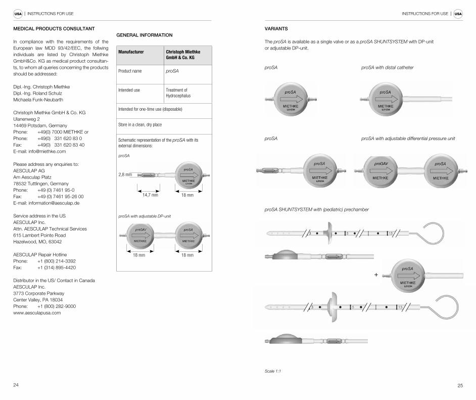
GENERAL INFORMATION
Manufacturer Christoph Miethke GmbH & Co. KG
Product name proSA
Intended use Treatment of Hydrocephalus
Intended for one-time use (disposable)
Store in a clean, dry place
Schematic representation of the proSA with its external dimensions:
proSA with adjustable DP-unit
proSA
18 mm14,7 mm
2,8 mm
18 mm18 mm
VARIANTS
The proSA is available as a single valve or as a proSA SHUNTSYSTEM with DP-unit or adjustable DP-unit.
proSA proSA with distal catheter
proSA proSA with adjustable differential pressure unit
proSA SHUNTSYSTEM with (pediatric) prechamber
Scale 1:1
+
26
| INSTRUCTIONS FOR USEUSA
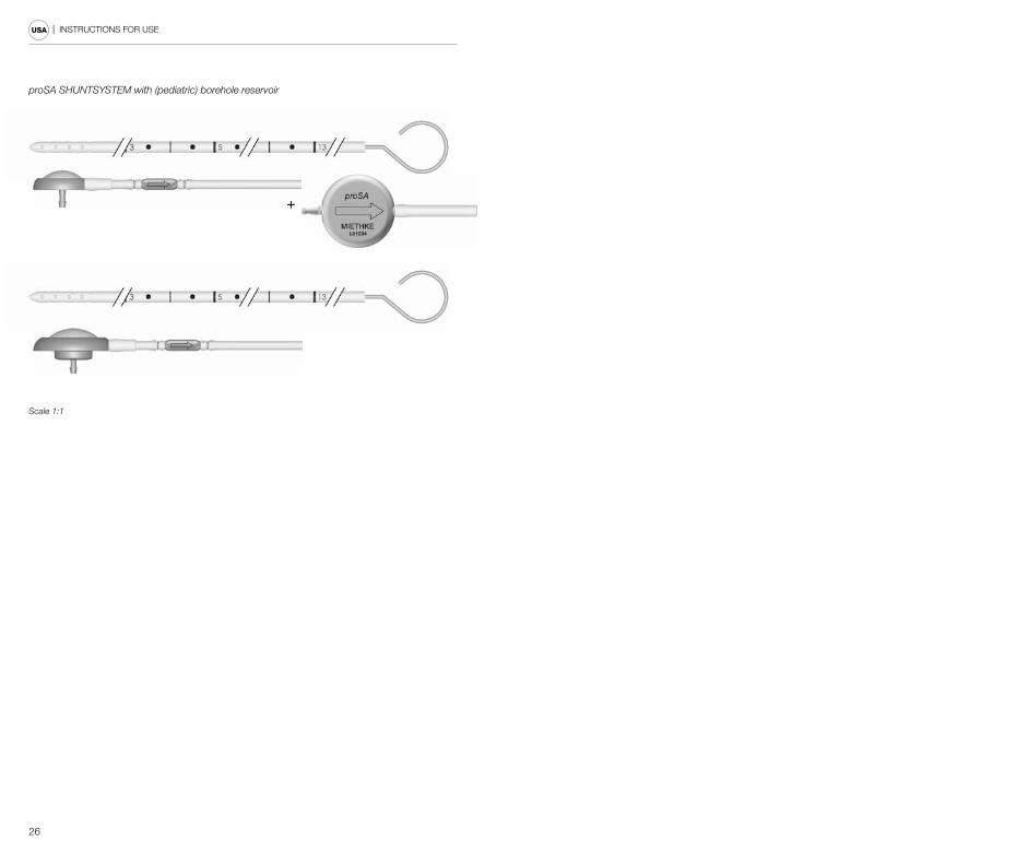
proSA SHUNTSYSTEM with (pediatric) borehole reservoir
Scale 1:1
+

TA 012822 GBA_38_05_0217_USA
CE-Kennzeichnung gemäß Richtlinie 93/42/EWGCE marking according to directive 93/42/EECLabel CE conforme à la directive 93/42/CEEIdentificatión CE en conformidad con la directriz 93/42/CEEMarchio CE conforme alla direttiva 93/42/CEE
Technische Änderungen vorbehaltenTechnical alterations reservedSous réserve de modifications techniquesSujeto a modificationes técnicasCon riserva di modifiche tecniche
Manufacturer acc. MDD 93/42/EEC:
CHRISTOPH MIETHKE GMBH & CO. KG
Christoph Miethke GmbH & Co. KG | Ulanenweg 2 | 14469 Potsdam | GermanyPhone +49 (0) 331 62 083-0 | Fax +49 (0) 331 62 083-40 | www.miethke.com
Distributed by:
Aesculap AG | Am Aesculap-Platz | 78532 Tuttlingen | GermanyPhone +49 (0) 7461 95-0 | Fax +49 (0) 74 61 95-26 00 | www.aesculap.com
Aesculap - a B. Braun company
0297