Embed Size (px)
Citation preview

Proposal for an ArcGeology Version 1A Geodatabase Design for Digital Geologic Maps using
ArcGIS®
By Jordan T. Hastings1,2, Gary L. Raines2, Lorre A. Moyer2
1 Nevada Bureau of Mines and Geology (as of August 2007) Mackay School of Earth Sciences and Engineering
University of Nevada, Reno, NV 89557-0178email: [email protected] U.S. Geological Survey
Mackay School of Earth Sciences and EngineeringUniversity of Nevada, Reno, NV 89557-0176
email: [email protected]; [email protected]
ABSTRACTThis document presents a geodatabase design, proposed
as an “ArcGeology Version 1”, for digital geologic maps utilizing ESRI ArcGIS® 9.1 or 9.2 software. The design outlines a specific set of feature datasets and feature classes, together with feature attributes, subtypes and domains, suit-able for a variety of geologic maps. In addition to basic geol-ogy (lithology, contacts and faults, etc.), the maps may include rock/mineral alteration and other overprints, cross-sections, and explanatory legend-graphics such as descriptive lists of map units and correlation charts, used to supplement columnar legends automatically produced by ArcGIS. Setup files are provided to create a new empty geodatabase and companion map document. The geodatabase design is compatible with field work using ArcPad® 6 or 7.
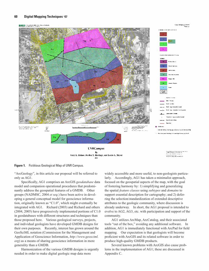
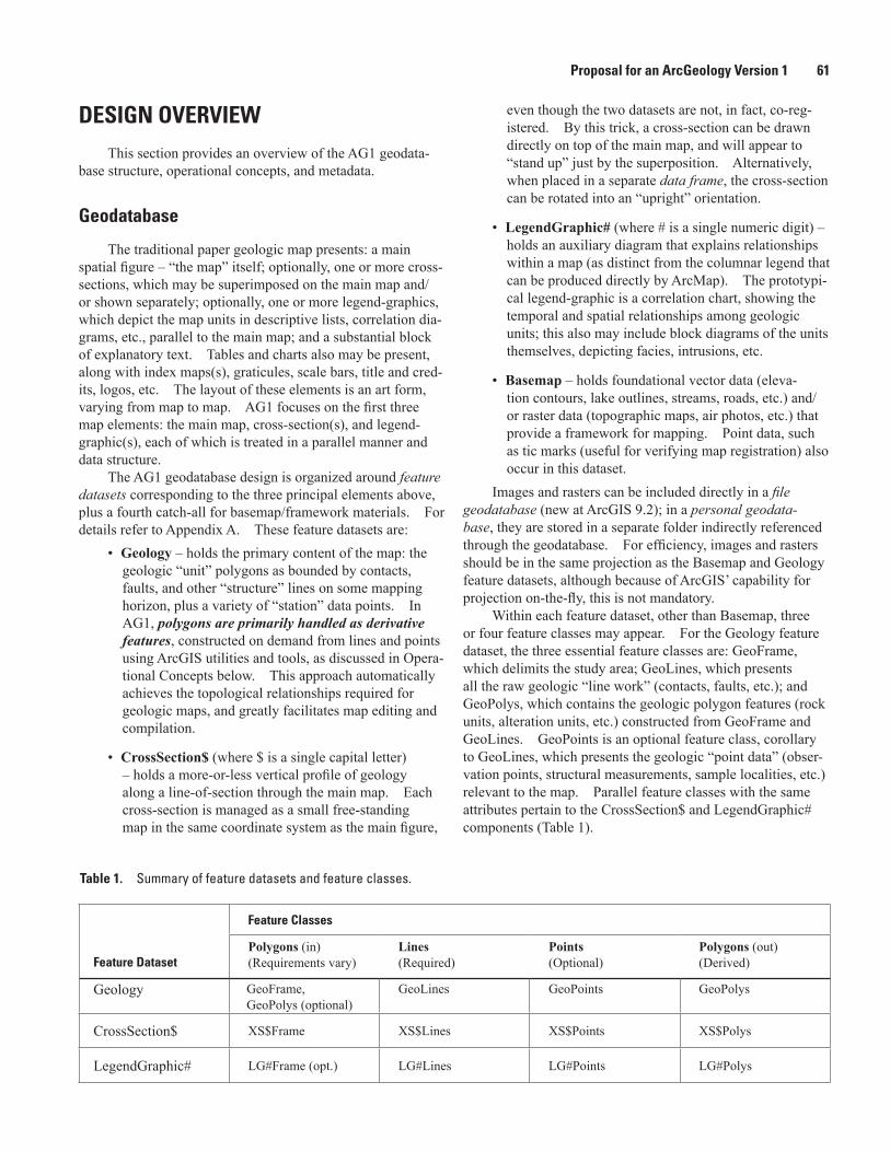
This proposal is demonstrated with a fictitious geologic map, UNRCampus, set on the University of Nevada, Reno campus (Figure 1). This demonstration, as a completed ArcMap document and geodatabase with FGDC-compliant metadata, plus the setup files to create similar databases, is available for download at http://ngmdb.usgs.gov/info/dmt/docs/AG1b.zip. To better understand this report and geodata-base design, the reader invited to fully explore the UNRCam-pus demonstration.
Throughout this document, proficiency with ArcGIS and geodatabases is presumed. For simplicity and portability, only ArcGIS software is used. To create new maps, at least an ArcEditor-level license is required.
INTRODUCTIONThe following typographic conventions are adopted
in this document. Geologic mapping and ArcGIS-related technical terms are italicized on first use, and concepts and practices of particular importance are noted in bold ital-ics. Specific data structures, fields, etc., are shown in roman Title Case, without quotes to avoid clutter. Sans serif font is used for Windows-specific file names and also for ArcGIS tool names; the latter are bolded on every use (optionally followed by a parenthetical comment about the user-interface context in which they can be found).
Geologic maps present a complex amalgam of basic topographic facts, verifiable field observations, and subjec-tive interpretations (Bain and Giles, 1997); they are among the most intricate of cartographic products. Widespread automation in geosciences, including the use of geographic information systems (GIS), presents the opportunity to capture geologic knowledge into map-databases. In addition to their cartographic sophistication, such map-databases afford more versatility and analytical capability than is possible with tradi-tional paper maps.
Based on ESRI ArcGIS software, this proposal for an “ArcGeology Version 1” (AG1) outlines a simple but flexible system for producing a geologic map-database (GMDB) that serves both cartographic and analytical purposes. Because the geoscience community and ESRI have not yet engaged in a collective process to design such a GMDB structure, which by ESRI convention might then be formally named
60 Digital Mapping Techniques ‘07
Figure 1. Fictitious Geological Map of UNR Campus.
“ArcGeology”, in this article our proposal will be referred to only as AG1.
Specifically, AG1 comprises an ArcGIS geodatabase data model and companion operational procedures that predomi-nantly address the geospatial features of a GMDB. Other groups (NADMSC, 2004 et seq.) have been active in devel-oping a general conceptual model for geoscience informa-tion, originally known as “C1.0”, which might eventually be integrated with AG1. Richard (2003) and Richard and others (2004, 2005) have progressively implemented portions of C1.0 in geodatabases with different structures and techniques than those proposed here. Various geological surveys, projects, and individual geologists have developed GMDB designs for their own purposes. Recently, interest has grown around the GeoSciML notation (Commission for the Management and Application of Geoscience Information, http://www.geosciml.org) as a means of sharing geoscience information in more generality than a GMDB.
Harmonization of the various GMDB designs is urgently needed in order to make digital geologic map data more
widely accessible and more useful, to non-geologists particu-larly. Accordingly, AG1 has taken a minimalist approach, focused on the geospatial aspects of the map, with the goal of fostering harmony by: 1) simplifying and generalizing the spatial feature classes using subtypes and domains to support essential description for cartography; and 2) defer-ring the selection/standardization of extended descriptive attributes to the geologic community, where discussion is already underway. In short, the AG1 proposal is intended to evolve to AG2, AG3, etc. with participation and support of the community.
AG1 utilizes ArcMap, ArcCatalog, and their associated tools “out of the box,” avoiding any additional software. In addition, AG1 is immediately functional with ArcPad for field mapping. Our expectation is that geologists will become proficient with ArcGIS and its related software in order to produce high-quality GMDB products.
Several known problems with ArcGIS also cause prob-lems in the implementation of AG1; these are discussed in Appendix C.
Proposal for an ArcGeology Version 1 61
DESIGN OVERVIEWThis section provides an overview of the AG1 geodata-
base structure, operational concepts, and metadata.
Geodatabase
The traditional paper geologic map presents: a main spatial figure – “the map” itself; optionally, one or more cross-sections, which may be superimposed on the main map and/or shown separately; optionally, one or more legend-graphics, which depict the map units in descriptive lists, correlation dia-grams, etc., parallel to the main map; and a substantial block of explanatory text. Tables and charts also may be present, along with index maps(s), graticules, scale bars, title and cred-its, logos, etc. The layout of these elements is an art form, varying from map to map. AG1 focuses on the first three map elements: the main map, cross-section(s), and legend-graphic(s), each of which is treated in a parallel manner and data structure.
The AG1 geodatabase design is organized around feature datasets corresponding to the three principal elements above, plus a fourth catch-all for basemap/framework materials. For details refer to Appendix A. These feature datasets are:
• Geology – holds the primary content of the map: the geologic “unit” polygons as bounded by contacts, faults, and other “structure” lines on some mapping horizon, plus a variety of “station” data points. In AG1, polygons are primarily handled as derivative features, constructed on demand from lines and points using ArcGIS utilities and tools, as discussed in Opera-tional Concepts below. This approach automatically achieves the topological relationships required for geologic maps, and greatly facilitates map editing and compilation.
• CrossSection$ (where $ is a single capital letter) – holds a more-or-less vertical profile of geology along a line-of-section through the main map. Each cross-section is managed as a small free-standing map in the same coordinate system as the main figure,
even though the two datasets are not, in fact, co-reg-istered. By this trick, a cross-section can be drawn directly on top of the main map, and will appear to “stand up” just by the superposition. Alternatively, when placed in a separate data frame, the cross-section can be rotated into an “upright” orientation.
• LegendGraphic# (where # is a single numeric digit) – holds an auxiliary diagram that explains relationships within a map (as distinct from the columnar legend that can be produced directly by ArcMap). The prototypi-cal legend-graphic is a correlation chart, showing the temporal and spatial relationships among geologic units; this also may include block diagrams of the units themselves, depicting facies, intrusions, etc.
• Basemap – holds foundational vector data (eleva-tion contours, lake outlines, streams, roads, etc.) and/or raster data (topographic maps, air photos, etc.) that provide a framework for mapping. Point data, such as tic marks (useful for verifying map registration) also occur in this dataset.
Images and rasters can be included directly in a file geodatabase (new at ArcGIS 9.2); in a personal geodata-base, they are stored in a separate folder indirectly referenced through the geodatabase. For efficiency, images and rasters should be in the same projection as the Basemap and Geology feature datasets, although because of ArcGIS’ capability for projection on-the-fly, this is not mandatory.
Within each feature dataset, other than Basemap, three or four feature classes may appear. For the Geology feature dataset, the three essential feature classes are: GeoFrame, which delimits the study area; GeoLines, which presents all the raw geologic “line work” (contacts, faults, etc.); and GeoPolys, which contains the geologic polygon features (rock units, alteration units, etc.) constructed from GeoFrame and GeoLines. GeoPoints is an optional feature class, corollary to GeoLines, which presents the geologic “point data” (obser-vation points, structural measurements, sample localities, etc.) relevant to the map. Parallel feature classes with the same attributes pertain to the CrossSection$ and LegendGraphic# components (Table 1).
Table 1. Summary of feature datasets and feature classes.
Feature Dataset
Feature Classes
Polygons (in)(Requirements vary)
Lines(Required)
Points(Optional)
Polygons (out)(Derived)
Geology GeoFrame, GeoPolys (optional)
GeoLines GeoPoints GeoPolys
CrossSection$ XS$Frame XS$Lines XS$Points XS$Polys
LegendGraphic# LG#Frame (opt.) LG#Lines LG#Points LG#Polys
62 Digital Mapping Techniques ‘07
For each feature class other than the “Frames”, which are in general simple perimeters, a group of up to seven common feature attributes is present. These attributes are described in Table 2 with regard to the Geology feature dataset, and Table 3 presents some examples of their use. See Appendix A for additional details.
The first five entries deal with the basic symboliza-tion of the features in the map. Kind, Type, and Style are closely controlled fields, established via ArcGIS domains and subtypes. These fields encode AG1’s knowledge organi-zation system (World Wide Web Consortium; http://www.w3.org/2004/02/skos/) for GMDBs in general, and should not be modified casually. Kind subdivides geologic features into tiers (rock, alteration, overprint, etc.), while Type and Style define rough and fine categorizations, respectively, of features within a tier. In some regards, these three fields function hierarchically and in other regards independently (Table 3). Note that only a few example entries are shown.
By contrast, Symbol and Symval are unconstrained user-supplied fields, providing cartographic and descriptive
details for particular features as needed. Typically, Symbol is used for map-unit labels, dip amounts (which may be blank or non-numeric, e.g. <10), station identifiers, etc. Symval is available for various purposes where a number is required, such as symbol transparency or rotation. Domain-based control of Symbols (but not Symvals) is also possible, if for example the stratigraphy of units that may appear on a map is fixed in advance.
ItemID serves to link the geospatial features to extended desciptions in other tables, if present: it is a generic foreign key. Depending on the complexity of these tables, ItemID may link directly from feature classes to particular tables on a class-by-class basis, or indirectly from feature classes through an intermediary “dispatch table” to any number of tables concurrently. The built-in Item table is designed for the latter purpose. Taken altogether, these first six feature attributes are sufficient to record, symbolize, and label the features in a geologic map, and to arrange further description of these features as desired.
Table 2. Common feature attributes for all feature classes.
Attribute Description
Kind Top-level category of geologic features, e.g. Rock, Alteration and other (Short Int: Coded Text*, Global Domain) Overprints, etc. Several geologic Kinds may be present in GeoPoints,
GeoLines and GeoPolys concurrently. Thus new Kinds (e.g. Soils) can be defined and added to the underlying domain, if needed, without creating additional feature classes. (*Coded Text denotes a text field automatically derived from a numeric code via an ArcGIS domain.)
Type Sub-category of feature, e.g. Contact, Fault, Attitude measurement, etc. (Short Int: Subtype selector) Types can be adjusted by editing the underlying subtype lists for GeoPoints,
GeoLines and GeoPolys as needed. By convention, the zero subtype is always available, generally as “not applicable” (N/A) catch-all.
Style More-specific term for a feature within its Type, e.g. Contact, Certain; Nor-(Long Int: Coded Text, Domain per Type) mal Fault, Concealed; Sedimentary Bedding Attitude. As for Kind, Style
terms are maintained in an underlying domain; however, these terms also interface through the ESRI Style Manager with standard symbology, which must be updated concurrently.
Symbol Mnemonic assigned to support cartographic representation of individual fea-(Free Text, 20-character max.) tures, e.g. dip amounts, sample numbers, fault names, and notably the geo-
logic unit codes for GeoPolys. The latter codes are typically not managed through Styles, because they vary greatly across mapping projects. Symbols in addition to Styles may be used with any feature class; for example, to import pre-existing line symbology coded as text.
Symval Numeric value providing additional cartographic detail or control, e.g. ra-(Floating-Pt) diometric age, strike/plunge direction for attitude symbols, etc.ItemID Per feature link to rows of related table(s), optionally providing extended (Long Int) descriptions for documentation or analysis, over and above the symboliza-
tion and labeling of features on the map.Selected Persistent control (True/False=0) on selection of individual features and (Boolean, as Short Int) their participation in various operations, especially polygon construction.
Proposal for an ArcGeology Version 1 63
The final field, Selected, is used to persistently mark indi-vidual features for inclusion or exclusion in various procedural steps, particularly polygon construction (see below). For example, it is often desirable to exclude intraformational con-tacts and faults, so that the associated map-unit polygons are not “broken” by these lines. Similarly, it may be desirable to include some but not all strike-and-dip symbols within some “busy” portions of a map.
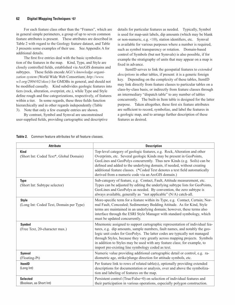
A GMDB inherently involves deep integration of spatial features and aspatial tabular data, beyond that required for map production. Even using databases, this integration can become technically complex. In AG1, the linkage between features and tabular data is effected via the single field, ItemID, leaving the spatial and tabular aspects otherwise free-standing. In general, two sets of relationship classes are involved: first, the spatial features “link in” to a central Item table, built-in to the geodatabase; from here, the Item entries “link out” again (are dispatched) to the aspatial, user-supplied tables, which can vary by map author and across maps of dif-ferent areas or emphases. For details, refer to Appendix B.
A sample tabular data schema for the UNRCampus.mdb prototype is included in Appendix B. The tables and attri-butes shown in this prototype are intended only to demonstrate the capabilities of the AG1 design; they are not a formal recommendation. Other organizations of tabular data for geologic maps are presented in the NADMSC “C1.0” specifi-cation (2004), Brodaric and Hastings (2002), and Johnson and others (1999).
The doubly linked approach to extended descriptions (Figure 2, solid lines) provides the greatest flexibility both in the design of the user-supplied tables and in the timing of relationships (implying persistence of categorization). Each feature is linkable to and through a unique row in the Item table to any number of other tables, which themselves can have any desired (or pre-existing) organization. If several features link to the same Item row, then a group description results, e.g. multiple pieces of a named fault, all occurrences of a particular map unit. By repeating columns in the Item table, a single feature can have both individual and group descriptions, e.g. an outcrop of a generalized map unit that
Table 3. Examples of Kind, Type, and Style attributes.
[Free text entries are shown in quotes for clarity; the quotes are not included in the database. Type and Style fields in GeoPolys are set to zero during polygon construction (from GeoPoints); these fields may be deleted after construction (see Appendix A, footnote), but are shown here for completeness]
Kind Type Type Type (Deletable after construction) Style Style Style (Deletable as above) "Symbol" , Symval "Symbol" , Symval "Symbol" , Symval
GeoPoints GeoLines GeoPolys
Rock
Label Contact 0
N/A Contact, Certain 0 "Kd" Contact, Approximate "Kd" "Jg" Fault "Jg" Normal Fault, Certain
Station Thrust Fault, Buried
Attitude Rock
"<10", 60 Dike
Fossil “Td”
"#2006-01" Fold
RadioAge Anticline
"2.1 mA", 2.1 , 10
Alter
Label Contact 0
N/A Contact, Inferred 0
"argillic" Fault "argillic"
"potassic" Fault, Inferred “potassic”
64 Digital Mapping Techniques ‘07
has a more detailed individual description. As an example of persistence, in a geodatabase comprising multiple maps, the Item table can be used to enumerate the distinctly identifiable features across all maps; this can be completed even before the first map is started.
Alternatively, in a singly linked approach (Figure 2, dashed lines), each feature is linkable directly to a single row in one other table, as is customary with ArcGIS joins. Mul-tiple features that link to the same row will share a group defi-nition, as above; however, each feature can have at most one description. Using the current ArcGIS utilities, singly linked tables are required in preparing shapefile exports for ArcPad.
In either approach, definition queries allow ramification of the linkage from a single feature class to various descriptive tables according to Kind, e.g. Rock and Alteration to sepa-rate tables. The only requirement is that primary keys in all tables be integers.
The sample tabular data in Appendix B demonstrate both approaches simultaneously, because of the way the IDs have been assigned. Specifically, the descriptive table Unit can be linked either directly to GeoPolys or indirectly through Item.
Operational Concepts
At the outset of a new mapping project, both a geo-database and a map document must be established. The ArcGeology1.xml schema is used to populate an empty AG1 geodatabase for a new geologic map. Importing this schema (in ArcGIS, a “workspace document”) creates all the geoda-tabase feature datasets, feature classes, and associated tables (Appendix A), together with relationship classes among them, and also populates their domains. At the same time, “stock” metadata (below) for the feature datasets and feature classes are created. Although empty, the geodatabase is fully functional after coordinate systems have been specified for the feature datasets.
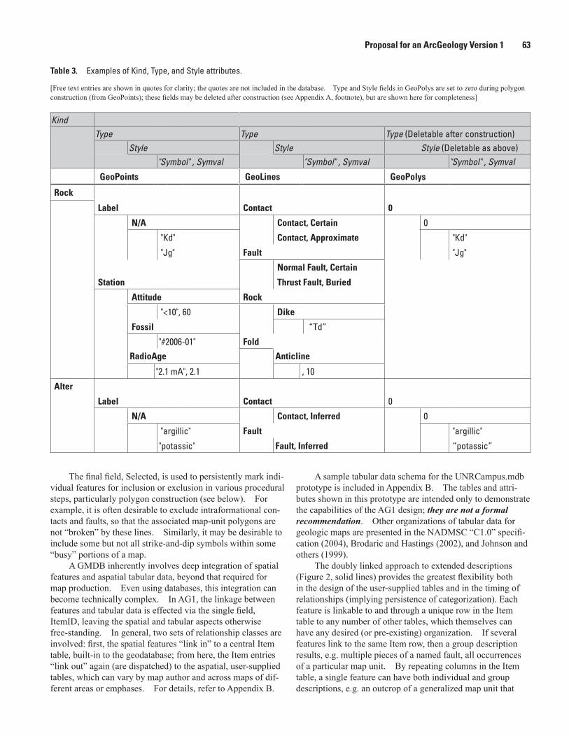
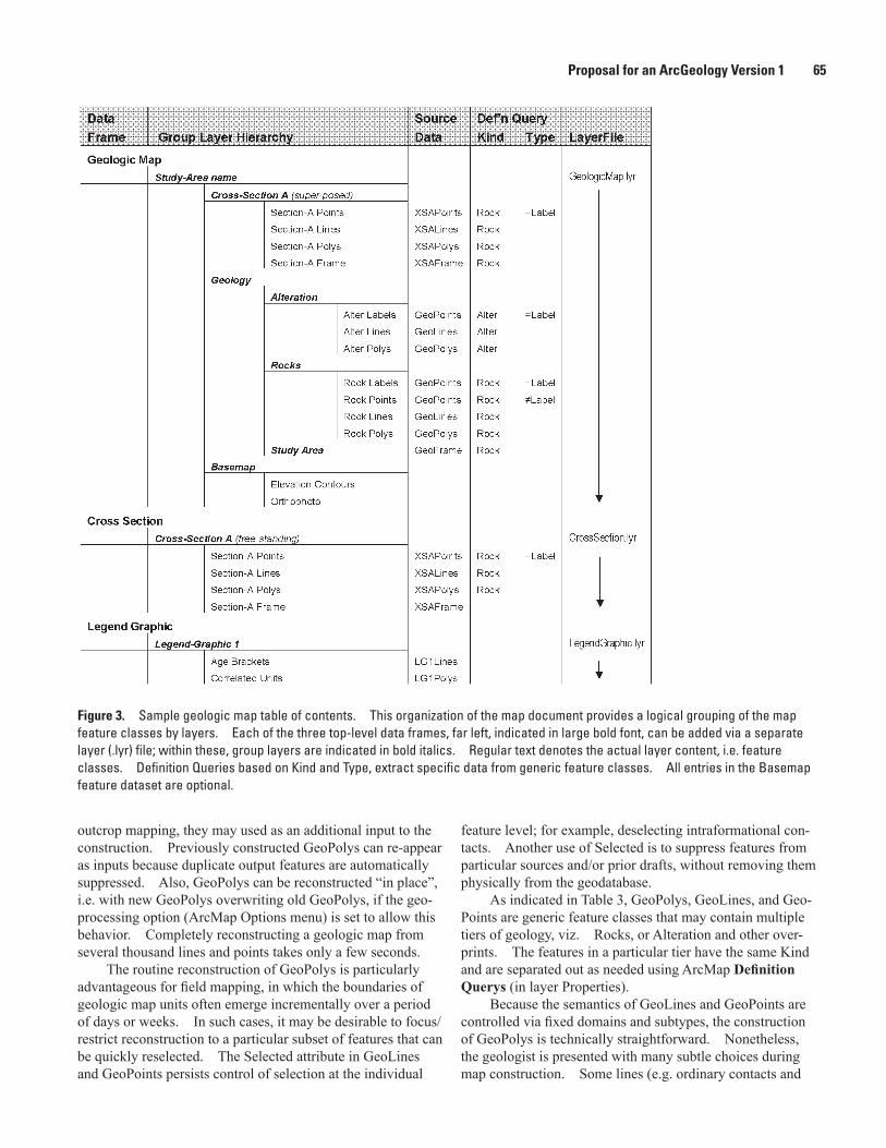
The companion ArcGeology1.mxt template, shown sche-matically in Figure 3, can be used to create an AG1 map docu-ment that incorporates the USGS-style map layout depicted in Figure 1; this is easily adaptable to other layouts. Hierarchi-cal layer (.lyr) files also are provided for flexibility: the geol-ogy.lyr file for the Geologic Map data frame, which embeds a single Cross-Section A; a stand-alone CrossSection.lyr file for additional Cross-Section data frames; and similarly a generic LegendGraphic.lyr file for Legend-Graphic data frames.
The arrangement of data frames and data layers produced in ArcMap by these .mxt and .lyr files reflect just one of many possible ways that a geologic map can be “laid out”. Map layout and cartography are not currently specified in AG1; however, increased standardization of maps in these regards would be beneficial, both to facilitate understanding of geo-logic maps by non-geologists and to simplify development of software tools for map-making.
The geospatial features of a GMDB are assembled based on field work and/or transcribed from existing paper maps. In either case, the majority of map-unit polygons, GeoPolys, are constructed from other features, GeoFrame, GeoLines, and optionally GeoPoints, using various ArcGIS utilities and tools (below). With the exception of areal out-crops (directly entered into GeoPolys), and GeoFrame (used as the study-area perimeter), polygons are not directly edited in AG1.
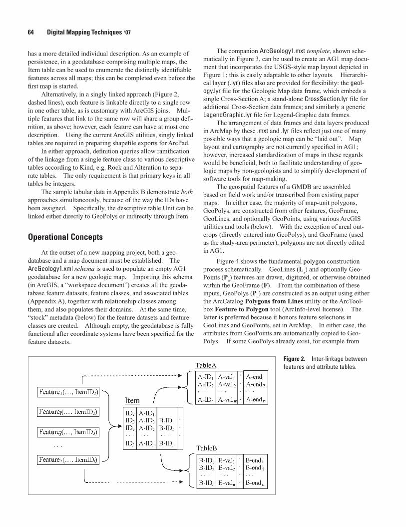
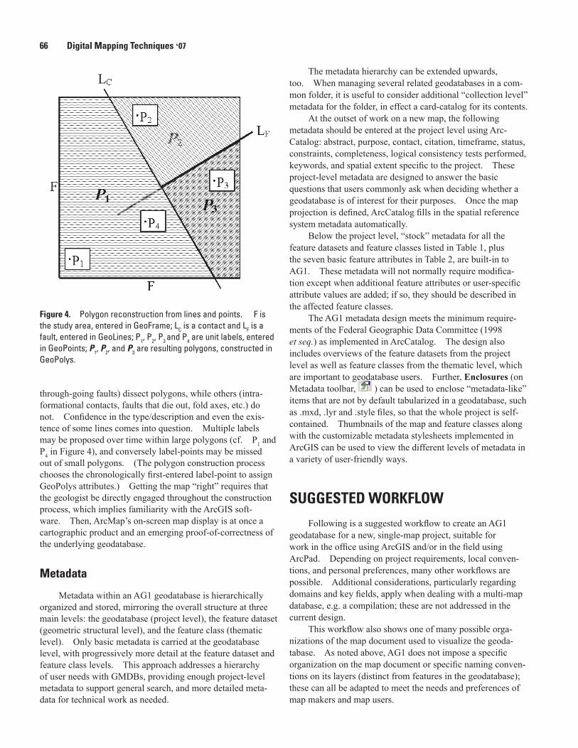
Figure 4 shows the fundamental polygon construction process schematically. GeoLines (Lx) and optionally Geo-Points (Pn) features are drawn, digitized, or otherwise obtained within the GeoFrame (F). From the combination of these inputs, GeoPolys (Pn) are constructed as an output using either the ArcCatalog Polygons from Lines utility or the ArcTool-box Feature to Polygon tool (ArcInfo-level license). The latter is preferred because it honors feature selections in GeoLines and GeoPoints, set in ArcMap. In either case, the attributes from GeoPoints are automatically copied to Geo-Polys. If some GeoPolys already exist, for example from
Figure 2. Inter-linkage between features and attribute tables.
Proposal for an ArcGeology Version 1 65
Figure 3. Sample geologic map table of contents. This organization of the map document provides a logical grouping of the map feature classes by layers. Each of the three top-level data frames, far left, indicated in large bold font, can be added via a separate layer (.lyr) file; within these, group layers are indicated in bold italics. Regular text denotes the actual layer content, i.e. feature classes. Definition Queries based on Kind and Type, extract specific data from generic feature classes. All entries in the Basemap feature dataset are optional.
outcrop mapping, they may used as an additional input to the construction. Previously constructed GeoPolys can re-appear as inputs because duplicate output features are automatically suppressed. Also, GeoPolys can be reconstructed “in place”, i.e. with new GeoPolys overwriting old GeoPolys, if the geo-processing option (ArcMap Options menu) is set to allow this behavior. Completely reconstructing a geologic map from several thousand lines and points takes only a few seconds.
The routine reconstruction of GeoPolys is particularly advantageous for field mapping, in which the boundaries of geologic map units often emerge incrementally over a period of days or weeks. In such cases, it may be desirable to focus/restrict reconstruction to a particular subset of features that can be quickly reselected. The Selected attribute in GeoLines and GeoPoints persists control of selection at the individual
feature level; for example, deselecting intraformational con-tacts. Another use of Selected is to suppress features from particular sources and/or prior drafts, without removing them physically from the geodatabase.
As indicated in Table 3, GeoPolys, GeoLines, and Geo-Points are generic feature classes that may contain multiple tiers of geology, viz. Rocks, or Alteration and other over-prints. The features in a particular tier have the same Kind and are separated out as needed using ArcMap Definition Querys (in layer Properties).
Because the semantics of GeoLines and GeoPoints are controlled via fixed domains and subtypes, the construction of GeoPolys is technically straightforward. Nonetheless, the geologist is presented with many subtle choices during map construction. Some lines (e.g. ordinary contacts and
66 Digital Mapping Techniques ‘07
Figure 4. Polygon reconstruction from lines and points. F is the study area, entered in GeoFrame; LC is a contact and LF is a fault, entered in GeoLines; P1, P2, P3 and P4 are unit labels, entered in GeoPoints; P1, P2, and P3 are resulting polygons, constructed in GeoPolys.
through-going faults) dissect polygons, while others (intra-formational contacts, faults that die out, fold axes, etc.) do not. Confidence in the type/description and even the exis-tence of some lines comes into question. Multiple labels may be proposed over time within large polygons (cf. P1 and P4 in Figure 4), and conversely label-points may be missed out of small polygons. (The polygon construction process chooses the chronologically first-entered label-point to assign GeoPolys attributes.) Getting the map “right” requires that the geologist be directly engaged throughout the construction process, which implies familiarity with the ArcGIS soft-ware. Then, ArcMap’s on-screen map display is at once a cartographic product and an emerging proof-of-correctness of the underlying geodatabase.
Metadata
Metadata within an AG1 geodatabase is hierarchically organized and stored, mirroring the overall structure at three main levels: the geodatabase (project level), the feature dataset (geometric structural level), and the feature class (thematic level). Only basic metadata is carried at the geodatabase level, with progressively more detail at the feature dataset and feature class levels. This approach addresses a hierarchy of user needs with GMDBs, providing enough project-level metadata to support general search, and more detailed meta-data for technical work as needed.
The metadata hierarchy can be extended upwards, too. When managing several related geodatabases in a com-mon folder, it is useful to consider additional “collection level” metadata for the folder, in effect a card-catalog for its contents.
At the outset of work on a new map, the following metadata should be entered at the project level using Arc-Catalog: abstract, purpose, contact, citation, timeframe, status, constraints, completeness, logical consistency tests performed, keywords, and spatial extent specific to the project. These project-level metadata are designed to answer the basic questions that users commonly ask when deciding whether a geodatabase is of interest for their purposes. Once the map projection is defined, ArcCatalog fills in the spatial reference system metadata automatically.
Below the project level, “stock” metadata for all the feature datasets and feature classes listed in Table 1, plus the seven basic feature attributes in Table 2, are built-in to AG1. These metadata will not normally require modifica-tion except when additional feature attributes or user-specific attribute values are added; if so, they should be described in the affected feature classes.
The AG1 metadata design meets the minimum require-ments of the Federal Geographic Data Committee (1998 et seq.) as implemented in ArcCatalog. The design also includes overviews of the feature datasets from the project level as well as feature classes from the thematic level, which are important to geodatabase users. Further, Enclosures (on Metadata toolbar, ) can be used to enclose “metadata-like” items that are not by default tabularized in a geodatabase, such as .mxd, .lyr and .style files, so that the whole project is self-contained. Thumbnails of the map and feature classes along with the customizable metadata stylesheets implemented in ArcGIS can be used to view the different levels of metadata in a variety of user-friendly ways.
SUGGESTED WORKFLOW
Following is a suggested workflow to create an AG1 geodatabase for a new, single-map project, suitable for work in the office using ArcGIS and/or in the field using ArcPad. Depending on project requirements, local conven-tions, and personal preferences, many other workflows are possible. Additional considerations, particularly regarding domains and key fields, apply when dealing with a multi-map database, e.g. a compilation; these are not addressed in the current design.
This workflow also shows one of many possible orga-nizations of the map document used to visualize the geoda-tabase. As noted above, AG1 does not impose a specific organization on the map document or specific naming conven-tions on its layers (distinct from features in the geodatabase); these can all be adapted to meet the needs and preferences of map makers and map users.
Proposal for an ArcGeology Version 1 67
Setup
1. Establish a working folder for the project. The name of this folder is arbitrary, adaptable to the user’s map-naming conventions, viz. UNRCampus
2. Within the working folder:
a. Create a simple shapefile, StudyArea, with polygon(s) depicting the study area boundaries and apply the appropriate map projection to it. Water bodies, excluded areas, etc. appearing within StudyArea should be detailed as “NoData” areas. (Note: For use with ArcPad, spatial data must be in projected units.)
b. Optionally, use StudyArea to clip other framework layers of interest.
3. Then, using ArcCatalog:
a. Create a new empty geodatabase for the project; rename this as desired. A recommended conven-tion is to name the geodatabase in parallel with the enclosing folder name, viz. UNRCampus\UNRCam-pus.mdb
b. Use Import | XML Workspace Document (geoda-tabase context menu) to set up the new geodatabase according to the ArcGeology1.xml schema.
c. Import (feature dataset context menu) the StudyArea shapefile into a StudyArea feature class within the Basemap geodatabase feature dataset. This step establishes the spatial reference system for Basemap.
d. Import (feature dataset context menu) other desired framework/ reference data into Basemap. Note that images and rasters will appear as stand-alone objects in a personal geodatabase, outside any feature dataset.
e. Use Load Data (feature class context menu) to load the StudyArea feature class (from 3c) into the empty GeoFrame feature class in the Geology feature dataset. This step establishes the spatial reference system for Geology.
f. Import (feature dataset Properties | XY Coordinate System) the coordinate system from the Geology fea-ture dataset, established via the loading operation (3e above) to the CrossSectionA feature dataset, to ensure that their spatial reference systems are the same.
g. Enter the project-level metadata for the map. Option-ally, enter any feature-level metadata regarding modi-fied Styles, Symbols and Symvals, etc.
4. Finally, using ArcMap:
a. Create a new empty map document for the project; rename this as desired. A recommended conven-tion is to name the map document in parallel with the enclosing folder name, viz. UNRCampus\UNRCampus.mxd. If the map document is based on a template, proceed to step 4e.
b. Rename the default data frame from “Layers” to “Geologic Map”; add the GeologicMap.lyr file to this data frame, and rename the added layer to reflect the study area. This step will define a grouped layer structure (“table of contents”) for the main map, although the layers themselves will be flagged with a red exclamation mark, indicating that they are not yet connected to geospatial data.
c. If the project involves cross-section(s), for each of them insert a “Cross Section $” data frame (where $ is A, B, C, etc.); add the CrossSection.lyr file to each inserted data frame and rename the layer as appro-priate. Alternatively, the “Cross Section A” group layer from the Geologic Map data frame can be cut-and-pasted into the stand-alone data frame(s). Note that the .lyr files should be made with relative paths.
d. If the project involves legend-graphic(s), for each of them insert a “Legend Graphic #” data frame (where # is 1, 2, 3, etc.); add the LegendGraphic.lyr file to each inserted data frame and rename the layer as appropriate.
e. Finally, if any feature class has a red exclamation mark following it, double-click on that mark and navigate to the corresponding feature class in the geo-database (e.g. GeoFrame layer to GeoFrame feature class). Doing this will automatically reconnect all the feature classes in the data frame, so the red flags will disappear.
Data Development
In a typical workflow, ArcMap is used to edit incremental sets of GeoLines and GeoPoints, after which GeoPolys are reconstructed on demand. GeoLines and GeoPoints contain, respectively, the raw “line work” and “point data” of the map, which can be input directly on-screen (heads-up digitizing), transcribed from paper maps using ArcScan, or captured in the field via ArcPad. Regardless of origin, the fundamental AG1 map construction process is as follows:
• Sketch, digitize, download or otherwise obtain an increment of GeoLines and, optionally, GeoPolys (out-crops) and GeoPoints (label-points) for the map.
68 Digital Mapping Techniques ‘07
• Review the Kind, Type and associated Style terms for all new features, according to the guidelines below:
◦ The Kind of primary interest in a geologic map, for all feature classes, is Rock; this is the default. Other Types include Alteration and a generic Overprint.
◦ The Type of primary interest for GeoLines is Structure: a Contact, Fault, or Rock Body, e.g. dike or marker bed; Contact is the default. Other Types are Folds, Geomorphics (lineaments, slickensides, etc), and Miscellaneous non-geologic lines, such as lines of section. By default, Contacts, Faults, and RockBodies are marked as Selected.
◦ Types of interest for GeoPoints are Labels (for label-points to be constructed into map-unit poly-gons) and Stations (for field measurements and observations); Label is the default. Both Labels and Stations are marked as Selected.
• Optionally, set/clear the Selected attribute to indicate features that should be included/excluded in construc-tion of polygons, e.g. features newly acquired from a field system or features to be omitted from polygon construction.
• Construct GeoPolys from the selected GeoLines and optionally GeoPolys (outcrops) and GeoPoints (label-points only) together with GeoFrame, preferably using the ArcToolbox Feature to Polygon tool. Polygons constructed around label-points will have attributes from them transferred automatically; polygons without label-points must be attributed manually.
• Repeat as necessary, augmenting GeoLines and GeoPoints until all GeoPolys have been constructed, filling the GeoFrame. Each successive set of poly-gons is, by construction, topologically consistent with the then-current lines and points and no slivering occurs. Also, duplicate polygons are automatically suppressed. Because label-point attributes are auto-matically transferred to polygons, rework is negligible.
For polygons that are constructed around label-points, in addition to the label-point attributes, their metadata also is transferred, which is erroneous. After the map is completed, importing the supplied GeoPolys.xml metadata document into GeoPolys will correct this error.
When the Geology feature classes include multiple Kinds of data, e.g. Alteration and Rock tiers, the above procedures must be limited to pre-selections (usually established via Defi-nition Querys) of features, so that only one Kind is processed at a time. Repeated processing with different selections builds up the complete Geology feature dataset. See Appen-dix C for a known problem with ArcGIS Definition Queries.
Cross-section(s) are treated in the same manner as Geology, but using XS$Points and XS$Lines to construct XS$Polys. Cross-section(s) also may include multiple
Kinds of data, as for Geology. An important difference from Geology is that XS$Frame has for its base the line of section and for its top the section’s topographic profile, connected by vertical sides left and right. The authors are developing a geoprocessing tool that will automate extraction of XS$Frame.
Legend-graphic(s) too are treated in the same manner as Geology, but using LG#Points and LG#Lines to construct LG#Polys. Sets of intersecting horizontal and vertical lines can be used to define rectangular polygons in the desired con-figuration; alternatively, a prototypical polygon can be drawn, then repeatedly copied/moved as needed. A LG#Frame is optional. Finished Legend-graphic “units” are parallel to the Geology units in the main figure, just abstracted in shape and usually arranged in some temporal way. The authors are developing a geoprocessing tool that will automate the process of defining the LG#Lines and/or LG#Polys.
Symbolization
A combination of layer (.lyr) and style (.style) files are used to achieve consistent map symbolization in AG1. The convention is to symbolize feature attributes controlled by domains and subtypes using styles, and to symbolize other, user-defined feature attributes using layers. In particular, the symbolization of geological units, GeoPolys, is generally map-specific, based on Symbol. To achieve consistency across the Geologic Map, Cross Section, and Legend Graphic data frames, the GeoPolys symbolization can be easily imported between layers. The completed map symbolization, for all feature geometries and symbolization methods, can be re-exported to a map-specific .style file, if desired. Moyer and others (2005) provide a detailed discussion of style-based symbolization for geologic maps.
Currently, the built-in terminology for GeoLines and GeoPoints matches the U.S. Geological Survey Open-File Report 95-525 (USGS, 1995), which also forms the basis of ArcGIS’ Geology24K style. (The symbols in that report, with modifications, formed the basis for the Federal Geo-graphic Data Committee’s recently-published standard for geologic map symbolization (FGDC, 2006), which could be supported in future.) As supplied in the ArcGeology.xml schema, GeoLines and GeoPoints domains are predefined in conformance with USGS 95-525 styles, so that the Match Features in a Style tool works using the Geology24K style “out of the box”. If additional GeoLines or GeoPoints symbols are desired, the changes should be made to a copy of the Geology24K style and substituted for it, after which corresponding changes will need to be made in various domains. See Appendix C for a known problem with ArcGIS symbolization.
Layout Template
An ArcMap template (.mxt) file provides a convenient way to assemble geospatial features in a standard map layout
Proposal for an ArcGeology Version 1 69
with marginalia suitable for printing a paper map. The supplied template, ArcGeology1.mxt, which follows USGS publication conventions, is designed so that each data frame corresponds to a geodatabase feature dataset; for example, the Legend Graphic data frame displays the data for the Legend-Graphic1 feature dataset. To use this template, open it in ArcMap, apply the proper page and print settings (e.g. 11 x17 in., landscape), then Save an appropriately named map docu-ment. Click on one of the red exclamation points (adjacent to a layer) and navigate to the corresponding geodatabase feature class to set the data source path for all the layers in the Data Frame.
Alternatively, if starting from an existing layout, select Change Layout (Layout toolbar, ), browse to and select the ArcGeology1.mxt template; afterward, it may also be neces-sary to re-order for the data frames in the dialog box. Either method will likely require further adjustment to map elements (scalebar, graticule, legend, text box, font size, etc.) in order to achieve the best use of space while maintaining the visual emphasis on the most important elements of the map, usually the main figure and cross section(s).
SUMMARY
AG1 is a simple but flexible system for producing digital geologic map-databases using ESRI ArcGIS and ArcPad soft-ware. By taking advantage of the many ArcGIS utilities and tools, AG1 avoids custom programming while simultaneously fostering user skill with the ESRI products. Further, AG1 strongly encourages standardization of basic geologic map ter-minology through its integrated system of subtypes, domains, and styles. These design choices facilitate the “migratabil-ity” of AG1-formatted datasets to future versions of ArcGIS and their “sharability” with other GIS software systems.
Development of an AG2 should, we feel, concentrate in two areas: 1) design and integration of comprehensive “stan-dard” descriptive data attributes, based on the NADMSC and GeoSciML recommendations; and 2) collateral integration of the FGDC 2006 standard for cartographic representation.
If, ultimately, some AGx becomes widely adopted, full documentation of its design, implementation, and operational use will be needed for use by the general geologist. The present document is a bare sketch of these topics. The authors heartily encourage comments and suggestions for improvement of these ideas.
REFERENCES
Bain, K.A., and Giles, J.R.A., 1997, A standard model for stor-age of geologic map data: Computers and Geosciences, v. 23, no. 6, p. 613-620.
Brodaric, Boyan, and Hastings, Jordan, 2002, An object model for geologic map information, in Richardson, D., and van Oosterom, P., eds., Advances in Spatial Data Handling, 10th International Symposium on Spatial Data Handling: Springer-Verlag, p.55-68.
Federal Geographic Data Committee, 1998, Content stan-dard for digital geospatial metadata: Reston, Va., Federal Geographic Data Committee Document Number FGDC-STD-001-1998, available at http://www.fgdc.gov/standards/projects/FGDC-standards-projects/metadata/base-metadata/.
Federal Geographic Data Committee [prepared for the Federal Geographic Data Committee by the U.S. Geologi-cal Survey], 2006, FGDC Digital Cartographic Standard for Geologic Map Symbolization: Reston, Va., Federal Geographic Data Committee Document Number FGDC-STD-013-2006, 290 p., 2 plates, available at http://ngmdb.usgs.gov/fgdc_gds/.
Johnson, B.R., Brodaric, B., Raines, G.L., Hastings, J.T., and Wahl, Ron, 1999, Digital Geologic Map Data Model, v4.3: AASG/USGS Data Model Working Group report, accessed at http://www.nadm-geo.org/dmdt/Model43a.pdf.
Moyer, L.A., Hastings, J.T., and Raines, G.L., 2005, Methods to create ArcMap styles with examples for lithology and time: U.S. Geological Survey Open-file Report 2005-1314, 21 p., available at http://pubs.usgs.gov/of/2005/1314/.
NADMSC [North American Geologic Map Data Model (NADM) Steering Committee] Data Model Design Team (2004) NADM conceptual model 1.0 – A conceptual model for geologic map information: U.S. Geological Survey Open-file Report 2004-1334, 60 p., available at http://pubs.usgs.gov/of/2004/1334/.
Richard, S.M., 2003, Geologic map database implementation in the ESRI Geodatabase environment, in Soller, D.R., ed., Digital Mapping Techniques ’03 – Workshop Proceedings: U.S. Geological Survey Open-file Report 03-471, p. 169-183, available at http://pubs.usgs.gov/of/2003/of03-471/richard2/.
Richard, S.M., Craigue, J.A., and Soller, D.R., 2004, Imple-ichard, S.M., Craigue, J.A., and Soller, D.R., 2004, Imple-menting NADM C1 for the National Geologic Map Data-base, in Soller, D.R., ed., Digital Mapping Techniques ‘04 – Workshop Proceedings: U.S. Geological Survey Open-file Report 2004-1451, p. 111-144, available at http://pubs.usgs.gov/of/2004/1451/richard/.
Richard, S.M., Craigue, J.A., and Soller, D.R., 2005, NGMDB Geologic Map Feature Class Model, in Soller, D.R., ed., Digital Mapping Techniques ‘05 – Workshop Proceedings: U.S. Geological Survey Open-file Report 2005-1428, p. 143-158, available at http://pubs.usgs.gov/of/2005/1428/richard/.
U.S. Geological Survey, 1995, Cartographic and digital stan-.S. Geological Survey, 1995, Cartographic and digital stan-dard for geologic map information: U.S. Geological Survey Open-file Report 1995-525, 257 p.
70 Digital Mapping Techniques ‘07
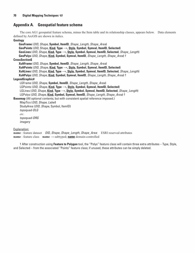
Appendix A. Geospatial feature schema
The core AG1 geospatial feature schema, minus the Item table and its relationship classes, appears below. Data elements defined by ArcGIS are shown in italics.Geology
GeoFrame (OID, Shape, Symbol, ItemID, Shape_Length, Shape_Area)GeoPoints (OID, Shape, Kind, Type →, Style, Symbol, Symval, ItemID, Selected)GeoLines (OID, Shape, Kind, Type →, Style, Symbol, Symval, ItemID, Selected, Shape_Length)GeoPolys (OID, Shape, Kind, Symbol, Symval, ItemID, Shape_Length, Shape_Area) †
CrossSection$XsAFrame (OID, Shape, Symbol, ItemID, Shape_Length, Shape_Area)XsAPoints (OID, Shape, Kind, Type →, Style, Symbol, Symval, ItemID, Selected)XsALines (OID, Shape, Kind, Type →, Style, Symbol, Symval, ItemID, Selected, Shape_Length)XsAPolys (OID, Shape, Kind, Symbol, Symval, ItemID, Shape_Length, Shape_Area) †
LegendGraphic#LGFrame (OID, Shape, Symbol, ItemID, Shape_Length, Shape_Area)LGPoints (OID, Shape, Kind, Type →, Style, Symbol, Symval, ItemID, Selected)LGLines (OID, Shape, Kind, Type →, Style, Symbol, Symval, ItemID, Selected, Shape_Length) LGPolys (OID, Shape, Kind, Symbol, Symval, ItemID, Shape_Length, Shape_Area) †
Basemap (All optional contents; but with consistent spatial reference imposed.) MapTics (OID, Shape, Label)StudyArea (OID, Shape, Symbol, ItemID)topoquad-DLGetc.topoquad-DRGimagery
Explanation: name : feature dataset OID, Shape, Shape_Length, Shape_Area: ESRI reserved attributesname : feature class name → subtyped; name domain-controlled
† After construction using Feature to Polygon tool, the “Polys” feature class will contain three extra attributes – Type, Style, and Selected – from the associated “Points” feature class; if unused, these attributes can be simply deleted.
Proposal for an ArcGeology Version 1 71
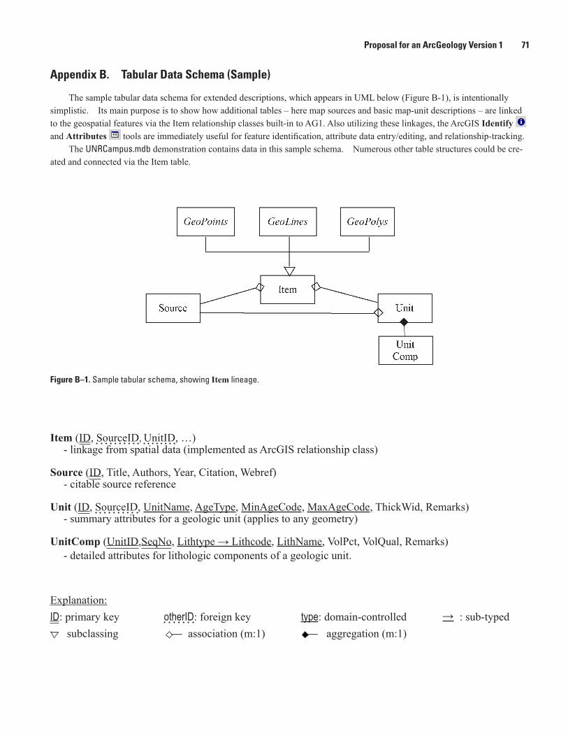
Appendix B. Tabular Data Schema (Sample)
The sample tabular data schema for extended descriptions, which appears in UML below (Figure B-1), is intentionally simplistic. Its main purpose is to show how additional tables – here map sources and basic map-unit descriptions – are linked to the geospatial features via the Item relationship classes built-in to AG1. Also utilizing these linkages, the ArcGIS Identify and Attributes tools are immediately useful for feature identification, attribute data entry/editing, and relationship-tracking.
The UNRCampus.mdb demonstration contains data in this sample schema. Numerous other table structures could be cre-ated and connected via the Item table.
Figure B–1. Sample tabular schema, showing Item lineage.
Item (ID, SourceID, UnitID, …)- linkage from spatial data (implemented as ArcGIS relationship class)
Source (ID, Title, Authors, Year, Citation, Webref)- citable source reference
Unit (ID, SourceID, UnitName, AgeType, MinAgeCode, MaxAgeCode, ThickWid, Remarks)- summary attributes for a geologic unit (applies to any geometry)
UnitComp (UnitID,SeqNo, Lithtype → Lithcode, LithName, VolPct, VolQual, Remarks)- detailed attributes for lithologic components of a geologic unit.
Explanation:ID: primary key otherID: foreign key type: domain-controlled : sub-typed subclassing association (m:1) aggregation (m:1)
→
72 Digital Mapping Techniques ‘07
Appendix C: Known Problems
1. Feature construction: Using the ArcToolbox Fea-ture to Polygon tool, but not the ArcCatalog Features from Lines utility, if the (optional) point feature class is supplied, its metadata is transferred onto the newly constructed polygons. This transfer occurs even if the polygons are being reconstructed. The workaround is to import the supplied GeoPolys.xml metadata document into GeoPolys after all construction is completed.
2. Definition queries: The existence of a Definition Query interferes with the reconstruction of polygons from lines and (other) polygons. Specifically, it is not possible to use the ArcToolbox Feature to Polygon tool to recon-struct GeoPolys in a feature class that has such a query in place, e.g. for Kind (Rock, Alteration, etc.). Removing
the query temporarily allows the reconstruction, but also results in all contents of GeoPolys being overwritten, not just the features of the chosen Kind. The workaround is to always construct into a new feature class (GeoPolys1, GeoPolys2, etc.), and when satisfactory, delete/re-merge them into GeoPolys. GeoPolys itself should not be deleted; doing so will also delete its relationship classes and destroy its metadata.
3. Matching to styles: When a feature class is symbolized using Match to Symbols in a Style, all of the symbols in the style are added to the map table of contents, whereas when the feature class is symbolized directly, only sym-bols for the features that are actually present appear. The workaround is to delete unwanted entries from the map table of contents after the feature class has been symbol-ized.