Embed Size (px)
DESCRIPTION
Â
Citation preview
ArcGIS®
9Building a Geodatabase

Copyright © 1999–2004 ESRIAll rights reserved.Printed in the United States of America.
The information contained in this document is the exclusive property of ESRI. This work is protected under United States copyright law and otherinternational copyright treaties and conventions. No part of this work may be reproduced or transmitted in any form or by any means, electronic ormechanical, including photocopying and recording, or by any information storage or retrieval system, except as expressly permitted in writing by ESRI. Allrequests should be sent to Attention: Contracts Manager, ESRI, 380 New York Street, Redlands, CA 92373-8100, USA.
The information contained in this document is subject to change without notice.
DATA CREDITSGraphical Editing map: Wilson, North Carolina
Universal Data Editor map, Editing in Data view and Layout view map: Greeley, Colorado
Context Menus and Shortcut Keys map: P.F.R.A., Regina, Saskatchewan, Canada
Quick-start tutorial data: Wilson, North Carolina; Greeley, Colorado
CONTRIBUTING WRITERSAndrew Perencsik, Simon Woo, Bob Booth, Scott Crosier, Jill Clark, Andy MacDonald
U.S. GOVERNMENT RESTRICTED/LIMITED RIGHTSAny software, documentation, and/or data delivered hereunder is subject to the terms of the License Agreement. In no event shall the U.S. government acquiregreater than RESTRICTED/LIMITED RIGHTS. At a minimum, use, duplication, or disclosure by the U.S. Government is subject to restrictions as set forth inFAR §52.227-14 Alternates I, II, and III (JUN 1987); FAR §52.227-19 (JUN 1987) and/or FAR §12.211/12.212 (Commercial Technical Data/ComputerSoftware); and DFARS §252.227-7015 (NOV 1995) (Technical Data) and/or DFARS §227.7202 (Computer Software), as applicable. Contractor/Manufactureris ESRI, 380 New York Street, Redlands, CA 92373-8100, USA.
ESRI, the ESRI globe logo, ArcGIS, ArcMap, ArcCatalog, ArcInfo, ArcSDE, ArcToolbox, ArcIMS, ArcReader, ArcEditor, ArcStorm, SDE, Spatial DatabaseEngine, ArcView, ArcObjects, GIS by ESRI, the ArcGIS logo, and www.esri.com are trademarks, registered trademarks, or service marks of ESRI in the UnitedStates, the European Community, or certain other jurisdictions.
Other companies and products mentioned herein are trademarks or registered trademarks of their respective trademark owners.
Attribution.pmd 3/8/2004, 8:23 AM1
iii
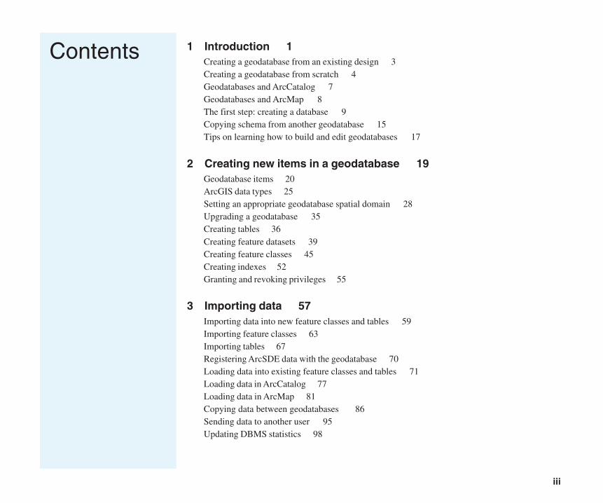
Contents 1 Introduction 1Creating a geodatabase from an existing design 3Creating a geodatabase from scratch 4Geodatabases and ArcCatalog 7Geodatabases and ArcMap 8The first step: creating a database 9Copying schema from another geodatabase 15Tips on learning how to build and edit geodatabases 17
2 Creating new items in a geodatabase 19Geodatabase items 20ArcGIS data types 25Setting an appropriate geodatabase spatial domain 28Upgrading a geodatabase 35Creating tables 36Creating feature datasets 39Creating feature classes 45Creating indexes 52Granting and revoking privileges 55
3 Importing data 57Importing data into new feature classes and tables 59Importing feature classes 63Importing tables 67Registering ArcSDE data with the geodatabase 70Loading data into existing feature classes and tables 71Loading data in ArcCatalog 77Loading data in ArcMap 81Copying data between geodatabases 86Sending data to another user 95Updating DBMS statistics 98
Contents.pmd 3/8/2004, 8:16 AM3
iv BUILDING A GEODATABASE
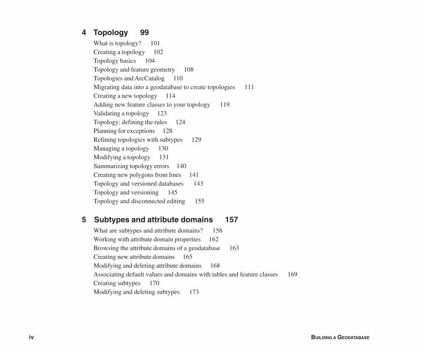
4 Topology 99What is topology? 101Creating a topology 102Topology basics 104Topology and feature geometry 108Topologies and ArcCatalog 110Migrating data into a geodatabase to create topologies 111Creating a new topology 114Adding new feature classes to your topology 119Validating a topology 123Topology: defining the rules 124Planning for exceptions 128Refining topologies with subtypes 129Managing a topology 130Modifying a topology 131Summarizing topology errors 140Creating new polygons from lines 141Topology and versioned databases 143Topology and versioning 145Topology and disconnected editing 155
5 Subtypes and attribute domains 157What are subtypes and attribute domains? 158Working with attribute domain properties 162Browsing the attribute domains of a geodatabase 163Creating new attribute domains 165Modifying and deleting attribute domains 168Associating default values and domains with tables and feature classes 169Creating subtypes 170Modifying and deleting subtypes 173
Contents.pmd 3/8/2004, 8:16 AM4
CONTENTS v
6 Defining relationship classes 175What is a relationship class? 176Relationship classes in ArcCatalog and ArcMap 180Creating a simple relationship class 182Creating a composite relationship class 186Creating an attributed relationship class 189Creating relationship rules 191Managing relationship classes 193Exploring related objects in ArcMap 194Using related fields in ArcMap 197
7 Geometric networks 199What is a geometric network? 200Geometric networks and ArcCatalog 204Creating geometric networks 205Creating a new geometric network 211Building a geometric network from existing simple feature classes 215Adding new feature classes to your geometric network 221Network connectivity: defining the rules 224Establishing connectivity rules 225Managing a geometric network 227
8 Managing annotation 229Annotation in the geodatabase 230Annotation and ArcCatalog 235Creating annotation feature classes 236Converting labels to annotation 241Importing coverage annotation 244
Contents.pmd 3/8/2004, 8:16 AM5
vi BUILDING A GEODATABASE
9 Dimensioning 247Dimensions in the geodatabase 248Dimensions and ArcCatalog 251Creating dimension feature classes 252Creating and managing dimension styles 257
10 Working with a versioned geodatabase 267Integrating versioning with your organization’s work flow 268Registering data as versioned 270Creating and administering versions in ArcCatalog 271Working with versions in ArcMap 278Editing and conflict resolution 281Editing a version 286Versioning scenarios 290
11 Disconnected editing 293Disconnected editing 294Checking out data from a geodatabase 313Customizing a check-out 315Checking in data to a geodatabase 318Managing check-outs 321
12 Building a raster geodatabase 327Rasters and the geodatabase 328Importing and loading raster data 332Attributes of type raster 340Converting raster formats 341Mosaicking raster datasets 342Raster data and disconnected editing 343More about rasters in ArcGIS 344
Contents.pmd 3/8/2004, 8:16 AM6

CONTENTS vii
Glossary 345
Index 369
Contents.pmd 3/8/2004, 8:16 AM7

Contents.pmd 3/8/2004, 8:16 AM8
IN THIS CHAPTER
1
Introduction 1• Creating a geodatabase from an
existing design
• Creating a geodatabase fromscratch
• Geodatabases and ArcCatalog
• Geodatabases and ArcMap
• The first step: creating a database
• Copying schema from anothergeodatabase
• Tips on learning how to build andedit geodatabases
The geodatabase supports a model of topologically integrated featureclasses, similar to the coverage model. It also extends the coveragemodel with support for complex networks, topologies, relationshipsamong feature classes, and other object-oriented features. The ESRI®
ArcGIS® applications (ArcMapTM, ArcCatalogTM, and ArcToolboxTM) workwith geodatabases as well as with coverages and shapefiles.
The ArcGIS geodatabase model is implemented on standard relationaldatabases with the ArcSDE® application server. ArcSDE defines an openinterface to database systems. It allows ArcInfoTM or ArcEditorTM seatsto manage geographic information on a variety of different databaseplatforms including Oracle®, Microsoft® SQL ServerTM, IBM® DB2®, andInformix®.
The geodatabase provides a generic framework for geographicinformation. This framework can be used to define and work with a widevariety of different user- or application-specific models.
The geodatabase supports object-oriented vector and raster data. In thismodel, entities are represented as objects with properties, behavior, andrelationships. Support for a variety of different geographic object types isbuilt into the system. These object types include simple objects, geographicfeatures, network features, annotation features, and other morespecialized feature types. The model allows you to define relationshipsbetween objects and rules for maintaining referential and topologicalintegrity between objects.
2 BUILDING A GEODATABASE
How the data is stored in the database, the applications thataccess it, and the client and server hardware configurationsare all key factors to a successful multiuser geographicinformation system (GIS). Successfully implementing a GISwith ArcInfo and ArcSDE starts with a good data modeldesign. Designing a geodatabase is a critical process thatrequires planning and revision until you reach a design thatmeets your requirements and performs well. You can eitherstart with an existing geodatabase design or design yourown from scratch. Throughout this book, guidelines forgood data modeling of each aspect of the geodatabase arediscussed to help you implement a successful multiuser GISsystem with ArcInfo, either with ArcSDE or with apersonal geodatabase.
Once you have a design, you can create the geodatabaseand its schema by creating new database items withArcCatalog, loading existing shapefile and coverage data,using Unified Modeling Language (UML) and Computer-Aided Software Engineering (CASE) tools, or acombination of these.
A critical part of a well-performing geodatabase is thetuning of the database management system (DBMS) inwhich it is stored. This tuning is not required for personalgeodatabases; however, it is critical for ArcSDEgeodatabases. For more information on tuning yourdatabase for ArcSDE and the geodatabase, see theConfiguration and Tuning Guide for <DBMS> PDF file.
The main tools you will use to create and edit geodatabasesare found in ArcCatalog and ArcMap. ArcCatalog hasvarious tools for creating and modifying your geodatabase
schema, while ArcMap has tools for analyzing and editingthe contents of your geodatabase.
This book teaches you how to implement a geodatabase. Ifyou’re using ArcView®, it shows you how to create apersonal geodatabase, import data, set up domains, andcreate standard annotation feature classes and rastercatalogs. If you’re using ArcEditor or ArcInfo, it shows youhow to create personal and ArcSDE geodatabases; importdata; create geodatabase topology, subtypes, domains,relationship classes, geometric networks, standard andfeature-linked annotation classes, raster catalogs, andmosaics; and manage editing with versions anddisconnected editing. This book is one of three booksdesigned to teach you how to make the most ofgeodatabases.
The second book, Editing in ArcMap, approaches thegeodatabase from the editor and data manager’sperspective. It describes how to create and edit data withinan existing geodatabase.
The third book, Geodatabase Workbook, contains tutorialexercises that allow you to apply the concepts developed inthe first two books.
INTRODUCTION 3
There may be a data model that already exists that may partly orwholly suit your needs. Adopting an existing design can give youa quick head start in creating a geodatabase.
Data models distributed by ESRI
ESRI and a number of leaders in their disciplines have beenactively designing a series of GIS data models using topologyand other capabilities in ArcGIS. The goal is to provide a commondesign framework for key layers of geographic information, andpromote openness and interoperability of GIS data. These effortshave resulted in a series of comprehensive design specificationsfor a number of thematic layers:
• Census and Administrative Boundaries (applied to U.S.Census geography)
• Topographic basemaps for 1:24,000-scale maps
• Hydrography
• Raster imagery and elevation catalogs
• Streets and comprehensive address information
• Transportation (to support linear referencing, navigation,addressing, and cartography)
• Public Land Survey System (PLSS) (to support a nationaldatabase of the legal survey fabric)
• Parcels (to support both U.S. and worldwide systems)
• Water facilities
• And numerous other efforts
These data models provide a practical template for implementing ageodatabase. While you may find your industry-specific model tobe a great starting point for your geodatabase, you may also findrelated models useful. For the latest information on the datamodels or to download one of them, see http://support.esri.com.
Creating a geodatabase from an existing design
Data models from other locations
You may know an ArcGIS user in a similar industry who hassuccessfully implemented a geodatabase. ArcMap andArcCatalog provide tools that allow you to copy the schema froman existing geodatabase. Once copied, the schema can be sent tosomeone else and adopted as a starting point for a geodatabasedesign. The tools that allow you to copy a schema are discussedlater in this chapter.
Loading data
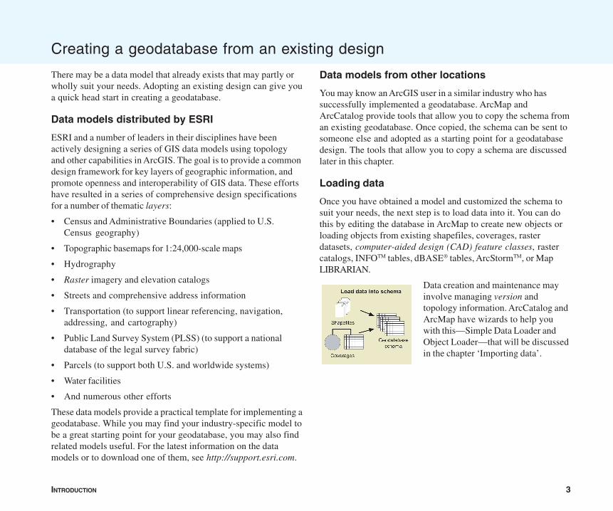
Once you have obtained a model and customized the schema tosuit your needs, the next step is to load data into it. You can dothis by editing the database in ArcMap to create new objects orloading objects from existing shapefiles, coverages, rasterdatasets, computer-aided design (CAD) feature classes, rastercatalogs, INFOTM tables, dBASE® tables, ArcStormTM, or MapLIBRARIAN.
Data creation and maintenance mayinvolve managing version andtopology information. ArcCatalog andArcMap have wizards to help youwith this—Simple Data Loader andObject Loader—that will be discussedin the chapter ‘Importing data’.
4 BUILDING A GEODATABASE
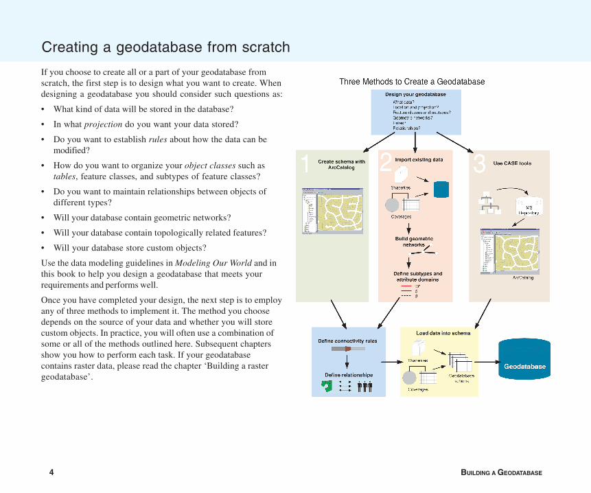
If you choose to create all or a part of your geodatabase fromscratch, the first step is to design what you want to create. Whendesigning a geodatabase you should consider such questions as:
• What kind of data will be stored in the database?
• In what projection do you want your data stored?
• Do you want to establish rules about how the data can bemodified?
• How do you want to organize your object classes such astables, feature classes, and subtypes of feature classes?
• Do you want to maintain relationships between objects ofdifferent types?
• Will your database contain geometric networks?
• Will your database contain topologically related features?
• Will your database store custom objects?
Use the data modeling guidelines in Modeling Our World and inthis book to help you design a geodatabase that meets yourrequirements and performs well.
Once you have completed your design, the next step is to employany of three methods to implement it. The method you choosedepends on the source of your data and whether you will storecustom objects. In practice, you will often use a combination ofsome or all of the methods outlined here. Subsequent chaptersshow you how to perform each task. If your geodatabasecontains raster data, please read the chapter ‘Building a rastergeodatabase’.
Creating a geodatabase from scratch
INTRODUCTION 5
Creating schema with ArcCatalog
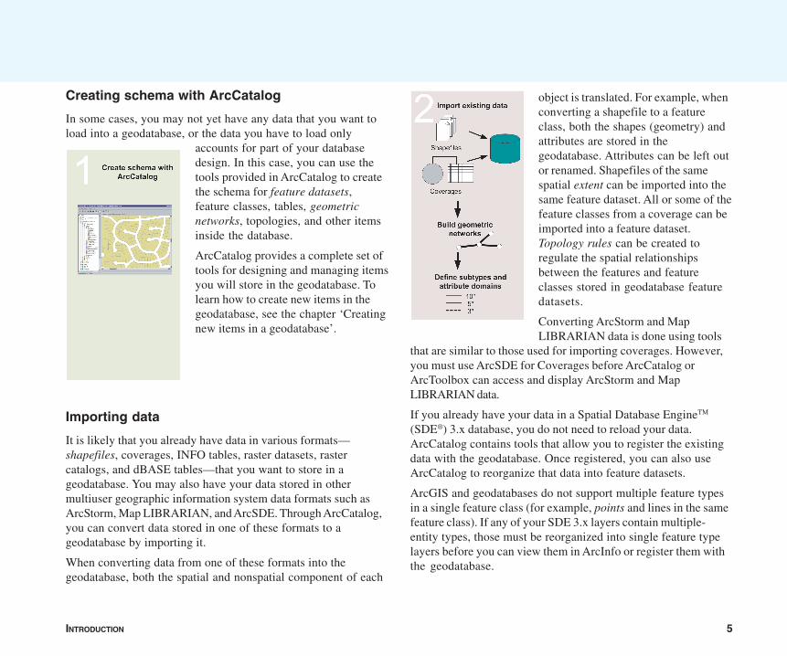
In some cases, you may not yet have any data that you want toload into a geodatabase, or the data you have to load only
accounts for part of your databasedesign. In this case, you can use thetools provided in ArcCatalog to createthe schema for feature datasets,feature classes, tables, geometricnetworks, topologies, and other itemsinside the database.
ArcCatalog provides a complete set oftools for designing and managing itemsyou will store in the geodatabase. Tolearn how to create new items in thegeodatabase, see the chapter ‘Creatingnew items in a geodatabase’.
Importing data
It is likely that you already have data in various formats—shapefiles, coverages, INFO tables, raster datasets, rastercatalogs, and dBASE tables—that you want to store in ageodatabase. You may also have your data stored in othermultiuser geographic information system data formats such asArcStorm, Map LIBRARIAN, and ArcSDE. Through ArcCatalog,you can convert data stored in one of these formats to ageodatabase by importing it.
When converting data from one of these formats into thegeodatabase, both the spatial and nonspatial component of each
object is translated. For example, whenconverting a shapefile to a featureclass, both the shapes (geometry) andattributes are stored in thegeodatabase. Attributes can be left outor renamed. Shapefiles of the samespatial extent can be imported into thesame feature dataset. All or some of thefeature classes from a coverage can beimported into a feature dataset.Topology rules can be created toregulate the spatial relationshipsbetween the features and featureclasses stored in geodatabase featuredatasets.
Converting ArcStorm and MapLIBRARIAN data is done using tools
that are similar to those used for importing coverages. However,you must use ArcSDE for Coverages before ArcCatalog orArcToolbox can access and display ArcStorm and MapLIBRARIAN data.
If you already have your data in a Spatial Database EngineTM
(SDE®) 3.x database, you do not need to reload your data.ArcCatalog contains tools that allow you to register the existingdata with the geodatabase. Once registered, you can also useArcCatalog to reorganize that data into feature datasets.
ArcGIS and geodatabases do not support multiple feature typesin a single feature class (for example, points and lines in the samefeature class). If any of your SDE 3.x layers contain multiple-entity types, those must be reorganized into single feature typelayers before you can view them in ArcInfo or register them withthe geodatabase.
6 BUILDING A GEODATABASE
2. Generate geodatabase schema from XMI with CASE tools. Tolearn how, see the online help.
Further refining the geodatabase
Whether you load data manually or use ArcCatalog to create thegeodatabase schema, you can continue to define yourgeodatabase by establishing how objects in the database relateto one another.
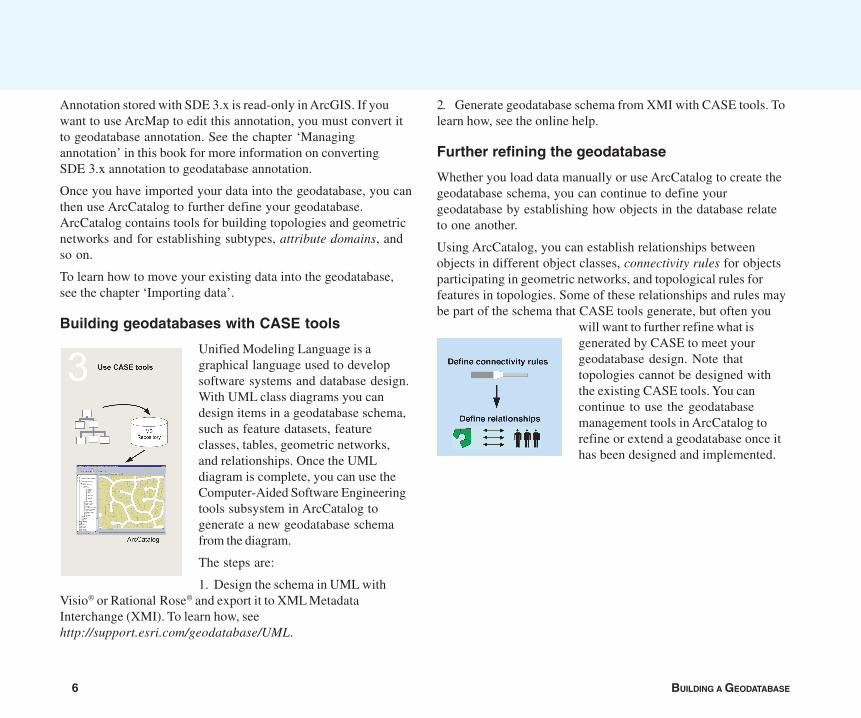
Using ArcCatalog, you can establish relationships betweenobjects in different object classes, connectivity rules for objectsparticipating in geometric networks, and topological rules forfeatures in topologies. Some of these relationships and rules maybe part of the schema that CASE tools generate, but often you
will want to further refine what isgenerated by CASE to meet yourgeodatabase design. Note thattopologies cannot be designed withthe existing CASE tools. You cancontinue to use the geodatabasemanagement tools in ArcCatalog torefine or extend a geodatabase once ithas been designed and implemented.
Annotation stored with SDE 3.x is read-only in ArcGIS. If youwant to use ArcMap to edit this annotation, you must convert itto geodatabase annotation. See the chapter ‘Managingannotation’ in this book for more information on convertingSDE 3.x annotation to geodatabase annotation.
Once you have imported your data into the geodatabase, you canthen use ArcCatalog to further define your geodatabase.ArcCatalog contains tools for building topologies and geometricnetworks and for establishing subtypes, attribute domains, andso on.
To learn how to move your existing data into the geodatabase,see the chapter ‘Importing data’.
Building geodatabases with CASE tools
Unified Modeling Language is agraphical language used to developsoftware systems and database design.With UML class diagrams you candesign items in a geodatabase schema,such as feature datasets, featureclasses, tables, geometric networks,and relationships. Once the UMLdiagram is complete, you can use theComputer-Aided Software Engineeringtools subsystem in ArcCatalog togenerate a new geodatabase schemafrom the diagram.
The steps are:
1. Design the schema in UML withVisio® or Rational Rose® and export it to XML MetadataInterchange (XMI). To learn how, seehttp://support.esri.com/geodatabase/UML.
INTRODUCTION 7
ArcCatalog allows you to easily view and modify the contents ofyour geodatabase. ArcCatalog contains a full suite of tools tocreate and manage your geodatabase.
Accessing geodatabases in ArcCatalog
You can manage geographic data in a variety of formats inArcCatalog. Some of the formats that you can manage directlyinclude personal geodatabases, shapefiles, ArcInfo coverages,rasters, TINs, and tables.
In addition to managing data on your desktop or local network,you can manage remote ArcSDE geodatabases by creating aconnection to the database. Database connections to remotegeodatabases behave similarly to personal geodatabases, withone important difference: when you delete a personalgeodatabase, the database itself is deleted from the disk. Whenyou delete a remote geodatabase connection, however, only theconnection is deleted—the geodatabase and its data areunaffected.
Spatial database connections
Using data stored in a DBMS, such as Oracle, requires a databaseconnection. There are two methods for connecting to a spatialdatabase from ArcInfo. One method is to connect to an ArcSDEservice that spawns a process on the server to broker theconnection between ArcInfo and the database instance.
The second method is to use a direct connection to the database.In this case, ArcInfo connects directly to the database server. Thefunctionality that is managed by the server process in the firstconnection method is transferred to the client, thus eliminatingthe middle tier. The direct connect method is a two-tiered ratherthan three-tiered architecture.
Geodatabases and ArcCatalog
You can use the direct connect method to connect to yourgeodatabase if it is stored in Oracle8iTM, Oracle9iTM, SQL Server,DB2, or Informix. If connecting to SQL Server, you do not requireany additional software to connect to the database. If directconnecting to any of the others, you’ll need to install clientsoftware on your machine. For more information about directconnect, see Making a Direct Connection, located on theArcSDE CD–ROM.
When you add a new connection to an ArcSDE geodatabaseservice or a direct database connection in ArcCatalog, it creates aconnection file on disk. This file contains the information neededto establish a connection. The username and password can beincluded in the connection file and are encrypted for security.
You can set up connection files for your organization anddistribute these such that end users will not require anyinformation about the geodatabase server to which they areconnecting.
8 BUILDING A GEODATABASE
ArcMap allows you to edit the contents of your geodatabase.ArcMap contains a full suite of tools to edit simple features,geometric networks, and topologies in your geodatabase.
Editing geodatabases in ArcMap
You can edit geographic data in a variety of formats in ArcMap.ArcView seats of ArcMap can be used to edit simple features inshapefiles and personal geodatabases. ArcInfo and ArcEditorseats have more extensive toolsets with special tools for creatingand editing geographic data in topologies or geometric networksand performing spatial adjustment and disconnected editing.
Editing topologies
Editing a feature in a map topology or geodatabase topology withthe topology edit tools automatically updates the geometry of theshared parts of all the features. After you edit a topology, thegeodatabase can discover if any of the edits violate the rules ofthe topology. If there are errors, ArcMap enables you to quicklysee which features are involved and which rules have beenviolated and allows you to fix the error, mark it as an exception, orleave it as an error. Error reporting in ArcMap gives you ameasure of how good your data is.
Editing geometric networks
Editing features in a geometric network allows you to maintainnetwork connectivity of specified types of features and lets youmove connected features without breaking the connections aswell as add junctions to certain types of edges without splittingthem. Geometric networks are useful for modeling connectedlinear features, such as pipes, cables, and streams, and formodeling points that represent nodes in the network such asvalves, switches, and stream confluences or gauging stations.
Geodatabases and ArcMap
The features that participate in a geometric network becomenetwork feature classes, not simple feature classes.
Versions
ArcEditor and ArcInfo seats of ArcMap allow you to editversioned geodatabases. Different versions of a geodatabase canbe used to model complex “what if ” scenarios; create differentdesign alternatives; or manage the stages in a multistep planning,design, and construction work flow cycle without modifying ormaking multiple copies of your base data. Versioning also allowsmultiple editors to work on the same large continuous GIS datasetwithout the need to lock the data or divide it into tiles.
ArcMap lets you easily switch from one version to another to seehow they differ.
When you are ready to merge changes from a version intoanother version, ArcMap can reconcile the versions. Whenmultiple editors are working on an area, there is a chance for thesame feature to be modified by more than one editor—in thesecases, ArcMap helps you identify and resolve the conflicts.
There are currently no versioning capabilities for raster data.
Disconnected editing
ArcInfo and ArcEditor seats of ArcMap can be used to check outdata from your geodatabase to use while disconnected from thenetwork. This is especially useful for remote offices that need towork with a portion of the database without incurring network-related performance problems and for people who need to take apart of the geodatabase out into the field for editing or analysison a field computer. Changes to the data made in the field can bechecked back in to the main geodatabase to allow them to beused by others.
INTRODUCTION 9
The first step:creating adatabaseThe first step in creating ageodatabase is to create thedatabase itself usingArcCatalog.
There are two kinds of geodata-bases: personal geodatabasesand ArcSDE geodatabases.Creating a new personalgeodatabase involves creatinga new .mdb file on disk.
Before you can create data in anArcSDE geodatabase, you mustdo some setup. Setting up thedatabase for use as an ArcSDEgeodatabase is described inManaging ArcSDE Servicesand in the ArcSDE InstallationGuide, located on the ArcSDECD–ROM. For informationabout direct connections,please see Making a DirectConnection, also located onthe ArcSDE CD–ROM.
Several versions of an ArcSDEgeodatabase can exist, althoughnot every table or feature classin the geodatabase must beversioned. Feature editing inArcMap requires a versionedfeature class in a geodatabase.
New connections will automati-cally access the DEFAULTversion of the database. u
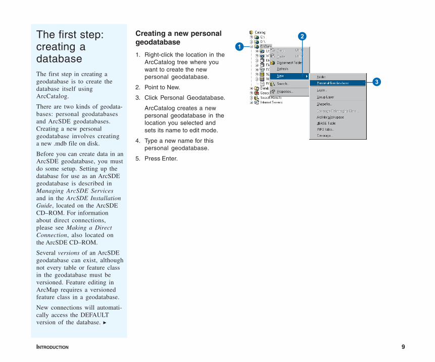
Creating a new personalgeodatabase
1. Right-click the location in theArcCatalog tree where youwant to create the newpersonal geodatabase.
2. Point to New.
3. Click Personal Geodatabase.
ArcCatalog creates a newpersonal geodatabase in thelocation you selected andsets its name to edit mode.
4. Type a new name for thispersonal geodatabase.
5. Press Enter.
21
3
10 BUILDING A GEODATABASE
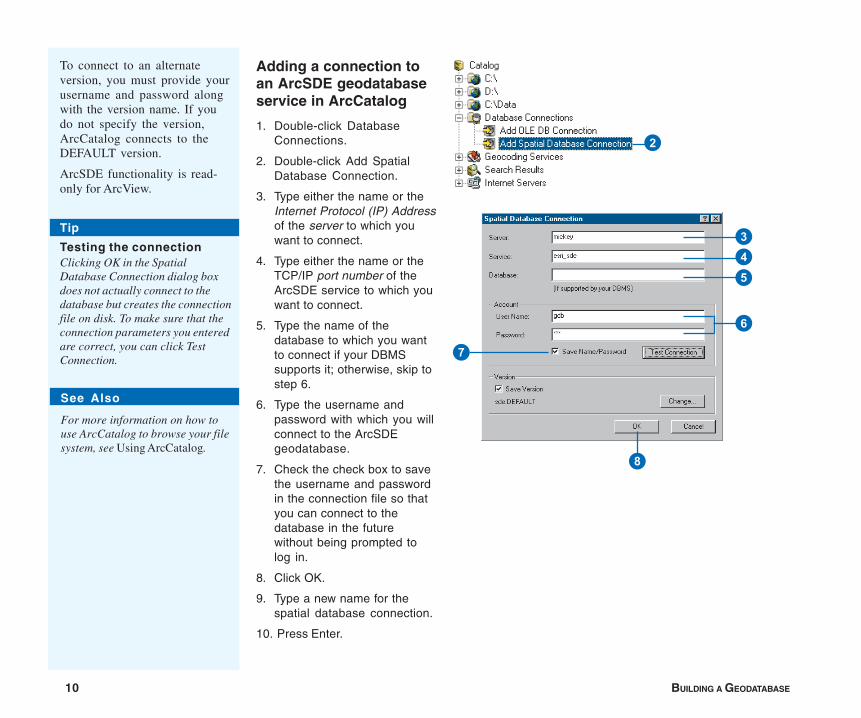
Adding a connection toan ArcSDE geodatabaseservice in ArcCatalog
1. Double-click DatabaseConnections.
2. Double-click Add SpatialDatabase Connection.
3. Type either the name or theInternet Protocol (IP) Addressof the server to which youwant to connect.
4. Type either the name or theTCP/IP port number of theArcSDE service to which youwant to connect.
5. Type the name of thedatabase to which you wantto connect if your DBMSsupports it; otherwise, skip tostep 6.
6. Type the username andpassword with which you willconnect to the ArcSDEgeodatabase.
7. Check the check box to savethe username and passwordin the connection file so thatyou can connect to thedatabase in the futurewithout being prompted tolog in.
8. Click OK.
9. Type a new name for thespatial database connection.
10. Press Enter.
To connect to an alternateversion, you must provide yourusername and password alongwith the version name. If youdo not specify the version,ArcCatalog connects to theDEFAULT version.
ArcSDE functionality is read-only for ArcView.
2
34
6
8
7
5
Tip
Testing the connectionClicking OK in the SpatialDatabase Connection dialog boxdoes not actually connect to thedatabase but creates the connectionfile on disk. To make sure that theconnection parameters you enteredare correct, you can click TestConnection.
See Also
For more information on how touse ArcCatalog to browse your filesystem, see Using ArcCatalog.
INTRODUCTION 11
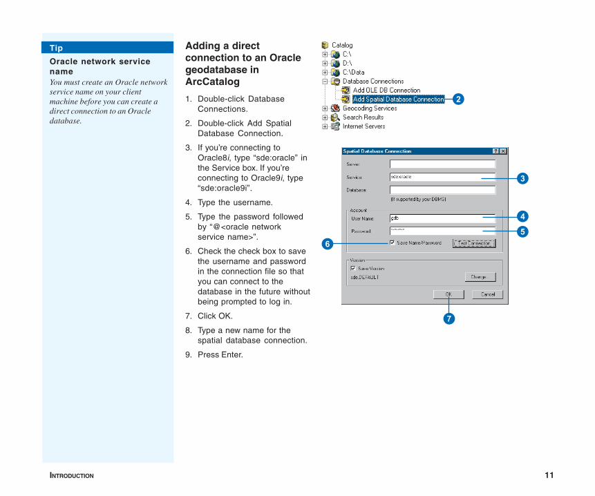
Adding a directconnection to an Oraclegeodatabase inArcCatalog
1. Double-click DatabaseConnections.
2. Double-click Add SpatialDatabase Connection.
3. If you’re connecting toOracle8i, type “sde:oracle” inthe Service box. If you’reconnecting to Oracle9i, type“sde:oracle9i”.
4. Type the username.
5. Type the password followedby “@<oracle networkservice name>”.
6. Check the check box to savethe username and passwordin the connection file so thatyou can connect to thedatabase in the future withoutbeing prompted to log in.
7. Click OK.
8. Type a new name for thespatial database connection.
9. Press Enter.
3
5
7
6
4
Tip
Oracle network servicenameYou must create an Oracle networkservice name on your clientmachine before you can create adirect connection to an Oracledatabase.
2

12 BUILDING A GEODATABASE
Adding a directconnection to aSQL Server geodatabasein ArcCatalog
1. Double-click DatabaseConnections.
2. Double-click Add SpatialDatabase Connection.
3. Type “sde:sqlserver:<nameor the IP Address of theserver>” in the Service box.In this example, the servername is fabio.
4. Type the name of thedatabase you want toconnect to.
5. Type the username andpassword.
6. Check the check box to savethe username and passwordin the connection file so thatyou can connect to thedatabase in the futurewithout being prompted tolog in.
7. Click OK.
8. Type a new name for thespatial database connection.
9. Press Enter.
2
6
7
34
5
INTRODUCTION 13
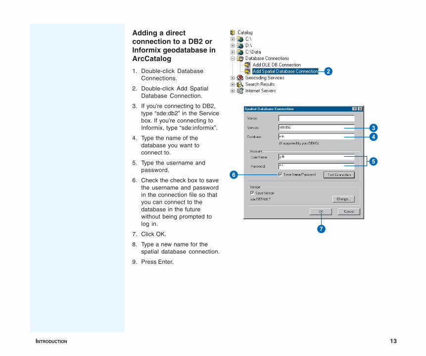
Adding a directconnection to a DB2 orInformix geodatabase inArcCatalog
1. Double-click DatabaseConnections.
2. Double-click Add SpatialDatabase Connection.
3. If you’re connecting to DB2,type “sde:db2” in the Servicebox. If you’re connecting toInformix, type “sde:informix”.
4. Type the name of thedatabase you want toconnect to.
5. Type the username andpassword.
6. Check the check box to savethe username and passwordin the connection file so thatyou can connect to thedatabase in the futurewithout being prompted tolog in.
7. Click OK.
8. Type a new name for thespatial database connection.
9. Press Enter.
2
6
7
34
5
14 BUILDING A GEODATABASE
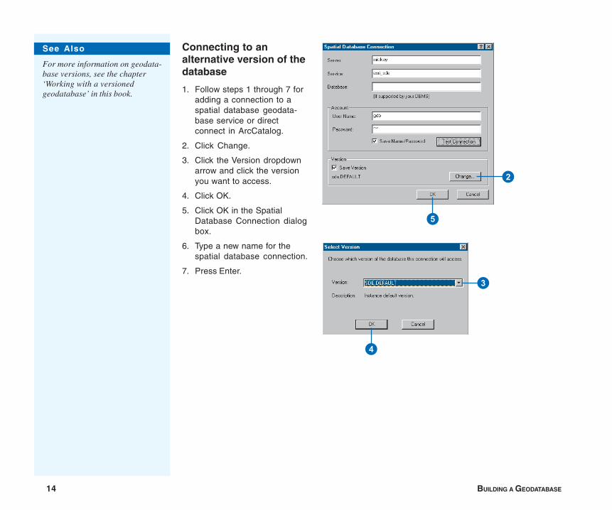
Connecting to analternative version of thedatabase
1. Follow steps 1 through 7 foradding a connection to aspatial database geodata-base service or directconnect in ArcCatalog.
2. Click Change.
3. Click the Version dropdownarrow and click the versionyou want to access.
4. Click OK.
5. Click OK in the SpatialDatabase Connection dialogbox.
6. Type a new name for thespatial database connection.
7. Press Enter.
2
5
3
4
See Also
For more information on geodata-base versions, see the chapter‘Working with a versionedgeodatabase’ in this book.
INTRODUCTION 15
Copying schemafrom anothergeodatabaseA great way to get design ideasfor your new geodatabase is tolook at the design of an existinggeodatabase.
If you want to see someoneelse’s design, ask them toexport their schema to a ZIP fileand send it to you. You canthen import the schema into ageodatabase. Please see theArcGIS online Help system formore information.
Another tool that allows you tocopy schema from anothergeodatabase is the Extract Datawizard in ArcMap. It allows youto modify the spatial referenceof the new schema you create.This is useful because thespatial reference requirementsof your new geodatabase willprobably be different fromthose of the sourcegeodatabase.
Regardless of the method youchoose, the result is a newschema with no data but with allthe feature datasets, featureclasses, tables, topologies,relationships, geometricnetworks, domains, subtypes,indexes, and field propertiesfrom the source geodatabase.
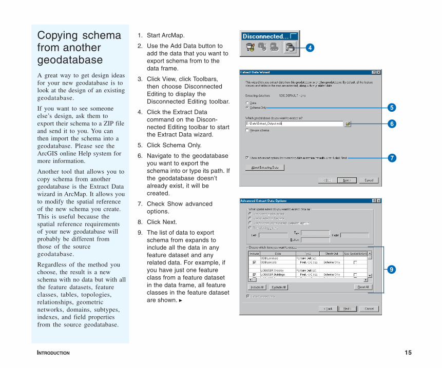
1. Start ArcMap.
2. Use the Add Data button toadd the data that you want toexport schema from to thedata frame.
3. Click View, click Toolbars,then choose DisconnectedEditing to display theDisconnected Editing toolbar.
4. Click the Extract Datacommand on the Discon-nected Editing toolbar to startthe Extract Data wizard.
5. Click Schema Only.
6. Navigate to the geodatabaseyou want to export theschema into or type its path. Ifthe geodatabase doesn’talready exist, it will becreated.
7. Check Show advancedoptions.
8. Click Next.
9. The list of data to exportschema from expands toinclude all the data in anyfeature dataset and anyrelated data. For example, ifyou have just one featureclass from a feature datasetin the data frame, all featureclasses in the feature datasetare shown. u
4
5
6
7
9
16 BUILDING A GEODATABASE
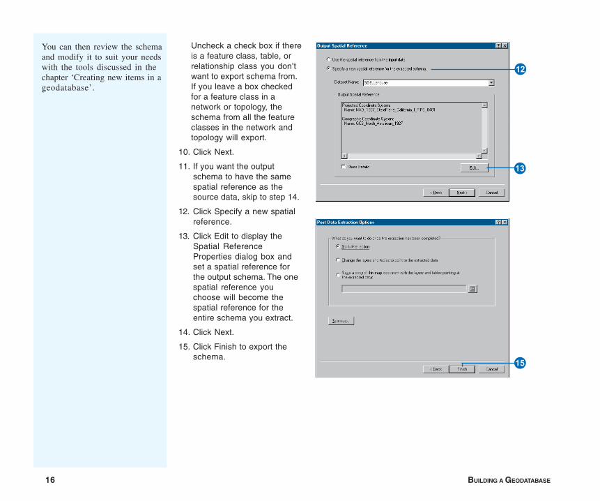
Uncheck a check box if thereis a feature class, table, orrelationship class you don’twant to export schema from.If you leave a box checkedfor a feature class in anetwork or topology, theschema from all the featureclasses in the network andtopology will export.
10. Click Next.
11. If you want the outputschema to have the samespatial reference as thesource data, skip to step 14.
12. Click Specify a new spatialreference.
13. Click Edit to display theSpatial ReferenceProperties dialog box andset a spatial reference forthe output schema. The onespatial reference youchoose will become thespatial reference for theentire schema you extract.
14. Click Next.
15. Click Finish to export theschema.
You can then review the schemaand modify it to suit your needswith the tools discussed in thechapter ‘Creating new items in ageodatabase’.
E
R
Y

INTRODUCTION 17
Tips on learning how to build and edit geodatabases
If you’re new to GIS, you don’t have to know everything aboutArcCatalog, ArcMap, and geodatabases or how to extend thegeneric geodatabase data model to get immediate results. To learnhow to create and edit geodatabases, see the GeodatabaseWorkbook. ArcGIS comes with the data used in the tutorials, soyou can follow along step by step at your computer. You can alsoread the tutorial without using your computer.
Finding answers to questions
If you are like most people, your goal is to complete your taskswhile investing a minimum amount of time and effort on learninghow to use the software. You want intuitive, easy-to-use softwarethat gives you immediate results without having to read pages ofdocumentation. However, when you do have a question, youwant to be able to find the answer quickly so that you cancomplete your task. That’s what this book is all about—gettingyou the answers you need when you need them.
This book describes how to get your existing data into ageodatabase; how to create new items in your geodatabase; andonce created, how to add a variety of behavior to that data andedit it. Although you can read this book from start to finish, youwill likely use it more as a reference. When you want to know howto do a particular task, such as creating a geometric network ortopology, just look it up in the table of contents or index.
What you will find is a concise, step-by-step description of howto complete tasks. Some chapters also include detailedinformation if you want to learn more about the concepts behindthe tasks. Refer to the glossary if you come across any unfamiliarGIS terms or need to refresh your memory.
About this book
This book is designed to introduce how to build and edit ageodatabase. While this book does have some conceptualcontent about the different aspects of the geodatabase, itassumes that you already have a schema design that you aretrying to implement. If you have not yet designed your schema orneed more information on how to make the best schema designdecisions, read Modeling Our World.
Getting help on your computer
In addition to this book, the ArcGIS online Help system is avaluable resource for learning how to use the software.
Contacting ESRI
If you need to contact ESRI for technical support, refer to‘Contacting Technical Support’ in the ‘Getting more help’ sectionof the ArcGIS Desktop Help system. You can also visit ESRI onthe Web at www.esri.com and support.esri.com for moreinformation on the geodatabase and ArcGIS.
ESRI education solutions
ESRI provides educational opportunities related to geographicinformation science, GIS applications, and technology. You canchoose among instructor-led courses, Web-based courses, andself-study workbooks to find educational solutions that fit yourlearning style. For more information, go to www.esri.com/education.

IN THIS CHAPTER
19
Creating new items in a geodatabase 2• Geodatabase items
• ArcGIS data types
• Setting an appropriategeodatabase spatial domain
• Upgrading a geodatabase
• Creating tables
• Creating feature datasets
• Creating feature classes
• Creating indexes
• Granting and revoking privileges
The first step in creating any database is to design the tables it will contain.A good design will ensure that data retrieval is fast and efficient. ModelingOur World discusses the considerations to take into account when you builda geodatabase.
Once your design is complete, you can start using tools in ArcCatalog tocreate tables, feature datasets, and feature classes. After adding data totables and feature classes, you can build indexes for the appropriate fields toimprove query performance. You can also grant and revoke privileges onyour table, feature class, or feature datasets for another database user.
After creating feature classes, tables, and feature datasets, you can refer tofurther chapters in this book to create more advanced items such asrelationship classes, topologies, and geometric networks.
To create raster-based items, such as raster datasets, raster catalogs, orraster attributes, refer to the chapter ‘Building a raster geodatabase’.
ArcView can create simple feature classes and tables in a personalgeodatabase. More advanced geodatabase functionality requires anArcEditor or ArcInfo license.
20 BUILDING A GEODATABASE
Geodatabases organize geographic data into a hierarchy of dataobjects. These data objects are stored in feature classes, objectclasses, and feature datasets. An object class is a table in thegeodatabase that stores nonspatial data. A feature class is acollection of features with the same type of geometry and thesame attributes.
A feature dataset is a collection of feature classes that share thesame spatial reference. Feature classes that store simple featurescan be organized either inside or outside a feature dataset. Simplefeature classes that are outside a feature dataset are calledstandalone feature classes. Feature classes that store topologicalfeatures must be contained within a feature dataset to ensure acommon spatial reference.
ArcCatalog contains tools for creating object classes (tables),feature classes, and feature datasets. Once these items arecreated in the geodatabase, further items such as subtypes,relationship classes, geometric networks, and topologies can alsobe created. These geodatabase items are covered in subsequentchapters.
Spatial reference
When creating a new feature dataset or standalone feature class,you must specify its spatial reference. The spatial reference for afeature class describes its coordinate system (for example,geographic, Universal Transverse Mercator [UTM], and StatePlane), spatial domain, and precision. The spatial domain is bestdescribed as the allowable coordinate range for x,y coordinates,m (measure) values, and z-values. The precision describes thenumber of system units per one unit of measure. A spatialreference with a precision of 1 will store integer values, while aprecision of 1,000 will store three decimal places. Once the spatialreference for a feature dataset or standalone feature class hasbeen set, only the coordinate system can be modified—thespatial domain is fixed.
All feature classes in a feature dataset share the same spatialreference. The spatial reference is an important part ofgeodatabase design because its spatial domain describes themaximum spatial extent to which the data can grow. You must becareful to choose an appropriate x, y, m, and z domain. Forexample, if you create a feature dataset with a minimum z-value of0 and a precision of 1,000, none of the features in the featuredataset can have z-values that are less than 0, and all z-values willbe stored to three decimal places. The same rule applies to x- andy-values. The exception to the rule is m domains; feature classeswithin the same feature dataset can have different m domains.
The spatial domain for a feature class or feature dataset cannot bechanged. If the required x-, y-, m-, or z-value ranges for yourdatabase change, the data has to be reloaded into feature classeswith a spatial reference that accommodates the new value range.
A collection of predefined geographic and projected coordinatesystems is installed with ArcInfo. You can create customcoordinate systems, or you can import a coordinate system froman existing feature class, feature dataset, coverage, or shapefile.You can read more about spatial references and spatial domains inManaging ArcSDE Services and Understanding MapProjections.
Spatial index grid
Much like you use a locator grid on a city map to find a street,ArcMap uses grids to quickly locate features in feature classes.Identifying a feature, selecting features by pointing or dragging abox, and panning and zooming all require ArcMap to use thespatial index grid to locate features.
A feature class can have up to three grids. The size of each mustbe at least three times the previous grid size. For most featureclasses, only a single grid size is required. Feature classes withfeatures of very different sizes may require additional grids sothat larger features can be queried faster.
Geodatabase items
CREATING NEW ITEMS IN A GEODATABASE 21
When you create an empty feature class in ArcCatalog or importdata to create a new feature class, you can choose a default gridsize or specify your own. Once the feature class is created, youcan change the grid size any time.
ArcMap doesn’t use the spatial index grid for feature classes inInformix ArcSDE geodatabases. As other strategies are used tolocate features in Informix, you can ignore the grid size. For amore detailed discussion of spatial indexes and grid sizes, see theArcSDE Configuration and Tuning Guide for <DBMS> PDF file.
Field properties
When you use ArcCatalog to create a new table or feature class,you can specify any number of fields to be included. You canalso specify settings for fields such as the field type and themaximum size of the data that can be stored in it.
Each field type has special properties. All fields have propertydefault values, domains, aliases, and allow nulls. The field aliasproperty will be discussed in the next section. You can set theallow nulls property to No if you do not want the field to storenull values. If you set the allow nulls property to Yes, then thefield will allow null values.
Use the default value property if you want the field to beautomatically populated with a default value when a new featureor object is created with the ArcMap editing tools. You can set adomain, which is a valid set or range of values that can be storedin the field by using the domain property. Default values anddomains are discussed in detail in the ‘Subtypes and attributedomains’ chapter.
The exceptions are fields of type ObjectID, binary large object(BLOB), GlobalID, and Geometry which do not have a defaultvalue or domain property. Alias is the only property of theObjectID and GlobalID fields you can modify, while BLOB andGeometry fields have special properties you can modify.
The properties of a Geometry field describe the kind of featuresthat can be stored in a feature class, the size of the spatial index,and the spatial reference for the features.
Field precision and scale
The precision and scale of a field describe the maximum size andprecision of data that can be stored in it. The precision describesthe number of digits that can be stored in the field, while the scaledescribes the number of decimal places for float and doublefields. When creating a new field in a geodatabase feature classor table, you can specify the field’s type, precision, and scale.When the field is actually created in the database, the field typemay be changed based on the precision and scale values youspecify.
Use the following guidelines for choosing the correct field typefor a given precision and scale:
• When you create a float, double, or integer field and specify 0for precision and scale, the geodatabase will attempt to createa binary type field if the underlying database supports it.Personal geodatabases support only binary type fields, andprecision and scale are ignored.
• When you create float and double fields and specify aprecision and scale, if your precision is greater than 6, use adouble; otherwise, use a float. If you create a double field andspecify a precision of 6 or less, a float field is created in thedatabase. If you create a float field and specify a precisiongreater than 6, a double field is created.
• If you specify a scale of 0 and a precision of 10 or less, youshould be creating integer fields. When creating integer fields,your precision should be 10 or less or your field may becreated as double.
22 BUILDING A GEODATABASE
Required fields
All tables and feature classes have a set of required fields that arenecessary to record the state of any particular object in the tableor feature class. These required fields are automatically createdwhen you create a new feature class or table and they cannot bedeleted. Required fields may also have required properties suchas their domain property. You cannot modify the requiredproperty of a required field.
For example, in a simple feature class, OBJECTID and Shape arerequired fields. They do have properties you can modify, such astheir aliases and geometry type, but these fields cannot bedeleted.
Some types of feature classes have a number of required fields;for more information, see the chapters ‘Managing annotation’,‘Geometric networks’, and ‘Topology’ in this book.
Field, table, and feature class aliases
The names of feature classes and tables in a geodatabase are thesame as the names of the physical tables in the DBMS in whichthey are stored. When storing data in a DBMS, often the namesfor tables and fields are cryptic, and you require a detailed datadictionary to keep track of what data each table stores and whateach field in those tables represents. For example, your databasemay have a feature class called “Pole” that has a field called“HGT”. Without consulting your data dictionary, you may have adifficult time determining that Pole stores utility poles and HGThas values for pole heights.
The geodatabase provides the ability to create aliases for fields,tables, and feature classes. An alias is an alternative name to referto those objects. Unlike true names, aliases do not have to adhere
to the limitations of the database, so they can contain specialcharacters such as spaces. In the above example, you may set thealias for the Pole table to “Utility Poles” and the alias for the HGTfield to “Height”. In ArcMap, when using data with aliases, thealias name is automatically used for feature classes, tables, andfields. However, in ArcCatalog these objects are alwaysrepresented by their true names. You can view the alias for featureclasses, tables, and fields by examining their properties.
Aliases can be specified when creating a feature class or tableand can be modified at any time. Similarly, when creating newfields, the alias is set as a property of that field and can bemodified at any time.
Tracking properties of geometry
Often when working with spatial data, you may want to queryyour data based on properties of the geometry. For example, youmay want to query the water mains feature class for all mains thatare more than 50 feet in length. Doing this by examining eachgeometry and calculating its length can be a slow process,especially if there is a large number of water mains in the featureclass. To make this more efficient, the feature class has specialfields that track this kind of information about the geometry ofyour features.
Line feature classes have a field that tracks the features’ length,while polygon feature classes have fields that track both thefeatures’ area and perimeter. When changes are made to thegeometry, the values in these fields are automatically updated.These fields behave similar to other fields, except that you cannotdelete them, assign default values and attribute domains to them,or assign values to them while editing in ArcMap.
When you create a new feature class in a personal geodatabase,these fields will not be displayed in the fields panel of the wizard.However, when you open the properties dialog box for a polygon
CREATING NEW ITEMS IN A GEODATABASE 23
feature class, you will see fields named Shape_Area andShape_Length that store the area and perimeter of the geometry.When you open the properties dialog box for a line feature class,you will see a field named Shape_Length that stores the length ofthe geometry. Point and multipoint feature classes do not haveeither field.
When you create a new feature class in an ArcSDE geodatabase,these fields will be called SHAPE.AREA and SHAPE.LEN,respectively.
In ArcMap, these fields behave as any other field in the identifywindow, the layer properties dialog box, the attribute table dialogbox, and the query builder. For more information on these aspectsof ArcMap, see Using ArcMap.
Feature datasets
Feature datasets exist in the geodatabase to define a scope for aparticular spatial reference. All feature classes that participate intopological relationships with one another, for example, ageometric network or a topology, must have the same spatialreference. Feature datasets are a way to group feature classeswith the same spatial reference so they can participate intopological relationships with each other.
Feature datasets also have a natural organizational quality, muchlike a folder on a file system. Since for many GIS applications themajority of the data for a particular database has the same spatialreference, it is possible to use feature datasets as organizationalcontainers.
Bear in mind that topologically related feature classes must residein the same feature dataset. If you are interested in organizingfeature classes purely by category, you can arrange layer filesinto logical groups within folders at a shared location, withoutregard to the organization of the feature classes in thegeodatabase.
Topologies
Many vector datasets have features that could share boundariesor corners. If you create a topology in the dataset, you can set uprules defining how features share their geometry. Editing aboundary or vertex shared by two or more features updates theshape of each of those features. Topology rules can govern therelationships between features within a single feature class orbetween features in two different feature classes. For example,moving a slope boundary in one feature class could update twoslope-class polygons and also update the boundary of a foreststand in another feature class.
Topologically associated feature classes in a geodatabase arestored in a feature’s dataset with a topology. The feature classesremain simple feature classes, and the topology manages therules that control how features can be spatially related. You canuse the topological editing tools in ArcMap to maintain thetopological associations of features.
To learn more about topologies, see the chapter ‘Topology’ inthis book.
For more information about topology in general, see ModelingOur World.
Geometric networks
Some vector datasets, particularly those used to modelcommunications, material or energy flow, or transportationnetworks, need to support connectivity tracing and networkconnectivity rules. Geometric networks allow you to turn simplepoint and line features into network edge and junction featuresthat can be used for network analysis. Connectivity rules ofgeometric networks let you control what types of networkfeatures may be connected together when editing the network.Geometric networks, like topologies, must be created from a set offeature classes in the same feature dataset.
24 BUILDING A GEODATABASE
To learn more about geometric networks, see the ‘Geometricnetworks’ chapter in this book.
For more information about geometric networks in general, seeModeling Our World.
Relationship classes
Relationship classes define relationships between objects in thegeodatabase. These relationships can be simple one-to-onerelationships, such as you might create between a feature and arow in a table, or more complex one-to-many (or many-to-many)relationships between features and table rows. Somerelationships specify that a given feature, row, or table is not onlyrelated to another, but that creating, editing, or deleting one willhave a specified effect on the other. These are compositerelationships and they can be used to ensure the links betweenobjects in the database are maintained and up to date. Deleting afeature, such as a power pole, can trigger the deletion of otherfeatures, such as a transformer mounted on the pole or themaintenance records in a related table.
To learn more about relationship classes, see the ‘Definingrelationship classes’ chapter in this book.
Schema locking
In multiuser databases, more than one user may be reading andediting the same data at the same time. To be able to work withdata in a geodatabase for applications such as ArcMap, theapplication must assume that the schema for that data is fixedwhile it is working with it.
For example, when you add a feature class from a geodatabase toyour map, its schema cannot be altered by you or another user.Once you have removed the feature class from your map and noother users are querying or editing that feature class, its schemacan be altered.
ArcMap, ArcCatalog, and other applications written with theArcGIS Component Object Model (COM) components willautomatically acquire a shared lock when editing or querying thecontents of a geodatabase feature class or table. Any number ofshared locks can be acquired on a single feature class or table atone time. When using ArcCatalog to modify schema—add a field,alter rules, and so on—the application will attempt to acquire anexclusive lock on the data being altered.
An exclusive lock can only be acquired if no other locks—sharedor exclusive—are already on the data. If there are already otherlocks on the feature class or table, ArcCatalog will not be able toestablish its exclusive lock, and the schema will not be editable.Once an exclusive lock has been acquired, no shared locks can beapplied, so the data will not be accessible in ArcMap orArcCatalog by another user.
Exclusive locks can only be acquired by the owner of the featureclass or table being modified and, therefore, only the owner canever modify the schema of an item in a geodatabase. Some of theitems that exist in a geodatabase—which are discussed in furtherchapters, such as geometric networks, relationship classes,topologies, and so on—have special schema-locking behaviors.Each of these is discussed in its own respective chapter.
Schema locking in personal geodatabases works in much thesame way except the locks are databasewide. Once an exclusiveor shared lock is acquired on an item in a personal geodatabase,that lock applies to all items in the geodatabase.

CREATING NEW ITEMS IN A GEODATABASE 25
When creating tables, you will need to select a data type for eachfield in your table. The available types include a variety ofnumber types, text, date, BLOB, or globally unique identifier(GUID). Choosing the correct data type allows you to correctlystore the data and will facilitate your analysis, data management,and business needs.
Numeric data types
Numeric fields can be stored as one of four numeric data types.These include short integers; long integers; single-precisionfloating point numbers, often referred to as floats; and double-precision floating point numbers, commonly called doubles. Eachof these numeric data types varies in the size and method ofstoring a numeric value.
In numeric data storage, it is important to understand thedifference between decimal and binary numbers. The majority ofpeople are accustomed to decimal numbers, a series of digitsbetween 0 and 9 with negative or positive values and the possibleplacement of a decimal point. On the other hand, computers storenumbers as binary numbers. A binary number is simply a series of0s and 1s. In the different numeric data types, these 0s and 1srepresent different coded values, including the positive ornegative nature of the number, the actual digits involved, and theplacement of a decimal point. Understanding this type of numberstorage will help you make the correct decision in choosingnumeric data types.
The most basic numeric data type is the short integer. This typeof numeric value is stored as a series of 16 0s or 1s, commonlyreferred to as 16 bits. Eight bits are referred to as a byte, thus ashort integer takes up two bytes of data. One bit states whetherthe number is positive or negative, and the remaining 15 translateto a numeric value with five significant digits. The actual numericvalue for a short integer is approximately between -32,000 and
+32,000. A long integer is a four-byte number. Again, one bitstores the positive or negative nature of the number, while theremaining bits translate to a numeric value with 10 significantdigits. The actual range for a long integer is approximatelybetween -2 billion and +2 billion. Both short and long integers canstore only real numbers. That is to say that you cannot havefractions, or numbers, to the right of the decimal place. To storedata with decimal values, you will need to use either a float or adouble.
A float and double are both binary number types that store thepositive or negative nature of the number, a series of significantdigits, and a coded value to define the placement of a decimalpoint. This is referred to as the exponent value. Floats anddoubles are coded in a format similar to scientific notation. Forexample, if you wanted to represent the number -3,125 in scientificnotation, you would say -3.125x10³ or -3.125E3. The binary codewould break this number apart and assign one bit to state that itis a negative number; another series of bits would define thesignificant digits 3125; another bit would indicate whether theexponent value is positive or negative; and the final series of bitswould define the exponent value of 3. A float is a four-bit numberand can store up to seven significant digits, producing anapproximate range of values between -3.4E-38 to -1.2E38 fornegative numbers and from 3.4E-38 to 1.2E38 for positive numbers.A double is an eight-byte number and can store up to15 significant digits, producing an approximate range of valuesbetween -2.2E-308 to -1.8E308 for negative numbers and 2.2E-308 to1.8E308 for positive numbers.
It is important to note, however, that floats and doubles areapproximate numbers. This is due to two factors. First, thenumber of significant digits is a limiting factor. For example, youcould not express the number 1,234,567.8 as a float because thisnumber contains more than the permissible seven digits. In orderto store the number as a float, it will be rounded to 1,234,568, a
ArcGIS data types
26 BUILDING A GEODATABASE
number containing the permissible seven digits. This numbercould easily be expressed as a double, as it contains less than thepermissible 15 significant digits. There are also some limitationsto numbers a binary value can represent. One analogy that can bemade would be in expressing fractions versus decimals. Thefraction 1/3 represents a particular value. However, if you try toexpress this number as a decimal, the number will need to berounded at some point. It could be expressed as 0.3333333,however, this is still an approximation of the actual value. Just asfractions cannot always be expressed as decimals, some numberscannot be exactly expressed in binary code, and these numbersare replaced by approximate values. One example of such anumber is 0.1. This number cannot be expressed as a binarynumber. However, the number 0.099999 can be expressed inbinary. Thus 0.1 would be replaced with an approximate value of0.099999.
In choosing the numeric data type, there are two things toconsider. First, it is always best to use the smallest byte size datatype needed. This will not only minimize the amount of storagerequired for your geodatabase but will also improve theperformance. You should also consider the need for exactnumbers versus approximate numbers. For example, if you need toexpress a fractional number and seven significant digits willsuffice, use a float. However, if the number must be more precise,choose a double. If the field values will not include fractionalnumbers, choose either a short or long integer.
Text fields
A text field represents a series of alphanumeric symbols. This caninclude street names, attribute properties, or other textualdescriptions. An alternative to using repeating textual attributesis to establish a coded value. A textual description would becoded with a numeric value. For example, you might code roadtypes with numeric values assigning a 1 to paved improved
roads, a 2 to gravel roads, and so on. This has the advantage ofusing less storage space in the geodatabase; however, the codedvalues must be understood by the data user. If you define yourcoded values in a coded value domain in the geodatabase andassociate the domain with the integer field storing your codes,the geodatabase will display the textual description when thetable is viewed in ArcMap or ArcCatalog. For more information oncoded value domains, see the chapter ‘Subtypes and attributedomains’ in this book.
Date fields
The date data type can store dates, times, or date and times. Thedefault format in which the information is presented is mm/dd/yyyy hh:mm:ss and a specification of AM or PM. When youenter date fields in the table, they will be converted to this format.
BLOB fields
A binary large object is simply some data stored in thegeodatabase as a long sequence of binary numbers. Items suchas images, multimedia, or bits of code can be stored in this type offield.
Global identifier fields
GlobalID and GUID data types store registry style strings thatuniquely identify a feature or table row within a geodatabase andacross geodatabases. Developers can use them in relationshipsor in any application requiring globally unique identifiers. In arelationship, if a GlobalID field is the origin key, a GUID field mustbe the destination key. You must add the GlobalID fieldprogrammatically; however, once you add it ArcGIS maintains itsvalues. You can create the GUID field in ArcCatalog, but youmust maintain its values.
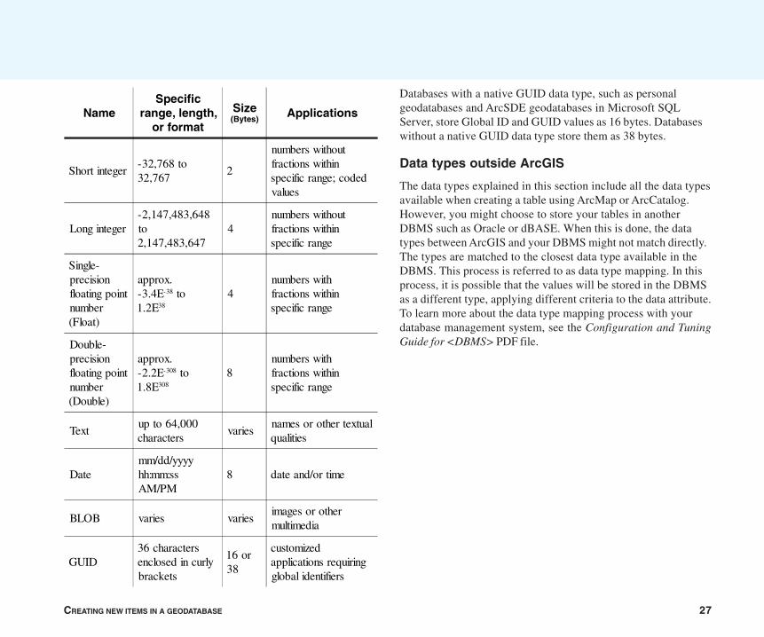
CREATING NEW ITEMS IN A GEODATABASE 27
Databases with a native GUID data type, such as personalgeodatabases and ArcSDE geodatabases in Microsoft SQLServer, store Global ID and GUID values as 16 bytes. Databaseswithout a native GUID data type store them as 38 bytes.
Data types outside ArcGIS
The data types explained in this section include all the data typesavailable when creating a table using ArcMap or ArcCatalog.However, you might choose to store your tables in anotherDBMS such as Oracle or dBASE. When this is done, the datatypes between ArcGIS and your DBMS might not match directly.The types are matched to the closest data type available in theDBMS. This process is referred to as data type mapping. In thisprocess, it is possible that the values will be stored in the DBMSas a different type, applying different criteria to the data attribute.To learn more about the data type mapping process with yourdatabase management system, see the Configuration and TuningGuide for <DBMS> PDF file.
NameSpecific
range, length,or format
Size(Bytes)
Applications
Short integer-32,768 to32,767
2
numbers withoutfractions withinspecific range; codedvalues
Long integer-2,147,483,648to2,147,483,647
4numbers withoutfractions withinspecific range
Single-precisionfloating pointnumber(Float)
approx.-3.4E-38 to1.2E38
4numbers withfractions withinspecific range
Double-precisionfloating pointnumber(Double)
approx.-2.2E-308 to1.8E308
8numbers withfractions withinspecific range
Textup to 64,000characters
variesnames or other textualqualities
Datemm/dd/yyyyhh:mm:ssAM/PM
8 date and/or time
BLOB varies variesimages or othermultimedia
GUID36 charactersenclosed in curlybrackets
16 or38
customizedapplications requiringglobal identifiers
28 BUILDING A GEODATABASE
Setting an appropriate geodatabase spatial domain
For spatial data to be appropriately stored and referenced to alocation on the earth, it must have a spatial reference composedof a coordinate system and precision. The coordinate system(geographic or projected) defines the location of the spatial dataon the earth. For example, using the GCS_North_American_1983geographic coordinate system, ESRI headquarters are located at-117.195533 longitude and 34.057058 latitude. Precision definesthe level of detail that is maintained when data values are storedin the geographic database. For example, if you store the abovecoordinates and your precision only maintains two decimalplaces, the values -117.20, 34.06 (rounded) would be stored in thegeographic database. If these coordinates are rounded to twodecimal places, the point would represent an ellipse on the earth’ssurface of 1,109 by 923 meters. Therefore, careful considerationshould be given to choosing an appropriate data precision tomaintain the precision of your data collection.
For information on choosing an appropriate coordinate system,see the Map projections topic in the ArcGIS Desktop Help. Therest of this topic discusses how to set the geodatabase precisionaspect of the spatial reference. The first section discusses thefundamentals of geodatabase precision. The second sectiondiscusses different approaches for calculating precisionappropriate for your data.
About geodatabase precision
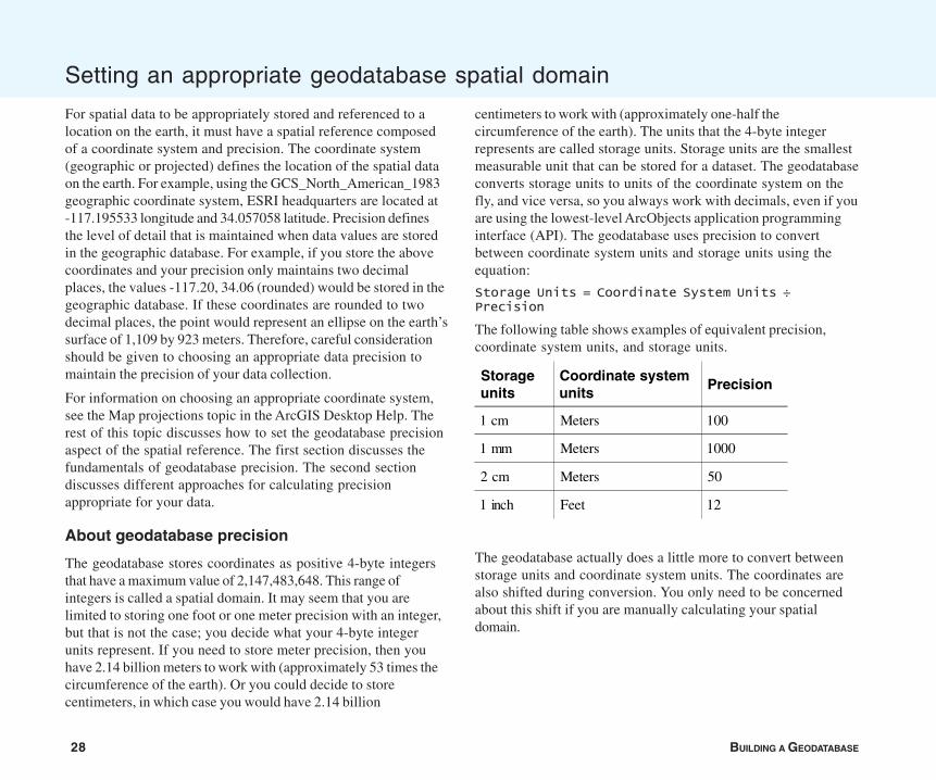
The geodatabase stores coordinates as positive 4-byte integersthat have a maximum value of 2,147,483,648. This range ofintegers is called a spatial domain. It may seem that you arelimited to storing one foot or one meter precision with an integer,but that is not the case; you decide what your 4-byte integerunits represent. If you need to store meter precision, then youhave 2.14 billion meters to work with (approximately 53 times thecircumference of the earth). Or you could decide to storecentimeters, in which case you would have 2.14 billion
centimeters to work with (approximately one-half thecircumference of the earth). The units that the 4-byte integerrepresents are called storage units. Storage units are the smallestmeasurable unit that can be stored for a dataset. The geodatabaseconverts storage units to units of the coordinate system on thefly, and vice versa, so you always work with decimals, even if youare using the lowest-level ArcObjects application programminginterface (API). The geodatabase uses precision to convertbetween coordinate system units and storage units using theequation:
Storage Units = Coordinate System Units ÷Precision
The following table shows examples of equivalent precision,coordinate system units, and storage units.
Storageunits
Coordinate systemunits
Precision
1 cm Meters 100
1 mm Meters 1000
2 cm Meters 50
1 inch Feet 12
The geodatabase actually does a little more to convert betweenstorage units and coordinate system units. The coordinates arealso shifted during conversion. You only need to be concernedabout this shift if you are manually calculating your spatialdomain.
CREATING NEW ITEMS IN A GEODATABASE 29
Spatial domain extent
The relationship is inverse between the precision and the domainextent (the area you can store). Because you have 2.14 billionintegers, there is an outer edge for the spatial domain. As yourstorage units get smaller (and precision gets larger) the extent ofyour spatial domain also gets smaller. If you attempt to addfeatures outside the spatial domain, you will get the followingerror: “The coordinates or measures are out of bounds.” So it isimportant that you do not make your storage units so small, andtherefore, your precision so large, that you will not be able to addfeatures for your entire study area. With approximately 2.14 billionstorage units to work with, you can avoid this problem by simplysetting the precision appropriately. For example, you can store theentire world with 1-meter storage units but only half the worldwith 1-cm storage units. Using a decimal degree-basedgeographic coordinate system such as NAD 1983, you could use1.9-cm storage units for the entire world in a single feature class.
Benefits of storing integers
Performance is the reason the geodatabase uses integer storageinstead of floating point storage. Internally, integer coordinatesallow the geodatabase to perform spatial operations severalorders of magnitude faster than operations using decimalcoordinates. Also, integers can be compressed to consume fewerstorage resources, producing better performance. Only enterprise(ArcSDE) geodatabases take advantage of integer compression,so this storage benefit does not apply to personal geodatabases.ArcSDE uses relative offset compression of the integercoordinate values to minimize storage resources. As the precisionbecomes larger, the relative offsets between coordinates will getlarger, thereby increasing the storage requirements.
How to set the spatial domain
Before you create a spatial domain, there are three things toconsider:
1. Will the precision of the data maintain the precision of yourdata collection?
2. Will the spatial domain cover the entire extent of your studyarea?
3. Is the precision small enough to maximize integer compression(enterprise geodatabases only)?
You don’t always need to worry about all these issues. Manytimes you can let the default settings generated by the softwaredeal with these issues for you. Below are three differentapproaches to creating a spatial domain. Choose the one that ismost appropriate for your application.
A. Accept the defaults when importing data.
B. Define a spatial domain by setting the extent and maximizingthe precision.
C. Define a spatial domain by manually calculating yourprecision and extent.
Approach A: Accepting the defaults whenimporting data
This is the easiest of the approaches. You simply take the defaultspatial domain generated by the software.
Use this approach if you
• Have at least one vector dataset or a group of tiled datasetsthat covers the entire extent of your study area.
• Want the most precision possible within your study area.
30 BUILDING A GEODATABASE
If you have a dataset that covers the entire study area, import thedataset first and accept the default values for the spatial domain.The defaults will create a domain that encompasses all of thefeatures with a little room to grow. If you have tiled datasets thattogether cover the entire study area, calculate a spatial domainthat encompasses all of the datasets using the Create SpatialReference tool. Then, create an empty feature class with thisspatial domain and load the tiled data into it.
Using this method, the precision will be maximized within thedefault extent. Because the resulting precision could be verylarge, this would not be the best approach if you are trying tomaximize your ArcSDE geodatabase’s performance. However, thisapproach will ensure that all your data will fit inside the spatialdomain and that you are using the highest precision possible foryour data.
As you create or import subsequent datasets to the geodatabase,use the spatial reference calculated from this original featureclass. You can do this by importing the spatial reference from thisfeature class whenever you create new feature classes or featuredatasets. You can also set your geoprocessing settings to use thespatial reference from this feature class.
Setting the geoprocessing environment to use aspecific spatial reference
1. In ArcCatalog or ArcMap, from the Tools menu, click Options.
2. Click the Geoprocessing tab.
3. Click the Environments button.
4. Expand General Settings.
5. For Output Spatial Reference, click As Specified Below.
6. Next to the following input box, click the folder icon.
7. On the Coordinate System tab, click Import.
8. Navigate to and select the first feature class that you importedinto the geodatabase.
9. Click Add.
10. Click OK on all the open dialog boxes.
Now all subsequent geoprocessing operations, including newdata imports performed by the current user on this machine, willuse this spatial reference.
Approach B: Defining a spatial domain by settingthe extent and maximizing the precision
This approach helps you determine an extent for your study area,then maximizes the precision within that study area.
Use this approach if you
• Do not have a single vector dataset that covers the extent ofyour study area, but you can define your study area on a map.
• Want the most precision possible within your study area.
The result of this approach will be exactly the same as ApproachA; therefore, this approach has the same strengths andweaknesses. Before you can begin, you must know whichcoordinate system you plan to use. For information on choosinga coordinate system, see the Map projections topic in the ArcGISDesktop Help. If you plan to use the State Plane or UTMcoordinate systems, you can find data defining the zone locationsat <ArcGIS Installation location>\ArcGIS\Reference Systems inthe usstpln83 and utm shapefiles.
CREATING NEW ITEMS IN A GEODATABASE 31
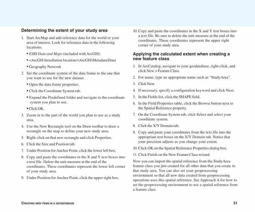
Determining the extent of your study area
1. Start ArcMap and add reference data for the world or yourarea of interest. Look for reference data in the followinglocations:
• ESRI Data and Maps (included with ArcGIS)
• <ArcGIS Installation location>\ArcGIS\Metadata\Data
• Geography Network
2. Set the coordinate system of the data frame to the one thatyou want to use for the new dataset.
• Open the data frame properties.
• Click the Coordinate System tab.
• Expand the Predefined folder and navigate to the coordinate system you plan to use.
• Click OK.
3. Zoom in to the part of the world you plan to use as a studyarea.
4. Use the New Rectangle tool on the Draw toolbar to draw arectangle on the map to define your new study area.
5. Right-click on that new rectangle and click Properties.
6. Click the Size and Position tab.
7. Under Position for Anchor Point, click the lower left box.
8. Copy and paste the coordinates in the X and Y text boxes intoa text file. Delete the unit measure at the end of thecoordinates. These coordinates represent the lower left cornerof your study area.
9. Under Position for Anchor Point, click the upper right box.
10. Copy and paste the coordinates in the X and Y text boxes intoa text file. Be sure to delete the unit measure at the end of thecoordinates. These coordinates represent the upper rightcorner of your study area.
Applying the calculated extent when creating anew feature class
1. In ArcCatalog, navigate to your geodatabase, right-click, andclick New > Feature Class.
2. For name, type an appropriate name such as “StudyArea”.
3. Click Next.
4. If necessary, specify a configuration keyword and click Next.
5. In the Fields list, click the SHAPE field.
6. In the Field Properties table, click the Browse button next tothe Spatial Reference property.
7. On the Coordinate System tab, click Select and select yourcoordinate system.
8. Click the X/Y Domain tab.
9. Copy and paste your coordinates from the text file into theappropriate text boxes on the X/Y Domain tab. Notice thatyour precision adjusts as you change your extent.
10. Click OK on the Spatial Reference Properties dialog box.
11. Click Finish on the New Feature Class wizard.
Now you can import the spatial reference from the StudyAreafeature class you just created for all other data that you create inthat study area. You can also set your geoprocessingenvironment so that all new data created from geoprocessingoperations uses this spatial reference. See Approach A for how toset the geoprocessing environment to use a spatial reference froma feature class.
32 BUILDING A GEODATABASE
Approach C: Defining the spatial domain bymanually calculating your precision and extent
For this approach, you calculate the spatial domain parametersmanually. Use this approach if you want to optimize performancein an ArcSDE geodatabase.
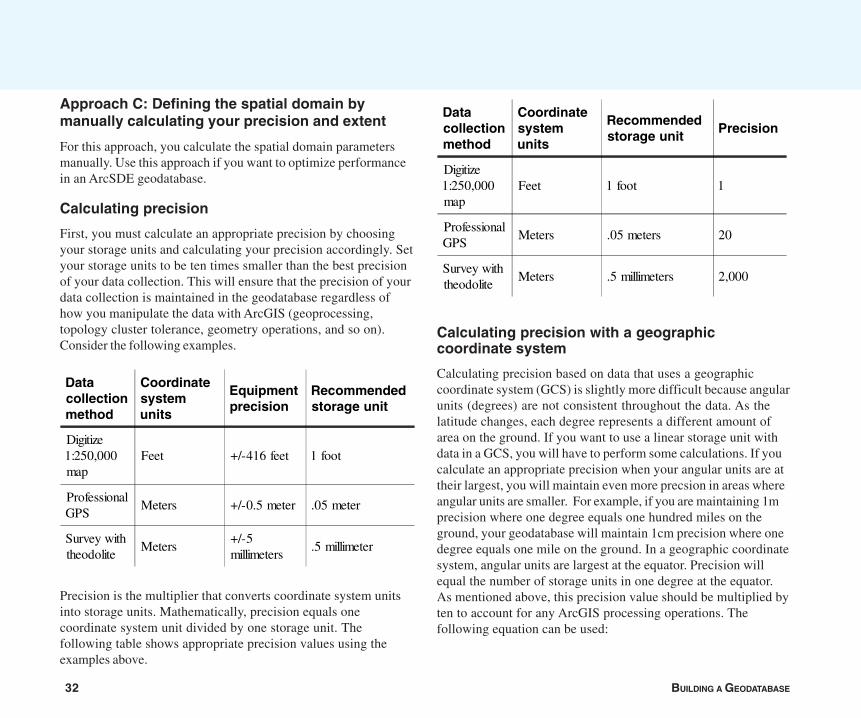
Calculating precision
First, you must calculate an appropriate precision by choosingyour storage units and calculating your precision accordingly. Setyour storage units to be ten times smaller than the best precisionof your data collection. This will ensure that the precision of yourdata collection is maintained in the geodatabase regardless ofhow you manipulate the data with ArcGIS (geoprocessing,topology cluster tolerance, geometry operations, and so on).Consider the following examples.
Precision is the multiplier that converts coordinate system unitsinto storage units. Mathematically, precision equals onecoordinate system unit divided by one storage unit. Thefollowing table shows appropriate precision values using theexamples above.
Calculating precision with a geographiccoordinate system
Calculating precision based on data that uses a geographiccoordinate system (GCS) is slightly more difficult because angularunits (degrees) are not consistent throughout the data. As thelatitude changes, each degree represents a different amount ofarea on the ground. If you want to use a linear storage unit withdata in a GCS, you will have to perform some calculations. If youcalculate an appropriate precision when your angular units are attheir largest, you will maintain even more precsion in areas whereangular units are smaller. For example, if you are maintaining 1mprecision where one degree equals one hundred miles on theground, your geodatabase will maintain 1cm precision where onedegree equals one mile on the ground. In a geographic coordinatesystem, angular units are largest at the equator. Precision willequal the number of storage units in one degree at the equator.As mentioned above, this precision value should be multiplied byten to account for any ArcGIS processing operations. Thefollowing equation can be used:
Datacollectionmethod
Coordinatesystemunits
Recommendedstorage unit
Precision
Digitize1:250,000map
Feet 1 foot 1
ProfessionalGPS
Meters .05 meters 20
Survey withtheodolite
Meters .5 millimeters 2,000
Datacollectionmethod
Coordinatesystemunits
Equipmentprecision
Recommendedstorage unit
Digitize1:250,000map
Feet +/-416 feet 1 foot
ProfessionalGPS
Meters +/-0.5 meter .05 meter
Survey withtheodolite
Meters+/-5millimeters
.5 millimeter
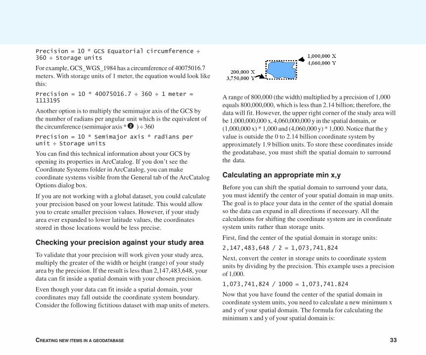
CREATING NEW ITEMS IN A GEODATABASE 33
Precision = 10 * GCS Equatorial circumference ÷360 ÷ Storage units
For example, GCS_WGS_1984 has a circumference of 40075016.7meters. With storage units of 1 meter, the equation would look likethis:
Precision = 10 * 40075016.7 ÷ 360 ÷ 1 meter =1113195
Another option is to multiply the semimajor axis of the GCS bythe number of radians per angular unit which is the equivalent ofthe circumference (semimajor axis * 2ð) ÷ 360
Precision = 10 * Semimajor axis * radians perunit ÷ Storage units
You can find this technical information about your GCS byopening its properties in ArcCatalog. If you don’t see theCoordinate Systems folder in ArcCatalog, you can makecoordinate systems visible from the General tab of the ArcCatalogOptions dialog box.
If you are not working with a global dataset, you could calculateyour precision based on your lowest latitude. This would allowyou to create smaller precision values. However, if your studyarea ever expanded to lower latitude values, the coordinatesstored in those locations would be less precise.
Checking your precision against your study area
To validate that your precision will work given your study area,multiply the greater of the width or height (range) of your studyarea by the precision. If the result is less than 2,147,483,648, yourdata can fit inside a spatial domain with your chosen precision.
Even though your data can fit inside a spatial domain, yourcoordinates may fall outside the coordinate system boundary.Consider the following fictitious dataset with map units of meters.
A range of 800,000 (the width) multiplied by a precision of 1,000equals 800,000,000, which is less than 2.14 billion; therefore, thedata will fit. However, the upper right corner of the study area willbe 1,000,000,000 x, 4,060,000,000 y in the spatial domain, or(1,000,000 x) * 1,000 and (4,060,000 y) * 1,000. Notice that the yvalue is outside the 0 to 2.14 billion coordinate system byapproximately 1.9 billion units. To store these coordinates insidethe geodatabase, you must shift the spatial domain to surroundthe data.
Calculating an appropriate min x,y
Before you can shift the spatial domain to surround your data,you must identify the center of your spatial domain in map units.The goal is to place your data in the center of the spatial domainso the data can expand in all directions if necessary. All thecalculations for shifting the coordinate system are in coordinatesystem units rather than storage units.
First, find the center of the spatial domain in storage units:
2,147,483,648 / 2 = 1,073,741,824
Next, convert the center in storage units to coordinate systemunits by dividing by the precision. This example uses a precisionof 1,000.
1,073,741,824 / 1000 = 1,073,741.824
Now that you have found the center of the spatial domain incoordinate system units, you need to calculate a new minimum xand y of your spatial domain. The formula for calculating theminimum x and y of your spatial domain is:

34 BUILDING A GEODATABASE
Min X = ([DataMinX + DataMaxX] / 2) - Domaincenter in coordinate system units
Min Y = ([DataMinY + DataMaxY] / 2) - Domaincenter in coordinate system units
This equation finds the minimum coordinates of your spatialdomain to locate the center of your data at the center of thedomain. Remember, all these calculations are in coordinate systemunits. Examine this equation for the x dimension given theexample data:
First, find the center of your data.
(DataMinX + DataMaxX) ÷ 2
(200,000 + 1,000,000) ÷ 2 = 600,000
Next, find the difference between the center of your data and thecenter of the geodatabase space.
Min X = 600,000 – 1,073,741.824 = -473,741.824
Because this is a negative number, the spatial domain will shift tothe left. Remember, the shift is applied to the spatial domain, notthe data. The shift is calculated for both dimensions, so youwould need to repeat this process for the y coordinates.
Using your calculated spatial domain inArcCatalog
Once you have calculated an appropriate spatial domain, you areready to create spatial data in the geodatabase. When creatingyour first dataset, navigate to the X/Y Domain tab of the spatialreference properties and enter the Min X, Min Y, and precisionvalues that you calculated. The maximum x and y values will becalculated automatically. For all subsequent data that you importor create, you can simply import this spatial reference. You canalso set your geoprocessing environment so that all new datacreated from geoprocessing operations uses this spatialreference. See Approach A for how to set the geoprocessingenvironment to use a spatial reference from a feature class.
Defining Z and M spatial domains
The z and m domains are easier to calculate than the x and ydomains. Examine your data and enter the lowest value for theminimum value and the precision to support its accuracy. You cancalculate z and m precision the same way you calculated precisionfor the x and y coordinates. Just like x and y coordinates, youhave 2,147,483,648 storage units to work with. Generally it is notnecessary to center the z and m domains about the data as youcan set an absolute minimum based on your data.
When calculating the minimum for a z domain, you could use thelowest point on the earth (-11,033 meters, located at the MarianaTrench off the coast of Japan). Generally m coordinates arepositive numbers, so a minimum value of 0 may be appropriate.You may also set the minimum m to have a slight negative offsetto account for negative values that could be produced by theextrapolation of measures during operations like Calibrate. Thesenegative values could be corrected later instead of rejectedduring the extrapolation.
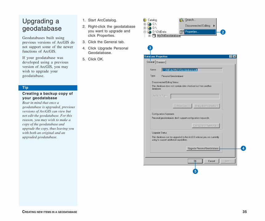
CREATING NEW ITEMS IN A GEODATABASE 35
Upgrading ageodatabaseGeodatabases built usingprevious versions of ArcGIS donot support some of the newerfunctions of ArcGIS.
If your geodatabase wasdeveloped using a previousversion of ArcGIS, you maywish to upgrade yourgeodatabase.
1. Start ArcCatalog.
2. Right-click the geodatabaseyou want to upgrade andclick Properties.
3. Click the General tab.
4. Click Upgrade PersonalGeodatabase.
5. Click OK.
2
3
4
5
Tip
Creating a backup copy ofyour geodatabaseBear in mind that once ageodatabase is upgraded, previousversions of ArcGIS can view butnot edit the geodatabase. For thisreason, you may wish to make acopy of the geodatabase andupgrade the copy, thus leaving youwith both an original and anupgraded geodatabase.
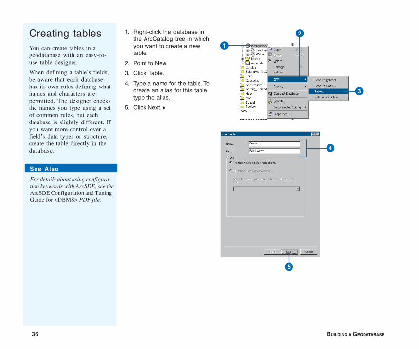
36 BUILDING A GEODATABASE
Creating tablesYou can create tables in ageodatabase with an easy-to-use table designer.
When defining a table’s fields,be aware that each databasehas its own rules defining whatnames and characters arepermitted. The designer checksthe names you type using a setof common rules, but eachdatabase is slightly different. Ifyou want more control over afield’s data types or structure,create the table directly in thedatabase.
1. Right-click the database inthe ArcCatalog tree in whichyou want to create a newtable.
2. Point to New.
3. Click Table.
4. Type a name for the table. Tocreate an alias for this table,type the alias.
5. Click Next. u
2
1
3
4
5
See Also
For details about using configura-tion keywords with ArcSDE, see theArcSDE Configuration and TuningGuide for <DBMS> PDF file.
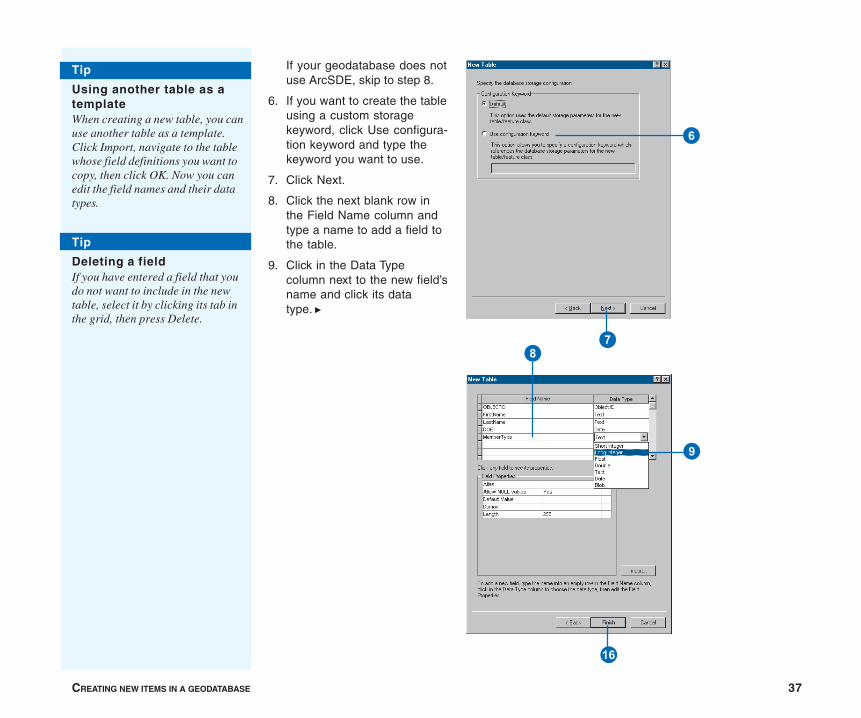
CREATING NEW ITEMS IN A GEODATABASE 37
If your geodatabase does notuse ArcSDE, skip to step 8.
6. If you want to create the tableusing a custom storagekeyword, click Use configura-tion keyword and type thekeyword you want to use.
7. Click Next.
8. Click the next blank row inthe Field Name column andtype a name to add a field tothe table.
9. Click in the Data Typecolumn next to the new field’sname and click its datatype. u
6
7
U
8
9
Tip
Using another table as atemplateWhen creating a new table, you canuse another table as a template.Click Import, navigate to the tablewhose field definitions you want tocopy, then click OK. Now you canedit the field names and their datatypes.
Tip
Deleting a fieldIf you have entered a field that youdo not want to include in the newtable, select it by clicking its tab inthe grid, then press Delete.
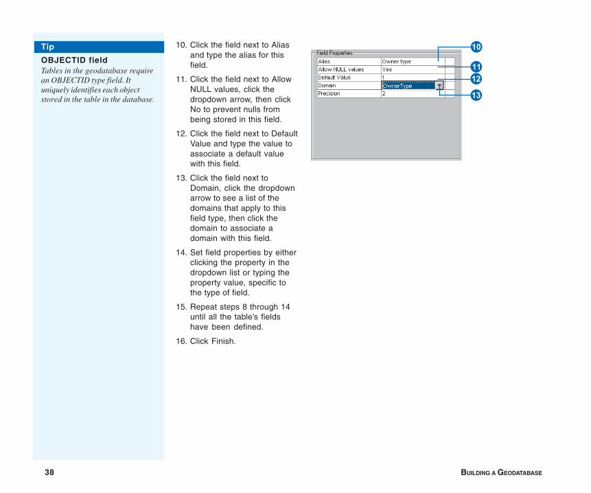
38 BUILDING A GEODATABASE
10. Click the field next to Aliasand type the alias for thisfield.
11. Click the field next to AllowNULL values, click thedropdown arrow, then clickNo to prevent nulls frombeing stored in this field.
12. Click the field next to DefaultValue and type the value toassociate a default valuewith this field.
13. Click the field next toDomain, click the dropdownarrow to see a list of thedomains that apply to thisfield type, then click thedomain to associate adomain with this field.
14. Set field properties by eitherclicking the property in thedropdown list or typing theproperty value, specific tothe type of field.
15. Repeat steps 8 through 14until all the table’s fieldshave been defined.
16. Click Finish.
Q
R
WE
Tip
OBJECTID fieldTables in the geodatabase requirean OBJECTID type field. Ituniquely identifies each objectstored in the table in the database.

CREATING NEW ITEMS IN A GEODATABASE 39
Creating a featuredataset with a predefinedcoordinate system
1. Right-click the database inthe ArcCatalog tree in whichyou want to create a newfeature dataset.
2. Point to New.
3. Click Feature Dataset.
4. Type a name for the featuredataset.
5. Click Edit to define thefeature dataset’s spatialreference. u
Creating featuredatasetsWhen creating a new featuredataset, you must define itsspatial reference. This includesits coordinate system, eithergeographic or a specificprojection, and the coordinatedomains—the minimum x-, y-,z-, and m-values and theirprecision. All feature classes inthe dataset must use the samecoordinate system, and eachcoordinate of every feature inall feature classes must fallwithin the coordinate domains.The exception to the rule is mdomains; feature classes in thesame feature dataset can havedifferent m domains.
When defining the coordinatesystem, you can choose apredefined coordinate system,use an existing feature datasetor standalone feature class as atemplate, or define a customgeographic or projectedcoordinate system.
3
1
2
4
5
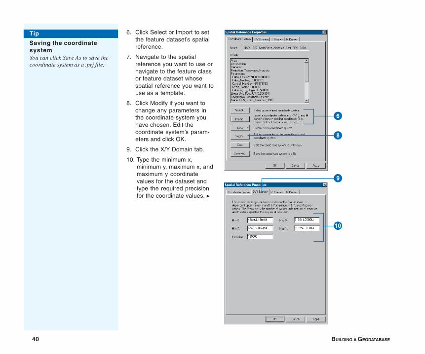
40 BUILDING A GEODATABASE
6. Click Select or Import to setthe feature dataset’s spatialreference.
7. Navigate to the spatialreference you want to use ornavigate to the feature classor feature dataset whosespatial reference you want touse as a template.
8. Click Modify if you want tochange any parameters inthe coordinate system youhave chosen. Edit thecoordinate system’s param-eters and click OK.
9. Click the X/Y Domain tab.
10. Type the minimum x,minimum y, maximum x, andmaximum y coordinatevalues for the dataset andtype the required precisionfor the coordinate values. u
6
8
9
Q
Tip
Saving the coordinatesystemYou can click Save As to save thecoordinate system as a .prj file.
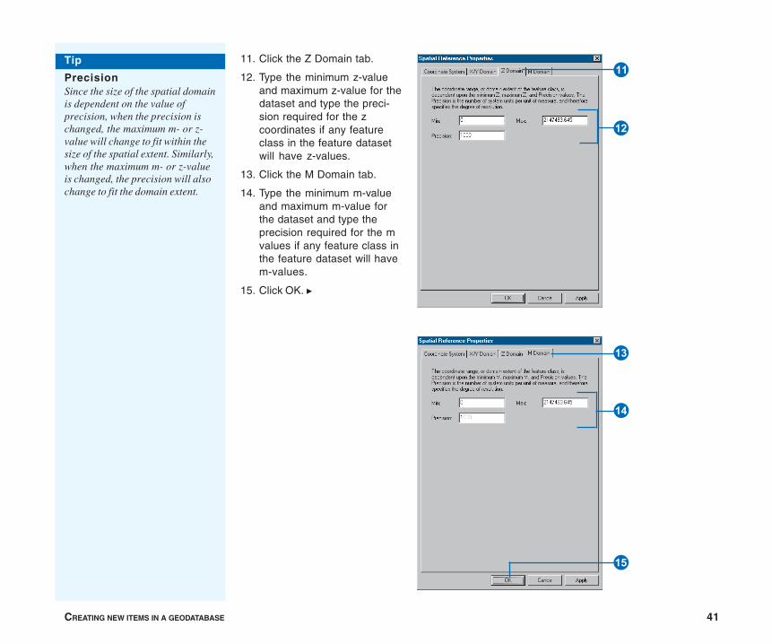
CREATING NEW ITEMS IN A GEODATABASE 41
11. Click the Z Domain tab.
12. Type the minimum z-valueand maximum z-value for thedataset and type the preci-sion required for the zcoordinates if any featureclass in the feature datasetwill have z-values.
13. Click the M Domain tab.
14. Type the minimum m-valueand maximum m-value forthe dataset and type theprecision required for the mvalues if any feature class inthe feature dataset will havem-values.
15. Click OK. u
E
W
Y
T
R
Tip
PrecisionSince the size of the spatial domainis dependent on the value ofprecision, when the precision ischanged, the maximum m- or z-value will change to fit within thesize of the spatial extent. Similarly,when the maximum m- or z-valueis changed, the precision will alsochange to fit the domain extent.
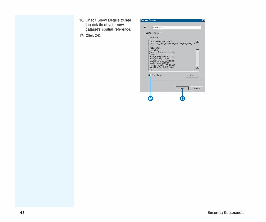
42 BUILDING A GEODATABASE
16. Check Show Details to seethe details of your newdataset’s spatial reference.
17. Click OK.
U I
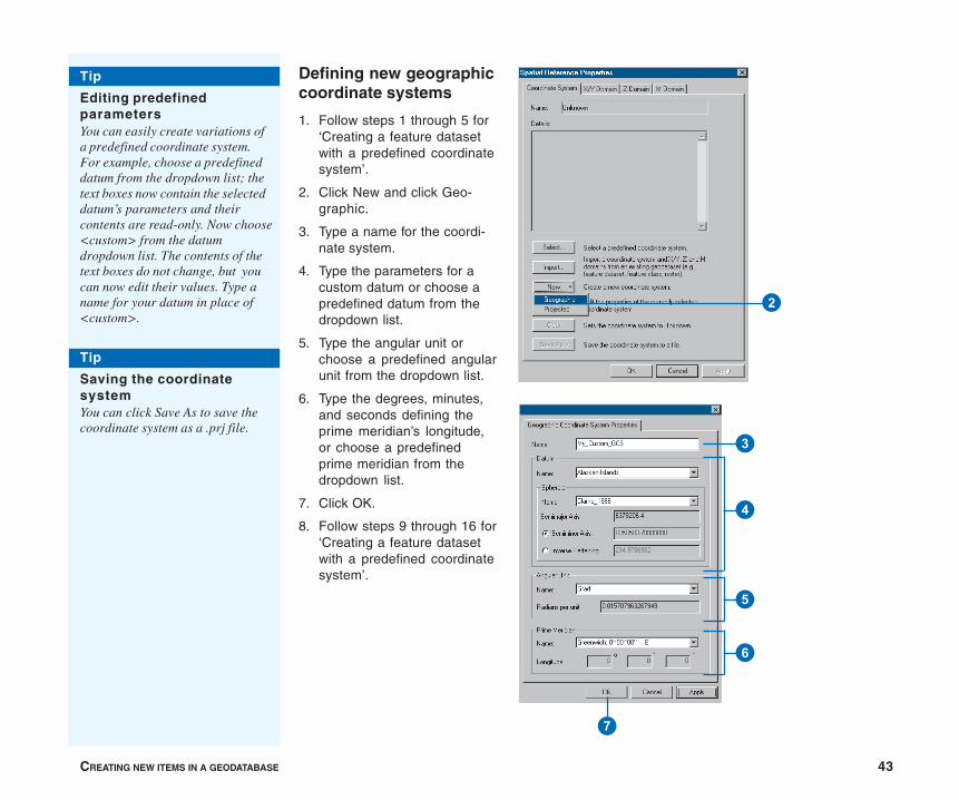
CREATING NEW ITEMS IN A GEODATABASE 43
Defining new geographiccoordinate systems
1. Follow steps 1 through 5 for‘Creating a feature datasetwith a predefined coordinatesystem’.
2. Click New and click Geo-graphic.
3. Type a name for the coordi-nate system.
4. Type the parameters for acustom datum or choose apredefined datum from thedropdown list.
5. Type the angular unit orchoose a predefined angularunit from the dropdown list.
6. Type the degrees, minutes,and seconds defining theprime meridian’s longitude,or choose a predefinedprime meridian from thedropdown list.
7. Click OK.
8. Follow steps 9 through 16 for‘Creating a feature datasetwith a predefined coordinatesystem’.
2
7
3
4
5
6
Tip
Editing predefinedparametersYou can easily create variations ofa predefined coordinate system.For example, choose a predefineddatum from the dropdown list; thetext boxes now contain the selecteddatum’s parameters and theircontents are read-only. Now choose<custom> from the datumdropdown list. The contents of thetext boxes do not change, but youcan now edit their values. Type aname for your datum in place of<custom>.
Tip
Saving the coordinatesystemYou can click Save As to save thecoordinate system as a .prj file.
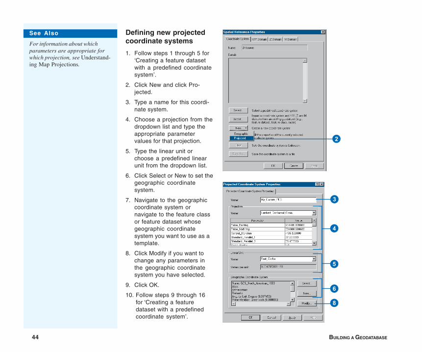
44 BUILDING A GEODATABASE
Defining new projectedcoordinate systems
1. Follow steps 1 through 5 for‘Creating a feature datasetwith a predefined coordinatesystem’.
2. Click New and click Pro-jected.
3. Type a name for this coordi-nate system.
4. Choose a projection from thedropdown list and type theappropriate parametervalues for that projection.
5. Type the linear unit orchoose a predefined linearunit from the dropdown list.
6. Click Select or New to set thegeographic coordinatesystem.
7. Navigate to the geographiccoordinate system ornavigate to the feature classor feature dataset whosegeographic coordinatesystem you want to use as atemplate.
8. Click Modify if you want tochange any parameters inthe geographic coordinatesystem you have selected.
9. Click OK.
10. Follow steps 9 through 16for ‘Creating a featuredataset with a predefinedcoordinate system’.
8
3
4
5
6
2
See Also
For information about whichparameters are appropriate forwhich projection, see Understand-ing Map Projections.
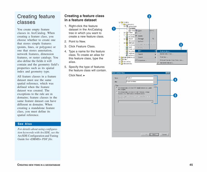
CREATING NEW ITEMS IN A GEODATABASE 45
Creating a feature classin a feature dataset
1. Right-click the featuredataset in the ArcCatalogtree in which you want tocreate a new feature class.
2. Point to New.
3. Click Feature Class.
4. Type a name for the featureclass. To create an alias forthis feature class, type thealias.
5. Specify the type of featuresthe feature class will contain.
Click Next. u
Creating featureclassesYou create empty featureclasses in ArcCatalog. Whencreating a feature class, youchoose whether to create onethat stores simple features(points, lines, or polygons) orone that stores annotation,network features, dimensionfeatures, or raster catalogs. Youalso define the fields it willcontain and the geometry field’sproperties such as its spatialindex and geometry type.
All feature classes in a featuredataset must use the samespatial reference, which wasdefined when the featuredataset was created. Theexceptions to the rule are mdomains; feature classes in thesame feature dataset can havedifferent m domains. Whencreating a standalone featureclass, you must define itsspatial reference.
1
2
3
See Also
For details about using configura-tion keywords with ArcSDE, see theArcSDE Configuration and TuningGuide for <DBMS> PDF file.
5
4

46 BUILDING A GEODATABASE
If your geodatabase does notuse ArcSDE, skip to step 8.
6. Click Use configurationkeyword and type thekeyword you want to use ifyou want to create the tableusing a custom storagekeyword.
7. Click Next.
8. Click the next blank row inthe Field Name column andtype a name to add a field tothe feature class.
9. Click in the Data Typecolumn next to the new field’sname and click its datatype. u
6
7
F
9
8
Tip
Using another featureclass as a templateWhen creating a new feature class,you can use another feature classas a template. Click Import,navigate to the feature class whosefield definitions you want to copy,and click OK. Now you can edit thefield names and their data types.
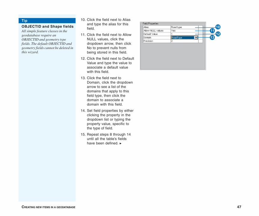
CREATING NEW ITEMS IN A GEODATABASE 47
10. Click the field next to Aliasand type the alias for thisfield.
11. Click the field next to AllowNULL values, click thedropdown arrow, then clickNo to prevent nulls frombeing stored in this field.
12. Click the field next to DefaultValue and type the value toassociate a default valuewith this field.
13. Click the field next toDomain, click the dropdownarrow to see a list of thedomains that apply to thisfield type, then click thedomain to associate adomain with this field.
14. Set field properties by eitherclicking the property in thedropdown list or typing theproperty value, specific tothe type of field.
15. Repeat steps 8 through 14until all the table’s fieldshave been defined. u
Tip
OBJECTID and Shape fieldsAll simple feature classes in thegeodatabase require anOBJECTID and geometry typefields. The default OBJECTID andgeometry fields cannot be deleted inthis wizard.
RE
QW
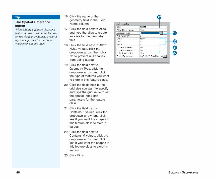
48 BUILDING A GEODATABASE
16. Click the name of thegeometry field in the FieldName column.
17. Click the field next to Aliasand type the alias to createan alias for the geometryfield.
18. Click the field next to AllowNULL values, click thedropdown arrow, then clickNo to prevent null shapesfrom being stored.
19. Click the field next toGeometry Type, click thedropdown arrow, and clickthe type of features you wantto store in this feature class.
20. Click the fields next to thegrid size you want to specifyand type the grid value to setthe spatial index gridparameters for the featureclass.
21. Click the field next toContains Z values, click thedropdown arrow, and clickYes if you want the shapes inthis feature class to store z-values.
22. Click the field next toContains M values, click thedropdown arrow, and clickYes if you want the shapes inthis feature class to store m-values.
23. Click Finish.
I
DS
A
P
Tip
The Spatial ReferencebuttonWhen adding a feature class to afeature dataset, this button lets youreview the feature dataset’s spatialreference parameters; however,you cannot change them.
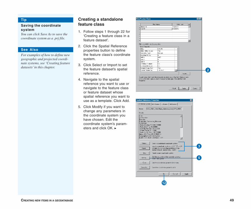
CREATING NEW ITEMS IN A GEODATABASE 49
Creating a standalonefeature class
1. Follow steps 1 through 22 for‘Creating a feature class in afeature dataset’.
2. Click the Spatial Referenceproperties button to definethe feature class’s coordinatesystem.
3. Click Select or Import to setthe feature dataset’s spatialreference.
4. Navigate to the spatialreference you want to use ornavigate to the feature classor feature dataset whosespatial reference you want touse as a template. Click Add.
5. Click Modify if you want tochange any parameters inthe coordinate system youhave chosen. Edit thecoordinate system’s param-eters and click OK. u
E
3
5
2
Tip
Saving the coordinatesystemYou can click Save As to save thecoordinate system as a .prj file.
See Also
For examples of how to define newgeographic and projected coordi-nate systems, see ‘Creating featuredatasets’ in this chapter.
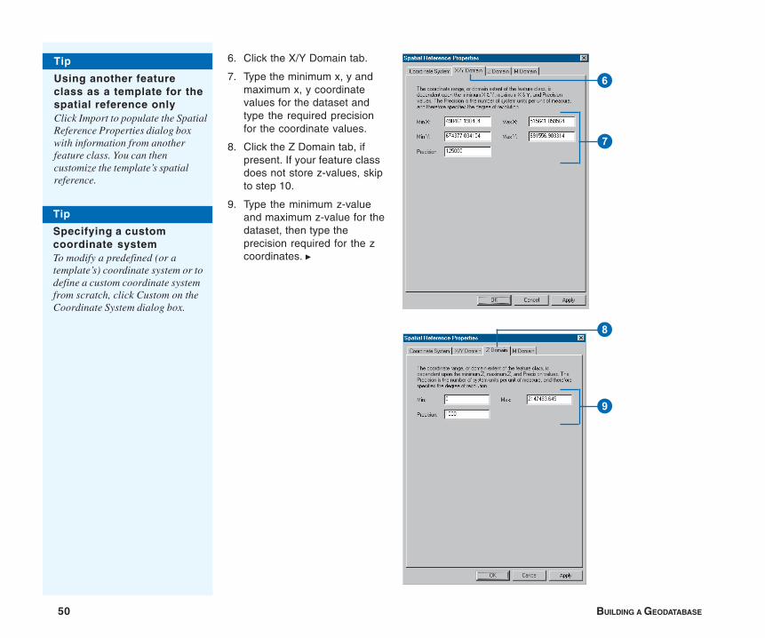
50 BUILDING A GEODATABASE
6. Click the X/Y Domain tab.
7. Type the minimum x, y andmaximum x, y coordinatevalues for the dataset andtype the required precisionfor the coordinate values.
8. Click the Z Domain tab, ifpresent. If your feature classdoes not store z-values, skipto step 10.
9. Type the minimum z-valueand maximum z-value for thedataset, then type theprecision required for the zcoordinates. u
9
8
7
6
Tip
Using another featureclass as a template for thespatial reference onlyClick Import to populate the SpatialReference Properties dialog boxwith information from anotherfeature class. You can thencustomize the template’s spatialreference.
Tip
Specifying a customcoordinate systemTo modify a predefined (or atemplate’s) coordinate system or todefine a custom coordinate systemfrom scratch, click Custom on theCoordinate System dialog box.
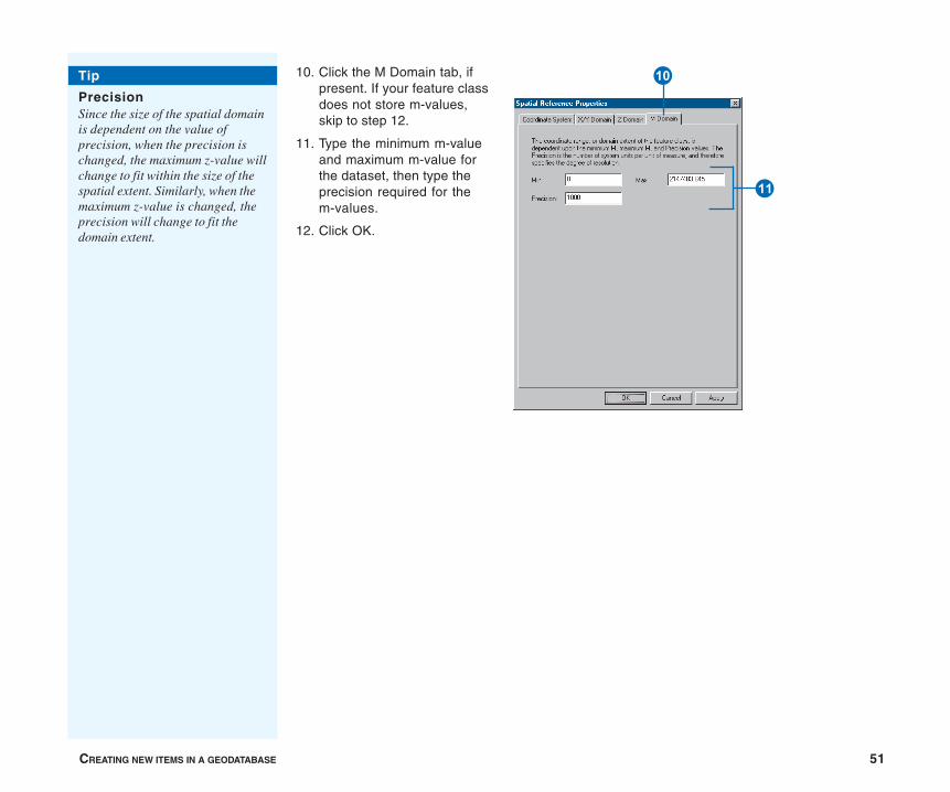
CREATING NEW ITEMS IN A GEODATABASE 51
10. Click the M Domain tab, ifpresent. If your feature classdoes not store m-values,skip to step 12.
11. Type the minimum m-valueand maximum m-value forthe dataset, then type theprecision required for them-values.
12. Click OK.
Tip
PrecisionSince the size of the spatial domainis dependent on the value ofprecision, when the precision ischanged, the maximum z-value willchange to fit within the size of thespatial extent. Similarly, when themaximum z-value is changed, theprecision will change to fit thedomain extent.
Q
W
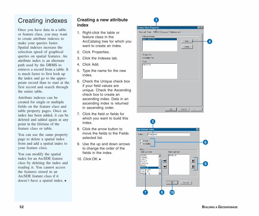
52 BUILDING A GEODATABASE
Creating indexesOnce you have data in a tableor feature class, you may wantto create attribute indexes tomake your queries faster.Spatial indexes increase theselection speed of graphicalqueries on spatial features. Anattribute index is an alternatepath used by the DBMS toretrieve a record from a table. Itis much faster to first look upthe index and go to the appro-priate record than to start at thefirst record and search throughthe entire table.
Attribute indexes can becreated for single or multiplefields on the feature class andtable property pages. Once anindex has been added, it can bedeleted and added again at anypoint in the lifetime of thefeature class or table.
You can use the same propertypage to delete a spatial indexfrom and add a spatial index toyour feature class.
You can modify the spatialindex for an ArcSDE featureclass by deleting the index andreading it. You cannot accessthe features stored in anArcSDE feature class if itdoesn’t have a spatial index. u
Creating a new attributeindex
1. Right-click the table orfeature class in theArcCatalog tree for which youwant to create an index.
2. Click Properties.
3. Click the Indexes tab.
4. Click Add.
5. Type the name for the newindex.
6. Check the Unique check boxif your field values areunique. Check the Ascendingcheck box to create anascending index. Data in anascending index is returnedin ascending order.
7. Click the field or fields forwhich you want to build thisindex.
8. Click the arrow button tomove the fields to the Fieldsselected list.
9. Use the up and down arrowsto change the order of thefields in the index.
10. Click OK. u
3
4
Q7 8
9
6
5
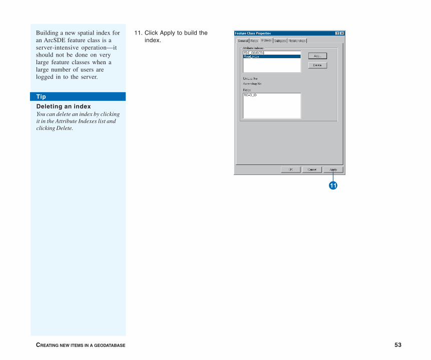
CREATING NEW ITEMS IN A GEODATABASE 53
11. Click Apply to build theindex.
Building a new spatial index foran ArcSDE feature class is aserver-intensive operation—itshould not be done on verylarge feature classes when alarge number of users arelogged in to the server.
Tip
Deleting an indexYou can delete an index by clickingit in the Attribute Indexes list andclicking Delete.
W
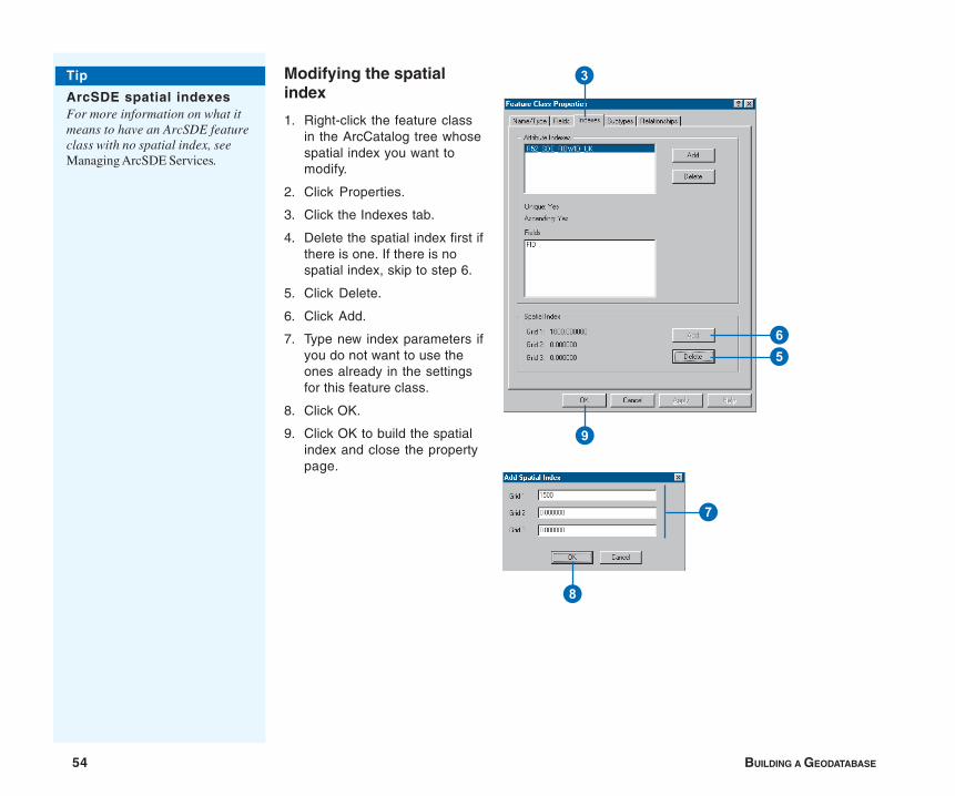
54 BUILDING A GEODATABASE
Modifying the spatialindex
1. Right-click the feature classin the ArcCatalog tree whosespatial index you want tomodify.
2. Click Properties.
3. Click the Indexes tab.
4. Delete the spatial index first ifthere is one. If there is nospatial index, skip to step 6.
5. Click Delete.
6. Click Add.
7. Type new index parameters ifyou do not want to use theones already in the settingsfor this feature class.
8. Click OK.
9. Click OK to build the spatialindex and close the propertypage.
3
56
9
7
8
Tip
ArcSDE spatial indexesFor more information on what itmeans to have an ArcSDE featureclass with no spatial index, seeManaging ArcSDE Services.
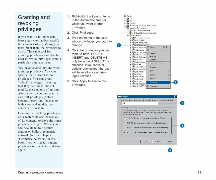
CREATING NEW ITEMS IN A GEODATABASE 55
Granting andrevokingprivilegesIf you want to let other data-base users view and/or modifythe contents of any items, youmust grant them the privilege todo so. The same tool forgranting privileges can also beused to revoke privileges from aparticular database user.
You have several options whengranting privileges. You canspecify that a user has noprivileges. You can grant“select” privileges, meaningthat they can view, but notmodify, the contents of an item.Alternatively, you can grant auser full privileges (Select,Update, Insert, and Delete) toboth view and modify thecontents of an item.
Granting or revoking privilegeson a feature dataset causes allof its contents to have the sameprivilege changes. When youadd new items to a featuredataset or build a geometricnetwork (see the chapter‘Geometric networks’ in thisbook), you will need to grantprivileges on the feature datasetagain.
1. Right-click the item or itemsin the ArcCatalog tree forwhich you want to grantprivileges.
2. Click Privileges.
3. Type the name of the userwhose privileges you want tochange.
4. Click the privileges you wantthem to have. UPDATE,INSERT, and DELETE willonly be active if SELECT ischecked. If you leave alloptions unchecked, the userwill have all access privi-leges revoked.
5. Click Apply to enable theprivileges.
3
4
5
1
2

IN THIS CHAPTER
57
Importing data 3• Importing data into new feature
classes and tables
• Registering ArcSDE data with thegeodatabase
• Loading data into existing featureclasses and tables
• Copying data betweengeodatabases
• Updating DBMS statistics
With ArcCatalog, you can import shapefiles, coverages, CAD data, andINFO and dBASE tables into a geodatabase. For each feature class andtable you import, you create a new feature class or table in the geodatabase.You can also load data from any of these formats into an existing featureclass or table.
For data in formats other than those listed above or discussed in this chapter,you use other processes to migrate the data. To import coverage annotation,please see the chapter ‘Managing annotation’, and to import raster data,please see the chapter ‘Building a raster geodatabase’. If your data is storedin TIGER® files or in another format, ArcCatalog has the tools you need toconvert the data into a format that can be imported or loaded into thegeodatabase.
In other cases, you may already have data in a geodatabase but want tocopy it to another geodatabase. You can import and load data from onegeodatabase feature class or table to another the same way you import andload other formats.
ArcGIS provides additional tools that copy data between geodatabases. InArcCatalog, you can copy and paste feature datasets, classes, and tablesbetween geodatabases. In ArcMap, you can select features or records usingany selection method and export them to another geodatabase. If you wantto share a small amount of data with someone, you can export to a ZIP fileand send it to them.
58 BUILDING A GEODATABASE
Importing or copying large amounts of data into an ArcSDEgeodatabase requires careful planning to ensure goodperformance. Before you begin, work with your databaseadministrator to review the data sources and the newfeature classes and tables you will create. Your databaseadministrator will provide you with configuration keywordsdefining the optimum way to create and store the newfeature classes and tables in your DBMS. You specify thekeywords when you use the tools outlined in this chapter.
Once you’ve finished creating feature classes and tablesand loading data, update the DBMS statistics for them. Thistoo is essential to maximize performance.
You can import and load data into a personal geodatabasewith ArcView. You must have an ArcEditor or ArcInfolicense to import or load into an ArcSDE geodatabase.
IMPORTING DATA 59
ArcCatalog contains tools that import a coverage, shapefile, CADfile, INFO table, dBASE table, geodatabase feature class, or table.The tools also allow you to import more than one feature classand table at the same time. For each feature class or table youimport, you create a new feature class or table in the geodatabase.
As the geodatabase stores data different from the formats you’reimporting, ArcCatalog will automatically convert the geometryand fields you import to types used by the geodatabase.
Importing a feature class
You use the Feature Class to Feature Class tool to import ashapefile, coverage, or a CAD feature class into a newgeodatabase feature class. You can also import a feature classfrom another geodatabase. You can specify which fields to importand how to name them, and limit which features import byspecifying a query.
The feature class you create can stand alone or import into anexisting feature dataset.
When you create a standalone feature class, the new featureclass is created with the same coordinate system as the featureclass you’re importing. It’s also created with the same spatialdomain but expanded by a factor of 5 percent.
If you’re creating a feature class in an existing feature dataset, thenew feature class will automatically take on the same coordinatesystem, spatial domain, and precision as the feature dataset. Formore information about spatial references, see the chapter‘Creating new items in a geodatabase’ in this book.
If you’re importing into an ArcSDE geodatabase, you can specifya configuration keyword to customize how the feature class iscreated and stored.
You can specify one spatial index grid size if you’re importing intoa personal geodatabase, and up to three if you’re importing intoan ArcSDE geodatabase. A poorly defined grid size can reducespatial query performance in ArcMap, so if you’re unfamiliar withcreating spatial grids, use the defaults. For information on thespatial index grid, see the chapter ‘Creating new items in ageodatabase’.
Importing a table
Importing tables is a similar process to importing feature classes.When you import a table, you can choose which fields to importand how to name them, and you can choose which records toimport by specifying a query.
Importing several feature classes or tables
If you’re importing a number of feature classes or tables into ageodatabase and they require the same settings at import, youcan use the Feature Class to Geodatabase or Table toGeodatabase tool to import them at the same time. One featureclass or table will be created for each feature class or table youimport.
On the other hand, many of the feature classes and tables youimport may require individual settings at import, such as for thedestination geodatabase, custom configuration keyword, orspatial index. If this is the case, you can create and run a modelinstead of manually repeating the steps outlined in this chapter. Amodel helps automate importing by allowing you to save andreuse environment settings and tool parameters. Once you’vecreated a model, you can import data, edit the model to specifyother input data, modify any parameters you wish, then rerun themodel with a single click. For more information on models, seeGeoprocessing in ArcGIS.
Importing data into new feature classes and tables
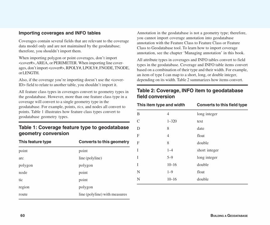
60 BUILDING A GEODATABASE
Importing coverages and INFO tables
Coverages contain several fields that are relevant to the coveragedata model only and are not maintained by the geodatabase;therefore, you shouldn’t import them.
When importing polygon or point coverages, don’t import<cover#>, AREA, or PERIMETER. When importing line cover-ages, don’t import <cover#>, RPOLY#, LPOLY#, FNODE, TNODE,or LENGTH.
Also, if the coverage you’re importing doesn’t use the <cover-ID> field to relate to another table, you shouldn’t import it.
All feature class types in coverages convert to geometry types inthe geodatabase. However, more than one feature class type in acoverage will convert to a single geometry type in thegeodatabase. For example, points, tics, and nodes all convert topoints. Table 1 illustrates how feature class types convert togeodatabase geometry types.
Table 1: Coverage feature type to geodatabasegeometry conversion
This feature type Converts to this geometry
point point
arc line (polyline)
polygon polygon
node point
tic point
region polygon
route line (polyline) with measures
Annotation in the geodatabase is not a geometry type; therefore,you cannot import coverage annotation into geodatabaseannotation with the Feature Class to Feature Class or FeatureClass to Geodatabase tool. To learn how to import coverageannotation, see the chapter ‘Managing annotation’ in this book.
All attribute types in coverages and INFO tables convert to fieldtypes in the geodatabase. Coverage and INFO table items convertbased on a combination of their type and their width. For example,an item of type I can map to a short, long, or double integer,depending on its width. Table 2 summarizes how items convert.
Table 2: Coverage, INFO item to geodatabasefield conversion
This item type and width Converts to this field type
B 4 long integer
C 1–320 text
D 8 date
F 4 float
F 8 double
I 1–4 short integer
I 5–9 long integer
I 10–16 double
N 1–9 float
N 10–16 double
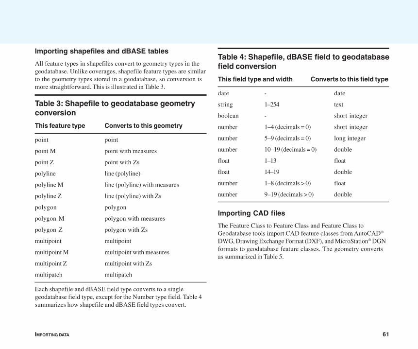
IMPORTING DATA 61
Importing shapefiles and dBASE tables
All feature types in shapefiles convert to geometry types in thegeodatabase. Unlike coverages, shapefile feature types are similarto the geometry types stored in a geodatabase, so conversion ismore straightforward. This is illustrated in Table 3.
Table 3: Shapefile to geodatabase geometryconversion
This feature type Converts to this geometry
point point
point M point with measures
point Z point with Zs
polyline line (polyline)
polyline M line (polyline) with measures
polyline Z line (polyline) with Zs
polygon polygon
polygon M polygon with measures
polygon Z polygon with Zs
multipoint multipoint
multipoint M multipoint with measures
multipoint Z multipoint with Zs
multipatch multipatch
Each shapefile and dBASE field type converts to a singlegeodatabase field type, except for the Number type field. Table 4summarizes how shapefile and dBASE field types convert.
Table 4: Shapefile, dBASE field to geodatabasefield conversion
This field type and width Converts to this field type
date - date
string 1–254 text
boolean - short integer
number 1–4 (decimals = 0) short integer
number 5–9 (decimals = 0) long integer
number 10–19 (decimals = 0) double
float 1–13 float
float 14–19 double
number 1–8 (decimals > 0) float
number 9–19 (decimals > 0) double
Importing CAD files
The Feature Class to Feature Class and Feature Class toGeodatabase tools import CAD feature classes from AutoCAD®
DWG, Drawing Exchange Format (DXF), and MicroStation® DGNformats to geodatabase feature classes. The geometry convertsas summarized in Table 5.
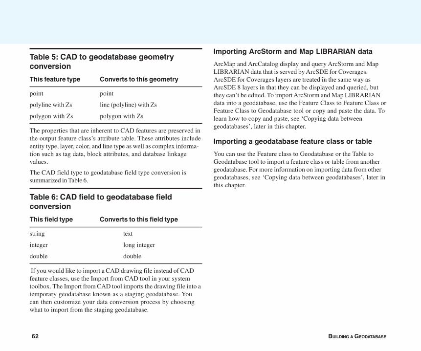
62 BUILDING A GEODATABASE
Table 5: CAD to geodatabase geometryconversion
This feature type Converts to this geometry
point point
polyline with Zs line (polyline) with Zs
polygon with Zs polygon with Zs
The properties that are inherent to CAD features are preserved inthe output feature class’s attribute table. These attributes includeentity type, layer, color, and line type as well as complex informa-tion such as tag data, block attributes, and database linkagevalues.
The CAD field type to geodatabase field type conversion issummarized in Table 6.
Table 6: CAD field to geodatabase fieldconversion
This field type Converts to this field type
string text
integer long integer
double double
If you would like to import a CAD drawing file instead of CADfeature classes, use the Import from CAD tool in your systemtoolbox. The Import from CAD tool imports the drawing file into atemporary geodatabase known as a staging geodatabase. Youcan then customize your data conversion process by choosingwhat to import from the staging geodatabase.
Importing ArcStorm and Map LIBRARIAN data
ArcMap and ArcCatalog display and query ArcStorm and MapLIBRARIAN data that is served by ArcSDE for Coverages.ArcSDE for Coverages layers are treated in the same way asArcSDE 8 layers in that they can be displayed and queried, butthey can’t be edited. To import ArcStorm and Map LIBRARIANdata into a geodatabase, use the Feature Class to Feature Class orFeature Class to Geodatabase tool or copy and paste the data. Tolearn how to copy and paste, see ‘Copying data betweengeodatabases’, later in this chapter.
Importing a geodatabase feature class or table
You can use the Feature class to Geodatabase or the Table toGeodatabase tool to import a feature class or table from anothergeodatabase. For more information on importing data from othergeodatabases, see ‘Copying data between geodatabases’, later inthis chapter.
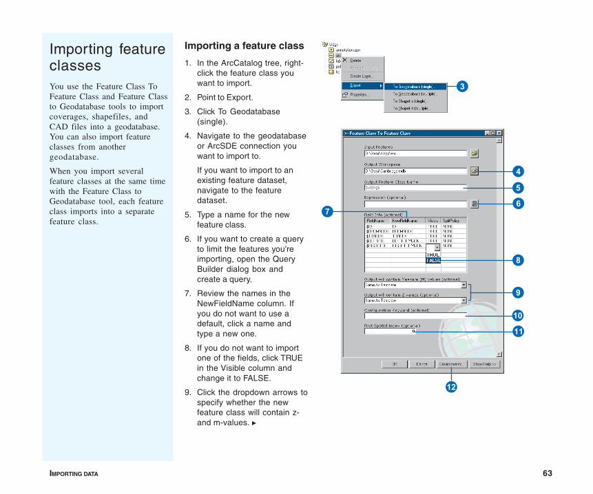
IMPORTING DATA 63
Importing a feature class
1. In the ArcCatalog tree, right-click the feature class youwant to import.
2. Point to Export.
3. Click To Geodatabase(single).
4. Navigate to the geodatabaseor ArcSDE connection youwant to import to.
If you want to import to anexisting feature dataset,navigate to the featuredataset.
5. Type a name for the newfeature class.
6. If you want to create a queryto limit the features you’reimporting, open the QueryBuilder dialog box andcreate a query.
7. Review the names in theNewFieldName column. Ifyou do not want to use adefault, click a name andtype a new one.
8. If you do not want to importone of the fields, click TRUEin the Visible column andchange it to FALSE.
9. Click the dropdown arrows tospecify whether the newfeature class will contain z-and m-values. u
Importing featureclassesYou use the Feature Class ToFeature Class and Feature Classto Geodatabase tools to importcoverages, shapefiles, andCAD files into a geodatabase.You can also import featureclasses from anothergeodatabase.
When you import severalfeature classes at the same timewith the Feature Class toGeodatabase tool, each featureclass imports into a separatefeature class.
3
E
4
5
6
8
7
9
Q
W
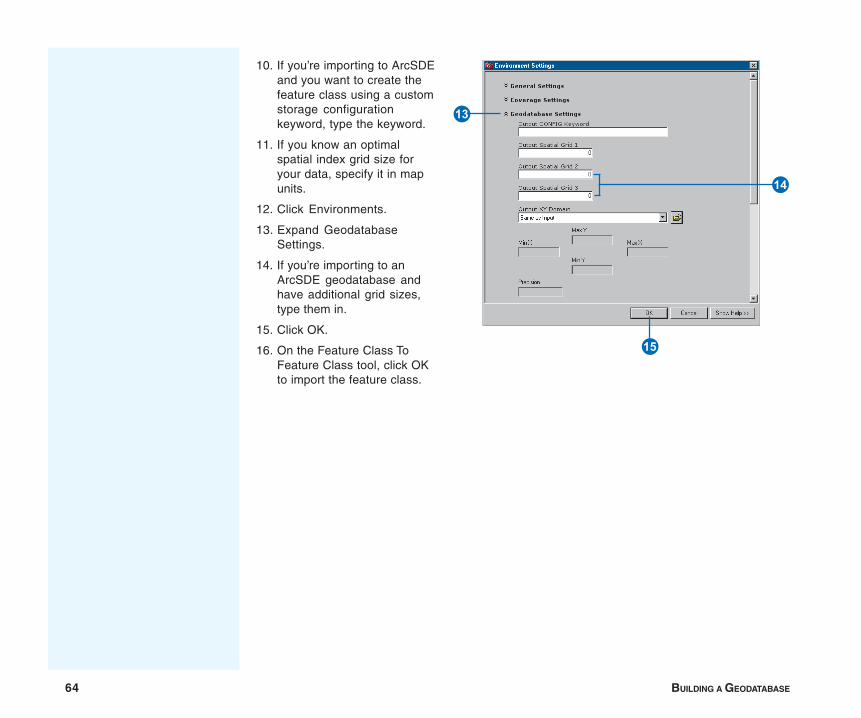
64 BUILDING A GEODATABASE
10. If you’re importing to ArcSDEand you want to create thefeature class using a customstorage configurationkeyword, type the keyword.
11. If you know an optimalspatial index grid size foryour data, specify it in mapunits.
12. Click Environments.
13. Expand GeodatabaseSettings.
14. If you’re importing to anArcSDE geodatabase andhave additional grid sizes,type them in.
15. Click OK.
16. On the Feature Class ToFeature Class tool, click OKto import the feature class.
R
T
Y
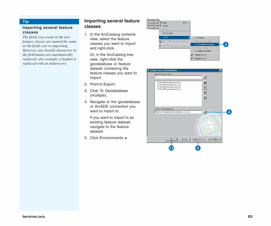
IMPORTING DATA 65
Importing several featureclasses
1. In the ArcCatalog contentsview, select the featureclasses you want to importand right-click.
Or, in the ArcCatalog treeview, right-click thegeodatabase or featuredataset containing thefeature classes you want toimport.
2. Point to Export.
3. Click To Geodatabase(multiple).
4. Navigate to the geodatabaseor ArcSDE connection youwant to import to.
If you want to import to anexisting feature dataset,navigate to the featuredataset.
5. Click Environments. u
Tip
Importing several featureclassesThe fields you create in the newfeature classes are named the sameas the fields you’re importing.However, any invalid characters inthe field names are automaticallyreplaced—for example, a hyphen isreplaced with an underscore.
3
4
5R
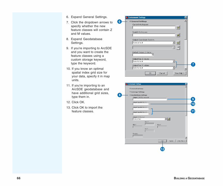
66 BUILDING A GEODATABASE
6. Expand General Settings.
7. Click the dropdown arrows tospecify whether the newfeature classes will contain Zand M values.
8. Expand GeodatabaseSettings.
9. If you’re importing to ArcSDEand you want to create thefeature classes using acustom storage keyword,type the keyword.
10. If you know an optimalspatial index grid size foryour data, specify it in mapunits.
11. If you’re importing to anArcSDE geodatabase andhave additional grid sizes,type them in.
12. Click OK.
13. Click OK to import thefeature classes.
6
7
8
Q
E
W
9
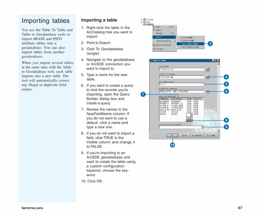
IMPORTING DATA 67
Importing tablesYou use the Table To Table andTable to Geodatabase tools toimport dBASE and INFOattribute tables into ageodatabase. You can alsoimport tables from anothergeodatabase.
When you import several tablesat the same time with the Tableto Geodatabase tool, each tableimports into a new table. Thetool will automatically correctany illegal or duplicate fieldnames.
Importing a table
1. Right-click the table in theArcCatalog tree you want toimport.
2. Point to Export.
3. Click To Geodatabase(single).
4. Navigate to the geodatabaseor ArcSDE connection youwant to import to.
5. Type a name for the newtable.
6. If you want to create a queryto limit the records you’reimporting, open the QueryBuilder dialog box andcreate a query.
7. Review the names in theNewFieldName column. Ifyou do not want to use adefault, click a name andtype a new one.
8. If you do not want to import afield, click TRUE in theVisible column and change itto FALSE.
9. If you’re importing to anArcSDE geodatabase andwant to create the table usinga custom configurationkeyword, choose the key-word.
10. Click OK.
3
7
4
5
6
8
Q
9
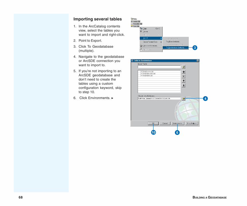
68 BUILDING A GEODATABASE
Importing several tables
1. In the ArcCatalog contentsview, select the tables youwant to import and right-click.
2. Point to Export.
3. Click To Geodatabase(multiple).
4. Navigate to the geodatabaseor ArcSDE connection youwant to import to.
5. If you’re not importing to anArcSDE geodatabase anddon’t need to create thetables using a customconfiguration keyword, skipto step 10.
6. Click Environments. u
3
4
Q 6

IMPORTING DATA 69
7. Expand GeodatabaseSettings.
8. Type the configurationkeyword.
9. Click OK to close theEnvironment Settings dialogbox.
10. Click OK to import the tables.
78
9
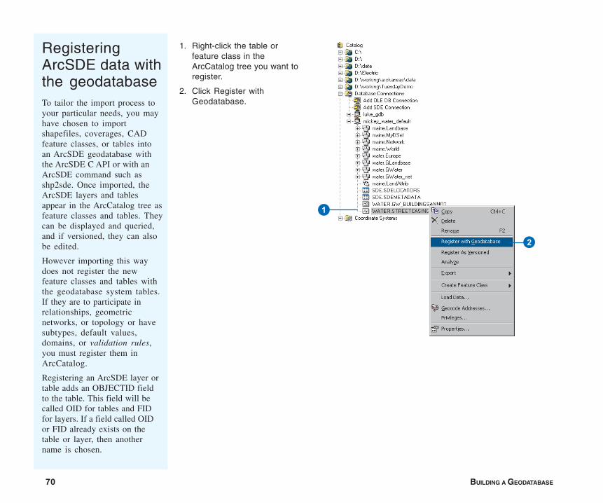
70 BUILDING A GEODATABASE
RegisteringArcSDE data withthe geodatabaseTo tailor the import process toyour particular needs, you mayhave chosen to importshapefiles, coverages, CADfeature classes, or tables intoan ArcSDE geodatabase withthe ArcSDE C API or with anArcSDE command such asshp2sde. Once imported, theArcSDE layers and tablesappear in the ArcCatalog tree asfeature classes and tables. Theycan be displayed and queried,and if versioned, they can alsobe edited.
However importing this waydoes not register the newfeature classes and tables withthe geodatabase system tables.If they are to participate inrelationships, geometricnetworks, or topology or havesubtypes, default values,domains, or validation rules,you must register them inArcCatalog.
Registering an ArcSDE layer ortable adds an OBJECTID fieldto the table. This field will becalled OID for tables and FIDfor layers. If a field called OIDor FID already exists on thetable or layer, then anothername is chosen.
1. Right-click the table orfeature class in theArcCatalog tree you want toregister.
2. Click Register withGeodatabase.
1
2
IMPORTING DATA 71
Loading data into existing feature classes and tables
Suppose you’ve created a geodatabase data model from onedistributed by ESRI or by copying the schema of an existinggeodatabase and modifying it to suit your needs. Or, maybe youhave manually created empty feature classes, tables, and othergeodatabase elements in ArcCatalog or used CASE tools togenerate a schema from UML. Regardless of the method you’vechosen, if you have empty feature classes and tables, the nextstep is to load data into them. In other cases, your feature classesand tables may already contain data but you want to add more.
You can load coverage, shapefile, CAD, or geodatabase featureclass data into an existing feature class, providing it falls withinthe x/y domain of the feature class you’re loading into. You canload INFO, dBASE, or geodatabase table data into an existingtable. You load the data with the Simple Data Loader inArcCatalog or the Object Loader in ArcMap.
You load data with the Object Loader in ArcMap after you startan edit session. If you’re loading into a network feature class,ArcMap builds connectivity for you as each feature is added. Ifyou’re loading into a relationship feature class or table that hasmessaging, ArcMap adds a record to the related table as eachfeature or record is added. If you’re loading into a feature classthat has feature-linked annotation, ArcMap adds a record to thelinked annotation class as each feature is added. And if you’reloading line features that do not connect properly at the ends,ArcMap snaps them together as they load. Because you’reloading during an edit session, once you’ve finished loading youcan undo the changes if you need to.
If you don’t require any of these capabilities, you should loadwith the Simple Data Loader because it’s faster than the ObjectLoader.
Loading a lot of data into a network feature class with the ObjectLoader can take a long time, especially if the network is large andconsists of several feature classes. So if you’re creating a
network from scratch, you should load all of the data with theSimple Data Loader before you build the network. If you’vealready built the network, instead of using the Object Loader,save time by deleting the network class, loading with the SimpleData Loader, then rebuilding the network. These strategies arediscussed below.
If you’re loading into a feature class that has topology, you canload with either the Object Loader or the Simple Data Loader.However, neither tool validates topology as the features load, sothe end result is the same—you will need to validate the topologyyourself once you’ve finished loading.
Loading into versioned feature classes and tables
If you’re migrating data to a geodatabase, you should load thedata before registering your data as versioned. Loading into aversioned feature class or table is slower than loading into featureclasses or tables that aren’t versioned. Once you’ve completedmigrating your data and applications to the geodatabase, registeryour feature classes and tables as versioned. You can then loadany updates into the versioned feature classes and tables.
If you use the Simple Data Loader to load into a versionedArcSDE feature class or table, the data loads directly into thebase tables. However if you use the Object Loader, the data loadsinto the delta tables. Therefore, after you’ve finished loading withthe Object Loader you should run Compress on your database topush all the records from the delta tables to the base tables.Having your data in the base tables will result in better queryspeed than if you have large amounts of data in your delta tables.For more details on compressing your database to improveperformance, see the chapter ‘Working with a versionedgeodatabase’ in this book.
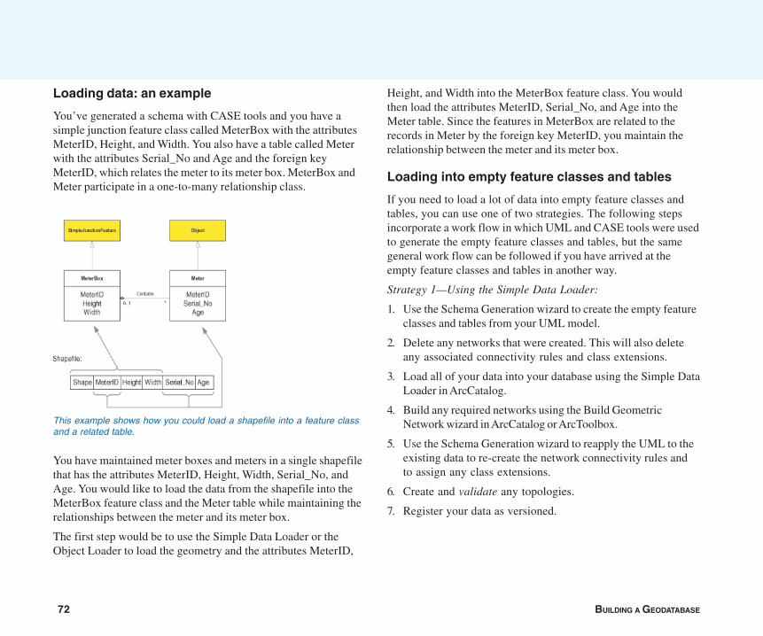
72 BUILDING A GEODATABASE
Loading data: an example
You’ve generated a schema with CASE tools and you have asimple junction feature class called MeterBox with the attributesMeterID, Height, and Width. You also have a table called Meterwith the attributes Serial_No and Age and the foreign keyMeterID, which relates the meter to its meter box. MeterBox andMeter participate in a one-to-many relationship class.
You have maintained meter boxes and meters in a single shapefilethat has the attributes MeterID, Height, Width, Serial_No, andAge. You would like to load the data from the shapefile into theMeterBox feature class and the Meter table while maintaining therelationships between the meter and its meter box.
The first step would be to use the Simple Data Loader or theObject Loader to load the geometry and the attributes MeterID,
Height, and Width into the MeterBox feature class. You wouldthen load the attributes MeterID, Serial_No, and Age into theMeter table. Since the features in MeterBox are related to therecords in Meter by the foreign key MeterID, you maintain therelationship between the meter and its meter box.
Loading into empty feature classes and tables
If you need to load a lot of data into empty feature classes andtables, you can use one of two strategies. The following stepsincorporate a work flow in which UML and CASE tools were usedto generate the empty feature classes and tables, but the samegeneral work flow can be followed if you have arrived at theempty feature classes and tables in another way.
Strategy 1—Using the Simple Data Loader:
1. Use the Schema Generation wizard to create the empty featureclasses and tables from your UML model.
2. Delete any networks that were created. This will also deleteany associated connectivity rules and class extensions.
3. Load all of your data into your database using the Simple DataLoader in ArcCatalog.
4. Build any required networks using the Build GeometricNetwork wizard in ArcCatalog or ArcToolbox.
5. Use the Schema Generation wizard to reapply the UML to theexisting data to re-create the network connectivity rules andto assign any class extensions.
6. Create and validate any topologies.
7. Register your data as versioned.
This example shows how you could load a shapefile into a feature classand a related table.
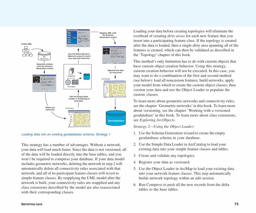
IMPORTING DATA 73
This strategy has a number of advantages. Without a network,your data will load much faster. Since the data is not versioned, allof the data will be loaded directly into the base tables, and youwon’t be required to compress your database. If your data modelincludes geometric networks, deleting the network in step 2 willautomatically delete all connectivity rules associated with thatnetwork, and all of its participant feature classes will revert tosimple feature classes. By reapplying the UML model after thenetwork is built, your connectivity rules are reapplied and anyclass extensions described by the model are also reassociatedwith their corresponding classes.
Loading your data before creating topologies will eliminate theoverhead of creating dirty areas for each new feature that youinsert into a participating feature class. If the topology is createdafter the data is loaded, then a single dirty area spanning all of thefeatures is created, which can then be validated as described inthe ‘Topology’ chapter of this book.
This method’s only limitation has to do with custom objects thathave custom object creation behavior. Using this strategy,custom creation behavior will not be executed. In this case, youmay want to do a combination of the first and second method(see below): load all noncustom features, build networks, applyyour model from which to create the custom object classes, thenversion your data and use the Object Loader to populate thecustom classes.
To learn more about geometric networks and connectivity rules,see the chapter ‘Geometric networks’ in this book. To learn moreabout versioning, see the chapter ‘Working with a versionedgeodatabase’ in this book. To learn more about class extensions,see Exploring ArcObjects.
Strategy 2—Using the Object Loader:
1. Use the Schema Generation wizard to create the emptygeodatabase schema in your database.
2. Use the Simple Data Loader in ArcCatalog to load yourexisting data into your simple feature classes and tables.
3. Create and validate any topologies.
4. Register your data as versioned.
5. Use the Object Loader in ArcMap to load your existing datainto your network feature classes. This step automaticallybuilds network topology within an edit session.
6. Run Compress to push all the new records from the deltatables to the base tables.
Loading data into an existing geodatabase schema: Strategy 1
Create UML
MSRepository
Geodatabase
Delete anynetworks
Generate schemawith the Schema
Generation wizard
Shapefiles
Coverages
ArcCatalog
Use the Simple DataLoader in ArCatalog to
load data.
ArcCatalog
Use the Build GemetricNetwork wizard to buildany required networks
Reapply UML withthe Schema
Generation wizard
Register the dataas versioned
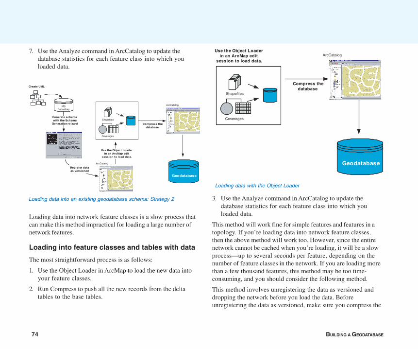
74 BUILDING A GEODATABASE
7. Use the Analyze command in ArcCatalog to update thedatabase statistics for each feature class into which youloaded data.
Loading data into network feature classes is a slow process thatcan make this method impractical for loading a large number ofnetwork features.
Loading into feature classes and tables with data
The most straightforward process is as follows:
1. Use the Object Loader in ArcMap to load the new data intoyour feature classes.
2. Run Compress to push all the new records from the deltatables to the base tables.
3. Use the Analyze command in ArcCatalog to update thedatabase statistics for each feature class into which youloaded data.
This method will work fine for simple features and features in atopology. If you’re loading data into network feature classes,then the above method will work too. However, since the entirenetwork cannot be cached when you’re loading, it will be a slowprocess—up to several seconds per feature, depending on thenumber of feature classes in the network. If you are loading morethan a few thousand features, this method may be too time-consuming, and you should consider the following method.
This method involves unregistering the data as versioned anddropping the network before you load the data. Beforeunregistering the data as versioned, make sure you compress the
Shapefiles
Coverages
Geodatabase
Compress thedatabase
ArcCatalogUse the Object Loader
in an ArcMap editsession to load data.
Loading data with the Object Loader
ArcCatalog
Create UML
MSRepository
Geodatabase
Compress thedatabase
Register dataas versioned
Use the Object Loaderin an ArcMap edit
session to load data.
ArcCatalog
Generate schemawith the Schema
Generation wizardShapefiles
Coverages
Loading data into an existing geodatabase schema: Strategy 2
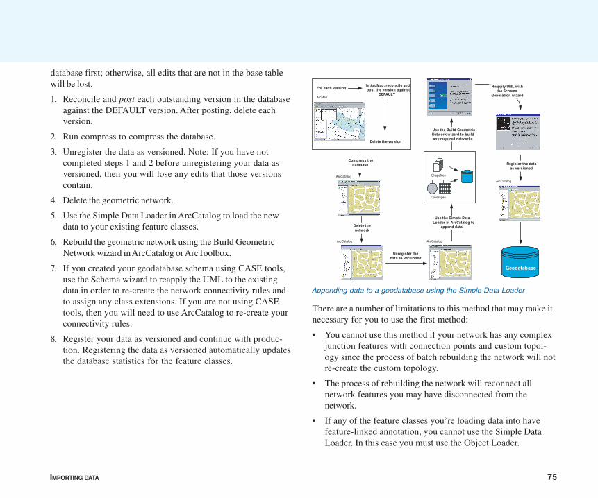
IMPORTING DATA 75
database first; otherwise, all edits that are not in the base tablewill be lost.
1. Reconcile and post each outstanding version in the databaseagainst the DEFAULT version. After posting, delete eachversion.
2. Run compress to compress the database.
3. Unregister the data as versioned. Note: If you have notcompleted steps 1 and 2 before unregistering your data asversioned, then you will lose any edits that those versionscontain.
4. Delete the geometric network.
5. Use the Simple Data Loader in ArcCatalog to load the newdata to your existing feature classes.
6. Rebuild the geometric network using the Build GeometricNetwork wizard in ArcCatalog or ArcToolbox.
7. If you created your geodatabase schema using CASE tools,use the Schema wizard to reapply the UML to the existingdata in order to re-create the network connectivity rules andto assign any class extensions. If you are not using CASEtools, then you will need to use ArcCatalog to re-create yourconnectivity rules.
8. Register your data as versioned and continue with produc-tion. Registering the data as versioned automatically updatesthe database statistics for the feature classes.
There are a number of limitations to this method that may make itnecessary for you to use the first method:
• You cannot use this method if your network has any complexjunction features with connection points and custom topol-ogy since the process of batch rebuilding the network will notre-create the custom topology.
• The process of rebuilding the network will reconnect allnetwork features you may have disconnected from thenetwork.
• If any of the feature classes you’re loading data into havefeature-linked annotation, you cannot use the Simple DataLoader. In this case you must use the Object Loader.
Appending data to a geodatabase using the Simple Data Loader
Geodatabase
Shapefiles
Coverages
ArcCatalog
Use the Simple DataLoader in ArcCatalog to
append data.
ArcCatalog
Use the Build GeometricNetwork wizard to buildany required networks
Reapply UML withthe Schema
Generation wizard
Register the dataas versioned
ArcMap
In ArcMap, reconcile andpost the version against
DEFAULT
Delete the version
For each version
Compress thedatabase
ArcCatalog
ArcCatalog
Delete thenetwork
Unregister thedata as versioned
76 BUILDING A GEODATABASE
• This method is incompatible with some work flows. If youhave outstanding versions that cannot be reconciled andposted to DEFAULT, then you cannot use this method. Suchversions include outstanding design versions that are notcomplete, are not ready for posting, or are historical versions.If this is the case, you need to use the Object Loader andappend your data as part of an edit session.
To learn more about geometric networks, complex junctions,enabled and disabled network features, and connectivity rules,see the chapter ‘Geometric networks’. To learn more aboutreconcile, post, compress, and versioning, see the chapter‘Working with a versioned geodatabase’.
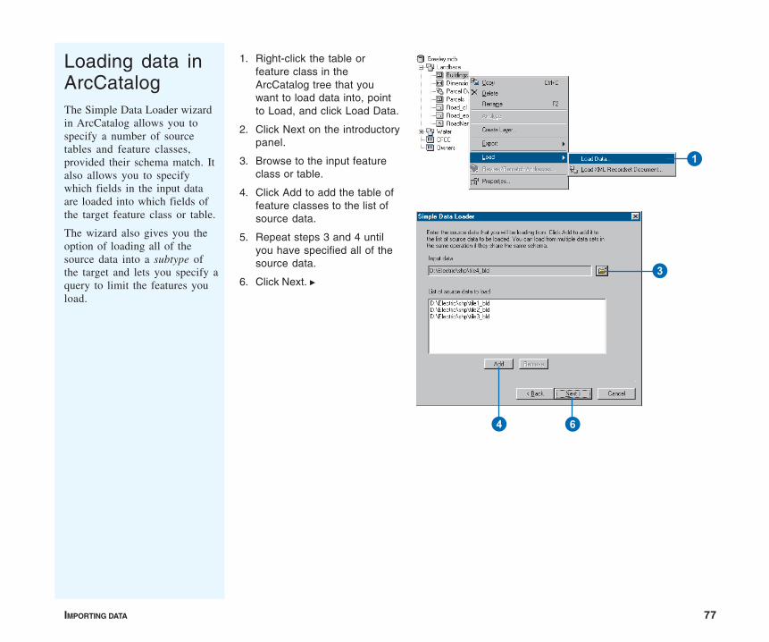
IMPORTING DATA 77
Loading data inArcCatalogThe Simple Data Loader wizardin ArcCatalog allows you tospecify a number of sourcetables and feature classes,provided their schema match. Italso allows you to specifywhich fields in the input dataare loaded into which fields ofthe target feature class or table.
The wizard also gives you theoption of loading all of thesource data into a subtype ofthe target and lets you specify aquery to limit the features youload.
1. Right-click the table orfeature class in theArcCatalog tree that youwant to load data into, pointto Load, and click Load Data.
2. Click Next on the introductorypanel.
3. Browse to the input featureclass or table.
4. Click Add to add the table offeature classes to the list ofsource data.
5. Repeat steps 3 and 4 untilyou have specified all of thesource data.
6. Click Next. u
1
3
4 6
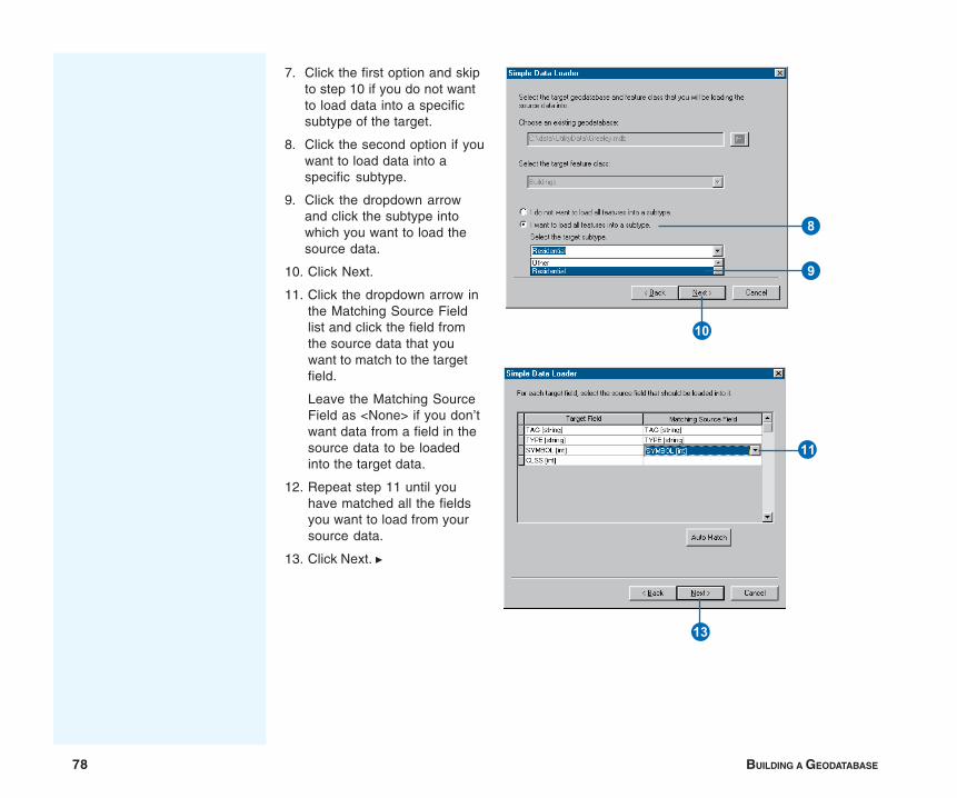
78 BUILDING A GEODATABASE
7. Click the first option and skipto step 10 if you do not wantto load data into a specificsubtype of the target.
8. Click the second option if youwant to load data into aspecific subtype.
9. Click the dropdown arrowand click the subtype intowhich you want to load thesource data.
10. Click Next.
11. Click the dropdown arrow inthe Matching Source Fieldlist and click the field fromthe source data that youwant to match to the targetfield.
Leave the Matching SourceField as <None> if you don’twant data from a field in thesource data to be loadedinto the target data.
12. Repeat step 11 until youhave matched all the fieldsyou want to load from yoursource data.
13. Click Next. u
8
9
Q
W
R
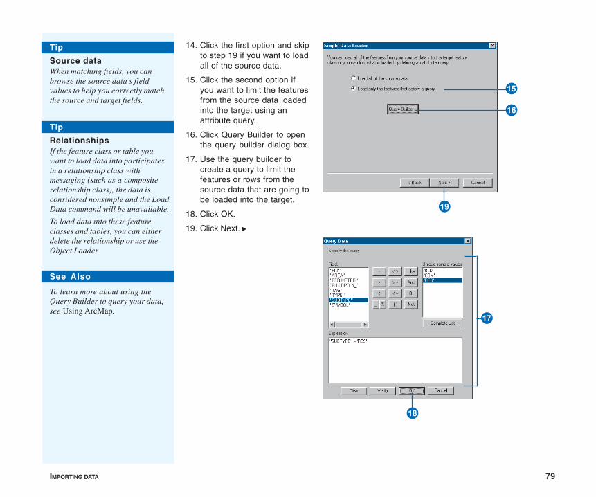
IMPORTING DATA 79
14. Click the first option and skipto step 19 if you want to loadall of the source data.
15. Click the second option ifyou want to limit the featuresfrom the source data loadedinto the target using anattribute query.
16. Click Query Builder to openthe query builder dialog box.
17. Use the query builder tocreate a query to limit thefeatures or rows from thesource data that are going tobe loaded into the target.
18. Click OK.
19. Click Next. u
See Also
To learn more about using theQuery Builder to query your data,see Using ArcMap.
Tip
Source dataWhen matching fields, you canbrowse the source data’s fieldvalues to help you correctly matchthe source and target fields.
Tip
RelationshipsIf the feature class or table youwant to load data into participatesin a relationship class withmessaging (such as a compositerelationship class), the data isconsidered nonsimple and the LoadData command will be unavailable.
To load data into these featureclasses and tables, you can eitherdelete the relationship or use theObject Loader.
I
O
P
U
Y
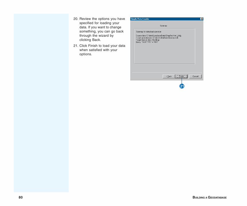
80 BUILDING A GEODATABASE
20. Review the options you havespecified for loading yourdata. If you want to changesomething, you can go backthrough the wizard byclicking Back.
21. Click Finish to load your datawhen satisfied with youroptions.
S
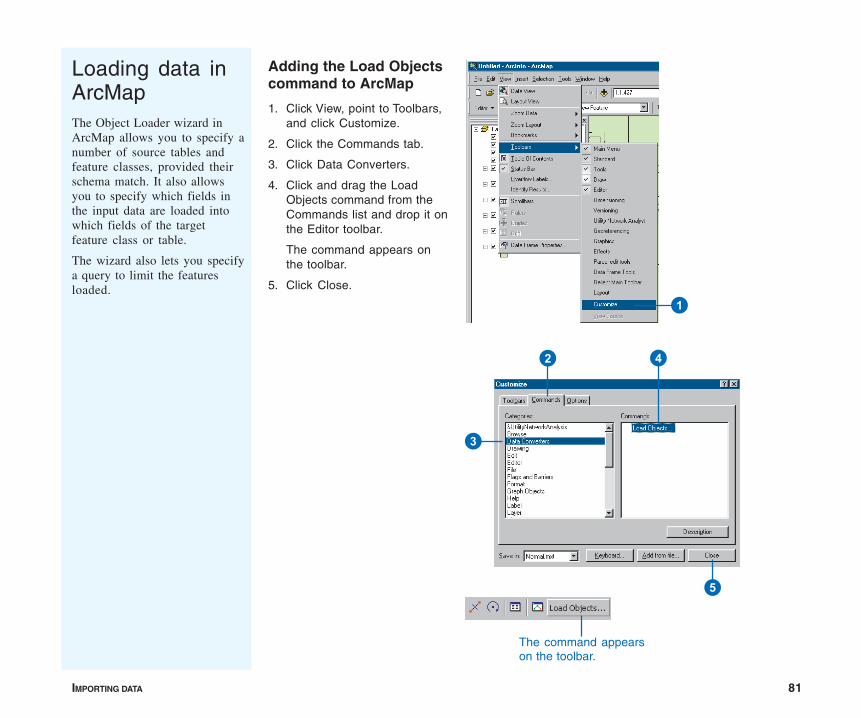
IMPORTING DATA 81
Adding the Load Objectscommand to ArcMap
1. Click View, point to Toolbars,and click Customize.
2. Click the Commands tab.
3. Click Data Converters.
4. Click and drag the LoadObjects command from theCommands list and drop it onthe Editor toolbar.
The command appears onthe toolbar.
5. Click Close.
The command appearson the toolbar.
1
2
3
4
5
Loading data inArcMapThe Object Loader wizard inArcMap allows you to specify anumber of source tables andfeature classes, provided theirschema match. It also allowsyou to specify which fields inthe input data are loaded intowhich fields of the targetfeature class or table.
The wizard also lets you specifya query to limit the featuresloaded.

82 BUILDING A GEODATABASE
Loading data with theLoad Objects command
1. Add your data to ArcMap,click Editor, then click StartEditing.
2. Click the Target layerdropdown arrow and clickthe feature class or subtypeinto which you want to loaddata.
3. Click Load Objects. u
Tip
Versioned dataWhen you load data into aversioned feature class, the newfeatures are only visible in theversion you are working with.
1
2
3
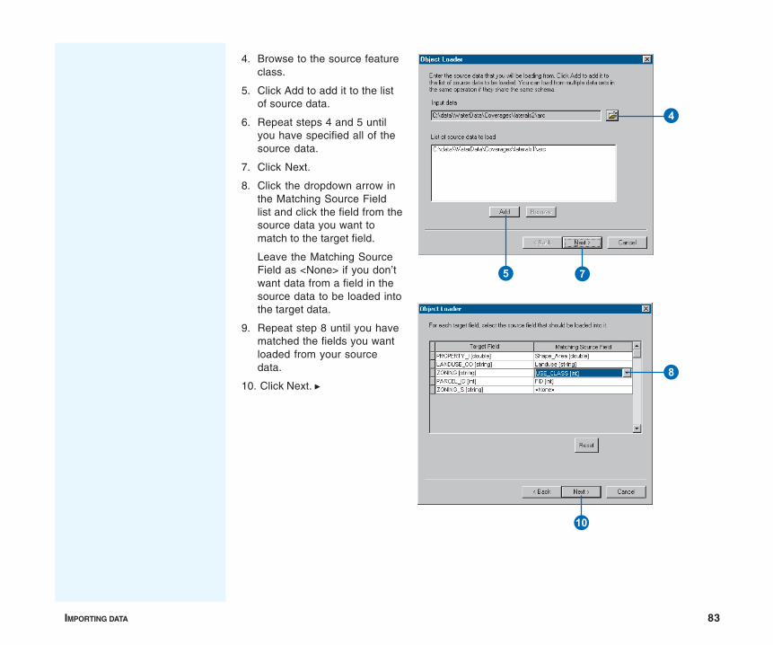
IMPORTING DATA 83
4. Browse to the source featureclass.
5. Click Add to add it to the listof source data.
6. Repeat steps 4 and 5 untilyou have specified all of thesource data.
7. Click Next.
8. Click the dropdown arrow inthe Matching Source Fieldlist and click the field from thesource data you want tomatch to the target field.
Leave the Matching SourceField as <None> if you don’twant data from a field in thesource data to be loaded intothe target data.
9. Repeat step 8 until you havematched the fields you wantloaded from your sourcedata.
10. Click Next. u
4
5 7
Q
8
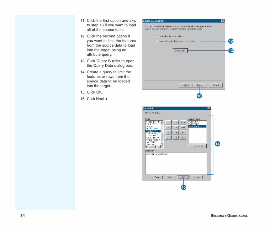
84 BUILDING A GEODATABASE
11. Click the first option and skipto step 16 if you want to loadall of the source data.
12. Click the second option ifyou want to limit the featuresfrom the source data to loadinto the target using anattribute query.
13. Click Query Builder to openthe Query Data dialog box.
14. Create a query to limit thefeatures or rows from thesource data to be loadedinto the target.
15. Click OK.
16. Click Next. u U
R
E
Y
T

IMPORTING DATA 85
17. Click No if you don’t wantyour features to be snappedto existing features in youredit session.
Click Yes if you want to usethe current Editor snappingenvironment to snap the newfeatures as they are loaded.
18. Click No if you don’t wantyour new features to bevalidated after they areloaded.
Click Yes if the feature classor subtype into which youare loading data has rulesassociated with it and youwant any new invalidfeatures to be selected afterthe loading process.
19. Click Next.
20. Review the options you havespecified for loading yourdata. If you want to changesomething, go back throughthe wizard by clicking Back.
21. Click Finish to load yourdata when satisfied withyour options.
Tip
Network featuresWhen loading data into an edgenetwork feature class, the networkconnectivity is maintained, anddefault junctions are used asdescribed earlier in this chapter.
See Also
For more information on theArcMap snapping environment, seeEditing in ArcMap.
Tip
Feature class validationThe option to validate the newfeatures applies only to thegeodatabase validation rules anddoes not validate the topology. Formore information on topologies,see the chapter ‘Topology’ in thisbook. P
O
I
S
86 BUILDING A GEODATABASE
Copying data between geodatabases
This chapter has shown you how to use the Feature Class toGeodatabase and Table to Geodatabase tools as well as the LoadData and Load Object commands. While these tools and com-mands work with data in a variety of formats, they also allow youto import or load data from a geodatabase feature class or table.The end result is like copying data from one geodatabase featureclass or table to another.
ArcCatalog and ArcMap contain additional tools that copy databetween geodatabases. As with the above tools, these tools copydata between personal geodatabases, between ArcSDEgeodatabases, or between personal and ArcSDE geodatabases.
Because these tools copy data into new feature classes andtables you create during the copying process, you must use theLoad Data or Load Objects command to load data into an existingfeature class or table.
Copying feature datasets, classes, and tables
ArcCatalog allows you to copy data from the tree view orcontents view and paste it to another location. You can copyentire feature datasets or individual feature classes and tables.For every feature dataset, feature class, and table you copy andpaste, the result is a new feature dataset, feature class, and tablein the destination geodatabase with all the features or recordsfrom the source data. If you’re copying into an ArcSDEgeodatabase, you can specify a configuration keyword to controlhow the new feature classes and tables are stored.
When you copy and paste, you copy any dependent data as well.Therefore if you copy a geometric network or topology class,then all the feature classes in the network or topology are alsocopied. If you copy a feature class or table in a relationship, therelationship class, along with the feature class or table it relatesto, is also copied. The same goes for a feature class that hasfeature-linked annotation; the feature-linked annotation is copied
too. For a feature class that has a domain, subtype, or index, thedomain, subtype, or index also copies.
If you are copying a feature class into an existing feature dataset,either in the same geodatabase or in another geodatabase, thespatial reference of the feature class and feature dataset mustmatch. If they don’t, you will not be able to copy the data.
Copying selected features and records
Suppose you don’t want to copy all of the features or recordsfrom a feature class or table, but only a selection. In ArcMap youcan select features or records using any selection method, suchas selecting features by dragging a box around them or byspecifying an attribute query. You can then export them to a newfeature class or table using either the Extract Data wizard or theExport Data command.
If you want to export dependent data with the features or records,like Copy and Paste does, use the Extract Data wizard. Because itcan export data from any layer or table in the ArcMap document,it also allows you to export from several feature classes at thesame time.
If you are exporting to an ArcSDE geodatabase, the Extract Datawizard doesn’t allow you to specify a configuration keyword. Oneway to get around this would be to use Extract Data, then copyand paste the new data to specify one or more configurationkeywords.
If you want to export selected features or records from a singlefeature class or table, you can use the Export Data command.Unlike Copy and Paste, it exports attributes and records only,without any dependent data. For example, if you export featuresfrom a feature class that uses a domain or has linked annotation,the domain or annotation doesn’t export with the features. ExportData does preserve field properties though, such as the alias,whether to allow null values, and the default value.
IMPORTING DATA 87
If you are exporting to an ArcSDE geodatabase, the Export Datacommand doesn’t allow you to specify a configuration keyword.So if you want to control how the new feature class or table iscreated and stored, use the Feature Class to Feature Class orTable to Table tool. They copy data the same way Export Datadoes, only they apply the configuration keyword you specify inthe geoprocessing environment. For more information on thesetools, see the tasks earlier in this chapter.
Sending data to another user
Suppose you have a small amount of data, less than a fewhundred thousand features, you want to send to another user.One option is to copy the data into a personal geodatabase andeither send it to the other user or have it transferred to the otheruser’s computer. However if you’re working with enough data,the geodatabase can be a large file to send or transfer.
Another option is to export all or any part of your geodatabase toa smaller ZIP file. You can then send or transfer the ZIP file toanother user, who can import the data into a differentgeodatabase to create new feature datasets, feature classes, ortables.
This chapter shows you how to export feature datasets, featureclasses, and tables to a ZIP file. When you export entire featureclasses and tables, you export any dependent data as well. Oncethe data has been imported into another geodatabase, the endresult is like copying and pasting data from one geodatabase toanother.
If instead you want to send features or records to someone whowants to import them into an existing feature class or table, youcan export the features or records to a ZIP file. However, unlikewhen you export entire feature classes and tables, any dependentdata doesn’t export. So once the data has been sent to someoneand loaded into an existing feature class or table, the end result is
like using the Load Data command in ArcCatalog or the LoadObjects command in ArcMap. For more information on exportingfeatures and records, please see the ArcGIS online Help system.
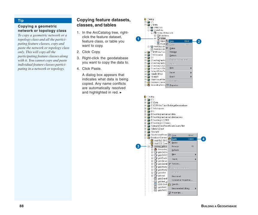
88 BUILDING A GEODATABASE
Copying feature datasets,classes, and tables
1. In the ArcCatalog tree, right-click the feature dataset,feature class, or table youwant to copy.
2. Click Copy.
3. Right-click the geodatabaseyou want to copy the data to.
4. Click Paste.
A dialog box appears thatindicates what data is beingcopied. Any name conflictsare automatically resolvedand highlighted in red. u
21
3
4
Tip
Copying a geometricnetwork or topology classTo copy a geometric network or atopology class and all the partici-pating feature classes, copy andpaste the network or topology classonly. This will copy all theparticipating feature classes alongwith it. You cannot copy and pasteindividual feature classes partici-pating in a network or topology.
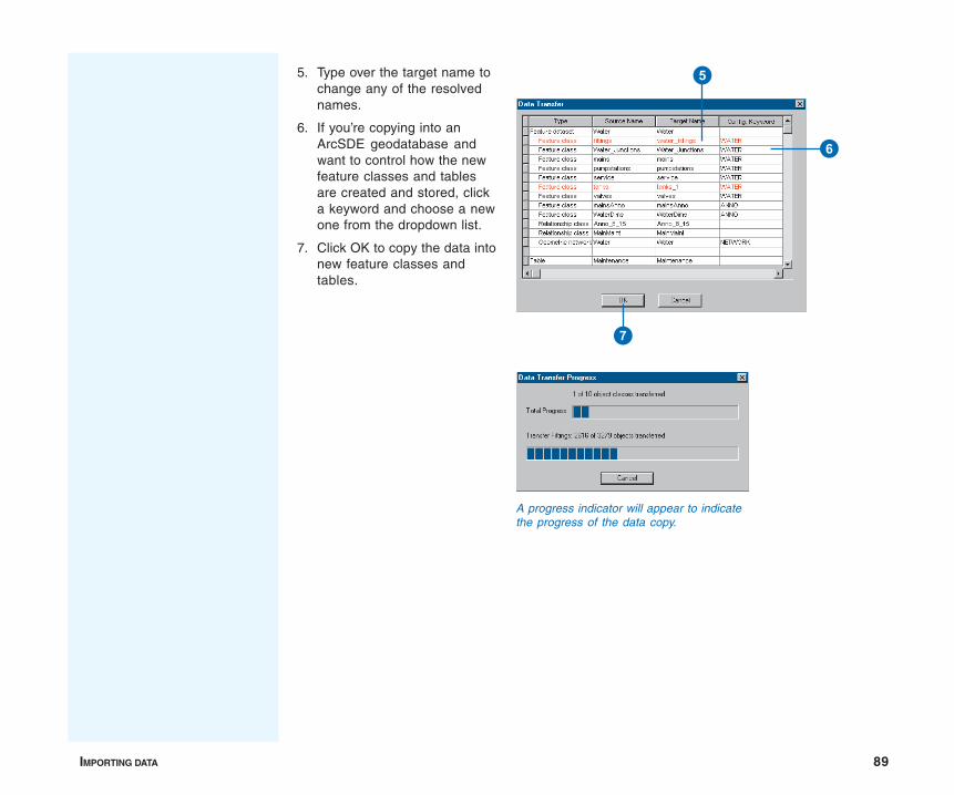
IMPORTING DATA 89
A progress indicator will appear to indicatethe progress of the data copy.
5
6
7
5. Type over the target name tochange any of the resolvednames.
6. If you’re copying into anArcSDE geodatabase andwant to control how the newfeature classes and tablesare created and stored, clicka keyword and choose a newone from the dropdown list.
7. Click OK to copy the data intonew feature classes andtables.

90 BUILDING A GEODATABASE
Exporting selectedfeatures with the ExtractData wizard
1. In ArcMap on the main menu,click View, point to Toolbars,then choose DisconnectedEditing.
The Disconnected Editingtoolbar will now appear onyour map document.
2. Specify the features you wantto export by setting thecurrent view extent to includethem, drawing a graphicaround them, selecting thefeatures, or applying adefinition query.
Or, you can specify thebounding coordinate valueslater in the wizard.
If you use more than one ofthese methods, the featuresin common will export.
3. Click the Extract Datacommand. u
1
3
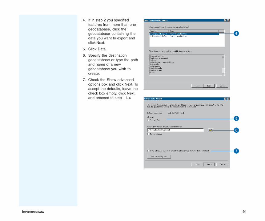
IMPORTING DATA 91
4. If in step 2 you specifiedfeatures from more than onegeodatabase, click thegeodatabase containing thedata you want to export andclick Next.
5. Click Data.
6. Specify the destinationgeodatabase or type the pathand name of a newgeodatabase you wish tocreate.
7. Check the Show advancedoptions box and click Next. Toaccept the defaults, leave thecheck box empty, click Next,and proceed to step 11. u
4
7
5
6
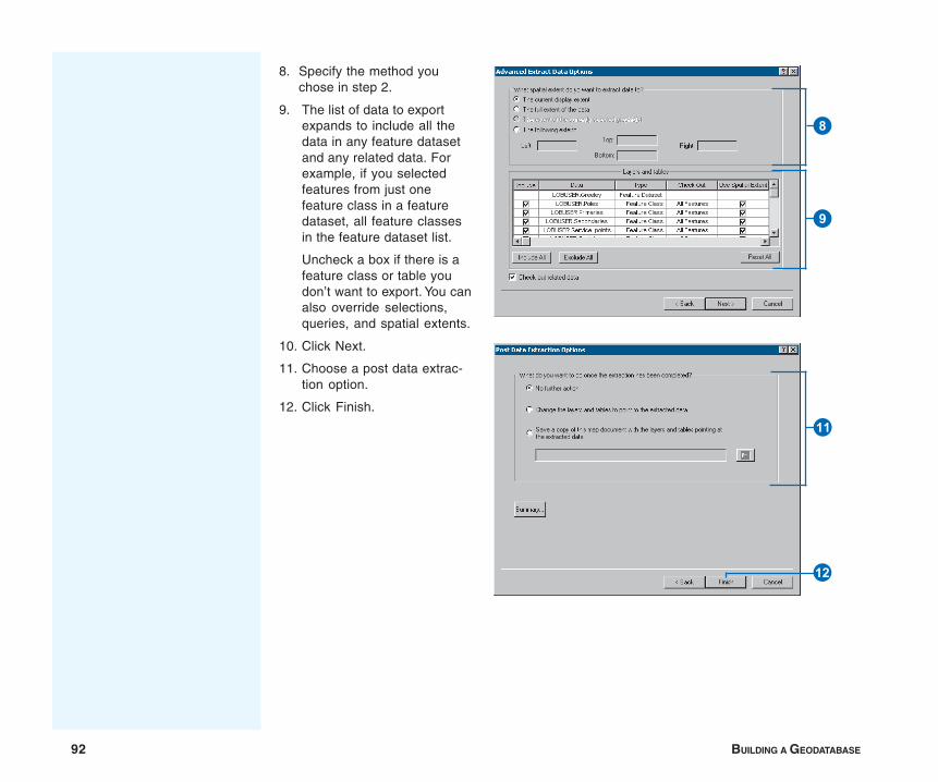
92 BUILDING A GEODATABASE
8. Specify the method youchose in step 2.
9. The list of data to exportexpands to include all thedata in any feature datasetand any related data. Forexample, if you selectedfeatures from just onefeature class in a featuredataset, all feature classesin the feature dataset list.
Uncheck a box if there is afeature class or table youdon’t want to export. You canalso override selections,queries, and spatial extents.
10. Click Next.
11. Choose a post data extrac-tion option.
12. Click Finish.
9
8
W
E
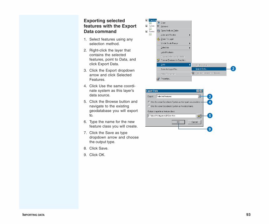
IMPORTING DATA 93
Exporting selectedfeatures with the ExportData command
1. Select features using anyselection method.
2. Right-click the layer thatcontains the selectedfeatures, point to Data, andclick Export Data.
3. Click the Export dropdownarrow and click SelectedFeatures.
4. Click Use the same coordi-nate system as this layer’sdata source.
5. Click the Browse button andnavigate to the existinggeodatabase you will exportto.
6. Type the name for the newfeature class you will create.
7. Click the Save as typedropdown arrow and choosethe output type.
8. Click Save.
9. Click OK.
2
34
5
9
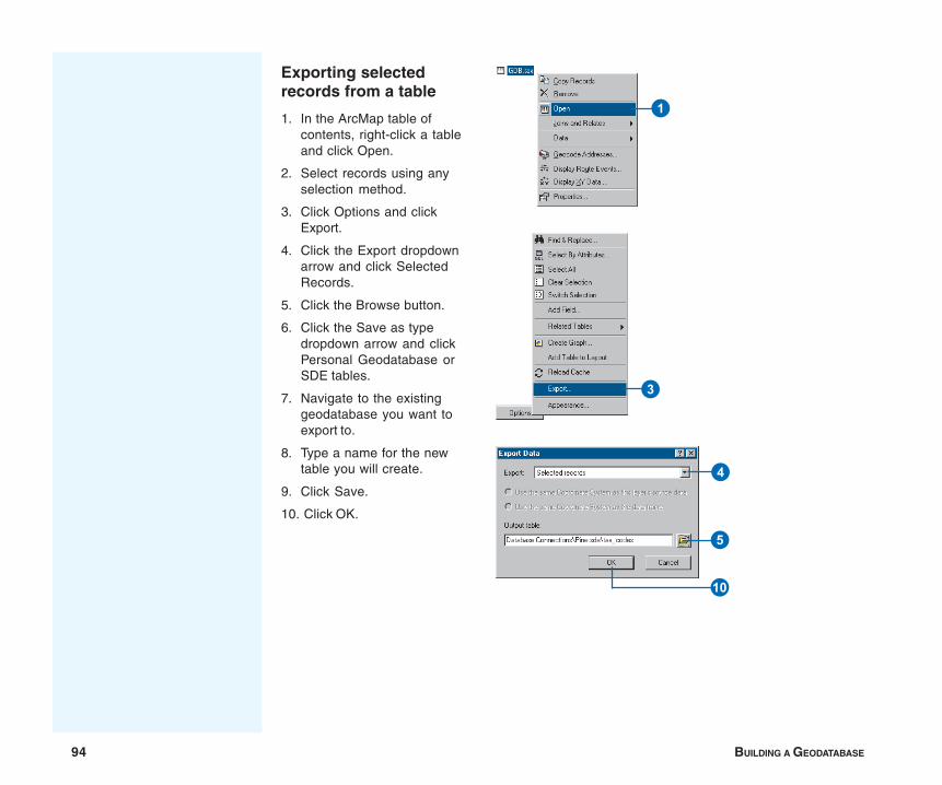
94 BUILDING A GEODATABASE
Exporting selectedrecords from a table
1. In the ArcMap table ofcontents, right-click a tableand click Open.
2. Select records using anyselection method.
3. Click Options and clickExport.
4. Click the Export dropdownarrow and click SelectedRecords.
5. Click the Browse button.
6. Click the Save as typedropdown arrow and clickPersonal Geodatabase orSDE tables.
7. Navigate to the existinggeodatabase you want toexport to.
8. Type a name for the newtable you will create.
9. Click Save.
10. Click OK.
1
3
4
5
Q
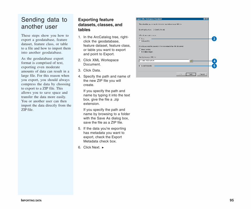
IMPORTING DATA 95
Sending data toanother userThese steps show you how toexport a geodatabase, featuredataset, feature class, or tableto a file and how to import theminto another geodatabase.
As the geodatabase exportformat is comprised of text,exporting even moderateamounts of data can result in alarge file. For this reason whenyou export, you should alwayscompress the data by choosingto export to a ZIP file. Thisallows you to save space andtransfer the data more easily.You or another user can thenimport the data directly from theZIP file.
Exporting featuredatasets, classes, andtables
1. In the ArcCatalog tree, right-click the geodatabase,feature dataset, feature class,or table you want to exportand point to Export.
2. Click XML WorkspaceDocument.
3. Click Data.
4. Specify the path and name ofthe new ZIP file you willcreate.
If you specify the path andname by typing it into the textbox, give the file a .zipextension.
If you specify the path andname by browsing to a folderwith the Save As dialog box,save the file as a ZIP file.
5. If the data you’re exportinghas metadata you want toexport, check the ExportMetadata check box.
6. Click Next. u
3
45
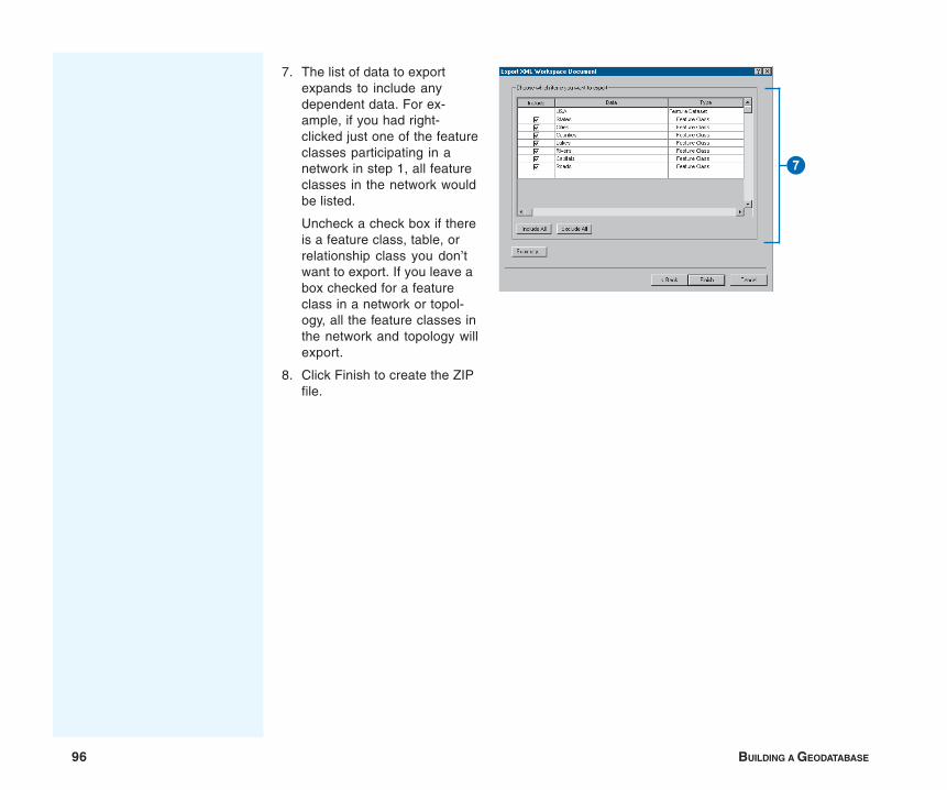
96 BUILDING A GEODATABASE
7. The list of data to exportexpands to include anydependent data. For ex-ample, if you had right-clicked just one of the featureclasses participating in anetwork in step 1, all featureclasses in the network wouldbe listed.
Uncheck a check box if thereis a feature class, table, orrelationship class you don’twant to export. If you leave abox checked for a featureclass in a network or topol-ogy, all the feature classes inthe network and topology willexport.
8. Click Finish to create the ZIPfile.
7
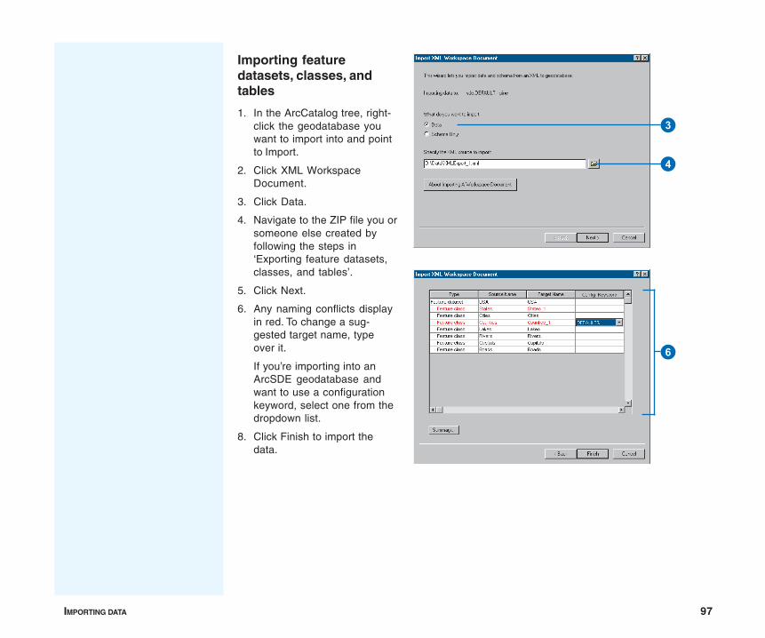
IMPORTING DATA 97
Importing featuredatasets, classes, andtables
1. In the ArcCatalog tree, right-click the geodatabase youwant to import into and pointto Import.
2. Click XML WorkspaceDocument.
3. Click Data.
4. Navigate to the ZIP file you orsomeone else created byfollowing the steps in‘Exporting feature datasets,classes, and tables’.
5. Click Next.
6. Any naming conflicts displayin red. To change a sug-gested target name, typeover it.
If you’re importing into anArcSDE geodatabase andwant to use a configurationkeyword, select one from thedropdown list.
8. Click Finish to import thedata.
3
4
6
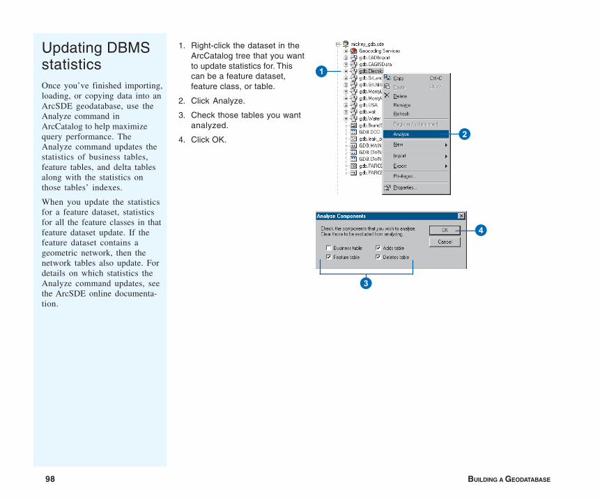
98 BUILDING A GEODATABASE
Updating DBMSstatisticsOnce you’ve finished importing,loading, or copying data into anArcSDE geodatabase, use theAnalyze command inArcCatalog to help maximizequery performance. TheAnalyze command updates thestatistics of business tables,feature tables, and delta tablesalong with the statistics onthose tables’ indexes.
When you update the statisticsfor a feature dataset, statisticsfor all the feature classes in thatfeature dataset update. If thefeature dataset contains ageometric network, then thenetwork tables also update. Fordetails on which statistics theAnalyze command updates, seethe ArcSDE online documenta-tion.
1. Right-click the dataset in theArcCatalog tree that you wantto update statistics for. Thiscan be a feature dataset,feature class, or table.
2. Click Analyze.
3. Check those tables you wantanalyzed.
4. Click OK.
1
2
3
4
IN THIS CHAPTER
99
Topology 4• What is topology?
• Creating a topology
• Topology and feature geometry
• Adding new feature classes toyour topology
• Topology: defining the rules
• Refining topologies with subtypes
• Managing and modifyinga topology
• Creating polygons from lines
• Topology and versioning
• Topology and disconnectedediting
When you model geographic features, you may find that you want to modelsome features that have spatial relationships with other features aroundthem. Countries might be modeled such that adjacent countries meet withoutgaps along a common border line but never overlap. States or provincescould be modeled such that they fall exclusively within one country. Streetsmay be modeled such that two streets always meet at an intersection andnever share a segment. Bus stops may be modeled such that they mustalways occur on a street. These relationships are maintained in thegeodatabase through an association called a topology.
In GIS technology, topology is the model used to describe how featuresshare geometry, and it is also the mechanism for establishing and maintainingtopological relationships between features. ArcGIS implements topologythrough a set of validation rules that define how features may share ageographic space and a set of editing tools that work with features thatshare geometry in an integrated fashion.
A topology is stored in a geodatabase as one or more relationships thatdefine how the features in one or more feature classes share geometry. Thefeatures participating in a topology are still simple feature classes—ratherthan modifying the definition of the feature class, a topology serves as adescription of how the features can be spatially related. ArcInfo andArcEditor provide tools for creating, evaluating, and managing the quality ofthose topological relationships. This chapter describes the physicalgeodatabase data model for topology, how you create and configure atopology, and the editing tools in ArcGIS that help you to maintain the quality
100 BUILDING A GEODATABASE
of the integrated features in a topology. Another type oftopological association, the geometric network, isdiscussed in the chapter ‘Geometric networks’ in this book.
You can create simple temporary topological relationshipsbetween features in ArcView. Creating or editinggeodatabase topology requires an ArcEditor or ArcInfolicense.
TOPOLOGY 101
Topology has historically been viewed as a spatial data structurethat is used primarily to ensure that the associated data forms aconsistent and clean topological fabric. With advances in object-oriented GIS development, an alternative view of topology hasevolved. The geodatabase supports an approach to modelinggeography that integrates the behavior of different feature typesand supports different types of key relationships. In this context,topology is a collection of rules and relationships that, coupledwith a set of editing tools and techniques, enables thegeodatabase to more accurately model geometric relationshipsfound in the world.
Topology, implemented as feature behavior and rules, allows amore flexible set of geometric relationships to be modeled thantopology implemented as a data structure. It also allows topologi-cal relationships to exist between more discrete types of featureswithin a feature dataset. In this alternative view, topology maystill be employed to ensure that the data forms a clean andconsistent topological fabric, but also more broadly, it is used toensure that the features obey the key geometric rules defined fortheir role in the database.
Why use topology?
Topology is used most fundamentally to ensure data quality andto allow your geodatabase to more realistically represent geo-graphic features. A geodatabase provides a framework withinwhich features can have behavior, such as subtypes, defaultvalues, attribute domains, validation rules, and structuredrelationships, to tables or other features. This behavior enablesyou to more accurately model the world and maintain referentialintegrity between objects in the geodatabase. Topology may beconsidered an extension of this framework for behavior thatallows you to control the geometric relationships betweenfeatures and to maintain their geometric integrity. Unlike other
What is topology?
feature behavior, topology rules are managed at the level of thetopology and dataset, not for individual feature classes.
How do I work with topology?
Different people work with topology in different ways, dependingon their role in an organization and its GIS design and manage-ment work flow.
Initially, creating a topology requires a geodatabase designer. Atopology organizes the spatial relationships between features in aset of feature classes. The designer analyzes an organization’sdata modeling needs, identifies the key topological relationshipsrequired in the geodatabase, and defines the rules that willconstrain different features’ topological relationships.
Once the participating feature classes have been added to thetopology and the rules defined, the topology is validated. Dataquality managers use the topology tools to analyze, visualize,report, and where necessary, repair the spatial integrity of thedatabase after it is initially created as well as after editing.Topology provides these users with a set of validation rules forthe topologically related features. It also provides a set of editingtools that lets users find and fix integrity violations.
As the geodatabase is used and maintained, new features areadded and existing features are modified. Data editors updatefeatures in the geodatabase and use the topology tools toconstruct and maintain relationships between features within theconstraints imposed by the database designer. Depending on thework flow of the organization, the topology may be validated aftereach edit session or on a schedule.
102 BUILDING A GEODATABASE
A topology consists of a set of rules structuring the relationshipbetween a collection of features in one or more feature classes ina feature dataset.
To create a topology, you must specify which feature classes willparticipate in the topology and what rules will govern theinteraction of features. All feature classes participating in atopology must be in the same feature dataset.
Because creating topological relationships involves snappingfeature vertices together to make them coincident, a clustertolerance must be specified for the topology. Vertices within thecluster tolerance may move slightly in the snapping process. Thedefault cluster tolerance is the minimum possible cluster toleranceand is based on the precision defined for the dataset. The clustertolerance should be small, so only close vertices are snappedtogether. A typical cluster tolerance is at least an order ofmagnitude smaller than the accuracy of your data. For example, ifyour features are accurate to 2 meters, your cluster toleranceshould be no more than 0.2 meters.
Often, you will want to be able to control which feature classesare more likely to be moved in the clustering process. Forexample, when features in one feature class are known to havemore reliable positions than another set of features, you maywant the less reliable features to snap to the more reliable ones.Ranks are assigned to the feature classes in the topology toaccommodate this common situation. Vertices of lower rankingfeatures within the cluster tolerance will be snapped to nearbyvertices of higher ranking features. Vertices of features of equalrank that lie within the cluster tolerance will be geometricallyaveraged together.
Building a topology
You may already have data from which you want to create atopology in your geodatabase. ArcCatalog contains tools tocreate a topology from that data.
The process of building a topology from existing data can besummarized in the following steps:
1. Use ArcCatalog or ArcToolbox tools to convert and load yourdata into a feature dataset in a geodatabase.
2. Use the ArcCatalog Topology wizard to build a topology fromexisting simple feature classes. In the wizard, you dosteps 3–9.
3. Name the topology.
4. Set a cluster tolerance for the topology.
5. Choose the feature classes that will participate in thetopology.
6. Choose the number of ranks to use in the topology.
7. Rank the feature classes in the topology.
8. Add topology rules to structure the spatial relationshipsbetween features.
9. Create the topology.
10. Use ArcCatalog or ArcMap to validate the topology.
11. Use the ArcMap Topology Error Inspector to identifytopology errors.
12. Use ArcMap to fix topology errors or mark them asexceptions.
Creating a topology
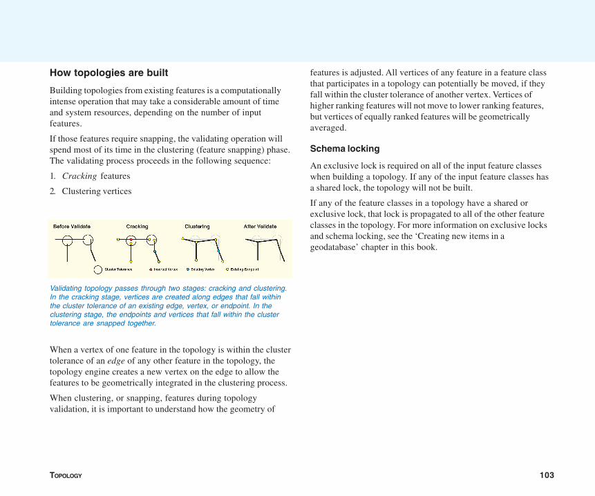
TOPOLOGY 103
How topologies are built
Building topologies from existing features is a computationallyintense operation that may take a considerable amount of timeand system resources, depending on the number of inputfeatures.
If those features require snapping, the validating operation willspend most of its time in the clustering (feature snapping) phase.The validating process proceeds in the following sequence:
1. Cracking features
2. Clustering vertices
When a vertex of one feature in the topology is within the clustertolerance of an edge of any other feature in the topology, thetopology engine creates a new vertex on the edge to allow thefeatures to be geometrically integrated in the clustering process.
When clustering, or snapping, features during topologyvalidation, it is important to understand how the geometry of
Validating topology passes through two stages: cracking and clustering.In the cracking stage, vertices are created along edges that fall withinthe cluster tolerance of an existing edge, vertex, or endpoint. In theclustering stage, the endpoints and vertices that fall within the clustertolerance are snapped together.
features is adjusted. All vertices of any feature in a feature classthat participates in a topology can potentially be moved, if theyfall within the cluster tolerance of another vertex. Vertices ofhigher ranking features will not move to lower ranking features,but vertices of equally ranked features will be geometricallyaveraged.
Schema locking
An exclusive lock is required on all of the input feature classeswhen building a topology. If any of the input feature classes hasa shared lock, the topology will not be built.
If any of the feature classes in a topology have a shared orexclusive lock, that lock is propagated to all of the other featureclasses in the topology. For more information on exclusive locksand schema locking, see the ‘Creating new items in ageodatabase’ chapter in this book.
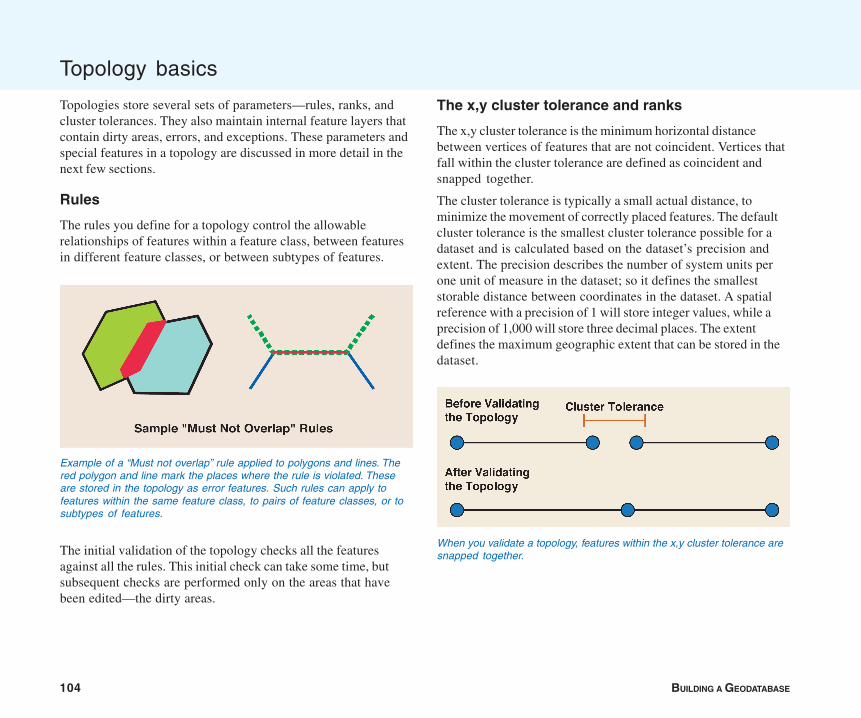
104 BUILDING A GEODATABASE
Topology basics
Topologies store several sets of parameters—rules, ranks, andcluster tolerances. They also maintain internal feature layers thatcontain dirty areas, errors, and exceptions. These parameters andspecial features in a topology are discussed in more detail in thenext few sections.
Rules
The rules you define for a topology control the allowablerelationships of features within a feature class, between featuresin different feature classes, or between subtypes of features.
The initial validation of the topology checks all the featuresagainst all the rules. This initial check can take some time, butsubsequent checks are performed only on the areas that havebeen edited—the dirty areas.
The x,y cluster tolerance and ranks
The x,y cluster tolerance is the minimum horizontal distancebetween vertices of features that are not coincident. Vertices thatfall within the cluster tolerance are defined as coincident andsnapped together.
The cluster tolerance is typically a small actual distance, tominimize the movement of correctly placed features. The defaultcluster tolerance is the smallest cluster tolerance possible for adataset and is calculated based on the dataset’s precision andextent. The precision describes the number of system units perone unit of measure in the dataset; so it defines the smalleststorable distance between coordinates in the dataset. A spatialreference with a precision of 1 will store integer values, while aprecision of 1,000 will store three decimal places. The extentdefines the maximum geographic extent that can be stored in thedataset.
Example of a “Must not overlap” rule applied to polygons and lines. Thered polygon and line mark the places where the rule is violated. Theseare stored in the topology as error features. Such rules can apply tofeatures within the same feature class, to pairs of feature classes, or tosubtypes of features.
When you validate a topology, features within the x,y cluster tolerance aresnapped together.
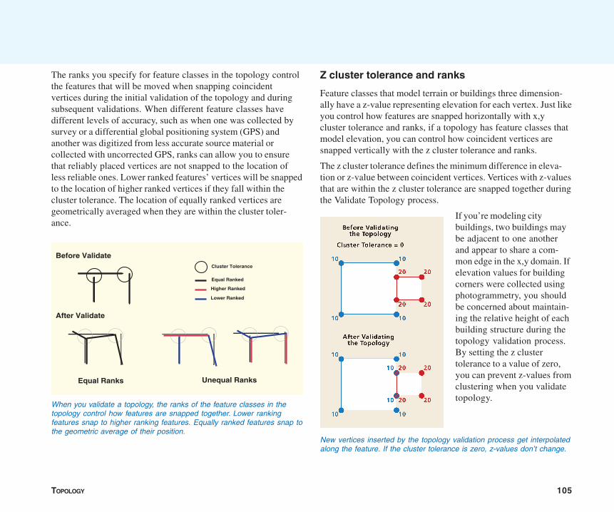
TOPOLOGY 105
The ranks you specify for feature classes in the topology controlthe features that will be moved when snapping coincidentvertices during the initial validation of the topology and duringsubsequent validations. When different feature classes havedifferent levels of accuracy, such as when one was collected bysurvey or a differential global positioning system (GPS) andanother was digitized from less accurate source material orcollected with uncorrected GPS, ranks can allow you to ensurethat reliably placed vertices are not snapped to the location ofless reliable ones. Lower ranked features’ vertices will be snappedto the location of higher ranked vertices if they fall within thecluster tolerance. The location of equally ranked vertices aregeometrically averaged when they are within the cluster toler-ance.
Z cluster tolerance and ranks
Feature classes that model terrain or buildings three dimension-ally have a z-value representing elevation for each vertex. Just likeyou control how features are snapped horizontally with x,ycluster tolerance and ranks, if a topology has feature classes thatmodel elevation, you can control how coincident vertices aresnapped vertically with the z cluster tolerance and ranks.
The z cluster tolerance defines the minimum difference in eleva-tion or z-value between coincident vertices. Vertices with z-valuesthat are within the z cluster tolerance are snapped together duringthe Validate Topology process.
If you’re modeling citybuildings, two buildings maybe adjacent to one anotherand appear to share a com-mon edge in the x,y domain. Ifelevation values for buildingcorners were collected usingphotogrammetry, you shouldbe concerned about maintain-ing the relative height of eachbuilding structure during thetopology validation process.By setting the z clustertolerance to a value of zero,you can prevent z-values fromclustering when you validatetopology.
Cluster Tolerance
Higher Ranked
Equal Ranked
Before Validate
After Validate
Equal Ranks Unequal Ranks
Lower Ranked
When you validate a topology, the ranks of the feature classes in thetopology control how features are snapped together. Lower rankingfeatures snap to higher ranking features. Equally ranked features snap tothe geometric average of their position.
New vertices inserted by the topology validation process get interpolatedalong the feature. If the cluster tolerance is zero, z-values don’t change.
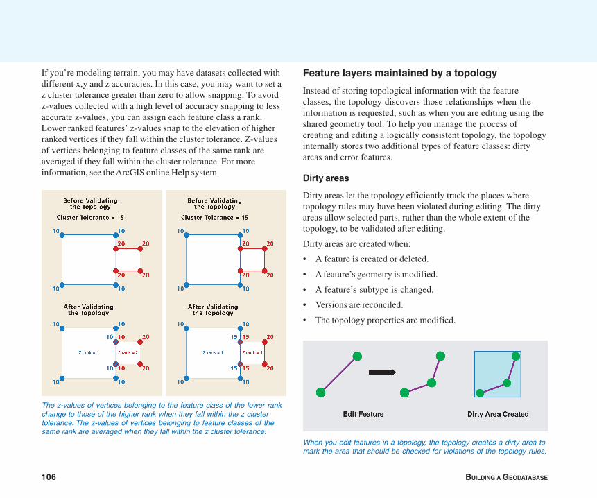
106 BUILDING A GEODATABASE
If you’re modeling terrain, you may have datasets collected withdifferent x,y and z accuracies. In this case, you may want to set az cluster tolerance greater than zero to allow snapping. To avoidz-values collected with a high level of accuracy snapping to lessaccurate z-values, you can assign each feature class a rank.Lower ranked features’ z-values snap to the elevation of higherranked vertices if they fall within the cluster tolerance. Z-valuesof vertices belonging to feature classes of the same rank areaveraged if they fall within the cluster tolerance. For moreinformation, see the ArcGIS online Help system.
Feature layers maintained by a topology
Instead of storing topological information with the featureclasses, the topology discovers those relationships when theinformation is requested, such as when you are editing using theshared geometry tool. To help you manage the process ofcreating and editing a logically consistent topology, the topologyinternally stores two additional types of feature classes: dirtyareas and error features.
Dirty areas
Dirty areas let the topology efficiently track the places wheretopology rules may have been violated during editing. The dirtyareas allow selected parts, rather than the whole extent of thetopology, to be validated after editing.
Dirty areas are created when:
• A feature is created or deleted.
• A feature’s geometry is modified.
• A feature’s subtype is changed.
• Versions are reconciled.
• The topology properties are modified.
When you edit features in a topology, the topology creates a dirty area tomark the area that should be checked for violations of the topology rules.
The z-values of vertices belonging to the feature class of the lower rankchange to those of the higher rank when they fall within the z clustertolerance. The z-values of vertices belonging to feature classes of thesame rank are averaged when they fall within the z cluster tolerance.
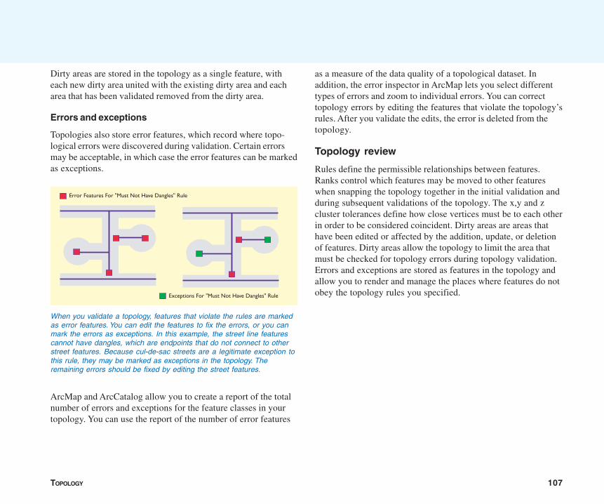
TOPOLOGY 107
Error Features For "Must Not Have Dangles" Rule
Exceptions For "Must Not Have Dangles" Rule
When you validate a topology, features that violate the rules are markedas error features. You can edit the features to fix the errors, or you canmark the errors as exceptions. In this example, the street line featurescannot have dangles, which are endpoints that do not connect to otherstreet features. Because cul-de-sac streets are a legitimate exception tothis rule, they may be marked as exceptions in the topology. Theremaining errors should be fixed by editing the street features.
Dirty areas are stored in the topology as a single feature, witheach new dirty area united with the existing dirty area and eacharea that has been validated removed from the dirty area.
Errors and exceptions
Topologies also store error features, which record where topo-logical errors were discovered during validation. Certain errorsmay be acceptable, in which case the error features can be markedas exceptions.
ArcMap and ArcCatalog allow you to create a report of the totalnumber of errors and exceptions for the feature classes in yourtopology. You can use the report of the number of error features
as a measure of the data quality of a topological dataset. Inaddition, the error inspector in ArcMap lets you select differenttypes of errors and zoom to individual errors. You can correcttopology errors by editing the features that violate the topology’srules. After you validate the edits, the error is deleted from thetopology.
Topology review
Rules define the permissible relationships between features.Ranks control which features may be moved to other featureswhen snapping the topology together in the initial validation andduring subsequent validations of the topology. The x,y and zcluster tolerances define how close vertices must be to each otherin order to be considered coincident. Dirty areas are areas thathave been edited or affected by the addition, update, or deletionof features. Dirty areas allow the topology to limit the area thatmust be checked for topology errors during topology validation.Errors and exceptions are stored as features in the topology andallow you to render and manage the places where features do notobey the topology rules you specified.
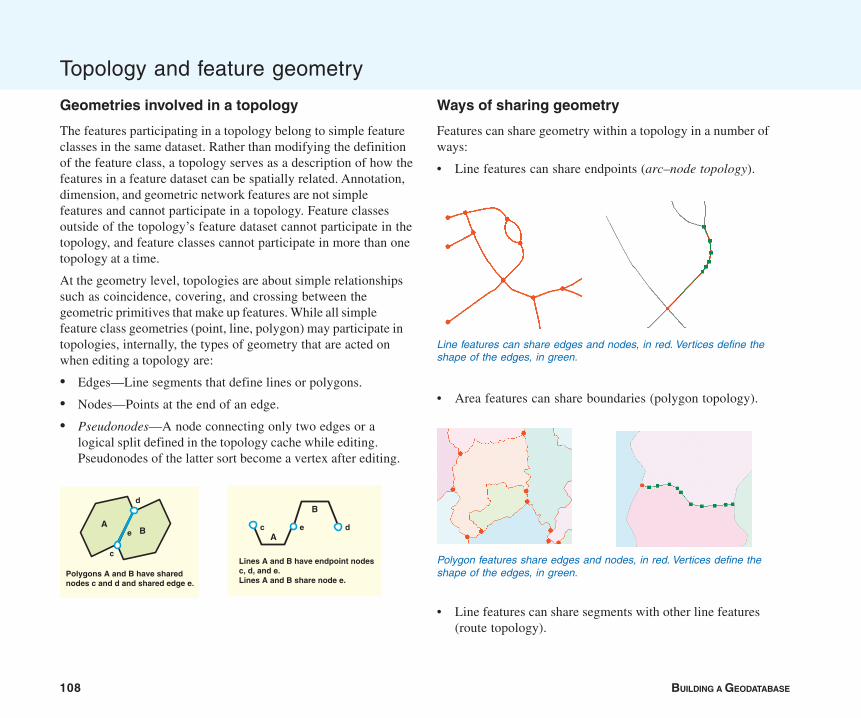
108 BUILDING A GEODATABASE
Geometries involved in a topology
The features participating in a topology belong to simple featureclasses in the same dataset. Rather than modifying the definitionof the feature class, a topology serves as a description of how thefeatures in a feature dataset can be spatially related. Annotation,dimension, and geometric network features are not simplefeatures and cannot participate in a topology. Feature classesoutside of the topology’s feature dataset cannot participate in thetopology, and feature classes cannot participate in more than onetopology at a time.
At the geometry level, topologies are about simple relationshipssuch as coincidence, covering, and crossing between thegeometric primitives that make up features. While all simplefeature class geometries (point, line, polygon) may participate intopologies, internally, the types of geometry that are acted onwhen editing a topology are:
• Edges—Line segments that define lines or polygons.
• Nodes—Points at the end of an edge.
• Pseudonodes—A node connecting only two edges or alogical split defined in the topology cache while editing.Pseudonodes of the latter sort become a vertex after editing.
Ways of sharing geometry
Features can share geometry within a topology in a number ofways:
• Line features can share endpoints (arc–node topology).
• Area features can share boundaries (polygon topology).
• Line features can share segments with other line features(route topology).
Topology and feature geometry
Polygon features share edges and nodes, in red. Vertices define theshape of the edges, in green.Polygons A and B have shared
nodes c and d and shared edge e.
AB
c
d
e
Lines A and B have endpoint nodes c, d, and e. Lines A and B share node e.
A
B
c de
Line features can share edges and nodes, in red. Vertices define theshape of the edges, in green.
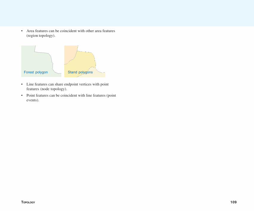
TOPOLOGY 109
• Area features can be coincident with other area features(region topology).
• Line features can share endpoint vertices with pointfeatures (node topology).
• Point features can be coincident with line features (pointevents).
Forest polygon Stand polygons
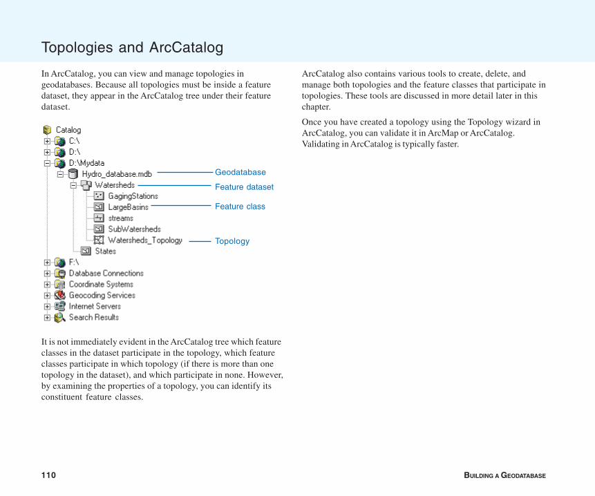
110 BUILDING A GEODATABASE
In ArcCatalog, you can view and manage topologies ingeodatabases. Because all topologies must be inside a featuredataset, they appear in the ArcCatalog tree under their featuredataset.
It is not immediately evident in the ArcCatalog tree which featureclasses in the dataset participate in the topology, which featureclasses participate in which topology (if there is more than onetopology in the dataset), and which participate in none. However,by examining the properties of a topology, you can identify itsconstituent feature classes.
Topologies and ArcCatalog
Geodatabase
Feature class
Topology
Feature dataset
ArcCatalog also contains various tools to create, delete, andmanage both topologies and the feature classes that participate intopologies. These tools are discussed in more detail later in thischapter.
Once you have created a topology using the Topology wizard inArcCatalog, you can validate it in ArcMap or ArcCatalog.Validating in ArcCatalog is typically faster.
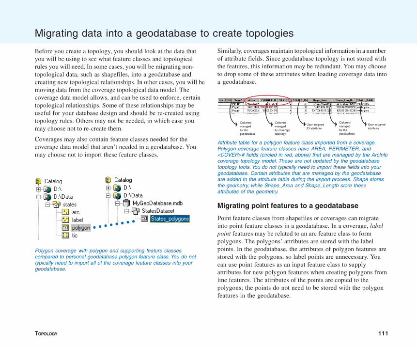
TOPOLOGY 111
Migrating data into a geodatabase to create topologies
Before you create a topology, you should look at the data thatyou will be using to see what feature classes and topologicalrules you will need. In some cases, you will be migrating non-topological data, such as shapefiles, into a geodatabase andcreating new topological relationships. In other cases, you will bemoving data from the coverage topological data model. Thecoverage data model allows, and can be used to enforce, certaintopological relationships. Some of these relationships may beuseful for your database design and should be re-created usingtopology rules. Others may not be needed, in which case youmay choose not to re-create them.
Coverages may also contain feature classes needed for thecoverage data model that aren’t needed in a geodatabase. Youmay choose not to import these feature classes.
Similarly, coverages maintain topological information in a numberof attribute fields. Since geodatabase topology is not stored withthe features, this information may be redundant. You may chooseto drop some of these attributes when loading coverage data intoa geodatabase.
Migrating point features to a geodatabase
Point feature classes from shapefiles or coverages can migrateinto point feature classes in a geodatabase. In a coverage, labelpoint features may be related to an arc feature class to formpolygons. The polygons’ attributes are stored with the labelpoints. In the geodatabase, the attributes of polygon features arestored with the polygons, so label points are unnecessary. Youcan use point features as an input feature class to supplyattributes for new polygon features when creating polygons fromline features. The attributes of the points are copied to thepolygons; the points do not need to be stored with the polygonfeatures in the geodatabase.
Columns managed by the geodatabase
Columns managed by coverage topology
User assigned ID attribute
Columns managed by the geodatabase
User assigned attribute
Attribute table for a polygon feature class imported from a coverage.Polygon coverage feature classes have AREA, PERIMETER, and<COVER># fields (circled in red, above) that are managed by the ArcInfocoverage topology model. These are not updated by the geodatabasetopology tools. You do not typically need to import these fields into yourgeodatabase. Certain attributes that are managed by the geodatabaseare added to the attribute table during the import process. Shape storesthe geometry, while Shape_Area and Shape_Length store theseattributes of the geometry.
Polygon coverage with polygon and supporting feature classes,compared to personal geodatabase polygon feature class. You do nottypically need to import all of the coverage feature classes into yourgeodatabase.
○ ○ ○ ○ ○ ○ ○ ○
112 BUILDING A GEODATABASE
Geometry
Point features are not constructed from other feature classes inthe coverage data model, so there are no supporting featureclasses to keep or drop when importing coverage point featuresto a geodatabase. The Area and Perimeter items may be dropped,as they are used to manage polygon coverage topology.
Attributes
Node feature classes in an arc coverage may carry attributes andcan be migrated to point feature classes in the geodatabase. TheARC# item in a node attribute table may be redundant, as it isprimarily used to manage coverage arc–node topology.
Topology
In a geodatabase topology, point features can be topologicallyrelated to line features, the endpoints of line features, andpolygon features. Points can be constrained to fall along lines, atthe endpoints of lines, within polygons, or on the edges ofpolygons. See the ‘Topology: defining the rules’ section of thischapter for a more detailed discussion of the main topologicalrelationships supported by the geodatabase for point features.
Migrating linear features to a geodatabase
Line features are represented by arcs in a coverage and bypolylines in a shapefile. Arc and polyline feature classes migrateinto line feature classes in a geodatabase.
Geometry
Arcs may be topologically related to nodes, polygons, or otherarcs (routes) in the coverage data model. When migrating arccoverages into a geodatabase, you may want to import the nodefeatures as point features if you use the nodes to store attributevalues. If you do not store attributes with nodes, you can choose
not to migrate the node features. When migrating route features,you can choose whether or not to migrate the supporting arcfeature class to another line feature class.
Attributes
Coverage arc feature classes have a Length field that is super-seded by the geodatabase’s Shape_length field. The geodatabasewill not update this field, so it may be deleted when you load thefeature class. Coverage arc feature classes also have FNODE#,TNODE#, LPOLY#, RPOLY#, and <cover name># fields that arenot managed by geodatabase topology. You can drop these fieldswhen you import the coverage.
Topology
Polyline features in shapefiles do not have topology rules ortopological relationships to other features.
Coverage arc feature classes have built-in topology rules thatspecify that they must split at a node when they cross other arcs.Arcs have an additional topology rule that they must connect tomore than one other arc at a node. Exceptions to this rule arecalled dangles—where an end of an arc fails to connect toanother arc—and pseudonodes—where an arc connects to itselfor one other arc.
In a geodatabase topology, line features can be topologicallyrelated to point features, other line features, and polygonfeatures. Lines can be constrained to fall along other lines, toconnect to other lines at their endpoints, or not to touch orintersect themselves or other lines. They can be constrained notto have dangles or pseudonodes. They can outline the edges ofpolygons or not touch polygons. See the ‘Topology: defining therules’ section of this chapter for a more detailed discussion of themain topological relationships supported by the geodatabase forline features.
TOPOLOGY 113
Migrating area features to a geodatabase
Area features are represented by polygon feature classes incoverages and in shapefiles. They may also be represented byregion feature classes in a coverage. Coverage polygon topologyhas certain inherent rules, requiring coverage polygon edges tobe defined by the arcs’ feature class, to completely tile the extentof the coverage, and not to overlap other polygons. Coveragepolygons may also be topologically related to a label pointfeature class.
Shapefile polygons do not have any topology rules and are nottopologically related to other feature classes.
Geometry
Coverage polygon feature classes are topologically related to twosupporting feature classes, the label and arc feature classes. Theymay also be topologically related to other polygons to formregions, which are coverage area features that can overlap andwhich do not have to tile the whole extent of the coverage.Regions are somewhat like shapefile polygons. They migrate topolygon features in a geodatabase. You may choose not tomigrate the supporting polygon feature classes if the regionsstore the attributes you use.
Attributes
Coverage polygon feature classes have Perimeter and Area fieldsthat are superseded by the geodatabase’s Shape_length andShape_area fields. Perimeter and Area fields can be dropped whenpolygon coverages are migrated to the geodatabase. Thesupporting arc and node feature classes can also be dropped asgeodatabase polygons do not depend upon these featureclasses.
Topology
In a geodatabase topology, polygon features can be topologicallyrelated to point features, line features, and other polygonfeatures. Points can be constrained to fall inside or on the edgesof polygons. Lines can be constrained to fall along the edges ofpolygons, within polygons, outside or not touching polygons, ornot crossing the edges of polygons. Polygons can be con-strained to not overlap or to be allowed to overlap. Polygons fromone feature class may tile within the polygons of another polygonfeature class, may exactly cover the other feature class, or maynot overlap polygons of another feature class. See the ‘Topology:defining the rules’ section of this chapter for a more detaileddiscussion of the main topological relationships supported by thegeodatabase for polygon features.
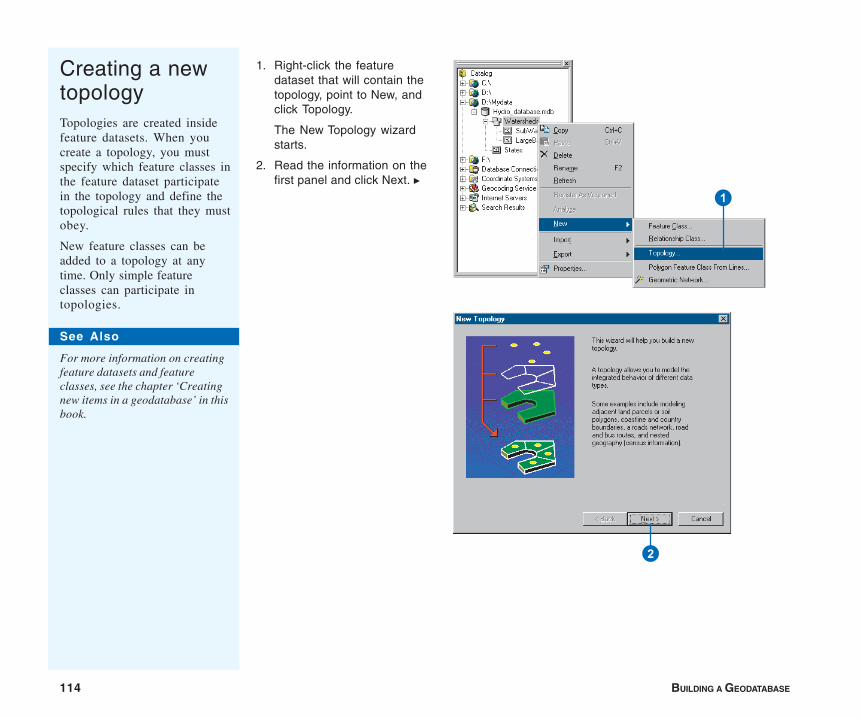
114 BUILDING A GEODATABASE
Creating a newtopologyTopologies are created insidefeature datasets. When youcreate a topology, you mustspecify which feature classes inthe feature dataset participatein the topology and define thetopological rules that they mustobey.
New feature classes can beadded to a topology at anytime. Only simple featureclasses can participate intopologies.
1. Right-click the featuredataset that will contain thetopology, point to New, andclick Topology.
The New Topology wizardstarts.
2. Read the information on thefirst panel and click Next. u
2
1
See Also
For more information on creatingfeature datasets and featureclasses, see the chapter ‘Creatingnew items in a geodatabase’ in thisbook.
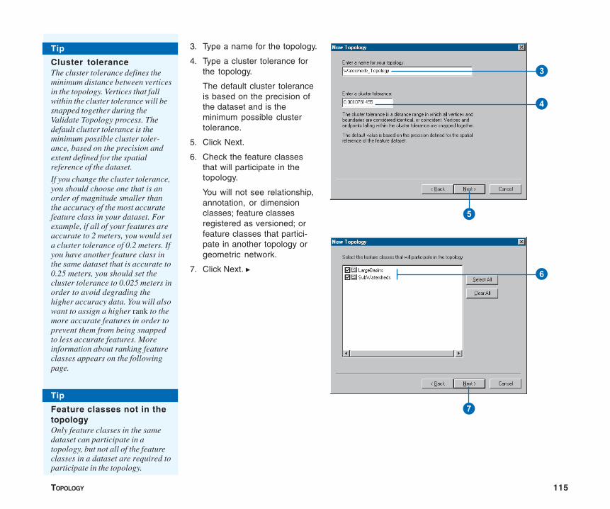
TOPOLOGY 115
3. Type a name for the topology.
4. Type a cluster tolerance forthe topology.
The default cluster toleranceis based on the precision ofthe dataset and is theminimum possible clustertolerance.
5. Click Next.
6. Check the feature classesthat will participate in thetopology.
You will not see relationship,annotation, or dimensionclasses; feature classesregistered as versioned; orfeature classes that partici-pate in another topology orgeometric network.
7. Click Next. u
Tip
Cluster toleranceThe cluster tolerance defines theminimum distance between verticesin the topology. Vertices that fallwithin the cluster tolerance will besnapped together during theValidate Topology process. Thedefault cluster tolerance is theminimum possible cluster toler-ance, based on the precision andextent defined for the spatialreference of the dataset.
If you change the cluster tolerance,you should choose one that is anorder of magnitude smaller thanthe accuracy of the most accuratefeature class in your dataset. Forexample, if all of your features areaccurate to 2 meters, you would seta cluster tolerance of 0.2 meters. Ifyou have another feature class inthe same dataset that is accurate to0.25 meters, you should set thecluster tolerance to 0.025 meters inorder to avoid degrading thehigher accuracy data. You will alsowant to assign a higher rank to themore accurate features in order toprevent them from being snappedto less accurate features. Moreinformation about ranking featureclasses appears on the followingpage.
Tip
Feature classes not in thetopologyOnly feature classes in the samedataset can participate in atopology, but not all of the featureclasses in a dataset are required toparticipate in the topology.
3
4
5
6
7
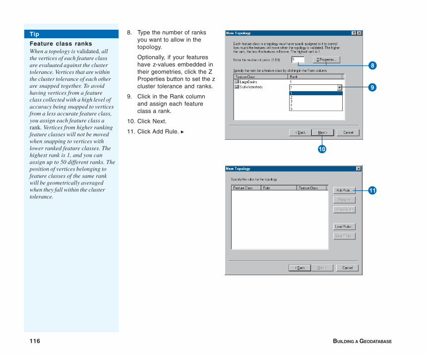
116 BUILDING A GEODATABASE
8. Type the number of ranksyou want to allow in thetopology.
Optionally, if your featureshave z-values embedded intheir geometries, click the ZProperties button to set the zcluster tolerance and ranks.
9. Click in the Rank columnand assign each featureclass a rank.
10. Click Next.
11. Click Add Rule. u
Q
W
Tip
Feature class ranksWhen a topology is validated, allthe vertices of each feature classare evaluated against the clustertolerance. Vertices that are withinthe cluster tolerance of each otherare snapped together. To avoidhaving vertices from a featureclass collected with a high level ofaccuracy being snapped to verticesfrom a less accurate feature class,you assign each feature class arank. Vertices from higher rankingfeature classes will not be movedwhen snapping to vertices withlower ranked feature classes. Thehighest rank is 1, and you canassign up to 50 different ranks. Theposition of vertices belonging tofeature classes of the same rankwill be geometrically averagedwhen they fall within the clustertolerance.
8
9
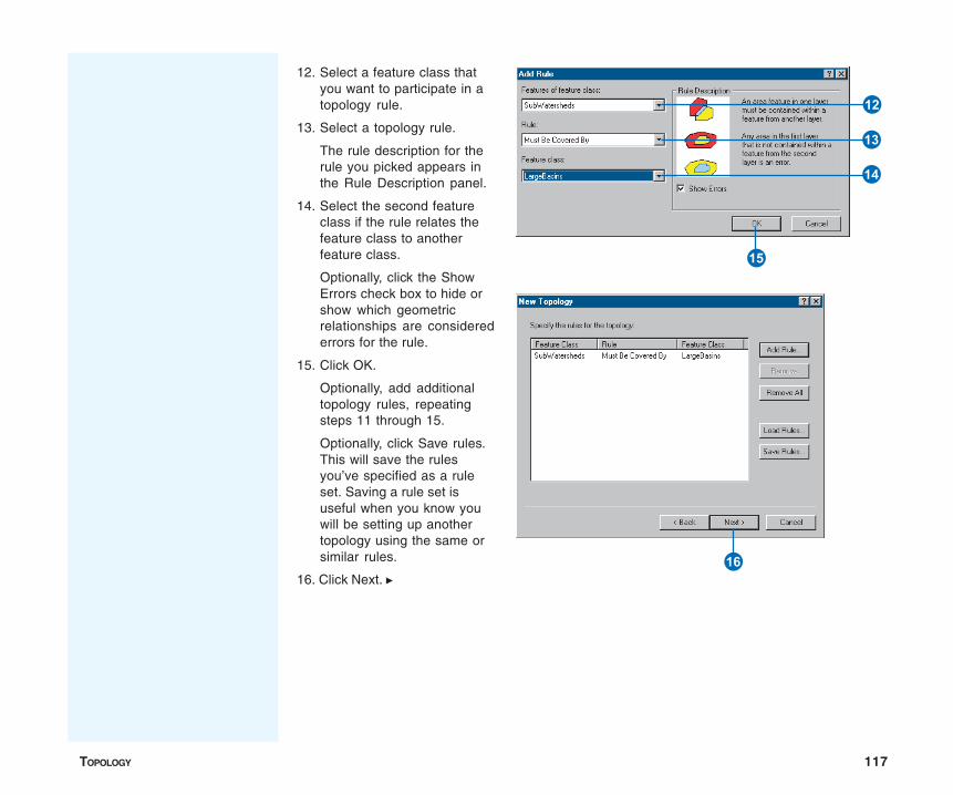
TOPOLOGY 117
12. Select a feature class thatyou want to participate in atopology rule.
13. Select a topology rule.
The rule description for therule you picked appears inthe Rule Description panel.
14. Select the second featureclass if the rule relates thefeature class to anotherfeature class.
Optionally, click the ShowErrors check box to hide orshow which geometricrelationships are considerederrors for the rule.
15. Click OK.
Optionally, add additionaltopology rules, repeatingsteps 11 through 15.
Optionally, click Save rules.This will save the rulesyou’ve specified as a ruleset. Saving a rule set isuseful when you know youwill be setting up anothertopology using the same orsimilar rules.
16. Click Next. u
E
T
Y
R
U
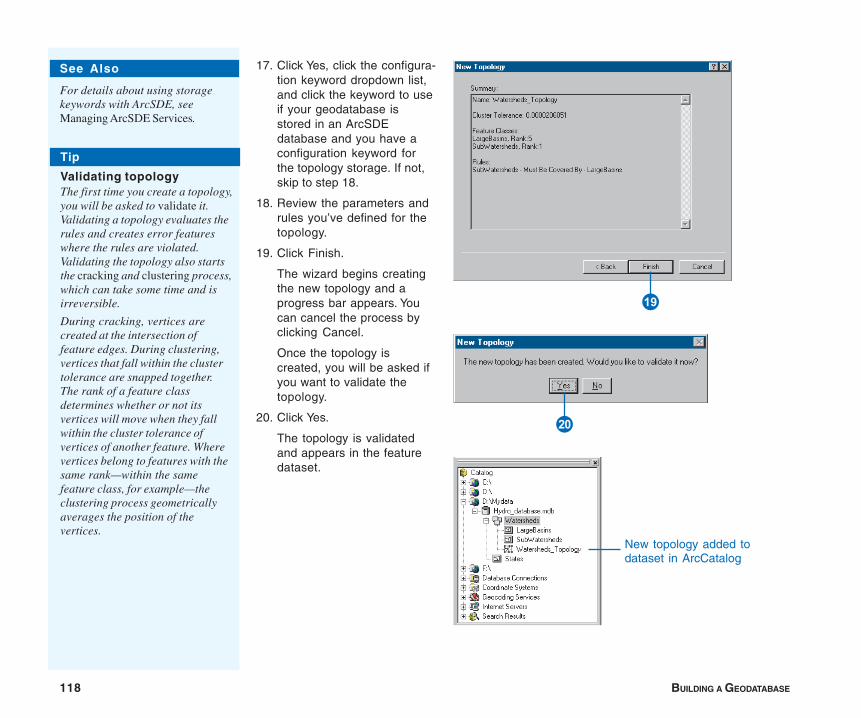
118 BUILDING A GEODATABASE
17. Click Yes, click the configura-tion keyword dropdown list,and click the keyword to useif your geodatabase isstored in an ArcSDEdatabase and you have aconfiguration keyword forthe topology storage. If not,skip to step 18.
18. Review the parameters andrules you’ve defined for thetopology.
19. Click Finish.
The wizard begins creatingthe new topology and aprogress bar appears. Youcan cancel the process byclicking Cancel.
Once the topology iscreated, you will be asked ifyou want to validate thetopology.
20. Click Yes.
The topology is validatedand appears in the featuredataset.
P
New topology added todataset in ArcCatalog
A
See Also
For details about using storagekeywords with ArcSDE, seeManaging ArcSDE Services.
Tip
Validating topologyThe first time you create a topology,you will be asked to validate it.Validating a topology evaluates therules and creates error featureswhere the rules are violated.Validating the topology also startsthe cracking and clustering process,which can take some time and isirreversible.
During cracking, vertices arecreated at the intersection offeature edges. During clustering,vertices that fall within the clustertolerance are snapped together.The rank of a feature classdetermines whether or not itsvertices will move when they fallwithin the cluster tolerance ofvertices of another feature. Wherevertices belong to features with thesame rank—within the samefeature class, for example—theclustering process geometricallyaverages the position of thevertices.
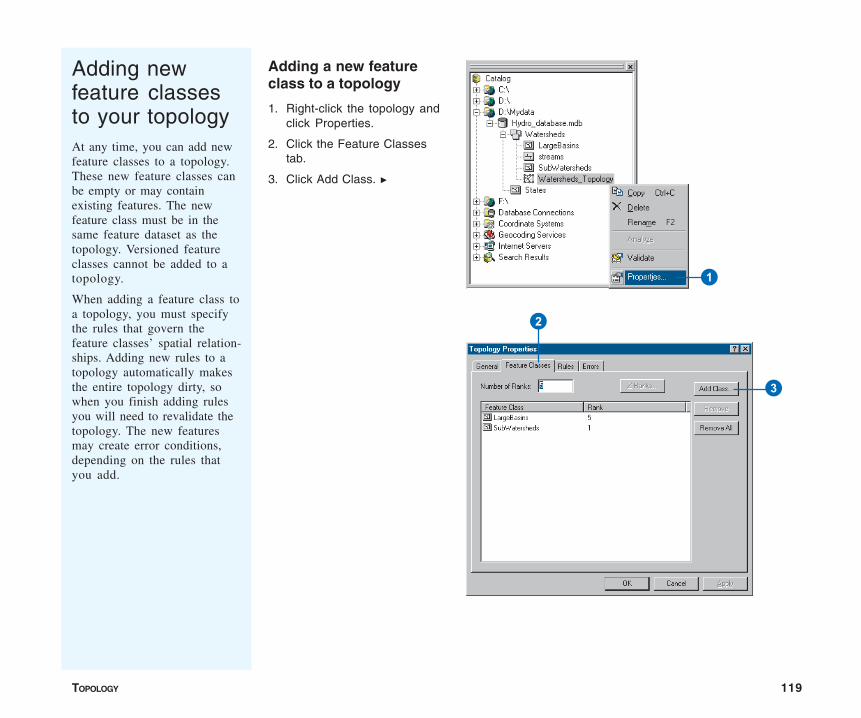
TOPOLOGY 119
Adding newfeature classesto your topologyAt any time, you can add newfeature classes to a topology.These new feature classes canbe empty or may containexisting features. The newfeature class must be in thesame feature dataset as thetopology. Versioned featureclasses cannot be added to atopology.
When adding a feature class toa topology, you must specifythe rules that govern thefeature classes’ spatial relation-ships. Adding new rules to atopology automatically makesthe entire topology dirty, sowhen you finish adding rulesyou will need to revalidate thetopology. The new featuresmay create error conditions,depending on the rules thatyou add.
Adding a new featureclass to a topology
1. Right-click the topology andclick Properties.
2. Click the Feature Classestab.
3. Click Add Class. u
1
2
3

120 BUILDING A GEODATABASE
4. Click the feature class thatyou want to add to thetopology.
Only feature classes that arewithin the dataset, and thatare not currently participatingin a topology or geometricnetwork, can be added.
You will not see relationship,annotation, or dimensionclasses; feature classesregistered as versioned; orfeature classes that partici-pate in another topology orgeometric network.
5. Click OK.
6. Click in the Rank column andset a rank for the new featureclass. u
6
4
5
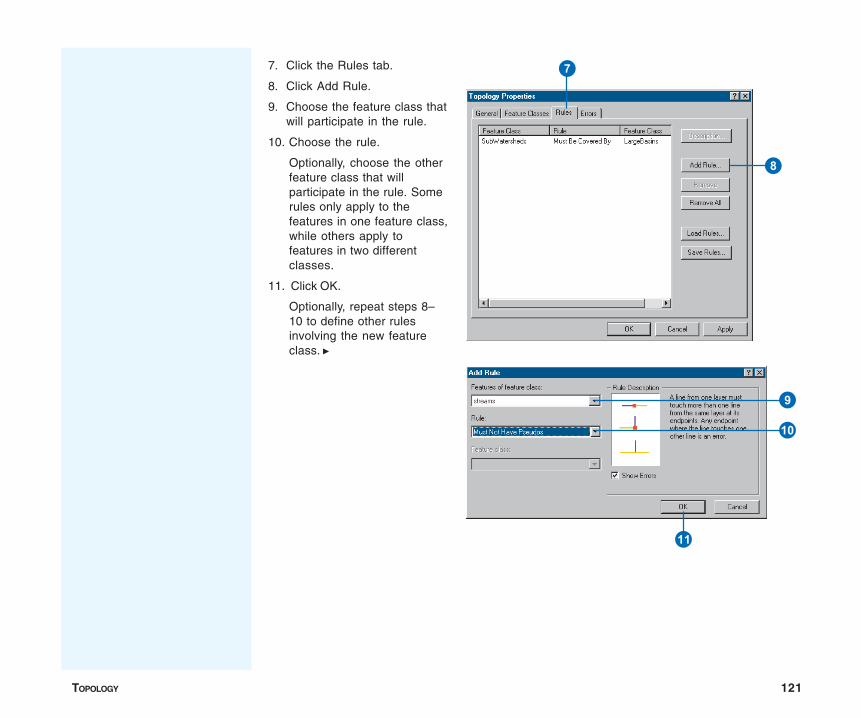
TOPOLOGY 121
7. Click the Rules tab.
8. Click Add Rule.
9. Choose the feature class thatwill participate in the rule.
10. Choose the rule.
Optionally, choose the otherfeature class that willparticipate in the rule. Somerules only apply to thefeatures in one feature class,while others apply tofeatures in two differentclasses.
11. Click OK.
Optionally, repeat steps 8–10 to define other rulesinvolving the new featureclass. u
7
8
9
Q
W
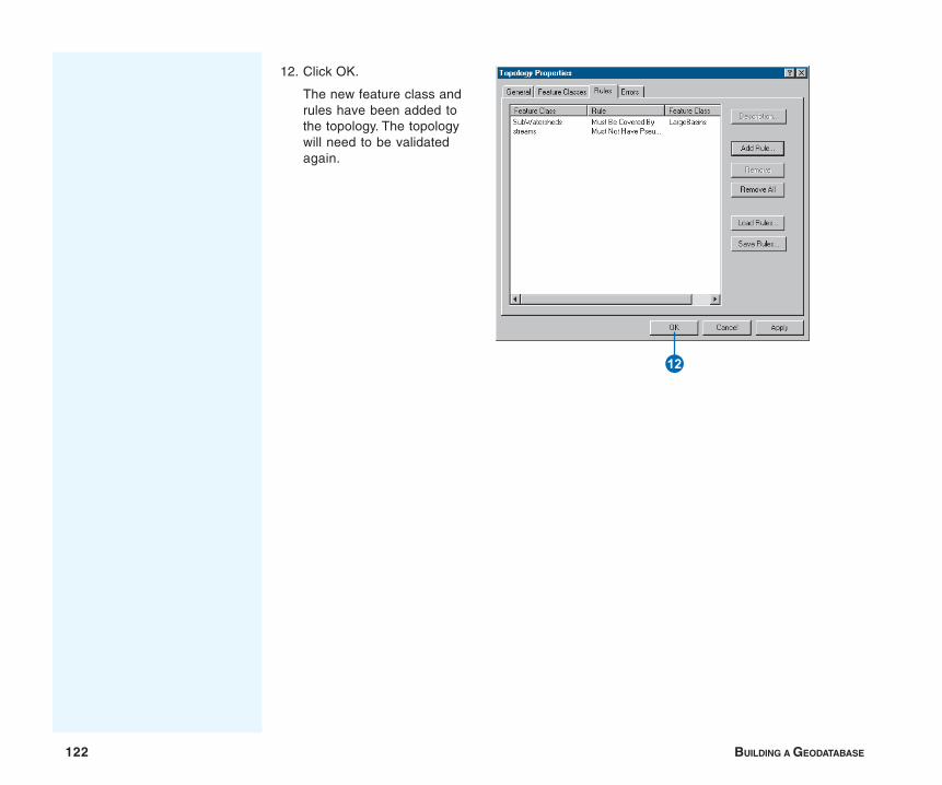
122 BUILDING A GEODATABASE
12. Click OK.
The new feature class andrules have been added tothe topology. The topologywill need to be validatedagain.
E
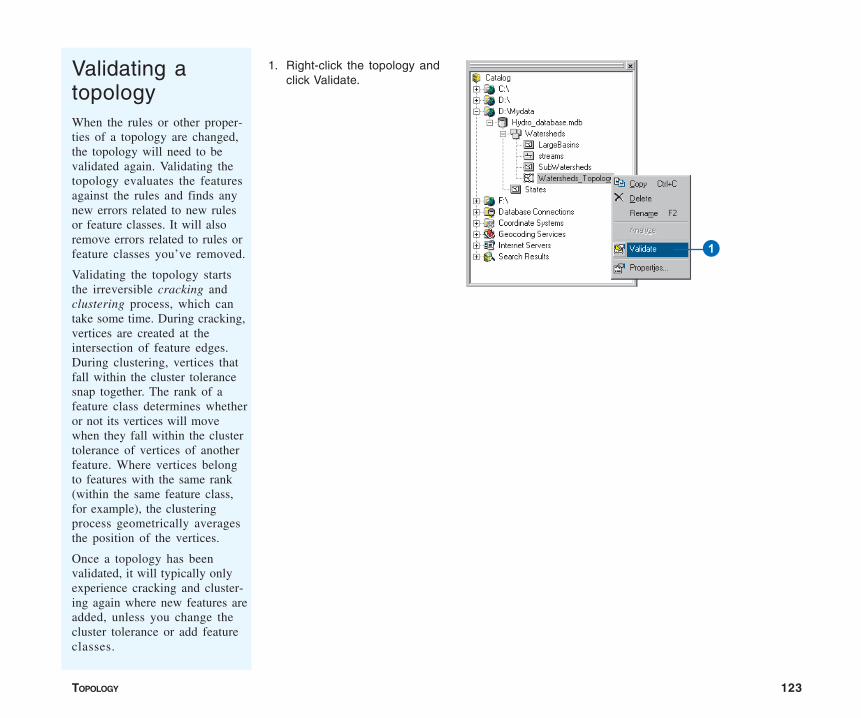
TOPOLOGY 123
When the rules or other proper-ties of a topology are changed,the topology will need to bevalidated again. Validating thetopology evaluates the featuresagainst the rules and finds anynew errors related to new rulesor feature classes. It will alsoremove errors related to rules orfeature classes you’ve removed.
Validating the topology startsthe irreversible cracking andclustering process, which cantake some time. During cracking,vertices are created at theintersection of feature edges.During clustering, vertices thatfall within the cluster tolerancesnap together. The rank of afeature class determines whetheror not its vertices will movewhen they fall within the clustertolerance of vertices of anotherfeature. Where vertices belongto features with the same rank(within the same feature class,for example), the clusteringprocess geometrically averagesthe position of the vertices.
Once a topology has beenvalidated, it will typically onlyexperience cracking and cluster-ing again where new features areadded, unless you change thecluster tolerance or add featureclasses.
1. Right-click the topology andclick Validate.
Validating atopology
1
124 BUILDING A GEODATABASE
Topology: defining the rules
Some topology rules govern the relationship between features ina single feature class, while others govern the relationshipbetween features in two feature classes. The rules can also bebetween two subtypes in a feature class or between subtypes intwo different feature classes.
Some of the key topological rules are discussed in the followingpages. The first step is to choose the most important ones foryour data, then plan how you will implement and maintain eachone.
Polygon rules
Must Not Overlap
This rule requires that the interior of polygons in the feature classnot overlap. The polygons can share edges or vertices. This ruleis used when an area cannot belong to two or more polygons. Itis useful for modeling administrative boundaries, such as ZIPCodes or voting districts, and mutually exclusive area classifica-tions such as land cover or landform type.
Must Not Have Gaps
This rule requires that there are no voids within a single polygonor between adjacent polygons. All polygons must form a continu-ous surface. An error will always exist on the perimeter of thesurface. You can either ignore this error or mark it as an exception.Use this rule on data that must completely cover an area. Forexample, soil polygons cannot include gaps nor form voids—theymust cover an entire area.
Must Not Overlap With
This rule requires that the interior of polygons in one featureclass must not overlap with the interior of polygons in anotherfeature class. Polygons of two feature classes can share edges orvertices or be completely disjointed. This rule is used when an
area cannot belong to two separate feature classes. It is useful forcombining two mutually exclusive systems of area classification,such as zoning and water body type, where areas defined withinthe zoning class cannot also be defined in the water body classand vice versa.
Must Be Covered By Feature Class Of
This rule requires that a polygon in one feature class must shareall of its area with polygons in another feature class. An area inthe first feature class that is not covered by polygons from theother feature class is an error. This rule is used when an area ofone type, such as a state, should be completely covered by areasof another type, such as counties.
Must Cover Each Other
This rule requires that the polygons of one feature class mustshare all of their area with the polygons of another feature class.Polygons may share edges or vertices. Any area defined in eitherfeature class that is not shared with the other is an error. This ruleis used when two systems of classification are used for the samegeographic area and any given point defined in one system mustalso be defined in the other. One such case occurs with nestedhierarchical datasets, such as census blocks and block groups orsmall watersheds and large drainage basins. The rule can also beapplied to nonhierarchically related polygon feature classes, suchas soil type and slope class.
Must Be Covered By
This rule requires that polygons of one feature class must becontained within polygons of another feature class. Polygonsmay share edges or vertices. Any area defined in the containedfeature class must be covered by an area in the covering featureclass. This rule is used when area features of a given type mustbe located within features of another type. This rule is useful
TOPOLOGY 125
when modeling areas that are subsets of a larger surroundingarea, such as management units within forests or blocks withinblock groups.
Boundary Must Be Covered By
This rule requires that boundaries of polygon features must becovered by lines in another feature class. This rule is used whenarea features need to have line features that mark the boundariesof the areas. This is usually when the areas have one set ofattributes, and their boundaries have other attributes. Forexample, parcels might be stored in the geodatabase along withtheir boundaries. Each parcel might be defined by one or moreline features that store information about their length or the datesurveyed, and every parcel should exactly match its boundaries.
Area Boundary Must Be Covered By Boundary Of
This rule requires that boundaries of polygon features in onefeature class be covered by boundaries of polygon features inanother feature class. This is useful when polygon features inone feature class, such as subdivisions, are composed of multiplepolygons in another class, such as parcels, and the sharedboundaries must be aligned.
Contains Point
This rule requires that a polygon in one feature class contain atleast one point from another feature class. Points must be withinthe polygon, not on the boundary. This is useful when everypolygon should have at least one associated point, such as whenparcels must have an address point.
Line rules
Must Not Overlap
This rule requires that lines not overlap with lines in the samefeature class. This rule is used where line segments should not be
duplicated, for example, in a stream feature class. Lines can crossor intersect but cannot share segments.
Must Not Intersect
This rule requires that line features from the same feature classnot cross or overlap each other. Lines can share endpoints. Thisrule is used for contour lines that should never cross each otheror in cases where the intersection of lines should only occur atendpoints such as street segments and intersections.
Must Not Have Dangles
This rule requires that a line feature must touch lines from thesame feature class at both endpoints. An endpoint that is notconnected to another line is called a dangle. This rule is usedwhen line features must form closed loops such as when they aredefining the boundaries of polygon features. It may also be usedin cases where lines typically connect to other lines as withstreets. In this case, exceptions can be used where the rule isoccasionally violated as with cul-de-sac or dead-end streetsegments.
Must Not Have Pseudos
This rule requires that a line connect to at least two other lines ateach endpoint. Lines that connect to one other line (or tothemselves) are said to have pseudo-nodes. This rule is usedwhere line features must form closed loops, such as when theydefine the boundaries of polygons, or when line features logicallymust connect to two other line features at each end, as withsegments in a stream network, with exceptions being marked forthe originating ends of first-order streams.
Must Not Intersect Or Touch Interior
This rule requires that a line in one feature class must only touchother lines of the same feature class at endpoints. Any linesegment in which features overlap or any intersection not at anendpoint is an error. This rule is useful where lines must only be
126 BUILDING A GEODATABASE
connected at endpoints, such as in the case of lot lines, whichmust split (only connect to the endpoints of) back lot lines andwhich cannot overlap each other.
Must Not Overlap With
This rule requires that a line from one feature class not overlapwith line features in another feature class. This rule is used whenline features cannot share the same space. For example, roadsmust not overlap with railroads, or depression subtype of contourlines cannot overlap with other contour lines.
Must Be Covered By Feature Class Of
This rule requires that lines from one feature class must becovered by the lines in another feature class. This is useful formodeling logically different but spatially coincident lines such asroutes and streets. A bus route feature class must not depart fromthe streets defined in the street feature class.
Must Be Covered By Boundary Of
This rule requires that lines be covered by the boundaries of areafeatures. This is useful for modeling lines, such as lot lines, thatmust coincide with the edge of polygon features, such as lots.
Endpoint Must Be Covered By
This rule requires that the endpoints of line features must becovered by point features in another feature class. This is usefulfor modeling cases where a fitting must connect two pipes or astreet intersection must be found at the junction of two streets.
Must Not Self Overlap
This rule requires that line features not overlap themselves. Theycan cross or touch themselves, but must not have coincidentsegments. This rule is useful for such features as streets, wheresegments might touch, in a loop, but where the same streetshould not follow the same course twice.
Must Not Self Intersect
This rule requires that line features not cross or overlap them-selves. This rule is useful for lines, such as contour lines, thatcannot cross themselves.
Must Be Single Part
This rule requires that lines must have only one part. This rule isuseful where line features, such as highways, may not havemultiple parts.
Point rules
Must Be Covered By Boundary Of
This rule requires that points fall on the boundaries of areafeatures. This is useful when the point features help support theboundary system, such as boundary markers, which must befound on the edges of certain areas.
Must Be Properly Inside Polygons
This rule requires that points fall within area features. This isuseful when the point features are related to polygons, such aswells and well pads or address points and parcels.
Must Be Covered By Endpoint Of
This rule requires that points in one feature class must becovered by the endpoints of lines in another feature class. Thisrule is similar to the line rule, Endpoint Must Be Covered By,except that, in cases where the rule is violated, it is the pointfeature that is marked as an error rather than the line. Boundarycorner markers might be constrained to be covered by theendpoints of boundary lines.
TOPOLOGY 127
Must Be Covered By Line
This rule requires that points in one feature class must becovered by lines in another feature class. It does not constrainthe covering portion of the line to be an endpoint. This rule isuseful for points that fall along a set of lines, such as highwaysigns that fall along highways.
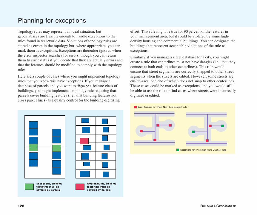
128 BUILDING A GEODATABASE
Planning for exceptions
Topology rules may represent an ideal situation, butgeodatabases are flexible enough to handle exceptions to therules found in real-world data. Violations of topology rules arestored as errors in the topology but, where appropriate, you canmark them as exceptions. Exceptions are thereafter ignored whenthe error inspector searches for errors, though you can returnthem to error status if you decide that they are actually errors andthat the features should be modified to comply with the topologyrules.
Here are a couple of cases where you might implement topologyrules that you know will have exceptions. If you manage adatabase of parcels and you want to digitize a feature class ofbuildings, you might implement a topology rule requiring thatparcels cover building features (i.e., that building features notcross parcel lines) as a quality control for the building digitizing
effort. This rule might be true for 90 percent of the features inyour management area, but it could be violated by some high-density housing and commercial buildings. You can designate thebuildings that represent acceptable violations of the rule asexceptions.
Similarly, if you manage a street database for a city, you mightcreate a rule that centerlines must not have dangles (i.e., that theyconnect at both ends to other centerlines). This rule wouldensure that street segments are correctly snapped to other streetsegments when the streets are edited. However, some streets arecul-de-sacs, one end of which does not snap to other centerlines.These cases could be marked as exceptions, and you would stillbe able to use the rule to find cases where streets were incorrectlydigitized or edited.
Error features for "Must Not Have Dangles" rule
Exceptions for "Must Not Have Dangles" rule
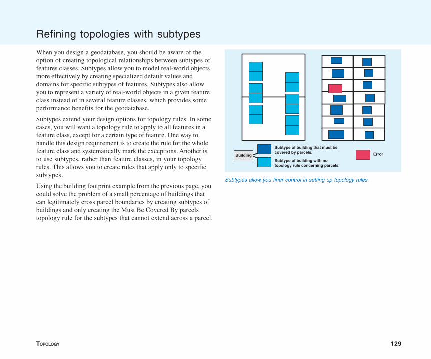
TOPOLOGY 129
Refining topologies with subtypes
When you design a geodatabase, you should be aware of theoption of creating topological relationships between subtypes offeatures classes. Subtypes allow you to model real-world objectsmore effectively by creating specialized default values anddomains for specific subtypes of features. Subtypes also allowyou to represent a variety of real-world objects in a given featureclass instead of in several feature classes, which provides someperformance benefits for the geodatabase.
Subtypes extend your design options for topology rules. In somecases, you will want a topology rule to apply to all features in afeature class, except for a certain type of feature. One way tohandle this design requirement is to create the rule for the wholefeature class and systematically mark the exceptions. Another isto use subtypes, rather than feature classes, in your topologyrules. This allows you to create rules that apply only to specificsubtypes.
Using the building footprint example from the previous page, youcould solve the problem of a small percentage of buildings thatcan legitimately cross parcel boundaries by creating subtypes ofbuildings and only creating the Must Be Covered By parcelstopology rule for the subtypes that cannot extend across a parcel.
Subtype of building that must be covered by parcels.
Subtype of building with no topology rule concerning parcels.
ErrorBuilding
Subtypes allow you finer control in setting up topology rules.
130 BUILDING A GEODATABASE
Managing a topology
You can manage topologies using ArcCatalog. Unlike most itemsthat appear in ArcCatalog, the topology does not represent asingle entity, such as a table, shapefile, or feature class. Atopology is actually an association among several feature classesand is represented by several tables in the database. Managing atopology is different from managing other items in ArcCatalog.
Managing the topology itself
Some of the standard operations on the topology are handled thesame way as other items in ArcCatalog. A topology can berenamed or deleted. Renaming the topology doesn’t affect any ofits member feature classes or the structure of the topology.Deleting a topology does not affect the participating featureclasses; it merely removes the rules governing their spatialrelationships.
You can delete a topology in two ways. The first is to delete theentire feature dataset that contains the topology. This actiondeletes from the geodatabase all of the participating featureclasses, all of the topology rules, and any other objects storedinside that feature dataset. The second method is to simply deletethe topology itself and leave the rest of the feature dataset intact.
You can also copy and paste a topology from one feature datasetto another. Copying a topology also copies the feature classesthat participate in the topology.
Managing topologically related feature classes
Managing feature classes in a topology is more restricted thanmanaging feature classes that do not participate in a topology.You must remove the feature class from the topology or delete thetopology before you can rename or delete a feature class thatparticipates in a topology. You can still add fields, alter subtypes,and modify domains of fields for feature classes in a topology.
Schema locking
An exclusive lock is required to modify a topology’s rules or torename or delete a topology. An exclusive lock can only beacquired for a topology if the feature classes that participate inthe topology can also be locked. Therefore, if another user has anexclusive or shared lock on any of the feature classes in atopology, then the properties of the topology cannot be edited.
For more information on exclusive locks and schema locking, seethe chapter ‘Creating new items in a geodatabase’ in this book.
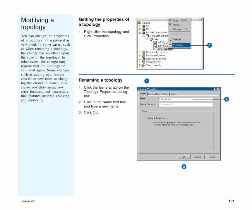
TOPOLOGY 131
Modifying atopologyYou can change the propertiesof a topology not registered asversioned. In some cases, suchas when renaming a topology,the change has no effect uponthe state of the topology. Inother cases, the change mayrequire that the topology bevalidated again. Some changes,such as adding new featureclasses or new rules or chang-ing the cluster tolerance, maycreate new dirty areas, newerror features, and necessitatethat features undergo crackingand clustering.
Renaming a topology
1. Click the General tab on theTopology Properties dialogbox.
2. Click in the Name text boxand type a new name.
3. Click OK.
Getting the properties ofa topology
1. Right-click the topology andclick Properties.
1
1
2
3
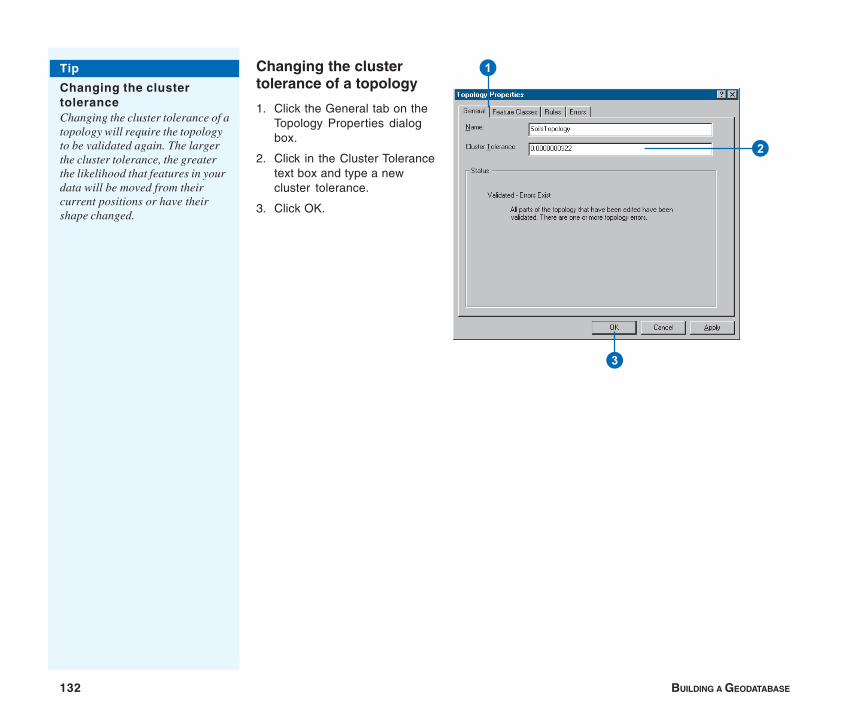
132 BUILDING A GEODATABASE
Changing the clustertolerance of a topology
1. Click the General tab on theTopology Properties dialogbox.
2. Click in the Cluster Tolerancetext box and type a newcluster tolerance.
3. Click OK.
1
2
3
Tip
Changing the clustertoleranceChanging the cluster tolerance of atopology will require the topologyto be validated again. The largerthe cluster tolerance, the greaterthe likelihood that features in yourdata will be moved from theircurrent positions or have theirshape changed.
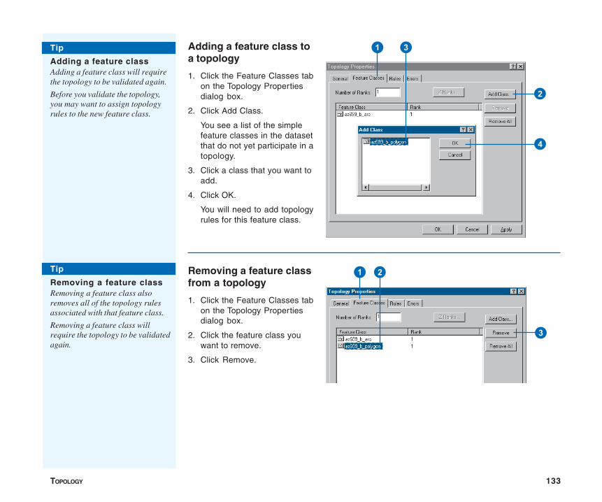
TOPOLOGY 133
Adding a feature class toa topology
1. Click the Feature Classes tabon the Topology Propertiesdialog box.
2. Click Add Class.
You see a list of the simplefeature classes in the datasetthat do not yet participate in atopology.
3. Click a class that you want toadd.
4. Click OK.
You will need to add topologyrules for this feature class.
Removing a feature classfrom a topology
1. Click the Feature Classes tabon the Topology Propertiesdialog box.
2. Click the feature class youwant to remove.
3. Click Remove.
Tip
Adding a feature classAdding a feature class will requirethe topology to be validated again.
Before you validate the topology,you may want to assign topologyrules to the new feature class.
Tip
Removing a feature classRemoving a feature class alsoremoves all of the topology rulesassociated with that feature class.
Removing a feature class willrequire the topology to be validatedagain.
1
2
3
4
1 2
3
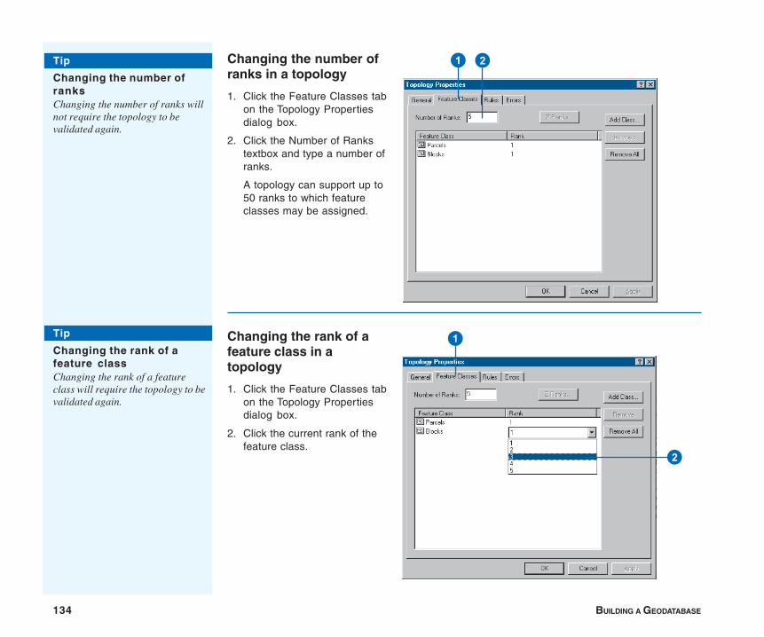
134 BUILDING A GEODATABASE
Changing the number ofranks in a topology
1. Click the Feature Classes tabon the Topology Propertiesdialog box.
2. Click the Number of Rankstextbox and type a number ofranks.
A topology can support up to50 ranks to which featureclasses may be assigned.
Changing the rank of afeature class in atopology
1. Click the Feature Classes tabon the Topology Propertiesdialog box.
2. Click the current rank of thefeature class.
1 2
1
2
Tip
Changing the number ofranksChanging the number of ranks willnot require the topology to bevalidated again.
Tip
Changing the rank of afeature classChanging the rank of a featureclass will require the topology to bevalidated again.
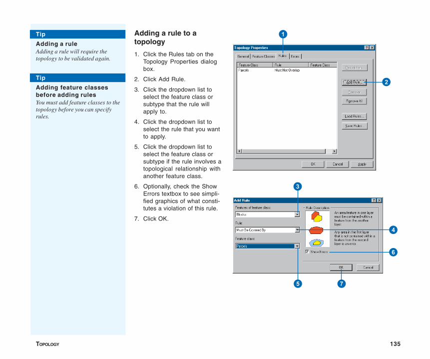
TOPOLOGY 135
Adding a rule to atopology
1. Click the Rules tab on theTopology Properties dialogbox.
2. Click Add Rule.
3. Click the dropdown list toselect the feature class orsubtype that the rule willapply to.
4. Click the dropdown list toselect the rule that you wantto apply.
5. Click the dropdown list toselect the feature class orsubtype if the rule involves atopological relationship withanother feature class.
6. Optionally, check the ShowErrors textbox to see simpli-fied graphics of what consti-tutes a violation of this rule.
7. Click OK.
Tip
Adding a ruleAdding a rule will require thetopology to be validated again.
Tip
Adding feature classesbefore adding rulesYou must add feature classes to thetopology before you can specifyrules.
1
2
3
4
5
6
7
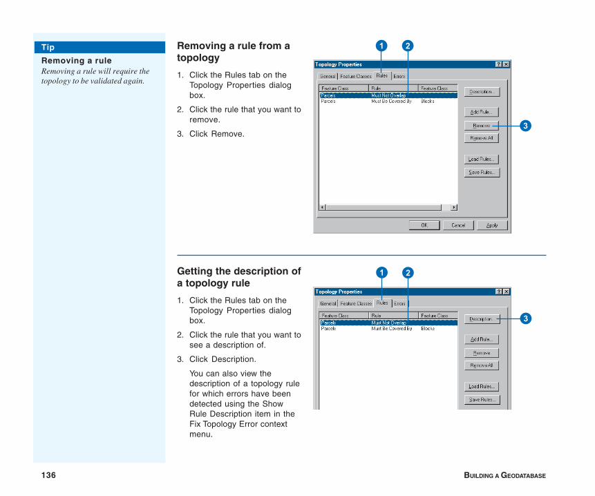
136 BUILDING A GEODATABASE
Removing a rule from atopology
1. Click the Rules tab on theTopology Properties dialogbox.
2. Click the rule that you want toremove.
3. Click Remove.
Getting the description ofa topology rule
1. Click the Rules tab on theTopology Properties dialogbox.
2. Click the rule that you want tosee a description of.
3. Click Description.
You can also view thedescription of a topology rulefor which errors have beendetected using the ShowRule Description item in theFix Topology Error contextmenu.
1
3
2
1
3
2
Tip
Removing a ruleRemoving a rule will require thetopology to be validated again.

TOPOLOGY 137
Saving rules for atopology into a Rule Setfile
1. Click the Rules tab on theTopology Properties dialogbox.
2. Click Save Rules.
3. Navigate to the place whereyou want to save the rulesthat you’ve defined for thetopology.
4. Type a name for the Rule Setfile.
5. Click Save to save all therules for the topology to thefile.
1
2
3
5
4
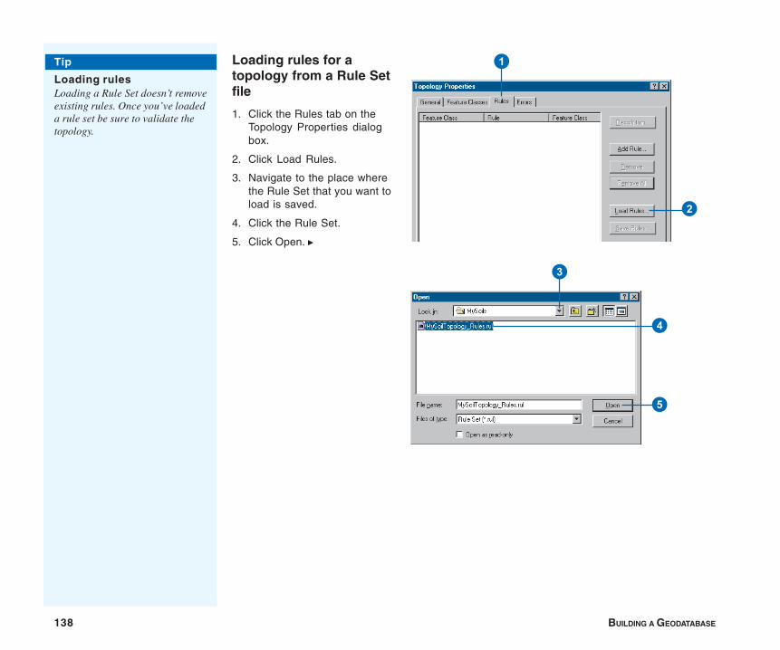
138 BUILDING A GEODATABASE
Loading rules for atopology from a Rule Setfile
1. Click the Rules tab on theTopology Properties dialogbox.
2. Click Load Rules.
3. Navigate to the place wherethe Rule Set that you want toload is saved.
4. Click the Rule Set.
5. Click Open. u
3
5
4
1
2
Tip
Loading rulesLoading a Rule Set doesn’t removeexisting rules. Once you’ve loadeda rule set be sure to validate thetopology.
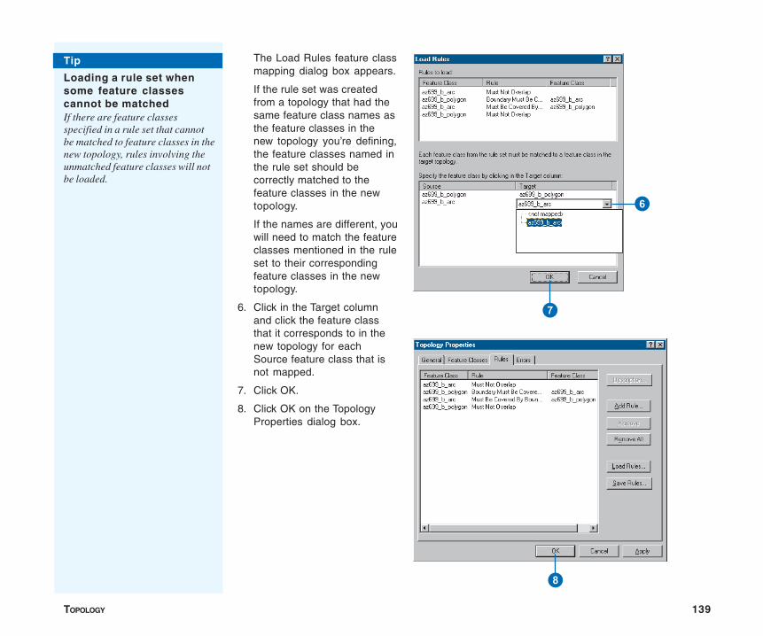
TOPOLOGY 139
The Load Rules feature classmapping dialog box appears.
If the rule set was createdfrom a topology that had thesame feature class names asthe feature classes in thenew topology you’re defining,the feature classes named inthe rule set should becorrectly matched to thefeature classes in the newtopology.
If the names are different, youwill need to match the featureclasses mentioned in the ruleset to their correspondingfeature classes in the newtopology.
6. Click in the Target columnand click the feature classthat it corresponds to in thenew topology for eachSource feature class that isnot mapped.
7. Click OK.
8. Click OK on the TopologyProperties dialog box.
Tip
Loading a rule set whensome feature classescannot be matchedIf there are feature classesspecified in a rule set that cannotbe matched to feature classes in thenew topology, rules involving theunmatched feature classes will notbe loaded.
6
7
8
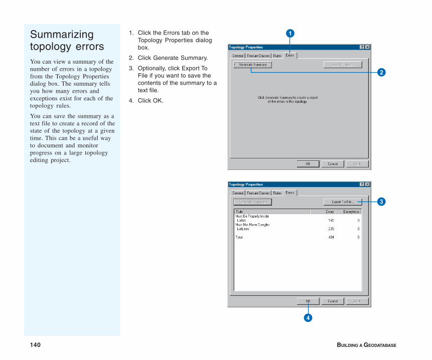
140 BUILDING A GEODATABASE
Summarizingtopology errorsYou can view a summary of thenumber of errors in a topologyfrom the Topology Propertiesdialog box. The summary tellsyou how many errors andexceptions exist for each of thetopology rules.
You can save the summary as atext file to create a record of thestate of the topology at a giventime. This can be a useful wayto document and monitorprogress on a large topologyediting project.
1. Click the Errors tab on theTopology Properties dialogbox.
2. Click Generate Summary.
3. Optionally, click Export ToFile if you want to save thecontents of the summary to atext file.
4. Click OK.
1
2
3
4
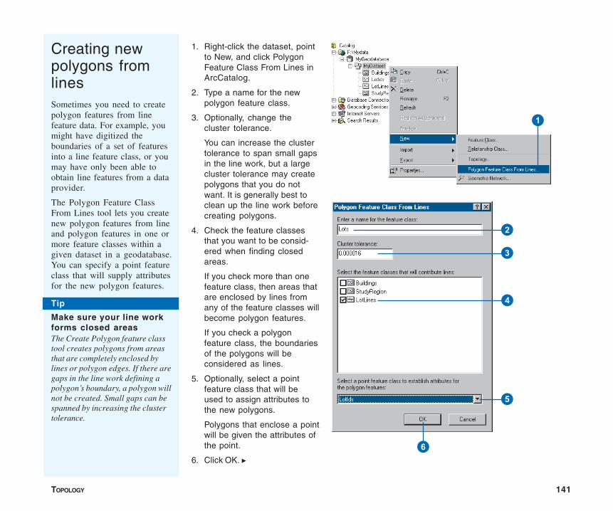
TOPOLOGY 141
Creating newpolygons fromlinesSometimes you need to createpolygon features from linefeature data. For example, youmight have digitized theboundaries of a set of featuresinto a line feature class, or youmay have only been able toobtain line features from a dataprovider.
The Polygon Feature ClassFrom Lines tool lets you createnew polygon features from lineand polygon features in one ormore feature classes within agiven dataset in a geodatabase.You can specify a point featureclass that will supply attributesfor the new polygon features.
1. Right-click the dataset, pointto New, and click PolygonFeature Class From Lines inArcCatalog.
2. Type a name for the newpolygon feature class.
3. Optionally, change thecluster tolerance.
You can increase the clustertolerance to span small gapsin the line work, but a largecluster tolerance may createpolygons that you do notwant. It is generally best toclean up the line work beforecreating polygons.
4. Check the feature classesthat you want to be consid-ered when finding closedareas.
If you check more than onefeature class, then areas thatare enclosed by lines fromany of the feature classes willbecome polygon features.
If you check a polygonfeature class, the boundariesof the polygons will beconsidered as lines.
5. Optionally, select a pointfeature class that will beused to assign attributes tothe new polygons.
Polygons that enclose a pointwill be given the attributes ofthe point.
6. Click OK. u
Tip
Make sure your line workforms closed areasThe Create Polygon feature classtool creates polygons from areasthat are completely enclosed bylines or polygon edges. If there aregaps in the line work defining apolygon’s boundary, a polygon willnot be created. Small gaps can bespanned by increasing the clustertolerance.
1
2
4
3
5
6
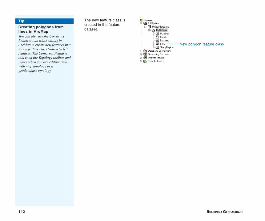
142 BUILDING A GEODATABASE
Tip
Creating polygons fromlines in ArcMapYou can also use the ConstructFeatures tool while editing inArcMap to create new features in atarget feature class from selectedfeatures. The Construct Featurestool is on the Topology toolbar andworks when you are editing datawith map topology or ageodatabase topology.
The new feature class iscreated in the featuredataset.
New polygon feature class
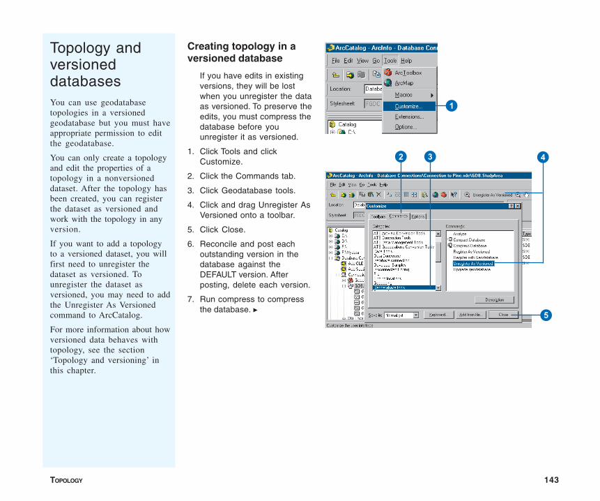
TOPOLOGY 143
Topology andversioneddatabasesYou can use geodatabasetopologies in a versionedgeodatabase but you must haveappropriate permission to editthe geodatabase.
You can only create a topologyand edit the properties of atopology in a nonversioneddataset. After the topology hasbeen created, you can registerthe dataset as versioned andwork with the topology in anyversion.
If you want to add a topologyto a versioned dataset, you willfirst need to unregister thedataset as versioned. Tounregister the dataset asversioned, you may need to addthe Unregister As Versionedcommand to ArcCatalog.
For more information about howversioned data behaves withtopology, see the section‘Topology and versioning’ inthis chapter.
Creating topology in aversioned database
If you have edits in existingversions, they will be lostwhen you unregister the dataas versioned. To preserve theedits, you must compress thedatabase before youunregister it as versioned.
1. Click Tools and clickCustomize.
2. Click the Commands tab.
3. Click Geodatabase tools.
4. Click and drag Unregister AsVersioned onto a toolbar.
5. Click Close.
6. Reconcile and post eachoutstanding version in thedatabase against theDEFAULT version. Afterposting, delete each version.
7. Run compress to compressthe database. u
1
2 3 4
5
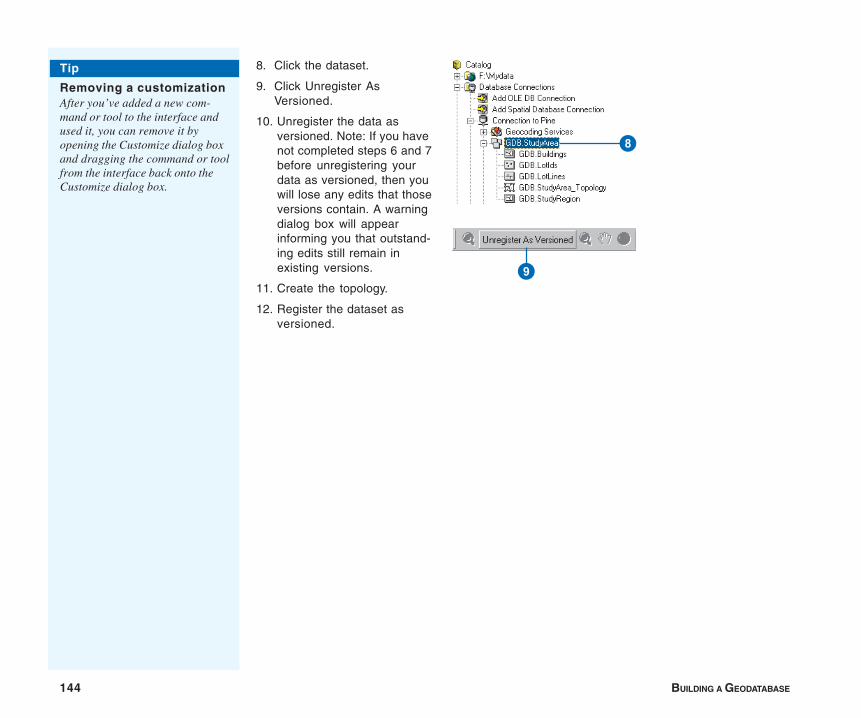
144 BUILDING A GEODATABASE
8. Click the dataset.
9. Click Unregister AsVersioned.
10. Unregister the data asversioned. Note: If you havenot completed steps 6 and 7before unregistering yourdata as versioned, then youwill lose any edits that thoseversions contain. A warningdialog box will appearinforming you that outstand-ing edits still remain inexisting versions.
11. Create the topology.
12. Register the dataset asversioned.
Tip
Removing a customizationAfter you’ve added a new com-mand or tool to the interface andused it, you can remove it byopening the Customize dialog boxand dragging the command or toolfrom the interface back onto theCustomize dialog box.
8
9

TOPOLOGY 145
Topology and versioning
It is helpful to understand how the versioning process works ingeodatabases before planning your work flow. For more informa-tion on how versioning works in a geodatabase, see the chapter‘Working with a versioned geodatabase’ in this book.
In a versioned geodatabase, feature classes that participate in atopology do not have any special version reconciliation orconflict detection and resolution behavior. However, the dirtyareas, error features, and exceptions that are maintained by thetopology itself do have special behavior in the version reconcilia-tion and conflict detection process to ensure the integrity of thetopology.
The nature of topological edits and the cracking and clusteringmodifications that the validate process makes to feature geometrymay result in conflicts during version reconciliation.
You should consider the behavior of dirty areas, error features,and the types of conflicts that may result from topological editswhen you are planning your work flow for managing versionedtopological feature classes.
The following sections describe the results of a reconcile on dirtyareas, errors, exceptions, and potential conflicts. In each case, theresults are based on a reconcile in which a parent and childversion have both been edited since the child version wascreated. If the parent version is not edited before the childversion is reconciled, the results of the reconcile will be thecontents of the child version. In each example, Version2 is createdas a child of Version1. Both versions are then edited in the
Version1
Validate
Dirty Area
Version Label
Operation
Feature
Error
Exception
Note: both the errorfeature from the parentand the error featurefrom the child (markedas an exception) arepresent afterreconcile.
Comment
Conflict
Vertex
manner described in the example; then Version2 is reconciledagainst Version1. For the illustrations in the following examples,use the following as a legend:
Dirty areas
New topology errors may occur when edited parent and childversions are reconciled, even when the dirty areas within eachversion have been validated and are free of errors. In order todetect such topology errors, dirty areas are treated in a specialway by the reconcile process. Results of the reconcile on dirtyareas can be summarized as:
• Any dirty areas present in the parent or child version that didnot exist before the parent and child version were created willremain dirty as a result of the reconcile:
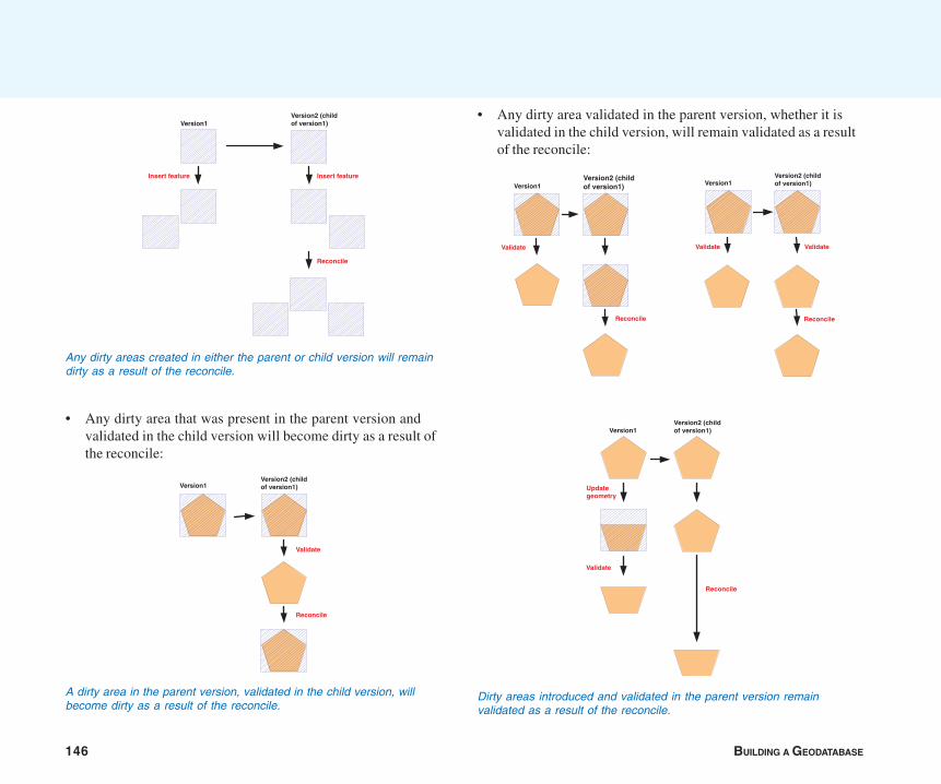
146 BUILDING A GEODATABASE
• Any dirty area that was present in the parent version andvalidated in the child version will become dirty as a result ofthe reconcile:
• Any dirty area validated in the parent version, whether it isvalidated in the child version, will remain validated as a resultof the reconcile:
Any dirty areas created in either the parent or child version will remaindirty as a result of the reconcile.
Version1Version2 (childof version1)
Reconcile
Insert featureInsert feature
A dirty area in the parent version, validated in the child version, willbecome dirty as a result of the reconcile.
Version1Version2 (childof version1)
Reconcile
Validate
Version1
Reconcile
Validate
Version2 (childof version1) Version1
Version2 (childof version1)
Reconcile
ValidateValidate
Dirty areas introduced and validated in the parent version remainvalidated as a result of the reconcile.
Version1Version2 (childof version1)
Validate
Reconcile
Updategeometry
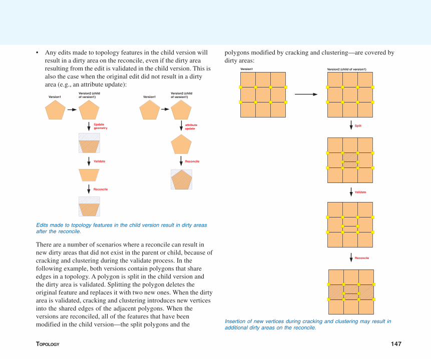
TOPOLOGY 147
• Any edits made to topology features in the child version willresult in a dirty area on the reconcile, even if the dirty arearesulting from the edit is validated in the child version. This isalso the case when the original edit did not result in a dirtyarea (e.g., an attribute update):
There are a number of scenarios where a reconcile can result innew dirty areas that did not exist in the parent or child, because ofcracking and clustering during the validate process. In thefollowing example, both versions contain polygons that shareedges in a topology. A polygon is split in the child version andthe dirty area is validated. Splitting the polygon deletes theoriginal feature and replaces it with two new ones. When the dirtyarea is validated, cracking and clustering introduces new verticesinto the shared edges of the adjacent polygons. When theversions are reconciled, all of the features that have beenmodified in the child version—the split polygons and the
polygons modified by cracking and clustering—are covered bydirty areas:
Edits made to topology features in the child version result in dirty areasafter the reconcile.
Version1Version2 (childof version1)
Validate
Reconcile
Updategeometry
Version1Version2 (childof version1)
Reconcile
attributeupdate
Insertion of new vertices during cracking and clustering may result inadditional dirty areas on the reconcile.
Version1 Version2 (child of version1)
Reconcile
Split
Validate

148 BUILDING A GEODATABASE
The following examples illustrate why this is necessary. In thefollowing example, new features were created in each version, andthe resulting dirty areas were validated, resulting in no errors. Ona reconcile, dirty areas must be re-created such that errorsintroduced by merging the changes from the two versionstogether can be discovered. In this example, features added inVersion1 and Version2 overlap each other, which is a violation ofthe “no overlaps” rule:
Errors and exceptions
Error features and error features marked as exceptions havespecial logic with respect to how they are treated during theversion reconciliation process. Since errors and exceptionscannot be edited directly, the system will not report conflicts forthem between two versions. Errors are only created by thetopology validation process and can be deleted by correcting theerror using the topology error correction tools in ArcMap or byediting features and using the validation process. Error featurescan only be updated by marking an error as an exception or bymarking an exception as an error.
The results of a reconcile on errors and exceptions in the parentversion can be summarized as:
• Any error created in the parent version, whether or not it ismarked as an exception, will be brought into the child versionas a result of the reconcile:
It is necessary to reactivate dirty areas from the child version after areconcile to discover errors that may result from additional edits made inthe parent version.
Version2 (childof version1)
Reconcile
Validate
Createfeature
Version1(no features)
Createfeature
Validate
Validate
Errors and exceptions created in the parent version are brought into thechild version as a result of the reconcile.
Version1Version2 (childof version1)
Validate
Insertfeature
Reconcile
Version1Version2 (childof version1)
Validateand mark asexception
Insertfeature
Reconcile
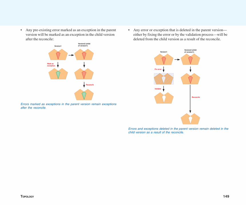
TOPOLOGY 149
• Any pre-existing error marked as an exception in the parentversion will be marked as an exception in the child versionafter the reconcile:
• Any error or exception that is deleted in the parent version—either by fixing the error or by the validation process—will bedeleted from the child version as a result of the reconcile.
Errors marked as exceptions in the parent version remain exceptionsafter the reconcile.
Version1Version2 (childof version1)
Reconcile
Mark asexception
Errors and exceptions deleted in the parent version remain deleted in thechild version as a result of the reconcile.
Version1Version2 (childof version1)
Reconcile
Validate
Fix error
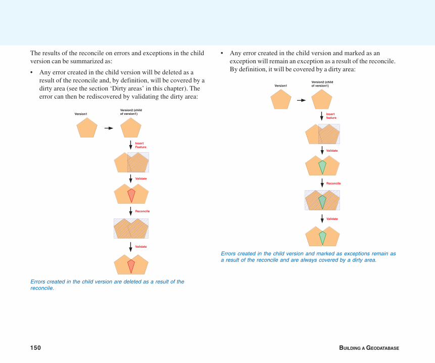
150 BUILDING A GEODATABASE
The results of the reconcile on errors and exceptions in the childversion can be summarized as:
• Any error created in the child version will be deleted as aresult of the reconcile and, by definition, will be covered by adirty area (see the section ‘Dirty areas’ in this chapter). Theerror can then be rediscovered by validating the dirty area:
• Any error created in the child version and marked as anexception will remain an exception as a result of the reconcile.By definition, it will be covered by a dirty area:
Errors created in the child version are deleted as a result of thereconcile.
Version1Version2 (childof version1)
Validate
Reconcile
Validate
InsertFeature
Errors created in the child version and marked as exceptions remain asa result of the reconcile and are always covered by a dirty area.
Version1Version2 (childof version1)
Validate
Reconcile
Insertfeature
Validate
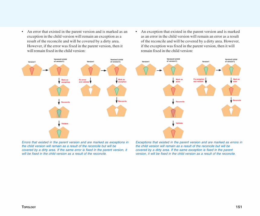
TOPOLOGY 151
• An error that existed in the parent version and is marked as anexception in the child version will remain an exception as aresult of the reconcile and will be covered by a dirty area.However, if the error was fixed in the parent version, then itwill remain fixed in the child version:
• An exception that existed in the parent version and is markedas an error in the child version will remain an error as a resultof the reconcile and will be covered by a dirty area. However,if the exception was fixed in the parent version, then it willremain fixed in the child version:
Errors that existed in the parent version and are marked as exceptions inthe child version will remain as a result of the reconcile but will becovered by a dirty area. If the same error is fixed in the parent version, itwill be fixed in the child version as a result of the reconcile.
Version1Version2 (childof version1)
Reconcile
Validate
Mark asexception
Version1Version2 (childof version1)
Reconcile
Mark asexception
Fix errorand validate
Exceptions that existed in the parent version and are marked as errors inthe child version will remain as a result of the reconcile but will becovered by a dirty area. If the same exception is fixed in the parentversion, it will be fixed in the child version as a result of the reconcile.
Version1Version2 (childof version1)
Reconcile
Validate
Mark aserror
Version1Version2 (childof version1)
Reconcile
Fix exceptionand validate
Mark aserror
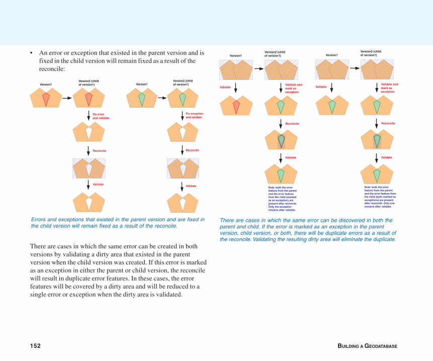
152 BUILDING A GEODATABASE
• An error or exception that existed in the parent version and isfixed in the child version will remain fixed as a result of thereconcile:
There are cases in which the same error can be created in bothversions by validating a dirty area that existed in the parentversion when the child version was created. If this error is markedas an exception in either the parent or child version, the reconcilewill result in duplicate error features. In these cases, the errorfeatures will be covered by a dirty area and will be reduced to asingle error or exception when the dirty area is validated.
There are cases in which the same error can be discovered in both theparent and child. If the error is marked as an exception in the parentversion, child version, or both, there will be duplicate errors as a result ofthe reconcile. Validating the resulting dirty area will eliminate the duplicate.
Version1Version2 (childof version1)
Validate andmark asexception
Validate
Reconcile
Validate
Note: both the errorfeature from the parentand the error featurefrom the child (markedas an exception) arepresent after reconcile.Only the exceptionremains after validate.
Version1Version2 (childof version1)
Validate andmark asexception
Validate
Reconcile
Validate
Note: both the errorfeature from the parentand the error feature fromthe child (both marked asexceptions) are presentafter reconcile. Only oneremains after validate.
Errors and exceptions that existed in the parent version and are fixed inthe child version will remain fixed as a result of the reconcile.
Version1Version2 (childof version1)
Reconcile
Validate
Fix errorand validate
Version1Version2 (childof version1)
Reconcile
Validate
Fix exceptionand validate
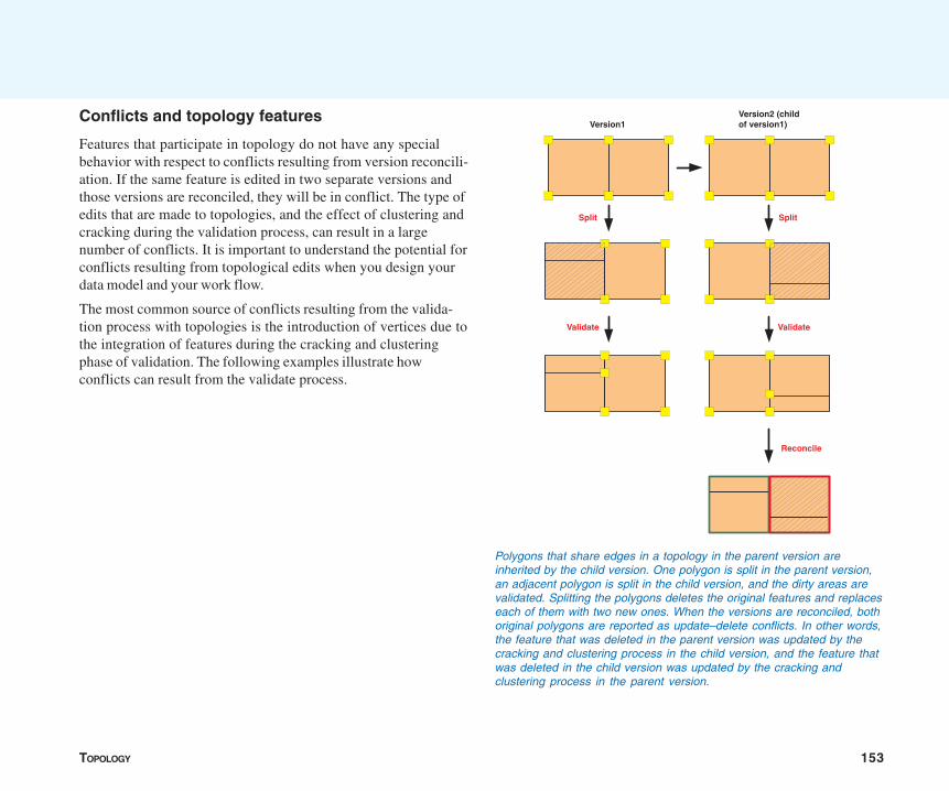
TOPOLOGY 153
Conflicts and topology features
Features that participate in topology do not have any specialbehavior with respect to conflicts resulting from version reconcili-ation. If the same feature is edited in two separate versions andthose versions are reconciled, they will be in conflict. The type ofedits that are made to topologies, and the effect of clustering andcracking during the validation process, can result in a largenumber of conflicts. It is important to understand the potential forconflicts resulting from topological edits when you design yourdata model and your work flow.
The most common source of conflicts resulting from the valida-tion process with topologies is the introduction of vertices due tothe integration of features during the cracking and clusteringphase of validation. The following examples illustrate howconflicts can result from the validate process.
Polygons that share edges in a topology in the parent version areinherited by the child version. One polygon is split in the parent version,an adjacent polygon is split in the child version, and the dirty areas arevalidated. Splitting the polygons deletes the original features and replaceseach of them with two new ones. When the versions are reconciled, bothoriginal polygons are reported as update–delete conflicts. In other words,the feature that was deleted in the parent version was updated by thecracking and clustering process in the child version, and the feature thatwas deleted in the child version was updated by the cracking andclustering process in the parent version.
Version1Version2 (childof version1)
ValidateValidate
Split
Reconcile
Split
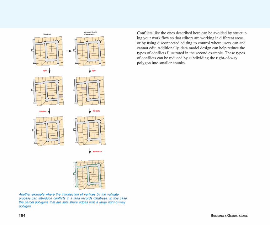
154 BUILDING A GEODATABASE
Another example where the introduction of vertices by the validateprocess can introduce conflicts in a land records database. In this case,the parcel polygons that are split share edges with a large right-of-waypolygon.
Split
Validate Validate
Version1Version2 (childof version1)
Reconcile
Split
Conflicts like the ones described here can be avoided by structur-ing your work flow so that editors are working in different areas,or by using disconnected editing to control where users can andcannot edit. Additionally, data model design can help reduce thetypes of conflicts illustrated in the second example. These typesof conflicts can be reduced by subdividing the right-of-waypolygon into smaller chunks.
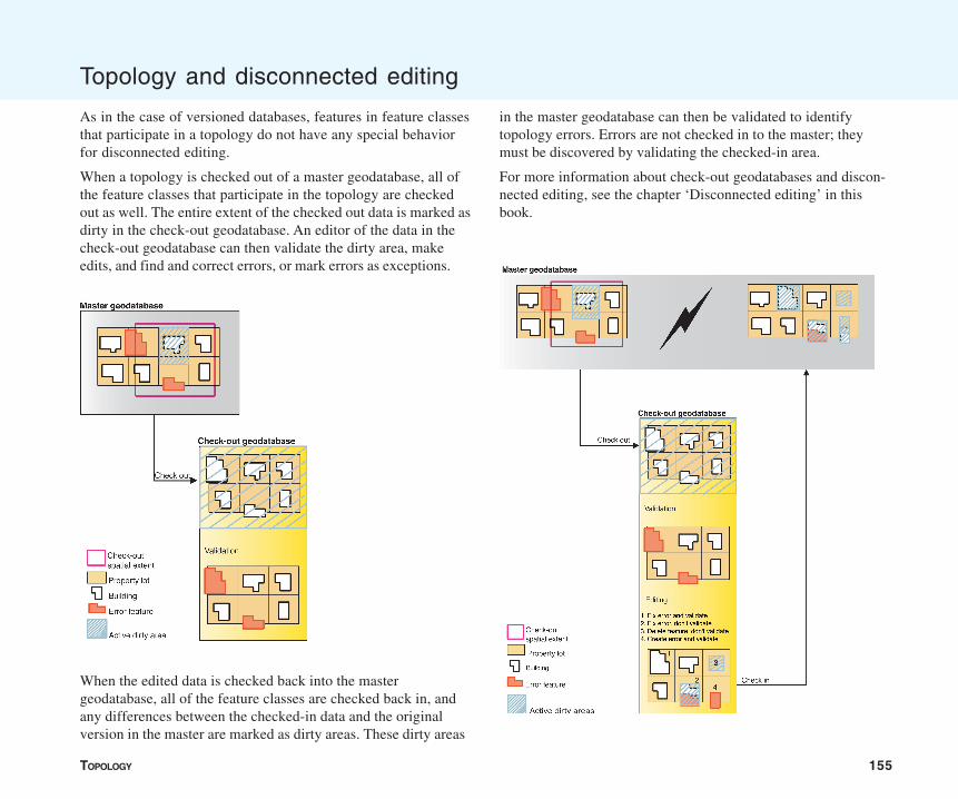
TOPOLOGY 155
Topology and disconnected editing
As in the case of versioned databases, features in feature classesthat participate in a topology do not have any special behaviorfor disconnected editing.
When a topology is checked out of a master geodatabase, all ofthe feature classes that participate in the topology are checkedout as well. The entire extent of the checked out data is marked asdirty in the check-out geodatabase. An editor of the data in thecheck-out geodatabase can then validate the dirty area, makeedits, and find and correct errors, or mark errors as exceptions.
When the edited data is checked back into the mastergeodatabase, all of the feature classes are checked back in, andany differences between the checked-in data and the originalversion in the master are marked as dirty areas. These dirty areas
in the master geodatabase can then be validated to identifytopology errors. Errors are not checked in to the master; theymust be discovered by validating the checked-in area.
For more information about check-out geodatabases and discon-nected editing, see the chapter ‘Disconnected editing’ in thisbook.

IN THIS CHAPTER
157
Subtypes and attribute domains 5• What are subtypes and attribute
domains?
• Working with attribute domainproperties
• Browsing the attribute domains ofa geodatabase
• Creating new attribute domains
• Modifying and deleting attributedomains
• Associating default values anddomains with tables and featureclasses
• Creating subtypes
• Modifying and deleting subtypes
When maintaining your geographic database, care must be taken to ensurethat when you edit the data you do so in a manner that is consistent with thesystem you are modeling. The geodatabase together with the ArcMap Editorprovides mechanisms to ensure that the data you store in your geodatabaseis consistent with your data model.
The geodatabase has several data integrity and data management capabilitiesincluding validation rules, subtypes, relationship classes, geometric networks,and so on. Each of these capabilities and how you use them are coveredthroughout this book. This chapter describes the subtypes and the first classof validation rules—attribute domains.
Subtypes can be used to add finer control of spatial relationships in topologiesand in connectivity rules for geometric networks. See the chapter ‘Topology’in this book for more information about using subtypes in topologies. See thechapter ‘Geometric networks’ in this book for more information about usingsubtypes in geometric networks.
ArcView can view feature classes that use advanced geodatabase function-ality. To create or edit feature classes that take advantage of advancedgeodatabase functionality, you need an ArcEditor or ArcInfo license.
158 BUILDING A GEODATABASE
The geodatabase stores objects. These objects may representnonspatial real-world entities, such as manufacturers, or they mayrepresent spatial objects such as pipes in a water network.Objects in the geodatabase are stored in feature classes (spatial)and tables (nonspatial).
The objects stored in a feature class or table may be organizedinto subtypes and can have a set of validation rules associatedwith them. The ArcInfo system uses these validation rules to helpyou maintain a geodatabase that contains valid objects. Thischapter outlines how to create subtypes for your feature classesand tables and how to establish attribute validation rules for theobjects stored in them. These validation rules are distinct fromthe validation rules established in a topology.
Subtypes and validation rules
Tables and feature classes store objects of the same type—thatis, that have the same behavior and attributes. For example, afeature class called WaterMains may store pressurized watermains. All of the water mains behave alike and have the attributesReferenceID, Depth, Material, GroundSurfaceType, Size, andPressureRating.
You may be modeling a system in which water mains can only bemade of cast iron, ductile iron, or copper. They can only be acertain size based on their type, and there are four possibleground surface types. When you create a new water main objectusing ArcMap, you may want these attributes to take on certaindefault values. Similarly, when ArcMap changes values for anattribute, you may want to make sure that only legal or validvalues are inserted into the attributes for that lateral.
When an object in a feature class or table has valid values for allof its attributes, it is considered to be a valid object. If one of itsattributes contains an invalid value, it is considered to be aninvalid object. When designing your geodatabase, you can
specify what makes any particular object in a feature class ortable a valid feature by establishing one or more validation rules.
In addition to topology rules, there are four broad classes ofvalidation rules: attribute domains, connectivity rules, relation-ship rules, and custom rules. Connectivity rules are discussedfurther in the chapter ‘Geometric networks’ and relationship rulesare discussed further in the chapter ‘Defining relationshipclasses’ in this book; custom rules are discussed further inExploring ArcObjects. This chapter focuses on attribute do-mains.
Attribute domains are rules that describe the permissible valuesof a field type. Multiple feature classes and tables can shareattribute domains stored in the database. This allows the watermains feature class to use the same domain for the groundsurface type field as a feature class that stores water laterals.
Although all objects in a feature class or table must have thesame behavior and attributes, not all objects must share the sameattribute domains. For example, it may be true in a water networkthat only transmission water mains can have a pressure between40 and 100 psi, while distribution water mains can have a pressurebetween 50 and 75 psi. You would use an attribute domain toenforce this restriction. To implement this kind of validation rule,you do not have to create separate feature classes for transmis-sion and distribution water mains, but you would want todistinguish these types of water mains from each other toestablish a separate set of domains and default values. You cando this using subtypes.
Feature classes and tables can contain subtypes. An object’ssubtype is determined by its subtype code value. The subtypecode is stored in an integer field in the feature class or table. Eachsubtype can have its own set of default values and attributedomains for a given field, different connectivity rules, anddifferent topology rules.
What are subtypes and attribute domains?
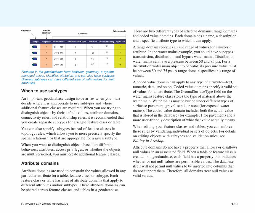
SUBTYPES AND ATTRIBUTE DOMAINS 159
When to use subtypes
An important geodatabase design issue arises when you mustdecide where it is appropriate to use subtypes and whereadditional feature classes are required. When you are trying todistinguish objects by their default values, attribute domains,connectivity rules, and relationship rules, it is recommended thatyou create separate subtypes for a single feature class or table.
You can also specify subtypes instead of feature classes intopology rules, which allows you to more precisely specify thespatial relationships that are appropriate for a given subtype.
When you want to distinguish objects based on differentbehaviors, attributes, access privileges, or whether the objectsare multiversioned, you must create additional feature classes.
Attribute domains
Attribute domains are used to constrain the values allowed in anyparticular attribute for a table, feature class, or subtype. Eachfeature class or table has a set of attribute domains that apply todifferent attributes and/or subtypes. These attribute domains canbe shared across feature classes and tables in a geodatabase.
There are two different types of attribute domains: range domainsand coded value domains. Each domain has a name, a description,and a specific attribute type to which it can apply.
A range domain specifies a valid range of values for a numericattribute. In the water mains example, you could have subtypestransmission, distribution, and bypass water mains. Distributionwater mains can have a pressure between 50 and 75 psi. For adistribution water main object to be valid, its pressure value mustbe between 50 and 75 psi. A range domain specifies this range ofvalues.
A coded value domain can apply to any type of attribute—text,numeric, date, and so on. Coded value domains specify a valid setof values for an attribute. The GroundSurfaceType field on thewater mains feature class stores the type of material above thewater main. Water mains may be buried under different types ofsurfaces: pavement, gravel, sand, or none (for exposed watermains). The coded value domain includes both the actual valuethat is stored in the database (for example, 1 for pavement) and amore user-friendly description of what that value actually means.
When editing your feature classes and tables, you can enforcethese rules by validating individual or sets of objects. For detailson editing objects with subtypes and validation rules, seeEditing in ArcMap.
Attribute domains do not have a property that allows or disallowsnull values in an associated field. When a table or feature class iscreated in a geodatabase, each field has a property that indicateswhether or not null values are permissible values. The databaseitself will not permit null values to be inserted into columns thatdo not support them. Therefore, all domains treat null values asvalid values.
Features in the geodatabase have behavior, geometry, a system-managed unique identifier, attributes, and can also have subtypes.Different subtypes can have different sets of valid values for theirattributes.
Shape ReferenceID GroundSurfaceType Material PressureRating
M1111-TM
M1112-TM
M1111-DM
M1111-BM
CI
CI
CO
CO
25
25
10
15
1
1
3
2
Geometry
AttributesSubtype code
ObjectID
1
2
3
4
Uniqueidentifier
TypeCode
1
1
2
3
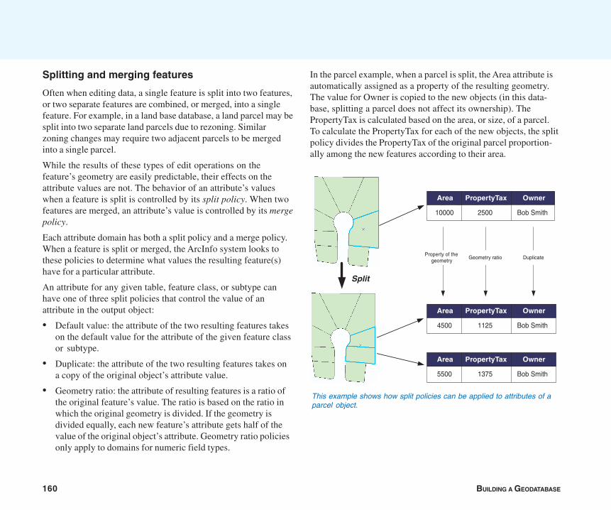
160 BUILDING A GEODATABASE
Splitting and merging features
Often when editing data, a single feature is split into two features,or two separate features are combined, or merged, into a singlefeature. For example, in a land base database, a land parcel may besplit into two separate land parcels due to rezoning. Similarzoning changes may require two adjacent parcels to be mergedinto a single parcel.
While the results of these types of edit operations on thefeature’s geometry are easily predictable, their effects on theattribute values are not. The behavior of an attribute’s valueswhen a feature is split is controlled by its split policy. When twofeatures are merged, an attribute’s value is controlled by its mergepolicy.
Each attribute domain has both a split policy and a merge policy.When a feature is split or merged, the ArcInfo system looks tothese policies to determine what values the resulting feature(s)have for a particular attribute.
An attribute for any given table, feature class, or subtype canhave one of three split policies that control the value of anattribute in the output object:
• Default value: the attribute of the two resulting features takeson the default value for the attribute of the given feature classor subtype.
• Duplicate: the attribute of the two resulting features takes ona copy of the original object’s attribute value.
• Geometry ratio: the attribute of resulting features is a ratio ofthe original feature’s value. The ratio is based on the ratio inwhich the original geometry is divided. If the geometry isdivided equally, each new feature’s attribute gets half of thevalue of the original object’s attribute. Geometry ratio policiesonly apply to domains for numeric field types.
In the parcel example, when a parcel is split, the Area attribute isautomatically assigned as a property of the resulting geometry.The value for Owner is copied to the new objects (in this data-base, splitting a parcel does not affect its ownership). ThePropertyTax is calculated based on the area, or size, of a parcel.To calculate the PropertyTax for each of the new objects, the splitpolicy divides the PropertyTax of the original parcel proportion-ally among the new features according to their area.
This example shows how split policies can be applied to attributes of aparcel object.
Area PropertyTax Owner
4500 1125 Bob Smith
Area PropertyTax Owner
10000 2500 Bob Smith
Area PropertyTax Owner
5500 1375 Bob Smith
Split
Geometry ratio DuplicateProperty of the
geometry
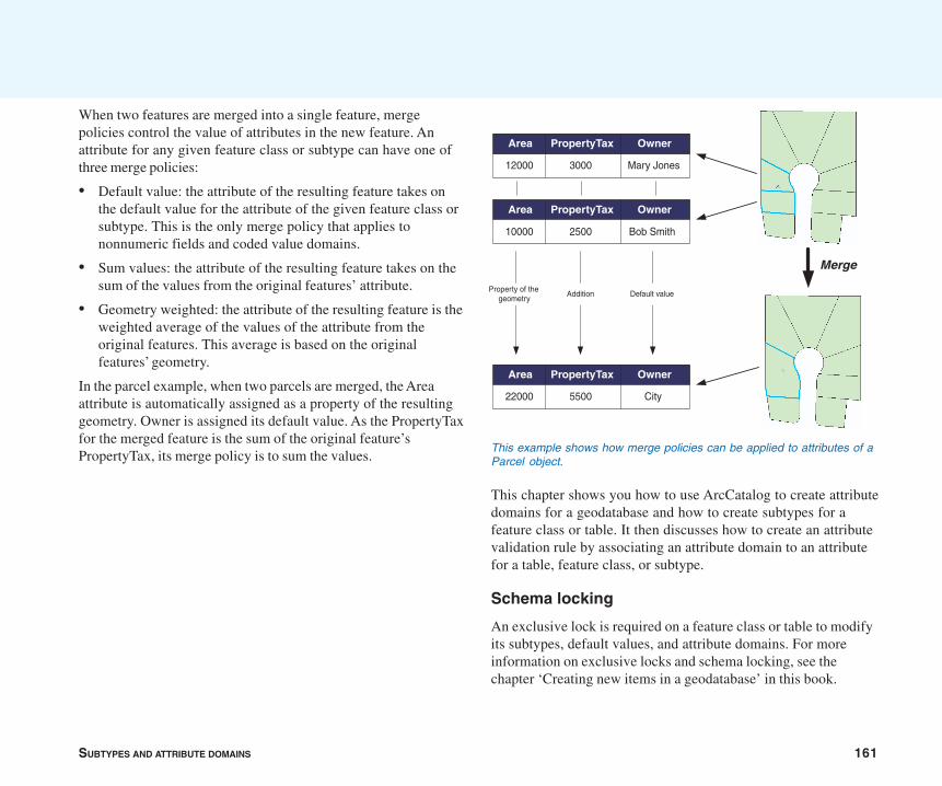
SUBTYPES AND ATTRIBUTE DOMAINS 161
When two features are merged into a single feature, mergepolicies control the value of attributes in the new feature. Anattribute for any given feature class or subtype can have one ofthree merge policies:
• Default value: the attribute of the resulting feature takes onthe default value for the attribute of the given feature class orsubtype. This is the only merge policy that applies tononnumeric fields and coded value domains.
• Sum values: the attribute of the resulting feature takes on thesum of the values from the original features’ attribute.
• Geometry weighted: the attribute of the resulting feature is theweighted average of the values of the attribute from theoriginal features. This average is based on the originalfeatures’ geometry.
In the parcel example, when two parcels are merged, the Areaattribute is automatically assigned as a property of the resultinggeometry. Owner is assigned its default value. As the PropertyTaxfor the merged feature is the sum of the original feature’sPropertyTax, its merge policy is to sum the values.
This chapter shows you how to use ArcCatalog to create attributedomains for a geodatabase and how to create subtypes for afeature class or table. It then discusses how to create an attributevalidation rule by associating an attribute domain to an attributefor a table, feature class, or subtype.
Schema locking
An exclusive lock is required on a feature class or table to modifyits subtypes, default values, and attribute domains. For moreinformation on exclusive locks and schema locking, see thechapter ‘Creating new items in a geodatabase’ in this book.
This example shows how merge policies can be applied to attributes of aParcel object.
Area PropertyTax Owner
12000 3000 Mary Jones
Area PropertyTax Owner
10000 2500 Bob Smith
Area PropertyTax Owner
22000 5500 City
Addition Default valueProperty of the
geometry
Merge

162 BUILDING A GEODATABASE
The Domains tab of the Database Properties dialog box includes alist of all the domains that exist in a geodatabase. Each domain’sname, description, properties, and valid set of values are dis-played.
From this dialog box, you can also add, remove, and modifydomains. An explanation of how to use this property page tomanage your geodatabase’s domains comes later in this chapter.
Working with attribute domain properties
A list of the domains and their descriptions.
Displays the properties of the selected domain such as its fieldtype, domain type, minimum and maximum values (for rangedomains), and the domain’s split and merge policies.
If a coded value domain is selected, the list of valid values andtheir user-friendly descriptions is displayed.
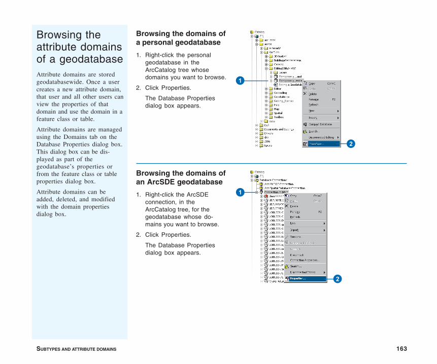
SUBTYPES AND ATTRIBUTE DOMAINS 163
Browsing theattribute domainsof a geodatabaseAttribute domains are storedgeodatabasewide. Once a usercreates a new attribute domain,that user and all other users canview the properties of thatdomain and use the domain in afeature class or table.
Attribute domains are managedusing the Domains tab on theDatabase Properties dialog box.This dialog box can be dis-played as part of thegeodatabase’s properties orfrom the feature class or tableproperties dialog box.
Attribute domains can beadded, deleted, and modifiedwith the domain propertiesdialog box.
Browsing the domains ofa personal geodatabase
1. Right-click the personalgeodatabase in theArcCatalog tree whosedomains you want to browse.
2. Click Properties.
The Database Propertiesdialog box appears.
Browsing the domains ofan ArcSDE geodatabase
1. Right-click the ArcSDEconnection, in theArcCatalog tree, for thegeodatabase whose do-mains you want to browse.
2. Click Properties.
The Database Propertiesdialog box appears.
1
2
1
2
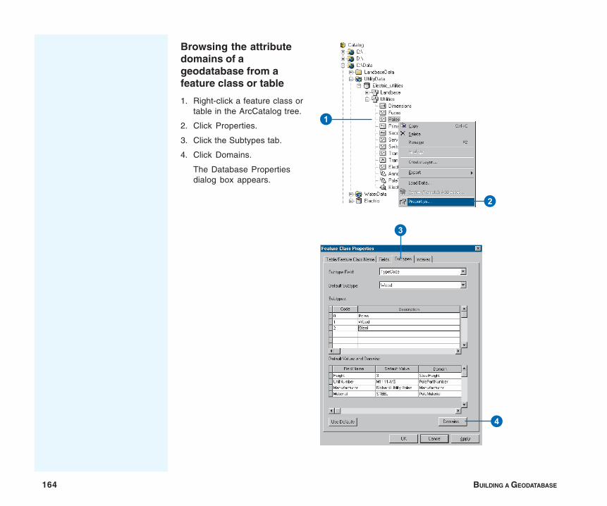
164 BUILDING A GEODATABASE
Browsing the attributedomains of ageodatabase from afeature class or table
1. Right-click a feature class ortable in the ArcCatalog tree.
2. Click Properties.
3. Click the Subtypes tab.
4. Click Domains.
The Database Propertiesdialog box appears.
1
2
3
4
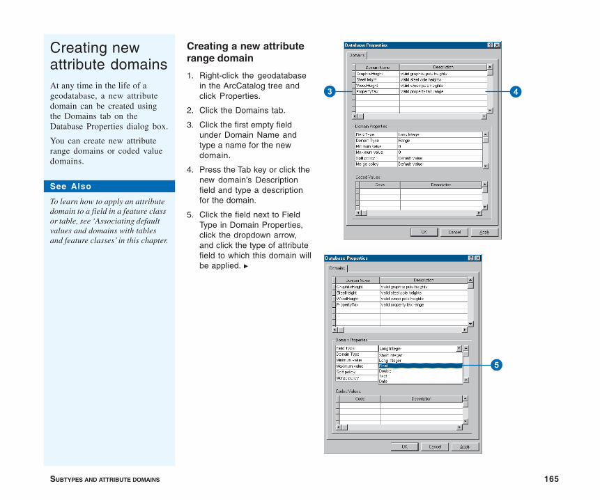
SUBTYPES AND ATTRIBUTE DOMAINS 165
Creating newattribute domainsAt any time in the life of ageodatabase, a new attributedomain can be created usingthe Domains tab on theDatabase Properties dialog box.
You can create new attributerange domains or coded valuedomains.
Creating a new attributerange domain
1. Right-click the geodatabasein the ArcCatalog tree andclick Properties.
2. Click the Domains tab.
3. Click the first empty fieldunder Domain Name andtype a name for the newdomain.
4. Press the Tab key or click thenew domain’s Descriptionfield and type a descriptionfor the domain.
5. Click the field next to FieldType in Domain Properties,click the dropdown arrow,and click the type of attributefield to which this domain willbe applied. u
5
3 4
See Also
To learn how to apply an attributedomain to a field in a feature classor table, see ‘Associating defaultvalues and domains with tablesand feature classes’ in this chapter.

166 BUILDING A GEODATABASE
6. Click the field next to DomainType, click the dropdownarrow, and click Range fromthe list of domain types.
7. Click the field with theminimum value for the rangedomain and type the mini-mum value. Do the same forthe maximum value.
8. Click the field next to Splitpolicy, click the dropdownarrow, and click the splitpolicy for the new domain. Dothe same for the mergepolicy.
9. Click Apply to create the newdomain in the geodatabaseor OK to create the domainand close the dialog box.
Tip
Range domainsRange domains can’t be created fortext fields. They can only be appliedto numeric and date fields.
6
8
9
7
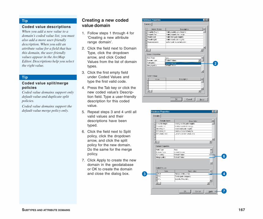
SUBTYPES AND ATTRIBUTE DOMAINS 167
Creating a new codedvalue domain
1. Follow steps 1 through 4 for‘Creating a new attributerange domain’.
2. Click the field next to DomainType, click the dropdownarrow, and click CodedValues from the list of domaintypes.
3. Click the first empty fieldunder Coded Values andtype the first valid code.
4. Press the Tab key or click thenew coded value’s Descrip-tion field. Type a user-friendlydescription for this codedvalue.
5. Repeat steps 3 and 4 until allvalid values and theirdescriptions have beentyped.
6. Click the field next to Splitpolicy, click the dropdownarrow, and click the splitpolicy for the new domain.Do the same for the mergepolicy.
7. Click Apply to create the newdomain in the geodatabaseor OK to create the domainand close the dialog box. 43
6
7
2
Tip
Coded value descriptionsWhen you add a new value to adomain’s coded value list, you mustalso add a more user-friendlydescription. When you edit anattribute value for a field that hasthis domain, the user-friendlyvalues appear in the ArcMapEditor. Descriptions help you selectthe right value.
Tip
Coded value split/mergepoliciesCoded value domains support onlydefault value and duplicate splitpolicies.
Coded value domains support thedefault value merge policy only.
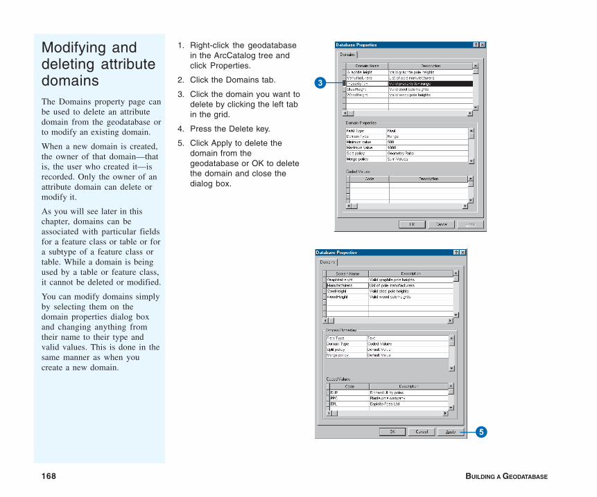
168 BUILDING A GEODATABASE
Modifying anddeleting attributedomainsThe Domains property page canbe used to delete an attributedomain from the geodatabase orto modify an existing domain.
When a new domain is created,the owner of that domain—thatis, the user who created it—isrecorded. Only the owner of anattribute domain can delete ormodify it.
As you will see later in thischapter, domains can beassociated with particular fieldsfor a feature class or table or fora subtype of a feature class ortable. While a domain is beingused by a table or feature class,it cannot be deleted or modified.
You can modify domains simplyby selecting them on thedomain properties dialog boxand changing anything fromtheir name to their type andvalid values. This is done in thesame manner as when youcreate a new domain.
1. Right-click the geodatabasein the ArcCatalog tree andclick Properties.
2. Click the Domains tab.
3. Click the domain you want todelete by clicking the left tabin the grid.
4. Press the Delete key.
5. Click Apply to delete thedomain from thegeodatabase or OK to deletethe domain and close thedialog box.
3
5
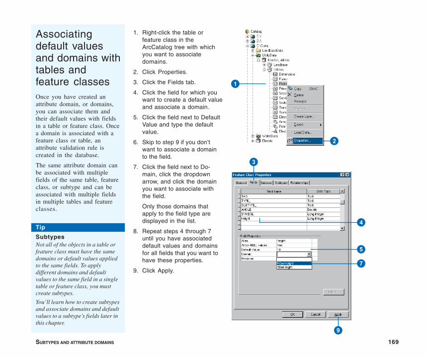
SUBTYPES AND ATTRIBUTE DOMAINS 169
Associatingdefault valuesand domains withtables andfeature classesOnce you have created anattribute domain, or domains,you can associate them andtheir default values with fieldsin a table or feature class. Oncea domain is associated with afeature class or table, anattribute validation rule iscreated in the database.
The same attribute domain canbe associated with multiplefields of the same table, featureclass, or subtype and can beassociated with multiple fieldsin multiple tables and featureclasses.
1. Right-click the table orfeature class in theArcCatalog tree with whichyou want to associatedomains.
2. Click Properties.
3. Click the Fields tab.
4. Click the field for which youwant to create a default valueand associate a domain.
5. Click the field next to DefaultValue and type the defaultvalue.
6. Skip to step 9 if you don’twant to associate a domainto the field.
7. Click the field next to Do-main, click the dropdownarrow, and click the domainyou want to associate withthe field.
Only those domains thatapply to the field type aredisplayed in the list.
8. Repeat steps 4 through 7until you have associateddefault values and domainsfor all fields that you want tohave these properties.
9. Click Apply.
1
2
3
4
5
7
9
Tip
SubtypesNot all of the objects in a table orfeature class must have the samedomains or default values appliedto the same fields. To applydifferent domains and defaultvalues to the same field in a singletable or feature class, you mustcreate subtypes.
You’ll learn how to create subtypesand associate domains and defaultvalues to a subtype’s fields later inthis chapter.
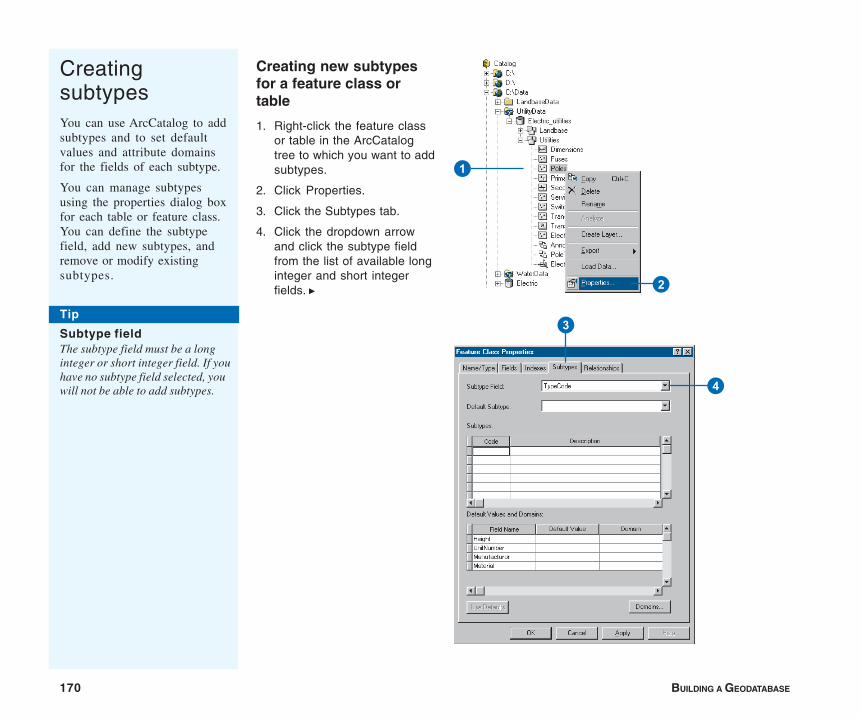
170 BUILDING A GEODATABASE
CreatingsubtypesYou can use ArcCatalog to addsubtypes and to set defaultvalues and attribute domainsfor the fields of each subtype.
You can manage subtypesusing the properties dialog boxfor each table or feature class.You can define the subtypefield, add new subtypes, andremove or modify existingsubtypes.
Creating new subtypesfor a feature class ortable
1. Right-click the feature classor table in the ArcCatalogtree to which you want to addsubtypes.
2. Click Properties.
3. Click the Subtypes tab.
4. Click the dropdown arrowand click the subtype fieldfrom the list of available longinteger and short integerfields. u
1
2
3
4
Tip
Subtype fieldThe subtype field must be a longinteger or short integer field. If youhave no subtype field selected, youwill not be able to add subtypes.
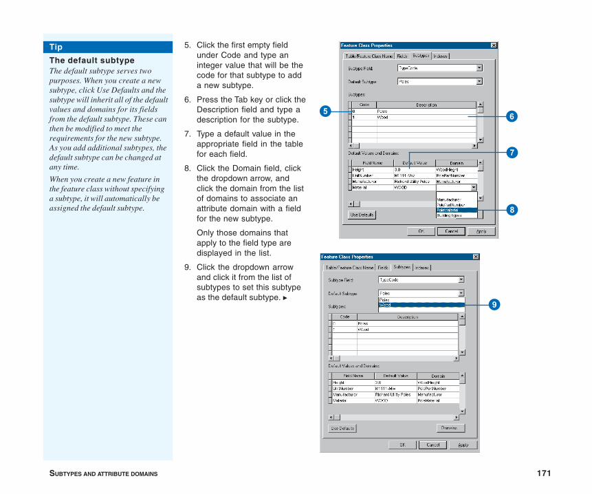
SUBTYPES AND ATTRIBUTE DOMAINS 171
5. Click the first empty fieldunder Code and type aninteger value that will be thecode for that subtype to adda new subtype.
6. Press the Tab key or click theDescription field and type adescription for the subtype.
7. Type a default value in theappropriate field in the tablefor each field.
8. Click the Domain field, clickthe dropdown arrow, andclick the domain from the listof domains to associate anattribute domain with a fieldfor the new subtype.
Only those domains thatapply to the field type aredisplayed in the list.
9. Click the dropdown arrowand click it from the list ofsubtypes to set this subtypeas the default subtype. u
9
8
7
65
Tip
The default subtypeThe default subtype serves twopurposes. When you create a newsubtype, click Use Defaults and thesubtype will inherit all of the defaultvalues and domains for its fieldsfrom the default subtype. These canthen be modified to meet therequirements for the new subtype.As you add additional subtypes, thedefault subtype can be changed atany time.
When you create a new feature inthe feature class without specifyinga subtype, it will automatically beassigned the default subtype.

172 BUILDING A GEODATABASE
10. Repeat steps 5 through 8 toadd additional subtypes. Youcan reset the default subtypeat any time.
11. Click Use Defaults to haveyour new subtype take all ofthe default values anddomains from the defaultsubtype when adding a newsubtype. You can then modifyall or some of these.
12. Click Apply to create thenew subtypes in thegeodatabase or OK to createthe subtypes and close thedialog box when you arefinished creating yoursubtypes and have selectedthe default subtype.
E
W
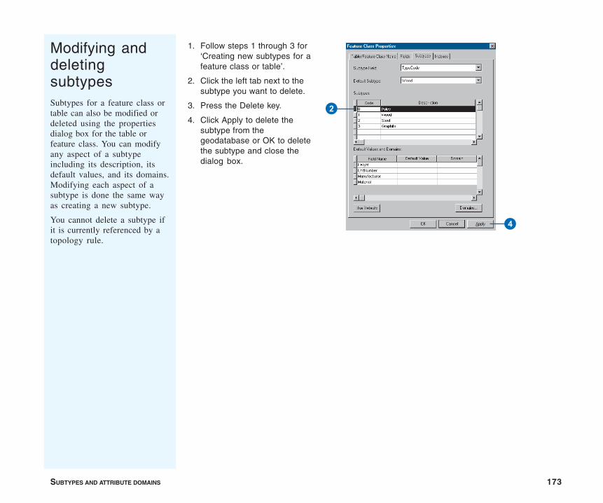
SUBTYPES AND ATTRIBUTE DOMAINS 173
Modifying anddeletingsubtypesSubtypes for a feature class ortable can also be modified ordeleted using the propertiesdialog box for the table orfeature class. You can modifyany aspect of a subtypeincluding its description, itsdefault values, and its domains.Modifying each aspect of asubtype is done the same wayas creating a new subtype.
You cannot delete a subtype ifit is currently referenced by atopology rule.
1. Follow steps 1 through 3 for‘Creating new subtypes for afeature class or table’.
2. Click the left tab next to thesubtype you want to delete.
3. Press the Delete key.
4. Click Apply to delete thesubtype from thegeodatabase or OK to deletethe subtype and close thedialog box.
4
2

IN THIS CHAPTER
175
6• What is a relationship class?
• Relationship classes in ArcCatalogand ArcMap
• Creating a simple relationshipclass
• Creating a composite relationshipclass
• Creating an attributed relationshipclass
• Creating relationship rules
• Managing relationship classes
• Exploring related objects inArcMap
• Using related fields in ArcMap
Objects in a real-world system often have particular associations with otherobjects in the database. These kinds of associations between objects in thegeodatabase are called relationships. Relationships can exist between spatialobjects (features in feature classes), nonspatial objects (rows in a table), orspatial and nonspatial objects. While spatial objects are stored in the geoda-tabase in feature classes and nonspatial objects are stored in tables, relation-ships are stored in relationship classes.
ArcCatalog contains tools to create, modify, and manage relationship classesin your geodatabase, while ArcMap provides tools to create, delete, and userelationships to find objects that are associated with other objects in thegeodatabase. This chapter describes how to use ArcCatalog to managethese relationship classes and how to use relationships in ArcMap. Editingin ArcMap discusses how to create and delete relationships.
ArcView can view feature classes that use advanced geodatabase function-ality. To create or edit feature classes that take advantage of advancedgeodatabase functionality, you need an ArcEditor or ArcInfo license.
Defining relationship classes

176 BUILDING A GEODATABASE
Objects in a real-world system, such as an electrical network or aparcel database, often have particular associations with otherobjects in the database. For example, in an electrical network,poles support transformers. In a parcel database, a parcel willhave one or many owners.
These kinds of associations between objects in the geodatabaseare called relationships. Relationships can exist between spatialobjects (features in feature classes), nonspatial objects (rows in atable), or spatial and nonspatial objects. While spatial objects arestored in the geodatabase in feature classes and nonspatialobjects are stored in tables, relationships are stored in relation-ship classes.
To store relationships, such as between electric transformers andpoles, you must create a relationship class. If, in your geodata-base, transformers also have relationships to transformer attributeobjects, then a second relationship class is required to storethose relationships.
The anatomy of a relationship
As with any association, relationships have particular character-istics. One obvious characteristic is the notion of cardinality.Cardinality describes how many objects of one type are related toan object of another type. In the pole–transformer example, asingle pole may support more than one transformer, but atransformer can only be mounted on a single pole. The relation-ship between poles and transformers is one to many: one pole,which is an object in the origin class of the relationship, to manytransformers, which is an object in the destination class of therelationship.
In general, relationships can have one-to-one, one-to-many, andmany-to-many cardinalities. As you will see later in this chapter,certain types of relationships support certain cardinalities, and
you can control cardinalities for any relationship class when youdefine relationship rules.
A relationship between two objects is maintained throughattribute values for key fields. In the pole–transformer example,the unit number of the pole that supports the transformer may beincluded in the attributes of the transformer object. This isreferred to as an embedded foreign key. It tells us what object inthe pole feature class this particular transformer is related to.
Relationship classes can have attributes. Any relationship classthat has attributes must be stored as a table in the database andhave a pair of foreign keys referencing the origin and destinationclasses of the relationship class. In this case, each relationship isstored as a row in the relationship classes table. Similarly, any
What is a relationship class?
A relationship is an association between two ormore objects in two feature classes or tables in ageodatabase. Relationships are stored inrelationship classes.
Polesfeature class
Transformerfeature class
PoleTransrelationship class
A Pole supports Transformers.
Transformers are mounted on a Pole.

DEFINING RELATIONSHIP CLASSES 177
many-to-many relationship classes require a table in the databaseto store at least the foreign keys.
Relationship classes have path labels. Forward and backwardpath labels describe the relationship when navigating from oneobject to another. The forward path label describes the relation-ship navigated from the origin class to the destination class; thebackward path label describes the relationship when navigatingfrom the destination to the origin class. In the pole–transformerexample, when navigating from the transformer to the pole, therelationship path label may be “is mounted on”. The samerelationship, when navigated from the pole to the transformer,may have a path label of “supports”.
Relationship classes can also be used to propagate standardmessages between related objects. Messaging is the mechanismthat objects related to each other use to notify each other whenthey change. For example, in a relationship between poles andtransformers, when the pole is deleted, it sends a message to itsrelated transformer objects informing them it was deleted. Astransformers can’t exist without a pole to support them, thesetransformer objects could respond to the message by deletingthemselves.
The geodatabase supports two kinds of relationships: simple (orpeer-to-peer) relationships and composite relationships. Each isdiscussed briefly below.
Simple relationships
Simple, or peer-to-peer, relationships are relationships betweentwo or more objects in the database that exist independently ofeach other.
In a relationship between object A and object B, if object A isdeleted from the database, object B continues to exist. Forexample, in a railroad network you may have railroad crossingsthat have one or more related signal lamps. However, a railroadcrossing can exist without a signal lamp, and signal lamps exist onthe railroad network where there are no railroad crossings.
Simple relationships can have one-to-one, one-to-many, or many-to-many cardinality.
Composite relationships
The geodatabase also supports the notion of a compositerelationship, where the lifetime of the origin object controls thelifetime of its related objects. The pole–transformer relationship isan example of a composite relationship. Once a pole is deleted, adelete message is sent to its related transformers, which aredeleted from the transformer’s feature class.
Composite relationships are always one-to-many but can beconstrained to be one-to-one using relationship rules.
Attributed relationship classes
One-to-one and one-to-many relationship classes do not require anew table in the geodatabase to be created to store the relation-ships. However, many-to-many relationship classes do require a
A relationship between two objects is maintained through attribute valuesfor key fields.
Origin class—Poles
Shape TranTypeObjectID
1
2
3
4
Overhead1
5
PoleID
1
2
WOOD
WOOD
1
2
STEEL3
15
15
20
Shape Height PoleTypeObjectID
Destination class—Transformers
Primary keyForeign key
3
3
1
Overhead2
Overhead1
Overhead3
Overhead3

178 BUILDING A GEODATABASE
new table in the database to store the foreign keys from the originand destination classes to make the relationship. This table canalso have other fields to store attributes of the relationship itselfthat are not attributes of either the origin or destination class.
For example, in a parcel database you may have a relationshipclass between parcels and owners, where owners “own” parcelsand parcels are “owned by” owners. An attribute of that relation-ship may be the percentage of ownership.
One-to-one and one-to-many relationship classes may also haveattributes; in this case, a table would be created to store therelationships.
Relationship rules
Relationship classes can have an associated set of relationshiprules. Relationship rules control which object subtypes from theorigin class can be related to which object subtypes in thedestination class. They can also be used to specify a validcardinality range for all permissible subtype pairs.
For example, the subtype wood pole may be able to support from0 to 3 transformers, whereas the subtype steel pole may support0 to 5 transformers. In the first case, the cardinality range wouldbe 0–3; in the second case, it would be 0–5.
You can establish a relationship between two or more objects inthe geodatabase by using tools available in ArcMap. Once therelationship is established, use ArcMap tools to navigate it. Youcan find all objects that have a relationship with a particularobject through any particular relationship class.
Performance considerations
When editing features that have relationships with messaging,edits, such as move, rotate, and delete, also affect the relatedobjects through the relationship class. There is a cost whennavigating these relationships. The cost is minimized whenindexes are maintained for the primary and foreign keys for therelationship class. When a new relationship class is created withArcCatalog, the primary and foreign keys are automaticallyindexed if they do not already have indexes.
It is important to realize that when a feature class participates in arelationship class, that feature class utilizes messaging. Whenediting that feature class in ArcMap, the related class must be
Relationships have cardinality. Cardinality describes how many objects oftype A are associated with objects of type B. Relationships can have 1–1,1–M, M–1, or N–M cardinality.
Originfeature class
Destinationfeature class
Relationshipclass
O1
O2
R1
R2
D1
D2
Originfeature class
Destinationfeature class
Relationshipclass
O1
O2
R1
R2
D1
D2
D3
D4
D5
Originfeature class
Destinationfeature class
Relationshipclass
O1
O2R1
R2
D1
D2O3
O4
Originfeature class
Destinationfeature class
Relationshipclass
O1
O2R1
R2
O3
O4
D1
D2
D3
D4
D5
One-to-one (1–1) One-to-many (1–M)
Many-to-one (M–1) Many-to-many (N–M)

DEFINING RELATIONSHIP CLASSES 179
opened so it can respond to the message—either by moving,deleting itself, or implementing some custom behavior. If therelated class is not already in the map you are working with, it willautomatically be opened to respond to the message, then closed.Each time it responds to a message, it will need to be reopened.
In general, when working with a class in ArcMap, have all relatedclasses also in the map. This way, the related classes are openedonce when they are added to ArcMap. If they are not in the map,then each time you access related objects, the class must beopened.
With many ArcInfo coverage data models, the feature–attributetable contained as few items as possible, and many of theattributes for a feature class were contained in a related table.This can be done with geodatabase feature classes; however,navigating a relationship in the geodatabase is a more costlyoperation than navigating relates in INFO. In the INFO environ-ment, it was common to store the symbology for a feature in anexternal, related table called a lookup table. This can still be donein the geodatabase using relationship classes and joining the twotables; however, for large data, symbolizing this way will be slow,even with indexes on the primary and foreign keys. Try to keepattributes for symbolization on the feature class’s table. Forperformance considerations, it is recommended that symbologyinformation be stored in the feature class itself.
Schema locking
An exclusive lock is required when modifying a relationshipclass’s relationship rules or when renaming or deleting a relation-ship class. An exclusive lock can only be acquired for a relation-ship class if the feature classes or tables that participate in therelationship can also be locked. Therefore, if another user has anexclusive or shared lock on either the origin, destination, or bothclasses, the properties of the relationship class cannot be edited.
For more information on exclusive locks and schema locking, seethe chapter ‘Creating new items in a geodatabase’ in this book.
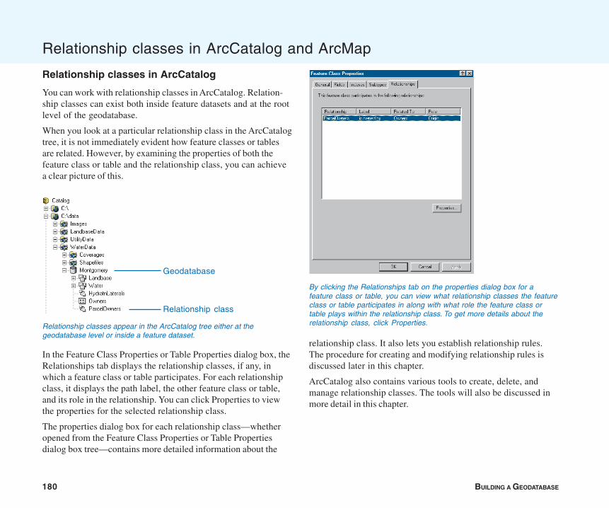
180 BUILDING A GEODATABASE
Relationship classes in ArcCatalog and ArcMap
Relationship classes in ArcCatalog
You can work with relationship classes in ArcCatalog. Relation-ship classes can exist both inside feature datasets and at the rootlevel of the geodatabase.
When you look at a particular relationship class in the ArcCatalogtree, it is not immediately evident how feature classes or tablesare related. However, by examining the properties of both thefeature class or table and the relationship class, you can achievea clear picture of this.
In the Feature Class Properties or Table Properties dialog box, theRelationships tab displays the relationship classes, if any, inwhich a feature class or table participates. For each relationshipclass, it displays the path label, the other feature class or table,and its role in the relationship. You can click Properties to viewthe properties for the selected relationship class.
The properties dialog box for each relationship class—whetheropened from the Feature Class Properties or Table Propertiesdialog box tree—contains more detailed information about the
relationship class. It also lets you establish relationship rules.The procedure for creating and modifying relationship rules isdiscussed later in this chapter.
ArcCatalog also contains various tools to create, delete, andmanage relationship classes. The tools will also be discussed inmore detail in this chapter.
By clicking the Relationships tab on the properties dialog box for afeature class or table, you can view what relationship classes the featureclass or table participates in along with what role the feature class ortable plays within the relationship class. To get more details about therelationship class, click Properties.Relationship classes appear in the ArcCatalog tree either at the
geodatabase level or inside a feature dataset.
Geodatabase
Relationship class
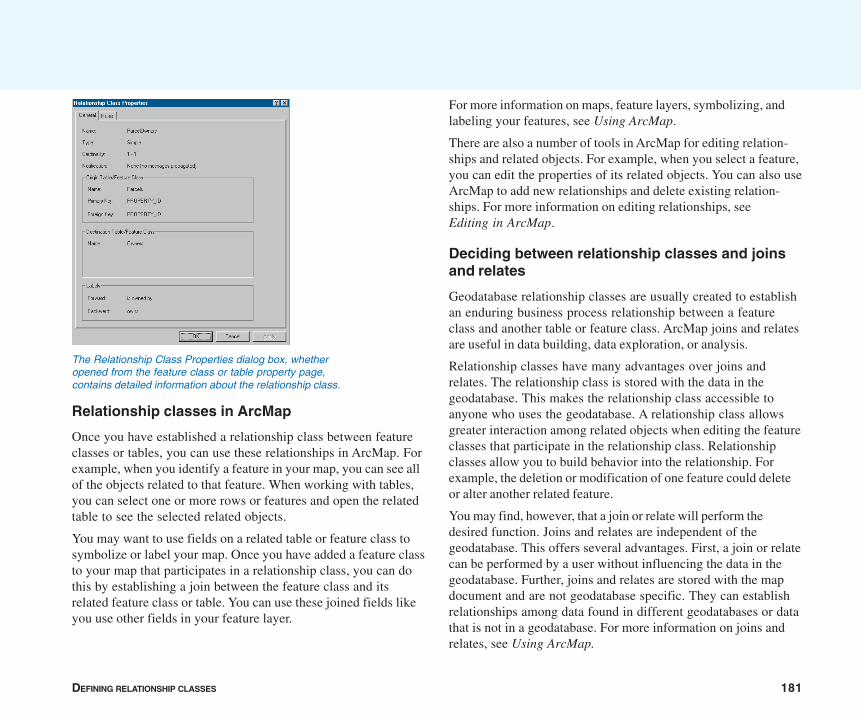
DEFINING RELATIONSHIP CLASSES 181
Relationship classes in ArcMap
Once you have established a relationship class between featureclasses or tables, you can use these relationships in ArcMap. Forexample, when you identify a feature in your map, you can see allof the objects related to that feature. When working with tables,you can select one or more rows or features and open the relatedtable to see the selected related objects.
You may want to use fields on a related table or feature class tosymbolize or label your map. Once you have added a feature classto your map that participates in a relationship class, you can dothis by establishing a join between the feature class and itsrelated feature class or table. You can use these joined fields likeyou use other fields in your feature layer.
For more information on maps, feature layers, symbolizing, andlabeling your features, see Using ArcMap.
There are also a number of tools in ArcMap for editing relation-ships and related objects. For example, when you select a feature,you can edit the properties of its related objects. You can also useArcMap to add new relationships and delete existing relation-ships. For more information on editing relationships, seeEditing in ArcMap.
Deciding between relationship classes and joinsand relates
Geodatabase relationship classes are usually created to establishan enduring business process relationship between a featureclass and another table or feature class. ArcMap joins and relatesare useful in data building, data exploration, or analysis.
Relationship classes have many advantages over joins andrelates. The relationship class is stored with the data in thegeodatabase. This makes the relationship class accessible toanyone who uses the geodatabase. A relationship class allowsgreater interaction among related objects when editing the featureclasses that participate in the relationship class. Relationshipclasses allow you to build behavior into the relationship. Forexample, the deletion or modification of one feature could deleteor alter another related feature.
You may find, however, that a join or relate will perform thedesired function. Joins and relates are independent of thegeodatabase. This offers several advantages. First, a join or relatecan be performed by a user without influencing the data in thegeodatabase. Further, joins and relates are stored with the mapdocument and are not geodatabase specific. They can establishrelationships among data found in different geodatabases or datathat is not in a geodatabase. For more information on joins andrelates, see Using ArcMap.
The Relationship Class Properties dialog box, whetheropened from the feature class or table property page,contains detailed information about the relationship class.
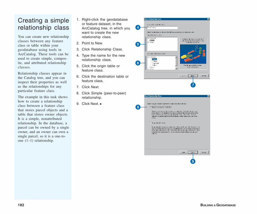
182 BUILDING A GEODATABASE
Creating a simplerelationship classYou can create new relationshipclasses between any featureclass or table within yourgeodatabase using tools inArcCatalog. These tools can beused to create simple, compos-ite, and attributed relationshipclasses.
Relationship classes appear inthe Catalog tree, and you caninspect their properties as wellas the relationships for anyparticular feature class.
The example in this task showshow to create a relationshipclass between a feature classthat stores parcel objects and atable that stores owner objects.It is a simple, nonattributedrelationship. In the database, aparcel can be owned by a singleowner, and an owner can own asingle parcel, so it is a one-to-one (1–1) relationship.
1. Right-click the geodatabaseor feature dataset, in theArcCatalog tree, in which youwant to create the newrelationship class.
2. Point to New.
3. Click Relationship Class.
4. Type the name for the newrelationship class.
5. Click the origin table orfeature class.
6. Click the destination table orfeature class.
7. Click Next.
8. Click Simple (peer-to-peer)relationship.
9. Click Next. u
4
5
6
7
8
9

DEFINING RELATIONSHIP CLASSES 183
10. Type the forward andbackward path labels.
11. Click the message notifica-tion direction.
12. Click Next.
13. Click the first cardinalityoption. In this example, anowner can own a singleparcel and a parcel can beowned by a single owner, sothis is a one-to-one (1–1)relationship.
14. Click Next. u
Q
W
E
R
T
Tip
M–N relationship classesMany-to-many (M–N) relationshipclasses require the relationshipclass to have its own table in thedatabase. You can optionally addattributes to this table, or you canallow ArcGIS to manage theschema of the table for you.
Tip
Notification directionBy default, the notification directionfor a simple relationship is None.
Tip
Turning on messagingTurning on messaging causesmessages to be generated for eachedit, slowing performance. Unlessyou are responding to messagesand reacting accordingly, youshould not turn on messaging.
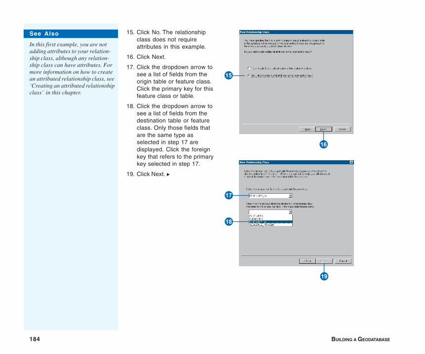
184 BUILDING A GEODATABASE
15. Click No. The relationshipclass does not requireattributes in this example.
16. Click Next.
17. Click the dropdown arrow tosee a list of fields from theorigin table or feature class.Click the primary key for thisfeature class or table.
18. Click the dropdown arrow tosee a list of fields from thedestination table or featureclass. Only those fields thatare the same type asselected in step 17 aredisplayed. Click the foreignkey that refers to the primarykey selected in step 17.
19. Click Next. u
Y
U
O
I
P
See Also
In this first example, you are notadding attributes to your relation-ship class, although any relation-ship class can have attributes. Formore information on how to createan attributed relationship class, see‘Creating an attributed relationshipclass’ in this chapter.
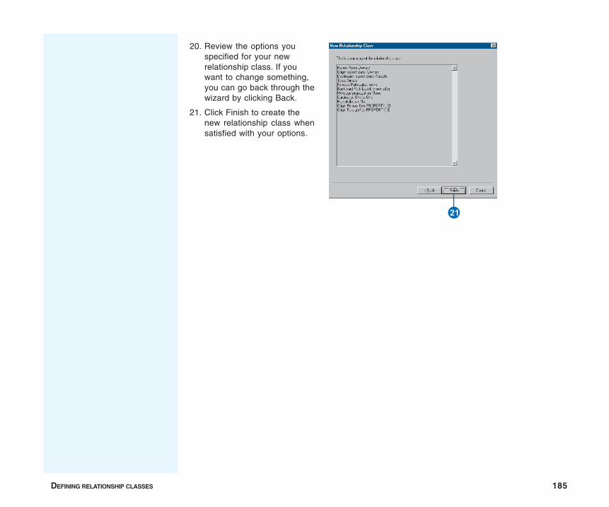
DEFINING RELATIONSHIP CLASSES 185
20. Review the options youspecified for your newrelationship class. If youwant to change something,you can go back through thewizard by clicking Back.
21. Click Finish to create thenew relationship class whensatisfied with your options.
S

186 BUILDING A GEODATABASE
1. Follow steps 1 through 7 for‘Creating a simple relation-ship class’.
2. Click Composite relationship.
3. Click Next.
4. Type the forward andbackward path labels.
5. If you need to turn onmessaging, click the mes-sage notification direction.
6. Click Next. u
Creating acompositerelationship classYou can use a wizard to create acomposite relationship class.The example in this subtaskshows how to create a relation-ship class between a featureclass that stores transformerbanks and one that storestransformer units.
The existence of a transformerunit in the database is depen-dent on the presence of atransformer bank. This relation-ship class is a compositerelationship with the trans-former bank as the originfeature class.
The relationship will benonattributed; compositerelationships are by definitionone-to-many (1–M) relation-ships.
Creating a composite relation-ship involves many of the samesteps used in the task forcreating a simple relationship.The steps outlined here reflectthe differences between the twotasks including using differentorigin and destination classes.
4
5
6
2
3
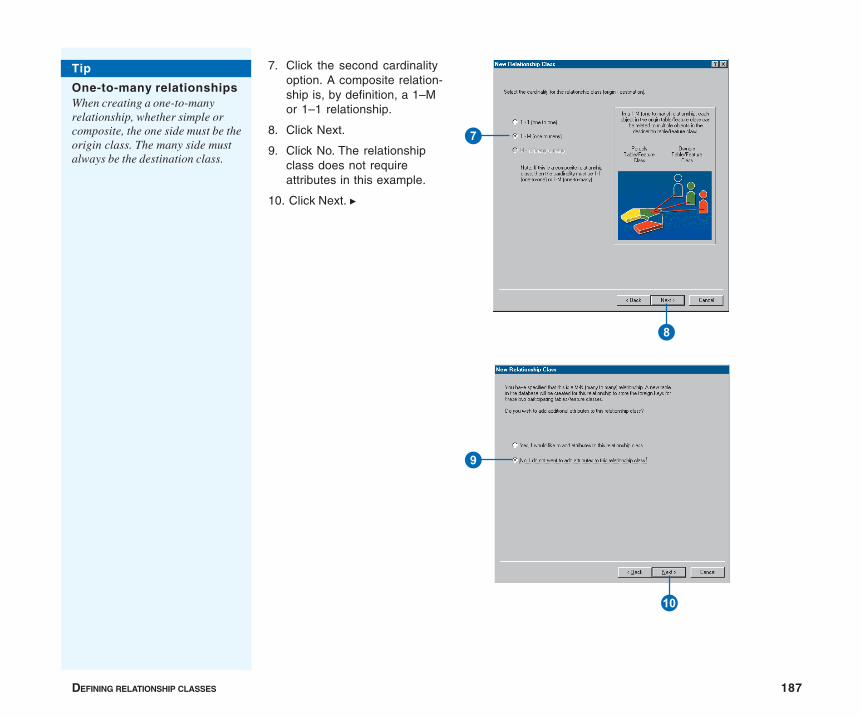
DEFINING RELATIONSHIP CLASSES 187
7. Click the second cardinalityoption. A composite relation-ship is, by definition, a 1–Mor 1–1 relationship.
8. Click Next.
9. Click No. The relationshipclass does not requireattributes in this example.
10. Click Next. u
7
8
Q
9
Tip
One-to-many relationshipsWhen creating a one-to-manyrelationship, whether simple orcomposite, the one side must be theorigin class. The many side mustalways be the destination class.
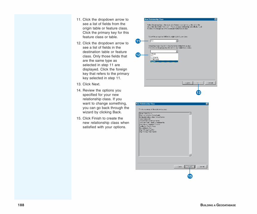
188 BUILDING A GEODATABASE
11. Click the dropdown arrow tosee a list of fields from theorigin table or feature class.Click the primary key for thisfeature class or table.
12. Click the dropdown arrow tosee a list of fields in thedestination table or featureclass. Only those fields thatare the same type asselected in step 11 aredisplayed. Click the foreignkey that refers to the primarykey selected in step 11.
13. Click Next.
14. Review the options youspecified for your newrelationship class. If youwant to change something,you can go back through thewizard by clicking Back.
15. Click Finish to create thenew relationship class whensatisfied with your options.
W
E
R
Y
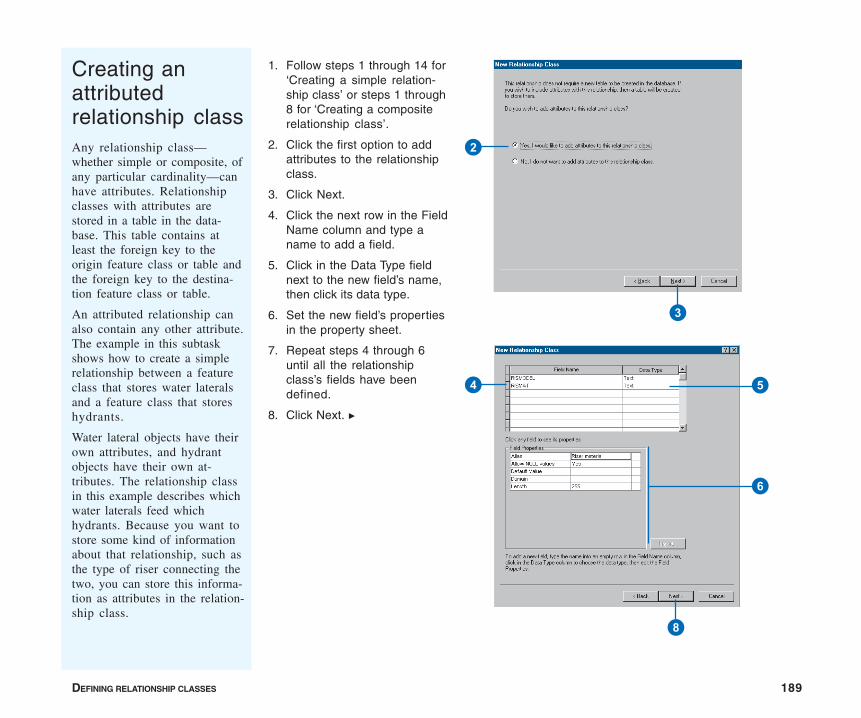
DEFINING RELATIONSHIP CLASSES 189
1. Follow steps 1 through 14 for‘Creating a simple relation-ship class’ or steps 1 through8 for ‘Creating a compositerelationship class’.
2. Click the first option to addattributes to the relationshipclass.
3. Click Next.
4. Click the next row in the FieldName column and type aname to add a field.
5. Click in the Data Type fieldnext to the new field’s name,then click its data type.
6. Set the new field’s propertiesin the property sheet.
7. Repeat steps 4 through 6until all the relationshipclass’s fields have beendefined.
8. Click Next. u
Creating anattributedrelationship classAny relationship class—whether simple or composite, ofany particular cardinality—canhave attributes. Relationshipclasses with attributes arestored in a table in the data-base. This table contains atleast the foreign key to theorigin feature class or table andthe foreign key to the destina-tion feature class or table.
An attributed relationship canalso contain any other attribute.The example in this subtaskshows how to create a simplerelationship between a featureclass that stores water lateralsand a feature class that storeshydrants.
Water lateral objects have theirown attributes, and hydrantobjects have their own at-tributes. The relationship classin this example describes whichwater laterals feed whichhydrants. Because you want tostore some kind of informationabout that relationship, such asthe type of riser connecting thetwo, you can store this informa-tion as attributes in the relation-ship class.
2
3
8
4 5
6

190 BUILDING A GEODATABASE
9. Click the dropdown arrow tosee a list of fields from theorigin table or feature class.Click the primary key for thisfeature class or table.
10. Type the name of the foreignkey field for the origin tableor feature class.
11. Click the dropdown arrow tosee a list of fields from thedestination table or featureclass. Click the primary keyfor this feature class or table.
12. Type the name of the foreignkey field for the destinationtable or feature class.
13. Click Next.
14. Review the options youspecified for your newrelationship class. If youwant to change something,you can go back through thewizard by clicking Back.
15. Click Finish to create thenew relationship class whensatisfied with your options.
Tip
Relationship table foreignkeysIn an attributed relationship, therelationship table must have fieldsthat act as foreign keys to theorigin and destination featureclasses or tables.
These foreign keys relate to theprimary keys on the origin anddestination feature class or tableprimary keys.
R
EQ
W9
Y
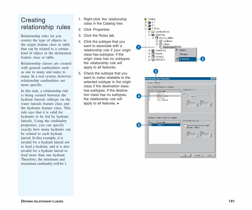
DEFINING RELATIONSHIP CLASSES 191
1. Right-click the relationshipclass in the Catalog tree.
2. Click Properties.
3. Click the Rules tab.
4. Click the subtype that youwant to associate with arelationship rule if your originclass has subtypes. If theorigin class has no subtypes,the relationship rule willapply to all features.
5. Check the subtype that youwant to make relatable to theselected subtype in the originclass if the destination classhas subtypes. If the destina-tion class has no subtypes,the relationship rule willapply to all features. u
Creatingrelationship rulesRelationship rules let yourestrict the type of objects inthe origin feature class or tablethat can be related to a certainkind of object in the destinationfeature class or table.
Relationship classes are createdwith general cardinalities suchas one to many and many tomany. In a real system, however,relationship cardinalities aremore specific.
In this task, a relationship ruleis being created between thehydrant laterals subtype on thewater laterals feature class andthe hydrants feature class. Thisrule says that it is valid forhydrants to be fed by hydrantlaterals. Using the cardinalityproperties, you can specifyexactly how many hydrants canbe related to each hydrantlateral. In this example, it isinvalid for a hydrant lateral notto feed a hydrant, and it is alsoinvalid for a hydrant lateral tofeed more than one hydrant.Therefore, the minimum andmaximum cardinality will be 1.
4
5
3
1
2
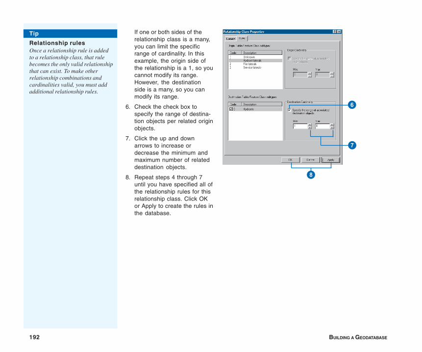
192 BUILDING A GEODATABASE
If one or both sides of therelationship class is a many,you can limit the specificrange of cardinality. In thisexample, the origin side ofthe relationship is a 1, so youcannot modify its range.However, the destinationside is a many, so you canmodify its range.
6. Check the check box tospecify the range of destina-tion objects per related originobjects.
7. Click the up and downarrows to increase ordecrease the minimum andmaximum number of relateddestination objects.
8. Repeat steps 4 through 7until you have specified all ofthe relationship rules for thisrelationship class. Click OKor Apply to create the rules inthe database.
Tip
Relationship rulesOnce a relationship rule is addedto a relationship class, that rulebecomes the only valid relationshipthat can exist. To make otherrelationship combinations andcardinalities valid, you must addadditional relationship rules.
6
8
7
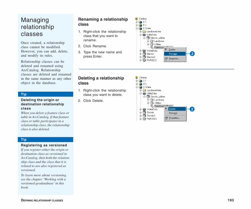
DEFINING RELATIONSHIP CLASSES 193
ManagingrelationshipclassesOnce created, a relationshipclass cannot be modified.However, you can add, delete,and modify its rules.
Relationship classes can bedeleted and renamed usingArcCatalog. Relationshipclasses are deleted and renamedin the same manner as any otherobject in the database.
Renaming a relationshipclass
1. Right-click the relationshipclass that you want torename.
2. Click Rename.
3. Type the new name andpress Enter.
Deleting a relationshipclass
1. Right-click the relationshipclass you want to delete.
2. Click Delete.
2
2
Tip
Deleting the origin ordestination relationshipclassWhen you delete a feature class ortable in ArcCatalog, if that featureclass or table participates in arelationship class, the relationshipclass is also deleted.
Tip
Registering as versionedIf you register either the origin ordestination class as versioned inArcCatalog, then both the relation-ship class and the class that it isrelated to are also registered asversioned.
To learn more about versioning,see the chapter ‘Working with aversioned geodatabase’ in thisbook.
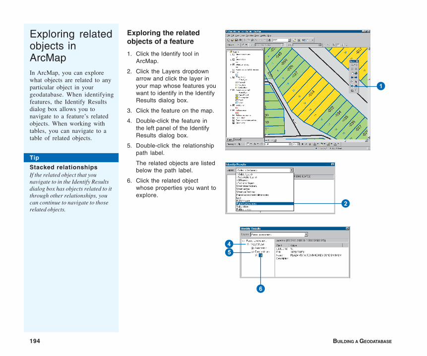
194 BUILDING A GEODATABASE
Exploring relatedobjects inArcMapIn ArcMap, you can explorewhat objects are related to anyparticular object in yourgeodatabase. When identifyingfeatures, the Identify Resultsdialog box allows you tonavigate to a feature’s relatedobjects. When working withtables, you can navigate to atable of related objects.
Exploring the relatedobjects of a feature
1. Click the Identify tool inArcMap.
2. Click the Layers dropdownarrow and click the layer inyour map whose features youwant to identify in the IdentifyResults dialog box.
3. Click the feature on the map.
4. Double-click the feature inthe left panel of the IdentifyResults dialog box.
5. Double-click the relationshippath label.
The related objects are listedbelow the path label.
6. Click the related objectwhose properties you want toexplore.
Tip
Stacked relationshipsIf the related object that younavigate to in the Identify Resultsdialog box has objects related to itthrough other relationships, youcan continue to navigate to thoserelated objects.
45
6
1
2
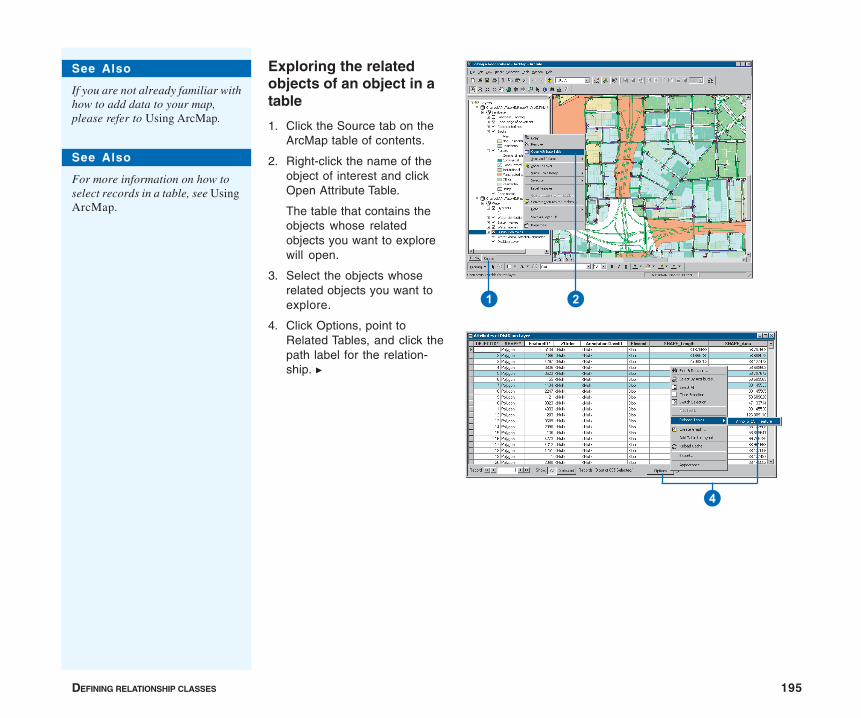
DEFINING RELATIONSHIP CLASSES 195
Exploring the relatedobjects of an object in atable
1. Click the Source tab on theArcMap table of contents.
2. Right-click the name of theobject of interest and clickOpen Attribute Table.
The table that contains theobjects whose relatedobjects you want to explorewill open.
3. Select the objects whoserelated objects you want toexplore.
4. Click Options, point toRelated Tables, and click thepath label for the relation-ship. u
1 2
4
See Also
If you are not already familiar withhow to add data to your map,please refer to Using ArcMap.
See Also
For more information on how toselect records in a table, see UsingArcMap.
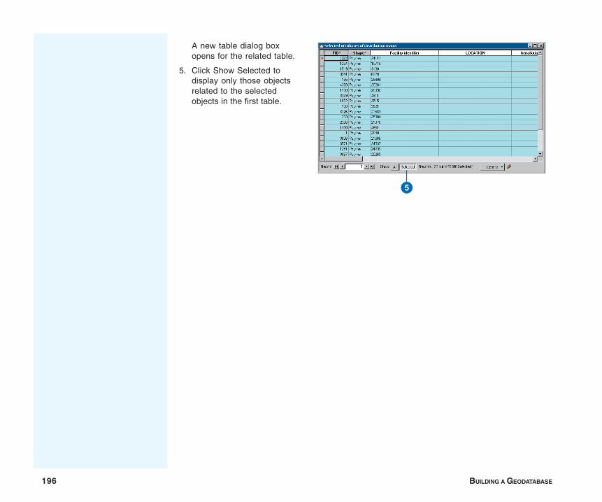
196 BUILDING A GEODATABASE
A new table dialog boxopens for the related table.
5. Click Show Selected todisplay only those objectsrelated to the selectedobjects in the first table.
5
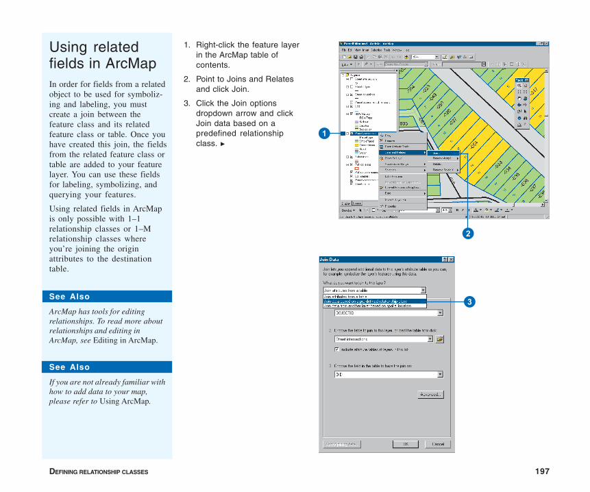
DEFINING RELATIONSHIP CLASSES 197
Using relatedfields in ArcMapIn order for fields from a relatedobject to be used for symboliz-ing and labeling, you mustcreate a join between thefeature class and its relatedfeature class or table. Once youhave created this join, the fieldsfrom the related feature class ortable are added to your featurelayer. You can use these fieldsfor labeling, symbolizing, andquerying your features.
Using related fields in ArcMapis only possible with 1–1relationship classes or 1–Mrelationship classes whereyou’re joining the originattributes to the destinationtable.
1. Right-click the feature layerin the ArcMap table ofcontents.
2. Point to Joins and Relatesand click Join.
3. Click the Join optionsdropdown arrow and clickJoin data based on apredefined relationshipclass. u
3
1
2
See Also
ArcMap has tools for editingrelationships. To read more aboutrelationships and editing inArcMap, see Editing in ArcMap.
See Also
If you are not already familiar withhow to add data to your map,please refer to Using ArcMap.
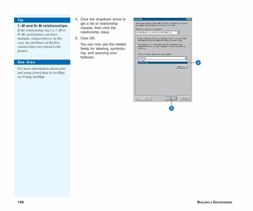
198 BUILDING A GEODATABASE
4. Click the dropdown arrow toget a list of relationshipclasses, then click therelationship class.
5. Click OK.
You can now use the relatedfields for labeling, symboliz-ing, and querying yourfeatures.
Tip
1–M and N–M relationshipsIf the relationship class is 1–M orN–M, each feature can havemultiple, related objects. In thiscase, the attributes of the firstrelated object are joined to thefeature.
See Also
For more information about joinsand using joined data in ArcMap,see Using ArcMap.
4
5
IN THIS CHAPTER
199
Geometric networks 7• What is a geometric network?
• Geometric networks andArcCatalog
• Creating geometric networks
• Creating a new geometric network
• Building a geometric network fromexisting simple feature classes
• Adding new feature classes toyour geometric network
• Network connectivity: defining therules
• Establishing connectivity rules
• Managing a geometric network
When you model automated mapping/facilities management (AM/FM) ortransportation networks, features have connectivity relationships with otherfeatures around them. This connectivity is maintained in the geodatabasethrough an association called a geometric network.
Geometric networks are created and managed using ArcCatalog. Thischapter highlights the key tasks for creating and managing geometricnetworks. Another type of topological association is discussed in the‘Topology’ chapter in this book.
ArcView can view feature classes that use advanced geodatabase function-ality. To create or edit feature classes that take advantage of advancedgeodatabase functionality, you need an ArcEditor or ArcInfo license.
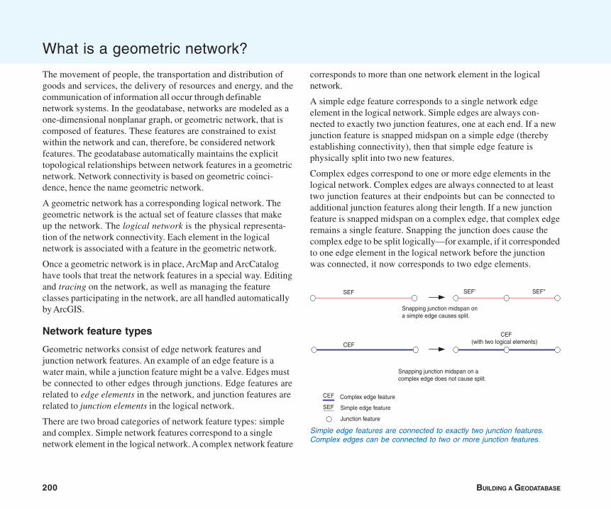
200 BUILDING A GEODATABASE
The movement of people, the transportation and distribution ofgoods and services, the delivery of resources and energy, and thecommunication of information all occur through definablenetwork systems. In the geodatabase, networks are modeled as aone-dimensional nonplanar graph, or geometric network, that iscomposed of features. These features are constrained to existwithin the network and can, therefore, be considered networkfeatures. The geodatabase automatically maintains the explicittopological relationships between network features in a geometricnetwork. Network connectivity is based on geometric coinci-dence, hence the name geometric network.
A geometric network has a corresponding logical network. Thegeometric network is the actual set of feature classes that makeup the network. The logical network is the physical representa-tion of the network connectivity. Each element in the logicalnetwork is associated with a feature in the geometric network.
Once a geometric network is in place, ArcMap and ArcCataloghave tools that treat the network features in a special way. Editingand tracing on the network, as well as managing the featureclasses participating in the network, are all handled automaticallyby ArcGIS.
Network feature types
Geometric networks consist of edge network features andjunction network features. An example of an edge feature is awater main, while a junction feature might be a valve. Edges mustbe connected to other edges through junctions. Edge features arerelated to edge elements in the network, and junction features arerelated to junction elements in the logical network.
There are two broad categories of network feature types: simpleand complex. Simple network features correspond to a singlenetwork element in the logical network. A complex network feature
corresponds to more than one network element in the logicalnetwork.
A simple edge feature corresponds to a single network edgeelement in the logical network. Simple edges are always con-nected to exactly two junction features, one at each end. If a newjunction feature is snapped midspan on a simple edge (therebyestablishing connectivity), then that simple edge feature isphysically split into two new features.
Complex edges correspond to one or more edge elements in thelogical network. Complex edges are always connected to at leasttwo junction features at their endpoints but can be connected toadditional junction features along their length. If a new junctionfeature is snapped midspan on a complex edge, that complex edgeremains a single feature. Snapping the junction does cause thecomplex edge to be split logically—for example, if it correspondedto one edge element in the logical network before the junctionwas connected, it now corresponds to two edge elements.
What is a geometric network?
Simple edge features are connected to exactly two junction features.Complex edges can be connected to two or more junction features.
CEF
SEF SEF' SEF''
CEF(with two logical elements)
Snapping junction midspan ona simple edge causes split.
Snapping junction midspan on acomplex edge does not cause split.
Complex edge feature
Simple edge feature
Junction feature
CEF
SEF

GEOMETRIC NETWORKS 201
Orphan junction feature class
When the first feature class is added to the geometric network, asimple junction feature class is created, called the orphan junctionfeature class. The name of the orphan junction feature classcorresponds to the name of the geometric network appended with“_Junction”. The orphan junction feature class is used by thegeometric network to maintain network integrity. Every edge inthe geometric network must have a junction connected to its end-points. During network building, an orphan junction will beinserted at the endpoint of any edge at which a geometricallycoincident junction does not already exist. Orphan junctionfeatures can be removed from the geometric network by subsum-ing them with other junction features. See the ArcGIS online Helpsystem for more information.
Sources and sinks
Networks are often used to model real-world systems in which thedirection of movement through the network is well defined. Forexample, the flow of electricity in an electrical network is from thepower generation station to the customers. In a water network,the flow direction may not be as well defined as in an electricnetwork, but the flow of water may be from a pump station to acustomer or from customers to a treatment plant.
Flow direction in a network is calculated from a set of sources andsinks. In the above examples, electricity and water flow are drivenby sources and sinks. Flow is away from sources, such as thepower generation station or a pump station, and toward sinkssuch as a water treatment plant (in the case of a wastewaternetwork).
Junction features in geometric networks can act as sources orsinks. When you create a new junction feature class in a network,you can specify whether the features stored in it can representsources, sinks, or neither in the network. If you specify that these
features can be sources or sinks, a field called AncillaryRole isadded to the feature class to record if the feature is a source, sink,or neither a source nor a sink. When you calculate the flowdirection for a geometric network in ArcMap, the flow directionwill be calculated based on the sources and sinks in the network.
For example, you may have a tank in your water network that isdown for maintenance, so its role in the network will be changed(temporarily) from source to none. The flow for the network isrecalculated by the system; any traces on the network will beaffected by the change in flow direction caused by the state ofthe tank. For more information on calculating flow direction andusing flow direction in network analysis, see Using ArcMap.
Network weights
A network can have a set of weights associated with it. A weightcan be used to represent the cost of traversing an element in thelogical network. For example, in a water network, a certain amountof pressure is lost when traveling the length of a transmissionmain due to surface friction within the pipe.
Weights are calculated based on some attribute of each feature.In the transmission main example above, an attribute that affectsthe weight would be the length of the feature.
A network can have any number of weights associated with it.Each feature class in the network may have some, all, or none ofthese weights associated with its attributes. The weight for eachfeature is determined by some attribute for that feature. Eachweight can be associated with one attribute in a feature but, at thesame time, can be associated with multiple features. For example,a weight called Diameter can be associated with the attributeDiameter in water main features and can also be associated withthe attribute Dia in water lateral features.
A network weight value of zero is reserved and is assigned to allorphan junction features. Also, if a weight is not associated with
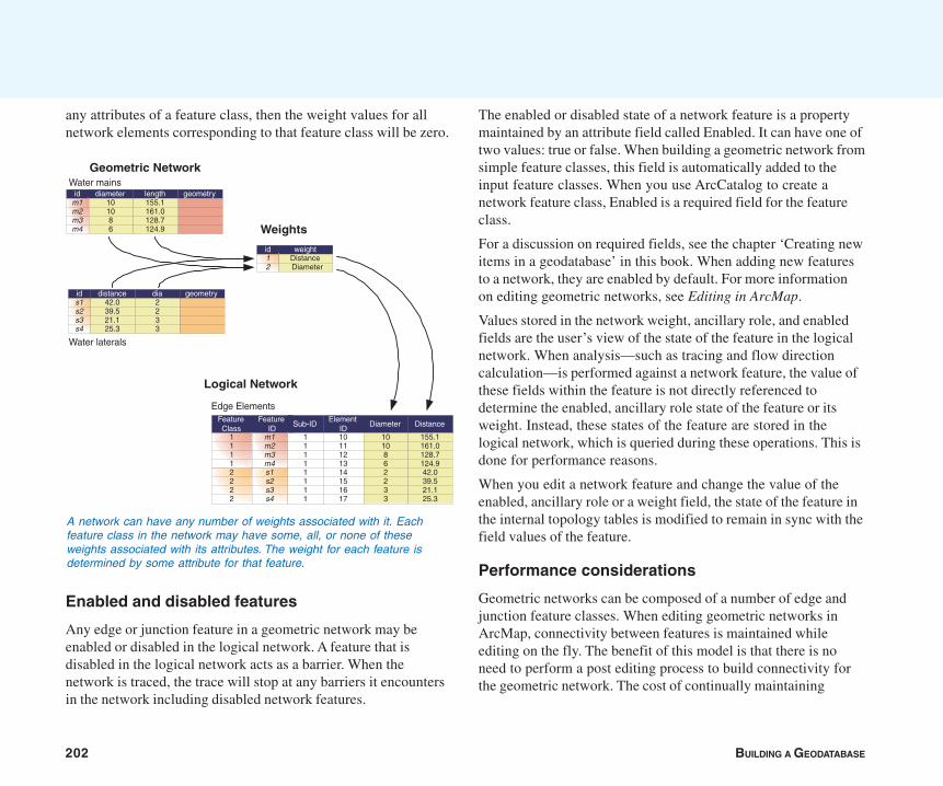
202 BUILDING A GEODATABASE
any attributes of a feature class, then the weight values for allnetwork elements corresponding to that feature class will be zero.
Enabled and disabled features
Any edge or junction feature in a geometric network may beenabled or disabled in the logical network. A feature that isdisabled in the logical network acts as a barrier. When thenetwork is traced, the trace will stop at any barriers it encountersin the network including disabled network features.
The enabled or disabled state of a network feature is a propertymaintained by an attribute field called Enabled. It can have one oftwo values: true or false. When building a geometric network fromsimple feature classes, this field is automatically added to theinput feature classes. When you use ArcCatalog to create anetwork feature class, Enabled is a required field for the featureclass.
For a discussion on required fields, see the chapter ‘Creating newitems in a geodatabase’ in this book. When adding new featuresto a network, they are enabled by default. For more informationon editing geometric networks, see Editing in ArcMap.
Values stored in the network weight, ancillary role, and enabledfields are the user’s view of the state of the feature in the logicalnetwork. When analysis—such as tracing and flow directioncalculation—is performed against a network feature, the value ofthese fields within the feature is not directly referenced todetermine the enabled, ancillary role state of the feature or itsweight. Instead, these states of the feature are stored in thelogical network, which is queried during these operations. This isdone for performance reasons.
When you edit a network feature and change the value of theenabled, ancillary role or a weight field, the state of the feature inthe internal topology tables is modified to remain in sync with thefield values of the feature.
Performance considerations
Geometric networks can be composed of a number of edge andjunction feature classes. When editing geometric networks inArcMap, connectivity between features is maintained whileediting on the fly. The benefit of this model is that there is noneed to perform a post editing process to build connectivity forthe geometric network. The cost of continually maintaining
A network can have any number of weights associated with it. Eachfeature class in the network may have some, all, or none of theseweights associated with its attributes. The weight for each feature isdetermined by some attribute for that feature.
Logical Network
id12
weightDistanceDiameter
ids1s2s3s4
geometry
Water laterals
distance dia2233
42.039.521.125.3
idm1m2m3m4
geometryWater mains
diameter length101086
155.1161.0128.7124.9
Geometric Network
DiameterFeatureClass
FeatureID
ElementID
Edge Elements
Sub-ID
1111
m1m2m3m4
11111111
1011121314151617
1010862233
Distance
155.1161.0128.7124.942.039.521.125.3
2222
s1s2s3s4
Weights

GEOMETRIC NETWORKS 203
network connectivity imposes overhead on the time it takes toadd or modify features in network feature classes.
Connectivity in a network feature class is based on geometriccoincidence. If a junction is added along an edge, the edge andjunction will become connected to one another. When a newfeature is added to a network feature class, this geometriccoincidence must be discovered. So, each feature class in thenetwork must be analyzed by performing a spatial query against itto determine if the new feature is coincident with networkfeatures. If coincidence is discovered, then network connectivityis established.
When discovering connectivity, a separate spatial query must beexecuted on the server for each feature class in the network. Ifyou use the map cache while editing the network, these spatialqueries do not need to go against the server and are much faster.You will not pay as much of a penalty in performance for having alarge number of feature classes in your network if you use themap cache. Using the map cache when editing your networkfeatures will significantly improve performance when adding newfeatures or connecting and moving existing features. For moreinformation on editing geometric networks and using the cache,see Editing in ArcMap.
Try to reduce the number of feature classes you have in yourgeometric network by lumping feature classes together usingsubtypes. If your feature classes carry different attributes, youcan use relationships to manage subtype-specific attributes indifferent tables in the database, or you can keep all the attributesin the same table, using nulls for those that don’t apply to aparticular subtype.
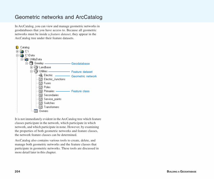
204 BUILDING A GEODATABASE
In ArcCatalog, you can view and manage geometric networks ingeodatabases that you have access to. Because all geometricnetworks must be inside a feature dataset, they appear in theArcCatalog tree under their feature datasets.
It is not immediately evident in the ArcCatalog tree which featureclasses participate in the network, which participate in whichnetwork, and which participate in none. However, by examiningthe properties of both geometric networks and feature classes,the network feature classes can be determined.
ArcCatalog also contains various tools to create, delete, andmanage both geometric networks and the feature classes thatparticipate in geometric networks. These tools are discussed inmore detail later in this chapter.
Geometric networks and ArcCatalog
Geodatabase
Feature class
Geometric network
Feature dataset
GEOMETRIC NETWORKS 205
A geometric network is a connectivity relationship between acollection of feature classes in a feature dataset. Each feature hasa role in the geometric network of either an edge or a junction.Multiple feature classes may have the same role in a singlegeometric network.
The basic methodology for creating a geometric network is todetermine which feature classes will participate in the networkand what role each will play. Optionally, a series of networkweights can be specified, as can other more advanced parameters.
Two different methods are available for creating a network. Theseare creating a new, empty geometric network and building ageometric network from existing simple features.
Creating a new, empty network
In ArcCatalog you can create, design, and build a geometricnetwork from scratch. You can then use editing tools in ArcMapor custom Visual Basic® (VB), Visual Basic for Applications(VBA), or C++ code to add features to the geometric network.
The process of creating a network can be summarized in thefollowing steps:
1. Use ArcCatalog to create the feature dataset that will containthe geometric network and its feature classes.
2. Use ArcCatalog to create an empty geometric network in thefeature dataset.
3. Use ArcCatalog to create new feature classes in the featuredataset and assign each a role in the geometric network.
4. Use ArcCatalog to establish connectivity rules for elements ofthe geometric network.
5. Use custom scripts or ArcMap editing tools to add features tothe network.
Building a geometric network from existing data
You may already have data from which you want to create ageometric network in your geodatabase. ArcCatalog contains awizard that creates a geometric network from existing data.
The process of building a geometric network from existing datacan be summarized in the following steps, each performed inArcCatalog:
1. Convert and load your data into a geodatabase.
2. Build a geometric network from existing simple feature classes.
3. Add any additional empty feature classes to the geometricnetwork.
4. Establish connectivity rules for the geometric network.
How networks are built
Building networks from existing features is a computationallyintense operation that may take a considerable amount of timeand system resources, depending on the number of inputfeatures. If those features require snapping, the network buildingoperation will spend most of its time in the feature snappingphase. The network building process proceeds in the followingsequence:
1. If snapping is specified, snap simple features.
2. If snapping is specified, snap complex features.
3. Create an empty logical network.
4. Create the network schema in the database.
5. Extract attributes from the input feature classes for weightcalculations.
6. Create the topology.
Creating geometric networks
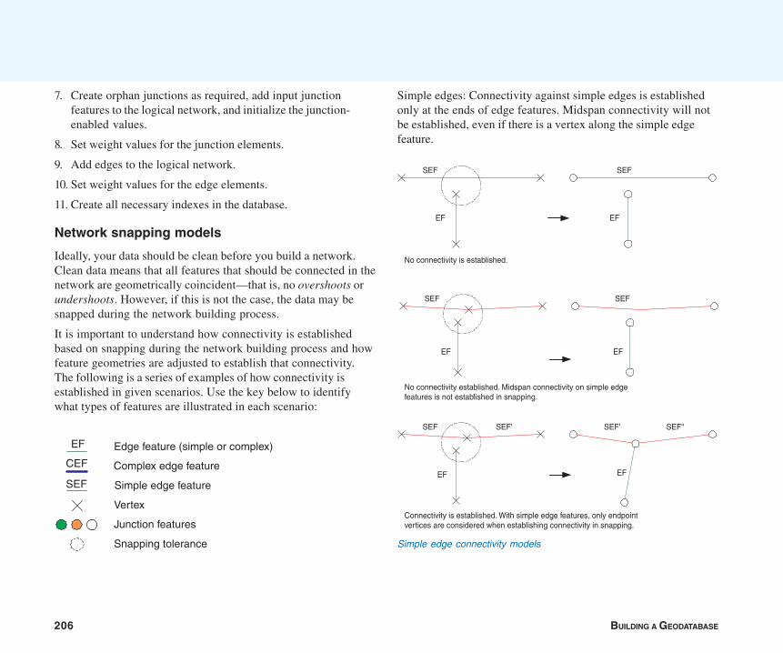
206 BUILDING A GEODATABASE
7. Create orphan junctions as required, add input junctionfeatures to the logical network, and initialize the junction-enabled values.
8. Set weight values for the junction elements.
9. Add edges to the logical network.
10. Set weight values for the edge elements.
11. Create all necessary indexes in the database.
Network snapping models
Ideally, your data should be clean before you build a network.Clean data means that all features that should be connected in thenetwork are geometrically coincident—that is, no overshoots orundershoots. However, if this is not the case, the data may besnapped during the network building process.
It is important to understand how connectivity is establishedbased on snapping during the network building process and howfeature geometries are adjusted to establish that connectivity.The following is a series of examples of how connectivity isestablished in given scenarios. Use the key below to identifywhat types of features are illustrated in each scenario:
Simple edges: Connectivity against simple edges is establishedonly at the ends of edge features. Midspan connectivity will notbe established, even if there is a vertex along the simple edgefeature.
Complex edge feature
Simple edge feature
Vertex
Junction features
Snapping tolerance
Edge feature (simple or complex)
CEF
EF
SEF
Simple edge connectivity models
SEF
EF
SEF
EF
SEF'
SEF
EF
SEF
EF
SEF
EF
SEF' SEF''
EF
No connectivity is established.
No connectivity established. Midspan connectivity on simple edgefeatures is not established in snapping.
Connectivity is established. With simple edge features, only endpointvertices are considered when establishing connectivity in snapping.
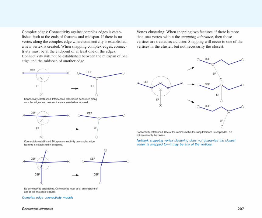
GEOMETRIC NETWORKS 207
Complex edges: Connectivity against complex edges is estab-lished both at the ends of features and midspan. If there is novertex along the complex edge where connectivity is established,a new vertex is created. When snapping complex edges, connec-tivity must be at the endpoint of at least one of the edges.Connectivity will not be established between the midspan of oneedge and the midspan of another edge.
Vertex clustering: When snapping two features, if there is morethan one vertex within the snapping tolerance, then thosevertices are treated as a cluster. Snapping will occur to one of thevertices in the cluster, but not necessarily the closest.
Complex edge connectivity models
EF EF
CEFCEF
CEF
EF EF
CEF
Connectivity established. Intersection detection is performed alongcomplex edges, and new vertices are inserted as required.
Connectivity established. Midspan connectivity on complex edgefeatures is established in snapping.
CEF
CEF'
CEF
CEF'
No connectivity established. Connectivity must be at an endpoint ofone of the two edge features.
CEF
EF
CEF
EF
CEF
EF
CEF
EF
Connectivity established. One of the vertices within the snap tolerance is snapped to, butnot necessarily the closest.
Network snapping vertex clustering does not guarantee the closestvertex is snapped to—it may be any of the vertices.

208 BUILDING A GEODATABASE
Connecting features to themselves: When the endpoints of asingle edge feature come within the snapping tolerance of itself,the endpoint will not be snapped and no connectivity will beestablished. Connectivity is not established between a featureand itself.
CEF CEF
SEF SEF
No connectivity established. Connectivity is not created between featuresand themselves.
Coincident junctions: When the network building processencounters coincident junctions, or when the snapping processresults in coincident junctions, the resulting connectivity will benondeterministic. That is, connectivity will only be established toone of the coincident junctions.
Adjusting features
When snapping features during network building, it is importantto understand how the geometry of features is adjusted whensnapping. All or part of any feature in a feature class that wasspecified as being adjustable in the Build Geometric Networkwizard can potentially be moved. Those features that are infeature classes that are not adjustable will remain fixed through-out the network building process.
All features in all feature classes have equal weights when beingadjusted during snapping. This means that if the endpoints fortwo edges need to be snapped and both features can be adjusted,then they will move an equal distance to snap together. If one of
CEF
EF
CEF
EF
CEF
EF
Connectivity is nondeterministic when coincident junctions areencountered.

GEOMETRIC NETWORKS 209
the features is not adjustable, then only the adjustable feature willmove to snap to the static feature.
SEF
EF
SEF'
SEF feature class snapping = FalseEF feature class snapping = True
SEF
EF
SEF'
SEF
EF
SEF'SEF
EF
SEF'
SEF
EF
SEF' SEF
EF
SEF'
SEF feature class snapping = TrueEF feature class snapping = False
SEF feature class snapping = TrueEF feature class snapping = True
How simple edge features are adjusted depends on whether the featuresthey are snapping to can or cannot be adjusted.
How complex edge features are adjusted depends on whether thefeatures they are snapping to can or cannot be adjusted.
CEF
EF
CEF
EF
CEF
EF
EF
CEF
EF
CEF
CEF feature class snapping = TrueEF feature class snapping = True
CEF
EF
CEF feature class snapping = TrueEF feature class snapping = True
CEF
EFCEF feature class snapping = TrueEF feature class snapping = False
CEF
EFCEF feature class snapping = FalseEF feature class snapping = True
Identifying network build errors
When building a geometric network, the feature classes that areselected to participate in the network may contain features whosegeometries are invalid within the context of a geometric network.These geometries include:
• features that have empty geometry
• edge features that contain multiple parts
• edge features that form a closed loop
• edge features that have zero length
At the end of the build process, a summary of these errorsdisplays in a dialog box. Features with invalid geometries are alsoidentified and recorded in the network build errors table. The
table lists the Object ID, Class ID and the reason why a feature’sgeometry is invalid. The table is located at the workspace leveland named as the geometric network’s name appended with‘_BUILDERR’. For example, a network called ‘MyNetwork’ willhave a network build errors table called ‘MyNetwork_BUILDERR’.
The table is used by the Network Build Errors command withinArcMap to identify the features with invalid geometries. Thenetwork build errors table does not get updated when you editfeatures, so you should update the table’s contents as soon aspossible after editing features. For information on how to repairnetwork feature geometry, please see the ArcGIS online Helpsystem.
210 BUILDING A GEODATABASE
Schema locking
An exclusive lock is required on all of the input feature classeswhen building a geometric network. If any of the input featureclasses have a shared lock, the network will not be built.
If any of the feature classes in a network have a shared orexclusive lock, that lock is propagated to all of the other featureclasses in the network. For more information on exclusive locksand schema locking, see the chapter ‘Creating new items in ageodatabase’ in this book.
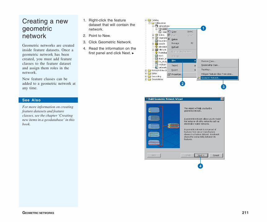
GEOMETRIC NETWORKS 211
Creating a newgeometricnetworkGeometric networks are createdinside feature datasets. Once ageometric network has beencreated, you must add featureclasses to the feature datasetand assign them roles in thenetwork.
New feature classes can beadded to a geometric network atany time.
1. Right-click the featuredataset that will contain thenetwork.
2. Point to New.
3. Click Geometric Network.
4. Read the information on thefirst panel and click Next. u
See Also
For more information on creatingfeature datasets and featureclasses, see the chapter ‘Creatingnew items in a geodatabase’ in thisbook.
4
3
1
2

212 BUILDING A GEODATABASE
5. Click the second option tobuild an empty geometricnetwork.
6. Click Next.
7. Type a name for the newgeometric network.
8. Click Next. u5
6
7
8
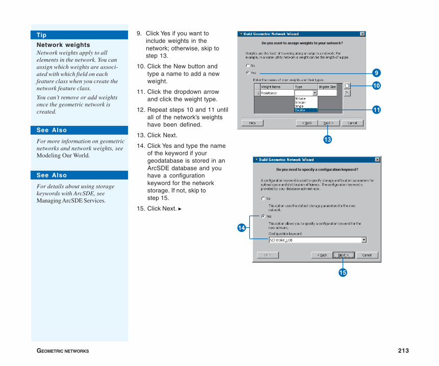
GEOMETRIC NETWORKS 213
9. Click Yes if you want toinclude weights in thenetwork; otherwise, skip tostep 13.
10. Click the New button andtype a name to add a newweight.
11. Click the dropdown arrowand click the weight type.
12. Repeat steps 10 and 11 untilall of the network’s weightshave been defined.
13. Click Next.
14. Click Yes and type the nameof the keyword if yourgeodatabase is stored in anArcSDE database and youhave a configurationkeyword for the networkstorage. If not, skip tostep 15.
15. Click Next. u
See Also
For details about using storagekeywords with ArcSDE, seeManaging ArcSDE Services.
See Also
For more information on geometricnetworks and network weights, seeModeling Our World.
Tip
Network weightsNetwork weights apply to allelements in the network. You canassign which weights are associ-ated with which field on eachfeature class when you create thenetwork feature class.
You can’t remove or add weightsonce the geometric network iscreated.
9
Q
W
R
T
Y
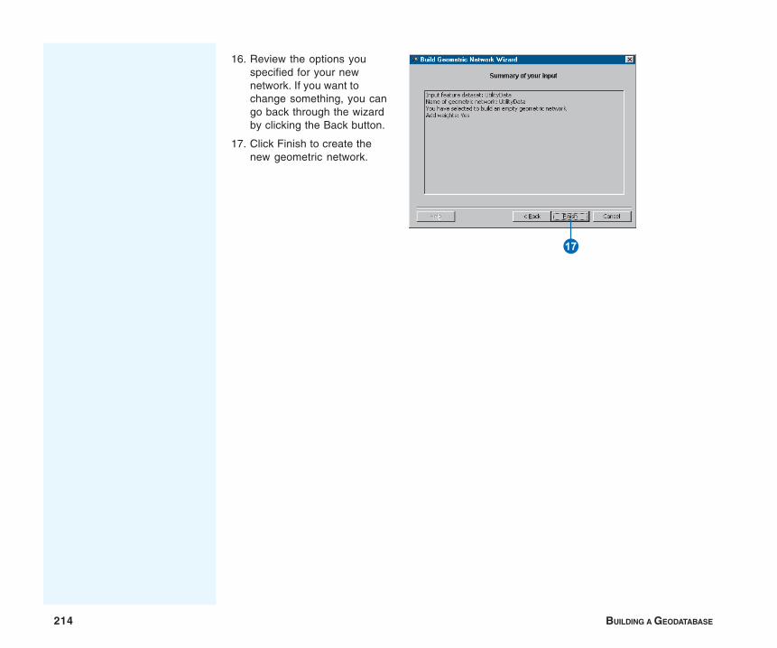
214 BUILDING A GEODATABASE
16. Review the options youspecified for your newnetwork. If you want tochange something, you cango back through the wizardby clicking the Back button.
17. Click Finish to create thenew geometric network.
I

GEOMETRIC NETWORKS 215
Building ageometricnetwork fromexisting simplefeature classesAn alternative to creating andpopulating an empty geometricnetwork is to build a geometricnetwork from existing simplefeature classes.
The Build Geometric Networkwizard discovers the connectiv-ity for a group of featureclasses in a feature dataset andpromotes them from simplefeature types (lines and points)to network feature types (edgesand junctions).
When you build a geometricnetwork, the feature classesmust already exist in the featuredataset. However, they can beempty. After the network hasbeen built, you can add newempty network feature classes.
1. Right-click the featuredataset that will contain thenetwork.
2. Point to New.
3. Click Geometric Network.
4. Read the information on thefirst panel and click Next. u
4
23
1
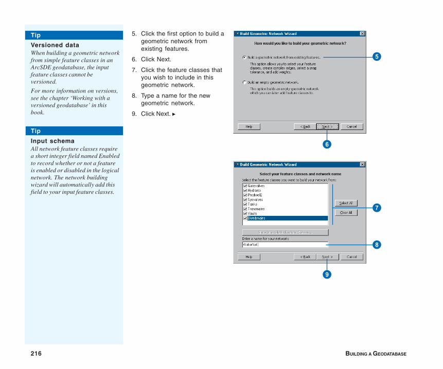
216 BUILDING A GEODATABASE
5. Click the first option to build ageometric network fromexisting features.
6. Click Next.
7. Click the feature classes thatyou wish to include in thisgeometric network.
8. Type a name for the newgeometric network.
9. Click Next. u
5
6
Tip
Versioned dataWhen building a geometric networkfrom simple feature classes in anArcSDE geodatabase, the inputfeature classes cannot beversioned.
For more information on versions,see the chapter ‘Working with aversioned geodatabase’ in thisbook.
Tip
Input schemaAll network feature classes requirea short integer field named Enabledto record whether or not a featureis enabled or disabled in the logicalnetwork. The network buildingwizard will automatically add thisfield to your input feature classes.
7
8
9
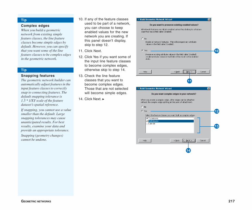
GEOMETRIC NETWORKS 217
10. If any of the feature classesused to be part of a network,you can choose to keepenabled values for the newnetwork you are creating. Ifthis panel doesn’t display,skip to step 12.
11. Click Next.
12. Click Yes if you want some ofthe input line feature classesto become complex edges,otherwise skip to step 14.
13. Check the line featureclasses that you want tobecome complex edges.Those that are not selectedwill become simple edges.
14. Click Next. u
Tip
Complex edgesWhen you build a geometricnetwork from existing simplefeature classes, the line featureclasses become simple edges bydefault. However, you can specifythat you want some of the linefeature classes to be complex edgesin the geometric network.
Tip
Snapping featuresThe geometric network builder canautomatically adjust features in theinput feature classes to correctlysnap to connecting features. Thedefault snapping tolerance is1.5 * 1/XY scale of the featuredataset’s spatial reference.
If snapping, you cannot use a valuesmaller than the default. Largesnapping tolerances may causeunanticipated results. For bestresults, examine your data andprovide an appropriate tolerance.
Snapping (geometry changes)cannot be undone.
E
R
T
Q
W
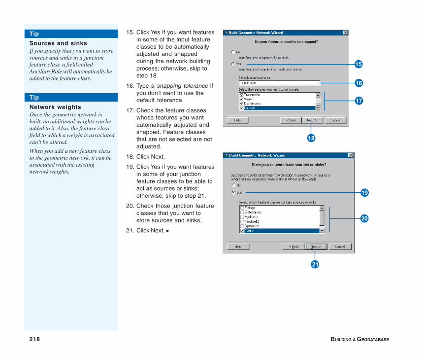
218 BUILDING A GEODATABASE
15. Click Yes if you want featuresin some of the input featureclasses to be automaticallyadjusted and snappedduring the network buildingprocess; otherwise, skip tostep 18.
16. Type a snapping tolerance ifyou don’t want to use thedefault tolerance.
17. Check the feature classeswhose features you wantautomatically adjusted andsnapped. Feature classesthat are not selected are notadjusted.
18. Click Next.
19. Click Yes if you want featuresin some of your junctionfeature classes to be able toact as sources or sinks;otherwise, skip to step 21.
20. Check those junction featureclasses that you want tostore sources and sinks.
21. Click Next. u
Tip
Network weightsOnce the geometric network isbuilt, no additional weights can beadded to it. Also, the feature classfield to which a weight is associatedcan’t be altered.
When you add a new feature classto the geometric network, it can beassociated with the existingnetwork weights.
Tip
Sources and sinksIf you specify that you want to storesources and sinks in a junctionfeature class, a field calledAncillaryRole will automatically beadded to the feature class.
O
I
U
Y
P
S
A
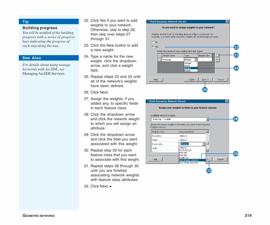
GEOMETRIC NETWORKS 219
22. Click Yes if you want to addweights to your network.Otherwise, skip to step 26,then skip over steps 27through 31.
23. Click the New button to adda new weight.
24. Type a name for the newweight, click the dropdownarrow, and click a weighttype.
25. Repeat steps 23 and 24 untilall of the network’s weightshave been defined.
26. Click Next.
27. Assign the weights, if youadded any, to specific fieldsin each feature class.
28. Click the dropdown arrowand click the network weightto which you will assign anattribute.
29. Click the dropdown arrowand click the field you wantassociated with this weight.
30. Repeat step 29 for eachfeature class that you wantto associate with this weight.
31. Repeat steps 28 through 30until you are finishedassociating network weightswith feature class attributes.
32. Click Next. u
Tip
Building progressYou will be notified of the buildingprogress with a series of progressbars indicating the progress ofeach step along the way.
See Also
For details about using storagekeywords with ArcSDE, seeManaging ArcSDE Services.
J
G
D
F
L
Z
V
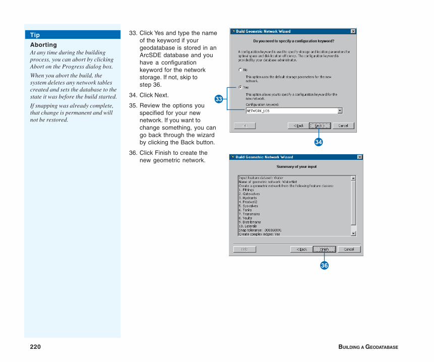
220 BUILDING A GEODATABASE
33. Click Yes and type the nameof the keyword if yourgeodatabase is stored in anArcSDE database and youhave a configurationkeyword for the networkstorage. If not, skip tostep 36.
34. Click Next.
35. Review the options youspecified for your newnetwork. If you want tochange something, you cango back through the wizardby clicking the Back button.
36. Click Finish to create thenew geometric network.
N
Tip
AbortingAt any time during the buildingprocess, you can abort by clickingAbort on the Progress dialog box.
When you abort the build, thesystem deletes any network tablescreated and sets the database to thestate it was before the build started.
If snapping was already complete,that change is permanent and willnot be restored.
<
B
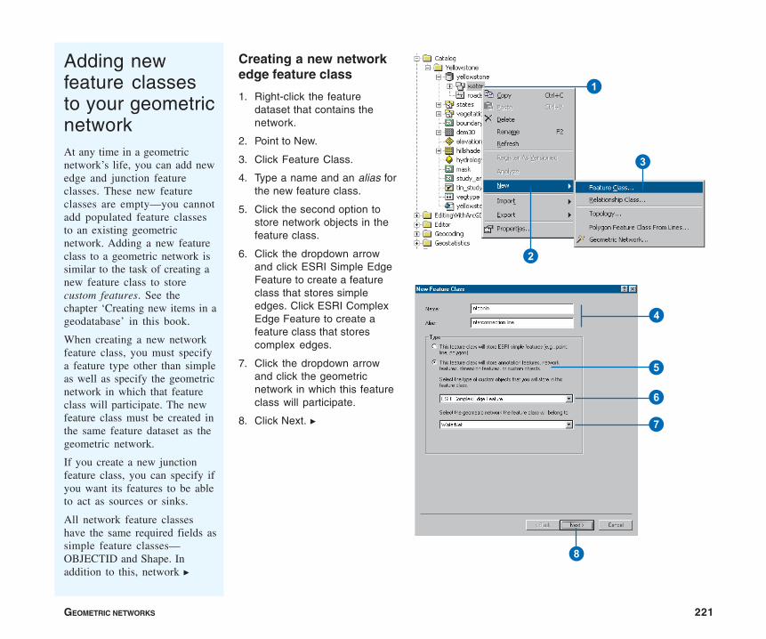
GEOMETRIC NETWORKS 221
Adding newfeature classesto your geometricnetworkAt any time in a geometricnetwork’s life, you can add newedge and junction featureclasses. These new featureclasses are empty—you cannotadd populated feature classesto an existing geometricnetwork. Adding a new featureclass to a geometric network issimilar to the task of creating anew feature class to storecustom features. See thechapter ‘Creating new items in ageodatabase’ in this book.
When creating a new networkfeature class, you must specifya feature type other than simpleas well as specify the geometricnetwork in which that featureclass will participate. The newfeature class must be created inthe same feature dataset as thegeometric network.
If you create a new junctionfeature class, you can specify ifyou want its features to be ableto act as sources or sinks.
All network feature classeshave the same required fields assimple feature classes—OBJECTID and Shape. Inaddition to this, network u
Creating a new networkedge feature class
1. Right-click the featuredataset that contains thenetwork.
2. Point to New.
3. Click Feature Class.
4. Type a name and an alias forthe new feature class.
5. Click the second option tostore network objects in thefeature class.
6. Click the dropdown arrowand click ESRI Simple EdgeFeature to create a featureclass that stores simpleedges. Click ESRI ComplexEdge Feature to create afeature class that storescomplex edges.
7. Click the dropdown arrowand click the geometricnetwork in which this featureclass will participate.
8. Click Next. u
2
3
1
7
8
4
5
6

222 BUILDING A GEODATABASE
9. Follow the steps for ‘Creatingfeature classes’ as describedin the chapter ‘Creating newitems in a geodatabase’ inthis book. You will be pre-sented with an additionaldialog box where you canassociate the network’sweights with fields in thefeature class.
10. To associate a weight in thenetwork with a field in thisnew feature class underField, click the field next tothe weight you want toassociate.
11. Click the name of the field inthe dropdown list to associ-ate with this weight.
12. Repeat steps 10 and 11 untilyou have associated theweights in the network withfields. You do not have toassociate all of the weightswith fields.
13. Click Finish.
features have a required fieldcalled Enabled.
The Enabled field recordswhether or not a feature in thefeature class is enabled ordisabled in the logical network.This field has a fixed attributedomain automatically associ-ated with it.
Junction features can also actas sources and sinks in thenetwork. To record whether ornot a junction feature is asource or a sink, a required fieldcalled AncillaryRole is createdfor the feature class. Like theEnabled field, the AncillaryRolefield has a fixed attributedomain automatically associ-ated with it.
For more information on howsources, sinks, and enabled anddisabled features affect flow ina network, see Using ArcMap.
Q
W
R
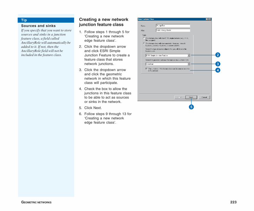
GEOMETRIC NETWORKS 223
Creating a new networkjunction feature class
1. Follow steps 1 through 5 for‘Creating a new networkedge feature class’.
2. Click the dropdown arrowand click ESRI SimpleJunction Feature to create afeature class that storesnetwork junctions.
3. Click the dropdown arrowand click the geometricnetwork in which this featureclass will participate.
4. Check the box to allow thejunctions in this feature classto be able to act as sourcesor sinks in the network.
5. Click Next.
6. Follow steps 9 through 13 for‘Creating a new networkedge feature class’.
Tip
Sources and sinksIf you specify that you want to storesources and sinks in a junctionfeature class, a field calledAncillaryRole will automatically beadded to it. If not, then theAncillaryRole field will not beincluded in the feature class. 2
34
5
224 BUILDING A GEODATABASE
Network connectivity: defining the rules
In most networks, you do not want all edge types to be able tologically connect to all junction types. Similarly, not all edgetypes can logically connect to all other edge types through alljunction types. For example, in a water network, a hydrant canconnect to a hydrant lateral but not to a service lateral. Similarly,in the same water network, a 10-inch transmission main can onlyconnect to an 8-inch transmission main through a reducer.
Network connectivity rules constrain the type of network featuresthat may be connected to one another and the number of featuresof any particular type that can be connected to features ofanother type. By establishing these rules, along with other rulessuch as attribute domains, you can maintain the integrity of thenetwork data in the database. At any time, you can selectivelyvalidate features in the database and generate reports as to whichfeatures in the network are invalid—that is, are violating one ofthe connectivity or other rules.
There are two types of connectivity rules: edge–junction andedge–edge rules. An edge–junction rule is a connectivity rulethat establishes that an edge of one type may connect to ajunction of another type. An edge–edge rule is a connectivityrule that establishes that an edge of one type may connect to anedge of another type through a set of junction types. Edge–edgerules always involve a set of junctions.
You can establish and modify the connectivity rules for a networkfrom within ArcCatalog by modifying the geometric networkproperties. You can establish connectivity rules between twofeature classes, a feature class and the subtype of another featureclass, or a subtype of one feature class and a subtype of another.In the water network example above, a connectivity rule would beestablished between two subtypes of the same edge feature classand a subtype of a third junction feature class (10-inch and 8-inchtransmission mains and reducer valves).
Default junctions
Both edge–edge and edge–junction connectivity rules can havedefault junctions associated with them. Default junctions areautomatically inserted by ArcMap when creating connectivity ina network.
When an edge pair has an edge–edge connectivity rule defined inthe database and you create a new edge that connects to anexisting edge, the default junction is automatically inserted. Foran edge–junction connectivity rule, ArcMap automatically insertsthe default junction at the free end of new edges that are createdin the network.
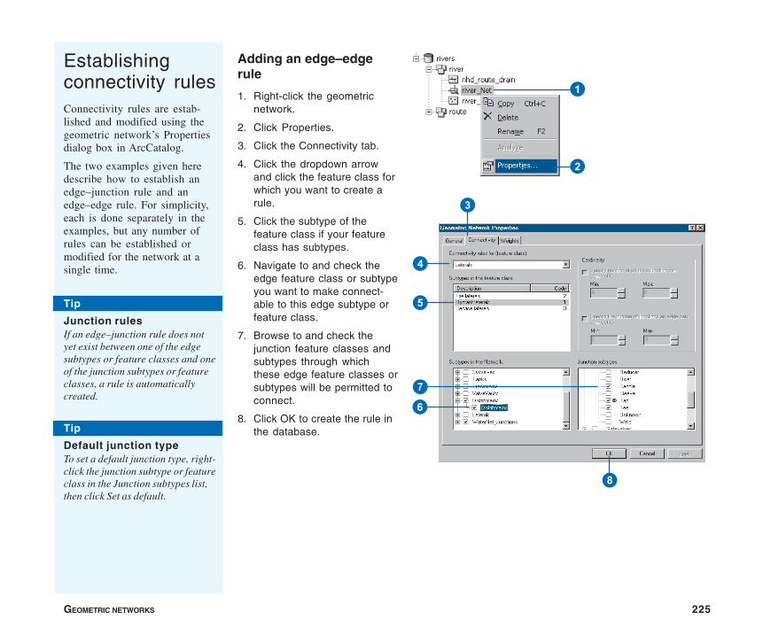
GEOMETRIC NETWORKS 225
Establishingconnectivity rulesConnectivity rules are estab-lished and modified using thegeometric network’s Propertiesdialog box in ArcCatalog.
The two examples given heredescribe how to establish anedge–junction rule and anedge–edge rule. For simplicity,each is done separately in theexamples, but any number ofrules can be established ormodified for the network at asingle time.
Adding an edge–edgerule
1. Right-click the geometricnetwork.
2. Click Properties.
3. Click the Connectivity tab.
4. Click the dropdown arrowand click the feature class forwhich you want to create arule.
5. Click the subtype of thefeature class if your featureclass has subtypes.
6. Navigate to and check theedge feature class or subtypeyou want to make connect-able to this edge subtype orfeature class.
7. Browse to and check thejunction feature classes andsubtypes through whichthese edge feature classes orsubtypes will be permitted toconnect.
8. Click OK to create the rule inthe database.
2
1
3
4
5
6
7
8
Tip
Default junction typeTo set a default junction type, right-click the junction subtype or featureclass in the Junction subtypes list,then click Set as default.
Tip
Junction rulesIf an edge–junction rule does notyet exist between one of the edgesubtypes or feature classes and oneof the junction subtypes or featureclasses, a rule is automaticallycreated.
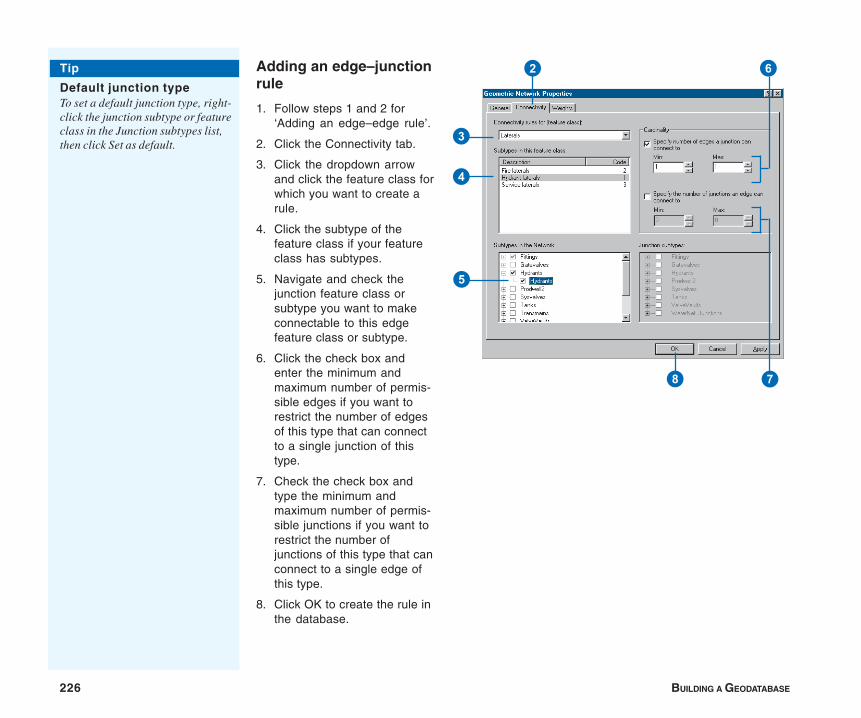
226 BUILDING A GEODATABASE
Adding an edge–junctionrule
1. Follow steps 1 and 2 for‘Adding an edge–edge rule’.
2. Click the Connectivity tab.
3. Click the dropdown arrowand click the feature class forwhich you want to create arule.
4. Click the subtype of thefeature class if your featureclass has subtypes.
5. Navigate and check thejunction feature class orsubtype you want to makeconnectable to this edgefeature class or subtype.
6. Click the check box andenter the minimum andmaximum number of permis-sible edges if you want torestrict the number of edgesof this type that can connectto a single junction of thistype.
7. Check the check box andtype the minimum andmaximum number of permis-sible junctions if you want torestrict the number ofjunctions of this type that canconnect to a single edge ofthis type.
8. Click OK to create the rule inthe database.
Tip
Default junction typeTo set a default junction type, right-click the junction subtype or featureclass in the Junction subtypes list,then click Set as default.
78
4
5
62
3
GEOMETRIC NETWORKS 227
Managing a geometric network
You can manage geometric networks using ArcCatalog. Unlikemost items that appear in ArcCatalog, the geometric network doesnot represent a single entity, such as a table, shapefile, or featureclass. A geometric network is actually an association amongseveral feature classes and is represented by several tables in thedatabase. Managing a geometric network is different frommanaging other items in ArcCatalog.
Managing the geometric network itself
Some of the standard operations on the geometric network workthe same way as with other items in ArcCatalog. A geometricnetwork can be copied or deleted. Copying a geometric networkpersists the network connectivity and feature classes. Deleting ageometric network also deletes the network schema and causesthe network feature classes to revert to simple feature classes.
Geometric networks can be copied in two ways: either by copyingthe feature dataset containing the geometric network or copyingthe geometric network itself. If the geometric network is copied,the target feature dataset must have the same spatial referenceand extent as the source feature dataset.
Geometric networks can be deleted by deleting the feature datasetthat contains it. This will remove the geometric network and allthe feature classes participating in it. You can also delete thegeometric network to leave the feature dataset and feature classesintact. When you delete the network this way, all of the featureclasses in the network are demoted to simple feature types. Edgefeature classes become line feature classes, and junction featureclasses become point feature classes. Deleting the network willalso delete all of the related network tables and the orphanjunction feature class from the geodatabase. However, theenabled and ancillary role fields will not be removed from their
respective feature classes and any snapping performed on thenetwork during building will not be undone.
Managing network feature classes
Managing network feature classes is more restrictive thanmanaging simple feature classes. While a network feature class’salias can be changed, its name cannot. Deleting a network featureclass is also more difficult than deleting simple feature classes. Todelete the network feature class, you must first delete thegeometric network; this action converts the network feature classto a simple feature class that can then be deleted. The alternativeis to delete the entire feature dataset, which deletes the networkand all of the feature classes.
Schema locking
An exclusive lock is required to modify a geometric network’sconnectivity rules, add a feature class to the geometric network,or delete a geometric network. An exclusive lock can only beacquired for a geometric network if the feature classes thatparticipate in the network can also be locked. Therefore, if a userhas an exclusive or shared lock on any of the feature classes in ageometric network, then the properties of the geometric networkcan’t be edited. For more information on exclusive locks andschema locking, see the chapter ‘Creating new items in ageodatabase’ in this book.

IN THIS CHAPTER
229
Managing annotation 8• Annotation in the geodatabase
• Annotation and ArcCatalog
• Creating annotation featureclasses
• Converting labels to annotation
• Importing coverage annotation
In addition to geometry and location, geographic features may also havesome descriptive text associated with them. For example, a feature class thatcontains streets may have text with the street names associated with it.Annotation may also be a geographically located piece of text that existsindependently of any other feature, such as the name of a mountain range ona physical map.
Annotation refers either to the process of automating text placement or tothe text itself. This chapter describes how to create annotation for yourfeature classes and how to convert annotation that you have in coverages togeodatabase annotation.
You can create and store annotation in a personal geodatabase withArcView. To take advantage of advanced annotation functionality, you needan ArcEditor or ArcInfo license.
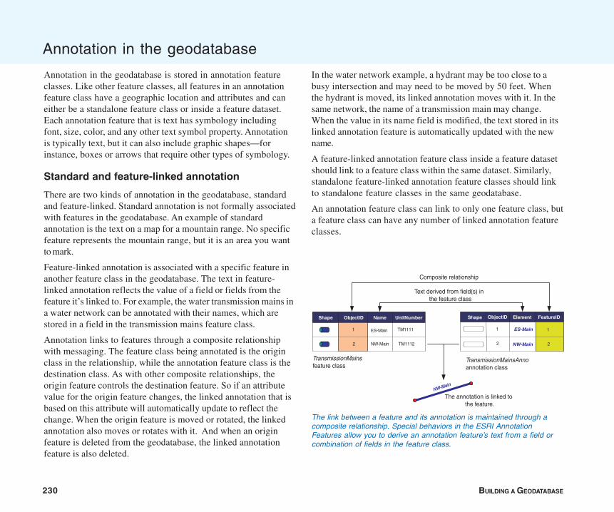
230 BUILDING A GEODATABASE
Annotation in the geodatabase
Annotation in the geodatabase is stored in annotation featureclasses. Like other feature classes, all features in an annotationfeature class have a geographic location and attributes and caneither be a standalone feature class or inside a feature dataset.Each annotation feature that is text has symbology includingfont, size, color, and any other text symbol property. Annotationis typically text, but it can also include graphic shapes—forinstance, boxes or arrows that require other types of symbology.
Standard and feature-linked annotation
There are two kinds of annotation in the geodatabase, standardand feature-linked. Standard annotation is not formally associatedwith features in the geodatabase. An example of standardannotation is the text on a map for a mountain range. No specificfeature represents the mountain range, but it is an area you wantto mark.
Feature-linked annotation is associated with a specific feature inanother feature class in the geodatabase. The text in feature-linked annotation reflects the value of a field or fields from thefeature it’s linked to. For example, the water transmission mains ina water network can be annotated with their names, which arestored in a field in the transmission mains feature class.
Annotation links to features through a composite relationshipwith messaging. The feature class being annotated is the originclass in the relationship, while the annotation feature class is thedestination class. As with other composite relationships, theorigin feature controls the destination feature. So if an attributevalue for the origin feature changes, the linked annotation that isbased on this attribute will automatically update to reflect thechange. When the origin feature is moved or rotated, the linkedannotation also moves or rotates with it. And when an originfeature is deleted from the geodatabase, the linked annotationfeature is also deleted.
In the water network example, a hydrant may be too close to abusy intersection and may need to be moved by 50 feet. Whenthe hydrant is moved, its linked annotation moves with it. In thesame network, the name of a transmission main may change.When the value in its name field is modified, the text stored in itslinked annotation feature is automatically updated with the newname.
A feature-linked annotation feature class inside a feature datasetshould link to a feature class within the same dataset. Similarly,standalone feature-linked annotation feature classes should linkto standalone feature classes in the same geodatabase.
An annotation feature class can link to only one feature class, buta feature class can have any number of linked annotation featureclasses.
The link between a feature and its annotation is maintained through acomposite relationship. Special behaviors in the ESRI AnnotationFeatures allow you to derive an annotation feature’s text from a field orcombination of fields in the feature class.
Shape Name UnitNumber
ES-Main
NW-Main
TM1111
TM1112
ObjectID
1
2
TransmissionMainsfeature class
TransmissionMainsAnnoannotation class
Composite relationship
Text derived from field(s) inthe feature class
NW-Main
Shape FeatureID
1
2
Element
ES-Main
NW-Main
ObjectID
1
2
The annotation is linked tothe feature.
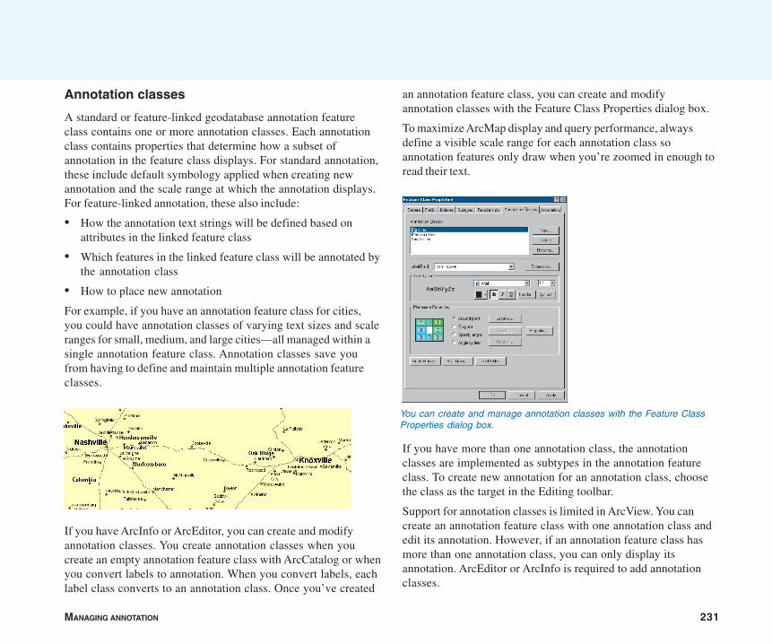
MANAGING ANNOTATION 231
Annotation classes
A standard or feature-linked geodatabase annotation featureclass contains one or more annotation classes. Each annotationclass contains properties that determine how a subset ofannotation in the feature class displays. For standard annotation,these include default symbology applied when creating newannotation and the scale range at which the annotation displays.For feature-linked annotation, these also include:
• How the annotation text strings will be defined based onattributes in the linked feature class
• Which features in the linked feature class will be annotated bythe annotation class
• How to place new annotation
For example, if you have an annotation feature class for cities,you could have annotation classes of varying text sizes and scaleranges for small, medium, and large cities—all managed within asingle annotation feature class. Annotation classes save youfrom having to define and maintain multiple annotation featureclasses.
If you have ArcInfo or ArcEditor, you can create and modifyannotation classes. You create annotation classes when youcreate an empty annotation feature class with ArcCatalog or whenyou convert labels to annotation. When you convert labels, eachlabel class converts to an annotation class. Once you’ve created
an annotation feature class, you can create and modifyannotation classes with the Feature Class Properties dialog box.
To maximize ArcMap display and query performance, alwaysdefine a visible scale range for each annotation class soannotation features only draw when you’re zoomed in enough toread their text.
If you have more than one annotation class, the annotationclasses are implemented as subtypes in the annotation featureclass. To create new annotation for an annotation class, choosethe class as the target in the Editing toolbar.
Support for annotation classes is limited in ArcView. You cancreate an annotation feature class with one annotation class andedit its annotation. However, if an annotation feature class hasmore than one annotation class, you can only display itsannotation. ArcEditor or ArcInfo is required to add annotationclasses.
You can create and manage annotation classes with the Feature ClassProperties dialog box.
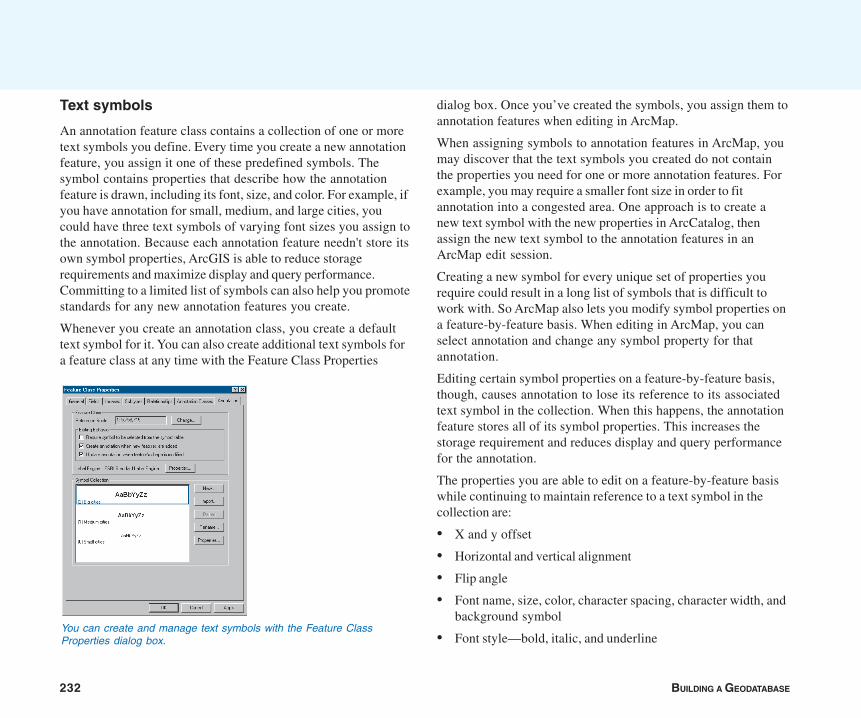
232 BUILDING A GEODATABASE
Text symbols
An annotation feature class contains a collection of one or moretext symbols you define. Every time you create a new annotationfeature, you assign it one of these predefined symbols. Thesymbol contains properties that describe how the annotationfeature is drawn, including its font, size, and color. For example, ifyou have annotation for small, medium, and large cities, youcould have three text symbols of varying font sizes you assign tothe annotation. Because each annotation feature needn't store itsown symbol properties, ArcGIS is able to reduce storagerequirements and maximize display and query performance.Committing to a limited list of symbols can also help you promotestandards for any new annotation features you create.
Whenever you create an annotation class, you create a defaulttext symbol for it. You can also create additional text symbols fora feature class at any time with the Feature Class Properties
dialog box. Once you’ve created the symbols, you assign them toannotation features when editing in ArcMap.
When assigning symbols to annotation features in ArcMap, youmay discover that the text symbols you created do not containthe properties you need for one or more annotation features. Forexample, you may require a smaller font size in order to fitannotation into a congested area. One approach is to create anew text symbol with the new properties in ArcCatalog, thenassign the new text symbol to the annotation features in anArcMap edit session.
Creating a new symbol for every unique set of properties yourequire could result in a long list of symbols that is difficult towork with. So ArcMap also lets you modify symbol properties ona feature-by-feature basis. When editing in ArcMap, you canselect annotation and change any symbol property for thatannotation.
Editing certain symbol properties on a feature-by-feature basis,though, causes annotation to lose its reference to its associatedtext symbol in the collection. When this happens, the annotationfeature stores all of its symbol properties. This increases thestorage requirement and reduces display and query performancefor the annotation.
The properties you are able to edit on a feature-by-feature basiswhile continuing to maintain reference to a text symbol in thecollection are:
• X and y offset
• Horizontal and vertical alignment
• Flip angle
• Font name, size, color, character spacing, character width, andbackground symbol
• Font style—bold, italic, and underlineYou can create and manage text symbols with the Feature ClassProperties dialog box.
MANAGING ANNOTATION 233
• Word spacing
• Leading property
For example, if you reduce an annotation feature’s font size from12 to 8, the annotation feature still references a predefinedsymbol; however, it stores its own font size of 8. If you change aproperty not listed above, such as giving the annotation feature ahalo, the annotation feature loses reference to its associated textsymbol and stores all of the symbol properties.
You can always use text formatting tags to modify the format of aportion of a piece of annotation. This lets you create mixed-formatannotation where, for example, one word in a sentence isunderlined. Formatting tags always take precedence over anannotation feature’s symbol properties. For more information onformatting tags, see the ArcGIS online Help system.
When deciding what symbols to store in your annotation featureclass, choose a default symbol for each annotation class whenyou create it, then add any additional symbols containing theproperties you’ll commonly need. As for properties that areseldom needed, you can apply them on a feature-by-feature basis.A limited number of features storing their own symbol propertieswill have little impact on the storage requirements andperformance of a feature class.
Creating annotation
ArcCatalog and ArcMap contain tools that create standard andfeature-linked annotation. Creating annotation requires bothcreating a feature class to store the annotation and populating itwith annotation features. You can follow one of three approaches:
• If you’ve already invested time and effort creating coverage,SDE 3, CAD, or vector product format (VPF) annotation, youcan display these formats in ArcMap and import them into anew standard or feature-linked annotation feature class.
Importing from these formats into a feature-linked annotationfeature class does not link annotation to features. If theannotation feature class you imported has a field that relatesto a field in the feature class you want to link to, you can useSQL to link the annotation to their features. See http://support.esri.com for more information. If you don’t havethese fields, you can manually link the imported annotation tofeatures with the editing tools in ArcMap.
• If the text you want to display is stored in one or moreattributes in a feature class, you can display the text as labelsin ArcMap and convert them to annotation. This creates anew standard or feature-linked annotation feature class.
• If you don’t have any data or want to design your annotationfeature class schema from scratch, you can create an emptystandard or feature-linked annotation feature class inArcCatalog, then populate it with annotation.
To populate an empty standard annotation feature class, youcan display and convert labels to annotation in ArcMap ormanually add annotation using the tools on the Annotationtoolbar.
To populate an empty feature-linked annotation feature class,you can select features in ArcMap and use the AnnotateSelected Features command to generate annotation. Or youcan have ArcMap create new annotation for you as you addnew features.
When creating annotation in an ArcSDE geodatabase byconverting labels or importing from another format, you shouldalways try to create the annotation before registering your dataas versioned. If the data is not versioned, all of the data will beloaded directly into the base tables and a database compress willnot be required. For more information about data loadingstrategies and their versioning impacts, see the chapter‘Importing data’ in this book.
234 BUILDING A GEODATABASE
If you are creating feature-linked annotation that is linked to anetwork feature class, you should create the annotation afterbuilding the geometric network. When features are snapped inthe network building process, their geometry is modified at a levelat which messages are not sent to linked annotation features toupdate themselves. So after building the network, if a feature’sgeometry was changed in the snapping process, the feature andits linked annotation may no longer correspond correctly. To learnmore about geometric networks, see the chapter ‘Geometricnetworks’ in this book.
Managing annotation feature classes
Annotation feature classes can be managed the same way asother feature classes and tables. They can be renamed, copied,and deleted using ArcCatalog. You can also use the Feature ClassProperties dialog box to set the alias and spatial and attributeindexes as well as manage properties unique to annotation featureclasses—annotation classes, symbols, and settings thatdetermine how the annotation features can be edited.
To save you from having to maintain several annotation featureclasses, you may want to combine them into a single annotationfeature class. You might do this, for example, if they annotatefeatures in the same feature class or if they are standardannotation feature classes that annotate similar features in morethan one feature class. When you combine annotation featureclasses, the annotation from each feature class becomes anannotation class in the new annotation feature class. Youcombine annotation feature classes with the Append AnnotationFeature Classes tool. For more information, see the ArcGIS onlineHelp system.
The relationship class that links feature-linked annotation ismanaged like any other relationship class. If the relationship classis deleted, the annotation will no longer be feature-linked, but will
become standard annotation. To learn how to re-create thisrelationship class, see the chapter ‘Defining relationship classes’in this book.
Upgrading ArcGIS 8 annotation feature classes
ArcGIS 9 adds functionality to annotation feature classes thatwas not available in previous versions. If you have annotationfeature classes created in ArcGIS 8, you can display and querythem. However, to edit them or modify their properties, you mustupgrade them. Upgrading annotation feature classes also addstext symbol fields that are useful for querying and editing. Formore information on upgrading annotation feature classes, seethe ArcGIS online Help system.
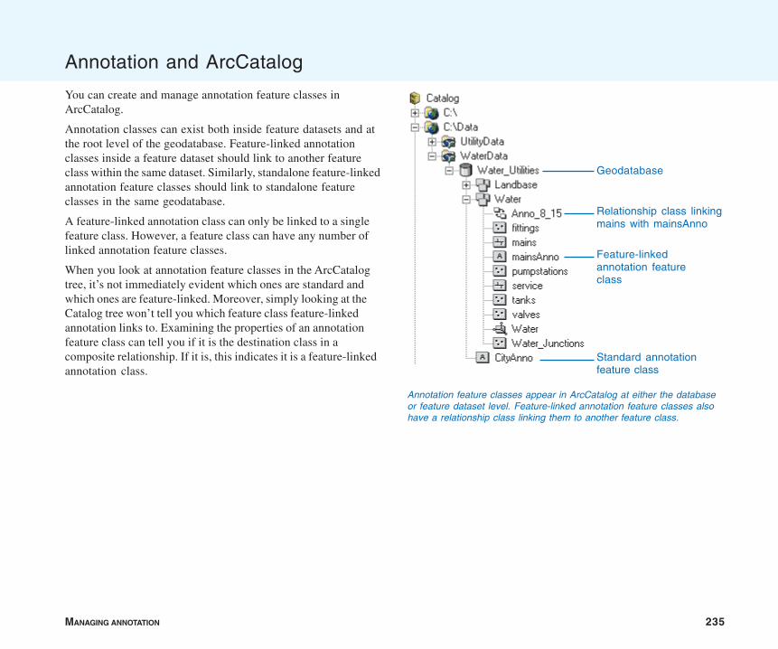
MANAGING ANNOTATION 235
Annotation and ArcCatalog
You can create and manage annotation feature classes inArcCatalog.
Annotation classes can exist both inside feature datasets and atthe root level of the geodatabase. Feature-linked annotationclasses inside a feature dataset should link to another featureclass within the same dataset. Similarly, standalone feature-linkedannotation feature classes should link to standalone featureclasses in the same geodatabase.
A feature-linked annotation class can only be linked to a singlefeature class. However, a feature class can have any number oflinked annotation feature classes.
When you look at annotation feature classes in the ArcCatalogtree, it’s not immediately evident which ones are standard andwhich ones are feature-linked. Moreover, simply looking at theCatalog tree won’t tell you which feature class feature-linkedannotation links to. Examining the properties of an annotationfeature class can tell you if it is the destination class in acomposite relationship. If it is, this indicates it is a feature-linkedannotation class.
Annotation feature classes appear in ArcCatalog at either the databaseor feature dataset level. Feature-linked annotation feature classes alsohave a relationship class linking them to another feature class.
Geodatabase
Feature-linkedannotation featureclass
Standard annotationfeature class
Relationship class linkingmains with mainsAnno
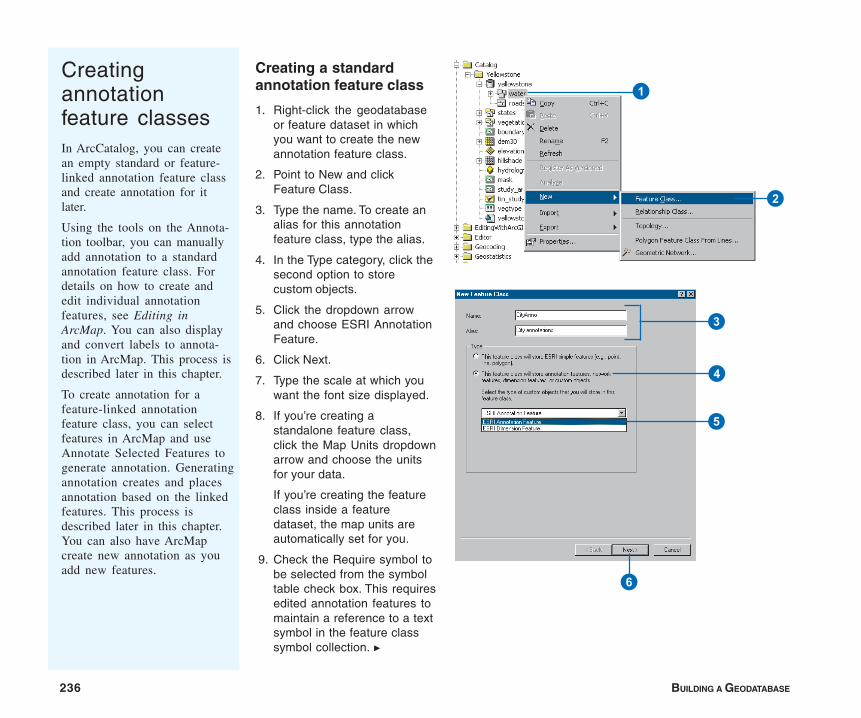
236 BUILDING A GEODATABASE
Creatingannotationfeature classesIn ArcCatalog, you can createan empty standard or feature-linked annotation feature classand create annotation for itlater.
Using the tools on the Annota-tion toolbar, you can manuallyadd annotation to a standardannotation feature class. Fordetails on how to create andedit individual annotationfeatures, see Editing inArcMap. You can also displayand convert labels to annota-tion in ArcMap. This process isdescribed later in this chapter.
To create annotation for afeature-linked annotationfeature class, you can selectfeatures in ArcMap and useAnnotate Selected Features togenerate annotation. Generatingannotation creates and placesannotation based on the linkedfeatures. This process isdescribed later in this chapter.You can also have ArcMapcreate new annotation as youadd new features.
Creating a standardannotation feature class
1. Right-click the geodatabaseor feature dataset in whichyou want to create the newannotation feature class.
2. Point to New and clickFeature Class.
3. Type the name. To create analias for this annotationfeature class, type the alias.
4. In the Type category, click thesecond option to storecustom objects.
5. Click the dropdown arrowand choose ESRI AnnotationFeature.
6. Click Next.
7. Type the scale at which youwant the font size displayed.
8. If you’re creating astandalone feature class,click the Map Units dropdownarrow and choose the unitsfor your data.
If you’re creating the featureclass inside a featuredataset, the map units areautomatically set for you.
9. Check the Require symbol tobe selected from the symboltable check box. This requiresedited annotation features tomaintain a reference to a textsymbol in the feature classsymbol collection. u
6
4
5
3
1
2
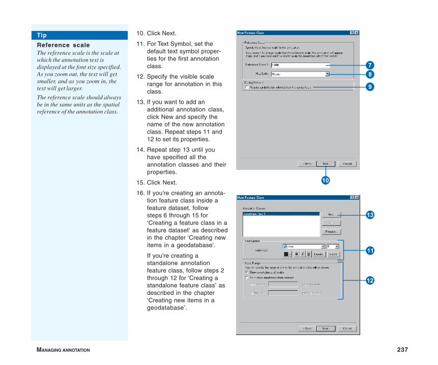
MANAGING ANNOTATION 237
10. Click Next.
11. For Text Symbol, set thedefault text symbol proper-ties for the first annotationclass.
12. Specify the visible scalerange for annotation in thisclass.
13. If you want to add anadditional annotation class,click New and specify thename of the new annotationclass. Repeat steps 11 and12 to set its properties.
14. Repeat step 13 until youhave specified all theannotation classes and theirproperties.
15. Click Next.
16. If you’re creating an annota-tion feature class inside afeature dataset, followsteps 6 through 15 for‘Creating a feature class in afeature dataset’ as describedin the chapter ‘Creating newitems in a geodatabase’.
If you’re creating astandalone annotationfeature class, follow steps 2through 12 for ‘Creating astandalone feature class’ asdescribed in the chapter‘Creating new items in ageodatabase’.
Tip
Reference scaleThe reference scale is the scale atwhich the annotation text isdisplayed at the font size specified.As you zoom out, the text will getsmaller, and as you zoom in, thetext will get larger.
The reference scale should alwaysbe in the same units as the spatialreference of the annotation class.
Q
78
9
E
W
R
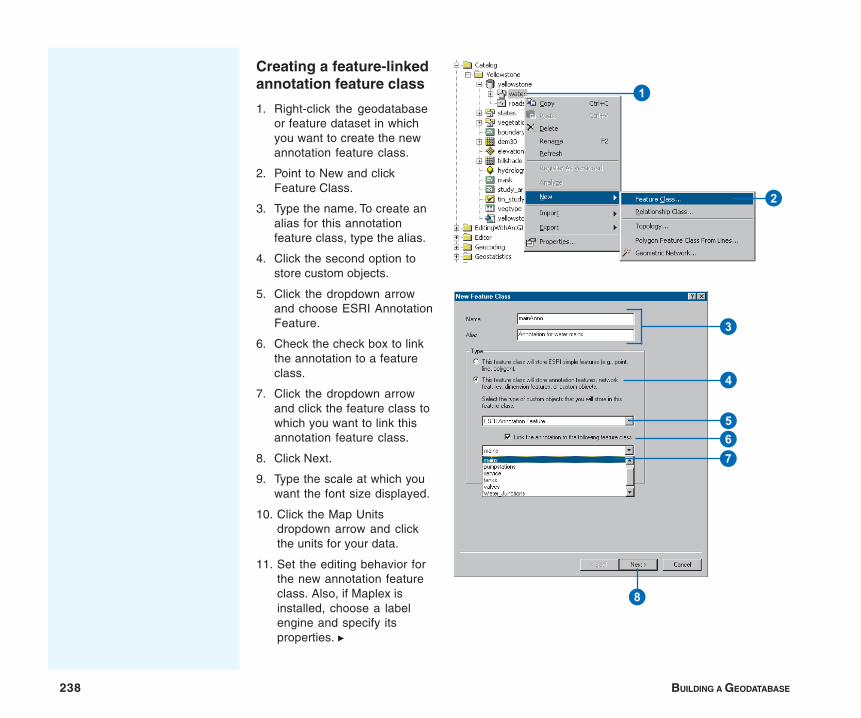
238 BUILDING A GEODATABASE
Creating a feature-linkedannotation feature class
1. Right-click the geodatabaseor feature dataset in whichyou want to create the newannotation feature class.
2. Point to New and clickFeature Class.
3. Type the name. To create analias for this annotationfeature class, type the alias.
4. Click the second option tostore custom objects.
5. Click the dropdown arrowand choose ESRI AnnotationFeature.
6. Check the check box to linkthe annotation to a featureclass.
7. Click the dropdown arrowand click the feature class towhich you want to link thisannotation feature class.
8. Click Next.
9. Type the scale at which youwant the font size displayed.
10. Click the Map Unitsdropdown arrow and clickthe units for your data.
11. Set the editing behavior forthe new annotation featureclass. Also, if Maplex isinstalled, choose a labelengine and specify itsproperties. u
7
8
4
56
3
1
2
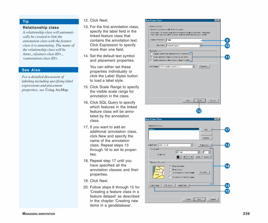
MANAGING ANNOTATION 239
12. Click Next.
13. For the first annotation class,specify the label field in thelinked feature class thatcontains the annotation text.Click Expression to specifymore than one field.
14. Set the default text symboland placement properties.
You can either set theseproperties individually orclick the Label Styles buttonto load a label style.
15. Click Scale Range to specifythe visible scale range forannotation in the class.
16. Click SQL Query to specifywhich features in the linkedfeature class will be anno-tated by the annotationclass.
17. If you want to add anadditional annotation class,click New and specify thename of the annotationclass. Repeat steps 13through 16 to set its proper-ties.
18. Repeat step 17 until youhave specified all theannotation classes and theirproperties.
19. Click Next.
20. Follow steps 6 through 15 for‘Creating a feature class in afeature dataset’ as describedin the chapter ‘Creating newitems in a geodatabase’.
See Also
For a detailed discussion oflabeling including specifying labelexpressions and placementproperties, see Using ArcMap.
Tip
Relationship classA relationship class will automati-cally be created to link theannotation class with the featureclass it is annotating. The name ofthe relationship class will beAnno_<feature class ID>_<annotation class ID>.
E
Q
W
9
T
Y
R
T
I
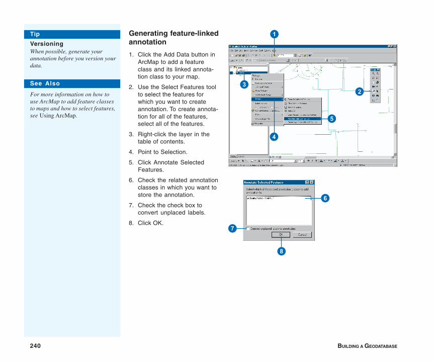
240 BUILDING A GEODATABASE
Generating feature-linkedannotation
1. Click the Add Data button inArcMap to add a featureclass and its linked annota-tion class to your map.
2. Use the Select Features toolto select the features forwhich you want to createannotation. To create annota-tion for all of the features,select all of the features.
3. Right-click the layer in thetable of contents.
4. Point to Selection.
5. Click Annotate SelectedFeatures.
6. Check the related annotationclasses in which you want tostore the annotation.
7. Check the check box toconvert unplaced labels.
8. Click OK.
1
23
5
4
Tip
VersioningWhen possible, generate yourannotation before you version yourdata.
See Also
For more information on how touse ArcMap to add feature classesto maps and how to select features,see Using ArcMap.
7
8
6
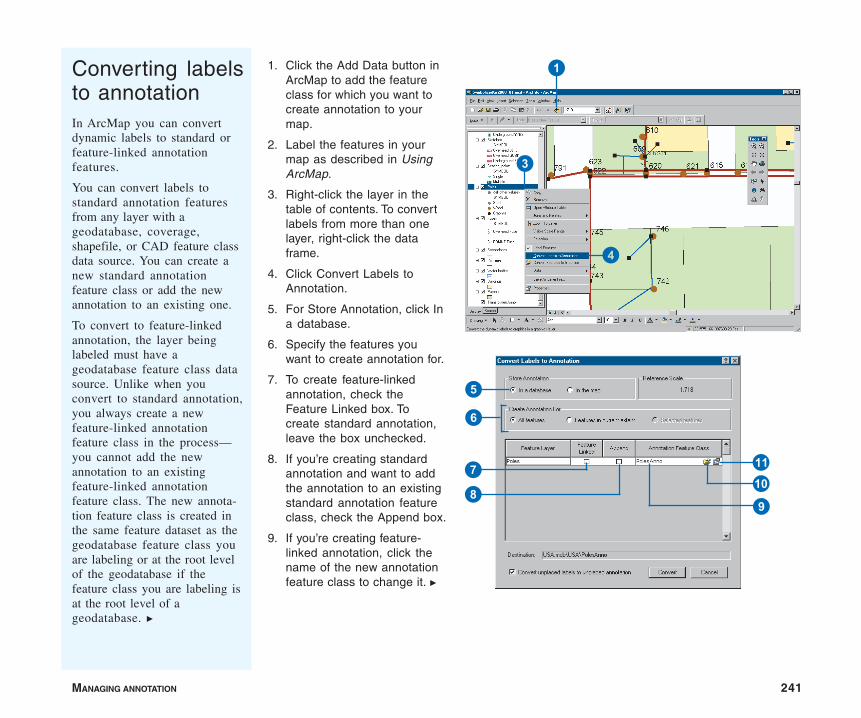
MANAGING ANNOTATION 241
Converting labelsto annotationIn ArcMap you can convertdynamic labels to standard orfeature-linked annotationfeatures.
You can convert labels tostandard annotation featuresfrom any layer with ageodatabase, coverage,shapefile, or CAD feature classdata source. You can create anew standard annotationfeature class or add the newannotation to an existing one.
To convert to feature-linkedannotation, the layer beinglabeled must have ageodatabase feature class datasource. Unlike when youconvert to standard annotation,you always create a newfeature-linked annotationfeature class in the process—you cannot add the newannotation to an existingfeature-linked annotationfeature class. The new annota-tion feature class is created inthe same feature dataset as thegeodatabase feature class youare labeling or at the root levelof the geodatabase if thefeature class you are labeling isat the root level of ageodatabase. u
1. Click the Add Data button inArcMap to add the featureclass for which you want tocreate annotation to yourmap.
2. Label the features in yourmap as described in UsingArcMap.
3. Right-click the layer in thetable of contents. To convertlabels from more than onelayer, right-click the dataframe.
4. Click Convert Labels toAnnotation.
5. For Store Annotation, click Ina database.
6. Specify the features youwant to create annotation for.
7. To create feature-linkedannotation, check theFeature Linked box. Tocreate standard annotation,leave the box unchecked.
8. If you’re creating standardannotation and want to addthe annotation to an existingstandard annotation featureclass, check the Append box.
9. If you’re creating feature-linked annotation, click thename of the new annotationfeature class to change it. u
1
3
4
9
7
5
6
QW
8
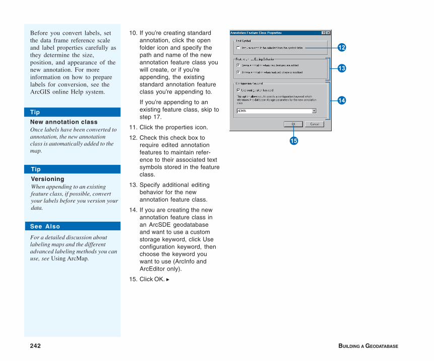
242 BUILDING A GEODATABASE
See Also
For a detailed discussion aboutlabeling maps and the differentadvanced labeling methods you canuse, see Using ArcMap.
Tip
New annotation classOnce labels have been converted toannotation, the new annotationclass is automatically added to themap.
Tip
VersioningWhen appending to an existingfeature class, if possible, convertyour labels before you version yourdata.
10. If you’re creating standardannotation, click the openfolder icon and specify thepath and name of the newannotation feature class youwill create, or if you’reappending, the existingstandard annotation featureclass you’re appending to.
If you’re appending to anexisting feature class, skip tostep 17.
11. Click the properties icon.
12. Check this check box torequire edited annotationfeatures to maintain refer-ence to their associated textsymbols stored in the featureclass.
13. Specify additional editingbehavior for the newannotation feature class.
14. If you are creating the newannotation feature class inan ArcSDE geodatabaseand want to use a customstorage keyword, click Useconfiguration keyword, thenchoose the keyword youwant to use (ArcInfo andArcEditor only).
15. Click OK. u
Before you convert labels, setthe data frame reference scaleand label properties carefully asthey determine the size,position, and appearance of thenew annotation. For moreinformation on how to preparelabels for conversion, see theArcGIS online Help system.
R
Y
T
E
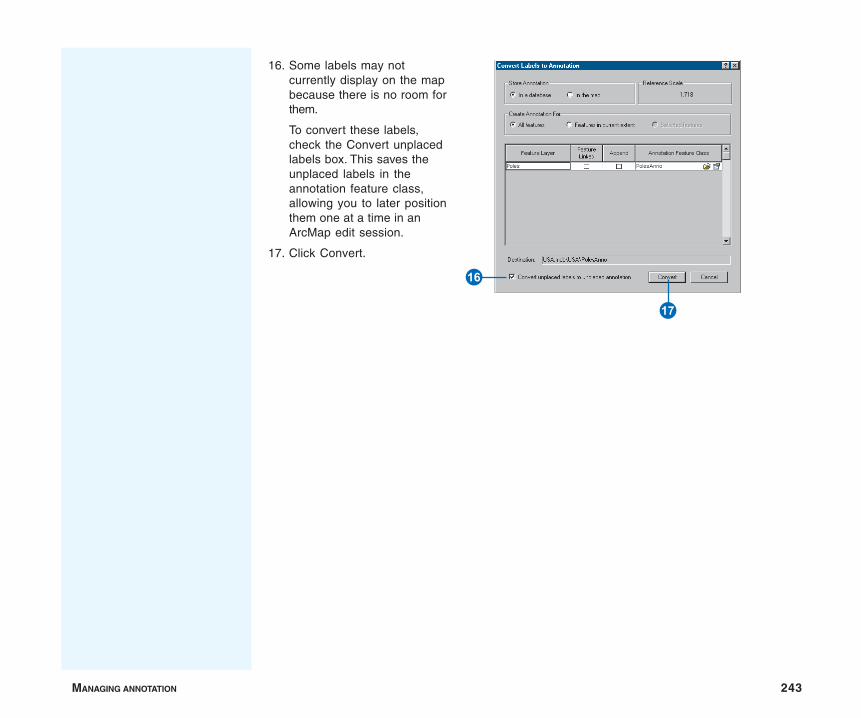
MANAGING ANNOTATION 243
16. Some labels may notcurrently display on the mapbecause there is no room forthem.
To convert these labels,check the Convert unplacedlabels box. This saves theunplaced labels in theannotation feature class,allowing you to later positionthem one at a time in anArcMap edit session.
17. Click Convert.
I
U
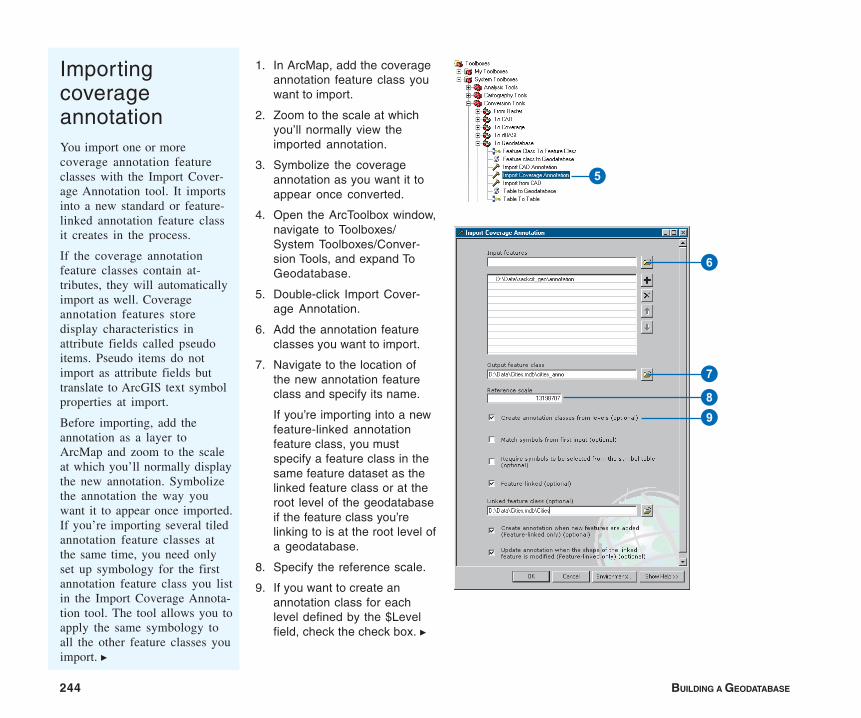
244 BUILDING A GEODATABASE
1. In ArcMap, add the coverageannotation feature class youwant to import.
2. Zoom to the scale at whichyou’ll normally view theimported annotation.
3. Symbolize the coverageannotation as you want it toappear once converted.
4. Open the ArcToolbox window,navigate to Toolboxes/System Toolboxes/Conver-sion Tools, and expand ToGeodatabase.
5. Double-click Import Cover-age Annotation.
6. Add the annotation featureclasses you want to import.
7. Navigate to the location ofthe new annotation featureclass and specify its name.
If you’re importing into a newfeature-linked annotationfeature class, you mustspecify a feature class in thesame feature dataset as thelinked feature class or at theroot level of the geodatabaseif the feature class you’relinking to is at the root level ofa geodatabase.
8. Specify the reference scale.
9. If you want to create anannotation class for eachlevel defined by the $Levelfield, check the check box. u
ImportingcoverageannotationYou import one or morecoverage annotation featureclasses with the Import Cover-age Annotation tool. It importsinto a new standard or feature-linked annotation feature classit creates in the process.
If the coverage annotationfeature classes contain at-tributes, they will automaticallyimport as well. Coverageannotation features storedisplay characteristics inattribute fields called pseudoitems. Pseudo items do notimport as attribute fields buttranslate to ArcGIS text symbolproperties at import.
Before importing, add theannotation as a layer toArcMap and zoom to the scaleat which you’ll normally displaythe new annotation. Symbolizethe annotation the way youwant it to appear once imported.If you’re importing several tiledannotation feature classes atthe same time, you need onlyset up symbology for the firstannotation feature class you listin the Import Coverage Annota-tion tool. The tool allows you toapply the same symbology toall the other feature classes youimport. u
5
6
7
89
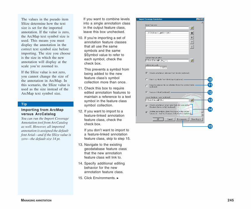
MANAGING ANNOTATION 245
If you want to combine levelsinto a single annotation classin the output feature class,leave this box unchecked.
10. If you’re importing a set ofannotation feature classesthat all use the samesymbols and the same$Symbol value to refer toeach symbol, check thecheck box.
This prevents a symbol frombeing added to the newfeature class’s symbolcollection more than once.
11. Check this box to requireedited annotation features tomaintain a reference to a textsymbol in the feature classsymbol collection.
12. If you want to import to afeature-linked annotationfeature class, check thecheck box.
If you don’t want to import toa feature-linked annotationfeature class, skip to step 15.
13. Navigate to the existinggeodatabase feature classthat the new annotationfeature class will link to.
14. Specify additional editingbehavior for the newannotation feature class.
15. Click Environments. u
Tip
Importing from ArcMapversus ArcCatalogYou can run the Import CoverageAnnotation tool from ArcCatalogas well. However, all importedannotation is assigned the defaultfont Arial—and if the $Size value iszero—the default size 14 pt.
The values in the pseudo item$Size determine how the textsize is set for the importedannotation. If the value is zero,the ArcMap text symbol size isused. This means you mustdisplay the annotation in thecorrect text symbol size beforeimporting. The size you chooseis the size in which the newannotation will display at thescale you’re zoomed to.
If the $Size value is not zero,you cannot change the size ofthe annotation in ArcMap. Inthis scenario, the $Size value isused as the size instead of theArcMap text symbol size. E
W
T
Y
R
Q
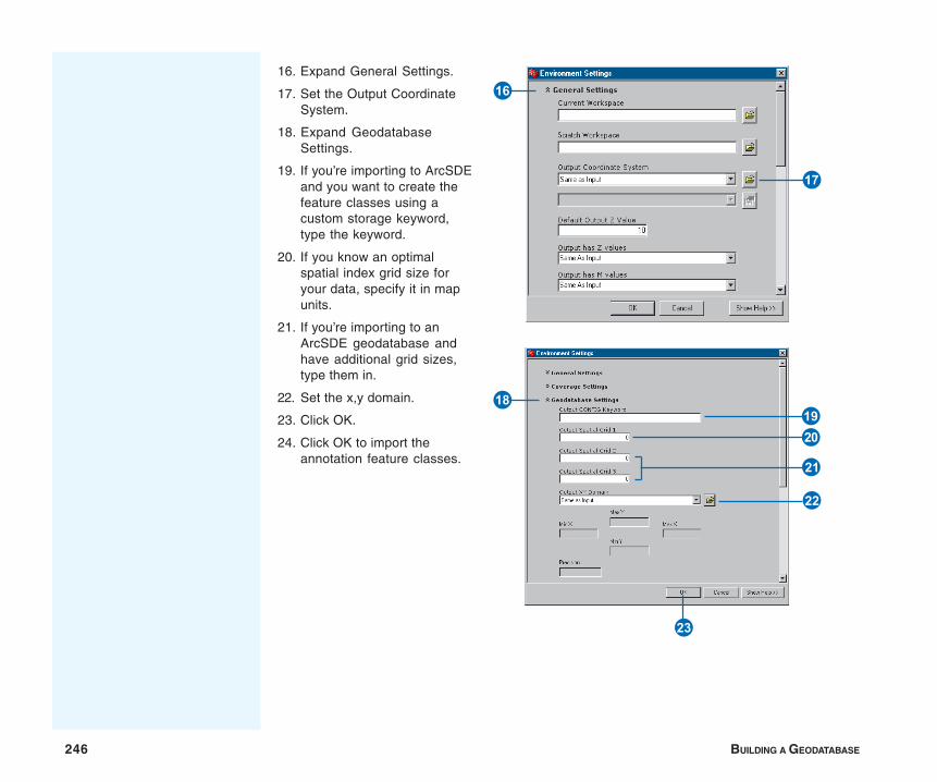
246 BUILDING A GEODATABASE
16. Expand General Settings.
17. Set the Output CoordinateSystem.
18. Expand GeodatabaseSettings.
19. If you’re importing to ArcSDEand you want to create thefeature classes using acustom storage keyword,type the keyword.
20. If you know an optimalspatial index grid size foryour data, specify it in mapunits.
21. If you’re importing to anArcSDE geodatabase andhave additional grid sizes,type them in.
22. Set the x,y domain.
23. Click OK.
24. Click OK to import theannotation feature classes.
I
U
OP
S
D
A
F
IN THIS CHAPTER
247
Dimensioning 9• Dimensions in the geodatabase
• Dimensions and ArcCatalog
• Creating dimension featureclasses
• Creating and managing dimensionstyles
For many applications, plotting a map that shows a feature’s shape and somedescriptive annotation isn’t sufficient for showing precise measurements ordistances. Dimensions are a special kind of map annotation for showing justthat—specific lengths or distances. A dimension may indicate the length of aside of a building or land parcel, or it may indicate the distance between twofeatures—for example, a fire hydrant and the corner of a building.
ArcGIS provides tools that allow you to store dimensions in yourgeodatabase. You can also create dimension styles to apply to yourdimension features so they are consistent with your application standards.ArcGIS supports a number of dimension types and methods for creatingdimensions. Dimensions can be created automatically from existing features,or you can use the rich set of construction tools available in ArcMap.
This chapter describes how to create dimension feature classes anddimension styles. Editing in ArcMap contains a chapter dedicated to usingthe editing capabilities of ArcMap to create and modify dimension features.
You can view dimension feature classes in ArcView. To take advantage ofother dimensioning functionality, you need an ArcEditor or ArcInfo license.
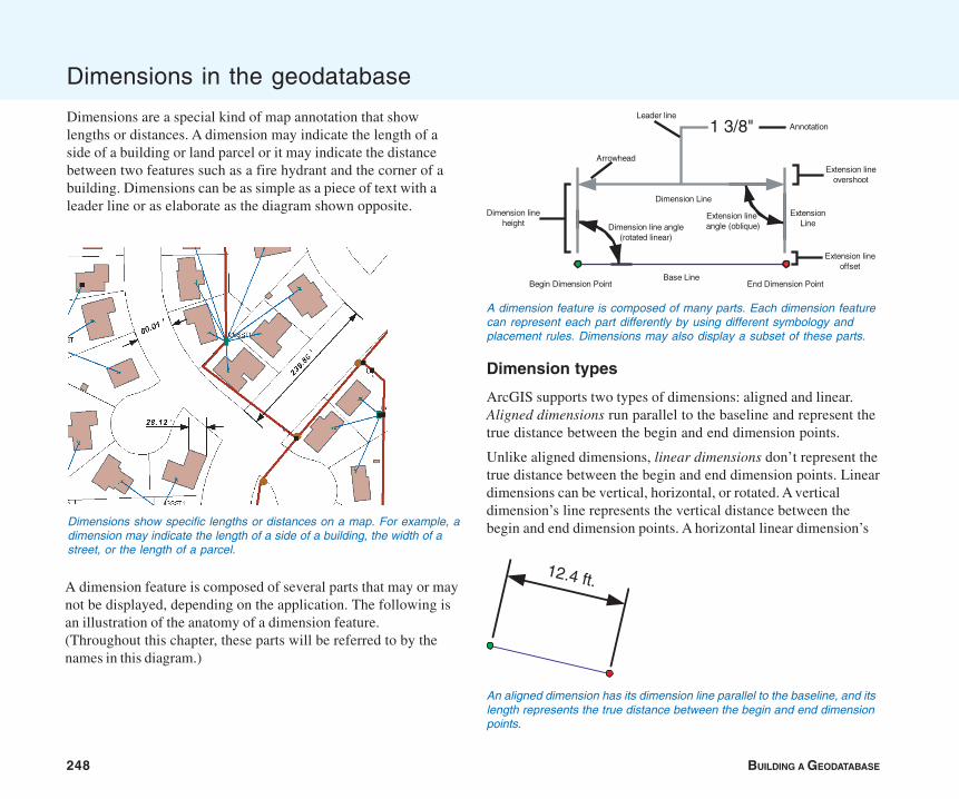
248 BUILDING A GEODATABASE
Dimensions in the geodatabase
Dimensions are a special kind of map annotation that showlengths or distances. A dimension may indicate the length of aside of a building or land parcel or it may indicate the distancebetween two features such as a fire hydrant and the corner of abuilding. Dimensions can be as simple as a piece of text with aleader line or as elaborate as the diagram shown opposite.
Dimension types
ArcGIS supports two types of dimensions: aligned and linear.Aligned dimensions run parallel to the baseline and represent thetrue distance between the begin and end dimension points.
Unlike aligned dimensions, linear dimensions don’t represent thetrue distance between the begin and end dimension points. Lineardimensions can be vertical, horizontal, or rotated. A verticaldimension’s line represents the vertical distance between thebegin and end dimension points. A horizontal linear dimension’s
A dimension feature is composed of several parts that may or maynot be displayed, depending on the application. The following isan illustration of the anatomy of a dimension feature.(Throughout this chapter, these parts will be referred to by thenames in this diagram.)
Dimensions show specific lengths or distances on a map. For example, adimension may indicate the length of a side of a building, the width of astreet, or the length of a parcel.
A dimension feature is composed of many parts. Each dimension featurecan represent each part differently by using different symbology andplacement rules. Dimensions may also display a subset of these parts.
Annotation
Base Line
Arrowhead
Dimension Line
Begin Dimension Point End Dimension Point
ExtensionLine
1 3/8"Leader line
Extension lineangle (oblique)
Extension lineovershoot
Dimension lineheight
Extension lineoffset
Dimension line angle(rotated linear)
12.4 ft.
An aligned dimension has its dimension line parallel to the baseline, and itslength represents the true distance between the begin and end dimensionpoints.
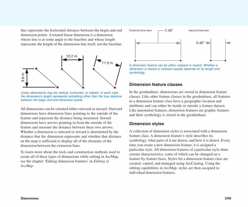
DIMENSIONING 249
line represents the horizontal distance between the begin and enddimension points. A rotated linear dimension is a dimensionwhose line is at some angle to the baseline and whose lengthrepresents the length of the dimension line itself, not the baseline.
Dimension feature classes
In the geodatabase, dimensions are stored in dimension featureclasses. Like other feature classes in the geodatabase, all featuresin a dimension feature class have a geographic location andattributes and can either be inside or outside a feature dataset.Like annotation features, dimension features are graphic featuresand their symbology is stored in the geodatabase.
Dimension styles
A collection of dimension styles is associated with a dimensionfeature class. A dimension feature’s style describes itssymbology, what parts of it are drawn, and how it is drawn. Everytime you create a new dimension feature, it is assigned aparticular style. All dimension features of a particular style sharecertain characteristics, some of which can be changed on afeature-by-feature basis. Styles for a dimension feature class arecreated, copied, and managed using ArcCatalog. Using theediting capabilities in ArcMap, styles are then assigned toindividual dimension features.
All dimensions can be oriented either outward or inward. Outwarddimensions have dimension lines pointing to the outside of thefeature and represent the distance being measured. Inwarddimensions have arrows pointing in from the outside of thefeature and measure the distance between these two arrows.Whether a dimension is outward or inward is determined by thedistance that the dimension represents and whether that distanceon the map is sufficient to display all of the elements of thedimension between the extension lines.
To learn more about the tools and construction methods used tocreate all of these types of dimensions while editing in ArcMap,see the chapter ‘Editing dimension features’ in Editing inArcMap.
10.2 m
9.8
m
11.0 m
Linear dimensions may be vertical, horizontal, or rotated. In each casethe dimension’s length represents something other than the true distancebetween the begin and end dimension points.
A dimension feature can be either outward or inward. Whether adimension is inward or outward usually depends on its length andsymbology.
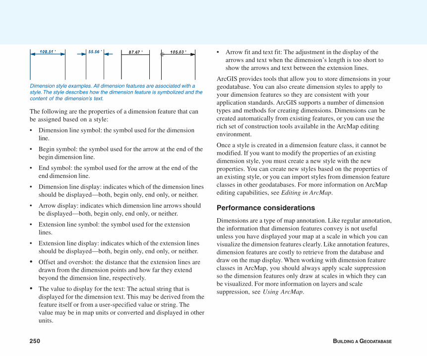
250 BUILDING A GEODATABASE
The following are the properties of a dimension feature that canbe assigned based on a style:
• Dimension line symbol: the symbol used for the dimensionline.
• Begin symbol: the symbol used for the arrow at the end of thebegin dimension line.
• End symbol: the symbol used for the arrow at the end of theend dimension line.
• Dimension line display: indicates which of the dimension linesshould be displayed—both, begin only, end only, or neither.
• Arrow display: indicates which dimension line arrows shouldbe displayed—both, begin only, end only, or neither.
• Extension line symbol: the symbol used for the extensionlines.
• Extension line display: indicates which of the extension linesshould be displayed—both, begin only, end only, or neither.
• Offset and overshot: the distance that the extension lines aredrawn from the dimension points and how far they extendbeyond the dimension line, respectively.
• The value to display for the text: The actual string that isdisplayed for the dimension text. This may be derived from thefeature itself or from a user-specified value or string. Thevalue may be in map units or converted and displayed in otherunits.
• Arrow fit and text fit: The adjustment in the display of thearrows and text when the dimension’s length is too short toshow the arrows and text between the extension lines.
ArcGIS provides tools that allow you to store dimensions in yourgeodatabase. You can also create dimension styles to apply toyour dimension features so they are consistent with yourapplication standards. ArcGIS supports a number of dimensiontypes and methods for creating dimensions. Dimensions can becreated automatically from existing features, or you can use therich set of construction tools available in the ArcMap editingenvironment.
Once a style is created in a dimension feature class, it cannot bemodified. If you want to modify the properties of an existingdimension style, you must create a new style with the newproperties. You can create new styles based on the properties ofan existing style, or you can import styles from dimension featureclasses in other geodatabases. For more information on ArcMapediting capabilities, see Editing in ArcMap.
Performance considerations
Dimensions are a type of map annotation. Like regular annotation,the information that dimension features convey is not usefulunless you have displayed your map at a scale in which you canvisualize the dimension features clearly. Like annotation features,dimension features are costly to retrieve from the database anddraw on the map display. When working with dimension featureclasses in ArcMap, you should always apply scale suppressionso the dimension features only draw at scales in which they canbe visualized. For more information on layers and scalesuppression, see Using ArcMap.
Dimension style examples. All dimension features are associated with astyle. The style describes how the dimension feature is symbolized and thecontent of the dimension’s text.
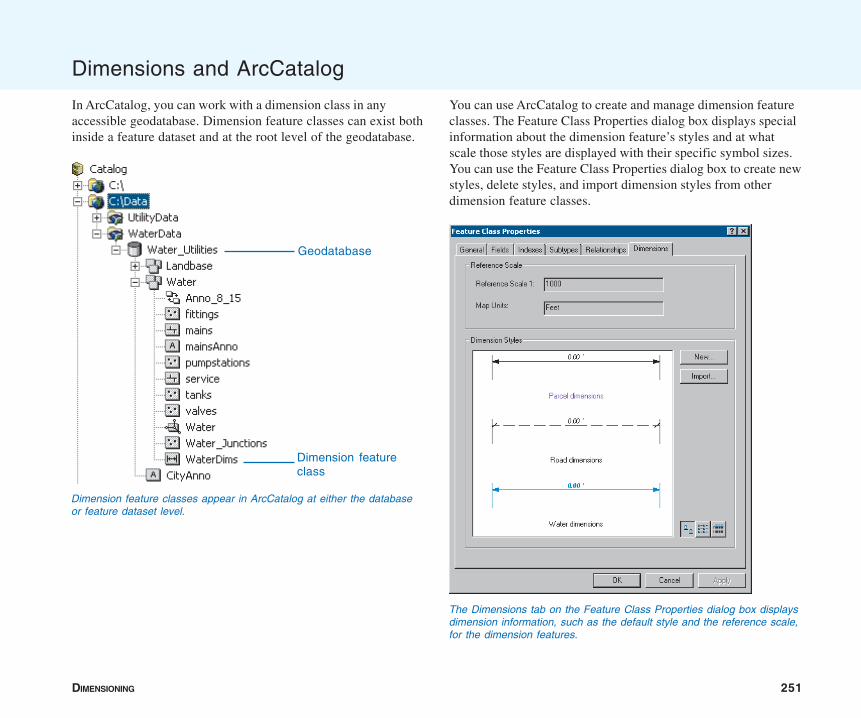
DIMENSIONING 251
Dimensions and ArcCatalog
In ArcCatalog, you can work with a dimension class in anyaccessible geodatabase. Dimension feature classes can exist bothinside a feature dataset and at the root level of the geodatabase.
You can use ArcCatalog to create and manage dimension featureclasses. The Feature Class Properties dialog box displays specialinformation about the dimension feature’s styles and at whatscale those styles are displayed with their specific symbol sizes.You can use the Feature Class Properties dialog box to create newstyles, delete styles, and import dimension styles from otherdimension feature classes.
Dimension feature classes appear in ArcCatalog at either the databaseor feature dataset level.
Geodatabase
Dimension featureclass
The Dimensions tab on the Feature Class Properties dialog box displaysdimension information, such as the default style and the reference scale,for the dimension features.
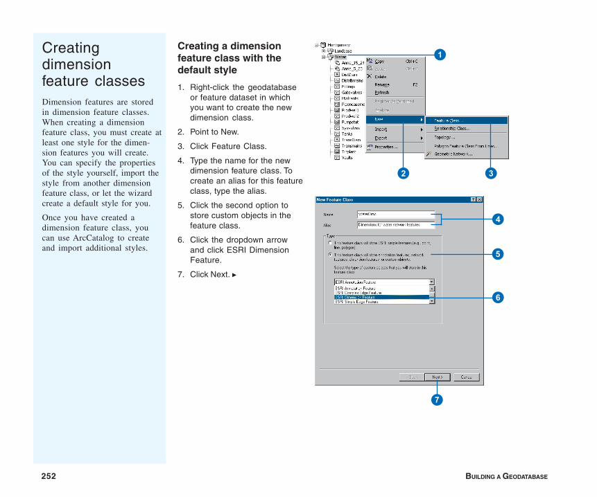
252 BUILDING A GEODATABASE
Creatingdimensionfeature classesDimension features are storedin dimension feature classes.When creating a dimensionfeature class, you must create atleast one style for the dimen-sion features you will create.You can specify the propertiesof the style yourself, import thestyle from another dimensionfeature class, or let the wizardcreate a default style for you.
Once you have created adimension feature class, youcan use ArcCatalog to createand import additional styles.
Creating a dimensionfeature class with thedefault style
1. Right-click the geodatabaseor feature dataset in whichyou want to create the newdimension class.
2. Point to New.
3. Click Feature Class.
4. Type the name for the newdimension feature class. Tocreate an alias for this featureclass, type the alias.
5. Click the second option tostore custom objects in thefeature class.
6. Click the dropdown arrowand click ESRI DimensionFeature.
7. Click Next. u
1
2 3
4
5
6
7
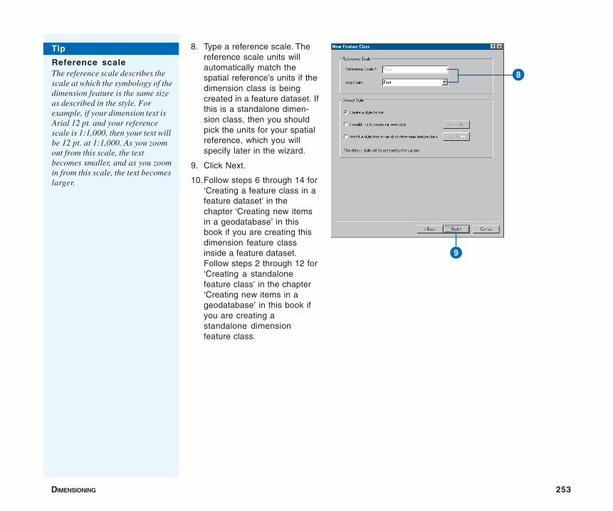
DIMENSIONING 253
8. Type a reference scale. Thereference scale units willautomatically match thespatial reference’s units if thedimension class is beingcreated in a feature dataset. Ifthis is a standalone dimen-sion class, then you shouldpick the units for your spatialreference, which you willspecify later in the wizard.
9. Click Next.
10.Follow steps 6 through 14 for‘Creating a feature class in afeature dataset’ in thechapter ‘Creating new itemsin a geodatabase’ in thisbook if you are creating thisdimension feature classinside a feature dataset.Follow steps 2 through 12 for‘Creating a standalonefeature class’ in the chapter‘Creating new items in ageodatabase’ in this book ifyou are creating astandalone dimensionfeature class.
8
9
Tip
Reference scaleThe reference scale describes thescale at which the symbology of thedimension feature is the same sizeas described in the style. Forexample, if your dimension text isArial 12 pt. and your referencescale is 1:1,000, then your text willbe 12 pt. at 1:1,000. As you zoomout from this scale, the textbecomes smaller, and as you zoomin from this scale, the text becomeslarger.
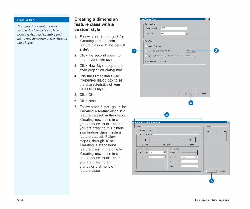
254 BUILDING A GEODATABASE
Creating a dimensionfeature class with acustom style
1. Follow steps 1 through 8 for‘Creating a dimensionfeature class with the defaultstyle’.
2. Click the second option tocreate your own style.
3. Click New Style to open thestyle properties dialog box.
4. Use the Dimension StyleProperties dialog box to setthe characteristics of yourdimension style.
5. Click OK.
6. Click Next.
7. Follow steps 6 through 14 for‘Creating a feature class in afeature dataset’ in the chapter‘Creating new items in ageodatabase’ in this book ifyou are creating this dimen-sion feature class inside afeature dataset. Followsteps 2 through 12 for‘Creating a standalonefeature class’ in the chapter‘Creating new items in ageodatabase’ in this book ifyou are creating astandalone dimensionfeature class.
See Also
For more information on whateach style element is and how tocreate styles, see ‘Creating andmanaging dimension styles’ later inthis chapter.
2 3
6
4
5
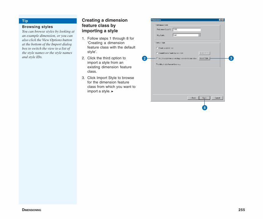
DIMENSIONING 255
Creating a dimensionfeature class byimporting a style
1. Follow steps 1 through 8 for‘Creating a dimensionfeature class with the defaultstyle’.
2. Click the third option toimport a style from anexisting dimension featureclass.
3. Click Import Style to browsefor the dimension featureclass from which you want toimport a style. u
2 3
8
Tip
Browsing stylesYou can browse styles by looking atan example dimension, or you canalso click the View Options buttonat the bottom of the Import dialogbox to switch the view to a list ofthe style names or the style namesand style IDs.
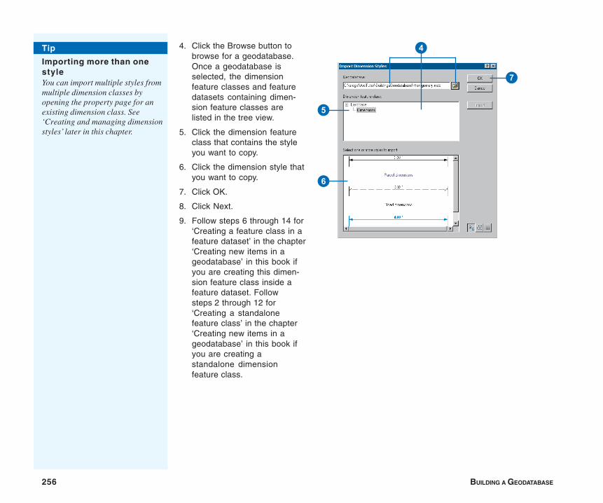
256 BUILDING A GEODATABASE
4. Click the Browse button tobrowse for a geodatabase.Once a geodatabase isselected, the dimensionfeature classes and featuredatasets containing dimen-sion feature classes arelisted in the tree view.
5. Click the dimension featureclass that contains the styleyou want to copy.
6. Click the dimension style thatyou want to copy.
7. Click OK.
8. Click Next.
9. Follow steps 6 through 14 for‘Creating a feature class in afeature dataset’ in the chapter‘Creating new items in ageodatabase’ in this book ifyou are creating this dimen-sion feature class inside afeature dataset. Followsteps 2 through 12 for‘Creating a standalonefeature class’ in the chapter‘Creating new items in ageodatabase’ in this book ifyou are creating astandalone dimensionfeature class.
Tip
Importing more than onestyleYou can import multiple styles frommultiple dimension classes byopening the property page for anexisting dimension class. See‘Creating and managing dimensionstyles’ later in this chapter.
7
4
5
6
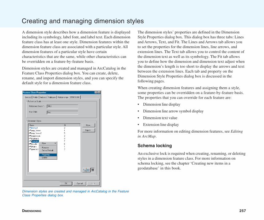
DIMENSIONING 257
Creating and managing dimension styles
A dimension style describes how a dimension feature is displayedincluding its symbology, label font, and label text. Each dimensionfeature class has at least one style. Dimension features within thedimension feature class are associated with a particular style. Alldimension features of a particular style have certaincharacteristics that are the same, while other characteristics canbe overridden on a feature-by-feature basis.
Dimension styles are created and managed in ArcCatalog in theFeature Class Properties dialog box. You can create, delete,rename, and import dimension styles, and you can specify thedefault style for a dimension feature class.
The dimension styles’ properties are defined in the DimensionStyle Properties dialog box. This dialog box has three tabs: Linesand Arrows, Text, and Fit. The Lines and Arrows tab allows youto set the properties for the dimension lines, line arrows, andextension lines. The Text tab allows you to control the content ofthe dimension text as well as its symbology. The Fit tab allowsyou to define how the dimension and dimension text adjust whenthe dimension’s length is too short to display the arrows and textbetween the extension lines. Each tab and property on theDimension Style Properties dialog box is discussed in thefollowing pages.
When creating dimension features and assigning them a style,some properties can be overridden on a feature-by-feature basis.The properties that you can override for each feature are:
• Dimension line display
• Dimension line arrow symbol display
• Dimension text value
• Extension line display
For more information on editing dimension features, see Editingin ArcMap.
Schema locking
An exclusive lock is required when creating, renaming, or deletingstyles in a dimension feature class. For more information onschema locking, see the chapter ‘Creating new items in ageodatabase’ in this book.
Dimension styles are created and managed in ArcCatalog in the FeatureClass Properties dialog box.
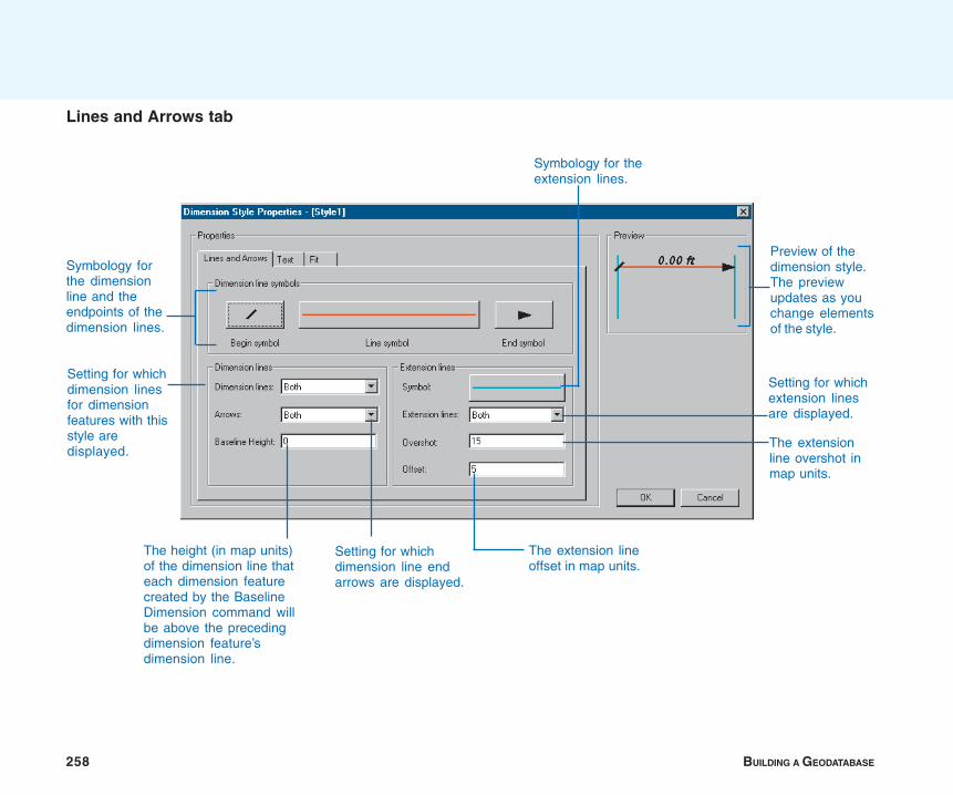
258 BUILDING A GEODATABASE
Lines and Arrows tab
Preview of thedimension style.The previewupdates as youchange elementsof the style.
Symbology forthe dimensionline and theendpoints of thedimension lines.
Setting for whichdimension linesfor dimensionfeatures with thisstyle aredisplayed.
The height (in map units)of the dimension line thateach dimension featurecreated by the BaselineDimension command willbe above the precedingdimension feature’sdimension line.
Setting for whichdimension line endarrows are displayed.
Symbology for theextension lines.
The extension lineoffset in map units.
The extensionline overshot inmap units.
Setting for whichextension linesare displayed.
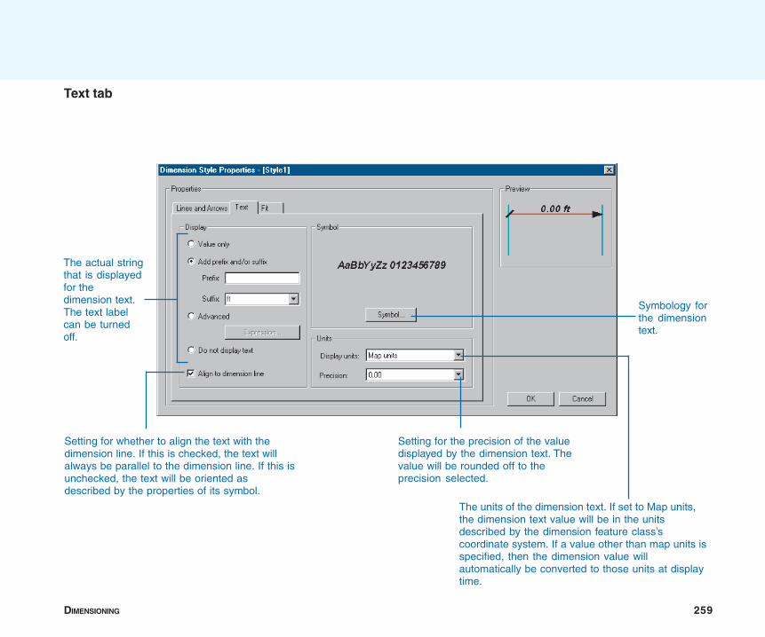
DIMENSIONING 259
Text tab
The actual stringthat is displayedfor thedimension text.The text labelcan be turnedoff.
Setting for whether to align the text with thedimension line. If this is checked, the text willalways be parallel to the dimension line. If this isunchecked, the text will be oriented asdescribed by the properties of its symbol.
Symbology forthe dimensiontext.
Setting for the precision of the valuedisplayed by the dimension text. Thevalue will be rounded off to theprecision selected.
The units of the dimension text. If set to Map units,the dimension text value will be in the unitsdescribed by the dimension feature class’scoordinate system. If a value other than map units isspecified, then the dimension value willautomatically be converted to those units at displaytime.

260 BUILDING A GEODATABASE
Fit tab
The behavior of the dimension whenits length is too short for thedimension line arrows and the textto fit between the extension lines
Setting for whether to draw thedimension line between the arrows forinward dimensions
Setting for how to resolve the casewhere the dimension is too short forthe dimension text to fit between theextension lines
Setting for whether to extend the dimensionline to underline the dimension text when itis moved to the outside of the dimension
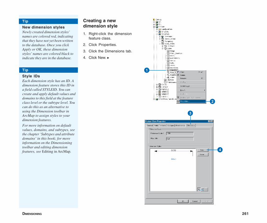
DIMENSIONING 261
Creating a newdimension style
1. Right-click the dimensionfeature class.
2. Click Properties.
3. Click the Dimensions tab.
4. Click New. u
1
2
3
4
Tip
New dimension stylesNewly created dimension styles’names are colored red, indicatingthat they have not yet been writtento the database. Once you clickApply or OK, these dimensionstyles’ names are colored black toindicate they are in the database.
Tip
Style IDsEach dimension style has an ID. Adimension feature stores this ID ina field called STYLEID. You cancreate and apply default values anddomains to this field at the featureclass level or the subtype level. Youcan do this as an alternative tousing the Dimension toolbar inArcMap to assign styles to yourdimension features.
For more information on defaultvalues, domains, and subtypes, seethe chapter ‘Subtypes and attributedomains’ in this book; for moreinformation on the Dimensioningtoolbar and editing dimensionfeatures, see Editing in ArcMap.
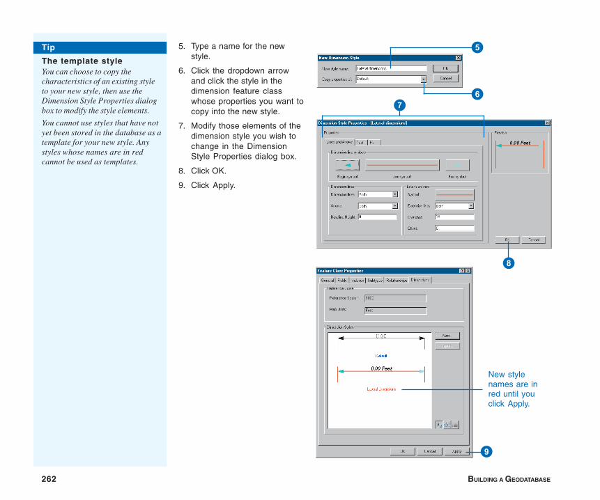
262 BUILDING A GEODATABASE
5. Type a name for the newstyle.
6. Click the dropdown arrowand click the style in thedimension feature classwhose properties you want tocopy into the new style.
7. Modify those elements of thedimension style you wish tochange in the DimensionStyle Properties dialog box.
8. Click OK.
9. Click Apply.
8
7
New stylenames are inred until youclick Apply.
9
6
5Tip
The template styleYou can choose to copy thecharacteristics of an existing styleto your new style, then use theDimension Style Properties dialogbox to modify the style elements.
You cannot use styles that have notyet been stored in the database as atemplate for your new style. Anystyles whose names are in redcannot be used as templates.
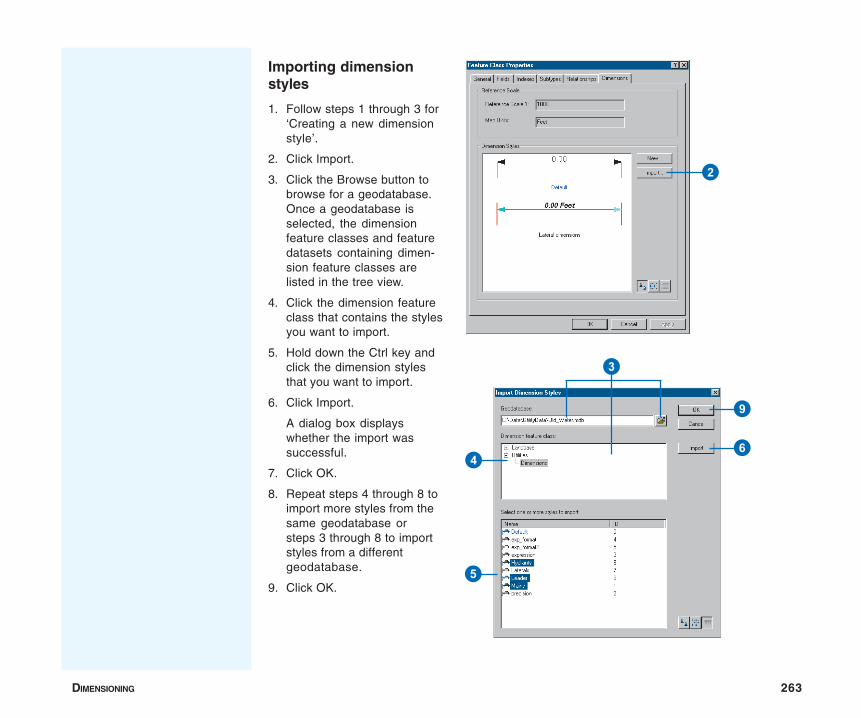
DIMENSIONING 263
Importing dimensionstyles
1. Follow steps 1 through 3 for‘Creating a new dimensionstyle’.
2. Click Import.
3. Click the Browse button tobrowse for a geodatabase.Once a geodatabase isselected, the dimensionfeature classes and featuredatasets containing dimen-sion feature classes arelisted in the tree view.
4. Click the dimension featureclass that contains the stylesyou want to import.
5. Hold down the Ctrl key andclick the dimension stylesthat you want to import.
6. Click Import.
A dialog box displayswhether the import wassuccessful.
7. Click OK.
8. Repeat steps 4 through 8 toimport more styles from thesame geodatabase orsteps 3 through 8 to importstyles from a differentgeodatabase.
9. Click OK.
2
3
4
5
6
9

264 BUILDING A GEODATABASE
Renaming a dimensionstyle
1. Follow steps 1 through 3 for‘Creating a new dimensionstyle’.
2. Right-click the dimensionstyle you want to rename.
3. Click Rename.
4. Type the new name for thestyle and press Enter.
5. Click Apply.
Tip
Dimension featuresIf dimension features that referencethe style you want to renamealready exist in your dimensionfeature class, they will not beaffected. Those features will stillreference the same style after it hasbeen renamed.
3
4
5
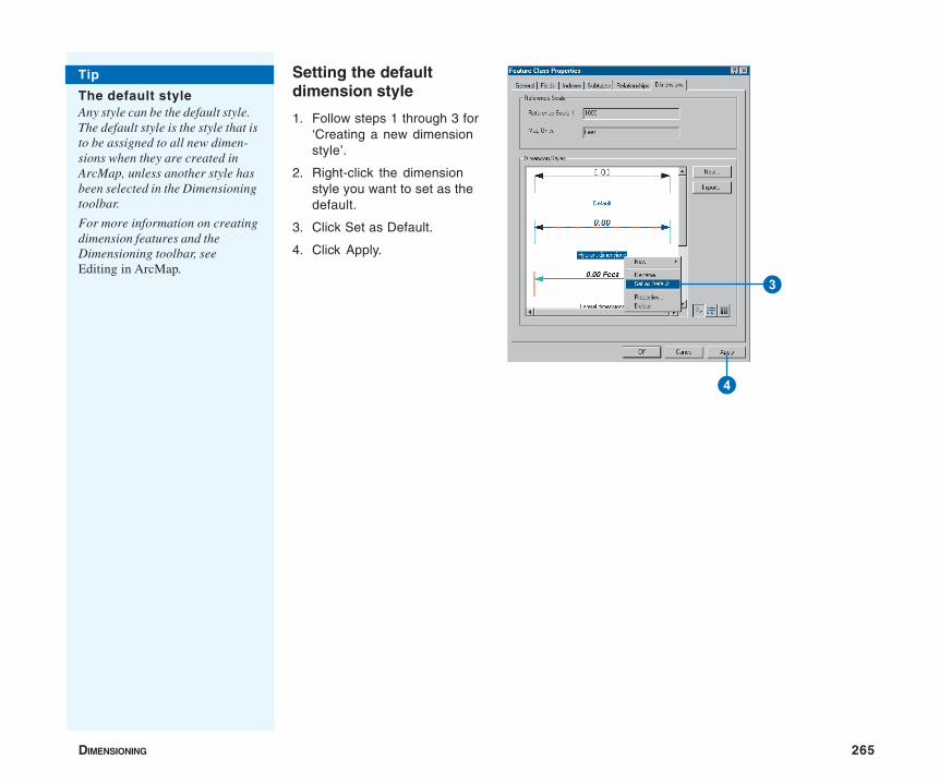
DIMENSIONING 265
Setting the defaultdimension style
1. Follow steps 1 through 3 for‘Creating a new dimensionstyle’.
2. Right-click the dimensionstyle you want to set as thedefault.
3. Click Set as Default.
4. Click Apply.
Tip
The default styleAny style can be the default style.The default style is the style that isto be assigned to all new dimen-sions when they are created inArcMap, unless another style hasbeen selected in the Dimensioningtoolbar.
For more information on creatingdimension features and theDimensioning toolbar, seeEditing in ArcMap.
3
4
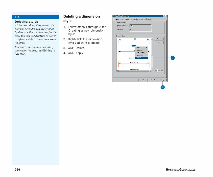
266 BUILDING A GEODATABASE
Deleting a dimensionstyle
1. Follow steps 1 through 3 for‘Creating a new dimensionstyle’.
2. Right-click the dimensionstyle you want to delete.
3. Click Delete.
4. Click Apply.
Tip
Deleting stylesAll features that reference a stylethat has been deleted are symbol-ized as raw lines with a box for thetext. You can use ArcMap to assigna different style to those dimensionfeatures.
For more information on editingdimension features, see Editing inArcMap.
3
4
IN THIS CHAPTER
267
Working with a versioned geodatabase 10• Integrating versioning with your
organization’s work flow
• Registering data as versioned
• Creating and administeringversions in ArcCatalog
• Working with versions in ArcMap
• Editing and conflict resolution
• Editing a version
• Versioning scenarios
With ArcGIS, multiple users can access geographic data in a geodatabasethrough versioning. Versioning lets users simultaneously create multiple,persistent representations of the database without data replication. Userscan edit the same features or rows without explicitly applying locks toprohibit other users from modifying the same data.
An organization can use versioning to manage alternative engineeringdesigns, solve complex what-if scenarios without impacting the corporatedatabase, and create point-in-time representations of the database.
Primarily, versioning simplifies the editing experience. Multiple users candirectly modify the database without having to extract data or lock featuresand rows before editing. If, by chance, the same features are modified, aconflict resolution dialog box guides the user through the process ofdetermining the feature’s correct representation and attributes.
Versioned databases may contain topologies. For more information on howversioning affects topologies, see the chapter ‘Topology’ in this book.
Versioned databases may also be the check-out databases for disconnectededitors. See the chapter ‘Disconnected editing’ in this book for moreinformation on using versioned databases for disconnected editing.
You can view versioned geodatabases in ArcView. To take advantage ofother versioning functionality, you need an ArcEditor or ArcInfo license.
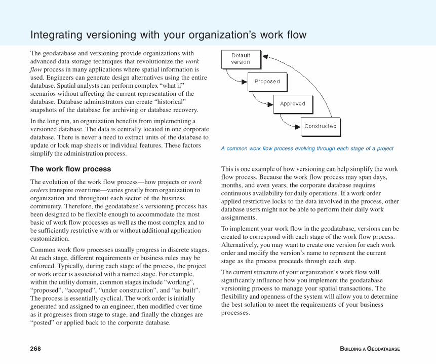
268 BUILDING A GEODATABASE
This is one example of how versioning can help simplify the workflow process. Because the work flow process may span days,months, and even years, the corporate database requirescontinuous availability for daily operations. If a work orderapplied restrictive locks to the data involved in the process, otherdatabase users might not be able to perform their daily workassignments.
To implement your work flow in the geodatabase, versions can becreated to correspond with each stage of the work flow process.Alternatively, you may want to create one version for each workorder and modify the version’s name to represent the currentstage as the process proceeds through each step.
The current structure of your organization’s work flow willsignificantly influence how you implement the geodatabaseversioning process to manage your spatial transactions. Theflexibility and openness of the system will allow you to determinethe best solution to meet the requirements of your businessprocesses.
Integrating versioning with your organization’s work flow
The geodatabase and versioning provide organizations withadvanced data storage techniques that revolutionize the workflow process in many applications where spatial information isused. Engineers can generate design alternatives using the entiredatabase. Spatial analysts can perform complex “what if”scenarios without affecting the current representation of thedatabase. Database administrators can create “historical”snapshots of the database for archiving or database recovery.
In the long run, an organization benefits from implementing aversioned database. The data is centrally located in one corporatedatabase. There is never a need to extract units of the database toupdate or lock map sheets or individual features. These factorssimplify the administration process.
The work flow process
The evolution of the work flow process—how projects or workorders transpire over time—varies greatly from organization toorganization and throughout each sector of the businesscommunity. Therefore, the geodatabase’s versioning process hasbeen designed to be flexible enough to accommodate the mostbasic of work flow processes as well as the most complex and tobe sufficiently restrictive with or without additional applicationcustomization.
Common work flow processes usually progress in discrete stages.At each stage, different requirements or business rules may beenforced. Typically, during each stage of the process, the projector work order is associated with a named stage. For example,within the utility domain, common stages include “working”,“proposed”, “accepted”, “under construction”, and “as built”.The process is essentially cyclical. The work order is initiallygenerated and assigned to an engineer, then modified over timeas it progresses from stage to stage, and finally the changes are“posted” or applied back to the corporate database.
A common work flow process evolving through each stage of a project

WORKING WITH A VERSIONED GEODATABASE 269
The remaining sections of this chapter will help illustrate how touse ArcCatalog and ArcMap to perform various versioning tasks.In particular, the last section provides examples of how anorganization can implement work flow processes using thegeodatabase’s versioning capabilities. For additional details onmanaging your organization’s work flow with versions, readModeling Our World.
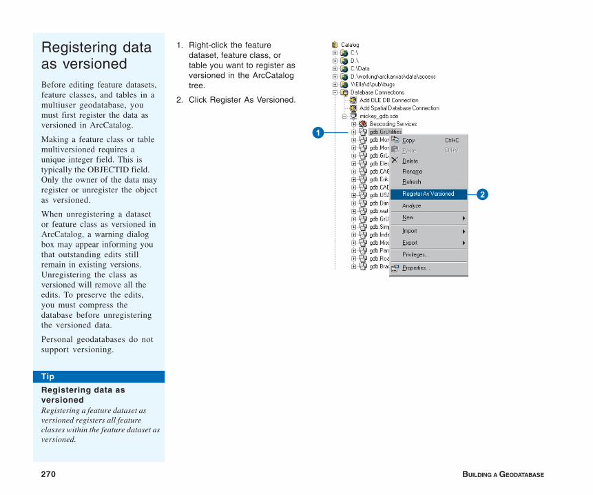
270 BUILDING A GEODATABASE
Registering dataas versionedBefore editing feature datasets,feature classes, and tables in amultiuser geodatabase, youmust first register the data asversioned in ArcCatalog.
Making a feature class or tablemultiversioned requires aunique integer field. This istypically the OBJECTID field.Only the owner of the data mayregister or unregister the objectas versioned.
When unregistering a datasetor feature class as versioned inArcCatalog, a warning dialogbox may appear informing youthat outstanding edits stillremain in existing versions.Unregistering the class asversioned will remove all theedits. To preserve the edits,you must compress thedatabase before unregisteringthe versioned data.
Personal geodatabases do notsupport versioning.
1. Right-click the featuredataset, feature class, ortable you want to register asversioned in the ArcCatalogtree.
2. Click Register As Versioned.
Tip
Registering data asversionedRegistering a feature dataset asversioned registers all featureclasses within the feature dataset asversioned.
2
1
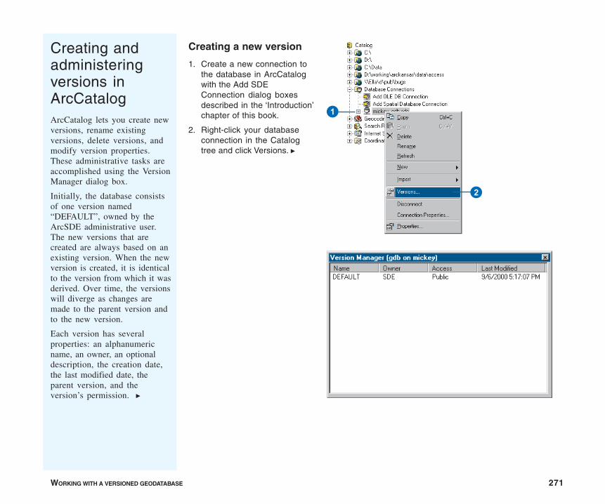
WORKING WITH A VERSIONED GEODATABASE 271
Creating andadministeringversions inArcCatalogArcCatalog lets you create newversions, rename existingversions, delete versions, andmodify version properties.These administrative tasks areaccomplished using the VersionManager dialog box.
Initially, the database consistsof one version named“DEFAULT”, owned by theArcSDE administrative user.The new versions that arecreated are always based on anexisting version. When the newversion is created, it is identicalto the version from which it wasderived. Over time, the versionswill diverge as changes aremade to the parent version andto the new version.
Each version has severalproperties: an alphanumericname, an owner, an optionaldescription, the creation date,the last modified date, theparent version, and theversion’s permission. u
Creating a new version
1. Create a new connection tothe database in ArcCatalogwith the Add SDEConnection dialog boxesdescribed in the ‘Introduction’chapter of this book.
2. Right-click your databaseconnection in the Catalogtree and click Versions. u
2
1
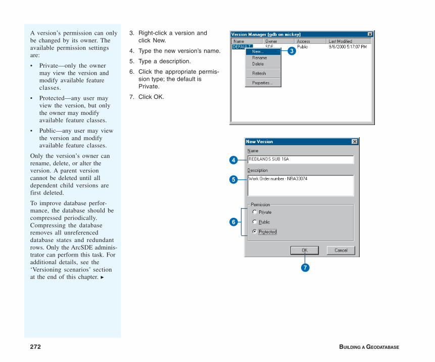
272 BUILDING A GEODATABASE
3. Right-click a version andclick New.
4. Type the new version’s name.
5. Type a description.
6. Click the appropriate permis-sion type; the default isPrivate.
7. Click OK.
A version’s permission can onlybe changed by its owner. Theavailable permission settingsare:
• Private—only the ownermay view the version andmodify available featureclasses.
• Protected—any user mayview the version, but onlythe owner may modifyavailable feature classes.
• Public—any user may viewthe version and modifyavailable feature classes.
Only the version’s owner canrename, delete, or alter theversion. A parent versioncannot be deleted until alldependent child versions arefirst deleted.
To improve database perfor-mance, the database should becompressed periodically.Compressing the databaseremoves all unreferenceddatabase states and redundantrows. Only the ArcSDE adminis-trator can perform this task. Foradditional details, see the‘Versioning scenarios’ sectionat the end of this chapter. u
3
4
5
6
7
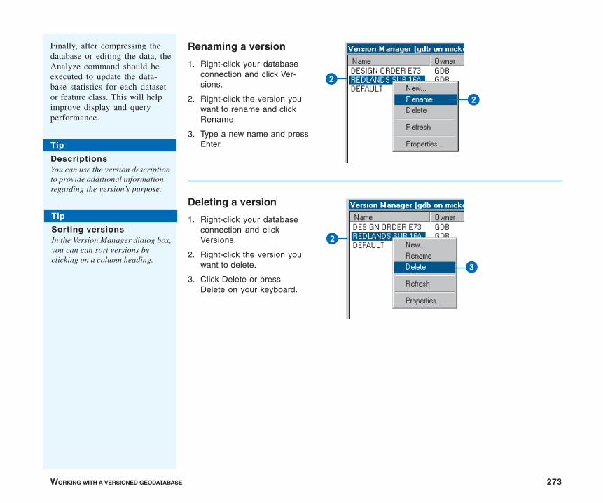
WORKING WITH A VERSIONED GEODATABASE 273
Renaming a version
1. Right-click your databaseconnection and click Ver-sions.
2. Right-click the version youwant to rename and clickRename.
3. Type a new name and pressEnter.
Deleting a version
1. Right-click your databaseconnection and clickVersions.
2. Right-click the version youwant to delete.
3. Click Delete or pressDelete on your keyboard.
Finally, after compressing thedatabase or editing the data, theAnalyze command should beexecuted to update the data-base statistics for each datasetor feature class. This will helpimprove display and queryperformance.
2
2
3
2
Tip
DescriptionsYou can use the version descriptionto provide additional informationregarding the version’s purpose.
Tip
Sorting versionsIn the Version Manager dialog box,you can can sort versions byclicking on a column heading.
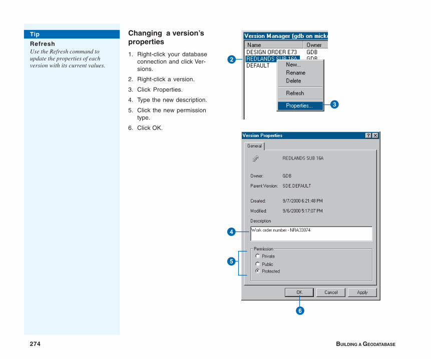
274 BUILDING A GEODATABASE
Changing a version’sproperties
1. Right-click your databaseconnection and click Ver-sions.
2. Right-click a version.
3. Click Properties.
4. Type the new description.
5. Click the new permissiontype.
6. Click OK.
Tip
RefreshUse the Refresh command toupdate the properties of eachversion with its current values.
3
2
6
4
5
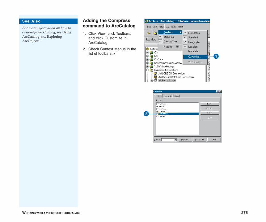
WORKING WITH A VERSIONED GEODATABASE 275
Adding the Compresscommand to ArcCatalog
1. Click View, click Toolbars,and click Customize inArcCatalog.
2. Check Context Menus in thelist of toolbars. u
1
2
See Also
For more information on how tocustomize ArcCatalog, see UsingArcCatalog and ExploringArcObjects.
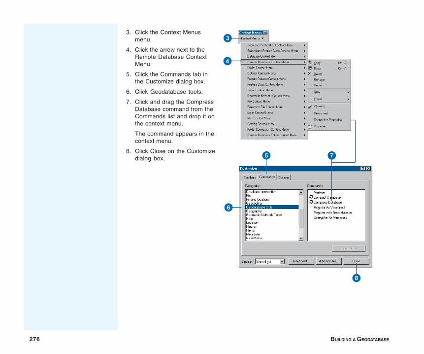
276 BUILDING A GEODATABASE
3. Click the Context Menusmenu.
4. Click the arrow next to theRemote Database ContextMenu.
5. Click the Commands tab inthe Customize dialog box.
6. Click Geodatabase tools.
7. Click and drag the CompressDatabase command from theCommands list and drop it onthe context menu.
The command appears in thecontext menu.
8. Click Close on the Customizedialog box.
3
4
5
6
7
8
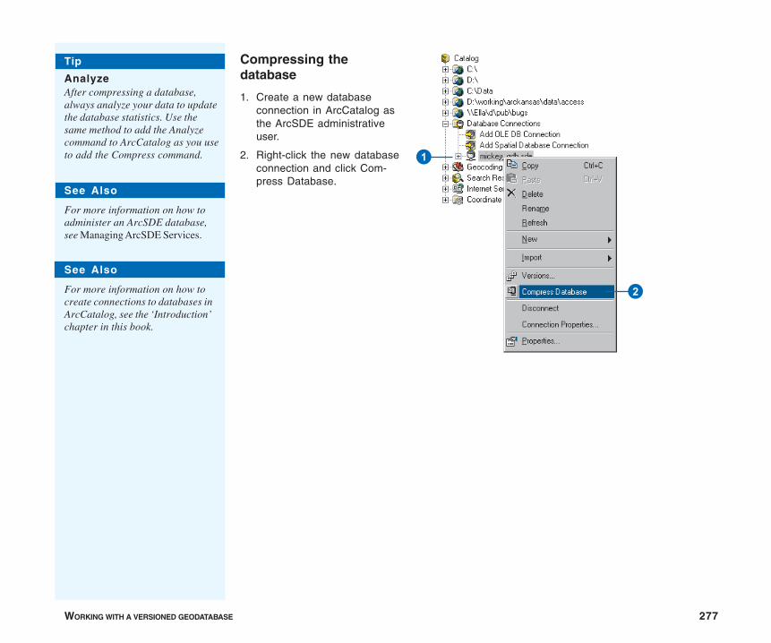
WORKING WITH A VERSIONED GEODATABASE 277
Compressing thedatabase
1. Create a new databaseconnection in ArcCatalog asthe ArcSDE administrativeuser.
2. Right-click the new databaseconnection and click Com-press Database.
2
1
Tip
AnalyzeAfter compressing a database,always analyze your data to updatethe database statistics. Use thesame method to add the Analyzecommand to ArcCatalog as you useto add the Compress command.
See Also
For more information on how toadminister an ArcSDE database,see Managing ArcSDE Services.
See Also
For more information on how tocreate connections to databases inArcCatalog, see the ‘Introduction’chapter in this book.
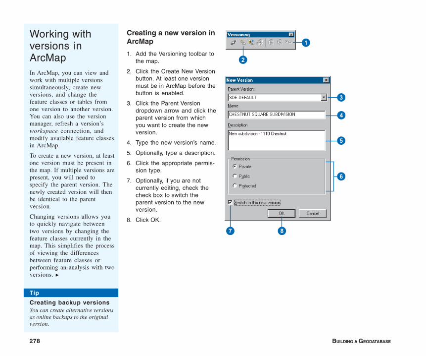
278 BUILDING A GEODATABASE
Working withversions inArcMapIn ArcMap, you can view andwork with multiple versionssimultaneously, create newversions, and change thefeature classes or tables fromone version to another version.You can also use the versionmanager, refresh a version’sworkspace connection, andmodify available feature classesin ArcMap.
To create a new version, at leastone version must be present inthe map. If multiple versions arepresent, you will need tospecify the parent version. Thenewly created version will thenbe identical to the parentversion.
Changing versions allows youto quickly navigate betweentwo versions by changing thefeature classes currently in themap. This simplifies the processof viewing the differencesbetween feature classes orperforming an analysis with twoversions. u
Creating a new version inArcMap
1. Add the Versioning toolbar tothe map.
2. Click the Create New Versionbutton. At least one versionmust be in ArcMap before thebutton is enabled.
3. Click the Parent Versiondropdown arrow and click theparent version from whichyou want to create the newversion.
4. Type the new version’s name.
5. Optionally, type a description.
6. Click the appropriate permis-sion type.
7. Optionally, if you are notcurrently editing, check thecheck box to switch theparent version to the newversion.
8. Click OK.
Tip
Creating backup versionsYou can create alternative versionsas online backups to the originalversion.
1
2
3
4
5
6
7 8

WORKING WITH A VERSIONED GEODATABASE 279
Changing versions
1. Click the Source tab at thebottom of the ArcMap table ofcontents to list theworkspaces in your map.
2. Right-click a versionworkspace.
3. Click Change Version.
4. Click the version to whichyou want to change.
5. Click OK.
When a version workspace ischanged to a different version,all feature classes present in theworkspace will represent thenew “target” version.
Two methods are available inArcMap for changing versions.You can change versions fromthe Versioning toolbar or in thetable of contents.
When you work in a multiuserenvironment, the database maybe modified by another user atthe same time you’re viewingthe database. Therefore, thefeature classes present inArcMap may become outdated.
To update feature classes inArcMap you can refresh one orall of the version workspacespresent by clicking the Refreshbutton on the Versioningtoolbar. While you are editing,the Refresh button is unavail-able.
You can have as many versionsin the map as needed, but youcan only edit one version peredit session.
1
2
3
Tip
The Change VersioncommandUse the Change Version commandinstead of adding multiple versionworkspaces to your map document.
5
4

280 BUILDING A GEODATABASE
Refreshing a workspace
1. Click the Refresh button onthe Versioning toolbar.
Tip
Preserving a versionIf you need to preserve a currentrepresentation of the database,create a new version beforerefreshing.
1
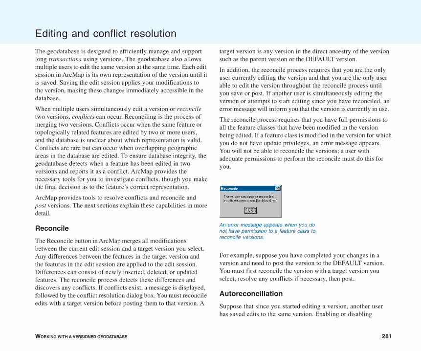
WORKING WITH A VERSIONED GEODATABASE 281
target version is any version in the direct ancestry of the versionsuch as the parent version or the DEFAULT version.
In addition, the reconcile process requires that you are the onlyuser currently editing the version and that you are the only userable to edit the version throughout the reconcile process untilyou save or post. If another user is simultaneously editing theversion or attempts to start editing since you have reconciled, anerror message will inform you that the version is currently in use.
The reconcile process requires that you have full permissions toall the feature classes that have been modified in the versionbeing edited. If a feature class is modified in the version for whichyou do not have update privileges, an error message appears.You will not be able to reconcile the versions; a user withadequate permissions to perform the reconcile must do this foryou.
For example, suppose you have completed your changes in aversion and need to post the version to the DEFAULT version.You must first reconcile the version with a target version youselect, resolve any conflicts if necessary, then post.
Autoreconciliation
Suppose that since you started editing a version, another userhas saved edits to the same version. Enabling or disabling
Editing and conflict resolution
The geodatabase is designed to efficiently manage and supportlong transactions using versions. The geodatabase also allowsmultiple users to edit the same version at the same time. Each editsession in ArcMap is its own representation of the version until itis saved. Saving the edit session applies your modifications tothe version, making these changes immediately accessible in thedatabase.
When multiple users simultaneously edit a version or reconciletwo versions, conflicts can occur. Reconciling is the process ofmerging two versions. Conflicts occur when the same feature ortopologically related features are edited by two or more users,and the database is unclear about which representation is valid.Conflicts are rare but can occur when overlapping geographicareas in the database are edited. To ensure database integrity, thegeodatabase detects when a feature has been edited in twoversions and reports it as a conflict. ArcMap provides thenecessary tools for you to investigate conflicts, though you makethe final decision as to the feature’s correct representation.
ArcMap provides tools to resolve conflicts and reconcile andpost versions. The next sections explain these capabilities in moredetail.
Reconcile
The Reconcile button in ArcMap merges all modificationsbetween the current edit session and a target version you select.Any differences between the features in the target version andthe features in the edit session are applied to the edit session.Differences can consist of newly inserted, deleted, or updatedfeatures. The reconcile process detects these differences anddiscovers any conflicts. If conflicts exist, a message is displayed,followed by the conflict resolution dialog box. You must reconcileedits with a target version before posting them to that version. A
An error message appears when you donot have permission to a feature class toreconcile versions.
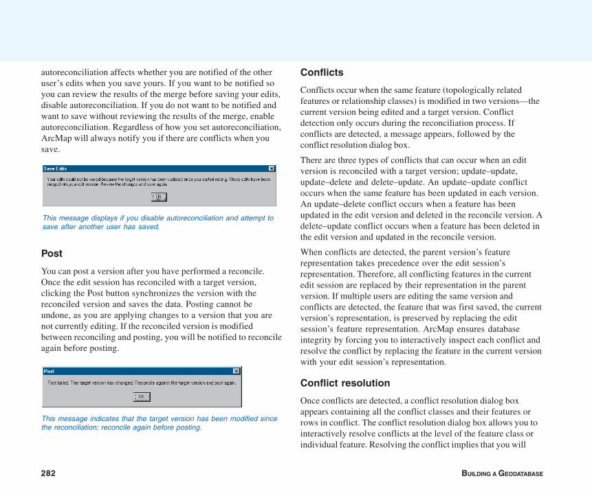
282 BUILDING A GEODATABASE
Conflicts
Conflicts occur when the same feature (topologically relatedfeatures or relationship classes) is modified in two versions—thecurrent version being edited and a target version. Conflictdetection only occurs during the reconciliation process. Ifconflicts are detected, a message appears, followed by theconflict resolution dialog box.
There are three types of conflicts that can occur when an editversion is reconciled with a target version; update–update,update–delete and delete–update. An update–update conflictoccurs when the same feature has been updated in each version.An update–delete conflict occurs when a feature has beenupdated in the edit version and deleted in the reconcile version. Adelete–update conflict occurs when a feature has been deleted inthe edit version and updated in the reconcile version.
When conflicts are detected, the parent version’s featurerepresentation takes precedence over the edit session’srepresentation. Therefore, all conflicting features in the currentedit session are replaced by their representation in the parentversion. If multiple users are editing the same version andconflicts are detected, the feature that was first saved, the currentversion’s representation, is preserved by replacing the editsession’s feature representation. ArcMap ensures databaseintegrity by forcing you to interactively inspect each conflict andresolve the conflict by replacing the feature in the current versionwith your edit session’s representation.
Conflict resolution
Once conflicts are detected, a conflict resolution dialog boxappears containing all the conflict classes and their features orrows in conflict. The conflict resolution dialog box allows you tointeractively resolve conflicts at the level of the feature class orindividual feature. Resolving the conflict implies that you will
autoreconciliation affects whether you are notified of the otheruser’s edits when you save yours. If you want to be notified soyou can review the results of the merge before saving your edits,disable autoreconciliation. If you do not want to be notified andwant to save without reviewing the results of the merge, enableautoreconciliation. Regardless of how you set autoreconciliation,ArcMap will always notify you if there are conflicts when yousave.
Post
You can post a version after you have performed a reconcile.Once the edit session has reconciled with a target version,clicking the Post button synchronizes the version with thereconciled version and saves the data. Posting cannot beundone, as you are applying changes to a version that you arenot currently editing. If the reconciled version is modifiedbetween reconciling and posting, you will be notified to reconcileagain before posting.
This message displays if you disable autoreconciliation and attempt tosave after another user has saved.
This message indicates that the target version has been modified sincethe reconciliation; reconcile again before posting.
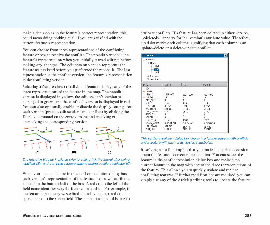
WORKING WITH A VERSIONED GEODATABASE 283
make a decision as to the feature’s correct representation; thiscould mean doing nothing at all if you are satisfied with thecurrent feature’s representation.
You can choose from three representations of the conflictingfeature or row to resolve the conflict. The preedit version is thefeature’s representation when you initially started editing, beforemaking any changes. The edit session version represents thefeature as it existed before you performed the reconcile. The lastrepresentation is the conflict version, the feature’s representationin the conflicting version.
Selecting a feature class or individual feature displays any of thethree representations of the feature in the map. The preedit’sversion is displayed in yellow, the edit session’s version isdisplayed in green, and the conflict’s version is displayed in red.You can also optionally enable or disable the display settings foreach version (preedit, edit session, and conflict) by clicking theDisplay command on the context menu and checking orunchecking the corresponding version.
When you select a feature in the conflict resolution dialog box,each version’s representation of the feature’s or row’s attributesis listed in the bottom half of the box. A red dot to the left of thefield name identifies why the feature is a conflict. For example, ifthe feature’s geometry was edited in each version, a red dotappears next to the shape field. The same principle holds true for
attribute conflicts. If a feature has been deleted in either version,“<deleted>” appears for that version’s attribute value. Therefore,a red dot marks each column, signifying that each column is anupdate–delete or a delete–update conflict.
Resolving a conflict implies that you made a conscious decisionabout the feature’s correct representation. You can select thefeature in the conflict resolution dialog box and replace thecurrent feature in the map with any of the three representations ofthe feature. This allows you to quickly update and replaceconflicting features. If further modifications are required, you cansimply use any of the ArcMap editing tools to update the feature.
The lateral in blue as it existed prior to editing (A), the lateral after beingmodified (B), and the three representations during conflict resolution (C).
This conflict resolution dialog box shows two feature classes with conflictsand a feature with each of its version’s attributes.
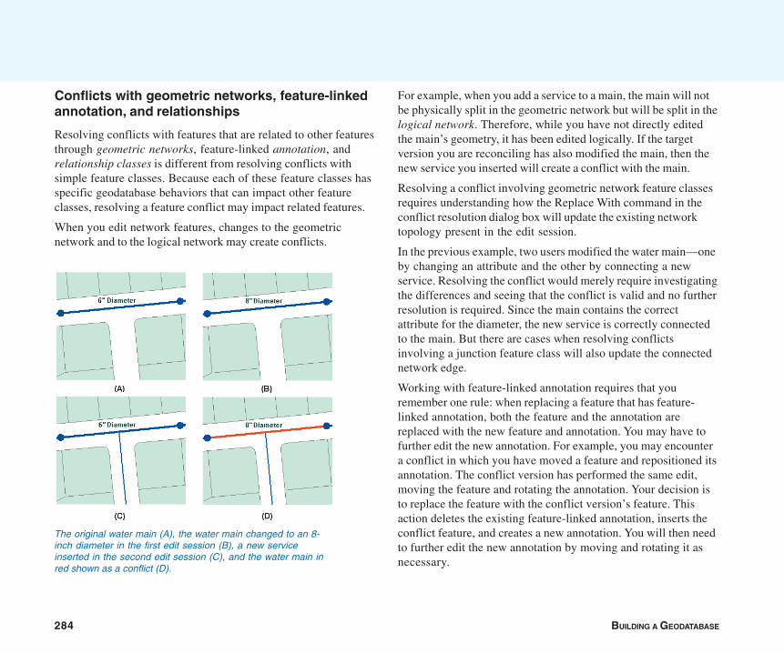
284 BUILDING A GEODATABASE
Conflicts with geometric networks, feature-linkedannotation, and relationships
Resolving conflicts with features that are related to other featuresthrough geometric networks, feature-linked annotation, andrelationship classes is different from resolving conflicts withsimple feature classes. Because each of these feature classes hasspecific geodatabase behaviors that can impact other featureclasses, resolving a feature conflict may impact related features.
When you edit network features, changes to the geometricnetwork and to the logical network may create conflicts.
For example, when you add a service to a main, the main will notbe physically split in the geometric network but will be split in thelogical network. Therefore, while you have not directly editedthe main’s geometry, it has been edited logically. If the targetversion you are reconciling has also modified the main, then thenew service you inserted will create a conflict with the main.
Resolving a conflict involving geometric network feature classesrequires understanding how the Replace With command in theconflict resolution dialog box will update the existing networktopology present in the edit session.
In the previous example, two users modified the water main—oneby changing an attribute and the other by connecting a newservice. Resolving the conflict would merely require investigatingthe differences and seeing that the conflict is valid and no furtherresolution is required. Since the main contains the correctattribute for the diameter, the new service is correctly connectedto the main. But there are cases when resolving conflictsinvolving a junction feature class will also update the connectednetwork edge.
Working with feature-linked annotation requires that youremember one rule: when replacing a feature that has feature-linked annotation, both the feature and the annotation arereplaced with the new feature and annotation. You may have tofurther edit the new annotation. For example, you may encountera conflict in which you have moved a feature and repositioned itsannotation. The conflict version has performed the same edit,moving the feature and rotating the annotation. Your decision isto replace the feature with the conflict version’s feature. Thisaction deletes the existing feature-linked annotation, inserts theconflict feature, and creates a new annotation. You will then needto further edit the new annotation by moving and rotating it asnecessary.
The original water main (A), the water main changed to an 8-inch diameter in the first edit session (B), a new serviceinserted in the second edit session (C), and the water main inred shown as a conflict (D).

WORKING WITH A VERSIONED GEODATABASE 285
Relationships have similar dependencies to feature-linkedannotation. Deleting a feature from an origin relationship classmay trigger a message to delete a feature from the destinationrelationship class. Therefore, be aware of the ramifications ofsimply replacing conflicts involving feature classes thatparticipate in relationship classes.
An example of when a conflict can arise between relationshipclasses is if you were to update the origin class primary field,breaking the relationship in version A. At the same time, inversion B, the destination class-related feature is also updated.When you reconcile the versions, since the destination class isdependent on the origin class, a conflict is detected. A similarexample is if you were to delete a pole that has a relationship to atransformer, the transformer is also deleted. But in the conflictversion, the transformer’s attributes are edited. An update–deleteconflict would be detected when reconciled.
Conflicts with topologies
Because features in feature classes that participate in a topologycan share geometry with other features, the process of resolvingconflicts between versions of topological feature classes isdifferent from resolving conflicts with simple feature classes. It isalso different from that used to resolve conflicts with geometricnetworks, relationship classes, and feature-linked annotation.
When a feature class that participates in a topology is edited,other topologically related features may be simultaneouslychanged. The changed features may belong to the same featureclass or to one or more other feature classes. To manage theprocess of detecting new topology errors that may have beenintroduced by edits, topologies record where edits have beenmade as dirty areas. Editing features in a topology creates dirtyareas in the topology.
New topology errors may occur when edited parent and childversions are reconciled, even when the dirty areas within eachversion have been validated and are free of errors. In order todetect such topology errors, the dirty areas in a child version areall returned to dirty status after changes from the parent versionare brought into it during a reconcile. After the reconcile theseareas can be revalidated and any errors will be detected.
Reconciling two versions that do not contain active dirty areasmay still result in dirty areas. Any dirty area that has been presentin the child version, whether it has been validated or not, will be adirty area after the versions are reconciled. In general, whenreconciling a version:
• Any dirty area the child version inherited from the parentversion, whether it is validated in the child version or not, willbe a dirty area after the reconcile.
• Any dirty area that was created for any feature that wascreated, updated, or deleted in the child version, whether it isvalidated or not, will be a dirty area after the reconcile.
For more information on reconciling versions with topologies, seethe section ‘Topology and versioning’ in the ‘Topology’ chapterof this book or in the chapter ‘Editing topology’ in Editing inArcMap.
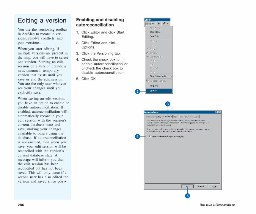
286 BUILDING A GEODATABASE
Enabling and disablingautoreconciliation
1. Click Editor and click StartEditing.
2. Click Editor and clickOptions.
3. Click the Versioning tab.
4. Check the check box toenable autoreconciliation oruncheck the check box todisable autoreconciliation.
5. Click OK.
Editing a versionYou use the versioning toolbarin ArcMap to reconcile ver-sions, resolve conflicts, andpost versions.
When you start editing, ifmultiple versions are present inthe map, you will have to selectone version. Starting an editsession on a version creates anew, unnamed, temporaryversion that exists until yousave or end the edit session.You are the only user who cansee your changes until youexplicitly save.
When saving an edit session,you have an option to enable ordisable autoreconciliation. Ifenabled, autoreconciliation willautomatically reconcile youredit session with the version’scurrent database state andsave, making your changesavailable to others using thedatabase. If autoreconciliationis not enabled, then when yousave, your edit session will bereconciled with the version’scurrent database state. Amessage will inform you thatthe edit session has beenreconciled but has not beensaved. This will only occur if asecond user has also edited theversion and saved since you u
3
4
5
2
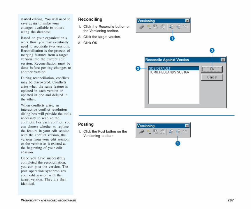
WORKING WITH A VERSIONED GEODATABASE 287
Reconciling
1. Click the Reconcile button onthe Versioning toolbar.
2. Click the target version.
3. Click OK.
Posting
1. Click the Post button on theVersioning toolbar.
started editing. You will need tosave again to make yourchanges available to othersusing the database.
Based on your organization’swork flow, you may eventuallyneed to reconcile two versions.Reconciliation is the process ofmerging features from a targetversion into the current editsession. Reconciliation must bedone before posting changes toanother version.
During reconciliation, conflictsmay be discovered. Conflictsarise when the same feature isupdated in each version orupdated in one and deleted inthe other.
When conflicts arise, aninteractive conflict resolutiondialog box will provide the toolsnecessary to resolve theconflicts. For each conflict, youcan choose whether to replacethe feature in your edit sessionwith the conflict version, theversion from your edit session,or the version as it existed atthe beginning of your editsession.
Once you have successfullycompleted the reconciliation,you can post the version. Thepost operation synchronizesyour edit session with thetarget version. They are thenidentical.
3
2
1
1
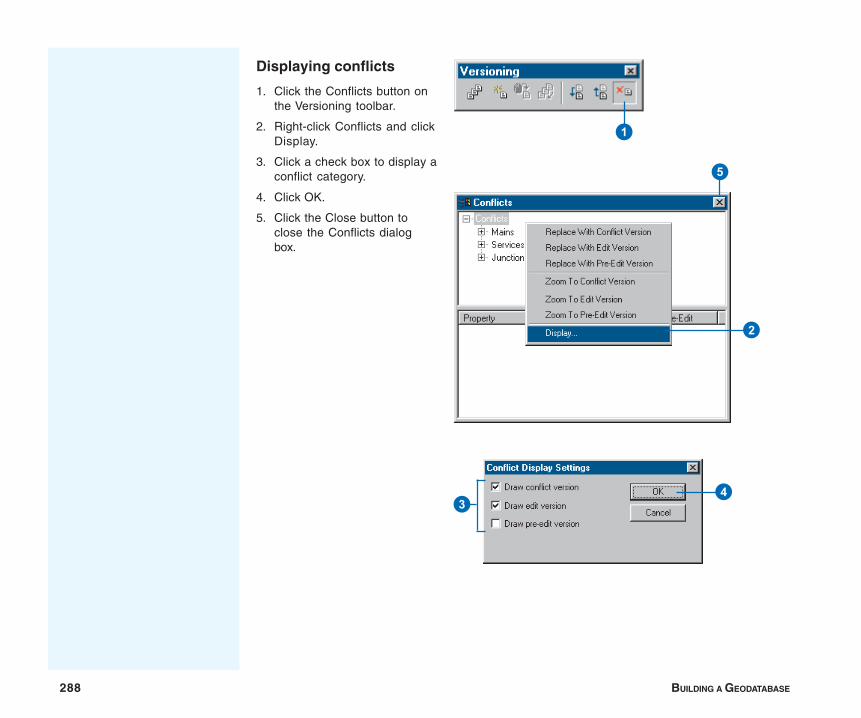
288 BUILDING A GEODATABASE
Displaying conflicts
1. Click the Conflicts button onthe Versioning toolbar.
2. Right-click Conflicts and clickDisplay.
3. Click a check box to display aconflict category.
4. Click OK.
5. Click the Close button toclose the Conflicts dialogbox.
1
34
2
5
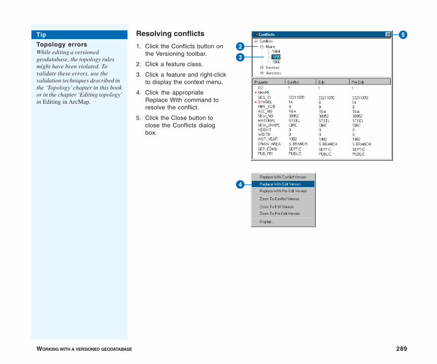
WORKING WITH A VERSIONED GEODATABASE 289
Resolving conflicts
1. Click the Conflicts button onthe Versioning toolbar.
2. Click a feature class.
3. Click a feature and right-clickto display the context menu.
4. Click the appropriateReplace With command toresolve the conflict.
5. Click the Close button toclose the Conflicts dialogbox.
3
2
5
4
Tip
Topology errorsWhile editing a versionedgeodatabase, the topology rulesmight have been violated. Tovalidate these errors, use thevalidation techniques described inthe ‘Topology’ chapter in this bookor in the chapter ‘Editing topology’in Editing in ArcMap.
290 BUILDING A GEODATABASE
The following scenarios show how an organization can implementits work flow process using a versioned database. Theseexamples demonstrate several techniques available for performinglong transactions in a multiuser environment. It is likely thatorganizations will, in some manner, use each of these techniquesdepending on the task.
Scenario 1: Simple database modifications
Task: Multiple users are concurrently editing the database,performing common map sheet changes such as inserting newfeatures, updating attributes, and removing out-of-date facilities.
Solution: Users can simply connect to the DEFAULT version(simultaneously), start editing, and save their changes when theirwork is complete. Users do not have to create new versions tomodify the database. If another user has edited the DEFAULTversion since the current user has started editing, the user savingis notified that the version has been changed and, therefore, theversion will need to be saved again. Users may bypass thiswarning message by enabling autoreconciliation in the ArcMapOptions dialog box. Also, if two users modify the same featureduring their edit sessions, the second user to save encounters aconflict. The user then has to decide what the feature’s correctrepresentation is and save the edit session.
Scenario 2: Transactions spanning multiple days
Task: Update the database to incorporate new and updatedfacilities in the field, which will likely require multiple editsessions and a couple of days to complete.
Solution: A user creates and switches to a new version derivedfrom the DEFAULT version. The user starts editing the newversion and begins modifying features and saving as required.The user can resume the edit session, as appropriate, thefollowing day or possibly the following week. When the changes
Versioning scenarios
are complete and ready to be posted to the DEFAULT version,the user must first click the Reconcile button on the Versioningtoolbar. If conflicts are detected, the user can resolve thedifferences and complete the transaction by clicking the Postbutton. The posting process applies all the changes in the user’sversion to the DEFAULT version. The user can then delete theversion.
Scenario 3: A work flow process
Task: Create individual versions for each step or stage of thework order and work flow process and post the work order to thedatabase.
Solution: A user or supervisor creates a new version derived fromthe DEFAULT version. The user starts editing the new versionand begins modifying features or creating a new design. Whenthe user has completed the design or proposed modifications, thework order can be submitted to a supervisor for review. At thistime, a new version can be created to ensure the preservation ofthe initial design. The new version can then be further modified oradjusted as required. Once the work order has been approved forconstruction, another version can be created. The purpose of thisversion is to reflect any changes that may occur while the workorder is being constructed in the field. Finally, as the constructionis completed and the new facilities are in service, the work ordermust be posted to the database. A user can then start editing thework order, perform a reconcile with the DEFAULT version,resolve any conflicts if necessary, and post.
The solution allows the organization to create new versions ofthe work order for each step of the project—the initial design orproposed version, a working or accepted version, and a versionfor the construction phase. Each version is preserved andavailable to review for historical purposes. The final step is topost the constructed version to the database. The project
WORKING WITH A VERSIONED GEODATABASE 291
completes a full circle from start to finish, creating individualversions at each step.
Scenario 4: Restricting permissions to thedatabase
Task: The organization’s supervisor has restricted write access tothe DEFAULT version, requiring managerial review of each user’sedits prior to posting the changes to the database.
Solution: To restrict write permissions to the database (theDEFAULT version), the ArcSDE administrative user can set thepermission of the DEFAULT version to “protected” using theversion manager. This allows users to continue to view theDEFAULT version but does not allow users to start editing theversion. Therefore, users will need to create new versions forediting the database, similar to Scenario 2. When a user hascompleted and saved the edit session, the ArcSDE administratorcan reconcile the version with the DEFAULT version. Toaccomplish this task, the manager who connects to the databaseas the ArcSDE administrator starts editing the user’s version andclicks the Reconcile button. The process will merge all thechanges in the user’s version and the DEFAULT version. Ifconflicts are detected, the manager can resolve the conflicts andsave the edit session. Once the edits are acceptable to themanager, the version is ready to be posted to the DEFAULTversion. The ArcSDE administrative user can then start editingthe version, perform a reconcile, and post the version. The user’sversion can then be deleted.
Scenario 5: Compressing the database
Task: The geodatabase has been edited for an extended time, andthe number of database states and rows in each feature class’sdelta tables has significantly increased. How do you improveperformance?
Solution: The Compress command will remove all database statesthat are no longer referenced by a version and move all the rowsin the delta tables, which are common to all versions, to the basetable. To achieve the maximum benefit when running theCompress command, you can optionally first reconcile, post, anddelete each version with the DEFAULT version. Sometimes thismay not be a reasonable option based on your organization’swork flow. At minimum, to improve performance, simply reconcileeach version with the DEFAULT version and save, then performthe compress. This will ensure that all the edits in the DEFAULTversion will be compressed from the delta tables to the businesstable. Remember, the Compress command can still be executedwithout first reconciling, posting, and deleting each version, butthe benefits may not be as noticeable.

IN THIS CHAPTER
293
Disconnected editing
• Disconnected editing
• Checking out data from ageodatabase
• Customizing a check-out
• Checking in data to a geodatabase
• Managing check-outs
Exchanging and maintaining data between geographically dispersed usershas become an integral part of the work flow process. Some of theseremote users may be connected via a wide area network (WAN) or localarea network (LAN) to a central office infrastructure; others will be moremobile, requiring only to download and upload data to and from centraloffice databases on an infrequent basis.
These organizational requirements are supported in the geodatabase.
ArcInfo or ArcEditor is required to check data in and out, and to edit anArcSDE check-out geodatabase. You can edit a personal check-outgeodatabase with ArcView.
11
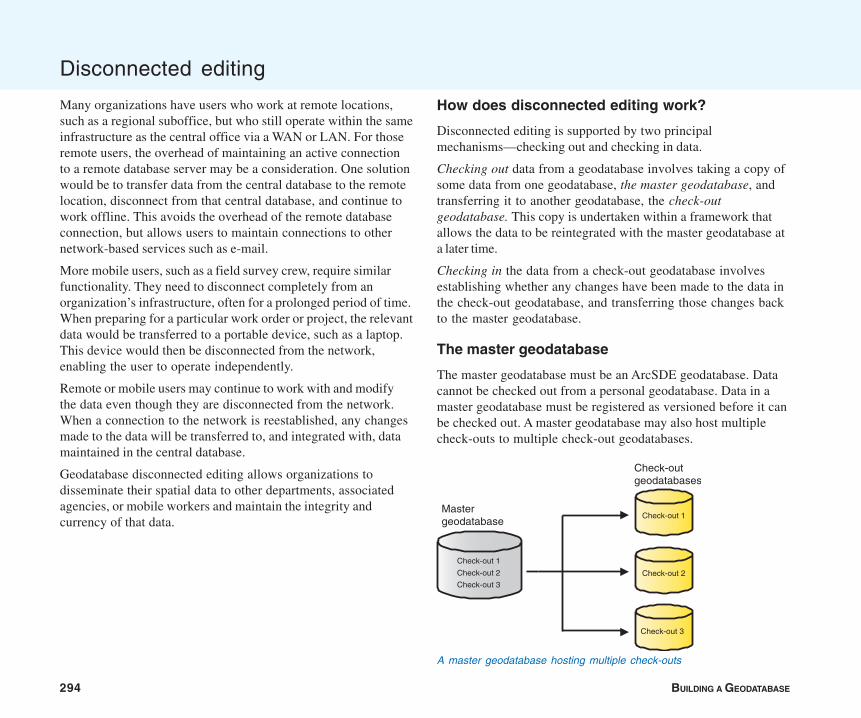
294 BUILDING A GEODATABASE
Many organizations have users who work at remote locations,such as a regional suboffice, but who still operate within the sameinfrastructure as the central office via a WAN or LAN. For thoseremote users, the overhead of maintaining an active connectionto a remote database server may be a consideration. One solutionwould be to transfer data from the central database to the remotelocation, disconnect from that central database, and continue towork offline. This avoids the overhead of the remote databaseconnection, but allows users to maintain connections to othernetwork-based services such as e-mail.
More mobile users, such as a field survey crew, require similarfunctionality. They need to disconnect completely from anorganization’s infrastructure, often for a prolonged period of time.When preparing for a particular work order or project, the relevantdata would be transferred to a portable device, such as a laptop.This device would then be disconnected from the network,enabling the user to operate independently.
Remote or mobile users may continue to work with and modifythe data even though they are disconnected from the network.When a connection to the network is reestablished, any changesmade to the data will be transferred to, and integrated with, datamaintained in the central database.
Geodatabase disconnected editing allows organizations todisseminate their spatial data to other departments, associatedagencies, or mobile workers and maintain the integrity andcurrency of that data.
Disconnected editing
How does disconnected editing work?
Disconnected editing is supported by two principalmechanisms—checking out and checking in data.
Checking out data from a geodatabase involves taking a copy ofsome data from one geodatabase, the master geodatabase, andtransferring it to another geodatabase, the check-outgeodatabase. This copy is undertaken within a framework thatallows the data to be reintegrated with the master geodatabase ata later time.
Checking in the data from a check-out geodatabase involvesestablishing whether any changes have been made to the data inthe check-out geodatabase, and transferring those changes backto the master geodatabase.
The master geodatabase
The master geodatabase must be an ArcSDE geodatabase. Datacannot be checked out from a personal geodatabase. Data in amaster geodatabase must be registered as versioned before it canbe checked out. A master geodatabase may also host multiplecheck-outs to multiple check-out geodatabases.
Mastergeodatabase
Check-outgeodatabases
Check-out 3
Check-out 2
Check-out 1
Check-out 1
Check-out 2
Check-out 3
A master geodatabase hosting multiple check-outs
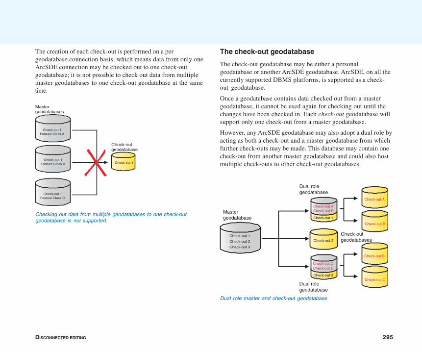
DISCONNECTED EDITING 295
The check-out geodatabase
The check-out geodatabase may be either a personalgeodatabase or another ArcSDE geodatabase. ArcSDE, on all thecurrently supported DBMS platforms, is supported as a check-out geodatabase.
Once a geodatabase contains data checked out from a mastergeodatabase, it cannot be used again for checking out until thechanges have been checked in. Each check-out geodatabase willsupport only one check-out from a master geodatabase.
However, any ArcSDE geodatabase may also adopt a dual role byacting as both a check-out and a master geodatabase from whichfurther check-outs may be made. This database may contain onecheck-out from another master geodatabase and could also hostmultiple check-outs to other check-out geodatabases.
The creation of each check-out is performed on a pergeodatabase connection basis, which means data from only oneArcSDE connection may be checked out to one check-outgeodatabase; it is not possible to check out data from multiplemaster geodatabases to one check-out geodatabase at the sametime.
Checking out data from multiple geodatabases to one check-outgeodatabase is not supported.
Mastergeodatabases
Check-out 1
Check-outgeodatabase
Check-out 1
Check-out 1
Check-out 1Feature Class A
Feature Class B
Feature Class C
Mastergeodatabase
Check-outgeodatabases
Check-out A
Check-out B
Check-out C
Check-out D
Dual rolegeodatabase
Check-out 3
Check-out D
Check-out 2
Check-out 1
Check-out B
Check-out 1
Check-out 2
Check-out 3
Check-out A
Check-out C
Dual rolegeodatabase
Dual role master and check-out geodatabase
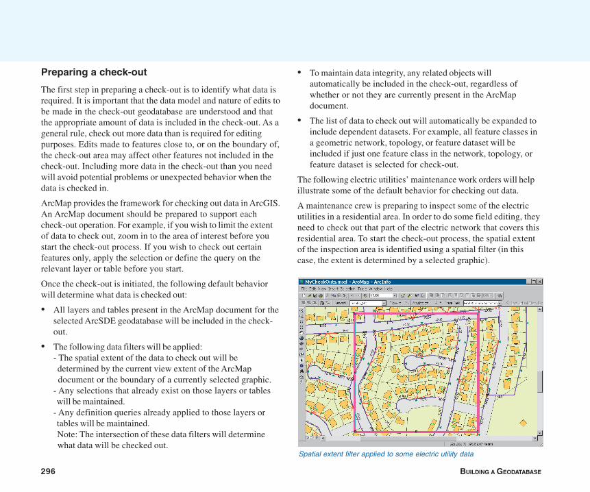
296 BUILDING A GEODATABASE
Preparing a check-out
The first step in preparing a check-out is to identify what data isrequired. It is important that the data model and nature of edits tobe made in the check-out geodatabase are understood and thatthe appropriate amount of data is included in the check-out. As ageneral rule, check out more data than is required for editingpurposes. Edits made to features close to, or on the boundary of,the check-out area may affect other features not included in thecheck-out. Including more data in the check-out than you needwill avoid potential problems or unexpected behavior when thedata is checked in.
ArcMap provides the framework for checking out data in ArcGIS.An ArcMap document should be prepared to support eachcheck-out operation. For example, if you wish to limit the extentof data to check out, zoom in to the area of interest before youstart the check-out process. If you wish to check out certainfeatures only, apply the selection or define the query on therelevant layer or table before you start.
Once the check-out is initiated, the following default behaviorwill determine what data is checked out:
• All layers and tables present in the ArcMap document for theselected ArcSDE geodatabase will be included in the check-out.
• The following data filters will be applied:- The spatial extent of the data to check out will be determined by the current view extent of the ArcMap document or the boundary of a currently selected graphic.- Any selections that already exist on those layers or tables will be maintained.- Any definition queries already applied to those layers or tables will be maintained. Note: The intersection of these data filters will determine what data will be checked out.
• To maintain data integrity, any related objects willautomatically be included in the check-out, regardless ofwhether or not they are currently present in the ArcMapdocument.
• The list of data to check out will automatically be expanded toinclude dependent datasets. For example, all feature classes ina geometric network, topology, or feature dataset will beincluded if just one feature class in the network, topology, orfeature dataset is selected for check-out.
The following electric utilities’ maintenance work orders will helpillustrate some of the default behavior for checking out data.
A maintenance crew is preparing to inspect some of the electricutilities in a residential area. In order to do some field editing, theyneed to check out that part of the electric network that covers thisresidential area. To start the check-out process, the spatial extentof the inspection area is identified using a spatial filter (in thiscase, the extent is determined by a selected graphic).
Spatial extent filter applied to some electric utility data
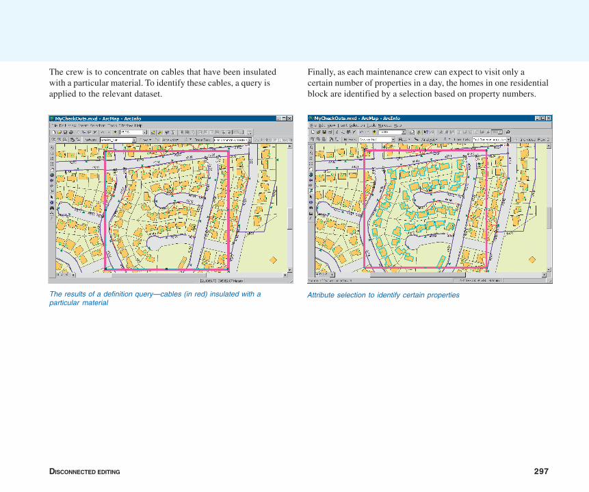
DISCONNECTED EDITING 297
Finally, as each maintenance crew can expect to visit only acertain number of properties in a day, the homes in one residentialblock are identified by a selection based on property numbers.
The crew is to concentrate on cables that have been insulatedwith a particular material. To identify these cables, a query isapplied to the relevant dataset.
The results of a definition query—cables (in red) insulated with aparticular material
Attribute selection to identify certain properties
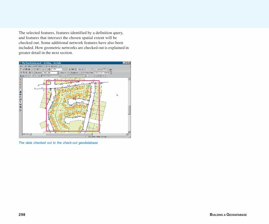
298 BUILDING A GEODATABASE
The selected features, features identified by a definition query,and features that intersect the chosen spatial extent will bechecked out. Some additional network features have also beenincluded. How geometric networks are checked out is explained ingreater detail in the next section.
The data checked out to the check-out geodatabase
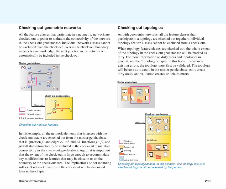
DISCONNECTED EDITING 299
Checking out geometric networks
All the feature classes that participate in a geometric network arechecked out together to maintain the connectivity of the networkin the check-out geodatabase. Individual network classes cannotbe excluded from the check-out. Where the check-out boundaryintersects a network edge, the next junction in the network willautomatically be included in the check-out.
In this example, all the network elements that intersect with thecheck-out extent are checked out from the master geodatabase—that is, junction j2 and edges e1, e7, and e8. Junctions j1, j7, andj4 will also automatically be included in the check-out to maintainconnectivity in the check-out geodatabase. Again, it is importantthat the extent of the check-out is large enough to accommodateany modifications to features that may be close to or on theboundary of the check-out area. The implications of not includingsufficient network features in the check-out will be discussedlater in this chapter.
Checking out topologies
As with geometric networks, all the feature classes thatparticipate in a topology are checked out together; individualtopology feature classes cannot be excluded from a check-out.
When topology feature classes are checked out, the whole extentof the topology in the check-out geodatabase will be marked asdirty. For more information on dirty areas and topologies ingeneral, see the ‘Topology’ chapter in this book. To discoverexisting errors, the topology must first be validated. The topologywill behave as it would in the master geodatabase: edits createdirty areas, and validation creates or deletes errors.
Checking out network features
Master geodatabase
Check out
j8
j5 j6
j1
j2e1
e2e3
j3
j4
j7
e4
e5
e6e7
e8
Check-out geodatabase
j1
e1
j2e7 j4e8
j7
Check-out area
Network edges
Network junctions
Master geodatabase
Check out
Check-out geodatabase
Check-out spatial extent
Property lot
Building
Active dirty area
Error feature
Validation...
Checking out topological data. In this example, one topology rule is ineffect—buildings must be contained by the parcels.
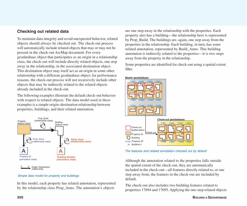
300 BUILDING A GEODATABASE
Checking out related data
To maintain data integrity and avoid unexpected behavior, relatedobjects should always be checked out. The check-out processwill automatically include related objects that may or may not bepresent in the check-out ArcMap document. For everygeodatabase object that participates as an origin in a relationshipclass, the check-out will include directly related objects, one stepaway in the relationship, in the associated destination object.This destination object may itself act as an origin in some otherrelationship with a different geodatabase object; for performancereasons, the check-out process will not recursively include otherobjects that may be indirectly related to the related objectsalready included in the check-out.
The following examples illustrate the default check-out behaviorwith respect to related objects. The data model used in theseexamples is a simple origin–destination relationship betweenproperties, buildings, and their related annotation.
In this model, each property has related annotation, representedby the relationship class Prop_Anno. The annotation’s objects
Although the annotation related to the properties falls outsidethe spatial extent of the check-out, they are automaticallyincluded in the check-out—all features directly related to, or onestep away from, the features in the check-out are included bydefault.
The check-out also includes two building features related toproperties 17694 and 17695. Applying the one-step related objects
are one step away in the relationship with the properties. Eachproperty also has a building—the relationship here is representedby Prop_Build. The buildings are, again, one step away from theproperties in the relationship. Each building, in turn, has somerelated annotation, represented by Build_Anno. This buildingannotation is indirectly related to the properties—it is two stepsaway from the property in the relationship.
Some properties are identified for check-out using a spatial extentfilter.
The features and related annotation checked out by default
Master geodatabase1769117691 1769217692 1769317693 1769417694
1769517695176961769617697176971769817698
1770617706177051770517704177041770317703
Check out
Check-out geodatabase
21
23
191715
252729
1769117691 1769217692 1769317693 1769417694
1769517695176961769617697176971769817698
191715
252729
31 33 35 37
Check-out spatial extent
Property ID
Property lot
Building
Building #21
1770417704
Simple data model for property and buildings
Property(feature class)
Origin–Destinationrelationship
Property ID Building Number(annotation class)
O D
O D
O
D
O
D
Prop_Anno(relationship class)
Build_Anno(relationship class)
Prop_Build(relationship class)
(feature class)Building
(annotation class)
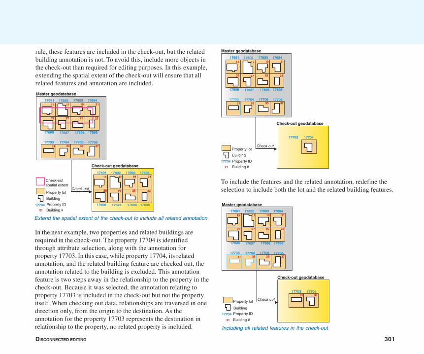
DISCONNECTED EDITING 301
In the next example, two properties and related buildings arerequired in the check-out. The property 17704 is identifiedthrough attribute selection, along with the annotation forproperty 17703. In this case, while property 17704, its relatedannotation, and the related building feature are checked out, theannotation related to the building is excluded. This annotationfeature is two steps away in the relationship to the property in thecheck-out. Because it was selected, the annotation relating toproperty 17703 is included in the check-out but not the propertyitself. When checking out data, relationships are traversed in onedirection only, from the origin to the destination. As theannotation for the property 17703 represents the destination inrelationship to the property, no related property is included.
Master geodatabase
1769117691 1769217692 1769317693 1769417694
1769517695176961769617697176971769817698
1770617706177051770517704177041770317703
Check out
Check-out geodatabase
191715
252729
31 35 37
21
23
17704177041770317703
33
Property ID
Property lot
Building
Building # 21
1770417704
To include the features and the related annotation, redefine theselection to include both the lot and the related building features.
rule, these features are included in the check-out, but the relatedbuilding annotation is not. To avoid this, include more objects inthe check-out than required for editing purposes. In this example,extending the spatial extent of the check-out will ensure that allrelated features and annotation are included.
Master geodatabase1769117691 1769217692 1769317693 1769417694
1769517695176961769617697176971769817698
1770617706177051770517704177041770317703
Check out
Check-out geodatabase
191715
252729
1769117691 1769217692 1769317693 1769417694
1769517695176961769617697176971769817698
191715
252729
31 33 35 37
21
23
21
23
Check-out spatial extent
Property ID
Property lot
Building
Building # 21
1770417704
Extend the spatial extent of the check-out to include all related annotation
Master geodatabase1769117691 1769217692 1769317693 1769417694
1769517695176961769617697176971769817698
1770617706177051770517704177041770317703
Check out
Check-out geodatabase
191715
252729
31 33 35 37
21
23
1770417704177031770331 33
Property ID
Property lot
Building
Building # 21
1770417704
Including all related features in the check-out
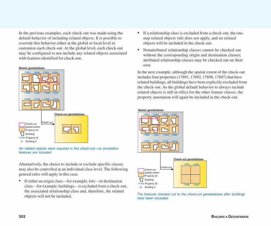
302 BUILDING A GEODATABASE
In the previous examples, each check-out was made using thedefault behavior of including related objects. It is possible tooverride this behavior either at the global or local level tocustomize each check-out. At the global level, each check-outmay be configured to not include any related objects associatedwith features identified for check-out.
Alternatively, the choice to include or exclude specific classesmay also be controlled at an individual class level. The followinggeneral rules will apply in this case:
• If either an origin class—for example, lots—or destinationclass—for example, buildings—is excluded from a check-out,the associated relationship class and, therefore, the relatedobjects will not be included.
• If a relationship class is excluded from a check-out, the one-step related objects rule does not apply, and no relatedobjects will be included in the check-out.
• Nonattributed relationship classes cannot be checked outwithout the corresponding origin and destination classes;attributed relationship classes may be checked out on theirown.
In the next example, although the spatial extent of the check-outincludes four properties (17691, 17692, 17698, 17697) that haverelated buildings, all buildings have been explicitly excluded fromthe check-out. As the global default behavior to always includerelated objects is still in effect for the other feature classes, theproperty annotation will again be included in the check-out.
No related objects were required in this check-out—no annotationfeatures are included.
Master geodatabase
1769117691 1769217692 1769317693 1769417694
1769517695176961769617697176971769817698
1770617706177051770517704177041770317703
Check out
Check-out geodatabase
191715
252729
31 33 35 37
21
23
Property ID
Property lot
Building
Building # 21
Check-out spatial extent
1770417704
The features checked out to the check-out geodatabase after buildingshave been excluded
Master geodatabase
1769117691 1769217692 1769317693 1769417694
1769517695176961769617697176971769817698
1770617706177051770517704177041770317703
Check out
191715
252729
31 33 35 37
21
23
Check-out geodatabase
1769117691 1769217692
17697176971769817698Property ID
Property lot
Building
Building # 21
Check-out spatial extent
1770417704
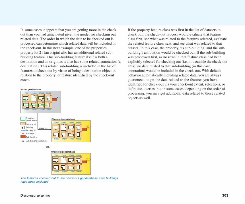
DISCONNECTED EDITING 303
In some cases it appears that you are getting more in the check-out than you had anticipated given the model for checking outrelated data. The order in which the data to be checked out isprocessed can determine which related data will be included inthe check-out. In this next example, one of the properties,property lot 21 (an origin) also has an additional related sub-building feature. This sub-building feature itself is both adestination and an origin as it also has some related annotation (adestination). This related sub-building is included in the list offeatures to check out by virtue of being a destination object inrelation to the property lot feature identified by the check-outextent.
If the property feature class was first in the list of datasets tocheck out, the check-out process would evaluate that featureclass first, see what was related to the features selected, evaluatethe related feature class next, and see what was related to thatdataset. In this case, the property, its sub-building, and the sub-building’s annotation would be checked out. If the sub-buildingwas processed first, as no rows in that feature class had beenexplicitly selected for checking out (i.e., it’s outside the check-outarea), no data related to that sub-building (in this case,annotation) would be included in the check-out. With defaultbehavior automatically including related data, you are alwaysguaranteed to get the data related to the features you haveidentified for check-out via your check-out extent, selections, ordefinition queries, but in some cases, depending on the order ofprocessing, you may get additional data related to those relatedobjects as well.
The features checked out to the check-out geodatabase after buildingshave been excluded
Master geodatabase
check out
1769117691 1769217692 1769317693 1769417694
1769517695176961769617697176971769817698
21
23
191715
252729
Check-out spatial extent
1769917699Property ID
Property lot
Building
Building #21
Sub_building
Sub_building annotationB 2
B 2
Check-out geodatabase
1769117691 1769217692 1769317693 1769417694
1769517695176961769617697176971769817698
191715
252729
21
23
B 2
OR...
Check-out geodatabase
1769117691 1769217692 1769317693 1769417694
1769517695176961769617697176971769817698
191715
252729
21
23
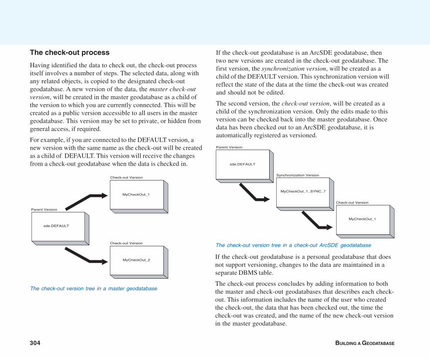
304 BUILDING A GEODATABASE
The check-out process
Having identified the data to check out, the check-out processitself involves a number of steps. The selected data, along withany related objects, is copied to the designated check-outgeodatabase. A new version of the data, the master check-outversion, will be created in the master geodatabase as a child ofthe version to which you are currently connected. This will becreated as a public version accessible to all users in the mastergeodatabase. This version may be set to private, or hidden fromgeneral access, if required.
For example, if you are connected to the DEFAULT version, anew version with the same name as the check-out will be createdas a child of DEFAULT. This version will receive the changesfrom a check-out geodatabase when the data is checked in.
If the check-out geodatabase is an ArcSDE geodatabase, thentwo new versions are created in the check-out geodatabase. Thefirst version, the synchronization version, will be created as achild of the DEFAULT version. This synchronization version willreflect the state of the data at the time the check-out was createdand should not be edited.
The second version, the check-out version, will be created as achild of the synchronization version. Only the edits made to thisversion can be checked back into the master geodatabase. Oncedata has been checked out to an ArcSDE geodatabase, it isautomatically registered as versioned.
sde.DEFAULT
Version
MyCheckOut_1
MyCheckOut_2
Check-out Version
Check-out Version
Parent
The check-out version tree in a master geodatabase
If the check-out geodatabase is a personal geodatabase that doesnot support versioning, changes to the data are maintained in aseparate DBMS table.
The check-out process concludes by adding information to boththe master and check-out geodatabases that describes each check-out. This information includes the name of the user who createdthe check-out, the data that has been checked out, the time thecheck-out was created, and the name of the new check-out versionin the master geodatabase.
sde.DEFAULT
MyCheckOut_1_SYNC_7
MyCheckOut_1
VersionParent
Synchronization Version
Check-out Version
The check-out version tree in a check-out ArcSDE geodatabase
DISCONNECTED EDITING 305
Details about the source of the data, the master geodatabase, arealso recorded. This involves storing partial ArcSDE connectioninformation, which will be used during the check-in process.Usernames and passwords are not stored in the check-outgeodatabase.
Check-out restrictions
There are some important restrictions to remember when checkingout data. First, the version created in the master geodatabaseshould not be edited while the data it represents is still checkedout. As this check-out version in the master geodatabase ispublic and, therefore, editable when created, any changes madeto this version may be overwritten during the check-in process,as no conflict reconciliation is undertaken at this point.
Second, it is not possible to append data to or refresh an existingcheck-out. You cannot check out an updated version of the samedata to a check-out geodatabase while it contains a check-out.You must first check in the original check-out, then make asecond check-out. Once data has been checked back in, thecheck-out geodatabase no longer participates in any check-out/check-in relationship with a master geodatabase. However, it ispossible to reuse a geodatabase for a new check-out. You canreuse the existing schema in a geodatabase to form a template fora second check-out. If the data to be checked out is complex,reusing the schema in a geodatabase will afford someperformance improvements. When creating the new check-out, ifthe geodatabase to be reused contains an older copy of the data,this will be deleted in preparation for receiving the latest copy ofthe data from the master geodatabase. If required, additionalobjects may be included to augment the check-out.
Finally, the check-out model does not support schemamodifications to data that have been checked out. If the schemais altered in any way, either in the master or check-out
geodatabase, for example, by adding a field to a table or featureclass, the check-out is rendered invalid and any attempts to checkin the modified schema and data will fail. If a new table has beencreated in the check-out geodatabase, it will be ignored when therest of the data is checked in.
Managing check-outs
Once a check-out has been created, any subsequentmodifications to the properties of the check-out are madeasynchronously. This means that changes made to the propertiesof a check-out in a master geodatabase are independent of theassociated check-out in the check-out geodatabase and viceversa. For example, if a check-out is unregistered in the mastergeodatabase, this will not unregister the associated check-out inthe check-out geodatabase. Similarly, if a check-out is renamed inthe master geodatabase, that operation does not rename thecheck-out in the check-out geodatabase. The name of a check-outin a master geodatabase does not have to match the name of thecheck-out in the corresponding check-out geodatabase. If acheck-out is renamed in the master but not the check-outgeodatabase, the data can still be checked in.
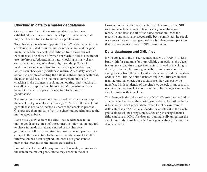
306 BUILDING A GEODATABASE
Checking in data to a master geodatabase
Once a connection to the master geodatabase has beenestablished, such as reconnecting a laptop to a network, datamay be checked back in to the master geodatabase.
Two check-in models are supported; the pull model, in which thecheck-in is initiated from the master geodatabase, and the pushmodel, in which the check-in is initiated from the check-outgeodatabase. The choice of which approach to take is a matter ofuser preference. A data administrator checking in many check-outs to one master geodatabase might use the pull check-inmodel; open one connection to the master geodatabase andlocate each check-out geodatabase in turn. Alternately, once aneditor has completed editing the data in a check-out geodatabase,the push model would be the most convenient option forchecking in the changes; checking out, editing, and checking incan all be accomplished within one ArcMap session withouthaving to reopen a separate connection to the mastergeodatabase.
The master geodatabase does not record the location and type ofthe check-out geodatabase, so for a pull check-in, the check-outgeodatabase has to be located as part of the check-in process.Changes are then pulled in from the check-out geodatabase to themaster geodatabase.
For a push check-in from the check-out geodatabase to themaster geodatabase, most of the connection information requiredto check in the data is already stored in the check-outgeodatabase. All that is required is a username and password tocomplete the connection to the master geodatabase. Once thisinformation has been supplied, the check-out geodatabasepushes the changes to the master geodatabase.
For both check-in models, any user who has write permissions tothe data in the master geodatabase may check in the data.
However, only the user who created the check-out, or the SDEuser, can check data back in to a master geodatabase withreconcile and post as part of the same operation. Once thereconcile and post have successfully been completed, the check-out version in the master geodatabase is deleted—an operationthat requires version owner or SDE permissions.
Delta databases and XML files
If you connect to the master geodatabase via a WAN with lessbandwidth for data transfer or unreliable connections, the check-in can take a long time or get interrupted. Instead of checking indirectly from the check-out geodatabase, you can export thechanges only from the check-out geodatabase to a delta databaseor delta XML file. As delta databases and XML files are smallerthan the original check-out geodatabase, they can easily betransferred independently of the check-out/check-in process to amachine on the same LAN as the server. The changes can then bechecked in from that machine.
The changes in the delta database or XML file may be checked inas a pull check-in from the master geodatabase. As with a check-in from a check-out geodatabase, when the check-in from thedelta database or XML file succeeds, the check-out in the mastergeodatabase will be unregistered. Checking in changes from adelta database or XML file does not automatically unregister thecheck-out in the associated check-out geodatabase; this must bedone manually.
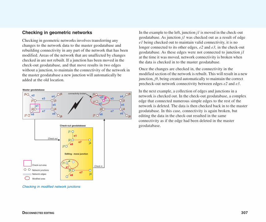
DISCONNECTED EDITING 307
In the example to the left, junction j1 is moved in the check-outgeodatabase. As junction j1 was checked out as a result of edgee1 being checked out to maintain valid connectivity, it is nolonger connected to its other edges, e2 and e3, in the check-outgeodatabase. As these edges were not connected to junction j1at the time it was moved, network connectivity is broken whenthe data is checked in to the master geodatabase.
Once the changes are checked in, the connectivity in themodified section of the network is rebuilt. This will result in a newjunction, j9, being created automatically to maintain the correctprecheck-out network connectivity between edges e2 and e3.
Checking in geometric networks
Checking in geometric networks involves transferring anychanges to the network data to the master geodatabase andrebuilding connectivity in any part of the network that has beenmodified. Areas of the network that are unaffected by changeschecked in are not rebuilt. If a junction has been moved in thecheck-out geodatabase, and that move results in two edgeswithout a junction, to maintain the connectivity of the network inthe master geodatabase a new junction will automatically beadded at the old location.
In the next example, a collection of edges and junctions in anetwork is checked out. In the check-out geodatabase, a complexedge that connected numerous simple edges to the rest of thenetwork is deleted. The data is then checked back in to the mastergeodatabase. In this case, connectivity is again broken, butediting the data in the check-out resulted in the sameconnectivity as if the edge had been deleted in the mastergeodatabase.
Master geodatabase
Check out
Check-out geodatabase
j8
j5 j6
j1
j2e1
e2e3
j3
j4
j7
e4
e5
e6e7
e8
Check in
connectivity broken
j8
j5 j6
j1
j2
e1
e2 e3j3
j4
j7
e4
e5
e6e7
e8
j9
Editing - move junction
j1
e1j2
e8e7 j4
j1
e1
j2e7 j4e8
j7
Check-out area
Network edges
Network junctions
Modified area
Checking in modified network junctions
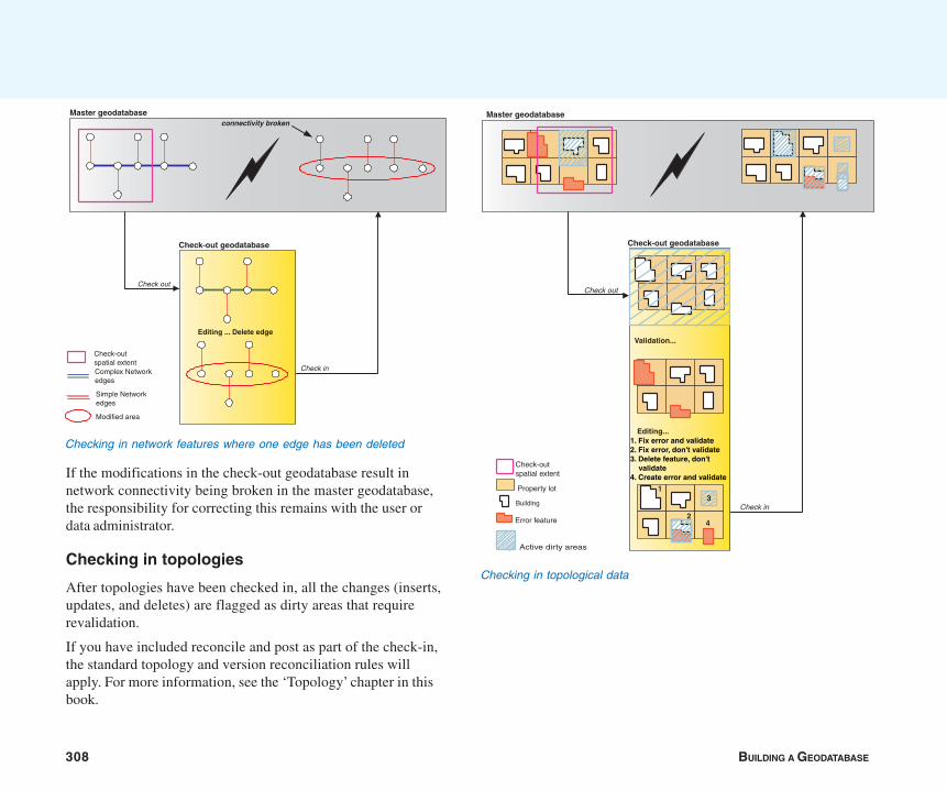
308 BUILDING A GEODATABASE
If the modifications in the check-out geodatabase result innetwork connectivity being broken in the master geodatabase,the responsibility for correcting this remains with the user ordata administrator.
Checking in topologies
After topologies have been checked in, all the changes (inserts,updates, and deletes) are flagged as dirty areas that requirerevalidation.
If you have included reconcile and post as part of the check-in,the standard topology and version reconciliation rules willapply. For more information, see the ‘Topology’ chapter in thisbook.
Master geodatabase
Check out
Check-out geodatabase
Check in
connectivity broken
Editing ... Delete edge
Simple Network edges
Modified area
Complex Network edges
Check-out spatial extent
Checking in network features where one edge has been deleted
Master geodatabase
Check out
Active dirty areas
Check-out spatial extent
Property lot
Building
Error feature
Check in
Check-out geodatabase
Validation...
Editing...
1
24
1. Fix error and validate 2. Fix error, don't validate 3. Delete feature, don't validate 4. Create error and validate
3
Checking in topological data
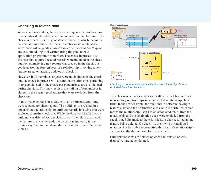
DISCONNECTED EDITING 309
Checking in related data
When checking in data, there are some important considerationsto remember if related data was not included in the check-out. Thecheck-in process is a full geodatabase check-in, which means theprocess assumes that edits made in a check-out geodatabasewere made with a geodatabase-aware editor, such as ArcMap, orany custom editing tool written using the geodatabaseapplication programming interface. The check-in process alsoassumes that required related records were included in the check-out. For example, if a new feature was created in the check-outgeodatabase, the foreign keys of a relationship involving a newfeature are automatically updated on check-in.
However, if all the related objects were not included in the check-out, the check-in process will ensure that relationships pertainingto objects deleted in the check-out geodatabase are also deletedduring check-in. This may result in the nulling of foreign keys inclasses in the master geodatabase that were excluded from thecheck-out.
In this first example, some features in an origin class, buildings,were selected for checking out. The buildings are related, in anonattributed relationship, to attribute records in a table that wereexcluded from the check-out. While the data was checked out, abuilding was deleted. On check-in, to void the relationship withthe feature that was deleted, the corresponding entry in theforeign key field in the related destination class, the table, is setto NULL.
This check-in behavior may also result in the deletion of rowsrepresenting relationships in an attributed relationship classtable. In the next example, the relationship between the originfeature class and the destination class table is attributed, whichmeans the relationship itself has an associated table. Both therelationship and the destination class were excluded from thecheck-out. Edits made to the origin feature class resulted in onefeature being deleted. On check-in, the row in the attributedrelationship class table representing this feature’s relationship toan object in the destination class is removed.
Only relationships are deleted on check-in; related objectsthemselves are never deleted.
Master geodatabase
Check-out geodatabase
Editing...delete feature
Check in
Check out
FID 1 FID 2
FID 3
ObjectID FKeyID1
34
2
512
3 FID 1 FID 2
Modified area
Property
Building
ObjectID FKeyID1
34
2
15
2
<NULL>
Origin class
Destination class
Origin class
Destination class
Checking in nonattributed relationships when related objects wereexcluded from the check-out
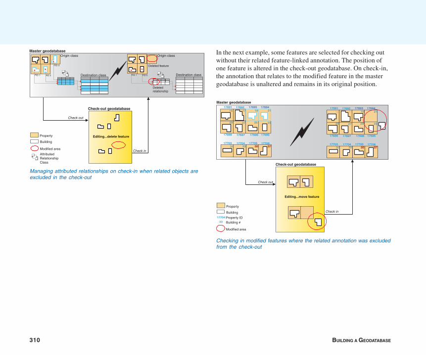
310 BUILDING A GEODATABASE
In the next example, some features are selected for checking outwithout their related feature-linked annotation. The position ofone feature is altered in the check-out geodatabase. On check-in,the annotation that relates to the modified feature in the mastergeodatabase is unaltered and remains in its original position.
Managing attributed relationships on check-in when related objects areexcluded in the check-out
Master geodatabase
Check-out geodatabase
Editing...delete feature
Check in
Check out
FID 1 FID 2
FID 3
FID 1 FID 2
Modified area
Property
Building
AttributedRelationshipClass
Deleted feature
Origin class
Destination class
Deleted relationship
++
++
++
++++
++
Origin class
Destination class
Master geodatabase
Check out
Check-out geodatabase
Editing...move feature
Check in
17691 17692 17693 17694
17695176961769717698
17706177051770417703
191715
252729
31 33 3535 3737
21
23
17691 17692 17693 17694
17695176961769717698
17706177051770417703
191715
252729
31 33 3535 3737
21
23
Property ID
Property
Building
Modified area
17704
33 Building #
Checking in modified features where the related annotation was excludedfrom the check-out
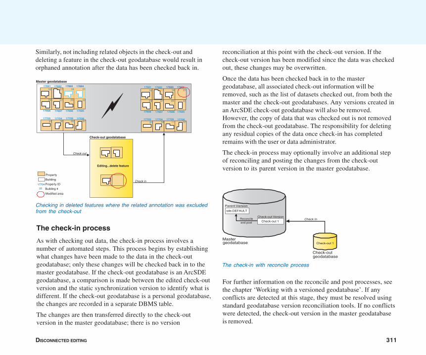
DISCONNECTED EDITING 311
Similarly, not including related objects in the check-out anddeleting a feature in the check-out geodatabase would result inorphaned annotation after the data has been checked back in.
The check-in process
As with checking out data, the check-in process involves anumber of automated steps. This process begins by establishingwhat changes have been made to the data in the check-outgeodatabase; only these changes will be checked back in to themaster geodatabase. If the check-out geodatabase is an ArcSDEgeodatabase, a comparison is made between the edited check-outversion and the static synchronization version to identify what isdifferent. If the check-out geodatabase is a personal geodatabase,the changes are recorded in a separate DBMS table.
The changes are then transferred directly to the check-outversion in the master geodatabase; there is no version
reconciliation at this point with the check-out version. If thecheck-out version has been modified since the data was checkedout, these changes may be overwritten.
Once the data has been checked back in to the mastergeodatabase, all associated check-out information will beremoved, such as the list of datasets checked out, from both themaster and the check-out geodatabases. Any versions created inan ArcSDE check-out geodatabase will also be removed.However, the copy of data that was checked out is not removedfrom the check-out geodatabase. The responsibility for deletingany residual copies of the data once check-in has completedremains with the user or data administrator.
The check-in process may optionally involve an additional stepof reconciling and posting the changes from the check-outversion to its parent version in the master geodatabase.
For further information on the reconcile and post processes, seethe chapter ‘Working with a versioned geodatabase’. If anyconflicts are detected at this stage, they must be resolved usingstandard geodatabase version reconciliation tools. If no conflictswere detected, the check-out version in the master geodatabaseis removed.
Master geodatabase
Check out
Check-out geodatabase
Editing...delete feature
Check in
17691 17692 17693 17694
17695176961769717698
17706177051770417703
191715
252729
31 33 35 37
21
23
17691 17692 17693 17694
17695176961769717698
17706177051770417703
191715
252729
31 33 35 37
21
23
Property ID
Property
Building
Modified area
17704
25 Building #
Checking in deleted features where the related annotation was excludedfrom the check-out
The check-in with reconcile process
Mastergeodatabase
Check-outgeodatabase
Check-out 1
Check In
Parent Version
Reconcileand post
sde.DEFAULT
Check-out Version
Check-out 1

312 BUILDING A GEODATABASE
Working with ArcGIS 8.3 and 9 geodatabases
Geodatabases built using previous versions of ArcGIS do notsupport some of the newer functions of ArcGIS. Consequently, ifyour organization has both ArcGIS 8.3 and 9 geodatabases,consider the following:
• You can check out and check in between geodatabases of thesame version. With ArcGIS 9 for example, you can check outand check in between an 8.3 master geodatabase and an 8.3check-out geodatabase.
• You can check out and check in between an 8.3 mastergeodatabase and a 9 check-out geodatabase. When editingthe check-out geodatabase, be careful not to introduce editsthat are not supported in 8.3. For example, annotation classeswere introduced in 9 and, therefore, are not supported in 8.3.
• You cannot check out from a 9 geodatabase to an 8.3geodatabase, since 9 geodatabases support data types that8.3 geodatabases do not. Similarly, you cannot check in froman 8.3 geodatabase to a 9 geodatabase.
• If you check out to an 8.3 geodatabase and upgrade themaster geodatabase to 9, you will need to upgrade the check-out geodatabase before checking in. If checking in from adelta file, you will need to upgrade the check-out geodatabaseand reexport the delta file.
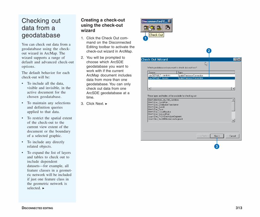
DISCONNECTED EDITING 313
Checking outdata from ageodatabaseYou can check out data from ageodatabase using the check-out wizard in ArcMap. Thewizard supports a range ofdefault and advanced check-outoptions.
The default behavior for eachcheck-out will be:
• To include all the data,visible and invisible, in theactive document for thechosen geodatabase.
• To maintain any selectionsand definition queriesapplied to that data.
• To restrict the spatial extentof the check-out to thecurrent view extent of thedocument or the boundaryof a selected graphic.
• To include any directlyrelated objects.
• To expand the list of layersand tables to check out toinclude dependentdatasets—for example, allfeature classes in a geomet-ric network will be includedif just one feature class inthe geometric network isselected. u
Creating a check-outusing the check-outwizard
1. Click the Check Out com-mand on the DisconnectedEditing toolbar to activate thecheck-out wizard in ArcMap.
2. You will be prompted tochoose which ArcSDEgeodatabase you want towork with if the currentArcMap document includesdata from more than onegeodatabase. You can onlycheck out data from oneArcSDE geodatabase at atime.
3. Click Next. u
1
2
3
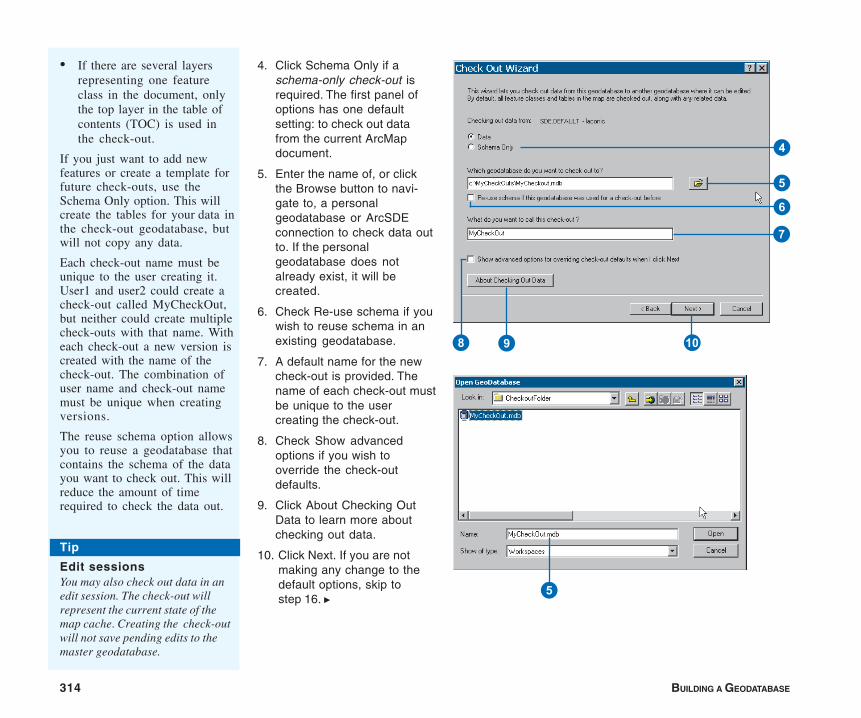
314 BUILDING A GEODATABASE
4. Click Schema Only if aschema-only check-out isrequired. The first panel ofoptions has one defaultsetting: to check out datafrom the current ArcMapdocument.
5. Enter the name of, or clickthe Browse button to navi-gate to, a personalgeodatabase or ArcSDEconnection to check data outto. If the personalgeodatabase does notalready exist, it will becreated.
6. Check Re-use schema if youwish to reuse schema in anexisting geodatabase.
7. A default name for the newcheck-out is provided. Thename of each check-out mustbe unique to the usercreating the check-out.
8. Check Show advancedoptions if you wish tooverride the check-outdefaults.
9. Click About Checking OutData to learn more aboutchecking out data.
10. Click Next. If you are notmaking any change to thedefault options, skip tostep 16. u
• If there are several layersrepresenting one featureclass in the document, onlythe top layer in the table ofcontents (TOC) is used inthe check-out.
If you just want to add newfeatures or create a template forfuture check-outs, use theSchema Only option. This willcreate the tables for your data inthe check-out geodatabase, butwill not copy any data.
Each check-out name must beunique to the user creating it.User1 and user2 could create acheck-out called MyCheckOut,but neither could create multiplecheck-outs with that name. Witheach check-out a new version iscreated with the name of thecheck-out. The combination ofuser name and check-out namemust be unique when creatingversions.
The reuse schema option allowsyou to reuse a geodatabase thatcontains the schema of the datayou want to check out. This willreduce the amount of timerequired to check the data out.
4
6
5
7
9 Q8
5
Tip
Edit sessionsYou may also check out data in anedit session. The check-out willrepresent the current state of themap cache. Creating the check-outwill not save pending edits to themaster geodatabase.

DISCONNECTED EDITING 315
11. Click the appropriate extentoption to modify the spatialextent of the check-out.
12. Uncheck the check boxassociated with that layer ortable to exclude individuallayers or tables from thecheck-out.
13. Each entry in the Check Outcolumn is a combo box ofoptions. The options alwaysinclude All Features andSchema Only. If a particularlayer or table has a selectionset or definition querydefined, the options mayalso include SelectedFeatures Only, All Featuresin Def. Query, and SelectedFeatures in Def. Query.Select the All Featuresoption and uncheck the UseSpatial Extent check box ifyou do not wish to apply anydata filters.
14. Uncheck the Check outrelated data check box if youdo not wish to check out anyrelated data.
15. Click Next. u
Customizing acheck-outThe advanced check-outoptions allow you to customizethe check-out. The advancedpanel will initially reflect thecurrent check-out defaults andthe expanded list of all thedatasets that will be included inthis check-out. Any data that isnot versioned or for which youdo not have read–write permis-sions will be automaticallyexcluded from the list.
The extent of the check-outarea may be determined by oneof the following:
• The current view extent (thedefault)
• The full extent of the data
• The boundary of a currentlyselected graphic
• User-defined coordinates
If a schema-only check-out wasselected previously, this topsection will be unavailable.
The options in the grid deter-mine how many records fromeach layer or table will bechecked out. In addition toexcluding layers and tables fromthe list of data to check out,you may also override thedefaults for individual layersand tables. For example, if aselection set exists for a u
T
E
W
R
Y
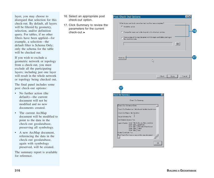
316 BUILDING A GEODATABASE
layer, you may choose todisregard that selection for thischeck-out. By default, all layerswill be filtered by geometry,selection, and/or definitionquery. For tables, if no otherfilters have been applied—forexample, a selection—thedefault filter is Schema Only;only the schema for the tablewill be checked out.
If you wish to exclude ageometric network or topologyfrom a check-out, you mustexclude all the participatinglayers; including just one layerwill result in the whole networkor topology being checked out.
The final panel includes somepost check-out options:
• No further action (thedefault)—the currentdocument will not bemodified and no newdocuments created.
• The current ArcMapdocument will be modified topoint to the data in thecheck-out geodatabase,preserving all symbology.
• A new ArcMap document,referencing the data in thecheck-out geodatabase,again with symbologypreserved, will be created.
The summary report is availablefor reference.
16. Select an appropriate postcheck-out option.
17. Click Summary to review theparameters for the currentcheck-out. u
I
U
I
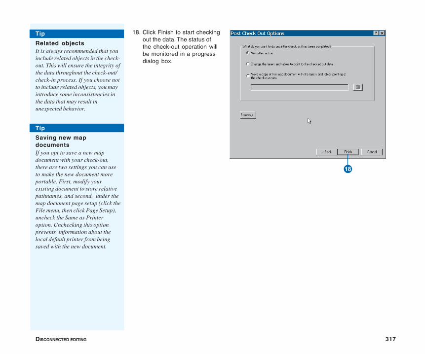
DISCONNECTED EDITING 317
18. Click Finish to start checkingout the data. The status ofthe check-out operation willbe monitored in a progressdialog box.
O
Tip
Saving new mapdocumentsIf you opt to save a new mapdocument with your check-out,there are two settings you can useto make the new document moreportable. First, modify yourexisting document to store relativepathnames, and second, under themap document page setup (click theFile menu, then click Page Setup),uncheck the Same as Printeroption. Unchecking this optionprevents information about thelocal default printer from beingsaved with the new document.
Tip
Related objectsIt is always recommended that youinclude related objects in the check-out. This will ensure the integrity ofthe data throughout the check-out/check-in process. If you choose notto include related objects, you mayintroduce some inconsistencies inthe data that may result inunexpected behavior.
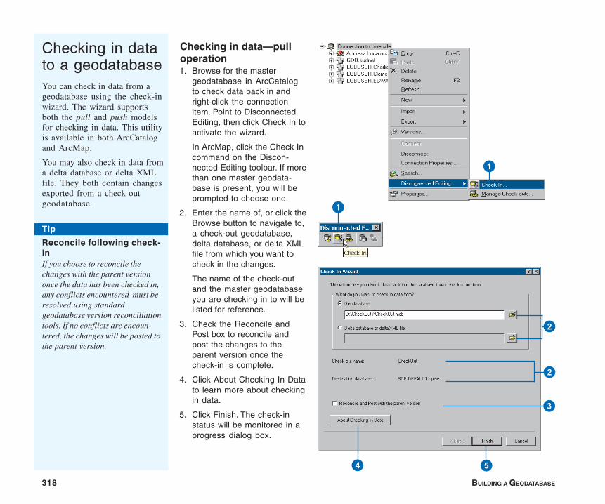
318 BUILDING A GEODATABASE
Checking in datato a geodatabaseYou can check in data from ageodatabase using the check-inwizard. The wizard supportsboth the pull and push modelsfor checking in data. This utilityis available in both ArcCatalogand ArcMap.
You may also check in data froma delta database or delta XMLfile. They both contain changesexported from a check-outgeodatabase.
Checking in data—pulloperation1. Browse for the master
geodatabase in ArcCatalogto check data back in andright-click the connectionitem. Point to DisconnectedEditing, then click Check In toactivate the wizard.
In ArcMap, click the Check Incommand on the Discon-nected Editing toolbar. If morethan one master geodata-base is present, you will beprompted to choose one.
2. Enter the name of, or click theBrowse button to navigate to,a check-out geodatabase,delta database, or delta XMLfile from which you want tocheck in the changes.
The name of the check-outand the master geodatabaseyou are checking in to will belisted for reference.
3. Check the Reconcile andPost box to reconcile andpost the changes to theparent version once thecheck-in is complete.
4. Click About Checking In Datato learn more about checkingin data.
5. Click Finish. The check-instatus will be monitored in aprogress dialog box.
1
4 5
2
3
2
Tip
Reconcile following check-inIf you choose to reconcile thechanges with the parent versiononce the data has been checked in,any conflicts encountered must beresolved using standardgeodatabase version reconciliationtools. If no conflicts are encoun-tered, the changes will be posted tothe parent version.
1

DISCONNECTED EDITING 319
Checking in data—pushoperation
1. Select your check-outgeodatabase in ArcCatalogand right-click the databaseobject. Point to DisconnectedEditing, then click Check In.
In ArcMap, click the Check Incommand on the Discon-nected Editing toolbar. Ifmore than one check-outgeodatabase is present inyour document, you will beprompted to choose one.
The name of the check-outand the master geodatabaseyou are checking in to will belisted for reference.
2. Check the Reconcile andPost box if you want toreconcile and post thechanges to the parentversion once the check-in iscomplete.
3. Click About Checking InData to learn more aboutchecking in data.
4. Click Finish. u
1
1
2
3 4
2

320 BUILDING A GEODATABASE
5. Supply the necessaryinformation to complete theconnection to the mastergeodatabase in the SDEconnection dialog box.
6. Click OK. The status of thecheck-in will be monitored ina progress dialog box.
6
5
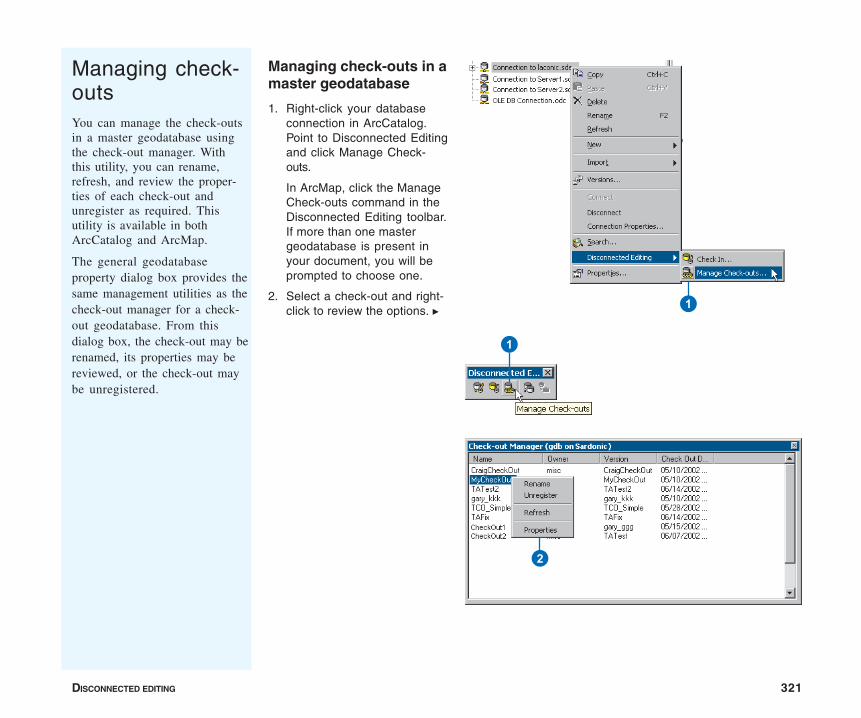
DISCONNECTED EDITING 321
Managing check-outsYou can manage the check-outsin a master geodatabase usingthe check-out manager. Withthis utility, you can rename,refresh, and review the proper-ties of each check-out andunregister as required. Thisutility is available in bothArcCatalog and ArcMap.
The general geodatabaseproperty dialog box provides thesame management utilities as thecheck-out manager for a check-out geodatabase. From thisdialog box, the check-out may berenamed, its properties may bereviewed, or the check-out maybe unregistered.
Managing check-outs in amaster geodatabase
1. Right-click your databaseconnection in ArcCatalog.Point to Disconnected Editingand click Manage Check-outs.
In ArcMap, click the ManageCheck-outs command in theDisconnected Editing toolbar.If more than one mastergeodatabase is present inyour document, you will beprompted to choose one.
2. Select a check-out and right-click to review the options. u 1
1
2
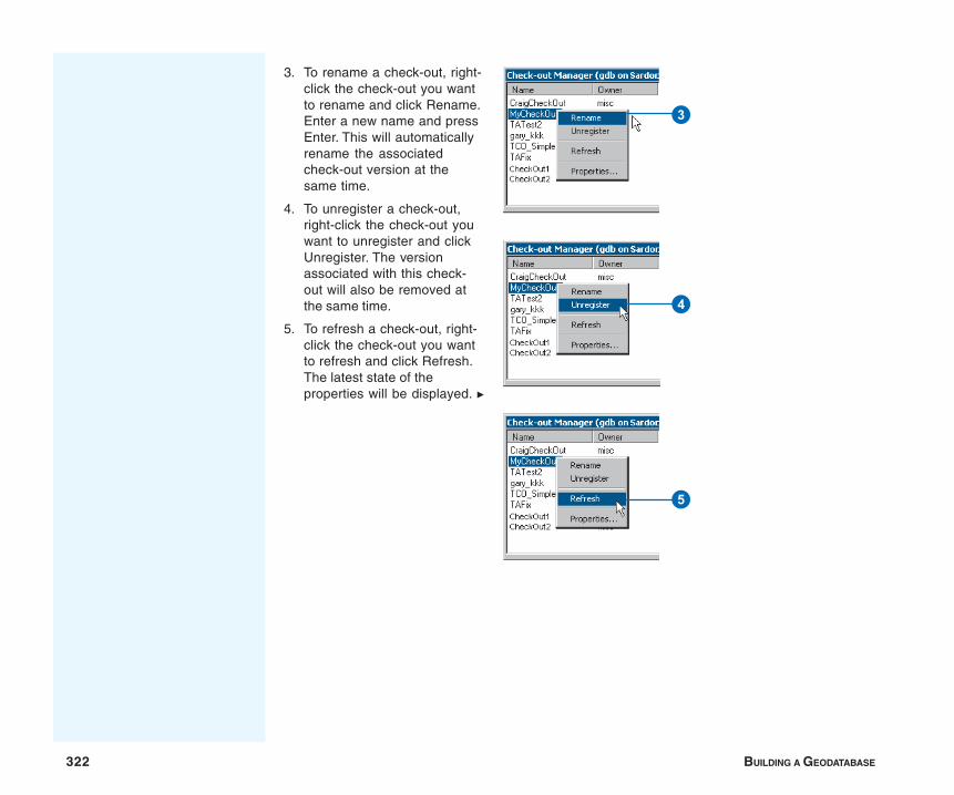
322 BUILDING A GEODATABASE
3. To rename a check-out, right-click the check-out you wantto rename and click Rename.Enter a new name and pressEnter. This will automaticallyrename the associatedcheck-out version at thesame time.
4. To unregister a check-out,right-click the check-out youwant to unregister and clickUnregister. The versionassociated with this check-out will also be removed atthe same time.
5. To refresh a check-out, right-click the check-out you wantto refresh and click Refresh.The latest state of theproperties will be displayed. u
3
4
5

DISCONNECTED EDITING 323
6. Right-click the check-out andclick Properties to view theproperties of a check-out. Theproperties include informa-tion on when the check-outwas created, who created it,and the associated check-outversion. A full list of the datachecked out is also included.
6
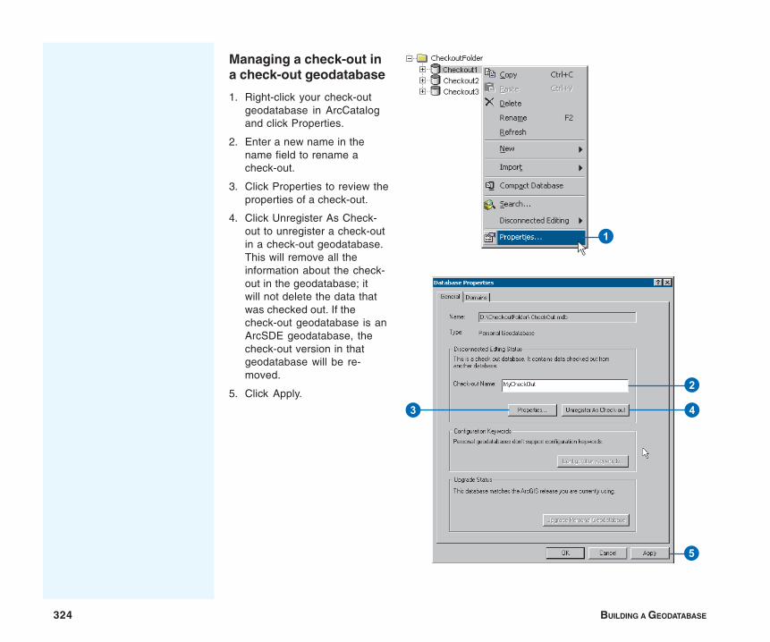
324 BUILDING A GEODATABASE
Managing a check-out ina check-out geodatabase
1. Right-click your check-outgeodatabase in ArcCatalogand click Properties.
2. Enter a new name in thename field to rename acheck-out.
3. Click Properties to review theproperties of a check-out.
4. Click Unregister As Check-out to unregister a check-outin a check-out geodatabase.This will remove all theinformation about the check-out in the geodatabase; itwill not delete the data thatwas checked out. If thecheck-out geodatabase is anArcSDE geodatabase, thecheck-out version in thatgeodatabase will be re-moved.
5. Click Apply.
1
2
3 4
5
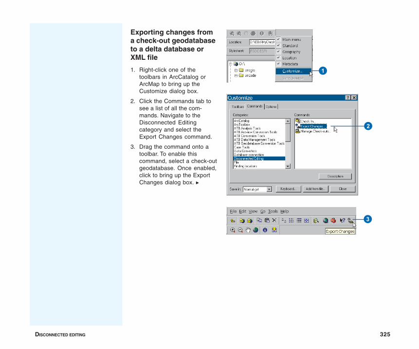
DISCONNECTED EDITING 325
Exporting changes froma check-out geodatabaseto a delta database orXML file
1. Right-click one of thetoolbars in ArcCatalog orArcMap to bring up theCustomize dialog box.
2. Click the Commands tab tosee a list of all the com-mands. Navigate to theDisconnected Editingcategory and select theExport Changes command.
3. Drag the command onto atoolbar. To enable thiscommand, select a check-outgeodatabase. Once enabled,click to bring up the ExportChanges dialog box. u
1
2
3
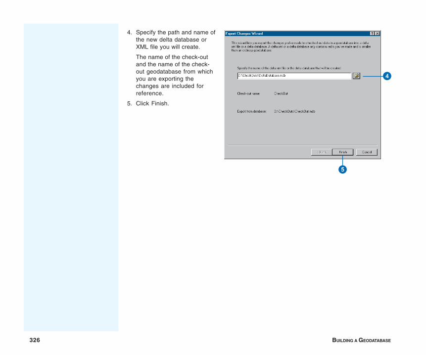
326 BUILDING A GEODATABASE
4. Specify the path and name ofthe new delta database orXML file you will create.
The name of the check-outand the name of the check-out geodatabase from whichyou are exporting thechanges are included forreference.
5. Click Finish.
5
4
IN THIS CHAPTER
327
Building a raster geodatabase 12• Rasters and the geodatabase
• Importing and loading raster data
• Attributes of type raster
• Converting raster formats
• Mosaicking raster datasets
• Raster data and disconnectedediting
• More about rasters in ArcGIS
Raster data comes in many forms, and the pixels they contain describemany different types of phenomena. Each pixel contains informationdescribing the spatial area it represents. These pixels can depict manydifferent types of information, such as a reflectance value (that is, ameasure of light) or a thematic value (for example, land use type). Whengrouped together, these pixels create images depicting information that canbe used in analysis or as a backdrop to a map. Raster images canoriginate from satellite imagery, aerial photography, scanned images, or asthe result of analysis, using calculations such as surface interpolation,slope, hillshades, or aspect.
This chapter will discuss raster-related tasks and concepts within therealm of geodatabases. After reading this chapter, you will be able tocreate and manage your raster data in both a personal and ArcSDEgeodatabase.
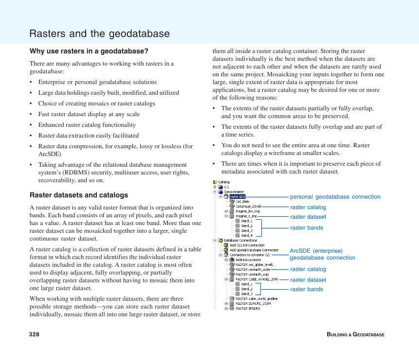
328 BUILDING A GEODATABASE
Rasters and the geodatabase
Why use rasters in a geodatabase?
There are many advantages to working with rasters in ageodatabase:
• Enterprise or personal geodatabase solutions
• Large data holdings easily built, modified, and utilized
• Choice of creating mosaics or raster catalogs
• Fast raster dataset display at any scale
• Enhanced raster catalog functionality
• Raster data extraction easily facilitated
• Raster data compression, for example, lossy or lossless (forArcSDE)
• Taking advantage of the relational database managementsystem’s (RDBMS) security, multiuser access, user rights,recoverability, and so on.
Raster datasets and catalogs
A raster dataset is any valid raster format that is organized intobands. Each band consists of an array of pixels, and each pixelhas a value. A raster dataset has at least one band. More than oneraster dataset can be mosaicked together into a larger, singlecontinuous raster dataset.
A raster catalog is a collection of raster datasets defined in a tableformat in which each record identifies the individual rasterdatasets included in the catalog. A raster catalog is most oftenused to display adjacent, fully overlapping, or partiallyoverlapping raster datasets without having to mosaic them intoone large raster dataset.
When working with multiple raster datasets, there are threepossible storage methods—you can store each raster datasetindividually, mosaic them all into one large raster dataset, or store
them all inside a raster catalog container. Storing the rasterdatasets individually is the best method when the datasets arenot adjacent to each other and when the datasets are rarely usedon the same project. Mosaicking your inputs together to form onelarge, single extent of raster data is appropriate for mostapplications, but a raster catalog may be desired for one or moreof the following reasons:
• The extents of the raster datasets partially or fully overlap,and you want the common areas to be preserved.
• The extents of the raster datasets fully overlap and are part ofa time series.
• You do not need to see the entire area at one time. Rastercatalogs display a wireframe at smaller scales.
• There are times when it is important to preserve each piece ofmetadata associated with each raster dataset.
personal geodatabase connection
raster dataset
ArcSDE (enterprise)geodatabase connection
raster catalog
raster dataset
raster catalog
raster bands
raster bands
BUILDING A RASTER GEODATABASE 329
Rasters can also be an attribute to a feature. This means that afield of type raster can exist as one of the columns within afeature class. This is similar to having a hyperlink of a file-basedimage in a field, except the raster image is stored and protectedwithin the geodatabase.
Enterprise or personal geodatabase?
Raster data stored within the ArcSDE database offers anenterprise level of functionality, such as security, multiuseraccess, data sharing, and so on. Raster data is imported intoArcSDE and rebuilt as ArcSDE raster data, so it can be accessedfrom the underlying database in the most efficient manner.Because of its new storage structure, the raster data is said to bemanaged, or fully controlled, by the geodatabase.
In the personal geodatabase, the raster data is always stored asreferenced raster dataset files on disk. The personal geodatabasecan either manage or not manage the raster data it is referencing.When the raster data is managed, it is converted from its originallocation and format into an ERDAS IMAGINE (.img) file inside aspecial folder located next to the personal geodatabase. Deletingmanaged raster data deletes the associated ERDAS IMAGINEfiles, which are stored in the special raster geodatabase folder.
The personal geodatabase can also reference raster dataset filesof any supported format from their existing location withouthaving to manage the files. This type of reference does notrequire the raster data to be imported, and it can significantlysave time. Prototyping is easily done using the nonmanagedapproach, but because of its nonmanaged nature, there ispotential insecurity in this scenario. Deleting a row (rasterdataset) of a nonmanaged geodatabase will not delete thereferenced raster files.
Because personal geodatabase raster datasets are likely to haveadditional data mosaicked into them, they are always managed by
the geodatabase. However, raster catalogs and raster attributesstored in a personal geodatabase can either be designated asmanaged or nonmanaged geodatabase entities.
A personal geodatabase is good for the following reasons:
• Raster catalogs can be managed or unmanaged.
• It works well to allow for quick raster catalog prototyping.
• Only a moderate number of users read the data.
• It does not involve an enterprise RDBMS; therefore, there is alower cost for maintenance, administration, and the RDBMSitself.
• You do not already have an ArcSDE geodatabase, or you donot need its higher performance.
An ArcSDE enterprise geodatabase is good for these reasons:
• It has the best display performance on large raster datasets(can be multiple terabytes of data).
• It is the preferred option for raster dataset mosaics, whichgrow larger than 2 GB (uncompressed).
• It allows multiuser access for updating and reading.
• It allows for incremental updates.
• It allows for lossy or lossless compression.
• If you already use ArcSDE, then it is recommended that youmake the best use of it by adding raster data, thus creatingcentralized data storage.
Importing rasters
Raster data is imported into a geodatabase via the user interfacein several ways. Raster data can be imported into either apersonal or enterprise geodatabase using the Import contextmenu by clicking a geodatabase workspace. Data can also be
330 BUILDING A GEODATABASE
Enterprise geodatabase raster storage
In the enterprise geodatabase, raster data is stored in a structurewhere the data is tiled, indexed, pyramided, and most oftencompressed. Because of tiling, indexing, and pyramiding, eachtime the raster data is queried, only the tiles necessary to satisfythe extent and resolution of the query are returned, instead of thewhole dataset. Compression, which is highly recommended,reduces the amount of data transferred between the client and theserver, making it possible to store large, seamless raster datasetsand raster catalogs as large as several terabytes and serve themquickly to a client for display.
There are several storage parameters from which you can choosewhen storing enterprise geodatabase raster data: pyramids, tilesize, and data compression.
Pyramids are reduced resolution representations of your datasetused to improve performance. Pyramids can speed up the displayof raster data because the server returns only the data at aspecified resolution that is required for the display. Pyramids arecreated by resampling the original data into several differentlayers, each representing an increasingly larger resolution. Theresampling methods instruct the server how to resample the datato build the pyramids. Nearest neighbor should be used fornominal data or raster datasets with color maps, such as land useor pseudocolor images. Bilinear interpolation or cubic
convolution should be used for continuous data such as satelliteimagery or aerial photography. Prototyping the most appropriateresampling technique for your particular data is highlyrecommended. Remember that pyramid resampling only affectsthe display, not the original data.
The tile size controls the number of pixels you want to store ineach database memory block. This is specified as a number ofpixels. The default tile size is 128 by 128, and most applications donot warrant deviating from these default values.
Data compression compresses the tiles of raster data beforestoring them in the geodatabase. The compression used can belossy (JPEG and JPEG 2000) or lossless (LZ77). Losslesscompression means the values of cells in the raster dataset willnot be changed. The amount of compression will depend on thetype of pixel data; the more homogeneous the image, the higherthe compression ratio.
The primary benefit of compressing your data is that it requiresless storage space. An added benefit is the overwhelminglyimproved performance, because you are transferring fewerpackets of data from the server to the client application.
Lossy compression should be chosen for the following reasons:
• If the rasters are only background images, and there will be noanalysis on the raster data.
• Data loading and retrieval are faster.
• Less storage space is needed since the compression ratios canbe 5:1 or 10:1 (choose JPEG 2000 for higher compression ratiossuch as 10:1 or 20:1).
Lossless compression should be chosen for the followingreasons:
• The raster datasets are to be used for deriving new data oreven visual analysis.
loaded into a raster dataset or raster catalog in a geodatabasewith the Load Data context menu choice found in ArcCatalog.The Copy Raster geoprocessing tool can be used to import rasterdata. Finally, raster data can be loaded into the ArcSDE enterprisegeodatabase using the SDERASTER command line loader. Themost efficient way to load many raster datasets to thegeodatabase is to use geoprocessing scripting and SDERasterbatch files (ArcSDE only) within ArcObjects™ programming.
BUILDING A RASTER GEODATABASE 331
• The compression required is only between 1:1 and 3:1.
• You don’t plan to retain the original data.
• Your inputs are already lossy compressed.
Although the enterprise geodatabase storage can accommodateraster data without compression, compression is recommended. Ifyou are unsure of which to use, always use the default of LZ77(lossless).
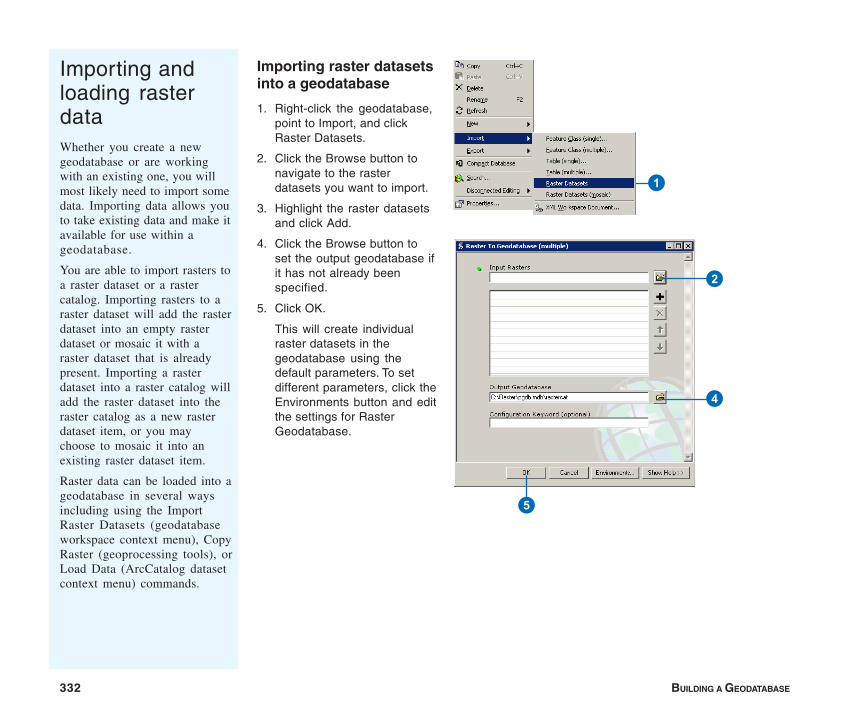
332 BUILDING A GEODATABASE
Importing raster datasetsinto a geodatabase
1. Right-click the geodatabase,point to Import, and clickRaster Datasets.
2. Click the Browse button tonavigate to the rasterdatasets you want to import.
3. Highlight the raster datasetsand click Add.
4. Click the Browse button toset the output geodatabase ifit has not already beenspecified.
5. Click OK.
This will create individualraster datasets in thegeodatabase using thedefault parameters. To setdifferent parameters, click theEnvironments button and editthe settings for RasterGeodatabase.
Importing andloading rasterdataWhether you create a newgeodatabase or are workingwith an existing one, you willmost likely need to import somedata. Importing data allows youto take existing data and make itavailable for use within ageodatabase.
You are able to import rasters toa raster dataset or a rastercatalog. Importing rasters to araster dataset will add the rasterdataset into an empty rasterdataset or mosaic it with araster dataset that is alreadypresent. Importing a rasterdataset into a raster catalog willadd the raster dataset into theraster catalog as a new rasterdataset item, or you maychoose to mosaic it into anexisting raster dataset item.
Raster data can be loaded into ageodatabase in several waysincluding using the ImportRaster Datasets (geodatabaseworkspace context menu), CopyRaster (geoprocessing tools), orLoad Data (ArcCatalog datasetcontext menu) commands.
1
4
2
5

BUILDING A RASTER GEODATABASE 333
Creating an empty rasterdataset in a personalgeodatabase
1. Right-click the personalgeodatabase, point to New,then click Raster Dataset.
2. Make sure that the outputgeodatabase is correct. Ifnot, navigate to the propergeodatabase.
3. Type in the name of the newraster dataset. No extensionis needed, since it will bestored in a geodatabase.
4. Set the cell size of thegeodatabase raster dataset.If you do not specify a cellsize, the cell size of the rasterdataset that you load into itwill be used.
5. Set the pixel type for thegeodatabase raster dataset.
6. Click the Browse button toset the spatial coordinatesystem.
7. Type the number of bandsthat the raster dataset willcontain.
8. Click OK.
Tip
Load raster data into anempty raster datasetOnce an empty raster dataset iscreated, you can load raster datainto it.
Tip
The raster databasenaming conventionThe raster dataset name cannothave spaces. You can use under-scores to separate letters.
1
2
3
4
5
6
7
8
Tip
Blank spatial referenceIf you leave the spatial referenceblank, the raster dataset will usethe spatial reference of the rasterthat you load.
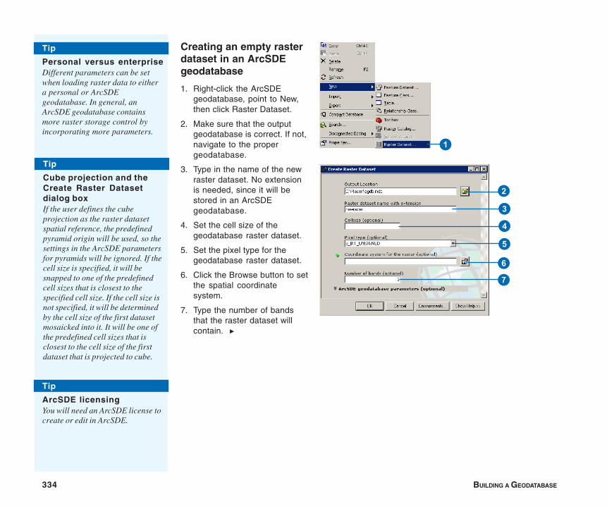
334 BUILDING A GEODATABASE
Creating an empty rasterdataset in an ArcSDEgeodatabase
1. Right-click the ArcSDEgeodatabase, point to New,then click Raster Dataset.
2. Make sure that the outputgeodatabase is correct. If not,navigate to the propergeodatabase.
3. Type in the name of the newraster dataset. No extensionis needed, since it will bestored in an ArcSDEgeodatabase.
4. Set the cell size of thegeodatabase raster dataset.
5. Set the pixel type for thegeodatabase raster dataset.
6. Click the Browse button to setthe spatial coordinatesystem.
7. Type the number of bandsthat the raster dataset willcontain. u
Tip
Personal versus enterpriseDifferent parameters can be setwhen loading raster data to eithera personal or ArcSDEgeodatabase. In general, anArcSDE geodatabase containsmore raster storage control byincorporating more parameters.
1
2
3
4
5
6
7
Tip
Cube projection and theCreate Raster Datasetdialog boxIf the user defines the cubeprojection as the raster datasetspatial reference, the predefinedpyramid origin will be used, so thesettings in the ArcSDE parametersfor pyramids will be ignored. If thecell size is specified, it will besnapped to one of the predefinedcell sizes that is closest to thespecified cell size. If the cell size isnot specified, it will be determinedby the cell size of the first datasetmosaicked into it. It will be one ofthe predefined cell sizes that isclosest to the cell size of the firstdataset that is projected to cube.
Tip
ArcSDE licensingYou will need an ArcSDE license tocreate or edit in ArcSDE.
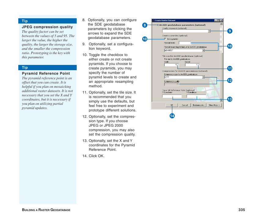
BUILDING A RASTER GEODATABASE 335
8. Optionally, you can configurethe SDE geodatabaseparameters by clicking thearrows to expand the SDEgeodatabase parameters.
9. Optionally, set a configura-tion keyword.
10. Toggle the checkbox toeither create or not createpyramids. If you choose tocreate pyramids, you mayspecify the number ofpyramid levels to create andan appropriate resamplingmethod.
11. Optionally, set the tile size. Itis recommended that yousimply use the defaults, butfeel free to experiment andprototype different solutions.
12. Optionally, set the compres-sion type. If you chooseJPEG or JPEG 2000compression, you may alsoset the compression quality.
13. Optionally, set the X and Ycoordinates for the PyramidReference Point.
14. Click OK.
W
E
Q
R
Tip
JPEG compression qualityThe quality factor can be setbetween the values of 5 and 95. Thelarger the value, the higher thequality, the larger the storage size,and the smaller the compressionratio. Prototyping is the key withthis parameter.
T
98
Q
Tip
Pyramid Reference PointThe pyramid reference point is anoffset that you can create. It ishelpful if you plan on mosaickingadditional raster datasets. It is notnecessary that you set the X and Ycoordinates, but it is necessary ifyou plan on utilizing partialpyramid updates.
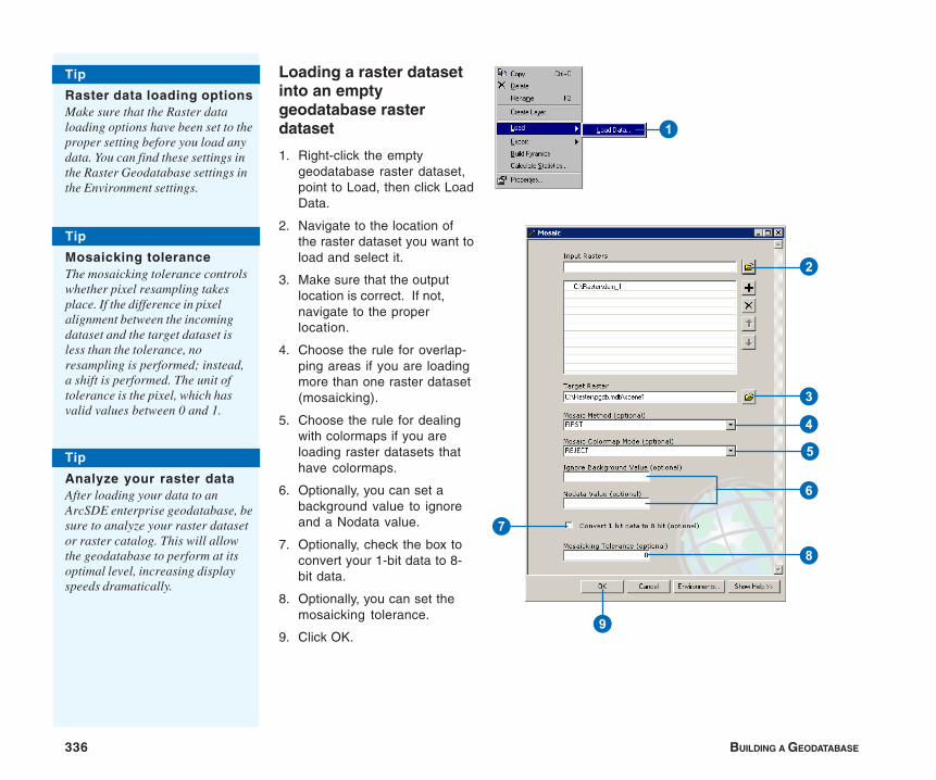
336 BUILDING A GEODATABASE
Loading a raster datasetinto an emptygeodatabase rasterdataset
1. Right-click the emptygeodatabase raster dataset,point to Load, then click LoadData.
2. Navigate to the location ofthe raster dataset you want toload and select it.
3. Make sure that the outputlocation is correct. If not,navigate to the properlocation.
4. Choose the rule for overlap-ping areas if you are loadingmore than one raster dataset(mosaicking).
5. Choose the rule for dealingwith colormaps if you areloading raster datasets thathave colormaps.
6. Optionally, you can set abackground value to ignoreand a Nodata value.
7. Optionally, check the box toconvert your 1-bit data to 8-bit data.
8. Optionally, you can set themosaicking tolerance.
9. Click OK.
Tip
Raster data loading optionsMake sure that the Raster dataloading options have been set to theproper setting before you load anydata. You can find these settings inthe Raster Geodatabase settings inthe Environment settings.
1
Tip
Analyze your raster dataAfter loading your data to anArcSDE enterprise geodatabase, besure to analyze your raster datasetor raster catalog. This will allowthe geodatabase to perform at itsoptimal level, increasing displayspeeds dramatically.
3
2
4
5
6
8
9
7
Tip
Mosaicking toleranceThe mosaicking tolerance controlswhether pixel resampling takesplace. If the difference in pixelalignment between the incomingdataset and the target dataset isless than the tolerance, noresampling is performed; instead,a shift is performed. The unit oftolerance is the pixel, which hasvalid values between 0 and 1.
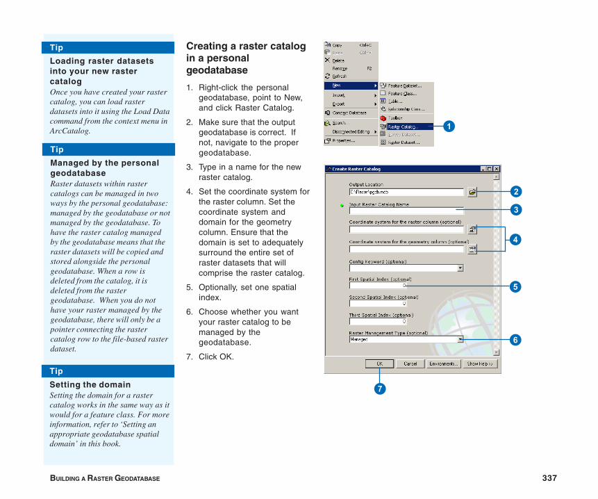
BUILDING A RASTER GEODATABASE 337
Tip
Loading raster datasetsinto your new rastercatalogOnce you have created your rastercatalog, you can load rasterdatasets into it using the Load Datacommand from the context menu inArcCatalog.
Creating a raster catalogin a personalgeodatabase
1. Right-click the personalgeodatabase, point to New,and click Raster Catalog.
2. Make sure that the outputgeodatabase is correct. Ifnot, navigate to the propergeodatabase.
3. Type in a name for the newraster catalog.
4. Set the coordinate system forthe raster column. Set thecoordinate system anddomain for the geometrycolumn. Ensure that thedomain is set to adequatelysurround the entire set ofraster datasets that willcomprise the raster catalog.
5. Optionally, set one spatialindex.
6. Choose whether you wantyour raster catalog to bemanaged by thegeodatabase.
7. Click OK.
Tip
Managed by the personalgeodatabaseRaster datasets within rastercatalogs can be managed in twoways by the personal geodatabase:managed by the geodatabase or notmanaged by the geodatabase. Tohave the raster catalog managedby the geodatabase means that theraster datasets will be copied andstored alongside the personalgeodatabase. When a row isdeleted from the catalog, it isdeleted from the rastergeodatabase. When you do nothave your raster managed by thegeodatabase, there will only be apointer connecting the rastercatalog row to the file-based rasterdataset.
Tip
Setting the domainSetting the domain for a rastercatalog works in the same way as itwould for a feature class. For moreinformation, refer to ‘Setting anappropriate geodatabase spatialdomain’ in this book.
1
2
3
4
5
6
7
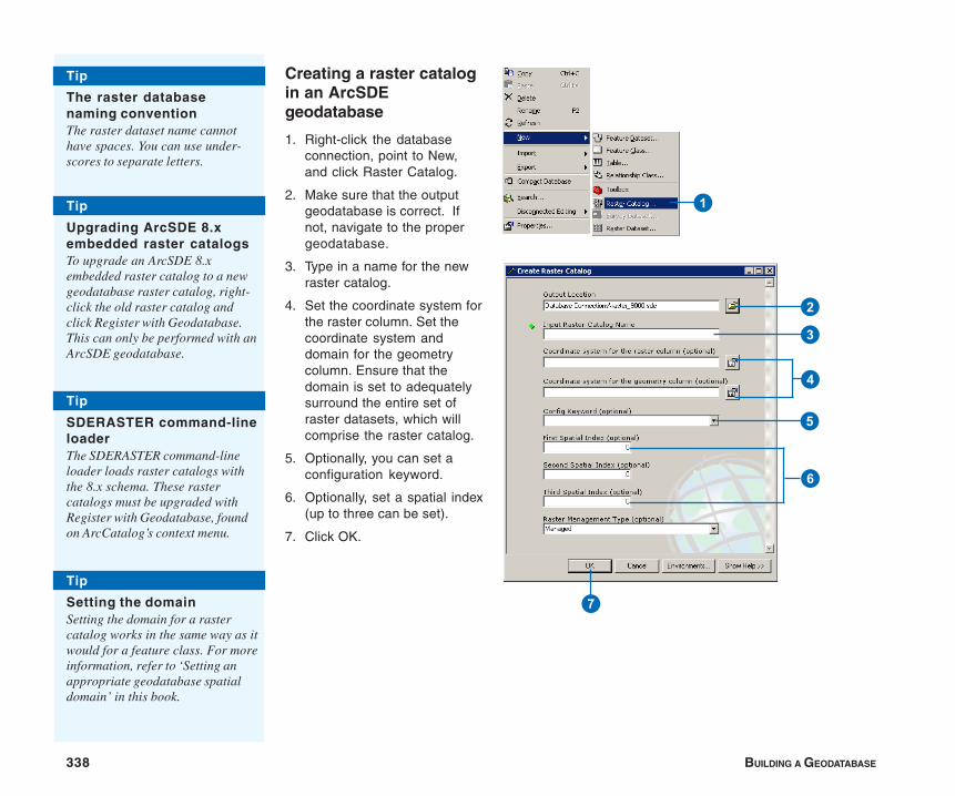
338 BUILDING A GEODATABASE
Creating a raster catalogin an ArcSDEgeodatabase
1. Right-click the databaseconnection, point to New,and click Raster Catalog.
2. Make sure that the outputgeodatabase is correct. Ifnot, navigate to the propergeodatabase.
3. Type in a name for the newraster catalog.
4. Set the coordinate system forthe raster column. Set thecoordinate system anddomain for the geometrycolumn. Ensure that thedomain is set to adequatelysurround the entire set ofraster datasets, which willcomprise the raster catalog.
5. Optionally, you can set aconfiguration keyword.
6. Optionally, set a spatial index(up to three can be set).
7. Click OK.
Tip
Upgrading ArcSDE 8.xembedded raster catalogsTo upgrade an ArcSDE 8.xembedded raster catalog to a newgeodatabase raster catalog, right-click the old raster catalog andclick Register with Geodatabase.This can only be performed with anArcSDE geodatabase.
Tip
The raster databasenaming conventionThe raster dataset name cannothave spaces. You can use under-scores to separate letters.
1
2
3
4
5
6
7
Tip
Setting the domainSetting the domain for a rastercatalog works in the same way as itwould for a feature class. For moreinformation, refer to ‘Setting anappropriate geodatabase spatialdomain’ in this book.
Tip
SDERASTER command-lineloaderThe SDERASTER command-lineloader loads raster catalogs withthe 8.x schema. These rastercatalogs must be upgraded withRegister with Geodatabase, foundon ArcCatalog’s context menu.
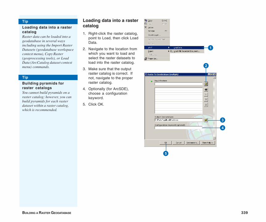
BUILDING A RASTER GEODATABASE 339
Loading data into a rastercatalog
1. Right-click the raster catalog,point to Load, then click LoadData.
2. Navigate to the location fromwhich you want to load andselect the raster datasets toload into the raster catalog.
3. Make sure that the outputraster catalog is correct. Ifnot, navigate to the properraster catalog.
4. Optionally (for ArcSDE),choose a configurationkeyword.
5. Click OK.
Tip
Loading data into a rastercatalogRaster data can be loaded into ageodatabase in several waysincluding using the Import RasterDatasets (geodatabase workspacecontext menu), Copy Raster(geoprocessing tools), or LoadData (ArcCatalog dataset contextmenu) commands.
Tip
Building pyramids forraster catalogsYou cannot build pyramids on araster catalog; however, you canbuild pyramids for each rasterdataset within a raster catalog,which is recommended.
1
2
3
4
5
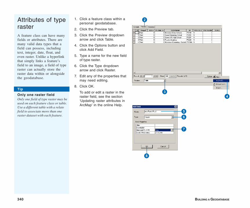
340 BUILDING A GEODATABASE
1. Click a feature class within apersonal geodatabase.
2. Click the Preview tab.
3. Click the Preview dropdownarrow and click Table.
4. Click the Options button andclick Add Field.
5. Type a name for the new fieldof type raster.
6. Click the Type dropdownarrow and click Raster.
7. Edit any of the properties thatmay need editing.
8. Click OK.
To add or edit a raster in theraster field, see the section‘Updating raster attributes inArcMap’ in the online Help.
Attributes of typerasterA feature class can have manyfields or attributes. There aremany valid data types that afield can possess, includingtext, integer, date, float, andeven raster. Unlike a hyperlinkthat simply links a feature’sfield to an image, a field of typeraster can actually store theraster data within or alongsidethe geodatabase.
2
34
56
7
8
Tip
Only one raster fieldOnly one field of type raster may beused on each feature class or table.Use a different table with a relatefield to associate more than oneraster dataset with each feature.

BUILDING A RASTER GEODATABASE 341
1. Right-click the raster dataset,point to Export, and clickRaster To Different Format.
2. Make sure that the inputraster dataset is correct. Ifnot, navigate to the properraster dataset.
3. Navigate to the outputlocation and type in thename of the output rasterdataset. The output rasterdataset format can bechosen on the Output RasterDataset dialog box bychoosing a geodatabaseworkspace or an appropriatefile extension (within a file-based workspace).
4. Optionally, choose a configu-ration keyword (ArcSDEonly).
5. Optionally, you can set abackground value to ignoreand a Nodata value.
6. Optionally, check the box toconvert your 1-bit data to 8-bit data.
7. Optionally, check the box toconvert your colormap rasterinto a red, green, and blue(RGB) raster.
8. Click OK.
Converting rasterformatsThere are many different rasterdataset formats. These formatsare normally differentiated usingdifferent file extensions. ArcGISis able to view many differentraster file formats; however, it isonly able to output a rasterdataset as an ESRI GRID,ERDAS IMAGINE, or a TIFF.You can store these rasters in afile-based system or a personalgeodatabase (even ingeodatabase raster catalogs).You can also save your rasterdataset or raster catalog to anArcSDE geodatabase.
1
Tip
Naming rasters in ageodatabaseWhen you save to an ArcSDE orpersonal geodatabase, you do notneed to specify a format—theformat will be converted to ageodatabase format.
6
7
4
3
5
2
8
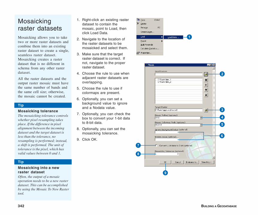
342 BUILDING A GEODATABASE
1. Right-click an existing rasterdataset to contain themosaic, point to Load, thenclick Load Data.
2. Navigate to the location ofthe raster datasets to bemosaicked and select them.
3. Make sure that the targetraster dataset is correct. Ifnot, navigate to the properraster dataset.
4. Choose the rule to use whenadjacent raster datasets areoverlapping.
5. Choose the rule to use ifcolormaps are present.
6. Optionally, you can set abackground value to ignoreand a Nodata value.
7. Optionally, you can check thebox to convert your 1-bit datato 8-bit data.
8. Optionally, you can set themosaicking tolerance.
9. Click OK.
Mosaickingraster datasetsMosaicking allows you to taketwo or more raster datasets andcombine them into an existingraster dataset to create a single,seamless raster dataset.Mosaicking creates a rasterdataset that is no different inschema from any other rasterdataset.
All the raster datasets and theoutput raster mosaic must havethe same number of bands andthe same cell size; otherwise,the mosaic cannot be created.
1
6
Tip
Mosaicking into a newraster datasetOften, the output of a mosaicoperation needs to be a new rasterdataset. This can be accomplishedby using the Mosaic To New Rastertool.
3
4
2
5
7
8
9
Tip
Mosaicking toleranceThe mosaicking tolerance controlswhether pixel resampling takesplace. If the difference in pixelalignment between the incomingdataset and the target dataset isless than the tolerance, noresampling is performed; instead,a shift is performed. The unit oftolerance is the pixel, which hasvalid values between 0 and 1.

BUILDING A RASTER GEODATABASE 343
Raster data anddisconnectededitingRaster extraction allows you toclip a raster dataset or a rastercatalog. Raster extractionperformed on a raster datasetwill output a raster dataset withonly the extracted (clipped)portion of the dataset. Rasterextraction that is performed on araster catalog will output araster catalog with each of theraster datasets that intersect (orare contained in) the extractionenvelope.
1. Add a raster dataset or rastercatalog contained within ageodatabase.
2. Click Tools on the main menuand click Customize.
3. Click the Toolbars tab.
4. Check the DisconnectedEditing check box.
5. Click Close.
6. Click the Rectangle Drawtool.
7. Draw a rectangle around thearea from which you want toextract data.
8. Click the Extract Data buttonon the Disconnected Editingtoolbar.
9. Click the Browse button tospecify the outputgeodatabase.
10. Click Next.
11. Click Finish.
2
3
4
5
6
8
9
Q
Tip
Valid raster extractioninputs and outputsOnly raster datasets and rastercatalogs stored in a geodatabaseare valid for performing rasterextractions. The output of theextraction must also be storedwithin a geodatabase.
Tip
Raster check-out supportWhen performing a check-out ofyour data, raster data can beincluded. Although the raster datacannot be edited or checked backin, it will be extracted instead.Raster check-out only supportsrasters created in ArcGIS 9.x.
344 BUILDING A GEODATABASE
More about rasters in ArcGIS
Speed
There are several ways to speed up your raster data within ageodatabase. Pyramids will help you display your raster datafaster, since they display the most appropriate level of detail. Datacompression compresses data in tiles before it is stored. SinceArcSDE normally serves data over a network with a specified andperhaps shared bandwidth, the fewer the data packets, the fasterthe transfer.
Sharing
Data can be shared between users through a geodatabase or viaan ArcIMS® server. Sharing on ArcSDE is especially useful sinceit has multiuser capabilities. All sorts of themes and layers can beshared, so duplicates of file-based raster datasets and rastercatalogs are not necessary. If raster catalogs are distributed toother users, it is a good idea to create them using relative paths.
Scale of use
The scale of use usually pertains to the cell size (pixel resolution)of the raster datasets you are using in your project. For example,it doesn’t make sense to use a scale of pixels equal to 1 km toadequately map the streets of a city, nor does it make sense touse two-foot resolution data to map the soils of an entire country.One is as inadequate as the other is overkill. Scale of use alsomeans ensuring that a scanned map that was built to satisfy acertain scale (for example, 1:24,000) is not used for projectsrequiring 1:100,000 scale mapping. Finally, scale of use can alsorefer to prototyping how much lossy compression will affect yourdata (for example, 1-meter orthophotos). Since highercompression ratios can degrade the display quality of the rasterdata, prototyping needs to be conducted to ensure that asubjective quality threshold has not been crossed.
Raster catalogs
File-based raster catalogs are obviously useful; however,geodatabase raster catalogs have many additional benefits. Ageodatabase raster catalog can contain raster datasets that arenot homogeneous, whereby they can still be displayed properly.Using heterogeneous raster catalogs allows you to mix rasterdatasets of different cell sizes and number of bands. Geodatabaseraster catalogs also allow the user to select raster datasets basedon attribute or spatial queries.
Loading procedures
Raster data can be loaded into a geodatabase in several waysincluding using the Import Raster Datasets (geodatabaseworkspace context menu), Copy Raster (geoprocessing tools), orLoad Data (ArcCatalog dataset context menu) commands.
Custom formats
Raster support in ArcGIS is built using a publicly available API.With this open structure, users can add their own format supportinto ArcGIS by creating a customized raster format dynamic linklibrary (DLL) and plugging it into ArcGIS. The customized rasterformat will be treated the same as other raster formats (varyingdegrees of support may be programmed). The customized DLLcreated in ArcGIS can be plugged into ArcIMS 4.0.1 or later andcustomized format support can be served through ArcIMS. Tolearn more about creating your own format, refer to the technicaldocuments section at www.esri.com/arcobjectsonline and lookfor the document ‘Creating a customized raster format dll’.

345
12Glossary absolute modeSee digitizing mode.
active data frameThe data frame currently being worked on—for example, the data frame to which layers are beingadded. The active data frame is highlighted on the map, and its name is shown in bold text in thetable of contents.
aliasAn alternative name specified for fields, tables, and feature classes that is more descriptive anduser-friendly than the actual name of these items. On computer networks, a single e-mail alias mayrefer to a group of e-mail addresses. In database management systems, aliases can containcharacters, such as spaces, that can’t be included in the actual names.
aligned dimensionA drafting symbol that runs parallel to the baseline and indicates the true distance betweenbeginning and ending dimension points. ArcInfo supports aligned dimension and linear dimension.
annotationDescriptive text used to label features on or around a map. Information stored for annotationincludes a text string, a position at which it can be displayed, and display characteristics.
annotation classA subset of annotation in the standard or feature-linked geodatabase annotation feature class thatcontains properties that determine how the subset of annotation will display. A standard or feature-linked geodatabase annotation feature class may contain one or more annotation classes.
annotation feature classA geodatabase feature class that stores text or graphics that provide additional information aboutfeatures or general areas of a map (annotation). An annotation feature class may be linked toanother feature class, so that edits to the features are reflected in the annotation (feature-linkedannotation). Annotation in a geodatabase is edited during an edit session, using the tools on theAnnotation toolbar.
346 BUILDING A GEODATABASE
ArcInfo workspaceA file-based collection of coverages, grids, triangulated irregularnetworks (TINs), or shapefiles stored as a directory of folders inthe file system.
arc–node topologyThe data structure in a coverage used to represent linear featuresand polygon boundaries and to support analysis functions, suchas network tracing. Nodes represent the beginning and endingvertices of each arc. Arcs that share a node are connected, andpolygons are defined by a series of connected arcs. An arc thatintersects another arc is split into two arcs. Each arc that definesall or part of a polygon boundary records the number of thepolygon to its left and to its right, giving it a direction of travel.
ArcSDEServer software that provides ArcSDE client applications (such asArcGIS Desktop, ArcGIS Server, and ArcIMS) a gateway forstoring, managing, and using spatial data in one of the followingcommercial database management systems: IBM DB2 UDB, IBMInformix, Microsoft SQL Server, and Oracle.
asynchronousNot synchronous; that is, not happening, existing, or arising atthe same time. For example, in disconnected editing, modifyingthe properties of a check-out is an asynchronous operation;changes made to the check-out in a master geodatabase do notaffect the associated check-out in a check-out geodatabase.
attribute1. Information about a geographic feature in a GIS, generallystored in a table and linked to the feature by a unique identifier.For example, attributes of a river might include its name, length,and average depth.
2. In raster datasets, information associated with each uniquevalue of raster cells.
attribute domainIn a geodatabase, a mechanism for enforcing data integrity.Attribute domains define what values are allowed in a field in afeature class or nonspatial attribute table. If the features ornonspatial objects have been grouped into subtypes, differentattribute domains can be assigned to each of the subtypes.
attribute tableA database or tabular file containing information about a set ofgeographic features, usually arranged so that each rowrepresents a feature and each column represents one featureattribute. In raster datasets, each row of an attribute tablecorresponds to a certain region of cells having the same value. Ina GIS, attribute tables are often joined or related to spatial datalayers, and the attribute values they contain can be used to find,query, and symbolize features or raster cells.
attributes dialog boxIn ArcMap, a dialog box that displays attributes of selectedfeatures for editing.
azimuthThe angle, measured in degrees, between a baseline drawn from acenter point and another line drawn from the same point.Normally, the baseline points true north, and the angle ismeasured clockwise from the baseline. Azimuth is often used todefine an oblique cylindrical map projection or the angle of ageodesic between two points.
bandA set of adjacent wavelengths or frequencies with a commoncharacteristic, such as the visible band of the electromagneticspectrum.
GLOSSARY 347
behaviorThe way in which an object in a geodatabase functions oroperates. Behavior rules define how geodatabase objects can beedited and drawn. Defined behaviors include, but are not limitedto, validation rules, subtypes, default values, and relationships.
bilinear interpolationA resampling method that uses an average of the four nearestcells to determine the new value.
bufferA zone around a map feature measured in units of distance ortime. A buffer is useful for proximity analysis.
CADA computer-based system for the design, drafting, and display ofgraphical information. Also known as computer-aided drafting,such systems are most commonly used to support engineering,planning, and illustrating activities.
CAD feature classA read-only member of a CAD feature dataset, comprising one ofthe following: polylines, points, polygons, multipatch, orannotation. The feature attribute table of a CAD feature class is avirtual table comprising select CAD graphic properties and anyexisting field attribute values.
centroidThe geometric center of a feature. Of a line, it is the midpoint; of apolygon, the center of area; of a three-dimensional figure, thecenter of volume.
check-inThe procedure that transfers a copy of data into a mastergeodatabase, overwriting the original copy of that data andreenabling it so it can be accessed and saved from that location.
check-outA procedure that records the duplication of data from onegeodatabase to another and disables the original data so thatboth versions cannot be accessed or saved at the same time.
check-out geodatabaseA personal or ArcSDE geodatabase that contains data checkedout from a master geodatabase.
check-out versionThe data version created in a check-out geodatabase when datais checked out to that database. This version is created as a copyof the synchronization version. Only the edits made to this check-out version can be checked back in to the master geodatabase.
See also check-out geodatabase, master check-out version.
circular arcA line with two vertices, one situated at each endpoint, ratherthan a line composed of numerous vertices with line segmentsbetween them.
clipIn ArcInfo, a command that extracts the features from onecoverage that reside entirely within a boundary defined byfeatures in another coverage (the clip coverage).
cluster toleranceIn geodatabase feature classes, a definition for the minimumtolerated distance between vertices in the topology. Vertices thatfall within the set cluster tolerance will be snapped togetherduring the validate topology process.
clusteringA part of the topology validation process in which vertices thatfall within the cluster tolerance are snapped together.

348 BUILDING A GEODATABASE
coincidentOccupying the same space. Coincident features or parts offeatures occupy the same space in the same plane. Ingeodatabase feature classes, vertices or boundaries that fallwithin the set cluster tolerance of one another are coincident;they are snapped together during the validate topology process.
colormapA set of values that are associated with colors. Colormaps aremost commonly used to display a raster dataset consistently onmany different platforms.
columnThe vertical dimension of a table. Each column stores the valuesof one type of attribute for all the records, or rows, in the table.All the values in a given column are of the same data type—forexample, number, string, BLOB, date.
compactionSee compression.
compressionA reduction of file size for data handling and storage. Examples ofsuch methods include quadtrees, run–length encoding, andwavelet.
computer-aided designSee CAD.
conflictAn opposing action of incompatibles that occurs when multipleusers simultaneously edit a version or reconcile two versions.Conflicts occur when the same feature or topologically relatedfeatures are edited in both the edit and reconciliation versions,and it is unclear in the database which representation is valid.
connectivity1. In a geodatabase, the state of edges and junctions in a logicalnetwork that controls flow, tracing, and pathfinding.
2. In a coverage, topological identification of connected arcs byrecording the from-node and to-node for each arc. Arcs that sharea common node are connected. See also arc–node topology.
connectivity ruleA rule that constrains the type and number of network featuresthat can be connected to one another in a geodatabase. There aretwo types of connectivity rules: edge–junction and edge–edge.
constraintsLimits imposed on a model to maintain data integrity. For example,in a water network model, an 8-inch pipe cannot connect to a4-inch pipe.
construct featuresIn ArcMap, an edit command that takes selected features fromone or more feature classes and creates new features in a targetfeature class. The Construct Features tool uses the inputgeometries of the selected features to construct polygons or linesfollowing polygon boundaries, depending on the geometry of thetarget feature class.
controlIn mapping, a system of points with established horizontal andvertical positions that are used as fixed references for knownground points or specific locations. The establishment ofcontrols is one of the first steps in digitizing.
control pointsSee control.
GLOSSARY 349
coordinate systemA fixed reference framework superimposed on the surface of anarea to designate the position of a point within it; a referencesystem consisting of a set of points, lines, and/or surfaces; and aset of rules, used to define the positions of points in space ineither two or three dimensions. The Cartesian coordinate systemand the geographic coordinate system used on the earth’ssurface are common examples of coordinate systems.
coordinatesValues represented by x, y, and possibly z that define a position interms of a spatial reference framework. Coordinates are used torepresent locations on the earth’s surface relative to otherlocations.
coverageA data model for storing geographic features using ArcInfosoftware. A coverage stores a set of thematically associated dataconsidered a unit. It usually represents a single layer, such assoils, streams, roads, or land use. In a coverage, features arestored as both primary features (points, arcs, polygons) andsecondary features (tics, links, annotation). Feature attributes aredescribed and stored independently in feature attribute tables.Coverages cannot be edited in ArcGIS.
crackingA part of the topology validation process in which vertices arecreated at the intersection of feature edges.
cubic convolutionA resampling method that uses an average of the nearest 16 cellsto calculate the new cell value.
current taskDuring editing in ArcMap, a setting in the Current Taskdropdown list that determines the task with which the sketchconstruction tools (Sketch, Arc, Distance–Distance, andIntersection) will work. The current task is set by clicking a task inthe Current Task dropdown list.
custom behaviorA set of methods, functions, or operations associated with ageodatabase object that has been specifically created oroverridden by a developer.
custom featureIn geodatabases, a feature with specialized behavior instantiatedin a class by a developer.
custom objectAn object with custom behavior provided by a developer.
dangle lengthSee dangle tolerance.
dangle toleranceIn ArcInfo coverages, the minimum length allowed for danglingarcs by the Clean process. Clean removes dangling arcs shorterthan the dangle tolerance.
dangling arcAn arc having the same polygon on both its left and right sidesand having at least one node that does not connect to any otherarc. It often occurs where a polygon does not close properly,where arcs do not connect properly (an undershoot), or where anarc was digitized past its intersection with another arc (anovershoot). A dangling arc is not always an error; for example, itcan represent a cul-de-sac in a street network.
350 BUILDING A GEODATABASE
dataAny collection of related facts arranged in a particular format;often, the basic elements of information that are produced, stored,or processed by a computer.
data frameA map element that defines a geographic extent, a page extent, acoordinate system, and other display properties for one or morelayers in ArcMap. A dataset can be represented in one or moredata frames. In data view, only one data frame is displayed at atime; in layout view, all of a map’s data frames are displayed at thesame time. Many cartography texts use the term “map body” torefer to what ESRI calls a data frame.
data integrityThe degree to which the data in a database is accurate andconsistent according to data model and data type. Data integrityis maintained through the creation of attribute domains andthrough mandatory conflict resolution between versions of adataset.
data sourceAny geographic data. Data sources may include coverages,shapefiles, rasters, or feature classes.
data typeThe attribute of a variable, field, or column in a table thatdetermines the kind of data it can store. Common data typesinclude character, integer, decimal, single, double, and string.
data viewAn all-purpose view in ArcMap and ArcReaderTM for exploring,displaying, and querying geographic data. This view hides allmap elements, such as titles, North arrows, and scalebars.
See also layout view.
databaseOne or more structured sets of persistent data, managed andstored as a unit and generally associated with software to updateand query the data. A simple database might be a single file withmany records, each of which references the same set of fields. AGIS database includes data about the spatial locations andshapes of geographic features recorded as points, lines, areas,pixels, grid cells, or TINs, as well as their attributes.
datasetAny organized collection of data with a common theme.
dataset precisionThe mathematical exactness or detail with which a value is storedwithin the dataset, based on the number of significant digits thatcan be stored for each coordinate. In a geodatabase, the precisionof the dataset is the number of internal storage units that areallocated to each of the linear units of a coordinate system.
decimal degreesValues of latitude and longitude expressed in decimal formatrather than degrees, minutes, and seconds.
default junction typeIn geometric networks, the user-established junction type thatautomatically connects two edge types in the absence of acurrent user choice, in cases where two edge types may beconnectable through more than one junction type. An edge mayalso have a default end junction type, used for the free ends ofnew edges.
delta databaseSee delta file.
GLOSSARY 351
delta fileA file that contains data edits that can be exchanged betweengeodatabases or between geodatabases and other data stores.The edits can come from a check-out geodatabase, modified rowsbetween source and target versions, or a custom application.Supported delta file formats are XML (delta XML file) and deltadatabase (.mdb file).
digitizingThe process of converting the geographic features on an analogmap into digital format using a digitizing tablet, or digitizer, whichis connected to a computer. Features on a paper map are tracedwith a digitizer puck, a device similar to a mouse, and the x,ycoordinates of these features are automatically recorded andstored as spatial data.
digitizing modeOne of the ways in which a digitizing tablet operates. In digitizingmode, locations on the tablet are mapped to specific locations onthe screen. Moving the digitizer puck on the tablet surface causesthe screen pointer to move to precisely the same position.
dimension construction methodsProcedures that dictate what type of dimension feature is createdand the number of points required to complete the feature’sgeometry. Construction methods include simple aligned, aligned,linear, rotated linear, free aligned, and free linear.
dimension featureA special kind of geodatabase annotation that shows specificlengths or distances on a map. A dimension feature may indicatethe length of a side of a building or land parcel, or it may indicatethe distance between two features, such as a fire hydrant and thecorner of a building. ArcInfo supports aligned dimensions andlinear dimensions.
dimension feature classA collection of spatial data in the geodatabase that shares thesame dimension features. Like other feature classes in thegeodatabase, all features in a dimension feature class have ageographic location and attributes and can either be inside oroutside a feature dataset.
dimension styleDescription of a dimension feature’s symbology, what parts of itare drawn, and how it is drawn. Every time a new dimensionfeature is created, it is assigned a particular style according to itsshared characteristics. A collection of dimension styles isassociated with a dimension feature class. Styles for a dimensionfeature class are created, copied, and managed using ArcCatalogor the editing capabilities in ArcMap. Styles are then assigned toindividual dimension features.
Dimensioning toolbarA toolbar in ArcMap that facilitates the creation of dimensionfeatures.
direct connectA two-tier configuration for connecting to a spatial database.Direct connect moves processing from the server to the client. Itdoes not require the ArcSDE Application Server to connect to aspatial database. With direct connect, ArcSDE processing stilloccurs, but it primarily happens on the client side.
dirty areasRegions surrounding features that have been altered after theinitial topology validation process and require an additionaltopology validation to be performed to discover any errors.
352 BUILDING A GEODATABASE
disconnected editingThe process of copying data to another geodatabase, editing thatdata, then merging the changes with the data in the source ormaster geodatabase.
distance unitsThe units of length (for example, feet, miles, meters, or kilometers)that are used to report measurements, dimensions of shapes, anddistance tolerances and offsets.
domainSee attribute domain.
double precisionThe level of coordinate exactness based on the possible numberof significant digits that can be stored for each coordinate.Datasets can be stored in either single or double precision.Double-precision geometries store up to 15 significant digits percoordinate (typically 13 to 14 significant digits), retaining theaccuracy at much less than one meter at a global extent.
See also single precision.
double-coordinate precisionSee double precision.
edgeA line between two nodes, points, or junctions that forms theboundary of one or more faces of a spatial entity. In an image,edges separate areas of different tones or colors. In a topology,an edge defines lines or polygon boundaries; multiple features inone or more feature classes may share edges.
edge elementA line connecting nodes in the network through which acommodity, such as information, water, or electricity, presumablyflows.
edge–edge ruleIn geodatabases, a connectivity rule that establishes that an edgeof type A may connect to an edge of type B through a junction oftype C. Edge–edge rules always involve a junction type.
edge–junction cardinalityIn a relationship between objects in a geodatabase, the number ofedges of one type that may be associated with junctions ofanother type. Edge–junction cardinality defines a range ofpermissible connections that may occur in a one-to-manyrelationship between a single junction and many edges.
edge–junction ruleA connectivity rule in geodatabases establishing that an edge oftype A may connect to a junction of type B.
edit cacheSee map cache.
edit sessionIn ArcMap, the environment in which spatial and attribute editingtake place. After starting an edit session, a user can modifyfeature locations, geometry, or attributes. Modifications are notsaved unless the user explicitly chooses to save them.
Editor toolbarIn ArcMap, a set of tools that allows the creation andmodification of features and their attributes.

GLOSSARY 353
ellipseA geometric shape equivalent to a circle that is viewed obliquely.It is described mathematically as the collection of points whosedistances from two given points add up to the same sum.
errorSee topology error.
extensible markup language (XML)Developed by the World Wide Web Consortium (W3C), XML is astandard for designing text formats that facilitates the interchangeof data between computer applications. XML is a set of rules forcreating standard information formats using customized tags andsharing both the format and the data across applications.
extentThe coordinate pairs defining the minimum bounding rectangle(xmin, ymin and xmax, ymax) of a data source. All coordinates forthe data source fall within this boundary.
feature1. A representation of a real-world object on a map. Features canbe represented in a GIS as vector data (points, lines, or polygons)or as cells in a raster data format. To be displayed in a GIS,features must have geometry and locational information.
2. A group of spatial elements that represents a real-world entity.A complex feature is made up of more than one group of spatialelements: for example, a set of line elements with the commontheme of roads representing a road network.
feature attribute tableSee attribute table.
feature classA collection of geographic features with the same geometry type(such as point, line, or polygon), the same attributes, and thesame spatial reference. Feature classes can stand alone within ageodatabase or be contained within shapefiles, coverages, orother feature datasets. Feature classes allow homogeneousfeatures to be grouped into a single unit for data storagepurposes. For example, highways, primary roads, and secondaryroads can be grouped into a line feature class named “roads”. In ageodatabase, feature classes can also store annotation anddimensions.
feature datasetA collection of feature classes stored together that share thesame spatial reference; that is, they have the same coordinatesystem, and their features fall within a common geographic area.Feature classes with different geometry types may be stored in afeature dataset.
fieldA column in a table that stores the values for a single attribute.
See also attribute, column.
fuzzy toleranceIn ArcInfo, the distance within which coordinates of nearbyfeatures are adjusted to coincide with each other when topologyis being constructed. Nodes and vertices within the fuzzytolerance are merged into a single coordinate location, connectingpreviously separate features. Fuzzy tolerance is a very smalldistance, usually from 1/1,000,000 to 1/10,000 times the width ofthe coverage extent, and is generally used to correct inexactintersections. The fuzzy tolerance defines the resolution of acoverage resulting from the Clean operation or a topologicaloverlay operation, such as Union, Intersect, or Clip. Ingeodatabase feature classes, this concept is replaced by clustertolerance.
354 BUILDING A GEODATABASE
GDBSee geodatabase.
geodatabaseAn object-oriented data model introduced by ESRI thatrepresents geographic features and attributes as objects and therelationships between objects but is hosted inside a relationaldatabase management system. A geodatabase can store objects,such as feature classes, feature datasets, nonspatial tables, andrelationship classes.
geodatabase data modelA geographic data model that represents real-world geographicfeatures as objects in an object-relational database. In thegeodatabase data model, features are stored as rows in a table,and geometry is stored in a shape field. Objects in thegeodatabase data model may have custom behavior.
geometric networkTopologically connected edge and junction features thatrepresent a linear network such as a road, utility, or hydrologicsystem.
georelational data modelA geographic data model that represents geographic features asan interrelated set of spatial and attribute data. The georelationalmodel is the fundamental data model used in coverages.
identityA topological overlay that computes the geometric intersection oftwo coverages. The output coverage preserves all the features ofthe first coverage plus those portions of the second (polygon)coverage that overlap the first. For example, a road passingthrough two counties would be split into two arc features, eachwith the attributes of the road and the county it passes through.
See also intersect, union.
indexA data structure used to speed the search for records in adatabase or for spatial features in geographic datasets. In general,unique identifiers stored in a key field point to records or filesholding more detailed information.
instanceSee service.
intersectA geometric integration of spatial datasets that preserves featuresor portions of features that fall within areas common to the inputdatasets.
See also identity, union.
IP addressInternet protocol address. The identification of each client orserver computer on the Internet by a unique number. IP addressesallow data to travel between one computer and another via theInternet and are commonly expressed as a dotted quad, with foursets of numerals separated by periods.
item1. An element in the Catalog tree. Items include data sources,such as shapefiles and geodatabases, and nonspatial elements,such as folders.
2. A column of information in an INFO table.
See also field.
junction elementIn a linear network, a network feature that occurs at theintersection of two or more edges or at the endpoint of an edgethat allows the transfer of flow between edges.
GLOSSARY 355
label pointIn a coverage, a feature class used to represent points or identifypolygons. When representing points, the x,y location of the pointdescribes the location of the feature. When identifying polygons,the point can be located anywhere within the polygon.
layer1. A reference to a data source, such as a coverage, geodatabasefeature class, raster, and so on, that defines how the data shouldbe displayed on a map. Layers can also define additionalproperties, such as which features from the data source areincluded. In ArcGIS 9, layers can be used as inputs togeoprocessing tools. Layers can be stored in map documents(.mxd) or saved individually as layer files (.lyr). Layers areconceptually similar to themes at ArcView 3.x.
2. A standalone feature class in a geodatabase managed withSDE 3.
layout viewIn ArcMap and ArcReader, the view for laying out a map. Layoutview shows the virtual page upon which geographic data andmap elements, such as titles, legends, and scalebars, are placedand arranged for printing.
See also data view.
left–right topologyThe topological data structure in an ArcInfo coverage that stores,for each arc, the identity of the polygons to the left and right of it.Left–right topology supports analysis functions such asadjacency.
See also topology.
linear dimensionA measurement of the horizontal or vertical dimension of afeature. Unlike aligned dimensions, linear dimensions do notrepresent the true distance between beginning and endingdimension points.
logical networkAn abstract representation of a network. A logical networkconsists of edge, junction, and turn elements and theconnectivity between them. It does not contain information aboutthe geometry or location of its elements.
lossless compressionData compression that has the ability to store data withoutchanging any of the values; however, it is only able to compressthe data at a low ratio (typically 2:1 or 3:1). In GIS, this type ofcompression is often used to compress raster data when the pixelvalues of the raster will be used for analysis or deriving otherdata products.
lossy compressionData compression that provides high compression ratios (forexample, 10:1 to 100:1); however, lossy compression does notretain all the information in the data. In GIS, lossy compression isused to compress raster datasets that will be used as backgroundimages, but this compression is not suitable for raster analysis.
356 BUILDING A GEODATABASE
map1. A graphic depiction on a flat surface of the physical features ofthe whole or a part of the earth or other body, or of the heavens,using shapes to represent objects and symbols to describe theirnature; at a scale whose representative fraction is less than 1:1.Maps generally use a specified projection and indicate thedirection of orientation.
2. The document used in ArcMap to display and work withgeographic data. In ArcMap, a map contains one or more layersof geographic data, contained in data frames, and varioussupporting map elements, such as a scalebar.
map cacheA setting used in ArcMap that allows temporary storage ofgeodatabase features from a given map extent in the desktopcomputer’s RAM, which may result in performance improvementsin ArcMap for editing, feature rendering, and labeling.
map documentIn ArcMap, the file that contains one map; its layout; and itsassociated layers, tables, charts, and reports. Map documentscan be printed or embedded in other documents. Map documentfiles have a .mxd extension.
map featureSee feature.
map projectionSee projection.
map topologyA temporary set of topological relationships between coincidentparts of simple features on a map, used to edit shared parts ofmultiple features.
map unitsThe ground units—for example, feet, miles, meters, orkilometers—in which the coordinates of spatial data are stored.
master check-out versionThe data version in the master geodatabase, created when data ischecked out, that represents the state of the data at the time itwas checked out.
See also check-out version, master geodatabase.
master geodatabaseA geodatabase from which data has been checked out.
See also check-out geodatabase.
merge policyIn geodatabases, rules that dictate what happens to therespective attributes of features that are merged together duringediting in ArcMap. A merge policy can be set to assign a defaultvalue to the new attribute, summarize the values of the mergedattributes, or create a weighted average from the mergedattributes.
minimum bounding rectangleA rectangle, oriented to the x and y axes, that bounds ageographic feature or a geographic dataset. It is specified by twocoordinate pairs: xmin, ymin and xmax, ymax. For example, anextent can define a minimum bounding rectangle for a coverage.
mosaicA raster dataset that is composed of two or more merged rasterdatasets—for example, one image created by merging severalindividual images or photographs of adjacent areas.
GLOSSARY 357
multipart featureA feature that is composed of more than one physical part butonly references one set of attributes in the database. For example,in a layer of states, the state of Hawaii could be considered amultipart feature. Although composed of many islands, it wouldbe recorded in the database as one feature.
multipoint featureA feature that consists of more than one point but onlyreferences one set of attributes in the database. For example, asystem of oil wells might be considered a multipoint feature, sincethere is a single set of attributes for multiple well holes.
multiuser geodatabaseA geodatabase in an RDBMS served to client applications—forexample, ArcMap—by ArcSDE. Multiuser geodatabases can bevery large and support multiple concurrent editors. They aresupported on a variety of commercial RDBMSs including Oracle,Microsoft SQL Server, IBM DB2, and Informix.
nearest-neighbor resamplingA technique for resampling raster data in which the value of eachcell in an output grid is calculated using the value of the nearestcell in an input grid. Nearest-neighbor assignment does notchange any of the values of cells from the input layer; for thisreason, it is often used to resample categorical or integer data (forexample, land use, soil, or forest type).
See also bilinear interpolation, cubic convolution.
network traceA function that follows connectivity in a geometric network.Specific kinds of network tracing include finding features that areconnected, finding common ancestors, finding loops, tracingupstream, and tracing downstream.
See also geometric network.
nodeIn a geodatabase, the point representing the beginning or endingpoint of an edge, topologically linked to all the edges that meetthere.
null valueThe absence of a recorded value for a geographic feature. A nullvalue differs from a value of zero in that zero may represent themeasure of an attribute, while a null value indicates that nomeasurement has been taken.
objectIn GIS, a digital representation of a discrete spatial entity. Anobject may belong to an object class and will thus have attributevalues and behavior in common with other defined elements.
object classA collection of objects in the geodatabase that have the samebehavior and the same set of attributes. All objects in thegeodatabase are stored in object classes.
overshootThe portion of an arc digitized past its intersection with anotherarc.
See also dangling arc.
panTo move an onscreen display window up, down, or across a mapimage without changing the viewing scale.
358 BUILDING A GEODATABASE
passwordA secret series of characters that enables a user to access acomputer, data file, or program. The user must enter his or herpassword before the computer will respond to commands. Thepassword helps ensure that unauthorized users do not access thecomputer, file, or program.
personal geodatabaseA geodatabase that stores data in a single-user relationaldatabase management system. A personal geodatabase can beread simultaneously by several users, but only one user at a timecan write data into it.
pixelThe smallest unit of information in an image or raster map.Usually square or rectangular, pixel is often used synonymouslywith cell.
pixel typeSee data type.
planarizeThe process of creating multiple line features by splitting longerfeatures at the places where they intersect other line features.This process can be useful when you have nontopological linework that has been spaghetti digitized or imported from a CADdrawing.
See also spaghetti data.
pointA zero-dimensional abstraction of an object; a single x,ycoordinate pair that represents a geographic feature too small tobe displayed as a line or area at that scale.
point digitizingSee point mode digitizing.
point featureSee point.
point mode digitizingA method of digitizing in which a series of precise points, orvertices, are created.
See also stream mode digitizing.
polygonA closed, two-dimensional figure with at least three sides thatrepresents an area. It is used in GIS to describe spatial elementswith a discrete area, such as parcels, political districts, areas ofhomogeneous land use, and soil types.
polygon–arc topologyIn a polygon coverage, the list of topologically connected arcsthat define the boundary of a polygon feature and the label pointthat links it to an attribute record in the coverage point attributetable.
port numberThe TCP/IP port number on which an ArcSDE geodatabaseservice is communicating.
postDuring versioned geodatabase editing, the process of applyingthe current edit session to the reconciled target version.
precision (dataset)See dataset precision.
GLOSSARY 359
preliminary topologyIn coverages, refers to incomplete region topology. Regiontopology defines region–arc and region–polygon relationships. Atopological region has both the region–arc relationship and theregion–polygon relationship. A preliminary region has theregion–arc relationship but not the region–polygon relationship.In other words, preliminary regions have no polygon topology.Coverages with preliminary topology have red in their icons inArcCatalog.
projectionA method by which the curved surface of the earth is portrayedon a flat surface. This generally requires a systematicmathematical transformation of the earth’s graticule of lines oflongitude and latitude onto a plane. It can be visualized as atransparent globe with a light bulb at its center casting lines oflatitude and longitude onto a sheet of paper. Generally, the paperis either flat and placed tangent to the globe (a planar or azimuthalprojection), or formed into a cone or cylinder and placed over theglobe (cylindrical and conical projections). Every map projectiondistorts distance, area, shape, direction, or some combinationthereof.
propertyAn attribute of an object defining one of its characteristics or anaspect of its behavior. For example, the Visible property affectswhether a control can be seen at runtime. You can set an item’sproperties using its Properties dialog box.
pseudonodeIn a geodatabase topology, a temporary feature marking thelocation where an edge has been split during an edit session.This type of pseudonode becomes a vertex when the edit issaved.
pull check-inA check-in operation initiated from a master geodatabase.
push check-inA check-in operation initiated from a check-out geodatabase.
pyramidIn raster datasets, a reduced resolution layer that copies theoriginal data in decreasing levels of resolution to enhanceperformance. The coarsest level of resolution is used to quicklydraw the entire dataset. As the display zooms in, layers with finerresolutions are drawn; drawing speed is maintained becausefewer pixels are needed to represent the successively smallerareas.
queryA request that selects features or records from a database. Aquery is often written as a statement or logical expression.
radiusThe distance from the center to the outer edge of a circle orcircular curve.
rankA method of assigning an accuracy value to feature classes toavoid having vertices from a feature class collected with a highlevel of accuracy being snapped to vertices from a less accuratefeature class. Vertices from higher ranking feature classes will notbe moved when snapping with vertices with lower-ranked featureclasses. The highest rank is 1; up to 50 different ranks can beassigned.
360 BUILDING A GEODATABASE
rasterA spatial data model that defines space as an array of equallysized cells arranged in rows and columns. Each cell contains anattribute value and location coordinates. Unlike a vectorstructure, which stores coordinates explicitly, raster coordinatesare contained in the ordering of the matrix. Groups of cells thatshare the same value represent geographic features.
raster catalogA collection of raster datasets defined in a table of any format, inwhich the records define the individual raster datasets that areincluded in the catalog. A raster catalog is used to displayadjacent or overlapping raster datasets without having to mosaicthem together into one large file.
raster snappingSee snapping.
RDBMSRelational database management system. A type of database inwhich the data is organized across several tables. Tables areassociated with each other through common fields. Data itemscan be recombined from different files. In contrast to otherdatabase structures, an RDBMS requires few assumptions abouthow data is related or how it will be extracted from the database.
reconcileIn version management, to merge all modified datasets, featureclasses, and tables in the current edit session with a secondtarget version. All features and rows that do not conflict aremerged into the edit session, replacing the current features orrows. Features that are modified in more than one version areconflicts and require further resolution via the Conflict Resolutiondialog box.
recordA set of related data fields, often a row in a database, containingall the attribute values for a single entity. For example, in anaddress database, the fields that, together, provide the addressfor a specific individual comprise one record. In SQL terms, arecord is analogous to a tuple.
reflectanceThe fraction of the total rate of flow of radiant energy incidentupon a surface that is reflected and that varies according to thewavelength distribution of the incident radiation.
relateAn operation that establishes a temporary connection betweenrecords in two tables using an item common to both.
relational database management systemSee RDBMS.
relational joinAn operation by which two data tables are related through acommon field, known as a key.
relationshipAn association or link between two objects in a geodatabase.Relationships can exist between spatial objects (features infeature classes), nonspatial objects (rows in a table), or spatialand nonspatial objects.
relationship classAn item in the geodatabase that stores information about arelationship. A relationship class is visible as an item in theArcCatalog tree or contents view.
GLOSSARY 361
resamplingThe process of extrapolating new cell values when transformingrasters to a new coordinate space or cell size. The three mostcommon resampling techniques are nearest neighbor assignment,bilinear interpolation, and cubic convolution.
resolutionThe area represented by each cell or pixel in a raster.
row1. A record in an attribute table.
2. The horizontal dimension of a table composed of a set ofcolumns containing one data item each.
3. A horizontal group of cells in a raster.
scanningThe process of capturing data in raster format with a device calleda scanner. Some scanners also use software to convert raster datato vector data.
schemaThe organization and definitions of the feature classes, tables,and other items in a geodatabase. Creating or deleting items orchanging their definitions modifies the schema. The schema doesnot include actual data, only its structure.
schema-only check-outA type of check-out that creates the schema of the data beingchecked out in the check-out geodatabase but does not copy anydata.
segmentA line that connects vertices. For example, in a sketch of abuilding, a segment might represent one wall.
selectTo choose from a number or group of features or records; tocreate a separate set or subset.
selectable layersLayers from which features can be selected in ArcMap with theinteractive selection tools. Selectable layers can be chosen usingthe Set Selectable Layers command in the Selection menu or onthe optional Selection tab in the table of contents.
selected setA subset of features in a layer or records in a table that is chosenby the user.
selection anchorIn an ArcMap editing session, a small “x” located in the center ofselected features. The selection anchor is used in the snappingenvironment or when rotating, moving, and scaling features.
serverA computer in a network that is used to provide services, such asaccess to files or e-mail routing, to other computers in thenetwork. Servers may also be used to host Web sites orapplications that can be accessed remotely.
serviceA collection of persistent, server-side software processes thatprovides data or computing resources for client applications.Examples include ArcSDE Application Server, ArcIMS ApplicationServer, and DBMS server.
shapeThe characteristic appearance or visible form of a geographicobject. Geographic objects can be represented on a map usingone of three basic shapes: points, lines, or polygons.

362 BUILDING A GEODATABASE
shapefileA vector data storage format for storing the location, shape, andattributes of geographic features. A shapefile is stored in a set ofrelated files and contains one feature class.
shared boundaryA segment or boundary common to two features. For example, ina parcel database, adjacent parcels will share a boundary. Anotherexample might be a parcel that shares a boundary on one sidewith a river. The segment of the river that coincides with theparcel boundary would share the same coordinates as the parcelboundary.
shared vertexA vertex common to multiple features. For example, in a parceldatabase, adjacent parcels will share a vertex at the commoncorner.
simple featureA point, line, or polygon that is not part of a geometric networkand is not an annotation feature, dimension feature, or customobject.
single precisionRefers to a level of coordinate exactness based on the number ofsignificant digits that can be stored for each coordinate. Singleprecision numbers store up to seven significant digits for eachcoordinate, retaining a precision of ±5 meters in an extent of1,000,000 meters. Datasets can be stored in either single or doubleprecision coordinates.
See also double precision.
single-coordinate precisionSee single precision.
sketchIn ArcMap, a shape that represents a feature’s geometry. Everyexisting feature on a map has this alternate form, a sketch, thatallows visualization of that feature’s composition, with all verticesand segments of the feature visible. When features are edited inArcMap, the sketch is modified, not the original feature. A sketchmust be created in order to create a feature. Only line andpolygon sketches can be created, since points have neithervertices nor segments.
sketch constraintIn ArcMap editing, an angle or length limitation that can beplaced on segments created using the Sketch tool.
sketch operationIn ArcMap, an editing operation that is performed on an existingsketch. Examples are Insert Vertex, Delete Vertex, Flip, Trim, DeleteSketch, Finish Sketch, and Finish Part. All these operations areavailable from the Sketch context menu.
snappingAn automatic editing operation in which points or features withina specified distance or tolerance of other points or features aremoved to match or coincide exactly with each other’s coordinates.
snapping environmentSettings in the ArcMap Snapping Environment window andEditing Options dialog box that define the conditions in whichsnapping will occur. These settings include snapping tolerance,snapping properties, and snapping priority.
snapping priorityThe order in which snapping will occur by layer during anArcMap editing session, set from the Snapping Environmentwindow.
See also snapping environment.
GLOSSARY 363
snapping propertiesIn ArcMap editing, a combination of a shape to snap to and amethod for what part of the shape will be snappped to. Snappingproperties can be set to have a feature snap to a vertex, edge, orendpoint of features in a specific layer. For example, a layersnapping property might allow snapping to the vertices ofbuildings. A more generic, sketch-specific snapping propertymight allow snapping to the vertices of a sketch being created.
snapping toleranceIn an ArcMap editing session, the distance within which thepointer or a feature will snap to another location. If the locationbeing snapped to (vertex, boundary, midpoint, or connection) iswithin that distance, the pointer will automatically snap. Snappingtolerance can be measured using either map units or pixels.
spaghetti dataVector data composed of simple lines with no topology andusually no attributes. Spaghetti lines may overlap, but there areno relationships between the features.
spatial databaseAny database that contains spatial data.
spatial domainFor a spatial dataset, the defined precision and allowable rangefor x and y coordinates and for m- and z-values, if present. Thespatial domain must be specified by the user when creating ageodatabase feature dataset or standalone feature class.
spatial joinA type of table join operation in which fields from one layer’sattribute table are appended to another layer’s attribute tablebased on the relative locations of the features in the two layers.
spatial referenceThe coordinate system used to store a spatial dataset. For featureclasses and feature datasets within a geodatabase, the spatialreference also includes the spatial domain.
split policyAll attribute domains in geodatabases have a split policyassociated with them. When a feature is split into two newfeatures in ArcMap, the split policies dictate what happens to thevalue of the attribute with which the domain is associated.Standard split policies are duplicate, default value, and geometryratio.
SQLSee Structured Query Language.
stream digitizingSee stream mode digitizing.
stream mode digitizingA method of digitizing in which points are recorded automaticallyat preset intervals of either distance or time.
stream toleranceDuring stream digitizing, the minimum interval between vertices.Stream tolerance is measured in map units.
Structured Query Language (SQL)A syntax for defining and manipulating data from a relationaldatabase. Developed by IBM in the 1970s, SQL has become anindustry standard for query languages in most relational databasemanagement systems.
364 BUILDING A GEODATABASE
subtypeIn geodatabases, a subset of features in a feature class or objectsin a table that share the same attributes. For example, the streetsin a streets feature class could be categorized into threesubtypes: local streets, collector streets, and arterial streets.Creating subtypes can be more efficient than creating manyfeature classes or tables in a geodatabase—for example, ageodatabase with one dozen feature classes that have subtypeswill perform better than a geodatabase with one hundred featureclasses. Subtypes also make editing data faster and more accuratebecause default attribute values and domains can be set up. Forexample, a Local Street subtype could be created and defined sothat whenever this type of street is added to the feature class, itsspeed limit attribute is automatically set to 35 miles per hour.
symbolA graphic representation of a geographic feature or class offeatures that helps identify and distinguish it from other featureson a map. For example, line symbols represent arc features; markersymbols, points; shade symbols, polygons; and text symbols,annotation. Many characteristics define symbols including color,size, angle, and pattern.
symbologyThe set of conventions, or rules, that defines how geographicfeatures are represented with symbols on a map. A characteristicof a feature may influence the size, color, and shape of the symbolused.
synchronization versionA data version created in a check-out geodatabase when data ischecked out to that geodatabase. This version exists as a copy ofthe original data and represents the state of the data at the time ofthe check-out.
See also check-out version, master check-out version.
tableA set of data elements arranged in rows and columns. Each rowrepresents an individual entity, record, or feature, and eachcolumn represents a single field or attribute value. A table has aspecified number of columns but can have any number of rows.
table of contentsA list of data frames and layers on a map that shows how the datais symbolized.
tabular dataDescriptive information, usually alphanumeric, that is stored inrows and columns in a database and can be linked to mapfeatures.
See also table.
tagged valueUsed to set additional properties of UML elements. For example,you can set the maximum number of characters in a string field byusing a tagged value.
target layerIn an ArcMap editing session, the layer to which edits will beapplied. The target layer must be specified when creating newfeatures and modifying existing features.
thematic mapA map designed to convey information about a single topic ortheme, such as population density or geology.
GLOSSARY 365
ticA registration or geographic control point for a coveragerepresenting a known location on the earth’s surface. Tics allowall coverage features to be recorded in a common coordinatesystem such as Universal Transverse Mercator (UTM). Tics areused to register map sheets when they are mounted on a digitizer.They are also used to transform the coordinates of a coverage,for example, from digitizer units (inches) to the appropriate valuesfor a coordinate system (meters for UTM).
tilingAn internal subsetting of a raster dataset into a manageablerectangular set, or rows and columns of pixels, typically used toprocess or analyze a large raster dataset without consuming vastquantities of computer memory.
TOCSee table of contents.
toleranceThe minimum or maximum variation allowed when processing orediting a geographic feature’s coordinates. For example, duringediting, if a second point is placed within the snapping tolerancedistance of an existing point, the second point will be snapped tothe existing point.
topological associationThe spatial relationship between features that share geometrysuch as boundaries and vertices. When a boundary or vertexshared by two or more features is edited using the topology toolsin ArcMap, the shape of each of those features is updated.
topological featureA feature that supports network connectivity that is establishedand maintained based on geometric coincidence.
topology1. In geodatabases, a set of governing rules applied to featureclasses that explicitly define the spatial relationships that mustexist between feature data.
2. In an ArcInfo coverage, the spatial relationships betweenconnecting or adjacent features in a geographic data layer (forexample, arcs, nodes, polygons, and points). Topologicalrelationships are used for spatial modeling operations that do notrequire coordinate information.
See also arc–node topology, polygon–arc topology.
topology errorViolation of a topology rule detected during the topologyvalidation process.
topology ruleAn instruction to the geodatabase defining the permissiblerelationships of features within a given feature class or betweenfeatures in two different feature classes.
transaction1. A group of atomic data operations that comprise a completeoperational task, such as inserting a row into a table.
2. A logical unit of work as defined by a user. Transactions can bedata definition (create an object), data manipulation (update anobject), or data read (select from an object).
two-tier connectionSee direct connect.
undershootAn arc that does not extend far enough to intersect another arc.See also dangling arc.
366 BUILDING A GEODATABASE
unionA topological overlay of two polygonal spatial datasets thatpreserves features that fall within the spatial extent of either inputdataset; that is, all features from both coverages are retained.
See also identity, intersect.
usernameThe identification used for authentication when a user logs in to ageodatabase.
validate (topology)The process of comparing the topology rules against the featuresin a dataset. When you validate a topology, features that violatethe rules are marked as error features. Topology validation istypically performed after the initial topology rules have beendefined, after the feature classes have been modified, or ifadditional feature classes or rules have been added to the maptopology.
validation ruleA rule applied to objects in the geodatabase to ensure that theirstate is consistent with the system that the database is modeling.The geodatabase supports attribute, connectivity, relationship,and custom validation rules.
versionIn geodatabases, an alternative representation of the databasethat has an owner, a description, a permission (private, protected,or public), and a parent version. Versions are not affected bychanges occurring in other versions of the database.
vertexOne of a set of ordered x,y coordinate pairs that defines a line orpolygon feature.
virtual pageThe map page as seen in layout view in ArcMap.
VPF feature classSee feature class.
wizardAn interactive user interface that helps a user complete a task onestep at a time. It is often implemented as a sequence of dialogboxes that the user can move through, filling in required details. Awizard is usually used for long, difficult, or complex tasks.
work flowAn organization’s established processes for design, construction,and maintenance of facilities.
work orderOne specific task that proceeds through each stage of anorganization’s work flow process, including design, acceptance,and construction in the field.
workspaceA container for geographic data. A workspace can be a folder thatcontains shapefiles, an ArcInfo workspace that containscoverages, a geodatabase, or a feature dataset.
XMISee XML Metadata Interchange (XMI).
XMLSee extensible markup language (XML).
GLOSSARY 367
XML Metadata Interchange (XMI)A standard from Object Management Group (OMG) that specifieshow to store a UML model in an XML file. ArcGIS can readmodels in XMI files.
XML recordset documentAn export file containing the features or records from anindividual geodatabase feature class or table. Data in the file isencoded in XML and can be imported into an existing featureclass or table.
XML workspace documentAn export file containing geodatabase feature datasets, classes,and tables. It can include the schema and data or just the schema.The schema and data in the file are encoded in XML and can beimported to a geodatabase.

369
12Index A
Active data framedefined 345
Aerial photography 327Alias
defined 345described 22–24feature class 22, 45, 221field 21, 22, 47table 22
Aligned dimensiondefined 345
AM/FM (Automated mapping/Facilitiesmanagement) 199
Analyze command 98Angular unit 43Annotation
and ArcCatalog 235and disconnected editing 300. See also
disconnected editing: annotationCAD 233classes 231coverage 233, 244–245creating 233–234, 236, 241–242defined 345described 230feature-linked
creating 238, 240in ArcMap 240
geometric networks 234managing 234performance 231, 232populating 233SDE 3 233text symbols 232–233upgrading 234versioning 233, 284VPF 233
Annotation class 231defined 345
Annotation feature class. See also annotation:classes
defined 345Appending data 71–76Application programming interface (API) 309ArcCatalog
creating schema 5customizing 275disconnected editing 318, 319getting help 17schema locking 24tree 9, 110versioning 269, 270, 271
ArcInfo workspacedefined 346
ArcMapcommands 81customizing 81, 143default values 21disconnected editing 296, 313, 318, 319relationships 175table of contents 240, 241versioning 269, 278–279, 281
Arc–node topology 108defined 346
ArcSDE 329. See also SDE: connectionand disconnected editing 295, 304, 320connections 7
adding 10testing 10
defined 346described 1for coverages 62registering data with the geodatabase 70
ArcStorm 5, 62Area 23Area feature
in geodatabaseattributes 113described 113geometry 113topology 113
370 BUILDING A GEODATABASE
Association 175, 176. See also relationshipsAsynchronous
defined 346Attribute
creating 20defined 346fields and coverages 111mentioned 5, 267, 283, 290raster 329relationship classes 176, 178, 184, 189rules 158. See also attribute domainsvalidation rule 169. See also attribute
domainsmentioned 158
Attribute domains. See also domainand topology 101associating with a field 38, 47, 169associating with a subtype 170, 173browsing in ArcCatalog. See also domain:
Domain Properties dialog boxcoded value domain
code description 159, 162, 167codes 159, 162, 167creating 167described 159in ArcCatalog 162
creating 165defined 346deleting 168described 158–161field type 162, 165mentioned 6, 21, 26, 70, 157, 222merge policy
defining 166, 167modifying 168properties 162, 168range domain
creating 165–166described 159–161minimum and maximum value 162, 166
Attribute domains (continued)split policy
defining 166, 167mentioned 162
Attribute tabledefined 346
Attributes dialog boxdefined 346
AutoCAD DWG 61Automated mapping/Facilities management
(AM/FM) 199Azimuth
defined 346
B
Banddefined 346
Barrier 202Behavior 1, 158, 284
and topology 101defined 347
Bilinear interpolationdefined 347
Binary numbersdescribed 25
Bufferdefined 347
C
CAD (computer-aided design)CAD feature class
defined 347field mapping (table) 62importing 59–62, 63, 71–76, 77, 81
defined 347Cardinality 176–179CASE tools
mentioned 2, 6
Centroiddefined 347
Check-indefined 347
Check-outdefined 347
Check-out geodatabasedefined 347
Check-out versiondefined 347
Circular arcdefined 347
Clipdefined 347
Cluster tolerancedefined 347
Clusteringdefined 347topology validation 103
Coincidentdefined 348
Colormapdefined 348
Columndefined 348
COM (Component Object Model) 24Compaction. See compressionComplex edge 200, 217. See also network
featuresComplex junction. See also network featuresComponent Object Model (COM) 24Compression
defined 348lossless 330lossy 330
Computer-aided design (CAD). See CADComputer-Aided Software Engineering
(CASE). See CASE toolsConfiguration keyword 37, 46, 58, 69Conflict 267, 281, 286–287
and topology featuresversioned geodatabase 153
INDEX 371
Conflict (continued)defined 348
Connection file 7Connectivity
and disconnected editing 307defined 348
Connectivity rulescreating 225default junctions 224defined 348described 224edge–edge rule
creating 225described 224
edge–junction rulecardinality 226creating 226described 224
mentioned 6, 158, 205Constraints. See also attribute domains
defined 348Construct features
defined 348Control
defined 348Control points. See controlConverting data. See importing data; loading
dataCoordinate system
and feature datasets 39custom 20, 43defined 349defining 39, 43described 20geographic 43projected 44saving 40
Coordinatesdefined 349
Copy/Paste commands 86, 88–89
Copying datageodatabase feature classes 86–87, 88–
89, 95geodatabase feature datasets 86–87, 88–
89, 95geodatabase tables 86–87, 88–89, 95selected features 90, 93
Copying schema 3, 15–16Coverage
annotation 233, 244–245data model 1
and point features 112defined 349importing 59–62, 63, 71–76, 77, 81, 111items
mapping (table) 60mentioned 2, 5–6node 60point 60polygon features
topological relationships 113tics 60
Cracking. See also topology: validationdefined 349topology validation 103
Cubic convolutiondefined 349
Current taskdefined 349
Custombehavior. See also behavior
defined 349feature. See also behavior
defined 349object 4. See also behavior
defined 349rules. See also validation rules
Customization. See ArcCatalog:customizing; ArcMap: customizing
D
Dangledescribed 112
Dangle length. See dangle toleranceDangle tolerance
defined 349Dangling arc
defined 349Data 267
and versioned database 268converters 81defined 350dictionary 22migration
to create topology 111model
mentioned 296, 300quality and topology 101type 25, 28. See also field: properties: data
typedate 26double 25float 25GlobalID 26GUID 26long integer 25short integer 25text 26
Data framedefined 350
Data integritydefined 350
Data models 3Data source
defined 350Data type
defined 350Data view
defined 350
372 BUILDING A GEODATABASE
Database 267and versioning 268defined 350
Database management system (DBMS). SeeRDBMS (relational databasemanagement system)
Datasetdefined 350
Dataset precisiondefined 350
Date data typedescribed 26
Datum 43DB2 1, 7, 13dBASE tables
importing 59–62, 67, 71–76, 77, 81DBMS (database management system)
mentioned 2. See also ArcSDE; RDBMS(relational database managementsystem)
statistics 98Decimal degrees
defined 350Default junction type
defined 350Default values
and topology 101associating with a field 47, 169associating with a subtype 170described 21, 158mentioned 70
Delta databases 306, 318, 325. See also deltafile
Delta filedefined 351XML files 306, 318, 325
Designing a geodatabase 3, 4, 15Destination class
and disconnected editing 309DGN 61Digitizing
defined 351
Dimension construction methodsdefined 351
Dimension feature classand ArcCatalog 251creating 252, 252–253
by importing a style 255with a custom style 254
defined 249, 351Properties dialog box 251
Dimension featuresbaseline 249creating 247, 250defined 351discussed 248Feature Class Properties dialog box 251mentioned 247, 252performance 250types
aligned 248horizontal linear 248rotated linear 248vertical linear 248
Dimension stylesArcCatalog 251arrow
and text fit 250display 250
begin symbol 250creating 261–262
and managing 257default style
mentioned 252setting 265
defined 249, 351deleting 266dimension line
display 250symbol 250
end symbol 250extension line display 250importing 255, 263mentioned 247, 252
Dimension styles (continued)offset and overshot 250overriding 257properties
lines and arrows 258text 259text and arrow fit 260
renaming 264style ID 261text display 250
Dimensioning toolbardefined 351
Direct connect 7, 11, 12, 13defined 351
Dirty areasand topology 106
versioned geodatabase 145defined 351
Disconnected editingand ArcMap 296annotation 301Check In command 318Check In wizard 318
About Checking In Data button 318progress dialog box 318Reconcile and Post box 318
Check Out wizard 313About Checking Out Data button 314advanced check-out options 314, 315post check-out option 316related data check box 315reusing schema 314summary report 316
check-inpull model 306, 318push model 306, 319
check-in proceduredeletion of rows 309described 309geometric networks 307nulling of foreign keys 309related data 309

INDEX 373
Disconnected editing (continued)check-in procedure (continued)
topology 308check-out
customizing 315default behavior 300limitations 295manager 321preparing 296renaming 321reviewing properties 321schema-only 314, 315spatial extent 313, 315template 314unregistering 321
check-out procedure 295amount to check out 296and ArcMap 313automated processes 296, 300behavior 313dependent datasets 313described 299, 304included information 304related data 300, 304saving new map documents 317topologies 299
check-out version 304data filters
definition queries 296intersection of data filters 296selections 296spatial extent 296, 300, 315
defined 352delta databases 306, 318, 325delta XML files 306, 318, 325described 294destination object 300dirty areas 155extracting data. See also exporting datafunctionality 294
restrictions 305geodatabase property dialog box 321
Disconnected editing (continued)managing check-outs 305, 321
exporting changes to a delta geodatabase325
exporting changes to a delta XML file 325in a check-out geodatabase 324in a master geodatabase 321
master geodatabase 294check-in models 306independence from check-out geodatabase
305, 306mentioned 304
reconcile. See Reconcile: and disconnectedediting
synchronization version 304topology errors 155topology validation 155
Distance unitsdefined 352
Domain. See also attribute domainsdefined 352domain description 165Domain Properties dialog box 163name 165type 162, 166, 167
Double precisiondefined 352described 25
Double-coordinate precisiondefined 352
Drawing Exchange Format (DXF) 61DWG 61DXF (Drawing Exchange Format) 61
E
Edge. See also topologydefined 352described 108
Edge element. See also logical networkdefined 352
Edge feature classcreating 221–222mentioned 225
Edge features. See network featuresEdge–edge rule
defined 352Edge–junction cardinality
defined 352Edge–junction rule
defined 352Edit cache. See map cacheEdit session. See also editing; editing in
ArcMapand disconnected editing 314and versioning 279, 281, 282, 286, 290defined 352
Editing 279Editing in ArcMap
and subtypes 158and versioning 281editing relationships
described 197loading objects 82snapping environment 85Target layer 82
Editor toolbardefined 352
Ellipsedefined 353
Embedded foreign key 176. See also key fieldError. See topology: error features; topology:
error summaryError features
and topologyversioned geodatabase 148
Error inspectormentioned 107
Errors and exceptionsin topology 107
report 107ESRI Annotation Feature. See feature type
374 BUILDING A GEODATABASE
ESRI Complex Edge Feature 221ESRI Dimension Feature 252ESRI Simple Edge Feature 221ESRI Simple Feature. See feature typeESRI Simple Junction Feature 223Exceptions
in topologyand versioned geodatabase 148
Exclusive lock. See schema locking: exclusivelock
Export Data command (ArcMap) 86–87, 93Exporting data
geodatabase feature classes 86–87, 88–89, 95
geodatabase feature datasets 88–89geodatabase tables 86–87, 88–89, 95selected features 86–87, 90, 93selected records 86–87
Exporting schema 15–16Extensible markup language (XML)
defined 353Extent 313, 315
defined 353Extract Data wizard 15–16, 86–87, 90Extracting data. See exporting dataExtracting schema 15–16
F
Feature. See also feature class; featuretype; object
defined 353described 1editing. See also Editor toolbarmentioned 175, 229, 267, 281, 290selecting 181splitting and merging 160
Feature attribute table. See attribute tableFeature class
adding to topology 133as a template 46attribute domains 169
Feature class (continued)creating
described 20, 45defined 353described 20geometric networks 200–203mentioned 1, 5, 19, 83, 163, 168, 173,278, 282participating in topology 110registering with the geodatabase 70relationship classes 175removing from topology 133simple 20, 202, 215spatial reference 20, 49–51standalone 20, 45
creating 49–51subtypes 158versioned geodatabase 270
Feature Class To Feature Class tool 59Feature Class To Geodatabase tool
59, 63, 65, 68Feature classes
annotation 230Feature dataset
creating 39defined 353described 20, 23geometric networks 204, 205mentioned 5, 19, 45, 114, 211, 215, 221–
222, 253, 254, 256modeling 23relationship classes 180topology 102, 110versioned geodatabase 270
Feature type 221custom 221ESRI Complex Edge Feature 221ESRI Dimension Feature 252ESRI Simple Edge Feature 221ESRI Simple Junction Feature 223network. See also network features
Feature type (continued)simple 20, 45, 215, 221topological 20. See also topology
Feature-linked annotation 230. See alsoannotation
disconnected editing 310Field
attribute domains 38, 168, 169creating 36defined 353deleting 37described 21indexes 52loading data 77, 81mentioned 19, 283properties
data type 36, 158, 189default value 38name 189precision 21scale 21
related 181, 197required 22, 202, 222
for versioning 270type
choosing 21, 25, 28Float
described 25Foreign key 189, 190Fuzzy tolerance
defined 353
G
GDB. See geodatabaseGeodatabase
and versions 267creating 9
from an existing design 3from scratch 4
data model 1, 3, 157defined 354

INDEX 375
Geodatabase (continued)defined 354designing 3, 4, 15disconnected
editing 8in ArcCatalog 7, 8schema
copying 3, 15–16designing 3, 4downloading from ESRI 3
three ways to create 4upgrading 35
Geographic database 157. See also geodatabaseGeometric network
adding feature classes 221build errors 209Build Geometric Network Wizard 215building 205, 208, 215connectivity rules 225creating 205, 211defined 23, 354deleting 130, 227described 200editing 8flow direction 201in ArcCatalog 204loading data 71managing 130, 227mentioned 4, 20–24, 70, 199modeling 202orphan junctions 201–203performance 202properties 224, 225renaming 130snapping models 206sources and sinks 201–203, 218
mentioned 222versioning 284, 285
Geometric relationships 101Geometry
area and length 22
Geometry (continued)field 45, 48mentioned 20, 229, 283tracking properties 22type
setting 48Geoprocessing
environment 63model 59
Georelational data modeldefined 354
GlobalID data typedescribed 26
GUID data typedescribed 26
H
Helpfinding answers to questions 17
I
Identitydefined 354
Imagerysatellite 327scanned 327
Importing dataannotation 233, 244–245ArcSDE data 70ArcStorm data 62CAD files 59–62, 63, 71–76, 77, 81coverages 59–62, 63, 71–76, 77, 81dBASE tables 59–62, 67, 71–76, 77, 81feature classes 59–62geodatabase feature classes 59–62, 63, 71–
76, 77, 81, 86–87, 88–89, 95geodatabase feature datasets 86, 87, 88–
89, 95
Importing data (continued)geodatabase tables 59–62, 67, 71–
76, 77, 81, 86–87, 88–89, 95geoprocessing environment 63geoprocessing model 59in batch 59INFO tables 59–62, 67, 71–76, 77, 81Map LIBRARIAN data 62overview 57raster 329shapefiles 59–62, 63, 71–76, 77, 81tables 59–62, 67TIGER files 57
Indexattribute
ascending 52creating 52deleting 53described 52–53unique 52
defined 354spatial. See also spatial index
INFO tablesimporting 59–62, 67, 71–76, 77, 81
Informix 7, 13Instance
defined 354Intersect
defined 354Invalid features 224Invalid objects. See invalid featuresIP address 10, 12
defined 354Item
defined 354
J
Junction elementdefined 354
Junction feature class. See also geometricnetwork
376 BUILDING A GEODATABASE
Junction feature class (continued)and connectivity rules 225, 226and disconnected editing 307and versioning 284creating 221, 223described 201
Junction features. See network features
K
Key field 176, 184, 188, 285. See alsoForeign key; Primary key
L
Label pointdefined 355migrating into a geodatabase 111
Labelsconverting to annotation 241–242using related objects 197
Layerdefined 355
Layout viewdefined 355
Left–right topologydefined 355
Line 22Line feature
attributesin geodatabase 112
geometryin geodatabase 112
topological relationships 112topology
in geodatabase 112Linear
unit 44Linear dimension
defined 355Load Data command (ArcCatalog) 71–76, 77
Load Objects commandadding to ArcMap 81loading data 82
Load Objects command (ArcMap) 71–76, 81Loading data. See also importing data
mentioned 5network feature classes 71Object Loader 71–76, 81, 82relationships 79Simple Data Loader 71–76, 77
Local area network (LAN)mentioned 293
Logical network 200. See also geometricnetwork
defined 355Long integer
described 25Lossless compression
defined 355Lossy compression
defined 355
M
Map 240, 278. See also ArcMapdefined 356document
and disconnected editing 317Map cache
and geometric networks 203defined 356
Map documentdefined 356
Map feature. See featureMap LIBRARIAN 62Map projection. See projectionMap topology
defined 356Map units
defined 356Master check-out version
defined 356
Master geodatabase. See also disconnectedediting
and topology 155defined 356
Merge policy. See also attribute domainsdefault value 161defined 356described 160–161geometry weighted 161sum values 161
MicroStation DGN 61Migrating data
to create topology 111to the geodatabase. See also importing data
Minimum bounding rectangledefined 356
Mobile users. See disconnected editingMosaic 329
defined 356raster 328
Moving data. See copying dataMultipart feature
defined 357Multipoint 23Multipoint feature
defined 357Multiuser
database 24Multiuser geodatabase
defined 357Multiversioned. See version
N
Nearest-neighbor resamplingdefined 357
Network classesdisconnected editing 299
Network connectivity 199, 200, 215Network elements 201
INDEX 377
Network feature class. See also edge featureclass; junction feature class
creating 215, 221managing 227
Network features. See also geometric networkancillary role 201complex 1, 200creating 23described 200, 200–203edges 200, 205, 215, 224editing in ArcMap 85enabled and disabled 202feature class. See also edge feature classjunctions 200, 205, 224mentioned 221orphan junctions 201–203simple 200sources and sinks 221, 223versioning 284
Network tracedefined 357
Network weightsassociating with a field 222creating 213, 218described 201–203mentioned 205
Nodedefined 357described 108topology 109
Null valuesdefined 357in attribute domains 159mentioned 21, 47
O
Objectand relationships 20, 176, 182, 191custom. See also custom: objectdefined 357
Object (continued)described 1invalid 158mentioned 4, 5, 175simple 1valid 158
Object class 4, 20defined 357described 20
Object Loader 71–76, 81. See also loadingdata
ObjectID 21, 38Object-oriented 1Oracle 1, 7, 11Orphan junction feature class 201–203Overshoot
defined 357
P
Pandefined 357
Passworddefined 358
Perimeter 23Permissions. See also privileges
and disconnected editing 306Personal geodatabase 9, 163, 329
defined 358raster 329
Pixel 328defined 358type. See also data type
Planarizedefined 358
Point 23defined 358
Point digitizing. See point mode digitizingPoint events
and shared geometry 109
Point feature. See also pointattributes
in geodatabase 112used when creating polygons 111
geometryin geodatabase 112
topologyin geodatabase 112
Point mode digitizingdefined 358
Polygon 22creating from lines 141defined 358Feature Class From Lines tool 141topology 108
Polygon-arc topologydefined 358
Port numberdefined 358
Post 281, 286–287, 290and disconnected editing 306and versioned geodatabase 268defined 358
Precision. See also field: properties: precisiondataset. See also dataset precisiondescribed 20spatial domain 41
Preliminary topologydefined 359
Primary key 184, 188, 190Prime meridian 43Privileges
and versioningdescribed 272, 281, 291private 272protected 272public 272
delete 55described 55granting 19, 55insert 55mentioned 159
378 BUILDING A GEODATABASE
Privileges (continued)revoking 19, 55select 55update 55
Projection 4, 44defined 359
Propertydefined 359
Pseudonodedefined 359described 108, 112
Pull check-indefined 359
Pull model. See disconnected editing: mastergeodatabase: check in models
Push check-indefined 359
Push model. See disconnected editing: mastergeodatabase: check in models
Pyramid 330defined 359
Q
Query 81defined 359
Query Builder 79, 84
R
Radiusdefined 359
Ranksdefined 359topology
described 102, 105Rasters
analyze 336ArcSDE geodatabase 329attribute 329, 340bilinear interpolation 330
Rasters (continued)catalogs 5, 328, 344
creating 337, 338defined 360pyramids 339
check-out 343compression 330, 335cubic convolution 330customized DLL 344data compression 330datasets 5, 328
creating 333, 334defined 360extraction 343field raster 340file 328formats
ERDAS Imagine 341ESRI Grid 341TIFF 341
geodatabase settings 336importing 329, 332, 344index 330JPEG compression 335loading 332, 333, 334, 336, 337, 339, 344lossless 330lossy 330managed 329, 337mosaic 328, 329, 342nearest neighbor 330personal geodatabase 329pixel 327pyramids 330, 339, 344scale of use 344snapping. See also snappingstorage 329
ArcSDE geodatabase 329personal geodatabase 329
tile 330size 329
time series 328versioning 8
Rasters (continued)x,y domain 337, 338
RDBMS (relational database managementsystem) 1, 22, 52, 328. See alsoArcSDE; DBMS (databasemanagement system): mentioned
defined 360Reconcile 281, 286–287, 290
and disconnected editing 306, 318defined 360
Recorddefined 360
Referencescale 253
for annotation 237Reflectance
defined 360Region topology 109Registering data 70Relate
defined 360Related objects. See also relationship class
and disconnected editing 309, 311, 317Relational database management system. See
RDBMSRelational join
defined 360Relationship
defined 360Relationship class
annotation 235, 239attributed
described 177–179cardinality 189, 191composite 177–179, 189creating
attributed 189composite 186simple 182
defined 360deleting 193described 24, 175, 176–179
INDEX 379
Relationship class (continued)destination class
176, 178, 182, 186, 189, 190, 191disconnected editing 309foreign key. See also foreign keyin ArcCatalog 180, 182in ArcMap 181, 194, 197managing 193mentioned 20, 24, 157messaging 177, 183, 186modeling 178origin class 178, 182, 186, 189, 190, 191path labels
backward path label 183, 186described 177–179editing in ArcMap 194forward path label 183, 186
performance 178primary key. See also primary keyrenaming 193simple 177–179, 186, 189versioning 282, 284versus join and relate 181
Relationship rulescardinality 178, 191, 192creating 191described 178–179mentioned 158, 180
Relationshipsand annotation 230and disconnected editing 300and topology 101and versioning 285creating 181deleting 181described 176–179destination object 192mentioned 1, 4, 6, 70, 99, 175, 199origin object 192related object 284
Remote geodatabase. See disconnectedediting; SDE: geodatabase
Resamplingdefined 361
Resolutiondefined 361
Route topology 108Row 175, 176. See also object
defined 361Rules
and topology 104, 124topology
mentioned 101
S
Satellite imagery 327Scale. See field: properties: scaleScanned images 327Scanning
defined 361Schema
copying 3, 15–16creating 5defined 361designing 3, 4, 15, 17, 19, 159downloading from ESRI 3exporting 15–16geometric networks 216loading data 77, 81mentioned 2modifying 24
Schema lockingand dimension styles 257and geometric networks 130, 210, 227and relationship classes 179and subtypes 161and topology 103described 24exclusive lock 103, 130, 179, 210, 257
described 24shared lock 24, 103, 130, 179, 210
Schema-only check-outdefined 361
SDE. See also ArcSDEconnection 7, 10, 11, 12, 13, 163for coverages. See also ArcSDEgeodatabase 7, 9, 37, 46server 10, 12service 10
Segmentdefined 361
Selectdefined 361
Selectable layersdefined 361
Selected setdefined 361
Selection 240Selection anchor
defined 361Server
defined 361Service
defined 361Shape
defined 361Shape_Area 23Shapefile
as a template 20defined 362field mapping (table) 61importing 59–62, 63, 71–76, 77, 81mentioned 2, 5–6, 130, 227polygons
and topology rules 113Shape_Length 23Shared boundary
defined 362Shared vertex
defined 362Short integer
described 25Simple Data Loader 71–76, 77Simple edge. See also network features
and junction 200

380 BUILDING A GEODATABASE
Simple featuredefined 362
Single precisiondefined 362
Single-coordinate precision. See single precisionSketch
defined 362Sketch constraint
defined 362Sketch operation
defined 362Snapping
defined 362features 217snap tolerance 218
Snapping environmentdefined 362
Snapping prioritydefined 362
Snapping propertiesdefined 363
Snapping tolerancedefined 363
Spaghetti datadefined 363
Spatial databasedefined 363engine (SDE) 306
Spatial domaindefined 363described 20
Spatial extent 313, 315. See also extentSpatial index
creating 52–53, 54deleting 54described 20grid size 48, 54, 59–62
Spatial joindefined 363
Spatial referenceand feature classes 45and feature datasets 39
Spatial reference (continued)defined 363described 20importing 39–40precision 20, 41selecting 39–40spatial domain 39, 40
Spatial relationships. See topology: rulesSplit policy. See also attribute domains
default value 160defined 363described 160–161duplicate 160geometry ratio 160
Splitting and merging features. See mergepolicy; split policy
SQL (Structured Query Language)defined 363Server 7, 12
Standard annotation 230Storing rasters 329Stream digitizing. See stream mode digitizingStream mode digitizing
defined 363Stream tolerance
defined 363Subtypes
attribute domains 168, 169connectivity rules 224, 225creating 170data loading 77default subtype 171defined 364deleting 173described 158–161mentioned 4, 6, 20modifying 170, 173relationship rules 178, 191subtype
code 158, 171description 171, 173field 158, 170
Subtypes (continued)topology 101
rules 129Symbol
annotation 232–233defined 364
Symbology 181defined 364using related objects 197
Synchronization versiondefined 364
T
Tableattribute domains 168, 169creating 36
from template 37simple objects 36
dBASE 5–6, 61defined 364designer 36in UML 130, 227INFO 5–6mentioned 5, 19, 20, 175, 278relationship classes 176, 176–
179, 180, 182, 183, 189subtypes 158, 163, 173versioned geodatabase 270
Table of contentsdefined 364disconnected editing 314
Table to Geodatabase tool 67Table to Table tool 67Tabular data
defined 364Tagged value
defined 364Target layer
defined 364TCP/IP 10
INDEX 381
Text data typedescribed 26
Text symbolsannotation 232–233
Thematic mapdefined 364
Ticdefined 365
Tile 330Tiling
defined 365Time series
raster 328TOC. See table of contentsTolerance
defined 365Topological association
defined 365Topological feature
defined 365Topology
adding feature classes 114described 119
and ArcCatalog 110and ArcSDE 118arc–node 108basics 104building 102
resources needed 102cluster tolerance
changing 115, 132described 102, 104, 115ranks 102, 105, 116, 134
conflictsand versioned geodatabase 153
creating 102, 114assigning a name 115in a versioned geodatabase 143mentioned 101setting cluster tolerance 115
danglesdescribed 112
Topology (continued)defined 365described 23, 99, 101dirty areas
and versioned geodatabase 145disconnected editing 155, 299, 308error features
and versioned geodatabase 148error summary 140exceptions
and versioned geodatabase 148feature dataset 23feature geometry 108geometries involved 108geometry
edge 108node 108pseudonode 108, 112
how to use 101integrated features 281managing 110mentioned 20, 99migrating data 111
area features 113coverages 111line features 112point features 111
modifying 131adding a feature class 133adding a rule 135changing cluster tolerance 132changing number of ranks 134changing rank of feature class 134getting properties 131removing a feature class 133removing a rule 136renaming 131
network topology 130, 200, 205. See alsonetwork connectivity
New Topology wizard 114node 109permissions 143
Topology (continued)point and line features 109point events 109polygon 108region 109route 108rules 104, 116, 124
assigning a feature class 117coverage arc features 112defined 365errors and exceptions 107exceptions 128getting a description 136line rules 125loading a rule set 138mentioned 5point rules 126polygon rules 124polyline features 112Rule Description panel 117saving a rule set 117, 137setting 116
sharing geometry 108–109storage 99subtypes 129validation
clustering features 103cracking features 103dirty areas 106mentioned 101, 110process 123validating a new topology 118
versioned databases 143theory 145
view 110wizard
mentioned 102, 110Topology error
defined 365Transaction 281, 290–291
defined 365Transportation networks 199
382 BUILDING A GEODATABASE
Two-tier connection. See direct connect
U
UMLmentioned 2, 6
Undershootdefined 365
Uniondefined 366
Upgradinggeodatabase 35
Usernamedefined 366
V
Validate (topology)defined 366
Validation rules. See also attributedomains; connectivityrules; relationship rules; topology:validation
and importing data 70and loading data 85and topology 101defined 366described 158mentioned 4
Vector data 1Version
administering 271changing properties 274compressing database 277, 291deleting 273renaming 273
changing in ArcMap 279conflict. See also conflict
displaying 288feature-linked annotation 284geometric networks 284
Version (continued)conflict (continued)
resolving 281–285, 289connecting to 14creating 271DEFAULT 9defined 366described 267, 268–269descriptions 273disconnected editing 304editing 281–285, 286
autoreconciliation 281–282, 286post 282, 287reconcile 281, 287
in ArcCatalog 270in ArcMap 278–279permissions 272, 291post. See also postpreserving edits 270purpose 8reconcile. See also reconcile
and post a topology 143refresh 274, 279, 280registering data 270relationships
conflicts 285scenarios 290–291topology 143
conflicts 285, 289theory 145
transaction. See also transactionunregistered database 143
Versioned data 159, 193, 216loading 82, 88
Vertexcreating new
topology validation 103defined 366moving
topology validation 103Virtual page
defined 366
VPF feature class. See feature class
W
Wide area network (WAN)mentioned 293
Wizarddefined 366
Work flow. See also versioncommon stages 268defined 366disconnected editing 293process 268, 290
Work order. See also work flowdefined 366
Workspace 278defined 366
X
XMI. See XML Metadata Interchange (XMI)XML. See also extensible markup language
(XML)delta files 306, 318, 325exporting data to 87, 95importing data from 87, 95
XML Metadata Interchange (XMI)defined 367
XML recordset documentdefined 367wizard 87
XML workspace documentdefined 367wizard 87, 95
Z
ZIP filesexporting data to 87, 95exporting schema to 15