Embed Size (px)
Citation preview
Propeller regulator PR1-P
Installation and operating manual
Revision# 2.9 17/9/2013For firmware version 3.5
1
INDEX PAGE
1 - Important notices and warnings ….................................................................... 3
2 – Installation …................................................................................................ 4
2.1 – Dimensions …........................................................................................... 4
2.2 - Wiring installation …................................................................................... 4
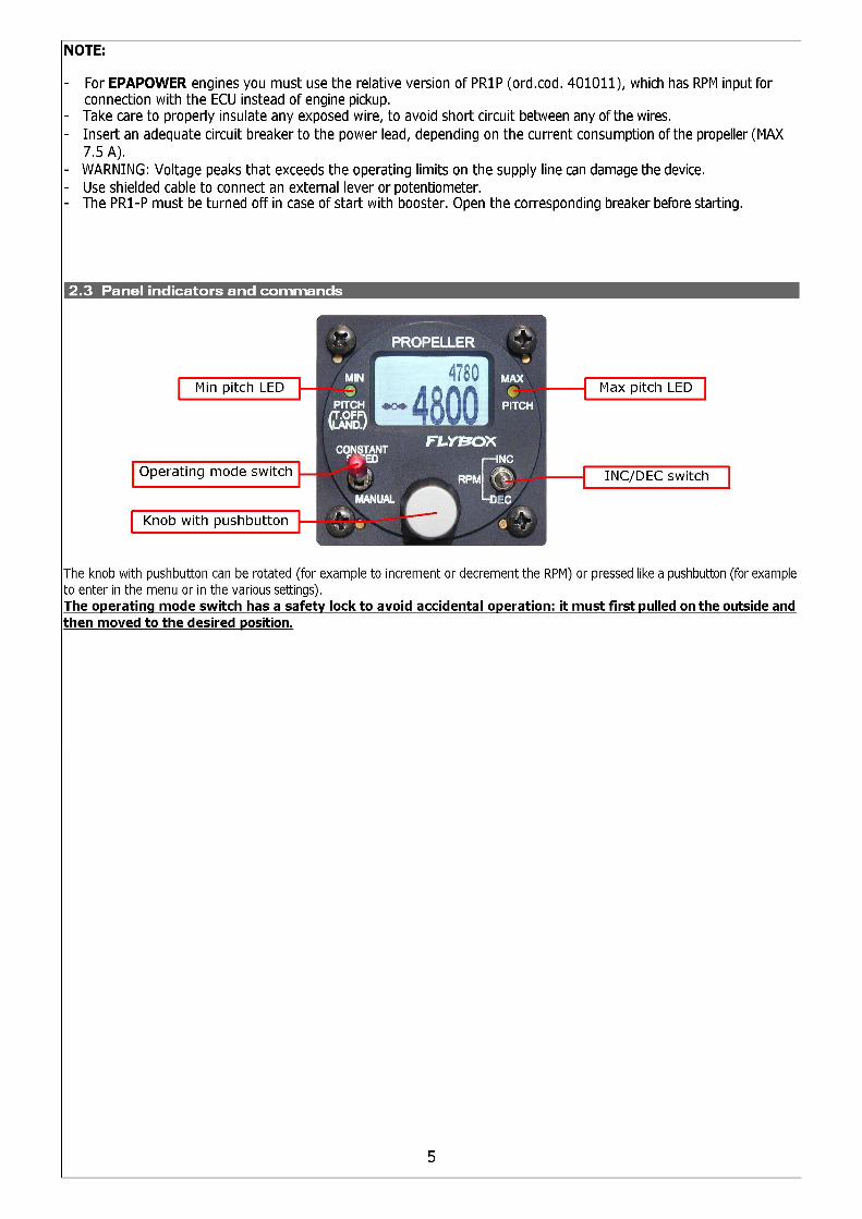
2.3 - Panel indicators and commands …................................................................ 5
2.4 - Wiring check ….......................................................................................... 6
3 - Operating instructions ….................................................................................. 6
3.1 - Use in “Constant speed” mode ….................................................................. 6
3.1.1 - In case of failure/emergency …................................................................ 7
3.2 - Use in “Manual” mode ….............................................................................. 7
3.3 - Functions menu …...................................................................................... 7
3.4 - Setup menu …........................................................................................... 8
3.5 - Additional functions …................................................................................. 84 - Using an external potentiometer or the FLYBOX lever mod. PR1PL …...................... 85 - Using an external switch …............................................................................... 96 - Technical specifications …................................................................................. 9
7 – Warranty …................................................................................................... 10
2
1. Important notices and warnings
- This device is intended for installation onto non type certified aircraft only, because it has no aviation
certification.
Refer to your local aviation authorities to check if this device may be installed in your aircraft.
- Read entirely this manual before installing the instrument in your aircraft, and follow the installation and operating
instructions described here.- Keep this manual in the aircraft.- This document must accompany the instrument in the event of change of ownership.- The pilot must understand the operation of this instrument prior to flight, and must not allow anyone to use it withoutknowing the operation. Don't use this instrument in flight until you are sure of the correct operating of the same.
- When the installation is finished you must do a test, prior to flight, as explained in chap. 2.4, switching on also all the possible source of electric noise and checking the properly operation of this instrument.
- Using this instrument over the maximum allowable ranges can cause malfunction or wrong indications.- The software of this instrument can be subject to change, update, addition or removal of functions, so also the operating mode of the instrument can be subject to change. Always refer to the installation and operating manual updated with the software version used in your instrument. To obtain updated manuals, please visit www.flyboxavionics.it.
- Responsibility for installation lies entirely with the installer. Responsibility for operations lies entirely with the operator.Responsibility for any calibration, settings or any other customization lies with the person performing these operations.
- The PR1-P is connected directly to the propeller pitch actuator: the non-respect of the notices above or a damage to the PR1-P may result in unexpected pitch changes.
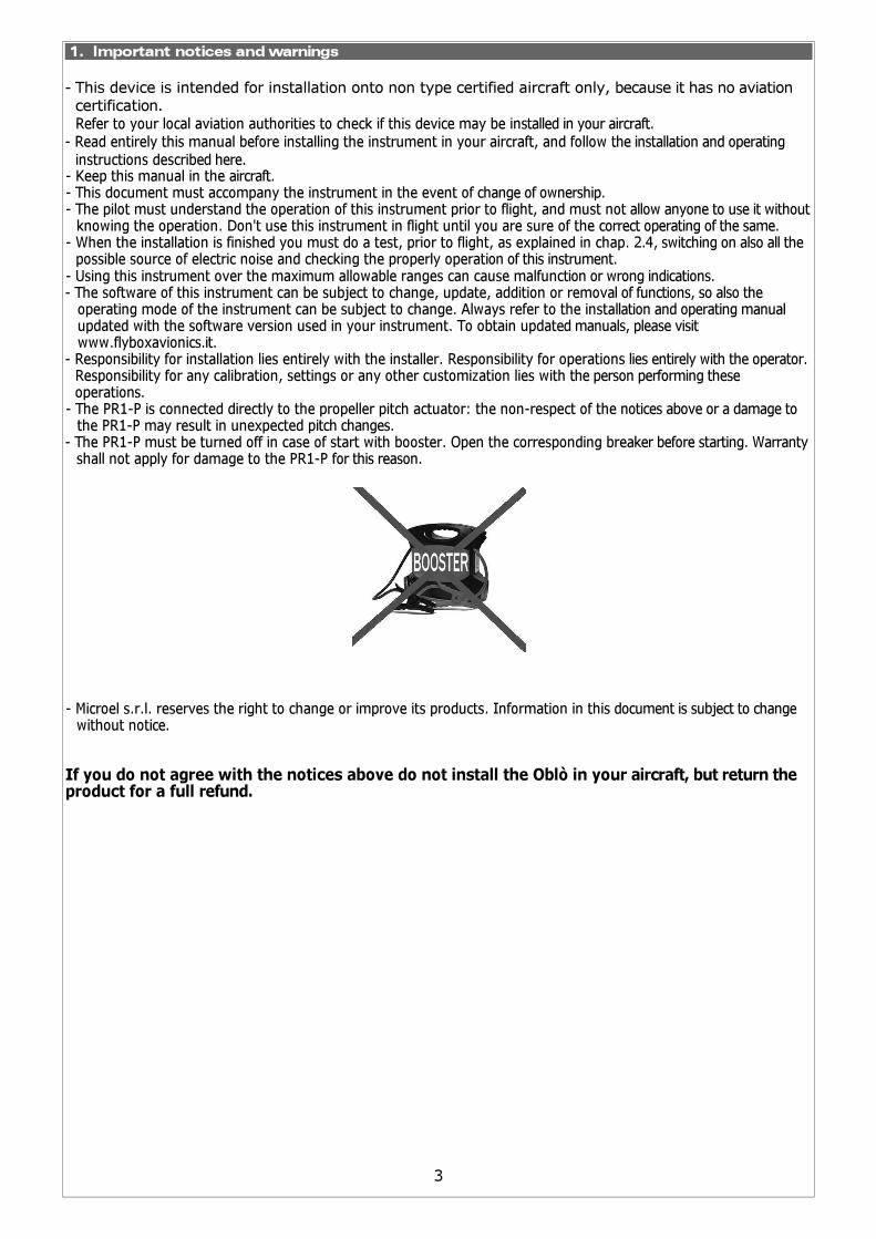
- The PR1-P must be turned off in case of start with booster. Open the corresponding breaker before starting. Warrantyshall not apply for damage to the PR1-P for this reason.
- Microel s.r.l. reserves the right to change or improve its products. Information in this document is subject to change without notice.
If you do not agree with the notices above do not install the Oblò in your aircraft, but return theproduct for a full refund.
3
2. Installation
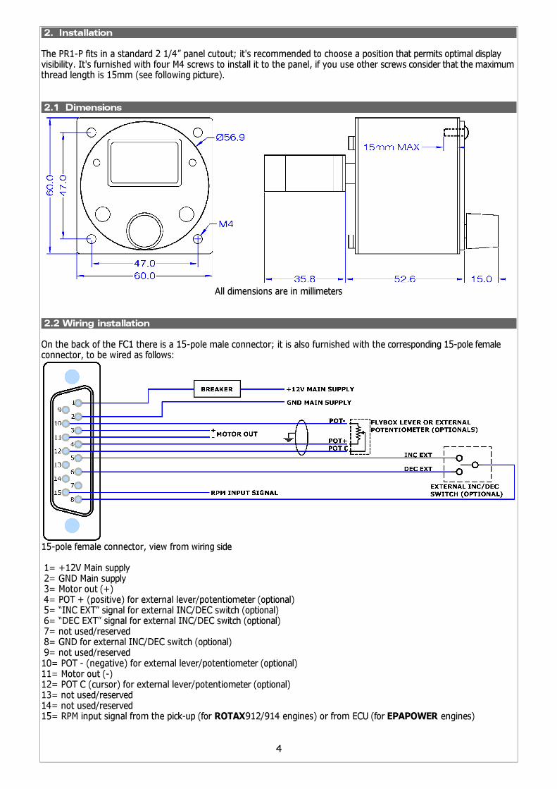
The PR1-P fits in a standard 2 1/4” panel cutout; it's recommended to choose a position that permits optimal displayvisibility. It's furnished with four M4 screws to install it to the panel, if you use other screws consider that the maximumthread length is 15mm (see following picture).
2.1 Dimensions
All dimensions are in millimeters
2.2 Wiring installation
On the back of the FC1 there is a 15-pole male connector; it is also furnished with the corresponding 15-pole femaleconnector, to be wired as follows:
15-pole female connector, view from wiring side
1= +12V Main supply 2= GND Main supply 3= Motor out (+) 4= POT + (positive) for external lever/potentiometer (optional) 5= “INC EXT” signal for external INC/DEC switch (optional) 6= “DEC EXT” signal for external INC/DEC switch (optional) 7= not used/reserved 8= GND for external INC/DEC switch (optional) 9= not used/reserved10= POT - (negative) for external lever/potentiometer (optional)11= Motor out (-)12= POT C (cursor) for external lever/potentiometer (optional)13= not used/reserved14= not used/reserved15= RPM input signal from the pick-up (for ROTAX912/914 engines) or from ECU (for EPAPOWER engines)
4
2.4 Wiring check
Before using the PR1-P in flight for the first time you must execute this checklist (with the engine turned off):
- Turn-on the PR1-P
- Put the operating mode switch in the “Manual” position
- Press the “INC/DEC” switch in the “INC” position (increment RPM) and check that the propeller pitch decrease; check
also that the “Min pitch” LED will go on when the propeller reach the min pitch stop.
If the propeller pitch change in the wrong direction (towards the max pitch) you must invert the two motor out cable
(Motor+ and Motor-).
- Press the “INC/DEC” switch in the “DEC” position (decrement RPM) and check that the propeller pitch increase; check
also that the “Max pitch” LED will go on when the propeller reach the max pitch stop.
- Turn-on the engine and execute a propeller/regulator test (see the function “Prop test” in chapter 3.3)
NOTES:
- Perform this test after every modifications or maintenance of the propeller system to verify that all connections are
restored correctly.
- Refer to the propeller constructor's manual if you need to adjust the mechanical min and max pitch stop of the
propeller
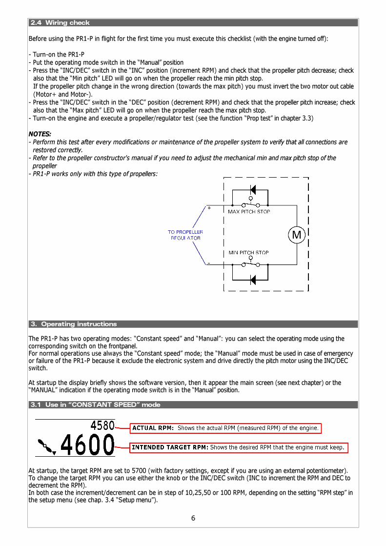
- PR1-P works only with this type of propellers:
3. Operating instructions
The PR1-P has two operating modes: “Constant speed” and “Manual”: you can select the operating mode using thecorresponding switch on the frontpanel.For normal operations use always the “Constant speed” mode; the “Manual” mode must be used in case of emergencyor failure of the PR1-P because it exclude the electronic system and drive directly the pitch motor using the INC/DECswitch.
At startup the display briefly shows the software version, then it appear the main screen (see next chapter) or the“MANUAL” indication if the operating mode switch is in the “Manual” position.
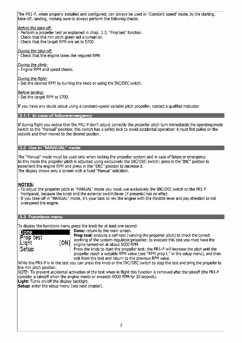
3.1 Use in “CONSTANT SPEED” mode
At startup, the target RPM are set to 5700 (with factory settings, except if you are using an external potentiometer).To change the target RPM you can use either the knob or the INC/DEC switch (INC to increment the RPM and DEC todecrement the RPM).In both case the increment/decrement can be in step of 10,25,50 or 100 RPM, depending on the setting “RPM step” inthe setup menu (see chap. 3.4 “Setup menu”).
6
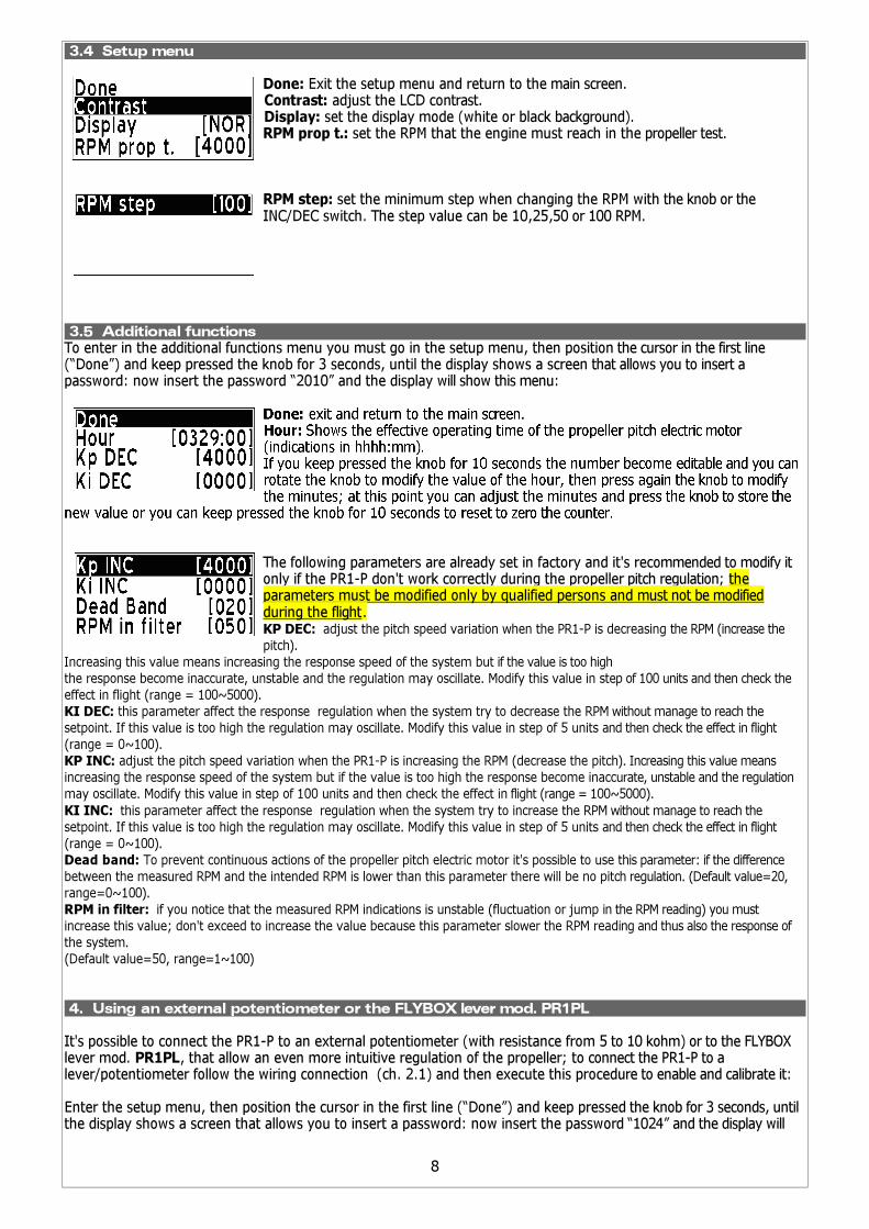
3.4 Setup menu
Done: Exit the setup menu and return to the main screen.Contrast: adjust the LCD contrast.Display: set the display mode (white or black background).RPM prop t.: set the RPM that the engine must reach in the propeller test.
RPM step: set the minimum step when changing the RPM with the knob or the INC/DEC switch. The step value can be 10,25,50 or 100 RPM.
3.5 Additional functions To enter in the additional functions menu you must go in the setup menu, then position the cursor in the first line(“Done”) and keep pressed the knob for 3 seconds, until the display shows a screen that allows you to insert apassword: now insert the password “2010” and the display will show this menu:
The following parameters are already set in factory and it's recommended to modify it only if the PR1-P don't work correctly during the propeller pitch regulation; the parameters must be modified only by qualified persons and must not be modified during the flight. KP DEC: adjust the pitch speed variation when the PR1-P is decreasing the RPM (increase the
pitch).
Increasing this value means increasing the response speed of the system but if the value is too high
the response become inaccurate, unstable and the regulation may oscillate. Modify this value in step of 100 units and then check the
effect in flight (range = 100~5000).
KI DEC: this parameter affect the response regulation when the system try to decrease the RPM without manage to reach the
setpoint. If this value is too high the regulation may oscillate. Modify this value in step of 5 units and then check the effect in flight
(range = 0~100).
KP INC: adjust the pitch speed variation when the PR1-P is increasing the RPM (decrease the pitch). Increasing this value means
increasing the response speed of the system but if the value is too high the response become inaccurate, unstable and the regulation
may oscillate. Modify this value in step of 100 units and then check the effect in flight (range = 100~5000).
KI INC: this parameter affect the response regulation when the system try to increase the RPM without manage to reach the
setpoint. If this value is too high the regulation may oscillate. Modify this value in step of 5 units and then check the effect in flight
(range = 0~100).
Dead band: To prevent continuous actions of the propeller pitch electric motor it's possible to use this parameter: if the difference
between the measured RPM and the intended RPM is lower than this parameter there will be no pitch regulation. (Default value=20,
range=0~100).
RPM in filter: if you notice that the measured RPM indications is unstable (fluctuation or jump in the RPM reading) you must
increase this value; don't exceed to increase the value because this parameter slower the RPM reading and thus also the response of
the system.
(Default value=50, range=1~100)
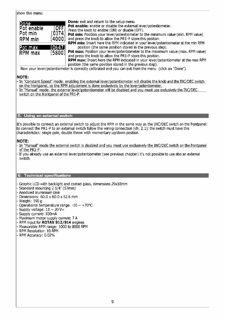
4. Using an external potentiometer or the FLYBOX lever mod. PR1PL
It's possible to connect the PR1-P to an external potentiometer (with resistance from 5 to 10 kohm) or to the FLYBOXlever mod. PR1PL, that allow an even more intuitive regulation of the propeller; to connect the PR1-P to alever/potentiometer follow the wiring connection (ch. 2.1) and then execute this procedure to enable and calibrate it:
Enter the setup menu, then position the cursor in the first line (“Done”) and keep pressed the knob for 3 seconds, untilthe display shows a screen that allows you to insert a password: now insert the password “1024” and the display will
8
7. Warranty
This product is warranted to be free from defects for a period of 12 months from the user invoice date.
The warranty only covers manufacturer defects and shall not apply to a product that has been improperly installed,
misused or incorrect maintenance, repaired or altered by non-qualified persons.
MICROEL s.r.l.Via Mortara 192-194
27038 Robbio (PV) - ITALYTel +39-0384-670602 - Fax +39-0384-671830
www.flyboxavionics.it
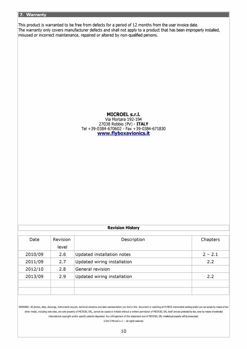
Revision History
Date Revision
level
Description Chapters
2010/09 2.6 Updated installation notes 2 – 2.1
2011/09 2.7 Updated wiring installation 2.2
2012/10 2.8 General revision
2013/09 2.9 Updated wiring installation 2.2
WARNING: All photos, data, drawings, instruments layouts, technical solutions and data representation you find in this document or watching at FLYBOX instruments working and/or you can access by means of any
other media, including web sites, are sole property of MICROEL SRL, cannot be copied or imitate without a written permission of MICROEL SRL itself and are protected by law, even by means of extended
international copyright and/or specific patents deposited. Any infringement of this statement and of MICROEL SRL intellectual property will be prosecuted.
©2013 Microel s.r.l. – all rights reserved.
10