Embed Size (px)
Citation preview
This text was printed from the NTSB Maintenance Accident Report Infobase developed by Galaxy ScientificCorporation with funding from the Federal Aviation Administration Office of Aviation Medicine. Copyright©
1998. All rights reserved.
04/28/88 Aloha Airlines
Official Accident Report Index Page
This text was printed from the NTSB Maintenance Accident Report Infobase developed by Galaxy ScientificCorporation with funding from the Federal Aviation Administration Office of Aviation Medicine. Copyright©
1998. All rights reserved.
Report Number NTSB/AAR-89/03
Access Number PB89-91C404
Report Title Aircraft Accident Report--Aloha Airlines, Flight 243, Boeing737-200, N73711, near Maui, Hawaii, April 28, 1988
Report Date June 14, 1989
Organization Name National Transportation Safety Board Bureau of AccidentInvestigation Washington, D.C. 20594
WUN 4886A
Sponsor Name NATIONAL TRANSPORTATION SAFETY BOARD Washington,D.C. 20594
Report Type Aircraft Accident Report April 28, 1988
Distribution Status This document is available to the public through the NationalTechnical Information Service, Springfield, Virginia 22161
Report Class UNCLASSIFIED
Pg Class UNCLASSIFIED
Pages 262
Keywords decompression; disbonding; fatigue cracking; corrosion; multiplesite damage (MSD); FAA surveillance; maintenance program;nondestructive inspection
This text was printed from the NTSB Maintenance Accident Report Infobase developed by Galaxy ScientificCorporation with funding from the Federal Aviation Administration Office of Aviation Medicine. Copyright©
1998. All rights reserved.
Abstract On April 28, 1988, at 1346, a Boeing 737-200, N73711, operated byAloha Airlines Inc., as flight 243, experienced an explosivedecompression and structural failure at 24,000 feet, while en routefrom Hilo, to Honolulu, Hawaii. Approximately 18 feet of the cabinskin and structure aft of the cabin entrance door and above thepassenger floorline separated from the airplane during flight. Therewere 89 passengers and 6 crewmembers on board. One flightattendant was swept overboard during the decompression and ispresumed to have been fatally injured; 7 passengers and 1 flightattendant received serious injuries. The flightcrew performed anemergency descent and landing at Kahului Airport on the Island ofMaui.The safety issues raised in this report include: the quality of aircarrier maintenance programs and the FAA surveillance of thoseprograms, the engineering airworthiness of the B-737 with particularemphasis on multiple site fatigue cracking of the fuselage lap joints,the human factors aspects of air carrier maintenance and inspectionfor the continuing airworthiness of transport category airplanes, toinclude repair procedures and the training, certification andqualification of mechanics and inspectors.
Facts of the Accident
This text was printed from the NTSB Maintenance Accident Report Infobase developed by Galaxy ScientificCorporation with funding from the Federal Aviation Administration Office of Aviation Medicine. Copyright©
1998. All rights reserved.
Accident NTSB ID 89-03
Airline Aloha Airlines
Model aircraft 737-200, N73711
Year shipped 1969
Aircraft manufacturer Boeing
Engine type JT8D-9A
Engine manuafacturer Pratt & Whitney
Date 04/28/88
Time 1346
Location Near Maui, Hawaii
Country USA
IFR or VFR? VFR
Fatalities 1
Injuries 8
Fire during flight? N
Fire on the ground? N
Probable cause Failure of the Aloha Airlines maintenance program to detect thepresence of significant disbonding and fatigue damage whichultimately led to failure of the lap joint at S-10L and the separationof the fuselage upper lobe.
Contributing causes The failure of Aloha Airlines management to supervise properly itsmaintenance force; the failure of the FAA to evaluate properly theAloha Airlines maintenance program and to assess the airline'sinspection and quality control deficiencies; the failure of the FAA torequire Airworthiness Directive 87-21-08 inspection of all the lapjoints proposed by Boeing Alert Service Bulletin SB 737-53A1039;and the lack of a complete terminating action (neither generated byBoeing nor required by the FAA) after the discovery of earlyproduction difficulties in the B-737 cold bond lap joint whichresulted in low bond durability, corrosion, and premature fatiguecracking.
This text was printed from the NTSB Maintenance Accident Report Infobase developed by Galaxy ScientificCorporation with funding from the Federal Aviation Administration Office of Aviation Medicine. Copyright©
1998. All rights reserved.
Weather conditions No significant adverse weather experienced
Total crew size 5
Cockpit crew size 2
Cabin crew size 3
Passengers 90
Report ID NTSB/AAR-89/03
Pages 262
Day or night? Day
Flight number 243
Flight origin Hilo, Hawaii
Flight destination Honolulu, Hawaii
Description Aloha flight 243 experienced an explosive decompression andstructural failure at 24,000 feet. Approziately 18 feet of cabin skinand structure above the passenger floorline separated from theairplane during flight. One flight attendant was swept overboardand presumed dead. The flightcrew performed an emergencydescent and landing at Maui.
Executive SummaryOn April 28, 1988, at 1346, a Boeing 737-200, N73711, operated by Aloha Airlines Inc., as flight 243, experiencedan explosive decompression and structural failure at 24,000 feet, while en route from Hilo, to Honolulu, Hawaii.Approximately 18 feet from the cabin skin and structure aft of the cabin entrance door and above the passengerfloorline separated from the airplane during flight. There were 89 passengers and 6 crewmembers on board. Oneflight attendant was swept overboard during the decompression and is presumed to have been fatally injured; 7passengers and 1 flight attendant received serious injuries. The flight crew performed an emergency descent andlanding at Kahului Airport on the Island of Maui.
The National Transportation Safety Board determines that the probable cause of this accident was the failure of theAloha Airlines maintenance program to detect the presence of significant disbonding and fatigue damage whichultimately led to failure of the lap joint at S-10L and the separation of the fuselage upper lobe. Contributing to theaccident were the failure of Aloha Airlines management to supervise properly its maintenance force; the failure ofthe FAA to evaluate properly the Aloha Airlines maintenace program and to assess the airline's inspection andquality control deficiencies; the failure of the FAA to require Airworthiness Directive 87-21-08 inspection of all thelap joints proposed by Boeing Alert Service Bulletin SB 737-53A1039; and the lack of a complete terminating
This text was printed from the NTSB Maintenance Accident Report Infobase developed by Galaxy ScientificCorporation with funding from the Federal Aviation Administration Office of Aviation Medicine. Copyright©
1998. All rights reserved.
action (neither generated by Boeing nor required by the FAA) after the discovery of early production difficulties inthe B-737 cold bond lap joint which resulted in low bond durability, corrosion, and premature fatigue cracking.
The safety issues raised in this report include:
· The quality of air carrier maintenance programs and the FAA surveillance of those programs.
· The engineering design, certification, and continuing airworthiness of the B-737 withparticular emphasis on multiple site fatigue cracking of the fuselage lap joints.
· The human factors aspects of air carrier maintenance and inspection for the continuingairworthiness of transport category airplanes, to include repair procedures and the training,certification and qualification of mechanics and inspectors.
Recommendations concerning these issues were addressed to the Federal Aviation Administration, Aloha Airlines,and the Air Transport Association.
1. Factual Information
1.1 History of the FlightOn April 28, 1988, an Aloha Airlines Boeing 737, N73711, based at the Honolulu International Airport, Hawaii,was scheduled for a series of interisland flights to be conducted under Title 14 Code of Federal Regulations (CFR)Part 121. A captain and first officer were assigned for the first six flights of the day with a planned first officerchange to complete the remainder of the daily schedule.
The first officer checked in with the dispatch office about 0500 Hawaiian standard time at the Aloha AirlinesOperations Facility. After familiarizing himself with the flight operations paperwork, he proceeded to the AlohaAirlines parking apron and performed the preflight inspection required by company procedures before the firstflight of the day. He stated that the airplane maintenance log release was signed and that there were no opendiscrepancies. He prepared the cockpit for the external portion of the preflight, exited the airplane in predawndarkness, and performed the visual exterior inspection on the lighted apron. He stated that he found nothingunusual and was satisfied that the airplane was ready for flight.
The captain checked in for duty about 0510; he completed his predeparture duties in the dispatch office and thenproceeded to the airplane.
The crew flew three roundtrip flights, one each from Honolulu to Hilo, Maui, and Kauai. They reported that all sixflights were uneventful and that all airplane systems performed in the normal and expected manner. Flightcrewvisual exterior inspections between flights were not required by Federal Aviation Administration (FAA) acceptedcompany procedures, and none were performed.
At 1100, a scheduled first officer change took place for the remainder of the day. The crew flew from Honolulu toMaui and then from Maui to Hilo. As with the previous flights of the day, no system, powerplant, or structuralabnormalities were noted during these operations, and the flights were uneventful. Neither pilot left the airplane onarrival in Hilo, and the crew did not perform any visual exterior inspection nor were they required to do so.
At 1325, flight 243 departed Hilo Airport en route to Honolulu as part of the normal scheduled service. In additionto the two pilots, there were three flight attendants, an FAA air traffic controller, who was seated in the observer
This text was printed from the NTSB Maintenance Accident Report Infobase developed by Galaxy ScientificCorporation with funding from the Federal Aviation Administration Office of Aviation Medicine. Copyright©
1998. All rights reserved.
seat in the cockpit, and 89 passengers on board. Passenger boarding, engine start, taxi, and takeoff were uneventful.
The planned routing for Aloha flight 243 was from Hilo to Honolulu at flight level 240. Maui was listed as thealternate landing airport.
The first officer conducted the takeoff and en route climb from Hilo. The captain performed the nonflying pilotduties. The first officer did not recall using the autopilot.
The flight was conducted in visual meteorological conditions. There were no advisories for significantmeteorological information (SIGMET) or airman's meteorological information (AIRMET) valid for the area alongthe planned route of flight.
No unusual occurrences were noted by either crewmember during the departure and climbout. As the airplaneleveled at 24,000 feet, both pilots heard a loud "clap" or "whooshing" sound followed by a wind noise behind them.The first officer's head was jerked backward, and she stated that debris, including pieces of gray insulation, wasfloating in the cockpit. The captain observed that the cockpit entry door was missing and that "there was blue skywhere the first-class ceiling had been." The captain immediately took over the controls of the airplane. Hedescribed the airplane attitude as rolling slightly left and right and that the flight controls felt "loose."
Because of the decompression, both pilots and the air traffic controller in the observer seat donned their oxygenmasks. The captain began an emergency descent. He stated that he extended the speed brakes and descended at anindicated airspeed (IAS) of 280 to 290 knots. Because of ambient noise, the pilots initially used hand signals tocommunicate. The first officer stated that she observed a rate of descent of 4,100 feet per minute at some pointduring the emergency descent. The captain also stated that he actuated the passenger oxygen switch. The passengeroxygen manual tee handle was not actuated.
When the decompression occurred, all the passengers were seated and the seat belt sign was illuminated. The No. 1flight attendant reportedly was standing at seat row 5. According to passenger observations, the flight attendant wasimmediately swept out of the cabin through a hole in the left side of the fuselage. The No. 2 flight attendant,standing by row 15/16, was thrown to the floor and sustained minor bruises. She was subsequently able to crawl upand down the aisle to render assistance and calm the passengers. The No. 3 flight attendant, standing at row 2, wasstruck in the head by debris and thrown to the floor. She suffered serious injuries including a concussion and severehead lacerations.
The first officer said she tuned the transponder to emergency code 7700 and attempted to notify Honolulu Air RouteTraffic Control Center (ARTCC) that the flight was diverting to Maui. Because of the cockpit noise level, she couldnot hear any radio transmissions, and she was not sure if the Honolulu ARTCC heard the communication.
Although Honolulu ARTCC did not receive the first officer's initial communication, the controller working flight243 observed an emergency code 7700 transponder return about 23 nautical miles (nmi) south-southeast of theKahalui Airport, Maui. Starting at 1348:15, the controller attempted to communicate with the flight several timeswithout success.
When the airplane descended through 14,000 feet, the first officer switched the radio to the Maui Tower frequency.At 1348:35, she informed the tower of the rapid decompression, declared an emergency, and stated the need foremergency equipment. Maui Tower acknowledged and began emergency notifications based on the first officer'sreport of decompression.
At the local controller's direction, the specialist working the Maui Tower clearance delivery position notified theairport's rescue and firefighting personnel, via the direct hot line, that a B-737 had declared an emergency, wasinbound and that the nature of the emergency was a decompression. Rescue vehicles took up alert positions along
This text was printed from the NTSB Maintenance Accident Report Infobase developed by Galaxy ScientificCorporation with funding from the Federal Aviation Administration Office of Aviation Medicine. Copyright©
1998. All rights reserved.
the left side of the runway.
At the Maui Airport, ambulance service was available from the nearby community when notified by control towerpersonnel through the local "911" telephone number. Tower personnel did not consider it necessary at that time tocall for an ambulance based on their understanding of the nature of the emergency.
At 1349:00, emergency coordination began between Honolulu Center and Maui Approach Control. Honoluluadvised Maui Approach Control that they had received an emergency code 7700 transponder return that could be anAloha 737 and stated, "You might be prepared in case he heads your way." Maui Approach Control then advisedHonolulu Center that flight 243 was diverting to land at Maui.
The local controller instructed flight 243 to change to the Maui Sector transponder code to identify the flight andindicate to surrounding air traffic control (ATC) facilities that the flight was being handled by the Maui ATCfacility. The first officer changed the transponder as requested.
The flight was operating beyond the local controller's area of radar authority of about 13 nmi. At 1350:58, the localcontroller requested the flight to switch to 119.5 MHz. (approach frequency) so that the approach controller couldmonitor the flight. Although the request was acknowledged, the flight was not heard on 119.5 MHz. Flight 243continued to transmit on the local controller frequency.
At 1353:44, the first officer informed the local controller, "We're going to need assistance. We cannot communicatewith the flight attendants. We'll need assistance for the passengers when we land." An ambulance request was notinitiated as a result of this radio call. The first officer also provided the local controller with the flight's passengercount, but she did not indicate the fuel load. The local controller did not repeat the request for the fuel load evenafter a query from the chief of the emergency response team.
The captain stated that he began slowing the airplane as the flight approached 10,000 feet mean sea level (msl).This maneuver is required as a routine operations practice to comply with ATC speed limitations. He retracted thespeed brakes, removed his oxygen mask, and began a gradual turn toward Maui's runway 02. At 210 knots IAS, theflightcrew could communicate verbally. The captain gave the command to lower the flaps. Initially flaps 1 wereselected, then flaps 5. When attempting to extend beyond flaps 5, the airplane became less controllable, and thecaptain decided to return to flaps 5 for the landing.
Because the captain found the airplane becoming less controllable below 170 knots IAS, he elected to use 170 knotsIAS for the approach and landing.
Using the public address (PA) system and on-board interphone, the first officer attempted to communicate with theflight attendants; however, there was no response.
At the command of the captain, the first officer lowered the landing gear at the normal point in the approach pattern.The main gear indicated down and locked; however, the nose gear position indicator light did not illuminate.Manual nose gear extension was selected and still the green indicator light did not illuminate; however, the redlanding gear unsafe indicator light was not illuminated. After another manual attempt, the handle was placed downto complete the manual gear extension procedure. The captain said no attempt was made to use the nose geardownlock viewer because the center jumpseat was occupied and the captain believed it was urgent to land theairplane immediately.
At 1355:05, the first officer advised the tower, "We won't have a nose gear," and at 1356:14, the crew advised thetower, "We'll need all the equipment you've got."
While advancing the power levers to maneuver for the approach, the captain sensed a yawing motion anddetermined that the No. 1 (left) engine had failed. At 170 to 200 knots IAS, he placed the No. 1 engine start switch
This text was printed from the NTSB Maintenance Accident Report Infobase developed by Galaxy ScientificCorporation with funding from the Federal Aviation Administration Office of Aviation Medicine. Copyright©
1998. All rights reserved.
to the "flight" position in an attempt to start the engine; there was no response.
A normal descent profile was established 4 miles out on the final approach. The captain said that the airplane was"shaking a little, rocking slightly and felt springy."
Flight 243 landed on runway 02 at Maui's Kahului Airport at 1358:45. The captain said that he was able to make anormal touchdown and landing rollout. He used the No. 2 engine thrust reverser and brakes to stop the airplane.During the latter part of the rollout, the flaps were extended to 40° as required for an evacuation. An emergencyevacuation was then accomplished on the runway.
After the accident, a passenger stated that as she was boarding the airplane through the jet bridge at Hilo, sheobserved a longitudinal fuselage crack. The crack was in the upper row of rivets along the S-10L lap joint, abouthalfway between the cabin door and the edge of the jet bridge hood. She made no mention of the observation to theairline ground personnel or flightcrew.
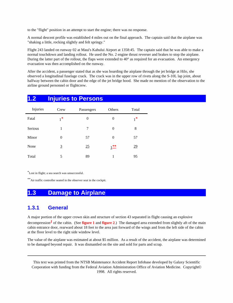
1.2 Injuries to PersonsInjuries Crew Passengers Others Total
Fatal 1* 0 0 1*
Serious 1 7 0 8
Minor 0 57 0 57
None 3 25 1** 29
Total 5 89 1 95
*Lost in flight; a sea search was unsuccessful.
**Air traffic controller seated in the observer seat in the cockpit.
1.3 Damage to Airplane
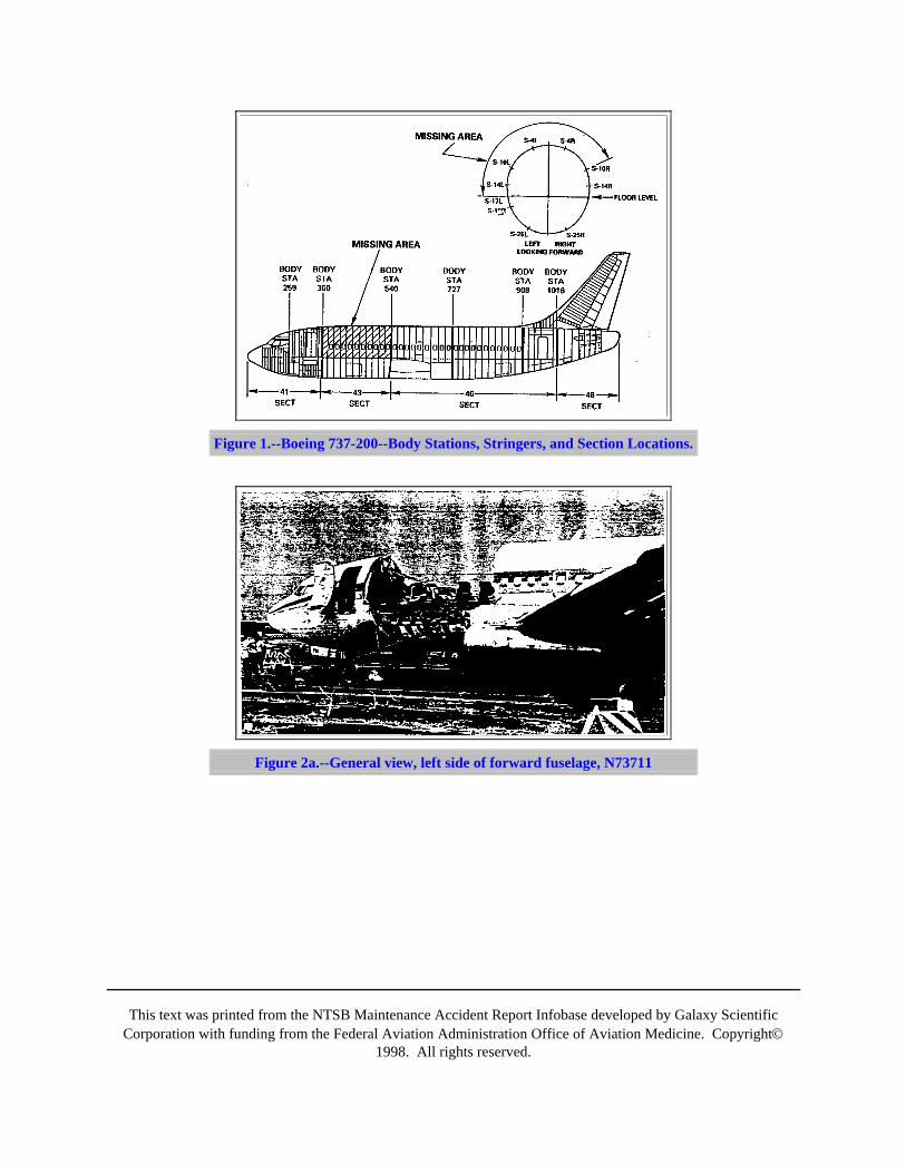
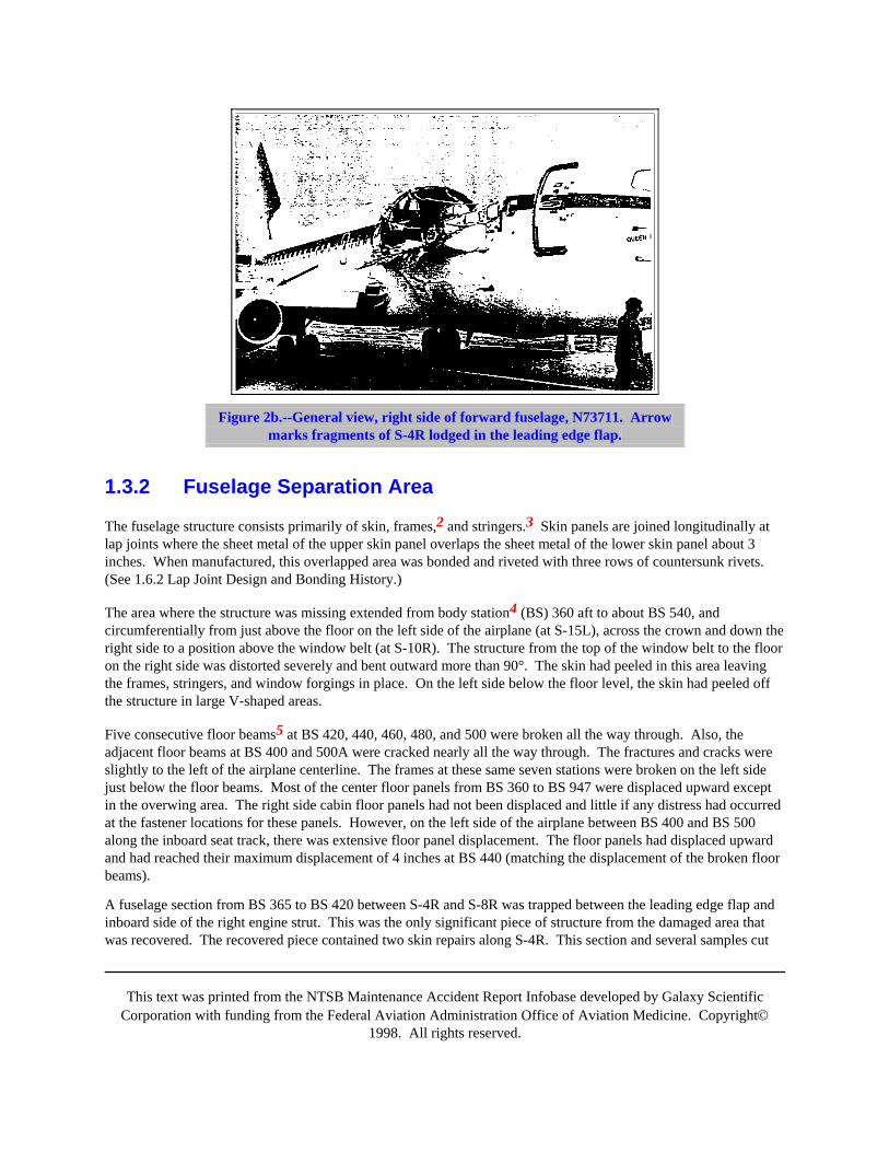
1.3.1 GeneralA major portion of the upper crown skin and structure of section 43 separated in flight causing an explosivedecompression1 of the cabin. (See figure 1 and figure 2.) The damaged area extended from slightly aft of the maincabin entrance door, rearward about 18 feet to the area just forward of the wings and from the left side of the cabinat the floor level to the right side window level.
The value of the airplane was estimated at about $5 million. As a result of the accident, the airplane was determinedto be damaged beyond repair. It was dismantled on the site and sold for parts and scrap.
This text was printed from the NTSB Maintenance Accident Report Infobase developed by Galaxy ScientificCorporation with funding from the Federal Aviation Administration Office of Aviation Medicine. Copyright©
1998. All rights reserved.
Figure 1.--Boeing 737-200--Body Stations, Stringers, and Section Locations.
Figure 2a.--General view, left side of forward fuselage, N73711
This text was printed from the NTSB Maintenance Accident Report Infobase developed by Galaxy ScientificCorporation with funding from the Federal Aviation Administration Office of Aviation Medicine. Copyright©
1998. All rights reserved.
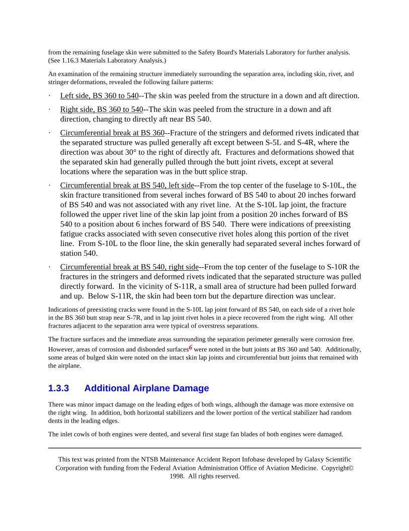
Figure 2b.--General view, right side of forward fuselage, N73711. Arrowmarks fragments of S-4R lodged in the leading edge flap.
1.3.2 Fuselage Separation Area
The fuselage structure consists primarily of skin, frames,2 and stringers.3 Skin panels are joined longitudinally atlap joints where the sheet metal of the upper skin panel overlaps the sheet metal of the lower skin panel about 3inches. When manufactured, this overlapped area was bonded and riveted with three rows of countersunk rivets.(See 1.6.2 Lap Joint Design and Bonding History.)
The area where the structure was missing extended from body station4 (BS) 360 aft to about BS 540, andcircumferentially from just above the floor on the left side of the airplane (at S-15L), across the crown and down theright side to a position above the window belt (at S-10R). The structure from the top of the window belt to the flooron the right side was distorted severely and bent outward more than 90°. The skin had peeled in this area leavingthe frames, stringers, and window forgings in place. On the left side below the floor level, the skin had peeled offthe structure in large V-shaped areas.
Five consecutive floor beams5 at BS 420, 440, 460, 480, and 500 were broken all the way through. Also, theadjacent floor beams at BS 400 and 500A were cracked nearly all the way through. The fractures and cracks wereslightly to the left of the airplane centerline. The frames at these same seven stations were broken on the left sidejust below the floor beams. Most of the center floor panels from BS 360 to BS 947 were displaced upward exceptin the overwing area. The right side cabin floor panels had not been displaced and little if any distress had occurredat the fastener locations for these panels. However, on the left side of the airplane between BS 400 and BS 500along the inboard seat track, there was extensive floor panel displacement. The floor panels had displaced upwardand had reached their maximum displacement of 4 inches at BS 440 (matching the displacement of the broken floorbeams).
A fuselage section from BS 365 to BS 420 between S-4R and S-8R was trapped between the leading edge flap andinboard side of the right engine strut. This was the only significant piece of structure from the damaged area thatwas recovered. The recovered piece contained two skin repairs along S-4R. This section and several samples cut
This text was printed from the NTSB Maintenance Accident Report Infobase developed by Galaxy ScientificCorporation with funding from the Federal Aviation Administration Office of Aviation Medicine. Copyright©
1998. All rights reserved.
from the remaining fuselage skin were submitted to the Safety Board's Materials Laboratory for further analysis.(See 1.16.3 Materials Laboratory Analysis.)
An examination of the remaining structure immediately surrounding the separation area, including skin, rivet, andstringer deformations, revealed the following failure patterns:
· Left side, BS 360 to 540--The skin was peeled from the structure in a down and aft direction.
· Right side, BS 360 to 540--The skin was peeled from the structure in a down and aftdirection, changing to directly aft near BS 540.
· Circumferential break at BS 360--Fracture of the stringers and deformed rivets indicated thatthe separated structure was pulled generally aft except between S-5L and S-4R, where thedirection was about 30° to the right of directly aft. Fractures and deformations showed thatthe separated skin had generally pulled through the butt joint rivets, except at severallocations where the separation was in the butt splice strap.
· Circumferential break at BS 540, left side--From the top center of the fuselage to S-10L, theskin fracture transitioned from several inches forward of BS 540 to about 20 inches forwardof BS 540 and was not associated with any rivet line. At the S-10L lap joint, the fracturefollowed the upper rivet line of the skin lap joint from a position 20 inches forward of BS540 to a position about 6 inches forward of BS 540. There were indications of preexistingfatigue cracks associated with seven consecutive rivet holes along this portion of the rivetline. From S-10L to the floor line, the skin generally had separated several inches forward ofstation 540.
· Circumferential break at BS 540, right side--From the top center of the fuselage to S-10R thefractures in the stringers and deformed rivets indicated that the separated structure was pulleddirectly forward. In the vicinity of S-11R, a small area of structure had been pulled forwardand up. Below S-11R, the skin had been torn but the departure direction was unclear.
Indications of preexisting cracks were found in the S-10L lap joint forward of BS 540, on each side of a rivet holein the BS 360 butt strap near S-7R, and in lap joint rivet holes in a piece recovered from the right wing. All otherfractures adjacent to the separation area were typical of overstress separations.
The fracture surfaces and the immediate areas surrounding the separation perimeter generally were corrosion free.However, areas of corrosion and disbonded surfaces6 were noted in the butt joints at BS 360 and 540. Additionally,some areas of bulged skin were noted on the intact skin lap joints and circumferential butt joints that remained withthe airplane.
1.3.3 Additional Airplane DamageThere was minor impact damage on the leading edges of both wings, although the damage was more extensive onthe right wing. In addition, both horizontal stabilizers and the lower portion of the vertical stabilizer had randomdents in the leading edges.
The inlet cowls of both engines were dented, and several first stage fan blades of both engines were damaged.
This text was printed from the NTSB Maintenance Accident Report Infobase developed by Galaxy ScientificCorporation with funding from the Federal Aviation Administration Office of Aviation Medicine. Copyright©
1998. All rights reserved.
Remnants of fuselage structure were found against the inlet guide vanes and embedded in the acoustic liner of theright engine.
A cable in the closed loop cable system for the left engine thrust lever and a cable in the left engine start leversystem were broken near a pulley cluster located in the leading edge of the left wing immediately inboard of theengine strut. The broken start lever cable prevented motion of the fuel control to the start position; the broken thrustlever cable prevented any power increase on the engine. The left engine fuel control was found in the "cutoff"position. Initial examination of the broken cables showed signs of heavy corrosion in the area of the separation.Routing of these cables between the cockpit and the left engine pod was traced through the area of maximumupward floor defection at BS 440 under the cabin floor. The cables were retained and submitted to the SafetyBoard's Materials Laboratory for further examination. (See 1.16.3 Materials Laboratory Analysis.)
The upper fuselage crown separation resulted in damage to overhead wire bundles, and a number of circuit breakersin the cockpit were tripped. Most of these circuit breakers were related to passenger service unit and lavatorywiring. The potable water line was leaking and its conduit was broken. The pitot line and the static line to the flightdata recorder (FDR) were broken, as was the conditioned air distribution ducting. The passenger oxygen manifoldwas severed which prevented use of the passenger oxygen system; however, the flightcrew oxygen system wasundamaged. The flightcrew and passenger oxygen cylinders were fully discharged. Both engine fire bottles wereempty, and both of the engine fire extinguisher switches in the cockpit had been activated, per the airplaneemergency evacuation procedures.
The hydraulic system was not damaged. All the landing gear were down and locked, the flaps and leading edgedevices were fully extended, the spoilers were retracted, and there was no loss of hydraulic fluid. An examinationof the nose gear position indicator light module revealed that one of the two bulbs was burned out and that themodule was slightly loose in its housing. No other discrepancies were found in the nose gear position indicatingsystem.
1.3.4 Pressurization SystemThe main (aft) outflow valve and the forward outflow valve were fully closed. The forward outflow valve receivesposition signals from the main outflow valve. The pressurization controller was found in "automatic" and theflight/ground mode selector switch was found in the "flight" position. The flight position causes the cabin altitudecontroller to conform to the selected flight profile and also to modulate the main outflow valve toward the closedposition to pressurize the cabin slightly (0.1 psi) during ground operation. The switch is normally set to flight afterengine start to pressurize the airplane; the switch is set to "ground" to depressurize after the landing rollout.
Continuity checks showed normal system operation. All relevant system components were removed from theairplane for further functional tests. (See 1.16.1 Pressurization System.)
1.4 Other DamageNone.
1.5 Personnel InformationThe flightcrew consisted of the captain, first officer, and three flight attendants. (See appendix B.)
This text was printed from the NTSB Maintenance Accident Report Infobase developed by Galaxy ScientificCorporation with funding from the Federal Aviation Administration Office of Aviation Medicine. Copyright©
1998. All rights reserved.
The captain was hired by Aloha Airlines on May 31, 1977, as a B-737 first officer. he was upgraded to captain onJune 1, 1987. He possessed a current first-class medical certificate with no limitations. He held an airline transportcertificate with a type rating for the B-737. At the time of the accident, the captain had accrued about 8,500 totalflight hours with 6,700 hours in the B-737. His pilot-in-command time with Aloha Airlines was 400 hours, all inthe B-737.
The first officer was hired by Aloha Airlines on June 4, 1979, as a B-737 first officer. She possessed a currentfirst-class medical certificate with a limitation for corrective lenses. She holds an airline transport certificatewithout type ratings. At the time of the accident, the first officer had accrued about 8,000 total flying hours withabout 3,500 hours in the B-737.
A dispatch records review indicated that the crew had complied with all relevant flightcrew duty time limitations.
Flightcrew training records included documentation of normal and emergency procedures training. The AlohaAirlines flightcrew training program outline required emphasis on cockpit resource management (CRM) concepts;however, the training program did not include a specific CRM course, and line oriented flight training (LOFT)programs were not conducted, nor were they required by regulation.
1.6 Airplane Information
1.6.1 GeneralThe accident airplane, N73711, a Boeing 737-297, serial number 20209, was manufactured in 1969 as productionline number 152. It was equipped with two Pratt and Whitney JT8D-9A engines. The airplane was delivered onMay 10, 1969, to Aloha Airlines, the original operator.
According to the limitations section of the FAA-approved Airplane Flight Manual for B-737, N73711, themaximum zero fuel weight is 88,000 pounds, the maximum certificated takeoff weight is 100,000 pounds. Theactual weights for the departure on the accident flight were calculated at 80,253 pounds zero fuel weight and 93,133pounds actual takeoff weight. The center of gravity (CG) computed for departure was 22 percent meanaerodynamic chord (MAC). The calculated CG limits for this gross weight were 4.0 percent and 30.5 percentMAC, respectively.
The Aloha Airlines fleet consisted of eleven airplanes, all B-737s. Four of the airplanes were considered high time,in excess of 60,000 cycles; one was the worldwide fleet leader.
At the time of the accident, the N73711 had accumulated 35,496 flight hours and 89,680 flight cycles (landings), thesecond highest number of cycles in the worldwide B-737 fleet. Due to the short distance between destinations onsome Aloha Airlines routes, the maximum pressure differential of 7.5 psi was not reached on every flight.Therefore, the number of equivalent full pressurization cycles on the accident airplane is significantly less than the89,680 cycles accumulated on the airplane.
A review of B-737 accidents and incidents reported to the Safety Board revealed one previous mishap involvingN73711. On February 21, 1979, the airplane was operated into clear air turbulence that resulted in serious injury totwo flight attendants. No record of any damage or required repair to the airplane was found.
There had been one previous accident involving in-flight structural failure of a B-737 fuselage. A Far Eastern AirTransport, Ltd. (FEAT) B-737-200, Republic of China registration B-2603, experienced and explosive

This text was printed from the NTSB Maintenance Accident Report Infobase developed by Galaxy ScientificCorporation with funding from the Federal Aviation Administration Office of Aviation Medicine. Copyright©
1998. All rights reserved.
decompression and in-flight breakup on August 22, 1981.7 The accident occurred near Sanyi, Miaoli, Taiwan, andwas investigated by the Civil Aeronautics Administration (CAA) of the Ministry of Communications, Taiwan,Republic of China. The Safety Board, Boeing, and the FAA participated in the investigation. The Republic ofChina CAA determined that the probable cause of the accident was:
extensive corrosion damage in the lower fuselage structures, and at a number of locations there were corrosionpenetrated through pits, holes and cracks due to intergranular corrosion and skin thinning exfoliation corrosion, andin addition, the possible existence of undetected cracks because of the great number of pressurization cycles of theaircraft (a total of 33,313 landings), interaction of these defects and the damage had so deteriorated that rapidfracture occurred at a certain flight altitude and pressure differential resulting rapid decompression and suddenbreak of passenger compartment floor beams and connecting frames, cutting control cables and electrical wiring.And eventually loss of power, loss of control, midair disintegration.8
Questions arose during the Aloha Airlines accident investigation regarding certain information in the CAA reportabout cabin floor beam bending that suggested that the initial failure may have been in the upper lobe of thefuselage as opposed to the lower lobe as cited by the CAA. Testimony of Boeing and FAA experts at the SafetyBoard's public hearing (See appendix A.) on the Aloha Airlines accident revealed that the evidence cited in theCAA report was consistent with an initial failure in the lower lobe of the FEAT airplane.
A review of N73711's discrepancy logbook, the flight attendant cabin log, the line maintenance activity log, and thedispatch logs for the day of the accident revealed no significant entries prior to the accident.
1.6.2 Lap Joint Design and Bonding HistoryThe B-737 fuselage is divided into four sections with sections 41, 43, and 46 comprising the majority of thepressure vessel.(See figure 1.) These sections, along with section 48, are butt joined at circumferential frames toform the entire fuselage. Section 43 forms the forward cabin area from BS 360 to BS 540, where the area of skinseparation occurred. The sections are constructed of circumferential frames and longitudinal stringers that arecovered by formed aluminum skin panels that are riveted to the underlying structure. Each skin panel in the upperlobe of section 43 is the length of the entire section -- about 18 feet.
Adjacent skin panels are joined longitudinally by overlapping the edge of the upper panel about 3 inches over theedge of the lower panel. The overlap (joint) area is fastened with three rows of rivets and a bonding process. Thecenter row of rivets secures the lap joint to a stringer underneath the skin, which, in turn, is attached to thecircumferential frames by riveted clips. Below the window belt and in the lower lobe, the skin is connected to theframes between the stringers using riveted L-shaped brackets (shear ties). In section 43, the skin panel lap jointsexist at S-4L and S-4R, S-10L and S-10R, and S-14L and S-14R in the upper lobe and at S-19L and S-19R andS-26L and S-26R in the lower lobe.
The upper lobe skin panels in section 43 are fabricated from two complete preformed sheets of 0.036-inch thickaluminum that are joined together using a "hot" bonding process. An acid etch is used to prepare the surfaces of thesheets before bonding. Since the epoxy hot bonding material is nonreactive at room temperature, the bond is curedat 250°F at 45 psi (hot-bond process). The inner sheet is then masked and the panel is milled chemically leaving the"waffle" doublers that provides circumferential tear straps at 10-inch intervals and a longitudinal double thickness ateach stringer location.
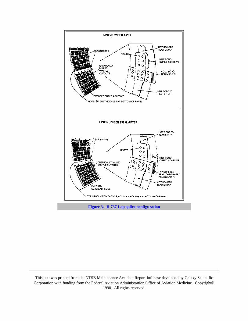
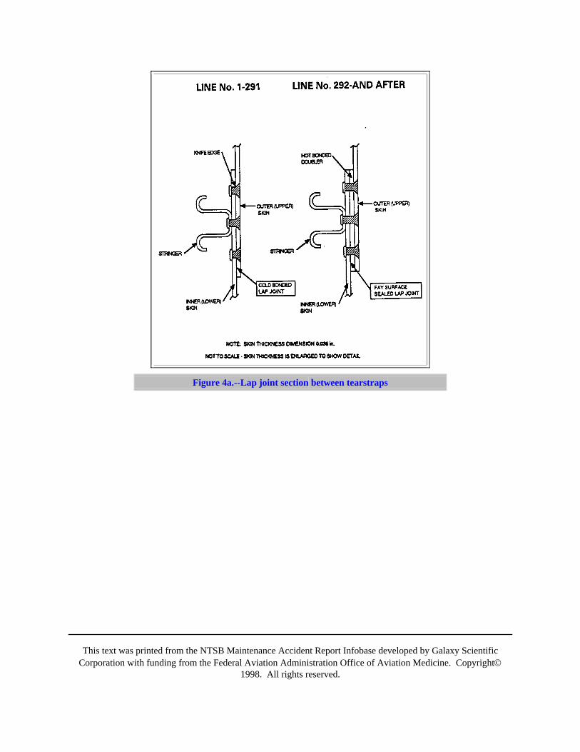
On the early model airplanes (through production line number 291), the doubler sheet was milled away chemicallyat the lap joint locations; for production line number 292 and the subsequent numbers, the doubler sheet wasretained on the outer panel of each lap joint to provide an extra 0.036 inch of material thickness in the joint.(See
This text was printed from the NTSB Maintenance Accident Report Infobase developed by Galaxy ScientificCorporation with funding from the Federal Aviation Administration Office of Aviation Medicine. Copyright©
1998. All rights reserved.
figures 3, 4a and 4b.) Additionally, for production line number 465 and the subsequent numbers, an improvedbond surface pretreat process using a phosphoric acid anodize was employed.
For B-737 production line numbers 1 through 291, the fuselage skin lap joints were "cold" bonded. A cold-bondedprocess used an epoxy impregnated woven "scrim" cloth to join the longitudinal edges of the single thickness0.036-inch skin panels together. In addition, the joint was mechanically assembled with three rows of countersunkrivets. The metal surfaces to be bonded were etched to ensure cleanliness and to prepare a suitable bonding surface.Since the epoxy "cold" bond material was reactive at room temperature, it was stored in rolls at dry ice temperatureuntil shortly before its use. It was then allowed to warm to room temperature before installation. This bond curedat room temperature after assembly.
The cold bonding process was intended to provide structural efficiency and manufacturing cost advantages plusoverall airplane weight reduction over traditionally riveted thick skin panels. Fuselage hoop loads (circumferentialpressurization loads) were intended to be transferred through the bonded joint, rather than through the rivets,allowing the use of lighter, thinner fuselage skin panels with no degradation in fatigue life. Laboratory "coupon"tests9 of the bonded joints, as well as the "quonset hut"10 full scale fuselage section fatigue test were performed bythe Boeing Company and were used to assess cold bond durability. According to Boeing, the results indicated thatcertification requirements were met.
This text was printed from the NTSB Maintenance Accident Report Infobase developed by Galaxy ScientificCorporation with funding from the Federal Aviation Administration Office of Aviation Medicine. Copyright©
1998. All rights reserved.
Figure 3.--B-737 Lap splice configuration
This text was printed from the NTSB Maintenance Accident Report Infobase developed by Galaxy ScientificCorporation with funding from the Federal Aviation Administration Office of Aviation Medicine. Copyright©
1998. All rights reserved.
Figure 4a.--Lap joint section between tearstraps
This text was printed from the NTSB Maintenance Accident Report Infobase developed by Galaxy ScientificCorporation with funding from the Federal Aviation Administration Office of Aviation Medicine. Copyright©
1998. All rights reserved.
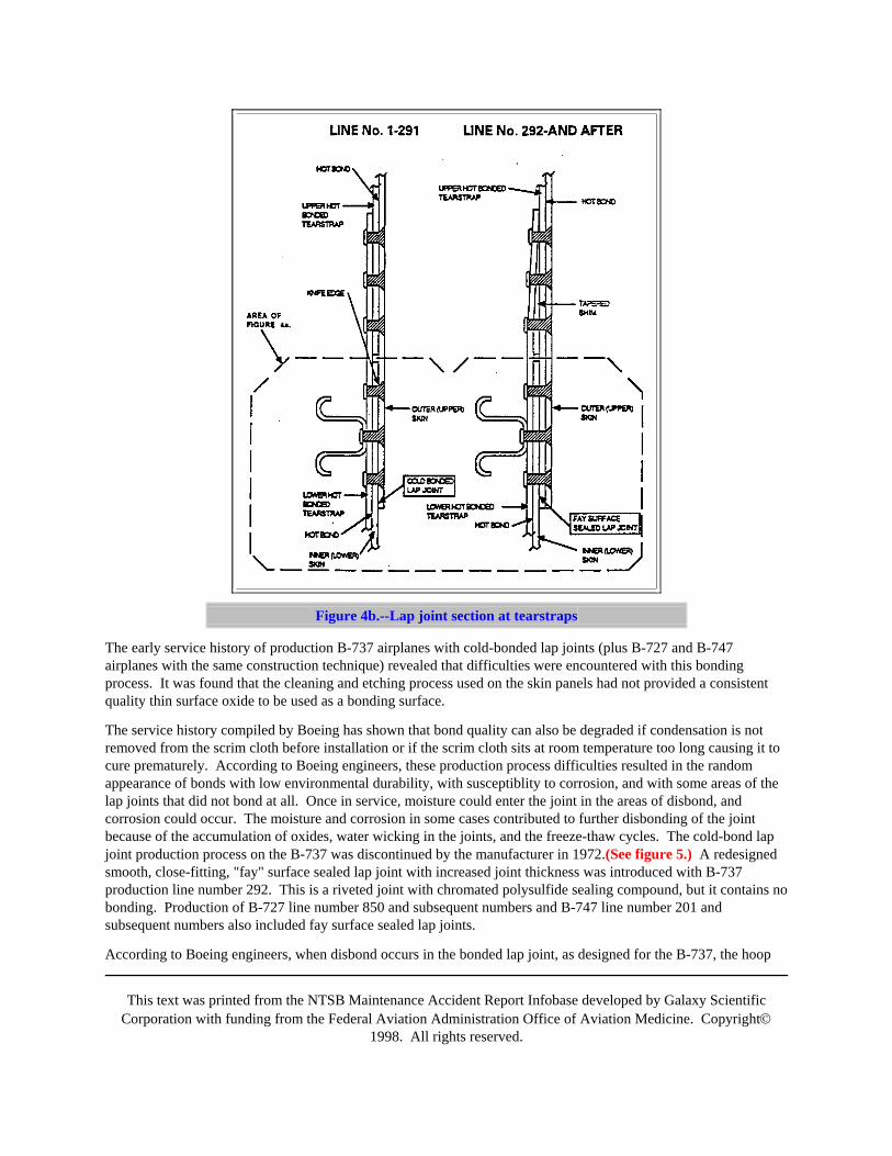
Figure 4b.--Lap joint section at tearstraps
The early service history of production B-737 airplanes with cold-bonded lap joints (plus B-727 and B-747airplanes with the same construction technique) revealed that difficulties were encountered with this bondingprocess. It was found that the cleaning and etching process used on the skin panels had not provided a consistentquality thin surface oxide to be used as a bonding surface.
The service history compiled by Boeing has shown that bond quality can also be degraded if condensation is notremoved from the scrim cloth before installation or if the scrim cloth sits at room temperature too long causing it tocure prematurely. According to Boeing engineers, these production process difficulties resulted in the randomappearance of bonds with low environmental durability, with susceptiblity to corrosion, and with some areas of thelap joints that did not bond at all. Once in service, moisture could enter the joint in the areas of disbond, andcorrosion could occur. The moisture and corrosion in some cases contributed to further disbonding of the jointbecause of the accumulation of oxides, water wicking in the joints, and the freeze-thaw cycles. The cold-bond lapjoint production process on the B-737 was discontinued by the manufacturer in 1972.(See figure 5.) A redesignedsmooth, close-fitting, "fay" surface sealed lap joint with increased joint thickness was introduced with B-737production line number 292. This is a riveted joint with chromated polysulfide sealing compound, but it contains nobonding. Production of B-727 line number 850 and subsequent numbers and B-747 line number 201 andsubsequent numbers also included fay surface sealed lap joints.
According to Boeing engineers, when disbond occurs in the bonded lap joint, as designed for the B-737, the hoop
This text was printed from the NTSB Maintenance Accident Report Infobase developed by Galaxy ScientificCorporation with funding from the Federal Aviation Administration Office of Aviation Medicine. Copyright©
1998. All rights reserved.
load transfer through the joint is borne by the three rows of countersunk rivets that mechanically fasten the skinpanels together. Because of the single thickness skin surface that was facilitated by the bonded construction, thecountersink for the flush rivet heads extended through the entire thickness of the outer 0.036-inch sheet. A knifeedge was created at the bottom of the hole which concentrated stresses. These stresses were cyclic withpressurization loads, and fatigue cracking ultimately occurred at the site.
In a cylindrical fuselage like the B-737, the circumferential pressurization stresses are twice as large as thelongitudinal stresses. As fatigue effects take lace, cracks propagate longitudinally, perpendicular to the dominantpressurization (hoop) loads. In the B-737, fatigue cracking initially is expected to occur in the outer layer of skinalong the lap joint because the outer layer contains a knife edge at each of the countersunk rivet holes. Furthermore,the fatigue cracking primarily is found in the upper row of the outer skin panel lap joint rivet holes because this areacarries the greatest stress. For the underlying skin of the lap joint, the area of greatest stress is through the lowerrow of lap joint rivet holes. However, since the rivet holes in this skin panel are not countersunk, fatigue cracking isnot as likely to initiate at this location.
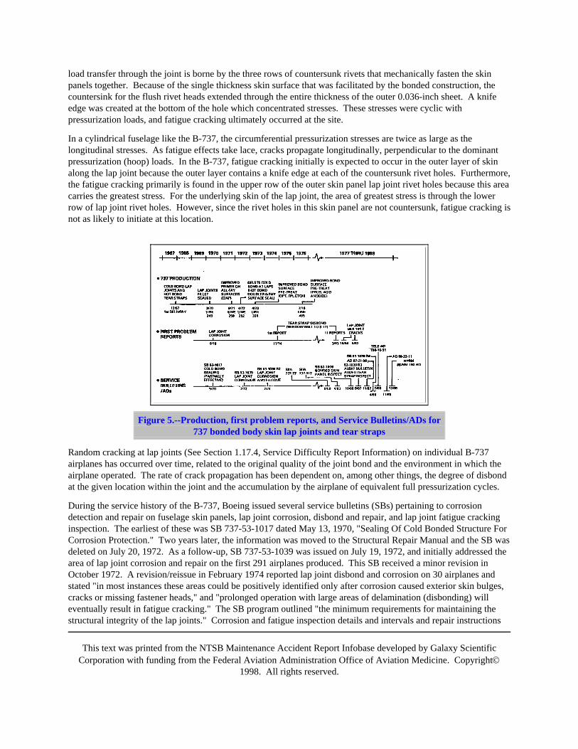
Figure 5.--Production, first problem reports, and Service Bulletins/ADs for737 bonded body skin lap joints and tear straps
Random cracking at lap joints (See Section 1.17.4, Service Difficulty Report Information) on individual B-737airplanes has occurred over time, related to the original quality of the joint bond and the environment in which theairplane operated. The rate of crack propagation has been dependent on, among other things, the degree of disbondat the given location within the joint and the accumulation by the airplane of equivalent full pressurization cycles.
During the service history of the B-737, Boeing issued several service bulletins (SBs) pertaining to corrosiondetection and repair on fuselage skin panels, lap joint corrosion, disbond and repair, and lap joint fatigue crackinginspection. The earliest of these was SB 737-53-1017 dated May 13, 1970, "Sealing Of Cold Bonded Structure ForCorrosion Protection." Two years later, the information was moved to the Structural Repair Manual and the SB wasdeleted on July 20, 1972. As a follow-up, SB 737-53-1039 was issued on July 19, 1972, and initially addressed thearea of lap joint corrosion and repair on the first 291 airplanes produced. This SB received a minor revision inOctober 1972. A revision/reissue in February 1974 reported lap joint disbond and corrosion on 30 airplanes andstated "in most instances these areas could be positively identified only after corrosion caused exterior skin bulges,cracks or missing fastener heads," and "prolonged operation with large areas of delamination (disbonding) willeventually result in fatigue cracking." The SB program outlined "the minimum requirements for maintaining thestructural integrity of the lap joints." Corrosion and fatigue inspection details and intervals and repair instructions
This text was printed from the NTSB Maintenance Accident Report Infobase developed by Galaxy ScientificCorporation with funding from the Federal Aviation Administration Office of Aviation Medicine. Copyright©
1998. All rights reserved.
were presented. Operator compliance was not made mandatory by the FAA.
On August 20, 1987, the subject SB was elevated to "Alert" status with Revision 3. The following was reason forthe upgraded status:
Since the release of Revision 2 an operator has reported multiple fatigue cracks on three airplanes which haveaccumulated 40,400/42,800 flight hours and 44,700/49,900 flight cycles. Cracks were located in the upper skin atstringer four (S-4), left and right, S-10 right and S-14 right, between Body Stations 360 and 907.
Therefore, Revision 3 was issued to up-grade this service bulletin to an "ALERT" status and to revise the repeatinspection thresholds for detecting fatigue cracking of the outer skin panel at the lap joint upper row of fasteners.Part I of SB 1039 Revision 3 dealt with "Corrosion Inspection" and Part II addressed "Fatigue Damage and Repair."The subject areas were lap joints at S-4, S-10, S-14, S-19, S-20, and S-24. Part III covered "Tear Strap Inspectionand Repair" in the same structural areas as Part II.
The FAA issued an Airworthiness Directive (AD) 87-21-08 effective November 2, 1987, which stated in part:
To prevent rapid depressurization as a result of failure of certain fuselage lap splices, accomplish the following: ....(instructions followed)
The AD made the inspection for fatigue cracking referenced in SB 737-53A1039 Revision 3 mandatory for S-4Land R (note only S-4L and R) on production line numbers 1 through 291, before the accumulation of 30,000landings or within the next 250 landings after the effective date of the AD. Repairs for cracks found were to beaccomplished in accordance with instructions contained in the referenced Boeing SB. (The AD and SB revisions 2and 3, with nondestructive testing (NDT) instructions, are included as appendix C.)
An additional SB 737-53-1076 dated October 30, 1986, deals with skin bonding problems. (A summary of SB737-53-1076 is included as appendix D.)
Boeing issued revision 4 to SB 737-53A1039 dated April 14, 1988, to permit an interim repair when cracks weredetected and time was not available for complete restoration per the previous instructions. This information was notrelevant to the accident.
1.6.3 Aloha Maintenance History
1.6.3.1 Maintenance Program
Airplanes operated by Aloha Airlines are maintained under an FAA-approved Continuous AirworthinessMaintenance Program as required by 14 CFR Part 121, Subpart L. The maintenance, based on guidance provided inthe Boeing Maintenance Planning Document (MPD) (Document number D6-17594), recommended that aircraftmaintenance inspections be divided into four series of checks with specific recurring frequency. The checks arereferred to as follows:
A. Check--Primary inspection to disclose general condition
B. Check--Intermediate check to determine general condition
C. Check--System and component check, airworthiness evaluation
This text was printed from the NTSB Maintenance Accident Report Infobase developed by Galaxy ScientificCorporation with funding from the Federal Aviation Administration Office of Aviation Medicine. Copyright©
1998. All rights reserved.
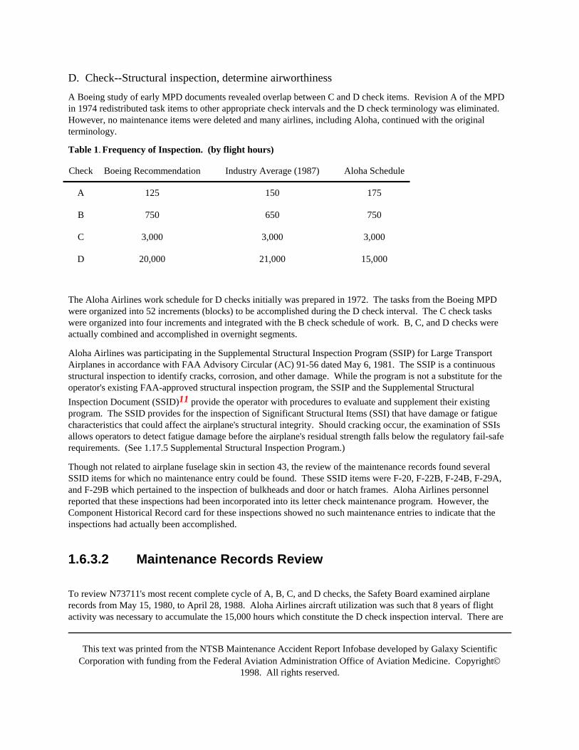
D. Check--Structural inspection, determine airworthinessA Boeing study of early MPD documents revealed overlap between C and D check items. Revision A of the MPDin 1974 redistributed task items to other appropriate check intervals and the D check terminology was eliminated.However, no maintenance items were deleted and many airlines, including Aloha, continued with the originalterminology.
Table 1. Frequency of Inspection. (by flight hours)
Check Boeing Recommendation Industry Average (1987) Aloha Schedule
A 125 150 175
B 750 650 750
C 3,000 3,000 3,000
D 20,000 21,000 15,000
The Aloha Airlines work schedule for D checks initially was prepared in 1972. The tasks from the Boeing MPDwere organized into 52 increments (blocks) to be accomplished during the D check interval. The C check taskswere organized into four increments and integrated with the B check schedule of work. B, C, and D checks wereactually combined and accomplished in overnight segments.
Aloha Airlines was participating in the Supplemental Structural Inspection Program (SSIP) for Large TransportAirplanes in accordance with FAA Advisory Circular (AC) 91-56 dated May 6, 1981. The SSIP is a continuousstructural inspection to identify cracks, corrosion, and other damage. While the program is not a substitute for theoperator's existing FAA-approved structural inspection program, the SSIP and the Supplemental StructuralInspection Document (SSID)11 provide the operator with procedures to evaluate and supplement their existingprogram. The SSID provides for the inspection of Significant Structural Items (SSI) that have damage or fatiguecharacteristics that could affect the airplane's structural integrity. Should cracking occur, the examination of SSIsallows operators to detect fatigue damage before the airplane's residual strength falls below the regulatory fail-saferequirements. (See 1.17.5 Supplemental Structural Inspection Program.)
Though not related to airplane fuselage skin in section 43, the review of the maintenance records found severalSSID items for which no maintenance entry could be found. These SSID items were F-20, F-22B, F-24B, F-29A,and F-29B which pertained to the inspection of bulkheads and door or hatch frames. Aloha Airlines personnelreported that these inspections had been incorporated into its letter check maintenance program. However, theComponent Historical Record card for these inspections showed no such maintenance entries to indicate that theinspections had actually been accomplished.
1.6.3.2 Maintenance Records Review
To review N73711's most recent complete cycle of A, B, C, and D checks, the Safety Board examined airplanerecords from May 15, 1980, to April 28, 1988. Aloha Airlines aircraft utilization was such that 8 years of flightactivity was necessary to accumulate the 15,000 hours which constitute the D check inspection interval. There are

This text was printed from the NTSB Maintenance Accident Report Infobase developed by Galaxy ScientificCorporation with funding from the Federal Aviation Administration Office of Aviation Medicine. Copyright©
1998. All rights reserved.
eight structural inspection blocks (portions of the complete D check) that require the removal of airplane interiorcomponents. These inspection blocks were proposed by the airline and approved by the local FAA principalmaintenance inspector (PMI) to be accomplished sequentially, one block at a time. A one-time heavy maintenancehanger visit for a D check was not scheduled. A complete interior removal at any one time was not required norwas it accomplished.
The maintenance records review indicated that the previous cycles of A, B, C, and D checks were recorded asaccomplished within the prescribed intervals. The most recent scheduled maintenance checks were: A--April 25,1988; B--March 31, 1988; C-4--March 31, 1988; D (block 5)--June 22, 1987, (This block called for inspection offuselage skin and framing around windshields and windows.); and D (block 8)--February 20, 1981, (This blockcalled for inspection of fuselage skin and stringer splices at BS 320 and a general inspection of the fuselage at BS400 and BS 520 areas).
The D check structural inspection included an FAA-approved 1/4 sampling program. This meant that certain blocksof the D check were accomplished on 1/4 of the airplanes in the Aloha 10-airplane fleet at the normal 15,000-hourinterval, and if no adverse findings were encountered, another 1/4 of the fleet was inspected at 30,000 hours.Again, with no adverse findings, another 1/4 was to be inspected at 45,000 hours, etc.
The Boeing MPD states,
Should an operator encounter an adverse finding, the following actions are recommended: (1) Inspect remainingaircraft in his fleet at the earliest opportunity, (2) Evaluate findings from these inspections together with data fromBoeing on the inspection time or area, (3) Determine if a change in frequency of the time interval and/or the fractionneeds to be accomplished and then make the change in the program.
There were no adverse findings recorded in any of the records reviewed; therefore, there were no changes in thefrequency of inspection or the fraction related to the sampling program.
After the accident, the Safety Board conducted visual inspections of the exterior of the airplanes in the AlohaAirlines B-737 fleet. Considerable evidence of corrosion on the fuselage of the airplanes in the fleet was seen.Swelling and bulging of the skin (pillowing), dished fastener heads, pulled and popped rivets, and blistering,scaling, and flaking paint were present at many sites along the lap joints of almost every airplane.
Aloha Airlines did not produce evidence that it had in place specific severe operating environment corrosiondetection and corrosion control programs employing the techniques outlined in the Boeing Commercial JetCorrosion Prevention Manual (Boeing Document D6-41910). Program requirements in the manual includeextensive application of water displacing corrosion inhibiting compounds, reapplication at fastener locations andpanel edges of exterior fuselage skin every 6 months and internal treatment at 2-year intervals, washing the aircraftat 15-day intervals, plus regular buffing and brightening of the unpainted surfaces. Aloha Airlines maintenance Dcheck instructions for structural inspection addressed corrosion with an introductory note. This notation defined theinspection as a rigorous visual examination for condition (damage, cracks, galling, scratches, wear, corrosion, rust,evidence of overheating, rubbing, or age) without further definition. Aloha Airlines inspectors and quality controlpersonnel stated that the corrosion was corrected when detected during normal inspection and maintenance activitiesas part of their normal task card activity.
The Safety Board subcategorized and evaluated all pressurization discrepancies recorded from 1980 to 1988 todetermine adverse trends or significant anomalies. This maintenance historical review produced no evidence ofprior structural overstress incidents for N73711 as a result of pressurization or other malfunction.
This text was printed from the NTSB Maintenance Accident Report Infobase developed by Galaxy ScientificCorporation with funding from the Federal Aviation Administration Office of Aviation Medicine. Copyright©
1998. All rights reserved.
1.6.3.3 Service Bulletins
Boeing periodically issued information via SBs to inform operators of reported or anticipated difficulties withvarious airplane models. The following communications were relevant to the B-737 fuselage structure, includingsection 43:
· Structural Item Interim Advisories (SIIA)
· Service Bulletins (SB)
· Service Letters (SL)
· In-Service Activity Reports (ISAR)
· Significant Service Items (SSI)Nine SBs provided guidance for maintenance or information otherwise applicable to section 43. Of these nine SBs,entries referring to the following five SBs were found in the Aloha Airlines fleet maintenance records:
SB 737-53-1017 Sealing of Cold Bonded Splices
SB 737-53A1027 Cargo Compartment Body Frames
SB 737-53A1039 Skin Lap Joint Inspection
SB 737-53A1042 Lower Lobe Skins
SB 737-53A1064 Frames Stations 351 and 360Due to the method of entering the SBs in the Aloha Airlines maintenance records, the recurring nature ofinspections could not be determined. Also, entries for the following four SBs were not located in the records:
SB 737-53-1076 Fuselage-Bonded Skin Panel Inspection and Repair
SB 737-53-1078 Fuselage Window Belt Skin Panel Inspection and Repair
SB 737-53-1085 Fuselage Stringer to Frame Tie Clips Inspection and Replacement
SB 737-53-1089 Fuselage Skin Crack At Stringer 17 Inspection and PreventiveModifications
Aloha Airlines personnel stated that the information contained in these particular SBs had been incorporated intoAloha Airlines letter check inspection system; however, specific documentation of this fact was not produced.
1.6.3.4 FAA Airworthiness Directive (AD) Compliance AD 87-21-08
Airworthiness Directive (AD) 87-21-08, which became effective on November 2, 1987, was issued "to preventrapid depressurization as a result of failure of certain fuselage lap splices...." The AD required operators to performa "close visual inspection"12 of S-4L and R, and if cracks were found, operators were required to perform an eddy

This text was printed from the NTSB Maintenance Accident Report Infobase developed by Galaxy ScientificCorporation with funding from the Federal Aviation Administration Office of Aviation Medicine. Copyright©
1998. All rights reserved.
current inspection13 of the skin around the upper row of lap joint rivets for the full length of the panel. Compliancewith the AD was required before the accumulation of 30,000 landings or within 250 landings after the effectivedate, whichever occurred later. The AD was based on Boeing Alert Service Bulletin (ASB) 737-53A1039, Revision3, dated August 20, 1987. The ASB required an inspection of the skin around the upper row of rivets along the lapjoints at S-4, -10, -14, -19, -20, and -24 left and right. An FAA employee testified at the public hearing that thedecision to limit the scope of the mandatory inspection was based on analysis of statistical information available tothem and the recognition of the scope of work required.
A review of the maintenance discrepancy logs found that two repairs to cracks on the S-4R lap joint on N73711were accomplished on November 12, 1987. The small separated section of upper fuselage recovered after theaccident contained both of the repaired areas. The maintenance log for N73711 indicated that a visual inspectionhad been accomplished in accordance with AD 87-21-08; however, the record contained no evidence that therequired eddy current inspection had been accomplished.
An Aloha Airlines inspector testified at the public hearing that it was company practice to perform an eddy currentconfirmation inspection whenever a crack was detected visually. Both the Aloha Airlines director of quality controland the staff vice president for quality assurance and engineering stated that a Nondestructive Testing Report (FormNo. M-86) should be filled out by the inspector when any NDT inspection is performed. The form is then used bymanagement for tracking purposes. A search of the records for N73711 failed to find a copy of an NDT inspectionreport of the S-4R lap joint.
The inspector who performed the initial AD inspection on N73711 stated that he did not believe that documentingthe eddy current inspection was necessary or required. During the investigation, Aloha Airlines did not produce awritten maintenance policy regarding the requirement for the entry of an eddy current inspection in the maintenancelog. However, a broad examination of maintenance records revealed that other inspectors had made such entriesduring this same time period.
Two inspectors working on separate shifts conducted the inspection required by AD 87-21-08 on the accidentairplane. They followed guidance in the AD and the related SB (SB-737-53A1039) which were taken to the worksite. The first inspector started on November 12, 1987, and visually detected the cracks on S-4L. This inspectorstated that after visually detecting the cracks, he performed an eddy current inspection of the lap joint upper rivetholes along the length of the panel (BS 360 to BS 540) and found no additional cracks.
After maintenance personnel accomplished two sheet metal repairs, the first inspector inspected the work and signedthe log book. The second inspector stated that he performed a complete visual inspection of the airplane, includingthe area inspected by the first inspector and the two repaired areas, and he signed off the completion of the AD inthe maintenance log on November 14, 1987. The related inspections on the lap joints at S-10, -14, -19, -20, and-24, which were recommended by SB 737-53A1039 but not by the AD, were not accomplished. At the time of theAD inspection and repair, N73711 had accumulated 87,056 cycles. The accident occurred at 89,680 cycles.
1.7 Meteorological InformationThe accident occurred in day visual meteorological conditions. There was no significant adverse weatherexperienced.
1.8 Aids to NavigationNot relevant to this accident.

This text was printed from the NTSB Maintenance Accident Report Infobase developed by Galaxy ScientificCorporation with funding from the Federal Aviation Administration Office of Aviation Medicine. Copyright©
1998. All rights reserved.
1.9 CommunicationsThere were radio communications difficulties between flight 243 and ATC shortly after the explosivedecompression. At 280 to 290 knots IAS and with a part of the forward cabin structure and the cockpit doormissing, high noise levels impeded air/ground communications briefly. There were no other communicationanomalies.
1.10 Aerodrome InformationAfter the explosive decompression, the airplane proceeded to the nearest suitable landing field, Kahului Airport, a14 CFR Part 139 certificated Index D airport on the island of Maui, Hawaii. The only instrument runway, 02/20, is6,995 feet long, 150 feet wide, and constructed of asphalt with a grooved surface.
1.11 Flight RecordersThe airplane was equipped with a Fairchild model 5424 foil type analog FDR, S/N 7274, and a Collins model642C-1 cockpit voice recorder (CVR), S/N 54. After the accident, the recorders were removed from the airplaneand sent to the Safety Board's Flight Recorder Laboratory in Washington, D.C. for examination and readout ofpertinent data. (See appendix E.)
Examination of the FDR recorded traces indicated that the flight was normal from liftoff to the accident. Theairspeed trace abruptly ceased at the time of the accident and dropped to a position below zero KIAS. The otherrecorder parameters appeared to operate normally. Peak vertical acceleration (G) excursions recorded as a result ofthe accident were -0.48 and +2.95. These peak values were not sustained.
The CVR revealed normal communications before the decompression. Following the decompression, loud windnoise from the opening in the fuselage prevented normal cockpit conversations. Hand signals were used tocommunicate. When the airspeed and related wind noise had been reduced to a level where conversations wereintelligible, the flightcrew discontinued using the oxygen masks. Cockpit conversations then continued to berecorded in the normal manner.
1.12 Wreckage and Impact InformationThe extensive air and surface search of the ocean failed to locate the portions of the airplane lost during theexplosive decompression.
1.13 Medical and Pathological InformationThe flight attendant who was ejected from the fuselage was not found and she is assumed to have been fatallyinjured in the accident.
Two passengers who were seated in the first class cabin in seats 2A and 2C were struck by debris and wiring whichresulted in multiple lacerations and electrical shock burns to the face and hands. Passengers seated in seats 4A and4F (window seats) sustained serious injuries including cerebral concussions and multiple lacerations to their heads
This text was printed from the NTSB Maintenance Accident Report Infobase developed by Galaxy ScientificCorporation with funding from the Federal Aviation Administration Office of Aviation Medicine. Copyright©
1998. All rights reserved.
and faces. Passengers seated in 4B, C, D, and E (center and aisle seats) sustained multiple lacerations and weretreated and released on the day of the accident.
Passengers seated in rows 5, 6, and 7 also sustained cerebral concussions and multiple lacerations. An 84-year-oldfemale passenger seated in 5A was the most seriously injured with a skull fracture, lacerations and a skeletal systemfracture. The passenger seated in 6A sustained a broken right arm, multiple facial lacerations, and blood effusion inboth ears.
The majority of the passengers seated in rows 8 through 21 received minor injuries including lacerations, abrasions,and barotrauma. They were treated and released on the day of the accident. Twenty-five passengers reported noinjuries and continued to their destinations that same evening. There were no reported injuries as a result of usingthe emergency evacuation slides.
1.14 FireThere was no fire.
1.15 Survival AspectsThis was a survivable accident; the fatality was the result of the explosive nature of the decompression. The flightattendant was swept violently from the airplane and passed through an opening of jagged metal. There were bloodstains on seat cushions at seat 5A on the left side of cabin near BS 500 and on the exterior left side of the fuselagewhere the flight attendant was standing when the decompression occurred. Passengers who observed her during theexplosive decompression stated that they saw the flight attendant pulled upward and toward the left side of the cabinat seat row 5.
1.15.1 Supplemental Oxygen SystemsThe flightcrew and the cockpit observer seat occupant used the airplane-installed crew oxygen system. Postaccidentinspection showed that both the crew and the passenger oxygen bottles that were located in the forward cargocompartment had zero quantity and pressure. The passenger oxygen distribution manifolds were part of the materiallost during the structural separation, and thus, there was no supply of oxygen to the first-class and coach cabins.
1.15.2 Sea SearchAt 1430, the FAA notified the U.S. Coast Guard that an Aloha Airlines B-737 was diverting to Maui airport due toan "inflight explosion." A Coast Guard helicopter, airborne on a training mission, was assigned to search the areafor debris and the flight attendant. The Coast Guard cutter CAPE CORWIN was also directed into the search areaas was a Marine Corps helicopter. A full search effort by ships, helicopters, and fixed-wing aircraft continued for 3days without success.
1.15.3 Rescue and Firefighting ResponseThe Maui Airport fire department responded with five emergency vehicles. After the ambulatory passengers hadevacuated the airplane via slides and the aft airstair, fire department personnel entered the airplane and assisted the
This text was printed from the NTSB Maintenance Accident Report Infobase developed by Galaxy ScientificCorporation with funding from the Federal Aviation Administration Office of Aviation Medicine. Copyright©
1998. All rights reserved.
injured still on board. All occupants were removed from the airplane in 25 minutes.
1.15.4 Ambulance ResponseThe flightcrew initially communicated the nature of the emergency as a "rapid decompression." The full nature ofthe structural damage was not verbalized. ATC notified rescue and firefighting personnel, but did not immediatelycall for ambulance assistance. A subsequent call from the flightcrew at 1353, "We'll need assistance for thepassengers when we land," was confirmed by ATC personnel. Police dispatcher records indicated the "Medic I"ambulance was notified at 1358, about the time of touchdown. A reason for the notification delay was notdetermined. The first ambulance arrived at the scene at 1405 and radioed for assistance. Other ambulance vehiclesarrived at 1411.
1.16 Tests and Research
1.16.1 Pressurization SystemAll of the pressurization system wiring from the selector panel to the pressure controller to the outflow valve wasexamined. No discrepancies were found. Additionally, a visual examination of the components including theoutflow valve, both relief valves, the controller, and the selector panel did not reveal any discrepancies. Thesecomponents were removed from the airplane after the accident and subjected to standard acceptance test proceduresfor new units. There were no significant anomalies discovered.
1.16.2 Eddy Current and Visual InspectionAn Aloha Airlines inspector under supervision of the Safety Board conducted postaccident eddy current inspectionson selected portions of the remaining fuselage lap joints to determine the extent of fatigue cracking of the skin alongthe top row of rivets (the area of highest stress). The inspected areas included the left and right lap joints at S-4,-10, and -14 from BS 540 to BS 1016.
Initially, the skin around 53 rivets exhibited crack indications along S-4L and S-4R, some visually detectable bypaint cracks. To make the rivet heads more discernible, the paint was sanded off and the skin was reinspected.Twenty-eight of the original 53 indications were confirmed cracks. Stripping of the paint layers was not attempted.(It is not normal Aloha Airlines or industry practice to remove paint by sanding.) Two samples of the lap joint werecut from S-4L between BS 727 and 747 and between BS 847 and 867 for further examination.
The eddy current inspection along S-10 and S-14 revealed 17 cracks along S-10L and 2 cracks along S-14R. Therewere no cracks along S-10R or S-14L. No attempt was made to strip the paint layers. (Appendix F provides detailsof these inspections.)
There were 25 locations where previous fuselage skin repairs or rework had been performed. Most of these areasconsisted of external doubler patches at various stringer and frame locations. In several areas, countersunk rivetshad been replaced with universal buttonhead rivets in lap joints, mostly in the lower lobe. (Appendix G provides adescription of the repairs or reworked areas and their locations.)

This text was printed from the NTSB Maintenance Accident Report Infobase developed by Galaxy ScientificCorporation with funding from the Federal Aviation Administration Office of Aviation Medicine. Copyright©
1998. All rights reserved.
1.16.3 Materials Laboratory ExaminationSelected pieces of the fuselage skin and associated structures were returned to the Safety Board's MaterialsLaboratory for analysis. These pieces included lap joint samples (S-4R, S-4L and S-10L) and a section of acircumferential butt joint strap.
The lap joint sample, S-4R between BS 360 and BS 420 (found wedged in the right wing area), contained twoexternal doubler patches. The patches were removed to examine the holes for evidence of cracks. There wasextensive fatigue cracking in the upper row rivet holes both under and between the patches. The examination foundone of the longest cracks on the airplane, 0.27 inch, in this piece. This stringer section (S-4R) contained three areaswhere the tear straps are riveted above the primary 1ap joint. There was extensive fatigue cracking present in allthree locations. Also, the entire cold-bonded lap joint had become disbonded. There was light to moderatecorrosion with severe corrosion (unrepairable depletion of metal) in some areas. Nearly all of the hot-bonded tearstraps were disbonded in the vicinity of the lap joint.
The lap joint samples, S-4L from BS 727 to BS 747 and from BS 847 to BS 867, each contained 18 columns of lapjoint rivets. The laboratory examination revealed fatigue cracking in the skin adjacent to nearly every hole in theupper rivet row with the larger crack lengths located in the mid-bay areas (half way between two adjacentcircumferential tear straps). A comparison of the final results of the postaccident on-scene eddy current inspectionconducted by Aloha Airlines technicians and the Safety Board laboratory findings revealed that the on-scene eddycurrent inspection only successfully identified cracks larger than 0.08 inch. The laboratory examination found fivecracks that measured 0.08 inch (+/-.005). The postaccident inspection had identified only one of these five cracks.This crack-length inspection threshold of 0.08 inch varies from the Boeing NDT Manual which states, "Thisinspection can find cracks 0.040 or longer beneath the countersunk fastener heads...."
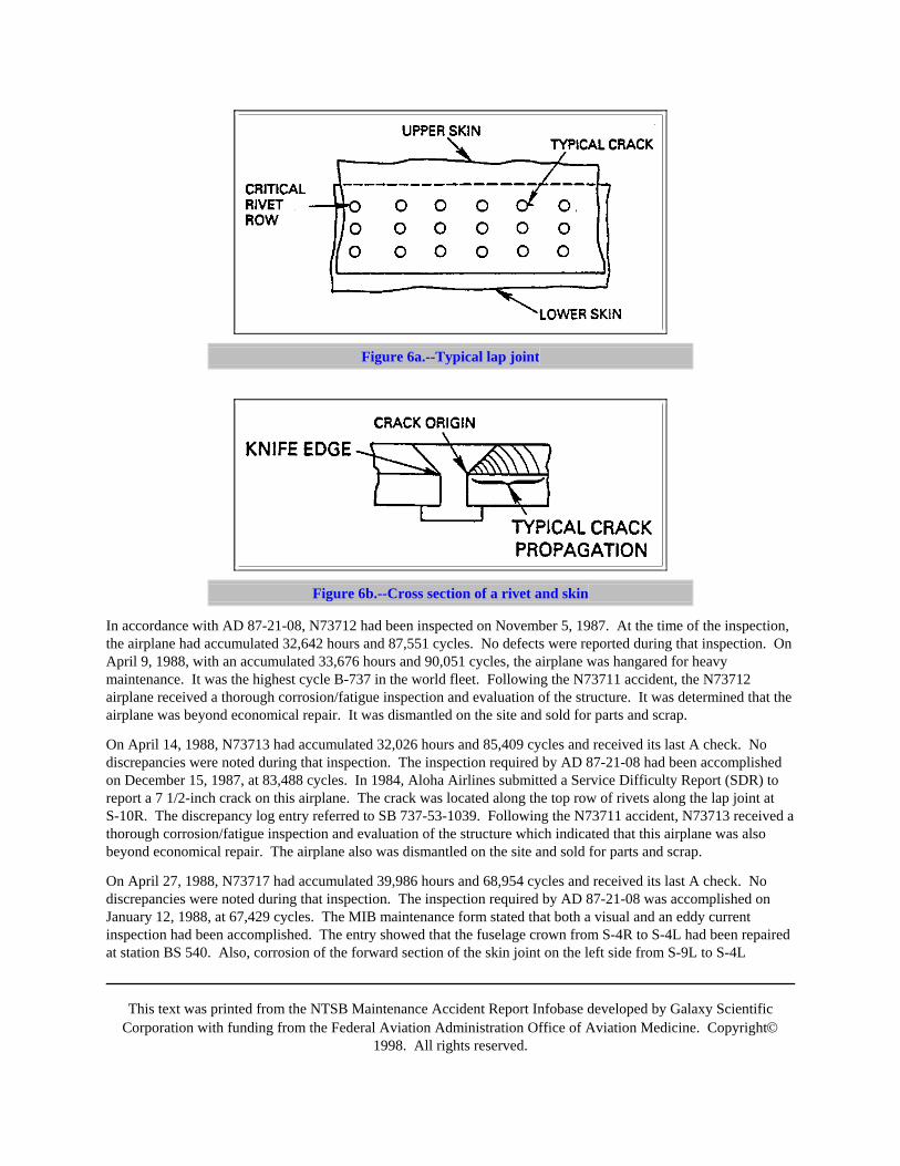
The lap joint piece, S-4L, from BS 519 to BS 536, exhibited fatigue cracking from 16 consecutive rivet holes alongthe upper row of lap joint rivets. The largest single fatigue crack in one direction measured 0.18 inch from the knifeedge of the countersink. (See figure 6.) The longest total combined crack length in both directions across a rivethole (end to end of the crack including the hole) measured 0.53 inch. Both the cold-bonded lap joint and thehot-bonded tear straps in this area had disbonded. Light to moderate corrosion was present on the previouslybonded surfaces.
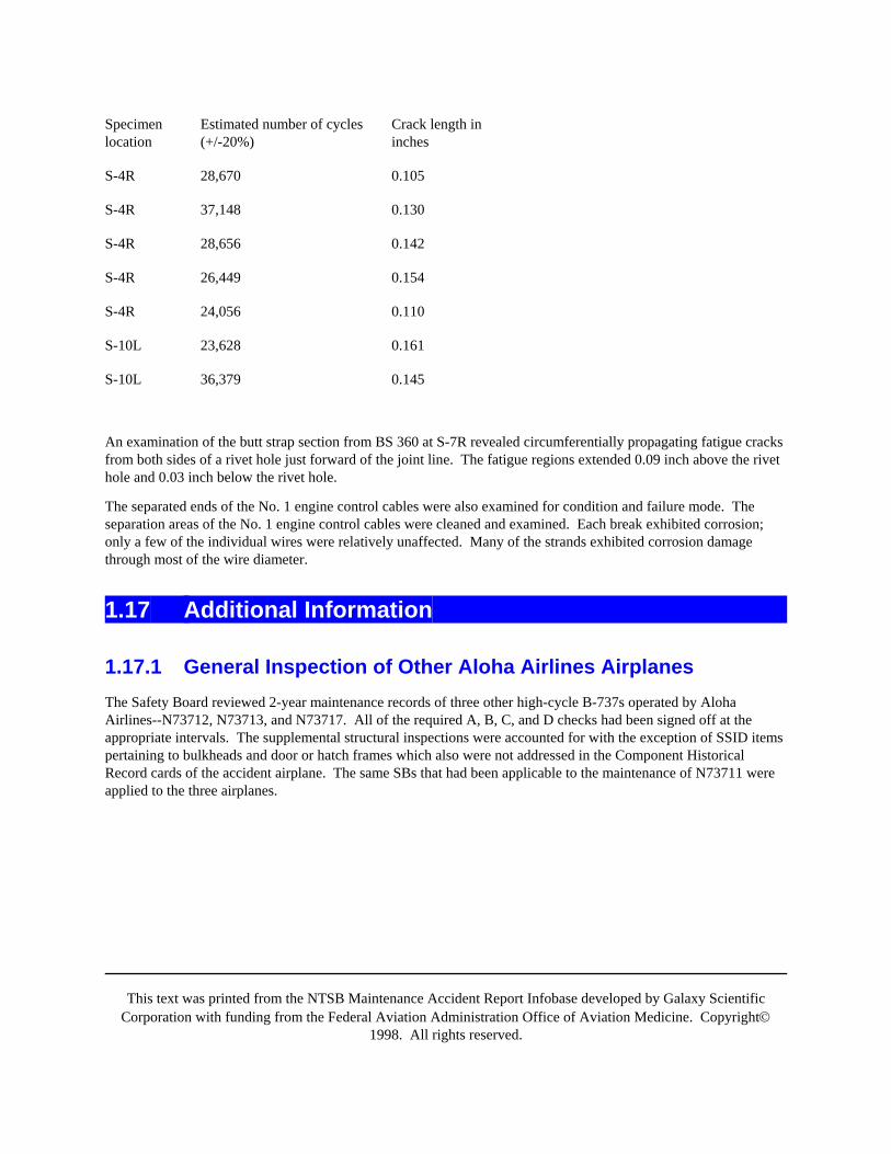
At the request of the Safety Board, Boeing performed a striation count on several of the larger fatigue cracks fromthe skin along S-4R and S-10L to determine age and crack propagation rate. Although data could not be obtainedfrom all the cracks examined, Table 2 provides the estimated number of cycles of crack growth found on the sevencrack samples that provided suitable data.
Table 2. Striation counts on selected cracks from the lap joints along S-4R and S-10L
This text was printed from the NTSB Maintenance Accident Report Infobase developed by Galaxy ScientificCorporation with funding from the Federal Aviation Administration Office of Aviation Medicine. Copyright©
1998. All rights reserved.
Specimenlocation
Estimated number of cycles(+/-20%)
Crack length ininches
S-4R 28,670 0.105
S-4R 37,148 0.130
S-4R 28,656 0.142
S-4R 26,449 0.154
S-4R 24,056 0.110
S-10L 23,628 0.161
S-10L 36,379 0.145
An examination of the butt strap section from BS 360 at S-7R revealed circumferentially propagating fatigue cracksfrom both sides of a rivet hole just forward of the joint line. The fatigue regions extended 0.09 inch above the rivethole and 0.03 inch below the rivet hole.
The separated ends of the No. 1 engine control cables were also examined for condition and failure mode. Theseparation areas of the No. 1 engine control cables were cleaned and examined. Each break exhibited corrosion;only a few of the individual wires were relatively unaffected. Many of the strands exhibited corrosion damagethrough most of the wire diameter.
1.17 Additional Information
1.17.1 General Inspection of Other Aloha Airlines AirplanesThe Safety Board reviewed 2-year maintenance records of three other high-cycle B-737s operated by AlohaAirlines--N73712, N73713, and N73717. All of the required A, B, C, and D checks had been signed off at theappropriate intervals. The supplemental structural inspections were accounted for with the exception of SSID itemspertaining to bulkheads and door or hatch frames which also were not addressed in the Component HistoricalRecord cards of the accident airplane. The same SBs that had been applicable to the maintenance of N73711 wereapplied to the three airplanes.
This text was printed from the NTSB Maintenance Accident Report Infobase developed by Galaxy ScientificCorporation with funding from the Federal Aviation Administration Office of Aviation Medicine. Copyright©
1998. All rights reserved.
Figure 6a.--Typical lap joint
Figure 6b.--Cross section of a rivet and skin
In accordance with AD 87-21-08, N73712 had been inspected on November 5, 1987. At the time of the inspection,the airplane had accumulated 32,642 hours and 87,551 cycles. No defects were reported during that inspection. OnApril 9, 1988, with an accumulated 33,676 hours and 90,051 cycles, the airplane was hangared for heavymaintenance. It was the highest cycle B-737 in the world fleet. Following the N73711 accident, the N73712airplane received a thorough corrosion/fatigue inspection and evaluation of the structure. It was determined that theairplane was beyond economical repair. It was dismantled on the site and sold for parts and scrap.
On April 14, 1988, N73713 had accumulated 32,026 hours and 85,409 cycles and received its last A check. Nodiscrepancies were noted during that inspection. The inspection required by AD 87-21-08 had been accomplishedon December 15, 1987, at 83,488 cycles. In 1984, Aloha Airlines submitted a Service Difficulty Report (SDR) toreport a 7 1/2-inch crack on this airplane. The crack was located along the top row of rivets along the lap joint atS-10R. The discrepancy log entry referred to SB 737-53-1039. Following the N73711 accident, N73713 received athorough corrosion/fatigue inspection and evaluation of the structure which indicated that this airplane was alsobeyond economical repair. The airplane also was dismantled on the site and sold for parts and scrap.
On April 27, 1988, N73717 had accumulated 39,986 hours and 68,954 cycles and received its last A check. Nodiscrepancies were noted during that inspection. The inspection required by AD 87-21-08 was accomplished onJanuary 12, 1988, at 67,429 cycles. The MIB maintenance form stated that both a visual and an eddy currentinspection had been accomplished. The entry showed that the fuselage crown from S-4R to S-4L had been repairedat station BS 540. Also, corrosion of the forward section of the skin joint on the left side from S-9L to S-4L
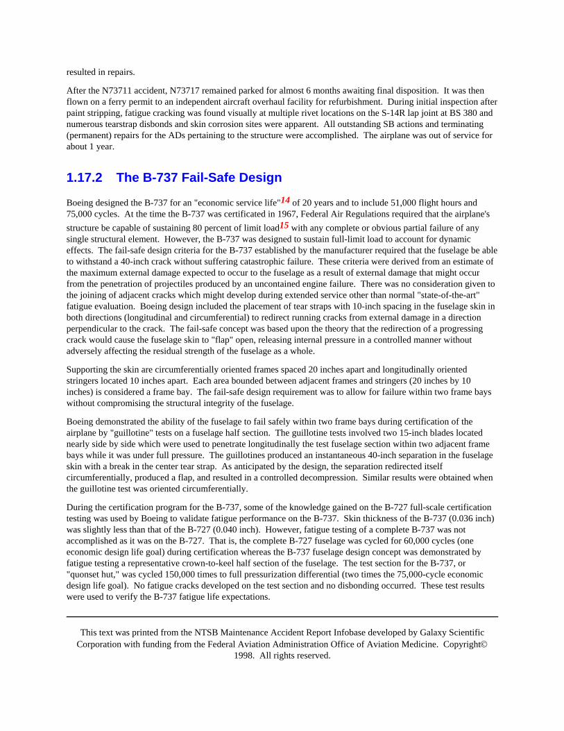
This text was printed from the NTSB Maintenance Accident Report Infobase developed by Galaxy ScientificCorporation with funding from the Federal Aviation Administration Office of Aviation Medicine. Copyright©
1998. All rights reserved.
resulted in repairs.
After the N73711 accident, N73717 remained parked for almost 6 months awaiting final disposition. It was thenflown on a ferry permit to an independent aircraft overhaul facility for refurbishment. During initial inspection afterpaint stripping, fatigue cracking was found visually at multiple rivet locations on the S-14R lap joint at BS 380 andnumerous tearstrap disbonds and skin corrosion sites were apparent. All outstanding SB actions and terminating(permanent) repairs for the ADs pertaining to the structure were accomplished. The airplane was out of service forabout 1 year.
1.17.2 The B-737 Fail-Safe Design
Boeing designed the B-737 for an "economic service life"14 of 20 years and to include 51,000 flight hours and75,000 cycles. At the time the B-737 was certificated in 1967, Federal Air Regulations required that the airplane'sstructure be capable of sustaining 80 percent of limit load15 with any complete or obvious partial failure of anysingle structural element. However, the B-737 was designed to sustain full-limit load to account for dynamiceffects. The fail-safe design criteria for the B-737 established by the manufacturer required that the fuselage be ableto withstand a 40-inch crack without suffering catastrophic failure. These criteria were derived from an estimate ofthe maximum external damage expected to occur to the fuselage as a result of external damage that might occurfrom the penetration of projectiles produced by an uncontained engine failure. There was no consideration given tothe joining of adjacent cracks which might develop during extended service other than normal "state-of-the-art"fatigue evaluation. Boeing design included the placement of tear straps with 10-inch spacing in the fuselage skin inboth directions (longitudinal and circumferential) to redirect running cracks from external damage in a directionperpendicular to the crack. The fail-safe concept was based upon the theory that the redirection of a progressingcrack would cause the fuselage skin to "flap" open, releasing internal pressure in a controlled manner withoutadversely affecting the residual strength of the fuselage as a whole.
Supporting the skin are circumferentially oriented frames spaced 20 inches apart and longitudinally orientedstringers located 10 inches apart. Each area bounded between adjacent frames and stringers (20 inches by 10inches) is considered a frame bay. The fail-safe design requirement was to allow for failure within two frame bayswithout compromising the structural integrity of the fuselage.
Boeing demonstrated the ability of the fuselage to fail safely within two frame bays during certification of theairplane by "guillotine" tests on a fuselage half section. The guillotine tests involved two 15-inch blades locatednearly side by side which were used to penetrate longitudinally the test fuselage section within two adjacent framebays while it was under full pressure. The guillotines produced an instantaneous 40-inch separation in the fuselageskin with a break in the center tear strap. As anticipated by the design, the separation redirected itselfcircumferentially, produced a flap, and resulted in a controlled decompression. Similar results were obtained whenthe guillotine test was oriented circumferentially.
During the certification program for the B-737, some of the knowledge gained on the B-727 full-scale certificationtesting was used by Boeing to validate fatigue performance on the B-737. Skin thickness of the B-737 (0.036 inch)was slightly less than that of the B-727 (0.040 inch). However, fatigue testing of a complete B-737 was notaccomplished as it was on the B-727. That is, the complete B-727 fuselage was cycled for 60,000 cycles (oneeconomic design life goal) during certification whereas the B-737 fuselage design concept was demonstrated byfatigue testing a representative crown-to-keel half section of the fuselage. The test section for the B-737, or"quonset hut," was cycled 150,000 times to full pressurization differential (two times the 75,000-cycle economicdesign life goal). No fatigue cracks developed on the test section and no disbonding occurred. These test resultswere used to verify the B-737 fatigue life expectations.
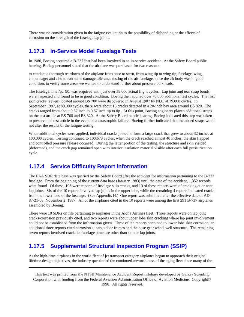
This text was printed from the NTSB Maintenance Accident Report Infobase developed by Galaxy ScientificCorporation with funding from the Federal Aviation Administration Office of Aviation Medicine. Copyright©
1998. All rights reserved.
There was no consideration given in the fatigue evaluation to the possibility of disbonding or the effects ofcorrosion on the strength of the fuselage lap joints.
1.17.3 In-Service Model Fuselage TestsIn 1986, Boeing acquired a B-737 that had been involved in an in-service accident. At the Safety Board publichearing, Boeing personnel stated that the airplane was purchased for two reasons:
to conduct a thorough teardown of the airplane from nose to stern, from wing tip to wing tip, fuselage, wing,empennage; and also to run some damage tolerance testing of the aft fuselage, since the aft body was in goodcondition, to verify some areas we wanted to understand further about pressure bulkheads.
The fuselage, line No. 90, was acquired with just over 59,000 actual flight cycles. Lap joint and tear strap bondswere inspected and found to be in good condition. Boeing then applied over 70,000 additional test cycles. The firstskin cracks (seven) located around BS 780 were discovered in August 1987 by NDT at 79,000 cycles. InSeptember 1987, at 89,000 cycles, there were about 15 cracks detected in a 20-inch bay area around BS 820. Thecracks ranged from about 0.37 inch to 0.67 inch tip to tip. At this point, Boeing engineers placed additional strapson the test article at BS 760 and BS 820. At the Safety Board public hearing, Boeing indicated this step was takento preserve the test article in the event of a catastrophic failure. Boeing further indicated that the added straps wouldnot alter the results of the fatigue testing.
When additional cycles were applied, individual cracks joined to form a large crack that grew to about 32 inches at100,000 cycles. Testing continued to 100,673 cycles; when the crack reached almost 40 inches, the skin flappedand controlled pressure release occurred. During the latter portion of the testing, the structure and skin yielded(deformed), and the crack gap remained open with interior insulation material visible after each full pressurizationcycle.
1.17.4 Service Difficulty Report InformationThe FAA SDR data base was queried by the Safety Board after the accident for information pertaining to the B-737fuselage. From the beginning of the current data base (January 1983) until the date of the accident, 1,352 recordswere found. Of these, 198 were reports of fuselage skin cracks, and 10 of these reports were of cracking at or nearlap joints. Six of the 10 reports involved lap joints in the upper lobe, while the remaining 4 reports indicated cracksfrom the lower lobe of the fuselage. (See Appendix H.) One report was submitted after the effective date of AD87-21-08, November 2, 1987. All of the airplanes cited in the 10 reports were among the first 291 B-737 airplanesassembled by Boeing.
There were 18 SDRs on file pertaining to airplanes in the Aloha Airlines fleet. Three reports were on lap jointcracks/corrosion previously cited, and two reports were about upper lobe skin cracking where lap joint involvementcould not be established from the information given. Three of the reports pertained to lower lobe skin corrosion; anadditional three reports cited corrosion at cargo door frames and the nose gear wheel well structure. The remainingseven reports involved cracks in fuselage structure other than skin or lap joints.
1.17.5 Supplemental Structural Inspection Program (SSIP)As the high-time airplanes in the world fleet of jet transport category airplanes began to approach their originallifetime design objectives, the industry questioned the continued airworthiness of the aging fleet since many of the
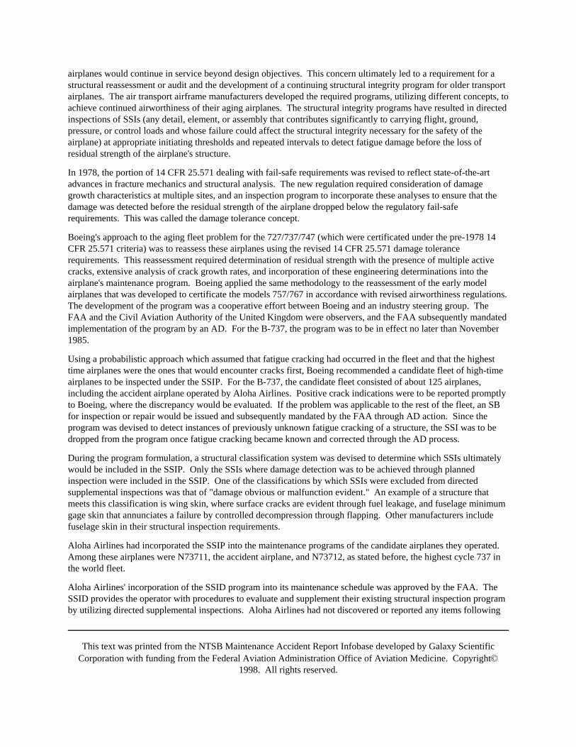
This text was printed from the NTSB Maintenance Accident Report Infobase developed by Galaxy ScientificCorporation with funding from the Federal Aviation Administration Office of Aviation Medicine. Copyright©
1998. All rights reserved.
airplanes would continue in service beyond design objectives. This concern ultimately led to a requirement for astructural reassessment or audit and the development of a continuing structural integrity program for older transportairplanes. The air transport airframe manufacturers developed the required programs, utilizing different concepts, toachieve continued airworthiness of their aging airplanes. The structural integrity programs have resulted in directedinspections of SSIs (any detail, element, or assembly that contributes significantly to carrying flight, ground,pressure, or control loads and whose failure could affect the structural integrity necessary for the safety of theairplane) at appropriate initiating thresholds and repeated intervals to detect fatigue damage before the loss ofresidual strength of the airplane's structure.
In 1978, the portion of 14 CFR 25.571 dealing with fail-safe requirements was revised to reflect state-of-the-artadvances in fracture mechanics and structural analysis. The new regulation required consideration of damagegrowth characteristics at multiple sites, and an inspection program to incorporate these analyses to ensure that thedamage was detected before the residual strength of the airplane dropped below the regulatory fail-saferequirements. This was called the damage tolerance concept.
Boeing's approach to the aging fleet problem for the 727/737/747 (which were certificated under the pre-1978 14CFR 25.571 criteria) was to reassess these airplanes using the revised 14 CFR 25.571 damage tolerancerequirements. This reassessment required determination of residual strength with the presence of multiple activecracks, extensive analysis of crack growth rates, and incorporation of these engineering determinations into theairplane's maintenance program. Boeing applied the same methodology to the reassessment of the early modelairplanes that was developed to certificate the models 757/767 in accordance with revised airworthiness regulations.The development of the program was a cooperative effort between Boeing and an industry steering group. TheFAA and the Civil Aviation Authority of the United Kingdom were observers, and the FAA subsequently mandatedimplementation of the program by an AD. For the B-737, the program was to be in effect no later than November1985.
Using a probabilistic approach which assumed that fatigue cracking had occurred in the fleet and that the highesttime airplanes were the ones that would encounter cracks first, Boeing recommended a candidate fleet of high-timeairplanes to be inspected under the SSIP. For the B-737, the candidate fleet consisted of about 125 airplanes,including the accident airplane operated by Aloha Airlines. Positive crack indications were to be reported promptlyto Boeing, where the discrepancy would be evaluated. If the problem was applicable to the rest of the fleet, an SBfor inspection or repair would be issued and subsequently mandated by the FAA through AD action. Since theprogram was devised to detect instances of previously unknown fatigue cracking of a structure, the SSI was to bedropped from the program once fatigue cracking became known and corrected through the AD process.
During the program formulation, a structural classification system was devised to determine which SSIs ultimatelywould be included in the SSIP. Only the SSIs where damage detection was to be achieved through plannedinspection were included in the SSIP. One of the classifications by which SSIs were excluded from directedsupplemental inspections was that of "damage obvious or malfunction evident." An example of a structure thatmeets this classification is wing skin, where surface cracks are evident through fuel leakage, and fuselage minimumgage skin that annunciates a failure by controlled decompression through flapping. Other manufacturers includefuselage skin in their structural inspection requirements.
Aloha Airlines had incorporated the SSIP into the maintenance programs of the candidate airplanes they operated.Among these airplanes were N73711, the accident airplane, and N73712, as stated before, the highest cycle 737 inthe world fleet.
Aloha Airlines' incorporation of the SSID program into its maintenance schedule was approved by the FAA. TheSSID provides the operator with procedures to evaluate and supplement their existing structural inspection programby utilizing directed supplemental inspections. Aloha Airlines had not discovered or reported any items following
This text was printed from the NTSB Maintenance Accident Report Infobase developed by Galaxy ScientificCorporation with funding from the Federal Aviation Administration Office of Aviation Medicine. Copyright©
1998. All rights reserved.
the performance of SSID inspections.
1.17.6 FAA Surveillance of Aloha Airlines MaintenanceThe FAA's Principal Maintenance Inspector (PMI) has the responsibility to oversee an airline's compliance withFederal regulations with respect to maintenance, preventive maintenance, and alteration programs. The PMIdetermines the need for and then establishes work programs for surveillance and inspection of the airline to assureadherence to the applicable regulations. A portion of the PMI's position description reads as follows:
Provides guidance to the assigned air carrier in the development of required maintenance manuals and recordkeeping systems. Reviews and determines adequacy of manuals associated with the air carrier's maintenanceprograms and revisions thereto. Assures that manuals and revisions comply with regulatory requirements, prescribesafe practices, and furnish clear and specific instructions governing maintenance programs. Approves operationsspecifications and amendments thereto.
Determines if overhaul and inspection time limitations warrant revision.
Determines if the air carrier's training program meets the requirements of the FARs, is compatible with themaintenance program, is properly organized and effectively conducted, and results in trained and competentpersonnel.
Directs the inspection and surveillance of the air carrier's continuous airworthiness maintenance program. Monitorsall phases of the air carrier's maintenance operation, including the following: maintenance, engineering, qualitycontrol, production control, training, and reliability programs.
At the Safety Board's public hearing on the accident, the PMI for Aloha Airlines at the time of the accident statedthat he was trained as an FAA air carrier inspector and had been assigned to Aloha Airlines since January 1987. Heattended a recent course in maintenance planning; however, he had not received any specific training in corrosioncontrol, multiple site fatigue damage, or management of high time "lead the fleet" aging aircraft. He stated that hewas not aware of an FAA course devoted specifically to PMI duties.
The Honolulu FAA Flight Standards District Office (FSDO-13) held the FAA certificates of Aloha Airlines. Theoffice Work Planning Management System (WPMS) records were reviewed for aircraft records examinations andspot and ramp inspections accomplished on N73711 and N73712, for 6 months before the accident. The review ofthese records disclosed that all required WPMS activities had been accomplished and that the PMI maintained acontinuous surveillance of the airline. In addition, the PMI had been informed when skin cracks on S-4L and S-4Rwere found on N73712 on April 26, 1988. No record was found nor required indicating that the PMI examined theS-4R repair on N73711 which was signed off by the Aloha Airlines inspector on November 14, 1987.
FAA surveillance of Aloha Airlines maintenance activities was organized around the daily work schedule of thePMI. In a few cases, the PMI visited the Aloha Airlines maintenance facility early in the morning to assessmaintenance practices. In most cases, his visits took place after the majority of the maintenance work had beenaccomplished. Thus, the PMI primarily observed completed maintenance actions rather than work in progress orthe actual condition of airplanes before the start of a repair.
The PMI stated that his heavy workload assignment made frequent visits to observe Aloha Airlines maintenanceprogram impossible. The PMI was responsible for nine air carriers and seven repair stations. These carriers andrepair stations were spread throughout the Pacific basin and were situated in the People's Republic of China,Taiwan, Hong Kong, Singapore, the Philippines, and Hawaii. He stated that the travel distances reduced the timeavailable for surveillance of each operator. The PMI stated that he was "zeroing in on getting the organization
This text was printed from the NTSB Maintenance Accident Report Infobase developed by Galaxy ScientificCorporation with funding from the Federal Aviation Administration Office of Aviation Medicine. Copyright©
1998. All rights reserved.
[Aloha's maintenance department] up to date, modernized, getting the program changed to a program that wouldrecognize the changes that [had] taken place over the years." The PMI stated that he had recognized a "lack ofdepth in Aloha management" and was concentrating his efforts at Aloha Airlines to resolve this issue. The PMIbelieved that improving management would also result in improvements in Aloha Airlines operational maintenanceprogram.
The Aloha Airlines Operations Specifications for maintenance inspection time intervals in effect at the time of theaccident was dated August 30, 1982, well before the arrival of the current PMI. A D-check interval of 11,000 hourswas extended to 15,000 hours by the previous PMI at the request of the operator. The time increase was based onthe "excellent reliability of the airframe structure and inspections (which) disclosed no significant findings...." TheAloha Airlines Maintenance Manual containing the D check program16 had been established in 1972.
Further, the PMI was not familiar with Aloha Airlines prior to his assignment as PMI. He testified at the SafetyBoard public hearing that other members of the FSDO, including the previous PMI, had informed him that AlohaAirlines was a good operator and that there were no problems with the maintenance department. The new PMIstated that he was not made aware of the high-time status of some Aloha Airlines aircraft, nor did he receive anyinformation regarding the in-service model testing of the B-737 conducted by the manufacturer in the fall of 1987.
1.17.7 Boeing Commercial Airplanes Customer VisitsAs an adjunct to the Aging Fleet Program required by the SSID, Boeing initiated a program to assess aging airplanestructures and systems. The Boeing Aging Fleet Evaluation Program consisted of Boeing survey teams visitingoperators to assess the condition of aging 707, 720, 727, 737, and 747 airplanes by observing selected airplanestructures, systems, and maintenance programs. The program also provided Boeing with information on problemsencountered by the operators during maintenance. The objectives of this program were to observe the effectivenessof maintenance programs, observe the effectiveness of corrosion prevention and control, gather information toensure safe and economic operation of aging airplanes, and promote improved design of new airplanes. Thirty-fiveoperators from 19 countries initially were selected for and agreed to host team visits.
Aloha Airlines was one of the operators visited by the Boeing team. The selection of Aloha was based on itsoperation of the highest flight/cycle time airplanes in the B-737 fleet and the fact that several of Aloha AirlinesB-737s had exceeded 75 percent of the airplane's design life objectives.
The Boeing team's first visit to Aloha Airlines maintenance facility occurred from September 17 to 23, 1987.During this visit, the team surveyed N73712 while it was in for a heavy maintenance inspection. From October 22to 29, 1987, the team returned to survey N73713.
On October 28, 1987, senior Boeing executives met with Aloha Airlines' president and chief executive officer andits vice president of operations to discuss the findings of the survey team. At this meeting, Boeing personnel voicedtheir concern about the corrosion and skin patches found on the two airplanes. At that time, Boeing personnelrecommended, among other things, that Aloha Airlines "put present airplanes down for a period of 30 to 60 daysand totally strip and upgrade the structure."
In a letter dated October 27, 1987, Aloha Airlines requested the Boeing Maintenance and Ground OperationsSystems (MGOS) organization to evaluate Aloha Airlines maintenance operations. According to Aloha Airlinesmanagement staff, the request was generated by their concern to upgrade and modernize their maintenance program.A Boeing team visited Aloha Airlines facilities and evaluated its maintenance program in November 1987.
A similar "aging fleet" survey of N73717 was accomplished from January 8 to 15, 1988. At that time, the Boeing
This text was printed from the NTSB Maintenance Accident Report Infobase developed by Galaxy ScientificCorporation with funding from the Federal Aviation Administration Office of Aviation Medicine. Copyright©
1998. All rights reserved.
team observed the repair of a S-4 body skin lap splice while the airplane was in for heavy maintenance.
The MGOS report on maintenance operations was delivered to Aloha Airlines January 30, 1988, and contained 37recommendations. (See appendix I.)
On April 14, 1988, Aloha Airlines met with Boeing to discuss the findings of the aging aircraft survey team and theMGOS recommendations with Aloha Airlines management. Boeing personnel stated they were under theimpression that Aloha Airlines was planning to delay the recommended structural overhaul of its high-timeairplanes. In fact, at that time, a high-time airplane (N73712) was in the hangar for heavy maintenance. Boeingpersonnel requested that the FAA PMI be excluded from this meeting in order to "protect the confidentialrelationship existing between Boeing and the customer airlines." The following recommendations were made byBoeing to Aloha:
Reinstate plan to conduct complete structural inspection on at least the following airplanes:N73711, N73712, N73713, N73717.
Conduct a detailed S-4 lap splice inspection on all airplanes having over 40,000 flight cyclesand perform total corrective action on any discrepancies found.
Initiate belly skin replacement program.
Reinstate existing corrosion control program immediately.
Initiate, when available, Boeing developed maintenance program including recommendedcorrosion control program.
Review and correct, as necessary, supplemental structural inspection program and airplanesampling program requirements.
A package of briefing notes and related material pertaining to the Boeing team visits and briefings to Aloha wasreviewed by the Safety Board.
After the accident, Aloha Airlines responded directly to the Safety Board with comments addressing the Boeingvisits and its documentation. Regarding the maintenance organization evaluation, Aloha Airlines stated that theyhad initiated actions to comply with many of the recommendations before they received the report. Their reply inpart said:
Prior to the issuance of the January 30, 1988, maintenance organizational evaluation, many of the recommendationshad already been implemented. Since that date and prior to April 28, 1988, several major programs, including thetotal reorganization of the Quality Assurance and Maintenance departments, have been accomplished. Theremaining recommendations, including a new heavy maintenance program currently being written by Boeing, are inthe process of being implemented. This program will tailor Aloha's current corrosion control practices to Boeing'srecommended corrosion control procedures.
Since the Boeing report was written, Aloha had added a Staff Vice President of Quality Assurance and Engineering,a Director of Quality Assurance and a Chief Inspector. These positions were added to assure assertiveness andstature of Aloha's inspectors. In addition, the Manager of Operations Standards is preparing a new TrainingManual, which does include a special emphasis on corrosion detection. Aloha has asked Boeing to provideadditional training for inspectors in non-destructive testing techniques and procedures.
On March 1, 1988, Aloha increased the number of management people in the Quality Assurance Department from 1to 4 and created a new three (3) person operations department for training and technical publications and a new
This text was printed from the NTSB Maintenance Accident Report Infobase developed by Galaxy ScientificCorporation with funding from the Federal Aviation Administration Office of Aviation Medicine. Copyright©
1998. All rights reserved.
manager of shops position. An additional manager and supervisor in Maintenance have been added.
Under the new maintenance program, "C" checks will be accomplished in a two-week extended visit rather than inovernight segments. As part of the new "C" check package, critical flow charts will be developed to monitor thedevelopment of the checks.
Regarding the aging aircraft evaluation, Aloha Airlines noted that Boeing did not present their briefing (and slidepresentation) until as much as 6 months after their initial visits. Aloha further stated:
Boeing's reference to "the deteriorated condition of high cycle 737's" is illustrative. When discussing the conditionof these aircraft following the commencement of Boeing's aging fleet analysis with (officials) of Boeing, Aloha'sPresident and Vice President of Operations were assured that the aircraft were safe to continue in operation. Thisteleconference occurred on October 16, 1987. These assurances were given during Boeing's aging fleet evaluation.
Like many airlines, Aloha had relied upon FAA designated engineering representatives and engineers from Boeing'sCustomer Support group to assure structural integrity. In addition, Boeing has maintained an on-site customersupport office manned by a Boeing customer service representative since 1969. Aloha has an effective program ofstructural repair. All required structural terminating actions have been accomplished. Aloha has 42 years ofcorrosion control experience in a harsh environment. In fact, Boeing visited Aloha for its aging fleet analysis whiletwo Aloha aircraft were undergoing scheduled corrosion control and repair. While Aloha aircraft experienced ahigh number of flight cycles, it is also true that those same aircraft fly at lower altitudes and pressure differentialsthan other air carriers.
1.17.8 The National Aviation Safety Inspection ProgramAs part of the FAA's National Aviation Safety Inspection Program (NASIP), a notice published by the FAA onApril 13, 1987, "Interim Guidance For Conducting Indepth Inspections", states, "The objective of indepthinspections is to determine air carrier compliance with the FARs, including company procedures and policies thatare FAA approved, and with written FAA guidance material." Guidance in the form of inspection criteria isprovided to focus on operational and airworthiness regulatory items which can clearly be recognized as in place ornot present. Neither quality assessment of the various programs nor the identification of systemic deficiencies ofairline operations or FAA surveillance are included as objectives of the NASIP.
The most recent special FAA inspection of Aloha Airlines before the N73711 accident was conducted in December1987 as part of the NASIP. Aloha Airlines was suggested for inclusion in the NASIP schedule by the FAA'sregional director because the airline had not had a recent indepth inspection. FAA personnel, including the teamleader for this inspection, were assembled from FAA regions other than FSDO-13.
A preinspection NASIP team briefing was conducted at FAA headquarters. At the Safety Board's public hearing,the manager of the Flight Standards Evaluation Staff of the FAA stated:
There were no items that were specific to Aloha at that time--and this briefing was conducted--for Aloha, wasconducted in September 87. Trending up to that point demanded that we look at management, that we look atAirworthiness Directives compliance, that we look at training programs, those kinds of things.
FAA personnel involved in the inspection later revealed that the team was instructed to: conduct a thorough recordsreview, look carefully at the airline methods of compliance with regulatory items such as the [minimum equipmentlists] and ADs, and then go to the airplanes to insure that things were actually accomplished.
There was no advance inspection emphasis placed on the harsh operating environment, the SSID program, "fleet
This text was printed from the NTSB Maintenance Accident Report Infobase developed by Galaxy ScientificCorporation with funding from the Federal Aviation Administration Office of Aviation Medicine. Copyright©
1998. All rights reserved.
leader" aircraft, aging aircraft, or specific condition of the aircraft on the ramp.
The December 1987 NASIP report of Aloha Airlines contained numerous regulatory compliance findings. Thefollowing were the general introductory findings:
Aloha Airlines Maintenance Management has been remiss in their responsibilities by not being able to recognizetheir own deficiencies as this report will indicate. The size and characteristics of Domestic and Flag Carriersdemand a formal management organization to establish and maintain controls over mandatory areas such asContinuing Analysis and Surveillance, Reliability Programs, development and control of its policy manual,recordkeeping systems and compliance with its operations specifications.
This inspection reveals that the present management group has the knowledge and expertise to perform the technicaltasks conducive for the airline function. However, it will be shown throughout the report, that TASS [Aloha]management has fallen short of being able to accomplish its obligation for compliance of the FAR's particularly inthe area of Continuing Analysis and Surveillance, and Maintenance Reliability.
A selection of representative NASIP findings follows:
2.2.4 Operations Specifications, Page 11 of 15 authorizes "Reliability Programs" based on the following:
a. Propulsion System Reliability Control Program Pratt and Whitney JT8D-7, JT8D-9, andJT8D-17, document dated July 2, 1971.
b. Auxiliary Power Unit Reliability Program Airesearch GTC P-85-129 document, dated March16, 1972.
c. Hydraulic System Internal Leakage Test (HIST) Program document, dated July 20, 1976.This Operations Specifications page is invalid due to the nonexistence of the aforementioned documents. Inaddition, the above documents are not on file at the Honolulu FAA FSDO.
2.4.1 Training records for Aloha Airlines Inspectors do not contain a description or source of the material used fortraining in non-destructive testing.
2.4.2. Training records for 3 Supervisors have no entries.
2.4.3 Examination of processes used in maintenance revealed that composite material repair is being accomplishedby untrained mechanics. Review of the training program and discussion with individuals verified the fact thatAloha has no training program for composite material repair.
2.4.4 The Aloha Training Manual states that a minimum average grade of 70% must be attained on all formalclassroom training. In a conference with the person who schedules training and maintains training records, he statedthat written examinations are not conducted; therefore there are no procedures for grading of training received asrequired by Aloha Airlines manual.
2.14.1 Aloha Airlines, Inc. Continuing Analysis and Surveillance Program does not contain adequate proceduresand standards to meet the requirements of FAR 121.373 for such a program. The type of finding(s) in this NASIPreport serve to substantiate that Aloha Airlines does not have an effective internal audit program.
2.16.7 Aloha Airlines, Inc. has no procedure to classify repairs as major or minor and has no informationconcerning any minor or major repairs, in their General Maintenance Manual.
2.16.8 The Aloha Airlines General Maintenance Manual (GMM), Section 3-31, Authority For Change states, "All
This text was printed from the NTSB Maintenance Accident Report Infobase developed by Galaxy ScientificCorporation with funding from the Federal Aviation Administration Office of Aviation Medicine. Copyright©
1998. All rights reserved.
major repairs and alterations which are not covered by manufacturer's approved data shall require FAA approval."This is incorrect because the manufacturer's data must be FAA approved.
After the inspection, the FAA provided Aloha Airlines with a copy of the investigative team's findings and theairline was provided an opportunity to respond. The Aloha Airlines response was evaluated by the local FSDOstaff. Consistent with the FAA Flight Standards policy, the NASIP team inspectors were not involved in thefollowup, review, or closeout of any negative findings. If a response was considered to be adequate by the localFAA staff, the investigative team's finding was classified as "closed" and removed from the report. This evaluationprocess was repeated monthly by the local FAA staff and resulted in a "Status of Findings/Corrective Action" letterto Aloha Airlines dated April 21, 1988. This letter was reviewed by the Safety Board. It was found that theoutstanding corrective actions did not address specific airplane structural maintenance pertaining to the accidentairplane.
1.17.9 Subsequent FAA ActionThe day following the Aloha Airlines accident, the FAA issued AD T88-09-51 applicable to all B-737's with morethan 55,000 landings, requiring flight at reduced cabin pressure and visual inspections of the lap splices at S-4 and-10L and R and all circumferential splices between BS 360 and 1016.
After the receipt of more information, AD T88-09-51 was superseded by AD T88-10-51 issued May 4, 1988,applicable to all B-737's with more than 30,000 landings, requiring visual inspections of all lap splices and eddycurrent inspections of lap splices at S-4 and -10L and R. Additionally, a reporting requirement was included forpositive indications of cracking or corrosion. The FAA received reports from 18 operators reporting a total of 49findings of corrosion or minor cracking (small, isolated cracks). Fourteen airplanes had multiple site cracking(cracks emanating from six or more adjacent fasteners).
A postaccident evaluation of Aloha Airlines was conducted May 7 through 15, 1988, by a special FAA team fromthe Western-Pacific Region. The team was instructed to conduct an in-depth inspection of the Aloha Airlinesstructural inspection program and review the compliance with structural airworthiness directives. A hands-oninspection of the Aloha Airlines fleet was not undertaken.
AD 88-22-11 became effective on November 21, 1988, requiring the inspections of lap splices and tear straps; AD88-22-12 was effective on December 1, 1988, requiring the inspections of bonded doublers and circumferentialsplices. In addition, the mandatory replacement of the rivets along the upper rows of the lap splices was proposedby a new Notice of Proposed Rulemaking (NPRM) signed on October 27, 1988. The final rule was published asAD 89-09-03 and became effective May 8, 1989.
As a result of an FAA sponsored "Conference On Older Airplanes" held in June 1988, an airline industry task forceled by the Airline Transport Association, has recommended to the FAA a modification or replacement program toassure the airworthiness of older aircraft. The task force involved some 150 international experts representing theairlines, airframe manufacturers, regulatory agencies, National Aeronautics and Space Administration, andprofessional aviation mechanics from the United States and Asian and European nations.
As a result of the industry effort, early models of Boeing 727, 737, and 747 airplanes will undergo intensifiedmaintenance and inspection procedures, many of which will require modification or replacement of selected areas orparts rather than continued inspection. Aircraft areas affected will include lap joints and bonded joints which haveexperienced delamination or corrosion. In addition, widescale modification, replacement of aircraft structuralmaterials, fittings and skin has been recommended on the basis of service experience. Many of the changes(terminating actions) are already being accomplished at airline maintenance bases. Boeing consolidated all of theproposed modifications into a single document for each airplane type in March 1989. The FAA issued an NPRM
This text was printed from the NTSB Maintenance Accident Report Infobase developed by Galaxy ScientificCorporation with funding from the Federal Aviation Administration Office of Aviation Medicine. Copyright©
1998. All rights reserved.
for each airplane type which proposes the mandatory completion of the modifications listed in the Boeingdocuments when an airplane reaches its economic design goal, or within 4 years, whichever occurs later. Otherairplane manufacturers' older model airplanes are also under review with similar proposals for consolidated servicedocuments.
In addition, the FAA Flight Standards Service created an ongoing Aging Fleet Program. Aging fleet evaluationteams were formed with specialists, district office inspectors, and certification engineers. These teams are visitingairlines to evaluate, through over-the-shoulder inspection, the effectiveness of the airline's corrosion controlprograms, structural inspection techniques, and AD accomplishment. The goal of the Aging Fleet Program is torecommend methods, policy, or regulatory changes to improve the maintenance program for operators of aging fleetaircraft to ensure that each operator is aware of and is applying maximum effort in the application of structuralinspection programs to allow aging fleet airplanes to continue safely in revenue service.
2. Analysis
2.1 GeneralThe flightcrew of flight 243 was qualified in accordance with applicable Federal Aviation Regulations and companypolicy and procedures. The airplane was certificated, equipped, and operated according to applicable regulations.Meteorological conditions were not a factor in this accident. Aerodrome, navigation, and communications facilitiesdid not contribute to the accident.
The Safety Board determined that the accident sequence initiated with the structural separation of the pressurizedfuselage skin. As a result of this separation, an explosive decompression occurred, and a large portion of theairplane cabin structure comprising the upper portion of section 43 was lost.
The Safety Board's analysis of this accident included an evaluation of the structural and metallurgical evidence todetermine the initial failure origin and the manner of fuselage separation. Further, the Safety Board analyzed thequality and effectiveness of Aloha Airline's maintenance practices and the FAA's oversight of that program. Also,human factors aspects of airline maintenance and inspection programs were examined to determine if important butrepetitive tasks can be performed more accurately by the assigned personnel. The Safety Board also evaluated theB-737 structural design and certification concepts and the support role of the manufacturer and the FAA regardingthe continuing airworthiness of high time/high cycle B-737s specifically, and the "aging aircraft" fleet in general.
Finally, due to concerns about the continuing airworthiness of aging transport category aircraft under existingpolicies, practices, and regulations, the report analyzes the existing design concepts and regulations that permit atransport aircraft to have an indefinite service life based on proper maintenance, inspection and repair.
2.2 Origin of Fuselage SeparationA postaccident examination of N73711 revealed that the remaining structure did not contain the origin of thefailure. Since the sea and air search did not locate recoverable structure from the airplane, it was necessary todetermine the failure origin by examining and analyzing the remaining structure and the airworthiness history of theairplane.
An examination of the production butt joint at BS 360 (the forward edge of section 43) revealed that the frame wasintact, as were the skin and rivets forward of the joint centerline. Aft of the joint centerline, nearly all of the rivets
This text was printed from the NTSB Maintenance Accident Report Infobase developed by Galaxy ScientificCorporation with funding from the Federal Aviation Administration Office of Aviation Medicine. Copyright©
1998. All rights reserved.
remained in the splice doubler. These rivets were deformed aft, although the rivets between S-5L and S-4R werealso deformed to the right of aft. This deformation indicated that the skin immediately aft of BS 360 was intact upto the time of separation. Similarly, the skin at the butt joint at BS 540 (aft edge of section 43) was intact at the timeof the separation, as indicated by the forward deformation of the rivets in the splice doubler. The BS 540 frameitself also was intact. This evidence indicated that the primary failure had originated at a location between BS 360and BS 540 and that the skin at these butt joints was pulled away in tension overload as a result of the primaryfailure.
As a result, the areas along the longitudinal separation of section 43 were examined as a likely area for the origin ofthe failure. Very little of the structure in section 43 from the left side of the fuselage above the floor was found.The frames between BS 360 and 540 on the left side had broken at floor level with a substantial portion of thestructure separating outward, downward, and aft. This mode of separation was corroborated by the degree ofingestion damage to the left engine and leading edge damage to the left wing and horizontal stabilizer.
In addition, the right side of the fuselage portion of section 43 that remained with the airplane was severely distortedand bent outward more than 90°. Five consecutive floor beams at BS 420, 440, 460, 480, and 500 were broken allthe way through. Also, adjacent floor beams at BS 400 and BS 500A were cracked nearly all the way through.Most of the center floor panels on the left side from BS 360 to BS 947 had lifted.
The right side cabin floor panels were not displaced, and little if any distress had occurred at the fastener locationsfor these panels; however, floor panels on the left side of the cabin between BS 400 and BS 500 along the inboardseat track were displaced. This damage suggested that the initial failure was on the left side of the fuselage.Further, the size and the characteristics of the separated area, coupled with the intact structure at BS 360 and BS540, indicated that the defect was oriented longitudinally along the fuselage.
The severely damaged left cabin floor suggests that the origin of the initial failure area was on the left side of thefuselage. As the cabin pressure in the upper lobe was released, the pressure in the lower lobe was contained by thecabin floor. However, the cabin floor was not designed to sustain a large pressure differential. Consequently, thecabin floor of N73711 deflected upward during decompression, and floor panel failures allowed release of thepressure in the lower lobe.
Studies conducted by Douglas Aircraft following a foreign operated DC-10 accident17 related to a cargo doorfailure disclosed that distribution of the pressure differential during an explosive decompression peaks at the pointof the opening in the fuselage. This pressure peak also can cause the maximum damage to the floor, depending onthe strength of the floor structure, the magnitude of the pressure differential that exists before the failure, and thesize of the opening in the fuselage.
The point of maximum floor deflection on N73711 occurred at and to the left of the inboard seat track for the leftside seats at BS 440 (seat row 3); this is an area of the floor that is strengthened to sustain cabin seat loads.Therefore, the Safety Board concludes that the initial failure occurred on the left side of the fuselage in section 43,probably near BS 440.
Because of the damage pattern on N73711 and the service history of the lap joints on earlier B-737s, the mostprobable origin sites were the three upper lobe lap joints on the left side of the airplane--S-4, S-10, and S-14. Thelap joint at S-4L was eliminated as the location of origin of the failure because of the aft and right movement of theseparated structure along BS 360 between S-5L and S-4R. The movement indicated that the origin was lower andto the left of S-5L at the lap joint along S-10L or S-14L.
Had the fuselage first separated along S-14L (below the window line and above the floor line), there would havebeen only a small fuselage wall remaining above the floor to react to the pressure inside the cabin. The resultantforce reacted by this small wall area and internal pressure would have been insufficient to bend the wall outward to
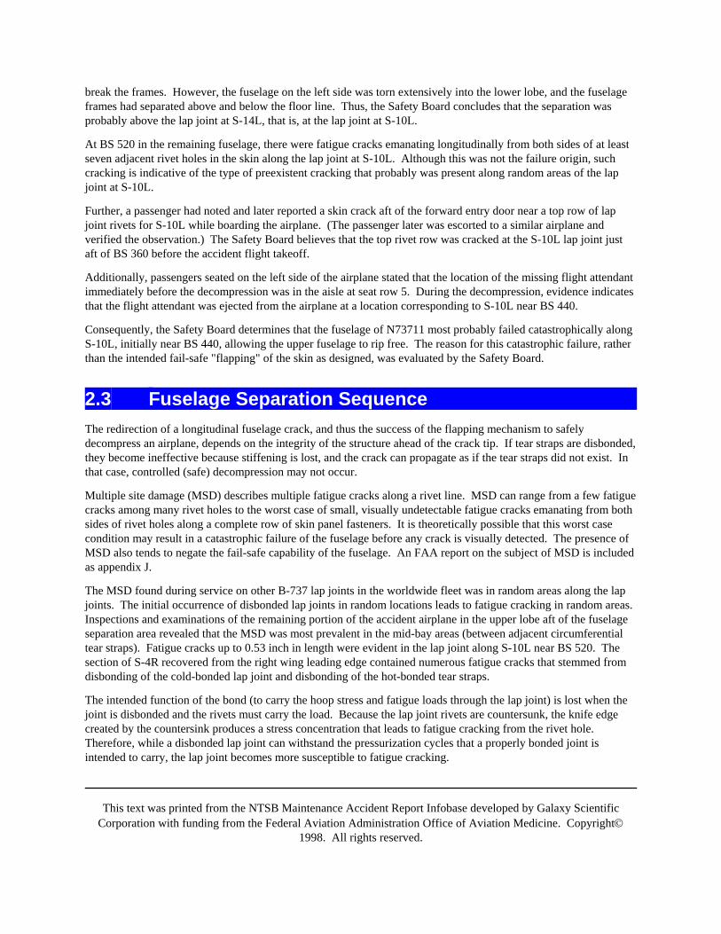
This text was printed from the NTSB Maintenance Accident Report Infobase developed by Galaxy ScientificCorporation with funding from the Federal Aviation Administration Office of Aviation Medicine. Copyright©
1998. All rights reserved.
break the frames. However, the fuselage on the left side was torn extensively into the lower lobe, and the fuselageframes had separated above and below the floor line. Thus, the Safety Board concludes that the separation wasprobably above the lap joint at S-14L, that is, at the lap joint at S-10L.
At BS 520 in the remaining fuselage, there were fatigue cracks emanating longitudinally from both sides of at leastseven adjacent rivet holes in the skin along the lap joint at S-10L. Although this was not the failure origin, suchcracking is indicative of the type of preexistent cracking that probably was present along random areas of the lapjoint at S-10L.
Further, a passenger had noted and later reported a skin crack aft of the forward entry door near a top row of lapjoint rivets for S-10L while boarding the airplane. (The passenger later was escorted to a similar airplane andverified the observation.) The Safety Board believes that the top rivet row was cracked at the S-10L lap joint justaft of BS 360 before the accident flight takeoff.
Additionally, passengers seated on the left side of the airplane stated that the location of the missing flight attendantimmediately before the decompression was in the aisle at seat row 5. During the decompression, evidence indicatesthat the flight attendant was ejected from the airplane at a location corresponding to S-10L near BS 440.
Consequently, the Safety Board determines that the fuselage of N73711 most probably failed catastrophically alongS-10L, initially near BS 440, allowing the upper fuselage to rip free. The reason for this catastrophic failure, ratherthan the intended fail-safe "flapping" of the skin as designed, was evaluated by the Safety Board.
2.3 Fuselage Separation SequenceThe redirection of a longitudinal fuselage crack, and thus the success of the flapping mechanism to safelydecompress an airplane, depends on the integrity of the structure ahead of the crack tip. If tear straps are disbonded,they become ineffective because stiffening is lost, and the crack can propagate as if the tear straps did not exist. Inthat case, controlled (safe) decompression may not occur.
Multiple site damage (MSD) describes multiple fatigue cracks along a rivet line. MSD can range from a few fatiguecracks among many rivet holes to the worst case of small, visually undetectable fatigue cracks emanating from bothsides of rivet holes along a complete row of skin panel fasteners. It is theoretically possible that this worst casecondition may result in a catastrophic failure of the fuselage before any crack is visually detected. The presence ofMSD also tends to negate the fail-safe capability of the fuselage. An FAA report on the subject of MSD is includedas appendix J.
The MSD found during service on other B-737 lap joints in the worldwide fleet was in random areas along the lapjoints. The initial occurrence of disbonded lap joints in random locations leads to fatigue cracking in random areas.Inspections and examinations of the remaining portion of the accident airplane in the upper lobe aft of the fuselageseparation area revealed that the MSD was most prevalent in the mid-bay areas (between adjacent circumferentialtear straps). Fatigue cracks up to 0.53 inch in length were evident in the lap joint along S-10L near BS 520. Thesection of S-4R recovered from the right wing leading edge contained numerous fatigue cracks that stemmed fromdisbonding of the cold-bonded lap joint and disbonding of the hot-bonded tear straps.
The intended function of the bond (to carry the hoop stress and fatigue loads through the lap joint) is lost when thejoint is disbonded and the rivets must carry the load. Because the lap joint rivets are countersunk, the knife edgecreated by the countersink produces a stress concentration that leads to fatigue cracking from the rivet hole.Therefore, while a disbonded lap joint can withstand the pressurization cycles that a properly bonded joint isintended to carry, the lap joint becomes more susceptible to fatigue cracking.
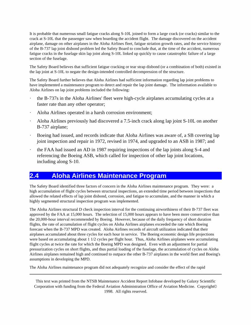
This text was printed from the NTSB Maintenance Accident Report Infobase developed by Galaxy ScientificCorporation with funding from the Federal Aviation Administration Office of Aviation Medicine. Copyright©
1998. All rights reserved.
It is probable that numerous small fatigue cracks along S-10L joined to form a large crack (or cracks) similar to thecrack at S-10L that the passenger saw when boarding the accident flight. The damage discovered on the accidentairplane, damage on other airplanes in the Aloha Airlines fleet, fatigue striation growth rates, and the service historyof the B-737 lap joint disbond problem led the Safety Board to conclude that, at the time of the accident, numerousfatigue cracks in the fuselage skin lap joint along S-10L linked up quickly to cause catastrophic failure of a largesection of the fuselage.
The Safety Board believes that sufficient fatigue cracking or tear strap disbond (or a combination of both) existed inthe lap joint at S-10L to negate the design-intended controlled decompression of the structure.
The Safety Board further believes that Aloha Airlines had sufficient information regarding lap joint problems tohave implemented a maintenance program to detect and repair the lap joint damage. The information available toAloha Airlines on lap joint problems included the following:
· the B-737s in the Aloha Airlines' fleet were high-cycle airplanes accumulating cycles at afaster rate than any other operator;
· Aloha Airlines operated in a harsh corrosion environment;
· Aloha Airlines previously had discovered a 7.5-inch crack along lap joint S-10L on anotherB-737 airplane;
· Boeing had issued, and records indicate that Aloha Airlines was aware of, a SB covering lapjoint inspection and repair in 1972, revised in 1974, and upgraded to an ASB in 1987; and
· the FAA had issued an AD in 1987 requiring inspections of the lap joints along S-4 andreferencing the Boeing ASB, which called for inspection of other lap joint locations,including along S-10.
2.4 Aloha Airlines Maintenance ProgramThe Safety Board identified three factors of concern in the Aloha Airlines maintenance program. They were: ahigh accumulation of flight cycles between structural inspections, an extended time period between inspections thatallowed the related effects of lap joint disbond, corrosion, and fatigue to accumulate, and the manner in which ahighly segmented structural inspection program was implemented.
The Aloha Airlines structural D check inspection interval for the continuing airworthiness of their B-737 fleet wasapproved by the FAA at 15,000 hours. The selection of 15,000 hours appears to have been more conservative thanthe 20,000-hour interval recommended by Boeing. However, because of the daily frequency of short durationflights, the rate of accumulation of flight cycles on Aloha Airlines airplanes exceeded the rate which Boeingforecast when the B-737 MPD was created. Aloha Airlines records of aircraft utilization indicated that theirairplanes accumulated about three cycles for each hour in service. The Boeing economic design life projectionswere based on accumulating about 1 1/2 cycles per flight hour. Thus, Aloha Airlines airplanes were accumulatingflight cycles at twice the rate for which the Boeing MPD was designed. Even with an adjustment for partialpressurization cycles on short flights, and thus partial loading of the fuselage, the accumulation of cycles on AlohaAirlines airplanes remained high and continued to outpace the other B-737 airplanes in the world fleet and Boeing'sassumptions in developing the MPD.
The Aloha Airlines maintenance program did not adequately recognize and consider the effect of the rapid

This text was printed from the NTSB Maintenance Accident Report Infobase developed by Galaxy ScientificCorporation with funding from the Federal Aviation Administration Office of Aviation Medicine. Copyright©
1998. All rights reserved.
accumulation of flight cycles. The Safety Board notes that flight cycles are the dominant concern in thedevelopment of fatigue cracking in pressurized fuselages and the accumulation of damage as a result of flight andlanding loads. The Aloha Airlines maintenance program allowed one and one half times the number of flight cyclesto accumulate on an airplane before the appropriate inspection. The Safety Board believes Aloha Airlines created aflight-hour based structural maintenance program without sufficient regard to flight cycle accumulation.
The Boeing MPD assumed a 6- to 8-year interval for a complete D check cycle, and the Aloha Airlines D checkmaintenance program required 8 years to complete a D check cycle. The Safety Board believes that the 8 yearinspection intervals in the Aloha Airlines maintenance program was too lengthy to permit early detection of disbondrelated corrosion, to allow damage repair, and to implement corrosion control/prevention with the maximum use ofinhibiting agents.
Of additional concern to the Safety Board was Aloha Airlines' practice of inspecting the airplane in smallincrements. The Aloha Airlines D check inspection of the B-737 fleet was covered in 52 independent workpackages. Limited areas of the airplane were inspected during each work package and this practice precluded acomprehensive assessment of the overall structural condition of the airplane.
The Safety Board believes that the use of 52 blocks/independent work packages is an inappropriate way to assessthe overall condition of an airplane and effect comprehensive repairs because of the potential for air carriers tohurry checks in order to keep airplanes in service. Further, the fact that the FAA found this practice to beacceptable without analysis is a matter of serious concern.
The effectiveness of Aloha Airlines inspection programs was further limited by time and manpower constraints andinadequate work planning methods. Maintenance scheduling practices utilized the overnight nonflying periods toaccomplish B checks which, in reality, included portions of the C and D check items. However, since there wereusually no spare airplanes in the fleet, it was obvious to both the maintenance and inspection personnel that eachairplane would be needed in a fully operational status to meet the next day's flying schedule. Thus, only a few hourswere available during each 24 hour period to complete B, C and D inspection items and to perform any related orunscheduled maintenance on the airplane.
The Safety Board believes that the FAA should include in its procedures for the approval of airline maintenanceprograms, deviations in airplane use by the operator as compared to the manufacturer's original design estimate,tempered by the operating history of the existing fleet. A calendar cap for low-flight hour operators and a maximumcycle limit for short flight operators are more appropriate inspection intervals for these operators.
The Safety Board also believes that the FAA should reevaluate the criteria and guidance provided to principalinspectors for approving individual operator's maintenance plans that divide structural inspections into a largenumber of independent work packages (segments) to be spread over the normal D check interval. The Safety Boardrecognizes the concept that the D check, as outlined in the MPD, for each aircraft is accomplished in a reasonabletime period such as 3 to 5 weeks. A true heavy maintenance inspection involves extensive work which may takeseveral days. Comprehensive structural inspections for aging airplanes, likewise, can best be accomplished by a Dcheck in which the entire airplane is inspected and refurbished in one hangar visit. As an alternative, someoperators have found it efficient to use yearly block C checks with a phased 1/4 D check inspection. Any deviationfrom this "full airplane" inspection at "seasonal scheduling intervals" should be evaluated carefully before approval.
Operator initiated changes to maintenance manuals and operations specifications are approved by the PMI. ManyPMI decisions require knowledge of airplane engineering and human performance far beyond the capabilities of anyone individual. The Safety Board believes that the PMI should be required to seek additional assistance or inputfrom other divisions of the FAA and, through channels, from the manufacturer and other operators. The types ofinput, the sources for both airworthiness and flight standards information and the conditions under which such inputshould be used, need to be reviewed and guidance developed by the FAA so the PMI can perform his duties more
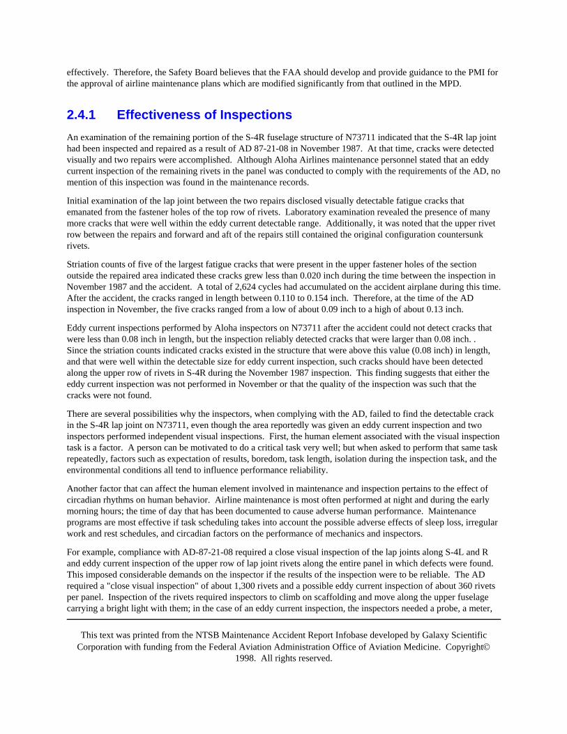
This text was printed from the NTSB Maintenance Accident Report Infobase developed by Galaxy ScientificCorporation with funding from the Federal Aviation Administration Office of Aviation Medicine. Copyright©
1998. All rights reserved.
effectively. Therefore, the Safety Board believes that the FAA should develop and provide guidance to the PMI forthe approval of airline maintenance plans which are modified significantly from that outlined in the MPD.
2.4.1 Effectiveness of InspectionsAn examination of the remaining portion of the S-4R fuselage structure of N73711 indicated that the S-4R lap jointhad been inspected and repaired as a result of AD 87-21-08 in November 1987. At that time, cracks were detectedvisually and two repairs were accomplished. Although Aloha Airlines maintenance personnel stated that an eddycurrent inspection of the remaining rivets in the panel was conducted to comply with the requirements of the AD, nomention of this inspection was found in the maintenance records.
Initial examination of the lap joint between the two repairs disclosed visually detectable fatigue cracks thatemanated from the fastener holes of the top row of rivets. Laboratory examination revealed the presence of manymore cracks that were well within the eddy current detectable range. Additionally, it was noted that the upper rivetrow between the repairs and forward and aft of the repairs still contained the original configuration countersunkrivets.
Striation counts of five of the largest fatigue cracks that were present in the upper fastener holes of the sectionoutside the repaired area indicated these cracks grew less than 0.020 inch during the time between the inspection inNovember 1987 and the accident. A total of 2,624 cycles had accumulated on the accident airplane during this time.After the accident, the cracks ranged in length between 0.110 to 0.154 inch. Therefore, at the time of the ADinspection in November, the five cracks ranged from a low of about 0.09 inch to a high of about 0.13 inch.
Eddy current inspections performed by Aloha inspectors on N73711 after the accident could not detect cracks thatwere less than 0.08 inch in length, but the inspection reliably detected cracks that were larger than 0.08 inch. .Since the striation counts indicated cracks existed in the structure that were above this value (0.08 inch) in length,and that were well within the detectable size for eddy current inspection, such cracks should have been detectedalong the upper row of rivets in S-4R during the November 1987 inspection. This finding suggests that either theeddy current inspection was not performed in November or that the quality of the inspection was such that thecracks were not found.
There are several possibilities why the inspectors, when complying with the AD, failed to find the detectable crackin the S-4R lap joint on N73711, even though the area reportedly was given an eddy current inspection and twoinspectors performed independent visual inspections. First, the human element associated with the visual inspectiontask is a factor. A person can be motivated to do a critical task very well; but when asked to perform that same taskrepeatedly, factors such as expectation of results, boredom, task length, isolation during the inspection task, and theenvironmental conditions all tend to influence performance reliability.
Another factor that can affect the human element involved in maintenance and inspection pertains to the effect ofcircadian rhythms on human behavior. Airline maintenance is most often performed at night and during the earlymorning hours; the time of day that has been documented to cause adverse human performance. Maintenanceprograms are most effective if task scheduling takes into account the possible adverse effects of sleep loss, irregularwork and rest schedules, and circadian factors on the performance of mechanics and inspectors.
For example, compliance with AD-87-21-08 required a close visual inspection of the lap joints along S-4L and Rand eddy current inspection of the upper row of lap joint rivets along the entire panel in which defects were found.This imposed considerable demands on the inspector if the results of the inspection were to be reliable. The ADrequired a "close visual inspection" of about 1,300 rivets and a possible eddy current inspection of about 360 rivetsper panel. Inspection of the rivets required inspectors to climb on scaffolding and move along the upper fuselagecarrying a bright light with them; in the case of an eddy current inspection, the inspectors needed a probe, a meter,
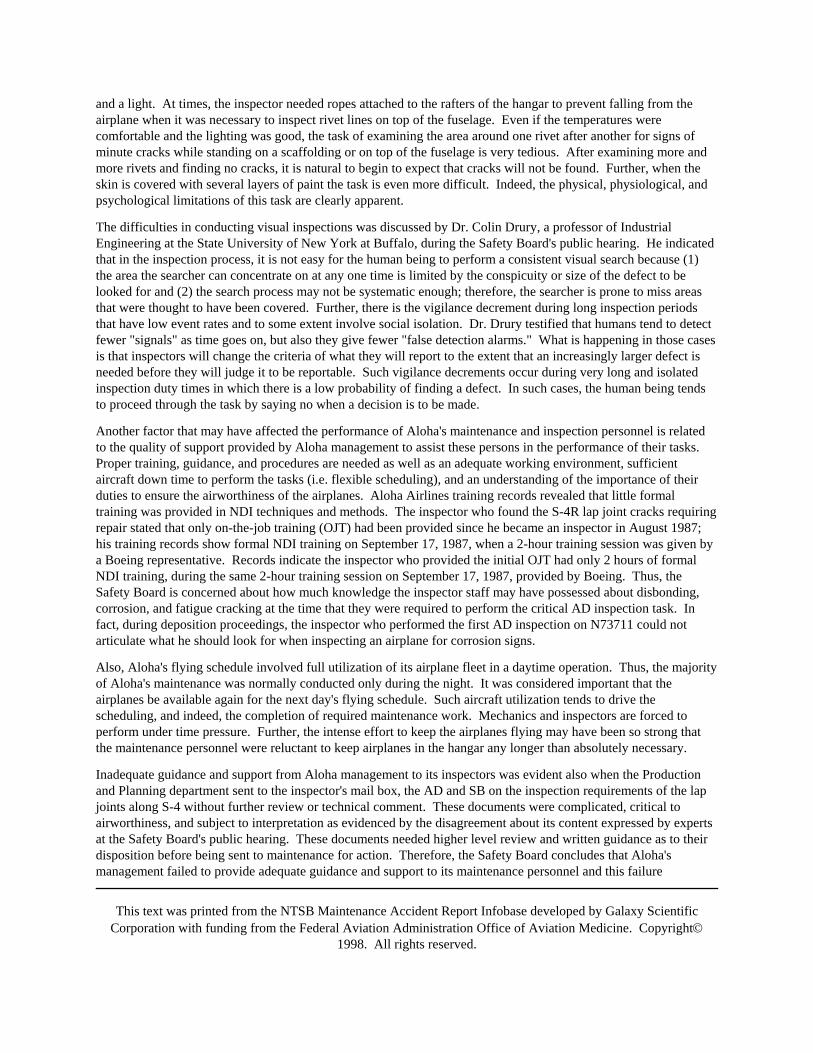
This text was printed from the NTSB Maintenance Accident Report Infobase developed by Galaxy ScientificCorporation with funding from the Federal Aviation Administration Office of Aviation Medicine. Copyright©
1998. All rights reserved.
and a light. At times, the inspector needed ropes attached to the rafters of the hangar to prevent falling from theairplane when it was necessary to inspect rivet lines on top of the fuselage. Even if the temperatures werecomfortable and the lighting was good, the task of examining the area around one rivet after another for signs ofminute cracks while standing on a scaffolding or on top of the fuselage is very tedious. After examining more andmore rivets and finding no cracks, it is natural to begin to expect that cracks will not be found. Further, when theskin is covered with several layers of paint the task is even more difficult. Indeed, the physical, physiological, andpsychological limitations of this task are clearly apparent.
The difficulties in conducting visual inspections was discussed by Dr. Colin Drury, a professor of IndustrialEngineering at the State University of New York at Buffalo, during the Safety Board's public hearing. He indicatedthat in the inspection process, it is not easy for the human being to perform a consistent visual search because (1)the area the searcher can concentrate on at any one time is limited by the conspicuity or size of the defect to belooked for and (2) the search process may not be systematic enough; therefore, the searcher is prone to miss areasthat were thought to have been covered. Further, there is the vigilance decrement during long inspection periodsthat have low event rates and to some extent involve social isolation. Dr. Drury testified that humans tend to detectfewer "signals" as time goes on, but also they give fewer "false detection alarms." What is happening in those casesis that inspectors will change the criteria of what they will report to the extent that an increasingly larger defect isneeded before they will judge it to be reportable. Such vigilance decrements occur during very long and isolatedinspection duty times in which there is a low probability of finding a defect. In such cases, the human being tendsto proceed through the task by saying no when a decision is to be made.
Another factor that may have affected the performance of Aloha's maintenance and inspection personnel is relatedto the quality of support provided by Aloha management to assist these persons in the performance of their tasks.Proper training, guidance, and procedures are needed as well as an adequate working environment, sufficientaircraft down time to perform the tasks (i.e. flexible scheduling), and an understanding of the importance of theirduties to ensure the airworthiness of the airplanes. Aloha Airlines training records revealed that little formaltraining was provided in NDI techniques and methods. The inspector who found the S-4R lap joint cracks requiringrepair stated that only on-the-job training (OJT) had been provided since he became an inspector in August 1987;his training records show formal NDI training on September 17, 1987, when a 2-hour training session was given bya Boeing representative. Records indicate the inspector who provided the initial OJT had only 2 hours of formalNDI training, during the same 2-hour training session on September 17, 1987, provided by Boeing. Thus, theSafety Board is concerned about how much knowledge the inspector staff may have possessed about disbonding,corrosion, and fatigue cracking at the time that they were required to perform the critical AD inspection task. Infact, during deposition proceedings, the inspector who performed the first AD inspection on N73711 could notarticulate what he should look for when inspecting an airplane for corrosion signs.
Also, Aloha's flying schedule involved full utilization of its airplane fleet in a daytime operation. Thus, the majorityof Aloha's maintenance was normally conducted only during the night. It was considered important that theairplanes be available again for the next day's flying schedule. Such aircraft utilization tends to drive thescheduling, and indeed, the completion of required maintenance work. Mechanics and inspectors are forced toperform under time pressure. Further, the intense effort to keep the airplanes flying may have been so strong thatthe maintenance personnel were reluctant to keep airplanes in the hangar any longer than absolutely necessary.
Inadequate guidance and support from Aloha management to its inspectors was evident also when the Productionand Planning department sent to the inspector's mail box, the AD and SB on the inspection requirements of the lapjoints along S-4 without further review or technical comment. These documents were complicated, critical toairworthiness, and subject to interpretation as evidenced by the disagreement about its content expressed by expertsat the Safety Board's public hearing. These documents needed higher level review and written guidance as to theirdisposition before being sent to maintenance for action. Therefore, the Safety Board concludes that Aloha'smanagement failed to provide adequate guidance and support to its maintenance personnel and this failure
This text was printed from the NTSB Maintenance Accident Report Infobase developed by Galaxy ScientificCorporation with funding from the Federal Aviation Administration Office of Aviation Medicine. Copyright©
1998. All rights reserved.
contributed directly to the cause of this accident.
While the foregoing indicates that there were deficiencies in the training, guidance, and support provided by AlohaAirlines management to its maintenance personnel, there are indications that, had these deficiencies not existed andthe inspection task been well defined and structured properly, the inspection error rate would still not have beentotally eliminated. This belief is, in part, supported by the reports received by the FAA after this accident as a resultof AD-T88-10-11 which required inspection and reports on positive indications of cracks and corrosion found inearly model B-737 airplanes. The FAA received 49 reports of corrosion or cracks not previously found; 14 of theseinstances involved multisite cracking. No matter how well organized a corrosion detection and crack detectionprogram may be and no matter how dedicated and vigilant the NDI work force, the inspection process is inherentlysusceptible to some error rate. Therefore, the Safety Board believes that the terminating action of AD-T88-10-11,which consisted of drilling out the existing rivets and replacing them with protruding head rivets, an action adoptedimmediately by a number of airlines, was superior to the option in the AD that permitted repeated inspections andpatching of cracks; a process that included substantial potential for human performance error. The Safety Boardfully concurs with recent FAA terminating action for B-737 lap joints that requires installation of protruding headrivets as the mandatory solution to the lap joint disbonding and fatigue problem.
The Safety Board believes that exacerbating the difficulty in the inspection tasks of airline maintenance personnel isthe fact that FAA approved training for aircraft maintenance technicians contains material that is largely irrelevantto the tasks that licensed personnel will actually perform in an airline environment. For example, 14 CFR 147,which governs the certification of maintenance personnel, requires that students in FAA approved maintenanceschools be knowledgeable in such topics as wood airframes, airframe fabric repair, and application of paint anddope. In a time when the FAA is certificating air transport aircraft with fly by wire technology, composite materialsconstruction and computer self monitoring capabilities, the words "computer" and "composite" do not appear in thelist of required curriculum subjects among airframe systems and components in 14 CFR 147, Appendix C. TheSafety Board believes that current requirements for training aviation maintenance personnel fail to address the tasksthat such personnel will actually perform following their licensure. The Safety Board is concerned about how wellthe FAA approved training curricula can address the human performance limitations of a relatively simple visualinspection task when the training that maintenance personnel receive fails to address the basic skills they will beexpected to perform on the job. The Safety Board believes that the FAA should examine the regulations governingthe certification of aviation maintenance technican schools and the licensure of airframe and powerplant mechanicsand revise the regulations to address contemporary developments in airplane maintenance.
Another area of Safety Board concern arises from the fact that there are no FAA requirements for formal training orlicensing of NDI personnel. The Safety Board is aware that the United Kingdom Civil Aviation Authorities andthose in other countries have formally recognized the importance of NDI skills and have required in-depth training,skill demonstration, licensing and recurrent certification of NDI personnel. While NDI technology and techniquesin some industries in the United States are quite advanced and personnel certification follows the American Societyfor Nondestructive Testing (ASNT) guidelines, the aviation industry has not applied such advanced techniques orpractices. For instance, in the current environment any mechanic, including those designated as inspectors, could beassigned to perform detailed and critical NDI inspections on airplanes with little or no training and with tools thathave not been technologically improved for some time.
Because of its criticality and complexity, the Safety Board believes that the NDI maintenance function should bereviewed by the FAA with a view towards requiring formal training, skill demonstration, apprenticeships, andformal licensing and recurrent certification for NDI inspectors.
Selection of inspection personnel was another issue raised during the investigation of this accident. The concernwas expressed about what kinds of characteristics are appropriate to consider when selecting persons to perform anobviously tedious, repetitive task such as a protracted NDI inspection. Inspectors normally come up through the
This text was printed from the NTSB Maintenance Accident Report Infobase developed by Galaxy ScientificCorporation with funding from the Federal Aviation Administration Office of Aviation Medicine. Copyright©
1998. All rights reserved.
seniority ranks. If they have the desire, knowledge and skills, they bid on the position and are selected for theinspector job on that basis. However, to ask a technically knowledgeable person to perform an obviously tediousand exceedingly boring task, rather than to have him supervise the quality of the task, may not be an appropriate useof personnel; persons who have demonstrated a capability to move up to supervisory duties may not necessarilyperform well at repetitive tasks. In light of the critical importance of the maintenance inspection task, asdemonstrated by this accident, the Safety Board believes that the FAA should sponsor, as part of its recentlyinitiated human factors program on this subject, research to determine suitable means for use by air carriers inselecting inspector candidates.
Finally, the Safety Board is concerned that nondestructive inspections in the aviation industry involve inspectionmethods that are substantially dependent on human beings performing repetitive and detailed tasks. The SafetyBoard believes that research is needed to improve upon the methods presently used to examine very large areas orperform a very large number of similar repetitive actions to find very small defects. Inspections of aviationstructures involving large areas or numerous repetitive actions should be automated to the extent possible, or othertechniques developed to eliminate or minimize the potential errors inherent in human performance of such tasks.
2.4.2 Aloha Airlines Corrosion ControlThe policies, procedures, and organization of Aloha Airlines aircraft maintenance and inspection programsignificantly affected the control of corrosion on its airplanes. According to airplane maintenance records, lap jointand other areas of corrosion were detected, but corrective action was frequently deferred without recording the basisfor such deferrals. Routine inspection task cards contained the "check for corrosion" instruction for specific areas;however, a programatic approach to corrosion prevention and control of the whole airplane was not evident. Itappears that even when Aloha Airlines personnel observed corrosion in the lap joints and tear straps, thesignificance of the damage and its criticality to lap joint integrity, tear strap function, and overall airplaneairworthiness was not recognized by the Aloha Airlines inspectors and maintenance managers. This wasparticularly noteworthy when one considers that Aloha Airlines indicated that SB737-53-1039, Revision 2 (1974),was incorporated in their maintenance plan. The overall condition of the Aloha Airlines fleet indicated that pilotsand line maintenance personnel came to accept the classic signs of on-going corrosion damage as a normaloperating condition.
The Safety Board was also concerned about the uncommanded shutdown of the left engine during the accidentsequence. The left engine fuel control was found in the "cutoff" position; the control apparently was positionedthere by the residual tension in the intact cable or motion of that cable induced by the cabin floor deflection sincethe cables are routed through cutouts in the floor beams.
Since the point of maximum upward floor deflection (hence maximum cable deflection) was at BS 440 in the cabin,the actual location of the throttle cable failures (in the wing leading edge) seemed an unlikely one. Additionally, thebroken cable ends lacked the unraveling that is characteristic of cables that fail in tension overload. When theappropriate cable sections were removed from the airplane and inspected more closely, there were indications ofcorrosion. These observations were confirmed by laboratory examination which concluded that the diameters ofmany of the individual wires that comprise the cables had been reduced significantly by corrosion damage. Thiscorrosion likely weakened the cables so that they separated at a lower than designed load when placed in tension bythe displacement of the left side floor beams. The cables of the right engine also exhibited extensive surfacecorrosion where they were routed through the leading edge of the wing. These cables may have remained intactduring the separation sequence only because of the much smaller amount of floor beam deflection that occurred onthe right side of the cabin.
The damage to the throttle cables appears much the same as the type of corrosion described in Boeing Service Letter
This text was printed from the NTSB Maintenance Accident Report Infobase developed by Galaxy ScientificCorporation with funding from the Federal Aviation Administration Office of Aviation Medicine. Copyright©
1998. All rights reserved.
(SL) 737-SL-76-2-A issued on August 25, 1997. This SL was issued as a result of the discovery by Aloha Airlinesthat a carbon steel thrust control cable and corroded and frayed. Only five of the seven strands of the cable werereported intact. The remaining five strands were also corroded, and the corrosion was present on the entire lengthof that portion of the cable routed through the wing leading edge.
The Boeing recommended action following this discovery was to replace the carbon steel engine control cables withcorrosion resistant stainless steel cables on the production line beginning with production line number 503 whichwas delivered in September 1977. Boeing recommended that operators of existing airplanes replace the originalcarbon steel cables on production line numbers 1 through 502 as required. At this date, the number of aircraftmodified in accordance with the applicable SL has not been established accurately. Laboratory examination of theseparated cables from N73711 confirmed that they were the original carbon steel type. The Safety Board isconcerned that Aloha Airlines did not take advantage of the manufacturer's corrective action for these cables,especially in light of their initial discovery of the problem and recognition of their own harsh operatingenvironment.
The record establishes that corrosion problems were detected by Aloha maintenance personnel and, on occasion,repairs were deferred without a full evaluation by management of the airworthiness implications or appropriatereference to the structural repair manual. This leads the Safety Board to conclude that economic considerations, alack of structural understanding, airplane utilization, and the lack of spare airplanes were factors which may haveinduced Aloha Airlines to allow these deferrals.
2.4.3 Engineering ServicesAt the time of the accident, Aloha Airlines, like many small operators, did not have an engineering department.Some of the functions that are usually performed by engineers at large airlines were accomplished by AlohaAirlines Quality Assurance (QA) department.
The responsibilities of an airline engineering department generally include evaluating and implementingmanufacturer's SBs and ADs, evaluating airplane accidental or corrosion damage, designing or evaluating repairs,establishing aircraft maintenance schedule specifications, and providing technical assistance to other areas of theairline. Another important aspect of engineering staff activities is the oversight of inspector performance andrelated quality assurance activites.
The condition of high cycle B-737's in the Aloha Airlines fleet with respect to lap joint corrosion, multiple repairs,and and detection of fatigue cracking is an example of what can occur in the absence of regular and knowledgeableevaluations of aircraft condition by qualified engineering staff.
Aloha Airlines management could have recognized the importance of Alert SB 737-53A1039 in light of their ownexperience with the previous crack along the lap joint at S-10R and could have inspected all the lap joints called outin the referenced SB while they accomplished the requirements of AD 87-21-08. The same concept applies to theSL recommending replacement of engine control cables which were recognized by Aloha as susceptible tocorrosion.
In addition, a qualified engineer should have interpreted the lap joint AD regarding the use of oversize protrudinghead fasteners in the event that fatigue damage was found. More importantly, a comprehensive structuralengineering and maintenance program likely would have precluded the deteriorated condition of the airplanes byevaluating and implementing the appropriate corrosion control techniques and SBs, thus retaining company assets.
An additional area of concern to the Safety Board is the extent and number of skin repairs evident on the airplaneand the effect that these repairs may have on the damage tolerance properties of the original design. The accident
This text was printed from the NTSB Maintenance Accident Report Infobase developed by Galaxy ScientificCorporation with funding from the Federal Aviation Administration Office of Aviation Medicine. Copyright©
1998. All rights reserved.
airplane had over two dozen fuselage repairs; the majority were skin repairs using doubler patches. This conditionillustrates the extent to which aging airplanes may continue to be repaired (patched) in accordance with existingmanufacturer's and FAA requirements.
A large repair or the cumulative effects of numerous small repairs can adversely impact the ability of the structure tocontain damage to the extent necessary to meet fail-safe or damage tolerant regulations. Additionally, the structureunderlying the repairs can be difficult if not impossible to inspect, which can be detrimental where fuselage lapjoints are concerned. These types of evaluations are typically beyond the expertise of QA and maintenancedepartments and must be addressed by qualified engineering personnel.
The Safety Board believes that the continued airworthiness of airplanes as they age would be enhanced by includingqualified engineers in the operator's organization. While the Safety Board recognizes that situation may beeconomically unrealistic for all operators, it believes that an equivalent level of safety can be achieved only by usingengineering representatives from some other source. Qualified engineers could evaluate service information andairworthiness directives with particular respect to the fleet aircraft and operating conditions. The assistance of thesequalified engineers may be available through an industry group or the manufacturer. The Safety Board, therefore,recommends that the FAA require airline operators that do not have a functioning engineering department tomaintain a formal alternative to provide engineering services.
In summary, the Safety Board believes that the Aloha Airlines maintenance department did not have sufficientmanpower, the technical knowledge, or the required programs to meet its responsibility to ensure the continuedstructural integrity of its airplanes.
2.5 FAA Responsibilities
2.5.1 Issuance and Clarity of Airworthiness DirectivesIn-service fatigue cracking in a disbonded area of a B-737 lap joint was first reported in 1984 (by Aloha Airlines).Then in April 1987, a foreign operator reported several cases within his fleet. Boeing acted by revising the existinglap joint disbond information, SB 737-53-1039, Revision 2 (which had advised that prolonged operation withdisbonded areas would result in fatigue cracks), upgrading the SB to Alert status, and notifying the FAA. InOctober 1987, multiple site cracking was discovered during the manufacturer's continued fatigue testing of a B-737aft body section. Within the same time frame, the FAA issued AD 87-21-08 which required mandatory inspectionfor fatigue cracking.
The Safety Board considers it unfortunate that the Boeing Alert SB to inspect all lap joints was not issued after thefirst instance of cracking, and that the intent of the Alert SB was altered significantly by the FAA to reduce thescope of the inspection when the AD was released. The Safety Board believes that had a full inspection of all lapjoints been mandated, the likelihood of this accident occurring may have been reduced. Therefore, the limited ADrequirements imposed by the FAA precluded the continuing airworthiness of the aging B-737s and the reducedinspection criteria is considered a contributing factor to the cause of this accident.
When Aloha Airlines accomplished the inspections and repairs associated with the AD, they omitted inspections oflap joints other than those along S-4 and they did not replace the remaining fasteners in the upper row of the S-4Rlap joint with protruding head rivets, as outlined in Boeing ASB 737-53A1039. The AD pertaining to the lap jointinspections states, in part:
Repair all cracks and tearstrap delaminations found as a result of the above inspections prior to further flight in
This text was printed from the NTSB Maintenance Accident Report Infobase developed by Galaxy ScientificCorporation with funding from the Federal Aviation Administration Office of Aviation Medicine. Copyright©
1998. All rights reserved.
accordance with Boeing Alert Service Bulletin 737-53A109, Revision 3, Dated August 20, or later FAA-approvedrevisions.
The appropriate section of the ASB states, in part:
Repair fatigue cracks using a repair similar to that shown in 737 Structural Repair Manual Subject 53-30-3, Figure16, and replace all remaining upper row flush joint-fasteners in that panel joint with oversized protruding head solidfasteners per Part IV - Repair Data.
While operators have interpreted the repair instructions listed in the AD note as requiring the installation of theprotruding head rivets as a part of the repair, the FAA personnel stated that its intent was to have protruding headfasteners installed throughout the skin panel joint where cracking was found.
Repairs of the S-4 joint by Aloha Airlines were accomplished using the procedure in the Structural Repair Manualand excluded replacing the remaining flush joint-fastners. The Safety Board believes that the instructions containedin the AD were inexact and subject to misinterpretation.
Such confusion illustrates the difficulty inherent in attempting to present technical information so that it can beinterpreted properly by the users of the information. In the case of this AD, it is believed that the repair instructionscould have been presented more explicity. This was, in fact, done in subsequent ADs pertaining to the samesubject.
The Safety Board is satisfied that the terminating action for the disbonding of B-737 lap joints and tear strapsrequiring replacement of the upper rivet row is an effective measure to correct this recognized B-737 deficiency.
However, laboratory examination of the S-4R lap joint sample from the accident airplane revealed another area ofconcern with early line number B-737 airplanes. Fatigue cracks were found emanating from the fastener holes of asignificant number of rivets in the middle row of the lap joint. The Safety Board is concerned that because of theextended lifetime of the B-737 afforded by the terminating action mandated for the upper rivet row, the lower rivetrow on the inner (lower) skin panel eventually will be a location for fatigue cracks to develop. These cracks, if theyoccur, cannot be detected externally by visual means since they are covered by the outer skin panel. The FAA andBoeing should continue to evaluate the early model B-737 airplanes to determine the types of inspections,inspection intervals, and corrective actions to be instituted if a significant fatigue cracking problem develops in themiddle and lower row of lap joint fasteners.
2.5.2 Needed Research on Corrosion Control and NDIWhile it is the responsibility of the operator to develop and implement a proper and complete maintenance programapplicable to the operating environment, the Safety Board believes that the FAA should define acceptable corrosioncontrol program parameters and provide them as a guide for both the operator and the PMI. The Safety Boardbelieves that an operator's comprehensive corrosion control program, fully supported by the manufacturer andenforced by the FAA, is a critical and necessary step in the continued airworthiness of an aging airplane fleet.
The Safety Board also believes that the FAA should assume the lead role in encouraging further research intoimproved corrosion detection and prevention methods. Many areas of an airplane are difficult to inspect forcorrosion. For example, within lap joints, the corrosion can go undetected until it is so severe that the damage isevident visibly from the condition of the outer skin. There have been various experiments on NDT inspectionmethods but none have proved effective in all cases. The NDT equipment manufacturers appear able to supply verytechnical equipment to other industries; however, in the aviation industry, neither the most technically advanced andautomated equipment nor the human factors involved in using such equipment effectively have been pursued
This text was printed from the NTSB Maintenance Accident Report Infobase developed by Galaxy ScientificCorporation with funding from the Federal Aviation Administration Office of Aviation Medicine. Copyright©
1998. All rights reserved.
thoroughly. The FAA and aircraft maintenance interests should challenge the NDT equipment manufacturers withthe specific needs for the aviation industry in order to develop improved, economical, state-of-the-art equipment andto employ methods which minimize human performance inadequacies.
Even though the corrosion problems with the carbon steel engine control cables have been known for quite sometime, the Safety Board believes that it would be beneficial to once again address this area in light of the cablecondition on the accident airplane and the fact that some portions of the cables can be difficult to inspect. TheSafety Board believes that the FAA should issue an Airworthiness Directive to the operators of the affected B-737airplanes advising them of the corrosion potential of carbon steel engine control cables and directing them to theinformation contained in 737-SL-76-2-A regarding cable replacement.
2.5.3 FAA OversightThe Safety Board has issued numerous safety recommendations pertaining to the surveillance of air carriermaintenance by the FAA. Generally, these safety recommendations have addressed maintenance problems withspecific aircraft, revisions to manuals, and accident or special study identified areas for surveillance programimprovement. After the Aloha Airlines accident, the Safety Board probed deeper into the FAA's surveillanceprogram, including NASIP. The investigation and analysis of the accident revealed several areas of concernincluding staffing levels and FAA philosophy regarding maintenance surveillance.
The investigation has revealed that staffing levels in some FSDOs are insufficient. The PMI responsible for AlohaAirlines indicated that he was also assigned as the PMI for nine other operators and seven repair stations throughoutthe Pacific rim area. He also was assigned out of his geographic area of responsibility to participate in a NASIPinspection. The Safety Board believes that the PMI's workload was too extensive for him to be adequatelyeffective.
As a result of the FAA sponsored Safety Activity Functional Evaluation (Project SAFE) in 1984, the FAA FlightStandards System is now in a 5-year program to improve inspection guidance, field surveillance, andstandardization. The FAA has been allocated additional hiring authority and funds to increase the number of aircarrier inspectors. While additional personnel will improve the staffing situation, the Safety Board is concernedabout the qualifications of the newly hired inspectors and the training of the inspector force. Because there are alimited number of candidates who have extensive air carrier backgrounds, the FAA has had to hire people withgeneral aviation or military backgrounds or transfer inspectors from general aviation assigments. As a result, thenew inspectors are not fully familiar with air carrier maintenance programs and practices. Although the FAAprovides a 6-week indoctrination for the new inspectors, it requires several years of on-the-job experience to makethe inspectors most effective. Then they progress on a career path that leads toward being appointed as a PMI.There is no specific formal training course for PMIs. Additionally, recurrent training is sporadic and difficult toattain, resulting in a work force that must try very hard to stay ahead of the operators and quickly advancing aircrafttechnology.
Increased FAA inspector staffing levels should help with the manpower requirements necessary to reviewpaperwork that ensures that airlines have complied with Federal regulations. However, without proper FAAinspection of actual airplane condition, less responsible or knowledgeable operators can operate airplanes ofdubious structural and mechanical integrity. The paperwork review system has become so entrenched in FAAinspections that an alteration of philosophy is required to create an effective maintenance surveillance program.
The Safety Board sought to identify existing boundaries of responsibility of the PMI regarding regulatorycompliance and the level of maintenance quality demonstrated by the assigned air carrier. Evidence ofaccountability of the PMI and district office for the performance of the assigned carrier(s) was not apparent.
This text was printed from the NTSB Maintenance Accident Report Infobase developed by Galaxy ScientificCorporation with funding from the Federal Aviation Administration Office of Aviation Medicine. Copyright©
1998. All rights reserved.
Evidence suggests that FAA surveillance and inspection programs are directed toward the air carrier, and thein-house evaluation of PMI performance is oriented toward quantity of work and the ability to handle approvalssmoothly and directly. The Safety Board is concerned that the PMI has the authority to approve critical areas of aircarrier maintenance programs without being held responsible for those approvals. There does not appear to be aneffective method in place for FAA management to make recurring qualitative assessments of PMI approvals.
Followup of the NASIP findings is also indicative of a lack of PMI accountability. The negative findings of anairline maintenance program are placed into the oversight of the PMI to promote and monitor corrective action.That is, a negative situation may occur under the jurisdiction and surveillance of a PMI and yet he is responsible toevaluate and followup on corrective action. Therefore, the accountability for the on-going quality of the PMIs workperformance does not appear to exist.
It appears that the current surveillance system can lead to "rubber stamp" approvals and endorsement of an aircarrier's operations and maintenance programs. Improvements are needed to encourage and support the PMI'sefforts to secure compliance and to promote upgraded levels of performance by the assigned air carrier in bothsafety and reliabiliy areas. Without such improvements, the system of program approval can be driven by themomentum and interests of the air carrier. It appears the present system is sustained by the personal integrity anddedication of the concerned FAA inspector personnel rather than by an FAA system that includes adequateoversight and internal review. With the current environment, only the most motivated PMIs will maintain theirsense of responsibility to ensure maximum efficiency and safety. The Safety Board recognizes the need forincreased FAA management emphasis on the accountability of a PMI's performance. Both regional andheadquarters Flight Standards staff should become more involved in assessing and ensuring PMI accountability.
In addition, there is also a need for a program of standardized approvals of air carrier maintenance programs topromote a uniform and acceptable level of safety performance in the current competitive air carrier industry. TheSafety Board believes that the authority of the PMI for approval of airlines procedures and operations specificationscan be better guided, and overall PMI performance improved, if definitive Flight Standards criteria are provided tothose in the field.
The FAA management's primary tool for overseeing surveillance by the inspector work force, WPMS, requiresinspectors to enter the number, type, and results of inspections performed into a computer. During Safety Boardinterviews, inspectors have expressed concern that this system creates administrative requirements to the detrimentof the time available for performing their surveillance responsibilities. The Safety Board recognizes that FAAmanagement requires the data for their workload and personnel management systems and that the information isused to ensure that inspectors perform the required inspections. However, at present, the information plays only alimited part to enhance the quality of airline surveillance. The Safety Board suggests that further improvements canbe made to streamline the system and perhaps to gain more qualitative information about both the carrier and thePMI surveillance.
The Safety Board also investigated the effectiveness of the NASIP after the Aloha Airlines accident. A NASIPinspection had been performed at Aloha Airlines in December 1987 and none of the findings and corrective actionsaddressed airplane structural maintenance. In fact, NASIP looked chiefly at manuals and records with a minimaleffort expended to the condition of the fleet. A month earlier, Boeing had performed a maintenance evaluation ofthe carrier at Aloha Airlines' request. Boeing found several areas of concern including the deteriorated structuralcondition of the Aloha Airlines' high-cycle airplanes and Aloha Airlines' immediate need for a structures engineer.The Boeing inspection provided a convenient yardstick by which the effectiveness of the NASIP effort can bemeasured. The Boeing effort concentrated initially on the actual condition of the airplanes, and then it reviewed thepaperwork to find out why the maintenance program had resulted in the airplane deterioration. The Safety Boardconcluded that there are inadequacies in the NASIP objectives and methodology which require a change in thecurrent philosophy of FAA surveillance to include added inspection of fleet airplane condition.
This text was printed from the NTSB Maintenance Accident Report Infobase developed by Galaxy ScientificCorporation with funding from the Federal Aviation Administration Office of Aviation Medicine. Copyright©
1998. All rights reserved.
The Safety Board also believes that routine surveillance and the NASIP concept should be adjusted toward a more"safety-oriented" qualitative program to complement the current "Federal regulation compliance" approach. That is,under the current philosophy, the FAA examines airline records for compliance with regulations, and some negativefindings (violations) result in enforcement actions for which there are clear guidelines. However, many negativefindings are "nonregulatory" matters for which both the local PMIs and the NASIP teams believe corrective actionsshould be taken. In the preamble to the 1987 NASIP report of Aloha Airlines, the FAA team stated, "AlohaAirlines' Maintenance Management has been remiss in their responsibilities by not being able to recognize their owndeficiencies, as this report will indicate." "Responsibilities" apparently refers to regulations under which AlohaAirlines is charged with maintaining its airplane in an airworthy condition (FAR 121.363). "Deficiencies" in thiscase apparently refers to items which the FAA believes Aloha Airlines should correct to operate safely. There wasno national FAA program to evaluate and verify the quality of the corrective actions, nor to determine the timelinessof such actions. For example, the NASIP team found that Aloha Airlines "... does not have an effective internalaudit program." Although FAR 121.373 "Continuing analysis and surveillance" addresses an air carrier'sresponsibility to maintain a system for continuing analysis and surveillance of its inspection and maintenanceprograms, the FAA NASIP inspectors apparently concluded that the regulation was too subjective to use as a basisfor enforcement action to assure that Aloha Airlines corrected deficiencies in their internal audit program.
Technically, as stated by the FAA, if an airline complies with the regulations, it is "safe." However, manyregulations are subjective in nature and are subject to interpretation. Consequently, even with several significantnegative findings by a NASIP team, as was the case with Aloha Airlines, the airline was allowed to continueoperations without making immediate changes and without having to set deadlines for completion on recommendedactions. In fact, the oversight and closeout of corrective actions suggested by the NASIP team were left to theAloha Airlines PMI, under whose jurisdiction and routine surveillance the discrepancies had been allowed to exist.
Some negative findings of the FAA NASIP team were similar in nature to the findings of the Boeing team thatevaluated Aloha Airlines maintenance program in November 1987 and the "aging fleet" survey team that visitedAloha Airlines in January 1988. Although several corrective actions were taken by Aloha Airlines in early 1988and several others were in process at the time of the accident, Aloha Airlines continued flight operationsuninterrupted during this period, despite the negative nature of many of these findings.
The Safety Board is concerned that an airline that is charged by regulation to conduct operations in a certain mannercan be found in noncompliance with the intent of the regulations and yet, it can continue commercial flightoperations without substantive interruption or corrective actions taken. If an airline is either unable or unwilling todevelop and maintain an effective maintenance and inspection program, the current FAA oversight philosophy willnot prevent deficiencies from occurring, and it will not verify that substantive and timely corrective actions havebeen taken. Furthermore, the FAA did not intend to actually "inspect" Aloha Airlines fleet to verify if the airplaneswere, in fact, safe. The findings of the Safety Board following the accident of N73711, regarding the quality ofAloha Airlines maintenance program, suggests that the FAA routine and special inspection programs were noteffective in verifying that the airplanes were maintained in a safe, airworthy condition.
2.6 Boeing
2.6.1. Boeing 737 CertificationWhile the initial certification of the B-737 conformed to existing regulatory requirements, the accelerated fatiguetesting schedule did not compensate for the in-service environmental effects on the bonded lap joints or tear straps.The inadequacy of the testing schedule was due in part to the state-of-the-art of laboratory bonding verification
This text was printed from the NTSB Maintenance Accident Report Infobase developed by Galaxy ScientificCorporation with funding from the Federal Aviation Administration Office of Aviation Medicine. Copyright©
1998. All rights reserved.
testing which had not yet discovered the problem of long term bond durability. The bond production problems didnot become known until several years after the airplane went into service. It appears that Boeing addressed thisproblem swiftly thereafter by issuing SBs, improving the bonding process, conducting additional fatigue testing, andultimately eliminating the cold-bond method and redesigning the lap joint.
At the time of the initial certification of the B-737, a consideration for MSD was not a part of the certificationrequirements, nor is it required now. This is demonstrated by the fact that there is no specific FAA requirement forfull-scale fatigue testing to multiple projected service lifetimes of an airplane. Boeing attempted to assure fatiguelife by testing the representative half fuselage section to two lifetimes. However, the durability of the lap joint coldbond appears to be the governing factor producing multiple site fatigue cracking in the B-737 lap joints. The SafetyBoard believes that the Boeing fatigue tests of the fuselage to two lifetimes did not generate fatigue cracking,probably because the lap joint and tear strap bonds on the test article were initially of good quality. Nonetheless,the Safety Board believes in light of the increased knowledge of and concern for the occurrence of MSD, thedifficulties that may be encountered in detecting this type of damage and the catastrophic failure that may resultfrom such damage, full-scale fatigue testing to a minimum of two projected service lifetimes should be required forcertification of new designs.
The Safety Board believes that full-scale fatigue testing obviously is not a substitute for a comprehensive structuralinspection program throughout the airplane's service life. The effectiveness of these inspection programs as theairplane ages would be enhanced by the early identification of areas where MSD does occur and incorporation ofthe necessary preventive design changes so that MSD is not a significant factor during the airplane's operatinglifetime.
The Safety Board is also concerned about other Boeing transports, including some B-727 and early B-747 airplanes,that utilize the cold bond construction. The Safety Board recognizes that the design of B-727 and B-747 airplanes isless susceptible to fatigue cracking problems in the lap joints as early in the service life as those that arose in theB-737 fleet. However, a significant number of these airplanes are being used beyond the economic service lifepredicted by the manufacturer. The approach to fatigue testing for the early B-727 and B-747 airplanes was similarto that performed during the B-737 certification in that it did not include the possibility of in service lap jointdisbonding. Additionally, although the entire airplane was tested in each case, only one service life objective wasachieved. As a result, the onset point of widespread cracking may not be known. The Safety Board believes thatonce airplanes of each particular type approach their economic service life, that in-depth analyses are necessary toverify the continued airworthiness of these airplanes. Therefore, the Safety Board believes that the FAA shouldrequire all U.S. currently certificated turbojet transport category airplanes, and those airplanes certificated in thefuture, receive full scale structural fatigue testing to a minimum of two tims the projected economic service life.
2.6.2 Boeing Structures ClassificationThe Supplemental Structural Inspection Programs (SSIPs) mandated by the FAA vary by concept andimplementation from manufacturer to manufacturer and from model to model. As Boeing devised the SSIP for theirexisting certificated airplanes, a structural classification system determined which SSIs are included in thesupplemental inspections. Because Boeing defined the fuselage skin as "damage obvious or malfuction evident" ifit cracks, the fuselage skin was excluded from directed supplemental inspection. Other manufacturers use differentcriteria and include primary fuselage structure and skin in the structural inspection program.
Boeing believes that their current FAA approved inspection program is adequate for detecting lead cracks resultingfrom MSD before the damage becomes critical. However, the Aloha Airlines accident illustrates that it is possibleto have enough undetected (but technically detectable) damage along a rivet line to negate the controlleddecompression mechanism.

This text was printed from the NTSB Maintenance Accident Report Infobase developed by Galaxy ScientificCorporation with funding from the Federal Aviation Administration Office of Aviation Medicine. Copyright©
1998. All rights reserved.
The Safety Board recommends that the classification of fuselage minimum gage skin as damage obvious bediscontinued and the affected SSIPs be revised accordingly. Additionally, all of the remaining SSIs in the damageobvious category should be reviewed in light of the recent approach for possible inclusion in the SSIP.
2.6.3 Boeing Visits to Aloha AirlinesWhen Boeing visited Aloha Airlines as part of its Aging Fleet Evaluation Program, it expressed concern about thedeteriorated condition of the surveyed airplanes (N73711 was not included in the survey). Although Boeing did notinform Aloha Airlines that the airplanes were unsafe, Boeing believed that they made it clear that an unsafecondition could result if corrective action was not taken.
While responsibility for determining the operational airworthiness of the aircraft rests primarily with the operator,both the manufacturer and the FAA have a responsibility to verify that conditions do not appear that lead to the lossof continuing airworthiness. Both the manufacturer and the FAA participate in the process with initial certificationaction, operations specifications approval and continuing maintenance guidance and recommendations to assist theoperator to maintain an airworthy fleet.
The Safety Board agrees that it is important to maintain communication between the manufacturer and the operator.The manufacturers require information about airplane performance and conditions in service in order to resolvedifficulties and provide corrective actions to operators. Evaluations by the FAA of the condition of airplanes toverify regulatory compliance and enforcement should be performed as an independent oversight measure to ensurethat the operator/manufacturer exchange continues. When Boeing prevented the Aloha Airlines PMI from attendinga meeting at which Boeing presented the results of its evaluation, Boeing stated that it was motivated by a corporateconcern to preserve the privacy of communication between operators and the manufacturer.
Manufacturers should maintain private customer contacts but they must reserve the option to notify the FAAregarding the aspects of air safety of any individual operator should such a need arise. Boeing did not inform theFAA of the condition of the Aloha Airlines airplanes, nor was it required to by regulation. Boeing determined thatan unsafe condition "could develop" in the Aloha Airlines airplanes that were surveyed if corrective actions werenot taken and preferred to discuss the findings exclusively with Aloha Airlines.
Title 14 CFR 21.3, "Reporting of Failures, Malfunctions, and Defects," is intended to ensure that the FAA becomesaware of service difficulties that are not reported through the existing service difficulty system. The lap joint andtear strap corrosion and potential fatigue cracking problems were well known and corrective action was beingformulated. The Safety Board recognizes that although Boeing had no regulatory obligation to report the findingsof their survey of Aloha Airlines to the FAA, the Safety Board considers it a potential benefit to report suchinformation. Therefore, the Safety Board believes that the FAA should evaluate the safety benefits that may begained from manufacturer's survey information, such as aging aircraft reports, and take appropriate measures toensure such data remain accessible to the appropriate authorities. The FAA's evaluation should lead to more explicitcriteria and guidelines to operators and manufacturers about what information should be reported to the FAA underthe provisions of 14 CFR 21.3.
2.7 Operational ConsiderationsThe magnitude of the accident was well beyond any anticipated emergency scenario. The flightcrew's actions wereconsistent with simulator training situations which minimize the exposure to physiological effects. The flightcrew'ssuccess in managing the multiple emergency situations and recovering the aircraft to a safe landing speaks well of
This text was printed from the NTSB Maintenance Accident Report Infobase developed by Galaxy ScientificCorporation with funding from the Federal Aviation Administration Office of Aviation Medicine. Copyright©
1998. All rights reserved.
their training and airmanship.
The cabin crew also performed in a highly commendable manner when faced with a totally unpredicted event.Their bravery in moving about to reassure the passengers and prepare them for landing was exemplary.
The Safety Board reviewed three operational areas: assessment of in-flight structural damage; air/ground emergencycommunications; and emergency ambulance response.
It was apparent from crew interviews and the FDR that a rapid descent was initiated shortly after the explosivedecompression. The Safety Board notes that speed brakes and 280 to 290 KIAS were used without first assuring thestructural integrity of the airplane (the cockpit door was missing and sky was visible overhead). The IAS used inthe descent, although it minimized the time at altitude, increased the maneuvering loads and subjected thepassengers to flailing and windburn from the effect of exposure. The open fuselage break was also subjected tohigh dynamic pressure from the wind force.
The Operators Manual, Emergency Descent procedure (and emergency checklist) states that if structural integrity isin doubt, "limit airspeed as much as possible and avoid high maneuvering loads." The Safety Board considers thatevaluation of the structural integrity and techniques of emergency descent (target airspeed, configuration changes,and maneuvering loads) can be critical to the success of further flight. The Safety Board therefore suggests that theFAA issue an Air Carrier Operations Bulletin (ACOB) to review the accident scenario and reiterate the need toassess airplane airworthiness as stated in the operators manual before taking any action that may cause furtherdamage or the breakup of a damaged airframe.
In the course of this accident, ATC changed frequency for primary radio contact with the airplane during theemergency. Flight 234 was transmitting transponder emergency code 7700 and after some difficulty, the crewestablished contact with Maui Tower; Maui Tower was initially not apprised of the full nature of the emergency orthe structural damage. After notification of the emergency, ATC directed a frequency change to Maui approachcontrol. Later, flight 243 contacted Maui Tower for landing. The Safety Board recognizes the requirement for suchfrequency changes during normal operations; however, Maui Tower received both the emergency transponder codeand confirmation of a pressurization emergency before their instructions to change frequency.
The Safety Board wishes to reiterate that ATC must make every effort to minimize the workload of a crew duringan emergency. Further, an error during the handoff could result in lost communications and a possible loss ofpositive traffic control of the emergency aircraft.
The Safety Board is also concerned about the circumstances surrounding the ambulance response at the Mauiairport. Had the ambulance service been notified earlier by the control tower and been waiting at the airport whenthe airplane landed, the seriously injured passengers could have been treated and transported to the hospital 13minutes sooner. It is incumbent on those persons making a judgement for notification of emergency services to beaware of the circumstances and possibilities of each scenario.
3. Conclusions
3.1 Findings1. The flightcrew was certificated and qualified for the flight and the airplane was dispatched in
accordance with company procedures and Federal regulations.
This text was printed from the NTSB Maintenance Accident Report Infobase developed by Galaxy ScientificCorporation with funding from the Federal Aviation Administration Office of Aviation Medicine. Copyright©
1998. All rights reserved.
2. Weather was not a factor in this accident.
3. Although Aloha Airlines operated according to the FAA operating certificate and operationsspecifications, the quality of Aloha Airlines maintenance and inspection program wasdeficient.
4. There was no evidence of preexisting failure or malfunction of the airplane's air conditioning,pressurization, pneumatic, or electrical systems that could have contributed to the fuselagefailure.
5. The flightcrew's use of a target speed of 280-290 KIAS and speedbrakes in the descent afterthe structural separation indicated they did not consider the appropriate emergency descentchecklist which states, in part, that if structural integrity is in doubt, airspeed should belimited as much as possible and high maneuvering loads should be avoided.
6. The left engine became inoperative because the engine control cables separated due to anincrease in cable tension caused by cabin floor deformation, coupled with corrosion found inthe area of cable separation.
7. The fuselage failure initiated in the lap joint along S-10L; the failure mechanism was a resultof multiple site fatigue cracking of the skin adjacent to rivet holes along the lap joint upperrivet row and tear strap disbond which negated the fail-safe characteristics of the fuselage.
8. The fatigue cracking initiated from the knife edge associated with the countersunk lap jointrivet holes; the knife edge concentrated stresses that were transferred through the rivetsbecause of lap joint disbonding.
9. The disbonding of lap joints and tear straps originated from manufacturing difficultiesencountered with surface preparation and/or bond material processing during theconstruction of the airplane which resulted in lap joint bonds with low environmentaldurability or a lack of bonding.
10. Although a representative fuselage section of a Boeing 737 was tested to 150,000 cyclesduring certification, the test did not reflect the fatigue performance of the actual fleet aircraftbecause the test parameters did not consider the long term effects of disbonding, corrosion,and fatigue cracking in the lap joints as experienced in airline service.
11. Disbonding of B-737 lap joints, with resulting corrosion and probable fatigue cracking, wasexplicitly defined in Boeing Service Bulletin 737-53-1039, Revision 2 dated February 8,1974; however the serious implications of multiple site damage were not realized, apermanent solution was not determined, and corrective action was relegated to repetitivevisual inspections and damage repair.
12. There was sufficient information available to Aloha Airlines to alert it to the crackingproblems associated with the deterioration of lap joint bonds, and Aloha should havefollowed a maintenance program to detect and repair cracking before it reached a critical

This text was printed from the NTSB Maintenance Accident Report Infobase developed by Galaxy ScientificCorporation with funding from the Federal Aviation Administration Office of Aviation Medicine. Copyright©
1998. All rights reserved.
condition.
13. FAA AD 87-21-08 should have mandated inspection of all lap joints per Boeing ASB737-53A1039, Revision 3, instead of limiting the inspection of only the lap joints at S-4.
14. It was not determined whether Aloha Airlines actually performed the required eddy currentinspection in compliance with AD 87-21-08 or whether it was performed ineffectively.
15. A properly conducted eddy current inspection, performed in accordance with AD-87-21-08in November 1987, would have detected additional fatigue cracks in the holes of the upperrivet row of the lap joint along S-4R.
16. FAA licensed Aircraft and Powerplant mechanics are not required to be knowledgeable inthe maintenance and inspection of modern contemporary airplanes because the trainingcurriculum has not kept pace with aviation industry technology.
17. There are human factors issues associated with visual and nondestructive inspection whichcan degrade inspector performance to the extent that theoretically detectable damage isoverlooked.
18. Aloha Airlines management failed to recognize the human performance factors of inspectionand to fully motivate and focus their inspector force toward the critical nature of lap jointinspection, corrosion control and crack detection. However, reports of fleet-wide cracksreceived by the FAA after the Aloha Airlines accident indicate that a similar lack of criticalattention to lap joint inspection and fatigue crack detection was an industry-wide deficiency.
19. Because of the inexact instructions in AD 87-21-08, Aloha Airlines maintenance personneldid not replace the S-4R lap joint upper row countersunk rivets with protruding head rivets.
20. The NASIP inspection of Aloha Airlines in December 1987 did not reflect accurately theairworthiness of the operating fleet because the team failed to inspect adequately and reportthe physical condition of the fleet.
21. The PMI assigned to Aloha Airlines, although motivated toward his FAA surveillance tasks,was overburdened with other FSDO responsibilities and not suitably informed about the ageand condition of the Aloha fleet or the nature of the Aloha operations. He was thereforeunable to provide sufficient impetus to effect necessary timely improvements in the AlohaAirlines maintenance program.
22. The PMI was not specifically trained to deal with the lap joint corrosion and disbondingproblems of the B-737. His efficiency was further eroded when he was excluded from theinformational loop regarding Boeing aging aircraft inspections of Aloha airplanes and notapprised of the program between the FAA Aircraft Certification Service and Boeingregarding structural testing of an in-service airplane.
23. Principal Inspectors have difficulty initiating safety improvements in air carrier operationsand maintenance programs outside the "regulatory compliance" approach, and they must
This text was printed from the NTSB Maintenance Accident Report Infobase developed by Galaxy ScientificCorporation with funding from the Federal Aviation Administration Office of Aviation Medicine. Copyright©
1998. All rights reserved.
resort to salesmanship and persuasion unless an enforcement is clearly viable.
24. The Boeing SSIP did not include supplemental inspections on the fuselage minimum gageskin due to damage tolerant design which was classified as "damage obvious" or"malfunction evident" because of the controlled decompression scenario.
25. The aviation industry premise that airplanes can be operated in a safe airworthiness conditionindefinitely is sound only if operators have an effective inspection, corrosion control, anddamage repair program.
26. The current FAA and industry activities to address the aging airplane issue must becontinued to prevent accidents caused by structural failure.
3.2 Probable CauseThe National Transportation Safety Board determines that the probable cause of this accident was the failure of theAloha Airlines maintenance program to detect the presence of significant disbonding and fatigue damage whichultimately led to failure of the lap joint at S-10L and the separation of the fuselage upper lobe. Contributing to theaccident were the failure of Aloha Airlines management to supervise properly its maintenance force; the failure ofthe FAA to evaluate properly the Aloha Airlines maintenance program and to assess the airline's inspection andquality control deficiencies; the failure of the FAA to require Airworthiness Directive 87-21-08 inspection of all thelap joints proposed by Boeing Alert Service Bulletin SB 737-53A1039; and, the lack of a complete terminatingaction (neither generated by Boeing nor required by the FAA) after the discovery of early production difficulties inthe B-737 cold bond lap joint which resulted in low bond durability, corrosion, and premature fatigue cracking.
4. RecommendationsAs a result of its investigation of this accident, the National Transportation Safety Board made the following safetyrecommendations:
--to the Federal Aviation Administration:
Provide specific guidance and proper engineering support to Principal MaintenanceInspectors to evaluate modifications of airline maintenance programs and operationsspecifications which propose segmenting major maintence inspections. (Class II, PriorityAction) (A-89-53)
Identify operators whose airplane use differs significantly from the flight cycle versus flighttime relationship upon which the Maintenance Planning Document was predicated, andverify that their maintenance programs provide timely detection of both cycle and timerelated deficiencies. (Class II, Priority Action) (A-89-54)
Revise the regulations governing the certification of aviation maintenance technician schoolsand the licensing of airframe and powerplant mechanics to require that the curriculum andtesting requirements include modern aviation industry technology. (Class II, Priority Action)
This text was printed from the NTSB Maintenance Accident Report Infobase developed by Galaxy ScientificCorporation with funding from the Federal Aviation Administration Office of Aviation Medicine. Copyright©
1998. All rights reserved.
(A-89-55)
Require formal certification and recurrent training of aviation maintenance inspectorsperforming nondestructive inspection functions. Formal training should includeapprenticeship and periodic skill demonstration. (Class II, Priority Action) (A-89-56)
Require operators to provide specific training programs for maintenance and inspectionpersonnel about the conditions under which visual inspections must be conducted. Requireoperators to periodically test personnel on their ability to detect the defined defects. (ClassII, Priority Action) (A-89-57)
Develop a continuing inspection program for those B-737 airplanes that have incorporatedlap joint terminating action (protruding head solid fasteners installed in the upper row of alllap splices) to detect any fatigue cracking that may develop in the middle or lower rows offuselage lap joint fastener holes (for both the inner and outer skin panels) or in the adjacenttear strap fastener holes, and define the types of inspections, inspection intervals, andcorrective actions needed for continuing airworthiness. (Class II, Priority Action) (A-89-58)
Develop a model program for a comprehensive corrosion control program to be included ineach operator's approved maintenance program. (Class II, Priority Action) (A-89-59)
Issue an Airworthiness Directive for B-737 airplanes equipped with carbon steel enginecontrol cables to periodically inspect the cables for evidence of corrosion and if there is suchevidence, to accomplish the actions set forth in Boeing Service Letter 737-SL-76-2-A.(Class II, Priority Action) (A-89-60)
Require that air carrier maintenance departments use the engineering services available fromthe manufacturer or other sources to periodically evaluate their maintenance practicesincluding structural repair, compliance with airworthiness directives and service bulletins,performance of inspection and quality assurance sections and overall effectiveness ofcontinuing airworthiness programs. (Class II, Priority Action) (A-89-61)
Revise the National Aviation Safety Inspection Program objectives to require that inspectorsevaluate not only the paperwork trail, but also the actual condition of the fleet airplanesundergoing maintenance and on the operational ramp. (Class II, Priority Action) (A-89-62)
Require National Aviation Safety Inspection Program teams to indicate related systemicdeficiencies within an operators maintenance activity when less than satisfactory fleetcondition is identified. (Class II, Priority Action) (A-89-63)
Evaluate the quality of FAA surveillance provided by the principal inspectors as part of theNational Aviation Safety Inspection Program. (Class II, Priority Action) (A-89-64)
Integrate the National Aviation Safety Inspection Program team leader in the closeout of theteam findings. (Class II, Priority Action) (A-89-65)
Enhance the stature and performance of the principal inspectors through; (1) formal
This text was printed from the NTSB Maintenance Accident Report Infobase developed by Galaxy ScientificCorporation with funding from the Federal Aviation Administration Office of Aviation Medicine. Copyright©
1998. All rights reserved.
management training and guidance, (2) greater encouragement and backing by headquartersof efforts by principal inspectors to secure the implementation by carriers of levels of safetyabove the regulatory minimums, (3) improved accountability for the quality of thesurveillance and (4) additional headquarters assistance in standardizing surveillanceactivities. (Class II, Priority Action) (A-89-66)
Require that all turbojet transport category airplanes certificated in the future, receive fullscale structural fatigue testing to a minimum of two times the projected economic servicelife. Also require that all currently certificated turbojet transport category airplanes that havenot been fatigue tested to two lifetimes, be subjected to such testing. As a result of thistesting and subsequent inspection and analysis, require manufacturers to identify structuresusceptible to multiple site damage and adopt inspection programs appropriate for thedetection of such damage. (Class II, Priority Action) (A-89-67)
Discontinue classification of fuselage skin as "malfunction evident" or "damage obvious" onsupplemental structural inspection documents. In addition, review all the remainingstructurally significant items in the damage obvious category for possible inclusion in theSupplementary Inspection Program. (Class II, Priority Action) (A-89-68)
Issue an Air Carrier Operations Bulletin for all air carrier flight training departments toreview the accident scenario and reiterate the need to assess airplane airworthiness as statedin the operators manual before taking action that may cause further damage or breakup of adamaged airframe. (Class II, Priority Action) (A-89-69)
--to Aloha Airlines:
Revise the maintenance program to recognize the high-time high cycles nature of the fleetoperations and initiate maintenance inspection and overhaul concepts based on realistic andacceptable calendar and flight cycle intervals. (Class II, Priority Action) (A-89-70)
Initiate a corrosion prevention and control program designed to afford maximum protectionfrom the effects of harsh operating environments (as defined by the airplane manufacturer).(Class II, Priority Action) (A-89-71)
Revise and upgrade the technical division manpower and organization to provide thenecessary management, quality assurance, engineering, technical training and productionpersonnel to maintain a high level of airworthiness of the fleet. (Class II, Priority Action)(A-89-72)
-- to the Air Transport Association:
Assist member air carriers to establish maintenance department engineering services toevaluate maintenance practices including structural repair, compliance with airworthinessdirectives and service bulletins, performance of inspection and quality assurance sections,and overall effectiveness of continuing airworthiness programs. (Class II, Priority Action)
This text was printed from the NTSB Maintenance Accident Report Infobase developed by Galaxy ScientificCorporation with funding from the Federal Aviation Administration Office of Aviation Medicine. Copyright©
1998. All rights reserved.
(A-89-73)BY THE NATIONAL TRANSPORTATION SAFETY BOARD
James L. KolstadActing Chairman
Jim BurnettMember
John K. LauberMember
Joseph T. NallMember
Lemoine V. Dickinson, Jr.Member
Joseph T. Nall, Member, filed the following concurring/dissenting statement:
While I concur with most of the majority's findings, I disagree with the probable cause and certain conclusions.Industry's best engineers reviewed the carrier's records, knew of its high-cycle operations, and even inspected someof Aloha's 737 fleet. No one--not Boeing, Aloha nor the FAA principal maintenance inspectors--recognized orpredicted the critical nature of the multi-site cracking or that the aircraft hull was about to rupture. If a "failure"occurred, it was a system failure. Could those who designed, inspected or maintained the aircraft, given theirknowledge at the time of the accident, have reasonably foreseen this accident was about to happen? I think not. Iwould have preferred to cite simply "the presence of undetected disbonding and fatigue cracking" as the probablecause. I agree with the majority that contributing to the failure to detect the hull defects were systems, programs ordecisions of all the participants. But I emphasize these are simply contributing factors, not the probable cause of theaccident.
The majority's probable cause is too narrow and I therefore cannot agree that Aloha's maintenance program was theprobable cause of the accident. I would have supported the following probable cause:
The National Transportation Safety Board determines that the probable cause of this accident was the presence ofundetected disbonding and fatigue cracking which led to the failure of the fuselage lap joint at S-10L.
Contributing to the accident were: the failure of Aloha Airlines management to supervise its maintenance forceproperly; the failure of the Federal Aviation Administration to assess the quality and effectiveness of the AlohaAirlines maintenance program; the failure of FAA Airworthiness Directive 87-21-08 to require inspection of all thelap joints as proposed by Boeing Alert Service Bulletin 737-53A1039; and the lack of a complete terminating action(neither generated by Boeing nor required by the FAA) after the discovery of difficulties in the early productionB-737 cold bond lap joint.
Joseph T. NallMember
June 14, 1989
Appendixes

This text was printed from the NTSB Maintenance Accident Report Infobase developed by Galaxy ScientificCorporation with funding from the Federal Aviation Administration Office of Aviation Medicine. Copyright©
1998. All rights reserved.
Appendix A Investigation And Hearing
1. InvestigationThe Washington Headquarters of the National Transportation Safety Board was notified of the Aloha Airlinesaccident within a short time after the occurrence. A full investigation team departed Washington, DC at 0800eastern daylight time the following morning and arrived in Maui 1400 Hawaiian standard time on the same day.The team was composed of the following investigative groups: Operations, Structures/Systems, MaintenanceRecords, Metallurgy, and Survival Factors. In addition, specialist reports were prepared to summarize findingsrelevant to the CVR and FDR.
Parties to the field investigation were Aloha Airlines, the FAA, the State of Hawaii Department of TransportationAirports Division, the Boeing Commercial Airplane Company, the Air Line Pilots Association, the InternationalAssociation of Machinists, and the Association of Flight Attendants.
2. Public HearingA 4-day public hearing was held in Seattle, Washington, beginning on July 12, 1988. Parties represented at thehearing were the FAA, Aloha Airlines, Boeing Commercial Airplane Company, and the Air Line Pilots Association.
Appendix B Personnel Information
Captain Robert Lawrence SchornstheimerCaptain Robert L. Schornstheimer, 44, was hired by Aloha Airlines on May 31, 1977. The captain holds AirlineTransport Pilot (ATP) Certificate No. 1958730 with airplane multiengine land ratings and commercial privileges inairplane single engine land. The captain is type rated in the Boeing 737. The captain was issued a First ClassMedical Certificate on November 25, 1987, with no limitations.
On January 7, 1988, the captain completed recurrent ground training on the Boeing 737. On February 17, 1988, thecaptain received a proficiency check in a B-737. On February 17, 1988, the captain received a proficiency hadflown a total of 8,500 hours, 6,700 hours of which were in the Boeing 737. During the last 90 days, 60 days, and 30days before the accident, the captain had flown: 107 hours, 4 minutes; 72 hours, 3 minutes; and 41 hours, 23minutes, respectively. In the 24 hours previous to the accident, the captain had flown 4 hours and 26 minutes andhad a total duty time of 8 hours and 50 minutes.
First Officer Madeline Lynn TompkinsFirst Officer Madeline L. Tompkins, 37, was hired by Aloha Airlines on June 4, 1979. The first officer holds ATPCertificate 1907395, with commercial privileges in airplanes single and multiengine land and glider aero tow only.The first officer was issued an FAA First Class Medical Certificate with no restrictions on January 5, 1988, with thelimitation that "Holder shall wear corrective lenses while exercising the privilege of her airman certificate."

This text was printed from the NTSB Maintenance Accident Report Infobase developed by Galaxy ScientificCorporation with funding from the Federal Aviation Administration Office of Aviation Medicine. Copyright©
1998. All rights reserved.
The first officer qualified as a Boeing 737 first officer on June 30, 1979. Her most recent recurrent ground trainingand proficiency check were both completed on April 8, 1988. The first officer had flown a total of 8,000 hours,3,500 hours of which were in the Boeing 737. During the last 90 days, 60 days, and 30 days before the accident, thefirst officer had flown: 189 hours, 29 minutes; 128 hours, 27 minutes; and 58 hours, 46 minutes, respectively. Inthe 24 hours previous to the accident, the first officer had flown 1 hour and 5 minutes and had a total duty time of 3hours and 20 minutes.
Flight Attendant Clarabelle LansingFlight Attendant Clarabelle Lansing, 58, was employed by Aloha Airlines on August 1, 1951 and she had completedrecurrent emergency training on September 29, 1987. She was assigned exit L-1 for takeoff and landing.
Flight Attendant Michelle HondaFlight Attendant Michelle Honda, 35, was employed by Aloha Airlines on July 1, 1974 and she had completedrecurrent emergency training on December 9, 1987. She was assigned exit R-3 for takeoff and landing.
Flight Attendant Jane Sato-TomitaFlight Attendant Jane Sato-Tomita, 43, was employed by Aloha Airlines on December 1, 1969 and she hadcompleted recurrent emergency training on January 5, 1988. She was assigned exit R-1 for takeoff and landing.
Inspector Wilfred Y. K. SoongInspector Wilfred Y. K. Soong was employed by Aloha Airlines in June, 1966 in the line maintenance department.He has served as an Aloha Airlines maintenance supervisor. He holds FAA Airplane and Powerplant License1687694 and has 22 years experience in aircraft maintenance. He was appointed to his present position as aninspector in September, 1987. Mr. Soong testified that his inspector training was received through on-the-jobinstruction. Mr. Soong's Aloha Airlines Formal Training Record contains one entry for the period subsequent to hisappointment as an inspector, an NDI workshop presented by Boeing for 2 hours.
Senior Lead Inspector Edward MatsumotoSenior Lead Inspector Edward Matsumoto was employed by Aloha Airlines in January, 1960, as a mechanic. Hehas served as an Aloha Airlines inspector and foreman. He holds FAA Airplane and Powerplant License 1450079and has more than 33 years experience in aircraft maintenance. Mr. Matsumoto's Aloha Airlines Formal TrainingRecord is silent from 1968 until September 17, 1987, when he attended an NDI workshop presented by Boeing for 2hours.
Appendix C Boeing Service Bulletin 737-53-1039, Rev. 2
This text was printed from the NTSB Maintenance Accident Report Infobase developed by Galaxy ScientificCorporation with funding from the Federal Aviation Administration Office of Aviation Medicine. Copyright©
1998. All rights reserved.
Revision Transmittal Sheet Boeing Service Bulletin 737-53-1039This sheet transmits REVISION 2 dated February 8, 1974 to Service Bulletin 737-53-1039, BODY SKIN LAPJOINT INSPECTION AND REPAIR.This revision constitutes a complete reissue.
SummaryThis revision is issued to add a specific corrosion and fatigue damage inspection program, expand the effectivity toinclude airplanes sealed in production, delete ultrasonic void and feeler gage inspections, delete several ultrasonicthickness measuring instruments and incorporate outstanding status change notices.
Airplanes on which lap joints were sealed per Service Bulletin 53-1017, SEALING OF COLD-BONDEDSTRUCTURE FOR CORROSION PROTECTION, as an adhesive deterioration and corrosion preventive measurerequire corrosion and fatigue damage inspection per this revision.
Airplanes on which joints were refastened per previous issues of this bulletin or the methods detailed in StructuralRepair Manual, 53-30-1, Figure 5, require corrosion inspection only per this revision.
All pages of this revision contain new, revised or relocated information.
Revision HistoryOriginal Issue: July 19, 1972
Revision 1: October 11, 1972
Revision 2: February 8, 1974
BOEING COMMERCIAL AIRPLANE COMPANY CUSTOMER SUPPORT
Appendix C
Subject: Body Skin Lap Joint Inspection And Repair
I. Planning Information
A. Effectivity
1. Airplanes Affected
This change is applicable only to the airplanes listed below.
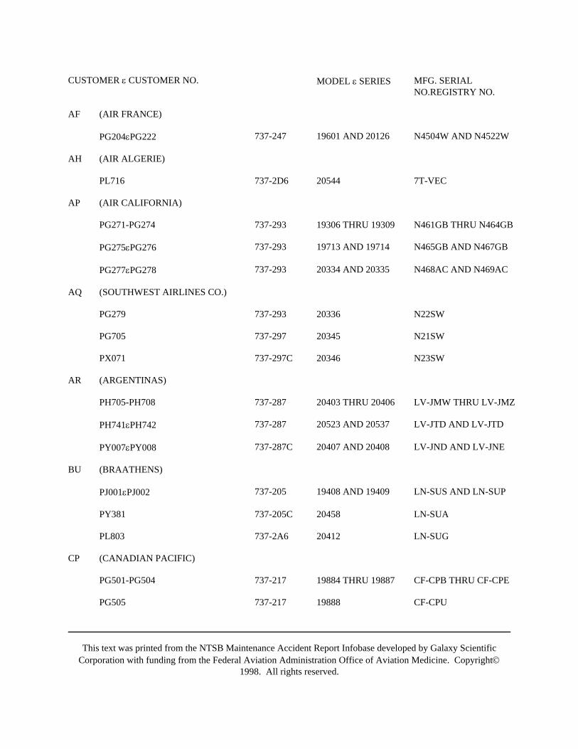
This text was printed from the NTSB Maintenance Accident Report Infobase developed by Galaxy ScientificCorporation with funding from the Federal Aviation Administration Office of Aviation Medicine. Copyright©
1998. All rights reserved.
CUSTOMER ε CUSTOMER NO. MODEL ε SERIES MFG. SERIALNO.REGISTRY NO.
AF (AIR FRANCE)
PG204εPG222 737-247 19601 AND 20126 N4504W AND N4522W
AH (AIR ALGERIE)
PL716 737-2D6 20544 7T-VEC
AP (AIR CALIFORNIA)
PG271-PG274 737-293 19306 THRU 19309 N461GB THRU N464GB
PG275εPG276 737-293 19713 AND 19714 N465GB AND N467GB
PG277εPG278 737-293 20334 AND 20335 N468AC AND N469AC
AQ (SOUTHWEST AIRLINES CO.)
PG279 737-293 20336 N22SW
PG705 737-297 20345 N21SW
PX071 737-297C 20346 N23SW
AR (ARGENTINAS)
PH705-PH708 737-287 20403 THRU 20406 LV-JMW THRU LV-JMZ
PH741εPH742 737-287 20523 AND 20537 LV-JTD AND LV-JTD
PY007εPY008 737-287C 20407 AND 20408 LV-JND AND LV-JNE
BU (BRAATHENS)
PJ001εPJ002 737-205 19408 AND 19409 LN-SUS AND LN-SUP
PY381 737-205C 20458 LN-SUA
PL803 737-2A6 20412 LN-SUG
CP (CANADIAN PACIFIC)
PG501-PG504 737-217 19884 THRU 19887 CF-CPB THRU CF-CPE
PG505 737-217 19888 CF-CPU
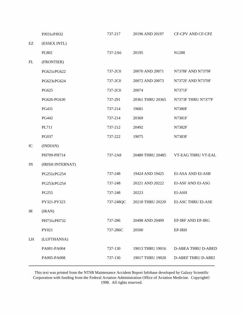
This text was printed from the NTSB Maintenance Accident Report Infobase developed by Galaxy ScientificCorporation with funding from the Federal Aviation Administration Office of Aviation Medicine. Copyright©
1998. All rights reserved.
PJ031εPJ032 737-217 20196 AND 20197 CF-CPV AND CF-CPZ
EZ (ESSEX INTL)
PL802 737-2A6 20195 N1288
FL (FRONTIER)
PG621εPG622 737-2C0 20070 AND 20071 N7378F AND N7379F
PG623εPG624 737-2C0 20072 AND 20073 N7372F AND N7370F
PG625 737-2C0 20074 N7371F
PG626-PG630 737-291 20361 THRU 20365 N7373F THRU N7377F
PG431 737-214 19681 N7380F
PG442 737-214 20369 N7381F
PL711 737-212 20492 N7382F
PG037 737-222 19075 N7383F
IC (INDIAN)
PH709-PH714 737-2A8 20480 THRU 20485 VT-EAG THRU VT-EAL
IN (IRISH INTERNAT)
PG251εPG254 737-248 19424 AND 19425 EI-ASA AND EI-ASB
PG253εPG254 737-248 20221 AND 20222 EI-ASF AND EI-ASG
PG255 737-248 20223 EI-ASH
PY321-PY323 737-248QC 20218 THRU 20220 EI-ASC THRU EI-ASE
IR (IRAN)
PH731εPH732 737-286 20498 AND 20499 EP-IRF AND EP-IRG
PY021 737-286C 20500 EP-IRH
LH (LUFTHANSA)
PA001-PA004 737-130 19013 THRU 19016 D-ABEA THRU D-ABED
PA005-PA008 737-130 19017 THRU 19020 D-ABEF THRU D-ABEI
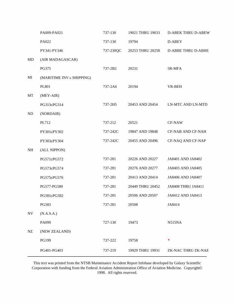
This text was printed from the NTSB Maintenance Accident Report Infobase developed by Galaxy ScientificCorporation with funding from the Federal Aviation Administration Office of Aviation Medicine. Copyright©
1998. All rights reserved.
PA009-PA021 737-130 19021 THRU 19033 D-ABEK THRU D-ABEW
PA022 737-130 19794 D-ABEY
PY341-PY346 737-230QC 20253 THRU 20258 D-ABBE THRU D-ABHE
MD (AIR MADAGASCAR)
PG375 737-2B2 20231 5R-MFA
MI (MARITIME INV ε SHIPPING)
PL801 737-2A6 20194 VR-BEH
MT (MEY-AIR)
PG313εPG314 737-2H5 20453 AND 20454 LN-MTC AND LN-MTD
ND (NORDAIR)
PL712 737-212 20521 CF-NAW
PY301εPY302 737-242C 19847 AND 19848 CF-NAB AND CF-NAH
PY303εPY304 737-242C 20455 AND 20496 CF-NAQ AND CF-NAP
NH (ALL NIPPON)
PG571εPG572 737-281 20226 AND 20227 JA8401 AND JA8402
PG573εPG574 737-281 20276 AND 20277 JA8403 AND JA8405
PG575εPG576 737-281 20413 AND 20414 JA8406 AND JA8407
PG577-PG580 737-281 20449 THRU 20452 JA8408 THRU JA8411
PG581εPG582 737-281 20506 AND 20507 JA8412 AND JA8413
PG583 737-281 20508 JA8414
NV (N.A.S.A.)
PA099 727-130 19473 N515NA
NZ (NEW ZEALAND)
PG199 737-222 19758 *
PG401-PG403 737-219 19929 THRU 19931 ZK-NAC THRU ZK-NAE
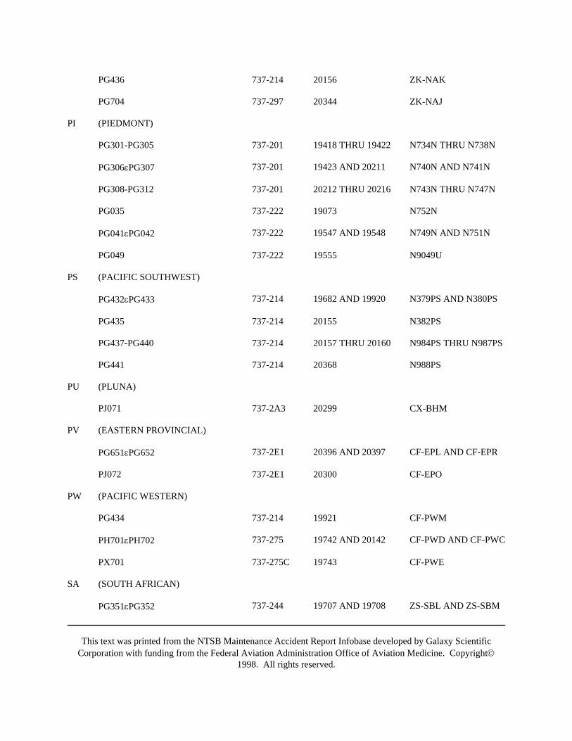
This text was printed from the NTSB Maintenance Accident Report Infobase developed by Galaxy ScientificCorporation with funding from the Federal Aviation Administration Office of Aviation Medicine. Copyright©
1998. All rights reserved.
PG436 737-214 20156 ZK-NAK
PG704 737-297 20344 ZK-NAJ
PI (PIEDMONT)
PG301-PG305 737-201 19418 THRU 19422 N734N THRU N738N
PG306εPG307 737-201 19423 AND 20211 N740N AND N741N
PG308-PG312 737-201 20212 THRU 20216 N743N THRU N747N
PG035 737-222 19073 N752N
PG041εPG042 737-222 19547 AND 19548 N749N AND N751N
PG049 737-222 19555 N9049U
PS (PACIFIC SOUTHWEST)
PG432εPG433 737-214 19682 AND 19920 N379PS AND N380PS
PG435 737-214 20155 N382PS
PG437-PG440 737-214 20157 THRU 20160 N984PS THRU N987PS
PG441 737-214 20368 N988PS
PU (PLUNA)
PJ071 737-2A3 20299 CX-BHM
PV (EASTERN PROVINCIAL)
PG651εPG652 737-2E1 20396 AND 20397 CF-EPL AND CF-EPR
PJ072 737-2E1 20300 CF-EPO
PW (PACIFIC WESTERN)
PG434 737-214 19921 CF-PWM
PH701εPH702 737-275 19742 AND 20142 CF-PWD AND CF-PWC
PX701 737-275C 19743 CF-PWE
SA (SOUTH AFRICAN)
PG351εPG352 737-244 19707 AND 19708 ZS-SBL AND ZS-SBM

This text was printed from the NTSB Maintenance Accident Report Infobase developed by Galaxy ScientificCorporation with funding from the Federal Aviation Administration Office of Aviation Medicine. Copyright©
1998. All rights reserved.
PG353 737-244 20229 ZS-SBN
PG354-PG356 737-244 20329 THRU 20331 ZS-SBO THRU ZS-SBR
SQ (SINGAPORE AIRLINES LTD.)
PC001εPC002 737-112 19768 AND 19769 9V-BFD AND 9V-BBC
PC003εPC004 737-112 19770 AND 19771 9V-BFE AND 9V-BBE
PC005 737-112 19772 9V-BFF
TM (DETA)
PH703εPH704 737-2B1 20280 AND 20281 CR-BAA AND CR-BAB
PY031 737-2B1C 20536 CR-BAC
TS (ALOHA)
PA231εPA232 737-159 19679 AND 19680 N73715 AND N73717
PG701εPG702 737-297 20209 AND 20210 N73711 AND N73712
PG703 737-297 20242 N73713
TZ (TRANSAIR LTD.)
PY004εPY005 737-2A9C 20205 AND 20206 CF-TAO AND CF-TAN
UA (UNITED)
PG001-PG004 737-222 19039 THRU 19042 N9001U THRU N9004U
PG006-PG034 737-222 19044 THRU 19072 N9006U THRU N9034U
PG038-PG040 737-222 19076 THRU 19078 N9038U THRU N9040U
PG043-PG048 737-222 19549 THRU 19554 N9043U THRU N9048U
PG050 737-222 19556 N9050U
PG051-PG075 737-222 19932 THRU 19956 N9051U THRU N9075U
VP (VASP SAO PAULO)
PG471-PG475 737-2A1 20092 THRU 20096 PP-SMA THRU PP-SME
WA (WESTERN)
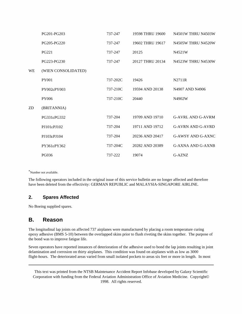
This text was printed from the NTSB Maintenance Accident Report Infobase developed by Galaxy ScientificCorporation with funding from the Federal Aviation Administration Office of Aviation Medicine. Copyright©
1998. All rights reserved.
PG201-PG203 737-247 19598 THRU 19600 N4501W THRU N4503W
PG205-PG220 737-247 19602 THRU 19617 N4505W THRU N4520W
PG221 737-247 20125 N4521W
PG223-PG230 737-247 20127 THRU 20134 N4523W THRU N4530W
WE (WIEN CONSOLIDATED)
PY001 737-202C 19426 N2711R
PY002εPY003 737-210C 19594 AND 20138 N4907 AND N4906
PY006 737-210C 20440 N4902W
ZD (BRITANNIA)
PG331εPG332 737-204 19709 AND 19710 G-AVRL AND G-AVRM
PJ101εPJ102 737-204 19711 AND 19712 G-AVRN AND G-AVRD
PJ103εPJ104 737-204 20236 AND 20417 G-AWSY AND G-AXNC
PY361εPY362 737-204C 20282 AND 20389 G-AXNA AND G-AXNB
PG036 737-222 19074 G-AZNZ
*Number not available.
The following operators included in the original issue of this service bulletin are no longer affected and thereforehave been deleted from the effectivity: GERMAN REPUBLIC and MALAYSIA-SINGAPORE AIRLINE.
2. Spares Affected
No Boeing supplied spares.
B. ReasonThe longitudinal lap joints on affected 737 airplanes were manufactured by placing a room temperature curingepoxy adhesive (BMS 5-10) between the overlapped skins prior to flush riveting the skins together. The purpose ofthe bond was to improve fatigue life.
Seven operators have reported instances of deterioration of the adhesive used to bond the lap joints resulting in jointdelamination and corrosion on thirty airplanes. This condition was found on airplanes with as low as 3000flight-hours. The deteriorated areas varied from small isolated pockets to areas six feet or more in length. In most
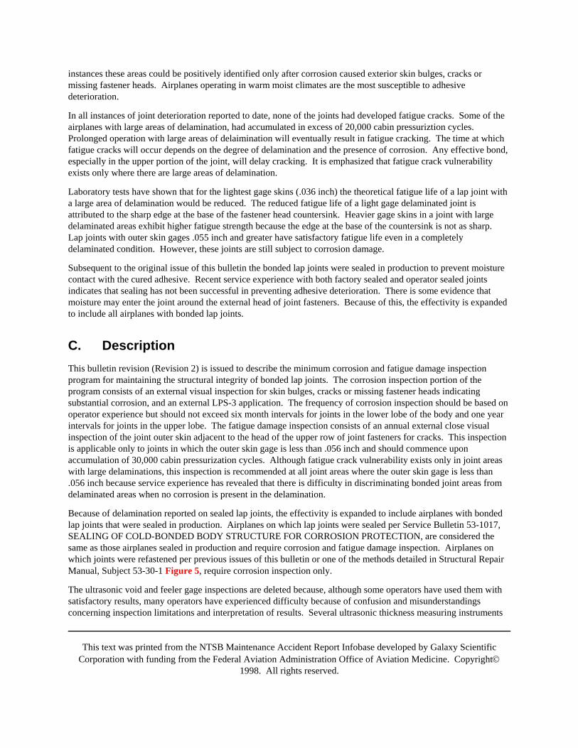
This text was printed from the NTSB Maintenance Accident Report Infobase developed by Galaxy ScientificCorporation with funding from the Federal Aviation Administration Office of Aviation Medicine. Copyright©
1998. All rights reserved.
instances these areas could be positively identified only after corrosion caused exterior skin bulges, cracks ormissing fastener heads. Airplanes operating in warm moist climates are the most susceptible to adhesivedeterioration.
In all instances of joint deterioration reported to date, none of the joints had developed fatigue cracks. Some of theairplanes with large areas of delamination, had accumulated in excess of 20,000 cabin pressuriztion cycles.Prolonged operation with large areas of delaimination will eventually result in fatigue cracking. The time at whichfatigue cracks will occur depends on the degree of delamination and the presence of corrosion. Any effective bond,especially in the upper portion of the joint, will delay cracking. It is emphasized that fatigue crack vulnerabilityexists only where there are large areas of delamination.
Laboratory tests have shown that for the lightest gage skins (.036 inch) the theoretical fatigue life of a lap joint witha large area of delamination would be reduced. The reduced fatigue life of a light gage delaminated joint isattributed to the sharp edge at the base of the fastener head countersink. Heavier gage skins in a joint with largedelaminated areas exhibit higher fatigue strength because the edge at the base of the countersink is not as sharp.Lap joints with outer skin gages .055 inch and greater have satisfactory fatigue life even in a completelydelaminated condition. However, these joints are still subject to corrosion damage.
Subsequent to the original issue of this bulletin the bonded lap joints were sealed in production to prevent moisturecontact with the cured adhesive. Recent service experience with both factory sealed and operator sealed jointsindicates that sealing has not been successful in preventing adhesive deterioration. There is some evidence thatmoisture may enter the joint around the external head of joint fasteners. Because of this, the effectivity is expandedto include all airplanes with bonded lap joints.
C. DescriptionThis bulletin revision (Revision 2) is issued to describe the minimum corrosion and fatigue damage inspectionprogram for maintaining the structural integrity of bonded lap joints. The corrosion inspection portion of theprogram consists of an external visual inspection for skin bulges, cracks or missing fastener heads indicatingsubstantial corrosion, and an external LPS-3 application. The frequency of corrosion inspection should be based onoperator experience but should not exceed six month intervals for joints in the lower lobe of the body and one yearintervals for joints in the upper lobe. The fatigue damage inspection consists of an annual external close visualinspection of the joint outer skin adjacent to the head of the upper row of joint fasteners for cracks. This inspectionis applicable only to joints in which the outer skin gage is less than .056 inch and should commence uponaccumulation of 30,000 cabin pressurization cycles. Although fatigue crack vulnerability exists only in joint areaswith large delaminations, this inspection is recommended at all joint areas where the outer skin gage is less than.056 inch because service experience has revealed that there is difficulty in discriminating bonded joint areas fromdelaminated areas when no corrosion is present in the delamination.
Because of delamination reported on sealed lap joints, the effectivity is expanded to include airplanes with bondedlap joints that were sealed in production. Airplanes on which lap joints were sealed per Service Bulletin 53-1017,SEALING OF COLD-BONDED BODY STRUCTURE FOR CORROSION PROTECTION, are considered thesame as those airplanes sealed in production and require corrosion and fatigue damage inspection. Airplanes onwhich joints were refastened per previous issues of this bulletin or one of the methods detailed in Structural RepairManual, Subject 53-30-1 Figure 5, require corrosion inspection only.
The ultrasonic void and feeler gage inspections are deleted because, although some operators have used them withsatisfactory results, many operators have experienced difficulty because of confusion and misunderstandingsconcerning inspection limitations and interpretation of results. Several ultrasonic thickness measuring instruments
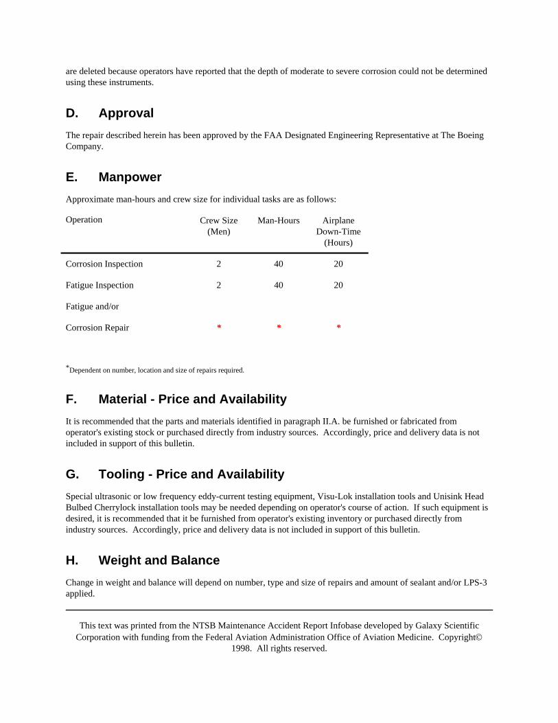
This text was printed from the NTSB Maintenance Accident Report Infobase developed by Galaxy ScientificCorporation with funding from the Federal Aviation Administration Office of Aviation Medicine. Copyright©
1998. All rights reserved.
are deleted because operators have reported that the depth of moderate to severe corrosion could not be determinedusing these instruments.
D. ApprovalThe repair described herein has been approved by the FAA Designated Engineering Representative at The BoeingCompany.
E. ManpowerApproximate man-hours and crew size for individual tasks are as follows:
Operation Crew Size(Men)
Man-Hours AirplaneDown-Time
(Hours)
Corrosion Inspection 2 40 20
Fatigue Inspection 2 40 20
Fatigue and/or
Corrosion Repair * * *
*Dependent on number, location and size of repairs required.
F. Material - Price and AvailabilityIt is recommended that the parts and materials identified in paragraph II.A. be furnished or fabricated fromoperator's existing stock or purchased directly from industry sources. Accordingly, price and delivery data is notincluded in support of this bulletin.
G. Tooling - Price and AvailabilitySpecial ultrasonic or low frequency eddy-current testing equipment, Visu-Lok installation tools and Unisink HeadBulbed Cherrylock installation tools may be needed depending on operator's course of action. If such equipment isdesired, it is recommended that it be furnished from operator's existing inventory or purchased directly fromindustry sources. Accordingly, price and delivery data is not included in support of this bulletin.
H. Weight and BalanceChange in weight and balance will depend on number, type and size of repairs and amount of sealant and/or LPS-3applied.
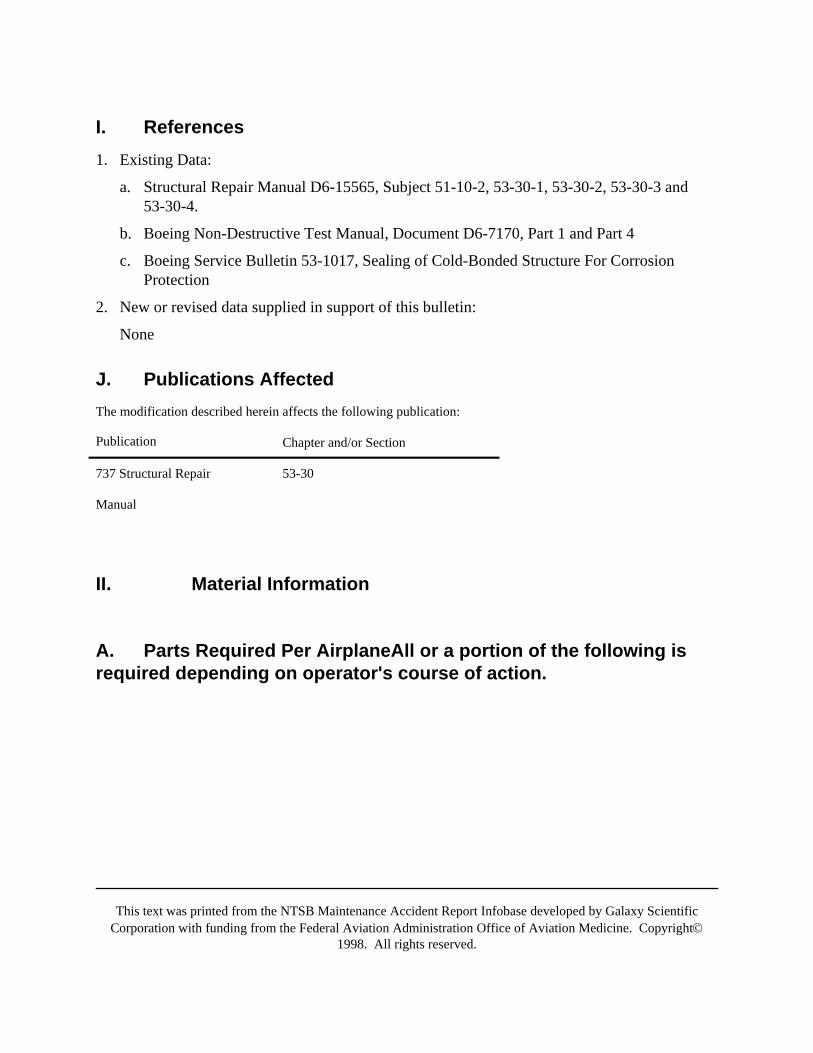
This text was printed from the NTSB Maintenance Accident Report Infobase developed by Galaxy ScientificCorporation with funding from the Federal Aviation Administration Office of Aviation Medicine. Copyright©
1998. All rights reserved.
I. References1. Existing Data:
a. Structural Repair Manual D6-15565, Subject 51-10-2, 53-30-1, 53-30-2, 53-30-3 and53-30-4.
b. Boeing Non-Destructive Test Manual, Document D6-7170, Part 1 and Part 4
c. Boeing Service Bulletin 53-1017, Sealing of Cold-Bonded Structure For CorrosionProtection
2. New or revised data supplied in support of this bulletin:
None
J. Publications AffectedThe modification described herein affects the following publication:
Publication Chapter and/or Section
737 Structural Repair 53-30
Manual
II. Material Information
A. Parts Required Per AirplaneAll or a portion of the following isrequired depending on operator's course of action.
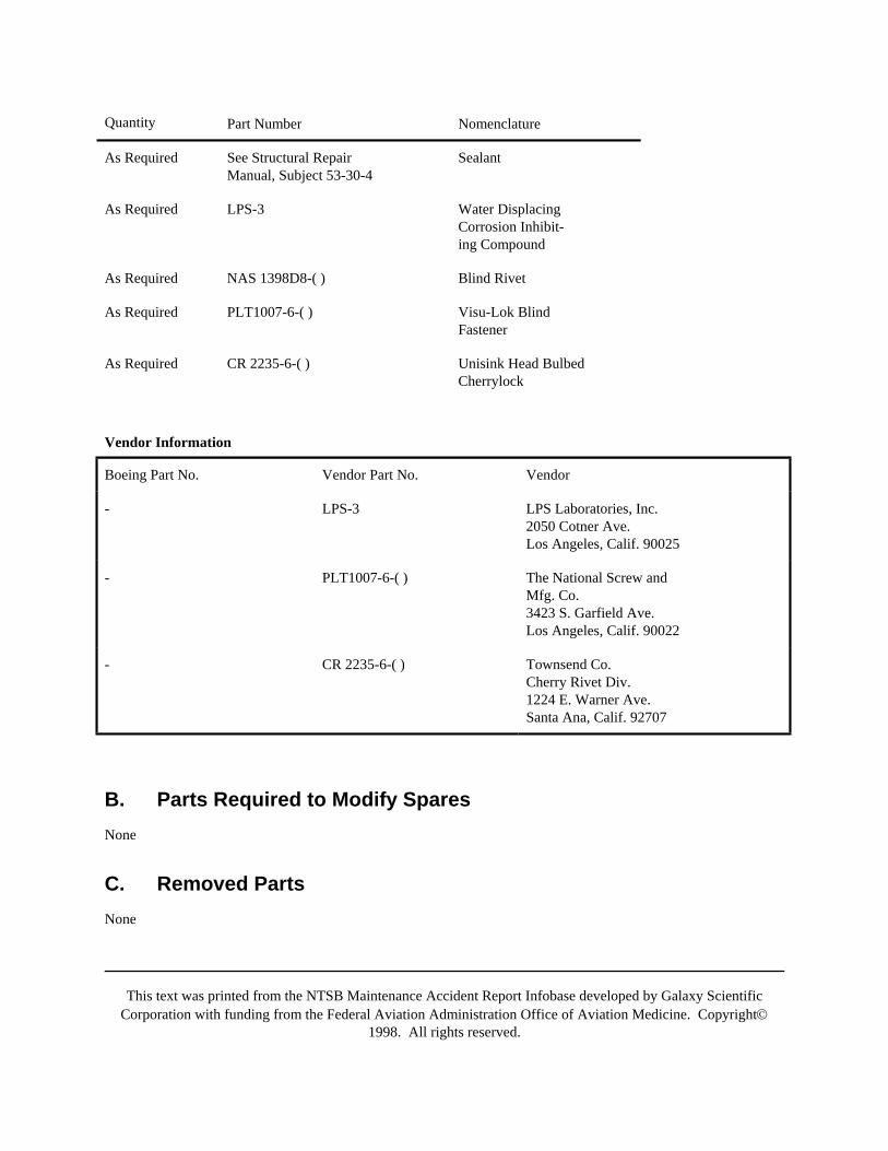
This text was printed from the NTSB Maintenance Accident Report Infobase developed by Galaxy ScientificCorporation with funding from the Federal Aviation Administration Office of Aviation Medicine. Copyright©
1998. All rights reserved.
Quantity Part Number Nomenclature
As Required See Structural RepairManual, Subject 53-30-4
Sealant
As Required LPS-3 Water DisplacingCorrosion Inhibit-ing Compound
As Required NAS 1398D8-( ) Blind Rivet
As Required PLT1007-6-( ) Visu-Lok BlindFastener
As Required CR 2235-6-( ) Unisink Head BulbedCherrylock
Vendor Information
Boeing Part No. Vendor Part No. Vendor
- LPS-3 LPS Laboratories, Inc.2050 Cotner Ave.Los Angeles, Calif. 90025
- PLT1007-6-( ) The National Screw andMfg. Co.3423 S. Garfield Ave.Los Angeles, Calif. 90022
- CR 2235-6-( ) Townsend Co.Cherry Rivet Div.1224 E. Warner Ave.Santa Ana, Calif. 92707
B. Parts Required to Modify SparesNone
C. Removed PartsNone
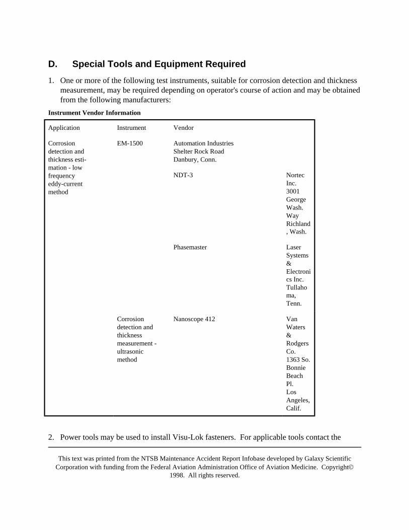
This text was printed from the NTSB Maintenance Accident Report Infobase developed by Galaxy ScientificCorporation with funding from the Federal Aviation Administration Office of Aviation Medicine. Copyright©
1998. All rights reserved.
D. Special Tools and Equipment Required1. One or more of the following test instruments, suitable for corrosion detection and thickness
measurement, may be required depending on operator's course of action and may be obtainedfrom the following manufacturers:
Instrument Vendor Information
Application Instrument Vendor
Corrosiondetection andthickness esti-mation - lowfrequencyeddy-currentmethod
EM-1500 Automation IndustriesShelter Rock RoadDanbury, Conn.
NDT-3 NortecInc.3001GeorgeWash.WayRichland, Wash.
Phasemaster LaserSystems&Electronics Inc.Tullahoma,Tenn.
Corrosiondetection andthicknessmeasurement -ultrasonicmethod
Nanoscope 412 VanWaters&RodgersCo.1363 So.BonnieBeachPl.LosAngeles,Calif.
2. Power tools may be used to install Visu-Lok fasteners. For applicable tools contact the
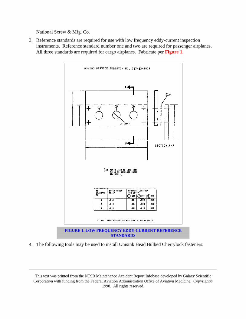
This text was printed from the NTSB Maintenance Accident Report Infobase developed by Galaxy ScientificCorporation with funding from the Federal Aviation Administration Office of Aviation Medicine. Copyright©
1998. All rights reserved.
National Screw & Mfg. Co.
3. Reference standards are required for use with low frequency eddy-current inspectioninstruments. Reference standard number one and two are required for passenger airplanes.All three standards are required for cargo airplanes. Fabricate per Figure 1.
FIGURE 1. LOW FREQUENCY EDDY-CURRENT REFERENCESTANDARDS
4. The following tools may be used to install Unisink Head Bulbed Cherrylock fasteners:
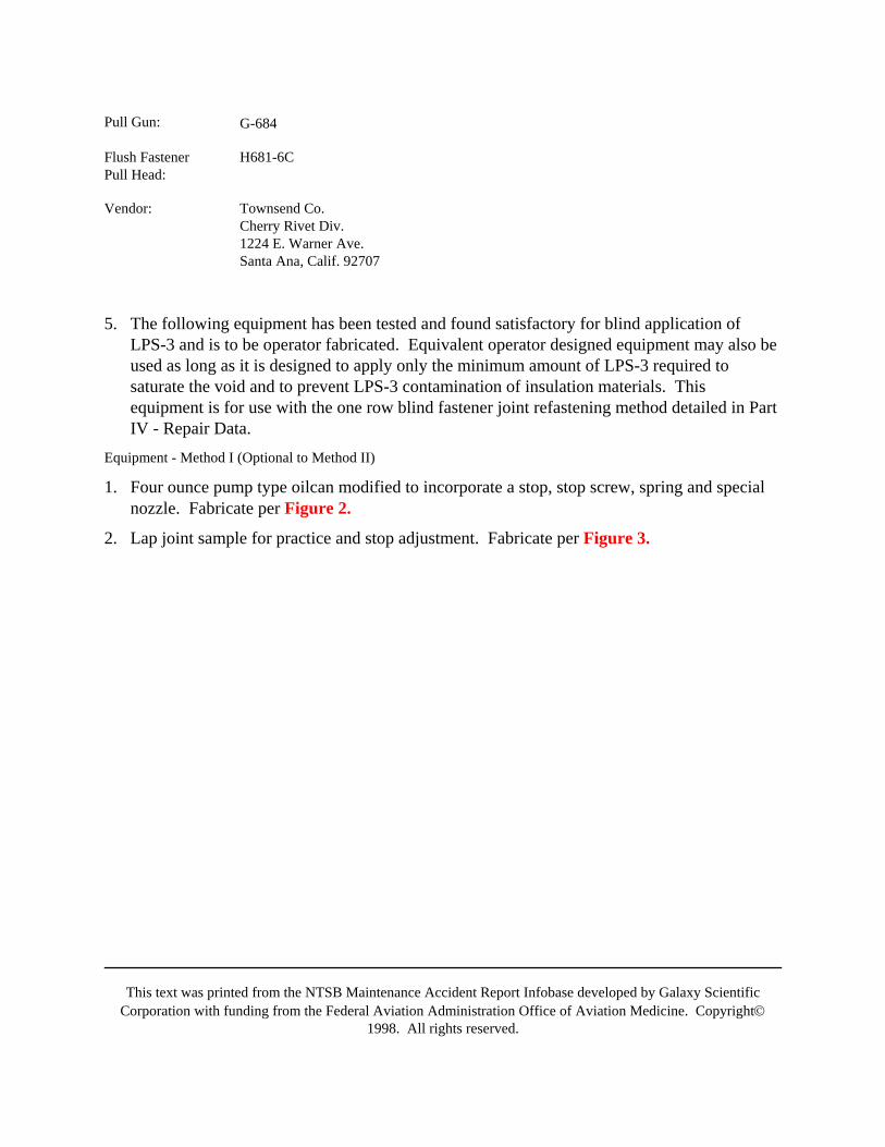
This text was printed from the NTSB Maintenance Accident Report Infobase developed by Galaxy ScientificCorporation with funding from the Federal Aviation Administration Office of Aviation Medicine. Copyright©
1998. All rights reserved.
Pull Gun: G-684
Flush FastenerPull Head:
H681-6C
Vendor: Townsend Co.Cherry Rivet Div.1224 E. Warner Ave.Santa Ana, Calif. 92707
5. The following equipment has been tested and found satisfactory for blind application ofLPS-3 and is to be operator fabricated. Equivalent operator designed equipment may also beused as long as it is designed to apply only the minimum amount of LPS-3 required tosaturate the void and to prevent LPS-3 contamination of insulation materials. Thisequipment is for use with the one row blind fastener joint refastening method detailed in PartIV - Repair Data.
Equipment - Method I (Optional to Method II)
1. Four ounce pump type oilcan modified to incorporate a stop, stop screw, spring and specialnozzle. Fabricate per Figure 2.
2. Lap joint sample for practice and stop adjustment. Fabricate per Figure 3.
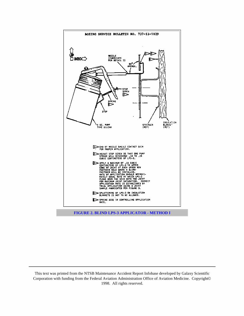
This text was printed from the NTSB Maintenance Accident Report Infobase developed by Galaxy ScientificCorporation with funding from the Federal Aviation Administration Office of Aviation Medicine. Copyright©
1998. All rights reserved.
FIGURE 2. BLIND LPS-3 APPLICATOR - METHOD I
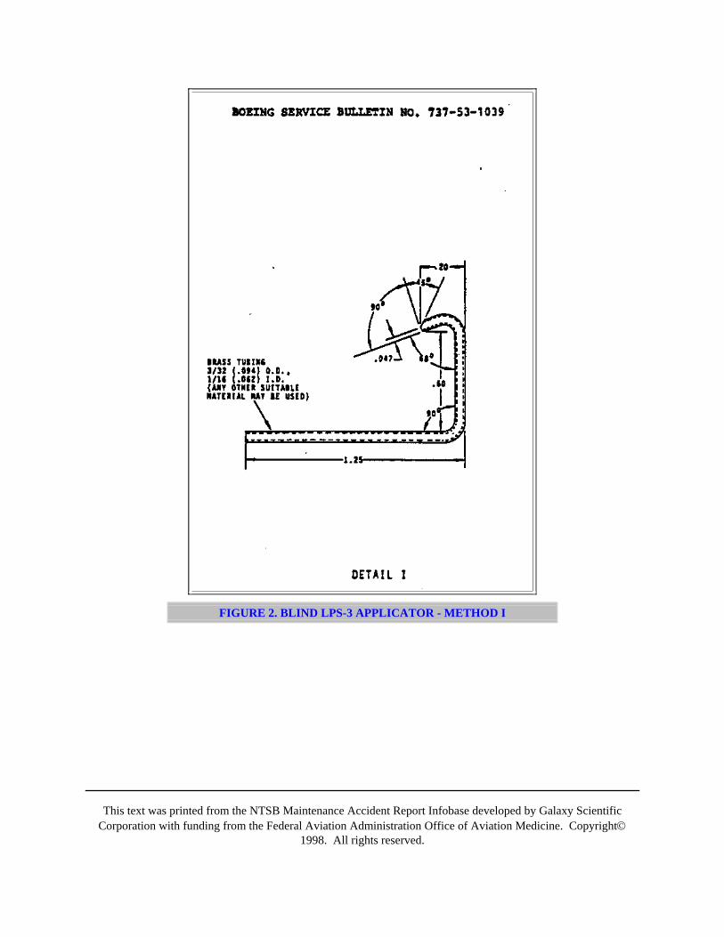
This text was printed from the NTSB Maintenance Accident Report Infobase developed by Galaxy ScientificCorporation with funding from the Federal Aviation Administration Office of Aviation Medicine. Copyright©
1998. All rights reserved.
FIGURE 2. BLIND LPS-3 APPLICATOR - METHOD I
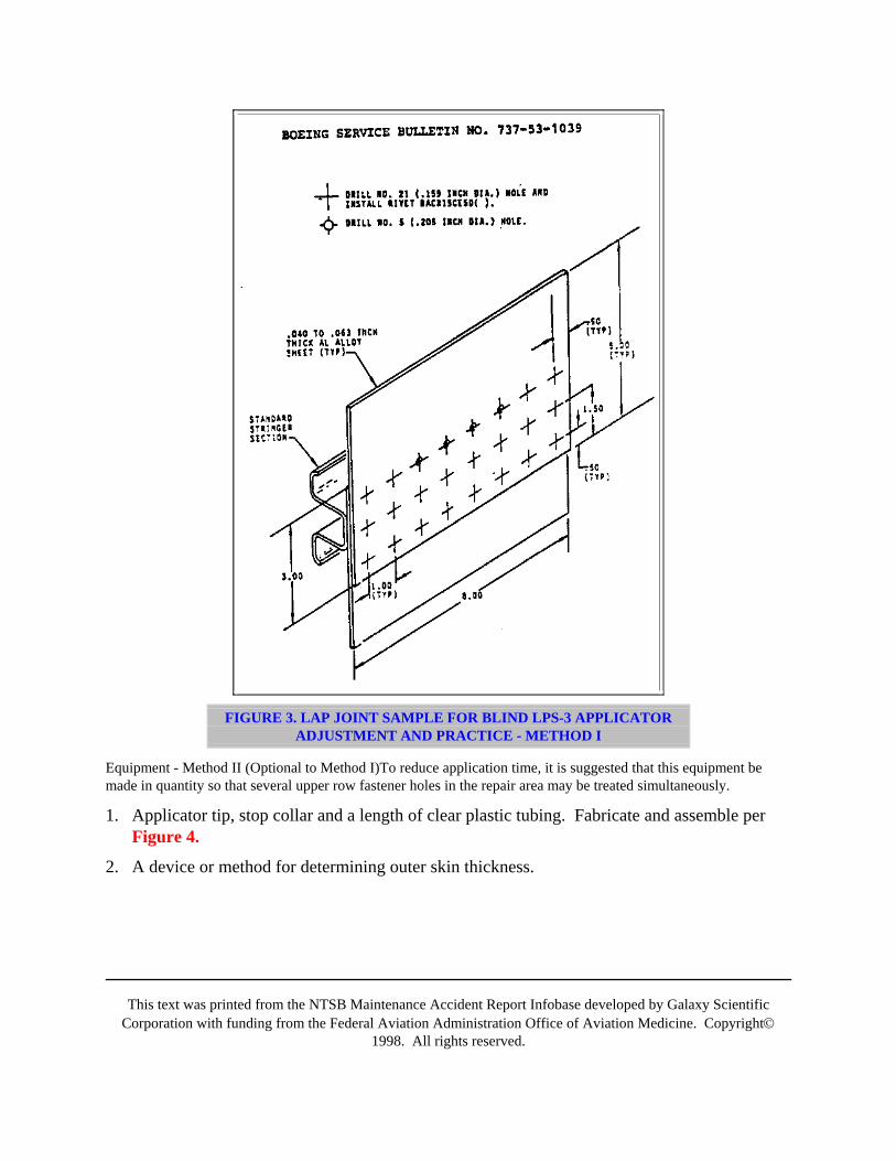
This text was printed from the NTSB Maintenance Accident Report Infobase developed by Galaxy ScientificCorporation with funding from the Federal Aviation Administration Office of Aviation Medicine. Copyright©
1998. All rights reserved.
FIGURE 3. LAP JOINT SAMPLE FOR BLIND LPS-3 APPLICATORADJUSTMENT AND PRACTICE - METHOD I
Equipment - Method II (Optional to Method I)To reduce application time, it is suggested that this equipment bemade in quantity so that several upper row fastener holes in the repair area may be treated simultaneously.
1. Applicator tip, stop collar and a length of clear plastic tubing. Fabricate and assemble perFigure 4.
2. A device or method for determining outer skin thickness.
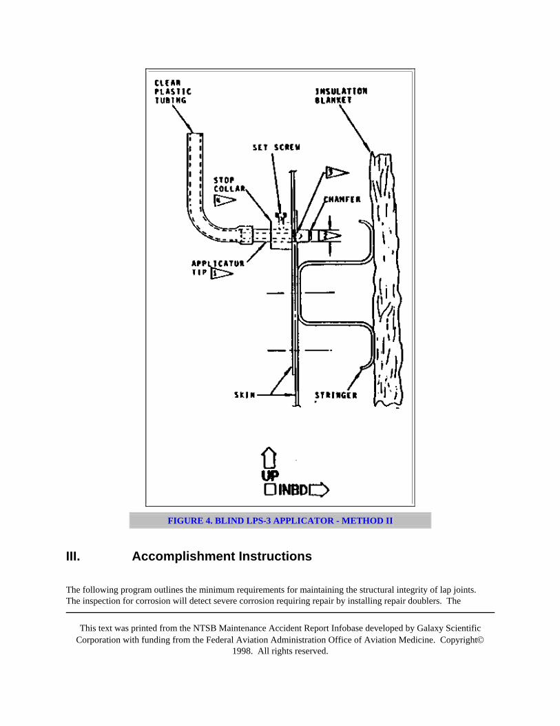
This text was printed from the NTSB Maintenance Accident Report Infobase developed by Galaxy ScientificCorporation with funding from the Federal Aviation Administration Office of Aviation Medicine. Copyright©
1998. All rights reserved.
FIGURE 4. BLIND LPS-3 APPLICATOR - METHOD II
III. Accomplishment Instructions
The following program outlines the minimum requirements for maintaining the structural integrity of lap joints.The inspection for corrosion will detect severe corrosion requiring repair by installing repair doublers. The
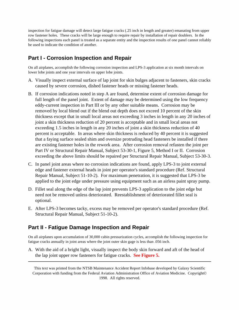
This text was printed from the NTSB Maintenance Accident Report Infobase developed by Galaxy ScientificCorporation with funding from the Federal Aviation Administration Office of Aviation Medicine. Copyright©
1998. All rights reserved.
inspection for fatigue damage will detect large fatigue cracks (.25 inch in length and greater) emanating from upperrow fastener holes. These cracks will be large enough to require repair by installation of repair doublers. In thefollowing inspections each panel is treated as a separate entity and the inspection results of one panel cannot reliablybe used to indicate the condition of another.
Part I - Corrosion Inspection and RepairOn all airplanes, accomplish the following corrosion inspection and LPS-3 application at six month intervals onlower lobe joints and one year intervals on upper lobe joints.
A. Visually inspect external surface of lap joint for skin bulges adjacent to fasteners, skin crackscaused by severe corrosion, dished fastener heads or missing fastener heads.
B. If corrosion indications noted in step A are found, determine extent of corrosion damage forfull length of the panel joint. Extent of damage may be determined using the low frequencyeddy-current inspection in Part III or by any other suitable means. Corrosion may beremoved by local blend out if the blend out depth does not exceed 10 percent of the skinthickness except that in small local areas not exceeding 3 inches in length in any 20 inches ofjoint a skin thickness reduction of 20 percent is acceptable and in small local areas notexceeding 1.5 inches in length in any 20 inches of joint a skin thickness reduction of 40percent is acceptable. In areas where skin thickness is reduced by 40 percent it is suggestedthat a faying surface sealed shim and oversize protruding head fasteners be installed if thereare existing fastener holes in the rework area. After corrosion removal refasten the joint perPart IV or Structural Repair Manual, Subject 53-30-1, Figure 5, Method I or II. Corrosionexceeding the above limits should be repaired per Structural Repair Manual, Subject 53-30-3.
C. In panel joint areas where no corrosion indications are found, apply LPS-3 to joint externaledge and fastener external heads in joint per operator's standard procedure (Ref. StructuralRepair Manual, Subject 51-10-2). For maximum penetration, it is suggested that LPS-3 beapplied to the joint edge under pressure using equipment such as an airless paint spray pump.
D. Fillet seal along the edge of the lap joint prevents LPS-3 application to the joint edge butneed not be removed unless deteriorated. Reestablishment of deteriorated fillet seal isoptional.
E. After LPS-3 becomes tacky, excess may be removed per operator's standard procedure (Ref.Structural Repair Manual, Subject 51-10-2).
Part II - Fatigue Damage Inspection and RepairOn all airplanes upon accumulation of 30,000 cabin pressurization cycles, accomplish the following inspection forfatigue cracks annually in joint areas where the joint outer skin gage is less than .056 inch.
A. With the aid of a bright light, visually inspect the body skin forward and aft of the head ofthe lap joint upper row fasteners for fatigue cracks. See Figure 5.
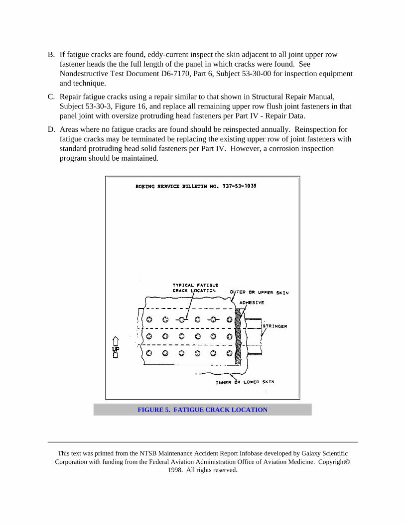
This text was printed from the NTSB Maintenance Accident Report Infobase developed by Galaxy ScientificCorporation with funding from the Federal Aviation Administration Office of Aviation Medicine. Copyright©
1998. All rights reserved.
B. If fatigue cracks are found, eddy-current inspect the skin adjacent to all joint upper rowfastener heads the the full length of the panel in which cracks were found. SeeNondestructive Test Document D6-7170, Part 6, Subject 53-30-00 for inspection equipmentand technique.
C. Repair fatigue cracks using a repair similar to that shown in Structural Repair Manual,Subject 53-30-3, Figure 16, and replace all remaining upper row flush joint fasteners in thatpanel joint with oversize protruding head fasteners per Part IV - Repair Data.
D. Areas where no fatigue cracks are found should be reinspected annually. Reinspection forfatigue cracks may be terminated be replacing the existing upper row of joint fasteners withstandard protruding head solid fasteners per Part IV. However, a corrosion inspectionprogram should be maintained.
FIGURE 5. FATIGUE CRACK LOCATION
This text was printed from the NTSB Maintenance Accident Report Infobase developed by Galaxy ScientificCorporation with funding from the Federal Aviation Administration Office of Aviation Medicine. Copyright©
1998. All rights reserved.
Part III-Low Frequency Eddy-Current Corrosion Damage InspectionEddy-current instruments with low frequency capability provide a rapid method of locating moderate to severecorrosion on inner and outer joint skin faying surfaces. Instruments of this type provide an estimate of skinthickness loss by the comparison method. Although a precise measurement is not obtained, the method is fast, doesnot require paint stripping or a couplant, does not require access to the internal side of the joint and can inspectinner and outer skin faying surfaces simultaneously.
Technical information on low frequency eddy-current inspection will be published in Boeing Nondestructive TestManual, Document D6-7170.
A. Equipment
1. The following instruments, or equivalent, may be used.
a. EM-1500
b. NDT-3
c. Phasemaster
1. These instruments should have frequency capabilities or modules listed in Table I.
2. See paragraph II.D.1 for instrument vendor information.
2. Use a flat spring loaded eddy-current probe compatible to the instrument used. Probeswith wear plates are suggested if large areas are to be scanned.
B. Prepare surface for inspection by removing dust and dirt per operator's standard procedure.
C. Calibrate instrument for simultaneous inspection of inner and outer joint skin faying surfacesas follows:
1. Set up instrument to operate on correct frequency for applicable skin thickness. SeeTable I.
2. Adjust for lift-off per instrument manufacturer's instructions.
3. Using reference standard, check instrument response to a 10 percent loss in inner skinthickness. It is suggested that instrument sensitivity be set such that a 10 percentthickness reduction will cause a 10 percent change in meter reading.
4. Inspect area in question per Step D.
D. Inspect area in question as follows:
1. Place probe on lap joint between fasteners and adjust meter to approximately mid scale.
2. Scan area in question for indications of corrosion. Severity of corrosion will be indicatedby magnitude of meter change.
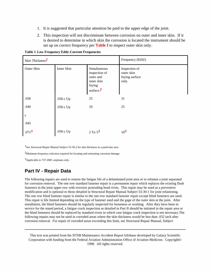
This text was printed from the NTSB Maintenance Accident Report Infobase developed by Galaxy ScientificCorporation with funding from the Federal Aviation Administration Office of Aviation Medicine. Copyright©
1998. All rights reserved.
1. It is suggested that particular attention be paid to the upper edge of the joint.
2. This inspection will not discriminate between corrosion on outer and inner skin. If itis desired to determine in which skin the corrosion is located the instrument should beset up on correct frequency per Table I to inspect outer skin only.
Table 1. Low Frequency Eddy-Current Frequencies
Skin Thickness1 Frequency (KHZ)
Outer Skin Inner Skin Simultaneousinspection ofouter andinner skinfayingsurface.2
Inspection ofouter skinfaying surfaceonly.
.036 .036 ε Up 25 31
.040 .036 ε Up 10 25
ε
.045
.0713 .036 ε Up 2 To 53 103
1See Structural Repair Manual Subject 53-30-2 for skin thickness in a particular area.
2Minimum frequency selection required for locating and estimating corrosion damage.
3Applicable to 737-200C airplanes only.
Part IV - Repair DataThe following repairs are used to restore the fatigue life of a delaminated joint area or to refasten a joint separatedfor corrosion removal. The one row standard fastener repair is a permanent repair which replaces the existing flushfasteners in the joint upper row with oversize protruding head rivets. This repair may be used as a preventivemodification and is optional to those detailed in Structural Repair Manual Subject 53-30-1 for joint refastening.The one row blind fastener repair is similar to the one row standard fastener repair except blind fasteners are used.This repair is life limited depending on the type of fastener used and the gage of the outer skin at the joint. Afterinstallation, the blind fasteners should be regularly inspected for looseness or working. After they have been inservice for the stated period, a fatigue crack inspection as detailed in Part II should be initiated in the repair area orthe blind fasteners should be replaced by standard rivets in which case fatigue crack inspection is not necessary.Thefollowing repairs may not be used in corroded areas where the skin thickness would be less than .032 inch aftercorrosion removal. For repair of corroded areas exceeding this limit, see Structural Repair Manual, Subject
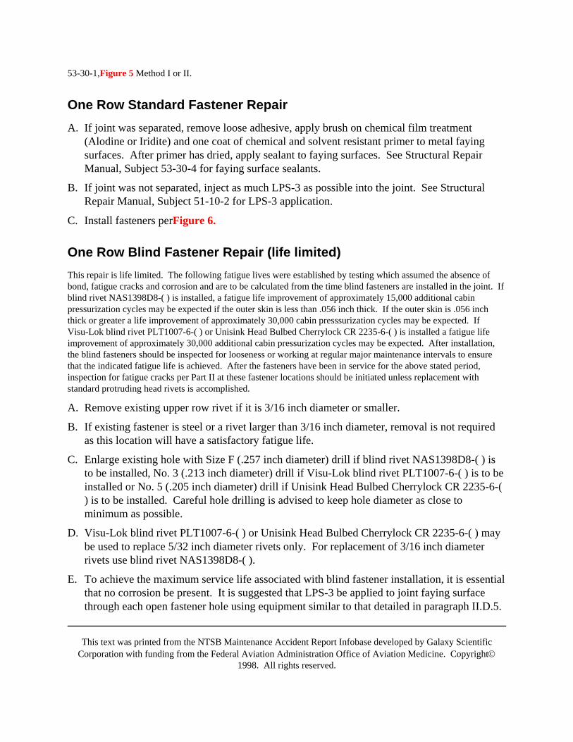
This text was printed from the NTSB Maintenance Accident Report Infobase developed by Galaxy ScientificCorporation with funding from the Federal Aviation Administration Office of Aviation Medicine. Copyright©
1998. All rights reserved.
53-30-1,Figure 5 Method I or II.
One Row Standard Fastener RepairA. If joint was separated, remove loose adhesive, apply brush on chemical film treatment
(Alodine or Iridite) and one coat of chemical and solvent resistant primer to metal fayingsurfaces. After primer has dried, apply sealant to faying surfaces. See Structural RepairManual, Subject 53-30-4 for faying surface sealants.
B. If joint was not separated, inject as much LPS-3 as possible into the joint. See StructuralRepair Manual, Subject 51-10-2 for LPS-3 application.
C. Install fasteners perFigure 6.
One Row Blind Fastener Repair (life limited)This repair is life limited. The following fatigue lives were established by testing which assumed the absence ofbond, fatigue cracks and corrosion and are to be calculated from the time blind fasteners are installed in the joint. Ifblind rivet NAS1398D8-( ) is installed, a fatigue life improvement of approximately 15,000 additional cabinpressurization cycles may be expected if the outer skin is less than .056 inch thick. If the outer skin is .056 inchthick or greater a life improvement of approximately 30,000 cabin presssurization cycles may be expected. IfVisu-Lok blind rivet PLT1007-6-( ) or Unisink Head Bulbed Cherrylock CR 2235-6-( ) is installed a fatigue lifeimprovement of approximately 30,000 additional cabin pressurization cycles may be expected. After installation,the blind fasteners should be inspected for looseness or working at regular major maintenance intervals to ensurethat the indicated fatigue life is achieved. After the fasteners have been in service for the above stated period,inspection for fatigue cracks per Part II at these fastener locations should be initiated unless replacement withstandard protruding head rivets is accomplished.
A. Remove existing upper row rivet if it is 3/16 inch diameter or smaller.
B. If existing fastener is steel or a rivet larger than 3/16 inch diameter, removal is not requiredas this location will have a satisfactory fatigue life.
C. Enlarge existing hole with Size F (.257 inch diameter) drill if blind rivet NAS1398D8-( ) isto be installed, No. 3 (.213 inch diameter) drill if Visu-Lok blind rivet PLT1007-6-( ) is to beinstalled or No. 5 (.205 inch diameter) drill if Unisink Head Bulbed Cherrylock CR 2235-6-() is to be installed. Careful hole drilling is advised to keep hole diameter as close tominimum as possible.
D. Visu-Lok blind rivet PLT1007-6-( ) or Unisink Head Bulbed Cherrylock CR 2235-6-( ) maybe used to replace 5/32 inch diameter rivets only. For replacement of 3/16 inch diameterrivets use blind rivet NAS1398D8-( ).
E. To achieve the maximum service life associated with blind fastener installation, it is essentialthat no corrosion be present. It is suggested that LPS-3 be applied to joint faying surfacethrough each open fastener hole using equipment similar to that detailed in paragraph II.D.5.
This text was printed from the NTSB Maintenance Accident Report Infobase developed by Galaxy ScientificCorporation with funding from the Federal Aviation Administration Office of Aviation Medicine. Copyright©
1998. All rights reserved.
After application, remove all traces of LPS-3 from external skin surface using a 1:1 mixtureof methyl ethyl ketone and toluene.
1. Contamination of insulation blankets with LPS-3 is not to be permitted.
2. LPS-3 application restrictions detailed in 737 Structural Repair Manual, Subject 51-10-2concerning application in the vicinity of oxygen systems must be observed during blindapplication of LPS-3.
3. For full width delaminations both external and blind internal application of LPS-3 issuggested.
4. Application by aerosal can has been found to be unsatisfactory for blind application dueto the likelihood of over-saturation from an uncontrolled spray and possiblecontamination of insulation blankets. However, it is satisfactory for external applicationwhere full width delaminations are found and excess amounts of LPS-3 may be wiped up.
F. Install blind rivet NAS1398D8-( ), Visu-Lok blind rivet PLT1007-6-( ) or Unisink HeadBulbed Cherrylock CR 2235-6-( ) as applicable with wet sealant PR1431G or PR1436Gunder rivet head.
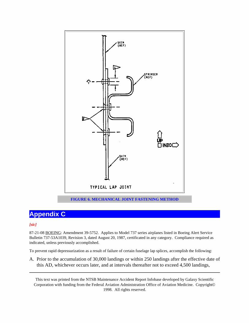
This text was printed from the NTSB Maintenance Accident Report Infobase developed by Galaxy ScientificCorporation with funding from the Federal Aviation Administration Office of Aviation Medicine. Copyright©
1998. All rights reserved.
FIGURE 6. MECHANICAL JOINT FASTENING METHOD
Appendix C[sic]
87-21-08 BOEING: Amendment 39-5752. Applies to Model 737 series airplanes listed in Boeing Alert ServiceBulletin 737-53A1039, Revision 3, dated August 20, 1987, certificated in any category. Compliance required asindicated, unless previously accomplished.
To prevent rapid depressurization as a result of failure of certain fuselage lap splices, accomplish the following:
A. Prior to the accumulation of 30,000 landings or within 250 landings after the effective date ofthis AD, whichever occurs later, and at intervals thereafter not to exceed 4,500 landings,
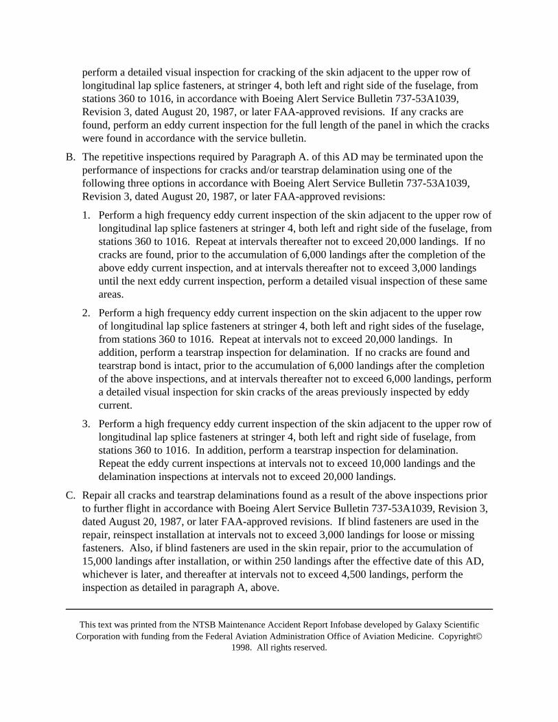
This text was printed from the NTSB Maintenance Accident Report Infobase developed by Galaxy ScientificCorporation with funding from the Federal Aviation Administration Office of Aviation Medicine. Copyright©
1998. All rights reserved.
perform a detailed visual inspection for cracking of the skin adjacent to the upper row oflongitudinal lap splice fasteners, at stringer 4, both left and right side of the fuselage, fromstations 360 to 1016, in accordance with Boeing Alert Service Bulletin 737-53A1039,Revision 3, dated August 20, 1987, or later FAA-approved revisions. If any cracks arefound, perform an eddy current inspection for the full length of the panel in which the crackswere found in accordance with the service bulletin.
B. The repetitive inspections required by Paragraph A. of this AD may be terminated upon theperformance of inspections for cracks and/or tearstrap delamination using one of thefollowing three options in accordance with Boeing Alert Service Bulletin 737-53A1039,Revision 3, dated August 20, 1987, or later FAA-approved revisions:
1. Perform a high frequency eddy current inspection of the skin adjacent to the upper row oflongitudinal lap splice fasteners at stringer 4, both left and right side of the fuselage, fromstations 360 to 1016. Repeat at intervals thereafter not to exceed 20,000 landings. If nocracks are found, prior to the accumulation of 6,000 landings after the completion of theabove eddy current inspection, and at intervals thereafter not to exceed 3,000 landingsuntil the next eddy current inspection, perform a detailed visual inspection of these sameareas.
2. Perform a high frequency eddy current inspection on the skin adjacent to the upper rowof longitudinal lap splice fasteners at stringer 4, both left and right sides of the fuselage,from stations 360 to 1016. Repeat at intervals not to exceed 20,000 landings. Inaddition, perform a tearstrap inspection for delamination. If no cracks are found andtearstrap bond is intact, prior to the accumulation of 6,000 landings after the completionof the above inspections, and at intervals thereafter not to exceed 6,000 landings, performa detailed visual inspection for skin cracks of the areas previously inspected by eddycurrent.
3. Perform a high frequency eddy current inspection of the skin adjacent to the upper row oflongitudinal lap splice fasteners at stringer 4, both left and right side of fuselage, fromstations 360 to 1016. In addition, perform a tearstrap inspection for delamination.Repeat the eddy current inspections at intervals not to exceed 10,000 landings and thedelamination inspections at intervals not to exceed 20,000 landings.
C. Repair all cracks and tearstrap delaminations found as a result of the above inspections priorto further flight in accordance with Boeing Alert Service Bulletin 737-53A1039, Revision 3,dated August 20, 1987, or later FAA-approved revisions. If blind fasteners are used in therepair, reinspect installation at intervals not to exceed 3,000 landings for loose or missingfasteners. Also, if blind fasteners are used in the skin repair, prior to the accumulation of15,000 landings after installation, or within 250 landings after the effective date of this AD,whichever is later, and thereafter at intervals not to exceed 4,500 landings, perform theinspection as detailed in paragraph A, above.
This text was printed from the NTSB Maintenance Accident Report Infobase developed by Galaxy ScientificCorporation with funding from the Federal Aviation Administration Office of Aviation Medicine. Copyright©
1998. All rights reserved.
D. Terminating action for the inspections required by this AD is the replacement of the existingupper row of joint fasteners with standard protruding head solid fasteners at all affectedfuselage longitudinal lap splices and ensuring functional tearstraps in accordance withBoeing Alert Service Bulletin 737-53A1039, Revision 3, dated August 20, 1987, or laterFAA-approved revisions.
E. For the purpose of complying with this AD, the number of landings may be determined toequal the number of pressurization cycles where the cabin pressure differential was greaterthan 2.0 PSI.
F. An alternate means of compliance or adjustment of the compliance time, which provides anacceptable level of safety, and which has the concurrence of an FAA Principal MaintenanceInspector, may be used when approved by the Manager, Seattle Aircraft Certification Office,FAA, Northwest Mountain Region.
G. Special flight permits may be issued in accordance with FAR 21.197 and 21.199 to operateairplanes to a base for the accomplishment of inspections and/or modifications required bythis AD.
All persons affected by this directive who have not already received the appropriate service information from themanufacturer may obtain copies upon request to the Boeing Commercial Airplane Company, P.O. Box 3707,Seattle, Washington 98124. This information may be examined at FAA, Northwest Mountain Region, 17900Pacific Highway South, Seattle, Washington, or Seattle Aircraft Certification Office, FAA, Northwest MountainRegion, 9010 East Marginal Way South, Seattle, Washington.
This amendment becomes effective November 2, 1987.
FOR FURTHER INFORMATION CONTACT: Ms. Barbara J. Baillie, Airframe Branch, ANM-120S; telephone(206) 431-1927. Mailing address: FAA, Northwest Mountain Region, 17900 Pacific Highway South, C-68966,Seattle, Washington 98168.
Appendix CREVISION TRANSMITTAL SHEET
Boeing Service Bulletin 737-53A1039
This sheet transmits REVISION 3 dated August 20, 1987 of Service Bulletin 737-53A1039, "BODY SKIN LAPJOINT INSPECTION AND REPAIR".This revision constitutes a complete reissue.
SummaryThis revision is issued to up-grade this service bulletin to an 'ALERT' status and to advise operators of recentservice experience that warrants changes to the inspection cycle frequency after initial inspection at the 30,000flight cycle threshold.
Airplane effectivity is updated to reflect current airplane ownership.
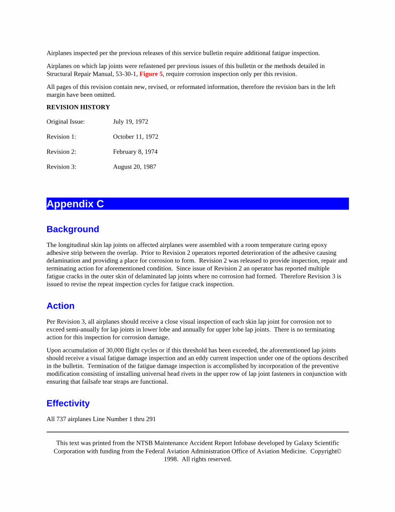
This text was printed from the NTSB Maintenance Accident Report Infobase developed by Galaxy ScientificCorporation with funding from the Federal Aviation Administration Office of Aviation Medicine. Copyright©
1998. All rights reserved.
Airplanes inspected per the previous releases of this service bulletin require additional fatigue inspection.
Airplanes on which lap joints were refastened per previous issues of this bulletin or the methods detailed inStructural Repair Manual, 53-30-1, Figure 5, require corrosion inspection only per this revision.
All pages of this revision contain new, revised, or reformated information, therefore the revision bars in the leftmargin have been omitted.
REVISION HISTORY
Original Issue: July 19, 1972
Revision 1: October 11, 1972
Revision 2: February 8, 1974
Revision 3: August 20, 1987
Appendix C
BackgroundThe longitudinal skin lap joints on affected airplanes were assembled with a room temperature curing epoxyadhesive strip between the overlap. Prior to Revision 2 operators reported deterioration of the adhesive causingdelamination and providing a place for corrosion to form. Revision 2 was released to provide inspection, repair andterminating action for aforementioned condition. Since issue of Revision 2 an operator has reported multiplefatigue cracks in the outer skin of delaminated lap joints where no corrosion had formed. Therefore Revision 3 isissued to revise the repeat inspection cycles for fatigue crack inspection.
ActionPer Revision 3, all airplanes should receive a close visual inspection of each skin lap joint for corrosion not toexceed semi-anually for lap joints in lower lobe and annually for upper lobe lap joints. There is no terminatingaction for this inspection for corrosion damage.
Upon accumulation of 30,000 flight cycles or if this threshold has been exceeded, the aforementioned lap jointsshould receive a visual fatigue damage inspection and an eddy current inspection under one of the options describedin the bulletin. Termination of the fatigue damage inspection is accomplished by incorporation of the preventivemodification consisting of installing universal head rivets in the upper row of lap joint fasteners in conjunction withensuring that failsafe tear straps are functional.
EffectivityAll 737 airplanes Line Number 1 thru 291
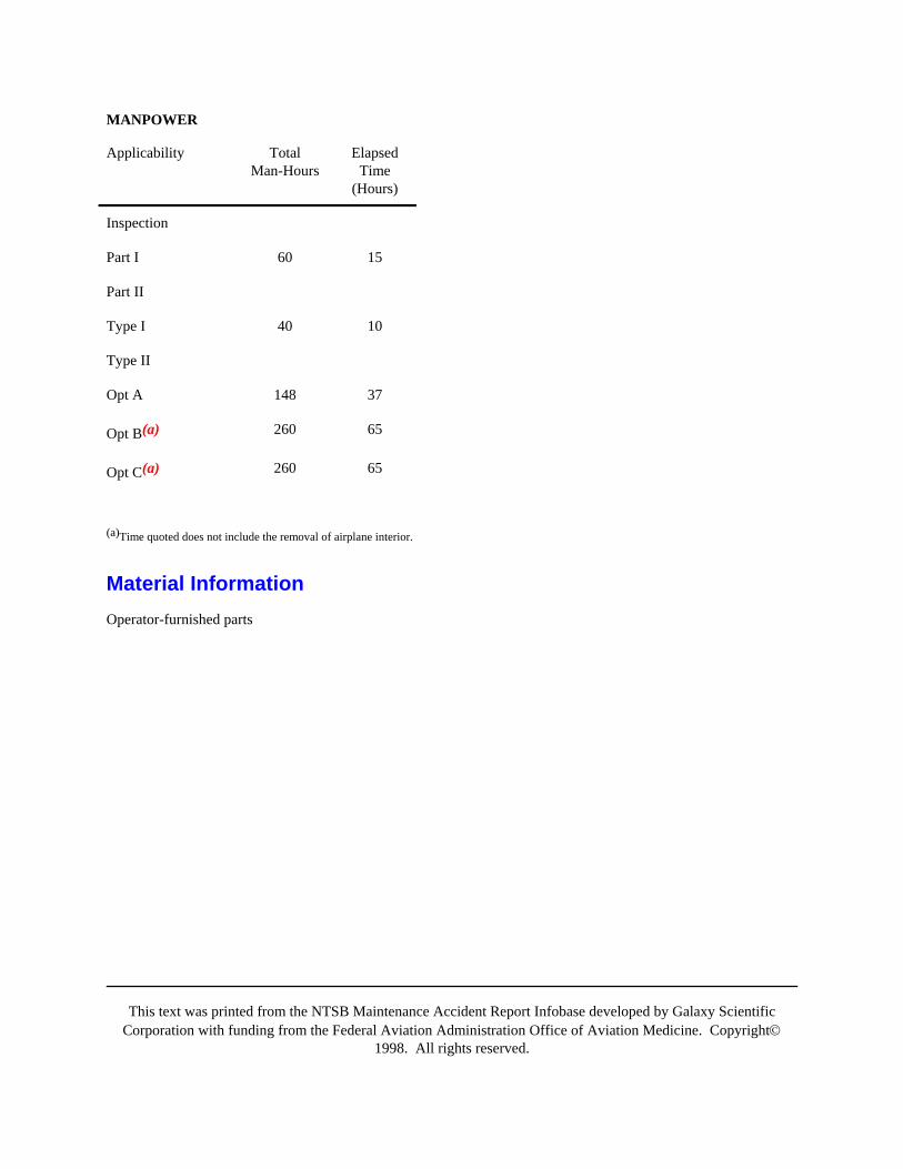
This text was printed from the NTSB Maintenance Accident Report Infobase developed by Galaxy ScientificCorporation with funding from the Federal Aviation Administration Office of Aviation Medicine. Copyright©
1998. All rights reserved.
MANPOWER
Applicability TotalMan-Hours
ElapsedTime
(Hours)
Inspection
Part I 60 15
Part II
Type I 40 10
Type II
Opt A 148 37
Opt B(a) 260 65
Opt C(a) 260 65
(a)Time quoted does not include the removal of airplane interior.
Material InformationOperator-furnished parts
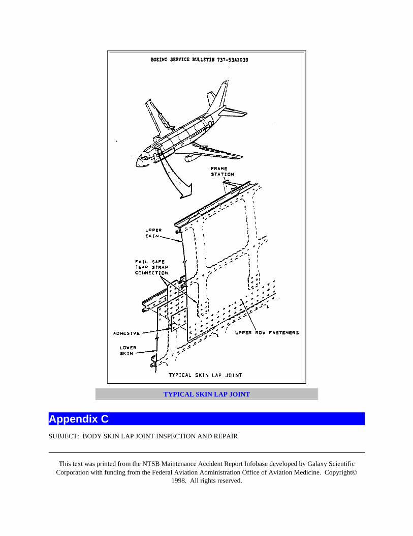
This text was printed from the NTSB Maintenance Accident Report Infobase developed by Galaxy ScientificCorporation with funding from the Federal Aviation Administration Office of Aviation Medicine. Copyright©
1998. All rights reserved.
TYPICAL SKIN LAP JOINT
Appendix CSUBJECT: BODY SKIN LAP JOINT INSPECTION AND REPAIR
This text was printed from the NTSB Maintenance Accident Report Infobase developed by Galaxy ScientificCorporation with funding from the Federal Aviation Administration Office of Aviation Medicine. Copyright©
1998. All rights reserved.
THIS SERVICE BULLETIN IS BEING SENT TO EACH AFFECTED OPERATOR. IF THE OPERATOR HASLEASED AIRPLANES, THIS SERVICE BULLETIN SHOULD BE FORWARDED TO THE LESSEE. IF THEOPERATOR HAS SOLD AIRPLANES OR TRANSFERRED AFFECTED SPARES WITHIN THE LAST SIXMONTHS, THIS SERVICE BULLETIN SHOULD BE FORWARDED TO THE NEW OWNER, UNLESSCONFIRMATION HAS BEEN RECEIVED THAT BOEING HAS INCLUDED THE NEW OPERATOR ONTHE DISTRIBUTION LIST.
I. Planning Information
A. Effectivity
1. Airplanes AffectedSee Service Bulletin Index Part 3 for cross reference of Variable Number to Airplane Serial Number.
This change is applicable only to airplanes listed below.
LISTING BY CUSTOMER CODE AND VARIABLE NUMBER

This text was printed from the NTSB Maintenance Accident Report Infobase developed by Galaxy ScientificCorporation with funding from the Federal Aviation Administration Office of Aviation Medicine. Copyright©
1998. All rights reserved.
ALO PG046 PG629 PG701-PG703 PG705 PY001
PY003 PY005
AMW PG036 PG331 PG577 PJ102 PL801
ANA PG578-PG581 PG583
ANS PL302
ARG PH705-PH708 PH741-PH742 PY007-PY008
ARL PG251-PG255 PG573 PG575 PY321-PY323
AWW PC004
AZE PA001 PA003-PA004 PC003
BRI PJ103-PJ104 PY361-PY362
BRT PJ001-PJ002 PL803
CGA PG224
CHI PG572 PG574
CLF PA231-PA232 PG034 PG201 PG204 PG217
PG222 PG271-PG276 PG278 PG403 PG438
CNV PG351
COP PC001
CPA PG651-PG652 FJ031-PJ032 PJ072
DAL PG202-PG203 PG205 PG207 PG209 PG211-PG214
PG216 PG218-PG221
DLH PY345-PY346
EAG PY381
EGN PG037 PG208 PG210 PG215 PG431
ERA PG026 PG028-PG029
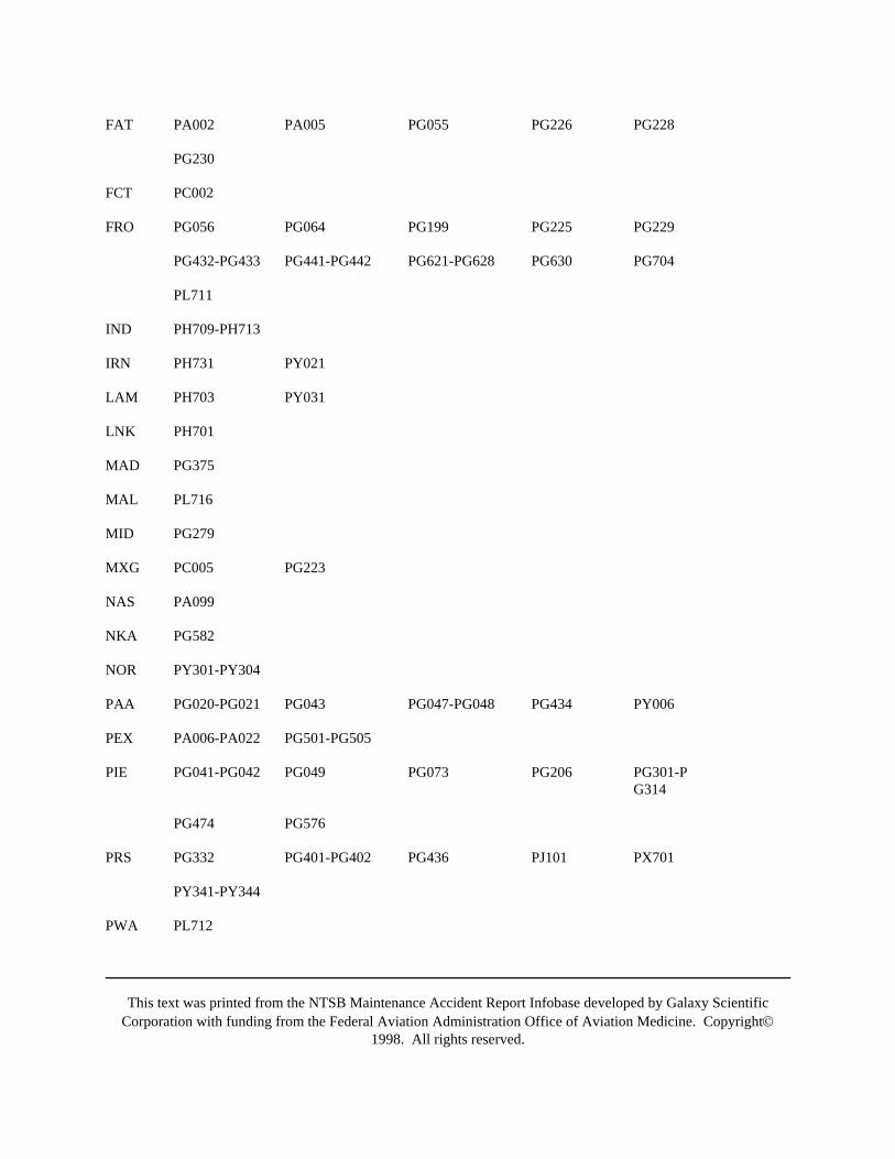
This text was printed from the NTSB Maintenance Accident Report Infobase developed by Galaxy ScientificCorporation with funding from the Federal Aviation Administration Office of Aviation Medicine. Copyright©
1998. All rights reserved.
FAT PA002 PA005 PG055 PG226 PG228
PG230
FCT PC002
FRO PG056 PG064 PG199 PG225 PG229
PG432-PG433 PG441-PG442 PG621-PG628 PG630 PG704
PL711
IND PH709-PH713
IRN PH731 PY021
LAM PH703 PY031
LNK PH701
MAD PG375
MAL PL716
MID PG279
MXG PC005 PG223
NAS PA099
NKA PG582
NOR PY301-PY304
PAA PG020-PG021 PG043 PG047-PG048 PG434 PY006
PEX PA006-PA022 PG501-PG505
PIE PG041-PG042 PG049 PG073 PG206 PG301-PG314
PG474 PG576
PRS PG332 PG401-PG402 PG436 PJ101 PX701
PY341-PY344
PWA PL712
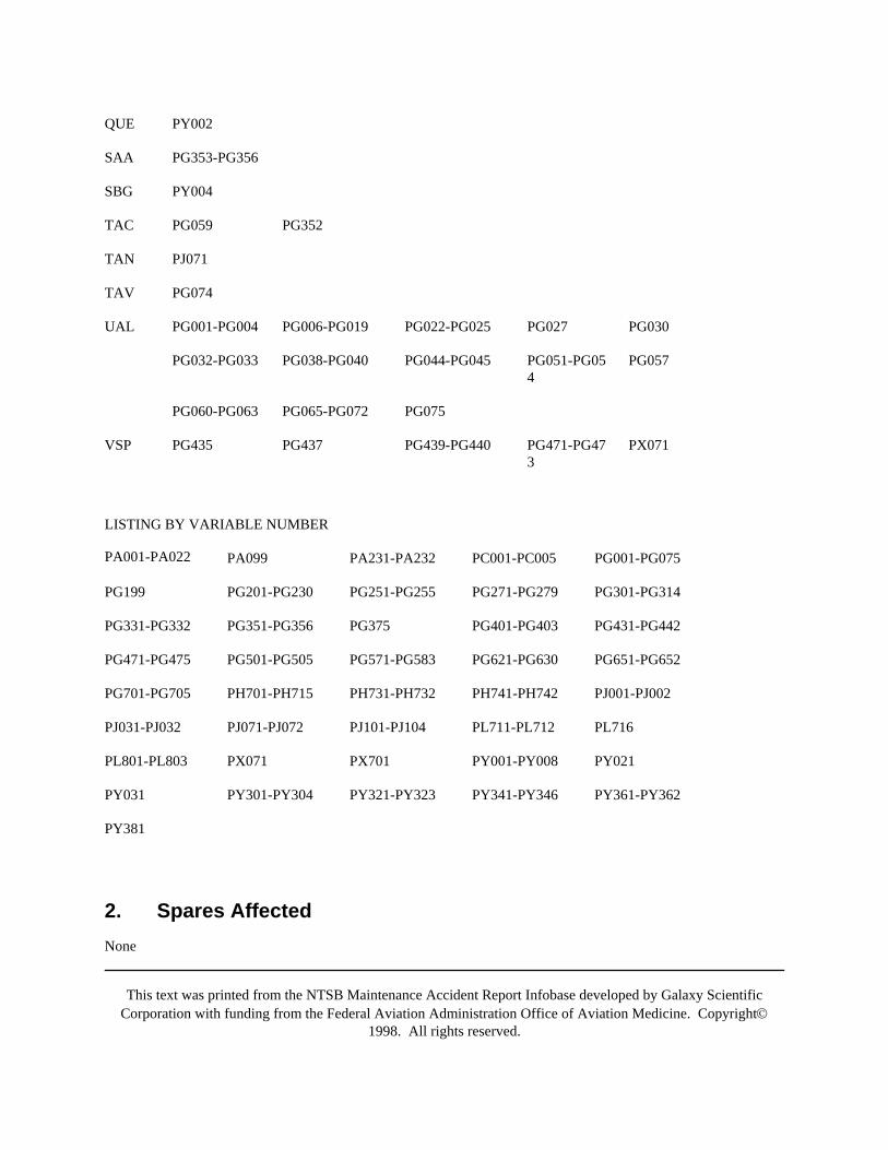
This text was printed from the NTSB Maintenance Accident Report Infobase developed by Galaxy ScientificCorporation with funding from the Federal Aviation Administration Office of Aviation Medicine. Copyright©
1998. All rights reserved.
QUE PY002
SAA PG353-PG356
SBG PY004
TAC PG059 PG352
TAN PJ071
TAV PG074
UAL PG001-PG004 PG006-PG019 PG022-PG025 PG027 PG030
PG032-PG033 PG038-PG040 PG044-PG045 PG051-PG054
PG057
PG060-PG063 PG065-PG072 PG075
VSP PG435 PG437 PG439-PG440 PG471-PG473
PX071
LISTING BY VARIABLE NUMBER
PA001-PA022 PA099 PA231-PA232 PC001-PC005 PG001-PG075
PG199 PG201-PG230 PG251-PG255 PG271-PG279 PG301-PG314
PG331-PG332 PG351-PG356 PG375 PG401-PG403 PG431-PG442
PG471-PG475 PG501-PG505 PG571-PG583 PG621-PG630 PG651-PG652
PG701-PG705 PH701-PH715 PH731-PH732 PH741-PH742 PJ001-PJ002
PJ031-PJ032 PJ071-PJ072 PJ101-PJ104 PL711-PL712 PL716
PL801-PL803 PX071 PX701 PY001-PY008 PY021
PY031 PY301-PY304 PY321-PY323 PY341-PY346 PY361-PY362
PY381
2. Spares AffectedNone
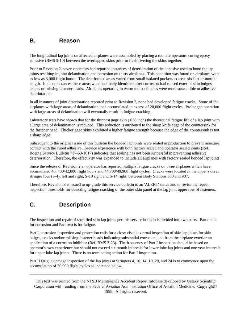
This text was printed from the NTSB Maintenance Accident Report Infobase developed by Galaxy ScientificCorporation with funding from the Federal Aviation Administration Office of Aviation Medicine. Copyright©
1998. All rights reserved.
B. Reason
The longitudinal lap joints on affected airplanes were assembled by placing a room temperature curing epoxyadhesive (BMS 5-10) between the overlapped skins prior to flush riveting the skins together.
Prior to Revision 2, seven operators had reported instances of deterioration of the adhesive used to bond the lapjoints resulting in joint delamination and corrosion on thirty airplanes. This condition was found on airplanes withas low as 3,000 flight hours. The deteriorated areas varied from small isolated pockets to areas six feet or more inlength. In most instances these areas were positively identified after corrosion had caused exterior skin bulges,cracks or missing fastener heads. Airplanes operating in warm moist climates were more susceptible to adhesivedeterioration.
In all instances of joint deterioration reported prior to Revision 2, none had developed fatigue cracks. Some of theairplanes with large areas of delamination, had accumulated in excess of 20,000 flight cycles. Prolonged operationwith large areas of delamination will eventually result in fatigue cracking.
Laboratory tests have shown that for the thinnest gage skin (.036 inch) the theoretical fatigue life of a lap joint witha large area of delamination is reduced. This reduction is attributed to the sharp knife edge of the countersink forthe fastener head. Thicker gage skins exhibited a higher fatigue strength because the edge of the countersink is nota sharp edge.
Subsequent to the original issue of this bulletin the bonded lap joints were sealed in production to prevent moisturecontact with the cured adhesive. Service experience with both factory sealed and operator sealed joints (Ref.Boeing Service Bulletin 737-53-1017) indicates that sealing has not been successful in preventing adhesivedeterioration. Therefore, the effectivity was expanded to include all airplanes with factory sealed bonded lap joints.
Since the release of Revision 2 an operator has reported multiple fatigue cracks on three airplanes which haveaccumulated 40, 400/42,800 flight hours and 44,700/49,900 flight cycles. Cracks were located in the upper skin atstringer four (S-4), left and right, S-10 right and S-14 right, between Body Stations 360 and 907.
Therefore, Revision 3 is issued to up-grade this service bulletin to an 'ALERT' status and to revise the repeatinspection thresholds for detecting fatigue cracking of the outer skin panel at the lap joint upper row of fasteners.
C. Description
The inspection and repair of specified skin lap joints per this service bulletin is divided into two parts. Part one isfor corrosion and Part two is for fatigue.
Part I, corrosion inspection and protection calls for a close visual external inspection of skin lap joints for skinbulges, cracks and/or missing fastener heads indicating substantial corrosion, and from the airplane exterior anapplication of a corrosion inhibitor (Ref. BMS 3-23). The frequency of Part I inspection should be based onoperator's own experience but should not exceed six month intervals for lower lobe lap joints and one year intervalsfor upper lobe lap joints. There is no terminating action for Part I inspection.
Part II fatigue damage inspection of the lap joints at Stringers 4, 10, 14, 19, 20, and 24 is to commence upon theaccumulation of 30,000 flight cycles as indicated below.

This text was printed from the NTSB Maintenance Accident Report Infobase developed by Galaxy ScientificCorporation with funding from the Federal Aviation Administration Office of Aviation Medicine. Copyright©
1998. All rights reserved.
Two types of inspection are called for:
Type I - An external close visual inspection of the critical upper row of fastener holes forcracks at each lap joint where the outer skin gage is less than 0.056 inch.
Type II - A high frequency eddy current inspection (NDT) of the skin adjacent to the fastenerheads of the critical upper row of lap joint fasteners at each lap joint for cracks where theouter skin gage is less than 0.056 inch and a visual inspection of the tear straps, as noted inthe options below.
For affected airplanes which have accumulated 30,000 flight cycles or more, perform the Type I inspection at next'C' check, but not to exceed 4,500 flight cycles after receipt of Revision 3 of this service bulletin. If no cracks arefound, repeat Type I inspection at 4,500 flight cycles intervals until the threshold for Type II inspection is reached.Type II inspection consists of three options, all with initial thresholds at the next Major Structural MaintenancePeriod (D check) after reaching 30,000 flight cycles but within 10,000 cycles of receipt of Revision 3 of this servicebulletin.
PLEASE REPORT YOUR PLANNED ACTION AND INSPECTION RESULTS TO BOEING CUSTOMERSUPPORT AS SOON AS EACH INSPECTION IS COMPLETE.
CONTACT: BOEING COMMERCIAL AIRPLANE COMPANY ATTENTION: MANAGER, AIRLINESUPPORT
1. Contact Boeing for instructions if any damaged areas exceed the specified limits. Toexpedite Boeing response, be specific when defining and locating the damage.Circumstances leading up to the damage and any secondary effects, when known, should beincluded in the communication and followed up by sketches and photographs whenappropriate. In addition, where corrosion is involved, length, width, and greatest depth ofclean-up are required. CONTACT: BOEING COMMERCIAL AIRPLANE COMPANYATTENTION: MANAGER, AIRLINE SUPPORT
2. Prior or concurrent incorporation of Service Bulletin 737-53A1042, "Lower LobeHot-Bonded Skin Panel Inspection, Repair, and Panel Replacement", is recommended oncommonly affected airplanes.
D. Approval
This service bulletin has been reviewed by the Federal Aviation Administration (FAA) and the (repairs and)modifications herein comply with the applicable Federal Aviation Regulations (FAR's) and are FAA approved.
E. Manpower
Approximate man-hours and a crew size for individual tasks are as follows:
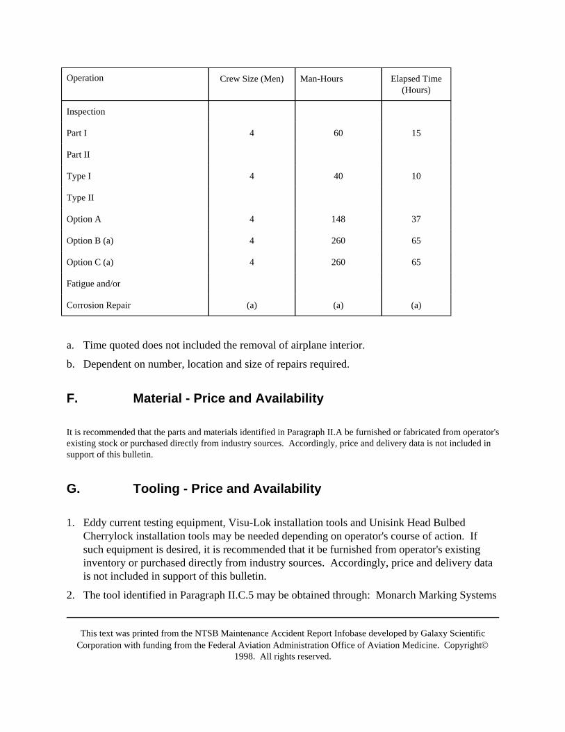
This text was printed from the NTSB Maintenance Accident Report Infobase developed by Galaxy ScientificCorporation with funding from the Federal Aviation Administration Office of Aviation Medicine. Copyright©
1998. All rights reserved.
Operation Crew Size (Men) Man-Hours Elapsed Time(Hours)
Inspection
Part I 4 60 15
Part II
Type I 4 40 10
Type II
Option A 4 148 37
Option B (a) 4 260 65
Option C (a) 4 260 65
Fatigue and/or
Corrosion Repair (a) (a) (a)
a. Time quoted does not included the removal of airplane interior.
b. Dependent on number, location and size of repairs required.
F. Material - Price and Availability
It is recommended that the parts and materials identified in Paragraph II.A be furnished or fabricated from operator'sexisting stock or purchased directly from industry sources. Accordingly, price and delivery data is not included insupport of this bulletin.
G. Tooling - Price and Availability
1. Eddy current testing equipment, Visu-Lok installation tools and Unisink Head BulbedCherrylock installation tools may be needed depending on operator's course of action. Ifsuch equipment is desired, it is recommended that it be furnished from operator's existinginventory or purchased directly from industry sources. Accordingly, price and delivery datais not included in support of this bulletin.
2. The tool identified in Paragraph II.C.5 may be obtained through: Monarch Marking Systems

This text was printed from the NTSB Maintenance Accident Report Infobase developed by Galaxy ScientificCorporation with funding from the Federal Aviation Administration Office of Aviation Medicine. Copyright©
1998. All rights reserved.
P.O. Box 608 Dayton, Ohio 45401
Part Number Quantity Price
PRY-1 1 tool per Package $2.95
PRY-4 4 tools per Package $9.50
H. Weight and Balance
Change in weight and balance will depend on number, type and size of repairs and amount of sealant (Ref. BMS5-95) and/or corrosion inhibitor (Ref. BMS 3-23) applied.
I. References
1. Existing Data:
a. Structural Repair Manual D6-15565, Subjects 51-10-2, 53-30-1, 53-30-2, 53-30-4 and53-30-4
b. Boeing Nondestructive Test Manual, Document D6-37239, Part 1 and Part 6
c. Boeing Service Bulletin 737-53-1017, "Sealing of Cold-Bonded Structure For CorrosionProtection"
d. Boeing Service Bulletin 737-53A1042, "Lower Lobe Hot-Bonded Skin Panel InspectionRepair, and Panel Replacement"
e. Boeing Corrosion Prevention Manual Part 1, Section 20-60-00
2. New or revised data supplied in support of this service bulletin:
None
J. Publications Affected
The modification described herein affects the following publication:
Publication Chapter-Section
737 Structural Repair Manual 53-30

This text was printed from the NTSB Maintenance Accident Report Infobase developed by Galaxy ScientificCorporation with funding from the Federal Aviation Administration Office of Aviation Medicine. Copyright©
1998. All rights reserved.
II. Material Information
A. Parts Required Per AirplaneAll of the following may berequired depending on operator's course of action.
Quantity Part Number Nomenclature
As Required See Structural RepairManual, Subject 53-30-4
Sealant
As Required BMS 3-23 or equivalent Water DisplacingCorrosion InhibitingCompound
As Required NAS1398D8-( ) Blind Rivet
As Required PLT1007-6-( ) Visu-Lok BlindFastener
As Required CR 2235-6-( ) Unisink Head BulbedCherrylock
As Required MS20470D5-5 Rivet
As Required BMS 5-95, Class B Sealant
Vendor Information
Boeing Part No. Vendor Part No. Vendor
- PLT1007-6-( ) The National Screw and Mfg.Co.3423 S. Garfield Ave.Los Angeles, Calif. 90022
- CR 2235-6-( ) Townsend Co.Cherry Rivet Div.1224 E. Warner Ave.Santa Ana, Calif. 92707

This text was printed from the NTSB Maintenance Accident Report Infobase developed by Galaxy ScientificCorporation with funding from the Federal Aviation Administration Office of Aviation Medicine. Copyright©
1998. All rights reserved.
B. Parts Required to Modify Spares
None
C. Special Tools and Equipment Required
1. Low frequency eddy current inspection instruments for corrosion loss measurement are listedin the Boeing Nondestructive Test Manual D6-37239, Part 6, 51-00-00, Figure 5.
Two corrosion reference standards fabricated from 0.036 inch and 0.040 inch clad aluminumsheet are required to perform corrosion loss measurements.
2. Power tools may be used to install Visu-Lok fasteners. For applicable tools contact theNational Screw & Mfg. Co.
3. The following tools may be used to install Unisink head Bulbed Cherrylock fasteners:
Pull Gun: G-684
Flush Fastener Pull Head: H681-6C
Vendor: Townsend Co., Cherry Rivet Div.1224 E. Warner Ave.Santa Ana, Calif. 92707
4. The following equipment has been tested and found satisfactory for blind application ofcorrosion inhibitor and is to be operator fabricated. Equivalent operator designed equipmentmay also be used as long as it is designed to apply only the minimum amount of corrosioninhibitor required to saturate the void and to prevent contamination of insulation materials.This equipment is for use with the one row blind fastener joint refastening method detailed inPart IV - Repair Data.
5. The following tool is suitable for use in Part III - Tear Strap Inspection for disbond.
Nomenclature Part Number
Econo-Pry PRY-1 or
PRY-4

This text was printed from the NTSB Maintenance Accident Report Infobase developed by Galaxy ScientificCorporation with funding from the Federal Aviation Administration Office of Aviation Medicine. Copyright©
1998. All rights reserved.
An equivalent tool may be used at operator's discretion.
Equipment - Method I (Optional to Method II)1. Four ounce pump type oilcan modified to incorporate a stop, stop screw, spring and special
nozzle. Fabricate per Figure 3.
2. Lap joint sample for practice and stop adjustment. Fabricate per Figure 4.
Equipment - Method II (Optional to Method I)To reduce applicationtime, it is suggested that this equipment be made in quantity so thatseveral upper row fastener holes in the repair area may be treatedsimultaneously.1. Applicator tip, stop collar and a length of clear plastic tubing. Fabricate and assemble per
Figure 5.
2. Determine outer skin thickness (737 Structural Repair Manual Subject 53-30-2, Figure 2 andFigure 3).
D. Existing Parts Accountability
None
III. Accomplishment Instructions1. The following program outlines the minimum requirements for maintaining the structural
integrity of skin lap joints. The inspection for corrosion will detect severe corrosionrequiring repair by installing repair doublers. The inspection for fatigue damage will detectlarge fatigue cracks (0.25 inch in length and greater) emanating from upper row - fastenerholes. These cracks will be large enough to require repair by installation of repair doublers.In the following inspections each panel is treated as a separate entity and the inspectionresults of one panel reliably cannot be used to indicate the condition of another.
2. On the figures, unless otherwise specified:
· All linear dimensions are in inches
· Tolerance on linear dimensions other than rivet and bolt edge margin is plus or minus0.03
· Tolerance on rivet and bolt edge margin is plus or minus 0.05

This text was printed from the NTSB Maintenance Accident Report Infobase developed by Galaxy ScientificCorporation with funding from the Federal Aviation Administration Office of Aviation Medicine. Copyright©
1998. All rights reserved.
· Angular tolerance is plus or minus 2 degrees
· Hole size for standard solid rivets is per 737 Structural Repair Manual Chapter 51
Part I - Corrosion Inspection and Repair
On all airplanes, accomplish the following corrosion inspection and application of corrosion inhibitor BMS 3-23 orequivalent (Ref. Corrosion Prevention Manual Part 1, Section 20-60-00) at six month intervals on lower lobe jointsand one year intervals on upper lobe joints.
A. Visually inspect external surface of each lap joint for skin bulges adjacent to fasteners, skincracks caused by severe corrosion, dished fastener heads or missing fastener heads betweenBody Station 178 and 1016 (See Figure 1).
B. If corrosion indications noted in Step A are found, determine extent of corrosion damage forfull length of the panel joint. Extent of damage may be determined using low frequencyeddy current inspection (Ref. 737 Nondestructive Test Manual D6-37239, Part 6, 51-00-00Figure 5) or by any other suitable means.
C. Corrosion may be removed by local blend out if the blend out depth does not exceed 10percent of the skin thickness except as follows:
1. In small local areas not exceeding 3 inches in length in any 20 inches of joint, a skinthickness reduction of 20 percent is acceptable.
2. In smaller areas not exceeding 1.5 inches in length in any 20 inches of joint a skinthickness reduction of 40 percent is acceptable. In areas where skin thickness is reducedby 40 percent it is suggested that a faying surface sealed shim and oversize protrudinghead fasteners be installed if there are existing fastener holes in the rework area. Aftercorrosion removal refasten the joint per 737 Structural Repair Manual Subject 53-30-1,Figure 5, Method II or III.
3. Corrosion exceeding the above limits should be repaired per 737 Structural RepairManual Subject 53-30-3.
D. In panel lap joint areas where no corrosion indications are found, apply corrosion inhibitor tojoint external edge and fastener external heads in joint (Ref. 737 Structural Repair ManualSubject 51-10-2). For maximum penetration, it is suggested that corrosion inhibitor beapplied to the joint edge under pressure using equipment such as an airless paint spray pump.
E. Fillet seal along the edge of the lap joint prevents corrosion inhibitor application to the jointedge, but need not be removed unless deteriorated.
F. After corrosion inhibitor becomes tacky, excess may be removed (Ref. 737 Structural RepairManual Subject 51-10-2).
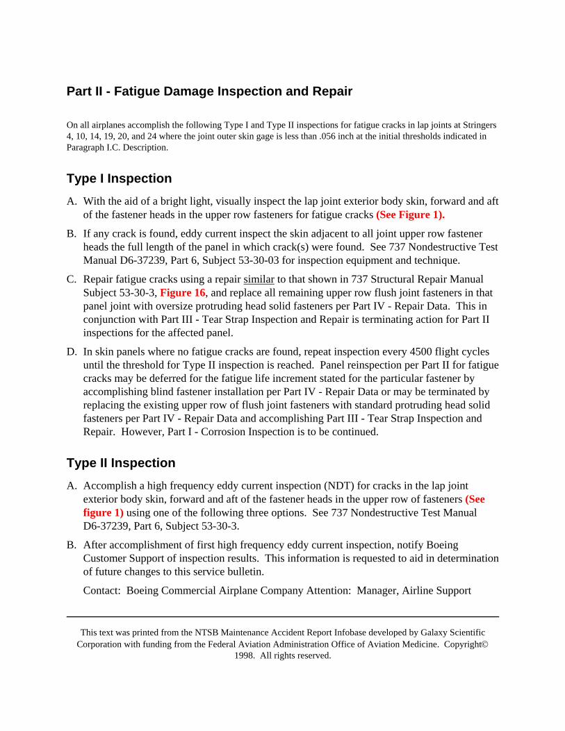
This text was printed from the NTSB Maintenance Accident Report Infobase developed by Galaxy ScientificCorporation with funding from the Federal Aviation Administration Office of Aviation Medicine. Copyright©
1998. All rights reserved.
Part II - Fatigue Damage Inspection and Repair
On all airplanes accomplish the following Type I and Type II inspections for fatigue cracks in lap joints at Stringers4, 10, 14, 19, 20, and 24 where the joint outer skin gage is less than .056 inch at the initial thresholds indicated inParagraph I.C. Description.
Type I InspectionA. With the aid of a bright light, visually inspect the lap joint exterior body skin, forward and aft
of the fastener heads in the upper row fasteners for fatigue cracks (See Figure 1).
B. If any crack is found, eddy current inspect the skin adjacent to all joint upper row fastenerheads the full length of the panel in which crack(s) were found. See 737 Nondestructive TestManual D6-37239, Part 6, Subject 53-30-03 for inspection equipment and technique.
C. Repair fatigue cracks using a repair similar to that shown in 737 Structural Repair ManualSubject 53-30-3, Figure 16, and replace all remaining upper row flush joint fasteners in thatpanel joint with oversize protruding head solid fasteners per Part IV - Repair Data. This inconjunction with Part III - Tear Strap Inspection and Repair is terminating action for Part IIinspections for the affected panel.
D. In skin panels where no fatigue cracks are found, repeat inspection every 4500 flight cyclesuntil the threshold for Type II inspection is reached. Panel reinspection per Part II for fatiguecracks may be deferred for the fatigue life increment stated for the particular fastener byaccomplishing blind fastener installation per Part IV - Repair Data or may be terminated byreplacing the existing upper row of flush joint fasteners with standard protruding head solidfasteners per Part IV - Repair Data and accomplishing Part III - Tear Strap Inspection andRepair. However, Part I - Corrosion Inspection is to be continued.
Type II InspectionA. Accomplish a high frequency eddy current inspection (NDT) for cracks in the lap joint
exterior body skin, forward and aft of the fastener heads in the upper row of fasteners (Seefigure 1) using one of the following three options. See 737 Nondestructive Test ManualD6-37239, Part 6, Subject 53-30-3.
B. After accomplishment of first high frequency eddy current inspection, notify BoeingCustomer Support of inspection results. This information is requested to aid in determinationof future changes to this service bulletin.
Contact: Boeing Commercial Airplane Company Attention: Manager, Airline Support
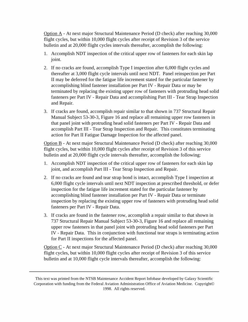
This text was printed from the NTSB Maintenance Accident Report Infobase developed by Galaxy ScientificCorporation with funding from the Federal Aviation Administration Office of Aviation Medicine. Copyright©
1998. All rights reserved.
Option A - At next major Structural Maintenance Period (D check) after reaching 30,000flight cycles, but within 10,000 flight cycles after receipt of Revision 3 of the servicebulletin and at 20,000 flight cycles intervals thereafter, accomplish the following:
1. Accomplish NDT inspection of the critical upper row of fasteners for each skin lapjoint.
2. If no cracks are found, accomplish Type I inspection after 6,000 flight cycles andthereafter at 3,000 flight cycle intervals until next NDT. Panel reinspection per PartII may be deferred for the fatigue life increment stated for the particular fastener byaccomplishing blind fastener installation per Part IV - Repair Data or may beterminated by replacing the existing upper row of fasteners with protruding head solidfasteners per Part IV - Repair Data and accomplishing Part III - Tear Strap Inspectionand Repair.
3. If cracks are found, accomplish repair similar to that shown in 737 Structural RepairManual Subject 53-30-3, Figure 16 and replace all remaining upper row fasteners inthat panel joint with protruding head solid fasteners per Part IV - Repair Data andaccomplish Part III - Tear Strap Inspection and Repair. This constitutes terminatingaction for Part II Fatigue Damage Inspection for the affected panel.
Option B - At next major Structural Maintenance Period (D check) after reaching 30,000flight cycles, but within 10,000 flight cycles after receipt of Revision 3 of this servicebulletin and at 20,000 flight cycle intervals thereafter, accomplish the following:
1. Accomplish NDT inspection of the critical upper row of fasteners for each skin lapjoint, and accomplish Part III - Tear Strap Inspection and Repair.
2. If no cracks are found and tear strap bond is intact, accomplish Type I inspection at6,000 flight cycle intervals until next NDT inspection at prescribed threshold, or deferinspection for the fatigue life increment stated for the particular fastener byaccomplishing blind fastener installation per Part IV - Repair Data or terminateinspection by replacing the existing upper row of fasteners with protruding head solidfasteners per Part IV - Repair Data.
3. If cracks are found in the fastener row, accomplish a repair similar to that shown in737 Structural Repair Manual Subject 53-30-3, Figure 16 and replace all remainingupper row fasteners in that panel joint with protruding head solid fasteners per PartIV - Repair Data. This in conjunction with functional tear straps is terminating actionfor Part II inspections for the affected panel.
Option C - At next major Structural Maintenance Period (D check) after reaching 30,000flight cycles, but within 10,000 flight cycles after receipt of Revision 3 of this servicebulletin and at 10,000 flight cycle intervals thereafter, accomplish the following:
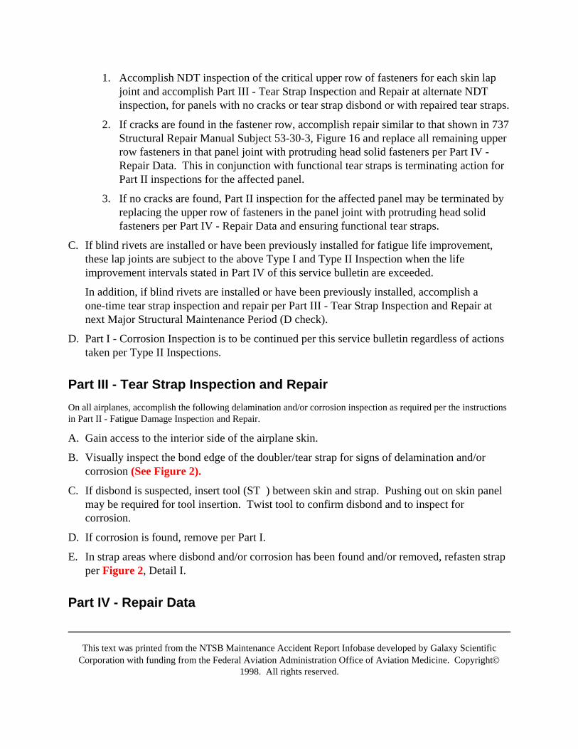
This text was printed from the NTSB Maintenance Accident Report Infobase developed by Galaxy ScientificCorporation with funding from the Federal Aviation Administration Office of Aviation Medicine. Copyright©
1998. All rights reserved.
1. Accomplish NDT inspection of the critical upper row of fasteners for each skin lapjoint and accomplish Part III - Tear Strap Inspection and Repair at alternate NDTinspection, for panels with no cracks or tear strap disbond or with repaired tear straps.
2. If cracks are found in the fastener row, accomplish repair similar to that shown in 737Structural Repair Manual Subject 53-30-3, Figure 16 and replace all remaining upperrow fasteners in that panel joint with protruding head solid fasteners per Part IV -Repair Data. This in conjunction with functional tear straps is terminating action forPart II inspections for the affected panel.
3. If no cracks are found, Part II inspection for the affected panel may be terminated byreplacing the upper row of fasteners in the panel joint with protruding head solidfasteners per Part IV - Repair Data and ensuring functional tear straps.
C. If blind rivets are installed or have been previously installed for fatigue life improvement,these lap joints are subject to the above Type I and Type II Inspection when the lifeimprovement intervals stated in Part IV of this service bulletin are exceeded.
In addition, if blind rivets are installed or have been previously installed, accomplish aone-time tear strap inspection and repair per Part III - Tear Strap Inspection and Repair atnext Major Structural Maintenance Period (D check).
D. Part I - Corrosion Inspection is to be continued per this service bulletin regardless of actionstaken per Type II Inspections.
Part III - Tear Strap Inspection and RepairOn all airplanes, accomplish the following delamination and/or corrosion inspection as required per the instructionsin Part II - Fatigue Damage Inspection and Repair.
A. Gain access to the interior side of the airplane skin.
B. Visually inspect the bond edge of the doubler/tear strap for signs of delamination and/orcorrosion (See Figure 2).
C. If disbond is suspected, insert tool (ST ) between skin and strap. Pushing out on skin panelmay be required for tool insertion. Twist tool to confirm disbond and to inspect forcorrosion.
D. If corrosion is found, remove per Part I.
E. In strap areas where disbond and/or corrosion has been found and/or removed, refasten strapper Figure 2, Detail I.
Part IV - Repair Data
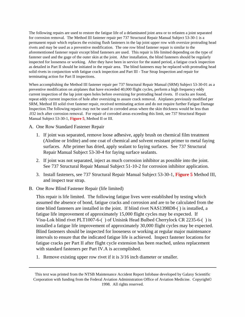
This text was printed from the NTSB Maintenance Accident Report Infobase developed by Galaxy ScientificCorporation with funding from the Federal Aviation Administration Office of Aviation Medicine. Copyright©
1998. All rights reserved.
The following repairs are used to restore the fatigue life of a delaminated joint area or to refasten a joint separatedfor corrosion removal. The Method III fastener repair per 737 Structural Repair Manual Subject 53-30-1 is apermanent repair which replaces the existing flush fasteners in the lap joint upper row with oversize protruding headrivets and may be used as a preventive modification. The one row blind fastener repair is similar to theaforementioned fastener repair except blind fasteners are used. This repair is life limited depending on the type offastener used and the gage of the outer skin at the joint. After installation, the blind fasteners should be regularlyinspected for looseness or working. After they have been in service for the stated period, a fatigue crack inspectionas detailed in Part II should be initiated in the repair area. The blind fasteners may be replaced with protruding headsolid rivets in conjunction with fatigue crack inspection and Part III - Tear Strap Inspection and repair forterminating action for Part II inspections.
When accomplishing the Method III fastener repair per 737 Structural Repair Manual (SRM) Subject 53-30-01 as apreventive modification on airplanes that have exceeded 40,000 flight cycles, perform a high frequency eddycurrent inspection of the lap joint open holes before oversizing for protruding head rivets. If cracks are found,repeat eddy current inspection of hole after oversizing to assure crack removal. Airplanes previously modified perSRM, Method III solid rivet fastener repair, received terminating action and do not require further Fatigue DamageInspection.The following repairs may not be used in corroded areas where the skin thickness would be less than.032 inch after corrosion removal. For repair of corroded areas exceeding this limit, see 737 Structural RepairManual Subject 53-30-1, Figure 5, Method II or III.
A. One Row Standard Fastener Repair
1. If joint was separated, remove loose adhesive, apply brush on chemical film treatment(Alodine or Iridite) and one coat of chemical and solvent resistant primer to metal fayingsurfaces. Afte primer has dried, apply sealant to faying surfaces. See 737 StructuralRepair Manual Subject 53-30-4 for faying surface sealants.
2. If joint was not separated, inject as much corrosion inhibitor as possible into the joint.See 737 Structural Repair Manual Subject 51-10-2 for corrosion inhibitor application.
3. Install fasteners, see 737 Structural Repair Manual Subject 53-30-1, Figure 5 Method III,and inspect tear strap.
B. One Row Blind Fastener Repair (life limited)
This repair is life limited. The following fatigue lives were established by testing whichassumed the absence of bond, fatigue cracks and corrosion and are to be calculated from thetime blind fasteners are installed in the joint. If blind rivet NAS1398D8-( ) is installed, afatigue life improvement of approximately 15,000 flight cycles may be expected. IfVisu-Lok blind rivet PLT1007-6-( ) of Unisink Head Bulbed Cherrylock CR 2235-6-( ) isinstalled a fatigue life improvement of approximately 30,000 flight cycles may be expected.Blind fasteners should be inspected for looseness or working at regular major maintenanceintervals to ensure that the indicated fatigue life is achieved. Inspect fastener locations forfatigue cracks per Part II after flight cycle extension has been reached, unless replacementwith standard fasteners per Part IV.A is accomplished.
1. Remove existing upper row rivet if it is 3/16 inch diameter or smaller.
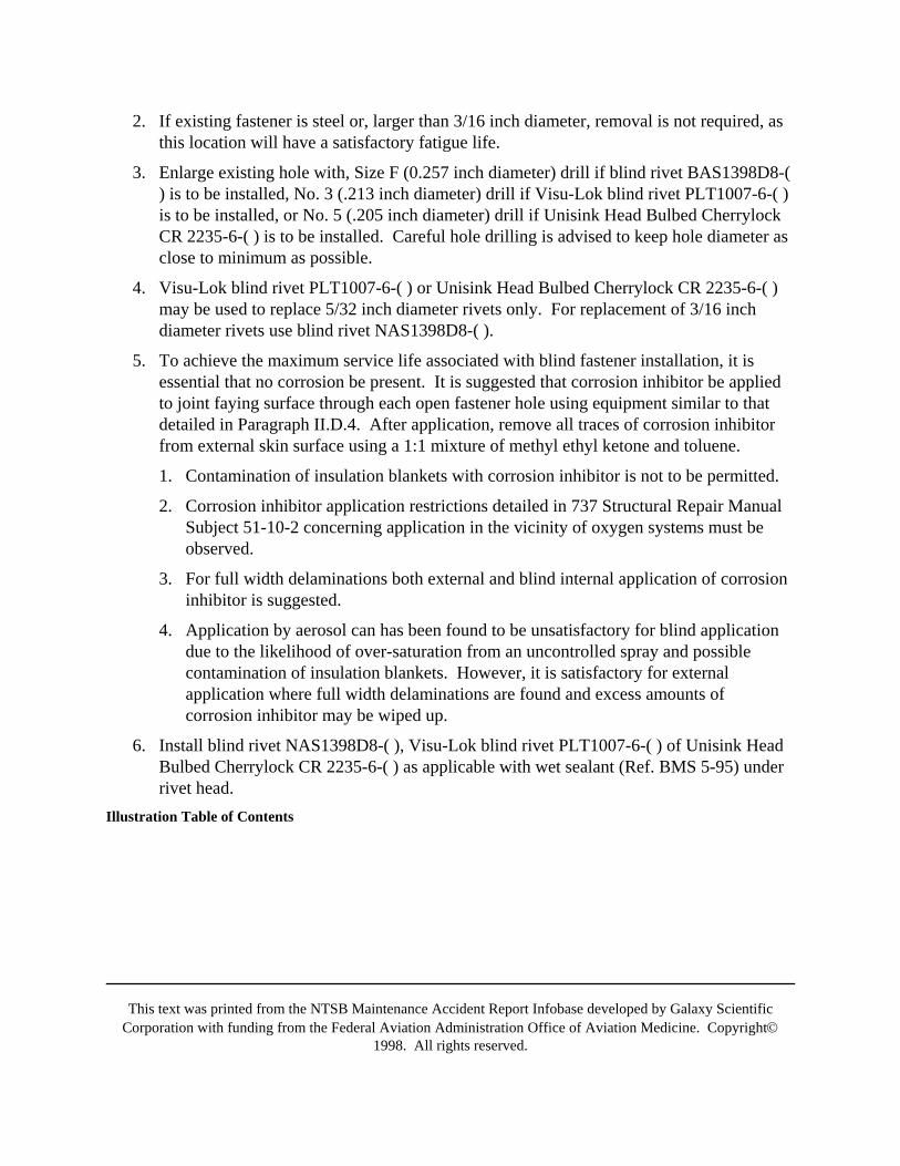
This text was printed from the NTSB Maintenance Accident Report Infobase developed by Galaxy ScientificCorporation with funding from the Federal Aviation Administration Office of Aviation Medicine. Copyright©
1998. All rights reserved.
2. If existing fastener is steel or, larger than 3/16 inch diameter, removal is not required, asthis location will have a satisfactory fatigue life.
3. Enlarge existing hole with, Size F (0.257 inch diameter) drill if blind rivet BAS1398D8-() is to be installed, No. 3 (.213 inch diameter) drill if Visu-Lok blind rivet PLT1007-6-( )is to be installed, or No. 5 (.205 inch diameter) drill if Unisink Head Bulbed CherrylockCR 2235-6-( ) is to be installed. Careful hole drilling is advised to keep hole diameter asclose to minimum as possible.
4. Visu-Lok blind rivet PLT1007-6-( ) or Unisink Head Bulbed Cherrylock CR 2235-6-( )may be used to replace 5/32 inch diameter rivets only. For replacement of 3/16 inchdiameter rivets use blind rivet NAS1398D8-( ).
5. To achieve the maximum service life associated with blind fastener installation, it isessential that no corrosion be present. It is suggested that corrosion inhibitor be appliedto joint faying surface through each open fastener hole using equipment similar to thatdetailed in Paragraph II.D.4. After application, remove all traces of corrosion inhibitorfrom external skin surface using a 1:1 mixture of methyl ethyl ketone and toluene.
1. Contamination of insulation blankets with corrosion inhibitor is not to be permitted.
2. Corrosion inhibitor application restrictions detailed in 737 Structural Repair ManualSubject 51-10-2 concerning application in the vicinity of oxygen systems must beobserved.
3. For full width delaminations both external and blind internal application of corrosioninhibitor is suggested.
4. Application by aerosol can has been found to be unsatisfactory for blind applicationdue to the likelihood of over-saturation from an uncontrolled spray and possiblecontamination of insulation blankets. However, it is satisfactory for externalapplication where full width delaminations are found and excess amounts ofcorrosion inhibitor may be wiped up.
6. Install blind rivet NAS1398D8-( ), Visu-Lok blind rivet PLT1007-6-( ) of Unisink HeadBulbed Cherrylock CR 2235-6-( ) as applicable with wet sealant (Ref. BMS 5-95) underrivet head.
Illustration Table of Contents

This text was printed from the NTSB Maintenance Accident Report Infobase developed by Galaxy ScientificCorporation with funding from the Federal Aviation Administration Office of Aviation Medicine. Copyright©
1998. All rights reserved.
TitlePage
Figure 1. Lap Joint Inspection
Figure 2. Tear Strap Inspection
Figure 3. Blind Corrosion Inhibitor Applicator - Method I
Figure 4. Lap Joint Sample
Figure 5. Blind Corrosion Inhibitor Applicator - Method II
FIGURE 1. LAP JOINT INSPECTION
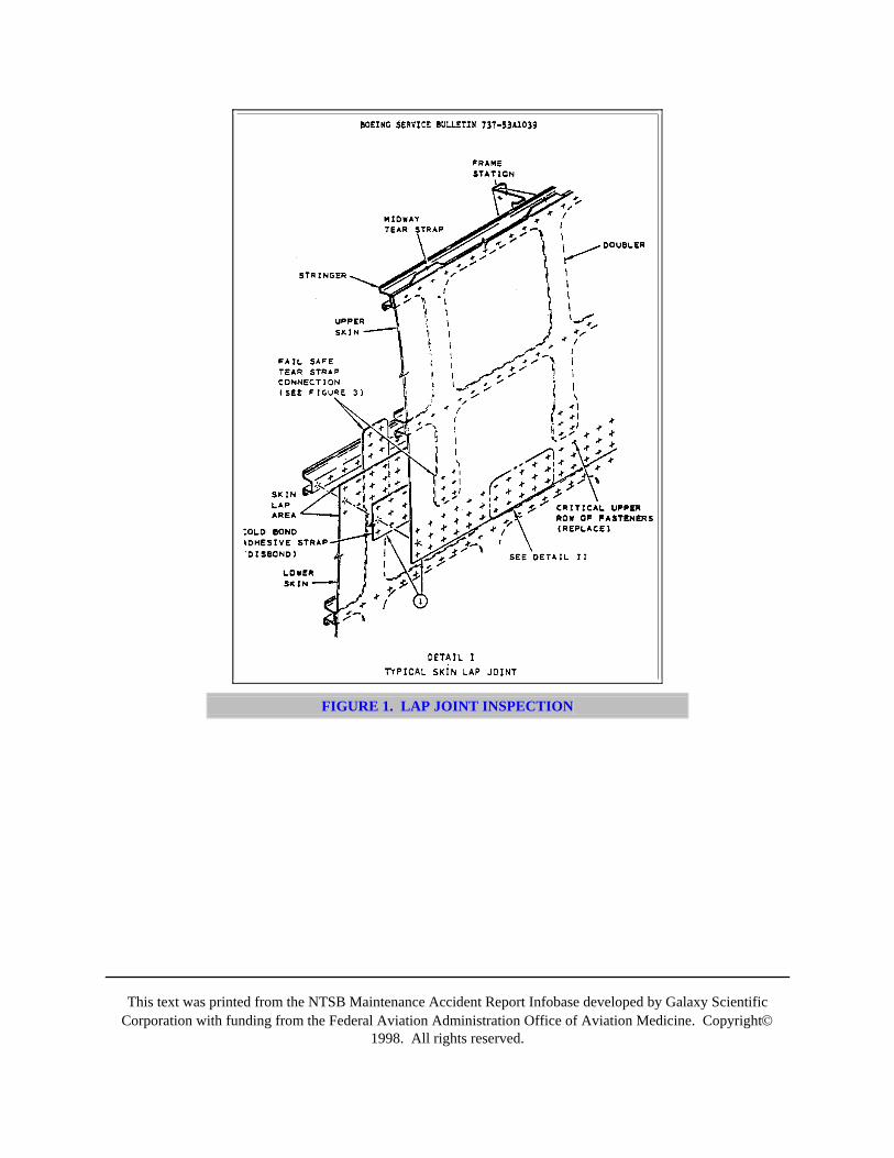
This text was printed from the NTSB Maintenance Accident Report Infobase developed by Galaxy ScientificCorporation with funding from the Federal Aviation Administration Office of Aviation Medicine. Copyright©
1998. All rights reserved.
FIGURE 1. LAP JOINT INSPECTION
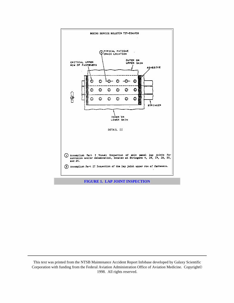
This text was printed from the NTSB Maintenance Accident Report Infobase developed by Galaxy ScientificCorporation with funding from the Federal Aviation Administration Office of Aviation Medicine. Copyright©
1998. All rights reserved.
FIGURE 1. LAP JOINT INSPECTION
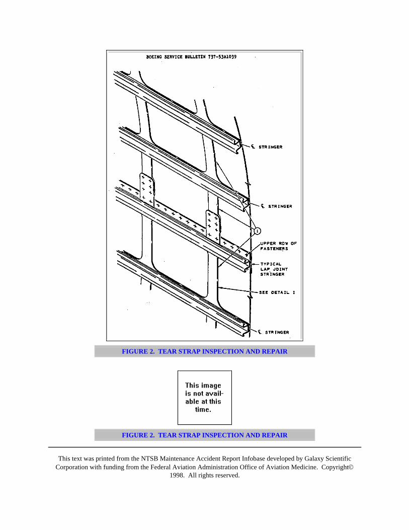
This text was printed from the NTSB Maintenance Accident Report Infobase developed by Galaxy ScientificCorporation with funding from the Federal Aviation Administration Office of Aviation Medicine. Copyright©
1998. All rights reserved.
FIGURE 2. TEAR STRAP INSPECTION AND REPAIR
FIGURE 2. TEAR STRAP INSPECTION AND REPAIR
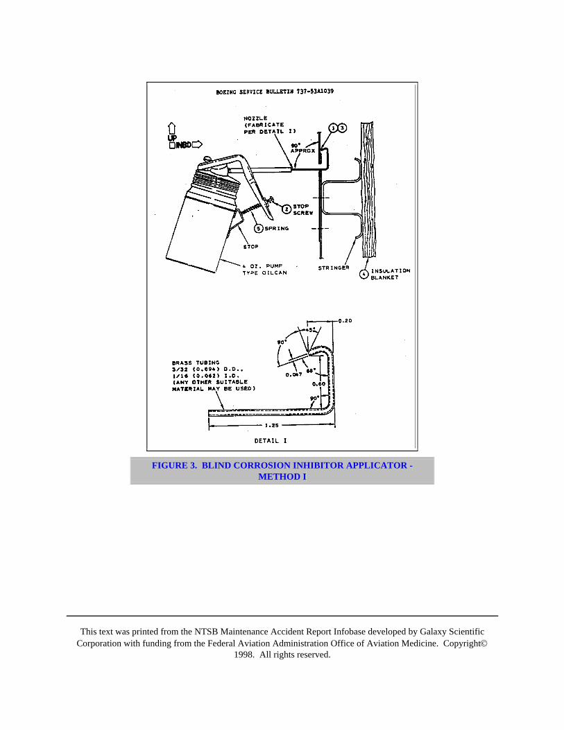
This text was printed from the NTSB Maintenance Accident Report Infobase developed by Galaxy ScientificCorporation with funding from the Federal Aviation Administration Office of Aviation Medicine. Copyright©
1998. All rights reserved.
FIGURE 3. BLIND CORROSION INHIBITOR APPLICATOR -METHOD I

This text was printed from the NTSB Maintenance Accident Report Infobase developed by Galaxy ScientificCorporation with funding from the Federal Aviation Administration Office of Aviation Medicine. Copyright©
1998. All rights reserved.
FIGURE 4. LAP JOINT SAMPLE
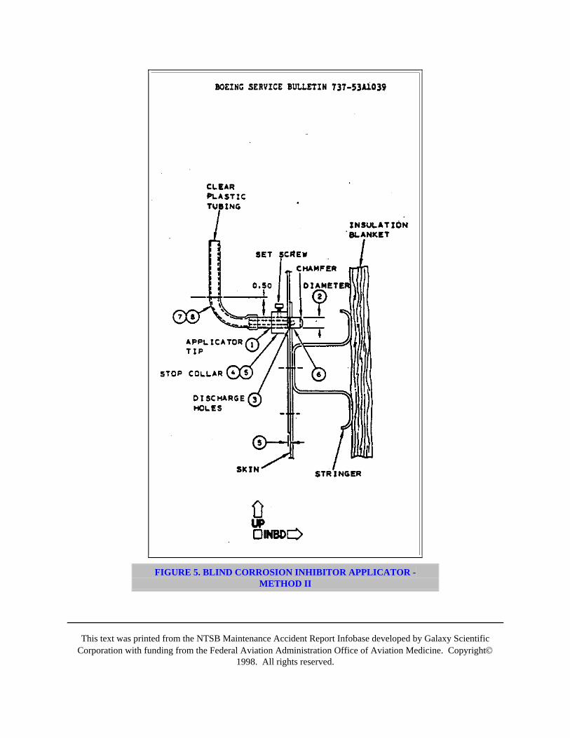
This text was printed from the NTSB Maintenance Accident Report Infobase developed by Galaxy ScientificCorporation with funding from the Federal Aviation Administration Office of Aviation Medicine. Copyright©
1998. All rights reserved.
FIGURE 5. BLIND CORROSION INHIBITOR APPLICATOR -METHOD II
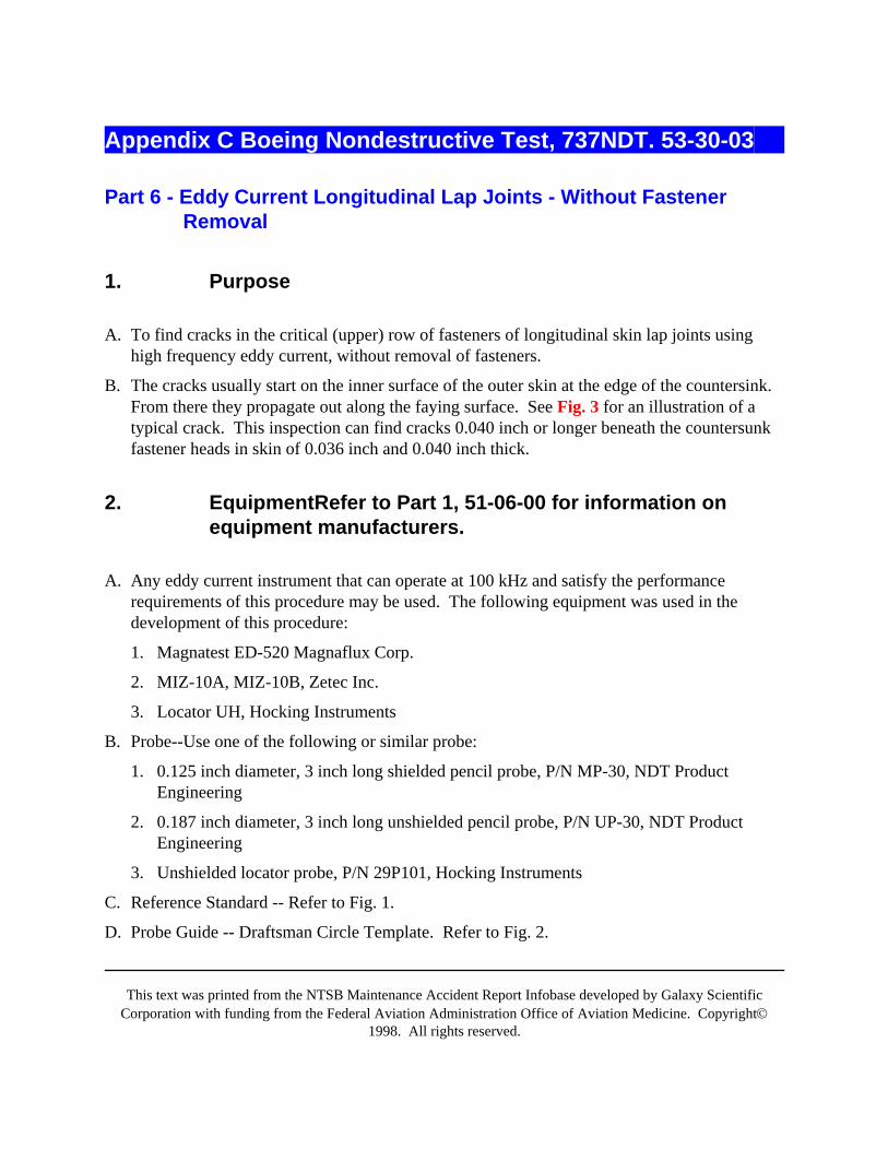
This text was printed from the NTSB Maintenance Accident Report Infobase developed by Galaxy ScientificCorporation with funding from the Federal Aviation Administration Office of Aviation Medicine. Copyright©
1998. All rights reserved.
Appendix C Boeing Nondestructive Test, 737NDT. 53-30-03
Part 6 - Eddy Current Longitudinal Lap Joints - Without FastenerRemoval
1. Purpose
A. To find cracks in the critical (upper) row of fasteners of longitudinal skin lap joints usinghigh frequency eddy current, without removal of fasteners.
B. The cracks usually start on the inner surface of the outer skin at the edge of the countersink.From there they propagate out along the faying surface. See Fig. 3 for an illustration of atypical crack. This inspection can find cracks 0.040 inch or longer beneath the countersunkfastener heads in skin of 0.036 inch and 0.040 inch thick.
2. EquipmentRefer to Part 1, 51-06-00 for information onequipment manufacturers.
A. Any eddy current instrument that can operate at 100 kHz and satisfy the performancerequirements of this procedure may be used. The following equipment was used in thedevelopment of this procedure:
1. Magnatest ED-520 Magnaflux Corp.
2. MIZ-10A, MIZ-10B, Zetec Inc.
3. Locator UH, Hocking Instruments
B. Probe--Use one of the following or similar probe:
1. 0.125 inch diameter, 3 inch long shielded pencil probe, P/N MP-30, NDT ProductEngineering
2. 0.187 inch diameter, 3 inch long unshielded pencil probe, P/N UP-30, NDT ProductEngineering
3. Unshielded locator probe, P/N 29P101, Hocking Instruments
C. Reference Standard -- Refer to Fig. 1.
D. Probe Guide -- Draftsman Circle Template. Refer to Fig. 2.
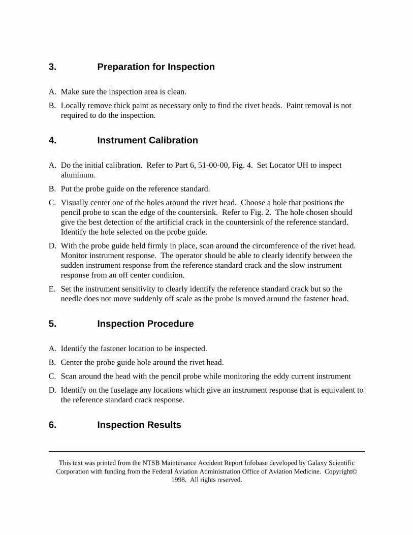
This text was printed from the NTSB Maintenance Accident Report Infobase developed by Galaxy ScientificCorporation with funding from the Federal Aviation Administration Office of Aviation Medicine. Copyright©
1998. All rights reserved.
3. Preparation for Inspection
A. Make sure the inspection area is clean.
B. Locally remove thick paint as necessary only to find the rivet heads. Paint removal is notrequired to do the inspection.
4. Instrument Calibration
A. Do the initial calibration. Refer to Part 6, 51-00-00, Fig. 4. Set Locator UH to inspectaluminum.
B. Put the probe guide on the reference standard.
C. Visually center one of the holes around the rivet head. Choose a hole that positions thepencil probe to scan the edge of the countersink. Refer to Fig. 2. The hole chosen shouldgive the best detection of the artificial crack in the countersink of the reference standard.Identify the hole selected on the probe guide.
D. With the probe guide held firmly in place, scan around the circumference of the rivet head.Monitor instrument response. The operator should be able to clearly identify between thesudden instrument response from the reference standard crack and the slow instrumentresponse from an off center condition.
E. Set the instrument sensitivity to clearly identify the reference standard crack but so theneedle does not move suddenly off scale as the probe is moved around the fastener head.
5. Inspection Procedure
A. Identify the fastener location to be inspected.
B. Center the probe guide hole around the rivet head.
C. Scan around the head with the pencil probe while monitoring the eddy current instrument
D. Identify on the fuselage any locations which give an instrument response that is equivalent tothe reference standard crack response.
6. Inspection Results
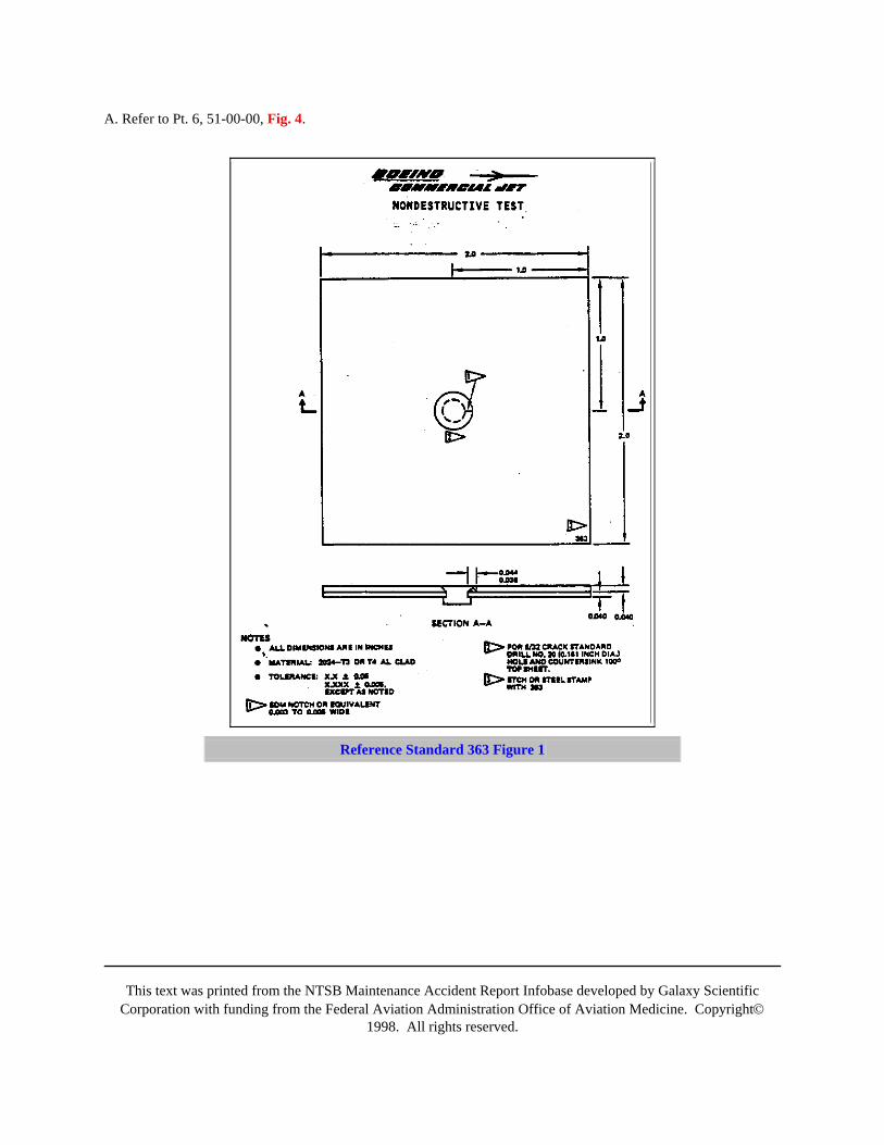
This text was printed from the NTSB Maintenance Accident Report Infobase developed by Galaxy ScientificCorporation with funding from the Federal Aviation Administration Office of Aviation Medicine. Copyright©
1998. All rights reserved.
A. Refer to Pt. 6, 51-00-00, Fig. 4.
Reference Standard 363 Figure 1
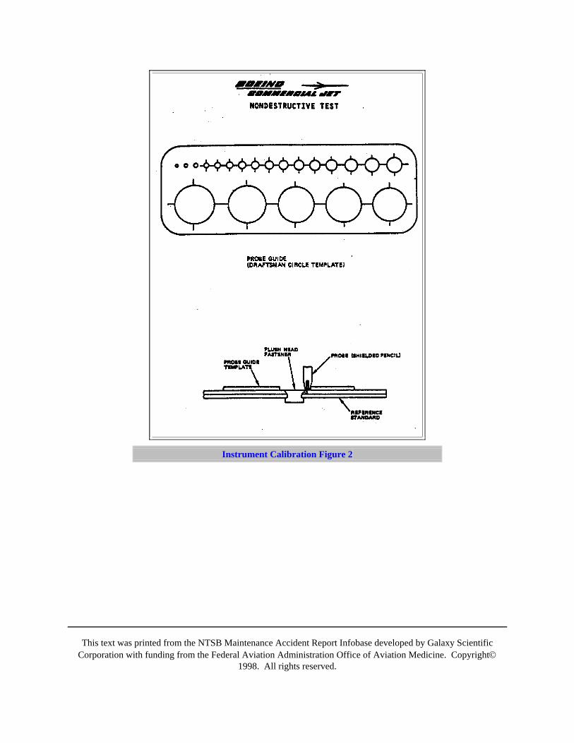
This text was printed from the NTSB Maintenance Accident Report Infobase developed by Galaxy ScientificCorporation with funding from the Federal Aviation Administration Office of Aviation Medicine. Copyright©
1998. All rights reserved.
Instrument Calibration Figure 2
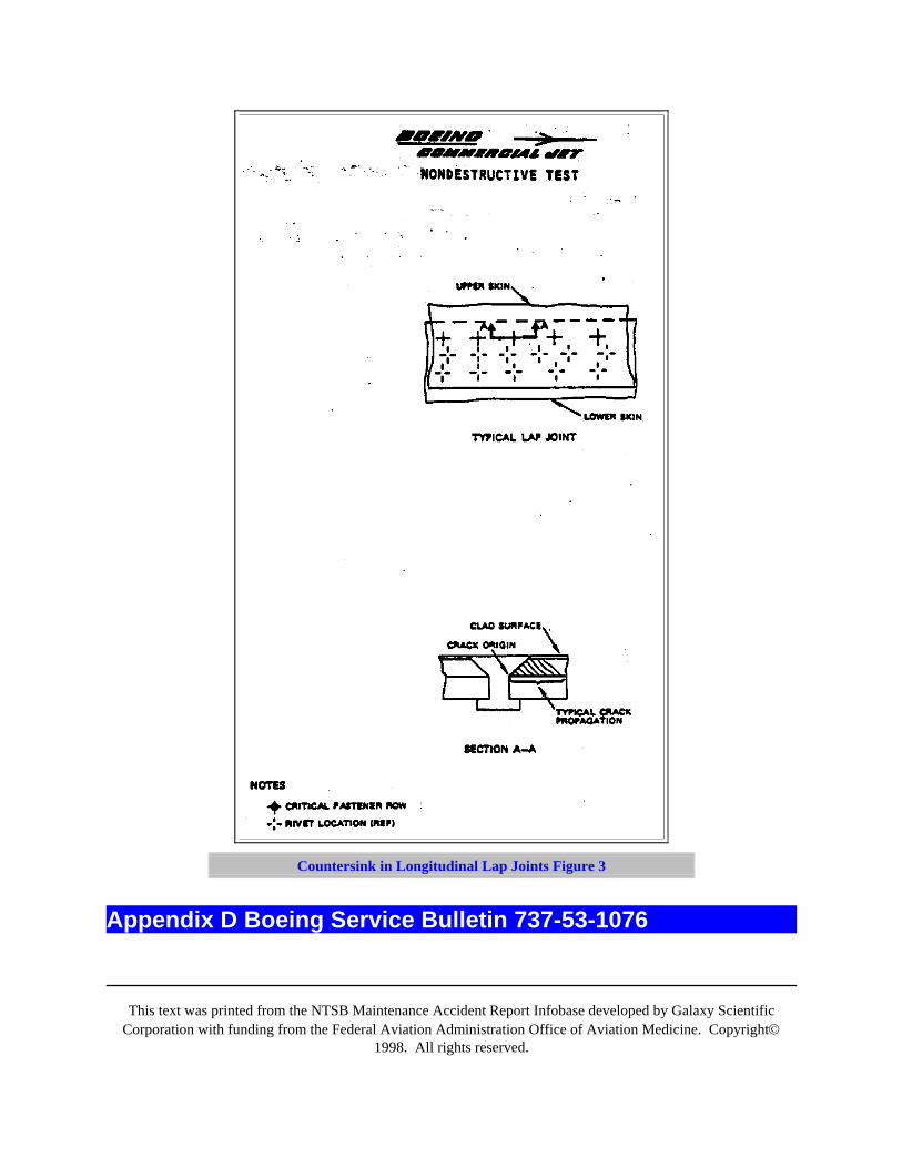
This text was printed from the NTSB Maintenance Accident Report Infobase developed by Galaxy ScientificCorporation with funding from the Federal Aviation Administration Office of Aviation Medicine. Copyright©
1998. All rights reserved.
Countersink in Longitudinal Lap Joints Figure 3
Appendix D Boeing Service Bulletin 737-53-1076
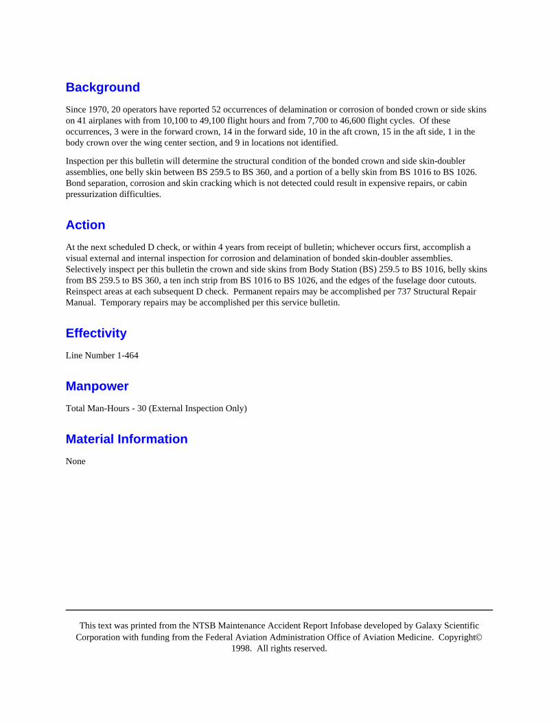
This text was printed from the NTSB Maintenance Accident Report Infobase developed by Galaxy ScientificCorporation with funding from the Federal Aviation Administration Office of Aviation Medicine. Copyright©
1998. All rights reserved.
BackgroundSince 1970, 20 operators have reported 52 occurrences of delamination or corrosion of bonded crown or side skinson 41 airplanes with from 10,100 to 49,100 flight hours and from 7,700 to 46,600 flight cycles. Of theseoccurrences, 3 were in the forward crown, 14 in the forward side, 10 in the aft crown, 15 in the aft side, 1 in thebody crown over the wing center section, and 9 in locations not identified.
Inspection per this bulletin will determine the structural condition of the bonded crown and side skin-doublerassemblies, one belly skin between BS 259.5 to BS 360, and a portion of a belly skin from BS 1016 to BS 1026.Bond separation, corrosion and skin cracking which is not detected could result in expensive repairs, or cabinpressurization difficulties.
ActionAt the next scheduled D check, or within 4 years from receipt of bulletin; whichever occurs first, accomplish avisual external and internal inspection for corrosion and delamination of bonded skin-doubler assemblies.Selectively inspect per this bulletin the crown and side skins from Body Station (BS) 259.5 to BS 1016, belly skinsfrom BS 259.5 to BS 360, a ten inch strip from BS 1016 to BS 1026, and the edges of the fuselage door cutouts.Reinspect areas at each subsequent D check. Permanent repairs may be accomplished per 737 Structural RepairManual. Temporary repairs may be accomplished per this service bulletin.
EffectivityLine Number 1-464
ManpowerTotal Man-Hours - 30 (External Inspection Only)
Material InformationNone
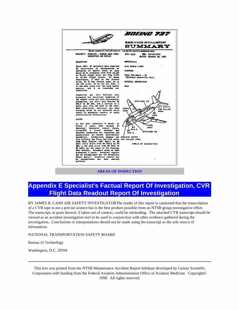
This text was printed from the NTSB Maintenance Accident Report Infobase developed by Galaxy ScientificCorporation with funding from the Federal Aviation Administration Office of Aviation Medicine. Copyright©
1998. All rights reserved.
AREAS OF INSPECTION
Appendix E Specialist's Factual Report Of Investigation, CVRFlight Data Readout Report Of Investigation
BY JAMES R. CASH AIR SAFETY INVESTIGATORThe reader of this report is cautioned that the transcriptionof a CVR tape is not a precise science but is the best product possible from an NTSB group investigative effort.The transcript, or parts thereof, if taken out of context, could be misleading. The attached CVR transcript should beviewed as an accident investigation tool to be used in conjunction with other evidence gathered during theinvestigation. Conclusions or interpretations should not be made using the transcript as the sole source ofinformation.
NATIONAL TRANSPORTATION SAFETY BOARD
Bureau of Technology
Washington, D.C. 20594
This text was printed from the NTSB Maintenance Accident Report Infobase developed by Galaxy ScientificCorporation with funding from the Federal Aviation Administration Office of Aviation Medicine. Copyright©
1998. All rights reserved.
May 26, 1988
GROUP CHAIRMAN'S FACTUAL REPORT OF INVESTIGATION COCKPIT VOICE RECORDERDCAMA88054
A. AccidentLocation: Near Maui, Hawaii
Date: April 28, 1988
Time: 1346 Hawaii Standard Time (HST)
Aircraft: Aloha Airlines, Boeing 737, N73711
B. GroupJames R. Cash, National Transportation Safety Board Chairman Quentin J. Smith, Federal Aviation AdministrationMember Barry A. Kane, Airline Pilots Assoc., Aloha Airlines Member.
C. SummaryA Collins Model 642C-1 Cockpit Voice Recorder (CVR) SN 54 was brought to the audio laboratory of the NationalTransportation Safety Board. A transcript was prepared of the final 16 minutes of the fair quality 32 minuterecording (attached).
D. Details Of InvestigationThe CVR Recording starts at 1328:11 Hawaiian Standard Time (HST) just as the flight crew is receiving theirtakeoff information from dispatch at Hilo Airport. The flying crew performed their taxi checklist at 1329:05 HSTwhich included setting the aircraft's air-conditioning and pressurization to flight. The flight progressed normallyduring the takeoff and initial climb to their assigned altitude of FL240. There were no conversations on the CVRthat pertained to pressurization problems during takeoff or climb. The transcripts starts at 1344:22 HST andcontinues until the end of tape at 1359:57.5 HST. The ambient background noise recorded on the cockpit area mikeincreased drastically at 1345:43 HST. After the increase in the background noise there were no inter-cockpitconversations identified until 1349:32 HST. The intelligibility of the inter-cockpit conversations was low due to thehigh level of wind and background noise present in the cockpit after the structual failure. Once the aircraftdescended and slowed down on final approach the intelligibility of the crew conversations increased.
The flight crew reviewed the group's transcript on May 11, 1988 and suggested the following corrections andadditions:

This text was printed from the NTSB Maintenance Accident Report Infobase developed by Galaxy ScientificCorporation with funding from the Federal Aviation Administration Office of Aviation Medicine. Copyright©
1998. All rights reserved.
TIME CONTENT
1344:56 CAM-3 well--we have friends celebrating their50th anniversary
1353:16 CAM-1 they've picked up some of your*transmissions right there I think that they canhear your but they can't hear me.
1353:18 CAM-2 allright
1353:27 CAM-2 allright
1355:09 CAM-1 pull the manual*
1356:54 CAM-1 figure a * be a partial flap setting andhold that for * final*
1357:15 CAM-2 the very back
1357:18 CAM-1 no * * next to the take the asymmetricalflaps partial
1358:07 CAM-1 one fifty bug
1358:23 CAM-2 want me to go flaps forty - help you withthe brakes.
1358:38 CAM-1 they'll follow
1358:45 CAM-2 one reverse
1358:46 CAM-2 no thrust reverser
1358:48 CAM-1 * * okay shut put it down
1358:50 CAM-1 (Delete statement)
1358:52 CAM-1 no *** the left engine
1359:05 CAM-1 okay *** the emergency evacuation
1359:07 ((sound similar to ACM seat noises))
1359:18 CAM-1 okay everybody who * get out I'll gothrough it you go
1359:29 *how do you get this up
This text was printed from the NTSB Maintenance Accident Report Infobase developed by Galaxy ScientificCorporation with funding from the Federal Aviation Administration Office of Aviation Medicine. Copyright©
1998. All rights reserved.
1359:49 CAM-1 the APU I had running so we might as wellfire that one too
1359:53 CAM-2 fire extinguishers are discharged.
James R. CashElectronics Engineer
TRANSCRIPT OF A COLLINS MODEL 642C-1 COCKPIT VOICE RECORDER S/N 54 REMOVED FROMALOHA AIRLINES BOEING 737 WHICH WAS INVOLVED IN AN ACCIDENT ON APRIL 28, 1988, NEARMAUI, HAWAII
CAM Cockpit area microphone voice or sound source
RDO Radio transmission from accident aircraft
-1 Voice identified as Captain
-2 Voice identified as First Officer
-3 Voice identified as Jumpseat Passenger
-? Voice unidentified
TWR Kahului Local Air Traffic Control (Tower)
UNK Unknown
* Unintelligible word
@ Nonpertinent word
# Expletive deleted
% Break in continuity
() Questionable text
(()) Editorial insertion
Pause
All times are expressed in Hawaii Standard Time only those radio transmissions to and from the accident aircraftwere transcribed.
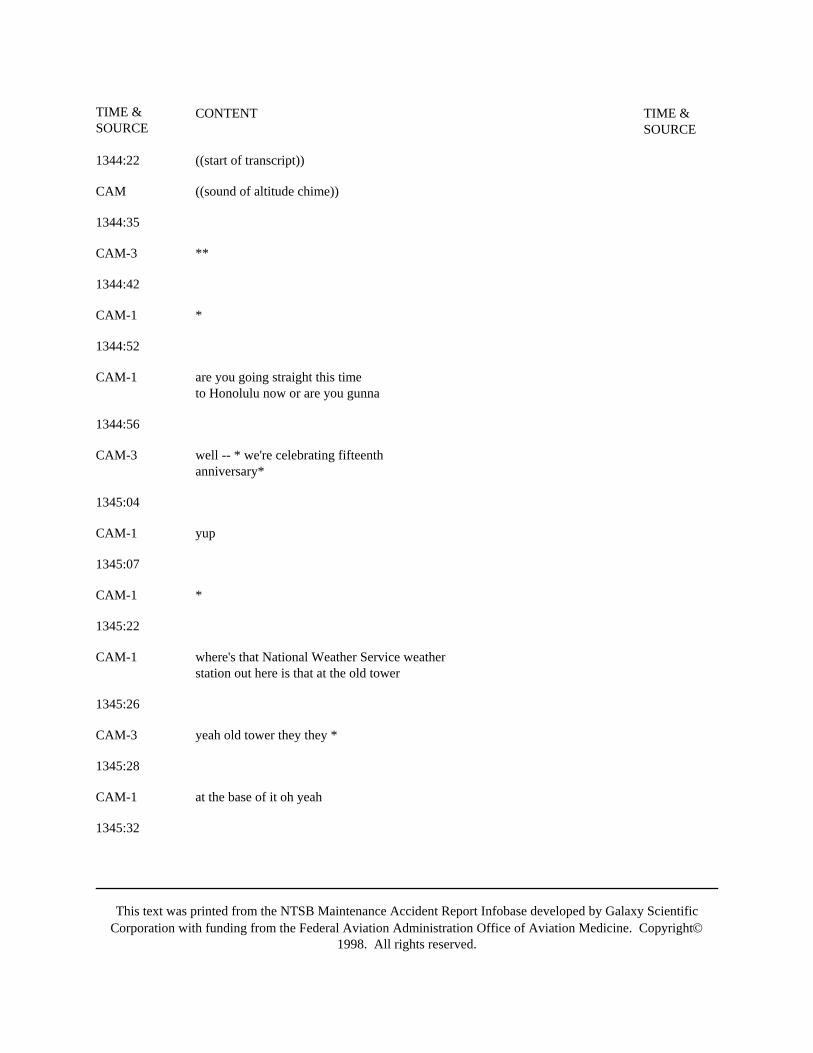
This text was printed from the NTSB Maintenance Accident Report Infobase developed by Galaxy ScientificCorporation with funding from the Federal Aviation Administration Office of Aviation Medicine. Copyright©
1998. All rights reserved.
TIME &SOURCE
CONTENT TIME &SOURCE
1344:22 ((start of transcript))
CAM ((sound of altitude chime))
1344:35
CAM-3 **
1344:42
CAM-1 *
1344:52
CAM-1 are you going straight this timeto Honolulu now or are you gunna
1344:56
CAM-3 well -- * we're celebrating fifteenthanniversary*
1345:04
CAM-1 yup
1345:07
CAM-1 *
1345:22
CAM-1 where's that National Weather Service weatherstation out here is that at the old tower
1345:26
CAM-3 yeah old tower they they *
1345:28
CAM-1 at the base of it oh yeah
1345:32

This text was printed from the NTSB Maintenance Accident Report Infobase developed by Galaxy ScientificCorporation with funding from the Federal Aviation Administration Office of Aviation Medicine. Copyright©
1998. All rights reserved.
CAM-1 they don't have any radiosor anything * or any air toground radios do they
1345:38
CAM-3 *
1345:43
CAM ((sound of increased wind noise))
1345:44
CAM-? ((sound of scream))
CAM ((sound of dramatic increase in cockpitwind noise))
((no cockpit conversations wereheard till 1349:32))
((all radio transmissions were madeusing the oxygen mask microphone until1349:57))
1346:13
RDO-2
1346:44
RDO-2
1346:55
RDO-2
1347:25
RDO-2
1347:44
RDO-2
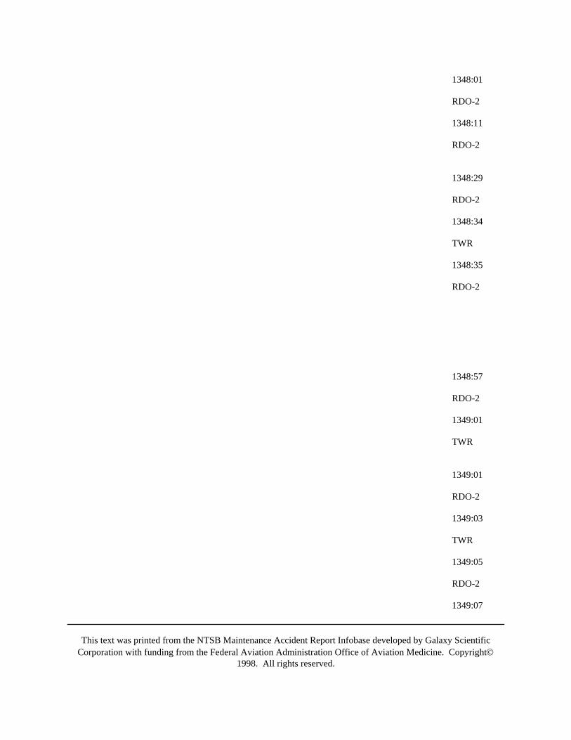
This text was printed from the NTSB Maintenance Accident Report Infobase developed by Galaxy ScientificCorporation with funding from the Federal Aviation Administration Office of Aviation Medicine. Copyright©
1998. All rights reserved.
1348:01
RDO-2
1348:11
RDO-2
1348:29
RDO-2
1348:34
TWR
1348:35
RDO-2
1348:57
RDO-2
1349:01
TWR
1349:01
RDO-2
1349:03
TWR
1349:05
RDO-2
1349:07
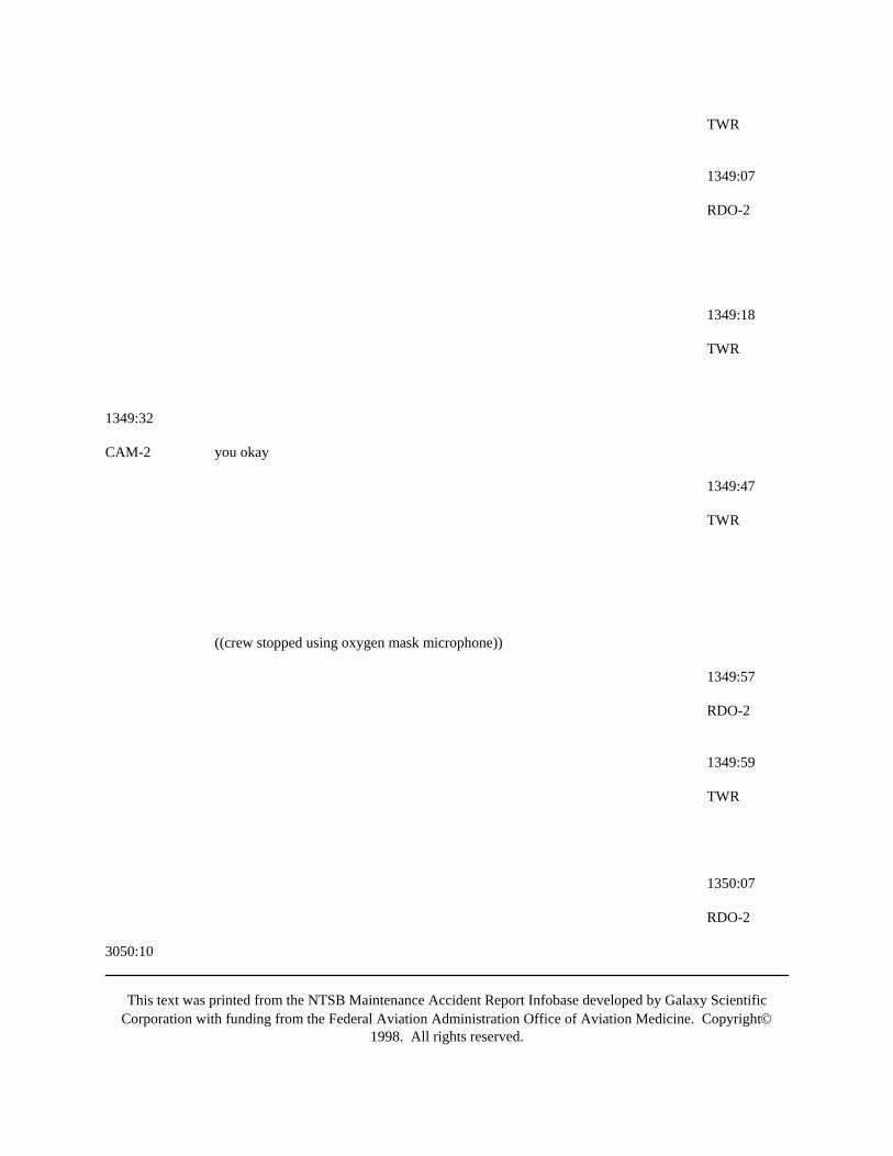
This text was printed from the NTSB Maintenance Accident Report Infobase developed by Galaxy ScientificCorporation with funding from the Federal Aviation Administration Office of Aviation Medicine. Copyright©
1998. All rights reserved.
TWR
1349:07
RDO-2
1349:18
TWR
1349:32
CAM-2 you okay
1349:47
TWR
((crew stopped using oxygen mask microphone))
1349:57
RDO-2
1349:59
TWR
1350:07
RDO-2
3050:10

This text was printed from the NTSB Maintenance Accident Report Infobase developed by Galaxy ScientificCorporation with funding from the Federal Aviation Administration Office of Aviation Medicine. Copyright©
1998. All rights reserved.
CAM-2 *
1350:41
CAM-2 do you want me to call for anything else
1350:43
CAM-1 nope
1350:54
CAM-2 *
1351:00
TWR
1351:04
RDO-2
1351:07
RDO-2
1351:19
RDO-2
1351:30
((sound of engine ignition whine starts))
1351:48
CAM-1 *
1351:51
CAM-3 I'm fine
1352:10
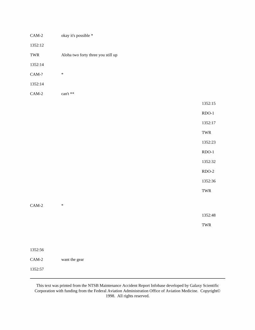
This text was printed from the NTSB Maintenance Accident Report Infobase developed by Galaxy ScientificCorporation with funding from the Federal Aviation Administration Office of Aviation Medicine. Copyright©
1998. All rights reserved.
CAM-2 okay it's possible *
1352:12
TWR Aloha two forty three you still up
1352:14
CAM-? *
1352:14
CAM-2 can't **
1352:15
RDO-1
1352:17
TWR
1352:23
RDO-1
1352:32
RDO-2
1352:36
TWR
CAM-2 *
1352:48
TWR
1352:56
CAM-2 want the gear
1352:57
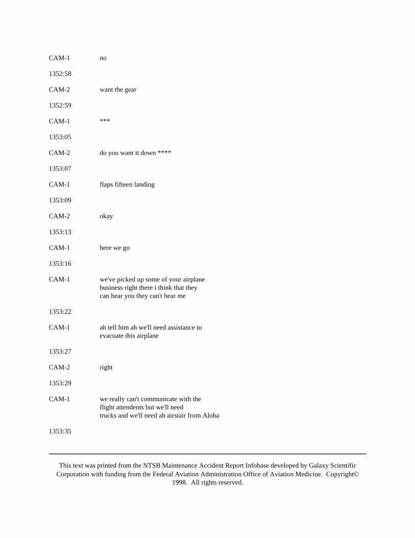
This text was printed from the NTSB Maintenance Accident Report Infobase developed by Galaxy ScientificCorporation with funding from the Federal Aviation Administration Office of Aviation Medicine. Copyright©
1998. All rights reserved.
CAM-1 no
1352:58
CAM-2 want the gear
1352:59
CAM-1 ***
1353:05
CAM-2 do you want it down ****
1353:07
CAM-1 flaps fifteen landing
1353:09
CAM-2 okay
1353:13
CAM-1 here we go
1353:16
CAM-1 we've picked up some of your airplanebusiness right there i think that theycan hear you they can't hear me
1353:22
CAM-1 ah tell him ah we'll need assistance toevacuate this airplane
1353:27
CAM-2 right
1353:29
CAM-1 we really can't communicate with theflight attendents but we'll needtrucks and we'll need ah airstair from Aloha
1353:35

This text was printed from the NTSB Maintenance Accident Report Infobase developed by Galaxy ScientificCorporation with funding from the Federal Aviation Administration Office of Aviation Medicine. Copyright©
1998. All rights reserved.
CAM-2 alright
1353:40
RDO-2
1353:42
TWR
1353:44
RDO-2
1353:52
TWR
1353:57
RDO-2
1354:14
CAM-1 feels like manual reversion
1354:17
CAM-2 what
1354:18
CAM-1 flight controls feels like manualreversion
1354:23
CAM-1 *
1354:25

This text was printed from the NTSB Maintenance Accident Report Infobase developed by Galaxy ScientificCorporation with funding from the Federal Aviation Administration Office of Aviation Medicine. Copyright©
1998. All rights reserved.
CAM-2 well we could * the hole
1354:26
CAM-1 I know it yeah
1354:28
CAM-1 ah
1354:30
CAM-2 can we maintain altitude okay
1354:31
CAM-1 let's try flying let's try flying with the gear downhere
1354:34
CAM-2 alright you got it
1354:37
CAM ((sound of gear being lowered))
1354:42
TWR
1354:45
CAM-1 do you have a passenger count for tower
1354:47
RDO-2
1354:52
TWR
1354:53
CAM-2 they still don't understand

This text was printed from the NTSB Maintenance Accident Report Infobase developed by Galaxy ScientificCorporation with funding from the Federal Aviation Administration Office of Aviation Medicine. Copyright©
1998. All rights reserved.
1354:56
RDO-2
1354:59
TWR
1355:00
RDO-2
1355:02
TWR
1355:06
RDO-2
1355:09
CAM-1 *
1355:31
CAM-1 how far how far till we intercept
1355:39
CAM-2 down here
1355:41
CAM-1 yeah back me up for now
1355:52
CAM-1 tell him we got such problems but weare going to land anyway - even withouta nose gear - but they should be awareof we do not have a safe nose gear downindication
1356:02
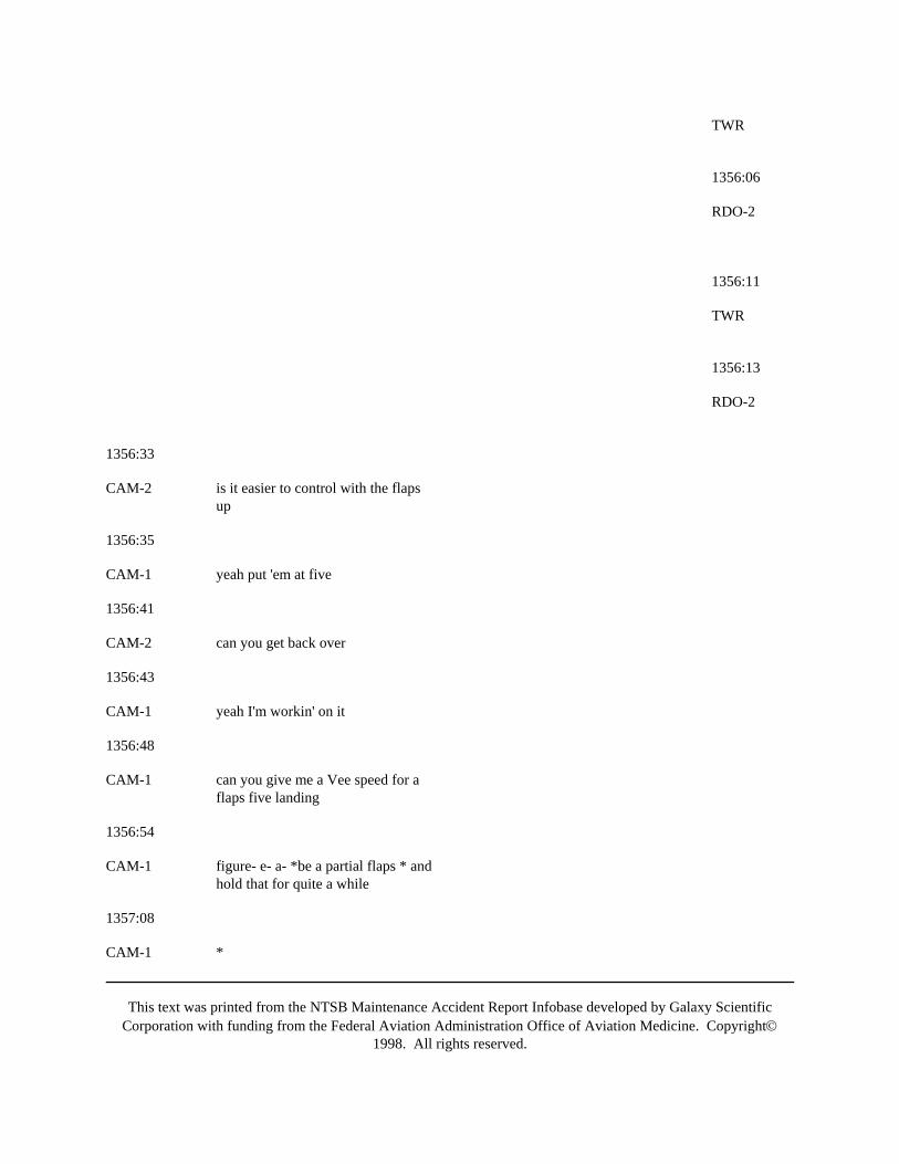
This text was printed from the NTSB Maintenance Accident Report Infobase developed by Galaxy ScientificCorporation with funding from the Federal Aviation Administration Office of Aviation Medicine. Copyright©
1998. All rights reserved.
TWR
1356:06
RDO-2
1356:11
TWR
1356:13
RDO-2
1356:33
CAM-2 is it easier to control with the flapsup
1356:35
CAM-1 yeah put 'em at five
1356:41
CAM-2 can you get back over
1356:43
CAM-1 yeah I'm workin' on it
1356:48
CAM-1 can you give me a Vee speed for aflaps five landing
1356:54
CAM-1 figure- e- a- *be a partial flaps * andhold that for quite a while
1357:08
CAM-1 *
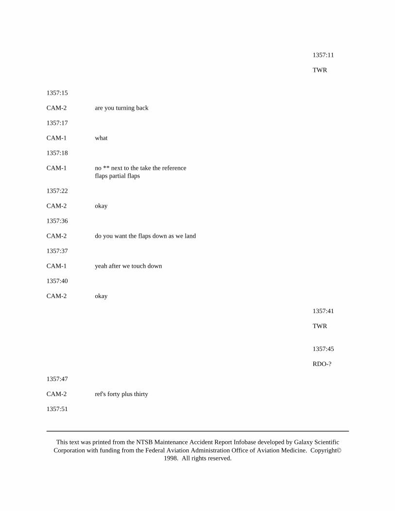
This text was printed from the NTSB Maintenance Accident Report Infobase developed by Galaxy ScientificCorporation with funding from the Federal Aviation Administration Office of Aviation Medicine. Copyright©
1998. All rights reserved.
1357:11
TWR
1357:15
CAM-2 are you turning back
1357:17
CAM-1 what
1357:18
CAM-1 no ** next to the take the referenceflaps partial flaps
1357:22
CAM-2 okay
1357:36
CAM-2 do you want the flaps down as we land
1357:37
CAM-1 yeah after we touch down
1357:40
CAM-2 okay
1357:41
TWR
1357:45
RDO-?
1357:47
CAM-2 ref's forty plus thirty
1357:51
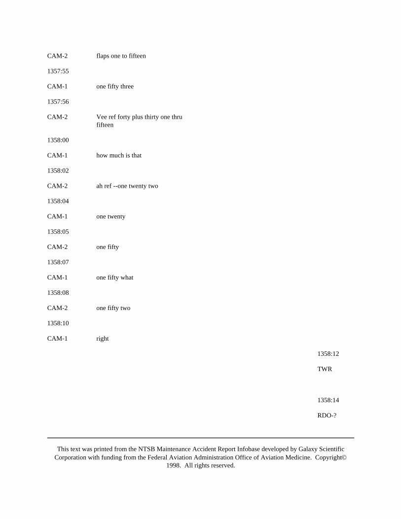
This text was printed from the NTSB Maintenance Accident Report Infobase developed by Galaxy ScientificCorporation with funding from the Federal Aviation Administration Office of Aviation Medicine. Copyright©
1998. All rights reserved.
CAM-2 flaps one to fifteen
1357:55
CAM-1 one fifty three
1357:56
CAM-2 Vee ref forty plus thirty one thrufifteen
1358:00
CAM-1 how much is that
1358:02
CAM-2 ah ref --one twenty two
1358:04
CAM-1 one twenty
1358:05
CAM-2 one fifty
1358:07
CAM-1 one fifty what
1358:08
CAM-2 one fifty two
1358:10
CAM-1 right
1358:12
TWR
1358:14
RDO-?
This text was printed from the NTSB Maintenance Accident Report Infobase developed by Galaxy ScientificCorporation with funding from the Federal Aviation Administration Office of Aviation Medicine. Copyright©
1998. All rights reserved.
1358:23
CAM-2 want me to go flaps forty - help you to *
1358:25
CAM-1 no
1358:27
CAM-2 okay
1358:28
CAM-1 on the ground
1358:38
CAM-1 ( they'll find)
1358:42
CAM ((sound of touchdown))
1358:45
CAM-2 one reverse no -
1358:46
CAM-1 okay
CAM-2 thrust reverser
1358:48
CAM-1 okay shut it down
1358:49
CAM-2 shut it down
1358:50
CAM-1 yup
1358:52
CAM-1 now ** left engine
This text was printed from the NTSB Maintenance Accident Report Infobase developed by Galaxy ScientificCorporation with funding from the Federal Aviation Administration Office of Aviation Medicine. Copyright©
1998. All rights reserved.
1358:54
CAM-2 flaps
1358:55
TWR
1359:01
CAM-1 okay
1359:01
((sound of engine ignition whine stops))
1359:05
CAM-2 that's off
CAM-1 okay start * call for the emergencyevacuation
1359:06
CAM ((sound of engine winding down))
1359:12
CAM-1 the flaps are down good
1359:17
CAM-1 go through the checklist and stuff
1359:18
CAM-1 okay everybody who can get out I'llgo through it you go out the steps
1359:22
CAM-2 do you want me to help them
1359:25

This text was printed from the NTSB Maintenance Accident Report Infobase developed by Galaxy ScientificCorporation with funding from the Federal Aviation Administration Office of Aviation Medicine. Copyright©
1998. All rights reserved.
CAM-1 let's see where it is
1359:29
CAM-3 how do you get this up
1359:32
CAM-1 ah squeeze it together squeeze ittogether squeeze the top togetherwith the bottom
1359:37
CAM-3 okay
1359:38
CAM-2 parking brake
1359:39
CAM-1 set
1359:45
CAM-1 stowed speedbrakes emergency evacuationfire
1359:45
CAM-1 ah does it say fire the bottles anywhereokay we won't do that I'll get this oneyou get that one
1359:49
CAM-1 the APU I had running so we might aswell throttle that one too
1359:53
CAM-2 *
CAM-1 I'm gunna' shut off the APU now
1359:56
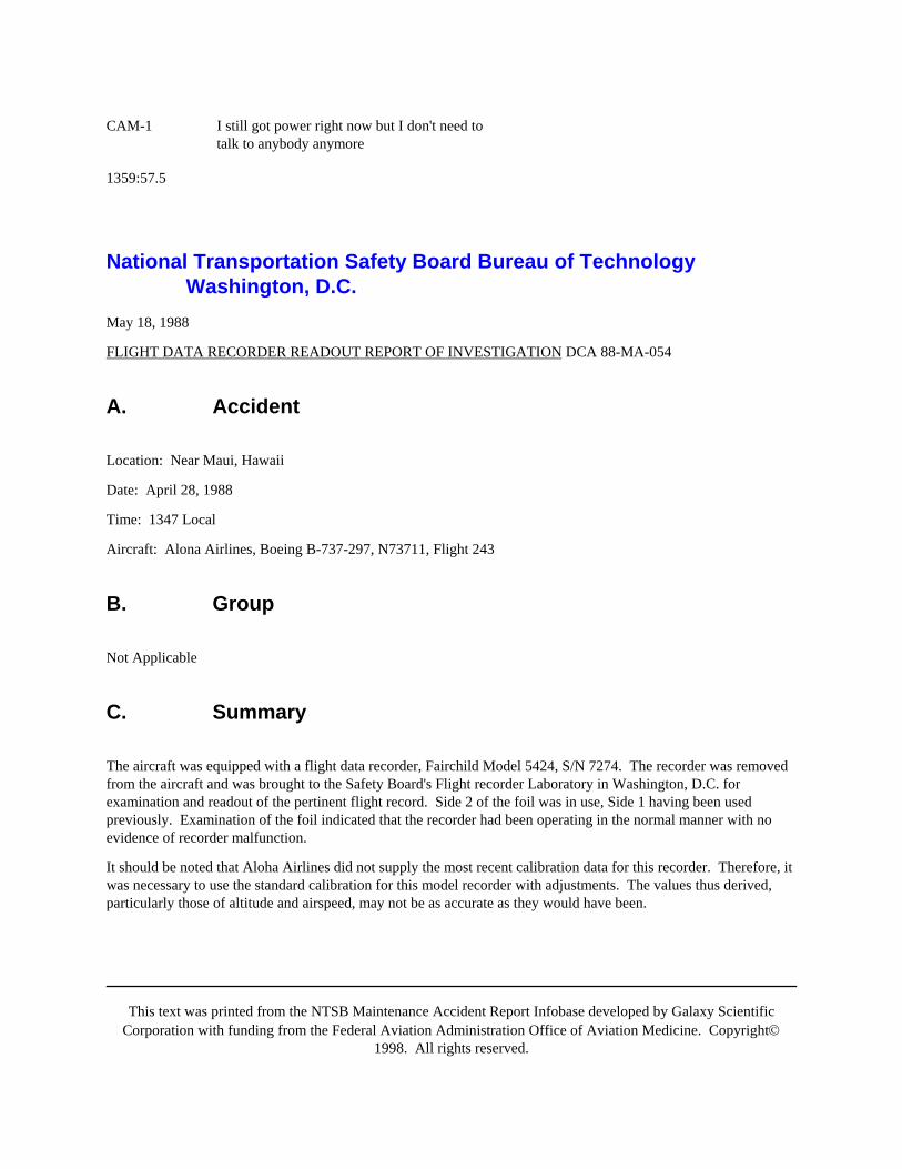
This text was printed from the NTSB Maintenance Accident Report Infobase developed by Galaxy ScientificCorporation with funding from the Federal Aviation Administration Office of Aviation Medicine. Copyright©
1998. All rights reserved.
CAM-1 I still got power right now but I don't need totalk to anybody anymore
1359:57.5
National Transportation Safety Board Bureau of TechnologyWashington, D.C.
May 18, 1988
FLIGHT DATA RECORDER READOUT REPORT OF INVESTIGATION DCA 88-MA-054
A. Accident
Location: Near Maui, Hawaii
Date: April 28, 1988
Time: 1347 Local
Aircraft: Alona Airlines, Boeing B-737-297, N73711, Flight 243
B. Group
Not Applicable
C. Summary
The aircraft was equipped with a flight data recorder, Fairchild Model 5424, S/N 7274. The recorder was removedfrom the aircraft and was brought to the Safety Board's Flight recorder Laboratory in Washington, D.C. forexamination and readout of the pertinent flight record. Side 2 of the foil was in use, Side 1 having been usedpreviously. Examination of the foil indicated that the recorder had been operating in the normal manner with noevidence of recorder malfunction.
It should be noted that Aloha Airlines did not supply the most recent calibration data for this recorder. Therefore, itwas necessary to use the standard calibration for this model recorder with adjustments. The values thus derived,particularly those of altitude and airspeed, may not be as accurate as they would have been.
This text was printed from the NTSB Maintenance Accident Report Infobase developed by Galaxy ScientificCorporation with funding from the Federal Aviation Administration Office of Aviation Medicine. Copyright©
1998. All rights reserved.
D. Details Of Examination
It was reported that the aircraft was climbing to cruise and was passing through the area of 24,000 feet pressurealtitude when the ceiling area of the forward passenger cabin burst open in explosive decompression. The aircraftwas kept under control by the flight crew and an emergency landing was made in Maui.
Examination of the recorded traces showed the flight to be relatively smooth from the point of liftoff to theoccurrence. The airspeed trace ceased abruptly and dropped to a position below zero KIAS and remained there untilelectric power was removed. The other parameter styli appeared to operate in the normal manner; however, theywere affected by the vibration as shown on the graph attached. The airspeed trace, in its bottomed-out position,showed the effects of this vibration also. The "G" force measured at the emergency landing was 2.4g which is onlya change of 1.4g from an at rest position.
The readout results and a graphic display of those results are attached as part of this report.
Billy M. HopperAir Safety Investigator
ATTACHMENTS:
1. Readout Data
2. Readout Graph
3. Ground Measurements and Styli Offsets
4. Recorder Calibration Data
5. Photograph of Foil Medium and Traces
Attachment 1
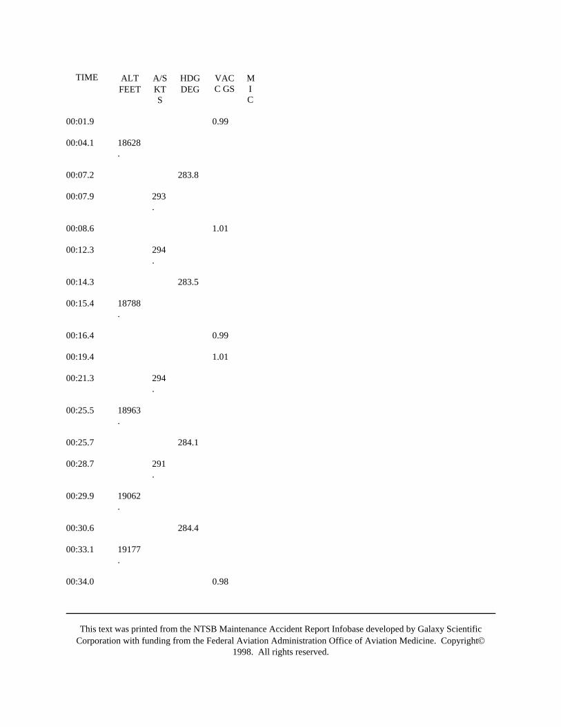
This text was printed from the NTSB Maintenance Accident Report Infobase developed by Galaxy ScientificCorporation with funding from the Federal Aviation Administration Office of Aviation Medicine. Copyright©
1998. All rights reserved.
TIME ALTFEET
A/SKTS
HDGDEG
VACC GS
MIC
00:01.9 0.99
00:04.1 18628.
00:07.2 283.8
00:07.9 293.
00:08.6 1.01
00:12.3 294.
00:14.3 283.5
00:15.4 18788.
00:16.4 0.99
00:19.4 1.01
00:21.3 294.
00:25.5 18963.
00:25.7 284.1
00:28.7 291.
00:29.9 19062.
00:30.6 284.4
00:33.1 19177.
00:34.0 0.98

This text was printed from the NTSB Maintenance Accident Report Infobase developed by Galaxy ScientificCorporation with funding from the Federal Aviation Administration Office of Aviation Medicine. Copyright©
1998. All rights reserved.
00:37.0 1.00
00:37.3 283.9
00:38.0 19252.
00:40.9 292.
00:43.2 19308.
00:45.8 283.7
00:52.4 292.
00:57.5 283.1
00:59.3 19600.
01:03.8 1.00
01:04.2 282.9
01:04.5 19727.
01:08.5 291.
01:11.6 19883.
01:12.5 1.00
01:14.3 290.
01:17.0 0.98
01:18.6 281.9
01:21.5 20107.
01:25.3 281.6
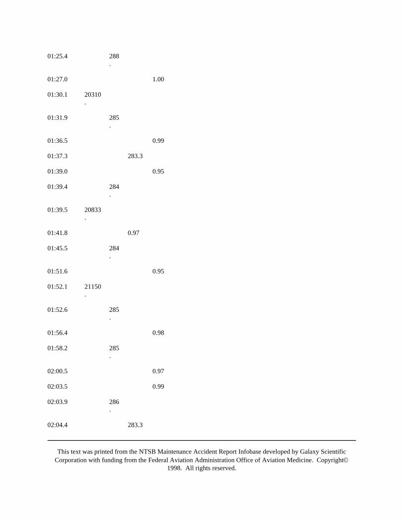
This text was printed from the NTSB Maintenance Accident Report Infobase developed by Galaxy ScientificCorporation with funding from the Federal Aviation Administration Office of Aviation Medicine. Copyright©
1998. All rights reserved.
01:25.4 288.
01:27.0 1.00
01:30.1 20310.
01:31.9 285.
01:36.5 0.99
01:37.3 283.3
01:39.0 0.95
01:39.4 284.
01:39.5 20833.
01:41.8 0.97
01:45.5 284.
01:51.6 0.95
01:52.1 21150.
01:52.6 285.
01:56.4 0.98
01:58.2 285.
02:00.5 0.97
02:03.5 0.99
02:03.9 286.
02:04.4 283.3
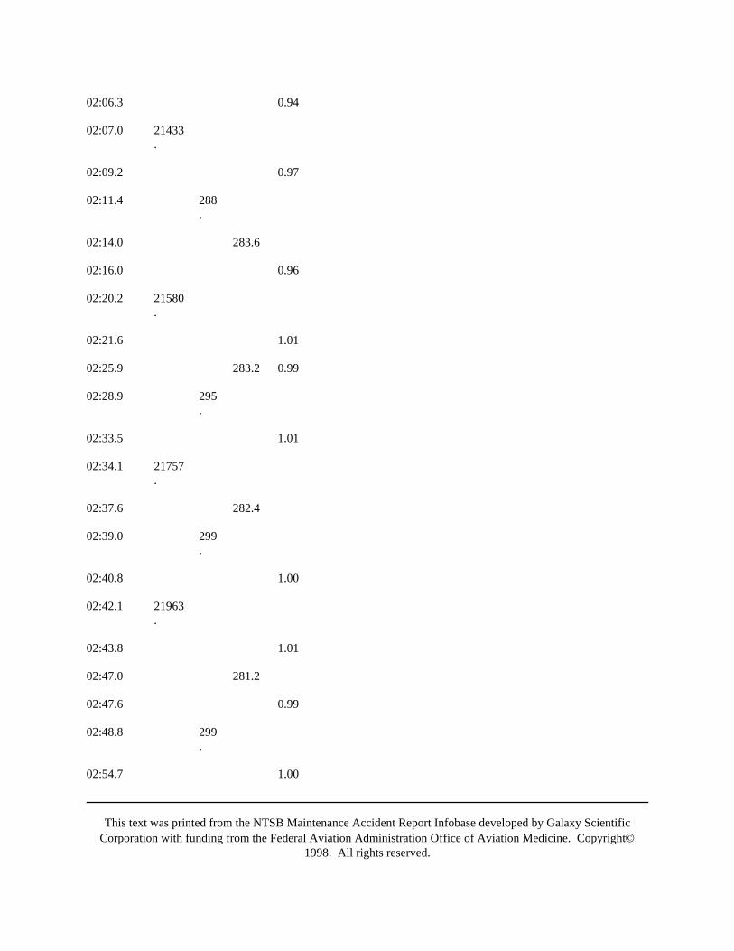
This text was printed from the NTSB Maintenance Accident Report Infobase developed by Galaxy ScientificCorporation with funding from the Federal Aviation Administration Office of Aviation Medicine. Copyright©
1998. All rights reserved.
02:06.3 0.94
02:07.0 21433.
02:09.2 0.97
02:11.4 288.
02:14.0 283.6
02:16.0 0.96
02:20.2 21580.
02:21.6 1.01
02:25.9 283.2 0.99
02:28.9 295.
02:33.5 1.01
02:34.1 21757.
02:37.6 282.4
02:39.0 299.
02:40.8 1.00
02:42.1 21963.
02:43.8 1.01
02:47.0 281.2
02:47.6 0.99
02:48.8 299.
02:54.7 1.00
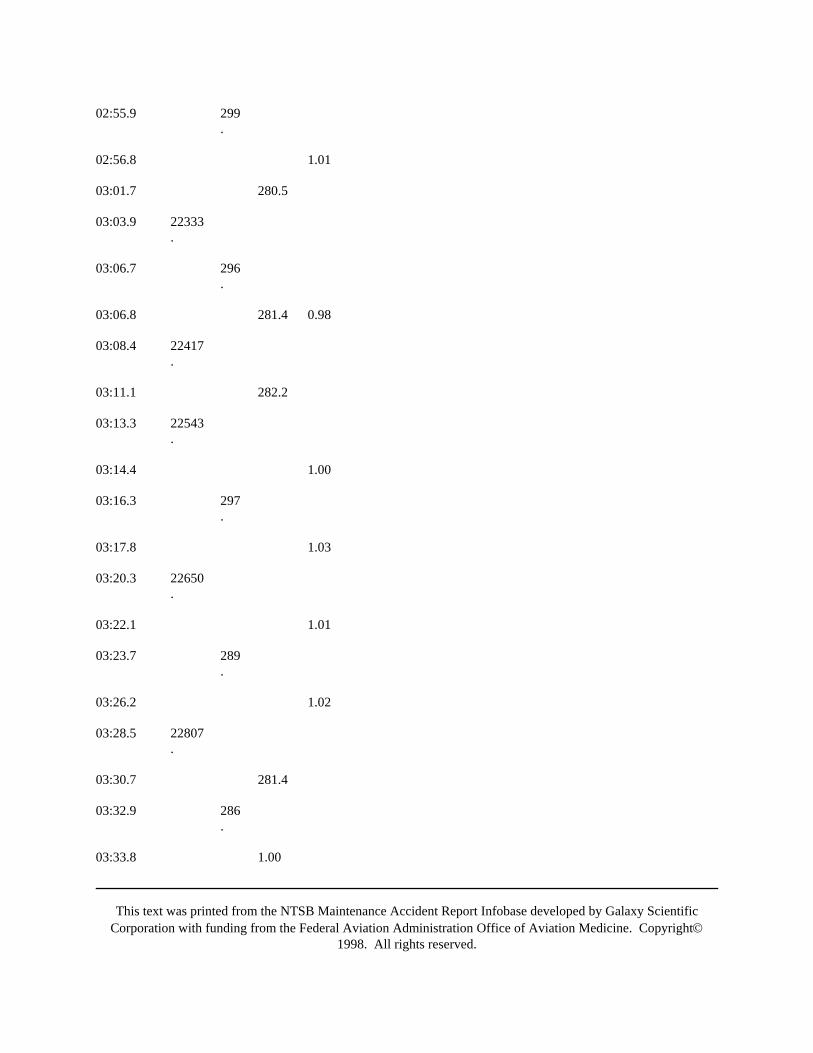
This text was printed from the NTSB Maintenance Accident Report Infobase developed by Galaxy ScientificCorporation with funding from the Federal Aviation Administration Office of Aviation Medicine. Copyright©
1998. All rights reserved.
02:55.9 299.
02:56.8 1.01
03:01.7 280.5
03:03.9 22333.
03:06.7 296.
03:06.8 281.4 0.98
03:08.4 22417.
03:11.1 282.2
03:13.3 22543.
03:14.4 1.00
03:16.3 297.
03:17.8 1.03
03:20.3 22650.
03:22.1 1.01
03:23.7 289.
03:26.2 1.02
03:28.5 22807.
03:30.7 281.4
03:32.9 286.
03:33.8 1.00
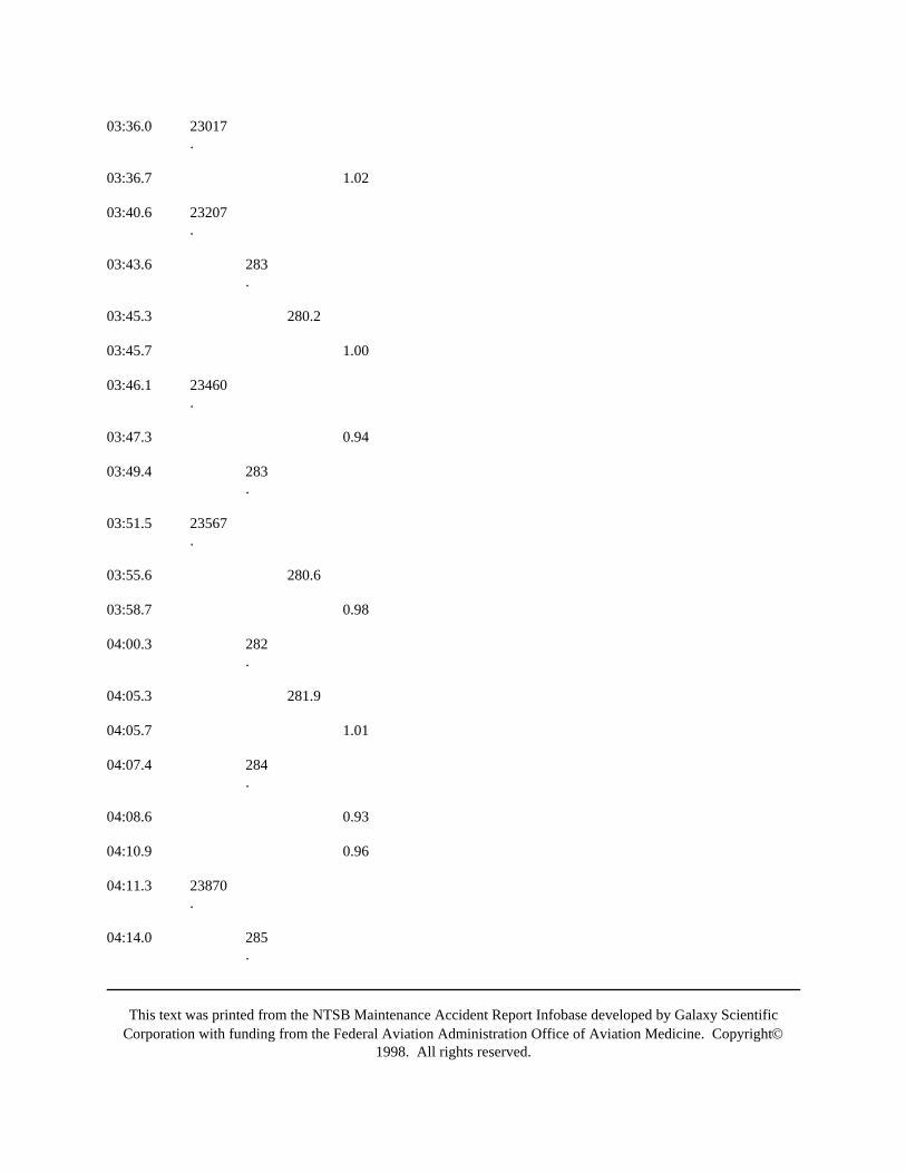
This text was printed from the NTSB Maintenance Accident Report Infobase developed by Galaxy ScientificCorporation with funding from the Federal Aviation Administration Office of Aviation Medicine. Copyright©
1998. All rights reserved.
03:36.0 23017.
03:36.7 1.02
03:40.6 23207.
03:43.6 283.
03:45.3 280.2
03:45.7 1.00
03:46.1 23460.
03:47.3 0.94
03:49.4 283.
03:51.5 23567.
03:55.6 280.6
03:58.7 0.98
04:00.3 282.
04:05.3 281.9
04:05.7 1.01
04:07.4 284.
04:08.6 0.93
04:10.9 0.96
04:11.3 23870.
04:14.0 285.
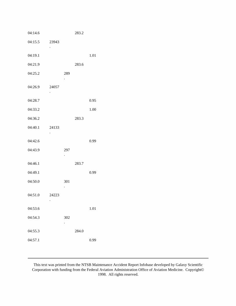
This text was printed from the NTSB Maintenance Accident Report Infobase developed by Galaxy ScientificCorporation with funding from the Federal Aviation Administration Office of Aviation Medicine. Copyright©
1998. All rights reserved.
04:14.6 283.2
04:15.5 23943.
04:19.1 1.01
04:21.9 283.6
04:25.2 289.
04:26.9 24057.
04:28.7 0.95
04:33.2 1.00
04:36.2 283.3
04:40.1 24133.
04:42.6 0.99
04:43.9 297.
04:46.1 283.7
04:49.1 0.99
04:50.0 301.
04:51.0 24223.
04:53.6 1.01
04:54.3 302.
04:55.3 284.0
04:57.1 0.99
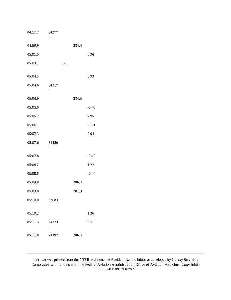
This text was printed from the NTSB Maintenance Accident Report Infobase developed by Galaxy ScientificCorporation with funding from the Federal Aviation Administration Office of Aviation Medicine. Copyright©
1998. All rights reserved.
04:57.7 24277.
04:59.9 284.4
05:01.5 0.96
05:03.1 303.
05:04.5 0.93
05:04.6 24317.
05:04.9 284.5
05:05.0 -0.48
05:06.2 2.95
05:06.7 -0.31
05:07.3 2.94
05:07.6 24450.
05:07.8 -0.42
05:08.2 1.22
05:08.6 -0.44
05:09.8 286.4
05:09.8 281.3
05:10.0 23683.
05:10.2 1.36
05:11.3 24373.
0.51
05:11.8 24397.
286.4
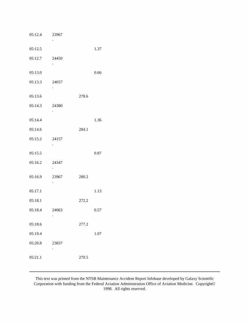
This text was printed from the NTSB Maintenance Accident Report Infobase developed by Galaxy ScientificCorporation with funding from the Federal Aviation Administration Office of Aviation Medicine. Copyright©
1998. All rights reserved.
05:12.4 23967.
05:12.5 1.37
05:12.7 24450.
05:13.0 0.66
05:13.3 24057.
05:13.6 278.6
05:14.3 24380.
05:14.4 1.36
05:14.6 284.1
05:15.2 24157.
05:15.5 0.87
05:16.2 24347.
05:16.9 23967.
280.2
05:17.1 1.13
05:18.1 272.2
05:18.4 24063.
0.57
05:18.6 277.2
05:19.4 1.07
05:20.8 23837.
05:21.1 270.5
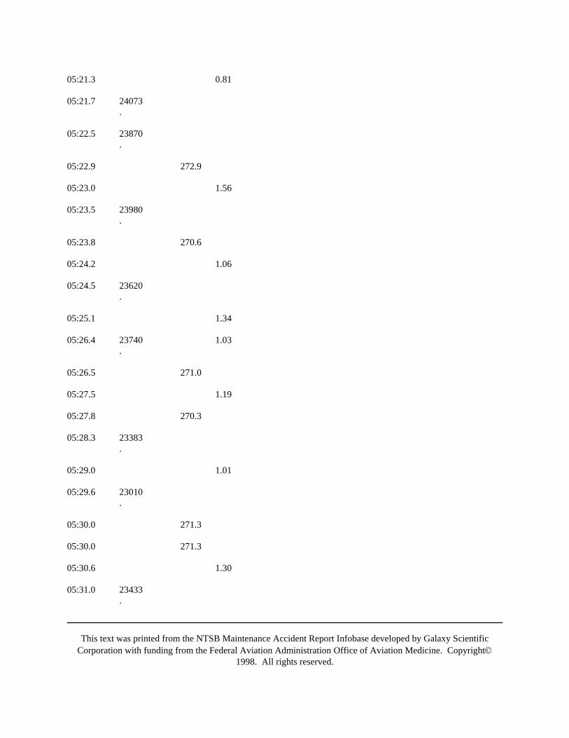
This text was printed from the NTSB Maintenance Accident Report Infobase developed by Galaxy ScientificCorporation with funding from the Federal Aviation Administration Office of Aviation Medicine. Copyright©
1998. All rights reserved.
05:21.3 0.81
05:21.7 24073.
05:22.5 23870.
05:22.9 272.9
05:23.0 1.56
05:23.5 23980.
05:23.8 270.6
05:24.2 1.06
05:24.5 23620.
05:25.1 1.34
05:26.4 23740.
1.03
05:26.5 271.0
05:27.5 1.19
05:27.8 270.3
05:28.3 23383.
05:29.0 1.01
05:29.6 23010.
05:30.0 271.3
05:30.0 271.3
05:30.6 1.30
05:31.0 23433.

This text was printed from the NTSB Maintenance Accident Report Infobase developed by Galaxy ScientificCorporation with funding from the Federal Aviation Administration Office of Aviation Medicine. Copyright©
1998. All rights reserved.
05:32.4 270.8
05:32.6 1.08
05:33.1 23093.
05:33.7 1.28
05:34.4 271.8
05:34.8 23243.
05:35.5 1.01
05:35.9 22783.
05:36.4 1.27
05:36.5 23030.
05:37.0 0.99
05:37.6 271.4
05:37.9 22617.
05:38.3 22790.
05:38.5 1.22
05:39.8 22310.
270.4
05:39.8 22710.
05:40.0 0.95
05:40.5 22620.
05:41.5 22850.
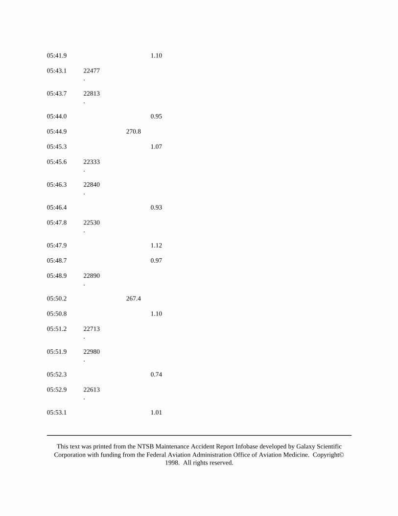
This text was printed from the NTSB Maintenance Accident Report Infobase developed by Galaxy ScientificCorporation with funding from the Federal Aviation Administration Office of Aviation Medicine. Copyright©
1998. All rights reserved.
05:41.9 1.10
05:43.1 22477.
05:43.7 22813.
05:44.0 0.95
05:44.9 270.8
05:45.3 1.07
05:45.6 22333.
05:46.3 22840.
05:46.4 0.93
05:47.8 22530.
05:47.9 1.12
05:48.7 0.97
05:48.9 22890.
05:50.2 267.4
05:50.8 1.10
05:51.2 22713.
05:51.9 22980.
05:52.3 0.74
05:52.9 22613.
05:53.1 1.01
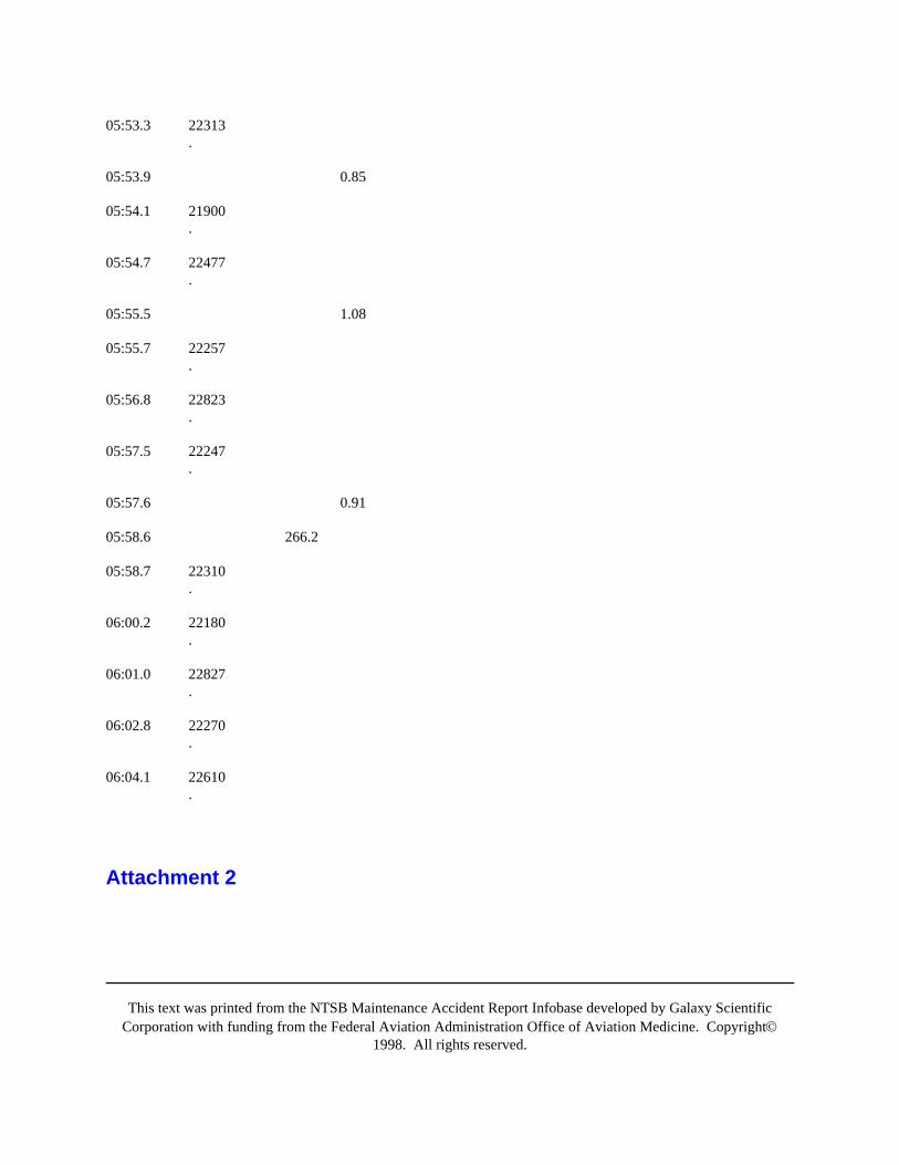
This text was printed from the NTSB Maintenance Accident Report Infobase developed by Galaxy ScientificCorporation with funding from the Federal Aviation Administration Office of Aviation Medicine. Copyright©
1998. All rights reserved.
05:53.3 22313.
05:53.9 0.85
05:54.1 21900.
05:54.7 22477.
05:55.5 1.08
05:55.7 22257.
05:56.8 22823.
05:57.5 22247.
05:57.6 0.91
05:58.6 266.2
05:58.7 22310.
06:00.2 22180.
06:01.0 22827.
06:02.8 22270.
06:04.1 22610.
Attachment 2

This text was printed from the NTSB Maintenance Accident Report Infobase developed by Galaxy ScientificCorporation with funding from the Federal Aviation Administration Office of Aviation Medicine. Copyright©
1998. All rights reserved.
Attachment 3Case No. DCA 88-M-A054
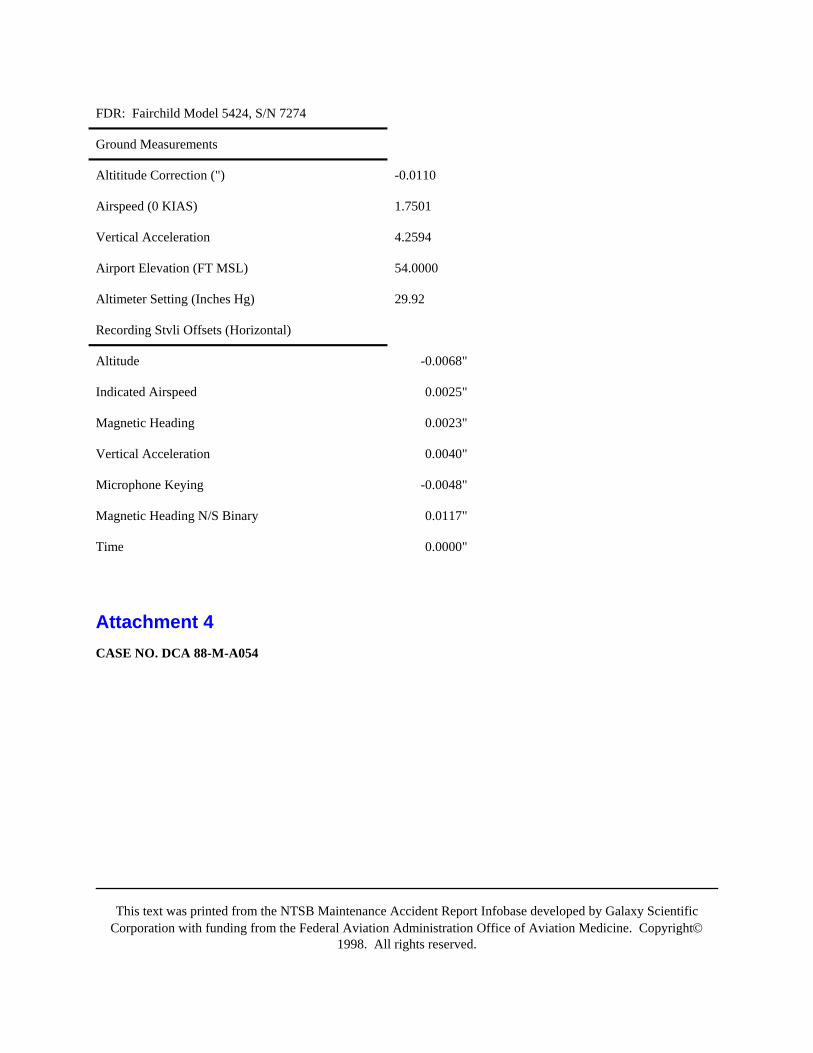
This text was printed from the NTSB Maintenance Accident Report Infobase developed by Galaxy ScientificCorporation with funding from the Federal Aviation Administration Office of Aviation Medicine. Copyright©
1998. All rights reserved.
FDR: Fairchild Model 5424, S/N 7274
Ground Measurements
Altititude Correction (") -0.0110
Airspeed (0 KIAS) 1.7501
Vertical Acceleration 4.2594
Airport Elevation (FT MSL) 54.0000
Altimeter Setting (Inches Hg) 29.92
Recording Stvli Offsets (Horizontal)
Altitude -0.0068"
Indicated Airspeed 0.0025"
Magnetic Heading 0.0023"
Vertical Acceleration 0.0040"
Microphone Keying -0.0048"
Magnetic Heading N/S Binary 0.0117"
Time 0.0000"
Attachment 4CASE NO. DCA 88-M-A054

This text was printed from the NTSB Maintenance Accident Report Infobase developed by Galaxy ScientificCorporation with funding from the Federal Aviation Administration Office of Aviation Medicine. Copyright©
1998. All rights reserved.
FDR: Fairchild Model 5424, S/N 7274
Calibration Data
Altitude Airspeed
-1000 0.1250" 0 1,7515"
0 0.1920 100 1.7825"
1000 0.2550" 150 1.8205"
2000 0.3170" 200 1.8755"
3000 0.3760" 250 1.9545"
4000 0.4350" 300 2.0445"
6000 0.5450"
8000 0.6480"
10,000 0.7430"
12,000 0.8270"
14,000 0.9310"
16,000 0.9950"
18,000 1.0160"
20,000 1.1360"
22,000 1.1960"
25,000 1.2860"
Appendix F
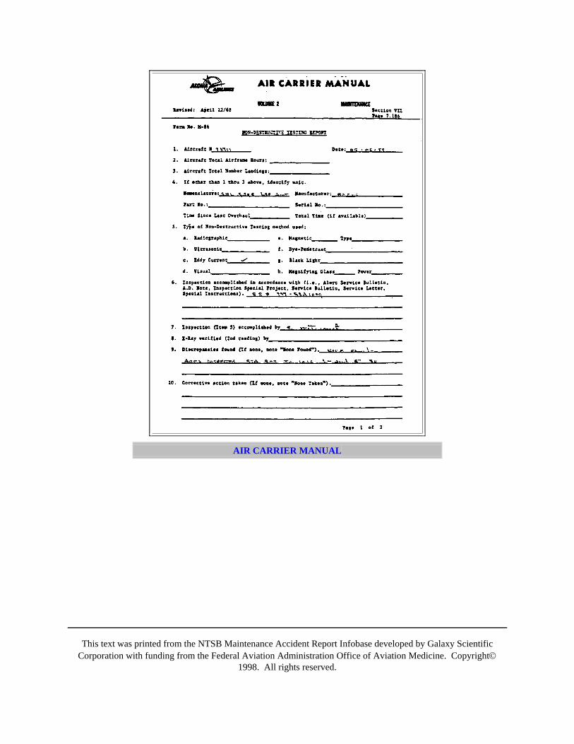
This text was printed from the NTSB Maintenance Accident Report Infobase developed by Galaxy ScientificCorporation with funding from the Federal Aviation Administration Office of Aviation Medicine. Copyright©
1998. All rights reserved.
AIR CARRIER MANUAL
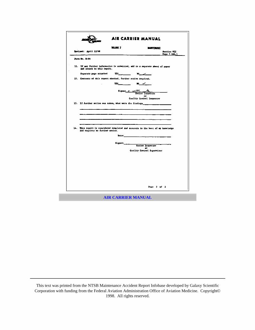
This text was printed from the NTSB Maintenance Accident Report Infobase developed by Galaxy ScientificCorporation with funding from the Federal Aviation Administration Office of Aviation Medicine. Copyright©
1998. All rights reserved.
AIR CARRIER MANUAL
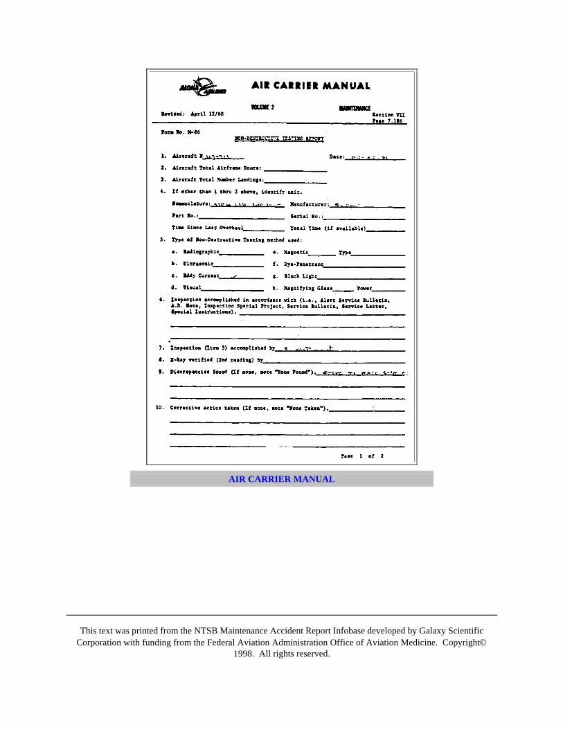
This text was printed from the NTSB Maintenance Accident Report Infobase developed by Galaxy ScientificCorporation with funding from the Federal Aviation Administration Office of Aviation Medicine. Copyright©
1998. All rights reserved.
AIR CARRIER MANUAL
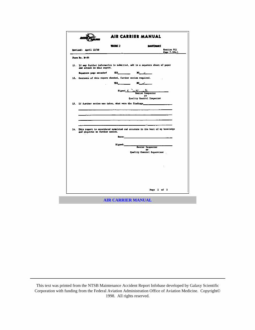
This text was printed from the NTSB Maintenance Accident Report Infobase developed by Galaxy ScientificCorporation with funding from the Federal Aviation Administration Office of Aviation Medicine. Copyright©
1998. All rights reserved.
AIR CARRIER MANUAL
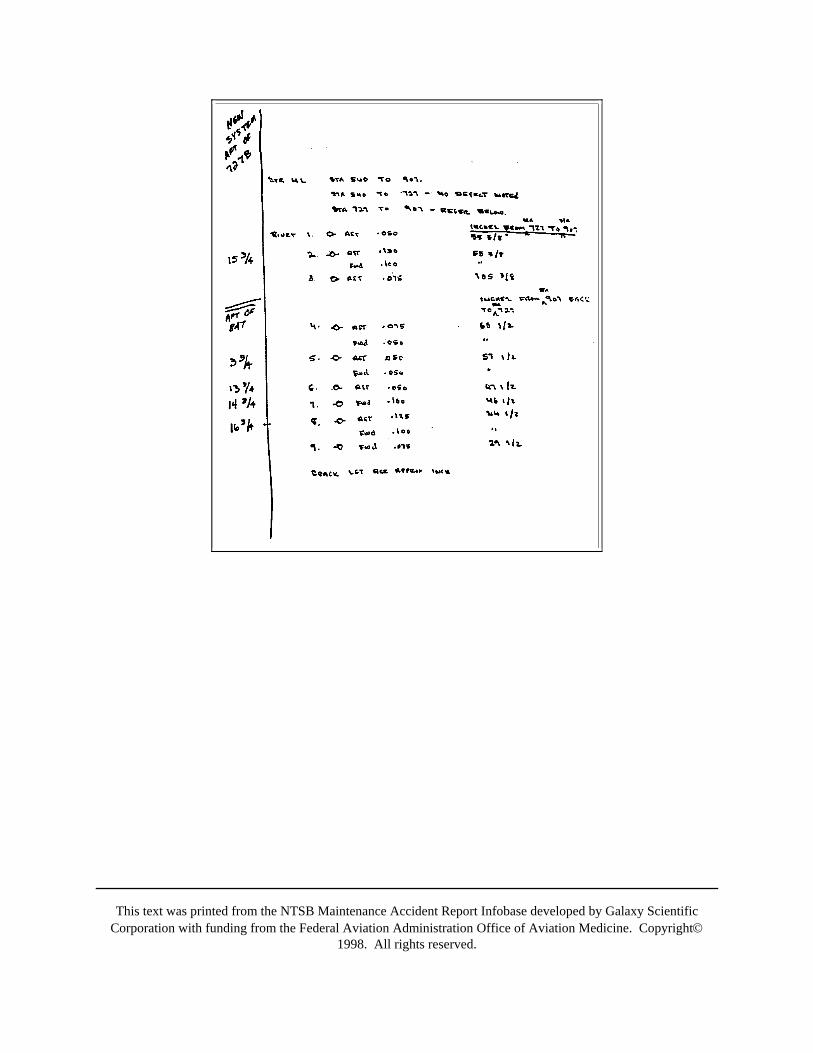
This text was printed from the NTSB Maintenance Accident Report Infobase developed by Galaxy ScientificCorporation with funding from the Federal Aviation Administration Office of Aviation Medicine. Copyright©
1998. All rights reserved.
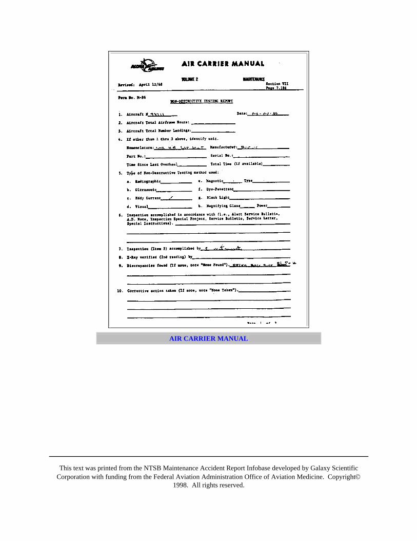
This text was printed from the NTSB Maintenance Accident Report Infobase developed by Galaxy ScientificCorporation with funding from the Federal Aviation Administration Office of Aviation Medicine. Copyright©
1998. All rights reserved.
AIR CARRIER MANUAL
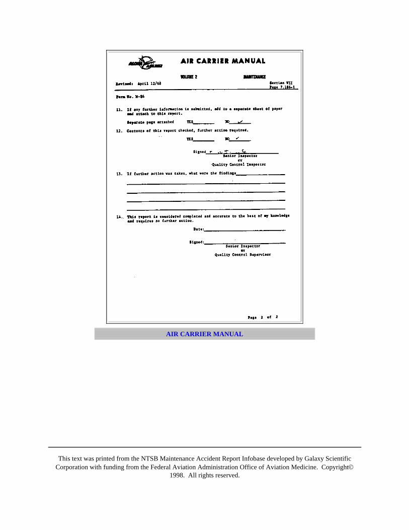
This text was printed from the NTSB Maintenance Accident Report Infobase developed by Galaxy ScientificCorporation with funding from the Federal Aviation Administration Office of Aviation Medicine. Copyright©
1998. All rights reserved.
AIR CARRIER MANUAL
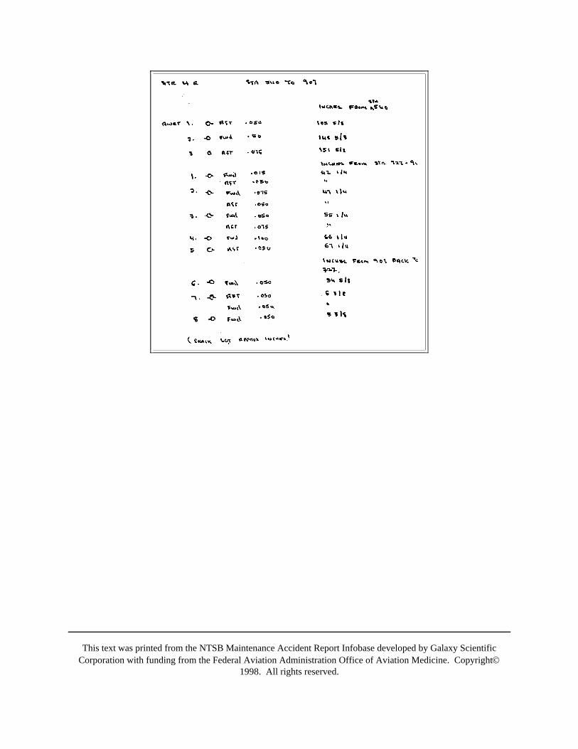
This text was printed from the NTSB Maintenance Accident Report Infobase developed by Galaxy ScientificCorporation with funding from the Federal Aviation Administration Office of Aviation Medicine. Copyright©
1998. All rights reserved.
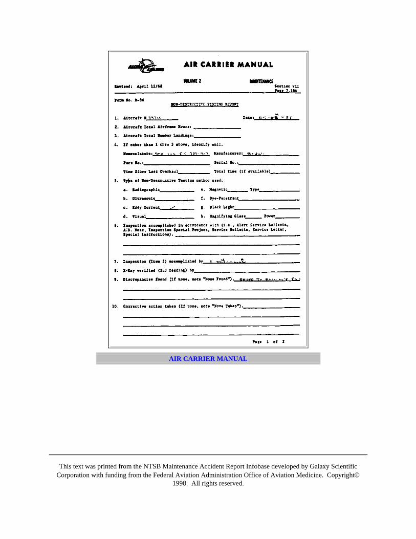
This text was printed from the NTSB Maintenance Accident Report Infobase developed by Galaxy ScientificCorporation with funding from the Federal Aviation Administration Office of Aviation Medicine. Copyright©
1998. All rights reserved.
AIR CARRIER MANUAL
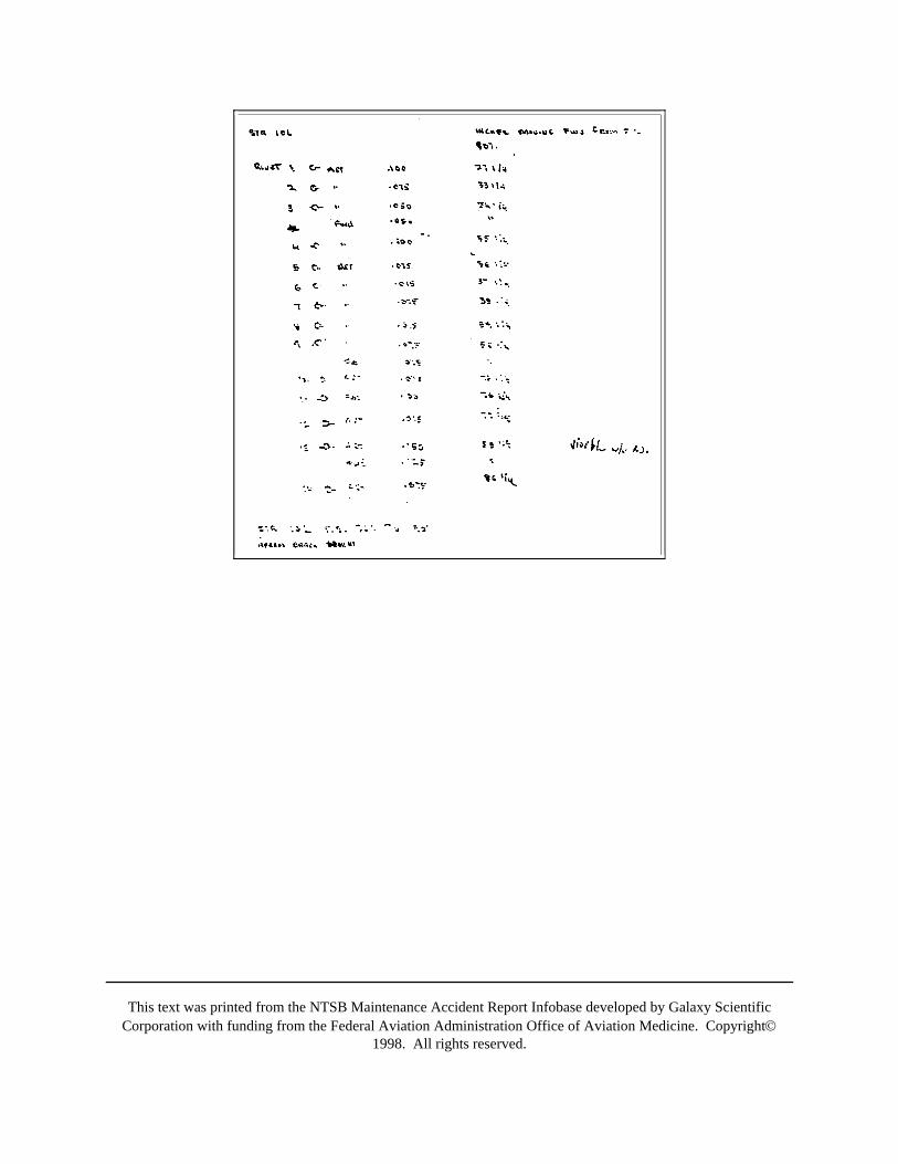
This text was printed from the NTSB Maintenance Accident Report Infobase developed by Galaxy ScientificCorporation with funding from the Federal Aviation Administration Office of Aviation Medicine. Copyright©
1998. All rights reserved.
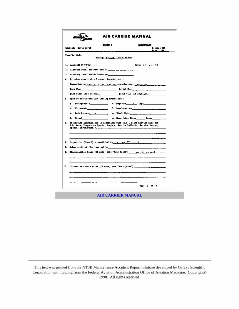
This text was printed from the NTSB Maintenance Accident Report Infobase developed by Galaxy ScientificCorporation with funding from the Federal Aviation Administration Office of Aviation Medicine. Copyright©
1998. All rights reserved.
AIR CARRIER MANUAL
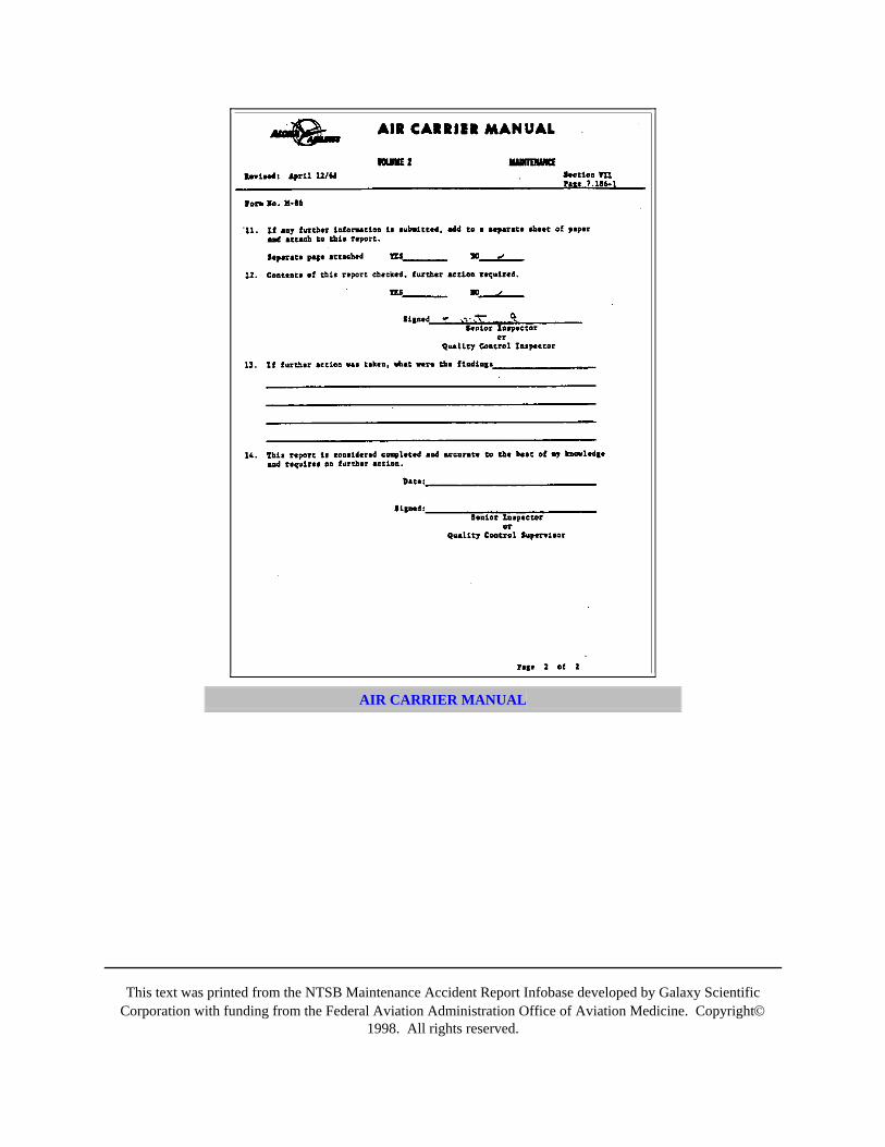
This text was printed from the NTSB Maintenance Accident Report Infobase developed by Galaxy ScientificCorporation with funding from the Federal Aviation Administration Office of Aviation Medicine. Copyright©
1998. All rights reserved.
AIR CARRIER MANUAL

This text was printed from the NTSB Maintenance Accident Report Infobase developed by Galaxy ScientificCorporation with funding from the Federal Aviation Administration Office of Aviation Medicine. Copyright©
1998. All rights reserved.
AIR CARRIER MANUAL

This text was printed from the NTSB Maintenance Accident Report Infobase developed by Galaxy ScientificCorporation with funding from the Federal Aviation Administration Office of Aviation Medicine. Copyright©
1998. All rights reserved.
AIR CARRIER MANUAL
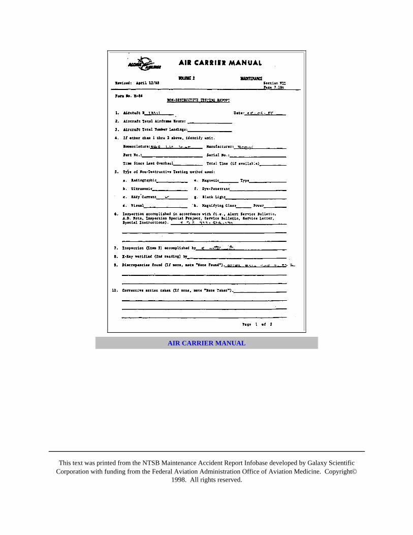
This text was printed from the NTSB Maintenance Accident Report Infobase developed by Galaxy ScientificCorporation with funding from the Federal Aviation Administration Office of Aviation Medicine. Copyright©
1998. All rights reserved.
AIR CARRIER MANUAL
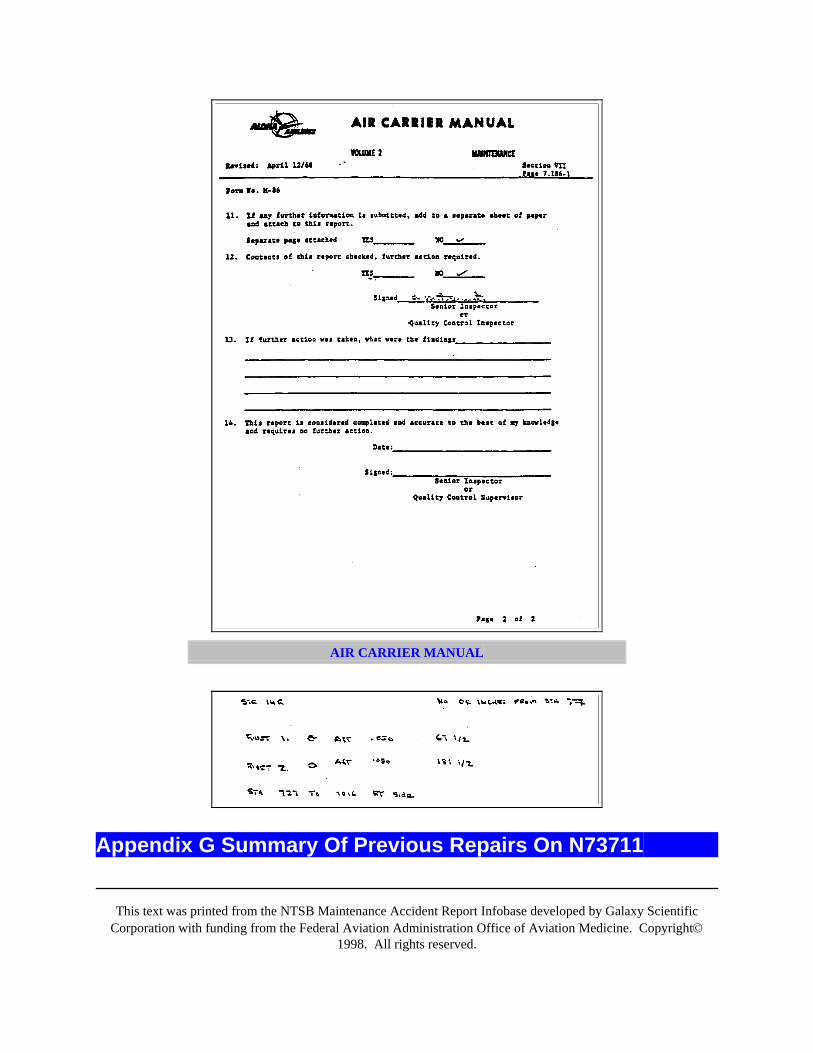
This text was printed from the NTSB Maintenance Accident Report Infobase developed by Galaxy ScientificCorporation with funding from the Federal Aviation Administration Office of Aviation Medicine. Copyright©
1998. All rights reserved.
AIR CARRIER MANUAL
Appendix G Summary Of Previous Repairs On N73711

This text was printed from the NTSB Maintenance Accident Report Infobase developed by Galaxy ScientificCorporation with funding from the Federal Aviation Administration Office of Aviation Medicine. Copyright©
1998. All rights reserved.
NATIONAL TRANSPORTATION SAFETY BOARD Bureau of Technology Washington, DC 20594
The following summary of existing skin repairs or rework areas was derived from the on-scene examination of theairplane in Kahului, Maui, Hawaii, from April 29 to May 6, 1988.
Left Side Of AirplaneBS 540 -- Scab patch from S-1 to S-2L, using universal rivets. Replacement of countersunkrivets on forward skin of the butt joint from S-4L to S-4R, and forward along S-4L for theremaining short length (S-4R missing).
BS 580 -- Scab patch with countersunk rivets between S-2L and S-3L.
BS 727A -- Scab patch with countersunk rivets, 6" X 7", just above S-17L
BS 927 -- Scab patch between S-2L and S-3L, universal rivets, 5" long.
BS 1016 -- Scab patch with countersunk rivets above S-19L, 6" X 13".
BS 1121 -- Scab patch with countersunk rivets underneath third vortex generator, 8" X 8".
BS 767 to 818 -- flush patch in top skin of S-20L lap joint, 6" high, countersunk rivets.Repair continued forward under the aft portion of the wing to body fairing.
BS 747 to 1016 -- Top row of rivets at S-25L lap joint were replaced with blind universalrivets.
BS 927 to 947.6 -- Blind universal rivets in the top row of the lap joint at S-20L.
Right Side Of AirplaneBS 420 -- Scab patch with universal rivets, 8" long X 6" high, centered over S-17R.
BS 500B -- Scab patch with universal rivets, 7" long X 6" high, centered around S-15R.
BS 727A -- Scab patch with countersunk rivets, 6" X 8", centered about S-15R.
BS 727B -- Scab patch with countersunk rivets along S-17R, 2" aft of frame and 8" forward,7" high centered around the stringer.
BS 800 -- Scab patch with countersunk rivets in forward frame of aft cargo door, 3" × 5"starting below S-19R.
BS 840 -- Scab patch with countersunk rivets in aft frame of aft cargo door, 1" × 7" startingat S-19R; scab patch with countersunk rivets, 1" × 4", starting above S-23R.
BS 960 -- Scab patch with countersunk rivets at forward edge of aft galley service door, 3" ×4", at S-14R location.
BS 970 -- Scab patch with countersunk rivets at mid-span of aft galley service door aft of the
This text was printed from the NTSB Maintenance Accident Report Infobase developed by Galaxy ScientificCorporation with funding from the Federal Aviation Administration Office of Aviation Medicine. Copyright©
1998. All rights reserved.
lower door hinge lower corner, 2" × 3", at S-15R location.
BS 1016 -- Scab patch with countersunk rivets in top skin of lap joint at S-16R, 4" × 4",centered about stringer.
BS 1104 -- Scab patch with countersunk rivets under second vortex generator, 8" × 7".
BS 1121 -- Scab patch with countersunk rivets under third vortex generator, 8" × 7".
BS 1121 to 1138 -- Scab patch with countersunk rivets above APU access door hinge line, 9"high.
BS 767 -- three rows of rivets replaced in S-20R lap joint, center row with universal rivets,continued forward under wing to body fairing.
BS 897 to 1016 -- top row of rivets at S-25R replaced by universal head rivets. Replacementstarted again at BS 767 and continued forward under wing to body fairing.
GeneralSeveral areas of rivets replaced by universal rivets around BS 747 to 807, S-27L and R; S-25R at BS 787.
Appendix H Sdr SummaryNATIONAL TRANSPORTATION SAFETY BOARD Bureau of Technology Washington, DC 20594
February 13, 1989
BOEING 737 FUSELAGE SERVICE DIFFICULTY REPORT INFORMATION
A. AccidentLocation: Near Maui, Hawaii
Date: April 28, 1988
Time: 1347 Hawaiian Standard Time
Aircraft: Aloha Airlines, Inc. Flight 243, Boeing 737-297, N73711
Accident No.: DCA-88-M-AO54
B. Summary Of Service Difficulty Report Information
1. General
This text was printed from the NTSB Maintenance Accident Report Infobase developed by Galaxy ScientificCorporation with funding from the Federal Aviation Administration Office of Aviation Medicine. Copyright©
1998. All rights reserved.
The Federal Aviation Administration's (FAA) Service Difficulty Report (SDR) data base was queried forinformation pertaining to the Boeing 737 fuselage. It was found that 3,387 records existed from the beginning ofthe current data base (January, 1983) to February 7, 1989. This number was reduced to 2,082 records byeliminating all models of the 737 that were not produced as part of the first 291 airplanes.
Between January, 1983 and the date of the accident, a total of 1,352 records were found. Of these, 198 were reportsof fuselage skin cracks, and ten of these reports were of cracking at or near lap joints. Six of the ten reportsinvolved lap joints in the upper lobe, while the remaining four were from the lower lobe of the fuselage. Six of thereports were submitted by Piedmont Airlines, three by Aloha (including a lower lobe crack on the accidentairplane), and one by American Airlines. The report by American was the only report submitted subsequent to theeffective date of Airworthiness Directive (AD) 87-21-08, November 2, 1987. All of the airplanes cited in the tenreports were manufactured within the first 291 airplanes.
A summary of the information contained in the preceding cracking reports is given below: --
I. I. Upper Lobe Reports
September 8, 1983 -- Piedmont Airlines model -201, N734N (line no. 29), total time38,155 hours: "Found fuselage skin cracked at FS (fuselage station or body station, BS)727A between stringers 14L and 15L. Crack was one inch long."
October 11, 1984 -- Aloha Airlines model -297, N73713 (line no. 222), total time 24, 814hours: "Crack in the right side fuselage skin panel longitudinal lap joint along thefastener line of stringer 10R between BS 727A-727B".
March 16, 1987 -- Piedmont Airlines model -201, N744N (line no. 160), total time45,337 hours: "on walkaround, found fuselage skin cracked in skin lap joint below leftcabin windows, station 370 to 435, a total of 21 cracks. 10 - .375 inch, 4 - .5 inch, 1 - 1inch, 2 - 1.25 inch, 2 - 1.375 inch, 2 - 1.5 inch."
July 17, 1987 -- Piedmont Airlines model -2Al, N767N (line no. 188), total time 46,367hours: "During C-check found fuselage skin cracked at lap joint station 370 to 380stringer 14R."
July 17, 1987 -- on line no. 188 above: "Found fuselage skin cracked at lap joint station727 stringer 4R."
November 27, 1987 -- American Airlines model -247, N470AC (line no. 140), total time45,185 hours: "During BC-3 check, found a 5.0 inch crack in fuselage skin at stringer14L, station 366."
II. II. Lower Lobe Reports
October 6, 1983 -- Piedmont Airlines model -201, N746N (line no. 207), total time36,267 hours: "Found 1.5 inch crack in fuselage skin on right side above stringer 20Rand aft of FS 727."
November 23, 1983 -- Aloha Airlines model -297, N73711 (line no. 152), total time26,049 hours: "Found multiple skin cracks approx 3 inches long above left fuselage skin
This text was printed from the NTSB Maintenance Accident Report Infobase developed by Galaxy ScientificCorporation with funding from the Federal Aviation Administration Office of Aviation Medicine. Copyright©
1998. All rights reserved.
lap between stringers 20L and 21L at FS 756.9 to 816.9."
December 16, 1983 -- Aloha Airlines model -297, N73712 (line no. 163), total time24,340 hours: "Fuselage skin bulged and cracked between S-25R and S-26R forward ofFS 1016."
November 9, 1986 -- Piedmont Airlines model -201, N745N (line no. 172), total time44,521: "During C-check inspection found one inch crack in fuselage skin at station 727stringer 20R."
2. Aloha Fleet Report Summary
Of the 2,082 reports that were submitted prior to the accident, 18 pertained to airplanes in the Aloha fleet. Threewere the lap joint crack/corrosion reports previously cited, and two were upper lobe skin cracking reports where lapjoint involvement could not be established from the information given. Three of the reports pertained to lower lobeskin corrosion, with an additional three reports citing corrosion at cargo door frames and the nose gear wheel wellstructure. The remaining seven reports involved cracks in fuselage structure other than skin or lap joints.
Brian S. RichardsonAerospace Engineer
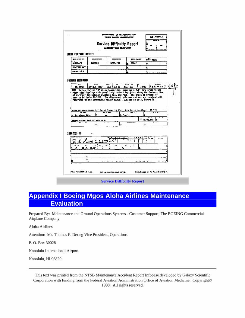
This text was printed from the NTSB Maintenance Accident Report Infobase developed by Galaxy ScientificCorporation with funding from the Federal Aviation Administration Office of Aviation Medicine. Copyright©
1998. All rights reserved.
Service Difficulty Report
Appendix I Boeing Mgos Aloha Airlines MaintenanceEvaluation
Prepared By: Maintenance and Ground Operations Systems - Customer Support, The BOEING CommercialAirplane Company.
Aloha Airlines
Attention: Mr. Thomas F. Derieg Vice President, Operations
P. O. Box 30028
Nonolulu International Airport
Nonolulu, HI 96820
This text was printed from the NTSB Maintenance Accident Report Infobase developed by Galaxy ScientificCorporation with funding from the Federal Aviation Administration Office of Aviation Medicine. Copyright©
1998. All rights reserved.
Subject: Boeing Maintenance Evaluation Aloha Airlines (ALO), November 10 - 19, 1987
Reference: Letter, Request for Evaluation, T. Derieg to R. Oldani, 27 October, 1987
Gentlemen:
In response to the reference request, a Boeing team consisting of Peter Ansdell (team leader). Richard Fugate, TibetGiray and John Hall from our Maintenance and Ground Operations Systems (MGOS) organization conducted thesubject evaluation.
The purpose of the Boeing team's visit was to conduct an evaluation of Aloha Airlines's Maintenance operations.Observations and recommendations have been included in the attached report which should be of assistance toimprove productivity, enhance technical operating efficiency and assure effective maintenance standards.
We appreciate having had the opportunity to work with your technical staff again and convey our thanks for theexcellent cooperation and courtesy shown to our team members during this visit.
Please confirm your receipt of this report and feel free to make any comments, or request any additional informationor assistance regarding its contents.
Very truly yours,
CUSTOMER SUPPORT
R. L. OldaniManager, Maintenance and Ground Operations Systems
TABLE OF CONTENTS

This text was printed from the NTSB Maintenance Accident Report Infobase developed by Galaxy ScientificCorporation with funding from the Federal Aviation Administration Office of Aviation Medicine. Copyright©
1998. All rights reserved.
PAGE
PART I. INTRODUCTION 2
PART II. EXECUTIVE SUMMARY 3-7
1. General 3
2. Summary of Recommendations 3
3. Conclusion 7
PART III. TECHNICAL DETAILS 8-29
1. General 8
2. Technical Policies and Procedures Manual 8
3. Organization 9
4. Quality Assurance 11
5. Reliability 12
6. Engineering 13
7. Planning and Production Control 14
8. Shops 17
9. Maintenance 18
10. Maintenance Program 20
11. Supplemental Structural Inspection 22
12. Technical Training 24
13. Computerization 25
14. Technical Supply 27
15. Industrial Safety 28
16. Manpower 28
17. Communication 29

This text was printed from the NTSB Maintenance Accident Report Infobase developed by Galaxy ScientificCorporation with funding from the Federal Aviation Administration Office of Aviation Medicine. Copyright©
1998. All rights reserved.
PART IV SUPPORTING DATA AND CHARTS
Appendix A - Organization Chart - ALO Management
Appendix B - Organization Chart - ALO Technical Division
Appendix C - Typical Operator Technical Organization
Appendix D - Typical Quality Assurance Department
Appendix E - Proposed ALO Technical Organization
Appendix F* - Supplemental Structural Inspection Data
Appendix G* - Boeing Safety Procedures, First Aid/CPR Manuals
*These documents and data are being sent separately by M-7360-88-0279, dated January 30, 1988.
Part I. IntroductionIn response to a request from Mr. Thomas Derieg, Vice President, Operations, a team from the Boeing CommercialAirplane Company, Maintenance and Ground Operations Systems (MGOS) organization within the CustomerSupport Division conducted an evaluation of Aloha Airlines's (ALO) maintenance operations during November 10 -19, 1987. The Boeing team consisted of Peter Ansdell (team leader), Richard Fugate, Tibet Giray and John Hall.The team members visited the Aloha Airlines maintenance facility located at Nonolulu International Airport.
The purpose of this visit was to conduct an evaluation of Aloha Airline's technical operations by makingobservations and recommendations to assist ALO to enhance technical operating efficiency, improve productivityand assure a high standard of maintenance.
This report has been divided as follows:
PART I - INTRODUCTION
PART II - EXECUTIVE SUMMARY
PART III - TECHNICAL DETAILS
PART IV - SUPPORTING DATA, CHARTS, ETC.
The team members wish to express their appreciation to the following airline personnel for their cooperation,assistance and courtesy extended during this visit:
This text was printed from the NTSB Maintenance Accident Report Infobase developed by Galaxy ScientificCorporation with funding from the Federal Aviation Administration Office of Aviation Medicine. Copyright©
1998. All rights reserved.
Thomas Derieg Vice President, Operations
James Williamson Vice President, Development
Henry Arii Staff Vice President, Maintenance
Frederick Medina Director, Maintenance
Ralph Akutagawa Manager, Production Planning
Bob Takamine Manager, Quality Assurance
Gene Rodrigues Manager, Base Maintenance
Darwin Hammersley Manager, Maintenance Support
Ed Matsumoto Senior Inspector
Robert Okimoto Inspector
John Wade Supervisor, Shops
Special appreciation is expressed to Mr. Henry Arii for making the team's arrangements for this visit. A suitablework area was provided, the day-to-day meetings were effectively coordinated and an excellent tour was conductedof the Aloha Honolulu facility.
Peter A. AnsdellRichard L. Rugate
Tibet GirayJohn Hall
Part II. Executive Summary
1. General:
This evaluation by the Boeing team was conducted in accordance with the request of Mr. Thomas Derieg, VicePresident, Operations.
PART II is limited to highlights of significant recommendations relevant to this evaluation for executiveconsideration and a conclusion. PART III contains the detailed description of the technical aspects of theevaluation. PART IV includes appendices consisting of charts and other supporting data.
This text was printed from the NTSB Maintenance Accident Report Infobase developed by Galaxy ScientificCorporation with funding from the Federal Aviation Administration Office of Aviation Medicine. Copyright©
1998. All rights reserved.
2. Summary Of Recommendations:
The following contains a summary of recommendations (these are repeated in PART III accompanied by relatedbackground details of the topics covered in the various departments):
· Give high priority to completely revamping the Technical policies & Procedures Manual (theAloha Air Carrier Manual). It should be maintained, kept current, and distributed throughoutthe Technical Division. Any interim changes between revisions which do not requireregulatory authority approval, such as organization changes, etc., could be covered by"Temporary Revisions" or "Advance Information Notices".
· Institute an aggressive program to assure that all copies of the Aloha Air Carrier Manual, aswell as all applicable manufacturer and vendor technical manuals and documents distributedthroughout the Technical Division, are maintained up-to-date.
· Consider the proposed organizational changes shown in Item 3 of PART III - TECHNICALDETAILS (also shown in Appendix E). This includes the forming of new Engineering andReliability sections and covers other areas such as Technical Library & Publications;Technical Training; Quality Assurance; Planning & Production Control; and TechnicalSupply.
· Rotate all inspectors through a training program on inspection techniques with specialemphasis on corrosion detection. Encourage inspectors to be more assertive in their dealingswith Aircraft Services.
· Either assign extra inspectors to cover the shops or have Quality Assurance delegate (inwriting) appropriate shop personnel with the necessary inspection approval authority.
· Assure that Quality Assurance conducts random audits (unannounced spot checks) ofHonolulu Line Maintenance (both ALO and contract flight lines); component shops andstores on a frequent basis and the outstations at least once a year.
· Construct a dust free, temperature controlled laboratory for MDT, borescope, and calibrationequipment.
· Re-evaluate all 737 components as regards the maintenance control process that would bebest suited to each (Hard Time - HT, On Condition - OC, or Condition Monitoring - CM).
· Consider developing achievable long, medium and short range production plans (eachcontaining the appropriate level of detail) taking into account availability and requirementsfor manpower, facilities, equipment and material.
· By recording manhours for all scheduled and unscheduled maintenance tasks carried out onthe airplanes over a period of time, norms can be established against which futureperformance can be measured. Such data will assist in achieving more realistic production
This text was printed from the NTSB Maintenance Accident Report Infobase developed by Galaxy ScientificCorporation with funding from the Federal Aviation Administration Office of Aviation Medicine. Copyright©
1998. All rights reserved.
planning and better estimates of airplane downtimes for scheduled checks. Manhour trendscould also be used as a parameter to be used in the reliability program.
· Consider initiating the practice of preparing a planning chart to be used by the maintenancedepartment as a guide in sequencing the items of work to be accomplished. By indicating thecompleted work, this flow chart would provide an effective means of monitoring the progressof a check.
· Ensure that all shop planning and production control are the responsibility of the Planning &Production Control (PPC) department. No shop should carry out any tasks on hardware untila work order is received from PPC. PPC should establish priorities for shop work load basedon stockroom requirements for serviceable components.
· Develop a comprehensive component tracking systems covering their location from stores toairplane, through the repair shops, and back to stores. This would help to reduce theunusually high number of unserviceable spares which have accumulated in certain shopsover the past years. This tracking system could ideally be computerized.
· Encourage the PPC manager and senior members of the staff to visit the PPC departments ofother operators and join aviation industry organizations on this subject.
· Consider changing the color of the unserviceable components tags to red and the serviceablecomponents tags to green.
· Conduct an inventory exercise to determine how many parts are presently in the componentshops. A decision should then be made as to whether they should be scrapped, disposed of,or repaired as part of the overall spares inventory.
· Review and expand the equipment calibration program.
· Consider providing in the hangar, a board with slots on which task cards can be grouped byaircraft zone, skills required and work progress status. This will assist the maintenanceforeman in issuing work to his mechanics and provide visibility of progress.
· Establish better control and accountability of tools. A separate tool crib area isrecommended.
· Review the maintenance program concepts detailed in Item 10, PART III and advise Boeingof the program preferred by ALO so that details can be developed by the BoeingMaintenance & Ground Operations Systems (MGOS) organization.
· Before initiating the new 737 maintenance program, perform a complete structural inspectionand incorporate certain key service bulletins on all ALO 737 airplanes. In the absence of anEngineering department at ALO, Boeing Customer Support Service Engineering willprioritize the "extended life" service bulletins applicable to ALO's 737s.
· Ensure that all personnel responsible for planning, developing, checking, implementing and
This text was printed from the NTSB Maintenance Accident Report Infobase developed by Galaxy ScientificCorporation with funding from the Federal Aviation Administration Office of Aviation Medicine. Copyright©
1998. All rights reserved.
conducting the ALO Supplemental Structural Inspection Document (SSID) program,familiarize themselves with the guidelines, examples and procedures in the 737 SSID.Particular attention should be paid to the notes and instructions associated with the DTRcheck forms.
· Correct all existing DTR check forms errors and misinterpretations (listed in Appendix F).Note, there may be additional errors on the existing DTR check items that are not listed inAppendix F.
· Add a procedure to the ALO Air Carrier Manual for reporting structural discrepancies inaccordance with Section 6 of the SSID. Ensure that all cracks and previously unreportedoccurrences of significant corrosion involving a Significant Structural Item (SSI) that weredetected during earlier SSID inspections be reported to Boeing.
· Provide 737 training to all maintenance mechanics who have not received training for thismodel airplane.
· Consider adopting a policy requiring all technical personnel to receive a minimum of oneweek of refresher training each year. The course should include review of the Aloha AirCarrier Manual and extra training should be given to inspectors and foremen.
· Provide management development and leadership courses to all recently appointedsupervision.
· Obtain cassettes on various specialized training aspects to be used in the hangar or shops toassist with on-the-job training.
· Consider holding specialized training courses such as structural repair, corrosion preventionand control, rigging and nondestructive test (NDT) methods.
· Formulate a master plan for the development of computerization in the technical divisionutilizing inputs from all potential users.
· Prepare certain technical records, such as service bulletin accomplishment accountability foreach airplane, by manual methods until such time as a computerized data base is set up.Initial priority should be given to recording the status of the structural service bulletins.These should be particularly useful to ALO while operating several fleet leader high cycleairplanes and where airplanes are being added or removed from the fleet due to the variousleasing arrangements.
· Establish a separate area devoted to the shipping and receiving of parts.
· Adopt a policy whereby components removed from the airplane are first sent to Stores andplaced in a quarantine area. When it can be determined that a replacement part does notsolve the airplane problem, the removed component can be tagged as serviceable andreturned to stock.
This text was printed from the NTSB Maintenance Accident Report Infobase developed by Galaxy ScientificCorporation with funding from the Federal Aviation Administration Office of Aviation Medicine. Copyright©
1998. All rights reserved.
· Consider assigning a Safety Coordinator under the Quality Assurance department to coverthe Technical Division.
· Encourage an interest in safety by forming an employee safety committee and appointing"safety monitors".
· Make an intensive effort to hire more personnel, as needed in each department in theTechnical division, and bring manpower up to industry levels. For all supervisory andmanagement positions, it is desirable to assign suitable understudies who can be trained toassume the position of the applicable supervisor or manager in their absence.
· Ensure that there is a good rapport between the Flight Operations and Technical Divisions tomake sure that each appreciates the other's problems and constraints, and highlight what theTechnical Division is doing to find solutions. Flight Operations can provide valuable inputson actual operating condition and technical defects. This in turn can contribute to moreeffective trouble shooting, timely rectification, minimizing delays, improving dispatchreliability and reducing costs.
3. Conclusion:
Maintenance Engineering evaluations by the airframe manufacturers have the unique advantage of providingoperators with an independent perspective which often avoids the "blind spots" that internal audits possess due to"home born-and-bred cultures". A feedback is provided of comparison of maintenance performance by a neutralparty which highlights strengths and weaknesses of the systems and methods, the health of the airplanes andequipment, and the effectiveness of key personnel and organizational structure.
The Boeing Customer Support Division welcomes this opportunity to provide technical assistance to AlohaAirlines. It is sincerely hoped that by adoption of some of the recommendations in this report, Aloha Airlinestechnical personnel will be able to enhance their standard of maintenance operations.
Part III. Technical Details
1. General:
This section, (PART III) of the report provides details of observations and recommendations which concern theoperation of the Aloha Airlines Maintenance Division. PART IV contains appendices to this section withsupporting data and charts.
At the time of this visit, the AIO fleet was as follows:

This text was printed from the NTSB Maintenance Accident Report Infobase developed by Galaxy ScientificCorporation with funding from the Federal Aviation Administration Office of Aviation Medicine. Copyright©
1998. All rights reserved.
AIRPLANETYPE
REG.NO.
FLIGHTCYCLE
S
FLIGHTHOURS
ENGINE TYPE
DELIVERYDATE
737-202C N801AL 47,632 39,935 JTSD-9 OCT, 1968
737-297 N73711 85,300 33,726 JTSD-9 APR, 1969
737-297 N73712 86,493 32,200 JTSD-9 MAY, 1969
737-210C N4906 47,200 38,995 JTSD-9 MAY, 1969
737-297 N73713 82,336 30,775 JTSD-9 NOV, 1969
737-2A9C N803AL 46,374 44,385 JTSD-9 APR, 1970
737-2H4 N73717 64,551 38,775 JTSD-9 JUN, 1971
737-2S5C N802AL 6,527 8,642 JTSD-9 MAY, 1980
737-297 N728AL 29,948 11,598 JTSD-9 FEB, 1982
737-297 N730AL 28,098 10,830 JTSD-9 JUL, 1982
Total Airplane Fleet - 10
Seven of the ten airplanes are over 15 years old. Three of the 737s: N73711, N73712 and N73713, are the highestflight cycle airplanes of all Boeing jets currently in operation in the world.
In 1987, the ALO 737 fleet averaged 15.56 flight cycles and 6.0 flight hours per airplane. Mechanical dispatchreliability was an impressive 99.59%.
Aloha operates regional (Havaiian Islands) routes in an environment known to be highly susceptible to the effects ofcorrosion.
Appendices A and B show the organization and management personnel at the time of this visit. The total number ofAloha Airlines employees throughout the whole operation was stated to be approximately 1,188. Of these,approximately 200 were employed in the Maintenance and Quality Assurance departments as shown on AppendixB. In comparison to similarly equipped operators, it appears that ALO is short of technical personnel in the offices,shops and hangar (this is discussed in Item 14 - MANPOWER).
2. Technical Policies & Procedures Manual:
An airline's Technical Policy & Procedures Manual (TPPM) provides the means of establishing effectivemaintenance standards and control as well as giving direction on all Technical Division activities.
This text was printed from the NTSB Maintenance Accident Report Infobase developed by Galaxy ScientificCorporation with funding from the Federal Aviation Administration Office of Aviation Medicine. Copyright©
1998. All rights reserved.
Operators usually have their Quality Assurance department responsible for ensuring adherence to this manual. Thepreparation, revision and upkeep of the manual and standard forms are usually the responsibility of an Engineeringdepartment and a Technical Publications section (which may be grouped with the Technical Library underTechnical Services - see the recommendation on this aspect in Item 3 - ORGANIZATION).
The ALO version of the TPPM is the "Aloha Air Carrier Manual". Although the contents in the various volumesare generally in line with the FAR requirements, there appears to be gaps of no records of revisions for severalyears, many of the contents do not apply, some procedures (for example, regarding corrosion control) areinadequate and several sections have not been kept up-to-date. Strict control of the distributed copies is required.The "Inspection Alert Bulletins" which are described to be on blue paper and listed, were not available in the copiesof the manual which were examined.
· It is recommended that high priority be given to completely revamping the Aloha Air CarrierManual. The contents should be in accordance with all regulatory authority requirements. Astatement should be provided in the introduction describing the policy of how the manual isto be maintained, defining the responsible authorities, the extent of its distribution and who isto keep it current.
· It is recommended that interim revisions to the Aloha Air Carrier Manual which do notrequire regulatory approval, for example, organizational changes, etc., should be covered by"advance" or "temporary" revisions.
3. Organization:
For the Technical Division to function smoothly, it is important to ensure that individual roles are clearly definedand the reporting relationships are properly understood. Personnel should have a clear understanding of the keyresponsibilities within the organization, be fully aware of who has the authority, and recognize their ownaccountability, so as to automatically and correctly react and interact to any necessary required action.
Many internal conflicts or bottlenecks can be eradicated or reduced to manageable levels by the careful and properstreamlining of the organizational structure. In this respect, a continual review of the organizational structure maybe necessary to cater for factors such as increase in utilization, changes in operational strategies, airplane leasing,meeting regulatory authority requirements, contract maintenance, workload "peaks" and "valleys" and changes ofpersonnel, all of which also require continual upgrading of skills, including technical and administrativedevelopment.
Several Technical Division management changes had recently taken place within the six months prior to the visit bythe team and these are reflected in Appendices A & B.
The Aloha Airlines Technical Division appears to have most of the appropriate sections usually found in similarsized airlines. A typical operator organization is shown in Appendix C. The' team observed that the following areascould benefit from various organizational improvements: Engineering; Technical Library & Publications; TechnicalTraining; Quality Assurance; Reliability; Production Planning & Control; and Technical Supply. Aloha Airlinesmight consider these suggestions should any future technical organization changes be planned (see Appendix E -PROPOSED ALOHA TECHNICAL ORGANIZATION):
· Engineering:
This text was printed from the NTSB Maintenance Accident Report Infobase developed by Galaxy ScientificCorporation with funding from the Federal Aviation Administration Office of Aviation Medicine. Copyright©
1998. All rights reserved.
Typical operator engineering functions are shown in Appendix C. As detailed in Item 6 -ENGINEERING and Appendix E, it is proposed that an Engineering section be formed aseither a stand alone department or as part of a new "Technical Services" departmentincluding Production Planning & Control, Technical Training and TechnicalPublications/Library.
· Technical Publications/Technical Library:
There appears to be a need to expand the Technical Library into a TechnicalPublications/Technical Library section. By employing some technical writers, revisionscould be made to manuals affected by incorporation of service bulletins and otherengineering change action. The prime function should be maintaining the Technical Policies& Procedures Manual, standard forms and placards. This section should institute anaggressive program to assure that all copies of the TPPM as well as all applicablemanufacturer and vendor technical manuals and documents distributed throughout theTechnical Division are maintained up-to-date.
· Technical Training:
As detailed in Item 11 - TECHNICAL TRAINING, there is a need to form a dedicatedTechnical Training school and it is proposed that this be under a Technical Servicesdepartment.
· Quality Assurance (QA):
A typical QA department and responsibilities are shown in Appendix D. Proposed plans forphasing in various sections of this department are shown in Item 4 - QUALITYASSURANCE.
· Reliability:
It appears that an effective Reliability section needs to be created (as recommended in Item 5- RELIABILITY). Depending on the emphasis of the reliability program, operators usuallyhave a Reliability section under either Technical Services or QA (see Appendix E -PROPOSED ALOHA TECHNICAL ORGANIZATION).
· Technical Supply:
In many operators, Technical Supply is a separate department under the Technical Division(see Appendix C). This is also proposed in Appendix E.
4. Quality Assurance (QA):
It was observed that the ALO QA department, which is staffed by 12 personnel, has experienced and dedicatedpersonnel. QA is independent of the Maintenance department and the head of QA reports to technical management
This text was printed from the NTSB Maintenance Accident Report Infobase developed by Galaxy ScientificCorporation with funding from the Federal Aviation Administration Office of Aviation Medicine. Copyright©
1998. All rights reserved.
at one level above that of the head of Maintenance. This is satisfactory and is in conformance with the acceptedconcept that work verification should not be influenced by production demands. The responsibilities of QA shouldinclude surveillance of the entire Technical Division including Technical Supply.
At present, the ALO QA has responsibility for QC (Inspection), Technical Records, the Technical Library andPublications. Other responsibilities, according to the ALO Air Carrier Manual, include the reliability aspects of thecontinuing analysis and surveillance program.
The ALO inspection function is performed by the participation of inspectors in maintenance checks. All inspectionsper task cards and service bulletins are carried out by inspectors. All items written up by inspectors for correctionare re-inspected and accepted by them after rectification of the discrepancies by mechanics (inspector buy-back).This practice of 100% inspection and buy back by inspectors indicates the commitment in principle by ALOmanagement to have well maintained airplanes. Whereas the team applauds this practice, and the high airplanereliability plus excellent condition of the airplane systems have proven to be outstanding, there is some questionregarding the deteriorated structure of the high cycle airplanes. The lack of a corrosion prevention and controlprogram is a factor, but there is also the possibility that specialized inspector training and more assertiveness on thepart of inspection is required.
· It is recommended that all ALO inspectors be rotated through a training program oninspection techniques with special emphasis on corrosion detection. In the future, inspectorsshould also receive specialized training (as listed in Item 12 -TECHNICAL TRAINING).
There have been cases in the past where the Aircraft Services department, in an effort to meetschedules, had painted over or closed up areas of the airplane prior to inspection. Thissuggests that this may be an area where the QC inspectors should be more assertive andwhere the Aircraft Service department should be made aware of QC importance. On theother hand, in an effort to not affect production schedules, QC inspectors should review theirinitial inspection priorities during the early part of their maintenance checks to cover theseopened up areas.
There did not appear to be any involvement by inspection in the Shops. Build-up enginesand overhauled components had tags with no inspection approval indicated.
· It is recommended that additional inspectors be assigned to cover the Shops or appropriateshop personnel be delegated (in writing) inspection and approval authority by QA.
ALO inspectors were not involved with Line maintenance activities at Honolulu or at otherstations.
· It is recommended that the QA department conduct random audits (unannounced spotchecks) of Honolulu Line maintenance (both ALO and contract flight lines), componentshops and stores on a frequent basis and the outstations at least once a year.
The responsibilities of the QC (Inspection) section shown in Appendices D & E coveringStores/Receiving includes inspection of incoming materials and components, hidden damageinspection, proper attention to storage of flammable materials, and parts shelf life limitscontrol. It would be beneficial if this section could also assume some limited responsibilityfor audits of vendor quality and make recommendations to Technical Supply for the ALO

This text was printed from the NTSB Maintenance Accident Report Infobase developed by Galaxy ScientificCorporation with funding from the Federal Aviation Administration Office of Aviation Medicine. Copyright©
1998. All rights reserved.
approved vendor list.
In the absence of an Engineering department, QA performs most of the functions usuallyaccomplished by engineers (see Item 6 - ENGINEERING). These functions conflict with thegenerally accepted role of a QA/QC department. It is analogous to a student writing his ownexamination text and then grading his own paper.
A part of QC which needs some attention concerns the NDT, borescope, and calibrationequipment (instruments and mechanical test). This is important considering the presentamount of in-house heavy maintenance. It should be QC's responsibility to control andoperate all NDT and borescope equipment, as well as to check and monitor when allcalibrations are due throughout the Technical Division. Consolidation of these aspectsrequires a dust free, temperature controlled laboratory for this sensitive equipment. Thelaboratory should be located adjacent to, or within the hangar.
· It is recommended that a laboratory be constructed for NDT, borescope and calibrationequipment.
5. Reliability:
The ALO Air Carrier Manual states that the reliability program is administered by Quality Assurance and thatrevisions are made to the airplane maintenance Operations Specifications and the Component MaintenanceSchedule.
QA also has responsibility for the ALO Propulsion System Reliability Control Program (PSRCP), the HydraulicInternal Leakage Test (NILT) system and a Continuing Surveillance & Analysis program consisting of:
· Data Collection & Surveillance;
· Data Analysis;
· Corrective Action (based on exceedance of "alert values" and review by monthly ReliabilityControl Board meetings).
The present ALO Component Maintenance Schedule has most components incorrectly listed as "on condition" (OC)when they should be either "herd time" (HT) or "condition monitored" (CM). To classify a component as OC, theremust be some scheduled inspection, check, or tests which ensure that the component will function properly until thenext scheduled check.
· It is recommended that ALO consider re-evaluating all 737 components as regards themaintenance control process that would be best suited to each (HT, OC, or CM). Data willthen need to be collected and analyzed for CM components. Scheduled on-airplane checksshould be identified for OC components.
An effective program administered by a reliability section under QA should be in place inorder to realize the full advantages of adopting condition monitoring for component control.
This text was printed from the NTSB Maintenance Accident Report Infobase developed by Galaxy ScientificCorporation with funding from the Federal Aviation Administration Office of Aviation Medicine. Copyright©
1998. All rights reserved.
Also, this section should consider the use of computerized reliability software programs.
· It is recommended that a Reliability section be formed reporting to the Quality Assurancesection.
The organization of Quality Assurance and the proper management of a reliability program as just described willprovide an effective system for continuing analysis and surveillance of maintenance and inspection programs.
6 Engineering:
The responsibilities of an Engineering department include evaluation and implementation of manufacturer's ServiceBulletins, Airworthiness Directives, airline originated modifications and repair action, design, research, studies,reports and investigations, preparation of specifications, drawings and standards, establishment and control of theairplane, engine and component maintenance schedule specifications, and providing technical assistance (forexample, in trouble shooting) as required by Maintenance, Shops and Flight Operations. The manufacturer ServiceBulletins receive a thorough assessment as to merits, payback, and whether they provide practical improvements oreffective solutions to problems.
It appears the most urgent need at ALO is for a structural engineer. The deteriorated condition of the older, highcycle ALO 737s and the four 737-200Cs which had been previously operated in Alaska and remote regions ofCanada on rough, unimproved runways, requires that special attention should be given to their structural integrity.This should include proper corrosion prevention and control, complete definition of structural repairs andterminating correction, as well as review for incorporation of selected structural service bulletins recommended byBoeing to extend airplane life. The team discussed and left a complete list of these selected structural servicebulletins applicable to all ten ALO 737s. These bulletins reflect the influence of operator service experience,regulatory authority action, new materials and processes. They provide estimated incremental structural life andrecommended incorporation threshold data.
In the present absence of an ALO Engineering department, Boeing Customer Support Service Engineering isstudying the lists of selected "extended life" service bulletins (SBs) applicable to all ALO airplanes and will benotifying ALO through the Boeing Field Service office of a priority category for each SB applicable to ALO'soperations and environment. These lists may be supplemented by other SBs considered beneficial to ALO 737s.
Three of the 737-200Cs will become "Supplemental Structural Inspection Document (SSID) candidate airplanes"this year. However, the SSID items which will need to be incorporated into these airplanes' maintenance programwill only involve significant structural items associated with the individual cargo airplane features.
7. Planning And Production Control:
Operators generally have their Planning & Production Control (PPC) sections responsible for the planning,scheduling of maintenance operations and establishment of appropriate controls. This assures production schedulesmeet the time limitations as specified in the airplane, engine and component maintenance operations schedulesection in the Technical Policies & Procedures Manual.
Effective maintenance control is achieved by scheduling maintenance action in the proper sequence and at theproper time. It is desirable that competent personnel, equipment, facilities, tools, spares and materials be available
This text was printed from the NTSB Maintenance Accident Report Infobase developed by Galaxy ScientificCorporation with funding from the Federal Aviation Administration Office of Aviation Medicine. Copyright©
1998. All rights reserved.
to accomplish the assigned maintenance task. This section acts as a regulator for the maintenance cycle providingsafeguards to prevent:
· Exceeding approved time interval limitations;
· Backlog accumulation of work, possibly resulting in loss of airplane availability;
· Errors resulting from unplanned and hastily performed work;
· Manpower shortages;
· Spares/material shortages for major checks;
· Facility overload;
· Failure to comply with regulatory authority regulations.Some maintenance actions are performed on a non-routine (unscheduled) basis. In such cases, this section shouldprovide the required flexibility to compensate for variations in workloads and still control the production schedule.Operators usually have their PPC coordinate the efforts of Engineering, Quality Control, Maintenance, OverhaulShops and Technical Supply.
In general, the ALO PPC staff accomplish the following:
· Keep track of airplane utilization (accumulated flight hours and cycles);
· Schedule airplane maintenance tasks by making sure that intervals or thresholds are notexceeded for any time controlled maintenance requirement;
· Assemble the paperwork for airplane checks;
· Track the hard time controlled components by location, calendar time, hours, or cycles;
· Perform material planning;
· Undertake special projects which would normally be accomplished by an Engineeringdepartment at other operators;
· Arrange for the repair or overhaul of 737 components at vendors or-other outside repairagencies.
At many operators, offective planning for a maintenance check includes a thorough review of the work package,estimating the workload and elapsed time requirements for each task and preparing a work flow chart that scheduleseach item of work at the optimum time. To be able to do this, an adequate data base of manhour statistics has to beestablished over a period of time. ALO's Aireraft Services maintenance department was not recording manhoursexpended to perform maintenance tasks. It also appeared that personnal in PPC were so occupied with dailyproblems and expediting paperwork that there was hardly enough time for offective planning.
The following recommendations are made regarding PPC:
· Consider developing achievable long, medium and short range production plans (eachcontaining the appropriate level of detail) taking into consideration availability andrequirements for manpower, facilities, equipment and material.
This text was printed from the NTSB Maintenance Accident Report Infobase developed by Galaxy ScientificCorporation with funding from the Federal Aviation Administration Office of Aviation Medicine. Copyright©
1998. All rights reserved.
· By recording manhours for all scheduled and unscheduled maintenance tasks carried out onthe airplanes over a period of time, norms can be established against which futureperformance can be measured. Such data will assist in achieving more realistic productionplanning and better estimates of airplane downtimes for schedule checks. Manhour trendscould also be used as a parameter to be used in the reliability program.
· Consider initiating the practice of preparing a planning chart to be used by the maintenancedepartment as a guide in sequencing the items of work to be accomplished. By indicating thecompleted work, this flow chart would provide an effective means of monitoring the progressof a check.
The ALO PPC has a computer list showing the part numbers and quantities of rotable components in the ALOinventory. However, except for hard time components and units sent out on repair orders, the PPC does not knowwhether a specific unit is installed on an airplane, is a serviceable spare, or is waiting to be repaired in some ALOshop. Accumulated hours and cycles on these units are not kept. Mechanics removing components from airplanestake them directly to the applicable component shop. By this practice, the component does not go through the storesor a quarantine area and the accompanying paperwork is not sent to the PPC. Each shop decides whether a specificunit should be repaired or sent to an outside overhaul agency.
The following recommendations are made:
· It is desirable that all shop production planning and control activities be assigned to the PPC.No shop should carry out any tasks on hardware until a work order is received from PPC.PPC should establish priorities for these shop work orders by closely monitoring shop workloads and stockroom requirements for serviceable components.
· ALO should develop a comprehensive component tracking system (including thosecomponents on OC and CM which are currently not tracked) covering their location fromstores to airplane, through the repair shops, and back to stores. This would help to reduce theunusually high number of unserviceable spares which have accumulated in certain shopsover the past years (see Item 8 - SHOPS). This tracking system could ideally becomputerized (see Item 12 - COMPUTERIZATION).
The ALO PPC also has responsibility for material planning. Initially, reorder levels for theexpendable parts were assigned by PPC. These values were entered into the inventorycontrol computer program. The Purchasing department now orders parts automatically basedon these reorder levels, resulting in no involvement by PPC except when there is a problem.Rotable component purchases and repair orders are handled by PPC. The total inventory ofspares increased from $7.8 million to $8.5 million in the first six months of 1987.Approximately $5 million worth of the total spares inventory consists of rotable components.The team was informed that it was a rare occurrence for an ALO 737 flight to be delayed dueto the lack of a spare part. It appears that ALO could save a substantial amount of money byimplementing an effective component control and tracking system as discussed earlier. Thiswould permit more efficient use of the accumulated spares inventory.

This text was printed from the NTSB Maintenance Accident Report Infobase developed by Galaxy ScientificCorporation with funding from the Federal Aviation Administration Office of Aviation Medicine. Copyright©
1998. All rights reserved.
At present, the ALO PPC is staffed by three planners and a manager who reports to theDirector, Maintenance. It appears that this department is understaffed even to effectivelycarry out its present responsibilities. If recommendations from this report are implemented,there may be a need for additional manpower. However, savings that can be achieved by abetter functioning PPC should justify the extra personnel acquired.
It appeared that the ALO PPC staff had been introduced to working in this type of work withminimal preparation or prior training in PPC skills. Even though the members of the staff arevery conscientious and hard working, they have had to "rediscover the wheel" on their own.Consequently, they are not quite fully aware of the state-of-the-art in airline PPC.
· It is recommended that the PPC manager and senior members of the staff be given theopportunities to visit PPCs of other operators and join aviation industry organizations on thissubject.
The additional responsibilities recommended in this section encompassing not only aircraft maintenance activities,but also the shop component PPC, indicates that it would be preferable for the PPC function to be independent fromthe maintenance department. Either a separate Planning & Production Control (PPC) group should be formedreporting to the Staff Vice President, Maintenance & QA, or the PPC should report to the Manager, TechnicalServices (as proposed in Item 3 - ORGANIZATION and shown in Appendix E). The separate PPC could thenhandle the carry over discrepancies and unscheduled work more efficiently on a priority basis and keep each to anabsolute minimum due to the effective monitoring and scheduling.
8. Shops:
The ALO shops consist of those associated with aircraft overhaul, accessories (components) and electrical &electronics. Those supporting aircraft overhaul consist of sheet metal, painting, welding, upholstery and emergencyequipment. The accessories shops consist of engine system components, power plant build-up and teardown, APUand components, landing gear overhaul, modifications, repair and service, wheels, tires & brakes, and machineshop. The radio, instrument and electrical shops maintain, repair, and bench check radios and navigationequipment.
A large portion of the sheet metal personnel had been hired in the last few months and approximately a third of theelectrical & electronic personnel have been hired during the last year. On the job training (OJT) was being carriedout in the shops by supervision during the team's visit to improve the skill level.
Whereas some of the accessories shops such as wheels, tires & brakes, power plant and APU were adequatelysupporting the operational needs of the airline, there were some deficiencies with other component shops.Considerable investment in many components is being wasted with many parts lying around awaiting repair,creating excess spares and occupying valuable shop space. Examples included numerous APU solenoids awaitingrepair in one shop, and in another, a forward support fitting, part number 65-555C7-1, removed from airplaneN73711 on February 25, 1972, had a green unserviceable tag which had become yellow with age.
· It is recommended that ALO consider changing to red tags for unserviceable components andgreen tags for serviceable components.
This text was printed from the NTSB Maintenance Accident Report Infobase developed by Galaxy ScientificCorporation with funding from the Federal Aviation Administration Office of Aviation Medicine. Copyright©
1998. All rights reserved.
The excess of parts in the component shops suggests that there are problems with thetracking or proper control of components through the shop or else it could be due to theshortage of personnel.
· It is recommended that ALO conduct an inventory exercise to determine how many parts arepresently in the component shops. A decision should then be made as to whether they shouldbe scrapped, disposed of, or repaired as part of the overall spares inventory. Subsequent tothis stock taking, a system should be implemented to track and control the flow ofcomponents through the shops (see Item 8 - PLANNING & PRODUCTION CONTROL).
During the shop visits, many items of test equipment were tagged "calibration not required".In many cases, these pieces of equipment would have to be calibrated prior to each use ifvalid results are to be obtained. This results in excessive amounts of time being wasted oncalibration.
· It is recommended that ALO review and expand the equipment calibration program.
9. Maintenance:
The ALO Aircraft Services department, which reports to the Manager, Maintenance, consists of the followingmaintenance crews: Cycle Check Crew; ALO Flight Line; Contract Flight Line; and Airplane Overhaul.
The Cycle Check Crew accomplishes the scheduled A, B and Quarter C checks. This crew works nights with a shiftstarting at 2100 hours. The airplanes fly only during the daytime and cycle checks are accomplished on severalnights in a row during the week.
The ALO Flight Line mechanics are responsible for preparing and turning around ALO airplanes at the Honoluluflight line. Their shift starts at 0645 hours.
The Contract Flight Line mechanics carry out all line maintenance activities on the airplanes belonging to ALO'scontract customers. Several major United States and foreign operators have contracted their line maintenance atHonolulu to ALO. This group provides 24 hour coverage.
The Airplane Overhaul mechanics work a "Fall Project" every year accomplishing the D check blocks on severalairplanes. This group is made up of mechanics who are borrowed from the other crews. Two shifts are workedduring the day starting at 0645 and 1500 hours.
In addition to the above groups, an Aircraft Grooming department also reports to the Manager Maintenance. Thisdepartment is responsible for the airplane exterior and interior cleaning and all ramp service personnel. Workaccomplished by this department left a favorable impression on the team members, however, it is not intended tocover this department's activities in this report.
Of the four Aircraft Services maintenance groups, the Contract Flight Line and ALO Flight Line crews appeared tohave the highest priority for taking the best, more experienced mechanics. This observation is supported by the factthat the ALO 737s achieve 99.6% mechanical dispatch reliability. Also, the team was informed that the contractcustomers are very satisfied with ALO's support. However, this success at the flight line seems to be achieved at theexpense of the airplane hangar maintenance. It is difficult to keep a steady workforce on the scheduled check

This text was printed from the NTSB Maintenance Accident Report Infobase developed by Galaxy ScientificCorporation with funding from the Federal Aviation Administration Office of Aviation Medicine. Copyright©
1998. All rights reserved.
airplanes in the hangar when almost on a daily basis mechanics are reassigned to satisfy the more pressing needs ofeither ALO or Contract Flight Lines. As will be discussed in Item 16 - MANPOWER, ALO does not havesufficient manpower in the Aircraft Services department. As an example, the number of mechanics which ALOexpected to assign to the cycle checks was six. This number is low to complete a B plus quarter C check in areasonable amount of time, yet sometimes this number would be whittled down to as low as two mechanics aspersonnel were reassigned to support the flight line operations.
The team was impressed to learn that practically all mechanics (except for a few "old timers") possess A & Plicenses. However, the team determined that in general most mechanics did not receive adequate training afterjoining Aircraft Maintenance. This aspect is not helped by the fact that almost two thirds of the ALO AircraftNaintenance mechanics are relatively new, young personnel, whereas the rest consist of mechanics which over 20years experience. The abundance of mechanics new to ALO and the lack of effective recurrent training for theolder mechanics result in a workforce with an overall low skill level (this is addressed in Item 12 - TECHNICALTRAINING).
The teas members had the impression that there were instances of a lack of motivation and "esprit de corps"amongst the maintenance personnel. Our maintenance evaluations exclude analyses of employer/employeerelations, however, the harmful effect on maintenance quality and performance cannot be ignored. The teamassumes that ALO management is well aware of this situation and is addressing this problem. Improvement inemployee satisfaction and work spirit would help to retain the highly qualified mechanics and attract new recruits.
Actual manhours expended to accomplish specific maintenance tasks are not recorded by ALO mechanics orinspectors. There were no work plans or flow charts for sequencing, prioritiring and distributing the scheduledwork to be accomplished during a maintenance check. The maintenance supervisors knew what was going on, butvisibility aids were not on display which could provide an effective means of monitoring check progress (see Item 7- PLANNING & PRODUCTION CONTROL). A board with slots on which task cards could be grouped by aircraftzone, skills required and work progress status, would provide this needed visibility.
ALO keeps two separate deferred item logs for each airplane. One is the list of pilot write-ups that are deferred.The team was impressed that this list had no more than one or two items per airplane. The other deferred item logcontains those items whose correction has been deferred until the next cycle (B plus Quarter C) check. As anexample, there were 40 items on the deferred item list observed regarding airplane N73713 some of which had beenoutstanding for some months.
Storing and controlling the use of on-airplane maintenance tools and GSE were the responsibility of the spare partsstore. A viable calibration control and monitoring system was not in existence (this was also discussed in Item 8 -SHOPS).
• It is recommended that there be better control and accountability of tools. It is desirable to have a separate toolcrib area.
10. Maintenance Program:
The initial maintenance requirements for the 737 were established by the FAA 737 Maintenance Review Board(MRB) in 1967. At that time, the initial inspection and overhaul intervals were stated in flight hours based on 0.8flight hours per flight as the average stage length. While this MRB permitted operators to develop a maintenanceProgram compatible with their own basic maintenance requirements. It was envisaged that operators would usetheir methods of continuing analysis and surveillance to adjust these intervals based on their own experience and
This text was printed from the NTSB Maintenance Accident Report Infobase developed by Galaxy ScientificCorporation with funding from the Federal Aviation Administration Office of Aviation Medicine. Copyright©
1998. All rights reserved.
individual operating environment.
In general, this process seems to be working well to the desired effect amongst most operators. However, in ALO'scase, as evident by the deteriorated condition of the high cycle 737s in the fleet, the intent of this maintenanceconcept has not been met. This has resulted from such factors as the lack of a corrosion prevention and controlprogram, the unusually high rate of flight cycles, the improper methods of structural sampling, somemisinterpretation of the SSID program, incomplete reporting of significant structural deficiencies to themanufacturer, not accomplishing structural terminating action and incorrect listing of many components as "oncondition".
ALO recognizes there are deficiencies with the present maintenance program and requested technical assistancefrom Boeing Customer Support in developing a 737 maintenance program applicable to ALO's current operationand environment.
The present ALO 737 maintenance check intervals (in flight hours) are:
A B C D
150 750 3,000
15,000
Various maintenance program concepts based on calendar time intervals were discussed with ALO during thisevaluation. One of those suggested included the concept of a five year structural inspection program with a yearly"C" check phased into four parts and accomplished in conjunction with the "B" check. The "A" check would beperformed at approximately one quarter of the "B" check interval.
Another concept which was discussed suggested a yearly "C" check as a block including a quarter of a "D" check atthe same time. In this scheme, the "D" check would be completed at the end of the fourth year, giving an effective"D" check interval of approximately 22,000 flight cycles, which is a realistic and acceptable interval. If two weekswere scheduled for each 737 airplane every year in order to accomplish the block "C" check plus quarter "D" check,it would take 20 weeks for the 10 airplane fleet. During the remaining 32 weeks when there would be no "C" plusquarter "D" check, an additional airplane could be interjected into revenue service. Maintenance schedules could bearranged to make the 32 weeks with an extra airplane coincide with ALO's peak passenger traffic season.
These conceptual programs are assumed to include an aggressive corrosion prevention and control program,incorporation of a 100z structural inspection program (that is, no sampling) and implementation of the SupplementalStructural Inspection Program. Sampling is not practical when the corrosion program is in place because it is easierto inspect the structure at the same time rather than keeping records of a sampling program.
It is desirable before any new maintenance program is implemented, that all ALO airplanes undergo a completestructural inspection, incorporate recommended extended life service bulletins, and carry out terminating structuralaction so that each airplane is in the best possible condition.
11. Supplemental Structural Inspection Program:
The Damage Tolerance Rating (DTR) check forms included in the 737 Supplemental Structural InspectionDocument (SSID), D6-37089, are intended for use by operators to demonstrate compliance with the FAA
This text was printed from the NTSB Maintenance Accident Report Infobase developed by Galaxy ScientificCorporation with funding from the Federal Aviation Administration Office of Aviation Medicine. Copyright©
1998. All rights reserved.
Airworthiness Directive (AD) 84-21-06. Copies of completed ALO DTR check forms dated 9/10/87 were providedfor review by the Boeing team.
• It is recommended that all ALO DTR check forms show the original date in 1984 when they were originallyprepared and indicated the 9/10/87 date as a revision. The reason for this is that AD 84-21-06 required operators toincorporate the checks specified in the SSID into their maintenance program by November, 1985.
The ALO DTR check forms are well prepared (typed) and easy to follow. However, the paperwork used to recordthe scheduled, completed and deferred inspections and recording/reporting of discrepancies found is vague andsubject to possible errors. The forms contained a number of errors ranging from typographical and misreading ofthe charts to complete misinterpretation of the notes and instructions provided in the SSID. In addition, there wassome misuse of the available visual inspection methods defined in Section 5 of the SSID. For example, "GeneralVisual" checks by mechanics during "A" checks were assumed equivalent to "Detailed" inspections. This impliesthat an inspector conducting an intensive visual inspection of a detail during an intermediate or major check has nomore chance of detecting a fatigue crack than a mechanic has looking at the same detail during an "A" check. TheDTR curve normally used to represent inspections by a mechanic during minor checks is identified as "GEN"(General Visual).
In some cases, special inspections are stipulated in the ALO DTR check forms that are over and above thoserequired to meet the required DTR. For example, the use of more than one Nondestructive Inspection (NDI)method for an item when a single method is adequate. This again could be due to misinterpretation of the programrequirements. The inspections defined by the DTR system are the minimum required to assure timely detection offatigue damage in the 737 fleet, should it occur. It should be noted that some operators choose to inspect itemsmore frequently than is needed to meet the required DTR. The reason for this is that the cost of the extrainspections is low compared to the cost of repairing extensive fatigue damage.
A list of errors and anomalies found during the review of the ALO DTR check forms was discussed with and leftwith ALO personnel (this list has been included in Appendix F). Corrections and alternative approaches wereprovided for some of the more significant errors that could be readily changed.
The DTR check forms have been completed on an item-by-item basis with little or no cross-referencing made interms of access requirements, insulation removal, etc. While this is acceptable, it is not the most economic program.Sheets are provided in the SSID showing the item numbers and DTR check forms in relation to inspection zones.These are intended as an aid to plan the program in terms of minimizing access requirements, insulation removal,etc. For example, the "best available" inspection program should be developed for the DTR check form in eachinspection area requiring the most frequent access. This in turn determines the repeat access interval for all theother items and, with the appropriate inspection methods, will provide more than the required DTR.
The check intervals used to complete the ALO DTR check forms, the corresponding "typical" values used for theexample program in the 737 SSID, and the current 737 fleet average values are as follows:

This text was printed from the NTSB Maintenance Accident Report Infobase developed by Galaxy ScientificCorporation with funding from the Federal Aviation Administration Office of Aviation Medicine. Copyright©
1998. All rights reserved.
C REPEAT CHECK INTERVAL IN FLIGHTCYCLES
ALOHA 737 SSID 737 FLEET
A 500 250 160
B 2,100 --- 630
C 8,100 3,000 2,970
D 40,500 24,000 20,500
As can be seen, the ALO intervals are much higher than the fleet average and the typical values used to develop theexample program in the SSID. Consequently, it is difficult to achieve the required DTR within the existingregularly scheduled maintenance program for a number of items, and some special supplemental inspections(generally internal inspections and/or NDI) will be required.
Each completed DTR check form is included in the ALO Air Carrier Manual and is used as the basis for theinspection instructions. Each "inspection package" also includes the appropriate page from the SSID showing thegeneral location of the Structural Significant Item (SSI) to be inspected. The final page(s) in each package includesinstructions for access, clean-up, inspection and closeout. Each step requires a sign-off by a mechanic and forinspector. It was noted that this same procedure is used even when the existing maintenance program meets therequired DTR. Although this is acceptable, it could possibly lead to some duplication of inspection instructions andeffort. The inspection packages did not include any procedure or instructions for reporting discrepancies found,which are required as defined in Section 6 of the SSID.
Boeing will be providing assistance to completely restructure the ALO 737 maintenance program (some conceptsare detailed in Item 10 - MAINTENANCE PROGRAM), including integration of the SSID requirements.Therefore, no extensive recommendations regarding the SSID program will be made in this report. However, untilthe new program becomes available, the following is recommended:
· Insure that personnel responsible for planning, developing, checking, implementing andconducting the ALO SSID program, familiarize themselves with the guidelines, example'sand procedures provided in the 737 SSID. Particular attention should be paid to the notesand instructions associated with the DTR check forms.
· Correct all existing DTR check forms errors and misinterpretations (listed in Appendix F).Note, there may be additional errors on the existing DTR check forms that are not listed inAppendix F.
· Add a procedure to the AIO Air Carrier Manual for reporting structural discrepancies inaccordance with Section 6 of the SSID. Ensure that all cracks and previously unreportedoccurrences of significant corrosion involving a SSI that were detected during earlier SSIDinspections be reported to Boeing.

This text was printed from the NTSB Maintenance Accident Report Infobase developed by Galaxy ScientificCorporation with funding from the Federal Aviation Administration Office of Aviation Medicine. Copyright©
1998. All rights reserved.
12. Technical Training:
Technical training is an important and distinct function of an airline's technical organization which provides forsystematic development of personnel knowledge, ability and competence in maintaining the airworthiness of theairplanes, maintaining associated flight equipment, and ground support equipment. It is essential that technicalpersonnel keep pace with the development of new and complex equipment as well as with the rapid changes inconcepts and procedures applied to airplane maintenance. A well-planned technical training program is required tomeet current and future needs. Training is an expensive investment, however, the lack of it can be even moreexpensive.
To ensure that the minimum standards are met and constantly maintained, it is necessary to periodically review thesyllabus, innovate effective methods of examinations, rationally control the issue of competency licensing/approvalsand maintain a system of mandatory recurrent training.
The adverse effects of lack of sufficient technical training are longer elapsed times to complete maintenance tasksand less effective trouble shooting. Personnel in component shops, bangar, line maintenance and outstations, lacksufficient technical trouble shooting knowledge and are not proficient in using various types of test equipment. Thisresults in unnecessary removal of serviceable components and orders of repair parts which may not be required.
The high number of new hires within the last year in the ALO maintenance section and Technical Divisionmanagement necessitates a thorough 737 technical training program. Emphasis should be placed to includefamiliarity with the Technical Policies & Procedures Nanual. Recurrent or refresher courses are required for theexperienced personnel. Management Development and leadership training would be beneficial to new supervision.
The present location of the Technical Training classrooms as part of the maintenance base is most convenient forconducting the practical "hands-on" aspects in the hangar and shops.
· It is recommended that plans be made to provide 737 training to all maintenance mechanicswho have not yet received training for this model airplane.
· It is recommended that ALO adopt a policy requiring all technical personnel to receive aminimum of one week of refresher training each year. To be effective, this training programshould require mandatory attendance, written testing and minimum test scores for completionof credit. Special emphasis or even extra training should be given to foremen and inspectors.
· It is recommended that management development and leadership training courses be given toall recently appointed supervision.
· It is recommended that cassettes on various specialized training aspects be acquired to beused in the hanger or the shops to assist with "on-the-job" training.
· It is recommended that specialized training courses be considered such as structural repair,corrosion prevention & control, rigging and nondestructive testing.
Training should not be inferred to mean formal classroom courses only. The effective exposure of key personnelmay take the form of seminars, conferences, meetings, or even just a purposeful visit to an equivalent operator'sfacility. Such exposure also serves to broaden the person's outlook and makes the personnel appreciate the

This text was printed from the NTSB Maintenance Accident Report Infobase developed by Galaxy ScientificCorporation with funding from the Federal Aviation Administration Office of Aviation Medicine. Copyright©
1998. All rights reserved.
importance of control systems, procedures, feedback and communication.
13. Computerization:
Computer applications are being gradually introduced into the ALO Technical department. Each additional taskthat can be placed on the computer can help to increase productivity and create utilization improvements.
The team was informed that ALO has been using a computerized spare parts inventory control system for severalyears. This system uses the ALO mainframe computer. ALO's technical management appeared to be satisfied withthis system.
Apart from this inventory control system, the only other venture into computerization by the technical departmentwas in June, 1987 with the purchase of one module from the DASH software package (developed by a Canadiancompany). The DASH module currently being implemented is the "Rotable Parts Naintenance". During the team'svisit, component history data was in the process of being entered into the computer.
The following recommendations are made:
· Consider the formulation of a master plan for the development of computerization in thetechnical division utilizing inputs from all potential users. Compatibility of the different userrequirements should be reviewed as well as how they complement each other. The planshould contain the requirements and scheduled timing for each potential user group, theintegration analyses and options (such as whether to continue with the DASH system orconsider other software packages which may have more capability). The master plan shouldbe periodically reviewed by top management and modified to reflect changing needs.
· By contacting other operators, a determination can be made of how and to what degree theyhave implemented the use of computers in their technical operations. Boeing CustomerSupport has in the past also assisted operators under contract in the planning andimplementation of computerization.
As mentioned in Item 7 - PRODUCTION PLANNING & CONTROL, the entire componenttracking and control system is a prime candidate for computerization. Although the teamwas not able to determine the full capabilities of the DASH system, the type of informationthat would be expected from an effective state-of-the-art computerized component data basewould include: all relevant information for each component, including part number, serialnumber, nomenclature, total accumulated hours and cycles, shelf life, maintenance controlprocess, on-aircraft inspection requirements for OC components, HT component removal andlife limits, store issue data, installation and removal data, location within the componentrotation cycle at any time, shop loadings and findings, manhours, modification status,interchangeability, and indication of in-house capability or repair agency. Such informationis vital in performing a credible reliability analysis program and performance forecast. Thesystem will also support shop work planning and scheduling, manpower planning, piece partand component inventory adjustment and budgeting and cost control.
This text was printed from the NTSB Maintenance Accident Report Infobase developed by Galaxy ScientificCorporation with funding from the Federal Aviation Administration Office of Aviation Medicine. Copyright©
1998. All rights reserved.
When the team members wanted to check some technical records (such as service bulletinincorporation lists by individual airplane) the response received was that the requested datawould not be available in the desired format until the system is computerized. The team feelsthat impending computerization is not sufficient reason for delaying the preparation ofcertain records manually. In the present situation, the required information regarding servicebulletin incorporation on a specific ALO airplane could probably be extracted by the reviewof various different records but it would be a long and arduous process. Recognizing this,ALO had already begun to manually prepare an AD compliance list per airplane. The nextstep should be the preparation of service bulletin accomplishment lists for each airplane.
· It is recommended that certain technical records, such as service bulletin accomplishment oneach airplane, be prepared manually. Initial priority should be given to recording the statusof the structural service bulletins. These particular records should prove to be especiallyuseful to ALO while operating several fleet leader high cycle airplanes and where airplanesare being added or removed from the fleet due to the various leasing arrangements.
14. Technical Supply
The Technical Supply section is presently part of the same ORGANIZATION and Appendix E - PROPOSED ALOTECHNICAL ORGANIZATION, it is recommended that Technical Supply be a separate department reporting tothe Staff Vice President, Maintenance & QA.
Significant progress has been made in the stores area in the last few months, but much further development remainsto be accomplished.
The main stores area has been cleaned up and a cataloging and storage system implemented. A computerizedinventory control program is used and a rotable parts maintenance module has recently been acquired as part of theDASH computer system (see Item 13 - COMPUTERIZATION). Stock levels appear to be adequate with very fewcomplaints from the hangar floor.
Shipping and receiving is accomplished from the aislearys of the storeroom. On some days, this causes extremecongestion.
It is recommended that ALO establish a separate area devoted exclusively to the shipping and receiving of parts.
Components which have been removed from the airplane are often sent directly to the applicable shop. It isdesirable that these components be first sent to Stores where they should be placed in a quarantine area until it canbe determined if the replacement part corrected the problem. If the replacement part does hot solve the problem, theremoved component can be tagged as serviceable and returned to stock.
Combustible flammable materials were intermixed with other parts in the storeroom despite a statement in the AlohaCarrier Manual, Section 3-46, "Storage of combustible flammable materials (for example, paint thinner solvents,lubricants, etc.) should be enclosed in airtight metal containers". This is a dangerous practice which could result innot only the loss of the storeroom and its contents, but possibly the hangar as well.
Tool storage appeared to be done in a haphazard manner throughout the storeroom and out on the hangar floor.
This text was printed from the NTSB Maintenance Accident Report Infobase developed by Galaxy ScientificCorporation with funding from the Federal Aviation Administration Office of Aviation Medicine. Copyright©
1998. All rights reserved.
This causes congestion and wasted time when a special tool must be located. It appeared that security and toolcheck-out procedures would be beneficial (a recommendation on a separate tool room is made in Item 9 -MAINTENANCE)
25. Industrial Safety:
Airplane maintenance in hangars and shops brings together many disciplines of every trade and skill. Thisconcentration of personnal, the limits of space in which they work, and the variety of activities, provide a realchallenge to safe working practices. Safety directly affects operational efficiency and airplane dispatch. Not onlydo unsafe practices and conditions result in injuries to personnel and damage to equipment, but they also causecostly delays. Careful adherence to adopted safety standards and precautions will greatly reduce, or eliminatehazards present in shop, hangar and ramp areas and operations.
· It is recommended that the position of Safety Coordinator be assigned under the QualityAssurance department.
· It is recommended that the technical division employees be encouraged to take an interest insafety by forming an employee safety committee and appointing "safety monitors". They canconduct safety walk-through inspections, suggest new interest-arousing approaches andprocedures, and act as a pipeline to handle safety suggestions from other employees.Membership of the safety committee should be rotated in order to get the maximum numberof employees involved. Committee members could be given first aid, CPR and other specialtraining to increase their value and also add to their feeling of involvement in the program.Once trained, some identification of their skill, such as a "first aid or CPR" sign above theirwork area, can alert personnel in an emergency situation.
A copy of Boeing's Accident and Fire Prevention manual (Appendix F) is to be supplied under separate cover.
16. Manpower:
Qualified, experienced, technical personnel are in high demand in the aviation industry, are costly to train anddevelop, they take long lead times to attain proficiency in their fields, but are less costly to retain than to replacewith new recruits that must be trained and developed over long periods in order to regain a satisfactory state ofproductivity.
The wages, salaries and fringe benefits should be competitive with other operators and reflect the market valuesapplicable to their skills. It is preferable for the technical personnal to stay in their same jobs and acquire theseasoning and expertise that come with time, experience, continuous practice and professional development.
Although Havail is a desirable place to spend a vacation, it is unfortunately a relatively expensive place to live.ALO has had difficulty in recruiting technical personnel. Some consideration was being given to initiating anapprentice training scheme. The team concurs that the creation of an apprenticeship program is an The total numberof ALO technical personnel (disregarding those associated with Technical Supply and utility services, for example,airplane cleaning) is about 165 or approximately 17 per airplane. A comparative study done a few years ago
This text was printed from the NTSB Maintenance Accident Report Infobase developed by Galaxy ScientificCorporation with funding from the Federal Aviation Administration Office of Aviation Medicine. Copyright©
1998. All rights reserved.
indicated that the average number of technical personnel for operators within the United States totals about 27 perairplane. The team's observations confirm the need for additional manpower at ALO in specific areas as discussedthroughout this report. Also, additional personnal would be needed to implement the proposed reorganization asshown in Appendix E.
[sic] It is recommended that an intensive effort be made to hire more personnel as needed in each department in thetechnical division. For all supervisory and management positions, it is desirable to assign suitable understudies whocan be trained to assume the position of the applicable supervisor or manager in their absence.
17. Communication:
With all the aforementioned factors in place, airworthiness and profitability now require the Organization to work inharmony and in unison both internally and externally, around the clock and around the network, in the air and on theground. This is only possible with the establishment of an extensive and reliable communication network and thecultivation of proper communicative aptitude and attitude among staff.
The network should work when and as required and the subsequent interaction should convey the message in theright context and atmosphere. The communication norm should be that correct messages be conveyed on time, inthe right manner, by the right means -- each time and every time, with acknowledgement.
On technical and operational matters, it is recommended that a very good rapport (with constant dialogue) existbetween the Flight Operations and Technical divisions to make sure that each appreciates the other's problems andconstraints, and highlight what the Technical Division is doing to find solutions. Flight Operations can providevaluable inputs on actual operating condition and technical defects. This in turn can contribute to more effectivetrouble shooting, timely rectification, minimizing delays, improving dispatch reliability and reducing costs. Aboveall, it should promote the camaraderie of the Technical Division and Flight Operations as partners in a completeteam, to maintain and operate safe airplanes on the ground and in the air.
The same applies with the airplane, engine and component manufacturers. The channels of communication shouldbe established, kept open and made available at any time. In this regard, Boeing is pleased to have our Field ServiceRepresentative located on site, and we velcome any requests for further information regarding this report, or otherin-service problens, to be directed through his office.
Appendix J FAA Report on Multiple Site Cracking, December18, 1986
DEPARTMENT OF TRANSPORTATION FEDERAL AVIATION ADMINISTRATION
Northwest Mountain Region Aircraft Certification Division
A Report on the Review of Large Transport Category Airplane Manufacturers' Approach to Multiple Site Crackingand the Safe Decompression Failure Mode
December 18, 1986
TABLE OF CONTENTS

This text was printed from the NTSB Maintenance Accident Report Infobase developed by Galaxy ScientificCorporation with funding from the Federal Aviation Administration Office of Aviation Medicine. Copyright©
1998. All rights reserved.
I. Purpose 3
II. Introduction 4
III. Review Team 6
IV. The Review 7
V. Summary 12
VI. Conclusions 13
VII. Recommendations 14
I. Purpose.This report sets forth the conclusions and recommendations of a team whose purpose was to review the largetransport category airplane manufacturers approach to Multiple Site Damage (MSD) and the safe decompressionfailure mode for the structures of their various models.
II. Introduction.The present rules for the structural design of aircraft have evolved from successful experiences as well as fromlessons learned in service. Most of the early propeller/reciprocating engine transport category airplanes were retiredfor reasons of technical obsolesence and hence for these airframes, geriatrics never became a structural integrityissue. Airframe integrity has been achieved with philosophies such as safe-life, fail-safe, and most recently, damagetolerance. In 1978 the Federal Aviation Administration (FAA) recognized the problems of geriatrics by requiringthe preparation of a Continued Airworthiness Document/Supplemental Inspection Document (SID) to assure thestructural integrity.
It has become a concern of the FAA that the initial geriatric assessments did not adequately consider Multiple SiteDamage (MSD). Multiple Site Damage is defined as a condition which occurs after extended service use wherein astructure has sufficient cracking in adjacent or neighboring fastener holes to: (1) precipitate a net section yieldfailure mode; and/or (2) degrade its fail-safe capability.
The basic concern involving MSD is that current inspection programs are not oriented to interrogate the structurefor the small cracks associated with one mode of MSD. This mode occurs when these small uninspectable crackssuddenly join together into a large critical crack. It may be impractical to find these small flaws (approximately 0.2inch in length) on operational airplanes.
There is considerable evidence that MSD can and has developed in airplane structure. For example, a teardowninspection of the BAC 1-11 fatigue test article indicated a possible 100-inch strip of MSD. However, there aresome anomalies, discussed later in this report, concerning this example. The DC-9 has had MSD occur in service at
This text was printed from the NTSB Maintenance Accident Report Infobase developed by Galaxy ScientificCorporation with funding from the Federal Aviation Administration Office of Aviation Medicine. Copyright©
1998. All rights reserved.
several locations, including the fuselage crown skin and aft pressure bulkheads. The catastrophic destruction ofeach of the A-300 fuselage fatigue test sections was attributed, at least in part, to MSD. Fatigue tests on the B-767and B-747 aft pressure bulkheads exhibited patches of MSD as did the cockpit crown skin on the B-767. An MSDcrack in the B-747 fuselage crown skin was found in service. This phenomenon has been observed also in wingstructures. Multiple Site Damage in the lower surface of the KC-135 wing lowered the service life of thatcomponent from 18,000 to 8,500 hours. A teardown inspection of a 707-300 airplane with 13,600 flights revealedMSD in the lower wing splice stringers. The teardown inspection performed in the late seventies on the C-5A wingshowed that fail-safety of this wing would have been significantly impaired by MSD at approximately 7500 flighthours. Many more examples would no doubt be evident if more teardown inspections had been performed.
The B-747 accident of August 12, 1985, gave cause for an additional concern.. It was believed that cracking in theaft pressure bulkhead would lead to a controlled decompression failure mode. This, however, did not appear tohappen. Subsequent crack growth and residual strength tests on B-747 and B-767 aft pressure domes indicated thatthe controlled decompression failure mode was not reliable. Since the supplemental inspection documents for someairplanes rely on controlled decompression, the validity of these documents was in question.
Based on the concerns expressed above, the Manager of the FAA Aircraft Certification Division (ANM-100)directed that a team be assembled to assess large transport category airplanes relative to their potential for MSD andtheir capability to accommodate controlled decompression. Recommendations for actions to maintain safety onoperational airplanes were to be developed. The Manager of the Airframe Branch, Seattle Aircraft CertificationOffice (ANM-120S) was tasked with heading the team, conducting the review, and providing the appropriaterecommendations.
III. Review Team.
This text was printed from the NTSB Maintenance Accident Report Infobase developed by Galaxy ScientificCorporation with funding from the Federal Aviation Administration Office of Aviation Medicine. Copyright©
1998. All rights reserved.
James W. Hart, Jr., Chairman Manager, Airframe Branch, Seattle AircraftCertification Office, AircraftCertification Division, Federal AviationAdministration, Northwest Mountain Region
William Perrella Supervisor, Airframe Branch, SeattleAircraft Certification Office, AircraftCertification Division, Federal AviationAdministration, Northwest Mountain Region
W. A. von Brockdorff Manager, Airframe Branch, Long BeachAircraft Certification Office, AircraftCertification Division, Federal AviationAdministration, Northwest Mountain Region
Iven Connally Aerospace Engineer, Regulations Branch,Transport Standards Staff, AircraftCertification Division, Federal AviationAdministration, Northwest Mountain Region
Thomas Swift National Resource Specialist - FractureMechanics/Metallurgy, Federal AviationAdministration
Dr. James W. Mar Hunsaker Professor of Aerospace Education,Department of Aeronautics and Astronautics,Massachusetts Institute of Technology
Dr. John W. Lincoln Structural Technical Expert - AeronauticalSystems Division/Engineering FlightsSystems, Wright-Patterson Air Force Base
K. I. Leikach Head for Tactical Aircraft, Structures -Naval Air Systems Command, Washington, D.C.
IV. The Review.Multiple Site Damage is more acute for the fuselage of an airplane than for the wing because each flight appliesapproximately two-thirds of the limit pressurization condition, whereas the load cycles on the wing during eachflight may be relatively benign. Thus, it appears that fuselages of the present transports will accumulate fatiguedamage at a higher rate than will the wings. Accordingly, only the fuselage was assessed.
Letters were sent to Boeing, Douglas, and Lockheed citing the team's purpose and noting that a meeting with eachmanufacturer would be arranged. Similar letters were sent to the Civil Aviation Authority - United Kingdom(CAAUK), the French Direction Generale de l'Aviation Civile (DGAC), and the Dutch Rijksluchtvaartdienst(RLD). The letters stated that a team had been appointed to determine:
This text was printed from the NTSB Maintenance Accident Report Infobase developed by Galaxy ScientificCorporation with funding from the Federal Aviation Administration Office of Aviation Medicine. Copyright©
1998. All rights reserved.
1. For the fuselage, including the pressure bulkheads, were inspection intervals under thesupplemental structural inspection program predicated on cracks turning at tearstraps orframes?
a. If inspections are predicated on cracks turning, what test data are available to showcracks will turn?
b. If inspections are required, what are the details of the inspections?
2. What is the threshold for multiple site cracking and what data validates this threshold?
3. What inspections/actions are recommended to maintain safety for the multiple site crackingproblem?
Transport category airplanes which exceed 75,000 pounds taxi weight and are in extensive use by the airlineindustry were reviewed. Those reviewed were:
BAC1-11
DC-8 L-1011
B-737
B-767
BAe 146 DC-9 B-707 B-747
A-300
DC-10
B-727 B-757
A-310
Discussions of the meetings with each manufacturer follow.
BAe 146 and BAC 1-11
The team met with Dr. John Bristow of the CAAUK to discuss the BAC 1-11 and the BAe 146. Dr. Bristow statedthat neither the BAC 1-11 nor the BAe 146 considered controlled decompression of the structure as an obviousfailure. Inspections of the structure are required to preclude catastrophic failure.
The BAe 146 is a relatively new airplane and fatigue tests are still in progress. The fatigue test articles will becycled for at least two lifetimes of expected operational use. The BAe 146 will be viewed in light of the team'srecommendations.
The BAC 1-11 fatigue test airplane was cycled for 114,000 flights. There was no teardown inspection of the testarticle and it was subsequently destroyed. A structural integrity audit was conducted on the BAC 1-11 to allow anincrease beyond its life limit of 60,000 flights. The audit was based on an engineering assessment of an AlleghenyAirlines airplane with 48,000 service cycles. A teardown inspection for MSD was performed. Multiple SiteDamage was found in the critical fuselage longitudinal and circumferential splices as well as in the wing. Itappeared that there may have been a 100-inch strip of MSD. However, MSD team members were concerned sincethere were several instances of multiple cracks extending from fastener holes. This cracking mode did not appear tobe typical of fatigue but may have been caused by manufacturing problems. Portions of the fuselage skin were cut

This text was printed from the NTSB Maintenance Accident Report Infobase developed by Galaxy ScientificCorporation with funding from the Federal Aviation Administration Office of Aviation Medicine. Copyright©
1998. All rights reserved.
from the airframe and fatigue tested. Additional analyses were performed. The audit resulted in a new life limit of85,000 flights and a supplemental inspection program for the airplanes beyond 60,000 flights. Should the 85,000flight life limit be exceeded, the audit will have to be continued to support the safety of the BAC 1-11. Should theinspection program find MSD in the areas of concern, a further reassessment will be necessary to determine the nextcritical MSD areas.
DC-8, 9, and 10
None of the Douglas models depend on controlled decompression to announce a structural problem. Inspections ofcritical elements are necessary.
Douglas believes that MSD thresholds are in excess of current fleet cycles and operational lives. They base thisbelief on the vast number of pressure cycles accumulated on their full-scale fatigue test articles and the smallamount of fatigue cracking found. Additionally, the longitudinal splices of the DC-10 are designed so the fatiguefailures will be readily visible.
Douglas agrees that MSD is a potential problem. They believe that sufficient fatigue testing will provide assurancethat MSD will not occur in the operational life of an airplane.
L-1011
Lockheed has not considered controlled decompression in their damage tolerant assessment of the L-1011.
Lockheed discussed the fatigue test program accomplished on the L-1011. They believe MSD thresholds arebeyond lives demonstrated by component and full-scale tests. All critical parts have been subjected to tests to showadequate life. It is expected that skin cracks will appear at the first rivet attaching the fuselage skin to each frame oneither side of each stringer, before MSD becomes a problem. This was demonstrated on a component test of thecrown skin and stringers. Since there are thousands of these details in the fuselage, Lockheed expects that the coststo repair these cracks will force the retirement of the airplane and that MSD therefore will never be a problem. TheL-1011 longitudinal splices have been designed and tested so that fatigue failures will occur in readily visible areas.
Lockheed believes that MSD is properly accounted for when sufficient fatigue tests are conducted to show that theairplane has acceptable fatigue characteristics throughout the expected life of the airplane.
Boeing Airplanes
Boeing's damage tolerant assessment considers the lead crack growing out of a fastener hole, secondary cracks outof the same fastener hole, and independent cracks at adjacent fastener holes.
Boeing has four categories for structures.
Category 1 - Secondary structure.
Category 2 - Structure that is malfunction evident if it cracks or fails.

This text was printed from the NTSB Maintenance Accident Report Infobase developed by Galaxy ScientificCorporation with funding from the Federal Aviation Administration Office of Aviation Medicine. Copyright©
1998. All rights reserved.
Category 3 - Structure that requires an inspection program to maintain safety.
Category 4 - Safe life structure.Boeing's position on MSD is that the current inspection program does account for the possibility of MSD. Theystrongly believe that MSD which could cause net section yielding problems will not be a problem because there willalways be a lead crack that will be found by their current inspection program.
Boeing's supplemental inspection program for the pressure shell is based on cracks turning or gapping sufficientlyto allow safe decompression (flapping - Boeing's Category 2 structure). Boeing has completed tests of a modified747/767 aft pressure bulkhead design involving a reinforced center ring and the addition of heavy tear straps. Thesetests have demonstrated a fatigue life over three and a half times the design life goal, and controlled decompressionfor very large radial cracks in the lap splices. Structural inspection documents will be changed, or other actionproposed, to require inspections for early airplanes with unmodified domes.
Based on the Boeing presentations, it is the concensus of the team that Boeing may not have included all of thesignificant aspects and scenarios of MSD in their damage tolerant assessments. The majority of the team believesthat the data base is not sufficient to support the lead crack hypothesis.
A300-A310
Mr. Claude Frantzen of the French DGAC was contacted to determine if representatives of the DGAC could cometo Seattle, Washington, to discuss the A300 and A310 airplanes relative to the team's efforts. Mr. Frantzen advisedthat a similar team had been created by the DGAC to conduct a similar review of the A300 and A310. He noted thatan exchange of reports should give each Authority the data necessary to move forward on the problems of concern.
Team Discussions
It was noted that of the four manufacturers whose airplanes had been reviewed, only Boeing considers and accountsfor controlled decompression in their supplemental structural inspection programs.
In reviewing the results of the initial discussions, the team determined that an additional understanding of themanufacturers' approach in dealing with MSD was necessary. Letters were sent to Boeing, Douglas, and Lockheed(information copies to CAAUK, the French DGAC, and the Dutch RLD) asking the following:
1. Inspections are a necessary ingredient in maintaining the health of the fleet. Inspectionintervals are based on finding a lead crack before it reaches critical length. If MSD ispresent, it would appear that the critical crack size could be adversely affected resulting inthe inspections being inadequate. Accordingly, how is this accounted for in the inspectionprograms for the pressure shell.
2. There may be cases where safety is maintained through controlled decompression. ShouldMSD be present in such areas or in bays adjacent to such areas, it would seem that MSD mayadversely affect the safety of the airplane. Please comment on how this affects the airplanesin your fleet.
This text was printed from the NTSB Maintenance Accident Report Infobase developed by Galaxy ScientificCorporation with funding from the Federal Aviation Administration Office of Aviation Medicine. Copyright©
1998. All rights reserved.
3. The team's concern with MSD cracking is that relatively equal length cracks propagatingfrom a long row of fastener holes may not arrest should the cracks join. It is believed that thecritical crack length for this mode is very small due to net section yielding between adjacentcrack tips. It would follow that sophisticated Non Destructive Inspection (NDI) techniqueswould be required to find these small cracks. The team believes that these cracks may, infact, be too small to have a sufficient probability of detection. Please advise the size of thesecracks in the critical areas of the pressure shell.
The manufacturers' responses to the questions were as follows:
Question 1: Douglas does not expect lead crack residual strength to be affected by MSD.With the exception of a few cases, the large number of component and full-scale tests to liveswell in excess of anticipated operational lives demonstrates that MSD thresholds are inexcess of operational lives. Lockheed believes that MSD will not appear in the pressure shelluntil other obvious damage has been detected. This is based on low stress levels, good detaildesign, and the extensive test program conducted which substantiated this conclusion.Boeing believes their service and test evidence shows that MSD occurs nonuniformly withcracking in small groups of fastener holes. Their inspection programs are established to findcracking as it develops in these local areas.
Question 2: Both Douglas and Lockheed noted that the question was not applicable to themas they do not consider controlled decompression. Boeing believes that service experienceand test evidence substantiated that MSD occurs in small noncontiguous areas. They accountfor what they consider realistic MSD in the evaluation of all structure expected to providesafety by controlled decompression.
Question 3: According to Douglas, in highly loaded areas MSD crack sizes would be small.They also believe that wide-spread, detailed inspections for MSD are not feasible, and forthis reason they test components and full-scale articles far beyond the anticipated operationallives of the airplanes. Where MSD has occurred in service, NDI inspections have beenrecommended which will detect the cracks before they become a safety problem. Lockheedbelieves that the results of their test program show that MSD will not occur in the absence ofprior detectable cracks. Their inspection program is based on finding these prior cracksrather than the MSD cracks. Boeing believes that a cracking scenario predicated on small,equal length cracks joining up to form a long crack is neither realistic nor probable. Theybelieve it is probable that local areas will have cracks of similar size which can and will joinup to form a detectable crack. All MSD cracks of which they are aware support this belief.Inspection intervals are geared to this and cracks will be found long before the remainingfastener holes have reached their crack initiation lives.
V. Summary.Multiple Site Damage (MSD) is defined as a cracking phenomenon which say occur in structure along rows of
This text was printed from the NTSB Maintenance Accident Report Infobase developed by Galaxy ScientificCorporation with funding from the Federal Aviation Administration Office of Aviation Medicine. Copyright©
1998. All rights reserved.
fastener holes after extended service usage. These cracks say lead to a net section failure mode or degrade thestructure's fail-safe capability. Because these cracks are visually undetectable, it may be possible to have a longstring of these cracks join and cause a catastrophe before crack detection. It is, therefore, necessary to acquire testand service data to support the existence of this mode of MSD.
As indicated in this report, there are considerable differences in the manufacturers' approaches to address MSD intheir aircraft. There appeared to be a concensus among the manufacturers that if their aircraft were flown longenough, there would be cracking at multiple sites; but not all agreed that this would constitute MSD as defined inthis report. To restate the U.S. manufacturer's position; Boeing believes that the potential for MSD is alreadyaccounted for in their inspection program and a lead crack will always precede a condition where the structure willfail from net section yielding. Douglas believes that they design and test to ensure that MSD will not occur in theoperational lifetime of their aircraft. Lockhead designs their aircraft so that detectable cracks precede theoccurrence of MSD.
The team in their deliberations came to several generic conclusions regarding MSD and its potential for occurrenceon large transport category aircraft. These are set forth in the conclusions portion of this report.
It is possible to design pressure structure to fail in a controlled manner and cause a controlled decompression ratherthan an explosive decompression. Some supplemental structural inspection programs are based on a controlleddecompression announcing structural cracks rather than inspections. With the failure of the JAL B-747 aft pressurebulkhead, the likelihood of controlled decompression for that design of pressure bulkhead came under question.Neither British Aerospace, Douglas, nor Lockheed considered controlled decompression in developing thestructural inspection programs for their airplanes; Boeing does take this factor into account.
VI. CONCLUSIONS.The team had the following conclusions:
1. At this time the team sees no evidence that any of the aircraft included in the assessment areoperating unsafely because of MSD. It is the judgement of the team that the aircraft havebeen designed to sound damage tolerance principles to ensure safe operation. Themanufacturers aggressively pursued the development of inspection programs and have beenresponsive to modification needs.
2. The previous geriatric assessments say not have adequately considered the potential forMSD. Many of these assessments considered multiple cracking scenarios, but these werequite limited in scope. It appears that there may be some important cracking scenariosomitted that would lead to significant reductions in critical crack size and consequently affectinspection methods and intervals.
3. The structural integrity of older aircraft may in the future be impaired by net section yieldingor degradation of fail-safety. The team has observed enough MSD in service and tests to feelconfident that this condition is possible.
4. Assessment of MSD on a given aircraft should be based on tests or service experienceinterpreted through teardown inspections. If one examines the test data in the literature,there is considerable scatter in the statistical conclusions that may be drawn. Some of the
This text was printed from the NTSB Maintenance Accident Report Infobase developed by Galaxy ScientificCorporation with funding from the Federal Aviation Administration Office of Aviation Medicine. Copyright©
1998. All rights reserved.
data supports the Boeing claim that the detection of the lead crack will precede failurethrough MSD. Other data indicates that this approach could lead to an uninspectable MSDcondition. Consequently, to make a meaningful statement about a particular model, oneneeds to examine test and teardown inspection data for that aircraft.
5. For all aircraft examined in this assessment, the existing data base is insufficient to determinethe onset of MSD. This uncertainty should be reduced for the DC-9 when the teardowninspection data has been analyzed. However, for most of the other aircraft, the lack of goodteardown inspection information is preventing a good evaluation for the onset of MSD.
6. Depending on detail design for fuselage skins as thick as .056 inches, ControlledDecompression (CD) is an acceptable failure mode for the cylindrical portions of Boeing'scurrent fleet of airplanes, even in the presence of MSD.
VII. Recommendations.The team has the following recommendations:
1. As suggested by CAAUK, Service Bulletin 51/A/PM/5830 should be made mandatory for allBAC 1-11 airplanes. If it appears a BAC 1-11 in service will exceed 85,000 flights, anotherstructural audit should take place. The responsible FAA Aircraft Certification Office (ACO)should follow through accordingly.
2. When the French DGAC reports become available on the A300 and A310, the responsibleFAA ACO should review them in light of the recommendations set forth in this report andtake action as appropriate.
3. The aft pressure domes on the Boeing airplanes, except for the B-767, were initiallyconsidered Category 2 structure. Tests indicate that this structure should be identified asCategory 3. The responsible FAA ACO should require inspections to find the cracks beforea severe problem is encountered.
4. Regarding MSD:
a. Each manufacturer should establish a data base to determine the threshold and severity ofMSD by at least one of the following.
1. Extended fatigue tests beyond the anticipated service life by one lifetimeaccompanied by teardown inspections.
2. Teardown inspections of hightime service airplanes augmented by component tests,fatigue, and fracture analysis.
3. Other FAA-approved means.
b. From the data base each manufacturer should sugment the inspection program asappropriate. He should also examine each case where controlled decompression is used
This text was printed from the NTSB Maintenance Accident Report Infobase developed by Galaxy ScientificCorporation with funding from the Federal Aviation Administration Office of Aviation Medicine. Copyright©
1998. All rights reserved.
for possible MSD effects.
c. The FAA should mandate the inspection programs.
5. Revise Advisory Circular (AC) 25.571-1A, to clarify that the damage tolerance assessmentmust be large enough in scope to account for the likely operational life of the airplane type.If the operational life exceeds the initial life assumption, it will be necessary for themanufacturer to suitably account for this fact.1"Explosive decompression" in this case indicates a violent expansion and noise from cabin air released under pressure rather than the
effects of a chemical explosive device.2Frames are the circumferential structural members of the fuselage.3Stringers (S) are the longitudinal structural members of the fuselage. Stringers are identified by sequential numbers from the centerline of
the top crown of the fuselage and by left (L) and right (R) letters as viewed forward from the rear of the airplane.4Body station (BS) refers to a point along the fuselage measured longitudinally (in inches) from a zero reference point near the nose of the
airplane.5Floor beams are transverse structural support members for the floor, spaced 20 inches apart, running horizontally below the cabin floor at
the S 17 level.6Disbonded indicates the separation of previously joined (glued together) surfaces; in this case, aluminum fuselage skin panels.7Aircraft Accident Investigation Report (translation), Far Eastern Air Transport, LTD., Boeing 737-200, B-2603, August 22, 1981, Civil
Aeronautics Administration, Ministry of Communications, Taipei, Taiwan, Republic of China.8The wording of this probable cause has been excerpted, verbatim, from the translated copy of the official Aircraft Accident Investigation
Report.9"Coupon" describes small sections of skin simulating the joint configuration.10"Quonset hut" refers to a full scale 1/2 section of fuselage containing both the upper and lower lobe.11Boeing, with assistance from the operating airlines, developed and presented to the FAA, programs to extend the operating life of older
airplanes and to ensure the continued safe operation of those airplanes. The FAA issued AD 84-21-06 effective November 1984 to place theprogram in effect for the B-737.
12The Safety Board was unable to locate an industry definition of a "close visual inspection."13An eddy current inspection is a nondestructive test (NDT) method in which an induced electrical eddy current is generated in the test
object. A material deviation such as a crack or difference in skin thickness causes the eddy current to change and allows the anomaly to bedetected.
14Boeing's definition for "economic service life" requires the airplane to attain these values (51,000 flight hours and 75,000 cycles) withoutstructural fatigue cracking which would cause significant operator maintenance expense.
15"Limit load" is the maximum flight load expected in service.16The PMI does not formally approve the airline manual or changes, but the PMI has the responsibility to review the manual and promptly
advise the operator when any portion is found unacceptable. (Reference, Airworthiness Inspectors Handbook, Department of Transportation,Federal Aviation Administration, Order 8300.9 July 25, 1985, Chapter 6, Section 4, Maintenance Manual Requirements.)
17Turkish Airlines Accident, DC-10, TC-JAV, Ermononville Forest, France, March 3, 1974.