Embed Size (px)
Citation preview
PB92-910403NTSB/AAR-92/03
NATIONALTRANSPORTATIONSAFETYBOARDWASHINGTON, D.C. 20594
AIRCRAFT ACCIDENT REPORT
ATLANTIC SOUTHEAST AIRLINES, INC., FLIGHT 2311UNCONTROLLED COLLISION WITH TERRAINAN EMBRAER EMB-120, N270ASBRUNSWICK, GEORGIAAPRIL 5, 1991
5511A
-
The National Transportation Safety Board is an independent Federal agency dedicated topromoting aviation, railroad, highway, marine, pipeline, and hazardous materials safety.Established in 1967, the agency is mandated by Congress through the Independent SafetyBoard Act of 1974 to investigate transportation accidents, determine the probable causes ofthe accidents, issue safety recommendations, study transportation safety issues, and evaluatethe safety effectiveness of government agencies involved in transportation. The SafetyBoard makes public its actions and decisions through accident reports, safety studies, specialinvestigation reports, safety recommendations, and statistical reviews.
Information about available publications may be obtained by contacting:
National Transportation Safety BoardPublic Inquiries Section, RE-51490 L’Enfant Plaza, S.W.Washington, D.C. 20594(202)382-6735
Safety Board publications may be purchased, by individual copy or by subscription, from:
National Technical Information Service5285 Port Royal RoadSpringfield, Virginia 22161(703)487-4600
eNTSBIAAR-92103 PB92-910403
NATIONAL TRANSPORTATIONSAFETY BOARDWASHINGTON, D.C. 20594
AIRCRAFT ACCIDENT REPORT
ATLANTIC SOUTHEAST AIRLINES, INC., FLIGHT 2311UNCONTROLLED COLLISION WITH TERRAIN
AN EMBRAER EMB-120, N270ASBRUNSWICK, GEORGIA
APRIL 5,199l
Adopted: April 28,1992Notation 5511A
Abstract: This report explains the loss of control in flight and crash of Atlantic SoutheastAirlines, Inc., Flight 2311, while the airplane was conducting a landing approach to runway 07 atthe Glynco Jetport, Brunswick, Georgia. The safety issues discussed in this report include thecertification and inspection requirements for the Hamilton Standard model 14RF and other modelpropeller systems, and the scheduling of reduced flightcrew rest periods that are beyond the intentof Federal regulations. Safety recommendations concerning these issues were made to the FederalAviation Administration, Atlantic Southeast Airlines, Inc., and the Regional Airline Association.

CONTENTS
EXECUTIVE SUMMARY . . . . . . . . . . . . . . . . . . . . . . . . . . . . . . . . . . . . . . . . . . . . . . . . . . . . . . . . . . . . . . . . . V
1. FACTUAL INFORMATION1.1 History of the Flight ..............................................................................1.2 Injuries to Persons .................................................................................1.3 Damage to Aircraft ...............................................................................1.4 Other Damage .......................................................................................1.5 Personnel Information ...........................................................................1.6 Aircraft Information ..............................................................................1.7 Meteorological Information ..................................................................1.8 Aids to Navigation ................................................................................1.9 Communications ...................................................................................1.10 Aerodrome Information.........................................................................1.11 Flight Recorders ....................................................................................1.12 Wreckage and Impact Information ........................................................1.13 Medical and Pathological Information ..................................................1.14 Fire .......................................................................................................1.15 Survival Aspects ...................................................................................1.16 Tests and Research ...............................................................................1.16.1 Airplane Systems ..................................................................................1.16.2 Engine and Propeller Inspections ..........................................................1.16.3 Propeller System Static Testing.............................................................1.16.4 Propeller System Flight Tests ................................................................1.16.5 Flight Simulator Tests ...........................................................................1.17 Other Information .................................................................................1.17.1 Hamilton Standard Alert Service Bulletin .............................................1.17.2 Transfer Tube Finish Change ................................................................1.17.3 Propeller Control Unit Servo Ballscrew Wear .......................................1.17.4 Flightcrew Scheduling ..........................................................................
133356777788999
1010111416182222242728
2. ANALYSIS2.1 General ................................................................................................. 302.2 Propeller System Components .............................................................. 312.3 Loss of Propeller Control ...................................................................... 332.4 Flightcrew and Airplane Performance ................................................... 342.5 Propeller System Certification .............................................................. 372.6 Flightcrew Duty Time ........................................................................... 39
. . .111

3. CONCLUSIONS3.1 Findings . . . . . . . . . . . . . . . . . . . . . . . . . . . . . . . . . . . . . . . . . . . . . . . . . . . . . . . . . . . . . . . . . . . . . . . . . . . . . . . . . . . . . . . . . . . . . . . . 403.2 Probable Cause . . . . . . . . . . . . . . . . . . . . . . . . . . . . . . . . . . . . . . . . . . . . . . . . . . . . . . . . . . . . . . . . . . . . . . . . . . . . . . . . . . . . . 42
4. RECOMMENDATIONS . . . . . . . . . . . . . . . . . . . . . . . . . . . . . . . . . . . . . . . . . . . . . . . . . . . . . . . . . . . . . . . . . . . . 43
iv
EXECUTIVE SUMMARY
On April 5, 1991, Atlantic Southeast Airlines, Inc., flight 2311, anEmbraer EMB-120, N270AS, crashed during a landing approach to runway 07 atthe Glynco Jetport, Brunswick, Georgia. The flight was a scheduled commuterflight from Atlanta to Brunswick, Georgia, and was being conducted underinstrument flight rules. The airplane was operating in visual meteorologicalconditions at the time of the accident. The aircraft was destroyed; and the twopilots, the flight attendant, and all 20 passengers received fatal injuries.
Flight 23 11 was cleared for a visual approach to Glynco Jetport a fewminutes before the accident. Witnesses reported that as the airplane approachedthe airport, it suddenly turned or rolled to the left until the wings wereperpendicular to the ground. The airplane then fell in a nose-down attitude anddisappeared out of sight behind the trees.
Examinations of the left propeller components indicated a propellerblade angle of about 3 degrees at impact while the left propeller control unitballscrew position was consistent with a commanded a blade angle of 79.2 degrees.The discrepancy between the actual propeller blade angle and the anglecommanded screw is a strong indication that there was a discrepancy inside thepropeller control unit prior to impact and that the left propeller had achieved anuncommanded low blade angle.
The discrepancy in the propeller control unit was found to have beenextreme wear on the propeller control unit quill spline teeth which normallyengaged the titanium-nitrided splines of the propeller transfer tube. It was foundthat the titanium-nitrided surface was much harder and rougher than the nitridedsurface of the quill. Therefore, the transfer tube splines acted like a file and causedabnormal wear of the gear teeth on the quill. The investigation found that wear ofthe quill was not considered during the certification of the propeller system.
The investigation revealed crew rest practices that may be detrimentalto crew performance although they probably had no bearing in the cause of thisaccident.
The National Transportation Safety Board determines that theprobable cause of this accident was the loss of control in flight as a result of amalfunction of the left engine propeller control unit which allowed the propellerblade angles to go below the flight idle position. Contributing to the accident was
V
the deficient design of the propeller control unit by Hamilton Standard and theapproval of the design by the Federal Aviation Administration. The design did notcorrectly evaluate the failure mode that occurred during this flight, which resultedin an uncommanded and uncorrectable movement of the blades of the airplane’sleft propeller below the flight idle position.
As a result of its investigation of this accident, the Safety Board madefour recommendations to the Federal Aviation Administration pertaining to thecertification of propeller systems, the recertification and the need to establishperiodic inspection requirements for the Hamilton Standard model 14RFpropellers, and regarding the flightcrew reduced rest provisions contained in14 CFR section 135.265. In addition, the Safety Board made a recommendation toAtlantic Southeast Airlines, Inc., and the Regional Airlines Association urgingthem to discontinue scheduling reduced rest for flightcrews.
vi
NATIONAL TRANSPORTATION SAFETY BOARDWASHINGTON, D.C. 20594
AIRCRAFT ACCIDENT REPORT
ATLANTIC SOUTHEAST AIRLINES, INC., FLIGHT 2311UNCONTROLLED COLLISION WITH TERRAIN
AN EMBRAER EMB-120, N270ASBRUNSWICK, GEORGIA
APRIL 5,199l
1. FACTUAL INFORMATION
1.1 History of the Flight
On April 5, 1991, Atlantic Southeast Airlines (ASA), Inc., flight 2311,an Empresa Brasileria de Aeronautica S.A. (Embraer) EMB-120RT, N270AS,crashed during a landing approach to runway 07 at the Glynco Jetport, Brunswick,Georgia. The accident occurred at about 1451 eastern standard time. The flightwas a scheduled passenger flight from Atlanta to Brunswick, Georgia, operatingunder the provisions of Title 14 Code of Federal Regulations (CFR) Part 135. Theflight was operated in accordance with an instrument flight rules (IFR) flight plan,as required by the airline’s procedures. The two pilots, the flight attendant, and all20 passengers received fatal injuries. The airplane was destroyed by impact andpostcrash fire.
The crew of flight 2311 began their sequence of trips on flight 2284about 13 19 on April 4, 1991, on a round-trip flight from Atlanta to Tallahassee,Florida. The airplane returned to Atlanta at approximately 1559. A subsequentround-trip flight to Panama City, Florida, was flown, and the crew completed theirduty day with flight 2173 arriving at Dothan, Alabama, at 2141. The flightcrewchecked into their hotel about 2245.
On the morning of the accident, the captain and the first officerreceived the wake-up calls that they had requested at 0515 and 0530, respectively.They arrived at the airport by taxi about 0615. The taxi cab driver reported that thecrew was in good spirits and readily engaged in conversation. The crew resumedtheir assigned flight sequence at 0645 on April 5 with flight 2101 returning toAtlanta. They then flew a round trip to Montgomery, Alabama, and returned to
2
Atlanta at 1042 on flight 2238. At this time, they began a scheduled break of2 hours and 37 minutes. Other ASA employees who talked with the two pilotsduring this rest period reported that they appeared to be well rested and in goodspirits.
Flight 23 11 was scheduled initially for airplane N228AS to depart at1324. However, because of mechanical problems, an airplane change was made toN270AS, at approximately 1307. As a result, flight 23 11 departed Atlanta at 1347.This was the fourth flight of the day for N270AS. No problems were noted by theflightcrews on the previous flights. The flight deviated around weather while enroute to Brunswick and arrived in the Brunswick area about 1444. At 1448:10, theflight acknowledged to Jacksonville air route traffic control center that the airportwas in sight, and flight 23 11 was subsequently cleared for a visual approach. Thecrew acknowledged the clearance at 1448121. The ASA manager at the airportreported that the flight made an “in-range call” on the company radio frequencyand that the pilot gave no indication that the flight had any mechanical problems;that transmission was the last one known from flight 23 11.
Witnesses reported seeing the airplane approaching the airport invisual meteorological conditions at a much lower than normal altitude. Severalwitnesses estimated that the airplane flew over them at an altitude of 100 to200 feet above the ground. The majority of the witnesses reported that the airplanesuddenly turned or rolled to the left until the wings were perpendicular to theground. The airplane then descended in a nose-down attitude and disappearedfrom sight behind trees. Only one witness reported seeing a puff of smoke prior toor subsequent to the airplane rolling to the left. Some witnesses reported loudengine noises described as a squeal, whine, or an overspeeding or acceleratingengine during the last moments of the flight. They further stated that these noisesdiminished or ceased before impact.
An Airline Transport Pilot (ATP) observed the flight from a distanceof 2 to 3 miles as he drove along state Route 25 west, southwest of the airport. Hesaid that he saw the airplane in normal flight at normal altitudes, proceeding on aleft downwind approach to runway 07, and then turning an “Arc” from the base legtowards the final approach path in about a 20-degree bank and a gradual descent.He believed that the approach was normal. The airplane completed a 180-degreeturn from the downwind leg of the approach and continued the turn. He observedthe airplane pitch up about 5 degrees, then roll left until the wings were vertical.The airplane then nosed down into the ground. He saw no fire or smoke during theflight and he believed both propellers were rotating.
3
Company personnel who listened to the air traffic control tapereported that all of the communications were being made by the first officer. Bycompany practice, this would indicate that the captain was flying the airplane.
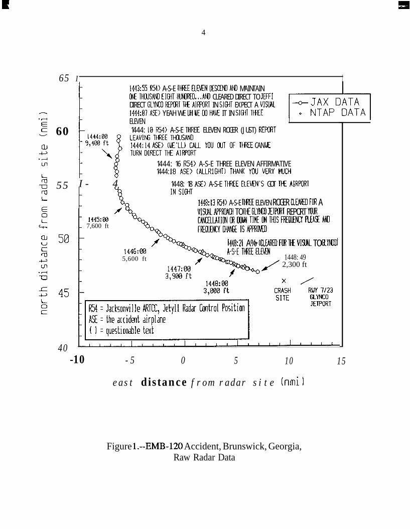
Air traffic control radar data were plotted to show the flightpath offlight 2311 for the last 5 minutes of radar coverage. (See figure 1). The radarantenna beam is limited by line-of-sight. Therefore, because of the distance to theaccident location and the geometry of the radar antenna coverage, the last recordedand lowest possible radar data in the accident area is about 2,300 feet above theground. The interpretation of the radar data, using the anticipated winds aloft,indicates that at the time of the last radar return the airplane’s indicated airspeedhad decreased to 150 knots and that the airplane was on a heading of about117 degrees magnetic.
The accident occurred about 1451 during the hours of daylight, at 3 1015’ 34.8” north latitude and 810 30’ 34.2” west longitude. The bearing and distancefrom the accident site to the threshold of runway 07 was 100 degrees and about9,975 feet, respectively.
1.2 Injuries to Persons
Injuries Crew
Fatal 3Serious 0Minor 0None 0
Total 3
1.3 Damage to Aircraft
Passengers
2000
020
Others Total
0 230 00 00 00 23
The airplane was destroyed by impact and postcrash fire. The valueof the airplane was estimated at $7.8 million.
1.4 Other Damage
Several trees and vegetation in the area of the crash were destroyed bythe impact and the postcrash fire.
4
65 I I
- I 1443:55 RW A-S-E TH%E EtEKN OESCEED AtQ MAINTAINOEt TtWSAN3 EIGHT HlNRED.,.AED CLEARED DIRECT TO JEFF1DIRECT GLYKU REPCRT TtE AIII’ORT IN SIGHT EXPECT A VISUAL1444:07 A%> YEAH WE Ui UE W HAK IT IN SIGHT THZE‘F-l
E 60
-5 55rdL
40
ELEVEN I1444: 18 R54> A-S-E THREE ELEVEN ROGER (JUST) REP@ITLEAVINS THREE TI-WSAND1444:14 ASE> (WE'LL) CALL YOU OUT OF Tt+EE CAN I*ETURN DIRECT TH AIRPORT
1444: 16 R54> A-S-E THREE ELEVEN AFFIRMATIVE1444: 18 ASE> (ALLRIGHT) THANK YOU VERY MUCH
I- 4 1448: 18 A93 A-S-E TH3EE ELEXN’S GOT TtE AIRPORI
1445:m7,600 ft
IN SIGHT1448~13 R54> A-S-E TtfEE ELEVEN ROGER CLEllpED Ftfl AVISUN APPROACH TO K GlyMxl JElKXT REPORT YOMf 448:21 A%> KlEAREO FOR llf VIW TO GIYKOl
1446:@35,600 ft 1448: 49
2,300 ft
-10 -5 0 5 10
east distance from radar site hmil
15
Figure l.--EMB-120 Accident, Brunswick, Georgia,Raw Radar Data
5
1.5 Personnel Information
The captain and first officer were properly certificated in accordancewith existing Federal Aviation Regulations (FARs). The investigation revealedthat the pilots were in good general health.
The captain, age 34, had been hired by ASA on May 15, 1981. Heheld an ATP certificate with ratings for the EMB-120, EMB-110, DHC-7, airplanemultiengine land and included commercial privileges for airplane single engineland. His first-class airman medical certificate was issued on March 1, 1991, withno limitations. He also held an airframe and power-plant mechanic certificate. Thecompany estimated that at the time of the accident he had accumulated about11,724 total flying hours, of which 5,720 hours were in the EMB-120.
He received his initial type rating flight check in the EMB-120 onAugust 18, 1985, and the certificate was issued on August 29, 1985. He had beenactively involved in the acceptance of the first EMB-120 placed in service in theUnited States, and received his training from the manufacturer at the same time asthe Federal Aviation Administration (FAA) project pilot, who subsequently gavehim his type rating flight check. The inspector commented on the flight checkform, “Excellent flight check and oral test, has extensive knowledge of aircraft andsystems. Excellent pilot techniques.” The captains last proficiency check wasaccomplished on February 25, 1991, and his last recurrent training was received onOctober 26, 1990. There was no record of any incidents, accidents, flightviolations, or enforcement investigations in his FAA airman records.
The first officer, age 36, was hired by ASA on June 6, 1988. He heldan ATP certificate with ratings for airplane multiengine land, and commercialprivileges for airplane single engine land. He also held a flight instructorcertificate, with ratings for airplane single and multiengine. His most recent FAAfirst-class medical certificate was issued on July 27, 1990, with no limitations.Because more than 6 months had passed since the first-class medical certificatewas issued, it automatically reverted to a second class certificate. A second classcertification was adequate for his duties as a first officer.
At the time of the accident, the company estimated that he hadaccumulated about 3,925 total flying hours, of which 2,795 hours were in theEMB-120. After being hired by ASA, he completed ground school on June 30,1988, and began flight training in the EMB-120 on July 18, 1988. He completedhis initial proficiency check on July 26, 1988, and his most recent proficiency
6
check was on May 16,199O. He received his last recurrent training on October 18,1990. There was no record of any incidents, accidents, flight violations, orenforcement investigations in his FAA airman records.
1.6 Aircraft Information
The airplane was an Embraer EMB-120, Brasilia, S/N 120-218,registration N270AS, manufactured on November 30, 1990. It was equipped withtwo Pratt & Whitney of Canada PW-118 engines and Hamilton Standard 14RF-9propellers. The airplane received its U.S. standard airworthiness certificate onDecember 20, 1990. The airplane had accumulated about 816.5 total hours offlight time and 845 cycles. Its last daily line inspection was completed on April 4,1991, and its last phase inspection, an “A” check, was completed on April 1, 1991,at 790.9 hours.
During the last phase inspection, an operational check of the flightidle lockout systems for the left and right engines was performed. An inspection ofthe autofeather and beta system1 was performed during the line inspectionconducted on the morning of the accident. During this line inspection, anoperational inspection was accomplished on the flight idle lockout system inaccordance with the manufacturer’s and the airline’s approved procedures.Additionally, the airline’s standard practice was to perform a feather/unfeathercheck of the propellers prior to each flight. Discussions with ASA pilots indicatedthat the check was routine and always accomplished prior to flight. Additionally,other ASA pilots who had flown with the captain of flight 23 11 reported that healways accomplished this check.
A review of the airplane’s maintenance logs disclosed only onedeferred maintenance item. It was for fuel leaking from the auxiliary power unit(APU) cowling. The circuit breaker for the APU had been pulled and securedpending resolution of this discrepancy. There were no recurring pilot complaints
1 The beta range of operation is intended for ground use only. It is the range ofpropeller blade angles between flight idle and ground idle. In this range, the propeller bladeangle is controlled directly by power lever movement, and the propeller governor has no effecton blade angle. The power lever quadrant has gates at the flight idle position to preventinadvertent movement of the power lever below the flight idle position. Additionally, theEMB-120 is equipped with a flight idle lockout system. The lockout system is an electricallyactuated physical stop in the power lever linkage which prevents power lever movement into thebeta range until the airplane is on the ground.
7
or maintenance discrepancy cards concerning the flight control systems, engines,propellers, or auto-pilot system.
The maximum allowable gross weight for the airplane was25,529 pounds with a center of gravity limitation of 18.7 percent and 40 percent ofmean aerodynamic chord (MAC). Upon departure from Atlanta, the airplaneweighed about 23,303 pounds. The landing weight at Brunswick, Georgia, wouldhave been about 22,303 pounds. The center of gravity for the flight was calculatedto have been 32 percent MAC. During the departure from Atlanta, while en route,and at the time of the accident, the airplane was within its allowable weight andcenter of gravity limitations.
1.7 Meteorological Information
At 1450, the reported surface weather observation at Brunswick was:
Clouds--2,500 feet scattered, estimated 10,000 feet broken,ceiling 20,000 feet broken; wind--l60 degrees at 10 knots,visibility--7 miles, temperature--78’ F, dewpoint--69’ F, andaltimeter--30.19 inches of mercury. Moderate rain was reportedat Brunswick at 1350. The rain began at 1303 and ended at 1410.
1.8 Aids to Navigation
aids.There were no reported or known difficulties with the navigational
1.9 Communications
There were no reported or known communications difficulties.
1.10 Aerodrome Information
The Glynco Jetport is located 5 miles north of Brunswick, Georgia, atan elevation of 26 feet mean sea level (msl). The airport had one runway, 07-25,which was 8,001 feet long by 150 feet wide. The airport is served by a commontraffic advisory frequency (UNICOM). When the accident occurred, the largestairplane used to provide commercial passenger service to the airport was theEMB-120.
8
Runway 07 had an instrument landing system and a medium intensityapproach light system with runway alignment indicator lights (MALSR). Therunway was equipped with unlighted distance-to-go markers. The airport wascertificated by the FAA as an Index A airport for Aircraft Rescue and Fire Fighting(ARFF) service. The current FAR Part 139 certificate was obtained on March 31,1982. The airport ARFP station was located adjacent to the terminal building. Theairport’s approved emergency plan was last exercised in February 1990, with a12-month review in January 199 1.
1.11 Flight Recorders
N270AS was not equipped, nor was it required to be equipped, witheither a cockpit voice recorder (CVR) or a flight data recorder (FDR).Commencing on October 11, 1991, CVRs were required on multiengine turbine-powered airplanes with six or more passenger seats. FDRs were required oncommuter airplanes with 20 or more passenger seats. N270AS had been prewiredduring its manufacture for the installation of a CVR and a FDR.
1.12 Wreckage and Impact Information
The accident site was located on flat terrain in a densely forested area.The total length of the wreckage path was about 250 feet from where the airplanefirst struck the tops of the trees. The airplane came to rest, upright, on a heading ofabout 245 degrees. The bearing from the initial tree strikes to the wreckage wasapproximately 355 degrees. Damage to the trees indicated that the airplane wasbanked nearly 90 degrees to the left and in a steep angle of descent at impact. Allof the airplane’s structure was accounted for at the described wreckage site. Therewas no evidence of any in-flight fire or preimpact separation of airframecomponents.
The interior of the passenger cabin was destroyed by fire, and most ofthe fuselage between the cockpit and the aft cargo compartment was burned to thelevel of the ground. Both wings were in their relative positions to the fuselage butseverely burned and distorted. Impact marks on the flap track roller indicated aflap setting between 25 and 45 degrees (the flap roller only rotates about the samepoint after the extension has reached 25 degrees). The flap handle in the cockpitwas set at 25 degrees. Additionally, all of the flap actuator rods indicated similarextensions that correlated with a flap setting of 25 degrees. The elevators, rudder,ailerons, and trim tabs showed no evidence of preimpact failure.
9
Examination of the three landing gear extension actuator rods showedthat all three landing gears were in the extended position. The landing gear controllever in the cockpit was set to the down position. There was no evidence ofpreimpact failure of any of the control system components.
The cockpit power levers were found above flight idle. The lever forthe No. 1 (left) engine was 1.9 inches from the center pedestal forward mountingflange, and the lever for the No. 2 engine was 4.0 inches from the flange. The No.1 condition lever was 0.5 inch from its maximum stop position, and the No. 2 leverwas 1 to 2 inches from its maximum stop position.
The on-scene inspection of the electrical, hydraulic, and fuel systemsfound no evidence of preimpact failure or malfunction.
The on-scene inspection of both engines and propellers did not revealany evidence of preimpact malfunction or failure. There was burned and shreddedvegetation throughout the gas path on both engines. Maintenance records indicatedthat the propellers and engines had a total time of 8 16.5 hours and had accumulated845 cycles since new. The details of the tear-down inspections of the engines andpropellers are discussed in section 1.16.2.
1.13 Medical and Pathological Information
The cause of death for the 20 passengers and the three crewmemberswas determined to have been blunt force impact trauma. Autopsies of the twopilots did not reveal any preexisting conditions that could have contributed to theaccident. The toxicological specimens obtained following the accident werenegative for drugs (licit and illicit) and alcohol.
1.14 Fire
There was no evidence of an in-flight fire. The fuselage was largelyconsumed by the postcrash fire.
1.15 Survival Aspects
The accident was nonsurvivable due to the high impact forces.
10
1 . 1 6 Tests and Research
1 . 1 6 . 1 Airplane Systems
Selected components from the airplane were examined at the SafetyBoard’s laboratory and at the respective manufacturers’ facilities. The cockpitMultiple Alarm Panel (MAP), the overhead panel, engine instruments, flapannunciator panel, engine control pedestal, auto-pilot control panels, and theengine flight idle lockout stops from the engine nacelles were examined in detail.A lightbulb analysis was conducted on all 40 lightbulb capsules in the MAP, aswell as caution and warning lights for the overhead panel and glare shield. Theexamination disclosed no warnings of a problem prior to impact. Examination ofthe lightbulb filaments from the beta warning panel found that the filaments werenot elongated, indicating that the filaments were not illuminated at impact. Thebeta warning light is powered by a switch on the propeller control unit (PCU) andis lighted when the PCU is operating in the beta range. The circuit breaker for theflight idle lockout protection system was found in the “in” or “circuit closed”position.
During the documentation of the cockpit, it was found that thenumber 1 and 2 inverter switches, the autofeather switch, and the rudder boostswitches for the two hydraulic systems were in the “off’ position. These switcheswould normally be in the “on” position during the approach to the airport.Subsequent examination in the laboratory under magnification revealed that theinverter and rudder boost switches had been forced to the “off’ position. Therewas no evidence that the autofeather switch had been forced to the “off’ position,and the switch was found to move freely.
The section of the cockpit control pedestal, which contained theengine power and condition levers, was examined in detail in the Safety Boardslaboratory. The power and condition lever rods and bellcranks beneath thepedestal were examined for evidence of witness marks on adjacent brackets. Nomarks were found that would indicate the position of the levers when the airplanestruck the trees or the ground.
The engine flight idle lockout stops and brackets from both engineswere examined in the laboratory for any witness marks that could be associatedwith preimpact position of the engine controls. Additionally, the solenoid for eachlockout, though damaged by impact, heat, and fire, was examined in detail. These
11
examinations did not disclose the preimpact position of the engine controls due tothe damage that had occurred.
Examination of the rudder power control unit and its two actuatorsrevealed that the units exhibited minimal damage from impact and postcrash fire.The units were examined at the manufacturer’s facility and functionally tested. Thetests found that the power control units and the actuators met or exceeded themanufacturer’s production acceptance test standards. The autopilot servo andassociated components were taken to their manufacturer’s facility for inspection.The units had been exposed to varying degrees of fire, heat, and impact damagewhich precluded functional testing. However, disassembly of the units revealednothing abnormal, and the servo spools were not binding and were free to move.
1.16.2 Engine and Propeller Inspections
The Pratt and Whitney Canada PW-118 is a turbopropeller engineconsisting of two modules, the turbomachinery module and the reduction gearboxmodule, joined to form a single unit. The turbomachinery includes twoindependent, coaxially mounted, centrifugal compressors, each driven by a singlestage turbine, and a two-stage power turbine that drives the reduction gearbox bymeans of a coaxial shaft that passes through the compressor shaft. The reductiongearbox drives a flanged propeller shaft and also provides accessory drives.
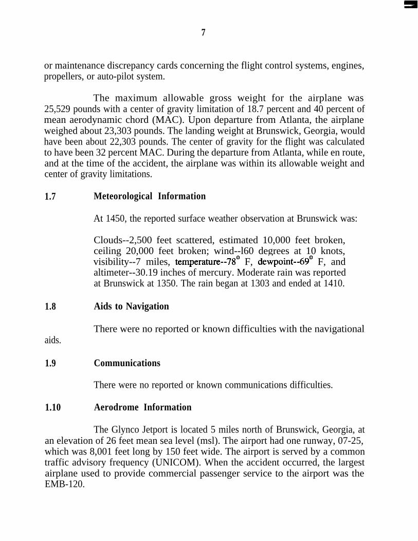
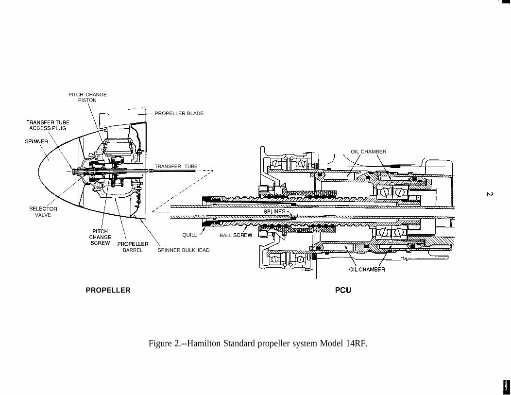
The Hamilton Standard 14RF-9 propeller is a flange mounted,controllable pitch, dual acting, full feathering, reversible, four blade propeller withcomposite blades. The propeller and PCU are mounted on a common centerlineand connected through the propeller shaft by the oil transfer tube. The transfertube provides high pressure oil from the gearbox-mounted main oil pump to thepropeller hub. The PCU governor provides metered oil pressure to operate aballscrew drive which imparts rotary motion to the transfer tube by means of asplined quill. The transfer tube turns an acme screw in the pitch change assembly.The acme screw positions the pitch change selector valve, which directs oil to the“increase pitch” or “decrease pitch” side of the piston. (See figure 2).
Both PCU oil transfer tubes had the newer titanium-nitrided surfacecoating on the splines that engage the quill rather than the originally certificatednitrided surface finish. The spline surfaces on both tubes had a “matted” or dullfinish appearance. The manufacturer’s engineers stated that the matted appearancewas the result of a relatively rough surface and that a smoother surface would have
PITCH CHANGEPISTON
SELECiORVALVE
- PROPELLER BLADE
TRANSFER TUBEbp - --*-P
/’///.’
,//
OIL CHAMBER
SPLINES 7
QUILL BALL SCR/EW
BARREL SPINNER BULKHEAD
PROPELLER PCU
Figure 2.--Hamilton Standard propeller system Model 14RF.
13
more of a gloss or shiny appearance. They further stated that the matted finish waswithin the allowable surface finish specifications for the transfer tube splines.
On the left engine, the PCU remained mounted to the reductiongearbox, and the propeller hub was mounted to the propeller shaft. The PCU hadseparated from the reduction gearbox on the right engine. The oil transfer tuberemained attached to the propeller actuator assembly and was bent in the areaoutside the reduction gearbox at the PCU end. The right propeller hub remainedmounted to the propeller shaft flange and had been exposed to extensive fire. Allfour blades from both propellers had separated from their respective hubs.
The teardown inspections of both the left and right engines revealedno evidence of preimpact damage or of fire or malfunction prior to impact.Additionally, the inspections revealed no evidence of damage that would beassociated with either engine having experienced an overspeed condition.Over-speed experience with the PW-118 has indicated that if an engine has beensubjected to propeller speeds greater than about 120 percent or maximumauthorized speed, rub marks will occur on the power turbine shaft and the interiorof the high pressure rotor shaft. At propeller speeds above about 140 percent, thecompressor impellers will start rubbing the inner diameter of the engine case.
The propeller blades, propeller hubs, transfer tubes, and PCUs wereexamined at the manufacturer’s facility. The examination and matching of damageand score marks on the propeller blades and hub halves were inconclusive andindicated that the blade angles varied from -36.5 to 68 degrees on the left propellerassembly and 28 degrees to 35 degrees on the right propeller assembly.
The end of the pitchlock screw to the end of the pitchlock screw nutwas measured on each propeller to determine the blade angle as correlated with theacme screw position. These measurements disclosed that the blade angle on theright propeller was 22.6 degrees and that the blade angle on the left propeller was3 degrees.
The PCU ballscrew position was measured on both units. Themeasurements indicated that the PCU ballscrew position for the left propeller wasin a location that would coincide with a PCU-commanded propeller blade angle of79.2 degrees, which is the feathered position. The PCU ballscrew position for theright propeller corresponded to a commanded propeller blade angle of24.5 degrees.
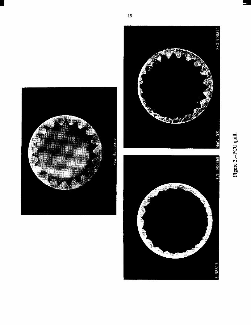
The ballscrew quills were removed from the PCUs for examination.The quills from both PCUs had severely worn internal splines. (See figure 3). Thespline teeth on the left quill were almost entirely worn away, and the wear patternwas slightly off the axial centerline. The right quill spline wear was more eccentricwith a heavy wear pattern on one side and relatively little wear on the oppositeteeth. The left quill was assembled on the left oil transfer tube for measuring radialdisplacement of the quill when engaged on the spline teeth of the transfer tube.While thus assembled, the quill would rotate freely about the tube, and the quillteeth were worn to the extent that they did not engage the grooves or teeth on thetube. A similar test accomplished with the right quill indicated that the quill wouldengage the spline teeth of the transfer tube.
1.16.3 Propeller System Static Testing
During the inspection of the PCU quills, Hamilton Standardrepresentatives and engineers stated that while the extreme wearing of the quill wasunusual, the FAA certification tests and computer simulation modeling of thepropeller system indicated that the disengagement of the quill from the transfertube would not result in an unsafe condition. The representatives stated that such adisengagement would result in the propeller either staying at the blade angle inwhich the disengagement occurred or eventually assuming the feathered orstreamlined position. The manufacturer’s representatives stated that because of the“fail-safe” nature of the propeller design, as confirmed by testing and failure modesand effects analysis,2 and the relatively low torque loads imposed on themechanism, the transfer tube and quill did not require any periodic inspection ortime limits for service.
To determine the effects on propeller control with a severely wornquill, a series of tests was conducted in the engine manufacturer’s test cell in July1991. Three quill configurations were tested: a new standard production quill; aworn quill returned from service; and a modified quill with all of the spline teethmachined away. A transfer tube with the titanium-nitrided splines was used in allof the tests.
2 Failure Modes and Effects Analysis (FMEA) is a study of the statisticalprobability of failure modes of individual components within an operating system and theconsequences of each assumed failure on the system operation. Effects analysis considers theability of the system to prevent additional damage or the development of an unsafe condition.
15
16
The new quill was first installed in the PCU to establish a baselineprofile for the standard configuration. After this test, the new quill was replacedwith the worn quill. As expected in this configuration, the system was unable tounfeather the propeller after engine start, action that would have precluded furthertesting. To continue the tests, a pitchlock adapter was installed in the propeller oilsystem to permit the engine to be started with the propeller at a fixed blade angleposition and to provide normal operation of the PCU after engine start. After theengine reached the desired operating speed, the pitchlock adapter was deenergizedto allow the PCU to operate in its normal governing mode. With both the wornquill and the machined quill, this method was used to start the engine with theblade angle at a normal in-flight setting of 33 degrees. Two tests were run withboth the worn and machined quills. After start, the condition lever was set to select85 percent propeller speed (Np), and the propeller operated at 81 percent Np in thefirst test and 90 percent Np 111 the second test. In each case, when the pitchlockadapter was deenergized, the blade angle slowly and steadily moved toward featherwith PCU action having no effect on blade angle. Inspection of the PCU found thequill to be in a position that would correspond to a feathered propeller.
1 . 1 6 . 4 Propeller System Flight Tests
It was recognized prior to the start of the test cell experiments that thedynamic effects of airplane vibration and aerodynamic loads on the propellerassembly could not be duplicated in the test cell. Therefore, flight tests wereconducted with a machined quill used to simulate an extremely worn quill inNovember 1991. The aircraft used for these tests was the prototype EMB-120.The engine, propeller hub, actuator, and PCU used in the static testing wereinstalled in the No.1 (left) engine position. Different propeller blades had to beused because those used in the test cell were considered unairworthy. The actuatorwas modified to include a fixed low pitch stop at 22-degrees blade angle, which theairplane manufacturer determined would provide for sufficient controllability of theairplane in the event that the propeller blades went into low pitch rather thanfeather. The pitchlock adapter and the titanium-nitrided transfer tube used for thestatic testing were also used for the flight tests.
The original test plan called for three quills to be used: a standardproduction configuration; a modified quill with all of the spline teeth machinedaway; and the worn quill used in static testing. The standard quill was used toverify that the airplane could be flown using the pitchlock adapter to maintain aselected fixed propeller blade angle and to establish initial test conditions. Aprocedure was devised to approach pitchlock adapter activation from higher blade
17
angles to achieve the target test blade angle of 38 degrees. Airplane climbcapability, controllability and engine controllability were thus demonstrated at thetarget fixed blade angle.
Tests were then conducted with the modified quill installed in thePCU. During ground tests, when the pitchlock adapter was activated the propellerblade angles would drift toward lower values. When the pitchlock adapter wasdeactivated the propeller blade angles would drift toward higher values. In highspeed ground runs, it was possible to set the blade angle to 46 degrees prior toengine start, then activate the pitchlock adapter, and start the takeoff ground roll.At approximately 60 knots indicated airspeed (KIAS), the pitchlock adapter wasdeactivated, and the blade angle increased to about 68 degrees. When thepitchlock adapter was activated, the propeller blade angle remained at 68 degrees.Based upon this experience, the test pilots decided that the airplane could be flownand that the test condition of 42 degrees of blade angle could be set by alternatelyactivating and deactivating the pitchlock adapter.
Using the above procedure, the airplane was flown to the testcondition of 125 KIAS at 4,000 feet msl. The pitchlock adapter was thendeactivated at a propeller blade angle of 37 degrees, and the blade angle slowlydecreased to 27 degrees over 4 minutes. When propeller speed reached100 percent, the power lever was reduced to maintain that propeller speed. Theblade angle then decreased at a higher rate until reaching the 22-degree stop.
A second flight was conducted using the modified quill but at aninitial test configuration of 150 KIAS at 5,000 feet msl. The pitchlock adapter wasdeactivated during the takeoff roll at a propeller blade angle of 46 degrees, and theblade angle slowly decreased during climb to 33 degrees at 5,000 feet. Power wasthen reduced to maintain 85 percent propeller speed at 35 percent torque. Theblade angle slowly increased to 39 degrees. With no further engine controlchanges, the blade angle then decreased at an average rate of approximately5.5 degrees per minute to the 22-degree pitch stop. It was noted that the propellerblade angle decreased in steps and that while it was moving the average blade ratewas about 7.5 degrees per minute. The test was then terminated, and the airplanereturned to base. An overspeed of the propeller did not occur in either of the twotests.
The flight test pilots stated that the aircraft became difficult to controlas the propeller reached the 22-degree stops. Therefore, in the interest of safety, nofurther flight tests were conducted. The pilots also stated that they did not notice
18
any discernible control problems with the airplane until the propeller blade anglewas reduced from 26 to 24 degrees. Further, they said that the first indication ofanything unusual was the tendency for propeller speed to rise above 100 percent.They stated that they were able to prevent overspeeding of the propeller byreducing the power lever angle (PLA). At no time during the flight test did thepropeller exceed the overspeed governor setting of about 110 percent.
Although only two relatively short tests were conducted, the rate atwhich propeller blade angles decreased to lower blade angles appeared to besensitive to several factors, such as airplane attitude, airspeed, and power settings.Because of the potential for loss of airplane control, it was not determined what therate of propeller pitch change would have been if the propeller blade angles hadbeen allowed to go below 22 degrees.
1.16.5 Flight Simulator Tests
Since many of the possible conditions that could lead to the accidentwere potentially too hazardous to duplicate in flight, the Safety Board requestedthat the manufacturer of the airplane make its engineering flight simulator availablefor a series of tests. In support of these tests, the manufacturer of the propellerassembly provided its most recent simulator model of the propeller system.Additionally, computer software changes were made to simulate reverse propellerthrust with the accompanying loss of lift over the section of wing directly behindthe propeller.
The majority of witnesses stated that the airplane was in a steep leftbank as it abruptly descended to the ground. Evidence at the crash site indicated ahigh rate of descent, a northerly heading, and almost 90 degrees of left bankattitude when the airplane struck the trees. The Safety Board evaluated variousmalfunctions to determine whether they were consistent with the evidence. Sevendifferent failure scenarios were investigated: full upward deflection of the leftaileron; flap asymmetry; full left deflection of the rudder; a linear decrease in theleft propeller blade angles; a PCU-driven decrease in the propeller blade angles;oscillating propeller blade angles; and the movement of the power lever from flightidle to ground idle in flight. In each case, it was assumed that the malfunctioncould not be deactivated. Multiple simulator flights were performed for eachfailure mode.
E19
The starting point for the majority of simulator flights was the point oflast radar contact with the accident flight: 2,300 feet above msl, 2.6 nautical miles(nmi) from the crash site, and 4.1 nmi from runway 07. The initial configurationsassumed applicable to the accident flight were: landing gear extended, flaps25 degrees, condition levers to 100 percent N , power levers to 30 percent torque,and airspeed between 125 and 150 KIA .E The initial descent rate wasapproximately 1,000 feet per minute, on a heading of 117 degrees.
Prior to the simulated malfunction tests, simulations of a normalapproach to the airport were accomplished to establish a basis for comparison.These simulated flights approximated the radar-defined flightpath of the accidentflight to the point where radar data ceased. The accident flightcrew’s intendedapproach path after radar coverage ended is unknown; however, an anglingstraight-in approach was assumed.
The simulated baseline flights originated at points as far away as17 nmi from the runway at 7,600 feet msl, and showed that flight 231 l’s radar-defined flightpath was reasonable to the extent that a straight-in approach andnormal landing could be made from any point along the path while using standardEMB-120 flight manual procedures. The manufacturer’s engineering test pilot andthe other pilots participating in the test experienced no difficulty with the approach,and in every case the landing was successful.
During certification testing, the EMB-120 was flown with asymmetricflaps, runaway aileron, and runaway rudder conditions. However, quantitativeflight test data suitable for use in the simulation model were not recorded.Therefore, during the investigation, wind tunnel data were used to simulate flapasymmetries, aileron hardovers, and rudder hardovers.3
During the left aileron hardover test, the maximum autopilot servotorque was used to produce a left roll. During EMB-120 certification testing, itwas shown that one pilot could overcome this type of malfunction and control theairplane. In the simulated flight tests, the pilots were able to control the airplaneand successfully land.
3 The terms “hardover” or “runaway,” when applied to a flight control surface,mean that the surface is driven to an uncommanded position through some type of malfunction.The flight control surface might be driven to either partial or full deflection, depending on thenature of the malfunction.
20
Two different flap asymmetry conditions were evaluated: the leftoutboard flap panel was in the 0 degree position and all other panels were at45 degrees; and the right outboard flap panel was set to 45 degrees and all otherpanels were at 0 degrees. There was little difference between the two conditions interms of the magnitude of the rolling moment that had to be counteracted by thepilot to control the airplane. During EMB-120 certification testing, it was shownthat one pilot could overcome either type of malfunction and control the airplane.In the simulated flights, the pilots counteracted the malfunction and successfullylanded the airplane.
The left rudder hardover was simulated by assuming that themaximum available hydraulic actuator force was applied, producing a left rudderdeflection of 9.5 degrees. One flight simulation was accomplished, and the pilotcounteracted the rudder deflection and landed. During EMB-120 certification, itwas shown that one pilot could overcome an autopilot-induced rudder hardoverthat produced approximately 5 degrees of rudder deflection.
The remaining four simulator tests addressed EMB-120 controllabilitywith abnormally low propeller blade angles on the left engine. The propeller bladeangle for an engine at flight idle power is between 17 and 25 degrees, dependingupon airspeed. At blade angles below the flight idle angle of 17 degrees, thepropeller can begin to produce considerable aerodynamic drag. Aerodynamicprinciples dictate that as propeller thrust increases, there is a corresponding rise inthe dynamic pressure of the airflow behind the propeller disk. Similarly, aspropeller thrust decreases, there is a corresponding reduction in the dynamicpressure of the airflow behind the propeller disk. These changes in pressure occurover a substantial portion of the EMB-120 wing because of the relatively largediameter of the propeller.
The high dynamic pressure of the airflow behind a normally operatingengine/propeller produces a sizable lift “gain” on the affected wing. When thepropeller is generating reverse thrust, there is a reduction in airflow behind thepropeller disk that produces a sizable lift “loss” on the affected wing. Thesechanges in lift contribute to the total rolling moment that must be offset by theflight controls to maintain wings-level flight. Empirical data for the effects of in-flight reverse thrust do not exist for the EMB-120 and therefore theoreticalaerodynamic calculations were used to simulate the effect of reverse thrust on winglift.
e21
The most critical situation occurs while one propeller is producingforward thrust and the other is producing substantially less or reverse thrust. Thelift “loss” and lift “gain” on each wing unite to roll the airplane toward thereversing propeller. The simulation model showed that roll control becameincreasingly difficult as thrust and blade angle decreased on the left propeller. Theleft rolling moment was most pronounced at high power levels on both engines andwas the most significant factor affecting airplane controllability during thesimulations. The yawing moment produced by the asymmetrical thrust was a lesscritical factor.
In the first series of tests, the investigators simulated bypassing thePCU by programming into the simulator different decreasing propeller blade anglerates of change on the left propeller. Normal propeller blade angle was the initialcondition for each flight. Blade angle rates of change ranged from 3 to 15 degreesper second. In each of the simulations, the airplane crashed short of the runway.Beginning with the same approach heading as the accident flight, the simulatorattitude at crash impact was usually left wing down, along a northwesterly tonortherly heading.
The propeller blade angle rates of change that occurred during theflight tests conducted with the prototype EMB-120 indicated that a slow rate ofchange might be pertinent to the investigation of airplane controllability.Therefore, a series of simulator tests was conducted using the relatively lowpropeller blade angle rate of change of 7.5 degrees/minute that was exhibited inflight testing. Engine and propeller controls were not moved during the earlystages of each test so that torque and propeller speed (Np) could be monitored.Changes in N
P,occurred 20 to 30 seconds after the introduction of the malfunction
even though P A remained constant.
The lower blade angle rate of change allowed the pilot to control thesimulator for a longer period of time after the introduction of abnormal blademovement. In two tests, the simulator was controllable for approximately5 minutes after the introduction of abnormal blade movement. However, a crashstill occurred after propeller blade angle on the left propeller neared zero degrees.It was found that as the blade angle on the left propeller approached zero degrees, areduction to idle power on both engines was necessary for the pilot to acquire awings-level attitude. Although roll control could be maintained while the powerwas at idle, the simulated airplane could not fly to the runway and a wings-levelcrash occurred.
2 2
One simulator test used the 7.5 degrees/minute rate of blade anglemovement but with the malfunction initiated about 5 nmi away from the runwayand only 2 minutes of flying time needed to land. This brief period did not provideenough time for the blade angle on the left propeller to reach the target level ofzero degrees. Although roll control became progressively more difficult, the leftpropeller blade angle remained sufficiently high (12 degrees at the end of thesimulation) to allow the pilot to maintain control and successfully land.
In one group of tests, the simulator was configured to allow aPLA-commanded pitch change to preselected blade angles. There were threesimulated flights. Two of them used a target blade angle of 3 degrees, and one ofthem used a target blade angle of 15 degrees. The target angles were reached ineach flight with a blade angle rate of change of more than 20 degrees/second. Ineach case, the airplane crashed short of the runway.
Four simulations were accomplished to evaluate airplanecontrollability following the use of ground idle thrust in flight. These conditionsrequired the PLA to be below flight idle. In three of the tests, the left PLA wasmoved from flight idle to ground idle and left in that position. In all three tests theairplane crashed short of the runway. The headings at impact were northerly tonortheasterly.
In one simulation, both PLAs were placed into the ground idle rangeand then back to normal after about 5 seconds. It was noted that the right PLA wasnot calibrated with the left PLA, apparently because of the differences between theright and left propeller models. Controllability was returned after PLA wasreturned to flight idle, and a successful landing was made.
.‘.*The last test evaluated a cyclic propeller blade angle. The minimum
blade angle was 3 degrees and changed with time according to a cosine function tosimulate an oscillating propeller. The period of oscillation was assumed to be5 seconds. The airplane crashed short of the runway in this test.
1 . 1 7 Other Information
1 . 1 7 . 1 Hamilton Standard Alert Service Bulletin
In January 1991, a PCU for the model 14RF-9 propeller was returnedfor service to Hamilton Standard for repair. During the service inspection, it was
23
found that the splines on the quill were extremely worn. The quill had about3,931 hours in service. In the following 4 months, three other worn PCU quillswere discovered by Hamilton Standard’s overhaul personnel. On February 14,1991, a worn quill with 1,975 hours in service was found during overhaul of aPCU; one on April 8, 1991, with 820 hours in service; and one on May 3, 1991,with 726 hours in service. All of the PCUs that contained these quills were sent infor service after the operators found that the propeller would not feather orunfeather during a ground test. The manufacturer’s engineers stated that thesePCUs were originally equipped with a transfer tube that had the titanium-nitridedsplines rather than the nitrided finished splines.
In several years of service, with some PCUs accumulating severalthousand hours in service, the manufacturer stated that quill spline tooth wear hadnot been a problem. Thus, it was determined that the accelerated wear was a resultof the introduction of a transfer tube having titanium nitride-coated spline teeth.The titanium nitride-coated surface is significantly harder than the case-hardenednitrided surface of the quill spline teeth. The history of the introduction of thetitanium nitride-coated transfer tubes is further discussed in 1.17.2.
Hamilton Standard representatives reported that initially they were notconcerned about the finding of the worn quills because of the “fail-safe” designfeatures of the propeller system. They believed that a disconnect of the transfertube from the quill could only occur when a relatively high torque load was placedon the quill and that such a torque only happens when ground idle is selected,during a feather/unfeather check, or a rapid increase in PLA. It was reported thatthe torque load during a feather/unfeather check was about 7 times greater than theloads during normal flight.
However, based upon the number of worn quills found, includingthose from the accident airplane, the manufacturer issued Alert Service Bulletin14RF-9-61-A49 on May 7, 1991, that advised all operators to inspect PCUs forworn quills and began a fleet campaign to remove from service the titaniumnitrided transfer tubes and to replace them with the original nitrided tubes. TheAlert Service Bulletin defined the manufacturer’s recommended inspectionintervals and wear limits for the quill.
On May 9, 1991, the FAA issued emergency airworthiness directive(AD) T91-10-5 1, based upon the service bulletin, which required inspection of thePCU ballscrew quill in installations that had a titanium-nitride transfer tube at amaximum of 500 hours of service and established repetitive inspection intervals.
24
Instructions were included that provided operators with procedures and wear limitsfor inspecting the quills.
Reports following the initial inspections indicated that there was aneed to reduce the allowable wear limits on the quills and the periodic inspectionintervals. In one case, it was reported that a quill that passed inspection did notengage the transfer tube when it was reinstalled in the PCU. Based upon thisinformation, the FAA issued emergency AD T9 l-l l-5 1 on May 19, 1991 whichsuperseded the previous AD. AD T91-1 l-5 1 reduced the initial time-in-serviceinspection to a maximum of 200 hours and reduced the wear limits and repetitiveinspection hours for quills that were returned to service. The terminating action forboth ADS was the installation of the original nitrided transfer tube. HamiltonStandard reported that all of the titanium-nitrided transfer tubes had been removedfrom service by August 1991.
1.17.2 Transfer Tube Finish Change
The FAA certification office responsible for the propeller systemreported that there had never been a reported problem with the spline tube-quillgear connection when it was equipped with the nitrided spline tubes. The nitridedsurface was originally specified for the propeller system and had beenmanufactured until June 1990. A review of the FAA service difficulty reports andthe malfunction or defect reports did not reveal any service problems with theoriginal nitrided spline tubes.
The FAA and the manufacturer reported that the surface finish on thetransfer tube spline was changed in order to improve the ability to manufacture thetransfer tube. It was further stated that the transfer tube had been a candidate in themanufacturer’s product improvement program. The change in surface finish wasmade to eliminate the finish scaling and the straightening problems encounteredwhen nitriding the spline teeth by the hot bath method. The titanium-nitridesurface is applied by a vapor deposit process at much lower temperatures. Themanufacturer’s various technical review committees, following the procedures ofthe FAA-approved Quality Program Manual and Engineering Systems Manual,concurred with the change to the titanium-nitrided coating. The manufacturer’spast experience had indicated that the wear rate for the titanium-nitrided coatingwas three to four times less than the original nitrided finish. However, wear wasnot considered a factor because the design load of the spline to quill is relativelysmall, about 7 inch-pounds. Additionally, the manufacturer reportedly had
25
considerable experience in using titanium-nitrided coatings on other similarapplications and engaging materials with different surface finishes without anyproblems.
The surface roughness specification for the transfer tube spline teethwas the same for both finishes, and the manufacturer reported that productionsplines always met the design requirements. On May 31, 1991, the manufacturerreverted back to the use of the original nitriding process for the transfer tube splinesurface and began a program to remove the titanium nitrided tubes from service.At that time, the surface finish specification, both prior to and after nitriding, wassignificantly changed in order to ensure a smoother surface on the transfer tubesplines.
Prior to applying for approval of the titanium-nitrided transfer tube forservice, Hamilton Standard conducted a series of test cell runs from June 18 toAugust 1, 1987, using a General Electric turbine engine. During these tests, a totalof 229.18 engine hours was accumulated, exceeding the 150 hours normallyrequired for a propulsion system certification test. During the tests, the propellerwas feathered twice every 55 minutes, resulting in an accumulation of 500 feathercycles. Additionally, the test cycle provided for 750 propeller reverse cycles and750 cycles from ground idle to takeoff and back to ground idle. The spline surfaceof the titanium-nitrided transfer tube used had a “bright gold” or “shiny” finish.Both the transfer tube and the ballscrew quill were examined after the tests andfound in good condition with no visible signs of wear. Tests were notaccomplished with a “matted gold” or dull finished titanium-nitrided transfer tube.
At the completion of these tests, further review of the proposed designchange was accomplished by Hamilton Standard’s Configuration Manager, aProduction Control Representative, a Manufacturing Engineer, a Quality ControlEngineer, a Reliability Engineer, a Project Engineer, and a FAA-DesignatedEngineering Representative (DER). Upon their approval of the proposed change infinish coating materials, another DER completed the FAA Statement ofCompliance form, indicating his approval of the proposed change.
The type-design change provisions of 14 CFR section 21, subpart Dwere used by Hamilton Standard to approve the titanium-nitrided coating for thetransfer tube spline. The coating change was classified as a minor change to thetype design under FAR section 21.93. Since the FAA authorizes, under FARsection 21.95, a type certificate holder to introduce a minor change without priorFAA approval, Hamilton Standard approved the coating change after completing
E26
the above-mentioned tests and analysis. The statement of compliance form wassubmitted to the FAA certification office as part of Hamilton Standards periodicdata submittal. The design change paperwork was reviewed by FAA certificationengineers and subsequently approved on January 6, 1988. However, the firsttitanium-nitrided transfer tubes did not enter service until July 1990.
The failure mode and effects analysis of all the propeller componentswas completed by the manufacturer, and a report was submitted to the FAA duringthe original certification of the propeller system. The components were groupedinto two failure categories. The first group included failures that had a predictedprobability of occurrence of less than 10-9, and the second group included failureswith a predicted probability of greater than 10-9. The transfer tube and quillinterface were listed in the first group and were assigned as an “on condition”inspection item because of the perceived extremely remote possibility of failureand the lightly loaded application. For an “on condition” component, inspection isonly required after a problem is found during service. Since the transfer tube andquill were considered structural parts having a remote possibility of failing,verification of the propeller system response following the failure of thesecomponents was not required.
The transfer tube was also an item that had been inspected under theFAA Maintenance Review Board’s analytical sampling program of propellercomponents. As previously stated, there had been no reported discrepancies orwear of the spline tube during these inspections. Therefore, the FAA determinedthat there was no need to change the “on condition” inspection criteria for thetransfer tube.
The certification standards for reversible propellers are contained in14 CFR section 35.21. These standards state, in part, the following:
A reversible propeller must be adaptable for use with a reversingsystem in an airplane so that no single failure or malfunction inthat system during normal or emergency operation will result inunwanted travel of the propeller blades to a position substantiallybelow the normal flight low-pitch stop. Failure of structuralelements need not be considered if the occurrence of such afailure is expected to be extremely remote.4
lo-?4 The FAA has defined “extremely remote” as a possibility of failure of less than
27
The FAA reported that during the certification of a propeller system,the FAA establishes a certification basis or criteria for the propeller system. Themanufacturer must then demonstrate compliance with the certification basis by acombination of testing, comput& modeling, and analysis. The average percentagedistribution of these activities for propellers is: 72 percent for testing, 2 percent forcomputer modeling, and 26 percent for analysis. After satisfactorily demonstratingcompliance of the propeller with the certification basis, the FAA issues a TypeCertificate. Flight test evaluation of an airplane powered by the propeller isaccomplished during the FAA’s certification of the airplane.
1.17.3 Propeller Control Unit Servo Ballscrew Wear
During the investigation, the Safety Board became aware of incidentsinvolving another problem with the Hamilton Standard PCU used on the EMB-120.On three occasions involving different airplanes, the operators found that apropeller would not feather during ground tests. The PCUs were sent to themanufacturer’s facility for overhaul. Unlike the worn quill problem, the inspectionof the PCU components found that the ballscrew teeth that engage the quill wereextremely worn and would ‘not engage the gear teeth on the quill. Themanufacturer first noted this problem on September 7, 1990, while inspecting aPCU that had about 3,600 hours in service when returned. The next occurrences ofthis problem were on March 5, 1991, on a PCU with about 5,400 hours in serviceand on May 18, 1991, on a PCU with about 2,600 hours in service. As in the caseof the worn quills, the manufacturer believed that the disengagement would onlyoccur during the relatively high torque loads during a feather/unfeather check andthat servo ballscrew wear was not a safety of flight issue.
On February 28, 1992, an Air Littoral EMB-120 experienced a loss ofpropeller control after takeoff from Rome, Italy. It was reported that prior tostarting the engines, the pilot noticed that the propeller was not fully feathered.After starting the engines, he accomplished several feather/unfeather checks andbelieved that the propeller opebrated satisfactorily. After takeoff, the pilot noticedthat the engine was overtorquing to about 110 percent and that propeller speed wasdropping. He reduced PLA to flight idle and returned to the airport. During thefinal approach to landing, he shut down the engine and the propeller did feather.The subsequent landing and roll out were uneventful. The inspection of the PCUrevealed extreme wear on the outer diameter splines of the servo ballscrew to theextent that the servo ballscrew would not fully engage the quill. The investigationof this incident is being conducted by the French Bureau Enquetes-Accidents.
28
Based upon findings of the Air Littoral incident, Hamilton Standardissued a service bulletin on March 9, 1992, that provided for periodic inspectionsfor wear of the internal splines on the propeller model 14RF-9. Only propellermodel 14RF-9 was addressed by the service bulletin as the extreme spline wear hasonly been documented in EMB-120 airplanes equipped with this propeller. OnApril 10, 1992, the FAA issued airworthiness directive 92-08-03 that requiredcompliance with the Hamilton Standard Service Bulletin.
1.17.4 Flightcrew Scheduling
The flightcrew spent the night before the accident on a layover in ahotel following a g-hour and 21-minute duty day that included 5 hours and40 minutes of flight time. They were off duty for about 8 hours. This scheduled“‘reduced rest” period provided the crew with about 6 to 6.5 hours of rest from thetime they checked into their hotel until they received their wakeup calls. When theflightcrew was observed eating a meal on the morning of the accident prior toreporting for duty, they appeared alert and normal in all respects.
The rest time of ASA flightcrews, including the pilots of flight 2311,complied with the reduced rest provisions of 14 CFR Part 135. The FAA, uponpublishing the flight time limitations and rest requirements for Part 135 scheduledoperations in 1985, referred to the use of the reduced rest provisions of theregulation and stated:
The purpose of the rest reduction is to allow schedulingflexibility for the benefit of air carriers, pilots, and the flyingpublic. Although this rule allows for scheduling a reduced rest, itdoes not allow for any reduction of the minimum reduced rest orthe minimum compensatory rest under any circumstances.Therefore, in order to benefit fully from this flexibility, an aircarrier should schedule realistically to avoid any possible flightschedule disruptions. The FAA expects that most air carriers willschedule at least 9- to 1 l-hour required rest periods. But in thoseinstances when air carriers need to schedule a shorter rest orwhen rest must be reduced because actual flight time hasexceeded scheduled flight time, the rule allows for somescheduling flexibility.
The FAA further stated that:
29
The FAA wants to stress that the goal of these revisions is toprevent fatigue. . ..It is the responsibility of both the operator andthe flight crewmember to prevent fatigue, not only by followingthe regulations but also by acting intelligently andconscientiously while serving the traveling public. This meanstaking into consideration weather conditions, air traffic, health ofeach flight crewmember, or any other circumstances (personalproblems, etc.) that might affect the flight crewmember’salertness or judgment on a particular flight.
During the rulemaking process, airline and regional airline associationrepresentatives assured the FAA that the reduced rest provisions of the proposedregulation, necessary to provide an air carrier with the flexibility to cope withoperational delays, would be applied by air carriers on a contingency basis, andwould not be used to routinely develop daily schedules.
The reduced rest provisions of the regulation allow an air carrier toshorten the rest period of a flightcrew to accommodate operational delays whenthey are encountered. However, a review of the duty and rest time of the accidentflightcrew and other ASA pilots indicated that reduced rest periods were scheduledfor about 60 percent of the layovers in day-to-day operations. A review of otherregional airlines indicated a similar tendency to schedule duty cycles that wouldrequire reduced rest schedules.
The FAA has recently commissioned a working group to study theflightcrew duty time for operations conducted under 14 CFR Part 135. Theworking group is expected to convene officially after May 1992, and will be part ofthe Aviation Rulemaking Advisory Committee.
I30
2. ANALYSIS
2.1 General
The investigation revealed that the flightcrew was properlycertificated and qualified in accordance with applicable Federal AviationRegulations (FARs) and company requirements and that they were in good generalhealth and had proper FAA medical certificates at the time of the accident. Therewas no evidence of adverse medical conditions that affected the flightcrew, andthey were not under the influence of, or impaired by, drugs or alcohol.Additionally, there was no evidence that the performance of either flightcrewmember was impaired by fatigue.
The investigation determined that the airplane had been maintained inaccordance with applicable FARs and company operations’ specifications.Weather was not a factor in the accident.
Simulation tests of asymmetric flaps, runaway aileron, and runawayrudder malfunctions found that in every case, and with different pilots at thecontrols, it was possible to control the airplane and to successfully land theairplane. These simulation tests were consistent with the certification findings thatsuch malfunctions would not cause uncontrollable flight characteristics. Also,extensive investigation disclosed no evidence of problems with any flight controlsystem. The subsequent inspection of the control system actuators did not find anyevidence of a malfunction or asymmetric condition. Therefore, the Safety Boarddoes not believe that a flight control system malfunction either caused orcontributed to the accident.
Examinations of the engines revealed that all damage was the result ofimpact and ground fire. No evidence of malfunction or failure prior to groundimpact was found. The rotational-type damage in the compressor impellers andturbines of both engines indicates that both engines were operating normally atimpact. The presence of burned and shredded vegetation throughout the gas path isalso indicative of normal air flow and combustion in the engines at the time ofimpact with the trees.
The circumstances of this accident indicate that a severe asymmetricthrust condition caused a left roll that led to loss of control of the airplane. TheSafety Boards investigation examined all the possible events that could have
31
caused the loss of control. The powerplant and propeller examinations indicatedthat the engines were operating normally but that a propeller system malfunctionoccurred which caused abnormally low propeller blade angles and a high dragcondition on the left side of the airplane.
2.2 Propeller System Components
On the right engine, the pitchlock acme screw was in a position thatcorresponded to a propeller blade angle of 22.6 degrees, and the ballscrew was in aposition of 24.5 degrees. This difference of 1.9 degrees is within the expectedaccuracy of the measurements. Therefore, the evidence indicates that the PCU onthe right engine was properly controlling the right propeller blade angle prior toimpact.
Examinations of the left propeller components indicated a propellerblade angle of about 3 degrees at impact. This position was based upon theposition of the pitchlock acme screw. The left PCU ballscrew position indicatedthat the PCU had commanded a blade angle of 79.2 degrees. The discrepancybetween the ballscrew position and the position of the pitchlock acme screw is astrong indication that a disconnect between these two components occurred prior toimpact and that the left propeller had achieved an uncommanded blade angle belowthe normai flight range.
The position of the PCU ballscrew on each engine is significant.When an propeller off-speed condition is sensed by the governor, oil pressure isdirected to one side or the other of the ballscrew to move the servo valve by meansof the transfer tube, thereby commanding an appropriate blade angle change.
If the speed change does not occur, the ballscrew will continue tomove until it reaches its limit of travel. Because the left PCU ballscrew was foundin a position corresponding to feather blade angle, and the left propeller actuatorwas at a low blade angle position, it is apparent that a condition existed in whichthe PCU was moving in a direction to slow propeller speed by increasing bladeangle; however, the actuator did not respond. Because there was no preimpactdamage to preclude normal servo valve and actuator operation, the most likelyreason for the failure to change blade angle was the failure of the PCU to positionthe servo valve because of the worn quill spline, which was disengaged from thetransfer tube spline teeth.
e32
The cause of the wear on the quill spline teeth is attributed to thedifference in surface hardness between the titanium-nitrided coating on the tubesplines and the conventionally nitrided quill splines. The titanium-nitrided surfaceis much harder than the original nitrided surface. Because it is a thin coatingapplied over the base material, it conformed to, but did not fill in, any surfaceirregularities. It was found that the surface roughness specification for the originalnitrided finish was the same as that used for the titanium-nitrided finish.Therefore, the relatively hard and rough titanium-nitrided surface sliding on a lesshard surface would act like a file and cause abnormal wear of the gear teeth in thequill.
Using measurements and the inspection procedures for the quill andtransfer tube of the Hamilton Standard Alert Service Bulletin, it was determinedthat the left PCU quill spline was worn to the extent that its gear teeth did notengage the transfer tube spline. In addition, the test cell and flight tests showedthat the propeller blade angle could not be controlled by the PCU with adisengaged transfer tube. In the test cell, the blade angle moved toward high pitch;however, the propeller was operating at zero airspeed and did not experiencenormal flight loads. In contrast, the flight tests showed that the blade angle wouldmove toward low pitch with a disengaged transfer tube. The blade characteristicsindicate that centrifugal and aerodynamic twisting moments tend to move theblades toward low pitch.
The Safety Board believes that the worn quill on the left engine PCUbecame disengaged from the transfer tube prior to the loss of control of the airplaneduring the approach to Brunswick. Moreover, the propeller blades moved to a lowangle, resulting in an asymmetric lift and drag condition that exceeded thecapability of the pilots to counteract with the airplane controls available.
In the flight test, with a quill with no teeth, the propeller blade angledecreased at a slow rate--a situation that the pilot might be expected to notice andattempt to correct. However, without quill engagement, the pilot would have nocontrol of propeller blade angle and would have had limited control of enginespeed by reducing torque or shutting the engine down. Because of the 22-degreefixed stop used for the flight test, it is not known whether the pitch change ratewould increase as the propeller blades moved below that angle. The blade anglewould probably continue to decrease due to a centrifugal twisting moment resultingfrom the distribution of mass along the propeller blade chord line. With thedisengaged spline, the propeller could not be feathered; thus, a high asymmetric
33
drag condition would have existed along with a substantial loss of lift on the wingsection aft of the propeller disk.
The damage to the engine and propeller indicates that the engine wasdeveloping power at impact. Therefore, the Safety Board believes that the crewdid not shut down the engine and that after the propeller blade angle decreased tothe range below flight idle, the airplane was no longer controllable. The SafetyBoard believes that the flightcrew would have taken actions to regain control of theleft propeller; however, the actions that were taken and the effects of those actionare unknown.
2.3 Loss of Propeller Control
It was the airline’s procedure to conduct a feather/unfeather check ofthe propellers prior to each flight. Discussions with pilots for the airline indicatedthat the procedure was routine and always accomplished by the captain of flight2311. Therefore, the Safety Board believes that in all likelihood the flightcrew offlight 2311 accomplished the feather/unfeather check prior to departing Atlanta andthat no problems were noted during the check.
Hamilton Standard engineers said that in accomplishing thefeather/unfeather check, the highest torque loads are transmitted to the ballscrewquill. They said that although the torque load is relatively low in actual magnitude,the normal torque experienced during flight is about 7 times lower. Previousdisconnects of the transfer tube from the ballscrew quill have been detected duringthe feather/unfeather check. On those occasions, after accomplishing thefeather/unfeather check, the flightcrews discovered that the propeller would nolonger respond to power lever commands.
The Safety Board believes that there was sufficient engagementbetween the quill and the transfer tube during the feather/unfeather check beforethe accident flight to permit a successful check. However, during the flight, thequill continued to wear on the transfer tube until complete disengagement of thesplines occurred. The investigation was unable to determine exactly when theballscrew quill became disconnected from the transfer tube. If the failure occurredvery close to the Glynco Jetport or if the rate at which the propeller blade angledecreased was quite low, it probably would have been possible to land the airplaneprior to the blade angle having reached a critical angle.
I
34
Hamilton Standard provided the Safety Board with an analysis of thesound spectrum of flight 23 1 l’s last communications with air traffic control. Thatanalysis indicates that during the last two communications with the controllers, asound frequency was found that would correspond to a propeller rotating at100 percent norrnal speed. Embraer performed a similar sound spectrum study andwas unable to positively identify a sound spectrum that could be associated withthe left propeller speed. The Safety Board believes that even if HamiltonStandards analysis was correct, it would not confirm whether the quill wasengaged with the transfer tube at the moment of the communication. It was notedin the flight tests with the fully disengaged quill that the propeller speed was at100 percent at numerous points during the tests. Therefore, the Safety Board isunable to determine conclusively whether the quill was engaged during theflightcrew’s last two communications with air traffic control.
The Safety Board believes that during the flight, the normal movementof the quill on the transfer tube wore down the remaining surfaces of the quill gearteeth until the ballscrew quill became disengaged from the transfer tube during thedescent and approach to the airport. The examination of other worn ballscrewquills, including the one from the right PCU of the accident airplane, revealed thatthe wear pattern was not uniform around the inner diameter of the quill. In severalcases, the transfer tube had begun to cut into the quill forming “new” gear teeth andthus retained engagement. The ballscrew quill from the left PCU of N270AS wasunusual because the wear was nearly concentric for all of the gear teeth and thewear was relatively even.
The installation of the ballscrew quill allows tolerances for alignmentof propeller hub and the PCU. Therefore, it would appear that the ballscrew quillfor the left PCU was better aligned than the others that were examined. The SafetyBoard believes that the better alignment allowed more uniform engagement of theteeth of the quill to the splines of the transfer tube. Although the teeth were veryworn, there was sufficient contact area for the quill/transfer tube connection towithstand the torque loads of the feather/unfeather check before the accident flight.Additional wear during the flight subsequently led to slipping of the teeth anddisengagement of the quill from the transfer tube.
2.4 Flightcrew and Airplane Performance
The Safety Board considered the possibility that the power lever forthe left engine was either accidentally or intentionally brought past the flight idlestop and into the ground operation position by a crewmember during the approach.
35
Placing the power lever in the ground idle position and then returning it to theflight idle position would provide a substantial increase in torque on the quill thatcould lead to sudden disengagement of a seriously worn quill from the transfertube. Additionally, the action of placing the power lever below the flight idle stopwould result in the propeller rotating to a lower blade angle. Thus, these actionswould result in the propeller being commanded to a lower blade angle and theballscrew quill disengaging from the transfer tube. However, the Safety Boardbelieves that such actions by the pilots are unlikely. Examination of the flight idlestops did not reveal any wear that would have allowed the power lever to beinadvertently moved below the flight idle position. Additionally, duringmaintenance performed on the airplane on the morning before the accident theflight idle protection system was tested and found fully operational. Thus, twoseparate failure events, one mechanical and one electrical, would have beenrequired to place the PLA below the flight idle position. The simulator testsindicated that a normal approach to the airport could have been accomplishedwithout reducing the power lever below the flight idle position. Furthermore, theSafety Board believes that the notoriety and wide dissemination of data regardingthe propeller overspeed events in EMB-120s have made pilots aware of the controlproblems that can occur if a propeller were to overspeed. Therefore, it is doubtfulthat the flightcrew of flight 2311 would have intentionally or inadvertently placedthe power lever below the flight idle position.
The simulation tests found that as the propeller blade angle wasreduced below the 22-degree stop setting used in the flight tests, the airplanebecame increasingly difficult to control. Indeed, as the blade angle approachedabout 3 degrees, the airplane was uncontrollable. After numerous attempts, withthe left propeller assuming low blade angles, the test pilot could only crash in awings-level attitude by reducing the power on both engines to flight idle. Theinvestigation showed that the loss of control was the result of a loss of lift over theleft wing due to a reduction in aifflow behind the left propeller disk and the highdrag of the left propeller. At very low blade angles, the rolling moment becametoo large to be counteracted by the flight controls.
The simulator tests show close agreement with the witness reports thatthe airplane was at a low altitude before rolling sharply to the left and pitchingdown. In each of the simulator tests in which the propeller blade angle reachedabout 3 degrees and control was lost, the pilot had to trade altitude for airspeed inorder to maintain some control over the airplane until the propeller blade anglereached a point that control was lost. Increasing power to the right engine in anattempt to maintain airspeed would increase the control difficulties. Although the
E
36
simulator tests were not intended to duplicate the accident flight, in the majority ofthe tests with the left propeller at low blade angles, the airplane crashed in anattitude and heading similar to that of the accident airplane.
The witness statements, the examination of the propeller controlcomponents, and the simulator tests all provide compelling evidence that the lossof control of the airplane was due to the blades of the propeller having moved to avery low pitch angle during the approach to land. Associated with this event wasthe fact that the pilots were unable to regain control or to feather the propeller afterthe initiating malfunction occurred.
The geometry of the flightpath dictates that if the quill were engagedduring the last communication from flight 2311 and if the rate of reduction inpropeller blade angle was between 5.5 and 7.5 degrees per minute, the airplanewould not have crashed where it did and a successful landing would have beenpossible. Therefore, the quill must have been disconnected prior to the lastcommunication or the rate of reduction in propeller blade angle must have beengreater.
The flight tests indicated that the rate of reduction in propeller anglecould be influenced by such factors as airplane attitude, airspeeds, PLA, and rate ofPLA movement. Because there was concern over the safety of additional flighttests, further flights to develop additional data on the effects of these factors werenot attempted. However, the flight test pilots stated that the first indication of aproblem was the propeller speed surpassing 100 percent. The proper proceduresfor a pilot to follow upon suspicion of an overspeeding propeller would be toreduce PLA and airspeed to gain control of the propeller. To quickly reduceairspeed the pilot would increase the airplane’s angle of attack. The Safety Boardcannot rule out the possibility that a rapid change in airplane attitude, with theresulting change in propeller angle of attack and gyroscopic forces, could inducerates of propeller blade angle change greater than those experienced in the flighttests.
All of the Safety Boards flight tests were conducted with adisengaged quill at the start of the test. A dynamic disengagement, or a quill goingfrom engaged to disengaged in flight, was not attempted during the Safety Boardsflight tests. Embraer has since informed the Safety Board that it conductedadditional flight tests to evaluate dynamic propeller decoupling. Dynamicdecoupling was achieved by modifying a transfer tube so that when propeller speedwas commanded above a predetermined setting the quill would move to an area on
37
the transfer tube splines where the splines had been removed. The Embraer dataindicated that pitch change rates as high as 23 degrees/second were recordedduring these tests. Thus, the Safety Board believes that the propeller blade anglechange rate was substantially greater for the accident flight than the rates foundduring the flight tests. Therefore, the Safety Board believes that the time betweenthe loss of engagement between the quill and the transfer tube on flight 2311 andthe loss of control of the airplane may have been substantially less than theintervals observed in the simulation flights.
Following the flight tests conducted in the presence of the SafetyBoard, the test pilots stated that they did not perceive any problem with theairplane until the propeller blade angle was between 24 and 26 degrees. Theystated that the airplane became very difficult to control after the propeller reachedthe 22-degree stop. Therefore, it is most likely that the pilots of flight 23 11 did notnotice a problem with the airplane until the propeller began to overspeed and rollcontrol was affected. In such an event, their primary focus would have beendirected at maintaining control of the airplane and isolating the cause of theproblem. The flightcrew probably would not have had the opportunity tocommunicate with air traffic control or the company’s ground station at Brunswick.The flight and simulator tests indicated that it was unlikely that the flightcrewwould have been able to prevent the accident after the quill became disconnectedfrom the transfer tube. During the simulation flights, Embraer’s senior flight testpilot could, after numerous simulation attempts, only maintain the airplane in awings-level attitude, until it crashed well short of the airport, after both engineswere shut down. Moreover, the rate of the propeller blade angle reduction mayhave been substantially greater for the accident flight, allowing less time for thepilots to have considered shutting down the engines prior to the loss of control.Therefore, the Safety Board finds that the flightcrew of flight 23 11 could not haveavoided the accident.
2.5 Propeller System Certification
The investigation found that wear of the quill was not consideredduring the certification of the propeller system because of the very light torqueloading on the quill during flight. Service history of the PCU quill prior to theintroduction of the titanium-nitrided transfer tube indicted that quill spline wearwas not a problem. Additionally, the manufacturer provided an analysis duringcertification indicating that even in the event of a failure, the propeller would eitherdrift into the feathered position or maintain the blade angle present when the failureoccurred. However, the accident involving flight 2311 and the subsequent
38
investigation have determined that these assumptions, though originally supportedby numerous engineering evaluations and manufacturing experience, are invalidand that there are single failure modes that could result in an uncommandedpropeller blade angles below flight idle.
The Safety Board notes that there have been four reported instances ofextreme wear of the PCU servo ballscrew, one of which was discovered in flight.The worn parts were not in contact with a titanium-nitrided surface or a surface thathad a finish rougher than allowed in the specifications. Therefore, the wear of theservo ballscrew is another case where wearing of the components was notconsidered in the certification. The Safety Board believes that if the engagementbetween the ballscrew and the quill fails it would be possible for the propellerblade angle to rotate below the flight idle angle, resulting in loss of control of theairplane. Therefore, the Safety Board concludes that the Hamilton Standard model14RF propeller system does not comply with the purpose of the certificationrequirements contained in 14 CFR section 35.
The Safety Board notes that prior to the emergency airworthinessdirective issued in May 1991, inspection of the PCU transfer tube or ballscrewquill was to be conducted “on condition.” Thus, the part was only to be inspectedif a problem was noted. The accident involving flight 2311 and a recent finding ofextreme wear of the servo ballscrew quill indicate that “on condition” maintenanceof a PCU, or waiting for it to fail in service prior to inspection, could result in theloss of the airplane. Therefore, the FAA should establish a periodic inspectionrequirement for the Hamilton Standard propeller model 14RF PCU and all similardesigns.
During the flight tests, it was noted that the behavior of the propellerwhen the quill was disengaged was substantially different than predicted by themanufacturer’s engineers and from the propeller system computer simulationmodel. This finding leads the Safety Board to believe that prior to this accidentneither the manufacturer nor the FAA understood the potential effects of the failuremodes of the propeller system and that further study is necessary. Therefore, theFAA should conduct a certification review of the Hamilton Standard propellermodel 14RF and all propeller systems that are based upon a similar designphilosophy.
The Safety Board is also concerned that the testing of a “shiny”titanium-nitrided coated transfer tube was accomplished in a test cell using adifferent manufacturer’s powerplant than one which is certificated for the
39
EMB-120. Thus, the testing used to validate the introduction of the titanium-nitrided transfer tube did not consider the service environment of the transfer tube.Additionally, the use of a tube with a shiny or smooth surface would not producethe rapid wear that was experienced with the tubes with the “matted” surface.
The test cell and flight tests accomplished as part of this investigationfound contrary behavior of the propeller with a disengaged quill. The Safety Boardbelieves that additional testing should be accomplished with each airplane andengine combination to more fully evaluate the propeller performance and wearpattern. The need for such testing is emphasized by the fact that four instances ofworn servo ballscrews have been found in EMB-120 installations and none in othermanufacturer’s airplanes using this propeller system.
2.6 Flightcrew Duty Time
The flightcrew’s duty schedule allowed for a maximum off-duty timeof 8 hours and 15 minutes on the night prior to the accident. The Safety Boardbelieves that the flightcrew’s actual rest time would have been reducedsubstantially to 6.5 hours or less as a result of ground transportation, meals,personal hygiene requirements, and time to check into and out of the hotel. TheSafety Board believes that the pilots actually received 5 to 6 hours of sleep inpreparation for duty the next day.
Although the circumstances of this accident established that flightcrewfatigue was not a factor, the Safety Board is concerned that ASA, not unlike othercommuter air carriers, scheduled reduced rest periods for about 60 percent of thelayovers in its day-to-day operations. The Safety Board believes that this practiceis inconsistent with the level of safety intended by the regulations, which is toallow reduced rest periods as a contingency to a schedule disruption, and has thepotential of adversely affecting pilot fitness and performance.
Therefore, the Safety Board believes that the FAA should reiterate andclarify to the Regional Airline Association and commuter air carriers the intent ofthe reduced rest provisions of 14 CFR 135.265, and should require air carriers toapply the regulation in a manner consistent with that intent.
P
40
3. CONCLUSIONS
3.1 Findings
1.
2.
3.
4.
5.
6.
7.
8.
The airplane was certificated, equipped, and maintained inaccordance with Federal regulations and approved procedures,although the Hamilton Standard model 14RF propeller does notcomply with the purpose of the certification requirements of14 CFR Section 35.21 because of unforeseen failure modes thatresult in the propeller blade angle going below the flight idleposition.
There was no failure or malfunction in the airplane, its systemsor power-plants that contributed to the accident prior to loss ofpropeller control.
The flightcrew was certificated, experienced and qualified fortheir respective duties.
Events in the lives of the captain and the first officer during the3&y period prior to the accident did not adversely affect theirperformance on the accident flight.
The left propeller blade angle at the time of impact was about3 degrees, which is below the range for normal flight. The rightpropeller blade angle was above the flight idle low pitch stop.
The left propeller actuator did not respond to a PCU action toincrease blade angle because the PCU quill spline teeth wereseverely worn and could not engage the transfer tube spline.
The titanium-nitrided coating on the transfer tube was selectedto improve manufacturing efficiency compared to the originallycertificated nitrided transfer tube.
Hamilton Standard’s engineering analysis and testing of thetitanium-nitrided transfer tube indicated that the use of thiscoating would not compromise the safety of the propellersystem.
41
9. Mechanical wear of the transfer tube, quill, or servo ballscrewwas not considered a factor during the certification process dueto the relatively low torque loading on these components andthe manufacturer’s analysis indicating that the propeller bladeangle would go to the feather position if a failure occurred.
10. The extreme and rapid wear of the nitrided quill spline teethwas the result of the sliding contact with the harder titanium-nitrided surface of the transfer tube spline.
11. The left propeller blades moved to lower blade angles due tocentrifugal and aerodynamic forces during the approach to theairport. The airplane became uncontrollable at the lower bladeangles because of asymmetric lift and drag forces that exceededthe limits of the airplane’s lateral control authority.
12. The pilots of flight 23 11 could not have prevented the accident.
13. During flight tests, the propeller blade angles decreased untilrestrained by the 22-degree safety stops with a disengagedballscrew quill. Contrary to the FAA’s fail-safe designrequirements, the propeller system did not feather as predictedby the manufacturer’s analysis and propeller simulation model.
14. Certification testing of the titanium-nitrided coated transfertube, accomplished in a test cell, using a different engine thanthat certificated for the EMB-120, did not simulate the in-flightloads and vibration environment of actual service.
15. The titanium-nitrided transfer tube used in the certificationtesting had a relatively smooth surface finish on its splines anddid not represent the range of possible finishes that could beexpected in service.
16. The transfer tube, quill, and servo ballscrew were certificatedwithout a requirement for periodic inspection.
42
17. Commuter air carriers, including ASA, use the reduced restprovisions of 14 CFR Part 135 to routinely schedule reducedrest periods in daily operations, contrary to the purpose of theregulation, which is primarily to allow for schedulingflexibility.
3.2 Probable Cause
The National Transportation Safety Board determines that theprobable cause of this accident was the loss of control in flight as a result of amalfunction of the left engine propeller control unit which allowed the propellerblade angles to go below the flight idle position. Contributing to the accident wasthe deficient design of the propeller control unit by Hamilton Standard and theapproval of the design by the Federal Aviation Administration. The design did notcorrectly evaluate the failure mode that occurred during this flight, which resultedin an uncommanded and uncorrectable movement of the blades of the airplane’sleft propeller below the flight idle position.
43
4. RECOMMENDATIONS
As a result of its investigation of this accident, the NationalTransportation Safety Board makes the following recommendations:
--to the Federal Aviation Administration:
Conduct a certification review of the Hamilton Standard model14RF propeller system and require appropriate modification toensure that the propeller system complies with the provisions of14 CFR Section 35.21. The certification review should includesubjecting the system to the vibration spectrum that would beencountered in flight on those aircraft for which it is certificated.(Class II, Priority Action) (A-92-25)
Examine the certification basis of other model propeller systemsthat have the same design characteristics as the HamiltonStandard propeller model 14RF and ensure that the fail-safefeatures of those propeller systems will function properly in theevent of unforeseen wear of components in the propeller system.(Class II, Priority Action) (A-92-26)
Establish a periodic inspection time requirement for the transfertube splines, servo ballscrew and ballscrew quill on HamiltonStandard model 14RF propellers and other propeller systems ofsimilar design. (Class II, Priority Action) (A-92-27)
Issue an Air Carrier Operations Bulletin (ACOB) directingPrincipal Operations Inspectors to clarify with their operators thatthe intent of 14 CFR Section 135.265 is not to routinely schedulereduced rest, but to allow for unexpected operational delays, andto require compliance with the intent of the regulation. (Class II,Priority Action) (A-92-28)
44
--To Atlantic Southeast Airlines, Inc.:
Discontinue the scheduling of reduced rest periods in flightoperations; and, in the interest of flight safety, utilize reduced restperiods for operational contingencies consistent with the intent of14 CFR 135.265. (Class II, Priority Action) (A-92-29)
--To the Regional Airline Association:
Advise your members that the intent of the reduced restprovisions of 14 CFR 135.265 is not to routinely schedulereduced rest, but, consistent with flight safety, to allow forunexpected operational delays, and urge them to comply with theintent of the regulation. (Class II, Priority Action) (A-92-30)
BY THE NATIONAL TRANSPORTATION SAFETY BOARD
.collwActing Chairman
Member
.Istot, hmMember
Member
L. KolsuMember
April 28,1992