Embed Size (px)
Citation preview
Loss of Pitch Control During TakeoffAir Midwest Flight 5481Raytheon (Beechcraft) 1900D, N233YVCharlotte, North CarolinaJanuary 8, 2003
Aircraft Accident ReportNTSB/AAR-04/01
PB2004-910401Notation 7545B
National TransportationSafety BoardWashington, D.C.

Aircraft Accident Report
Loss of Pitch Control During TakeoffAir Midwest Flight 5481Raytheon (Beechcraft) 1900D, N233YVCharlotte, North CarolinaJanuary 8, 2003
NTSB/AAR-04/01PB2004-910401 National Transportation Safety BoardNotation 7545B 490 L�Enfant Plaza, S.W.Adopted February 26, 2004 Washington, D.C. 20594
E PLUR IBUS UNUM
NA
T IO
NAL TRA S PORTA
TION
B OARDSAFE T Y
N
National Transportation Safety Board. 2004. Loss of Pitch Control During Takeoff, Air MidwestFlight 5481, Raytheon (Beechcraft) 1900D, N233YV, Charlotte, North Carolina, January 8, 2003.Aircraft Accident Report NTSB/AAR-04/01. Washington, DC.
Abstract: This report explains the accident involving Air Midwest (doing business as US AirwaysExpress) flight 5481, a Raytheon (Beechcraft) 1900D, N233YV, which crashed shortly after takeoff fromCharlotte-Douglas International Airport, Charlotte, North Carolina. The safety issues discussed in thisreport include maintenance work practices, oversight, and quality assurance; maintenance training; aircraftweight and balance programs; Federal Aviation Administration oversight; and cockpit voice recorders onBeech 1900D airplanes.
The National Transportation Safety Board is an independent Federal agency dedicated to promoting aviation, railroad, highway, marine,pipeline, and hazardous materials safety. Established in 1967, the agency is mandated by Congress through the Independent Safety BoardAct of 1974 to investigate transportation accidents, determine the probable causes of the accidents, issue safety recommendations, studytransportation safety issues, and evaluate the safety effectiveness of government agencies involved in transportation. The Safety Boardmakes public its actions and decisions through accident reports, safety studies, special investigation reports, safety recommendations, andstatistical reviews.
Recent publications are available in their entirety on the Web at <http://www.ntsb.gov>. Other information about available publications alsomay be obtained from the Web site or by contacting:
National Transportation Safety BoardPublic Inquiries Section, RE-51490 L�Enfant Plaza, S.W.Washington, D.C. 20594(800) 877-6799 or (202) 314-6551
Safety Board publications may be purchased, by individual copy or by subscription, from the National Technical Information Service. Topurchase this publication, order report number PB2004-910401 from:
National Technical Information Service5285 Port Royal RoadSpringfield, Virginia 22161(800) 553-6847 or (703) 605-6000
The Independent Safety Board Act, as codified at 49 U.S.C. Section 1154(b), precludes the admission into evidence or use of Board reportsrelated to an incident or accident in a civil action for damages resulting from a matter mentioned in the report.
iii Aircraft Accident Report
Contents
Abbreviations . . . . . . . . . . . . . . . . . . . . . . . . . . . . . . . . . . . . . . . . . . . . . . . . . . . . . . viii
Executive Summary . . . . . . . . . . . . . . . . . . . . . . . . . . . . . . . . . . . . . . . . . . . . . . . . . . . x
1. Factual Information . . . . . . . . . . . . . . . . . . . . . . . . . . . . . . . . . . . . . . . . . . . . . . . . . . . 11.1 History of Flight . . . . . . . . . . . . . . . . . . . . . . . . . . . . . . . . . . . . . . . . . . . . . . . . . . . . . . . . 1
1.1.1 Maintenance Events Preceding the Accident Flight . . . . . . . . . . . . . . . . . . . . . . . . . 41.2 Injuries to Persons. . . . . . . . . . . . . . . . . . . . . . . . . . . . . . . . . . . . . . . . . . . . . . . . . . . . . . . 81.3 Damage to Airplane . . . . . . . . . . . . . . . . . . . . . . . . . . . . . . . . . . . . . . . . . . . . . . . . . . . . . 81.4 Other Damage . . . . . . . . . . . . . . . . . . . . . . . . . . . . . . . . . . . . . . . . . . . . . . . . . . . . . . . . . . 81.5 Personnel Information. . . . . . . . . . . . . . . . . . . . . . . . . . . . . . . . . . . . . . . . . . . . . . . . . . . . 9
1.5.1 The Captain . . . . . . . . . . . . . . . . . . . . . . . . . . . . . . . . . . . . . . . . . . . . . . . . . . . . . . . . 91.5.2 The First Officer. . . . . . . . . . . . . . . . . . . . . . . . . . . . . . . . . . . . . . . . . . . . . . . . . . . . 101.5.3 The Maintenance Personnel . . . . . . . . . . . . . . . . . . . . . . . . . . . . . . . . . . . . . . . . . . . 11
1.5.3.1 The Quality Assurance Inspector. . . . . . . . . . . . . . . . . . . . . . . . . . . . . . . . . . . . . 111.5.3.2 The Foreman . . . . . . . . . . . . . . . . . . . . . . . . . . . . . . . . . . . . . . . . . . . . . . . . . . . . 121.5.3.3 The Mechanic. . . . . . . . . . . . . . . . . . . . . . . . . . . . . . . . . . . . . . . . . . . . . . . . . . . . 121.5.3.4 The Raytheon Aerospace Site Manager. . . . . . . . . . . . . . . . . . . . . . . . . . . . . . . . 131.5.3.5 The Air Midwest Regional Site Manager . . . . . . . . . . . . . . . . . . . . . . . . . . . . . . 14
1.6 Airplane Information . . . . . . . . . . . . . . . . . . . . . . . . . . . . . . . . . . . . . . . . . . . . . . . . . . . 141.6.1 Pitch Control System . . . . . . . . . . . . . . . . . . . . . . . . . . . . . . . . . . . . . . . . . . . . . . . . 15
1.6.1.1 Pitch Trim Control System . . . . . . . . . . . . . . . . . . . . . . . . . . . . . . . . . . . . . . . . . 191.6.2 Maintenance Program . . . . . . . . . . . . . . . . . . . . . . . . . . . . . . . . . . . . . . . . . . . . . . . 191.6.3 Elevator Control System Rigging Procedure . . . . . . . . . . . . . . . . . . . . . . . . . . . . . . 20
1.6.3.1 Rigging Procedure at the Time of the Accident. . . . . . . . . . . . . . . . . . . . . . . . . . 201.6.3.2 Applicable Steps That Were Skipped During Maintenance . . . . . . . . . . . . . . . . 221.6.3.3 Revised Rigging Procedure . . . . . . . . . . . . . . . . . . . . . . . . . . . . . . . . . . . . . . . . . 23
1.6.4 Weight and Balance . . . . . . . . . . . . . . . . . . . . . . . . . . . . . . . . . . . . . . . . . . . . . . . . . 261.7 Meteorological Information. . . . . . . . . . . . . . . . . . . . . . . . . . . . . . . . . . . . . . . . . . . . . . 281.8 Aids to Navigation . . . . . . . . . . . . . . . . . . . . . . . . . . . . . . . . . . . . . . . . . . . . . . . . . . . . . 281.9 Communications . . . . . . . . . . . . . . . . . . . . . . . . . . . . . . . . . . . . . . . . . . . . . . . . . . . . . . . 281.10 Airport Information. . . . . . . . . . . . . . . . . . . . . . . . . . . . . . . . . . . . . . . . . . . . . . . . . . . . . 28
1.10.1 Aircraft Rescue and Firefighting . . . . . . . . . . . . . . . . . . . . . . . . . . . . . . . . . . . . . . . 291.10.2 Air Traffic Control . . . . . . . . . . . . . . . . . . . . . . . . . . . . . . . . . . . . . . . . . . . . . . . . . . 30
1.11 Flight Recorders . . . . . . . . . . . . . . . . . . . . . . . . . . . . . . . . . . . . . . . . . . . . . . . . . . . . . . . 311.11.1 Cockpit Voice Recorder . . . . . . . . . . . . . . . . . . . . . . . . . . . . . . . . . . . . . . . . . . . . . . 31
1.11.1.1 Safety Recommendations A-97-36 and A-02-25. . . . . . . . . . . . . . . . . . . . . . . . . 321.11.2 Flight Data Recorder . . . . . . . . . . . . . . . . . . . . . . . . . . . . . . . . . . . . . . . . . . . . . . . . 32
1.11.2.1 Flight Data Recorder Study . . . . . . . . . . . . . . . . . . . . . . . . . . . . . . . . . . . . . . . . . 331.12 Wreckage and Impact Information . . . . . . . . . . . . . . . . . . . . . . . . . . . . . . . . . . . . . . . . . 34
1.12.1 General Wreckage Description . . . . . . . . . . . . . . . . . . . . . . . . . . . . . . . . . . . . . . . . 341.12.2 Fuselage . . . . . . . . . . . . . . . . . . . . . . . . . . . . . . . . . . . . . . . . . . . . . . . . . . . . . . . . . . 351.12.3 Engines . . . . . . . . . . . . . . . . . . . . . . . . . . . . . . . . . . . . . . . . . . . . . . . . . . . . . . . . . . . 361.12.4 Pitch Control System . . . . . . . . . . . . . . . . . . . . . . . . . . . . . . . . . . . . . . . . . . . . . . . . 37
Contents iv Aircraft Accident Report
1.12.4.1 Pitch Trim Control System . . . . . . . . . . . . . . . . . . . . . . . . . . . . . . . . . . . . . . . . . 391.13 Medical and Pathological Information . . . . . . . . . . . . . . . . . . . . . . . . . . . . . . . . . . . . . . 391.14 Fire . . . . . . . . . . . . . . . . . . . . . . . . . . . . . . . . . . . . . . . . . . . . . . . . . . . . . . . . . . . . . . . . . 391.15 Survival Aspects . . . . . . . . . . . . . . . . . . . . . . . . . . . . . . . . . . . . . . . . . . . . . . . . . . . . . . . 40
1.15.1 Emergency Response . . . . . . . . . . . . . . . . . . . . . . . . . . . . . . . . . . . . . . . . . . . . . . . . 401.16 Tests and Research . . . . . . . . . . . . . . . . . . . . . . . . . . . . . . . . . . . . . . . . . . . . . . . . . . . . . 42
1.16.1 Ground Tests . . . . . . . . . . . . . . . . . . . . . . . . . . . . . . . . . . . . . . . . . . . . . . . . . . . . . . 421.16.1.1 Baseline Configuration . . . . . . . . . . . . . . . . . . . . . . . . . . . . . . . . . . . . . . . . . . . . 421.16.1.2 Turnbuckle Length Adjustments . . . . . . . . . . . . . . . . . . . . . . . . . . . . . . . . . . . . . 421.16.1.3 Cable Tension Adjustment Procedural Errors . . . . . . . . . . . . . . . . . . . . . . . . . . . 431.16.1.4 Cable Stretch . . . . . . . . . . . . . . . . . . . . . . . . . . . . . . . . . . . . . . . . . . . . . . . . . . . . 43
1.16.2 Airplane Performance Study . . . . . . . . . . . . . . . . . . . . . . . . . . . . . . . . . . . . . . . . . . 431.16.2.1 Flight 5481 Weight and Balance Study . . . . . . . . . . . . . . . . . . . . . . . . . . . . . . . . 44
1.16.2.1.1 Air Midwest Weight and Balance Program . . . . . . . . . . . . . . . . . . . . . . . . . 441.16.2.1.2 Airplane Component Buildup Method . . . . . . . . . . . . . . . . . . . . . . . . . . . . . 441.16.2.1.3 Takeoff Ground Roll Weight Analysis . . . . . . . . . . . . . . . . . . . . . . . . . . . . . 46
1.16.2.2 Load Manifest Study . . . . . . . . . . . . . . . . . . . . . . . . . . . . . . . . . . . . . . . . . . . . . . 471.16.2.3 Elevator Control Authority Study . . . . . . . . . . . . . . . . . . . . . . . . . . . . . . . . . . . . 48
1.16.2.3.1 Relationship Between Pitch Control Position and Actual Elevator Position . . . . . . . . . . . . . . . . . . . . . . . . . . . . . . . . . . . . . . . . 48
1.16.2.3.2 Available Elevator Travel . . . . . . . . . . . . . . . . . . . . . . . . . . . . . . . . . . . . . . . 501.16.2.4 Beech 1900D Simulation Studies . . . . . . . . . . . . . . . . . . . . . . . . . . . . . . . . . . . . 50
1.16.2.4.1 Elevator Required to Match Accident Flight Data . . . . . . . . . . . . . . . . . . . . 511.16.2.4.2 Elevator Required to Establish Controlled Flight . . . . . . . . . . . . . . . . . . . . . 521.16.2.4.3 Kinematics Extraction . . . . . . . . . . . . . . . . . . . . . . . . . . . . . . . . . . . . . . . . . . 521.16.2.4.4 Simulator Trims. . . . . . . . . . . . . . . . . . . . . . . . . . . . . . . . . . . . . . . . . . . . . . . 53
1.17 Organizational and Management Information . . . . . . . . . . . . . . . . . . . . . . . . . . . . . . . . 541.17.1 Air Midwest . . . . . . . . . . . . . . . . . . . . . . . . . . . . . . . . . . . . . . . . . . . . . . . . . . . . . . . 54
1.17.1.1 Air Midwest Maintenance Training Program . . . . . . . . . . . . . . . . . . . . . . . . . . . 551.17.1.2 Huntington Maintenance Station Operations. . . . . . . . . . . . . . . . . . . . . . . . . . . . 561.17.1.3 Air Midwest Audits of the Huntington Maintenance Station . . . . . . . . . . . . . . . 581.17.1.4 Postaccident Actions . . . . . . . . . . . . . . . . . . . . . . . . . . . . . . . . . . . . . . . . . . . . . . 59
1.17.2 Raytheon Aerospace. . . . . . . . . . . . . . . . . . . . . . . . . . . . . . . . . . . . . . . . . . . . . . . . . 601.17.2.1 Contract Between Raytheon Aerospace and Air Midwest . . . . . . . . . . . . . . . . . 62
1.17.3 Structural Modification and Repair Technicians . . . . . . . . . . . . . . . . . . . . . . . . . . . 621.17.3.1 Contract Between Structural Modification and
Repair Technicians and Raytheon Aerospace . . . . . . . . . . . . . . . . . . . . . . . . . . . 631.17.4 Federal Aviation Administration Oversight . . . . . . . . . . . . . . . . . . . . . . . . . . . . . . . 63
1.17.4.1 Continuing Analysis and Surveillance System . . . . . . . . . . . . . . . . . . . . . . . . . . 651.17.4.2 Correspondence From the Federal Aviation Administration
to Air Midwest . . . . . . . . . . . . . . . . . . . . . . . . . . . . . . . . . . . . . . . . . . . . . . . . . . . 661.17.5 Raytheon Aircraft Company . . . . . . . . . . . . . . . . . . . . . . . . . . . . . . . . . . . . . . . . . . 68
1.18 Additional Information . . . . . . . . . . . . . . . . . . . . . . . . . . . . . . . . . . . . . . . . . . . . . . . . . . 681.18.1 Weight and Balance Procedures. . . . . . . . . . . . . . . . . . . . . . . . . . . . . . . . . . . . . . . . 68
1.18.1.1 Federal Aviation Administration . . . . . . . . . . . . . . . . . . . . . . . . . . . . . . . . . . . . . 681.18.1.1.1 Postaccident Average Weight Survey . . . . . . . . . . . . . . . . . . . . . . . . . . . . . . 70
1.18.1.2 Air Midwest . . . . . . . . . . . . . . . . . . . . . . . . . . . . . . . . . . . . . . . . . . . . . . . . . . . . . 721.18.1.2.1 Postaccident Weight and Balance Revisions. . . . . . . . . . . . . . . . . . . . . . . . . 74
1.18.1.3 US Airways Express . . . . . . . . . . . . . . . . . . . . . . . . . . . . . . . . . . . . . . . . . . . . . . 75
Contents v Aircraft Accident Report
1.18.2 Federal Aviation Administration Emergency Airworthiness Directive 2003-03-18 . . . . . . . . . . . . . . . . . . . . . . . . . . . . . . . . . . . . 76
1.18.3 Federal Aviation Administration Guidance for On-the-Job Training . . . . . . . . . . . . . . . . . . . . . . . . . . . . . . . . . . . . . . . . . . . . . . 78
1.18.4 Other Related Accidents. . . . . . . . . . . . . . . . . . . . . . . . . . . . . . . . . . . . . . . . . . . . . . 791.18.4.1 Ryan Air Service Flight 103, Homer, Alaska . . . . . . . . . . . . . . . . . . . . . . . . . . . 791.18.4.2 ValuJet Airlines Flight 592, Everglades,
Near Miami, Florida. . . . . . . . . . . . . . . . . . . . . . . . . . . . . . . . . . . . . . . . . . . . . . . 801.18.4.2.1 Safety Recommendation A-97-70 . . . . . . . . . . . . . . . . . . . . . . . . . . . . . . . . . 811.18.4.2.2 Safety Recommendation A-97-74 . . . . . . . . . . . . . . . . . . . . . . . . . . . . . . . . . 82
1.18.4.3 Fine Airlines Flight 101, Miami, Florida. . . . . . . . . . . . . . . . . . . . . . . . . . . . . . . 831.18.4.3.1 Safety Recommendation A-98-49 . . . . . . . . . . . . . . . . . . . . . . . . . . . . . . . . . 83
1.18.4.4 Emery Airlines Flight 17, Rancho Cordova, California . . . . . . . . . . . . . . . . . . . 841.18.4.4.1 Safety Recommendation A-03-31 . . . . . . . . . . . . . . . . . . . . . . . . . . . . . . . . . 85
1.18.4.5 Colgan Air Flight 9446, Yarmouth, Massachusetts. . . . . . . . . . . . . . . . . . . . . . . 851.18.4.5.1 Federal Aviation Administration
Airworthiness Directive 2003-20-10. . . . . . . . . . . . . . . . . . . . . . . . . . . . . . . 871.18.4.6 CommutAir Flight 8718, Albany, New York . . . . . . . . . . . . . . . . . . . . . . . . . . . 87
1.18.5 Human Factors Research . . . . . . . . . . . . . . . . . . . . . . . . . . . . . . . . . . . . . . . . . . . . . 891.18.6 Other Passenger and Baggage Weight Information . . . . . . . . . . . . . . . . . . . . . . . . . 90
1.18.6.1 Civil Aviation Authority Report . . . . . . . . . . . . . . . . . . . . . . . . . . . . . . . . . . . . . 901.18.6.2 Australian Department of Transport and
Communications Report . . . . . . . . . . . . . . . . . . . . . . . . . . . . . . . . . . . . . . . . . . . 911.18.6.3 Civil Aviation Authority of New Zealand Survey. . . . . . . . . . . . . . . . . . . . . . . . 92
2. Analysis . . . . . . . . . . . . . . . . . . . . . . . . . . . . . . . . . . . . . . . . . . . . . . . . . . . . . . . . . . . . 942.1 General . . . . . . . . . . . . . . . . . . . . . . . . . . . . . . . . . . . . . . . . . . . . . . . . . . . . . . . . . . . . . . 942.2 Loading and Preflight Activities. . . . . . . . . . . . . . . . . . . . . . . . . . . . . . . . . . . . . . . . . . . 942.3 Restricted Downward Elevator Travel . . . . . . . . . . . . . . . . . . . . . . . . . . . . . . . . . . . . . . 96
2.3.1 Conspicuity of the Elevator Control System Misrig . . . . . . . . . . . . . . . . . . . . . . . . 972.3.2 Adequacy of On-the-Job Training
Provided to the Mechanic. . . . . . . . . . . . . . . . . . . . . . . . . . . . . . . . . . . . . . . . . . . . . 982.3.3 Skipped Steps in the Elevator Control
System Rigging Procedure . . . . . . . . . . . . . . . . . . . . . . . . . . . . . . . . . . . . . . . . . . . . 992.3.4 Lack of an Effective Postmaintenance Check . . . . . . . . . . . . . . . . . . . . . . . . . . . . 101
2.4 Aft Center of Gravity and Its Effect on the Restricted Elevator Travel . . . . . . . . . . . . . . . . . . . . . . . . . . . . . . . . . . . . . . . . . . . . . . 103
2.4.1 Air Midwest’s Weight and Balance Programs. . . . . . . . . . . . . . . . . . . . . . . . . . . . 1042.5 Organizational and Management Factors . . . . . . . . . . . . . . . . . . . . . . . . . . . . . . . . . . . 105
2.5.1 Air Midwest . . . . . . . . . . . . . . . . . . . . . . . . . . . . . . . . . . . . . . . . . . . . . . . . . . . . . . 1052.5.1.1 Required Inspection Item Maintenance
Tasks and Inspections . . . . . . . . . . . . . . . . . . . . . . . . . . . . . . . . . . . . . . . . . . . . 1062.5.1.2 Maintenance Training Program . . . . . . . . . . . . . . . . . . . . . . . . . . . . . . . . . . . . . 108
2.5.1.2.1 Maintenance Training Guidelines . . . . . . . . . . . . . . . . . . . . . . . . . . . . . . . . 1082.5.1.2.2 Maintenance Training Oversight. . . . . . . . . . . . . . . . . . . . . . . . . . . . . . . . . 109
2.5.1.3 Continuing Analysis and Surveillance System Program . . . . . . . . . . . . . . . . . . 1112.5.1.4 Detail 6 Inspection Procedures Checklist . . . . . . . . . . . . . . . . . . . . . . . . . . . . . 114
2.5.2 Federal Aviation Administration . . . . . . . . . . . . . . . . . . . . . . . . . . . . . . . . . . . . . . 1162.5.2.1 Oversight of Air Midwest . . . . . . . . . . . . . . . . . . . . . . . . . . . . . . . . . . . . . . . . . 116
Contents vi Aircraft Accident Report
2.5.2.2 Oversight of Continuing Analysis and Surveillance System Programs . . . . . . . . . . . . . . . . . . . . . . . . . . . . . . . . . . . . . 118
2.5.2.3 Oversight of Maintenance Training Programs. . . . . . . . . . . . . . . . . . . . . . . . . . 1192.5.2.3.1 Programs to Reduce Human Error
in Aircraft Maintenance. . . . . . . . . . . . . . . . . . . . . . . . . . . . . . . . . . . . . . . . 1202.5.2.4 Oversight of Weight and Balance Programs . . . . . . . . . . . . . . . . . . . . . . . . . . . 120
2.5.2.4.1 Approval of Air Midwest’s Weight and Balance Program . . . . . . . . . . . . . . . . . . . . . . . . . . . . . . . . . . . . . . . . . . . . . 121
2.5.2.4.2 Use of Average Weights . . . . . . . . . . . . . . . . . . . . . . . . . . . . . . . . . . . . . . . 1232.5.2.4.3 Technological Advances . . . . . . . . . . . . . . . . . . . . . . . . . . . . . . . . . . . . . . . 123
2.5.3 Raytheon Aircraft Company . . . . . . . . . . . . . . . . . . . . . . . . . . . . . . . . . . . . . . . . . 1242.6 Cockpit Voice Recorders Installed in Beech 1900
Series Airplanes . . . . . . . . . . . . . . . . . . . . . . . . . . . . . . . . . . . . . . . . . . . . . . . . . . . . . . 125
3. Conclusions . . . . . . . . . . . . . . . . . . . . . . . . . . . . . . . . . . . . . . . . . . . . . . . . . . . . . . . . 1283.1 Findings . . . . . . . . . . . . . . . . . . . . . . . . . . . . . . . . . . . . . . . . . . . . . . . . . . . . . . . . . . . . 1283.2 Probable Cause . . . . . . . . . . . . . . . . . . . . . . . . . . . . . . . . . . . . . . . . . . . . . . . . . . . . . . . 131
4. Recommendations . . . . . . . . . . . . . . . . . . . . . . . . . . . . . . . . . . . . . . . . . . . . . . . . . . . 1324.1 New Recommendations . . . . . . . . . . . . . . . . . . . . . . . . . . . . . . . . . . . . . . . . . . . . . . . . 1324.2 Previously Issued Recommendation Reiterated in This Report . . . . . . . . . . . . . . . . . . 1354.3 Previously Issued Recommendation Resulting From
This Accident Investigation . . . . . . . . . . . . . . . . . . . . . . . . . . . . . . . . . . . . . . . . . . . . . 1354.4 Previously Issued Recommendation Classified in This Report . . . . . . . . . . . . . . . . . . 135
5. AppendixesA: Investigation and Hearing. . . . . . . . . . . . . . . . . . . . . . . . . . . . . . . . . . . . . . . . . . . . . . . . . . 137B: Cockpit Voice Recorder Transcript . . . . . . . . . . . . . . . . . . . . . . . . . . . . . . . . . . . . . . . . . . 138C: Air Midwest’s Elevator Control System Rigging Procedure
at the Time of the Accident . . . . . . . . . . . . . . . . . . . . . . . . . . . . . . . . . . . . . . . . . . . . . . . . 192D: Air Midwest’s Revised Elevator Control System Rigging Procedure . . . . . . . . . . . . . . . . 200
vii Aircraft Accident Report
Figures
1. Detail six work card at the time of the accident . . . . . . . . . . . . . . . . . . . . . . . . . . . . . . . . . . . 5
2. Aircraft maintenance record of nonroutine items for January 6, 2003, at the Huntington, West Virginia, maintenance station. . . . . . . . . . . . . . . . . . . . . . . . . . . . . . . . . . . . . . . . . . . . . 7
3. Beech 1900D pitch control system . . . . . . . . . . . . . . . . . . . . . . . . . . . . . . . . . . . . . . . . . . . . 16
4. Side view of Beech 1900D tail section. . . . . . . . . . . . . . . . . . . . . . . . . . . . . . . . . . . . . . . . . 16
5. Turnbuckle assemblies. . . . . . . . . . . . . . . . . . . . . . . . . . . . . . . . . . . . . . . . . . . . . . . . . . . . . . 18
6. Turnbuckles as found in the wreckage. . . . . . . . . . . . . . . . . . . . . . . . . . . . . . . . . . . . . . . . . . 38
7. Weight and center of gravity information for flight 5481. . . . . . . . . . . . . . . . . . . . . . . . . . . 47
8. Flight data recorder pitch control and pitch trim control positions. . . . . . . . . . . . . . . . . . . . 49
9. Elevator travel available before and after the detail six maintenance check. . . . . . . . . . . . . 51
10. Organizational structure of Air Midwest�s Huntington, West Virginia, maintenance station operations . . . . . . . . . . . . . . . . . . . . . . . . . . . . . . . . . . . . . . . . . . . . . . . . . . . . . . . . . . . . . . . 57
11. Flight 5481 weight and center of gravity information compared with flight 103 weight and center of gravity information. . . . . . . . . . . . . . . . . . . . . . . . . . . . . . . . . . . . . . . . . . . . . . . . . 80
viii Aircraft Accident Report
Abbreviations
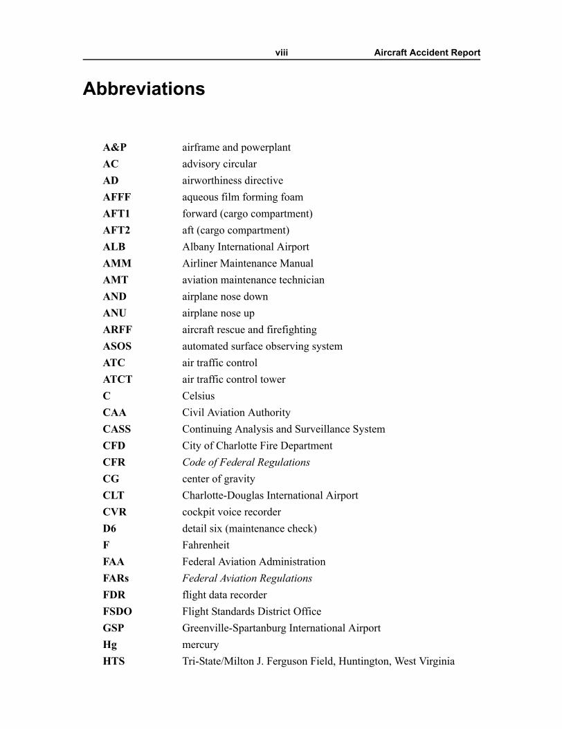
A&P airframe and powerplantAC advisory circularAD airworthiness directiveAFFF aqueous film forming foamAFT1 forward (cargo compartment) AFT2 aft (cargo compartment) ALB Albany International AirportAMM Airliner Maintenance ManualAMT aviation maintenance technicianAND airplane nose downANU airplane nose upARFF aircraft rescue and firefightingASOS automated surface observing systemATC air traffic controlATCT air traffic control towerC CelsiusCAA Civil Aviation AuthorityCASS Continuing Analysis and Surveillance SystemCFD City of Charlotte Fire DepartmentCFR Code of Federal RegulationsCG center of gravityCLT Charlotte-Douglas International AirportCVR cockpit voice recorderD6 detail six (maintenance check)F FahrenheitFAA Federal Aviation AdministrationFARs Federal Aviation RegulationsFDR flight data recorderFSDO Flight Standards District OfficeGSP Greenville-Spartanburg International AirportHg mercuryHTS Tri-State/Milton J. Ferguson Field, Huntington, West Virginia
Abbreviations ix Aircraft Accident Report
JAA Joint Aviation Authorities (European)JARs Joint Aviation RegulationsLYH Lynchburg Regional Airport/Preston Glenn FieldMETAR meteorological aerodrome reportmsl mean sea levelOAT outside air temperatureOJT on-the-job trainingPAI principal avionics inspector PIC pilot-in-commandPMI principal maintenance inspectorPOI principal operations inspectorRALLC Raytheon Aerospace, LLCRAMS Regional Airline Maintenance ServiceRASIP Regional Aviation Safety Inspection ProgramRDU Raleigh-Durham International AirportRII required inspection itemSB service bulletinSMART Structural Modification and Repair Technicians, Inc.STAN Sum Total Aft and Nose systemTRACON terminal radar approach controlTTS Tennessee Technical ServicesUTC coordinated universal timeVHF very high frequency
x Aircraft Accident Report
Executive Summary
On January 8, 2003, about 0847:28 eastern standard time, Air Midwest (doingbusiness as US Airways Express) flight 5481, a Raytheon (Beechcraft) 1900D, N233YV,crashed shortly after takeoff from runway 18R at Charlotte-Douglas International Airport,Charlotte, North Carolina. The 2 flight crewmembers and 19 passengers aboard theairplane were killed, 1 person on the ground received minor injuries, and the airplane wasdestroyed by impact forces and a postcrash fire. Flight 5481 was a regularly scheduledpassenger flight to Greenville-Spartanburg International Airport, Greer, South Carolina,and was operating under the provisions of 14 Code of Federal Regulations Part 121 on aninstrument flight rules flight plan. Visual meteorological conditions prevailed at the timeof the accident.
The National Transportation Safety Board determines that the probable cause ofthis accident was the airplane�s loss of pitch control during takeoff. The loss of pitchcontrol resulted from the incorrect rigging of the elevator control system compounded bythe airplane�s aft center of gravity, which was substantially aft of the certified aft limit.
Contributing to the cause of the accident were (1) Air Midwest�s lack of oversightof the work being performed at the Huntington, West Virginia, maintenance station;(2) Air Midwest�s maintenance procedures and documentation; (3) Air Midwest�s weightand balance program at the time of the accident; (4) the Raytheon Aerospace qualityassurance inspector�s failure to detect the incorrect rigging of the elevator control system;(5) the Federal Aviation Administration�s (FAA) average weight assumptions in its weightand balance program guidance at the time of the accident; and (6) the FAA�s lack ofoversight of Air Midwest�s maintenance program and its weight and balance program.
The safety issues in this report focus on maintenance work practices, oversight,and quality assurance; aircraft weight and balance programs; maintenance training; FAAoversight; and Beech 1900 cockpit voice recorder problems. Safety recommendationsconcerning these issues are addressed to the FAA.
1 Aircraft Accident Report
1. Factual Information
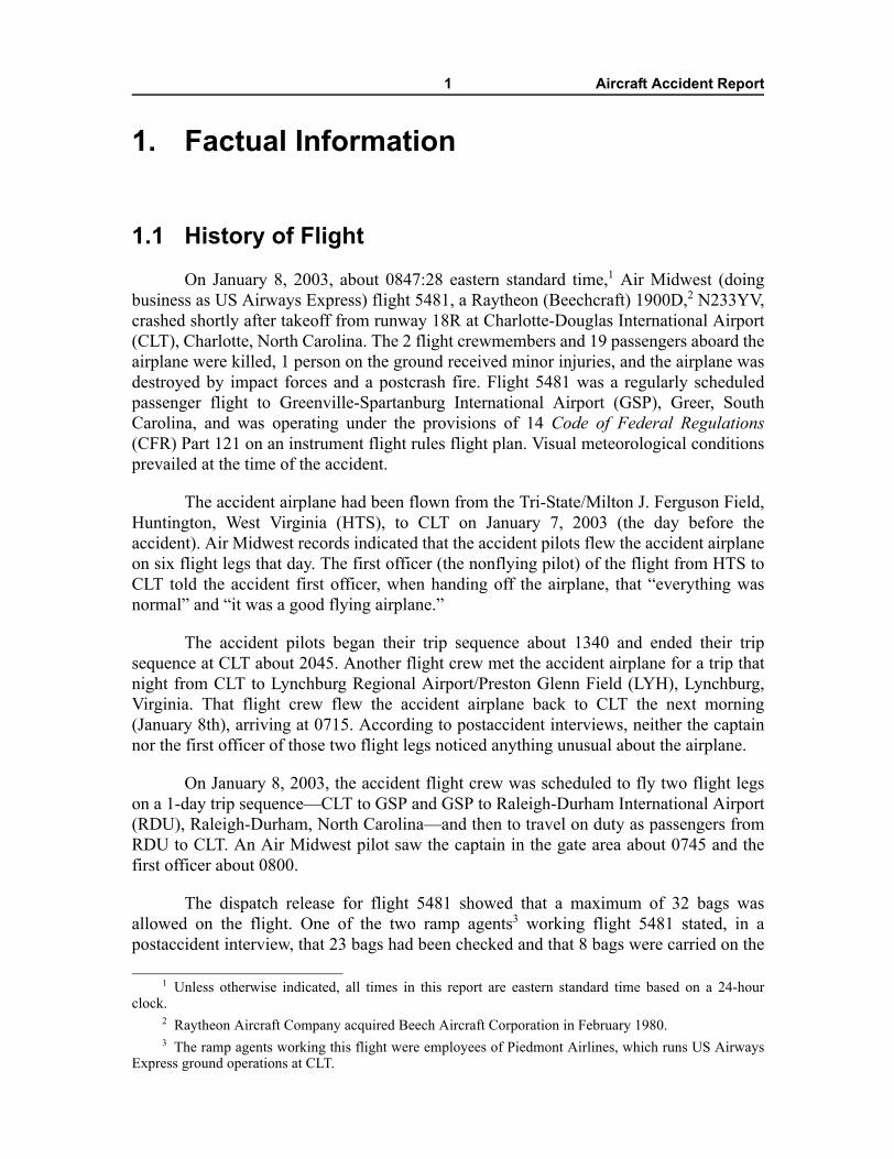
1.1 History of FlightOn January 8, 2003, about 0847:28 eastern standard time,1 Air Midwest (doing
business as US Airways Express) flight 5481, a Raytheon (Beechcraft) 1900D,2 N233YV,crashed shortly after takeoff from runway 18R at Charlotte-Douglas International Airport(CLT), Charlotte, North Carolina. The 2 flight crewmembers and 19 passengers aboard theairplane were killed, 1 person on the ground received minor injuries, and the airplane wasdestroyed by impact forces and a postcrash fire. Flight 5481 was a regularly scheduledpassenger flight to Greenville-Spartanburg International Airport (GSP), Greer, SouthCarolina, and was operating under the provisions of 14 Code of Federal Regulations(CFR) Part 121 on an instrument flight rules flight plan. Visual meteorological conditionsprevailed at the time of the accident.
The accident airplane had been flown from the Tri-State/Milton J. Ferguson Field,Huntington, West Virginia (HTS), to CLT on January 7, 2003 (the day before theaccident). Air Midwest records indicated that the accident pilots flew the accident airplaneon six flight legs that day. The first officer (the nonflying pilot) of the flight from HTS toCLT told the accident first officer, when handing off the airplane, that �everything wasnormal� and �it was a good flying airplane.�
The accident pilots began their trip sequence about 1340 and ended their tripsequence at CLT about 2045. Another flight crew met the accident airplane for a trip thatnight from CLT to Lynchburg Regional Airport/Preston Glenn Field (LYH), Lynchburg,Virginia. That flight crew flew the accident airplane back to CLT the next morning(January 8th), arriving at 0715. According to postaccident interviews, neither the captainnor the first officer of those two flight legs noticed anything unusual about the airplane.
On January 8, 2003, the accident flight crew was scheduled to fly two flight legson a 1-day trip sequence�CLT to GSP and GSP to Raleigh-Durham International Airport(RDU), Raleigh-Durham, North Carolina�and then to travel on duty as passengers fromRDU to CLT. An Air Midwest pilot saw the captain in the gate area about 0745 and thefirst officer about 0800.
The dispatch release for flight 5481 showed that a maximum of 32 bags wasallowed on the flight. One of the two ramp agents3 working flight 5481 stated, in apostaccident interview, that 23 bags had been checked and that 8 bags were carried on the
1 Unless otherwise indicated, all times in this report are eastern standard time based on a 24-hourclock.
2 Raytheon Aircraft Company acquired Beech Aircraft Corporation in February 1980. 3 The ramp agents working this flight were employees of Piedmont Airlines, which runs US Airways
Express ground operations at CLT.
Factual Information 2 Aircraft Accident Report
airplane. The ramp agent stated that two of the checked bags were heavy, with anestimated weight of between 70 and 80 pounds. The ramp agent also stated that he told thecaptain that some of the bags were heavy, although they were not marked as such.According to the ramp agent, the captain indicated that the bags were fine because a childwould be on board, which would allow for the extra baggage weight.4 The ramp agentestimated that the forward cargo compartment was about 98 percent full by volume.5
Cockpit voice recorder (CVR) information early in the recording indicated that theflight crew was completing the preflight paperwork regarding the airplane�s weight andbalance. Air Midwest records indicated that flight 5481 departed the gate on time about 0830.The captain was the flying pilot, and the first officer was the nonflying pilot.
Flight data recorder (FDR) data indicated that, beginning about 0835:16, the flightcrew performed a control check of the elevators.6 The pitch control position parameter,which measures the position of the control column, recorded values from 15º ANU to16.5º AND.7 These values corresponded to elevator positions from full ANU to 7º AND.About 0837:20, the CVR recorded the first officer contacting the CLT Air Traffic ControlTower (ATCT) ground controller and informing him that flight 5481 was ready to taxi.The ground controller instructed the flight crew to taxi to runway 18R.
About 0846:18, the tower (local) controller cleared flight 5481 for takeoff andinstructed the flight crew to turn right to a heading of 230º after takeoff. About 0846:35,the captain asked the first officer to set the takeoff power, and the first officer stated thatthe power had been set.
About 0846:48, the airplane�s airspeed was above 102 knots,8 and the elevatorposition was 7º AND. About 3 seconds later, the elevator position was 1º AND, and thepitch attitude of the airplane began to increase. After 0846:53, the pitch trim startedmoving AND, and, about 3 seconds later, the captain called for the landing gear to beretracted. About 0846:57, the elevator position returned to 7º AND, and, about 2 secondslater, the CVR recorded the sound of the landing gear retracting.
4 In calculating the weight and balance of the airplane, the flight crew used Air Midwest�s standardadult weight figure (175 pounds) for this child, who was 12 years of age.
5 A cargo net separates the forward (AFT1) cargo compartment from the aft (AFT2) cargocompartment. A ramp agent stated that the cargo net was in place before the accident flight.
6 An elevator is an aerodynamic control surface hinged to the back of the horizontal stabilizer. Anelevator moves up and down to control the airplane�s wing angle of attack, pitch, and climb. Normal elevatortravel for the Beech 1900D is from 20º to 21º airplane nose up (ANU) to 14º to 15º airplane nose down(AND), and the elevator neutral position is 0º. The elevator control check in the Beech 1900D involvesmoving the control column from the full forward position to the full aft position.
7 In a properly rigged elevator control system, the FDR pitch control position parameter accuratelyreflects the elevator position. For the accident flight, however, the recorded pitch control positions did notreflect the actual elevator positions. The recorded pitch control positions were about 9º more AND than theactual elevator positions. For more information on this 9º AND shift, see sections 1.11.2.1, 1.16.1.2, and1.16.2.3. In this section, all references to elevator positions reflect the actual elevator positions.
8 According to Air Midwest�s Beech 1900D Performance Manual, the rotation speed during takeoff is105 knots.
Factual Information 3 Aircraft Accident Report
About 0847:02, the first officer stated, �wuh,� and the captain stated, �oh.�About 0847:03, the captain stated, �help me.� At that point, the airplane was about 90 feetabove ground level, and FDR data showed that the airplane�s pitch attitude was 20º ANUand airspeed was 139 knots. About 0847:04, the CVR recorded the captain asking, �yougot it?� and FDR data indicated that the flight crew was forcefully commanding AND.During the next 8 seconds, the CVR recorded multiple statements and sounds from bothflight crewmembers associated with their efforts to push the airplane�s nose down. Also,about 0847:09, the CVR recorded a change in engine/propeller noise and, about 1 secondlater, the beginning of a sound similar to the stall warning horn.
About 0847:13, the FDR recorded a maximum pitch attitude of 54º ANU.About 0847:16, the captain radioed the ATCT and stated, �we have an emergency for Air[Midwest] fifty four eighty one,� and the CVR recorded the end of the sound similar to thestall warning horn. About 0847:18, the airplane�s pitch attitude decreased through 0º, andthe elevator position began to move ANU. By 0847:19, the airplane was about 1,150 feetabove ground level, and the FDR recorded a maximum left roll of 127º and a minimumairspeed of 31 knots. About 1 second later, the FDR recorded a pitch attitude of 42º AND.
About 0847:21, the captain stated, �pull the power back,� the elevator positionreached full ANU, and the airplane�s pitch attitude was 39º AND. At 0847:21.7, the CVRrecorded the beginning of a sound similar to the stall warning horn, which continued to theend of the recording. About 0847:22, the airplane�s roll attitude stabilized at about 20º leftwing down; the pitch attitude began to increase; and the elevator position moved in theAND direction, reaching about 8º ANU. About 1 second later, the elevator position beganmoving in the ANU direction. About 0847:24 the airplane rolled right through wingslevel, and the pitch attitude increased to about 5º AND.
About 0847:26, the FDR recorded a maximum right roll of 68º and a maximumvertical acceleration of 1.9 Gs.9 About the same time, the captain stated, �oh my god ahh,�and the first officer stated something similar to, �uh uh god ahh [expletive].� The CVRrecording ended at 0847:28.1. The FDR�s last recorded pitch attitude was 47º AND; rollattitude was 66º to the right; and pitch control position was 19.2º ANU, whichcorresponded to an elevator position of full ANU.
The airplane struck a US Airways maintenance hangar on CLT property and cameto rest about 1,650 feet east of the runway 18R centerline and about 7,600 feet beyond therunway 18R threshold. ATCT controllers heard an emergency locator transmitter signalbeginning about 0847:29.10 The accident occurred at 35º 12' 25" north latitude and 80º 56'46.85" west longitude during daylight hours.
9 One G is equivalent to the acceleration caused by the earth�s gravity (32.174 feet/second2).10 See section 1.10.2 for information about the tower controllers� observations regarding the accident
flight.
Factual Information 4 Aircraft Accident Report
1.1.1 Maintenance Events Preceding the Accident Flight
Between the night of January 6 and the morning of January 7, 2003, the accidentairplane underwent a detail six (D6) maintenance check11 at Air Midwest�s HTSmaintenance station. Air Midwest contracted with Raytheon Aerospace, LLC (RALLC),12
to provide mechanics, quality assurance inspectors, and a site manager for the HTSmaintenance station. RALLC contracted with Structural Modification and RepairTechnicians, Inc. (SMART), to supply the mechanic workforce.
The RALLC quality assurance inspector on duty the night of January 6th wasproviding on-the-job training (OJT) to two SMART mechanics on specific tasksassociated with the D6 maintenance check. Neither mechanic had previously performedthe complete D6 check.
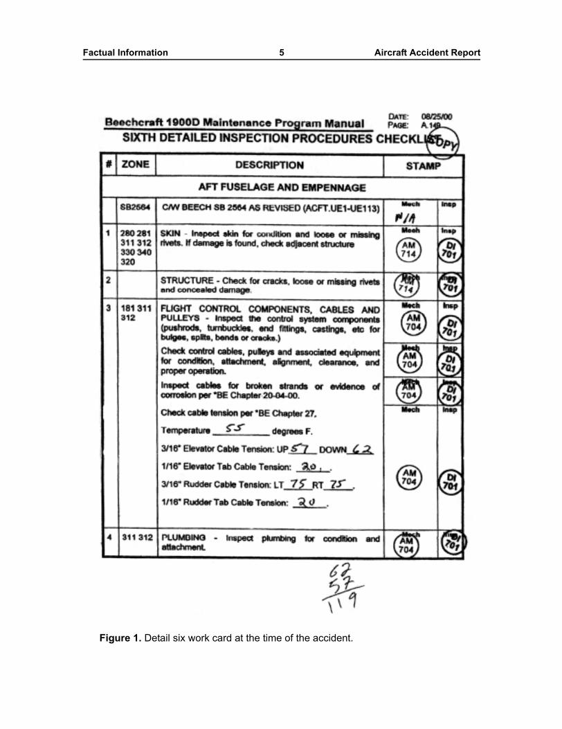
One of the mechanics receiving OJT was assigned to inspect and check theelevator control cable tension. The D6 inspection procedures checklist (also known as theD6 work card), dated August 25, 2000, indicated that the cable tension was to be checkedaccording to the procedures in chapter 27 of the Raytheon Aircraft Beech 1900D AirlinerMaintenance Manual (AMM), as shown in figure 1. The first step on the D6 work cardindicated that a temperature reading needed to be taken (to determine the tension values atwhich the control cables should be set) but did not specify how to take the temperature.13
The work card showed that the mechanic recorded the temperature as 55º Fahrenheit (F).
11 The D6 maintenance check comprises an elevator check, a rudder check, and a trim tab check.12 On June 20, 2003, RALLC changed its name to Vertex Aerospace, LLC. On December 1, 2003, L-3
Communications acquired Vertex Aerospace and named the new business unit L-3 CommunicationsAeroTech, LLC.
13 In a postaccident interview, the mechanic stated that he obtained a temperature reading from theoutside air temperature (OAT) gauge located beneath the captain�s side window, but the quality assuranceinspector subsequently indicated that the temperature was actually read from an OAT gauge that was goingto be installed on the accident airplane during the maintenance visit. The quality assurance inspectorprovided the Safety Board with the following written statement, dated February 25, 2003: �at the time thecable tensions were adjusted on A/C [aircraft] 233 [the accident airplane] the OAT gage [sic] reading wastaken while it was laying on the top shelf of the podium. The podium was located at the nose of the A/Capproximately 6 ft from the right avionics bay door.�
Factual Information 5 Aircraft Accident Report
Figure 1. Detail six work card at the time of the accident.
Factual Information 6 Aircraft Accident Report
The next step on the D6 work card indicated that the ANU and AND elevator cabletensions needed to be measured. The mechanic stated that he used a cable tensiometer tocheck the tension in each cable and determined that the average tension was too low. Themechanic stated that he then referred to the Beech 1900D AMM, Section 27-30-02,�Elevator Control Rigging � Maintenance Practices� (dated February 22, 2002). Themechanic indicated that he used the elevator cable tension graph in section 27-30-02 todetermine the proper cable tension.14
The mechanic stated that he worked under the supervision of the quality assuranceinspector to adjust the cables to the proper tension range. According to the D6 work card,the mechanic adjusted the ANU cable tension to 57 pounds and the AND cable tension to62 pounds.15
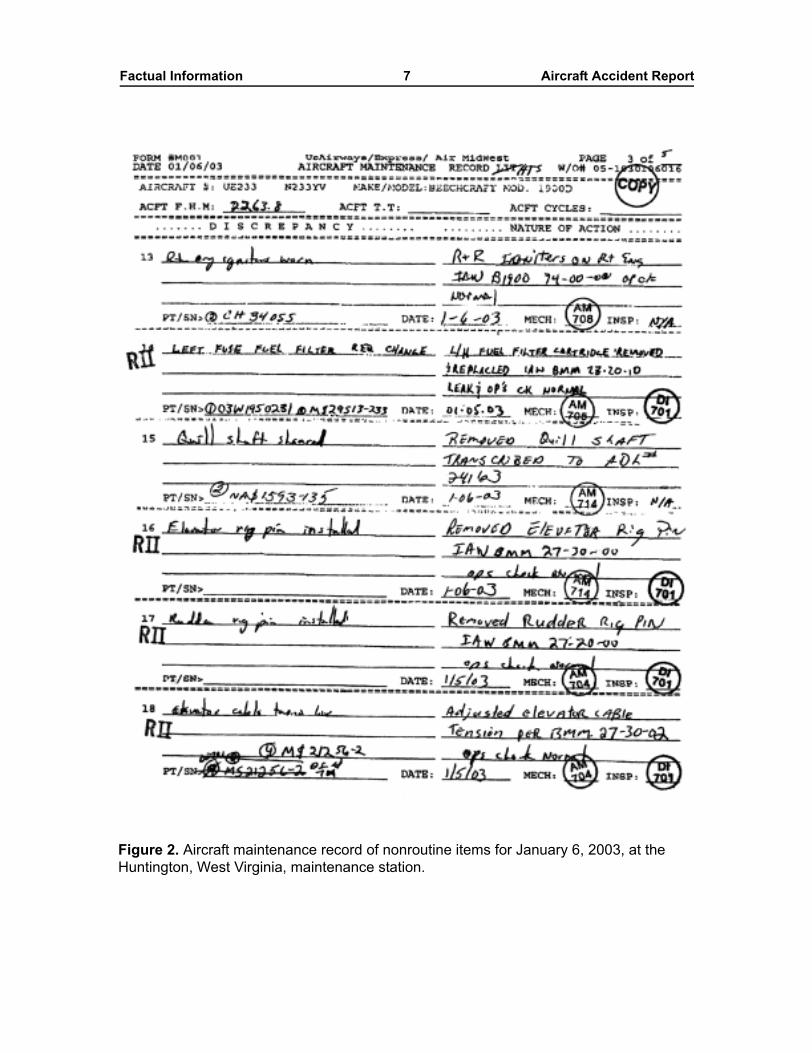
The aircraft maintenance record of nonroutine items for January 6, 2003,indicated, in a discrepancy block, that the airplane�s elevator cable tension was low. Arequired inspection item (RII)16 stamp appeared in this block, as shown at the bottom offigure 2. The form also indicated, in a nature of action block, that the elevator cabletension was adjusted per section 27-30-02 and that the operations check was normal. Themechanic�s and quality assurance inspector�s stamps appeared in their respective blockson the form. In addition, the mechanic�s OJT records indicated that he completed trainingon the entire D6 aft fuselage/empennage inspection procedure on January 7, 2003. Themechanic stated, during a postaccident interview, that he performed the elevator andrudder checks but not the trim tab check on the night of January 6th.
14 The elevator cable tension graph showed temperature readings (in Fahrenheit) along one axis,pounds of tension along the other axis, and a reference line for optimum cable tension. The mechanic statedthat he plotted 55º F on the graph and determined that the optimum cable tension would be an average of61 pounds for the ANU and AND cables. The graph indicated that the tension tolerance was ±8 pounds. Asa result, the mechanic could have adjusted the average cable tension to between 53 and 69 pounds.
15 Section 27-30-02 indicated that the ANU and AND cable tensions were to be added and then dividedby two so that the average tension of both cables was 66 ±8 pounds (with the elevators at neutral).According to the D6 work card, the average tension of the accident airplane�s cables was 59.5 pounds.
16 According to Air Midwest�s Maintenance Procedures Manual (dated November 9, 1999), �RequiredInspection Items are items of maintenance and/or alteration that must be inspected before [the aircraft�s]return to service, including at least those items that could result in a failure, malfunction, or defectendangering the safe operation of the aircraft, if not performed properly.� The rigging of elevator cables isidentified in the manual as an RII. According to 14 CFR 121.371(c), �no person may perform a requiredinspection if [that person] performed the item of work required to be inspected.�
Factual Information 7 Aircraft Accident Report
Figure 2. Aircraft maintenance record of nonroutine items for January 6, 2003, at the Huntington, West Virginia, maintenance station.
Factual Information 8 Aircraft Accident Report
In addition, the mechanic stated that, while adjusting the cable tension, hebypassed several steps of the complete elevator control system rigging procedure(section 27-30-02).17 The Beech 1900D AMM did not contain a stand-alone procedure forchecking elevator cable tension, as called for on the D6 work card, or for adjustingelevator cable tension without rigging the entire elevator control system.18 The qualityassurance inspector stated, during a postaccident interview, that he and the mechanicdiscussed which steps to bypass and that he allowed the mechanic to adjust only the cabletension.
The accident airplane returned to service on the morning of January 7, 2003. Theairplane flew a total of nine flight legs before the accident flight.
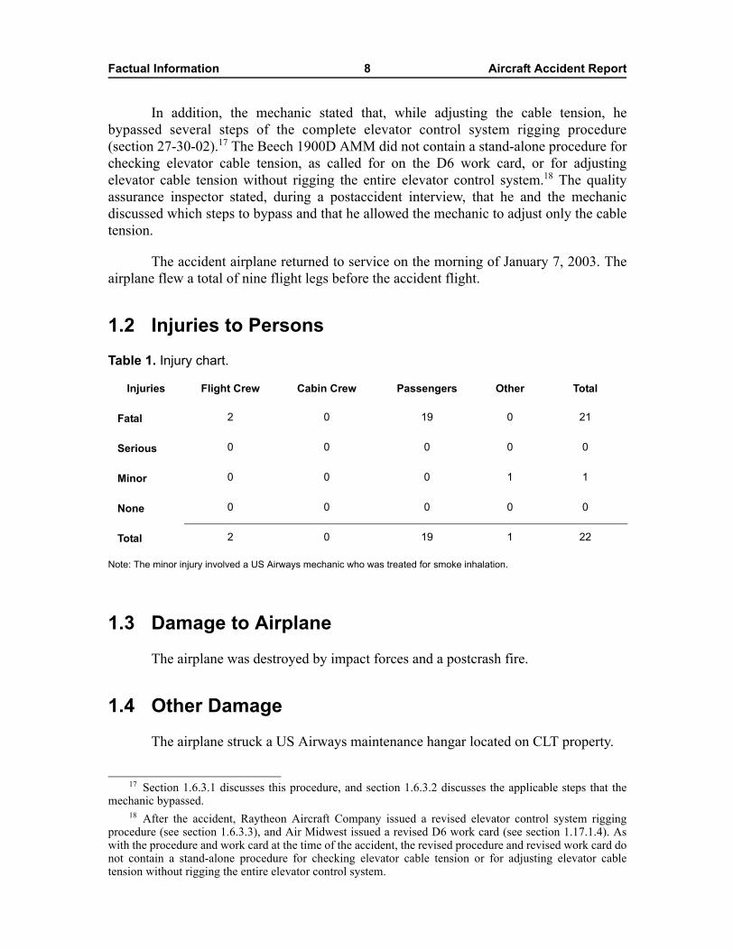
1.2 Injuries to PersonsTable 1. Injury chart.
Note: The minor injury involved a US Airways mechanic who was treated for smoke inhalation.
1.3 Damage to AirplaneThe airplane was destroyed by impact forces and a postcrash fire.
1.4 Other DamageThe airplane struck a US Airways maintenance hangar located on CLT property.
17 Section 1.6.3.1 discusses this procedure, and section 1.6.3.2 discusses the applicable steps that themechanic bypassed.
18 After the accident, Raytheon Aircraft Company issued a revised elevator control system riggingprocedure (see section 1.6.3.3), and Air Midwest issued a revised D6 work card (see section 1.17.1.4). Aswith the procedure and work card at the time of the accident, the revised procedure and revised work card donot contain a stand-alone procedure for checking elevator cable tension or for adjusting elevator cabletension without rigging the entire elevator control system.
Injuries Flight Crew Cabin Crew Passengers Other Total
Fatal 2 0 19 0 21
Serious 0 0 0 0 0
Minor 0 0 0 1 1
None 0 0 0 0 0
Total 2 0 19 1 22
Factual Information 9 Aircraft Accident Report
1.5 Personnel Information
1.5.1 The Captain
The captain, age 25, was hired by Air Midwest in March 2000. She held an airlinetransport pilot certificate and a Federal Aviation Administration (FAA) first-class medicalcertificate dated November 19, 2002, with no limitations. The captain received a typerating on the Beech 1900D in March 2001.
The captain received her private pilot certificate in February 1997 while she wasan aviation student at Louisiana Tech University, Ruston, Louisiana. From February 1999to March 2000, the captain was a flight instructor and flight school supervisor at theuniversity. The captain�s résumé for employment with Air Midwest indicated that she hadaccumulated 925 hours total flying time (625 of which were as pilot-in-command [PIC]and 101 hours of which were in a multiengine airplane) in Beech 76 and Cessna 152, 172,and 310 airplanes.
Air Midwest records indicated that the captain had accumulated 1,865 hours totalcompany flying time, including 1,100 hours as a Beech 1900D PIC. She had flownapproximately 134, 32, and 6 hours in the 90 days, 30 days, and 24 hours, respectively,before the accident. The captain�s last Beech 1900D proficiency check occurred onAugust 20, 2002; her last recurrent ground school occurred on September 18, 2002; andher last line check occurred on November 26, 2002. FAA records indicated no accident orincident history or enforcement action, and a search of the National Driver Registerdatabase found no record of driver�s license suspension or revocation.
In postaccident interviews, Air Midwest pilots who had flown with the captainmade favorable comments about her piloting skills. A check airman stated that the captainhad no difficulties during upgrade training and that she demonstrated very goodknowledge of the airplane�s systems and very good judgment. Another check airmandescribed the captain as one of the better company pilots and stated that she made verygood decisions about flying. First officers stated that the captain was a thorough andmethodical pilot who controlled the airplane well and involved them with the flight byasking for opinions and letting them review paperwork.
The captain was single and lived in the Charlotte area. She was reported to be ingood health. She did not smoke and would occasionally have a glass of wine with dinner.Her personal situation was reported to be stable and her financial situation to be adequateduring the months preceding the accident. She was described by her boyfriend as �healthy,happy, and not tired� on the morning of the accident.
Between 0810 and 1144 on January 5, 2003, the captain traveled on duty as apassenger from CLT to Key West, Florida, for a trip that originated there. Fromabout 1230 to 2330, the captain flew six flight legs and accumulated about 6 hours offlight time. She arrived at her hotel about 0035 on January 6th and, from about 1130 to1600, traveled on duty as a passenger from Key West to CLT.
Factual Information 10 Aircraft Accident Report
On January 7, 2003, the captain was on reserve duty for the airline. She awokebetween 0900 and 0930 and was notified by crew scheduling, about 1000, that she wouldbe flying a six-leg trip sequence with the accident first officer. The first leg of the tripsequence was scheduled to depart about 1200 but did not depart until 1340. The last leg ofthe trip sequence was scheduled to arrive at CLT about 1910 but did not arrive until 2045.The captain accumulated 6 hours of flight time during the trip sequence. She went to bedthat night about 2230 and awoke about 0625 on January 8th to get ready for that day�s tripsequence.
1.5.2 The First Officer
The first officer, age 27, was hired by Air Midwest in May 2001. He held acommercial pilot license dated November 12, 2000, and an FAA first-class medicalcertificate dated December 10, 2002, with no limitations.
From August 1999 to February 2001, the first officer was enrolled at San JuanCollege, Farmington, New Mexico, as part of the Mesa Airlines19 Pilot DevelopmentProgram. On his application for employment with Air Midwest, the first officer reportedthat he had accumulated 390 hours total flying time in Beech 36, 58, and 1900; AeroncaChampion; and Citabria airplanes.
Air Midwest records indicated that the first officer had accumulated 706 hourstotal company flying time on Beech 1900D airplanes. He had flown approximately 210,59, and 6 hours in the 90 days, 30 days, and 24 hours, respectively, before the accident.The first officer�s last line check occurred on August 20, 2001, and his initial Beech1900D proficiency check occurred on May 4, 2002. FAA records indicated no accident orincident history or enforcement action, and a search of the National Driver Registerdatabase found no record of driver�s license suspension or revocation.
In postaccident interviews, Air Midwest pilots who had flown with the first officermade favorable comments about his piloting skills. Pilots described the first officer as atalented and very precise pilot with good attention to detail and good communicationskills. Pilots also stated that the first officer possessed good situational awareness andgood knowledge of the Beech 1900D.
The first officer was single and lived in the Charlotte area. He was reported to be inexcellent health. He did not smoke and consumed alcohol occasionally in social settings.His personal and financial situations during the months preceding the accident werereported to be stable.
On January 5, 2003, the first officer was off duty until 2035, when he departedCLT for a flight to LYH, which arrived about 2130. About 0620 on January 6th, the firstofficer flew back to CLT, arriving about 0715. On January 7th, the first officer flew the
19 Mesa Airlines is one of four airline liveries operated by Mesa Air Group, Inc., which is the parentcompany of Air Midwest. See section 1.17.1 for more information.
Factual Information 11 Aircraft Accident Report
same trip sequence as the accident captain. The times that the first officer went to sleep onthe night of January 7th and awoke on January 8th are not known.
1.5.3 The Maintenance Personnel
Sections 1.5.3.1 through 1.5.3.3 provide information about the three HTSmaintenance personnel who were involved with the maintenance of the accident airplane�selevator control system. Sections 1.5.3.4 and 1.5.3.5 provide information about the HTSmaintenance managers. For additional information about the maintenance personnel andthe maintenance managers, see sections 1.17.1 through 1.17.3.
1.5.3.1 The Quality Assurance Inspector
The quality assurance inspector, age 50, was hired by RALLC in July 2002. Hewas initially hired as a mechanic at the HTS maintenance station and was subsequentlypromoted to foreman and secondary (backup) quality assurance inspector.20 He receivedhis airframe and powerplant (A&P) certificate in January 1985.
On his application for employment with RALLC, the quality assurance inspectorreported that he had between 3 and 4 years of aviation maintenance experience with lightgeneral aviation airplanes. From about 1988 to July 1999, the quality assurance inspectorwas not employed in the aviation maintenance field. Between July 1999 and October 2001,the quality assurance inspector worked on Beech 1900D airplanes at the maintenancestation at Dubois Jefferson County Airport, Dubois, Pennsylvania. (He was employed atthe Dubois maintenance station by Mesa Airlines between July and December 1999,Arctic Slope21 between December 1999 and September 2001, and RALLC betweenSeptember and October 2001.) Between October 2001 and July 2002, the qualityassurance inspector was not employed in the aviation maintenance field.
According to RALLC time cards, the quality assurance inspector worked shiftsfrom 1700 on January 4 to 1200 on January 5, 2003, and from 2100 on January 5th to0630 on January 6th. He began work on the night of January 6th at 2100. The qualityassurance inspector stated that he was providing OJT to two mechanics and that it was hisfirst time training two mechanics while performing inspector duties. In addition, thequality assurance inspector performed an engine borescope inspection that took about30 minutes to accomplish. His shift ended at 1230 on January 7th.
The quality assurance inspector described his health as good and stated that heslept when his shift ended and that he awoke in the afternoon. The quality assuranceinspector reported no significant life events in the months preceding the accident andstated that nothing affected his performance on the night of January 6th. In a postaccidentinterview, the Air Midwest HTS regional site manager (see section 1.5.3.5) stated that he
20 The primary quality assurance inspector was not at work on the night of January 6, 2003, so theforeman/secondary quality assurance inspector assumed his duties.
21 Arctic Slope was a maintenance contractor.
Factual Information 12 Aircraft Accident Report
had �a lot of faith� in the quality assurance inspector. At the public hearing for thisaccident,22 the quality assurance inspector testified that he had performed elevator controlsystem rigging work once.
1.5.3.2 The Foreman
The foreman, age 36, was employed by SMART and had begun working at theHTS maintenance station in July 2002. He received his A&P certificate in July 1995.
From 1984 to 1987, the foreman worked as a mechanic on B-52 and KC-135airplanes with the U.S. Air Force. He gained experience as a foreman while working withthe Air Force. Between 1993 and 1999, the foreman worked as a mechanic on generalaviation and commuter airplanes. From December 2001 to July 2002, the foreman wasemployed by SMART and was assigned to RALLC at the Dubois maintenance station as amechanic working on Beech 1900D airplanes.
The foreman stated that he typically arrived at work between 2100 and 2130, about30 minutes before the arrival of the airplane that was scheduled for maintenance. He thenreviewed the work scheduled for the shift, organized the paperwork, and reviewed thepersonnel and equipment requirements. He assigned mechanics to the required tasks butdid not do any of the maintenance himself. He indicated that work assignments were basedon what work had to be done and which mechanic was best suited for a particular job. Theforeman tried to keep the same mechanics on the same jobs throughout the shift. Theforeman normally communicated with Air Midwest maintenance control about 0400regarding the status of the airplane undergoing maintenance.
During a postaccident interview, the foreman stated that, if a mechanic had notdone a job before and someone was available who had previously done the job, he wouldassign the experienced mechanic to the job and would train the mechanic withoutexperience as time permitted. The foreman indicated that he tried to train only onemechanic at a time but that, sometimes, more than one mechanic needed to be trained atthe same time.
According to SMART time cards, the foreman was off duty for the shift fromJanuary 4 to 5, 2003, but worked an 8-hour shift from January 5th to 6th. For the shiftfrom January 6th to 7th, the foreman worked 15 hours. On the night of January 6th, heassigned the work tasks for the accident airplane�s D6 maintenance check. The foremanwas aware that, besides he and the quality assurance inspector, none of the mechanics onduty that night had done an elevator control system rigging check on a Beech 1900D.
1.5.3.3 The Mechanic
The mechanic, age 30, was employed by SMART and began working at the HTSmaintenance station in November 2002. He attended the Pittsburgh Institute ofAeronautics, Pittsburgh, Pennsylvania, from 1991 to 1993 and received his A&Pcertificate in March 1993.
22 Appendix A provides details about the public hearing.
Factual Information 13 Aircraft Accident Report
Between 1994 and 1999, the mechanic was not employed in the aviationmaintenance field. From January to October 2000, the mechanic performed linemaintenance for Piedmont Airlines, Philadelphia, Pennsylvania, on De Havilland CanadaDHC-8 airplanes. From October 2000 to January 2002, the mechanic performed heavymaintenance for US Airways, Pittsburgh, Pennsylvania, on Boeing 737 and Fokker F.100airplanes. In October and November 2002, he worked at Stambaugh Air Service,Harrisburg, Pennsylvania. The mechanic had no previous experience working on Beech1900D airplanes before beginning work at the HTS maintenance station.
According to SMART time cards, the mechanic worked 17.5 hours from January 4to 5, 2003, and 8 hours from January 5th to 6th. For the shift from January 6th to 7th, themechanic worked 14 hours, during which he performed the D6 maintenance check for thefirst time. The mechanic stated that he did not have any previous OJT for that inspectionbut that he had previous flight control rigging experience at Piedmont and US Airways.The mechanic thought that he was �properly trained� for the rigging task because he didnot perceive any differences, in terms of rigging flight controls, between the Beech 1900Dand previous airplanes on which he had worked. He estimated that it took about 7 hours tocomplete his assigned tasks for the D6 maintenance check and stated that he receivedproper oversight.
In a postaccident interview, the RALLC site manager (see section 1.5.3.4)described the mechanic as capable. The site manager also stated that he had receivedpositive reports about the mechanic from inspectors and foremen at the HTS maintenancestation.
1.5.3.4 The Raytheon Aerospace Site Manager
The RALLC site manager23 for the HTS maintenance station, age 50, beganworking for RALLC in July 2002. He received his A&P certificate in April 1979.
Between June 2001 and July 2002, the RALLC site manager was employed bySMART as a mechanic assigned to the RALLC maintenance station in Panama City,Florida, where he worked on Beech 1900D airplanes. He became the foreman and wasresponsible for two crews. The RALLC site manager indicated that he had previousaviation manufacturing and maintenance experience with large commercial airplanes (theBoeing 727, Airbus A300, Lockheed L-1011, and Douglas DC-8 and DC-9), largemilitary airplanes (the C-5B, C-130, and P-3), and general aviation airplanes (includingthe Learjet 25 and 35).
The RALLC site manager worked from 0800 to 1700 Monday through Friday.During his shift, the RALLC site manager would typically review the paperwork from theprevious night to identify what work was done and to check that the work had beenproperly documented, examine the status and condition of the hangar and its equipment,review attendance sheets and time cards, and coordinate with the parts manager to ensurethat parts were available to meet maintenance needs. The RALLC site manager would alsointeract with other personnel at the HTS maintenance station who worked a day shift,
23 Air Midwest refers to this position as �maintenance manager.�
Factual Information 14 Aircraft Accident Report
including the Air Midwest regional site manager. In addition, the RALLC site managerwould participate in daily maintenance conference calls that addressed, among otherthings, upcoming maintenance needs. (RALLC site managers from the four other AirMidwest maintenance stations24 and Air Midwest maintenance personnel also participatedin the daily conference calls.) The RALLC site manager stated that he occasionally visitedthe hangar at night.
1.5.3.5 The Air Midwest Regional Site Manager
The Air Midwest regional site manager, age 44, has been employed by AirMidwest for 22 years and has been the regional site manager at the HTS maintenancestation since August 2002. He received his A&P certificate in February 1995.
Before his HTS assignment, the Air Midwest regional site manager worked for8 years as a quality assurance inspector at the company�s Wichita, Kansas, maintenancestation.25 He has performed aviation maintenance on various turboprop commuterairplanes.
At the time of the accident, the Air Midwest regional site manager normallyworked from 0830 to 1700 Monday through Friday. During his shift, he would typicallyreview the previous night�s paperwork to determine if it had been properly signed off and,if he noted any discrepancies, would either speak with the RALLC site manager or writeup a noncompliance form. He also participated in the daily maintenance conference callsand daily conference calls with Air Midwest flight operations personnel. The regional sitemanager stated that he occasionally visited the hangar at night.
1.6 Airplane InformationBeech 1900 series airplanes entered service in 1984 and have accumulated more
than 11 million flight hours since then. The Beech 1900D is a low-wing, twin-engine,propeller-driven, pressurized airplane. It has an overall length of 57 feet 10 inches, aheight of 14 feet 11 inches, and a wingspan of 57 feet 11 inches.
The accident airplane, serial number UE-233, was delivered new to Air Midwestfrom Raytheon Aircraft Company on August 30, 1996. The airplane was registered asN233YV on November 20, 1996. At the time of the accident, the airplane had 15,003 totalflight hours and 21,332 total cycles. 26
The accident airplane was configured with a captain�s seat, a first officer�s seat,16 single passenger seats, and a triple passenger seat in the rear of the airplane (for a totalof 19 passenger seats in 9 rows). The airplane had a main entry door on the left forward
24 These maintenance stations are located in Dubois, Pennsylvania; Farmington, New Mexico; LittleRock, Arkansas; and Panama City, Florida.
25 Air Midwest closed its Wichita maintenance station on September 30, 2002, because of flightschedule changes.
26 An airplane cycle is one complete takeoff and landing sequence.
Factual Information 15 Aircraft Accident Report
side of the fuselage and three emergency exits, two of which were on the right side of thecabin (at rows 4 and 6) and one of which was on the left side of the cabin (at row 6). Theairplane also had a cargo door on the left aft side of the fuselage. The cargo storage areabegan at the partition immediately aft of the triple passenger seat and extended almost tothe aft pressure bulkhead. According to Raytheon Aircraft Company, the airplane�sinterior was installed in 1996 and was certified to meet Federal material flammabilityrequirements.
The accident airplane was equipped with two Pratt & Whitney Canada PT6A-67Dturbopropeller engines and Hartzell model HC-E4A-3I four-bladed, constant-speed,full-feathering, reversible propellers. The PT6A-67D turbopropeller engine has a gasgenerator module and a power turbine module. The HC-E4A-3I propeller is hydraulicallyactuated and has model E10950 composite blades.
The left engine gas generator module, serial number 114328, was installed on theaccident airplane on November 2, 2001. At the time of the accident, the module hadaccumulated 14,659 hours and 21,142 cycles since new and 2,445 hours and 3,319 cyclessince overhaul. The left engine power turbine module, serial number 114301, was installedon the accident airplane on October 25, 2000. At the time of the accident, the module hadaccumulated 14,557 hours and 21,514 cycles since new and 4,778 hours and 6,349 cyclessince overhaul.
The right engine gas generator module, serial number 114091, was installed on theaccident airplane on May 28, 2002. At the time of the accident, the module hadaccumulated 18,447 hours and 25,612 cycles since new and 1,225 hours and 1,640 cyclessince overhaul. The right engine power turbine module, serial number 114343, wasinstalled on the accident airplane on May 24, 2002. At the time of the accident, the modulehad accumulated 13,548 hours and 22,093 cycles since new and 1,225 hours and 1,640 cyclessince overhaul.
The accident airplane was not equipped with an autopilot.
1.6.1 Pitch Control System
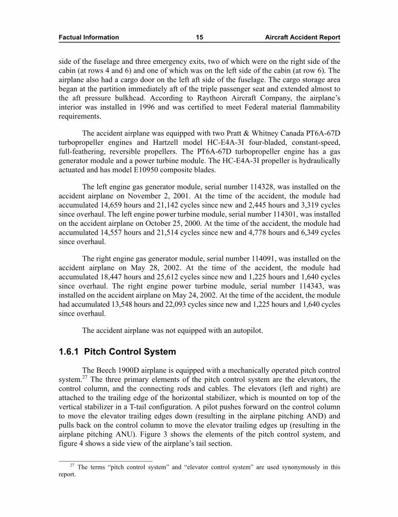
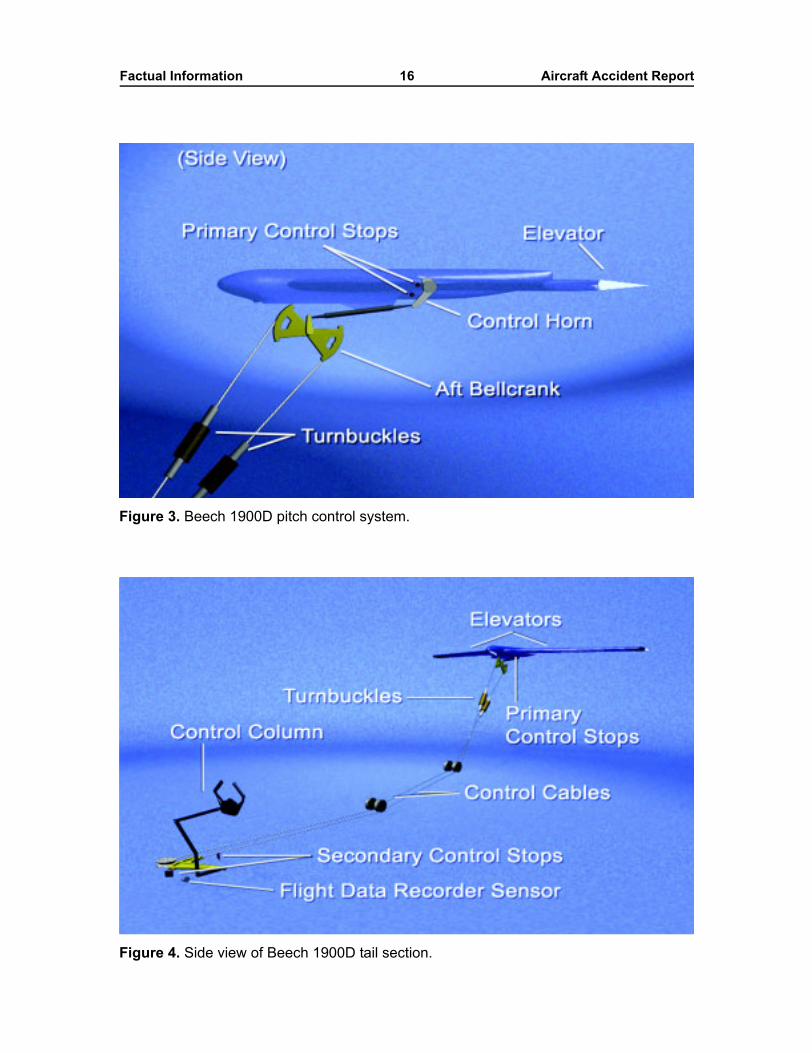
The Beech 1900D airplane is equipped with a mechanically operated pitch controlsystem.27 The three primary elements of the pitch control system are the elevators, thecontrol column, and the connecting rods and cables. The elevators (left and right) areattached to the trailing edge of the horizontal stabilizer, which is mounted on top of thevertical stabilizer in a T-tail configuration. A pilot pushes forward on the control columnto move the elevator trailing edges down (resulting in the airplane pitching AND) andpulls back on the control column to move the elevator trailing edges up (resulting in theairplane pitching ANU). Figure 3 shows the elements of the pitch control system, andfigure 4 shows a side view of the airplane�s tail section.
27 The terms �pitch control system� and �elevator control system� are used synonymously in thisreport.
Factual Information 16 Aircraft Accident Report
Figure 3. Beech 1900D pitch control system.
Figure 4. Side view of Beech 1900D tail section.
Factual Information 17 Aircraft Accident Report
The inboard end of each elevator has a control horn that is connected to theelevator surface by a shaft. Four primary stop bolts (left upper, left lower, right upper, andright lower) are mounted on airplane structure. The limit of travel for each of the elevatorcontrol horns is contact with an up stop bolt or a down stop bolt. The Beech 1900D AMM,section 27-30-02, indicates that the elevator primary stop deflection settings are 20º+1º/-0º up from the neutral position and 14º +1º/-0º down from the neutral position. Theelevator�s neutral position is the point at which the position of the trailing edge of theelevator is aligned with the chord plane of the horizontal stabilizer.
The left and right elevator control horns are connected by independent aftpushrods to the aft bellcrank, which is located near the junction of the horizontal andvertical stabilizers. Left and right tension springs connect the aft bellcrank arm to airplanestructure and orient the pitch control system toward the AND direction. Attachment linksconnect the springs to the aft bellcrank arm. Structure adjacent to the aft bellcrankcontains holes for a rig pin.28
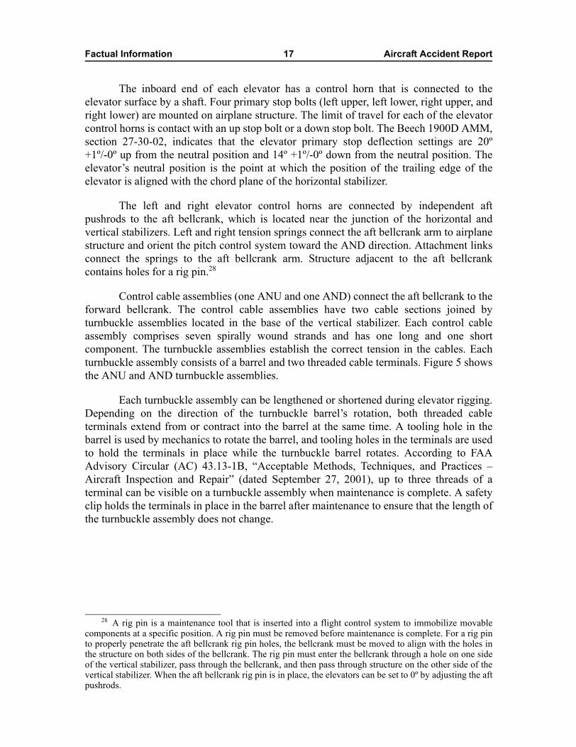
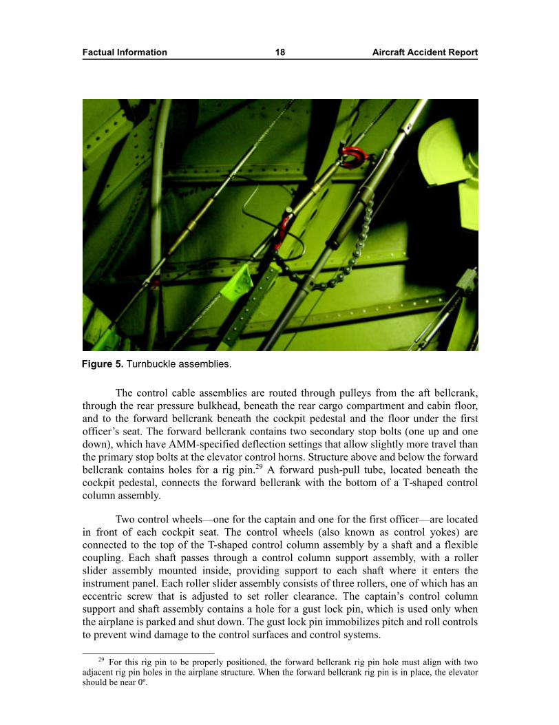
Control cable assemblies (one ANU and one AND) connect the aft bellcrank to theforward bellcrank. The control cable assemblies have two cable sections joined byturnbuckle assemblies located in the base of the vertical stabilizer. Each control cableassembly comprises seven spirally wound strands and has one long and one shortcomponent. The turnbuckle assemblies establish the correct tension in the cables. Eachturnbuckle assembly consists of a barrel and two threaded cable terminals. Figure 5 showsthe ANU and AND turnbuckle assemblies.
Each turnbuckle assembly can be lengthened or shortened during elevator rigging.Depending on the direction of the turnbuckle barrel�s rotation, both threaded cableterminals extend from or contract into the barrel at the same time. A tooling hole in thebarrel is used by mechanics to rotate the barrel, and tooling holes in the terminals are usedto hold the terminals in place while the turnbuckle barrel rotates. According to FAAAdvisory Circular (AC) 43.13-1B, �Acceptable Methods, Techniques, and Practices �Aircraft Inspection and Repair� (dated September 27, 2001), up to three threads of aterminal can be visible on a turnbuckle assembly when maintenance is complete. A safetyclip holds the terminals in place in the barrel after maintenance to ensure that the length ofthe turnbuckle assembly does not change.
28 A rig pin is a maintenance tool that is inserted into a flight control system to immobilize movablecomponents at a specific position. A rig pin must be removed before maintenance is complete. For a rig pinto properly penetrate the aft bellcrank rig pin holes, the bellcrank must be moved to align with the holes inthe structure on both sides of the bellcrank. The rig pin must enter the bellcrank through a hole on one sideof the vertical stabilizer, pass through the bellcrank, and then pass through structure on the other side of thevertical stabilizer. When the aft bellcrank rig pin is in place, the elevators can be set to 0º by adjusting the aftpushrods.
Factual Information 18 Aircraft Accident Report
The control cable assemblies are routed through pulleys from the aft bellcrank,through the rear pressure bulkhead, beneath the rear cargo compartment and cabin floor,and to the forward bellcrank beneath the cockpit pedestal and the floor under the firstofficer�s seat. The forward bellcrank contains two secondary stop bolts (one up and onedown), which have AMM-specified deflection settings that allow slightly more travel thanthe primary stop bolts at the elevator control horns. Structure above and below the forwardbellcrank contains holes for a rig pin.29 A forward push-pull tube, located beneath thecockpit pedestal, connects the forward bellcrank with the bottom of a T-shaped controlcolumn assembly.
Two control wheels�one for the captain and one for the first officer�are locatedin front of each cockpit seat. The control wheels (also known as control yokes) areconnected to the top of the T-shaped control column assembly by a shaft and a flexiblecoupling. Each shaft passes through a control column support assembly, with a rollerslider assembly mounted inside, providing support to each shaft where it enters theinstrument panel. Each roller slider assembly consists of three rollers, one of which has aneccentric screw that is adjusted to set roller clearance. The captain�s control columnsupport and shaft assembly contains a hole for a gust lock pin, which is used only whenthe airplane is parked and shut down. The gust lock pin immobilizes pitch and roll controlsto prevent wind damage to the control surfaces and control systems.
Figure 5. Turnbuckle assemblies.
29 For this rig pin to be properly positioned, the forward bellcrank rig pin hole must align with twoadjacent rig pin holes in the airplane structure. When the forward bellcrank rig pin is in place, the elevatorshould be near 0º.
Factual Information 19 Aircraft Accident Report
The control column pivots forward and aft on bearings near the cockpit floor. Abob weight, attached through an interconnect link to the control column, provides controlcolumn feel and flight control stability. The bob weight installation has a tertiary downstop bolt.
The FDR pitch control position sensor is located beneath the cockpit floor. Thesensor is attached to structure located to the left of the base of the control column (lookingforward). One rubber-cushioned, steel-band clamp (called an Adel clamp) holds the sensorto the structure. The sensor is connected to the elevator system by a short rod that extendsfrom the sensor to a bracket attached to the lower part of the control column.
1.6.1.1 Pitch Trim Control System
The accident airplane was equipped with a mechanically operated pitch trimcontrol system. The pitch trim control system includes a single movable trim tab30 for eachelevator and a cable-driven jackscrew actuator for each tab. The trim tabs, which arelocated on the inboard trailing edge of each elevator, relieve the force a pilot must hold onthe control wheel to provide longitudinal control (for example, angle of attack or pitch) ofthe airplane. According to the Beech 1900D AMM, the trim tabs move from 5.75º ±0.25ºup to 17º ±0.5º down. Movement of the trim tabs in the downward direction creates anupward aerodynamic moment on the elevator and results in an ANU pitching moment.
1.6.2 Maintenance Program
The Air Midwest Maintenance Program Manual describes the company�sContinuous Airworthiness Maintenance Program. This program incorporates guidancefrom the Beech 1900D AMM. The program includes the following inspections:
� Periodic service check. This check is accomplished during an airplane�slayover when applicable. The check involves a visual inspection ofsafety-of-flight items and servicing when necessary.
� Routine check. This check is performed every 100 flight hours. The checkincludes a visual inspection and servicing of the airplane�s major components.
� Detail check. This check is divided into six different phases, known as detailone through detail six, and a different phase is performed every 200 hoursalong with a routine check. One major airplane section is inspected during eachphase. Detail one covers the wings, detail two covers the powerplants, detailthree covers the flight compartment and cabin, detail four covers theenvironmental systems and nose, detail five covers the landing gear, and detailsix covers the aft fuselage and empennage. Details one through six compriseone full cycle, and an airplane must complete one full cycle each year.
� Structural check. This check is accomplished when the airplane hasaccumulated 12,000 flight hours and then every 3,000 flight hours afterward.
30 The trim tabs on the Beech 1900D are geared tabs, which move in relation to the position of theelevator.
Factual Information 20 Aircraft Accident Report
The accident airplane�s last periodic service check and routine check occurred onJanuary 6, 2003. The airplane�s last detail checks occurred as follows: detail one, July 31,2002; detail two, September 16, 2002; detail three, October 11, 2002; detail four,November 7, 2002; detail five, December 5, 2002; and detail six, January 6, 2003. Theairplane�s last structural check occurred on August 27, 2002.
The maintenance paperwork for the accident airplane from January 2001 toJanuary 2003 was reviewed for discrepancies related to elevator or pitch control. Notrends or discrepancies were noted before the accident flight. FAA Service DifficultyReports were reviewed for flight control maintenance discrepancies involving the accidentairplane. No trends or discrepancies were noted before the accident flight. In addition, AirMidwest records indicated no previous accidents involving the airplane.
1.6.3 Elevator Control System Rigging Procedure
As stated in section 1.1.1, the mechanic who performed the cable tension checkbypassed several steps of the elevator control system rigging procedure insection 27-30-02 of the Beech 1900D AMM (with the quality assurance inspector�sconcurrence). The procedure at the time of the accident is detailed in section 1.6.3.1, andthe applicable steps that the mechanic skipped are discussed in section 1.6.3.2. After theaccident, Raytheon Aircraft Company revised its elevator control system riggingprocedure, and the revised procedure is presented in section 1.6.3.3.
1.6.3.1 Rigging Procedure at the Time of the Accident
The Raytheon Aircraft elevator control system rigging procedure that was in effectat the time of the accident is summarized below and presented in its entirety inappendix C.
ELEVATOR CONTROL SYSTEM RIGGING
a. Disconnect the autopilot servo cables.
b. Locate and remove all access panels from the vertical and horizontal stabilizersto gain access to the aft elevator bellcrank and the elevator cables.
c. Locate and remove the flight compartment seats, carpet, and floorboards to gainaccess to the forward elevator bellcrank.
d. Locate and remove the passenger seats, carpet, and floorboards on the right sideof the passenger compartment to gain access to the elevator cable turnbuckles.
e. Install an elevator travel board[31] on each elevator at station 50.00.
31 An elevator travel board is a template that is unique to a specific airplane design. The travel boardattaches to the horizontal stabilizer to provide a reference for measuring movement of the elevators. Theposition of the elevator trailing edge aligns with 1º markings on the travel board that show the angularposition of the elevator in degrees.
Factual Information 21 Aircraft Accident Report
f. Adjust the center-to-center length of the push-pull tube assembly between thecontrol column and the forward elevator bellcrank to a dimension of 15.12 ± 0.06inch.
g. Adjust the surface stop bolts on the elevator control horn support for up-travelof 20º + 1º - 0 and down-travel of 14º + 1º - 0º.
h. Verify the bob weight stop bolt clearance is 0.5 ± 0.06 inch. Adjust if necessary.
i. Adjust the forward bellcrank stops for 0.37 ± 0.06 inch clearance from the stopbolts.
j. Verify the forward bellcrank stop bolts make contact before the bob weight stopbolts make contact with the weight.
k. Install a rig pin in the aft elevator bellcrank.
NOTE
Verify threads are visible through the inspection holes at the end of the pushrodsafter adjustments are made.
l. Adjust the pushrods between the aft elevator bellcrank and the elevator to positionthe elevator at neutral (0º deflection).
m. Remove the rig pin from the aft elevator bellcrank.
n. Remove the safety clips from the turnbuckles and release cable tension.
o. Move the control yoke to install the rig pin in the forward elevator bellcrank.
p. Tighten the elevator-up cable until the elevator rises to neutral (0º on the travelboard).
q. Tighten the elevator-down cable until the average tension of the up- anddown-cables is 66 ± 8 pounds (the sum of up-cable and down-cable tensions,divided by two). Refer to Figure 203.[32]
r. Continue to balance the adjustment of the two cables until the average tension is66 ± 8 pounds while maintaining 0º deflection of the elevator.
s. Perform the CONTROL COLUMN SUPPORT ROLLER INSPECTIONprocedure.
t. Install safety clips on the turnbuckles.
32 Figure 203 was an elevator cable tension graph included in section 27-30-02 of the Beech 1900DAMM. The graph did not contain instructions on how to take a temperature reading.
Factual Information 22 Aircraft Accident Report
u. On aircraft equipped with the F1000 Flight Data Recorder, calibrate the PitchPosition Potentiometer. Perform the FLIGHT DATA RECORDER (FDR) � PITCHADJUSTMENT procedure.[33]
v. Remove the travel boards from the horizontal stabilizers.
w. Connect the autopilot servo cables to the elevator primary control cables.
x. Install the seats, carpet and floorboards.
y. Replace all access panels.
Step a, to disconnect the autopilot servo cables, and step w, to connect the autopilotservo cables to the elevator primary control cables, were not applicable to the accidentairplane because it did not have an autopilot. Step d, to locate and remove the passengerseats, carpet, and floorboards on the right side of the passenger compartment to gainaccess to the turnbuckles, was not applicable because the elevator cable turnbuckles forthe Beech 1900D model are not located under the passenger compartment floorboards.34
1.6.3.2 Applicable Steps That Were Skipped During Maintenance
The mechanic indicated that he bypassed step c, to locate and remove the flightcompartment seats, carpet, and floorboards to gain access to the forward elevatorbellcrank, because the quality assurance inspector told him that the flight compartmentseats and floorboards did not need to be removed to comply with the rigging procedure. Infact, the mechanic stated that access to the rig pin hole was adequate without removing theseats and the floorboards because the foreman showed the mechanic a small access panelthat needed to be opened to access the forward bellcrank rig pin hole.35 The mechanic alsostated that he bypassed step f, to adjust the center-to-center length of the forward push-pulltube to a dimension of 15.12 inches ±0.06 inch, with the quality assurance inspector�sconcurrence.
The mechanic indicated that he bypassed step g, to adjust the stop bolts on theelevator control horn supports for a deflection setting of 20º +1º/-0º up and 14º +1º/-0ºdown, because he did not think that cable tensioning required a measurement of thedeflection settings. The mechanic stated that he had manually pushed the elevators up anddown before rigging to determine if the elevator control horns were hitting the stops.
The mechanic stated that he decided, and the quality assurance inspectorconcurred, that the following steps were not required: step h, to verify the bob weight stopbolt clearance and adjust if necessary; step i, to adjust the forward bellcrank stops for
33 The pitch adjustment procedure involves setting the elevator to eight different data points, rangingfrom 14º AND to 20º ANU (including 0º), and recording the FDR readout.
34 The turnbuckles for the Beech 1900C model are located under the passenger compartmentfloorboards.
35 During ground tests (see section 1.16.1), Safety Board investigators noted that it was easier to viewthe inserted rig pin when the floorboard in front of the first officer�s seat was removed, as directed in part bystep c of the rigging procedure, rather than when just the small access panel was opened.
Factual Information 23 Aircraft Accident Report
clearance from the stop bolts; and step j, to verify that the forward bellcrank stop boltsmake contact before the bob weight stop bolt makes contact with the weight. Themechanic stated that he bypassed part of step n, to release cable tension, because he couldadjust cable tension by tightening the cables without releasing them before the adjustment.
The mechanic stated that he bypassed step s, to perform the control columnsupport roller inspection procedure, because he decided that it was not required. Thequality assurance inspector concurred. The mechanic also stated that he bypassed step u,to calibrate the F1000 FDR pitch position potentiometer and to perform the FDR pitchadjustment procedure, because he did not think that the calibration needed to be done. Thequality assurance inspector stated that he did not think that an FDR was installed on theairplane.36
During a postaccident interview, the mechanic and quality assurance inspectorfurther stated that steps c, f, g, h, i, j, n, and s were not required because those steps wereonly necessary for cable replacement and not for cable tensioning. The Air Midwestregional site manager stated, during a postaccident interview, that all of these steps shouldhave been followed, except for step n (releasing the cable tension before a readjustment ofthe cables). The regional site manager thought that loosening the cables would not haveaffected the final outcome of a proper rig.
In addition, the mechanic stated that he bypassed the Elevator Control SystemFriction Test described in section 27-30-02 of the Beech 1900D AMM because he decidedthat the test was not required. The quality assurance inspector concurred.
1.6.3.3 Revised Rigging Procedure
On February 12, 2003, Raytheon Aircraft revised its elevator control systemrigging procedure for the Beech 1900D airplane. The revised procedure is summarizedbelow and presented in its entirety in appendix D.
36 Most, if not all, Beech 1900D airplanes are outfitted with an FDR. The wiring and the sensor for theFDR are in the same area of the airplane where maintenance was being performed. Also, the FDR unit ismounted in the AFT1 cargo compartment and is readily visible. In addition, a circuit breaker for the FDR islocated in the cockpit.
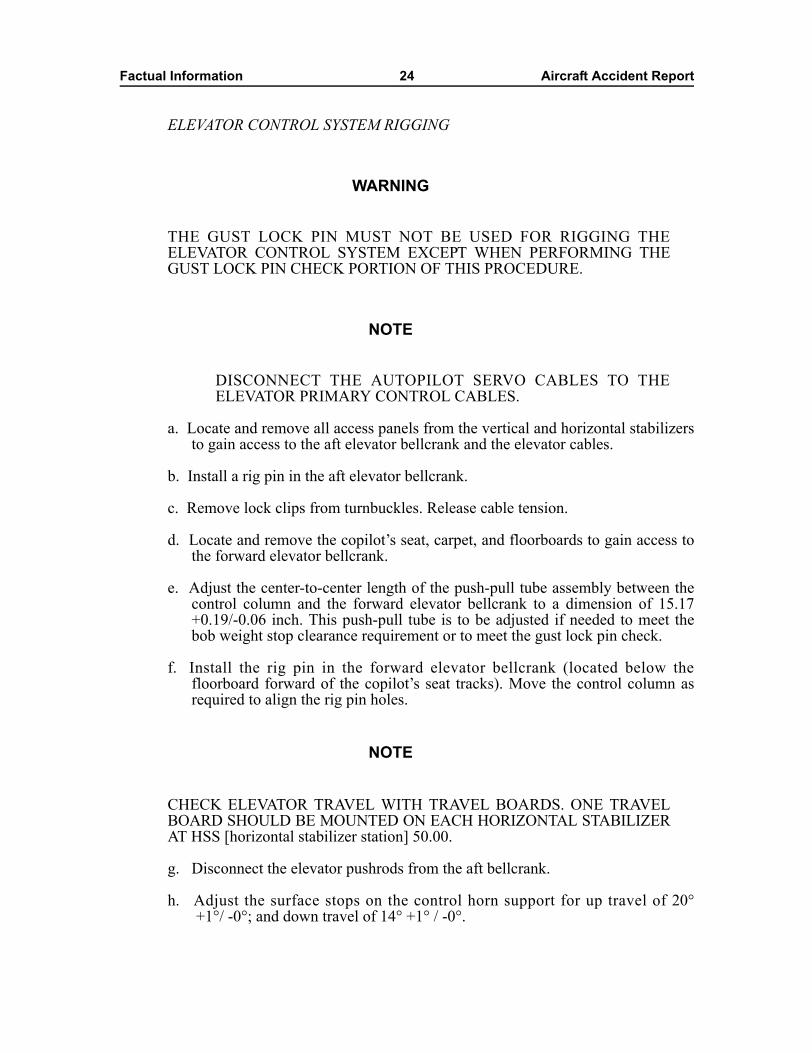
Factual Information 24 Aircraft Accident Report
ELEVATOR CONTROL SYSTEM RIGGING
WARNING
THE GUST LOCK PIN MUST NOT BE USED FOR RIGGING THEELEVATOR CONTROL SYSTEM EXCEPT WHEN PERFORMING THEGUST LOCK PIN CHECK PORTION OF THIS PROCEDURE.
NOTE
DISCONNECT THE AUTOPILOT SERVO CABLES TO THEELEVATOR PRIMARY CONTROL CABLES.
a. Locate and remove all access panels from the vertical and horizontal stabilizersto gain access to the aft elevator bellcrank and the elevator cables.
b. Install a rig pin in the aft elevator bellcrank.
c. Remove lock clips from turnbuckles. Release cable tension.
d. Locate and remove the copilot�s seat, carpet, and floorboards to gain access tothe forward elevator bellcrank.
e. Adjust the center-to-center length of the push-pull tube assembly between thecontrol column and the forward elevator bellcrank to a dimension of 15.17+0.19/-0.06 inch. This push-pull tube is to be adjusted if needed to meet thebob weight stop clearance requirement or to meet the gust lock pin check.
f. Install the rig pin in the forward elevator bellcrank (located below thefloorboard forward of the copilot�s seat tracks). Move the control column asrequired to align the rig pin holes.
NOTE
CHECK ELEVATOR TRAVEL WITH TRAVEL BOARDS. ONE TRAVELBOARD SHOULD BE MOUNTED ON EACH HORIZONTAL STABILIZERAT HSS [horizontal stabilizer station] 50.00.
g. Disconnect the elevator pushrods from the aft bellcrank.
h. Adjust the surface stops on the control horn support for up travel of 20°+1°/ -0°; and down travel of 14° +1° / -0°.
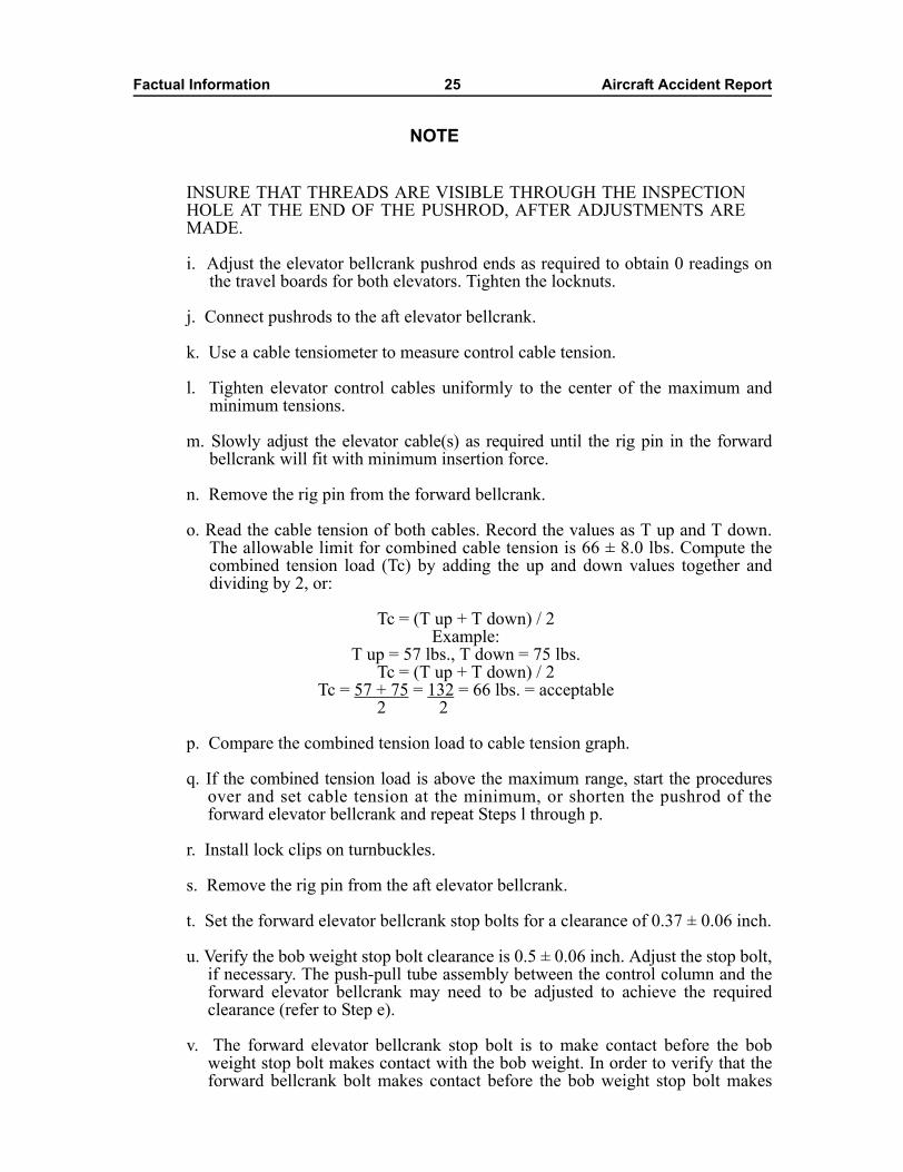
Factual Information 25 Aircraft Accident Report
NOTE
INSURE THAT THREADS ARE VISIBLE THROUGH THE INSPECTIONHOLE AT THE END OF THE PUSHROD, AFTER ADJUSTMENTS AREMADE.
i. Adjust the elevator bellcrank pushrod ends as required to obtain 0 readings onthe travel boards for both elevators. Tighten the locknuts.
j. Connect pushrods to the aft elevator bellcrank.
k. Use a cable tensiometer to measure control cable tension.
l. Tighten elevator control cables uniformly to the center of the maximum andminimum tensions.
m. Slowly adjust the elevator cable(s) as required until the rig pin in the forwardbellcrank will fit with minimum insertion force.
n. Remove the rig pin from the forward bellcrank.
o. Read the cable tension of both cables. Record the values as T up and T down.The allowable limit for combined cable tension is 66 ± 8.0 lbs. Compute thecombined tension load (Tc) by adding the up and down values together anddividing by 2, or:
Tc = (T up + T down) / 2Example:
T up = 57 lbs., T down = 75 lbs.Tc = (T up + T down) / 2
Tc = 57 + 75 = 132 = 66 lbs. = acceptable 2 2
p. Compare the combined tension load to cable tension graph.
q. If the combined tension load is above the maximum range, start the proceduresover and set cable tension at the minimum, or shorten the pushrod of theforward elevator bellcrank and repeat Steps l through p.
r. Install lock clips on turnbuckles.
s. Remove the rig pin from the aft elevator bellcrank.
t. Set the forward elevator bellcrank stop bolts for a clearance of 0.37 ± 0.06 inch.
u. Verify the bob weight stop bolt clearance is 0.5 ± 0.06 inch. Adjust the stop bolt,if necessary. The push-pull tube assembly between the control column and theforward elevator bellcrank may need to be adjusted to achieve the requiredclearance (refer to Step e).
v. The forward elevator bellcrank stop bolt is to make contact before the bobweight stop bolt makes contact with the bob weight. In order to verify that theforward bellcrank bolt makes contact before the bob weight stop bolt makes
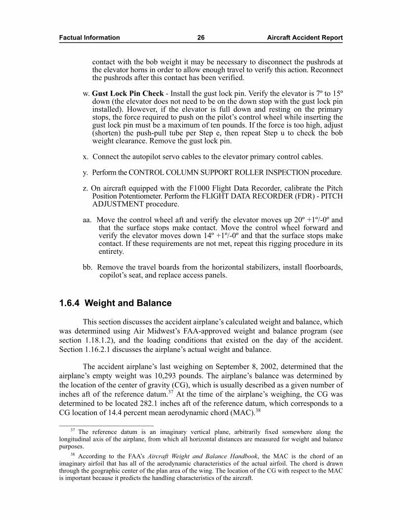
Factual Information 26 Aircraft Accident Report
contact with the bob weight it may be necessary to disconnect the pushrods atthe elevator horns in order to allow enough travel to verify this action. Reconnectthe pushrods after this contact has been verified.
w. Gust Lock Pin Check - Install the gust lock pin. Verify the elevator is 7º to 15ºdown (the elevator does not need to be on the down stop with the gust lock pininstalled). However, if the elevator is full down and resting on the primarystops, the force required to push on the pilot�s control wheel while inserting thegust lock pin must be a maximum of ten pounds. If the force is too high, adjust(shorten) the push-pull tube per Step e, then repeat Step u to check the bobweight clearance. Remove the gust lock pin.
x. Connect the autopilot servo cables to the elevator primary control cables.
y. Perform the CONTROL COLUMN SUPPORT ROLLER INSPECTION procedure.
z. On aircraft equipped with the F1000 Flight Data Recorder, calibrate the PitchPosition Potentiometer. Perform the FLIGHT DATA RECORDER (FDR) - PITCHADJUSTMENT procedure.
aa. Move the control wheel aft and verify the elevator moves up 20º +1º/-0º andthat the surface stops make contact. Move the control wheel forward andverify the elevator moves down 14º +1º/-0º and that the surface stops makecontact. If these requirements are not met, repeat this rigging procedure in itsentirety.
bb. Remove the travel boards from the horizontal stabilizers, install floorboards,copilot�s seat, and replace access panels.
1.6.4 Weight and Balance
This section discusses the accident airplane�s calculated weight and balance, whichwas determined using Air Midwest�s FAA-approved weight and balance program (seesection 1.18.1.2), and the loading conditions that existed on the day of the accident.Section 1.16.2.1 discusses the airplane�s actual weight and balance.
The accident airplane�s last weighing on September 8, 2002, determined that theairplane�s empty weight was 10,293 pounds. The airplane�s balance was determined bythe location of the center of gravity (CG), which is usually described as a given number ofinches aft of the reference datum.37 At the time of the airplane�s weighing, the CG wasdetermined to be located 282.1 inches aft of the reference datum, which corresponds to aCG location of 14.4 percent mean aerodynamic chord (MAC).38
37 The reference datum is an imaginary vertical plane, arbitrarily fixed somewhere along thelongitudinal axis of the airplane, from which all horizontal distances are measured for weight and balancepurposes.
38 According to the FAA�s Aircraft Weight and Balance Handbook, the MAC is the chord of animaginary airfoil that has all of the aerodynamic characteristics of the actual airfoil. The chord is drawnthrough the geographic center of the plan area of the wing. The location of the CG with respect to the MACis important because it predicts the handling characteristics of the aircraft.
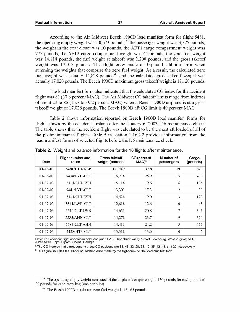
Factual Information 27 Aircraft Accident Report
According to the Air Midwest Beech 1900D load manifest form for flight 5481,the operating empty weight was 10,673 pounds,39 the passenger weight was 3,325 pounds,the weight in the coat closet was 10 pounds, the AFT1 cargo compartment weight was775 pounds, the AFT2 cargo compartment weight was 45 pounds, the zero fuel weightwas 14,818 pounds, the fuel weight at takeoff was 2,200 pounds, and the gross takeoffweight was 17,018 pounds. The flight crew made a 10-pound addition error whensumming the weights that comprise the zero fuel weight. As a result, the calculated zerofuel weight was actually 14,828 pounds,40 and the calculated gross takeoff weight wasactually 17,028 pounds. The Beech 1900D maximum gross takeoff weight is 17,120 pounds.
The load manifest form also indicated that the calculated CG index for the accidentflight was 81 (37.8 percent MAC). The Air Midwest CG takeoff limits range from indexesof about 23 to 85 (16.7 to 39.2 percent MAC) when a Beech 1900D airplane is at a grosstakeoff weight of 17,028 pounds. The Beech 1900D aft CG limit is 40 percent MAC.
Table 2 shows information reported on Beech 1900D load manifest forms forflights flown by the accident airplane after the January 6, 2003, D6 maintenance check.The table shows that the accident flight was calculated to be the most aft loaded of all ofthe postmaintenance flights. Table 5 in section 1.16.2.2 provides information from theload manifest forms of selected flights before the D6 maintenance check.
Table 2. Weight and balance information for the 10 flights after maintenance.
Note: The accident flight appears in bold face print. LWB, Greenbrier Valley Airport, Lewisburg, West Virginia; AHN, Athens/Ben Epps Airport, Athens, Georgia.a The CG indexes that correspond to these CG positions are 81, 48, 32, 28, 31, 19, 35, 42, 43, and 20, respectively.b This figure includes the 10-pound addition error made by the flight crew on the load manifest form.
39 The operating empty weight consisted of the airplane�s empty weight, 170 pounds for each pilot, and20 pounds for each crew bag (one per pilot).
40 The Beech 1900D maximum zero fuel weight is 15,165 pounds.
DateFlight number and
routeGross takeoff
weight (pounds)CG (percent
MAC)aNumber of passengers
Cargo (pounds)
01-08-03 5481/CLT-GSP 17,028b 37.8 19 820
01-08-03 5434/LYH-CLT 16,278 25.9 15 470
01-07-03 5461/CLT-LYH 15,118 19.6 6 195
01-07-03 5441/LYH-CLT 13,303 17.3 2 70
01-07-03 5441/CLT-LYH 14,528 19.0 3 120
01-07-03 5514/LWB-CLT 12,618 12.6 0 45
01-07-03 5514/CLT-LWB 14,653 20.8 7 345
01-07-03 5585/AHN-CLT 14,278 23.7 9 320
01-07-03 5585/CLT-AHN 14,413 24.2 5 455
01-07-03 5428/HTS-CLT 13,318 13.6 0 45

Factual Information 28 Aircraft Accident Report
1.7 Meteorological InformationWeather observations at CLT are made by an automated surface observing system
(ASOS), which records continuous information on wind speed and direction, cloud cover,temperature, precipitation, and visibility.41 The ASOS transmits an official meteorologicalaerodrome report (known as a METAR) that is valid at 51 minutes past each hour and aspecial weather observation as conditions warrant; such conditions include a relevantwind shift, visibility change, and ceiling change (cloud cover or height). Weatherobservations are transmitted in coordinated universal time (UTC). Eastern standard time is5 hours behind UTC time.
The 1251Z42 METAR (0751 local time) indicated that the winds were 260º at6 knots, visibility was 10 miles, clouds were scattered at 14,000 feet and broken at 25,000 feet,the temperature was 3º Celsius (C), the dew point was -7º C, and the altimeter setting was29.75 inches of mercury (Hg). The 1351Z METAR (0851 local time) indicated that thewinds were 230º at 7 knots, visibility was 10 miles, clouds were scattered at 14,000 feetand broken at 25,000 feet, the temperature was 4º C, the dew point was -6º C, and thealtimeter setting was 29.76 inches of Hg.
CLT is also equipped with a terminal doppler weather radar system, whichprovides windshear and microburst alerts. During the time surrounding the accident, thesystem did not transmit an alert.
1.8 Aids to NavigationNo problems with any navigational aids were reported.
1.9 CommunicationsNo communications problems were reported between the pilots and any of the air
traffic controllers who handled the flight.
1.10 Airport Information CLT is located about 4 miles west of the city of Charlotte at an elevation of
748 feet mean sea level (msl). An average of 1,250 aircraft operate at the airport daily,about 90 percent of which are scheduled air carrier or air taxi operations; the remainderare general aviation and military operations. The airport has two parallel runways,18L/36R and 18R/36L, and a third runway, 5/23. Runway 18R, from which flight 5481
41 Cloud cover is expressed in feet above ground level. Visibility is expressed in statute miles.42 The �Z� designation that follows the time in a weather observation stands for Zulu, which indicates
UTC time.
Factual Information 29 Aircraft Accident Report
took off, is 10,000 feet long and 150 feet wide and is made of wire-combed concrete. Theairport was certificated under 14 CFR Part 139.
CLT Airport Operations personnel perform airport inspections two times each day.The first inspection, which begins about 0800, includes all of the airport movement areas.The second inspection, which begins about 1600, includes all of the airport movementareas and the airfield lighting facilities. The self-inspection log sheet indicated nodiscrepancies for the first inspection performed on the day of the accident. CLT AirportOperations personnel performed a special inspection after the accident. The specialinspection, which began about 0906, examined runways 18R/36L and 5/23 and severaltaxiways for foreign object debris; none was recorded on the log sheet.
CLT has an airport emergency plan detailing response, recovery, and resolutionactions in the event of an accident or incident involving aircraft at the airport or within theboundary of Mecklenburg County, North Carolina. (The city of Charlotte is withinMecklenburg County.) CLT is responsible for conducting a full-scale mock disaster drillonce every 3 years to test this plan. On May 13, 2000, CLT conducted a full-scale triennialdrill with participation from the following organizations: the FAA; CLT AirportOperations, Airport Law Enforcement, and Aircraft Rescue and Firefighting (ARFF); theCLT ATCT; the Charlotte-Mecklenburg Police Department; the City of Charlotte FireDepartment (CFD); the North Carolina Air National Guard; the Mecklenburg CountyMedical Examiner; the American Red Cross; and US Airways.
1.10.1 Aircraft Rescue and Firefighting
CLT and the North Carolina Air National Guard maintain an index D ARFFfacility43 on the airfield. The ARFF station (Station 17), which is owned by the AirNational Guard, is continuously staffed with a minimum of nine CFD firefighters. Thestation houses eight crash trucks, six of which are owned by the Air National Guard (Blaze 1,Blaze 2, Blaze 3, Blaze 5, Blaze 8, and Blaze 18) and two of which (Blaze 7 and Engine 17)are owned by the CFD. An off-airport fire station (Station 30) is the backup facility for allalerts on airport property.
ARFF personnel receive 56 hours of initial training, including classroominstruction and a live burn pit/mobile trainer fire exercise. ARFF personnel use the FAA�saircraft rescue and firefighter computer-based training program, which covers 13 subjectareas, to accomplish recurrent training. In addition, the State of North Carolina requiresARFF personnel to have a minimum of 24 hours of continuing education each year in the13 FAA-required subject areas. To meet this requirement, CFD conducts training duringquarterly sessions consisting of 4 hours of classroom instruction and 5 hours of practicalskills, for a total of 9 hours per quarter and 36 hours per year.
43 According to 14 CFR 139.317, an index D ARFF facility is required to have (1) either onefirefighting vehicle with 500 pounds of sodium-based dry chemical or Halon 1211 or 450 pounds ofpotassium-based dry chemical and water with a commensurate quantity of aqueous film forming foam(AFFF) to total 100 gallons and (2) two firefighting vehicles with water and a commensurate quantity ofAFFF so that the total quantity of water for foam production carried by all three vehicles is at least 4,000 gallons.
Factual Information 30 Aircraft Accident Report
1.10.2 Air Traffic Control
The CLT ATCT is an FAA-staffed combined terminal approach radar control(TRACON)44 and tower with about 500,000 operations per year. The tower cab iscontinuously open and is located on the north side of the airport, centered betweenrunways 18L/36R and 18R/36L. Air traffic control (ATC) radar data are provided by anairport surveillance radar-9 sensor located midfield on the airport between runways 18R/36Land 5/23. Radar data processing is performed by an automated radar terminal system-3Aprocessor.
Flight 5481 was handled by three air traffic controllers on the day of the accident:the clearance delivery controller, the ground control west controller, and the local controlwest controller. Two local control east controllers (one of which was at the developmentallevel), a ground control east controller, and a tower supervisor were also present at theCLT ATCT at the time of the accident.
The ground control west controller has been a controller at the CLT ATCT sinceJune 1982. He was a controller for the U.S. Air Force before beginning work for the FAA.He first became aware of a problem with flight 5481 when the local control westcontroller stated that the airplane might stall. The ground control west controller thennoticed the airplane climbing from about 200 feet. He stated that the climb was steep andthat, at an altitude of about 1,000 feet, the airplane �winged over to the left.� He alsostated that he saw the airplane descend in a nose-down attitude, pick up speed, and leveloff at about the height of the US Airways hangar. He thought that the pilot had brieflyrecovered control of the airplane, but then its nose went down. He stated that the airplanehit the hangar and that he then saw a ball of fire. He further stated that both enginesappeared to be running throughout the flight and that he did not notice anything fall fromthe airplane.
The local control west controller has been a controller at the CLT ATCT since1987. He was a controller at the RDU ATCT and with the U.S. Air Force before beginningwork at the CLT ATCT. The local control west controller stated that the airplane lifted offabout 3,200 feet down the runway and started a normal climb that kept getting steeper. Headded that, rather than entering a departure turn to the right, the airplane continued to pitchhigher and was nearly vertical between 800 and 1,000 feet. The local control westcontroller stated that he realized something was wrong with the airplane and that he saidaloud, �that guy�s gonna stall.� He stated that the airplane�s rate of pitchup was smoothand not like an aerobatic demonstration. He saw the airplane fall to the left, in an apparentstall, and then regain a somewhat-level flight attitude. Next, he saw the airplane roll to theright, flip upside down, and hit the hangar. He stated that he saw a ball of fire afterward.
The ground control east controller was positioned closest to the crash phone. (Thecrash phone links the ATCT directly with ARFF Station 17, the CLT Airport OperationsCenter, and the North Carolina Air National Guard.) The controller stated that she heard
44 TRACON personnel did not interact with the accident flight.
Factual Information 31 Aircraft Accident Report
someone yell, �crash phone,� and that she picked up the phone while the airplane was stillin the air. The controller stated that she saw the airplane �wiggle,� �go nose down,� andcrash just as the phone was answered. Emergency response information is detailed insection 1.15.1.
1.11 Flight Recorders
1.11.1 Cockpit Voice Recorder
The accident airplane was equipped with a Fairchild model A-100A CVR, serialnumber 61979. The exterior of the CVR was heavily covered with soot and showedevidence of significant heat exposure. The interior surfaces and components were coveredwith soot. Some of the internal components appeared to be partially melted. The exteriorof the case that housed the tape spool assembly was covered with soot but was generallyintact, with little or no mechanical damage noted. The tape spool assembly and othercomponents inside the case were not damaged and were generally in good condition. Noapparent evidence of heat or mechanical damage to the tape was found.
The CVR was sent to the National Transportation Safety Board�s audio laboratoryin Washington, D.C., for readout and evaluation. The tape was played back normally andwithout difficulty. The CVR data started about 0815:41 and continued uninterrupted until0847:28.1. The recording consisted of four separate channels of audio information: thecockpit area microphone, the captain�s and first officer�s audio panels, and the publicaddress system. Hot microphone transmissions from the captain and the first officer werealso captured on their respective audio channels.
The cockpit area microphone and public address system information were goodquality.45 The captain�s and first officer�s audio panel information was fair to poor qualitywith respect to the audio captured from the airplane�s very high frequency (VHF) radiosystems, but the audio information from the captain�s and the first officer�s hotmicrophones was excellent to good quality. A transcript was prepared of the entire31-minute 47-second recording (see appendix B).
The volume of the incoming VHF radio messages during the accident flight wasextremely low compared with the volume of the audio captured by the flight crew�s hotmicrophones. Because the audio from the captain�s (or first officer�s) hot microphone wasrecorded on the same channel as the audio from the VHF radio, the two audio signalscould not be isolated from each other on the recording. (The mixing of these two audiosignals onto the same CVR channel is normal and is not unique to this CVR system.)
45 The Safety Board rates the quality of CVR recordings according to a five-category scale: excellent,good, fair, poor, and unusable. See appendix B for a description of these ratings.
Factual Information 32 Aircraft Accident Report
1.11.1.1 Safety Recommendations A-97-36 and A-02-25
Beech 1900 series airplanes had previously experienced problems with the lowsignal volume of VHF radio messages as recorded by the CVR. On May 22, 1997, theSafety Board issued Safety Recommendation A-97-36, which asked the FAA to
Promptly require the inspection of the cockpit voice recorder (CVR) andassociated equipment on all Beech 1900 aircraft and ensure that operators takecorrective action to repair deficient CVR systems so that the intelligibility ofrecorded communications, including radio transmissions to and from the airplane,is as high as practicable.
In response to the Safety Board�s recommendation, Raytheon Aircraft Companyissued Service Bulletin (SB) 23-3094, which recommended the incorporation of animproved CVR amplifier and new circuitry for the wiring. Subsequently, the FAA issuedAirworthiness Directive (AD) 2000-20-07, which required that all applicable Beech 1900series airplanes comply with Raytheon Aircraft�s SB. On January 30, 2001, the Boardstated that, with the issuance of AD 2000-20-07, the FAA had completed therecommended action, and, as a result, Safety Recommendation A-97-36 was classified�Closed�Acceptable Action.� The accident airplane�s maintenance records indicated thatthe actions required by the AD were accomplished on March 3, 2001.
On August 29, 2002, the Safety Board issued Safety Recommendation A-02-25 asa result of longstanding concerns regarding the availability of CVR information forreportable accidents or incidents. Specifically, the Board was concerned about tape ormemory that had been overwritten by events subsequent to an accident or incident andrecording systems that had malfunctioned or were inoperative at the time of an accident orincident. Safety Recommendation A-02-25 asked the FAA to
Require that all operators of airplanes equipped with a cockpit voice recorder(CVR) test the functionality of the CVR system prior to the first flight of each day,as part of an approved aircraft checklist. This test must be conducted according toprocedures provided by the CVR manufacturer and shall include, at a minimum,listening to the recorded signals on each channel to verify that the audio is beingrecorded properly, is intelligible, and is free from electrical noise or otherinterference.
Safety Recommendation A-02-25, which was classified �Open�AcceptableResponse� on January 16, 2003, is discussed in detail in section 2.6.
1.11.2 Flight Data Recorder
The accident airplane was equipped with an L3 Communications Fairchild modelF-1000 FDR, serial number 01110. The FDR used a solid-state flash memory module,stored in a crash-protected memory case, as the recording medium. The FDR system, as
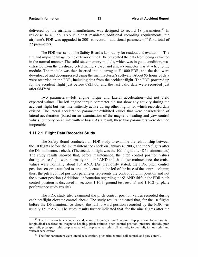
Factual Information 33 Aircraft Accident Report
delivered by the airframe manufacturer, was designed to record 18 parameters.46 Inresponse to a 1997 FAA rule that mandated additional recording requirements, theairplane�s FDR was upgraded in 2001 to record 4 additional parameters,47 for a total of22 parameters.
The FDR was sent to the Safety Board�s laboratory for readout and evaluation. Thefire and impact damage to the exterior of the FDR prevented the data from being extractedin the normal manner. The solid-state memory module, which was in good condition, wasextracted from the crash-protected memory case, and a new connector was attached to themodule. The module was then inserted into a surrogate F-1000 FDR, and the data weredownloaded and decompressed using the manufacturer�s software. About 95 hours of datawere recorded on the FDR, including data from the accident flight. The FDR powered upfor the accident flight just before 0825:00, and the last valid data were recorded justafter 0847:28.
Two parameters�left engine torque and lateral acceleration�did not yieldexpected values. The left engine torque parameter did not show any activity during theaccident flight but was intermittently active during other flights for which recorded dataexisted. The lateral acceleration parameter exhibited values that were characteristic oflateral acceleration (based on an examination of the magnetic heading and yaw controlvalues) but only on an intermittent basis. As a result, these two parameters were deemedinoperable.
1.11.2.1 Flight Data Recorder Study
The Safety Board conducted an FDR study to examine the relationship betweenthe 10 flights before the D6 maintenance check on January 6, 2003, and the 9 flights afterthe D6 maintenance check. (The accident flight was the 10th flight after D6 maintenance.)The study results showed that, before maintenance, the pitch control position valuesduring cruise flight were normally about 4º AND and that, after maintenance, the cruisevalues were normally about 13º AND. (As previously stated, the FDR pitch controlposition sensor is attached to structure located to the left of the base of the control column;thus, the pitch control position parameter represents the control column position and notthe elevator position.) Additional information regarding the 9º AND shift in the FDR pitchcontrol position is discussed in sections 1.16.1 (ground test results) and 1.16.2 (airplaneperformance study results).
The FDR study also examined the pitch control position values recorded duringeach preflight elevator control check. The study results indicated that, for the 10 flightsbefore the D6 maintenance check, the full forward position recorded by the FDR wasusually 15.6º AND. The study results further indicated that, for the nine flights after the
46 The 18 parameters were airspeed, comm1 keying, comm2 keying, flap position, frame counter,longitudinal acceleration, magnetic heading, pitch attitude, pitch control position, pressure altitude, proprpm left, prop rpm right, prop reverse left, prop reverse right, roll attitude, torque left, torque right, andvertical acceleration.
47 The four parameters were lateral acceleration, pitch trim control, roll control, and yaw control.
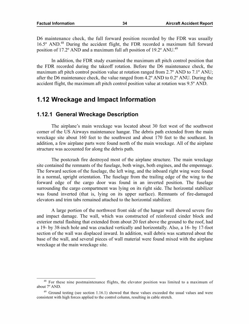
Factual Information 34 Aircraft Accident Report
D6 maintenance check, the full forward position recorded by the FDR was usually16.5º AND.48 During the accident flight, the FDR recorded a maximum full forwardposition of 17.2º AND and a maximum full aft position of 19.2º ANU.49
In addition, the FDR study examined the maximum aft pitch control position thatthe FDR recorded during the takeoff rotation. Before the D6 maintenance check, themaximum aft pitch control position value at rotation ranged from 2.7º AND to 7.1º ANU;after the D6 maintenance check, the value ranged from 4.2º AND to 0.2º ANU. During theaccident flight, the maximum aft pitch control position value at rotation was 9.5º AND.
1.12 Wreckage and Impact Information
1.12.1 General Wreckage Description
The airplane�s main wreckage was located about 30 feet west of the southwestcorner of the US Airways maintenance hangar. The debris path extended from the mainwreckage site about 160 feet to the southwest and about 170 feet to the southeast. Inaddition, a few airplane parts were found north of the main wreckage. All of the airplanestructure was accounted for along the debris path.
The postcrash fire destroyed most of the airplane structure. The main wreckagesite contained the remnants of the fuselage, both wings, both engines, and the empennage.The forward section of the fuselage, the left wing, and the inboard right wing were foundin a normal, upright orientation. The fuselage from the trailing edge of the wing to theforward edge of the cargo door was found in an inverted position. The fuselagesurrounding the cargo compartment was lying on its right side. The horizontal stabilizerwas found inverted (that is, lying on its upper surface). Remnants of fire-damagedelevators and trim tabs remained attached to the horizontal stabilizer.
A large portion of the northwest front side of the hangar wall showed severe fireand impact damage. The wall, which was constructed of reinforced cinder block andexterior metal flashing that extended from about 20 feet above the ground to the roof, hada 19- by 38-inch hole and was cracked vertically and horizontally. Also, a 16- by 17-footsection of the wall was displaced inward. In addition, wall debris was scattered about thebase of the wall, and several pieces of wall material were found mixed with the airplanewreckage at the main wreckage site.
48 For these nine postmaintenance flights, the elevator position was limited to a maximum ofabout 7º AND.
49 Ground testing (see section 1.16.1) showed that these values exceeded the usual values and wereconsistent with high forces applied to the control column, resulting in cable stretch.
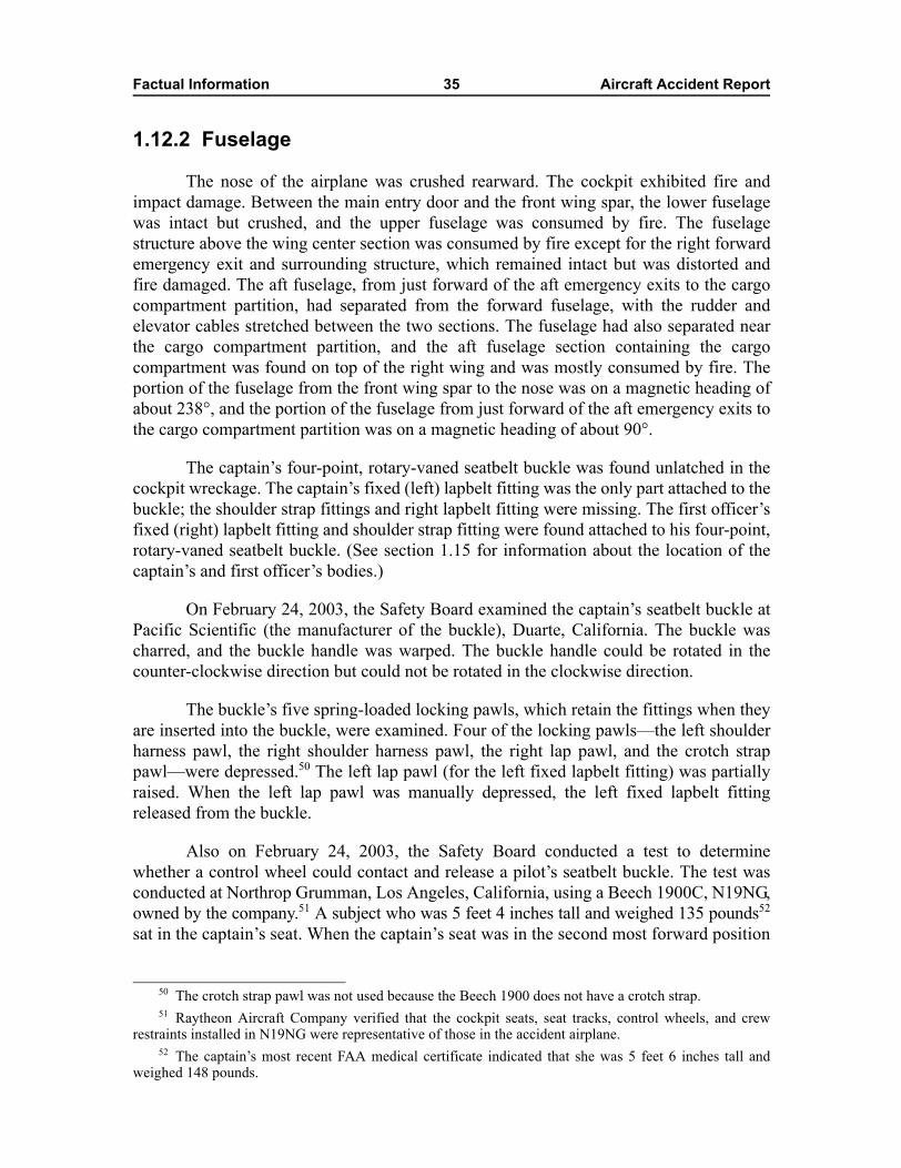
Factual Information 35 Aircraft Accident Report
1.12.2 Fuselage
The nose of the airplane was crushed rearward. The cockpit exhibited fire andimpact damage. Between the main entry door and the front wing spar, the lower fuselagewas intact but crushed, and the upper fuselage was consumed by fire. The fuselagestructure above the wing center section was consumed by fire except for the right forwardemergency exit and surrounding structure, which remained intact but was distorted andfire damaged. The aft fuselage, from just forward of the aft emergency exits to the cargocompartment partition, had separated from the forward fuselage, with the rudder andelevator cables stretched between the two sections. The fuselage had also separated nearthe cargo compartment partition, and the aft fuselage section containing the cargocompartment was found on top of the right wing and was mostly consumed by fire. Theportion of the fuselage from the front wing spar to the nose was on a magnetic heading ofabout 238°, and the portion of the fuselage from just forward of the aft emergency exits tothe cargo compartment partition was on a magnetic heading of about 90°.
The captain�s four-point, rotary-vaned seatbelt buckle was found unlatched in thecockpit wreckage. The captain�s fixed (left) lapbelt fitting was the only part attached to thebuckle; the shoulder strap fittings and right lapbelt fitting were missing. The first officer�sfixed (right) lapbelt fitting and shoulder strap fitting were found attached to his four-point,rotary-vaned seatbelt buckle. (See section 1.15 for information about the location of thecaptain�s and first officer�s bodies.)
On February 24, 2003, the Safety Board examined the captain�s seatbelt buckle atPacific Scientific (the manufacturer of the buckle), Duarte, California. The buckle wascharred, and the buckle handle was warped. The buckle handle could be rotated in thecounter-clockwise direction but could not be rotated in the clockwise direction.
The buckle�s five spring-loaded locking pawls, which retain the fittings when theyare inserted into the buckle, were examined. Four of the locking pawls�the left shoulderharness pawl, the right shoulder harness pawl, the right lap pawl, and the crotch strappawl�were depressed.50 The left lap pawl (for the left fixed lapbelt fitting) was partiallyraised. When the left lap pawl was manually depressed, the left fixed lapbelt fittingreleased from the buckle.
Also on February 24, 2003, the Safety Board conducted a test to determinewhether a control wheel could contact and release a pilot�s seatbelt buckle. The test wasconducted at Northrop Grumman, Los Angeles, California, using a Beech 1900C, N19NG,owned by the company.51 A subject who was 5 feet 4 inches tall and weighed 135 pounds52
sat in the captain�s seat. When the captain�s seat was in the second most forward position
50 The crotch strap pawl was not used because the Beech 1900 does not have a crotch strap. 51 Raytheon Aircraft Company verified that the cockpit seats, seat tracks, control wheels, and crew
restraints installed in N19NG were representative of those in the accident airplane. 52 The captain�s most recent FAA medical certificate indicated that she was 5 feet 6 inches tall and
weighed 148 pounds.
Factual Information 36 Aircraft Accident Report
along the seat track53 and the subject pulled the control wheel full aft and rotated itclockwise, the control wheel did not contact the seatbelt buckle. When the captain�s seatwas in the full forward and full up position and the subject pulled the control wheel full aftand rotated it clockwise, the control wheel contacted the seatbelt buckle and released it.54
In addition, the locking pawls from the captain�s and the first officer�s seatbeltbuckles, as well as those from another Air Midwest seatbelt buckle (which had beenremoved from service), were examined by microscope at the Safety Board�s MaterialsLaboratory. The locking pawls on the captain�s seatbelt buckle did not show anysignificant witness marks. The locking pawls on the first officer�s seatbelt buckle showedimpression marks. The locking pawls on the other Air Midwest seatbelt buckle showedminor wear but no impression marks.
More than 10 years before the flight 5481 accident, engineers from PacificScientific and The Boeing Company designed a guarded seatbelt buckle with a protectivecircular guard around the rotary vanes of the seatbelt to prevent the inadvertent release ofthe restraint. Because unguarded rotary seatbelt buckles pose an unnecessary safety risk toflight crewmembers since the buckles may become unlatched, the Safety Board issuedSafety Recommendation A-03-57 on January 2, 2004. Safety Recommendation A-03-57asked the FAA to �identify all airplanes equipped with unguarded flight crewmemberrotary seatbelt buckles and require replacement with guarded buckles that cannot beinadvertently unlatched.�
1.12.3 Engines
The left engine was lying upright immediately forward of the engine nacelle andwas displaced about 45º to the left of the airframe centerline. The right engine was lyingon its right side forward of the left wing center spar and was displaced about 90º to the leftof the airframe centerline.
Both propeller assemblies were found outside the main wreckage area and separatefrom their respective engines. No impact marks were found on the left propeller assemblythat could positively determine the exact blade pitch angle at the time of the accident.However, the position of the cylinder buckles around the piston suggested that the pistonwas not in reverse or in feather but was at some point within the propeller blade operatingrange. One impact mark (a puncture hole) found on the right propeller assembly�s spinnerwas consistent in size and shape with a blade counterweight. According to HartzellPropeller, the location of the puncture hole in relation to the blade plane of rotationcorresponded to a blade pitch angle of about 22º.
53 The captain�s seat was found in this seat track position, but the seat height could not be determinedbecause of the damage to the seat.
54 During the on-site investigation of this accident, an Air Midwest Beech 1900 pilot informed theSafety Board that he had experienced the uncommanded release of his seatbelt when the control wheel waspulled aft, striking one of the buckle�s vanes. In addition, the Air Line Pilots Association reported fiveinstances of a pilot�s seatbelt becoming unbuckled when the control wheel was pulled aft and the wheel, or aclipboard attached to the wheel, contacted a buckle vane.
Factual Information 37 Aircraft Accident Report
From January 27 to 31, 2003, the engines were disassembled and examined atPratt & Whitney Canada�s facility in St-Hubert, Quebec, Canada. On February 12, 2003,the propellers were disassembled and examined at Hartzell Propeller�s facility in Piqua,Ohio. No preexisting defects or anomalies were found that would have prevented normaloperation of the engines or the propellers.
1.12.4 Pitch Control System
The rivets connecting the elevator control horns to the elevator shafts were tight,and the control horns were solidly fixed to the elevator shafts. The control horns movedfreely in their respective bearings. The primary stop bolts were attached to the elevatorcontrol horn supports and were found safety wired.
The aft end of each aft pushrod was connected to its respective elevator controlhorn, and the forward end of each pushrod was connected to the aft bellcrank and itsrespective aft bellcrank link. The length of the left aft pushrod was 20.53 inches, and thelength of the right aft pushrod was 20.44 inches.
Most of the structure that contained the rig pin holes for the aft bellcrank wasmissing, and the part that remained was heavily fire damaged. The left tension spring wasfound with its upper end attached to its attachment link and its lower end attached tostructure. The right tension spring was found with its upper end separated from itsattachment link and its lower end attached to structure. Examination of the right tensionspring at the Safety Board�s Materials Laboratory showed partial surface melting of thebellcrank adjacent to the right spring attachment link (the upper end of the spring) andsome resolidified metal adjacent to the lower end of the spring. Magnified visualexamination of the unattached end of the right spring and the right attachment link showedno evidence of unusual wear patterns, scratching, or other damage related to the separationof the spring from the link.55
The elevator control cables generally had numerous bends and kinks. Two of theelevator AND cable�s seven spirally wound strands were completely broken andunwound, and one strand was partially broken and unwound. (These strands were locatednear the trailing edge of the wing, where the fuselage had folded toward the right wingtip.) The unwound sections of the cable were examined at the Safety Board�s MaterialsLaboratory, and no evidence of fatigue cracking or a preexisting condition was found.
The ANU turnbuckle was almost fully contracted, and the AND turnbuckle wasalmost fully extended. The measurement from the center of the tooling hole in onethreaded cable terminal to the center of the tooling hole in the other cable terminal was5.54 inches for the ANU turnbuckle and 7.30 inches for the AND turnbuckle. In addition,the AND turnbuckle had one thread visible, and the ANU turnbuckle did not have anythreads visible. Figure 6 shows the turnbuckles as found in the wreckage and a drawingthat shows a turnbuckle barrel and threaded cable terminals.
55 During ground tests on January 21 and 22, 2003, a tension spring was disconnected from the testairplane to determine the effect of a disconnected spring on the forces felt at the control column. This testrevealed that about 6 additional pounds of force were required to move the control column forward.
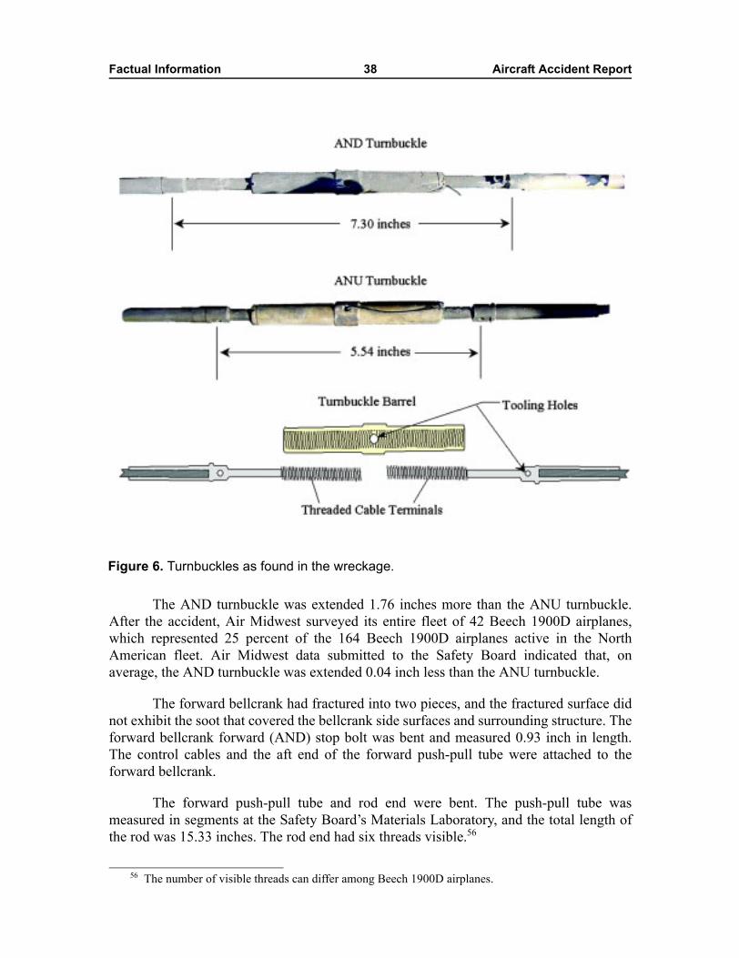
Factual Information 38 Aircraft Accident Report
The AND turnbuckle was extended 1.76 inches more than the ANU turnbuckle.After the accident, Air Midwest surveyed its entire fleet of 42 Beech 1900D airplanes,which represented 25 percent of the 164 Beech 1900D airplanes active in the NorthAmerican fleet. Air Midwest data submitted to the Safety Board indicated that, onaverage, the AND turnbuckle was extended 0.04 inch less than the ANU turnbuckle.
The forward bellcrank had fractured into two pieces, and the fractured surface didnot exhibit the soot that covered the bellcrank side surfaces and surrounding structure. Theforward bellcrank forward (AND) stop bolt was bent and measured 0.93 inch in length.The control cables and the aft end of the forward push-pull tube were attached to theforward bellcrank.
The forward push-pull tube and rod end were bent. The push-pull tube wasmeasured in segments at the Safety Board�s Materials Laboratory, and the total length ofthe rod was 15.33 inches. The rod end had six threads visible.56
Figure 6. Turnbuckles as found in the wreckage.
56 The number of visible threads can differ among Beech 1900D airplanes.
Factual Information 39 Aircraft Accident Report
The control column was dented and slightly crushed but was intact. The left andright pivot bearings were found in the wreckage. The captain�s and the first officer�scontrol column shaft and support assemblies had separated from the forward subpanelstructure, and their control wheels had separated from the control column shaft assembly.The roller slider assemblies contained within the captain�s control column supportassembly were burned; the shaft was displaced away from the center of the rollers, and theslider rollers were unable to rotate. The roller slider assemblies contained within the firstofficer�s control column support assembly were able to rotate. The roller containing aneccentric screw rotated freely on its bearing, and a clearance of about 0.06 inch existedbetween the rollers and the control column shaft assembly.57
The bob weight and its surrounding structure were displaced from their normallyrigged positions and exhibited impact damage that was consistent with the impact damagefound on the nose of the airplane. The gap between the head of the stop bolt and the bobweight could not be measured because of the severe impact damage in that area.
1.12.4.1 Pitch Trim Control System
The elevator trim tab control wheel was intact and was attached in the cockpit. Thepitch trim appeared to be near the full AND position. The pitch trim control cables werebroken. The control cables were in the correct orientation. The left and right drums hadtheir respective cables wrapped around to the middle position.
1.13 Medical and Pathological InformationTissue specimens from the captain and the first officer tested negative for ethanol
and a wide range of drugs, including major drugs of abuse. Postaccident drug tests on thetwo ramp agents who handled the accident flight and their supervisor as well as themechanic and the quality assurance inspector who worked on the accident airplane werenegative for drugs of abuse.58
1.14 FireNo evidence of an in-flight fire was found. A postcrash fire developed after
airplane impact. According to interviews with ARFF personnel and a videotape taken bythe CFD and the Charlotte-Mecklenburg Police Department, the main fire was at thewreckage site, and spot fires occurred along the grass strip on the parking lot side of theairport perimeter fence and in a gully south of the accident site. Thick black smokeemanated from the southwest corner of the US Airways hangar. ARFF personnelestimated that it took about 3 minutes of AFFF application to knock down the main fire.
57 The Beech 1900D AMM specifies a 0.01-inch gap between the rollers and the control column shaftassembly.
58 Urine samples were obtained on January 8, 2003, at 1530 for one ramp agent, 1745 for the otherramp agent, 1230 for their supervisor, and 1542 for the quality assurance inspector. The mechanic�s urinesample was obtained on January 9, 2003, at 1000.
Factual Information 40 Aircraft Accident Report
1.15 Survival AspectsAutopsy results from the Mecklenburg County Medical Examiner indicated that
the cause of death for all of the airplane occupants was �multiple blunt force injuries dueto airplane crash.� The captain�s body was found about 4 feet in front of the cockpitwreckage. The medical examiner did not find any significant markings on her torso thatwould have been left by the lapbelt or shoulder harness on airplane impact. The firstofficer was found restrained in his seat with his lapbelt and shoulder harness buckled.
1.15.1 Emergency Response
According to the crash phone transcript,59 the crash alarm sounded at ARFFStation 17, the CLT Airport Operations Center, and the North Carolina Air National Guardabout 0847:28. The ground control east controller stated, about 0847:37, �anemergency�landing right now at the US Air maintenance ramp�right at the corner of thebuilding�there�s a fire.� About 0847:47, a CFD firefighter at the ARFF station asked thecontroller what type of airplane had crashed and, about 0847:49, whether the airplane wascommercial or small. About 0847:52, the controller responded that the airplane was aGulfstream III. About 0847:55, the controller stated, �no no no,� and a hangup sound wasrecorded. One second later, the controller stated that a Beech 1900 had crashed, but, in apostaccident interview, the controller indicated that she was not able to complete thistransmission before the hangup sound occurred.
About 0848:31, an ARFF captain notified the CFD dispatch center of the airplanecrash. The CFD dispatch center then dispatched CFD fire rescue personnel and notifiedthe Charlotte-Mecklenburg Police Department and Mecklenburg Emergency MedicalService dispatch center.60
Four ARFF vehicles (Blaze 1, Blaze 2, Blaze 5, and Blaze 7) and nine ARFFpersonnel responded to the initial call to the ARFF station. Blaze 2 had a speed restrictionof 30 mph during emergency operations because the hubs on the vehicle were subject to aU.S. Air Force restriction notice.61 One of the firefighters aboard Blaze 2 reported that thevehicle traveled to the accident site at a speed of about 50 mph.
In addition, Engine 30, with four ARFF personnel, responded to the initial call.Engine 30 is normally based at the off-airport fire station that responds to emergencies on
59 The crash phone transmissions were recorded in the CLT Airport Operations Center. 60 CFD was also responsible for notifying the Charlotte-Mecklenburg Emergency Management Office,
which was responsible for notifying the American Red Cross and the North Carolina Department ofEmergency Management. The Mecklenburg Emergency Medical Service was responsible for notifying areahospitals and dispatching area ambulances, medical evacuation helicopters, triage teams, medicalexaminers, medical mutual aid responders, and volunteer departments.
61 In March 1998, the U.S. Air Force issued a restriction notice for all P-23 trucks (such as Blaze 2) inits fleet because of an increasing number of hub axle failures. Although the P-23 truck, an eight-wheel-drivevehicle, would remain stable in the event of a hub axle failure, the Air Force determined that a separatedwheel resulting from the failure could be dangerous to people near the truck at the time.
Factual Information 41 Aircraft Accident Report
airport property but was at Station 17 in place of Engine 17, which was at training. Engine 17,with four ARFF personnel, left training to respond to the accident.
CFD radio logs indicated that the first ARFF unit arrived at the accident siteabout 0849:10, about 1 minute 42 seconds after the time of the crash alarm.62 A captainfrom ARFF Station 17 was the initial fire incident commander at the accident site. Heestablished a staging area for emergency response vehicles at gate 17, an access pointalong the airport perimeter fence, and an initial triage area on a taxiway southwest of theaccident site. The staging area location was later changed to gate 66 when it wasdetermined that the accident site was located closer to that gate.
ARFF personnel indicated that the first unit on scene (Blaze 2) was directed todisperse AFFF from the turret nozzle located on the top of the vehicle�s cab. The initialdispersion consisted of two or three sweeps of the main wreckage area. The ARFFpersonnel paused for the visibility to clear and then dispersed AFFF during two moresweeps. Afterward, ARFF personnel used hand lines from Blaze 2 and Blaze 7 to suppressand control spot fires and flareups. In addition, ARFF personnel from Engine 17 usedhand lines to suppress the fire along the grass strip on the parking lot side of the airportperimeter fence and in the gully area.
A CFD battalion chief arrived on scene about 0858:49 and assumed control of theaccident site about 0859:21. According to the CFD radio log, a �bulk of fire knock down�call was transmitted about 0901:45. The CFD radio logs also indicated that a �fire control�call was transmitted about 0912:25, about 23 minutes after the initial dispersion of AFFF.
US Airways personnel from inside the hangar responded to the accident, andARFF personnel observed the US Airways personnel using three portable fireextinguishers. CLT Airport Law Enforcement and the Charlotte-Mecklenburg PoliceDepartment also responded to the accident. In addition, the Mecklenburg EmergencyMedical Service arrived at the accident scene within 5 to 7 minutes of notification of theaccident. The medical incident commander notified local area hospitals while she was enroute to the accident site and set up a formal triage area near gate 66 when she arrived onscene. The CFD emergency medical service coordinator told the medical incidentcommander that no one had survived the accident, so the medical incident commanderindicated that the additional units responding to the scene and to hospitals should return tonormal operations.
62 Title 14 CFR 139.319(i) requires at least one ARFF vehicle (at airports certificated under Part 139) tobe capable of achieving a 3-minute response time from the time of the alarm to the beginning of fire-fightingagent application. The ARFF vehicle is required to travel from its assigned post to �the midpoint of thefurthest runway serving air carrier aircraft� or �any other specified point of comparable distance on themovement area which is available to air carriers.� All other ARFF vehicles are required to reach the samespecified point and begin fire-fighting agent application within 4 minutes.
Factual Information 42 Aircraft Accident Report
1.16 Tests and Research
1.16.1 Ground Tests
From July 29 to 31, 2003, the Safety Board conducted ground tests on the pitchcontrol system of a Beech 1900D, N46YV,63 at Raytheon Aircraft Company�s Wichitafacility. One purpose of the tests was to compare the test airplane�s elevator position withthe pitch control position recorded on the FDR for various elevator control systemconfigurations. Another purpose of the tests was to observe which elevator control systemstops were contacted in each system configuration when the control column was pushedfull forward.
1.16.1.1 Baseline Configuration
For the baseline configuration, the elevator control system was rigged according tothe Beech 1900D AMM revised elevator control system rigging procedure (section 27-30-02).When the control column was at neutral, the elevator deflection was 0º (as measured byRaytheon Aircraft�s master travel board), and the pitch control position recorded on theFDR was 0.1º AND. When the control column was moved full forward, the elevatordeflection was 14.5º AND (as measured by the travel board), the pitch control positionrecorded on the FDR was 14.6º AND, and the elevator control system made contact withthe primary stop at the elevator control horn.
1.16.1.2 Turnbuckle Length Adjustments
The test airplane�s elevator cable turnbuckles were adjusted a total of 3.1 inches toreplicate the accident airplane�s 9º AND shift. To achieve this shift, the test airplane�selevator cable turnbuckles were adjusted to matching lengths while maintaining propercable tension. The elevator was held at the 4º AND position (to replicate the accidentairplane�s premaintenance pitch control position values during cruise flight),64 and theturnbuckles were adjusted until the FDR showed that the control column position was13º AND (to replicate the accident airplane�s postmaintenance pitch control positioncruise values).
While the turnbuckles were being adjusted, the control column moved forward,and the travel board showed that the elevator did not move, as designed. When theelevator was released, the control column moved forward and stopped when the elevatorreached 6.8º AND, but the pitch control position recorded on the FDR was 16.3º AND.The elevator control horns no longer made contact with the primary stops; instead, theforward bellcrank rested on the secondary stop.
63 The complete results of the July 2003 ground tests can be found in the public docket for this accident,DCA03MA022, on the Safety Board�s Web site at <http://www.ntsb.gov>. See the Systems Group FactualAddendum for Ground Tests at Raytheon Aircraft Company on July 29-31, 2003. On January 21 and 22,2003, a set of less extensive ground tests was performed at Raytheon�s Wichita facility on the pitch controlsystem of another Beech 1900D, N116YV. The results of the January 2003 ground tests can be found in theSystems Group Factual Report in the public docket for this accident.
64 The 4º AND position is typical for cruise flight.
Factual Information 43 Aircraft Accident Report
1.16.1.3 Cable Tension Adjustment Procedural Errors
This test altered or omitted specific steps in the elevator control system riggingprocedure. Some of these alterations or omissions were intended to replicate actionsreported by the mechanic who adjusted the elevator cable tension on the accident airplaneand the quality assurance inspector who was providing OJT to the mechanic.
The forward and aft pushrod lengths and elevator control stop settings wereadjusted so they matched those found in the accident airplane wreckage. A rig pin wasinstalled in the aft bellcrank, and the cable tensions were released, which allowed thecontrol column to move forward while the elevator was held at neutral by the aft rig pin.The forward bellcrank rig pin was installed without engaging the bellcrank arm. The rigpin was not in the rig pin hole of the forward bellcrank arm but was aft of the arm. Thecontrol column could not be returned from forward to neutral because the aft side of theforward bellcrank arm would contact the forward rig pin. Elevator tension was thenincreased by tightening the turnbuckle on the AND cable (which is located above theANU cable). This adjustment caused the forward bellcrank to move aft until the aft side ofthe bellcrank arm contacted the forward rig pin. The turnbuckle barrels were then rotatedto maintain this position while establishing cable tension.
When the aft rig pin was removed and the control column was moved full forward,the ANU turnbuckle length was 5.12 inches, and the AND turnbuckle length was7.70 inches. The elevator deflection was 7.7º AND (as measured by the travel board), andthe pitch control position recorded on the FDR was 13.3º AND. The elevator control hornsdid not contact the primary stops; instead, the forward bellcrank rested on the secondary stop.
1.16.1.4 Cable Stretch
This test was performed to measure the amount of cable stretch that could beintroduced by applying force to the control column while the forward bellcrank engagedthe secondary up and down stops. (In the misrigged position, the forward bellcrankcontacted the secondary down stop.) When 120 pounds of forward force was applied tothe control column, the FDR recorded a column position that was 0.5º AND beyond thepoint at which the elevator stopped moving. The amount of aft force required to pull thecontrol column from its resting position to the up stop was 37 pounds. When an additional87 pounds of aft force was applied to the control column, the FDR recorded a columnposition that was 2.4º ANU beyond the point at which the elevator stopped moving.
1.16.2 Airplane Performance Study
The Safety Board conducted an airplane performance study for the accidentairplane.65 The study included a weight and balance study, a load manifest study, anelevator control authority study, and Beech 1900D simulations. As part of the study, ATCtranscript, ATC radar, CVR transcript, and FDR data were correlated to a common
65 The complete airplane performance study can be found in the public docket for this accident,DCA03MA022, on the Safety Board�s Web site.
Factual Information 44 Aircraft Accident Report
reference time. The airplane performance study determined that the accident airplane�sactual weight was 17,700 ±200 pounds and that the accident airplane�s actual CG positionwas 45.5 ±2 percent MAC. The study also determined that the actual elevator travelavailable was from about 20º ANU to about 7º AND and that about 9º to 10º ANDelevator was required to establish a controlled climb at the accident airplane�s actualweight and CG position. The study results are discussed in detail in sections 1.16.2.1through 1.16.2.4.
1.16.2.1 Flight 5481 Weight and Balance Study
The Safety Board calculated the accident airplane�s weight using three methods:the Air Midwest weight and balance program, which was used by the flight crew (seesection 1.16.2.1.1); an airplane component buildup based on the available physicalevidence (see section 1.16.2.1.2); and an analysis of the airplane�s takeoff ground rolldynamics using FDR data (see section 1.16.2.1.3). The Board calculated the accidentairplane�s balance by distributing the calculated airplane weight according to availablecomponent weight and component location information.
1.16.2.1.1 Air Midwest Weight and Balance Program
The load manifest for flight 5481 indicated that the airplane had a calculated grosstakeoff weight of 17,028 pounds and a calculated CG position of 37.8 percent MAC.According to the Air Midwest weight and balance program at the time of the accident,flight 5481 was operating within the Beech 1900D weight and CG envelope(17,120 pounds and 40 percent MAC, respectively).
If the extra weight of the two reportedly heavy bags (see section 1.1) had beenincluded in the Air Midwest weight and balance program calculation, flight 5481 wouldhave had a gross takeoff weight of 17,078 pounds and a CG position of 38.8 percentMAC. Also, if the Air Midwest weight and balance program calculation had accounted forthe two reportedly heavy bags, estimated an additional 110 pounds of fuel at takeoff,66 andrecorded the 12-year-old passenger�s weight as 80 pounds rather than 175 pounds,67 flight5481 would have had a gross takeoff weight of 17,093 pounds and a CG position of38.8 percent MAC. Thus, under these two scenarios, flight 5481 would still have beenoperating within the Beech 1900D weight and CG envelope.
1.16.2.1.2 Airplane Component Buildup Method
The Safety Board calculated the weight and balance for flight 5481 by adding theairplane component weights, which included the empty weight; the crew weight,including crew baggage; the passenger weight, including carry-on baggage; the cargo
66 The flight 5481 dispatch release indicated that the airplane was loaded with 2,420 pounds of fuelbefore takeoff. Given Air Midwest�s taxi fuel burn assumption of 110 pounds, the airplane would have had2,310 pounds of fuel at takeoff. The load manifest indicated 2,200 pounds of fuel at takeoff.
67 The Air Midwest Flight Operations Procedures Manual at the time of the accident (see section 1.18.1.2)stated that an average weight of 175 pounds could be used for each adult passenger during the winter andthat an average weight of 80 pounds could be used for children between the ages of 2 and 12 years.
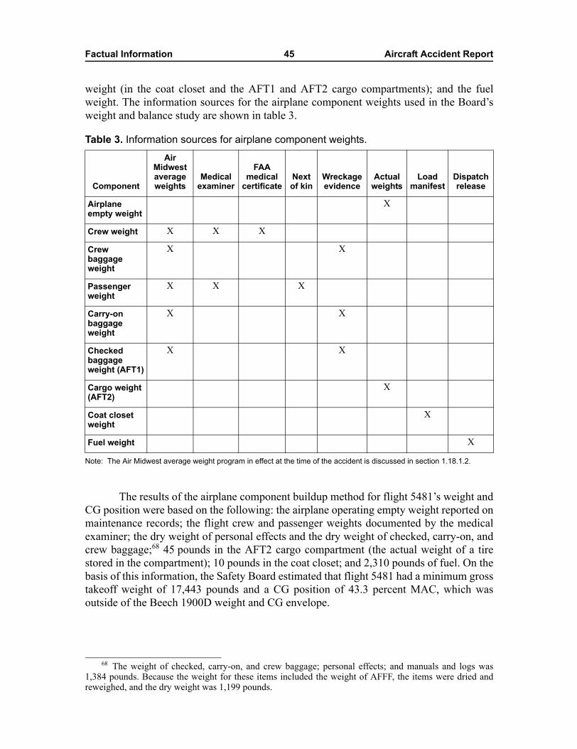
Factual Information 45 Aircraft Accident Report
weight (in the coat closet and the AFT1 and AFT2 cargo compartments); and the fuelweight. The information sources for the airplane component weights used in the Board�sweight and balance study are shown in table 3.
Table 3. Information sources for airplane component weights.
Note: The Air Midwest average weight program in effect at the time of the accident is discussed in section 1.18.1.2.
The results of the airplane component buildup method for flight 5481�s weight andCG position were based on the following: the airplane operating empty weight reported onmaintenance records; the flight crew and passenger weights documented by the medicalexaminer; the dry weight of personal effects and the dry weight of checked, carry-on, andcrew baggage;68 45 pounds in the AFT2 cargo compartment (the actual weight of a tirestored in the compartment); 10 pounds in the coat closet; and 2,310 pounds of fuel. On thebasis of this information, the Safety Board estimated that flight 5481 had a minimum grosstakeoff weight of 17,443 pounds and a CG position of 43.3 percent MAC, which wasoutside of the Beech 1900D weight and CG envelope.
Component
Air Midwest average weights
Medical examiner
FAA medical
certificateNext of kin
Wreckage evidence
Actual weights
Load manifest
Dispatch release
Airplane empty weight
X
Crew weight X X X
Crew baggage weight
X X
Passenger weight
X X X
Carry-on baggage weight
X X
Checked baggage weight (AFT1)
X X
Cargo weight (AFT2)
X
Coat closet weight
X
Fuel weight X
68 The weight of checked, carry-on, and crew baggage; personal effects; and manuals and logs was1,384 pounds. Because the weight for these items included the weight of AFFF, the items were dried andreweighed, and the dry weight was 1,199 pounds.
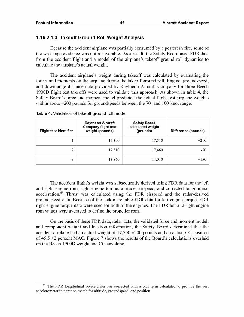
Factual Information 46 Aircraft Accident Report
1.16.2.1.3 Takeoff Ground Roll Weight Analysis
Because the accident airplane was partially consumed by a postcrash fire, some ofthe wreckage evidence was not recoverable. As a result, the Safety Board used FDR datafrom the accident flight and a model of the airplane�s takeoff ground roll dynamics tocalculate the airplane�s actual weight.
The accident airplane�s weight during takeoff was calculated by evaluating theforces and moments on the airplane during the takeoff ground roll. Engine, groundspeed,and downrange distance data provided by Raytheon Aircraft Company for three Beech1900D flight test takeoffs were used to validate this approach. As shown in table 4, theSafety Board�s force and moment model predicted the actual flight test airplane weightswithin about ±200 pounds for groundspeeds between the 70- and 100-knot range.
Table 4. Validation of takeoff ground roll model.
The accident flight�s weight was subsequently derived using FDR data for the leftand right engine rpm, right engine torque, altitude, airspeed, and corrected longitudinalacceleration.69 Thrust was calculated using the FDR airspeed and the radar-derivedgroundspeed data. Because of the lack of reliable FDR data for left engine torque, FDRright engine torque data were used for both of the engines. The FDR left and right enginerpm values were averaged to define the propeller rpm.
On the basis of these FDR data, radar data, the validated force and moment model,and component weight and location information, the Safety Board determined that theaccident airplane had an actual weight of 17,700 ±200 pounds and an actual CG positionof 45.5 ±2 percent MAC. Figure 7 shows the results of the Board�s calculations overlaidon the Beech 1900D weight and CG envelope.
Flight test identifier
Raytheon Aircraft Company flight test
weight (pounds)
Safety Board calculated weight
(pounds) Difference (pounds)
1 17,300 17,510 +210
2 17,510 17,460 -50
3 13,860 14,010 +150
69 The FDR longitudinal acceleration was corrected with a bias term calculated to provide the bestaccelerometer integration match for altitude, groundspeed, and position.
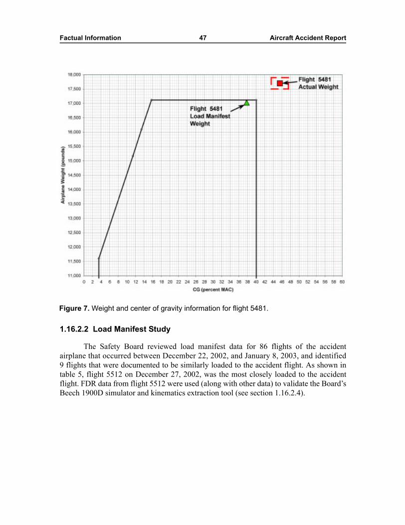
Factual Information 47 Aircraft Accident Report
1.16.2.2 Load Manifest Study
The Safety Board reviewed load manifest data for 86 flights of the accidentairplane that occurred between December 22, 2002, and January 8, 2003, and identified9 flights that were documented to be similarly loaded to the accident flight. As shown intable 5, flight 5512 on December 27, 2002, was the most closely loaded to the accidentflight. FDR data from flight 5512 were used (along with other data) to validate the Board�sBeech 1900D simulator and kinematics extraction tool (see section 1.16.2.4).
Figure 7. Weight and center of gravity information for flight 5481.
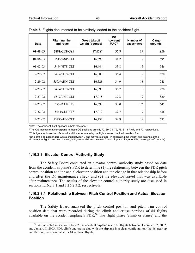
Factual Information 48 Aircraft Accident Report
Table 5. Flights documented to be similarly loaded to the accident flight.
Note: The accident flight appears in bold face print. a The CG indexes that correspond to these CG positions are 81, 70, 69, 74, 72, 75, 81, 67, 67, and 72, respectively.b This figure includes the 10-pound addition error made by the flight crew on the load manifest form. c One of the 15 passengers was a child between 2 and 12 years of age. In calculating the weight and balance of the airplane, the flight crew used the weight figure for children between 2 and 12 years of age for this passenger (80 pounds).
1.16.2.3 Elevator Control Authority Study
The Safety Board conducted an elevator control authority study based on datafrom the accident airplane�s FDR to determine (1) the relationship between the FDR pitchcontrol position and the actual elevator position and the change in that relationship beforeand after the D6 maintenance check and (2) the elevator travel that was availableafter maintenance. The results of the elevator control authority study are discussed insections 1.16.2.3.1 and 1.16.2.3.2, respectively.
1.16.2.3.1 Relationship Between Pitch Control Position and Actual Elevator Position
The Safety Board analyzed the pitch control position and pitch trim controlposition data that were recorded during the climb and cruise portions of 84 flightsavailable on the accident airplane�s FDR.70 The flight phase (climb or cruise) and the
DateFlight number
and routeGross takeoff
weight (pounds)
CG (percent MAC)a
Number of passengers
Cargo (pounds)
01-08-03 5481/CLT-GSP 17,028b 37.8 19 820
01-06-03 5515/GSP-CLT 16,393 34.2 19 595
01-02-03 5464/HTS-CLT 16,444 33.8 15 546
12-29-02 5464/HTS-CLT 16,883 35.4 19 670
12-29-02 5573/AHN-CLT 16,528 34.9 18 745
12-27-02 5464/HTS-CLT 16,893 35.7 18 770
12-27-02 5512/LYH-CLT 17,018 37.8 19 820
12-22-02 5576/CLT-HTS 16,598 33.0 15c 645
12-22-02 5464/CLT-HTS 17,019 32.7 17 656
12-22-02 5573/AHN-CLT 16,433 34.9 18 695
70 As indicated in section 1.16.2.2, the accident airplane made 86 flights between December 22, 2002,and January 8, 2003. FDR climb and cruise data with the airplane in a clean configuration (that is, gear upand flaps up) were available for 84 of those flights.
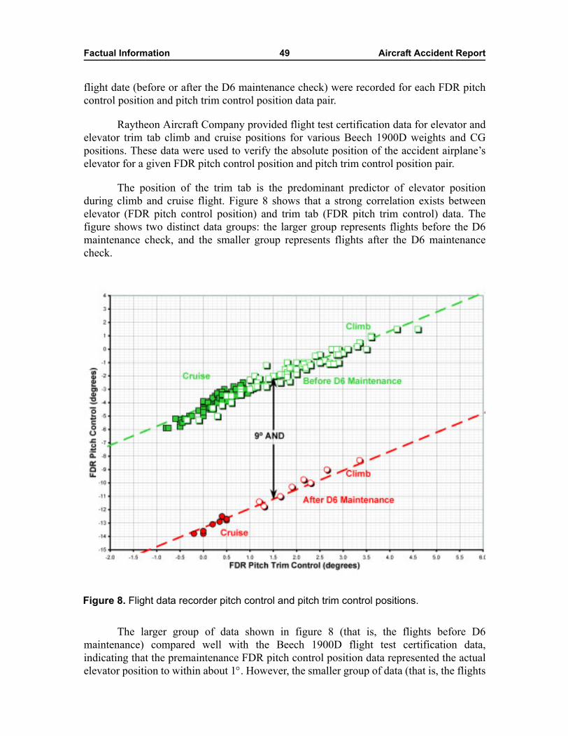
Factual Information 49 Aircraft Accident Report
flight date (before or after the D6 maintenance check) were recorded for each FDR pitchcontrol position and pitch trim control position data pair.
Raytheon Aircraft Company provided flight test certification data for elevator andelevator trim tab climb and cruise positions for various Beech 1900D weights and CGpositions. These data were used to verify the absolute position of the accident airplane�selevator for a given FDR pitch control position and pitch trim control position pair.
The position of the trim tab is the predominant predictor of elevator positionduring climb and cruise flight. Figure 8 shows that a strong correlation exists betweenelevator (FDR pitch control position) and trim tab (FDR pitch trim control) data. Thefigure shows two distinct data groups: the larger group represents flights before the D6maintenance check, and the smaller group represents flights after the D6 maintenancecheck.
The larger group of data shown in figure 8 (that is, the flights before D6maintenance) compared well with the Beech 1900D flight test certification data,indicating that the premaintenance FDR pitch control position data represented the actualelevator position to within about 1°. However, the smaller group of data (that is, the flights
Figure 8. Flight data recorder pitch control and pitch trim control positions.
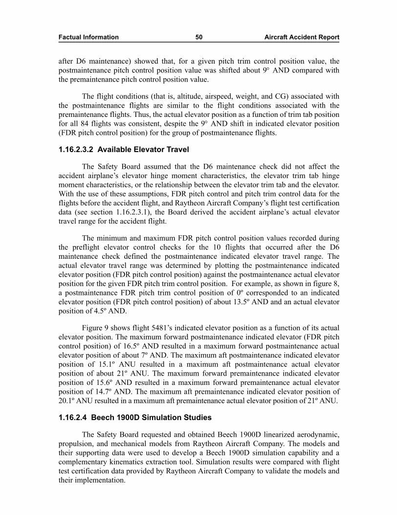
Factual Information 50 Aircraft Accident Report
after D6 maintenance) showed that, for a given pitch trim control position value, thepostmaintenance pitch control position value was shifted about 9° AND compared withthe premaintenance pitch control position value.
The flight conditions (that is, altitude, airspeed, weight, and CG) associated withthe postmaintenance flights are similar to the flight conditions associated with thepremaintenance flights. Thus, the actual elevator position as a function of trim tab positionfor all 84 flights was consistent, despite the 9° AND shift in indicated elevator position(FDR pitch control position) for the group of postmaintenance flights.
1.16.2.3.2 Available Elevator Travel
The Safety Board assumed that the D6 maintenance check did not affect theaccident airplane�s elevator hinge moment characteristics, the elevator trim tab hingemoment characteristics, or the relationship between the elevator trim tab and the elevator.With the use of these assumptions, FDR pitch control and pitch trim control data for theflights before the accident flight, and Raytheon Aircraft Company�s flight test certificationdata (see section 1.16.2.3.1), the Board derived the accident airplane�s actual elevatortravel range for the accident flight.
The minimum and maximum FDR pitch control position values recorded duringthe preflight elevator control checks for the 10 flights that occurred after the D6maintenance check defined the postmaintenance indicated elevator travel range. Theactual elevator travel range was determined by plotting the postmaintenance indicatedelevator position (FDR pitch control position) against the postmaintenance actual elevatorposition for the given FDR pitch trim control position. For example, as shown in figure 8,a postmaintenance FDR pitch trim control position of 0º corresponded to an indicatedelevator position (FDR pitch control position) of about 13.5º AND and an actual elevatorposition of 4.5º AND.
Figure 9 shows flight 5481�s indicated elevator position as a function of its actualelevator position. The maximum forward postmaintenance indicated elevator (FDR pitchcontrol position) of 16.5º AND resulted in a maximum forward postmaintenance actualelevator position of about 7º AND. The maximum aft postmaintenance indicated elevatorposition of 15.1º ANU resulted in a maximum aft postmaintenance actual elevatorposition of about 21º ANU. The maximum forward premaintenance indicated elevatorposition of 15.6º AND resulted in a maximum forward premaintenance actual elevatorposition of 14.7º AND. The maximum aft premaintenance indicated elevator position of20.1º ANU resulted in a maximum aft premaintenance actual elevator position of 21º ANU.
1.16.2.4 Beech 1900D Simulation Studies
The Safety Board requested and obtained Beech 1900D linearized aerodynamic,propulsion, and mechanical models from Raytheon Aircraft Company. The models andtheir supporting data were used to develop a Beech 1900D simulation capability and acomplementary kinematics extraction tool. Simulation results were compared with flighttest certification data provided by Raytheon Aircraft Company to validate the models andtheir implementation.
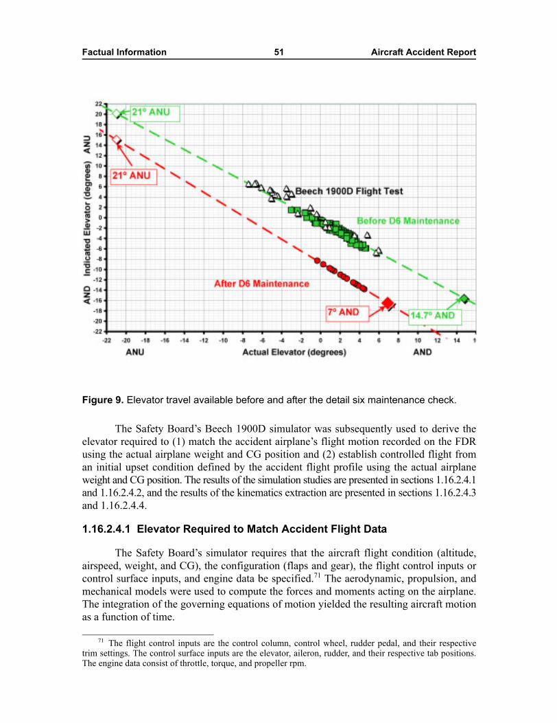
Factual Information 51 Aircraft Accident Report
The Safety Board�s Beech 1900D simulator was subsequently used to derive theelevator required to (1) match the accident airplane�s flight motion recorded on the FDRusing the actual airplane weight and CG position and (2) establish controlled flight froman initial upset condition defined by the accident flight profile using the actual airplaneweight and CG position. The results of the simulation studies are presented in sections 1.16.2.4.1and 1.16.2.4.2, and the results of the kinematics extraction are presented in sections 1.16.2.4.3and 1.16.2.4.4.
1.16.2.4.1 Elevator Required to Match Accident Flight Data
The Safety Board�s simulator requires that the aircraft flight condition (altitude,airspeed, weight, and CG), the configuration (flaps and gear), the flight control inputs orcontrol surface inputs, and engine data be specified.71 The aerodynamic, propulsion, andmechanical models were used to compute the forces and moments acting on the airplane.The integration of the governing equations of motion yielded the resulting aircraft motionas a function of time.
Figure 9. Elevator travel available before and after the detail six maintenance check.
71 The flight control inputs are the control column, control wheel, rudder pedal, and their respectivetrim settings. The control surface inputs are the elevator, aileron, rudder, and their respective tab positions.The engine data consist of throttle, torque, and propeller rpm.
Factual Information 52 Aircraft Accident Report
Unless otherwise noted, the accident flight simulations used an airplane weight of17,700 pounds and a CG position of 45.5 percent MAC (based on the results of the SafetyBoard�s weight and balance work). Simulator values for engine torque, propeller rpm,elevator trim tab, and flap position were defined by FDR data from the accident airplane.Elevator, control wheel, and rudder pedal positions were defined as a function of time tomatch the FDR altitude, airspeed, and attitude data.
Simulation results were compared with FDR and FDR-derived data for the portionof the flight from the takeoff ground roll to shortly before the sound of the stall warninghorn recorded on the CVR (at 0847:10.8). The simulation indicated that the accidentairplane�s uncontrolled pitch maneuver could be reproduced with an elevator position thatwas limited to a constant value of about 8º AND.
1.16.2.4.2 Elevator Required to Establish Controlled Flight
The Safety Board evaluated the elevator required to establish controlled flightfrom an initial upset condition defined by the data from the accident airplane�s FDR andCVR. FDR data indicated that, during the uncontrolled pitch maneuver, the flight crewwas commanding AND inputs to stabilize the airplane�s pitch attitude while maintainingthe airplane�s power (engine torque and propeller rpm) and trim tab and flap settings.These AND commands corresponded with the first officer�s comment, �wuh,� at0847:02.1; the captain�s comment, �oh,� at 0847:02.2; and evidence that the landing gearhad been completely stowed.
The Beech 1900D simulation indicated that the airplane required an elevatorposition of about 9.5º AND to recover from the initial upset and establish controlled flightat a nearly constant 15º pitch attitude.
1.16.2.4.3 Kinematics Extraction
The Safety Board�s kinematics extraction tool requires that the aircraft motion(accelerations and attitudes), flight condition, and configuration be specified. Thekinematics extraction tool then calculates the control or control surface inputs required toproduce the specified aircraft motion. For the flight 5481 accident investigation, thekinematics extraction tool was used to calculate the elevator time histories for four flightsegments flown by the accident airplane before the D6 maintenance check, two flightsegments flown by the accident airplane after the D6 maintenance check, and the accidentflight.
The extracted elevator time histories were compared with the elevator timehistories recorded on the accident airplane�s FDR. The kinematics extraction resultsshowed that the airplane�s premaintenance pitch control position matched the extractedelevator time history within about 1º for a range of airplane weights and CG positions, aspreviously confirmed by Raytheon Aircraft Company�s flight test certification data (seesection 1.16.2.3.1). The results also confirmed that the postmaintenance pitch controlposition was offset from the actual elevator position by about 9º AND. Moreover, anactual elevator position of 6º to 6.5º AND was required for the postmaintenance flightbefore the accident flight that was the most heavily loaded and had the most aft CG position.
Factual Information 53 Aircraft Accident Report
The kinematics extraction for the accident flight determined the flight controldeflections required to produce the airplane motion recorded on the FDR. As with theresults of the simulation, about 8º of AND elevator was required to reproduce the motionrecorded during the airplane�s uncontrolled pitch maneuver.
The accident airplane�s motion during takeoff was input into the Safety Board�skinematics extraction tool to calculate the elevator sensitivity to CG position for a fixedairplane weight of 17,700 pounds and CG positions of 43.5, 45.5, and 47.5 percent MAC.The calculation showed that elevator positions of about 7º, 8º, and 9º AND were requiredto reproduce the uncontrolled pitch maneuver for CG positions of 43.5, 45.5, and47.5 percent MAC, respectively. A 2-percent CG shift in this range required slightly lessthan 1º of elevator to trim.
The kinematics extraction tool was then used to calculate the elevator sensitivity tothe accident airplane�s weight for a fixed CG position of 45.5 percent MAC and weights of17,500, 17,700, and 17,900 pounds. This calculation verified that the weight magnitudehad little to no effect on the elevator required to reproduce the accident airplane�suncontrolled pitch maneuver.
1.16.2.4.4 Simulator Trims
The simulation was also used to calculate the Beech 1900D speed stability for thefollowing conditions: (1) trimmed power for level, free air flight; flaps 17.5º; and geardeployed; (2) reduced takeoff power, flaps 17.5º, gear deployed, and free air flight (todetermine the effects of power); (3) reduced takeoff power, flaps 17.5º, gear stowed, andfree air flight (to determine the effects of landing gear position); and (4) reduced takeoffpower, flaps 17.5º, gear stowed, full trim tab AND, and free air flight (to determine theeffects of trim tab position).
Condition number 4 simulated the accident airplane�s configuration during theuncontrolled pitch maneuver. The Safety Board determined that elevator positions ofbetween 7.5º and 8.5º AND were required to match the airplane�s motion and that elevatorpositions of between 9º and 10º AND were required to trim the airplane.
Factual Information 54 Aircraft Accident Report
1.17 Organizational and Management Information
1.17.1 Air Midwest
Air Midwest, Inc., is a domestic Part 121 air carrier based in Wichita. Thecompany was founded in May 1965 and became a wholly owned subsidiary of Mesa AirGroup,72 which is based in Phoenix, Arizona, in 1991. At the time of the accident, theairline had 743 employees and 43 Beech 1900D 19-seat airplanes (including the accidentairplane). The airline operated its fleet under code-share agreements with US AirwaysExpress, America West Express, Mesa Airlines, and Midwest Express (now known asMidwest Airlines), with 389 daily departures to 72 destinations.
Air Midwest conducted its maintenance program according to guidance in threecompany manuals: Manual 210, Maintenance Procedures Manual; Manual 240,Maintenance Training Manual; and Manual 260, Maintenance Program Manual.73
Mechanics working on Air Midwest airplanes at the contract maintenance stations (HTS;Dubois, Pennsylvania; Farmington, New Mexico; Little Rock, Arkansas; and PanamaCity, Florida) were required to be familiar with the policies and procedures in thesemanuals.74
Although Air Midwest�s maintenance work was distributed among regional main-tenance stations and was performed exclusively by contracted maintenance personnel, theair carrier remained responsible for the airworthiness of its airplanes and all of the mainte-nance performed. Specifically, 14 CFR 121.363 states that an air carrier is responsible forensuring the airworthiness of the aircraft it operates and that an air carrier is not relievedof this responsibility when maintenance is contracted to another party. Also, AC 120-16D,�Continuous Airworthiness Maintenance Programs,� states the following: 75
72 According to a July 11, 2002, press release posted on the Mesa Air Group Web site(http://www.mesa-air.com), Mesa Air Group was awarded a contract by the Department of Transportation inJuly 2002 for seven new essential air service markets in Arkansas, Oklahoma, and Texas. (The essential airservice program ensured that, after the Airline Deregulation Act was enacted in 1978, smaller communitieswould retain a link to the national air transportation system.) The new markets include Enid and Ponca City,Oklahoma; Brownwood, Texas; and Harrison, Hot Springs, El Dorado/Camden, and Jonesboro, Arkansas.According to the press release, the air service was to be provided beginning in the fall of 2002 by AirMidwest operating as Mesa Airlines, and four Beech 1900D airplanes were dedicated to the new routes.Also, Mesa Air Group would receive a federally guaranteed subsidy of $13.4 million for providing this airservice during the 2-year term of the contract.
73 Title 14 CFR 121.367(a) states that aircraft maintenance, preventive maintenance, and alterations areto be performed in accordance with operators� maintenance manuals. Title 14 CFR 121.369(b) states thatoperators� maintenance manuals must describe the method to be followed in performing routine andnonroutine maintenance, preventive maintenance, and alterations and the method to be followed inperforming RII inspections. Title 14 CFR 25.1529 requires manufacturers to prepare �Instructions forContinued Airworthiness� for operators of transport-category airplanes. Appendix H of Part 25 containsthese instructions, which often become the basis for the operators� maintenance manuals required bySection 121.369.
74 Air carriers are required by 14 CFR 121.367(b) to ensure the competence of their maintenancepersonnel for the proper performance of maintenance, preventive maintenance, and alterations.
75 Additional information about AC 120-16D appears in section 1.17.4.1.
Factual Information 55 Aircraft Accident Report
As an air carrier, you are responsible for the maintenance of your aircraft. UnderFAA�s regulations, you must perform and/or approve all maintenance alterationson your aircraft. You may arrange for a maintenance provider, such as a repairstation, to perform your maintenance for you. However, you retain responsibilityfor the performance and approval of that maintenance even if someone elseperforms the work for you�.The air carrier also has the option to authorizeanother person to perform the maintenance, but the maintenance must be carriedout in accordance with the air carrier�s maintenance program and maintenancemanual. The air carrier still retains the responsibility for the properaccomplishment of the maintenance.
According to the Air Midwest regional site manager at HTS, the regional sitemanager at each contract maintenance station is responsible for quality control functions.These functions include reviewing all maintenance and engineering paperwork to ensurethat it meets Air Midwest standards. This paperwork is forwarded to companyheadquarters on Mondays, Wednesdays, and Fridays. The regional site managers are alsoresponsible for performing station and fuel audits to ensure that the contractors adhere toAir Midwest standards. In addition, the regional site managers conduct indoctrinationtraining. (See section 1.17.1.1 for more information about Air Midwest�s maintenancetraining program.) The regional site managers report to the Air Midwest ChiefInspector/Director of Quality Assurance.
As indicated in section 1.5.3.5, the Air Midwest regional site manager at HTSworked the day shift at the time of the accident. His tasks included receiving verbalbriefings from the foreman regarding the previous night�s assignments; taking part in0900, 0930, and 1600 maintenance calls with the other regional site managers andupper-level managers from Air Midwest and RALLC; and reviewing maintenancepaperwork and OJT records for quality and accuracy. He stated that he did not typicallyhave direct contact with mechanics except when he was providing training or wascorrecting problems with paperwork. The Air Midwest regional site manager stated thathe had �no authority over anybody.� For example, if he had a problem with the mechanicsor their paperwork, he would have to notify the RALLC site manager, who then wouldraise the issue with the mechanic and take appropriate action.
There is no backup for the Air Midwest regional site manager position at HTS. Ifthe regional site manager is not there for an extended period, Air Midwest either sends aregional site manager from another station to cover the HTS site manager�s duties or thepaperwork that is normally reviewed at HTS by the site manager and sent to Wichita everyMonday, Wednesday, and Friday is sent directly to Wichita for review instead.
1.17.1.1 Air Midwest Maintenance Training Program
Air Midwest is responsible for conducting its maintenance training program inaccordance with 14 CFR 121.375, which requires airline maintenance training programsto �ensure that each person (including inspection personnel) who determines the adequacyof work done is fully informed about procedures and techniques and new equipment in useand is competent to perform his duties.� The Vice President/Director of Maintenance and
Factual Information 56 Aircraft Accident Report
the Chief Inspector/Director of Quality Assurance are both responsible for ensuring thatall required training is performed. The Maintenance Training Coordinator ensures thattraining records are properly retained, develops training and testing programs, overseesindoctrination training, and ensures that OJT is completed and recorded in a timelymanner.
As stated in section 1.17.1, the Air Midwest regional site manager at each of thecontract maintenance stations is responsible for conducting indoctrination training for allemployees, including contractors. The training, which lasts 4 hours, is presented toemployees before they begin work for Air Midwest. The purpose of the training is tofamiliarize the employees with Air Midwest�s paperwork, tooling, equipment, safetypolicies, and training practices. The employees take a written, 50-question, open-book testat the end of the training session; a grade of 70 percent is a passing score. Qualityassurance inspectors, foremen, and mechanics are required to take the test each year tomake sure that they have retained the information that was taught during indoctrinationtraining. The regional site manager forwards indoctrination training records to theMaintenance Training Coordinator.
Air Midwest does not provide Beech 1900D familiarization classroom training.All airplane-specific training is learned through OJT.76 According to Air Midwest�sMaintenance Training Manual,
OJT will be used to learn and demonstrate knowledge and practical skills ofnormal job related duties. OJT training will be performed under the guidance of aqualified technician or staff member. The OJT will use practical situations foundeveryday [sic] on the job. The person providing the training shall havedocumentation of previously completed OJT training.
1.17.1.2 Huntington Maintenance Station Operations
Air Midwest opened the HTS maintenance station in July 2002 after the airlinetook over routes previously operated by CC Air, which was owned by the Mesa AirGroup. Figure 10 shows the organizational structure of Air Midwest�s HTS maintenancestation operations.
76 According to training records for HTS maintenance personnel, only one of the quality assuranceinspectors had received formal systems training before his employment with RALLC.
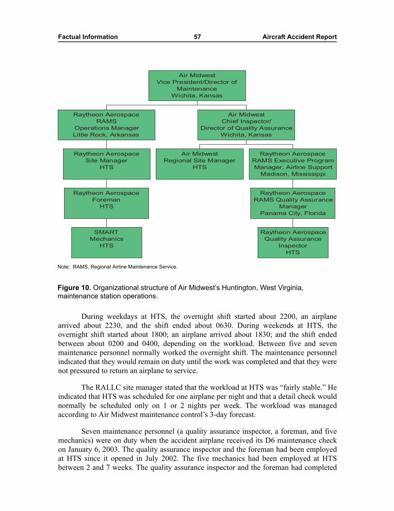
Factual Information 57 Aircraft Accident Report
During weekdays at HTS, the overnight shift started about 2200, an airplanearrived about 2230, and the shift ended about 0630. During weekends at HTS, theovernight shift started about 1800; an airplane arrived about 1830; and the shift endedbetween about 0200 and 0400, depending on the workload. Between five and sevenmaintenance personnel normally worked the overnight shift. The maintenance personnelindicated that they would remain on duty until the work was completed and that they werenot pressured to return an airplane to service.
The RALLC site manager stated that the workload at HTS was �fairly stable.� Heindicated that HTS was scheduled for one airplane per night and that a detail check wouldnormally be scheduled only on 1 or 2 nights per week. The workload was managedaccording to Air Midwest maintenance control�s 3-day forecast.
Seven maintenance personnel (a quality assurance inspector, a foreman, and fivemechanics) were on duty when the accident airplane received its D6 maintenance checkon January 6, 2003. The quality assurance inspector and the foreman had been employedat HTS since it opened in July 2002. The five mechanics had been employed at HTSbetween 2 and 7 weeks. The quality assurance inspector and the foreman had completed
Figure 10. Organizational structure of Air Midwest�s Huntington, West Virginia, maintenance station operations.
SMART
Mechanics
HTS
Raytheon Aerospace
Foreman
HTS
Raytheon Aerospace
Site Manager
HTS
Raytheon Aerospace
RAMS
Operations Manager
Little Rock, Arkansas
Air Midwest
Regional Site Manager
HTS
Raytheon Aerospace
Quality Assurance
Inspector
HTS
Raytheon Aerospace
RAMS Quality Assurance
Manager
Panama City, Florida
Raytheon Aerospace
RAMS Executive Program
Manager, Airline Support
Madison, Mississippi
Air Midwest
Chief Inspector/
Director of Quality Assurance
Wichita, Kansas
Air Midwest
Vice President/Director of
Maintenance
Wichita, Kansas
Note: RAMS, Regional Airline Maintenance Service.
Factual Information 58 Aircraft Accident Report
training for the D6 maintenance check, but the five mechanics had not completed thetraining.
The Air Midwest regional site manager stated that HTS had experienced a highturnover of its mechanic workforce. The RALLC site manager at HTS estimated that theaverage tenure for SMART employees was about 3 months. Both site managers indicatedthat the turnover occurred because mechanics received better contracts, wanted to workcloser to their home, or wanted to work in another part of the country. The RALLC sitemanager did not think that there was any difference in the attitude, tenacity, skills, orcompetency between RALLC and SMART employees but thought that RALLCemployees might have a greater level of commitment to the company. The Air Midwestregional site manager also did not think that there was any difference between RALLCand SMART employees, except that SMART personnel �come in for a couple months andleave.�
1.17.1.3 Air Midwest Audits of the Huntington Maintenance Station
On November 5, 2002, an Air Midwest auditor from Wichita conducted an audit ofthe HTS maintenance station using the Air Midwest maintenance station audit guidechecklist. One item on the checklist was to determine whether proper training was beingprovided for new hires, training records were being kept up to date, and proper recurrenttraining was being provided. The auditor found that those areas were satisfactory. Theauditor also determined that overall staffing was not sufficient. Specifically, the auditorindicated on the checklist that HTS had only one foreman and one quality assuranceinspector but should have two foremen and two inspectors.
A letter from Air Midwest�s quality assurance auditor, dated November 21, 2002,to the RALLC site manager detailed the audit findings and indicated that HTS had 30 daysto respond to the findings. The letter also stated that the quality assurance auditor neededto know, in writing, when resolution of the findings was complete. In a January 3, 2003,letter to the quality assurance auditor, the RALLC site manager indicated that HTS hadincreased its maintenance staff by 20 percent in the last month. At the public hearing onthis accident, the RALLC site manager indicated that two mechanics had been hired butthat an inspector and a foreman had not been hired.
On January 14, 2003, an Air Midwest auditor from Wichita conducted anotheraudit of the HTS maintenance station. The auditor had concerns about whether propertraining was being provided for new hires and training records were kept up to date,whether the shift overlap was adequate and verbal turnovers were used properly, andwhether sufficient staff existed for each shift. The auditor determined that maintenancemanual revisions were not complete and that foremen were not ensuring that trainingforms were properly stamped by instructors.
A letter from Air Midwest�s quality assurance auditor, dated January 17, 2003, tothe Air Midwest regional site manager detailed the audit findings and indicated that HTShad 30 days to respond to the findings. In a February 20, 2003, letter to the quality assurance
Factual Information 59 Aircraft Accident Report
auditor, the Air Midwest regional site manager responded to the audit findings. The letterstated that the following corrective actions had been accomplished:
� All of the items on the mechanics� OJT training that were signed off by themechanic but not the instructor had been corrected. The Air Midwest regionalsite manager indicated that he explained to the mechanics that, when they signfor something in their OJT records, the instructor has to sign at the same time.
� The RALLC site manager comes to work for a verbal turnover before theforeman leaves. The foreman also provides a daily written turnover.
� RALLC was hiring more people so that the total number of maintenancepersonnel at HTS would increase from 9 to 11.
� The Air Midwest regional site manager verified that all manual revisions thatHTS received were added to the maintenance manuals and were properlydocumented. He also ensured that all manuals were up to date.
1.17.1.4 Postaccident Actions
In February 2003, Air Midwest reassigned the HTS regional site manager to workthe night shift so that his work schedule would be aligned with those of the RALLC andSMART maintenance personnel. (The regional site managers at the other Air Midwestmaintenance stations were also reassigned to work the night shift.) The regional sitemanager stated that the change in shift allowed him to be present at HTS when work wasbeing performed but prevented him from participating in the maintenance calls. (TheRALLC site manager still worked the day shift; thus, his work schedule still did not alignwith the overnight shift of the regional site manager, quality assurance inspector, foreman,and mechanics.)
Air Midwest removed the quality assurance inspector�s authorization to performmaintenance and RII inspections on company airplanes. The quality assurance inspector isstill employed by RALLC but is working as a mechanic at the Dubois maintenancestation. Air Midwest also removed the mechanic�s authorization to perform maintenanceon company airplanes. The mechanic no longer works for SMART. The RALLC sitemanager is still employed by RALLC but now works as a mechanic at the Panama Citymaintenance station. In addition, Air Midwest gave disciplinary time off to anotherSMART mechanic and the primary quality assurance inspector at HTS because theyfalsely indicated on the mechanic�s OJT record that he had completed training on the D6aft fuselage/empennage inspection procedure on January 6, 2003. (The primary qualityassurance inspector was not on duty on the night of January 6th. The mechanic inspectedand checked the engines but did not perform the entire D6 maintenance procedure,including the elevator check.) The mechanic and primary quality assurance inspector weresubsequently retrained and then reinstated to their former positions.
In a February 12, 2003, letter to the Safety Board, the Air Midwest VicePresident/Director of Maintenance expressed the air carrier�s concerns regarding themanufacturer�s elevator control system rigging procedure. The letter stated, �a review ofthe Raytheon Aircraft Beech 1900D Maintenance Manual revealed a lack of explicit
Factual Information 60 Aircraft Accident Report
instructions, which if included, could have avoided the elevator mis-rigging.� The letterdetailed numerous deficiencies in the rigging procedure that were identified by AirMidwest.
On July 18, 2003, Air Midwest revised its D6 work card. The revised work cardincluded the following steps for performing an elevator cable tension check and blocksbeside each step for the mechanic�s and quality assurance inspector�s stamps:
Let aircraft temperature stabilize for three hours.
Take the temperature reading with the aircraft OAT temperature gauge.
Gain access to the elevator�cables under the cargo compartment floorboard.
Using a calibrated tensiometer with the proper riser installed, take the elevatorcable tension readings I.A.W. [in accordance with] Raytheon MaintenanceManual.
Compare readings from the aircraft to the proper cable tension charts in the BeechMaintenance Manual. (For the elevator tension chart, ref. *Raytheon[Maintenance] Manual Chapter 27-30-02, fig 203�.)
If cable tensions are within tolerance, no adjustment to the cable tension isrequired.
If tensions are not within tolerance of the tension chart, perform the completeelevator�control system rigging procedure. (For elevator rigging, ref. *Raytheon[Maintenance] Manual 27-30-02�.) �N/A� [not applicable] this block if noadjustments were made.
List all work performed on the AMR [aircraft maintenance record of nonroutineitems], if adjustments were made. �N/A� this block if no adjustments were made.
Air Midwest also revised its weight and balance procedures. These revisions arepresented in section 1.18.1.2.1 after a discussion of the procedures that were in effect atthe time of the accident (section 1.18.1.2).
1.17.2 Raytheon Aerospace
RALLC is headquartered in Madison, Mississippi. At the time of the accident,RALLC provided one site manager, two quality assurance inspectors (one of whom wasdesignated as the primary quality assurance inspector and the other of whom wasdesignated as the foreman), and seven SMART A&P-certified mechanics to AirMidwest�s HTS maintenance station.
Air Midwest paid RALLC for its services. RALLC paid salaries and benefits forits employees. RALLC also paid SMART for its maintenance personnel, but SMARTemployees received their salaries and benefits directly from SMART.
Factual Information 61 Aircraft Accident Report
The RALLC site manager stated that he reported to the RAMS operations managerin Little Rock, who reported to the Air Midwest Vice President/Director of Maintenancein Wichita.77 The primary quality assurance inspector reported to the RAMS qualityassurance manager in Panama City, Florida.78 The foreman reported to the RALLC sitemanager. According to public hearing testimony, the SMART mechanics reported to aSMART manager through an HTS on-site coordinator (one of the mechanics).
The RALLC site manager was responsible for the daily operations at the HTSmaintenance station and the work performed there. The foreman assigned maintenancework and followed the progress of the mechanics in accomplishing the work, and thequality assurance inspector checked the RIIs.79 As previously stated, when the primaryquality assurance inspector was not at work (as on the night of January 6, 2003), theforeman would assume his duties. A SMART mechanic would then assume the foreman�sduties.80
The foreman was responsible for providing OJT to the mechanics and for signingoff their OJT records. The quality assurance inspector who was not on duty on the night ofJanuary 6, 2003, stated, in a postaccident interview, that the quality assurance inspectorwho was on duty should not have been providing OJT.81
The RALLC site manager did not personally oversee the work performed by themechanics because he worked the day shift. As a result, the site manager depended �veryheavily� on the quality assurance inspector and the foreman for information about themechanics� work. In addition, the site manager indicated that, even though he was themaintenance administrator, he performed employee job performance reviews for thequality assurance inspectors. The site manager further stated that the RAMS qualityassurance manager performed the part of the performance review covering qualityassurance issues.
77 The Air Midwest Maintenance Procedures Manual indicated that the RALLC site manager reporteddirectly to the Air Midwest Vice President/Director of Maintenance.
78 The RAMS quality assurance manager reported to the RAMS Executive Program Manager forAirline Support in Madison, Mississippi, who reported to the Air Midwest Chief Inspector/Director ofQuality Assurance in Wichita.
79 Title 14 CFR 121.365(c) states, �each person performing required inspections in addition to othermaintenance, preventive maintenance, or alterations, shall organize the performance of those functions so asto separate the required inspection functions from the other maintenance, preventive maintenance, oralteration functions.� In addition, AC 120-16D states, �a primary concept of the RII function is that theperson performing the work may not perform the required inspection of that item of work.�
80 On the basis of the work schedule in effect at the time of the accident, a SMART mechanic acted asthe foreman 4 nights per week.
81 Air Midwest Maintenance Procedures Manual stated that the foreman�s duties include performingand documenting OJT on aircraft maintenance practices, company policies, and safety procedures, asrequired. The manual did not include these duties as part of the quality assurance inspector�s job description.
Factual Information 62 Aircraft Accident Report
1.17.2.1 Contract Between Raytheon Aerospace and Air Midwest
The contract between RALLC and Air Midwest was a 60-month agreement thatbecame effective on January 1, 2003.82 The contract contained 29 statements ofunderstanding and 3 appendixes that detailed the conditions of the agreement.
The contract stated that RALLC would provide a manager, foremen, mechanics,and inspectors to Air Midwest to meet its maintenance requirements and that RALLCwould confer with Air Midwest before any changes were made to the number of personnelprovided. No language in the contract prevented RALLC from contracting with anotherparty for maintenance personnel.
The contract stated that scheduled maintenance and unscheduled on-callmaintenance would be performed according to the procedures in Air Midwest�smaintenance manuals and that all maintenance actions, parts, and documentation wouldmeet Federal Aviation Regulations (FARs) and Air Midwest requirements. The contractfurther stated that RALLC would work toward achieving a 99-percent reliability rate forscheduled maintenance.
According to the contract, Air Midwest would supply all parts, materials, andequipment and would be responsible for technical data management, qualitycontrol/quality assurance inspection, a technical library, and a tracking system fortime-compliance and hard-time items.
The contract specified the allocation of cost at each of the Air Midwestmaintenance stations. According to the contract, Air Midwest was solely responsible forthe hangar facility at HTS.
1.17.3 Structural Modification and Repair Technicians
SMART, which is headquartered in Edgewater, Florida, recruits maintenancepersonnel for its aviation industry clients. SMART accepts résumés through recruiters oron its Web site and then qualifies applicants by conducting a 5-year background check, a10-year security check,83 and drug testing. SMART mechanics indicated that the companydoes not interview applicants in person to determine their experience level, but publichearing testimony by SMART�s Director of Recruiting indicated that the companyconducts telephone interviews to make such determinations.
Applicants that pass the reference checks and the drug testing are hired as SMARTemployees. They bid on open job postings for placement with an aviation industry client.SMART employees work for SMART and not the aviation industry client. SMART doesnot oversee, evaluate, or direct its employees at the client�s work site.
82 The contract between RALLC and Air Midwest was originally negotiated in September 2001 andwas renegotiated in September 2002.
83 SMART employees that were hired before September 11, 2001, were subject to a 5-year securitycheck.
Factual Information 63 Aircraft Accident Report
1.17.3.1 Contract Between Structural Modification and Repair Technicians and Raytheon Aerospace
The contract between SMART and RALLC was signed on March 25, 2002. Thecontract contained 22 agreement statements that identified the conditions in which the twocompanies would work together.
The contract stated that SMART would provide aircraft maintenance personnel toperform services at locations designated by RALLC but that the personnel would not beconsidered employees of RALLC. The contract also stated that SMART was responsiblefor all matters concerning the maintenance personnel�s working conditions, termination,working hours, vacation and other leave, expenses, wages, and worker�s compensationinsurance. The contract further stated that SMART was responsible for instructing theiremployees to follow RALLC policies and regulations as long as they were communicatedin writing in a timely manner.
The contract stated that SMART would use its sole discretion in deciding whichmaintenance personnel would be provided to RALLC.84 The contract also stated thatRALLC was solely responsible for supervising the work of SMART employees and thatRALLC would provide each SMART employee with a daily time card and would approvethe time cards. In addition, the contract specified that the use of any SMART employeecould be terminated at any time by RALLC85 and that, if the employee�s performance inthe first 8 hours of work was not satisfactory, SMART would not charge for theemployee�s services.
1.17.4 Federal Aviation Administration Oversight
The Air Midwest principal operations inspector (POI) has been in that positionsince October 1999. The Air Midwest certificate is the only one he oversees. Two assistantPOIs and one aircrew program manager help the POI with his oversight duties. The POI�soffice (the Wichita Flight Standards District Office [FSDO]) is located about 3 miles fromAir Midwest�s office.
The POI indicated that he reviewed Air Midwest�s Flight Operations ProceduresManual and training program. He stated that oversight of Air Midwest�s weight andbalance procedures was accomplished during en route inspections. The POI indicated thatan en route inspector or geographic inspector would check the cargo bin, count the numberof bags, and look at the size of the bags and then compare the findings to the informationdocumented on the load manifest form. The inspector would also examine the weightscales at the stations.
84 The RALLC site manager indicated that he reviewed the résumés of the SMART employees thatworked at the HTS maintenance station before they were hired by SMART.
85 Although RALLC has the right to terminate a SMART employee, RALLC must depend on SMARTto carry out the termination.
Factual Information 64 Aircraft Accident Report
The Air Midwest principal maintenance inspector (PMI) began work for the FAAin 1988 and has been in his current position, which is based in Wichita, since December 1998.The Air Midwest certificate is the only one the PMI oversees. Two assistants help the PMIcarry out his responsibilities. During postaccident interviews, the PMI stated that he had40 years of aviation-related experience, including 30 years as an A&P mechanic and25 years as a maintenance inspector.
The PMI stated that he tried to visit all of the Air Midwest maintenance stationstwo to three times per year for at least 3 days each time. The PMI stated that he rarelyannounced his inspections of Air Midwest�s maintenance stations. The PMI stated that heusually took a morning flight to a maintenance station, visited the station after arriving,and met with the maintenance managers to discuss any of their concerns. The PMI alsostated that he would return to the station at night to observe maintenance operations.
The PMI visited the HTS maintenance station before it opened in July 2002. ThePMI also visited HTS in September 2002. According to postaccident interviews, the PMIspoke with the quality assurance inspector and the foreman but did not speak with themechanics. Also, the RALLC site manager and the Air Midwest regional site managerstated that the PMI reviewed training records and other documentation and observedmaintenance operations during the overnight shift. The RALLC site manager furtherstated that the PMI told him that the mechanics �seemed very competent.�86 In apostaccident interview, the PMI stated that, before the accident, he was unaware thatthird-party maintenance contractors were being used at HTS.
During public hearing testimony, the PMI stated that he would not readily findproblems concerning OJT at the maintenance stations and that the only way he woulddiscover such a problem would be to �work some kind of a spreadsheet where [he] couldcorrelate whoever signed it [the OJT] off on the job card versus the training folder,� whichwas �a little bit of work.� The PMI did state his concern that HTS personnel did not followthe Air Midwest maintenance manual while conducting OJT.
In addition, the RALLC site manager and the Air Midwest regional site managerstated that flight standards inspectors from the Charleston, West Virginia, FSDO hadvisited HTS once for an informal introduction and that the visit was not an inspection ofthe facility. The Air Midwest regional site manager further stated that airworthinessinspectors from the Charleston FSDO visited HTS once while he and the RALLC sitemanager were at lunch.
Finally, in addition to the POI and PMI, a principal avionics inspector (PAI) wasassigned to the Air Midwest certificate. The PAI, who was based in Wichita, reviewed allof Air Midwest�s maintenance training manual submissions. The PMI stated, in a January 2004interview, that the PAI had worked as a maintenance inspector before becoming anavionics inspector and that he understood both areas very well.
86 The RALLC site manager also stated that, about the time of the PMI�s visit, HTS �had peopletraining us from other sites on a regular basis and so we had two guys that were really knowledgeable, plusthe staff that we normally had.�
Factual Information 65 Aircraft Accident Report
1.17.4.1 Continuing Analysis and Surveillance System
In 1964, the FAA introduced the requirement for air carriers to have a ContinuingAnalysis and Surveillance System (CASS) because maintenance program ineffectivenesshad been identified as a primary causal factor in some maintenance-related air carrieraccidents. Specifically, 14 CFR 121.373, �Continuing Analysis and Surveillance,�required air carriers to
establish and maintain a system for the continuing analysis and surveillance of theperformance and effectiveness of its inspection program and the programcovering other maintenance, preventive maintenance, and alterations and for thecorrection of any deficiency in those programs, regardless of whether thoseprograms are carried out by the certificate holder or by another person.
Between August 1980 and March 2003, the primary CASS guidance available toair carriers was contained in AC 120-16C, �Continuing Airworthiness MaintenancePrograms,� and was less than 1 page in length. The guidance stated that a CASS programshould be designed to monitor for, and provide timely corrective action in response to,decreases in mechanical reliability and should provide a continuous auditing function thatexamines a broad range of issues, including the currency and availability of publications,conformity between maintenance practices and company policies, adequacy ofrecord-keeping and training, and handling of deferred maintenance items.
In March 2003, the FAA revised AC 120-16C. The revised AC (AC 120-16D)presented expanded CASS guidance in a dedicated chapter that was several pages inlength. The guidance defined CASS as an �air carrier quality assurance system� designedto detect and correct air carrier maintenance program deficiencies through a closed-loop,continuous cycle of surveillance and investigations, data collection and analysis,corrective actions, and monitoring and feedback. The guidance stated that an air carrier�sCASS program should monitor the following nine elements of the carrier�s continuousairworthiness maintenance program: airworthiness responsibility, maintenance manual,maintenance organization, maintenance schedule, maintenance record-keeping system,accomplishment and approval of maintenance and alterations, contract maintenance,CASS, and personnel training.
The CASS guidance in AC 120-16D also stated that a CASS program shouldinclude �detailed policy and procedures� for determining whether an air carrier needed toamend its maintenance program or manual and for making amendments. In addition, theguidance stated that, �proactive surveillance and analysis forecasts faults in your [the aircarrier�s] maintenance program or manual through the collection and analysis of a widevariety of data. It corrects those faults, including human factors87 issues, in advance of anyspecific event, accident, or incident.� Further, the guidance stated that an air carrier�s�CASS audit schedule should include�all manuals, publications, and forms [to ensurethat they] are useable, current, accurate, and readily available to the user.�
87 The discipline of human factors identifies capabilities and limitations of humans and ways to adapthuman and system components accordingly to increase efficiency, effectiveness, and safety.
Factual Information 66 Aircraft Accident Report
In April 2003, the FAA published AC 120-79, �Developing and Implementing aContinuing Analysis Surveillance System,� which was a comprehensive guide for thedevelopment of CASS programs.88 The AC provided information on CASS-related topics,including the following: the desired purpose and structure of a CASS program, CASSpolicy and documentation, major CASS activities, CASS personnel requirements,communication between CASS personnel and other departments, comparison of CASSand other required maintenance programs, CASS program evaluation, and the role of theFAA in an air carrier�s CASS program. The AC also described model CASS programs forair carriers in three different size ranges.
1.17.4.2 Correspondence From the Federal Aviation Administration to Air Midwest
In an October 16, 2000, letter, the Air Midwest PMI stated that a recent FAAinspection conducted at Air Midwest headquarters could not be completed because the aircarrier lacked adequate records to determine whether it was in compliance with 14 CFR121.371(a) and 121.375.89 The PMI noted that, among other things, �required[maintenance] training records are either not at the Wichita facility or are not up to dateand complete,� and advised Air Midwest of the need to comply with 14 CFR 121.371(a)and 14 CFR 121.375. The PMI requested a meeting with Air Midwest officials to �avoidfurther investigation of these areas,� and this meeting was held on October 26, 2000.
In a November 9, 2000, letter, the Air Midwest PMI stated that Air Midwest�sCASS program did not include a reliable way of charting operational data at specifiedintervals to reveal trend-related information.
In a December 18, 2000, letter, the Air Midwest assistant PMI asked the air carrierto submit a strategy to resolve the inadequacy of the carrier�s training manual and trainingrecords.90 The Air Midwest Vice President/Director of Maintenance indicated that the aircarrier would, by February 1, 2001, audit training records, rewrite its maintenance trainingmanual, forward copies of training records to company headquarters, and add a managerto the training department. 91
In a September 6, 2001, letter, the Air Midwest PAI stated that he was returningAir Midwest�s April 1, 2001, revised maintenance training manual so that numerous
88 AC 120-79 provided one method of compliance with the requirements of 14 CFR 121.373.89 Title 14 CFR 121.371(a) requires that carriers operating under 14 CFR Part 121 use only persons
who are properly certificated, trained, qualified, and authorized for performing required inspections. Seesection 1.17.1.1 for a description of 14 CFR 121.375.
90 A followup inspection of Air Midwest�s training files was conducted on December 4, 2000. Thisinspection revealed evidence of continuing deficiencies in the training files as well as deficiencies in the aircarrier�s training manual. The PMI gave Air Midwest a deadline of February 1, 2001, to remedy thesedeficiencies.
91 A Regional Aviation Safety Inspection Program (RASIP) inspection, conducted between March 12and 29, 2001, found that deficiencies in the maintenance training manual still existed and that training wasnot being conducted in accordance with company procedures. The RASIP inspection also found that AirMidwest was not performing the biannual audits required by the company�s CASS procedures.
Factual Information 67 Aircraft Accident Report
changes could be made.92 Air Midwest resubmitted its revised maintenance trainingmanual on October 9, 2001, but, in a letter dated January 16, 2002, the PAI citeddeficiencies in the manual, some of which had been previously identified, and asked AirMidwest to make the necessary corrections.
In a February 11, 2002, letter to the Air Midwest Vice President/Director ofMaintenance, the Air Midwest PMI stated that he could still not determine whether AirMidwest was in compliance with the FARs and asked Air Midwest to develop and initiatea plan within 2 weeks to address maintenance training program deficiencies in need ofimmediate improvement or be subject to an in-depth audit. The Air Midwest VicePresident/Director of Maintenance responded to this letter by notifying the PMI of actionsthe air carrier was taking to resolve some of his concerns and by stating that solutions toother problems would be implemented after the revised maintenance training manual wasaccepted by the FAA.
On February 11, 2002, Air Midwest submitted another revised maintenancetraining manual for the FAA�s review. In a letter dated February 19, 2002, the PAI againcited deficiencies in the manual and asked Air Midwest again to make the necessarycorrections. On February 28, 2002, the FAA accepted Air Midwest�s revised maintenancetraining manual.
In the February 19, 2002, letter, the Air Midwest PAI also communicated hisconcern that Air Midwest�s CASS program lacked an auditor training curriculum. In anApril 26, 2002, letter, the Wichita FSDO manager and the Air Midwest PMI stated thatAir Midwest had a written audit program but no dedicated program manager and that thisand other issues needed to be resolved before Air Midwest would be allowed to change itsroute structure.93 (The other issues involving Air Midwest included that its infrastructurehad not kept up with its growth, its pilot training program had deficiencies, RASIP issueswere unresolved, and procedures in its General Maintenance Manual were inadequate.) Inan August 19, 2002, letter, the Air Midwest PMI cited deficiencies that Air Midwestneeded to address before route structure changes could be approved, including actions toensure that the audit procedures contained in the company�s audit manual were beingfollowed.
92 Air Midwest�s revised training manual and audit manual were submitted to the FAA for review aboutthe same time. The FAA asked Air Midwest which manual should have priority, and it was decided that theaudit manual would have priority. The audit manual was accepted by the FAA on December 19, 2001.
93 The POI was the FAA official responsible for approving any proposed route expansion. Hisoperations supervisor advised him against delaying Air Midwest�s proposed route changes (see section 1.17.1).In a January 2004 interview, the operations supervisor told the Safety Board that she could not recall thedetails of that conversation. She stated that she did recall that the FAA had sent Air Midwest letters ofconcern before a prior route expansion in Dallas, Texas, and that Air Midwest had consistently been willingto meet with the FAA to address its concerns, had made needed improvements in flight operations, and wasessentially in compliance with the FARs. In a January 2004 interview, the PMI said that Air Midwest hadbeen responsive in communicating with the FAA but that Air Midwest management did not alwaysadequately follow through in resolving all of his concerns, including the need for aircraft familiarizationtraining and better supervision of OJT.
Factual Information 68 Aircraft Accident Report
1.17.5 Raytheon Aircraft Company
On December 10, 2003, the President of Raytheon Airline Aviation Services metwith the Safety Board to discuss Beech 1900 series maintenance initiatives. According tothe Raytheon official, these initiatives were undertaken to reinforce with operators theimportance of properly maintaining Beech 1900 series airplanes. In a December 16, 2003,facsimile, the Raytheon official summarized the initiatives he discussed at the meeting.The facsimile included the following initiatives:
� communicating more actively with all levels of Beech 1900 operatorpersonnel, including the chief executive officer/owner, Director ofMaintenance, and mechanics;
� providing all Beech 1900 operators with a CD-ROM of all Beech 1900 safetyand model communiqués and SBs;
� posting all Beech 1900 safety and model communiqués and SBs on theRaytheon Aircraft Company Web site;
� conducting Beech 1900 Airliner Operators Conferences, the first of which washeld in Wichita on October 21 through 23, 2003, so that operators, suppliers,and Raytheon Airline Aviation Services have a forum to discuss maintenanceissues;
� developing �easy-to-follow� text and illustrations to improve the explanationof certain procedures, including flight control rigging and functional testing;subjecting these procedures to �validation and verification;� and issuingchanges to the procedures as temporary revisions to the Beech 1900 AMMs;and
� sending technical teams to Beech 1900 operators to provide on-site training formechanics and launching a Web-based training site that will be accessible to allBeech 1900 mechanics.
1.18 Additional Information
1.18.1 Weight and Balance Procedures
1.18.1.1 Federal Aviation Administration
Air carriers are required to have procedures in place for the control of weight andbalance of airplanes. Title 14 CFR 121.153 permits air carriers with more than ninepassenger seats to use an approved average weight program instead of actual weights foraircraft weight and balance calculations. The use of average weights instead of actualweights allows air carriers to board passengers, load baggage and cargo, and calculateweight and balance more quickly. Air carriers can use actual weights, average weightsestablished by survey data, or a combination of both to determine the weight ofcrewmembers, crew baggage, passengers and personal items, carry-on baggage, andchecked baggage.94
Factual Information 69 Aircraft Accident Report
The FAA published its aircraft weight and balance guidance in AC 121-5, �AircraftWeight and Balance Control,� in January 1965 and then in AC 120-27, �Aircraft Weightand Balance Control,� in October 1968. The content in AC 120-27 was subsequentlyrevised three times: AC 120-27A was issued in May 1980, AC 120-27B was issued inOctober 1990, and AC 120-27C was issued in November 1995 and was the version ineffect at the time of the flight 5481 accident.95 According to AC 120-27C,
an operator may submit, for inclusion into its operations specifications, anymethod and procedure which shows that an aircraft will be properly loaded andwill not exceed approved weight and balance limitations during operation. Theapproval of such a weight and balance control system is based on an evaluation ofthe program presented for a particular aircraft and of a particular operator�s abilityto implement that program.
The average weight suggested in AC 120-27C for an adult passenger was 180 poundsin the spring and summer months and 185 pounds in the fall and winter months; bothweights included 20 pounds for carry-on baggage. The average weight suggested in theAC for checked baggage was at least 25 pounds. The AC warned that the standard averagepassenger weights presented were developed for a conventional airline passenger groupand that the weights �cannot be arbitrarily adopted for operations with passenger groupsthat appreciably differ from the basis or where the mix of male and female passengers isknown to be different than a 60 percent male/40 percent female operation.�96
The guidance in AC 120-27C was not intended to address all possible air carrierweight and balance configurations. As a result, the AC noted that air carriers shouldconsider conducting a reliable survey to establish average weights for their specificoperations and providing the results of the survey to the FAA. An appendix in the AClisted procedures for conducting surveys and establishing average passenger and baggageweights based on statistical analyses. Also, the guidance in AC 120-27C advised aircarriers that their weight and balance program should (1) account for all probable loadingconditions that may be experienced in service, (2) ensure satisfactory loading within theaircraft weight and CG limits during ground and flight operations, (3) maintain the aircraftweight and CG limits, and (4) stress that the aircraft must be operated at or below itsmaximum certificated operating weight.
PMIs oversee and evaluate air carriers� weight and balance programs according tothe guidance in FAA Order 8300.10, Airworthiness Inspector�s Handbook. The guidancestates that the use of average weights may be authorized as long as the weights are based
94 Actual weights are required to be used for the aircraft empty weight, fuel, U.S. mail, and companymaterial.
95 Flight Standards Handbook Bulletin for Airworthiness 95-14 and Flight Standard Handbook Bulletinfor Air Transportation 95-15, �Adherence to Advisory Circular 120-27C, �Aircraft Weight and BalanceControl,�� were issued in November 1995 and provided guidance to assist regional air carriers with limitedcarry-on baggage programs, such as Air Midwest, with the development of their weight and balanceprogram.
96 AC 120-27C stated that actual passenger weights were to be used for nonstandard weight groups(such as athletic teams) unless average weights had been established for such groups.
Factual Information 70 Aircraft Accident Report
on acceptable data that were collected during actual operations (for example, by weighingpassengers and baggage and documenting the weights). The order also states that theaverage passenger and baggage weights listed in AC 120-27C are not regulatory and donot constitute authorization as a method for controlling aircraft weight and balance. Inaddition, the order states that average passenger and baggage weights must be evaluatedfor applicability to individual air carriers. Regardless of the weight and balance programin place or the source of the data used to establish average weights, the air carrier isultimately responsible for ensuring proper aircraft weight and CG loading before eachflight is dispatched.
1.18.1.1.1 Postaccident Average Weight Survey
Because the flight 5481 accident raised concerns about aircraft loading and averageweights used in weight and balance control programs, the FAA issued Notice 8400.40,�Weight and Balance Control Programs for 10 to 19 Seat Airplanes Operated Under14 CFR 121,� on January 27, 2003. The notice requested that all operators of 10- to19-passenger seat airplanes operated under 14 CFR Part 121 conduct a survey to validatethe average weights contained in their weight and balance program.97 Of the 22 operatorsthat have 10- to 19-passenger seat airplanes, 15 operators used average weight programs,and 7 operators used actual weight programs.
The survey was to be conducted during a 3-day period that included 2 heaviertraveled days�Sunday and Monday�and 1 lighter traveled day�Tuesday. The surveywas to include 30 percent of the operators� stations and was to sample 15 percent of thestations� flights.98 In conducting the survey, the operators either asked the passengers theirweight and added 10 pounds (for personal items) to the number reported or actuallyweighed the passengers. The operators also weighed all checked baggage and all carry-onbaggage that were checked at the airplane. Table 6 shows the results of the survey byoperator, and table 7 shows the overall survey results.
97 Another purpose of the notice was for operators to determine the condition of cargo restraint systems,such as tie-down rings, locking devices, and cargo nets.
98 Air Midwest indicated that it surveyed 100 percent of its flights during the 3-day period (540 flights)at 98 percent of its stations.
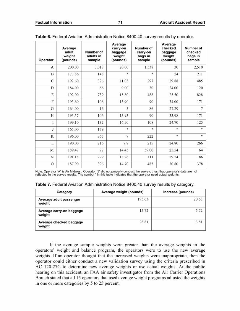
Factual Information 71 Aircraft Accident Report
Table 6. Federal Aviation Administration Notice 8400.40 survey results by operator.
Note: Operator �A� is Air Midwest. Operator �J� did not properly conduct the survey; thus, that operator�s data are not reflected in the survey results. The symbol * in this table indicates that the operator used actual weights.
Table 7. Federal Aviation Administration Notice 8400.40 survey results by category.
If the average sample weights were greater than the average weights in theoperators� weight and balance program, the operators were to use the new averageweights. If an operator thought that the increased weights were inappropriate, then theoperator could either conduct a new validation survey using the criteria prescribed inAC 120-27C to determine new average weights or use actual weights. At the publichearing on this accident, an FAA air safety investigator from the Air Carrier OperationsBranch stated that all 15 operators that used average weight programs adjusted the weightsin one or more categories by 5 to 25 percent.
Operator
Average adult
weight (pounds)
Number of adults in sample
Average carry-on baggage weight
(pounds)
Number of carry-on bags in sample
Average checked baggage weight
(pounds)
Number of checked bags in sample
A 200.00 3,018 20.00 1,538 30 2,510
B 177.86 148 * * 24 211
C 192.60 326 11.03 297 29.88 485
D 184.00 66 9.00 30 24.00 120
E 192.00 739 15.80 488 25.50 828
F 193.60 106 13.90 90 34.00 171
G 164.00 16 5 86 27.29 7
H 193.57 106 13.93 90 33.98 171
I 199.10 132 16.90 108 24.70 125
J 165.00 179 * * * *
K 196.00 365 7 222 * *
L 190.00 216 7.8 215 24.80 266
M 189.47 77 14.45 59.00 25.54 64
N 191.18 229 18.26 111 29.24 186
O 187.90 396 14.70 485 30.80 378
Category Average weight (pounds) Increase (pounds)
Average adult passenger weight
195.63 20.63
Average carry-on baggage weight
15.72 5.72
Average checked baggage weight
28.81 3.81
Factual Information 72 Aircraft Accident Report
On May 12, 2003, the FAA issued Notice 8300.112, �Revision to All AverageWeight Programs,� which required all 14 CFR Part 121, 125, and 135 operators, byAugust 11, 2003, either to revise their average weight program or complete an averageweight survey.99 Operators that chose to revise their average weight program were to add10 pounds per passenger for personal items, add 5 pounds for each domestic checked bag,and use actual weights for U.S. mail and company material.
In addition, the FAA plans to revise AC 120-27C and other related guidance afterconsidering the advice and recommendations of an Aircraft Weight and Balance ControlProgram Aviation Rulemaking Committee. This committee is composed of government,union, and industry representatives from the aviation community.100 The committee willaddress several issues, including average passenger, carry-on, and checked baggageweights; seasonal operations; time interval between average weight validations; oversizedbag weights; and male/female ratios in average weight programs. The committee will alsoconsider whether the FAA should implement different average weights based on aircraftpassenger seating capacity.
The Aviation Rulemaking Committee provided the FAA with draft revisions to AC120-27C on January 30, 2004. The FAA expects to release the new version of AC 120-27(AC 120-27D) for comment at the end of 2004.
1.18.1.2 Air Midwest
Air carriers are required by 14 CFR 119.49(a)(9) to have, in their operationsspecifications, FAA authorization for the method of controlling weight and balance oftheir aircraft. Paragraph E-96 of Air Midwest�s operations specifications contained the aircarrier�s weight and balance control procedures, which were approved by the Air MidwestPMI on April 9, 2001. The PMI approved Air Midwest�s average weight program withoutvalidating that the program was viable. During the public hearing on this accident, the airsafety investigator from the FAA�s Air Carrier Operations Branch stated that air carrierswere responsible for evaluating the program�s impact on weight and balance.
The Air Midwest passenger and baggage weight procedures that were in effect atthe time of the accident were detailed in the company�s Flight Operations ProceduresManual, chapter 7, revision 02-02, dated January 18, 2002. The manual stated the followingunder the heading, �Passenger Weight Calculations�:
We are authorized to use average passenger weights in lieu of actual passengerweights to compute passenger loads over any route, except in those cases wherenonstandard weight passenger groups are carried.
99 The operators that participated in the average weight survey under Notice 8400.40 (see table 6) areexempt from this requirement.
100 The first meeting of the Aviation Rulemaking Committee was held on August 26, 2003, inWashington, D.C. A second meeting was held on December 3 and 4, 2003, in Washington D.C. Foursteering committee meetings have also been held.
Factual Information 73 Aircraft Accident Report
Either method may be used interchangeably, provided only one method is usedfor any flight segment.
1) Actual weight
Actual weight may be determined by scale weighing of each passengerprior to boarding the aircraft, with such weight including minor articlescarried on board by the passenger. If such articles are not weighed,account for the estimated weight. The actual passenger weight may alsobe determined by asking each passenger his weight, adding ten poundsper passenger during the calendar period from November 1 throughApril 30.
2) Average Passenger Weight
a. An average weight of 170 pounds (summer) may be used for adultpassengers during the calendar period of May 1 through October 31.
b. An average weight of 175 pounds (winter) may be used for each adultpassenger during the calendar period from November 1 throughApril 30.
c. An average of 80 pounds may be used for children between the ages of2 and 12. Two children are counted as one passenger only for enteringthe Passenger Index Table and determining the index. Whendetermining the passenger index, if there is an odd number (1, 3, 5, etc.)of children in a section, the last child is ignored if seated in the forwardsection and counted as an adult passenger if seated in the aft section.Children above 12 years of age are classified as adults for the purposeof weight and balance computations. Children less than 2 years old areconsidered �babes in arms�.
NOTE: These passenger weights include minor items normally carriedby a passenger and include ten pounds per passenger for carry-onluggage. These minor items may be stowed under the seats if they arethe size and shape that fit under the seat, or may be stowed in the coatcloset.
The articles stowed in the coat closet will be added as weight at 10 lbs.estimated weight or actual weight as deemed appropriate by the PIC.Carry-on luggage not fitting in the seat or in the coat closet will be putin the aft cargo bin and considered as 25 pounds for weight and balancepurposes. Carry-on baggage/cargo that must be secured in a passengerseat, (musical instruments, television cameras, etc.) shall be securedforward of the most forward seated passenger. These items may beviewed as a child for the purpose of calculating index units.
Factual Information 74 Aircraft Accident Report
The Flight Operations Procedures Manual stated the following under the heading,�Passenger and Baggage�:
The following average passenger baggage weights may be used in lieu of actualweights:
1) For each piece of checked baggage, an average of not less than 25 pounds, and
2) For each military duffle, average weight of 50 pounds.
3) Carry-on baggage is assumed at ten pounds per item.
NOTE: Carry-on baggage weight is included in the average passenger weightsshown in Paragraph (c) [in the �Passenger Weight Calculation� section].
The Flight Operations Procedures Manual detailed the method to establish the CGfor a Beech 1900D airplane with a 19-seat configuration. The method required that indexunits for the airplane�s basic operating weight, passengers, AFT1 and AFT2 cargocompartments, coat closet, and fuel be computed and added together. The index unit totalwas to be cross-referenced with the gross takeoff weight on a weight and CG envelopegraph, and a mark was to be made on the graph to indicate where the gross takeoff weightand the index unit total intersected. This point of intersection was required to fall withinthe forward and aft limits of the CG envelope.
Also, the gross takeoff weight was required to be cross-referenced with the grosstakeoff weight index on the weight and CG envelope graph, and the point of intersection was tofall within the forward and aft limits for both takeoff and landing. In addition, the zero fuelweight and the corresponding zero fuel weight index were required to be cross-referenced, andthe point of intersection was to fall within the forward and aft limits of the CG envelope. If thepoint of intersection fell within a forward shaded area on the graph, passengers were to beseated fully aft within the forward and aft sections of the airplane; if the point fell within an aftshaded area, passengers were to be seated fully forward in both sections.101
The Flight Operations Procedures Manual also discussed Air Midwest�s Beechcraft1900D Load Manifest (form F-0001E). In normal operations, the flight crew is responsible forfilling out most of the information on the form.102 One copy of the form is left at the station,and one copy remains aboard the airplane. The manual stated that, before takeoff, both flightcrewmembers were responsible for reviewing the manifest for errors and omissions.
1.18.1.2.1 Postaccident Weight and Balance Revisions
After the accident, Air Midwest implemented new average adult passenger andbaggage weights, as shown in table 8, based on the results of the FAA-required survey (seesection 1.18.1.1.1). According to Air Midwest, the new average weights became effective
101 Rows 1 through 5 are in the airplane�s forward section; rows 6 through 9 are in the airplane�s aft section.102 Station operations personnel fill out the basic information in the upper right-hand corner of the form,
but flight crewmembers are not precluded from filling out the entire form.
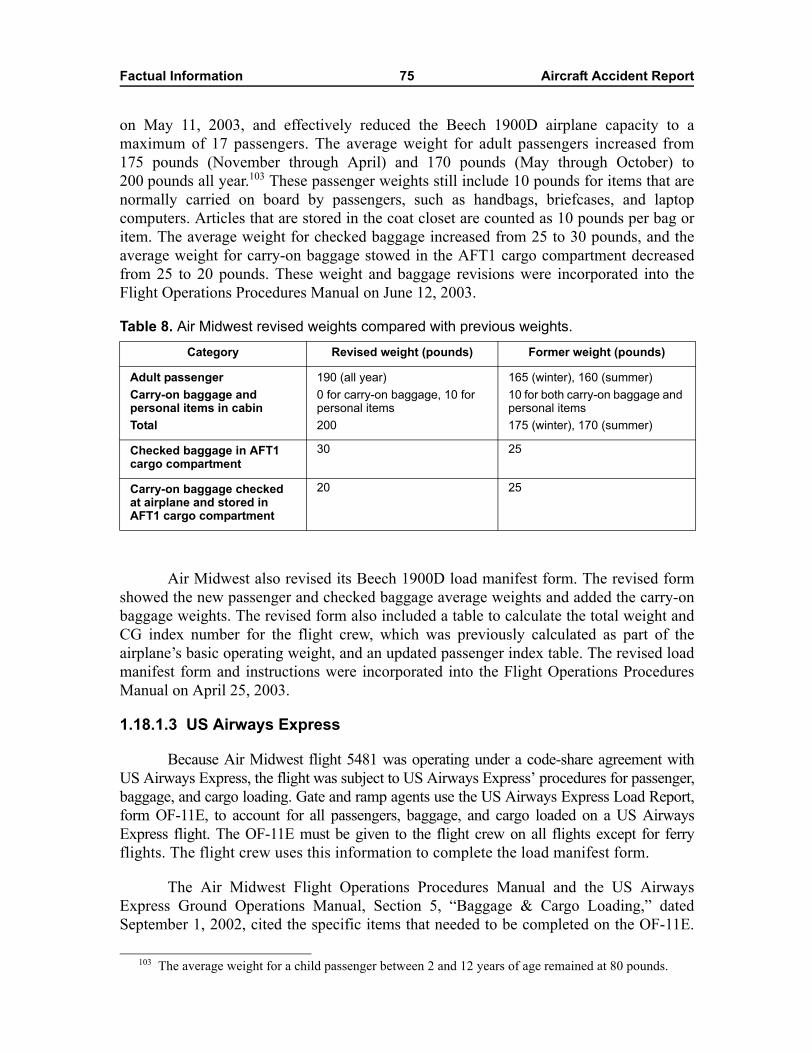
Factual Information 75 Aircraft Accident Report
on May 11, 2003, and effectively reduced the Beech 1900D airplane capacity to amaximum of 17 passengers. The average weight for adult passengers increased from175 pounds (November through April) and 170 pounds (May through October) to200 pounds all year.103 These passenger weights still include 10 pounds for items that arenormally carried on board by passengers, such as handbags, briefcases, and laptopcomputers. Articles that are stored in the coat closet are counted as 10 pounds per bag oritem. The average weight for checked baggage increased from 25 to 30 pounds, and theaverage weight for carry-on baggage stowed in the AFT1 cargo compartment decreasedfrom 25 to 20 pounds. These weight and baggage revisions were incorporated into theFlight Operations Procedures Manual on June 12, 2003.
Table 8. Air Midwest revised weights compared with previous weights.
Air Midwest also revised its Beech 1900D load manifest form. The revised formshowed the new passenger and checked baggage average weights and added the carry-onbaggage weights. The revised form also included a table to calculate the total weight andCG index number for the flight crew, which was previously calculated as part of theairplane�s basic operating weight, and an updated passenger index table. The revised loadmanifest form and instructions were incorporated into the Flight Operations ProceduresManual on April 25, 2003.
1.18.1.3 US Airways Express
Because Air Midwest flight 5481 was operating under a code-share agreement withUS Airways Express, the flight was subject to US Airways Express� procedures for passenger,baggage, and cargo loading. Gate and ramp agents use the US Airways Express Load Report,form OF-11E, to account for all passengers, baggage, and cargo loaded on a US AirwaysExpress flight. The OF-11E must be given to the flight crew on all flights except for ferryflights. The flight crew uses this information to complete the load manifest form.
The Air Midwest Flight Operations Procedures Manual and the US AirwaysExpress Ground Operations Manual, Section 5, �Baggage & Cargo Loading,� datedSeptember 1, 2002, cited the specific items that needed to be completed on the OF-11E.
103 The average weight for a child passenger between 2 and 12 years of age remained at 80 pounds.
Category Revised weight (pounds) Former weight (pounds)
Adult passengerCarry-on baggage and personal items in cabinTotal
190 (all year)0 for carry-on baggage, 10 for personal items200
165 (winter), 160 (summer)10 for both carry-on baggage and personal items175 (winter), 170 (summer)
Checked baggage in AFT1 cargo compartment
30 25
Carry-on baggage checked at airplane and stored in AFT1 cargo compartment
20 25
Factual Information 76 Aircraft Accident Report
These items included the total number of passengers, including children; the total numberof pieces of checked, carry-on, and crew baggage; and the combined weight of all cargo ineach bin. One copy of the OF-11E is left at the station, and the other copy is given to theflight crew. The US Airways Express manual indicated that the flight crew must benotified if passengers or bags were added after the OF-11E was completed and given tothe crew. Any changes had to be noted in the �remarks� section of the station copy.
In a postaccident interview, the Director of US Airways Express Training statedthat any bag weighing up to 70 pounds was accounted for under the average baggageweight program. She also stated that a bag weighing between 70 and 100 pounds wasconsidered to be an overweight bag. Ticket agents are responsible for putting a �heavybag� tag on such bags at check-in but are not required to list the weight of the bags on theheavy bag tags. Ramp agents are required to indicate �heavy bag� in the remarks sectionof the OF-11E for those bags with heavy bag tags. At the time of the accident, no formalprocedures existed for reporting overweight bags in the weight and balance paperwork(except for military duffle bags, which were considered to have an average weight of50 pounds).104 The Director of US Airways Express Training further stated that bags thatweigh more than 100 pounds were considered air freight. Procedures were in place forreporting air freight in the weight and balance paperwork.
According to the US Airways Express Ground Operations Manual, carry-on itemsthat are too large to fit in the cabin of aircraft operated by US Airways Express must betagged with a carry-on tag and placed in the cargo compartment of the aircraft. The itemsare to be loaded in the cargo compartment last, off-loaded first, and returned to thecustomer upon deplaning.
The US Airways Express Ramp Lesson Plan and Student Workbook states that theBeech 1900D AFT1 cargo compartment has a maximum weight allowance of 1,000 poundsand that the AFT2 cargo compartment has a maximum weight allowance of 630 pounds.The workbook cautions that �the rear section of the cargo compartment is only to be usedat the instruction of the crew. The netting must stay in place at all other times.�
1.18.2 Federal Aviation Administration Emergency Airworthiness Directive 2003-03-18
FAA Emergency AD 2003-03-18, dated January 27, 2003, was sent to all ownersand operators of Beech 1900, 1900C, and 1900D airplanes. The AD indicated that recentground testing and a review of the rigging procedures of a 1900D airplane revealed thatthe elevator control system could be misrigged to restrict elevator travel if currentmaintenance procedures were not properly followed. Such restricted travel might not bedetected until the airplane was operating in a loading condition that required full elevatorauthority to control the pitch. The 1900 and 1900C models were included in this ADbecause their elevator control system design is similar to that of the 1900D model.
104 The revised Air Midwest average baggage weight guidance states that, in the absence of an actualweight, an average weight of 60 pounds can be used for each heavy or oversized bag.
Factual Information 77 Aircraft Accident Report
The FAA determined, among other things, that inspections and verificationsshould be accomplished on all affected airplanes to ensure that the elevator surfaces hadfull travel. Specifically, Emergency AD 2003-03-18 required owners and operators ofBeech 1900 series airplanes, by January 31, 2003, to perform a control column sweepinspection to verify full elevator travel to the primary up and down stops and a stop boltinspection to verify that the stop bolt length was not excessive. For those airplanes that didnot pass the initial control column sweep and stop bolt inspections, the AD requiredanother rig of the elevator control system and/or a more detailed inspection of the system.For those airplanes that did pass the initial control column sweep and stop boltinspections, the AD required a more detailed inspection of the elevator control systemwithin 100 hours time in service. In addition, the AD required that owners and operatorsof Beech 1900 series airplanes report the results of the initial inspections and the 100-hourtime-in-service inspection (if applicable).
Air Midwest complied with Emergency AD 2003-03-18 and found that, of the42 Beech 1900D airplanes in its inventory, 5 airplanes had maximum elevator deflectionsthat were less than 20º or greater than 21º ANU (design range is between 20º and 21º ANU)or less than 14º AND (design range is between 14º and 15º AND).105 In addition, oneairplane�s elevator control horn did not contact the left and right AND stop bolts, andanother airplane�s elevator control horn did not contact the left AND stop bolt.
According to the FAA, Raytheon Aircraft Company received 296 reports from theinitial control column sweep and stop bolt inspection. The reports showed that 40 airplanesfailed this initial check and thus required another rig. The FAA also indicated thatRaytheon Aircraft received 227 reports from the 100-hour time-in-service inspection.According to the reports, 39 airplanes failed the 100-hour inspection, 18 of which failedby more than 1º in either the ANU or AND direction. Both the left and the right elevatorson 9 of these 18 airplanes had insufficient AND travel. Specifically, the AND travel forthese nine airplanes were as follows: four airplanes had left and right elevator deflectionsthat were limited to 12º AND; one airplane had left and right elevator deflections limitedto 13º and 11.3º AND, respectively; one airplane had left and right elevator deflectionslimited to 12.5º and 10.5º AND, respectively; one airplane had left and right elevatordeflections limited to 12º and 13º AND, respectively; one airplane had left and rightelevator deflections limited to 11.5º and 12.5º AND, respectively, and the airplane with theworst AND travel had left and right elevator deflections limited to 16.5º AND. Thediscrepancies in ANU travel ranged from 16.5º to 26º for the left elevator and from 17.5ºto 26º for the right elevator.
105 The first of the five airplanes had a maximum left elevator deflection of 19º ANU. The secondairplane had a maximum right elevator deflection of 19º ANU. The third airplane had a maximum leftelevator deflection of 21.5º ANU and a maximum right elevator deflection of 22.5º ANU. The fourthairplane had maximum left and right elevator deflections of 13º AND. The fifth airplane had a maximum leftelevator deflection of 12.5º AND.
Factual Information 78 Aircraft Accident Report
1.18.3 Federal Aviation Administration Guidance for On-the-Job Training
The FAA�s Human Factors Guide for Aviation Maintenance and Inspection106
described OJT as follows:
On-the-job training (OJT) is the generic name describing a variety of trainingmethods in which trainees work while they learn job skills. On-the-job trainingfollows the apprenticeship model of education where a new employee is mentoredby a seasoned employee thought to be an expert in the field. This is sometimescalled the �buddy� system. Demonstration and supervised practice withequipment and procedures within the work environment is what is normallyconsidered OJT.
OJT has several positive aspects: trainees perform many job tasks while becomingmore proficient; trainees observe highly skilled technicians perform the tasks theyare learning; and the trainees have an opportunity to build one-to-onerelationships with mentors.
Improperly used however, OJT can be inefficient from both the points-of-view oflearning and cost. The results of OJT are highly dependent on the trainer�steaching and interpersonal skills. In most OJT situations, the trainer is an AMT[aviation maintenance technician] whose primary job is maintenance, not training.At its worst, OJT is idiosyncratic, incomplete, haphazard, and time-consuming.
The Human Factors Guide for Aviation Maintenance and Inspection alsoexplained the following:
Certain aviation maintenance training practices have been frequently criticized.Recurrent training tends to receive less emphasis than the constant technologicalchanges in the industry demand. Mechanics sent to school for training on aspecific aircraft may not receive formal training again on that aircraft type for 10years or more. Training related to technological changes tends to be done on thejob, instead of in formal, structured settings. There is ample evidence that OJT isnot the best training method for a variety of skills needed by today�s AMT.
Even when using OJT is appropriate, the current system has been criticized for itslax OJT training practices, which tend to be unstructured. Younger mechanics turnto more senior employees for ad hoc OJT, although there is no systematic way toensure that the senior AMTs work or teaching skills are adequate to ensure theefficient transfer of skills and knowledge.
The Human Factors Guide for Aviation Maintenance and Inspection includedvoluntary guidelines for air carriers that wanted to develop OJT programs. Theseguidelines recommended that structured OJT be
106 Maddox, M. (Ed.) Human Factors Guide for Aviation Maintenance and Inspection, Version 3.0(Atlanta: Galaxy Scientific Corporation, 1998).
Factual Information 79 Aircraft Accident Report
� based on measurable performance standards;
� designed and delivered in a systems framework that includes informationpresentation, demonstration, practice, and evaluation;
� designed to provide initial, recurrent, and remedial training;
� used to standardize procedures and to provide consistent training amongworkers;
� conducted by experienced employees trained in structured OJT techniques andadult learning principles;
� delivered in segments that are planned, scheduled, and frequent and includekeeping complete, up-to-date trainee performance records; and
� audited annually to identify areas in need of improvement.
In addition, the guide recommended that OJT be conducted in the followingsequence: orientation, demonstration, practice, and evaluation and closure.
1.18.4 Other Related Accidents
1.18.4.1 Ryan Air Service Flight 103, Homer, Alaska
On November 23, 1987, Ryan Air Service flight 103, a Beech 1900C,107 N401RA,crashed short of the runway during arrival at the Homer, Alaska, airport. Flight 103 was ascheduled 14 CFR Part 135 flight operating from Kodiak, Alaska, to Anchorage, Alaska,with intermediate stops in Homer and Kenai, Alaska. The 2 flight crewmembers and16 passengers were killed, and 3 passengers were seriously injured.
The accident investigation revealed that the airplane was loaded with about600 pounds more cargo than the first officer had requested. The airplane was 400 to500 pounds over the airplane�s maximum takeoff weight and 100 to 200 pounds over itsmaximum landing weight. In addition, the CG position was 12 to 16 percent MAC aft ofthe allowable aft limit, and the flight crew did not comply with company and FAAprocedures in computing the CG position. Even with an extreme aft CG, the airplane wasable to take off and establish cruise flight. Evidence indicated that the flight crew lostcontrol of the airplane as its flaps were lowered for landing.
The Safety Board determined that the probable cause of this accident was thefailure of the flight crew to properly supervise the loading of the airplane, which resultedin the CG being displaced to such an aft location that airplane control was lost when theflaps were lowered for landing.108
107 The Beech 1900C is generally similar in size and capacity to the 1900D. The airplanes havenumerous similar components and share a common FAA type certificate.
108 For more information, see National Transportation Safety Board, Ryan Air Service, Inc., Flight 103,Beech 1900C, N401RA, Homer, Alaska, November 23, 1987, Aircraft Accident Report NTSB/AAR-88/11(Washington, DC: NTSB, 1988).
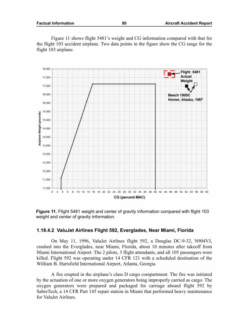
Factual Information 80 Aircraft Accident Report
Figure 11 shows flight 5481�s weight and CG information compared with that forthe flight 103 accident airplane. Two data points in the figure show the CG range for theflight 103 airplane.
1.18.4.2 ValuJet Airlines Flight 592, Everglades, Near Miami, Florida
On May 11, 1996, ValuJet Airlines flight 592, a Douglas DC-9-32, N904VJ,crashed into the Everglades, near Miami, Florida, about 10 minutes after takeoff fromMiami International Airport. The 2 pilots, 3 flight attendants, and all 105 passengers werekilled. Flight 592 was operating under 14 CFR 121 with a scheduled destination of theWilliam B. Hartsfield International Airport, Atlanta, Georgia.
A fire erupted in the airplane�s class D cargo compartment. The fire was initiatedby the actuation of one or more oxygen generators being improperly carried as cargo. Theoxygen generators were prepared and packaged for carriage aboard flight 592 bySabreTech, a 14 CFR Part 145 repair station in Miami that performed heavy maintenancefor ValuJet Airlines.
Figure 11. Flight 5481 weight and center of gravity information compared with flight 103 weight and center of gravity information.
Factual Information 81 Aircraft Accident Report
The Safety Board�s investigation of the FAA�s oversight of ValuJet Airlinesrevealed that inspectors from the Aircraft Maintenance Division within the Office ofFlight Standards had recommended recertification of the airline 3 months before theaccident. Specifically, in a February 14, 1996, summary report, the inspectors indicated,�consideration should be given to an immediate FAR 121 recertification of this airline�because of safety-related issues, such as the absence of adequate policies and proceduresfor maintenance personnel. The inspectors also indicated that the overall surveillance ofValuJet Airlines should be increased with special attention directed toward �manuals andprocedures, structural inspections, the adequacy of the maintenance program, and shopsand facilities.�
The Safety Board determined that the probable causes of this accident were (1) thefailure of SabreTech to properly prepare, package, and identify unexpended chemicaloxygen generators before presenting them to ValuJet for carriage; (2) the failure of ValuJetto oversee its contract maintenance program to ensure compliance with maintenance,maintenance training, and hazardous materials requirements and practices; and (3) thefailure of the FAA to require smoke detection and fire suppression systems in class Dcargo compartments.
Contributing to the accident was the failure of the FAA to adequately monitorValuJet�s heavy maintenance programs and responsibilities, including ValuJet�s oversightof its contractors, and SabreTech�s repair station certificate; the failure of the FAA toadequately respond to prior chemical oxygen generator fires with programs to address thepotential hazards; and ValuJet�s failure to ensure that both ValuJet and contractmaintenance facility employees were aware of the carrier�s �no-carry� hazardousmaterials policy and had received appropriate hazardous materials training.109
1.18.4.2.1 Safety Recommendation A-97-70
During its investigation of the ValuJet Airlines flight 592 accident, the SafetyBoard determined that the SabreTech mechanics had many shortcomings, including theirfailure to install safety caps, their improper maintenance entries, their use of impropertags, and their inadequate communications between the maintenance shop floor and storesdepartment. In its final report on the accident, the Board indicated that these shortcomingsresulted from human failures that might have been avoided if more attention were given tohuman factors issues in the maintenance environment. As a result, the Board issued SafetyRecommendation A-97-70 on September 9, 1997. Safety Recommendation A-97-70asked the FAA to
Include, in its development and approval of air carrier maintenance proceduresand programs, explicit consideration of human factors issues, including training,procedures development, redundancy, supervision, and the work environment, toimprove the performance of personnel and their adherence to procedures.
109 For more information, see National Transportation Safety Board, In-flight Fire and Impact WithTerrain, ValuJet Airlines Flight 592, DC-9-32, N904VJ, Everglades, Near Miami, Florida, May 11, 1996,Aircraft Accident Report NTSB/AAR-97/06 (Washington, DC: NTSB, 1997).
Factual Information 82 Aircraft Accident Report
On October 2, 2000, the FAA stated that it had reviewed the information containedin its report, Human Factors in Aviation Maintenance and Inspection, Strategic ProgramPlan, and that it was amending AC 120-16C, �Continuous Airworthiness MaintenancePrograms,� to include information from the report. The FAA indicated that the revisions tothe AC would also expand on CASS programs. On April 24, 2001, the Safety Board statedthat it was difficult to determine whether the revisions to AC 120-16C would address theissues in this recommendation. On July 21, 2003, the FAA stated that chapter 10 of AC120-16D included human factors as part of initial training.
On February 23, 2004, the Safety Board stated that, although AC 120-16Daddressed many of the human factors issues related to training, procedures development,redundancy, supervision, and work environment, the AC would be significantlystrengthened if the FAA added specific references to its available human factorsinformation related to aviation maintenance operations, such as the Human Factors Guidefor Aviation Maintenance and Inspection. The Board also stated that it continued toinvestigate major accidents in which incorrect maintenance led to a loss of control of theairplane and that human factors in aviation maintenance was an important safety issue.Pending the inclusion in AC 120-16D of references to FAA-published guidance on humanfactors in aviation maintenance, Safety Recommendation A-97-70 was classified �Open�Acceptable Response.�
1.18.4.2.2 Safety Recommendation A-97-74
In its final report on the ValuJet Airlines flight 592 accident, the Safety Boarddetermined that the FAA�s surveillance of ValuJet before the accident did not include anysignificant oversight of the air carrier�s heavy maintenance contractors, includingSabreTech. The Board further determined that the FAA�s limited oversight of ValuJet�smaintenance contractors was not sufficient to detect potential problems. The ValuJet PMIwas not required to conduct surveillance of the air carrier�s contract maintenancefacilities. Thus, the Board concluded that the lack of an explicit requirement for a PMI ofa 14 CFR Part 121 air carrier to regularly inspect repair stations that are performing heavymaintenance for the carrier is a significant deficiency in the FAA�s oversight of thecarrier�s total maintenance program. As a result, the Board issued SafetyRecommendation A-97-74 on September 9, 1997. Safety Recommendation A-97-74asked the FAA to
Ensure that Part 121 air carriers� maintenance functions receive the same level ofFAA surveillance, regardless of whether those functions are performed in house orby a contract maintenance facility.
On April 22, 1998, the FAA stated that it issued Flight Standards HandbookBulletin for Airworthiness 96-05C, �Air Carrier Operations Specifications Authorizationto Make Arrangements With Other Organizations to Perform Substantial Maintenance,�on December 15, 1997. The FAA indicated that the bulletin described
Factual Information 83 Aircraft Accident Report
detailed procedures to ensure that surveillance of each 14 CFR Part 121 aircarrier�s maintenance function entails the performance of the maintenance, theadequacy of the maintenance organization, the competency of maintenancepersonnel, and the adequacy of maintenance facilities and equipment, regardlessof whether those functions are performed in-house or by a contract maintenancefacility.
On July 23, 1999, the Safety Board stated that the FAA�s actions met the intent ofSafety Recommendation A-97-74 and classified it �Closed�Acceptable Action.�
1.18.4.3 Fine Airlines Flight 101, Miami, Florida
On August 7, 1997, Fine Airlines flight 101, a Douglas DC-8-61, N27UA, crashedafter takeoff from Miami International Airport. The three flight crewmembers and onepassenger on board the airplane were killed, one person on the ground was killed, and theairplane was destroyed by impact forces and a postcrash fire. The cargo flight, which hada scheduled destination of Santo Domingo, Dominican Republic, was operated under14 CFR Part 121 as a supplemental air carrier.
The accident airplane was loaded incorrectly, which resulted in an aft CG. Also, anincorrect stabilizer trim setting precipitated an extreme pitchup at rotation.
The Safety Board determined that the probable cause of this accident was thefailure of Fine Air to exercise operational control over the cargo loading process and thefailure of Aeromar (a cargo shipper) to load the airplane as specified by Fine Air.Contributing to the accident was the failure of the FAA to adequately monitor Fine Air�soperational control responsibilities for cargo loading and to ensure that knowncargo-related deficiencies were corrected at Fine Air.110
1.18.4.3.1 Safety Recommendation A-98-49
In its final report on the Fine Airlines accident, the Safety Board discussed theSum Total Aft and Nose (STAN) system, which is an electronic system installed on somecargo airplanes that allows flight crews to verify an airplane�s weight and balance beforedeparture. According to the report, the STAN system uses pressure transducers to convertmain gear and nose gear shock strut air pressure to an electronic signal. The system thenprovides flight crews with a digital readout in the cockpit (on the flight engineer�sinstrument panel) of the airplane�s gross weight and CG values.
The Safety Board�s final report on the Fine Airlines accident concluded that, if theflight crew had an independent method in the cockpit for verifying the airplane�s actualweight and balance and gross weight, it might have alerted them to loading anomalies andprevented the accident. As a result, on July 10, 1998, the Safety Board issued SafetyRecommendation A-98-49 to the FAA. Safety Recommendation A-98-49 asked the FAA to
110 For more information, see National Transportation Safety Board, Uncontrolled Impact With Terrain,Fine Airlines Flight 101, Douglas DC-8-61, N27UA, Miami, Florida, August 7, 1997, Aircraft AccidentReport NTSB/AAR-98/02 (Washington, DC: NTSB, 1998).
Factual Information 84 Aircraft Accident Report
Evaluate the benefit of the STAN (Sum Total Aft and Nose) and similar systemsand require, if warranted, the installation of a system that displays airplane weightand balance and gross weight in the cockpit of transport-category cargo airplanes.
On December 30, 1998, the FAA stated that it had completed an evaluation of thereliability of onboard weight and balance systems. The FAA found that some operatorshad reliability and accuracy concerns with such systems because of factors such as wind,ramp slope, oleo stiction, low hydraulic pressure, and asymmetrical gear loads. The FAAstated that the results of its evaluation did not support imposing a requirement to install asystem that displays airplane weight and balance and gross weight in the cockpit oftransport-category cargo airplanes. On January 11, 2000, the Safety Board stated that, onthe basis of the FAA�s evaluation and subsequent determination that onboard weight andbalance systems do not yet meet the quality standards for a mandatory system, SafetyRecommendation A-98-49 was classified �Closed�Acceptable Action.�
1.18.4.4 Emery Airlines Flight 17, Rancho Cordova, California
On February 16, 2000, Emery Airlines flight 17, a McDonnell Douglas DC-8-71F,N8079U, crashed in an automobile salvage yard shortly after takeoff while attempting toreturn to Sacramento Mather Airport, Rancho Cordova, California, for an emergencylanding. Flight 17 was a scheduled 14 CFR Part 121 cargo flight from Sacramento toJames M. Cox Dayton International Airport, Dayton, Ohio. The two pilots and the flightengineer were killed, and the airplane was destroyed.
The Safety Board�s investigation of this accident determined that the bolt attachingthe accident airplane�s right elevator control tab crank fitting to the pushrod wasimproperly secured and inspected during either the airplane�s most recent D inspection(heavy maintenance accomplished every 12 years) or subsequent maintenance. TennesseeTechnical Services (TTS), an Emery Airlines maintenance contractor, performed theaccident airplane�s last D inspection between August 27 and November 17, 1999. Eightdays after the D inspection was completed, a pilot reported increased control columnforces. Emery maintenance personnel found that the left and the right elevator damperswere reversed, and the maintenance logbook indicated that the maintenance personnelmoved the dampers to their correct positions. Emery maintenance personnel could havecome in contact with the bolt at the control tab crank fitting while troubleshooting thereported problem.
The Safety Board determined that the probable cause of the accident was a loss ofpitch control resulting from the disconnection of the right elevator control tab. Thedisconnection was caused by the failure to properly secure and inspect the attachmentbolt.111
111 For more information, see National Transportation Safety Board, Loss of Pitch Control on Takeoff,Emery Worldwide Airlines, Inc., Flight 17, McDonnell Douglas DC-8-71F, N8079U, Rancho Cordova,California, February 16, 2000, Aircraft Accident Report NTSB/AAR-03/02 (Washington, DC: NTSB,2003).
Factual Information 85 Aircraft Accident Report
1.18.4.4.1 Safety Recommendation A-03-31
In its final report on the Emery Airlines flight 17 accident, the Safety Boarddiscussed the accident airplane�s last B-2 maintenance inspection (the second of foursegmented inspections generally accomplished at 136-hour intervals) on January 21 and 22,2000. The B-2 inspection includes a visual check of the elevators and tabs for generalcondition, corrosion, leakage, and security of attachment. The DC-8 elevator assemblydesign requires the elevator control tab inboard fairing to be removed for maintenancepersonnel to inspect the inboard hinge fitting and the control tab crank fitting to pushrodattachment.
During postaccident interviews, Emery Airlines maintenance personnel stated that,when performing the accident airplane�s last B-2 maintenance, they did not remove theelevator control tab inboard fairing or inspect the crank fitting to pushrod attachment.During public hearing testimony, witnesses from Emery Airlines indicated that its B-2inspection was intended to be a general visual inspection that was to be accomplishedwithout removing access or inspection panels or fairings. However, witnesses from TTSstated that removal of the control tab fairing was necessary to satisfactorily perform thetasks described on the Emery Airlines B-2 work card, even though that step was notspecifically listed on the work card.
The Safety Board noted that several air carriers have tried to clarify the intendedscope of maintenance tasks by including, on their work cards, an enumeration of theactions that are necessary for the proper accomplishment of the associated work task. TheBoard stated that the inclusion of this additional detail on work cards, although notrequired by the FAA, should result in more consistent accomplishment of maintenancetasks. As a result, the Board issued Safety Recommendation A-03-31 on August 18, 2003.Safety Recommendation A-03-31 asked the FAA to
Require all 14 CFR Part 121 air carrier operators to revise their task documentsand/or work cards to describe explicitly the process to be followed inaccomplishing maintenance tasks.
On January 12, 2004, the FAA stated that Safety Recommendation A-03-31 waslimited to DC-8 operators only. The FAA also stated that the Boeing Company issuedtemporary revisions to the DC-8 AMM on May 8, 2002, and that these revisions explicitlydescribed the maintenance task process to be followed. On January 23, 2004, the SafetyBoard classified Safety Recommendation A-03-31 �Open�Response Received.�
1.18.4.5 Colgan Air Flight 9446, Yarmouth, Massachusetts
On August 26, 2003, Colgan Air (doing business as US Airways Express) flight9446, a Beech 1900D, N240CJ, crashed into water near Yarmouth, Massachusetts. Thetwo flight crewmembers were killed, and the airplane was substantially damaged. Therepositioning flight, which was conducted under 14 CFR Part 91, departed BarnstableMunicipal Airport, Hyannis, Massachusetts, for Albany International Airport (ALB),Albany, New York.
Factual Information 86 Aircraft Accident Report
Shortly after takeoff, the flight crewmembers declared an emergency and reporteda trim problem. The airplane had reached an altitude of about 1,100 feet msl. The flightcrew requested to land on a specific runway, and the controller cleared the flight to land onany runway. No further transmissions were received from the flight crew. FDR dataindicated that the airplane�s airspeed continued to increase to about 250 knots and that theairplane�s last recorded altitude was about 300 feet msl.
The accident airplane�s FDR pitch trim control position parameter had been placedon the minimum equipment list (deferred maintenance) for the flight because theparameter was not calibrated. The Safety Board�s airplane performance study for thisaccident determined that the recorded pitch trim control positions did not reflect the actualpitch trim control positions. The difference between the recorded and actual pitch trimcontrol positions was about 2.1º ANU.
According to the airplane performance study, the airplane began the flight with apitch trim control position of about 0.5º ANU. Shortly after takeoff, the pitch trim controlposition moved to about 0.8º AND and remained there for about 10 seconds. The pitchtrim control position then moved to about 5º AND and remained there for the rest of theflight. Calculations showed that the airplane would have required about 200 pounds of aft(pulling) control force to maintain level flight in the out-of-trim condition.
The accident flight was the first flight after maintenance had been performed onthe airplane. The maintenance work included replacement of both elevator trim tabactuators (because of a failed freeplay check) in accordance with Beech 1900D AMMsection 27-30-06, �Elevator Trim Tab Actuator, Removal and Installation and the ActuatorCable Replacement.� The procedure required that the elevator be removed before theactuators were replaced. The Safety Board�s investigation of this accident determined thatthe mechanics skipped this procedural step and replaced the actuators with the elevatorsinstalled.
The mechanics thought that the forward elevator trim tab cable had becomejammed or kinked during the replacement of the trim tab actuator. The mechanics thentried to replace the cable according to the procedure in Beech 1900D AMM section 27-30-04,�Elevator Trim Tab Cables, Removal and Installation.� A postaccident examination of asection of the forward elevator trim cable revealed evidence consistent with a misroutedcable. The Beech 1900D AMM and Colgan Air work cards did not include a trim systemcheck at the end of the elevator trim tab cable procedure. Although the mechanics statedthat they checked the trim system, evidence was consistent with the trim system operatingin a direction opposite from the command of the trim wheel.112
The Safety Board�s investigation of this accident revealed that the illustration ofthe forward elevator trim tab cable drum appeared backward in section 27-30-04 in theBeech 1900D AMM. On October 22, 2003, Raytheon Aircraft Company revised its Beech1900D AMM elevator trim tab cable rigging procedure to show the correct illustration forthe forward elevator trim tab cable drum.
112 Additional information about this accident, NYC03MA183, can be found on the Safety Board�s Website.
Factual Information 87 Aircraft Accident Report
1.18.4.5.1 Federal Aviation Administration Airworthiness Directive 2003-20-10
On October 15, 2003, the FAA issued AD 2003-20-10, which applied to all Beechmodel 1900, 1900C, and 1900D airplanes. The FAA reviewed Raytheon Aircraft�s currentmaintenance procedures for the elevator trim system and determined that the figures in theapplicable maintenance manuals depicted the elevator trim cable drum at 180º from theinstalled position and showed the open, keyed side of the drum instead of the flat side ofthe drum.113 The FAA�s review of the maintenance procedure also identified the need toadd a step to visually confirm that the trim wheel position and the trim tab position wereconsistent. According to the FAA, such a check would detect and correct any problemswith the elevator trim system installation before problems occur during operation.
AD 2003-20-10 warned that an incorrectly installed elevator trim systemcomponent, if not detected and corrected, could result in difficulties in controlling theairplane or a total loss of pitch control. As a result, the AD required operators of Beech1900 series airplanes to replace the incorrect figure in the elevator trim systemmaintenance procedures with the corrected figure, incorporate a temporary revision to theapplicable maintenance manual that describes the elevator trim operational check, andperform an elevator trim operational check each time maintenance is accomplished on theelevator trim system.114
1.18.4.6 CommutAir Flight 8718, Albany, New York
On October 16, 2003, CommutAir (doing business as Continental Connection)flight 8718, a Beech 1900D, N850CA, aborted takeoff from ALB because of an elevatorcontrol system discrepancy. The pilot stated that, during the takeoff roll, the controlcolumn would not move aft when the airspeed reached V1.115 The intended destination forthe positioning flight, which was conducted under 14 CFR Part 91, was WestchesterCounty Airport, White Plains, New York. The two flight crewmembers were not injured,and the airplane was not damaged.
Maintenance was performed on the airplane 1 day before the incident, and theincident flight was the first postmaintenance flight. Maintenance records showed that aworn detent pin was replaced on the right thrust lever assembly. The mechanic whoreplaced the detent pin stated that he looked in the Beech 1900D AMM for a procedure toreplace the pin or a procedure to access the thrust lever assembly. The mechanic indicated
113 The FAA indicated that, although the figures in the manuals were incorrectly depicted, thestep-by-step instructions in the procedure, if followed correctly, would result in the proper installation andaction of the elevator trim system. If only the figures were used, a reversing of the action of the elevatormanual trim system could result.
114 Raytheon Aircraft Company addressed these issues in its Safety Communiqué number 234, datedSeptember 2003.
115 According to 14 CFR Part 1, �V1 means the maximum speed in the takeoff at which the pilot musttake the first action (e.g., apply brakes, reduce thrust, deploy speed brakes) to stop the airplane within theaccelerate-stop distance. V1 also means the minimum speed in the takeoff, following a failure of the criticalengine at VEF [the speed at which the critical engine is assumed to fail during takeoff], at which the pilot cancontinue the takeoff and achieve the required height above the takeoff surface within the takeoff distance.�
Factual Information 88 Aircraft Accident Report
that the Beech 1900D AMM did not contain either procedure, so he looked in aCommutAir manual that contained a list of the manufacturer�s field service kits, found areference to a field service kit for �thrust lever, replaceable detent pin,� and obtained thekit.
The field service kit installation instructions included a step to remove the thrustcontrol assembly from the center pedestal, but the instructions did not provide informationabout how to access the thrust lever assembly so that it could be removed from thepedestal. The instructions also did not provide any reference to technical documents thatcontained instructions for the removal and installation of the thrust lever assembly.
The mechanic stated that he accessed the thrust lever assembly by removing theelevator trim wheel and an access panel from the left side of the cockpit pedestal. Nowriteup was generated for the trim wheel removal, and no markings or tags were placed onthe trim wheel to ensure proper reinstallation. The investigation of this incidentdetermined that, when the elevator trim wheel was reinstalled, the mechanic did notproperly align the elevator trim tab position indicator with the elevator trim tab position.116
As a result, the trim wheel was reinstalled incorrectly. The mechanic did not perform afunctional test of the elevator trim control system, as required by AD 2003-20-10 (seesection 1.18.4.5.1).117
The Safety Board and Raytheon Aircraft Company performed a functional checkof the elevator trim control system. The check verified that the elevator trim tab positionindicator did not accurately reflect the elevator trim tab position. Specifically, when theelevator trim tab position indicator was set at 3 units of ANU trim, the elevator trim tabwas deflected 4.6º AND from its neutral position. (The elevator trim tab�s full ANDposition is 5.5º from neutral.) The functional check determined that the elevator trim tabposition indicator pointer was off by about 6 units, which equates to about 8.8º of elevatortrim tab, or about 37 percent of the trim tab�s full range of travel.
After the cause of the elevator trim control system discrepancy was determined, aCommutAir mechanic properly aligned the elevator trim tab position indicator to theelevator trim tab position. Elevator and elevator trim control system functional tests wereaccomplished to verify that the systems were operating according to the requirementsdescribed in the Beech 1900D AMM. A high-speed taxi test and a flight test wereaccomplished to verify the functionality of the elevator and elevator trim controlsystems.118
116 When the elevator trim tab position indicator is at 0°, the elevator trim tab position should also be at 0°. 117 The quality assurance inspector also did not perform a functional test of the elevator trim control
system. The inspector stated that he did not know that the mechanic�s work involved the trim system. 118 Additional information about this incident, NYC04IA010, can be found on the Safety Board�s Web
site.
Factual Information 89 Aircraft Accident Report
1.18.5 Human Factors Research
Since 1989, the FAA has sponsored a research program on human factors inaviation maintenance and produced guidance on countermeasures to mitigate humanfactors problems in aviation maintenance. For example, the FAA�s Guide to HumanFactors in Maintenance and Inspection provides information on work shift schedulingprograms, workplace design, and procedural guidance design. The guide also addressesdeveloping and implementing structured OJT programs, maintenance error reportingprograms, and maintenance resource management training.119
The European Joint Aviation Authorities (JAA)120 association has also sponsoredinitiatives addressing human factors problems in aviation maintenance. The JAA focusedits efforts on revising the regulatory framework under which aviation maintenance isperformed. In its May 2001 Human Factors in Maintenance Working Group Report,121 theJAA proposed revisions to its Joint Aviation Regulations (JARs). These proposed revisionsincluded the following requirements for maintenance organizations:
� communicate information about deficiencies in maintenance procedures toaircraft certificate holders,
� publish an organizational safety policy,
� consider human factors principles when writing maintenance procedures,
� develop appropriate shift turnover procedures,
� consider human fatigue limitations in the organization�s planning,
� consider performing duplicate maintenance inspections,
� plan maintenance work better,
� ensure thorough inspection of maintenance work before inspector signoff, and
� require initial and recurrent training of maintenance personnel to ensure thathuman factors principles are effectively applied within maintenanceorganizations.
In September 2003, the JAA revised JAR Part 145, �Approved MaintenanceOrganizations,� to include this information.
119 AC 120-72, �Maintenance Resource Management Training,� which provides guidelines forspecialized voluntary training programs for improving communication, effectiveness, and safety inmaintenance organizations, is an example of the FAA�s efforts to encourage voluntary human factorsprograms in the aviation industry.
120 The JAA is an associated body of the European Civil Aviation Conference, which represents the civilaviation regulatory authorities of those European States that have agreed to cooperate in developing andimplementing common regulatory safety standards and procedures.
121 Joint Aviation Authorities Maintenance Human Factors Working Group, Human Factors inMaintenance Working Group Report (Hoofddorp, the Netherlands: JAA, 2001).
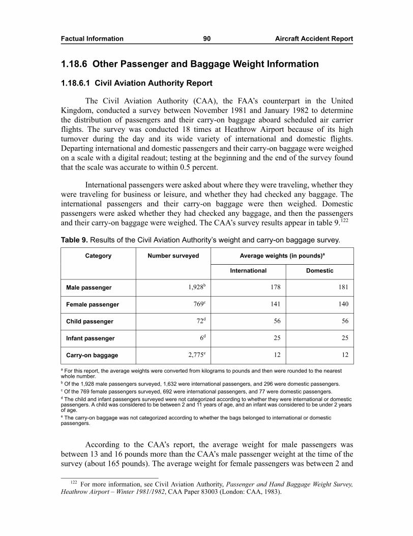
Factual Information 90 Aircraft Accident Report
1.18.6 Other Passenger and Baggage Weight Information
1.18.6.1 Civil Aviation Authority Report
The Civil Aviation Authority (CAA), the FAA�s counterpart in the UnitedKingdom, conducted a survey between November 1981 and January 1982 to determinethe distribution of passengers and their carry-on baggage aboard scheduled air carrierflights. The survey was conducted 18 times at Heathrow Airport because of its highturnover during the day and its wide variety of international and domestic flights.Departing international and domestic passengers and their carry-on baggage were weighedon a scale with a digital readout; testing at the beginning and the end of the survey foundthat the scale was accurate to within 0.5 percent.
International passengers were asked about where they were traveling, whether theywere traveling for business or leisure, and whether they had checked any baggage. Theinternational passengers and their carry-on baggage were then weighed. Domesticpassengers were asked whether they had checked any baggage, and then the passengersand their carry-on baggage were weighed. The CAA�s survey results appear in table 9.122
Table 9. Results of the Civil Aviation Authority�s weight and carry-on baggage survey.
a For this report, the average weights were converted from kilograms to pounds and then were rounded to the nearest whole number.b Of the 1,928 male passengers surveyed, 1,632 were international passengers, and 296 were domestic passengers. c Of the 769 female passengers surveyed, 692 were international passengers, and 77 were domestic passengers. d The child and infant passengers surveyed were not categorized according to whether they were international or domestic passengers. A child was considered to be between 2 and 11 years of age, and an infant was considered to be under 2 years of age. e The carry-on baggage was not categorized according to whether the bags belonged to international or domestic passengers.
According to the CAA�s report, the average weight for male passengers wasbetween 13 and 16 pounds more than the CAA�s male passenger weight at the time of thesurvey (about 165 pounds). The average weight for female passengers was between 2 and
122 For more information, see Civil Aviation Authority, Passenger and Hand Baggage Weight Survey,Heathrow Airport � Winter 1981/1982, CAA Paper 83003 (London: CAA, 1983).
Category Number surveyed Average weights (in pounds)a
International Domestic
Male passenger 1,928b 178 181
Female passenger 769c 141 140
Child passenger 72d 56 56
Infant passenger 6d 25 25
Carry-on baggage 2,775e 12 12
Factual Information 91 Aircraft Accident Report
3 pounds less than the CAA�s female passenger weight at the time (about 143 pounds).The average weight for carry-on baggage was 5 pounds more than the CAA�s carry-onbaggage weight at the time (about 7 pounds).
1.18.6.2 Australian Department of Transport and Communications Report
The Flight Standards Division of the Australian Department of Transport andCommunications conducted a project to investigate the methodology of standard weightsand weight surveys. The Flight Standards Division was concerned about the use of170 pounds (converted from kilograms) as the standard adult passenger weight in aircraftof all passenger capacities. The 170-pound figure, which was derived from a surveyconducted in 1946, made no distinction between male and female passengers and includedcarry-on baggage.
The Flight Standards Division found that the adult standard weight of 170 poundswas based on inaccurate and outdated passenger weight data. The 1988 report on thisproject123 included a discussion of the following issues:
� the need for new weight surveys,
� the basic statistics theory applicable to standard weights,
� the errors in the criteria used to determine the then-current standard weights,
� the maximum probability of overload and its relation to safety,
� the effect on the maximum probability of overload when the standardpassenger weight was constant,
� the effect on standard passenger weight when the maximum probability ofoverload was constant,
� a proposed method for calculating future standard passenger weights (asliding-scale formula that based passenger weight on the maximum seatingcapacity of the airplane), and
� interim standard weights based on then-current data from the AustralianNational Heart Foundation for adult males and females and the AustralianNational Health and Medical Research Council for infants (under 3 years ofage), children (4 to 12 years of age), and adolescent males and females (13 to16 years of age).
The Flight Standards Division concluded that the use of one adult standard weightfor all aircraft capacities was no longer acceptable because smaller aircraft had asignificant risk of being overloaded and larger aircraft were being unnecessarilypenalized. The Flight Standards Division further concluded that all aircraft should have asimilar level of safety with respect to the uncertainty of passenger load and that a
123 For more information, see Airworthiness Branch, Flight Standards Division, Department ofTransport and Communications, Standard Weights for Passenger and Baggage in Australian Aircraft,Airworthiness Report AF 51 (Canberra: Department of Transport and Communications, 1988).
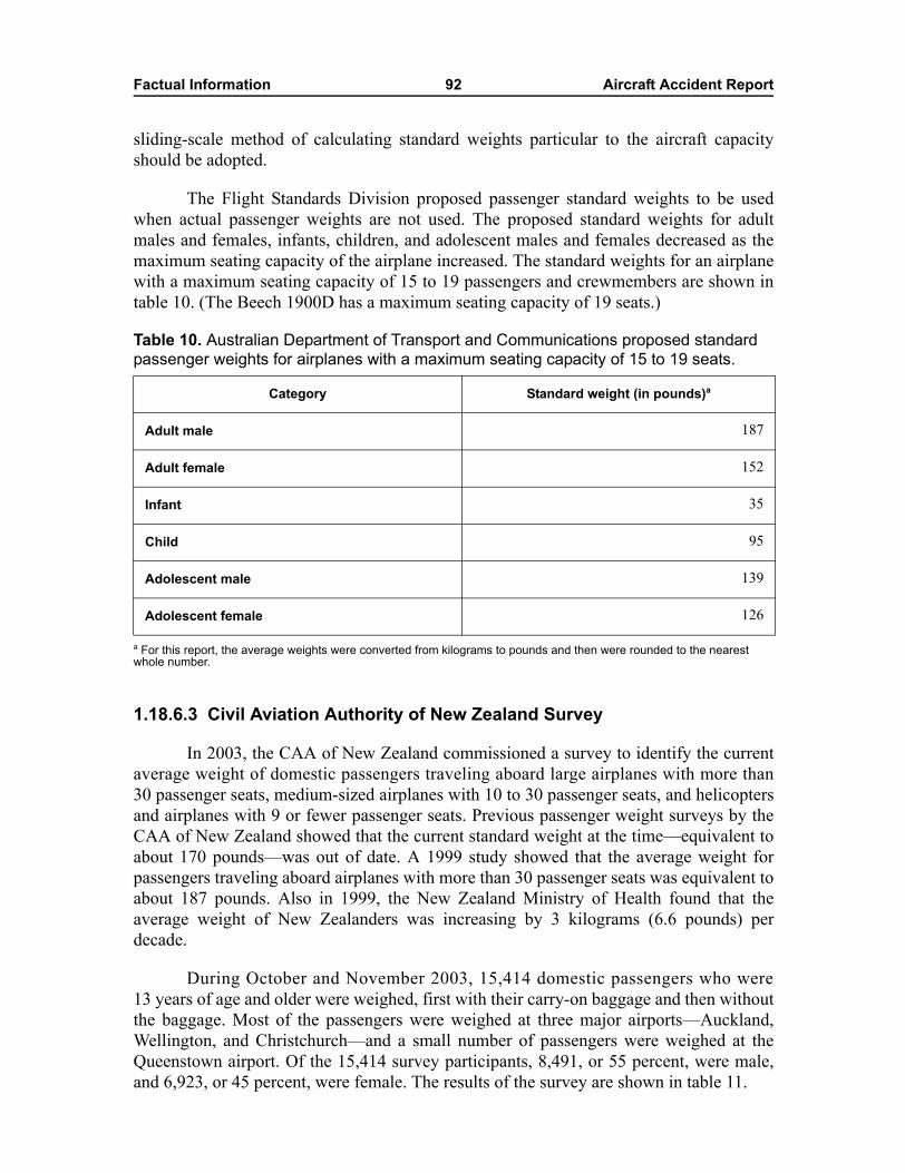
Factual Information 92 Aircraft Accident Report
sliding-scale method of calculating standard weights particular to the aircraft capacityshould be adopted.
The Flight Standards Division proposed passenger standard weights to be usedwhen actual passenger weights are not used. The proposed standard weights for adultmales and females, infants, children, and adolescent males and females decreased as themaximum seating capacity of the airplane increased. The standard weights for an airplanewith a maximum seating capacity of 15 to 19 passengers and crewmembers are shown intable 10. (The Beech 1900D has a maximum seating capacity of 19 seats.)
Table 10. Australian Department of Transport and Communications proposed standard passenger weights for airplanes with a maximum seating capacity of 15 to 19 seats.
a For this report, the average weights were converted from kilograms to pounds and then were rounded to the nearest whole number.
1.18.6.3 Civil Aviation Authority of New Zealand Survey
In 2003, the CAA of New Zealand commissioned a survey to identify the currentaverage weight of domestic passengers traveling aboard large airplanes with more than30 passenger seats, medium-sized airplanes with 10 to 30 passenger seats, and helicoptersand airplanes with 9 or fewer passenger seats. Previous passenger weight surveys by theCAA of New Zealand showed that the current standard weight at the time�equivalent toabout 170 pounds�was out of date. A 1999 study showed that the average weight forpassengers traveling aboard airplanes with more than 30 passenger seats was equivalent toabout 187 pounds. Also in 1999, the New Zealand Ministry of Health found that theaverage weight of New Zealanders was increasing by 3 kilograms (6.6 pounds) perdecade.
During October and November 2003, 15,414 domestic passengers who were13 years of age and older were weighed, first with their carry-on baggage and then withoutthe baggage. Most of the passengers were weighed at three major airports�Auckland,Wellington, and Christchurch�and a small number of passengers were weighed at theQueenstown airport. Of the 15,414 survey participants, 8,491, or 55 percent, were male,and 6,923, or 45 percent, were female. The results of the survey are shown in table 11.
Category Standard weight (in pounds)a
Adult male 187
Adult female 152
Infant 35
Child 95
Adolescent male 139
Adolescent female 126
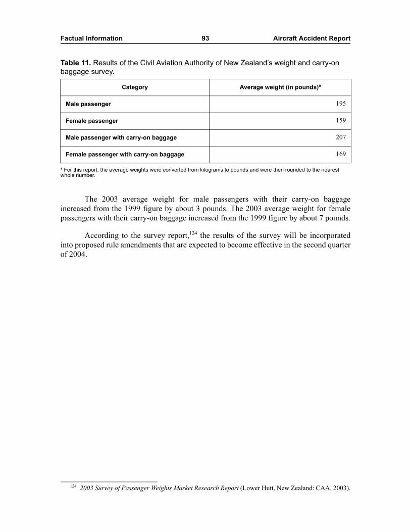
Factual Information 93 Aircraft Accident Report
Table 11. Results of the Civil Aviation Authority of New Zealand�s weight and carry-on baggage survey.
a For this report, the average weights were converted from kilograms to pounds and were then rounded to the nearest whole number.
The 2003 average weight for male passengers with their carry-on baggageincreased from the 1999 figure by about 3 pounds. The 2003 average weight for femalepassengers with their carry-on baggage increased from the 1999 figure by about 7 pounds.
According to the survey report,124 the results of the survey will be incorporatedinto proposed rule amendments that are expected to become effective in the second quarterof 2004.
Category Average weight (in pounds)a
Male passenger 195
Female passenger 159
Male passenger with carry-on baggage 207
Female passenger with carry-on baggage 169
124 2003 Survey of Passenger Weights Market Research Report (Lower Hutt, New Zealand: CAA, 2003).
94 Aircraft Accident Report
2. Analysis
2.1 GeneralThe captain and the first officer were properly certificated and qualified under
Federal regulations. No evidence indicated any preexisting medical or behavioralconditions that might have adversely affected their performance during the accident flight.Flight crew fatigue was not a factor in this accident.
The accident airplane was properly certified and equipped in accordance withFederal regulations. Except for the elevator control system (which is discussed in section 2.3),no evidence indicated that the airplane was improperly maintained. The recoveredcomponents showed no evidence of any preexisting structural, engine, or systems failures.
Weather was not a factor in this accident. The air traffic controllers that handledthe accident flight were properly trained and provided appropriate air traffic controlservices. The emergency response for this accident was timely and effective. The accidentwas not survivable for the airplane occupants because they were subjected to impactforces that exceeded the limits of human tolerance.
This analysis discusses why the flight crew lost control of the airplane during itstakeoff rotation and initial climb and what effect the airplane�s elevator and center ofgravity (CG) had on this accident. The analysis also examines organizational andmanagement issues that played a role in the circumstances of this accident and providesinformation about an ongoing problem with cockpit voice recorders (CVR) installed onBeech 1900 series airplanes.
2.2 Loading and Preflight Activities On the day of the accident, the accident first officer was seen conducting a
walk-around inspection of the airplane. He did not report anything unusual about theairplane, including its elevator control system.125
The accident flight crew filled out the Air Midwest Beechcraft 1900D LoadManifest form for the flight using the average weight values for passengers and baggagein Air Midwest�s weight and balance program at the time of the accident.126 The load
125 The three previous flight crews who flew the accident airplane also did not report anything unusualabout the elevator control system. In fact, the first officer of the flight from Huntington, West Virginia(HTS), to Charlotte, North Carolina, on January 7, 2003, stated that �everything was normal� and �it was agood flying airplane.�
126 The flight crew made a 10-pound addition error when summing the weights that comprise the zerofuel weight. This addition error was not a factor in the accident.
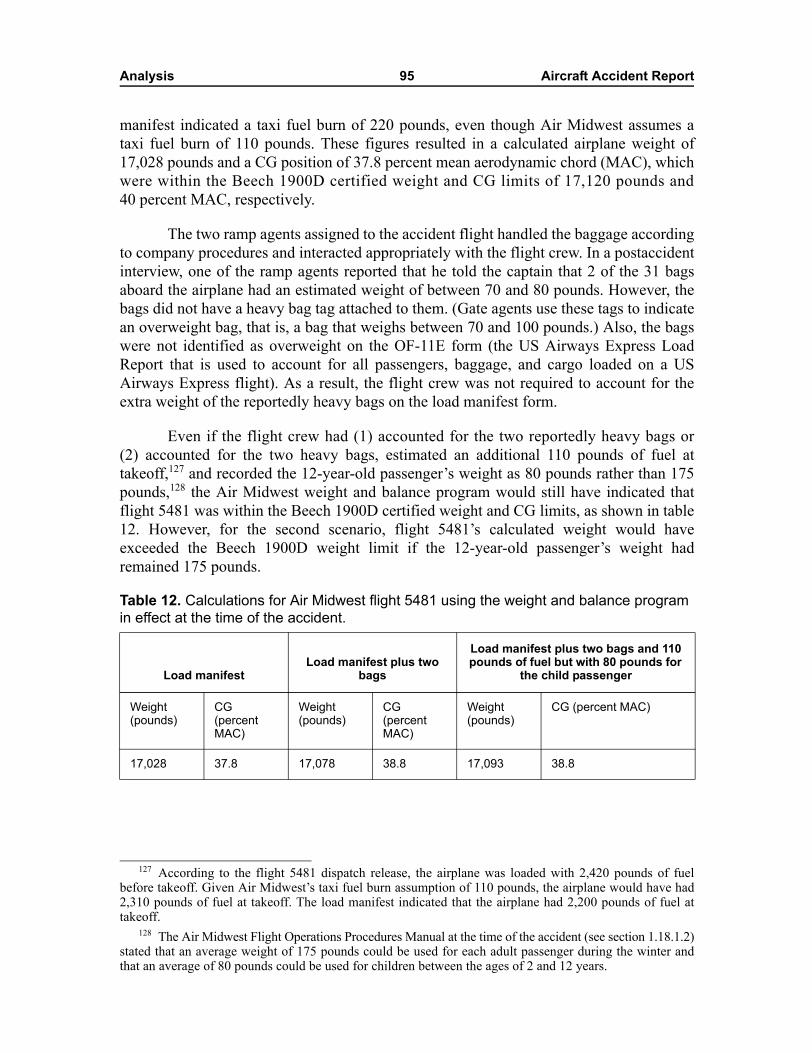
Analysis 95 Aircraft Accident Report
manifest indicated a taxi fuel burn of 220 pounds, even though Air Midwest assumes ataxi fuel burn of 110 pounds. These figures resulted in a calculated airplane weight of17,028 pounds and a CG position of 37.8 percent mean aerodynamic chord (MAC), whichwere within the Beech 1900D certified weight and CG limits of 17,120 pounds and40 percent MAC, respectively.
The two ramp agents assigned to the accident flight handled the baggage accordingto company procedures and interacted appropriately with the flight crew. In a postaccidentinterview, one of the ramp agents reported that he told the captain that 2 of the 31 bagsaboard the airplane had an estimated weight of between 70 and 80 pounds. However, thebags did not have a heavy bag tag attached to them. (Gate agents use these tags to indicatean overweight bag, that is, a bag that weighs between 70 and 100 pounds.) Also, the bagswere not identified as overweight on the OF-11E form (the US Airways Express LoadReport that is used to account for all passengers, baggage, and cargo loaded on a USAirways Express flight). As a result, the flight crew was not required to account for theextra weight of the reportedly heavy bags on the load manifest form.
Even if the flight crew had (1) accounted for the two reportedly heavy bags or(2) accounted for the two heavy bags, estimated an additional 110 pounds of fuel attakeoff,127 and recorded the 12-year-old passenger�s weight as 80 pounds rather than 175pounds,128 the Air Midwest weight and balance program would still have indicated thatflight 5481 was within the Beech 1900D certified weight and CG limits, as shown in table12. However, for the second scenario, flight 5481�s calculated weight would haveexceeded the Beech 1900D weight limit if the 12-year-old passenger�s weight hadremained 175 pounds.
Table 12. Calculations for Air Midwest flight 5481 using the weight and balance program in effect at the time of the accident.
127 According to the flight 5481 dispatch release, the airplane was loaded with 2,420 pounds of fuelbefore takeoff. Given Air Midwest�s taxi fuel burn assumption of 110 pounds, the airplane would have had2,310 pounds of fuel at takeoff. The load manifest indicated that the airplane had 2,200 pounds of fuel attakeoff.
128 The Air Midwest Flight Operations Procedures Manual at the time of the accident (see section 1.18.1.2)stated that an average weight of 175 pounds could be used for each adult passenger during the winter andthat an average of 80 pounds could be used for children between the ages of 2 and 12 years.
Load manifestLoad manifest plus two
bags
Load manifest plus two bags and 110 pounds of fuel but with 80 pounds for
the child passenger
Weight (pounds)
CG (percent MAC)
Weight (pounds)
CG (percent MAC)
Weight (pounds)
CG (percent MAC)
17,028 37.8 17,078 38.8 17,093 38.8
Analysis 96 Aircraft Accident Report
2.3 Restricted Downward Elevator Travel Flight data recorder (FDR) and CVR data from the accident flight showed that the
airplane was rotating airplane nose up (ANU) after takeoff, even though the flight crewwas pushing the control column fully forward and trimming the airplane in theairplane-nose-down (AND) direction. Neither of these actions allowed the flight crew tocontrol the airplane�s pitch attitude.
FDR data, ground test results, and the airplane performance study for this accidentshowed that, before the accident airplane�s detail six (D6) maintenance check onJanuary 6, 2003, at Air Midwest�s HTS maintenance station, the airplane�s full range ofdownward elevator travel was available. FDR data, ground test results, and the airplaneperformance study also showed that, after the D6 maintenance check, the airplane�sdownward elevator travel was limited to about 7º rather than the 14º to 15º specified in theBeech 1900D Airliner Maintenance Manual (AMM).
Before the D6 maintenance check, the accident airplane�s actual elevator position(derived from Beech 1900D aerodynamic characteristics and performance data from theFDR) was consistent with the pitch control position recorded on the FDR. Specifically,before maintenance, the actual elevator position during a typical cruise flight was 4º AND,and the pitch control position recorded on the FDR was also 4º AND.
After the D6 maintenance check, the accident airplane�s actual elevator position(derived from Beech 1900D aerodynamic characteristics and performance data from theFDR) was not consistent with the pitch control position recorded on the FDR. Specifically,the actual elevator position during a typical cruise flight was again determined to be4º AND, but the pitch control position recorded on the FDR was 13º AND. Thus, the FDRpitch control position sensor (which is attached to structure located to the left of the baseof the control column) indicated a 9º AND shift, even though the actual elevator positionremained at 4º AND. Further, when the maximum elevator available was achieved orcommanded during postmaintenance ground operations and during the accident flight, theactual elevator position was 7º AND; however, as a result of the 9º AND shift, the FDRrecorded a pitch control position of 16º AND.
The Safety Board examined the maintenance work performed at HTS during theaccident airplane�s D6 maintenance check to determine whether any of the work resultedin the airplane�s restricted downward elevator movement. Part of the D6 check involvedchecking the tension of the elevator control system cables and adjusting the tension ifnecessary. The Structural Modification and Repair Technicians (SMART) mechanic whoperformed this work had not previously performed it on a Beech 1900D. As a result, themechanic was receiving on-the-job training (OJT) from a Raytheon Aerospace, LLC(RALLC), quality assurance inspector for the tasks associated with that part of the D6check. (The OJT provided to the mechanic is discussed in section 2.3.2.)
The SMART mechanic determined that the accident airplane�s cables needed to beadjusted because their average tension was too low. He stated that he adjusted the cables
Analysis 97 Aircraft Accident Report
and performed some, but not all, of the steps of the elevator control system riggingprocedure (section 27-30-02) in the Beech 1900D AMM. However, whenever cabletension adjustments are made, the entire elevator control system rigging procedure needsto be performed and not just those steps that apply to cable tensioning. (The issue ofskipped procedural steps is discussed in section 2.3.3.)
Examination of the accident airplane�s pitch control cable turnbuckles as found inthe wreckage revealed that the AND turnbuckle, which measured 7.30 inches in length,was extended 1.76 inches more than the ANU turnbuckle, which measured 5.54 inches inlength. However, according to data from Air Midwest�s postaccident survey of its entirefleet of 42 Beech 1900D airplanes, the AND turnbuckle was extended, on average, only0.04 inch less than the ANU turnbuckle. Further, ground tests showed that turnbucklesadjusted to the lengths of those found in the wreckage would result in limited downwardelevator travel, although the FDR would indicate that full downward travel was available.
The Safety Board could not determine the exact measurements of the accidentairplane�s ANU and AND cable turnbuckles and other adjustable components129 when theairplane entered the D6 maintenance check. However, it is clear that the adjustments to thecable turnbuckles (and possibly other adjustable components) during maintenance resultedin FDR pitch control measurements that showed a 9º AND loss of travel, which restrictedthe accident airplane�s elevator travel to 7º AND.
The Safety Board could not precisely determine the changes that were made to theelevator control system during the D6 maintenance check to restrict the accident airplane�selevator travel to 7º AND. However, during the ground tests, the Board discovered onescenario that provided results that were reasonably consistent with FDR data from theaccident airplane. Specifically, when the rig pin for the aft bellcrank was not removedfrom the test airplane and the cable tension was released and then the rig pin for theforward bellcrank was installed aft of the bellcrank arm, adjustments to the turnbucklesresulted in an ANU turnbuckle length of 5.12 inches and an AND turnbuckle length of7.70 inches. After the aft rig pin was removed, the test airplane�s elevator moved to 7.7º AND.
The Safety Board concludes that the accident airplane entered the D6 maintenancecheck with an elevator control system that was rigged to achieve full elevator travel in thedownward direction. The Safety Board further concludes that the accident airplane�selevator control system was incorrectly rigged during the D6 maintenance check and thatthe incorrect rigging restricted the airplane�s elevator travel to 7º AND, or about one-halfof the downward travel specified by the airplane manufacturer.
2.3.1 Conspicuity of the Elevator Control System Misrig
The only visible sign of the misrig during the first officer�s external preflightinspection would have been a change in the elevator resting position. The normal elevator
129 The other adjustable components are the forward push-pull tube; the left and right aft pushrods; andthe primary, secondary, and tertiary control stops.
Analysis 98 Aircraft Accident Report
resting position is between 14º and 15º AND; after the misrig, the elevator resting positionwas about 7º AND. Because the horizontal stabilizer on a parked Beech 1900D is locatedabout 15 feet above the ground, it would be difficult to detect the change in the elevatorresting position from the ground. In fact, during ground tests, Safety Board investigators,while on the ground, observed the test airplane�s elevator before and after the elevatorcontrol system was misrigged. The investigators did not observe a conspicuous change inthe elevator resting position. The ground tests also showed that, in both rigging positions,the control column was fully forward. When the control column was pulled fully aft, therange of total control column travel for the misrigged position was 1 inch less than for theproperly rigged position. However, the 1-inch reduction in the range of travel was notnoticeable to Board investigators.
The ground tests further showed that the only evidence during flight of the misrigwould have been a forward shift of the control column�s neutral (0°) position by about0.72 inch. No control column markings or other visual indications would have alerted theflight crew that the control column position corresponding to the elevator�s neutralposition had changed. In addition, three Beech 1900D type-rated pilots conducted controlsweeps (full forward and full aft movement of the control column) on a test airplane withthe elevator control system rigged according to the Beech 1900 AMM and then with thesystem rigged to match the accident airplane. The pilots did not report any noticeablechange in the feel or position of the control wheel between the two sets of control sweeps.
The Safety Board concludes that the changes in the elevator control systemresulting from the incorrect rigging were not conspicuous to the flight crew.
2.3.2 Adequacy of On-the-Job Training Provided to the Mechanic
Five of the six SMART mechanics who were on duty on the night of January 6,2003, had worked at HTS for less than 8 weeks. None of these mechanics had completedtraining for the D6 maintenance check. The mechanic assigned by the foreman (the otherSMART mechanic on duty at HTS on January 6th) to perform the elevator control cablecheck was selected for the task because he had previously accomplished flight controlrigging work on DHC-8 airplanes. The RALLC quality assurance inspector, who wasproviding the mechanic�s OJT, stated that he did not think he needed to closely supervisethe mechanic because of his previous flight control rigging experience.
The mechanic stated that, before he inspected the elevator control system, theforeman helped him locate the access panel for the forward bellcrank rig pin and theelevator cable turnbuckles. The mechanic also stated that he and the quality assuranceinspector discussed the low cable tensions, the need to adjust the tensions, and the stepsthat could be skipped. The mechanic indicated that the quality assurance inspector thenleft to attend to other duties. The mechanic further stated that another mechanic held theturnbuckles while he adjusted them and that the quality assurance inspector returned afterthe rigging work was completed to observe the final check of the elevator control system.
Analysis 99 Aircraft Accident Report
The quality assurance inspector stated that, after he verified that the forwardbellcrank rig pin had been inserted (he did not actually observe the rig pin being inserted),he left the mechanic unsupervised during the elevator control cable inspections andturnbuckle adjustments. The quality assurance inspector indicated that he had to conductother duties, which included providing OJT to another mechanic and performing aborescope inspection on an engine. The inspector also indicated that he returned to inspectthe elevator control system after the mechanic had completed his work. (Section 2.3.4provides information about the inspector�s inspection.)
Even though the mechanic possessed previous flight control rigging experience, hehad never performed rigging work on the Beech 1900D airplane. As a result, the mechanicneeded more training and supervision than the quality assurance inspector had provided. Itwould have been prudent for the quality assurance inspector to have described thecomponents of the elevator control system; explained the steps in the rigging procedure,demonstrated the critical steps, and insisted that all steps needed to be accomplished; andobserved the mechanic while he examined the elevator control cable tensions andperformed the rigging work.
The insufficient training and supervision resulted in the mechanic making mistakesthat led to the incorrect rigging and the restricted downward elevator travel. If the qualityassurance inspector had provided better training and supervision, the likelihood of sucherrors would have been minimized. The Safety Board concludes that the RALLC qualityassurance inspector did not provide adequate OJT and supervision to the SMARTmechanic who examined and incorrectly adjusted the elevator control system on theaccident airplane.
2.3.3 Skipped Steps in the Elevator Control System Rigging Procedure
The Beech 1900D elevator control system rigging procedure (section 27-30-02)does not include provisions for adjusting cable tension as an isolated task. However, themechanic decided to adjust the cables as an isolated task and, as a result, did not followeach step included in the rigging procedure. The quality assurance inspector was awarethat the mechanic was selectively performing steps from the rigging procedure and that hewas only adjusting cable tension. In fact, the inspector stated, during a postaccidentinterview, that he did not think the manufacturer intended for mechanics to follow theentire rigging procedure and that the entire procedure had not been followed when pastcable tension adjustments were made.
Analysis 100 Aircraft Accident Report
The mechanic skipped nine applicable steps in the Beech 1900D elevator controlsystem rigging procedure (see section 1.6.3.2).130 One of these steps indicated that, forairplanes equipped with an F-1000 FDR, the pitch position potentiometer needed to becalibrated (step u). The mechanic was required to perform this step because the accidentairplane had an F-1000 FDR installed. Step u indicated that, to calibrate the pitch positionpotentiometer, the mechanic needed to perform the FDR pitch adjustment proceduredescribed in another section of the Beech 1900D AMM. This procedure referred themechanic to a table that specified eight different elevator settings, ranging from 14º ANDto 20º ANU (including 0º), and instructed the mechanic to record the FDR readout forthese settings. The mechanic, however, would not have been able to move the elevator tothe first setting, 14º AND, because elevator travel was restricted to about 7º AND.
The performance of step u would have likely alerted the mechanic or the qualityassurance inspector that the elevator control system was not properly rigged. However, themechanic indicated that he skipped step u because he thought the calibration did not needto be done. The quality assurance inspector stated that he did not think that an FDR wasinstalled on the airplane, but the inspector should have known that the airplane wasequipped with an FDR because most, if not all, Beech 1900D airplanes were outfitted withan FDR. Also, the inspector could have easily determined that the airplane was equippedwith an FDR. Specifically, the wiring and the sensor for the FDR were in the same area ofthe airplane where maintenance was being performed. Also, the FDR unit is mounted inthe forward (AFT1) cargo compartment and is readily visible. In addition, a circuit breakerfor the FDR is located in the cockpit.
Title 14 Code of Federal Regulations (CFR) 121.367 states that aircraftmaintenance, preventive maintenance, and alterations are to be performed in accordancewith operators� maintenance manuals. Thus, maintenance personnel are expected tofollow all procedural steps unless authorization has been granted. The SMART mechanicand RALLC quality assurance inspector were not authorized to decide whether a specificstep of the maintenance manual could be skipped. Air carriers have procedures in place formaking such determinations on a one-time or short-term basis. These determinations aremade by managers and engineers in accordance with the air carrier�s maintenancemanual.131
For long-term changes, the Continuing Analysis and Surveillance System (CASS)is used to change an air carrier�s maintenance procedure if it is deficient or needscorrection. Title 14 CFR 121.373(a), �Continuing Analysis and Surveillance,� requiresoperators to establish and maintain a system for the continuing analysis and surveillance
130 The Safety Board is aware of another recent instance in which mechanics skipped a step of a Beech1900D AMM procedure. Specifically, the investigation into the August 26, 2003, Colgan Air flight 9446accident determined that the mechanics had to replace both elevator trim tab actuators because of excessivefreeplay. Beech 1900D AMM section 27-30-06 required the mechanics to remove the elevators before theactuators were replaced. However, the mechanics skipped that procedural step and replaced the actuatorswith the elevators installed.
131 The Air Midwest General Maintenance Manual required that deviations to maintenance proceduresbe approved by the Federal Aviation Administration (FAA), but the HTS maintenance station did not havethe necessary support during the night shift to receive such approval.
Analysis 101 Aircraft Accident Report
of the performance and effectiveness of their maintenance and inspection programs andfor the correction of any deficiency found in those programs. Also, FAA AdvisoryCircular (AC) 120-16D, �Continuous Airworthiness Maintenance Programs,� states thatCASS programs must ensure that all elements of an air carrier�s maintenance program arebeing accomplished in accordance with its maintenance manual and that any deficienciesin an air carrier�s manual are identified and corrected. (Sections 2.5.1.3 and 2.5.2.2provide details about Air Midwest�s CASS program and the FAA�s oversight of CASSprograms, respectively.) The findings of the flight 5481 investigation suggest that aircarriers may not have adequate CASS programs despite the requirements of 14 CFR121.373.
The Safety Board concludes that, because the RALLC quality assurance inspectorand the SMART mechanic did not diligently follow the elevator control system riggingprocedure as written, they missed a critical step that would have likely detected the misrigand thus prevented the accident. Therefore, the Safety Board believes that the FAA shouldadopt a program for performing targeted surveillance and increased oversight ofmaintenance practices at 14 CFR Part 121 air carriers to ensure that maintenanceinstructions are being followed as written and that maintenance personnel (including, butnot limited to, management, quality assurance, tooling, and training personnel, as well asmechanics) are following all steps in the instructions unless authorization has beengranted in accordance with the air carrier�s maintenance program. In addition, the SafetyBoard believes that the FAA should verify that 14 CFR Part 121 air carriers haveprocedures in their CASS program for identifying deficiencies and incorporating changesto the carrier�s maintenance program and that maintenance personnel for these air carriers(including, but not limited to, management, quality assurance, tooling, and trainingpersonnel, as well as mechanics) use these procedures.
2.3.4 Lack of an Effective Postmaintenance Check
The mechanic indicated that he conducted control sweeps from the cockpit afterthe cable tension had been adjusted. He stated that he �ran the elevator full travel a fewtimes� and then checked the cable tensions to make sure that they had not changed.However, the mechanic also stated that no one was at the tail of the airplane observing theelevator travel when he conducted the control sweeps.
The quality assurance inspector stated that he observed the elevator at a neutralposition on the travel board with the rig pin installed at the forward bellcrank. Theinspector also stated that, after the rig pin was removed, he grasped the elevator with thetravel board still attached and moved the elevator throughout the available travel. Theinspector thought that the elevator could be fully deflected with the forward bellcrank rigpin removed and stated that elevator travel was �within limits.� However, results from theSafety Board�s investigation, including simulations, ground tests, and FDR data, indicatedthat elevator travel could not have been within the limits specified in Beech 1900D AMMsection 27-30-02. The quality assurance inspector further stated that he was present whenthe mechanic verified cable tension by attaching a tensiometer on both cables andchecking the tensions.
Analysis 102 Aircraft Accident Report
The postmaintenance checks performed by the quality assurance inspector and themechanic were not adequate to detect the elevator control system misrig. As stated insection 2.3.3, if step u of the rigging procedure (the calibration of the pitch positionpotentiometer) had been performed on the accident airplane, it is likely that the qualityassurance inspector and the mechanic would have caught the misrigging problem. Also, ifa functional check had been included at the end of the procedure, the quality assuranceinspector and the mechanic would have had another opportunity to detect the misriggingproblem. A functional check at the end of the procedure would have provided a morecomprehensive, systematic, and direct method to ensure that any misrigging problem wascaught before an airplane was returned to service.132 Such a functional check wouldconsist of a mechanic in the cockpit pushing the control wheel full forward and thenpulling the wheel full aft while another mechanic, who was at eye level with the horizontalstabilizer, measured the position of the elevator using a travel board. This process woulddetermine whether the elevator achieved the correct deflection for the full forward and fullaft movement of the control column.
The Safety Board recognizes that Raytheon Aircraft Company added apostmaintenance functional check to its revised elevator control system rigging procedureissued on February 12, 2003. Specifically, step aa indicates that the mechanic is to movethe control wheel aft and forward and verify that the elevator moves up 20º +1º/-0º anddown 14º +1º/-0º, respectively, and that the control stops make contact.
The lack of a functional check at the end of a maintenance procedure is also anissue with the Colgan Air flight 9446 accident. During the replacement of the elevator trimtab actuators, the mechanics thought that the forward elevator trim tab cable had becomejammed or kinked and thus needed to be replaced. The mechanics tried to replace thecable in accordance with Beech 1900D AMM section 27-30-04. This procedure does notdescribe in detail how to manipulate the electric and manual trim systems in each directionand verify that the full range of motion in the commanded direction is observed at the trimtabs. The mechanics stated, during a postaccident interview, that they moved the trim tabsthrough a full range of motion using the electric and manual systems and observed noanomalies. However, without a detailed procedure to ensure that the trim tabs are movingin the proper direction, it is possible that the trim tabs could move in a reversed directionand remain unnoticed.
In addition, the investigation of the October 16, 2003, CommutAir flight 8718incident determined that the mechanic did not perform a functional test of the elevatortrim control system, as required by FAA Airworthiness Directive (AD) 2003-20-10. Afunctional check of the system would have indicated that the elevator trim wheel had beenreinstalled incorrectly.
The Safety Board concludes that a complete functional check at the end ofmaintenance for critical flight systems or their components133 would help to ensure their
132 The Safety Board notes that some elevator control system maintenance procedures do not include anFDR check and that FDRs can be placed on an air carrier�s minimum equipment list, as was the case withColgan Air flight 9446.
Analysis 103 Aircraft Accident Report
safe operation, but no such check is currently required. Therefore, the Safety Boardbelieves that the FAA should modify (1) appendix G of 14 CFR Part 23 and appendix H of14 CFR Part 25 and (2) 14 CFR 121.369 to require that the Instructions for ContinuedAirworthiness and air carrier maintenance manuals, respectively, include a completefunctional check at the end of maintenance for each critical flight system. The SafetyBoard also believes that the FAA should require manufacturers of aircraft operated under14 CFR Part 121 to identify appropriate procedures for a complete functional check ofeach critical flight system; determine which maintenance procedures should be followedby such functional checks; and modify their existing maintenance manuals, if necessary,so that they contain procedures at the end of maintenance for a complete functional checkof each critical flight system. The Safety Board further believes that the FAA shouldrequire 14 CFR Part 121 air carriers to modify their existing maintenance manuals, ifnecessary, so that they contain procedures at the end of maintenance for a completefunctional check of each critical flight system.
2.4 Aft Center of Gravity and Its Effect on the Restricted Elevator Travel The airplane performance study for flight 5481 determined that the accident
airplane�s actual weight was about 17,700 pounds and that its actual CG position wasabout 45.5 percent MAC. As a result, flight 5481 had exceeded the Beech 1900D certifiedweight limit of 17,120 pounds and the certified aft CG limit of 40 percent MAC.
Of the accident airplane�s 10 flights after the D6 maintenance check, the accidentflight was by far the most aft loaded.134 When an airplane is loaded so that the CG is aft ofthe aft limit, greater-than-normal AND pitch control is required.
The Safety Board made several calculations to determine the conditions underwhich the accident airplane would have been flyable during different flight segments. Thecalculations showed that, with full elevator travel (14º to 15º AND) and the accidentairplane loaded to the weight and balance of the accident flight, the airplane should havebeen able to maintain flight during the takeoff and climb (requiring 9º to 10º ANDelevator), cruise and descent (requiring 5º to 6º AND elevator), and approach and land(requiring 8º to 9º AND elevator) segments. The calculations also showed that, withreduced elevator travel (7º to 8º AND) and the accident airplane loaded to, but notexceeding, the Beech 1900D weight and CG limits, the airplane might have been able tofly during the takeoff and climb (requiring 7º to 8º AND elevator), cruise and descent(requiring 4º to 5º AND elevator), and approach and land (requiring 7º to 8º ANDelevator) segments. Even if the required AND elevator slightly exceeded the availableAND elevator, the airplane would have been controllable. The airplane would have
133 A flight system or component is considered critical if its failure can be catastrophic. 134 Although the other nine flights after the D6 maintenance check had a CG position that was farther
forward, the airplane was still being operated in a potentially dangerous situation as a result of the restricteddownward elevator travel.
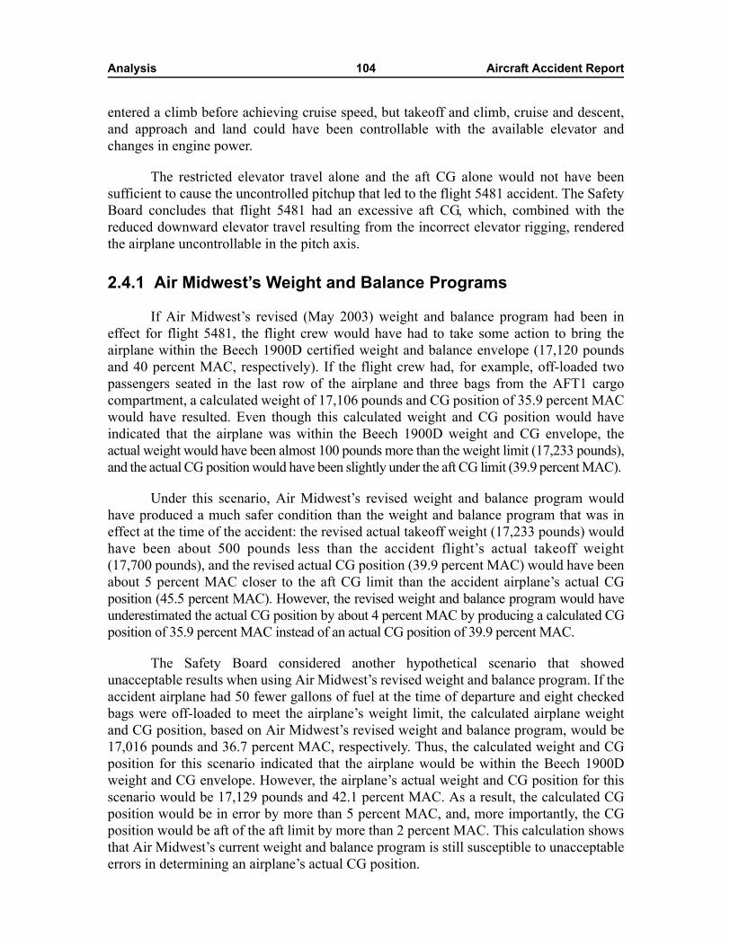
Analysis 104 Aircraft Accident Report
entered a climb before achieving cruise speed, but takeoff and climb, cruise and descent,and approach and land could have been controllable with the available elevator andchanges in engine power.
The restricted elevator travel alone and the aft CG alone would not have beensufficient to cause the uncontrolled pitchup that led to the flight 5481 accident. The SafetyBoard concludes that flight 5481 had an excessive aft CG, which, combined with thereduced downward elevator travel resulting from the incorrect elevator rigging, renderedthe airplane uncontrollable in the pitch axis.
2.4.1 Air Midwest�s Weight and Balance Programs
If Air Midwest�s revised (May 2003) weight and balance program had been ineffect for flight 5481, the flight crew would have had to take some action to bring theairplane within the Beech 1900D certified weight and balance envelope (17,120 poundsand 40 percent MAC, respectively). If the flight crew had, for example, off-loaded twopassengers seated in the last row of the airplane and three bags from the AFT1 cargocompartment, a calculated weight of 17,106 pounds and CG position of 35.9 percent MACwould have resulted. Even though this calculated weight and CG position would haveindicated that the airplane was within the Beech 1900D weight and CG envelope, theactual weight would have been almost 100 pounds more than the weight limit (17,233 pounds),and the actual CG position would have been slightly under the aft CG limit (39.9 percent MAC).
Under this scenario, Air Midwest�s revised weight and balance program wouldhave produced a much safer condition than the weight and balance program that was ineffect at the time of the accident: the revised actual takeoff weight (17,233 pounds) wouldhave been about 500 pounds less than the accident flight�s actual takeoff weight(17,700 pounds), and the revised actual CG position (39.9 percent MAC) would have beenabout 5 percent MAC closer to the aft CG limit than the accident airplane�s actual CGposition (45.5 percent MAC). However, the revised weight and balance program would haveunderestimated the actual CG position by about 4 percent MAC by producing a calculated CGposition of 35.9 percent MAC instead of an actual CG position of 39.9 percent MAC.
The Safety Board considered another hypothetical scenario that showedunacceptable results when using Air Midwest�s revised weight and balance program. If theaccident airplane had 50 fewer gallons of fuel at the time of departure and eight checkedbags were off-loaded to meet the airplane�s weight limit, the calculated airplane weightand CG position, based on Air Midwest�s revised weight and balance program, would be17,016 pounds and 36.7 percent MAC, respectively. Thus, the calculated weight and CGposition for this scenario indicated that the airplane would be within the Beech 1900Dweight and CG envelope. However, the airplane�s actual weight and CG position for thisscenario would be 17,129 pounds and 42.1 percent MAC. As a result, the calculated CGposition would be in error by more than 5 percent MAC, and, more importantly, the CGposition would be aft of the aft limit by more than 2 percent MAC. This calculation showsthat Air Midwest�s current weight and balance program is still susceptible to unacceptableerrors in determining an airplane�s actual CG position.
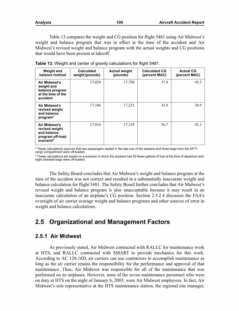
Analysis 105 Aircraft Accident Report
Table 13 compares the weight and CG position for flight 5481 using Air Midwest�sweight and balance program that was in effect at the time of the accident and AirMidwest�s revised weight and balance program with the actual weights and CG positionsthat would have been present at takeoff.
Table 13. Weight and center of gravity calculations for flight 5481.
a These calculations assume that two passengers seated in the last row of the airplane and three bags from the AFT1 cargo compartment were off-loaded.b These calculations are based on a scenario in which the airplane had 50 fewer gallons of fuel at the time of departure and eight checked bags were off-loaded.
The Safety Board concludes that Air Midwest�s weight and balance program at thetime of the accident was not correct and resulted in a substantially inaccurate weight andbalance calculation for flight 5481. The Safety Board further concludes that Air Midwest�srevised weight and balance program is also unacceptable because it may result in aninaccurate calculation of an airplane�s CG position. Section 2.5.2.4 discusses the FAA�soversight of air carrier average weight and balance programs and other sources of error inweight and balance calculations.
2.5 Organizational and Management Factors
2.5.1 Air Midwest
As previously stated, Air Midwest contracted with RALLC for maintenance workat HTS, and RALLC contracted with SMART to provide mechanics for this work.According to AC 120-16D, air carriers can use contractors to accomplish maintenance aslong as the air carrier retains the responsibility for the performance and approval of thatmaintenance. Thus, Air Midwest was responsible for all of the maintenance that wasperformed on its airplanes. However, none of the seven maintenance personnel who wereon duty at HTS on the night of January 6, 2003, were Air Midwest employees. In fact, AirMidwest�s sole representative at the HTS maintenance station, the regional site manager,
Weight and balance method
Calculated weight (pounds)
Actual weight (pounds)
Calculated CG (percent MAC)
Actual CG (percent MAC)
Air Midwest�s weight and balance program at the time of the accident
17,028 17,700 37.8 45.5
Air Midwest�s revised weight and balance programa
17,106 17,233 35.9 39.9
Air Midwest�s revised weight and balance program off-load scenariob
17,016 17,129 36.7 42.1
Analysis 106 Aircraft Accident Report
worked the day shift at the time, so he was not present when the maintenance work wasactually being performed.
As stated in section 2.3.3, 14 CFR 121.367 requires aircraft maintenance,preventive maintenance, and alterations to be performed in accordance with an aircarrier�s maintenance manual. Also, AC 120-16D indicates that it is the air carrier�sresponsibility to make sure that a contractor is performing maintenance according to theair carrier�s maintenance program and maintenance manual. Thus, although the SMARTmechanic decided to skip several steps in the elevator control system rigging procedureand the RALLC quality assurance inspector concurred with the mechanic�s decision toskip steps, it was still Air Midwest�s responsibility to ensure that its maintenance manualwas being followed.
In its final report on the ValuJet Airlines flight 592 accident, the Safety Boardrecognized that air carriers could successfully subcontract maintenance. However, theBoard noted that air carriers engaging in subcontracting had to properly oversee theircontractors to ensure the airworthiness of their airplanes. The Board stated that, althoughsubcontractors bear independent responsibility for their activities, an air carrier cannotdelegate its responsibility for the safety of its operations and maintenance to itssubcontractors. The Board concluded that ValuJet failed to adequately oversee SabreTech(a heavy maintenance contractor) and that this failure was causal to the accident.
The Air Midwest flight 5481 accident presents another example of an air carrierthat did not adequately oversee airplane maintenance being performed by contractors.Title 14 CFR 121.363 states that an air carrier is responsible for ensuring the airworthinessof the aircraft it operates and that an air carrier is not relieved of this responsibility whenmaintenance is contracted to another party. Also, 14 CFR 121.367 states that an air carrieris responsible for determining that each aircraft released to service is airworthy and hasbeen properly maintained. Thus, although the SMART mechanic incorrectly rigged theaccident airplane�s elevator control system and the RALLC quality assurance inspectorfailed to detect the problem, Air Midwest was ultimately responsible for returning theairplane to service in an airworthy condition.
The Safety Board concludes that Air Midwest did not adequately oversee the workperformed by RALLC and SMART personnel at its HTS maintenance station and did notensure that the accident airplane was returned to service in an airworthy condition.
2.5.1.1 Required Inspection Item Maintenance Tasks and Inspections
Air Midwest�s Maintenance Procedures Manual states that elevator control systemrigging is a required inspection item (RII), which means that maintenance work performedon the system must be inspected before the airplane can be returned to service. Title 14CFR 121.371(c) states, �no person may perform a required inspection if [that person]performed the item of work required to be inspected.� The aircraft maintenance record ofnonroutine items for January 6, 2003, at HTS showed, in a discrepancy block about theairplane�s low elevator cable tension, an RII stamp and the quality assurance inspector�sstamp (see figure 2 in section 1.1.1).
Analysis 107 Aircraft Accident Report
RII maintenance tasks that are not performed properly could result in a failure,malfunction, or defect that would endanger the safe operation of the airplane. Thus, it isimperative to have an independent inspection of RII maintenance tasks by a second, fullyqualified mechanic to ensure that the work has been properly completed. Currentregulations do not explicitly prohibit inspectors from training a mechanic on a task andthen inspecting that same task.135 However, the inspectors cannot properly fulfill their RIIresponsibilities in such a situation. The purpose of an RII inspection is to provide �asecond set of eyes� to ensure that any error made in performing maintenance work isdetected and corrected before an airplane is returned to service. The Safety Boardconcludes that, when an inspector provides OJT for an RII maintenance task and theninspects that same task, the independent nature of the RII inspection is compromised.Therefore, the Safety Board believes that the FAA should prohibit inspectors fromperforming RII inspections on any maintenance task for which the inspector provided OJTto the mechanic who accomplished the task.
According to AC 120-16D, Air Midwest was responsible for overseeing theperformance of RII inspections. In fact, Air Midwest acknowledged in its contract withRALLC that Air Midwest would be responsible for quality control and quality assuranceinspections. However, oversight of the quality assurance function at HTS went throughtwo different levels of management at RALLC (the Regional Airline Maintenance Service[RAMS] quality assurance manager in Panama City, Florida, and the RAMS ExecutiveProgram Manager for Airline Support in Madison, Mississippi) before becoming theresponsibility of the Air Midwest Chief Inspector/Director of Quality Assurance inWichita, Kansas (see figure 10). In addition, the only Air Midwest employee at HTS (theregional site manager) normally worked the day shift, and he was only sporadicallypresent when the maintenance work and inspections were being accomplished. As a result,Air Midwest was not sufficiently overseeing the RII inspections at HTS, which isespecially troublesome considering the importance of these inspections.
Sufficient oversight of RII maintenance tasks and inspections requires air carrierpersonnel to maintain an on-site presence and to be thoroughly involved in, and familiarwith, all aspects of a maintenance facility�s operations relating to RII tasks andinspections. Such oversight requires, at a minimum, that air carrier personnel bephysically present when a substantial amount of the RII planning, tasking, maintenancework, and inspections are performed and that air carrier personnel be readily availablewhen they are not physically present. In addition, air carriers need to ensure that theprocesses and procedures used by contractors to perform RII maintenance tasks andinspections are the same as those used by air carrier maintenance personnel.
135 On March 26, 2003, the quality assurance inspector at HTS on the night of January 6, 2003, wasadvised that the FAA would be investigating the inspector�s actions in �giving on-the-job training after workwas assigned.� On September 30, 2003, the FAA notified the inspector that the investigation �did notestablish a violation of the Federal Aviation Regulations [FAR].� (The FAA also investigated the mechanic�sactions �involving work being accomplished� and the foreman�s actions �involving work being assigned,�and the investigation found that their actions did not violate the FARs.)
Analysis 108 Aircraft Accident Report
The Safety Board concludes that air carriers that use contractors to perform RIImaintenance tasks and inspections need to provide substantial and direct oversight duringeach work shift to ensure that this work is being properly conducted. Therefore, the SafetyBoard believes that the FAA should require 14 CFR Part 121 air carriers that usecontractors to perform RII maintenance tasks and inspections to have air carrier personnelwho are physically present when a substantial amount of the RII planning, tasking,maintenance work, and inspections are performed and are readily available when they arenot physically present and who ensure that the processes and procedures used bycontractors to perform RII maintenance tasks and inspections are the same as those usedby air carrier maintenance personnel.
2.5.1.2 Maintenance Training Program
2.5.1.2.1 Maintenance Training Guidelines
Air Midwest required mechanics to complete OJT for a procedure before theycould perform that procedure unsupervised. However, Air Midwest had little guidance onhow to effectively provide OJT.
The only guidance in Air Midwest�s Maintenance Training Manual about OJT as atraining method stated that (1) OJT would teach knowledge and practical skills of normaljob-related duties and would include practical situations found every day on the job and(2) OJT would be performed under the guidance of a qualified technician or staff memberwho has documentation of previously received OJT. The Maintenance Training Manualdid not include other issues related to the delivery of OJT, including how many studentsshould be permitted per instructor, how tasks should be demonstrated before beingperformed, how the learning environment should be controlled, and how to ensure that theskills learned through OJT would be retained.
Because Air Midwest lacked specific OJT guidance, the OJT provided to newmechanics at the HTS maintenance station varied based on the instructors� teaching style.For example, the quality assurance inspector on the night of January 6, 2003, stated,during a postaccident interview, that it was not necessary to �hold [a mechanic�s] hand� ifhe thought the mechanic knew what he was doing based on past experience. Also, themechanic who performed the elevator cable inspection and adjustments on the accidentairplane indicated that it was routine for mechanics to work independently during OJT andreceive little supervision. However, a mechanic who assisted the quality assuranceinspector with the engine borescope inspection on the night of January 6th stated that,when he last received OJT, the instructor (who was at HTS from the Panama Citymaintenance station) walked him through the task �step by step.�
The Safety Board concludes that Air Midwest did not have maintenance trainingpolicies and procedures in place to ensure that each of its maintenance stations had aneffective OJT program.
Air carriers are required by 14 CFR 121.367(b) to ensure the competence of theirmaintenance personnel for the proper performance of maintenance, preventive
Analysis 109 Aircraft Accident Report
maintenance, and alterations. However, according to AC 120-16D, FAA regulationscontain the flexibility necessary to allow each air carrier to develop a training programthat fits its particular needs. Many air carriers have provided, and will continue to provide,airplane-specific maintenance training through OJT programs.
During a 1993 Safety Board public hearing on commuter airline safety,representatives from the commuter airline industry indicated that the quality of air carriermaintenance training varied throughout the industry, with some airlines doing an excellentjob of training mechanics and other airlines providing mechanics with only minimaltraining.13637 Also, a 1998 FAA study of personnel training and qualifications at aviationmaintenance facilities13738 found that, although airline mechanics reported that they weregenerally satisfied with the maintenance training provided by their companies, one area ofconcern involved informal OJT. Specifically, a significant number of mechanics indicatedthat they would prefer OJT that was more formal, with task objectives, checklists, andspecific task signoffs. In addition, the FAA�s 1998 Guide for Human Factors in AviationMaintenance and Inspection (see section 1.18.3) stated that OJT had several positiveaspects but that OJT practices were lax and tended to be unstructured.
The FAA�s Guide for Human Factors in Aviation Maintenance and Inspectioncontained voluntary guidelines for developing structured OJT programs. However, aircarriers are not currently required to follow these guidelines when developing OJTprograms. The Safety Board concludes that it is important that air carrier OJT programsare developed in accordance with detailed guidance that emphasizes effective trainingpractices. Therefore, the Safety Board believes that the FAA should develop detailed OJTrequirements for 14 CFR Part 121 air carriers that rely on OJT as a maintenance trainingmethod. These requirements should include, but not be limited to, best practices,procedures, and methods for accomplishment and administration of this training. TheSafety Board also believes that the FAA should ensure that these OJT requirements areincorporated into 14 CFR Part 121 air carrier maintenance training programs.
2.5.1.2.2 Maintenance Training Oversight
The Safety Board identified deficiencies in Air Midwest�s oversight of itsmaintenance training program. First, because only one RALLC quality assuranceinspector and one RALLC foreman (the backup quality assurance inspector) worked atHTS at the time of the accident, a SMART mechanic was appointed as foreman 4 nightsper week (when the quality assurance inspector was not on duty and the foreman assumedthe inspector�s responsibilities). One of the foreman�s responsibilities was to follow theprogress of the mechanics in accomplishing the assigned maintenance work. However, theSMART mechanic who was the foreman on the night of January 6, 2003, had notcompleted OJT for the Beech 1900D.
136 For more information, see National Transportation Safety Board, Commuter Airline Safety, SpecialStudy NTSB/SS-94/02 (Washington, DC: NTSB, 1994).
137 R.P. Goldsby and J. Watson, Comparative Study of Personnel Training and Qualifications at AviationMaintenance Facilities (Washington, DC: Office of Aviation Medicine, FAA, 1998).
Analysis 110 Aircraft Accident Report
Second, according to Air Midwest�s Maintenance Procedures Manual, the foremanwas responsible for ensuring that OJT was provided to mechanics by someone other thanthe quality assurance inspector. However, the quality assurance inspector routinelyprovided OJT. In fact, the quality assurance inspector on duty on the night of January 6thstated that he had received most of his training at Mesa Airlines, Arctic Slope, and AirMidwest from inspectors and that he believed it was standard practice for inspectors toprovide OJT. Also, the foreman stated that a quality assurance inspector had beenproviding OJT to mechanics since he began working for RALLC in December 2001.
The Air Midwest regional site manager was aware that inspectors were providingmost of the OJT because he reviewed maintenance training records on a daily basis.However, the regional site manager should have been aware that this situation increasedthe inspector�s workload (providing OJT and performing RII inspections) and did notseparate maintenance and inspection tasks. The quality assurance inspector stated that theregional site manager never mentioned to him that inspectors should not provide OJT.
Last, according to Air Midwest�s Maintenance Training Manual and MaintenanceProcedures Manual, the regional site manager was responsible for maintaining trainingrecords and ensuring that the training was properly documented. As previously stated, theregional site manager reviewed maintenance training records daily, and he indicated thathe attempted to have discrepancies corrected quickly. The regional site managerforwarded the training records to Air Midwest�s Maintenance Training Coordinator inWichita, who reviewed the records for completeness and accuracy. However, an FAAinspection conducted by geographic inspectors from the Charleston, West Virginia, FlightStandards District Office (FSDO) 2 days after the accident found that maintenancetraining records for employees at HTS were �not complete or current.� Also, the SafetyBoard discovered numerous discrepancies in the training records of HTS maintenancepersonnel, including the following:
� The mechanic who performed the elevator control cable work had his trainingrecords signed as complete for the D6 aft fuselage/empennage inspectionprocedure and for �rudder, aileron, or elevator cable tension adjustment� by thequality assurance inspector. However, the mechanic had not been trained onthe rudder and aileron rigging procedures. Air Midwest�s maintenance trainingprogram considered mechanics to be fully trained on all three major controlcable rigging procedures after the mechanics had received training on only oneof the procedures, despite significant differences among the procedures.
� Another SMART mechanic and the primary quality assurance inspectorincorrectly indicated on that mechanic�s OJT record that he had completedtraining on the D6 aft fuselage/empennage inspection procedure on January6th. The mechanic inspected and checked the engines but did not perform theentire D6 procedure, including the elevator check.
� The mechanics that were on duty on the night of January 6th had numerousitems (dating as far back as December 14, 2002) signed as complete in theirtraining records, but these items did not have the required instructor signaturestamps.
Analysis 111 Aircraft Accident Report
� The foreman�s training records indicated that he had received OJT for thedetail 2 through detail 5 checks all on the same day. It is unrealistic for anymechanic to have completed OJT for all those tasks on a single day becauseone detail check generally takes an entire shift to complete.
Further, the Air Midwest principal maintenance inspector (PMI) stated that theFAA has had longstanding concerns with Air Midwest�s management of its maintenancetraining program. These concerns included that mechanics received no formal (classroom)training, OJT records were not being properly maintained, no one was adequatelymonitoring the quality of the OJT provided, and the training was not consistent withguidelines set forth in Air Midwest�s Maintenance Training Manual. Letters from the FAAto Air Midwest showed that, during a 2-year period beginning in October 2000, the FAAhad encouraged Air Midwest to improve its maintenance training program (see section 2.5.2.1for more information). However, evidence discovered during the investigation of the flight5481 accident showed that deficiencies still existed in Air Midwest�s maintenance trainingprogram.
The Safety Board concludes that Air Midwest did not ensure that its maintenancetraining was conducted and documented in accordance with the company�s maintenancetraining program, which degraded the quality of training and inspection activities at theHTS maintenance station. Because of the numerous discrepancies in the training recordsof HTS maintenance personnel, the Safety Board believes that the FAA should audittraining records for personnel who are currently performing maintenance on Air Midwestairplanes to verify that the training was properly accomplished in accordance with thecompany�s Maintenance Procedures Manual and Maintenance Training Manual.
2.5.1.3 Continuing Analysis and Surveillance System Program
The Safety Board identified numerous deficiencies in Air Midwest�s maintenanceprogram during the investigation of the flight 5481 accident. These deficiencies includedinadequate oversight of maintenance at the HTS maintenance station, poorly designedmaintenance procedures, lack of adherence to maintenance procedures, inadequateinspection of accomplished maintenance, and poorly developed policies and proceduresfor training maintenance personnel. During the public hearing on this accident, the FAA�sTechnical Advisor for Aircraft Maintenance stated that Air Midwest�s primary tool fordetecting and correcting such deficiencies should have been its CASS program. However,FAA and Air Midwest documents indicated that deficiencies existed in Air Midwest�sCASS program, which prevented it from fulfilling its intended purpose.
The FAA notified Air Midwest about CASS deficiencies several times, includingthe following:
Analysis 112 Aircraft Accident Report
� In a November 9, 2000, letter, the Air Midwest PMI stated that Air Midwest�sCASS program did not include a reliable way of charting operational data atspecified intervals to reveal trend-related information.
� A Regional Aviation Safety Inspection Program (RASIP) inspection,conducted between March 12 and 29, 2001, found that Air Midwest was notperforming the biannual audits required by the company�s CASS procedures.
� In a February 19, 2002, letter, the Air Midwest principal avionics inspectorcommunicated his concern that Air Midwest�s CASS program lacked anauditor training curriculum.
� In an April 26, 2002, letter, the Wichita FSDO manager and the Air MidwestPMI stated that Air Midwest had a written audit program but no dedicatedprogram manager.
� In an August 19, 2002, letter, the Air Midwest PMI told Air Midwest thataction was needed to ensure that the audit procedures contained in thecompany�s audit manual were being followed.
Air Midwest�s CASS program did not identify some maintenance training programdeficiencies. For example, Air Midwest performed its first audit of the HTS maintenancestation on November 5, 2002. One item on the Air Midwest maintenance station auditguide checklist was to determine whether proper training was being provided for newhires, training records were being kept up to date, and proper recurrent training was beingprovided. An Air Midwest auditor found that those areas were satisfactory; however,letters from the FAA to Air Midwest (described in sections 1.17.4.2 and 2.5.2.2) indicatedthat deficiencies in those areas existed and were well known to Air Midwest officials.Further, postaccident interviews, training records, public hearing testimony, and findingsfrom an Air Midwest audit conducted 6 days after the accident indicated that maintenancetraining program deficiencies existed at HTS in the months before the accident.
Air Midwest�s CASS program also did not correct deficiencies that were identifiedthrough company audits. For example, the November 2002 audit of HTS found thatsupervisory staffing was inadequate; specifically, HTS was only staffed with one qualityassurance inspector and one foreman but should have been staffed with two qualityassurance inspectors and two foremen. In a January 3, 2003, letter to the Air Midwestquality assurance auditor, the RALLC site manager indicated that staffing at HTS hadincreased 20 percent during the last month. During the public hearing on this accident,however, the RALLC site manager stated that no new quality assurance inspectors orforemen were hired during that period but that one mechanic was authorized to work as aforeman.
As stated in section 2.3.3, 14 CFR 121.373 required Air Midwest to have a CASSprogram and to correct deficiencies in its maintenance program identified through theCASS program, including deficiencies in its maintenance manuals. Air Midwest�sMaintenance Procedures Manual stated that the company�s Vice President/Director ofMaintenance was responsible for ensuring compliance with requirements of the CASS
Analysis 113 Aircraft Accident Report
program and for ensuring that appropriate corrective actions were taken on issuesidentified through the CASS program. However, the Safety Board further questioned theeffectiveness of Air Midwest�s CASS program after the Board received a February 12,2003, letter from the Air Midwest Vice President/Director of Maintenance. This letterstated, �a review of the Raytheon Aircraft Beech 1900D Maintenance Manual revealed alack of explicit instructions, which if included, could have avoided the elevatormis-rigging.� The letter also described numerous deficiencies in the elevator controlsystem rigging procedure, including the following:
� Step d, which requires the removal of passenger seats, carpet, and floorboardson the right side of the passenger compartment to access the elevator controlcable turnbuckles, was not required because the turnbuckles on the Beech1900D model are located in the tail of the airplane.
� Steps f, g, h, i, and l did not include procedures for making adjustments to thepush-pull tube, elevator control horn stop bolts, bob weight stop bolt, forwardbellcrank stop bolts, and aft pushrods, respectively.
� Step q refers the mechanic to the elevator cable tension graph (figure 203) insection 27-30-02 for performing cable tensioning, but no instructions weregiven regarding whether the airframe, outside air, or cable temperature was tobe taken when determining the amount of cable tension; whether the flightcompartment cabin temperature gauge or an outside air temperature gauge wasto be used in determining the temperature; and what type of device was to beused to measure cable tension.
Air Midwest and its predecessor companies had been operating Beech 1900Dairplanes since the 1990s; as a result, it is highly unlikely that the maintenance manualdeficiencies that Air Midwest identified in its February 2003 letter first came to light afterthe flight 5481 accident. Each of the deficiencies raised in the letter would have beenapparent every time the elevator control system rigging procedure was accomplished.Thus, Air Midwest�s CASS program was ineffective.
The Safety Board notes that the flight 5481 accident investigation is not the firsttime that problems have been found with an air carrier�s CASS program. The Board�sinvestigation of the January 31, 2000, Alaska Airlines flight 261 accident found that apostaccident FAA special inspection of the air carrier revealed deficiencies in its CASSprogram,138 and the Board�s final report on the accident concluded that �at the time of theflight 261 accident, Alaska Airlines� maintenance program had widespread systemic
138 These deficiencies included that Alaska Airlines� manuals did not contain facsimiles of auditchecklists to be used in administering its CASS program, data-gathering was periodic rather thancontinuous, and audit checklists did not address compliance with regulatory safety standards checklists butinstead were modeled after a generic audit program that was not specifically designed for Alaska Airlines.
Analysis 114 Aircraft Accident Report
deficiencies.�139 (Section 2.5.2.2 discusses the results of an investigation conducted by theDepartment of Transportation Office of Inspector General in response to these findings.)
The Safety Board concludes that Air Midwest�s CASS program was not beingeffectively implemented because it did not adequately identify deficiencies in the aircarrier�s maintenance program, including some that were found by the FAA before theflight 5481 accident.
2.5.1.4 Detail 6 Inspection Procedures Checklist
The Air Midwest D6 inspection procedures checklist (also known as the D6 workcard) was the document that mechanics used for inspecting and adjusting elevator controlcables. The work card referred the mechanics to the Beech 1900D AMM for additionaldetails regarding the cable inspection and adjustments. The work card and the AMMcontained general instructions to guide the mechanics in performing these tasks.
The D6 work card instructed mechanics to check cable tension according to Beech1900D AMM chapter 27.140 However, the D6 work card did not specifically refer themechanics to section 27-30-02 of the AMM, which contained the only reference�anelevator cable tension graph�in chapter 27 for determining cable tension. Further, to usethe graph, the mechanic was first required to determine cable temperature, but neither theD6 work card nor the elevator cable tension graph described how to prepare the airplanefor temperature measurement or how and where to obtain temperature readings. TheSafety Board�s January 2003 ground tests showed that temperature readings varieddepending on the method used by individual mechanics for measuring cable temperatureand that the method used for measuring temperature could affect cable tension.
Interviews with Air Midwest and Raytheon Aircraft Company officials revealedthat, when cable tension was found to be outside of acceptable parameters, mechanicswere expected to perform the entire elevator control system rigging procedure. Neither theD6 work card nor the Beech 1900D AMM explicitly stated that the entire riggingprocedure needed to be performed or that the elevator cable tension adjustment could notbe accomplished as an isolated task.
139 For more information, see National Transportation Safety Board, Loss of Control and Impact WithPacific Ocean, Alaska Airlines Flight 261, McDonnell Douglas MD-83, N963AS, About 2.7 Miles North ofAnacapa Island, California, January 31, 2000, Aircraft Accident Report NTSB/AAR-02/01 (Washington,DC: NTSB, 2002).
140 The only other details provided on the work card regarding elevator cable tensioning were blank lineson which a mechanic recorded the cable temperature and the number of pounds of tension for the ANU andAND cables (see figure 1 in section 1.1.1).
Analysis 115 Aircraft Accident Report
Maintenance procedures are developed and are expected to be followed to ensurethat maintenance work is properly performed. When a maintenance procedure containsmultiple steps that are not applicable to the airplane on which a mechanic is working,141 amechanic may decide to skip applicable steps. Although well-trained mechanics may bemore capable of distinguishing between steps that are and are not applicable to a particularaircraft than mechanics with less training, maintenance procedures should be written sothey minimize the possibility that any mechanic would need to make such distinctions.Errors can be made if applicable steps are skipped along with inapplicable steps, asdemonstrated by the elevator control system maintenance on the accident airplane.Mechanics would be less likely to skip applicable steps and more likely to follow amaintenance procedure in its entirety if the procedure were well written.
The FAA has sponsored human factors research regarding the quality ofmaintenance procedures and instructions, and this research has found a link between theusability of maintenance procedures and the likelihood that mechanics will follow theprocedures. For example, a 2002 survey142 found that only 18 percent of mechanicsthought that their organization�s maintenance manual described the best way to perform amaintenance procedure. The survey also found that 62 percent of the mechanics hadperformed maintenance using methods that they considered to be better than thosedetailed in their organization�s written procedures. The results of the survey suggest thatthe usability of work cards may be a factor affecting whether mechanics will adhere totheir organization�s accepted procedures when performing maintenance.
In its final report on the Emery Airlines flight 17 accident, the Safety Boarddetermined that unclear maintenance work card instructions might have contributed tomaintenance errors involved in that accident. The Board concluded that all air carriersshould provide maintenance personnel with more detailed information regarding the stepsor actions that are necessary to satisfactorily accomplish a maintenance task. Also, theBoard issued Safety Recommendation A-03-31, which asked the FAA to �require all14 CFR Part 121 air carrier operators to revise their task documents and/or work cards todescribe explicitly the process to be followed in accomplishing maintenance tasks.�
The mechanics� failure to follow the general guidance provided on Air Midwest�sD6 work card and in the Beech 1900D AMM supports the need for the actionsrecommended in Safety Recommendation A-03-31. However, Safety Recommendation A-03-31focused only on the role of the air carrier in revising work cards and did not consider thesafety benefit of involving the aircraft manufacturer in the process of reviewing andrevising maintenance procedures. Placing this responsibility solely on air carriers raisesthe possibility that individual carriers could identify deficiencies in flight-critical
141 Three steps in section 27-30-02 were not applicable to the accident airplane. Two steps pertained tothe autopilot, but the airplane was not equipped with an autopilot. One step pertained to the removal ofpassenger seats and passenger cabin floorboards, but the airplane�s elevator cable turnbuckles were notlocated beneath those components.
142 A. Chaparro, and L.S. Groff, �Human Factors Survey of Aviation Maintenance Technical Manuals,�Proceedings of the 16th Human Factors in Aviation Maintenance Symposium (Washington, DC: FAA,2002).
Analysis 116 Aircraft Accident Report
maintenance procedures but fail to share this information with other air carriers thatoperate the same airplane. If aircraft manufacturers were involved in the process ofreviewing and revising maintenance procedures, safety information would more likely beshared among air carriers.
In addition, the flight 5481 accident demonstrated that the usability of aircraftmaintenance manuals is as important to safety as the usability of work cards, but SafetyRecommendation A-03-31 did not address the added safety benefit of revising procedurescontained in aircraft maintenance manuals. As a result, the Safety Board classifies SafetyRecommendation A-03-31 �Closed�Superseded.�
The Safety Board concludes that accurate and usable work cards developed jointlyby air carriers and aircraft manufacturers would improve the performance of maintenancefor critical flight systems. Therefore, the Safety Board believes that the FAA shouldrequire 14 CFR Part 121 air carriers to implement a program in which carriers and aircraftmanufacturers review all work card and maintenance manual instructions for critical flightsystems and ensure the accuracy and usability of these instructions so that they areappropriate to the level of training of the mechanics performing the work.
2.5.2 Federal Aviation Administration
2.5.2.1 Oversight of Air Midwest
The Air Midwest PMI had identified several deficiencies in the air carrier�smaintenance training program during the 2 years before the accident. These deficienciesincluded inadequate oversight of training, inadequate record-keeping, inadequate trainingprocedures, and lack of adherence to company training procedures. In letters to AirMidwest, the FAA expressed its concerns and urged the air carrier to improve. Forexample, in an October 16, 2000, letter, the Air Midwest PMI stated that a recent FAAinspection conducted at Air Midwest headquarters could not be completed because the aircarrier lacked adequate records to determine whether it was in compliance with 14 CFR121.371 and 121.375.143 Specifically, the PMI noted that required maintenance trainingrecords were either not at company headquarters or were not up to date and complete. Afollowup inspection of Air Midwest�s training files was conducted on December 4, 2000.This inspection revealed evidence of continuing deficiencies in the air carrier�s trainingrecords as well as deficiencies in its training manual. The PMI gave Air Midwest adeadline of February 1, 2001, to remedy these deficiencies.
The FAA�s March 2001 RASIP inspection found that deficiencies still existed inthe maintenance training manual and that training was not being conducted in accordancewith company procedures. Specifically, the inspection found that Air Midwest did nothave adequate procedures for verifying the experience of new hires,144 information in the
143 Title 14 CFR 121.371 requires, among other things, that air carriers use only properly trainedpersonnel for performing required inspections. Title 14 CFR 121.375 requires air carriers to have a trainingprogram that ensures that each person is fully informed about procedures, techniques, and new equipmentand is competent to perform applicable duties.
Analysis 117 Aircraft Accident Report
maintenance training manual was inconsistent and obsolete, mechanics were notcompleting OJT within the company�s 2-year time limit,145 and training was not beingproperly documented.
During the next year, discussions between the FAA and Air Midwest continuedregarding the adequacy of the air carrier�s training manuals and the completion of requiredtraining for its maintenance personnel. In an April 26, 2002, letter, the Wichita FSDOmanager and the Air Midwest PMI notified Air Midwest that the FAA intended to delaythe air carrier�s planned expansion to its route structure because of unresolved concerns,including the air carrier�s CASS and maintenance training programs. The planned routeexpansion related to a 2-year contract awarded in July 2002 by the Department ofTransportation to Mesa Air Group (Air Midwest�s parent company) for seven newessential air service markets in Arkansas, Oklahoma, and Texas. The new marketsincluded Enid and Ponca City, Oklahoma; Brownwood, Texas; and Harrison, Hot Springs,El Dorado/Camden, and Jonesboro, Arkansas. The air service was to be providedbeginning in the fall of 2002 by Air Midwest doing business as Mesa Airlines, and fourBeech 1900D airplanes were dedicated to the new routes. Mesa Air Group would receive afederally guaranteed subsidy of $13.4 million for providing air service during the 2-yearterm of the contract.
As of August 2002, the Air Midwest PMI and principal operations inspector hadstill planned to delay the expansion; however, an FAA operations supervisor advised themagainst the delay. The Safety Board is concerned that, even though deficiencies in AirMidwest�s maintenance training program were clearly documented by the FAA in itsletters to the air carrier, the FAA did not use Air Midwest�s subsidized route expansion asleverage to effect improvements in the carrier�s maintenance training program.
The FAA could also have insisted that Air Midwest improve its maintenancetraining program before allowing the air carrier to open the HTS maintenance station inJuly 2002. The Safety Board�s investigation into the flight 5481 accident found that HTShad the same persistent problems that had been identified at other Air Midwestmaintenance stations, including the poor quality of OJT. This problem is especiallyevident in the training records of the HTS mechanic who examined and adjusted theelevator control system on the accident airplane. Specifically, on January 7, 2003, themechanic was signed off on the entire D6 aft fuselage/empennage inspection procedure,even though he clearly received none of the orientation, demonstration, practice,evaluation, and closure that FAA�s guidelines for OJT recommended. In addition, themechanic performed the elevator control system adjustment incorrectly, and he did notperform any of the other tasks associated with the D6 maintenance check.
The Safety Board notes that the flight 5481 accident investigation is the not firsttime that the FAA was unable or unwilling to follow the judgment of its aviation safetyinspectors. In its final report on the ValuJet Airlines flight 592 accident, the Board
144 This finding was the only one cited by the RASIP inspection team as a FAR violation.145 This requirement was replaced in the February 2002 revision of Air Midwest�s maintenance training
manual with a requirement stating that a mechanic would not be assigned work until OJT was accomplished.
Analysis 118 Aircraft Accident Report
criticized the FAA for its failure to act on its inspectors� concerns about that air carrier andfound that the FAA�s inability to provide adequate oversight of ValuJet and itsmaintenance contractors contributed to the cause to the accident.
It is critical that proper FAA oversight is provided for every air carriermaintenance training program to ensure that any program deficiencies are identified. It iseven more critical for the FAA to forcefully pursue maintenance training programimprovements when deficiencies have been identified. The Safety Board concludes thatthe FAA�s failure to aggressively pursue the serious deficiencies in Air Midwest�smaintenance training program that were previously and consistently identified permittedthe practices that prevailed at the HTS maintenance station and during the accidentairplane�s D6 maintenance check.
2.5.2.2 Oversight of Continuing Analysis and Surveillance System Programs
The FAA developed the requirement for air carrier CASS programs so that thecarriers would have internal quality control systems to reduce safety hazards and improveoperational performance. However, the regulation requiring air carrier CASS programs�14 CFR 121.373�did not describe program requirements in detail. The primary CASSprogram guidance that was in effect at the time of the flight 5481 accident was containedin FAA AC 120-16C, �Continuing Airworthiness Maintenance Programs,� and was lessthan 1 page in length.
After the Alaska Airlines flight 261 accident and the FAA�s postaccidentinspection of the air carrier, the Department of Transportation Office of Inspector Generalconducted an investigation of the FAA�s oversight of CASS programs. The office�sDecember 12, 2001, report on the investigation stated that the findings of the FAA�spostaccident inspection raised questions regarding why the FAA�s routine surveillance hadnot identified deficiencies in Alaska Airlines� CASS program and ensured that they werecorrected. The report also stated that the FAA �placed limited emphasis on CASS in itsoversight� and recommended that the FAA improve CASS program oversight and expandexisting program guidance to better describe what an effective CASS program shouldinclude.146 In its comments on a draft of the report (dated October 4, 2001), the FAAagreed, among other things, to revise existing guidance for CASS development andimplementation, conduct annual CASS inspections, develop CASS training for inspectors,and require that all inspectors be trained by January 2004.
In March 2003, the FAA revised AC 120-16C. The revised AC (AC 120-16D)presented expanded CASS guidance in a dedicated chapter that was several pages inlength. The guidance indicated that an air carrier�s CASS program should detect andcorrect air carrier maintenance program deficiencies through a closed-loop, continuouscycle of surveillance and investigations, data collection and analysis, corrective actions,and monitoring and feedback.
146 U.S. Department of Transportation, Office of the Secretary of Transportation, Office of InspectorGeneral, Oversight of Aircraft Maintenance, Continuing Analysis and Surveillance Systems, FederalAviation Administration (Washington, DC: Department of Transportation, 2001).
Analysis 119 Aircraft Accident Report
AC 120-16D stated that an air carrier�s CASS program should monitor nineelements of the carrier�s continuous airworthiness maintenance program, including itsmaintenance manual. The guidance also stated that a CASS program should include�detailed policy and procedures� for determining whether an air carrier needed to amendits maintenance program or manual and for making such amendments. In addition, theguidance stated, �proactive surveillance and analysis forecasts faults in your [the aircarrier�s] maintenance program or manual through the collection and analysis of a widevariety of data. It corrects those faults, including human factors issues, in advance of anyspecific event, accident, or incident.� Further, the guidance stated that an air carrier�s�CASS audit schedule should include�all manuals, publications, and forms [to ensurethat they] are useable, current, accurate, and readily available to the user.�
In April 2003, the FAA published AC 120-79, �Developing and Implementing aContinuing Analysis Surveillance System,� which was a comprehensive guide for thedevelopment of CASS programs. The AC provided information on many CASS-relatedtopics and described model CASS programs for air carriers in three different size ranges.
The Safety Board commends the FAA for issuing improved, detailed guidance forthe development and implementation of CASS programs. However, the FAA has not yetincluded this guidance in FAA Order 8300.10, Airworthiness Inspector�s Handbook.147
Also, the FAA has not completed the development of CASS training for aviation safetyinspectors. The Board notes that, on January 26, 2004, the FAA provided the Board withthe draft lesson plan for the CASS portion of an air carrier indoctrination course that is tobe taught to all new inspectors.148 The Board hopes that the FAA will complete thedevelopment of CASS training and begin training aviation safety inspectors as soon aspossible.
The Safety Board concludes that updated CASS guidance would help FAAaviation safety inspectors ensure that CASS programs are being effectively implementedat 14 CFR Part 121 air carriers. Therefore, the Safety Board believes that the FAA shouldinclude the CASS guidance from AC 120-16D, �Continuing Airworthiness MaintenancePrograms,� and AC 120-79, �Developing and Implementing a Continuing AnalysisSurveillance System,� in FAA Order 8300.10, Airworthiness Inspector�s Handbook.
2.5.2.3 Oversight of Maintenance Training Programs
The Safety Board notes that, in contrast to other air carrier training programs, suchas those for pilots, flight attendants, dispatchers, flight instructors, check airmen, andpersonnel handling hazardous materials,149 maintenance training programs do not requireformal approval by the FAA. For those training programs that require formal approval, theair carrier submits its program plans to the FAA, which reviews those plans and either
147 Inspector guidance on the CASS program is currently found in volume 2, chapter 65, and volume 3,chapter 37, of the handbook. These handbook sections were developed in 1992 and 1993, respectively.
148 The FAA reported that the initial indoctrination course was taught during the week of January 12,2004.
149 See 14 CFR 121.401, �Training Program: General.�
Analysis 120 Aircraft Accident Report
approves them in writing or sends them back to the carrier for revision and resubmission.FAA staff indicated that managing the content of, and ensuring compliance with, aircarrier training programs that are not approved (such as maintenance training programs)can be more difficult than for programs that are approved. As a result, the FAA�s oversightof maintenance training programs may not be as effective as its oversight of air carriertraining programs that are required to be approved.
The Safety Board concludes that, because proper aircraft maintenance is crucial tosafety, air carrier maintenance training programs should be subject to the same standardthat exists for other air carrier training programs (that is, FAA approval). Therefore, theSafety Board believes that the FAA should require that all 14 CFR Part 121 air carriermaintenance training programs be approved.
2.5.2.3.1 Programs to Reduce Human Error in Aircraft Maintenance
The FAA�s research program on human factors in aviation maintenance hasprimarily resulted in the publication of guidance material and the promotion of voluntaryhuman factors programs for the aviation industry. The Safety Board commends the FAAfor its efforts to address issues related to human factors in aviation maintenance. However,major maintenance-related airplane accidents in the United States during the past decade(see section 1.18.4) suggest that the guidance for voluntary human factors programs maybe insufficient to prevent accidents resulting from human error in aviation maintenance.
The Safety Board concludes that the lessons learned by the FAA through its humanfactors research program need to be used to develop mandatory programs to preventhuman error in aviation maintenance. Therefore, the Safety Board believes that the FAAshould require that 14 CFR Part 121 air carriers implement comprehensive human factorsprograms to reduce the likelihood of human error in aviation maintenance.
2.5.2.4 Oversight of Weight and Balance Programs
As stated in section 2.4.1, flight 5481 clearly exceeded the Beech 1900D certifiedweight limit of 17,120 pounds and aft CG limit of 40 percent MAC, even though the flightcrew adhered to Air Midwest�s weight and balance program in effect at the time of theaccident. In addition, even Air Midwest�s revised weight and balance program couldresult, in certain conditions, in an airplane operating with an unacceptably aft CG position.
The Air Midwest weight and balance procedures used by the flight crew werebased on the use of average weights for the flight crewmembers, crew baggage,passengers, personal items, carry-on baggage stored in the cabin, checked baggage, andcarry-on baggage checked at the airplane and stored in the AFT1 cargo compartment. TheAir Midwest average passenger and checked baggage weight values were consistent withthe FAA guidance detailed in AC 120-27C, �Aircraft Weight and Balance Control,� andFlight Standards Handbook Bulletin for Airworthiness 95-14 and Flight StandardsHandbook Bulletin for Air Transportation 95-15, �Adherence to Advisory Circular 120-27C,�Aircraft Weight and Balance Control.�� However, as demonstrated by the flight 5481accident, these values did not ensure that the airplane would be operating within itscertified weight and CG envelope.
Analysis 121 Aircraft Accident Report
Wreckage evidence indicated that 4 of the 31 bags aboard flight 5481 weighedmore than 50 pounds. None of these bags were formally recorded on any of the flight�spaperwork. The heaviest of the four bags weighed 69 pounds, 44 pounds more than the25-pound average weight value attributed to it for weight and balance purposes. Althoughthe Director of US Airways Express Training stated, in a postaccident interview, that anybag weighing up to 70 pounds was accounted for under the average baggage weightprogram, the program underestimated the average weight of each of the 31 bagsby 4 pounds and, thus, the total baggage weight by at least 124 pounds.
AC 120-27C permits air carriers to assign the FAA�s standard weight value(25 pounds) for each checked bag. The AC, however, does not provide guidance to aircarriers regarding what weight cutoff should be used to avoid weight and balance errorsresulting from heavy bags. In addition, flight crews, gate agents, and baggage handlershave only minimal guidance on how to recognize situations that necessitate the use ofactual rather than average baggage weights.
The average weight of passengers aboard flight 5481 was 185 pounds, 10 poundsmore than the 175-pound average weight value attributed to each passenger. Of the19 passengers aboard the accident flight, 16 (about 84 percent) were male, and 3 (about16 percent) were female. AC 120-27C stated that the standard average passenger weights�cannot be arbitrarily adopted for operations with passenger groups that appreciably differfrom the basis or where the mix of male and female passengers is known to be differentthan a 60 percent male/40 percent female operation.� However, neither the FAA�sguidance nor Air Midwest�s weight and balance program identified specific nonstandardpassenger weight cues or thresholds to indicate when to use actual rather than averagepassenger weights.
The Safety Board concludes that the use of average weights does not necessarilyensure that an aircraft will be loaded within its weight and CG envelope. Therefore, theSafety Board believes that the FAA should identify those situations that would require theuse of actual instead of average weights in weight and balance computations and shouldincorporate this information into AC 120-27, �Aircraft Weight and Balance Control.�
2.5.2.4.1 Approval of Air Midwest�s Weight and Balance Program
On April 9, 2001, the Air Midwest PMI approved the weight and balanceprocedures contained in the air carrier�s operations specifications at the time of theaccident. However, the PMI approved Air Midwest�s weight and balance program withoutfirst validating the program. During the public hearing for this accident, an FAA air safetyinvestigator from the Air Carrier Operations Branch stated that air carriers wereresponsible for evaluating the program�s impact on weight and balance. The air safetyinvestigator also stated that the air carrier was responsible for ensuring that its weight andbalance program complied with the manufacturer�s limitations and that the FAA wasresponsible for promoting safety and providing oversight.
According to the Air Midwest PMI, oversight of the air carrier�s weight andbalance program occurred only during en route inspections, when an inspector would
Analysis 122 Aircraft Accident Report
check the cargo bin, count the number of bags, and look at the size of the bags and thencompare the findings with the information on the load manifest. If the FAA had providedeffective oversight by performing a survey to determine the average passenger andbaggage weights, it would have realized that these weights were significantly differentfrom the average passenger and baggage weights in Air Midwest�s program and inAC 120-27C. For example, FAA Notice 8400.40, which was issued less than 3 weeks afterthe flight 5481 accident, required 14 CFR Part 121 air carriers with 10- to 19-passengerseat airplanes and average weight programs (including Air Midwest) to survey passengerand baggage weights. The survey results showed that the average adult passenger, averagecarry-on baggage, and average checked baggage weights were greater than the averageweights included in AC 120-27C by almost 21, 6, and 4 pounds, respectively. As a result,all 15 operators that were required to participate in the survey had to adjust the weights inone or more categories of their average weight program by 5 to 25 percent.150
It is very likely that, if the FAA had conducted such a survey in 2001 beforeapproving Air Midwest�s weight and balance program, the FAA could have easilydiscovered that the average weight assumptions in its weight and balance programguidance were flawed. Thus, the Safety Board concludes that the FAA�s average weightassumptions in AC 120-27C, �Aircraft Weight and Balance Control,� were not correct.
As demonstrated by the results of the FAA Notice 8400.40 survey, periodicsampling can easily identify and track changing trends in passenger or baggage weights.Periodic sampling of passenger and baggage weights can also identify and track regional,seasonal, or passenger demographic variances that may result in loadings that aresignificantly different from those based on average weights. In addition, periodic samplingcan identify and track those aircraft or routes that carry passengers or baggage withweights that are significantly different from the average weights. Analysis of the surveyresults would provide a sound basis for future adjustments to average weights so that theywould more closely reflect actual passenger and baggage loads.
The Safety Board concludes that periodic sampling of passenger and baggageweights would determine whether air carrier average weight programs were accuratelyrepresenting passenger and baggage loads. Therefore, the Safety Board believes that,unless an actual weight program is developed and implemented, the FAA should establisha weight and balance program that requires 14 CFR Part 121 air carriers to periodicallysample passenger and baggage weights and determine appropriate statistical distributioncharacteristics for regional, seasonal, demographic, aircraft, and route variances. Inaddition, the Safety Board believes that the FAA should establish a program toperiodically review 14 CFR Part 121 air carrier weight and balance data to ensure thatregional, seasonal, demographic, aircraft, and route trends among carriers are valid.Further, the Safety Board believes that the FAA should require 14 CFR Part 121 aircarriers to retain all survey data and products, as well as documentation of themethodology used to justify their average weight programs, and should audit these data asnecessary.
150 Recent international survey data (see section 1.18.6.3) substantiate the trend of increasing passengerand carry-on baggage weights.
Analysis 123 Aircraft Accident Report
2.5.2.4.2 Use of Average Weights
The Safety Board is concerned that air carrier average weight programs do notgenerally account for variances in passenger and baggage weights and weightdistribution.151 As a result, it is possible for a flight crew to mistakenly determine that anairplane is within its certified weight and CG envelope when the airplane is actuallyoutside the envelope. The use of a predetermined average weight assumes that, althoughan individual passenger or bag may weigh more or less than the average weight, thevariance will be appropriately distributed throughout an aircraft. However, deviationsfrom the average weight value and average weight distribution can negatively affect anaircraft�s CG if the heavier passengers and baggage are not appropriately distributed.Further, it is possible that some airplane types may be more susceptible than others toerrors in CG loading. Specifically, the FAA air safety investigator from the Air CarrierOperations Branch stated, during public hearing testimony, �aircraft that have a largerseating capacity have the ability to spread the deviation from standard across a largerpopulation. So�aircraft with�a smaller seating capacity could have�a greater chancefor error than a larger aircraft.�
Several factors besides aircraft type (including region of travel, season, passengermix, number of bags, and amount of personal items) can influence the accuracy of averageweight assumptions, and no current method of calculating passenger and baggage weightscan ensure, with 100-percent certainty, that an airplane�s loading will not exceed itscertified weight and CG limits. An airplane�s susceptibility of operating outside its weightand CG limits could be minimized if additional safety margins were determined andfactored into weight and balance calculations.
The Safety Board concludes that the current safety margins in air carrier averageweight and balance programs do not ensure that aircraft will be loaded within theirmanufacturer-certified and FAA-approved weight and CG envelope. Therefore, the SafetyBoard believes that the FAA should require 14 CFR Part 121 air carriers that use averageweight and balance programs to develop and implement weight and CG safety margins toaccount for individual passenger and baggage variances.
2.5.2.4.3 Technological Advances
As a result of its findings from the August 7, 1997, Fine Airlines flight 101accident (see section 1.18.4.3), the Safety Board issued Safety Recommendation A-98-49in July 1998. Safety Recommendation A-98-49 asked the FAA to evaluate and, ifwarranted, require the installation of a system that provides a cockpit display of weightand balance information for transport-category cargo airplanes. One such system at thetime was the Sum Total Aft and Nose system (commonly referred to as the �STAN�system), which derived weight and balance information from pressure transducers on themain gear and nose gear shock struts. The FAA evaluated onboard weight and balancesystems and found that the existing systems could not meet the reliability and accuracystandards for a mandatory system (because of unresolved operational challenges such as
151 The average passenger, checked baggage, and carry-on baggage weights suggested by the FAA inAC 120-27C also do not consider weight variances and weight distribution variances.
Analysis 124 Aircraft Accident Report
wind, ramp slope, oleo stiction, low hydraulic pressure, and asymmetrical gear loads).Thus, the Safety Board classified Safety Recommendation A-98-49 �Closed�AcceptableAction.�
The Safety Board is aware of current efforts in private industry to develop aircraftonboard weight and balance systems. In fact, the FAA�s Aircraft Weight and BalanceControl Program Aviation Rulemaking Committee is considering adding onboard weightand balance system certification specifications to the guidance in the next version ofAC 120-27 (AC 120-27D). The Board is also aware of efforts to develop systems torapidly weigh and automatically track passenger and baggage weight and location data aspassengers board aircraft. Technological advances in hand-held computing devices,wireless bar code scanners, inventory tracking algorithms, and overnight packageshipping logistics suggest that it may be feasible to compile actual weight data andaccount for the weight location, enabling a rapid and reliable calculation of actual aircraftweight and balance.
The Safety Board concludes that technology may enable air carriers to accuratelydetermine weight and effectively control balance while maintaining operational efficiency.Therefore, the Safety Board believes that FAA should conduct or sponsor research todevelop systems that are capable of delivering actual aircraft weight and balance databefore flight dispatch. These systems should rapidly provide accurate and reliable weightand balance data. The Safety Board further believes that FAA should promote the use ofsystems that deliver accurate weight and balance data as a preferred alternative to the useof average weight and balance programs.
2.5.3 Raytheon Aircraft Company
During its investigation into the Air Midwest and Colgan Air accidents and theCommutAir incident, the Safety Board identified several areas in the Beech 1900D AMM(which each operator used as the basis for its maintenance work) that could be improvedto help mechanics follow each step completely and accomplish procedures correctly.
Regarding the Air Midwest accident, the elevator cable tension graph (figure 203)in the elevator control system rigging procedure did not contain instructions on how totake a temperature reading, which was needed to determine the tension values at which thecables should be set. Regarding the Colgan Air accident, the elevator trim system riggingprocedure showed an incorrect illustration of the forward elevator trim cable drum. Thiserror could have resulted in the incorrect installation of the elevator trim cable andelevator tab operation in the direction opposite of that commanded by the trim wheel.Regarding the CommutAir incident, the Beech 1900D AMM did not contain a procedurefor replacing a thrust lever detent pin.152
152 Because the AMM did not contain this procedure, the mechanic used the installation instructions in aBeech 1900D field service kit for �thrust lever, replaceable detent pin.� However, the installationinstructions did not describe how to remove the thrust lever control assembly from the center pedestal,which is required to replace a thrust lever detent pin. Also, the installation instructions did not provide anyreferences to specific maintenance manual sections or procedures for removing the thrust lever controlassembly from the center pedestal.
Analysis 125 Aircraft Accident Report
The Safety Board notes that Beech 1900 series airplanes have been in service since1984 and have accumulated about 11 million flight hours without significant problemswith the AMMs.153 However, the three recent events involving Beech 1900D airplanesraise concerns that the Beech 1900 series AMMs may no longer be adequate in the currentair carrier maintenance environment (less experienced mechanics, an increased prevalenceof contracting out maintenance work, and an increased number of startup operations).
On December 10, 2003, the President of Raytheon Airline Aviation Services metwith the Safety Board to discuss Beech 1900 maintenance initiatives. On December 16,2003, the Raytheon official sent the Board a facsimile detailing the initiatives thecompany would be taking to help Beech 1900 operators �achieve the best possiblemaintenance and safety practices.� The facsimile stated, among other things, thatRaytheon Airline Aviation Services would be �developing easy-to-follow text andillustrations designed to improve the explanation of certain procedures, including flightcontrol rigging and functional testing, which are then subject to �validation andverification.�� The facsimile also stated that Raytheon would issue these changes astemporary revisions to its Beech 1900 series AMMs.
Because the three recent events involving Beech 1900D airplanes demonstratedthat mechanics for the three operators did not adequately perform their duties, the SafetyBoard concludes that Beech 1900 mechanics would benefit from using AMMs with morespecific instructions for critical flight system procedures. Therefore, the Safety Boardbelieves that the FAA should ensure that Raytheon Aircraft Company revises themaintenance procedures for critical flight systems in its Beech 1900, 1900C, and 1900DAMMs to ensure that the procedures can be completely and correctly accomplished.
2.6 Cockpit Voice Recorders Installed in Beech 1900 Series Airplanes Before the flight 5481 accident, Beech 1900 series airplanes had experienced
problems with the low signal volume of very high frequency (VHF) radio messages thatwere recorded by CVRs installed on the airplanes. As a result, the Safety Board issuedSafety Recommendation A-97-36 on May 22, 1997. Safety Recommendation A-97-36asked the FAA to require the inspection of CVRs aboard Beech 1900 airplanes and ensurethat the operator take corrective actions so that the intelligibility of recordedcommunications was as high as practicable.
Raytheon Aircraft Company issued Service Bulletin (SB) 23-3094, whichrecommended the incorporation of an improved CVR amplifier and new circuitry for thewiring. Subsequently, the FAA issued AD 2000-20-07, which required that all applicableBeech 1900 airplanes comply with Raytheon Aircraft�s SB. On January 30, 2001, theSafety Board classified Safety Recommendation A-97-36 �Closed�Acceptable Action.�
153 The Safety Board�s accident and incident database included two Beech 1900 events in whichinadequate maintenance manual procedures were part of the probable cause. For information about theseevents, see MIA00IA266 and NYC00IA150 on the Safety Board�s Web site.
Analysis 126 Aircraft Accident Report
The accident airplane�s maintenance records indicated that the actions required bythe AD were accomplished on March 3, 2001. However, the volume of the incoming VHFradio messages during the accident flight was extremely low compared with the volume ofthe audio captured by the flight crew�s hot microphones. Because the audio from thecaptain�s, or first officer�s, hot microphone was recorded on the same channel as the audiofrom the VHF radio, the two audio signals could not be isolated from each other on therecording.
On August 29, 2002, the Safety Board issued Safety Recommendation A-02-25 asa result of its longstanding concerns about the availability of CVR information afterreportable accidents or incidents. Safety Recommendation A-02-25 asked the FAA to
Require that all operators of airplanes equipped with a cockpit voice recorder(CVR) test the functionality of the CVR system prior to the first flight of each day,as part of an approved aircraft checklist. This test must be conducted according toprocedures provided by the CVR manufacturer and shall include, at a minimum,listening to the recorded signals on each channel to verify that the audio is beingrecorded properly, is intelligible, and is free from electrical noise or otherinterference.
On December 12, 2002, the FAA stated current regulations (14 CFR 23.1457 and25.1457) require CVR equipment to have �an aural or visual means for preflight checkingof the recorder for proper operation.� The FAA also stated that it would survey currentmaintenance practices of air carrier and general aviation aircraft to determine ifcorrections to the operators� maintenance programs were necessary to ensure expectedrecorder reliability. On January 16, 2003, the Safety Board stated its concern that that theFAA�s maintenance survey would address only one part of the CVR reliability problem.The Board�s safety recommendation letter stressed that it was the flight crew�sresponsibility to check the CVR for proper operation each day before the first flight;consequently, the Board encouraged the FAA to include maintenance procedures and crewchecklist operational procedures in its survey.
The Safety Board was concerned that the FAA might have misunderstood theportion of the recommendation concerning a daily test of the equipment. Even though theFAA stated that 14 CFR 23.1457 and 25.1457 required CVR equipment to have �an auralor visual means for preflight checking of the recorder for proper operation,� the Boardstated that it was unaware of any CVR installations that did not have the ability to monitorthe audio using a headphone jack in the cockpit. The Board indicated that the intendedminimum for the daily test outlined in the safety recommendation would be similar to theprocedures outlined in FAA Order 8300.10, Chapter 143, �Monitor Cockpit VoiceRecorders.� This chapter states, among other things, to �check all channels to ensure thatthe quality of the reproduction has not deteriorated below an optimal audible level.�154
The Board urged the FAA to ensure that a similar check is required before the first flightof the day in all aircraft equipped with a CVR. Pending full implementation of this
154 The Safety Board�s letter also cited an example of a required daily check in the FAA�s FlightStandards Information Bulletin for Airworthiness 99-04. The bulletin indicated that the Beech 1900CAirplane Flight Manual contained a preflight inspection by the flight crew, which included monitoring thearea microphone.
Analysis 127 Aircraft Accident Report
requirement, Safety Recommendation A-02-25 was classified �Open�AcceptableResponse.�
Because the captain and the first officer�s audio panel information was fair to poorquality with respect to the audio captured from the airplane�s VHF radio systems, it ispossible that important CVR information from flight 5481 might not have beentranscribed if the audio information from the captain�s and the first officer�s hotmicrophones had not been excellent to good quality. The Safety Board concludes that,because the CVR can be one of the most valuable tools used for accident investigation,reliable daily test procedures are needed to safeguard CVR data. Therefore, the SafetyBoard reiterates Safety Recommendation A-02-25.
128 Aircraft Accident Report
3. Conclusions
3.1 Findings1. The captain and the first officer were properly certificated and qualified under Federal
regulations. No evidence indicated any preexisting medical or behavioral conditionsthat might have adversely affected their performance during the accident flight. Flightcrew fatigue was not a factor in this accident.
2. The accident airplane was properly certified and equipped in accordance with Federalregulations. Except for the elevator control system, no evidence indicated that theairplane was improperly maintained. The recovered components showed no evidenceof any preexisting structural, engine, or systems failures.
3. Weather was not a factor in this accident. The air traffic controllers that handled theaccident flight were properly trained and provided appropriate air traffic controlservices. The emergency response for this accident was timely and effective. Theaccident was not survivable for the airplane occupants because they were subjected toimpact forces that exceeded the limits of human tolerance.
4. The accident airplane entered the detail six maintenance check with an elevatorcontrol system that was rigged to achieve full elevator travel in the downwarddirection.
5. The accident airplane�s elevator control system was incorrectly rigged during thedetail six maintenance check, and the incorrect rigging restricted the airplane�selevator travel to 7º airplane nose down, or about one-half of the downward travelspecified by the airplane manufacturer.
6. The changes in the elevator control system resulting from the incorrect rigging werenot conspicuous to the flight crew.
7. The Raytheon Aerospace quality assurance inspector did not provide adequateon-the-job training and supervision to the Structural Modifications and RepairTechnicians mechanic who examined and incorrectly adjusted the elevator controlsystem on the accident airplane.
8. Because the Raytheon Aerospace quality assurance inspector and the StructuralModifications and Repair Technicians mechanic did not diligently follow the elevatorcontrol system rigging procedure as written, they missed a critical step that wouldhave likely detected the misrig and thus prevented the accident.
Conclusions 129 Aircraft Accident Report
9. A complete functional check at the end of maintenance for critical flight systems ortheir components would help to ensure their safe operation, but no such check iscurrently required.
10. Flight 5481 had an excessive aft center of gravity, which, combined with the reduceddownward elevator travel resulting from the incorrect elevator rigging, rendered theairplane uncontrollable in the pitch axis.
11. Air Midwest�s weight and balance program at the time of the accident was not correctand resulted in substantially inaccurate weight and balance calculations for flight5481.
12. Air Midwest�s revised weight and balance program is also unacceptable because itmay result in an inaccurate calculation of an airplane�s center of gravity position.
13. Air Midwest did not adequately oversee the work performed by Raytheon Aerospaceand Structural Modifications and Repair Technicians personnel at its Huntington,West Virginia, maintenance station and did not ensure that the accident airplane wasreturned to service in an airworthy condition.
14. When an inspector provides on-the-job training for a required inspection item (RII)maintenance task and then inspects that same task, the independent nature of the RIIinspection is compromised.
15. Air carriers that use contractors to perform required inspection item maintenancetasks and inspections need to provide substantial and direct oversight during eachwork shift to ensure that this work is being properly conducted.
16. Air Midwest did not have maintenance training policies and procedures in place toensure that each of its maintenance stations had an effective on-the-job trainingprogram.
17. It is important that air carrier on-the-job training programs are developed inaccordance with detailed guidance that emphasizes effective training practices.
18. Air Midwest did not ensure that its maintenance training was conducted anddocumented in accordance with the company�s maintenance training program, whichdegraded the quality of training and inspection activities at the Huntington, WestVirginia, maintenance station.
19. Air Midwest�s Continuing Analysis and Surveillance System program was not beingeffectively implemented because it did not adequately identify deficiencies in the aircarrier�s maintenance program, including some that were found by the FederalAviation Administration before the flight 5481 accident.
20. Accurate and usable work cards developed jointly by air carriers and aircraftmanufacturers would improve the performance of maintenance for critical flightsystems.
Conclusions 130 Aircraft Accident Report
21. The Federal Aviation Administration�s failure to aggressively pursue the seriousdeficiencies in Air Midwest�s maintenance training program that were previously andconsistently identified permitted the practices that prevailed at the Huntington, WestVirginia, maintenance station and during the accident airplane�s detail sixmaintenance check.
22. Updated Continuing Analysis and Surveillance System (CASS) guidance would helpFederal Aviation Administration aviation safety inspectors ensure that CASSprograms are being effectively implemented at 14 Code of Federal Regulations Part121 air carriers.
23. Because proper aircraft maintenance is crucial to safety, air carrier maintenancetraining programs should be subject to the same standard that exists for other aircarrier training programs (that is, Federal Aviation Administration approval).
24. The lessons learned by the Federal Aviation Administration through its human factorsresearch program need to be used to develop mandatory programs to prevent humanerror in aviation maintenance.
25. The use of average weights does not necessarily ensure that an aircraft will be loadedwithin its weight and center of gravity envelope.
26. The Federal Aviation Administration�s average weight assumptions in AdvisoryCircular 120-27C, �Aircraft Weight and Balance Control,� were not correct.
27. Periodic sampling of passenger and baggage weights would determine whether aircarrier average weight programs were accurately representing passenger and baggageloads.
28. Current safety margins in air carrier average weight and balance programs do notensure that aircraft will be loaded within their manufacturer-certified and FederalAviation Administration-approved weight and center of gravity envelope.
29. Technology may enable air carriers to accurately determine weight and effectivelycontrol balance while maintaining operational efficiency.
30. Beech 1900 mechanics would benefit from using Airliner Maintenance Manuals withmore specific instructions for critical flight system procedures.
31. Because the cockpit voice recorder (CVR) can be one of the most valuable tools usedfor accident investigation, reliable daily test procedures are needed to safeguard CVRdata.
Conclusions 131 Aircraft Accident Report
3.2 Probable CauseThe National Transportation Safety Board determines that the probable cause of
this accident was the airplane�s loss of pitch control during takeoff. The loss of pitchcontrol resulted from the incorrect rigging of the elevator control system compounded bythe airplane�s aft center of gravity, which was substantially aft of the certified aft limit.
Contributing to the cause of the accident were (1) Air Midwest�s lack of oversightof the work being performed at the Huntington, West Virginia, maintenance station;(2) Air Midwest�s maintenance procedures and documentation; (3) Air Midwest�s weightand balance program at the time of the accident; (4) the Raytheon Aerospace qualityassurance inspector�s failure to detect the incorrect rigging of the elevator control system;(5) the Federal Aviation Administration�s (FAA) average weight assumptions in its weightand balance program guidance at the time of the accident; and (6) the FAA�s lack ofoversight of Air Midwest�s maintenance program and its weight and balance program.
132 Aircraft Accident Report
4. Recommendations
4.1 New RecommendationsAs a result of the investigation of this accident, the National Transportation Safety
Board makes the following recommendations to the Federal Aviation Administration:
Adopt a program for performing targeted surveillance and increasedoversight of maintenance practices at 14 Code of Federal Regulations Part 121air carriers to ensure that maintenance instructions are being followed aswritten and that maintenance personnel (including, but not limited to,management, quality assurance, tooling, and training personnel, as well asmechanics) are following all steps in the instructions unless authorizationhas been granted in accordance with the air carrier�s maintenance program.(A-04-4)
Verify that 14 Code of Federal Regulations Part 121 air carriers haveprocedures in their Continuing Analysis and Surveillance System programfor identifying deficiencies and incorporating changes to the carrier�smaintenance program and that maintenance personnel for these air carriers(including, but not limited to, management, quality assurance, tooling, andtraining personnel, as well as mechanics) use these procedures. (A-04-5)
Modify (1) appendix G of 14 Code of Federal Regulations (CFR) Part 23and appendix H of 14 CFR Part 25 and (2) 14 CFR 121.369 to require thatthe Instructions for Continued Airworthiness and air carrier maintenancemanuals, respectively, include a complete functional check at the end ofmaintenance for each critical flight system. (A-04-6)
Require manufacturers of aircraft operated under 14 Code of FederalRegulations Part 121 to identify appropriate procedures for a completefunctional check of each critical flight system; determine whichmaintenance procedures should be followed by such functional checks; andmodify their existing maintenance manuals, if necessary, so that theycontain procedures at the end of maintenance for a complete functionalcheck of each critical flight system. (A-04-7)
Require 14 Code of Federal Regulations Part 121 air carriers to modifytheir existing maintenance manuals, if necessary, so that they containprocedures at the end of maintenance for a complete functional check ofeach critical flight system. (A-04-8)
Recommendations 133 Aircraft Accident Report
Prohibit inspectors from performing required inspection item inspectionson any maintenance task for which the inspector provided on-the-jobtraining to the mechanic who accomplished the task. (A-04-9)
Require 14 Code of Federal Regulations Part 121 air carriers that usecontractors to perform required inspection item (RII) maintenance tasksand inspections to have air carrier personnel who are physically presentwhen a substantial amount of the RII planning, tasking, maintenance work,and inspections are performed and are readily available when they are notphysically present and who ensure that the processes and procedures usedby contractors to perform RII maintenance tasks and inspections are thesame as those used by air carrier maintenance personnel. (A-04-10)
Develop detailed on-the-job (OJT) training requirements for 14 Code ofFederal Regulations (CFR) Part 121 air carriers that rely on OJT as amaintenance training method. These requirements should include, but notbe limited to, best practices, procedures, and methods for accomplishmentand administration of this training. Ensure that these OJT requirements areincorporated into 14 CFR Part 121 air carrier maintenance trainingprograms. (A-04-11)
Audit training records for personnel who are currently performingmaintenance on Air Midwest airplanes to verify that the training wasproperly accomplished in accordance with the company�s MaintenanceProcedures Manual and Maintenance Training Manual. (A-04-12)
Require 14 Code of Federal Regulations Part 121 air carriers to implementa program in which carriers and aircraft manufacturers review all workcard and maintenance manual instructions for critical flight systems andensure the accuracy and usability of these instructions so that they areappropriate to the level of training of the mechanics performing the work.(A-04-13)
Include the Continuing Analysis and Surveillance System guidance fromAdvisory Circular (AC) 120-16D, �Continuing Airworthiness MaintenancePrograms,� and AC 120-79, �Developing and Implementing a ContinuingAnalysis Surveillance System,� in Federal Aviation Administration Order8300.10, Airworthiness Inspector�s Handbook. (A-04-14)
Require that all 14 Code of Federal Regulations Part 121 air carriermaintenance training programs be approved. (A-04-15)
Require that 14 Code of Federal Regulations Part 121 air carriersimplement comprehensive human factors programs to reduce thelikelihood of human error in aviation maintenance. (A-04-16)
Recommendations 134 Aircraft Accident Report
Identify those situations that would require the use of actual instead ofaverage weights in weight and balance computations and incorporate thisinformation into Advisory Circular 120-27, �Aircraft Weight and BalanceControl.� (A-04-17)
Unless an actual weight program is developed and implemented, establisha weight and balance program that requires 14 Code of FederalRegulations Part 121 air carriers to periodically sample passenger andbaggage weights and determine appropriate statistical distributioncharacteristics for regional, seasonal, demographic, aircraft, and routevariances. (A-04-18)
Establish a program to periodically review 14 Code of Federal RegulationsPart 121 air carrier weight and balance data to ensure that regional,seasonal, demographic, aircraft, and route trends among carriers are valid.(A-04-19)
Require 14 Code of Federal Regulations Part 121 air carriers to retain allsurvey data and products, as well as documentation of the methodologyused to justify their average weight programs, and audit these data asnecessary. (A-04-20)
Require 14 Code of Federal Regulations Part 121 air carriers that useaverage weight and balance programs to develop and implement weightand center of gravity safety margins to account for individual passengerand baggage variances. (A-04-21)
Conduct or sponsor research to develop systems that are capable ofdelivering actual aircraft weight and balance data before flight dispatch.These systems should rapidly provide accurate and reliable weight andbalance data. (A-04-22)
Promote the use of systems that deliver accurate weight and balance data asa preferred alternative to the use of average weight and balance programs.(A-04-23)
Ensure that Raytheon Aircraft Company revises the maintenanceprocedures for critical flight systems in its Beech 1900, 1900C, and 1900DAirliner Maintenance Manuals to ensure that the procedures can becompletely and correctly accomplished. (A-04-24)
Recommendations 135 Aircraft Accident Report
4.2 Previously Issued Recommendation Reiterated in This ReportThe Safety Board reiterates the following recommendation to the Federal Aviation
Administration:
Require that all operators of airplanes equipped with a cockpit voicerecorder (CVR) test the functionality of the CVR system prior to the firstflight of each day, as part of an approved aircraft checklist. This test mustbe conducted according to procedures provided by the CVR manufacturerand shall include, at a minimum, listening to the recorded signals on eachchannel to verify that the audio is being recorded properly, is intelligible,and is free from electrical noise or other interference. (A-02-25)
4.3 Previously Issued Recommendation Resulting From This Accident InvestigationAs a result of the investigation of this accident, the Safety Board issued the
following recommendation to the Federal Aviation Administration on January 2, 2004:
Identify all airplanes equipped with unguarded flight crewmember rotaryseatbelt buckles and require replacement with guarded buckles that cannotbe inadvertently unlatched. (A-03-57)
For additional information about this recommendation, see section 1.12.2 of thisreport.
4.4 Previously Issued Recommendation Classified in This ReportSafety Recommendation A-03-31 (previously classified �Open�Response
Received�) is classified �Closed�Superseded� in section 2.5.1.4 of this report.
For more information about this recommendation, see sections 1.18.4.4.1 and2.5.1.4 of this report.
Recommendations 136 Aircraft Accident Report
BY THE NATIONAL TRANSPORTATION SAFETY BOARDELLEN ENGLEMAN CONNERSChairman
JOHN J. GOGLIAMember
MARK V. ROSENKERVice Chairman
CAROL J. CARMODYMember
RICHARD F. HEALINGMember
Adopted: February 26, 2004
137 Aircraft Accident Report
5. Appendixes
Appendix AInvestigation and Hearing
Investigation
The National Transportation Safety Board was initially notified of this accident onJanuary 8, 2003, about 0900. A full go-team was assembled and departed at 1300 fromRonald Reagan National Airport, Washington, D.C., for Charlotte, North Carolina. Theteam arrived on scene about 1500. Accompanying the team to Charlotte was BoardMember John Goglia.
The following investigative teams were formed: Aircraft Operations and HumanPerformance, Aircraft Structures, Aircraft Systems, Powerplants, Aircraft Maintenanceand Records, Air Traffic Control, Meteorology, Aircraft Performance, Survival Factors,and Airport and Emergency Response. Specialists were also assigned to conduct thereadout of the flight data recorder and transcribe the cockpit voice recorder at the SafetyBoard�s laboratory in Washington, D.C.
Parties to the investigation were the Federal Aviation Administration (FAA);Raytheon Aircraft Company; Raytheon Aerospace, LLC; Structural Modification andRepair Technicians, Inc. (SMART); International Association of Machinists; Air Midwest,Inc.; Air Line Pilots Association; National Air Traffic Controllers Association; andHartzell Propeller. Also, in accordance with the provisions of Annex 13 to the Conventionon International Civil Aviation, the Transportation Safety Board of Canada participated inthe investigation as the representative of the State of Design and Manufacture of theEngines.
Public Hearing
A public hearing was held on May 20 and 21, 2003, in Washington, D.C.Chairman Ellen Engleman Conners presided over the hearing; Vice Chairman MarkRosenker and Members John Goglia, Carol Carmody, and Richard Healing alsoparticipated in the hearing.
The issues presented at the public hearing were average versus actual passengerand baggage weights; contractor maintenance work practices, oversight, and qualityassurance; maintenance training; and FAA oversight. Parties to the public hearing werethe FAA, Raytheon Aircraft, Raytheon Aerospace, International Association ofMachinists, Air Midwest, Air Line Pilots Association, and SMART.
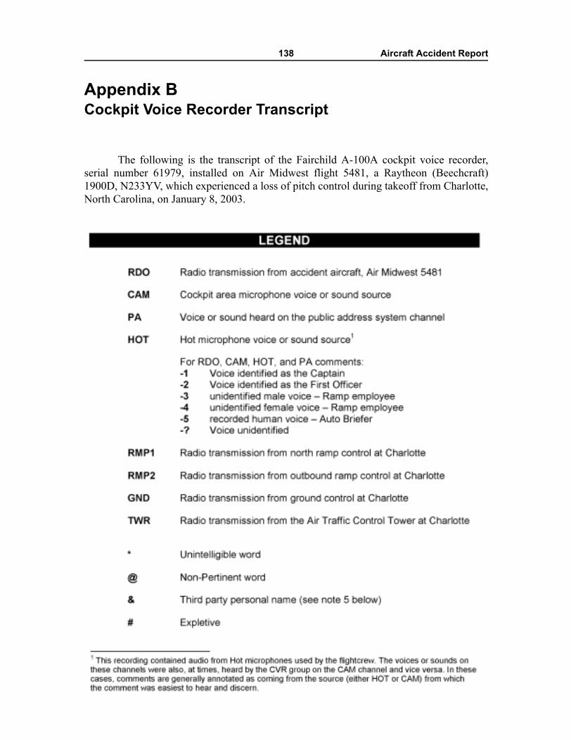
138 Aircraft Accident Report
Appendix BCockpit Voice Recorder Transcript
The following is the transcript of the Fairchild A-100A cockpit voice recorder,serial number 61979, installed on Air Midwest flight 5481, a Raytheon (Beechcraft)1900D, N233YV, which experienced a loss of pitch control during takeoff from Charlotte,North Carolina, on January 8, 2003.
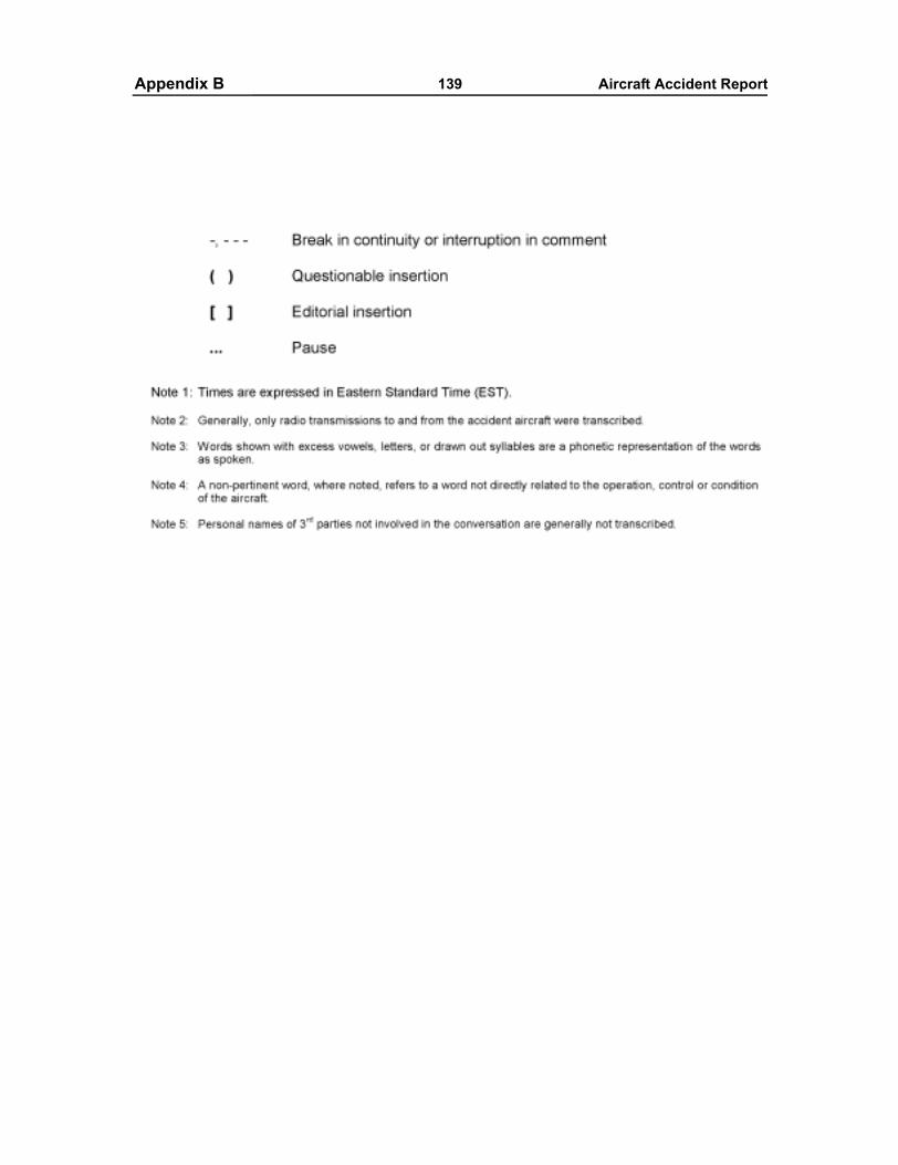
Appendixes 139 Aircraft Accident ReportAppendix B
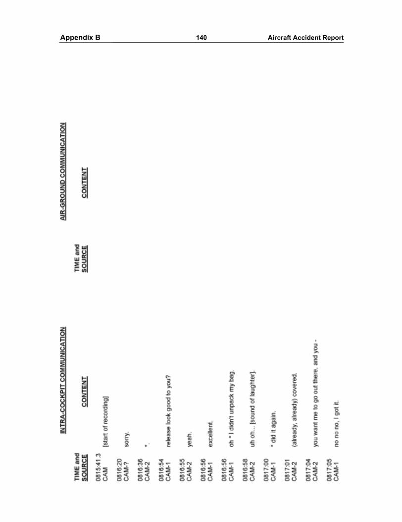
Appendixes 140 Aircraft Accident ReportAppendix B
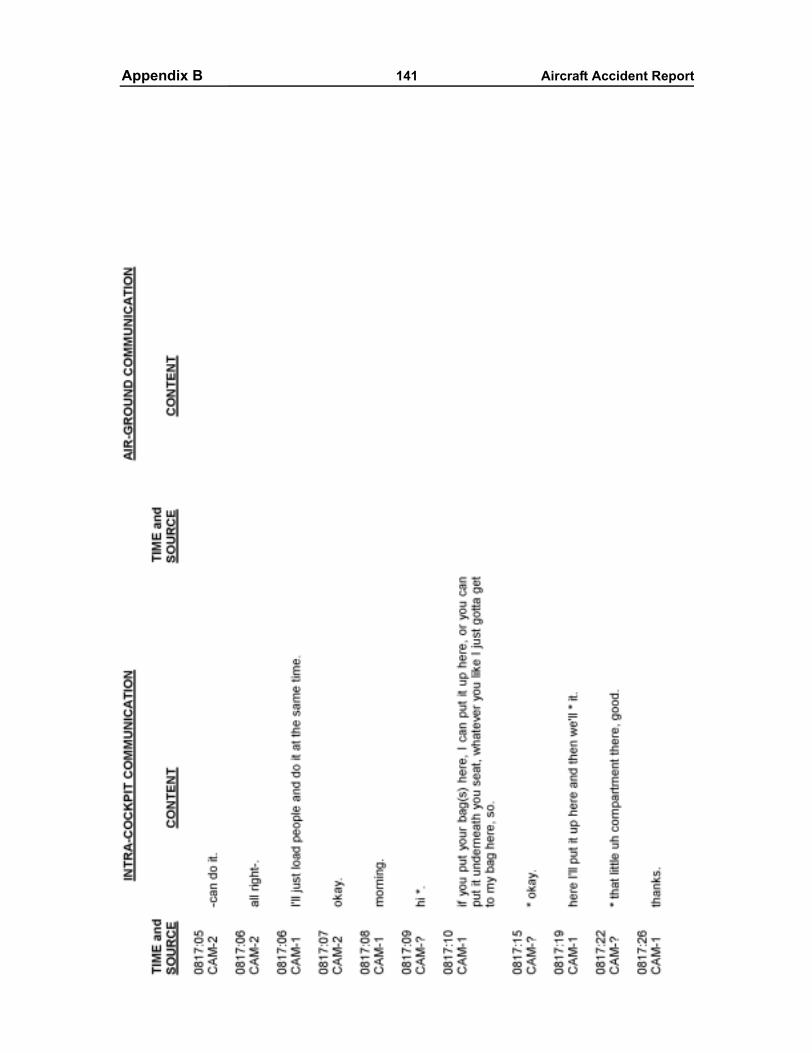
Appendixes 141 Aircraft Accident ReportAppendix B
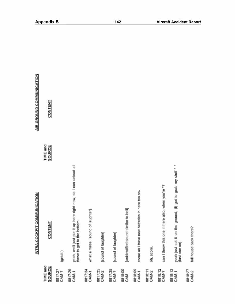
Appendixes 142 Aircraft Accident ReportAppendix B
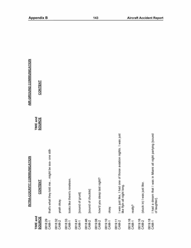
Appendixes 143 Aircraft Accident ReportAppendix B
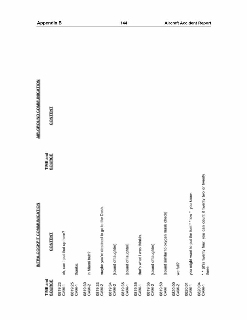
Appendixes 144 Aircraft Accident ReportAppendix B
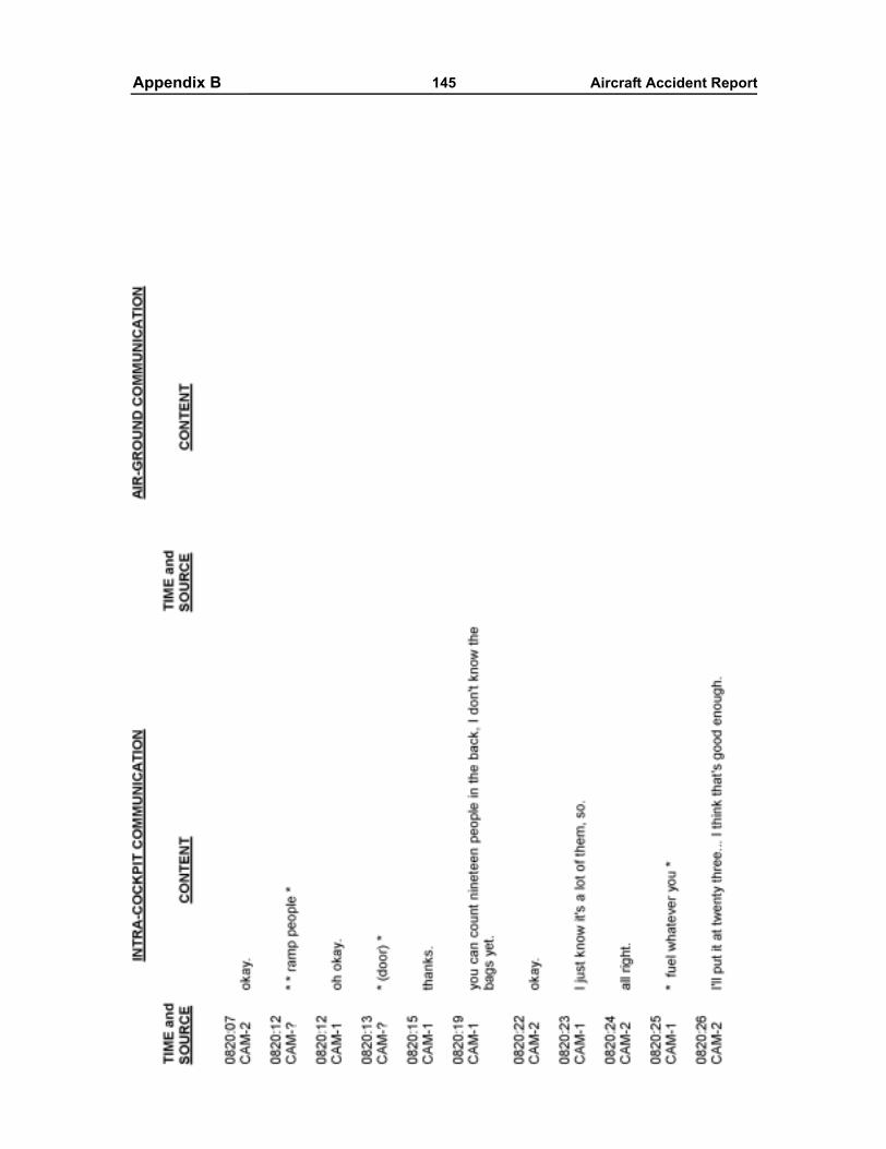
Appendixes 145 Aircraft Accident ReportAppendix B
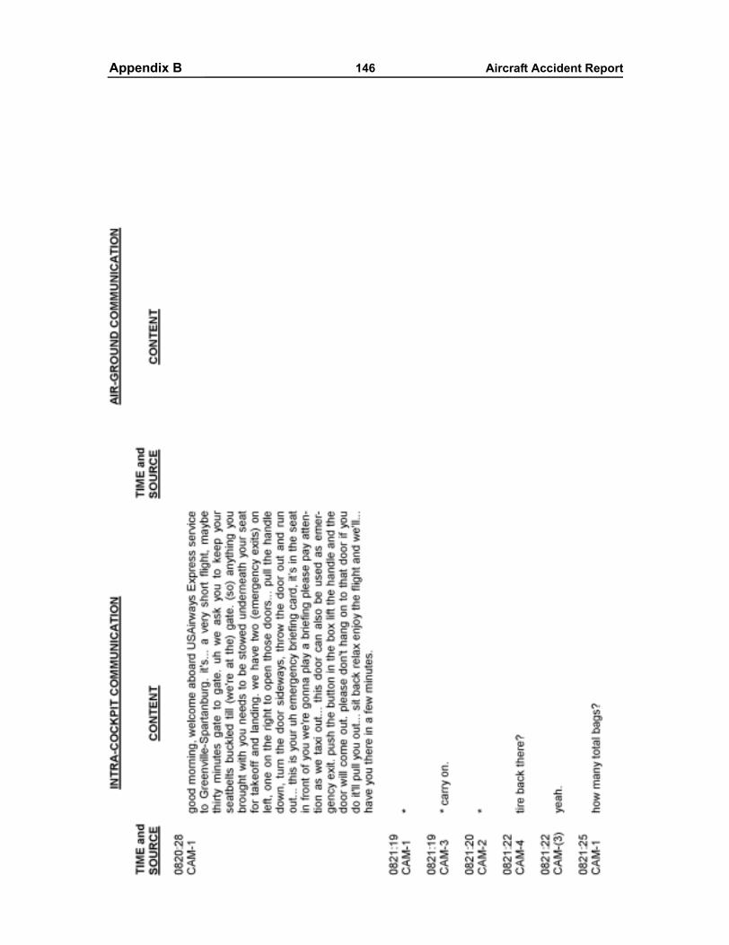
Appendixes 146 Aircraft Accident ReportAppendix B
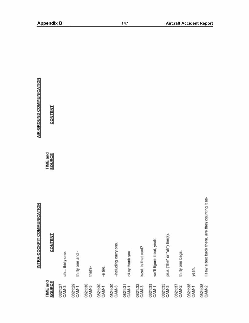
Appendixes 147 Aircraft Accident ReportAppendix B
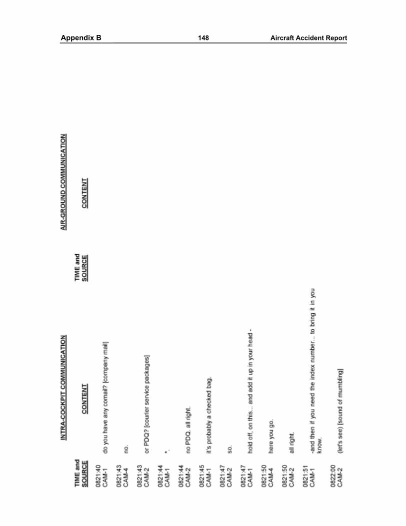
Appendixes 148 Aircraft Accident ReportAppendix B
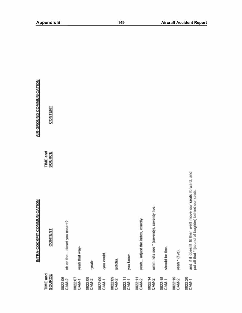
Appendixes 149 Aircraft Accident ReportAppendix B
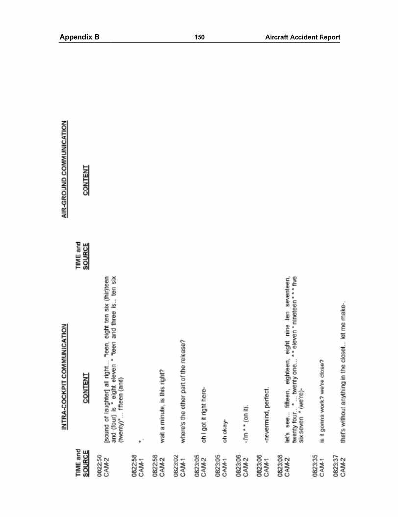
Appendixes 150 Aircraft Accident ReportAppendix B
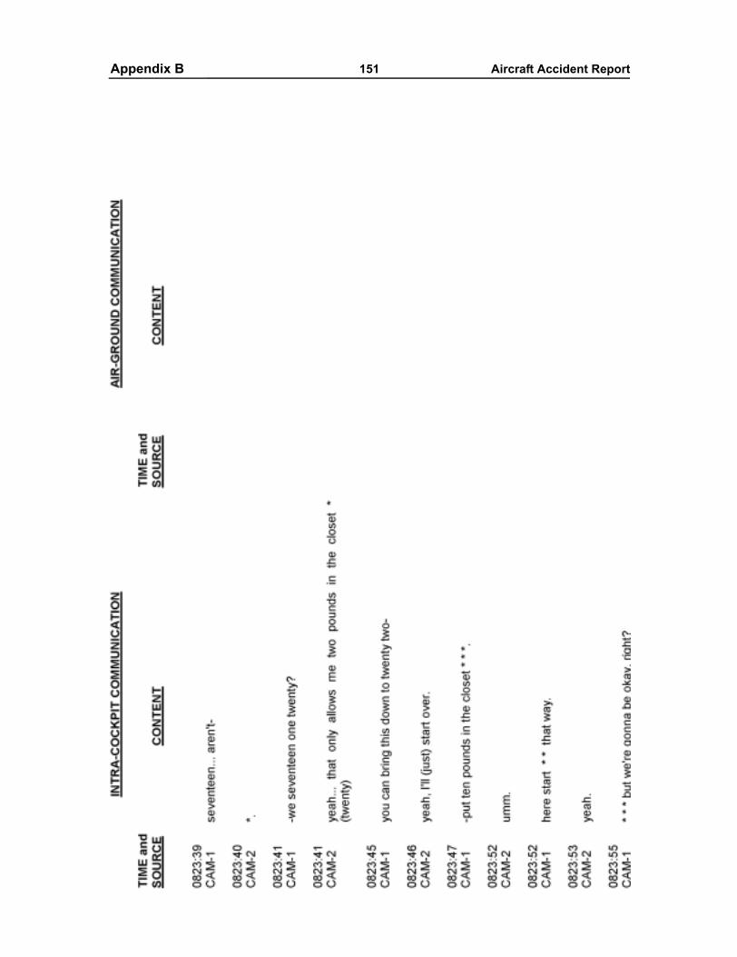
Appendixes 151 Aircraft Accident ReportAppendix B
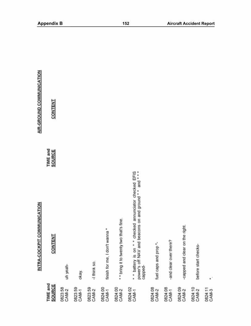
Appendixes 152 Aircraft Accident ReportAppendix B
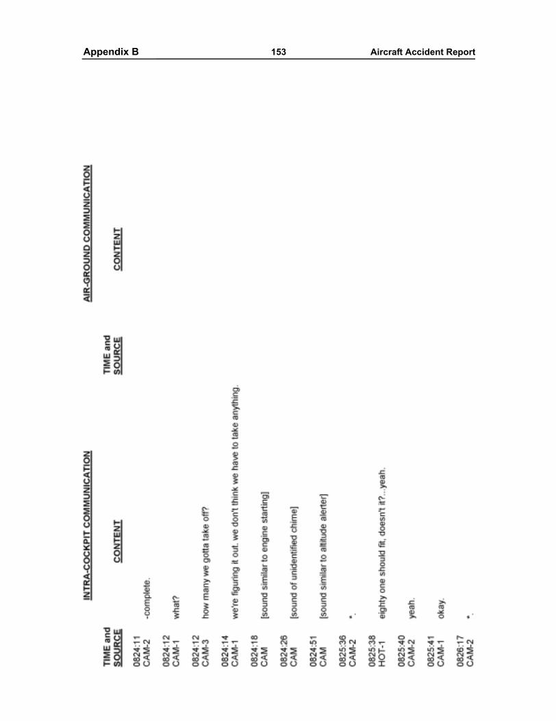
Appendixes 153 Aircraft Accident ReportAppendix B
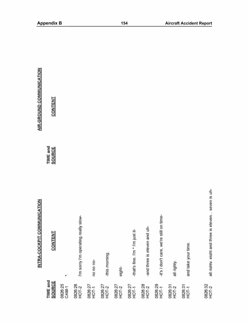
Appendixes 154 Aircraft Accident ReportAppendix B
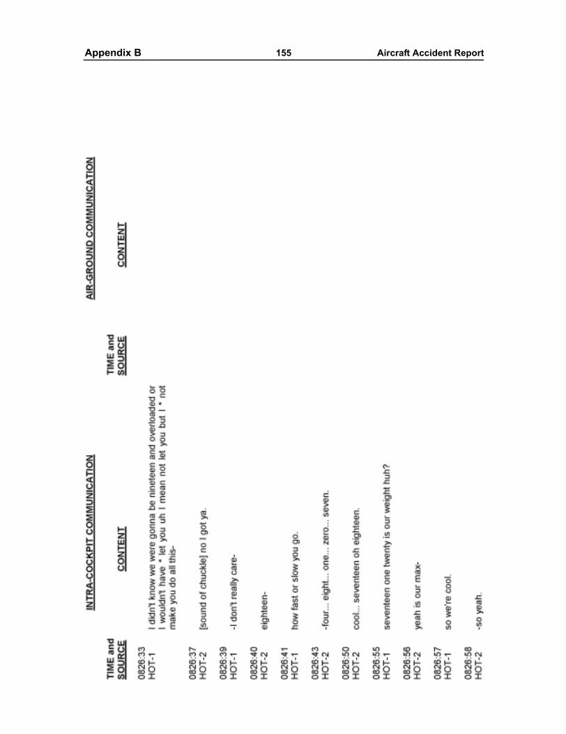
Appendixes 155 Aircraft Accident ReportAppendix B
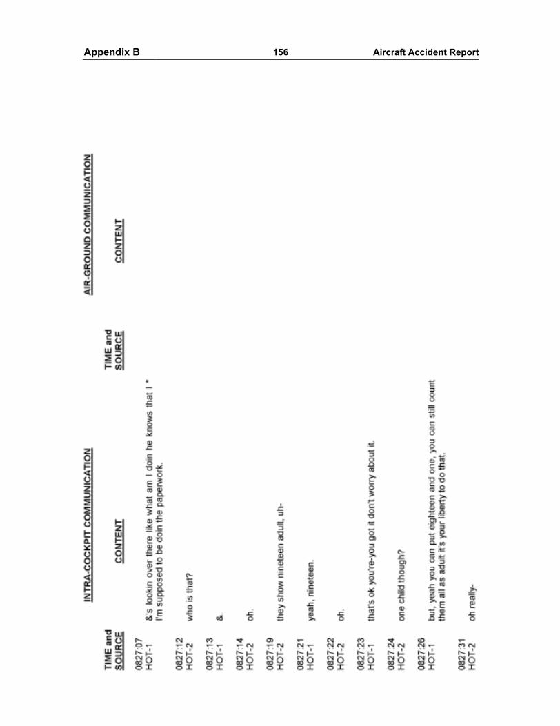
Appendixes 156 Aircraft Accident ReportAppendix B
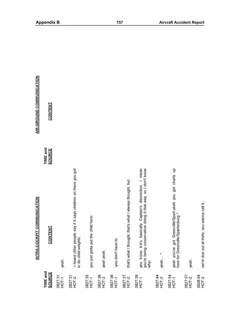
Appendixes 157 Aircraft Accident ReportAppendix B
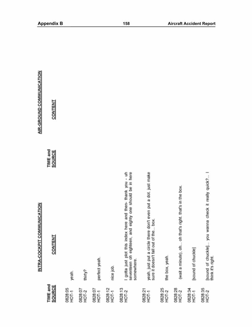
Appendixes 158 Aircraft Accident ReportAppendix B
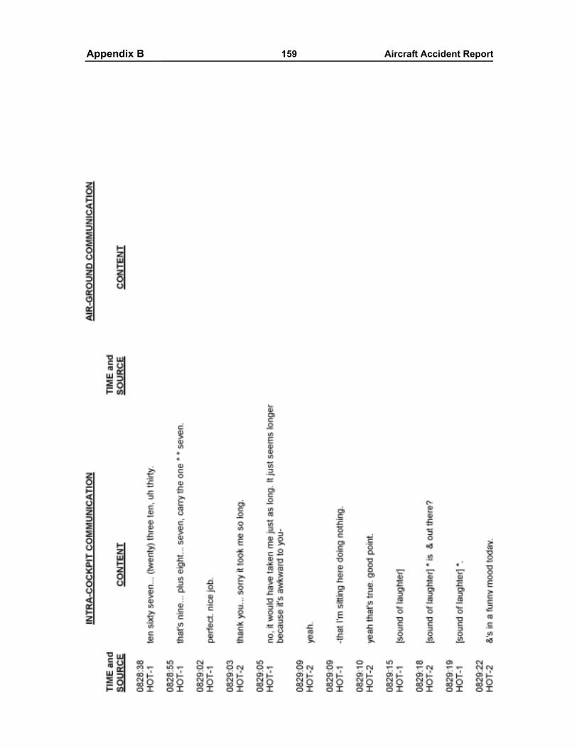
Appendixes 159 Aircraft Accident ReportAppendix B
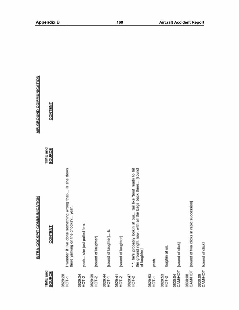
Appendixes 160 Aircraft Accident ReportAppendix B
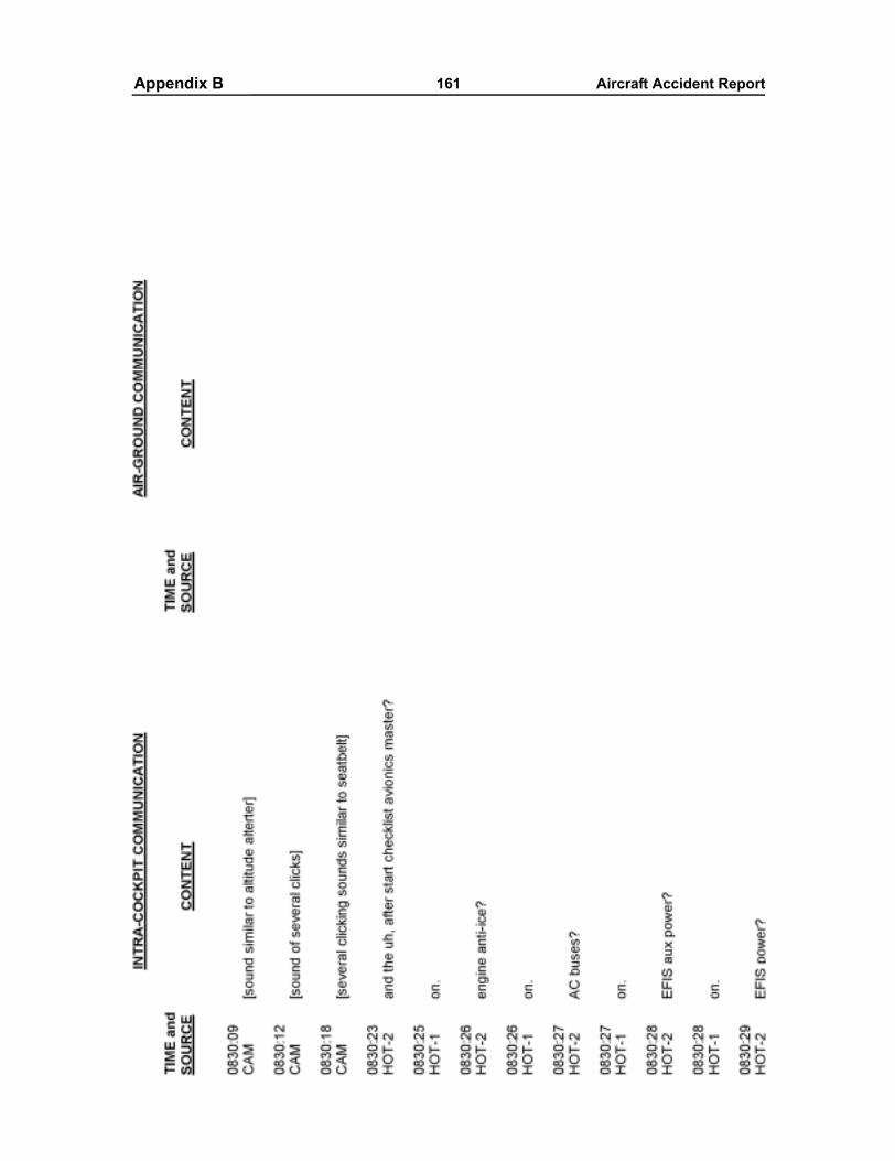
Appendixes 161 Aircraft Accident ReportAppendix B
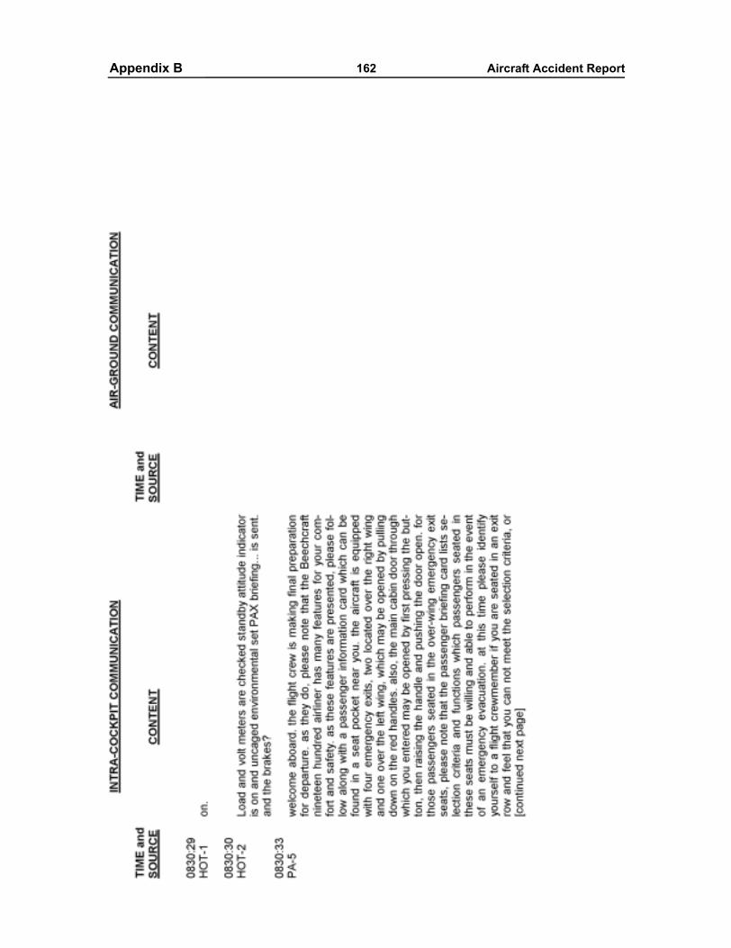
Appendixes 162 Aircraft Accident ReportAppendix B
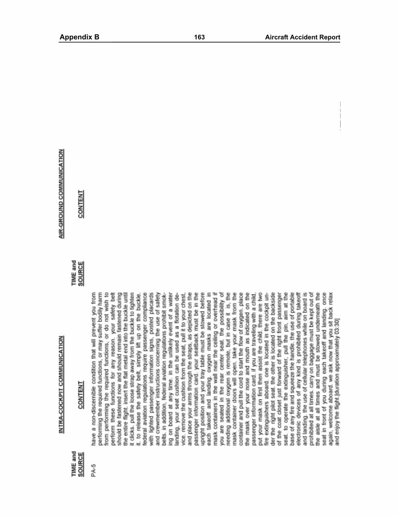
Appendixes 163 Aircraft Accident ReportAppendix B
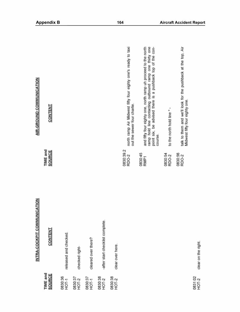
Appendixes 164 Aircraft Accident ReportAppendix B
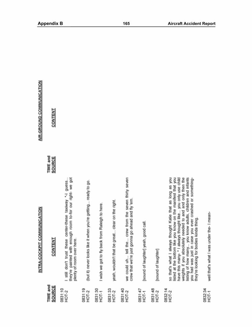
Appendixes 165 Aircraft Accident ReportAppendix B
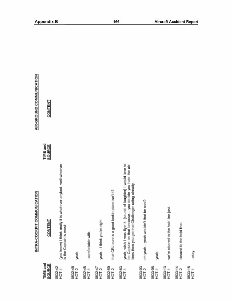
Appendixes 166 Aircraft Accident ReportAppendix B
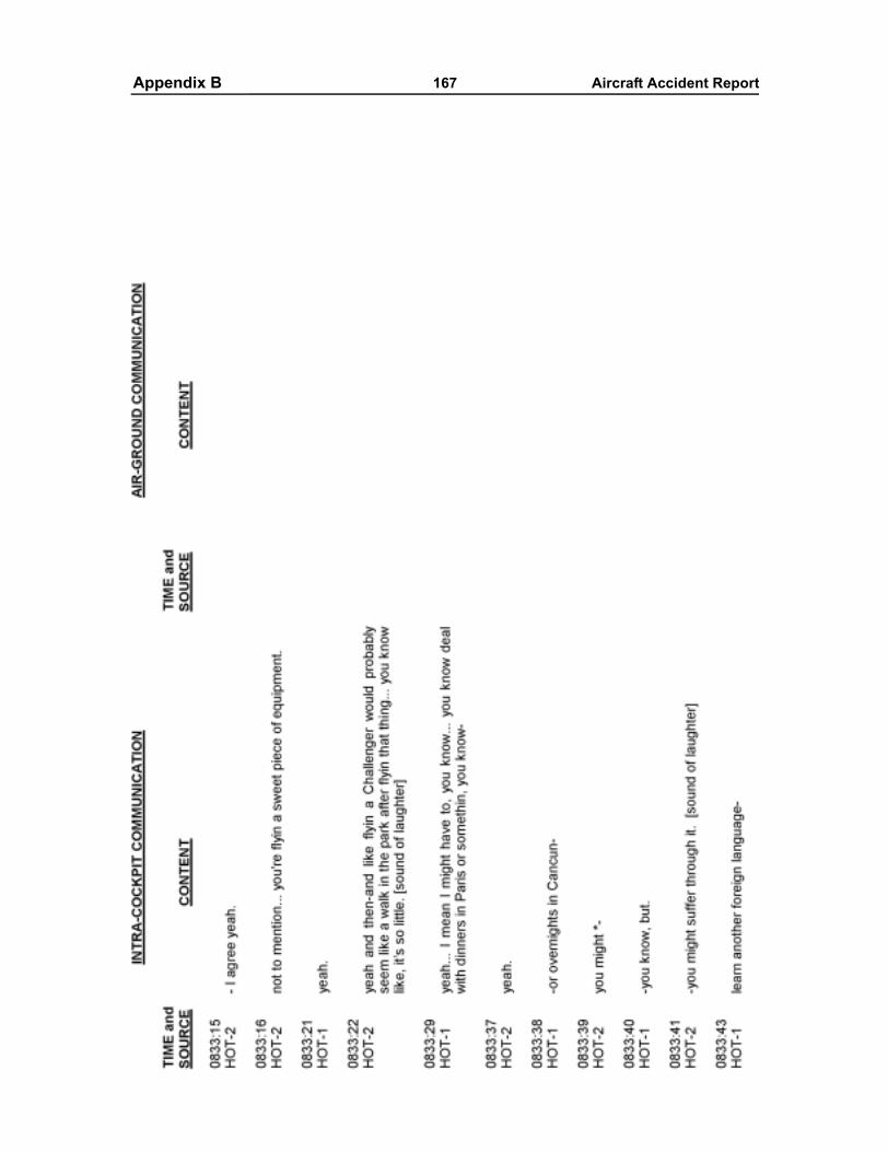
Appendixes 167 Aircraft Accident ReportAppendix B
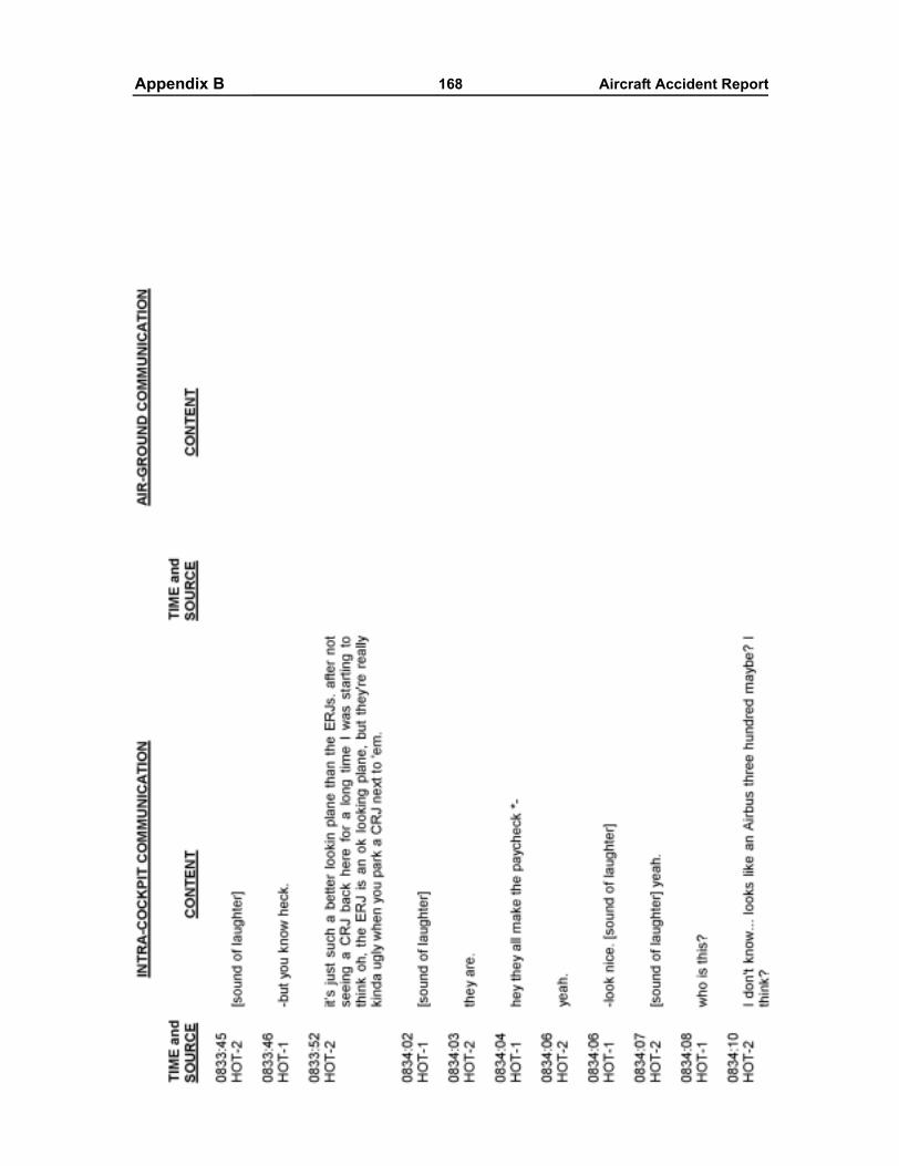
Appendixes 168 Aircraft Accident ReportAppendix B
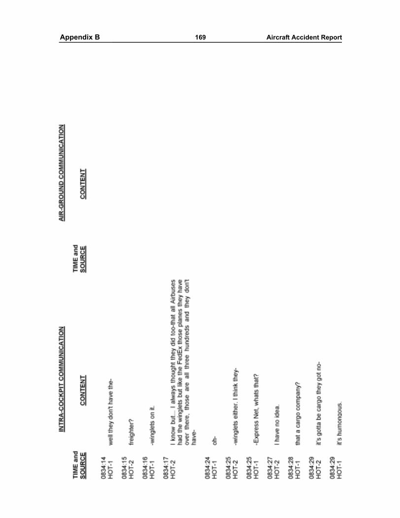
Appendixes 169 Aircraft Accident ReportAppendix B
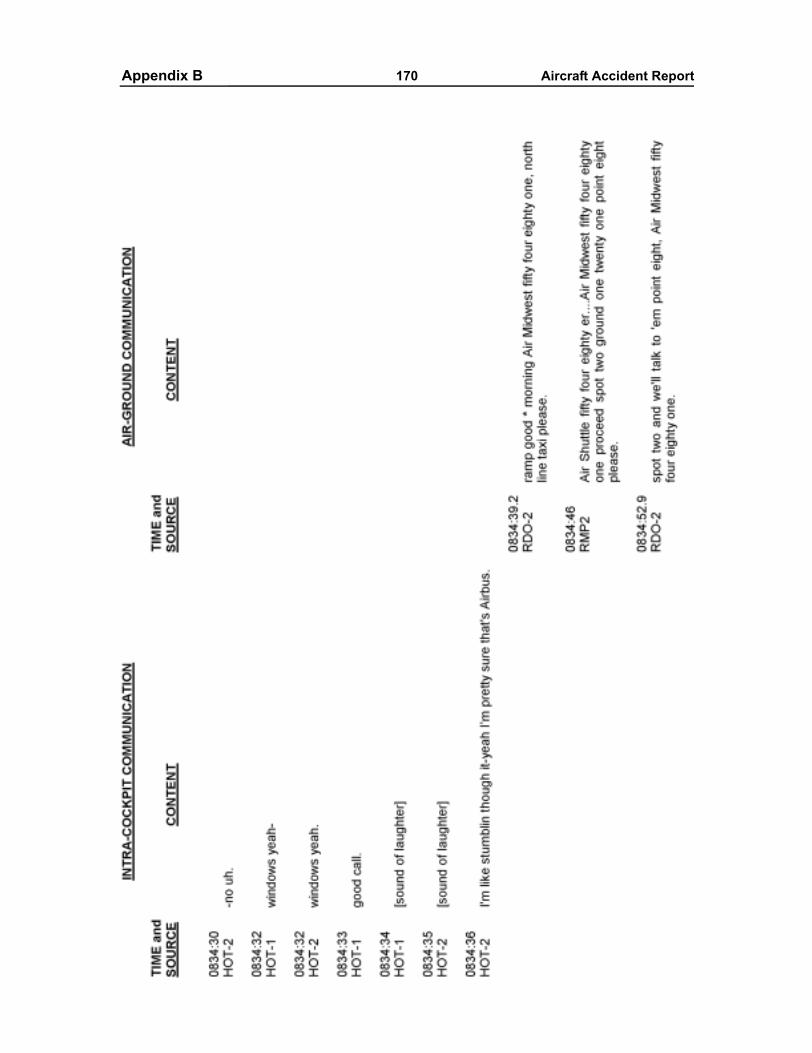
Appendixes 170 Aircraft Accident ReportAppendix B
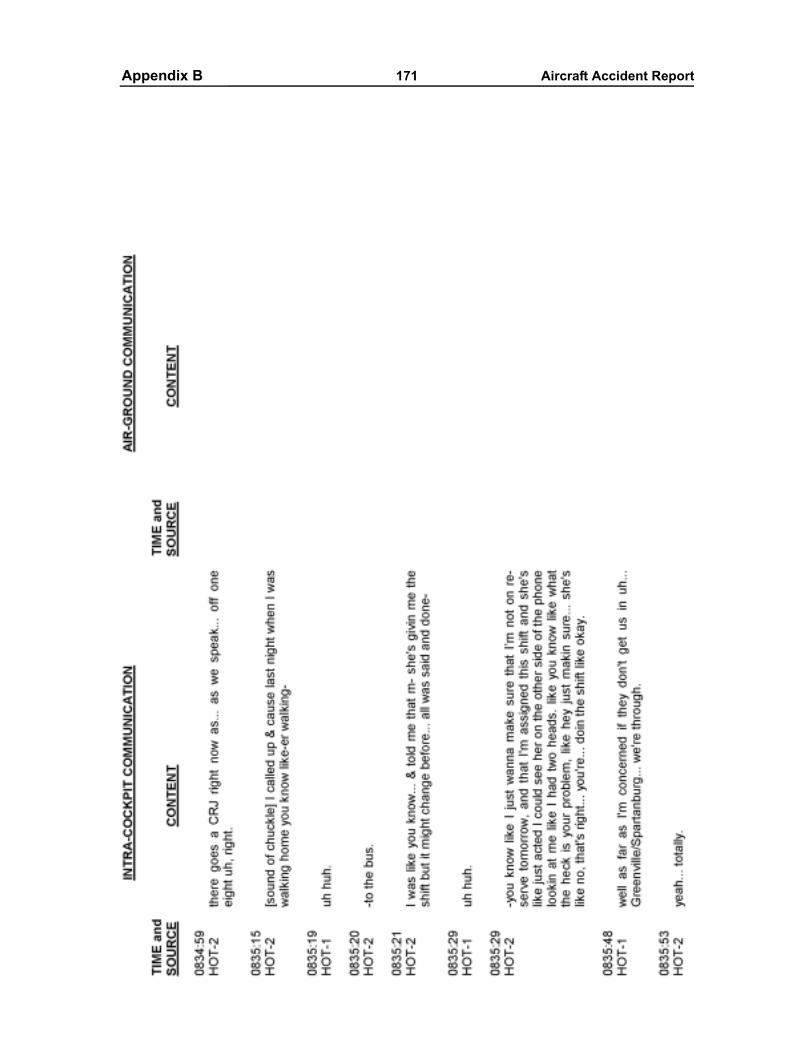
Appendixes 171 Aircraft Accident ReportAppendix B
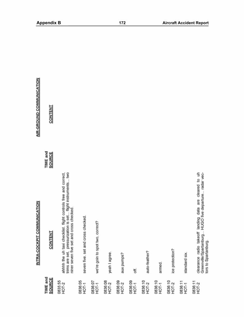
Appendixes 172 Aircraft Accident ReportAppendix B
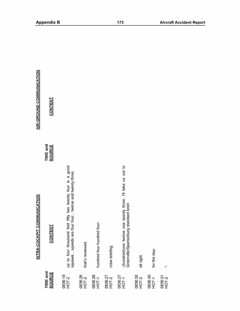
Appendixes 173 Aircraft Accident ReportAppendix B
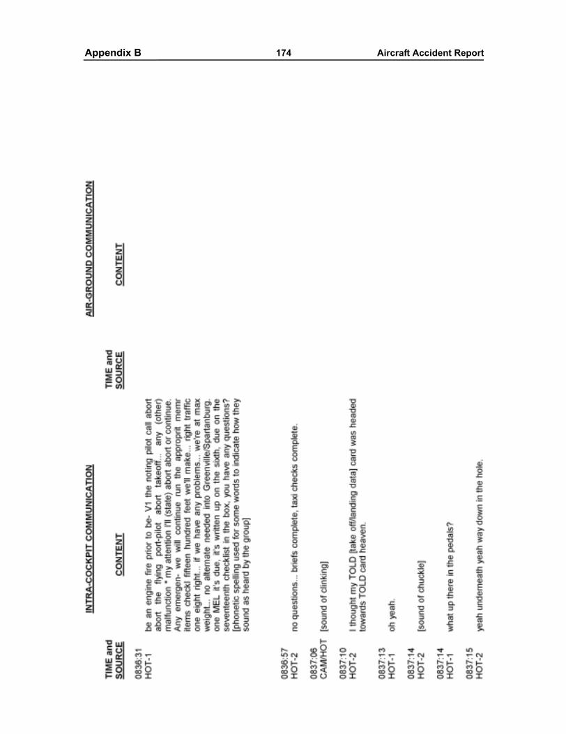
Appendixes 174 Aircraft Accident ReportAppendix B
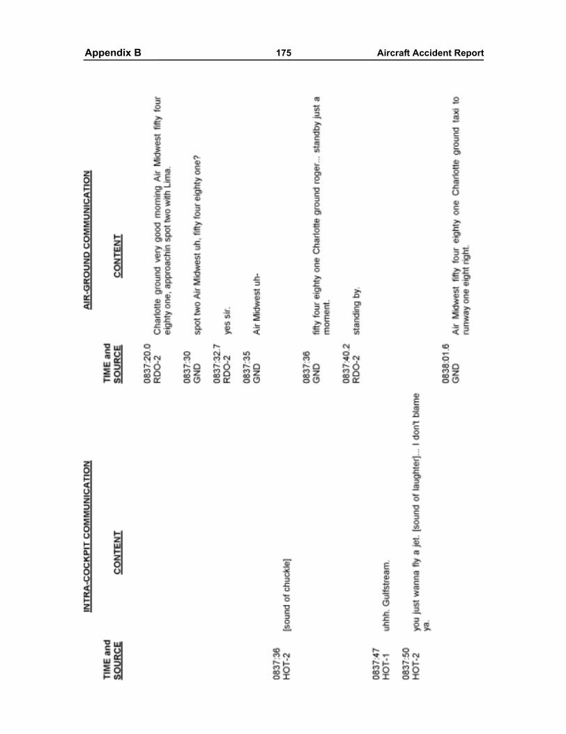
Appendixes 175 Aircraft Accident ReportAppendix B
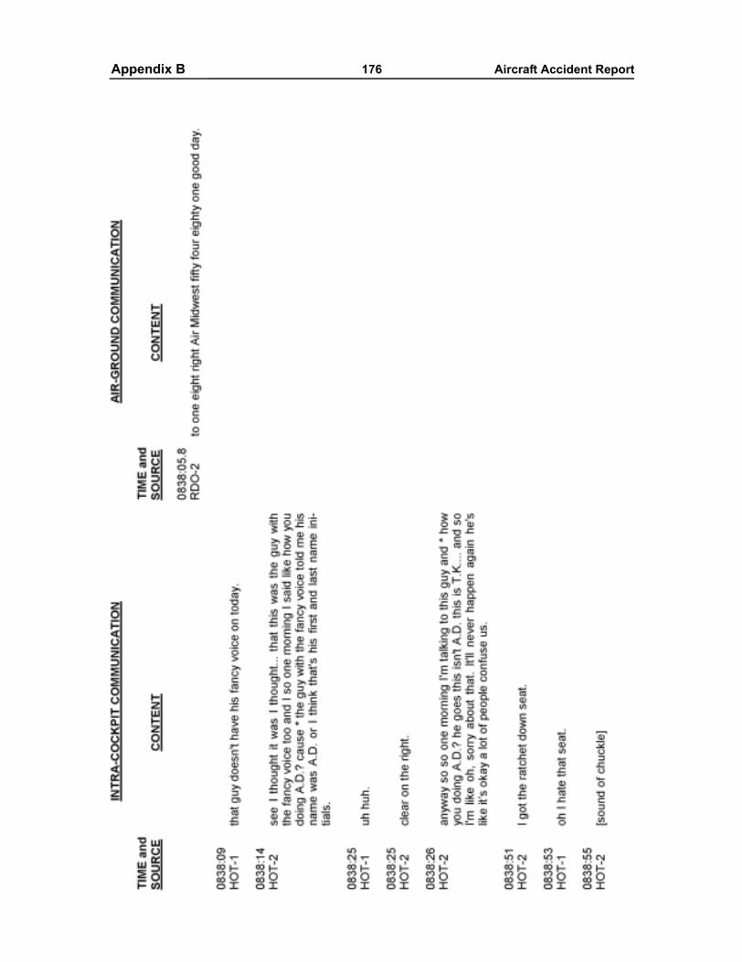
Appendixes 176 Aircraft Accident ReportAppendix B
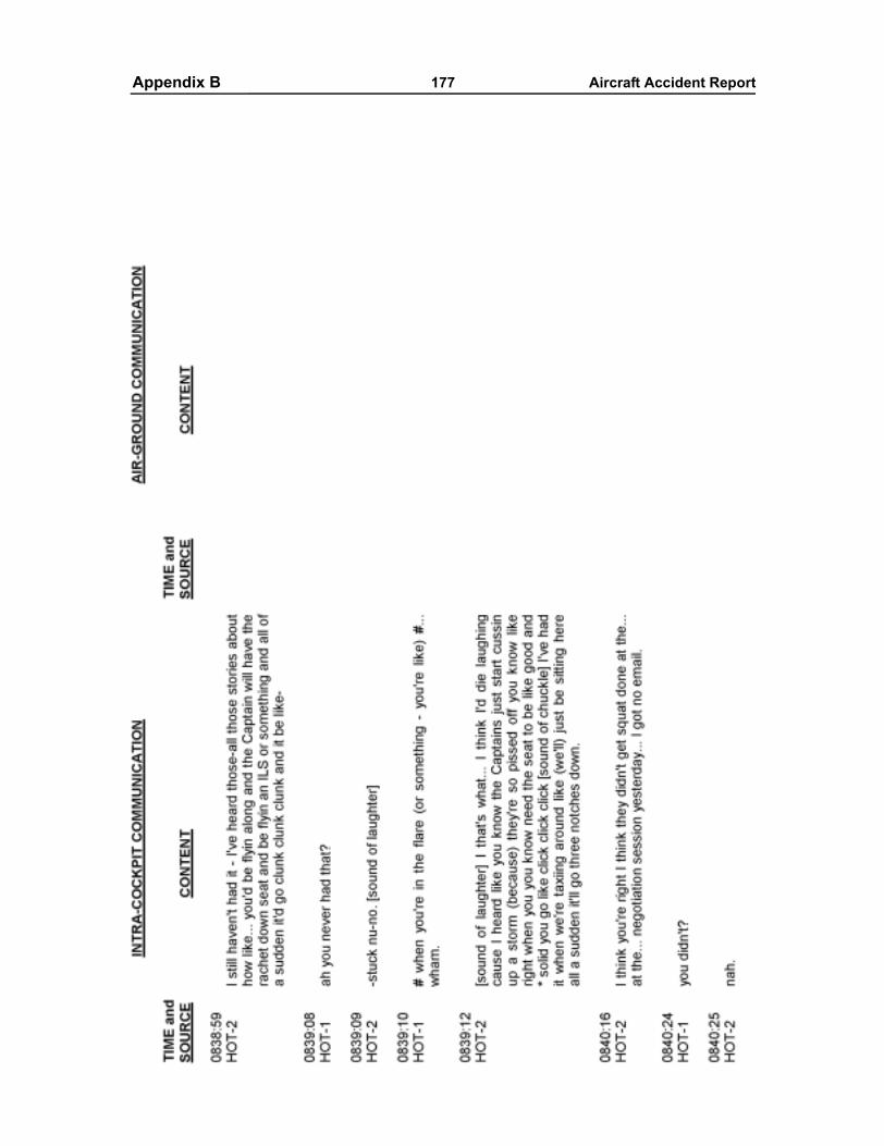
Appendixes 177 Aircraft Accident ReportAppendix B
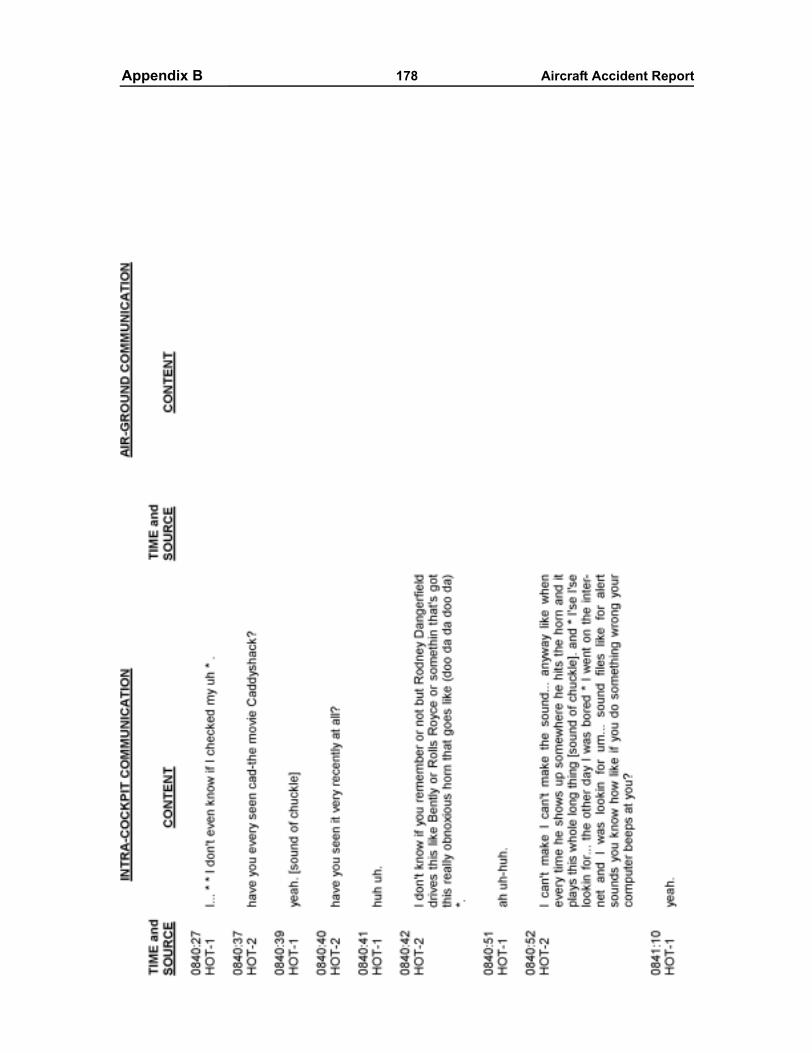
Appendixes 178 Aircraft Accident ReportAppendix B
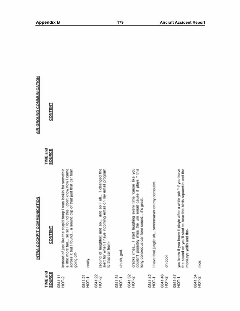
Appendixes 179 Aircraft Accident ReportAppendix B
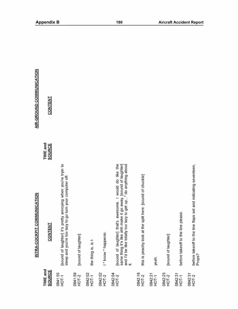
Appendixes 180 Aircraft Accident ReportAppendix B
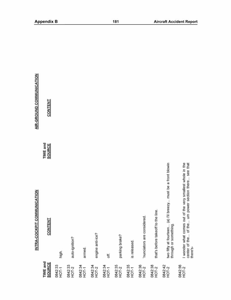
Appendixes 181 Aircraft Accident ReportAppendix B
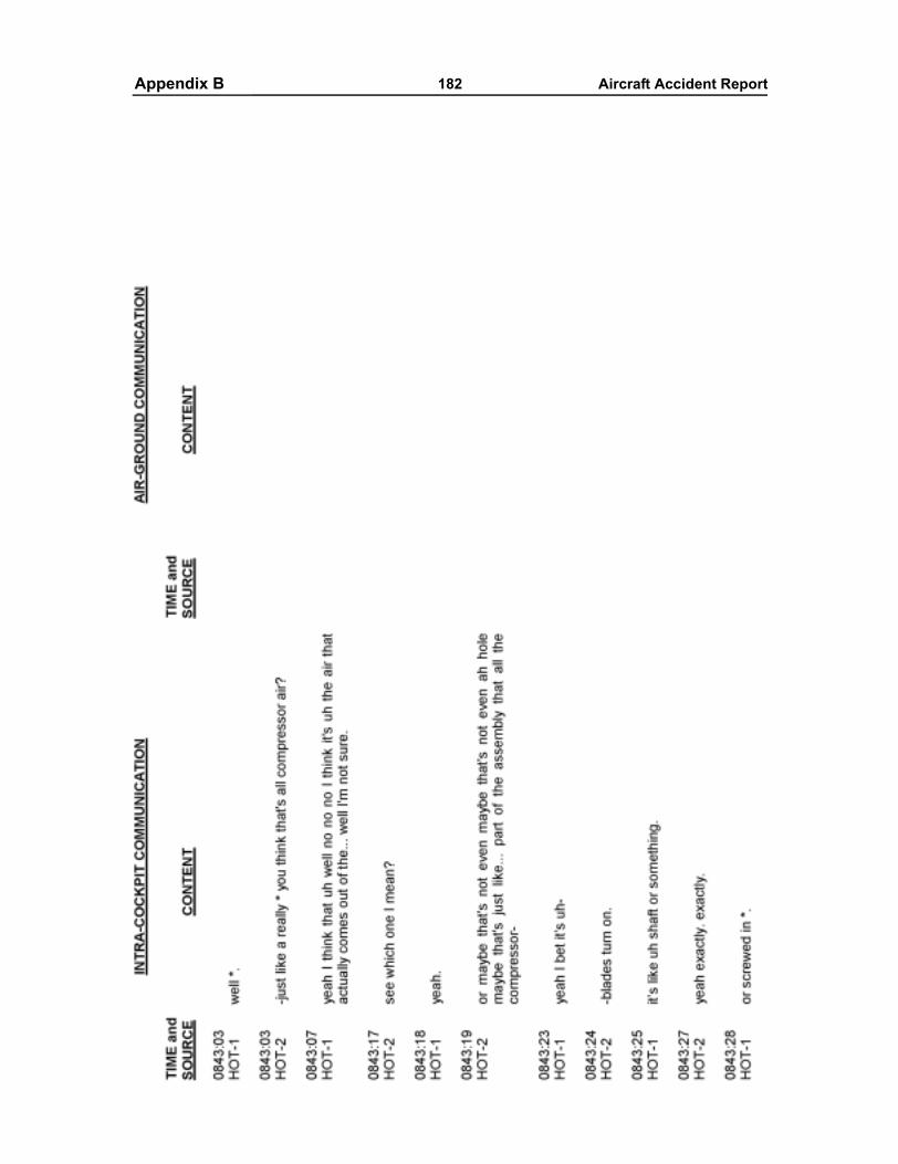
Appendixes 182 Aircraft Accident ReportAppendix B
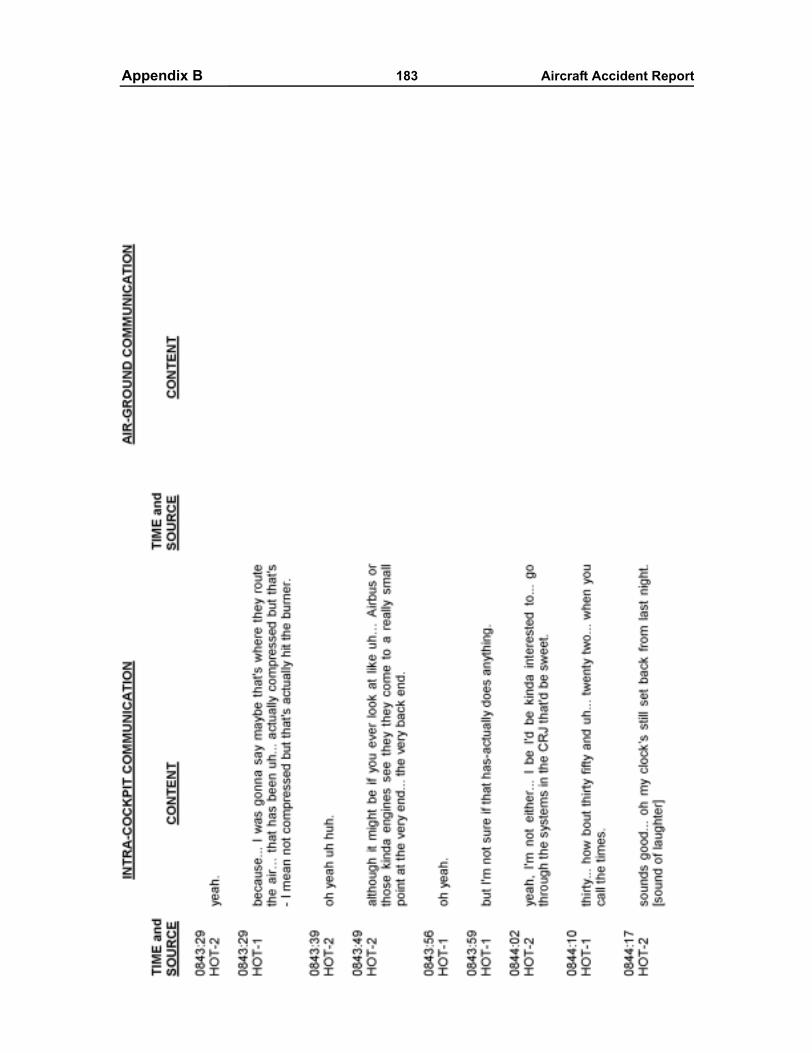
Appendixes 183 Aircraft Accident ReportAppendix B
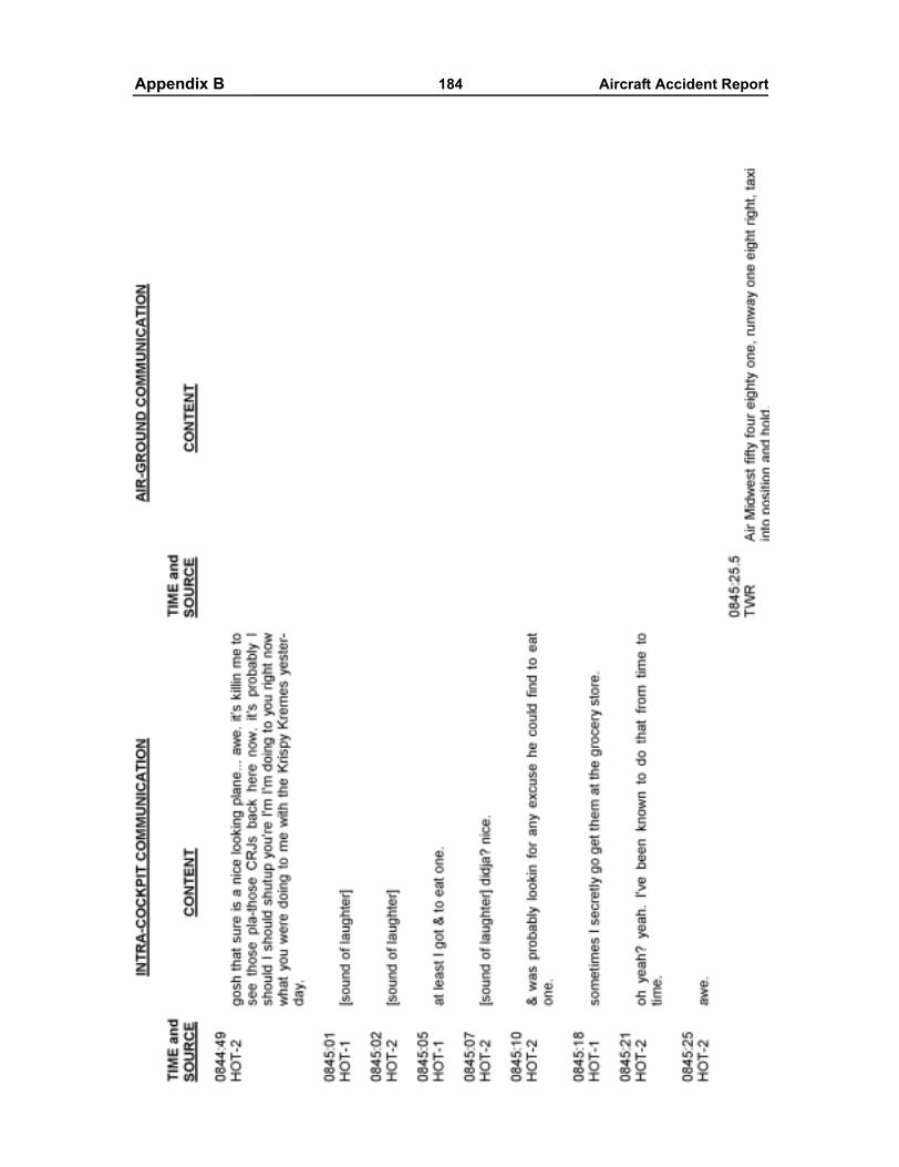
Appendixes 184 Aircraft Accident ReportAppendix B
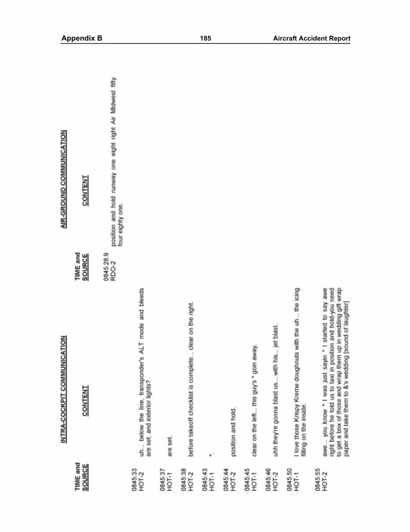
Appendixes 185 Aircraft Accident ReportAppendix B
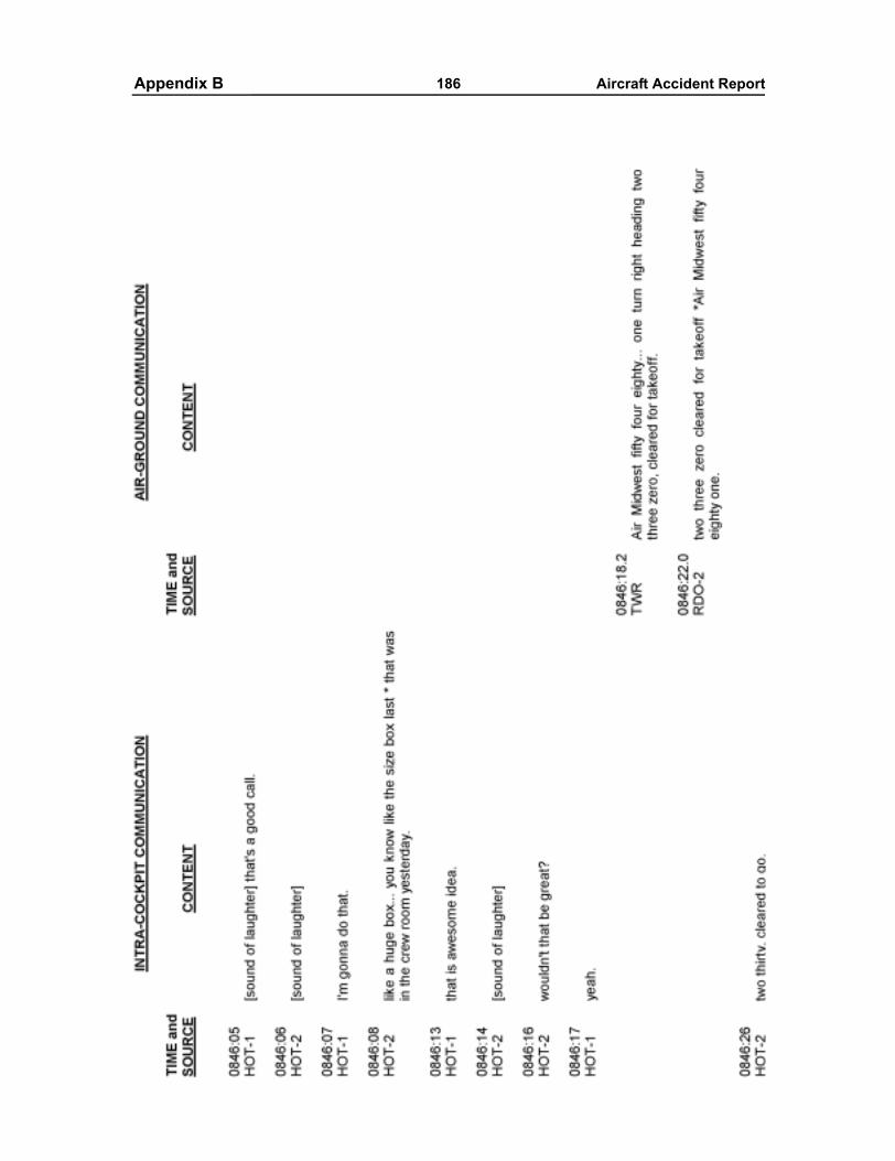
Appendixes 186 Aircraft Accident ReportAppendix B
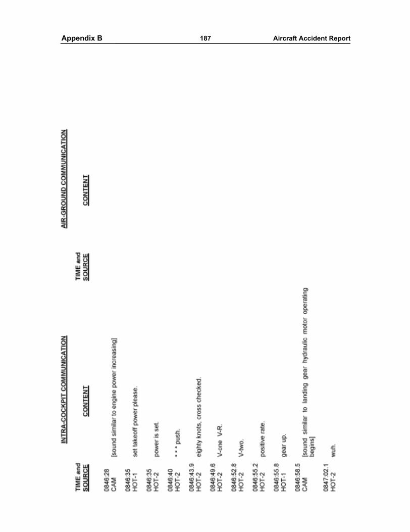
Appendixes 187 Aircraft Accident ReportAppendix B

Appendixes 188 Aircraft Accident ReportAppendix B
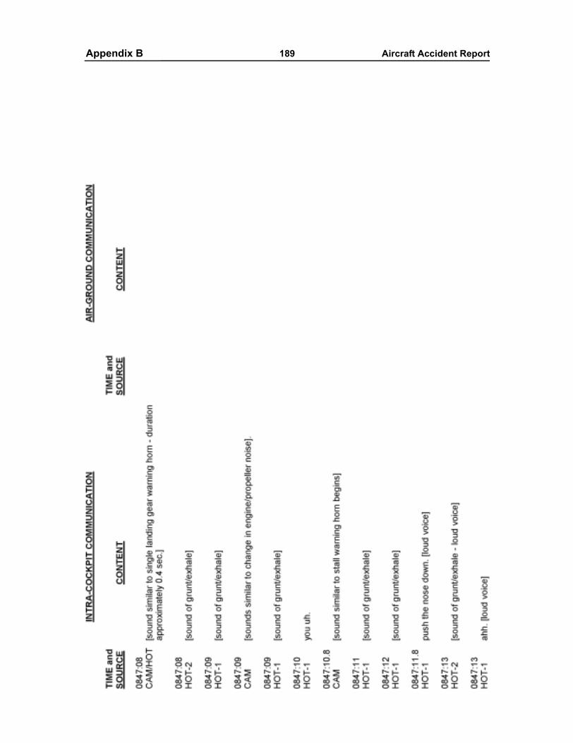
Appendixes 189 Aircraft Accident ReportAppendix B
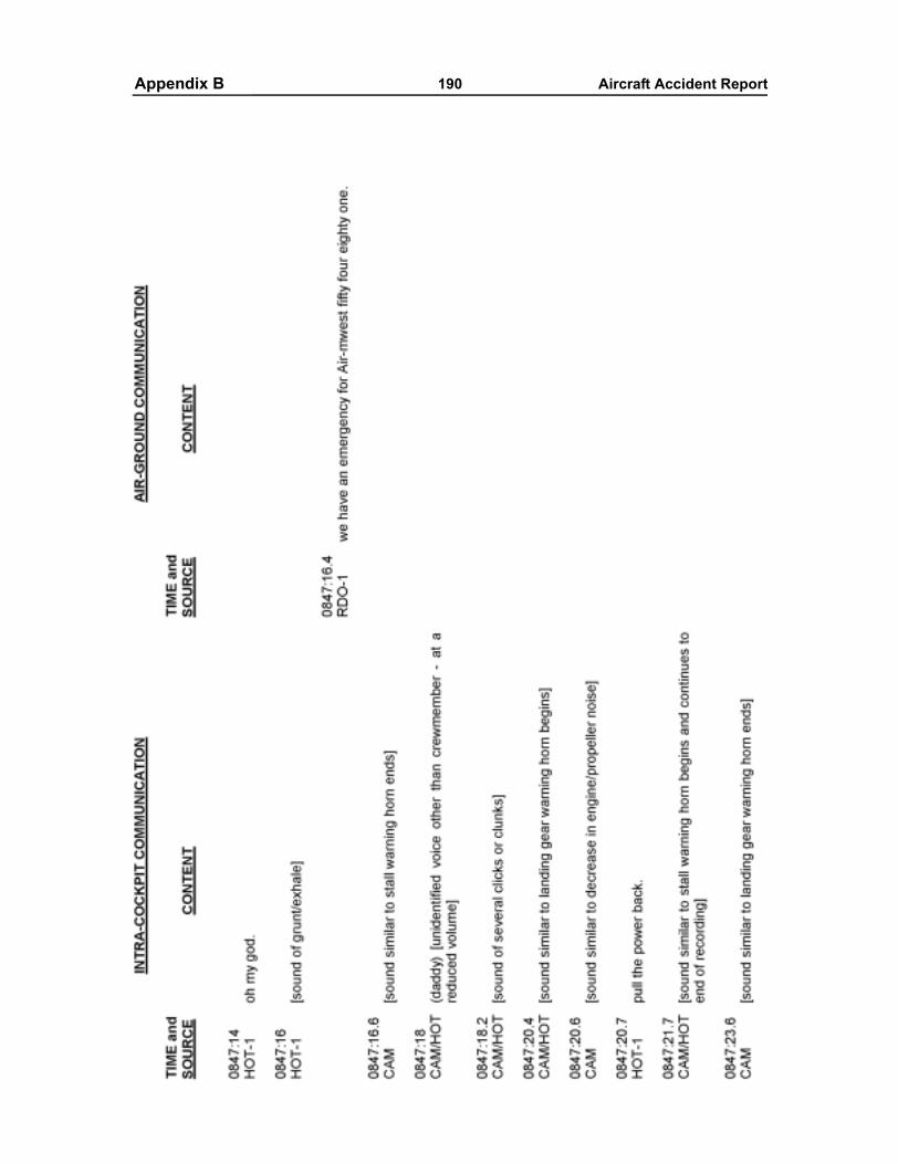
Appendixes 190 Aircraft Accident ReportAppendix B
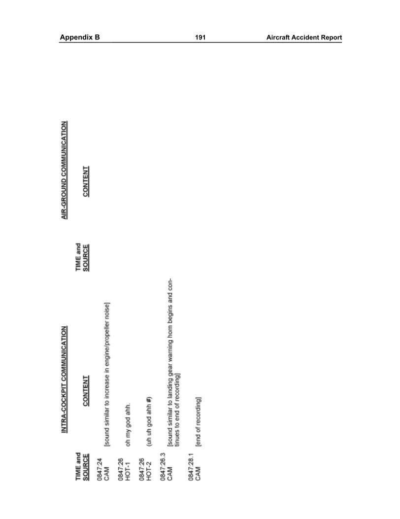
Appendixes 191 Aircraft Accident ReportAppendix B
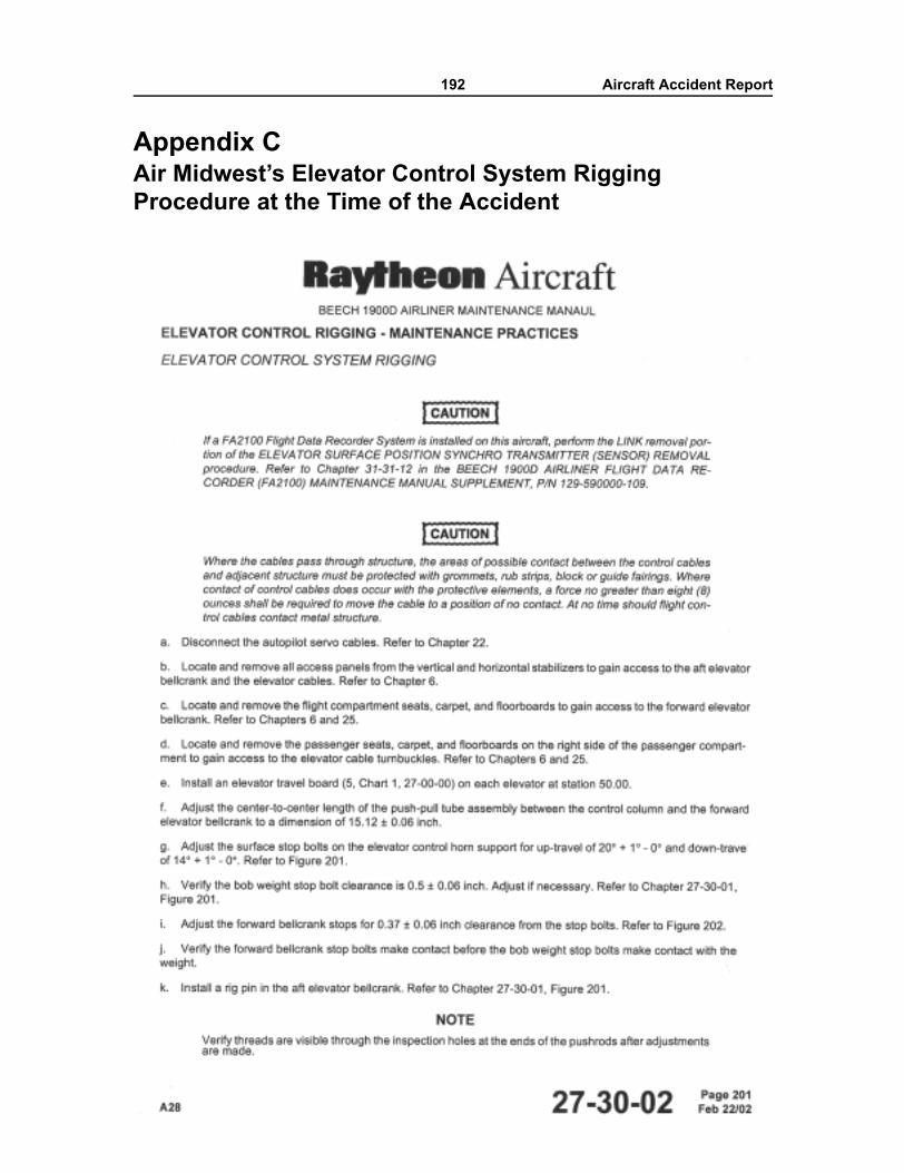
192 Aircraft Accident Report
Appendix CAir Midwest�s Elevator Control System Rigging Procedure at the Time of the Accident
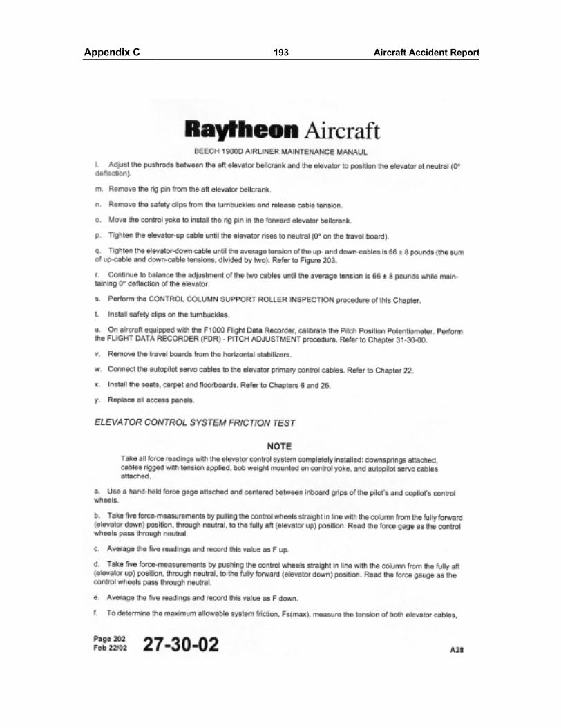
Appendixes 193 Aircraft Accident ReportAppendix C
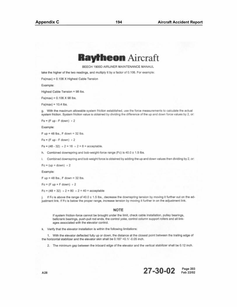
Appendixes 194 Aircraft Accident ReportAppendix C
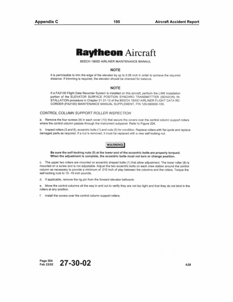
Appendixes 195 Aircraft Accident ReportAppendix C
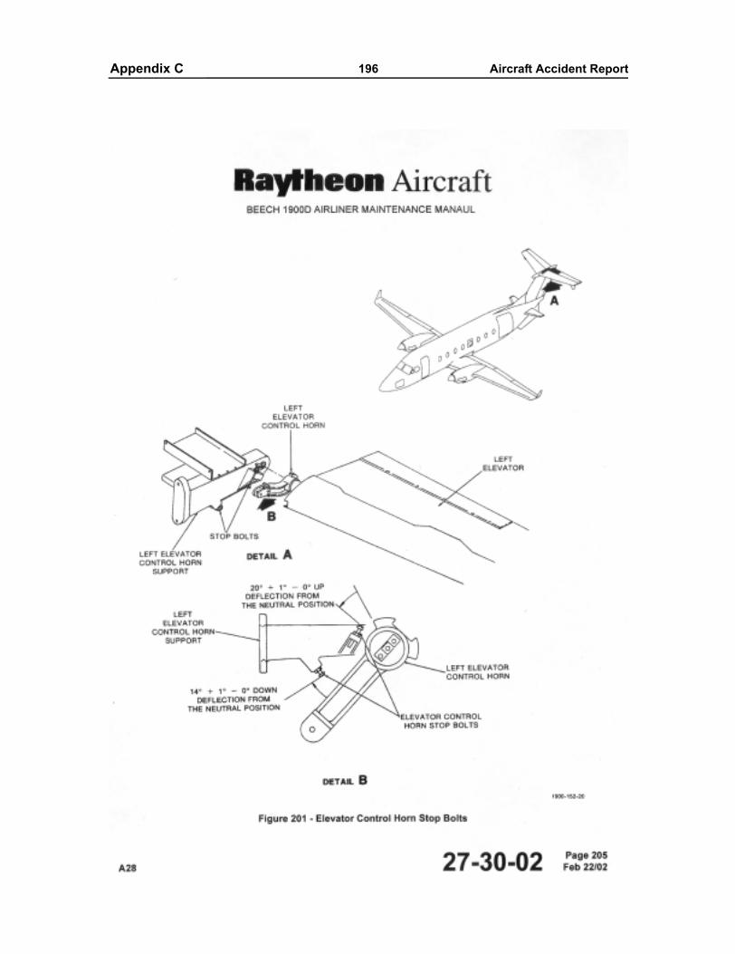
Appendixes 196 Aircraft Accident ReportAppendix C
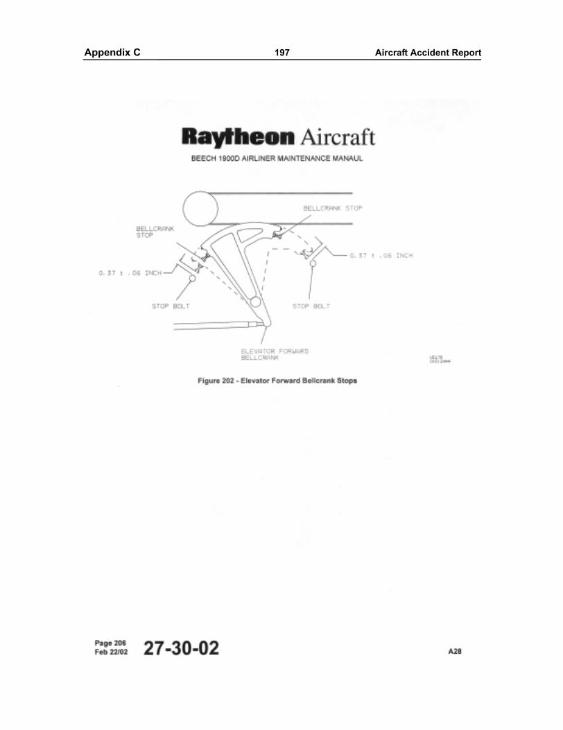
Appendixes 197 Aircraft Accident ReportAppendix C
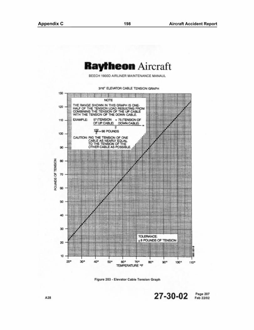
Appendixes 198 Aircraft Accident ReportAppendix C
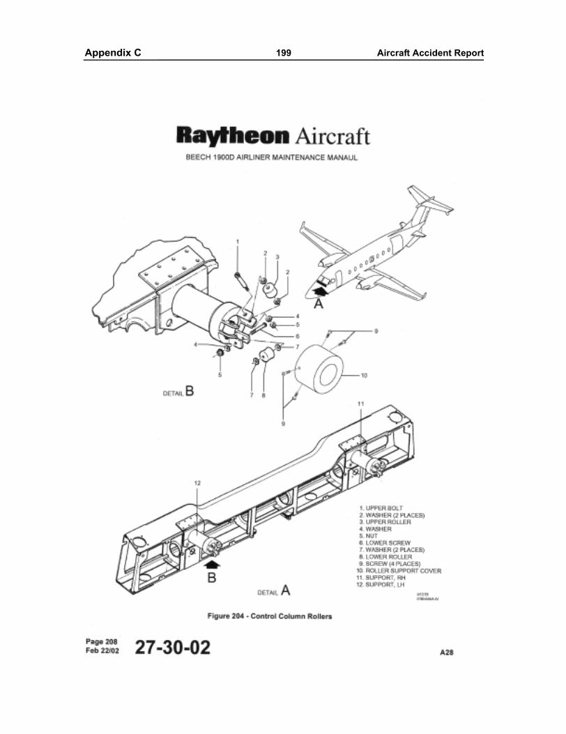
Appendixes 199 Aircraft Accident ReportAppendix C
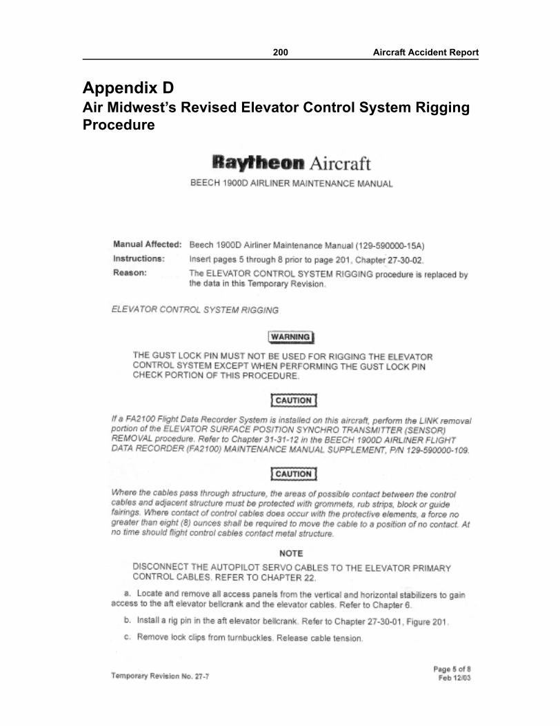
200 Aircraft Accident Report
Appendix DAir Midwest�s Revised Elevator Control System Rigging Procedure
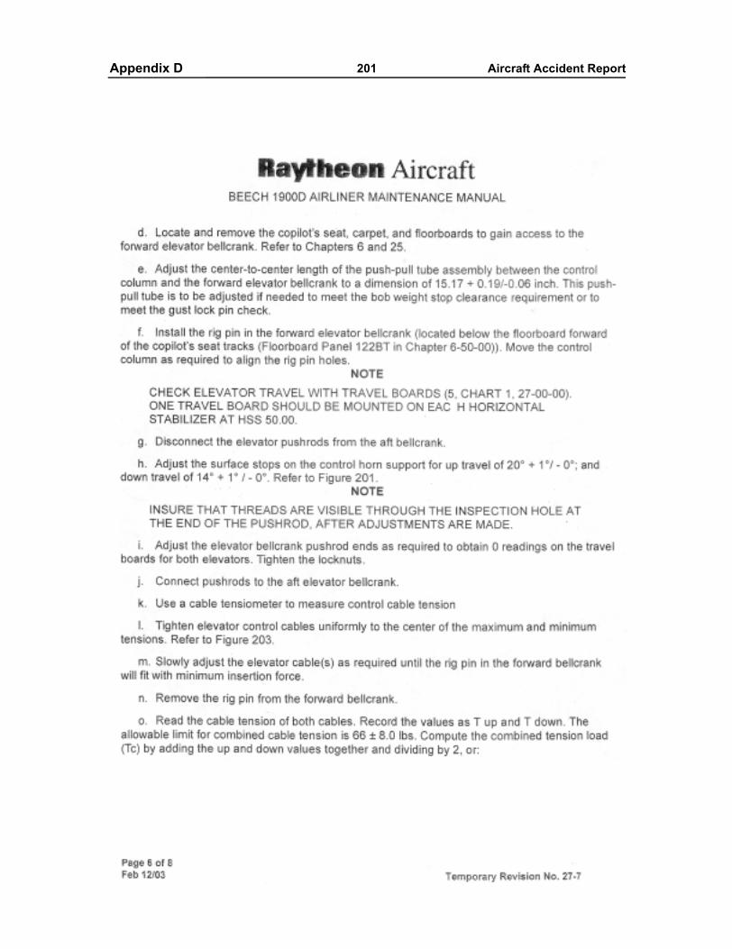
Appendixes 201 Aircraft Accident ReportAppendix D
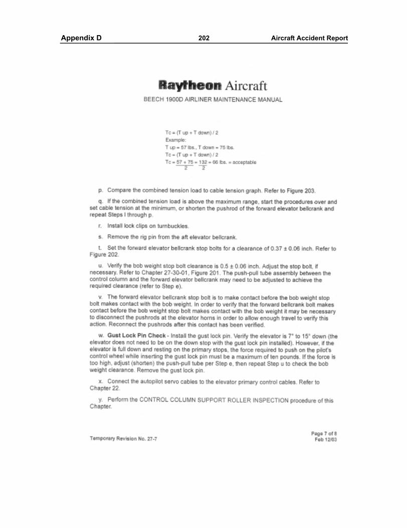
Appendixes 202 Aircraft Accident ReportAppendix D
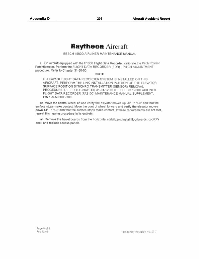
Appendixes 203 Aircraft Accident ReportAppendix D