Embed Size (px)
Citation preview
PB89-910402
NAT10TRANSPORTATIONSAFETYBOARD
WASHINGTON, D.C. 20594AIRCRAFT ACCIDENT REPORT
HORIZON AIR, INC.DEHAVILLAND DHC-8SEATTLE-TACOMA INTERNATIONAL AIRPORTSEATTLE, WASHINGTONAPRIL 15, 1988
NTSB/AAR-89102
UNITED STATES GOVERNMENT
t
TECHNICAL REPORT DOCUMENTATION PAGE1. Report No. 2. Government Accession No.
NTSBIAAR-89102 PB89-910402
4. Title and Subtitle Aircraft Accident Report--Horizon Air,Inc., deHavilland DHC-8, Seattle-Tacoma InternationalAirport, Seattle, Washington, April 15, 1988
7. Author(s)
9. Performing Organization Name and Address
National Transportation Safety BoardBureau of Accident InvestigationWashington, D.C. 20594
12. Sponsoring Agency Name and Address
NATIONAL TRANSPORTATION SAFETY BOARDWashington, D.C. 20594
15. Supplementary Notes
3. Recipient’s Catalog No.
5. Report DateMarch 6,1989
6. Performing OrganizationCode
a. Performing OrganizationReport No.
10. Work Unit No.4876A
11. Contract or Grant No.
13. Type of Report andPeriod Covered
Aircraft Accident ReportApril 15, 1988
14. Sponsoring Agency Code
16. Abstract On April 15, 1988, a deHavilland DHC-8, took off from the Seattle-TacomaInternational Airport. Shortly after takeoff, the aircrew noted a power loss on the right engineand decided to return to Seattle for a precautionary landing. After lowering the landing gear onfinal approach, a massive fire broke out in the right engine nacelle. Because almost all directionalcontrol and braking capability was lost, the airplane crossed a grass median area, entered thepaved ramp area, and struck a runway designator sign, several baggage carts, and two jetways.The airplane came to rest against another jetway. Four of the 37 passengers sustained seriousinjuries. The airplane was destroyed by the fire and impact. The safety issues discussed in thisreport include: the nacelle cowl design of the DHC-8; design and maintenance practice concerningthe loose fuel filter cover; design and maintenance practice concerning the generator brush accesscover and electrical lead-in port on P&W PWl2OA engines; shoulder harness/jump seat hold-upstrap wear on the DHC-8; and design and use of the closet/wardrobe on the DHC-8.Recommendations concerning these issues were addressed to the Federal Aviation Administration.
17. Key Words
filter cover; shoulder harness; jump seat hold-up strap;closet/wardrobe; DHC-8; nacelle
This document is available tothe public through theNational TechnicalInformation Service,Springfield, Virginia 22161
19. Security Classification 20. Security Classification 21. No. of Pages 22. Price(of this report) (of this page) 65
UNCLASSIFIED UNCLASSIFIEDJTSB Form 1765.2 (Rev. 5/88)
1.1.11.21.31.41.51.61.6.11.7
:-i1:101.111.121.12.11.131.141.151.161.16.11.16.21.16.31.16.3.11.16.3.21.16.41.16.51.16.5.11.16.5.21.16.5.31.16.61.171.17.11.181.18.11.18.2
2.2.1
5-s2:3.12.3.2
f-Z2:S.l
$7"
CONTENTS
EXECUTIVE SUMMARY . . . . . . . . . . . . . . . . . . . . . . . . . . . . . . . . . . . . . . . . 1
FACTUAL INFORMATIONHistoryoftheFlight . . . . . . . . . . . . . . . . . . . . . . . . . . . . . . . . . . . . . . . . . . 2Injuries to Persons . . . . . . . . . . . . . . . . . . . . . . . . . . . . . . . . . . . . . . . . . . . .Damage to Airplane . . . . . . . . . . . . . . . . . . . . . . . . . . . . . . . . . . . . . . . . . . zOtherDama
3e . . . . . . . . . . . . . . . . . . . . . . . . . . . . . . . . . . . . . . . . . . . . . . . 5
,Personnel In ormation . . . . . . . . . . . . . . . . . . . . . . . . . . . . . . . . . . . . . . . . 5Airplane Information . . . . . . . . . . . . . . . . . . . . . . . . . . . . . . . . . . . . . . . . . 6Hydromechanical Fuel Metering Unit Replacement . . . . . . . . . . . . . . 6Meteorologicallnformation . . . . . . . . . . . . . . . . . . . . . . . . . . . . . . . . . . . 7Aids to Navigation . . . . . . . . . . . . . . . . . . . . . . . . . . . . . . . . . . . . . . . . . . . . 7CommunicationsAerodromelnformatjon”:::::::::::::::::::::::::::::::::::::: 5FlightRecorders . . . . . . . . . . . . . . . . . . . . . . . . . . . . . . . . . . . . . . . . . . . . . . 7Wreckage and Impact Information . . . . . . . . . . . . . . . . . . . . . . . . . . . . . 9Right Engine Fire Damage . . . . . . . . . . . . . . . . . . . . . . . . . . . . . . . . . . . . . 9Medical-and Pathological Information . . . . . . . . . . . . . . . . . . . . . . . . . 11Fire 12Survival’ci;pect;‘::::::::::::::::::::::::::::::::::::::::::::: 1 2Tests and Research . . . . . . . . . . . . . . . . . . . . . . . . . . . . . . . . . . . . . . . . . . . 14The Cockpit Shoulder Harnesses . . . . . . . . . . . . . . . . . . . . . . . . . . . . . . . 14Postaccident Fuel System Pressure Test . . . . . . . . . . . . . . . . . . . . . . . . . 14High-Pressure Fuel Pump Examination and Test . . . . . . . . . . . . . . . . . 15Right Engine HMU/Fuel Pump Bench Test . . . . . . . . . . . . . . . . . . . . . . 17Fuel Pump Disassembly . . . . . . . . . . . . . . . . . . . . . . . . . . . . . . . . . . . . . . . 17Starter Generator Brush Access Cover Examination . . . . . . . . . . . . . . 17Airplane Hydraulic Systems Description . . . . . . . . . . . . . . . . . . . . . . . . 19Damage to the Hydraulic Systems . . . . . . . . . . . . . . . . . . . . . . . . . . . . . 19Emergency/Parking Brake System Description . . . . . . . . . . . . . . . . . . 21Left Hydraulic Pump Examination . . . . . . . . . . . . . . . . . . . . . . . . . . . . . 21Postcrash Hydraulic System Research . . . . . . . . . . . . . . . . . . . . . . . . . . 21Additional InformationDiscovery of Another Loose’Fuei Fi&er Cover. : : : : : : : : : : : : : : : : : : : 2New Investigation Techniques . . . . . . . . . . . . . . . . . . . . . . . . . . . . . . . . 23Radiographic Examination of the Fuel Filter . . . . . . . . . . . . . . . . . . . . 23Computer En hancement of the Video Tape . . . . . . . . . . . . . . . . . . . . 24
ANALYSISGeneralTheRight’E;;g;r;ei;‘e’l’ieai<ar;dfi;e’::::::::::::::::::::::::::: 2The Loss of Control on the Ground . . . . . . . . . . . . . . . . . . . . . . . . . . . . 27The No. 2 (Right) Hydraulic System . . . . . . . . . . . . . . . . . . . . . . . . . . . . 27The No. 1 (Left) HydraulicSystem . . . . . . . . . . . . . . . . . . . . . . . . . . . . . . 28Aircrew Actions . . . . . . . . . . . . . . . . . . . . . . . . . . . . . . . . . . . . . . . . . . . . . . 29Airplane Design . . . . . . . . . . . . . . . . . . . . . . . . . . . . . . . . . . . . . . . . . . . . . 30Engine Fire Suppression versus Engine Cowl Design . . . . . . . . . . . . . 30Shoulder Harness and Jumpseat Hold-up Strap Wear . . . . . . . . . . . . 31ClosetWardrobe Weight Restrictions . . . . . . . . . . . . . . . . . . . . . . . . . . 32
...III
a
Z-13:2
CONCLUSIONSFindings . . . . . . . . . . . . . . . . . . . . . . . . . . . . . . . . . . . . . . . . . . . . . . . . . . . . 33ProbableCause . . . . . . . . . . . . . . . . . . . . . . . . . . . . . . . . . . . . . . . . . . . . . . 34
4. RECOMMENDATIONS . . . . . . . . _. . . . . . . . . . . . . . . . . . . . . . . . . . . . . . . 35
5. APPENDIXESAppendix A--Investigation and Hearing . . . . . . . . . . . . . . . . . . . . . . . .Appendix B--Personnel Information . . . . . . . . . . . . . . . . . . . . . . . . . . .
ig
Appendix C--Airplane Information . . . . . . . . . . . . . . . . . . . . . . . . . . . . 41Appendix D--DHC-8 Engine Fire (In flight) Checklist . . . . . . . . . . . . . 43Appendix E--Cockpit Voice Recorder Transcript . . . . . . . . . . . . . . . . . 47
iv
P
EXECUTIVE SUMMARY
On April 15, 1988, Horizon Air, Inc., flight 2658, a 37-passenger deHavilland DHC-8registered in the United States as N819PH, was a regularly scheduled passenger-carrying flightbetween Seattle, Washington, and Spokane, Washington. Shortly after takeoff, with the captainat the controls, the aircrew noted a power loss on the right engine. The captain made the decisionto return to Seattle for a precautionary landing. After lowering the landing gear on finalapproach, a massive fire broke out in the right engine nacelle. After the first officer shut down theengine, the captain proceeded to land the airplane; however, shortly after touchdown, the crewrealized that almost all directional control and braking capability was lost. The airplane departedthe paved surface of the runway, crossed a grass median area, entered the paved ramp area, andstruck a runway designator sign, several baggage carts, and two jetways. The airplane came to restagainst another jetway. Four of the 37 passengers sustained serious injuries. The airplane wasdestroyed by the fire and impact.
The National Transportation Safety Board determines that the probable cause of this accidentwas the improper installation of the high-pressure fuel filter cover that allowed a massive fuel leakand subsequent fire to occur in the right engine nacelle. The improper installation probablyoccurred at the engine manufacturer; however, the failure of airline maintenance personnel todetect and correct the improper installation contributed to the accident. Also contributing to theaccident was the loss of the right engine center access panels from a fuel explosion that negatedthe fire suppression system and allowed hydraulic line burn-through that in turn caused a total lossof airplane control on the ground.
The safety issues discussed in this report include:
l the nacelle cowl design of the DHC-8;
l design and maintenance practice concerning the loose fuel filter cover;
l design and maintenance practice concerning the generator brush access cover andelectrical lead-in port on P&W PWl2OA engines;
l shoulder harness/jumpseat hold-up strap wear on the DHC-8; and
l design and use of the closet/wardrobe on the DHC8.
Recommendations concerning these issues were addressed to the Federal AviationAdministration.
V
NATIONAL TRANSPORTATION SAFETY BOARDWASHINGTON, D.C. 20594
AIRCRAFT ACCIDENT REPORT
HORIZON AIR, INC.DEHAVILLAND DHC-8
SEATTLE-TACOMA INTERNATIONAL AIRPORTSEATTLE, WASHINGTON
APRIL 15,1988
1. FACTUAL INFORMATION
1 .l History of the Fligh’t
On April 15, 1988, Horizon Air, Inc., flight 2658, a 37-passenger deHavilland DHC8 registeredin the United States as N819PH, was a regularly scheduled passenger-carrying flight betweenSeattle-Tacoma International Airport, Washington, and Spokane, Washington. Both pilots and theflight attendant assigned to originate flight 2658 reported to the Horizon Air operations facility atPortland, Oregon, at 1215. They then dead-headed to Seattle on Horizon Air flight 612, arriving at1420, on N819PH. On arrival, they learned that their trip sequence would also be on N819PH, asflight 2658. After lunch, the captain picked up the dispatch papers, and assisted the first officer inperforming a preflight inspection of the airplane. According to company procedures, the firstofficer performs the preflight inspection when the airplane experiences a crew change or whendirected by the captain. The flightcrew had about 1 l/2 hours before the scheduled takeoff, andtherefore, they were not rushed during preflight preparations. The crew stated that a typical crew-acceptance preflight takes about 20 minutes. The crew stated that they noted no problems duringthe preflight. They then flew an uneventful round trip to Pasco, Washington, and arrived back inSeattle at 1755.
In Seattle, the first officer performed a postflight walk-around inspection. No discrepancieswere noted. Flight 2658 left the gate at 1810, and following a normal engine start, the flight wascleared to taxi to runway 16L at 1813. At 1823:52, flight 2658 was cleared by the Seattle localcontroller to I’. . . taxi into position and hold runway 16L. Be prepared to go right out as soon astraffic clears the runway.” They acknowledged and were cleared for takeoff at about 1825 withinstructions to fly a heading of 130” after passing 1,000 feet mean sea level (msl).
The captain made the takeoff at 1825:51 and described everything as routine with noabnormal indications noted during takeoff. The airplane lifted off at 101 knots. At the captain’scommand, the first officer raised the landing gear, retracted the flaps from 5” to 0”, and reducedengine power to the climb power setting of 1,050 propeller rpm and 88 percent engine torque.The climb through 1,000 feet appeared normal to the pilots. They then began the initial left turn.The passenger in seat 9E later stated that during this first turn, he observed liquid leaking from theright engine nacelle. According to the passenger, the rate at which the liquid leaked lessened asthe captain leveled the wings at the end of the turn. He did not relay this information to the flightattendant at any time during the flight. About the time the captain completed the turn to 130” at1826:30, both crewmembers noticed a loss of power on the right (No. 2) engine. The captainobserved a slow drop in torque on the right engine to approximately 40 to 60 percent. The loss intorque was accompanied by right yaw. He then advanced the power levers on both engines to themaximum power setting. The flight data recorder (FDR) showed that No. 2 engine torque haddropped to about 36 percent when power on the No. 1 engine was increased. Based on hisevaluation, the captain concluded that the right engine was still producing thrust, so he elected to
12
,.
a
keep it running. He then told the first officer to advise the tower that they were returning to theairport, to request emergency equipment, to have the emergency checklists readily available, andto inform the flight attendant of their intention to return and land. These actions were completedby 1828:16. After the captain stabilized the power, he flew a somewhat wider than normaldownwind leg about 1 to 1.5 miles away from the runway and remained in visual flight rulesconditions. The aircrew completed the descent and approach checklists about midfield on thedownwind leg by 1829:09. The captain initially intended to lower the landing gear just afterturning on to base leg, but he did not because the airplane was above the maximum gear loweringspeed at that point. At 1830:56, as the airplane slowed down to below the maximum gearlowering speed, the flightcrew lowered the landing gear and turned onto final approach leg about1 mile from the intended touchdown point.
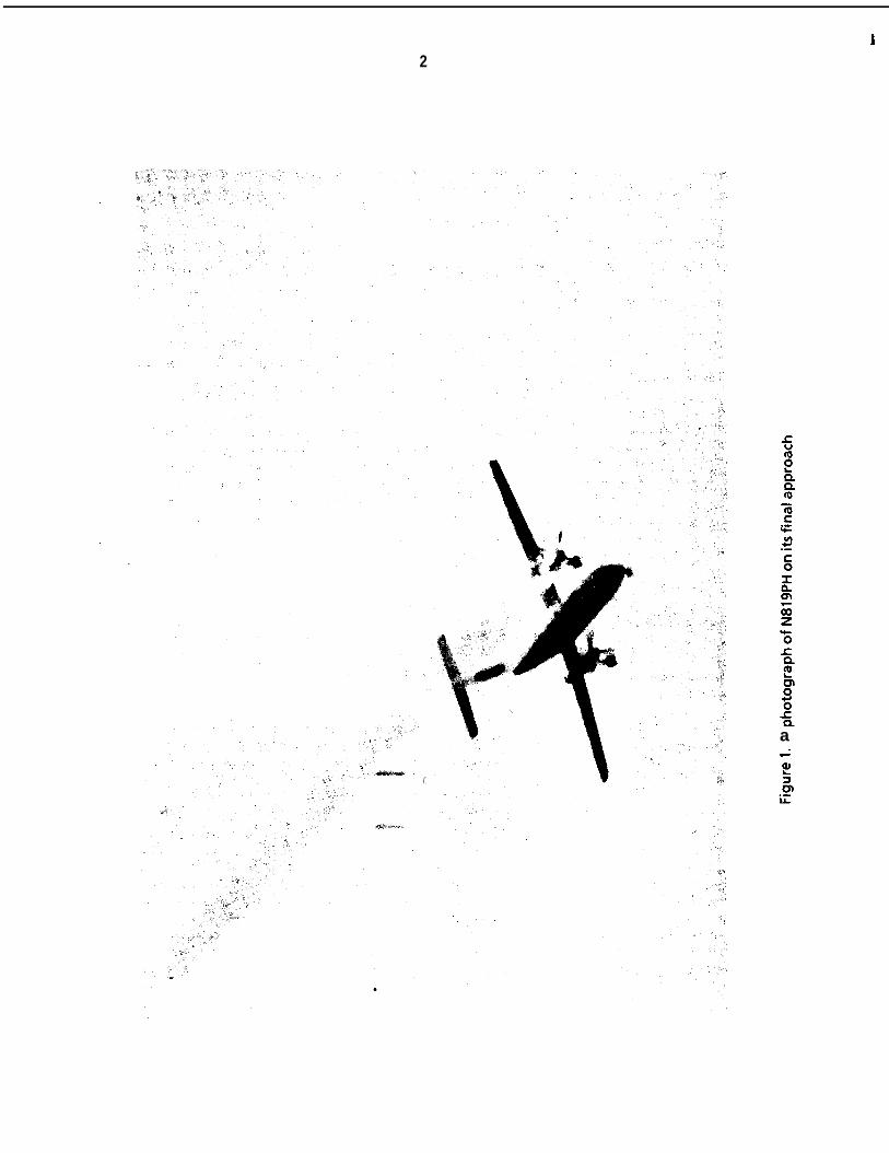
The first officer stated that as he was scanning for traffic out the right side window during theturn to final approach, he observed a “flash” from the right engine. The first officer then observedthat the center access panel on the left side of the right nacelle was missing and that anorange/yellow flame was in that area. The passenger in seat 9E also observed the fire and sawsections of engine cowl fall from the right nacelle. At 1831:03 the first officer stated, “We got afire.” Three seconds later the captain stated, “Max power. . .,‘I and at 1831:09 he called for 15” offlaps. According to the FDR, the flaps began to move down shortly thereafter. After informing thecaptain of the fire, the first officer returned his attention to the engine instruments. The captainthen retarded the right condition lever to the Start and Feather position and told the first officer topull the fuel cutoff T-handle and fire the extinguisher bottles. After the first officer fired theextinguisher bottles and pulled the fuel cutoff T-handle, he observed that the fire was still burningand also that the green landing gear lights were no longer illuminated. (See figure 1.)
At 1831:26, the flight attendant delivered her emergency landing briefing that included twodifferent brace positions because of the seating arrangement of the airplane.
About 114 mile from the runway (according to the captain) and about 100 feet above theground (according to the first officer), the crew began to notice a ‘I. . . significant change incontrollability” of the airplane. The first officer stated ‘I. . . the airplane felt like it was in slowflight, sort of wallowing around.” The airplane landed on runway 16L and then veered off the eastside of the runway on a heading of 154”. The captain stated that after touchdown at 1831:53 onthe paved surface and after reducing the left power lever to flight idle:
It was immediately obvious that the direction of movement was to the left of[the] runway direction. I attempted to use nosewheel steering, normaldifferential braking, and rudder to correct the direction. I had no directionalcontrol of the airplane. I first eased on the emergency brakes with no result andthen finally locked the lever into the parking position.
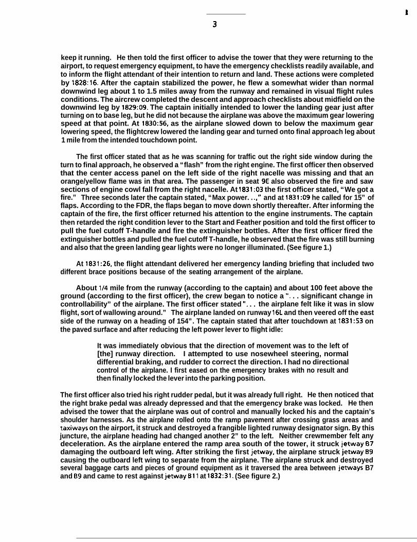
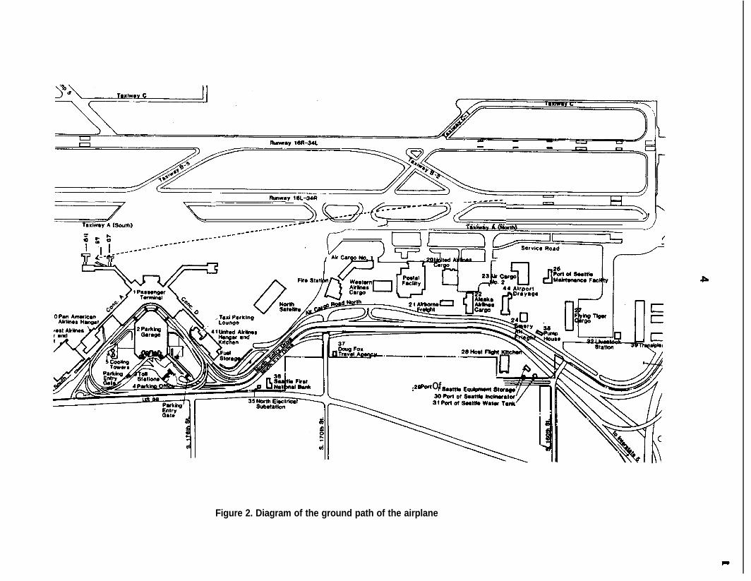
The first officer also tried his right rudder pedal, but it was already full right. He then noticed thatthe right brake pedal was already depressed and that the emergency brake was locked. He thenadvised the tower that the airplane was out of control and manually locked his and the captain’sshoulder harnesses. As the airplane rolled onto the ramp pavement after crossing grass areas andtaxiways on the airport, it struck and destroyed a frangible lighted runway designator sign. By thisjuncture, the airplane heading had changed another 2” to the left. Neither crewmember felt anydeceleration. As the airplane entered the ramp area south of the tower, it struck jetway 67damaging the outboard left wing. After striking the first jetway, the airplane struck jetway B9causing the outboard left wing to separate from the airplane. The airplane struck and destroyedseveral baggage carts and pieces of ground equipment as it traversed the area between jetways B7and B9 and came to rest against jetway Bll at 1832:31. (See figure 2.)
-~~~~~~--g+=--~-(p==_)
; f f -me--__*----
R ++--------_______ *_------ ---- ’ ?
I
28 Pat Of
Figure 2. Diagram of the ground path of the airplane
P
t
5
Within 15 seconds after the airplane came to a stop, the flightcrew saw fire suppressant foambeing applied to the airplane. The captain attempted to open the cockpit door and the overheademergency exits, both of which were jammed. The first officer then attempted to break thecaptain’s side window with the fire axe, but he was not successful. They then heard the firefightersassisting the passengers and were told to wait until the injured passengers had been evacuated.Subsequently, the firefighters opened the jammed cockpit door and assisted the pilots off theairplane.
During the accident sequence, 4 passengers received serious injuries; 24 passengers, the flightattendant, and both pilots received minor injuries; and 9 passengers received no injuries. Theairplane and various pieces of ground equipment were destroyed. The accident occurred duringdaylight hours.
1.2 Injuries to Persons
lniuries Crew Passenaers -Others Total
Fatal 0 0 0 0Serious 0 4 0 4Minor/None 3 33 0 35
Total 3 37 0 40
1.3 Damage to Airplane
The airplane received substantial damage because of the engine fire and was subsequentlydestroyed during impact with objects and structures on the ramp. The airplane was valued at $5.64million.
1.4 Other Damage
Numerous pieces of aviation ground support equipment, including one runway designatorsign, several baggage carts, a pickup truck, a ground auxiliary power unit, and three terminaljetways were damaged or destroyed by the airplane. The estimated value of these structures andpieces of equipment was $280,000.
1.5 Personnel Information
The captain was hired by Air Oregon in June 1979. Air Oregon was subsequently absorbed byHorizon Air, and the captain was hired by that company on September 1, 1981. He held airlinetransport pilot certificate No. 1767092 with ratings for the SA-227, the DHC8, airplane multiengineland, and commercial privileges for airplane single-engine land. At the time of the accident, he hadaccumulated approximately 9,328 total flying hours, 981 hours of which were in the DHC-8. Hereceived his initial type rating in the DHC-8 on November 5, 1986. The captain’s last line check wascompleted on September 5, 1987, and his last proficiency check was completed on October 5, 1987.The captain’s last recurrent training was accomplished on October 30, 1987. His most recent first-class Federal Aviation Administration (FAA) medical certificate was issued on January 19, 1988, withthe limitation, “Holder shall wear correcting lenses while exercising the privileges of his airmancertificate.”
The first officer was hired by Horizon Air on March 30, 1987. He held airline transport pilotcertificate No. 548882459 with ratings for airplane multiengine land and commercial privileges forairplane single-engine land. He also held a flight instructor certificate for airplane single-engineand multiengine land which was valid until March 31, 1989, and an air traffic control specialist
t
6
certificate. At the time of the accident, he had accumulated approximately 3,849 total flying hours,642 hours of which were in the DHC-8. The first officer completed his initial proficiency check onMay 7, 1987, and his last line check on May 22, 1987. His last recurrent training was accomplishedon March 11, 1988. His most recent second-class FAA medical certificate was issued on January 12,1988, with no limitations.
The flight attendant was hired by Horizon Air on March 9, 1987, after completing 56 hours ofbasic indoctrination, emergency training, and security training. She completed her initialoperating experience of 5.2 hours on the DHC-8 on March 12, 1987. She received her last recurrentground school and emergency training on March 20, 1988.
1.6 Airplane Information
The deHavilland DHC-8-102, N819PH, serial number 061, was manufactured on December 21,1985, and acquired by Horizon Air on February 6,1987.
The airplane weight and balance for the flight was as follows:
Basic weight (Ibs.) 22,425Passengers and cargo (Ibs.) 7,372Zero fuel weight (ZFW)(lbs.) 29,797Correction factor (Ibs.) 94Corrected ZFW (I bs.) 29,89 1Fuel load (Ibs.) 3,000Takeoff weight (Ibs.) 32,891
The planned fuel burn of 1,100 pounds would have resulted in a landing weight of 31,791pounds at Spokane. The maximum allowable takeoff weight was 34,500 pounds and the maximumlanding weight was 33,900 pounds. The forward center of gravity limit range varied linearly from20 to 21 percent mean aerodynamic chord (MAC) for weights between 32,000 and 34,500 pounds.The aft limit was 38 percent MAC. At the time of the accident, the center of gravity was about28.75 percent MAC.
1.6.1 Hydromechanical Fuel Metering Unit Replacement
Both engines on the airplane were equipped with a hydromechanical metering unit (HMU).An HMU assembly consists of the hydromechanical fuel control, a high-pressure fuel pump with anintegral fuel filter housing that contains the high-pressure fuel filter. The HMU assembly wasreplaced on the right engine of N819PH on April 8 and 9, 1988. The replacement HMU assemblywas removed as a complete unit from a spare serviceable engine in Horizon stores that had beenreceived from the Pratt and Whitney Canada factory. The fuel nozzles on the right engine alsowere replaced at that time. Horizon Air maintenance personnel stated that they performed thefollowing activity concerning the HMU:
1. An engine shop mechanic removed the replacement HMU assembly from spareengine S/N 120141 in the Horizon maintenance facility.
2. A Horizon engine maintenance inspector examined the HMU assembly andsigned the “serviceable tag.”
3. Another engine mechanic installed the HMU on the right engine (S/N 120078) ofN819PH. Part of the installation procedure was to attach the filter impendingbypass switch electrical lead onto the fuel filter cover.
7
4. An inspector signed off the replacement action for the HMU in the maintenancelogbook for N819PH.
5. Two different maintenance inspectors supervised a quality control engine runon N819PH which included a fluid leak check and signed off the quality controlinspection in the maintenance logbook.
6. A Horizon Air lead mechanic signed off the maintenance release on airplaneN819PH.
These maintenance actions were in response to an earlier series of crew maintenance logentries concerning fuel/oil fumes in the cockpit during flight. A teardown of the replaced HMU byits manufacturer later disclosed that the fuel fumes had been caused by a cracked bellows in theunit. According to a maintenance log entry, the removal and replacement of the HMU and the fuelnozzles was in accordance with Horizon maintenance manual 71-00-00, page 523. There were noother maintenance log entries in the log for the airplane after the HMU and fuel nozzle werereplaced on April 8 and 9.
1.7 Meteorological Information
A Seattle-Tacoma International Airport National Weather Service observation taken at 1832indicated a 2,300-foot scattered cloud layer with a measured 2,800-foot overcast ceiling. Visibilitywas 7 miles with a temperature of 60 “F and a dew point of 48 “F. Winds were from 250” at 4 knotsand the altimeter setting was 29.94 inches of mercury. At 1829:39, the tower controller clearedflight 2658 to land on runway 16L and gave flight 2658 winds of 240” at 8 knots during the sametransmission.
1.8 Aids to Navigation
The crew of N819PH did not use any navigational aids during the flight.
1.9 Communications
No communications difficulties were reported by the flightcrew or the air traffic controllers.
1 .lO Aerodrome Information
Seattle-Tacoma International Airport is operated by the Port of Seattle, Washington. It hastwo parallel runways designated 16L-34R and 16R-34L. Runway 16L is 11,900 feet long and 150 feetwide with a displaced threshold of 490 feet. It has an asphalt surface. The field elevation is 429feet msl. Runway 16L has high intensity runway tights, a medium intensity approach lightingsystem with sequenced flashing lights, and a visual approach slope indicator system. The airport’slast disaster exercise was an unannounced drill in January 1988.
1 .ll Flight Recorders
The airplane was equipped with a Sundstrand FDR that recorded 32 separate flight andequipment parameters during the flight. It was removed from the wreckage intact. Anexamination of the recovered data indicated that the recorder operated normally throughout theaccident flight. However, the parameters transmitted to the FDR for the right and left inboard andoutboard spoiler position, rudder position, left and right elevator position, and aileron positionwere not recorded when the airplane was on the ground during the landing roll. The reason for
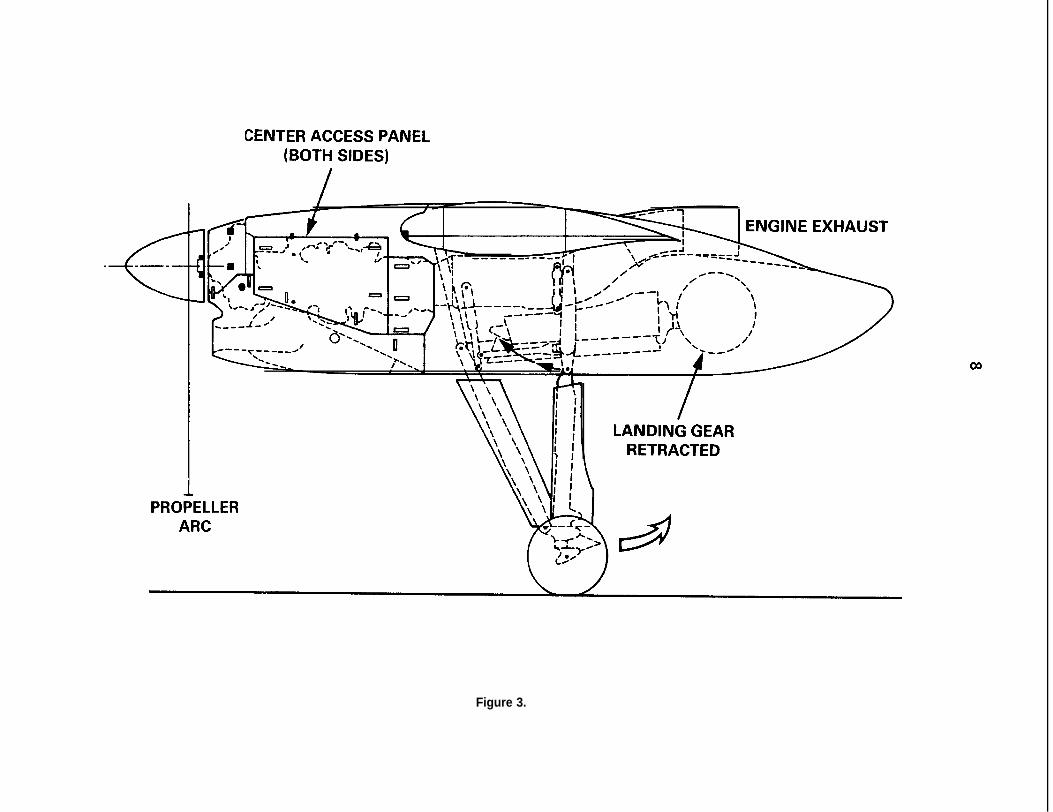
CENTER ACCESS PANEL(BOTH SIDES)
I ‘YNGINE EXHAUST
IIIIj
PRO;ELLERARC
LANDING GEARRETRACTED
Figure 3.
9
this data loss was attributed to the fire that compromised a number of electrical components onthe airplane.
The airplane was also equipped with a Sunstrand Model AV557-C cockpit voice recorder (CVR).It, too, was recovered from the wreckage undamaged. The tape was of excellent quality, and atranscript of the last 10 minutes on the tape is included as appendix E. At 1827:42, the recorderstopped and reversed direction; this is a normal function on this type of CVR.
1 .I 2 Wreckage and impact Information
The right engine inboard center access panel was located 10,300 feet to the north of thethreshold for runway 16L in a school yard. This panel was almost completely free of sooting anddisplayed no fire damage. No other components were recovered outside the airport boundary.
The first evidence of airplane ground contact was a set of wheel tracks associated with the leftwheel assembly when the airplane rolled off the east side of the runway. These tracks were 3,275feet south of the end of the runway threshold and began 128 feet east of the runway centerline.The direction of these tracks was 6” to the left of the runway heading. The right wheel tracksbegan 3,535 feet south of the threshold, and the nosewheel tracks began 3,672 feet south of thethreshold.
The path of the airplane was traced farther by more tire tracks, a trail of burned debris fromthe right nacelle area, and the use of an airport surveillance video tape that showed the landingsequence, landing rollout, and portions of the final impact with the jetways.
A large hole was ripped in the right side of the fuselage during impact with the groundequipment. It extended from the floor level of the cabin to above the window line and from theright underwing emergency escape hatch forward to the right emergency door. The airplane cameto rest against jetway Bll with its fuselage pointing east and the right wing penetrating thejetway boarding tunnel. (See figure 3). The position of the flaps was about 6” down when theairplane was later examined. This was also the last flap position recorded on the FDR about 74seconds before the end of the recording.
1.12.1 Right Engine Fire Damage
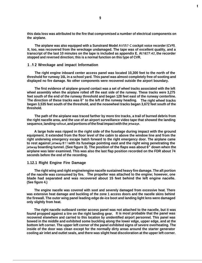
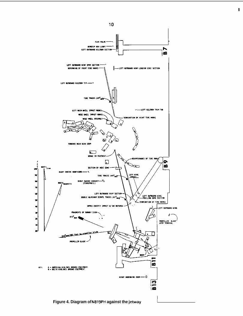
The right wing and right engine/engine nacelle sustained heavy fire damage. The aft portionof the nacelle was consumed by fire. The propeller was attached to the engine; however, oneblade had separated and was recovered about 15 feet behind the left engine nacelle.(See figure 4.)
The engine nacelle was covered with soot and severely damaged from excessive heat. Therewas extensive heat damage and buckling of the zone 1 access doors and the nacelle skins behindthe firewall. The outer wing panel leading edge de-ice boot and landing light lens were damagedonly slightly from heat.
The right nacelle outboard center access panel was not attached to the nacelle, but it wasfound propped against a tire on the right landing gear. It is most probable that the panel wasrecovered elsewhere and carried to this location by unidentified airport personnel. This panel wasbowed in the middle and exhibited some buckling along the lower edge, upper edge, and at thebottom left corner. The upper left corner of the panel exhibited signs of severe overheating. Theinside of the door was clean except for the normally dirty areas around the starter generatorcooling air inlet and outlet seals, and there was slight heat discoloration at the upper left corner.
t
\ A --..,,,,:3TfRM
Figure 4. Diagram of N819PH against the jetway
Y
11
Both panel hinges located along the upper edge of the door had fractured. The six cowl doorspring closed latches were all closed and latched.
The right nacelle inboard center access panel was bowed and moderately buckled along thelower edge and right rear corner. All six of the cowl door spring closed latches were closed andlatched. There was no heat damage to the outer or inner surface of the door panel. The oilservicing door was deformed outward. The upper push-to-release latch was closed and latched;however, the latch pin was outside the pocket. The lower push-to-release latch was in place andlatched.
The underside of the cowling was lightly sooted to about the center of the intake cowl. Aft ofthis area, the intensity of the sooting and fire damage increased toward the wheel well area. Justbelow the outboard zone 1 access panel, the metal was burned extensively and exhibited heatdamage. The top of the cowl exhibited only very light sooting. The inside and the outside surfacesof the upper rear access panel were damaged severely by heat. Although the louver was missing,the louver screen was in place, but it was punctured and covered with soot. The cowl right rearedge where the side door rear hinge attaches to the upper cowl structure was burned severely aswell as the rear left corner of the cowl rear access panel. Both sides of the right engine cowls werelightly sooted from the propeller spinner to the front edge of the side access panels and along thelower edges of side access panel frames to a point midway along the lower frame members. Aft ofthis area, there was increased heavy heat and fire damage that extended aft to the wing trailingedge.
The engine was sooted heavily over its entire surface; there was no physical damage and noexternal punctures noted on the compressor and, turbine cases. Continuity was establishedbetween the HMU and the cockpit controls; however, the cable drum was damaged. All hosesexhibited extensive heat damage; insulation was burned from most of the electrical wiring, andtube and wire clamp insulators were reduced to ash,
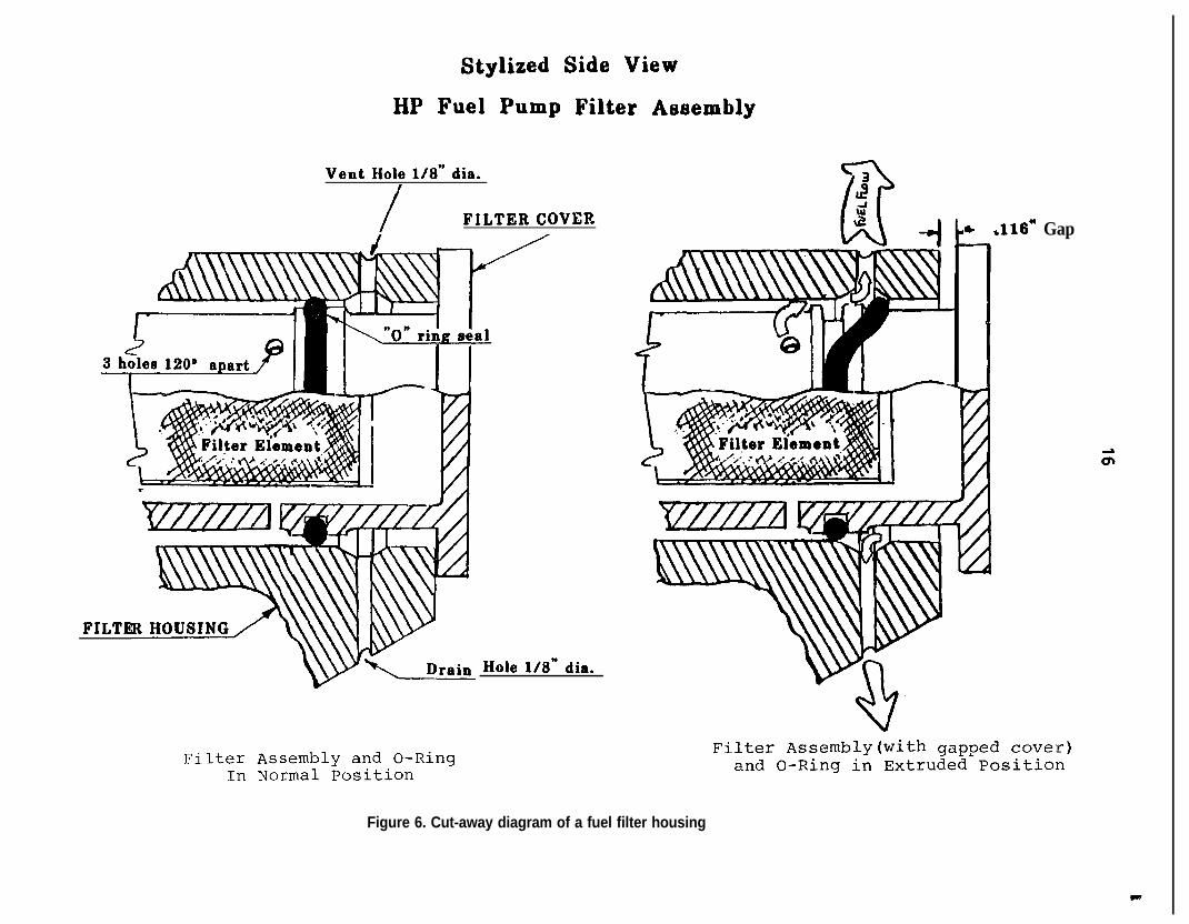
There was a 0.116-inch gap between the HMU high pressure fuel filter cover and the face ofthe housing. Fuel was observed leaking from the bottom of the gap 22 hours after the accident.The fuel filter cover on the left engine was examined, and the cover was noted to be bottomedagainst the filter housing; there was no gap. Specified torque on the fuel filter cover is 100 to 150inch pounds.
The right starter generator was heavily sooted and the brush cover band plating was blisteredover a 140” arc. The ignition exciter box was undamaged, but the outer surface was covered lightlywith soot.
1.13 Medical and Pathological Information
The captain was not requested to provide specimens for toxicological analysis following theaccident because investigators were unaware that he was sent to a different hospital than that ofthe other crewmembers. The hospital where the captain was treated was not requested to collectblood or urine as part of his treatment. The Center for Human Toxicology, University of Utah, SaltLake City, Utah, examined toxicological specimens from the first officer and the flight attendant.Using gas chromatography-mass spectrometry testing procedures, the Center did not detect drugsor alcohol in the specimens taken from either individual.
The captain, the first officer, and the flight attendant reported that they had experienced nosignificant adverse events in their lives recently. The investigation disclosed no unusual life habitsor events that could have affected the performance of either pilot or the flight attendant on theday of the accident.
t
12
1.14 Fire
Statements from the first officer and several passengers revealed that the first time theynoticed flames was shortly after the landing gear was lowered. The first officer stated, “We got afire,” at 1831:03,50 seconds before touchdown. The fire continued to burn throughout the flight,the landing rollout, and after the airplane came to a stop against the jetway at 1832:31. Port ofSeattle Fire Department (POSFD) truck 4 radioed to the fire station dispatcher,“We’ve got the firetapped,” at 1839, meaning that the fire was completely extinguished at that time.
1 .15 Survival Aspects
The cockpit seating arrangement consisted of seats for the captain and first officer and astowable jumpseat (stowed during the accident sequence) on the front face of the cockpit door.Neither the captain’s nor the first officer’s seats were displaced during the accident sequence. Theshoulder harnesses on both seats were intact and operational; however, they were frayed andabraded at the “Y” junction to about 12 inches above that junction. The plastic covers over theshoulder harness guide rollers on the backs of both seats were missing. In addition, the cockpitjumpseat hold-up strap in the cockpit was frayed and split. The jumpseat was held in the stowedposition by placing this split strap over the jumpseat hold-down stud on the hinged seat. The crashax was found on the floor behind the left seat, and the aft left cockpit window was cracked.
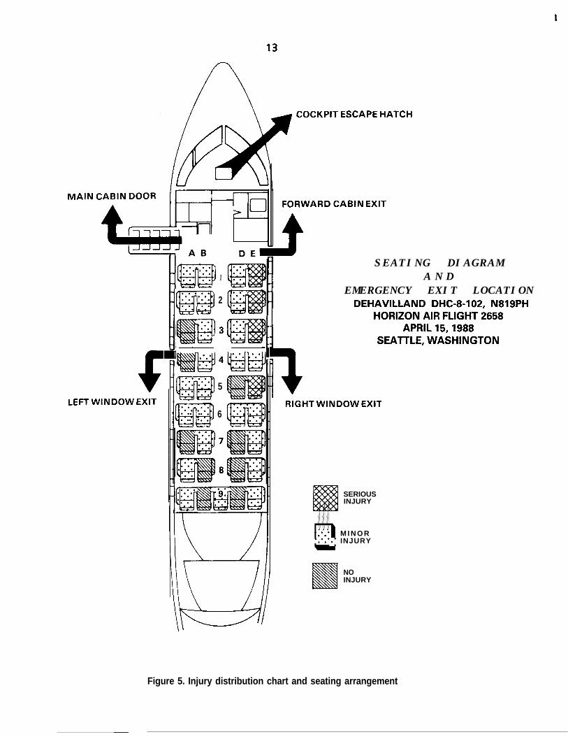
The cabin seating arrangement consisted of 37 coach seats. Seat rows l-8 were doubleoccupancy seats (four passengers per row with an aisle down the middle), and row 9 was acontinuous row that seated five passengers. (See figure 5.) An aft facing single-occupancy flightattendant jumpseat was attached to the left rear side of the closet/wardrobe adjacent to theforward main cabin door.
The airplane had five emergency exits: the main cabin door; the forward cabin emergencyexit; two mid-cabin emergency window exits at row 4; and the cockpit emergency hatch. Allpassengers escaped or were evacuated through the left mid-cabin window emergency exit or thehole in the right side of the fuselage. The hole extended from fuselage station 270 to fuselagestation 348 and from waterline 100 to waterline 160 (from seat rows 1 through 3).
Seats IDE, ZDE, and 3DE, in the area most heavily damaged during impact with groundequipment, were torn loose during the accident sequence. The passengers in seats 3D and 3E wereejected from the airplane while still buckled in their seats. The forward and aft outboard legattachments of seat 9E separated from the floor track. All other passenger seats as well as theflight attendant’s seat remained attached to the airplane floor, although some passenger seatssustained some degree of impact deformation. The overhead compartments over seats 2DE and3DE were open, while all other overhead compartments were closed.
The beverage cart was found on its side in the aisle between seat rows 3 and 4. The secondarysecuring latch for the cart was unlatched. Structural continuity of the floor area in the cart storagearea was lost around the “mushroom” floor lock doubler. The floor covering was torn on theforward side of the doubler, and the floor underneath the covering had dropped away from thedoubler. The secondary securing latch for the lower compartment door was also unlatched.
A closet/wardrobe was installed on the left side of the cabin, forward of the main cabin door.A placard on the wardrobe read, in part, “100 Ibs. floor load limit.” Objects removed from thiswardrobe following the accident included catering boxes, beer, wine and liquor containers, asuitcase and a small, portable mechanical carpet sweeper. The objects (not including the carpet
I
MAIN
COCKPIT ESCAPE HATCH
6LEFT WINDOW EXIT
. . . . .. . . .. . . .lm. .. ::1
2
I! If. . . .. .. . ::4iiiEl.:: -:.2. .. . :::w. . . .. . *..5
6
FORWARD CABIN EXIT
SEATING DIAGRAMA N D
EMERGENCY EXIT LOCATIONDEHAVILLAND DHC-8-102, N819PH
HORIZON AIR FLIGHT 2658APRIL 15,1988
SEATTLE, WASHINGTON
RIGHT WINDOW EXIT
SERIOUSINJURY
. . .-::. * M I N O Rq*.*a ‘.I INJURY. . .
NOINJURY
Figure 5. Injury distribution chart and seating arrangement
t
14
sweeper) weighed 146 pounds. DeHavilland Service Bulletin 8-25-35, dated February 19, 1988,called for a l/4-turn latch that, at the operator’s option, can be installed on the door of thewardrobe to prevent it from opening unexpectedly. This service bulletin also stated that until thelatch had been installed, the wardrobe should be restricted to hanging items only. The 1/6turnlatch had not been installed on N819PH, and the closet/wardrobe door separated completelyduring the accident. Following the accident, on November 28, 1988, Transport Canada issuedAirworthiness Directive (AD) CF-88-24. This document made the provision of Service Bulletin 8-25-35 mandatory for Canadian operators of DHC-8s. The FAA has not acted on this Canadian AD tomake the service bulletin mandatory for U.S. operators.
Aircraft rescue and firefighting activities began at 1827 when the ground controller notifiedthe POSFD that flight 2658 was returning to land. The fire department initiated a full responsewhich included two heavy crash trucks, one quick response vehicle, one engine, one firedepartment ambulance, and one command vehicle. After assuming their standby positions on theairfield, these vehicles followed the airplane as it crossed the ramp to the jetway area. Accordingto the POSFD and the video tape, firefighters began extinguishing the fire immediately after theairplane stopped at about 1832.31. The firefighters extinguished the fire in the right engine areaby 1839, about 7 minutes after the airplane first touched down. A firefighter entered the cabin assoon as passengers stopped using the exit and began extricating two passengers (seated in 1 E and2E) who were trapped by wreckage. Other firefighters assisted with the extrication after the firewas extinguished and both passengers were removed from the wreckage on backboards. Alloccupants were removed from the airplane by 1853. The first officer and the captain were the lasttwo individuals to be assisted off the airplane.
1 .I 6 Tests and Research
1.16.1 The Cockpit Shoulder Harnesses
The captain’s and first officer’s shoulder harness restraint systems were removed from theairplane and tested at the FAA’s Civil Aeromedical Institute’s Protection and Survival Laboratory inOklahoma City, Oklahoma. Pull tests were conducted on the abraded area of the upper torsowebbing of both restraint systems on an lnstron Model 1123 Universal Testing Machine. Thecaptain’s shoulder harness failed at 1,160 pounds just below the stitching at the “Y” junction in thewebbing. The first officer‘s shoulder harness webbing failed at 1,600 pounds in the same area onthe harness. According to Am-Safe, Inc., the company that manufactured the harnesses, thewebbing used on the harnesses was originally rated at 4,000 pounds.
1.16.2 Postaccident Fuel System Pressure Test
Because of the amount of maintenance accomplished on the right engine before the accidentto eliminate a fuel/oil odor in the cabin, an undisturbed pressure test on the fuel system of the rightengine was performed. The postaccident test protocol consisted of introducing a test fuel underpressure from an auxiliary tank into the engine fuel system to expose leaks. If no static leakageoccurred, the fuel pump would then be rotated to increase pressure by driving the accessorygearbox with an auxiliary motor.
The engine accessory gear box breather adaptor and drive coupling shaft were removed firstin order tu decouple the accessory drives from the main engine rotor and to allow rotation of onlythe accessory gears and fuel pump drive. A flexible pipe was used to connect the auxiliary fuel tankto the fuel heater inlet port. Test fuel then was applied at 10 psig to the fuel system; leaks wereobserved immediately at the fuel pump filter housing vent (top) and drain (bottom) holes.
c
15
Inlet fuel pressure was then increased to 20 psi and a clear flow of fuel came from the vent anddrain holes. Inlet fuel pressure was subsequently increased to 30 and 50 psi, respectively. At thattime, a considerable flow of test fuel sprayed from both the vent and drain holes in the fuel filterhousing. Further, additional test fuel leaked from the housing-cover gap. All of the leakingoccurred statically without the planned rotation of the fuel pump gears by motoring the gear box.
1.16.3 High-Pressure Fuel Pump Examination and Test
The HMU/fuel pump assembly was removed from the engine for operational testing. Beforethe disassembly, radiographs were made of the filter housing area of the assembly. (See figure 6.)Several of the radiographs clearly showed that a portion of the preformed o-ring packing hadcome out of its groove in the filter cover and was looped toward the cover face. This gap provideda direct path for fuel to flow beyond the o-ring groove and annulus machined into the cover, topass the looped and pinched o-ring packing, then to flow overboard, and into the enginecompartment through the vent and drain holes drilled in the fuel filter housing.
Before testing the HMU/fuel pump assembly that was removed from the accident airplane, anidentical serviceable HMU/fuel pump assembly was tested to determine the validity of theproposed test plan. Using the substitute pump, the test would determine the following:
0 the effect on outlet fuel flow leakage from the HMU ejector;
0 loss of pump inlet boost pressure;
0 torque requirement for backing out the filter cover under normal operatingconditions; and
0 at what point (gap) a backed out fuel pump filter cover would start to leak fuelfrom the vent and drain parts on the filter housing.
After the test was completed, the following conclusions were reached:
0 fuel ejector flow leakage did not effect fuel flow to the engine; and
0 a decrease in pump inlet fuel pressure had no effect on HMU output flow.
At this point, the test was terminated, and a gap of. 100 inch was established between the fuelfilter cover and the pump housing. A gap of less than the .116 inch found on the actual pump fromthe engine was selected so that any production machining tolerances would not affect thesubsequent pump testing. Pump testing was started again, and it was noted that no fuel leakagewas evident from the vent or drain holes or from the .lOO inch gap between the housing and thecover.
An attempt was then made to increase the gap by unthreading the fuel filter cover out of thehousing. In order to move the cover, the friction of the o-ring packing as well as the affect of fuelpressure had to be overcome. To back out the cover with a fuel pressure of 150 psi, 260 in/lbs. oftorque were required. Normal free running torque, without fuel pressure, was 10 in/lbs.
The filter cover then was backed out continually in small increments to determine at whatpoint leaking would occur from the drain and vent holes. A constant flow of fuel occurred whenthe filter cover was backed out .194 inch and with fuel pressure of 150 psi from a fully seatedposition.
Stylized Side View
HP Fuel Pump Filter Aeeembly
Vent Hole l/8” dia.I
/ FILTER COVER
FILTE
Filter Assembly and O-RingIn Normal Position
Hole l/8” dia.
* .116* Gap
Filter Assembly(with gapped cover)and O-Ring in Extruded Position
Figure 6. Cut-away diagram of a fuel filter housing
t
17
At this point, the test was terminated again. The filter cover was reseated and the filter wasaltered by installing a controllable bleed in the filter cover to simulate a fuel leak from the vent anddrain holes. Then, by increasing the rate of the leak, it could be determined at what point a fuelleak from the vent and drain ports would affect fuel flow.
By motoring the HMU/pump assembly to obtain fuel flow and pressure and then by graduallyincreasing the leak rate from the fuel cover, the tests indicated a significant loss of HMU meteredfuel flow when the filter leakage exceeded approximately 2,000 pounds per hour (pph). Fuel flowto the engine decreased from 602 pph to approximately 444 pph with a simulated leak of 2,450 pphfrom the controllable bleed.
1 .I 6.3.1 Right Engine HMWFuel Pump Bench Test
The right engine HMU assembly was installed on the test bench in the “as-received” condition.A short flushing cycle purged the control and it was pumped of trapped air. Since an extensive leakfrom the filter area of the pump was anticipated, a clear plastic cover was fabricated to protect theobservers. As boost pump pressure was applied, leaks were observed coming from the vent anddrain holes. At 300 rpm pump speed (100 percent pump speed is approximate 4,100 rpm), amassive fuel leak was observed at the filter housing vent and bleed holes as well as the housingcover thread area. Fuel was also dripping from the HMU power lever shaft. Because of themagnitude of the leak from the filter area at 300 rpm pump speed, it was considered unsafe andunnecessary to proceed, and the pump test was terminated.
1 .16.3.2 Fuel Pump Disassembly
In order to confirm the findings available from the radiographs and to examine the o-ringpacking and determine the cause of the leaks from the power lever shaft, the pump wasdisassembled partially.
To remove the fuel filter cover required 80 in/lb% breakaway and 40 in/lbs. running torque,which gradually decreased to a point where the cover could be removed by hand. A visualexamination of the cover showed that the threads were in good condition. The o-ring was in onepiece and in the proper position, but it exhibited some abrasion in the area where it had beenforced out of its groove. It also exhibited a small cut in this area. When the pump wasdisassembled, it revealed that the power lever shaft seals exhibited considerable heat damage. Thepower lever portion of the HMU as installed in the airplane was in an area of moderate to heavyf i r e d a m a g e .
1 .I 6.4 Starter Generator Brush Access Cover Examination
The starter generator brush access covers on the starter generators of both engines were notinstalled in accordance with the Lucas Corporation overhaul manual. This manual is the only placewhere the correct installation procedure is outlined. Horizon Air maintenance personnel did nothave the procedure on their work cards, nor was the procedure included in deHavillandmaintenance information concerning the generator (the source of the work card data). Theseaccess covers are metal bands that surround the generators with a gap or open area where the endsof the band connect. When properly installed, this gap is positioned over the top of a rib on thegenerator case. On the starter generators of both engines of the accident airplane, both brushaccess covers were rotated on the generator cases so that their gaps were over openings in thegenerator cases. The position of the brush access covers allowed an open path between the outsideof the starter generators and the starter generator brush areas. In addition, the design of thecovers allowed another open path to ambient air where the generator leads enter the startergenerator cases.
P
18
NO1ENGINEPUMP
QNO. 1STANDBYPUMP
9
-----aI/ ‘1---- 1
NO.2ENGINEPUMP
Q-+--\
POWER TRANSFER UNIT
HYDRAULIC HYDRAULICMOTOR PUMP
EXTENSON AND
CONTROL VALVE I
NO.2ST A N D B YPUMP
- +---/
NOSEWHEEL-4 STEERING 1
Figure 7. Schematic of the DHC-8 hydraulic system primary component
19
1.16.5 Airplane Hydraulic Systems Description
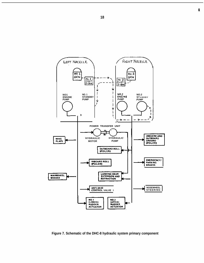
The N819PH was equipped with two independent constant pressure, variable flow hydraulicsystems called the No. 1 (left) and the No. 2 (right) systems. By design, it was not possible totransfer control of hydraulic devices from one system to the other. The airplane was equippedwith an emergency hydraulic system hand pump for use during emergency extension of thelanding gear. Also, a power transfer unit (PTU) was installed to aid in the retraction of the landinggear in the event of a right engine failure on takeoff. The PTU consisted of a No. 1 (left) systemhydraulic motor mechanically linked to a hydraulic pump that provided emergency pressure to thelanding gear retract cylinders, a No. 2 (right) system component. No fluid transfer betweenhydraulic systems could occur normally in the PTU. The output pressure of the engine drivenhydraulic pumps was rated at about 3,000 psi. Their flow rate was rated as 9.2 gallons per minute.The output pressure of the electric standby hydraulic pumps was rated as 2,750 psi under load.Their flow rate was rated as 1.56 gallons per minute. The No. 1 (left system) electric standbyhydraulic pump received electrical power from the No. 2 (right) electrical supply contactor junctionbox, and vice versa. (See figure 7.)
The following devices operated from the No. 1 (left) hydraulic system that received hydraulicpressure from the No. 1 engine-driven hydraulic pump and/or the No. 1 electrically driven hydraulicstandby pump:
1. the wing flaps;2. the mainwheel brakes;3. the inboard roll spoilers;4. the anti-skid control valve;5. the No. 1 (lower) rudder actuator; and6. the hydraulic motor section of the PTU.
The following devices operated from the No. 2 (right) hydraulic system that received hydraulicpressure from the No. 2 engine-driven hydraulic pump and/or the No. 2 electrically driven hydraulicstandby pump:
1. the landing gear extension and retraction system;2. the nosewheel steering system;3. the emergency/parking brake;4. the inboard and outboard ground spoilers;5. the outboard roll spoilers; and6. the No. 2 (upper) rudder actuator.
1 .I 6.5.1 Damage to the Hydraulic Systems
The fire had burned through electrical wiring insulation in the right wheel well that wasassociated with the No. 2 electrical-standby hydraulic pump. Circuit breakers associated with thispump were found open. Also, the fire destroyed the wiring to the No. 1 electrical-standbyhydraulic pump from its normal power supply in the right wheel well.
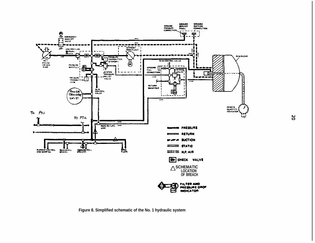
Three No. 1 (left) hydraulic pressure and fluid return lines in the right wing rear spar area ofthe right wheel well had been burned through by the fire. These fluid return lines included: onel/4-inch diameter hydraulic pressure supply line to the right wing inboard roll spoilers; one l/4-inchdiameter lift dump pressure line; and one 3/8-inch diameter No. 1 hydraulic system return line.Also, the emergency/parking brake accumulator unit was found intact but both hydraulic lines to itwere burned through. (See figure 8.) The destruction of these five hydraulic lines disabled bothhydraulic systems.
f
cl3 O(tclc V&VIn SCHEMATIC
LOCATIONOF BREACH
Figure 8. Simplified schematic of the No. 1 hydraulic system
t
21
Following the accident, the No. 2 hydraulic quantity gauge indicated about 1.5 quarts, and itsmechanical float linkage was seized. Less than 1 quart of fluid was drained from the reservoir afterit was detached from the wreckage. The normal No. 2 reservoir quantity is up to 5.19 U.S. quartswith at least 3 quarts needed to dispatch the airplane. The No. 1 hydraulic reservoir was found tocontain about 2 quarts of fluid. The normal No. 1 reservoir quantity is up to 2.68 U.S. quarts with atleast 1.5 quarts needed to dispatch the airplane.
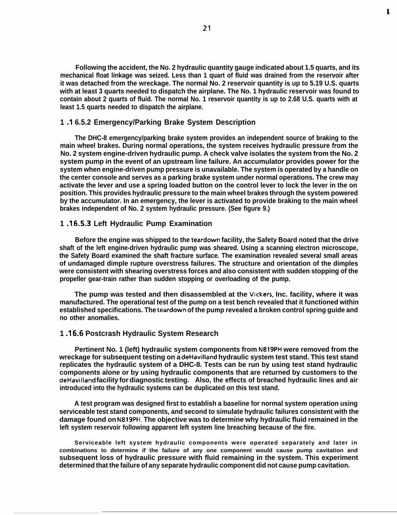
1 .I 6.5.2 Emergency/Parking Brake System Description
The DHC-8 emergency/parking brake system provides an independent source of braking to themain wheel brakes. During normal operations, the system receives hydraulic pressure from theNo. 2 system engine-driven hydraulic pump. A check valve isolates the system from the No. 2system pump in the event of an upstream line failure. An accumulator provides power for thesystem when engine-driven pump pressure is unavailable. The system is operated by a handle onthe center console and serves as a parking brake system under normal operations. The crew mayactivate the lever and use a spring loaded button on the control lever to lock the lever in the onposition. This provides hydraulic pressure to the main wheel brakes through the system poweredby the accumulator. In an emergency, the lever is activated to provide braking to the main wheelbrakes independent of No. 2 system hydraulic pressure. (See figure 9.)
1 .16.5.3 Left Hydraulic Pump Examination
Before the engine was shipped to the teardown facility, the Safety Board noted that the driveshaft of the left engine-driven hydraulic pump was sheared. Using a scanning electron microscope,the Safety Board examined the shaft fracture surface. The examination revealed several small areasof undamaged dimple rupture overstress failures. The structure and orientation of the dimpleswere consistent with shearing overstress forces and also consistent with sudden stopping of thepropeller gear-train rather than sudden stopping or overloading of the pump.
The pump was tested and then disassembled at the Vickers, Inc. facility, where it wasmanufactured. The operational test of the pump on a test bench revealed that it functioned withinestablished specifications. The teardown of the pump revealed a broken control spring guide andno other anomalies.
1 A6.6 Postcrash Hydraulic System Research
Pertinent No. 1 (left) hydraulic system components from N819PH were removed from thewreckage for subsequent testing on a deHavilland hydraulic system test stand. This test standreplicates the hydraulic system of a DHC-8. Tests can be run by using test stand hydrauliccomponents alone or by using hydraulic components that are returned by customers to thedeHavilland facility for diagnostic testing. Also, the effects of breached hydraulic lines and airintroduced into the hydraulic systems can be duplicated on this test stand.
A test program was designed first to establish a baseline for normal system operation usingserviceable test stand components, and second to simulate hydraulic failures consistent with thedamage found on N819PH. The objective was to determine why hydraulic fluid remained in theleft system reservoir following apparent left system line breaching because of the fire.
Serviceable left system hydraulic components were operated separately and later incombinations to determine if the failure of any one component would cause pump cavitation andsubsequent loss of hydraulic pressure with fluid remaining in the system. This experimentdetermined that the failure of any separate hydraulic component did not cause pump cavitation.
t
22
FAIIKING BRAKEFMSSURE INDICATOR
?ARt OFMASER CAUTION UGHTS 7 I
?ANEL N0
?ARKtNG DRAKE i 1?RESSURLTRANSMllTEA XCUWLATOR
PARKING BRAKECONTROL VALVE
TO SWVRLE VALVESAND BRAKE UNITS a tONOTHER + D iMAIN GEM
- PRESSURE
WSODBI~ RETURN
r-4 WCTION
= STATIC
=: = RF. AIR
El OIECK VALVE
SWOWN WITN CAllKIN nSCHEMATIC
DRAKE APPLIED LOCATIONOF BREACH
Figure 9. Schematic of the emergency/parking brake system
23
Next, the hydraulic components from N819PH were installed on the test stand and numeroustest runs were performed. For the rest of the testing, the No. 1 (left) hydraulic system wasconfigured with three rapid activation valves located in the system at the approximate sites of theline breaches found on N819PH. These valves were fast-acting, electrically powered valves thatcould simulate sudden line rupture.
During the first test run in this configuration, the system did not contain extraneous air, andall three valves were opened. This resulted in the cavitation of the engine-driven hydraulic pump,in the system pressure falling to 0 psi, and in a small amount of hydraulic fluid remaining in the
hydraulic lines and reservoir. This amount of fluid was less than the amount of fluid found in theleft hydraulic system in the wreckage of N819PH. In the numerous additional test runs thatfollowed, when the hydraulic lines were breached, the pump cavitated, the hydraulic pressuredropped, and a small amount of fluid remained in the system.
The next test run was accomplished after the No. 1 hydraulic system filter was removed,drained, and replaced on the No. 1 hydraulic system. The air intentionally introduced into thesystem by the drained filter was not bled out before the beginning of the test run. By introducing aknown quantity of air into the lines, there was a further attempt to determine why a great amountof fluid remained in the left hydraulic reservoir following the accident. During this run, thel/4-inch hydraulic pressure supply line for the left roll spoilers was breached via one of the fast-acting valves. This line was the smallest in diameter of the three that were burned through in thefire and it contained system operating pressure of 3,000 psi. It was determined that because it wasthe smallest line with the highest operating pressure of the three lines, it would have failed firstduring the fire. Following the simulated breach of this line, the pump cavitated as before,hydraulic system pressure fell to 0 psi as before, but this time a considerable amount of hydraulicfluid remained in the reservoir. This test was repeated with identical results.
1 .I 7 Additional Information
1.17.1 Discovery of Another Loose Fuel Filter Cover
During the investigation, when a loose fuel filter housing on N819PH first became suspect,another newly overhauled engine from Horizon Air stores was examined by Horizon Air personnelto determine what the filter housing should look like in a secured condition. The engine that wasexamined also had a loose fuel filter cover. This loose filter cover was later examined by HorizonAir’s FAA principal maintenance inspector. This engine, according to Horizon Air maintenancepersonnel, was recently shipped from Pratt and Whitney of Canada and had not been disturbed byanyone since its arrival at Horizon Air.
1 .I8 New Investigation Techniques
1.18.1 Radiographic Examination of the Fuel Filter
The high-pressure fuel filter assembly was examined via radiograph (x ray) before removingthe filter cover from the HMU. (The resulting radiographs did not contain sufficient photographiccontrast to be reproduced in this report.) Although the use of radiograph technology in accidentinvestigation is not a new technique, the ability of radiographs to reveal the position ofnonmetallic o-rings was particularly important to this investigation. At the time, someinvestigators and the technician operating the x-ray machine believed that the o-ring probablywould be masked fully by the denser metallic filter housing. In point of fact, the extruded o-ringwas visible on several of the radiographs. This knowledge was especially valuable because theo-ring snapped back into its correct position when the filter housing was removed. Because of its
t
24
damaged condition, the o-ring still would have been identified as the fuel leak source, but withoutthe radiographic proof, the fact that the o-ring had extruded over the filter weep hole would nothave been discovered. Given the relatively small amount of damage to the o-ring, it would havebeen very difficult to explain the high volume of the fuel leak.
1.18.2 Computer Enhancement of the Video Tape
The video tape of the accident sequence was of poor quality, but after key frames of the tapewere computer-enhanced, it was useful in proving that ground spoiler actuation did not occurduring the landing rollout.
The images on the video tape were enhanced electronically to highlight any horizontal andvertical edges on the wing upper surface. A mathematical “Roberts” edge filter was applied to thedigitized video pictures. This Roberts filter compared the brightness values of the neighboringpixel elements and enhanced the occurrences of line segments in the pictures. This enhancementwas used to see if edges of the spoilers could be detected over the edge of the wing. Using thistechnique, no evidence of ground spoiler activation was found on either wing in any of the keyvideo frames examined on the accident video tape.
L
25
2. ANALYSIS
2.1 General
The captain, first officer, and flight attendant aboard Horizon Air flight 2658 were trained andqualified for the flight in accordance with company policy and FAA regulations. The Safety Boardalso notes that Horizon Air has an established cockpit resource management (CRM) trainingprogram. The flightcrew’s actions during this accident illustrated familiarity with the concepts ofthis training.
In addition, the flight attendant’s instructions to passengers to take one of two bracepositions (due to the seating arrangement of the airplane) were delivered correctly beforetouchdown. Further, her repeated insistence that the passengers remain in the braced positionwhile the airplane rolled across the ramp and into the jetways was important in preventing moreserious injuries.
FAA air traffic control personnel in the Seattle tower and approach control facilitiesperformed their duties in a timely and appropriate manner during the accident sequence. Duringthe first phase of the incident, after the flightcrew notified the tower that they were returning toland (with no amplifying comments), the controller sequenced the airplane into landing trafficaccording to established procedures. Shortly thereafter, the local controller ordered emergencypersonnel into position, even though he knew only that the airplane was returning for unknownreasons. Although the flightcrew had not declared an emergency at that point, the controllerinitiated an emergency equipment response solely as a safety precaution. Because the incidentevolved from a simple precautionary landing into a catastrophic in-flight fire less than a minutebefore touchdown, the controller’s actions in alerting the emergency crews resulted in a timelyresponse and effective evacuation of the passengers and crew.
The effectiveness of the aircraft rescue and firefighting activities of the POSFD was alsonoteworthy. The fire that engulfed the right engine nacelle area was extinguished by 1839, within7 minutes after touchdown. In the video tape of the accident sequence, several firetrucks reversedtheir direction after the plane touched down, and in order to be in good position to put out the fireand begin passenger rescue as soon as possible, the firetrucks followed flight 2658 across the rampwhen the crew lost control of the airplane. The rapid response of the emergency personnel wasinstrumental in saving the life of the passenger in seat 1E who sustained a lacerated aorta. Therescue of this passenger began before the fire was extinguished.
2.2 The Right Engine Fuel Leak and Fire
The Safety Board determined that the cause of the fuel leak on the accident flight was theimproperly installed fuel filter cover on the right engine high-pressure fuel pump. The Boardbelieves that repeated high-pressure fuel pressurizations of the unsecured fuel filter cover allowedthe neoprene o-ring to distort and extrude into a position so that it allowed high-pressure fuel tobe channeled to a vent and drain hole on the filter housing and thereafter overboard into thenacelle. The distorted o-ring and its position in relation to the vent and drain hole appeared onradiographs before the filter cover was removed. The manufacturer stated that the purpose of thevent and drain holes in the filter housing was to prevent the possible spill of less than 1 pint of fuelduring periodic filter changes and that it was mainly a minor environmental safeguard.
The Board further believes that the filter cover was not seated before the installation of theHMU/fuel pump/filter assembly on the right engine of N819PH on April 8 and 9, 1988, but it wasunable to determine positively if Horizon Air received this unit in its unsafe condition. According toHorizon Air personnel, they would have had no need to adjust or inspect the filter housing or the
-
26
filter element before April 8 and 9. In addition, at the time of the accident, Pratt and Whitney ofCanada had no established procedure for documenting proper filter cover installation after thepostoverhaul engine run and before engine shipment to customers. Such documentation is now astandard practice at Pratt and Whitney. However, Horizon Air did install the filter impendingbypass switch electrical lead on the filter cover as part of the HMU assembly change. This wouldhave allowed maintenance personnel an opportunity to question the gap between the filter coverand the filter housing as being abnormal. Maintenance personnel at Horizon Air should have beenfamiliar with what a properly seated cover looks like and should have been able to detect the gapbecause the filter cover on the HMU has to be removed every 300 operating hours to check thefilter for contamination.
The fact that another unseated filter cover was found on a spare engine that had beenshipped recently from Pratt and Whitney to Horizon Air stores would tend to suggest that the loosefilter originated at the factory. Further, according to Pratt and Whitney personnel, it is theirpractice to inspect filters and chip detectors after overhaul testing to determine the health of theengine. It is possible that following this procedure, the filter cover was not tightened properly.The fact that Pratt and Whitney did not have a specific step on the post overhaul checklist thatrequired torqueing of the filter cover (a step was added after the accident) would also suggest thatan untorqued filter cover could have been missed at the factory. Based on these facts, it could beconcluded that the origin of the loose filter occurred at the factory. However, the circumstantialnature of the evidence precludes the Safety Board from drawing a positive conclusion about theorigin of the loose filter.
On April 19, 1988, Pratt and Whitney of Canada issued an Alert Wire asking all customers tocheck installed and spare engines for loose fuel filter covers. Any instances of loose covers were tobe reported back to Pratt and Whitney. Three weeks later, the survey was completed and itrevealed no other loose covers other than the two discovered at Horizon Air. On April 2 1, 1988, theFAA New England Engine Certification Office (ANE-140) recommended compliance with the AlertWire. On May 13, 1988, Transport Canada issued AD CF-88-11 which mandated compliance withthe Pratt and Whitney of Canada Alert Wire.
The Safety Board is also concerned that from the time the filter cover was last installed on theHMU assembly at Pratt and Whitney to the time the HMU was installed on the airplane by HorizonAir, no one who handled or examined the HMU assembly noticed that the filter cover was notseated properly. This oversight occurred in spite of the fact that the words “TORQUE TO 100-150INCH POUNDS” are cast into the top of the filter cover. None of the mechanics, inspectors, orquality assurance personnel at Horizon Air inspected this unit closely to see if the filter cover wasseated properly. All of these individuals, in addition to the Pratt and Whitney of Canada individualwho first put the cover on the HMU, either overlooked the gap or assumed that the job wasperformed correctly. Their actions negated the entire concept of maintenance quality assuranceand inspection.
The Safety Board believes that the fuel leak that was the source of the in-flight fire beganshortly after takeoff as the torque readings in the cockpit first began to drop. At that time, fuelbegan to collect in the engine nacelle, and shortly thereafter, the fuel also flowed rearward tocollect in the right wheel well. Fuel also leaked overboard from that wheel well and was observedby a passenger seated on the right side of the airplane. This passenger, following the observationof the fuel leak, could not have been expected to raise an alarm because he was unfamiliar withairplanes.
Before the outbreak of the fire, the Safety Board believes that the fuel/air mixture within thenacelle and wheel well was too rich to ignite. As the landing gear doors opened on final approach,this fuel/air mixture was leaned by ambient air, became combustible, and ignited rapidly. The exact
27
source of ignition could not be determined positively. The misplaced starter generator brush accesscover on the right generator conceivably could have been a factor in the ignition because it mayhave allowed a combustible fuel/air mixture to accumulate in the area of the generator brushes.
There is also another clear, unshielded path to the brush/armature area. Near the top of thestarter, generator electrical leads progress into the generator armature and brush area. There is anopen gap at this location which is about 1 foot closer to the fuel leak than the brush access cover.Therefore, in spite of the mispositioning of the access cover, there was another open path to anignition source.
Following the accident, on June 20, 1988, Lucas Aerospace Power Equipment Corporationissued a Service Information Letter 23088-00X-03 that outlined the correct installation of thestarter-generator brush access covers on 23088 series generators. The Service Information Letteralso recommended that any new or overhauled starter-generators be checked for correct brushcover installation before being placed on engines. On July 22, 1988, Lucas Corporation issuedService Information Letter 23088-00X-04 that recommended a procedure for sealing the open gapassociated with the electrical leads on 23088 series generators. This procedure was recommendedto be accomplished at the earliest opportunity. On July 26, 1988, Transport Canada issued ADCF-88-15 that mandated compliance with these two Lucas Service Information Letters. OnSeptember 2, 1988, FAA AD 88-18-12 became effective. This AD also called for mandatorycompliance with the two Lucas Service Information Letters.
Another possible ignition source could have been the engine exhaust pipe. Atomized, fuelcould have been drawn into the cooling air shroud surrounding the exhaust pipe. The area wherethis cooling air originated contained a large amount of accumulated fuel.
2.3 The Loss of Control on the Ground
The Safety Board noted that in accordance with accepted airplane design practices, a fire andsubsequent shutdown of one engine on a twin-engine airplane should not have caused thedeterioration and subsequent loss of airplane control. The Board concluded that all systems thatwould have aided in stopping N819PH on the ground after touchdown were disabled by the fire.
2.3.1 The No. 2 (Right) Hydraulic System
Following the outbreak of the fire, the pilots immediately shut the right engine down inaccordance with their emergency training. During a simple right engine shutdown (with no otherassociated problems), the following components, which could only receive hydraulic pressure fromthe right engine-driven hydraulic pump or the No. 2 electrical-standby hydraulic pump, would bedisabled:
1. The inboard and outboard ground spoilers. These wing-mounted automaticallyactivated panels normally activate on touchdown and aid in airplane control bydestroying lift on the wings and by acting as air brakes.
2. The outboard roll spoilers. Also mounted on the wings, these spoilers enhancethe roll rate while airborne and automatically activate and act as the groundspoilers above when the airplane is on the ground.
3. The emergency/parking brakes. This wheel brake system, hydraulically separatefrom the pilot’s mainwheel brakes, mechanically slows the airplane down via ahand lever in the cockpit. The captain attempted to use this system to no avail.
t
28
4. Nosewheel steering. This system casters the nosewheel via the captain’s handcontrol or by either captain or first officer rudder input. Both the captain andthe first officer attempted to use the nosewheel steering system to no avail.
5. The upper rudder actuator. This hydraulic actuator along with the lower rudderactuator powers the rudder, which yaws the airplane and provides directionalcontrol at moderate to high speeds during landing rollout. The system consistsof two actuators, one on each hydraulic system. Both crewmembers attemptedto steer the plane with the rudder, but to no avail.
6. Landing gear extension and retraction system. The nomenclature is self-explanatory.
The No. 2 electrical-standby hydraulic pump (located in the right engine nacelle) automaticallyshould have provided hydraulic pressure to these systems when the right engine-driven hydraulicpump was deactivated. This did not occur, however, because the electrical wiring and control unitthat furnishes power to the pump was destroyed by the fire. The No. 2 electrical-standby hydraulicpump circuit breaker, in fact, was tripped because of short circuiting in the control unit due to thefire.
2.3.2 The No. 1 (Left) Hydraulic System
The Safety Board believes the following components of the left hydraulic system weredisabled because the in-flight fire breached a No. 1 (left) lift dump hydraulic pressure line, a No. 1hydraulic system pressure return line, and a No. 1 system hydraulic line servicing the right wing in-board roll spoiler system, all located in the right wheel well:
1. The wing flaps. Trailing edge flaps that would have shortened the landing rollto some degree in their fully extended position. The pilots attempted toposition the flaps to the 15” landing position, but the flaps stopped at about 6”down as the left system hydraulic pressure was lost.
2. The mainwheel brakes. These brakes are the primary ground braking devices onthe airplane. Both pilots depressed their brake pedals to no avail. In fact, thefirst officer’s pedals are linked mechanically to the pilot’s pedals, so the failureof the left hydraulic system disabled both sets of brake pedals.
3. The in-board roll spoilers. These spoilers function like the outboard roll spoilers.(See item number 2 under the right hydraulic system discussion.)
4. The hydraulic motor half of the PTU. This device is a hydraulically poweredmotor designed to power automatically an auxiliary right system hydraulicpump to assist only in landing gear retraction in the event of a right enginefailure. There was no indication that this device was operating at any timeduring the flight, nor would it have aided the crew under the circumstances ofthis accident.
5. The lower rudder actuator. This unit is the identical counterpart to the upperrudder actuator, but powered from the left hydraulic system.
29
6. The anti-skid control valves. There are two hydraulic valves that regulatehydraulic fluid flow to the wheel brakes. These valves operate through an anti-skid control unit. Since the mainwheel brakes were inoperative during theaccident sequence, the failure of these valves did not affect the outcome ofevents.
The tests accomplished on the deHavilland hydraulic test stand indicate that as the firebreached the left system hydraulic lines, the hydraulic pressure from the No. 1 engine-drivenhydraulic pump to the No. 1 hydraulic reservoir dropped rapidly. The differential piston within thepump and the diaphragm in the reservoir then relaxed to the point where normal hydraulic pumpinlet pressure in the reservoir rapidly dropped to near 0 psi. The No. 1 hydraulic pump thencavitated because of the loss of pump inlet pressure.
Had the pump not cavitated, the hydraulic test stand experiments indicate that most of thefluid in the reservoir would have been expelled from the system through the breached lines. Thisalso would have caused the loss of all left system hydraulic components.
Last, the No. 1 electric-standby hydraulic pump was rendered inoperative because wiring fromits power source (the No. 2 contactor junction box in the right nacelle) was burned severely. Thecrosstie circuitry (also located in the right nacelle) that would have allowed the pump to operatefrom the No. 1 generator was destroyed also. If this pump had been operating, the outcome of theaccident would have been the same due to the breached left system hydraulic lines and resultingloss of hydraulic fluid and system pressure.
Following the successful operational test of the left engine-driven hydraulic pump at theVickers facility, this unit was disassembled. During the disassembly, a broken control spring guidewas discovered. An analysis of this anomaly revealed that the broken guide would have tended tobias the pump toward maximum output, if the guide had interfered with the spring compression.Therefore, it was concluded that the engine-driven pump was functioning normally until itcavitated while the airplane was on short final approach. The structure and orientation of thedimple overstress failures observed on the pump drive shaft end were consistent with shearingoverstress forces. This type of failure is also consistent with the sudden stopping of the propellergear-train during the impact sequence, rather than sudden stopping or overloading of the pumpitself during flight.
2.4 Aircrew Actions
The flightcrew noted nothing out of the ordinary during the preflight inspections of theexterior of the airplane. According to deHavilland and Horizon Air procedures, there is norequirement for aircrew inspection of the interior of the engine compartments during preflightactivity.
The entire incident involving flight 2658 spanned 6 minutes--when the initial partial powerloss occurred at 1826:30 to impact with jetway Bll at 1832:30. Until the fire broke out in the rightengine area, the flightcrew was confronted with an unexplained loss of right engine torque withno other associated problems. The Safety Board concludes that their actions in assessing the loss ofpower and its effect on the safe recovery of the airplane were appropriate and indicative of goodCRM. The Safety Board notes that comments from the captain during the initial power loss such as:“Okay, help me watch the airspeed there”; “Have that [emergency] checklist standing by”; and“Okay, let’s analyze [for] anything else . . .I’ are good examples of a captain enlisting the aid andknowledge of his first officer. Also, the captain’s instruction to the first officer to advise the flightattendant that they were returning to the airport and the fact that he later double-checked thatthis was done insured that all three crewmembers were involved in the attempt to recover the
t
30
airplane safely. From the onset of the emergency, the captain treated the situation as a teameffort.
The first officer’s quick and effective use of the various checklists and his frequent verbalconfirmation of activity in the cockpit are also commendable. His comments such as: “We still gotsome power, we don’t have an uptrim, we don’t have an autofeather”; I‘. . . everything’s lookin’good except for that torque”; and “Gear is down, but we don’t have any lights . . .‘I are allindicative of procedures and events the captain probably realized had occurred during theemergency, but it also indicated that the first officer was an active and involved member of theflightcrew and was not just following the captain’s lead or his specific orders.
At 1832:21, about 9 seconds before final impact and as the airplane was rolling unguidedtoward the terminal, the first officer had the presence of mind to lock the captain’s shoulderharness. At 1832:29, about 1 second before final impact, the captain stated, “We’re gonna’ dookay here, hang on.” These actions and comments indicate to the Safety Board that this crew wastrying to mitigate the results of the emergency to the maximum extent possible.
The flightcrew did not complete the Engine Fire (In Flight) emergency checklist after the firstofficer discovered the right engine fire at 1831:03. Of the six steps on this checklist (seeappendix D), they did not place the condition lever in the Fuel Off position, and they did notcomplete the Engine Shutdown procedure (another checklist) as a final step. During theinvestigation, the Safety Board determined that had the crew placed the condition lever in the FuelOff position, they would have prevented a small amount of fuel from reaching the enginecomponents feeding fuel to the fire. The Safety Board believes that this small amount of fuel,given .the already large stream of fuel flooding the nacelle, did not contribute significantly to theoverall intensity of the fire or to the eventual fire damage., In addition and more important, thefire broke out only 50 seconds before touchdown and (unbeknownst to the crew) almostimmediately disabled the rudder and all wing spoilers and’ caused the flaps to stop at anintermediate position. It is the opinion of the Safety Board that at that juncture, the difficult taskof landing the airplane without full lateral and roll control in an engine-out condition tookprecedence over completing the remaining steps in the Engine Fire (In Flight) emergency checklist.
The pretouchdown loss of rudder control, automatic ground spoiler activation, nose-wheelsteering, pilot braking capability, and thrust from one engine precluded almost all ability to steerthe airplane. Conceivably, the airplane heading could have been changed by varying thrust on theoperating left engine; however, such an action could have resulted in an increase in ground speedif positive thrust was applied, and the varying thrust possibly could have resulted in an inadvertentcollision with other objects, such as taxiing or parked airplanes or the terminal building. During apostaccident interview, the captain stated that at the time, he considered collision with the lightlyconstructed jetways a better option than a collision with the terminal building.
2.5 Airplane Design
2.5.1 Engine Fire Suppression versus Engine Cowl Design
The Safety Board is very concerned that the effectiveness of the engine fire suppression systemwas negated by apparent flaws in the design of the cowl and cowl latches on the deHavillandDHC-8. during this accident sequence, the left cowl on the right engine was blown off the nacellewhen the fuel pooled in the nacelle ignited. Although it could not be determined positively, theright cowl on that engine probably was blown open during the initial explosion and fell off thenacelle during impact with the jetways. When the first officer activated the fire bottles on theengine shortly after the fire broke out, the fire suppressant was expelled quickly onto and around
t
31
an essentially uncowled engine to no apparent avail. With no cowls to contain the fire suppressant,the fire suppressant system was rendered ineffective.
Following the accident, the center access panels from the right engine were examined. Bothpanels were bowed out and except for one corner of the right panel, exhibited no fire damage orsooting. Ail latches on the panels were latched and undamaged. it was apparent that the outwardforce of the fuel explosion bowed and buckled the panels so that the latches could no longer holdthe center access panels to the nacelle.
The Safety Board is aware of another instance of apparent center access panel latch failure onanother Horizon Air DHC-8. On June 19, 1987, aircraft N813PH experienced a right engine fire dueto a leaking fuel line. However, in this instance, the center access panels remained attached but ina loosened state, and the fire suppression system was effective.
The Safety Board is pleased to note that deHavilland is exploring means to enhance theeffectiveness of the engine cowls to preclude their loss during engine fires. Although anevaluation of the DHC-8 engine cowl design and installation revealed that they meet therequirements of the regulations, the Safety Board believes that the regulations should be reviewedto determine whether more stringent requirements are necessary. It is obvious that engine cowlscannot be designed to preclude loss during a significant explosion; however, the Safety Boardbelieves that explosions involving lesser overpressures can be better contained to preclude loss ofengine fire extinguishing agent. Among the options that should be considered are stiffener bandson the cowl panels, improvement of existing latches, an increase in the number and strength of thelatches, or the incorporation of hinged pressure relief doors, or blow-out doors.
2.6 Shoulder Harness and Jumpseat Hold-up Strap Wear
Although the flightcrew’s shoulder harnesses operated effectively during this relatively low-impact accident, the Safety Board is concerned that both cockpit shoulder harnesses on N819PHalong with two others on another Horizon Air DHC-8 airplane examined by the Safety board wereworn beyond acceptable limits. Tensile tests on the harnesses on the accident airplane revealedthat the pilot’s and first officer’s harnesses failed at 29 percent and 40 percent of their designedrating, respectively. The Board notes that new harnesses were placed on order by Horizonpersonnel during the investigation after the worn ones were discovered. The wear on theharnesses examined during the investigation was obvious however and should have been noticedby Horizon pilots or maintenance personnel. It is also disturbing that FAA maintenance andoperations inspectors failed to notice the harness wear and to order replacements as specified inFAA Action Notice A8300.11, dated November 1986. This notice required FAA inspectors to ensurethat air carriers establish procedures to inspect periodically, repair, and replace restraint systems“when there is obvious damage, wear or chafing which could degrade the integrity of the system.”
The Safety Board believes that shoulder harness wear similar to that discovered at Horizon Airis endemic to the entire DHC-8 fleet, even though the DHC-8 design is not old. When the SafetyBoard examined a factory-new DHC-8, it noted hard plastic covers over the shoulder harness guiderollers on the backs of the seats. This plastic cover had been broken away on older DHC-8 airplanesthat were examined during the investigation, and its absence did not affect the operation of theharness. The Safety Board believes that the FAA should review the design of the shoulder harnessguide cover on DHC-8 cockpit seats with the intent of determining the reason for excessive wear onthe shoulder harness webbing.
In addition, the jumpseat hold-up strap on the cockpit bulkhead of N819PH was not in aserviceable condition, although it remained somewhat effective when a split in the bulkhead strapwas looped over the jumpseat hold-down stud on the seat to hold the hinged seat in an upright,
t
32
stowed position. The danger of inadvertent deployment of the unoccupied, stowed jumpseatduring an accident and subsequent effect on pilot evacuation is obvious. This too, appears to be aproblem that is widespread among older DHC-8 airplanes. Therefore, the Safety Board believesthat Transport Canada and -the FAA should direct a one-time inspection of the jumpseat hold-upstrap and mandate repair, replacement, or redesign as necessary.
2.7 Closet/Wardrobe Weight Restrictions
The floor of the closet/wardrobe in the forward left portion of the passenger cabin wasoverloaded by about 50 pounds. The normal floor load limit for the closet was 100 pounds;however, 146 pounds of material was stowed on the floor of the closet, in addition to a smallcarpet sweeper that was not weighed during the investigation. The Safety Board is concerned thatthe door to the closet was never designed to contain such weight. Because it is conceivable thatitems in the closet could be expelled during an accident sequence, block exits from the cockpit orcabin, and impede evacuation, the Safety Board believes that a l/4-turn latch should be installed onthe closet door as recommended in Transport Canada’s AD CF-88-24 and that the FAA shouldensure that this is accomplished by issuing a similar AD. Also, the Safety Board believes that theFAA should include compliance with placarded closet load limits in its routine in-flight and groundinspections of DHC-8 operations.

33
3. CONCLUSIONS
3.1 Findings
1.
2.
3.
4.
5.
6.
7.
8.
9.
10.
11.
12.
13.
14.
15.
The flightcrew and flight attendant were trained and qualified in accordance withcurrent company and Federal requirements.
The fuel filter cover on a replacement high-pressure fuel pump was not seated fully inthe filter cover housing.
Despite the fact that the HMU/fuel pump assembly was handled or inspected by manymaintenance technicians before final installation on the right engine of N819PH, noone noticed that the filter cover was not seated properly.
The flights of N819PH between the installation of a replacement HMU assembly and theaccident were uneventful.
The flightcrew and flight attendant were well rested before the flight, and there wereno indications of chronic or stress-related factors that would have affected theirperformances.
After takeoff, a loss of torque occurred on the right engine due to a drop in fuelpressure caused by a massive fuel leak from the high-pressure fuel filter cover.
The flight was handled by air traffic control in accordance with applicable air trafficcontrol procedures, and ATC response to the emergency was commendable.
The flight attendant’s instructions to passengers were concise and accurate, and heractions were commendable and instrumental in preventing more serious injuries.
When the landing gear was lowered, a fire broke out in the right engine nacelle/rightwheel well that subsequently rendered both the left and right hydraulic systemsinoperative.
The starter generator, located in the right engine compartment, had an improperlyinstalled brush access cover. It could not be determined if this was the ignition source ofthe fire.
The initial explosive force of the fire blew one of the engine cowl panels off and theother open and rendered the engine fire suppression system ineffective.
Airplane control began to deteriorate in the air because of the loss of rudder controland roll spoilers on short final approach due to the burn through of hydraulic lines.
Following touchdown, all airplane control was lost due to the loss of normal brakes,emergency brakes, nosewheel steering, and rudder control.
During the emergency, the flightcrew performed commendably and exhibitedcoordinated crew interaction in accordance with good CRM concepts which mitigatedthe seriousness of the emergency.
The rapid response of the aircraft rescue and firefighting personnel was commendableand instrumental in preventing fatalities.
t
34
16. The shoulder harness and jumpseat hold-up strap in the cockpit of N819PH were wornbeyond safe limits.
3.2 Probable Cause
The National Transportation Safety Board determines that the probable cause of this accidentwas the improper installation of the high-pressure fuel filter cover that allowed a massive fuel leakand subsequent fire to occur in the right engine nacelle. The improper installation probablyoccurred at the engine manufacturer; however, the failure of airline maintenance personnel todetect and correct the improper installation contributed to the accident. Also contributing to theaccident was the loss of the right engine center access panels from a fuel explosion that negatedthe fire suppression system and allowed hydraulic line burn-through that in turn caused a total lossof airplane control on the ground.
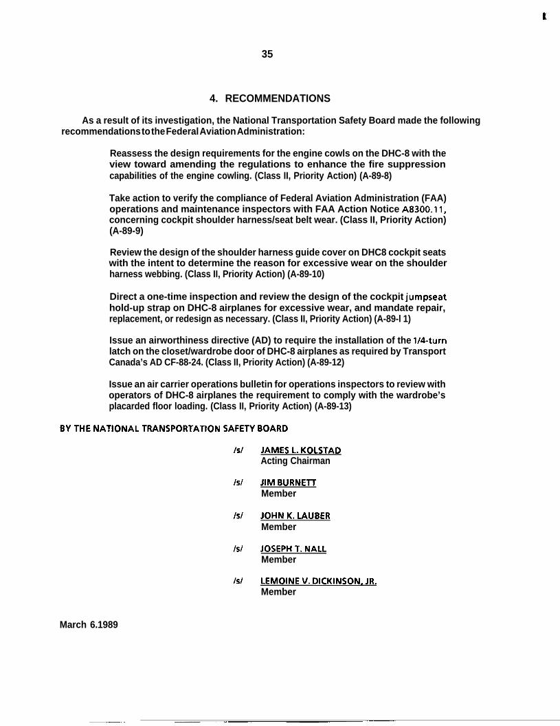
P
35
4. RECOMMENDATIONS
As a result of its investigation, the National Transportation Safety Board made the followingrecommendations to the Federal Aviation Administration:
Reassess the design requirements for the engine cowls on the DHC-8 with theview toward amending the regulations to enhance the fire suppressioncapabilities of the engine cowling. (Class II, Priority Action) (A-89-8)
Take action to verify the compliance of Federal Aviation Administration (FAA)operations and maintenance inspectors with FAA Action Notice A8300.11,concerning cockpit shoulder harness/seat belt wear. (Class II, Priority Action)(A-89-9)
Review the design of the shoulder harness guide cover on DHC8 cockpit seatswith the intent to determine the reason for excessive wear on the shoulderharness webbing. (Class II, Priority Action) (A-89-10)
Direct a one-time inspection and review the design of the cockpit jumpseathold-up strap on DHC-8 airplanes for excessive wear, and mandate repair,replacement, or redesign as necessary. (Class II, Priority Action) (A-89-l 1)
Issue an airworthiness directive (AD) to require the installation of the l/4-turnlatch on the closet/wardrobe door of DHC-8 airplanes as required by TransportCanada’s AD CF-88-24. (Class II, Priority Action) (A-89-12)
Issue an air carrier operations bulletin for operations inspectors to review withoperators of DHC-8 airplanes the requirement to comply with the wardrobe’splacarded floor loading. (Class II, Priority Action) (A-89-13)
BY THE NATIONAL TRANSPORTATION SAFETY BOARD
Is/ JAMES L. KOLSTADActing Chairman
IS/ JIM BURNETTMember
IS/ JOHN K. LAUBERMember
IS/ JOSEPH T. NALLMember
IS/ LEMOINE V. DICKINSON, JR.Member
March 6.1989

t
37
5. APPENDIXES
APPENDIX A
INVESTIGATION AND HEARING
1. Investigation
The National Transportation Safety Board was notified of the accident at 2200 on April 15,1988. An investigation team was dispatched from Washington, D.C. the next morning and arrivedon scene later that afternoon. Investigative groups were formed for operations, survival factors,human performance, structures, systems, air traffic control, and powerplants. Groups were laterformed for readout of the FDR and CVR in Washington, D.C.
Parties to the investigation were the FAA; Horizon Air, Inc.; deHavilland of Canada, Ltd.; thePort of Seattle, Washington; and the Association of Flight Attendants. A Canadian accreditedrepresentative from the Canadian Aviation Safety Board assisted in the investigation in accordancewith International Civil Aviation Organization Annex 13, and representatives from TransportCanada and the Airline Pilots Association were assigned observer status.
2. Public Hearing
The Safety Board did not hold a public hearing on this accident.

t
P
39
PERSONNEL INFORMATION
Captain Carl Eric Carlson
Captain Carlson, 38, was hired by Air Oregon in June 1979. Air Oregon was subsequentlyabsorbed by Horizon Air, and the captain was hired by that company on September 1, 1981. Heheld airline transport pilot certificate No. 1767092 with ratings for the SA-227, the DHC-8, airplanemultiengine land, and commercial privileges for airplane single-engine land. At the time of theaccident, he had accumulated approximately 9,328 total flying hours, 981 hours of which were inthe DHC-8. He received his initial type rating in the DHC-8 on November 5, 1986. The captain’s lastline check was completed on September 5, 1987, and his last proficiency check was on October 5,1987. The captain’s last recurrent training was on October 30, 1987. His most recent first-class FAAmedical certificate was issued on January 19, 1988, with the limitation, “Holder shall wearcorrecting lenses while exercising the privileges of his airman certificate.”
First Officer Mark Raymond Hilstad
First Officer Hilstad, 35, was hired by Horizon Air on March 30, 1987. He held airline transportpilot certificate No. 548882459 with ratings for airplane multiengine land and commercialprivileges for airplane single-engine land. He also held a flight instructor certificate for airplanesingle-engine and multiengine land which was valid until March 31, 1989, and an air traffic controlspecialist certificate. At the time of the accident, he had accumulated approximately 3,849 totalflying hours, 642 hours of which were in the DHC-8. The first officer completed his initialproficiency check on May 7, 1987. His last recurrent training was accomplished on March 11, 1988.His most recent second-class FAA medical certificate was issued on January 12, 1988, with nolimitations.
Flight Attendant Kimberly Walker
Flight Attendant Walker, 24, was hired by Horizon Air on March 9, 1987, after completing 56hours of basic indoctrination, emergency training, and security training. She completed initialoperating experience (5.2 hours) on the DHC8 on March 12, 1987, and was also qualified to serveon Fokker F-27 and Fokker F-28 airplane. Her most recent recurrent training occurred onMarch 20,1988.

E
P
41
APPENDIX C
AIRPLANE INFORMATION
The deHavilland of Canada DHC-8-102 was issued a U.S. type certificate under the bilateralprovisions of Title 14 Code of Federal Regulations Part 21. It is equipped with two Pratt andWhitney PWl2OA engines and two Hamilton Standard 145F-7 propellers. N819PH, serial number61, was manufactured on December 21,1985, and acquired by Horizon Air on February 6, 1987.
The airplane had accumulated a total of about 3,106 flight hours and about 4,097 cycles at thetime of the accident. The left engine, serial number 120215 had a total time of 3,106 hours and4,097 cycles. It was an original installation on the airplane. The right engine, serial number 120078,had a total time of 3,886 hours and 4,948 cycles. It was installed on February 25, 1988.

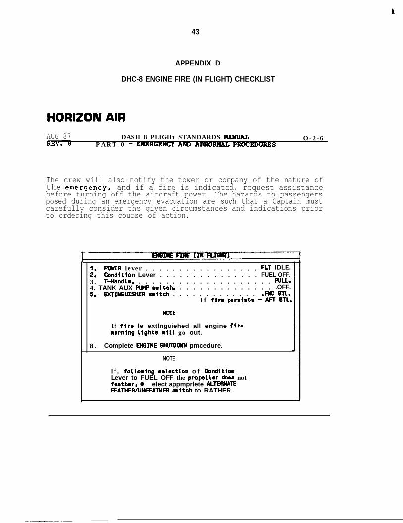
e
43
APPENDIX D
DHC-8 ENGINE FIRE (IN FLIGHT) CHECKLIST
HORIZON AIRAUG 87 DASH 8 PLIGHT STANDARDS HARDAL
PART 0 - EHBRGENCY ANDARNORHAL PROCEDIJRRSO-2-6
The crew will also notify the tower or company of the nature ofthe emergencyI and if a fire is indicated, request assistancebefore turning off the aircraft power. The hazards to passengersposed during an emergency evacuation are such that a Captain mustcarefully consider the given circumstances and indications priorto ordering this course of action.
::POWER lever . . . . . . . . . . . . . . . . . FL1 IDLE.Ccndltion Lever . . . . . . . . . . . . . . . FUEL OFF.
3 . T-Hendle. . . . . . . . . . . . . . . . . . . . . f%LL.4. TANK AUX PUHP -Itch. . . . . . . . . . . . . . . .OFF.5. DClIffiUISHER eritch . . . . . . . . . . . . . .m mL.
I f fire perslste - M BTL.
NOTE
If fire le extlnguiehed all engine flrerernlng light6 ~111 go out.
8 . Complete EM3INE HtWDWN pmcedure.
NOTE
I f , follorlng eelbction o f ConditionLever to FUEL OFF the pmpeller does notfeather, l elect appmprlete ALTEWATEFEAltlER/UNFEAlHER eultch to RATHER.
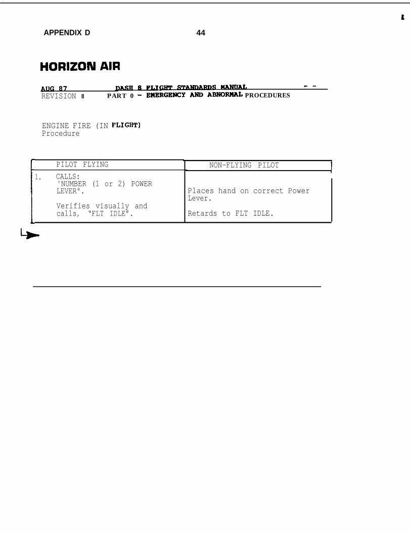
t
APPENDIX D 44
HORIZON AIRBllG 87 8Fy - -REVISION 8 PART 0 - EHERGENCYARDABNORllAL PROCEDURES
ENGINE FIRE (IN FLIGHT)Procedure
PILOT FLYING1. CALLS:
'NUMBER (1 or 2) POWERLEVER".Ib Verifies visually andcalls, “FLT IDLE”.
NON-FLYING PILOT
Places hand on correct PowerLever.
Retards to FLT IDLE.
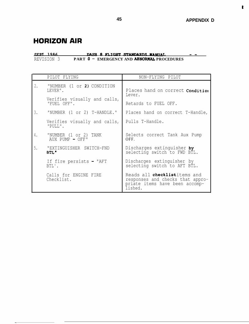
t
45 APPENDIX D
HORIZON AIR
T 19RC; 1. - -
REVISION 3 PART 0 - EMERGENCY AND ABNORML PROCEDURES
PILOT FLYING NON-FLYING PILOT
2. "NUMBER (1 or 2) CONDITIONLEVER". Places hand on correct Conditiol
Lever.Verifies visually and calls,"FUEL OFF". Retards to FUEL OFF.
3. "NUMBER (1 or 2) T-HANDLE." Places hand on correct T-Handle,
Verifies visually and calls, Pulls T-Handle."PULL".
4. "NUMBER (1 or 2) TANK Selects correct Tank Aux PumpAUX PUMP - OFF" OFF.
5. "EXTINGUISHER SWITCH-FND Discharges extinguisher byBTL" selecting switch to FWD BTL.
If fire persists - "AFT Discharges extinguisher byBTL'. selecting switch to AFT BTL.
Calls for ENGINE FIRE Reads all checklist items andChecklist. responses and checks that appro-
priate items have been accomp-lished.
-
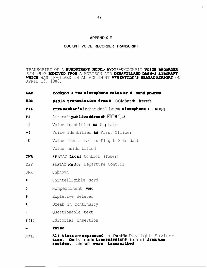
t
47
APPENDIX E
COCKPIT VOICE RECORDER TRANSCRIPT
TRANSCRIPT OF A SVNDSTRWD MODEL AV557-C COCKPIT VOICE =mRDERS/N 9993 REMOVED FRO?f A HORIZON AIR DEXAVIUAND DASH-~ JURQU~WHICH WAS INVOLVED IN AN ACCIDENT AT SEA'ITIZ'S SEATAC uR#IRT ONAPRIL
MC
PA-1
4
-3
TimDEP
UNK
*
Q
c
8
0
(0)
e
NOTE :
15, 1988.
Cockpit l rea microphone voice or l ound muroeRadio trenrmirrion from l CCid8nt l ircreftCrev member’8 individual boom ricrophona l o ur c eAircraft public addrams l yr temVoice identified as CaptainVoice identified as First Officer
Voice identified as Flight Attendant
Voice unidentified
SEATAC Local
SEATAC Radar
Unknovn
Control (Tower)
Departure Control
Unintelligible word
Nonpertinent vord
Expletive deleted
Break in continuity
Questionable text
Editorial insertion
P8use
2’i$tiaee are expressad in Pacific Daylight SavingsOnly radio traasmirrionr to and fros the
rccdient aircraft ware tr8n8sribedn
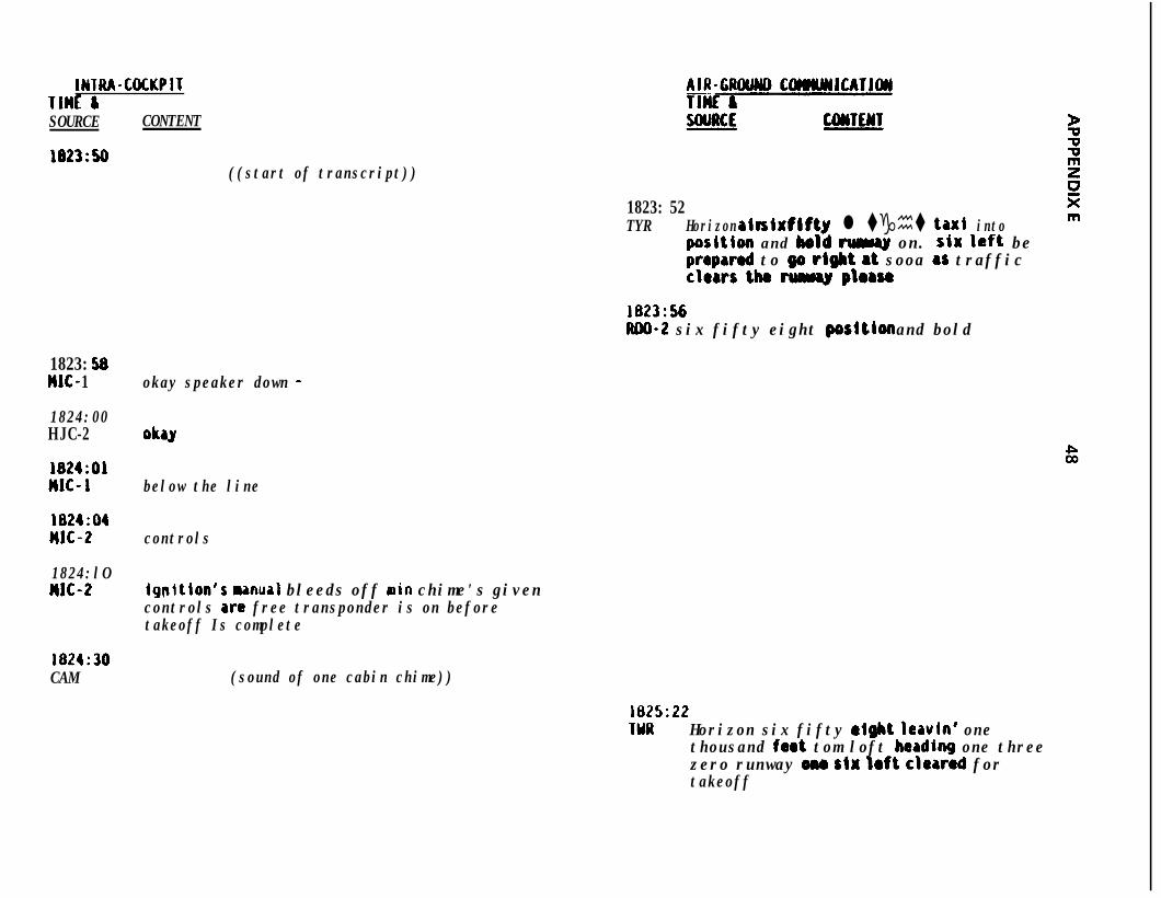
IWTRA-COCKPITTlHl &SOURCE CONTENT
1823:50((start of transcript))
1823: 52TYR Horizon air six fifty l tght ta ⌧i into
poritbn and bold cul~ly on. stx left beprepared to w right at sooa as trafficclears the w ploru
1823:56m-2 six fifty eight poritlon and bold
1823: 58IIJC- 1
1824:00HJC-2
1824:OAMJC- 1
1824:04MJC-2
1824:lOMJC-2
1824:30CAM
okay speaker down -
oh
below the line
controls
Igpitlon's manual bleeds off arin chime's givencontrols are free transponder is on beforetakeoff Is complete
(sound of one cabin chime))
1825:22IYR Horizon six fifty might leavin' one
thousand faot tom loft heading one threezero runway om stx loft clawed fortakeoff
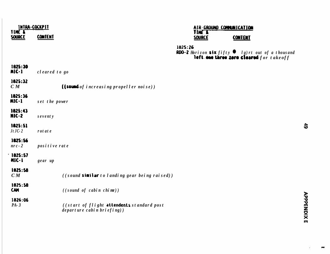
INTRA-COCKPITTlHE7;-----5tiMlCE COHTEWT
1825:30MJC-1 cleared to go
1825:32C M
1825:36MJC-1 set the power
J825:43Jw-2 seventy
J825:SAJtJC-2 rotate
1825:56nrc-2 positive rate
' 1825:57HJC-1 gear up
1825:58C M
1825:50
1826:06PA-3
((sod of increasing propeller noise))
((sound sirilar to landing gear being raised))
((sound of cabin chime))
((start of flight attendents standard postdeparture cabin briefing))
AIR-GfIOUNO COHWJCATJWliCSEY5OURCE C~TEWT
1825:26JUIO-2 Horizon six fifty l lg)rt out of a thousand
left&e thrm zero clorrod for takeoff
m
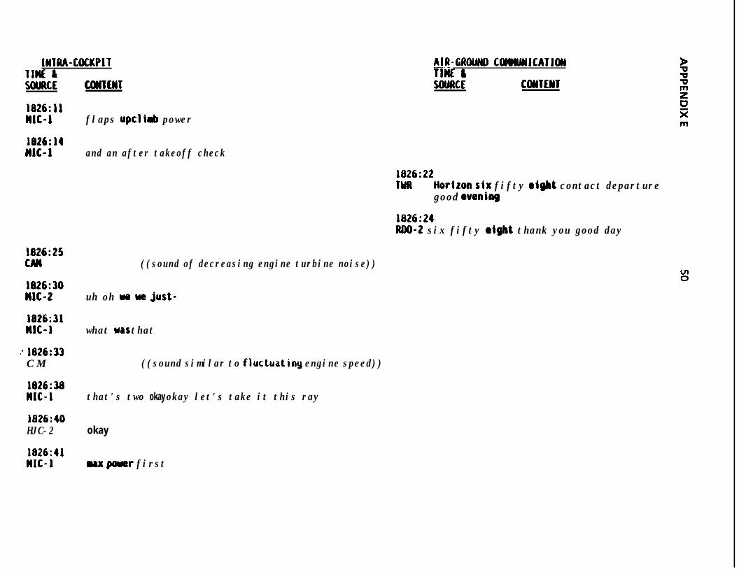
IWTUA-COCKPITTlnE IWJRCE COUENT
AIR-GROWID CWMMJCATJCM-. -TIME &SWRCE CollTElll
1826:11HJC-J flaps up cli& power
1826:14JJJC-J and an after takeoff check
1826:22TYR tioriron six fifty eight contact departure
good wenibbg
1826:24JUIO-2 six fifty sight thank you good day
1826:25CAM ((sound of decreasing engine turbine noise))
1826:30MJC-2 uh oh we y9 just-
1826:31IJC-1 what was that
: 1826:33C M ((sound similar to fluctuatiny engine speed))
1826:38nJC-I that's two okay okay let's take it this ray
1826:40HJC-2 okay
1826:41MJC-1 ux pouer first
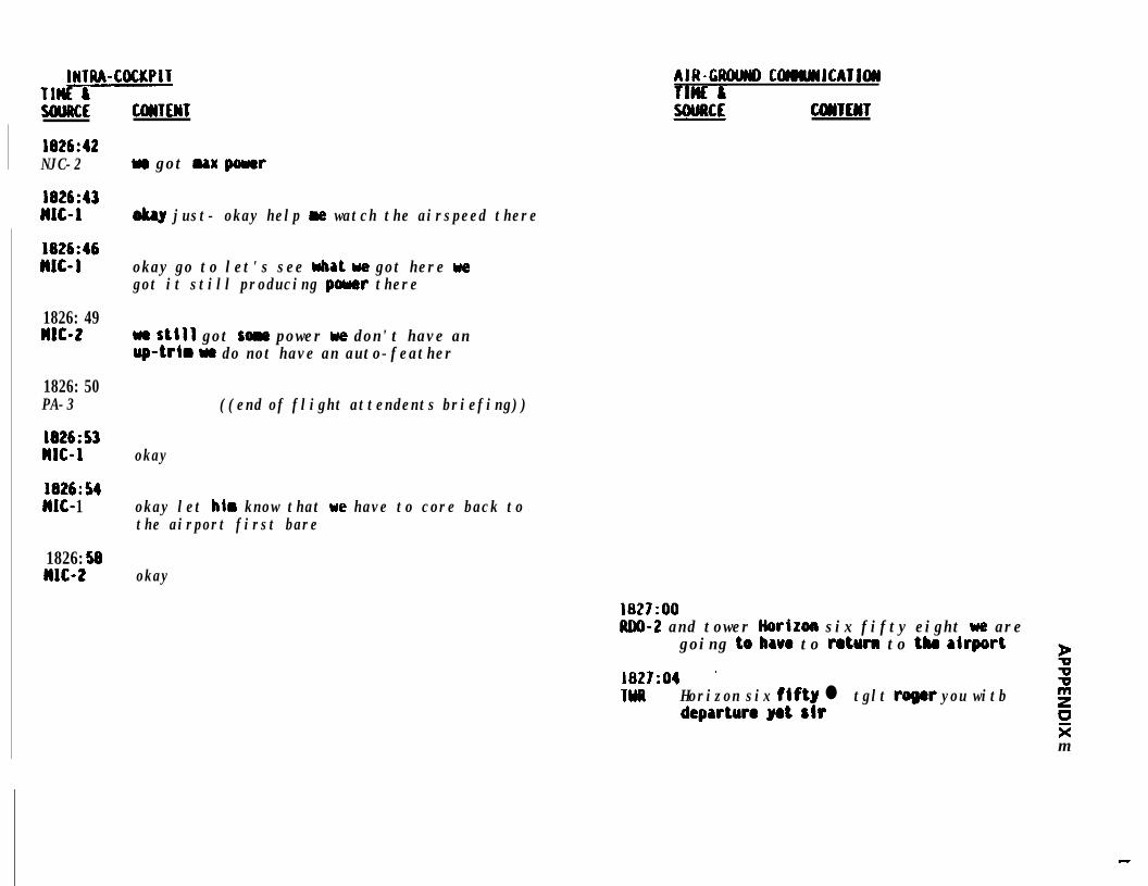
INTRA-COCKPITTl-SOWE
1826:42NJC-2
l826:43MJC-I
1826:46MJC-1
1826: 49MJC-2
1826: 50PA-3
1826:s)MJC-1
l826:54IJC- 1
1826: 58JJJC-2
CWTEWT
w got max p5uer
okay just- okay help w watch the airspeed there
okay go to let's see what we got here wegot it still producing poww there
we still got son power we don't have anup-trtm wr do not have an auto-feather
((end of flight attendents briefing))
okay
okay let him know that we have to core back tothe airport first bare
okay
AIR-CROUW COMMJCATJW
cmm
1827:OORllO-2 and tower Horizon six fifty eight we are
going to have to r&urn to tlw aiquwt b1827:04 ' zwll Horizon six fJfty l tglt roger you witb
departure yet sirguzm
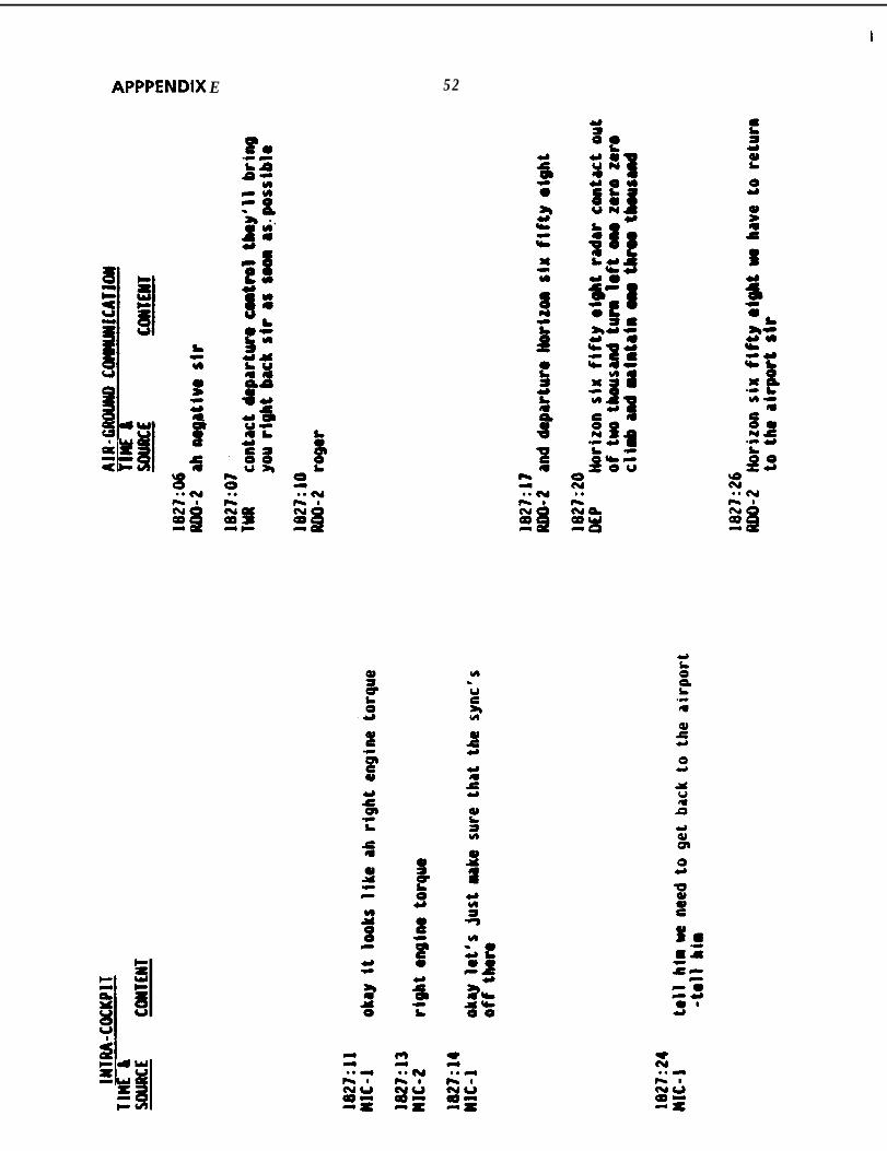
APPPENDIX E 52
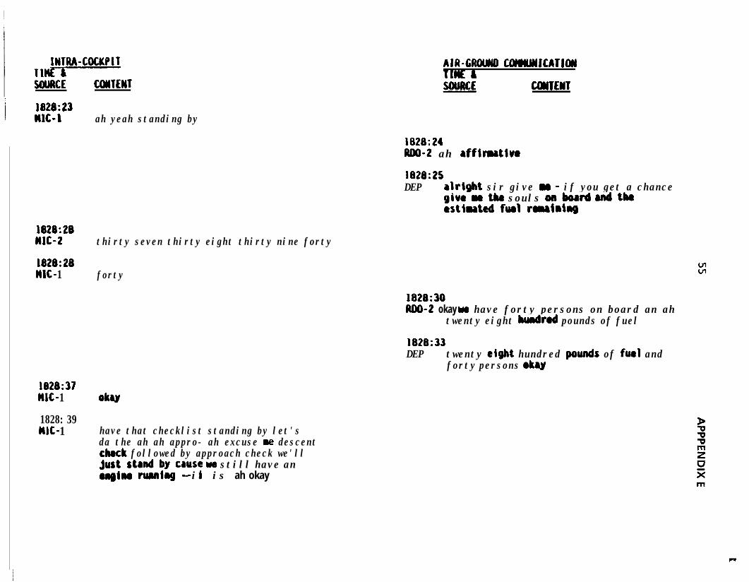
IWTRA-COCKPITTl-WAKE
1828:23WC-1
1828:28MJC-2
1828:28WC- 1
1828:37MC- 1
1828: 39w- 1
UMTEWT
ah yeah standing by
thirty seven thirty eight thirty nine forty
forty
AIR-CUOlMD COrmYJJCATJW
CWTEtiT
1828:24ADO-2 ah affimativo
1828:25DEP alrigbt sir give Y - if you get a chance
givraethe souls onboard 8ndtkestlnted furl romainhg
1828:30ND-2 okay we have forty persons on board an ah
twenty eight hundred pounds of fuel
1828:33DEP twenty eight hundred ~wnds of fueJ and
forty persons oky
OkU
have that checklist standing by let'sda the ah ah appro- ah excuse re descentcheck followed by approach check we'llj;us~ta&~qcause we still have an
-- it is ah okay
c
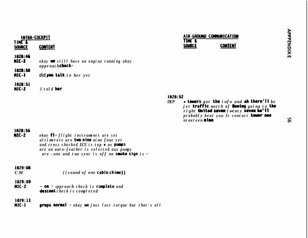
JNTlU-COCKPIT A#iG;WND COWILYIJCATJOII
5OUllCE C(WlE)ST
l828:46MlC-2 okay ue still have an engine running okay
approach cbeck-1828:50MC-1 did you talk to her yet
1828:SlMJC-2 J told her
1828:52DEP l toners got the info and ab there'll be
jet traffk north of JbeJng going to theright hited seven twenty seven bo'llprobably beat you Jr contact toner OIWnineteen nim
1828:56n1c-2 okay fl- flight instruments are set
altimeters are two nine nine four setand cross checked ECU is top l ux purgsare on auto-feather is selected aux pumpsare -one and two sync is off no saoke sign is -
1829:08C M ((sound of one cabln chime))
1829:09WC-2 - approach check is coaplete and
iezent check is completed
1829:13MIC-1 propsnorul - okay we just lost torque but that's all
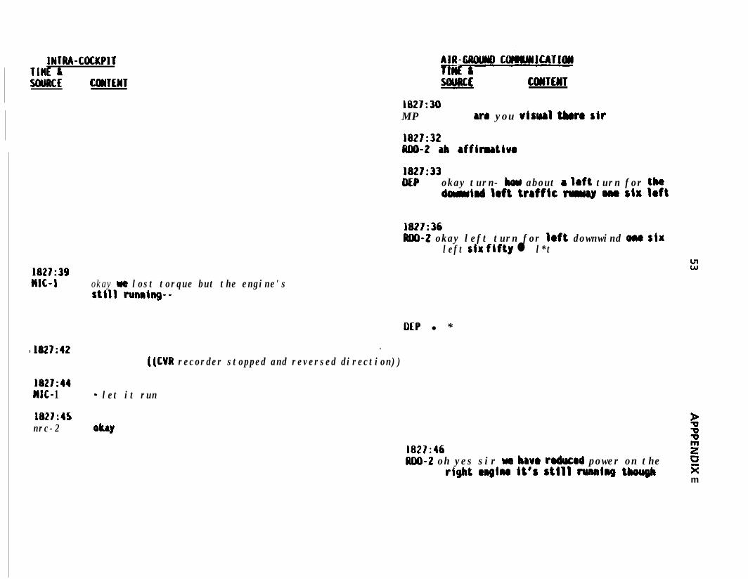
IWTRA-COCKPITTlHl: ISOURCE
1827:39MC-L
11827:42
1827:44MC- 1
1827:45nrc-2
CDmWT SOURCE CDWEHT1827:30M P W8 you uisurl t&o sir
1827:32lw-2 ab rffimatluo
1827:33DEP okay turn- bou about a Ioft turn for the
barmind Iaft ttrfftc M ona SIW I8ft
1827:36IUD-2 okay left turn for left downwind ona six
left riw fifty l l*tw”
okay w lost torque but the engine'sstill running--
DEP l *.
((CM recorder stopped and reversed direction))
- let it run
ObY1827:46 2ND-2 oh yes sir wa have rodwad power on the ci
rigbt emgIn@ it’s Still running though sim
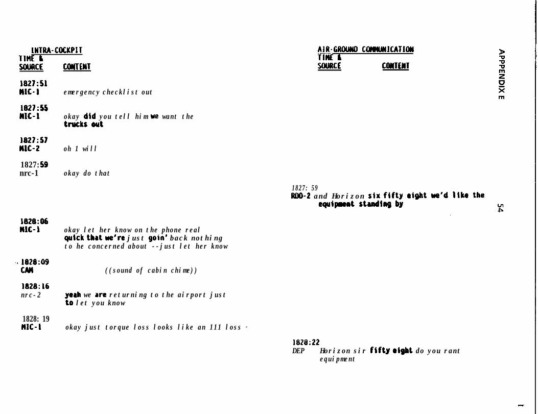
INTUA-COCKPITTIM liSOIJRCE CDUTfWT
AIR-GROUWD C~ICATIW.---TIM &SOURCE CONTENT
1827:SlMIC-1 emergency checklist out
1827:SSMlC- 1 okay did you tell him we want the
trucks out
1827:57MIC-2 oh 1 will
1827: 59nrc-1 okay do that
1827: 59RDO-2 and Horizon six fifty
aquipmntstudtngby
1828:D6n1c- 1 okay let her know on the phone real
quick that we're just goin' back nothingto he concerned about --just let her know
5) 1828:09CAN ((sound of cabin chime))
1828:L6nrc-2 yeah we are returning to the airport just
to let you know
1828: 19MIC-1 okay just torque loss looks like an 111 loss -
1828:22DEP Horizon sir flftg olgbt do you rant
equipment
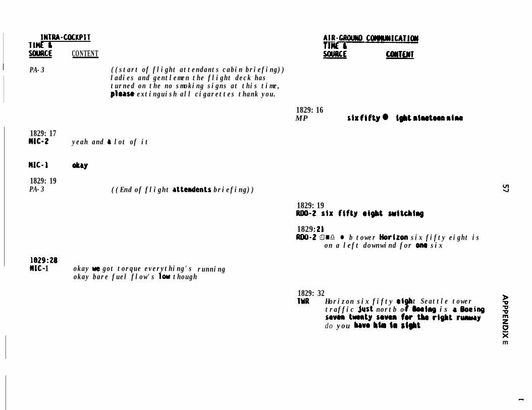
IWTRA-COCKPITnnt &SOURCE CONTENT
I PA-3 ((start of flight attendants cabin briefing))ladies and gentlemen the flight deck hasturned on the no smoking signs at this time,please extinguish all cigarettes thank you.
1829: 16M P siw fifty l i#bt riwte8a nine
1829: 17WIG-2 yeah and a lot of it
1829: 19PA-3 ((End of flight attcndents briefing))
1829: 19UOO-2 six fifty eight suitcbing
1829: 21RCU-2 a nd l b tower Horiroo six fifty eight is
on a left downwind for ome six
1829: 28n1c- 1 okay w got torque everything's
okay bare fuel flow's low thoughrunning
1829: 32'IOR Horizon six fifty (ti
0"t Seattle tower P
traffic jwt nortb o @ooirrg is a Ooeiog imum twrty seven for tba rdgbt runwaydo you bavo Mm la sight
20km
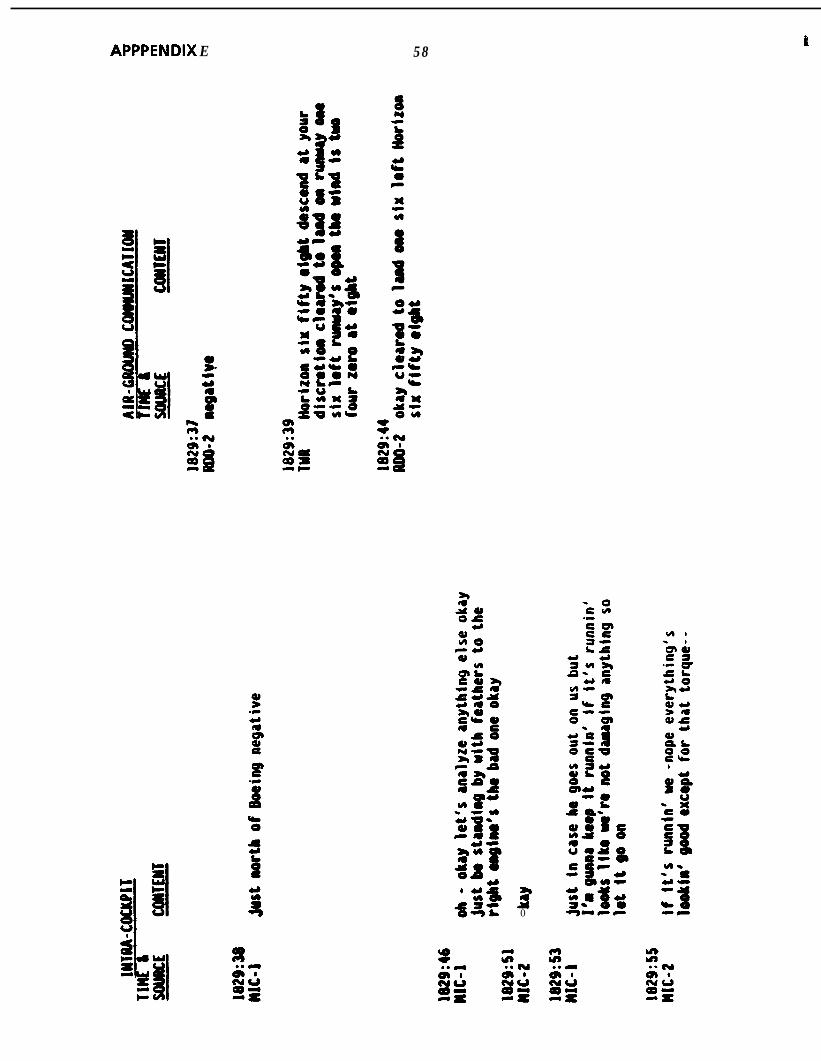
APPPENDIX E 58 t
t
30
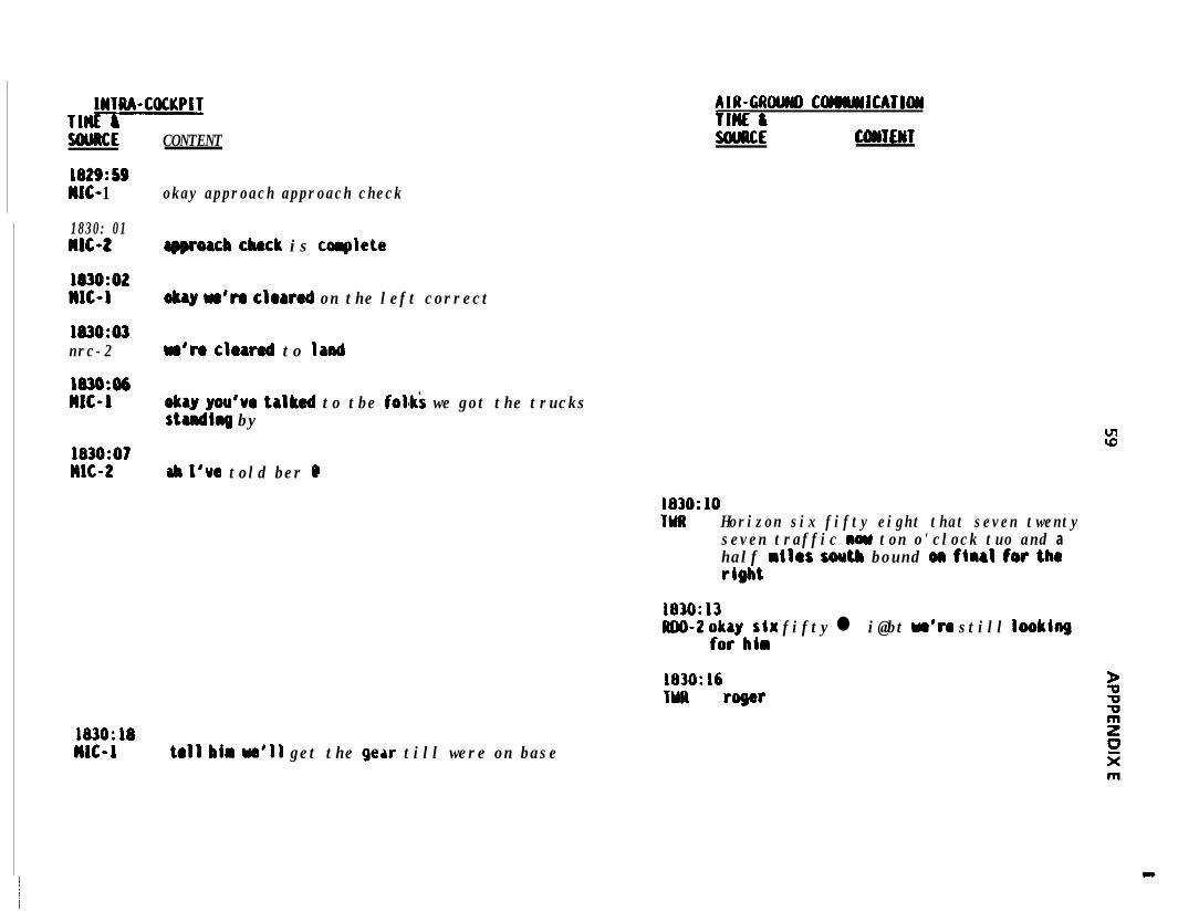
IHTRA-COCKPIT117SWRCE
1829:SSWC- 1
CONTENT
okay approach approach check
1830: 01MIC-2
1830:02MC-1
1830:03nrc-2
1830:06MC-1
1830:07MC-2
183O:MMlC-1
AIR-GAU COMWCATI~flnc ISouuCE CONTENT
rQQroacb check is collplete
okay w'ro cloarod on the left correct
w're cloarod to land
okay you've talked to tbe folai we got the trucksstandirrg by
ab I'ue told ber Q
tall him ~a'11 get the gear till were on base
183O:lOTMR Horizon six fifty eight that seven twenty
seven traffic nom ton o'clock tuo and ahalf miles south bound on firrl for theright
1830:13RDO-2 ;$ybflr fifty l i@bt w'ro still looking
1830:16TYR roger
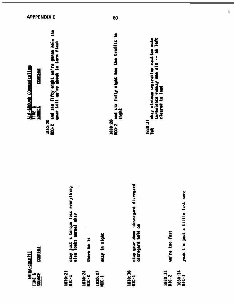
1APPPENDIX E 60
“blY
c;r--<
a--
-E,
Yr
3. . L,a &-z
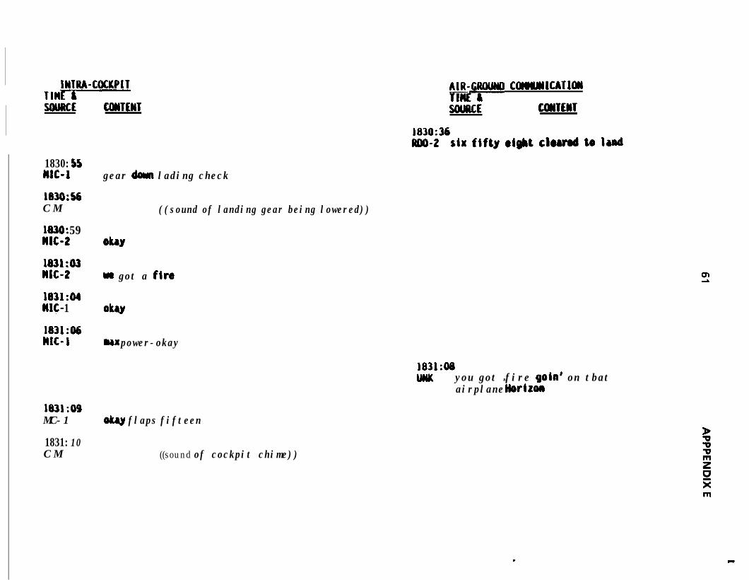
IWTRA-COCKPITTMVSWRCE CWTENT
1830: 55MC-1
183O:sbC M
1030: 59WIG2
1831:03MC-2
1831:04It&- 1
1831:06nrc- 1
1831:09MC-1
1831: 10C M
p ComJcllCATloll
SOURCE COWTEnT.
z$36six fifty eight chrod to Iand
gear dew lading check
ObY
((sound of landing gear being lowered))
we got a fire
oku
ux power-okay
1831:08DNK you got a fire gold on tbat
airplane liorizon
olmy flaps fifteen
((sound of cockpit chime))
.
m
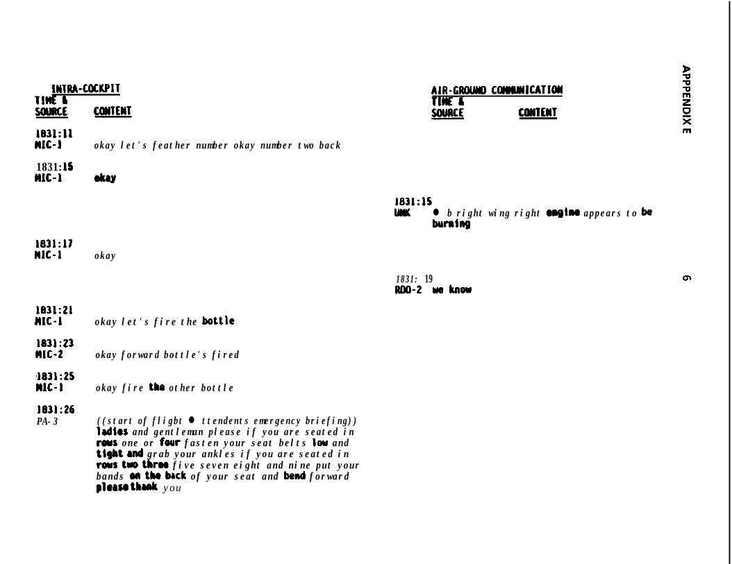
IWTIU-COCKPITTlti &UWRCE
183l:llnrc-l
1831: 15MIC-1
1831:17nrc-1
1831:21MC-1
1831:23MC-2
4831:25nrc-1
1831:26PA-3
CWTEWT
okay let's feather number okay number two back
AIR-CROWI COIWNlCATl(yI
COMTEHT
1831:lSUK l b right wing right mgiru appears to ba
humhg
okay
1831: 19mo-2 weknow
okay let's fire the bottle
okay forward bottle's fired
okay fire the other bottle
((start of fligbt l ttendents emergency briefing))ladies and gentleman please if you are seated intoys one or four fasten your seat belts low andtight and grab your ankles if you are seated inrows two tbrw five seven eight and nine put yourbands on tk brck of your seat and bend forwardplorso thank you
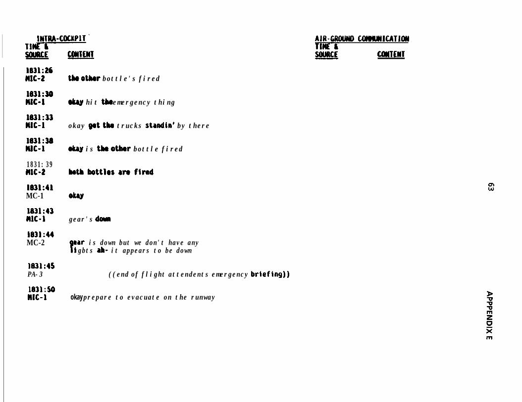
INTM-COCKPIT 'TlvSWRCE
l83L:26M-2
1631:33nrc-1
1831:38DUG1
1831: 39MC-2
1831:41MC-1
1831:43WIG-1
1831:44MC-2
1831:45PA-3
1831:50n1c-1
AIR-CROLMY) COMLYSlCATlOlJ
CUiTEWT
tk otlur bottle's fired
w hit the emergency thing
okay fpt tbm trucks standin' by there
o& is th otbw bottle fired
both bottles are fired
gear's dumb
Par is down but we don't have anyigbts ab- it appears to be down
((end of flight attendents emergency briefing))
okay prepare to evacuate on the runway
m
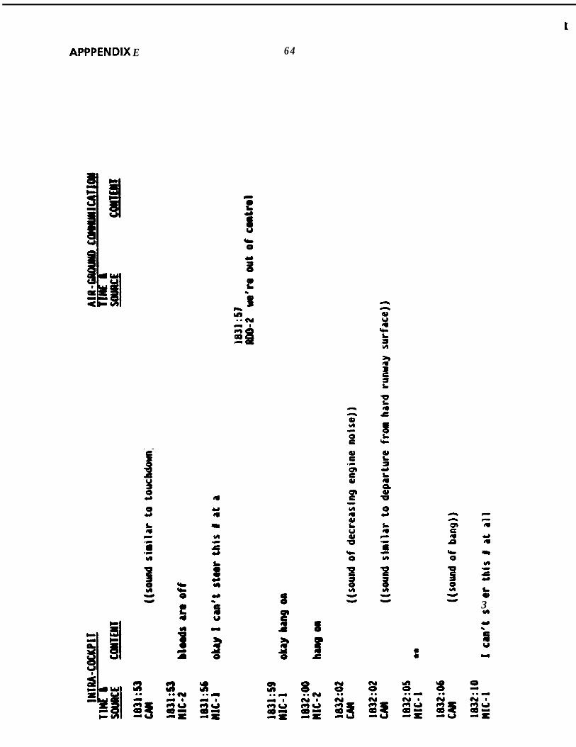
t
APPPENDIX E 64
--g33
k3H
f
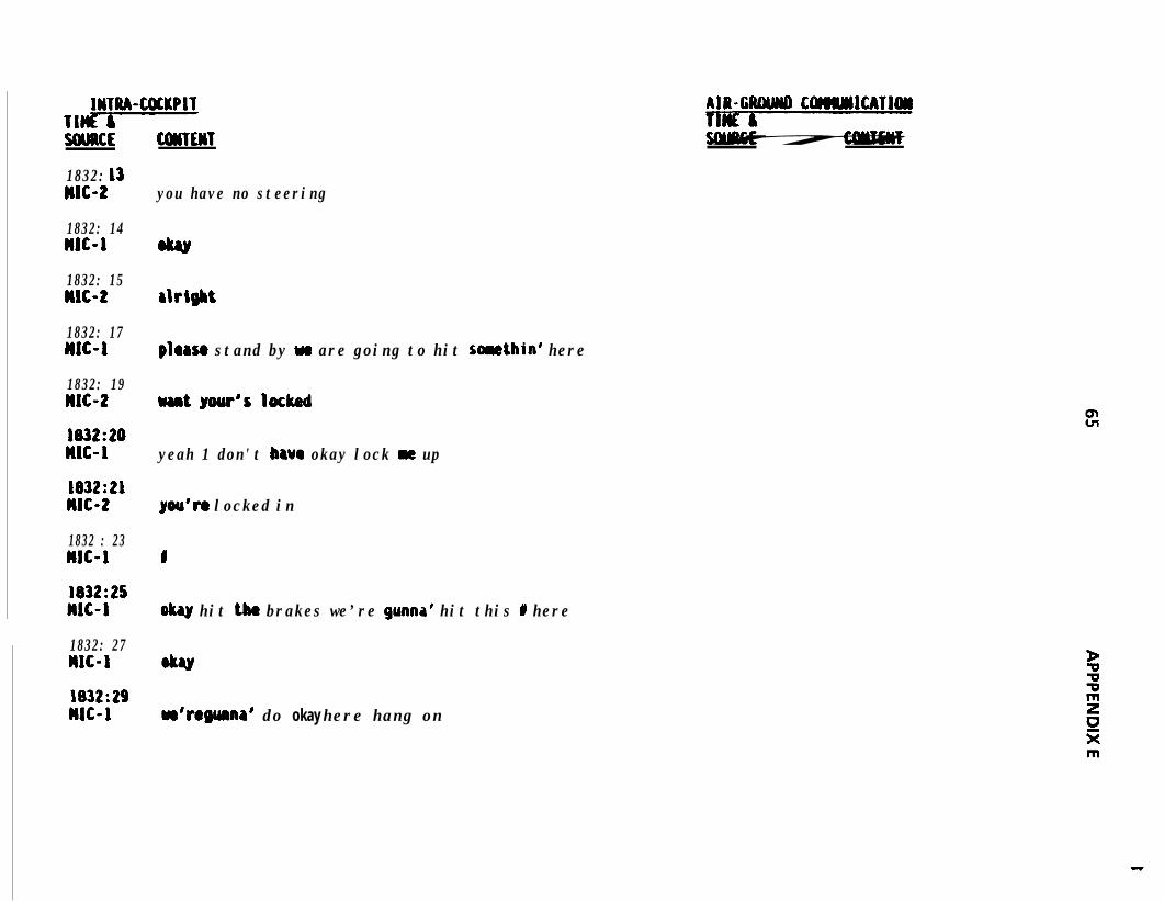
INTRA-COCKPITTl-SOURCE COUTEIIT
1832: 13nrc-2
1832: 14MlC-1
1832: 15MlC-2
1832: 17MC-1
1832: 19nrc-2
1832:20WC-1
1832:21n1c-t
1832 : 23nrc-1
1832:25w-i1832: 27nit-11832:29nit-r
you have no steering
rlrigbt
ploaso stand by we are going to hit somethin’ here
uantyour'slocked
yeah 1 don't bavcr okay lock m up
you'n locked in
I
okay hit the brakes we’re gunna’ hit this I here
w’ro guma’ do okay here hang on
AIR-CIUWD COlWM1CATlON
APPPENDIX E
s. .l N
8-3
6 6
aU.S.tOVtRN~NNT P R I N T I N G OfFICtr1989-242-320r80155