Embed Size (px)
Citation preview
RE 25402, edition: 2016-07, Bosch Rexroth AG
Pressure relief valve, direct operated
Features
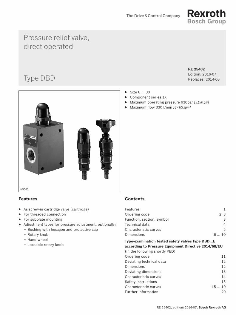
▶ As screw-in cartridge valve (cartridge) ▶ For threaded connection ▶ For subplate mounting ▶ Adjustment types for pressure adjustment, optionally:
– Bushing with hexagon and protective cap – Rotary knob – Hand wheel – Lockable rotary knob
Contents
Features 1Ordering code 2, 3Function, section, symbol 3Technical data 4Characteristic curves 5Dimensions 6 … 10
Type-examination tested safety valves type DBD…E according to Pressure Equipment Directive 2014/68/EU (in the following shortly PED) Ordering code 11Deviating technical data 12Dimensions 12Deviating dimensions 13Characteristic curves 14Safety instructions 15Characteristic curves 15 … 19Further information 20
▶ Size 6 … 30 ▶ Component series 1X ▶ Maximum operating pressure 630bar [9150 psi] ▶ Maximum flow 330 l/min [87 US gpm]
RE 25402 Edition: 2016-07Replaces: 2014-08
H5585
Type DBD
Inhalt
Features 1Contents 1Ordering code 2Ordering code 3Function, section, symbol 3Technical data (For applications outside these parameters, please consult us!) 4Characteristic curves (measured with HLP46, ϑoil = 40 ±5 °C [104 ±9 °F]) 5Dimensions: Threaded connection (dimensions in mm [inch]) 6Dimensions: Screw-in cartridge valve (dimensions in mm [inch]) 7Dimensions: Screw-in cartridge valve (dimensions in mm [inch]) 8Dimensions: Subplate mounting (dimensions in mm [inch]) 9Dimensions: Subplate mounting (dimensions in mm [inch]) 10Type-examination tested safety valves 11Ordering code: Type-examination tested safety valves type DBD 1) 11Deviating technical data: Type-examination tested safety valves type DBD 1) 12Dimensions: Sheet cut-out for front panel mounting with type-examination tested safety valves type DBD 1) (dimen-sions in mm [inch]) 12Deviating dimensions: Cartridge valve as type-examination tested safety valve type DBD 1) (dimensions in mm [inch]) 13Characteristic curves: Type-examination tested safety valves type DBD 1) 14Safety instructions: Type-examination tested safety valves type DBD 1) 15Characteristic curves: Counter pressure in the discharge line 15Characteristic curves: Counter pressure in the discharge line – size 6 16Characteristic curves: Counter pressure in the discharge line – size 10 17Characteristic curves: Counter pressure in the discharge line – size 20 18Characteristic curves: Counter pressure in the discharge line – size 30 19Further information 20
2/20 DBD | Pressure relief valve
Bosch Rexroth AG, RE 25402, edition: 2016-07
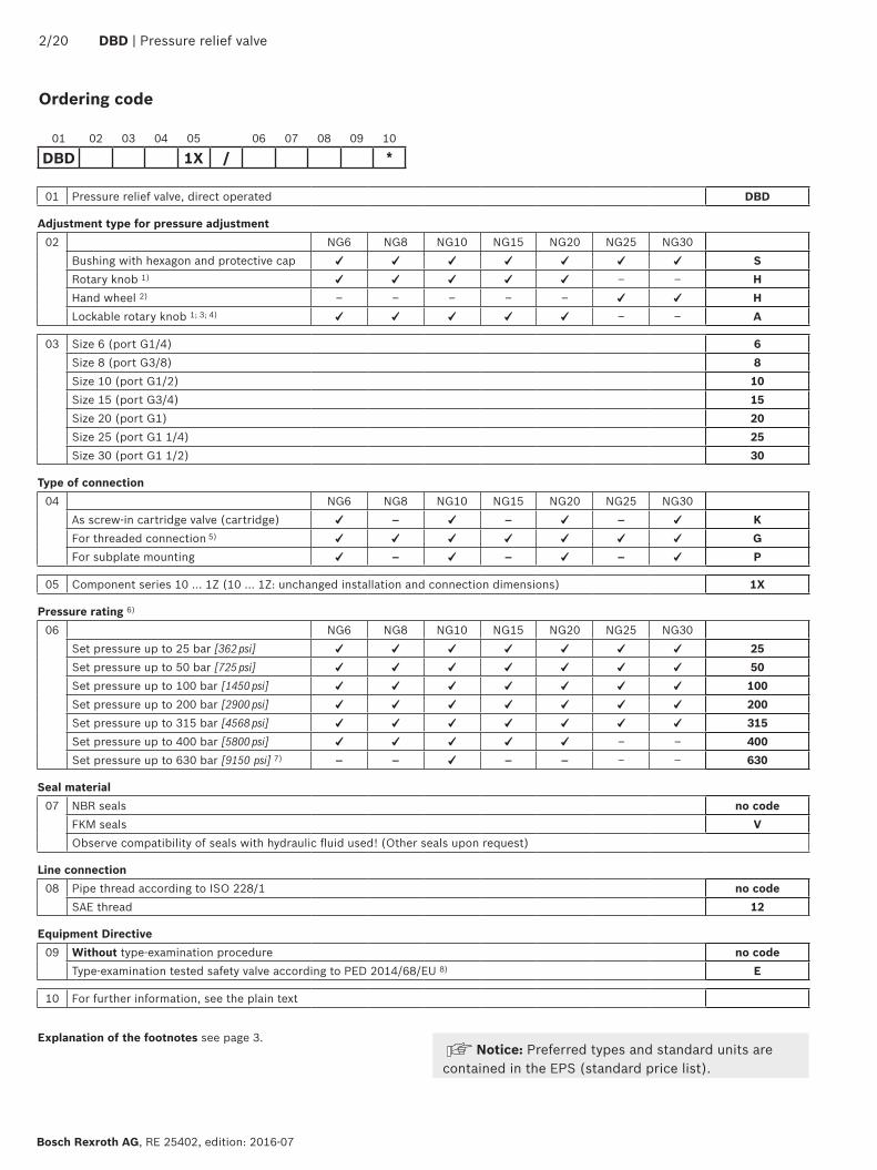
Ordering code
01 Pressure relief valve, direct operated DBD
Adjustment type for pressure adjustment02 NG6 NG8 NG10 NG15 NG20 NG25 NG30
Bushing with hexagon and protective cap ✓ ✓ ✓ ✓ ✓ ✓ ✓ SRotary knob 1) ✓ ✓ ✓ ✓ ✓ – – HHand wheel 2) – – – – – ✓ ✓ HLockable rotary knob 1; 3; 4) ✓ ✓ ✓ ✓ ✓ – – A
03 Size 6 (port G1/4) 6Size 8 (port G3/8) 8Size 10 (port G1/2) 10Size 15 (port G3/4) 15Size 20 (port G1) 20Size 25 (port G1 1/4) 25Size 30 (port G1 1/2) 30
Type of connection04 NG6 NG8 NG10 NG15 NG20 NG25 NG30
As screw-in cartridge valve (cartridge) ✓ – ✓ – ✓ – ✓ KFor threaded connection 5) ✓ ✓ ✓ ✓ ✓ ✓ ✓ GFor subplate mounting ✓ – ✓ – ✓ – ✓ P
05 Component series 10 ... 1Z (10 ... 1Z: unchanged installation and connection dimensions) 1X
Pressure rating 6)
06 NG6 NG8 NG10 NG15 NG20 NG25 NG30Set pressure up to 25 bar [362 psi] ✓ ✓ ✓ ✓ ✓ ✓ ✓ 25Set pressure up to 50 bar [725 psi] ✓ ✓ ✓ ✓ ✓ ✓ ✓ 50Set pressure up to 100 bar [1450 psi] ✓ ✓ ✓ ✓ ✓ ✓ ✓ 100Set pressure up to 200 bar [2900 psi] ✓ ✓ ✓ ✓ ✓ ✓ ✓ 200Set pressure up to 315 bar [4568 psi] ✓ ✓ ✓ ✓ ✓ ✓ ✓ 315Set pressure up to 400 bar [5800 psi] ✓ ✓ ✓ ✓ ✓ – – 400Set pressure up to 630 bar [9150 psi] 7) – – ✓ – – – – 630
Seal material07 NBR seals no code
FKM seals VObserve compatibility of seals with hydraulic fluid used! (Other seals upon request)
Line connection08 Pipe thread according to ISO 228/1 no code
SAE thread 12
Equipment Directive09 Without type-examination procedure no code
Type-examination tested safety valve according to PED 2014/68/EU 8) E
10 For further information, see the plain text
01 02 03 04 05 06 07 08 09 10
DBD 1X / *
Notice: Preferred types and standard units are contained in the EPS (standard price list).
Explanation of the footnotes see page 3.
T
P
T
P
5 1 2 3 6
T
P
T
P
5 1 2 4
P
T
Pressure relief valve | DBD 3/20
RE 25402, edition: 2016-07, Bosch Rexroth AG
Ordering code
1) With size 20, only available for the pressure ratings 25, 50 or 100 bar.
2) Only available for the pressure ratings 25, 50 or 100 bar.3) Key with material no. R900008158 is included in the scope of
delivery.4) Not available for type-examination tested safety valves.
5) Not available for type-examination tested safety valves of size 8, 15 and 25.
6) When selecting the pressure rating, please observe the characteristic curves and notes on page 5.
7) With version "G" and "P", only available as "SO292", see page 6 and 9.
8) See ordering code on page 11.
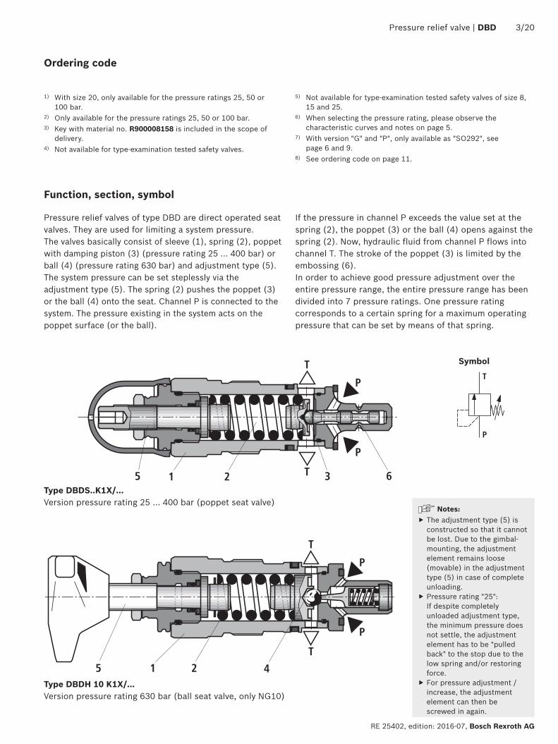
Pressure relief valves of type DBD are direct operated seat valves. They are used for limiting a system pressure.The valves basically consist of sleeve (1), spring (2), poppet with damping piston (3) (pressure rating 25 ... 400 bar) or ball (4) (pressure rating 630 bar) and adjustment type (5). The system pressure can be set steplessly via the adjustment type (5). The spring (2) pushes the poppet (3) or the ball (4) onto the seat. Channel P is connected to the system. The pressure existing in the system acts on the poppet surface (or the ball).
If the pressure in channel P exceeds the value set at the spring (2), the poppet (3) or the ball (4) opens against the spring (2). Now, hydraulic fluid from channel P flows into channel T. The stroke of the poppet (3) is limited by the embossing (6).In order to achieve good pressure adjustment over the entire pressure range, the entire pressure range has been divided into 7 pressure ratings. One pressure rating corresponds to a certain spring for a maximum operating pressure that can be set by means of that spring.
Type DBDS..K1X/…Version pressure rating 25 … 400 bar (poppet seat valve)
Symbol
Type DBDH 10 K1X/…Version pressure rating 630 bar (ball seat valve, only NG10)
Function, section, symbol
Notes: ▶ The adjustment type (5) is constructed so that it cannot be lost. Due to the gimbal-mounting, the adjustment element remains loose (movable) in the adjustment type (5) in case of complete unloading.
▶ Pressure rating "25": If despite completely unloaded adjustment type, the minimum pressure does not settle, the adjustment element has to be "pulled back" to the stop due to the low spring and/or restoring force.
▶ For pressure adjustment / increase, the adjustment element can then be screwed in again.
4/20 DBD | Pressure relief valve
Bosch Rexroth AG, RE 25402, edition: 2016-07
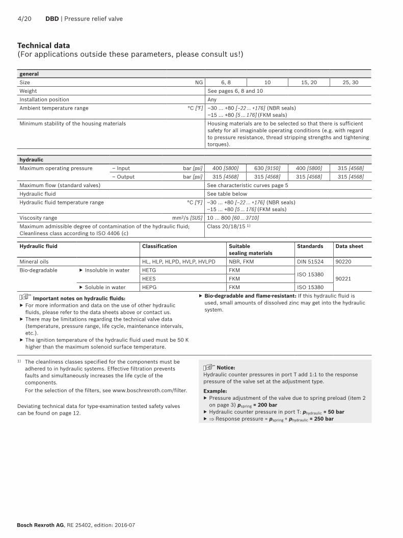
Technical data (For applications outside these parameters, please consult us!)
1) The cleanliness classes specified for the components must be adhered to in hydraulic systems. Effective filtration prevents faults and simultaneously increases the life cycle of the components.
For the selection of the filters, see www.boschrexroth.com/filter.
Deviating technical data for type-examination tested safety valves can be found on page 12.
hydraulicMaximum operating pressure – Input bar [psi] 400 [5800] 630 [9150] 400 [5800] 315 [4568]
– Output bar [psi] 315 [4568] 315 [4568] 315 [4568] 315 [4568]Maximum flow (standard valves) See characteristic curves page 5Hydraulic fluid See table belowHydraulic fluid temperature range °C [°F] –30 … +80 [–22 … +176] (NBR seals)
–15 … +80 [5 … 176] (FKM seals)Viscosity range mm2/s [SUS] 10 … 800 [60 … 3710]Maximum admissible degree of contamination of the hydraulic fluid; Cleanliness class according to ISO 4406 (c)
Class 20/18/15 1)
generalSize NG 6, 8 10 15, 20 25, 30Weight See pages 6, 8 and 10Installation position AnyAmbient temperature range °C [°F] –30 … +80 [–22 … +176] (NBR seals)
–15 … +80 [5 … 176] (FKM seals)Minimum stability of the housing materials Housing materials are to be selected so that there is sufficient
safety for all imaginable operating conditions (e.g. with regard to pressure resistance, thread stripping strengths and tightening torques).
Notice:Hydraulic counter pressures in port T add 1:1 to the response pressure of the valve set at the adjustment type.
Example: ▶ Pressure adjustment of the valve due to spring preload (item 2 on page 3) pspring = 200 bar
▶ Hydraulic counter pressure in port T: phydraulic = 50 bar ▶ ⇒ Response pressure = pspring + phydraulic = 250 bar
Hydraulic fluid Classification Suitable sealing materials
Standards Data sheet
Mineral oils HL, HLP, HLPD, HVLP, HVLPD NBR, FKM DIN 51524 90220Bio-degradable ▶ Insoluble in water HETG FKM
ISO 1538090221HEES FKM
▶ Soluble in water HEPG FKM ISO 15380
Important notes on hydraulic fluids: ▶ For more information and data on the use of other hydraulic fluids, please refer to the data sheets above or contact us.
▶ There may be limitations regarding the technical valve data (temperature, pressure range, life cycle, maintenance intervals, etc.).
▶ The ignition temperature of the hydraulic fluid used must be 50 K higher than the maximum solenoid surface temperature.
▶ Bio-degradable and flame-resistant: If this hydraulic fluid is used, small amounts of dissolved zinc may get into the hydraulic system.
1
450
400
300
200
100
50
10 20 30 40 500
[2][0] [4] [6] [8] [10] [13.2]
0
[6526]
[0]
[1000]
[12]
[2000]
[3000]
[4000]
[5000]
[6000]
500
400
300
200
10050
20 40 60 80 100 1200
[4][0] [8] [12] [16] [20] [31.7][24]
0[0]
[1000]
[2000]
[3000]
[4000]
[5000]
[6000]
[28]
600650
[7000]
[8000]
[9427]
1
450
400
200
300
100
50
50 100 150 200 25000
[6526]
[0]
[1000]
[2000]
[3000]
[4000]
[5000]
[6000]
[10][0] [20] [30] [40] [50] [66][60]
350
300
200
50
100
100 200 300 3500
[0]
0
[5076]
[0]
[1000]
[2000]
[3000]
[4000]
150
250
[92.5][10] [20] [30] [40] [50] [60] [70] [80]
Pressure relief valve | DBD 5/20
RE 25402, edition: 2016-07, Bosch Rexroth AG
Flow in l/min [US gpm] →
Flow in l/min [US gpm] →
Flow in l/min [US gpm] →
Flow in l/min [US gpm] →
Ope
ratin
g pr
essu
re in
bar
[psi]
→O
pera
ting
pres
sure
in b
ar [p
si] →
Ope
ratin
g pr
essu
re in
bar
[psi]
→O
pera
ting
pres
sure
in b
ar [p
si] →
Size 6
Size 15 and 20
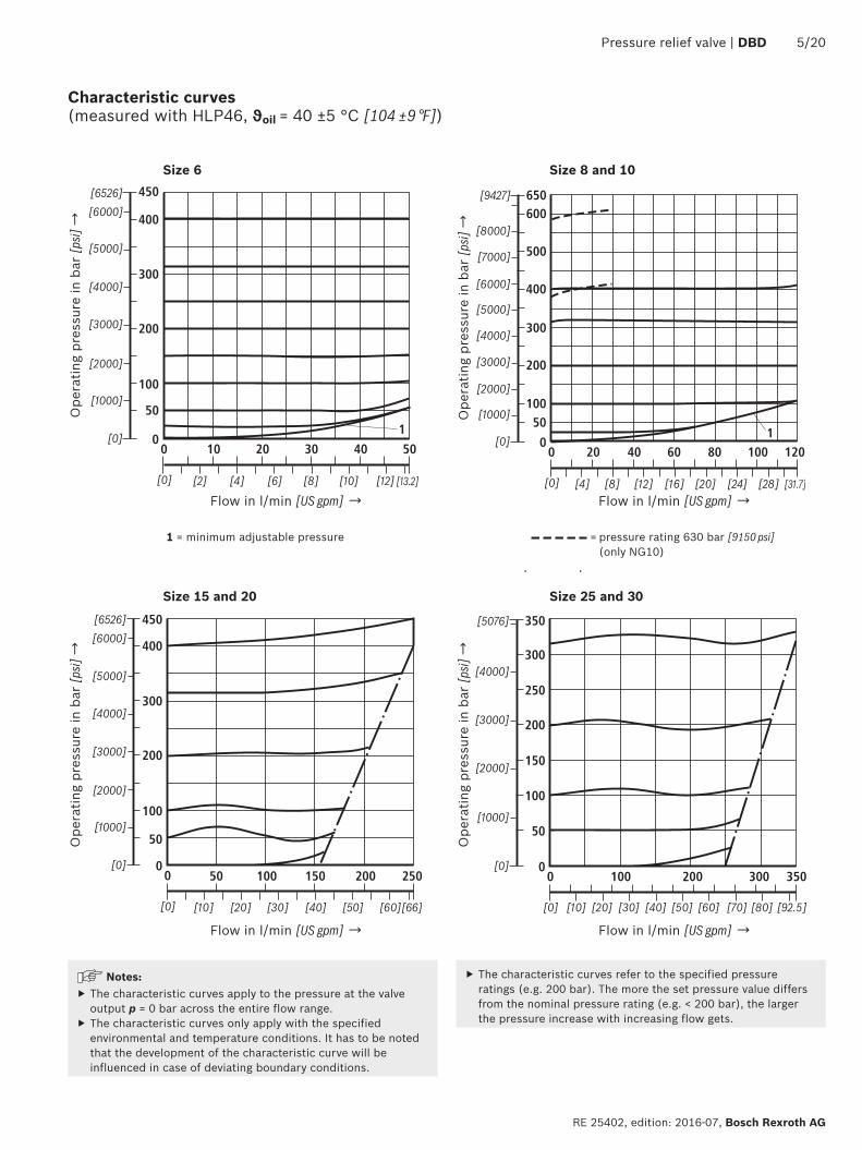
1 = minimum adjustable pressure = pressure rating 630 bar [9150 psi] (only NG10)
Size 8 and 10
Size 25 and 30
Characteristic curves (measured with HLP46, ϑoil = 40 ±5 °C [104 ±9 °F])
Notes: ▶ The characteristic curves apply to the pressure at the valve output p = 0 bar across the entire flow range.
▶ The characteristic curves only apply with the specified environmental and temperature conditions. It has to be noted that the development of the characteristic curve will be influenced in case of deviating boundary conditions.
▶ The characteristic curves refer to the specified pressure ratings (e.g. 200 bar). The more the set pressure value differs from the nominal pressure rating (e.g. < 200 bar), the larger the pressure increase with increasing flow gets.
L6
(P)
P
T
(P)
PT
D1 D4; T2
L2L1
L4L5
L3B1 B2
H2
H1
D2; T1 B1
3
4
2D3
1,5
[0.0
6]
==
1.1
6/20 DBD | Pressure relief valve
Bosch Rexroth AG, RE 25402, edition: 2016-07
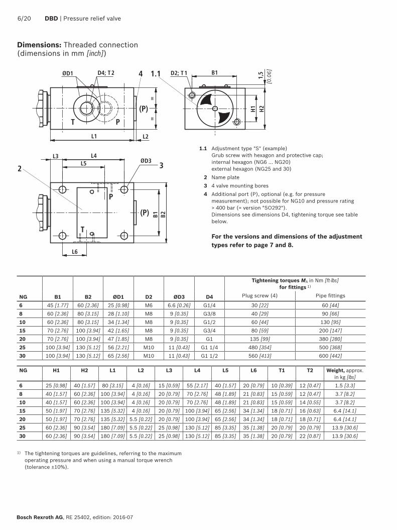
Dimensions: Threaded connection (dimensions in mm [inch])
1.1 Adjustment type "S" (example) Grub screw with hexagon and protective cap; internal hexagon (NG6 … NG20) external hexagon (NG25 and 30)
2 Name plate3 4 valve mounting bores4 Additional port (P), optional (e.g. for pressure
measurement); not possible for NG10 and pressure rating > 400 bar (= version "SO292"). Dimensions see dimensions D4, tightening torque see table below.
For the versions and dimensions of the adjustment types refer to page 7 and 8.
Tightening torques MA in Nm [ft-lbs] for fittings 1)
NG B1 B2 ØD1 D2 ØD3 D4 Plug screw (4) Pipe fittings
6 45 [1.77] 60 [2.36] 25 [0.98] M6 6.6 [0.26] G1/4 30 [22] 60 [44]8 60 [2.36] 80 [3.15] 28 [1.10] M8 9 [0.35] G3/8 40 [29] 90 [66]10 60 [2.36] 80 [3.15] 34 [1.34] M8 9 [0.35] G1/2 60 [44] 130 [95]15 70 [2.76] 100 [3.94] 42 [1.65] M8 9 [0.35] G3/4 80 [59] 200 [147]20 70 [2.76] 100 [3.94] 47 [1.85] M8 9 [0.35] G1 135 [99] 380 [280]25 100 [3.94] 130 [5.12] 56 [2.21] M10 11 [0.43] G1 1/4 480 [354] 500 [368]30 100 [3.94] 130 [5.12] 65 [2.56] M10 11 [0.43] G1 1/2 560 [413] 600 [442]
NG H1 H2 L1 L2 L3 L4 L5 L6 T1 T2 Weight, approx. in kg [lbs]
6 25 [0.98] 40 [1.57] 80 [3.15] 4 [0.16] 15 [0.59] 55 [2.17] 40 [1.57] 20 [0.79] 10 [0.39] 12 [0.47] 1.5 [3.3]8 40 [1.57] 60 [2.36] 100 [3.94] 4 [0.16] 20 [0.79] 70 [2.76] 48 [1.89] 21 [0.83] 15 [0.59] 12 [0.47] 3.7 [8.2]10 40 [1.57] 60 [2.36] 100 [3.94] 4 [0.16] 20 [0.79] 70 [2.76] 48 [1.89] 21 [0.83] 15 [0.59] 14 [0.55] 3.7 [8.2]15 50 [1.97] 70 [2.76] 135 [5.32] 4 [0.16] 20 [0.79] 100 [3.94] 65 [2.56] 34 [1.34] 18 [0.71] 16 [0.63] 6.4 [14.1]20 50 [1.97] 70 [2.76] 135 [5.32] 5.5 [0.22] 20 [0.79] 100 [3.94] 65 [2.56] 34 [1.34] 18 [0.71] 18 [0.71] 6.4 [14.1]25 60 [2.36] 90 [3.54] 180 [7.09] 5.5 [0.22] 25 [0.98] 130 [5.12] 85 [3.35] 35 [1.38] 20 [0.79] 20 [0.79] 13.9 [30.6]30 60 [2.36] 90 [3.54] 180 [7.09] 5.5 [0.22] 25 [0.98] 130 [5.12] 85 [3.35] 35 [1.38] 20 [0.79] 22 [0.87] 13.9 [30.6]
1) The tightening torques are guidelines, referring to the maximum operating pressure and when using a manual torque wrench (tolerance ±10%).
L17L1
9L18
L20
L21
L20
L18
L19
L23
L22
L24
L17
Ø2,5
SW5
SW3
SW2
SW1;
MA
SW1;
MA
SW6
SW2
SW3
SW1;
MA
ØD12
ØD12
ØD13
SW3
SW2
SW1; MA
SW2
SW1; MA
SW3
SW4ØD11
ØD11
6
7
1.2
1.11.381.210 10
11
10
10
10
ØD16 ØD
19-0
,2 1)
ØD17
L25
L26
L28L27
ØD18
L29
ØD15 D14
45°
ØD16
Ø0,1 A
L30
L31
0,008- / Pt 20
0,008
- / P
t 20 9
5
4
12
0,5 x
45°
Rz3 16
α1
AØ0,05 A
A0,0
2
-0,2 +0,2Rz 32
2)E
E
Pressure relief valve | DBD 7/20
RE 25402, edition: 2016-07, Bosch Rexroth AG
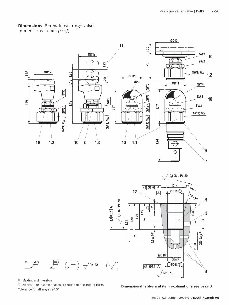
Dimensions: Screw-in cartridge valve (dimensions in mm [inch])
Dimensional tables and item explanations see page 8.
1) Maximum dimension2) All seal ring insertion faces are rounded and free of burrsTolerance for all angles ±0.5°
8/20 DBD | Pressure relief valve
Bosch Rexroth AG, RE 25402, edition: 2016-07
2) The tightening torques are guidelines with a friction coefficient µtotal = 0.12 and when using a manual torque wrench.
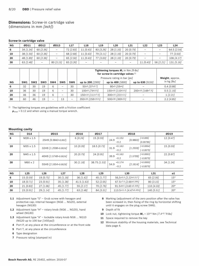
Dimensions: Screw-in cartridge valve (dimensions in mm [inch])
1.1 Adjustment type "S" – Grub screw with hexagon and protective cap; internal hexagon (NG6 … NG20), external hexagon (NG30)
1.2 Adjustment type "H" – rotary knob (NG6 … NG20), hand wheel (NG30)
1.3 Adjustment type "A" – lockable rotary knob NG6 … NG10 (NG20 up to 100 bar [1450 psi])
4 Port P, at any place at the circumference or at the front side5 Port T, at any place at the circumference6 Type designation7 Pressure rating (stamped in)
Screw-in cartridge valve NG ØD11 ØD12 ØD13 L17 L18 L19 L20 L21 L22 L23 L246 34 [1.34] 60 [2.36] – 72 [2.83] 11 [0.43] 83 [3.26] 28 [1.10] 20 [0.79] – – 64.5 [2.54]10 38 [1.50] 60 [2.36] – 68 [2.68] 11 [0.43] 79 [3.11] 28 [1.10] 20 [0.79] – – 77 [3.03]20 48 [1.89] 60 [2.36] – 65 [2.56] 11 [0.43] 77 [3.03] 28 [1.10] 20 [0.79] – – 106 [4.17]30 63 [2.48] – 80 [3.15] 83 [3.26] – – – – 11 [0.43] 56 [2.21] 131 [5.16]
Tightening torques MA in Nm [ft-lbs] for screw-in cartridge valves 2)
Pressure rating in bar [psi] Weight, approx. in kg [lbs]NG SW1 SW2 SW3 SW4 SW5 SW6 up to 200 [2900] up to 400 [5800] up to 630 [9150]
6 32 30 19 6 – 30 50±5 [37±3.7] 80±5 [59±4] – 0.4 [0.88]10 36 30 19 6 – 30 100±5 [74±3.5] 150±10 [110±3.5] 200±10 [148±7.5] 0.5 [1.10]20 46 36 19 6 – 30 150±10 [111±7.5] 300±15 [221±11] – 1 [2.21]30 60 46 19 – 13 – 350±20 [258±19.5] 500±30 [369±22] – 2.2 [4.85]
NG L25 L26 L27 L28 L29 L30 L31 α16 15 [0.59] 19 [0.75] 30 [1.18] 36 [1.42] 45 [1.77] 56,5±5,5 [2.22±0.217] 65 [2.56] 15°10 18 [0.71] 23 [0.91] 35 [1.38] 41.5 [1.63] 52 [2.05] 67.5±7.5 [2.66±0.295] 80 [3.15] 15°20 21 [0.83] 27 [1.06] 45 [1.77] 55 [2.17] 70 [2.76] 91.5±8.5 [3.60 ±0.335] 110 [4.33] 20°30 23 [0.91] 29 [1.14] 45 [1.77] 63 [2.48] 84 [3.31] 113.5±11.5 [4.47±0.453] 140 [5.51] 20°
8 Marking (adjustment of the zero position after the valve has been screwed in; then fixing of the ring by horizontal shifting until it engages on the plug screw SW6).
9 Depth of fit10 Lock nut, tightening torque MA = 10+5 Nm [7.4+3.7 ft-lbs]11 Space required to remove the key12 Minimum stability of the housing materials, see Technical
data page 4.
Mounting cavity
NG D14 ØD15 ØD16 ØD17 ØD18 ØD196 M28 x 1.5
25H9 [0.9843+0,002]6 [0.24] 15 [0.59]
24.9+0.152
[0.9803][+0.006] 12 [0.47]
–0.2 [0.00786]
10 M35 x 1.532H9 [1.2598+0.0024]
10 [0.39] 18.5 [0.73]31.9
+0.162[1.2559]
[+0.0064] 15 [0.59]–0.2 [–0.0079]
20 M45 x 1.540H9 [1.5748+0.0024]
20 [0.79] 24 [0.95]39.9
+0.162[1.5709]
[+0.0063] 22 [0.87]–0.2 [–0.0079]
30 M60 x 255H9 [2.1654+0.0029]
30 [1.18] 38.75 [1.53]54.9
+0.174[2.1614]
[+0.0069] 34 [1.34]–0.2 [–0.0079]
0,01/100
Rz1max 4
[0.0004/4.0]
H2
1.1
D9; T 3D8; T2 D10
PT
(P)PT
L1
L4L3
L2
B2B1
D3
L6
L5
(P)
42
L18
6
5
PT
R1
D7; T5 D6; T4
D5
L12 L12L8
12
1314
3
L17 D11; T6
L9=
L11
L16L15
L14
L13
H3
L10
[0.2
]
15
[Ø0.23]
B4B3
3
L7
=
1,5
[0.0
6]
Pressure relief valve | DBD 9/20
RE 25402, edition: 2016-07, Bosch Rexroth AG
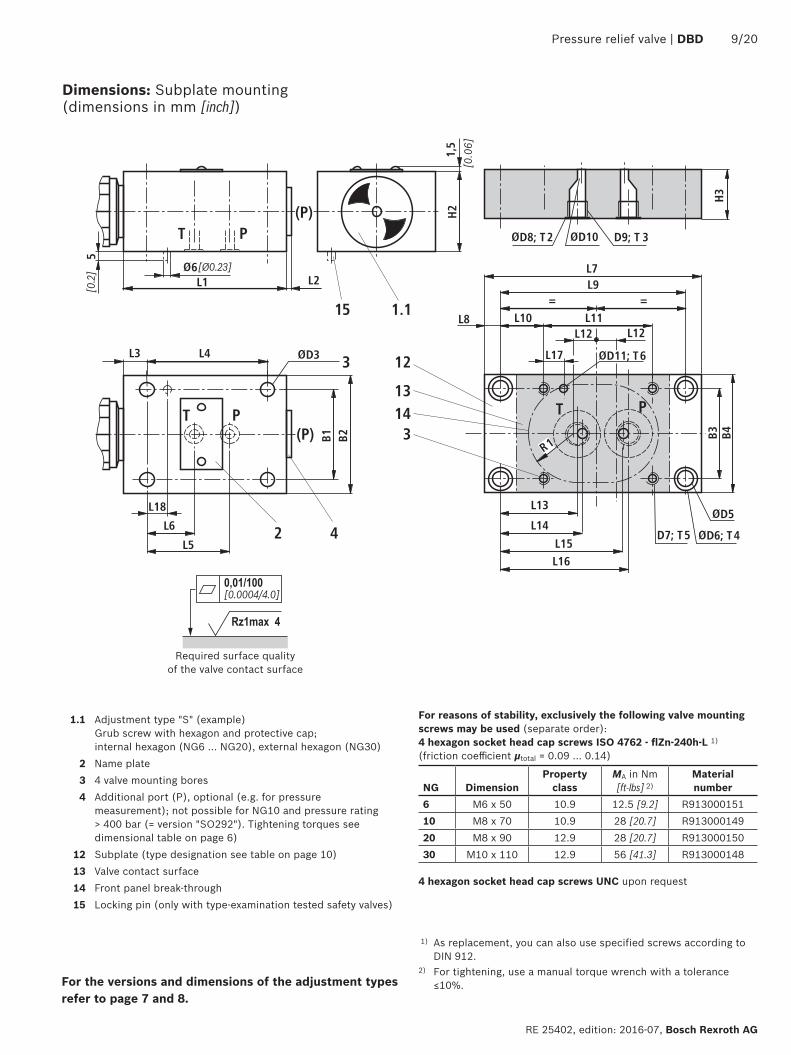
Dimensions: Subplate mounting (dimensions in mm [inch])
1.1 Adjustment type "S" (example) Grub screw with hexagon and protective cap; internal hexagon (NG6 … NG20), external hexagon (NG30)
2 Name plate3 4 valve mounting bores4 Additional port (P), optional (e.g. for pressure
measurement); not possible for NG10 and pressure rating > 400 bar (= version "SO292"). Tightening torques see dimensional table on page 6)
12 Subplate (type designation see table on page 10)13 Valve contact surface14 Front panel break-through15 Locking pin (only with type-examination tested safety valves)
For the versions and dimensions of the adjustment types refer to page 7 and 8.
1) As replacement, you can also use specified screws according to DIN 912.
2) For tightening, use a manual torque wrench with a tolerance ≤10%.
For reasons of stability, exclusively the following valve mounting screws may be used (separate order):4 hexagon socket head cap screws ISO 4762 - flZn-240h-L 1) (friction coefficient µtotal = 0.09 … 0.14)
NG DimensionProperty
classMA in Nm
[ft-lbs] 2)Material number
6 M6 x 50 10.9 12.5 [9.2] R91300015110 M8 x 70 10.9 28 [20.7] R91300014920 M8 x 90 12.9 28 [20.7] R91300015030 M10 x 110 12.9 56 [41.3] R913000148
4 hexagon socket head cap screws UNC upon request
Required surface quality of the valve contact surface
10/20 DBD | Pressure relief valve
Bosch Rexroth AG, RE 25402, edition: 2016-07
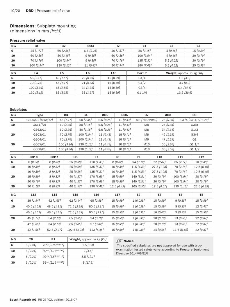
Pressure relief valve NG B1 B2 ØD3 H2 L1 L2 L36 45 [1.77] 60 [2.36] 6.6 [0.26] 40 [1.57] 80 [3.15] 4 [0.16] 15 [0.59]10 60 [2.36] 80 [3.15] 9 [0.35] 60 [2.36] 100 [3.94] 4 [0.16] 20 [0.79]20 70 [2.76] 100 [3.94] 9 [0.35] 70 [2.76] 135 [5.32] 5.5 [0.22] 20 [0.79]30 100 [3.94] 130 [5.12] 11 [0.43] 90 [3.54] 180 [7.09] 5.5 [0.22] 25 [0.98]
NG L4 L5 L6 L18 Port P Weight, approx. in kg [lbs]6 55 [2.17] 40 [1.57] 20 [0.79] 15 [0.59] G1/4 1.5 [3.3]10 70 [2.76] 45 [1.77] 21 [0.83] 15 [0.59] G1/2 3.7 [8.2]20 100 [3.94] 65 [2.56] 34 [1.34] 15 [0.59] G3/4 6.4 [14.1]30 130 [5.12] 85 [3.35] 35 [1.37] 15 [0.59] G1 1/4 13.9 [30.6]
SubplatesNG Type B3 B4 ØD5 ØD6 D7 ØD8 D96 G300/01 [G300/12] 45 [1.77] 60 [2.36] 6.6 [0.26] 11 [0.43] M6 [1/4-20 UNC] 25 [0.98] G1/4 [SAE 4; 7/16-20]10 G661//01 60 [2.36] 80 [3.15] 6.6 [0.26] 11 [0.43] M8 25 [0.98] G3/8
G662/01 60 [2.36] 80 [3.15] 6.6 [0.26] 11 [0.43] M8 34 [1.34] G1/220 G303/01 70 [2.76] 100 [3.94] 11 [0.43] 18 [0.71] M8 42 [1.65] G3/4
G304/01 70 [2.76] 100 [3.94] 11 [0.43] 18 [0.71] M8 47 [1.85] G130 G305/01 100 [3.94] 130 [5.12] 11 [0.43] 18 [0.71] M10 56 [2.20] G1 1/4
G306/01 100 [3.94] 130 [5.12] 11 [0.43] 18 [0.71] M10 65 [2.56] G1 1/2
NG ØD10 ØD11 H3 L7 L8 L9 L10 L11 L126 6 [0.24] 8 [0.32] 25 [0.98] 110 [4.33] 8 [0.32] 94 [3.70] 22 [0.87] 55 [2.17] 10 [0.39]10 10 [0.39] 8 [0.32] 25 [0.98] 135 [5.32] 10 [0.39] 115 [4.53] 27.5 [1.08] 70 [2.76] 12.5 [0.49]
10 [0.39] 8 [0.32] 25 [0.98] 135 [5.32] 10 [0.39] 115 [4.53] 27.5 [1.08] 70 [2.76] 12.5 [0.49]20 15 [0.59] 8 [0.32] 40 [1.57] 170 [6.69] 15 [0.59] 140 [5.51] 20 [0.79] 100 [3.94] 20 [0.79]
20 [0.79] 8 [0.32] 40 [1.57] 170 [6.69] 15 [0.59] 140 [5.51] 20 [0.79] 100 [3.94] 20 [0.79]30 30 [1.18] 8 [0.32] 40 [1.57] 190 [7.48] 12.5 [0.49] 165 [6.50] 17.5 [0.67] 130 [5.12] 22.5 [0.89]
NG L13 L14 L15 L16 L17 T2 T3 T4 T5
6 39 [1.54] 42 [1.65] 62 [2.44] 65 [2.56] 15 [0.59] 1 [0.039] 15 [0.59] 9 [0.35] 15 [0.59]
10 40.5 [1.59] 48.5 [1.91] 72.5 [2.85] 80.5 [3.17] 15 [0.59] 1 [0.039] 15 [0.59] 9 [0.35] 12 [0.47]
40.5 [1.59] 48.5 [1.91] 72.5 [2.85] 80.5 [3.17] 15 [0.59] 1 [0.039] 16 [0.63] 9 [0.35] 15 [0.59]
20 45 [1.77] 54 [2.13] 85 [3.35] 94 [3.70] 15 [0.59] 1 [0.039] 20 [0.79] 13 [0.51] 22 [0.87]
42 [1.65] 54 [2.13] 85 [3.35] 97 [3.82] 15 [0.59] 1 [0.039] 20 [0.79] 13 [0.51] 22 [0.87]
30 42 [1.65] 52.5 [2.07] 102.5 [4.04] 113 [4.45] 15 [0.59] 1 [0.039] 24 [0.95] 11.5 [0.45] 22 [0.87]
NG T6 R1 Weight, approx. in kg [lbs]
6 6 [0.24] 25+2 [0.98+0.079] 1.5 [3.3]
10 6 [0.24] 30+5 [1.18+0.197] 2 [4.4]
20 6 [0.24] 40+3 [1.57+0.118] 5.5 [12.1]
30 6 [0.24] 55+4 [2.16+0.157] 8 [17.6]
Dimensions: Subplate mounting (dimensions in mm [inch])
Notice: The specified subplates are not approved for use with type-examination tested safety valve according to Pressure Equipment Directive 2014/68/EU!
Pressure relief valve | DBD 11/20
RE 25402, edition: 2016-07, Bosch Rexroth AG
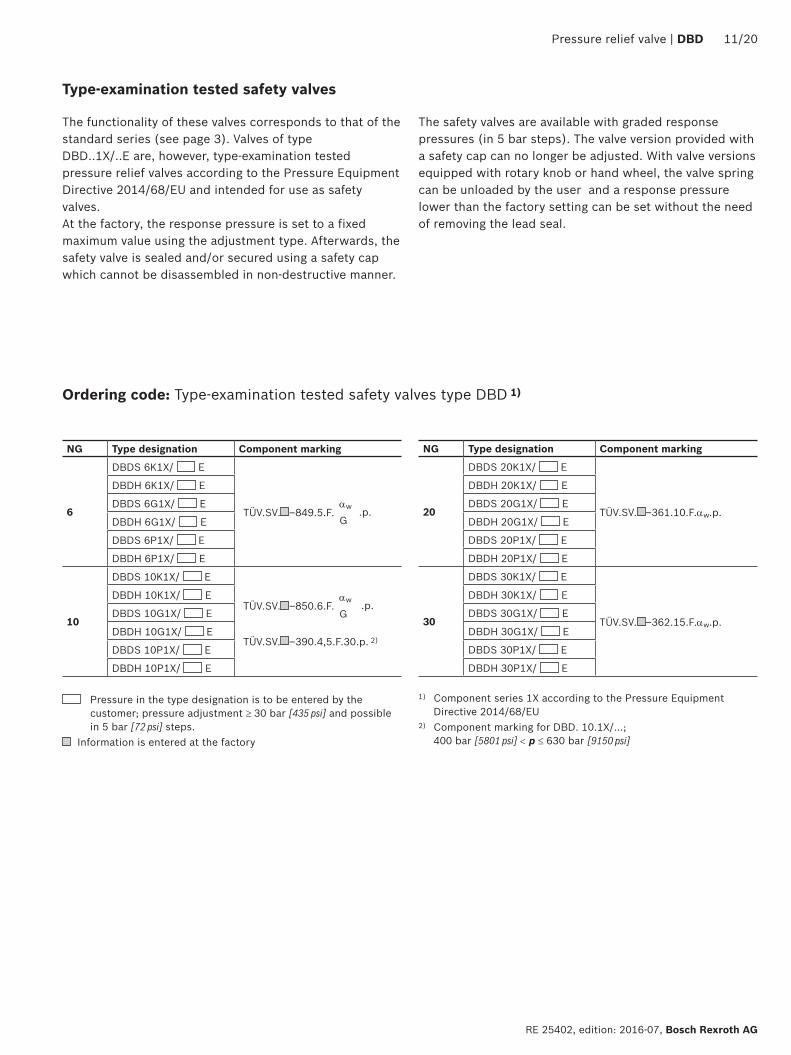
Ordering code: Type-examination tested safety valves type DBD 1)
Type-examination tested safety valves
NG Type designation Component marking
6
DBDS 6K1X/ E
TÜV.SV. –849.5.F.αw .p.G
DBDH 6K1X/ E
DBDS 6G1X/ E
DBDH 6G1X/ E
DBDS 6P1X/ E
DBDH 6P1X/ E
10
DBDS 10K1X/ E
TÜV.SV. –850.6.F.αw .p.G
TÜV.SV. –390.4,5.F.30.p. 2)
DBDH 10K1X/ E
DBDS 10G1X/ E
DBDH 10G1X/ E
DBDS 10P1X/ E
DBDH 10P1X/ E
NG Type designation Component marking
20
DBDS 20K1X/ E
TÜV.SV. –361.10.F.αw.p.
DBDH 20K1X/ E
DBDS 20G1X/ E
DBDH 20G1X/ E
DBDS 20P1X/ E
DBDH 20P1X/ E
30
DBDS 30K1X/ E
TÜV.SV. –362.15.F.αw.p.
DBDH 30K1X/ E
DBDS 30G1X/ E
DBDH 30G1X/ E
DBDS 30P1X/ E
DBDH 30P1X/ E
Pressure in the type designation is to be entered by the customer; pressure adjustment ≥ 30 bar [435 psi] and possible in 5 bar [72 psi] steps.
Information is entered at the factory
1) Component series 1X according to the Pressure Equipment Directive 2014/68/EU
2) Component marking for DBD. 10.1X/...; 400 bar [5801 psi] < p ≤ 630 bar [9150 psi]
The functionality of these valves corresponds to that of the standard series (see page 3). Valves of type DBD..1X/..E are, however, type-examination tested pressure relief valves according to the Pressure Equipment Directive 2014/68/EU and intended for use as safety valves.At the factory, the response pressure is set to a fixed maximum value using the adjustment type. Afterwards, the safety valve is sealed and/or secured using a safety cap which cannot be disassembled in non-destructive manner.
The safety valves are available with graded response pressures (in 5 bar steps). The valve version provided with a safety cap can no longer be adjusted. With valve versions equipped with rotary knob or hand wheel, the valve spring can be unloaded by the user and a response pressure lower than the factory setting can be set without the need of removing the lead seal.
H1
H2
B2ØD2
ØD1B1
ØD1
R1
12/20 DBD | Pressure relief valve
Bosch Rexroth AG, RE 25402, edition: 2016-07
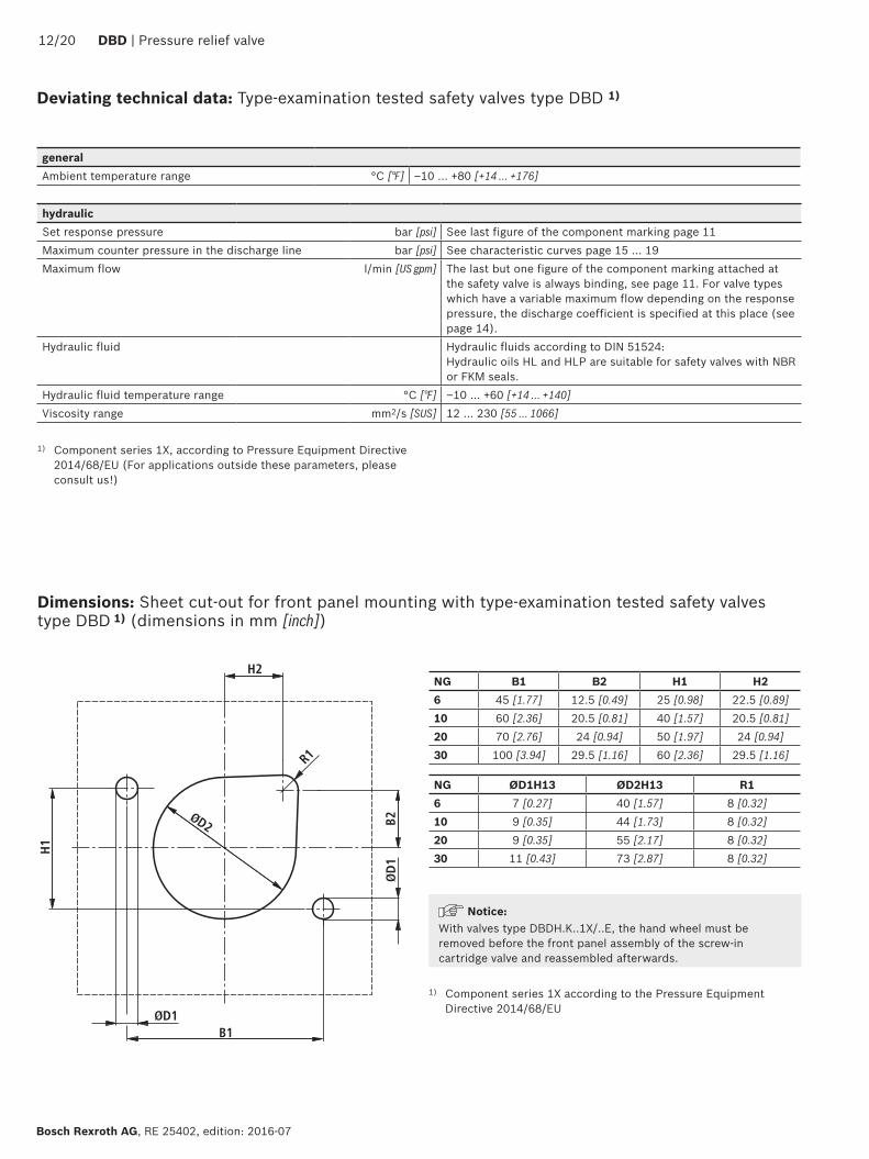
Dimensions: Sheet cut-out for front panel mounting with type-examination tested safety valves type DBD 1) (dimensions in mm [inch])
NG B1 B2 H1 H26 45 [1.77] 12.5 [0.49] 25 [0.98] 22.5 [0.89]10 60 [2.36] 20.5 [0.81] 40 [1.57] 20.5 [0.81]20 70 [2.76] 24 [0.94] 50 [1.97] 24 [0.94]30 100 [3.94] 29.5 [1.16] 60 [2.36] 29.5 [1.16]
NG ØD1H13 ØD2H13 R16 7 [0.27] 40 [1.57] 8 [0.32]10 9 [0.35] 44 [1.73] 8 [0.32]20 9 [0.35] 55 [2.17] 8 [0.32]30 11 [0.43] 73 [2.87] 8 [0.32]
1) Component series 1X according to the Pressure Equipment Directive 2014/68/EU
Notice:With valves type DBDH.K..1X/..E, the hand wheel must be removed before the front panel assembly of the screw-in cartridge valve and reassembled afterwards.
1) Component series 1X, according to Pressure Equipment Directive 2014/68/EU (For applications outside these parameters, please consult us!)
hydraulicSet response pressure bar [psi] See last figure of the component marking page 11Maximum counter pressure in the discharge line bar [psi] See characteristic curves page 15 … 19Maximum flow l/min [US gpm] The last but one figure of the component marking attached at
the safety valve is always binding, see page 11. For valve types which have a variable maximum flow depending on the response pressure, the discharge coefficient is specified at this place (see page 14).
Hydraulic fluid Hydraulic fluids according to DIN 51524: Hydraulic oils HL and HLP are suitable for safety valves with NBR or FKM seals.
Hydraulic fluid temperature range °C [°F] –10 … +60 [+14 … +140]Viscosity range mm2/s [SUS] 12 … 230 [55 … 1066]
Deviating technical data: Type-examination tested safety valves type DBD 1)
generalAmbient temperature range °C [°F] –10 … +80 [+14 … +176]
L18
L19
2)
L23
1)L22
ØD12ØD11
ØD13
SW3
SW2
SW1; MA
SW3
SW2
SW1; MA
1.2 1.2
10 10
L24
L17
SW1; MA
6
1.4
7
Pressure relief valve | DBD 13/20
RE 25402, edition: 2016-07, Bosch Rexroth AG
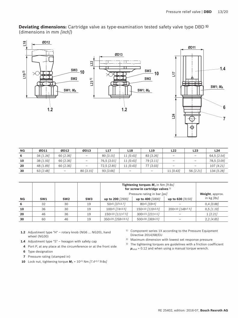
Deviating dimensions: Cartridge valve as type-examination tested safety valve type DBD 1) (dimensions in mm [inch])
1) Component series 1X according to the Pressure Equipment Directive 2014/68/EU
2) Maximum dimension with lowest set response pressure 3) The tightening torques are guidelines with a friction coefficient
µtotal = 0.12 and when using a manual torque wrench.
NG ØD11 ØD12 ØD13 L17 L18 L19 L22 L23 L246 34 [1.34] 60 [2.36] – 80 [3.15] 11 [0.43] 83 [3.26] – – 64,5 [2.54]10 38 [1.50] 60 [2.36] – 76,5 [3.01] 11 [0.43] 79 [3.11] – – 78,5 [3.09]20 48 [1.89] 60 [2.36] – 72,5 [2.85] 11 [0.43] 77 [3.03] – – 107 [4.21]30 63 [2.48] – 80 [3.15] 93 [3.66] – – 11 [0.43] 56 [2.21] 134 [5.28]
1.2 Adjustment type "H" – rotary knob (NG6 … NG20), hand wheel (NG30)
1.4 Adjustment type "S" – hexagon with safety cap4 Port P, at any place at the circumference or at the front side6 Type designation7 Pressure rating (stamped in)
10 Lock nut, tightening torque MA = 10+5 Nm [7.4+3.7 ft-lbs]
Tightening torques MA in Nm [ft-lbs] for screw-in cartridge valves 3)
Pressure rating in bar [psi] Weight, approx. in kg [lbs]NG SW1 SW2 SW3 up to 200 [2900] up to 400 [5800] up to 630 [9150]
6 32 30 19 50±5 [37±3.7] 80±5 [59±4] – 0,4 [0.88]10 36 30 19 100±5 [74±3.5] 150±10 [110±3.5] 200±10 [148±7.5] 0,5 [1.10]20 46 36 19 150±10 [111±7.5] 300±15 [221±11] – 1 [2.21]30 60 46 19 350±20 [258±19.5] 500±30 [369±22] – 2,2 [4.85]
400
300
405060
80
200
0 20 40 60 80 100 120
100
140
171
630
120150160
30
[0] [5] [15] [20] [25] [37][10] [30]
[435]
[5801]
[580][725][870]
[1160]
[1450]
[2901]
[4351]
[9150]
[1740][2176][2320][2480]
400
300
405060
80
200
300 12 20 28 36 44 52
100111
[0] [2] [6] [8] [10] [13.7][4] [12]
[5801]
[435]
[580]
[725][870]
[1160][1450][1610]
[2901]
[4351]
400
200
405060
80
100
300 60 90 120 150 180
300
120140160180
220260
316
240280
[0] [5] [47.5][10]
[5801]
[435]
[580]
[725][870]
[1160]
[1450]
[2901]
[4351]
[15] [20] [25] [30] [35] [40]
[1740][2030][2320][2610]
[3190][3771]
[4583]
0 60 120 180 240 300 360
220
280
[0] [95][10] [30] [40] [50] [60] [70] [80]
400
200
405060
80
100
30
300
120140160180
220260
316
[5801]
[435]
[580]
[725][870]
[1160]
[1450]
[2901]
[4351]
[1740][2030][2320][2610]
[3190][3771]
[4583]
[20]
14/20 DBD | Pressure relief valve
Bosch Rexroth AG, RE 25402, edition: 2016-07
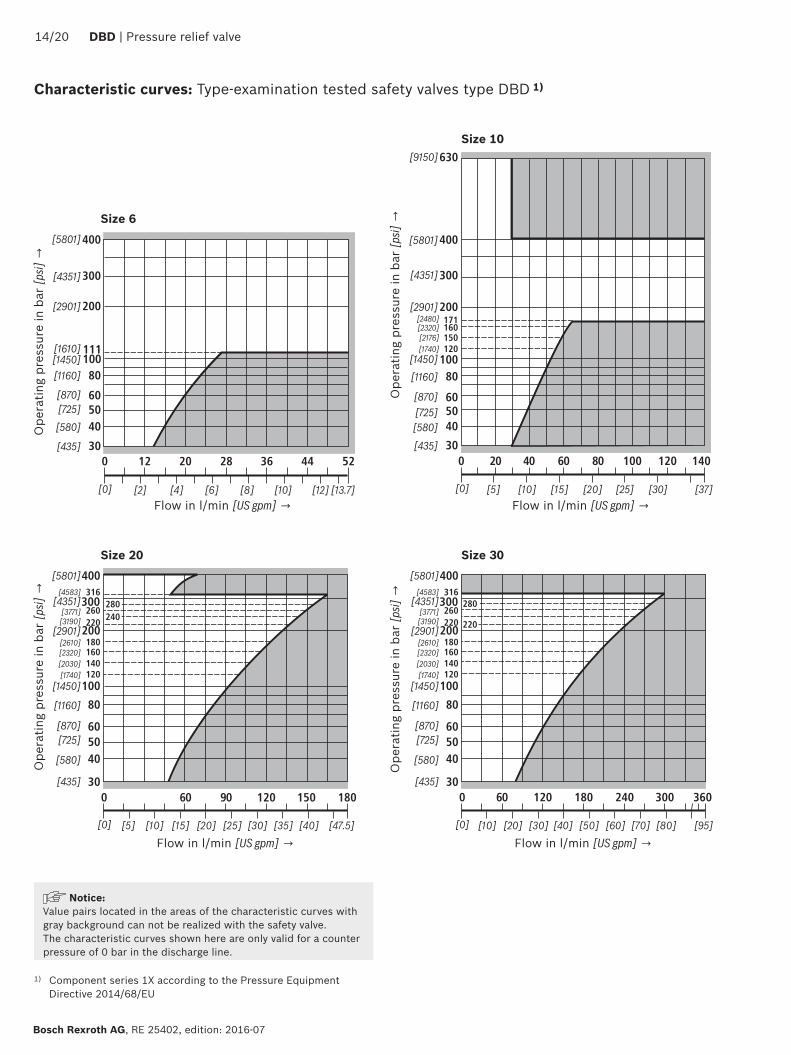
Characteristic curves: Type-examination tested safety valves type DBD 1)
Ope
ratin
g pr
essu
re in
bar
[psi]
→
Ope
ratin
g pr
essu
re in
bar
[psi]
→
Flow in l/min [US gpm] →
Flow in l/min [US gpm] →
Ope
ratin
g pr
essu
re in
bar
[psi]
→
Flow in l/min [US gpm] →
Flow in l/min [US gpm] →
Ope
ratin
g pr
essu
re in
bar
[psi]
→
Size 6
Size 10
Size 20 Size 30
Notice:Value pairs located in the areas of the characteristic curves with gray background can not be realized with the safety valve.The characteristic curves shown here are only valid for a counter pressure of 0 bar in the discharge line.
1) Component series 1X according to the Pressure Equipment Directive 2014/68/EU
Pressure relief valve | DBD 15/20
RE 25402, edition: 2016-07, Bosch Rexroth AG
Safety instructions: Type-examination tested safety valves type DBD 1)
▶ Before ordering a type-examination tested safety valve, it must be observed that for the desired response pressure p, the maximum admissible flow qVmax of the safety valve must be larger than the maximum possible flow of the system/accumulator to be secured. According to the Pressure Equipment Directive 2014/68/EU, the increase in the system pressure due to the flow must not exceed 10% of the set response pressure (see component marking on page 11).
▶ The maximum admissible flow qVmax stated in the component marking must not be exceeded.
▶ Discharge lines of safety valves must end in a risk-free manner. The accumulation of fluids in the discharge system must not be possible (see data sheet AD2000 A2).
It is imperative to observe the application notes! ▶ In the plant, the response pressure specified in the
component marking is set at a flow of 2 l/min [0.53 US gpm] .
▶ The maximum flow stated in the component marking applies for applications without counter pressure in the discharge line (port T).
▶ By removing the lead seal at the safety valve, the approval according to the Pressure Equipment Directive becomes void!
▶ Basically, the requirements of the Pressure Equipment Directive and of data sheet AD2000 A2 have to be observed!
▶ It is recommended to secure type-examination tested safety valves against inadmissible disassembly by means of wiring and sealing with the housing/block (bore available in the adjustment type).
Notice:The system pressure increases by the counter pressure in the discharge line (port T) due to the increasing flow. (Observe the data sheet AD 2000 A 2, point 6.3!)To ensure that this increase in system pressure caused by the flow does not exceed the value of 10% of the set response pressure, the admissible flow has to be reduced dependent on the counter pressure in the discharge line (port T) (see diagrams on pages 15 … 19).
1) Component series 1X according to the Pressure Equipment Directive 2014/68/EU
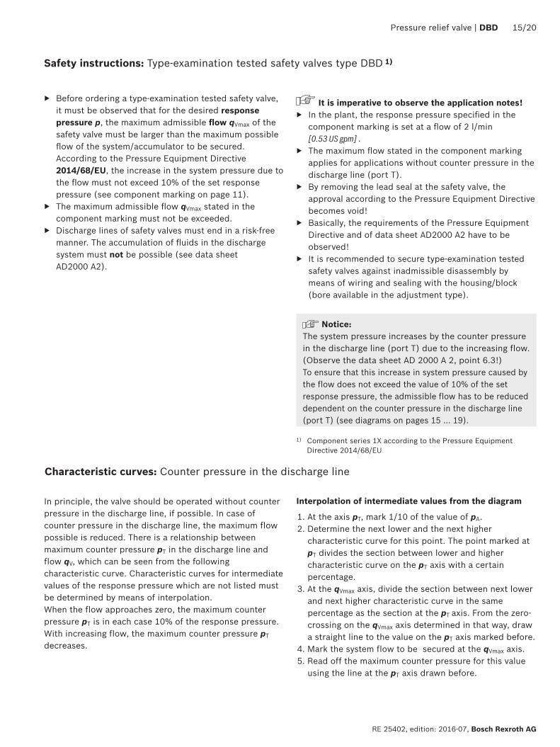
Characteristic curves: Counter pressure in the discharge line
In principle, the valve should be operated without counter pressure in the discharge line, if possible. In case of counter pressure in the discharge line, the maximum flow possible is reduced. There is a relationship between maximum counter pressure pT in the discharge line and flow qV, which can be seen from the following characteristic curve. Characteristic curves for intermediate values of the response pressure which are not listed must be determined by means of interpolation. When the flow approaches zero, the maximum counter pressure pT is in each case 10% of the response pressure. With increasing flow, the maximum counter pressure pT decreases.
Interpolation of intermediate values from the diagram
1. At the axis pT, mark 1/10 of the value of pA. 2. Determine the next lower and the next higher
characteristic curve for this point. The point marked at pT divides the section between lower and higher characteristic curve on the pT axis with a certain percentage.
3. At the qVmax axis, divide the section between next lower and next higher characteristic curve in the same percentage as the section at the pT axis. From the zero-crossing on the qVmax axis determined in that way, draw a straight line to the value on the pT axis marked before.
4. Mark the system flow to be secured at the qVmax axis. 5. Read off the maximum counter pressure for this value
using the line at the pT axis drawn before.
0
200
100
300
400
pA[bar]
pT[bar]
qVmax [l/min]
5
10
20
30
40
2122,5
11,5
17
6
3
11
31,5
x%100%
5 14 27 5230100 20 40100%
x%1
2 3
45
6
7
8
II
I
16/20 DBD | Pressure relief valve
Bosch Rexroth AG, RE 25402, edition: 2016-07
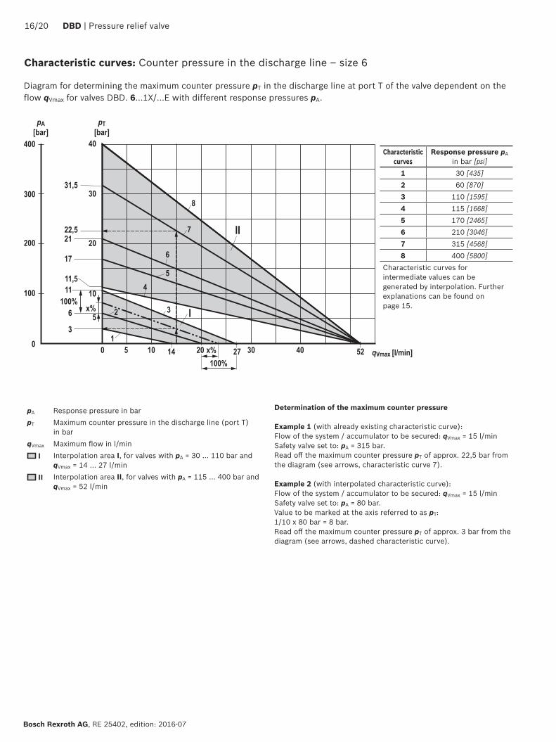
Characteristic curves: Counter pressure in the discharge line – size 6
Diagram for determining the maximum counter pressure pT in the discharge line at port T of the valve dependent on the flow qVmax for valves DBD. 6...1X/...E with different response pressures pA.
pA Response pressure in bar pT Maximum counter pressure in the discharge line (port T)
in bar qVmax Maximum flow in l/min
I Interpolation area I, for valves with pA = 30 … 110 bar and qVmax = 14 … 27 l/min
II Interpolation area II, for valves with pA = 115 … 400 bar and qVmax = 52 l/min
Determination of the maximum counter pressure
Example 1 (with already existing characteristic curve): Flow of the system / accumulator to be secured: qVmax = 15 l/min Safety valve set to: pA = 315 bar. Read off the maximum counter pressure pT of approx. 22,5 bar from the diagram (see arrows, characteristic curve 7). Example 2 (with interpolated characteristic curve): Flow of the system / accumulator to be secured: qVmax = 15 l/min Safety valve set to: pA = 80 bar. Value to be marked at the axis referred to as pT: 1/10 x 80 bar = 8 bar. Read off the maximum counter pressure pT of approx. 3 bar from the diagram (see arrows, dashed characteristic curve).
Characteristic curves
Response pressure pA in bar [psi]
1 30 [435]2 60 [870]3 110 [1595]4 115 [1668]5 170 [2465]6 210 [3046]7 315 [4568]8 400 [5800]
Characteristic curves for intermediate values can be generated by interpolation. Further explanations can be found on page 15.
0
200
100
300
400
500
600
pA[bar]
pT[bar]
qVmax [l/min]
5
10
20
30
50
60
40
2122,5
11,517
6
3
11
31,5
63
40,5
10 3029
50 70 100 140042 54 65
1
2
3
4
5
6
7
89
10
Pressure relief valve | DBD 17/20
RE 25402, edition: 2016-07, Bosch Rexroth AG
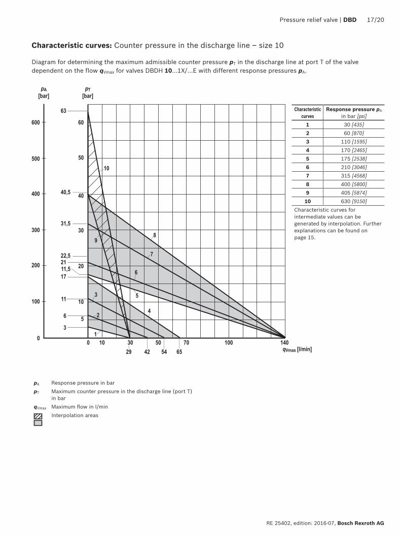
Characteristic curves
Response pressure pA in bar [psi]
1 30 [435]2 60 [870]3 110 [1595]4 170 [2465]5 175 [2538]6 210 [3046]7 315 [4568]8 400 [5800]9 405 [5874]10 630 [9150]
Characteristic curves for intermediate values can be generated by interpolation. Further explanations can be found on page 15.
Diagram for determining the maximum admissible counter pressure pT in the discharge line at port T of the valve dependent on the flow qVmax for valves DBDH 10...1X/...E with different response pressures pA.
Characteristic curves: Counter pressure in the discharge line – size 10
pA Response pressure in bar pT Maximum counter pressure in the discharge line (port T)
in bar qVmax Maximum flow in l/min
Interpolation areas
0
200
100
300
400
pA[bar]
pT[bar]
qVmax [l/min]
5
10
20
30
40
21
32
17
6
3
11
31,5
100 50 100 1501
2
3
45
6
7
8
6948 97 122 135 165
18/20 DBD | Pressure relief valve
Bosch Rexroth AG, RE 25402, edition: 2016-07
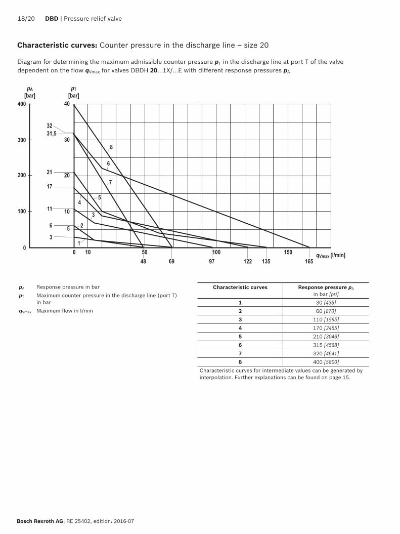
Diagram for determining the maximum admissible counter pressure pT in the discharge line at port T of the valve dependent on the flow qVmax for valves DBDH 20...1X/...E with different response pressures pA.
Characteristic curves: Counter pressure in the discharge line – size 20
Characteristic curves Response pressure pA in bar [psi]
1 30 [435]2 60 [870]3 110 [1595]4 170 [2465]5 210 [3046]6 315 [4568]7 320 [4641]8 400 [5800]
Characteristic curves for intermediate values can be generated by interpolation. Further explanations can be found on page 15.
pA Response pressure in bar pT Maximum counter pressure in the discharge line (port T)
in bar qVmax Maximum flow in l/min
0
200
100
300
400
pA[bar]
pT[bar]
qVmax [l/min]
5
10
20
30
40
21
17
6
3
11
31,5
200 100 200 3001
2
3
4
5
6
81 121 213170 240
Pressure relief valve | DBD 19/20
RE 25402, edition: 2016-07, Bosch Rexroth AG
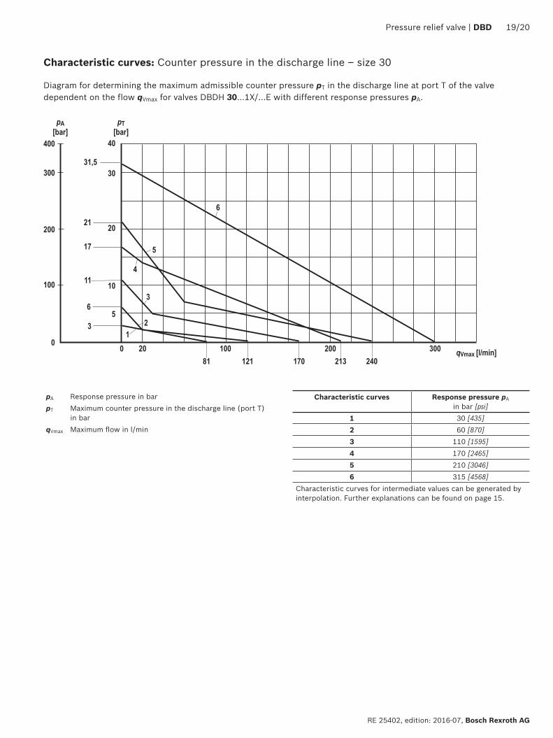
Diagram for determining the maximum admissible counter pressure pT in the discharge line at port T of the valve dependent on the flow qVmax for valves DBDH 30...1X/...E with different response pressures pA.
Characteristic curves: Counter pressure in the discharge line – size 30
Characteristic curves Response pressure pA in bar [psi]
1 30 [435]2 60 [870]3 110 [1595]4 170 [2465]5 210 [3046]6 315 [4568]
Characteristic curves for intermediate values can be generated by interpolation. Further explanations can be found on page 15.
pA Response pressure in bar pT Maximum counter pressure in the discharge line (port T)
in bar qVmax Maximum flow in l/min
Bosch Rexroth AG, RE 25402, edition: 2016-07
20/20 DBD | Pressure relief valve
Bosch Rexroth AG HydraulicsZum Eisengießer 197816 Lohr am Main, Germany Telephone +49 (0) 93 52 / 18-0 [email protected] www.boschrexroth.de
© This document, as well as the data, specifications and other information set forth in it, are the exclusive property of Bosch Rexroth AG. It may not be reproduced or given to third parties without its consent.The data specified above only serve to describe the product. No statements concerning a certain condition or suitability for a certain application can be derived from our information. The information given does not release the user from the obligation of own judgment and verification. It must be remembered that our products are subject to a natural process of wear and aging.
Further information
▶ Safety equipment against excessive pressure – safety valves Data sheet AD 2000 A 2 ▶ Subplates Data sheet 45100 ▶ Hydraulic fluids on mineral oil basis Data sheet 90220 ▶ Environmentally compatible hydraulic fluids Data sheet 90221 ▶ Flame-resistant, water-free hydraulic fluids Data sheet 90222 ▶ Flame-resistant hydraulic fluids - containing water (HFAE, HFAS, HFB, HFC) Data sheet 90223 ▶ Reliability characteristics according to EN ISO 13849 Data sheet 08012 ▶ Hydraulic valves for industrial applications Operating instructions 07600-B ▶ Selection of the filters www.boschrexroth.com/filter