Embed Size (px)
Citation preview
RA 29160/04.05Replaces: 06.98
Electric Drivesand Controls Hydraulics
Linear Motion andAssembly Technologies Pneumatics Service
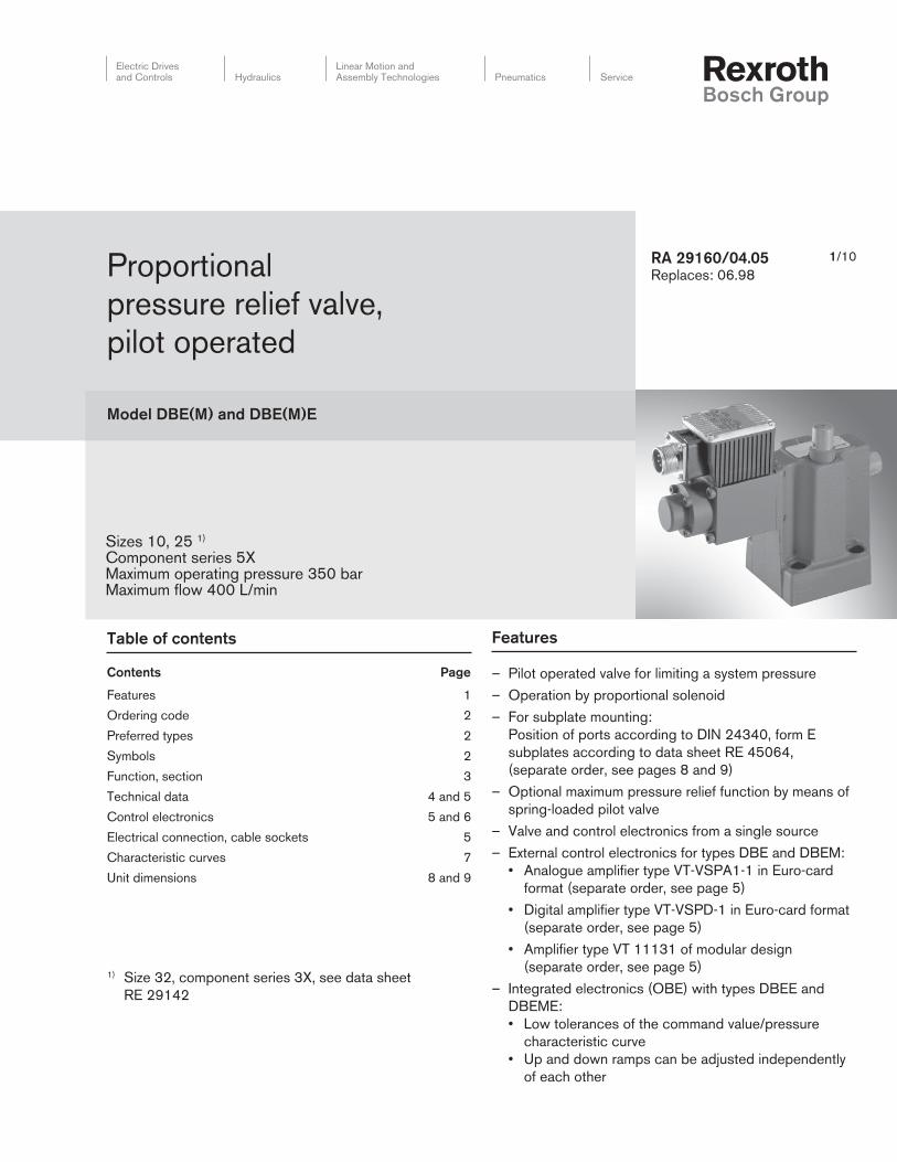
Proportional
pressure relief valve,
pilot operated
Model DBE(M) and DBE(M)E
Features 1
Ordering code 2
Preferred types 2
Symbols 2
Function, section 3
Technical data 4 and 5
Control electronics 5 and 6
Electrical connection, cable sockets 5
Characteristic curves 7
Unit dimensions 8 and 9
Sizes 10, 25 1)
Component series 5XMaximum operating pressure 350 barMaximum flow 400 L/min
1/10
Table of contents Features
Contents Page – Pilot operated valve for limiting a system pressure
– Operation by proportional solenoid
– For subplate mounting:
Position of ports according to DIN 24340, form E
subplates according to data sheet RE 45064,
(separate order, see pages 8 and 9)
– Optional maximum pressure relief function by means of
spring-loaded pilot valve
– Valve and control electronics from a single source
– External control electronics for types DBE and DBEM:
• Analogue amplifi er type VT-VSPA1-1 in Euro-card
format (separate order, see page 5)
• Digital amplifi er type VT-VSPD-1 in Euro-card format
(separate order, see page 5)
• Amplifi er type VT 11131 of modular design
(separate order, see page 5)
– Integrated electronics (OBE) with types DBEE and
DBEME:
• Low tolerances of the command value/pressure
characteristic curve
• Up and down ramps can be adjusted independently
of each other
1) Size 32, component series 3X, see data sheet
RE 29142
2/12 Bosch Rexroth Corp. | Industrial Hydraulics DBE(M) and DBE(M)E | RA 29160/04.05
B
X YA
B
X YA
B
YA
B
YA
B
X YA
B
X YA
B
YA
B
YA
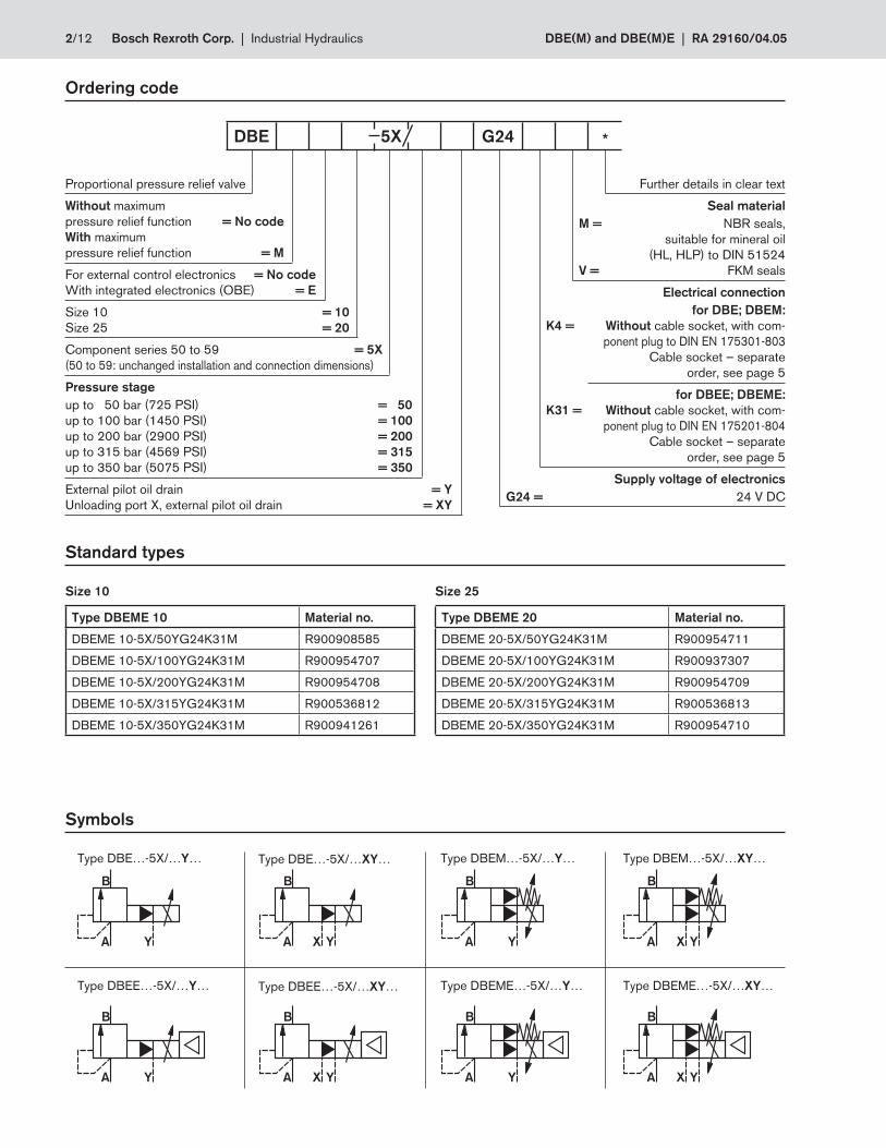
Ordering code
Proportional pressure relief valve
Without maximum
pressure relief function = No code
With maximum
pressure relief function = M
For external control electronics = No code
With integrated electronics (OBE) = E
Size 10 = 10
Size 25 = 20
Component series 50 to 59 = 5X
(50 to 59: unchanged installation and connection dimensions)
Pressure stage
up to 50 bar (725 PSI) = 50
up to 100 bar (1450 PSI) = 100
up to 200 bar (2900 PSI) = 200
up to 315 bar (4569 PSI) = 315
up to 350 bar (5075 PSI) = 350
External pilot oil drain = Y
Unloading port X, external pilot oil drain = XY
Further details in clear text
Seal material
M = NBR seals,
suitable for mineral oil
(HL, HLP) to DIN 51524
V = FKM seals
K4 =
Electrical connection
for DBE; DBEM:
Without cable socket, with com-
ponent plug to DIN EN 175301-803
Cable socket – separate
order, see page 5
K31 =
for DBEE; DBEME:
Without cable socket, with com-
ponent plug to DIN EN 175201-804
Cable socket – separate
order, see page 5
Supply voltage of electronics
G24 = 24 V DC
DBE 5X G24 *
Standard types
Size 10 Size 25
Symbols
Type DBEM…-5X/…XY…Type DBEM…-5X/…Y…Type DBE…-5X/…XY…Type DBE…-5X/…Y…
Type DBEME 10 Material no.
DBEME 10-5X/50YG24K31M R900908585
DBEME 10-5X/100YG24K31M R900954707
DBEME 10-5X/200YG24K31M R900954708
DBEME 10-5X/315YG24K31M R900536812
DBEME 10-5X/350YG24K31M R900941261
Type DBEME 20 Material no.
DBEME 20-5X/50YG24K31M R900954711
DBEME 20-5X/100YG24K31M R900937307
DBEME 20-5X/200YG24K31M R900954709
DBEME 20-5X/315YG24K31M R900536813
DBEME 20-5X/350YG24K31M R900954710
Type DBEME…-5X/…XY…Type DBEME…-5X/…Y…Type DBEE…-5X/…XY…Type DBEE…-5X/…Y…
DBE(M) and DBE(M)E | RA 29160/04.05 Industrial Hydraulics | Bosch Rexroth Corp. 3/12
BAX
a
a
1 9 15 12 2
11
10
8
6
7
4
3
13
5
Y15
14
17
16
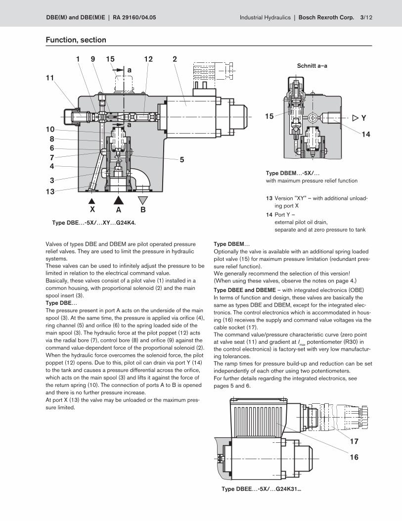
Function, section
Schnitt a–a
Type DBEM…-5X/…
with maximum pressure relief function
13 Version "XY" – with additional unload-
ing port X
14 Port Y –
external pilot oil drain,
separate and at zero pressure to tank
Type DBE…-5X/…XY…G24K4.
Valves of types DBE and DBEM are pilot operated pressure
relief valves. They are used to limit the pressure in hydraulic
systems.
These valves can be used to infi nitely adjust the pressure to be
limited in relation to the electrical command value.
Basically, these valves consist of a pilot valve (1) installed in a
common housing, with proportional solenoid (2) and the main
spool insert (3).
Type DBE…
The pressure present in port A acts on the underside of the main
spool (3). At the same time, the pressure is applied via orifice (4),
ring channel (5) and orifice (6) to the spring loaded side of the
main spool (3). The hydraulic force at the pilot poppet (12) acts
via the radial bore (7), control bore (8) and orifice (9) against the
command value-dependent force of the proportional solenoid (2).
When the hydraulic force overcomes the solenoid force, the pilot
poppet (12) opens. Due to this, pilot oil can drain via port Y (14)
to the tank and causes a pressure differential across the orifice,
which acts on the main spool (3) and lifts it against the force of
the return spring (10). The connection of ports A to B is opened
and there is no further pressure increase.
At port X (13) the valve may be unloaded or the maximum pres-
sure limited.
Type DBEM…
Optionally the valve is available with an additional spring loaded
pilot valve (15) for maximum pressure limitation (redundant pres-
sure relief function).
We generally recommend the selection of this version!
(When using these valves, observe the notes on page 4.)
Type DBEE and DBEME – with integrated electronics (OBE)
In terms of function and design, these valves are basically the
same as types DBE and DBEM, except for the integrated elec-
tronics. The control electronics which is accommodated in hous-
ing (16) receives the supply and command value voltages via the
cable socket (17).
The command value/pressure characteristic curve (zero point
at valve seat (11) and gradient at Imax
potentiometer (R30) in
the control electronics) is factory-set with very low manufactur-
ing tolerances.
The ramp times for pressure build-up and reduction can be set
independently of each other using two potentiometers.
For further details regarding the integrated electronics, see
pages 5 and 6.
Type DBEE…-5X/…G24K31...
4/12 Bosch Rexroth Corp. | Industrial Hydraulics DBE(M) and DBE(M)E | RA 29160/04.05
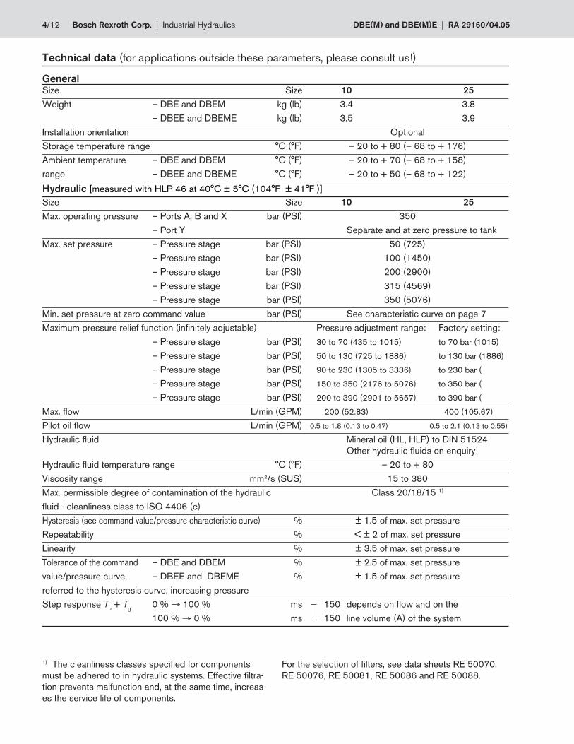
Technical data (for applications outside these parameters, please consult us!)
General
Size Size 10 25
Weight – DBE and DBEM kg (lb) 3.4 3.8
– DBEE and DBEME kg (lb) 3.5 3.9
Installation orientation Optional
Storage temperature range °C (°F) – 20 to + 80 (– 68 to + 176)
Ambient temperature – DBE and DBEM °C (°F) – 20 to + 70 (– 68 to + 158)
range – DBEE and DBEME °C (°F) – 20 to + 50 (– 68 to + 122)
Hydraulic [measured with HLP 46 at 40°C ± 5°C (104°F ± 41°F )]
Size Size 10 25
Max. operating pressure – Ports A, B and X bar (PSI) 350
– Port Y Separate and at zero pressure to tank
Max. set pressure – Pressure stage bar (PSI) 50 (725)
– Pressure stage bar (PSI) 100 (1450)
– Pressure stage bar (PSI) 200 (2900)
– Pressure stage bar (PSI) 315 (4569)
– Pressure stage bar (PSI) 350 (5076)
Min. set pressure at zero command value bar (PSI) See characteristic curve on page 7
Maximum pressure relief function (infi nitely adjustable) Pressure adjustment range: Factory setting:
– Pressure stage bar (PSI) 30 to 70 (435 to 1015) to 70 bar (1015)
– Pressure stage bar (PSI) 50 to 130 (725 to 1886) to 130 bar (1886)
– Pressure stage bar (PSI) 90 to 230 (1305 to 3336) to 230 bar (
– Pressure stage bar (PSI) 150 to 350 (2176 to 5076) to 350 bar (
– Pressure stage bar (PSI) 200 to 390 (2901 to 5657) to 390 bar (
Max. fl ow L/min (GPM) 200 (52.83) 400 (105.67)
Pilot oil fl ow L/min (GPM) 0.5 to 1.8 (0.13 to 0.47) 0.5 to 2.1 (0.13 to 0.55)
Hydraulic fl uid Mineral oil (HL, HLP) to DIN 51524
Other hydraulic fl uids on enquiry!
Hydraulic fl uid temperature range °C (°F) – 20 to + 80
Viscosity range mm2/s (SUS) 15 to 380
Max. permissible degree of contamination of the hydraulic Class 20/18/15 1)
fl uid - cleanliness class to ISO 4406 (c)
Hysteresis (see command value/pressure characteristic curve) % ± 1.5 of max. set pressure
Repeatability % < ± 2 of max. set pressure
Linearity % ± 3.5 of max. set pressure
Tolerance of the command – DBE and DBEM % ± 2.5 of max. set pressure
value/pressure curve, – DBEE and DBEME % ± 1.5 of max. set pressure
referred to the hysteresis curve, increasing pressure
Step response Tu + T
g 0 % → 100 % ms 150 depends on fl ow and on the
100 % → 0 % ms 150 line volume (A) of the system
1) The cleanliness classes specifi ed for components
must be adhered to in hydraulic systems. Effective fi ltra-
tion prevents malfunction and, at the same time, increas-
es the service life of components.
For the selection of fi lters, see data sheets RE 50070,
RE 50076, RE 50081, RE 50086 and RE 50088.
DBE(M) and DBE(M)E | RA 29160/04.05 Industrial Hydraulics | Bosch Rexroth Corp. 5/12
PE
1 2
PE
1 2
AF
EDC
B
Ø 6
.5…
Ø 1
1
0.2
5...
Ø 0
.43
)Ø 2
7
(1.0
6)
91 (3.58)
1
2
1
210A250V
GDM
27.5
(1.08)
18
(0
.71
)
43
(1.69)
10 (0.39)
34
.2
(13
4)
5.5
(02
)
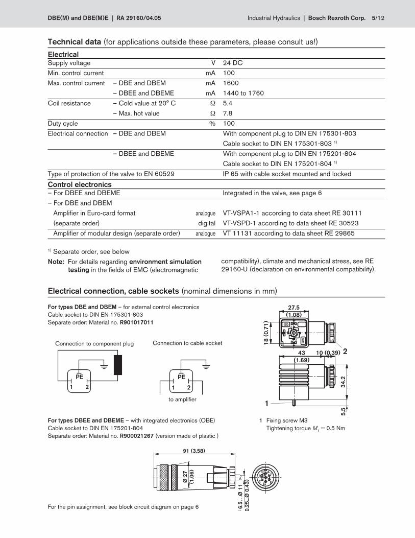
Technical data (for applications outside these parameters, please consult us!)
Electrical
Supply voltage V 24 DC
Min. control current mA 100
Max. control current – DBE and DBEM mA 1600
– DBEE and DBEME mA 1440 to 1760
Coil resistance – Cold value at 20° C Ω 5.4
– Max. hot value Ω 7.8
Duty cycle % 100
Electrical connection – DBE and DBEM With component plug to DIN EN 175301-803
Cable socket to DIN EN 175301-803 1)
– DBEE and DBEME With component plug to DIN EN 175201-804
Cable socket to DIN EN 175201-804 1)
Type of protection of the valve to EN 60529 IP 65 with cable socket mounted and locked
Control electronics – For DBEE and DBEME Integrated in the valve, see page 6
– For DBE and DBEM
Amplifi er in Euro-card format analogue VT-VSPA1-1 according to data sheet RE 30111
(separate order) digital VT-VSPD-1 according to data sheet RE 30523
Amplifi er of modular design (separate order) analogue VT 11131 according to data sheet RE 29865
Electrical connection, cable sockets (nominal dimensions in mm)
For the pin assignment, see block circuit diagram on page 6
For types DBEE and DBEME – with integrated electronics (OBE)
Cable socket to DIN EN 175201-804
Separate order: Material no. R900021267 (version made of plastic )
For types DBE and DBEM – for external control electronics
Cable socket to DIN EN 175301-803
Separate order: Material no. R901017011
Connection to cable socket
to amplifier
Connection to component plug
1) Separate order, see below
Note: For details regarding environment simulation
testing in the fi elds of EMC (elec tro ma gne tic
compatibility), climate and mecha nical stress, see RE
29160-U (declaration on environmental compatibility).
1 Fixing screw M3
Tightening torque MT = 0.5 Nm
6/12 Bosch Rexroth Corp. | Industrial Hydraulics DBE(M) and DBE(M)E | RA 29160/04.05
R 30 R 43
ImaxR 13+
–
0 V
+U
+7,5 V
-7,5 V
+
R 14
+U
=
=
I
D
E
F
C
B
A
n.c.
IminU
U
300 Hz
=
MP1
MP2
n.c.
1,6 A =
0,352 V
2
2
22
24
26
28
30
20
(66)
40
(131)
60
(197)
80
(262)
100
(328)
0.75 mm
1 mm
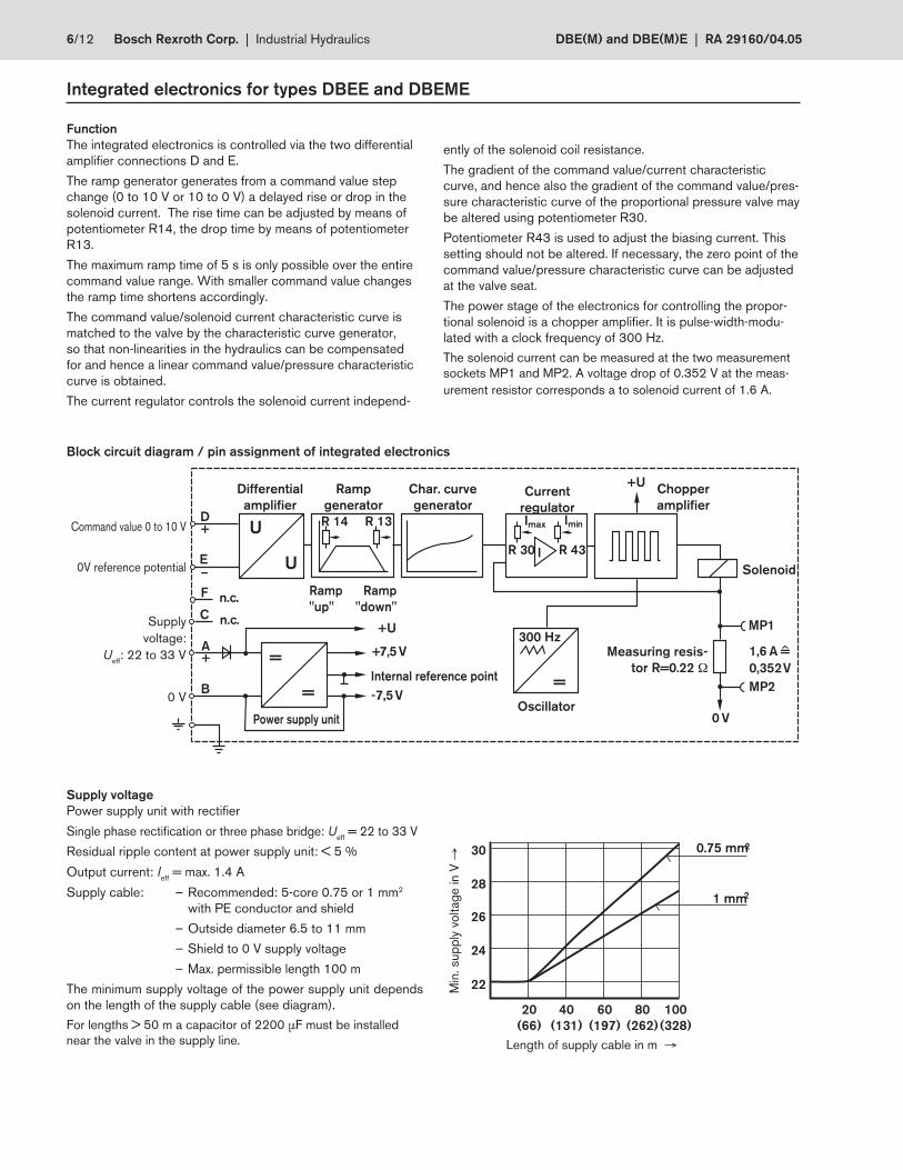
Integrated electronics for types DBEE and DBEME
Supply voltage
Power supply unit with rectifi er
Single phase rectifi cation or three phase bridge: Ueff
= 22 to 33 V
Residual ripple content at power supply unit: < 5 %
Output current: Ieff
= max. 1.4 A
Supply cable: – Recommended: 5-core 0.75 or 1 mm2
with PE conductor and shield
– Outside diameter 6.5 to 11 mm
– Shield to 0 V supply voltage
– Max. permissible length 100 m
The minimum supply voltage of the power supply unit depends
on the length of the supply cable (see diagram).
For lengths > 50 m a capacitor of 2200 μF must be installed
near the valve in the supply line.
0V reference po ten ti al
Block circuit diagram / pin assignment of integrated electronics
Function
The integrated electronics is controlled via the two differential
amplifi er connections D and E.
The ramp generator generates from a command value step
change (0 to 10 V or 10 to 0 V) a delayed rise or drop in the
solenoid current. The rise time can be adjusted by means of
potentiometer R14, the drop time by means of potentiometer
R13.
The maximum ramp time of 5 s is only possible over the entire
command value range. With smaller command value changes
the ramp time shortens accordingly.
The command value/solenoid current characteristic curve is
matched to the valve by the characteristic curve generator,
so that non-linearities in the hydraulics can be compensated
for and hence a linear command value/pressure characteristic
curve is obtained.
The current regulator controls the solenoid current independ-
ently of the solenoid coil resistance.
The gradient of the command value/current characteristic
curve, and hence also the gradient of the command value/pres-
sure characteristic curve of the proportional pressure valve may
be altered using potentiometer R30.
Potentiometer R43 is used to adjust the biasing current. This
setting should not be altered. If necessary, the zero point of the
command value/pressure characteristic curve can be adjusted
at the valve seat.
The power stage of the electronics for controlling the propor-
tional solenoid is a chopper amplifi er. It is pulse-width-modu-
lated with a clock frequency of 300 Hz.
The solenoid current can be measured at the two measurement
sockets MP1 and MP2. A voltage drop of 0.352 V at the meas-
urement resistor corresponds a to solenoid current of 1.6 A.
Command value 0 to 10 V
Supply
voltage:
Ueff
: 22 to 33 V
Chopper
amplifier
Ramp
"up"
Ramp
"down"
Internal reference point
Measuring resis-
tor R=0.22 Ω
Oscillator
Solenoid
Power supply unit
Ramp
generator
Differential
amplifier
Char. curve
generatorCurrent
regulator
0 V
Length of supply cable in m →
Min
. sup
ply
voltag
e in V
→
DBE(M) and DBE(M)E | RA 29160/04.05 Industrial Hydraulics | Bosch Rexroth Corp. 7/12
0
2 (29)
6 (87)
8 (116)
10 (145)
4 (58)
100 200 300
0 25 50 75 100
15 (218)
20 (290)
30 (435)
35 (508)
40 (580)
45 (653)
50 (725)
25 (363)
10 (145)
5 (73)
0 25 50 75 100
30 (435)
40 (580)
60 (870)
70 (1015)
80 (1160)
90 (1305)
100 (1450)
50 (725)
20 (290)
10 (145)
0 25 50 75 100
60 (870)
80 (1160)
120 (1740)
140 (2031)
160 (2321)
180 (2611)
200 (2901)
100 (1450)
40 (580)
20 (290)
315 (4569)
0 25 50 75 100
150 (2176)
250 (3626)
300 (4351)
200 (2901)
100 (1450)
50 (725)
0 25 50 75 100
150 (2176)
250 (3626)
300 (4351)
200 (2901)
100 (1450)
50 (725)
350 (5075)
0 100
(26.42)
200
(52.83)
300
(79.25)
400
(105.67)
50 (725)
100 (1450)
200 (2901)
250 (3626)
300 (4351)
350 (5075)
400 (5802)
150 (2176)
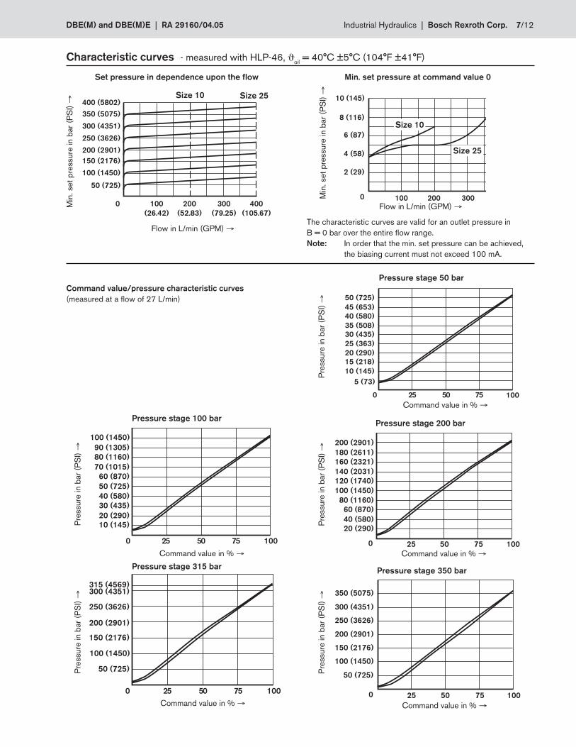
Command value/pressure characteristic curves
(measured at a flow of 27 L/min)
Pressure stage 315 bar
Characteristic curves - measured with HLP-46, ϑoil
= 40°C ±5°C (104°F ±41°F)
Set pressure in dependence upon the flowM
in. set
pre
ssure
in b
ar
(PS
I) →
Flow in L/min (GPM) →
Pressure stage 100 barPressure stage 200 bar
Pressure stage 50 bar
Pressure stage 350 bar
Pre
ssure
in b
ar
(PS
I) →
Command value in % →
The characteristic curves are valid for an outlet pressure in
B = 0 bar over the entire flow range.
Note: In order that the min. set pressure can be achieved,
the biasing current must not exceed 100 mA.
Min
. set
pre
ssure
in b
ar
(PS
I) →
Flow in L/min (GPM) →
Min. set pressure at command value 0
Size 10 Size 25
Pre
ssure
in b
ar
(PS
I) →
Command value in % →
Pre
ssure
in b
ar
(PS
I) →
Command value in % →
Command value in % →Command value in % →
Size 10Size 10
Size 25Size 25
Pre
ssure
in b
ar
(PS
I) →
Pre
ssure
in b
ar
(PS
I) →
8/12 Bosch Rexroth Corp. | Industrial Hydraulics DBE(M) and DBE(M)E | RA 29160/04.05
8 3
89 (3.50)
17
.3 (
0.6
8)
78
(3
.07
)
53.8 (2.12)
53
.8 (
2.1
2)
10
4 (
4.0
9)
27 (1.06)
Ø 14 (0.55)
Ø 25 (0.98)
G 1/4
14
5 (
5.7
1)
15
(0.5
9)
Y
A B
Y
15 (0.59)
196 (7.72)
B
21 (0.83)
26
(3.0
7)
A
Ø 12.3
(0.48)
12
9 (
5.0
8)
47.5 (1.87)
22.5
(0.86)
78
(3
.07
)
22.1 (0.87)
5 (
0.2
0)
X
X
263 (10.35) with integrated electronics
45
(1.7
7)
Ø 26.4 (1.04)
Ø 17.5 (0.69)
Ø 21.8 (0.86)
Ø 14 (0.55)Ø6
(0.24)
4 6 7 9
2
5
1
10
0,01/100mm
Rzmax 4
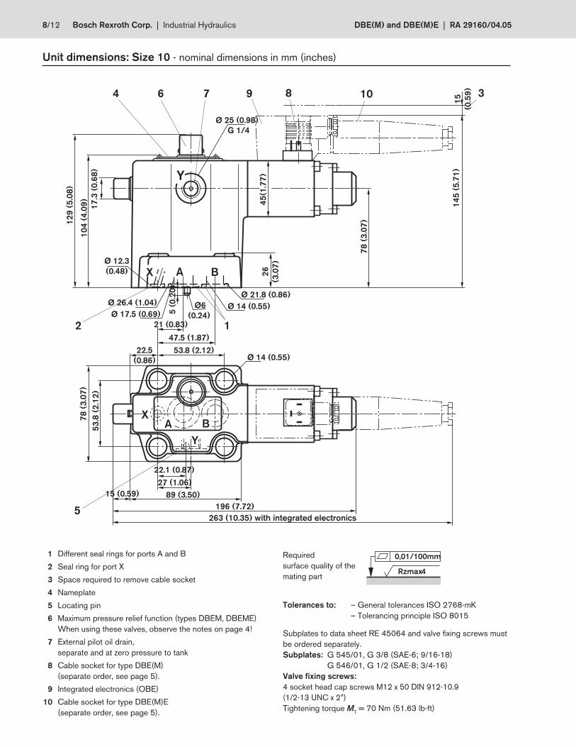
Unit dimensions: Size 10 - nominal dimensions in mm (inches)
Subplates to data sheet RE 45064 and valve fixing screws must
be ordered separately.
Subplates: G 545/01, G 3/8 (SAE-6; 9/16-18)
G 546/01, G 1/2 (SAE-8; 3/4-16)
Valve fixing screws:
4 socket head cap screws M12 x 50 DIN 912-10.9
(1/2-13 UNC x 2”)
Tightening torque MT = 70 Nm (51.63 lb-ft)
Required
surface quality of the
mating part
1 Different seal rings for ports A and B
2 Seal ring for port X
3 Space required to remove cable socket
4 Nameplate
5 Locating pin
6 Maximum pressure relief function (types DBEM, DBEME)
When using these valves, observe the notes on page 4!
7 External pilot oil drain,
separate and at zero pressure to tank
8 Cable socket for type DBE(M)
(separate order, see page 5).
9 Integrated electronics (OBE)
10 Cable socket for type DBE(M)E
(separate order, see page 5).
Tolerances to: – General tolerances ISO 2768-mK
– Tolerancing principle ISO 8015
DBE(M) and DBE(M)E | RA 29160/04.05 Industrial Hydraulics | Bosch Rexroth Corp. 9/12
117 (4.61)
79
(3
.11
)
66.7 (2.63)
70
(2
.76
)
Ø 18 (0.71)23.8 (0.94)
Ø 26 (1.02)
10
5 (
4.1
3)
33 (1.30)
13
0 (
5.1
2)
11.1 (0.44)34.5
(1.36) 55.6 (2.19)
33.4 (1.31)
10
0 (
3.9
4)
G 1/ 4
14
6 (
5.7
5)
195 (7.68)
A
Ø 40.7 (1.60)
Ø 40.7 (1.60)
Ø 17.5 (0.69)Ø 25 (0.98)
B
Y
Y
A BX
262 (10.31) with integrated electronics
X
4 6 7 9 8
2
1
5
10
1
17
.3 (
0.6
8)
Ø 25 (0.98)
15
(0.5
9)
15 (0.59)
26
(3.0
7)Ø 12.3
(0.48)
5 (
0.2
0)
45
(1.7
7)
Ø6
(0.24)
0,01/100mm
Rzmax 4
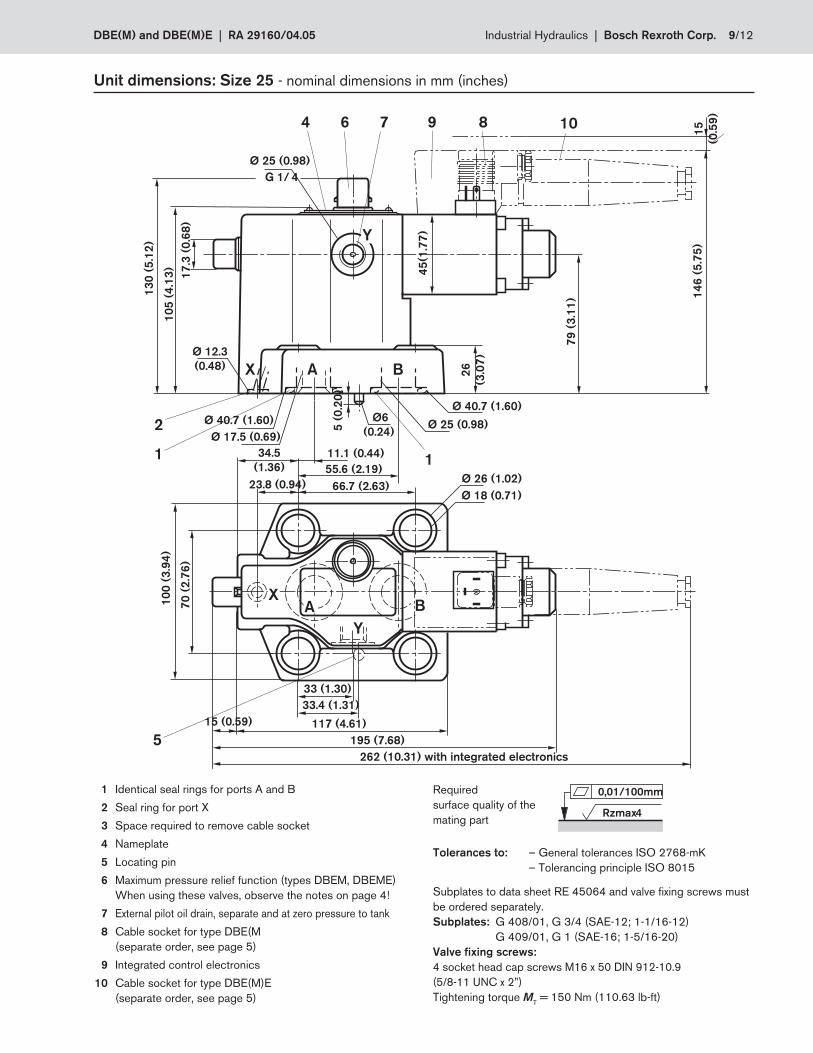
Unit dimensions: Size 25 - nominal dimensions in mm (inches)
Subplates to data sheet RE 45064 and valve fixing screws must
be ordered separately.
Subplates: G 408/01, G 3/4 (SAE-12; 1-1/16-12)
G 409/01, G 1 (SAE-16; 1-5/16-20)
Valve fixing screws:
4 socket head cap screws M16 x 50 DIN 912-10.9
(5/8-11 UNC x 2”)
Tightening torque MT = 150 Nm (110.63 lb-ft)
Required
surface quality of the
mating part
1 Identical seal rings for ports A and B
2 Seal ring for port X
3 Space required to remove cable socket
4 Nameplate
5 Locating pin
6 Maximum pressure relief function (types DBEM, DBEME)
When using these valves, observe the notes on page 4!
7 External pilot oil drain, separate and at zero pressure to tank
8 Cable socket for type DBE(M
(separate order, see page 5)
9 Integrated control electronics
10 Cable socket for type DBE(M)E
(separate order, see page 5)
Tolerances to: – General tolerances ISO 2768-mK
– Tolerancing principle ISO 8015
10/12 Bosch Rexroth Corp. | Industrial Hydraulics DBE(M) and DBE(M)E | RA 29160/04.05
Notes
Bosch Rexroth Corp.
Industrial Hydraulics
2315 City Line Road
Bethlehem, PA 18017-2131
USA
Telephone (610) 694-8300
Facsimile (610) 694-8467
www.boschrexroth-us.com
© 2004 Bosch Rexroth Corporation
All rights reserved. Neither this document nor any part of it may be reproduced,
duplicated circulated or disseminated, whether by copy, electronic format or
any other means, without the prior consent and authorization of Bosch Rexroth
Cor po ra tion.
The data and illustrations in this brochure/data sheet are intended only to
describe or depict the products. No representation or warranty, either express
or implied, relating to merchantability or fi tness for intended use, is given or
intended by virtue of the information contained in this brochure/data sheet. The
information contained in this brochure/data sheet in no way relieves the user of it
obligation to insure the proper use of the products for a specifi c use or applica-
tion. All products contained in this brochure/data sheet are subject to normal
wear and tear from usage.
Subject to change.
Bosch Rexroth Corp. | Industrial Hydraulics (Z)DBE and (Z)DBEE | RA 29158/04.05
Bosch Rexroth Corp.
Industrial Hydraulics
2315 City Line Road
Bethlehem, PA 18017-2131
USA
Telephone (610) 694-8300
Facsimile (610) 694-8467
www.boschrexroth-us.com
© 2004 Bosch Rexroth Corporation
All rights reserved. Neither this document nor any part of it may be reproduced,
duplicated circulated or disseminated, whether by copy, electronic format or
any other means, without the prior consent and authorization of Bosch Rexroth
Cor po ra tion.
The data and illustrations in this brochure/data sheet are intended only to
describe or depict the products. No representation or warranty, either express
or implied, relating to merchantability or fi tness for intended use, is given or
intended by virtue of the information contained in this brochure/data sheet. The
information contained in this brochure/data sheet in no way relieves the user of it
obligation to insure the proper use of the products for a specifi c use or applica-
tion. All products contained in this brochure/data sheet are subject to normal
wear and tear from usage.
Subject to change.
Notes