Embed Size (px)
Citation preview
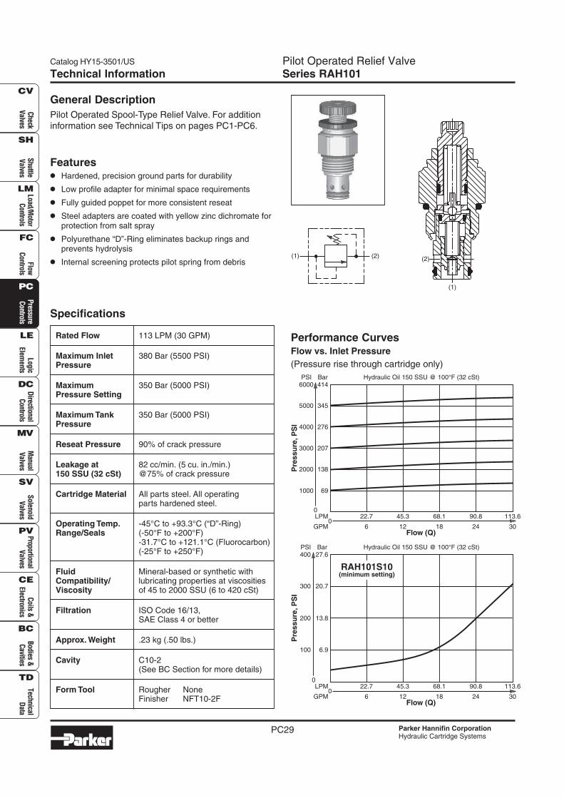
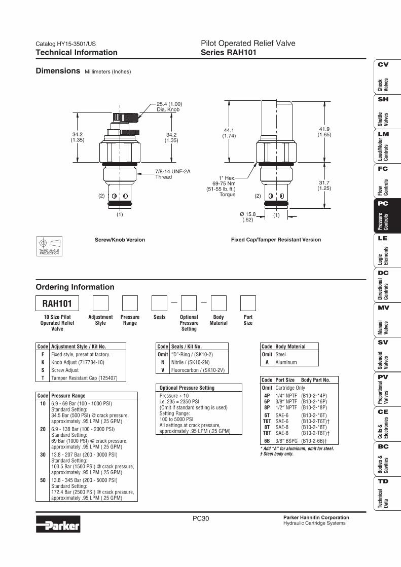
Catalog HY15-3501/US Pilot Operated Relief ValveSeries RAH101
PC29
Check
Valves
Shuttle
Valves
Load/Motor
Controls
FlowC
ontrolsP
ressureC
ontrolsLogic
Elements
DirectionalC
ontrolsM
anualV
alvesS
olenoidV
alvesP
roportionalV
alvesC
oils &Electronics
Bodies &C
avitiesTechnical
Data
SH
CV
LM
FC
PC
LE
DC
MV
SV
PV
CE
BC
TD
Parker Hannifin CorporationHydraulic Cartridge Systems
Technical Information
Specifications
Rated Flow 113 LPM (30 GPM)
Maximum Inlet 380 Bar (5500 PSI)Pressure
Maximum 350 Bar (5000 PSI)Pressure Setting
Maximum Tank 350 Bar (5000 PSI)Pressure
Reseat Pressure 90% of crack pressure
Leakage at 82 cc/min. (5 cu. in./min.)150 SSU (32 cSt) @75% of crack pressure
Cartridge Material All parts steel. All operatingparts hardened steel.
Operating Temp. -45°C to +93.3°C (“D”-Ring)Range/Seals (-50°F to +200°F)
-31.7°C to +121.1°C (Fluorocarbon)(-25°F to +250°F)
Fluid Mineral-based or synthetic withCompatibility/ lubricating properties at viscositiesViscosity of 45 to 2000 SSU (6 to 420 cSt)
Filtration ISO Code 16/13,SAE Class 4 or better
Approx. Weight .23 kg (.50 lbs.)
Cavity C10-2(See BC Section for more details)
Form Tool Rougher NoneFinisher NFT10-2F
Performance CurvesFlow vs. Inlet Pressure
(Pressure rise through cartridge only)
General Description
Pilot Operated Spool-Type Relief Valve. For addition
information see Technical Tips on pages PC1-PC6.
Features
• Hardened, precision ground parts for durability
• Low profile adapter for minimal space requirements
• Fully guided poppet for more consistent reseat
• Steel adapters are coated with yellow zinc dichromate forprotection from salt spray
• Polyurethane “D”-Ring eliminates backup rings andprevents hydrolysis
• Internal screening protects pilot spring from debris(2)(1) (2)
(1)
Flow (Q)
68.1
18
22.7
6
45.3
12
LPM
GPM0
90.8
24
113.6
30
Hydraulic Oil 150 SSU @ 100°F (32 cSt)
0
1000
2000
345
414
207
276
69
138
5000
6000PSI Bar
3000
4000
Pre
ss
ure
,P
SI
Flow (Q)
68.1
18
22.7
6
45.3
12
LPM
GPM0
90.8
24
113.6
30
Hydraulic Oil 150 SSU @ 100°F (32 cSt)
0
100
20.7
27.6
13.8
6.9
300
400PSI Bar
200
Pre
ss
ure
,P
SI
RAH101S10(minimum setting)
Pilot Operated Relief ValveSeries RAH101
Catalog HY15-3501/US
PC30
Che
ckV
alve
sS
huttl
eV
alve
sLo
ad/M
otor
Con
trol
sFl
owC
ontr
ols
Pre
ssur
eC
ontr
ols
Logi
cEl
emen
tsD
irec
tiona
lC
ontr
ols
Man
ual
Val
ves
Pro
port
iona
lV
alve
sC
oils
&El
ectr
onic
sTe
chni
cal
Dat
a
SH
CV
LM
FC
PC
LE
DC
MV
SV
PV
CE
BC
TD
Bod
ies
&C
aviti
esS
olen
oid
Val
ves
Parker Hannifin CorporationHydraulic Cartridge Systems
Technical Information
Dimensions Millimeters (Inches)
Ordering Information
THIRD-ANGLEPROJECTION
SealsPressureRange
AdjustmentStyle
BodyMaterial
PortSize
OptionalPressureSetting
Code Seals / Kit No.
Omit “D”-Ring / (SK10-2)
N Nitrile / (SK10-2N)
V Fluorocarbon / (SK10-2V)
Code Pressure Range
10 6.9 - 69 Bar (100 - 1000 PSI)Standard Setting:34.5 Bar (500 PSI) @ crack pressure,approximately .95 LPM (.25 GPM)
20 6.9 - 138 Bar (100 - 2000 PSI)Standard Setting:69 Bar (1000 PSI) @ crack pressure,approximately .95 LPM (.25 GPM)
30 13.8 - 207 Bar (200 - 3000 PSI)Standard Setting:103.5 Bar (1500 PSI) @ crack pressure,approximately .95 LPM (.25 GPM)
50 13.8 - 345 Bar (200 - 5000 PSI)Standard Setting:172.4 Bar (2500 PSI) @ crack pressure,approximately .95 LPM (.25 GPM)
Code Body Material
Omit Steel
A Aluminum
Code Adjustment Style / Kit No.
F Fixed style, preset at factory.
K Knob Adjust (717784-10)
S Screw Adjust
T Tamper Resistant Cap (125407)
Optional Pressure Setting
Pressure ÷ 10i.e. 235 = 2350 PSI(Omit if standard setting is used)Setting Range:100 to 5000 PSIAll settings at crack pressure,approximately .95 LPM (.25 GPM)
RAH101
10 Size PilotOperated Relief
Valve
* Add “A” for aluminum, omit for steel.† Steel body only.
Code Port Size Body Part No.
Omit Cartridge Only
4P 1/4″ NPTF (B10-2-*4P)6P 3/8″ NPTF (B10-2-*6P)8P 1/2″ NPTF (B10-2-*8P)
6T SAE-6 (B10-2-*6T)T6T SAE-6 (B10-2-T6T)†8T SAE-8 (B10-2-*8T)
T8T SAE-8 (B10-2-T8T)†
6B 3/8″ BSPG (B10-2-6B)†
34.2(1.35)
(1)
(2)
34.2(1.35)
25.4 (1.00)Dia. Knob
7/8-14 UNF-2AThread
Screw/Knob Version Fixed Cap/Tamper Resistant Version
44.1(1.74)
1" Hex.69-75 Nm
(51-55 lb. ft.)Torque
41.9(1.65)
31.7(1.25)
Ø 15.8(.62)
(1)
(2)
Catalog HY15-3501/US Direct Acting Relief ValveSeries A04B2FY*CE,HY*CE,PY*CE
PC17
Check
Valves
Shuttle
Valves
Load/Motor
Controls
FlowC
ontrolsP
ressureC
ontrolsLogic
Elements
DirectionalC
ontrolsM
anualV
alvesS
olenoidV
alvesP
roportionalV
alvesC
oils &Electronics
Bodies &C
avitiesTechnical
Data
SH
CV
LM
FC
PC
LE
DC
MV
SV
PV
CE
BC
TD
Parker Hannifin CorporationHydraulic Cartridge Systems
Technical Information
Specifications
General Description
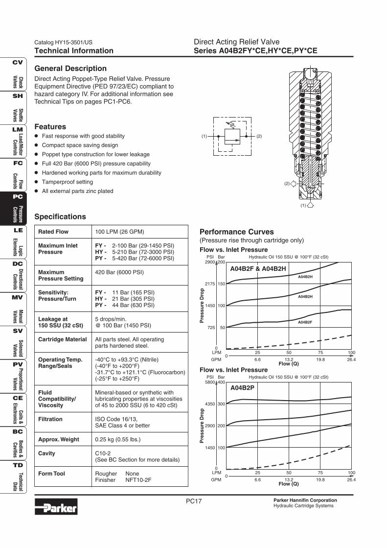
Direct Acting Poppet-Type Relief Valve. Pressure
Equipment Directive (PED 97/23/EC) compliant to
hazard category IV. For additional information seeTechnical Tips on pages PC1-PC6.
Features
• Fast response with good stability
• Compact space saving design
• Poppet type construction for lower leakage
• Full 420 Bar (6000 PSI) pressure capability
• Hardened working parts for maximum durability
• Tamperproof setting
• All external parts zinc plated
Rated Flow 100 LPM (26 GPM)
Maximum Inlet FY - 2-100 Bar (29-1450 PSI)Pressure HY - 5-210 Bar (72-3000 PSI)
PY - 5-420 Bar (72-6000 PSI)
Maximum 420 Bar (6000 PSI)Pressure Setting
Sensitivity: FY - 11 Bar (165 PSI)Pressure/Turn HY - 21 Bar (305 PSI)
PY - 44 Bar (630 PSI)
Leakage at 5 drops/min.150 SSU (32 cSt) @ 100 Bar (1450 PSI)
Cartridge Material All parts steel. All operatingparts hardened steel.
Operating Temp. -40°C to +93.3°C (Nitrile)Range/Seals (-40°F to +200°F)
-31.7°C to +121.1°C (Fluorocarbon)(-25°F to +250°F)
Fluid Mineral-based or synthetic withCompatibility/ lubricating properties at viscositiesViscosity of 45 to 2000 SSU (6 to 420 cSt)
Filtration ISO Code 16/13,SAE Class 4 or better
Approx. Weight 0.25 kg (0.55 lbs.)
Cavity C10-2(See BC Section for more details)
Form Tool Rougher NoneFinisher NFT10-2F
Performance Curves(Pressure rise through cartridge only)
(2)
(1)
(2)(1)
Flow (Q)
75
19.80
25
6.6
50
13.2
LPM
GPM
100
26.4
Hydraulic Oil 150 SSU @ 100°F (32 cSt)
0
725
150
200
100
50
Pre
ssu
re D
rop
2175
2900PSI Bar
1450
Flow vs. Inlet Pressure
A04B2H
A04B2H
A04B2F
A04B2F & A04B2H
Flow (Q)
75
19.80
25
6.6
50
13.2
LPM
GPM
100
26.4
Hydraulic Oil 150 SSU @ 100°F (32 cSt)
0
1450
300
400
200
100
Pre
ssu
re D
rop
4350
5800PSI Bar
2900
Flow vs. Inlet Pressure
A04B2P
Direct Acting Relief ValveSeries A04B2FY*CE,HY*CE,PY*CE
Catalog HY15-3501/US
PC18
Che
ckV
alve
sS
huttl
eV
alve
sLo
ad/M
otor
Con
trol
sFl
owC
ontr
ols
Pre
ssur
eC
ontr
ols
Logi
cEl
emen
tsD
irec
tiona
lC
ontr
ols
Man
ual
Val
ves
Pro
port
iona
lV
alve
sC
oils
&El
ectr
onic
sTe
chni
cal
Dat
a
SH
CV
LM
FC
PC
LE
DC
MV
SV
PV
CE
BC
TD
Bod
ies
&C
aviti
esS
olen
oid
Val
ves
Parker Hannifin CorporationHydraulic Cartridge Systems
Technical Information
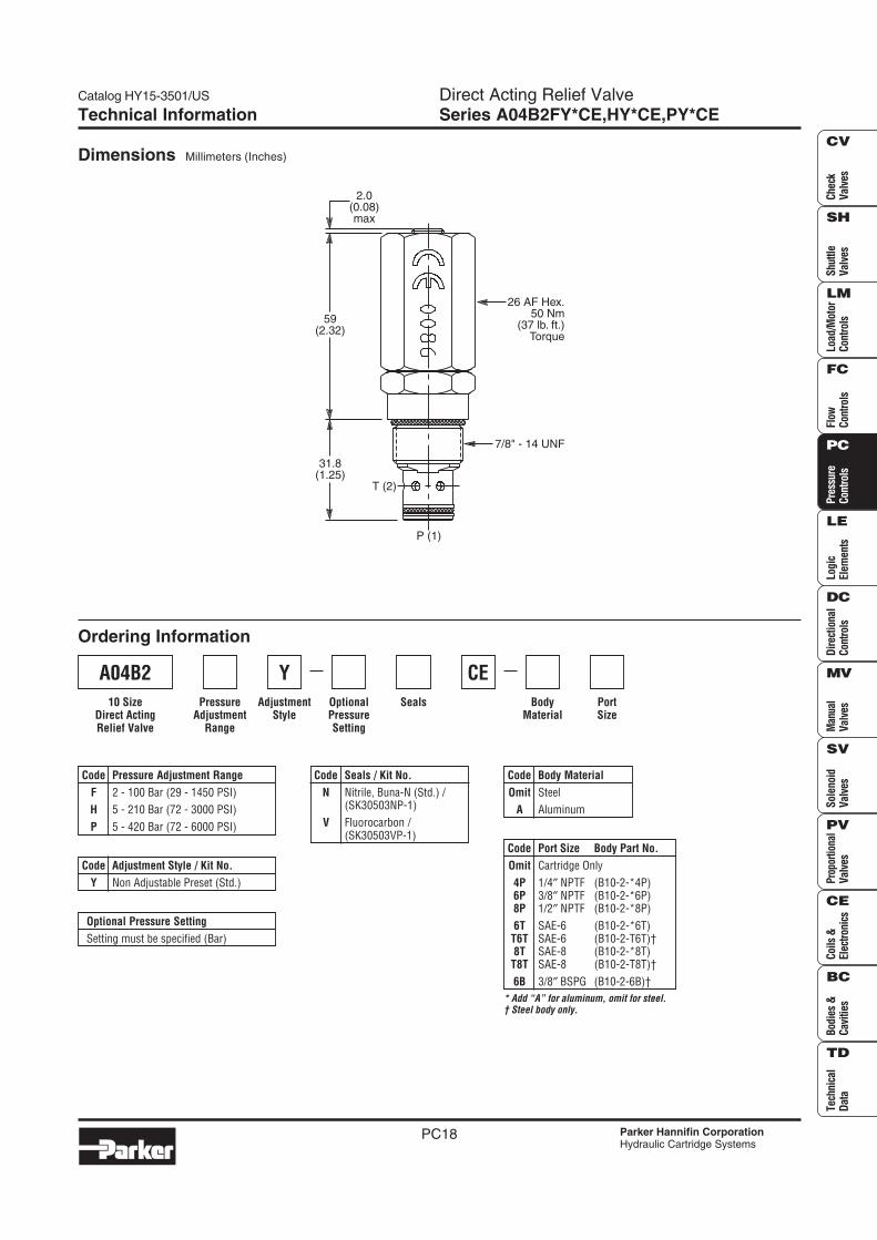
Dimensions Millimeters (Inches)
Ordering Information
AdjustmentStyle
PressureAdjustment
Range
SealsOptionalPressureSetting
Code Seals / Kit No.
N Nitrile, Buna-N (Std.) /(SK30503NP-1)
V Fluorocarbon /(SK30503VP-1)
Code Pressure Adjustment Range
F 2 - 100 Bar (29 - 1450 PSI)
H 5 - 210 Bar (72 - 3000 PSI)
P 5 - 420 Bar (72 - 6000 PSI)
Code Adjustment Style / Kit No.
Y Non Adjustable Preset (Std.)
A04B2
10 SizeDirect ActingRelief Valve
Optional Pressure Setting
Setting must be specified (Bar)
Y
2.0(0.08)max
59(2.32)
31.8(1.25)
26 AF Hex.50 Nm
(37 lb. ft.)Torque
7/8" - 14 UNF
T (2)
P (1)
BodyMaterial
PortSize
Code Body Material
Omit Steel
A Aluminum
* Add “A” for aluminum, omit for steel.† Steel body only.
Code Port Size Body Part No.
Omit Cartridge Only
4P 1/4″ NPTF (B10-2-*4P)6P 3/8″ NPTF (B10-2-*6P)8P 1/2″ NPTF (B10-2-*8P)
6T SAE-6 (B10-2-*6T)T6T SAE-6 (B10-2-T6T)†8T SAE-8 (B10-2-*8T)
T8T SAE-8 (B10-2-T8T)†
6B 3/8″ BSPG (B10-2-6B)†
CE
Catalog HY15-3501/US Pilot Operated Relief ValveSeries RAH161
PC31
Check
Valves
Shuttle
Valves
Load/Motor
Controls
FlowC
ontrolsP
ressureC
ontrolsLogic
Elements
DirectionalC
ontrolsM
anualV
alvesS
olenoidV
alvesP
roportionalV
alvesC
oils &Electronics
Bodies &C
avitiesTechnical
Data
SH
CV
LM
FC
PC
LE
DC
MV
SV
PV
CE
BC
TD
Parker Hannifin CorporationHydraulic Cartridge Systems
Technical Information
Specifications
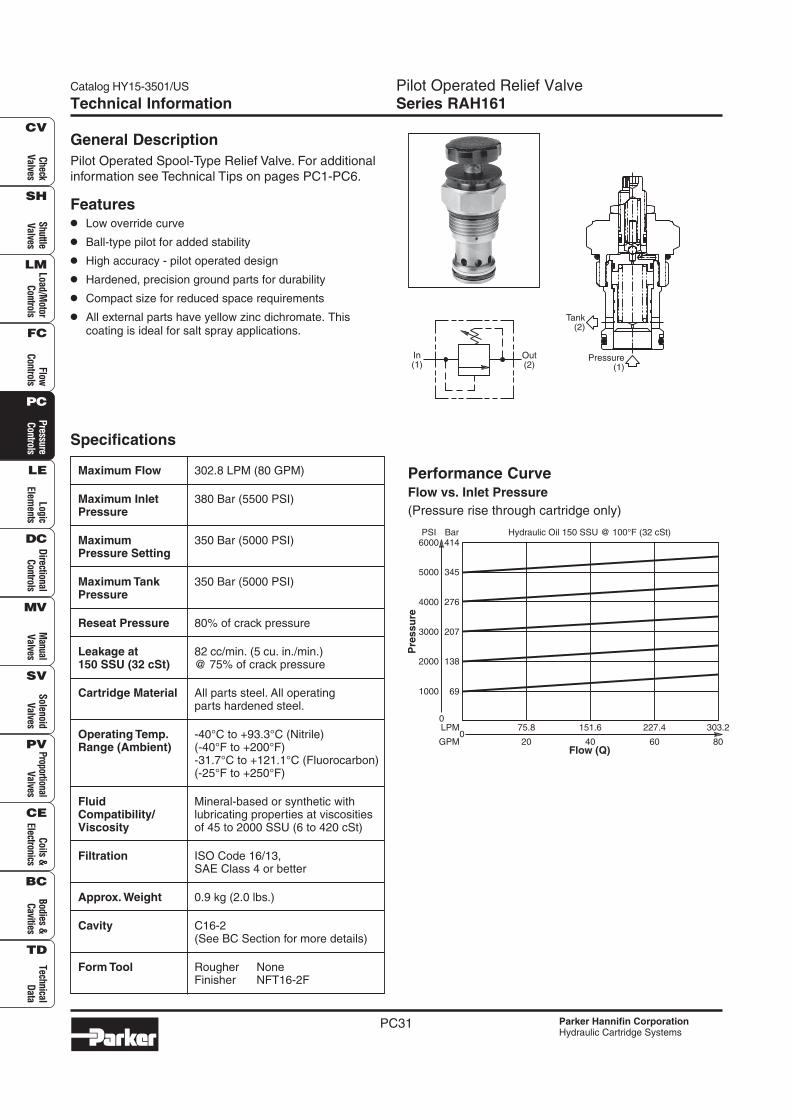
Maximum Flow 302.8 LPM (80 GPM)
Maximum Inlet 380 Bar (5500 PSI)Pressure
Maximum 350 Bar (5000 PSI)Pressure Setting
Maximum Tank 350 Bar (5000 PSI)Pressure
Reseat Pressure 80% of crack pressure
Leakage at 82 cc/min. (5 cu. in./min.)150 SSU (32 cSt) @ 75% of crack pressure
Cartridge Material All parts steel. All operatingparts hardened steel.
Operating Temp. -40°C to +93.3°C (Nitrile)Range (Ambient) (-40°F to +200°F)
-31.7°C to +121.1°C (Fluorocarbon)(-25°F to +250°F)
Fluid Mineral-based or synthetic withCompatibility/ lubricating properties at viscositiesViscosity of 45 to 2000 SSU (6 to 420 cSt)
Filtration ISO Code 16/13,SAE Class 4 or better
Approx. Weight 0.9 kg (2.0 lbs.)
Cavity C16-2(See BC Section for more details)
Form Tool Rougher NoneFinisher NFT16-2F
Performance CurveFlow vs. Inlet Pressure
(Pressure rise through cartridge only)
General Description
Pilot Operated Spool-Type Relief Valve. For additional
information see Technical Tips on pages PC1-PC6.
Features
• Low override curve
• Ball-type pilot for added stability
• High accuracy - pilot operated design
• Hardened, precision ground parts for durability
• Compact size for reduced space requirements
• All external parts have yellow zinc dichromate. Thiscoating is ideal for salt spray applications.
Out(2)
In(1)
Pressure(1)
Tank(2)
Hydraulic Oil 150 SSU @ 100°F (32 cSt)
Flow (Q)
151.6
40
75.8
20
LPM
GPM0
227.4
60
303.2
80
0
1000
2000
345
414
207
276
69
138
5000
6000PSI Bar
3000
4000
Pre
ssu
re
Pilot Operated Relief ValveSeries RAH161
Catalog HY15-3501/US
PC32
Che
ckV
alve
sS
huttl
eV
alve
sLo
ad/M
otor
Con
trol
sFl
owC
ontr
ols
Pre
ssur
eC
ontr
ols
Logi
cEl
emen
tsD
irec
tiona
lC
ontr
ols
Man
ual
Val
ves
Pro
port
iona
lV
alve
sC
oils
&El
ectr
onic
sTe
chni
cal
Dat
a
SH
CV
LM
FC
PC
LE
DC
MV
SV
PV
CE
BC
TD
Bod
ies
&C
aviti
esS
olen
oid
Val
ves
Parker Hannifin CorporationHydraulic Cartridge Systems
Technical Information
THIRD-ANGLEPROJECTION
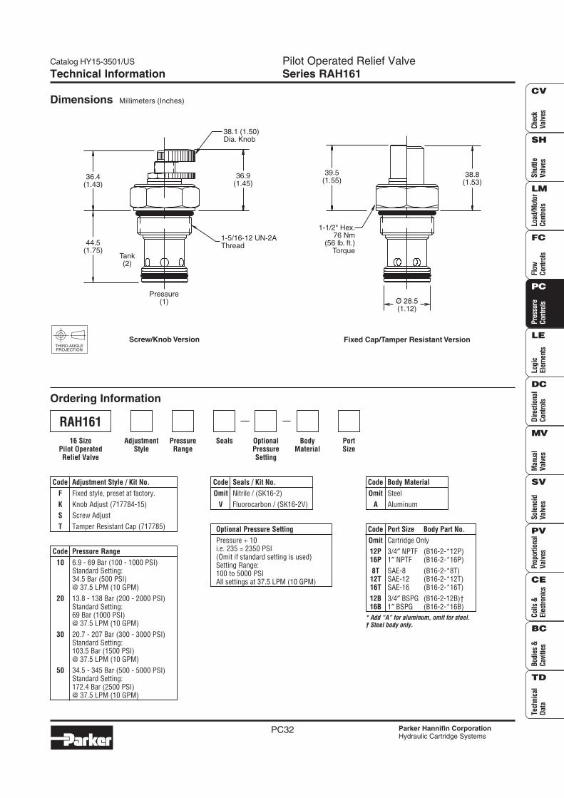
Ordering Information
Dimensions Millimeters (Inches)
SealsPressureRange
AdjustmentStyle
BodyMaterial
PortSize
OptionalPressureSetting
* Add “A” for aluminum, omit for steel.† Steel body only.
Code Port Size Body Part No.
Omit Cartridge Only
12P 3/4″ NPTF (B16-2-*12P)16P 1″ NPTF (B16-2-*16P)
8T SAE-8 (B16-2-*8T)12T SAE-12 (B16-2-*12T)16T SAE-16 (B16-2-*16T)
12B 3/4″ BSPG (B16-2-12B)†16B 1″ BSPG (B16-2-*16B)
Code Seals / Kit No.
Omit Nitrile / (SK16-2)
V Fluorocarbon / (SK16-2V)
Code Pressure Range
10 6.9 - 69 Bar (100 - 1000 PSI)Standard Setting:34.5 Bar (500 PSI)@ 37.5 LPM (10 GPM)
20 13.8 - 138 Bar (200 - 2000 PSI)Standard Setting:69 Bar (1000 PSI)@ 37.5 LPM (10 GPM)
30 20.7 - 207 Bar (300 - 3000 PSI)Standard Setting:103.5 Bar (1500 PSI)@ 37.5 LPM (10 GPM)
50 34.5 - 345 Bar (500 - 5000 PSI)Standard Setting:172.4 Bar (2500 PSI)@ 37.5 LPM (10 GPM)
Code Body Material
Omit Steel
A Aluminum
Code Adjustment Style / Kit No.
F Fixed style, preset at factory.
K Knob Adjust (717784-15)
S Screw Adjust
T Tamper Resistant Cap (717785) Optional Pressure Setting
Pressure ÷ 10i.e. 235 = 2350 PSI(Omit if standard setting is used)Setting Range:100 to 5000 PSIAll settings at 37.5 LPM (10 GPM)
RAH161
16 SizePilot OperatedRelief Valve
Fixed Cap/Tamper Resistant Version
38.8(1.53)
Ø 28.5(1.12)
39.5(1.55)
1-1/2" Hex.76 Nm
(56 lb. ft.)Torque
38.1 (1.50)Dia. Knob
36.9(1.45)
Pressure(1)
Tank(2)
44.5(1.75)
36.4(1.43)
1-5/16-12 UN-2AThread
Screw/Knob Version
Catalog HY15-3501/US Pilot Operated, Ventable Relief ValveSeries A04H3
PC41
Check
Valves
Shuttle
Valves
Load/Motor
Controls
FlowC
ontrolsP
ressureC
ontrolsLogic
Elements
DirectionalC
ontrolsM
anualV
alvesS
olenoidV
alvesP
roportionalV
alvesC
oils &Electronics
Bodies &C
avitiesTechnical
Data
SH
CV
LM
FC
PC
LE
DC
MV
SV
PV
CE
BC
TD
Parker Hannifin CorporationHydraulic Cartridge Systems
Technical Information
Specifications
General Description
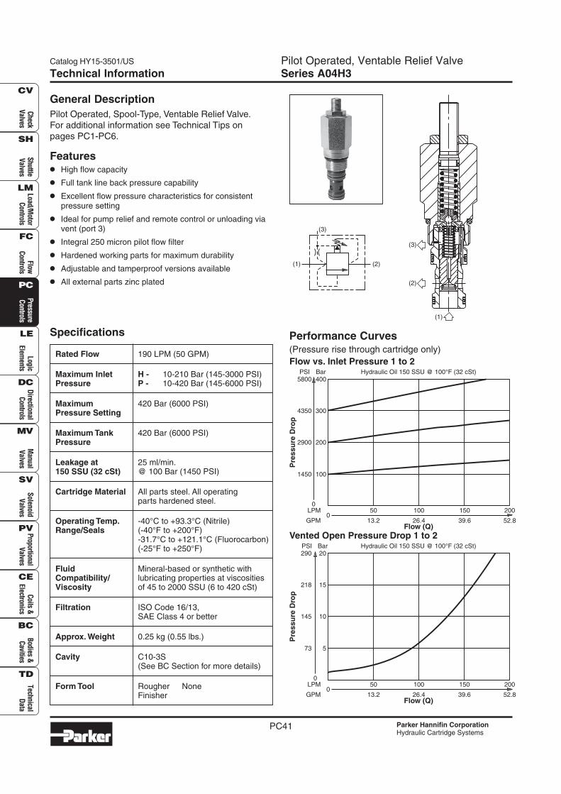
Pilot Operated, Spool-Type, Ventable Relief Valve.
For additional information see Technical Tips on
pages PC1-PC6.
Features
• High flow capacity
• Full tank line back pressure capability
• Excellent flow pressure characteristics for consistentpressure setting
• Ideal for pump relief and remote control or unloading viavent (port 3)
• Integral 250 micron pilot flow filter
• Hardened working parts for maximum durability
• Adjustable and tamperproof versions available
• All external parts zinc plated
Rated Flow 190 LPM (50 GPM)
Maximum Inlet H - 10-210 Bar (145-3000 PSI)Pressure P - 10-420 Bar (145-6000 PSI)
Maximum 420 Bar (6000 PSI)Pressure Setting
Maximum Tank 420 Bar (6000 PSI)Pressure
Leakage at 25 ml/min.150 SSU (32 cSt) @ 100 Bar (1450 PSI)
Cartridge Material All parts steel. All operatingparts hardened steel.
Operating Temp. -40°C to +93.3°C (Nitrile)Range/Seals (-40°F to +200°F)
-31.7°C to +121.1°C (Fluorocarbon)(-25°F to +250°F)
Fluid Mineral-based or synthetic withCompatibility/ lubricating properties at viscositiesViscosity of 45 to 2000 SSU (6 to 420 cSt)
Filtration ISO Code 16/13,SAE Class 4 or better
Approx. Weight 0.25 kg (0.55 lbs.)
Cavity C10-3S(See BC Section for more details)
Form Tool Rougher NoneFinisher
Performance Curves(Pressure rise through cartridge only)
(2)(1)
(3)
(2)
(3)
(1)
Flow (Q)
150
39.60
50
13.2
100
26.4
LPM
GPM
200
52.8
Hydraulic Oil 150 SSU @ 100°F (32 cSt)
0
1450
300
400
200
100
Pre
ssu
re D
rop
4350
5800PSI Bar
2900
Flow vs. Inlet Pressure 1 to 2
Flow (Q)
150
39.60
50
13.2
100
26.4
LPM
GPM
200
52.8
Hydraulic Oil 150 SSU @ 100°F (32 cSt)
0
73
15
20
10
5
Pre
ssu
re D
rop
218
290PSI Bar
145
Vented Open Pressure Drop 1 to 2
Pilot Operated, Ventable Relief ValveSeries A04H3
Catalog HY15-3501/US
PC42
Che
ckV
alve
sS
huttl
eV
alve
sLo
ad/M
otor
Con
trol
sFl
owC
ontr
ols
Pre
ssur
eC
ontr
ols
Logi
cEl
emen
tsD
irec
tiona
lC
ontr
ols
Man
ual
Val
ves
Pro
port
iona
lV
alve
sC
oils
&El
ectr
onic
sTe
chni
cal
Dat
a
SH
CV
LM
FC
PC
LE
DC
MV
SV
PV
CE
BC
TD
Bod
ies
&C
aviti
esS
olen
oid
Val
ves
Parker Hannifin CorporationHydraulic Cartridge Systems
Technical Information
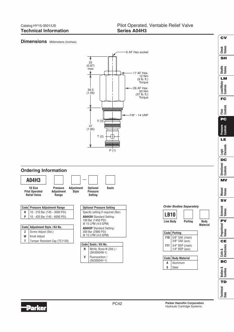
Dimensions Millimeters (Inches)
Ordering Information
AdjustmentStyle
PressureAdjustment
Range
SealsOptionalPressureSetting
Code Seals / Kit No.
N Nitrile, Buna-N (Std.) /(SK30504N-1)
V Fluorocarbon /(SK30504V-1)
Code Pressure Adjustment Range
H 10 - 210 Bar (145 - 3000 PSI)
P 10 - 420 Bar (145 - 6000 PSI)
Code Adjustment Style / Kit No.
Z Screw Adjust (Std.)
W Knob Adjust
T Tamper Resistant Cap (TC1130)
A04H3
10 SizePilot OperatedRelief Valve
Optional Pressure Setting
Specify setting if required (Bar)
A04H3H Standard Setting:100 Bar (1450 PSI)@ 15 LPM (4.0 GPM)
A04H3P Standard Setting:200 Bar (2900 PSI)@ 15 LPM (4.0 GPM)
Code Porting
710 5/8″ SAE (main)3/8″ SAE (aux)
711 3/4″ BSP (main)1/4″ BSP (aux)
BodyMaterial
Porting
Code Body Material
A Aluminum
S Steel
Line Body
LB10
Order Bodies Separately
22(0.87)max
39.5(1.56)
47(1.85)
5 AF Hex socket
17 AF Hex.12 Nm
(9 lb. ft.)Torque
26 AF Hex.50 Nm
(37 lb. ft.)Torque
7/8" - 14 UNF
T (2)
V (3)
P (1)
Catalog HY15-3501/US P.O. Pressure Reducing/Relieving ValveSeries PRH101
PC97
Check
Valves
Shuttle
Valves
Load/Motor
Controls
FlowC
ontrolsP
ressureC
ontrolsLogic
Elements
DirectionalC
ontrolsM
anualV
alvesS
olenoidV
alvesP
roportionalV
alvesC
oils &Electronics
Bodies &C
avitiesTechnical
Data
SH
CV
LM
FC
PC
LE
DC
MV
SV
PV
CE
BC
TD
Parker Hannifin CorporationHydraulic Cartridge Systems
Technical Information
Specifications
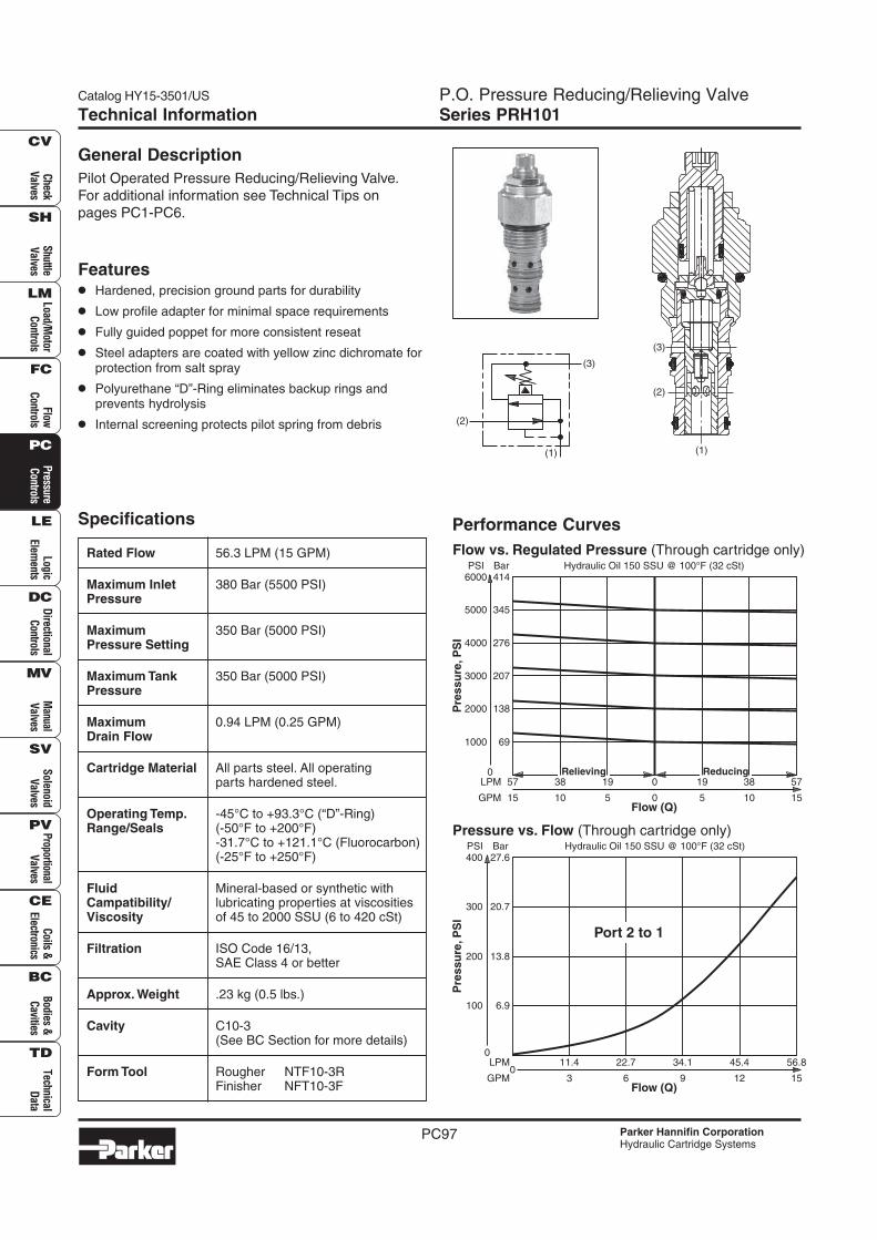
Rated Flow 56.3 LPM (15 GPM)
Maximum Inlet 380 Bar (5500 PSI)Pressure
Maximum 350 Bar (5000 PSI)Pressure Setting
Maximum Tank 350 Bar (5000 PSI)Pressure
Maximum 0.94 LPM (0.25 GPM)Drain Flow
Cartridge Material All parts steel. All operatingparts hardened steel.
Operating Temp. -45°C to +93.3°C (“D”-Ring)Range/Seals (-50°F to +200°F)
-31.7°C to +121.1°C (Fluorocarbon)(-25°F to +250°F)
Fluid Mineral-based or synthetic withCampatibility/ lubricating properties at viscositiesViscosity of 45 to 2000 SSU (6 to 420 cSt)
Filtration ISO Code 16/13,SAE Class 4 or better
Approx. Weight .23 kg (0.5 lbs.)
Cavity C10-3(See BC Section for more details)
Form Tool Rougher NTF10-3RFinisher NFT10-3F
Performance Curves
General Description
Pilot Operated Pressure Reducing/Relieving Valve.
For additional information see Technical Tips on
pages PC1-PC6.
Features
• Hardened, precision ground parts for durability
• Low profile adapter for minimal space requirements
• Fully guided poppet for more consistent reseat
• Steel adapters are coated with yellow zinc dichromate forprotection from salt spray
• Polyurethane “D”-Ring eliminates backup rings andprevents hydrolysis
• Internal screening protects pilot spring from debris (2)
(3)
(1) (1)
(2)
(3)
Flow (Q)
19
5
57
15
38
10
19
5
0
0
LPM
GPM
38
10
57
15
Hydraulic Oil 150 SSU @ 100°F (32 cSt)
0
1000
2000
345
414
207
276
69
138Pre
ss
ure
,P
SI
5000
6000PSI Bar
3000
4000
Relieving Reducing
Flow vs. Regulated Pressure (Through cartridge only)
Flow (Q)
34.1
9
11.4
3
22.7
6
LPM
GPM0
45.4
12
56.8
15
Hydraulic Oil 150 SSU @ 100°F (32 cSt)
0
100
20.7
27.6
13.8
6.9
300
400PSI Bar
200
Pre
ss
ure
,P
SI
Port 2 to 1
Pressure vs. Flow (Through cartridge only)
P.O. Pressure Reducing/Relieving ValveSeries PRH101
Catalog HY15-3501/US
PC98
Che
ckV
alve
sS
huttl
eV
alve
sLo
ad/M
otor
Con
trol
sFl
owC
ontr
ols
Pre
ssur
eC
ontr
ols
Logi
cEl
emen
tsD
irec
tiona
lC
ontr
ols
Man
ual
Val
ves
Pro
port
iona
lV
alve
sC
oils
&El
ectr
onic
sTe
chni
cal
Dat
a
SH
CV
LM
FC
PC
LE
DC
MV
SV
PV
CE
BC
TD
Bod
ies
&C
aviti
esS
olen
oid
Val
ves
Parker Hannifin CorporationHydraulic Cartridge Systems
Technical Information
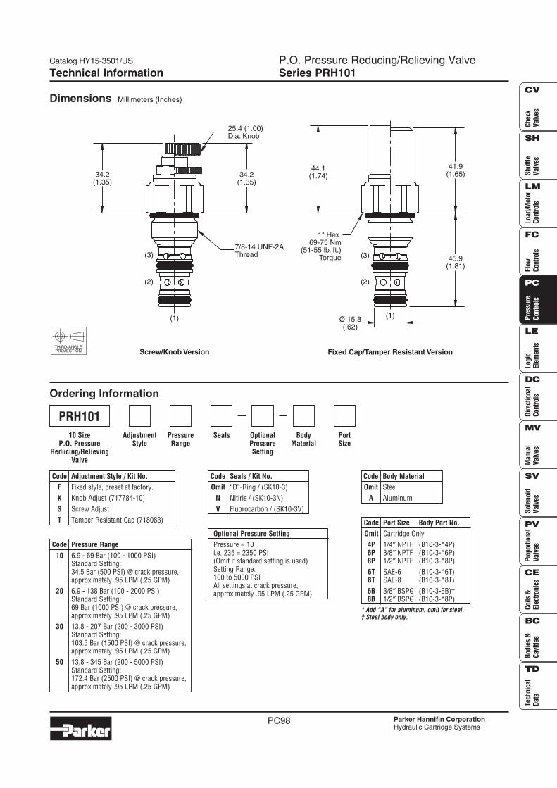
Dimensions Millimeters (Inches)
Ordering Information
THIRD-ANGLEPROJECTION
SealsPressureRange
AdjustmentStyle
BodyMaterial
PortSize
OptionalPressureSetting
Code Seals / Kit No.
Omit “D”-Ring / (SK10-3)
N Nitirle / (SK10-3N)
V Fluorocarbon / (SK10-3V)
Code Pressure Range
10 6.9 - 69 Bar (100 - 1000 PSI)Standard Setting:34.5 Bar (500 PSI) @ crack pressure,approximately .95 LPM (.25 GPM)
20 6.9 - 138 Bar (100 - 2000 PSI)Standard Setting:69 Bar (1000 PSI) @ crack pressure,approximately .95 LPM (.25 GPM)
30 13.8 - 207 Bar (200 - 3000 PSI)Standard Setting:103.5 Bar (1500 PSI) @ crack pressure,approximately .95 LPM (.25 GPM)
50 13.8 - 345 Bar (200 - 5000 PSI)Standard Setting:172.4 Bar (2500 PSI) @ crack pressure,approximately .95 LPM (.25 GPM)
Code Body Material
Omit Steel
A Aluminum
Code Adjustment Style / Kit No.
F Fixed style, preset at factory.
K Knob Adjust (717784-10)
S Screw Adjust
T Tamper Resistant Cap (718083)
Optional Pressure Setting
Pressure ÷ 10i.e. 235 = 2350 PSI(Omit if standard setting is used)Setting Range:100 to 5000 PSIAll settings at crack pressure,approximately .95 LPM (.25 GPM)
PRH101
10 SizeP.O. Pressure
Reducing/RelievingValve
* Add “A” for aluminum, omit for steel.† Steel body only.
Code Port Size Body Part No.
Omit Cartridge Only
4P 1/4″ NPTF (B10-3-*4P)6P 3/8″ NPTF (B10-3-*6P)8P 1/2″ NPTF (B10-3-*8P)
6T SAE-6 (B10-3-*6T)8T SAE-8 (B10-3-*8T)
6B 3/8″ BSPG (B10-3-6B)†8B 1/2″ BSPG (B10-3-*8P)
(1)
25.4 (1.00)Dia. Knob
(2)
(3)
34.2(1.35)
34.2(1.35)
Screw/Knob Version
7/8-14 UNF-2AThread
44.1(1.74)
41.9(1.65)
45.9(1.81)
1" Hex.69-75 Nm
(51-55 lb. ft.)Torque
Ø 15.8(.62)
Fixed Cap/Tamper Resistant Version
(1)
(2)
(3)
Catalog HY15-3501/US P.O Pressure Reducing/Relieving ValveSeries PRH121
PC99
Check
Valves
Shuttle
Valves
Load/Motor
Controls
FlowC
ontrolsP
ressureC
ontrolsLogic
Elements
DirectionalC
ontrolsM
anualV
alvesS
olenoidV
alvesP
roportionalV
alvesC
oils &Electronics
Bodies &C
avitiesTechnical
Data
SH
CV
LM
FC
PC
LE
DC
MV
SV
PV
CE
BC
TD
Parker Hannifin CorporationHydraulic Cartridge Systems
Technical Information
Specifications
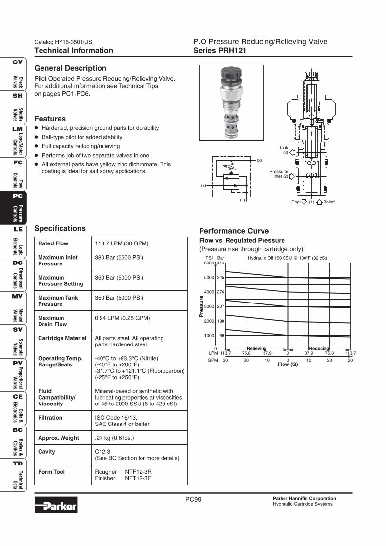
Rated Flow 113.7 LPM (30 GPM)
Maximum Inlet 380 Bar (5500 PSI)Pressure
Maximum 350 Bar (5000 PSI)Pressure Setting
Maximum Tank 350 Bar (5000 PSI)Pressure
Maximum 0.94 LPM (0.25 GPM)Drain Flow
Cartridge Material All parts steel. All operatingparts hardened steel.
Operating Temp. -40°C to +93.3°C (Nitrile)Range/Seals (-40°F to +200°F)
-31.7°C to +121.1°C (Fluorocarbon)(-25°F to +250°F)
Fluid Mineral-based or synthetic withCampatibility/ lubricating properties at viscositiesViscosity of 45 to 2000 SSU (6 to 420 cSt)
Filtration ISO Code 16/13,SAE Class 4 or better
Approx. Weight .27 kg (0.6 lbs.)
Cavity C12-3(See BC Section for more details)
Form Tool Rougher NTF12-3RFinisher NFT12-3F
Performance CurveFlow vs. Regulated Pressure
(Pressure rise through cartridge only)
General Description
Pilot Operated Pressure Reducing/Relieving Valve.
For additional information see Technical Tips
on pages PC1-PC6.
Features
• Hardened, precision ground parts for durability
• Ball-type pilot for added stability
• Full capacity reducing/relieving
• Performs job of two separate valves in one
• All external parts have yellow zinc dichromate. Thiscoating is ideal for salt spray applications.
(2)
(3)
(1)(1) ReliefReg.
Pressure/Inlet (2)
Tank(3)
Flow (Q)
37.9
10
113.7
30
75.8
20
37.9
10
0
0
LPM
GPM
75.8
20
113.7
30
Hydraulic Oil 150 SSU @ 100°F (32 cSt)
0
1000
2000
345
414
207
276
69
138
Pre
ss
ure
5000
6000PSI Bar
3000
4000
Relieving Reducing
P.O. Pressure Reducing/Relieving ValveSeries PRH121
Catalog HY15-3501/US
PC100
Che
ckV
alve
sS
huttl
eV
alve
sLo
ad/M
otor
Con
trol
sFl
owC
ontr
ols
Pre
ssur
eC
ontr
ols
Logi
cEl
emen
tsD
irec
tiona
lC
ontr
ols
Man
ual
Val
ves
Pro
port
iona
lV
alve
sC
oils
&El
ectr
onic
sTe
chni
cal
Dat
a
SH
CV
LM
FC
PC
LE
DC
MV
SV
PV
CE
BC
TD
Bod
ies
&C
aviti
esS
olen
oid
Val
ves
Parker Hannifin CorporationHydraulic Cartridge Systems
Technical Information
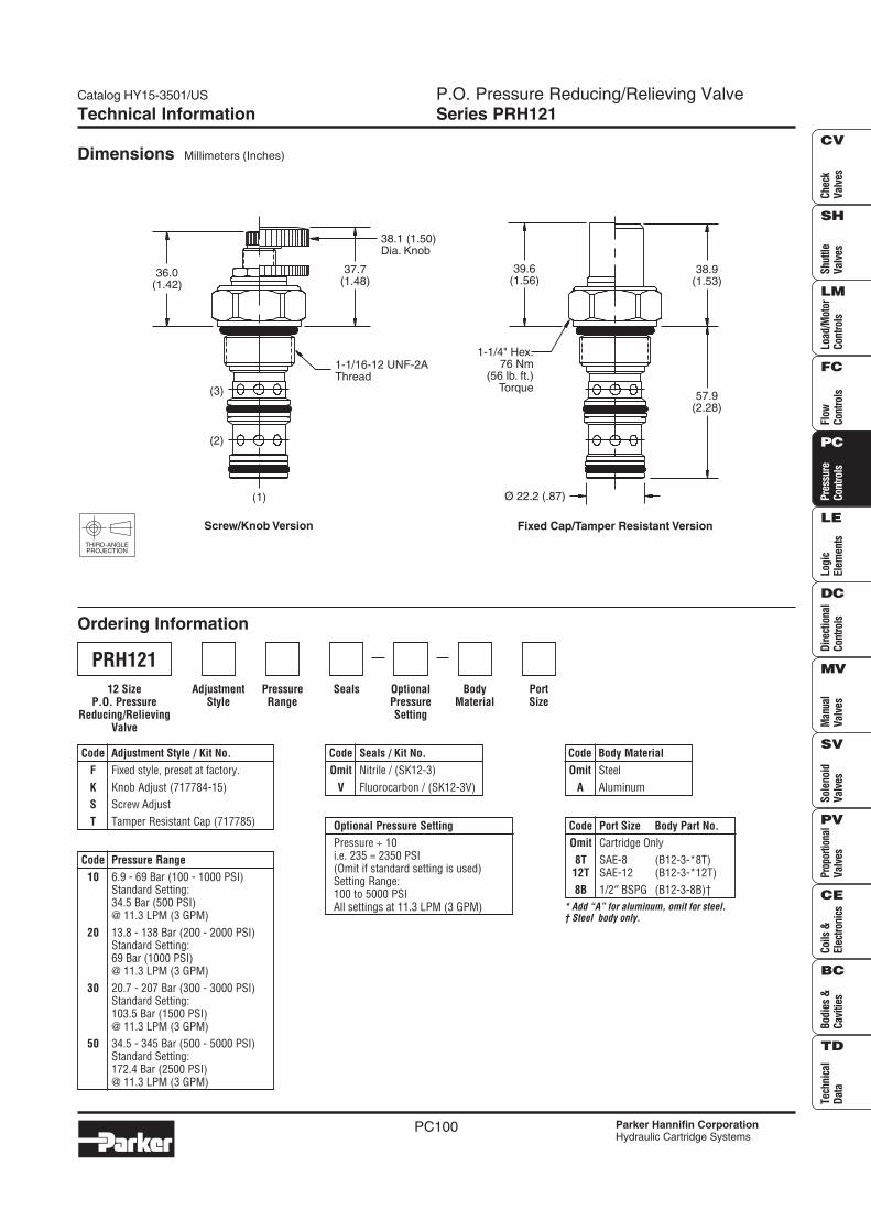
Dimensions Millimeters (Inches)
Ordering Information
THIRD-ANGLEPROJECTION
SealsPressureRange
AdjustmentStyle
BodyMaterial
PortSize
OptionalPressureSetting
Code Seals / Kit No.
Omit Nitrile / (SK12-3)
V Fluorocarbon / (SK12-3V)
Code Pressure Range
10 6.9 - 69 Bar (100 - 1000 PSI)Standard Setting:34.5 Bar (500 PSI)@ 11.3 LPM (3 GPM)
20 13.8 - 138 Bar (200 - 2000 PSI)Standard Setting:69 Bar (1000 PSI)@ 11.3 LPM (3 GPM)
30 20.7 - 207 Bar (300 - 3000 PSI)Standard Setting:103.5 Bar (1500 PSI)@ 11.3 LPM (3 GPM)
50 34.5 - 345 Bar (500 - 5000 PSI)Standard Setting:172.4 Bar (2500 PSI)@ 11.3 LPM (3 GPM)
Code Body Material
Omit Steel
A Aluminum
Code Adjustment Style / Kit No.
F Fixed style, preset at factory.
K Knob Adjust (717784-15)
S Screw Adjust
T Tamper Resistant Cap (717785) Optional Pressure Setting
Pressure ÷ 10i.e. 235 = 2350 PSI(Omit if standard setting is used)Setting Range:100 to 5000 PSIAll settings at 11.3 LPM (3 GPM)
PRH121
12 SizeP.O. Pressure
Reducing/RelievingValve
* Add “A” for aluminum, omit for steel.† Steel body only.
Code Port Size Body Part No.
Omit Cartridge Only
8T SAE-8 (B12-3-*8T)12T SAE-12 (B12-3-*12T)
8B 1/2″ BSPG (B12-3-8B)†
39.6(1.56)
1-1/4" Hex.76 Nm
(56 lb. ft.)Torque
57.9(2.28)
38.9(1.53)
Ø 22.2 (.87)
Fixed Cap/Tamper Resistant Version
36.0(1.42)
37.7(1.48)
38.1 (1.50)Dia. Knob
(3)
(2)
(1)
Screw/Knob Version
1-1/16-12 UNF-2AThread
Catalog HY15-3501/US P.O. Sequence Valve (Internal Pilot)Series SVH101
PC57
Check
Valves
Shuttle
Valves
Load/Motor
Controls
FlowC
ontrolsP
ressureC
ontrolsLogic
Elements
DirectionalC
ontrolsM
anualV
alvesS
olenoidV
alvesP
roportionalV
alvesC
oils &Electronics
Bodies &C
avitiesTechnical
Data
SH
CV
LM
FC
PC
LE
DC
MV
SV
PV
CE
BC
TD
Parker Hannifin CorporationHydraulic Cartridge Systems
Technical Information
Specifications
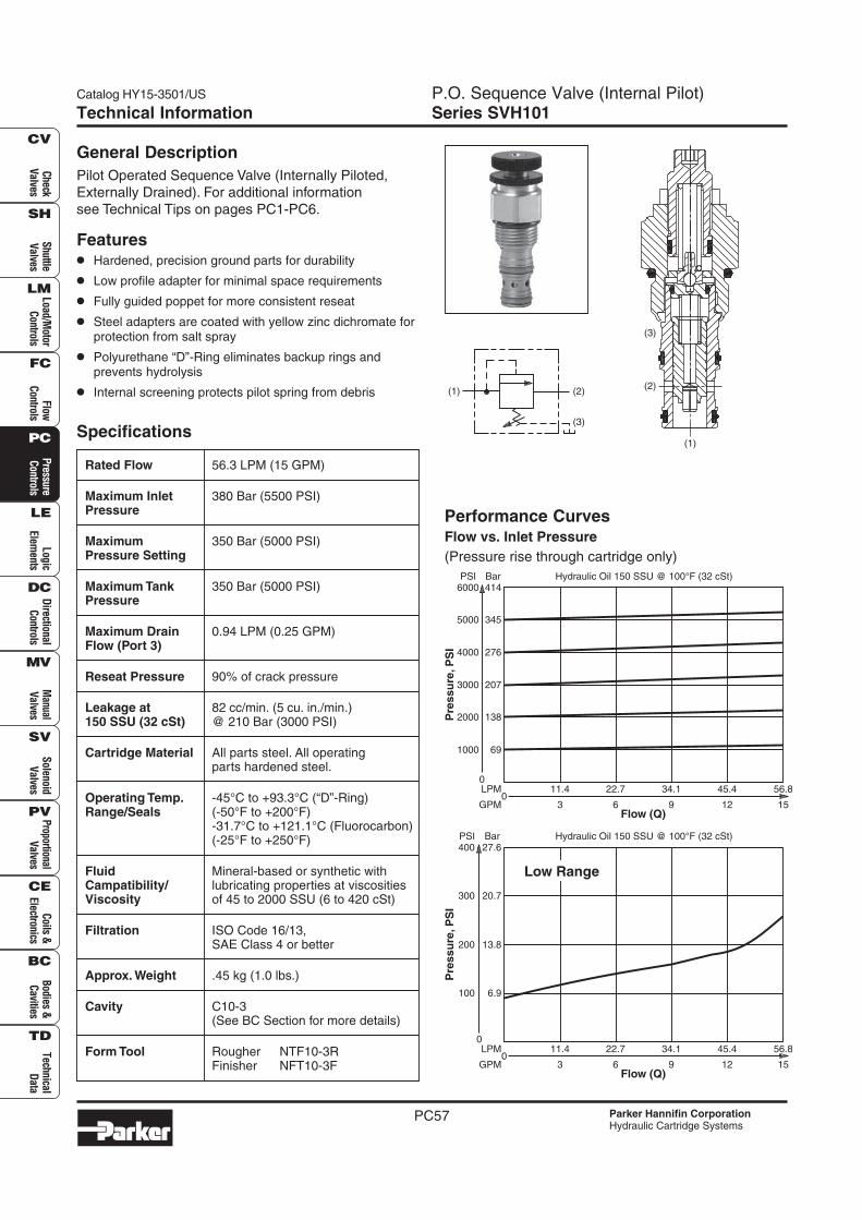
Rated Flow 56.3 LPM (15 GPM)
Maximum Inlet 380 Bar (5500 PSI)Pressure
Maximum 350 Bar (5000 PSI)Pressure Setting
Maximum Tank 350 Bar (5000 PSI)Pressure
Maximum Drain 0.94 LPM (0.25 GPM)Flow (Port 3)
Reseat Pressure 90% of crack pressure
Leakage at 82 cc/min. (5 cu. in./min.)150 SSU (32 cSt) @ 210 Bar (3000 PSI)
Cartridge Material All parts steel. All operatingparts hardened steel.
Operating Temp. -45°C to +93.3°C (“D”-Ring)Range/Seals (-50°F to +200°F)
-31.7°C to +121.1°C (Fluorocarbon)(-25°F to +250°F)
Fluid Mineral-based or synthetic withCampatibility/ lubricating properties at viscositiesViscosity of 45 to 2000 SSU (6 to 420 cSt)
Filtration ISO Code 16/13,SAE Class 4 or better
Approx. Weight .45 kg (1.0 lbs.)
Cavity C10-3(See BC Section for more details)
Form Tool Rougher NTF10-3RFinisher NFT10-3F
Performance CurvesFlow vs. Inlet Pressure
(Pressure rise through cartridge only)
General Description
Pilot Operated Sequence Valve (Internally Piloted,
Externally Drained). For additional information
see Technical Tips on pages PC1-PC6.
Features
• Hardened, precision ground parts for durability
• Low profile adapter for minimal space requirements
• Fully guided poppet for more consistent reseat
• Steel adapters are coated with yellow zinc dichromate forprotection from salt spray
• Polyurethane “D”-Ring eliminates backup rings andprevents hydrolysis
• Internal screening protects pilot spring from debris (2)
(3)
(1)
Flow (Q)
34.1
9
11.4
3
22.7
6
LPM
GPM0
45.4
12
56.8
15
Hydraulic Oil 150 SSU @ 100°F (32 cSt)
0
100
20.7
27.6
13.8
6.9
300
400PSI Bar
200
Pre
ss
ure
,P
SI
Low Range
Flow (Q)
34.1
9
11.4
3
22.7
6
LPM
GPM0
45.4
12
56.8
15
Hydraulic Oil 150 SSU @ 100°F (32 cSt)
0
1000
2000
345
414
207
276
69
138
5000
6000PSI Bar
3000
4000
Pre
ss
ure
,P
SI
(1)
(2)
(3)
P.O. Sequence Valve (Internal Pilot)Series SVH101
Catalog HY15-3501/US
PC58
Che
ckV
alve
sS
huttl
eV
alve
sLo
ad/M
otor
Con
trol
sFl
owC
ontr
ols
Pre
ssur
eC
ontr
ols
Logi
cEl
emen
tsD
irec
tiona
lC
ontr
ols
Man
ual
Val
ves
Pro
port
iona
lV
alve
sC
oils
&El
ectr
onic
sTe
chni
cal
Dat
a
SH
CV
LM
FC
PC
LE
DC
MV
SV
PV
CE
BC
TD
Bod
ies
&C
aviti
esS
olen
oid
Val
ves
Parker Hannifin CorporationHydraulic Cartridge Systems
Technical Information
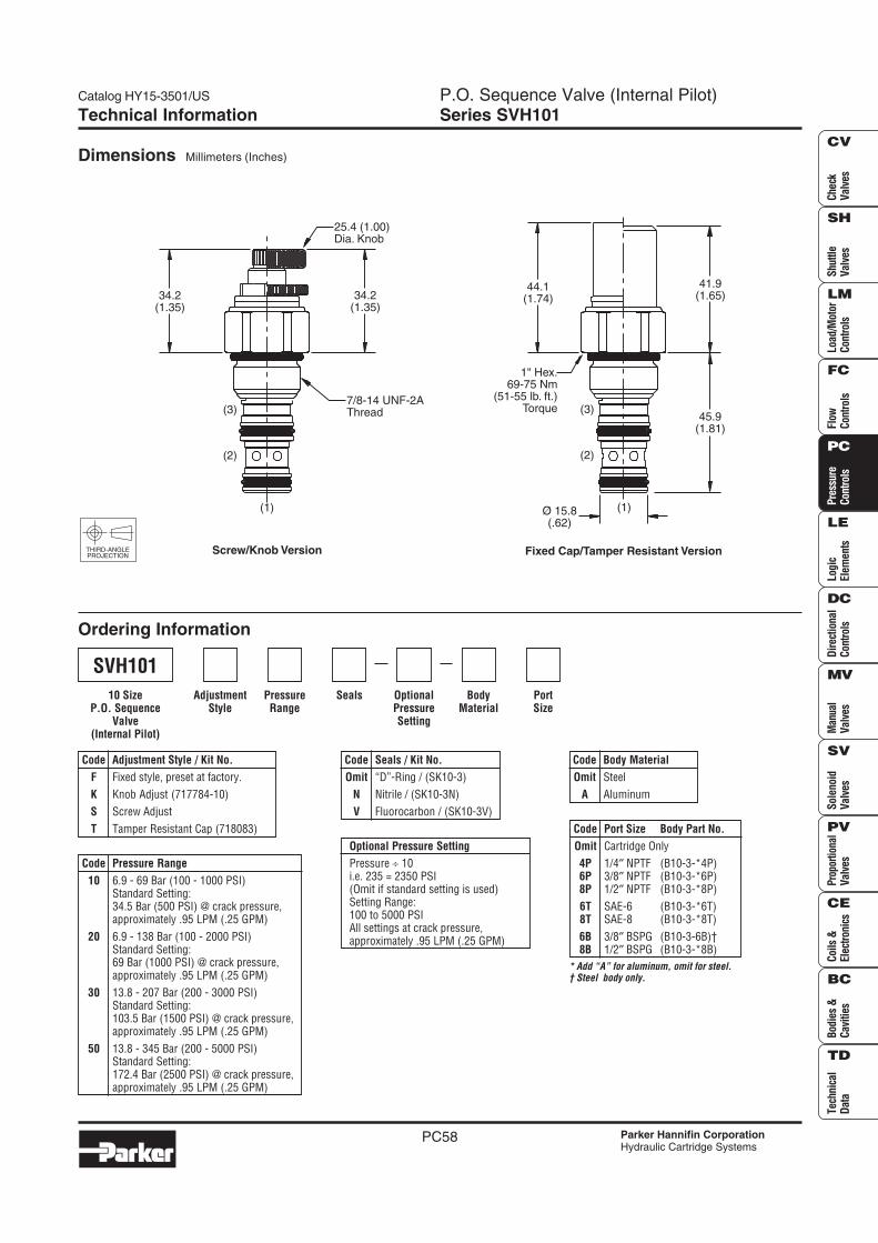
Dimensions Millimeters (Inches)
Ordering Information
THIRD-ANGLEPROJECTION
SealsPressureRange
AdjustmentStyle
BodyMaterial
PortSize
OptionalPressureSetting
Code Seals / Kit No.
Omit “D”-Ring / (SK10-3)
N Nitrile / (SK10-3N)
V Fluorocarbon / (SK10-3V)
Code Pressure Range
10 6.9 - 69 Bar (100 - 1000 PSI)Standard Setting:34.5 Bar (500 PSI) @ crack pressure,approximately .95 LPM (.25 GPM)
20 6.9 - 138 Bar (100 - 2000 PSI)Standard Setting:69 Bar (1000 PSI) @ crack pressure,approximately .95 LPM (.25 GPM)
30 13.8 - 207 Bar (200 - 3000 PSI)Standard Setting:103.5 Bar (1500 PSI) @ crack pressure,approximately .95 LPM (.25 GPM)
50 13.8 - 345 Bar (200 - 5000 PSI)Standard Setting:172.4 Bar (2500 PSI) @ crack pressure,approximately .95 LPM (.25 GPM)
Code Body Material
Omit Steel
A Aluminum
Code Adjustment Style / Kit No.
F Fixed style, preset at factory.
K Knob Adjust (717784-10)
S Screw Adjust
T Tamper Resistant Cap (718083)
Optional Pressure Setting
Pressure ÷ 10i.e. 235 = 2350 PSI(Omit if standard setting is used)Setting Range:100 to 5000 PSIAll settings at crack pressure,approximately .95 LPM (.25 GPM)
SVH101
10 SizeP.O. Sequence
Valve(Internal Pilot)
* Add “A” for aluminum, omit for steel.† Steel body only.
Code Port Size Body Part No.
Omit Cartridge Only
4P 1/4″ NPTF (B10-3-*4P)6P 3/8″ NPTF (B10-3-*6P)8P 1/2″ NPTF (B10-3-*8P)
6T SAE-6 (B10-3-*6T)8T SAE-8 (B10-3-*8T)
6B 3/8″ BSPG (B10-3-6B)†8B 1/2″ BSPG (B10-3-*8B)
Ø 15.8(.62)
1" Hex.69-75 Nm
(51-55 lb. ft.)Torque
44.1(1.74)
41.9(1.65)
45.9(1.81)
Fixed Cap/Tamper Resistant Version
(1)
(2)
(3)
34.2(1.35)
34.2(1.35)
25.4 (1.00)Dia. Knob
Screw/Knob Version
7/8-14 UNF-2AThread
(1)
(2)
(3)
Catalog HY15-3501/US P.O. Sequence Valve (External Pilot)Series SVH102
PC61
Check
Valves
Shuttle
Valves
Load/Motor
Controls
FlowC
ontrolsP
ressureC
ontrolsLogic
Elements
DirectionalC
ontrolsM
anualV
alvesS
olenoidV
alvesP
roportionalV
alvesC
oils &Electronics
Bodies &C
avitiesTechnical
Data
SH
CV
LM
FC
PC
LE
DC
MV
SV
PV
CE
BC
TD
Parker Hannifin CorporationHydraulic Cartridge Systems
Technical Information
Specifications
Rated Flow 56.3 LPM (15 GPM)
Maximum Inlet 380 Bar (5500 PSI)Pressure
Maximum 350 Bar (5000 PSI)Pressure Setting
Maximum Tank 350 Bar (5000 PSI)Pressure
Maximum See maximum drain flow chartDrain Flow (Lower right)
Reseat Pressure 90% of crack pressure
Leakage at 82 cc/min. (5 cu. in./min.)150 SSU (32 cSt) @ 210 Bar (3000 PSI)
Cartridge Material All parts steel. All operatingparts hardened steel.
Operating Temp. -45°C to +93.3°C (“D”-Ring)Range/Seals (-50°F to +200°F)
-31.7°C to +121.1°C (Fluorocarbon)(-25°F to +250°F)
Fluid Mineral-based or synthetic withCampatibility/ lubricating properties at viscositiesViscosity of 45 to 2000 SSU (6 to 420 cSt)
Filtration ISO Code 16/13,SAE Class 4 or better
Approx. Weight .45 kg (1.0 lbs.)
Cavity C10-3(See BC Section for more details)
Form Tool Rougher NTF10-3RFinisher NFT10-3F
Performance CurveFlow vs. Inlet Pressure
(Pressure rise through cartridge only)
General Description
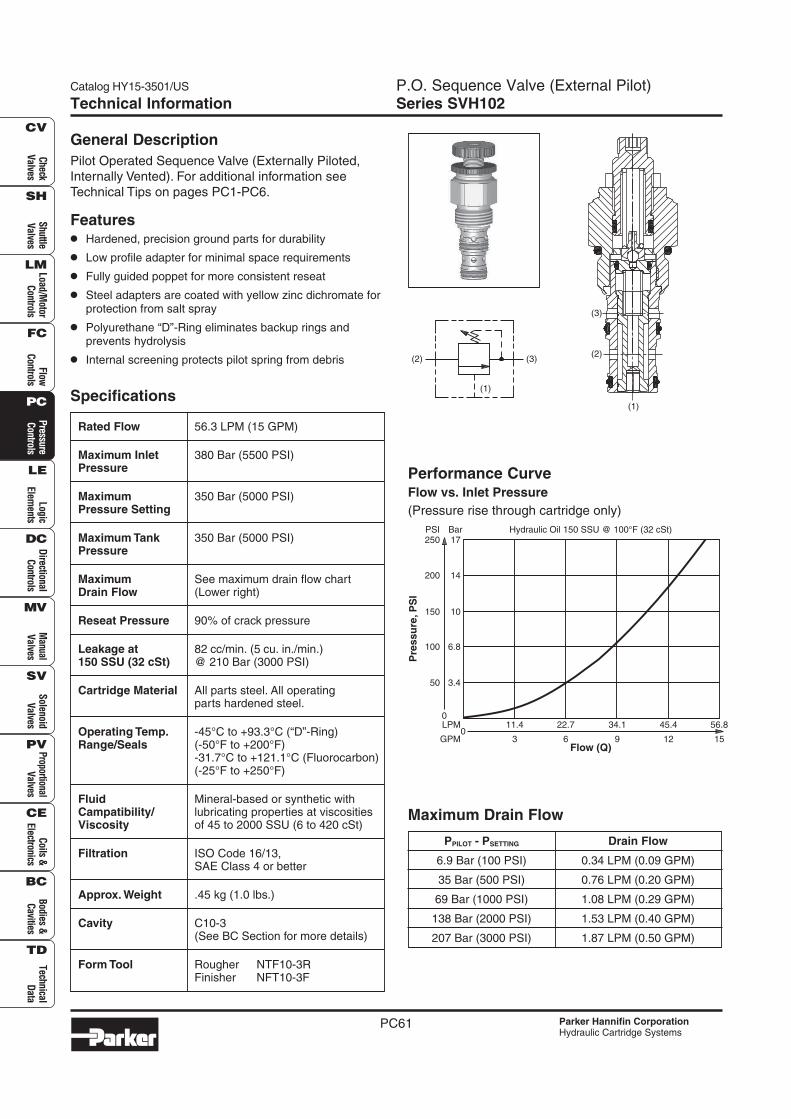
Pilot Operated Sequence Valve (Externally Piloted,
Internally Vented). For additional information see
Technical Tips on pages PC1-PC6.
Features
• Hardened, precision ground parts for durability
• Low profile adapter for minimal space requirements
• Fully guided poppet for more consistent reseat
• Steel adapters are coated with yellow zinc dichromate forprotection from salt spray
• Polyurethane “D”-Ring eliminates backup rings andprevents hydrolysis
• Internal screening protects pilot spring from debris
PPILOT - PSETTING Drain Flow
6.9 Bar (100 PSI) 0.34 LPM (0.09 GPM)
35 Bar (500 PSI) 0.76 LPM (0.20 GPM)
69 Bar (1000 PSI) 1.08 LPM (0.29 GPM)
138 Bar (2000 PSI) 1.53 LPM (0.40 GPM)
207 Bar (3000 PSI) 1.87 LPM (0.50 GPM)
Maximum Drain Flow
(3)
(1)
(2)
(1)
(2)
(3)
Flow (Q)
11.4
3
22.7
6
34.1
9
45.4
12
LPM
GPM0
56.8
15
Hydraulic Oil 150 SSU @ 100°F (32 cSt)
Pre
ssu
re,P
SI
0
50
14
17
6.8
10
3.4
200
250PSI Bar
100
150
P.O. Sequence Valve (External Pilot)Series SVH102
Catalog HY15-3501/US
PC62
Che
ckV
alve
sS
huttl
eV
alve
sLo
ad/M
otor
Con
trol
sFl
owC
ontr
ols
Pre
ssur
eC
ontr
ols
Logi
cEl
emen
tsD
irec
tiona
lC
ontr
ols
Man
ual
Val
ves
Pro
port
iona
lV
alve
sC
oils
&El
ectr
onic
sTe
chni
cal
Dat
a
SH
CV
LM
FC
PC
LE
DC
MV
SV
PV
CE
BC
TD
Bod
ies
&C
aviti
esS
olen
oid
Val
ves
Parker Hannifin CorporationHydraulic Cartridge Systems
Technical Information
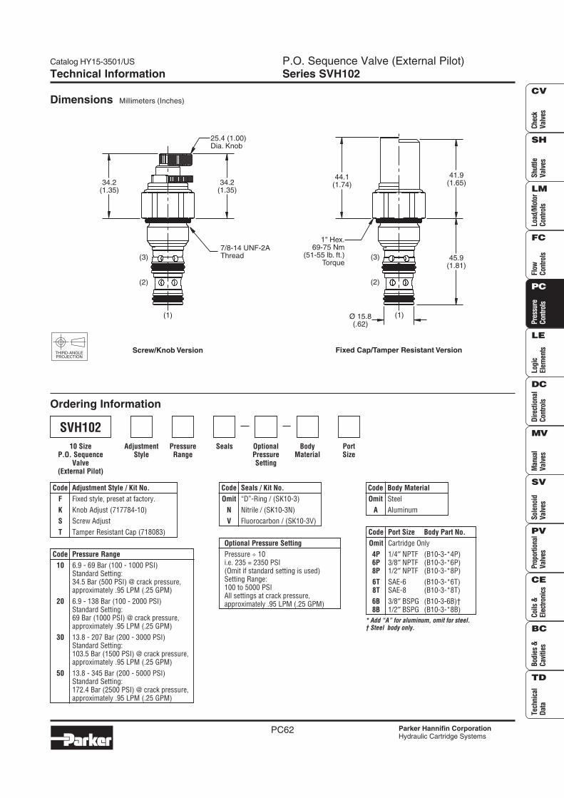
Dimensions Millimeters (Inches)
Ordering Information
THIRD-ANGLEPROJECTION
SealsPressureRange
AdjustmentStyle
BodyMaterial
PortSize
OptionalPressureSetting
Code Seals / Kit No.
Omit “D”-Ring / (SK10-3)
N Nitrile / (SK10-3N)
V Fluorocarbon / (SK10-3V)
Code Pressure Range
10 6.9 - 69 Bar (100 - 1000 PSI)Standard Setting:34.5 Bar (500 PSI) @ crack pressure,approximately .95 LPM (.25 GPM)
20 6.9 - 138 Bar (100 - 2000 PSI)Standard Setting:69 Bar (1000 PSI) @ crack pressure,approximately .95 LPM (.25 GPM)
30 13.8 - 207 Bar (200 - 3000 PSI)Standard Setting:103.5 Bar (1500 PSI) @ crack pressure,approximately .95 LPM (.25 GPM)
50 13.8 - 345 Bar (200 - 5000 PSI)Standard Setting:172.4 Bar (2500 PSI) @ crack pressure,approximately .95 LPM (.25 GPM)
Code Body Material
Omit Steel
A Aluminum
Code Adjustment Style / Kit No.
F Fixed style, preset at factory.
K Knob Adjust (717784-10)
S Screw Adjust
T Tamper Resistant Cap (718083)
Optional Pressure Setting
Pressure ÷ 10i.e. 235 = 2350 PSI(Omit if standard setting is used)Setting Range:100 to 5000 PSIAll settings at crack pressure,approximately .95 LPM (.25 GPM)
SVH102
10 SizeP.O. Sequence
Valve(External Pilot)
* Add “A” for aluminum, omit for steel.† Steel body only.
Code Port Size Body Part No.
Omit Cartridge Only
4P 1/4″ NPTF (B10-3-*4P)6P 3/8″ NPTF (B10-3-*6P)8P 1/2″ NPTF (B10-3-*8P)
6T SAE-6 (B10-3-*6T)8T SAE-8 (B10-3-*8T)
6B 3/8″ BSPG (B10-3-6B)†8B 1/2″ BSPG (B10-3-*8B)
1" Hex.69-75 Nm
(51-55 lb. ft.)Torque
Ø 15.8(.62)
41.9(1.65)
45.9(1.81)
44.1(1.74)
Fixed Cap/Tamper Resistant Version
(1)
(3)
(2)
34.2(1.35)
34.2(1.35)
25.4 (1.00)Dia. Knob
7/8-14 UNF-2AThread
Screw/Knob Version
(1)
(3)
(2)
LM5
Catalog HY15-3501/US Counterbalance ValveSeries CB101
Parker Hannifin CorporationHydraulic Cartridge Systems
Check
Valves
Shuttle
Valves
Load/Motor
Controls
FlowC
ontrolsP
ressureC
ontrolsLogic
Elements
DirectionalC
ontrolsM
anualV
alvesS
olenoidV
alvesP
roportionalV
alvesC
oils &Electronics
Bodies &C
avitiesTechnical
Data
SH
CV
LM
FC
PC
LE
DC
MV
SV
PV
CE
BC
TD
Specifications
Technical Information
Rated Flow 45 LPM (12 GPM)
Maximum 380 Bar (5500 PSI) - SteelInlet Pressure 210 Bar (3000 PSI) - Aluminum
Maximum 350 Bar (5000 PSI) - SteelSetting Pressure 210 Bar (3000 PSI) - Aluminum
Leakage at 5 drops/min. (.33 cc/min.) @150 SSU (32 cSt) 80% of thermal crack pressure
Cartridge Material All parts steel. All operatingparts hardened steel.
Operating Temp. -40°C to +93.3°C (Nitrile)Range/Seals (-40°F to +200°F)
-31.7°C to +121.1°C (Fluorocarbon)(-25°F to +250°F)
Fluid Mineral-based or synthetic withCompatibility/ lubricating properties at viscositiesViscosity of 45 to 2000 SSU (6 to 420 cSt)
Filtration ISO Code 16/13,SAE Class 4 or better
Approx. Weight .23 kg (0.5 lbs.)
Cavity C10-3(See BC Section for more details)
Form Tool Rougher NFT10-3RFinisher NFT10-3F
Performance CurveFlow vs. Pressure Drop
(Through cartridge only)
General Description
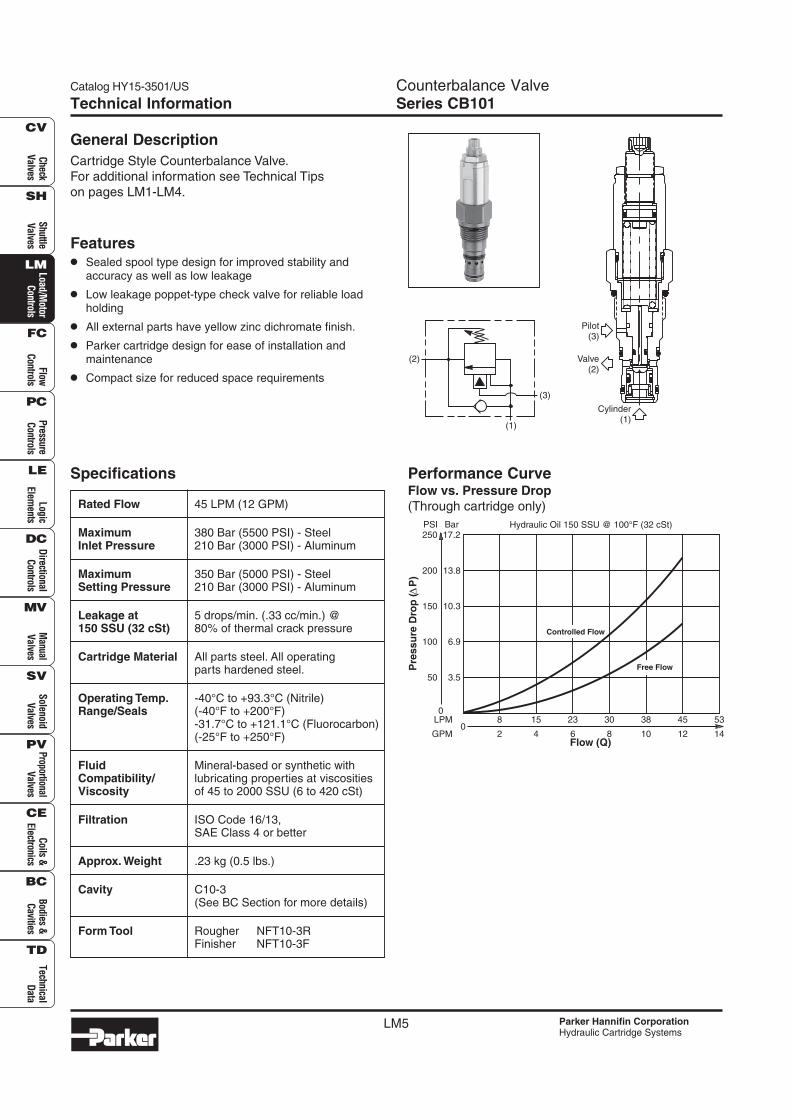
Cartridge Style Counterbalance Valve.
For additional information see Technical Tips
on pages LM1-LM4.
Features
• Sealed spool type design for improved stability andaccuracy as well as low leakage
• Low leakage poppet-type check valve for reliable loadholding
• All external parts have yellow zinc dichromate finish.
• Parker cartridge design for ease of installation andmaintenance
• Compact size for reduced space requirements
(2)
(1)
(3)
Cylinder(1)
Pilot(3)
Valve(2)
Hydraulic Oil 150 SSU @ 100°F (32 cSt)
Controlled Flow
Free Flow
0
50
100
13.8
17.2
10.3
3.5
6.9
200
250PSI Bar
150
Pre
ss
ure
Dro
p (
P)
Flow (Q)
38
100
8
2
15
4
23
6
30
8
LPM
GPM
45
12
53
14
LM6
Counterbalance ValveSeries CB101
Catalog HY15-3501/US
Parker Hannifin CorporationHydraulic Cartridge Systems
Che
ckV
alve
sS
huttl
eV
alve
sLo
ad/M
otor
Con
trol
sFl
owC
ontr
ols
Pre
ssur
eC
ontr
ols
Logi
cEl
emen
tsD
irec
tiona
lC
ontr
ols
Man
ual
Val
ves
Pro
port
iona
lV
alve
sC
oils
&El
ectr
onic
sTe
chni
cal
Dat
a
SH
CV
LM
FC
PC
LE
DC
MV
SV
PV
CE
BC
TD
Bod
ies
&C
aviti
esS
olen
oid
Val
ves
Ordering Information
AdjustmentStyle
PilotRatio
Seals OptionalPressureSetting
PressureRange
Code Pilot Ratio
A 3:1
B 4.5:1
C 7:1
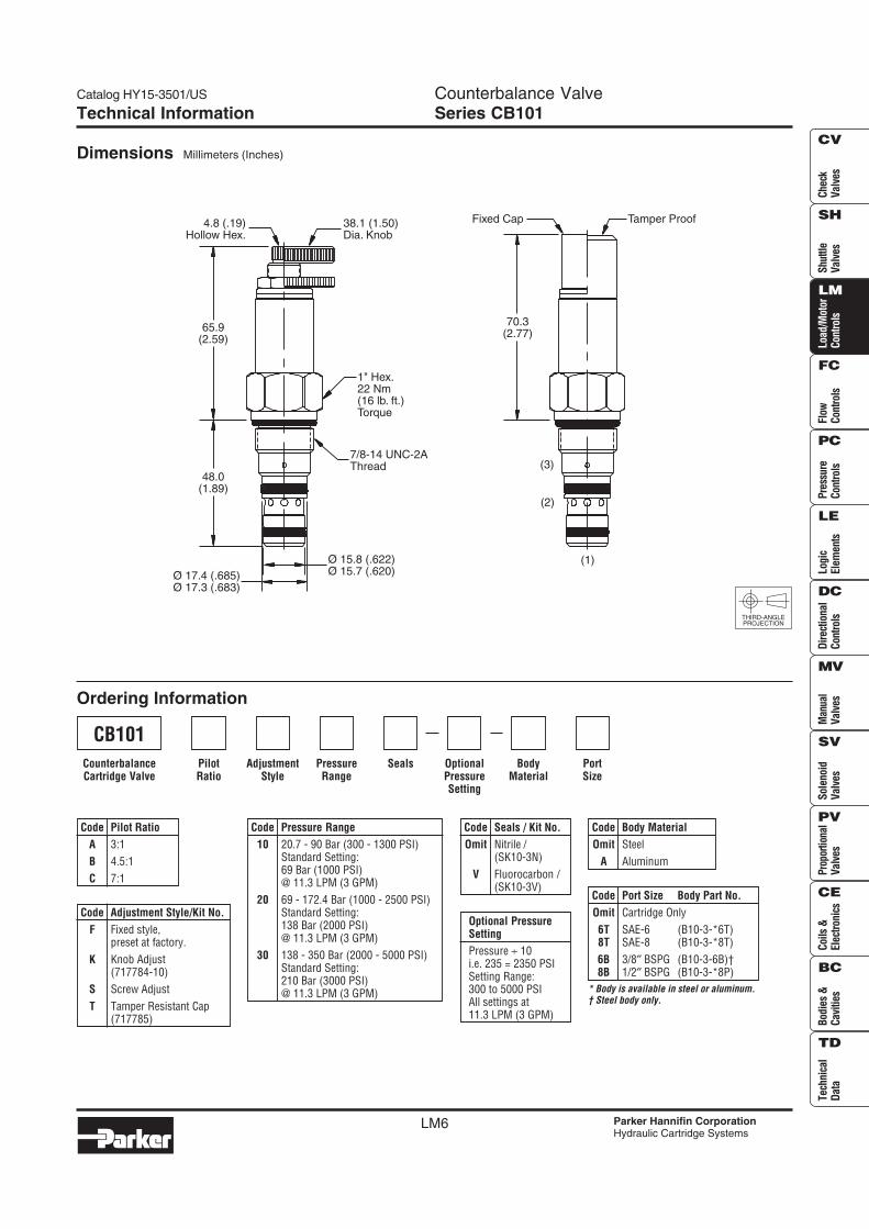
CB101
CounterbalanceCartridge Valve
BodyMaterial
PortSize
THIRD-ANGLEPROJECTION
Technical Information
Code Seals / Kit No.
Omit Nitrile /(SK10-3N)
V Fluorocarbon /(SK10-3V)
Code Pressure Range
10 20.7 - 90 Bar (300 - 1300 PSI)Standard Setting:69 Bar (1000 PSI)@ 11.3 LPM (3 GPM)
20 69 - 172.4 Bar (1000 - 2500 PSI)Standard Setting:138 Bar (2000 PSI)@ 11.3 LPM (3 GPM)
30 138 - 350 Bar (2000 - 5000 PSI)Standard Setting:210 Bar (3000 PSI)@ 11.3 LPM (3 GPM)
Code Body Material
Omit Steel
A Aluminum
Code Adjustment Style/Kit No.
F Fixed style,preset at factory.
K Knob Adjust(717784-10)
S Screw Adjust
T Tamper Resistant Cap(717785)
Optional PressureSetting
Pressure ÷ 10i.e. 235 = 2350 PSISetting Range:300 to 5000 PSIAll settings at11.3 LPM (3 GPM)
* Body is available in steel or aluminum.† Steel body only.
Code Port Size Body Part No.
Omit Cartridge Only
6T SAE-6 (B10-3-*6T)8T SAE-8 (B10-3-*8T)
6B 3/8″ BSPG (B10-3-6B)†8B 1/2″ BSPG (B10-3-*8P)
(1)
(2)
(3)
70.3(2.77)
Tamper ProofFixed Cap
Ø 15.8 (.622)Ø 15.7 (.620)
Ø 17.4 (.685)Ø 17.3 (.683)
48.0(1.89)
65.9(2.59)
4.8 (.19)Hollow Hex.
38.1 (1.50)Dia. Knob
1" Hex.22 Nm(16 lb. ft.)Torque
7/8-14 UNC-2AThread
Dimensions Millimeters (Inches)
Catalog HY15-3501/US
LM21
Load Control ValveSeries E2A060, E2B060, E2H060, E2J060
Parker Hannifin CorporationHydraulic Cartridge Systems
Check
Valves
Shuttle
Valves
Load/Motor
Controls
FlowC
ontrolsP
ressureC
ontrolsLogic
Elements
DirectionalC
ontrolsM
anualV
alvesS
olenoidV
alvesP
roportionalV
alvesC
oils &Electronics
Bodies &C
avitiesTechnical
Data
SH
CV
LM
FC
PC
LE
DC
MV
SV
PV
CE
BC
TD
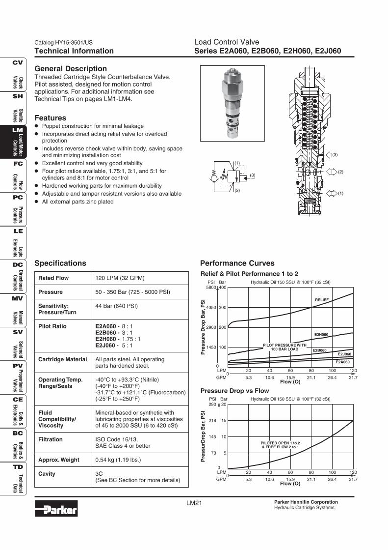
General DescriptionThreaded Cartridge Style Counterbalance Valve.Pilot assisted, designed for motion controlapplications. For additional information seeTechnical Tips on pages LM1-LM4.
Features• Poppet construction for minimal leakage
• Incorporates direct acting relief valve for overloadprotection
• Includes reverse check valve within body, saving spaceand minimizing installation cost
• Excellent control and very good stability
• Four pilot ratios available, 1.75:1, 3:1, and 5:1 forcylinders and 8:1 for motor control
• Hardened working parts for maximum durability
• Adjustable and tamper resistant versions also available
• All external parts zinc plated
Specifications
Technical Information
Performance Curves
Rated Flow 120 LPM (32 GPM)
Pressure 50 - 350 Bar (725 - 5000 PSI)
Sensitivity: 44 Bar (640 PSI)Pressure/Turn
Pilot Ratio E2A060 - 8 : 1E2B060 - 3 : 1E2H060 - 1.75 : 1E2J060 - 5 : 1
Cartridge Material All parts steel. All operatingparts hardened steel.
Operating Temp. -40°C to +93.3°C (Nitrile)Range/Seals (-40°F to +200°F)
-31.7°C to +121.1°C (Fluorocarbon)(-25°F to +250°F)
Fluid Mineral-based or synthetic withCompatibility/ lubricating properties at viscositiesViscosity of 45 to 2000 SSU (6 to 420 cSt)
Filtration ISO Code 16/13,SAE Class 4 or better
Approx. Weight 0.54 kg (1.19 lbs.)
Cavity 3C(See BC Section for more details)
Pressure Drop vs Flow
Flow (Q)
80
21.1
60
15.9
20
5.3
40
10.6
LPM
GPM0
100
26.4
120
31.7
Hydraulic Oil 150 SSU @ 100°F (32 cSt)
0
73
20
10
15
5
290
PSI Bar
145
218
Pre
ss
urD
rop
Ba
r,P
SI
PILOTED OPEN 1 to 2& FREE FLOW 2 to 1
Flow (Q)
80
21.1
60
15.9
20
5.3
40
10.6
LPM
GPM0
100
26.4
120
31.7
Hydraulic Oil 150 SSU @ 100°F (32 cSt)
0
1450
400
200
300
100
5800PSI Bar
2900
4350
Pre
ss
ure
Dro
p B
ar,
PS
I RELIEF
PILOT PRESSURE WITH100 BAR LOAD
E2A060
E2B060
E2H060
E2J060
Relief & Pilot Performance 1 to 2
(1)
(2)
(3)(2)
(3)
(1)
Load Control ValveSeries E2A060, E2B060, E2H060, E2J060
Catalog HY15-3501/US
LM22 Parker Hannifin CorporationHydraulic Cartridge Systems
Che
ckV
alve
sS
huttl
eV
alve
sLo
ad/M
otor
Con
trol
sFl
owC
ontr
ols
Pre
ssur
eC
ontr
ols
Logi
cEl
emen
tsD
irec
tiona
lC
ontr
ols
Man
ual
Val
ves
Pro
port
iona
lV
alve
sC
oils
&El
ectr
onic
sTe
chni
cal
Dat
a
SH
CV
LM
FC
PC
LE
DC
MV
SV
PV
CE
BC
TD
Bod
ies
&C
aviti
esS
olen
oid
Val
ves
Technical Information
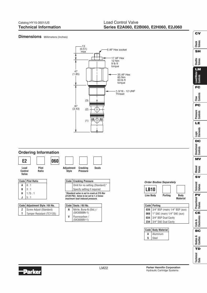
Dimensions Millimeters (Inches)
Ordering Information
AdjustmentStyle
CrackingPressure
Seals
Code Seals / Kit No.
N Nitrile, Buna-N (Std.) /(SK30008N-1)
V Fluorocarbon /(SK30008V-1)
Code Pilot Ratio
A 8 : 1
B 3 : 1
H 1.75 : 1
J 5 : 1
E2
PilotRatio
LoadControlValve
*Standard valve is set to crack at 215 Bar(3120 PSI). Valve to be set to 1.3 timesmaximum load induced pressure.
Code Body Material
A Aluminum
S Steel
Code Porting
039 3/4″ BSP (main) 1/4″ BSP (aux)
069 1″ SAE (main) 1/4″ SAE (aux)
034 3/4″ BSP Dual Cavity
234 3/4″ SAE Dual Cavity
Code Adjustment Style / Kit No.
Z Screw Adjust (Standard)
T Tamper Resistant (TC1125)
060
Code Cracking Pressure
Omit for no setting (Standard)*
Specify setting if required
BodyMaterial
PortingLine Body
LB10
Order Bodies Separately
13(0.51)max
47(1.85)
87(3.43)
5 AF Hex socket
35 AF Hex85 Nm63 lb fttorque
17 AF Hex12 Nm9 lb fttorque
1-3/16 - 12 UNFThread
(1)
(3)
(2)