Embed Size (px)
Citation preview
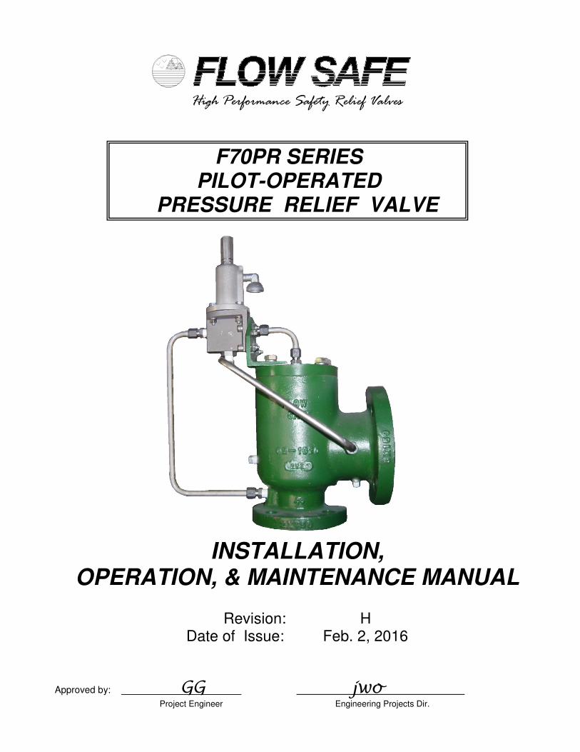
High Performance Safety Relief Valves
F70PR SERIES
PILOT-OPERATED
PRESSURE RELIEF VALVE
INSTALLATION,
OPERATION, & MAINTENANCE MANUAL
Revision: H Date of Issue: Feb. 2, 2016
Approved by: GG jwo Project Engineer Engineering Projects Dir.
INSTALLATION, OPERATION, & MAINTENANCE MANUAL TITLE: F70PR Series Rev. H Pilot-Operated Pressure Relief Valve Page 2 of 22
TABLE OF CONTENTS
Topic Page 1.0 General ................................................................................................ 3 2.0 Description, Operation, Service Envelope, Installation, & Startup 2.1 Description / Operation ........................................................................ 4 2.2 Service Envelope ................................................................................. 5 2.3 Installation ............................................................................................ 5 2.4 Set Pressure Considerations for Backpressure ................................... 6 2.5 Startup ................................................................................................. 6 3.0 Main Valve Maintenance 3.1 Disassembly of the F70PR Series Main Valve ..................................... 7 3.2 Reassembly of the F70PR Series Main Valve ..................................... 10 4.0 Pilot Valve Maintenance 4.1 F100 Pilot Valve (High pressure: 5 – 285 psig) ................................... 11 4.2 F100 Pilot Valve (Low pressure: 10” wc – 4.9 psig) ............................ 13 5.0 Pilot Valve Set Pressure Adjustment .................................................... 15 6.0 Main Valve and Inservice Testing 6.1 Testing of the Main Valve Subassembly .............................................. 16 6.2 Final Assembly Testing ........................................................................ 17 6.3 Inservice Testing with the Field Test Connection ................................. 18 7.0 Troubleshooting Guide .......................................... .............................. 20 8.0 Softgoods Kits 8.1 Main Valve Softgoods .......................................................................... 21 8.2 Pilot Valve Softgoods .......................................... ................................ 22
INSTALLATION, OPERATION, & MAINTENANCE MANUAL TITLE: F70PR Series Rev. H Pilot-Operated Pressure Relief Valve Page 3 of 22
1.0 GENERAL
1) This manual is intended to provide users with direction and guidance for the maintenance of FLOW SAFE F70PR Series safety relief valves. This manual indicates the proper method of valve disassembly, soft goods replacement, and valve reassembly. FLOW SAFE provides this manual as a guideline and reference only. It is not intended to serve as a training manual or manufacturing guide. FLOW SAFE assumes no responsibility for personal or property damage that may occur in conjunction with this manual.
2) FLOW SAFE recommends that all valves be placed on a regular maintenance schedule that
includes the routine replacement of softgoods. FLOW SAFE recommends softgoods replacement every three years but cautions that each customer make their own determination and set their own schedule based upon use and environment. FLOW SAFE believes that when maintenance and reassembly is performed as outlined in this manual there is no safety hazard.
Cycling the valve at least once a year is considered to be good practice to verify operation.
3) When a new valve leaves FLOW SAFE, it has been manufactured and tested by trained and
experienced personnel. When you remove a valve from your system and perform the maintenance tasks that are outlined herein you will need proper training.
Do not attempt to accomplish these tasks without adequate training and understanding of the valve
operation.
4) Any and all stated or implied warranties that are in effect during the purchase of a new FLOW SAFE valve are null and void once the valve has been disassembled by someone other than approved FLOW SAFE personnel.
5) It is highly recommended that all instructions herein be read in full prior to any assembly,
disassembly, or operation of this equipment.
6) The noted manufacturer’s standard lubricants should be used only if compatible with process fluid and application.
7) Specific design details described in this document are subject to change without notice. 8) Should the need arise for general assistance, contact the FLOW SAFE Sales or Service
department at (716) 662-2585 or (800) 828-1036 in Orchard Park NY or (832) 678-2070 in Houston TX. For more detailed technical assistance, contact the FLOW SAFE Engineering department at (716) 662-2585.
INSTALLATION, OPERATION, & MAINTENANCE MANUAL TITLE: F70PR Series Rev. H Pilot-Operated Pressure Relief Valve Page 4 of 22
2.0 DESCRIPTION, OPERATION, SERVICE ENVELOPE, INSTALLATION, and STARTUP
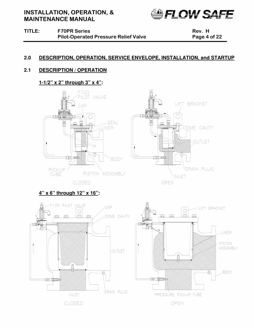
2.1 DESCRIPTION / OPERATION
1-1/2” x 2” through 3” x 4”:
4” x 6” through 12” x 16”:
INSTALLATION, OPERATION, & MAINTENANCE MANUAL TITLE: F70PR Series Rev. H Pilot-Operated Pressure Relief Valve Page 5 of 22
The FLOW SAFE F70PR Series pilot-operated relief valve provides overpressure protection with the ability to handle large volumes and provide consistent, leak-tight seating. This valve series is intended for installations where ASME Code construction is not required. Standard construction of the main valve assembly includes threaded (in the 1-1/2 x 2 size) or ANSI-150 flanged connections rated to 285 psig. The F70PR uses a modulating, flowing pilot valve (Model F100) to control the main valve. System pressure is routed from below the main valve seat through the pilot valve and to the dome cavity of the main valve. At the designated set pressure, the pilot valve vents dome pressure proportionally to demand at set pressure, and allows the piston to lift. Once system pressure is relieved, the pilot valve closes, which allows the dome to repressurize and main valve piston to close. When closed, dome pressure acts on a net positive differential area between the top and bottom of the piston assembly, creating a downward force to seat the piston. The pilot valve is leak-tight to approximately 95% of set pressure.
2.2 SERVICE ENVELOPE
(1) Confirm low-temperature environmental applications with factory. (2) Ratings based on use as low-pressure seat in 1-1/2 x 2, 2 x 3, and 3 x 4 only
2.3 INSTALLATION
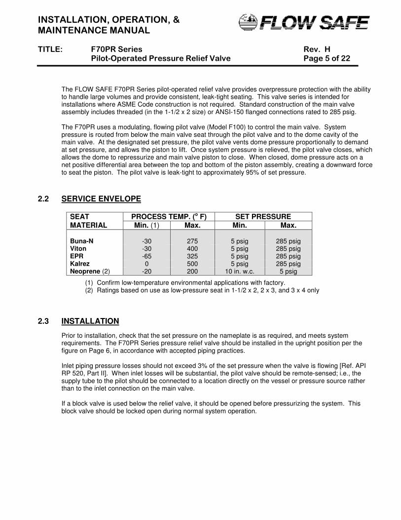
Prior to installation, check that the set pressure on the nameplate is as required, and meets system requirements. The F70PR Series pressure relief valve should be installed in the upright position per the figure on Page 6, in accordance with accepted piping practices.
Inlet piping pressure losses should not exceed 3% of the set pressure when the valve is flowing [Ref. API RP 520, Part II]. When inlet losses will be substantial, the pilot valve should be remote-sensed; i.e., the supply tube to the pilot should be connected to a location directly on the vessel or pressure source rather than to the inlet connection on the main valve.
If a block valve is used below the relief valve, it should be opened before pressurizing the system. This
block valve should be locked open during normal system operation.
SEAT PROCESS TEMP. (o F) SET PRESSURE MATERIAL Min. (1) Max. Min. Max. Buna-N
-30
275
5 psig
285 psig
Viton -30 400 5 psig 285 psig EPR -65 325 5 psig 285 psig Kalrez 0 500 5 psig 285 psig Neoprene (2) -20 200 10 in. w.c. 5 psig
INSTALLATION, OPERATION, & MAINTENANCE MANUAL TITLE: F70PR Series Rev. H Pilot-Operated Pressure Relief Valve Page 6 of 22
2.4 SET PRESSURE CONSIDERATIONS FOR BACK PRESSURE
The F70PR is slightly unbalanced against backpressure. Backpressure will cause a slight reduction in set pressure. If greater than system pressure, backpressure will open the main valve piston unless a backflow preventer is used in the assembly. Contact FLOW SAFE Engineering for specifics about set pressure reduction as a result of backpressure.
2.5 STARTUP
Foreign particles or dirt can damage the valve and make it inoperative. Prior to installation, clean out the piping thoroughly. If the valve is not installed immediately, inlet and outlet connections should be protected and covered.
Pressure can be applied to the valve as system pressure increases, or by slowly opening the block valve (if there is one) after the system has attained operating pressure. Pressure will flow through the pilot valve into the dome cavity of the main valve and seat the piston. The valve may briefly vent to the exhaust before the dome is fully pressurized. Verify that the valve seat is leak-tight, in accordance with Section 6.1.
The valve is now ready for service. Inspection and maintenance should be performed on a regular basis, typically once a year, depending on the service conditions.
INSTALLATION, OPERATION, & MAINTENANCE MANUAL TITLE: F70PR Series Rev. H Pilot-Operated Pressure Relief Valve Page 7 of 22
3.0 MAIN VALVE MAINTENANCE 3.1 DISASSEMBLY OF THE F70PR SERIES MAIN VALVE (See illustrations on Pages 8 and 9.)
CAUTION: It is extremely dangerous to attempt to disassemble any valve while it remains in service with incoming line pressure.
1) Remove the valve from service, or safely block the incoming pressure before disassembling the
valve and performing maintenance. 2) If necessary, remove the pilot valve and interconnecting tubing. See Section 4.0 for pilot valve
maintenance. 3) Remove the bolts and lockwashers and any lifting lugs to remove the cap. 4) With the cap removed, remove the top liner seal. If the valve is a low pressure 1-1/2 x 2, 2 x 3, or
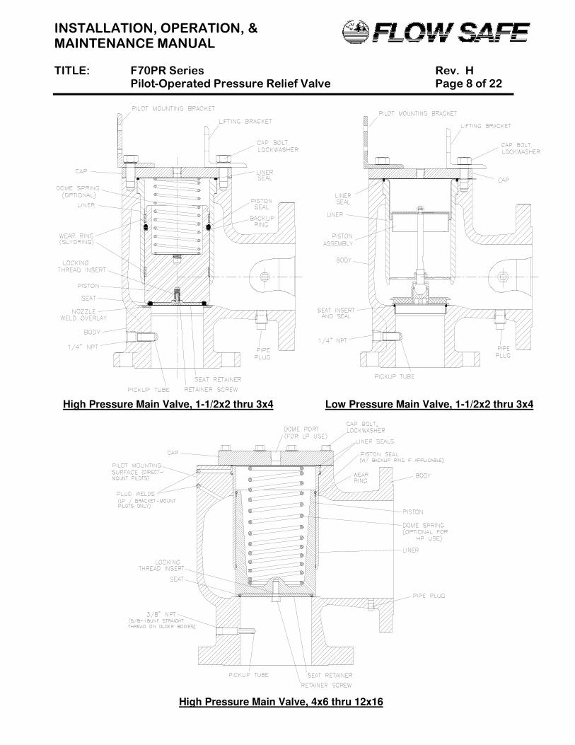
3 x 4, the rolling diaphragm must be carefully lifted up. 5) Carefully reach into the valve and remove the piston assembly. Larger pistons may have an
interior threaded hole into which a cap bolt can be inserted to use for lifting. In high pressure assemblies, do not be alarmed if the liner comes out with the piston assembly. Care must be taken during this removal because any damage might result in an eventual sealing problem when the valve is reassembled.
6) The liner may then be removed; again, care must be taken not to damage the liner. Do not attempt to pry or force the liner out as you may score the surface and cause a sealing problem. Note that on valves 4” x 6” and larger, there is a second liner O-ring seal in the main valve counterbore where the liner is supported.
7) To remove the piston seat, remove the retainer bolt/screw, for the high pressure version, and retainer. The low pressure retainer is threaded and needs to be unscrewed.
8) If the low pressure seat insert is damaged, unscrew it and remove the accompanying seal from the main valve body.
9) As required, install new main valve softgoods per the instructions in Section 3.2. Replacement soft goods are listed in Section 8.0 of this manual.
INSTALLATION, OPERATION, & MAINTENANCE MANUAL TITLE: F70PR Series Rev. H Pilot-Operated Pressure Relief Valve Page 8 of 22
High Pressure Main Valve, 1-1/2x2 thru 3x4 Low Pressure Main Valve, 1-1/2x2 thru 3x4
High Pressure Main Valve, 4x6 thru 12x16
INSTALLATION, OPERATION, & MAINTENANCE MANUAL TITLE: F70PR Series Rev. H Pilot-Operated Pressure Relief Valve Page 9 of 22
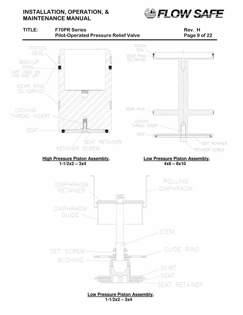
High Pressure Piston Assembly, Low Pressure Piston Assembly, 1-1/2x2 – 3x4 4x6 – 8x10
Low Pressure Piston Assembly, 1-1/2x2 – 3x4

INSTALLATION, OPERATION, & MAINTENANCE MANUAL TITLE: F70PR Series Rev. H Pilot-Operated Pressure Relief Valve Page 10 of 22
3.2 REASSEMBLY OF THE F70PR SERIES MAIN VALVE
1) Reassembly of these valves is basically the reverse of disassembly. Care must be taken in the handling of all items, particularly sealing surfaces and softgoods. All parts should be clean and free of any debris or contaminants.
2) Reinstall the liner and liner seals into the body. Do not nick or excessively stretch the liner seal O-rings. The bottom O-ring (for 4 x 6 and larger) may be carefully set in its sealing area in the body before the liner is inserted, or it may be fitted onto the liner and, if necessary, held in place with a suitable lubricant (e.g., Dow Corning Molykote 33). The top liner seal should be lightly pressed into place in its groove, such that it is evenly spread around the liner circumference and will not be pinched when reinstalling the valve cap.
3) Insert the main seat into the bottom of the piston, using care to position the seat completely within the piston O-ring groove. NOTE that any scratches, gouges, or particles on the seat may result in a sealing problem. Carefully position the retainer plate over the seat. For high pressure pistons, insert the retainer bolt and tighten firmly [NOTE: Female thread in piston must have locking thread insert. For low pressure pistons, the retainer is threaded and needs to be tightened.
4) Install the piston seal and backup ring, or rolling diaphragm, as applicable. A light lubricant may be applied to the O-ring.
5) Fit the wear rings in their proper groove around the piston assembly. While holding the wear rings (especially the free ends) in place, lower the piston assembly into the liner. The piston should move freely up and down, with slight resistance from the seal and wear rings. It is critically important that this installation result in even seating of the soft seat onto the nozzle lip in the valve body.
6) After checking placement of the top liner seal [see Step (2)] and low pressure rolling diaphragm, if applicable, the valve cap can be positioned on top of the body.
7) The cap bolts, with washers, can then be reinserted. Apply anti-seize compound to bolt threads. The following torque values are recommended:
Main Valve Size Cap Bolt Size Torque (ft-lbs) 1-1/2x2 1/4-20UNC 4 - 5 2x3, 3x4 1/2-13UNC 50 4x6 1/2-13UNC * 50 6x8 **, 8x10, 10x12, 12x16 3/4-10UNC * 120 * UNF thread on older valves ** 5/8-18UNF on older valves
8) If removed previously, reinstall the pilot valve and tubing. The pilot mounting bolts should be
treated with Loctite or Vibra-tite, if available, and firmly tightened. 9) The main valve is now completely assembled, and should be tested per Section 6.0 before being
returned to service.
INSTALLATION, OPERATION, & MAINTENANCE MANUAL TITLE: F70PR Series Rev. H Pilot-Operated Pressure Relief Valve Page 11 of 22
4.0 PILOT VALVE MAINTENANCE 4.1 F100 PILOT VALVE (HIGH PRESSURE: 5 – 285 psig) (See Illustration on Page 12)
A. Disassembly
CAUTION: It is extremely dangerous to attempt to disassemble any valve while it remains in service with incoming line pressure.
1) Remove the pilot valve from the main valve, or safely block the incoming pressure before
disassembling the valve and performing maintenance. 2) Unscrew the pressure adjustment (PA) screw cap from the PA screw. Loosen the lock nut. 3) Loosen but do not remove the PA screw from the bonnet. 4) Using a 7/16” wrench, remove the bolts, nuts, and lockwashers that hold the valve body and
bonnet in place. Separate the bonnet from the body. Remove spring and two spring washers. 5) With a 9/16” wrench on the diaphragm lock nut and screwdriver in the top of the spindle, loosen the
lock nut from the spindle. 6) Remove inner/outer spacer(s) from the top of the valve body. Remove the diaphragm from the
spindle by unscrewing it counterclockwise. 7) Turn the pilot valve body over and, using a 7/8” wrench, remove the nozzle and spindle. Unscrew
retainer screw from spindle. Remove the retainer and seat. 8) Replacement soft goods are listed in Section 8.0 of this manual.
B. Assembly
NOTE: Exercise care in handling softgoods, nozzles, and other sealing surfaces.
1) Confirm pressure setting and associated parts required per Section 5.0. 2) Place the valve body in a vise. 3) Apply Loctite to retainer screw and use it to attach seat and retainer to spindle. Insert spindle into
the body. Lightly lubricate nozzle O-ring with Dow Corning Molykote 33 or equal, fit over nozzle, and then tighten nozzle into body with nozzle seal. Check that there is vertical movement of spindle assembly (0.030" minimum). With spindle in down position, check that the spindle shoulder is within +0.010” / -0.005” of top surface of body.
4) Carefully assemble the diaphragm to the top of the spindle by slowly turning the diaphragm clockwise on the spindle threads until it bottoms on the shoulder. Make sure that there are no tears or rips in the diaphragm material.
5) Assemble the spacer(s) and lock nut to the spindle. With a wrench on the nut, and a screwdriver in the top of the spindle, tighten the parts together. Apply a small drop of Loctite to the nut threads. Make sure that the spacer is centered to the extent possible.
6) Assemble the spring and spring washers atop the spindle. 7) Assemble the bonnet over the spring / washers onto the top of the diaphragm / body. NOTE: The
gasket (shown in drawing) is only needed with the Teflon/FEP diaphragm and is installed above the diaphragm; use of the gasket with a Buna-N or Viton diaphragm may result in leakage.
8) Insert bolts through the four holes in bonnet and body. Older cast bodies will have thru-holes; nuts and washers will also be used.
9) Tighten the bolts to a torque of 5 - 6 ft-lbs. 10) Insert the PA screw into the top of the bonnet and install the lock nut. A PA screw seal is
recommended for weather-tightness. 11) Attach PA screw cap to top of PA screw, but do not tighten. 12) Check to make sure the screen is present in the INLET port. 13) Attach the bug screen to the bonnet, if necessary, so that it is facing downwards. 14) The pilot valve is now completely assembled and ready to be set per Section 5.0.
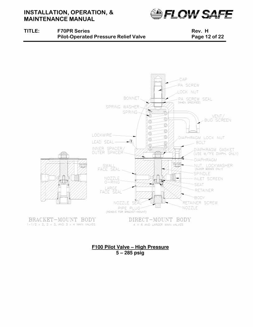
INSTALLATION, OPERATION, & MAINTENANCE MANUAL TITLE: F70PR Series Rev. H Pilot-Operated Pressure Relief Valve Page 12 of 22
F100 Pilot Valve – High Pressure 5 – 285 psig
INSTALLATION, OPERATION, & MAINTENANCE MANUAL TITLE: F70PR Series Rev. H Pilot-Operated Pressure Relief Valve Page 13 of 22
4.2 F100 PILOT VALVE (LOW PRESSURE: 10” wc to 4.9 psig) (See Illustration on Page 14)
A. Disassembly
CAUTION: It is extremely dangerous to attempt to disassemble any valve while it remains in service with incoming line pressure.
1) Remove the pilot valve from the main valve, or safely block the incoming pressure before
disassembling the valve and performing maintenance. 2) Unscrew the pressure adjustment (PA) screw cap from the PA screw. Loosen the lock nut. 3) Loosen but do not remove the PA screw from the bonnet. 4) Using a 7/16” wrench, remove the bolting that holds the two halves of the diaphragm housing in
place. With the housing separated, the spring, two spring washers, diaphragm, support plate, and top of the spindle will be accessible.
5) With a 9/16” wrench on the diaphragm lock nut and screwdriver in the top of the spindle, loosen the lock nut and remove it from the spindle.
6) Remove support plate from the top of the spindle. Remove the diaphragm from the spindle by unscrewing it counterclockwise.
7) Turn the pilot valve body over and, using a 7/8” wrench, remove the nozzle and spindle. Unscrew the retainer screw from the spindle. Remove the retainer and seat.
8) Replacement soft goods are listed in Section 8.0 of this manual. B. Assembly
NOTE: Exercise care in handling softgoods, nozzles, and other sealing surfaces.
1) Confirm pressure setting and associated parts required per Section 5.0. 2) Place the valve body in a vise. 3) Apply Loctite to retainer screw and use it to attach seat and retainer to spindle. Insert spindle into
the body. Lightly lubricate nozzle O-ring with Dow Corning Molykote 33 or equal, fit over nozzle, and then tighten nozzle into body with nozzle seal. Check that there is vertical movement of the spindle assembly (0.030" minimum).
4) Carefully assemble the diaphragm to the top of the spindle by slowly turning the diaphragm clockwise on the spindle threads until it bottoms on the shoulder. Make sure that there are no tears or rips in the diaphragm material.
5) Assemble support plate and diaphragm lock nut to spindle. Apply a small amount of Loctite to nut threads. With a wrench on the nut, and a screwdriver in top of spindle, tighten the parts together.
6) Assemble the spring and spring washers atop the spindle. 7) Assemble the bonnet and upper diaphragm housing over the spring / washers onto the top of the
diaphragm / body. For Teflon diaphragms only, use a diaphragm gasket on top of diaphragm. If the bonnet had previously been separated from the upper diaphragm housing, reassemble those two parts with upper housing gasket before joining the two halves of the housing. For weather-tightness, Permatex sealant (or equal) should be applied to the bonnet bolt threads.
8) Insert bolts through the 15 sets of holes in the diaphragm housing halves, fasten washers and nuts, and tighten to a torque of 5 - 6 ft-lbs. Be careful not to damage the diaphragm during this procedure.
9) Insert the PA screw into the top of the bonnet and install the lock nut. A PA screw seal is recommended for weather-tightness.
10) Attach PA screw cap to top of PA screw, but do not tighten. 11) Check to make sure the screen is present in the INLET port. 12) Attach the bug screen to the bonnet, if necessary, so that it is facing downwards. 13) The pilot valve is now completely assembled and ready to be set per Section 5.0.
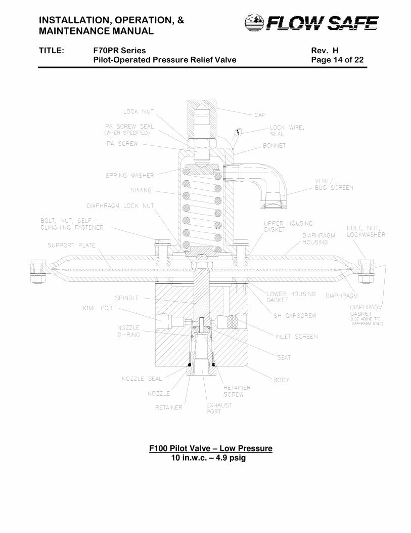
INSTALLATION, OPERATION, & MAINTENANCE MANUAL TITLE: F70PR Series Rev. H Pilot-Operated Pressure Relief Valve Page 14 of 22
F100 Pilot Valve – Low Pressure 10 in.w.c. – 4.9 psig
INSTALLATION, OPERATION, & MAINTENANCE MANUAL TITLE: F70PR Series Rev. H Pilot-Operated Pressure Relief Valve Page 15 of 22
5.0 PILOT VALVE SET PRESSURE ADJUSTMENT
1) The set pressure for the F100 pilot valve may be adjusted as follows: a) For the high pressure pilot, by turning the pressure adjusting screw, or changing spring or
outer/inner spacer combinations. b) For the low pressure pilot, by turning the pressure adjusting screw or changing spring only. c) All pilots may be adjusted + 3% beyond the nameplate setting, not to exceed service ratings
listed in Section 2.2. This is a flowing, modulating pilot valve. 2) Contact FLOW SAFE for assistance with replacement springs and spacers. Once the proper parts
have been selected, the valve can be reassembled per Section 4.1 or 4.2. 3) If possible, set pressure adjustments should be made with the pilot valve removed from the main
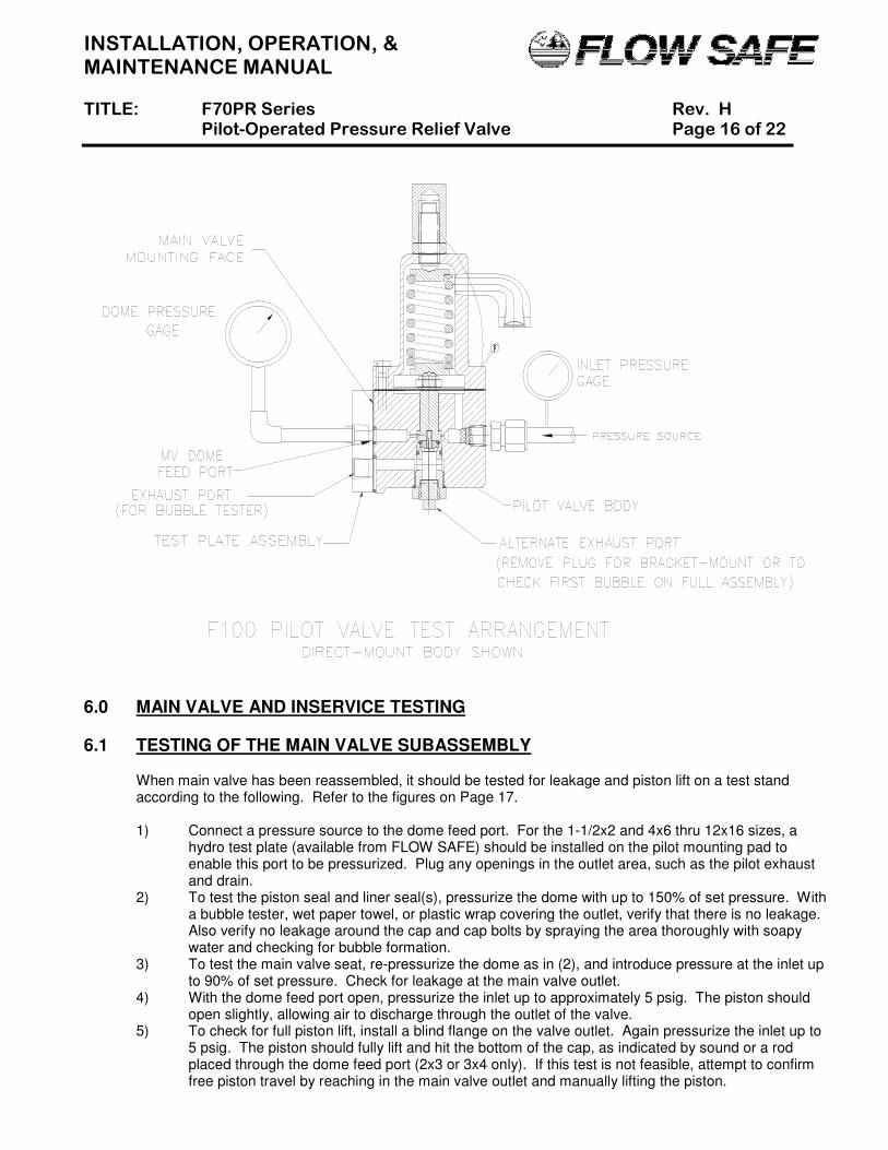
valve and connected to a test plate assembly (available from FLOW SAFE), as shown at the top of Page 16. The pressure adjustment is made by turning the pressure adjusting screw clockwise (in) to increase set pressure and counter-clockwise (out) to decrease set pressure.
4) Slowly increase inlet pressure to set point, which normally occurs when pilot exhaust is first detected at the exhaust port shown in the figure. The valve may also have been specified for main piston opening to correspond with set pressure. Before set point is reached, dome pressure and inlet pressure should increase at approximately the same rate. Tighten down the pressure adjustment screw lock nut.
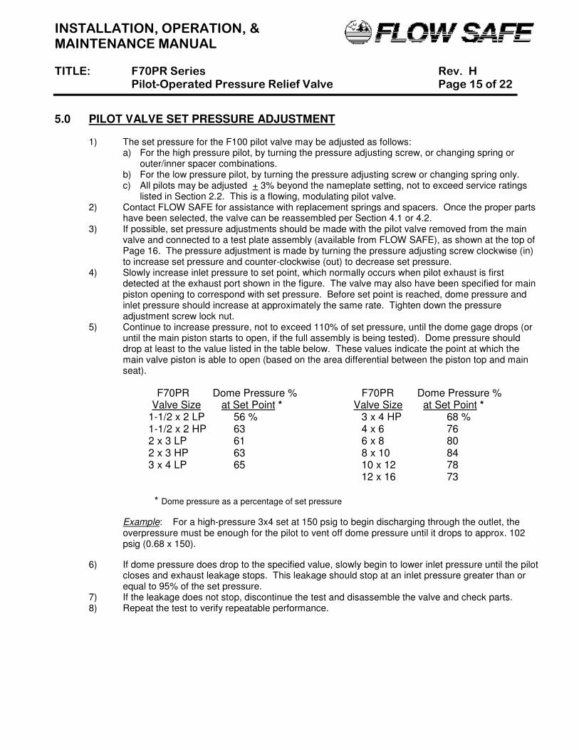
5) Continue to increase pressure, not to exceed 110% of set pressure, until the dome gage drops (or until the main piston starts to open, if the full assembly is being tested). Dome pressure should drop at least to the value listed in the table below. These values indicate the point at which the main valve piston is able to open (based on the area differential between the piston top and main seat).
F70PR Dome Pressure % F70PR Dome Pressure % Valve Size at Set Point * Valve Size at Set Point *
1-1/2 x 2 LP 56 % 3 x 4 HP 68 %
1-1/2 x 2 HP 63 4 x 6 76 2 x 3 LP 61 6 x 8 80 2 x 3 HP 63 8 x 10 84 3 x 4 LP 65 10 x 12 78 12 x 16 73 * Dome pressure as a percentage of set pressure
Example: For a high-pressure 3x4 set at 150 psig to begin discharging through the outlet, the overpressure must be enough for the pilot to vent off dome pressure until it drops to approx. 102 psig (0.68 x 150).
6) If dome pressure does drop to the specified value, slowly begin to lower inlet pressure until the pilot closes and exhaust leakage stops. This leakage should stop at an inlet pressure greater than or equal to 95% of the set pressure.
7) If the leakage does not stop, discontinue the test and disassemble the valve and check parts. 8) Repeat the test to verify repeatable performance.
INSTALLATION, OPERATION, & MAINTENANCE MANUAL TITLE: F70PR Series Rev. H Pilot-Operated Pressure Relief Valve Page 16 of 22
6.0 MAIN VALVE AND INSERVICE TESTING 6.1 TESTING OF THE MAIN VALVE SUBASSEMBLY
When main valve has been reassembled, it should be tested for leakage and piston lift on a test stand according to the following. Refer to the figures on Page 17.
1) Connect a pressure source to the dome feed port. For the 1-1/2x2 and 4x6 thru 12x16 sizes, a
hydro test plate (available from FLOW SAFE) should be installed on the pilot mounting pad to enable this port to be pressurized. Plug any openings in the outlet area, such as the pilot exhaust and drain.
2) To test the piston seal and liner seal(s), pressurize the dome with up to 150% of set pressure. With a bubble tester, wet paper towel, or plastic wrap covering the outlet, verify that there is no leakage. Also verify no leakage around the cap and cap bolts by spraying the area thoroughly with soapy water and checking for bubble formation.
3) To test the main valve seat, re-pressurize the dome as in (2), and introduce pressure at the inlet up to 90% of set pressure. Check for leakage at the main valve outlet.
4) With the dome feed port open, pressurize the inlet up to approximately 5 psig. The piston should open slightly, allowing air to discharge through the outlet of the valve.
5) To check for full piston lift, install a blind flange on the valve outlet. Again pressurize the inlet up to 5 psig. The piston should fully lift and hit the bottom of the cap, as indicated by sound or a rod placed through the dome feed port (2x3 or 3x4 only). If this test is not feasible, attempt to confirm free piston travel by reaching in the main valve outlet and manually lifting the piston.
INSTALLATION, OPERATION, & MAINTENANCE MANUAL TITLE: F70PR Series Rev. H Pilot-Operated Pressure Relief Valve Page 17 of 22
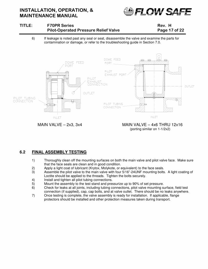
6) If leakage is noted past any seal or seat, disassemble the valve and examine the parts for contamination or damage, or refer to the troubleshooting guide in Section 7.0.
MAIN VALVE – 2x3, 3x4 MAIN VALVE – 4x6 THRU 12x16 (porting similar on 1-1/2x2)
6.2 FINAL ASSEMBLY TESTING
1) Thoroughly clean off the mounting surfaces on both the main valve and pilot valve face. Make sure
that the face seals are clean and in good condition. 2) Apply a light coat of lubricant (Krytox, Molykote, or equivalent) to the face seals. 3) Assemble the pilot valve to the main valve with four 5/16”-24UNF mounting bolts. A light coating of
Loctite should be applied to the threads. Tighten the bolts securely. 4) Install and tighten all pilot tubing connections. 5) Mount the assembly to the test stand and pressurize up to 90% of set pressure. 6) Check for leaks at all joints, including tubing connections, pilot valve mounting surface, field test
connection (if supplied), cap, cap bolts, and at valve outlet. There should be no leaks anywhere. 7) Once testing is complete, the valve assembly is ready for installation. If applicable, flange
protectors should be installed and other protection measures taken during transport.
INSTALLATION, OPERATION, & MAINTENANCE MANUAL TITLE: F70PR Series Rev. H Pilot-Operated Pressure Relief Valve Page 18 of 22
6.3 INSERVICE TESTING WITH THE FIELD TEST CONNECTION (FTC)
CAUTION: Extreme care must be taken when testing or servicing a pressure relief valve used in
gas or incompressible fluid service. The service medium may be volatile and under high pressure.
A. General
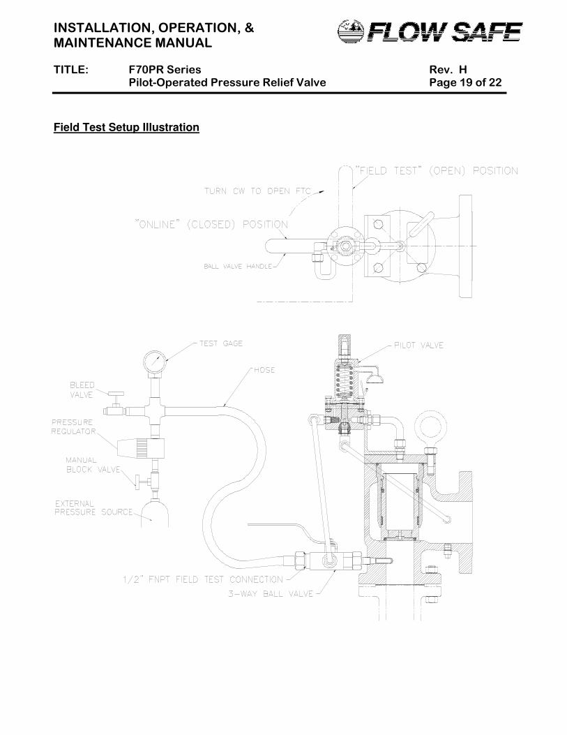
The FTC employs a three-way ball valve to allow the user to verify set pressure and reseat pressure with the pressure relief valve in service. An external pressure source is attached to the FTC to direct pressure to the pilot valve, while blocking off system pressure to the pilot valve. In the “closed” (“online”) position, the FTC valve is set for normal valve operation with inlet pressure routed through pilot valve inlet tubing. In the “open” position, system pressure at the main valve inlet is blocked, and pressure from an external source will be routed to the pilot.
B. Test Procedure
1) Unplug the open ½” female NPT port of the FTC ball valve, and connect pressure source. 2) Attach the test equipment to the FTC, as shown on Page 19. If an extra threaded connection to the
main valve cap is available, a dome pressure gage may be used to help monitor pilot response as described in Section 5.0.
3) Close the bleed valve. Slowly open the block valve at the remote pressure source. 4) Adjust the pressure regulator so that the pressure on the test gage is slightly greater than system
pressure but less than nameplate set pressure. 5) Remove any locking device or safety wire from the FTC handle, and open the valve by rotating the
handle 90o clockwise. The external pressure source will now control operation of the pilot.
CAUTION: Performance of Step (6) may cause the main valve to open, unless inlet pressure is
closed off by a block valve or the system is depressurized. If it is not desirable to have the main valve open with a pressurized system, start reducing test gas pressure per Step (7) as soon as pilot exhaust is heard.
6) Continue to increase the external pressure until the set pressure is reached, at which point pilot
exhaust should be heard. Continued exhausting of the pilot valve at or above set pressure will cause the main valve to open if system pressure is present at the inlet. If using a dome gage, refer to Step (5) in Section 5.0 for dome pressure percentages of inlet pressure that allow main piston movement.
7) Slowly open the bleed valve and decrease pressure to the pilot until the main valve closes, if applicable, and pilot exhaust stops. Pilot exhaust should stop completely at an inlet pressure greater than or equal to 95% of set pressure.
NOTE: Dome pressure will start to increase back to test gage pressure as soon as test pressure
drops below set pressure.
8) To safely remove the test equipment, keep the bleed valve open and close the block valve to the external pressure source. Close the FTC valve.
9) Replace the safety wire or other locking device on the FTC valve handle so that it cannot be accidentally moved during normal operation.
INSTALLATION, OPERATION, & MAINTENANCE MANUAL TITLE: F70PR Series Rev. H Pilot-Operated Pressure Relief Valve Page 19 of 22
Field Test Setup Illustration
INSTALLATION, OPERATION, & MAINTENANCE MANUAL TITLE: F70PR Series Rev. H Pilot-Operated Pressure Relief Valve Page 20 of 22
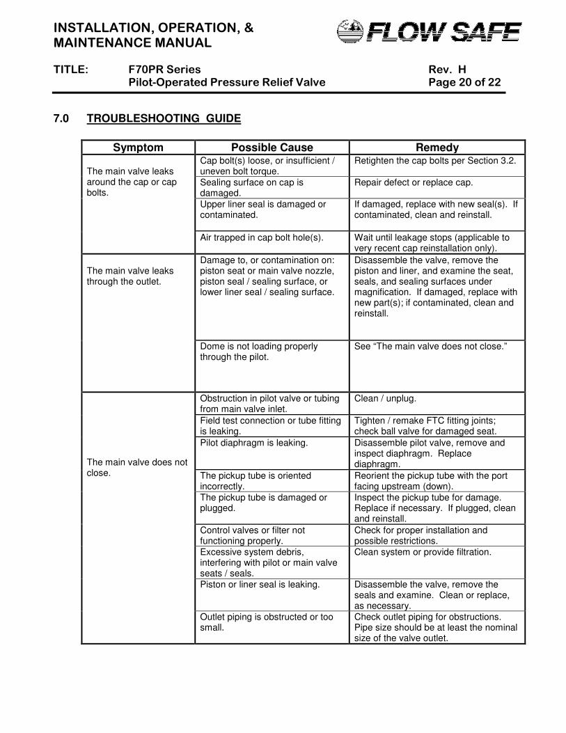
7.0 TROUBLESHOOTING GUIDE
Symptom Possible Cause Remedy
The main valve leaks around the cap or cap bolts.
Cap bolt(s) loose, or insufficient / uneven bolt torque.
Retighten the cap bolts per Section 3.2.
Sealing surface on cap is damaged.
Repair defect or replace cap.
Upper liner seal is damaged or contaminated.
If damaged, replace with new seal(s). If contaminated, clean and reinstall.
Air trapped in cap bolt hole(s).
Wait until leakage stops (applicable to very recent cap reinstallation only).
The main valve leaks through the outlet.
Damage to, or contamination on: piston seat or main valve nozzle, piston seal / sealing surface, or lower liner seal / sealing surface.
Disassemble the valve, remove the piston and liner, and examine the seat, seals, and sealing surfaces under magnification. If damaged, replace with new part(s); if contaminated, clean and reinstall.
Dome is not loading properly through the pilot.
See “The main valve does not close.”
The main valve does not close.
Obstruction in pilot valve or tubing from main valve inlet.
Clean / unplug.
Field test connection or tube fitting is leaking.
Tighten / remake FTC fitting joints; check ball valve for damaged seat.
Pilot diaphragm is leaking. Disassemble pilot valve, remove and inspect diaphragm. Replace diaphragm.
The pickup tube is oriented incorrectly.
Reorient the pickup tube with the port facing upstream (down).
The pickup tube is damaged or plugged.
Inspect the pickup tube for damage. Replace if necessary. If plugged, clean and reinstall.
Control valves or filter not functioning properly.
Check for proper installation and possible restrictions.
Excessive system debris, interfering with pilot or main valve seats / seals.
Clean system or provide filtration.
Piston or liner seal is leaking. Disassemble the valve, remove the seals and examine. Clean or replace, as necessary.
Outlet piping is obstructed or too small.
Check outlet piping for obstructions. Pipe size should be at least the nominal size of the valve outlet.
INSTALLATION, OPERATION, & MAINTENANCE MANUAL TITLE: F70PR Series Rev. H Pilot-Operated Pressure Relief Valve Page 21 of 22
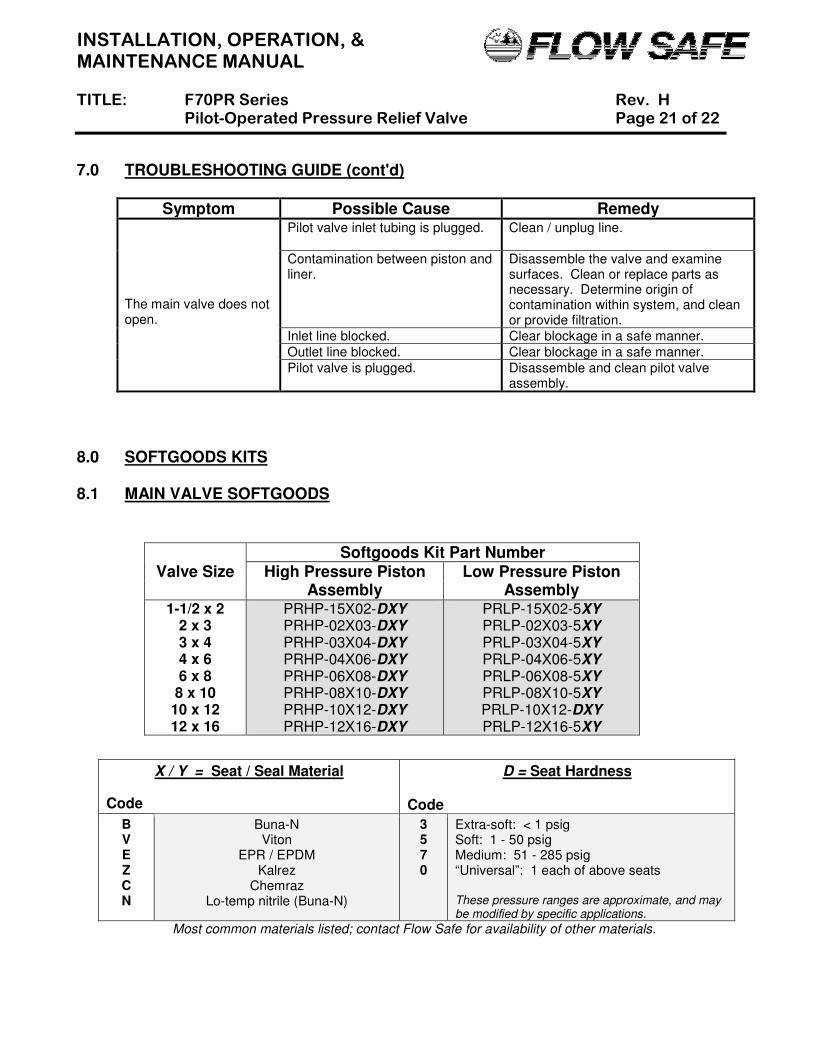
7.0 TROUBLESHOOTING GUIDE (cont'd)
Symptom Possible Cause Remedy The main valve does not open.
Pilot valve inlet tubing is plugged.
Clean / unplug line.
Contamination between piston and liner.
Disassemble the valve and examine surfaces. Clean or replace parts as necessary. Determine origin of contamination within system, and clean or provide filtration.
Inlet line blocked. Clear blockage in a safe manner.
Outlet line blocked. Clear blockage in a safe manner.
Pilot valve is plugged.
Disassemble and clean pilot valve assembly.
8.0 SOFTGOODS KITS 8.1 MAIN VALVE SOFTGOODS
Softgoods Kit Part Number
Valve Size High Pressure Piston Assembly
Low Pressure Piston Assembly
1-1/2 x 2 2 x 3 3 x 4 4 x 6 6 x 8 8 x 10
10 x 12 12 x 16
PRHP-15X02-DXY PRHP-02X03-DXY
PRHP-03X04-DXY PRHP-04X06-DXY
PRHP-06X08-DXY PRHP-08X10-DXY PRHP-10X12-DXY
PRHP-12X16-DXY
PRLP-15X02-5XY PRLP-02X03-5XY
PRLP-03X04-5XY PRLP-04X06-5XY
PRLP-06X08-5XY PRLP-08X10-5XY PRLP-10X12-DXY
PRLP-12X16-5XY
Most common materials listed; contact Flow Safe for availability of other materials.
X / Y = Seat / Seal Material
Code
D = Seat Hardness
Code
B V E Z C N
Buna-N Viton
EPR / EPDM Kalrez
Chemraz Lo-temp nitrile (Buna-N)
3 5 7 0
Extra-soft: < 1 psig Soft: 1 - 50 psig Medium: 51 - 285 psig “Universal”: 1 each of above seats These pressure ranges are approximate, and may be modified by specific applications.
INSTALLATION, OPERATION, & MAINTENANCE MANUAL TITLE: F70PR Series Rev. H Pilot-Operated Pressure Relief Valve Page 22 of 22
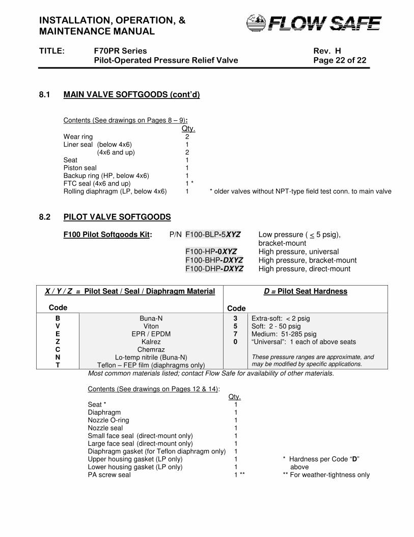
8.1 MAIN VALVE SOFTGOODS (cont’d) Contents (See drawings on Pages 8 – 9):
Qty. Wear ring 2 Liner seal (below 4x6) 1 (4x6 and up) 2 Seat 1 Piston seal 1 Backup ring (HP, below 4x6) 1 FTC seal (4x6 and up) 1 * Rolling diaphragm (LP, below 4x6) 1 * older valves without NPT-type field test conn. to main valve
8.2 PILOT VALVE SOFTGOODS F100 Pilot Softgoods Kit: P/N F100-BLP-5XYZ Low pressure ( < 5 psig), bracket-mount F100-HP-0XYZ High pressure, universal F100-BHP-DXYZ High pressure, bracket-mount F100-DHP-DXYZ High pressure, direct-mount
Most common materials listed; contact Flow Safe for availability of other materials.
Contents (See drawings on Pages 12 & 14): Qty.
Seat * 1 Diaphragm 1
Nozzle O-ring 1 Nozzle seal 1 Small face seal (direct-mount only) 1 Large face seal (direct-mount only) 1 Diaphragm gasket (for Teflon diaphragm only) 1 Upper housing gasket (LP only) 1 * Hardness per Code “D” Lower housing gasket (LP only) 1 above PA screw seal 1 ** ** For weather-tightness only
X / Y / Z = Pilot Seat / Seal / Diaphragm Material
Code
D = Pilot Seat Hardness Code
B V E Z C N T
Buna-N Viton
EPR / EPDM Kalrez
Chemraz Lo-temp nitrile (Buna-N)
Teflon – FEP film (diaphragms only)
3 5 7 0
Extra-soft: < 2 psig Soft: 2 - 50 psig Medium: 51-285 psig “Universal”: 1 each of above seats These pressure ranges are approximate, and may be modified by specific applications.