Embed Size (px)
Citation preview
Pressure Relief Reaction Forces – The Importance of
Evaluating Existing Installations
John Burgess | Smith & Burgess
Agenda
• Installation Details – Inlet Piping Design – Piping Support – Administrative Controls
• Atmospheric Discharge – Dispersion Consideration – Liquids – Review Surrounding
Areas 2
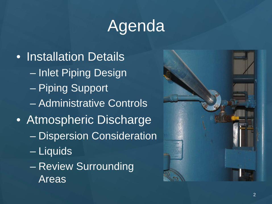
Installation Details Inlet Piping Design – General Good Practices • Limit the inlet line losses to 3%
• Use full bore PSVs sparingly and knowingly • Ensure relief valve accessibility for maintenance • Ensure valves used for PSV isolation are full port
• Consider gate valves instead of ball valves for PSV inlets/outlets
• Audit the CSO/LO procedures • Ensure the outlet piping is free draining • Ensure that the outlet piping is supported • Ensure that the valve is vertical • Ensure that the valve disposition is
• Pointed Up • At least 10’ away from anything
3
Installation Details
4
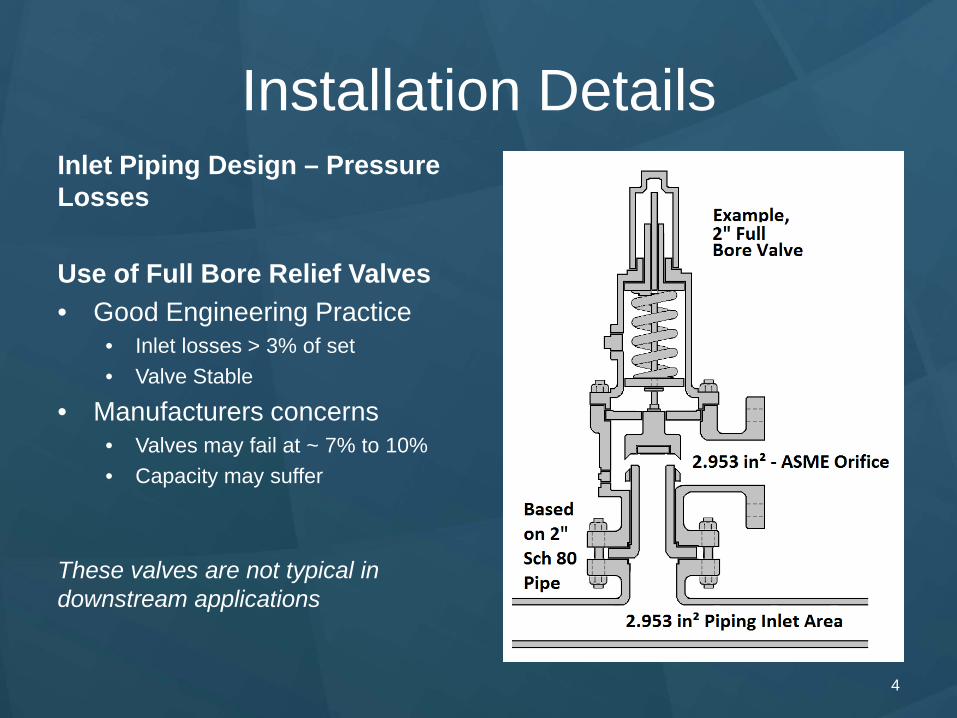
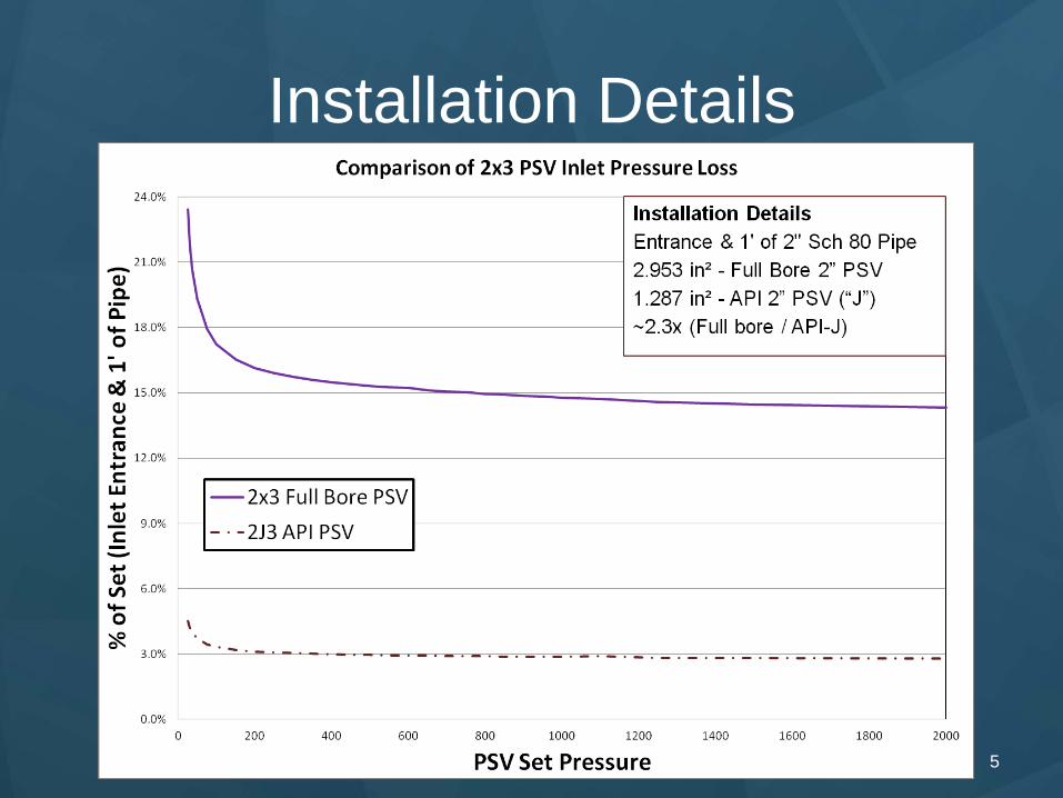
Inlet Piping Design – Pressure Losses
Use of Full Bore Relief Valves • Good Engineering Practice
• Inlet losses > 3% of set • Valve Stable
• Manufacturers concerns • Valves may fail at ~ 7% to 10% • Capacity may suffer
These valves are not typical in downstream applications
Installation Details
5
Installation Details
6
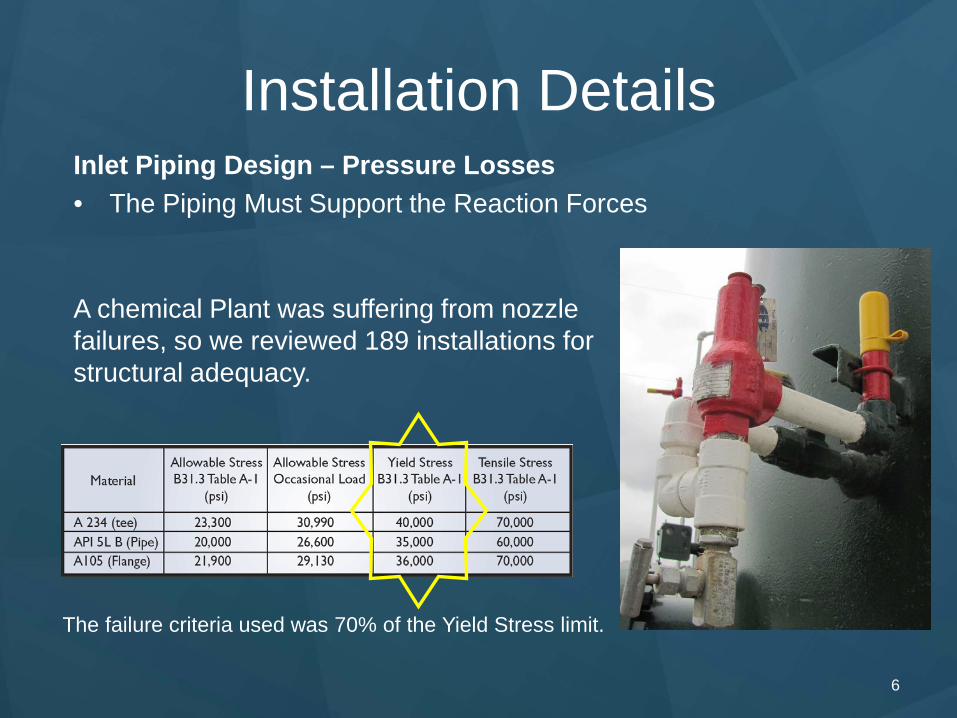
Inlet Piping Design – Pressure Losses • The Piping Must Support the Reaction Forces
A chemical Plant was suffering from nozzle failures, so we reviewed 189 installations for structural adequacy.
The failure criteria used was 70% of the Yield Stress limit.
Installation Details
7
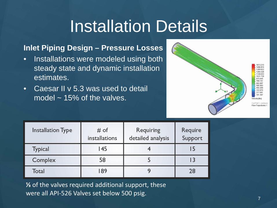
Inlet Piping Design – Pressure Losses • Installations were modeled using both
steady state and dynamic installation estimates.
• Caesar II v 5.3 was used to detail model ~ 15% of the valves.
⅓ of the valves required additional support, these were all API-526 Valves set below 500 psig.
Installation Details
8
Inlet Piping Design – Administrative Controls
• Undersized • In 15 years of doing this work I have never seen an undersized
relief device causing a loss of containment. • Vessel overpressure below hydrotest pressure typical • MIDAS DB Search returns 0 Cases (Around 2000/2001)
• Isolated
• Overpressure potentially limitless • No capacity when isolated • Personal experience / knowledge is ~10 Cases • Seems to be increasing in frequency
Installation Details
9
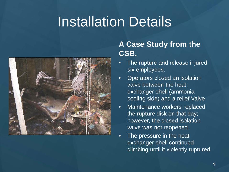
A Case Study from the CSB. • The rupture and release injured
six employees. • Operators closed an isolation
valve between the heat exchanger shell (ammonia cooling side) and a relief Valve
• Maintenance workers replaced the rupture disk on that day; however, the closed isolation valve was not reopened.
• The pressure in the heat exchanger shell continued climbing until it violently ruptured
Atmospheric Discharge
10
General Considerations • Dispersion
• Dispersion characteristics need to be considered • Most liquids should not be discharged to atmosphere
• Review Areas Surrounding Vents
• Thermal Radiation Potential • Noise • Pollution Requirements
Atmospheric Discharge
11
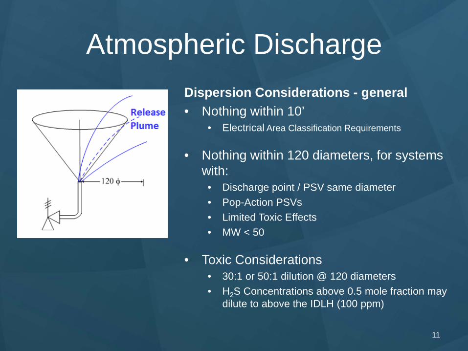
Dispersion Considerations - general • Nothing within 10’
• Electrical Area Classification Requirements
• Nothing within 120 diameters, for systems with:
• Discharge point / PSV same diameter • Pop-Action PSVs • Limited Toxic Effects • MW < 50
• Toxic Considerations • 30:1 or 50:1 dilution @ 120 diameters • H2S Concentrations above 0.5 mole fraction may
dilute to above the IDLH (100 ppm)
Atmospheric Discharge
12
Dispersion Considerations - Details • Dispersion modeling required if the API guidance is not sufficient
• High concentrations of toxics (over 50x the limit) • Heavy gases • Low discharge velocities.
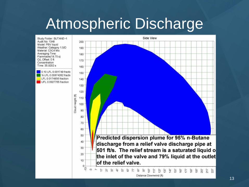
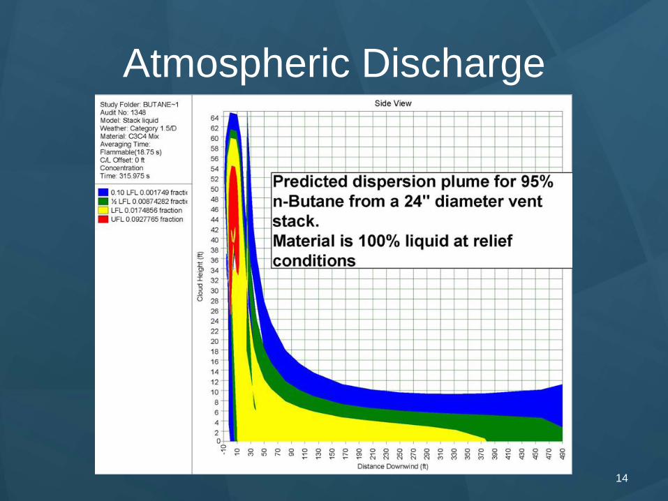
• Next Two Slides show the effects of Exit Velocity • Blue is “Okay”, between 10% and 50% of the LFL • Green “Concerning” between 50% of the LFL and the LFL • Yellow above the LFL and below the UFL
• High velocity discharge toxics may reach grade • ~500:1 dilution • H2S Concentrations above 5% (molar) may exceed IDLH
Atmospheric Discharge
13
Atmospheric Discharge
14
Atmospheric Discharge
15
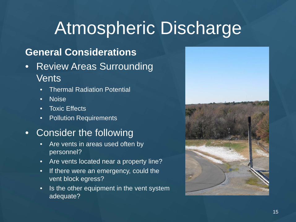
General Considerations • Review Areas Surrounding
Vents • Thermal Radiation Potential • Noise • Toxic Effects • Pollution Requirements
• Consider the following • Are vents in areas used often by
personnel? • Are vents located near a property line? • If there were an emergency, could the
vent block egress? • Is the other equipment in the vent system
adequate?