Embed Size (px)
Citation preview
protected
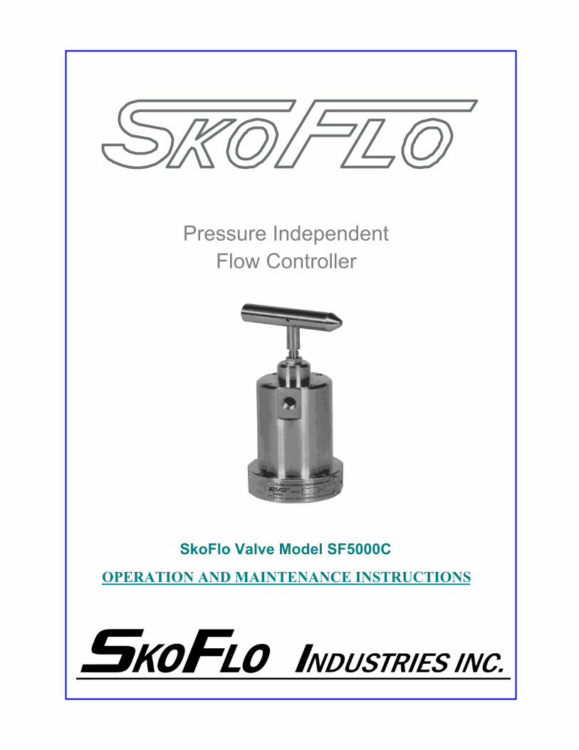
SkoFlo Valve Model SF5000C
OPERATION AND MAINTENANCE INSTRUCTIONS
Pressure IndependentFlow Controller
protected
SkoFlo Valve Model SF5000C
OPERATION AND MAINTENANCE INSTRUCTIONS
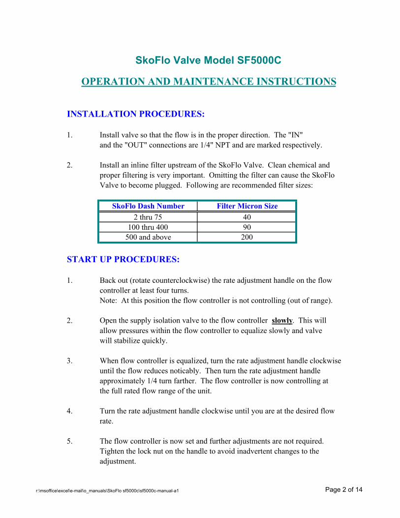
INSTALLATION PROCEDURES:
1. Install valve so that the flow is in the proper direction. The "IN" and the "OUT" connections are 1/4" NPT and are marked respectively.
2. Install an inline filter upstream of the SkoFlo Valve. Clean chemical andproper filtering is very important. Omitting the filter can cause the SkoFlo Valve to become plugged. Following are recommended filter sizes:
SkoFlo Dash Number Filter Micron Size2 thru 75 40
100 thru 400 90500 and above 200
START UP PROCEDURES:
1. Back out (rotate counterclockwise) the rate adjustment handle on the flowcontroller at least four turns.Note: At this position the flow controller is not controlling (out of range).
2. Open the supply isolation valve to the flow controller slowly. This will allow pressures within the flow controller to equalize slowly and valvewill stabilize quickly.
3. When flow controller is equalized, turn the rate adjustment handle clockwiseuntil the flow reduces noticably. Then turn the rate adjustment handleapproximately 1/4 turn farther. The flow controller is now controlling at the full rated flow range of the unit.
4. Turn the rate adjustment handle clockwise until you are at the desired flowrate.
5. The flow controller is now set and further adjustments are not required.Tighten the lock nut on the handle to avoid inadvertent changes to theadjustment.
r:\msoffice\excel\e-mail\o_manuals\SkoFlo sf5000c\sf5000c-manual-a1 Page 2 of 14
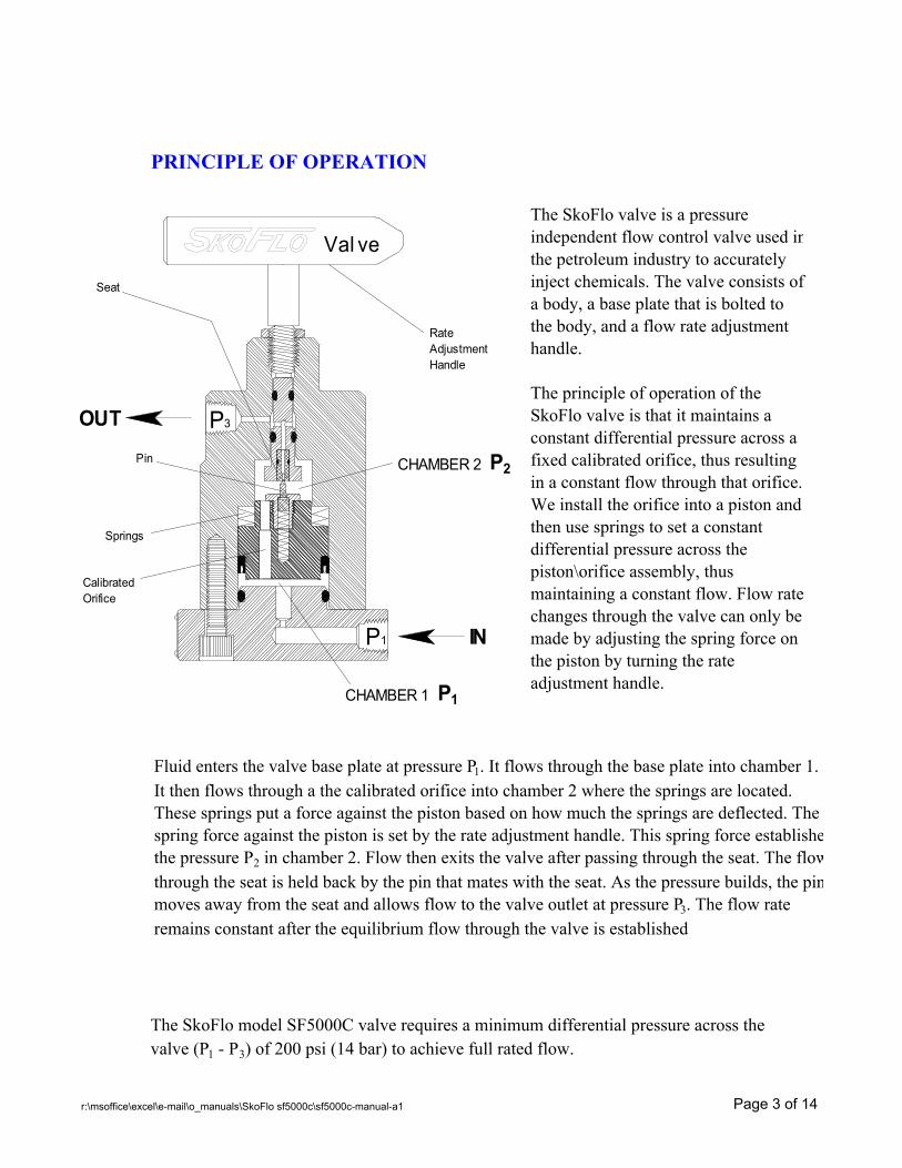
PRINCIPLE OF OPERATION
The SkoFlo model SF5000C valve requires a minimum differential pressure across thevalve (P1 - P3) of 200 psi (14 bar) to achieve full rated flow.
The SkoFlo valve is a pressure independent flow control valve used inthe petroleum industry to accurately inject chemicals. The valve consists of a body, a base plate that is bolted to the body, and a flow rate adjustment handle.
The principle of operation of the SkoFlo valve is that it maintains a constant differential pressure across a fixed calibrated orifice, thus resulting in a constant flow through that orifice. We install the orifice into a piston and then use springs to set a constant differential pressure across the piston\orifice assembly, thus maintaining a constant flow. Flow ratechanges through the valve can only be made by adjusting the spring force on the piston by turning the rate adjustment handle.
Fluid enters the valve base plate at pressure P1. It flows through the base plate into chamber 1. It then flows through a the calibrated orifice into chamber 2 where the springs are located. These springs put a force against the piston based on how much the springs are deflected. The spring force against the piston is set by the rate adjustment handle. This spring force establishethe pressure P2 in chamber 2. Flow then exits the valve after passing through the seat. The flowthrough the seat is held back by the pin that mates with the seat. As the pressure builds, the pinmoves away from the seat and allows flow to the valve outlet at pressure P3. The flow rate remains constant after the equilibrium flow through the valve is established
P3OUT
P1 IN
Val ve
RateAdjustmentHandle
CHAMBER 2 P2
CHAMBER 1 P1
Springs
Pin
Seat
CalibratedOrifice
r:\msoffice\excel\e-mail\o_manuals\SkoFlo sf5000c\sf5000c-manual-a1 Page 3 of 14
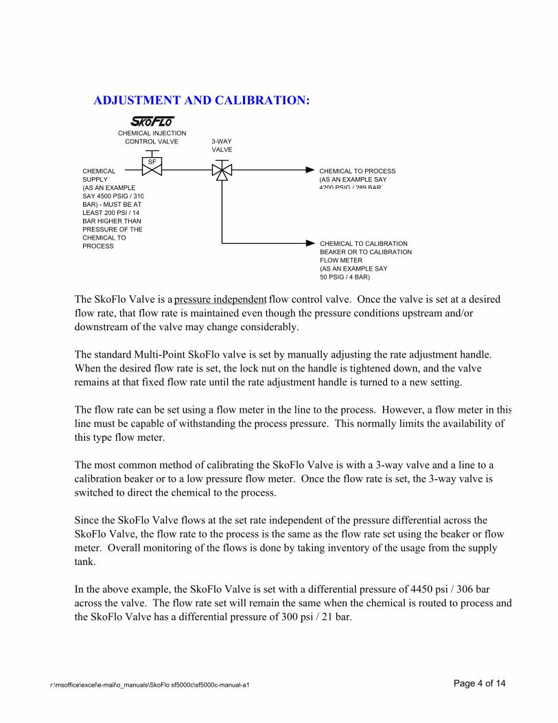
ADJUSTMENT AND CALIBRATION:
SF
3-WAYVALVE
CHEMICAL INJECTIONCONTROL VALVE
CHEMICAL TO PROCESS(AS AN EXAMPLE SAY 4200 PSIG / 289 BAR)
CHEMICAL TO CALIBRATIONBEAKER OR TO CALIBRATIONFLOW METER(AS AN EXAMPLE SAY 50 PSIG / 4 BAR)
CHEMICALSUPPLY(AS AN EXAMPLE SAY 4500 PSIG / 310BAR) - MUST BE AT LEAST 200 PSI / 14 BAR HIGHER THAN PRESSURE OF THE CHEMICAL TO PROCESS
The SkoFlo Valve is a pressure independent flow control valve. Once the valve is set at a desired flow rate, that flow rate is maintained even though the pressure conditions upstream and/or downstream of the valve may change considerably.
The standard Multi-Point SkoFlo valve is set by manually adjusting the rate adjustment handle. When the desired flow rate is set, the lock nut on the handle is tightened down, and the valve remains at that fixed flow rate until the rate adjustment handle is turned to a new setting.
The flow rate can be set using a flow meter in the line to the process. However, a flow meter in thisline must be capable of withstanding the process pressure. This normally limits the availability of this type flow meter.
The most common method of calibrating the SkoFlo Valve is with a 3-way valve and a line to a calibration beaker or to a low pressure flow meter. Once the flow rate is set, the 3-way valve is switched to direct the chemical to the process.
Since the SkoFlo Valve flows at the set rate independent of the pressure differential across the SkoFlo Valve, the flow rate to the process is the same as the flow rate set using the beaker or flow meter. Overall monitoring of the flows is done by taking inventory of the usage from the supply tank.
In the above example, the SkoFlo Valve is set with a differential pressure of 4450 psi / 306 bar across the valve. The flow rate set will remain the same when the chemical is routed to process and the SkoFlo Valve has a differential pressure of 300 psi / 21 bar.
r:\msoffice\excel\e-mail\o_manuals\SkoFlo sf5000c\sf5000c-manual-a1 Page 4 of 14
OPERATION NOTES AND WARNINGS:
1. The SkoFlo valve has hard seats and is not designed to provide complete"bubble-tight" shut off. Separate isolation valves should be used forshutting off the flow. The SkoFlo valve will reach its minimum flow beforethe handle is bottomed out. Overtightening the handle will not furtherreduce flow. If flow rate does not decrease when turning the handle in, see "Trouble Shooting Improper Valve Performance".
2. Quick opening or closing of valves upstream or downstream of the SkoFlovalve can cause the internal parts to move extremely fast and flow rate maysurge. Valves upstream and downstream should be opened slowly to allow internal pressures to balance and minimize shock to valves and piping.
3. The SkoFlo Valve is designed for flow in one direction only. Do not flow backwards through the SkoFlo valve. Some internal seals are designed for one direction only and could possibly become dislodged. The valve will not control in the reverse direction. SkoFlo Industries, Inc. recommends installation of a check valve in the outlet line within 5 feet from the SkoFlo valve (see "Multi-Point System Sample Schematic") to avoid reverse flow of process fluids into the chemical system.
MAINTENANCE:
1. Replacing Seals: When replacing valve seals, it is recommended thatthe Piston Seal Installer Tool (P/N SF10000-T2) and the O-Ring Installation Kit (P/N SF5000-T3) be used.
A. Remove SkoFlo valve from system.
B. Remove the base plate and the adjustment handle. Slowly pushthe internal parts out using a rod, hex driver, or similar tool. Usecare to avoid damage to the internal surfaces of the SkoFlo valve.(See Figure I).
r:\msoffice\excel\e-mail\o_manuals\SkoFlo sf5000c\sf5000c-manual-a1 Page 5 of 14
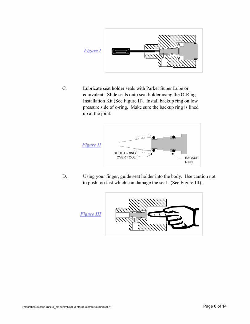
Figure I
C. Lubricate seat holder seals with Parker Super Lube or equivalent. Slide seals onto seat holder using the O-Ring Installation Kit (See Figure II). Install backup ring on low pressure side of o-ring. Make sure the backup ring is lined up at the joint.
Figure II
D. Using your finger, guide seat holder into the body. Use caution not to push too fast which can damage the seal. (See Figure III).
Figure III
BACKUPRING
SLIDE O-RINGOVER TOOL
r:\msoffice\excel\e-mail\o_manuals\SkoFlo sf5000c\sf5000c-manual-a1 Page 6 of 14
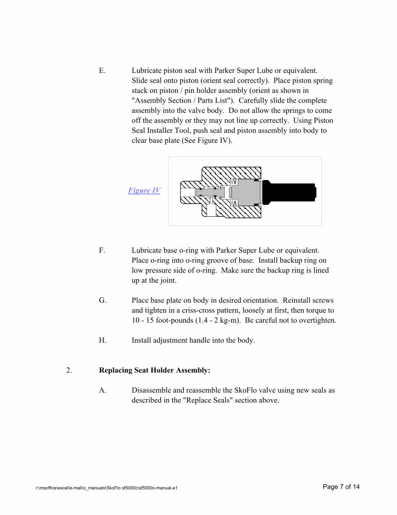
E. Lubricate piston seal with Parker Super Lube or equivalent.Slide seal onto piston (orient seal correctly). Place piston springstack on piston / pin holder assembly (orient as shown in"Assembly Section / Parts List"). Carefully slide the completeassembly into the valve body. Do not allow the springs to comeoff the assembly or they may not line up correctly. Using PistonSeal Installer Tool, push seal and piston assembly into body to clear base plate (See Figure IV).
Figure IV
F. Lubricate base o-ring with Parker Super Lube or equivalent.Place o-ring into o-ring groove of base. Install backup ring on low pressure side of o-ring. Make sure the backup ring is lined up at the joint.
G. Place base plate on body in desired orientation. Reinstall screws and tighten in a criss-cross pattern, loosely at first, then torque to 10 - 15 foot-pounds (1.4 - 2 kg-m). Be careful not to overtighten.
H. Install adjustment handle into the body.
2. Replacing Seat Holder Assembly:
A. Disassemble and reassemble the SkoFlo valve using new seals as described in the "Replace Seals" section above.
r:\msoffice\excel\e-mail\o_manuals\SkoFlo sf5000c\sf5000c-manual-a1 Page 7 of 14
3. Replacing Piston / Pin Assembly:
A. Disassemble and reassemble the SkoFlo valve using new sealsand piston assembly as described in the "Replace Seals"section above.
B. When installing pin holder into piston, hold piston in a mannerwhere the surface finish will not be damaged. Torque pinholder to 100 inch-pounds (1.15 kg-m).
4. Changing Orientation of Base Plate:
A. Remove SkoFlo valve from system.
B. Place valve with handle located down at bottom, and base plateat top. Remove 4 screws in base plate. Carefully remove baseplate without disturbing the base plate o-ring.
C. Reorient the base plate as desired.
D. Reinstall screws and tighten in a criss-cross pattern, loosely at first, then torque to 10 - 15 foot-pounds (1.4 - 2 kg-m). Be careful not to overtighten.
5. Orifice Backflushing Procedure:
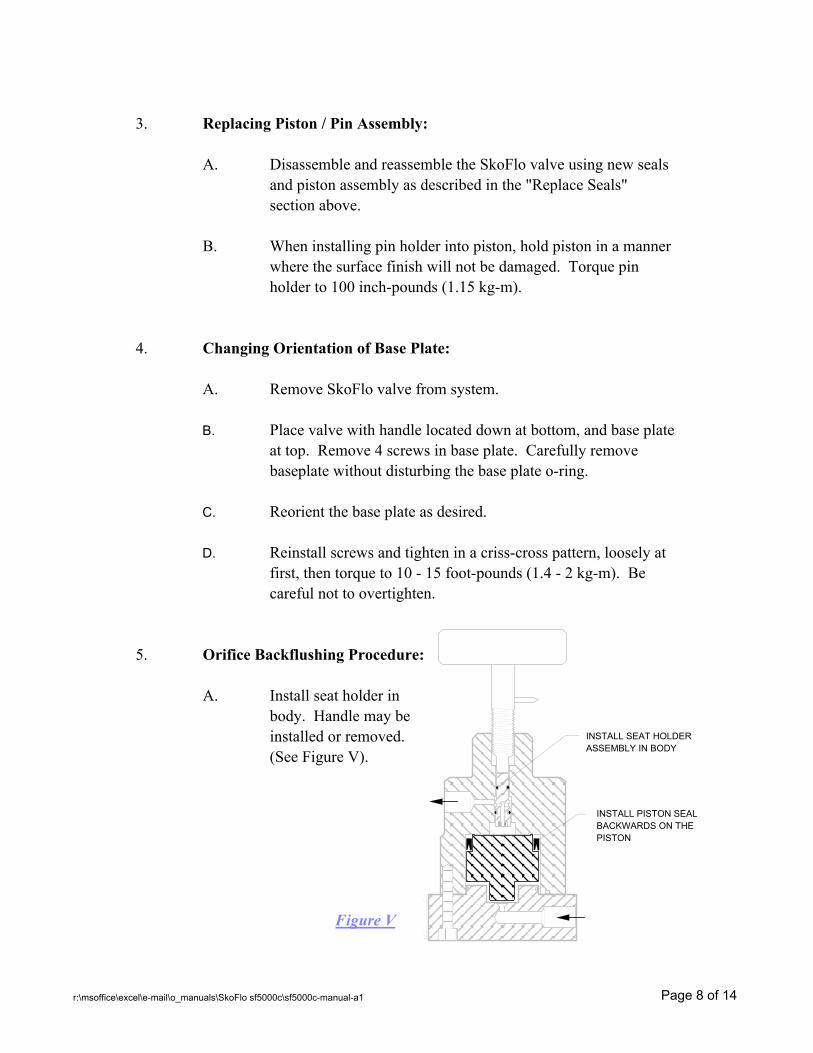
A. Install seat holder in body. Handle may beinstalled or removed.(See Figure V).
Figure V
INSTALL SEAT HOLDER ASSEMBLY IN BODY
INSTALL PISTON SEAL BACKWARDS ON THE PISTON
r:\msoffice\excel\e-mail\o_manuals\SkoFlo sf5000c\sf5000c-manual-a1 Page 8 of 14
B. Install the piston seal on the piston backwards from the normalposition. (The spring face of the seal will be toward the piston).
C. Install the piston in the body backwards from the normal position.
D. Install the valve base plate.
E. Apply clean chemical (or water) to the valve inlet. The fluidflow is in the reverse direction to the normal flow thus backflushing the orifice in the piston.
F. If plugging is not relieved by backflushing, the piston/orifice must be replaced.
TROUBLE SHOOTING IMPROPER VALVE PERFORMANCE:
SYMPTOM CAUSE REMEDY
1. No Flow Upstream filter is Clean or replaceplugged. filter element.
Flow controller Back-flush orifice ororifice is plugged. replace piston/orifice
assembly. Correctcause of plugging suchas leaking filter.
Supply valve is shut Open valve slowly.off.
Discharge line is Open valve.shut off.
2. Fluctuations in Rate adjustment handle Adjust handle in to flow rates is backed out past set flow as noted in
control range (valve is "Start Up Procedures".not controlling).
r:\msoffice\excel\e-mail\o_manuals\SkoFlo sf5000c\sf5000c-manual-a1 Page 9 of 14
SYMPTOM CAUSE REMEDY
2. Fluctuations in Piston Springs are Install springs in flow rates (cont.) not installed accordance with
properly. drawing SF-0091
Seat or pin worn Replace seat holderor damaged. or pin.
Supply pressure The flow controlleris not adequate. requires a minimum
of 200 psi (14 bar) differential pressure across the valve for full rated flow.
RECOMMENDED SPARE PARTS:
QTY PART NUMBER DESCRIPTION
1 SF5000C-4-(x) Piston/Orifice Assembly for dash size (x) Valve(Qty 1 for each different dash size)
1 SF5000C-5-STD Seat Holder with seat (Qty 1 for each 20 valvesof dash size 2 thru 75)
1 SF5000C-5-XL Seat Holder with seat (Qty 1 for each 20 valvesof dash size 100 thru 500)
1 SF5000C-20 Seal Kit (Qty 1 for each 20 valves)
STORAGE:
1. When storing SkoFlo valves prior to first use, it is recommended thatthe valves be stored indoors. If stored outdoors, apply a light coatingof protectant to the exterior of the valve. The shipping plugs in theINLET and OUTLET should remain in place.
2. When storing SkoFlo valves after being in use, dismantle, thoroughly cleanand reassemble. Then store as noted in number 1 above.
Please call the factory in Woodinville, Washington USA at phone number425-485-7816 if you have any questions.E-Mail: [email protected]
r:\msoffice\excel\e-mail\o_manuals\SkoFlo sf5000c\sf5000c-manual-a1 Page 10 of 14
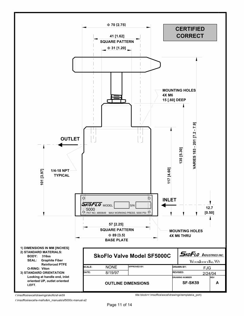
r:\msoffice\excel\drawings\skoflo\sf-sk59
r:\msoffice\excel\e-mail\o&m_manuals\sf5000c-manual-a2
Page 11 of 14
OUTLET
INLET
SQUARE PATTERN
SQUARE PATTERN
BASE PLATE
Φ 70 [2.75]
Φ 31 [1.20]
41 [1.62]
57 [2.25]
12.7[0.50]
101
[3.9
7]
117
[4.6
0]
135
[5.3
0]
VAR
IES
183
- 201
[7.2
- 7.
9]
MOUNTING HOLES4X M615 [.60] DEEP
MOUNTING HOLES4X M6 THRU
1/4-18 NPTTYPICAL
1) DIMENSIONS IN MM [INCHES]2) STANDARD MATERIALS: BODY: 316ss SEAL: Graphite Fiber Reinforced PTFE O-RING: Viton3) STANDARD ORIENTATION Looking at handle end, inlet oriented UP, outlet oriented
LEFT.
CERTIFIEDCORRECT
MODEL5000
S/N
PAT NO. 4893649 MAX WORKING PRESS. 5000 PSI
Φ 89 [3.5]
title block=r:\msoffice\excel\drawings\template\a_port)
SkoFlo Valve Model SF5000C
OUTLINE DIMENSIONS SF-SK59 A
8/19/97 2/24/04
SCALE:
DATE:
DRAWN BY:
REVISED:
DRAWING NUMBER REV
APPROVED BY:NONE FJG
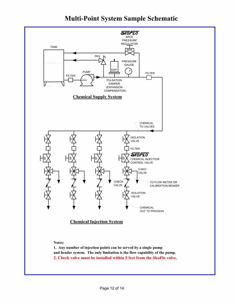
Multi-Point System Sample Schematic
Page 12 of 14
TANK
FILTERPUMP
EXP
PRV
BPR
BACKPRESSURE
REGULATOR
PRESSUREGAUGE
PULSATIONDAMPER
(EXPANSION COMPENSATOR)
Chemical Supply System
CHEMICALOUT TO PROCESS
Chemical Injection System
CHEMICALTO VALVES
Notes:1. Any number of injection points can be served by a single pumpand header system. The only limitation is the flow capability of the pump.2. Check valve must be installed within 5 feet from the SkoFlo valve.
ISOLATIONVALVE
ISOLATIONVALVE
SF
FILTER
3-WAYVALVE
CHEMICAL INJECTIONCONTROL VALVE
CHECKVALVE
TO FLOW METER ORCALIBRATION BEAKER
SFSFSF
FILTER
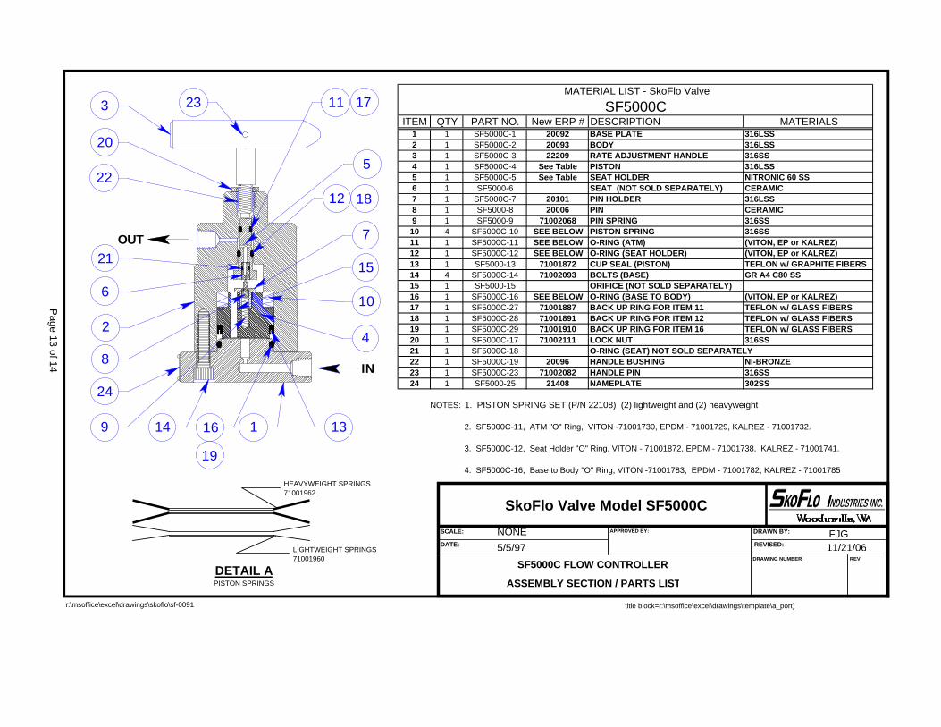
MATERIAL LIST - SkoFlo Valve
SF5000CITEM QTY PART NO. New ERP # DESCRIPTION MATERIALS
1 1 SF5000C-1 20092 BASE PLATE 316LSS2 1 SF5000C-2 20093 BODY 316LSS3 1 SF5000C-3 22209 RATE ADJUSTMENT HANDLE 316SS4 1 SF5000C-4 See Table PISTON 316LSS5 1 SF5000C-5 See Table SEAT HOLDER NITRONIC 60 SS6 1 SF5000-6 SEAT (NOT SOLD SEPARATELY) CERAMIC7 1 SF5000C-7 20101 PIN HOLDER 316LSS8 1 SF5000-8 20006 PIN CERAMIC9 1 SF5000-9 71002068 PIN SPRING 316SS10 4 SF5000C-10 SEE BELOW PISTON SPRING 316SS11 1 SF5000C-11 SEE BELOW O-RING (ATM) (VITON, EP or KALREZ)12 1 SF5000C-12 SEE BELOW O-RING (SEAT HOLDER) (VITON, EP or KALREZ)13 1 SF5000-13 71001872 CUP SEAL (PISTON) TEFLON w/ GRAPHITE FIBERS14 4 SF5000C-14 71002093 BOLTS (BASE) GR A4 C80 SS15 1 SF5000-15 ORIFICE (NOT SOLD SEPARATELY)16 1 SF5000C-16 SEE BELOW O-RING (BASE TO BODY) (VITON, EP or KALREZ)17 1 SF5000C-27 71001887 BACK UP RING FOR ITEM 11 TEFLON w/ GLASS FIBERS18 1 SF5000C-28 71001891 BACK UP RING FOR ITEM 12 TEFLON w/ GLASS FIBERS19 1 SF5000C-29 71001910 BACK UP RING FOR ITEM 16 TEFLON w/ GLASS FIBERS20 1 SF5000C-17 71002111 LOCK NUT 316SS21 1 SF5000C-18 O-RING (SEAT) NOT SOLD SEPARATELY22 1 SF5000C-19 20096 HANDLE BUSHING NI-BRONZE23 1 SF5000C-23 71002082 HANDLE PIN 316SS24 1 SF5000-25 21408 NAMEPLATE 302SS
NOTES: 1. PISTON SPRING SET (P/N 22108) (2) lightweight and (2) heavyweight
2. SF5000C-11, ATM "O" Ring, VITON -71001730, EPDM - 71001729, KALREZ - 71001732.
3. SF5000C-12, Seat Holder "O" Ring, VITON - 71001872, EPDM - 71001738, KALREZ - 71001741.
4. SF5000C-16, Base to Body "O" Ring, VITON -71001783, EPDM - 71001782, KALREZ - 71001785
r:\msoffice\excel\drawings\skoflo\sf-0091
IN
17
1
18
24
OUT
3 23
20
21
22
6
2
149 16
19
8
12
11
7
5
13
4
10
15
LIGHTWEIGHT SPRINGS71001960
HEAVYWEIGHT SPRINGS71001962
DETAIL APISTON SPRINGS
title block=r:\msoffice\excel\drawings\template\a_port)
Page 13 of 14
SkoFlo Valve Model SF5000C
SF5000C FLOW CONTROLLER
ASSEMBLY SECTION / PARTS LIST
5/5/97 11/21/06
SCALE:
DATE:
DRAWN BY:
REVISED:
DRAWING NUMBER REV
APPROVED BY:NONE FJG
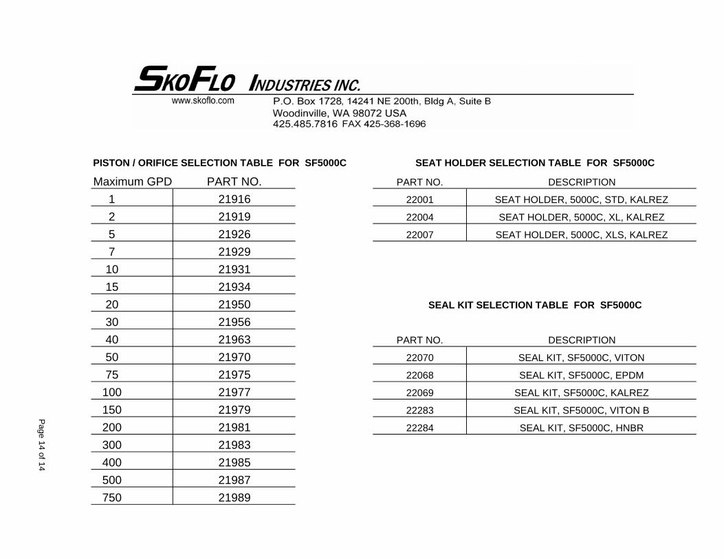
PISTON / ORIFICE SELECTION TABLE FOR SF5000C
125710152030405075
100150200300400500750
22283 SEAL KIT, SF5000C, VITON B
22284 SEAL KIT, SF5000C, HNBR
22069 SEAL KIT, SF5000C, KALREZ
22070 SEAL KIT, SF5000C, VITON
22068 SEAL KIT, SF5000C, EPDM
PART NO. DESCRIPTION
22001 SEAT HOLDER, 5000C, STD, KALREZ
22004 SEAT HOLDER, 5000C, XL, KALREZ
22007 SEAT HOLDER, 5000C, XLS, KALREZ
SEAT HOLDER SELECTION TABLE FOR SF5000C
PART NO. DESCRIPTION
SEAL KIT SELECTION TABLE FOR SF5000C
Maximum GPD PART NO.2191621919
219632197021975
21926
21931
2195021956
21929
21934
21977219792198121983219852198721989
Page 14 of 14
W:\Sales\PDF & EXCEL Drawings\O & M Manuals\SFI Customer Satisfaction Survey.doc Page 1 of 1
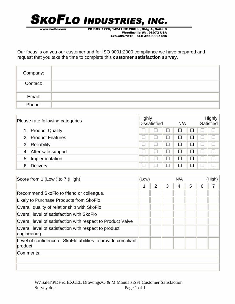
Our focus is on you our customer and for ISO 9001:2000 compliance we have prepared and request that you take the time to complete this customer satisfaction survey.
Company:
Contact:
Email:
Phone:
Please rate following categories Highly HighlyDissatisfied N/A Satisfied
1. Product Quality 2. Product Features 3. Reliability 4. After sale support 5. Implementation 6. Delivery
Score from 1 (Low ) to 7 (High) (Low) N/A (High)
1 2 3 4 5 6 7 Recommend SkoFlo to friend or colleague. Likely to Purchase Products from SkoFlo Overall quality of relationship with SkoFlo Overall level of satisfaction with SkoFlo Overall level of satisfaction with respect to Product Valve Overall level of satisfaction with respect to product engineering
Level of confidence of SkoFlo abilities to provide compliant product
Comments: