Embed Size (px)
Citation preview
Design Guide
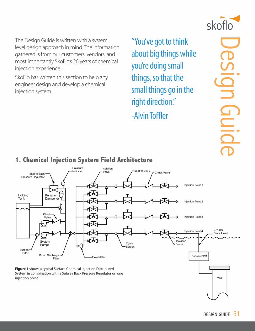
1. Chemical Injection System Field Architecture
SkoFlo BackPressure Regulator
HoldingTank
SystemPumps
SuctionFilter
Flow Meter
PulsationDampener
PressureIndicator
IsolationValve
CatchScreen
SkoFlo CIMVCheck Valve
Isolation Valve
Pump DischargeFilter
CheckValve
Subsea BPR
Injection Point 1
Injection Point 2
Injection Point 3
Injection Point 4
Well
275 Bar Static Head
Figure 1 shows a typical Surface Chemical Injection Distributed System in combination with a Subsea Back Pressure Regulator on one injection point.
The Design Guide is written with a system level design approach in mind. The information gathered is from our customers, vendors, and most importantly SkoFlo’s 26 years of chemical injection experience.
SkoFlo has written this section to help any engineer design and develop a chemical injection system.
“You’ve got to think about big things while you’re doing small things, so that the small things go in the right direction.” -Alvin Toffler
DESIGN GUIDE 51
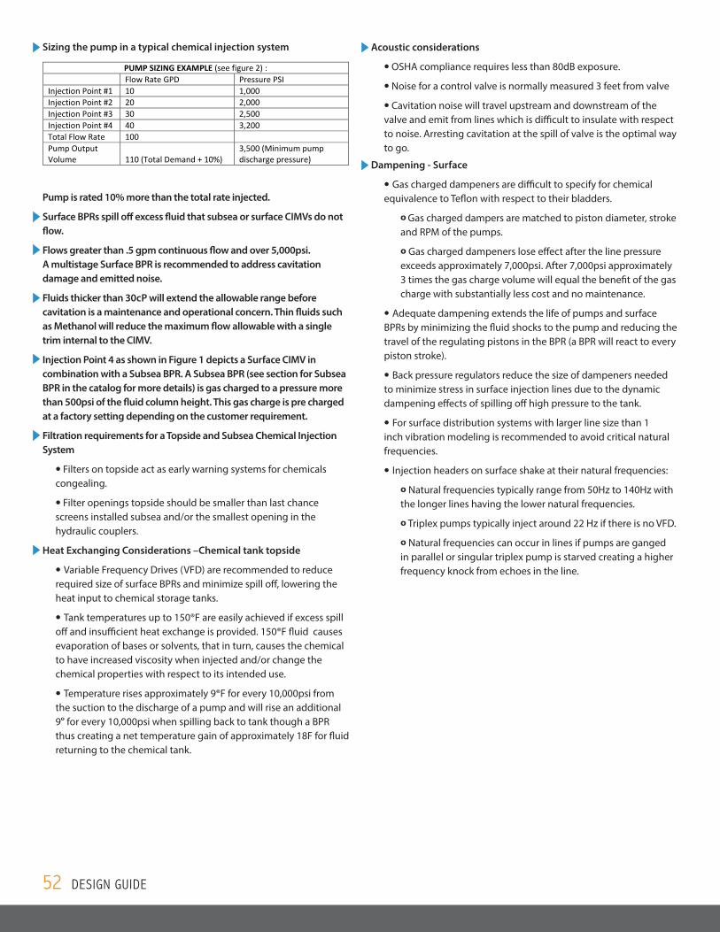
Sizing the pump in a typical chemical injection system
Pump is rated 10% more than the total rate injected.
Surface BPRs spill off excess fluid that subsea or surface CIMVs do not flow.
Flows greater than .5 gpm continuous flow and over 5,000psi. A multistage Surface BPR is recommended to address cavitation damage and emitted noise.
Fluids thicker than 30cP will extend the allowable range before cavitation is a maintenance and operational concern. Thin fluids such as Methanol will reduce the maximum flow allowable with a single trim internal to the CIMV.
Injection Point 4 as shown in Figure 1 depicts a Surface CIMV in combination with a Subsea BPR. A Subsea BPR (see section for Subsea BPR in the catalog for more details) is gas charged to a pressure more than 500psi of the fluid column height. This gas charge is pre charged at a factory setting depending on the customer requirement.
Filtration requirements for a Topside and Subsea Chemical Injection System
• Filters on topside act as early warning systems for chemicals congealing.
• Filter openings topside should be smaller than last chance screens installed subsea and/or the smallest opening in the hydraulic couplers.
Heat Exchanging Considerations –Chemical tank topside
• Variable Frequency Drives (VFD) are recommended to reduce required size of surface BPRs and minimize spill off, lowering the heat input to chemical storage tanks.
• Tank temperatures up to 150®F are easily achieved if excess spill off and insufficient heat exchange is provided. 150®F fluid causes evaporation of bases or solvents, that in turn, causes the chemical to have increased viscosity when injected and/or change the chemical properties with respect to its intended use.
• Temperature rises approximately 9®F for every 10,000psi from the suction to the discharge of a pump and will rise an additional 9o for every 10,000psi when spilling back to tank though a BPR thus creating a net temperature gain of approximately 18F for fluid returning to the chemical tank.
Acoustic considerations
• OSHA compliance requires less than 80dB exposure.
• Noise for a control valve is normally measured 3 feet from valve
• Cavitation noise will travel upstream and downstream of the valve and emit from lines which is difficult to insulate with respect to noise. Arresting cavitation at the spill of valve is the optimal way to go.
Dampening - Surface
• Gas charged dampeners are difficult to specify for chemical equivalence to Teflon with respect to their bladders.
o Gas charged dampers are matched to piston diameter, stroke and RPM of the pumps.
o Gas charged dampeners lose effect after the line pressure exceeds approximately 7,000psi. After 7,000psi approximately 3 times the gas charge volume will equal the benefit of the gas charge with substantially less cost and no maintenance.
• Adequate dampening extends the life of pumps and surface BPRs by minimizing the fluid shocks to the pump and reducing the travel of the regulating pistons in the BPR (a BPR will react to every piston stroke).
• Back pressure regulators reduce the size of dampeners needed to minimize stress in surface injection lines due to the dynamic dampening effects of spilling off high pressure to the tank.
• For surface distribution systems with larger line size than 1 inch vibration modeling is recommended to avoid critical natural frequencies.
• Injection headers on surface shake at their natural frequencies:
o Natural frequencies typically range from 50Hz to 140Hz with the longer lines having the lower natural frequencies.
o Triplex pumps typically inject around 22 Hz if there is no VFD.
o Natural frequencies can occur in lines if pumps are ganged in parallel or singular triplex pump is starved creating a higher frequency knock from echoes in the line.
Pump Sizing Example – Pg 50 of Round 1 Catalog – Rev 2 04.07.2016
Revisions done: Added in commas, lower case psi - NMT (Nina Thompson)
PUMP SIZING EXAMPLE (see figure 2) : Flow Rate GPD Pressure PSI Injection Point #1 10 1,000 Injection Point #2 20 2,000 Injection Point #3 30 2,500 Injection Point #4 40 3,200 Total Flow Rate 100 Pump Output Volume 110 (Total Demand + 10%)
3,500 (Minimum pump discharge pressure)
52 DESIGN GUIDE
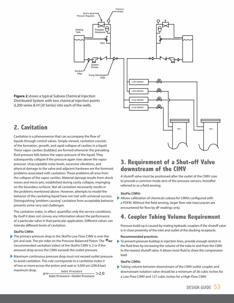
SkoFlo BackPressure Regulator
HoldingTank
SystemPumps
SuctionFilter
PulsationDampener
PressureIndicator
Pump DischargeFilter
L200 SERIES
L200 SERIES
H120 SERIES
H120 SERIES
PRV
WELL WELL
SkoFlo BackPressure Regulator
HoldingTank
SystemPumps
SuctionFilter
PulsationDampener
PressureIndicator
Pump DischargeFilter
L200 SERIES
L200 SERIES
H120 SERIES
H120 SERIES
PRV
WELL WELL
Figure 2 shows a typical Subsea Chemical Injection Distributed System with two chemical injection points (L200 series & H120 Series) into each of the wells.
2. CavitationCavitation is a phenomenon that can accompany the flow of liquids through control valves. Simply viewed, cavitation consists of the formation, growth, and rapid collapse of cavities in a liquid. These vapor cavities (bubbles) are formed whenever the prevailing fluid pressure falls below the vapor pressure of the liquid. They subsequently collapse if the pressure again rises above the vapor pressure. Unacceptable noise levels, excessive vibrations, and physical damage to the valve and adjacent hardware are the foremost problems associated with cavitation. These problems all arise from the collapse of the vapor cavities. Material damage results from shock waves and micro-jets, established during cavity collapse, impinging on the boundary surfaces. Not all cavitation necessarily results in the problems mentioned above. However, attempts to model the behavior of the cavitating liquid have not met with universal success. Distinguishing “problem causing” cavitation from acceptable behavior presents some very real challenges.
The cavitation index, in effect, quantifies only the service conditions. By itself it does not convey any information about the performance of a particular valve in that particular application. Different valves can tolerate different levels of cavitation.
SkoFlo CIMVs The primary pressure drop in the SkoFlo Low Flow CIMV is over the pin and seat. The pin rides on the Pressure-Balanced Piston. The (recommended cavitation index) of the SkoFlo CIMV is 2 or if the pressure drop across the CIMV exceeds the outlet pressure.
Maximum continuous pressure drop must not exceed outlet pressure to avoid cavitation. This rule corresponds to a cavitation index σ of two or more across the piston and seat or 3,000 psi (206.8 bar) maximum drop.
3. Chemical Injection Line sizing for constant rate control devices
When using rate controls that maintain constant flow Cv values are not relevant with respect to entering losses of valves using solvers for branch or series flow
Simply calculate the loss in psi per foot using the minimum pressure drop across the CIMV at the maximum anticipated flow for the most viscous fluid anticipated.
Most umbilical’s are too long to develop turbulent flow to flush lines during commissioning
4. Minimum Pressure Drop Requirements for a constant flow rate CIMV Minimum Pressure Drop Requirement for a SkoFlo CIMV is to simply energize the patented Pressure-Balanced
Piston, which maintains constant flow rate regardless of fluctuations in supply or well pressure. Show pressure drop curves for pressure independent rate controls for
i. Surface NMFE (Minimum dP: 500psi) ii. Surface SF5000C and SF10000DRS and high turn down valves (Minimum dP: 250 psi)
iii. Subsea Gen 2 low flow and Surface HTD CIMVs (Minimum dP: 250psi) iv. Subsea Gen Medium and High flow core (See High Flow Specification Sheet)
5. Cavitation
Cavitation is a phenomenon that can accompany the flow of liquids through control valves. Simply viewed, cavitation consists of the formation, growth and rapid collapse of cavities in a liquid. These vapor cavities (bubbles) are formed whenever the prevailing fluid pressure falls below the vapor pressure of the liquid. They subsequently collapse if the pressure again rises above the vapor pressure. Unacceptable noise levels, excessive vibrations, and physical damage to the valve and adjacent hardware are the foremost problems associated with cavitation. These problems all arise from the collapse of the vapor cavities. Material damage results from shock waves and micro-jets, established during cavity collapse, impinging on the boundary surfaces. Not all cavitation necessarily results in the problems mentioned above. However, attempts to model the behavior of the cavitating liquid have not met with universal success. Distinguishing "problem causing" cavitation from acceptable behavior presents some very real challenges.
The σ index, in effect, quantifies only the service conditions. By itself it does not convey any information about the performance of a particular valve in that particular application. Different valves can tolerate different levels of cavitation. The primary pressure drop in the SkoFlo Low Flow CIMV is over the pin and seat. The pin rides on the pressure balanced piston. The 𝛔𝛔𝐦𝐦𝐦𝐦 (recommended cavitation index) of the SkoFlo CIMV is 2 or if the pressure drop across the CIMV exceeds the outlet pressure.
Maximum continuous pressure drop must not exceed outlet pressure to avoid cavitation. This rule corresponds
to a cavitation index σ of two or more across the piston and seat or 3,000 psi (206.8 bar) maximum drop.
𝜎𝜎 𝐼𝐼𝐼𝐼𝐼𝐼𝐼𝐼𝐼𝐼 𝑃𝑃𝑃𝑃𝐼𝐼𝑃𝑃𝑃𝑃𝑃𝑃𝑃𝑃𝐼𝐼Inlet Pressure−Outlet Pressure
6. Requirement of a Shut-off Valve downstream of the CIMV
A shutoff valve must be positioned after the outlet of the CIMV core to provide a common mode zero of the dP sensor, hereafter referred to as a field zeroing, and to allow calibration of chemicals subsea for CIMVs configured with a PDFM. Without the field zeroing larger flow rate inaccuracies will be encounter for flow by DP readings only.
7. Coupler Tubing Length Requirement Tubing volume between downstream of the CIMV outlet coupler and downstream isolation valve should be a
minimum of 30 cubic inches If less than 30 cubic inches pressure exceeding the max allowable hydro test pressure of the valve may occur in
the outlet tubing and downstream isolation valve, outlet hydraulic coupler, and outlet pressure sensor in the SkoFlo valve.
8. Chemical Compatibility – Metallic & Non-metallic
The material compatibility of injection valve components to service chemicals and external environment is key to the reliability and longevity of valves.
i. For corrosion resistance all valve bodies, including metal seals, exposed to service chemicals use NACE
(MR0175/ISO 15156) compliant materials for subsea valves or stainless steel for surface valves. Metallic materials that are qualified using NACE MR0175/ISO 15156 are resistant to cracking in defined H2S (Hydrogen Sulphide)-containing environments in oil and gas production. All metallic parts are free of yellow metals (bronze, brass, copper and its alloys), to the risk of prevent galvanic corrosion and wear off.
ii. Elastomeric Seals (O-rings) are qualified for long-term compatibility with exposure fluids and environment within the operating temperature. This includes injection chemicals, dielectric fluids (for oil containing seals), seawater (for subsea valves), and process fluids. Aging is performed to estimate an operating life of at least 25 years. During the testing parameters such as compression set, elongation to failure, material hardness, and fluid absorption are considered to characterize degradation over time.
iii. Qualification of non-metallic components is covered by NORSOK M-710 (an internationally recognized standard) where individual seal materials are rigorously tested and approved based on numerous criteria such as Rapid Gas Decompression (RGD) or Explosive Decompression (ED), sour (CH4) and sweet gas (CO2) aging, compression set tests, and material property tests.
iv. For elastomeric seals, SkoFlo utilizes high reliability material grades such as perflouroelastomers which have a chemical resistance comparable to PTFE (Fluoropolymer) and is qualified for exposure to harsh environments with wide temperature ranges and is recommended by the industry for challenging oil and gas non-metallic sealing applications.
9. Adjustment accuracy, % reading & % rated full scale for flow measurements
Measurement accuracy as percent of reading is defined as the difference between the reported flow through the CIMV and the actual flow. Percent of Rated Full Scale (RFS) is the measured flow compared to the rated full scale flow of the valve. SkoFlo uses percent of reading for Low Flow CIMVs and percent of RFS for High Flow CIMVs
Adjustment Accuracy is defined as the ability of the valve to drive the stem to the set flow rate. Once the flow rate is initially set on a SkoFlo CIMV, the motor driven stem does not need to move to regulate flow. The mechanical pressure balanced piston regulates flow at the set rate.
DESIGN GUIDE 53
3. Requirement of a Shut-off Valve downstream of the CIMVA shutoff valve must be positioned after the outlet of the CIMV core to provide a common mode zero of the pressure sensors, hereafter referred to as a field zeroing.
SkoFlo CIMVs Allows calibration of chemicals subsea for CIMVs configured with a PDFM. Without the field zeroing, larger flow rate inaccuracies are encountered for flow by dP readings only.
4. Coupler Tubing Volume RequirementPressure build up is caused by mating hydraulic couplers if the shutoff valve is in close proximity of the inlet and outlet of the docking receptacle.
Recommended practices: To prevent pressure buildup in injection lines, provide enough stretch in the fluid lines by increasing the volume of the tube to and from the CIMV to the nearest shutoff valve. It allows more fluid to share the compression load.
SkoFlo CIMVs Tubing volume between downstream of the CIMV outlet coupler and downstream isolation valve should be a minimum of 36 cubic inches for a Low Flow CIMV and 127 cubic inches for a High Flow CIMV.
SkoFlo CIMVs
• Once the flow rate is initially set on a SkoFlo CIMV, the motor driven stem does not need to move to regulate flow for changes in pressure or fluid conditions. The mechanical Pressure- Balanced Piston regulates flow at the set rate.
• Low Flow CIMV
Measurement accuracy (% of reading:
Flow by PDFM = �Flow by PDFM−ReferenceReference
�× 100
Flow by dP = �Flow by dP−ReferenceReference
�× 100
Flow by Stem= �Flow by Stem−ReferenceReference
� × 100
Adjustment Accuracy (% of reading):
Flow by dP = (Flow by dP−Target Flow Rate)Target Flow Rate
∗ 100
Flow by Stem = (Flow by Stem−Target Flow Rate)Target Flow Rate
∗ 100
Flow by PDFM = (Flow by PDFM-Target Flow Rate)Target Flow Rate
*100
• High Flow CIMV
Measurement accuracy (% RFS):
Flow by dP = �Flow by dP−ReferenceRFS
�× 100
Flow by Stem = �Flow by Stem−ReferenceRFS
�× 100
Adjustment Accuracy (% RFS):
Flow by dP = (Flow by dP−Target Flow Rate)RFS
∗ 100
Flow by Stem = (Flow by Stem−Target Flow Rate)RFS
∗ 100
1. Minimum Pressure Drop Requirements for a SkoFlo CIMV
Minimum Pressure Drop Requirement for a Skoflo CIMV is to energize the patented Pressure-Balanced Piston, which maintains constant flow rate regardless of fluctuations in supply or well pressure.
5. Chemical CompatibilityMaterial compatibility of CIMV (chemically and seawater wetted) components is key to the reliability and longevity of valves.
Recommended Practices: All metallic parts are free of yellow metals (bronze, brass, copper and its alloys), to the risk of preventing galvanic corrosion and wear off.
All chemically wetted materials should be evaluated for chemical compatibility prior to deploying Subsea against the project specific chemicals.
SkoFlo CIMVs For elastomeric seals, SkoFlo utilizes high reliability material grades such as perflouroelastomers which have a chemical resistance comparable to PTFE (Fluoropolymer) and is qualified for exposure to harsh environments with wide temperature ranges and is recommended by the industry for challenging oil and gas non‐metallic sealing applications.
Individual Seal materials are rigorously tested and approved based on Rapid Gas Decompression (RGD).
6. Adjustment accuracy, % reading and % rated full scale for flow measurementsMeasurement accuracy as percent of reading is defined as the difference between the reported flow through the CIMV and the actual flow. Percent of Rated Full Scale (RFS) is the measured flow compared to the rated full scale flow of the valve. SkoFlo uses percent of reading for Low Flow CIMVs and percent of RFS for High Flow CIMVs
Adjustment Accuracy is defined as the ability of the valve to drive the stem to the set flow rate.
SkoFlo CIMVs Once the flow rate is initially set on a SkoFlo CIMV, the motor driven stem does not need to move to regulate flow for changes in pressure or fluid conditions. The mechanical pressure balanced piston regulates flow at the set rate.
7. Minimum Pressure Drop Requirements for a SkoFlo CIMVMinimum Pressure Drop Requirement for a SkoFlo CIMV is to energize the patented Pressure-Balanced Piston, which maintains constant flow rate regardless of fluctuations in supply or well pressure.
Surface NMFE (Minimum dP: 500psi)
Surface SF5000C and SF10000DRS and SFHTD valves (Minimum dP: 250 psi)
Subsea Low Flow CIMVs (Minimum dP: 250psi)
Subsea High flow CIMVs (See High Flow Product Datasheet on page 24)
8. Chemical Injection Line sizing for constant rate control devicesWhen using rate controls that maintain constant flow, Cv values are not relevant with respect to entering losses of valves using solvers for branched flow lines.
Recommended Practices: Calculate the loss in psi per foot using the minimum pressure drop across the CIMV at the maximum anticipated flow for the most viscous fluid anticipated.
Most umbilicals are too long to develop turbulent flow to flush lines during commissioning.
54 DESIGN GUIDE
NO PULSE RECORDED NO PULSE IN 5 MIN NO PULSE IN 5 MIN
4 GAL PER DAYTARGET
AC
TUAL
FLO
W T
HR
OU
GH
VAL
VE
IN G
PD
FIR
ST P
ULS
E
SEC
ON
D P
ULS
E
THIR
D P
ULS
E
FOU
RTH
PU
LSE
OPEN TO INCREASE FLOW
SKOFLO WILL OSCILATE WITHIN +/- 5% OF READING
ESTIMATED DELIVERY OF OTHER CIMVWITH NEEDLE AND ROTARY PISTON FLOW METER
SKOFLO DELIVERY SAECLASS 12 PASSING THROUGH220 MICRON SCREEN
60 MICRON FILTERED FLUID
100 GAL PER DAY
DOES NOT REQUIRE FEEDBACK FROM FLOW CONTROL DEVICE
DESIGN GUIDE 55
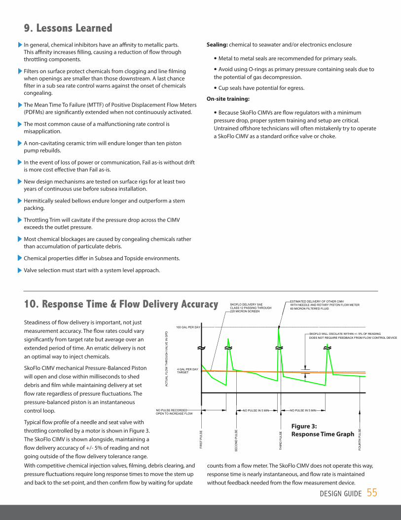
Figure 3: Response Time Graph
10. Response Time & Flow Delivery Accuracy
counts from a flow meter. The SkoFlo CIMV does not operate this way, response time is nearly instantaneous, and flow rate is maintained without feedback needed from the flow measurement device.
Steadiness of flow delivery is important, not just measurement accuracy. The flow rates could vary significantly from target rate but average over an extended period of time. An erratic delivery is not an optimal way to inject chemicals.
SkoFlo CIMV mechanical Pressure-Balanced Piston will open and close within milliseconds to shed debris and film while maintaining delivery at set flow rate regardless of pressure fluctuations. The pressure-balanced piston is an instantaneous control loop.
Typical flow profile of a needle and seat valve with throttling controlled by a motor is shown in Figure 3. The SkoFlo CIMV is shown alongside, maintaining a flow delivery accuracy of +/- 5% of reading and not going outside of the flow delivery tolerance range.
With competitive chemical injection valves, filming, debris clearing, and pressure fluctuations require long response times to move the stem up and back to the set-point, and then confirm flow by waiting for update
9. Lessons Learned In general, chemical inhibitors have an affinity to metallic parts. This affinity increases filling, causing a reduction of flow through throttling components.
Filters on surface protect chemicals from clogging and line filming when openings are smaller than those downstream. A last chance filter in a sub sea rate control warns against the onset of chemicals congealing.
The Mean Time To Failure (MTTF) of Positive Displacement Flow Meters (PDFMs) are significantly extended when not continuously activated.
The most common cause of a malfunctioning rate control is misapplication.
A non-cavitating ceramic trim will endure longer than ten piston pump rebuilds.
In the event of loss of power or communication, Fail as-is without drift is more cost effective than Fail as-is.
New design mechanisms are tested on surface rigs for at least two years of continuous use before subsea installation.
Hermitically sealed bellows endure longer and outperform a stem packing.
Throttling Trim will cavitate if the pressure drop across the CIMV exceeds the outlet pressure.
Most chemical blockages are caused by congealing chemicals rather than accumulation of particulate debris.
Chemical properties differ in Subsea and Topside environments.
Valve selection must start with a system level approach.
Sealing: chemical to seawater and/or electronics enclosure
• Metal to metal seals are recommended for primary seals.
• Avoid using O‐rings as primary pressure containing seals due to the potential of gas decompression.
• Cup seals have potential for egress.
On‐site training:
• Because SkoFlo CIMVs are flow regulators with a minimum pressure drop, proper system training and setup are critical. Untrained offshore technicians will often mistakenly try to operate a SkoFlo CIMV as a standard orifice valve or choke.
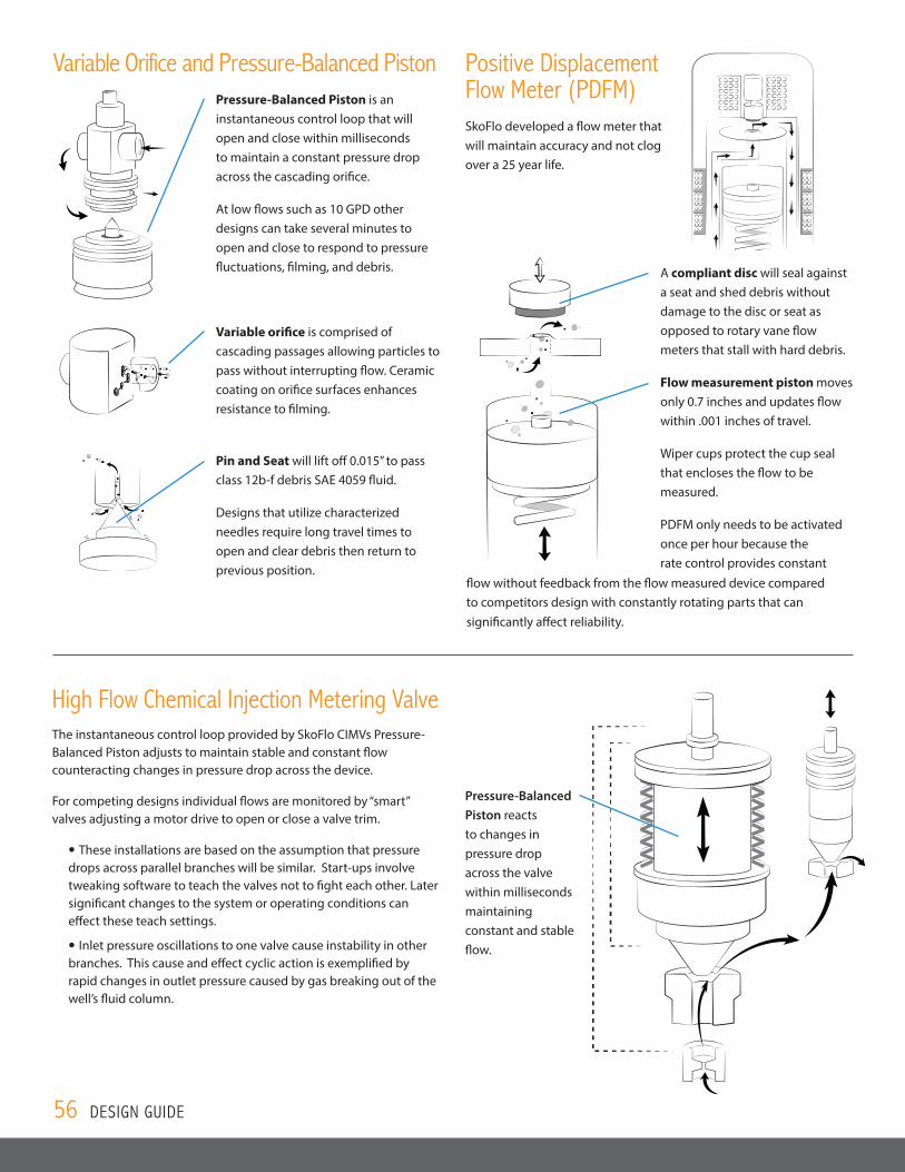
Variable Orifice and Pressure-Balanced PistonPressure-Balanced Piston is an instantaneous control loop that will open and close within milliseconds to maintain a constant pressure drop across the cascading orifice.
At low flows such as 10 GPD other designs can take several minutes to open and close to respond to pressure fluctuations, filming, and debris.
Variable orifice is comprised of cascading passages allowing particles to pass without interrupting flow. Ceramic coating on orifice surfaces enhances resistance to filming.
Pin and Seat will lift off 0.015” to pass class 12b-f debris SAE 4059 fluid.
Designs that utilize characterized needles require long travel times to open and clear debris then return to previous position.
Positive Displacement Flow Meter (PDFM)SkoFlo developed a flow meter that will maintain accuracy and not clog over a 25 year life.
A compliant disc will seal against a seat and shed debris without damage to the disc or seat as opposed to rotary vane flow meters that stall with hard debris.
Flow measurement piston moves only 0.7 inches and updates flow within .001 inches of travel.
Wiper cups protect the cup seal that encloses the flow to be measured.
PDFM only needs to be activated once per hour because the rate control provides constant
flow without feedback from the flow measured device compared to competitors design with constantly rotating parts that can significantly affect reliability.
High Flow Chemical Injection Metering Valve The instantaneous control loop provided by SkoFlo CIMVs Pressure-Balanced Piston adjusts to maintain stable and constant flow counteracting changes in pressure drop across the device.
For competing designs individual flows are monitored by “smart” valves adjusting a motor drive to open or close a valve trim.
• These installations are based on the assumption that pressure drops across parallel branches will be similar. Start-ups involve tweaking software to teach the valves not to fight each other. Later significant changes to the system or operating conditions can effect these teach settings.
• Inlet pressure oscillations to one valve cause instability in other branches. This cause and effect cyclic action is exemplified by rapid changes in outlet pressure caused by gas breaking out of the well’s fluid column.
Pressure-Balanced Piston reacts to changes in pressure drop across the valve within milliseconds maintaining constant and stable flow.
56 DESIGN GUIDE
DESIGN GUIDE 57
11. Terms and DefinitionsAbsolute Filtration: The absolute rating is the diameter of the largest spherical glass particle which will pass through the filter. The absolute rating reflects the pore opening size of the medium. Filter media with an exact and consistent pore size have an exact absolute rating.
Back Pressure Regulator (BPR): BPRs regulate the higher inlet (upstream) pressure by opening up only as much as necessary to hold back the desired pressure at the inlet (upstream). BPRs work just like relief valves, but the emphasis is on steady state pressure control instead of on/off pressure protection.
Brownfield: An existing onshore or offshore facility, e.g. ‘brownfield modification’ is an upgrade to an existing facility.
CANbus: A network communication protocol developed to communicate to the instrument.
Cathodic Protection (CP): CP is a technique used to control the corrosion of a metal surface by making it the cathode of an electrochemical cell.
Centipoise (cP): cP is a measure of dynamic viscosity.
Centistokes (cSt): cSt is a decimal fraction of the CGS unit of kinematic viscosity stokes, which is equal to centimeter per second (cm²/s). 1 stokes is a kinematic viscosity of a fluid with a density of 1 g/cm³ and a dynamic viscosity of 1 poise.
Check Valve: A check valve, clack valve, non-return valve or one-way valve is a valve that normally allows fluid (liquid or gas) to flow through it in only one direction.
Compressibility: Compressibility is a measure of the relative volume change of a fluid or solid as a response to a pressure (or mean stress) change.
Congealing: Process where chemicals thicken, gel (jelly-like) or solidify into a blocking element.
Cup Seal: Fluid control element normally directional in nature to allow for motion.
Design Life: Design life of a component or product is the period of time during which the item is expected by its designers to work within its specified parameters.
Electron Beam Welding (EBW): EBW is a fusion welding process in which a beam of high-velocity electrons is applied to two materials to be joined. The workpieces melt and flow together as the kinetic energy of the electrons is transformed into heat upon impact.
Fail as-is without drift: Upon loss of power, CIMV continues to regulate flow at the last set flow rate regardless of pressure fluctuations, line debris and filming.
Fail as-is: Upon loss of power, CIMV remains at the last set position.
Fail-open: Device opens at loss of power.
Filming: Formation of a thin layer of chemical to exposed CIMV surfaces.
Flow Delivery Accuracy: The percentage variation of the flow rate delivered as compared to the target flow rate.
Flow Measurement Accuracy: The percentage variation of measurement of flow rate as compared to actual flow rate.
Gas Tungsten Arc Welding (GTAW): GTAW, also known as tungsten inert gas (TIG) welding, is an arc welding process that uses a non-consumable tungsten electrode to produce the weld.
Greenfield: A new field development requiring new facilities, either onshore or offshore.
Holding Tank: Holding tank is used to store chemical, having material properties that are compatible with the chemical being stored.
Hysteresis: The difference between up-scale and down-scale results in instrument response when subjected to the same input approached from the opposite direction. Hysteresis can be caused by a multitude of variables, such as packing friction, loose linkage and pressure drop.
Impingement Angle: Angle between the fluid and the wall controlling element.
Incompressible Flow: Density of a fluid element does not change during its motion. Density variation are not linked to the pressure.
Inrush Current: Maximum, instantaneous input current drawn by an electrical device when first turned on.
Mass flow rate: Mass of a substance which passes per unit of time.
Modbus: A serial communication protocol developed to communicate to the instrument.
Mean Time Between Failure (MTBF): Average amount of time that a device or product functions before failing.
Mean Time To Failure (MTTF): Length of time a device or other product is expected to last in operation.
Multi Quick Connect (MQC): MQC is fitted to flying lead and jumper umbilicals, enabling hydraulic and electrical connection between subsea control equipment such as umbilical termination assemblies, distribution units and wellhead Christmas trees.
Newtonian Fluids: A fluid when viscosity is constant for different rates of shear and does not change with time.
Nominal Filtration: A nominal rating indicates the filter’s ability to prevent the passage of a minimum percentage of solid particles greater than the nominal rating’s stated micron size.
Non-Newtonian Fluids: A fluid when viscosity varies with the rate of shear or varies with time, even though the rate of shear is constant.
Perfluoroelastomer (FFKM): Effectively a rubber form of PTFE. They are commonly used to make O-rings and gaskets that are used in applications that involve contact with hydrocarbons or highly corrosive fluids, or when a wide range of temperatures is encountered.
Positive Displacement Flow Meter (PDFM): PDFMs are volumetric flow measurement instruments ideal for low flow rates, highly viscous fluids, and measurement of flows involving starts and stops or pulsing.
Pressure Compensator: Pressure compensators are used to maintain preset pressure differential across a hydraulic component to minimize the influence of pressure variation on a flow rate passing through the component.
Pressure Containing: A part whose failure to function as intended results in a release of retained fluid to the environment.
Pressure Controlling: A part which is intended to control or regulate the movement of pressurized fluid.
Pressure Gauge: A device used to monitor pressure level in the pump discharge line.
Pressure Regulator: A pressure regulator is a valve that automatically cuts off the flow of a liquid or gas at a certain pressure.
Pressure Retaining: A part which maintains pressure containing elements, normally not in contact with the primary fluid.
Pressure Safety Valve (PSV): PSV is either spring loaded, normally closed, adjustable valve or burst plate used to allow fluid to exit from the pump discharge line when pressure reaches Maximum Allowable Working Pressure (MAWP).
Primary seals: First barrier which retains fluid to the environment.
Pulsation Damper: Pulsation Damper is used to decrease pressure spikes in pump discharge caused by piston type pumps. Can be bladder type or piston type. Bladder type is more efficient for eliminating pump pulsation in fluid stream.
Pump: A Pump usually a positive displacement type, should have sufficient capacity to satisfy all injection demand PLUS 10%, should have sufficient pressure rating to satisfy design requirements.
12. AxiomsFinal truth of your flow rate is the change in tank level.
A test is worth a thousand expert “opinions”.
Never attempt to fool Mother Nature, mimic whenever possible.
If you don’t understand the design limits, it will lead to misapplication.
The best designs are simple rather than complex and are created from a collaboration of experts who remain with the project from conception to field installation.
Optimal chemical injection results are achieved with continuous rather than batch injection.
Viscosity, pressure drop, and outlet pressure are the most significant factors when predicting the onset of cavitation.
Due to line loss and compressibility, the most accurate control is achieved when the regulating device is closest to injection point.
Never get into an argument with someone who types faster than you.
ROV Mate: Electrical connector intended to be mated or plugged in by ROV or diver.
Secondary Seals: Redundant barrier to primary seal which retains fluid to the environment.
SIIS: Subsea Instrumentation Interface Standardization.
Stab Mate: Electrical connector intended to be mated when Junction plates are mounted.
Subsea Control Module (SCM)/Control Pod: The SCM/Control Pod is the interface between the control lines, supplying hydraulic and electric power and signals from the host facility, and the subsea equipment to be monitored and controlled. The pod contains electronic components that are used for control, communications and data-gathering.
Vapor Pressure: Pressure exerted by a vapor when the vapor is in equilibrium with the liquid or solid form, or both, of the same substance—i.e., when conditions are such that the substance can exist in both or in all three phases. Vapor pressure is a measure of the tendency of a material to change into the gaseous or vapor state, and it increases with temperature.
Viscosity: Viscosity is a measure of a fluids resistance to gradual deformation by shear stress or tensile stress.
Viscosity, Dynamic: Dynamic Viscosity is a measure of internal resistance.
Viscosity, Kinematic: Kinematic viscosity can be obtained by dividing the absolute viscosity of a fluid with the fluid mass density.
Volumetric flow rate: Volume of fluid which passes per unit time.
58 DESIGN GUIDE

SkoFlo maintains accreditation to international quality standard ISO 9001-2008
SkoFlo Industries, Inc.14241 NE 200th Street
Woodinville, WA 98072 USA1-425-485-7816
www.skoflo.com