Embed Size (px)
Citation preview
Access Modular ControllerAMC2-16ION
en Installation Manual

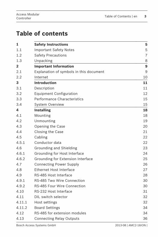
Table of contents
1 Safety Instructions 51.1 Important Safety Notes 51.2 Safety Precautions 71.3 Unpacking 8
2 Important Information 92.1 Explanation of symbols in this document 92.2 Internet 10
3 Introduction 113.1 Description 113.2 Equipment Configuration 123.3 Performance Characteristics 153.4 System Overview 15
4 Installing 184.1 Mounting 184.2 Unmounting 194.3 Opening the Case 204.4 Closing the Case 214.5 Cabling 224.5.1 Conductor data 224.6 Grounding and Shielding 234.6.1 Grounding for Host Interface 244.6.2 Grounding for Extension Interface 254.7 Connecting Power Supply 264.8 Ethernet Host Interface 274.9 RS-485 Host Interface 284.9.1 RS-485 Two Wire Connection 304.9.2 RS-485 Four Wire Connection 304.10 RS-232 Host Interface 314.11 DIL switch selector 324.11.1 Host settings 324.11.2 Board Settings 344.12 RS-485 for extension modules 344.13 Connecting Relay Outputs 36
Access ModularController
Table of Contents | en 3
Bosch Access Systems GmbH 2013-08 | AMC2-16ION |
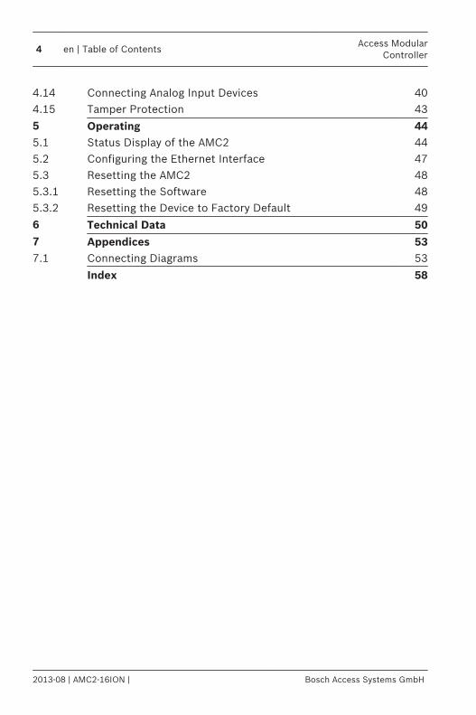
4.14 Connecting Analog Input Devices 404.15 Tamper Protection 43
5 Operating 445.1 Status Display of the AMC2 445.2 Configuring the Ethernet Interface 475.3 Resetting the AMC2 485.3.1 Resetting the Software 485.3.2 Resetting the Device to Factory Default 49
6 Technical Data 507 Appendices 537.1 Connecting Diagrams 53
Index 58
4 en | Table of ContentsAccess Modular
Controller
2013-08 | AMC2-16ION | Bosch Access Systems GmbH

Safety Instructions
Important Safety Notes1. Read, follow, and retain instructions - All safety and
operating instructions must be read and followed properlybefore putting the unit into operation. Retain instructionsfor future reference.
2. Do not ignore warnings - Adhere to all warnings on the unitand in the operating instructions.
3. Accessories - Use only accessories recommended by themanufacturer or those sold with the product. Accessoriesnot recommended by the manufacturer must not be used,as they may cause hazards.
4. Installation precautions - Do not place this unit on anunstable stand, tripod, bracket, or mount. The unit may fall,causing serious injury to persons and damage to the unit.Mount the unit according to the manufacturer’sinstructions.
5. Service - Do not attempt to service this unit by yourself.Opening or removing covers may expose you to dangerousvoltages or other hazards. Refer all servicing to qualifiedservice personnel.
6. Damage which requires service - Disconnect the unit fromthe main AC or DC power source and refer servicing toqualified service personnel under the following conditions:– If the power supply cord or plug is damaged.– If liquid has been spilled or an object has fallen into
the unit.– If the unit has been exposed to water and/or inclement
weather (rain, snow, etc.).– If the unit does not operate normally when following
the operating instructions. Adjust only those controlsspecified in the operating instructions. Improper
1
1.1
Access ModularController
Safety Instructions | en 5
Bosch Access Systems GmbH 2013-08 | AMC2-16ION |
adjustment of other controls may result in damage,and require extensive work by a qualified technician torestore the unit to normal operation.
– If the unit has been dropped or the cabinet damaged.– If the unit exhibits a distinct change in performance
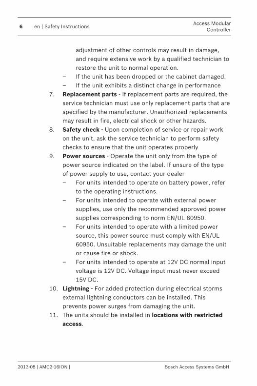
7. Replacement parts - If replacement parts are required, theservice technician must use only replacement parts that arespecified by the manufacturer. Unauthorized replacementsmay result in fire, electrical shock or other hazards.
8. Safety check - Upon completion of service or repair workon the unit, ask the service technician to perform safetychecks to ensure that the unit operates properly
9. Power sources - Operate the unit only from the type ofpower source indicated on the label. If unsure of the typeof power supply to use, contact your dealer– For units intended to operate on battery power, refer
to the operating instructions.– For units intended to operate with external power
supplies, use only the recommended approved powersupplies corresponding to norm EN/UL 60950.
– For units intended to operate with a limited powersource, this power source must comply with EN/UL60950. Unsuitable replacements may damage the unitor cause fire or shock.
– For units intended to operate at 12V DC normal inputvoltage is 12V DC. Voltage input must never exceed15V DC.
10. Lightning - For added protection during electrical stormsexternal lightning conductors can be installed. Thisprevents power surges from damaging the unit.
11. The units should be installed in locations with restrictedaccess.
6 en | Safety InstructionsAccess Modular
Controller
2013-08 | AMC2-16ION | Bosch Access Systems GmbH
Safety PrecautionsRead instructions!Before working with the AMC2 device, read these instructionscarefully. Make sure you have understood all informationdescribed in this document.
!
Warning!
Risk of electric shock
External power supplies must be installed and put into service
by qualified personnel.
Ensure compliance with the relevant regulations.
Ground the controller.
Disconnect both AC and battery power supply before working
on the controller.
!
Warning!
Risk of fire
Installation of the AMC2 device must comply with any local fire,
health, and safety regulations. A secured door that may be part
of an escape route from an area must be installed with:
Install a fail-safe lock (A), so that the door will be released if
power fails. Ideally, use a magnetic lock.
Install a normally-closed break glass or a manual pull (B) in the
lock supply wiring, so that in an emergency the fail-safe lock
can be immediately powered down.
1.2
Access ModularController
Safety Instructions | en 7
Bosch Access Systems GmbH 2013-08 | AMC2-16ION |
!
Warning!
Risk of explosion of Lithium battery
The battery can explode if it is replaced incorrectly.
Replace only with the same type as recommended by the
manufacturer.
Dispose used batteries according to the battery manufacturer’s
instructions.
Notice!
Risk of damage to equipment
Protect the hardware from electrostatic discharge by observing
ESD instructions before unpacking of touching connectors of
electronics.
Always switch off power of the AMC2 device before modifying
the installation.
Do not connect or disconnect plug connectors, data cables, or
screw connectors while power is on.
UnpackingCheck the packaging for visible damage. If anything has beendamaged during transport, please inform the transport agency.Unpack the unit carefully. This is an electronic device that mustbe handled with care to avoid damage. Do not attempt to putthe unit into operation if components are damaged.If any parts are missing, inform your customer servicerepresentative or a Bosch Security Systems salesperson. Theshipping carton is the safest transport container for the unit.Store it and the other packaging material for future use. If theunit has to be sent back, use the original packaging.
1.3
8 en | Safety InstructionsAccess Modular
Controller
2013-08 | AMC2-16ION | Bosch Access Systems GmbH
Important InformationRemarksThis hardware is part of a security system. Access should belimited to authorized persons only.Some states do not allow the exclusion or limitation of impliedwarranties, or limitation of liability for incidental orconsequential damages, hence the above limitation or exclusionmight not apply to you.Bosch Security Systems retains all rights not expressly granted.Nothing in this license constitutes a waiver of Bosch’s rightsunder the U.S. Copyright laws or any other federal or state law.If you have any questions concerning this license, please, writeto: Bosch Sicherheitssysteme GmbHRobert-Bosch-Ring 585630 GrasbrunnGermany.
Explanation of symbols in this documentThroughout this document, warning messages, important notes,and helpful tips are presented for the reader. These appear asfollows:
Danger!
Cause of Hazard
Indicates a hazardous situation, which, if not avoided, will result
in death or serious injury.
!
Warning!
Cause of Hazard
Indicates a hazardous situation, which, if not avoided, could
result in death or serious injury.
2
2.1
Access ModularController
Important Information | en 9
Bosch Access Systems GmbH 2013-08 | AMC2-16ION |

!
Caution!
Cause of Hazard
Indicates a hazardous situation, which, if not avoided, could
result in minor or moderate injury.
Notice!
Cause of Hazard
Important Notes that must be followed to avoid damage to the
equipment or environment, and to ensure successful operation
and programming.
Tips and shortcuts may also be included in such notes.
InternetIf you are interested in further information on this product orinformation on other products, please consult our website athttp://www.boschsecurity.com.
2.2
10 en | Important InformationAccess Modular
Controller
2013-08 | AMC2-16ION | Bosch Access Systems GmbH
Introduction
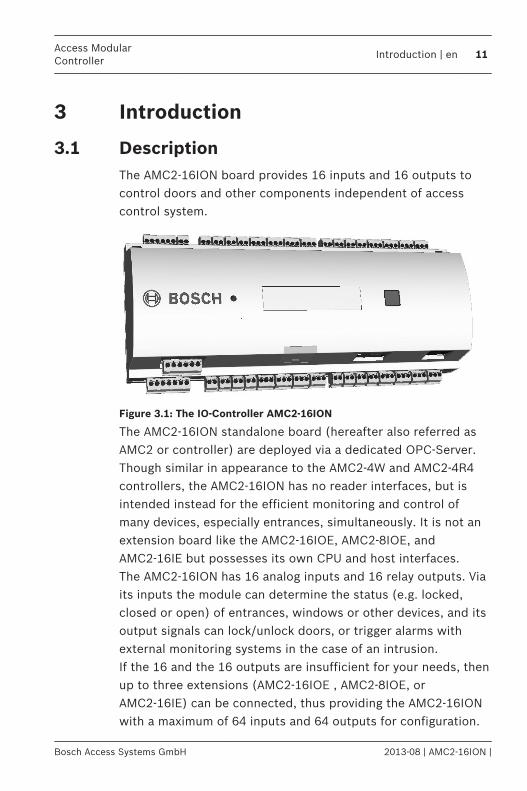
DescriptionThe AMC2-16ION board provides 16 inputs and 16 outputs tocontrol doors and other components independent of accesscontrol system.
Figure 3.1: The IO-Controller AMC2-16ION
The AMC2-16ION standalone board (hereafter also referred asAMC2 or controller) are deployed via a dedicated OPC-Server.Though similar in appearance to the AMC2-4W and AMC2-4R4controllers, the AMC2-16ION has no reader interfaces, but isintended instead for the efficient monitoring and control ofmany devices, especially entrances, simultaneously. It is not anextension board like the AMC2-16IOE, AMC2-8IOE, andAMC2-16IE but possesses its own CPU and host interfaces.The AMC2-16ION has 16 analog inputs and 16 relay outputs. Viaits inputs the module can determine the status (e.g. locked,closed or open) of entrances, windows or other devices, and itsoutput signals can lock/unlock doors, or trigger alarms withexternal monitoring systems in the case of an intrusion.If the 16 and the 16 outputs are insufficient for your needs, thenup to three extensions (AMC2-16IOE , AMC2-8IOE, orAMC2-16IE) can be connected, thus providing the AMC2-16IONwith a maximum of 64 inputs and 64 outputs for configuration.
3
3.1
Access ModularController
Introduction | en 11
Bosch Access Systems GmbH 2013-08 | AMC2-16ION |
Equipment Configuration
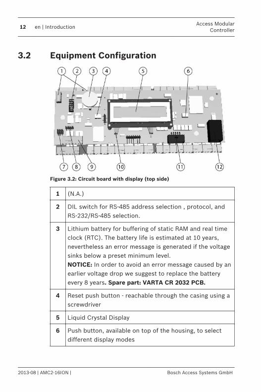
Figure 3.2: Circuit board with display (top side)
1 (N.A.)
2 DIL switch for RS-485 address selection , protocol, andRS-232/RS-485 selection.
3 Lithium battery for buffering of static RAM and real timeclock (RTC). The battery life is estimated at 10 years,nevertheless an error message is generated if the voltagesinks below a preset minimum level.NOTICE: In order to avoid an error message caused by anearlier voltage drop we suggest to replace the batteryevery 8 years. Spare part: VARTA CR 2032 PCB.
4 Reset push button - reachable through the casing using ascrewdriver
5 Liquid Crystal Display
6 Push button, available on top of the housing, to selectdifferent display modes
3.2
12 en | IntroductionAccess Modular
Controller
2013-08 | AMC2-16ION | Bosch Access Systems GmbH
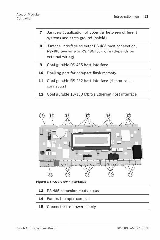
7 Jumper: Equalization of potential between differentsystems and earth ground (shield)
8 Jumper: Interface selector RS-485 host connection,RS-485 two wire or RS-485 four wire (depends onexternal wiring)
9 Configurable RS-485 host interface
10 Docking port for compact flash memory
11 Configurable RS-232 host interface (ribbon cableconnector)
12 Configurable 10/100 Mbit/s Ethernet host interface
Figure 3.3: Overview - Interfaces
13 RS-485 extension module bus
14 External tamper contact
15 Connector for power supply
Access ModularController
Introduction | en 13
Bosch Access Systems GmbH 2013-08 | AMC2-16ION |
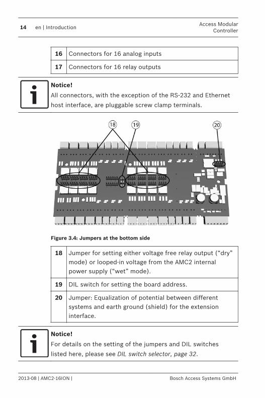
16 Connectors for 16 analog inputs
17 Connectors for 16 relay outputs
Notice!
All connectors, with the exception of the RS-232 and Ethernet
host interface, are pluggable screw clamp terminals.
Figure 3.4: Jumpers at the bottom side
18 Jumper for setting either voltage free relay output (“dry”mode) or looped-in voltage from the AMC2 internalpower supply (“wet” mode).
19 DIL switch for setting the board address.
20 Jumper: Equalization of potential between differentsystems and earth ground (shield) for the extensioninterface.
Notice!
For details on the setting of the jumpers and DIL switches
listed here, please see DIL switch selector, page 32.
14 en | IntroductionAccess Modular
Controller
2013-08 | AMC2-16ION | Bosch Access Systems GmbH
Performance Characteristics– Host address selectable using DIL sliding switch.– Four possible configurable host interfaces:
– Ethernet (= standard)– RS-485 2-wire– RS-485 4-wire– RS-232
– 16 relay outputs– voltage free, power is supplied externally (dry mode)– powered by internal power supply (wet mode)
– 16 analog inputs with internal power supply– Battery buffered SRAM and real time clock (RTC)– Pluggable Compact Flash card – Liquid Crystal Display– Transfer rate host interface RS-485: 38,4 kBit/s– Transfer rate host interface RS-232: 38,4 kBit/s– Transfer rate host interface Ethernet: 10/100 Mbit/s– Transfer rate to the extension interface: 9,6 kBit/s– Self regulating transmit/receive switching– Power supply: 10 V to 30 Vdc, max. 5 A– Tamper contact for external covers– If an external power supply is used then this should be an
PBC-60 (F.01U.026.573) with integrated uninterruptablepower supply (UPS).
System OverviewThe AMC2-16ION is deployed as an independent controllerbetween the management host system and various peripheraldevices. By default, a management host system is connected viaEthernet. A management host connection using RS-485 orRS-232 is also possible.
3.3
3.4
Access ModularController
Introduction | en 15
Bosch Access Systems GmbH 2013-08 | AMC2-16ION |
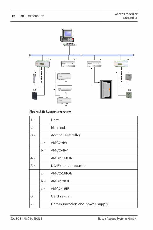
Figure 3.5: System overview
1 = Host
2 = Ethernet
3 = Access Controller
a = AMC2-4W
b = AMC2-4R4
4 = AMC2-16ION
5 = I/O-Extensionboards
a = AMC2-16IOE
b = AMC2-8IOE
c = AMC2-16IE
6 = Card reader
7 = Communication and power supply
16 en | IntroductionAccess Modular
Controller
2013-08 | AMC2-16ION | Bosch Access Systems GmbH
Depending on the kind of interface are available the followingconstellations are possible:– Using RS-232 host connection one AMC2-16ION can be
connected per COM port.– Using RS-485 host connection, up to eight of these modules
can be combined on one COM port.– Up to three extension boards can be connected to and
controlled by the AMC2-16ION. These can be anycombination of types AMC2-8IOE, AMC2-16IOE, orAMC2-16IE.
System configurations for Access Control applications– The minimum configuration consists of
– one PC with system software– one AMC2 controller– one AMC PBC-60 power supply– one AMC enclosure
– The maximum configuration depends on the systemsoftware.
Access ModularController
Introduction | en 17
Bosch Access Systems GmbH 2013-08 | AMC2-16ION |
Installing
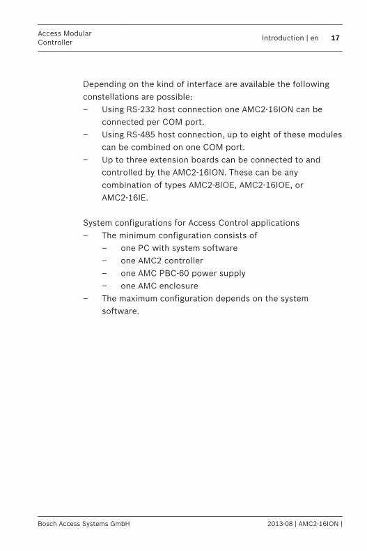
MountingThe AMC2-16ION can be attached on a standard 35 mm(1.377 in.) mounting rail using a snap-in mechanism. Attach theAMC2-16ION into the upper edge of the mounting rail [1], thenpush down the device and snap it onto the rail by pushing ittowards the back [2].
Figure 4.1: Mounting the AMC2 on a mounting rail
4
4.1
18 en | InstallingAccess Modular
Controller
2013-08 | AMC2-16ION | Bosch Access Systems GmbH
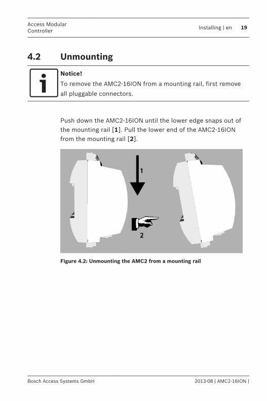
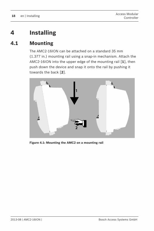
Unmounting
Notice!
To remove the AMC2-16ION from a mounting rail, first remove
all pluggable connectors.
Push down the AMC2-16ION until the lower edge snaps out ofthe mounting rail [1]. Pull the lower end of the AMC2-16IONfrom the mounting rail [2].
Figure 4.2: Unmounting the AMC2 from a mounting rail
4.2
Access ModularController
Installing | en 19
Bosch Access Systems GmbH 2013-08 | AMC2-16ION |
Opening the Case
Notice!
To open the AMC2-16ION, first remove all pluggable
connectors.
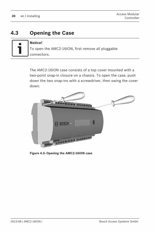
The AMC2-16ION case consists of a top cover mounted with atwo-point snap-in closure on a chassis. To open the case, pushdown the two snap-ins with a screwdriver, then swing the coverdown.
Figure 4.3: Opening the AMC2-16ION case
4.3
20 en | InstallingAccess Modular
Controller
2013-08 | AMC2-16ION | Bosch Access Systems GmbH
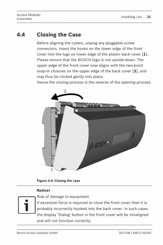
Closing the CaseBefore aligning the covers, unplug any pluggable screwconnectors. Insert the hooks on the lower edge of the frontcover into the lugs on lower edge of the plastic back cover [1].Please ensure that the BOSCH logo is not upside-down. Theupper edge of the front cover now aligns with the two-pointsnap-in closures on the upper edge of the back cover [2], andmay thus be clicked gently into place.Hence the closing process is the reverse of the opening process.
Figure 4.4: Closing the case
Notice!
Risk of damage to equipment
If excessive force is required to close the front cover then it is
probably incorrectly hooked into the back cover. In such cases
the display ’Dialog’ button in the front cover will be misaligned
and will not function correctly.
4.4
Access ModularController
Installing | en 21
Bosch Access Systems GmbH 2013-08 | AMC2-16ION |
Cabling
Conductor dataWith the calculation below you can find out which cable typemust be used. If you connect the power supply and the AMC-device with the delivered cable set from the enclosure thecalculation is not necessary.For distances below 25 m (75 ft) use AWG18 conductors(1mm²). For longer distances, install an additional power supplyclose to the AMC2 controller.Please, calculate the voltage drop by checking the conductorspecifications for characteristic resistance values. The voltagedrop shall not exceed 2 V.Example:Length = 100 m/328 ftU = 12V, I = 1A, maximum UDrop = 2V
i.e. RAWG18 (acc. specs) = 6.385 or 20,948
UDrop = 20,948 x 0.1 km x 1A = 2.1V
UDrop = 6.385 x 328 ft x 1A = 2.1V
Critical condition! Install the power supply closer to thecontroller.
Notice!
These specifications apply to power supply, readers, relay
outputs, and extension interface.
Regarding inputs, specific voltage-drop values need to be taken
into account. Refer to Connecting Analog Input Devices, page
40.
4.5
4.5.1
22 en | InstallingAccess Modular
Controller
2013-08 | AMC2-16ION | Bosch Access Systems GmbH
Grounding and ShieldingThe main grounding point at the AMC2-16ION is connected topin 2 of the power supply connector – see Connecting Diagrams,page 53.It is good practice to shield all wires carrying low level signals. The AMC2-16ION allows you to create a central ground orshielding point, simply by setting certain jumpers. Set thesejumpers only if grounding or shielding is not achieved by othermeans.
Notice!
Risk of malfunction
Ensure that no ground loops are formed.
Notice!
In general the following apply:
If the devices have their own power supplies, the shielding is
applied to one side only. The free end should be insulated to
avoid inadvertent connections.
If one device is fed power by another, the cable shielding
should be applied to both sides.
4.6
Access ModularController
Installing | en 23
Bosch Access Systems GmbH 2013-08 | AMC2-16ION |
Grounding for Host Interface
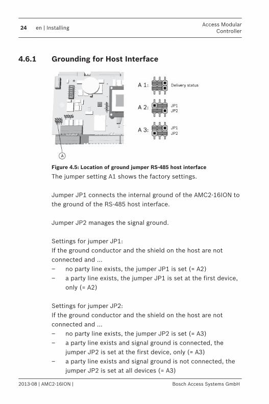
Figure 4.5: Location of ground jumper RS-485 host interface
The jumper setting A1 shows the factory settings. Jumper JP1 connects the internal ground of the AMC2-16ION tothe ground of the RS-485 host interface. Jumper JP2 manages the signal ground. Settings for jumper JP1:If the ground conductor and the shield on the host are notconnected and ...– no party line exists, the jumper JP1 is set (= A2)– a party line exists, the jumper JP1 is set at the first device,
only (= A2) Settings for jumper JP2:If the ground conductor and the shield on the host are notconnected and ...– no party line exists, the jumper JP2 is set (= A3)– a party line exists and signal ground is connected, the
jumper JP2 is set at the first device, only (= A3)– a party line exists and signal ground is not connected, the
jumper JP2 is set at all devices (= A3)
4.6.1
24 en | InstallingAccess Modular
Controller
2013-08 | AMC2-16ION | Bosch Access Systems GmbH
Grounding for Extension Interface
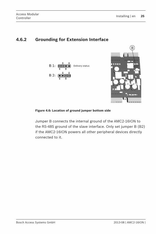
Figure 4.6: Location of ground jumper bottom side
Jumper B connects the internal ground of the AMC2-16ION tothe RS-485 ground of the slave interface. Only set jumper B (B2)if the AMC2-16ION powers all other peripheral devices directlyconnected to it.
4.6.2
Access ModularController
Installing | en 25
Bosch Access Systems GmbH 2013-08 | AMC2-16ION |
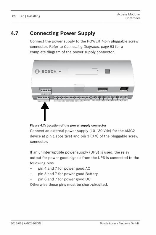
Connecting Power SupplyConnect the power supply to the POWER 7-pin pluggable screwconnector. Refer to Connecting Diagrams, page 53 for acomplete diagram of the power supply connector.
Figure 4.7: Location of the power supply connector
Connect an external power supply (10 - 30 Vdc) for the AMC2device at pin 1 (positive) and pin 3 (0 V) of the pluggable screwconnector. If an uninterruptible power supply (UPS) is used, the relayoutput for power good signals from the UPS is connected to thefollowing pins:– pin 4 and 7 for power good AC– pin 5 and 7 for power good Battery– pin 6 and 7 for power good DCOtherwise these pins must be short-circuited.
4.7
26 en | InstallingAccess Modular
Controller
2013-08 | AMC2-16ION | Bosch Access Systems GmbH
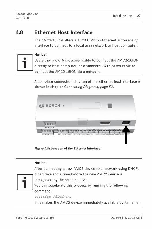
Ethernet Host InterfaceThe AMC2-16ION offers a 10/100 Mbit/s Ethernet auto-sensinginterface to connect to a local area network or host computer.
Notice!
Use either a CAT5 crossover cable to connect the AMC2-16ION
directly to host computer, or a standard CAT5 patch cable to
connect the AMC2-16ION via a network.
A complete connection diagram of the Ethernet host interface isshown in chapter Connecting Diagrams, page 53.
Figure 4.8: Location of the Ethernet interface
Notice!
After connecting a new AMC2 device to a network using DHCP,
it can take some time before the new AMC2 device is
recognized by the remote server.
You can accelerate this process by running the following
command:
ipconfig /flushdnsThis makes the AMC2 device immediately available by its name.
4.8
Access ModularController
Installing | en 27
Bosch Access Systems GmbH 2013-08 | AMC2-16ION |
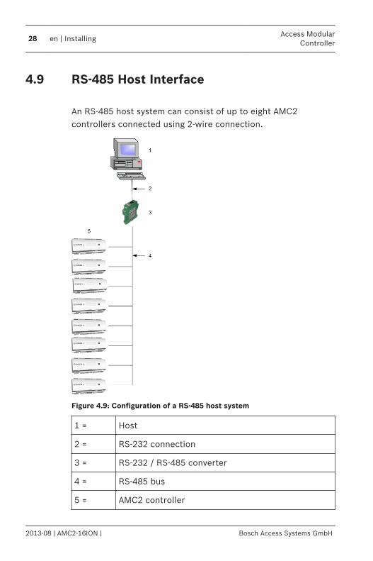
RS-485 Host Interface An RS-485 host system can consist of up to eight AMC2controllers connected using 2-wire connection.
Figure 4.9: Configuration of a RS-485 host system
1 = Host
2 = RS-232 connection
3 = RS-232 / RS-485 converter
4 = RS-485 bus
5 = AMC2 controller
4.9
28 en | InstallingAccess Modular
Controller
2013-08 | AMC2-16ION | Bosch Access Systems GmbH
The following conditions apply for an RS-485 bus system:– A bus system consists of a bus line and/or one or more
branch lines.– Cable lengths exceeding 100 m (300 ft) must be installed
as bus lines.– Branch lines are branching connections from a bus line.– Peripheral devices are AMC2 which are connected to the
host computer.– Maximum cable length of a bus line must not exceed
1200 m (4000ft).– The cable length of branch lines must not exceed 100m
(330ft).– Any bus line conductor connects up to eight AMC2. Do not
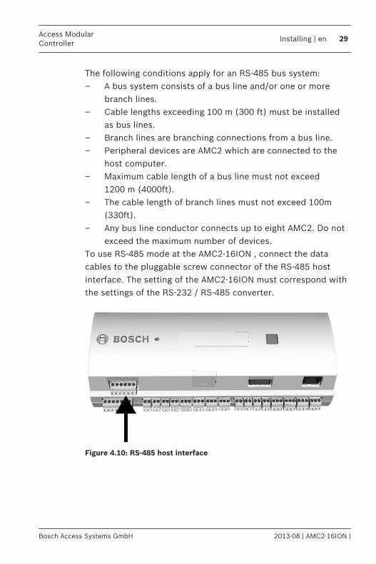
exceed the maximum number of devices.To use RS-485 mode at the AMC2-16ION , connect the datacables to the pluggable screw connector of the RS-485 hostinterface. The setting of the AMC2-16ION must correspond withthe settings of the RS-232 / RS-485 converter.
Figure 4.10: RS-485 host interface
Access ModularController
Installing | en 29
Bosch Access Systems GmbH 2013-08 | AMC2-16ION |
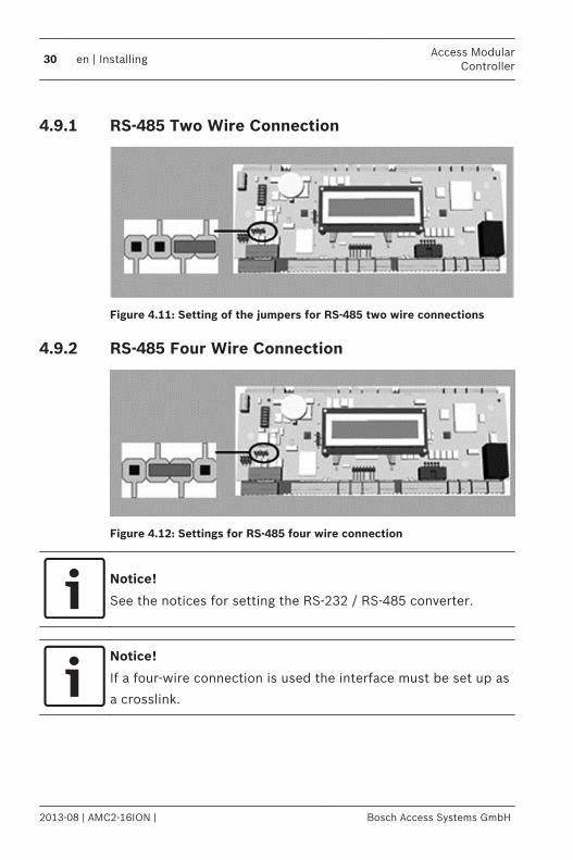
RS-485 Two Wire Connection
Figure 4.11: Setting of the jumpers for RS-485 two wire connections
RS-485 Four Wire Connection
Figure 4.12: Settings for RS-485 four wire connection
Notice!
See the notices for setting the RS-232 / RS-485 converter.
Notice!
If a four-wire connection is used the interface must be set up as
a crosslink.
4.9.1
4.9.2
30 en | InstallingAccess Modular
Controller
2013-08 | AMC2-16ION | Bosch Access Systems GmbH
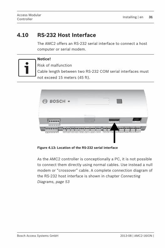
RS-232 Host InterfaceThe AMC2 offers an RS-232 serial interface to connect a hostcomputer or serial modem.
Notice!
Risk of malfunction
Cable length between two RS-232 COM serial interfaces must
not exceed 15 meters (45 ft).
Figure 4.13: Location of the RS-232 serial interface
As the AMC2 controller is conceptionally a PC, it is not possibleto connect them directly using normal cables. Use instead a nullmodem or “crossover” cable. A complete connection diagram ofthe RS-232 host interface is shown in chapter ConnectingDiagrams, page 53
4.10
Access ModularController
Installing | en 31
Bosch Access Systems GmbH 2013-08 | AMC2-16ION |
DIL switch selector
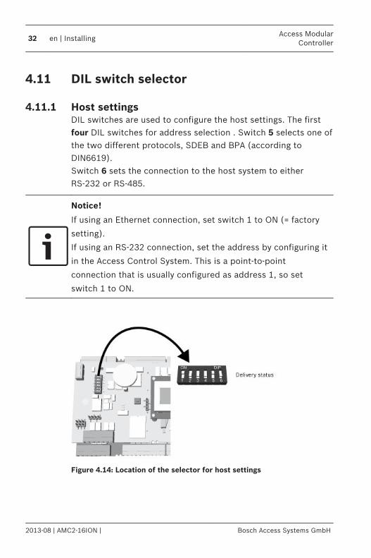
Host settingsDIL switches are used to configure the host settings. The firstfour DIL switches for address selection . Switch 5 selects one ofthe two different protocols, SDEB and BPA (according toDIN6619).Switch 6 sets the connection to the host system to eitherRS-232 or RS-485.
Notice!
If using an Ethernet connection, set switch 1 to ON (= factory
setting).
If using an RS-232 connection, set the address by configuring it
in the Access Control System. This is a point-to-point
connection that is usually configured as address 1, so set
switch 1 to ON.
Figure 4.14: Location of the selector for host settings
4.11
4.11.1
32 en | InstallingAccess Modular
Controller
2013-08 | AMC2-16ION | Bosch Access Systems GmbH
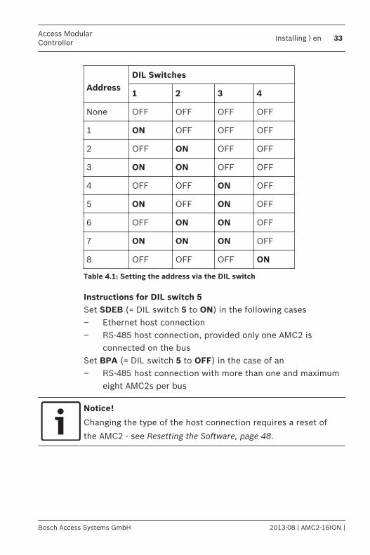
Address
DIL Switches
1 2 3 4
None OFF OFF OFF OFF
1 ON OFF OFF OFF
2 OFF ON OFF OFF
3 ON ON OFF OFF
4 OFF OFF ON OFF
5 ON OFF ON OFF
6 OFF ON ON OFF
7 ON ON ON OFF
8 OFF OFF OFF ON
Table 4.1: Setting the address via the DIL switch
Instructions for DIL switch 5Set SDEB (= DIL switch 5 to ON) in the following cases– Ethernet host connection– RS-485 host connection, provided only one AMC2 is
connected on the busSet BPA (= DIL switch 5 to OFF) in the case of an– RS-485 host connection with more than one and maximum
eight AMC2s per bus
Notice!
Changing the type of the host connection requires a reset of
the AMC2 - see Resetting the Software, page 48.
Access ModularController
Installing | en 33
Bosch Access Systems GmbH 2013-08 | AMC2-16ION |
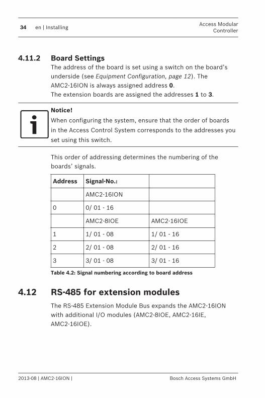
Board SettingsThe address of the board is set using a switch on the board’sunderside (see Equipment Configuration, page 12). TheAMC2-16ION is always assigned address 0.The extension boards are assigned the addresses 1 to 3.
Notice!
When configuring the system, ensure that the order of boards
in the Access Control System corresponds to the addresses you
set using this switch.
This order of addressing determines the numbering of theboards’ signals.
Address Signal-No.:
AMC2-16ION
0 0/ 01 - 16
AMC2-8IOE AMC2-16IOE
1 1/ 01 - 08 1/ 01 - 16
2 2/ 01 - 08 2/ 01 - 16
3 3/ 01 - 08 3/ 01 - 16
Table 4.2: Signal numbering according to board address
RS-485 for extension modulesThe RS-485 Extension Module Bus expands the AMC2-16IONwith additional I/O modules (AMC2-8IOE, AMC2-16IE,AMC2-16IOE).
4.11.2
4.12
34 en | InstallingAccess Modular
Controller
2013-08 | AMC2-16ION | Bosch Access Systems GmbH

Figure 4.15: Location of the RS-485 extension module bus
Up to three expansion modules can be connected to provideadditional in- and outputs, for example, for elevator control.You can find further information about the extension boards intheir installation manuals.A complete connection diagram of the RS-485 extension modulebus is shown in Connecting Diagrams, page 53.
Figure 4.16: Connection of an extension module to an AMC2
Access ModularController
Installing | en 35
Bosch Access Systems GmbH 2013-08 | AMC2-16ION |
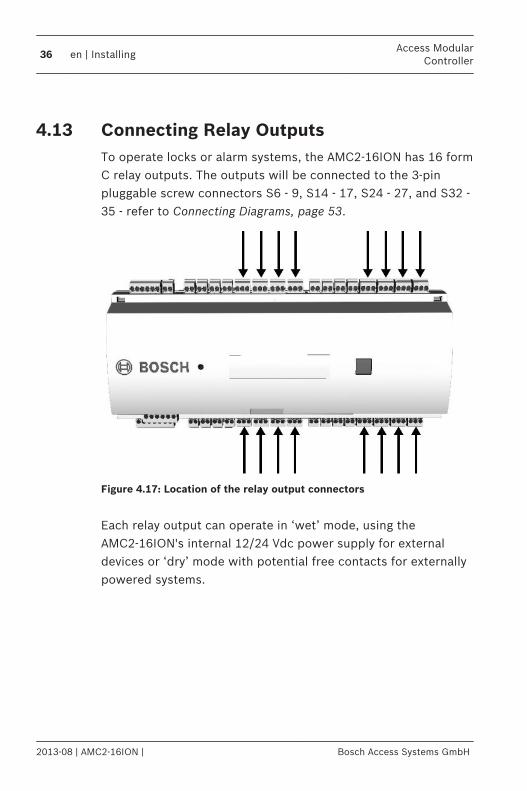
Connecting Relay OutputsTo operate locks or alarm systems, the AMC2-16ION has 16 formC relay outputs. The outputs will be connected to the 3-pinpluggable screw connectors S6 - 9, S14 - 17, S24 - 27, and S32 -35 - refer to Connecting Diagrams, page 53.
Figure 4.17: Location of the relay output connectors
Each relay output can operate in ‘wet’ mode, using theAMC2-16ION's internal 12/24 Vdc power supply for externaldevices or ‘dry’ mode with potential free contacts for externallypowered systems.
4.13
36 en | InstallingAccess Modular
Controller
2013-08 | AMC2-16ION | Bosch Access Systems GmbH
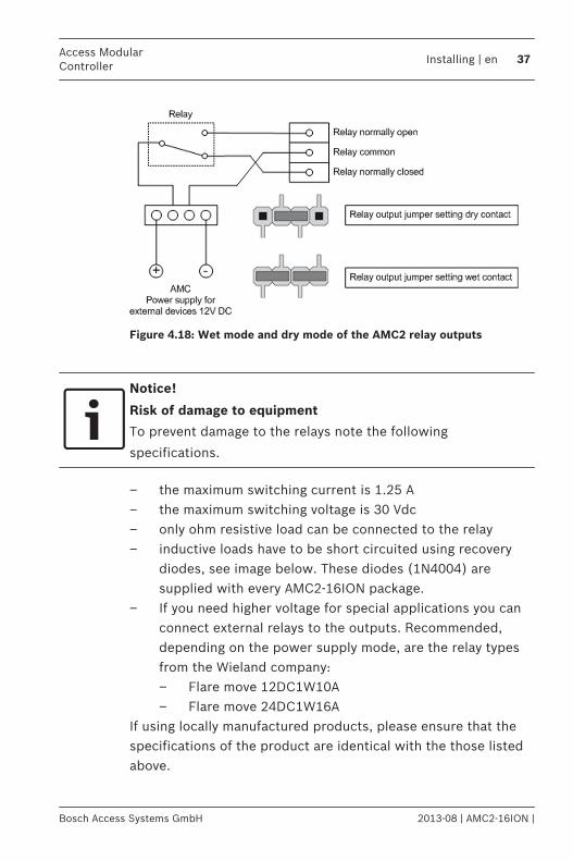
Figure 4.18: Wet mode and dry mode of the AMC2 relay outputs
Notice!
Risk of damage to equipment
To prevent damage to the relays note the following
specifications.
– the maximum switching current is 1.25 A– the maximum switching voltage is 30 Vdc– only ohm resistive load can be connected to the relay– inductive loads have to be short circuited using recovery
diodes, see image below. These diodes (1N4004) aresupplied with every AMC2-16ION package.
– If you need higher voltage for special applications you canconnect external relays to the outputs. Recommended,depending on the power supply mode, are the relay typesfrom the Wieland company:– Flare move 12DC1W10A– Flare move 24DC1W16A
If using locally manufactured products, please ensure that thespecifications of the product are identical with the those listedabove.
Access ModularController
Installing | en 37
Bosch Access Systems GmbH 2013-08 | AMC2-16ION |
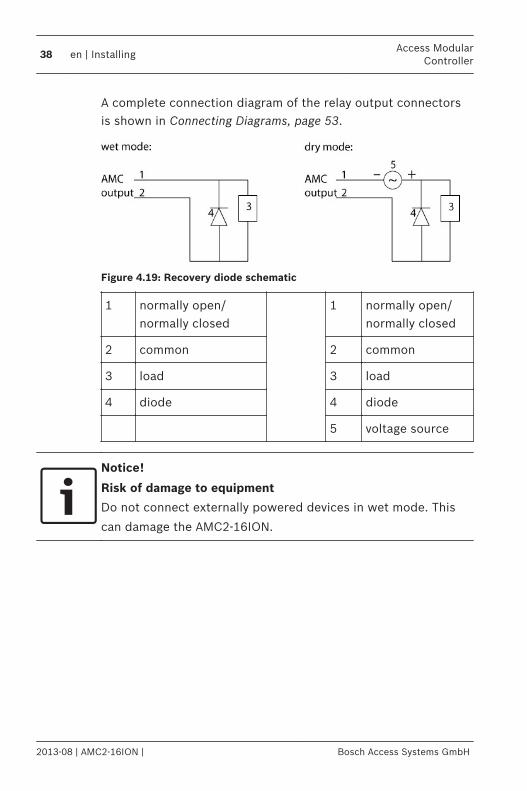
A complete connection diagram of the relay output connectorsis shown in Connecting Diagrams, page 53.
Figure 4.19: Recovery diode schematic
1 normally open/normally closed
1 normally open/normally closed
2 common 2 common
3 load 3 load
4 diode 4 diode
5 voltage source
Notice!
Risk of damage to equipment
Do not connect externally powered devices in wet mode. This
can damage the AMC2-16ION.
38 en | InstallingAccess Modular
Controller
2013-08 | AMC2-16ION | Bosch Access Systems GmbH
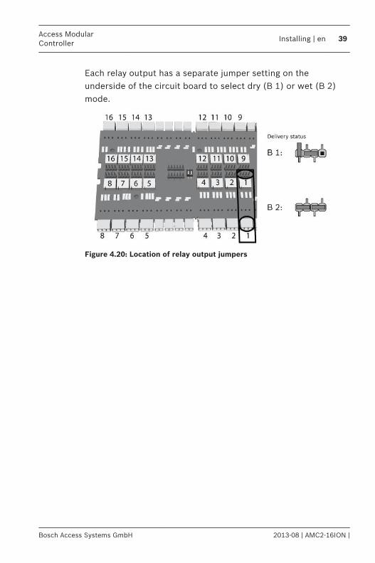
Each relay output has a separate jumper setting on theunderside of the circuit board to select dry (B 1) or wet (B 2)mode.
Figure 4.20: Location of relay output jumpers
Access ModularController
Installing | en 39
Bosch Access Systems GmbH 2013-08 | AMC2-16ION |
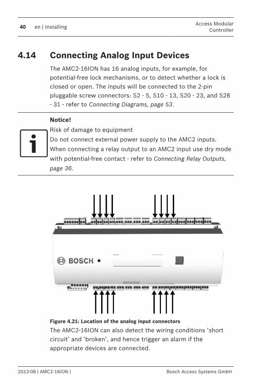
Connecting Analog Input DevicesThe AMC2-16ION has 16 analog inputs, for example, forpotential-free lock mechanisms, or to detect whether a lock isclosed or open. The inputs will be connected to the 2-pinpluggable screw connectors: S2 - 5, S10 - 13, S20 - 23, and S28- 31 - refer to Connecting Diagrams, page 53.
Notice!
Risk of damage to equipment
Do not connect external power supply to the AMC2 inputs.
When connecting a relay output to an AMC2 input use dry mode
with potential-free contact - refer to Connecting Relay Outputs,
page 36.
Figure 4.21: Location of the analog input connectors
The AMC2-16ION can also detect the wiring conditions ‘shortcircuit’ and ‘broken’, and hence trigger an alarm if theappropriate devices are connected.
4.14
40 en | InstallingAccess Modular
Controller
2013-08 | AMC2-16ION | Bosch Access Systems GmbH
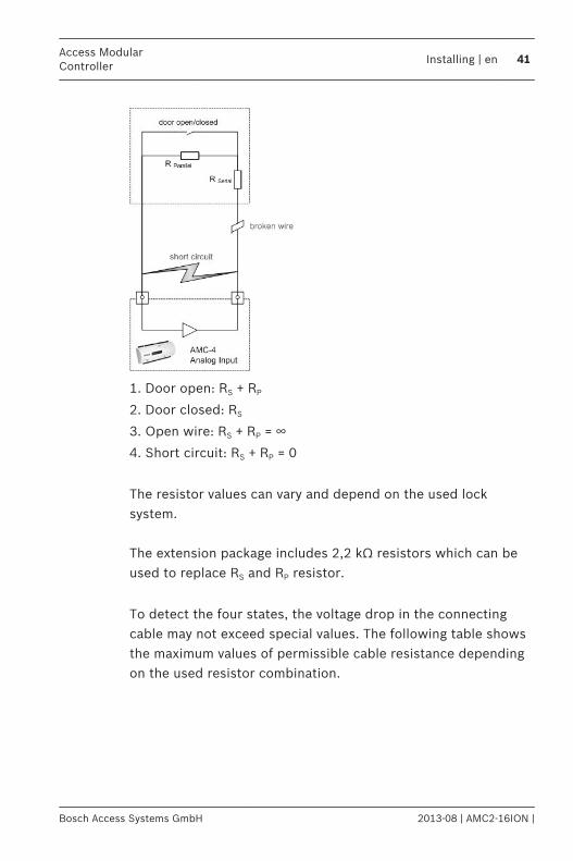
1. Door open: RS + RP
2. Door closed: RS
3. Open wire: RS + RP = ∞
4. Short circuit: RS + RP = 0
The resistor values can vary and depend on the used locksystem. The extension package includes 2,2 kΩ resistors which can beused to replace RS and RP resistor.
To detect the four states, the voltage drop in the connectingcable may not exceed special values. The following table showsthe maximum values of permissible cable resistance dependingon the used resistor combination.
Access ModularController
Installing | en 41
Bosch Access Systems GmbH 2013-08 | AMC2-16ION |

RP 1k
1k2
1k5
1k8
2k2
2k7
3k3
3k9
4k7
5k6
6k8
8k2
RS
1k 220 220 220 210 200
1k2 260 270 270 270 260 240
1k5 310 330 340 350 350 340 310 280
1k8 340 380 390 410 410 410 400 370 330 290 200
2k2 430 460 490 510 520 510 500 460 420 340 240
2k7 490 540 570 620 630 640 640 620 580 510 420
3k3 610 650 700 740 770 780 770 750 700 620
3k9 720 790 850 890 910 910 910 880 810
4k7 880 960 960 970 1100 1100 1050 1050
5k6 1050 1100 1200 1200 1300 1300 1250
6k8 1300 1400 1500 1500 1500 1500
8k2 1500 1650 1700 1800 1900
Table 4.3: Maximum values of cable resistance per used resistor combination in Ohm
Notice!
We recommend using serial resistors (RS) no higher than 5K6 in
order to obtain clear measurements.
42 en | InstallingAccess Modular
Controller
2013-08 | AMC2-16ION | Bosch Access Systems GmbH
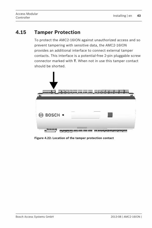
Tamper ProtectionTo protect the AMC2-16ION against unauthorized access and soprevent tampering with sensitive data, the AMC2-16IONprovides an additional interface to connect external tampercontacts. This interface is a potential-free 2-pin pluggable screwconnector marked with T. When not in use this tamper contactshould be shorted.
Figure 4.22: Location of the tamper protection contact
4.15
Access ModularController
Installing | en 43
Bosch Access Systems GmbH 2013-08 | AMC2-16ION |
Operating
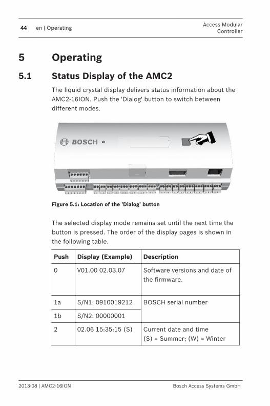
Status Display of the AMC2The liquid crystal display delivers status information about theAMC2-16ION. Push the 'Dialog' button to switch betweendifferent modes.
Figure 5.1: Location of the ’Dialog’ button
The selected display mode remains set until the next time thebutton is pressed. The order of the display pages is shown inthe following table.
Push Display (Example) Description
0 V01.00 02.03.07
Software versions and date ofthe firmware.
1a S/N1: 0910019212 BOSCH serial number
1b S/N2: 00000001
2 02.06 15:35:15 (S) Current date and time(S) = Summer; (W) = Winter
5
5.1
44 en | OperatingAccess Modular
Controller
2013-08 | AMC2-16ION | Bosch Access Systems GmbH
Push Display (Example) Description
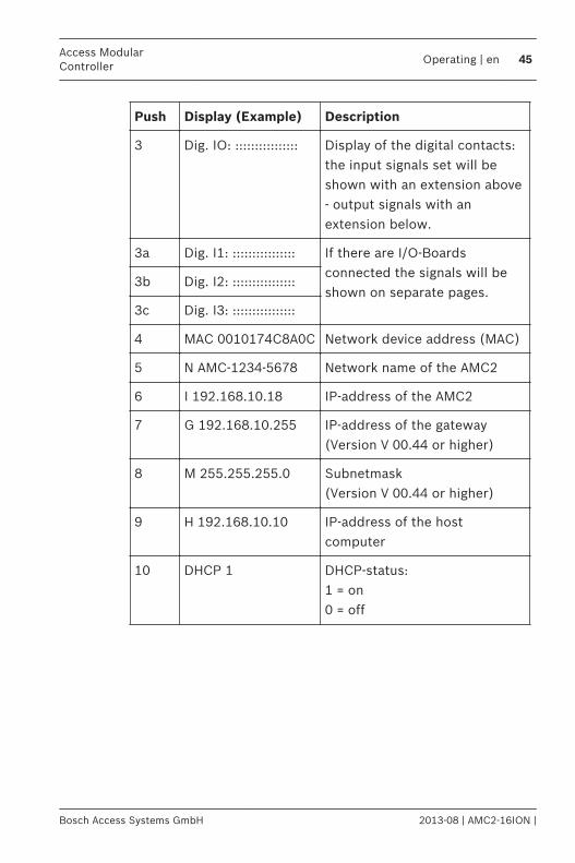
3 Dig. IO: :::::::::::::::: Display of the digital contacts:the input signals set will beshown with an extension above- output signals with anextension below.
3a Dig. I1: :::::::::::::::: If there are I/O-Boardsconnected the signals will beshown on separate pages.
3b Dig. I2: ::::::::::::::::
3c Dig. I3: ::::::::::::::::
4 MAC 0010174C8A0C Network device address (MAC)
5 N AMC-1234-5678 Network name of the AMC2
6 I 192.168.10.18 IP-address of the AMC2
7 G 192.168.10.255 IP-address of the gateway(Version V 00.44 or higher)
8 M 255.255.255.0 Subnetmask(Version V 00.44 or higher)
9 H 192.168.10.10 IP-address of the hostcomputer
10 DHCP 1 DHCP-status:1 = on0 = off
Access ModularController
Operating | en 45
Bosch Access Systems GmbH 2013-08 | AMC2-16ION |
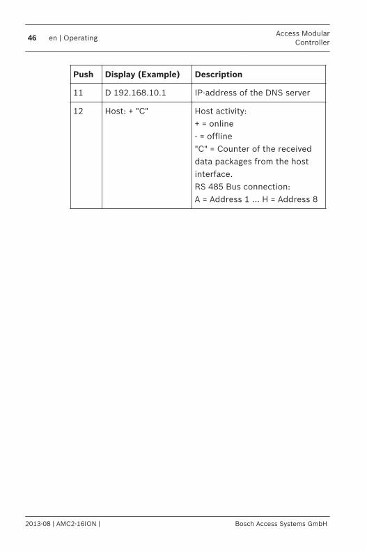
Push Display (Example) Description
11 D 192.168.10.1 IP-address of the DNS server
12 Host: + "C" Host activity:+ = online- = offline"C" = Counter of the receiveddata packages from the hostinterface.RS 485 Bus connection:A = Address 1 … H = Address 8
46 en | OperatingAccess Modular
Controller
2013-08 | AMC2-16ION | Bosch Access Systems GmbH
Configuring the Ethernet InterfaceTo configure the AMC2-16ION in a TCP/IP network environment,use the AmcIpConfig tool provided in the following directory onthe standalone or the remote server of the Building IntegrationSystem:\\Runtime-drive:\MgtS\AccessEngine\AC\bin The access control system Access Personal Edition has an entryof this tool in its program folder:Start > Programs > Access Personal Edition >AmcIpConfigThis tool can be copied and used on every computer on thenetwork.
Notice!
Use only alphanumeric characters plus the seperator "-" (minus/
dash).
Do not use special characters or spaces.
The network name must start with a letter.
The names are not case sensitive.
Notice!
Consult the AmcIpConfig tool’s own online help for details on
configuring the AMC2-16ION.
5.2
Access ModularController
Operating | en 47
Bosch Access Systems GmbH 2013-08 | AMC2-16ION |
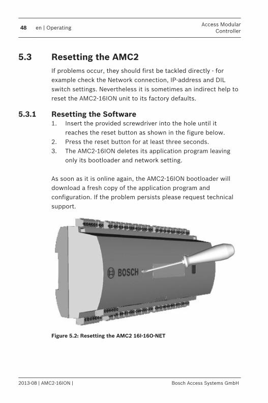
Resetting the AMC2If problems occur, they should first be tackled directly - forexample check the Network connection, IP-address and DILswitch settings. Nevertheless it is sometimes an indirect help toreset the AMC2-16ION unit to its factory defaults.
Resetting the Software1. Insert the provided screwdriver into the hole until it
reaches the reset button as shown in the figure below.2. Press the reset button for at least three seconds.3. The AMC2-16ION deletes its application program leaving
only its bootloader and network setting. As soon as it is online again, the AMC2-16ION bootloader willdownload a fresh copy of the application program andconfiguration. If the problem persists please request technicalsupport.
Figure 5.2: Resetting the AMC2 16I-16O-NET
5.3
5.3.1
48 en | OperatingAccess Modular
Controller
2013-08 | AMC2-16ION | Bosch Access Systems GmbH
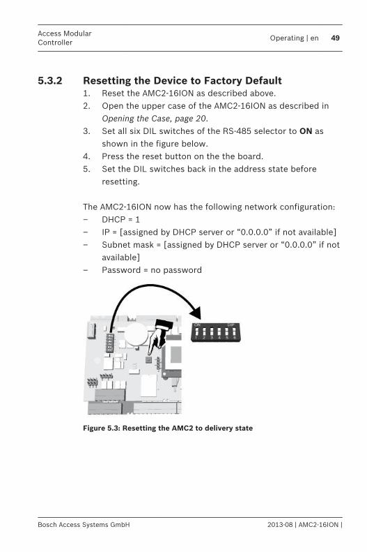
Resetting the Device to Factory Default1. Reset the AMC2-16ION as described above.2. Open the upper case of the AMC2-16ION as described in
Opening the Case, page 20.3. Set all six DIL switches of the RS-485 selector to ON as
shown in the figure below.4. Press the reset button on the the board.5. Set the DIL switches back in the address state before
resetting. The AMC2-16ION now has the following network configuration:– DHCP = 1– IP = [assigned by DHCP server or “0.0.0.0” if not available]– Subnet mask = [assigned by DHCP server or “0.0.0.0” if not
available]– Password = no password
Figure 5.3: Resetting the AMC2 to delivery state
5.3.2
Access ModularController
Operating | en 49
Bosch Access Systems GmbH 2013-08 | AMC2-16ION |
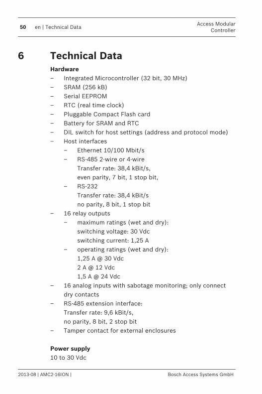
Technical DataHardware– Integrated Microcontroller (32 bit, 30 MHz)– SRAM (256 kB)– Serial EEPROM– RTC (real time clock)– Pluggable Compact Flash card – Battery for SRAM and RTC– DIL switch for host settings (address and protocol mode)– Host interfaces
– Ethernet 10/100 Mbit/s– RS-485 2-wire or 4-wire
Transfer rate: 38,4 kBit/s, even parity, 7 bit, 1 stop bit,
– RS-232 Transfer rate: 38,4 kBit/s no parity, 8 bit, 1 stop bit
– 16 relay outputs– maximum ratings (wet and dry):
switching voltage: 30 Vdcswitching current: 1,25 A
– operating ratings (wet and dry):1,25 A @ 30 Vdc2 A @ 12 Vdc1,5 A @ 24 Vdc
– 16 analog inputs with sabotage monitoring; only connectdry contacts
– RS-485 extension interface: Transfer rate: 9,6 kBit/s, no parity, 8 bit, 2 stop bit
– Tamper contact for external enclosures Power supply10 to 30 Vdc
6
50 en | Technical DataAccess Modular
Controller
2013-08 | AMC2-16ION | Bosch Access Systems GmbH
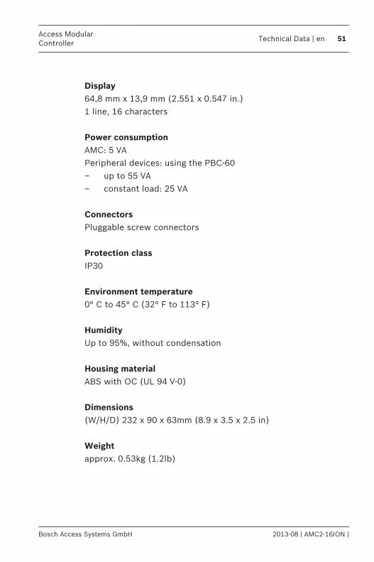
Display64,8 mm x 13,9 mm (2.551 x 0.547 in.)1 line, 16 characters Power consumptionAMC: 5 VAPeripheral devices: using the PBC-60– up to 55 VA– constant load: 25 VA ConnectorsPluggable screw connectors Protection classIP30 Environment temperature0° C to 45° C (32° F to 113° F) HumidityUp to 95%, without condensation Housing materialABS with OC (UL 94 V-0) Dimensions(W/H/D) 232 x 90 x 63mm (8.9 x 3.5 x 2.5 in) Weightapprox. 0.53kg (1.2lb)
Access ModularController
Technical Data | en 51
Bosch Access Systems GmbH 2013-08 | AMC2-16ION |
Notice!
The voltage drop from the power supply to the AMC2-16ION
affects the AMC interfaces. The total drop must not exceed 2V!
Notice!
To determine the environmental impact of an installation, take
into account the most extreme values of all participating
devices.
To determine the vulnerability of an installation, take into
account the most restrictive values of all participating devices.
52 en | Technical DataAccess Modular
Controller
2013-08 | AMC2-16ION | Bosch Access Systems GmbH
Appendices
Connecting Diagrams
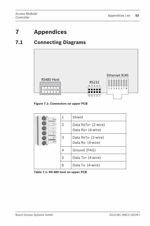
Figure 7.1: Connectors on upper PCB
1 Shield
2 Data RxTx+ (2-wire)Data Rx+ (4-wire)
3 Data RxTx- (2-wire)Data Rx- (4-wire)
4 Ground (PAG)
5 Data Tx+ (4-wire)
6 Data Tx- (4-wire)
Table 7.1: RS-485 host on upper PCB
7
7.1
Access ModularController
Appendices | en 53
Bosch Access Systems GmbH 2013-08 | AMC2-16ION |
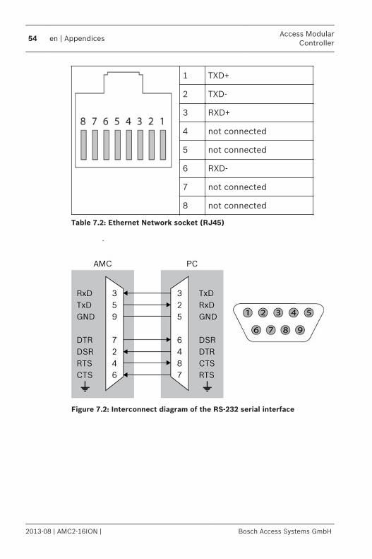
1 TXD+
2 TXD-
3 RXD+
4 not connected
5 not connected
6 RXD-
7 not connected
8 not connected
Table 7.2: Ethernet Network socket (RJ45)
Figure 7.2: Interconnect diagram of the RS-232 serial interface
54 en | AppendicesAccess Modular
Controller
2013-08 | AMC2-16ION | Bosch Access Systems GmbH
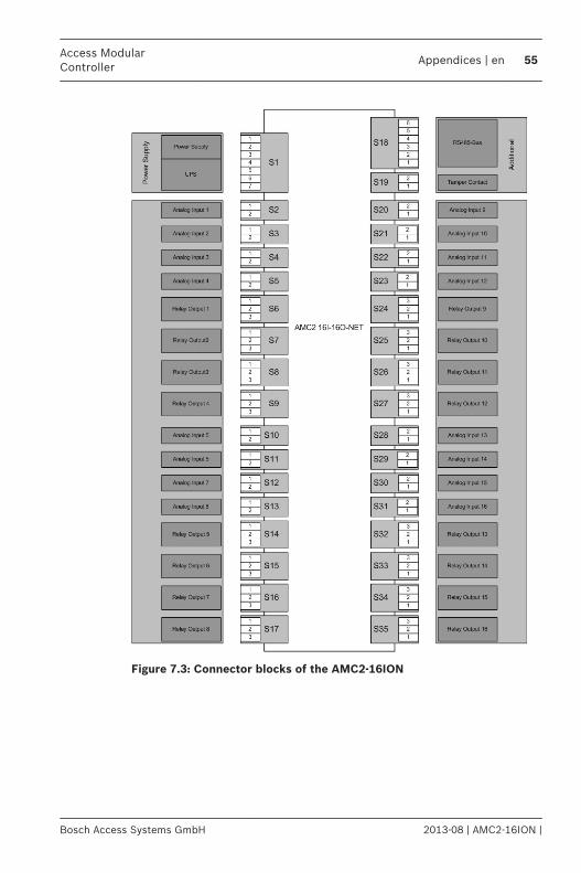
Figure 7.3: Connector blocks of the AMC2-16ION
Access ModularController
Appendices | en 55
Bosch Access Systems GmbH 2013-08 | AMC2-16ION |
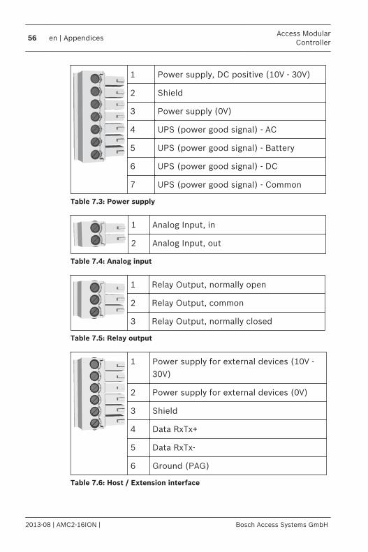
1 Power supply, DC positive (10V - 30V)
2 Shield
3 Power supply (0V)
4 UPS (power good signal) - AC
5 UPS (power good signal) - Battery
6 UPS (power good signal) - DC
7 UPS (power good signal) - Common
Table 7.3: Power supply
1 Analog Input, in
2 Analog Input, out
Table 7.4: Analog input
1 Relay Output, normally open
2 Relay Output, common
3 Relay Output, normally closed
Table 7.5: Relay output
1 Power supply for external devices (10V -30V)
2 Power supply for external devices (0V)
3 Shield
4 Data RxTx+
5 Data RxTx-
6 Ground (PAG)
Table 7.6: Host / Extension interface
56 en | AppendicesAccess Modular
Controller
2013-08 | AMC2-16ION | Bosch Access Systems GmbH
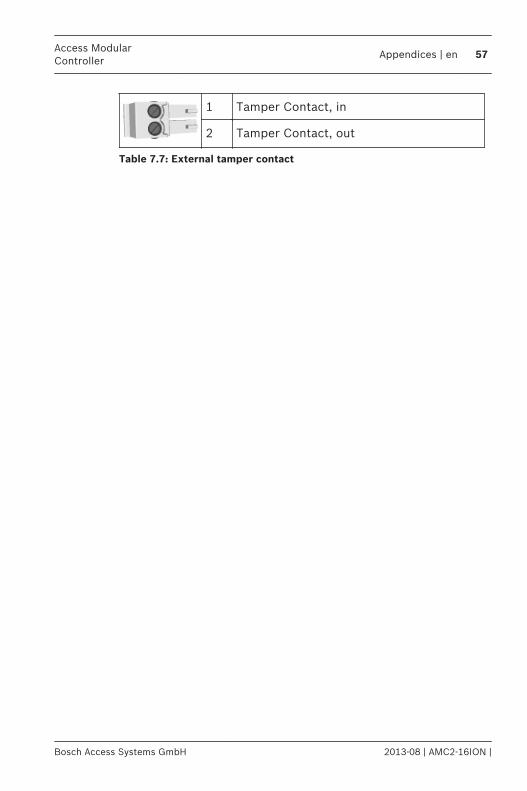
1 Tamper Contact, in
2 Tamper Contact, out
Table 7.7: External tamper contact
Access ModularController
Appendices | en 57
Bosch Access Systems GmbH 2013-08 | AMC2-16ION |
IndexDDIL, 12, 15, 32display, 44
EEthernet host interface, 15Ethernet interface, 27extension interface, 25, 50extension interfade, 34
Ggrounding, 23
Hhost interfaces, 15, 28, 50
II/O board, 34inputs, 15, 40, 50interfaces
Ethernet, 47extension, 25, 50host, 15, 27, 28, 31, 50
interfadesextension, 34
LLCD, 44
Mmounting, 18
Oopening, 20outputs, 15, 36, 50
Ppower supply, 22, 26
Rresetting, 48resistor, 40RS-232 host interface, 15, 31RS-485 host interface, 13, 15, 28
Sshielding, 23
Ttamper, 43transfer rates, 15, 50
Uunmounting, 19
58 en | IndexAccess Modular
Controller
2013-08 | AMC2-16ION | Bosch Access Systems GmbH


Bosch Sicherheitssysteme GmbHRobert-Bosch-Ring 585630 GrasbrunnGermanywww.boschsecurity.com© Bosch Sicherheitssysteme GmbH, 2014