Embed Size (px)
Citation preview
Preface
I
In this user manual we try to describe the matters concerning the
operation of this GS Series Spindle Servo Drive Unit to the greatest extent.
However, it is impossible to give particular descriptions for all unnecessary
or unallowable operations due to length limitation and products application
conditions; Therefore, the items not presented herein should be regarded as
“impossible” or “unallowable”.
Copyright is reserved to GSK CNC Equipment Co., Ltd. It is
illegal for any organization or individual to publish or reprint this manual.
GSK CNC Equipment Co., Ltd. reserves the right to ascertain their legal
liability.
GS Series Spindle Servo Drive Unit User Manual
II
Preface
Dear customers,
We are honored and thankful for your purchase of this GSK product!
This manual describes items concerning GS Series Spindle Servo
Drive Unit in detail, such as performance, installation, connection,
commissioning, usage and maintenance etc.
To ensure safe and effective running, please read this manual carefully
before installation and operation.
To avoid injury to operators and other personnels, and damage to the
mechanical equipments, please pay special attention to the following
warning signs when reading this manual.
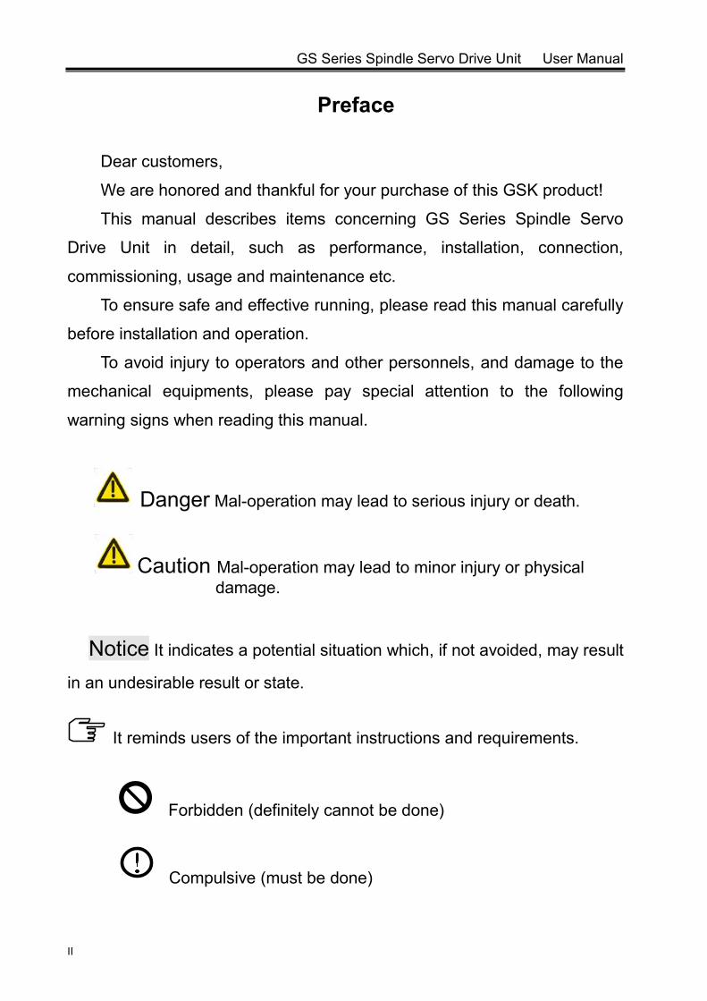
Danger Mal-operation may lead to serious injury or death.
Caution Mal-operation may lead to minor injury or physical damage.
Notice It indicates a potential situation which, if not avoided, may result
in an undesirable result or state.
It reminds users of the important instructions and requirements.
Forbidden (definitely cannot be done)
Compulsive (must be done)
Caution
III
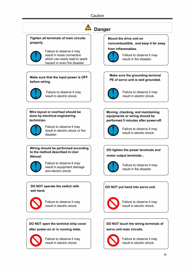
Make sure the grounding terminal PE of servo unit is well grounded.
! Failure to observe it may result in electric shock.
DO NOT open the terminal strip cover
after power-on or in running state.
DO NOT touch the wiring terminals of
servo unit main circuits.
Failure to observe it may result in electric shock.
Failure to observe it may result in electric shock.
Tighten all terminals of main circuits properly.
Failure to observe it may result in loose connection which can easily lead to spark hazard or even fire disaster.
Mount the drive unit on noncombustible, and keep it far away from inflammables.
! Failure to observe it may result in fire disaster. !
Make sure that the input power is OFF before wiring.
! Failure to observe it may result in electric shock.
Wire layout or overhaul should be done by electrical engineering technician.
Moving, checking, and maintaining equipments or wiring should be performed 5 minutes after power-off.
! !Failure to observe it may result in electric shock or fire disaster.
Failure to observe it may result in electric shock.
Wiring should be performed according to the method described in User Manual.
DO tighten the power terminals and motor output terminals.。
! !Failure to observe it may result in equipment damage and electric shock.
Failure to observe it may result in fire disaster.
DO NOT operate the switch with wet hand.
DO NOT put hand into servo unit.
Failure to observe it may result in electric shock.
Failure to observe it may result in electric shock.
Danger
GS Series Spindle Servo Drive Unit User Manual
IV
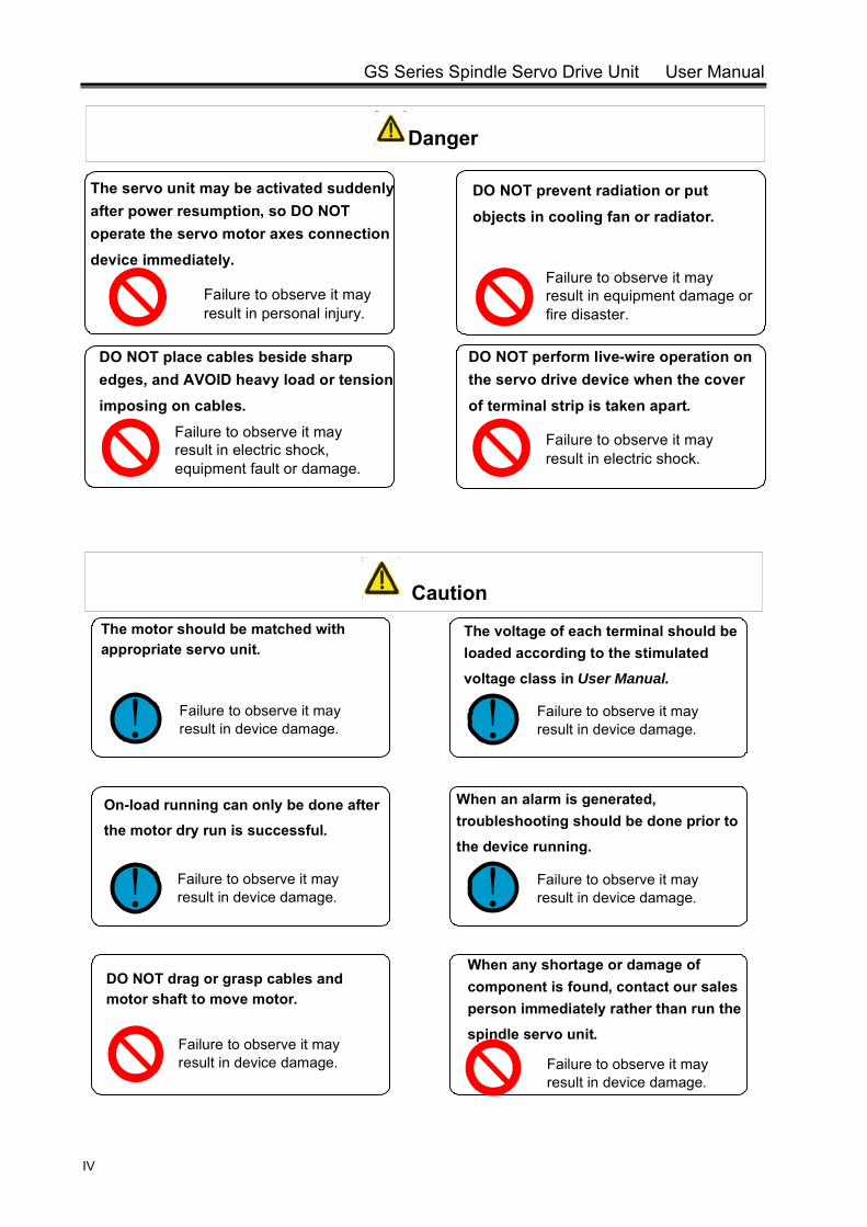
The servo unit may be activated suddenly after power resumption, so DO NOT operate the servo motor axes connection device immediately.
DO NOT prevent radiation or put
objects in cooling fan or radiator.
DO NOT place cables beside sharp edges, and AVOID heavy load or tension imposing on cables.
DO NOT perform live-wire operation on the servo drive device when the cover
of terminal strip is taken apart.
Failure to observe it may result in personal injury.
Failure to observe it may result in electric shock.
Failure to observe it may result in electric shock, equipment fault or damage.
Failure to observe it may result in equipment damage or fire disaster.
The voltage of each terminal should be loaded according to the stimulated
voltage class in User Manual.
On-load running can only be done after the motor dry run is successful.
When an alarm is generated, troubleshooting should be done prior to
the device running.
! Failure to observe it may result in device damage.
! !Failure to observe it may result in device damage.
Failure to observe it may result in device damage.
The motor should be matched with appropriate servo unit.
DO NOT drag or grasp cables and motor shaft to move motor.
When any shortage or damage of component is found, contact our sales person immediately rather than run the
spindle servo unit.
! Failure to observe it may result in device damage.
Failure to observe it may result in device damage. Failure to observe it may
result in device damage.
Caution
Danger
Caution
V
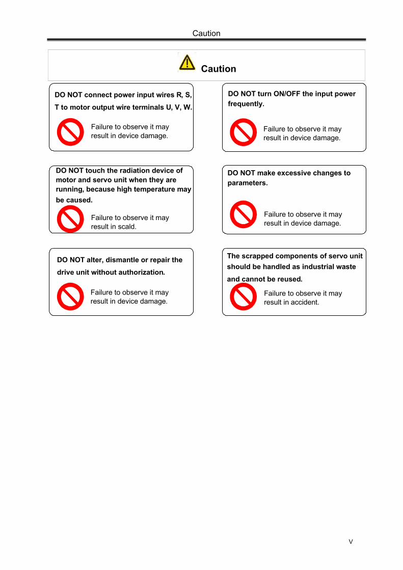
DO NOT touch the radiation device of motor and servo unit when they are running, because high temperature may be caused.
DO NOT make excessive changes to parameters.
DO NOT connect power input wires R, S, T to motor output wire terminals U, V, W.
The scrapped components of servo unit should be handled as industrial waste and cannot be reused.
DO NOT turn ON/OFF the input power frequently.
Failure to observe it may result in scald.
Failure to observe it may result in accident.
Failure to observe it may result in device damage.
Failure to observe it may result in device damage.
Failure to observe it may result in device damage.
DO NOT alter, dismantle or repair the drive unit without authorization.
Failure to observe it may result in device damage.
Caution
GS Series Spindle Servo Drive Unit User Manual
VI
Safety Responsibility
Manufacturer’s Responsibility ——Be responsible for the danger which should be eliminated and/or controlled on
design and configuration of the provided Servo Drive Unit and accessories.
——Be responsible for the safety of the provided Servo Drive Unit and accessories.
——Be responsible for the provided information and advice for the users.
User’s Responsibility
——Be trained with the safety operation of Servo Drive Unit and familiar with the safety
operation procedures.
——Be responsible for the dangers caused by adding, changing or altering to the
original Servo Drive Unit and the accessories.
——Be responsible for the failure to observe the provisions for operation, adjustment,
maintenance, installation and storage in the manual.
This manual is reserved by end user.
We are full of heartfelt gratitude to you for supporting us in the use of GSK’s products.
Contents
VII
Contents
CHAPTER I INSTRUCTION ...................................................................................................................... 1
1.1 Basics .............................................................................................................................................. 1
1.2 Product Confirmation ....................................................................................................................... 6
1.2.1 Instruction of AC Spindle Servo Motor Model ........................................................................... 6
1.2.2 Instruction of Spindle Servo Unit .............................................................................................. 7
1.2.3 Overall Appearance of Spindle Servo Unit ............................................................................... 8
1.3 Technical Specification .................................................................................................................. 11
1.3.1 Technical Specification of Spindle Motor ................................................................................ 11
1.3.2 Technical Specification of AC Spindle Servo Unit .................................................................. 13
1.4 Ordering Guidelines ....................................................................................................................... 15
1.4.1 Model Selection Process ........................................................................................................ 15
1.4.2 Examples ................................................................................................................................ 15
1.4.3 Standard Ex-factory Accessories ............................................................................................ 17
CHAPTER II INSTALLATION/MOUNTING ............................................................................................. 21
2.1 Spindle Servo Motor ...................................................................................................................... 21
2.1.1 Dimensions for Spindle Motor Installation .............................................................................. 21
2.1.2 Installation of Spindle Motor ................................................................................................... 23
2.2 Spindle Servo Unit ......................................................................................................................... 25
2.2.1 Installation Dimension ............................................................................................................. 26
2.2.2 Installation Intervals ................................................................................................................ 28
CHAPTER III CONNECTION .................................................................................................................. 31
3.1 Connection of Peripheral Equipments ........................................................................................... 32
3.2 Connection of Main Circuit ............................................................................................................ 37
3.2.1 Connection .............................................................................................................................. 37
3.2.2 Wiring of Main Circuit .............................................................................................................. 38
3.2.3 Servo Motor Connection Instruction ....................................................................................... 38
3.3 Connection of Control Signal ......................................................................................................... 40
3.3.1 CN1 Control Signal ................................................................................................................. 40
3.3.2 Speed Command Input ........................................................................................................... 43
3.3.3 Position Command Input ........................................................................................................ 44
3.3.4 Digital Input ............................................................................................................................. 47
3.3.5 Digital Output .......................................................................................................................... 49
3.3.6 Position Signal Output ............................................................................................................ 52
3.4 Connection of Position Feedback Signal ....................................................................................... 53
3.4.1 Motor Encoder Position Feedback Signal Interface CN2 ....................................................... 53
GS Series Spindle Servo Drive Unit User Manual
VIII
3.4.2 2nd Position Feedback Signal Interface CN3 ........................................................................ 57
3.4.3 Interface CN3 of GS Series MDR Products ........................................................................... 58
3.5 GSK-CAN Communication ............................................................................................................ 59
3.6 Connection in Different Working Mode ......................................................................................... 60
3.6.1 Connection in Speed Mode .................................................................................................... 60
3.6.2 Connection in Position Mode ................................................................................................. 63
3.6.3 Connection in Speed/Position Mode ...................................................................................... 65
CHAPTER IV DISPLAY AND OPERATION ........................................................................................... 69
4.1 Operation Panel ............................................................................................................................ 69
4.2 Display Menu ................................................................................................................................ 70
4.3 Status Monitoring .......................................................................................................................... 71
4.4 Parameter Setting ......................................................................................................................... 74
4.5 Parameter Management ............................................................................................................... 75
CHAPTER V GENERAL COMMISSIONING .......................................................................................... 77
5.1 Running in Manual/JOG Mode...................................................................................................... 78
5.1.1 Manual Running ..................................................................................................................... 79
5.1.2 JOG Running.......................................................................................................................... 80
5.2 Running in Speed Mode ............................................................................................................... 81
5.2.1 Analog Speed Command ....................................................................................................... 81
5.2.2 Internal Speed Command ...................................................................................................... 84
5.3 Running in Position Mode ............................................................................................................. 85
5.4 Running in Speed/Position Mode ................................................................................................. 87
CHAPTER VI FUNCTIONALITY TESTING ............................................................................................ 91
6.1 Instruction for Basic Performance Parameters Setting ................................................................. 91
6.1.1 Setting Methods ..................................................................................................................... 91
6.1.2 Three Gains of Closed-Loop Control ..................................................................................... 93
6.2 Switching of Motor Rotation Directions ......................................................................................... 94
6.3 Braking Stop.................................................................................................................................. 96
6.4 Testing in Position Mode ............................................................................................................... 97
6.4.1 Electronic Gear Ratio of Position Command ......................................................................... 97
6.4.2 Position Arrival Signal ............................................................................................................ 98
6.4.3 Position Deviation Clear ......................................................................................................... 99
6.4.4 Pulse Command Inhibition ..................................................................................................... 99
6.5 Testing in Speed Mode ............................................................................................................... 100
6.5.1 Orientation Function ............................................................................................................. 100
6.5.2 Adjustment of Analog Commands ....................................................................................... 105
6.5.3 Speed Arrival Signal ............................................................................................................. 106
Contents
IX
6.5.4 Zero Speed Clamp ................................................................................................................ 107
6.5.5 Speed Command Electronic Gear Ratio .............................................................................. 108
6.6 Spindle Clamp Interlock Signal (BREF)....................................................................................... 109
CHAPTER VII PARAMETERS .............................................................................................................. 111
7.1 Parameter List ............................................................................................................................. 111
CHAPTER VIII ABNORMALITIES AND REMEDIES ............................................................................ 123
8.1 Remedies for Normal Faults ........................................................................................................ 123
8.1.1 Speed Mode ............................................................................................................................. 123
8.1.2 Position Mode ....................................................................................................................... 125
8.1.3 Others ................................................................................................................................... 126
8.2 Alarms and Remedies ................................................................................................................. 128
8.3 Inspection and Maintenance ........................................................................................................ 133
APPENDIX A Model Code Parameters and Feed Servo Motors Table ................................................ 135
APPENDIX B Peripheral Equipments ................................................................................................... 136
B.1 Circuit Breaker and Contactor (essential) ................................................................................... 136
B.2 Three-phase AC filter (recommended)........................................................................................ 136
B.3 AC Reactor (recommended) ....................................................................................................... 137
APPENDIX C BRAKING RESISTOR SELECTION............................................................................... 138
APPENDIX D CONNECTION DIAGRAMS BETWEEN SPINDLE SERVO UNIT AND CNC SYSTEM
............................................................................................................................................................... 141

Chapter I Instruction
1
CHAPTER I INSTRUCTION
1.1 Basics
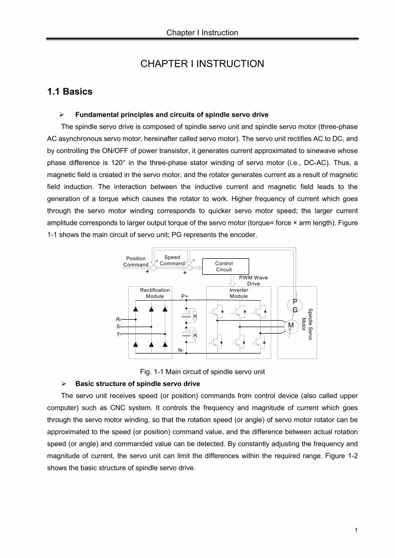
Fundamental principles and circuits of spindle servo drive The spindle servo drive is composed of spindle servo unit and spindle servo motor (three-phase
AC asynchronous servo motor, hereinafter called servo motor). The servo unit rectifies AC to DC, and
by controlling the ON/OFF of power transistor, it generates current approximated to sinewave whose
phase difference is 120° in the three-phase stator winding of servo motor (i.e., DC-AC). Thus, a
magnetic field is created in the servo motor, and the rotator generates current as a result of magnetic
field induction. The interaction between the inductive current and magnetic field leads to the
generation of a torque which causes the rotator to work. Higher frequency of current which goes
through the servo motor winding corresponds to quicker servo motor speed; the larger current
amplitude corresponds to larger output torque of the servo motor (torque= force × arm length). Figure
1-1 shows the main circuit of servo unit; PG represents the encoder.
N-
P+
MR
R
Rectification Module
Inverter Module
RST
3~
PG
Control Circuit
PWM Wave Drive
+
-Position Command
+- Speed
Command
Spindle S
ervo M
otor
Fig. 1-1 Main circuit of spindle servo unit
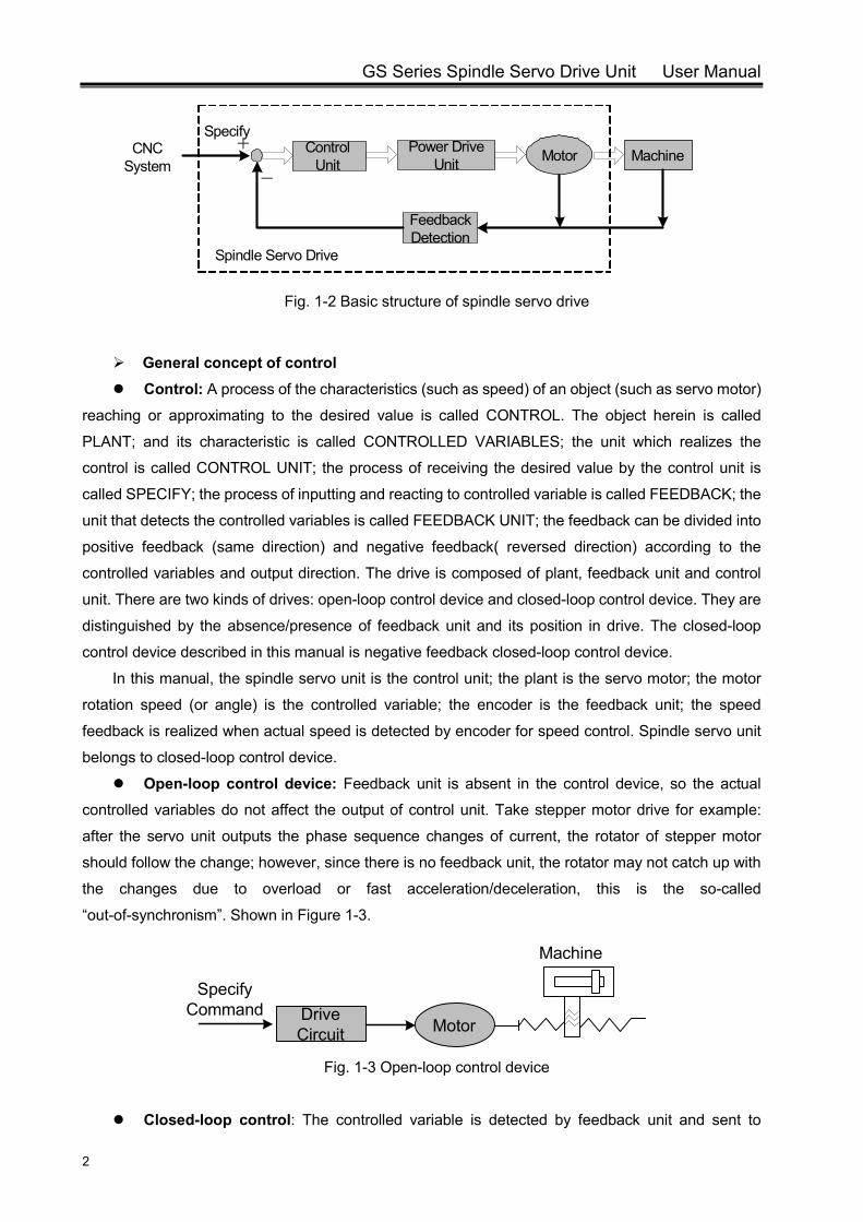
Basic structure of spindle servo drive The servo unit receives speed (or position) commands from control device (also called upper
computer) such as CNC system. It controls the frequency and magnitude of current which goes
through the servo motor winding, so that the rotation speed (or angle) of servo motor rotator can be
approximated to the speed (or position) command value, and the difference between actual rotation
speed (or angle) and commanded value can be detected. By constantly adjusting the frequency and
magnitude of current, the servo unit can limit the differences within the required range. Figure 1-2
shows the basic structure of spindle servo drive.
GS Series Spindle Servo Drive Unit User Manual
2
Control Unit
Power Drive Unit Motor Machine
Feedback Detection
Specify+
-
CNC System
Spindle Servo Drive
Fig. 1-2 Basic structure of spindle servo drive
General concept of control Control: A process of the characteristics (such as speed) of an object (such as servo motor)
reaching or approximating to the desired value is called CONTROL. The object herein is called
PLANT; and its characteristic is called CONTROLLED VARIABLES; the unit which realizes the
control is called CONTROL UNIT; the process of receiving the desired value by the control unit is
called SPECIFY; the process of inputting and reacting to controlled variable is called FEEDBACK; the
unit that detects the controlled variables is called FEEDBACK UNIT; the feedback can be divided into
positive feedback (same direction) and negative feedback( reversed direction) according to the
controlled variables and output direction. The drive is composed of plant, feedback unit and control
unit. There are two kinds of drives: open-loop control device and closed-loop control device. They are
distinguished by the absence/presence of feedback unit and its position in drive. The closed-loop
control device described in this manual is negative feedback closed-loop control device.
In this manual, the spindle servo unit is the control unit; the plant is the servo motor; the motor
rotation speed (or angle) is the controlled variable; the encoder is the feedback unit; the speed
feedback is realized when actual speed is detected by encoder for speed control. Spindle servo unit
belongs to closed-loop control device.
Open-loop control device: Feedback unit is absent in the control device, so the actual
controlled variables do not affect the output of control unit. Take stepper motor drive for example:
after the servo unit outputs the phase sequence changes of current, the rotator of stepper motor
should follow the change; however, since there is no feedback unit, the rotator may not catch up with
the changes due to overload or fast acceleration/deceleration, this is the so-called
“out-of-synchronism”. Shown in Figure 1-3.
Drive Circuit Motor
Machine
Specify Command
Fig. 1-3 Open-loop control device
Closed-loop control: The controlled variable is detected by feedback unit and sent to
Chapter I Instruction
3
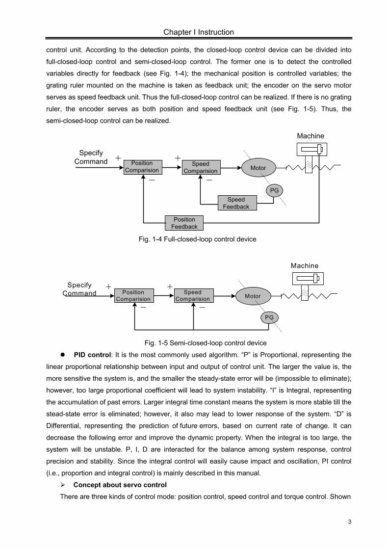
control unit. According to the detection points, the closed-loop control device can be divided into
full-closed-loop control and semi-closed-loop control. The former one is to detect the controlled
variables directly for feedback (see Fig. 1-4); the mechanical position is controlled variables; the
grating ruler mounted on the machine is taken as feedback unit; the encoder on the servo motor
serves as speed feedback unit. Thus the full-closed-loop control can be realized. If there is no grating
ruler, the encoder serves as both position and speed feedback unit (see Fig. 1-5). Thus, the
semi-closed-loop control can be realized.
Speed Comparision Motor
Machine
Position Comparision
PGSpeed
Feedback
Position Feedback
+
- -
+Specify
Command
Fig. 1-4 Full-closed-loop control device
Speed Comparision Motor
Machine
Position Comparision
Specify Command
PG
+
- -
+
Fig. 1-5 Semi-closed-loop control device
PID control: It is the most commonly used algorithm. “P” is Proportional, representing the
linear proportional relationship between input and output of control unit. The larger the value is, the
more sensitive the system is, and the smaller the steady-state error will be (impossible to eliminate);
however, too large proportional coefficient will lead to system instability. “I” is Integral, representing
the accumulation of past errors. Larger integral time constant means the system is more stable till the
stead-state error is eliminated; however, it also may lead to lower response of the system. “D” is
Differential, representing the prediction of future errors, based on current rate of change. It can
decrease the following error and improve the dynamic property. When the integral is too large, the
system will be unstable. P, I, D are interacted for the balance among system response, control
precision and stability. Since the integral control will easily cause impact and oscillation, PI control
(i.e., proportion and integral control) is mainly described in this manual.
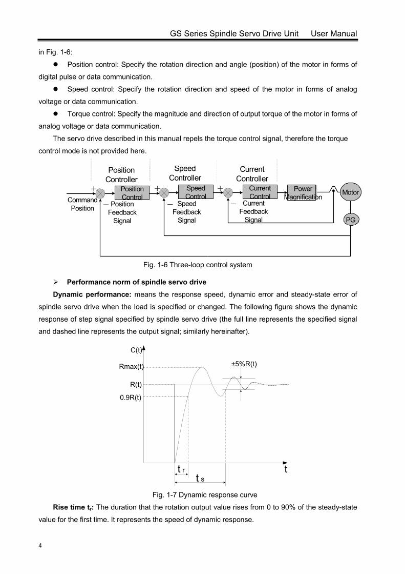
Concept about servo control There are three kinds of control mode: position control, speed control and torque control. Shown
GS Series Spindle Servo Drive Unit User Manual
4
in Fig. 1-6: Position control: Specify the rotation direction and angle (position) of the motor in forms of
digital pulse or data communication.
Speed control: Specify the rotation direction and speed of the motor in forms of analog
voltage or data communication.
Torque control: Specify the magnitude and direction of output torque of the motor in forms of
analog voltage or data communication.
The servo drive described in this manual repels the torque control signal, therefore the torque
control mode is not provided here.
Fig. 1-6 Three-loop control system
Performance norm of spindle servo drive
Dynamic performance: means the response speed, dynamic error and steady-state error of
spindle servo drive when the load is specified or changed. The following figure shows the dynamic
response of step signal specified by spindle servo drive (the full line represents the specified signal
and dashed line represents the output signal; similarly hereinafter).
t st r
C(t)
Rmax(t)
R(t)
0.9R(t)
t
±5%R(t)
Fig. 1-7 Dynamic response curve
Rise time tr: The duration that the rotation output value rises from 0 to 90% of the steady-state
value for the first time. It represents the speed of dynamic response.
PG
Position Feedback
Signal
-
+ Power Magnification
Current Control
+ Speed Control
-
+ Position Control
-Command Position
Speed Feedback
Signal
Current Feedback
Signal
Position Controller
Speed Controller
Current Controller
Motor

Chapter I Instruction
5
Settling time ts: The range -5%~+5% of the steady-state value is taken as permitted error zone.
The settling time is the minimum duration of the response curve to reach the zone (no excess any
more). It is used to measure the speed of the whole control process.
Percent overshoot σ: It is the maximum fraction by which the response overshoots the
steady-state value and expressed as a percentage, i.e.
%100)(
)()((%) max ×
−=
tRtRtR
σ
Steady-state error: The difference between the steady-state output value to the reference input
value at steady state is called the steady state error of the system.
Static performance: Stability is the crucial factor of a spindle servo drive. The static
performance mainly refers to positioning accuracy which means the difference between the reference
state and actual state after the transient process. The static precision can be affected by
measurement device error as well as the system error which is related to the system structure and
parameters. Fig. 1-8 shows the static curve of position servo drive.
Commanded Position
Following Response
Follo
win
g Er
ror
Lag
θ
t
Fig. 1-8 Static curve
Following error: The difference between the required position and actual position is called
following error. It equals to commanded position value minus actual position value.
Servo rigidity: The capacity of resisting deviation which is caused by load.
Comparison between spindle servo drive and inverter drive Although both two kinds of devices can realize the conversion of AC-DC-AC, and drive the
three-phase asynchronous motor, the spindle servo drive bears larger current frequency range and
wider valid regulating range. Since an encoder is mounted on servo motor, the spindle servo drive
belongs to closed-loop control device. Whereas, no encoder is mounted on an inverter-fed motor, the
inverter drive belongs to open-loop control device. Motor’s rotation speed will change as the load
changes; however, since feedback control function is not available, the inverter cannot recover the
speed like the servo unit does. To reduce cost, the overload capacity of inverter is 10%~20%, and
that of servo unit is greater than 50%. Higher overload capacity means faster acceleration and
response.
Compared with inverter drives, the spindle servo drives have the following advantages:

GS Series Spindle Servo Drive Unit User Manual
6
Both speed and position control are available; the control precision is high;
Wider regulating range; capable of outputting valid torque in zero-speed state;
Small speed fluctuation when load changes; quick to recover;
Strong overload capacity; fast response; high efficiency; adaptable to sudden start/stop
conditions;
1.2 Product Confirmation
Check the following items after receiving the products. Please contact us or the supplier if you come across any question.
Item RemarkCheck the consistency of servo
unit and servo motor Check the nameplate.
Check the completeness of accessories
Check the contents on packing list and contact the supplier if an inconsistency is found.
Check whether the product is damaged during delivery Check the overall appearance.
Check whether the screw is loose Check for loose connection with a screwdriver.
Caution 1. Spindle servo unit with loss or damage of parts should not be installed.
2. Servo unit should be matched with a servo motor with suitable power.
3. There are two types of GS series products: D-SUB and MDR. Make sure that the used product meets the requirements.
1.2.1 Instruction of AC Spindle Servo Motor Model
Nameplate of spindle servo motor:
Flange mounting plane B5
Chapter I Instruction
7
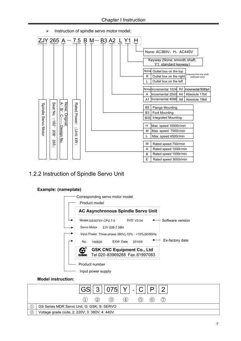
Instruction of spindle servo motor model:
B M B3 Y1-
Keyway (None: smooth shaft; Y1: standard keyway)
ZJY 265 7.5-A A2 L
Outlet box on the rightOutlet box on the top
Outlet box on the left
None
RL
Incremental 1024p/rNone
AA1
Incremental 2500p/rIncremental 4096p/r
Incremental 5000p/rA2A4A8
Absolute 17bitAbsolute 19bit
Foot MountingFlange Mounting
Integrated Mounting
B5B3B35
Max. speed 10000r/minHML
Max. speed 7000r/minMax. speed 4500r/min
Rated speed 750r/minWAB
Rated speed 1000r/minRated speed 1500r/min
E Rated speed 3000r/min
Spindle S
ervo Motor
Seat N
o.
(182
,208
,265
)
None: O
riginal; A
、B
、C……
:Design N
o.
Rated P
ower:
(Unit: kW
)
None: AC380V;H:AC440V
H
(Viewing from the shaft extension end)
1.2.2 Instruction of Spindle Servo Unit
Example: (nameplate)
Product model Corresponding servo motor model
Software version
Ex-factory date
Input power supply
Product number
Tel .020 -83969288 Fax.81997083
GS3075Y-CP2-7.5 V3.04
2010/9
GSK CNC Equipment Co., Ltd
AC Asynchronous Spindle Servo Unit
Model: SVD:
Servo Motor ZJY-208-7.5BH
Input Power Three-phase 380V(-15%~+10%)50/60Hz
No. 100620 EXW. Date
R
Model instruction:
GS 3 075 Y C P① ② ③ ④ ⑤ ⑥
2⑦
-
① GS Series MDR Servo Unit, G: GSK; S: SERVO ② Voltage grade code, 2: 220V; 3: 380V; 4: 440V.
GS Series Spindle Servo Drive Unit User Manual
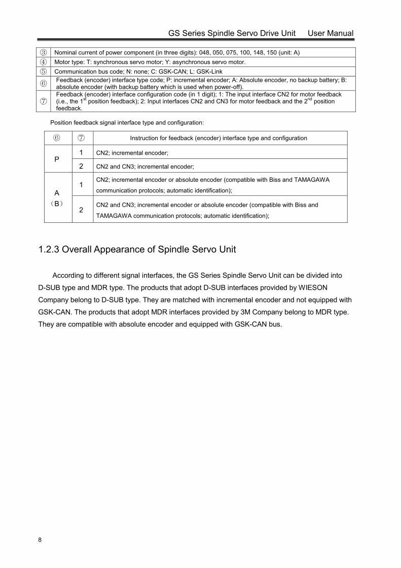
8
③ Nominal current of power component (in three digits): 048, 050, 075, 100, 148, 150 (unit: A) ④ Motor type: T: synchronous servo motor; Y: asynchronous servo motor. ⑤ Communication bus code; N: none; C: GSK-CAN; L: GSK-Link
⑥ Feedback (encoder) interface type code; P: incremental encoder; A: Absolute encoder, no backup battery; B: absolute encoder (with backup battery which is used when power-off).
⑦ Feedback (encoder) interface configuration code (in 1 digit); 1: The input interface CN2 for motor feedback (i.e., the 1st position feedback); 2: Input interfaces CN2 and CN3 for motor feedback and the 2nd position feedback.
Position feedback signal interface type and configuration:
⑥ ⑦ Instruction for feedback (encoder) interface type and configuration
P 1 CN2; incremental encoder;
2 CN2 and CN3; incremental encoder;
A (B)
1 CN2; incremental encoder or absolute encoder (compatible with Biss and TAMAGAWA
communication protocols; automatic identification);
2 CN2 and CN3; incremental encoder or absolute encoder (compatible with Biss and
TAMAGAWA communication protocols; automatic identification);
1.2.3 Overall Appearance of Spindle Servo Unit
According to different signal interfaces, the GS Series Spindle Servo Unit can be divided into
D-SUB type and MDR type. The products that adopt D-SUB interfaces provided by WIESON
Company belong to D-SUB type. They are matched with incremental encoder and not equipped with
GSK-CAN. The products that adopt MDR interfaces provided by 3M Company belong to MDR type.
They are compatible with absolute encoder and equipped with GSK-CAN bus.
Chapter I Instruction
9
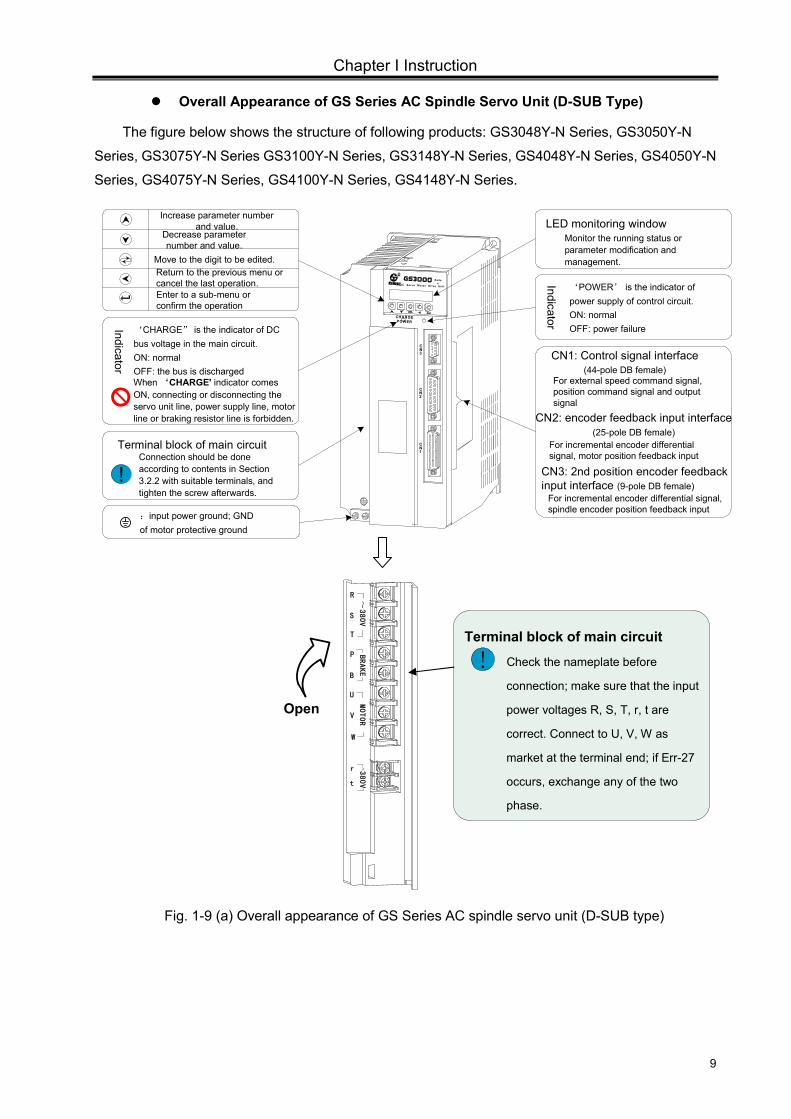
Overall Appearance of GS Series AC Spindle Servo Unit (D-SUB Type)
The figure below shows the structure of following products: GS3048Y-N Series, GS3050Y-N
Series, GS3075Y-N Series GS3100Y-N Series, GS3148Y-N Series, GS4048Y-N Series, GS4050Y-N
Series, GS4075Y-N Series, GS4100Y-N Series, GS4148Y-N Series.
Increase parameter number and value.
Decrease parameter number and value.
Enter to a sub-menu or confirm the operation
CN2: encoder feedback input interface (25-pole DB female)
CN1: Control signal interface (44-pole DB female)
For external speed command signal, position command signal and output signal
Indicator
:input power ground; GND of motor protective ground
Monitor the running status or parameter modification and management.
LED monitoring window
For incremental encoder differential signal, motor position feedback input
‘POWER’ is the indicator of power supply of control circuit.ON: normal OFF: power failure
Move to the digit to be edited.
‘CHARGE” is the indicator of DC bus voltage in the main circuit. ON: normalOFF: the bus is discharged When ‘CHARGE' indicator comes ON, connecting or disconnecting the servo unit line, power supply line, motor line or braking resistor line is forbidden.
Indicator
Connection should be done according to contents in Section 3.2.2 with suitable terminals, and tighten the screw afterwards.
Terminal block of main circuit
! CN3: 2nd position encoder feedback input interface (9-pole DB female)
For incremental encoder differential signal, spindle encoder position feedback input
CN3
CN2
CN1
R
AC Ser vo Motor Dri ve Uni t
Series
CHARGE POWER
Return to the previous menu or cancel the last operation.
Open
Fig. 1-9 (a) Overall appearance of GS Series AC spindle servo unit (D-SUB type)
Terminal block of main circuit
Check the nameplate before
connection; make sure that the input
power voltages R, S, T, r, t are
correct. Connect to U, V, W as
market at the terminal end; if Err-27
occurs, exchange any of the two
phase.
!
R ~380V
S
T
BRAKE
U
MOTORV
W
P
B
r
t
380V
GS Series Spindle Servo Drive Unit User Manual
10
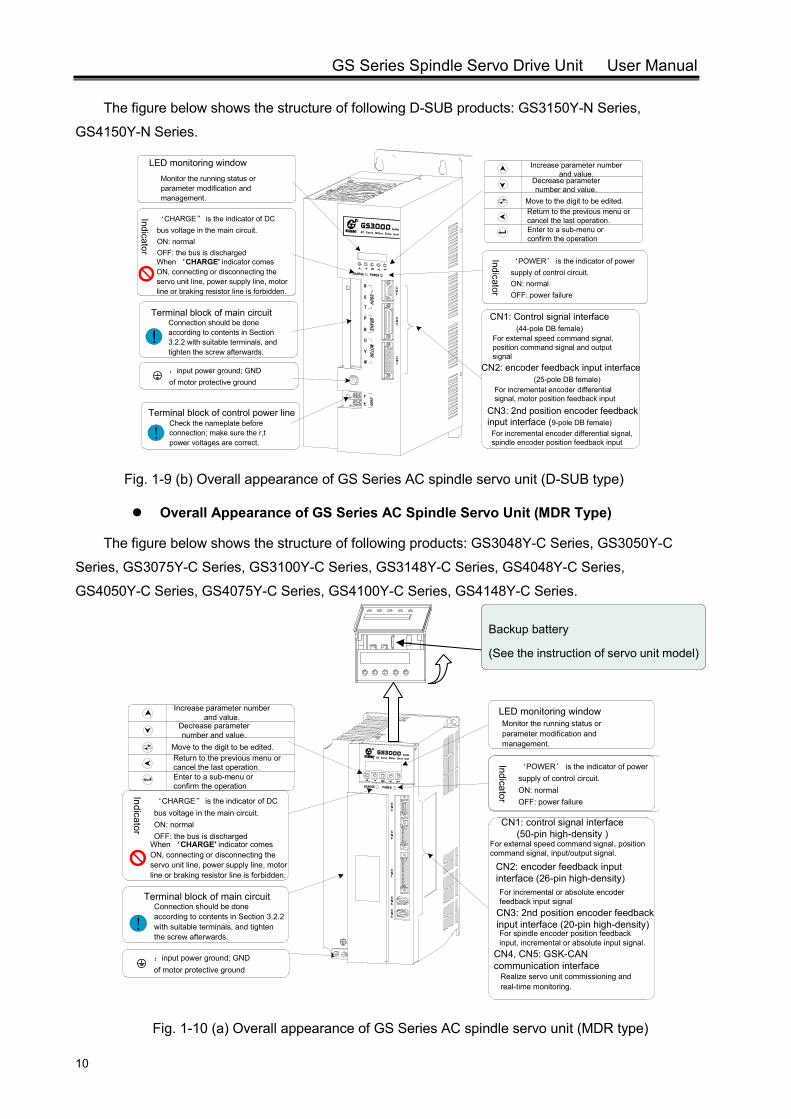
The figure below shows the structure of following D-SUB products: GS3150Y-N Series,
GS4150Y-N Series.
Monitor the running status or parameter modification and management.
LED monitoring window
‘CHARGE” is the indicator of DC bus voltage in the main circuit. ON: normalOFF: the bus is discharged When ‘CHARGE' indicator comes ON, connecting or disconnecting the servo unit line, power supply line, motor line or braking resistor line is forbidden.
Indicator
Increase parameter number and value.
Decrease parameter number and value.
Enter to a sub-menu or confirm the operation
Move to the digit to be edited. Return to the previous menu or cancel the last operation.
:input power ground; GND of motor protective ground
Connection should be done according to contents in Section 3.2.2 with suitable terminals, and tighten the screw afterwards.
Terminal block of main circuit
!
Indicator
‘POWER’ is the indicator of power supply of control circuit.ON: normal OFF: power failure
CN2: encoder feedback input interface (25-pole DB female)
CN1: Control signal interface (44-pole DB female)
For external speed command signal, position command signal and output signal
For incremental encoder differential signal, motor position feedback input
CN3: 2nd position encoder feedback input interface (9-pole DB female)
For incremental encoder differential signal, spindle encoder position feedback input
Check the nameplate before connection; make sure the r,t power voltages are correct.
Terminal block of control power line
!
CN3
CN2
CN1
R
AC Se rvo M otor D r iv e U n it
Series
CHARGE POWER
R ~380V
S
T
BRAKE
U MOTORV
W
P
B
r
t
380V
Fig. 1-9 (b) Overall appearance of GS Series AC spindle servo unit (D-SUB type)
Overall Appearance of GS Series AC Spindle Servo Unit (MDR Type)
The figure below shows the structure of following products: GS3048Y-C Series, GS3050Y-C
Series, GS3075Y-C Series, GS3100Y-C Series, GS3148Y-C Series, GS4048Y-C Series,
GS4050Y-C Series, GS4075Y-C Series, GS4100Y-C Series, GS4148Y-C Series.
!
CN2: encoder feedback input interface (26-pin high-density)
CN1: control signal interface (50-pin high-density )
For external speed command signal, position command signal, input/output signal.
For incremental or absolute encoder feedback input signal
CN3: 2nd position encoder feedback input interface (20-pin high-density)For spindle encoder position feedback input, incremental or absolute input signal.
CN1
CN5
CN4
CN2
CN3
R
AC Se rvo Mo to r Dri v e Un it
Series
CHARGE POWER
CN4, CN5: GSK-CAN communication interface
Realize servo unit commissioning and real-time monitoring.
Monitor the running status or parameter modification and management.
Connection should be done according to contents in Section 3.2.2 with suitable terminals, and tighten the screw afterwards.
:input power ground; GND of motor protective ground
Terminal block of main circuit
Indicator
‘CHARGE” is the indicator of DC bus voltage in the main circuit. ON: normalOFF: the bus is discharged
When ‘CHARGE' indicator comes ON, connecting or disconnecting the servo unit line, power supply line, motor line or braking resistor line is forbidden.
LED monitoring window
Indicator
‘POWER’ is the indicator of power supply of control circuit.ON: normal OFF: power failure
Increase parameter number and value.
Decrease parameter number and value.
Enter to a sub-menu or confirm the operation
Move to the digit to be edited. Return to the previous menu or cancel the last operation.
Fig. 1-10 (a) Overall appearance of GS Series AC spindle servo unit (MDR type)
Backup battery
(See the instruction of servo unit model)
Chapter I Instruction
11
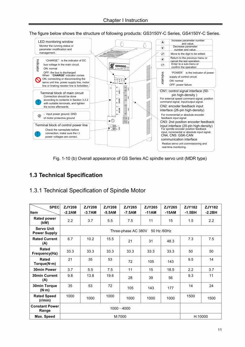
The figure below shows the structure of following products: GS3150Y-C Series, GS4150Y-C Series.
R
A C S erv o M ot or D r iv e Un i t
Series
CHARGE POWER
R ~380V
S
T
BRAKE
U MOTORV
W
P
B
r
t
380V
CN3
CN2
CN1
CN4
CN5
!Connection should be done according to contents in Section 3.2.2 with suitable terminals, and tighten the screw afterwards.
:input power ground; GND of motor protective ground
Terminal block of main circuit
Indicator
‘CHARGE” is the indicator of DC bus voltage in the main circuit. ON: normalOFF: the bus is discharged
When ‘CHARGE' indicator comes ON, connecting or disconnecting the servo unit line, power supply line, motor line or braking resistor line is forbidden.
Increase parameter number and value.
Decrease parameter number and value.
Enter to a sub-menu or confirm the operation
Move to the digit to be edited. Return to the previous menu or cancel the last operation.
Indicator
‘POWER’ is the indicator of power supply of control circuit.ON: normal OFF: power failure
Check the nameplate before connection; make sure the r,t power voltages are correct.
Terminal block of control power line
!
CN2: encoder feedback input interface (26-pin high-density)
CN1: control signal interface (50-pin high-density )
For external speed command signal, position command signal, input/output signal.
For incremental or absolute encoder feedback input signal
CN3: 2nd position encoder feedback input interface (20-pin high-density)For spindle encoder position feedback input, incremental or absolute input signal.CN4, CN5: GSK-CAN communication interfaceRealize servo unit commissioning and real-time monitoring.
Monitor the running status or parameter modification and management.
LED monitoring window
Fig. 1-10 (b) Overall appearance of GS Series AC spindle servo unit (MDR type)
1.3 Technical Specification
1.3.1 Technical Specification of Spindle Motor
SPEC Item
ZJY208 -2.2AM
ZJY208 -3.7AM
ZJY208-5.5AM
ZJY265 -7.5AM
ZJY265-11AM
ZJY265 -15AM
ZJY182 -1.5BH
ZJY182-2.2BH
Rated power (kW) 2.2 3.7 5.5 7.5 11 15 1.5 2.2
Servo Unit Power Supply Three-phase AC 380V 50 Hz /60Hz
Rated Current (A)
6.7 10.2 15.5 21 31 48.3 7.3 7.5
Rated Frequency(Hz) 33.3 33.3 33.3 33.3 33.3 33.3 50 50
Rated Torque(N·m)
21 35 53 72 105 143 9.5 14
30min Power 3.7 5.5 7.5 11 15 18.5 2.2 3.7 30min Current
(A) 9.8 13.8 19.6 28 39 56 9.3 11
30min Torque (N·m)
35 53 72 105 143 177 14 24
Rated Speed (r/min)
1000 1000 1000 1000 1000 1000 1500 1500
Constant Power Range 1000~4000
Max. Speed M:7000 H:10000
GS Series Spindle Servo Drive Unit User Manual
12
SPEC Item
ZJY208 -2.2AM
ZJY208 -3.7AM
ZJY208-5.5AM
ZJY265 -7.5AM
ZJY265-11AM
ZJY265-15AM
ZJY182 -1.5BH
ZJY182-2.2BH
Rotary Inertia 0.0168 0.0238 0.0309 0.0413 0.0826 0.086 0.0056 0.0074 Weight (kg) 51 66 77 51 125 143 27 32 Installation IM B5 or B3 IM B35
Power Supply of Cooling Fan
Three-phase AC 380V 50Hz 40W 0.14A
Three-phase AC 380V 50Hz 70W 0.21A
Three-phase AC 380V 50Hz 30W 0.08A
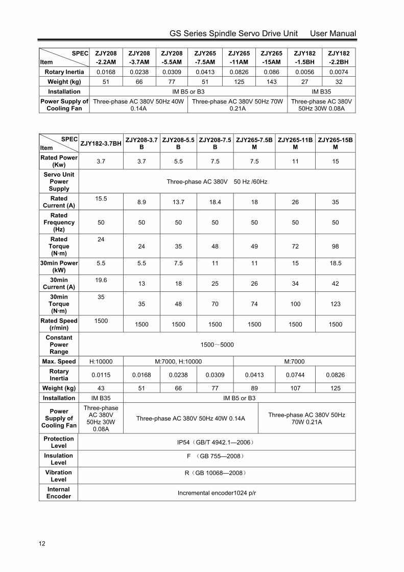
SPEC Item
ZJY182-3.7BH ZJY208-3.7B
ZJY208-5.5B
ZJY208-7.5B
ZJY265-7.5BM
ZJY265-11BM
ZJY265-15BM
Rated Power (Kw) 3.7 3.7 5.5 7.5 7.5 11 15
Servo Unit Power Supply
Three-phase AC 380V 50 Hz /60Hz
Rated Current (A)
15.5 8.9 13.7 18.4 18 26 35
Rated Frequency
(Hz) 50 50 50 50 50 50 50
Rated Torque (N·m)
24 24 35 48 49 72 98
30min Power (kW)
5.5 5.5 7.5 11 11 15 18.5
30min Current (A)
19.6 13 18 25 26 34 42
30min Torque (N·m)
35 35 48 70 74 100 123
Rated Speed (r/min)
1500 1500 1500 1500 1500 1500 1500
Constant Power Range
1500~5000
Max. Speed H:10000 M:7000, H:10000 M:7000 Rotary Inertia 0.0115 0.0168 0.0238 0.0309 0.0413 0.0744 0.0826
Weight (kg) 43 51 66 77 89 107 125 Installation IM B35 IM B5 or B3
Power Supply of
Cooling Fan
Three-phase AC 380V
50Hz 30W 0.08A
Three-phase AC 380V 50Hz 40W 0.14A Three-phase AC 380V 50Hz 70W 0.21A
Protection Level IP54(GB/T 4942.1—2006)
Insulation Level
F (GB 755—2008)
Vibration Level
R(GB 10068—2008)
Internal Encoder Incremental encoder1024 p/r
Chapter I Instruction
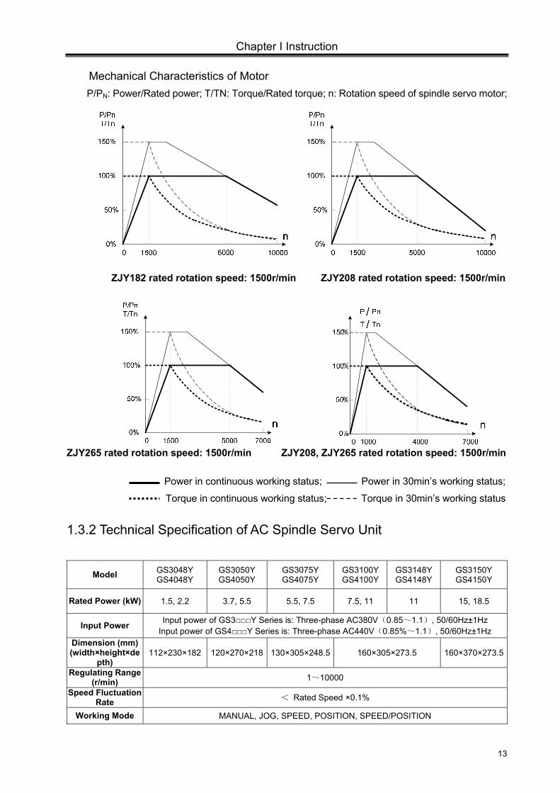
13
Mechanical Characteristics of Motor P/PN: Power/Rated power; T/TN: Torque/Rated torque; n: Rotation speed of spindle servo motor;
ZJY182 rated rotation speed: 1500r/min ZJY208 rated rotation speed: 1500r/min
ZJY265 rated rotation speed: 1500r/min ZJY208, ZJY265 rated rotation speed: 1500r/min
Power in continuous working status; Power in 30min’s working status;
Torque in continuous working status; Torque in 30min’s working status
1.3.2 Technical Specification of AC Spindle Servo Unit
Model GS3048Y GS4048Y
GS3050Y GS4050Y
GS3075Y GS4075Y
GS3100YGS4100Y
GS3148Y GS4148Y
GS3150Y GS4150Y
Rated Power (kW) 1.5, 2.2 3.7, 5.5 5.5, 7.5 7.5, 11 11 15, 18.5
Input Power Input power of GS3Y Series is: Three-phase AC380V(0.85~1.1), 50/60Hz±1Hz Input power of GS4Y Series is: Three-phase AC440V(0.85%~1.1), 50/60Hz±1Hz
Dimension (mm) (width×height×de
pth) 112×230×182 120×270×218 130×305×248.5 160×305×273.5 160×370×273.5
Regulating Range (r/min) 1~10000
Speed Fluctuation Rate < Rated Speed ×0.1%
Working Mode MANUAL, JOG, SPEED, POSITION, SPEED/POSITION
GS Series Spindle Servo Drive Unit User Manual
14
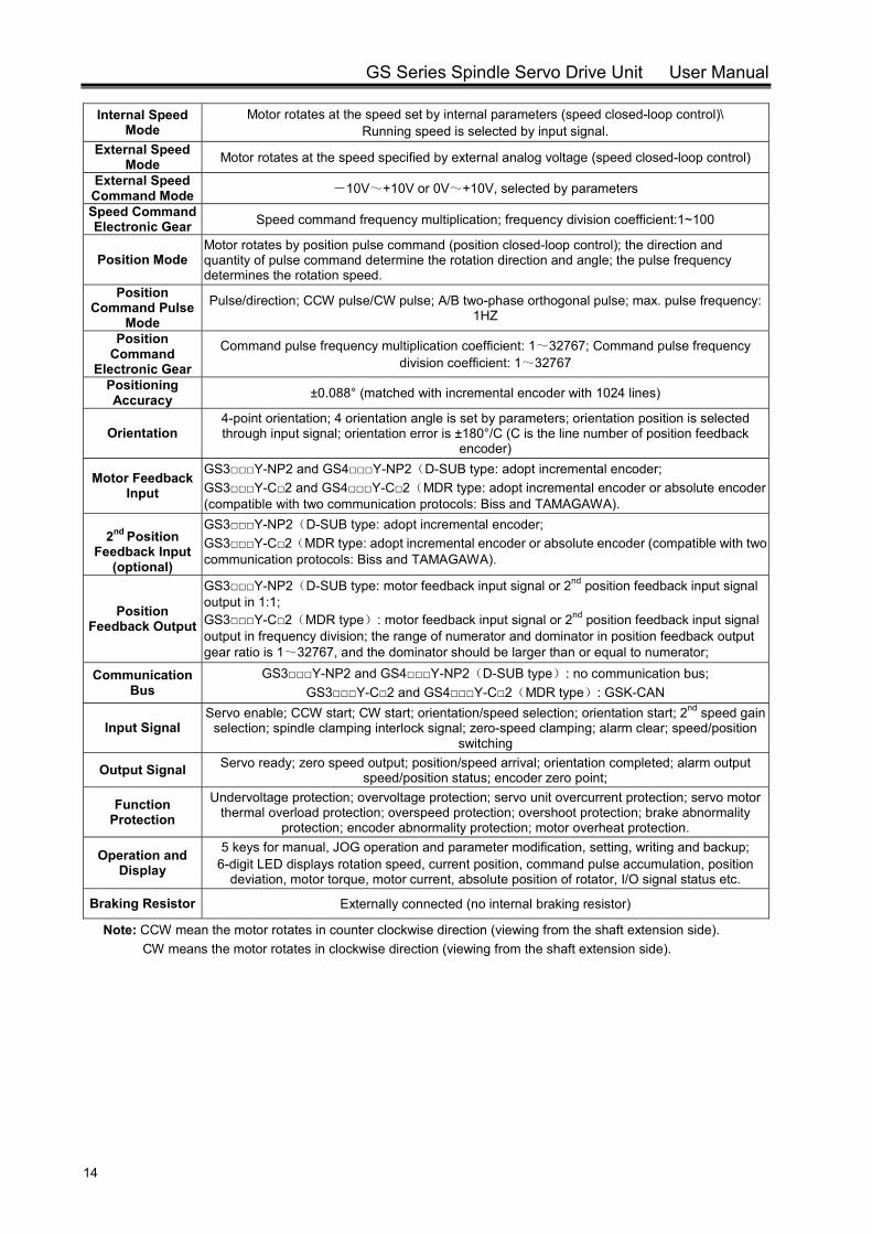
Internal Speed Mode
Motor rotates at the speed set by internal parameters (speed closed-loop control)\ Running speed is selected by input signal.
External Speed Mode Motor rotates at the speed specified by external analog voltage (speed closed-loop control)
External Speed Command Mode -10V~+10V or 0V~+10V, selected by parameters
Speed Command Electronic Gear Speed command frequency multiplication; frequency division coefficient:1~100
Position Mode Motor rotates by position pulse command (position closed-loop control); the direction and quantity of pulse command determine the rotation direction and angle; the pulse frequency determines the rotation speed.
Position Command Pulse
Mode Pulse/direction; CCW pulse/CW pulse; A/B two-phase orthogonal pulse; max. pulse frequency:
1HZ
Position Command
Electronic Gear
Command pulse frequency multiplication coefficient: 1~32767; Command pulse frequency division coefficient: 1~32767
Positioning Accuracy ±0.088° (matched with incremental encoder with 1024 lines)
Orientation 4-point orientation; 4 orientation angle is set by parameters; orientation position is selected through input signal; orientation error is ±180°/C (C is the line number of position feedback
encoder)
Motor Feedback Input
GS3Y-NP2 and GS4Y-NP2(D-SUB type: adopt incremental encoder; GS3Y-C2 and GS4Y-C2(MDR type: adopt incremental encoder or absolute encoder (compatible with two communication protocols: Biss and TAMAGAWA).
2nd Position
Feedback Input (optional)
GS3Y-NP2(D-SUB type: adopt incremental encoder; GS3Y-C2(MDR type: adopt incremental encoder or absolute encoder (compatible with two communication protocols: Biss and TAMAGAWA).
Position Feedback Output
GS3Y-NP2(D-SUB type: motor feedback input signal or 2nd position feedback input signal output in 1:1; GS3Y-C2(MDR type): motor feedback input signal or 2nd position feedback input signal output in frequency division; the range of numerator and dominator in position feedback output gear ratio is 1~32767, and the dominator should be larger than or equal to numerator;
Communication Bus
GS3Y-NP2 and GS4Y-NP2(D-SUB type): no communication bus; GS3Y-C2 and GS4Y-C2(MDR type): GSK-CAN
Input Signal Servo enable; CCW start; CW start; orientation/speed selection; orientation start; 2nd speed gain
selection; spindle clamping interlock signal; zero-speed clamping; alarm clear; speed/position switching
Output Signal Servo ready; zero speed output; position/speed arrival; orientation completed; alarm output speed/position status; encoder zero point;
Function Protection
Undervoltage protection; overvoltage protection; servo unit overcurrent protection; servo motor thermal overload protection; overspeed protection; overshoot protection; brake abnormality
protection; encoder abnormality protection; motor overheat protection.
Operation and Display
5 keys for manual, JOG operation and parameter modification, setting, writing and backup; 6-digit LED displays rotation speed, current position, command pulse accumulation, position
deviation, motor torque, motor current, absolute position of rotator, I/O signal status etc.
Braking Resistor Externally connected (no internal braking resistor)
Note: CCW mean the motor rotates in counter clockwise direction (viewing from the shaft extension side). CW means the motor rotates in clockwise direction (viewing from the shaft extension side).
Chapter I Instruction
15
1.4 Ordering Guidelines
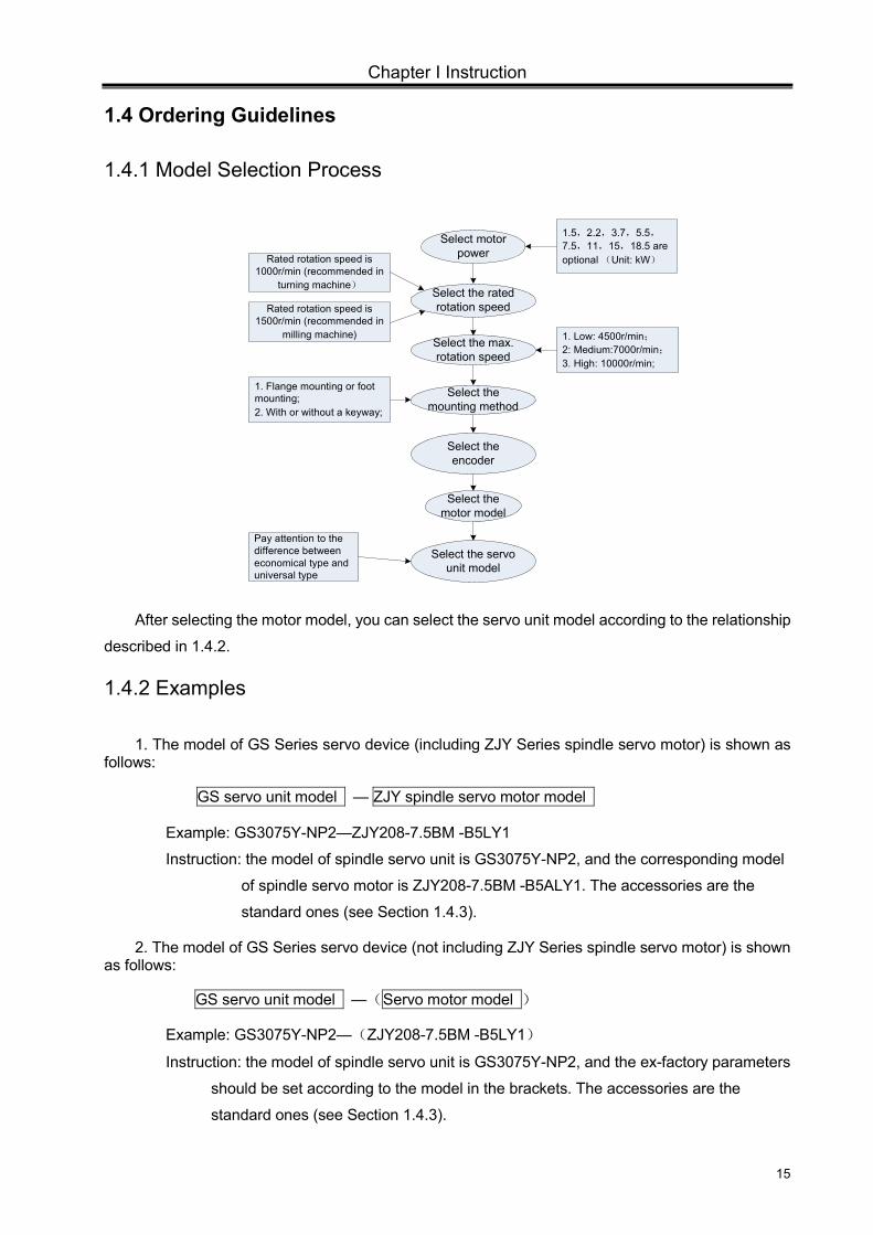
1.4.1 Model Selection Process
Select motor power
Select the rated rotation speed
Select the max. rotation speed
Select the mounting method
Select the encoder
Rated rotation speed is 1000r/min (recommended in
turning machine)
Rated rotation speed is 1500r/min (recommended in
milling machine)
1.5,2.2,3.7,5.5,7.5,11,15,18.5 are optional (Unit: kW)
1. Low: 4500r/min;2: Medium:7000r/min;3. High: 10000r/min;
1. Flange mounting or foot mounting; 2. With or without a keyway;
Select the motor model
Select the servo unit model
Pay attention to the difference between economical type and universal type
After selecting the motor model, you can select the servo unit model according to the relationship
described in 1.4.2.
1.4.2 Examples
1. The model of GS Series servo device (including ZJY Series spindle servo motor) is shown as follows:
GS servo unit model — ZJY spindle servo motor model
Example: GS3075Y-NP2—ZJY208-7.5BM -B5LY1
Instruction: the model of spindle servo unit is GS3075Y-NP2, and the corresponding model
of spindle servo motor is ZJY208-7.5BM -B5ALY1. The accessories are the
standard ones (see Section 1.4.3). 2. The model of GS Series servo device (not including ZJY Series spindle servo motor) is shown
as follows:
GS servo unit model —(Servo motor model )
Example: GS3075Y-NP2—(ZJY208-7.5BM -B5LY1)
Instruction: the model of spindle servo unit is GS3075Y-NP2, and the ex-factory parameters
should be set according to the model in the brackets. The accessories are the
standard ones (see Section 1.4.3).
GS Series Spindle Servo Drive Unit User Manual
16
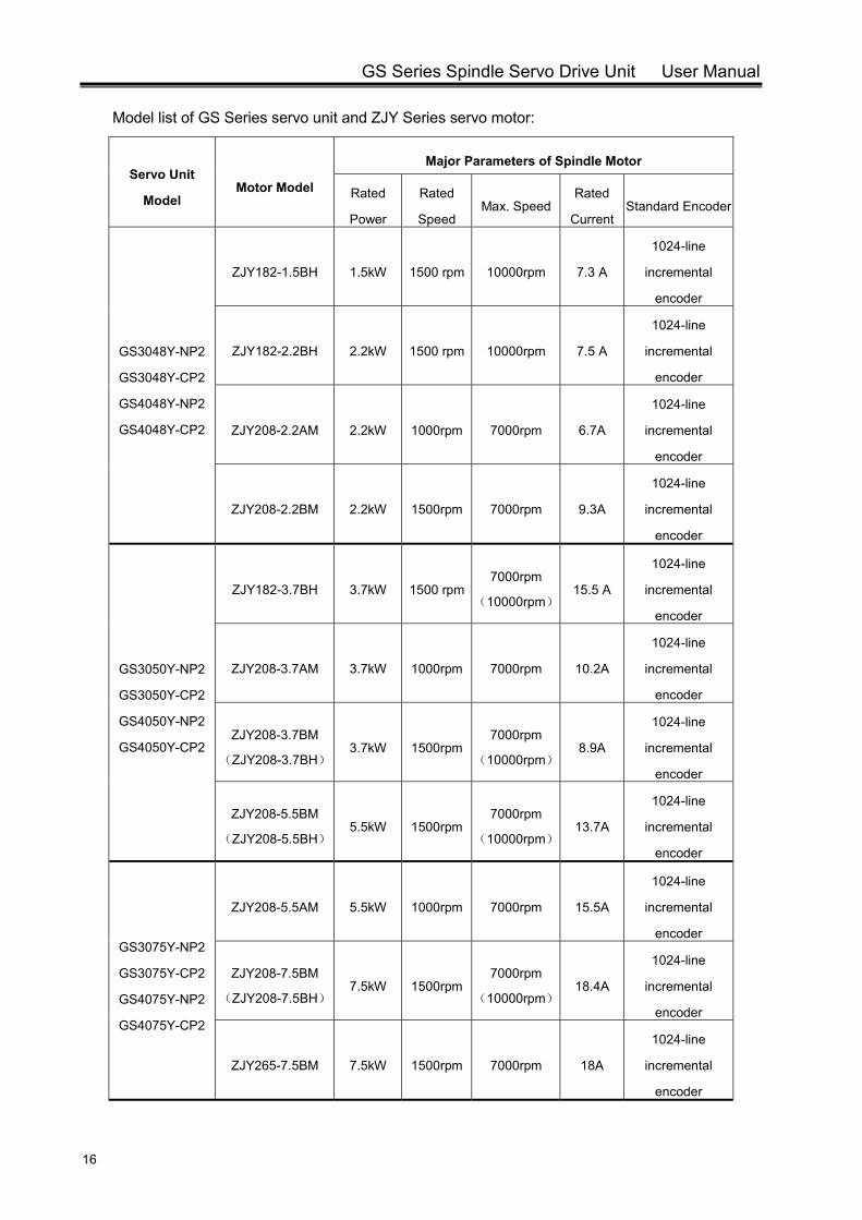
Model list of GS Series servo unit and ZJY Series servo motor:
Servo Unit
Model Motor Model
Major Parameters of Spindle Motor
Rated
Power
Rated
SpeedMax. Speed
Rated
Current Standard Encoder
GS3048Y-NP2
GS3048Y-CP2
GS4048Y-NP2
GS4048Y-CP2
ZJY182-1.5BH 1.5kW 1500 rpm 10000rpm 7.3 A
1024-line
incremental
encoder
ZJY182-2.2BH 2.2kW 1500 rpm 10000rpm 7.5 A
1024-line
incremental
encoder
ZJY208-2.2AM 2.2kW 1000rpm 7000rpm 6.7A
1024-line
incremental
encoder
ZJY208-2.2BM 2.2kW 1500rpm 7000rpm 9.3A
1024-line
incremental
encoder
GS3050Y-NP2
GS3050Y-CP2
GS4050Y-NP2
GS4050Y-CP2
ZJY182-3.7BH 3.7kW 1500 rpm7000rpm
(10000rpm)15.5 A
1024-line
incremental
encoder
ZJY208-3.7AM 3.7kW 1000rpm 7000rpm 10.2A
1024-line
incremental
encoder
ZJY208-3.7BM
(ZJY208-3.7BH) 3.7kW 1500rpm
7000rpm
(10000rpm)8.9A
1024-line
incremental
encoder
ZJY208-5.5BM
(ZJY208-5.5BH) 5.5kW 1500rpm
7000rpm
(10000rpm)13.7A
1024-line
incremental
encoder
GS3075Y-NP2
GS3075Y-CP2
GS4075Y-NP2
GS4075Y-CP2
ZJY208-5.5AM 5.5kW 1000rpm 7000rpm 15.5A
1024-line
incremental
encoder
ZJY208-7.5BM
(ZJY208-7.5BH) 7.5kW 1500rpm
7000rpm
(10000rpm)18.4A
1024-line
incremental
encoder
ZJY265-7.5BM 7.5kW 1500rpm 7000rpm 18A
1024-line
incremental
encoder
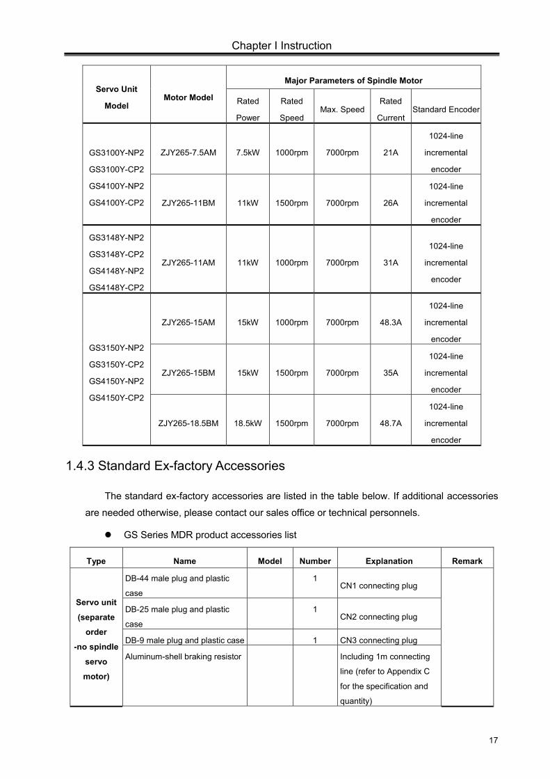
Chapter I Instruction
17
Servo Unit
Model Motor Model
Major Parameters of Spindle Motor
Rated
Power
Rated
SpeedMax. Speed
Rated
Current Standard Encoder
GS3100Y-NP2
GS3100Y-CP2
GS4100Y-NP2
GS4100Y-CP2
ZJY265-7.5AM 7.5kW 1000rpm 7000rpm 21A
1024-line
incremental
encoder
ZJY265-11BM 11kW 1500rpm 7000rpm 26A
1024-line
incremental
encoder
GS3148Y-NP2
GS3148Y-CP2
GS4148Y-NP2
GS4148Y-CP2
ZJY265-11AM 11kW 1000rpm 7000rpm 31A
1024-line
incremental
encoder
GS3150Y-NP2
GS3150Y-CP2
GS4150Y-NP2
GS4150Y-CP2
ZJY265-15AM 15kW 1000rpm 7000rpm 48.3A
1024-line
incremental
encoder
ZJY265-15BM 15kW 1500rpm 7000rpm 35A
1024-line
incremental
encoder
ZJY265-18.5BM 18.5kW 1500rpm 7000rpm 48.7A
1024-line
incremental
encoder
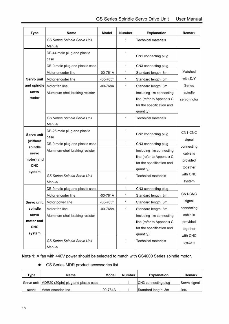
1.4.3 Standard Ex-factory Accessories
The standard ex-factory accessories are listed in the table below. If additional accessories
are needed otherwise, please contact our sales office or technical personnels.
GS Series MDR product accessories list
Type Name Model Number Explanation Remark
Servo unit
(separate
order
-no spindle
servo
motor)
DB-44 male plug and plastic
case
1 CN1 connecting plug
DB-25 male plug and plastic
case
1 CN2 connecting plug
DB-9 male plug and plastic case 1 CN3 connecting plug
Aluminum-shell braking resistor Including 1m connecting
line (refer to Appendix C
for the specification and
quantity)
GS Series Spindle Servo Drive Unit User Manual
18
Type Name Model Number Explanation Remark
GS Series Spindle Servo Unit
Manual
1 Technical materials
Servo unit
and spindle
servo
motor
DB-44 male plug and plastic
case
1 CN1 connecting plug
Matched
with ZJY
Series
spindle
servo motor
DB-9 male plug and plastic case 1 CN3 connecting plug
Motor encoder line -00-761A 1 Standard length: 3m
Motor encoder line -00-765* 1 Standard length: 3m
Motor fan line -00-768A 1 Standard length: 3m
Aluminum-shell braking resistor Including 1m connecting
line (refer to Appendix C
for the specification and
quantity)
GS Series Spindle Servo Unit
Manual
1 Technical materials
Servo unit
(without
spindle
servo
motor) and
CNC
system
DB-25 male plug and plastic
case
1 CN2 connecting plug CN1-CNC
signal
connecting
cable is
provided
together
with CNC
system
DB-9 male plug and plastic case 1 CN3 connecting plug
Aluminum-shell braking resistor Including 1m connecting
line (refer to Appendix C
for the specification and
quantity)
GS Series Spindle Servo Unit
Manual
1
Technical materials
Servo unit,
spindle
servo
motor and
CNC
system
DB-9 male plug and plastic case 1 CN3 connecting plug CN1-CNC
signal
connecting
cable is
provided
together
with CNC
system
Motor encoder line -00-761A 1 Standard length: 3m
Motor power line -00-765* 1 Standard length: 3m
Motor fan line -00-768A 1 Standard length: 3m
Aluminum-shell braking resistor Including 1m connecting
line (refer to Appendix C
for the specification and
quantity)
GS Series Spindle Servo Unit
Manual
1 Technical materials
Note 1: A fan with 440V power should be selected to match with GS4000 Series spindle motor.
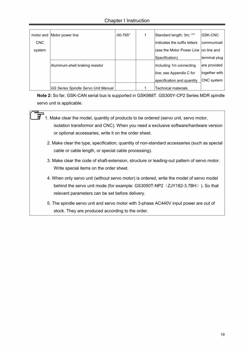
GS Series MDR product accessories list
Type Name Model Number Explanation Remark
Servo unit,
servo
MDR20 (20pin) plug and plastic case 1 CN3 connecting plug Servo signal
line, Motor encoder line -00-761A 1 Standard length: 3m
Chapter I Instruction
19
motor and
CNC
system
Motor power line -00-765* 1 Standard length: 3m; “*”
indicates the suffix letters
(see the Motor Power Line
Specification)
GSK-CNC
communicati
on line and
terminal plug
are provided
together with
CNC system
Aluminum-shell braking resistor Including 1m connecting
line; see Appendix C for
specification and quantity
GS Series Spindle Servo Unit Manual 1 Technical materials
Note 2: So far, GSK-CAN serial bus is supported in GSK988T. GS300Y-CP2 Series MDR spindle
servo unit is applicable.
1. Make clear the model, quantity of products to be ordered (servo unit, servo motor,
isolation transformor and CNC). When you need a exclusive software/hardware version
or optional accessaries, write it on the order sheet.
2. Make clear the type, specification, quantity of non-standard accessaries (such as special
cable or cable length, or special cable processing).
3. Make clear the code of shaft-extension, structure or leading-out pattern of servo motor.
Write special items on the order sheet.
4. When only servo unit (without servo motor) is ordered, write the model of servo model
behind the servo unit mode (for example: GS3050T-NP2(ZJY182-3.7BH)). So that
relevant parameters can be set before delivery.
5. The spindle servo unit and servo motor with 3-phase AC440V input power are out of
stock. They are produced according to the order.

GS Series Spindle Servo Drive Unit User Manual
20
Chapter II Installation/Mounting
21
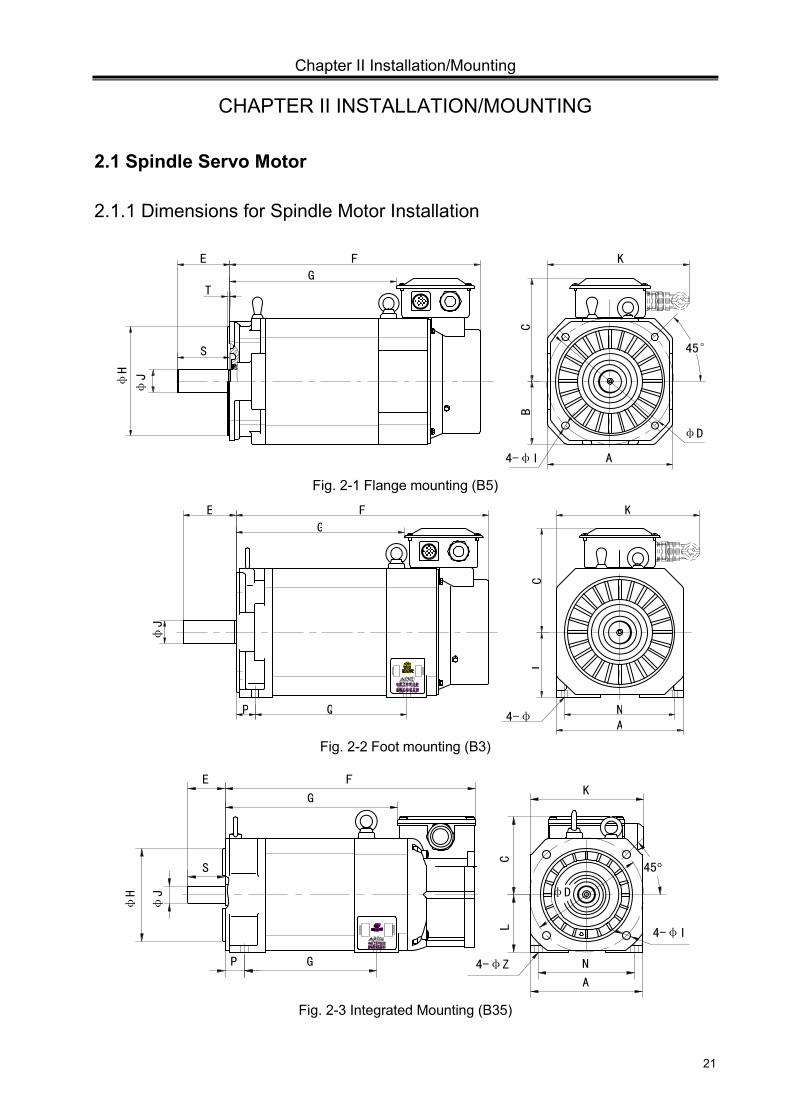
CHAPTER II INSTALLATION/MOUNTING
2.1 Spindle Servo Motor
2.1.1 Dimensions for Spindle Motor Installation
Fig. 2-1 Flange mounting (B5)
Fig. 2-2 Foot mounting (B3)
Fig. 2-3 Integrated Mounting (B35)
φH
φJ
E F
G
B
C
K
45°
A 4-φI
φD
T
S
φJ
E F
G
P Q
LC
K
NA
4-φ
S
φJ
φH
E F
G
P G 4-φZ N A
4-φI
45°
φD
K
C
L
GS Series Spindle Servo Drive Unit User Manual
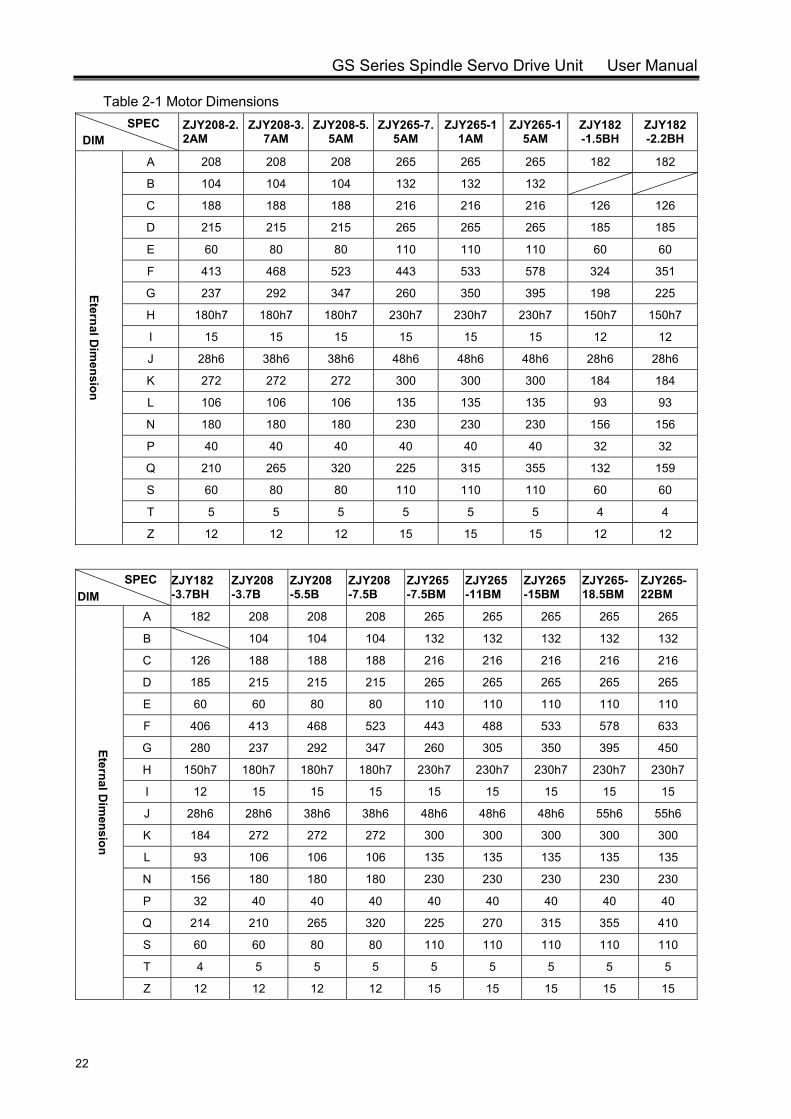
22
Table 2-1 Motor Dimensions SPEC
DIM ZJY208-2.2AM
ZJY208-3.7AM
ZJY208-5.5AM
ZJY265-7.5AM
ZJY265-11AM
ZJY265-15AM
ZJY182 -1.5BH
ZJY182-2.2BH
Eternal Dim
ension
A 208 208 208 265 265 265 182 182
B 104 104 104 132 132 132
C 188 188 188 216 216 216 126 126
D 215 215 215 265 265 265 185 185
E 60 80 80 110 110 110 60 60
F 413 468 523 443 533 578 324 351
G 237 292 347 260 350 395 198 225
H 180h7 180h7 180h7 230h7 230h7 230h7 150h7 150h7
I 15 15 15 15 15 15 12 12
J 28h6 38h6 38h6 48h6 48h6 48h6 28h6 28h6
K 272 272 272 300 300 300 184 184
L 106 106 106 135 135 135 93 93
N 180 180 180 230 230 230 156 156
P 40 40 40 40 40 40 32 32
Q 210 265 320 225 315 355 132 159
S 60 80 80 110 110 110 60 60
T 5 5 5 5 5 5 4 4
Z 12 12 12 15 15 15 12 12
SPEC DIM
ZJY182 -3.7BH
ZJY208 -3.7B
ZJY208 -5.5B
ZJY208 -7.5B
ZJY265 -7.5BM
ZJY265 -11BM
ZJY265 -15BM
ZJY265- 18.5BM
ZJY265-22BM
Eternal Dim
ension
A 182 208 208 208 265 265 265 265 265
B 104 104 104 132 132 132 132 132
C 126 188 188 188 216 216 216 216 216
D 185 215 215 215 265 265 265 265 265
E 60 60 80 80 110 110 110 110 110
F 406 413 468 523 443 488 533 578 633
G 280 237 292 347 260 305 350 395 450
H 150h7 180h7 180h7 180h7 230h7 230h7 230h7 230h7 230h7
I 12 15 15 15 15 15 15 15 15
J 28h6 28h6 38h6 38h6 48h6 48h6 48h6 55h6 55h6
K 184 272 272 272 300 300 300 300 300
L 93 106 106 106 135 135 135 135 135
N 156 180 180 180 230 230 230 230 230
P 32 40 40 40 40 40 40 40 40
Q 214 210 265 320 225 270 315 355 410
S 60 60 80 80 110 110 110 110 110
T 4 5 5 5 5 5 5 5 5
Z 12 12 12 12 15 15 15 15 15
Chapter II Installation/Mounting
23
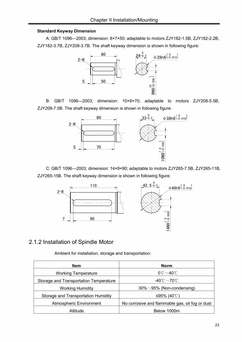
Standard Keyway Dimension A: GB/T 1096—2003; dimension: 8×7×50; adaptable to motors ZJY182-1.5B, ZJY182-2.2B,
ZJY182-3.7B, ZJY208-3.7B. The shaft keyway dimension is shown in following figure:
B: GB/T 1096—2003; dimension: 10×8×70; adaptable to motors ZJY208-5.5B,
ZJY208-7.5B. The shaft keyway dimension is shown in following figure:
C: GB/T 1096—2003; dimension: 14×9×90; adaptable to motors ZJY265-7.5B, ZJY265-11B,
ZJY265-15B. The shaft keyway dimension is shown in following figure:
2.1.2 Installation of Spindle Motor
Ambient for installation, storage and transportation:
Item Norm
Working Temperature 0~40
Storage and Transportation Temperature -40~70
Working Humidity 30%~95% (Non-condensing)
Storage and Transportation Humidity ≤95% (40 )
Atmospheric Environment No corrosive and flammable gas, oil fog or dust
Altitude Below 1000m
0 -0.036
24 0-0.2 φ28h6
0-0.013
5 50
2-R 60
8N9
10N9
0
-0.036
330
-0.2 φ38h6 0 -0.016
5 70
2-R
80
42.5 0-0.2
14N9
0
-0.043
φ 48h6 0 -0.016
7 90
2-R
110
GS Series Spindle Servo Drive Unit User Manual
24
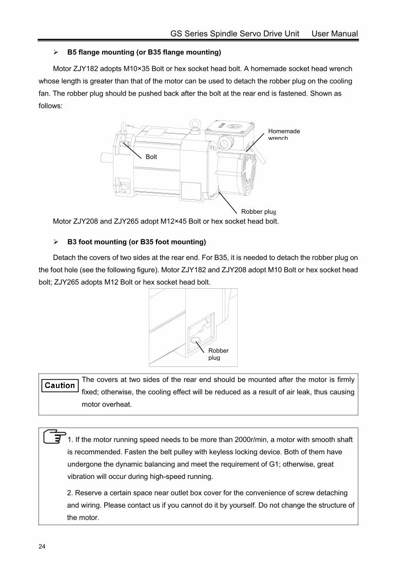
B5 flange mounting (or B35 flange mounting)
Motor ZJY182 adopts M10×35 Bolt or hex socket head bolt. A homemade socket head wrench
whose length is greater than that of the motor can be used to detach the robber plug on the cooling
fan. The robber plug should be pushed back after the bolt at the rear end is fastened. Shown as
follows:
Motor ZJY208 and ZJY265 adopt M12×45 Bolt or hex socket head bolt.
B3 foot mounting (or B35 foot mounting)
Detach the covers of two sides at the rear end. For B35, it is needed to detach the robber plug on
the foot hole (see the following figure). Motor ZJY182 and ZJY208 adopt M10 Bolt or hex socket head
bolt; ZJY265 adopts M12 Bolt or hex socket head bolt.
The covers at two sides of the rear end should be mounted after the motor is firmly
fixed; otherwise, the cooling effect will be reduced as a result of air leak, thus causing
motor overheat.
1. If the motor running speed needs to be more than 2000r/min, a motor with smooth shaft
is recommended. Fasten the belt pulley with keyless locking device. Both of them have
undergone the dynamic balancing and meet the requirement of G1; otherwise, great
vibration will occur during high-speed running.
2. Reserve a certain space near outlet box cover for the convenience of screw detaching
and wiring. Please contact us if you cannot do it by yourself. Do not change the structure of
the motor.
Robber plug
Bolt
Robber plug
Homemade wrench

Chapter II Installation/Mounting
25
Prevent the motor from direct sun light and rain splash. The mounting parts need
to be ventilated, dampproof and dust-proof.
Avoid flammable atmosphere in case of fire disaster.
Do not strike the spindle motor with hard objects during installation and
dismantling.
2.2 Spindle Servo Unit
The installation ambient greatly affects the servo unit function and life cycle; please pay
attention to the following cautions:
Item Norm
Working Temperature 0~40 Storage and Transportation Temperature -40~70
Working Humidity 30%~95% (Non-condensing) Storage and Transportation Humidity ≤95%(40)
Atmospheric Environment No corrosive and flammable gas, oil fog or dustAltitude Below 1000m
Vibration ≤0.6G(5.9m/s2) Atmospheric Pressure 86kPa~106kPa
Avoid rain splash and direct sunlight. Install the servo unit in electrical cabinet to avoid the invasion of dust,
corrosive gas, conductive contents and combustibles. The mounting parts need to be ventilated, dampproof and dust-proof. Avoid flammable atmosphere in case of fire disaster. Select a proper installation position for easy maintaining and inspection.
There are fragile components in the encoder. Do not subject the encoder to any force or shock during installation!
Do not subject the wheel belly to any force or shock during installation!
Caution
GS Series Spindle Servo Drive Unit User Manual
26
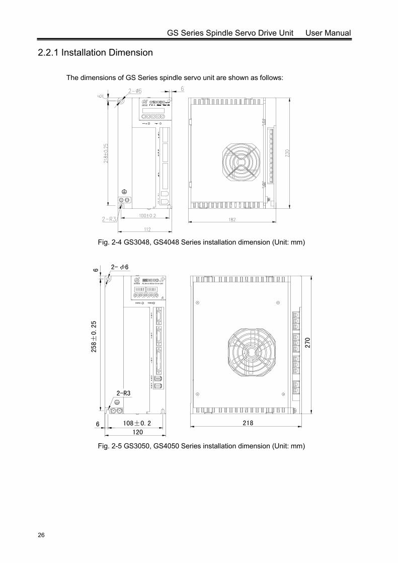
2.2.1 Installation Dimension
The dimensions of GS Series spindle servo unit are shown as follows:
Fig. 2-4 GS3048, GS4048 Series installation dimension (Unit: mm)
258±
0.25
120
NC
6 108±0.2
2-R35
1
CN4
NC
218
3
C
2N
CHARGE
NC
POWER
2- 66
270
AC Servo Motor Drive UnitSeries
Fig. 2-5 GS3050, GS4050 Series installation dimension (Unit: mm)
Chapter II Installation/Mounting
27
CHARGE POWER
N2
C
CN3
N4
5
CN
CN
C
1
2-R6
118±0.2
293±
0.25
305
2- 6
248.5
6
130
6
AC Serv o Motor Dr iv e U nit
Series
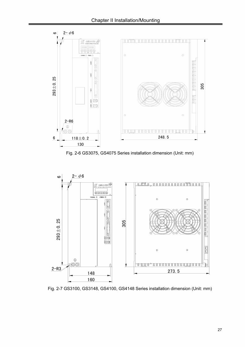
Fig. 2-6 GS3075, GS4075 Series installation dimension (Unit: mm)
5
2
1
C
NC
4N
NC
C
3N
CN
2-R3
6
160
148
2-φ6
305
273.5
293
±0.
25
A C S e r vo M o t o r D ri ve U n i t
S eries
Fig. 2-7 GS3100, GS3148, GS4100, GS4148 Series installation dimension (Unit: mm)
GS Series Spindle Servo Drive Unit User Manual
28
~380
VMOTO
R~
380V
BRA
KE
400±
0.25
418
370
10.5
30
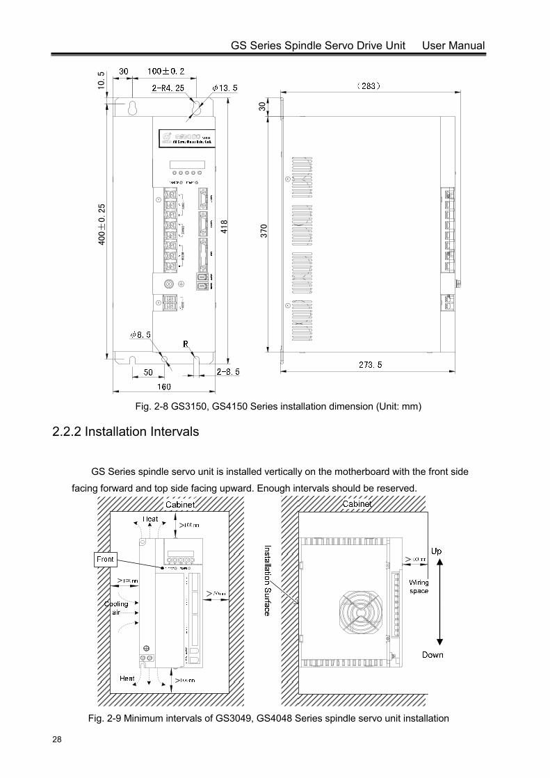
Fig. 2-8 GS3150, GS4150 Series installation dimension (Unit: mm)
2.2.2 Installation Intervals
GS Series spindle servo unit is installed vertically on the motherboard with the front side
facing forward and top side facing upward. Enough intervals should be reserved.
Fig. 2-9 Minimum intervals of GS3049, GS4048 Series spindle servo unit installation
Chapter II Installation/Mounting
29
50mm
100 mm
Cabinet
Front100 mm
Up
Down
Installation Surface
Cabinet
100mm
Cooling air
Heat
Heat
Wiring space
100 mm
NC
5
1
CN4
NC
3
C
2N
CHARGE
NC
POWER
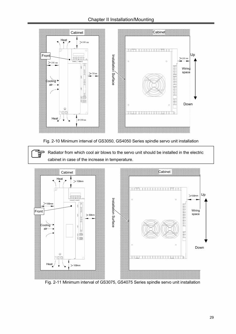
Fig. 2-10 Minimum interval of GS3050, GS4050 Series spindle servo unit installation
100mm
100mm
Cabinet
Front
100mm Up
Down
Installation Surface
Cabinet
100mm
60mm
Cooling air
Heat
Heat
Wiring space
CHARGE POWER
N2
C
CN3
N4
5
CN
CN
C
1
Fig. 2-11 Minimum interval of GS3075, GS4075 Series spindle servo unit installation
Radiator from which cool air blows to the servo unit should be installed in the electric
cabinet in case of the increase in temperature.
GS Series Spindle Servo Drive Unit User Manual
30
60mm100mm
100mm
Cabinet
Front Installation Surface100mm
5
2
1
C
NC
4N
NC
C
3N
CN
100mm Up
Down
Cooling air
Heat
Heat
Wiring space
Cabinet
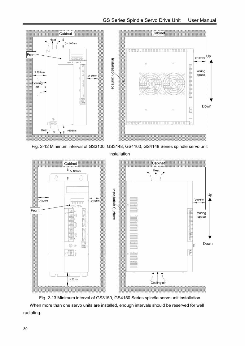
Fig. 2-12 Minimum interval of GS3100, GS3148, GS4100, GS4148 Series spindle servo unit
installation
80mm80mm
120mm
Cabinet
Front
Installation Surface
120mm
Up
Down
100mm
Heat
Cooling air
Wiring space
~380V
MO
TOR
~380V
BR
AKE
r
t
V
W
B
U
R
T
P
S
CHARGE
CN4
CN5
CN1
CN2
CN3
POWER
Cabinet
Fig. 2-13 Minimum interval of GS3150, GS4150 Series spindle servo unit installation
When more than one servo units are installed, enough intervals should be reserved for well
radiating.
Chapter III Connection
31
CHAPTER III CONNECTION
The following cautions should be read carefully and observed strictly so as to ensure safe
and success operation.
The connection should be done by professional personnel according to relevant instructions.
Connection or inspection should be done 5min later after the servo unit is power-off and the
grounding voltage of main circuit terminal is confirmed to be safe; otherwise, it is easy too get
electric shock.
Ensure that the servo unit and servo motor are properly grounding.
Wire layout should be carefully done to avoid pointed objects. Cables should not be dragged
by force; otherwise, it is easy to lead to electric shock or poor connection.
Do not lay the main circuit and the signal line in one pipe nor bound them together. They
should be laid independently or crossly, and the distance should be over 30cm, thus to prevent
high voltage circuit’s interference to signals and ensure normal working of the servo unit.
Do not turn ON or OFF the power frequently. Since in the spindle servo unit, there is large bulk
capacitance which will generate large charging current at power-on, frequent ON/OFF
switching will cause performance degradation on inner components. It is advised that the
interval between power ON and OFF should be more than 3min.
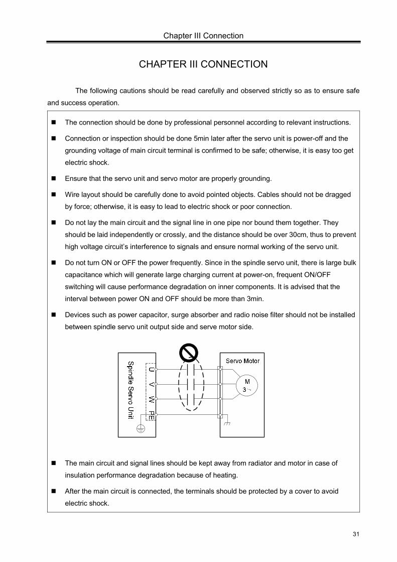
Devices such as power capacitor, surge absorber and radio noise filter should not be installed
between spindle servo unit output side and serve motor side.
The main circuit and signal lines should be kept away from radiator and motor in case of
insulation performance degradation because of heating.
After the main circuit is connected, the terminals should be protected by a cover to avoid
electric shock.
GS Series Spindle Servo Drive Unit User Manual
32
3.1 Connection of Peripheral Equipments
Some peripheral equipments are needed for the running of spindle servo unit. Proper
peripheral equipments ensure the stable running of servo unit and servo motor and prolong the
life cycle.
In the connection diagram, the following points should be noted:
The equipments in the dashed box are free to choose; the equipments in the solid line
box are available from GSK.
The selections for circuit breaker, AC filter, isolation transformer, AC reactor and AC
contactor are described in Appendix B.
Refer to Appendix C for the selection of braking resistor.
The equipments marked with “essential” can ensure safe and reliable operation of the
servo unit and minimize the loss to the greatest extent when fault occurs.
The equipments marked with “optional” can ensure stable running in poor power supply
environment.
Chapter III Connection
33
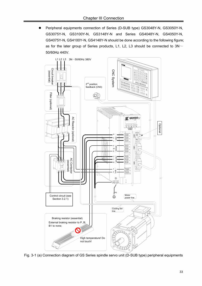
Peripheral equipments connection of Series (D-SUB type) GS3048Y-N, GS3050Y-N,
GS3075Y-N, GS3100Y-N, GS3148Y-N and Series GS4048Y-N, GS4050Y-N,
GS4075Y-N, GS4100Y-N, GS4148Y-N should be done according to the following figure; as for the later group of Series products, L1, L2, L3 should be connected to 3N~
50/60Hz 440V.
CN3
CN2
CN1
R
AC Servo Motor Drive Unit
Series
CHARGE POWER
PE
2nd position feedback (CN3)
rt~380V
R
S
T
~380V
P
B1B
BR
AKE
U
V
W
MO
TOR
L3L2L1 3N~50/60Hz 380V
AC
Contactor
(essential)
Filter (optional)C
ircuit breaker (essential)
Control circuit (see Section 3.2.1)
AC R
eactor (optional)
Braking resistor (essential)External braking resistor to P, B; B1 to none;
High temperature! Do not touch!
Motor power line
Cooling fan line
CN
C System
Optional
Fig. 3-1 (a) Connection diagram of GS Series spindle servo unit (D-SUB type) peripheral equipments
GS Series Spindle Servo Drive Unit User Manual
34
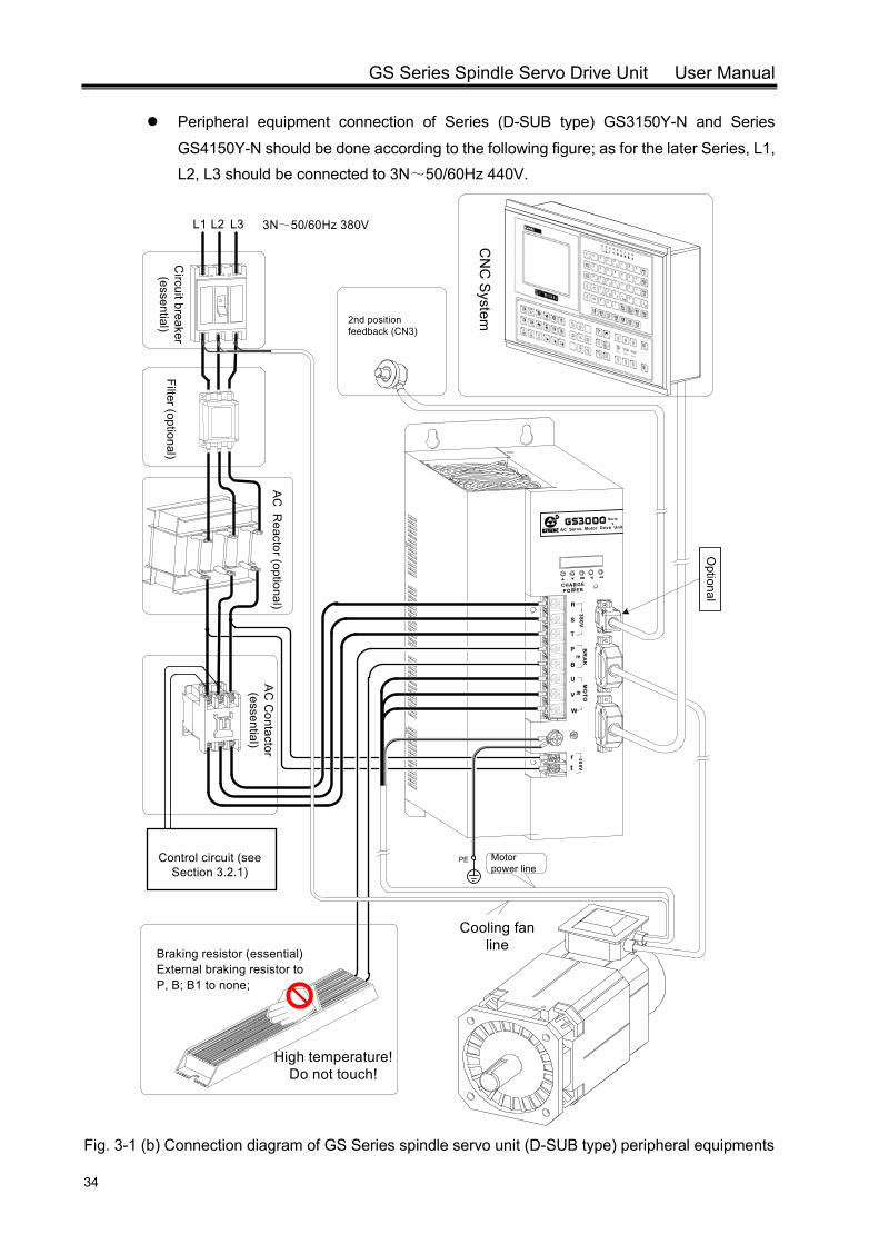
Peripheral equipment connection of Series (D-SUB type) GS3150Y-N and Series
GS4150Y-N should be done according to the following figure; as for the later Series, L1, L2, L3 should be connected to 3N~50/60Hz 440V.
R
AC Servo Motor Drive Unit
Series
CHARGE POWER
R ~380VS
T
BR
AK
E
U MO
TOR
V
W
rt
380V
P
B
2nd position feedback (CN3)
PE
Braking resistor (essential) External braking resistor to P, B; B1 to none;
L3L2L1 3N~50/60Hz 380V
AC
Contactor
(essential)
Filter (optional)C
ircuit breaker (essential)
Control circuit (see Section 3.2.1)
AC R
eactor (optional)
Motor power line
CN
C S
ystem
Optional
Cooling fan line
High temperature! Do not touch!
Fig. 3-1 (b) Connection diagram of GS Series spindle servo unit (D-SUB type) peripheral equipments
Chapter III Connection
35
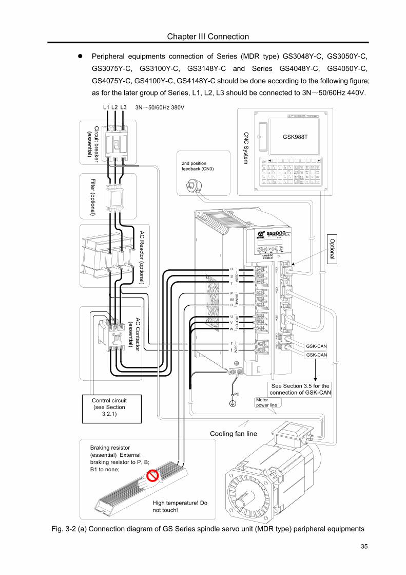
Peripheral equipments connection of Series (MDR type) GS3048Y-C, GS3050Y-C,
GS3075Y-C, GS3100Y-C, GS3148Y-C and Series GS4048Y-C, GS4050Y-C,
GS4075Y-C, GS4100Y-C, GS4148Y-C should be done according to the following figure; as for the later group of Series, L1, L2, L3 should be connected to 3N~50/60Hz 440V.
R
AC Servo M otor Drive Unit
Series
CHARGE POWER
See Section 3.5 for the connection of GSK-CAN
L3L2L1 3N~50/60Hz 380V
AC C
ontactor (essential)
Filter (optional)C
ircuit breaker (essential)
图形 帮助
设置位置
信息
转换
退格
程序 系统
输入上档
取消删除
RESET
988T
GSK988T
PE
Control circuit (see Section
3.2.1)
2nd position feedback (CN3)
rt~380V
CN
C S
ystem
AC
Reactor (optional)
High temperature! Do not touch!
Motor power line
Cooling fan line
CN2
CN1
CN3
CN4
CN5
Braking resistor (essential) External braking resistor to P, B; B1 to none;
GSK-CAN
GSK-CAN
R
S
T
~380V
P
B1B
BR
AKE
U
V
W
MO
TOR
Optional
Fig. 3-2 (a) Connection diagram of GS Series spindle servo unit (MDR type) peripheral equipments
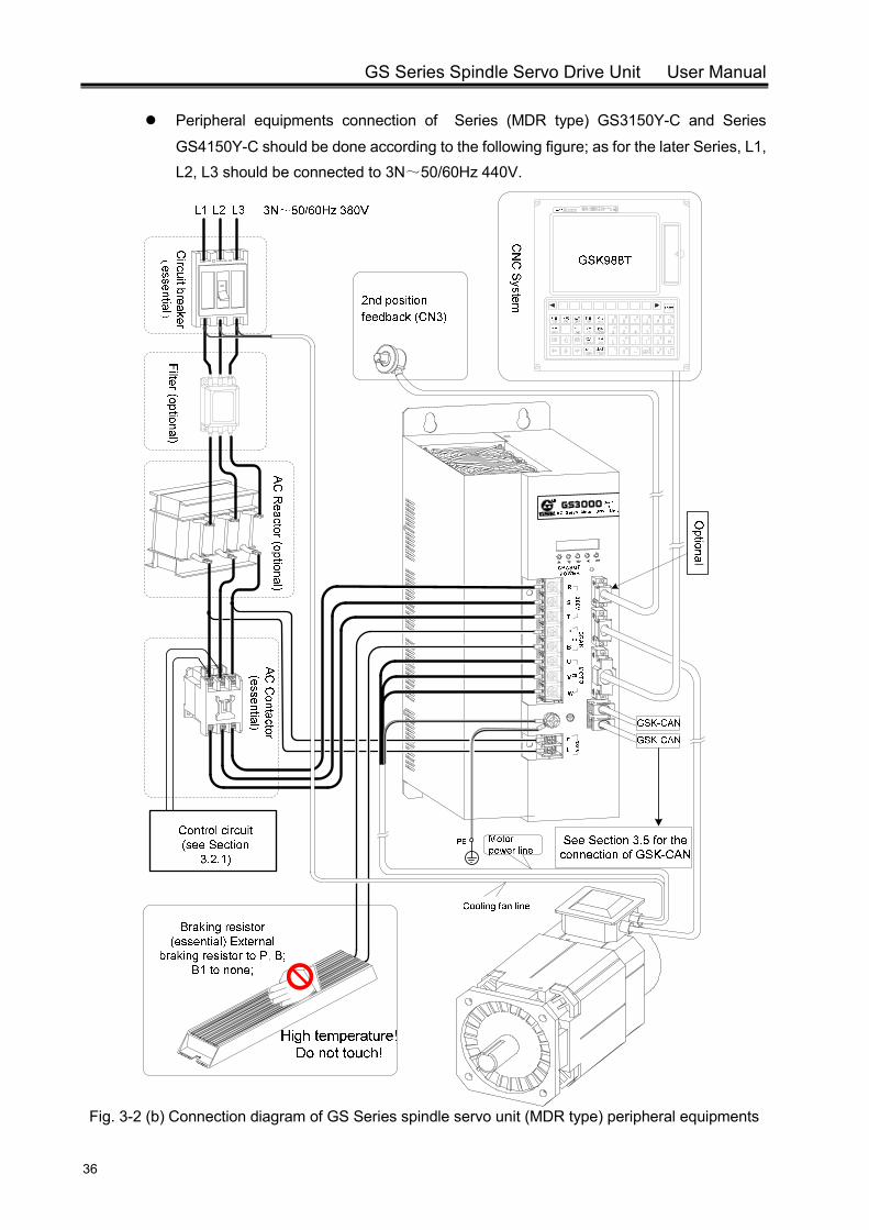
GS Series Spindle Servo Drive Unit User Manual
36
Peripheral equipments connection of Series (MDR type) GS3150Y-C and Series
GS4150Y-C should be done according to the following figure; as for the later Series, L1, L2, L3 should be connected to 3N~50/60Hz 440V.
Fig. 3-2 (b) Connection diagram of GS Series spindle servo unit (MDR type) peripheral equipments
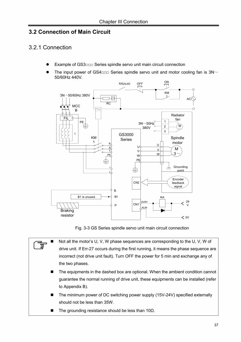
Chapter III Connection
37
3.2 Connection of Main Circuit
3.2.1 Connection
Example of GS3 Series spindle servo unit main circuit connection
The input power of GS4 Series spindle servo unit and motor cooling fan is 3N~50/60Hz 440V.
UVW
RST
PE
M3~
CN1
KM1
MCCB
PE
B
1B
FILPE
Braking resistor
P
B1 is unused.
U
VW
Grounding point
Spindle motor
GS3000 Series
3N~50/60Hz 380V
r
t
L
~
Encoder feedback
signalCN2
KA24V
0V
ALM+
ALM-
ACRC
KA(ALM) ON
KM1
OFF
123
M~
Radiator fan
3N~50Hz 380V
Fig. 3-3 GS Series spindle servo unit main circuit connection
Not all the motor’s U, V, W phase sequences are corresponding to the U, V, W of
drive unit. If Err-27 occurs during the first running, it means the phase sequence are
incorrect (not drive unit fault). Turn OFF the power for 5 min and exchange any of
the two phases.
The equipments in the dashed box are optional. When the ambient condition cannot
guarantee the normal running of drive unit, these equipments can be installed (refer
to Appendix B).
The minimum power of DC switching power supply (15V-24V) specified externally
should not be less than 35W.
The grounding resistance should be less than 10Ω.

38
3.2.2 Wiring of Main Circu
Terminal
Mark Name
R, S, T AC power input
terminal
U, V, W Three-phase AC
output terminal
B, P Braking resistor
terminal
PE Protective
grounding terminal
It is advised that the cables an
Model Motor Power
RU
TerBoltφ
GS3048 GS4048
1.5kW, 2.2kW, 3.7kW, 3
GS3050 GS4050 3.7kW, 5.5kW
GS3075 GS4075 5.5kW,7.5kW
GS3100 GS4100 7.5kW,11kW
GS3148 GS4148 11kW
GS3150 GS4150 15kW, 18.5kw
3.2.3 Servo Motor Connec
Instruction of ZJY spind
The three-phase winding U
glands. Their position in terminal b
to U, V, W, and PE terminal of serv
from motor shaft extension side to
GS Series Spindle Servo Drive Un
uit
Description
Three-phase AC power inp
Connected to three-phase winding
The braking resistor is used for dyna
The spindle servo unit works normally only
resistor is externally connect
The protective grounding resistance should
nd terminals meet the following requirements:
R, S, T, U, V, W r, t P, B
rminal t Size mm
Cable diam
eter m
m2
Terminal Bolt Sizeφmm
Cable diam
eter m
m2
Terminal Bolt Sizeφmm
Cable diam
eter m
m2
3.5 2.5 3.5 1 3.5 2.5
4 2.5 4 1 4 2.5
6 4 4 1 6 2.5
6 6 4 1 6 4
6 6 4 1 6 4
6 10 4 1 6 4
ction Instruction
dle servo motor terminal box:
U, V, W and the casing (grounding) are lead ou
box is shown in following figure. U, V, W and ca
vo unit main circuit respectively. The wind from
the end. Three-phase AC power supply is con
nit User Manual
put
g U, V, W
mic braking;
y when the braking
ted.
d be less than 10Ω.
PE
Cable
diameter
Terminal Bolt Size φmm
Cable diam
eter m
m2
5 4 2.5
5 5 2.5
5 5 2.5
6 4
6 4
6 6
t through cable
asing are connected
m cooling fan blows
nected externally.
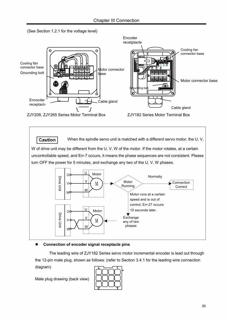
Chapter III Connection
39
Cable gland
Motor connector base
Cooling fan connector base
Encoder recetptacle
Grounding bolt
Cable glandEncocder receptacle
Grounding bolt
Cooling fan connector base
1 2 3
U V WU V W
1 2 3
Motor connector base
(See Section 1.2.1 for the voltage level)
ZJY208, ZJY265 Series Motor Terminal Box ZJY182 Series Motor Terminal Box
When the spindle servo unit is matched with a different servo motor, the U, V,
W of drive unit may be different from the U, V, W of the motor. If the motor rotates, at a certain
uncontrollable speed, and Err-7 occurs, it means the phase sequences are not consistent. Please
turn OFF the power for 5 minutes, and exchange any two of the U, V, W phases.
Motor Running
Normally
Connection Correct
Motor runs at a certain speed and is out of control; Err-27 occurs 10 seconds later.
Exchange any of two
phases
U
V
W
Drive U
nitU
V
W
Motor
M
U
V
W
Drive U
nit
U
V
W
Motor
M
Connection of encoder signal receptacle pins
The leading wire of ZJY182 Series servo motor incremental encoder is lead out through
the 12-pin male plug, shown as follows: (refer to Section 3.4.1 for the leading wire connection
diagram)
Male plug drawing (back view)
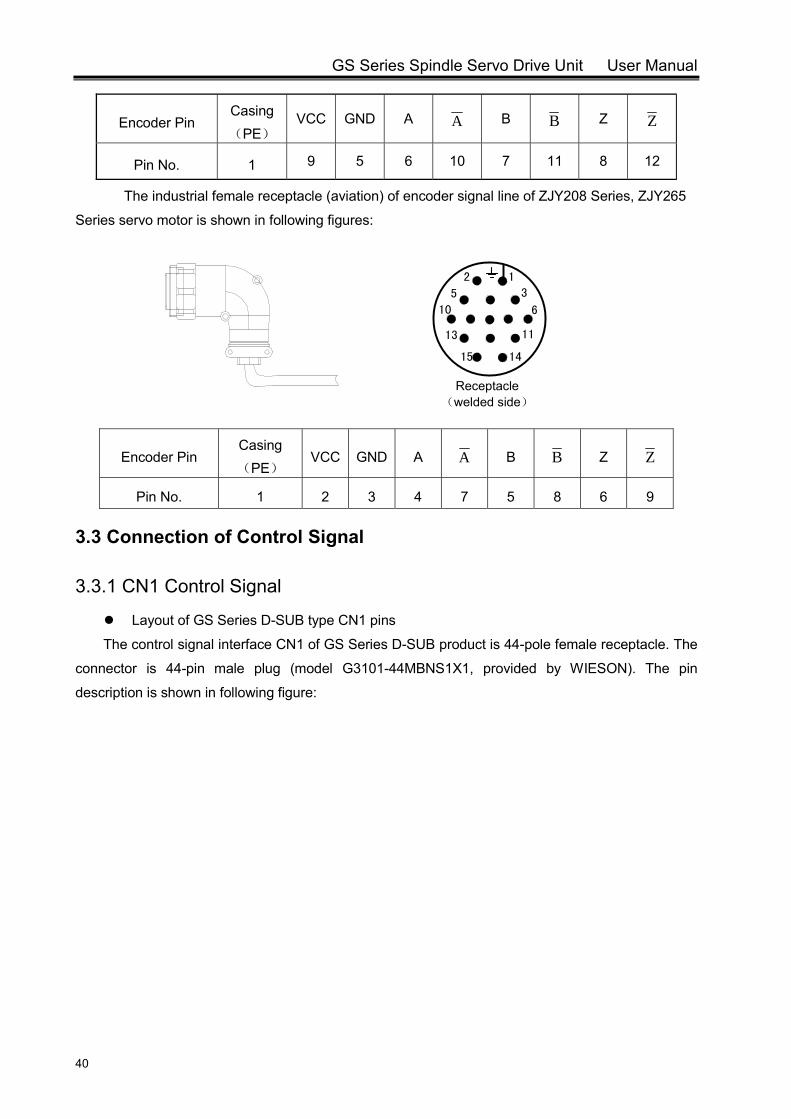
GS Series Spindle Servo Drive Unit User Manual
40
Encoder Pin Casing(PE)
VCC GND A A B B Z Z
Pin No. 1 9 5 6 10 7 11 8 12
The industrial female receptacle (aviation) of encoder signal line of ZJY208 Series, ZJY265
Series servo motor is shown in following figures:
Encoder Pin Casing(PE)
VCC GND A A B B Z Z
Pin No. 1 2 3 4 7 5 8 6 9
3.3 Connection of Control Signal
3.3.1 CN1 Control Signal
Layout of GS Series D-SUB type CN1 pins
The control signal interface CN1 of GS Series D-SUB product is 44-pole female receptacle. The
connector is 44-pin male plug (model G3101-44MBNS1X1, provided by WIESON). The pin
description is shown in following figure:
Receptacle (welded side)
12
35
610
1113
1415
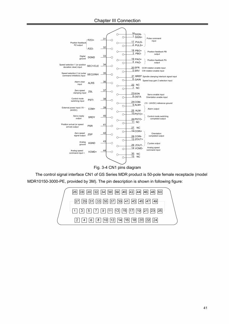
Chapter III Connection
41
SON
ALM+
PSTO+
NC
SEC2/INH
PAO+PAO-
PZO+
PBO+PBO-
AGND
161
31172
32183
33194
34205
35216
36227
37238
38249
392510
402611
412712
422813
432914
443015
COM+
Alarm clear input
Servo enable input
Speed selection 2 (or pulse command inhibition) input
Position feedback PA output
Zero speed clamping input
PULS-PULS+
External power input (15~24VDC)
Position feedback PZ output
Position feedback PB output
GAIN
DGNDDigital ground
NC
COM-
Orientation completed output
Control mode switching completed output
SIGN+SIGN-
Pulse command input
SEC1/CLE
Servo ready output
OSTA Orientation enable input
PZO-
BREF
Speed selection 1 (or position deviation clear) input
Spindle clamping interlock signal input
SRV CW rotation enable input
Speed loop gain 2 selection input
NC
Control mode switching input PSTI
(15~24VDC) reference ground
SRDY
PSR
Alarm output
NCCOIN+
ALM-
ZSP
ZOUT+
ZOUT-VCMD-
VCMD+
NCNC
COIN-
Analog speed command input
Analog ground Z pulse output
Zero speed signal output
Analog speed command input +
PSTO-
SFR CCW rotation enable input
Position arrival (or speed arrival) output
ZSL
ALRS
Fig. 3-4 CN1 pins diagram
The control signal interface CN1 of GS Series MDR product is 50-pole female receptacle (model
MDR10150-3000-PE, provided by 3M). The pin description is shown in following figure:
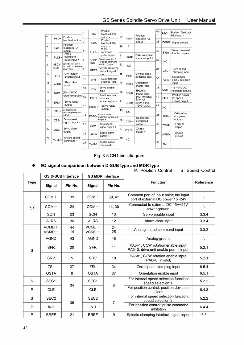
GS Series Spindle Servo Drive Unit User Manual
42
2
4
6
8
10
12
14
16
18
20
22
24
27
ZSL
ALRS
PBO+
PULS+
NC
COM-
SIGN+SIGN-
SEC1/CLE
NC
PSTO-
DGNDPZO+
SRV
SRDY-
ALM-
ZSP-
VCMD+
Position feedback output
PAO+Position feedback PA output +Pulse command pulse input +
Speed selection 1 (or position deviation clear) input
CW rotation enabled input
Alarm clear input
(15~24VDC) reference ground
Servo ready output -
Control mode switching completed output -
Zero-speed signal output -
Servo alarm output -
Analog speed command +
Position feedback PZ output +
26
28
30
32
34
36
38
40
42
44
46
48
50
GAIN
PZO-
COM-
NC
PSR-
COIN-
Position feedback PZ output -
Digital ground
Pulse command direction input -
Zero speed clamping input
Speed loop gain 2 selection input
Position arrival (or speed arrival) output -
ZOUT- Z signal output -
AGND Analog ground
NC
29
31
33
35
37
39
41
43
45
47
49
OSTA
COM+
BREF
NC
PSTI
ZOUT+
COIN+
NC
/
Pulse command direction input +
Orientation enable input
Z signal output +
1
3
5
7
9
11
13
15
17
19
21
23
25
SFR
PBO-
PULS-
SON
SEC2/INH
SRDY+
PSR+
PSTO+
Position feedback PB output -
PAO-Position feedback PA output -Pulse command pulse input -
Speed selection 2 (or pulse command inhibition) input
Spindle clamping interlock signal input
CCW rotation enabled input
Servo enable input
Servo ready output +
Position arrival (or speed arrival) output +
Control mode switching completed output +
ZSP+Zero speed signal output +
ALM+ Servo alarm output +
VCMD-Analog speed command -
Control mode switching input
(15~24VDC) reference ground
COM+External power input (15~24VDC)
Orientation completed output -Orientation
completed output +
External power input (15~24VDC)
Fig. 3-5 CN1 pins diagram
I/O signal comparison between D-SUB type and MDR type P: Position Control S: Speed Control
Type GS D-SUB Interface GS MDR Interface
Function ReferenceSignal Pin No. Signal Pin No.
P, S
COM+ 39 COM+ 39, 41 Common port of Input point; the input port of external DC power 15~24V \
COM- 24 COM- 14, 38 Connected to external DC 15V~24V power ground. \
SON 23 SON 13 Servo enable input 3.3.4
ALRS 36 ALRS 12 Alarm clear input 3.3.4
S
VCMD+ VCMD-
44 14
VCMD+ VCMD-
24 25 Analog speed command input 3.3.2
AGND 43 AGND 48 Analog ground \
SFR 20 SFR 11 PA6=1, CCW rotation enable input; PA6=0, drive unit enable permit input; 5.2.1
SRV 5 SRV 10 PA6=1, CCW rotation enable input; PA6=0, invalid; 5.2.1
ZSL 37 ZSL 34 Zero speed clamping input 6.5.4
OSTA 8 OSTA 37 Orientation enable input 6.5.1
S SEC1 34
SEC1 8
For internal speed selection function: speed selection 1; 5.2.2
P CLE CLE For position control: position deviation clear 6.4.3
S SEC2 35
SEC2 7
For internal speed selection function: speed selection 2; 5.2.2
P INH INH For position control: pulse command inhibition 6.4.4
P BREF 21 BREF 9 Spindle clamping interlock signal input; 6.6
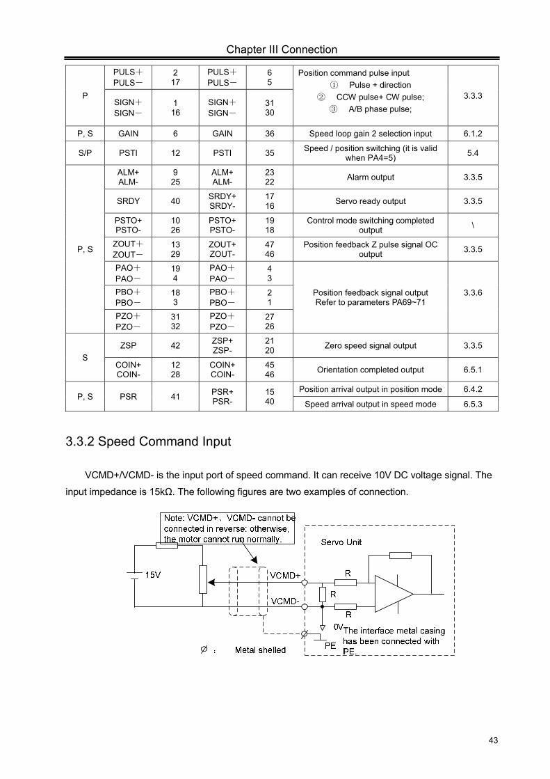
Chapter III Connection
43
P
PULS+ PULS-
2 17
PULS+ PULS-
6 5
Position command pulse input ① Pulse + direction
② CCW pulse+ CW pulse; ③ A/B phase pulse;
3.3.3 SIGN+ SIGN-
1 16
SIGN+ SIGN-
31 30
P, S GAIN 6 GAIN 36 Speed loop gain 2 selection input 6.1.2
S/P PSTI 12 PSTI 35 Speed / position switching (it is valid when PA4=5) 5.4
P, S
ALM+ ALM-
9 25
ALM+ ALM-
23 22 Alarm output 3.3.5
SRDY 40 SRDY+ SRDY-
17 16 Servo ready output 3.3.5
PSTO+ PSTO-
10 26
PSTO+ PSTO-
19 18
Control mode switching completed output \
ZOUT+ ZOUT-
13 29
ZOUT+ ZOUT-
47 46
Position feedback Z pulse signal OC output 3.3.5
PAO+ PAO-
19 4
PAO+ PAO-
4 3
Position feedback signal output Refer to parameters PA69~71
3.3.6
PBO+ PBO-
18 3
PBO+ PBO-
2 1
PZO+ PZO-
31 32
PZO+ PZO-
27 26
S ZSP 42 ZSP+
ZSP- 21 20 Zero speed signal output 3.3.5
COIN+ COIN-
12 28
COIN+ COIN-
45 46 Orientation completed output 6.5.1
P, S PSR 41 PSR+ PSR-
15 40
Position arrival output in position mode 6.4.2
Speed arrival output in speed mode 6.5.3
3.3.2 Speed Command Input
VCMD+/VCMD- is the input port of speed command. It can receive 10V DC voltage signal. The
input impedance is 15kΩ. The following figures are two examples of connection.
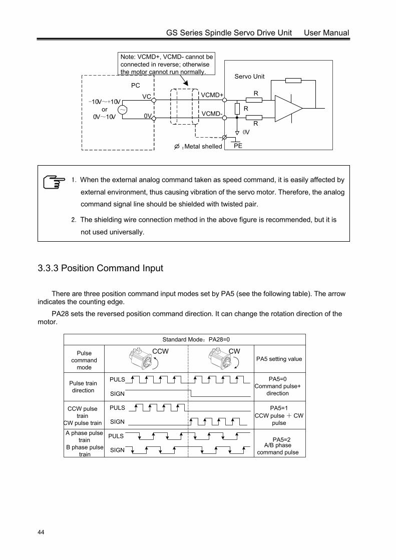
GS Series Spindle Servo Drive Unit User Manual
44
PC
~0V
VC
R
R
R0V
:Metal shelled PE
Servo Unit
VCMD+
VCMD-
-10V~+10Vor
0V~10V
Note: VCMD+, VCMD- cannot be connected in reverse; otherwise the motor cannot run normally.
3.3.3 Position Command Input
There are three position command input modes set by PA5 (see the following table). The arrow indicates the counting edge.
PA28 sets the reversed position command direction. It can change the rotation direction of the motor.
1. When the external analog command taken as speed command, it is easily affected by
external environment, thus causing vibration of the servo motor. Therefore, the analog
command signal line should be shielded with twisted pair.
2. The shielding wire connection method in the above figure is recommended, but it is
not used universally.
Pulse command
mode
Pulse train direction
CCW pulse train
CW pulse train
B phase pulse train
A phase pulse train
PULS
SIGN
PULS
SIGN
PULS
SIGN
PA5 setting value
PA5=0Command pulse+
direction
PA5=1CCW pulse + CW
pulse
PA5=2A/B phase
command pulse
CCW CW
Standard Mode:PA28=0
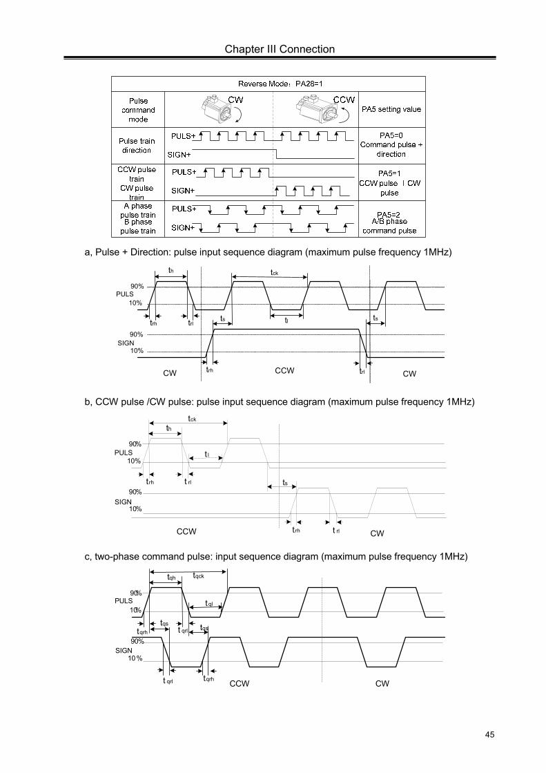
Chapter III Connection
45
a, Pulse + Direction: pulse input sequence diagram (maximum pulse frequency 1MHz)
th
tltrh trl ts ts
tck
trh trl
90%
90%
10%
10%
CW CWCCW
PULS
SIGN
b, CCW pulse /CW pulse: pulse input sequence diagram (maximum pulse frequency 1MHz)
th
t l
trh t rl ts
tck
trh t rl
10%
10%
90%
90%
CCW CW
PULS
SIGN
c, two-phase command pulse: input sequence diagram (maximum pulse frequency 1MHz)
tqh
tql
tqrh t qrl
tqck
10%
10%
90%
90%
tqs tqs
tqrht qrl CCW CW
PULS
SIGN
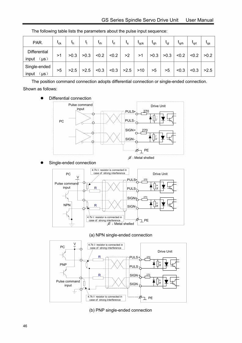
GS Series Spindle Servo Drive Unit User Manual
46
The following table lists the parameters about the pulse input sequence:
PAR. tck th tl trh trl ts tqck tqh tql tqrh tqrl tqs
Differential input (μs)
>1 >0.3 >0.3 <0.2 <0.2 >2 >1 >0.3 >0.3 <0.2 <0.2 >0.2
Single-ended input (μs)
>5 >2.5 >2.5 <0.3 <0.3 >2.5 >10 >5 >5 <0.3 <0.3 >2.5
The position command connection adopts differential connection or single-ended connection.
Shown as follows:
Differential connection
270
SIGN+
SIGN-
Pulse command input
270
PULS+
PULS-
Drive Unit
PC
: Metal shelled
PE
Single-ended connection
270
4.7K
SIGN+
SIGN-
Pulse command input
270
4.7K
PULS+
PULS-
Drive UnitPC
PE
R
V
RNPN
:Metal shelled
4.7kΩ resistor is connected in case of strong interference
4.7kΩ resistor is connected in case of strong interference
(a) NPN single-ended connection
270
4.7K
SIGN +
SIGN -Pulse command
input
270
4.7K
PULS+
PULS -
Drive UnitPC
PE
R
V
R
PNP
4.7kΩ resistor is connected in case of strong interference
4.7kΩ resistor is connected in case of strong interference
(b) PNP single-ended connection
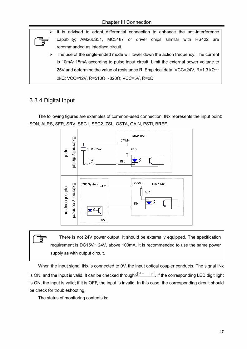
Chapter III Connection
47
It is advised to adopt differential connection to enhance the anti-interference
capability; AM26LS31, MC3487 or driver chips silmilar with RS422 are
recommanded as interface circuit.
The use of the single-ended mode will lower down the action frequency. The current
is 10mA~15mA according to pulse input circuit. Limit the external power voltage to
25V and determine the value of resistance R. Empirical data: VCC=24V, R=1.3 kΩ~
2kΩ; VCC=12V, R=510Ω~820Ω; VCC=5V, R=0Ω
3.3.4 Digital Input
The following figures are examples of common-used connection; INx represents the input point:
SON, ALRS, SFR, SRV, SEC1, SEC2, ZSL, OSTA, GAIN, PSTI, BREF.
Externally digital
input
E
xternally connect
optical coupler
When the input signal INx is connected to 0V, the input optical coupler conducts. The signal INx
is ON, and the input is valid. It can be checked through . If the corresponding LED digit light
is ON, the input is valid; if it is OFF, the input is invalid. In this case, the corresponding circuit should
be check for troubleshooting.
The status of monitoring contents is:
There is not 24V power output. It should be externally equipped. The specification
requirement is DC15V~24V, above 100mA. It is recommended to use the same power
supply as with output circuit.
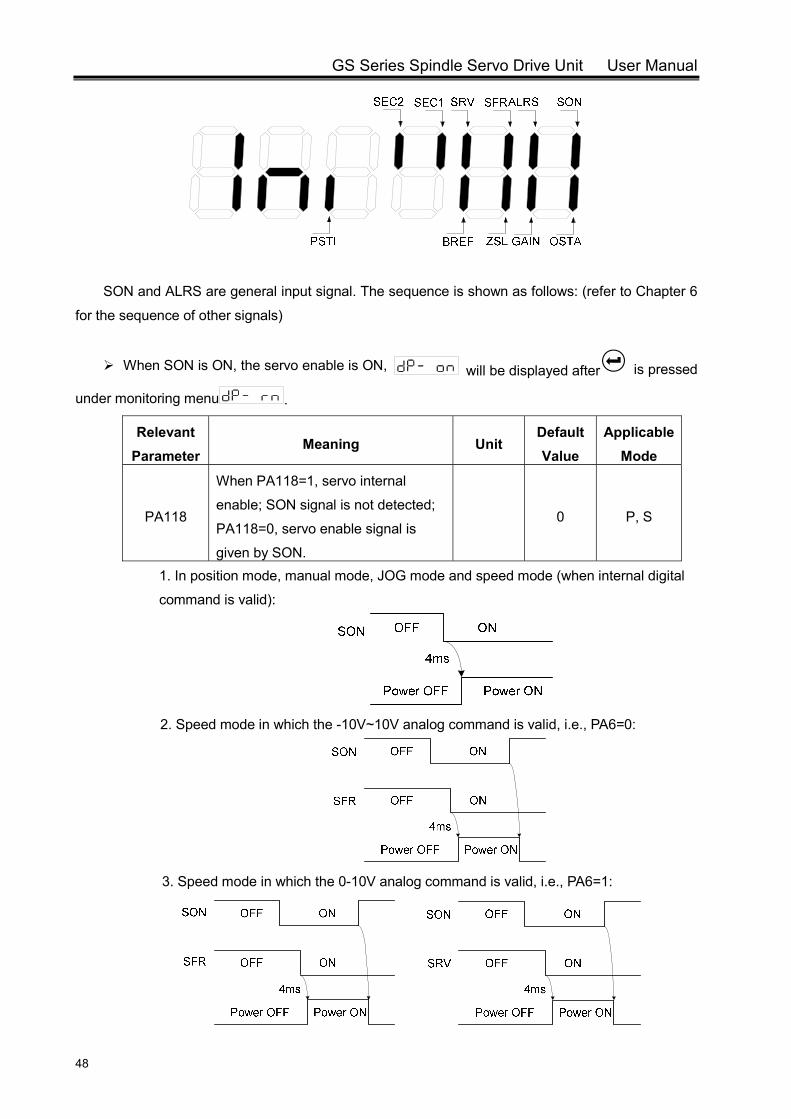
GS Series Spindle Servo Drive Unit User Manual
48
SON and ALRS are general input signal. The sequence is shown as follows: (refer to Chapter 6
for the sequence of other signals)
When SON is ON, the servo enable is ON, will be displayed after is pressed
under monitoring menu .
Relevant Parameter
Meaning Unit Default Value
Applicable Mode
PA118
When PA118=1, servo internal
enable; SON signal is not detected;
PA118=0, servo enable signal is
given by SON.
0 P, S
1. In position mode, manual mode, JOG mode and speed mode (when internal digital
command is valid):
2. Speed mode in which the -10V~10V analog command is valid, i.e., PA6=0:
3. Speed mode in which the 0-10V analog command is valid, i.e., PA6=1:
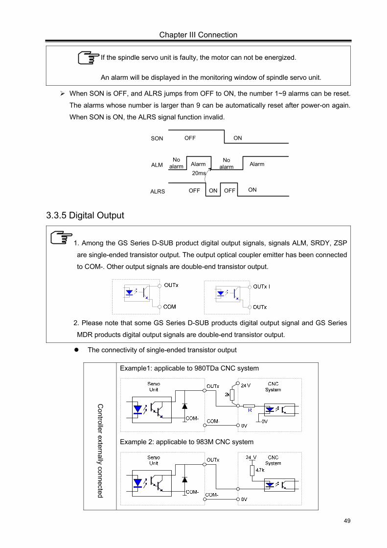
Chapter III Connection
49
When SON is OFF, and ALRS jumps from OFF to ON, the number 1~9 alarms can be reset.
The alarms whose number is larger than 9 can be automatically reset after power-on again.
When SON is ON, the ALRS signal function invalid.
SON
ALM
OFF ON
OFF ON OFFALRS
20ms
ON
No alarm Alarm Alarm
No alarm
3.3.5 Digital Output
1. Among the GS Series D-SUB product digital output signals, signals ALM, SRDY, ZSP
are single-ended transistor output. The output optical coupler emitter has been connected
to COM-. Other output signals are double-end transistor output.
2. Please note that some GS Series D-SUB products digital output signal and GS Series
MDR products digital output signals are double-end transistor output.
The connectivity of single-ended transistor output
Controller externally connected
Example1: applicable to 980TDa CNC system
Example 2: applicable to 983M CNC system
If the spindle servo unit is faulty, the motor can not be energized.
An alarm will be displayed in the monitoring window of spindle servo unit.
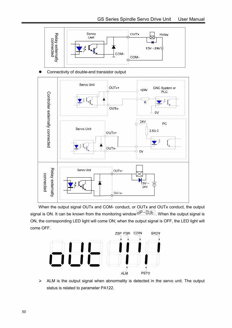
GS Series Spindle Servo Drive Unit User Manual
50
Relay externally connected
Connectivity of double-end transistor output
Controller externally connected
Relay externally
connected
When the output signal OUTx and COM- conduct, or OUTx and OUTx conduct, the output
signal is ON. It can be known from the monitoring window . When the output signal is
ON, the corresponding LED light will come ON; when the output signal is OFF, the LED light will
come OFF.
ALM is the output signal when abnormality is detected in the servo unit. The output
status is related to parameter PA122.
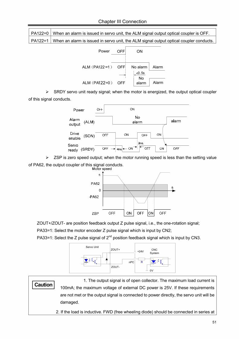
Chapter III Connection
51
PA122=0 When an alarm is issued in servo unit, the ALM signal output optical coupler is OFF.
PA122=1 When an alarm is issued in servo unit, the ALM signal output optical coupler conducts.
Power OFF ON
OFFNo
alarm AlarmALM(PA122=0)
OFF No alarm AlarmALM(PA122=1)<0.5s
SRDY servo unit ready signal; when the motor is energized, the output optical coupler
of this signal conducts.
ZSP is zero speed output; when the motor running speed is less than the setting value
of PA62, the output coupler of this signal conducts.
ZOUT+/ZOUT- are position feedback output Z pulse signal, i.e., the one-rotation signal;
PA33=1: Select the motor encoder Z pulse signal which is input by CN2;
PA33=1: Select the Z pulse signal of 2nd position feedback signal which is input by CN3.
Servo UnitZOUT+
ZOUT-
R
0V
+24V CNC System
nPC
1. The output signal is of open collector. The maximum load current is
100mA; the maximum voltage of external DC power is 25V. If these requirements
are not met or the output signal is connected to power directly, the servo unit will be
damaged.
2. If the load is inductive. FWD (free wheeling diode) should be connected in series at
Caution
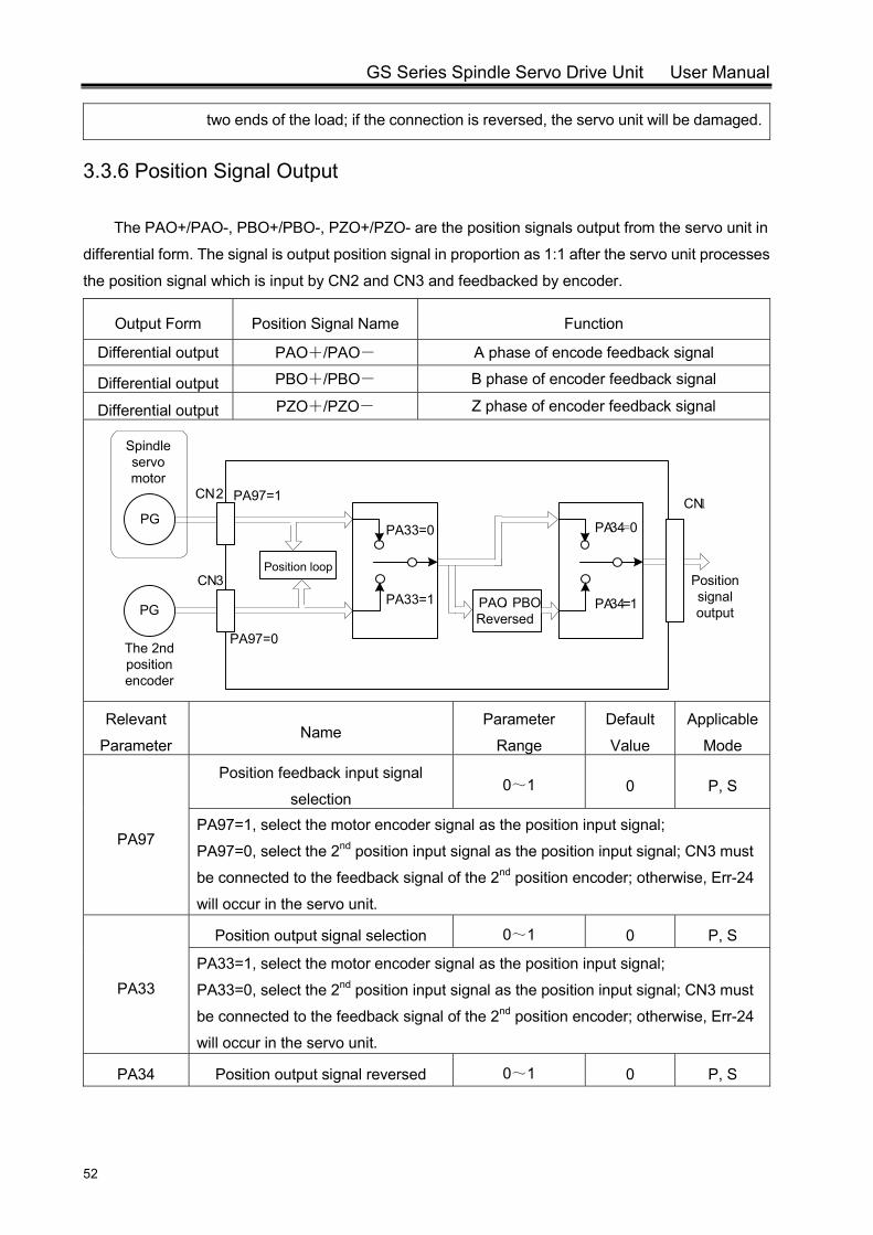
GS Series Spindle Servo Drive Unit User Manual
52
two ends of the load; if the connection is reversed, the servo unit will be damaged.
3.3.6 Position Signal Output
The PAO+/PAO-, PBO+/PBO-, PZO+/PZO- are the position signals output from the servo unit in
differential form. The signal is output position signal in proportion as 1:1 after the servo unit processes
the position signal which is input by CN2 and CN3 and feedbacked by encoder.
Output Form Position Signal Name Function
Differential output PAO+/PAO- A phase of encode feedback signal
Differential output PBO+/PBO- B phase of encoder feedback signal
Differential output PZO+/PZO- Z phase of encoder feedback signal
PG
CN2
CN3
PG
Spindle servo motor
The 2nd position encoder
PA97=1
Position loop
PAO,PBOReversed
PA34=0
PA34=1
Position signal output
CN1
PA97=0
PA33=1
PA33=0
Relevant
Parameter Name
Parameter
Range
Default
Value
Applicable
Mode
PA97
Position feedback input signal
selection 0~1 0 P, S
PA97=1, select the motor encoder signal as the position input signal;
PA97=0, select the 2nd position input signal as the position input signal; CN3 must
be connected to the feedback signal of the 2nd position encoder; otherwise, Err-24
will occur in the servo unit.
PA33
Position output signal selection 0~1 0 P, S
PA33=1, select the motor encoder signal as the position input signal;
PA33=0, select the 2nd position input signal as the position input signal; CN3 must
be connected to the feedback signal of the 2nd position encoder; otherwise, Err-24
will occur in the servo unit.
PA34 Position output signal reversed 0~1 0 P, S
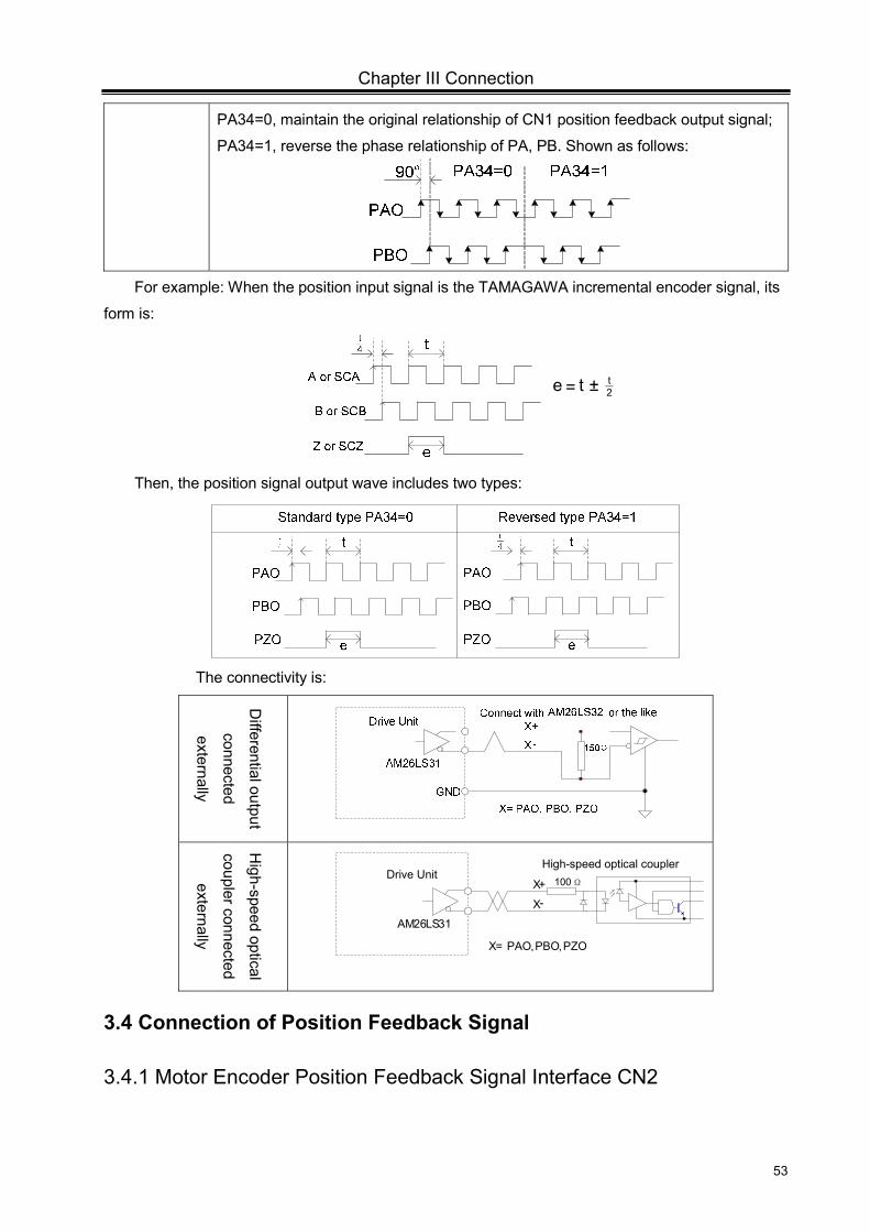
Chapter III Connection
53
PA34=0, maintain the original relationship of CN1 position feedback output signal;
PA34=1, reverse the phase relationship of PA, PB. Shown as follows:
For example: When the position input signal is the TAMAGAWA incremental encoder signal, its
form is:
Then, the position signal output wave includes two types:
The connectivity is:
Differential output
connected
externally
High-speed optical
coupler connected
externally
High-speed optical couplerDrive Unit
X+
X-
X= PAO, PBO, PZO
100Ω
AM26LS31
3.4 Connection of Position Feedback Signal
3.4.1 Motor Encoder Position Feedback Signal Interface CN2
e = t ± 2-t
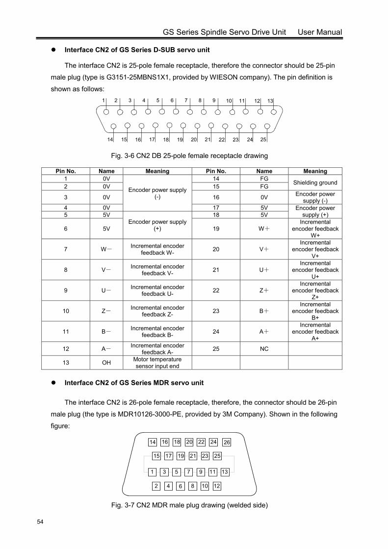
GS Series Spindle Servo Drive Unit User Manual
54
Interface CN2 of GS Series D-SUB servo unit
The interface CN2 is 25-pole female receptacle, therefore the connector should be 25-pin
male plug (type is G3151-25MBNS1X1, provided by WIESON company). The pin definition is
shown as follows: 61 3 4 8 95 72 10 11 12 13
14 15 16 17 18 19 20 21 22 23 24 25
Fig. 3-6 CN2 DB 25-pole female receptacle drawing
Pin No. Name Meaning Pin No. Name Meaning 1 0V
Encoder power supply (-)
14 FG Shielding ground 2 0V 15 FG
3 0V 16 0V Encoder power supply (-)
4 0V 17 5V Encoder power supply (+) 5 5V
Encoder power supply (+)
18 5V
6 5V 19 W+ Incremental
encoder feedback W+
7 W- Incremental encoder feedback W- 20 V+
Incremental encoder feedback
V+
8 V- Incremental encoder feedback V- 21 U+
Incremental encoder feedback
U+
9 U- Incremental encoder feedback U- 22 Z+
Incremental encoder feedback
Z+
10 Z- Incremental encoder feedback Z- 23 B+
Incremental encoder feedback
B+
11 B- Incremental encoder feedback B- 24 A+
Incremental encoder feedback
A+
12 A- Incremental encoder feedback A- 25 NC
13 OH Motor temperature sensor input end
Interface CN2 of GS Series MDR servo unit
The interface CN2 is 26-pole female receptacle, therefore, the connector should be 26-pin
male plug (the type is MDR10126-3000-PE, provided by 3M Company). Shown in the following
figure:
1
25
2
3
4
5
6
7
8
9
24
23
22
21
20
19
18
17
16
15
14
13
12
11
10
26
Fig. 3-7 CN2 MDR male plug drawing (welded side)
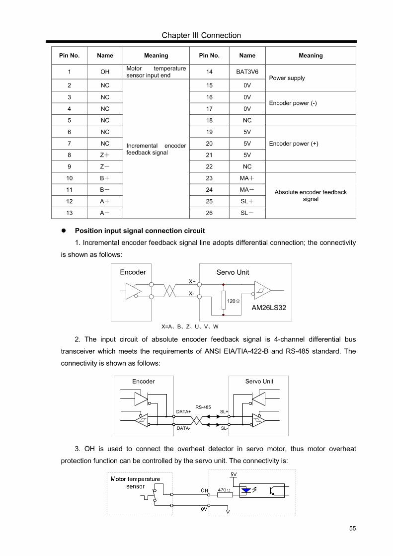
Chapter III Connection
55
Pin No. Name Meaning Pin No. Name Meaning
1 OH Motor temperature sensor input end 14 BAT3V6
Power supply 2 NC
Incremental encoder feedback signal
15 0V
3 NC 16 0V Encoder power (-)
4 NC 17 0V
5 NC 18 NC
6 NC 19 5V
Encoder power (+) 7 NC 20 5V
8 Z+ 21 5V
9 Z- 22 NC
10 B+ 23 MA+
Absolute encoder feedback signal
11 B- 24 MA-
12 A+ 25 SL+
13 A- 26 SL-
Position input signal connection circuit 1. Incremental encoder feedback signal line adopts differential connection; the connectivity
is shown as follows:
Servo UnitEncoderX+
X-
X=A、B、Z、U、V、W
120ΩAM26LS32
2. The input circuit of absolute encoder feedback signal is 4-channel differential bus
transceiver which meets the requirements of ANSI EIA/TIA-422-B and RS-485 standard. The
connectivity is shown as follows:
Servo UnitEncoder
RS-485
DATA-
DATA+ SL+
SL-
3. OH is used to connect the overheat detector in servo motor, thus motor overheat
protection function can be controlled by the servo unit. The connectivity is:
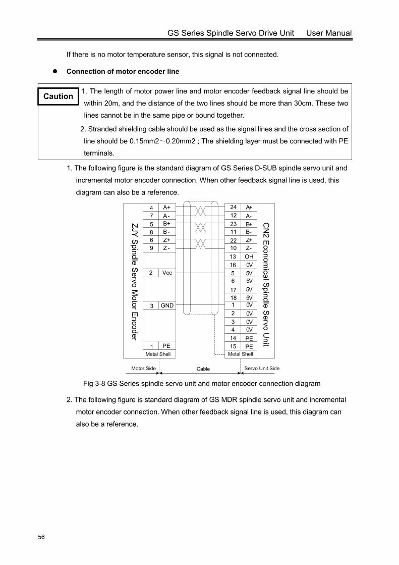
GS Series Spindle Servo Drive Unit User Manual
56
If there is no motor temperature sensor, this signal is not connected.
Connection of motor encoder line
1. The length of motor power line and motor encoder feedback signal line should be
within 20m, and the distance of the two lines should be more than 30cm. These two
lines cannot be in the same pipe or bound together.
2. Stranded shielding cable should be used as the signal lines and the cross section of
line should be 0.15mm2~0.20mm2 ; The shielding layer must be connected with PE
terminals.
1. The following figure is the standard diagram of GS Series D-SUB spindle servo unit and
incremental motor encoder connection. When other feedback signal line is used, this
diagram can also be a reference.
5617181234
1415
165V5V5V5V0V0V0V0VPEPE
13 OH
1
Vcc
PE
2
3 GND
Motor Side Cable Servo Unit Side
0V
CN
2 Econom
ical Spindle Servo U
nit
241223112210
A+A-B+B-Z+Z-
475869
A+A-B+B-Z+Z -
ZJY Spindle Servo M
otor Encoder
Metal ShellMetal Shell
Fig 3-8 GS Series spindle servo unit and motor encoder connection diagram
2. The following figure is standard diagram of GS MDR spindle servo unit and incremental
motor encoder connection. When other feedback signal line is used, this diagram can
also be a reference.
Caution
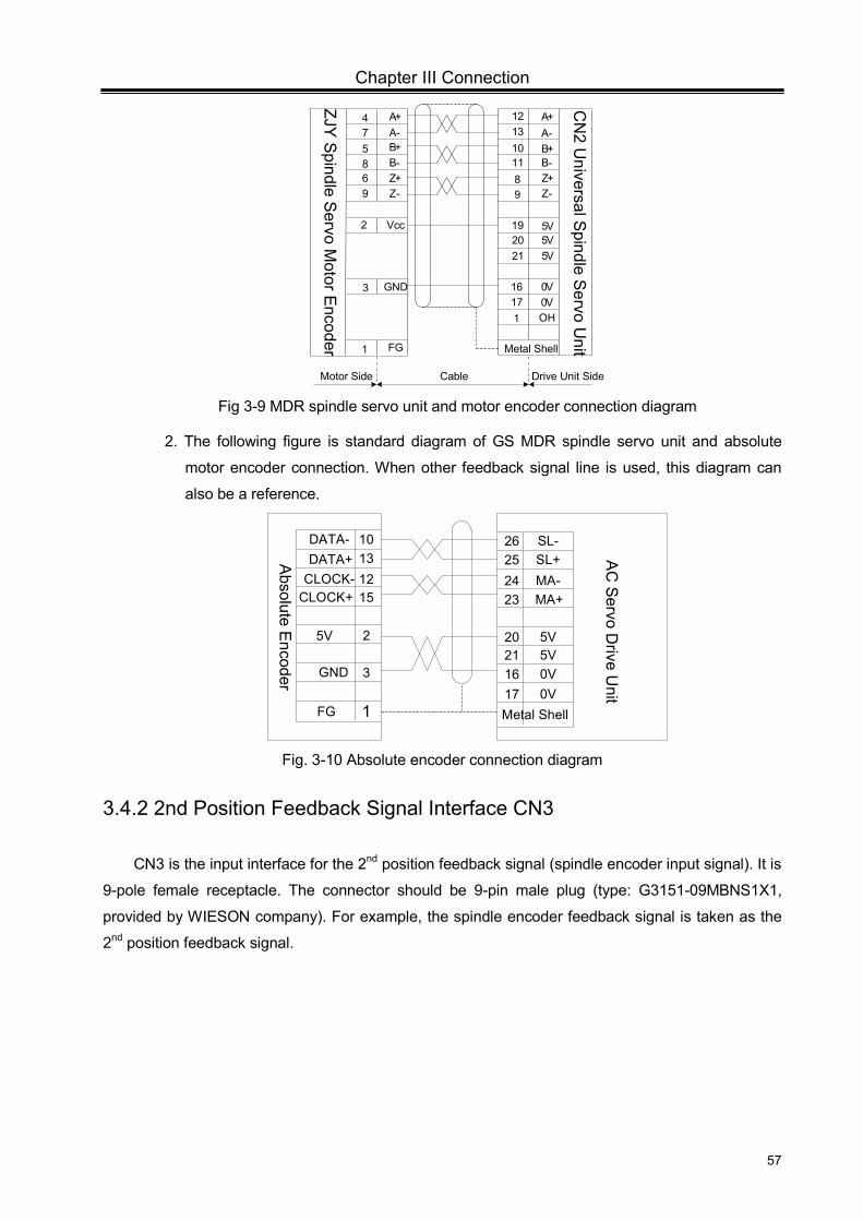
Chapter III Connection
57
192021
1716
5V5V5V
0V1 OH
1
Vcc
FG
2
3 GND
Motor Side Cable Drive Unit Side
0V
1213101189
A+A-B+B-Z+Z-
475869
A+A-B+B-Z+Z-
Metal Shell
ZJY Spindle S
ervo Motor Encoder
CN
2 Universal S
pindle Servo U
nit
Fig 3-9 MDR spindle servo unit and motor encoder connection diagram
2. The following figure is standard diagram of GS MDR spindle servo unit and absolute
motor encoder connection. When other feedback signal line is used, this diagram can
also be a reference.
SL-SL+MA-MA+
5V5V0V0V
26252423
20211617
DATA-DATA+
CLOCK-CLOCK+
5V
GND
FG
10131215
2
3
1 Metal Shell
AC
Servo Drive U
nit
Absolute Encoder
Fig. 3-10 Absolute encoder connection diagram
3.4.2 2nd Position Feedback Signal Interface CN3
CN3 is the input interface for the 2nd position feedback signal (spindle encoder input signal). It is
9-pole female receptacle. The connector should be 9-pin male plug (type: G3151-09MBNS1X1,
provided by WIESON company). For example, the spindle encoder feedback signal is taken as the
2nd position feedback signal.
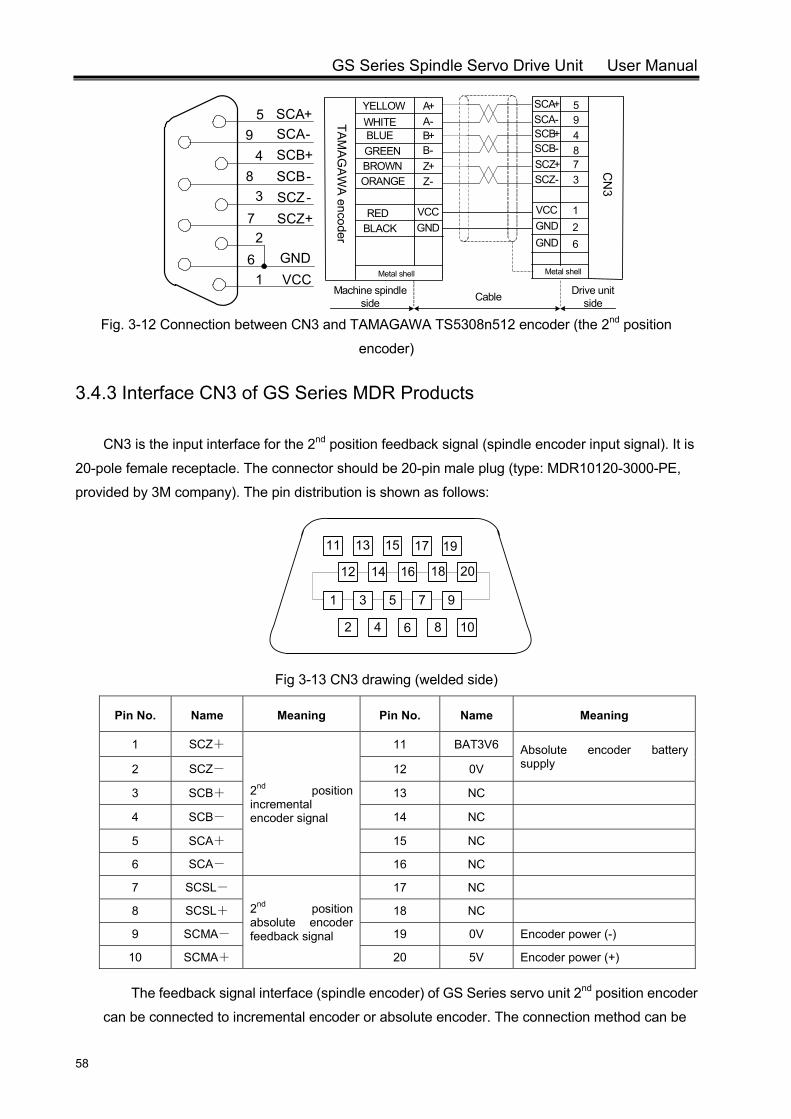
GS Series Spindle Servo Drive Unit User Manual
58
61
3
48
95
72
SCA+SCA-SCB+SCB-SCZ-SCZ+
GNDVCC
Fig. 3-12 Connection between CN3 and TAMAGAWA TS5308n512 encoder (the 2nd position
encoder)
3.4.3 Interface CN3 of GS Series MDR Products
CN3 is the input interface for the 2nd position feedback signal (spindle encoder input signal). It is
20-pole female receptacle. The connector should be 20-pin male plug (type: MDR10120-3000-PE,
provided by 3M company). The pin distribution is shown as follows:
1
2
3
4
5
6
7
11
12
17
16
15
14
13
2018
19
108
9
Fig 3-13 CN3 drawing (welded side)
Pin No. Name Meaning Pin No. Name Meaning
1 SCZ+
2nd position incremental encoder signal
11 BAT3V6 Absolute encoder battery supply 2 SCZ- 12 0V
3 SCB+ 13 NC
4 SCB- 14 NC 5 SCA+ 15 NC
6 SCA- 16 NC
7 SCSL-
2nd position absolute encoder feedback signal
17 NC
8 SCSL+ 18 NC
9 SCMA- 19 0V Encoder power (-)
10 SCMA+ 20 5V Encoder power (+)
The feedback signal interface (spindle encoder) of GS Series servo unit 2nd position encoder
can be connected to incremental encoder or absolute encoder. The connection method can be
A+A-B+B-Z+Z-
Metal shell
VCCGND
594873
SCA+SCA-SCB+SCB-SCZ+SCZ-
VCCGND
12
GND 6
YELLOWWHITEBLUEGREENBROWNORANGE
REDBLACK
CN
3
TAM
AG
AW
A encoder
Cable Drive unit side
Metal shell
Machine spindle side
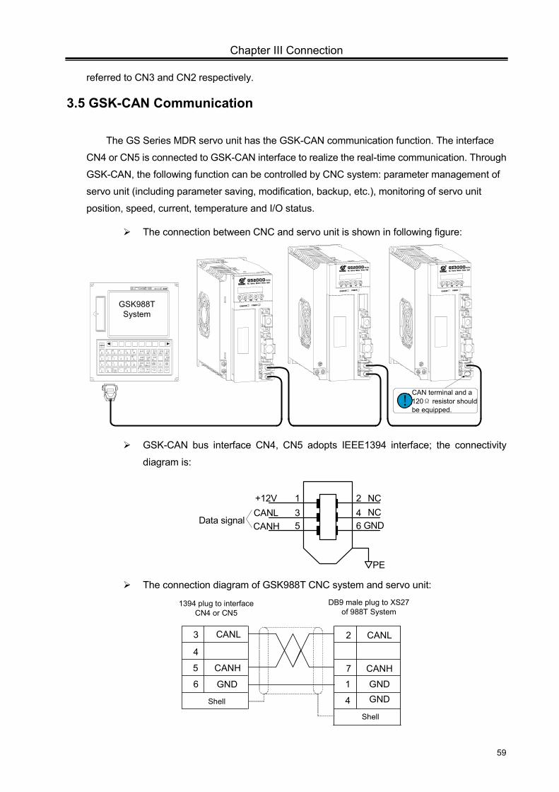
Chapter III Connection
59
referred to CN3 and CN2 respectively.
3.5 GSK-CAN Communication
The GS Series MDR servo unit has the GSK-CAN communication function. The interface
CN4 or CN5 is connected to GSK-CAN interface to realize the real-time communication. Through
GSK-CAN, the following function can be controlled by CNC system: parameter management of
servo unit (including parameter saving, modification, backup, etc.), monitoring of servo unit
position, speed, current, temperature and I/O status.
The connection between CNC and servo unit is shown in following figure:
CAN terminal and a 120Ω resistor should be equipped.
!
图形 帮助
设置位置
信息
转换
退格
程序 系统
输入上档
取消删除
RESET
988T
GSK988T System
R
AC Servo Motor Drive UnitSeries
CHARGE POWER
R
AC Servo Motor Drive UnitSeries
CHARGE POWER
R
AC Servo Motor Drive UnitSeries
CHARGE POWER
GSK-CAN bus interface CN4, CN5 adopts IEEE1394 interface; the connectivity
diagram is:
+12VCANLCANH GND
PE
Data signal
1 23 45 6
NCNC
The connection diagram of GSK988T CNC system and servo unit:
GND
CANL
CANH
GND
CANH
CANL
5
3
7
2
Shell
1
4
6
1394 plug to interface CN4 or CN5
4
DB9 male plug to XS27 of 988T System
GND
Shell
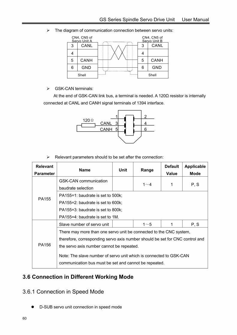
GS Series Spindle Servo Drive Unit User Manual
60
The diagram of communication connection between servo units:
GND
CANH
CANL
5
3
Shell
6
CN4, CN5 of Servo Unit A
4
GND
CANH
CANL
5
3
Shell
6
4
CN4, CN5 of Servo Unit B
GSK-CAN terminals:
At the end of GSK-CAN link bus, a terminal is needed. A 120Ω resistor is internally
connected at CANL and CANH signal terminals of 1394 interface.
Relevant parameters should to be set after the connection:
Relevant Parameter
Name Unit Range Default Value
Applicable Mode
PA155
GSK-CAN communication
baudrate selection 1~4 1 P, S
PA155=1: baudrate is set to 500k;
PA155=2: baudrate is set to 600k;
PA155=3: baudrate is set to 800k;
PA155=4: baudrate is set to 1M.
PA156
Slave number of servo unit 1~5 1 P, S
There may more than one servo unit be connected to the CNC system,
therefore, corresponding servo axis number should be set for CNC control and
the servo axis number cannot be repeated.
Note: The slave number of servo unit which is connected to GSK-CAN
communication bus must be set and cannot be repeated.
3.6 Connection in Different Working Mode
3.6.1 Connection in Speed Mode
D-SUB servo unit connection in speed mode
CANLCANH
1 23 45 6
120Ω
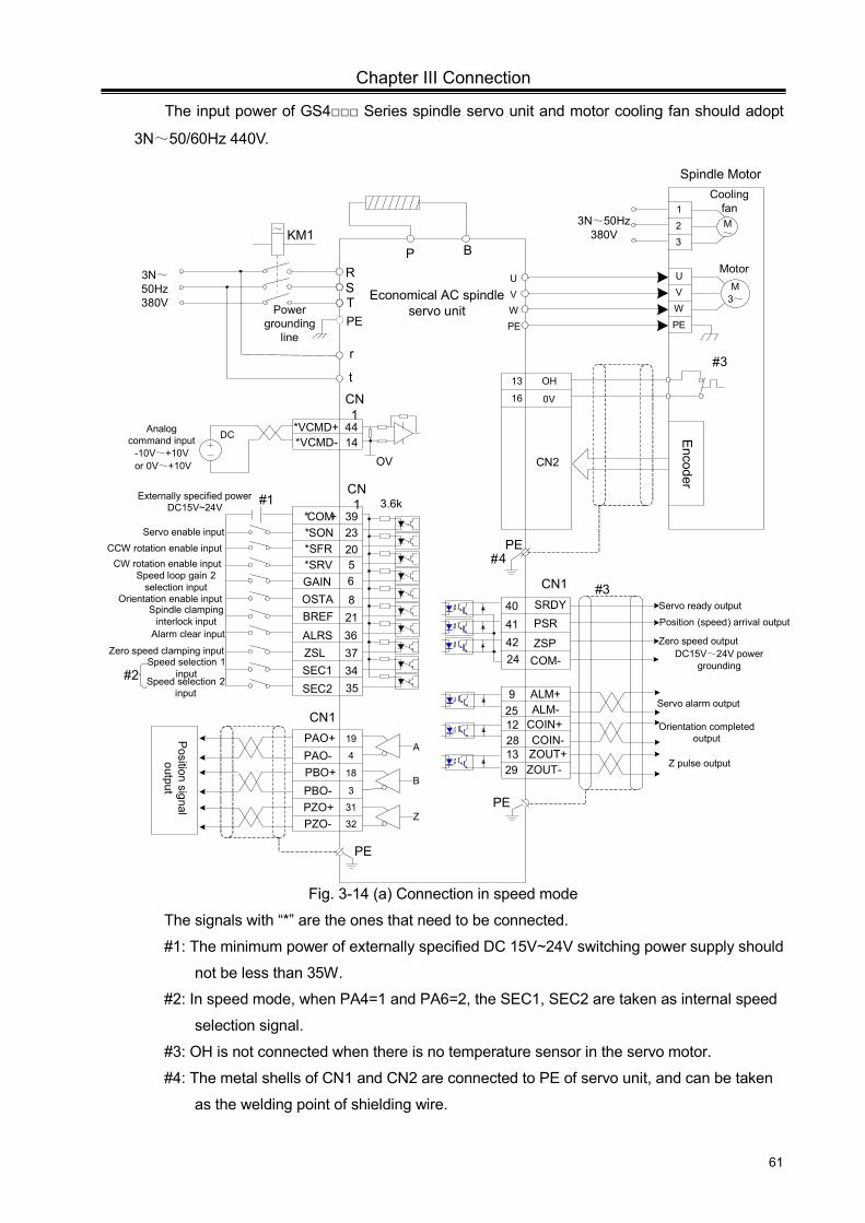
Chapter III Connection
61
The input power of GS4 Series spindle servo unit and motor cooling fan should adopt
3N~50/60Hz 440V.
*COM+ 39*SON 23*SFR 20
CN1 3.6k
ALRS
r
Analog command input
-10V~+10V or 0V~+10V
*VCMD+ 4414
OV
5*SRV
DC
CN1
#1
Servo enable inputCCW rotation enable input
t 13 OH
16 0V
CN2
PE
#2
#4
6821
*VCMD-
OSTAGAIN
Alarm clear input
Zero speed clamping input
Speed selection 2 input
Speed selection 1 input
Externally specified power DC15V~24V
Encoder
SEC2
363734SEC1
ZSL
BREF
35
Speed loop gain 2 selection input
Orientation enable inputSpindle clamping
interlock input
CW rotation enable input
PAO+PAO-
PBO-PZO+PZO-
A
B
Z
PBO+
CN1
Position signal
output
19
4
3
31
32
18
ZSP42
SRDY
41Zero speed output
Servo ready output40PSR
Servo alarm output
COM-
Orientation completed output
24
PE
COIN+COIN-
Position (speed) arrival output
1228
#3
DC15V~24V power grounding
ALM-9
25ALM+
CN1
Z pulse outputZOUT+ZOUT-
1329
PE
UVW
PE
M3~Economical AC spindle
servo unitPE
Power grounding
line
RST
KM1~
UVWPE
Motor
Spindle Motor
P B
#3
1
23
M~
Cooling fan
3N~50Hz 380V
3N~50Hz 380V
Fig. 3-14 (a) Connection in speed mode
The signals with “*” are the ones that need to be connected.
#1: The minimum power of externally specified DC 15V~24V switching power supply should
not be less than 35W.
#2: In speed mode, when PA4=1 and PA6=2, the SEC1, SEC2 are taken as internal speed
selection signal.
#3: OH is not connected when there is no temperature sensor in the servo motor.
#4: The metal shells of CN1 and CN2 are connected to PE of servo unit, and can be taken
as the welding point of shielding wire.
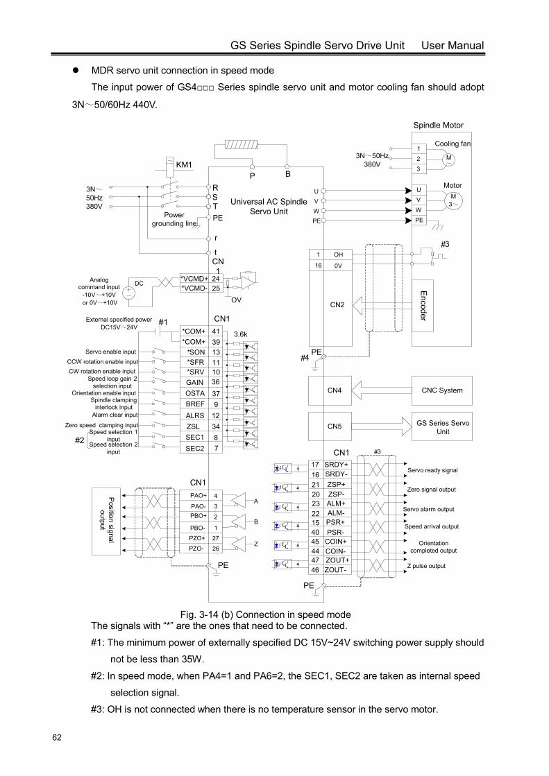
GS Series Spindle Servo Drive Unit User Manual
62
MDR servo unit connection in speed mode
The input power of GS4 Series spindle servo unit and motor cooling fan should adopt
3N~50/60Hz 440V.
CN4
CN5
CNC System
GS Series Servo Unit
39*SON 13*SFR 11
CN1
3.6k
ALRS
r
Analog command input
-10V~+10V or 0V~+10V
*VCMD+ 2425
OV
10*SRV
DC
CN1
#4
#1
Servo enable inputCCW rotation enable input
t 1 OH
16 0V
CN2
PE
#2
#3
36
379
*VCMD-
OSTAGAIN
Alarm clear input
Zero speed clamping input
Speed selection 2 input
Speed selection 1 input
External specified power DC15V~24V
Encoder
SEC2
12348SEC1
ZSL
BREF
7
Speed loop gain 2 selection input
Orientation enable input
CW rotation enable input
PAO+
PAO-
PBO-
PZO+
PZO-
A
B
Z
PBO+
CN1
Position signal
output
4
3
1
27
26
2Servo alarm output
Orientation completed output
PSR+PSR-
PE
COIN+COIN-
4544
#3
ALM-1540
2322
Speed arrival output
ALM+
CN1
Z pulse outputZOUT+ZOUT-
4746PE
Servo ready signal
Zero signal outputZSP+ZSP-
2120
SRDY-1716
SRDY+
*COM+ 41*COM+
UVW
PE
M3~Universal AC Spindle
Servo UnitPEPower
grounding line
RST
KM1~
UVWPE
Motor
Spindle Motor
P B
123
M~
Cooling fan
3N~50Hz 380V
3N~50Hz 380V
Spindle clamping interlock input
Fig. 3-14 (b) Connection in speed mode
The signals with “*” are the ones that need to be connected.
#1: The minimum power of externally specified DC 15V~24V switching power supply should
not be less than 35W.
#2: In speed mode, when PA4=1 and PA6=2, the SEC1, SEC2 are taken as internal speed
selection signal.
#3: OH is not connected when there is no temperature sensor in the servo motor.
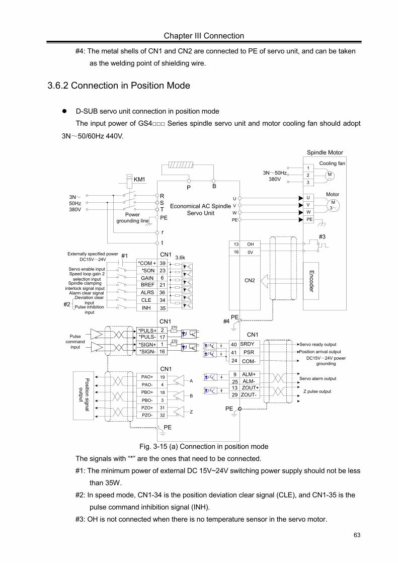
Chapter III Connection
63
#4: The metal shells of CN1 and CN2 are connected to PE of servo unit, and can be taken
as the welding point of shielding wire.
3.6.2 Connection in Position Mode
D-SUB servo unit connection in position mode
The input power of GS4 Series spindle servo unit and motor cooling fan should adopt
3N~50/60Hz 440V.
UVW
PE
M3~
*COM + 39*SON 23
CN1
Economical AC Spindle Servo Unit
3.6k
ALRS
PE
r
Power grounding line
RST
#4
#1
KM1~
Servo enable input
t
UVWPE
13 OH
16 0V
CN2
Motor
Spindle Motor
PE
#3
P B
621
GAIN
Externally specified power DC15V~24V
Encoder
INH
3634CLE
BREF
35
Speed loop gain 2 selection input
PAO+
PAO-
PBO-
PZO+
PZO-
A
B
Z
PBO+
CN1
Position signal
output
19
4
3
31
32
18
SRDY
41
Servo ready output40PSR
Servo alarm output
COM-24
PE
Position arrival output DC15V~24V power
grounding
ALM-925
ALM+
CN1
Z pulse outputZOUT+ZOUT-
1329
PE
#2
Alarm clear signal
Pulse inhibition input
Deviation clear input
123
M~
Cooling fan
3N~50Hz 380V
3N~50Hz 380V
CN1
Pulse command
input 116
217
*PULS+*PULS-
*SIGN-*SIGN+
270
270
Spindle clamping interlock signal input
Fig. 3-15 (a) Connection in position mode
The signals with “*” are the ones that need to be connected.
#1: The minimum power of external DC 15V~24V switching power supply should not be less
than 35W.
#2: In speed mode, CN1-34 is the position deviation clear signal (CLE), and CN1-35 is the
pulse command inhibition signal (INH).
#3: OH is not connected when there is no temperature sensor in the servo motor.
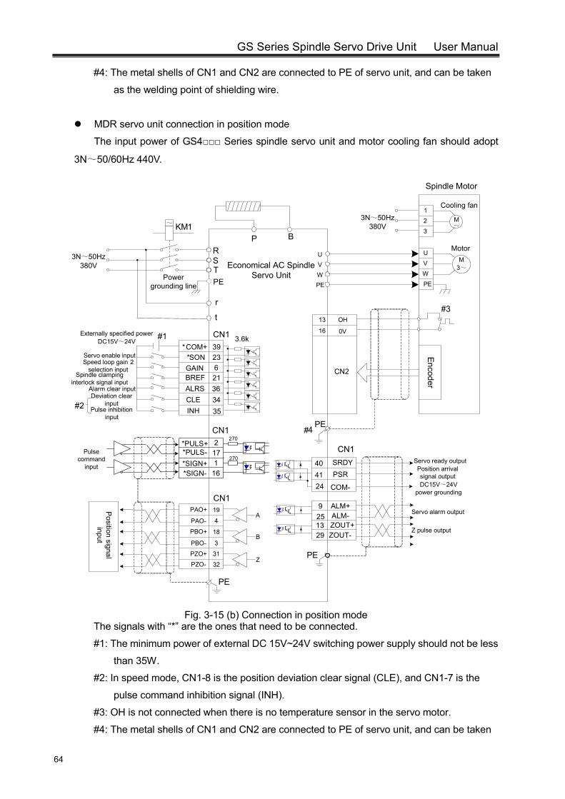
GS Series Spindle Servo Drive Unit User Manual
64
#4: The metal shells of CN1 and CN2 are connected to PE of servo unit, and can be taken
as the welding point of shielding wire.
MDR servo unit connection in position mode
The input power of GS4 Series spindle servo unit and motor cooling fan should adopt
3N~50/60Hz 440V.
U
VWPE
M3~
*COM+ 39*SON 23
CN1
Economical AC Spindle Servo Unit
3.6k
ALRS
PE
r
Power grounding line
RST
#4
#1
KM1~
Servo enable input
t
UVWPE
13 OH
16 0V
CN2
Motor
Spindle Motor
PE
#3
P B
621
GAIN
Externally specified power DC15V~24V
Encoder
INH
3634CLE
BREF
35
Speed loop gain 2 selection input
PAO+
PAO-
PBO-
PZO+
PZO-
A
B
Z
PBO+
CN1
Position signal
input
19
4
3
31
32
18
SRDY
41
Servo ready output40PSR
Servo alarm output
COM-24
PE
Position arrival signal outputDC15V~24V
power grounding
ALM-925
ALM+
CN1
Z pulse outputZOUT+ZOUT-
1329
PE
#2
Alarm clear input
Pulse inhibition input
Deviation clear input
123
M~
Cooling fan
3N~50Hz 380V
3N~50Hz 380V
CN1
Pulse command
input 116
217
*PULS+*PULS-
*SIGN-*SIGN+
270
270
Spindle clamping interlock signal input
Fig. 3-15 (b) Connection in position mode
The signals with “*” are the ones that need to be connected.
#1: The minimum power of external DC 15V~24V switching power supply should not be less
than 35W.
#2: In speed mode, CN1-8 is the position deviation clear signal (CLE), and CN1-7 is the
pulse command inhibition signal (INH).
#3: OH is not connected when there is no temperature sensor in the servo motor.
#4: The metal shells of CN1 and CN2 are connected to PE of servo unit, and can be taken
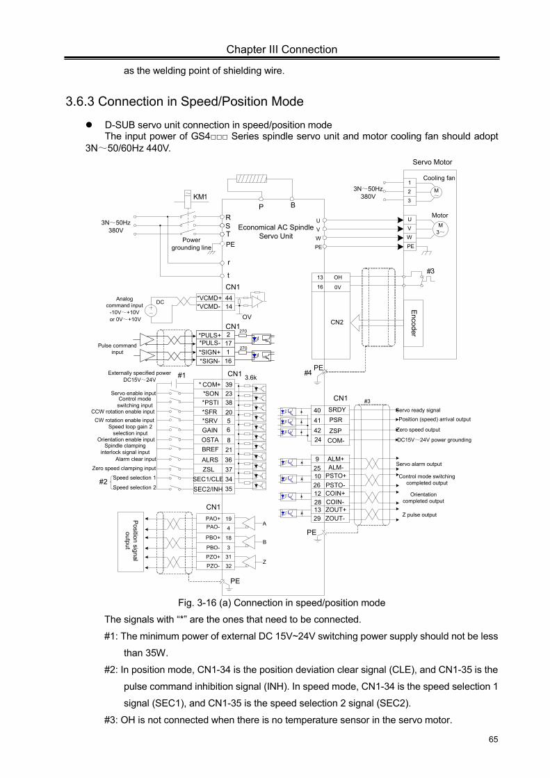
Chapter III Connection
65
as the welding point of shielding wire.
3.6.3 Connection in Speed/Position Mode
D-SUB servo unit connection in speed/position mode The input power of GS4 Series spindle servo unit and motor cooling fan should adopt
3N~50/60Hz 440V.
* COM+ 39*SON 23*PSTI 38*SFR 20
CN1 3.6k
ALRS
r
Analog command input
-10V~+10V or 0V~+10V
*VCMD+ 4414
OV
5*SRV
DC
CN1
#4#1
Servo enable inputControl mode
switching inputCCW rotation enable input
t 13 OH
16 0V
CN2
PE
#2
#3
6821
*VCMD-
OSTAGAIN
Alarm clear input
Zero speed clamping input
Speed selection 2
Speed selection 1
Externally specified power DC15V~24V
Encoder
SEC2/INH
363734SEC1/CLE
ZSL
BREF
35
Speed loop gain 2 selection input
Orientation enable input
CW rotation enable input
PAO+PAO-
PBO-
PZO+
PZO-
A
B
Z
PBO+
CN1
Position signal
output
19
4
3
31
32
18
ZSP42
SRDY
41Zero speed output
Servo ready signal40PSR
Servo alarm output
COM-
Orientation completed output
24
PSTO+PSTO-
PE
COIN+COIN-
Position (speed) arrival output
1228
#3
DC15V~24V power grounding
ALM-1026
925
Control mode switching completed output
ALM+
CN1
Z pulse outputZOUT+ZOUT-
1329
PE
UVWPE
M3~
Economical AC Spindle Servo Unit
PEPower
grounding line
RST
KM1~
UVWPE
Motor
Servo Motor
P B
123
M~
Cooling fan
3N~50Hz 380V
3N~50Hz 380V
CN1
Pulse command input 1
16
217
*PULS+*PULS-
*SIGN-*SIGN+
270
270
Spindle clamping interlock signal input
Fig. 3-16 (a) Connection in speed/position mode
The signals with “*” are the ones that need to be connected.
#1: The minimum power of external DC 15V~24V switching power supply should not be less
than 35W.
#2: In position mode, CN1-34 is the position deviation clear signal (CLE), and CN1-35 is the
pulse command inhibition signal (INH). In speed mode, CN1-34 is the speed selection 1
signal (SEC1), and CN1-35 is the speed selection 2 signal (SEC2).
#3: OH is not connected when there is no temperature sensor in the servo motor.
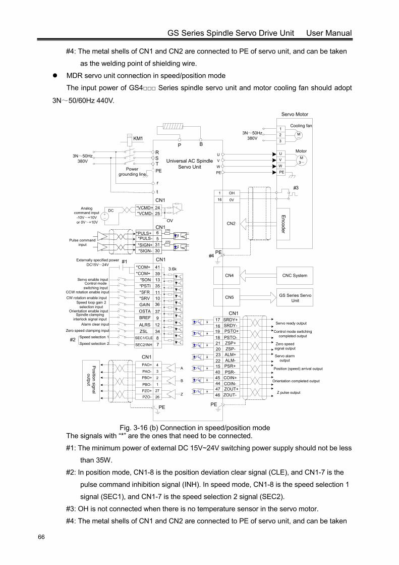
GS Series Spindle Servo Drive Unit User Manual
66
#4: The metal shells of CN1 and CN2 are connected to PE of servo unit, and can be taken
as the welding point of shielding wire.
MDR servo unit connection in speed/position mode
The input power of GS4 Series spindle servo unit and motor cooling fan should adopt
3N~50/60Hz 440V.
CN4
CN5
CNC System
GS Series Servo Unit
39*SON 13*PSTI 35*SFR 11
CN1
3.6k
ALRS
r
Analog command input
-10V~+10V or 0V~+10V
*VCMD+ 2425
OV
10*SRV
DC
CN1
#4#1
Servo enable inputControl mode
switching inputCCW rotation enable input
t 1 OH
16 0V
CN2
PE
#2
#3
36
379
*VCMD-
OSTAGAIN
Alarm clear input
Zero speed clamping input
Speed selection 2
Speed selection 1
Externally specified power DC15V~24V
Encoder
SEC2/INH
12348SEC1/CLE
ZSL
BREF
7
Speed loop gain 2 selection input
Orientation enable input
CW rotation enable input
PAO+
PAO-
PBO-
PZO+PZO-
A
B
Z
PBO+
CN1
Position signal
output
4
3
1
27
26
2
Servo alarm output
Orientation completed output
PSR+PSR-
PE
COIN+COIN-
4544
ALM-1540
2322
Position (speed) arrival output
ALM+
CN1
Z pulse outputZOUT+ZOUT-
4746
PE
Servo ready output
Zero speed signal output
PSTO+PSTO-ZSP+ZSP-
2120
SRDY-1918
1716
Control mode switching completed output
SRDY+
*COM+ 41*COM+
UVWPE
M3~Universal AC Spindle
Servo UnitPEPower
grounding line
RST
KM1~
UVWPE
Motor
Servo Motor
P B
123
M~
Cooling fan
3N~50Hz 380V
3N~50Hz 380V
CN1
Pulse command input 31
30
65
*PULS+*PULS-
*SIGN-*SIGN+
270
270
Spindle clamping interlock signal input
Fig. 3-16 (b) Connection in speed/position mode
The signals with “*” are the ones that need to be connected.
#1: The minimum power of external DC 15V~24V switching power supply should not be less
than 35W.
#2: In position mode, CN1-8 is the position deviation clear signal (CLE), and CN1-7 is the
pulse command inhibition signal (INH). In speed mode, CN1-8 is the speed selection 1
signal (SEC1), and CN1-7 is the speed selection 2 signal (SEC2).
#3: OH is not connected when there is no temperature sensor in the servo motor.
#4: The metal shells of CN1 and CN2 are connected to PE of servo unit, and can be taken

Chapter III Connection
67
as the welding point of shielding wire.

GS Series Spindle Servo Drive Unit User Manual
68
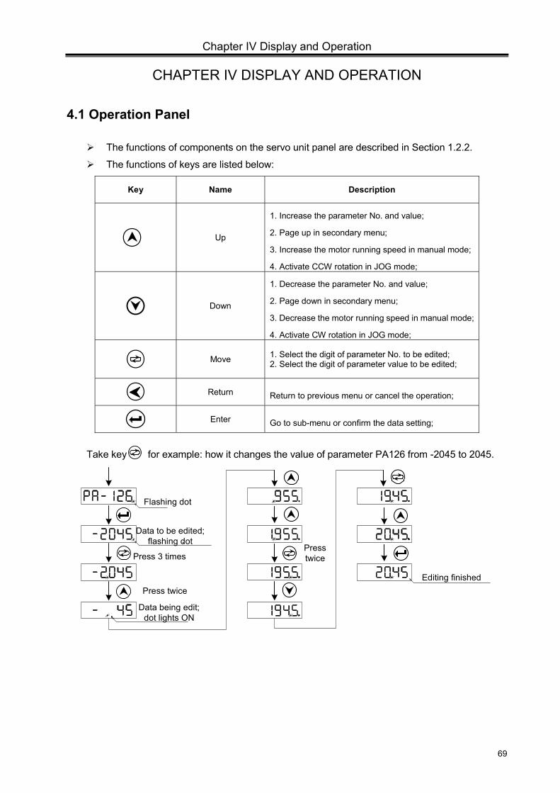
Chapter IV Display and Operation
69
CHAPTER IV DISPLAY AND OPERATION
4.1 Operation Panel
The functions of components on the servo unit panel are described in Section 1.2.2.
The functions of keys are listed below:
Key Name Description
Up
1. Increase the parameter No. and value;
2. Page up in secondary menu;
3. Increase the motor running speed in manual mode;
4. Activate CCW rotation in JOG mode;
Down
1. Decrease the parameter No. and value;
2. Page down in secondary menu;
3. Decrease the motor running speed in manual mode;
4. Activate CW rotation in JOG mode;
Move 1. Select the digit of parameter No. to be edited;
2. Select the digit of parameter value to be edited;
Return Return to previous menu or cancel the operation;
Enter Go to sub-menu or confirm the data setting;
Take key for example: how it changes the value of parameter PA126 from -2045 to 2045.
Press 3 times
Flashing dot
Data to be edited; flashing dot,
Data being edit; dot lights ON
Press twice
Presstwice
Editing finished
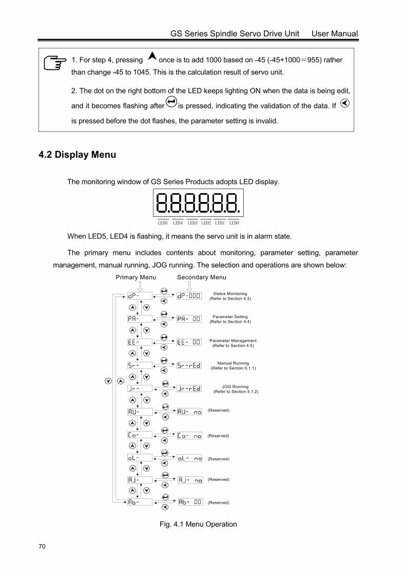
GS Series Spindle Servo Drive Unit User Manual
70
1. For step 4, pressing once is to add 1000 based on -45 (-45+1000=955) rather
than change -45 to 1045. This is the calculation result of servo unit.
2. The dot on the right bottom of the LED keeps lighting ON when the data is being edit,
and it becomes flashing after is pressed, indicating the validation of the data. If
is pressed before the dot flashes, the parameter setting is invalid.
4.2 Display Menu
The monitoring window of GS Series Products adopts LED display.
LED0LED1LED2LED3LED4LED5 When LED5, LED4 is flashing, it means the servo unit is in alarm state.
The primary menu includes contents about monitoring, parameter setting, parameter
management, manual running, JOG running. The selection and operations are shown below:
Status Monitoring (Refer to Section 4.3)
Parameter Setting (Refer to Section 4.4)
Parameter Management (Refer to Section 4.5)
Manual Running (Refer to Section 5.1.1)
JOG Running (Refer to Section 5.1.2)
Secondary MenuPrimary Menu
(Reserved)
(Reserved)
(Reserved)
(Reserved)
(Reserved)
Fig. 4.1 Menu Operation
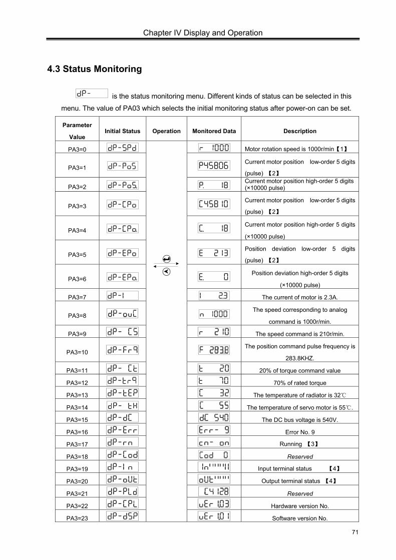
Chapter IV Display and Operation
71
4.3 Status Monitoring
is the status monitoring menu. Different kinds of status can be selected in this
menu. The value of PA03 which selects the initial monitoring status after power-on can be set.
Parameter
Value Initial Status Operation Monitored Data Description
PA3=0
Motor rotation speed is 1000r/min【1】
PA3=1 Current motor position low-order 5 digits
(pulse) 【2】
PA3=2 Current motor position high-order 5 digits (×10000 pulse)
PA3=3 Current motor position low-order 5 digits
(pulse) 【2】
PA3=4 Current motor position high-order 5 digits
(×10000 pulse)
PA3=5 Position deviation low-order 5 digits
(pulse) 【2】
PA3=6 Position deviation high-order 5 digits
(×10000 pulse)
PA3=7 The current of motor is 2.3A.
PA3=8 The speed corresponding to analog
command is 1000r/min.
PA3=9 The speed command is 210r/min.
PA3=10 The position command pulse frequency is
283.8KHZ.
PA3=11 20% of torque command value
PA3=12 70% of rated torque
PA3=13 The temperature of radiator is 32
PA3=14 The temperature of servo motor is 55 .
PA3=15 The DC bus voltage is 540V.
PA3=16 Error No. 9
PA3=17 Running 【3】
PA3=18 Reserved
PA3=19 Input terminal status 【4】
PA3=20 Output terminal status 【4】
PA3=21 Reserved
PA3=22 Hardware version No.
PA3=23 Software version No.
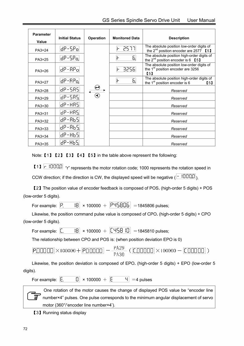
GS Series Spindle Servo Drive Unit User Manual
72
Parameter
Value Initial Status Operation Monitored Data Description
PA3=24
The absolute position low-order digits of the 2nd position encoder are 2577 【5】
PA3=25 The absolute position high-order digits of the 2nd position encoder is 6 【5】
PA3=26
The absolute position low-order digits of the 1st position encoder are 3256 【5】
PA3=27 The absolute position high-order digits of the 1st position encoder is 6 【5】
PA3=28 Reserved
PA3=29 Reserved
PA3=30 Reserved
PA3=31 Reserved
PA3=32 Reserved
PA3=33 Reserved
PA3=34 Reserved
PA3=35 Reserved
Note:【1】【2】【3】【4】【5】in the table above represent the following:
【1】 “r” represents the motor rotation code; 1000 represents the rotation speed in
CCW direction; if the direction is CW, the displayed speed will be negative ( ).
【2】The position value of encoder feedback is composed of POS. (high-order 5 digits) + POS
(low-order 5 digits).
For example: × 100000 + =1845806 pulses;
Likewise, the position command pulse value is composed of CPO. (high-order 5 digits) + CPO
(low-order 5 digits).
For example: × 100000 + =1845810 pulses;
The relationship between CPO and POS is: (when position deviation EPO is 0)
Likewise, the position deviation is composed of EPO. (high-order 5 digits) + EPO (low-order 5
digits).
For example: × 100000 + =4 pulses
One rotation of the motor causes the change of displayed POS value be “encoder line
number×4” pulses. One pulse corresponds to the minimum angular displacement of servo
motor (360°/‘encoder line number×4’).
【3】Running status display
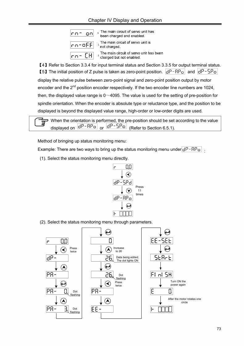
Chapter IV Display and Operation
73
【4】Refer to Section 3.3.4 for input terminal status and Section 3.3.5 for output terminal status. 【5】The initial position of Z pulse is taken as zero-point position. and display the relative pulse between zero-point signal and zero-point position output by motor
encoder and the 2nd position encoder respectively. If the two encoder line numbers are 1024,
then, the displayed value range is 0~4095. The value is used for the setting of pre-position for
spindle orientation. When the encoder is absolute type or reluctance type, and the position to be
displayed is beyond the displayed value range, high-order or low-order digits are used.
When the orientation is performed, the pre-position should be set according to the value
displayed on or (Refer to Section 6.5.1).
Method of bringing up status monitoring menu:
Example: There are two ways to bring up the status monitoring menu under :
(1). Select the status monitoring menu directly.
Press 11
times
(2). Select the status monitoring menu through parameters.
Press twice
Increase to 26
Press twice
Turn ON the power again
After the motor rotates one circle
Dot flashing
Data being edited;The dot lights ON
Dot flashing
Dot flashing
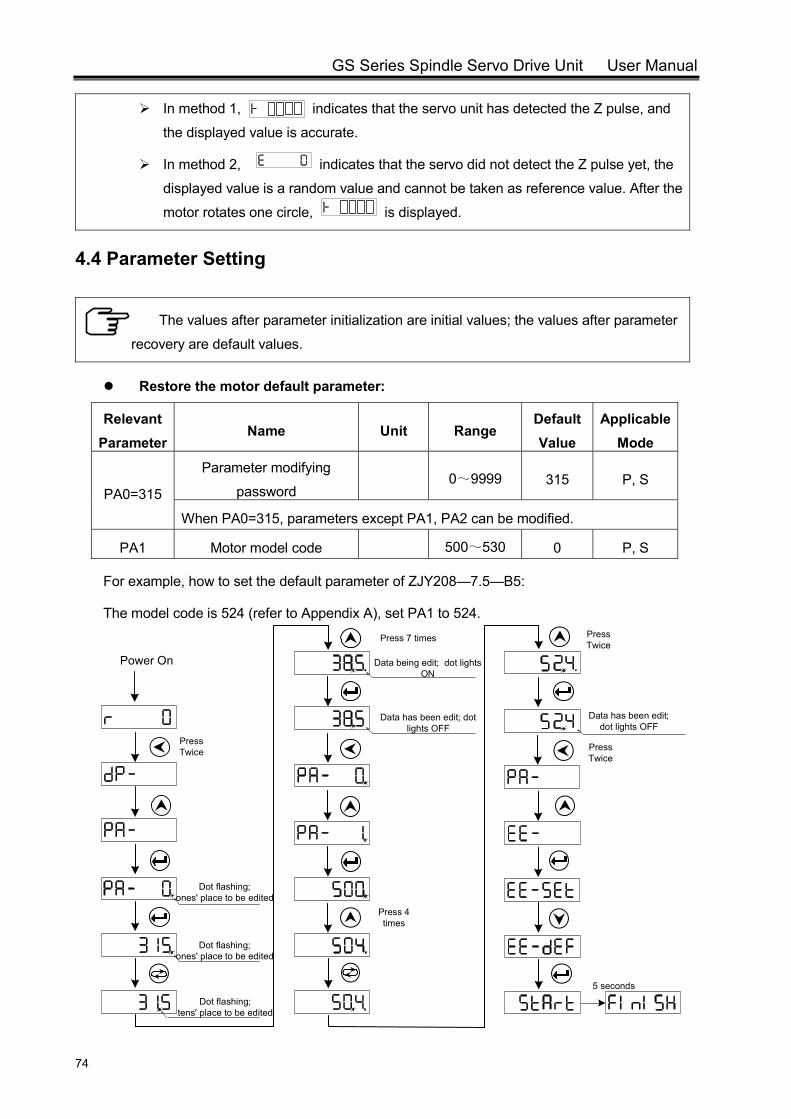
GS Series Spindle Servo Drive Unit User Manual
74
In method 1, indicates that the servo unit has detected the Z pulse, and
the displayed value is accurate.
In method 2, indicates that the servo did not detect the Z pulse yet, the
displayed value is a random value and cannot be taken as reference value. After the
motor rotates one circle, is displayed.
4.4 Parameter Setting
The values after parameter initialization are initial values; the values after parameter
recovery are default values.
Restore the motor default parameter:
Relevant Parameter
Name Unit Range Default Value
Applicable Mode
PA0=315
Parameter modifying
password 0~9999 315 P, S
When PA0=315, parameters except PA1, PA2 can be modified.
PA1 Motor model code 500~530 0 P, S
For example, how to set the default parameter of ZJY208—7.5—B5:
The model code is 524 (refer to Appendix A), set PA1 to 524.
Press Twice
Press 7 times
Dot flashing; ones' place to be edited
Data being edit; dot lights ON
Data has been edit; dot lights OFF
Press 4 times
5 seconds
Power On
Press Twice
Press Twice
Dot flashing; ones' place to be edited
Dot flashing; tens' place to be edited
Data has been edit; dot lights OFF
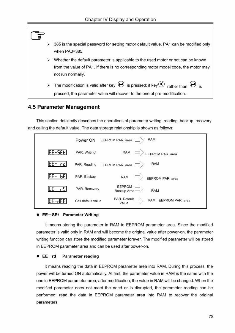
Chapter IV Display and Operation
75
385 is the special password for setting motor default value. PA1 can be modified only
when PA0=385.
Whether the default parameter is applicable to the used motor or not can be known
from the value of PA1. If there is no corresponding motor model code, the motor may
not run normally.
The modification is valid after key is pressed; if key rather than is
pressed, the parameter value will recover to the one of pre-modification.
4.5 Parameter Management
This section detailedly describes the operations of parameter writing, reading, backup, recovery
and calling the default value. The data storage relationship is shown as follows:
Power ON EEPROM PAR. area
PAR. Writing: RAM
PAR. Reading:
PAR. Backup:
PAR. Recovery EEPROM Backup Area
Call default value PAR. Default Value
RAM
RAMEEPROM PAR. area
EEPROM PAR. area
EEPROM PAR. area
RAM
RAM
RAM EEPROM PAR. area
EE-SEt Parameter Writing
It means storing the parameter in RAM to EEPROM parameter area. Since the modified
parameter is valid only in RAM and will become the original value after power-on, the parameter
writing function can store the modified parameter forever. The modified parameter will be stored
in EEPROM parameter area and can be used after power-on.
EE-rd Parameter reading
It means reading the data in EEPROM parameter area into RAM. During this process, the
power will be turned ON automatically. At first, the parameter value in RAM is the same with the
one in EEPROM parameter area; after modification, the value in RAM will be changed. When the
modified parameter does not meet the need or is disrupted, the parameter reading can be
performed: read the data in EEPROM parameter area into RAM to recover the original
parameters.
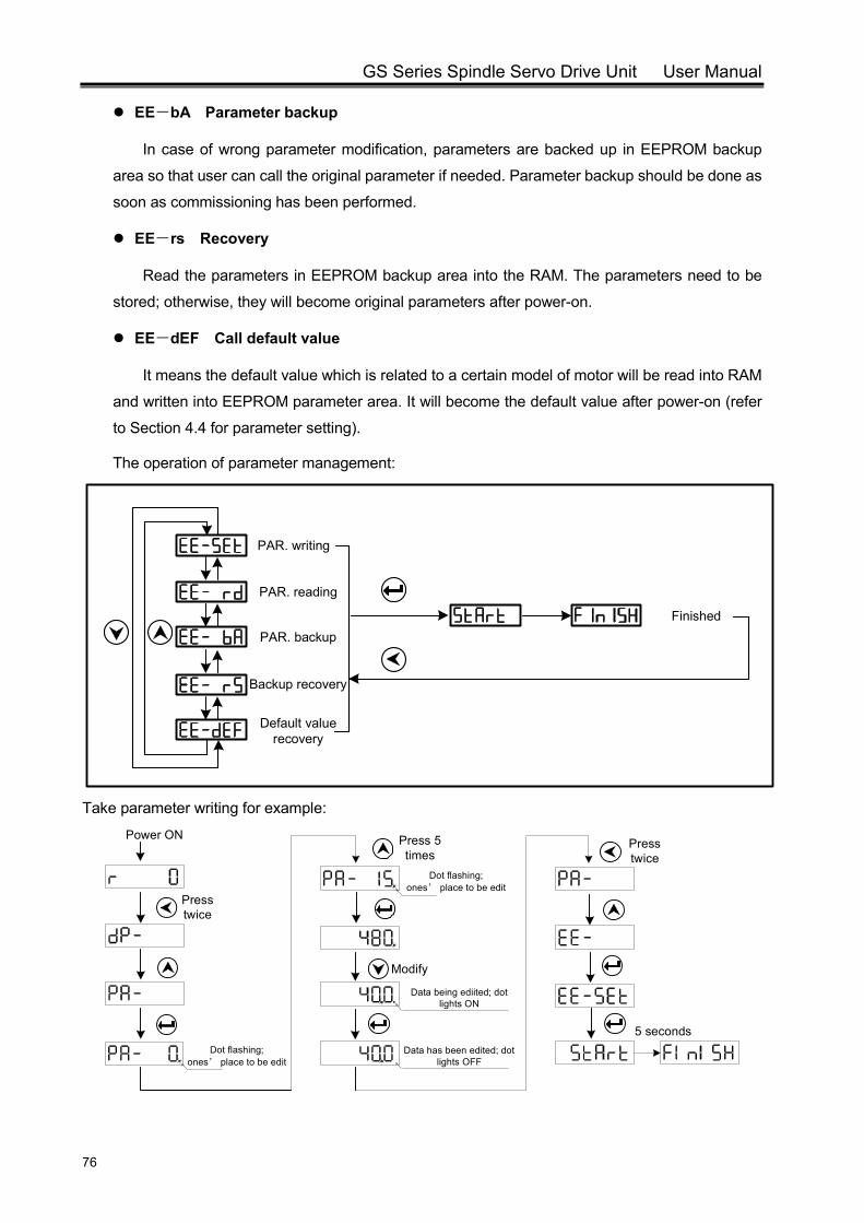
GS Series Spindle Servo Drive Unit User Manual
76
EE-bA Parameter backup
In case of wrong parameter modification, parameters are backed up in EEPROM backup
area so that user can call the original parameter if needed. Parameter backup should be done as
soon as commissioning has been performed.
EE-rs Recovery
Read the parameters in EEPROM backup area into the RAM. The parameters need to be
stored; otherwise, they will become original parameters after power-on.
EE-dEF Call default value
It means the default value which is related to a certain model of motor will be read into RAM
and written into EEPROM parameter area. It will become the default value after power-on (refer
to Section 4.4 for parameter setting).
The operation of parameter management:
Finished
PAR. writing
PAR. reading
PAR. backup
Backup recovery
Default value recovery
Take parameter writing for example:
Press twice
Modify
Dot flashing; ones’ place to be edit
Data being ediited; dot lights ON
Data has been edited; dot lights OFF
5 seconds
Power ON Press 5 times
Press twice
Dot flashing; ones’ place to be edit
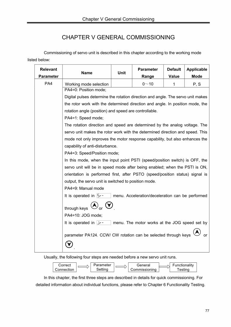
Chapter V General Commissioning
77
CHAPTER V GENERAL COMMISSIONING
Commissioning of servo unit is described in this chapter according to the working mode
listed below:
Relevant Parameter
Name Unit Parameter
Range Default Value
Applicable Mode
PA4 Working mode selection 0~10 1 P, S PA4=0: Position mode;
Digital pulses determine the rotation direction and angle. The servo unit makes
the rotor work with the determined direction and angle. In position mode, the
rotation angle (position) and speed are controllable.
PA4=1: Speed mode;
The rotation direction and speed are determined by the analog voltage. The
servo unit makes the rotor work with the determined direction and speed. This
mode not only improves the motor response capability, but also enhances the
capability of anti-disturbance.
PA4=3: Speed/Position mode;
In this mode, when the input point PSTI (speed/position switch) is OFF, the
servo unit will be in speed mode after being enabled; when the PSTI is ON,
orientation is performed first, after PSTO (speed/position status) signal is
output, the servo unit is switched to position mode.
PA4=9: Manual mode
It is operated in menu. Acceleration/deceleration can be performed
through keys or .
PA4=10: JOG mode;
It is operated in menu. The motor works at the JOG speed set by
parameter PA124. CCW/ CW rotation can be selected through keys or
.
Usually, the following four steps are needed before a new servo unit runs.
Parameter Setting
General Commissioning
Functionality Testing
Correct Connection
In this chapter, the first three steps are described in details for quick commissioning. For
detailed information about individual functions, please refer to Chapter 6 Functionality Testing.
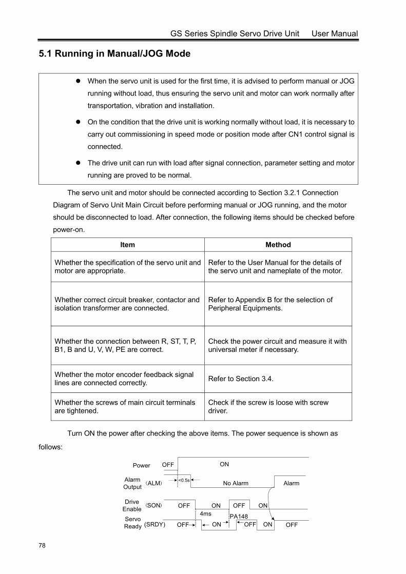
GS Series Spindle Servo Drive Unit User Manual
78
5.1 Running in Manual/JOG Mode
When the servo unit is used for the first time, it is advised to perform manual or JOG
running without load, thus ensuring the servo unit and motor can work normally after
transportation, vibration and installation.
On the condition that the drive unit is working normally without load, it is necessary to
carry out commissioning in speed mode or position mode after CN1 control signal is
connected.
The drive unit can run with load after signal connection, parameter setting and motor
running are proved to be normal.
The servo unit and motor should be connected according to Section 3.2.1 Connection
Diagram of Servo Unit Main Circuit before performing manual or JOG running, and the motor
should be disconnected to load. After connection, the following items should be checked before
power-on.
Item Method
Whether the specification of the servo unit and motor are appropriate.
Refer to the User Manual for the details of the servo unit and nameplate of the motor.
Whether correct circuit breaker, contactor and isolation transformer are connected.
Refer to Appendix B for the selection of Peripheral Equipments.
Whether the connection between R, ST, T, P, B1, B and U, V, W, PE are correct.
Check the power circuit and measure it with universal meter if necessary.
Whether the motor encoder feedback signal lines are connected correctly. Refer to Section 3.4.
Whether the screws of main circuit terminals are tightened.
Check if the screw is loose with screw driver.
Turn ON the power after checking the above items. The power sequence is shown as
follows:
Power
Alarm Output(ALM)
Drive Enable(SON)
Servo Ready (SRDY)
4ms PA148
No Alarm
OFF OFFON
OFF ON OFF
Alarm
ON OFF
ON
ONOFF
<0.5s
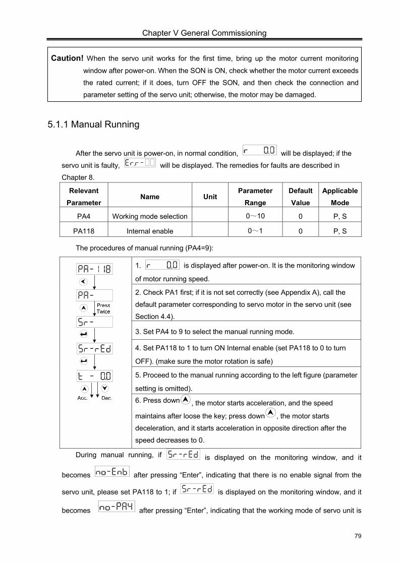
Chapter V General Commissioning
79
5.1.1 Manual Running
After the servo unit is power-on, in normal condition, will be displayed; if the
servo unit is faulty, will be displayed. The remedies for faults are described in
Chapter 8.
Relevant Parameter
Name Unit Parameter
Range Default Value
Applicable Mode
PA4 Working mode selection 0~10 0 P, S
PA118 Internal enable 0~1 0 P, S
The procedures of manual running (PA4=9):
1. is displayed after power-on. It is the monitoring window
of motor running speed.
2. Check PA1 first; if it is not set correctly (see Appendix A), call the
default parameter corresponding to servo motor in the servo unit (see
Section 4.4).
3. Set PA4 to 9 to select the manual running mode.
4. Set PA118 to 1 to turn ON Internal enable (set PA118 to 0 to turn
OFF). (make sure the motor rotation is safe)
5. Proceed to the manual running according to the left figure (parameter
setting is omitted). 6. Press down , the motor starts acceleration, and the speed
maintains after loose the key; press down , the motor starts
deceleration, and it starts acceleration in opposite direction after the
speed decreases to 0.
During manual running, if is displayed on the monitoring window, and it
becomes after pressing “Enter”, indicating that there is no enable signal from the
servo unit, please set PA118 to 1; if is displayed on the monitoring window, and it
becomes after pressing “Enter”, indicating that the working mode of servo unit is
Caution! When the servo unit works for the first time, bring up the motor current monitoring
window after power-on. When the SON is ON, check whether the motor current exceeds
the rated current; if it does, turn OFF the SON, and then check the connection and
parameter setting of the servo unit; otherwise, the motor may be damaged.
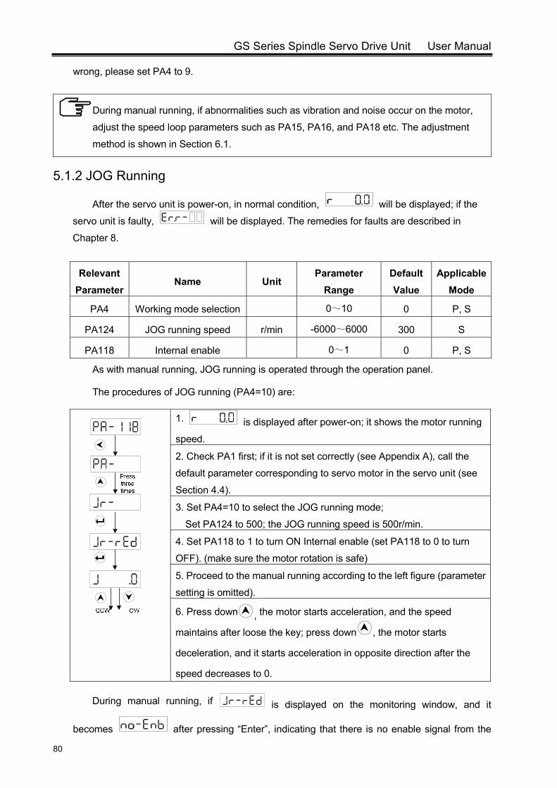
GS Series Spindle Servo Drive Unit User Manual
80
wrong, please set PA4 to 9.
During manual running, if abnormalities such as vibration and noise occur on the motor,
adjust the speed loop parameters such as PA15, PA16, and PA18 etc. The adjustment
method is shown in Section 6.1.
5.1.2 JOG Running
After the servo unit is power-on, in normal condition, will be displayed; if the
servo unit is faulty, will be displayed. The remedies for faults are described in
Chapter 8.
Relevant Parameter
Name Unit Parameter
Range Default Value
Applicable Mode
PA4 Working mode selection 0~10 0 P, S
PA124 JOG running speed r/min -6000~6000 300 S
PA118 Internal enable 0~1 0 P, S
As with manual running, JOG running is operated through the operation panel.
The procedures of JOG running (PA4=10) are:
1. is displayed after power-on; it shows the motor running
speed.
2. Check PA1 first; if it is not set correctly (see Appendix A), call the
default parameter corresponding to servo motor in the servo unit (see
Section 4.4).
3. Set PA4=10 to select the JOG running mode;
Set PA124 to 500; the JOG running speed is 500r/min.
4. Set PA118 to 1 to turn ON Internal enable (set PA118 to 0 to turn
OFF). (make sure the motor rotation is safe)
5. Proceed to the manual running according to the left figure (parameter
setting is omitted).
6. Press down , the motor starts acceleration, and the speed
maintains after loose the key; press down , the motor starts
deceleration, and it starts acceleration in opposite direction after the
speed decreases to 0.
During manual running, if is displayed on the monitoring window, and it
becomes after pressing “Enter”, indicating that there is no enable signal from the
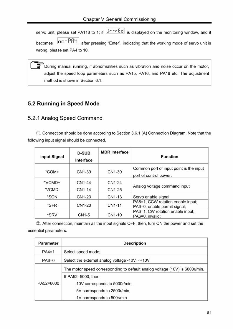
Chapter V General Commissioning
81
servo unit, please set PA118 to 1; if is displayed on the monitoring window, and it
becomes after pressing “Enter”, indicating that the working mode of servo unit is
wrong, please set PA4 to 10.
During manual running, if abnormalities such as vibration and noise occur on the motor,
adjust the speed loop parameters such as PA15, PA16, and PA18 etc. The adjustment
method is shown in Section 6.1.
5.2 Running in Speed Mode
5.2.1 Analog Speed Command
. Connection should be done according to Section 3.6.1 (A) Connection Diagram. Note that the ①
following input signal should be connected.
Input Signal D-SUB
Interface
MDR Interface Function
*COM+ CN1-39 CN1-39 Common port of input point is the input
port of control power.
*VCMD+
*VCMD-
CN1-44
CN1-14
CN1-24
CN1-25 Analog voltage command input
*SON CN1-23 CN1-13 Servo enable signal
*SFR CN1-20 CN1-11 PA6=1, CCW rotation enable input; PA6=0, enable permit signal;
*SRV CN1-5 CN1-10 PA6=1, CW rotation enable input; PA6=0, invalid;
. After connection, maintain all the input signals OFF, then, turn ON the power and set the ②
essential parameters.
Parameter Description
PA4=1 Select speed mode;
PA6=0 Select the external analog voltage -10V~+10V
PA52=6000
The motor speed corresponding to default analog voltage (10V) is 6000r/min.
If PA52=5000, then
10V corresponds to 5000r/min,
5V corresponds to 2500r/min,
1V corresponds to 500r/min.
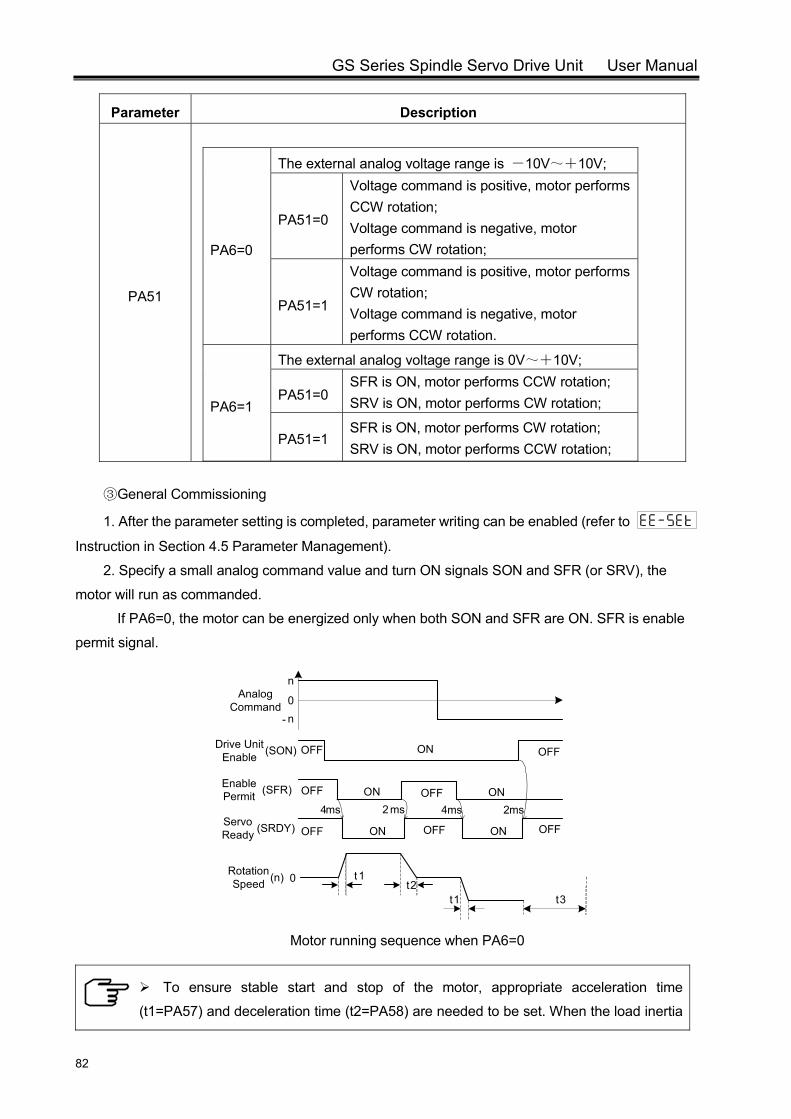
GS Series Spindle Servo Drive Unit User Manual
82
Parameter Description
PA51
PA6=0
The external analog voltage range is -10V~+10V;
PA51=0
Voltage command is positive, motor performs CCW rotation; Voltage command is negative, motor performs CW rotation;
PA51=1
Voltage command is positive, motor performs CW rotation; Voltage command is negative, motor performs CCW rotation.
PA6=1
The external analog voltage range is 0V~+10V;
PA51=0 SFR is ON, motor performs CCW rotation; SRV is ON, motor performs CW rotation;
PA51=1 SFR is ON, motor performs CW rotation; SRV is ON, motor performs CCW rotation;
General Commissioning③
1. After the parameter setting is completed, parameter writing can be enabled (refer to Instruction in Section 4.5 Parameter Management).
2. Specify a small analog command value and turn ON signals SON and SFR (or SRV), the
motor will run as commanded.
If PA6=0, the motor can be energized only when both SON and SFR are ON. SFR is enable
permit signal.
Drive Unit Enable (SON)
Enable Permit (SFR)
Servo Ready (SRDY)
Rotation Speed (n)
4ms 2ms
t
1t2
OFF OFF
OFF
ON
ON OFF ON
OFF ON OFF ON OFF
Analog Command 0
n
n-
ms4 2ms
t
1 t3
0
Motor running sequence when PA6=0
To ensure stable start and stop of the motor, appropriate acceleration time
(t1=PA57) and deceleration time (t2=PA58) are needed to be set. When the load inertia
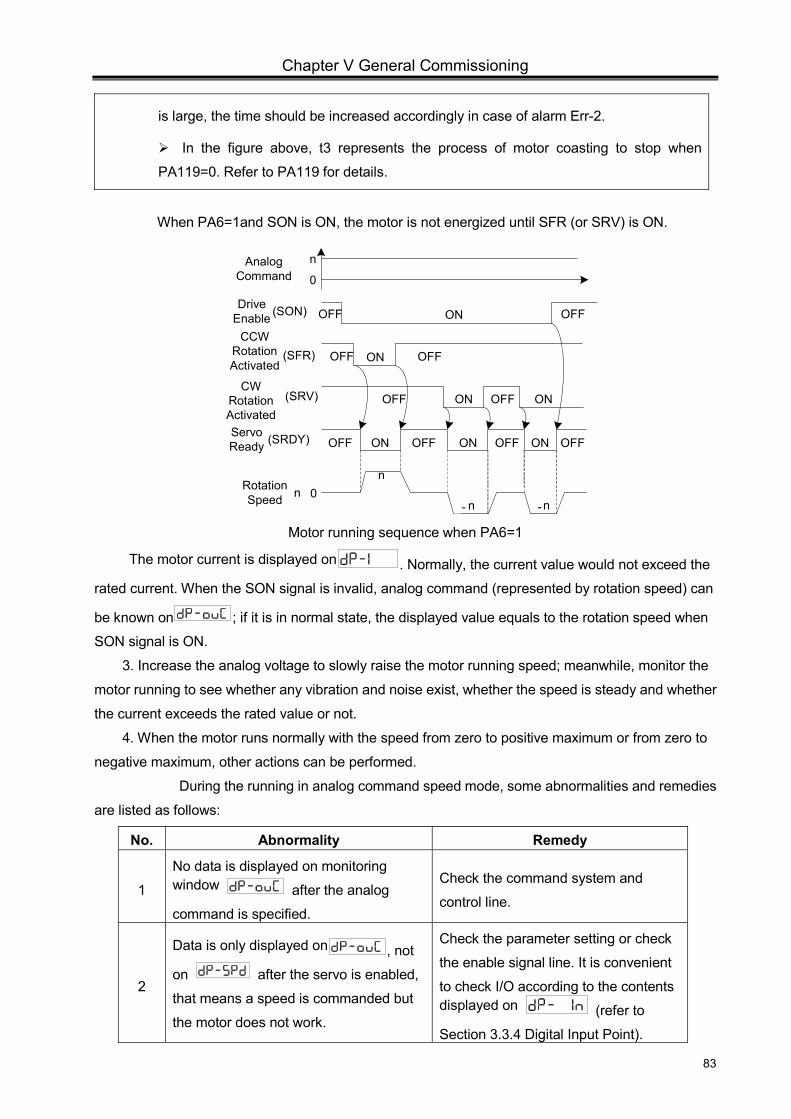
Chapter V General Commissioning
83
is large, the time should be increased accordingly in case of alarm Err-2.
In the figure above, t3 represents the process of motor coasting to stop when
PA119=0. Refer to PA119 for details.
When PA6=1and SON is ON, the motor is not energized until SFR (or SRV) is ON.
Drive Enable (SON)
(SFR)
Servo Ready (SRDY)
Rotation Speed n
OFF OFF
OFF
ON
ON
OFF ON OFF ON OFF
Analog Command 0
n
0
OFF(SRV)
ON OFF
ON ONOFF
OFF
n
n n- -
CCW Rotation Activated
CW Rotation Activated
Motor running sequence when PA6=1
The motor current is displayed on . Normally, the current value would not exceed the
rated current. When the SON signal is invalid, analog command (represented by rotation speed) can
be known on ; if it is in normal state, the displayed value equals to the rotation speed when
SON signal is ON.
3. Increase the analog voltage to slowly raise the motor running speed; meanwhile, monitor the
motor running to see whether any vibration and noise exist, whether the speed is steady and whether
the current exceeds the rated value or not.
4. When the motor runs normally with the speed from zero to positive maximum or from zero to
negative maximum, other actions can be performed.
During the running in analog command speed mode, some abnormalities and remedies
are listed as follows:
No. Abnormality Remedy
1
No data is displayed on monitoring window after the analog
command is specified.
Check the command system and
control line.
2
Data is only displayed on , not
on after the servo is enabled,
that means a speed is commanded but
the motor does not work.
Check the parameter setting or check
the enable signal line. It is convenient
to check I/O according to the contents displayed on (refer to
Section 3.3.4 Digital Input Point).
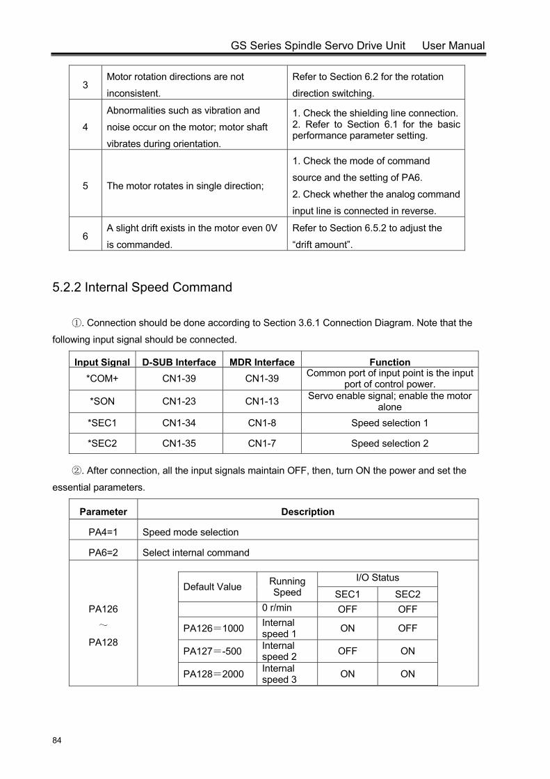
GS Series Spindle Servo Drive Unit User Manual
84
3 Motor rotation directions are not
inconsistent.
Refer to Section 6.2 for the rotation
direction switching.
4
Abnormalities such as vibration and
noise occur on the motor; motor shaft
vibrates during orientation.
1. Check the shielding line connection.2. Refer to Section 6.1 for the basic performance parameter setting.
5 The motor rotates in single direction;
1. Check the mode of command
source and the setting of PA6.
2. Check whether the analog command
input line is connected in reverse.
6 A slight drift exists in the motor even 0V
is commanded.
Refer to Section 6.5.2 to adjust the
“drift amount”.
5.2.2 Internal Speed Command
. Connection should be done according to Section 3.6.1 Connection Diagram. Note that the ①
following input signal should be connected.
Input Signal D-SUB Interface MDR Interface Function *COM+ CN1-39 CN1-39 Common port of input point is the input
port of control power.
*SON CN1-23 CN1-13 Servo enable signal; enable the motor alone
*SEC1 CN1-34 CN1-8 Speed selection 1
*SEC2 CN1-35 CN1-7 Speed selection 2
. After connection, all the input signals maintain OFF, then, turn ON the power and set the ②
essential parameters.
Parameter Description
PA4=1 Speed mode selection
PA6=2 Select internal command
PA126 ~
PA128
Default Value Running Speed
I/O Status
SEC1 SEC2 0 r/min OFF OFF
PA126=1000 Internal speed 1 ON OFF
PA127=-500 Internal speed 2 OFF ON
PA128=2000 Internal speed 3 ON ON
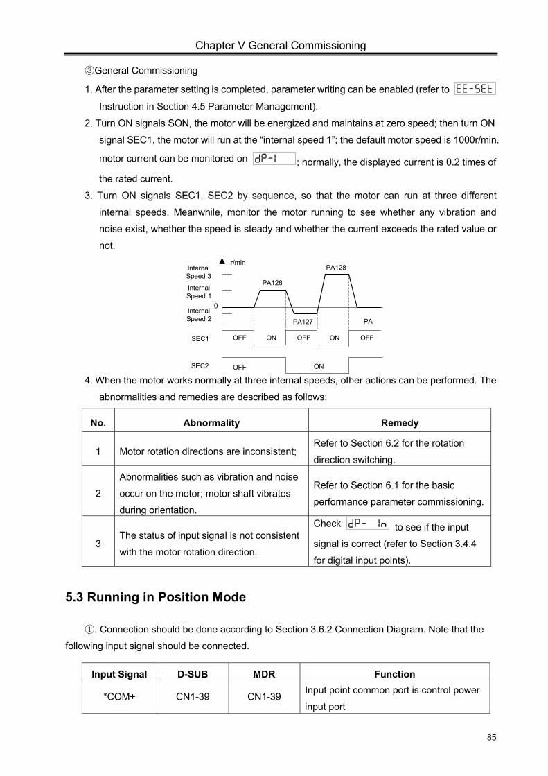
Chapter V General Commissioning
85
General Commissioning③
1. After the parameter setting is completed, parameter writing can be enabled (refer to Instruction in Section 4.5 Parameter Management).
2. Turn ON signals SON, the motor will be energized and maintains at zero speed; then turn ON
signal SEC1, the motor will run at the “internal speed 1”; the default motor speed is 1000r/min.
motor current can be monitored on ; normally, the displayed current is 0.2 times of
the rated current.
3. Turn ON signals SEC1, SEC2 by sequence, so that the motor can run at three different
internal speeds. Meanwhile, monitor the motor running to see whether any vibration and
noise exist, whether the speed is steady and whether the current exceeds the rated value or
not.
Internal Speed 1
Internal Speed 3
Internal Speed 2
SEC1
SEC2
ON OFFOFF
OFF
OFF ON
ON
PA126
PA127
PA128
PA
r/min
0
4. When the motor works normally at three internal speeds, other actions can be performed. The
abnormalities and remedies are described as follows:
No. Abnormality Remedy
1 Motor rotation directions are inconsistent; Refer to Section 6.2 for the rotation
direction switching.
2
Abnormalities such as vibration and noise
occur on the motor; motor shaft vibrates
during orientation.
Refer to Section 6.1 for the basic
performance parameter commissioning.
3 The status of input signal is not consistent
with the motor rotation direction.
Check to see if the input
signal is correct (refer to Section 3.4.4
for digital input points).
5.3 Running in Position Mode
. Connection should be done according to Section 3.6.2 Connection Diagram. Note that the ①
following input signal should be connected.
Input Signal D-SUB MDR Function
*COM+ CN1-39 CN1-39 Input point common port is control power
input port

GS Series Spindle Servo Drive Unit User Manual
86
*SON CN1-23 CN1-13 Servo enable signal
*PULS+ *PULS-
CN1-2 CN1-17
CN1-6 CN1-5
Position command input; the input mode
is :
PA5=0: Pulse + direction;
PA5=1: CCW pulse+CW pulse;
PA5=2: AB phase of orthogonal pulse;
*SIGN+ *SIGN-
CN1-1 CN1-16
CN1-31 CN1-30
. After connection, all the input signals maintain OFF, then, turn ON the power and set the ②
essential parameters.
Parameter Description
PA4=0 Select position mode
PA5
Selection pulse mode of position command;
PA5=0: Pulse + direction;
PA5=1: CCW pulse+CW pulse
PA5=2: AB phase of orthogonal pulse; (Refer to Section 3.3.3 for position
command input.)
PA28 Position command direction reversed; PA28=0: “Standard Mode” of position command; PA28=1: “Reverse Mode” of position command; (See Section 6.2).
PA29
PA30
Position command electronic gear ratio: PA29 pulse command frequency
multiplication coefficient;
PA30 pulse command frequency division coefficient;
The electronic gear ratio formula is :
S =I CR
ZM
ZD
δ CD
PA29
PA30
L
4C (Refer to Section 6.4.1 for details.)
. General Commissioning ③
1. After the parameter setting is completed, parameter writing can be enabled (refer to Instruction in Section 4.5 Parameter Management).
2. Turn ON signals SON, the motor will be energized and maintains at zero speed; specify the
position pulse with low frequency, and then the motor can start running. Motor current can be
monitored on ; normally, the displayed current will not exceed the rated current. When
PA29 and PA30 are set to 1, command pulse number can be read on after the execution
of some commands. The pulse number should be in accordance with the displayed pulse number on
. When the gear ratio is not 1:1, the pulse number should multiply the gear ratio.
The following figure is an example of driving the motor by pulse+direction commands.
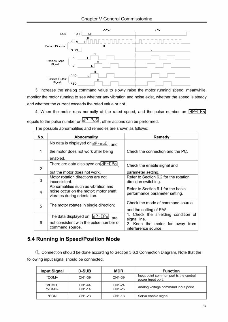
Chapter V General Commissioning
87
3. Increase the analog command value to slowly raise the motor running speed; meanwhile,
monitor the motor running to see whether any vibration and noise exist, whether the speed is steady
and whether the current exceeds the rated value or not.
4. When the motor runs normally at the rated speed, and the pulse number on
equals to the pulse number on , other actions can be performed.
The possible abnormalities and remedies are shown as follows:
No. Abnormality Remedy
1
No data is displayed on , and
the motor does not work after being
enabled. Check the connection and the PC.
2 There are data displayed on ,
but the motor does not work.
Check the enable signal and
parameter setting.
3 Motor rotation directions are not inconsistent.
Refer to Section 6.2 for the rotation direction switching.
4 Abnormalities such as vibration and noise occur on the motor; motor shaft vibrates during orientation.
Refer to Section 6.1 for the basic performance parameter setting.
5 The motor rotates in single direction; Check the mode of command source
and the setting of PA5.
6 The data displayed on are not consistent with the pulse number of command source.
1. Check the shielding condition of signal line. 2. Keep the motor far away from interference source.
5.4 Running in Speed/Position Mode
. Connection should be done according to Section 3.6.3 Connection Diagram. Note that the ①
following input signal should be connected.
Input Signal D-SUB MDR Function *COM+ CN1-39 CN1-39 Input point common port is the control
power input port. *VCMD+ *VCMD-
CN1-44 CN1-14
CN1-24 CN1-25 Analog voltage command input point.
*SON CN1-23 CN1-13 Servo enable signal.
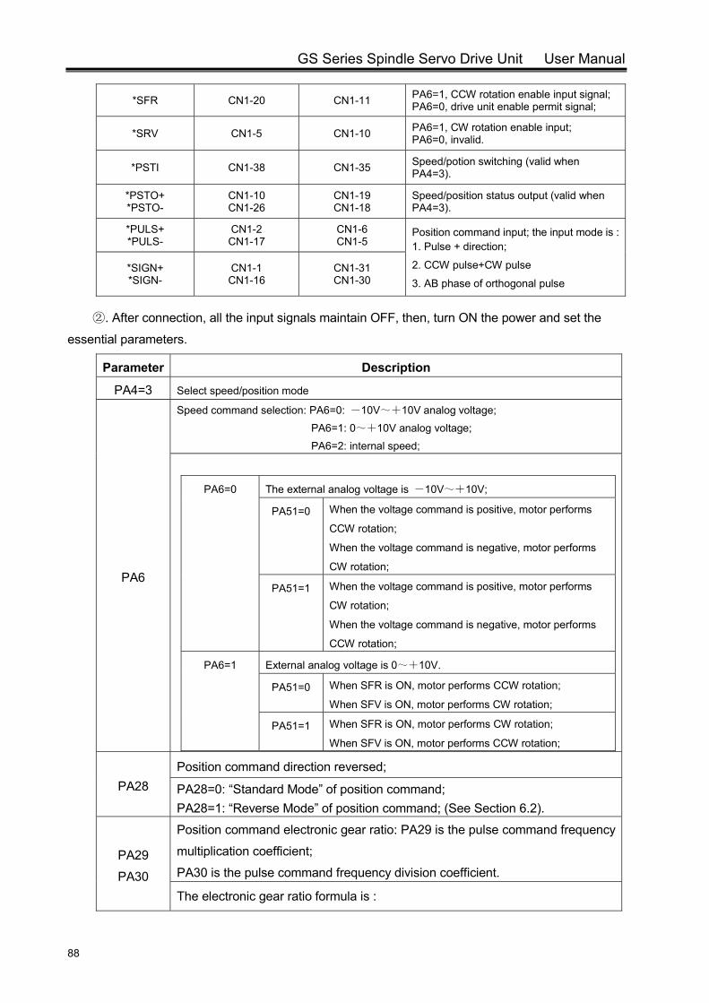
GS Series Spindle Servo Drive Unit User Manual
88
*SFR CN1-20 CN1-11 PA6=1, CCW rotation enable input signal; PA6=0, drive unit enable permit signal;
*SRV CN1-5 CN1-10 PA6=1, CW rotation enable input; PA6=0, invalid.
*PSTI CN1-38 CN1-35 Speed/potion switching (valid when PA4=3).
*PSTO+ *PSTO-
CN1-10 CN1-26
CN1-19 CN1-18
Speed/position status output (valid when PA4=3).
*PULS+ *PULS-
CN1-2 CN1-17
CN1-6 CN1-5
Position command input; the input mode is :1. Pulse + direction;
2. CCW pulse+CW pulse
3. AB phase of orthogonal pulse *SIGN+ *SIGN-
CN1-1 CN1-16
CN1-31 CN1-30
. After co② nnection, all the input signals maintain OFF, then, turn ON the power and set the
essential parameters.
Parameter Description
PA4=3 Select speed/position mode
PA6
Speed command selection: PA6=0: -10V~+10V analog voltage; PA6=1: 0~+10V analog voltage; PA6=2: internal speed;
PA6=0 The external analog voltage is -10V~+10V;
PA51=0 When the voltage command is positive, motor performs
CCW rotation;
When the voltage command is negative, motor performs
CW rotation;
PA51=1 When the voltage command is positive, motor performs
CW rotation;
When the voltage command is negative, motor performs
CCW rotation;
PA6=1 External analog voltage is 0~+10V.
PA51=0 When SFR is ON, motor performs CCW rotation;
When SFV is ON, motor performs CW rotation;
PA51=1 When SFR is ON, motor performs CW rotation;
When SFV is ON, motor performs CCW rotation;
PA28 Position command direction reversed;
PA28=0: “Standard Mode” of position command; PA28=1: “Reverse Mode” of position command; (See Section 6.2).
PA29
PA30
Position command electronic gear ratio: PA29 is the pulse command frequency
multiplication coefficient;
PA30 is the pulse command frequency division coefficient.
The electronic gear ratio formula is :

Chapter V General Commissioning
89
(Refer to Section 6.4.1 for details.)
PA89
Select the transition mode switching from position mode to speed mode.
In speed/position mode, it selects the transition mode switching from position mode to speed
mode.
PA89=0: When VP is OFF, switch to speed mode after the execution of position commands.
PA89=1: When VP is OFF, switch to speed mode no matter whether the position commands
are completed.
Parameter Description
PA90
PA91
Reference point position in speed/position switching mode
When switching from speed mode to position mode, the servo unit will work at
the speed set by PA99, and stops at the reference point set by PA90, PA91,
then, waits for position commands. (Refer to Section 6.5.1 for orientation
process.)
PA99
Orientation speed
When the spindle motor performs orientation, it rotates at the orientation speed
at first; then, after the Z pulse of encoder is acquired, the spindle motor rotates
to the orientation position.
. General Commissioning ③
1. After the parameter setting is completed, parameter writing can be enabled (refer to Instruction in Section 4.5 Parameter Management).
2. Speed/position switching. Input according to the status of PSTI:
PSTI is ON; the servo unit is in position mode;
PSTI is OFF; the servo unit is in speed mode;
The switching process is:
0
To the position set by PA90, PA91
Position Mode
Orientation Speed
Initial Speed
PA99
PSTI Input Point
OFF ON OFF
Speed Mode Speed Mode
Switch to speed mode
PSTI Output Point OFF ON OFF
Rotation Speed
Fig. 5-4-1 Switching process when PA89=0
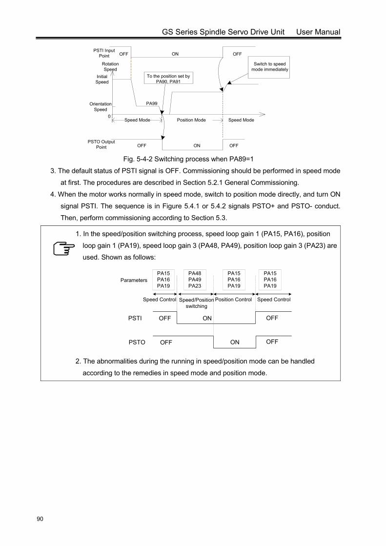
GS Series Spindle Servo Drive Unit User Manual
90
0Position Mode
Orientation Speed
Initial Speed
PA99
PSTI Input Point OFF ON OFF
Speed Mode Speed Mode
Switch to speed mode immediately
PSTO Output Point OFF ON OFF
Rotation Speed
To the position set by PA90, PA91
Fig. 5-4-2 Switching process when PA89=1
3. The default status of PSTI signal is OFF. Commissioning should be performed in speed mode
at first. The procedures are described in Section 5.2.1 General Commissioning.
4. When the motor works normally in speed mode, switch to position mode directly, and turn ON
signal PSTI. The sequence is in Figure 5.4.1 or 5.4.2 signals PSTO+ and PSTO- conduct.
Then, perform commissioning according to Section 5.3.
1. In the speed/position switching process, speed loop gain 1 (PA15, PA16), position
loop gain 1 (PA19), speed loop gain 3 (PA48, PA49), position loop gain 3 (PA23) are
used. Shown as follows:
PSTI OFF OFFON
PSTO OFF OFFON
Speed/Position switching
PA48PA49PA23
PA15PA16PA19
PA15PA16PA19
Parameters
Speed Control Position Control Speed Control
PA15PA16PA19
2. The abnormalities during the running in speed/position mode can be handled
according to the remedies in speed mode and position mode.
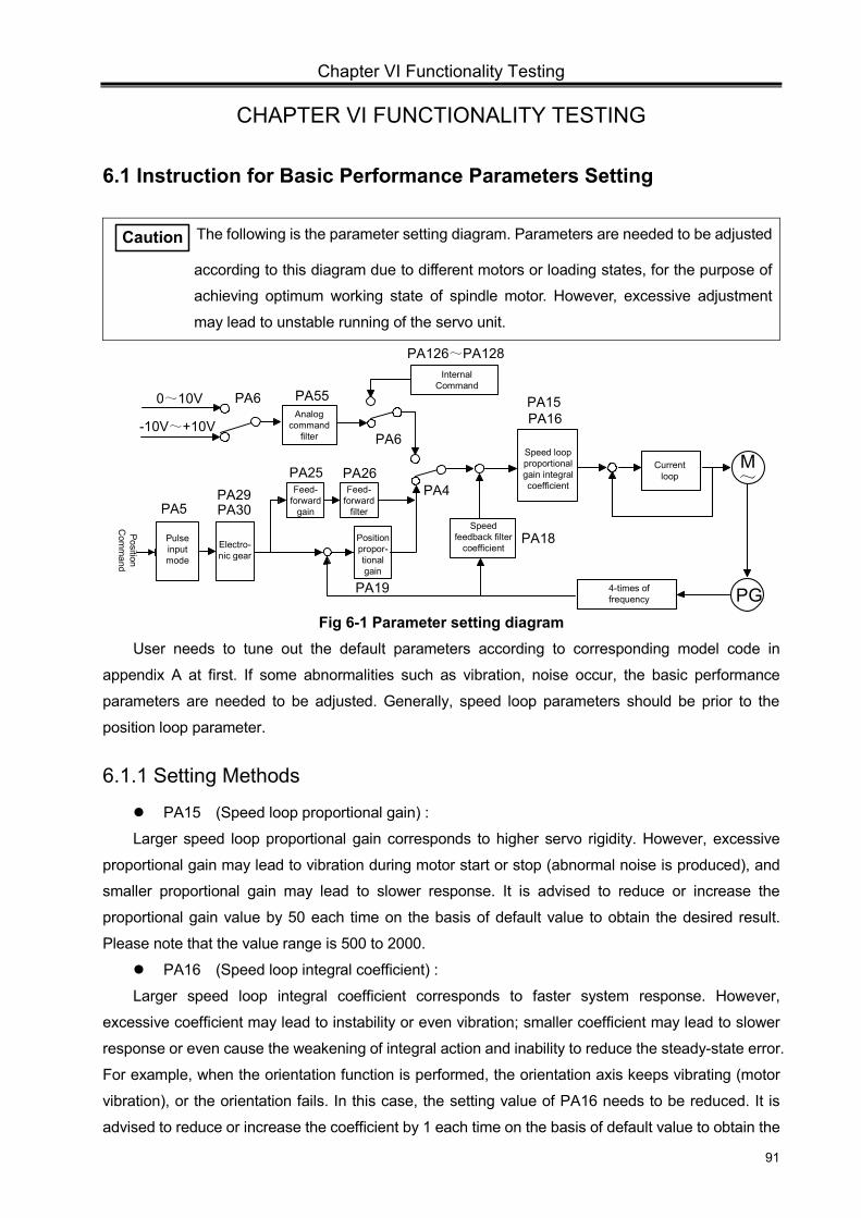
Chapter VI Functionality Testing
91
CHAPTER VI FUNCTIONALITY TESTING
6.1 Instruction for Basic Performance Parameters Setting
Caution The following is the parameter setting diagram. Parameters are needed to be adjusted
according to this diagram due to different motors or loading states, for the purpose of
achieving optimum working state of spindle motor. However, excessive adjustment
may lead to unstable running of the servo unit.
Speed loop proportional gain integral coefficient
M~
PG4-times of frequency
Speed feedback filter
coefficient
Analog command
filter
PA4
PA18
PA15PA16
Internal Command
PA126~PA128
PA60~10V
Position propor-tional gain
Feed-forward
filter
Feed-forward
gain
Electro-nic gear
Pulse input mode
Position C
omm
and
PA26PA25
PA19
PA29PA30PA5
PA6
Current loop
-10V~+10V
PA55
Fig 6-1 Parameter setting diagram
User needs to tune out the default parameters according to corresponding model code in
appendix A at first. If some abnormalities such as vibration, noise occur, the basic performance
parameters are needed to be adjusted. Generally, speed loop parameters should be prior to the
position loop parameter.
6.1.1 Setting Methods
PA15 (Speed loop proportional gain) :
Larger speed loop proportional gain corresponds to higher servo rigidity. However, excessive
proportional gain may lead to vibration during motor start or stop (abnormal noise is produced), and
smaller proportional gain may lead to slower response. It is advised to reduce or increase the
proportional gain value by 50 each time on the basis of default value to obtain the desired result.
Please note that the value range is 500 to 2000.
PA16 (Speed loop integral coefficient) :
Larger speed loop integral coefficient corresponds to faster system response. However,
excessive coefficient may lead to instability or even vibration; smaller coefficient may lead to slower
response or even cause the weakening of integral action and inability to reduce the steady-state error.
For example, when the orientation function is performed, the orientation axis keeps vibrating (motor
vibration), or the orientation fails. In this case, the setting value of PA16 needs to be reduced. It is
advised to reduce or increase the coefficient by 1 each time on the basis of default value to obtain the
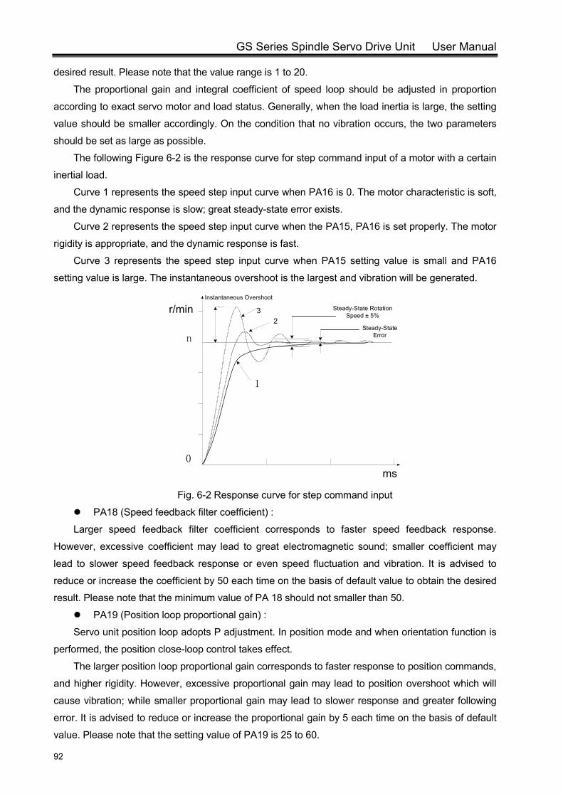
GS Series Spindle Servo Drive Unit User Manual
92
desired result. Please note that the value range is 1 to 20.
The proportional gain and integral coefficient of speed loop should be adjusted in proportion
according to exact servo motor and load status. Generally, when the load inertia is large, the setting
value should be smaller accordingly. On the condition that no vibration occurs, the two parameters
should be set as large as possible.
The following Figure 6-2 is the response curve for step command input of a motor with a certain
inertial load.
Curve 1 represents the speed step input curve when PA16 is 0. The motor characteristic is soft,
and the dynamic response is slow; great steady-state error exists.
Curve 2 represents the speed step input curve when the PA15, PA16 is set properly. The motor
rigidity is appropriate, and the dynamic response is fast.
Curve 3 represents the speed step input curve when PA15 setting value is small and PA16
setting value is large. The instantaneous overshoot is the largest and vibration will be generated.
r/min
n
0
ms
32
1
Instantaneous Overshoot
Steady-State Error
Steady-State Rotation Speed ± 5%
Fig. 6-2 Response curve for step command input
PA18 (Speed feedback filter coefficient) :
Larger speed feedback filter coefficient corresponds to faster speed feedback response.
However, excessive coefficient may lead to great electromagnetic sound; smaller coefficient may
lead to slower speed feedback response or even speed fluctuation and vibration. It is advised to
reduce or increase the coefficient by 50 each time on the basis of default value to obtain the desired
result. Please note that the minimum value of PA 18 should not smaller than 50.
PA19 (Position loop proportional gain) :
Servo unit position loop adopts P adjustment. In position mode and when orientation function is
performed, the position close-loop control takes effect.
The larger position loop proportional gain corresponds to faster response to position commands,
and higher rigidity. However, excessive proportional gain may lead to position overshoot which will
cause vibration; while smaller proportional gain may lead to slower response and greater following
error. It is advised to reduce or increase the proportional gain by 5 each time on the basis of default
value. Please note that the setting value of PA19 is 25 to 60.
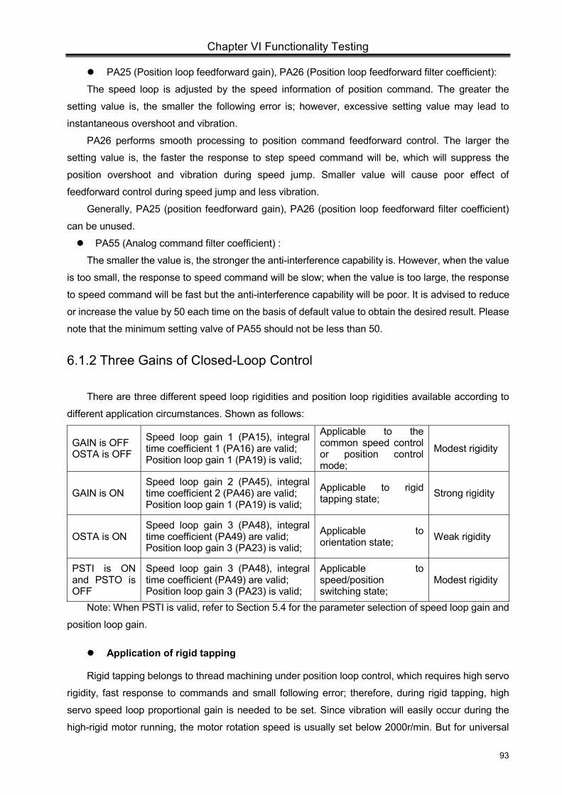
Chapter VI Functionality Testing
93
PA25 (Position loop feedforward gain), PA26 (Position loop feedforward filter coefficient):
The speed loop is adjusted by the speed information of position command. The greater the
setting value is, the smaller the following error is; however, excessive setting value may lead to
instantaneous overshoot and vibration.
PA26 performs smooth processing to position command feedforward control. The larger the
setting value is, the faster the response to step speed command will be, which will suppress the
position overshoot and vibration during speed jump. Smaller value will cause poor effect of
feedforward control during speed jump and less vibration.
Generally, PA25 (position feedforward gain), PA26 (position loop feedforward filter coefficient)
can be unused.
PA55 (Analog command filter coefficient) :
The smaller the value is, the stronger the anti-interference capability is. However, when the value
is too small, the response to speed command will be slow; when the value is too large, the response
to speed command will be fast but the anti-interference capability will be poor. It is advised to reduce
or increase the value by 50 each time on the basis of default value to obtain the desired result. Please
note that the minimum setting valve of PA55 should not be less than 50.
6.1.2 Three Gains of Closed-Loop Control
There are three different speed loop rigidities and position loop rigidities available according to
different application circumstances. Shown as follows:
GAIN is OFF OSTA is OFF
Speed loop gain 1 (PA15), integral time coefficient 1 (PA16) are valid; Position loop gain 1 (PA19) is valid;
Applicable to the common speed control or position control mode;
Modest rigidity
GAIN is ON Speed loop gain 2 (PA45), integral time coefficient 2 (PA46) are valid; Position loop gain 1 (PA19) is valid;
Applicable to rigid tapping state; Strong rigidity
OSTA is ON Speed loop gain 3 (PA48), integral time coefficient (PA49) are valid; Position loop gain 3 (PA23) is valid;
Applicable to orientation state; Weak rigidity
PSTI is ON and PSTO is OFF
Speed loop gain 3 (PA48), integral time coefficient (PA49) are valid; Position loop gain 3 (PA23) is valid;
Applicable to speed/position switching state;
Modest rigidity
Note: When PSTI is valid, refer to Section 5.4 for the parameter selection of speed loop gain and
position loop gain.
Application of rigid tapping
Rigid tapping belongs to thread machining under position loop control, which requires high servo
rigidity, fast response to commands and small following error; therefore, during rigid tapping, high
servo speed loop proportional gain is needed to be set. Since vibration will easily occur during the
high-rigid motor running, the motor rotation speed is usually set below 2000r/min. But for universal
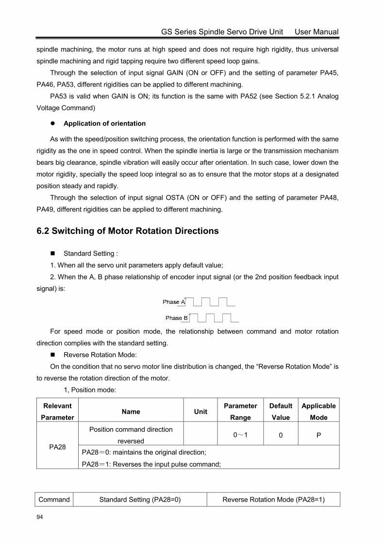
GS Series Spindle Servo Drive Unit User Manual
94
spindle machining, the motor runs at high speed and does not require high rigidity, thus universal
spindle machining and rigid tapping require two different speed loop gains.
Through the selection of input signal GAIN (ON or OFF) and the setting of parameter PA45,
PA46, PA53, different rigidities can be applied to different machining.
PA53 is valid when GAIN is ON; its function is the same with PA52 (see Section 5.2.1 Analog
Voltage Command)
Application of orientation
As with the speed/position switching process, the orientation function is performed with the same
rigidity as the one in speed control. When the spindle inertia is large or the transmission mechanism
bears big clearance, spindle vibration will easily occur after orientation. In such case, lower down the
motor rigidity, specially the speed loop integral so as to ensure that the motor stops at a designated
position steady and rapidly.
Through the selection of input signal OSTA (ON or OFF) and the setting of parameter PA48,
PA49, different rigidities can be applied to different machining.
6.2 Switching of Motor Rotation Directions
Standard Setting :
1. When all the servo unit parameters apply default value;
2. When the A, B phase relationship of encoder input signal (or the 2nd position feedback input
signal) is:
For speed mode or position mode, the relationship between command and motor rotation
direction complies with the standard setting.
Reverse Rotation Mode:
On the condition that no servo motor line distribution is changed, the “Reverse Rotation Mode” is
to reverse the rotation direction of the motor.
1, Position mode:
Relevant Parameter
Name Unit Parameter
Range Default Value
Applicable Mode
PA28
Position command direction
reversed 0~1 0 P
PA28=0: maintains the original direction;
PA28=1: Reverses the input pulse command;
Command Standard Setting (PA28=0) Reverse Rotation Mode (PA28=1)
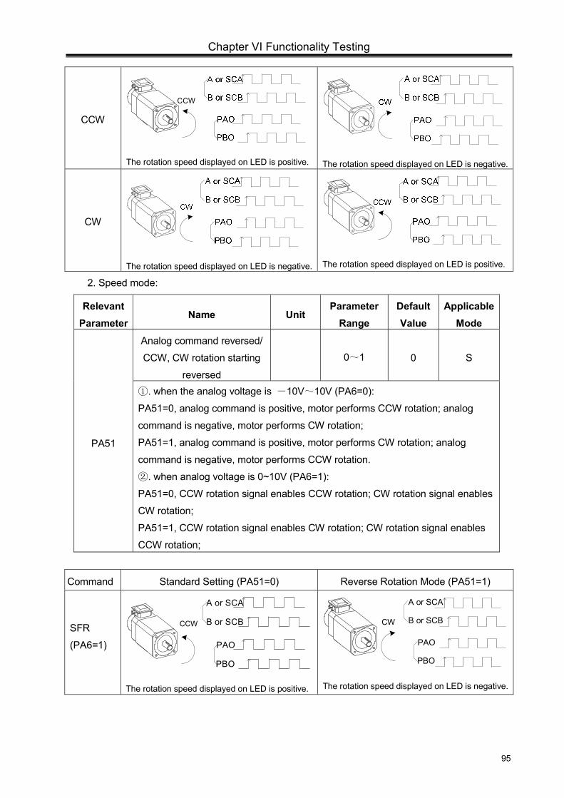
Chapter VI Functionality Testing
95
CCW
CCW
The rotation speed displayed on LED is positive.
The rotation speed displayed on LED is negative.
CW
The rotation speed displayed on LED is negative.
The rotation speed displayed on LED is positive.
2. Speed mode:
Relevant Parameter
Name Unit Parameter
Range Default Value
Applicable Mode
PA51
Analog command reversed/
CCW, CW rotation starting
reversed
0~1 0 S
. when the analog voltage is ① -10V~10V (PA6=0):
PA51=0, analog command is positive, motor performs CCW rotation; analog
command is negative, motor performs CW rotation;
PA51=1, analog command is positive, motor performs CW rotation; analog
command is negative, motor performs CCW rotation.
. when analog voltage is 0~10V (PA6=1):②
PA51=0, CCW rotation signal enables CCW rotation; CW rotation signal enables
CW rotation;
PA51=1, CCW rotation signal enables CW rotation; CW rotation signal enables
CCW rotation;
Command Standard Setting (PA51=0) Reverse Rotation Mode (PA51=1)
SFR
(PA6=1)
CCW
PAO
PBO
A or SCA
B or SCB
The rotation speed displayed on LED is positive.
CW
PAO
PBO
A or SCA
B or SCB
The rotation speed displayed on LED is negative.
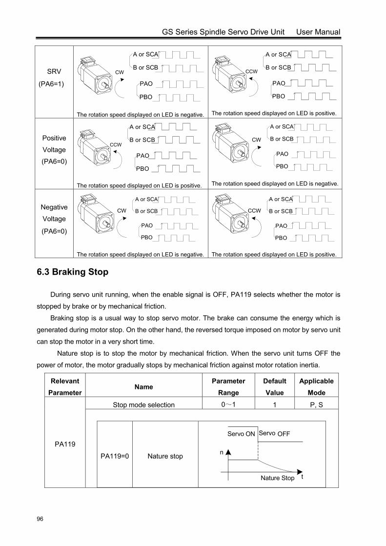
GS Series Spindle Servo Drive Unit User Manual
96
SRV
(PA6=1)
CW
PAO
PBO
A or SCA
B or SCB
The rotation speed displayed on LED is negative.
CCW
PAO
PBO
A or SCA
B or SCB
The rotation speed displayed on LED is positive.
Positive
Voltage
(PA6=0)
CCW
PAO
PBO
A or SCA
B or SCB
The rotation speed displayed on LED is positive.
CW
PAO
PBO
A or SCA
B or SCB
The rotation speed displayed on LED is negative.
Negative
Voltage
(PA6=0)
CW
PAO
PBO
A or SCA
B or SCB
The rotation speed displayed on LED is negative.
CCW
PAO
PBO
A or SCA
B or SCB
The rotation speed displayed on LED is positive.
6.3 Braking Stop
During servo unit running, when the enable signal is OFF, PA119 selects whether the motor is
stopped by brake or by mechanical friction.
Braking stop is a usual way to stop servo motor. The brake can consume the energy which is
generated during motor stop. On the other hand, the reversed torque imposed on motor by servo unit
can stop the motor in a very short time.
Nature stop is to stop the motor by mechanical friction. When the servo unit turns OFF the
power of motor, the motor gradually stops by mechanical friction against motor rotation inertia.
Relevant Parameter
Name Parameter
Range Default Value
Applicable Mode
PA119
Stop mode selection 0~1 1 P, S
PA119=0 Nature stop
OFFServo ON
Nature Stop
n
t
Servo
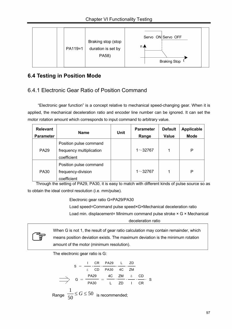
Chapter VI Functionality Testing
97
PA119=1
Braking stop (stop
duration is set by
PA58) Braking Stop
n
t
OFFServo ON Servo
6.4 Testing in Position Mode
6.4.1 Electronic Gear Ratio of Position Command
“Electronic gear function” is a concept relative to mechanical speed-changing gear. When it is
applied, the mechanical deceleration ratio and encoder line number can be ignored. It can set the
motor rotation amount which corresponds to input command to arbitrary value.
Relevant Parameter
Name Unit Parameter
Range Default Value
Applicable Mode
PA29
Position pulse command
frequency multiplication
coefficient
1~32767 1 P
PA30
Position pulse command
frequency-division
coefficient
1~32767 1 P
Through the setting of PA29, PA30, it is easy to match with different kinds of pulse source so as
to obtain the ideal control resolution (i.e. mm/pulse).
Electronic gear ratio G=PA29/PA30
Load speed=Command pulse speed×G×Mechanical deceleration ratio
Load min. displacement= Minimum command pulse stroke × G × Mechanical
deceleration ratio
When G is not 1, the result of gear ratio calculation may contain remainder, which
means position deviation exists. The maximum deviation is the minimum rotation
amount of the motor (minimum resolution).
The electronic gear ratio is G:
Range 50501
≤≤ G is recommended;
S =I CR
ZM
ZD
δ CD
PA29
PA30
L
4C
G =PA29
PA30=
ZM
ZDL
4C
I CR
δ CDS
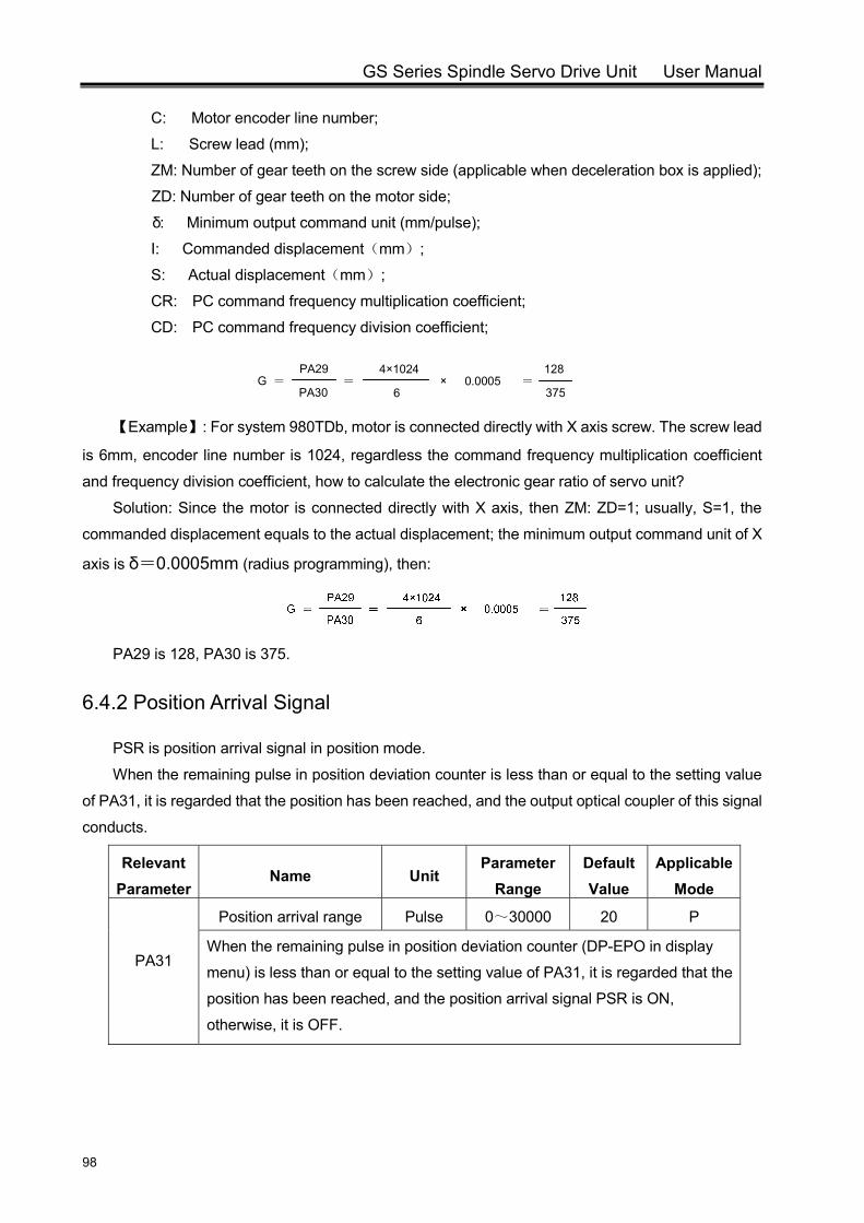
GS Series Spindle Servo Drive Unit User Manual
98
C: Motor encoder line number;
L: Screw lead (mm);
ZM: Number of gear teeth on the screw side (applicable when deceleration box is applied);
ZD: Number of gear teeth on the motor side;
δ: Minimum output command unit (mm/pulse);
I: Commanded displacement(mm);
S: Actual displacement(mm);
CR: PC command frequency multiplication coefficient;
CD: PC command frequency division coefficient;
【Example】: For system 980TDb, motor is connected directly with X axis screw. The screw lead
is 6mm, encoder line number is 1024, regardless the command frequency multiplication coefficient
and frequency division coefficient, how to calculate the electronic gear ratio of servo unit?
Solution: Since the motor is connected directly with X axis, then ZM: ZD=1; usually, S=1, the
commanded displacement equals to the actual displacement; the minimum output command unit of X
axis is δ=0.0005mm (radius programming), then:
PA29 is 128, PA30 is 375.
6.4.2 Position Arrival Signal
PSR is position arrival signal in position mode.
When the remaining pulse in position deviation counter is less than or equal to the setting value
of PA31, it is regarded that the position has been reached, and the output optical coupler of this signal
conducts.
Relevant Parameter
Name Unit Parameter
Range Default Value
Applicable Mode
PA31
Position arrival range Pulse 0~30000 20 P
When the remaining pulse in position deviation counter (DP-EPO in display
menu) is less than or equal to the setting value of PA31, it is regarded that the
position has been reached, and the position arrival signal PSR is ON,
otherwise, it is OFF.
G =PA29
PA30=
6
4×10240.0005
128
375× =
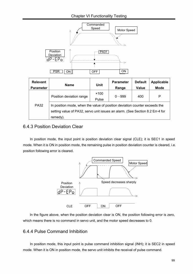
Chapter VI Functionality Testing
99
Relevant Parameter
Name Unit Parameter
Range Default Value
Applicable Mode
PA32
Position deviation range ×100
Pulse 0~999 400 P
In position mode, when the value of position deviation counter exceeds the
setting value of PA32, servo unit issues an alarm. (See Section 8.2 Err-4 for
remedy).
6.4.3 Position Deviation Clear
In position mode, the input point is position deviation clear signal (CLE); it is SEC1 in speed
mode. When it is ON in position mode, the remaining pulse in position deviation counter is cleared, i.e.
position following error is cleared.
Motor SpeedCommanded Speed
Position Deviation
CLE OFF ON OFF
Speed decreases sharply
In the figure above, when the position deviation clear is ON, the position following error is zero,
which means there is no command in servo unit, and the motor speed decreases to 0.
6.4.4 Pulse Command Inhibition
In position mode, this input point is pulse command inhibition signal (INH); it is SEC2 in speed
mode. When it is ON in position mode, the servo unit inhibits the receival of pulse command.
Motor Speed
Commanded Speed
Position Deviation
PSR
PA31
OFFON ON
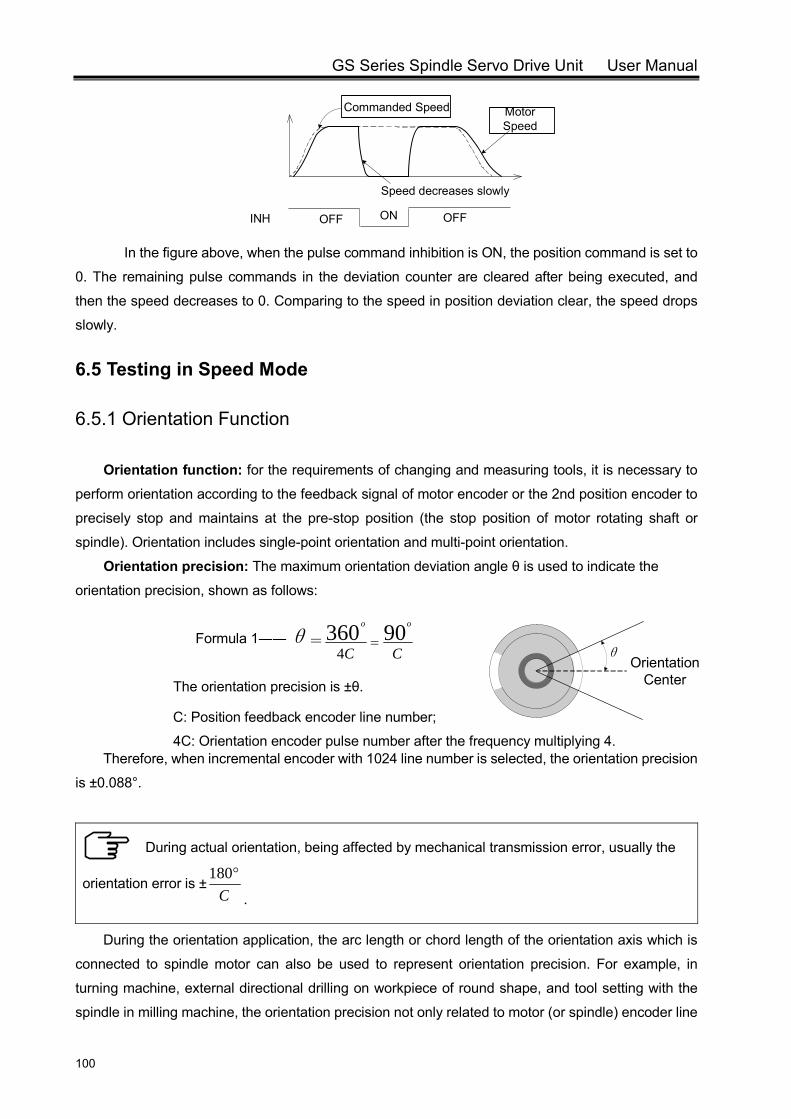
GS Series Spindle Servo Drive Unit User Manual
100
INH OFF ON OFF
Motor Speed
Commanded Speed
Speed decreases slowly
In the figure above, when the pulse command inhibition is ON, the position command is set to
0. The remaining pulse commands in the deviation counter are cleared after being executed, and
then the speed decreases to 0. Comparing to the speed in position deviation clear, the speed drops
slowly.
6.5 Testing in Speed Mode
6.5.1 Orientation Function
Orientation function: for the requirements of changing and measuring tools, it is necessary to
perform orientation according to the feedback signal of motor encoder or the 2nd position encoder to
precisely stop and maintains at the pre-stop position (the stop position of motor rotating shaft or
spindle). Orientation includes single-point orientation and multi-point orientation.
Orientation precision: The maximum orientation deviation angle θ is used to indicate the
orientation precision, shown as follows:
Formula 1――
The orientation precision is ±θ.
C: Position feedback encoder line number;
4C: Orientation encoder pulse number after the frequency multiplying 4. Therefore, when incremental encoder with 1024 line number is selected, the orientation precision
is ±0.088°.
During actual orientation, being affected by mechanical transmission error, usually the
orientation error is ±C°180
.
During the orientation application, the arc length or chord length of the orientation axis which is
connected to spindle motor can also be used to represent orientation precision. For example, in
turning machine, external directional drilling on workpiece of round shape, and tool setting with the
spindle in milling machine, the orientation precision not only related to motor (or spindle) encoder line
θ=CC
oo 903604
= Orientation
Center
θ

Chapter VI Functionality Testing
101
number, but also related to diameter. The formula is shown as follows:
Formula 2――
D: Orientation circle diameter
δ1: Orientation precision represented by chord length
It can also be calculated by:
Formula 3――
δ2: Orientation precision represented by arc length
It is known from formula 2 and 3 that the orientation precision can be described as ±δ1 or±δ2.
Example:
In the right figure, to drill a circular workpiece with 200 diameters, the orientation deviation should
not be larger than 50μm, how much the line number of the encoder should be to meet the
requirement?
Solution: To meet the requirement that the orientation deviation should not be larger than 50μm, the
drive unit should ensure ≤25μm. By formula 3, we can conclude that:
Then: C ≥ 6280; therefore, the encoder line number should be larger than or equal to 6280.
Relevant
Parameter Name Unit
Parameter
Range
Default
Value
Applicable
Mode
PA99 Orientation speed r/min 5~1000 100 S
PA102
Orientation position range Pulse 0~100 2 S
After the orientation function is activated, the position loop control is enabled. The
motor rotates at the orientation speed and stops at the orientation position. However, a
slight vibration may occur to the motor due to close-loop adjustment. If the vibration
difference is within the orientation position range, it is assumed that the orientation is
completed, then signal COIN is output, optical coupler conducts.
If this range is set too small, the orientation completed signal may be unstable due to motor
Orientation Center
Dθδ 1
δ 1
2π D
=δC4
2D sinδ = C
90°1
OFF ONCOIN
OFF ONOSTA
t
r /min
0
100
nPA99 Orientation
Speed PA102 Orientation Position Range
πD≥δ
C4
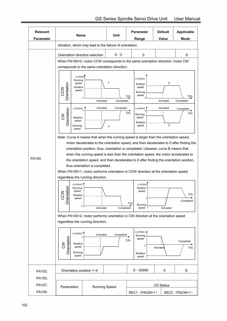
GS Series Spindle Servo Drive Unit User Manual
102
Relevant
Parameter Name Unit
Parameter
Range
Default
Value
Applicable
Mode
vibration, which may lead to the failure of orientation.
PA100
Orientation direction selection 0~2 0 S
When PA100=0, motor CCW corresponds to the same orientation direction; motor CW corresponds to the same orientation direction;
Note: Curve A means that when the running speed is larger than the orientation speed,
motor decelerates to the orientation speed, and then decelerates to 0 after finding the orientation position, thus, orientation is completed. Likewise, curve B means that when the running speed is less than the orientation speed, the motor accelerates to the orientation speed, and then decelerates to 0 after finding the orientation position, thus orientation is completed.
When PA100=1, motor performs orientation in CCW direction at the orientation speed regardless the running direction.
0
0
Running speedRotation speed
n (r/min)
CompletedActivated
n (r/min)Rotation speed
Running speed Activated
CompletedT(S)
T(S)
CC
W
Orie
ntat
ion
When PA100=2, motor performs orientation in CW direction at the orientation speed regardless the running direction.
0
0
Running speed
Rotation speed
n (r/min) CompletedActivated
T(S)
T(S)
n (r/min)Running speed
Rotation speed
Activated
Completed
CW
O
rient
atio
n
PA103,
PA105,
PA107,
PA109.
Orientation position 1~4 0~30000 0 S
Parameters Running Speed I/O Status
SEC1(PA239=1) SEC2(PA239=1)
Running speed
Rotation speed
CompletedActivated
A
0
CC
W
Orie
ntat
ion B
0
0
A B
0
CW
O
rient
atio
n
n (r/min)
n (r/min)
n (r/min)
Rotation speed
Running speed
Activated Completed
Rotation speed
Running speed
Running speed
Rotation speed
Activated CompletedCompletedActivated n (r/min)
T(S) T(S)
T(S)T(S)
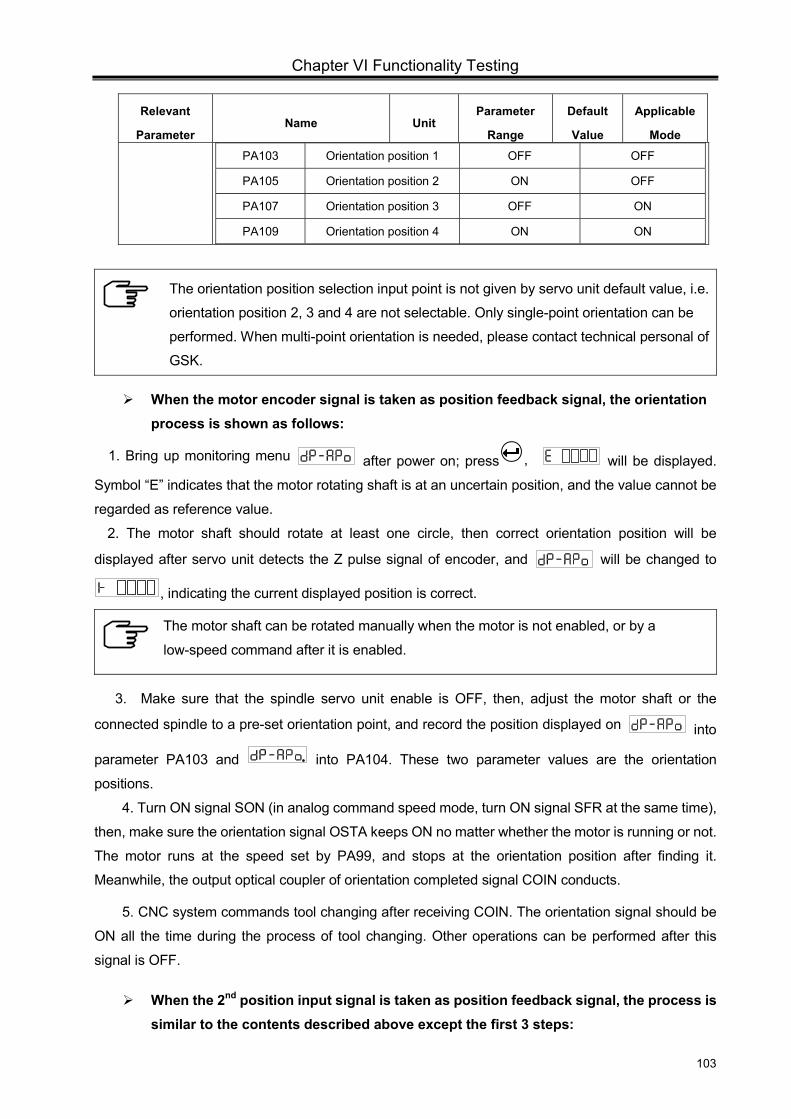
Chapter VI Functionality Testing
103
Relevant
Parameter Name Unit
Parameter
Range
Default
Value
Applicable
Mode
PA103 Orientation position 1 OFF OFF
PA105 Orientation position 2 ON OFF
PA107 Orientation position 3 OFF ON
PA109 Orientation position 4 ON ON
The orientation position selection input point is not given by servo unit default value, i.e.
orientation position 2, 3 and 4 are not selectable. Only single-point orientation can be
performed. When multi-point orientation is needed, please contact technical personal of
GSK.
When the motor encoder signal is taken as position feedback signal, the orientation process is shown as follows:
1. Bring up monitoring menu after power on; press , will be displayed.
Symbol “E” indicates that the motor rotating shaft is at an uncertain position, and the value cannot be
regarded as reference value.
2. The motor shaft should rotate at least one circle, then correct orientation position will be
displayed after servo unit detects the Z pulse signal of encoder, and will be changed to
, indicating the current displayed position is correct.
The motor shaft can be rotated manually when the motor is not enabled, or by a
low-speed command after it is enabled.
3. Make sure that the spindle servo unit enable is OFF, then, adjust the motor shaft or the
connected spindle to a pre-set orientation point, and record the position displayed on into
parameter PA103 and into PA104. These two parameter values are the orientation
positions.
4. Turn ON signal SON (in analog command speed mode, turn ON signal SFR at the same time),
then, make sure the orientation signal OSTA keeps ON no matter whether the motor is running or not.
The motor runs at the speed set by PA99, and stops at the orientation position after finding it.
Meanwhile, the output optical coupler of orientation completed signal COIN conducts.
5. CNC system commands tool changing after receiving COIN. The orientation signal should be
ON all the time during the process of tool changing. Other operations can be performed after this
signal is OFF.
When the 2nd position input signal is taken as position feedback signal, the process is similar to the contents described above except the first 3 steps:
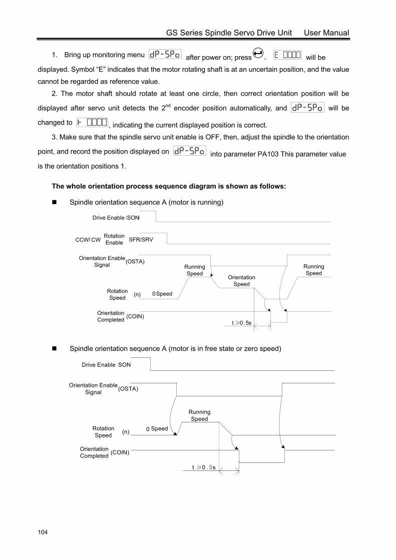
GS Series Spindle Servo Drive Unit User Manual
104
1. Bring up monitoring menu after power on; press , will be
displayed. Symbol “E” indicates that the motor rotating shaft is at an uncertain position, and the value
cannot be regarded as reference value.
2. The motor shaft should rotate at least one circle, then correct orientation position will be
displayed after servo unit detects the 2nd encoder position automatically, and will be
changed to , indicating the current displayed position is correct.
3. Make sure that the spindle servo unit enable is OFF, then, adjust the spindle to the orientation
point, and record the position displayed on into parameter PA103 This parameter value
is the orientation positions 1.
The whole orientation process sequence diagram is shown as follows:
Spindle orientation sequence A (motor is running)
Orientation Speed
t ≥0.5s
Running Speed
0Speed
Running Speed
Drive Enable(SON)
CCW/ CWRotation Enable SFR/SRV
Orientation Enable Signal (OSTA)
Rotation Speed (n)
Orientation Completed (COIN)
Spindle orientation sequence A (motor is in free state or zero speed)
t ≥0 . 5s
0
Running Speed
Speed
Orientation Enable Signal (OSTA)
Rotation Speed (n)
Orientation Completed (COIN)
Drive Enable SON
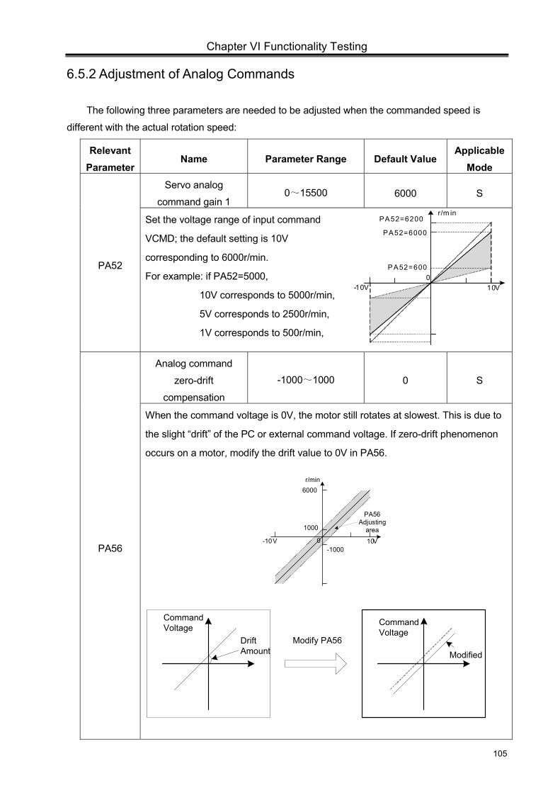
Chapter VI Functionality Testing
105
10V-10V 0
r/min6000
1000
-1000
PA56Adjusting
area
10V-10V0
PA52=6200r/m in
PA52=6000
PA52=600
6.5.2 Adjustment of Analog Commands
The following three parameters are needed to be adjusted when the commanded speed is
different with the actual rotation speed:
Relevant Parameter
Name Parameter Range Default Value Applicable
Mode
PA52
Servo analog
command gain 1 0~15500 6000 S
Set the voltage range of input command
VCMD; the default setting is 10V
corresponding to 6000r/min.
For example: if PA52=5000,
10V corresponds to 5000r/min,
5V corresponds to 2500r/min,
1V corresponds to 500r/min,
PA56
Analog command
zero-drift
compensation
-1000~1000 0 S
When the command voltage is 0V, the motor still rotates at slowest. This is due to
the slight “drift” of the PC or external command voltage. If zero-drift phenomenon
occurs on a motor, modify the drift value to 0V in PA56.
Drift Amount
Command Voltage Command
VoltageModify PA56
Modified
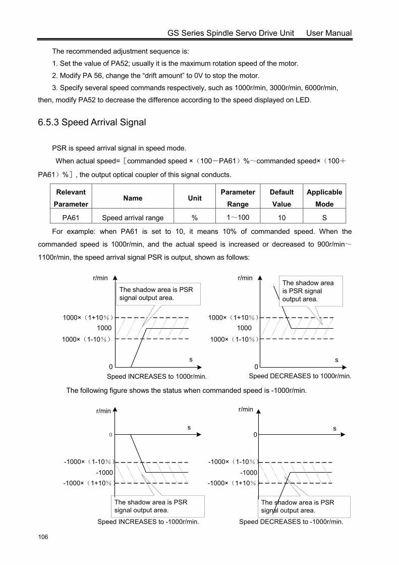
GS Series Spindle Servo Drive Unit User Manual
106
The recommended adjustment sequence is:
1. Set the value of PA52; usually it is the maximum rotation speed of the motor.
2. Modify PA 56, change the “drift amount” to 0V to stop the motor.
3. Specify several speed commands respectively, such as 1000r/min, 3000r/min, 6000r/min,
then, modify PA52 to decrease the difference according to the speed displayed on LED.
6.5.3 Speed Arrival Signal
PSR is speed arrival signal in speed mode.
When actual speed=[commanded speed ×(100-PA61)%~commanded speed×(100+
PA61)%], the output optical coupler of this signal conducts.
Relevant Parameter
Name Unit Parameter
Range Default Value
Applicable Mode
PA61 Speed arrival range % 1~100 10 S
For example: when PA61 is set to 10, it means 10% of commanded speed. When the
commanded speed is 1000r/min, and the actual speed is increased or decreased to 900r/min~
1100r/min, the speed arrival signal PSR is output, shown as follows:
The following figure shows the status when commanded speed is -1000r/min.
1000
1000×(1-10%)
1000×(1+10%)
r/min
1000
1000×(1-10%)
1000×(1+10%)
r/min
0 0Speed INCREASES to 1000r/min. Speed DECREASES to 1000r/min.
The shadow area is PSR signal output area.
The shadow area is PSR signal output area.
s s
The shadow area is PSR signal output area.
The shadow area is PSR signal output area.
-1000-1000×(1-10%)
-1000×(1+10%)
r/min
-1000-1000×(1-10%)
-1000×(1+10%)
r/min
0 0s s
Speed INCREASES to -1000r/min. Speed DECREASES to -1000r/min.
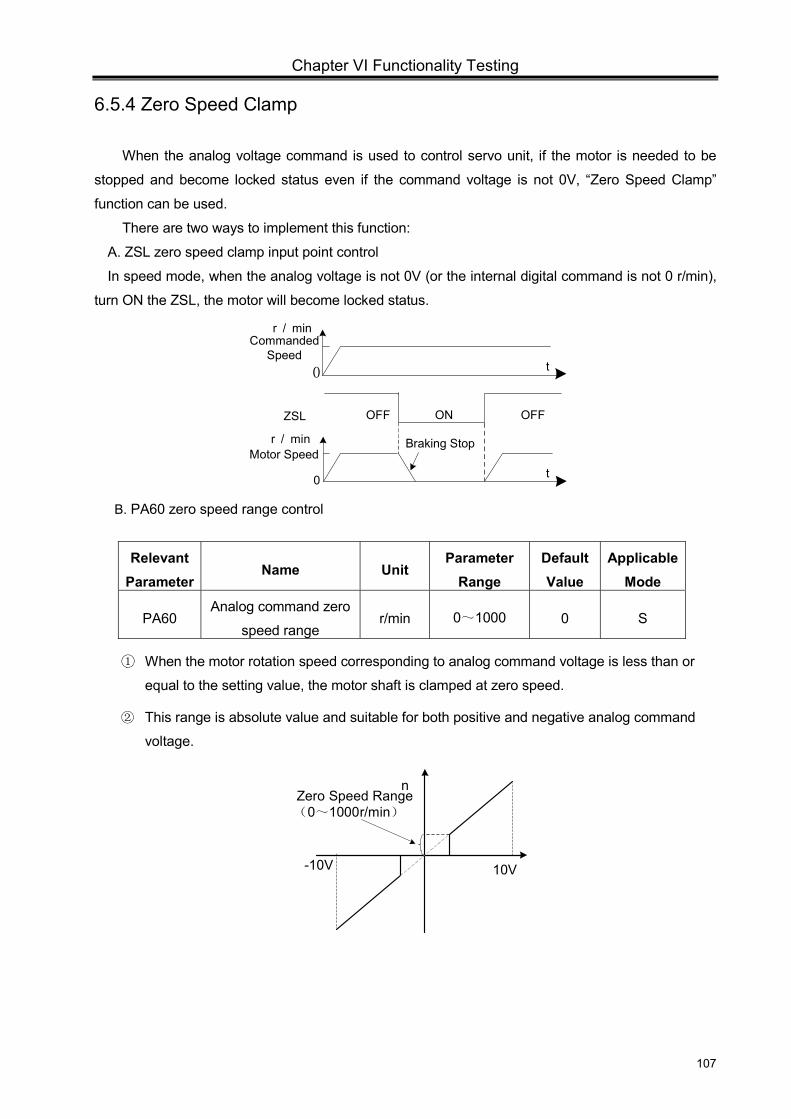
Chapter VI Functionality Testing
107
6.5.4 Zero Speed Clamp
When the analog voltage command is used to control servo unit, if the motor is needed to be
stopped and become locked status even if the command voltage is not 0V, “Zero Speed Clamp”
function can be used.
There are two ways to implement this function:
A. ZSL zero speed clamp input point control
In speed mode, when the analog voltage is not 0V (or the internal digital command is not 0 r/min),
turn ON the ZSL, the motor will become locked status.
Braking Stop
OFF ON
r / min
0 t
OFFZSL
0 t
Commanded Speed
Motor Speed
r / min
B. PA60 zero speed range control
Relevant Parameter
Name Unit Parameter
Range Default Value
Applicable Mode
PA60 Analog command zero
speed range r/min 0~1000 0 S
① When the motor rotation speed corresponding to analog command voltage is less than or
equal to the setting value, the motor shaft is clamped at zero speed.
② This range is absolute value and suitable for both positive and negative analog command
voltage.
n
-10V 10V
Zero Speed Range(0~1000r/min)
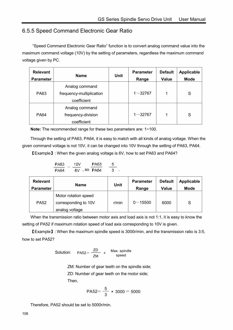
GS Series Spindle Servo Drive Unit User Manual
108
6.5.5 Speed Command Electronic Gear Ratio
“Speed Command Electronic Gear Ratio” function is to convert analog command value into the
maximum command voltage (10V) by the setting of parameters, regardless the maximum command
voltage given by PC.
Relevant Parameter
Name Unit Parameter
Range Default Value
Applicable Mode
PA63
Analog command
frequency-multiplication
coefficient
1~32767 1 S
PA64
Analog command
frequency-division
coefficient
1~32767 1 S
Note: The recommended range for these two parameters are: 1~100.
Through the setting of PA63, PA64, it is easy to match with all kinds of analog voltage. When the
given command voltage is not 10V, it can be changed into 10V through the setting of PA63, PA64.
【Example】: When the given analog voltage is 6V, how to set PA63 and PA64?
, so .
Relevant Parameter
Name Unit Parameter
Range Default Value
Applicable Mode
PA52
Motor rotation speed
corresponding to 10V
analog voltage
r/min 0~15500 6000 S
When the transmission ratio between motor axis and load axis is not 1:1, it is easy to know the
setting of PA52 if maximum rotation speed of load axis corresponding to 10V is given.
【Example】: When the maximum spindle speed is 3000r/min, and the transmission ratio is 3:5,
how to set PA52?
Solution: PA52=ZM
ZD× Max. spindle
speed
ZM: Number of gear teeth on the spindle side;
ZD: Number of gear teeth on the motor side;
Then,
PA52=35
× 3000= 5000
Therefore, PA52 should be set to 5000r/min.

Chapter VI Functionality Testing
109
6.6 Spindle Clamp Interlock Signal (BREF)
Nowadays, to perform drilling and tapping on the external circle of a workpiece, a mechanical
spindle clamp device is installed on spindle to ensure the precision and stability. Since the clamping
force and spindle motor torque is contrary, it is necessary to use servo unit to reduce the motor torque
when spindle is clamped. As for GS Series Spindle Servo Unit, signal BREF can be used to reduce
the motor torque.
Relevant Parameter
Name Unit Parameter
Range Default Value
Applicable Mode
PA150
Spindle clamp interlock delay time ms 0~32000 0 S, P
Set the delay time for reducing motor torque after the spindle is clamped.
Generally, PA150 setting value is 0. PA150 is set to other value only when parameter for
clamping interlock delay time is not set in CNC system. The delay time is used because motor torque
should be reduced after the spindle is completely clamped by mechanical device. Only in this way,
can the spindle offset be avoided during clamping.
The following figure is the clamping sequence controlled by CNC.
Spindle Clamped Signal(CNC→Clamping Device)
Spindle Clamped
Spindle Clamp Interlock Signal(CNC→Spindle
Servo Unit
Spindle Motor Torque
t
t=PA150+CNC delay time
ClampedUnclamped
ONOFF
ONOFF
N
0
After the machining is completed, the spindle clamp device releases. Turn OFF BREF signal,
spindle will enter to position mode, and the spindle remains in the position when being clamped. If
there is a slight drift when the clamping device releases, the spindle position will be back to the
position when spindle is clamped after the BREF turns to OFF.

GS Series Spindle Servo Drive Unit User Manual
110
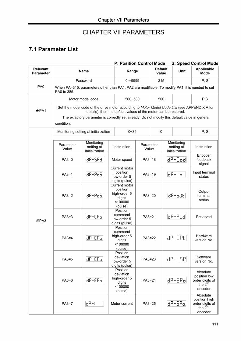
Chapter VII Parameters
111
CHAPTER VII PARAMETERS
7.1 Parameter List
P: Position Control Mode S: Speed Control Mode Relevant
Parameter Name Range Default Value Unit Applicable
Mode
PA0 Password 0~9999 315 P, S
When PA=315, parameters other than PA1, PA2 are modifiable; To modify PA1, it is needed to set PA0 to 385.
PA1
Motor model code 500~530 500 P,S
Set the model code of the drive motor according to Motor Model Code List (see APPENDIX A for details), then the default values of the motor can be restored.
The exfactory parameter is correctly set already. Do not modify this default value in general condition.
PA3※
Monitoring setting at initialization 0~35 0 P, S
Parameter Value
Monitoring setting at
initialization Instruction Parameter
Value
Monitoring setting at
initialization Instruction
PA3=0 Motor speed PA3=18
Encoder feedback
signal
PA3=1 Current motor
position low-order 5
digits (pulse)
PA3=19 Input terminal
status
PA3=2
Current motor position
high-order 5 digits
×100000 (pulse)
PA3=20 Output terminal status
PA3=3 Position
command low-order 5
digits (pulse)
PA3=21 Reserved
PA3=4
Position command
high-order 5 digits
×100000 (pulse)
PA3=22 Hardware
version No.
PA3=5 Position deviation
low-order 5 digits (pulse)
PA3=23 Software
version No.
PA3=6
Position deviation
high-order 5 digits
×100000 (pulse)
PA3=24
Absolute position low
order digits of the 2nd
encoder
PA3=7 Motor current PA3=25
Absolute position high order digits of
the 2nd encoder
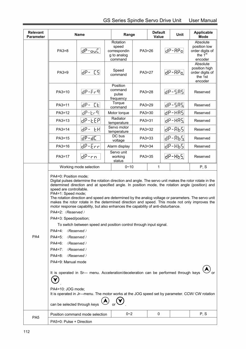
GS Series Spindle Servo Drive Unit User Manual
112
Relevant Parameter Name Range Default
Value Unit Applicable Mode
PA3=8
Rotation speed
corresponding to analog command
PA3=26
Absolute position low
order digits of the 1st
encoder
PA3=9 Speed
command PA3=27
Absolute position high order digits of
the 1st encoder
PA3=10
Position command
pulse frequency
PA3=28 Reserved
PA3=11 Torque
command PA3=29 Reserved
PA3=12 Motor torque PA3=30 Reserved
PA3=13 Radiator
temperature PA3=31 Reserved
PA3=14 Servo motor temperature PA3=32 Reserved
PA3=15 DC bus voltage PA3=33 Reserved
PA3=16 Alarm display PA3=34 Reserved
PA3=17
Servo unit working status
PA3=35 Reserved
PA4
Working mode selection 0~10 1 P, S
PA4=0: Position mode; Digital pulses determine the rotation direction and angle. The servo unit makes the rotor rotate in the determined direction and at specified angle. In position mode, the rotation angle (position) and speed are controllable. PA4=1: Speed mode; The rotation direction and speed are determined by the analog voltage or parameters. The servo unit makes the rotor rotate in the determined direction and speed. This mode not only improves the motor response capability, but also enhances the capability of anti-disturbance. PA4=2:(Reserved) PA4=3: Speed/position;
To switch between speed and position control through input signal. PA4=4: (Reserved) PA4=5: (Reserved) PA4=6: (Reserved) PA4=7: (Reserved) PA4=8: (Reserved) PA4=9: Manual mode
It is operated in Sr— menu. Acceleration/deceleration can be performed through keys or
. PA4=10: JOG mode; It is operated in Jr—menu. The motor works at the JOG speed set by parameter. CCW/ CW rotation
can be selected through keys or .
PA5 Position command mode selection 0~2 0 P, S
PA5=0: Pulse + Direction
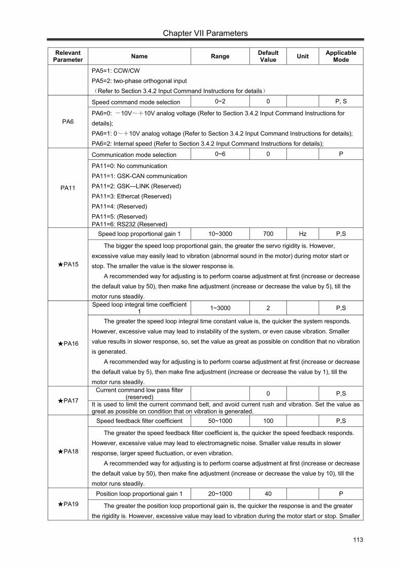
Chapter VII Parameters
113
Relevant Parameter Name Range Default
Value Unit Applicable Mode
PA5=1: CCW/CW PA5=2: two-phase orthogonal input (Refer to Section 3.4.2 Input Command Instructions for details)
PA6
Speed command mode selection 0~2 0 P, S
PA6=0: -10V~+10V analog voltage (Refer to Section 3.4.2 Input Command Instructions for details); PA6=1: 0~+10V analog voltage (Refer to Section 3.4.2 Input Command Instructions for details); PA6=2: Internal speed (Refer to Section 3.4.2 Input Command Instructions for details);
PA11
Communication mode selection 0~6 0 P
PA11=0: No communication PA11=1: GSK-CAN communication PA11=2: GSK—LINK (Reserved) PA11=3: Ethercat (Reserved) PA11=4: (Reserved) PA11=5: (Reserved) PA11=6: RS232 (Reserved)
PA15
Speed loop proportional gain 1 10~3000 700 Hz P,S
The bigger the speed loop proportional gain, the greater the servo rigidity is. However, excessive value may easily lead to vibration (abnormal sound in the motor) during motor start or stop. The smaller the value is the slower response is.
A recommended way for adjusting is to perform coarse adjustment at first (increase or decrease the default value by 50), then make fine adjustment (increase or decrease the value by 5), till the motor runs steadily.
PA16
Speed loop integral time coefficient 1 1~3000 2 P,S
The greater the speed loop integral time constant value is, the quicker the system responds. However, excessive value may lead to instability of the system, or even cause vibration. Smaller value results in slower response, so, set the value as great as possible on condition that no vibration is generated.
A recommended way for adjusting is to perform coarse adjustment at first (increase or decrease the default value by 5), then make fine adjustment (increase or decrease the value by 1), till the motor runs steadily.
PA17
Current command low pass filter (reserved) 0 P,S
It is used to limit the current command belt, and avoid current rush and vibration. Set the value as great as possible on condition that on vibration is generated.
PA18
Speed feedback filter coefficient 50~1000 100 P,S
The greater the speed feedback filter coefficient is, the quicker the speed feedback responds. However, excessive value may lead to electromagnetic noise. Smaller value results in slower response, larger speed fluctuation, or even vibration.
A recommended way for adjusting is to perform coarse adjustment at first (increase or decrease the default value by 50), then make fine adjustment (increase or decrease the value by 10), till the motor runs steadily.
PA19
Position loop proportional gain 1 20~1000 40 P
The greater the position loop proportional gain is, the quicker the response is and the greater the rigidity is. However, excessive value may lead to vibration during the motor start or stop. Smaller
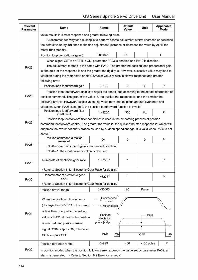
GS Series Spindle Servo Drive Unit User Manual
114
Relevant Parameter Name Range Default
Value Unit Applicable Mode
value results in slower response and greater following error. A recommended way for adjusting is to perform coarse adjustment at first (increase or decrease
the default value by 10), then make fine adjustment (increase or decrease the value by 2), till the motor runs steadily.
PA23
Position loop proportional gain 3 20~1000 36 P
When signal OSTA or PSTI is ON, parameter PA23 is enabled and PA19 is disabled. The adjustment method is the same with PA19. The greater the position loop proportional gain
is, the quicker the response is and the greater the rigidity is. However, excessive value may lead to vibration during the motor start or stop. Smaller value results in slower response and greater following error.
PA25
Position loop feedforward gain 0~100 0 % P
Position loop feedforward gain is to adjust the speed loop according to the speed information of position command. The greater the value is, the quicker the response is, and the smaller the following error is. However, excessive setting value may lead to instantaneous overshoot and vibration. When PA25 is set to 0, the position feedforward function is invalid.
PA26
Position loop feedforward filter coefficient 1~1200 300 Hz P
Position loop feedforward filter coefficient is used in the smoothing process of position command feedforward control. The greater the value is, the quicker the step response is, which will suppress the overshoot and vibration caused by sudden speed change. It is valid when PA25 is not set to 0.
PA28
Position command direction reversed 0~1 0 0 P
PA28=0: remains the original commanded direction; PA28=1: the input pulse direction is reversed.
PA29 Numerate of electronic gear ratio 1~32767 1 P
(Refer to Section 6.4.1 Electronic Gear Ratio for details)
PA30 Denominator of electronic gear
ratio 1~32767 1 P
(Refer to Section 6.4.1 Electronic Gear Ratio for details)
PA31
Position arrival range 0~30000 20 Pulse
Position deviation
PSR
PA31
OFFON ON
Motor speed
Commanded speed1 :
2 :
PA32
Position deviation range 0~999 400 ×100 pulse P
In position model, when the position following error exceeds the value set by parameter PA32, an alarm is generated. (Refer to Section 8.2 Err-4 for remedy)
When the position following error
(displayed as DP-EPO in the menu)
is less than or equal to the setting
value of PA31, it means the position
is reached, and position arrival
signal COIN outputs ON, otherwise,
COIN outputs OFF.
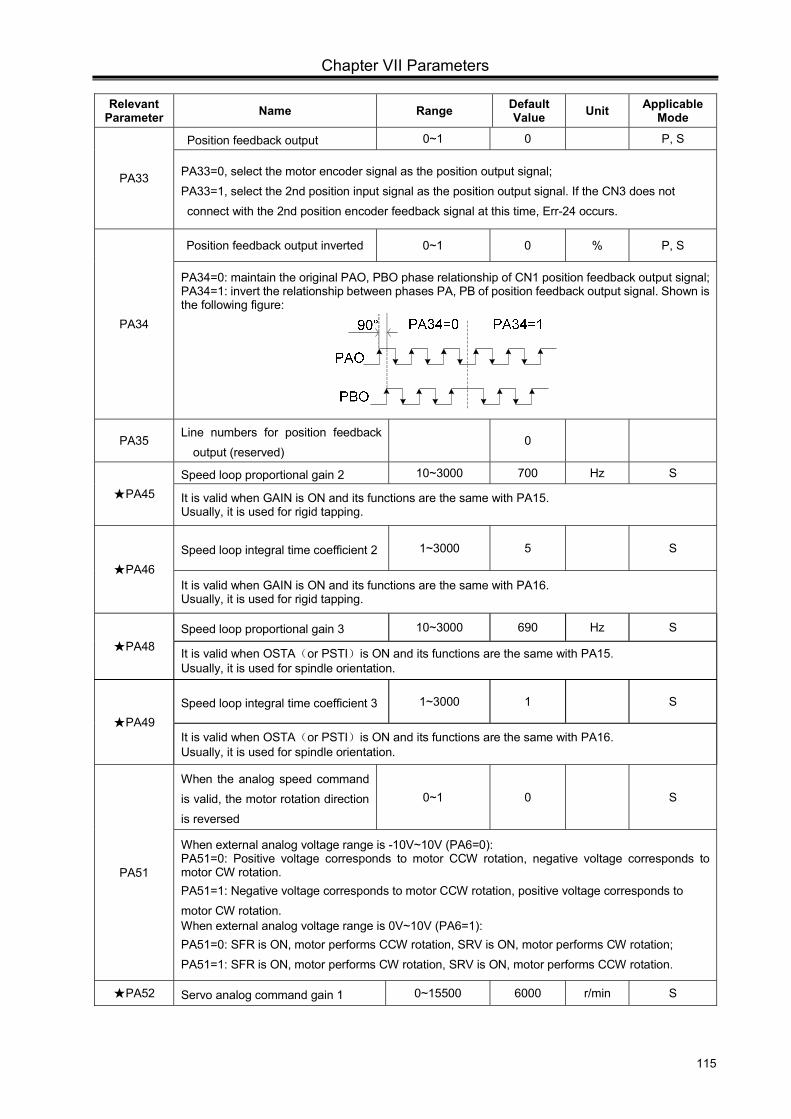
Chapter VII Parameters
115
Relevant Parameter Name Range Default
Value Unit Applicable Mode
PA33
Position feedback output 0~1 0 P, S
PA33=0, select the motor encoder signal as the position output signal; PA33=1, select the 2nd position input signal as the position output signal. If the CN3 does not connect with the 2nd position encoder feedback signal at this time, Err-24 occurs.
PA34
Position feedback output inverted 0~1 0 % P, S
PA34=0: maintain the original PAO, PBO phase relationship of CN1 position feedback output signal; PA34=1: invert the relationship between phases PA, PB of position feedback output signal. Shown is the following figure:
PA35 Line numbers for position feedback
output (reserved) 0
PA45 Speed loop proportional gain 2 10~3000 700 Hz S
It is valid when GAIN is ON and its functions are the same with PA15. Usually, it is used for rigid tapping.
PA46 Speed loop integral time coefficient 2 1~3000 5 S
It is valid when GAIN is ON and its functions are the same with PA16. Usually, it is used for rigid tapping.
PA48 Speed loop proportional gain 3 10~3000 690 Hz S
It is valid when OSTA(or PSTI)is ON and its functions are the same with PA15. Usually, it is used for spindle orientation.
PA49 Speed loop integral time coefficient 3 1~3000 1 S
It is valid when OSTA(or PSTI)is ON and its functions are the same with PA16. Usually, it is used for spindle orientation.
PA51
When the analog speed command is valid, the motor rotation direction is reversed
0~1 0 S
When external analog voltage range is -10V~10V (PA6=0): PA51=0: Positive voltage corresponds to motor CCW rotation, negative voltage corresponds to motor CW rotation. PA51=1: Negative voltage corresponds to motor CCW rotation, positive voltage corresponds to motor CW rotation. When external analog voltage range is 0V~10V (PA6=1): PA51=0: SFR is ON, motor performs CCW rotation, SRV is ON, motor performs CW rotation; PA51=1: SFR is ON, motor performs CW rotation, SRV is ON, motor performs CCW rotation.
PA52 Servo analog command gain 1 0~15500 6000 r/min S
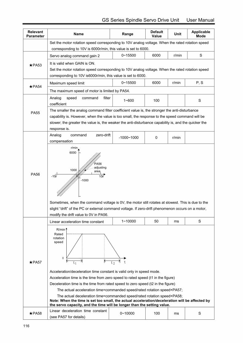
GS Series Spindle Servo Drive Unit User Manual
116
Relevant Parameter Name Range Default
Value Unit Applicable Mode
Set the motor rotation speed corresponding to 10V analog voltage. When the rated rotation speed corresponding to 10V is 6000r/min, this value is set to 6000.
PA53
Servo analog command gain 2 0~15500 6000 r/min S
It is valid when GAIN is ON. Set the motor rotation speed corresponding to 10V analog voltage. When the rated rotation speed corresponding to 10V is6000r/min, this value is set to 6000.
PA54 Maximum speed limit 0~15500 6000 r/min P, S
The maximum speed of motor is limited by PA54.
PA55
Analog speed command filter coefficient
1~600 100 S
The smaller the analog command filter coefficient value is, the stronger the anti-disturbance capability is. However, when the value is too small, the response to the speed command will be slower; the greater the value is, the weaker the anti-disturbance capability is, and the quicker the response is.
PA56
Analog command zero-drift compensation
-1000~1000 0 r/min
10V-10V 0
r/min6000
1000
-1000
PA56 adjusting area
Sometimes, when the command voltage is 0V, the motor still rotates at slowest. This is due to the slight “drift” of the PC or external command voltage. If zero-drift phenomenon occurs on a motor, modify the drift value to 0V in PA56.
PA57
Linear acceleration time constant 1~10000 50 ms S
Acceleration/deceleration time constant is valid only in speed mode. Acceleration time is the time from zero speed to rated speed (t1 in the figure) Deceleration time is the time from rated speed to zero speed (t2 in the figure) The actual acceleration time=commanded speed/rated rotation speed×PA57;
The actual deceleration time=commanded speed/rated rotation speed×PA58; Note: When the time is set too small, the actual acceleration/deceleration will be affected by the servo capacity, and the time will be longer than the setting value.
PA58 Linear deceleration time constant (see PA57 for details)
0~10000 100 ms S
R/min
t
Rated rotation speed
t2t10
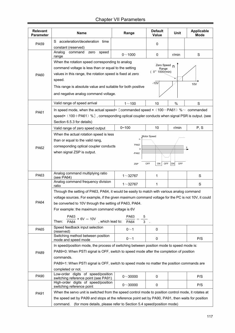
Chapter VII Parameters
117
Relevant Parameter Name Range Default
Value Unit Applicable Mode
PA59 S acceleration/deceleration time constant (reserved)
0
PA60
Analog command zero speed range 0~1000 0 r/min S
When the rotation speed corresponding to analog command voltage is less than or equal to the setting values in this range, the rotation speed is fixed at zero speed.
This range is absolute value and suitable for both positive
and negative analog command voltage.
PA61
Valid range of speed arrival 1~100 10 % S
In speed mode, when the actual speed=[commanded speed ×(100-PA61)%~ commanded speed×(100+PA61)%], corresponding optical coupler conducts when signal PSR is output. (see Section 6.5.3 for details)
PA62
Valid range of zero speed output 0~100 10 r/min P, S
When the actual rotation speed is less than or equal to the valid rang, corresponding optical coupler conducts when signal ZSP is output.
PA63 Analog command multiplying ratio (see PA64) 1~32767 1 S
PA64
Analog command frequency division ratio 1~32767 1 S
Through the setting of PA63, PA64, it would be easily to match with various analog command voltage sources. For example, if the given maximum command voltage for the PC is not 10V, it could be converted to 10V through the setting of PA63, PA64. For example: the maximum command voltage is 6V
Then: PA63PA64
10V6V× = , which lead to: =PA63PA64
53 .
PA65 Speed feedback input selection (reserved) 0~1 0
PA89
Switching method between position mode and speed mode 0~1 0 P/S
In speed/position mode, the process of switching between position mode to speed mode is: PA89=0: When PSTI signal is OFF, switch to speed mode after the completion of position commands. PA89=1: When PSTI signal is OFF, switch to speed mode no matter the position commands are completed or not.
PA90 Low-order digits of speed/position switching reference point (see PA91) 0~30000 0 P/S
PA91
High-order digits of speed/position switching reference point 0~30000 0 P/S
When the servo unit is switched from the speed control mode to position control mode, it rotates at the speed set by PA99 and stops at the reference point set by PA90, PA91, then waits for position command. (for more details, please refer to Section 5.4 speed/position mode)
0
PA62
-PA62
s
n
ZSP OFF ON OFF ON OFF
Motor Speed
n
-10V 10V
Zero Speed Range
( 0~ 1000r/min)
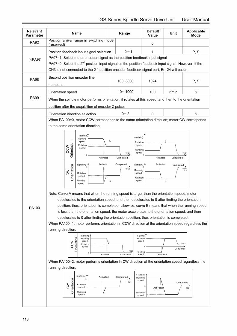
GS Series Spindle Servo Drive Unit User Manual
118
Relevant Parameter Name Range Default
Value Unit Applicable Mode
PA92 Position arrival range in switching mode (reserved) 0
PA97※
Position feedback input signal selection 0~1 1 P, S PA97=1: Select motor encoder signal as the position feedback input signal PA97=0: Select the 2nd position input signal as the position feedback input signal. However, if the CN3 is not connected to the 2nd position encoder feedback signal port, Err-24 will occur.
PA98 Second position encoder line
numbers 100~8000 1024 P, S
PA99 Orientation speed 10~1000 100 r/min S
When the spindle motor performs orientation, it rotates at this speed, and then to the orientation
position after the acquisition of encoder Z pulse.
PA100
Orientation direction selection 0~2 0 S When PA100=0, motor CCW corresponds to the same orientation direction; motor CW corresponds to the same orientation direction;
Note: Curve A means that when the running speed is larger than the orientation speed, motor
decelerates to the orientation speed, and then decelerates to 0 after finding the orientation position, thus, orientation is completed. Likewise, curve B means that when the running speed is less than the orientation speed, the motor accelerates to the orientation speed, and then decelerates to 0 after finding the orientation position, thus orientation is completed.
When PA100=1, motor performs orientation in CCW direction at the orientation speed regardless the running direction.
0
0
Running speed
Rotation speed
n (r/min)
CompletedActivated
n (r/min)Rotation speed
Running speed Activated
CompletedT(S)
T(S)
CC
W
Orie
ntat
ion
When PA100=2, motor performs orientation in CW direction at the orientation speed regardless the running direction.
0
0
Running speed
Rotation speed
n (r/m in) CompletedActivated
T(S)
T(S)
n (r/min)Running
speed
Rotation speed
Activated
Completed
CW
O
rient
atio
n
Running speed
Rotation speed
CompletedActivated
A
0
CC
W
Orie
ntat
ion B
0
0
A B
0
CW
O
rient
atio
n
n (r/min)
n (r/min)
n (r/min)
Rotation speed
Running speed
Activated Completed
Rotation speed
Running speed
Running speed
Rotation speed
Activated CompletedCompletedActivated n (r/min)
T(S) T(S)
T(S)T(S)
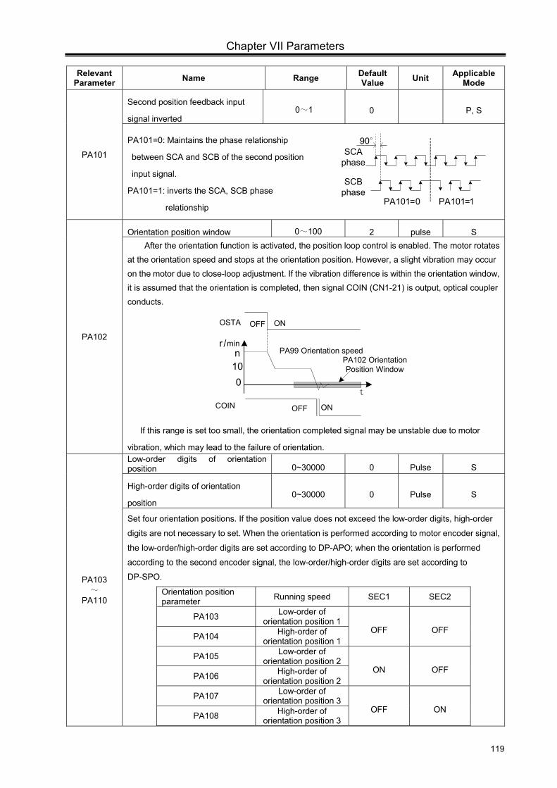
Chapter VII Parameters
119
Relevant Parameter Name Range Default
Value Unit Applicable Mode
PA101
Second position feedback input
signal inverted 0~1 0 P, S
PA101=0: Maintains the phase relationship
between SCA and SCB of the second position
input signal.
PA101=1: inverts the SCA, SCB phase
relationship
PA102
Orientation position window 0~100 2 pulse S After the orientation function is activated, the position loop control is enabled. The motor rotates at the orientation speed and stops at the orientation position. However, a slight vibration may occur on the motor due to close-loop adjustment. If the vibration difference is within the orientation window, it is assumed that the orientation is completed, then signal COIN (CN1-21) is output, optical coupler conducts.
OFF ONCOIN
OFF ONOSTA
t
r /min
010n PA99 Orientation speed
PA102 Orientation Position Window
If this range is set too small, the orientation completed signal may be unstable due to motor
vibration, which may lead to the failure of orientation.
PA103 ~
PA110
Low-order digits of orientation position 0~30000 0 Pulse S
High-order digits of orientation
position 0~30000 0 Pulse S
Set four orientation positions. If the position value does not exceed the low-order digits, high-order
digits are not necessary to set. When the orientation is performed according to motor encoder signal,
the low-order/high-order digits are set according to DP-APO; when the orientation is performed
according to the second encoder signal, the low-order/high-order digits are set according to
DP-SPO.
Orientation position parameter Running speed SEC1 SEC2
PA103 Low-order of orientation position 1
OFF OFF PA104 High-order of
orientation position 1
PA105 Low-order of orientation position 2
ON OFF PA106 High-order of
orientation position 2
PA107 Low-order of orientation position 3
OFF ON PA108 High-order of
orientation position 3
SCA phase
PA101=0 PA101=1
90°
SCB phase
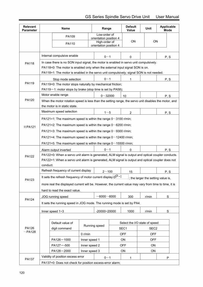
GS Series Spindle Servo Drive Unit User Manual
120
Relevant Parameter Name Range Default
Value Unit Applicable Mode
PA109 Low-order of orientation position 4
ON ON PA110 High-order of
orientation position 4
PA118
Internal compulsive enable 0~1 0 P, S
In case there is no SON input signal, the motor is enabled in servo unit compulsively. PA118=0: The motor is enabled only when the external input signal SON is on. PA118=1: The motor is enabled in the servo unit compulsively; signal SON is not needed.
PA119 Stop mode selection 0~1 1 P, S
PA119=0: The motor stops naturally by mechanical friction; PA119=1: motor stops by brake (stop time is set by PA58);
PA120
Motor enable range 0~32000 10 P, S When the motor rotation speed is less than the setting range, the servo unit disables the motor, and the motor is in static state.
PA121※
Maximum speed selection 1~5 2 P, S
PA121=1: The maximum speed is within the range 0~3100 r/min;
PA121=2: The maximum speed is within the range 0~6200 r/min;
PA121=3: The maximum speed is within the range 0~9300 r/min;
PA121=4: The maximum speed is within the range 0~12400 r/min;
PA121=5: The maximum speed is within the range 0~15500 r/min;
PA122
Alarm output inverted 0~1 0 P, S PA122=0: When a servo unit alarm is generated, ALM signal is output and optical coupler conducts.PA122=1: When a servo unit alarm is generated, ALM signal is output and optical coupler does not conduct.
PA123
Refresh frequency of current display 2~100 15 P, S
It sets the refresh frequency of motor current display ; the larger the setting value is,
more real the displayed current will be. However, the current value may vary from time to time, it is
hard to read the exact value.
PA124 JOG running speed -6000~6000 300 r/min S
It sets the running speed in JOG mode. The running mode is set by PA4.
PA126 ~PA128
Inner speed 1~3 -20000~20000 1000 r/min S
Default value of
digit command Running speed
Select the I/O state of speed
SEC1 SEC2
0 r/min OFF OFF
PA126=1000 Inner speed 1 ON OFF
PA127=-500 Inner speed 2 OFF ON
PA128=2000 Inner speed 3 ON ON
PA137 Validity of position excess error 0~1 1 P PA137=0: Does not check for position excess-error alarm;
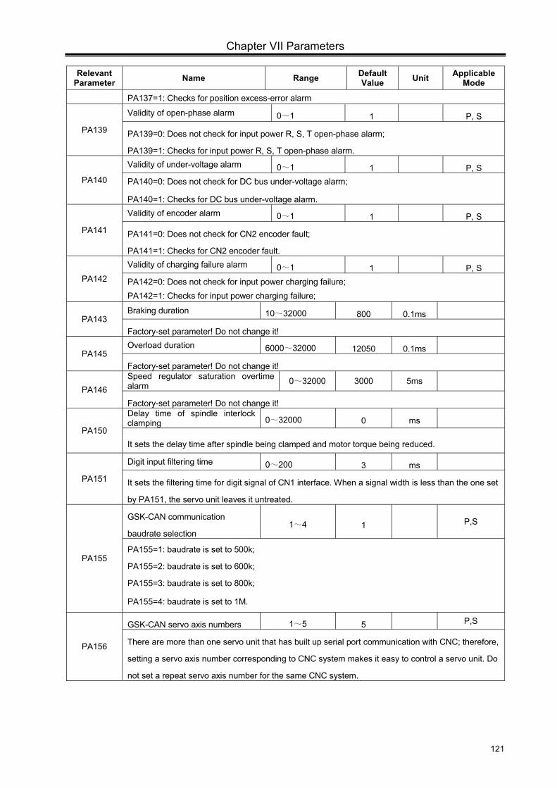
Chapter VII Parameters
121
Relevant Parameter Name Range Default
Value Unit Applicable Mode
PA137=1: Checks for position excess-error alarm
PA139
Validity of open-phase alarm 0~1 1 P, S
PA139=0: Does not check for input power R, S, T open-phase alarm;
PA139=1: Checks for input power R, S, T open-phase alarm.
PA140
Validity of under-voltage alarm 0~1 1 P, S PA140=0: Does not check for DC bus under-voltage alarm;
PA140=1: Checks for DC bus under-voltage alarm.
PA141
Validity of encoder alarm 0~1 1 P, S
PA141=0: Does not check for CN2 encoder fault;
PA141=1: Checks for CN2 encoder fault.
PA142
Validity of charging failure alarm 0~1 1 P, S PA142=0: Does not check for input power charging failure; PA142=1: Checks for input power charging failure;
PA143 Braking duration 10~32000 800 0.1ms
Factory-set parameter! Do not change it!
PA145 Overload duration 6000~32000 12050 0.1ms
Factory-set parameter! Do not change it!
PA146 Speed regulator saturation overtime alarm 0~32000 3000 5ms
Factory-set parameter! Do not change it!
PA150
Delay time of spindle interlock clamping 0~32000 0 ms
It sets the delay time after spindle being clamped and motor torque being reduced.
PA151
Digit input filtering time 0~200 3 ms
It sets the filtering time for digit signal of CN1 interface. When a signal width is less than the one set
by PA151, the servo unit leaves it untreated.
PA155
GSK-CAN communication
baudrate selection 1~4 1 P,S
PA155=1: baudrate is set to 500k;
PA155=2: baudrate is set to 600k;
PA155=3: baudrate is set to 800k;
PA155=4: baudrate is set to 1M.
PA156
GSK-CAN servo axis numbers 1~5 5 P,S
There are more than one servo unit that has built up serial port communication with CNC; therefore,
setting a servo axis number corresponding to CNC system makes it easy to control a servo unit. Do
not set a repeat servo axis number for the same CNC system.

GS Series Spindle Servo Drive Unit User Manual
122
The default setting of parameters marked with ‘ ’ is related to the motor model;
therefore, the default value varies with motors.
Parameters marked with ‘ ’ should be saved after modification and only be valid after ※
power-on.
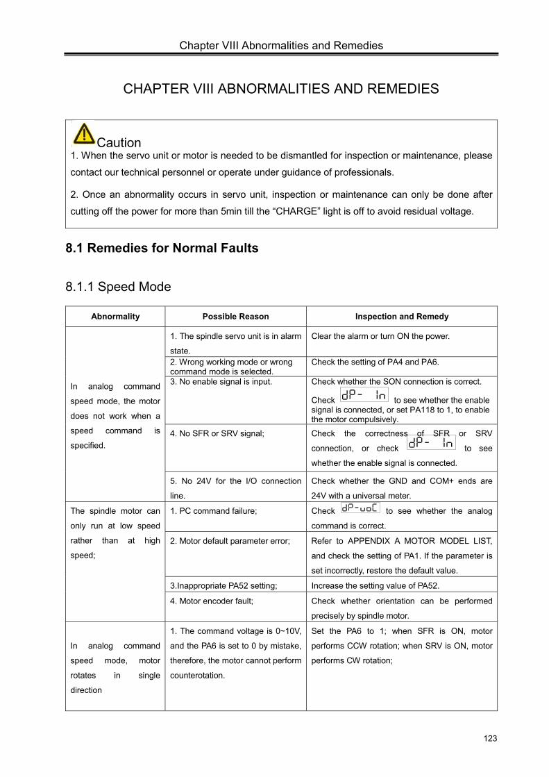
Chapter VIII Abnormalities and Remedies
123
CHAPTER VIII ABNORMALITIES AND REMEDIES
Caution 1. When the servo unit or motor is needed to be dismantled for inspection or maintenance, please
contact our technical personnel or operate under guidance of professionals.
2. Once an abnormality occurs in servo unit, inspection or maintenance can only be done after
cutting off the power for more than 5min till the “CHARGE” light is off to avoid residual voltage.
8.1 Remedies for Normal Faults
8.1.1 Speed Mode
Abnormality Possible Reason Inspection and Remedy
In analog command
speed mode, the motor
does not work when a
speed command is
specified.
1. The spindle servo unit is in alarm
state.
Clear the alarm or turn ON the power.
2. Wrong working mode or wrong command mode is selected.
Check the setting of PA4 and PA6.
3. No enable signal is input. Check whether the SON connection is correct.
Check to see whether the enable signal is connected, or set PA118 to 1, to enable the motor compulsively.
4. No SFR or SRV signal; Check the correctness of SFR or SRV
connection, or check to see
whether the enable signal is connected.
5. No 24V for the I/O connection
line.
Check whether the GND and COM+ ends are
24V with a universal meter.
The spindle motor can
only run at low speed
rather than at high
speed;
1. PC command failure; Check to see whether the analog
command is correct.
2. Motor default parameter error; Refer to APPENDIX A MOTOR MODEL LIST,
and check the setting of PA1. If the parameter is
set incorrectly, restore the default value.
3.Inappropriate PA52 setting; Increase the setting value of PA52.
4. Motor encoder fault; Check whether orientation can be performed
precisely by spindle motor.
In analog command
speed mode, motor
rotates in single
direction
1. The command voltage is 0~10V,
and the PA6 is set to 0 by mistake,
therefore, the motor cannot perform
counterotation.
Set the PA6 to 1; when SFR is ON, motor
performs CCW rotation; when SRV is ON, motor
performs CW rotation;
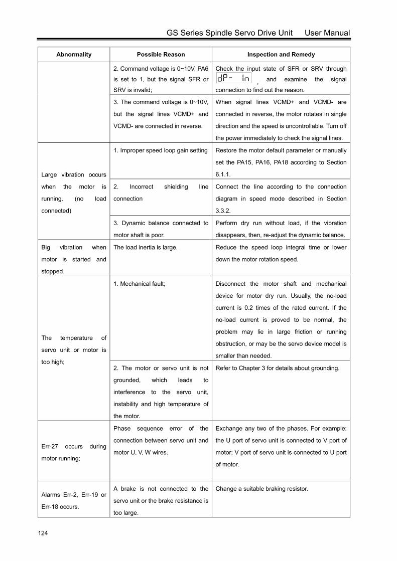
GS Series Spindle Servo Drive Unit User Manual
124
Abnormality Possible Reason Inspection and Remedy
2. Command voltage is 0~10V, PA6
is set to 1, but the signal SFR or
SRV is invalid;
Check the input state of SFR or SRV through
, and examine the signal
connection to find out the reason.
3. The command voltage is 0~10V,
but the signal lines VCMD+ and
VCMD- are connected in reverse.
When signal lines VCMD+ and VCMD- are
connected in reverse, the motor rotates in single
direction and the speed is uncontrollable. Turn off
the power immediately to check the signal lines.
Large vibration occurs
when the motor is
running. (no load
connected)
1. Improper speed loop gain setting Restore the motor default parameter or manually
set the PA15, PA16, PA18 according to Section
6.1.1.
2. Incorrect shielding line
connection
Connect the line according to the connection
diagram in speed mode described in Section
3.3.2.
3. Dynamic balance connected to
motor shaft is poor.
Perform dry run without load, if the vibration
disappears, then, re-adjust the dynamic balance.
Big vibration when
motor is started and
stopped.
The load inertia is large. Reduce the speed loop integral time or lower
down the motor rotation speed.
The temperature of
servo unit or motor is
too high;
1. Mechanical fault; Disconnect the motor shaft and mechanical
device for motor dry run. Usually, the no-load
current is 0.2 times of the rated current. If the
no-load current is proved to be normal, the
problem may lie in large friction or running
obstruction, or may be the servo device model is
smaller than needed.
2. The motor or servo unit is not
grounded, which leads to
interference to the servo unit,
instability and high temperature of
the motor.
Refer to Chapter 3 for details about grounding.
Err-27 occurs during
motor running;
Phase sequence error of the
connection between servo unit and
motor U, V, W wires.
Exchange any two of the phases. For example:
the U port of servo unit is connected to V port of
motor; V port of servo unit is connected to U port
of motor.
Alarms Err-2, Err-19 or
Err-18 occurs.
A brake is not connected to the
servo unit or the brake resistance is
too large.
Change a suitable braking resistor.
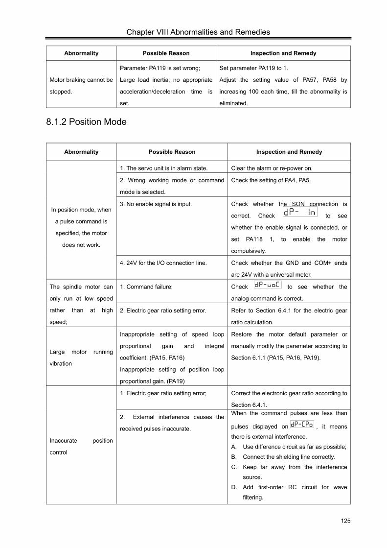
Chapter VIII Abnormalities and Remedies
125
Abnormality Possible Reason Inspection and Remedy
Motor braking cannot be
stopped.
Parameter PA119 is set wrong;
Large load inertia; no appropriate
acceleration/deceleration time is
set.
Set parameter PA119 to 1.
Adjust the setting value of PA57, PA58 by
increasing 100 each time, till the abnormality is
eliminated.
8.1.2 Position Mode
Abnormality Possible Reason Inspection and Remedy
In position mode, when
a pulse command is
specified, the motor
does not work.
1. The servo unit is in alarm state. Clear the alarm or re-power on.
2. Wrong working mode or command
mode is selected.
Check the setting of PA4, PA5.
3. No enable signal is input. Check whether the SON connection is
correct. Check to see
whether the enable signal is connected, or
set PA118 1, to enable the motor
compulsively.
4. 24V for the I/O connection line. Check whether the GND and COM+ ends
are 24V with a universal meter.
The spindle motor can
only run at low speed
rather than at high
speed;
1. Command failure; Check to see whether the
analog command is correct.
2. Electric gear ratio setting error. Refer to Section 6.4.1 for the electric gear
ratio calculation.
Large motor running
vibration
Inappropriate setting of speed loop
proportional gain and integral
coefficient. (PA15, PA16)
Inappropriate setting of position loop
proportional gain. (PA19)
Restore the motor default parameter or
manually modify the parameter according to
Section 6.1.1 (PA15, PA16, PA19).
Inaccurate position
control
1. Electric gear ratio setting error; Correct the electronic gear ratio according to
Section 6.4.1.
2. External interference causes the
received pulses inaccurate.
When the command pulses are less than
pulses displayed on , it means
there is external interference.
A. Use difference circuit as far as possible;
B. Connect the shielding line correctly.
C. Keep far away from the interference
source.
D. Add first-order RC circuit for wave
filtering.
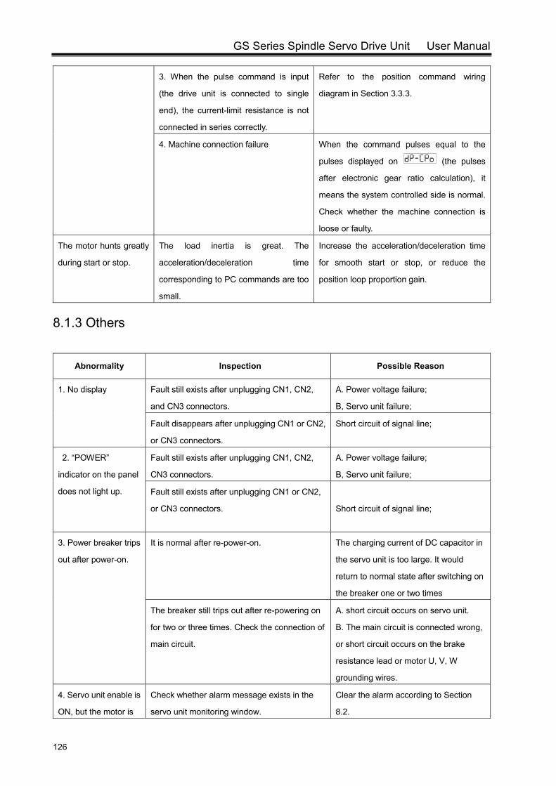
GS Series Spindle Servo Drive Unit User Manual
126
3. When the pulse command is input
(the drive unit is connected to single
end), the current-limit resistance is not
connected in series correctly.
Refer to the position command wiring
diagram in Section 3.3.3.
4. Machine connection failure When the command pulses equal to the
pulses displayed on (the pulses
after electronic gear ratio calculation), it
means the system controlled side is normal.
Check whether the machine connection is
loose or faulty.
The motor hunts greatly
during start or stop.
The load inertia is great. The
acceleration/deceleration time
corresponding to PC commands are too
small.
Increase the acceleration/deceleration time
for smooth start or stop, or reduce the
position loop proportion gain.
8.1.3 Others
Abnormality Inspection Possible Reason
1. No display Fault still exists after unplugging CN1, CN2,
and CN3 connectors.
A. Power voltage failure;
B, Servo unit failure;
Fault disappears after unplugging CN1 or CN2,
or CN3 connectors.
Short circuit of signal line;
2. “POWER”
indicator on the panel
does not light up.
Fault still exists after unplugging CN1, CN2,
CN3 connectors.
A. Power voltage failure;
B, Servo unit failure;
Fault still exists after unplugging CN1 or CN2,
or CN3 connectors.
Short circuit of signal line;
3. Power breaker trips
out after power-on.
It is normal after re-power-on. The charging current of DC capacitor in
the servo unit is too large. It would
return to normal state after switching on
the breaker one or two times
The breaker still trips out after re-powering on
for two or three times. Check the connection of
main circuit.
A. short circuit occurs on servo unit.
B. The main circuit is connected wrong,
or short circuit occurs on the brake
resistance lead or motor U, V, W
grounding wires.
4. Servo unit enable is
ON, but the motor is
Check whether alarm message exists in the
servo unit monitoring window.
Clear the alarm according to Section
8.2.

Chapter VIII Abnormalities and Remedies
127
Abnormality Inspection Possible Reason
in free state and not
energized.
Check to see whether the SON
signal is connected or whether the SFR (or
SRV) is connected in analog command speed
mode.
I/O signal line connection error;
5. Servo unit enable is
ON, and the motor
has performed
excitation, but the
motor does not work.
1. Check ; the current exceeds
the rated one, and orientation can be
performed accurately after load-off.
The fault may caused by short circuit or
mechanical stall. An alarm will be
generated. Refer Section 8.2 for details.
2. Check ; the current exceeds
the rated one, and orientation CANNOT be
performed accurately after load-off.
Motor encoder failure.
3. Check ;, the current does not
exceed the rate one.
A. Wrong working mode is selected
(refer to chapter 5 for correct setting);
B. The input command is not received
(refer to chapter 5 for the correct
command signal lines);
C. The parameter PA180 is set too
small;
No. Name Range Unit Default
Value
PA180 Maximum drive capacity 0~300 % 300
1. The setting value is represented by the percentage of motor rated
current. For example, value 300 means the overload current is 3 times
of the rated current.
2. This parameter value limits the maximum output torque of the
motor.
4. Check , no current is found. Servo unit failure;
6. The motor is
running unstably and
the speed fluctuation
is large.
The motor is running stably in manual mode. Strong interference occurs to input
command. Keep the motor far away
from the interference source and
properly lay the shielding lines.
In manual mode, the motor is running unstably,
and the speed fluctuation is large.
A. Motor encoder fault; change the
motor.
B. Parameter setting error. Re-set the
motor default parameter, especially the
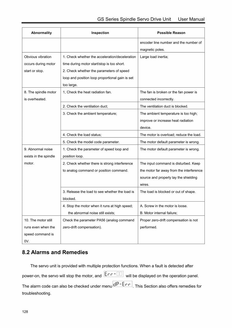
GS Series Spindle Servo Drive Unit User Manual
128
Abnormality Inspection Possible Reason
encoder line number and the number of
magnetic poles.
Obvious vibration
occurs during motor
start or stop.
1. Check whether the acceleration/deceleration
time during motor start/stop is too short.
2. Check whether the parameters of speed
loop and position loop proportional gain is set
too large.
Large load inertia;
8. The spindle motor
is overheated.
1, Check the heat radiation fan. The fan is broken or the fan power is
connected incorrectly.
2. Check the ventilation duct; The ventilation duct is blocked.
3. Check the ambient temperature; The ambient temperature is too high;
improve or increase heat radiation
device.
4. Check the load status; The motor is overload; reduce the load.
5. Check the model code parameter. The motor default parameter is wrong.
9. Abnormal noise
exists in the spindle
motor.
1. Check the parameter of speed loop and
position loop.
The motor default parameter is wrong.
2. Check whether there is strong interference
to analog command or position command.
The input command is disturbed. Keep
the motor far away from the interference
source and properly lay the shielding
wires.
3. Release the load to see whether the load is
blocked.
The load is blocked or out of shape.
4. Stop the motor when it runs at high speed;
the abnormal noise still exists;
A. Screw in the motor is loose.
B. Motor internal failure;
10. The motor still
runs even when the
speed command is
0V.
Check the parameter PA56 (analog command
zero-drift compensation).
Proper zero-drift compensation is not
performed.
8.2 Alarms and Remedies
The servo unit is provided with multiple protection functions. When a fault is detected after
power-on, the servo will stop the motor, and will be displayed on the operation panel.
The alarm code can also be checked under menu . This Section also offers remedies for
troubleshooting.
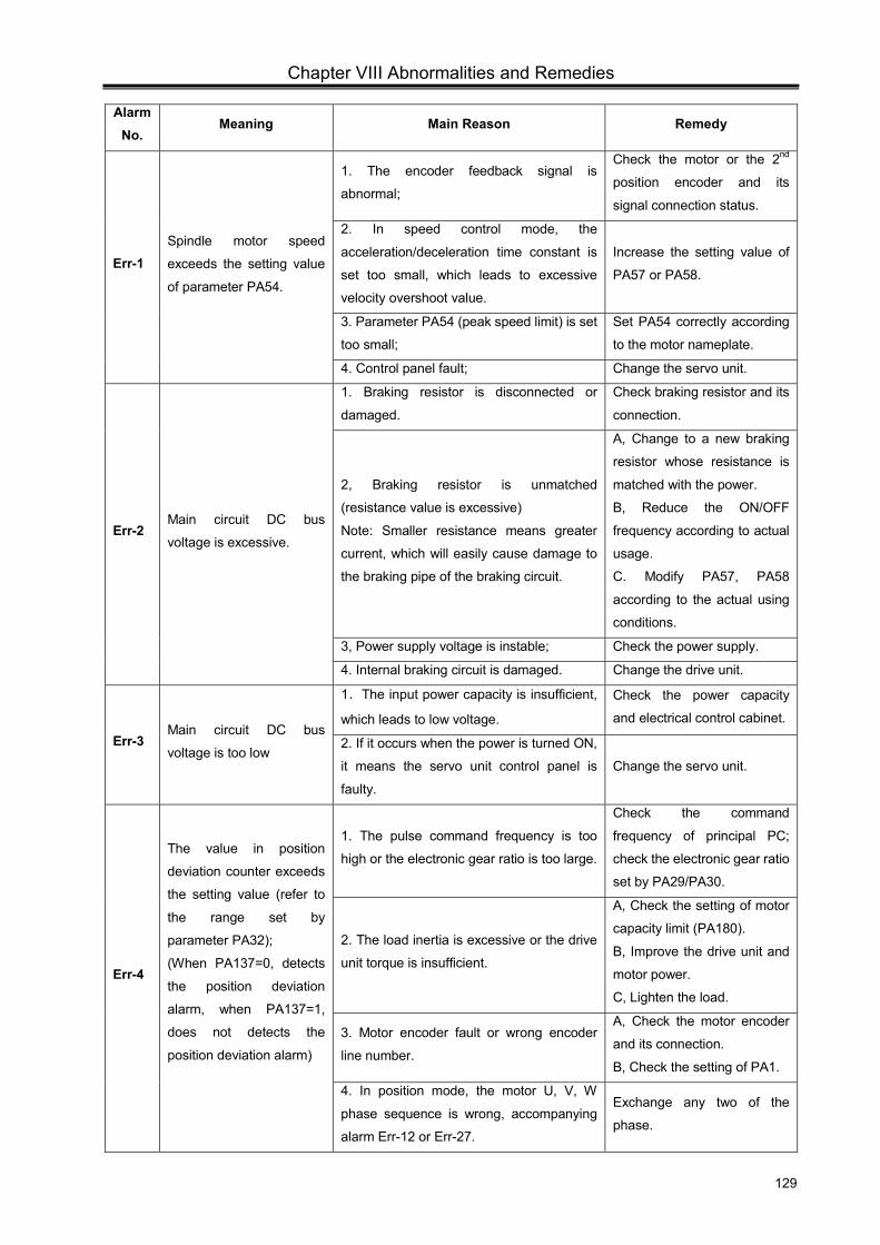
Chapter VIII Abnormalities and Remedies
129
Alarm No.
Meaning Main Reason Remedy
Err-1 Spindle motor speed
exceeds the setting value
of parameter PA54.
1. The encoder feedback signal is
abnormal;
Check the motor or the 2nd
position encoder and its
signal connection status.
2. In speed control mode, the
acceleration/deceleration time constant is
set too small, which leads to excessive
velocity overshoot value.
Increase the setting value of
PA57 or PA58.
3. Parameter PA54 (peak speed limit) is set
too small;
Set PA54 correctly according
to the motor nameplate.
4. Control panel fault; Change the servo unit.
Err-2 Main circuit DC bus
voltage is excessive.
1. Braking resistor is disconnected or
damaged.
Check braking resistor and its
connection.
2, Braking resistor is unmatched
(resistance value is excessive)
Note: Smaller resistance means greater
current, which will easily cause damage to
the braking pipe of the braking circuit.
A, Change to a new braking
resistor whose resistance is
matched with the power.
B, Reduce the ON/OFF
frequency according to actual
usage.
C. Modify PA57, PA58
according to the actual using
conditions.
3, Power supply voltage is instable; Check the power supply.
4. Internal braking circuit is damaged. Change the drive unit.
Err-3 Main circuit DC bus
voltage is too low
1.The input power capacity is insufficient,
which leads to low voltage.
Check the power capacity
and electrical control cabinet.
2. If it occurs when the power is turned ON,
it means the servo unit control panel is
faulty.
Change the servo unit.
Err-4
The value in position
deviation counter exceeds
the setting value (refer to
the range set by
parameter PA32);
(When PA137=0, detects
the position deviation
alarm, when PA137=1,
does not detects the
position deviation alarm)
1. The pulse command frequency is too
high or the electronic gear ratio is too large.
Check the command
frequency of principal PC;
check the electronic gear ratio
set by PA29/PA30.
2. The load inertia is excessive or the drive
unit torque is insufficient.
A, Check the setting of motor
capacity limit (PA180).
B, Improve the drive unit and
motor power.
C, Lighten the load.
3. Motor encoder fault or wrong encoder
line number.
A, Check the motor encoder
and its connection.
B, Check the setting of PA1.
4. In position mode, the motor U, V, W
phase sequence is wrong, accompanying
alarm Err-12 or Err-27.
Exchange any two of the
phase.
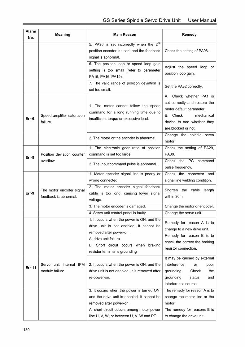
GS Series Spindle Servo Drive Unit User Manual
130
Alarm No.
Meaning Main Reason Remedy
5. PA98 is set incorrectly when the 2nd
position encoder is used, and the feedback
signal is abnormal.
Check the setting of PA98.
6. The position loop or speed loop gain
setting is too small (refer to parameter
PA15, PA16, PA19).
Adjust the speed loop or
position loop gain.
7. The valid range of position deviation is
set too small. Set the PA32 correctly.
Err-6 Speed amplifier saturation
failure
1. The motor cannot follow the speed
command for a long running time due to
insufficient torque or excessive load.
A. Check whether PA1 is
set correctly and restore the
motor default parameter.
B. Check mechanical
device to see whether they
are blocked or not.
2. The motor or the encoder is abnormal. Change the spindle servo
motor.
Err-8 Position deviation counter
overflow
1. The electronic gear ratio of position
command is set too large.
Check the setting of PA29,
PA30.
2. The input command pulse is abnormal. Check the PC command
pulse frequency.
Err-9 The motor encoder signal
feedback is abnormal.
1. Motor encoder signal line is poorly or
wrong connected.
Check the connector and
signal line welding condition.
2. The motor encoder signal feedback
cable is too long, causing lower signal
voltage.
Shorten the cable length
within 30m.
3. The motor encoder is damaged. Change the motor or encoder.
4. Servo unit control panel is faulty. Change the servo unit.
Err-11 Servo unit internal IPM
module failure
1. It occurs when the power is ON, and the
drive unit is not enabled. It cannot be
removed after power-on.
A, drive unit failure
B, Short circuit occurs when braking
resistor terminal is grounding
Remedy for reason A is to
change to a new drive unit.
Remedy for reason B is to
check the correct the braking
resistor connection.
2. It occurs when the power is ON, and the
drive unit is not enabled. It is removed after
re-power-on.
It may be caused by external
interference or poor
grounding. Check the
grounding status and
interference source.
3. It occurs when the power is turned ON,
and the drive unit is enabled. It cannot be
removed after power-on.
A. short circuit occurs among motor power
line U, V, W, or between U, V, W and PE.
The remedy for reason A is to
change the motor line or the
motor.
The remedy for reasons B is
to change the drive unit.
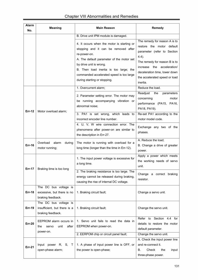
Chapter VIII Abnormalities and Remedies
131
Alarm No.
Meaning Main Reason Remedy
B. Drive unit IPM module is damaged.
4. It occurs when the motor is starting or
stopping and it can be removed after
re-power-on.
A. The default parameter of the motor set
by drive unit is wrong.
B. Then load inertia is too large; the
commanded accelerated speed is too large
during starting or stopping.
The remedy for reason A is to
restore the motor default
parameter (refer to Section
4.4).
The remedy for reason B is to
increase the acceleration/
deceleration time, lower down
the accelerated speed or load
inertia.
Err-12 Motor overload alarm;
1. Overcurrent alarm; Reduce the load.
2. Parameter setting error. The motor may
be running accompanying vibration or
abnormal noise;
Readjust the parameters
concerning motor
performance (PA15, PA16,
PA18, PA19).
3. PA1 is set wrong, which leads to
incorrect encoder line number.
Re-set PA1 according to the
motor model code.
4. U, V, W wire connection error. The
phenomena after power-on are similar to
the description in Err-27.
Exchange any two of the
phases.
Err-16 Overload alarm during
motor running;
The motor is running with overload for a
long time (longer than the time in Err-12).
A. Reduce the load;
B. Change a drive of greater
power.
Err-17 Braking time is too long
1. The input power voltage is excessive for
a long time.
Apply a power which meets
the working needs of servo
unit.
2. The braking resistance is too large. The
energy cannot be released during braking,
causing the rise of internal DC voltage.
Change a correct braking
resistor.
Err-18 The DC bus voltage is
excessive, but there is no
braking feedback.
1. Braking circuit fault; Change a servo unit.
Err-19 The DC bus voltage is
insufficient, but there is a
braking feedback.
1. Braking circuit fault; Change the servo unit.
Err-20
EEPROM alarm occurs in
the servo unit after
power-on.
1. Servo unit fails to read the data in
EEPROM when power-on.
Refer to Section 4.4 for
details to restore the motor
default parameter.
2. EERPOM chip or circuit panel fault; Change the servo unit.
Err-21 Input power R, S, T
open-phase alarm;
1. A phase of input power line is OFF, or
the power is open-phase;
A. Check the input power line
and re-connect it.
B. Check the input
three-phase power.
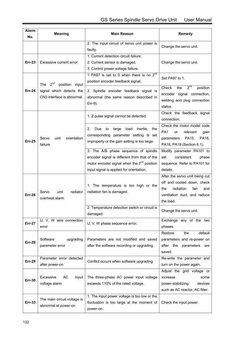
GS Series Spindle Servo Drive Unit User Manual
132
Alarm No.
Meaning Main Reason Remedy
2. The input circuit of servo unit power is
faulty. Change the servo unit.
Err-23 Excessive current error;
1. Current detection circuit failure;
2. Current sensor is damaged.
3. Control power voltage failure;
Change the servo unit.
Err-24 The 2nd position input
signal which detects the
CN3 interface is abnormal.
1 PA97 is set to 0 when there is no 2nd
position encoder feedback signal; Set PA97 to 1.
2. Spindle encoder feedback signal is
abnormal (the same reason described in
Err-9).
Check the 2nd position
encoder signal connection,
welding and plug connection
status.
Err-25 Servo unit orientation
failure
1. Z pulse signal cannot be detected. Check the feedback signal
connection;
2. Due to large load inertia, the
corresponding parameter setting is set
improperly or the gain setting is too large.
Check the motor model code
PA1 or relevant gain
parameters PA15, PA16,
PA18, PA19 (Section 6.1).
3. The A/B phase sequence of spindle
encoder signal is different from that of the
motor encoder signal when the 2nd position
input signal is applied for orientation.
Modify parameter PA101 to
set consistent phase
sequence. Refer to PA101 for
details.
Err-26 Servo unit radiator
overheat alarm
1. The temperature is too high or the
radiation fan is damaged.
After the servo unit being cut
off and cooled down, check
the radiation fan and
ventilation duct, and reduce
the load.
2. Temperature detection switch or circuit is
damaged. Change the servo unit.
Err-27 U, V, W wire connection
error U, V, W phase sequence error;
Exchange any of the two
phases.
Err-28 Software upgrading
parameter error
Parameters are not modified and saved
after the software recording or upgrading.
Restore the default
parameters and re-power on
after the parameters are
saved.
Err-29 Parameter error detected
after power-on Conflict occurs when software upgrading.
Re-write the parameter and
turn on the power again.
Err-30 Excessive AC input
voltage alarm
The three-phase AC power input voltage
exceeds 110% of the rated voltage.
Adjust the grid voltage or
increase some
power-stabilizing devices
such as AC reactor, AC filter.
Err-33 The main circuit voltage is
abnormal at power-on
1. The input power voltage is too low or the
fluctuation is too large at the moment of
power-on.
Check the input power.
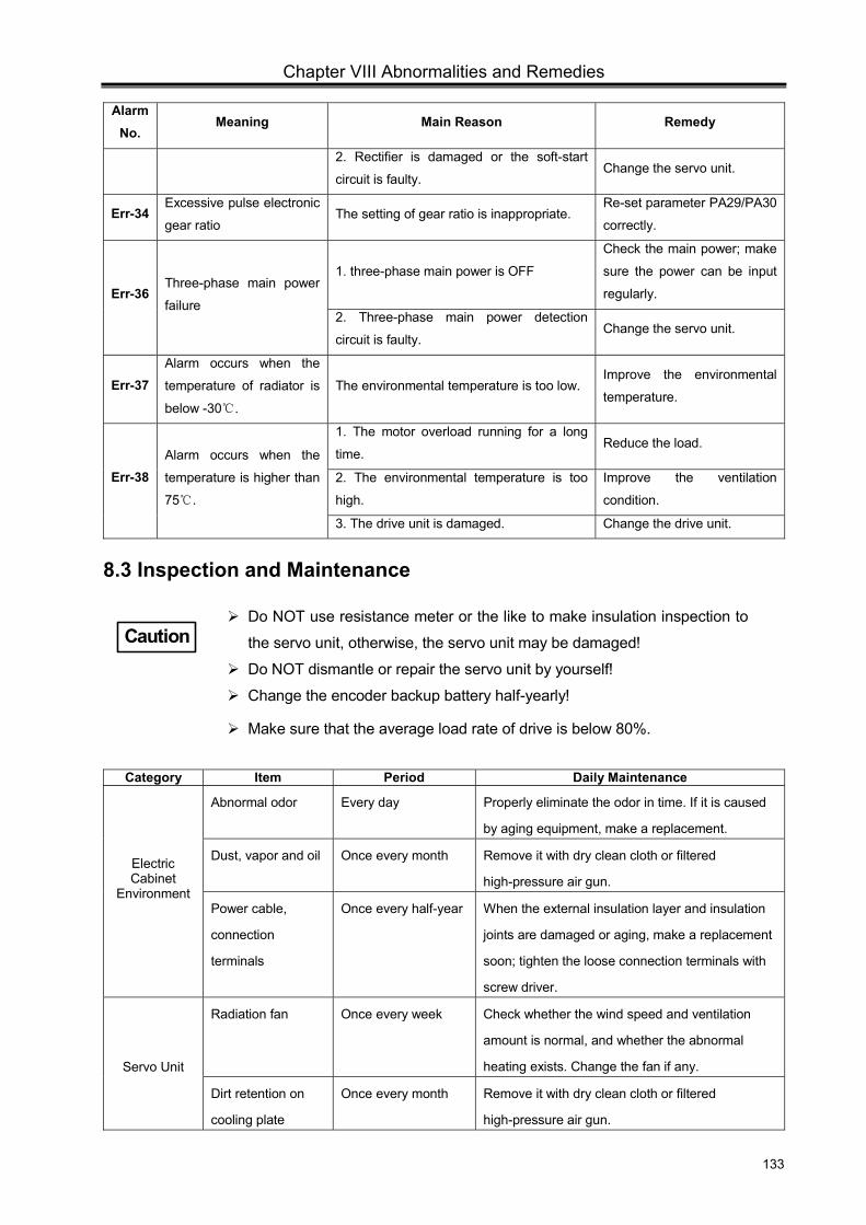
Chapter VIII Abnormalities and Remedies
133
Alarm No.
Meaning Main Reason Remedy
2. Rectifier is damaged or the soft-start
circuit is faulty. Change the servo unit.
Err-34 Excessive pulse electronic
gear ratio The setting of gear ratio is inappropriate.
Re-set parameter PA29/PA30
correctly.
Err-36 Three-phase main power
failure
1. three-phase main power is OFF
Check the main power; make
sure the power can be input
regularly.
2. Three-phase main power detection
circuit is faulty. Change the servo unit.
Err-37 Alarm occurs when the
temperature of radiator is
below -30 .
The environmental temperature is too low. Improve the environmental
temperature.
Err-38 Alarm occurs when the
temperature is higher than
75 .
1. The motor overload running for a long
time. Reduce the load.
2. The environmental temperature is too
high.
Improve the ventilation
condition.
3. The drive unit is damaged. Change the drive unit.
8.3 Inspection and Maintenance
Category Item Period Daily Maintenance
Electric Cabinet
Environment
Abnormal odor Every day Properly eliminate the odor in time. If it is caused
by aging equipment, make a replacement.
Dust, vapor and oil Once every month Remove it with dry clean cloth or filtered
high-pressure air gun.
Power cable,
connection
terminals
Once every half-year When the external insulation layer and insulation
joints are damaged or aging, make a replacement
soon; tighten the loose connection terminals with
screw driver.
Servo Unit
Radiation fan Once every week Check whether the wind speed and ventilation
amount is normal, and whether the abnormal
heating exists. Change the fan if any.
Dirt retention on
cooling plate
Once every month Remove it with dry clean cloth or filtered
high-pressure air gun.
Do NOT use resistance meter or the like to make insulation inspection to
the servo unit, otherwise, the servo unit may be damaged!
Do NOT dismantle or repair the servo unit by yourself!
Change the encoder backup battery half-yearly!
Make sure that the average load rate of drive is below 80%.
Caution
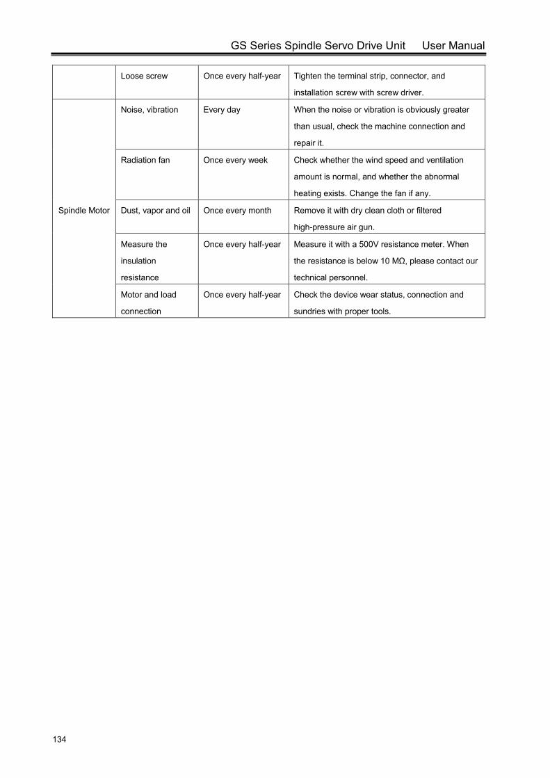
GS Series Spindle Servo Drive Unit User Manual
134
Loose screw Once every half-year Tighten the terminal strip, connector, and
installation screw with screw driver.
Spindle Motor
Noise, vibration Every day When the noise or vibration is obviously greater
than usual, check the machine connection and
repair it.
Radiation fan Once every week Check whether the wind speed and ventilation
amount is normal, and whether the abnormal
heating exists. Change the fan if any.
Dust, vapor and oil Once every month Remove it with dry clean cloth or filtered
high-pressure air gun.
Measure the
insulation
resistance
Once every half-year Measure it with a 500V resistance meter. When
the resistance is below 10 MΩ, please contact our
technical personnel.
Motor and load
connection
Once every half-year Check the device wear status, connection and
sundries with proper tools.
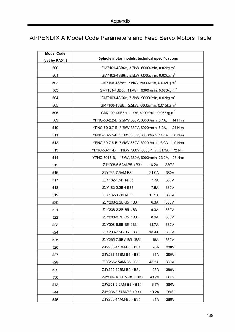
Appendix
135
APPENDIX A Model Code Parameters and Feed Servo Motors Table
Model Code
(set by PA01 ) Spindle motor models, technical specifications
500 GM7101-4SB6, 3.7kW, 6000r/min, 0.02kg.m2
501 GM7103-4SB6, 5.5kW, 6000r/min, 0.02kg.m2
502 GM7105-4SB6, 7.5kW, 6000r/min, 0.032kg.m2
503 GM7131-4SB6, 11kW, 6000r/min, 0.076kg.m2
504 GM7103-4SC6, 7.5kW, 9000r/min, 0.02kg.m2
505 GM7100-4SB6, 2.2kW, 6000r/min, 0.015kg.m2
506 GM7109-4SB6, 11kW, 6000r/min, 0.037kg.m2
509 YPNC-50-2.2-B, 2.2kW,380V, 6000r/min, 5.1A, 14 N·m
510 YPNC-50-3.7-B, 3.7kW,380V, 6000r/min, 8.0A, 24 N·m
511 YPNC-50-5.5-B, 5.5kW,380V, 6000r/min, 11.8A, 36 N·m
512 YPNC-50-7.5-B, 7.5kW,380V, 6000r/min, 16.0A, 49 N·m
513 YPNC-50-11-B, 11kW, 380V, 6000r/min, 21.3A, 72 N·m
514 YPNC-5015-B, 15kW, 380V, 6000r/min, 33.0A, 98 N·m
515 ZJY208-5.5AM-B5(B3) 16.2A 380V
516 ZJY265-7.5AM-B3 21.0A 380V
517 ZJY182-1.5BH-B35 7.3A 380V
518 ZJY182-2.2BH-B35 7.5A 380V
519 ZJY182-3.7BH-B35 15.5A 380V
520 ZJY208-2.2B-B5(B3) 6.3A 380V
521 ZJY208-2.2B-B5(B3) 9.3A 380V
522 ZJY208-3.7B-B5(B3) 8.9A 380V
523 ZJY208-5.5B-B5(B3) 13.7A 380V
524 ZJY208-7.5B-B5(B3) 18.4A 380V
525 ZJY265-7.5BM-B5(B3) 18A 380V
526 ZJY265-11BM-B5(B3) 26A 380V
527 ZJY265-15BM-B5(B3) 35A 380V
528 ZJY265-15AM-B5(B3) 48.3A 380V
529 ZJY265-22BM-B5(B3) 58A 380V
530 ZJY265-18.5BM-B5(B3) 48.7A 380V
543 ZJY208-2.2AM-B5(B3) 6.7A 380V
544 ZJY208-3.7AM-B5(B3) 10.2A 380V
546 ZJY265-11AM-B5(B3) 31A 380V
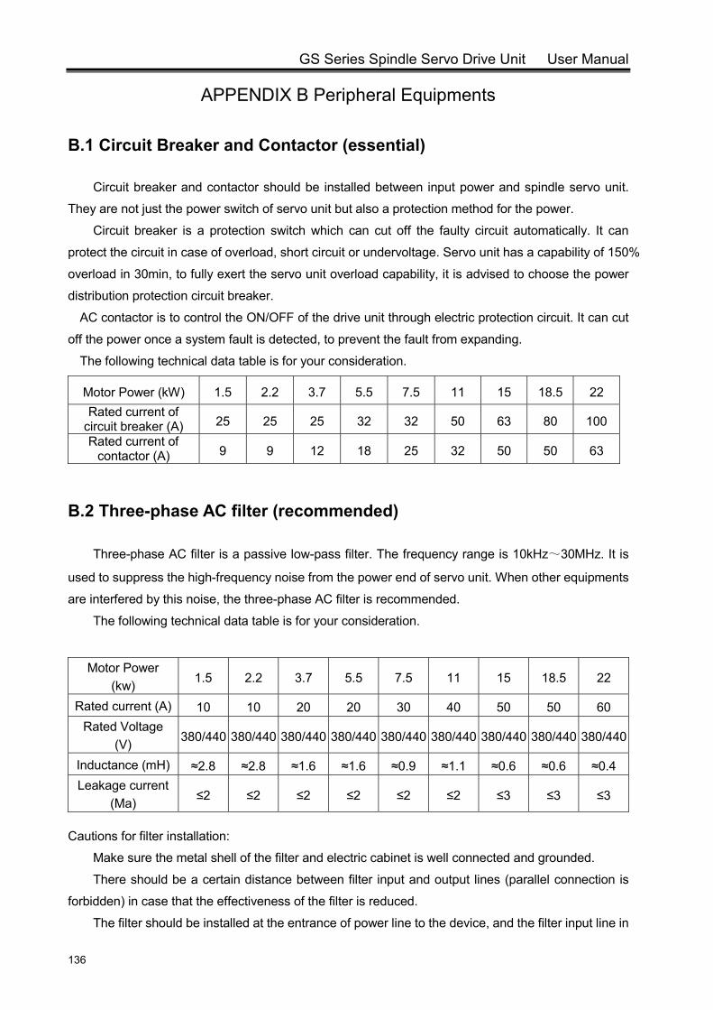
GS Series Spindle Servo Drive Unit User Manual
136
APPENDIX B Peripheral Equipments
B.1 Circuit Breaker and Contactor (essential)
Circuit breaker and contactor should be installed between input power and spindle servo unit.
They are not just the power switch of servo unit but also a protection method for the power.
Circuit breaker is a protection switch which can cut off the faulty circuit automatically. It can
protect the circuit in case of overload, short circuit or undervoltage. Servo unit has a capability of 150%
overload in 30min, to fully exert the servo unit overload capability, it is advised to choose the power
distribution protection circuit breaker.
AC contactor is to control the ON/OFF of the drive unit through electric protection circuit. It can cut
off the power once a system fault is detected, to prevent the fault from expanding.
The following technical data table is for your consideration.
Motor Power (kW) 1.5 2.2 3.7 5.5 7.5 11 15 18.5 22 Rated current of
circuit breaker (A) 25 25 25 32 32 50 63 80 100 Rated current of
contactor (A) 9 9 12 18 25 32 50 50 63
B.2 Three-phase AC filter (recommended)
Three-phase AC filter is a passive low-pass filter. The frequency range is 10kHz~30MHz. It is
used to suppress the high-frequency noise from the power end of servo unit. When other equipments
are interfered by this noise, the three-phase AC filter is recommended.
The following technical data table is for your consideration.
Motor Power (kw) 1.5 2.2 3.7 5.5 7.5 11 15 18.5 22
Rated current (A) 10 10 20 20 30 40 50 50 60 Rated Voltage
(V) 380/440 380/440 380/440 380/440 380/440 380/440 380/440 380/440 380/440
Inductance (mH) ≈2.8 ≈2.8 ≈1.6 ≈1.6 ≈0.9 ≈1.1 ≈0.6 ≈0.6 ≈0.4 Leakage current
(Ma) ≤2 ≤2 ≤2 ≤2 ≤2 ≤2 ≤3 ≤3 ≤3
Cautions for filter installation:
Make sure the metal shell of the filter and electric cabinet is well connected and grounded.
There should be a certain distance between filter input and output lines (parallel connection is
forbidden) in case that the effectiveness of the filter is reduced.
The filter should be installed at the entrance of power line to the device, and the filter input line in
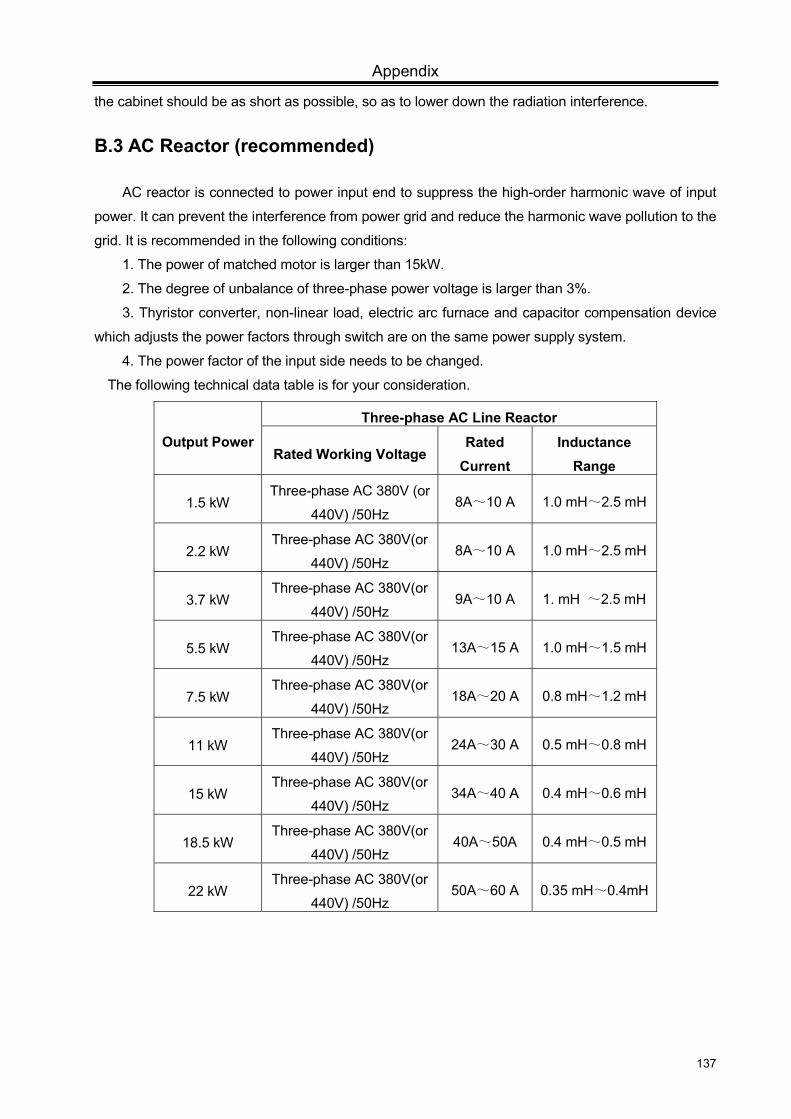
Appendix
137
the cabinet should be as short as possible, so as to lower down the radiation interference.
B.3 AC Reactor (recommended)
AC reactor is connected to power input end to suppress the high-order harmonic wave of input
power. It can prevent the interference from power grid and reduce the harmonic wave pollution to the
grid. It is recommended in the following conditions:
1. The power of matched motor is larger than 15kW.
2. The degree of unbalance of three-phase power voltage is larger than 3%.
3. Thyristor converter, non-linear load, electric arc furnace and capacitor compensation device
which adjusts the power factors through switch are on the same power supply system.
4. The power factor of the input side needs to be changed.
The following technical data table is for your consideration.
Output Power Three-phase AC Line Reactor
Rated Working VoltageRated
Current Inductance
Range
1.5 kW Three-phase AC 380V (or
440V) /50Hz 8A~10 A 1.0 mH~2.5 mH
2.2 kW Three-phase AC 380V(or
440V) /50Hz 8A~10 A 1.0 mH~2.5 mH
3.7 kW Three-phase AC 380V(or
440V) /50Hz 9A~10 A 1. mH ~2.5 mH
5.5 kW Three-phase AC 380V(or
440V) /50Hz 13A~15 A 1.0 mH~1.5 mH
7.5 kW Three-phase AC 380V(or
440V) /50Hz 18A~20 A 0.8 mH~1.2 mH
11 kW Three-phase AC 380V(or
440V) /50Hz 24A~30 A 0.5 mH~0.8 mH
15 kW Three-phase AC 380V(or
440V) /50Hz 34A~40 A 0.4 mH~0.6 mH
18.5 kW Three-phase AC 380V(or
440V) /50Hz 40A~50A 0.4 mH~0.5 mH
22 kW Three-phase AC 380V(or
440V) /50Hz 50A~60 A 0.35 mH~0.4mH
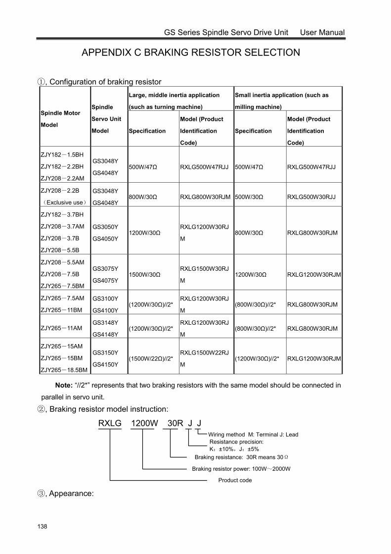
GS Series Spindle Servo Drive Unit User Manual
138
APPENDIX C BRAKING RESISTOR SELECTION
①, Configuration of braking resistor
Spindle Motor
Model
Spindle
Servo Unit
Model
Large, middle inertia application
(such as turning machine)
Small inertia application (such as
milling machine)
Specification
Model (Product
Identification
Code)
Specification
Model (Product
Identification
Code)
ZJY182-1.5BH
ZJY182-2.2BH
ZJY208-2.2AM
GS3048Y
GS4048Y 500W/47Ω RXLG500W47RJJ 500W/47Ω RXLG500W47RJJ
ZJY208-2.2B
(Exclusive use)
GS3048Y
GS4048Y 800W/30Ω RXLG800W30RJM 500W/30Ω RXLG500W30RJJ
ZJY182-3.7BH
ZJY208-3.7AM
ZJY208-3.7B
ZJY208-5.5B
GS3050Y
GS4050Y 1200W/30Ω
RXLG1200W30RJ
M 800W/30Ω RXLG800W30RJM
ZJY208-5.5AM
ZJY208-7.5B
ZJY265-7.5BM
GS3075Y
GS4075Y 1500W/30Ω
RXLG1500W30RJ
M 1200W/30Ω RXLG1200W30RJM
ZJY265-7.5AM
ZJY265-11BM
GS3100Y
GS4100Y (1200W/30Ω)//2*
RXLG1200W30RJ
M (800W/30Ω)//2* RXLG800W30RJM
ZJY265-11AM GS3148Y
GS4148Y (1200W/30Ω)//2*
RXLG1200W30RJ
M (800W/30Ω)//2* RXLG800W30RJM
ZJY265-15AM
ZJY265-15BM
ZJY265-18.5BM
GS3150Y
GS4150Y (1500W/22Ω)//2*
RXLG1500W22RJ
M (1200W/30Ω)//2* RXLG1200W30RJM
Note: “//2*” represents that two braking resistors with the same model should be connected in
parallel in servo unit.
②, Braking resistor model instruction:
RXLG 1200W 30R J JWiring method M: Terminal J: LeadResistance precision: K:±10%,J:±5%
Braking resistance: 30R means 30Ω
Braking resistor power: 100W~2000W
Product code ③, Appearance:
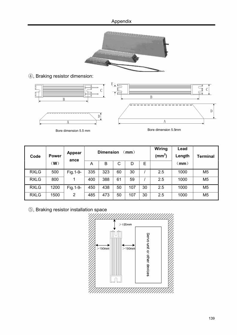
Appendix
139
④, Braking resistor dimension:
B
Bore dimension 5.5 mm
A
D
C
B
C
Bore dimension 5.5mm
A
D
E
Code
Power
(W)
Appearance
Dimension (mm) Wiring(mm2)
Lead Length
(mm) Terminal
A B C D E
RXLG 500 Fig.1-9-
1
335 323 60 30 / 2.5 1000 M5
RXLG 800 400 388 61 59 / 2.5 1000 M5
RXLG 1200 Fig.1-9-
2
450 438 50 107 30 2.5 1000 M5
RXLG 1500 485 473 50 107 30 2.5 1000 M5
⑤, Braking resistor installation space

GS Series Spindle Servo Drive Unit User Manual
140
Caution 1. When the servo is turned ON or is running, high voltage and temperature exists on the surface
of braking resistor, Do NOT touch it!
2. Please install a protection cover!
3. The temperature of braking resistor with aluminum case drops relatively slowly. Inspection and
maintenance can be done only after the servo unit is cut OFF for 10 min, and the braking resistor
surface temperature decrease to the room temperature.
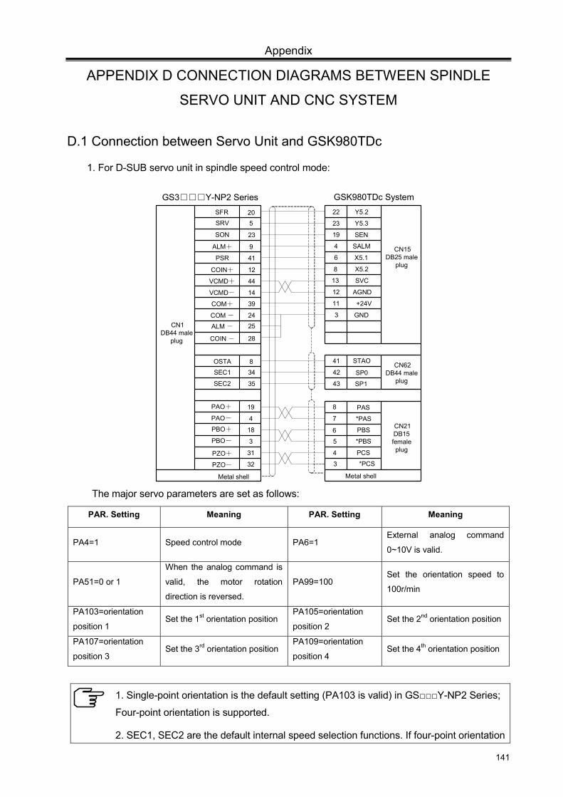
Appendix
141
APPENDIX D CONNECTION DIAGRAMS BETWEEN SPINDLE
SERVO UNIT AND CNC SYSTEM
D.1 Connection between Servo Unit and GSK980TDc
1. For D-SUB servo unit in spindle speed control mode:
Y5.2
X5.1
X5.2
SVC
GND
STAO
SP0
SP1
PAS
*PAS
PBS
*PBS
PCS
*PCS
SRVSFR
SON
ALM+
PSR
COIN+
VCMD+
VCMD-
SEC2
COM+
COM -
ALM -
COIN -
520
23
9
41
12
44
14
35
39
2425
28
22
23
19
4
6
8
13
12
11
3
41
42
43
Y5.3
SEN
SALM
AGND
+24V
GS3Y-NP2 Series GSK980TDc System
Metal shell
8
7
5
Metal shell
PAO+
PAO-
19
4
18
3
31
32
PBO+
PBO-
PZO+
PZO-
6
3
4
CN15DB25 male
plug
SEC1 34
OSTA 8 CN62DB44 male
plug
CN21DB15 female plug
CN1DB44 male
plug
The major servo parameters are set as follows:
PAR. Setting Meaning PAR. Setting Meaning
PA4=1 Speed control mode PA6=1 External analog command
0~10V is valid.
PA51=0 or 1
When the analog command is
valid, the motor rotation
direction is reversed.
PA99=100 Set the orientation speed to
100r/min
PA103=orientation
position 1 Set the 1st orientation position
PA105=orientation
position 2 Set the 2nd orientation position
PA107=orientation
position 3 Set the 3rd orientation position
PA109=orientation
position 4 Set the 4th orientation position
1. Single-point orientation is the default setting (PA103 is valid) in GSY-NP2 Series;
Four-point orientation is supported.
2. SEC1, SEC2 are the default internal speed selection functions. If four-point orientation
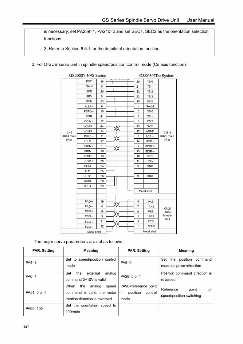
GS Series Spindle Servo Drive Unit User Manual
142
is necessary, set PA239=1, PA240=2 and set SEC1, SEC2 as the orientation selection
functions.
3. Refer to Section 6.5.1 for the details of orientation function.
2. For D-SUB servo unit in spindle speed/position control mode (Cs axis function):
Y5.0
SEN
SALM
X5.0
SVC
AGND
SCP+
SCP-
SDIR+
SDIR-
SPC
+24V
GND
GND
PAS
*PAS
PBS
*PBS
PCS
*PCS
PSTI
GAIN
SFR
SRV
SON
ALM+
PSTO+
PSR
COIN+
VCMD+
VCMD-
PULS+
PULS -
SIGN+
SIGN-
ZOUT+
COM+
COM -
ALM -
PSTO -
COIN -
ZOUT -
38
6
20
5
23
9
10
41
12
44
14
2
17
1
16
13
39
24
25
26
28
29
Metal shell
20
21
22
23
19
4
5
6
8
13
12
1
14
2
15
10
11
3
9
Y5.1
Y5.2
Y5.3
X5.1
X5.2
GS3000Y-NP2 Series GSK980TDc System
Metal shell
8
7
5
Metal shell
PAO+
PAO-
19
4
18
3
31
32
PBO+
PBO-
PZO+
PZO-
6
3
4
CN1DB44 male
plug
CN15DB25 male
plug
CN21DB15 female plug
The major servo parameters are set as follows:
PAR. Setting Meaning PAR. Setting Meaning
PA4=3 Set to speed/position control
mode PA5=0
Set the position command
mode as pulse+direction
PA6=1 Set the external analog
command 0~10V is valid PA28=0 or 1
Position command direction is
reversed
PA51=0 or 1
When the analog speed
command is valid, the motor
rotation direction is reversed.
PA90=reference point
in position control
mode
Reference point for
speed/position switching
PA99=100 Set the orientation speed to
100r/min
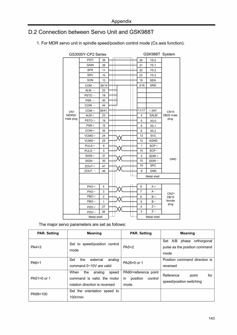
Appendix
143
D.2 Connection between Servo Unit and GSK988T
1. For MDR servo unit in spindle speed/position control mode (Cs axis function):
Y5.0
SEN
GND
X5.0
SVC
AGND
SCP+
SCP-
SDIR+
SDIR- SPC
+24V
GND
GND
PSTI
GAIN
SFR
SRV
SON
ALM+
PSTO+
PSR+
COIN+
VCMD+
VCMD-
PULS+
PULS -
SIGN+
SIGN-
ZOUT+
COM+
COM -
ALM -
PSTO -
COIN -
ZOUT -
35
36
11
10
13
23
19
15
45
24
25
6
5
31
30
47
39/41
38/14
22
18
44
46
20
21
22
23
19
3/16
5
6
8
13
11/17
4
12
1
2
Y5.1
Y5.2
Y5.3
X5.1
X5.2
GS3000Y-CP2 Series GSK988T System
Metal shell
8
7
5
Metal shell
PAO+
PAO-
4
3
2
1
27
26
PBO+
PBO-
PZO+
PZO-
6
3
4
CN1MDR50
male plug
CN15DB25 male
plug
CN21DB15 female plug
PSR - 40
SALM
15
14
10
9
Metal shell
A+
A-
B+
B-
Z+
Z-
The major servo parameters are set as follows:
PAR. Setting Meaning PAR. Setting Meaning
PA4=3 Set to speed/position control
mode PA5=2
Set A/B phase orthorgonal
pulse as the position command
mode
PA6=1 Set the external analog
command 0~10V are valid PA28=0 or 1
Position command direction is
reversed
PA51=0 or 1
When the analog speed
command is valid, the motor
rotation direction is reversed
PA90=reference point
in position control
mode
Reference point for
speed/position switching
PA99=100 Set the orientation speed to
100r/min