Embed Size (px)
Citation preview
FPS300.241-002-101
All parameters are specified at 24V, 12.5A, 230Vac, 25°C ambient and after a 5 minutes run-in time unless otherwise noted.
Feb. 2021 / Rev. 0.4 FPS300.241-002-101-EN www.pulspower.com 1 / 22
• IP65/67 degree of protection • 600Wpeak 5s • 100-240V wide-range input • 95.6% full load and excellent partial load efficiencies • DIN rail mounting possible, option “D” • Output connected to PE (PELV) • Version without connection to PE on request • Large output capacitors • Not potted • Negligible low input inrush current surge • Full power between -25°C and +55°C • DC-OK • 3 years warranty
The FPS300 is an industrial grade power supply for the single-phase mains system incorporated in a rugged wall-mount housing with a degree of protection IP65/67.
It provides one floating, stabilized SELV/PELV output, which is galvanically separated from the input.. In case of an overload or load failure, the output offers hiccup-mode.
The most outstanding features of the FPS series are the compact size, the wide operational temperature range, the low input inrush current and the extremely high efficiencies, which are achieved by various technological design technologies.
Various connector options support the different needs of individual applications. Please contact PULS for possible options.
High immunity to transients and power surges as well as low electromagnetic emission and an international approval package makes usage in nearly every environment possible.
Output voltage DC 24V Nominal Adjustment range 24-28V Factory setting 24.5V Output power Continuous: Up to: 360 / 300 / 150W +45 / +55 / +70°C Short term up to 5s 600 / 300W +55 / +70°C Input voltage AC AC 100-240V -15 / +10% Input voltage DC DC 110-300V ±20% Power factor 0.99 / 0.97 At 120 / 230Vac AC Inrush current 3 / 7Apeak At 120 / 230Vac Efficiency 94.2 / 95.6% At 120 / 230Vac Losses 22.4 / 16.2 W At 120 / 230Vac Hold-up time 37 / 37ms At 120 / 230Vac Temperature range -25°C to +70°C Derate linearly from +55°C to +70°C Size (wxhxd) 182x183x59mm Without connectors Weight 1200g / 3.4lb
Description: Power supply FPS300
Order Number Input Output FPS300.241-002-101* HAN Q4/2 HAN Q4/0
Accessories: Chapter 21 Related Products pending
*For DIN rail mounting PSU: (Order Number)D e.g. FPS300.241-002-101D
For details or an complete approval list, see chapter 19.
IEC 62368-1
IEC 61010-2-201
Pending Planned for Q2/2021
Pending Planned for Q2/2021
POWER SUPPLY 1AC 24V 300W
GENERAL DESCRIPTION SHORT-FORM DATA
ORDER NUMBERS MAIN APPROVALS
FPS300.241-002-101
All parameters are specified at 24V, 12.5A, 230Vac, 25°C ambient and after a 5 minutes run-in time unless otherwise noted.
Feb. 2021 / Rev. 0.4 FPS300.241-002-101-EN www.pulspower.com 2 / 22
Index Intended Use ................................................................... 3 Installation Instructions .................................................... 3 AC-Input .......................................................................... 4 DC-Input .......................................................................... 5 Input Inrush Current ......................................................... 5 Output ............................................................................. 6 Hold-up Time ................................................................... 7 DC-OK Relay Contact ........................................................ 7 Efficiency And Power Losses ............................................. 8 Lifetime Expectancy (Pending) .......................................... 9 MTBF (Pending)................................................................ 9 Functional Diagram ........................................................ 10 Dimensions and Connector Variants ............................... 11 User Interface ................................................................ 12 EMC ............................................................................... 14 Environment .................................................................. 15 Safety and Protection Features ....................................... 16
Dielectric Strength .......................................................... 17 Approvals and Fulfilled Standards (Pending) .................... 18 Regulatory Compliance ................................................... 18 Accessories .................................................................... 19
21.1. DIN RAIL Mounting KIT: ZM.FP-DIN2 ...................... 19 21.2. Connectors ........................................................... 19 Related Products (PENDING) ........................................... 20 Application Notes ........................................................... 21
23.1. Repetitive Pulse Loading ........................................ 21 23.2. External Input Protection (Pending) ....................... 21 23.3. Inductive and Capacitive Loads .............................. 21 23.4. Back Feeding Loads ............................................... 21 23.5. Mounting Orientations .......................................... 22
The information given in this document is correct to the best of our knowledge and experience at the time of publication. If not expressly agreed otherwise, this information does not represent a warranty in the legal sense of the word. As the state of our knowledge and experience is constantly changing, the information in this data sheet is subject to revision. We therefore kindly ask you to always use the latest issue of this document (available under www.pulspower.com).
No part of this document may be reproduced or utilized in any form without our prior permission in writing.
Packaging and packaging aids can and should always be recycled. The product itself may not be disposed of as domestic refuse.
TERMINOLOGY AND ABREVIATIONS
PE and Symbol PE is the abbreviation for Protective Earth and has the same meaning as the symbol . Earth, Ground This document uses the term “earth” which is the same as the U.S. term “ground”.
T.b.d. To be defined, value or description will follow later.
AC 230V A figure displayed with the AC or DC before the value represents a nominal voltage with standard tolerances (usually ±15%) included.
E.g.: DC 12V describes a 12V battery disregarding whether it is full (13.7V) or flat (10V)
230Vac A figure with the unit (Vac) at the end is a momentary figure without any additional tolerances included.
50Hz vs. 60Hz As long as not otherwise stated, AC 100V and AC 230V parameters are valid at 50Hz mains frequency. AC 120V parameters are valid for 60Hz mains frequency.
may A key word indicating flexibility of choice with no implied preference.
shall A key word indicating a mandatory requirement.
should A key word indicating flexibility of choice with a strongly preferred implementation.
FPS300.241-002-101
All parameters are specified at 24V, 12.5A, 230Vac, 25°C ambient and after a 5 minutes run-in time unless otherwise noted.
Feb. 2021 / Rev. 0.4 FPS300.241-002-101-EN www.pulspower.com 3 / 22
Intended Use
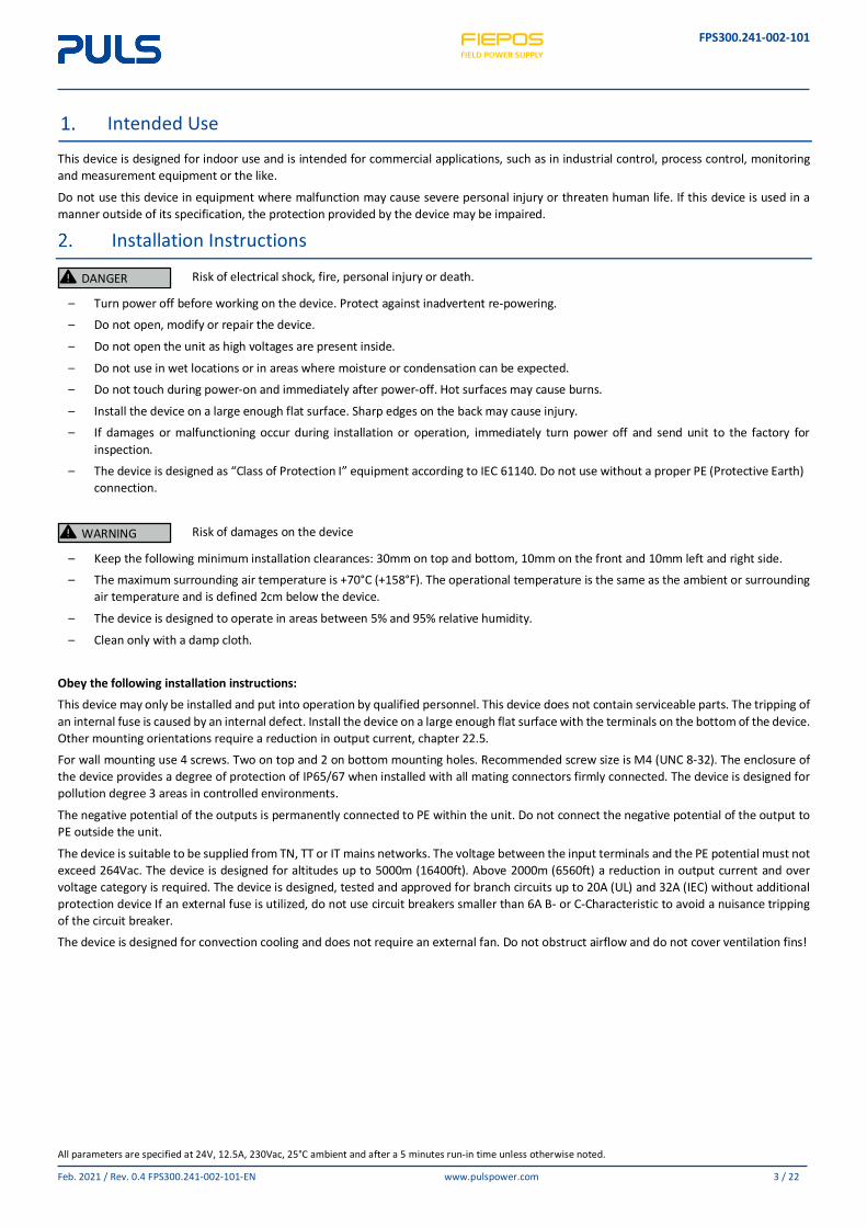
This device is designed for indoor use and is intended for commercial applications, such as in industrial control, process control, monitoring and measurement equipment or the like.
Do not use this device in equipment where malfunction may cause severe personal injury or threaten human life. If this device is used in a manner outside of its specification, the protection provided by the device may be impaired.
Installation Instructions
Risk of electrical shock, fire, personal injury or death.
– Turn power off before working on the device. Protect against inadvertent re-powering.
– Do not open, modify or repair the device.
– Do not open the unit as high voltages are present inside.
– Do not use in wet locations or in areas where moisture or condensation can be expected.
– Do not touch during power-on and immediately after power-off. Hot surfaces may cause burns.
– Install the device on a large enough flat surface. Sharp edges on the back may cause injury.
– If damages or malfunctioning occur during installation or operation, immediately turn power off and send unit to the factory for inspection.
– The device is designed as “Class of Protection I” equipment according to IEC 61140. Do not use without a proper PE (Protective Earth) connection.
Risk of damages on the device
– Keep the following minimum installation clearances: 30mm on top and bottom, 10mm on the front and 10mm left and right side.
– The maximum surrounding air temperature is +70°C (+158°F). The operational temperature is the same as the ambient or surrounding air temperature and is defined 2cm below the device.
– The device is designed to operate in areas between 5% and 95% relative humidity.
– Clean only with a damp cloth.
Obey the following installation instructions:
This device may only be installed and put into operation by qualified personnel. This device does not contain serviceable parts. The tripping of an internal fuse is caused by an internal defect. Install the device on a large enough flat surface with the terminals on the bottom of the device. Other mounting orientations require a reduction in output current, chapter 22.5.
For wall mounting use 4 screws. Two on top and 2 on bottom mounting holes. Recommended screw size is M4 (UNC 8-32). The enclosure of the device provides a degree of protection of IP65/67 when installed with all mating connectors firmly connected. The device is designed for pollution degree 3 areas in controlled environments.
The negative potential of the outputs is permanently connected to PE within the unit. Do not connect the negative potential of the output to PE outside the unit.
The device is suitable to be supplied from TN, TT or IT mains networks. The voltage between the input terminals and the PE potential must not exceed 264Vac. The device is designed for altitudes up to 5000m (16400ft). Above 2000m (6560ft) a reduction in output current and over voltage category is required. The device is designed, tested and approved for branch circuits up to 20A (UL) and 32A (IEC) without additional protection device If an external fuse is utilized, do not use circuit breakers smaller than 6A B- or C-Characteristic to avoid a nuisance tripping of the circuit breaker.
The device is designed for convection cooling and does not require an external fan. Do not obstruct airflow and do not cover ventilation fins!
DANGER
WARNING
FPS300.241-002-101
All parameters are specified at 24V, 12.5A, 230Vac, 25°C ambient and after a 5 minutes run-in time unless otherwise noted.
Feb. 2021 / Rev. 0.4 FPS300.241-002-101-EN www.pulspower.com 4 / 22
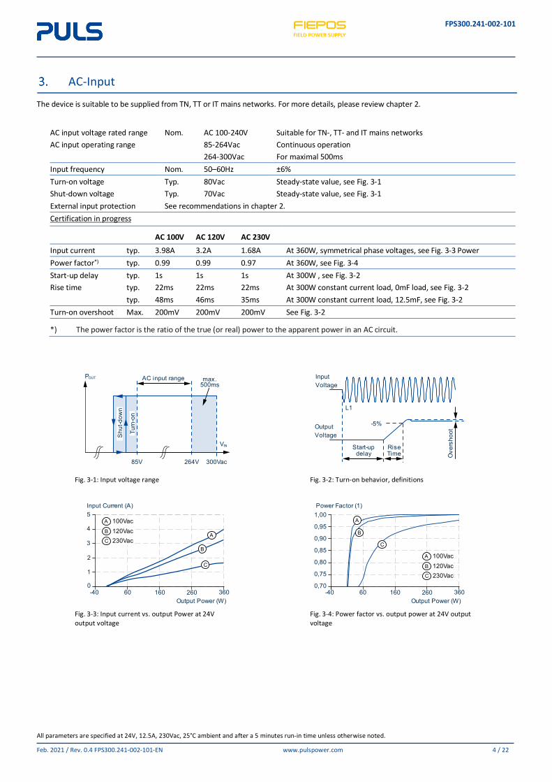
AC-Input
The device is suitable to be supplied from TN, TT or IT mains networks. For more details, please review chapter 2.
AC input voltage rated range Nom. AC 100-240V Suitable for TN-, TT- and IT mains networks AC input operating range 85-264Vac Continuous operation 264-300Vac For maximal 500ms Input frequency Nom. 50–60Hz ±6% Turn-on voltage Typ. 80Vac Steady-state value, see Fig. 3-1 Shut-down voltage Typ. 70Vac Steady-state value, see Fig. 3-1 External input protection See recommendations in chapter 2. Certification in progress
AC 100V AC 120V AC 230V Input current typ. 3.98A 3.2A 1.68A At 360W, symmetrical phase voltages, see Fig. 3-3 Power Power factor*) typ. 0.99 0.99 0.97 At 360W, see Fig. 3-4 Start-up delay typ. 1s 1s 1s At 300W , see Fig. 3-2 Rise time typ. 22ms 22ms 22ms At 300W constant current load, 0mF load, see Fig. 3-2 typ. 48ms 46ms 35ms At 300W constant current load, 12.5mF, see Fig. 3-2 Turn-on overshoot Max. 200mV 200mV 200mV See Fig. 3-2
*) The power factor is the ratio of the true (or real) power to the apparent power in an AC circuit.
Fig. 3-1: Input voltage range
Fig. 3-2: Turn-on behavior, definitions
Fig. 3-3: Input current vs. output Power at 24V output voltage
Fig. 3-4: Power factor vs. output power at 24V output voltage
85V
AC input range max.500ms
VIN
POUT
300Vac264V
Turn
-on
Shu
t-dow
n L1
Start-updelay
RiseTime O
vers
hoot
OutputVoltage
InputVoltage
-5%
A
B
C
A 100Vac
C 230VacB 120Vac
Input Current (A)
Output Power (W)
0
2
1
3
5
4
36026060 160-40
A
B
C
A 100Vac
C 230VacB 120Vac
Power Factor (1)
Output Power (W)
0,70
0,75
0,80
0,85
0,90
0,95
1,00
36026060 160-40
FPS300.241-002-101
All parameters are specified at 24V, 12.5A, 230Vac, 25°C ambient and after a 5 minutes run-in time unless otherwise noted.
Feb. 2021 / Rev. 0.4 FPS300.241-002-101-EN www.pulspower.com 5 / 22
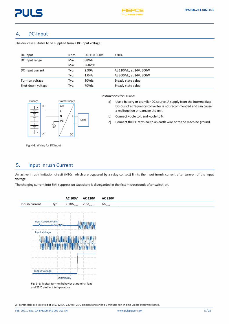
DC-Input
The device is suitable to be supplied from a DC input voltage.
DC input Nom. DC 110-300V ±20% DC input range Min. 88Vdc Max. 360Vdc DC input current Typ. 2.90A At 110Vdc, at 24V, 300W Typ. 1.04A At 300Vdc, at 24V, 300W Turn-on voltage Typ. 80Vdc Steady state value Shut-down voltage Typ. 70Vdc Steady state value
Fig. 4-1: Wiring for DC Input
Instructions for DC use:
a) Use a battery or a similar DC source. A supply from the intermediate DC-bus of a frequency converter is not recommended and can cause a malfunction or damage the unit.
b) Connect +pole to L and –pole to N.
c) Connect the PE terminal to an earth wire or to the machine ground.
Input Inrush Current
An active inrush limitation circuit (NTCs, which are bypassed by a relay contact) limits the input inrush current after turn-on of the input voltage.
The charging current into EMI suppression capacitors is disregarded in the first microseconds after switch-on.
AC 100V AC 120V AC 230V
Inrush current typ. 2.18Apeak 2.6Apeak 6Apeak
Fig. 5-1: Typical turn-on behavior at nominal load and 25°C ambient temperature
Battery Power Supply
DC
Load
AC
L
N
PE
+
-
+
-
250ms/DIV
Input Current 5A/DIV
Input Voltage
Output Voltage
FPS300.241-002-101
All parameters are specified at 24V, 12.5A, 230Vac, 25°C ambient and after a 5 minutes run-in time unless otherwise noted.
Feb. 2021 / Rev. 0.4 FPS300.241-002-101-EN www.pulspower.com 6 / 22
Output
The output provide a (PELV/ES1) rated voltage, which is galvanically isolated from the input voltage. The negative potential of the output is permanently connected to PE within the unit.
The device is designed to supply any kind of loads, including capacitive and inductive loads. If capacitors with a capacitance >100mF are connected to the output, this the unit might charge the capacitor in hiccup mode.
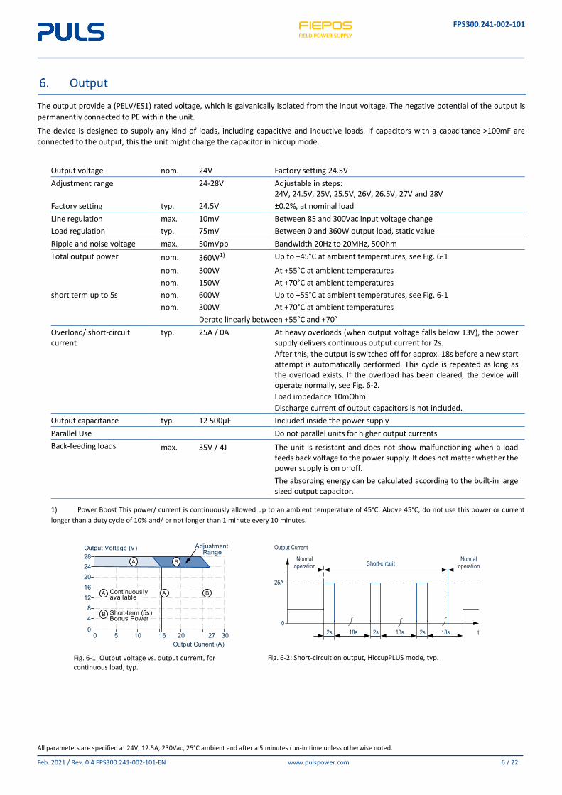
Output voltage nom. 24V Factory setting 24.5V Adjustment range 24-28V Adjustable in steps:
24V, 24.5V, 25V, 25.5V, 26V, 26.5V, 27V and 28V Factory setting typ. 24.5V ±0.2%, at nominal load Line regulation max. 10mV Between 85 and 300Vac input voltage change Load regulation typ. 75mV Between 0 and 360W output load, static value Ripple and noise voltage max. 50mVpp Bandwidth 20Hz to 20MHz, 50Ohm Total output power nom. 360W1) Up to +45°C at ambient temperatures, see Fig. 6-1
nom. 300W At +55°C at ambient temperatures nom. 150W At +70°C at ambient temperatures short term up to 5s nom. 600W Up to +55°C at ambient temperatures, see Fig. 6-1 nom. 300W At +70°C at ambient temperatures Derate linearly between +55°C and +70° Overload/ short-circuit current
typ. 25A / 0A At heavy overloads (when output voltage falls below 13V), the power supply delivers continuous output current for 2s. After this, the output is switched off for approx. 18s before a new start attempt is automatically performed. This cycle is repeated as long as the overload exists. If the overload has been cleared, the device will operate normally, see Fig. 6-2. Load impedance 10mOhm. Discharge current of output capacitors is not included.
Output capacitance typ. 12 500µF Included inside the power supply Parallel Use Do not parallel units for higher output currents Back-feeding loads max. 35V / 4J The unit is resistant and does not show malfunctioning when a load
feeds back voltage to the power supply. It does not matter whether the power supply is on or off. The absorbing energy can be calculated according to the built-in large sized output capacitor.
1) Power Boost This power/ current is continuously allowed up to an ambient temperature of 45°C. Above 45°C, do not use this power or current longer than a duty cycle of 10% and/ or not longer than 1 minute every 10 minutes.
Fig. 6-1: Output voltage vs. output current, for continuous load, typ.
Fig. 6-2: Short-circuit on output, HiccupPLUS mode, typ.
A
A B
B
A Continuouslyavailable
B Short-term (5s)Bonus Power
Output Voltage (V)
Output Current (A)
0
48
12
2016
2428
16100 5 302720
AdjustmentRange
Short-circuit
2s 2s18s 18s 2s 18s
25A
0t
Output Current
Normal operation
Normal operation
FPS300.241-002-101
All parameters are specified at 24V, 12.5A, 230Vac, 25°C ambient and after a 5 minutes run-in time unless otherwise noted.
Feb. 2021 / Rev. 0.4 FPS300.241-002-101-EN www.pulspower.com 7 / 22
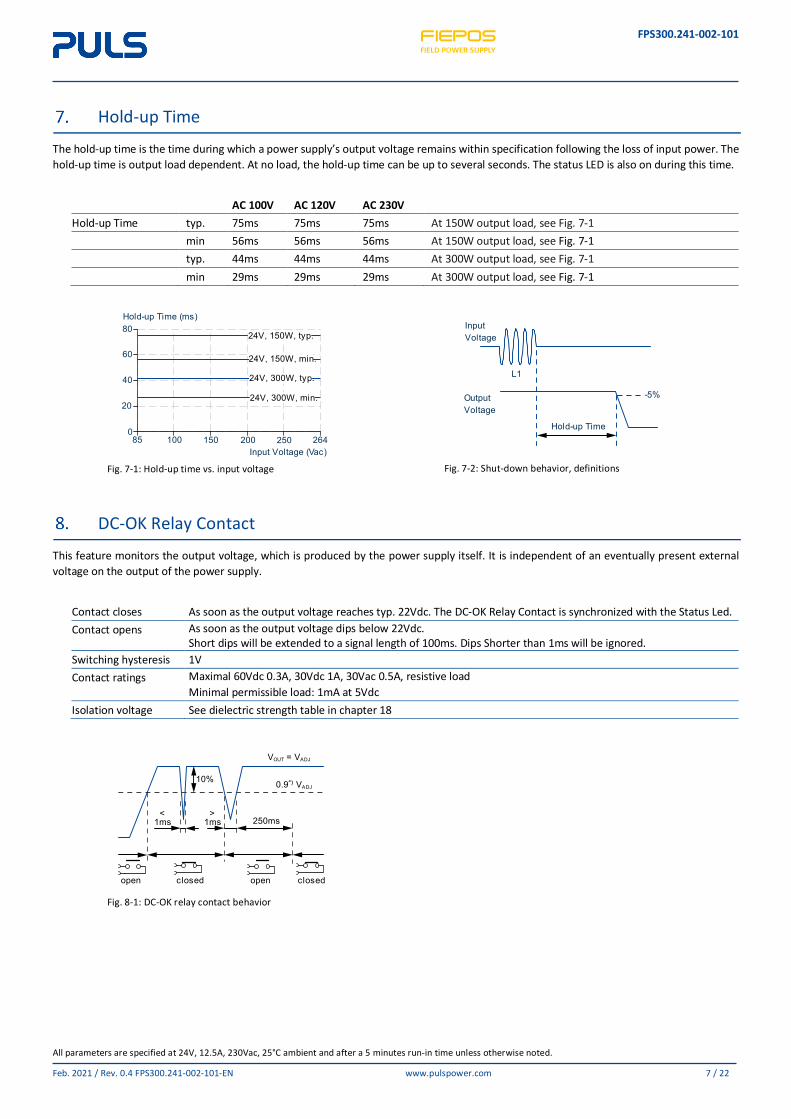
Hold-up Time
The hold-up time is the time during which a power supply’s output voltage remains within specification following the loss of input power. The hold-up time is output load dependent. At no load, the hold-up time can be up to several seconds. The status LED is also on during this time.
AC 100V AC 120V AC 230V Hold-up Time typ. 75ms 75ms 75ms At 150W output load, see Fig. 7-1 min 56ms 56ms 56ms At 150W output load, see Fig. 7-1 typ. 44ms 44ms 44ms At 300W output load, see Fig. 7-1 min 29ms 29ms 29ms At 300W output load, see Fig. 7-1
Fig. 7-1: Hold-up time vs. input voltage
Fig. 7-2: Shut-down behavior, definitions
DC-OK Relay Contact
This feature monitors the output voltage, which is produced by the power supply itself. It is independent of an eventually present external voltage on the output of the power supply.
Contact closes As soon as the output voltage reaches typ. 22Vdc. The DC-OK Relay Contact is synchronized with the Status Led. Contact opens As soon as the output voltage dips below 22Vdc.
Short dips will be extended to a signal length of 100ms. Dips Shorter than 1ms will be ignored. Switching hysteresis 1V Contact ratings Maximal 60Vdc 0.3A, 30Vdc 1A, 30Vac 0.5A, resistive load
Minimal permissible load: 1mA at 5Vdc Isolation voltage See dielectric strength table in chapter 18
Fig. 8-1: DC-OK relay contact behavior
24V, 300W, typ.
24V, 150W, min.
24V, 300W, min.
Input Voltage (Vac)
24V, 150W, typ.
Hold-up Time (ms)80
60
40
20
085 100 150 200 250 264
Hold-up Time
Output
L1
Voltage
Input
-5%
Voltage
250ms
open closed open closed
<1ms
>1ms
10% 0.9
VOUT VADJ
VADJ
=
FPS300.241-002-101
All parameters are specified at 24V, 12.5A, 230Vac, 25°C ambient and after a 5 minutes run-in time unless otherwise noted.
Feb. 2021 / Rev. 0.4 FPS300.241-002-101-EN www.pulspower.com 8 / 22
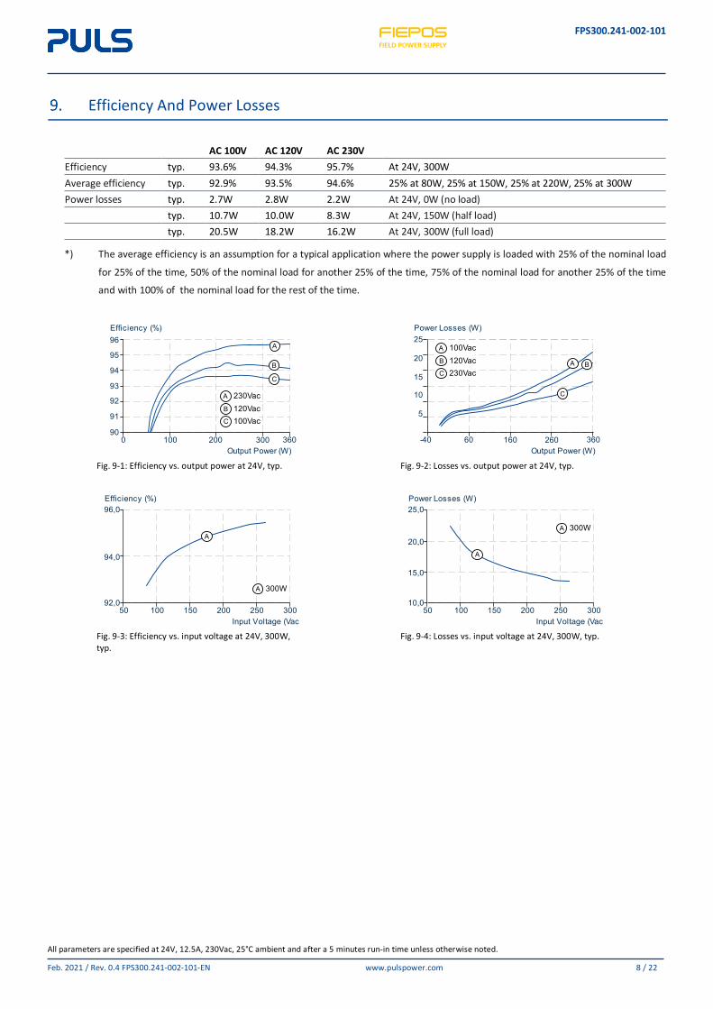
Efficiency And Power Losses
AC 100V AC 120V AC 230V Efficiency typ. 93.6% 94.3% 95.7% At 24V, 300W Average efficiency typ. 92.9% 93.5% 94.6% 25% at 80W, 25% at 150W, 25% at 220W, 25% at 300W Power losses typ. 2.7W 2.8W 2.2W At 24V, 0W (no load) typ. 10.7W 10.0W 8.3W At 24V, 150W (half load) typ. 20.5W 18.2W 16.2W At 24V, 300W (full load)
*) The average efficiency is an assumption for a typical application where the power supply is loaded with 25% of the nominal load
for 25% of the time, 50% of the nominal load for another 25% of the time, 75% of the nominal load for another 25% of the time
and with 100% of the nominal load for the rest of the time.
Fig. 9-1: Efficiency vs. output power at 24V, typ.
Fig. 9-2: Losses vs. output power at 24V, typ.
Fig. 9-3: Efficiency vs. input voltage at 24V, 300W, typ.
Fig. 9-4: Losses vs. input voltage at 24V, 300W, typ.
A
B
C
A 230Vac
C 100VacB 120Vac
Efficiency (%)96
95
94
93
92
91
90360200 3001000
Output Power (W)
A B
C
A 100Vac
C 230VacB 120Vac
Power Losses (W)25
20
15
10
5
Output Power (W)36026060 160-40
A
A 300W
Efficiency (%)
Input Voltage (Vac)
92,0
94,0
96,0
50 300100 150 200 250
A
A 300W
Power Losses (W)
Input Voltage (Vac)
10,0
20,0
15,0
25,0
50 300100 150 200 250
FPS300.241-002-101
All parameters are specified at 24V, 12.5A, 230Vac, 25°C ambient and after a 5 minutes run-in time unless otherwise noted.
Feb. 2021 / Rev. 0.4 FPS300.241-002-101-EN www.pulspower.com 9 / 22
Lifetime Expectancy (Pending)
The Lifetime expectancy shown in the table indicates the minimum operating hours (service life) and is determined by the lifetime expectancy of the built-in electrolytic capacitors. Lifetime expectancy is specified in operational hours and is calculated according to the capacitor’s manufacturer specification.
The manufacturer of the electrolytic capacitors only guarantees a maximum life of up to 15 years (131 400h). Any number exceeding this value is a calculated theoretical lifetime which can be used to compare devices.
AC 100V AC 120V AC 230V
Calculated lifetime expectancy t.b.d. t.b.d. t.b.d. t.b.d. t.b.d. t.b.d. t.b.d. t.b.d. t.b.d. t.b.d. t.b.d. t.b.d.
MTBF (Pending)
MTBF stands for Mean Time Between Failure, which is calculated according to statistical device failures, and indicates reliability of a device. It is the statistical representation of the likelihood of a unit to fail and does not necessarily represent the life of a product.
The MTBF figure is a statistical representation of the likelihood of a device to fail. A MTBF figure of e.g. 1 000 000h means that statistically one unit will fail every 100 hours if 10 000 units are installed in the field. However, it can not be determined if the failed unit has been running for 50 000h or only for 100h.
For these types of units the MTTF (Mean Time To Failure) value is the same value as the MTBF value.
AC 100V AC 120V AC 230V
MTBF SN 29500, IEC 61709 t.b.d. t.b.d. t.b.d. t.b.d. t.b.d. t.b.d. MTBF MIL HDBK 217F t.b.d. t.b.d. t.b.d. t.b.d. t.b.d. t.b.d. t.b.d. t.b.d. t.b.d. t.b.d. t.b.d. t.b.d.
FPS300.241-002-101
All parameters are specified at 24V, 12.5A, 230Vac, 25°C ambient and after a 5 minutes run-in time unless otherwise noted.
Feb. 2021 / Rev. 0.4 FPS300.241-002-101-EN www.pulspower.com 10 / 22
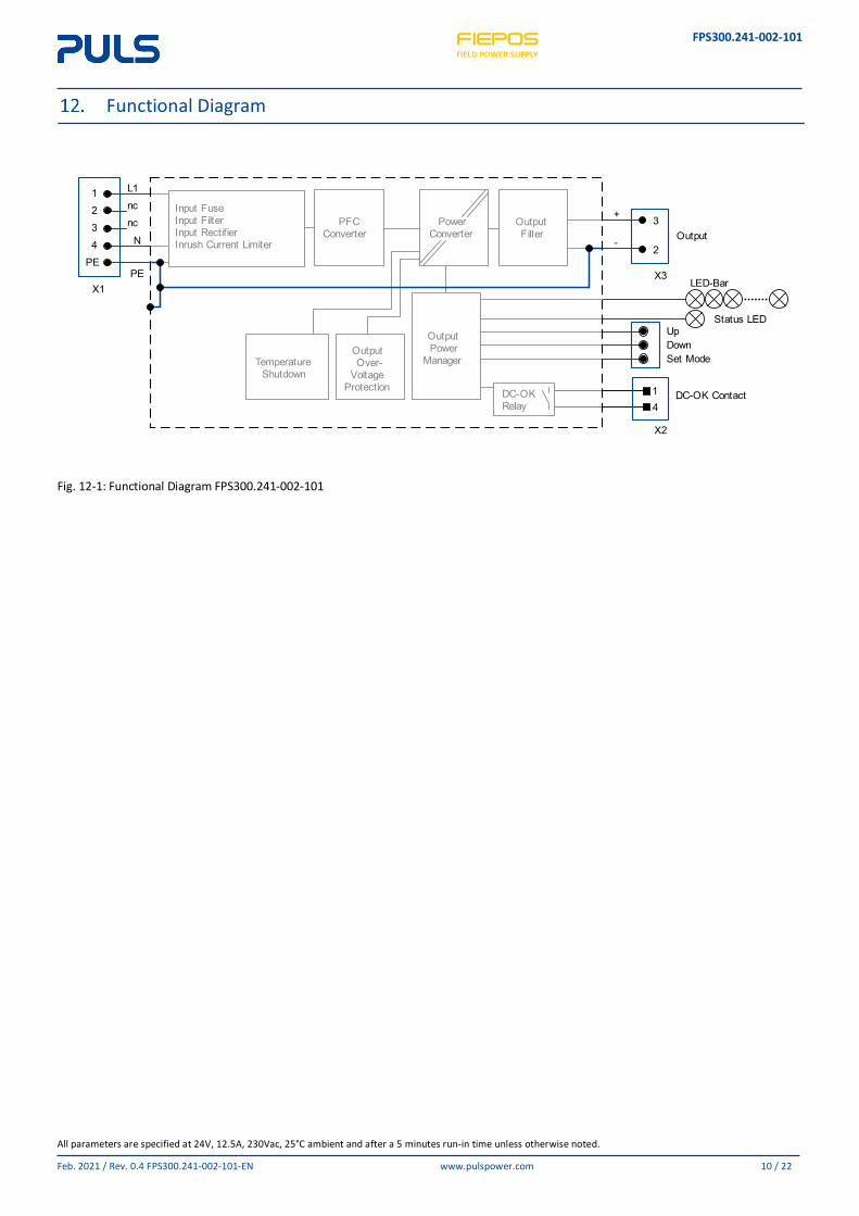
Functional Diagram
Fig. 12-1: Functional Diagram FPS300.241-002-101
Input FuseInput FilterInput RectifierInrush Current Limiter
PFC Converter
Temperature Shutdown
Output Over-
Voltage Protection
Output Power
Manager
Power Converter
Output Filter
DC-OK Relay
Status LED
Output
UpDownSet Mode
L1ncnc
1234
PEPE
X1
N
LED-Bar
DC-OK Contact
+
-
3
2
X3
X2
14
FPS300.241-002-101
All parameters are specified at 24V, 12.5A, 230Vac, 25°C ambient and after a 5 minutes run-in time unless otherwise noted.
Feb. 2021 / Rev. 0.4 FPS300.241-002-101-EN www.pulspower.com 11 / 22
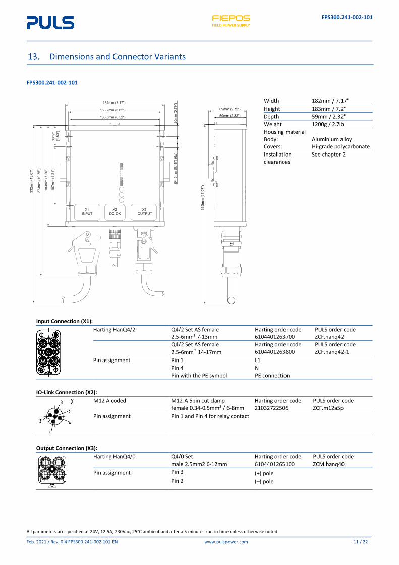
Dimensions and Connector Variants
FPS300.241-002-101
Width 182mm / 7.17'' Height 183mm / 7.2'' Depth 59mm / 2.32'' Weight 1200g / 2.7lb Housing material Body: Aluminium alloy Covers: Hi-grade polycarbonate Installation clearances
See chapter 2
Input Connection (X1):
Harting HanQ4/2 Q4/2 Set AS female 2.5-6mm² 7-13mm
Harting order code 6104401263700
PULS order code ZCF.hanq42
Q4/2 Set AS female 2.5-6mm² 14-17mm
Harting order code 6104401263800
PULS order code ZCF.hanq42-1
Pin assignment Pin 1 L1 Pin 4 N Pin with the PE symbol PE connection
IO-Link Connection (X2):
M12 A coded M12-A 5pin cut clamp female 0.34-0.5mm² / 6-8mm
Harting order code 21032722505
PULS order code ZCF.m12a5p
Pin assignment Pin 1 and Pin 4 for relay contact
Output Connection (X3):
Harting HanQ4/0 Q4/0 Set male 2.5mm2 6-12mm
Harting order code 6104401265100
PULS order code ZCM.hanq40
Pin assignment Pin 3 (+) pole Pin 2 (–) pole
183m
m (7
.20"
)
273m
m (1
0.75
")
332m
m (1
3.07
")
X1INPUT
X2DC-OK
X3OUTPUT
Ø4,
5mm
(0.1
8") (
6x)
165.5mm (6.52")
38m
m(1
.50"
)10
7mm
(4.2
1")
168.2mm (6.62")
182mm (7.17")
20m
m (0
.79"
)
69mm (2.72")
59mm (2.32")
332m
m (1
3.07
")
FPS300.241-002-101
All parameters are specified at 24V, 12.5A, 230Vac, 25°C ambient and after a 5 minutes run-in time unless otherwise noted.
Feb. 2021 / Rev. 0.4 FPS300.241-002-101-EN www.pulspower.com 12 / 22
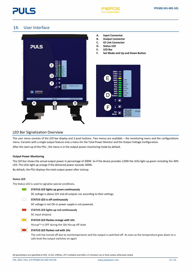
User Interface
A. Input Connector B. Output Connector C. IO Link Connector D. Status LED E. LED Bar F. Set Mode and Up and Down Button
LED Bar Signalization Overview The user menu consists of the LED bar display and 3 push buttons. Two menus are available – the monitoring menu and the configurations menu. Variants with a single output feature only a menu for the Total Power Monitor and the Output Voltage Configuration.
After the start-up of the PSU , the menu is in the output power monitoring mode by default.
Output Power Monitoring
The LED bar shows the actual output power in percentage of 300W. So if the device provides 120W the LEDs light up green including the 40% LED. The LEDs light up orange if the delivered power exceeds 300W.
By default, the PSU displays the total output power after startup.
Status LED
The Status LED is used to signalize special conditions.
STATUS LED lights up green continuously DC voltage is above 22V and all outputs run according to their settings.
STATUS LED is off continuously
DC voltage is not OK or power supply is not powered.
STATUS LED lights up red continuously AC input dropout
STATUS LED flashes orange with 1Hz HiccupPlus is OFF during the 18s Hiccup off state
STATUS LED flashes red with 1Hz
The unit has turned off due to overtemperature and the output is switched off. As soon as the temperature goes down to a safe level the output switches on again
E
D
F
A C B
E
D
F
FPS300.241-002-101
All parameters are specified at 24V, 12.5A, 230Vac, 25°C ambient and after a 5 minutes run-in time unless otherwise noted.
Feb. 2021 / Rev. 0.4 FPS300.241-002-101-EN www.pulspower.com 13 / 22
See actual output voltage
To see the actual output voltage press the “Set Mode” button for 3s. All LEDs will be flashing for 1s and the LED indicating the output voltage will remain on. Wait for 20s and the LED bar will return to output power monitoring mode.
Setting Functions Change output voltage
• Press SET / MODE for 3s. All LEDs light up for ones. • The LED display is now in Voltage Set Mode. A green LED signals the currently set voltage: e.g. the LED next to 20% represents a value of
24.5V. • All orange LEDs are off in this mode. • Voltage steps are labelled on the right hand side of the LED bar. • Push the UP button to increase the set point by one step. • Push the DOWN button to decrease the set point by one step. • New set point is applied immediately. • Exit the configuration menu by waiting for 20s without pressing any button – PSU will switch to output power monitoring mode
automatically. Lock Buttons
• In any monitoring menu, press UP and DOWN buttons simultaneously for 3s. All LEDs start
flashing for 5s to indicate that button lock status has changed.
• After that, the display returns to output power monitoring mode.
• If SET / MODE button is pushed for 3s and the button lock is activated, all LEDs starts flickering for 5s to indicate that buttons are locked
• Deactivate the button lock feature, by pressing the UP and DOWN buttons simultaneously for 3s in any monitoring menu again.
All LEDs start flashing for 5s to indicate that button lock status has changed.
FPS300.241-002-101
All parameters are specified at 24V, 12.5A, 230Vac, 25°C ambient and after a 5 minutes run-in time unless otherwise noted.
Feb. 2021 / Rev. 0.4 FPS300.241-002-101-EN www.pulspower.com 14 / 22
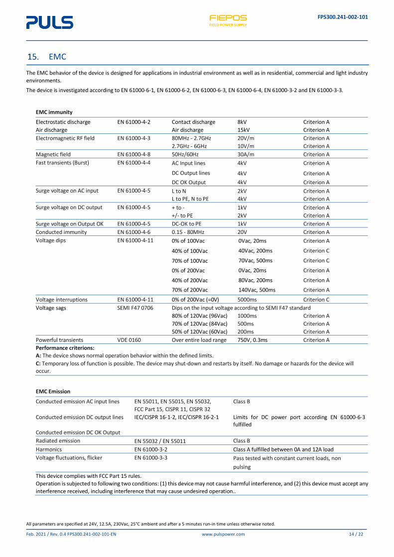
EMC
The EMC behavior of the device is designed for applications in industrial environment as well as in residential, commercial and light industry environments.
The device is investigated according to EN 61000-6-1, EN 61000-6-2, EN 61000-6-3, EN 61000-6-4, EN 61000-3-2 and EN 61000-3-3.
EMC immunity Electrostatic discharge EN 61000-4-2 Contact discharge 8kV Criterion A Air discharge Air discharge 15kV Criterion A Electromagnetic RF field EN 61000-4-3 80MHz - 2.7GHz 20V/m Criterion A 2.7GHz - 6GHz 10V/m Criterion A Magnetic field EN 61000-4-8 50Hz/60Hz 30A/m Criterion A Fast transients (Burst) EN 61000-4-4 AC Input lines 4kV Criterion A
DC Output lines 4kV Criterion A DC OK Output 4kV Criterion A Surge voltage on AC input EN 61000-4-5 L to N 2kV Criterion A L to PE, N to PE 4kV Criterion A Surge voltage on DC output EN 61000-4-5 + to - 1kV Criterion A +/- to PE 2kV Criterion A Surge voltage on Output OK EN 61000-4-5 DC-OK to PE 1kV Criterion A Conducted immunity EN 61000-4-6 0.15 - 80MHz 20V Criterion A Voltage dips EN 61000-4-11 0% of 100Vac 0Vac, 20ms Criterion A 40% of 100Vac 40Vac, 200ms Criterion C 70% of 100Vac 70Vac, 500ms Criterion C 0% of 200Vac 0Vac, 20ms Criterion A 40% of 200Vac 80Vac, 200ms Criterion A 70% of 200Vac 140Vac, 500ms Criterion A
Voltage interruptions EN 61000-4-11 0% of 200Vac (=0V) 5000ms Criterion C Voltage sags SEMI F47 0706 Dips on the input voltage according to SEMI F47 standard 80% of 120Vac (96Vac) 1000ms Criterion A 70% of 120Vac (84Vac) 500ms Criterion A 50% of 120Vac (60Vac) 200ms Criterion A Powerful transients VDE 0160 Over entire load range 750V, 0.3ms Criterion A Performance criterions: A: The device shows normal operation behavior within the defined limits. C: Temporary loss of function is possible. The device may shut-down and restarts by itself. No damage or hazards for the device will occur.
EMC Emission Conducted emission AC input lines EN 55011, EN 55015, EN 55032,
FCC Part 15, CISPR 11, CISPR 32 Class B
Conducted emission DC output lines IEC/CISPR 16-1-2, IEC/CISPR 16-2-1 Limits for DC power port according EN 61000-6-3 fulfilled
Conducted emission DC OK Output Radiated emission EN 55032 / EN 55011 Class B Harmonics EN 61000-3-2 Class A fulfilled between 0A and 12A load Voltage fluctuations, flicker EN 61000-3-3 Pass tested with constant current loads, non
pulsing This device complies with FCC Part 15 rules. Operation is subjected to following two conditions: (1) this device may not cause harmful interference, and (2) this device must accept any interference received, including interference that may cause undesired operation..
FPS300.241-002-101
All parameters are specified at 24V, 12.5A, 230Vac, 25°C ambient and after a 5 minutes run-in time unless otherwise noted.
Feb. 2021 / Rev. 0.4 FPS300.241-002-101-EN www.pulspower.com 15 / 22
Switching Frequencies PFC converter 20kHz to 135kHz Input voltage and output load dependent Main converter 60kHz to 140kHz Output load dependent Auxiliary converter 54kHz to 66kHz Output load dependent Microcontroller clocks 48Mhz and 32MHz Fixed frequency
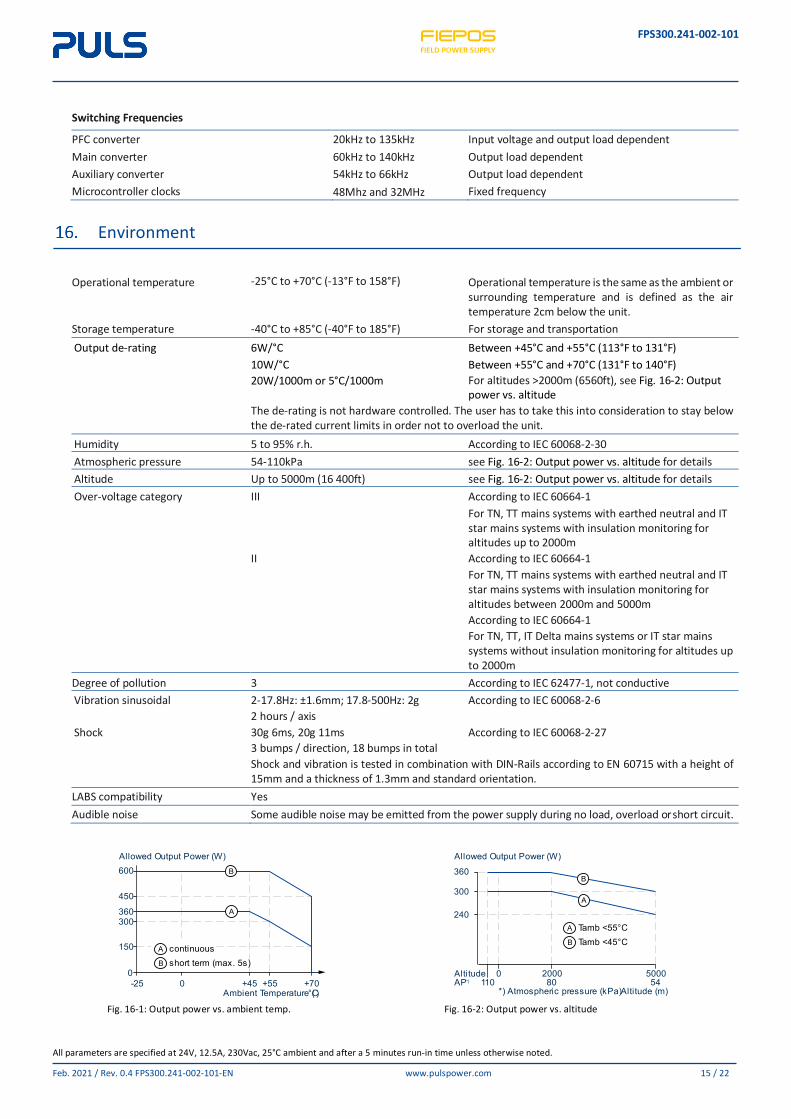
Environment
Operational temperature -25°C to +70°C (-13°F to 158°F) Operational temperature is the same as the ambient or
surrounding temperature and is defined as the air temperature 2cm below the unit.
Storage temperature -40°C to +85°C (-40°F to 185°F) For storage and transportation Output de-rating 6W/°C Between +45°C and +55°C (113°F to 131°F) 10W/°C Between +55°C and +70°C (131°F to 140°F) 20W/1000m or 5°C/1000m For altitudes >2000m (6560ft), see Fig. 16-2: Output
power vs. altitude The de-rating is not hardware controlled. The user has to take this into consideration to stay below
the de-rated current limits in order not to overload the unit. Humidity 5 to 95% r.h. According to IEC 60068-2-30 Atmospheric pressure 54-110kPa see Fig. 16-2: Output power vs. altitude for details Altitude Up to 5000m (16 400ft) see Fig. 16-2: Output power vs. altitude for details Over-voltage category III According to IEC 60664-1
For TN, TT mains systems with earthed neutral and IT star mains systems with insulation monitoring for altitudes up to 2000m
II According to IEC 60664-1 For TN, TT mains systems with earthed neutral and IT star mains systems with insulation monitoring for altitudes between 2000m and 5000m According to IEC 60664-1 For TN, TT, IT Delta mains systems or IT star mains systems without insulation monitoring for altitudes up to 2000m
Degree of pollution 3 According to IEC 62477-1, not conductive Vibration sinusoidal 2-17.8Hz: ±1.6mm; 17.8-500Hz: 2g According to IEC 60068-2-6 2 hours / axis
Shock 30g 6ms, 20g 11ms According to IEC 60068-2-27 3 bumps / direction, 18 bumps in total
Shock and vibration is tested in combination with DIN-Rails according to EN 60715 with a height of 15mm and a thickness of 1.3mm and standard orientation.
LABS compatibility Yes Audible noise Some audible noise may be emitted from the power supply during no load, overload or short circuit.
Fig. 16-1: Output power vs. ambient temp.
Fig. 16-2: Output power vs. altitude
A
B
A continuousB short term (max. 5s)
Allowed Output Power (W)
Ambient Temperature (°C)
600
450
360300
150
0-25 +450 +55 +70
A
B
A Tamb <55°CB Tamb <45°C
Allowed Output Power (W)
360
300
240
Altitude
*) Atmospheric pressure (kPa)Altitude (m)
20000 5000AP*) 80110 54
FPS300.241-002-101
All parameters are specified at 24V, 12.5A, 230Vac, 25°C ambient and after a 5 minutes run-in time unless otherwise noted.
Feb. 2021 / Rev. 0.4 FPS300.241-002-101-EN www.pulspower.com 16 / 22
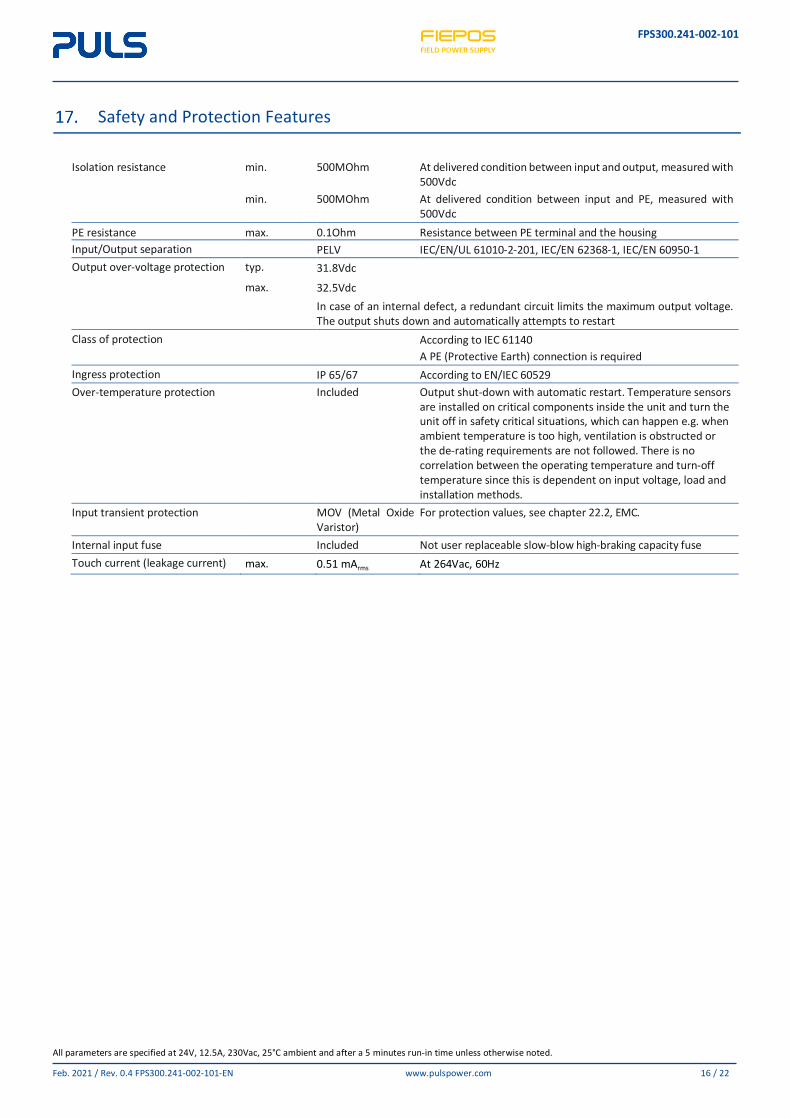
Safety and Protection Features
Isolation resistance min. 500MOhm At delivered condition between input and output, measured with
500Vdc min. 500MOhm At delivered condition between input and PE, measured with
500Vdc PE resistance max. 0.1Ohm Resistance between PE terminal and the housing Input/Output separation PELV IEC/EN/UL 61010-2-201, IEC/EN 62368-1, IEC/EN 60950-1 Output over-voltage protection typ. 31.8Vdc
max. 32.5Vdc
In case of an internal defect, a redundant circuit limits the maximum output voltage. The output shuts down and automatically attempts to restart
Class of protection According to IEC 61140 A PE (Protective Earth) connection is required Ingress protection IP 65/67 According to EN/IEC 60529 Over-temperature protection Included Output shut-down with automatic restart. Temperature sensors
are installed on critical components inside the unit and turn the unit off in safety critical situations, which can happen e.g. when ambient temperature is too high, ventilation is obstructed or the de-rating requirements are not followed. There is no correlation between the operating temperature and turn-off temperature since this is dependent on input voltage, load and installation methods.
Input transient protection MOV (Metal Oxide Varistor)
For protection values, see chapter 22.2, EMC.
Internal input fuse Included Not user replaceable slow-blow high-braking capacity fuse Touch current (leakage current) max. 0.51 mArms At 264Vac, 60Hz
FPS300.241-002-101
All parameters are specified at 24V, 12.5A, 230Vac, 25°C ambient and after a 5 minutes run-in time unless otherwise noted.
Feb. 2021 / Rev. 0.4 FPS300.241-002-101-EN www.pulspower.com 17 / 22
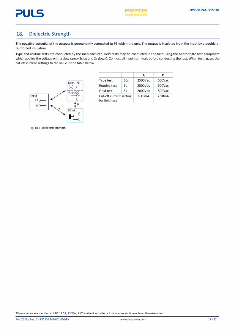
Dielectric Strength
The negative potential of the outputs is permanently connected to PE within the unit. The output is insulated from the input by a double or reinforced insulation.
Type and routine tests are conducted by the manufacturer. Field tests may be conducted in the field using the appropriate test equipment which applies the voltage with a slow ramp (2s up and 2s down). Connect all input-terminals before conducting the test. When testing, set the cut-off current settings to the value in the table below.
Fig. 18-1: Dielectric strength
A D Type test 60s 2500Vac 500Vac Routine test 5s 2500Vac 500Vac Field test 5s 2000Vac 500Vac Cut-off current setting for field test
> 10mA > 10mA
+-
Output(s)
Earth, PE
DC-ok
D
Input
N
L1
FPS300.241-002-101
All parameters are specified at 24V, 12.5A, 230Vac, 25°C ambient and after a 5 minutes run-in time unless otherwise noted.
Feb. 2021 / Rev. 0.4 FPS300.241-002-101-EN www.pulspower.com 18 / 22
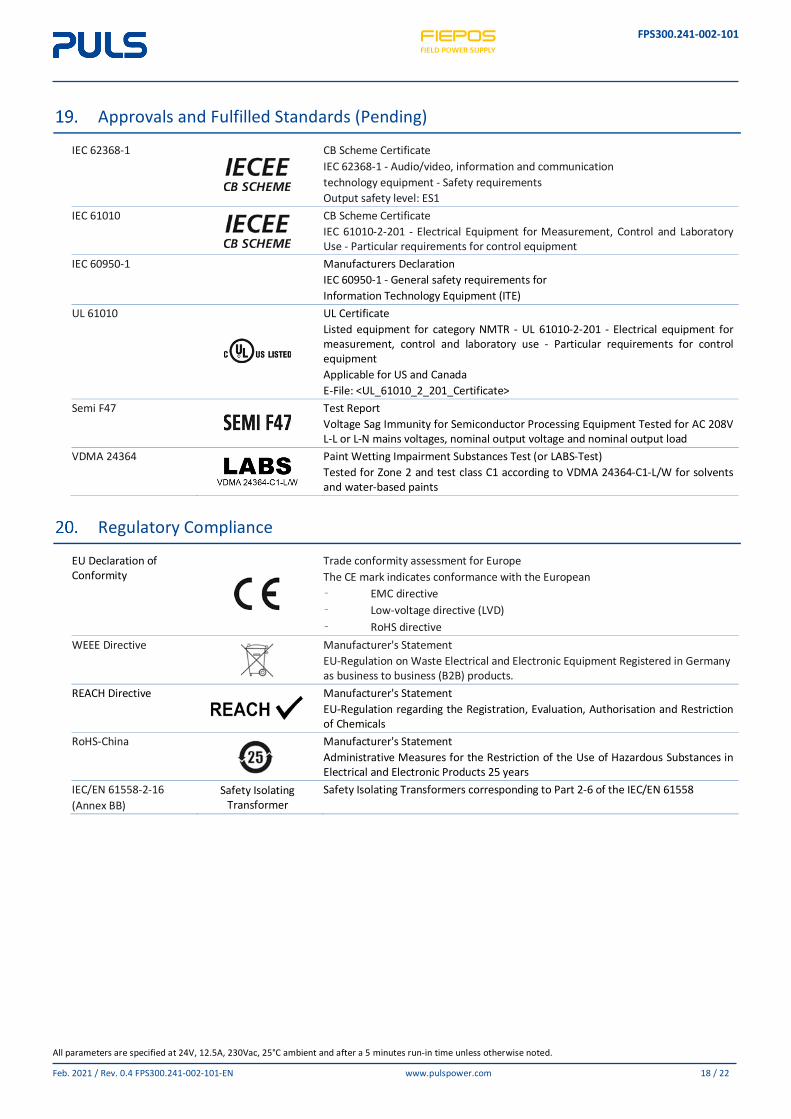
Approvals and Fulfilled Standards (Pending)
IEC 62368-1
CB Scheme Certificate IEC 62368-1 - Audio/video, information and communication technology equipment - Safety requirements Output safety level: ES1
IEC 61010
CB Scheme Certificate IEC 61010-2-201 - Electrical Equipment for Measurement, Control and Laboratory Use - Particular requirements for control equipment
IEC 60950-1
Manufacturers Declaration IEC 60950-1 - General safety requirements for Information Technology Equipment (ITE)
UL 61010
UL Certificate Listed equipment for category NMTR - UL 61010-2-201 - Electrical equipment for measurement, control and laboratory use - Particular requirements for control equipment Applicable for US and Canada E-File: <UL_61010_2_201_Certificate>
Semi F47
Test Report Voltage Sag Immunity for Semiconductor Processing Equipment Tested for AC 208V L-L or L-N mains voltages, nominal output voltage and nominal output load
VDMA 24364
Paint Wetting Impairment Substances Test (or LABS-Test) Tested for Zone 2 and test class C1 according to VDMA 24364-C1-L/W for solvents and water-based paints
Regulatory Compliance
EU Declaration of Conformity
Trade conformity assessment for Europe The CE mark indicates conformance with the European – EMC directive – Low-voltage directive (LVD) – RoHS directive
WEEE Directive
Manufacturer's Statement EU-Regulation on Waste Electrical and Electronic Equipment Registered in Germany as business to business (B2B) products.
REACH Directive
Manufacturer's Statement EU-Regulation regarding the Registration, Evaluation, Authorisation and Restriction of Chemicals
RoHS-China
Manufacturer's Statement Administrative Measures for the Restriction of the Use of Hazardous Substances in Electrical and Electronic Products 25 years
IEC/EN 61558-2-16 (Annex BB)
Safety Isolating Transformer
Safety Isolating Transformers corresponding to Part 2-6 of the IEC/EN 61558
FPS300.241-002-101
All parameters are specified at 24V, 12.5A, 230Vac, 25°C ambient and after a 5 minutes run-in time unless otherwise noted.
Feb. 2021 / Rev. 0.4 FPS300.241-002-101-EN www.pulspower.com 19 / 22
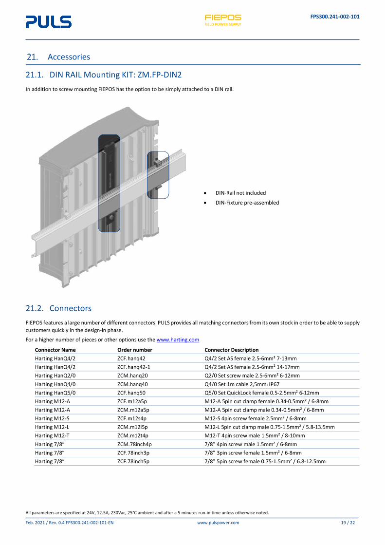
Accessories
21.1. DIN RAIL Mounting KIT: ZM.FP-DIN2 In addition to screw mounting FIEPOS has the option to be simply attached to a DIN rail.
• DIN-Rail not included
• DIN-Fixture pre-assembled
21.2. Connectors FIEPOS features a large number of different connectors. PULS provides all matching connectors from its own stock in order to be able to supply customers quickly in the design-in phase.
For a higher number of pieces or other options use the www.harting.com
Connector Name Order number Connector Description Harting HanQ4/2 ZCF.hanq42 Q4/2 Set AS female 2.5-6mm² 7-13mm Harting HanQ4/2 ZCF.hanq42-1 Q4/2 Set AS female 2.5-6mm² 14-17mm Harting HanQ2/0 ZCM.hanq20 Q2/0 Set screw male 2.5-6mm² 6-12mm Harting HanQ4/0 ZCM.hanq40 Q4/0 Set 1m cable 2,5mm2 IP67 Harting HanQ5/0 ZCF.hanq50 Q5/0 Set QuickLock female 0.5-2.5mm² 6-12mm Harting M12-A ZCF.m12a5p M12-A 5pin cut clamp female 0.34-0.5mm² / 6-8mm Harting M12-A ZCM.m12a5p M12-A 5pin cut clamp male 0.34-0.5mm² / 6-8mm Harting M12-S ZCF.m12s4p M12-S 4pin screw female 2.5mm² / 6-8mm Harting M12-L ZCM.m12l5p M12-L 5pin cut clamp male 0.75-1.5mm² / 5.8-13.5mm Harting M12-T ZCM.m12t4p M12-T 4pin screw male 1.5mm² / 8-10mm Harting 7/8” ZCM.78inch4p 7/8” 4pin screw male 1.5mm² / 6-8mm Harting 7/8” ZCF.78inch3p 7/8” 3pin screw female 1.5mm² / 6-8mm Harting 7/8” ZCF.78inch5p 7/8” 5pin screw female 0.75-1.5mm² / 6.8-12.5mm
FPS300.241-002-101
All parameters are specified at 24V, 12.5A, 230Vac, 25°C ambient and after a 5 minutes run-in time unless otherwise noted.
Feb. 2021 / Rev. 0.4 FPS300.241-002-101-EN www.pulspower.com 20 / 22
Related Products (PENDING)
The FIEPOS product family includes various devices with different technical parameters and features. The following page provides a general overview of the available solutions. Please also get in touch with your PULS contact person, for more detailed application advice and technical information.
FPS300.241-002-101
All parameters are specified at 24V, 12.5A, 230Vac, 25°C ambient and after a 5 minutes run-in time unless otherwise noted.
Feb. 2021 / Rev. 0.4 FPS300.241-002-101-EN www.pulspower.com 21 / 22
Application Notes
23.1. Repetitive Pulse Loading Typically, a load current is not constant and varies over time. This power supply is designed to support loads with a higher short-term power demand (=BonusPower®). The short-term duration is hardware controlled by an output power manager and is available on a repeated basis. If the average load is higher than the nominal output power, the output voltage will dip.
To avoid this, the following rules must be met:
a) The power demand of the pulse must be below 200% of the nominal output power.
b) The duration of the pulse power must be shorter than the allowed BonusPower® time. (see output section)
c) The average power should be lower than the nominal output power.
The R.M.S. output current must be below the specified continuous output current. If the R.M.S. current is higher, the unit will respond with a thermal shut-down after a period of time.
23.2. External Input Protection (Pending) The device is designed, tested and approved for branch circuits up to 30A (UL) and 32A (IEC) without additional protection device. If an external fuse is utilized, do not use circuit breakers smaller than 30A B- or C-Characteristic to avoid a nuisance tripping of the circuit breaker.
23.3. Inductive and Capacitive Loads The unit is designed to supply any kind of loads, including capacitive and inductive loads. If extreme large capacitors, such as EDLCs (electric double layer capacitors or “UltraCaps”) with a capacitance larger than 100mF are connected to the output, the unit might charge the capacitor in the HiccupPLUS mode (see chapter ).
23.4. Back Feeding Loads Loads such as decelerating motors and inductors can feed voltage back to the power supply. This feature is also called return voltage immunity or resistance against Back- E.M.F. (Electro Magnetic Force).
This power supply is resistant and does not show malfunctioning when a load feeds back voltage to the power supply. It does not matter whether the power supply is on or off.
FPS300.241-002-101
All parameters are specified at 24V, 12.5A, 230Vac, 25°C ambient and after a 5 minutes run-in time unless otherwise noted.
Feb. 2021 / Rev. 0.4 FPS300.241-002-101-EN www.pulspower.com 22 / 22
23.5. Mounting Orientations
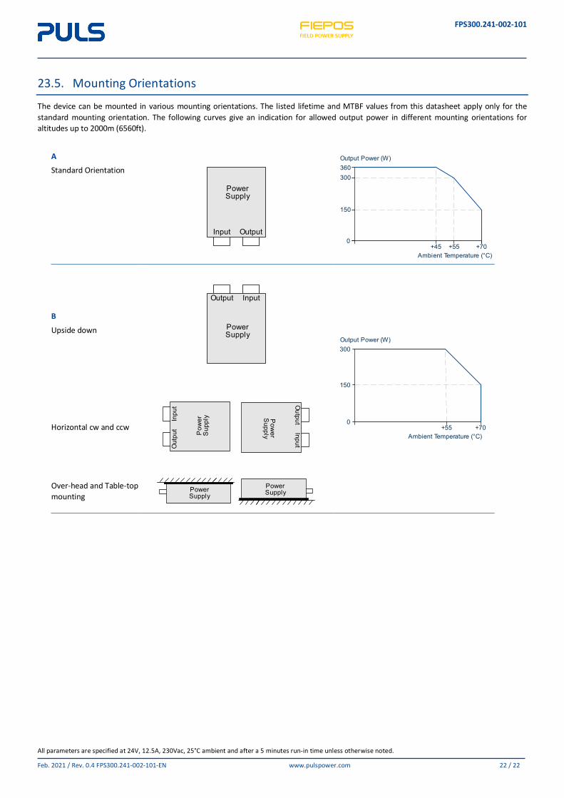
The device can be mounted in various mounting orientations. The listed lifetime and MTBF values from this datasheet apply only for the standard mounting orientation. The following curves give an indication for allowed output power in different mounting orientations for altitudes up to 2000m (6560ft).
A
Standard Orientation
B
Upside down
Horizontal cw and ccw
Over-head and Table-top mounting
Input Output
Power Supply
360300
150
0+45 +55 +70
Ambient Temperature (°C)
Output Power (W)
InputOutput
Power Supply
300
150
0+55 +70
Ambient Temperature (°C)
Output Power (W)
Inpu
tO
utpu
t Pow
er
Sup
ply
InputO
utputPow
er S
upply
Power Supply
Power Supply