Embed Size (px)
Citation preview

Research Collection
Journal Article
Possibilities of Additive Technologies for the Manufacturing ofTooling from Corrosion-Resistant Steels in Order to ProtectParts Surfaces from Thermochemical Treatment
Author(s): Metel, Alexander; Tarasova, Tatiana; Gutsaliuk, Evgenii; Egorov, Sergei; Grigoriev, Sergey
Publication Date: 2021-10
Permanent Link: https://doi.org/10.3929/ethz-b-000510171
Originally published in: Metals 11(10), http://doi.org/10.3390/met11101551
Rights / License: Creative Commons Attribution 4.0 International
This page was generated automatically upon download from the ETH Zurich Research Collection. For moreinformation please consult the Terms of use.
ETH Library

metals
Article
Possibilities of Additive Technologies for the Manufacturing ofTooling from Corrosion-Resistant Steels in Order to ProtectParts Surfaces from Thermochemical Treatment
Alexander Metel 1 , Tatiana Tarasova 1 , Evgenii Gutsaliuk 1, Roman Khmyrov 1, Sergei Egorov 1,2,*and Sergey Grigoriev 1
�����������������
Citation: Metel, A.; Tarasova, T.;
Gutsaliuk, E.; Khmyrov, R.; Egorov, S.;
Grigoriev, S. Possibilities of Additive
Technologies for the Manufacturing
of Tooling from Corrosion-Resistant
Steels in Order to Protect Parts
Surfaces from Thermochemical
Treatment. Metals 2021, 11, 1551.
https://doi.org/10.3390/met11101551
Academic Editor: Youngsik Kim
Received: 31 August 2021
Accepted: 24 September 2021
Published: 29 September 2021
Publisher’s Note: MDPI stays neutral
with regard to jurisdictional claims in
published maps and institutional affil-
iations.
Copyright: © 2021 by the authors.
Licensee MDPI, Basel, Switzerland.
This article is an open access article
distributed under the terms and
conditions of the Creative Commons
Attribution (CC BY) license (https://
creativecommons.org/licenses/by/
4.0/).
1 Department of High-Efficiency Machining Technologies, Moscow State University of Technology «STANKIN»,127055 Moscow, Russia; [email protected] (A.M.); [email protected] (T.T.);[email protected] (E.G.); [email protected] (R.K.); [email protected] (S.G.)
2 Swiss Federal Institute of Technology (ETH Zurich), 8092 Zurich, Switzerland* Correspondence: [email protected]
Abstract: The structure and physical–mechanical properties of products made from powders ofcorrosion-resistant steel 12X18H10T by the laser-beam powder bed fusion (LB-PBF) and subsequention-plasma nitriding in the work were investigated. Comparative studies of the physical mechanicalproperties of specimens made by the LB-PBF and conventional method from steel of the same gradewere carried out. The density of the specimens and the coefficient of linear thermal expansion (CLTE)after the LB-PBF are almost the same as those of the conventionally manufactured specimens. Ouranalysis of the obtained dilatograms in the temperature range from 20 to 600 ◦C showed that theCLTE of steel after the LB-PBF is within acceptable limits (18.6 × 10⁻⁶ 1/◦C). Their hardness, tensilestrength, yield strength and elongation are higher than those of a conventionally manufacturedspecimen. The phase composition and structure of specimens of steel 12X18H10T made by theLB-PBF after the process of ion-plasma nitriding were investigated. The obtained results show thatthe mode of ion-plasma nitriding used in this case (stage 1—570 ◦C for 36 h; stage 2—540 ◦C for 12 h)does not lead to deterioration of the characteristics of the selected steel. A technological process forthe manufacture of modified tooling from 12X18H10T steel by the LB-PBF was developed. It protectsthe surfaces that are not subject to nitriding and makes it possible to obtain a uniform high-qualitynitrided layer on the working surface of the part made from spheroidal graphite iron.
Keywords: additive technologies; selective laser melting; ion-plasma nitriding; austenitic steel;spheroidal graphite iron; laser beam powder bed fusion
1. Introduction
Additive manufacturing is defined as the process of coupling materials to createobjects from 3D model data, layer by layer. It is opposed to “subtractive” manufacturingmethods, such as traditional machining [1].
Additive manufacturing (AM) makes it possible to create products of complex shapesthat cannot be manufactured by conventional methods. AM makes it possible to reduce thetime between the drawing and the final product, reduce the production time of the product,reduce material consumption and shorten the technological cycle by reducing the numberof operations. Nowadays, one of the most promising areas of AM is the manufacturing ofproducts from metal powders by the laser beam powder bed fusion (LB-PBF) and directmetal deposition (DMD) [2–5]. The range of materials used is expanding, along with thewidespread use of corrosion-resistant steels; research is underway to determine the optimalparameters for the manufacture of products such as ceramics, metal alloys and compositematerials [6–8].
The authors of Reference [9] investigated the microstructure and electrochemical be-havior of 316L steel processed by LB-PBF in a concentrated solution (0.9 M NaOH + 0.9%
Metals 2021, 11, 1551. https://doi.org/10.3390/met11101551 https://www.mdpi.com/journal/metals

Metals 2021, 11, 1551 2 of 14
NaCl). It has been shown that the LB-PBF method does not reduce the corrosion resistanceof 316L steel in an alkaline solution and in some cases shows better electrochemical charac-teristics in comparison with a wrought alloy. In addition, the alloy treated with LB-PBFshowed a lower defect density compared to the wrought alloy.
The authors of Reference [10] analyzed the influence of SLM processing parameters,such as scanning strategy, powder layer thickness, laser power, scanning speed, on surfacemorphology and surface texturing, which ultimately determine the mechanical propertiesand functionality of the final product.
The authors of References [11,12] showed the possibility of temperature control in theprocess of the LB-PBF and DMD. An original optical diagnostic system was developed.The aim of the study was to improve product quality and ensure the stability and repro-ducibility of the process, using optical monitoring. The works used Ti6Al4V powder, twooriginally developed pyrometers and a FLIR Phoenix RDAS ™ infrared camera. Changesin the pyrometer signal and brightness temperature from the operating parameters of theprocesses were analyzed. The possibility of manufacturing parts of almost any complexityis shown.
In Reference [13], the authors noted that one of the most promising methods ofadditive manufacturing is LB-PBF. However, this method has very low productivity, thuslimiting its widespread use. The solution of this problem will make it possible to obtainmetal 3D objects of complex geometry in a short time. The authors propose to improve themethod by installing laser-beam profiling systems and online monitoring on the developedexperimental setup. Alternative distributions of the power density of the laser beam areobtained. Online video surveillance has shown that, with the use of a laser beam profilingsystem, the negative effects of the process are noticeably reduced.
The use of corrosion-resistant steel powders in AM is of great interest both for researchand for applied needs [14–17]. The following grades of corrosion-resistant steels are widelyused in the LB-PBF: austenitic corrosion-resistant steels (AISI 316L, Russian analogue-03X17H14M3; AISI 304L, Russian analogue-03X18H11) and martensitic corrosion-resistantsteels (AISI 420, Russian analogue-20X13, 30X13, 40X13) [10,13,15,17–20].
In Reference [17], the authors implemented a model for calculating thermal fieldsfor various schemes of laser processing of corrosion-resistant steels, making it possibleto obtain estimated geometric dimensions of melting zones during laser heat treatmentand LB-PBF. It is shown that, during laser heat treatment of corrosion-resistant steelsand LB-PBF of corrosion-resistant steels, a quenching mechanism from the liquid state isrealized. In this case, the structure of the melting zones is determined by the cooling rate.
The authors of Reference [18] studied the possibilities of using the methods of scanningelectron microscopy and particle size analysis for the study of domestically producedpowders from corrosion-resistant steels of 12X18H9T (AISI 321) and 20H13 (AISI 420); thegrades are considered for the purpose of their application in LB-PBF technology.
Corrosion-resistant steels are most actively used in the aerospace industry, for example,in the manufacture of aircraft exhaust pipes, technological equipment, cabin heaters,etc. [21]. The authors of References [22,23] showed the possibility of replacing conventionalmethods of manufacturing aircraft airframe parts from corrosion-resistant steels 20X13and X18H9T (washers of the airframe lock mechanism and air intake gratings) with analternative technology, i.e., laser-beam powder bed fusion.
At present, research is underway quite actively on the influence of various post-processing methods on the properties of parts manufactured by additive technologies.The authors of Reference [22] conducted research on the effect of post-treatment (heattreatment, ultrasonic liquid treatment and vibration tumbling) on the mechanical charac-teristics and surface quality of parts made by the LB-PBF from corrosion-resistant steels20X13 and X18H9T. The effect of heat treatment on the hardness and wear resistance of20X13 steel specimens manufactured by the LB-PBF was determined. The values of wearresistance and hardness of specimens obtained by LB-PBF with and without low temperingdiffer insignificantly. Abovementioned values slightly higher than the wear resistance of

Metals 2021, 11, 1551 3 of 14
specimens after conventional quenching and low tempering. Investigated the influenceof ultrasonic treatment and vibration tumbling on the surface quality of parts. It hasbeen established that the use of ultrasonic treatment and vibration tumbling after LB-PBFallows us to improve the surface quality by reducing the roughness at the micro leveland submicro level. The influence of the post-processing parameters on the mechanicalcharacteristics of products manufactured by the LB-PBF method is determined to ensurethe required properties of aerospace parts made of corrosion-resistant steels by the selectivelaser melting method.
The authors of Reference [8] consider shot blasting to reduce stresses and structuraldefects as a post-processing of specimens made of corrosion-resistant 316L steel by lasercladding. It is shown that the surface stress of the specimen formed by the hybrid processchanged from tensile to compressive stress. At the same time, internal microdefects suchas pores were reduced. The porosity of the specimen formed by the hybrid process wasreduced by 90.12% than that of the laser cladding specimen, and the surface roughnessdecreased by 43.16%.
It is shown that in the process of the LB-PBF a finely dispersed structure is formed.That provides higher strength properties of steels after the LB-PBF than after conventionalprocessing. The density of the specimens is at the similar level. The study of the effectof heat treatment on the mechanical characteristics of corrosion-resistant steels showedthat the hardness of 20X13 steel specimens obtained by the LB-PBF is higher than that of aconventionally heat treated specimens. The wear resistance decreases with an increasing inthe tempering temperature for all test specimens [22]. The authors of Reference [24] showthat the grain size in specimens made using low power is smaller than in specimens madeat higher power. The reason for it is that higher powers have a greater thermal effect on alarger melting pool. Specimens built by using lower power have a lower thermal gradientand slower cooling rate.
Despite the large number of different studies of corrosion-resistant steels obtained bythe LB-PBF, a number of unsolved scientific and technological problems still remain. Itaffects the quality and cost of the products. Not enough attention is paid to the influence ofthermal and thermochemical treatments on the products structure and properties. Researchin this area is necessary to solve specific problems of using LB-PBF of corrosion-resistantsteels in the engineering industry, particularly in the manufacture of various types oftooling. AM makes it possible to manufacture tooling for certain technological operations.For the manufacture of products that meet customer requirements, various types of toolingare used. The types of tooling are made for strictly defined operations. The use of additivetechnologies makes it possible to take into account the design features of the future toolingand design it strictly for a specific product. Currently, to increase the wear resistance ofthe parts, various types of thermal and thermochemical treatments are used; research isunderway to develop new functional coatings with unique properties [25–27]. At the sametime, there is a need to protect surfaces that are not subject to hardening. For this purpose,various methods are used, from special coatings to the manufacture of tooling. For example,it was used in the operations of ion-plasma nitriding. Specifically made equipment in theform of casings is used, and it covers certain surfaces from nitriding. The use of additivetechnologies makes it possible to manufacture special alloys tooling with specific complexshape. In this case, AM shows the maximum material utilization rate. Possibilities of usingadditive technologies for the manufacture of tooling from metal powders to protect thesurfaces of parts from thermochemical treatment have received insufficient attention. Itcannot be ruled out that the microstructure of products produced by the LB-PBF is exposedto saturating gases in a completely different way than the microstructure of productsmanufactured by conventional methods. There is a complex metal science task requiring alarge number of experiments and studies on the effect of thermochemical treatment on thematerial made by AM.

Metals 2021, 11, 1551 4 of 14
The purpose of this work is to study the structure and physicomechanical properties ofproducts made from domestically produced corrosion-resistant steel 12X18H10T powdersby the LB-PBF and subsequent ion-plasma nitriding.
2. Materials and Methods
Corrosion-resistant chromium–nickel austenitic steel, grade X18H9T, was chosen asa material for the study. Metal powders of steel X18H9T (PRX18H9T, fraction from 20 to63 µm) were prepared by AO “POLEMA” (Tula, Russia) by dispersing a molten metal by ajet of compressed gas. The choice of materials was determined by the request of aviationindustry enterprises. It was used for the development of technological processes for themanufacture of tooling using AM. The paper investigates the possibility of replacing theconventional manufacturing technology of protective tooling by the production of nitridedparts with the LB-PBF technology.
In the work, the block part made from spheroidal graphite iron was considered. Theflat end of the block was subjected to nitriding, while a number of surfaces were protectedfrom nitrogen saturation. For this purpose, according to the conventional technology,tooling is made from steel 12X18H10T (Figure 1a).
Metals 2021, 11, x FOR PEER REVIEW 5 of 15
(a) (b)
Figure 1. (a) Block blank in conventional tooling for ion-plasma nitriding; (b) block blank after ion-plasma nitriding (light gray zones with reduced hardness as a result of shielding from balls are clearly visible).
After ion-plasma nitriding, at the holes closed with balls, zones with a reduced hard-ness are formed (Figure 1b). Such zones appear due to the shielding of the cast-iron sur-face by balls. To eliminate this problem and obtain a high-quality nitrided layer on the working surface of the block, it is proposed to modernize the design of the tooling and manufacture it by the LB-PBF. A 3D model of the upgraded tooling is shown in Figure 2.
(a) (b)
Figure 2. Three-dimensional model of the modernized equipment: (a) “new” tooling and sketch of the assembled block and (b) section of the 3D model.
The non-nitriding holes are closed from below, thereby eliminating the shielding ef-fect during the ion-plasma nitriding process. The advantage of the new tooling is a high material utilization rate, as well as ease of use. The operational requirements for the tool-ing are as follows: • The tooling geometry must provide a uniform nitriding layer on the block surface;
the tooling components must cover the non-nitrided surfaces. • The chemical composition and microstructure of the steel must ensure the depth of
the nitrided layer is no more than 1/2 of the wall thickness of the tooling for a long period of time (to increase the service life).
• The nitrided layer, regardless of the service life, should not become embrittled. The material for the tooling is austenitic steel 12X18H10T, since this steel is almost
not prone to nitriding.
Figure 1. (a) Block blank in conventional tooling for ion-plasma nitriding; (b) block blank afterion-plasma nitriding (light gray zones with reduced hardness as a result of shielding from balls areclearly visible).
The production goal was to design a structure and develop a manufacturing processusing the LB-PBF method for protective tooling. The tooling protects blocks made fromspheroidal graphite iron used in piston pumps for aircraft engines from ion-plasma ni-triding in order to improve the quality of the nitrided layer. The goal was achieved bythe completion of studies of the physical and mechanical properties of specimens madefrom corrosion-resistant steel 12X18H10T by laser-beam powder bed fusion. The chemicalcomposition of spheroidal graphite iron is shown in Table 1. Block blank is nitrided byusing conventional tooling to protect surfaces that are not subject to nitriding.
Table 1. Chemical composition of spheroidal graphite iron MN.
Element Fe C Si Ni Mn Mg S P
wt.% Bal. 3.21 2.86 0.87 1.02 0.05 0.017 0.08
Tooling made in a conventional way does not provide a sufficient quality of thenitrided layer on the surface of the part (Figure 1b).
The block diameters are closed with a casing (1) and a cover (2), and the holes areclosed with balls (3). The part stands on a sheet (4) with a Ø 0.75 mm drilled hole forvacuum pumping. The casing, sheet and cover are made from steel 12X18H10T; the ballsare made from steel IIIX15 (Figure 1a).

Metals 2021, 11, 1551 5 of 14
After ion-plasma nitriding, at the holes closed with balls, zones with a reducedhardness are formed (Figure 1b). Such zones appear due to the shielding of the cast-ironsurface by balls. To eliminate this problem and obtain a high-quality nitrided layer on theworking surface of the block, it is proposed to modernize the design of the tooling andmanufacture it by the LB-PBF. A 3D model of the upgraded tooling is shown in Figure 2.
Metals 2021, 11, x FOR PEER REVIEW 5 of 15
(a) (b)
Figure 1. (a) Block blank in conventional tooling for ion-plasma nitriding; (b) block blank after ion-plasma nitriding (light gray zones with reduced hardness as a result of shielding from balls are clearly visible).
After ion-plasma nitriding, at the holes closed with balls, zones with a reduced hard-ness are formed (Figure 1b). Such zones appear due to the shielding of the cast-iron sur-face by balls. To eliminate this problem and obtain a high-quality nitrided layer on the working surface of the block, it is proposed to modernize the design of the tooling and manufacture it by the LB-PBF. A 3D model of the upgraded tooling is shown in Figure 2.
(a) (b)
Figure 2. Three-dimensional model of the modernized equipment: (a) “new” tooling and sketch of the assembled block and (b) section of the 3D model.
The non-nitriding holes are closed from below, thereby eliminating the shielding ef-fect during the ion-plasma nitriding process. The advantage of the new tooling is a high material utilization rate, as well as ease of use. The operational requirements for the tool-ing are as follows: • The tooling geometry must provide a uniform nitriding layer on the block surface;
the tooling components must cover the non-nitrided surfaces. • The chemical composition and microstructure of the steel must ensure the depth of
the nitrided layer is no more than 1/2 of the wall thickness of the tooling for a long period of time (to increase the service life).
• The nitrided layer, regardless of the service life, should not become embrittled. The material for the tooling is austenitic steel 12X18H10T, since this steel is almost
not prone to nitriding.
Figure 2. Three-dimensional model of the modernized equipment: (a) “new” tooling and sketch ofthe assembled block and (b) section of the 3D model.
The non-nitriding holes are closed from below, thereby eliminating the shieldingeffect during the ion-plasma nitriding process. The advantage of the new tooling is a highmaterial utilization rate, as well as ease of use. The operational requirements for the toolingare as follows:
• The tooling geometry must provide a uniform nitriding layer on the block surface; thetooling components must cover the non-nitrided surfaces.
• The chemical composition and microstructure of the steel must ensure the depth ofthe nitrided layer is no more than 1/2 of the wall thickness of the tooling for a longperiod of time (to increase the service life).
• The nitrided layer, regardless of the service life, should not become embrittled.
The material for the tooling is austenitic steel 12X18H10T, since this steel is almost notprone to nitriding.
Ion-plasma nitriding of blocks made from spheroidal graphite iron was carried outon an ELTROPULS H60/100 (ELTROPULS Anlagenbau GmbH, Baesweiler, Germany).Nitriding mode double-stage: 1st stage—570 ◦C, 36 h; 2nd stage—540 ◦C, 12 h. Beforenitriding, cleaning is carried out in a hydrogen environment for 10 min at a temperature of280 degrees and a pressure of 5 Pa.
Laser-beam powder bed fusion was carried out on an EOS M 280 (EOS GmbH,Krailling, Germany).
The granulometric analysis of the powders was carried out on an OCCHIO500nanoimage analyzer manufactured by OCCHIO SA (Belgium) by static image analysis, ac-cording to ISO 13322-1: 2014 [4,21]. Real-time chemical analysis and particle morphol-ogy were determined on a VEGA 3 LMH scanning electron microscope (TESCAN, Brno,Czech Republic).
The microstructure and microrelief of the steels surface were studied, using an opticalmicroscope Carl Zeiss AxioObserver D1m (Carl Zeiss, Oberkochen, Germany) and anelectron microscope Phenom ProX (Thermo Fisher Scientific, Waltham, MA, USA), inaccordance with GOST 5639-82 and GOST 1583-93.
X-ray phase analysis was carried out on an X-ray machine for structural analysis ARLX’TRA (Thermo Fisher Scientific, Waltham, MA, USA) by scanning with X-ray accordingto the Bregg–Brentano method. An X-ray tube with a copper (CuKα) anode was used toexcite the characteristic spectrum. To record the diffraction pattern, a Si (Li) semiconductor

Metals 2021, 11, 1551 6 of 14
detector was used, which suppresses the white radiation of the anode and the β-line ofthe X-ray tube spectrum in a ratio not worse than 1/300 with respect to Kα. The workof the machine is carried out by the WinXRD 2.0-8 control software and the ICDDPDF-2reference radiographs database (2010). X-ray diffraction patterns were taken at a maximumgoniometer radius of 520 mm, a tube current of 30 mA and an accelerating voltage of 40 kV.The horizontal collimation slits (limiting the vertical divergence of the X-ray beam) were2 mm × 2 mm in size. When taking X-ray diffraction patterns, a continuous method ofcounter movement with an angular velocity of 1.0◦/min was used in the range of angles(10◦–120◦)-2Θ.
Measurements of the geometric parameters of the products were carried out on a multi-sensor coordinate measuring machine for high-precision measurements (WerthMesstechnik,Giessen, Germany); roughness measurements were performed on a profiler-profilometer(HommelTester T8000, Jena, Germany).
The density of the specimens was determined by hydrostatic weighing on a Mettler-Toledo XP504 balance with an accuracy of 0.001 g/cm3.
Gas porosity was determined on panoramic images with an area of 4 mm2, using aCarl Zeiss AxioObserver D1m optical microscope. Image processing was performed byusing the ThixometPro program. The volume fraction of pores, their size distribution andthe total porosity score were evaluated.
Vickers microhardness was determined in accordance with GOST R ISO 6507-1-2007,using an Instron Wilson Hardness Group Tukon 2500 (Instron, Norwood, Massachusetts,USA) microhardness tester.
The INSTRON Electropuls E10000 testing system was used to measure tensile strength,yield strength and elongation.
The dilatometric analysis of LB-PBF-manufactured 12X18H10T steel specimens wascarried out by using a LINSEIS L75H/1400 (LINSEIS, Selb, Germany) differential dilatome-ter. Dilatometric analysis was carried out in order to reveal changes in the Coefficient ofLinear Thermal Expansion (CLTE) upon repeated heating from 20 to 600 ◦C. That specifiedparameter must be taken into account when determining the dimensions of the tooling.
3. Results and Discussion
The results of the granulometric and granulomorphological analysis show that thepowder of steel 12X18H10T is characterized by a spherical particle shape with a small num-ber of rod-shaped particles, high fluidity, microcrystalline structure, equiaxial morphologyand a small number of satellites (Figure 3).
Metals 2021, 11, x FOR PEER REVIEW 7 of 15
number of rod-shaped particles, high fluidity, microcrystalline structure, equiaxial mor-phology and a small number of satellites (Figure 3).
(a) (b)
Figure 3. Morphology of powder particles PR12X18H10T: (a) magnification ×870; (b) integral curve and differential histogram of powder particle size distribution.
According to the obtained integral and differential histograms of the powder particle size distribution, it was concluded that the average particle size, dav is 33.25 μm. The par-ticle size in the range of 0–45 μm is 82.35%, which follows from the results of Table 2. Thus, the analysis of PR-12X18H10T showed that the powder meets the requirements for pow-ders for the LB-PBF.
Table 2. Powder particle size distribution.
Size (μm)
1.00
–10.
00
10–1
6
16–2
0
20–2
5
25–3
2
32 –
38
38–4
5
45–5
3
53–6
3
63–7
5
75–9
0
90–1
06
106–
125
125–
150
150–
180
180–
212
Volume % 3.2 10.93 10.1 13.18 17.97 12.93 14.04 9.52 4.63 1.54 0.17 0.18 0.54 0 0 1.08 Total vol-
ume % 3.2 14.12 24.23 37.41 55.38 68.31 82.35 91.87 96.5 98.05 98.21 99.4 98.94 98.94 98.94 100.01
The modes for the manufacture of products from steel 12X18H10T by the LB-PBF were determined by using parametric analysis. Parametric analysis is based on varying process parameters. The main parameters affecting the quality of the manufactured spec-imens are the laser power, scanning speed, thickness of the powder layer and type of scanning strategy. The basic process mode for steel 12X18H10T is presented in Table 3.
Figure 3. Morphology of powder particles PR12X18H10T: (a) magnification ×870; (b) integral curveand differential histogram of powder particle size distribution.

Metals 2021, 11, 1551 7 of 14
According to the obtained integral and differential histograms of the powder particlesize distribution, it was concluded that the average particle size, dav is 33.25 µm. Theparticle size in the range of 0–45 µm is 82.35%, which follows from the results of Table 2.Thus, the analysis of PR-12X18H10T showed that the powder meets the requirements forpowders for the LB-PBF.
Table 2. Powder particle size distribution.
Size (µm)
1.00
–10.
00
10–1
6
16–2
0
20–2
5
25–3
2
32–
38
38–4
5
45–5
3
53–6
3
63–7
5
75–9
0
90–1
06
106–
125
125–
150
150–
180
180–
212
Volume % 3.2 10.93 10.1 13.18 17.97 12.93 14.04 9.52 4.63 1.54 0.17 0.18 0.54 0 0 1.08
Total volume % 3.2 14.12 24.23 37.41 55.38 68.31 82.35 91.87 96.5 98.05 98.21 99.4 98.94 98.94 98.94 100.01
The modes for the manufacture of products from steel 12X18H10T by the LB-PBF weredetermined by using parametric analysis. Parametric analysis is based on varying processparameters. The main parameters affecting the quality of the manufactured specimensare the laser power, scanning speed, thickness of the powder layer and type of scanningstrategy. The basic process mode for steel 12X18H10T is presented in Table 3.
Table 3. LB-PBF process mode for the manufacture of products from steel 12X18H10T.
Parameters Value
Laser power, W 50
Laser mode Continuous
Laser beam diameter, µm 100
Scanning speed, mm/s 80
Layer thickness, µm 50
Scanning strategy Two-zone
Protective environment Nitrogen
This mode for 12X18H10T powder makes it possible to obtain dense products witha minimum number of pores. The percentage of pores on the plane of the cross-sectionis 0.06–0.08%, which indicates a homogeneous material and complete penetration of thepowder particles. Dual-zone scanning strategy allows us to produce products with a greatisotropy of properties.
Comparative studies of the physical properties of the specimens made by the LB-PBFand conventionally manufactured ones of the same steel grade were carried out (Table 4).
Table 4. Physical properties of specimens made by the LB-PBF and comparison with the propertiesof conventionally manufactured specimen of the same steel.
Property LB-PBF Specimen ConventionallyManufactured Specimen
Porosity Af, % 0.07 -
Roughness Ra, µm 15–18 -
Density ρ, g/cm3 7.84 7.94
CLTE α in the range from 20 to 600 ◦C, 1/◦C 18.54 × 10⁻⁶ 18.61 × 10⁻⁶
The density of the specimens and the CLTE after the LB-PBF are almost the sameas the conventionally manufactured ones. The dilatometric analysis of steel 12X18H10Tspecimens was carried out by using a differential dilatometer. Analysis of the obtained

Metals 2021, 11, 1551 8 of 14
dilatograms was carried out in the temperature range from 20 to 600 ◦C. It showed thatthe change in dimensions is within acceptable limits, which will ensure the stability ofthe dimensions of the tooling in the nitriding process. Temperature range of ion-plasmanitriding (first stage—570 ◦C 36 h; second stage—540 ◦C 12 h), which correlates with theresults of previous studies [14].
To study the mechanical properties, the specimens were prepared according to themode indicated in Table 3. Table 5 shows the comparative characteristics of the mechanicalproperties of specimens made by the LB-PBF and conventionally manufactured specimenof the same steel.
Table 5. Results of the mechanical properties study of the specimens made by the LB-PBF andcomparison with the properties of conventionally manufactured specimen of the same steel.
Property LB-PBF Specimen ConventionallyManufactured Specimen
Vickers hardness, HV 228 169
Tensile strength σB, MPa 656 517
Yield strength σT, MPa 570 235
Relative elongation δ, % 47 39
The results of the study show that the hardness, tensile strength, yield strength andelongation are higher than those of a traditionally manufactured specimens, and theseresults are consistent with the data of Reference [28].
The phase composition and structure of specimens from steel 12X18H10T made bythe LB-PBF method before and after the nitriding process were investigated (Figures 4–7).
Metals 2021, 11, x FOR PEER REVIEW 9 of 15
The phase composition and structure of specimens from steel 12X18H10T made by the LB-PBF method before and after the nitriding process were investigated (Figures 4–7).
Figure 4 shows the microstructure of steel after the LB-PBF. The boundaries of the melt pools with an arcuate configuration are visible on the cross-section (Figure 4a). This is due to the Gaussian energy distribution of the laser beam. The direction of crystal growth in the central zone of the melt pool does not change significantly when crossing the boundary between the layers. There, epitaxial growth of the next layer on the previous one is possible.
Boundaries are observed both between the melt pools (oval configuration) and be-tween the tracks in the longitudinal cross-section (Figure 4b). Accumulations of carbides are visible as a result of thermal cycling near the boundaries of the melt pools and at the boundaries between the tracks. After quenching from the liquid state, which occurs dur-ing the crystallization of the melt pool, tempering occurs at different temperatures while reheating. The tempering temperature depends on the distance from the heating source.
(a) (b)
Figure 4. Microstructure of steel 12X18H10T manufactured by the LB-PBF: (a) cross-section perpen-dicular to the direction of laser scanning, ×200; (b) longitudinal cross-section parallel to the direction of laser scanning, ×500.
The structure of the steel before heat treatment (i.e., immediately after fabrication by the LB-PBF method) is γ-Fe and α-Fe; the intermetallic compound FeNi, iron carbide Fe3C and FeO oxide are also formed in steel by the LB-PBF method.
Two-stage nitriding of steel (first stage—570 °C for 36 h; second stage—540 °C for 12 h (nitriding mode for spheroidal graphite iron)) showed that the depth of the nitrided layer on the specimen made by the LB-PBF method is less than on the specimens obtained by the conventional method (Figure 5). That is explained by the more dispersed structure of steel after the LB-PBF.
(a) (b)
Figure 5. Microstructure of the nitrided layer on a specimen from steel 12X18H10T: (a) a specimen made by conventional method, layer depth 0.19 mm, microhardness 1251 HV5; (b) LB-PBF speci-men, dark field image, layer depth 0.16 mm, microhardness 1352 HV5.
Figure 4. Microstructure of steel 12X18H10T manufactured by the LB-PBF: (a) cross-section perpen-dicular to the direction of laser scanning, ×200; (b) longitudinal cross-section parallel to the directionof laser scanning, ×500.
Metals 2021, 11, x FOR PEER REVIEW 9 of 15
The phase composition and structure of specimens from steel 12X18H10T made by the LB-PBF method before and after the nitriding process were investigated (Figures 4–7).
Figure 4 shows the microstructure of steel after the LB-PBF. The boundaries of the melt pools with an arcuate configuration are visible on the cross-section (Figure 4a). This is due to the Gaussian energy distribution of the laser beam. The direction of crystal growth in the central zone of the melt pool does not change significantly when crossing the boundary between the layers. There, epitaxial growth of the next layer on the previous one is possible.
Boundaries are observed both between the melt pools (oval configuration) and be-tween the tracks in the longitudinal cross-section (Figure 4b). Accumulations of carbides are visible as a result of thermal cycling near the boundaries of the melt pools and at the boundaries between the tracks. After quenching from the liquid state, which occurs dur-ing the crystallization of the melt pool, tempering occurs at different temperatures while reheating. The tempering temperature depends on the distance from the heating source.
(a) (b)
Figure 4. Microstructure of steel 12X18H10T manufactured by the LB-PBF: (a) cross-section perpen-dicular to the direction of laser scanning, ×200; (b) longitudinal cross-section parallel to the direction of laser scanning, ×500.
The structure of the steel before heat treatment (i.e., immediately after fabrication by the LB-PBF method) is γ-Fe and α-Fe; the intermetallic compound FeNi, iron carbide Fe3C and FeO oxide are also formed in steel by the LB-PBF method.
Two-stage nitriding of steel (first stage—570 °C for 36 h; second stage—540 °C for 12 h (nitriding mode for spheroidal graphite iron)) showed that the depth of the nitrided layer on the specimen made by the LB-PBF method is less than on the specimens obtained by the conventional method (Figure 5). That is explained by the more dispersed structure of steel after the LB-PBF.
(a) (b)
Figure 5. Microstructure of the nitrided layer on a specimen from steel 12X18H10T: (a) a specimen made by conventional method, layer depth 0.19 mm, microhardness 1251 HV5; (b) LB-PBF speci-men, dark field image, layer depth 0.16 mm, microhardness 1352 HV5.
Figure 5. Microstructure of the nitrided layer on a specimen from steel 12X18H10T: (a) a specimenmade by conventional method, layer depth 0.19 mm, microhardness 1251 HV5; (b) LB-PBF specimen,dark field image, layer depth 0.16 mm, microhardness 1352 HV5.
Metals 2021, 11, 1551 9 of 14
Metals 2021, 11, x FOR PEER REVIEW 10 of 15
The phase analysis of the nitrided layer on 12X18H10T steel LB-PBF specimens and conventionally manufactured specimens shows that, in both cases, a nitride zone is formed, which is a single-phase region of the γ′-phase of Fe4N, γ-solid solution of nitrogen in austenite and chromium nitrides CrN (Figure 6).
Figure 6. X-ray diffraction pattern of a nitrided layer on a 12X18H10T steel specimen manufactured by the LB-PBF.
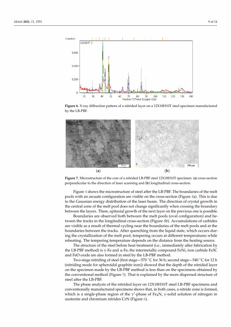
Our analysis of the microstructure of the core of a nitrided LB-PBF specimen from 12X18H10T steel (Figure 7) showed that annealing that occurs during nitriding leads to the blurring of the boundaries of the melt pools and the formation of a structure charac-teristic of austenitic steels—polyhedral grains.
(a) (b)
Figure 7. Microstructure of the core of a nitrided LB-PBF steel 12X18H10T specimen: (a) cross-sec-tion perpendicular to the direction of laser scanning and (b) longitudinal cross-section.
Thus, studies of the microstructure of specimens made from 12X18H10T steel and subjected to nitriding will not lead to the embrittlement of the layer on the tooling made by the LB-PBF. The structure of the core improves, as a result of annealing at 580 °C, the texture, leading to decreases in the anisotropy of properties and residual stresses. The ob-tained results show that the selected mode of ion-plasma nitriding (first stage—570 °C for 36 h; second stage—540 °C for 12 h) will not lead to the deterioration of the characteristics of the selected steel.
The kinetics of the depth growth of nitrided layers and the change in hardness on steel 12X18H10T were studied.
The diffusion of nitrogen into steel is extremely difficult, due to the predominant amount of the γ-phase and the dense chromium oxide film. However, this steel is nitrided by the ion-plasma method, due to cathodic sputtering in hydrogen or argon, in order to remove the oxide film, and the so-called “bombardment” of nitrogen atoms into the steel,
Figure 6. X-ray diffraction pattern of a nitrided layer on a 12X18H10T steel specimen manufacturedby the LB-PBF.
Metals 2021, 11, x FOR PEER REVIEW 10 of 15
The phase analysis of the nitrided layer on 12X18H10T steel LB-PBF specimens and conventionally manufactured specimens shows that, in both cases, a nitride zone is formed, which is a single-phase region of the γ′-phase of Fe4N, γ-solid solution of nitrogen in austenite and chromium nitrides CrN (Figure 6).
Figure 6. X-ray diffraction pattern of a nitrided layer on a 12X18H10T steel specimen manufactured by the LB-PBF.
Our analysis of the microstructure of the core of a nitrided LB-PBF specimen from 12X18H10T steel (Figure 7) showed that annealing that occurs during nitriding leads to the blurring of the boundaries of the melt pools and the formation of a structure charac-teristic of austenitic steels—polyhedral grains.
(a) (b)
Figure 7. Microstructure of the core of a nitrided LB-PBF steel 12X18H10T specimen: (a) cross-sec-tion perpendicular to the direction of laser scanning and (b) longitudinal cross-section.
Thus, studies of the microstructure of specimens made from 12X18H10T steel and subjected to nitriding will not lead to the embrittlement of the layer on the tooling made by the LB-PBF. The structure of the core improves, as a result of annealing at 580 °C, the texture, leading to decreases in the anisotropy of properties and residual stresses. The ob-tained results show that the selected mode of ion-plasma nitriding (first stage—570 °C for 36 h; second stage—540 °C for 12 h) will not lead to the deterioration of the characteristics of the selected steel.
The kinetics of the depth growth of nitrided layers and the change in hardness on steel 12X18H10T were studied.
The diffusion of nitrogen into steel is extremely difficult, due to the predominant amount of the γ-phase and the dense chromium oxide film. However, this steel is nitrided by the ion-plasma method, due to cathodic sputtering in hydrogen or argon, in order to remove the oxide film, and the so-called “bombardment” of nitrogen atoms into the steel,
Figure 7. Microstructure of the core of a nitrided LB-PBF steel 12X18H10T specimen: (a) cross-sectionperpendicular to the direction of laser scanning and (b) longitudinal cross-section.
Figure 4 shows the microstructure of steel after the LB-PBF. The boundaries of the meltpools with an arcuate configuration are visible on the cross-section (Figure 4a). This is dueto the Gaussian energy distribution of the laser beam. The direction of crystal growth inthe central zone of the melt pool does not change significantly when crossing the boundarybetween the layers. There, epitaxial growth of the next layer on the previous one is possible.
Boundaries are observed both between the melt pools (oval configuration) and be-tween the tracks in the longitudinal cross-section (Figure 4b). Accumulations of carbidesare visible as a result of thermal cycling near the boundaries of the melt pools and at theboundaries between the tracks. After quenching from the liquid state, which occurs dur-ing the crystallization of the melt pool, tempering occurs at different temperatures whilereheating. The tempering temperature depends on the distance from the heating source.
The structure of the steel before heat treatment (i.e., immediately after fabrication bythe LB-PBF method) is γ-Fe and α-Fe; the intermetallic compound FeNi, iron carbide Fe3Cand FeO oxide are also formed in steel by the LB-PBF method.
Two-stage nitriding of steel (first stage—570 ◦C for 36 h; second stage—540 ◦C for 12 h(nitriding mode for spheroidal graphite iron)) showed that the depth of the nitrided layeron the specimen made by the LB-PBF method is less than on the specimens obtained bythe conventional method (Figure 5). That is explained by the more dispersed structure ofsteel after the LB-PBF.
The phase analysis of the nitrided layer on 12X18H10T steel LB-PBF specimens andconventionally manufactured specimens shows that, in both cases, a nitride zone is formed,which is a single-phase region of the γ′-phase of Fe4N, γ-solid solution of nitrogen inaustenite and chromium nitrides CrN (Figure 6).

Metals 2021, 11, 1551 10 of 14
Our analysis of the microstructure of the core of a nitrided LB-PBF specimen from12X18H10T steel (Figure 7) showed that annealing that occurs during nitriding leads to theblurring of the boundaries of the melt pools and the formation of a structure characteristicof austenitic steels—polyhedral grains.
Thus, studies of the microstructure of specimens made from 12X18H10T steel andsubjected to nitriding will not lead to the embrittlement of the layer on the tooling made bythe LB-PBF. The structure of the core improves, as a result of annealing at 580 ◦C, the texture,leading to decreases in the anisotropy of properties and residual stresses. The obtainedresults show that the selected mode of ion-plasma nitriding (first stage—570 ◦C for 36 h;second stage—540 ◦C for 12 h) will not lead to the deterioration of the characteristics of theselected steel.
The kinetics of the depth growth of nitrided layers and the change in hardness onsteel 12X18H10T were studied.
The diffusion of nitrogen into steel is extremely difficult, due to the predominantamount of the γ-phase and the dense chromium oxide film. However, this steel is nitridedby the ion-plasma method, due to cathodic sputtering in hydrogen or argon, in order toremove the oxide film, and the so-called “bombardment” of nitrogen atoms into the steel,due to which the diffusion process proceeds faster. For the experiments, we used specimensmade by the LB-PBF and the conventional process. The specimens were subjected to five-fold nitriding in a two-stage mode: first stage—570 ◦C for 36 h; second stage—540 ◦C for12 h (nitriding mode for spheroidal graphite iron). The results of the dependence of thedepth of the nitrided layer on time are shown in Figure 8a, the hardness in Figure 8b, (blueline-depth of the layer on the conventionally manufactured specimens, red line-for thespecimens made by the LB-PBF).
Metals 2021, 11, x FOR PEER REVIEW 11 of 15
due to which the diffusion process proceeds faster. For the experiments, we used speci-mens made by the LB-PBF and the conventional process. The specimens were subjected to five-fold nitriding in a two-stage mode: first stage—570 °C for 36 h; second stage—540 °C for 12 h (nitriding mode for spheroidal graphite iron). The results of the depend-ence of the depth of the nitrided layer on time are shown in Figure 8a, the hardness in Figure 8b, (blue line-depth of the layer on the conventionally manufactured specimens, red line-for the specimens made by the LB-PBF).
(a) (b)
Figure 8. Dependence of the depth and hardness of the nitrided layer on the nitriding time. Blue line = conventionally manufactured specimens. Red line = specimens made by the LB-PBF. (a) Layer depth and (b) layer hardness.
Nitrogen diffusion, in both cases, proceeds in accordance with Fick’s first law: 𝐽 =−𝐷 , where J is the diffusion flux, D is the diffusion coefficient and is the concentra-tion gradient. There is a sharp increase in depth in 144 h to 0.26 mm on the plot of the nitrided layer depth dependence on time, and then the process slows down and goes to a depth of no more than 0.27 mm.
For the LB-PBF specimen, the diffusion of nitrogen into the depth of the metal is no-ticeably slower. The hardness of the layer is insignificantly higher than for the conven-tionally manufactured specimen. It is probably caused by the finer structure of the LB-PBF specimen.
According to the selected modes (Table 3), and in accordance with the developed model (Figure 2), the equipment was made from 12X18H10T steel by the LB-PBF. The benefit of the modified tooling is to reduce the number of elements (from 13 to 4). In ad-dition, it serves to improve the quality of the nitrided layer on the working surface of the block part made from spheroidal graphite iron. The tooling consists of a monolithic casing with thin-walled bushings, and two thin-walled covers covering the small outer and cen-tral inner diameters (Figure 9).
Figure 8. Dependence of the depth and hardness of the nitrided layer on the nitriding time. Blueline = conventionally manufactured specimens. Red line = specimens made by the LB-PBF. (a) Layerdepth and (b) layer hardness.
Nitrogen diffusion, in both cases, proceeds in accordance with Fick’s first law: J = −D ∂C∂x ,
where J is the diffusion flux, D is the diffusion coefficient and ∂C∂x is the concentration
gradient. There is a sharp increase in depth in 144 h to 0.26 mm on the plot of the nitridedlayer depth dependence on time, and then the process slows down and goes to a depth ofno more than 0.27 mm.
For the LB-PBF specimen, the diffusion of nitrogen into the depth of the metal isnoticeably slower. The hardness of the layer is insignificantly higher than for the con-ventionally manufactured specimen. It is probably caused by the finer structure of theLB-PBF specimen.

Metals 2021, 11, 1551 11 of 14
According to the selected modes (Table 3), and in accordance with the developedmodel (Figure 2), the equipment was made from 12X18H10T steel by the LB-PBF. Thebenefit of the modified tooling is to reduce the number of elements (from 13 to 4). Inaddition, it serves to improve the quality of the nitrided layer on the working surface ofthe block part made from spheroidal graphite iron. The tooling consists of a monolithiccasing with thin-walled bushings, and two thin-walled covers covering the small outer andcentral inner diameters (Figure 9).
Metals 2021, 11, x FOR PEER REVIEW 12 of 15
Figure 9. Tooling: 1—external cover, 2—inner cover and 3—casing.
An improvement in the quality of the nitrided layer is ensured by replacing the balls covering the non-nitrided holes with thin-walled bushings (Figure 9). Non-nitrided holes are closed from below, thereby eliminating the effect of shielding the spheroidal graphite iron surface by balls during the process of ion-plasma nitriding (Figure 10). As a result of shielding, a zone of local overheating appears, leading to a structural defect. The defect is the appearance of a zone of nitrogenous ferrite on the surface of the layer, which has a low hardness of 397–454 HV (Figure 10a). Comparative studies of the elemental composition in the surface zones of the defective layer (Figure 10) and in a similar area of the non-defective layer corresponding to the requirements of the technological process (Figure 11) by the method of energy dispersive spectroscopy (EDS) showed a decrease in the concen-tration of nitrogen and carbon in the defective layer.
(a) (b) (c)
Figure 10. Nitrided layer of spheroidal graphite iron, layer defect: (a) microstructure of the zone with reduced hardness and depth (hardness 397–454 HV5, depth 0.23 mm); (b) SEM image, meas-ured area (1); (c) histogram of the elemental composition of area 1.
Figure 9. Tooling: 1—external cover, 2—inner cover and 3—casing.
An improvement in the quality of the nitrided layer is ensured by replacing the ballscovering the non-nitrided holes with thin-walled bushings (Figure 9). Non-nitrided holesare closed from below, thereby eliminating the effect of shielding the spheroidal graphiteiron surface by balls during the process of ion-plasma nitriding (Figure 10). As a result ofshielding, a zone of local overheating appears, leading to a structural defect. The defect isthe appearance of a zone of nitrogenous ferrite on the surface of the layer, which has a lowhardness of 397–454 HV (Figure 10a). Comparative studies of the elemental composition inthe surface zones of the defective layer (Figure 10) and in a similar area of the non-defectivelayer corresponding to the requirements of the technological process (Figure 11) by themethod of energy dispersive spectroscopy (EDS) showed a decrease in the concentration ofnitrogen and carbon in the defective layer.
Metals 2021, 11, x FOR PEER REVIEW 12 of 15
Figure 9. Tooling: 1—external cover, 2—inner cover and 3—casing.
An improvement in the quality of the nitrided layer is ensured by replacing the balls covering the non-nitrided holes with thin-walled bushings (Figure 9). Non-nitrided holes are closed from below, thereby eliminating the effect of shielding the spheroidal graphite iron surface by balls during the process of ion-plasma nitriding (Figure 10). As a result of shielding, a zone of local overheating appears, leading to a structural defect. The defect is the appearance of a zone of nitrogenous ferrite on the surface of the layer, which has a low hardness of 397–454 HV (Figure 10a). Comparative studies of the elemental composition in the surface zones of the defective layer (Figure 10) and in a similar area of the non-defective layer corresponding to the requirements of the technological process (Figure 11) by the method of energy dispersive spectroscopy (EDS) showed a decrease in the concen-tration of nitrogen and carbon in the defective layer.
(a) (b) (c)
Figure 10. Nitrided layer of spheroidal graphite iron, layer defect: (a) microstructure of the zone with reduced hardness and depth (hardness 397–454 HV5, depth 0.23 mm); (b) SEM image, meas-ured area (1); (c) histogram of the elemental composition of area 1.
Figure 10. Nitrided layer of spheroidal graphite iron, layer defect: (a) microstructure of the zone withreduced hardness and depth (hardness 397–454 HV5, depth 0.23 mm); (b) SEM image, measuredarea (1); (c) histogram of the elemental composition of area 1.
The use of modified tooling made by the LB-PBF from austenitic corrosion-resistantsteel 12X18H10T (analogue of AISI 321) allows us to obtain a high-quality nitrided layer onthe surface of the block part made from spheroidal graphite iron.

Metals 2021, 11, 1551 12 of 14Metals 2021, 11, x FOR PEER REVIEW 13 of 15
(a) (b) (c)
Figure 11. Nitrided layer of spheroidal graphite iron that meets the requirements of the technological process: (a) layer microstructure, hardness 552–603 HV5, depth 0.31 mm; (b) SEM image, measured area (2); (c) histogram of the elemental composition of area 2.
The use of modified tooling made by the LB-PBF from austenitic corrosion-resistant steel 12X18H10T (analogue of AISI 321) allows us to obtain a high-quality nitrided layer on the surface of the block part made from spheroidal graphite iron.
4. Conclusions A technological process for the modified tooling manufacturing by the LB-PBF from
12X18H10T steel powder (analogue of AISI 321) was developed. Modified tooling protects certain surfaces of the part that are not subject to nitriding. That allows us to obtain a uniform high-quality nitrided layer on the working surface of the part made from sphe-roidal graphite iron. The proposed technology provides the required performance char-acteristics of the tooling.
Research confirms the fact that steel has good dimensional stability. The temperature coefficient of linear expansion of steel after the LB-PBF is within acceptable limits (18.6 × 10⁻⁶ 1/°C). Phase-transition γ↔α does not occur in the temperature range 500–600 °C (ni-triding temperature range). Tooling made from austenitic steel withstands long-term op-eration and multiple usage. That is shown by studies of the kinetics of the nitrided layers’ depth growth and the change in hardness on steel 12X18H10T in the process of ion-plasma nitriding. The results of the studies show that protective tooling made from steel 12X18H10T can be used industrially for the surfaces of spheroidal graphite iron blocks used in piston pumps of aircraft engines in order to improve the quality of the nitrided layer.
Author Contributions: Conceptualization, A.M. and S.G.; data curation, A.M. and S.G.; formal anal-ysis, T.T. and S.E.; funding acquisition, A.M. and S.G.; investigation, E.G. and R.K.; methodology, T.T.; project administration, S.G.; resources, R.K. and S.G.; software, E.G. and S.E.; supervision, A.M. and S.G.; validation, T.T. and R.K.; visualization, A.M. and E.G.; writing—original draft, T.T., E.G. and S.E.; writing—review and editing, T.T. and S.E. All authors have read and agreed to the pub-lished version of the manuscript.
Funding: The study was supported by a grant of the Russian Science Foundation (project No. 20-19-00620).
Institutional Review Board Statement: Not applicable.
Informed Consent Statement: Not applicable.
Data Availability Statement: Not applicable.
Acknowledgments: The authors carried out research on the equipment of the Center of collective use of MSUT “STANKIN” (agreement No. 075-15-2021-695).
Figure 11. Nitrided layer of spheroidal graphite iron that meets the requirements of the technological process: (a) layermicrostructure, hardness 552–603 HV5, depth 0.31 mm; (b) SEM image, measured area (2); (c) histogram of the elementalcomposition of area 2.
4. Conclusions
A technological process for the modified tooling manufacturing by the LB-PBF from12X18H10T steel powder (analogue of AISI 321) was developed. Modified tooling protectscertain surfaces of the part that are not subject to nitriding. That allows us to obtaina uniform high-quality nitrided layer on the working surface of the part made fromspheroidal graphite iron. The proposed technology provides the required performancecharacteristics of the tooling.
Research confirms the fact that steel has good dimensional stability. The temper-ature coefficient of linear expansion of steel after the LB-PBF is within acceptable lim-its (18.6 × 10⁻⁶ 1/◦C). Phase-transition γ↔α does not occur in the temperature range500–600 ◦C (nitriding temperature range). Tooling made from austenitic steel withstandslong-term operation and multiple usage. That is shown by studies of the kinetics of thenitrided layers’ depth growth and the change in hardness on steel 12X18H10T in the pro-cess of ion-plasma nitriding. The results of the studies show that protective tooling madefrom steel 12X18H10T can be used industrially for the surfaces of spheroidal graphite ironblocks used in piston pumps of aircraft engines in order to improve the quality of thenitrided layer.
Author Contributions: Conceptualization, A.M. and S.G.; data curation, A.M. and S.G.; formalanalysis, T.T. and S.E.; funding acquisition, A.M. and S.G.; investigation, E.G. and R.K.; methodology,T.T.; project administration, S.G.; resources, R.K. and S.G.; software, E.G. and S.E.; supervision, A.M.and S.G.; validation, T.T. and R.K.; visualization, A.M. and E.G.; writing—original draft, T.T., E.G. andS.E.; writing—review and editing, T.T. and S.E. All authors have read and agreed to the publishedversion of the manuscript.
Funding: The study was supported by a grant of the Russian Science Foundation (project No.20-19-00620).
Institutional Review Board Statement: Not applicable.
Informed Consent Statement: Not applicable.
Data Availability Statement: Not applicable.
Acknowledgments: The authors carried out research on the equipment of the Center of collectiveuse of MSUT “STANKIN” (agreement No. 075-15-2021-695).
Conflicts of Interest: The authors declare no conflict of interest.

Metals 2021, 11, 1551 13 of 14
References1. ASTM 1. Standard Terminology for Additive Manufacturing Technologies: ASTMF2792-12a; ASTM International: West Conshohocken,
PA, USA, 2012.2. ISO/ASTM. 52900:2015 Additive Manufacturing—General Principles—Terminology; ISO/ASTM International: Geneva, Switzerland,
2015; p. 19. Available online: https://www.sis.se/api/document/preview/919975/ (accessed on 15 August 2015).3. Grigor’Ev, S.N.; Tarasova, T.V. Possibilities of the Technology of Additive Production for Making Complex-Shape Parts and
Depositing Functional Coatings from Metallic Powders. Met. Sci. Heat Treat. 2016, 57, 579–584. [CrossRef]4. Hemmati, I.; Ocelík, V.; De Hosson, J.T.M. Microstructural characterization of AISI 431 martensitic stainless steel laser-deposited
coatings. J. Mater. Sci. 2011, 46, 3405–3414. [CrossRef]5. Zhang, C.; Zhu, J.; Ji, C.; Guo, Y.; Fang, R.; Mei, S.; Liu, S. Laser powder bed fusion of high-entropy alloy particle-reinforced
stainless steel with enhanced strength, ductility, and corrosion resistance. Mater. Des. 2021, 209, 109950. [CrossRef]6. Khmyrov, R.S.; Grigoriev, S.N.; Okunkova, A.A.; Gusarov, A.V. On the Possibility of Selective Laser Melting of Quartz Glass.
Phys. Procedia 2014, 56, 345–356. [CrossRef]7. Otto, M.; Pilz, S.; Gebert, A.; Kühn, U.; Hufenbach, J. Effect of Build Orientation on the Microstructure, Mechanical and Corrosion
Properties of a Biodegradable High Manganese Steel Processed by Laser Powder Bed Fusion. Metals 2021, 11, 944. [CrossRef]8. Wang, Y.; Xiong, W.; Tang, D.; Hao, L.; Li, Z.; Li, Y.; Cheng, K. Rheology effect and enhanced thermal conductivity of dia-
mond/metakaolin geopolymer fabricated by direct ink writing. Rapid Prototyp. J. 2021, 27, 837–850. [CrossRef]9. Karimi, M.S.; Yeganeh, M.; Zaree, S.A.; Eskandari, M. Corrosion behavior of 316L stainless steel manufactured by laser powder
bed fusion (L-PBF) in an alkaline solution. Opt. Laser Technol. 2021, 138, 106918. [CrossRef]10. Yadroitsev, I.; Bertrand, P.; Antonenkova, G.; Grigoriev, S.; Smurov, I. Use of track/layer morphology to develop functional parts
by selective laser melting. J. Laser Appl. 2013, 25, 052003. [CrossRef]11. Smurov, I.; Doubenskaia, M.; Grigoriev, S.; Nazarov, A. Optical Monitoring in Laser Cladding of Ti6Al4V. J. Therm. Spray Technol.
2012, 21, 1357–1362. [CrossRef]12. Doubenskaia, M.; Pavlov, M.; Grigoriev, S.; Tikhonova, E.; Smurov, I. Comprehensive Optical Monitoring of Selective Laser
Melting. J. Laser Micro Nanoeng. 2012, 7, 236–243. [CrossRef]13. Gusarov, A.; Grigoriev, S.N.; Volosova, M.A.; Melnik, Y.A.; Laskin, A.; Kotoban, D.V.; Okunkova, A.A. On productivity of laser
additive manufacturing. J. Mater. Process. Technol. 2018, 261, 213–232. [CrossRef]14. Facchini, L.; Vicente, N.; Lonardelli, I.; Magalini, E.; Robotti, P.; Molinari, A. Metastable Austenite in 17-4 Precipitation-Hardening
Stainless Steel Produced by Selective Laser Melting. Adv. Eng. Mater. 2010, 12, 184–188. [CrossRef]15. Gladush, G.G.; Smurov, I. Physics of Laser Materials Processing: Theory and Experiment; Springer Science & Business Media: Berlin,
Germany, 2011; 534p.16. Shishkovsky, I.V. Laser Synthesis of Functional Mesostructures and Tridimensional Products; FIZMATLIT: Moscow, Russia, 2009; 424p.17. Tarasova, T.V.; Gusarov, A.V.; Protasov, K.E.; Filatova, A.A. The influence of thermal fields on the structure of corrosion-resistant
steels in various laser processing schemes. Metall. Heat Treat. Met. 2017, 59, 37–44.18. Nowotny, S.; Tarasova, T.V.; Filatova, A.A.; Dolzhikova, E.Y. Methods for Characterizing Properties of Corrosion-Resistant Steel
Powders Used for Powder Bed Fusion Processes. In Materials Science Forum; Trans Tech Publications: Zurich, Switzerland, 2016;Volume 876, pp. 1–7.
19. Badrossamay, M.; Childs, T. Further studies in selective laser melting of stainless and tool steel powders. Int. J. Mach. Tools Manuf.2007, 47, 779–784. [CrossRef]
20. Abd-Elghany, K.; Bourell, D. Property evaluation of 304L stainless steel fabricated by selective laser melting. Rapid Prototyp. J.2012, 18, 420–428. [CrossRef]
21. Kameneva, A.L.; Minkova, A.A.; Cherkashneva, N.N.; Karmanov, V.V. Correlation between heat treatment process parameters,phase composition, texture, and mechanical properties of 12H18N10T stainless steel processed by selective laser melting. In IOPConference Series: Materials Science and Engineering; IOP Publishing: Bristol, UK, 2018; Volume 447.
22. Grigoriev, S.N.; Metel, A.S.; Tarasova, T.V.; Filatova, A.A.; Sundukov, S.K.; Volosova, M.A.; Okunkova, A.A.; Melnik, Y.A.;Podrabinnik, P.A. Effect of Cavitation Erosion Wear, Vibration Tumbling, and Heat Treatment on Additively ManufacturedSurface Quality and Properties. Metals 2020, 10, 1540. [CrossRef]
23. Metel, A.S.; Grigoriev, S.N.; Tarasova, T.V.; Filatova, A.A.; Sundukov, S.K.; Volosova, M.A.; Okunkova, A.A.; Melnik, Y.A.;Podrabinnik, P.A. Influence of Postprocessing on Wear Resistance of Aerospace Steel Parts Produced by Laser Powder Bed Fusion.Technologies 2020, 8, 73. [CrossRef]
24. Roehling, T.T.; Wu, S.S.; Khairallah, S.A.; Roehling, J.D.; Soezeri, S.S.; Crumb, M.F.; Matthews, M.J. Modulating laser intensityprofile ellipticity for microstructural control during metal additive manufacturing. Acta Mater. 2017, 128, 197–206. [CrossRef]
25. Sova, A.; Grigoriev, S.; Okunkova, A.; Smurov, I. Potential of cold gas dynamic spray as additive manufacturing technology. Int. J.Adv. Manuf. Technol. 2013, 69, 2269–2278. [CrossRef]
26. Sova, A.; Grigoriev, S.; Okunkova, A.; Smurov, I. Cold spray deposition of 316L stainless steel coatings on aluminium surfacewith following laser post-treatment. Surf. Coat. Technol. 2013, 235, 283–289. [CrossRef]

Metals 2021, 11, 1551 14 of 14
27. Sova, A.; Okunkova, A.; Grigoriev, S.; Smurov, I. Velocity of the Particles Accelerated by a Cold Spray Micronozzle: ExperimentalMeasurements and Numerical Simulation. J. Therm. Spray Technol. 2013, 22, 75–80. [CrossRef]
28. Wang, Z.; Palmer, T.A.; Beese, A.M. Effect of processing parameters on microstructure and tensile properties of austenitic stainlesssteel 304L made by directed energy deposition additive manufacturing. Acta Mater. 2016, 110, 226–235. [CrossRef]