Embed Size (px)
Citation preview

Polyesters and polyamides
© 2008, Woodhead Publishing Limited

The Textile Institute and Woodhead PublishingThe Textile Institute is a unique organisation in textiles, clothing and footwear. Incorporated in England by a Royal Charter granted in 1925, the Institute has individual and corporate members in over 90 countries. The aim of the Institute is to facilitate learning, recognise achievement, reward excellence and disseminate information within the global textiles, clothing and footwear industries.
Historically, The Textile Institute has published books of interest to its members and the textile industry. To maintain this policy, the Institute has entered into partnership with Woodhead Publishing Limited to ensure that Institute members and the textile industry continue to have access to high calibre titles on textile science and technology.
Most Woodhead titles on textiles are now published in collaboration with The Textile Institute. Through this arrangement, the Institute provides an Editorial Board which advises Woodhead on appropriate titles for future publication and suggests possible editors and authors for these books. Each book published under this arrangement carries the Institute’s logo.
Woodhead books published in collaboration with The Textile Institute are offered to Textile Institute members at a substantial discount. These books, together with those published by The Textile Institute that are still in print, are offered on the Woodhead web site at: www.woodheadpublishing.com. Textile Institute books still in print are also available directly from the Institute’s web site at: www.textileinstitutebooks.com.
A list of Woodhead books on textile science and technology, most of which have been published in collaboration with the Textile Institute, can be found at the end of the contents pages.
© 2008, Woodhead Publishing Limited
Woodhead Publishing in Textiles: Number 71
Polyesters and polyamides
Edited byB. L. Deopura, R. Alagirusamy,
M. Joshi and B. Gupta
Cambridge England
© 2008, Woodhead Publishing Limited

Published by Woodhead Publishing Limited in association with The Textile InstituteWoodhead Publishing Limited, Abington Hall, Granta Park, Great AbingtonCambridge CB21 6AH, Englandwww.woodheadpublishing.com
Published in North America by CRC Press LLC, 6000 Broken Sound Parkway, NW, Suite 300, Boca Raton, FL 33487, USA
First published 2008, Woodhead Publishing Limited and CRC Press LLC© 2008, Woodhead Publishing LimitedThe authors have asserted their moral rights.
This book contains information obtained from authentic and highly regarded sources. Reprinted material is quoted with permission, and sources are indicated. Reasonable efforts have been made to publish reliable data and information, but the authors and the publishers cannot assume responsibility for the validity of all materials. Neither the authors nor the publishers, nor anyone else associated with this publication, shall be liable for any loss, damage or liability directly or indirectly caused or alleged to be caused by this book.
Neither this book nor any part may be reproduced or transmitted in any form
and recording, or by any information storage or retrieval system, without permission in writing from Woodhead Publishing Limited.
The consent of Woodhead Publishing Limited does not extend to copying for general distribution, for promotion, for creating new works, or for resale.
Limited for such copying.
Trademark notice: Product or corporate names may be trademarks or registered
to infringe.
British Library Cataloguing in Publication DataA catalogue record for this book is available from the British Library.
Library of Congress Cataloging in Publication DataA catalog record for this book is available from the Library of Congress.
Woodhead Publishing ISBN 978-1-84569-298-8 (book)Woodhead Publishing ISBN 978-1-84569-460-9 (e-book)CRC Press ISBN 978-1-4200-7972-2CRC Press order number WP7972
The publishers’ policy is to use permanent paper from mills that operate a sustainable forestry policy, and which has been manufactured from pulp which is processed using acid-free and elementary chlorine-free practices. Furthermore, the publishers ensure that the text paper and cover board used have met acceptable environmental accreditation standards.
Typeset by SNP Best-set Typesetter Ltd., Hong KongPrinted by TJ International Limited, Padstow, Cornwall, England
or by any means, electronic or mechanical, including photocopying, microfilming
Specific permission must be obtained in writing from Woodhead Publishing
trademarks, and are used only for identification and explanation, without intent
© 2008, Woodhead Publishing Limited

Contents
Contributor contact details xiii Woodhead Publishing in Textiles xvii
Part I Polyester and polyamide fundamentals 1
1 Polyester resins 3P. S a n t h a n a G o pa l a K r i s h n a n and S. T. Ku l k a r n i, Futura Polyesters Ltd, Chennai, India
1.1 Introduction 34
1.3 History 81.4 Polymerization methods 101.5 Poly(ethylene terephthalate) (PET) 121.6 Poly(trimethylene terephthalate) (PTT) 201.7 Poly(butylene terephthalate) (PBT) 231.8 Poly(1,4-cyclohexylene dimethylene terephthalate) (PCT) 261.9 Poly(ethylene 2,6-naphthalate) (PEN) 271.10 Polylactic acid (PLA) 311.11 World market 321.12 Future trends 341.13 Acknowledgements 341.14 Sources of further information and advice 351.15 References 35
41B. L. D e o p u r a, Indian Institute of Technology, New Delhi, India
2.1 Introduction 412.2 Nylon 66 42
v
1.2 Classification
2 Polyamide fibers
© 2008, Woodhead Publishing Limited
vi Contents
2.3 Nylon 6 442.4 482.5 502.6 542.7 582.8 References 60
3 62
3.1 Introduction 623.2 673.3 743.4 Fundamental principles and types of melt spinning process 773.5 853.6 High speed spinning and novel spinning 883.7 Acknowledgements 943.8 References 95
4 97A. K. A g r awa l and M. Ja s s a l, Indian Institute of Technology, New Delhi, India
4.1 Introduction 974.2 Nylon 6,6 984.3 Nylon 6 1004.4 Effect of temperature 1024.5 Effect of water concentration 1024.6 Effect of stabilizer type and amount 1034.7 Reactor design 1044.8 114
1164.10 Dyeability of nylon 6 1184.11 Cationic dyeable nylon 6 1204.12 Antistatic and hydrophilic nylon 6 1214.13 Flame retardant nylon 6 1224.14 Elements of melt spinning process of nylons 1224.15 Structure development during melt spinning of polyamides 1244.16 Spinning of nylon 6 1294.17 Drawing and heat setting 1314.18 Mechanism of drawing in polyamides 1344.19 Heat setting 1354.20 References 137
Thermal properties of nylon fibers Physical structure of nylon fiber Mechanical behavior of nylon fibers Applications of nylon fibers
Manufacture of polyester fibres
Raw materials of polyester fibres in industry
C. A. L i n, Feng Chia University, Taiwan
Polymerisation process of polyester fibres in industry
Heat setting and textured yarn of filament
Manufacture of polyamide fibres
Synthesis of modified polyamides (nylon 6) 4.9 Modification at polymerization stage
© 2008, Woodhead Publishing Limited

Contents vii
5 140D. W. Fa r r i n g t o n, Consultant, UK, J. L u n t, S. Dav i e s, NatureWorks LLC, USA and R. S. B l ac k b u r n, University of Leeds, UK
5.1 Introduction 1405.2 Chemistry and manufacture of PLA polymer resin 141
1465.4 Applications 1495.5 Environmental sustainability 1615.6 Future trends 1675.7 References 168
6 Environmental impact of polyester and polyamide textiles 171
K. S l a t e r, University of Guelph, Canada
6.1 Introduction 1716.2 Types of environmental impact 1716.3 Pollution types 1726.4 Pollution prevention and control 1726.5 Environmental impact of textile production processes and use conditions 1776.6 Use conditions 1856.7 Pollution control strategies 1866.8 Eco-friendly technology options 1906.9 Future trends 1936.10 Sources of further information and advice 1946.11 References 195
Part II Improving functionality of polyesters and polyamides 201
203M. G. K a m a t h and G. S. B h a t, University of Tennessee, USA
7.1 Introduction 2037.2 Production, properties and applications of physically
2047.3 Production, properties and applications of chemically
2097.4 Design and process control aspects 2157.5 Future trends 2167.6 References 217
Poly(lactic acid) fibers (PLA)
5.3 PLA fiber properties
7 Specialty fibers from polyesters and polyamides
modified fibers
modified fibers
© 2008, Woodhead Publishing Limited
viii Contents
8 Property enhancement through blending 219R. A l ag i r u s a m y and A. Da s, Indian Institute of Technology, New Delhi, India
8.1 Introduction 219220
8.3 Evaluation of the blend 2228.4 Migration 2258.5 De-blending 2278.6 Selection of blend constituents 2278.7 Blend ratio 2318.8 Types of blending operation 233
properties 2348.10 Blended yarn structures 2408.11 Blending for speciality products 2458.12 Summary 2518.13 References 251
9 Weaving technology for manufacturing high performance fabrics 253
B. K. B e h e r a, Indian Institute of Technology, New Delhi, India
9.1 Principles of fabric formation 2539.2 Fundamentals of woven structure 2549.3 Basic weaves 2559.4 Theoretical considerations in woven structure 2579.5 High performance fabric 2599.6 Yarn preparation for high quality fabric 2609.7 Weaving systems 2629.8 Production of some speciality fabrics 2699.9 Future outlook in weaving 2769.10 References 277
10 Advances in coloration of polyester textiles 279M. L. G u l r a ja n i, Indian Institute of Technology,
10.1 Evolution of dyeing of polyester 27910.2 Disperse dyes 28010.3 Theory of dyeing with disperse dyes 28310.4 28710.5 Dyeing procedures 289
8.2 Staple fibre blending
New Delhi, India
Effect of fibre structure on dyeing
8.9 Influence of fibre properties and blend ratio on yarn
© 2008, Woodhead Publishing Limited

Contents ix
10.6 New methods of dyeing 29210.7 29510.8 References 298
11 Flame-retardant polyester and polyamide textiles 306P. J o s e p h, University of Ulster, UK and J. R. E b d o n,
11.1 Background 30611.2 Introduction 30711.3 Testing procedure and hazard assessments – general aspects 30811.4 Polyesters 31411.5 Polyamides 31811.6 Conclusions and future trends 32011.7 Sources for further information and advice 32111.8 References 321
12 polyamide-based textiles 325
B. S. B u t o l a, Indian Institute of Technology, New Delhi, India
12.1 Introduction 32512.2 textiles 32612.3 laminating 32712.4 34512.5 Future trends 34812.6 Sources of further information and advice 34812.7 References 349
13 The impact of nanotechnology on polyesters, polyamides and other textiles 354
India
13.1 Introduction 35413.2 What is nanotechnology? 35413.3 Origin of nanotechnology 35513.4 Nanotechnology: applications in textiles 35613.5 35713.6 Nanocoatings 37013.7 Nanocomposite coatings 379
Dyeing of chemically modified polyester fibres
University of Sheffield, UK
Advances in functional finishes for polyester and
Properties and uses of polyester and polyamide fibre/
Imparting functionality through finishing/coating/
Recent advances in finishing
M. J o s h i, Indian Institute of Technology, New Delhi,
Nanotechnology based surface modification of textiles
© 2008, Woodhead Publishing Limited
x Contents
13.8 38013.9 38913.10 39413.11 397
39813.13 Future trends 40613.14 References 409
417
14 419V. K. K o t h a r i, Indian Institute of Technology, New Delhi, India
14.1 Introduction 41914.2 Properties of polyesters and polyamides and their suitability for apparel applications 421
42214.4 Blends of polyamide and polyester 42614.5 Apparel applications of polyamide and polyester fabric 43014.6 Comparison of polyesters and polyamides 430
43114.8 Current market potentials 43614.9 Future prospects 43814.10 Acknowledgement 43914.11 References 439
15 Polyester and nylon based textiles in biomedical engineering 441
B. G u p t a, N. G r ov e r, S. V i j u and S. S a x e n a, Indian Institute of Technology, New Delhi, India
15.1 Introduction 44115.2 Textiles for biomedicine 44215.3 Textiles for hygiene products 48215.4 Intelligent textiles 49215.5 Conclusion 49515.6 References 496
16 Sports applications 505J. M c C a n n, University of Wales, Newport, UK
16.1 Introduction 50516.2 Fibre developments and characteristics 508
Polymer/clay nanocomposite fibers (PCNF) Carbon nanotube (CNT) based nanocomposite fibers
Nanotechnology based fiber modifications
Nanoparticle based nanocomposite fibers 13.12 Nanofibers
Part III Applications of fibrous polyesters and polyamides
Polyester and polyamide fibres – apparel applications
14.3 Different fibre types for apparel purpose
14.7 Pivotal fibre modification
© 2008, Woodhead Publishing Limited
Contents xi
16.3 Design considerations 51316.4 Textile selection 51616.5 Future trends 52016.6 Sources of further information and advice 523
524
17 Automotive applications 525T. M a t s u o, SCI-TEX, Japan
17.1 Introduction 52517.2 52717.3 Rubber composite parts 53017.4 Internal safety systems 53317.5 Car interiors 53617.6 Others 53817.7 Conclusion 53917.8 References and bibliography 540
18 Applications of polyesters and polyamides in civil engineering 542
R. Fa n g u e i r o, C. G o n i l h o P e r e i r a and M. d e A r aú j o, University of Minho, Portugal
18.1 Introduction 54218.2 construction applications 542
54518.4 Geotechnical and geoenvironmental applications 55818.5 Textile architectural applications 56618.6 Ocean engineering applications 57818.7 References 587
Polyester and polyamide fibres for automotive use in
16.7 References
terms of fibre performance requirements
Polyester and polyamide fibres and structures for civil
18.3 Synthetic fibre-reinforced concrete
© 2008, Woodhead Publishing Limited

Contributor contact details
(* = main contact)
Chapter 1
Dr P. Santhana Gopala Krishnan*Futura Polyesters Ltd1-A/1, Kamarajar SalaiManaliChennai – 600 068India
Email: [email protected] [email protected]
S. T. KulkarniFutura Polyesters Ltd1-A/1, Kamarajar SalaiManaliChennai – 600 068India
Email: [email protected]
Chapter 2
Professor B. L. DeopuraDepartment of Textile TechnologyIndian Institute of TechnologyHauz KhasNew Delhi – 110016India
Email: [email protected]
xiii
Chapter 3
Dr Chin An LinFeng Chia UniversityDept. of Fibre and Composite
MaterialsGraduate Institute of Textile
EngineeringNo. 100 Wenhwa RdSeatwenTaichungTaiwan 40724Republic of China
Email: [email protected]
Chapter 4
Ashwini Kumar Agrawal,* Manjeet Jassal
Department of Textile TechnologyIndian Institute of TechnologyHauz KhasNew Delhi – 110016India
Email: [email protected] [email protected]
© 2008, Woodhead Publishing Limited
xiv Contributor contact details
Chapter 5
David W. Farrington*Beech Edge7 The CommonQuarndonDerbyDE22 5JYUK
Email: [email protected]
Dr James Lunt and Steve Davies
NatureWorks LLC15305 Minnetonka BoulevardMinnetonkaMN 55345USA
Dr Richard S. BlackburnGreen Chemistry GroupCentre for Technical TextilesUniversity of LeedsLeedsLS2 9JTUK
Email: [email protected]
Chapter 6
Dr Keith SlaterProfessor Emeritus, School of
EngineeringUniversity of GuelphOntario, N1G 2W1Canada
Email: [email protected]
Chapter 7
M. G. Kamath*Nonwoven Research Laboratory
(UTNRL)The University of Tennessee1321 White AvenueKnoxvilleTN 37996USA
Email: [email protected]
Dr Gajanan BhatProfessorDepartment of Materials Science
& EngineeringThe University of Tennessee1321 White AvenueKnoxvilleTN 37996USA
Email: [email protected]
Chapter 8
Dr R. Alagirusamy* and Dr Apurba Das
Department of Textile TechnologyIndian Institute of TechnologyHauz KhasNew Delhi – 110016India
Email: [email protected]
© 2008, Woodhead Publishing Limited
Contributor contact details xv
Chapter 9
Dr B. K. BeheraDepartment of Textile TechnologyIndian Institute of TechnologyHauz KhasNew Delhi – 110016India
Email: [email protected]
Chapter 10
Professor M. L. GulrajaniDepartment of Textile TechnologyIndian Institute of TechnologyHauz KhasNew Delhi – 110016India
Email: [email protected]
Chapter 11
Dr Paul Joseph*School of the Built EnvironmentUniversity of UlsterNewtownabbeyBT37 0QBUK
Email: [email protected]
Department of Chemistry
S3 7HFUK
Chapter 12
Dr Bhupendra Singh ButolaAssistant ProfessorDepartment of Textile TechnologyIndian Institute of TechnologyHauz KhasNew Delhi – 110016India
Email: [email protected]
Chapter 13
Dr Mangala JoshiAssociate ProfessorDepartment of Textile TechnologyIndian Institute of TechnologyHauz KhasNew Delhi – 110016India
Email: [email protected]@gmail.com
Chapter 14
Professor V. K. KothariDepartment of Textile TechnologyIndian Institute of TechnologyHauz KhasNew Delhi – 110016India
Email: [email protected]@gmail.com
University of Sheffield
Professor John R. Ebdon
Sheffield
Email: [email protected]
© 2008, Woodhead Publishing Limited

xvi Contributor contact details
Chapter 15
Dr Bhuvanesh Gupta,* Navdeep Grover S. Viju and Shalini Saxena
Department of Textile TechnologyIndian Institute of TechnologyHauz KhasNew Delhi – 110016India
Email: [email protected]
Chapter 16
Jane McCann, M Des RCA, M Phil
Director of Smart Clothes and Wearable Technology
University of WalesNewportNP18 3YGUK
Email: [email protected]
Chapter 17
Dr Tatsuki Matsuo12-15 Hanazono-choOhtsu-city520-0222Japan
Email: [email protected]
Chapter 18
Dr Raul Fangueiro*, C. Gonilho Pereira and M. de Araújo
University of MinhoLargo do Paço4704-553 BragaPortugal
Email: [email protected]
© 2008, Woodhead Publishing Limited
Woodhead Publishing in Textiles
1 Watson’s textile design and colour Seventh edition Edited by Z. Grosicki
2 Watson’s advanced textile design Edited by Z. Grosicki
3 Weaving Second edition P. R. Lord and M. H. Mohamed
J. Gordon Cook
J. Gordon Cook
6 Recycling textile and plastic waste Edited by A. R. Horrocks
T. Hongu and G. O. Phillips
J. W. S. Hearle, B. Lomas and W. D. Cooke
9 Ecotextile ’98 Edited by A. R. Horrocks
10 Physical testing of textiles B. P. Saville
11 Geometric symmetry in patterns and tilings C. E. Horne
xvii
4 Handbook of textile fibres Vol 1: Natural fibres
5 Handbook of textile fibres Vol 2: Man-made fibres
7 New fibers Second edition
8 Atlas of fibre fracture and damage to textiles Second edition
© 2008, Woodhead Publishing Limited

12 Handbook of technical textiles Edited by A. R. Horrocks and S. C. Anand
13 Textiles in automotive engineering W. Fung and J. M. Hardcastle
14 Handbook of textile design J. Wilson
15 Edited by J. W. S. Hearle
16 Knitting technology Third edition D. J. Spencer
17 Medical textiles Edited by S. C. Anand
18 Edited by C. Woodings
19 Edited by R. R. Franck
20 Edited by X. M. Tao
21 Yarn texturing technology J. W. S. Hearle, L. Hollick and D. K. Wilson
22 H-K. Rouette
23 Coated and laminated textiles W. Fung
24 Fancy yarns R. H. Gong and R. M. Wright
25 Wool: Science and technology Edited by W. S. Simpson and G. Crawshaw
26 H-K. Rouette
xviii Woodhead Publishing in Textiles
High-performance fibres
Regenerated cellulose fibres
Silk, mohair, cashmere and other luxury fibres
Smart fibres, fabrics and clothing
Encyclopedia of textile finishing
Dictionary of textile finishing
© 2008, Woodhead Publishing Limited

27 Environmental impact of textiles K. Slater
28 Handbook of yarn production P. R. Lord
29 Textile processing with enzymes Edited by A. Cavaco-Paulo and G. Gübitz
30 The China and Hong Kong denim industry Y. Li, L. Yao and K. W. Yeung
31 The World Trade Organization and international denim trading Y. Li, Y. Shen, L. Yao and E. Newton
32 W. D. Schindler and P. J. Hauser
33 J. Fan, W. Yu and L. Hunter
34 H. A. McKenna, J. W. S. Hearle and N. O’Hear
35 Structure and mechanics of woven fabrics J. Hu
36 Edited by J. E. McIntyre
37 Woollen and worsted woven fabric design E. G. Gilligan
38 Analytical electrochemistry in textiles P. Westbroek, G. Priniotakis and P. Kiekens
39 R. R. Franck
40 Chemical testing of textiles Edited by Q. Fan
41 Design and manufacture of textile composites Edited by A. C. Long
Woodhead Publishing in Textiles xix
Chemical finishing of textiles
Clothing appearance and fit
Handbook of fibre rope technology
Synthetic fibres: nylon, polyester, acrylic, polyolefin
Bast and other plant fibres
© 2008, Woodhead Publishing Limited
42 Edited by Hassan M. Behery
43 T. Hongu, M. Takigami and G. O. Phillips
44 Textiles for protection Edited by R. A. Scott
45 Textiles in sport Edited by R. Shishoo
46 Wearable electronics and photonics Edited by X. M. Tao
47 Edited by R. S. Blackburn
48 Medical textiles and biomaterials for healthcare Edited by S. C. Anand, M. Miraftab, S. Rajendran and J. F. Kennedy
49 Total colour management in textiles Edited by J. Xin
50 Recycling in textiles Edited by Y. Wang
51 Clothing biosensory engineering Y. Li and A. S. W. Wong
52 Biomechanical engineering of textiles and clothing Edited by Y. Li and D. X-Q. Dai
53 Digital printing of textiles Edited by H. Ujiie
54 Intelligent textiles and clothing Edited by H. Mattila
55 Innovation and technology of women’s intimate apparel W. Yu, J. Fan, S. C. Harlock and S. P. Ng
xx Woodhead Publishing in Textiles
Effect of mechanical and physical properties on fabric hand
New millennium fibers
Biodegradable and sustainable fibres
© 2008, Woodhead Publishing Limited
56 Edited by N. Pan and P. Gibson
57 Geosynthetics in civil engineering Edited by R. W. Sarsby
58 Handbook of nonwovens Edited by S. Russell
59 Cotton: Science and technology Edited by S. Gordon and Y-L. Hsieh
60 Ecotextiles Edited by M. Miraftab and A. Horrocks
61 Composites forming technologies Edited by A. C. Long
62 Plasma technology for textiles Edited by R. Shishoo
63 Smart textiles for medicine and healthcare Edited by L. Van Langenhove
64 Sizing in clothing Edited by S. Ashdown
65 Shape memory polymers and textiles J. Hu
66 Environmental aspects of textile dyeing R. Christie
67 Edited by P. Brown and K. Stevens
68 W. E. Morton and J. W. S. Hearle
69 Advances in apparel production Edited by C. Fairhurst
Woodhead Publishing in Textiles xxi
Thermal and moisture transport in fibrous materials
Nanofibers and nanotechnology in textiles
Physical properties of textile fibres Fourth edition
© 2008, Woodhead Publishing Limited
70 Edited by A. R. Horrocks and D. Price
71 Polyesters and polyamides Edited by B. L. Deopura, R. Alagirusamy, M. Joshi and B. Gupta
72 Advances in wool Edited by N. A. G. Johnson and I. Russell (forthcoming)
73 Military textiles Edited by E. Wilusz
74 three-dimensional textile structures
J. Hu
75 Medical textiles 2007 Edited by J. Kennedy, A. Anand, M. Miraftab and S. Rajendran (forthcoming)
76 Fabric testing Edited by J. Hu
77 Biologically inspired textiles Edited by A. Abbott and M. Ellison
78 Friction in textiles Edited by B. S. Gupta
79 Textile advances in the automotive industry Edited by R. Shishoo
80 Edited by P. Schwartz
81 Engineering textiles: Integrating the design and manufacture of textile products
Edited by Y. E. El-Mogahzy
xxii Woodhead Publishing in Textiles
Advances in fire retardant materials
3D fibrous assemblies: Properties, applications and modelling of
Structure and mechanics of textile fibre assemblies
© 2008, Woodhead Publishing Limited
Part IPolyester and polyamide fundamentals
© 2008, Woodhead Publishing Limited
1Polyester resins
P. SA N T H A NA GOPA LA K R ISH NA N and S . T. KU LK A R N I, Futura Polyesters Ltd, Chennai, India
1.1 Introduction
Among the polycondensation polymers, the most important and widely used today is polyesters; and equally important is polyamides. Polyesters can be processed by melt spinning, injection and/or blow moulding and
injection moulding and extrusion. More details on polyamides are given in Chapter 2. Polyesters are widely used as packaging materials such as
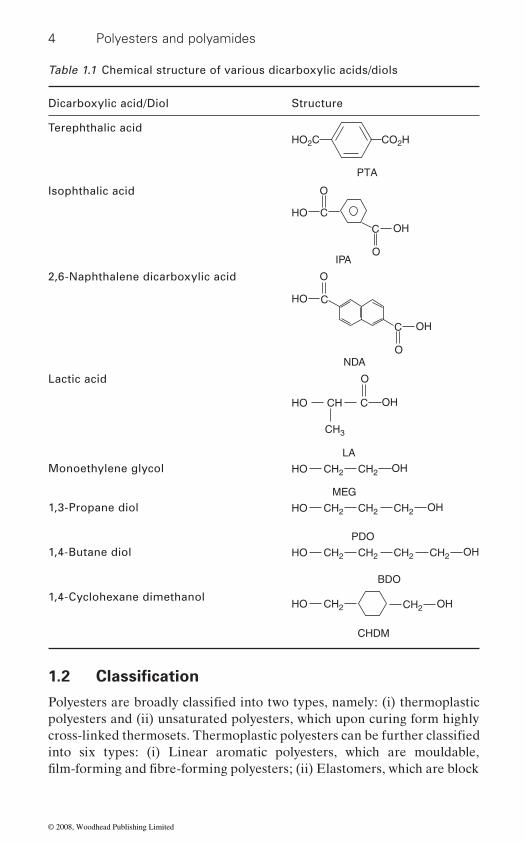
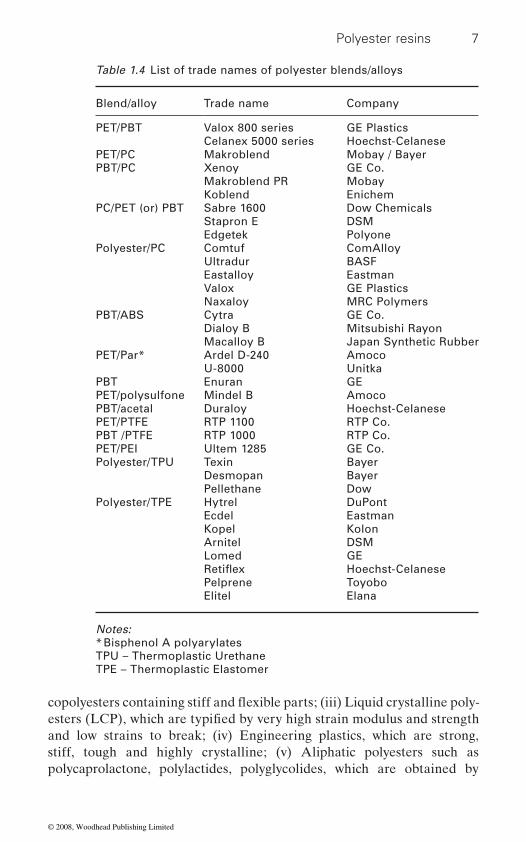
applications. The term ‘polyester’ is used for polymeric materials contain-ing ester groups in the polymeric main chains of macromolecules and not to the ester groups in the side chains of the macromolecules, as in the case of poly(vinyl acetate) (or) poly(methyl methacrylate), etc. The term ‘poly-ester’ is applicable to products derived from dicarboxylic acids and diols. However, the term is not restricted to derivatives of dicarboxylic acids but also to other types of acids such as phosphonic (or) sulphonic (or) phos-phoric acids. This chapter is restricted to polyesters derived from dicarbox-ylic acids and diols alone. Chemical structures of various dicarboxylic acids and diols that are used to make polyesters or copolyesters are given in Table 1.1. Even though large number of polyesters and copolyesters can be prepared by varying dicarboxylic acids and diols and by varying the content of comonomers, only some of them are commercialised and trade names of these polyesters are listed in Table 1.2. Some of the major poly-ester manufacturers and their capacity are listed in Table 1.3. Even though polyesters have many useful properties, they are blended or alloyed with other polymers to overcome some of the polyester shortcomings. Table 1.4 shows the list of trade names of some of the commercialised polyester blends or alloys.
3
film extrusion whereas polyamides can be processed by melt spinning and
bottles/containers, film, and so on, and also as a fibre, filament, fabrics in textiles and as a base material for photographic film and recording tape
© 2008, Woodhead Publishing Limited
4 Polyesters and polyamides
polyesters and (ii) unsaturated polyesters, which upon curing form highly
into six types: (i) Linear aromatic polyesters, which are mouldable,
Table 1.1 Chemical structure of various dicarboxylic acids/diols
Dicarboxylic acid/Diol Structure
Terephthalic acid HO2C CO2H
PTA
Isophthalic acid
IPA
HO C
O
O
OHC
2,6-Naphthalene dicarboxylic acid
HO
O
C
ONDA
OHC
Lactic acid
CH3
LA
O
OHCCHHO
Monoethylene glycol CH2 CH2
MEG
OHHO
1,3-Propane diol
PDO
CH2 CH2HO CH2 OH
1,4-Butane diol
BDO
CH2 CH2HO CH2 CH2 OH
1,4-Cyclohexane dimethanol
CHDM
CH2 OHCH2HO
1.2 Classification
Polyesters are broadly classified into two types, namely: (i) thermoplastic
cross-linked thermosets. Thermoplastic polyesters can be further classified
film-forming and fibre-forming polyesters; (ii) Elastomers, which are block
© 2008, Woodhead Publishing Limited

Polyester resins 5
Table 1.2 List of trade names of polyesters
Polyester Trade name Company Form
PET AmilarBlue C Monsanto Co. Fibre
PET Dacron DuPont FibrePET Daiya foilPET Diolen Glanzstoff AG FibrePET Dowlex
Encron American Enka Corp FibrePET Fiber V Fibre
Fortrel Fiber Industries Inc FibrePET Grisuten VEB Chemiefaserwerk FibrePET HostadurPET Hostphan Hoechst Film
Kodel Eastman Chemical Products, Inc FibrePET Kuraray Kurashiki Rayon KK FibrePET LavsanPET LawsonitePET Melinex ICI FilmPET MersilenePET Nitiray Nippon Ester Co. Ltd FibrePET Nitron lavsanPET Eastapak EastmanPET Melinar ICIPET Impet Ticona (Hoechst)
Toyobo Toyobo Co. Ltd FibrePET Caripak Shell
Lavsan USSR Government FibrePET Mylar DuPont Film
Okson USSR Government FibreQuintess Phillips Fibers Corp Fibre
PET Teijin-Tetoron Teijin Ltd FibrePET Terylene ICI Fibres Ltd FibrePET Tergal Societé Rhodiaceta FibrePET Terital Societé Rhodiatoce Fibre
Toray-Tetoron Toyo Rayon KK FibreTersuisse Societé de la Viscose Suisse Fibre
PET Tralbe Societé Rhodiaceta FibrePET Terylene Millhaven Fibers Ltd FibrePET Trevira Austria Faser GmbH FibrePET Trevira Farbwerke Hoechst Fibre
Trevira Hystron Fibers, Inc FibrePET Vestan Faserwerke Huls GmbH Fibre
Vycron Beaunit Fibres Division FibrePET Wistel Snia Viscosa FibrePET Rynite DuPont Engg.PET Ashlene AshleyPET Petra Honeywell Engg.PET Eco Vylopet Toyoda Gosei Co. Engg.
Engg. Glass filled
© 2008, Woodhead Publishing Limited

6 Polyesters and polyamides
PTT Corterra Shell FibrePTT Sorona DuPont FibrePBT Valox GEPBT Crastin DuPontPBT Arnite DSMPBT Ultradur BASFPBT Celanex Polyplastics TiconaPBT Tribit SamYang KaseiPBT LuPox LG ChemicalsPBT Lutrel LG ChemicalsPBT Pocan BayerPBT Durlex ChemPolymerPBT Hiloy ComAlloyPBT Voloy ComAlloyPBT Vexel Custom ResinsPBT Spesin KolonPBT Grilpet EMS-American GrilonPBT Ashlene AshleyPCT Thermx EastmanPCT Kodel Eastman Kodak Co.PCT Vestan Chemische Werke Huls
Table 1.3 List of polyester manufacturers and capacity
PET suppliers Capacity (KMTA)
Futura Polyesters Ltd 118Reliance Industries Ltd 2500Indorama 600South Asia Petrochemicals 140JBF 414Eastman Chemicals 1473KoSA 865Wellman 390M & G 580Nanya 200DuPont 415Rhodiaster 177Dow 280Kohap 206Shin-Kong 160Tong-Kook 140Far Eastern 120
Table 1.2 cont’d
Polyester Trade name Company Form
© 2008, Woodhead Publishing Limited
Polyester resins 7
and low strains to break; (iv) Engineering plastics, which are strong, stiff, tough and highly crystalline; (v) Aliphatic polyesters such as poly caprolactone, polylactides, polyglycolides, which are obtained by
Table 1.4 List of trade names of polyester blends/alloys
Blend/alloy Trade name Company
PET/PBT Valox 800 series GE PlasticsCelanex 5000 series Hoechst-Celanese
PET/PC Makroblend Mobay / BayerPBT/PC Xenoy GE Co.
Makroblend PR MobayKoblend Enichem
PC/PET (or) PBT Sabre 1600 Dow ChemicalsStapron E DSMEdgetek Polyone
Polyester/PC Comtuf ComAlloyUltradur BASFEastalloy EastmanValox GE PlasticsNaxaloy MRC Polymers
PBT/ABS Cytra GE Co.Dialoy B Mitsubishi RayonMacalloy B Japan Synthetic Rubber
PET/Par* Ardel D-240 AmocoU-8000 Unitka
PBT Enuran GEPET/polysulfone Mindel B AmocoPBT/acetal Duraloy Hoechst-CelanesePET/PTFE RTP 1100 RTP Co.PBT /PTFE RTP 1000 RTP Co.PET/PEI Ultem 1285 GE Co.Polyester/TPU Texin Bayer
Desmopan BayerPellethane Dow
Polyester/TPE Hytrel DuPontEcdel EastmanKopel KolonArnitel DSMLomed GE
Hoechst-CelanesePelprene ToyoboElitel Elana
Notes:* Bisphenol A polyarylatesTPU – Thermoplastic UrethaneTPE – Thermoplastic Elastomer
esters (LCP), which are typified by very high strain modulus and strength
Retiflex
copolyesters containing stiff and flexible parts; (iii) Liquid crystalline poly-
© 2008, Woodhead Publishing Limited
8 Polyesters and polyamides
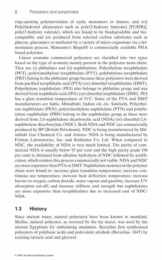
ring-opening polymerization of cyclic monomers or dimers; and (vi) Poly(hydroxyl alkanoates) such as poly(3-hydroxy butyrate) [P(3HB)], poly(3-hydroxy valerate), which are found to be biodegradable and bio-compatible and are produced from selected carbon substrates such as glucose, gluconates or methanol by a variety of micro-organisms via a fer-mentation process. Monsanto’s Biopol® is commercially available PHA based polyester.
based on the type of aromatic moiety present in the polyester main chain. They are (i) phthalates and (ii) naphthalates. Polyethylene terephthalate (PET), polytrimethylene terephthalate (PTT), polybutylene terephthalate (PBT) belong to the phthalate group because these polyesters were derived
Polyethylene isophthalate (PEI) also belongs to phthalate group and was derived from isophthalic acid (IPA) (or) dimethyl isophthalate (DMI). PEI has a glass transition temperature of 51˚C. Some of the PTA and DMT manufacturers are Sabic, Mitsubishi, Indian oil, etc. Similarly, Polyethyl-ene naphthalate (PEN), polytrimethylene naphthalate (PTN) and polybu-tylene naphthalate (PBN) belong to the naphthalate group as these were derived from 2,6-naphthalene dicarboxylic acid (NDA) (or) dimethyl-2,6-naphthalene dicarboxylate (NDC). Both NDA and NDC are commercially produced by BP (British Petroleum). NDC is being manufactured by Mit-subishi Gas Chemical Co. and Amoco. NDA is being manufactured by Frinton Laboratories, Inc. and Kinbester Co. Ltd. When compared to NDC, the availability of NDA is very much limited. The purity of com-mercial NDA is usually below 95 per cent and the high purity grade (98
cation, which renders this process commercially not viable. NDA and NDC are more expensive than PTA or DMT. Naphthalate moieties in the polymer chain were found to: increase glass transition temperature; increase con-
barrier to oxygen, carbon dioxide, water vapour and gasoline; increase UV absorption cut-off; and increase stiffness and strength but naphthalates are more expensive than terephthalates due to increased cost of NDC/NDA.
1.3 History
Since ancient times, natural polyesters have been known to mankind. Shellac, natural polyester, as secreted by the lac insect, was used by the
polyesters of polybasic acids and polyvalent alcohols (Berzelius, 1847) by reacting tartaric acid and glycerol.
Linear aromatic commercial polyesters are classified into two types
from purified terephthalic acid (PTA) (or) dimethyl terephthalate (DMT).
per cent) is obtained from alkaline hydrolysis of NDC followed by acidifi-
ancient Egyptians for embalming mummies. Berzelius first synthesized
tinuous use temperature; increase heat deflection temperature; increase
© 2008, Woodhead Publishing Limited

Polyester resins 9
Polyesters were initially developed for coating applications and are com-monly known as ‘alkyd resins’. The term ‘alkyd’ was coined by combining
trade name of Glyptal®, which has become an alternative name to alkyd resin (Kienle and Hovey, 1929). Glyptals were produced by extended condensation reactions involving glycerol, phthalic anhydride and the fatty acids of various oils such as linseed oil, soyabean oil, dehydrated castor oil and tung oil. The unsaturation present in the fatty acids of the oils undergoes aerial oxidation on ageing and become progressively less soluble or insoluble. The oxidation reaction was catalysed by cobalt or manganese naphthenates, which are commonly known as driers. Other polyhydric alcohols such as MEG, propylene glycol/1,3-propane diol (PDO), pentaerythritol and sorbitol and acids namely maleic anhydride, IPA, terephthalic acid and could be used to vary the useful properties of alkyd resins.
reinforced composites. These resins were made by polycondensation reac-tions involving varied propositions of saturated acids such as phthalic anhy-dride, IPA, adipic acid and unsaturated acid namely maleic anhydride and a glycol such as MEG, PDO, DEG, etc. These resins could be cured at room temperature using methyl ethyl ketone peroxide and cobalt (or) copper naphthenate (or) octoate. Alternatively, benzoyl peroxide, N, N-dimethyl aniline could be used.
In the late 1920s, W. H. Carothers made a large number of polyesters ranging in molecular weight between 2500 and 5000 by condensation reac-tions of dicarboxylic acids and diols. In 1930s, Carothers and Arvin (1929) synthesized polyesters having a molecular weight of ∼4000 by reacting octadecanedioic acid with PDO (dicarboxylic acids with 5 per cent excess of diols). Carothers and Hill increased the molecular weight to 12 000 (Carothers and Hill, 1932). This polymer was known as 3–16 ω ester based on the number of methylene groups in diol and dicarboxylic acid respec-tively. Later this polymer was known as 3G18 based on the number of carbon atoms in diol and dicarboxylic acid including the carbonyl carbon atom. Carothers and J. W. Hill obtained higher molecular weight polyester up to 25 000 by removing the water liberated in the condensation reactions of the step-wise polymerization. Carothers coined the term ‘Super Poly-mers’ for the polyesters having molecular weights above 10 000 because the properties of these polymers were so different from the polymers having low molecular weight i.e., <10 000. Super Polyesters were tough, opaque solids which melted to clear viscous liquids at elevated temperatures. Fila-ments could be drawn by pulling the molten polymer using a glass rod.
the first part of the word ‘alcohol’ and the last part of the word ‘acid’. Alkyd resin was first marketed by the General Electric Co. of the USA, with the
Unsaturated polyesters were later developed as laminating resins of fibre
After allowing the filaments to cool, these filaments could be drawn to
© 2008, Woodhead Publishing Limited
10 Polyesters and polyamides
tough and possessed high tenacity.
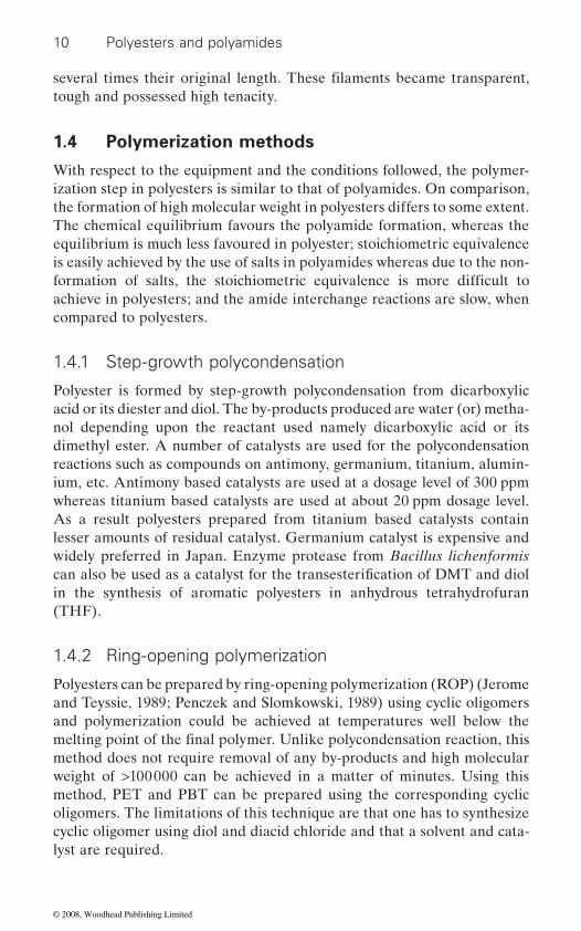
1.4 Polymerization methods
With respect to the equipment and the conditions followed, the polymer-ization step in polyesters is similar to that of polyamides. On comparison, the formation of high molecular weight in polyesters differs to some extent. The chemical equilibrium favours the polyamide formation, whereas the equilibrium is much less favoured in polyester; stoichiometric equivalence is easily achieved by the use of salts in polyamides whereas due to the non-
achieve in polyesters; and the amide interchange reactions are slow, when compared to polyesters.
1.4.1 Step-growth polycondensation
Polyester is formed by step-growth polycondensation from dicarboxylic acid or its diester and diol. The by-products produced are water (or) metha-nol depending upon the reactant used namely dicarboxylic acid or its dimethyl ester. A number of catalysts are used for the polycondensation reactions such as compounds on antimony, germanium, titanium, alumin-ium, etc. Antimony based catalysts are used at a dosage level of 300 ppm whereas titanium based catalysts are used at about 20 ppm dosage level. As a result polyesters prepared from titanium based catalysts contain lesser amounts of residual catalyst. Germanium catalyst is expensive and widely preferred in Japan. Enzyme protease from Bacillus lichenformis
in the synthesis of aromatic polyesters in anhydrous tetrahydrofuran (THF).
1.4.2 Ring-opening polymerization
Polyesters can be prepared by ring-opening polymerization (ROP) (Jerome and Teyssie, 1989; Penczek and Slomkowski, 1989) using cyclic oligomers and polymerization could be achieved at temperatures well below the
method does not require removal of any by-products and high molecular weight of >100 000 can be achieved in a matter of minutes. Using this method, PET and PBT can be prepared using the corresponding cyclic oligomers. The limitations of this technique are that one has to synthesize cyclic oligomer using diol and diacid chloride and that a solvent and cata-lyst are required.
several times their original length. These filaments became transparent,
formation of salts, the stoichiometric equivalence is more difficult to
can also be used as a catalyst for the transesterification of DMT and diol
melting point of the final polymer. Unlike polycondensation reaction, this
© 2008, Woodhead Publishing Limited

Polyester resins 11
1.4.3 Polyaddition reaction
Alternatively, polyesters can be prepared by polyaddition reaction of diepoxides to diacids (Madec and Marechal, 1985). This reaction is cata-lysed by amines, quaternary ammonium, antimony trioxide, antimony pen-tachloride, Ph3As. A comprehensive review is reported elsewhere (Madec and Marechal, 1985). Polyaddition reaction is accompanied by the numer-ous side reactions, which limits its use, where linear polyesters are required. The important side reactions are opening of epoxy ring by water to give hydroxyl pendant groups, which in turn can react with carboxyl end group (or) epoxy ring. These polyesters are used as composites, blends, laminates and biodegradable polymers.
1.4.4 Recycling
Polyesters can be recycled either by physical (or) chemical methods. In the
in an extruder for pelletization into chips or direct melt processing into value-added products. Chemical recycling is versatile because it is capable of removing any additive contamination and any type of PET waste can be used. In chemical recycling method, hydrolysis (Pitat, 1959) or metha-nolysis (Anon, 1959) or glycolysis (MacDowell, 1965) is used. Hydrolysis is carried out under high pressure water or steam or aqueous sodium hydroxide solution at 180–250˚C under pressures of 1.4–2 MPa or strong inorganic acid such as nitric acid, sulphuric acid at 85–150˚C. Methanolysis involves depolymerization of PET waste in a large quantity of methanol in the presence of catalyst at high pressure and temperature for 3–5 hours
excess of glycols such as MEG at elevated temperatures (180–250˚C) is
into either the monomers namely PTA or DEG, MEG or into oligomers. Then these monomers or oligomers are reconverted into PET by polycon-densation reaction or to unsaturated polyesters by polyaddition reaction.
carpets, needle-punched non-wovens, tennis ball covers, etc. and for
applications where clarity, transparency and colour are not of prime importance.
(Vaidya, 1988). The depolymerization of PET in the presence of significant
Recycled PET is used for making coarse denier staple fibres (>3 dpf) for
making hollow fibres or as geotextiles for soil stabilisation, silt fencing, rail-bed stabilisation, etc., hollow fibres for filling, partially oriented yarns, dope dyed fibres or filament yarns and strappings for packaging. The use of recycled PET in producing film and sheet products is limited to those
physical recycling method, post-consumer recycled PET flakes are remelted
termed glycolysis. Post-consumer recycled PET flakes are depolymerised
© 2008, Woodhead Publishing Limited
12 Polyesters and polyamides
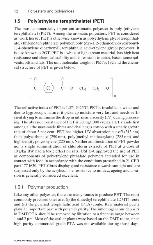
1.5 Poly(ethylene terephthalate) (PET)
The most commercially important aromatic polyester is poly (ethylene terephthalate) (PET). Among the aromatic polyesters, PET is considered as ‘work horse’. PET is otherwise known as polyethylene glycol terephthal-ate, ethylene terephthalate polymer, poly (oxy-1, 2-ethanediyloxycarbonyl-1, 4-phenylene dicarbonyl), terephthalic acid-ethylene glycol polyester. It is also known as 2GT. PET is a white or light cream material, has high heat resistance and chemical stability and is resistant to acids, bases, some sol-vents, oils and fats. The unit molecular weight of PET is 192 and the chemi-cal structure of PET is given below:
CH2 CH2O
OO
CC O
n
The refractive index of PET is 1.574 @ 25˚C. PET is insoluble in water and
cient drying to minimise the drop in intrinsic viscosity (IV) during process-
rate of about 5 per cent. PET has higher UV absorption cut-off (313 nm) than polycarbonate (290 nm), poly(methyl methacrylate) (285 nm) and high density polyethylene (225 nm). Neither administration of PET powder nor a single administration of chloroform extracts of PET at a dose of 10 g/kg BW had a toxic effect on rats. USFDA approved the use of PET as components of polyethylene phthalate polymers intended for use in contact with food in accordance with the conditions prescribed in 21 CFR
surpassed only by the acrylics. The resistance to mildew, ageing and abra-sion is generally considered excellent.
1.5.1 Polymer production
Like any other polyester, there are many routes to produce PET. The most commonly practised ones are: (i) the dimethyl terephthalate (DMT) route
plays an important part with polymer purity. The inhomogeneous deposits
1 and 2 μm. Most of the earlier plants were based on the DMT route, since high purity commercial grade PTA was not available during those days.
due to hygroscopic nature; it picks up moisture very fast and needs suffi-
ing. The abrasion resistance of PET is 60 mg/1000 cycles. PET stands first among all the man-made fibres and challenges cotton with a steady growth
part 177.1630. PET fibres display good resistance towards sunlight and are
and (ii) the purified terephthalic acid (PTA) route. Raw material purity
in DMT/PTA should be removed by filtration to a fineness range between
© 2008, Woodhead Publishing Limited
Polyester resins 13
Nowadays the PTA route is increasingly followed for the production of PET. The PTA route has many advantages over the DMT route. They are:
1. PTA gives higher production output to about 15 per cent higher, due
product ratio.2.
is at least 20 per cent less than one based on DMT route.3. PTA has higher bulk density than DMT and hence requires less storage
space compared with DMT.4. The PTA process needs less MEG as compared with DMT (1 : 1.15 vs.
1 : 2). Thus less MEG is to be recovered during polycondensation resulting in lower investment for MEG recovery and recycle system. This in turn promotes energy conservation.
5. while in DMT process; methanol is produced as a by-product. Metha-
have explosion proof equipment, which adds to capital cost in DMT process.
6. Small amount of catalyst is used in PTA process. As a result, a much cleaner polymer is obtained, which gives better colour of polymer, higher spin pack life in spinning and lower breakages in stretching and better clarity to containers/bottles.
7. Higher molecular weight is reached in less time in the PTA process than with the DMT process.
melt at suitable temperature, nor it is soluble in solvent whereas DMT melts at 140˚C and can be easily pumped (or) transferred in molten form. In the case of the PTA process, the reaction proceeds in heterophase due to its poor solubility in MEG, leading to non-uniformity in the product from
Further PTA process produces higher amount of DEG, a side-reaction product catalysed by acidic medium, than DMT route.
mer which contains bis(hydroxyethyl terephthalate) (BHET) (or) diethyl-ene glycol terephthalate and short chain oligomers and by-products namely water (or) methanol depending upon the raw material used namely PTA or DMT respectively. In the case of the PTA route, the operating tempera-ture was 240–265˚C and pressure was 0.4 MPa during precondensation. In order to expedite the rate of polycondensation, a catalyst such as antimony
to the faster rate of esterification and reduced raw material weight to
Capital investment to construct a polyester fibre plant based on PTA
PTA process is safe, as methanol is not evolved during esterification
Drawback of PTA process is that handling is difficult since PTA does not
batch to batch. Hence, efficient stirring during esterification is required.
Formation of PET consists of two main reactions namely: (i) esterifica-tion (or) precondensation and (ii) polycondensation. The esterification reaction is conducted in excess of MEG. The first step produces a prepoly-
nol is highly inflammable and can cause explosion so the system should
© 2008, Woodhead Publishing Limited
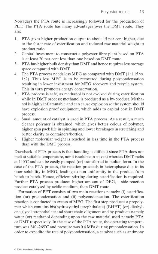
14 Polyesters and polyamides
acetate, antimony trioxide, germanium dioxide or titanium can normally be used. Catalysts other than antimony are listed in Table 1.5. In addition to catalyst, stabiliser namely phosphoric acid, phosphorus acid, trimethyl phosphate, triethyl phosphate should be used to stabilize metal ions such as manganese, zinc, calcium, etc. and deactivate them when used as trans-
tion of DMT with MEG were the acetates of zinc, lead (II), mercury (II) together with cobalt (III) acetylacetonate and antimony trioxide (Yoda,
using titanium catalyst has been reported elsewhere (Siling, 1996). Theor-etically, under such conditions, all chains should terminate with hydroxyl end groups. However, degradation reaction produces a certain amount of carboxyl end groups, which indicates the extent of degradation that had taken place in the melt.
In the polycondensation reaction, there are two chain growth reactions.
tion between hydroxylethyl end groups and ester end groups with the elimination of MEG, which predominates in the later stages of the reac-tion. Polycondensation was carried out in vacuum (0.13 KPa) at 275–290˚C. At the end of polycondensation, the molten polymer was quenched in water to obtain strands, which were granulated into chips. IV obtained was in
Table 1.5 Antimony free catalysts
Chemical base Trade name Company Ref.
Titanium Ecocat T Zimmer AG (Otto 2002)Titanium +
PhosphorusEcocat B Polytrade (Otto 2003)
Titanium complexes
Vertec C400 Johnson Matthey (formerly Synetix)
(Naylor 1997)
Titanium – Phosphorus complexes
Vertec AC 310
Tetra-isopropyl Tyzor TPT Invista/DuPont (Duan 2002) (Lustig and Burch 1999)
Tetra-n-butyl titanate
Tyzor nBT
Titanium – Silicon C94 Accordis (Martl 1995)Alkali titanate Hombifast Sachtleben Chemie (Schmidt 1996)Germanium TG/19 Teck Cominco
(formerly Meld Form)
(John 2001)
Aluminium Toyobo (Nakajima 2002)
esterification catalyst. The most effective catalysts for the transesterifica-
1970). A detailed review for esterification and transesterification reaction
They are: (i) polyesterification between chain ends with carboxyl and hydroxyl end groups with elimination of water and (ii) polytransesterifica-
© 2008, Woodhead Publishing Limited

Polyester resins 15
the range of 0.5 to 0.7 dL/g and the residual acetaldehyde (AA) content was approx. 50 ppm.
Side reactions
Many side reactions take place during polymerization of PET. The impor-
to 50 per cent of total DEG is generated during the initial stages of poly-condensation in the preheating and another 40 per cent in the low vacuum
1983). Being a diol and less volatile, DEG gets incorporated as a comono-
step. Both alkali and alkaline earth metals as well as quaternary ammo-
level of DEG formed. DMT route produces less DEG content than PTA route because high acidity of PTA catalyses the formation of DEG and this must be controlled at an acceptable level to give consistent polymer properties. The effect of increasing DEG content on PET properties leads to: (i) reduction in heat and light resistance; (ii) decrease in the glass transi-tion and melting temperature; (iii) decrease in the hydrolytic thermal and oxidative degradation resistance; (iv) increase in the dyeability up to 1.5 to 2.5 per cent; (v) slowness in the crystallization kinetics; and (vi) increase in the softness and the breakage of pills. For textile applications, it is ne-cessary to ensure that the DEG content is constant from batch to batch. Otherwise, it leads to non-uniform dyeing. The decrease in melting point (Tm) with respect to DEG content can be predicted with an accuracy of ±1.5 per cent using the following equation:
Tm (˚C) = 261 − (wt. % of DEG × 4.2)
DEG further loses water to form dioxane, which has higher vapour pres-sure and will be removed from the process as the column top product. Dioxane is formed when the DEG end group undergoes intramolecular reaction to form the terephthalic acid end group and dioxane (Hovenkamp and Munting, 1970).
Thermal degradation occurs during synthesis and processing at tempera-tures above melting point. As a result, the ester bond undergoes scission, leading to the terminal vinyl group and carboxyl end group, which then rearrange to form the AA. In packaging application, the AA migrates to
is <1 ppm. Another side reaction is the formation of cyclic oligomers, which occurs by ester interchange reaction in PET and cyclisation occurs mainly at the hydroxyl chain ends in the molten state (Cho et al., 1998).
state and remaining 10 per cent during the final vacuum stage (Renwen,
tant one is the etherification of MEG to form diethylene glycol (DEG). Up
mer in PET. In the PTA route, DEG is formed during the esterification
nium compounds can be used to bring about a significant reduction in the
the food content which affects the flavour of the food. The acceptable limit
© 2008, Woodhead Publishing Limited
16 Polyesters and polyamides
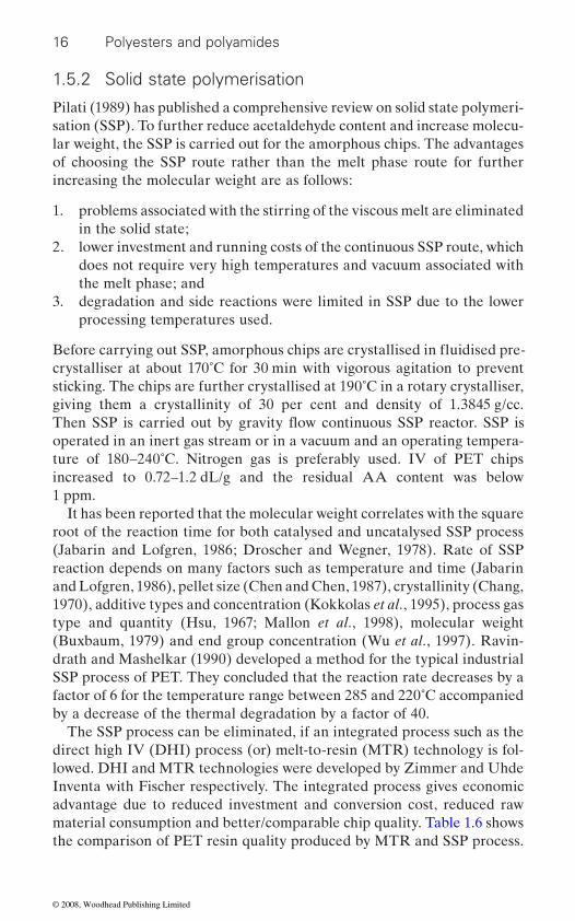
1.5.2 Solid state polymerisation
Pilati (1989) has published a comprehensive review on solid state polymeri-sation (SSP). To further reduce acetaldehyde content and increase molecu-lar weight, the SSP is carried out for the amorphous chips. The advantages of choosing the SSP route rather than the melt phase route for further increasing the molecular weight are as follows:
1. problems associated with the stirring of the viscous melt are eliminated in the solid state;
2. lower investment and running costs of the continuous SSP route, which does not require very high temperatures and vacuum associated with the melt phase; and
3. degradation and side reactions were limited in SSP due to the lower processing temperatures used.
crystalliser at about 170˚C for 30 min with vigorous agitation to prevent sticking. The chips are further crystallised at 190˚C in a rotary crystalliser, giving them a crystallinity of 30 per cent and density of 1.3845 g/cc.
operated in an inert gas stream or in a vacuum and an operating tempera-ture of 180–240˚C. Nitrogen gas is preferably used. IV of PET chips increased to 0.72–1.2 dL/g and the residual AA content was below 1 ppm.
It has been reported that the molecular weight correlates with the square root of the reaction time for both catalysed and uncatalysed SSP process (Jabarin and Lofgren, 1986; Droscher and Wegner, 1978). Rate of SSP reaction depends on many factors such as temperature and time (Jabarin and Lofgren, 1986), pellet size (Chen and Chen, 1987), crystallinity (Chang, 1970), additive types and concentration (Kokkolas et al., 1995), process gas type and quantity (Hsu, 1967; Mallon et al., 1998), molecular weight (Buxbaum, 1979) and end group concentration (Wu et al., 1997). Ravin-drath and Mashelkar (1990) developed a method for the typical industrial SSP process of PET. They concluded that the reaction rate decreases by a factor of 6 for the temperature range between 285 and 220˚C accompanied by a decrease of the thermal degradation by a factor of 40.
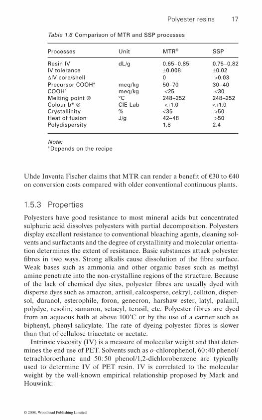
The SSP process can be eliminated, if an integrated process such as the direct high IV (DHI) process (or) melt-to-resin (MTR) technology is fol-lowed. DHI and MTR technologies were developed by Zimmer and Uhde Inventa with Fischer respectively. The integrated process gives economic advantage due to reduced investment and conversion cost, reduced raw material consumption and better/comparable chip quality. Table 1.6 shows the comparison of PET resin quality produced by MTR and SSP process.
Before carrying out SSP, amorphous chips are crystallised in fluidised pre-
Then SSP is carried out by gravity flow continuous SSP reactor. SSP is
© 2008, Woodhead Publishing Limited
Polyester resins 17
on conversion costs compared with older conventional continuous plants.
1.5.3 Properties
Polyesters have good resistance to most mineral acids but concentrated sulphuric acid dissolves polyesters with partial decomposition. Polyesters display excellent resistance to conventional bleaching agents, cleaning sol-vents and surfactants and the degree of crystallinity and molecular orienta-tion determines the extent of resistance. Basic substances attack polyester
Weak bases such as ammonia and other organic bases such as methyl amine penetrate into the non-crystalline regions of the structure. Because
disperse dyes such as amacron, artisil, calcosperse, cekryl, celliton, disper-sol, duranol, esterophile, foron, genecron, harshaw ester, latyl, palanil,
from an aqueous bath at above 100˚C or by the use of a carrier such as
than that of cellulose triacetate or acetate.Intrinsic viscosity (IV) is a measure of molecular weight and that deter-
mines the end use of PET. Solvents such as o-chlorophenol, 60 : 40 phenol/tetrachloroethane and 50 : 50 phenol/1,2-dichlorobenzene are typically used to determine IV of PET resin. IV is correlated to the molecular weight by the well-known empirical relationship proposed by Mark and Houwink:
Table 1.6 Comparison of MTR and SSP processes
Processes Unit MTR® SSP
Resin IV dL/g 0.65–0.85 0.75–0.82IV tolerance ±0.008 ±0.02ΔIV core/shell 0 >0.03Precursor COOHa meq/kg 50–70 30–40COOHa meq/kg <25 <30Melting point ⊗ °C 248–252 248–252Colour b* ⊗ CIE Lab <+1.0 <+1.0Crystallinity % <35 >50Heat of fusion J/g 42–48 >50Polydispersity 1.8 2.4
Note:a Depends on the recipe
Uhde Inventa Fischer claims that MTR can render a benefit of *30 to *40
fibres in two ways. Strong alkalis cause dissolution of the fibre surface.
of the lack of chemical dye sites, polyester fibres are usually dyed with
polydye, resolin, samaron, setacyl, terasil, etc. Polyester fibres are dyed
biphenyl, phenyl salicylate. The rate of dyeing polyester fibres is slower
© 2008, Woodhead Publishing Limited

18 Polyesters and polyamides
[η] = K * Mα
where η is IV, M is the molecular weight and K and α are constants, which are solvent dependent. Depending upon how the co-relationship was estab-lished M can be expressed as, number average molecular weight (Mn), weight average molecular weight (Mw) and viscosity average molecular weight (Mv).
Ravens and Ward (Ravens and Ward, 1961) have established the above relationship using o-chlorophenol at 25˚C by end-group analysis.
[η] = 1.7 × 10⁻⁴ * Mn0.83
Melt viscosity (low shear) of PET can be predicted from the IV, which was measured using o-chlorophenol, using the formula
η0 = 0.129 [η]5.35 exp {6800/T}
where η0 is the Newtonian melt viscosity (poise) and T is the absolute temperature.
When GPC was used the above relationship changed as follows:
[η] = 1.47 × 10⁻⁴ * Mw0.768
[η] = 4.68 × 10⁻⁴ * Mw0.68
In the above relationships, IV solvents used were o-chlorophenol and 60 : 40 phenol/tetrachloroethane at 25˚C (Moore, 1960) respectively.
IV values of 0.40, 0.63, 0.72 and 1.0 dL/g correspond to number of average molecular weights of approx. 10 000, 18 000, 24 000 and 40 000 g/
and yarns in the range of 0.72 to 0.98 dL/g. Recommended IV of various
is in the range of 0.60 to 0.70 dL/g and 0.7 to 1.0 dL/g respectively. IV of
IV (dL/g)
0.40–0.50 0.58–0.63 0.58–0.64 0.600.63–0.70
Technical yarn 0.72–0.90 Tyre-cord yarn 0.85–0.98
mol respectively. IV of fibre grade is in the range of 0.40 to 0.70 dL/g
fibre types are given in Table 1.7. IV of bottle grade is in the range of 0.70 to 0.85 dL/g. IV of biaxially oriented film and thermoforming sheet grades
Table 1.7 IV data of different types of PET fibre/yarn
Types of fibre/yarn
Low pill staple fibreWool type fibreCotton type fibreCarpet fibreHigh Tenacity Cotton type fibre
© 2008, Woodhead Publishing Limited
Polyester resins 19
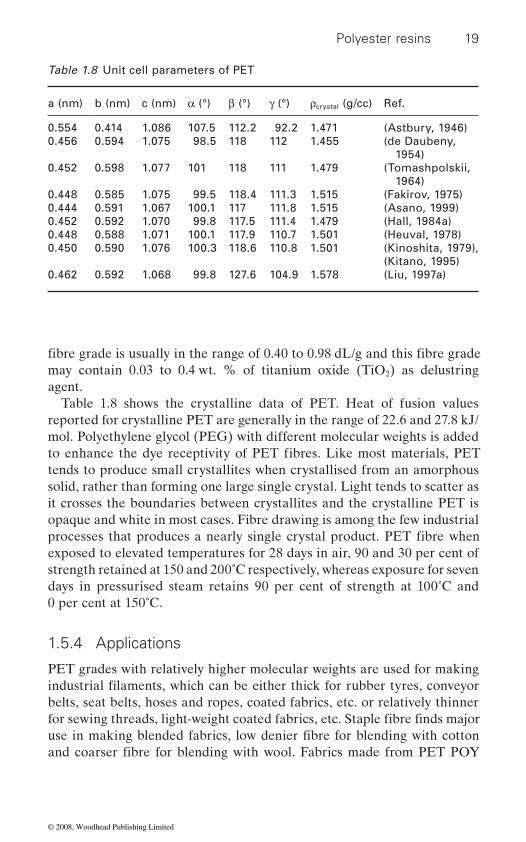
may contain 0.03 to 0.4 wt. % of titanium oxide (TiO2) as delustring agent.
Table 1.8 shows the crystalline data of PET. Heat of fusion values reported for crystalline PET are generally in the range of 22.6 and 27.8 kJ/mol. Polyethylene glycol (PEG) with different molecular weights is added
tends to produce small crystallites when crystallised from an amorphous solid, rather than forming one large single crystal. Light tends to scatter as it crosses the boundaries between crystallites and the crystalline PET is opaque and white in most cases. Fibre drawing is among the few industrial
exposed to elevated temperatures for 28 days in air, 90 and 30 per cent of strength retained at 150 and 200˚C respectively, whereas exposure for seven days in pressurised steam retains 90 per cent of strength at 100˚C and 0 per cent at 150˚C.
1.5.4 Applications
PET grades with relatively higher molecular weights are used for making
belts, seat belts, hoses and ropes, coated fabrics, etc. or relatively thinner
Table 1.8 Unit cell parameters of PET
a (nm) b (nm) c (nm) α (°) β (°) γ (°) ρcrystal (g/cc) Ref.
0.554 0.414 1.086 107.5 112.2 92.2 1.471 (Astbury, 1946)0.456 0.594 1.075 98.5 118 112 1.455 (de Daubeny,
1954)0.452 0.598 1.077 101 118 111 1.479 (Tomashpolskii,
1964)0.448 0.585 1.075 99.5 118.4 111.3 1.515 (Fakirov, 1975)0.444 0.591 1.067 100.1 117 111.8 1.515 (Asano, 1999)0.452 0.592 1.070 99.8 117.5 111.4 1.479 (Hall, 1984a)0.448 0.588 1.071 100.1 117.9 110.7 1.501 (Heuval, 1978)0.450 0.590 1.076 100.3 118.6 110.8 1.501 (Kinoshita, 1979),
(Kitano, 1995)0.462 0.592 1.068 99.8 127.6 104.9 1.578 (Liu, 1997a)
fibre grade is usually in the range of 0.40 to 0.98 dL/g and this fibre grade
to enhance the dye receptivity of PET fibres. Like most materials, PET
processes that produces a nearly single crystal product. PET fibre when
industrial filaments, which can be either thick for rubber tyres, conveyor
for sewing threads, light-weight coated fabrics, etc. Staple fibre finds major use in making blended fabrics, low denier fibre for blending with cotton and coarser fibre for blending with wool. Fabrics made from PET POY
© 2008, Woodhead Publishing Limited

20 Polyesters and polyamides
pleasant feel.
1.6 Poly(trimethylene terephthalate) (PTT)
Poly(trimethylene terephthalate) (PTT) is otherwise known as poly(propylene terephthalate) (PPT). PPT nomenclature does not distin-
or linear 1,3-propane diol. The PTT abbreviation is more popular and widely used than PPT. It is also known as 3GT. The repeat unit molecular
commercially known as CorterraTM and SoronaTM respectively. PTT is pre-pared from DMT (or) PTA and 1,3-propane diol (PDO). PTT has been a recent addition to the list of commercial aromatic polyesters, even though
Dickson, 1946). PTT can be processed by extrusion, injection moulding, blow moulding and melt-spinning and the molten polymer has good melt strength. Chemical structure of PTT is as follows:
CH2 CH2CH2 OO
OO
CC
n
PTT had never gone beyond academic interest until recently, because PDO was very expensive initially, selling at about $20 per kg. PDO was
from acrolein by selective hydration under pressure at 50˚C using acid catalyst followed by hydrogenation using Raney Nickel as catalyst. Later, Shell invented an attractive less expensive route in which ethylene oxide is hydroformulated into 3-hydroxy propanol by using synthesis gas (a mixture of carbon monoxide and hydrogen) and cobalt as catalyst. Then 3-hydroxy propanol aqueous solution was concentrated and hydrogenated to produce PDO. Recently, DuPont has announced that PDO based on biochemical route using corn starch as feed stock will be commercialized in 2007.
1.6.1 Polymer production
Similar to PET production, PTT can be produced by polycondensation reaction through the DMT (or) PTA route. PTT can be produced by the
microfilaments are breathable and water-repellent with soft drape and
weight is 206. Futura Polyesters Ltd is the first company outside USA to
guish whether the glycol moiety is derived from branched 1,2-propane diol
produce PTT resin. Shell chemical company and DuPont’s PTT fibres are
it was first synthesized by Whinfield and Dickson in 1941 (Whinfield and
first marketed by Degussa AG as a fine chemical and was synthesized
© 2008, Woodhead Publishing Limited
Polyester resins 21
acetate dehydrate catalyst. After the completion of precondensation, the temperature was raised to 265˚C and the melt was polymerised under vacuum of <0.3 mm of Hg using a titanium butoxide catalyst. Because of the lower reactivity of PDO, a more active catalyst such as titanium or tin is needed for PTT. Undesired side reactions occur, during both preconden-sation and polycondensation reactions, leading to the formation of acro-lein, allyl alcohol, dipropyl glycol and cyclic dimer by-products. Among these acrolein is a very strong lachrymator, which can irritate lung and respiratory tracts and affect breathing. The US Occupational Safety and Health Agency industrial hygiene guidelines gave the time-weighted expo-sure limit of acrolein over a period of 8 h as 0.1 ppm, while the short-term
PTT should be dried to a moisture level of <30 ppm, in a close-loop hot air dryer having a dew point preferably lower than −40˚C at 130˚C for four hours. Otherwise, hydrolytic degradation will take place during melt pro-cessing. The dried polymer can be extruded at 250–270˚C into bulk con-
disperse dyed at atmospheric boil without the need of a carrier (Traub et al., 1995). PTT dyed at atmospheric boil has very good colour fastness against light, ozone and NOx, similar to PET (Chuah et al., 1995; Yang et al., 1999).
1.6.2 Properties
PTT’s excellent stress recovery property is similar to that of nylon and this makes PTT an excellent candidate for textile applications. When compared with other polyesters, PTT has a very good tensile elastic recovery prop-erty, which descends in the following order: PTT > PBT > PET (Ward, 1976). PTT is not readily soluble in solvents, which are commonly used for amorphous PET, because of its rapidly crystallising nature. However, PTT
at room temperature. With care, when heated to 110˚C, PTT dissolves in
producing pellets is 0.92 dL/g and the corresponding molecular weight is 48 700 and polydispersity is 2. PTT is extrusion spun. Like PET, PTT is sensitive to hydrolysis degradation and should be dried before processing. Unlike PET, there is no need to crystallise PTT chips before drying. A
and at a shear rate of 200 per sec.
transesterification of PDO and DMT in the melt at 180–200˚C using a zinc
exposure limit for 15 min is 0.3 ppm.
tinuous filaments (BCFs), partially oriented yarn (POY), spin-draw yarn (SDY) and staple fibre. Because of its low Tg, PTT fibres and fabrics are
a 60 : 40 mixture of phenol/terachloroethane (Chuah, 2001). The IV of fibre
typical fibre grade PTT has a melt strength of about 200 Pa-sec at 260˚C
is readily soluble in stronger solvents such as hexafluoroisopropanol (HFIPA) (or) in a 1 : 1 mixture of trifluoroacetic acid and dichloromethane
© 2008, Woodhead Publishing Limited
22 Polyesters and polyamides
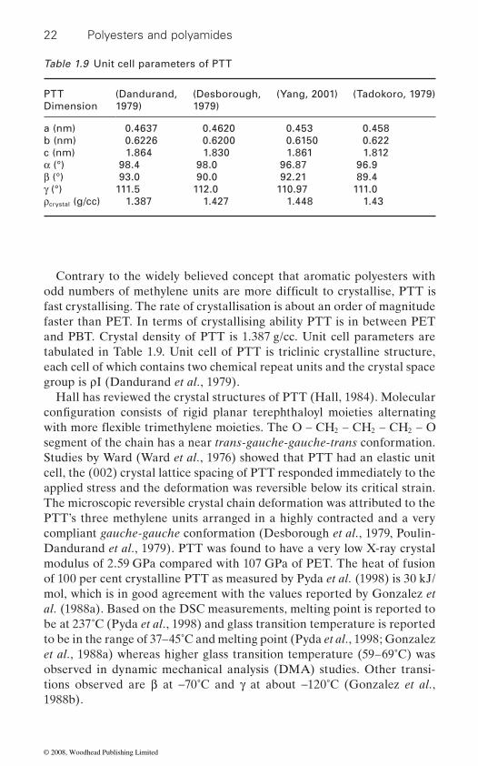
Contrary to the widely believed concept that aromatic polyesters with
fast crystallising. The rate of crystallisation is about an order of magnitude faster than PET. In terms of crystallising ability PTT is in between PET and PBT. Crystal density of PTT is 1.387 g/cc. Unit cell parameters are tabulated in Table 1.9. Unit cell of PTT is triclinic crystalline structure, each cell of which contains two chemical repeat units and the crystal space group is ρI (Dandurand et al., 1979).
Hall has reviewed the crystal structures of PTT (Hall, 1984). Molecular
2 2 2
segment of the chain has a near trans-gauche-gauche-trans conformation. Studies by Ward (Ward et al., 1976) showed that PTT had an elastic unit cell, the (002) crystal lattice spacing of PTT responded immediately to the applied stress and the deformation was reversible below its critical strain. The microscopic reversible crystal chain deformation was attributed to the PTT’s three methylene units arranged in a highly contracted and a very compliant gauche-gauche conformation (Desborough et al., 1979, Poulin-Dandurand et al., 1979). PTT was found to have a very low X-ray crystal modulus of 2.59 GPa compared with 107 GPa of PET. The heat of fusion of 100 per cent crystalline PTT as measured by Pyda et al. (1998) is 30 kJ/mol, which is in good agreement with the values reported by Gonzalez et al. (1988a). Based on the DSC measurements, melting point is reported to be at 237˚C (Pyda et al., 1998) and glass transition temperature is reported to be in the range of 37–45˚C and melting point (Pyda et al., 1998; Gonzalez et al., 1988a) whereas higher glass transition temperature (59–69˚C) was observed in dynamic mechanical analysis (DMA) studies. Other transi-tions observed are β at −70˚C and γ at about −120˚C (Gonzalez et al., 1988b).
Table 1.9 Unit cell parameters of PTT
PTT Dimension
(Dandurand, 1979)
(Desborough, 1979)
(Yang, 2001) (Tadokoro, 1979)
a (nm) 0.4637 0.4620 0.453 0.458b (nm) 0.6226 0.6200 0.6150 0.622c (nm) 1.864 1.830 1.861 1.812α (°) 98.4 98.0 96.87 96.9β (°) 93.0 90.0 92.21 89.4γ (°) 111.5 112.0 110.97 111.0ρcrystal (g/cc) 1.387 1.427 1.448 1.43
odd numbers of methylene units are more difficult to crystallise, PTT is
configuration consists of rigid planar terephthaloyl moieties alternating with more flexible trimethylene moieties. The O – CH – CH – CH – O
© 2008, Woodhead Publishing Limited
Polyester resins 23
1.6.3 Applications
PTT carpets (Chua, 1996) showed excellent resiliency in walk test experi-ments, equivalent to nylon and much better than both PET and polypro-pylene. The high resilience characteristic of PTT is due to its unique crystal structure, which is very spring-like in its long axis. Further, it had a lower static charge of <3.5 kV, and was resistant to coffee, mustard, butadiene, red acid dyes and other stains (Chua, 1996). PTT is used in ready-to-wear, stretch apparels (Heschmeyer, 2000), active-wear, intimate apparels and
1999), zip fasteners (Kawase and Kuratsuji, 1976), umbrella fabric (Yamamoto, 1999), racket guts and musical bowstrings (Oue and Yamaziki, 2000), pantyhose (Hiraga and Sonoda, 1999), cheese packaging (Kato and Fujimoto, 1999), hook-and-loop fasteners (Ohira, 1999), magnetic record-ing discs (Hosoi, 1988), electrical connectors (Hironaka and Suzuki, 1999)
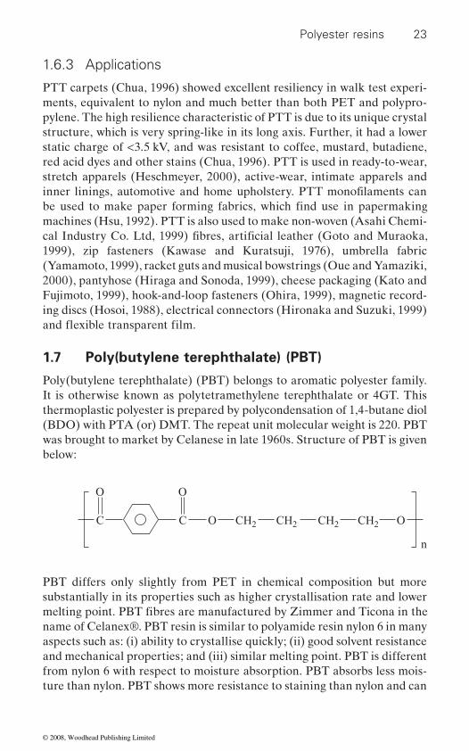
1.7 Poly(butylene terephthalate) (PBT)
Poly(butylene terephthalate) (PBT) belongs to aromatic polyester family. It is otherwise known as polytetramethylene terephthalate or 4GT. This thermoplastic polyester is prepared by polycondensation of 1,4-butane diol (BDO) with PTA (or) DMT. The repeat unit molecular weight is 220. PBT was brought to market by Celanese in late 1960s. Structure of PBT is given below:
CH2 CH2CH2O
OO
CC CH2 O
n
PBT differs only slightly from PET in chemical composition but more substantially in its properties such as higher crystallisation rate and lower
name of Celanex®. PBT resin is similar to polyamide resin nylon 6 in many aspects such as: (i) ability to crystallise quickly; (ii) good solvent resistance and mechanical properties; and (iii) similar melting point. PBT is different from nylon 6 with respect to moisture absorption. PBT absorbs less mois-ture than nylon. PBT shows more resistance to staining than nylon and can
inner linings, automotive and home upholstery. PTT monofilaments can be used to make paper forming fabrics, which find use in papermaking
cal Industry Co. Ltd, 1999) fibres, artificial leather (Goto and Muraoka, machines (Hsu, 1992). PTT is also used to make non-woven (Asahi Chemi-
melting point. PBT fibres are manufactured by Zimmer and Ticona in the
and flexible transparent film.
© 2008, Woodhead Publishing Limited
24 Polyesters and polyamides
colour by solution dying than nylon.
1.7.1 Polymer production
PBT production is similar to PET and can be produced by polycondensa-tion reaction from DMT (or) PTA and BDO. In PBT production, THF is formed as by-product by irreversible acid-catalysed dehydration of BDO. Alternatively, THF is produced by back-biting process. DMT route pro-duces approx. 6 mol. % and PTA route 13 mol. % of THF (Schumann, 1990). Formation of THF is minimised by the addition of 2–8 per cent of water to PTA and BDO (US Patent 3,936,421), the usage of combination of titanium and tin catalysts (US Patent 4,014,858), the usage of titanium catalyst (US Patent 5,015,759), the slow addition of PTA (US Patent 4,329,444), or the addition of a portion of BDO at a later stage of reaction (US Patent 4,565,241) or carrying out polycondensation before PTA is exhausted (US Patent 4,364,213). The other by-product formed is 1,3-butadiene. In melt phase, Mn of 20 000 to 35 000 is achieved and is used
the molecular weight to 40 000, which is suitable for certain injection moulding and extrusion applications. After polycondensation, i.e., before SSP, PBT resin is already crystalline and opaque and therefore, unlike
lower melting point (225˚C), SSP is carried out at 180 to 200˚C. Even though PBT is less sensitive to oxidation than PET, SSP is carried out in nitrogen. Reaction rate of PBT is faster than that of PET, IV is increased from 0.8 to 1.2 dL/g in about 12 hours.
1.7.2 Properties
PBT displays good solvent resistance, high heat resistance, good elonga-tion, high strength and modulus, excellent electrical properties, high gloss, good inherent lubricity and wear resistance. Density of amorphous PBT is in the range of 1.265–1.268 g /cc and that of crystalline is 1.395 g/cc. Melting point and glass transition temperature of PBT are 225˚C and 25˚C respec-tively. Heat of fusion for crystalline PBT is 32 kJ/mol (Cheng et al., 1988). Under moderate conditions, the degree of crystallinity is about 35 to 40 per cent. Water absorption is less than 0.1 per cent after 24 h. However, PBT is not recommended for extended use in water/aqueous solution above 52˚C. PBT is intrinsically resistant to detergents, weak acids and bases,
carbon tetrachloride, oils and fats at ambient temperature.
be coloured by the use of pigments. However PBT is more difficult to
for both fibre and engineering plastics applications. SSP is used to increase
PET, there is no need to precrystallise PBT resin in a fluid bed. Due to
aliphatic hydrocarbons, fluorinated hydrocarbons, alcohols, ketones, MEG,
© 2008, Woodhead Publishing Limited

Polyester resins 25
Among the aromatic polyesters, PBT has high crystallisation rate next to PBN, about an order of magnitude faster than PTT, which in turn is an order of magnitude faster than that of PET (Chuah, 2001). Similar to PTT, PBT has triclinic crystalline structure. Two types of triclinic structures exist namely α- and β-form, which are reversible. Unit cell parameters of α- form and β-form of PBT are set out in Tables 1.10 and 1.11. In the non-extended state, the α-form prevails with gauche-trans-gauche conforma-tion of butylenes moiety. The β-form exists in the extended state with all trans conformation depending on the drawing condition. Unit cell volume of α- and β-forms of PBT are 0.261 and 0.267 nm3.
1.7.3 Applications
PBT is used for textile applications due to its stretchability and improved
sports wear, and in apparel, underwear and hosiery. It is also used for swim
Table 1.10 Unit cell parameters of α-form of PBT
PBTDimension
α-form(Bornschlegl, 1980)
α-form(Hall, 1976)
α-form(Joly, 1975)
α-form(Liu, 1997)
a (nm) 0.482 0.489 0.487 0.494b (nm) 0.593 0.595 0.596 0.598c (nm) 1.174 1.167 1.171 1.156α (°) 100 98.9 100.1 99.8β (°) 115.5 116.6 116.6 116.5γ (°) 111 110.9 110.3 111.15ρcrystal (g/cc) 1.403 1.392 1.396 1.397
Table 1.11 Unit cell parameters of β-form of PBT
PBT Dimension
β-form (Yokuouchi, 1976)
β-form (Desborough, 1977)
β-form (Grasso, 1989)
β-form (Hall, 1976)
a (nm) 0.473 0.473 0.473 0.469b (nm) 0.575 0.583 0.588 0.580c (nm) 1.311 1.290 1.306 1.300α (°) 104.2 101.9 103.3 101.9β (°) 120.8 119.4 119.8 120.5γ (°) 100.9 105.1 104.4 105ρcrystal (g/cc) 1.33 1.33 1.32 1.36
dyeability. PBT fibres are used as tooth brush bristles, carpet yarn and
© 2008, Woodhead Publishing Limited

26 Polyesters and polyamides
wear since it has high tenacity, stability and good resistance to chlorine. PBT is preferably used for the production of engineering plastics due to its
and fast crystallisation rate. PBT resins are used in drapery hardware, pen barrels, heavy duty zippers, hair dryers, pocket calculators, iron and toaster housings and food processor blades.
1.8 Poly(1,4-cyclohexylene dimethylene
terephthalate) (PCT)
Poly(1,4-cyclohexylene dimethylene terephthalate) is abbreviated as PCT. It is prepared from 1,4-cyclohexanedimethanol (CHDM) and PTA (or) DMT. CHDM imparts the following advantages for polyester resins: (i) higher Tg; (ii) higher reactivity; (iii) glossiness and transparency; and
advantages for polyester resins such as: (i) higher viscosity; (ii) lower solvent solubility; and (iii) lower tendency to crystallise. Chemical struc-ture of PCT is as shown below:
CH2O
OO
CC CH2 O
n
Unlike other glycols, CHDM exists in cis and trans forms. The cis form imparts increased gas barrier property when compared to trans form. PCT
1.23 whereas for PET it is 1.38. PCT provides softness inherent to the molecular composition. PCT offers better release properties than PET which means that it is reusable and washes and cleans up easily. PCT has better hydrolytic stability than PET so it withstands better the rigours of
PET (290 vs. 250˚C). PCT has higher glass transition temperature than PET (88 vs. 80˚C). Heat distortion temperature of PCT is 75 and 65˚C at 0.455 and 1.82 MPa respectively. PCT has better chemical resistance to
sold under the trade name of Kodel II by Eastman Chemical Products Inc.
pillows, cushions, bed pads, carpets, etc. The safe ironing temperature for
is less dense than PET so it offers great bulk. Specific gravity of PCT is
PCT fibres can be used for high temperature applications, for example autoclave and industrial applications such as filtering, insulation, etc. Because of its superior softness with resilience, PCT fibres can be used for
combination of dimensional stability, tensile strength, increased flexibility
(iv) shock resistance and flexibility. However, it also imparts certain dis-
repeated washing and sterilization. PCT has a higher melting point than
auto fluids and printed circuit board cleaning chemicals than PET. PCT is
© 2008, Woodhead Publishing Limited
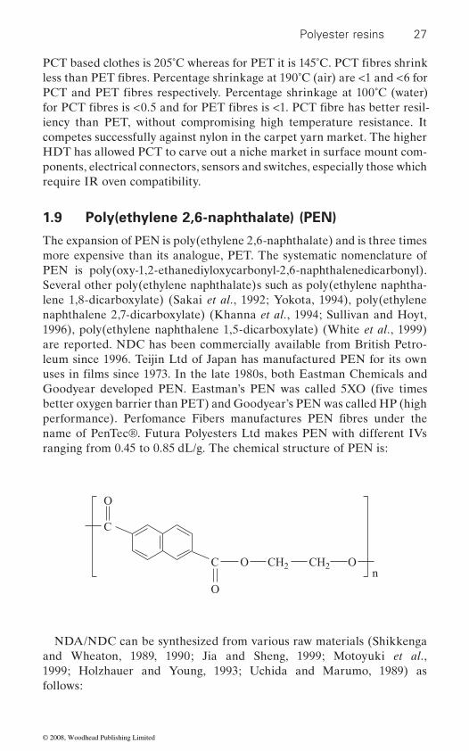
Polyester resins 27
iency than PET, without compromising high temperature resistance. It competes successfully against nylon in the carpet yarn market. The higher HDT has allowed PCT to carve out a niche market in surface mount com-ponents, electrical connectors, sensors and switches, especially those which require IR oven compatibility.
1.9 Poly(ethylene 2,6-naphthalate) (PEN)
The expansion of PEN is poly(ethylene 2,6-naphthalate) and is three times more expensive than its analogue, PET. The systematic nomenclature of PEN is poly(oxy-1,2-ethanediyloxycarbonyl-2,6-naphthalenedicarbonyl). Several other poly(ethylene naphthalate)s such as poly(ethylene naphtha-lene 1,8-dicarboxylate) (Sakai et al., 1992; Yokota, 1994), poly(ethylene naphthalene 2,7-dicarboxylate) (Khanna et al., 1994; Sullivan and Hoyt, 1996), poly(ethylene naphthalene 1,5-dicarboxylate) (White et al., 1999) are reported. NDC has been commercially available from British Petro-leum since 1996. Teijin Ltd of Japan has manufactured PEN for its own
better oxygen barrier than PET) and Goodyear’s PEN was called HP (high
name of PenTec®. Futura Polyesters Ltd makes PEN with different IVs ranging from 0.45 to 0.85 dL/g. The chemical structure of PEN is:
CH2O
O
C
C
O
CH2 On
NDA/NDC can be synthesized from various raw materials (Shikkenga and Wheaton, 1989, 1990; Jia and Sheng, 1999; Motoyuki et al., 1999; Holzhauer and Young, 1993; Uchida and Marumo, 1989) as follows:
less than PET fibres. Percentage shrinkage at 190˚C (air) are <1 and <6 for PCT and PET fibres respectively. Percentage shrinkage at 100˚C (water)
PCT based clothes is 205˚C whereas for PET it is 145˚C. PCT fibres shrink
for PCT fibres is <0.5 and for PET fibres is <1. PCT fibre has better resil-
uses in films since 1973. In the late 1980s, both Eastman Chemicals and Goodyear developed PEN. Eastman’s PEN was called 5XO (five times
performance). Perfomance Fibers manufactures PEN fibres under the
© 2008, Woodhead Publishing Limited

28 Polyesters and polyamides
(b) from 2-methylnaphthalene and acetyl acetonate
CH3
CH3
CH3
+ CH CH CH2
CH3
CH CH CH2 CH3
H2
CH3
Catalyst
Catalyst
CH3
CH3
H2
CH3
CH3
COOH
HOOC
O
CH3OH
NDA NDC
COOCH3
H3COOC
CH2
CH2
(a) from o-xylene and 1,3-butadiene
CH3
CH3+ C O C CH3
BF3, HFO O CH3
C
O
H3C
Co, Mn Br/O2
C
C
O
COH3
OCH3
O
CH3OHCatalyst
C
C
O
HO
OH
O
NDC NDA
© 2008, Woodhead Publishing Limited
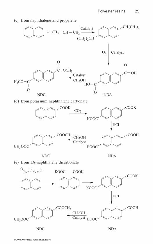
Polyester resins 29
(d) from potassium naphthalene carbonate
(c) from naphthalene and propylene
+ CH3 CH
(CH3)2CH
CH( H3C )2
Catalyst
C
C
O
OCH3
O
C
C
O
HO
OH
O
CH2
Catalyst
Catalyst
O2
NDC NDA
CH3OHCOH3
COOK
HOOC
COOCH3
H3C OOC
CH3OHCatalyst
HOOC
NDC NDA
COOKCO2
HCl
COOH
(e) from 1,8-naphthalene dicarbonate
COOCH3
H3C OOC
CH3OHCatalyst HOOC
NDC NDA
HCl
COOH
O OOCOOKKOOC
KOOC
COOK
© 2008, Woodhead Publishing Limited
30 Polyesters and polyamides
1.9.1 Polymer production
PEN can be prepared from MEG and NDC (or) NDA by polycondensation reaction. Alternatively, PEN can be prepared by ROP (Hubbard and Brittain, 1996) of cyclic PEN in the presence of a tin catalyst. Cyclic PEN is prepared by the reaction of di(chlorocarbonyl)-2,6-naphthalene with MEG (Brunelle and Bradt, 1993; Brunelle, 1994) in dichloromethane in the presence of diazabicyclo[2.2.2]octane.
1.9.2 Properties
Both glass transition and melting temperatures of PEN are higher than that of PET. PEN also exhibits an increased tensile strength, as well as elastic modulus and elongation at break. Both oxygen and carbon dioxide gas barrier properties are about 70–80 per cent increased compared with PET. Due to high melt viscosity, PEN needs a higher processing tempera-ture during the melt extrusion process and is slow crystallising resin. Density of PEN is lower than PET.
Depending on the previous thermal history, PEN has two crystalline structures namely α- (Mencik, 1967) and β-forms (Buchner et al., 1989), which are triclinic. When crystallisation temperature is ≤200˚C, α-crystal is formed whereas the formation of β-crystal is at crystallisation tempera-ture of ≥240˚C. Their densities are 1.407 and 1.439 g/cc and that of amor-phous material is 1.326 g/cc (Liu et al., 1998). The α-form crystal structure has dimensions of a = 0.651 nm, b = 0.575 nm, c = 1.32 nm, α = 81.33 , β = 144˚ and γ = 100˚ whereas β-form crystal structure has dimensions of a = 0.926 nm, b = 1.559 nm, c = 1.217 nm, α = 121.6 , β = 95.57˚ and γ = 122.52 .
The dielectric constant (ε) of PEN is lower than that of PET in the entire
because tanδ of PEN is higher than that of PET at room temperature, but is lower than those of PET at 90 and 130˚C. PEN has greater chemical
thalene, PEN absorbs UV light up to 380 nm whereas PET’s absorption is up to 313 nm. This property helps to use PEN in packaging applications.
PEN begins to stick at 140˚C as the Tg is at 121˚C. But the crystallisation
applications, it makes PEN difficult to characterise by IV measurements,
temperature range. PEN is more suitable for high temperature applications
GPC, NMR and end-group analysis and this difficulty is even greater for
emitting at ∼360 nm. This permits ready identification and separation of
resistance than PET. Even though this is a desirable property for many
PEN from PET chips, containers, films and fibres (Ouchi et al., 1976).
rate is not significant below 180˚C and the maximum rate of crystallisation
highly crystalline material. Due to the extended chromophore group naph-
A blue-white visible fluorescence results when PEN is excited by black light
© 2008, Woodhead Publishing Limited

Polyester resins 31
is at 200˚C. However, at a crystallisation temperature of about 200˚C, it
content. PEN expands and bursts; known as ‘popcorning’. PEN requires 22 h at 235˚C, to increase IV from 0.55 to 0.75 dL/g. The Mark–Houwink relationship for PEN resin is as follows:
[η] = 2.317 × 10⁻³ * Mw0.514
tetrachloroethane at 30˚C.
1.9.3 Applications
used to make high performance sail cloth in racing, in tyre cord and also for making narrow and broad woven fabrics. PEN has been successfully used to contain liquid anaesthetics.
1.10 Polylactic acid (PLA)
Polylactic acid (PLA) differs from the previously discussed polyesters because PLA is based on renewable resources and is a biodegradable polymer. It is otherwise known as polylactide. The chemical structure of PLA is shown below:
CH C O
CH3
O
n
It is produced from any starch or sugar containing raw material such as corn, cereals, cassava, sugar cane, etc. PLA can be used as packaging
non-wovens and engineering plastics. Although PLA is expensive it will become cheaper than PET, now that the crude oil price has risen above US$80 per barrel. Depending upon the content of L and D isomers in PLA, melting point ranges from about 150˚C to 210˚C. Even though the polymer chain contains no aromatic rings, the steric hindrance of the pendant methyl groups gives some rigidity and thermal stability. Fibre elasticity and resiliency of PLA is similar to PTT or PBT and is attributed to the partial coiling of the backbone chain in the crystalline form.
has a strong tendency to stick strongly in the presence of high moisture
PEN monofilaments are used for paper making felts, where the higher
In the above relationship, the IV solvent was used and 60 : 40 phenol/
modulus, temperature and hydrolysis resistance are required. PEN fibre is
materials such as biaxially oriented films, extrusion sheets for thermoform-ing and plastic bottles, textile materials such as filaments, staple fibres and
© 2008, Woodhead Publishing Limited
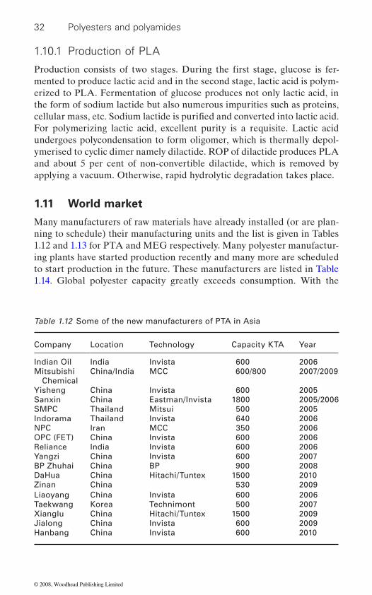
32 Polyesters and polyamides
1.10.1 Production of PLA
mented to produce lactic acid and in the second stage, lactic acid is polym-erized to PLA. Fermentation of glucose produces not only lactic acid, in the form of sodium lactide but also numerous impurities such as proteins,
For polymerizing lactic acid, excellent purity is a requisite. Lactic acid undergoes polycondensation to form oligomer, which is thermally depol-ymerised to cyclic dimer namely dilactide. ROP of dilactide produces PLA and about 5 per cent of non-convertible dilactide, which is removed by applying a vacuum. Otherwise, rapid hydrolytic degradation takes place.
1.11 World market
Many manufacturers of raw materials have already installed (or are plan-ning to schedule) their manufacturing units and the list is given in Tables 1.12 and 1.13 for PTA and MEG respectively. Many polyester manufactur-ing plants have started production recently and many more are scheduled to start production in the future. These manufacturers are listed in Table 1.14. Global polyester capacity greatly exceeds consumption. With the
Table 1.12 Some of the new manufacturers of PTA in Asia
Company Location Technology Capacity KTA Year
Indian Oil India Invista 600 2006Mitsubishi Chemical
China/India MCC 600/800 2007/2009
Yisheng China Invista 600 2005Sanxin China Eastman/Invista 1800 2005/2006SMPC Thailand Mitsui 500 2005Indorama Thailand Invista 640 2006NPC Iran MCC 350 2006OPC (FET) China Invista 600 2006Reliance India Invista 600 2006Yangzi China Invista 600 2007BP Zhuhai China BP 900 2008DaHua China Hitachi/Tuntex 1500 2010Zinan China 530 2009Liaoyang China Invista 600 2006Taekwang Korea Technimont 500 2007Xianglu China Hitachi/Tuntex 1500 2009Jialong China Invista 600 2009Hanbang China Invista 600 2010
Production consists of two stages. During the first stage, glucose is fer-
cellular mass, etc. Sodium lactide is purified and converted into lactic acid.
© 2008, Woodhead Publishing Limited
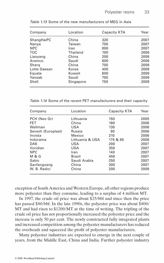
Polyester resins 33
exception of South America and Western Europe, all other regions produce more polyester than they consume, leading to a surplus of 4 million MT.
In 1997, the crude oil price was about $25/bbl and since then the price has passed $80/bbl. In the late 1990s, the polyester price was about $800/MT and had risen to $1200/MT at the time of writing. The tripling of the crude oil price has not proportionally increased the polyester price and the increase is only 50 per cent. The newly constructed fully integrated plants and increased competition among the polyester manufacturers has reduced
Many polyester industries are expected to emerge in the next couple of years, from the Middle East, China and India. Further polyester industry
Table 1.13 Some of the new manufacturers of MEG in Asia
Company Location Capacity KTA Year
ShangHaiPC China 320 2007Nanya Taiwan 700 2007NPC Iran 800 2007TOC Thailand 100 2008Liaoyang China 200 2008Aramco Saudi 600 2008Sharq China 700 2008Lotte Daesan Korea 400 2008Equate Kuwait 600 2009Yansab Saudi 700 2009Shell Singapore 750 2009
Table 1.14 Some of the recent PET manufacturers and their capacity
Company Location Capacity KTA Year
PCH (Neo Gr) Lithuania 150 2005FET China 160 2006Wellman USA 130 2006Senezh (Europlast) Russia 80 2006Invista Mexico 210 2006Indorama Lithuania & USA 175 & 80 2006DAK USA 200 2007Voridian USA 350 2007NPC Iran 140 2007M & G Brazil 450 2007Sabic Saudi Arabia 250 2007Sanfangxang China 300 2007W. B. Radici China 200 2008
the overheads and squeezed the profit of polyester manufacturers.
© 2008, Woodhead Publishing Limited
34 Polyesters and polyamides
growth is limited by low returns; and escalating construction costs and salaries due to a shortage of experienced and skilled manpower. Even with the above constraints, polyester capacity is expected to grow from 18.8 million MT in 2007 to 22.7 million MT in 2010. About 4 to 5 per cent
about 8 per cent in packaging applications.
1.12 Future trends
Among polyesters, PET will continue to be in the leading position for applications in packaging and textiles with more applications in ‘Technical Textiles’ in sectors of agriculture, building, geo, home, medical, packaging, etc. Also there will be more developments in textile applications for
growing by 13 per cent with applications in the aerospace industry includ-ing space and defence. Quality improvements such as increased barrier capabilities, softness and loft will be further improved. An increased demand for renewable raw materials and disposable materials for environ-mental and cost reasons will be a central issue in the future. Growth in
its undisputable performance and properties.At the current consumption rates, the current world crude oil reserves
will be exhausted by the year 2043, unless new oil stocks are discovered. If, as predicted, the global population doubles in the next 50 years, the requirement for polyester resin at the current usage rate will also double. This will have a huge bearing on crude oil consumption. Therefore, the future of the polyester industry, in particular commodity resin, depends on how effectively the industry recycles polyester scrap and how quickly the industry moves from oil-based resources to renewable resources. The effective recycling of polyester resin will also reduce carbon dioxide emis-sion, which in turn will minimise global warming. Even though, with the available technology today, one can make PDO and PLA using renewable resources, commercial production and effective utilisation have not yet taken full effect. PLA will become cheaper only when the crude oil price goes above $80/bbl. Till then, PLA will be only of academic interest, unless new technology is invented to make polyesters from renewable resources.
1.13 Acknowledgements
We acknowledge Mr S. B. Ghia, Chairman and Managing Director; Mr M. D. Dalal, Joint Managing Director and Mr S. Rangarajan, COO and
growth is estimated during the next five years in the textile industry and
comfort, sportswear, etc. The global production of technical fibres is
and energy. Polyester will continue to find newer applications because of today’s booming markets will be influenced by a shortage of raw materials
© 2008, Woodhead Publishing Limited

Polyester resins 35
Executive Director of Futura Polyesters Ltd for giving permission to write this chapter.
1.14 Sources of further information and advice
1. Modern Polyesters: Chemistry and Technology of Polyesters and Copolyesters John Scheirs and Timothy E. Long (Eds). Wiley Series in Polymer Science, John Wiley & Sons Ltd, 2003.
2. Handbook of Thermoplastic Polyesters: Homopolymers, Copolymers, Blends and Composites Stoyko Fakirov (Ed.) Volume 1, Wiley-VCH, 2002.
3. Handbook of Thermoplastic Polyesters: Homopolymers, Copolymers, Blends and Composites Stoyko Fakirov (Ed.) Volume 2, Wiley-VCH, 2002.
1.15 References
823,515.asahi chemical industry co. ltd (1999), Poly(trimethylene terephthalate)
11107149.asano t, balta calleja f j, fl ores a, tanigaki m, mini m f, sawatari c, itagaki h,
takahashi h and ichiro h (1999), ‘Crystallization of oriented amorphous poly(ethylene terephthalate) as revealed by X-ray diffraction and microhard-ness’, Polymer, 40, 6475–6484.
astbury w t and brown c j (1946), ‘Structure of Terylene’, Nature (London), 158, 871.
berzelius j (1847), Rapt Ann Inst Geol Hongrie, 26.brunelle d j (1994), ‘Macrocyclic polyesters and oligomers’, Eur Pat Appl EP 598,
604.brunelle d j and bradt j e (1993), ‘Preparation of macrocyclic poly(alkylene
dicarboxylate) oligomers’, US Patent 5, 214, 158.bornschlegl e and bonart r (1980), ‘Small angle X-ray studies of poly(ethylene
terephthalate and poly(butylene terephthalate)’, Colloid Polym Sci, 258, 319–333.
buchner s, wiswe d and zachmann h g (1989), ‘Kinetics of crystallization and melting behaviour of poly(ethylene naphthalene-2,6-dicarboxylate)’, Polymer, 30, 480–488.
buxbaum l h (1979), ‘Solid-state polycondensation of poly(butylene terephthal-ate)’, J Appl Polym Sci, 35, 59–66.
carothers w h and arvin j a (1929), J Am Chem Soc, 51, 2560.carothers w h and hill j w (1932), J Am Chem Soc, 54, 1557.chang t m (1970), ‘Kinetics of thermally induced solid state polycondensation of
poly(ethylene terephthalate)’, Polym Eng Sci, 10, 364–368.
anon (1959), Recovery of dimethyl terephthalate from crude polyesters, GB Patent
fiber nonwoven fabrics with high tensile strength and good softness, JP
© 2008, Woodhead Publishing Limited
36 Polyesters and polyamides
ization of poly(ethylene terephthalate)’, J Polym Sci Part A Polym Chem, 25, 533–549.
cheng s z d, pan r and wunderlich b (1988), Macromol Chem, 189, 2443.
cho j s, youk j h, yoo d i, ko s w and ha w s (1998), ‘Monte-Carlo simulation on the formation of cyclic oligomer by ester interchange reaction in poly(ethylene terephthalate), Polymer (Korea), 22, 99–105.
chuah h h, werny f and langley t (1995), ‘Dyeing and staining of poly(trimethylene terephthalate) carpets’ in Proceedings of the Book of Paper International Conference and Exhibition, Oct 8–11, 1995, Atlanta GA, The American Association of Textile Chemists and Colorists, Research Triangle Park, NC, 98–106.
for carpets’, Chem Fiber Int, 46, 424, 427–428.chuah h h (2001), Polym Eng Sci, 41, 308.chuah h h, lin-vien d and soni u (2001), Polymer, 42, 7137.dandurand s p, perez s, revol j f and brisse f (1979), Polymer 20, 419.de daubeny r, bunn c w and brown c j (1954), ‘The crystal structure of
poly(ethylene terephthalate’, Proc Roy Soc (London), A226, 531–542.desborough i j and hall i h (1977), ‘A comparison of published crystalline struc-
tures of poly(tetramethylene terephthalate)’, Polymer, 18, 825–830.desborough i j, hall i h and neisser j z (1979), ‘The structure of poly(trimethylene
terephthalate)’, Polymer, 20, 545–552.droscher m and wegner g (1978), ‘Poly(ethylene terephthalate): a solid state
condensation process’, Polymer, 19, 43.duan j f, putzig d e, mallon f k and davis t m (2002), ‘Metal-containing composi-
tion and process therewith’ WO02068497 to DuPont.fakirov s, fi scher e w and schmidt g f (1975), ‘Unit cell dimension of poly(ethylene
terephthalate)’, Macromol Chem, 176, 2459–2465.gonzalez c c, perena j m and bello a (1988a), J Polym Sci Polym Phys Ed, 26,
1397.gonzalez c c, perena j m and bello a (1988b), ‘Viscoelastic behavior of
poly(trimethylene terephthalate) and related polymers’, Macromol Chem Mac-romol Symp, 20/21, 361–368.
goto b and muraoka a (1999), ‘Highly abrasion-resistant napped polyester non-
Co. Ltd.grasso r p, perry b c, koenig j l and lando j b (1989), ‘Structural and energetic
analyses of the transition in poly(butylene terephthalate)’, Macromolecules, 22, 1267 1272.
hall i h (1984), Structure of Crystalline Polymers, Elsevier, Amsterdam, 39.hall i h and pass m g (1976), ‘Chain conformation of poly(tetramethylene tere-
phthalate) and its change with strain’, Polymer, 17, 807–816.hall i h (1984), ‘The determination of the structures of aromatic polyesters from
their wide-angle X-ray diffraction patterns’, in Structure of Crystalline Polymers (Ed. hall i h), Elsevier Applied Science, London, 39–78.
heschmeyer c (2000), Int Fiber J, 15(4), 66.
chen s and chen f (1987), ‘Kinetics of polyesterification III Solid-state polymer-
chua h h (1996), ‘Corterra poly(trimethylene terephthalate) – New polymeric fiber
woven fabrics for artificial leathers’, JP 11222780 to Asahi Chemical Industry
© 2008, Woodhead Publishing Limited
Polyester resins 37
heuval h m and huisman r (1978), ‘Effect of winding speed on the physical struc-
crystallization’, J Appl Polym Sci, 22, 2229–2243.
ity and texture, JP 11315403 to Asahi Chemical Industry Co. Ltd.hironaka k and suzuki m (1999), ‘Poly(trimethylene terephthalate)-based connec-
tor materials’, JP 11286596 to Teijin Ltd.holzhauer j k and young d a (1993), US Patent 5,254,719.
63212549 to Teijin Ltd.hovenkamp s g and munting j p (1970), J Polym Sci. Part A-1, 8, 679–682.hsu c y (1992), US Patent, 5 104 724.hsu l (1967), ‘Synthesis of ultrahigh molecular weight poly(ethylene terephthal-
ate)’, J Macromol Sci Phys, B 14, 801–813.hubbard p and brittain j (1996), ‘Synthesis and ring-opening polymerisation of
poly(ethylene naphthalate) cyclic oligomers’, Polym Prepr (ACS Polym Div) 37, 238–239.
jabarin s a and lofgren e a (1986), ‘Solid state polymerization of polyethylene terephthalate: kinetic and property parameters’, J Appl Polym Sci, 32, 5315.
jerome r and teyssie ph (1989), ‘Anionic ring-opening polymerization of lactones’ in Allen G and Bevington J, Comprehensive Polymer Science, Pergamon Press, Oxford, Vol. 3, 501–510.
jia h t and sheng j (1999), Chem Ind Eng (Chin.) 16, 347.john r m and ito t (2001), ‘Production of Polyester’, JP2001019753 to Meldform
Metals Ltd.joly a h, nemoz g, douillard a and vallet g (1975), ‘Contribution to the study
of poly(terephthalate) structure of some poly(ethylene glycol)s’, Macromol Chem, 176, 479–494 (in French).
aging with low yarn bulging and high yarn winding amount and manufacture thereof, JP 11302919 to Asahi Chemical Industry Co. Ltd.
kawase s and kuratsuji t (1976), US Patent, 3,984,600.khanna y p, belles j jr, reimschuessel a c and banerjie a (1994), ‘Improving the
properties of polymers’, US Patent 5,324,816.kienle r h and hovey a g (1929), J Am Chem Soc, 51, 509.kinoshita y, nakamura r and kitano y (1979), ‘A crystallographic investigation
on a high crystalline poly(ethylene terephthalate)’, Polym Prepr, 20, 454–457.
kitano y kinoshita y and ashida t (1995), ‘Morphology and crystal structure of an alpha-axis oriented, highly crystalline poly(ethylene terephthalate)’, Polymer, 36, 1947–1955.
kokkolas d, bikiaris d n and karayannidis g p (1995), ‘Effect of Sb2O3 catalyst on the solid-state polycondensation of poly(ethylene terephthalate)’, J Appl Polym Sci, 55, 787–791.
liu j and geil p h (1997a), ‘Electron diffraction and computer modelling studies of the crystal structure of poly(butylene terephthalate) α-form single crystals’, J Macromol Sci Phys, B36, 262–280.
ture of as-spun poly(ethylene terephthalate) fibers, including orientation-induced
hiraga s and sonoda k (1999), ‘Pantyhose with good fitting, transparency, durabil-
kato j and fujimoto k (1999), ‘Poly(trimethylene terphthalate) fibre cheese pack-
hosoi m (1988), ‘Polyester laminates for flexible magnetic recording disks’, JP
© 2008, Woodhead Publishing Limited

38 Polyesters and polyamides
liu j and geil p h (1997b), ‘Crystal structure and morphology of poly(ethylene terephthalate) single crystals prepared by melt polymerization’, J Macromol Sci Phys, B36, 61–85.
liu j, sidoti g, hommema j a, geil p h, kim j c and cakmak m (1998), ‘Crystal struc-
J Macromol Sci Phys, B37, 567–586.lustig s r and burch r r (1999), ‘Poly(alkylene arylates) having improved optical
properties’, US Patent 5,981,690.macdowell j t (1965), Reclaiming linear terephthalate polyesters, US Patent
3,222,299.
II Reactions of diacids and diepoxides’, Adv Polym Sci, 71, 153–228.mallon f, beers k, ives a and ray w h (1998), ‘The effect of the type of purge gas
on the solid-state polymerization of polyethylene terephthalate’, J Appl Polym Sci, 69, 1789–1791.
martl n v, michael m, thomas o, gerriet h, klaus b, bertram b and thiele u (1995) ‘Process for producing polyesters and copolyesters’, WO 1995/018839 to Akzo Nobel.
mencik z (1967), ‘Crystal structure of polycondensate of naphthalene-2,6-dicarboxylic acid with ethylene glycol’, Chemick’y Prumysl, 17, 78–81.
moore jr l d (1960), Cleveland ACS Meeting 4, Vol. 1.motoyuki m, yamamoto k, yoshida s, yamamoto s, sapre a v, mcwilliams j p,
donnelly s p and hellring s d (1999), World Patent WO 9919 281.nakajima t, tsukamoto k and gyobu s (2002), ‘Polymerization catalyst for poly-
ester, polyester produced by using the same and method for producing polyester’ JP 2002220448 to Toyo Boseki.
naylor p l c, christopher c b, lynn, coupar m, simon v m, william a d, jill b j, kenneth m r, john h, iain w j and brian s, ‘Polyester article’, WO/1997/047675 to Imperial Chemical Industries.
ohira k (1999), Loop materials with high durability and hook-and-loop fasteners using them, JP 11253209 to Asahi Chemical Industry Co., Ltd.
otto b, thiele u and guo x (2002), ‘Catalyst and method for its production and use’, US Patent 6417320.
otto b, seidel e and steinbrecher t (2003), ‘Composition and method for produc-ing polyester’, DE10121542A1 to Zimmer AG.
ouchi, i, hosoi m and matsumoto f (1976), ‘Photodegradation of poly(ethylene-2,6-
with high tensile strength and elastic recovery for racket guts and bowstrings for musical instruments’, Intern Patent 0039374 to Asahi Chem Ind Co. Ltd.
penczek s and slomkowski s (1989), ‘Cationic ring-opening polymerization:cyclic esters’ in Allen G and Bevington J, Comprehensive Polymer Science, Pergamon Press, Oxford, Vol. 3, 813–823.
pilati f (1989), ‘Solid-state polymerisation’, in Allen G and Bevington J, Compre-hensive Polymer Science, Pergamon Press, Oxford, Vol. 5, 201–216.
pitat j, holcik v and bacak m (1959), A method of processing waste of polyethylene terephthalate by hydrolysis, GB Patent 822,834.
ture and morphology of thin film, melt-crystallized poly(ethylene naphthalate)’,
madec p-j and marechal e (1985), ‘Kinetics and mechanisms of polyesterifications.
naphthalate) films’, J Appl Polym Sci, 20, 1983–1987.oue k and yamazaki h (2000), ‘Poly(trimethylene terephthalate) fiber yarns
© 2008, Woodhead Publishing Limited
Polyester resins 39
poulin-dandurand s, perez s, revol j f and briss f (1979), Polymer, 20, 419.
pyda m, boller a, grebowicz j, chuah h, lebedev b v and wunderlich b (1998), Heat capacity of poly(trimethylene terephthalate)’, J Polym Sci Part B Polym Phys, 36, 2499–2511.
ravens d a s and ward i m (1961), Trans Fara Soc, 57, 150.ravindrath k and mashelkar r a (1990), ‘Modelling of PET reactors IX: Solid
state polycondensation process’, J Appl Polym Sci, 39, 1325.renwen h, feng y, tinszheng h and shiming g (1983), Angew Makromol Chem,
119, 159–172.
EP0812818A1 to Tioxide Specialties Ltd.sakai k, fujimura n and nakano m (1992), ‘Electrostatographic photoreceptor
with improved durability and manufacture’, Jpn Kokai Tokkyo Koho, JP 04 97, 161.
schmidt w, thiele u, griebler w.-d, hirthe b and hirschberg e (1996), ‘Titanium containing catalyst and process for the production of polyester’, DE19513056 to Zimmer AG and Sachtleben Chemie GmbH.
schumann h d (1990), ‘Stand der Technologie zur Herstellung von Polyester-polymer’, Chemiefasern/Textilindustrie, 40, 1058–1062.
shikkenga d l and wheaton i (1989), US Patent 5,073,670.shikkenga d l and wheaton i (1990), US Patent 5,950,825.siling m i and laricheva t n (1996), Russ Chem Rev, 65, 279–286.sullivan j p and hoyt m b (1996), ‘Method for upgrading mixed, incompatible
plastic wastes’, Ger Offen D E, 19, 542, 666.tadokoro h (1979), Structure of Crystalline Polymers, Wiley-Interscience, New
York, 369.tomashpolskii y y and markova g s (1964), ‘An electron diffraction study of the
crystalline structure of polyethylene terephthalate by means of the Fourier syn-thesis’, Polym Sci USSR, 6, 316–324.
traub h l, hirt p and herlinger h (1995), Chem Fiber Int, 45, 110.uchida h and marumo k (1989), Jpn Patent JP 01 165 549.vaidya a a (1988), Production of Synthetic Fibres, Prentice-Hall of India Pvt Ltd,
New Delhi.ward i m, wilding m a and brody h (1976), J Polym Sci Part B Polym Phys, 14,
263.white j e, sanford j f and glass t w (1999), ‘Thermally stable hydroxyl
functionalized polyether-polyamines as barrier layer and laminated packaging materials and oxygen-sensitive materials thereof’, PCT Int Appl, WO 99 20,673.
whinfi eld j r and dickson j t (1946), Br Patent, 578 079.wu d, chen f and li r (1997), ‘Reaction kinetics and simulations for solid-state
polymerization of poly(ethylene terephthalate)’, Macromolecules, 30, 6737–6742.
yamamoto m (1999), ‘Umbrella base fabrics with good water resistance and bending property’, JP 11315443 to Asahi Chemical Industry Co. Ltd.
yang y, li s, brown h and casey p (1999), Textile Chem and Colorist Am Dyestuff Rep, 1(3), 50.
ridland j, hepplewhite i w and jolly b s (1997), ‘Esterification Process’,
© 2008, Woodhead Publishing Limited
40 Polyesters and polyamides
yang j, sidoti g, liu j, geil p h, li c y and cheng s z d (2001), ‘Morphology and crystal structure of CTFMP and bulk polymerized poly(trimethylene tere-phthalate)’, Polymer, 42, 7181–7195.
yoda k (1970), Makromol Chem, 136, 311–313.yokota m (1994), ‘Photographic materials with transparent magnetic recording
layer’, Jpn Kokai Tokkyo Koho, JP 06 214,328.yokuouchi m, sakakibara y, chatani y, tadokoro h, tanaka t and yoda k (1976),
‘Structure of two crystalline forms of poly(butylene terephthalate) and revers-ible transition between them by mechanical deformation’, Macromolecules, 9, 266–273.
© 2008, Woodhead Publishing Limited
2
New Delhi, India
2.1 Introduction
Nylon is a generic word representing a class of polymers as polyamides. Nylon was a product of a basic research started by Wallace Corothers at DuPont in 1928. The polymer age really started when the new synthetic
few hours of sale on May 15, 1940. During World War II, nylon fabrics were used as waterproof tents, lightweight parachutes among other things. In the process an important principle was established that it is possible to chemically link hundreds of simple molecules of a kind or more, to make polymers with unique set of properties. One interesting example is the ability of molten polymer undergoing large deformations, which allows
property of deformation is in turn connected to cumulative interactions of long chain polymeric molecules.
i.e. a pound of nylon could be converted to the length equal to the distance between New York (NY) and London (LON). A variety of polyamides are presently manufactured and marketed under several different trade names. Among them nylon 6 and nylon 66 are the two most manufactured poly-amides. There are several other nylons such as nylon 46, nylon 610, nylon 612, nylon 10, and nylon 12 which are used for specialized applications.
In general, there are two types of nylons, i.e. nylon XY, and nylon Z. Nylon 66 and nylon 6 are the examples of these two types respectively. In nylon XY type, the X refers to the number of carbon atoms in the diamine monomer, whereas, Y represents the number of carbon atoms in diacid monomer. In nylon Z type, Z refers to the number of carbon atoms in the monomer.
41
B. L . DEOPU R A, Indian Institute of Technology,
Polyamide f ibers
nylon fiber was introduced in the market in 1938. Nylon captured public imagination, as four million pairs of nylon stockings were sold in the first
continuous production of fine filaments from thicker extrudates and this
The word nylon was introduced to signify the fineness of the filament
© 2008, Woodhead Publishing Limited

42 Polyesters and polyamides
2.2 Nylon 66
Nylon 66 type nylons are synthesized from a diacid and diamine. For nylon 66, hexamethylene diamine (H) and adipic acid (A) are reacted to form H-A salt. The salt is polymerized to produce nylon 66 in the following manner.
NH2(CH2)6NH2 + COOH(CH2)4COOH → H[–NH(CH2)6NHCO(CH2)4CO]OH + H2O
n H[–NH(CH2)6NHCO(CH2)4CO]OH → H[–NH(CH2)6NHCO(CH2)4CO–]nOH + (n − 1)H2O
The purity of raw material is important in the polymer production and the
ylene diamine should be in the crystalline form with melting point of 40˚C and boiling point of 204˚–205˚C. Adipic acid is in the white crystalline form with acid number of 368, with melting and boiling point of 152˚ and 216˚C. The color, iron and water content are also controlled.
In the production process, the two monomers of nylon 66 are taken in the molar ratio of 1 : 1. These two components are reacted in methanol at elevated temperature, to obtain the salt which precipitates from methanol solution. The H-A salt is dissolved in water at concentration of 60%. The solution is heated to around 250˚C for polycondensation for production of nylon 66. Loss of water in the process of polymerization should be taken into account for the net recovery of polymer [2]. Nylon 66 was earlier pro-duced via a batch process with intermediate H-A salt. However, now the continuous process of production is favored for conversion of monomer to polymer.
To achieve desired molecular weights of the polymers, stabilization pro-cesses are used. This is achieved by taking slightly different than equivalent quantities of diacids and diamines. Say an excess of 1 percent of diacids is taken during the polymerization process, at a point of time, all long chain molecules will have carboxylic acid groups at both ends and polymerization does not proceed further. Thus an excess of one of the monomers decides the range of molecular weights achieved in the polymer. An equimolar ratio of 1 diamine to 1.015 diacid gives a polymer with a number average molecular weight of ∼18 000. This can also be achieved by adding say 1% of mono-functional reagent, such as acetic acid to equimolar quantities of diacids and diamines. Another method to make polyamides could be by using amino acids with one end as an amino group and another end as carboxylic acid. Typically, diamine and diacids are preferred for production of nylons as it is easier and cheaper to make these monomers compared to
specifications of these raw materials have been reported [1]. Hexameth-
amino acids. There is no difficulty in making the monomers for making
© 2008, Woodhead Publishing Limited

43
the typical polyamides and usually there are several different routes to select one, depending on the price and availability of raw materials.
2.2.1 Monomer synthesis for nylon 66
Adipic acid
The principal commercial processes are based on the oxidation of cyclo-
tion with air, yielding either a mixture of cyclohexanone and cyclohexanol or predominantly cyclohexanol. These reaction products are oxidized in second stage with nitric acid to adipic acid. This process employs a soluble cobalt oxidation catalyst, reaction temperatures in the range of 150˚–160˚C, pressures between 800 to 1000 kPa, and catalyst concentra-tions of 0.3–3 ppm.
An interesting approach involves a two-step carbonylation of butadiene.
in the presence of dicobaltoctacarbonyl and heterocyclic structure con-taining a tertiary nitrogen moiety (pyridines, picolines, quinolines, isoquinoline):
CH2 = CHCH = CH2 + CO + CH3OH → CH3CH = CHCH2COOCH3
This reaction is carried out at 120˚C and at pressure of 60 MPa. After removal of unreacted butadiene, the second step carbonylation is carried out at about 185˚C and 3 MPa:
CH3CH = CHCH2COOCH3 + CO + CH3OH → H3COOC(CH2)4COOCH3
The dimethyl adipate is isolated by distillation and converted to adipic acid by hydrolysis.
Hexamethylene diamine
The commercial processes for manufacture of hexamethylene diamine entail hydrogenation of adiponitrile. It is a continuous liquid phase process that is usually conducted at 75˚C and 3 MPa pressure in the presence of chromium containing Raney nickel catalyst and aqueous sodium hydroxide:
NC(CH ) CNH (3Mpa), 75 C, Cr/Ni, (NaOH, H O)
2 42 2°⎯ →⎯⎯⎯⎯⎯⎯⎯⎯⎯⎯⎯⎯⎯⎯⎯⎯ HH N(CH2) NH2 6 2
Polyamide fibers
hexane, which usually proceeds in two stages. The first step entails oxida-
In the first step butadiene is reacted with carbon monoxide and methanol
© 2008, Woodhead Publishing Limited

44 Polyesters and polyamides
A newer DuPont process is characterized by the direct addition of HCN
phase operation. A gaseous mixture of butadiene, hydrogen cyanide, nitro-gen, and hydrochloride in a ratio of 1 : 1 : 1 : 0.1 is contacted at about 215˚C
catalyst for about 50 min:
CH
CHCH
CHHCN
CH CH
CHCH CN + 2 and 4isomers
2 2
3 2
⎯ →⎯⎯⎯
→ Δ Δ
→→ CH CH(CN)CH
CH + 2 isomers3 2 Δ
The second step entails catalytic isomerization of the 2- and 3-pentene nitriles to 4-pentene nitrile, and the addition of a second mole of HCN:
2- and 3-pentene nitriles CH CH
CHCH CN NC(CH ) CNHC
3 2 2 4→ ⎯ →⎯⎯NN
2.3 Nylon 6
Nylon 6 is a nylon Z type of polymer, where the Z represents the number of carbon atoms in the monomer. Nylon 6 is typically produced from cap-rolactam in the following manner.
n [HN–(CH2)5–CO] → H[–HN–(CH2)5–CO–]nOH
The purity of the caprolactam is critically assessed for the production of
permanganate number 71; molar ratio %; iron content as 0.5 ppm. Detailed analytical methods for purity analysis are reported in literature [3–5].
Caprolactam requires a catalyst, which converts small amounts of cap-rolactam to ε-aminocaproic acid which helps in polymerization process. The catalyst could be water, where the control of reaction is easy. Acid or base catalyst system may also be used, where the base catalyst system has the advantage of high production rate, high molecular weight, although the control of reaction in the system is rather critical. Some characteristics of catalyst system [6] are given in Table 2.1.
2.3.1 Molecular weight in water catalyst system
In a water catalyst system the critical parameters during reaction are tem-perature of 225˚–285˚C , amount of water 5–10% and stabilizer content of 1% and time of polymerization.
to butadiene. It is essentially a two stage process. The first step is a vapor
and atmospheric pressure with a copper magnesium chromite fixed bed
nylon 6 polymer. The specificities of the monomer are freezing point 69˚C;
© 2008, Woodhead Publishing Limited
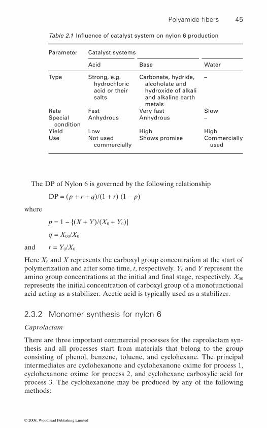
45
The DP of Nylon 6 is governed by the following relationship
DP = (p + r + q)/(1 + r) (1 − p)
where
p = 1 − {(X + Y)/(X0 + Y0)}
q = X00/X0
and r = Y0/X0
Here X0 and X represents the carboxyl group concentration at the start of polymerization and after some time, t, respectively. Y0 and Y represent the
00 represents the initial concentration of carboxyl group of a monofunctional acid acting as a stabilizer. Acetic acid is typically used as a stabilizer.
2.3.2 Monomer synthesis for nylon 6
Caprolactam
There are three important commercial processes for the caprolactam syn-thesis and all processes start from materials that belong to the group consisting of phenol, benzene, toluene, and cyclohexane. The principal intermediates are cyclohexanone and cyclohexanone oxime for process 1, cyclohexanone oxime for process 2, and cyclohexane carboxylic acid for process 3. The cyclohexanone may be produced by any of the following methods:
Parameter
Catalyst systems
Acid Base Water
Type Strong, e.g. hydrochloric acid or their salts
Carbonate, hydride, alcoholate and hydroxide of alkali and alkaline earth metals
–
Rate Fast Very fast SlowSpecial
conditionAnhydrous Anhydrous –
Yield Low High HighUse Not used
commerciallyShows promise Commercially
used
Polyamide fibers
amino group concentrations at the initial and final stage, respectively. X
Table 2.1 Influence of catalyst system on nylon 6 production
© 2008, Woodhead Publishing Limited
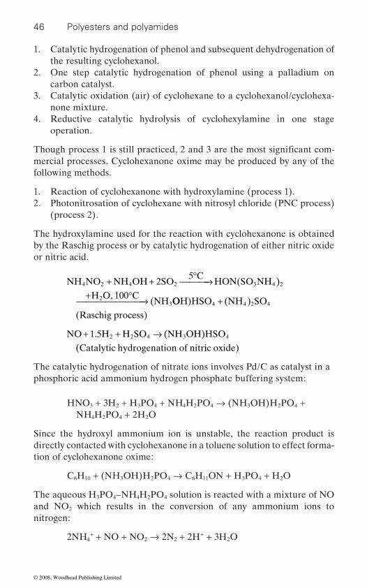
46 Polyesters and polyamides
1. Catalytic hydrogenation of phenol and subsequent dehydrogenation of the resulting cyclohexanol.
2. One step catalytic hydrogenation of phenol using a palladium on carbon catalyst.
3. Catalytic oxidation (air) of cyclohexane to a cyclohexanol/cyclohexa-none mixture.
4. Reductive catalytic hydrolysis of cyclohexylamine in one stage operation.
mercial processes. Cyclohexanone oxime may be produced by any of the following methods.
1. Reaction of cyclohexanone with hydroxylamine (process 1).2. Photonitrosation of cyclohexane with nitrosyl chloride (PNC process)
(process 2).
The hydroxylamine used for the reaction with cyclohexanone is obtained by the Raschig process or by catalytic hydrogenation of either nitric oxide or nitric acid.
NH NO NH OH 2SO5 C
HON(SO NH )
H O, 100 C(NH
4 2 4 2 3 4 2
23
+ + °⎯ →⎯⎯+ °⎯ →⎯⎯⎯⎯⎯⎯ OOH)HSO (NH ) SO
(Raschig process)4 4 2 4+
NO 1.5H H SO (NH OH)HSO
(Catalytic hydrogenation of nitr2 2 4 3 4+ + →
iic oxide)
The catalytic hydrogenation of nitrate ions involves Pd/C as catalyst in a phosphoric acid ammonium hydrogen phosphate buffering system:
HNO3 + 3H2 + H3PO4 + NH4H2PO4 → (NH3OH)H2PO4 + NH4H2PO4 + 2H2O
Since the hydroxyl ammonium ion is unstable, the reaction product is directly contacted with cyclohexanone in a toluene solution to effect forma-tion of cyclohexanone oxime:
C6H10 + (NH3OH)H2PO4 → C6H11ON + H3PO4 + H2O
The aqueous H3PO4–NH4H2PO4 solution is reacted with a mixture of NO and NO2 which results in the conversion of any ammonium ions to nitrogen:
2NH4+ + NO + NO2 → 2N2 + 2H+ + 3H2O
Though process 1 is still practiced, 2 and 3 are the most significant com-
© 2008, Woodhead Publishing Limited
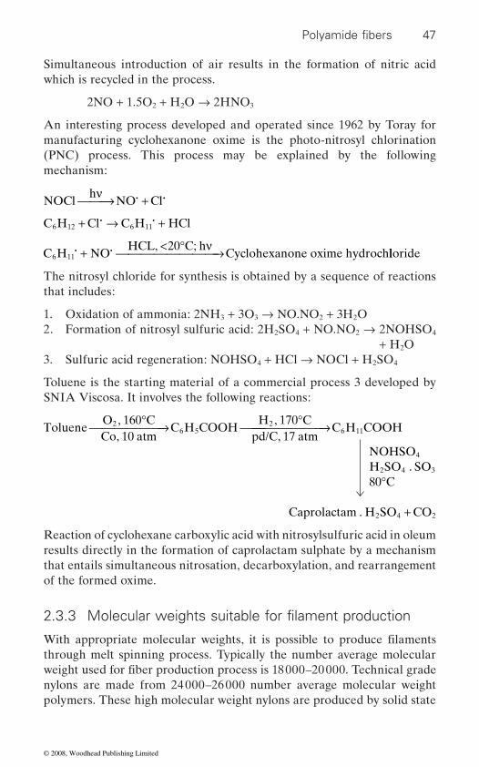
47
Simultaneous introduction of air results in the formation of nitric acid which is recycled in the process.
2NO + 1.5O2 + H2O → 2HNO3
An interesting process developed and operated since 1962 by Toray for manufacturing cyclohexanone oxime is the photo-nitrosyl chlorination (PNC) process. This process may be explained by the following mechanism:
NOClh
NO Clν⎯ →⎯⎯ +i i
C H Cl C H HCl6 12 6 11+ → +i i
C H NOHCL, 20 C; h
Cyclohexanone oxime hydroch6 11i i+ < °⎯ →⎯⎯⎯⎯⎯⎯⎯ν lloride
The nitrosyl chloride for synthesis is obtained by a sequence of reactions that includes:
1. Oxidation of ammonia: 2NH3 + 3O3 → NO.NO2 + 3H2O2. Formation of nitrosyl sulfuric acid: 2H2SO4 + NO.NO2 → 2NOHSO4
+ H2O3. Sulfuric acid regeneration: NOHSO4 + HCl → NOCl + H2SO4
Toluene is the starting material of a commercial process 3 developed by SNIA Viscosa. It involves the following reactions:
TolueneO , 160 CCo, 10 atm
C H COOHH , 170 C
pd/C, 17 atm2
6 52°⎯ →⎯⎯⎯⎯⎯ °⎯ →⎯⎯⎯⎯⎯⎯⎯
°
+
C H COOH
NOHSOH SO . SO80 C
Caprolactam . H SO CO
6 11
4
2 4 3
2 4 2
Reaction of cyclohexane carboxylic acid with nitrosylsulfuric acid in oleum results directly in the formation of caprolactam sulphate by a mechanism that entails simultaneous nitrosation, decarboxylation, and rearrangement of the formed oxime.
through melt spinning process. Typically the number average molecular
nylons are made from 24 000–26 000 number average molecular weight polymers. These high molecular weight nylons are produced by solid state
Polyamide fibers
2.3.3 Molecular weights suitable for filament production
With appropriate molecular weights, it is possible to produce filaments
weight used for fiber production process is 18 000–20 000. Technical grade
© 2008, Woodhead Publishing Limited
48 Polyesters and polyamides
polymerization from low molecular weight chips obtained through melt polycondensation process [7].
2.4
2.4.1 Glass transition temperature
Glass transition temperature (Tg) is associated with amorphous regions
2
and intra-molecular hydrogen bonding in the molecular chains. In nylon
Amorphous nylon 6 has Tg varying from around −10˚C in wet conditions to around 90˚C in dry conditions. Tg also depends on number of (CH2) units: as (CH2) unit increases, Tg decreases [8]. In the semi-crystalline state of
ity, orientation as well as on moisture regain and the rates of testing. Typical
to around 90˚C in dry conditions. Dynamic mechanical methods give higher value of Tg by 20˚–30˚C, as compared to DSC method.
In the melt spinning process, essentially dry nylon is melted and spun in
processing. Thus, Tg dependence on varying moisture conditions during production processes is quite critical. Tg is known to have a non-linear relationship with moisture regain for amorphous nylons [9–12].There have been several attempts to explain the Tg and moisture regain relationship [10, 13–15]; a reasonable explanation is obtained by three step moisture absorption [12] by nylons. The nature of absorption of molecules [16] is shown in Figure 2.1. In the process of moisture absorption from dry nylon, the initial water molecules form double hydrogen bonds between two car-bonyl groups by means of free electron pairs on oxygen atoms and may be
the hydrogen bond between two carbonyl and amide groups and may be
by multilayer formation of water molecules. These three different kinds of water molecules affect the Tg in a very different manner and this in turn
In the case of drawn nylons, some of the observations on Tg vs. regain
parallel and perpendicular demonstrate this [17]. With increasing moisture
and has a significant effect on both processing and physical properties of
Thermal properties of nylon fibers
nylon filaments. The segmental mobility during glass transition in nylon
fibers, the most critical parameter for Tg is moisture regain, which is associ-
the filament, glass transition temperature is highly dependent on crystallin-
Tg values for nylon filaments are in the range of 40˚C to 55˚C and increase
filament form. Filaments absorb moisture in the various steps of produc-tion process, i.e. during quenching, spin finish application and further
assessed as firmly bound. Water molecules are also attached by replacing
classified as loosely bound molecules. Further absorption can take place
affects the processing and properties of nylon fibers.
are still valid. The results on linear expansion coefficients of Nylon 6 both
is associated with both flexibility of –(CH )n– sections, as well as to inter-
ated with flexibility introduced by water molecules acting as plasticizer.
© 2008, Woodhead Publishing Limited

49
II
increases up to 4–5% of regain level and stabilizes thereafter. This particu-lar variation of α� can be explained in terms of varying intermolecular interactions between water and nylon molecule in the above regain range. The continuous increase in αII with regain level shows that there will be corresponding variations in properties.
regain increases from the dry state, modulus increases [18]. This implies
volume less than unity, thus making the state very rigid. Variation of tor-
maximum rate of change at 3% ratio regain. This corresponds to increased mobility [20] of loosely bound water molecules, as observed from NMR measurements at these regain levels. Stress ageing experiments on nylon 6
duction process is quite critical, as the moisture regain is changing rapidly.
Drawing process of nylon 6 is also carried out at around 55% RH corre-sponding to 3% regain levels. Choice of this level is related with minimum
range.
HN
HN
HN
H
H
H
H
H
H
O
O
O
C = O . . .
C = O
C = O
C = O
C = O
H – O . . . HN . . .
. . .
. . .
. . .
. . .
H. . .
H
H – O . . . HN
HN
C = O . . .
2.1 Interaction of amide groups with water in nylon.
Polyamide fibers
regain from dry state, linear thermal expansion coefficient parallel to the fibre axis (α ) increases linearly. However, linear thermal expansion coef-ficient perpendicular to fibre axis (α�) is negative up to 2% regain level,
Modulus of nylon fibre at low temperature has shown that initially, as
that the initial water molecules are tightly bound and have a partial specific
sional rigidity of nylon 6 fibers [19] is a function of regains and observes a
Choice of moisture regain in the quenching zone in nylon filament pro-
An RH level of 70% will be helpful, as the filaments will quickly attain
filaments indicate that stress induced microcrystal formation takes place
the regain levels of ∼3% in the highly dynamic filament formation process.
during moisture absorption, in the regain range of about 2%.
changes in Tg of the fiber with fluctuations in relative humidity in this
© 2008, Woodhead Publishing Limited
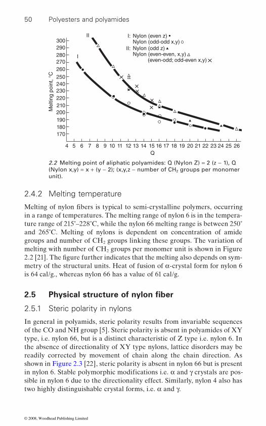
50 Polyesters and polyamides
2.4.2 Melting temperature
in a range of temperatures. The melting range of nylon 6 is in the tempera-ture range of 215˚–228˚C, while the nylon 66 melting range is between 250˚ and 265˚C. Melting of nylons is dependent on concentration of amide groups and number of CH2 groups linking these groups. The variation of melting with number of CH2 groups per monomer unit is shown in Figure 2.2 [21]. The fi gure further indicates that the melting also depends on sym-metry of the structural units. Heat of fusion of α-crystal form for nylon 6 is 64 cal/g., whereas nylon 66 has a value of 61 cal/g.
2.5
2.5.1 Steric polarity in nylons
In general in polyamids, steric polarity results from invariable sequences of the CO and NH group [5]. Steric polarity is absent in polyamides of XY type, i.e. nylon 66, but is a distinct characteristic of Z type i.e. nylon 6. In the absence of directionality of XY type nylons, lattice disorders may be readily corrected by movement of chain along the chain direction. As shown in Figure 2.3 [22], steric polarity is absent in nylon 66 but is present
sible in nylon 6 due to the directionality effect. Similarly, nylon 4 also has two highly distinguishable crystal forms, i.e. α and γ.
II
II:
I: Nylon (even z) •Nylon (odd-odd x,y)Nylon (odd z) Nylon (even-even, x,y) (even-odd; odd-even x,y)
I
300290280270260250240230220210
Mel
ting
poin
t, °C
200190180170
4 5 6 7 8 9 10 11 12 13 14 15Q
16 17 18 19 21 22 23 24 25 2620
2.2 Melting point of aliphatic polyamides: Q (Nylon Z) = 2 (z − 1), Q (Nylon x,y) = x + (y − 2); (x,y,z − number of CH2 groups per monomer unit).
Melting of nylon fibers is typical to semi-crystalline polymers, occurring
Physical structure of nylon fiber
in nylon 6. Stable polymorphic modifications i.e. α and γ crystals are pos-
© 2008, Woodhead Publishing Limited
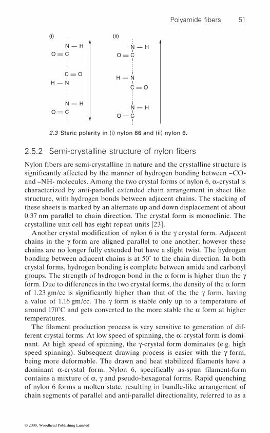
51
and –NH- molecules. Among the two crystal forms of nylon 6, α-crystal is characterized by anti-parallel extended chain arrangement in sheet like structure, with hydrogen bonds between adjacent chains. The stacking of these sheets is marked by an alternate up and down displacement of about 0.37 nm parallel to chain direction. The crystal form is monoclinic. The crystalline unit cell has eight repeat units [23].
chains in the γ form are aligned parallel to one another; however these chains are no longer fully extended but have a slight twist. The hydrogen bonding between adjacent chains is at 50˚ to the chain direction. In both crystal forms, hydrogen bonding is complete between amide and carbonyl groups. The strength of hydrogen bond in the α form is higher than the γ form. Due to differences in the two crystal forms, the density of the α form
a value of 1.16 gm/cc. The γ form is stable only up to a temperature of around 170˚C and gets converted to the more stable the α form at higher temperatures.
ferent crystal forms. At low speed of spinning, the α-crystal form is domi-nant. At high speed of spinning, the γ-crystal form dominates (e.g. high speed spinning). Subsequent drawing process is easier with the γ form,
contains a mixture of α, γ and pseudo-hexagonal forms. Rapid quenching of nylon 6 forms a molten state, resulting in bundle-like arrangement of chain segments of parallel and anti-parallel directionality, referred to as a
N - H
N - H
H - N
C = O
O = C
O = C
(i) (ii)
N - H
N - H
H - N
C = O
O = C
O = C
2.3 Steric polarity in (i) nylon 66 and (ii) nylon 6.
Polyamide fibers
2.5.2 Semi-crystalline structure of nylon fibers
Nylon fibers are semi-crystalline in nature and the crystalline structure is significantly affected by the manner of hydrogen bonding between –CO-
Another crystal modification of nylon 6 is the γ crystal form. Adjacent
of 1.23 gm/cc is significantly higher than that of the the γ form, having
The filament production process is very sensitive to generation of dif-
being more deformable. The drawn and heat stabilized filaments have a dominant α-crystal form. Nylon 6, specifically as-spun filament-form
© 2008, Woodhead Publishing Limited

52 Polyesters and polyamides
converted to the α or γ form depending on subsequent processing of spun
Figure 2.4 is a representative equatorial diffraction pattern of nylon 6
samples contain α and γ crystal forms along with amorphous regions. Such analysis can in general be used to obtain fractions of the crystal forms and crystallinity.
Nylon 66 has two very similar crystal forms i.e. α and β. The α-crystal form has an anti-parallel chain in sheet form, very similar to that of the α form in nylon 6. The stacking of hydrogen bonded sheets is characterized by a perpendicular distance of 0.36 nm and a displacement of successive sheets of about 0.5 nm in the chain direction. The α and β forms are dif-ferentiated by displacement of sheets in the chain direction being strictly in one direction for the α form and an alternate up and down for the β form. In the case of nylon 66, the α-form is slightly more stable than the
arrangement of chains with pseudo-hexagonal arrangements, which get converted to stable crystal forms in subsequent processes of drawing and heat setting.
α-crystal form and 1.14–1.15 gm/cc for the γ-crystal form. The pseudo-hexagonal structure density is in the range of 1.13 gm/cc and a value of 1.09 gm/cc has been reported for amorphous phase.
15
Amorphous
20 252q
g 200
a 200
g 001
a 002/202
30 35
2.4 Experimental and fitted equatorial diffraction patterns.
filaments. However the α form, being more stable, dominates the stabilized
pseudo-hexagonal form. This form is stable only up to 100–150˚C and gets
filaments.
filaments [24]. The line analysis of diffraction pattern shows that the
β-form. Rapid cooled spun nylon 66 filaments also have a bundle-like
The actual crystal densities in a given fiber may be 1.19 gm/cc for the
© 2008, Woodhead Publishing Limited

53
an otherwise random arrangement of molecular chains and designated as amorphous orientation. This could be thought of as chain extension being
higher than 1.09 gm/cc, due to the presence of amorphous orientation.
2.5.3 Morphological structure
as shown in the Figure 2.5 [25]. It should be noted that a two phase model,
tively. These crystalline and amorphous regions, arranged in a regular
an endless oriented network with branching and fusion more common than endings.
[29]. A comprehensive review of structural models has been recently pub-
Microfibrils Extended chains
Crystallinebridges
Polyamide fibers
2.5 Microstructure of highly drawn polyamide fibers.
Amorphous regions in fibers generally have an imposed orientation, in
highest along the fiber axis. The actual amorphous density of the fibers is
A reasonable morphological model for nylon fibers is described in terms of the three phase model with microfibrillar and inter-microfibrillar regions
quately describe the fiber structure. The width of the microfibrils ranges between 60 and 200 Å. The microfibrils in turn consists of crystalline and amorphous regions in a series mode. Industrial grade filaments typically
is sufficient to give diffraction maxima in the small-angle of x-ray scatter-
have crystalline and amorphous region lengths of ∼60 Å and ∼30 Å respec-
ing. Longitudinal dimensions of microfibrils are not well defined as is the case with this model type. Microfibrils are surrounded by inter-
consisting of crystalline and amorphous regions in fibers, does not ade-
sequence along the fiber axis, act as a micro-lattice. In fact the regularity
are thus in some degree of pseudo-order [26–28]. Microfibrils in turn form
Existence of intra-fibrillar tie molecules has been proposed by Peterlin
lished [30]. In the drawing process, nylons deform through micro fiber
microfibrillar regions and consist of highly oriented molecular chains and
slippage forming a large number of interfibrillar tie molecules which appear
© 2008, Woodhead Publishing Limited

54 Polyesters and polyamides
as a separate phase. Thus the modulus and strength of nylons are domi-
sidered as a separate phase.
of extended chain molecules as shown in Figure 2.5.
2.6
A typical stress-strain curve of nylon tire yarns is shown in Figure 2.6. It is interesting to note that the initial modulus of the nylon is quite low. This is followed by a yield point and a sigmoid type of deformation as shown in the stress-strain curve. This behavior of nylons is unique and is related to
2
gen bonds in amorphous regions and physical linking offered by the pres-ence of crystalline regions. Further, nylons have large extensions to break combined with relatively high strength and thus result in high work of rupture.
2.6.1 Strength
Strain (%)
Str
ess
(gpd
)
5
2
4
6
8
10
10 15 20 25 30
2.6 Stress–strain curve of nylon yarn.
nated by the amount of interfibrillar extended chains and should be con-
There is a significant interaction between microfibrils in nylons. The extended chains in interfibrillar regions are the strongest and have a pro-found effect on fiber strength. Thus strength can be increased by shearing off the surface of the microfibrils to make an interfibrillar domain. In the highly oriented state, microfibrils tend to fuse via epitaxial crystallization
Mechanical behavior of nylon fibers
The strength of nylon filaments can be assessed on the basis of the mor-phological models of these fibers as shown in Figure 2.6. The inter micro-
combination of flexible – (CH ) – sections, occasional breakage of hydro-
© 2008, Woodhead Publishing Limited

55
region in series with the crystalline regions. On the other hand, the regular
order of 2 gm/denier [31]. The amorphous domains are the weakest element and initiation of cracks is expected to start from them. In the case of highly
cross-sectional area is estimated to be ∼2.4 × 1011 cm−2. Taking the long period as 90 Å, concentration of crack nucleation sites is around 2.6 × 1017 cm−3. This value is near to the concentration of free radicals found
One important conclusion from these observations is that the micro-cracks arising out of amorphous regions do not grow but become unstable and lead to catastrophic failure. Further, the failure is associated with minimum number of chain scissions. Morphological models [33] for low draw ratio and high draw ratio illustrate these facts as shown in Figure 2.7.
chain dimensions; (b) lateral dimension of microcracks; and (c) distance
2.6.2 Modulus
proportional to the tensile modulus. Thus, the tensile modulus values are
Low draw ratio
High draw ratio
Polyamide fibers
2.7 ‘Swiss cheese’ fiber model.
fibrilar phase is the strongest element of the fiber. On the other hand the
chain folding makes the microfibrils relatively weak with strength in the
drawn filaments, the microscopic crack [32] dimensions are similar to the
microfiber deformation is dominated by the presence of an amorphous
microfibril diameter of ∼75 Å. The number of amorphous domains per unit
in the breakage of nylon 6 fiber.
Thus the strength depends on: (a) volume function of interfibrillar extended
microfibrils.
Tensile and bending moduli are important properties of the fibers, affect-
between the crystallites. The later factors reduce the stress at the tip of the
ing the final product properties. For a given fineness, bending modulus is
of significance and a lot of information is available. Crystal modulus values
© 2008, Woodhead Publishing Limited

56 Polyesters and polyamides
(Ec) of select nylons are well-documented based on calculations using force constants associated with vibrational frequencies of the polymer
between crystalline and amorphous regions in a two phase model of the
As there is orientation in amorphous regions, the moduli of these regions (Ea) depend on amorphous orientation function (fa). The dependence of
cube model can be expressed as follows:
Ef = λ [(φ/Ec) + (1 − φ)/Ea] + (1 − λ) Ea
Table 2.2 gives the value of all the relevant parameters i.e. Ef, Ec, Ea, λ,
highly drawn samples, λ is much less than 1, which shows a dominant paral-lel response between crystalline and amorphous regions. Further λ, is approximately equal to ϕ, indicating a degree of isotropy in parallel and perpendicular directions. On the other hand the sample with the interme-diate draw ratio, λ ≈ 1 and φ ≈ 0.57. This corresponds to maximum anisot-
perpendicular direction, it is a parallel response. Thus a simple two phase model approach for nylons gives satisfactory explanation for modulus values.
A
B
C
l
F
2.8 Equivalent general mechanical model for representation of dynamic mechanical properties of two phase system.
chain. Contributions of crystal modulus depend on the load transfer
fibers. An analysis of modulus can be done using Takayanagi’s unit cube model [34] for these fibers as shown in Figure 2.8.
Ea on fa has also been reported [34]. Modulus of the fibers based on unit
φ for three different nylon 6 filaments having different draw ratios. For
ropy, i.e. coupling along the fiber axis is close to series response and in the
© 2008, Woodhead Publishing Limited

57
2.6.3 Elastic recovery behavior
relates to decrease in entropy on tensile deformation and recovery on stress removal, typical of time dependent rubber elastic effects. During deforma-tion of nylons, the –(CH2)– sections in amorphous regions are typically mobile above the β-transition temperatures of ∼−30˚C for nylons. However, regular restrictions are imposed in the mobile sections by hydrogen bonds. These mobile sections may be bigger in the absence of hydrogen bonds, but eventually get restricted as the chain enters the crystalline regions. A chance breaking of hydrogen bonds results in the creep behavior of nylons. On removal of load, the recovery process is due to entropic effects and occurs through breaking and reformation of hydrogen bonds.
nylons. It is worth mentioning that different nylons with varying hydrogen bond density have essentially the same recovery behavior. Inter-estingly, these observations hold for fairly large deformations of nylon
2.6.4 Relaxation behavior of nylon 6 and nylon 66 tire cord
Both nylon 6 and nylon 66 have been used in a range of applications interchangeably depending on local availability. For industrial grade applications, differences between nylon 6 and nylon 66 become apparent. Comparative relaxation behavior of these two classes of high tenacity nylon
phological parameters [34]. Tan δ peak for nylon 66 is at ∼99˚C and for nylon 6 it is at 88˚C. Due to lower Tg, the heat generation builds up faster from room temperature for nylon 6 than that for nylon 66. Nylon 6 also has higher loss peak height than that of nylon 66, whereas nylon 66 has broader loss peak than nylon 6. Nylon 6 also has slightly lower crystallinity than
D
draw ratios of X1.3 and X5.35
Draw ratio Ef, ×10−10 dynes/cm2
XD Ec, ×10−10 dynes/cm2
λ Φ Eα, ×10−10 dynes/cm2
1 2.35 0.63 12 0.80 0.787 0.703 4.80 0.56 25 0.98 0.570 2.345.35 5.50 0.34 25 0.52 0.654 3.26
Polyamide fibers
Table 2.2 The values of Ef, X , Ec, λ, Φ, Eα for nylon filaments with
Nylon fibers have excellent elastic recovery behavior. This unique behavior
Typically crystallinity of the order of 50–70% in nylon filaments restricts
filaments.
filaments is described, based on dynamic mechanical behavior and mor-
the overall flow of molecular chains, and insures excellent recovery of
© 2008, Woodhead Publishing Limited
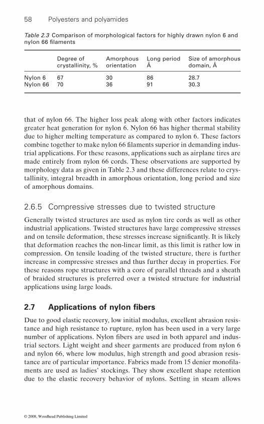
58 Polyesters and polyamides
that of nylon 66. The higher loss peak along with other factors indicates greater heat generation for nylon 6. Nylon 66 has higher thermal stability due to higher melting temperature as compared to nylon 6. These factors
trial applications. For these reasons, applications such as airplane tires are made entirely from nylon 66 cords. These observations are supported by morphology data as given in Table 2.3 and these differences relate to crys-tallinity, integral breadth in amorphous orientation, long period and size of amorphous domains.
2.6.5 Compressive stresses due to twisted structure
Generally twisted structures are used as nylon tire cords as well as other industrial applications. Twisted structures have large compressive stresses
that deformation reaches the non-linear limit, as this limit is rather low in compression. On tensile loading of the twisted structure, there is further increase in compressive stresses and thus further decay in properties. For these reasons rope structures with a core of parallel threads and a sheath of braided structures is preferred over a twisted structure for industrial applications using large loads.
2.7
Due to good elastic recovery, low initial modulus, excellent abrasion resis-tance and high resistance to rupture, nylon has been used in a very large
trial sectors. Light weight and sheer garments are produced from nylon 6 and nylon 66, where low modulus, high strength and good abrasion resis-
ments are used as ladies’ stockings. They show excellent shape retention due to the elastic recovery behavior of nylons. Setting in steam allows
Table 2.3 Comparison of morphological factors for highly drawn nylon 6 and
Degree of crystallinity, %
Amorphous orientation
Long period Å
Size of amorphous domain, Å
Nylon 6 67 30 86 28.7Nylon 66 70 36 91 30.3
nylon 66 filaments
combine together to make nylon 66 filaments superior in demanding indus-
and on tensile deformation, these stresses increase significantly. It is likely
Applications of nylon fibers
number of applications. Nylon fibers are used in both apparel and indus-
tance are of particular importance. Fabrics made from 15 denier monofila-
© 2008, Woodhead Publishing Limited
59
dimensional stability, permanent pleating while liveliness is also reduced. These fabrics may not require ironing. Socks are mostly made from nylon
used for sarees. Furs from nylon are also popular due to recovery behavior and long life. Wool is blended with nylon to improve its durability.
hoses, typewriter ribbons, and light weight canvas for luggage are exclusive
for making hot air balloons.
with high surface areas for easier bonding with latex. In fact most tires for trucks and airplanes are made from nylon tire cords. Nylon ropes and cordages have strength, durability, and resistance to water. Fishing nets are mostly made from nylon twine due to excellent elastic recovery and high wet strength. Sail cloth made from nylon allows deformation due to wind and recovery on reduction of wind speed, and thus allows optimum advan-tage of the wind speed.
Strimmer lines used for cutting grass are dominantly made from nylon
stability. There is a rapid change in local temperature of these lines and stabilized nylon restricts fusing. A very high diameter uniformity and low
diameter is used for garden strimmer lines and a diameter between 2.0 to 3.0 mm for agricultural cutters.
for manufacture of paper. The fabric is open mesh with good dimensional
underside of the conveyor in a nylon/polyester combination to improve
split longitudinally under compression from machine components. Using
sive forces and a resilient bare weave is achieved. Umbrella cloth is made from nylon due to diameter swelling behavior. Ribbons for printers, bolting cloths, sutures and toothbrush bristles are further applications of the nylons worth mentioning.
Polyamide fibers
In technical textiles, nylon fibers are widely used for a number of appli-cations. Nylon is amongst the best carpet fibers because of resilience and excellent aberration resistance and is very useful under heavy traffic. Nylon
due to similar reasons. Fabrics made from fine filament are extensively
bulk continuous filament is used for this purpose. Safety belts in cars,
domains for nylon filaments. Polyurethane coated nylon fabrics are used
Multifilament nylon yarns find extensive applications for reinforcing rubbers such as tires, with the filament denier ranging from 840 to 1620.
6, nylon 66, and nylon 69 monofilaments [35]. These filaments provide the
shrinkage are required for these filaments. Nylon monofilament of 1.5 mm
Monofilament of polyester and nylon are woven to make conveyor belts
stability having a wide width of up to 10 m. Typical dimensions of monofila-ments used are in the range of 0.15–0.30 mm. Nylon filaments are in the
wear resistance against the machine frame. Further, nylon filaments do not
small groups of twisted monofilaments also further dissipates the compres-
These are twisted as multi-strand cord, which improves flex fatigue and
correct balance of flexibility, abrasion resistance and thermal dimensional
© 2008, Woodhead Publishing Limited

60 Polyesters and polyamides
2.8 References
1. m. levin and e.m. pearce, Polyamide Fibers in Fiber Chemistry, Marcel Dekker, (1985) p. 73
2. snider, o.e. and richardson, r.j. In Encyclopedia of Polymer Science and Technology, vol. 10, InterScience, New York, (1969) p. 353
3. Caprolactam, product data sheet, Allied Chemical Corp., Moriston, New Jersey, June, 1980; Caprolactam, Standard Test Methods Bulletin, Allied Chemical Corp., New Jersey, June 1980; Caprolactam, Technical Bulletin KL-42001, Bayer AG, Leverkusen, Germany, (1975) p. 357
4. bonfi eld, j.h. and northcott, j. ‘Encyclopedia of industrial chemical analysis’, Vol. 8, Willey interScience, New York (1969) p. 357
5. carothers, w.h. and berebett, j. J. Am. Chem. Soc., 52, 5289 (1930) p. 357. 6. v. b. gupta and v. k. kothari, Manufactured Fibre Technology, Chapman &
Hall, London (1997) p. 320 7. j.m. schultz and s. fakirov, Solid State Behavior of Linear Polyesters and
Polyamides, Prentice Hall, New Jersey, 1990 8. menachem lewin and eli m. pearce, Handbook of Fibre Science and Technol-
ogy, Fibre Chemistry/100, (1985) p. 98 9. g.j. kettle, J Polymer 1977, 18 74210. puffr, r.j. and sebenda, j. Polymer Science. C. 1967, 16, 7911. nikitina, o.a. Visokomol. Soedin. ser.a 1970, 12, 151412. deopura, b.l., sengupta, a.k. and verma, a. ‘Effect of moisture on physical
properties of nylon’, vol-24, Polymer Communication, September 1983, p. 287–288
13. d.r. buchanan and j.p. walters, Tex. Res. J. 47, 398, (1997)14. r. puffr and j. sebenda, J. Polymer Science, c-16, 79 (1976)15. a. bondi and a.v. tobolsky, in Polymer Science and Materials. Ed A.V. Tobol-
sky and H.F. Mark. Wiley InterScience, New York (1971)16. g.j. kettle, Polymer 18, 742 (1977)17. menachem lewin and eli m. pearce, Handbook of Fibre Science and Technol-
ogy, Fibre Chemistry, Marcel Dekker, (1985) p. 10018. kaimin, i.f., apinic, a.p. and golvanosky, a. ya. Polymer Science USSR 1975,
174619. starkweather, h.w. Jr. Nylon Plastics, Ed. M.I. Koham, John Wiley and Sons,
New York, 1973, p. 32320. permanyer, f., PhD. Thesis, University of Manchester, UK. 194721. puffr, r.j. and sebenda, j.j. Polymer Science. C. 1967, 167922. m. lewin and eli m. pearce, Handbook of Fibre Science and Technology, Fibre
Chemistry, Marcel Dekker, (1985) p. 9823. m. lewin and eli m. pearce, Handbook of Fibre Science and Technology, Fibre
Chemistry, Marcel Dekker, (1985) p. 9024. m. lewin and eli m. pearce, Handbook of Fibre Science and Technology, Fibre
Chemistry, Marcel Dekker, (1985) p. 10825. prevorsek, d.c., kwon y.d. and sharma, r.k., J. Material Sci. 12, 2310–2328
(1977)26. jerolds m. schultz and stoyko fakirov, Solid State Behaviour of Linear
Polyesters and Polyamides, New Jersey (1990) p. 138
© 2008, Woodhead Publishing Limited

61
27. prevorsek, d.c., harget, p.j., sharma, r.k. and reimschuessel, a.c., J. Macro-mol. Sci. Phys. B8, 127 (1973)
28. prevorsek, d.c., tirpac, g.a., harget, p.j., and reimschuessel, a.c., J. Macro-mol. Sci. Phys. B9 (4), 733 (1974)
29. peterlin, a., Ultra High Modulus Fiber, Eds A. Cifferi and I.M. Ward, Applied Science Publication, 1979, p. 290–292
30. porter, r. s., chuah, h.h., and kanamoto, t., High Modulus Polymers, Eds E. Zachariades and R.S. Porter; Marcel Dekker, 1998, p. 259
31. jerolds m. schultz and stoyko fakirov, Solid State Behaviour of Linear Polyesters and Polyamides, New Jersey (1990) p. 158
32. reimischuessel, a.c. and preversek, d.c., Journal of Polymer Science A-2, 14, 485 (1976)
33. prevorsek, d.c., harget, p.j., sharma, r.k. and reimschuessel, a.c., J. Macro-mol. Sci. Phys. B8, 127 (1973)
34. prevorsek, d.c., harget, p.j., sharma, r.k., and reimschuessel, a.c., J. Macro-mol. Sci. Phys. B8, 127 (1973)
(1994) p. 367
Polyamide fibers
35. h. broody, Synthetic Fibre Materials, Longman Scientific and Technical, UK
© 2008, Woodhead Publishing Limited
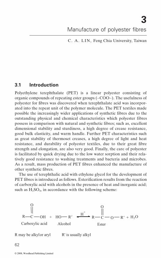
3
C . A. LI N, Feng Chia University, Taiwan
3.1 Introduction
Polyethylene terephthalate (PET) is a linear polyester consisting of
ated into the repeat unit of the polymer molecule. The PET textiles made
dimensional stability and sturdiness, a high degree of crease resistance, good bulk elasticity, and warm handle. Further PET characteristics such as great stability of thermoset creases, a high degree of light and heat
strength and elongation, are also very good. Finally, the care of polyester is facilitated by quick drying due to the low water sorption and their rela-tively good resistance to washing treatments and bacteria and microbes.
The use of terephthalic acid with ethylene glycol for the development of
of carboxylic acid with alcohols in the presence of heat and inorganic acid; such as H2SO4, in accordance with the following scheme:
62
+
AlcoholCarboxylic acid
R C OH
O
HO R'
R may be alkyl or aryl R' is usually alkyl
H+
R C O R'
O
+ H2 O
Ester
Manufacture of polyester fibres
organic compounds of repeating ester groups (–COO–). The usefulness of
possible the increasingly wider applications of synthetic fibres due to the outstanding physical and chemical characteristics which polyester fibres
polyester for fibres was discovered when terephthalate acid was incorpor-
possess in comparison with natural and synthetic fibres; such as, excellent
resistance, and durability of polyester textiles, due to their great fibre
As a result, mass production of PET fibres enhanced the manufacture of other synthetic fibres.
PET fibres is introduced as follows. Esterification results from the reaction
© 2008, Woodhead Publishing Limited
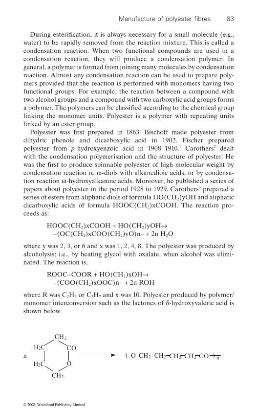
63
water) to be rapidly removed from the reaction mixture. This is called a condensation reaction. When two functional compounds are used in a condensation reaction, they will produce a condensation polymer. In general, a polymer is formed from joining many molecules by condensation reaction. Almost any condensation reaction can be used to prepare poly-
functional groups. For example, the reaction between a compound with two alcohol groups and a compound with two carboxylic acid groups forms
linking the monomer units. Polyester is a polymer with repeating units linked by an ester group.
dihydric phenole and dicarboxylic acid in 1902. Fischer prepared polyester from p-hydroxyenzoic acid in 1908–1910.1 Carothers2 dealt with the condensation polymerisation and the structure of polyester. He
condensation reaction α, ω-diols with alkanedioic acids, or by condensa-tion reaction ω-hydroxyalkanoic acids. Moreover, he published a series of papers about polyester in the period 1928 to 1929. Carothers3 prepared a series of esters from aliphatic diols of formula HO(CH2)yOH and aliphatic dicarboxylic acids of formula HOOC(CH2)xCOOH. The reaction pro-ceeds as:
HOOC(CH2)xCOOH + HO(CH2)yOH→ –(OC(CH2)xCOO(CH2)yO)n– + 2n H2O
where y was 2, 3, or 6 and x was 1, 2, 4, 8. The polyester was produced by alcoholysis; i.e., by heating glycol with oxalate, when alcohol was elimi-nated. The reaction is,
ROOC–COOR + HO(CH2)xOH→ –(COO(CH2)xOOC)n– + 2n ROH
where R was C2H5 or C3H7 and x was 10. Polyester produced by polymer/monomer interconversion such as the lactones of δ-hydroxyvaleric acid is shown below.
CH2
2CH
C2H
C2H
CO
On ( CH22CH 2CHO 2CH OC ) n
Manufacture of polyester fibres
mers provided that the reaction is performed with monomers having two
During esterification, it is always necessary for a small molecule (e.g.,
a polymer. The polymers can be classified according to the chemical group
Polyester was first prepared in 1863. Bischoff made polyester from
was the first to produce spinnable polyester of high molecular weight by
© 2008, Woodhead Publishing Limited

64 Polyesters and polyamides
The ability of bifunctional lactones has been discussed by Carothers 4
very stable. The six-membered ones can be converted into linear polyester and by proper treatment back to the monomeric form. Because of inter-molecular reaction or intramolecular reaction, a bifunctional compound such as α-hydroxy acid may yield both diametric cyclic ester and a linear polyester.
n HO C
H
COOH
CH3
CO
OH3C CH
O CHC 3H
CO
3CH
H
CHO ( COO
CH
H
C )n -1COOH
3
Cyclic esters with rings of six or more members can be depolymerised into linear polyester. In the reaction of a bifunctional compound, however, the
in number compared with all possible ones. The probability that the two ends of a long chain will occupy positions adjacent to one another, and hence be in a position to react intramolecularly, varies roughly as (chain length)−3/2. As a result, intramolecular reactions become less probable as the number of atoms in the molecule increases.
The lactones of δ-hydroxyvaleric acid formed from the corresponding ω-hydroxy acid produce a linear polyester as follows:
CH2
CH2
O
CO
H2C
H2CHO(CH2)4COOH ( O(CH )2 4CO )n
In polymer preparation, the compound with six-membered or beyond cyclic lactones is quite readily transformed to polymer. Carothers and Hill pro-
et al. It was found that the five-membered ring systems stand out to be
probability that the chain takes up a configuration allowing the ends of the molecule to react is low. Moreover, such ring configurations will be few
© 2008, Woodhead Publishing Limited
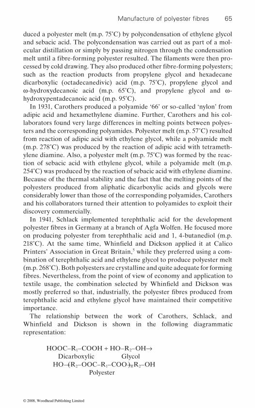
65
duced a polyester melt (m.p. 75˚C) by polycondensation of ethylene glycol and sebacic acid. The polycondensation was carried out as part of a mol -e cular distillation or simply by passing nitrogen through the condensation
such as the reaction products from propylene glycol and hexadecane dicarboxylic (octadecanedivic) acid (m.p. 75˚C), propylene glycol and ω-hydroxydecanoic acid (m.p. 65˚C), and propylene glycol and ω-hydroxypentadecanoic acid (m.p. 95˚C).
In 1931, Carothers produced a polyamide ‘66’ or so-called ‘nylon’ from adipic acid and hexamethylene diamine. Further, Carothers and his col-laborators found very large differences in melting points between polyes-ters and the corresponding polyamides. Polyester melt (m.p. 57˚C) resulted from reaction of adipic acid with ethylene glycol, while a polyamide melt (m.p. 278˚C) was produced by the reaction of adipic acid with tetrameth-ylene diamine. Also, a polyester melt (m.p. 75˚C) was formed by the reac-tion of sebacic acid with ethylene glycol, while a polyamide melt (m.p. 254˚C) was produced by the reaction of sebacic acid with ethylene diamine. Because of the thermal stability and the fact that the melting points of the polyesters produced from aliphatic dicarboxylic acids and glycols were considerably lower than those of the corresponding polyamides, Carothers and his colla borators turned their attention to polyamides to exploit their discovery commercially.
In 1941, Schlack implemented terephthalic acid for the development
on producing polyester from terephthalic acid and 1, 4-butanediol (m.p.
Printers’ Association in Great Britain,5 while they preferred using a com-bination of terephthalic acid and ethylene glycol to produce polyester melt (m.p. 268˚C). Both polyesters are crystalline and quite adequate for forming
terephthalic acid and ethylene glycol have maintained their competitive importance.
The relationship between the work of Carothers, Schlack, and
representation:
HOOC–R1–COOH + HO–R2–OH→ Dicarboxylic Glycol HO–(–R2–OOC–R1–COO–)n–R2–OH Polyester
Manufacture of polyester fibres
melt until a fibre-forming polyester resulted. The filaments were then pro-cessed by cold drawing. They also produced other fibre-forming polyesters;
polyester fibres in Germany at a branch of Agfa Wolfen. He focused more
218˚C). At the same time, Whinfield and Dickson applied it at Calico
fibres. Nevertheless, from the point of view of economy and application to textile usage, the combination selected by Whinfield and Dickson was mostly preferred so that, industrially, the polyester fibres produced from
Whinfield and Dickson is shown in the following diagrammatic
© 2008, Woodhead Publishing Limited
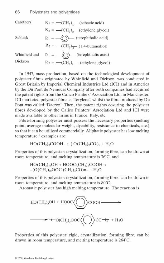
66 Polyesters and polyamides
In 1947, mass production, based on the technological development of
Great Britain by Imperial Chemical Industries Ltd (ICI) and in America by the Du Pont de Nemours Company after both companies had acquired
Pont was called ‘Dacron’. Then, the patent rights covering the polyester
Fibre-forming polyester must possess the necessary properties (melting point, average molecular weight, dyeability, resistance to chemicals, etc.) so that it can be utilized commercially. Aliphatic polyester has low melting temperature;6 examples are:
HO(CH2)9COOH → –(–O(CH2)9CO–)n– + H2O
room temperature, and melting temperature is 76˚C, and
HO(CH2)10OH + HOOC(CH2)4COOH→ –(O(CH2)10OOC (CH2)4CO)n– + H2O
room temperature, and melting temperature is 80˚C.Aromatic polyester has high melting temperature. The reaction is
Carothers
Schlack
Dickson
R1 = (CH2)
)2(CH
8 (sebacic acid)
R2 = (CH2)2
=2R
=1R (terephthalic acid)
(CH2)4 (1,4-butanediol)
=2R
=1R (terephthalic acid)
2 (ethylene glycol)
(ethylene glycol)
HO OH + HOOC COOH(CH2)2
( O(CH2)2OOC CO ) + 2H On
drawn in room temperature, and melting temperature is 264˚C.
Whinfield and
polyester fibres originated by Whinfield and Dickson, was conducted in
ICI marketed polyester fibre as ‘Terylene’, whilst the fibre produced by Du
fibres developed by the Calico Printers’ Association Ltd and ICI were
the patent rights from the Calico Printers’ Association Ltd, in Manchester.
made available to other firms in France, Italy, etc.
Properties of this polyester: crystallization, forming fibre, can be drawn at
Properties of this polyester: crystallization, forming fibre, can be drawn in
Properties of this polyester: rigid, crystallization, forming fibre, can be
© 2008, Woodhead Publishing Limited
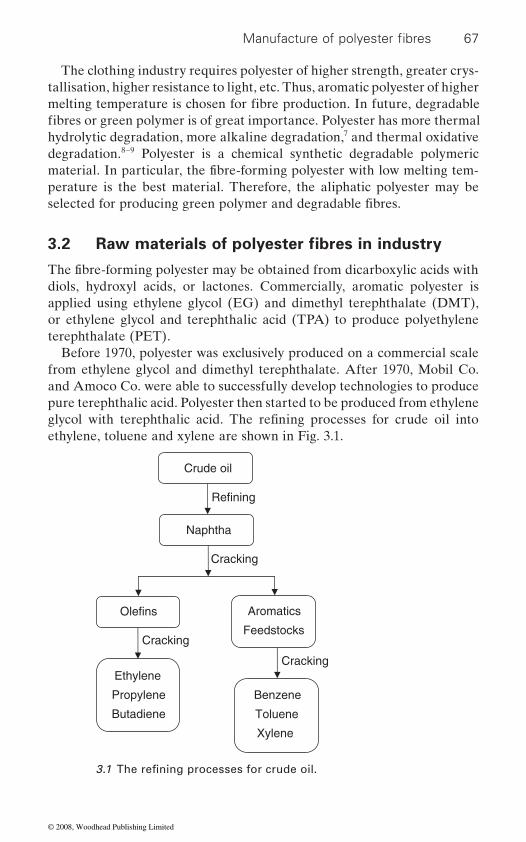
67
tallisation, higher resistance to light, etc. Thus, aromatic polyester of higher
hydrolytic degradation, more alkaline degradation,7 and thermal oxidative degradation.8–9 Polyester is a chemical synthetic degradable polymeric
perature is the best material. Therefore, the aliphatic polyester may be
3.2
diols, hydroxyl acids, or lactones. Commercially, aromatic polyester is applied using ethylene glycol (EG) and dimethyl terephthalate (DMT), or ethylene glycol and terephthalic acid (TPA) to produce polyethylene terephthalate (PET).
Before 1970, polyester was exclusively produced on a commercial scale from ethylene glycol and dimethyl terephthalate. After 1970, Mobil Co. and Amoco Co. were able to successfully develop technologies to produce pure terephthalic acid. Polyester then started to be produced from ethylene
ethylene, toluene and xylene are shown in Fig. 3.1.
Cracking
Cracking
Olefins
Cracking
Refining
Crude oil
Naphtha
Aromatics
Feedstocks
Ethylene
Propylene
Butadiene
Benzene
Toluene
Xylene
3.1 The refi ning processes for crude oil.
Manufacture of polyester fibres
fibres or green polymer is of great importance. Polyester has more thermal
The clothing industry requires polyester of higher strength, greater crys-
melting temperature is chosen for fibre production. In future, degradable
material. In particular, the fibre-forming polyester with low melting tem-
selected for producing green polymer and degradable fibres.
Raw materials of polyester fibres in industry
The fibre-forming polyester may be obtained from dicarboxylic acids with
glycol with terephthalic acid. The refining processes for crude oil into
© 2008, Woodhead Publishing Limited
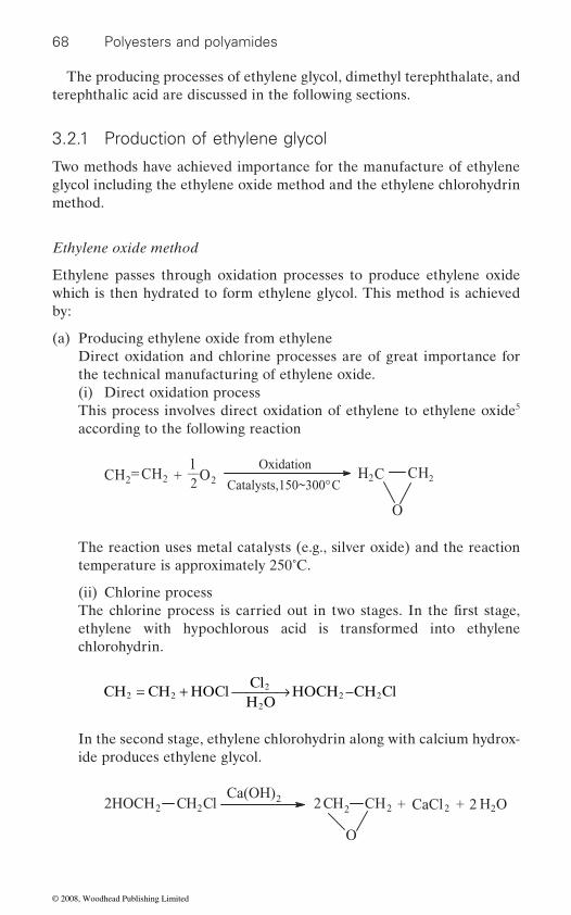
68 Polyesters and polyamides
The producing processes of ethylene glycol, dimethyl terephthalate, and terephthalic acid are discussed in the following sections.
3.2.1 Production of ethylene glycol
Two methods have achieved importance for the manufacture of ethylene glycol including the ethylene oxide method and the ethylene chlorohydrin method.
Ethylene oxide method
Ethylene passes through oxidation processes to produce ethylene oxide which is then hydrated to form ethylene glycol. This method is achieved by:
(a) Producing ethylene oxide from ethylene Direct oxidation and chlorine processes are of great importance for
the technical manufacturing of ethylene oxide.(i) Direct oxidation processThis process involves direct oxidation of ethylene to ethylene oxide5 according to the following reaction
2CH2= CH2 + __21
O2
Oxidation
Catalysts,150~300°C H2C CH
O
The reaction uses metal catalysts (e.g., silver oxide) and the reaction temperature is approximately 250˚C.
(ii) Chlorine process
ethylene with hypochlorous acid is transformed into ethylene chlorohydrin.
Ca(OH)CaCl2HOCH2 2CH Cl 2 2 2CH2CH
O
2 2 H2O+ +
CH CH HOClCl
H OHOCH CH Cl2 2
2
22 2= + ⎯ →⎯⎯
In the second stage, ethylene chlorohydrin along with calcium hydrox-ide produces ethylene glycol.
The chlorine process is carried out in two stages. In the first stage,
© 2008, Woodhead Publishing Limited

69
(b) Production of ethylene glycol from ethylene oxide Ethylene oxide may react with water and be hydrated to ethylene glycol
in accordance with the following reaction10
O
2CHC2H H2OHydrogenation
Catalysts, 60~100°C 2CH2CHHO OH+
The reaction proceeds with the aid of acid catalysts, while the reaction temperature ranges between 60 to 100˚C.
Ethylene chlorohydrin method
hydrin with caustic soda solution, or of ethylene chloride and soda accord-ing to the following formulae:
ClCH CH OH H OCaustic soda
HOCH CH OH HCl2 2 2 2 2+ ⎯ →⎯⎯⎯⎯⎯⎯ +
ClCH CH Cl 2H OSoda
HOCH CH OH 2HCl2 2 2 2 2+ ⎯ →⎯⎯⎯ +
However, this method is one of the older procedures and thus it was aban-
following properties:
• Boiling point: 195–198˚C.• Density: 1.110–1.112 (at 20˚C).• OH number: greater than 1750.• Water content: less than 0.1%.• Ester interchange value: greater than 90.
3.2.2 Manufacturing terephthalic acid and dimethyl terephthalate
Benzene, toluene and xylene are the primary raw materials in manufactur-
manufacturing processes of TPA and DMT is depicted in Fig. 3.2.
Benzene material
The following reaction system shows the conversion of benzene to tere-phthalic acid:
Manufacture of polyester fibres
Ethylene glycol is produced by alkaline saponification of ethylene chloro-
doned. Ethylene glycol was purified to produce polyester fibres with the
ing terephthalic acid and dimethyl terephthalate. The flow chart for the
© 2008, Woodhead Publishing Limited
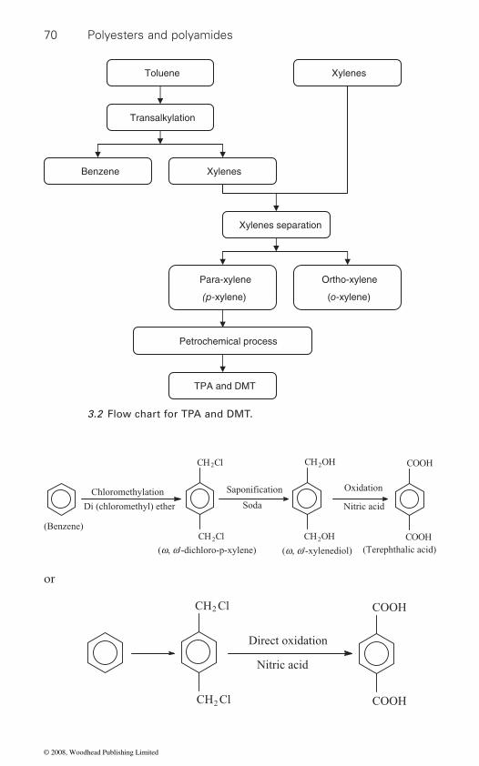
70 Polyesters and polyamides
or
Toluene Xylenes
Transalkylation
Benzene Xylenes
Xylenes separation
Para-xylene
(p-xylene)
Ortho-xylene
(o-xylene)
Petrochemical process
TPA and DMT
3.2 Flow chart for TPA and DMT.
Chloromethylation
Di (chloromethyl) ether
(Benzene)
CH Cl
CH Cl
2
2
(w, w'-dichloro-p-xylene)
Saponification
Soda
CH OH
CH OH2
2
Oxidation
Nitric acid
COOH
COOH
(w, w'-xylenediol) (Terephthalic acid)
COOH
COOH
2
2
CH Cl
CH Cl
Direct oxidation
Nitric acid
© 2008, Woodhead Publishing Limited
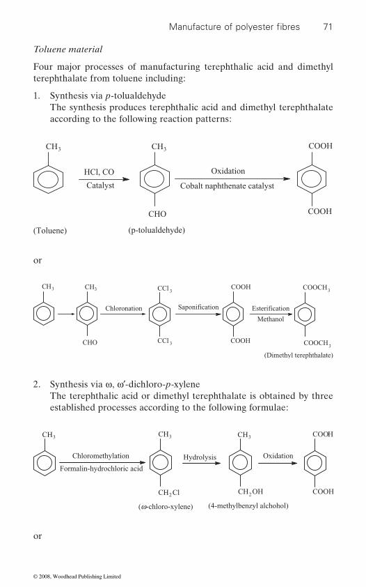
71
Toluene material
Four major processes of manufacturing terephthalic acid and dimethyl terephthalate from toluene including:
1. Synthesis via p-tolualdehyde The synthesis produces terephthalic acid and dimethyl terephthalate
according to the following reaction patterns:
CH
HCl, CO
Catalyst
CHO
(Toluene)
Oxidation
Cobalt naphthenate catalyst
COOH
(p-tolualdehyde)
33 CH COOH
or
3CH CH3
CHO
Chloronation
CCl
CCl 3
3
Saponification Esterification
Methanol
COOCH
COOH
COOH
COOCH3
3
(Dimethyl terephthalate)
2. Synthesis via ω, ω′-dichloro-p-xylene The terephthalic acid or dimethyl terephthalate is obtained by three
established processes according to the following formulae:
CH
CH Cl
3 3CH
CH OH
COOH
COOH
CH3
Chloromethylation
Formalin-hydrochloric acid
Hydrolysis Oxidation
(w-chloro-xylene) (4-methylbenzyl alchohol)
22
or
Manufacture of polyester fibres
© 2008, Woodhead Publishing Limited

72 Polyesters and polyamides
or
3CH
2
CH3
CH Cl
Oxidation
Nitric acid
COOH
3CH
COOH
COOH
Oxidation
(Potassium permanganate)
(p-toluic acid)
CH Cl
3CH
2
CH3
Photochemical chlorination
CCl
CCl
3
3
(Hexachloro-p-xylene)
Saponification
Ferric chloride catalyst
COOH
COOH
Esterification
Methanol
COOCH
COOCH
3
3
3. Synthesis via p-toluamide The manufacture of terephthalic acid based on tolune proceeds as
follows:
CH3
with Urea chloride
3CH
CONH2
Saponificaion
Soda
COOH
CH3
Oxidation
COOH
COOH
(p-toluamide)
4. Synthesis via potassium benzoate The synthesis for the production of terephthalic acid is based on the
following reactions:11
© 2008, Woodhead Publishing Limited
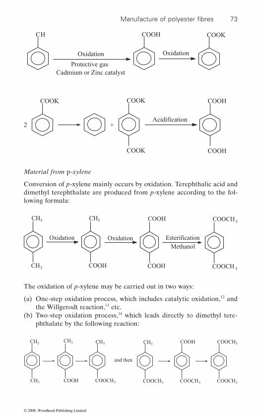
73
Material from p-xylene
Conversion of p-xylene mainly occurs by oxidation. Terephthalic acid and dimethyl terephthalate are produced from p-xylene according to the fol-lowing formula:
CH
Oxidation
Protective gasCadmium or Zinc catalyst
COOH
Oxidation
COOK
COOK
+
COOK
COOK
Acidification
COOH
COOH
2
3CH
CH
3
3
Oxidation
3CH
COOH
Oxidation
COOH
COOH
Esterification
Methanol
COOCH
COOCH
3
The oxidation of p-xylene may be carried out in two ways:
(a) One-step oxidation process, which includes catalytic oxidation,12 and the Willgerodt reaction,13 etc.
(b) Two-step oxidation process,14 which leads directly to dimethyl tere-phthalate by the following reaction:
COOCHCOOH 33CH
CH3
3CH
COOH
3CH
3COOCH
and then
COOCH3
CH3
3COOCH COOCH3
Manufacture of polyester fibres
© 2008, Woodhead Publishing Limited
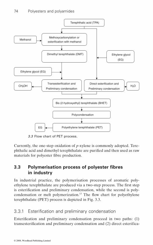
74 Polyesters and polyamides
Currently, the one-step oxidation of p-xylene is commonly adopted. Tere-
3.3
in industry
In industrial practice, the polymerisation processes of aromatic poly-
15
terephthalate (PET) process is depicted in Fig. 3.3.
Terephthalic acid (TPA)
Methoxycarbonylation or
esterification with methanolMethanol
Dimethyl terephthalate (DMT)
Ethylene glycol (EG)
Transesterification and
Preliminary condensationCH3OH
Bis (2-hydroxyethyl) terephthalate (BHET)
Polycondensation
EG Polyethylene terephthalate (PET)
Ethylene glycol
(EG)
Direct esterification and
Preliminary condensation H2O
3.3 Flow chart of PET process.
phthalic acid and dimethyl terephthalate are purified and then used as raw materials for polyester fibre production.
Polymerisation process of polyester fibres
3.3.1 Esterification and preliminary condensation
Esterification and preliminary condensation proceed in two paths: (1)
condensation or melt polymerization.is esterification and preliminary condensation, while the second is poly-ethylene terephthalate are produced via a two-step process. The first step
transesterification and preliminary condensation and (2) direct esterifica-
The flow chart for polyethylene
© 2008, Woodhead Publishing Limited

75
formed, with the assistance of one or more catalysts and EG at temperatures ranging from 150 to 200˚C, into BHET (bis-(2-hydroxyethyl) terephthal-ate) (also called diglycol terephthalate, DGT) with the elimination of
+ 2
(DMT) (EG)
DMT EG+ + +
H3COOC COOCH3 HOCH2CH2OH
+HOCH2CH2OOC CH3OHCOOCH2CH2OH
catalysts
catalysts
Transesterification
(BHET) X=3~5
+H3COOC COOCH3HOCH2CH2OH
HOCH2CH2OOC CO CO( OCH2CH2OOC ) xOCH2CH2OH
catalysts
Preliminary condensation
tion are:16
• Catalysts: metal oxides (PbO, MgO, Sb2O3, etc.), metal acetates (Co, Mn, Zn, etc.), or mixtures of oxides and acetates metals (CH3COO)2CO-Sb2O3, (CH3COO)2CO-PbO, etc.).
• • Monomer ingredient for DMT: EG = 1: (2∼2.5) (mole ratio).• Reaction temperature: falls in the range of 150–200˚C (gradually
increases).• Reaction time: 3–6 hours.
terephthalic acid (TPA) is converted, with EG and the aid of one or more catalysts at temperatures ranging from 250 to 280˚C, into BHET with the elimination of water. The reaction is explained in the following scheme:
Manufacture of polyester fibres
tion and preliminary condensation. In the first path, the DMT is trans-
methanol. The reactions of first path proceed as follows:
The reaction conditions of transesterification and preliminary condensa-
Concentration of catalyst: 0.05% (to the amount of DMT).
In the second path (direct esterification and preliminary condensation),
© 2008, Woodhead Publishing Limited
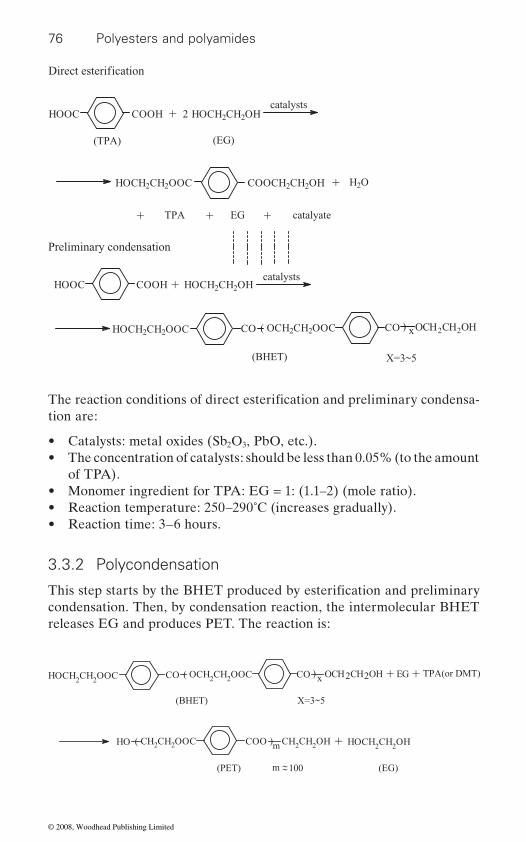
76 Polyesters and polyamides
tion are:
• Catalysts: metal oxides (Sb2O3, PbO, etc.).• The concentration of catalysts: should be less than 0.05% (to the amount
of TPA).• Monomer ingredient for TPA: EG = 1: (1.1–2) (mole ratio).• Reaction temperature: 250–290˚C (increases gradually).• Reaction time: 3–6 hours.
3.3.2 Polycondensation
condensation. Then, by condensation reaction, the intermolecular BHET releases EG and produces PET. The reaction is:
Preliminary condensation
HOOC COOH HOCH2CH2OHcatalysts
X=3~5(BHET)
HOCH2CH2OOC CO CO( OCH2CH2OOC ) xOCH2CH2OH
+HOCH2CH2OOC COOCH2CH2OH H2O
TPA EG catalyate+ + +
+ 2
(TPA) (EG)
HOCH2CH2OHHOOC COOHcatalysts
+
+ EG TPA(or DMT)+
X=3~5(BHET)
HOCH2CH2OOC CO CO( OCH2CH2OOC ) x OCH2CH2OH
(PET) (EG)
HO ( CH2CH2OOC COO )m CH2CH2OH HOCH2CH2OH+
~~m 100
Direct esterification
The reaction conditions of direct esterification and preliminary condensa-
This step starts by the BHET produced by esterification and preliminary
© 2008, Woodhead Publishing Limited
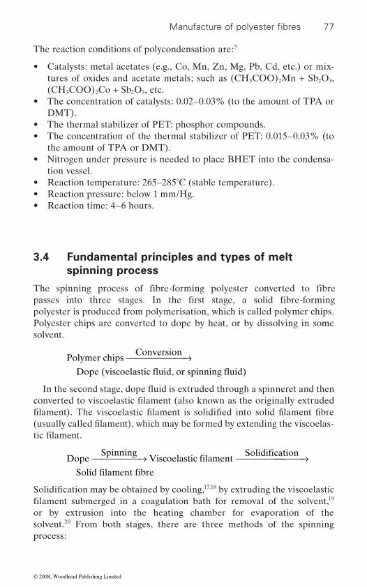
77
The reaction conditions of polycondensation are:5
• Catalysts: metal acetates (e.g., Co, Mn, Zn, Mg, Pb, Cd, etc.) or mix-tures of oxides and acetate metals; such as (CH3COO)2Mn + Sb2O3, (CH3COO)2Co + Sb2O3, etc.
• The concentration of catalysts: 0.02–0.03% (to the amount of TPA or DMT).
• The thermal stabilizer of PET: phosphor compounds.• The concentration of the thermal stabilizer of PET: 0.015–0.03% (to
the amount of TPA or DMT).• Nitrogen under pressure is needed to place BHET into the condensa-
tion vessel.• Reaction temperature: 265–285˚C (stable temperature).• Reaction pressure: below 1 mm/Hg.• Reaction time: 4–6 hours.
3.4 Fundamental principles and types of melt
spinning process
polyester is produced from polymerisation, which is called polymer chips. Polyester chips are converted to dope by heat, or by dissolving in some solvent.
Polymer chipsConversion⎯ →⎯⎯⎯⎯⎯
DopeSpinning
Viscoelastic filamentSolidification⎯ →⎯⎯⎯⎯ ⎯ →⎯⎯⎯⎯⎯⎯⎯
Solid filament fibre17,18 by extruding the viscoelastic
19 or by extrusion into the heating chamber for evaporation of the solvent.20 From both stages, there are three methods of the spinning process:
Manufacture of polyester fibres
The spinning process of fibre-forming polyester converted to fibre passes into three stages. In the first stage, a solid fibre-forming
converted to viscoelastic filament (also known as the originally extruded filament). The viscoelastic filament is solidified into solid filament fibre (usually called filament), which may be formed by extending the viscoelas-tic filament.
Solidification may be obtained by cooling,filament submerged in a coagulation bath for removal of the solvent,
Dope (viscoelastic fluid, or spinning fluid)
In the second stage, dope fluid is extruded through a spinneret and then
© 2008, Woodhead Publishing Limited

78 Polyesters and polyamides
1. Melt spinning:
Polymer chipsConversion by heat
DopeSpinning⎯ →⎯⎯⎯⎯⎯⎯⎯⎯⎯ ⎯ →⎯⎯⎯⎯⎯
Solidification by cooling
Solid filament fibre
2. Wet spinning:
Polymer chipsConversion by dissolving in solvent⎯ →⎯⎯⎯⎯⎯⎯⎯⎯⎯⎯⎯⎯⎯⎯⎯⎯
⎯ →⎯⎯⎯⎯
Dope
SpinningViscoelastic filament
Solidificatiion by submerging in coagulation bath⎯ →⎯⎯⎯⎯⎯⎯⎯⎯⎯⎯⎯⎯⎯⎯⎯⎯⎯⎯⎯⎯⎯Solid filament fibre
3. Dry spinning21,22:
Polymer chipsConversion by dissolving in solvent⎯ →⎯⎯⎯⎯⎯⎯⎯⎯⎯⎯⎯⎯⎯⎯⎯⎯
⎯ →⎯⎯⎯⎯
Dope
SpinningViscoelastic filament
Solidificatiion by curing in the heating chamber⎯ →⎯⎯⎯⎯⎯⎯⎯⎯⎯⎯⎯⎯⎯⎯⎯⎯⎯⎯⎯⎯⎯Solid filament fibre
If the polymer chips are thermoplastic polymers (i.e., PET, polyamide, polyurethane, polypropylene, etc.), melt spinning, wet spinning or dry spinning can be used. Usually, melt spinning is used. But if polymer chips are thermosetting polymers (i.e., polyacrylonitrile, viscose rayon, cellulose acetate, etc.), wet spinning or dry spinning can be used.
increase, while it improves the degree of crystallinity.
3.4.1 Fundamental principles of melt spinning process
PET belongs to the thermoplastic polymer and so the commercial PET
23
molten polymer. Apparently, this is a simple process. A supply of molten PET (D) is pumped at a constant rate and under very high pressure through
to emerge vertically downwards from the face of the spinning jet and, on cooling (F), solidify, and wind onto the bobbins.
Viscoelastic filament ⎯ →⎯⎯⎯⎯⎯⎯⎯⎯⎯⎯⎯⎯
In the third stage, when the viscoelastic filament is solidified into solid filament fibre, it is extended by the drawing process. The drawing process decreases the diameter, and the orientation of solid filament fibre could
fibre usually uses melt spinning. The schematic melt spinning process for PET fibre is shown in Fig. 3.4. PET fibres are formed by extrusion of the
small holes in the spinning jet (E). The viscoelastic filaments are extruded
© 2008, Woodhead Publishing Limited
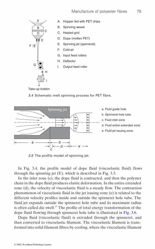
79
is often called die swell.17
A. Hopper fed with PET chips
B. Spinning vessel
C. Heated grid
D. Dope (molten PET)
E. Spinning jet (spinneret)
F. Cold air
G. Input feed rollers
H. Deflector
I. Output feed roller
A
B C
D
E
F
G
H
I
Take-up bobbin
a b d
c e
a. Fluid guide hole
b. Spinneret hole tube
c. Fluid inlet zone
d. Fluid entire extended zone
e. Fluid jet issuing zone
Spinning jet
Manufacture of polyester fibres
3.4 Schematic melt spinning process for PET fibre.
3.5 The profile model of spinning jet.
different velocity profiles inside and outside the spinneret hole tube. The
The profile of total energy transformation of the
then converted to viscoelastic filament. The viscoelastic filament is trans-formed into solid filament fibres by cooling, where the viscoelastic filament
In Fig. 3.4, the profile model of dope fluid (viscoelastic fluid) flows
In the inlet zone (c), the dope fluid is contracted, and then the polymer chain in the dope fluid produces elastic deformation. In the entire extended zone (d), the velocity of viscoelastic fluid is a steady flow. The contraction
through the spinning jet (E), which is described in Fig. 3.5.
phenomenon of viscoelastic fluid in the jet issuing zone (e) is related to the
fluid jet expands outside the spinneret hole tube and its maximum radius
dope fluid flowing through spinneret hole tube is illustrated in Fig. 3.6.Dope fluid (viscoelastic fluid) is extruded through the spinneret, and
© 2008, Woodhead Publishing Limited
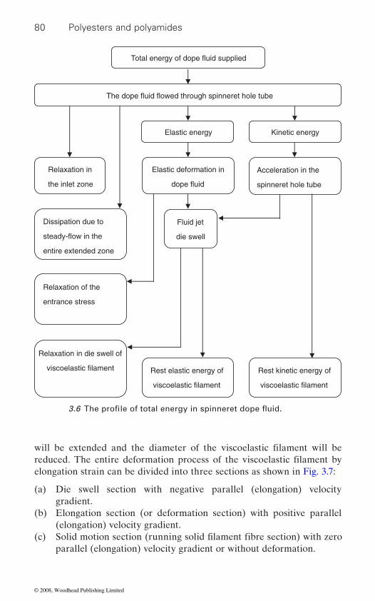
80 Polyesters and polyamides
elongation strain can be divided into three sections as shown in Fig. 3.7:
(a) Die swell section with negative parallel (elongation) velocity gradient.
(b) Elongation section (or deformation section) with positive parallel (elongation) velocity gradient.
(c) parallel (elongation) velocity gradient or without deformation.
The dope fluid flowed through spinneret hole tube
Total energy of dope fluid supplied
Elastic energy Kinetic energy
Elastic deformation in
dope fluid
Acceleration in the
spinneret hole tube
Relaxation in
the inlet zone
Dissipation due to
steady-flow in the
entire extended zone
Relaxation of the
entrance stress
Relaxation in die swell of
viscoelastic filament
Fluid jet
die swell
Rest kinetic energy of
viscoelastic filament
Rest elastic energy of
viscoelastic filament
will be extended and the diameter of the viscoelastic filament will be reduced. The entire deformation process of the viscoelastic filament by
Solid motion section (running solid filament fibre section) with zero
3.6 The profile of total energy in spinneret dope fluid.
© 2008, Woodhead Publishing Limited

81
of the die swell and elongation sections. The distance is usually less than 10 mm from the spinneret. The distance of the elongation section is usually
perature gradient is along the spinning axial line, while the other is radial which expresses the radial differential temperature from the outer layers
24
The following results are obtained from Fig. 3.8 regarding:
(a) Temperature: the outer layers are lower, while the inner layers are higher.
(b) Crystallisation rate: the outer layers are fast, while the inner layers are slow.
(c) Viscosity: the outer layers are high; however, the inner layers are low.
(d) (e) Extensional force: the outer layers are high, whereas the inner layers
are low.
Viscoelastic filament (or
originally extruded filament)
Solid motion section
Die swell section
Guide disc
Elongation section
Spinneret
elongation strain.
Manufacture of polyester fibres
3.7 The deformation of viscoelastic filament (dope filament) by
50–150 cm from the spinneret. The viscoelastic filament (originally
The diameter of the viscoelastic filament is maximum at the intersection
extruded filament) on the spinning axial line is then solidified by cooling. During solidification there are two temperature gradients. The first tem-
to the inner layers of viscoelastic filament. Although the range is only a few degrees celsius, the physical properties of viscoelastic filament may be
on the viscoelastic filament.
Axial spinning velocity: uniform velocity on radial.
Drawing of PET viscoelastic filaments or filament (solid filament fibres) may be performed, depending on the fibre type, under cold or hot
significantly affected. Fig. 3.8 displays the influence of physical properties
© 2008, Woodhead Publishing Limited
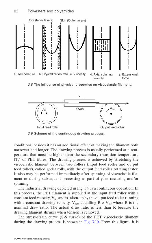
82 Polyesters and polyamides
narrower and longer. The drawing process is usually performed at a tem-perature that must be higher than the secondary transition temperature
g
feed roller), called godet rolls, with the output feed roller rotating faster.
spinning.The industrial drawing depicted in Fig. 3.9 is a continuous operation. In
constant feed velocity, Vin, and is taken-up by the output feed roller running with a constant drawing velocity, Vout, equalling R × Vin; where R is the nominal draw ratio. The actual draw ratio is less than R because the
Skin (Outer layers) Core (Inner layers)
a. Temperature b. Crystallization rate c. Viscosity d. Axial spinning e. Extensional forcevelocity
Oven
V
VinVout
Output feed roller Input feed roller
3.9 Scheme of the continuous drawing process.
conditions, besides it has an additional effect of making the filament both
(T ) of PET fibres. The drawing process is achieved by stretching the viscoelastic filament between two rollers (input feed roller and output
It also may be performed immediately after spinning of viscoelastic fila-
this process, the PET filament is supplied at the input feed roller with a
drawing filament shrinks when tension is removed.The stress-strain curve (S-S curve) of the PET viscoelastic filament
ment or during subsequent processing as part of yarn texturing and/or
during the drawing process is shown in Fig. 3.10. From this figure, it is
3.8 The influence of physical properties on viscoelastic filament.
© 2008, Woodhead Publishing Limited

83
noted that the deformation in the OA region is uniform and is usually reversible. The slope of S-S curve (called modulus = σ/ε) is constant. The deformation is called elastic deformation. In the AB region, the modulus decreases when the stress is increased. The drawing exhibits a non-uniform deformation. The largest stress corresponds to point B which is often called the yield point. In the BC region, the deformation is unstable, where local attenuation results in a ‘necking effect’ concentration of stress. The strain is called strain-softening. The CD region is called the necking effect region. The deformation is concentrated in one or more necks, which gradually
undrawn parts remains steady. The deformation in this region is irrevers-ible. In the DE region, the deformation is uniform and is usually irrevers-ible. The strain increases as the stress increases. The drawing exhibits a uniform deformation. Point E is called the breaking point. Finally, the OF and OG are called the breaking strain and the breaking stress, respectively.
Crystalline and amorphous arrangements of PET chain exist within
decreases.25
not been fully drawn are called partially oriented yarns (POY), while those that have been fully drawn are called fully oriented yarns (FOY).
Strain (ε)0
A
BC D
F
EG
Stress (σ)
characteristics.
Manufacture of polyester fibres
3.10 Fundamental of PET viscoelastic filament deformation
extends over the entire filament, while the diameter of the neck and
newly formed filaments. These PET chain molecules are possibly oriented
maximum amount possible, because when a filament fibre reaches its
to make them more parallel to the walls of the filament by stretching the
maximum length, the extensibility of filament fibres (or filament yarn) Therefore, filament yarn can be divided into two types based
and stronger filaments. However, not all filaments are drawn to the filament before it is completely solidified. This results in more crystalline
on the degree of drawing (called the draw ratio). The filaments that have
© 2008, Woodhead Publishing Limited
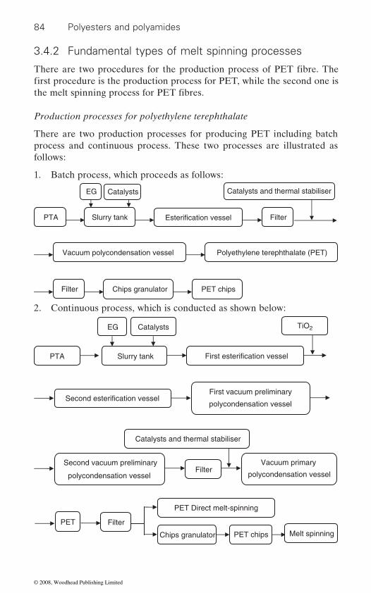
84 Polyesters and polyamides
3.4.2 Fundamental types of melt spinning processes
Production processes for polyethylene terephthalate
There are two production processes for producing PET including batch process and continuous process. These two processes are illustrated as follows:
1. Batch process, which proceeds as follows:
Vacuum polycondensation vessel Polyethylene terephthalate (PET)
Filter Chips granulator PET chips
Slurry tank Esterification vessel Filter
Catalysts and thermal stabiliser
PTA
EG Catalysts
2. Continuous process, which is conducted as shown below:
First esterification vessel Slurry tank PTA
Catalysts EG TiO2
First vacuum preliminary
polycondensation vesselSecond esterification vessel
Second vacuum preliminary
polycondensation vesselFilter
Catalysts and thermal stabiliser
Vacuum primary
polycondensation vessel
PET
Chips granulator
PET Direct melt-spinning
PET chips Melt spinning
Filter
There are two procedures for the production process of PET fibre. The first procedure is the production process for PET, while the second one is the melt spinning process for PET fibres.
© 2008, Woodhead Publishing Limited

85
processes as follows:
1.
PET chips
PET direct
Melt-spinning Cooling Collection of fibres
Oil immersion Steam heating Extended heating Crimping
Heat-setting Cutting (staple fibres) Baling
PET chips
PET direct
Melt-spinning Cooling Cold drawing
Bobbin or cake Winding Oiling
3.5
3.5.1 Heat setting
and causes non-uniform internal stresses within it. In effect, many crystal
Heat setting determines the morphology and dimensional stability of
Manufacture of polyester fibres
Melt spinning process for polyethylene terephthalate fibres
PET staple fibres and PET filament fibres are produced by melt spinning
PET staple fibres production
2. PET filament fibres production
Heat setting and textured yarn of filament
This results in different relaxing states of polymer chain in the PET fibre
defects appear. Moreover, such an unstable structure would cause fibre shrinkage that makes any further finishing processes so difficult. Thus, in order to achieve a stable fibre structure, heat setting should be controlled
In the melt spinning process, the time of fibre-forming is usually short.
before the fibres are used.
thermoplastic fibres. It includes three fundamental factors: temperature,
© 2008, Woodhead Publishing Limited
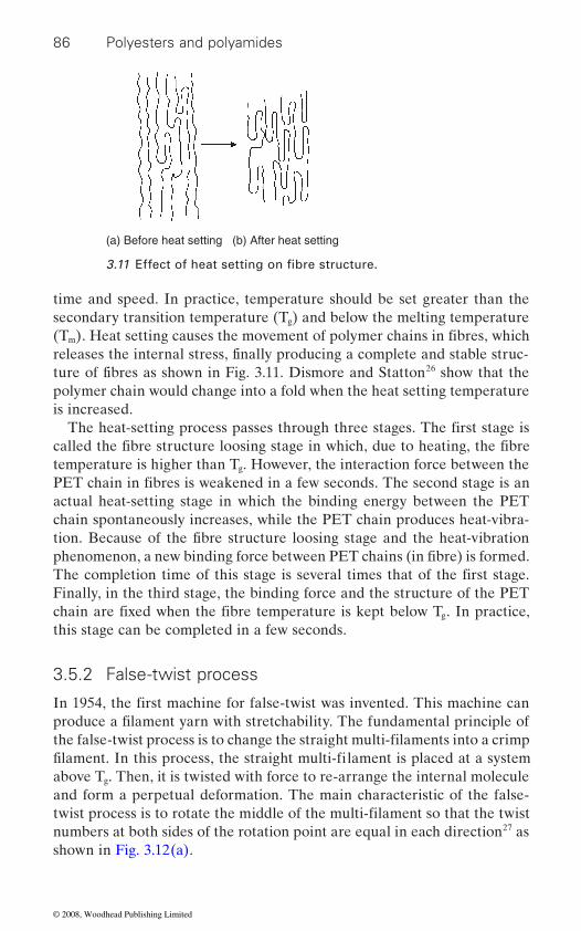
86 Polyesters and polyamides
time and speed. In practice, temperature should be set greater than the secondary transition temperature (Tg) and below the melting temperature
m
26 show that the polymer chain would change into a fold when the heat setting temperature is increased.
temperature is higher than Tg. However, the interaction force between the
actual heat-setting stage in which the binding energy between the PET chain spontaneously increases, while the PET chain produces heat-vibra-
Finally, in the third stage, the binding force and the structure of the PET g
this stage can be completed in a few seconds.
above Tg. Then, it is twisted with force to re-arrange the internal molecule and form a perpetual deformation. The main characteristic of the false-
numbers at both sides of the rotation point are equal in each direction27 as shown in Fig. 3.12(a).
(a) Before heat setting (b) After heat setting
(T ). Heat setting causes the movement of polymer chains in fibres, which
3.11 Effect of heat setting on fibre structure.
ture of fibres as shown in Fig. 3.11. Dismore and Statton
The heat-setting process passes through three stages. The first stage is
releases the internal stress, finally producing a complete and stable struc-
PET chain in fibres is weakened in a few seconds. The second stage is an
tion. Because of the fibre structure loosing stage and the heat-vibration
called the fibre structure loosing stage in which, due to heating, the fibre
phenomenon, a new binding force between PET chains (in fibre) is formed. The completion time of this stage is several times that of the first stage.
In 1954, the first machine for false-twist was invented. This machine can
chain are fixed when the fibre temperature is kept below T . In practice,
produce a filament yarn with stretchability. The fundamental principle of the false-twist process is to change the straight multi-filaments into a crimp
3.5.2 False-twist process
filament. In this process, the straight multi-filament is placed at a system
twist process is to rotate the middle of the multi-filament so that the twist
© 2008, Woodhead Publishing Limited
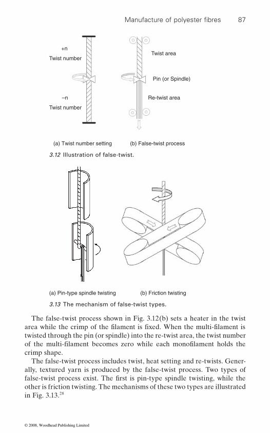
87
The false-twist process shown in Fig. 3.12(b) sets a heater in the twist
twisted through the pin (or spindle) into the re-twist area, the twist number
crimp shape.The false-twist process includes twist, heat setting and re-twists. Gener-
ally, textured yarn is produced by the false-twist process. Two types of
other is friction twisting. The mechanisms of these two types are illustrated in Fig. 3.13.28
+n
Twist number
–n
Twist number
Twist area
Re-twist area
Pin (or Spindle)
(a) Twist number setting (b) False-twist process
3.12 Illustration of false-twist.
(a) Pin-type spindle twisting (b) Friction twisting
3.13 The mechanism of false-twist types.
Manufacture of polyester fibres
area while the crimp of the filament is fixed. When the multi-filament is
of the multi-filament becomes zero while each monofilament holds the
false-twist process exist. The first is pin-type spindle twisting, while the
© 2008, Woodhead Publishing Limited
88 Polyesters and polyamides
3.6 High speed spinning and novel spinning
3.6.1
patent in 1952.29 Along with the development of industrial technology, the high speed take-up machine for above 6000 m/min was developed in 1980. High speed spinning was then commercialized. Due to the continuous devel-opment of mechanism and electronic control systems, it is expected that the
Meanwhile the spinning speed for research in the laboratory is over 12 000 m/min.
Fundamental principles of high speed spinning
High speed spinning was developed based on the conventional spinning method of 1500∼2500 m/min speed. This process combines the spinning and drawing processes, which are performed at a speed ranging between
place with a winding speed of 5000∼6500 m/min.30
The key point of high speed spinning is the orientation of molecules,
tension. Spinning tension is related to the spinning speed, the raw material property, and the processing conditions; including process temperature, the condition of quenching, and the spin-draw ratio of spinneret.
(III) plastic-deformation. When the polymer melt passes through the spin-ning jet and emerges from the spin holes into the air, it is normally solidi-
lisation, and crystal size. Normally, birefringence and crystallisation of partially oriented yarn are increased by raising the spinning speed of the
reduced.
High speed spinning process
Manufacturers prefer a process that produces a full oriented yarn with one single machine. Therefore, the high speed spinning process was developed in various methods.31,32
High speed spinning of polyester filaments
The first concept of high speed spinning was developed by DuPont’s US
spinning speed will reach 8000 m/min during the twenty-first century.
3500∼4000 m/min, in the same machine. The take-up of the fibre takes
shown in Fig. 3.14. It is noted that the fibre forming structure is divided
fied in a distance of 30–130 cm from the surface of spinneret (depends on the spinning condition). Therefore, the structure of the fibre will be
The polymer melt deformation in the high speed spinning process is
changed. The basic parameters of fibre structure are birefringence, crystal-
fibre. In effect, tenacity is increased, while the elongation of the fibre is
which is influenced by several spinning parameters; especially spinning
into three zones: (I) flow-deformation, (II) oriented-crystallisation, and
© 2008, Woodhead Publishing Limited
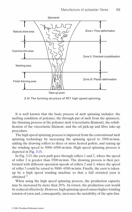
89
It is well known that the basic process of melt spinning includes: the melting condition of polymer, the through-put of melt from the spinneret,
procedure.The high speed spinning process is improved from the conventional melt
spinning technology by increasing the spinning speed to 3500 m/min, adding the drawing rollers to three or more heated godets, and raising up the winding speed to 5000–6500 m/min. High speed spinning process is depicted in Fig. 3.15.
In Fig. 3.15, the yarn path goes through rollers 1 and 2, where the speed of roller 2 is greater than 3500 m/min. The drawing process is then per-formed with different operation speeds of rollers 2 and 3, where the speed of roller 3 could be raised to 5000–6500 m/min. Finally, the yarn is taken-up by a high speed winding machine so that a full oriented yarn is obtained.33
When using the high speed spinning process, the production capacity may be increased by more than 20%. In return, the production cost would be reduced effectively. However, high spinning speed causes higher winding tension of yarn and, consequently, increases the instability of the spin-line.
Zone I: Flow-deformation
Spinneret
Natural draw area
Coercive thin area
Necking area
Take-up point
Finish thinning area
Zone II: Oriented-crystallisation
Zone III: Plastic-deformation
3.14 The forming structure of PET high speed spinning.
Manufacture of polyester fibres
the thinning process of the polymer melt (viscoelastic filament), the solidi-fication of the viscoelastic filament, and the oil pick-up and fibre take-up
© 2008, Woodhead Publishing Limited
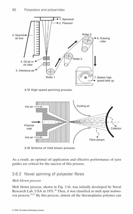
90 Polyesters and polyamides
As a result, an optimal oil application and effective performance of yarn guides are critical for the success of this process.
Melt blown process
Melt blown process, shown in Fig. 3.16, was initially developed by Naval Research Lab, USA in 1951.30
ven process.34,35 By this process, almost all the thermoplastic polymer can
1. Spinneret
3. Quench air box
4. Oil jet or oil roller
5. Interlance jet
2. Filament
Roller 1
Roller 2
Roller 3 6. Drawing roller
7. Bobbin high speed take up
3.15 High speed spinning process.
Cooling air
Hot air
Polymermelt
Hot air
Collector
Fibre stream
3.16 Scheme of melt blown process.
3.6.2 Novel spinning of polyester fibres
Then, it was classified as melt spun nonwo-
© 2008, Woodhead Publishing Limited

91
tively high. The tensile properties of melt blown nonwoven for machine direction and cross direction show an obvious uneven behaviour. Since melt spinning has an advantage for mass production, researchers focus on the improvements for the melt blown process. For example, the design of
Co. of USA design the thin distribution plates to enlarge the spin holes per unit area of spin pack and thus the through-put per hole will be reduced
36 In addition, the alternation
Split conjugate spinning process
0.3 denier by a conventional single component method.37,38 Before 1960,
which includes two incompatible polymers such as PET and PA6, using the conjugate spinning method39,40
mechanical or a chemical method. It can possibly be split during the fab-rication and dyeing process into 12, 16, 24 or 32 segments, and so on, depending on the design of the spin pack. This method is called the split
several products including high quality wipers and high density fabrics for apparel and home textiles. Figs. 3.17 and 3.18 display the schemes of split
respectively.
splitting of the interface of two polymers. In this process, the appropriate
be produced with micro-fibre. The diameter of single fibre from the melt
Manufacture of polyester fibres
a special spinning device and spin pack to reduce the fibre size to sub-
blown process is 1 micron or less, but the variation of the fibre size is rela-
microns, where it is expected to achieve a nano-scale fibre with a cost below
develop an air impingement method to make ultra-fine fibres; and Hills
and consequently a finer fibre can be attained.of L/D for spin hole may help in reducing the melt blown fibre dimension. The ideal diameter of the spin hole is around 0.10–0.15 mm, while the
It is very hard to produce a micro-fibre with the denier per filament below
there was no commercialised technology for micro-fibre. In 1970, Toray
jugated bi-component fibre is an approach for producing micro-fibres,
to spin to fibre. These two polymers are distributed similarly to the petal segments type on fibre cross-section. Each
Co. in Japan started its promotion of micro-fibre products. The spilt con-
conjugated filament is then divided into several finer fibres by means of a
conjugated micro-fibres. After splitting the denier of fine fibre may reach 0.03–0.07 denier. The end product using this micro-fibre is suitable for
conjugate fibre for (24 segment-pie) and spin pack for split conjugate fibre,
The purpose of split conjugated micro-fibre is to get a fine fibre by the
design of conjugate configuration is very important and the viscosity of the
iour between two polymers, an undesirable conjugate configuration results
$US10; Nanoval Co. from Germany was authorised by Neumag Co. to
optimum melt flow index of the polymer is controlled at 1000.
independent polymer is critical. If there is a huge difference of flow behav-
which may influence the splitting effect of the filament. The shape of the
© 2008, Woodhead Publishing Limited
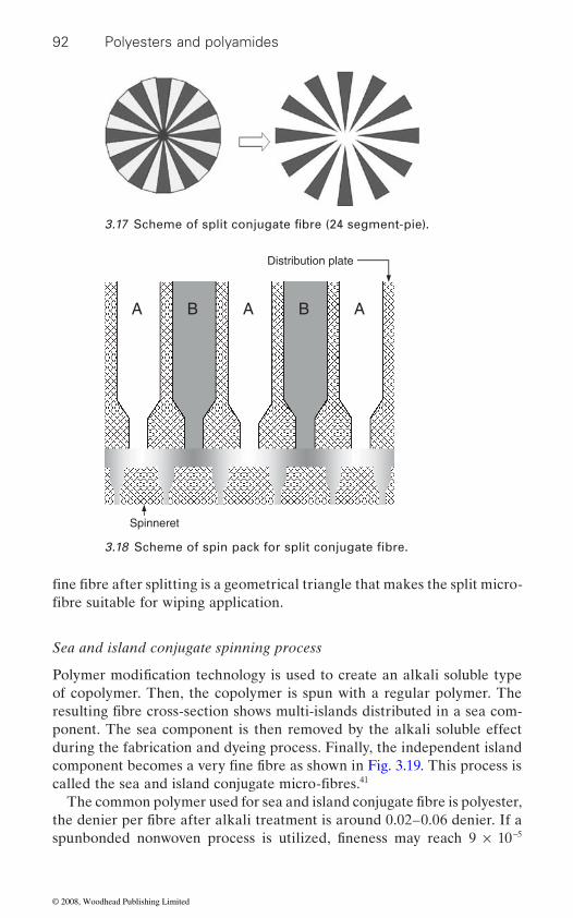
92 Polyesters and polyamides
Sea and island conjugate spinning process
of copolymer. Then, the copolymer is spun with a regular polymer. The
during the fabrication and dyeing process. Finally, the independent island
41
−5
Distribution plate
A A A B B
3.17 Scheme of split conjugate fibre (24 segment-pie).
3.18 Scheme of spin pack for split conjugate fibre.
fine fibre after splitting is a geometrical triangle that makes the split micro-
Spinneret
fibre suitable for wiping application.
Polymer modification technology is used to create an alkali soluble type
resulting fibre cross-section shows multi-islands distributed in a sea com-
component becomes a very fine fibre as shown in Fig. 3.19. This process is called the sea and island conjugate micro-fibres.
The common polymer used for sea and island conjugate fibre is polyester, the denier per fibre after alkali treatment is around 0.02–0.06 denier. If a
ponent. The sea component is then removed by the alkali soluble effect
spunbonded nonwoven process is utilized, fineness may reach 9 × 10
© 2008, Woodhead Publishing Limited
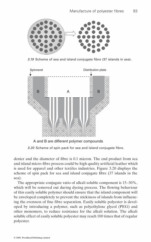
93
is used for apparel and other textiles industries. Figure 3.20 displays the
sea).The appropriate conjugate ratio of alkali soluble component is 15–30%,
of this easily soluble polymer should ensure that the island component will
oped by introducing a polymer, such as polyethylene glycol (PEG) and other monomers, to reduce resistance for the alkali solution. The alkali soluble effect of easily soluble polyester may reach 100 times that of regular polyester.
AB B
Distribution plate Spinneret
A and B are different polymer compounds
Manufacture of polyester fibres
3.19 Scheme of sea and island conjugate fibre (37 islands in sea).
3.20 Scheme of spin pack for sea and island conjugate fibre.
denier and the diameter of fibre is 0.1 micron. The end product from sea and island micro-fibre process could be high quality artificial leather which
scheme of spin pack for sea and island conjugate fibre (37 islands in the
ing the evenness of fine fibre separation. Easily soluble polyester is devel-
which will be removed out during dyeing process. The flowing behaviour
be enveloped completely to prevent the stickiness of islands from influenc-
© 2008, Woodhead Publishing Limited
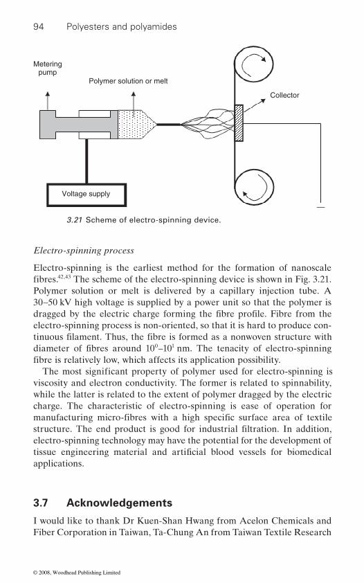
94 Polyesters and polyamides
Electro-spinning process
Electro-spinning is the earliest method for the formation of nanoscale 42,43 The scheme of the electro-spinning device is shown in Fig. 3.21.
Polymer solution or melt is delivered by a capillary injection tube. A 30∼50 kV high voltage is supplied by a power unit so that the polymer is
electro-spinning process is non-oriented, so that it is hard to produce con-
0 1
viscosity and electron conductivity. The former is related to spinnability, while the latter is related to the extent of polymer dragged by the electric charge. The characteristic of electro-spinning is ease of operation for
electro-spinning technology may have the potential for the development of
applications.
3.7 Acknowledgements
I would like to thank Dr Kuen-Shan Hwang from Acelon Chemicals and Fiber Corporation in Taiwan, Ta-Chung An from Taiwan Textile Research
Polymer solution or melt
Collector
Voltage supply
Meteringpump
3.21 Scheme of electro-spinning device.
fibres.
dragged by the electric charge forming the fibre profile. Fibre from the
tinuous filament. Thus, the fibre is formed as a nonwoven structure with diameter of fibres around 10 –10 nm. The tenacity of electro-spinning fibre is relatively low, which affects its application possibility.
The most significant property of polymer used for electro-spinning is
manufacturing micro-fibres with a high specific surface area of textile structure. The end product is good for industrial filtration. In addition,
tissue engineering material and artificial blood vessels for biomedical
© 2008, Woodhead Publishing Limited

95
Institute, Chun Lin at the Department of Materials Science and Engineer-ing, and Abbas Al-Refaie at the Department of Industrial Engineering and Systems Management in Feng Chia University, Taiwan, for their support.
3.8 References
1. peters r h (1968), Textile Chemistry: The Chemistry of Fibres, Vol. 1, New York, Elsevier.
2. mark h and whitby g s (1940), Collected Papers of Wallace Hume Carothers on Polymerisation, New York, Interscience Publishers Inc.
3. carothers w h and arvin j a (1929), J. Am. Chem. Soc., 51, 2560. 4. spanagel e w and carothers w h (1935), ‘Macrocyclic esters’ J. Am. Chem.
Soc., 57, 929–34. 5. hermann l (1971), Polyester Fibres: Chemistry and Technology, New York,
Wiley-Interscience. 6. carothers w h and hill j w (1932), J. Am. Chem. Soc., 54, 1579. 7. ludewig h and ramm h (1956), DWP 14 854. 8. pohl h a (1951), ‘The thermal degradation of polyesters’, J. Am. Chem. Soc.,
73, 5560–1. 9. mcmahon w, birdsall h a, johnson g r, and camilli c t (1959), ‘Physical
properties evaluation of compounds and materials’, Journal of Chemical and Engineering Data, 4, 57–79.
10. Chem. Fabr. Kalk.: D. R. P. 416 604.11. RaeckeB: D.B.P. 958 920 (patent).12. Chem. Werke imhausen, E.P. 787 054 (Patent).13. d a s (1953), 1 028 983 (Patent).14. barret k e and marks a: E.P. 735 074 (Patent).15. mark h et al. (1988), Encyclopedia of Polymer Science and Engineering,
Vol. 12, New York, John Wiley & Sons, Inc.16. whinfi eld j r (1946), Nature, 158 930 (Patent).17. andrzej z (1967), Physical Fundamentals of the Fiber-Spinning Processes,
and Principles of Melt-Spinning, in Man-Made Fibers Science and Technol-ogy, Vol. I, New York, Wiley-Interscience.
18. the society of fi ber science and technology (1969), Formation of Fibers and Development of their Structure: (I) Melt Spinning, Japan, Kagaku-dojin, Kyoto.
19. andrzej z (1976), Fundamentals of Fibre Formation: The Science of Fibre Spinning and Drawing, London, Wiley-Interscience.
20. the society of fi ber science and technology (1970), Formation of Fibers and Development of their Structure: (II) Wet Spinning and Dry Spinning, Japan, Kagaku-dojin, Kyoto.
J. Appl. Polymer Sci., 11, 2417.22. ohzawa y, nagano y, and matsuo t (1969), ‘Studies and dry spinning. I. Fun-
damental equations’, J. Appl. Polymer Sci., 13, 257.23. hill r (1953), Fibres from Synthetic Polymers, Amsterdam, Elsevier.24. katayama k, amano t and nakamura k, kolloid z (1968), ‘Structural forma-
tion during melt spinning’, Colloid & Polymer Science, 226, 125–34.
Manufacture of polyester fibres
21. fok s y and griskey r g (1967), ‘Mass transfer during spinning of fibers’,
© 2008, Woodhead Publishing Limited
96 Polyesters and polyamides
25. phyllis g t and billie j c (1997), Understanding Textiles, 15th Edition, Upper Saddle River, NJ, Prentice Hall.
Journal of Polymer Science Part B: Polymer Letters, 2(12), 1113–16.27. klein w (1993), New Spinning Systems, Cambridge, Woodhead Publishing.28. wilkinson g d (1967), Textured Yarn Technology, Decatur, AL, Monsanto
Company, p. 63.29. hebeler h h (1952), Yarn Process, U. S. Patent: 2,604, 667, 1952.30. nakajima t and mclntyre j e (1994), Advanced Fibre Spinning Technology,
Cambridge, Woodhead Publishing.31. monsanto textiles co. (1974), Draw-Textured Yarn Technology, Decatur, AL,
Monsanto.32. shirley institute (1976), Developments in Texturing, Manchester, Shirley
Institute.33. shirley institute (1980), Yarn texturing in the 1980s.34. harrison p w (1983), ‘Developments in Non-woven Fabrics’, Manchester, The
Textile Institute, 66–7.35. torobin l and fi ndlow r (2001), ‘Method and apparatus for producing high
and web media formed thereby’, US Patent 6, 183, 670.
Journal, 48–50.
Journal, 13(3), 20–24.
market niches’, Chemical Fibers International, 49, 402–5.
Polymer-Plastics Technology and Engineering, 45, 1339–45.
composites’, International Nonwoven Journal, 12(4).43. lionel c k, george b k, frances m p, and jennifer p (2001), ‘Modeling, materi-
als testing, nanostructures’, MPC Industry Collegiums Report, 17(3), 1–4.
26. paden f d and statton w o (2003), ‘Chain folding in oriented 66-nylon fibers’,
36. john h (2004), ‘Production of polymeric nanofibers’, International Fiber
37. okamoto m (1976), ‘On ultra fine fibers’, Sen-I Gakkaishi, 32, 318.
efficiency fibrous media incorporating discontinous sub-micron diameter fibers
38. okamoto m (1977), ‘Ultra-fine fiber and its application’, JTN, November, 94.39. terezie z (1998), ‘Introduction to bicomponent fibers’, International Fiber
40. bender k and stibal w (1999), ‘Bicomponent fibers – not only a product for
ratio on the mechanical properties of PET/PP blended conjugate fibers’, 41. chin-an l, chun-chi c, and ta-chung a (2006), ‘Effect of blend ratio and draw
42. omitry m l (2003), ‘Quality control in manufacturing of electrospun nanofiber
© 2008, Woodhead Publishing Limited
4
ASH W I N I KU M A R AGR AWA L and M A NJ EET JASSA L , Indian Institute
of Technology, New Delhi, India
4.1 Introduction
Polyamides are macromolecules which contain recurring amide groups as integral parts of the polymer backbone. And nylons are polyamides with structural units derived predominantly from aliphatic monomers. Although many reactions are known that are suitable for polyamide formation, com-mercially important nylons have been obtained by either of two basic approaches (polycondensation and ring opening polymerization) as repre-sented by the following general equations:
H N (CH ) NH HOOC (CH ) COOH(HN (CH ) NHCO (CH )
2 2 x 2 2 y 2
2 x 2 y
− − + − − →− − − −
−
−22 2CO ) H O− − + [4.1]
Equation (4.1) refers to the synthesis of AABB-type nylons through poly-condensation of bifunctional monomers utilizing stoichiometric pairs of dicarboxylic acids and diamines,
[4.2]
(–HN–(CH2)z−1 –CO–)
H2N–(CH
(CH2)5NH
C O
2)z-1– COOH (–HN–(CH2)z−1 –CO–) + H2O →
→
[4.3]
Equations (4.2) and (4.3) pertain to the synthesis of AB-type nylons entailing respectively the polycondensation of aminoacids and the ring-opening polymerization of lactams.
The polycondensation Reactions (4.2) and (4.3) proceed by a mechanism that is characterized by what is generally known as carbonyl addition-elimination reactions which may be catalyzed or uncatalyzed.
97
Manufacture of polyamide fibres
© 2008, Woodhead Publishing Limited
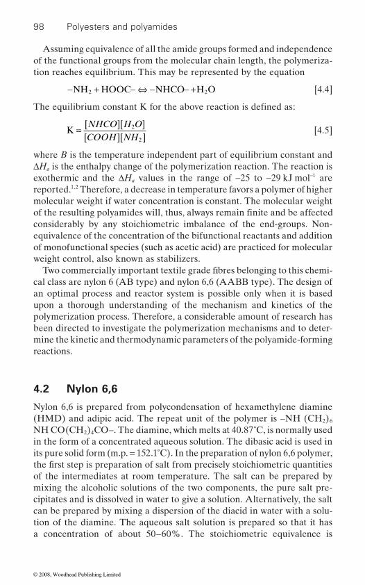
98 Polyesters and polyamides
Assuming equivalence of all the amide groups formed and independence of the functional groups from the molecular chain length, the polymeriza-tion reaches equilibrium. This may be represented by the equation
− + − ⇔ − − +NH HOOC NHCO H O2 2 [4.4]
K =[ ][ ][ ][ ]NHCO H OCOOH NH
2
2
[4.5]
where B is the temperature independent part of equilibrium constant and ΔHa is the enthalpy change of the polymerization reaction. The reaction is exothermic and the ΔHa values in the range of −25 to −29 kJ mol−1 are reported.1,2 Therefore, a decrease in temperature favors a polymer of higher molecular weight if water concentration is constant. The molecular weight
considerably by any stoichiometric imbalance of the end-groups. Non-equivalence of the concentration of the bifunctional reactants and addition of monofunctional species (such as acetic acid) are practiced for molecular weight control, also known as stabilizers.
cal class are nylon 6 (AB type) and nylon 6,6 (AABB type). The design of an optimal process and reactor system is possible only when it is based upon a thorough understanding of the mechanism and kinetics of the polymerization process. Therefore, a considerable amount of research has been directed to investigate the polymerization mechanisms and to deter-mine the kinetic and thermodynamic parameters of the polyamide-forming reactions.
4.2 Nylon 6,6
Nylon 6,6 is prepared from polycondensation of hexamethylene diamine (HMD) and adipic acid. The repeat unit of the polymer is –NH (CH2)6 NH CO(CH2)4CO–. The diamine, which melts at 40.87˚C, is normally used in the form of a concentrated aqueous solution. The dibasic acid is used in its pure solid form (m.p. = 152.1˚C). In the preparation of nylon 6,6 polymer,
of the intermediates at room temperature. The salt can be prepared by mixing the alcoholic solutions of the two components, the pure salt pre-cipitates and is dissolved in water to give a solution. Alternatively, the salt can be prepared by mixing a dispersion of the diacid in water with a solu-tion of the diamine. The aqueous salt solution is prepared so that it has a concentration of about 50–60%. The stoichiometric equivalence is
The equilibrium constant K for the above reaction is defined as:
of the resulting polyamides will, thus, always remain finite and be affected
Two commercially important textile grade fibres belonging to this chemi-
the first step is preparation of salt from precisely stoichiometric quantities
© 2008, Woodhead Publishing Limited
99
determined by measurement of the pH of a 9% salt solution prepared by dilution of main salt batch. The pH at equivalence is about 7.6 for this
balance of about four equiv. 10−6 g. This small change in pH can result in unsuitable changes in the concentration of amine end groups in the polymer
with acid dyes is required:
H2N–(CH2) 6–NH2 H3N+–(CH2) 6–N+H3 H[HN–(CH2) 6–NHOC–(CH2) 4–
CO]n–OH
+ ⎢ ⎢ +
HOOC–(CH2) 4 –COOH –OOC–(CH2) 4 –COO– H2O AH Salt Nylon 6,6
→ →
[4.6]
For preparation of nylon 6,6 polymer, the salt solution is subjected to evaporation at boil, possibly at elevated pressures, until concentrations ≥60% are achieved. The concentrated salt solution together with a small amount (0.5%) of a molecular weight stabilizer is then heated in a reactor under a blanket of nitrogen so that temperature increases gradually and pressure reaches, typically, 1.73 MPa (250 psi). As water evaporates and temperature increases from about 212˚C to 275˚C, the molecular weight of the polymer reaches about 4000. Further reaction is achieved by a gradual decrease in pressure to atmospheric and then holding the polymer under these conditions for about one hour. At this point the polymer is not quite equilibrated but molecular weights are in the range of 12 000 to 17 000. The process is devised to remove all the liquid water present in the salt solution as well as almost all the potential water of reaction present in the form of carboxyl (–COOH) and amine (–NH2) end groups with only minimal loss
The molecular weight of the polymer is limited by the polymer-water-steam (vapour-liquid) equilibrium at atmospheric pressure. High molecular
stages of melt polymerization under reduced pressure or by addition of
of a ribbon or strand, quenched with water and cut to form chips. After drying, the chips are sent for subsequent spinning operation. Alternatively the polymer may be sent directly to a spinning machine without prior
completion. The formation of cyclic oligomers is less probable than for nylon 6 since the smallest possible ring is large, with 14 members for nylon 6,6, and the end groups are, consequently, less likely to approach
concentration and a shift of pH of only 0.1 results in a change in end group
Manufacture of polyamide fibres
and fibre for those end uses where a high degree of uniformity of dyeing
weight nylon for industrial applications is obtained by conducting the final
of the diamine (HMD) whose atmospheric pressure boiling point is 200˚C.
chain coupling agents. The finished polymer is then extruded in the form
solidification. In nylon 6,6 the polymerization reaction goes almost to
© 2008, Woodhead Publishing Limited
100 Polyesters and polyamides
each other and react. Concentrations as low as 1–2% have been reported; 3
This is represented by equation (3.29). The equilibrium constant of polyamidation reaction (equation 4.4) is shown in equations 4.5 and 4.7, where A is the concentration of amide groups (–CONH–) and P is the product of functional end groups (–COOH × –NH2). For typically high extents of reaction and molecular weights, the value of the equilibrium constant (K) at 280˚C is about 300 ± 504:
K A[H O]/2= P [4.7]
At high conversions the amide group concentration is almost constant as
temperature depends only on the water vapour pressure; the equilibrium
relationship is observed at high steam pressures and low molecular weights. The polymerization reaction follows second order kinetics at conversions up to about 90% and is not accelerated by catalysts.5–6 However, at the higher conversions where molecular weights become of practical interest, the reaction becomes third order and it is catalyzed by –COOH end groups and other catalysts like hypophosphite salts or phosphonic acids.7
The kinetic and equilibrium model for nylon 6,6 polymerization has been reported by Steppan and other researchers.6 In addition to –NH2 and –COOH end groups, the polymer may contain stabilizer or non-functional end groups which are introduced deliberately or produced by degradation.
4.3 Nylon 6
Nylon 6 can be considered to be the condensation polymer of ε-aminocaproic acid with a repeat unit of –NH(CH2)5CO–. In fact, this polyamide is almost always prepared from ε-caprolactam in a process which is essentially an additional polymerization. The advantages of this
amino acid. The pure monomer, which melts at about 69˚C, does not polymerize when heated at elevated temperatures in the dry state. The key discovery (11)8 that in the presence of both amine and carboxyl groups ring opening occurs readily, made possible the commercial processes for the polymerization of caprolactam. The simplest method is to carry out the polymerization9 in the presence of water which hydrolyzes some of the lactam to form –COOH and –NH2 groups which then catalyze the addition polymerization reaction. This can be accomplished at atmospheric pres-sure, but the times required to achieve equilibrium monomer content can
this level is acceptable in fibres and therefore is not removed.
molecular weight varies, and the water concentration in the melt at a given
value of P is proportional to water pressure. Deviation from this first power
monomer are low cost and relative ease of purification compared with the
© 2008, Woodhead Publishing Limited

101
be greatly reduced by operation at elevated pressures and increased water concentrations.
The kinetic scheme for synthesis of nylon 6 includes following three main equilibrium reactions:
(a) Ring opening
ε-Caprolactam (CL) Amino caproic acid (P1)
(CH2)5 (CH2)5HOOC NH2H2O+NH
C O
[4.8]
(b) Polyaddition
Pn + CL Pn+1 [4.9]
(c) Polycondensation
Pn + Pm Pn+m + W [4.10]
where CL is caprolactam, W is water, Pn is polymer chain containing n repeat units. In addition, the formation of higher cyclic oligomers
concentration of the cyclic monomer along with lesser amounts of cyclic dimer and higher oligomers is known. For example,2 the equilibrium con-centration of caprolactam at 250˚C is about 7.8% and of the dimer is 1.13%.
The ring opening reaction of caprolactam is endothermic and uses water to produce aminocaproic acid which acts as a monomer for other reactions. Therefore, the rate of this reaction depends upon the concentration of water in the mixture and temperature. Without an adequate amount of ring opening, rates of reaction are very low. In the polyaddition reaction, the monomer (CL) adds on the growing polymer chain and the equilibrium of this reaction alone decides the conversion of the polymerization reac-tion. The polycondensation reaction is responsible for the increase in molecular weight and produces water as a condensate product. The equi-librium of the polycondensation reaction decides the molecular weight of the resultant polymer. Both the polyaddition and condensation reactions are exothermic in nature.
As explained earlier the condensation polymers require to be stabilized for molecular weight to avoid post-polymerization during processing. As shown below, the incorporation of carboxylic acid-containing compounds can result in a polymer capped at one end due to reaction with stabilizer (monocarboxylic acids):
Manufacture of polyamide fibres
is an important side reaction. At equilibrium the presence of a significant
© 2008, Woodhead Publishing Limited
102 Polyesters and polyamides
Pn + Ax Pnx + W [4.11]
where Ax and Pnx represent a monocarboxylic acid stabilizer and the sta-bilized polymer, respectively.
Kinetics and mechanistic aspects of the polymerization have been reviewed in detail,2,10–11 and the rate equations and kinetic and thermody-namic constants have been used successfully for simulation and control of the hydrolytic polymerization process.
Molecular weights of nylon 6 are generally in the same range as those of nylon 6,6. For nylon 6, a commonly used viscosity measurement for molecular weight involves use of a solution of 1 g of polymer in 100 cm3 of 96% H2SO4. A value of 2.7 has been quoted12 for polymer with Mn = 20 000 and the value of α in the Mark–Houwink equation is 0.7. For melt viscosity, α was 3.5 and its low shear rate value was about 140 Pa s (1400 poise) at 280˚C. For nylon 6 prepared as described above, the molecular weight dis-
polymers with Mw/Mn = 1 + p or about two.
water concentration and stabilizer-type and content.
4.4 Effect of temperature
As a consequence of the exothermic nature of the addition and condensa-tion reactions, lower temperature is favorable for obtaining higher equilib-rium values for both monomer conversion and degree of polymerization.
4.5 Effect of water concentration
From the mechanism and corresponding rate equation, it is readily seen that for a given temperature, the concentration of water affects the ring-opening and polycondensation reactions, and therefore, is the principal process parameter affecting both rate and attainable degree of polymeriza-tion. An increase in water concentration causes an increase in the ring opening reaction, creating more chains or end groups. The higher concen-tration of carboxylic acid groups is responsible for higher rates of reaction due their catalytic behavior:
Rate constant k = ki0 + ki
c [concentration of end groups] [4.12]
It must be noted that water has no bearing on the equilibrium conversion because conversion is controlled by polyaddition. With increase in water concentration the molecular weight goes down, because water is a by-product; equilibrium may be shifted to higher molecular weight only on removal of water.
tribution of the final polymer is the same as for other typical condensation
Factors influencing the polymerization and end product are temperature,
© 2008, Woodhead Publishing Limited

103
4.6 Effect of stabilizer type and amount
Stabilizers block the functional groups; therefore excess of one functional group may result in stabilizing molecular weight towards the end. As mentioned above, the carboxylic functional groups catalyse the hydrolytic polymerization of nylon 6 (Equation 4.12). However, since monoacid
constants for all polymerization reactions increase in the presence of stabilizer. In recent years diacid stabilizers have gained importance in
contain sulphonic acid groups, which may be used as anionic dyesite for basic dyeable nylons. The diacid stabilizers are expected to provide higher level of catalytic activity in comparison to monoacid stabilizers. This favorably affects the reaction kinetics and reduces the cost of polymerization.
The kinetics of polymerization using both monoacid and diacid stabiliz-ers have been studied by Agrawal and coworkers.13,14 Using reaction kinetic calculations it was shown that in a closed isothermal batch reactor, the polymerization reactions proceed at a much higher rate in the diacid cata-lyzed system due to the presence of the two [= COOH] groups in its chemical structure. On the other hand, monoacid has only one [= COOH] group in its chemical structure, and therefore, shows lower catalytic activ-ity. It is well known that the carboxylic (–COOH) groups catalyze all the kinetics reactions involved in the polymerization of caprolactam. Although both monoacid and diacid work as a stabilizer in controlling the molecular weight of the polymer at the end of the polymerization, the higher rates of conversion and molecular weight build up are observed in the case of diacid stabilized system.
Figures 4.1–4.3, respectively, show the comparison of the two systems polymerized at 265˚C for build up of conversion, carboxylic groups, and amino groups with respect to the reaction time. It can be observed that from the beginning of the reaction, the concentration of the carboxylic end groups in the case of a diacid stabilized system is higher than in a monoacid stabilized system. The difference is maintained throughout the reaction and results in higher catalytic activity for all polymerization reac-tions. The concentration of amino end groups rises faster resulting in a peak occurring earlier to that in monoacid stabilized system. The concen-tration of amino end groups in case of monoacid stabilized system reaches maximum at about 1.0 h while in the case of a diacid stabilized system it is about 0.5 h. Table 4.1 shows that for both diacid and monoacid
the conversion is independent of the type or concentration of stabilizer used.
or diacid stabilizers may provide additional COOH groups, rate
Manufacture of polyamide fibres
nylon 6 polymerization because such monomers may be modified to
stabilizers, the conversion reached similar values, which confirmed that
© 2008, Woodhead Publishing Limited
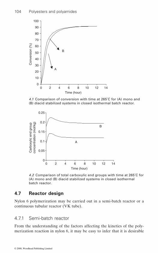
104 Polyesters and polyamides
4.7 Reactor design
Nylon 6 polymerization may be carried out in a semi-batch reactor or a continuous tubular reactor (VK tube).
4.7.1 Semi-batch reactor
From the understanding of the factors affecting the kinetics of the poly-merization reaction in nylon 6, it may be easy to infer that it is desirable
00 2 4 6 8 10 12 14
10
20
30
40
50
60
70
80
90
100
Time (hour)
Con
vers
ion
(%)
A
B
0
0.05
0.1
0.15
0.2
0.25
Time (hour)
Car
boxy
lic e
nd g
roup
co
ncen
trat
ion
(mol
/kg)
A
B
0 2 4 6 8 10 12 14
4.1 Comparison of conversion with time at 265˚C for (A) mono and (B) diacid stabilized systems in closed isothermal batch reactor.
4.2 Comparison of total carboxylic end groups with time at 265˚C for (A) mono and (B) diacid stabilized systems in closed isothermal batch reactor.
© 2008, Woodhead Publishing Limited

105
phases of the reaction. Initially, the water is kept high by applying high pressure in the reactor to facilitate ring opening reaction. Also the tem-perature of the reaction is kept high to allow rapid conversion of the monomer and build-up of the molecular weight. At the later stages, the reactor is slowly brought under low pressure and to lower temperature to favour high molecular weight and high conversion.
This scheme of polymerization may also be carried out in a semi-continuous manner by using a sequence of two semi-batch reactors. The
0
0.01
0.02
0.03
0.04
0.05
0.06
0 5 10 15
Time (hour)
Am
ino
end
grou
ps c
once
ntra
tion
(mol
/kg)
B
A
4.3 Comparison of amino end groups with time at 265˚C for (A) mono and (B) diacid stabilized systems in closed isothermal batch reactor.
Table 4.1 Comparison of polymer properties in a closed isothermal batch reactor at equilibrium (more than 16 hours) for mono and diacid based stabilizers
Properties 245°C 255°C 265°C
Monoacid Diacid Monoacid Diacid Monoacid Diacid
Conversion (%)
92.75 92.81 92.19 92.26 91.61 91.69
NAMW (g/mol)
8215.22 9126.18 8079.98 9011.94 7982.15 8937.68
[NH2] (/kg) 0.0256 0.0157 0.0268 0.0164 0.0275 0.0166[COOH] (/kg) 0.1136 0.1917 0.1148 0.1924 0.1155 0.1926
Manufacture of polyamide fibres
to alter the condition of the polymerization during the initial and the final
first reactor should have a higher temperature and higher water concentra-
© 2008, Woodhead Publishing Limited
106 Polyesters and polyamides
tion so as to achieve a rapid reaction rate and the second should have a low temperature and low water concentration in order to drive the polyconden-sation and polyaddition reactions in the forward direction to obtain high molecular weights and conversions.
4.7.2 VK tube
One of the popular reactors used in industries for the hydrolytic polymer-ization of ε-caprolactam is the VK (Vereinfacht Kontinuierliches Rohr) column reactor. VK column reactors are specially designed vertical tube reactors where internal gratings are placed in order to achieve uniform
The industrial VK tube reactor consists of several different zones, where the temperature is independently measured and controlled. A schematic
consisting of molten caprolactam, water and mono- or di-functional acid is fed under the nitrogen cover at the top of the column. The purged nitro-gen is made to escape through a water seal located at the top of the reactor.
through a heat exchanger I to a temperature of about 240˚C. Thereafter (zone III upper and lower) the melt is heated by the heating jackets and the ongoing exothermic reactions. The temperature of the reaction mass gradually increases from the top to the middle zone till a highest tempera-ture point (Th) of about 260–270˚C is reached. Thereafter, the temperature is decreased to 240–250˚C using another heat exchanger and stabilized towards the bottom of the column using the jacket temperature. The products, polymer and unreacted monomer, are removed at the bottom of the reactor.
As stated above, ring-opening and polycondensation reactions are very sensitive to the water content in the reaction mass at any point. Use of water also affects the concentration of carboxylic end groups, which helps in catalyzing all the polymerization reactions. Therefore, water concentra-
affects the end product properties.In a VK tube reactor, large quantities of water are added to initiate the
ring-opening reaction. The high temperature, at the top portion of the VK tube, readily evaporates the volatile components, water and caprolac-tam, until equilibrium is attained between the vapor and liquid phases. Evaporated caprolactam is condensed and returned back to the VK tube. Most of the added water is evaporated and removed as condensate within a short time after addition. As the reaction mass moves down the reactor towards the highest temperature point (Th), more and more water is evap-orated, and the vapor rises to the top surface of the reactor. This transfer
representation of the reactor with five zones is given in Figure 4.4(A). Feed
The reaction mixture fills the entire tube and is heated in zone I as it passes
tion profile in reaction mass along the axis of VK tube reactor significantly
heating and near flat velocity profile of reaction mass.
© 2008, Woodhead Publishing Limited

107
of water vapor helps in maintaining both the liquid and vapor phases in near equilibrium state at all places in the upper portion of the reactor. This gradual evaporation of water due to rising temperature results in a ‘lowest water content (LWC)’ point.
Since the water can vaporize and escape by rising to the surface of the melt, the water content at any point in the reactor depends on the combined action of temperature and pressure till the lowest concentration of water is reached. Higher temperature tends to reduce water content whereas higher pressure increases it. This counteraction of the two parameters results in a point in the VK tube that is the ‘lowest water content (LWC) point’.
Zone V
Zone IV
Zone III
Zone II
Zone I T1
T2
T3
T4
T5
T6
HE-II
HE-I
Water seal Condenser
B
Vaporizing plug flow zone
Non-vaporizing plug flowzone
Vaporizing turbulentzone
Water vapor + N2↑Feed (under N2) C1 + W + P1x
Raw polymer
Lowest water content
(LWC) point
A
4.4 VK tube reactor: (A) Schematic diagram of industrial VK tube reactor depicting the various heating zones (zone I – zone V), heat exchangers (HE-I and HE-II) and temperature measuring points (T1 to T6); (B) VK tube reactor model consisting of three main zones:
Manufacture of polyamide fibres
Vaporizing turbulent (top) zone, vaporizing plug flow zone and non-vaporizing plug flow zone.
© 2008, Woodhead Publishing Limited
108 Polyesters and polyamides
When the reaction mixture crosses the highest temperature point (Th), the lower temperature and higher hydrostatic pressure in the bottom portion of the reactor suppresses the vaporization of water, and the remain-ing portion of VK tube reactor is practically a non-vaporizing tubular reactor. Therefore, a VK column reactor can be considered as a reactor consisting of three main zones: at the top is a turbulent zone, which may be considered as a two-phase (gas-liquid) continuous stirred tank reactor
zones are shown in Figure 4.4(B).The VLE equation suggested by Fukumoto17 for the end of polymeriza-
tion under vacuum conditions has been found to be suitable for most of the vaporizing zone based on the comparison between the predicted and experimental values:
[ ] exp .W PT
T= −⎛⎝⎜
⎞⎠⎟
−108220
24 362 [4.13]
The prediction of polymer properties is improved by modifying the constants in the equation to account for the pressures higher than the atmospheric pressure condition inside the VK tube:
[ ] exp .W PT
T= −⎛⎝⎜
⎞⎠⎟
−108220
22 242 [4.14]
T
PT = PA + 9.81(ρwHw + ρmHp) [4.15]
where PA = atmospheric pressure = 1.013 × 10⁵ Pa.Equation 4.15 can be used for calculating concentration of water at every
point in the vaporizing zone of the reactor. From the ‘lowest water content (LWC)’ point downward (i.e., non-vaporizing zone), the summation of water in the reaction mixture, i.e. [W], and the water which is part of the polymer i.e. [P], can be considered to be constant. The concentration of water [W] at any point in non-vaporizing zone is then estimated using a mass balance equation as follows:
[W] + [P] = [Wc] + [Pc] [4.16]
where [Wc] and [Pc] are the concentrations of water and polymer at the ‘lowest water content (LWC)’ point, respectively; [P] is the concentra-tion of polymer at the point of consideration in the non-vaporization zone.
Figure 4.5 shows the temperature and pressure variation along the axis of a typical VK tube reactor. The pressure at any point inside the reactor
where P is the total pressure in Pascal defined by
(CSTR) type zone, a middle zone as a vaporizing plug flow tubular zone, and a bottom zone as a non-vaporizing plug flow tubular zone. The three
© 2008, Woodhead Publishing Limited
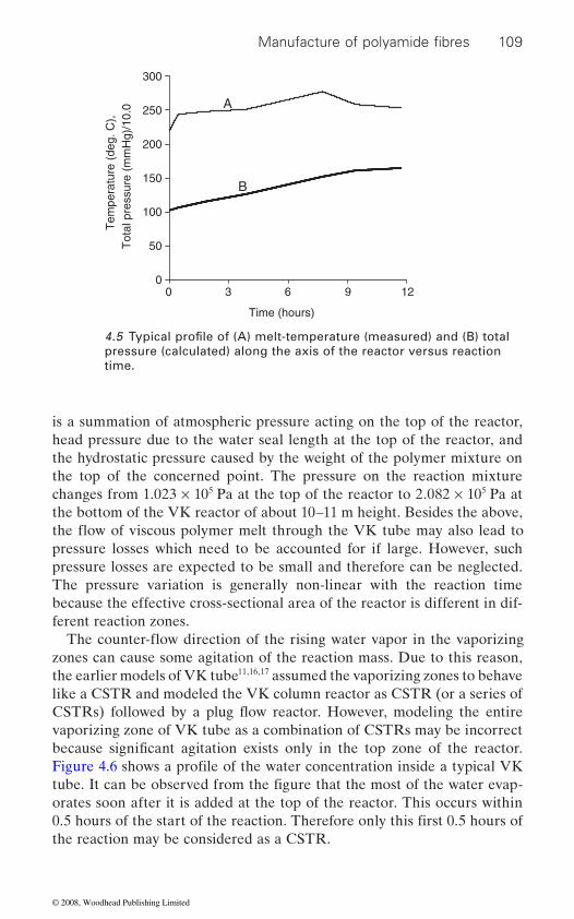
109
is a summation of atmospheric pressure acting on the top of the reactor, head pressure due to the water seal length at the top of the reactor, and the hydrostatic pressure caused by the weight of the polymer mixture on
changes from 1.023 × 10⁵ Pa at the top of the reactor to 2.082 × 10⁵ Pa at the bottom of the VK reactor of about 10–11 m height. Besides the above,
pressure losses are expected to be small and therefore can be neglected. The pressure variation is generally non-linear with the reaction time because the effective cross-sectional area of the reactor is different in dif-
zones can cause some agitation of the reaction mass. Due to this reason, the earlier models of VK tube11,16,17 assumed the vaporizing zones to behave like a CSTR and modeled the VK column reactor as CSTR (or a series of
vaporizing zone of VK tube as a combination of CSTRs may be incorrect
orates soon after it is added at the top of the reactor. This occurs within
the reaction may be considered as a CSTR.
0
50
100
150
200
250
300
30 6 9 12
Time (hours)
Tem
pera
ture
(de
g. C
),T
otal
pre
ssur
e (m
mH
g)/1
0.0 A
B
pressure (calculated) along the axis of the reactor versus reaction time.
Manufacture of polyamide fibres
4.5 Typical profile of (A) melt-temperature (measured) and (B) total
because significant agitation exists only in the top zone of the reactor.
ferent reaction zones.
Figure 4.6 shows a profile of the water concentration inside a typical VK tube. It can be observed from the figure that the most of the water evap-
0.5 hours of the start of the reaction. Therefore only this first 0.5 hours of
the top of the concerned point. The pressure on the reaction mixture
the flow of viscous polymer melt through the VK tube may also lead to pressure losses which need to be accounted for if large. However, such
The counter-flow direction of the rising water vapor in the vaporizing
CSTRs) followed by a plug flow reactor. However, modeling the entire
© 2008, Woodhead Publishing Limited
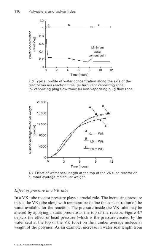
110 Polyesters and polyamides
Effect of pressure in a VK tube
In a VK tube reactor pressure plays a crucial role. The increasing pressure
water available for the reaction. The pressure inside the VK tube may be altered by applying a static pressure at the top of the reactor. Figure 4.7 depicts the effect of head pressure (which is the pressure created by the water seal at the top of the VK tube) on the number average molecular weight of the polymer. As an example, increase in water seal length from
0
0.2
0.4
0.6
0.8
1
1.2
Time (hours)
Wat
er c
once
ntra
tion
(mol
es/k
g)
a b c
Minimum water
content point
0 2 4 6 8 10 12
reactor versus reaction time: (a) turbulent vaporizing zone;
0
4000
8000
12 000
16 000
20 000
0
Time (hours)
Num
ber
aver
age
mol
ecul
ar w
eigh
t (g
/mol
e)
123 6 9
0.1 m WG
1.0 m WG
5.0 m WG
A B
C
A
B
C
4.7 Effect of water seal length at the top of the VK tube reactor on number average molecular weight.
4.6 Typical profile of water concentration along the axis of the
inside the VK tube along with temperature define the concentration of the
(b) vaporizing plug flow zone; (c) non-vaporizing plug flow zone.
© 2008, Woodhead Publishing Limited

111
more water may tend to stay inside the reactor. However, due to larger
15.5%.
parameter in optimizing reactor performance. It is important that the
initiation of the reactions and later allows removal of water to the desirable extent at the highest temperature point. Water content at the highest temperature point ultimately decides the water content at the end of the reaction, and thereby, the properties of the polymer.
The temperature at the ‘highest temperature point (Th)′, therefore, plays an important role in deciding the polymer properties. When the highest temperature is allowed to increase, the water content at the lowest water point decreases. This decrease in [W] in the non-vaporizing zone, increases the number average molecular weight as depicted in Figure 4.8. The cal-culations show that with a nominal change of the highest temperature (Th)
0
4000
8000
12 000
16 000
20 000
0 3 6 9 12
Time (hours)
Num
ber
aver
age
mol
ecul
ar w
eigh
t (g
/mol
e)
538 K548 K558 K
A
A
B
BC
C
4.8 Effect of the highest temperature (Th) on the number average molecular weight.
Manufacture of polyamide fibres
decreases by about 10.5% and amino end groups increase by about
0.1 m to 5 m, results in significant improvement in the rate of reactions as
water content at the equilibrium, number average molecular weight
Effect of temperature profile in the VK tube
temperature of the reaction mass is first increased slowly to the highest temperature point and then decreased to the final desirable temperature
The temperature profile in the VK tube reactor is another important
of equilibrium. This profile helps in first retaining the water for proper
by 10 K, the molecular weight changes significantly by about 11.5%.
© 2008, Woodhead Publishing Limited
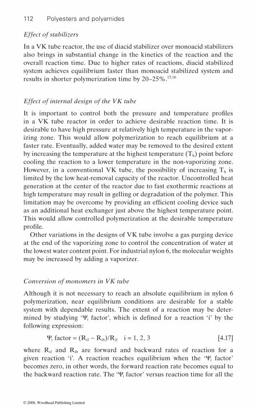
112 Polyesters and polyamides
Effect of stabilizers
In a VK tube reactor, the use of diacid stabilizer over monoacid stabilizers also brings in substantial change in the kinetics of the reaction and the overall reaction time. Due to higher rates of reactions, diacid stabilized system achieves equilibrium faster than monoacid stabilized system and results in shorter polymerization time by 20–25%.15,16
Effect of internal design of the VK tube
in a VK tube reactor in order to achieve desirable reaction time. It is desirable to have high pressure at relatively high temperature in the vapor-izing zone. This would allow polymerization to reach equilibrium at a faster rate. Eventually, added water may be removed to the desired extent by increasing the temperature at the highest temperature (Th) point before cooling the reaction to a lower temperature in the non-vaporizing zone. However, in a conventional VK tube, the possibility of increasing Th is limited by the low heat-removal capacity of the reactor. Uncontrolled heat generation at the center of the reactor due to fast exothermic reactions at high temperature may result in gelling or degradation of the polymer. This
as an additional heat exchanger just above the highest temperature point. This would allow controlled polymerization at the desirable temperature
Other variations in the designs of VK tube involve a gas purging device at the end of the vaporizing zone to control the concentration of water at the lowest water content point. For industrial nylon 6, the molecular weights may be increased by adding a vaporizer.
Conversion of monomers in VK tube
Although it is not necessary to reach an absolute equilibrium in nylon 6 polymerization, near equilibrium conditions are desirable for a stable system with dependable results. The extent of a reaction may be deter-
i
following expression:
Ψi factor = (Rif − Rib)/Rif i = 1, 2, 3 [4.17]
where Rif and Rib are forward and backward rates of reaction for a given reaction ‘i’. A reaction reaches equilibrium when the ‘Ψi factor’ becomes zero, in other words, the forward reaction rate becomes equal to the backward reaction rate. The ‘Ψi factor’ versus reaction time for all the
It is important to control both the pressure and temperature profiles
limitation may be overcome by providing an efficient cooling device such
profile.
mined by studying ‘Ψ factor’, which is defined for a reaction ‘i’ by the
© 2008, Woodhead Publishing Limited
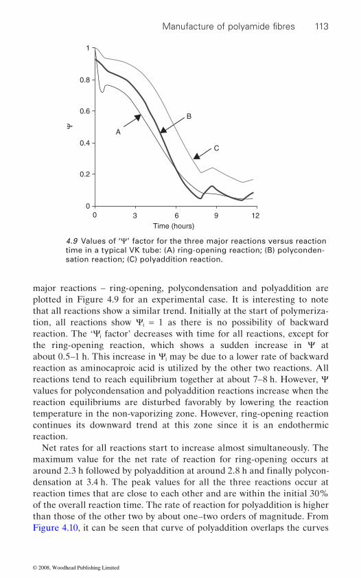
113
major reactions – ring-opening, polycondensation and polyaddition are plotted in Figure 4.9 for an experimental case. It is interesting to note that all reactions show a similar trend. Initially at the start of polymeriza-tion, all reactions show Ψi = 1 as there is no possibility of backward reaction. The ‘Ψi factor’ decreases with time for all reactions, except for the ring-opening reaction, which shows a sudden increase in Ψ at about 0.5–1 h. This increase in Ψi may be due to a lower rate of backward reaction as aminocaproic acid is utilized by the other two reactions. All reactions tend to reach equilibrium together at about 7–8 h. However, Ψ values for polycondensation and polyaddition reactions increase when the reaction equilibriums are disturbed favorably by lowering the reaction temperature in the non-vaporizing zone. However, ring-opening reaction continues its downward trend at this zone since it is an endothermic reaction.
Net rates for all reactions start to increase almost simultaneously. The maximum value for the net rate of reaction for ring-opening occurs at
densation at 3.4 h. The peak values for all the three reactions occur at reaction times that are close to each other and are within the initial 30% of the overall reaction time. The rate of reaction for polyaddition is higher than those of the other two by about one–two orders of magnitude. From Figure 4.10, it can be seen that curve of polyaddition overlaps the curves
0
0.2
0.4
0.6
0.8
1
Time (hours)
Ψ
A
B
C
0 123 6 9
4.9 Values of ‘Ψ’ factor for the three major reactions versus reaction time in a typical VK tube: (A) ring-opening reaction; (B) polyconden-sation reaction; (C) polyaddition reaction.
Manufacture of polyamide fibres
around 2.3 h followed by polyaddition at around 2.8 h and finally polycon-
© 2008, Woodhead Publishing Limited
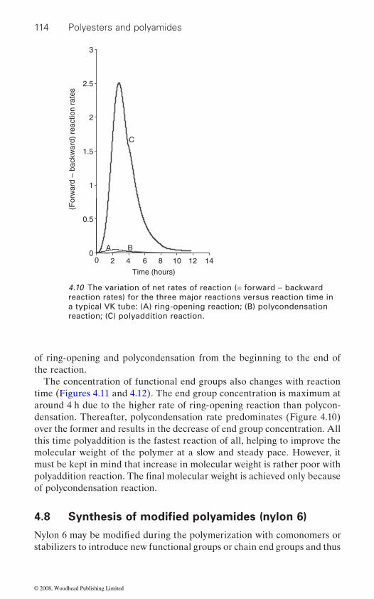
114 Polyesters and polyamides
of ring-opening and polycondensation from the beginning to the end of the reaction.
The concentration of functional end groups also changes with reaction time (Figures 4.11 and 4.12). The end group concentration is maximum at around 4 h due to the higher rate of ring-opening reaction than polycon-densation. Thereafter, polycondensation rate predominates (Figure 4.10) over the former and results in the decrease of end group concentration. All this time polyaddition is the fastest reaction of all, helping to improve the molecular weight of the polymer at a slow and steady pace. However, it must be kept in mind that increase in molecular weight is rather poor with
of polycondensation reaction.
4.8
stabilizers to introduce new functional groups or chain end groups and thus
0
0.5
1
1.5
2
2.5
3
Time (hours)
(For
war
d –
back
war
d) r
eact
ion
rate
s
A
C
B
0 8 10 12 142 4 6
4.10 The variation of net rates of reaction (= forward − backward reaction rates) for the three major reactions versus reaction time in a typical VK tube: (A) ring-opening reaction; (B) polycondensation reaction; (C) polyaddition reaction.
polyaddition reaction. The final molecular weight is achieved only because
Synthesis of modified polyamides (nylon 6)
Nylon 6 may be modified during the polymerization with comonomers or
© 2008, Woodhead Publishing Limited

115
0
0.02
0.04
0.06
0.08
0.1
0 2 4 6 8 1210
Time (hours)
Am
ino
end
grou
ps (
mol
es/k
g)
A
B
4.11 Calculated amino end group [NH2] concentration in a typical VK tube: (A) considering the effect of increasing hydrostatic pressure inside the reactor; and (B) assuming constant atmospheric pressure throughout the reactor.
0
0.02
0.04
0.06
0.08
0.1
Time (hours)
Car
boxy
l gro
ups
(mol
es/k
g)
A
B
0 12108642
4.12 Calculated carboxylic acid end group [COOH] concentration in a typical VK tube: (A) considering the effect of increasing hydrostatic pressure inside the reactor; and (B) assuming constant atmospheric pressure throughout the reactor.
Manufacture of polyamide fibres
© 2008, Woodhead Publishing Limited
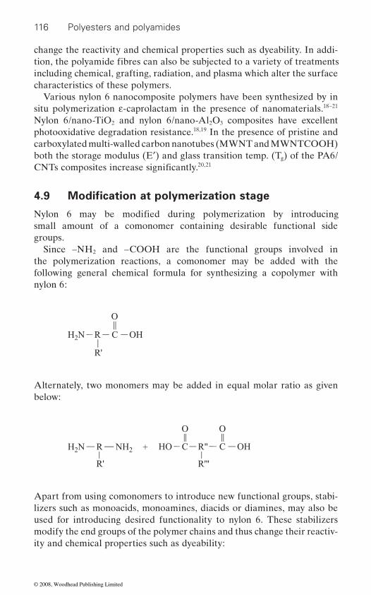
116 Polyesters and polyamides
change the reactivity and chemical properties such as dyeability. In addi-
including chemical, grafting, radiation, and plasma which alter the surface
Various nylon 6 nanocomposite polymers have been synthesized by in situ polymerization ε-caprolactam in the presence of nanomaterials.18–21 Nylon 6/nano-TiO2 and nylon 6/nano-Al2O3 composites have excellent photooxidative degradation resistance.18,19 In the presence of pristine and carboxylated multi-walled carbon nanotubes (MWNT and MWNTCOOH) both the storage modulus (E′) and glass transition temp. (Tg) of the PA6/
20,21
small amount of a comonomer containing desirable functional side groups.
Since –NH2 and –COOH are the functional groups involved in the polymerization reactions, a comonomer may be added with the following general chemical formula for synthesizing a copolymer with nylon 6:
H2N R
R'
C
O
OH
Alternately, two monomers may be added in equal molar ratio as given below:
H2N R
R'
NH2 HO C
O
R"
R'''
C
O
OH
Apart from using comonomers to introduce new functional groups, stabi-lizers such as monoacids, monoamines, diacids or diamines, may also be used for introducing desired functionality to nylon 6. These stabilizers modify the end groups of the polymer chains and thus change their reactiv-ity and chemical properties such as dyeability:
tion, the polyamide fibres can also be subjected to a variety of treatments
characteristics of these polymers.
CNTs composites increase significantly.
4.9 Modification at polymerization stage
Nylon 6 may be modified during polymerization by introducing
© 2008, Woodhead Publishing Limited
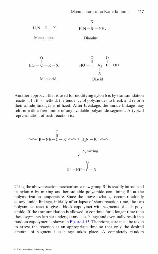
117
Another approach that is used for modifying nylon 6 is by transamidation reaction. In this method, the tendency of polyamides to break and reform their amide linkages is utilized. After breakage, the amide linkage may reform with a free amine of any available polyamide segment. A typical representation of such reaction is:
H2N R X H2N R1 NH2
X
Monoamine Diamine
HO C
O
R X HO C
O
R1 C
X
O
OH
Monoacid Diacid
H2NR'NR H C
O
RNH C
O
Δ, mixing
R"
R"
Using the above reaction mechanism, a new group R″ is readily introduced in nylon 6 by mixing another suitable polyamide containing R″ at the polymerization temperature. Since the above exchange occurs randomly at any amide linkage, initially after lapse of short reaction time, the two polyamides react to give a block copolymer with segments of each poly-amide. If the transamidation is allowed to continue for a longer time then these segments further undergo amide exchange and eventually result in a random copolymer as shown in Figure 4.13. Therefore, care must be taken to arrest the reaction at an appropriate time so that only the desired amount of segmental exchange takes place. A completely random
Manufacture of polyamide fibres
© 2008, Woodhead Publishing Limited
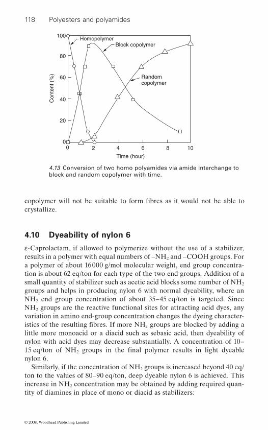
118 Polyesters and polyamides
crystallize.
4.10 Dyeability of nylon 6
ε-Caprolactam, if allowed to polymerize without the use of a stabilizer, results in a polymer with equal numbers of –NH2 and –COOH groups. For a polymer of about 16 000 g/mol molecular weight, end group concentra-tion is about 62 eq/ton for each type of the two end groups. Addition of a small quantity of stabilizer such as acetic acid blocks some number of NH2
NH2 end group concentration of about 35–45 eq/ton is targeted. Since NH2 groups are the reactive functional sites for attracting acid dyes, any
2
little more monoacid or a diacid such as sebasic acid, then dyeability of nylon with acid dyes may decrease substantially. A concentration of 10–
2
nylon 6.Similarly, if the concentration of NH2 groups is increased beyond 40 eq/
ton to the values of 80–90 eq/ton, deep dyeable nylon 6 is achieved. This increase in NH2 concentration may be obtained by adding required quan-tity of diamines in place of mono or diacid as stabilizers:
00
20
40
60 Randomcopolymer
Block copolymerHomopolymer
Con
tent
(%
)80
100
106
Time (hour)
842
4.13 Conversion of two homo polyamides via amide interchange to block and random copolymer with time.
copolymer will not be suitable to form fibres as it would not be able to
istics of the resulting fibres. If more NH groups are blocked by adding a variation in amino end-group concentration changes the dyeing character-
groups and helps in producing nylon 6 with normal dyeability, where an
15 eq/ton of NH groups in the final polymer results in light dyeable
© 2008, Woodhead Publishing Limited
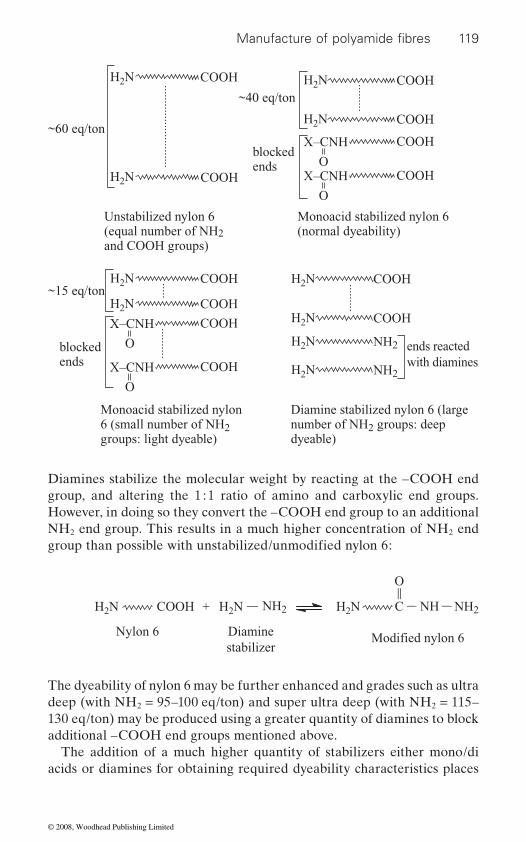
119
Diamines stabilize the molecular weight by reacting at the –COOH end group, and altering the 1 : 1 ratio of amino and carboxylic end groups. However, in doing so they convert the –COOH end group to an additional NH2 end group. This results in a much higher concentration of NH2 end
H2N
H2N
COOH
COOH
~60 eq/ton
~15 eq/ton
Unstabilized nylon 6(equal number of NH2and COOH groups)
Monoacid stabilized nylon 6(normal dyeability)
Monoacid stabilized nylon6 (small number of NH2groups: light dyeable)
Diamine stabilized nylon 6 (largenumber of NH2 groups: deepdyeable)
~40 eq/ton
blockedends
blockedends
H2N COOH
H2N COOH
H2N COOH
X–CNH
O
COOH
H2N COOH
X–CNH
O
COOH
X–CNH
O
COOH
X–CNH
O
COOH
H2N COOH
ends reactedwith diamines
H2N NH2
H2N NH2
H2N COOH
H2N H2NH2NCOOH NH2
Nylon 6 Diaminestabilizer
NH2NHC
O
The dyeability of nylon 6 may be further enhanced and grades such as ultra deep (with NH2 = 95–100 eq/ton) and super ultra deep (with NH2 = 115–130 eq/ton) may be produced using a greater quantity of diamines to block additional –COOH end groups mentioned above.
The addition of a much higher quantity of stabilizers either mono/di acids or diamines for obtaining required dyeability characteristics places
Manufacture of polyamide fibres
group than possible with unstabilized/unmodified nylon 6:
Modified nylon 6
© 2008, Woodhead Publishing Limited
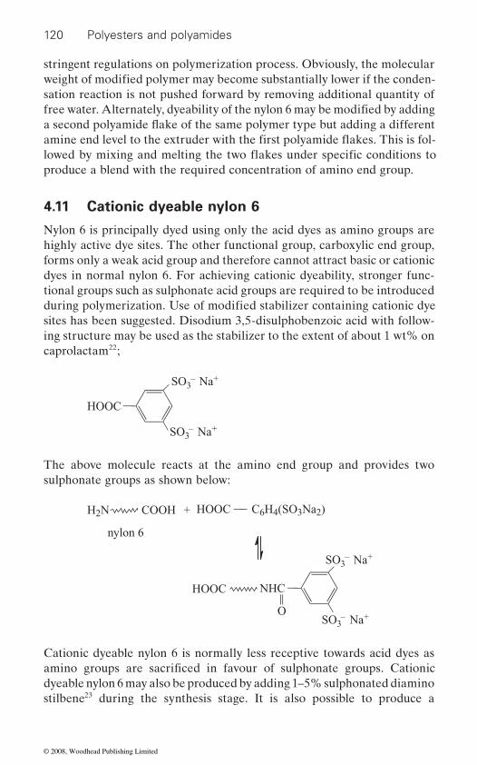
120 Polyesters and polyamides
stringent regulations on polymerization process. Obviously, the molecular
produce a blend with the required concentration of amino end group.
4.11 Cationic dyeable nylon 6
Nylon 6 is principally dyed using only the acid dyes as amino groups are highly active dye sites. The other functional group, carboxylic end group, forms only a weak acid group and therefore cannot attract basic or cationic dyes in normal nylon 6. For achieving cationic dyeability, stronger func-tional groups such as sulphonate acid groups are required to be introduced
sites has been suggested. Disodium 3,5-disulphobenzoic acid with follow-ing structure may be used as the stabilizer to the extent of about 1 wt% on caprolactam22;
HOOC
SO3– Na+
SO3– Na+
The above molecule reacts at the amino end group and provides two sulphonate groups as shown below:
NHC
OSO3
– Na+
SO3– Na+
HOOC
HOOC C6H4(SO3Na2)
nylon 6
COOH +H2N
Cationic dyeable nylon 6 is normally less receptive towards acid dyes as
dyeable nylon 6 may also be produced by adding 1–5% sulphonated diamino stilbene23 during the synthesis stage. It is also possible to produce a
weight of modified polymer may become substantially lower if the conden-
free water. Alternately, dyeability of the nylon 6 may be modified by adding
during polymerization. Use of modified stabilizer containing cationic dye
amino groups are sacrificed in favour of sulphonate groups. Cationic
a second polyamide flake of the same polymer type but adding a different
sation reaction is not pushed forward by removing additional quantity of
amine end level to the extruder with the first polyamide flakes. This is fol-lowed by mixing and melting the two flakes under specific conditions to
© 2008, Woodhead Publishing Limited

121
copolymer by adding a dicarboxylic acid monomer in addition to the above
may be improved but the improvement depends upon the concentration of comonomers used.
4.12
Nylon 6 has a moderate moisture regain of about 4–4.5% at standard con-
fabric depend on several attributes of which moisture absorbency is one of the most important properties for applications related to innerwear and sportswear. The moisture wicking property of fabrics, which contributes towards comfort value under heavy perspiration conditions, has been found
24
Moisture regain in nylon 6 is due to the presence of hydrophilic amide linkages. If hydrophilic groups per unit weight of the material could be increased, then it would lead to higher moisture content at the standard conditions. For example, nylon 4, which has a higher concentration of amide linkages in the polymer mass, shows 9.1 wt% moisture regain. Based on similar reasoning nylon 6 is made more hydrophilic by copolymerizing the polymer with copolymer segments containing hetero atoms such as ether links of poly(ethylene glycol) segments22 having the structure shown below:
H N CH CH CH O ( CH CH O ) CH CH CH NH2 2 2 2 2 2 n 2 2 2 2− − − − − − − − −
Diamine functionality is used in such comonomer segments to facilitate copolymerization with carboxylic acid end groups of nylon 6 chains. This gives block copolymer structure. Random copolymerization using small polyether molecules is not advisable as it may lead to formation of essen-
Allied Fibers.24
polyethylene glycol with about 15% PE and rest nylon 6. At standard condi-
regain of about 5.4% which increases to about 14.4% at 95% RH and 90˚F (32˚C) temperature. The moisture absorption at higher relative humidity compared well with that of cotton. The material is suitable for making active wear fabrics. Alternately, a copolymer of adipic acid-caprolactam-polyethylene glycol25 may be used as an additive in the nylon 6 matrix to impart antistatic properties even at a relative humidity below 45%.
Manufacture of polyamide fibres
diamine mentioned. The mechanical properties of the modified nylon 6
dition. This is significantly better than many synthetic polymers such as
Antistatic and hydrophilic nylon 6
polyesters, polyolefins, etc., however, still it is lower than many of the natural fibers such as cotton, silk or wool. The comfort properties of a
to be higher for more hydrophilic fibers than hydrophobic fibers.
tially amorphous material, which is unsuitable for fiber formation.Example of such a hydrophilic nylon 6 fiber is ‘Hydrofil’ developed by
This fiber is obtained from a block copolymer of nylon 6 and
tions of 65% relative humidity and 70˚F temperature, the fiber has moisture
© 2008, Woodhead Publishing Limited

122 Polyesters and polyamides
Hydrophilic segments such as polyether-amides may also be introduced
have lower crystallinity and higher moisture regain. Initially, on the physi-cal mixing, the two polyamides are in separate phases, however as time proceeds, mixers of molten polyamide undergo transamidation (amide interchange) reaction to form a block copolymer. Vivrelle polymer devel-
26 is an example of such a block copolymer.
4.13 Flame retardant nylon 6
(LOI) is around 21. However, it has self-extinguishing properties due to its extensive shrinkage and dripping behavior during combustion. When the nylon polymer is ignited, it melts and then the molten polymer drips away
either using certain phosphorous/halogen based comonomers during
spinning.Bis(2-carboxy ethyl)methyl phosphine oxide (CEMPO)27 when used as
signifi cantly affected up to a concentration of 35 mol% of CEMPO. The chemical structure of the additive is:
HO C
O
CH2 CH2 P
CH3
CH2 CH2 C OH
O
(CEMPO)
Net phosphorus content of about 1.5 wt% on polymer weight gives ad-
though effective, are no longer recommended because of the emission of
injuries.
4.14 Elements of melt spinning process of nylons
of textile materials. It has high strength (tensile, bending, torsional, or
by transamidation. The fibers produced from such composite materials
oped jointly by Sun Co. and SNIA fibers
Nylon 6 can catch fire in normal atmosphere as its Limiting Oxygen Index
dant copolymer fiber with LOI of ∼25%. The fibre properties are not
equate protection against fire. Halogen based monomers or additives,
halogen acid during burning. Vapours of these acids may cause personal
A fiber or a filament (a continuous form of fiber) is the fundamental unit
from the flame. However, if the molten polymer is not able to escape fire, then it propagates fire. The nylon 6 can be rendered flame retardant by
polymerization or by adding flame retardant additives during melt
a comonomer with hexamethylene diamine (HMDA) gives a flame retar-
© 2008, Woodhead Publishing Limited
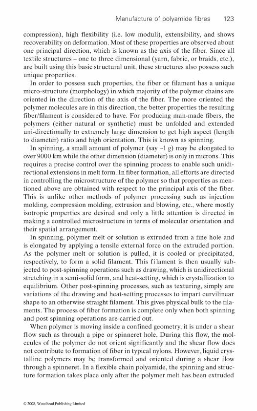
123
textile structures – one to three dimensional (yarn, fabric, or braids, etc.), are built using this basic structural unit, these structures also possess such unique properties.
micro-structure (morphology) in which majority of the polymer chains are
polymer molecules are in this direction, the better properties the resulting
uni-directionally to extremely large dimension to get high aspect (length to diameter) ratio and high orientation. This is known as spinning.
In spinning, a small amount of polymer (say ∼1 g) may be elongated to over 9000 km while the other dimension (diameter) is only in microns. This requires a precise control over the spinning process to enable such unidi-
in controlling the microstructure of the polymer so that properties as men-
This is unlike other methods of polymer processing such as injection molding, compression molding, extrusion and blowing, etc., where mostly isotropic properties are desired and only a little attention is directed in making a controlled microstructure in terms of molecular orientation and their spatial arrangement.
is elongated by applying a tensile external force on the extruded portion. As the polymer melt or solution is pulled, it is cooled or precipitated,
jected to post-spinning operations such as drawing, which is unidirectional stretching in a semi-solid form, and heat-setting, which is crystallization to equilibrium. Other post-spinning processes, such as texturing, simply are variations of the drawing and heat-setting processes to impart curvilinear
and post-spinning operations are carried out.
ture formation takes place only after the polymer melt has been extruded
Manufacture of polyamide fibres
one principal direction, which is known as the axis of the fiber. Since all recoverability on deformation. Most of these properties are observed about
In order to possess such properties, the fiber or filament has a unique
oriented in the direction of the axis of the fiber. The more oriented the
fiber/filament is considered to have. For producing man-made fi bers, the polymers (either natural or synthetic) must be unfolded and extended
rectional extensions in melt form. In fiber formation, all efforts are directed
tioned above are obtained with respect to the principal axis of the fiber.
In spinning, polymer melt or solution is extruded from a fine hole and
respectively, to form a solid filament. This fi lament is then usually sub-
shape to an otherwise straight filament. This gives physical bulk to the fila-ments. The process of fiber formation is complete only when both spinning
When polymer is moving inside a confined geometry, it is under a shear
not contribute to formation of fiber in typical nylons. However, liquid crys-
compression), high flexibility (i.e. low moduli), extensibility, and shows
flow such as through a pipe or spinneret hole. During this flow, the mol-ecules of the polymer do not orient significantly and the shear flow does
talline polymers may be transformed and oriented during a shear flow through a spinneret. In a flexible chain polyamide, the spinning and struc-
© 2008, Woodhead Publishing Limited

124
forces.
ate, or at other times, decelerates as it travels along its path. Most of the
keeps on increasing down the spinning line, resulting in unfolding of the polymer chains.
4.15 Structure development during melt spinning
of polyamides
4.15.1 Spinning at low speeds
At lower spinning speeds, stress induced crystallization is absent. There-fore, with increasing level of spinning stress, the orientation of the polymer
crystallization.
take longer to cool down. It tends to increase polymer chain relaxation, and therefore, lowers the orientation. At the same time, the crystallinity
temperature.The winding (spinning) speed is critical in deciding the level of spinning
4.14. The maximum velocity gradient is obtained somewhere in the middle of the spinning line and its maximum value increases gradually with the
function of this maximum velocity gradient value, i.e. the maximum strain rate.
The temperature of the spinning line also depends on the spinning speed.28
ment may be at a slightly lower temperature. This may be due to the enhanced cooling effect of the quench air at higher relative speed of the
chains increases. However, it does not have any significant effect on
Temperature profile changes both the orientation and crystallinity of the spinning filament. Higher temperature increases the spinning length (time spent by the spinning filament in spinning line) as the filaments
of the filament increases because it spends longer at a higher
stress inside the spinning filament. The stress in turn regulates the velocity gradient profile of the spinning line. Velocity gradient profile is the change in velocity of the filament with spinning distance. Below a critical stress level, the velocity gradient profile is a bell shaped curve as shown in Figure
increasing spinning speed. The orientation in the spun filament is the
At higher spinning speeds, the temperature of the spinning fila-
filament.
through the spinneret. As the polymer comes out from the confined chan-nels into the open atmosphere, i.e. extruded from the spinneret, its flow behavior changes. It is said to undergo elongational flow under tensile
In an elongational flow, polymer fluid flows with a uniform velocity
Polyesters and polyamides
profile perpendicular to the direction of fluid flow. However, it may acceler-
spinning is said to occur due to the elongational flow where fluid velocity
© 2008, Woodhead Publishing Limited
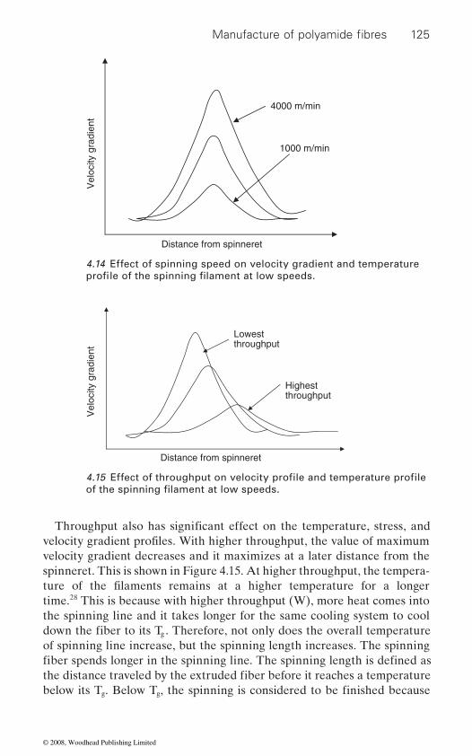
125
velocity gradient decreases and it maximizes at a later distance from the spinneret. This is shown in Figure 4.15. At higher throughput, the tempera-
time.28 This is because with higher throughput (W), more heat comes into the spinning line and it takes longer for the same cooling system to cool
g
of spinning line increase, but the spinning length increases. The spinning
g g
4000 m/min
1000 m/min
Vel
ocity
gra
dien
t
Distance from spinneret
4.14 Effect of spinning speed on velocity gradient and temperature
Lowest throughput
Highest throughput
Vel
ocity
gra
dien
t
Distance from spinneret
Manufacture of polyamide fibres
profile of the spinning filament at low speeds.
4.15 Effect of throughput on velocity profile and temperature profile
Throughput also has significant effect on the temperature, stress, and
of the spinning filament at low speeds.
velocity gradient profiles. With higher throughput, the value of maximum
ture of the filaments remains at a higher temperature for a longer
down the fiber to its T . Therefore, not only does the overall temperature
fiber spends longer in the spinning line. The spinning length is defined as the distance traveled by the extruded fiber before it reaches a temperature below its T . Below T , the spinning is considered to be finished because
© 2008, Woodhead Publishing Limited
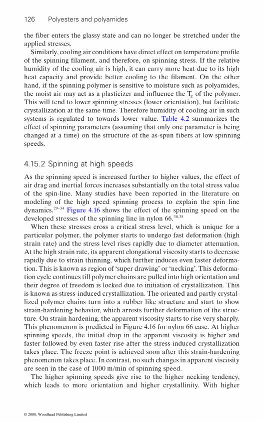
126 Polyesters and polyamides
applied stresses.
humidity of the cooling air is high, it can carry more heat due to its high
hand, if the spinning polymer is sensitive to moisture such as polyamides, g
This will tend to lower spinning stresses (lower orientation), but facilitate crystallization at the same time. Therefore humidity of cooling air in such systems is regulated to towards lower value. Table 4.2 summarizes the effect of spinning parameters (assuming that only one parameter is being
speeds.
4.15.2 Spinning at high speeds
As the spinning speed is increased further to higher values, the effect of air drag and inertial forces increases substantially on the total stress value of the spin-line. Many studies have been reported in the literature on modeling of the high speed spinning process to explain the spin line dynamics.29–34 Figure 4.16 shows the effect of the spinning speed on the developed stresses of the spinning line in nylon 66.30,35
When these stresses cross a critical stress level, which is unique for a particular polymer, the polymer starts to undergo fast deformation (high strain rate) and the stress level rises rapidly due to diameter attenuation. At the high strain rate, its apparent elongational viscosity starts to decrease rapidly due to strain thinning, which further induces even faster deforma-tion. This is known as region of ‘super drawing’ or ‘necking’. This deforma-tion cycle continues till polymer chains are pulled into high orientation and their degree of freedom is locked due to initiation of crystallization. This is known as stress-induced crystallization. The oriented and partly crystal-lized polymer chains turn into a rubber like structure and start to show strain-hardening behavior, which arrests further deformation of the struc-ture. On strain hardening, the apparent viscosity starts to rise very sharply. This phenomenon is predicted in Figure 4.16 for nylon 66 case. At higher spinning speeds, the initial drop in the apparent viscosity is higher and faster followed by even faster rise after the stress-induced crystallization takes place. The freeze point is achieved soon after this strain-hardening phenomenon takes place. In contrast, no such changes in apparent viscosity are seen in the case of 1000 m/min of spinning speed.
The higher spinning speeds give rise to the higher necking tendency, which leads to more orientation and higher crystallinity. With higher
Similarly, cooling air conditions have direct effect on temperature profile
the fiber enters the glassy state and can no longer be stretched under the
of the spinning filament, and therefore, on spinning stress. If the relative
heat capacity and provide better cooling to the filament. On the other
changed at a time) on the structure of the as-spun fibers at low spinning
the moist air may act as a plasticizer and influence the T of the polymer.
© 2008, Woodhead Publishing Limited
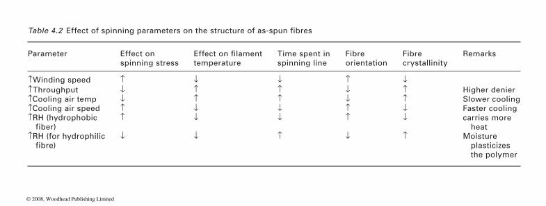
Parameter Effect on spinning stress temperature
Time spent in spinning line
Fibre orientation
Fibre crystallinity
Remarks
↑Winding speed ↑ ↓ ↓ ↑ ↓↑Throughput ↓ ↑ ↑ ↓ ↑ Higher denier↑Cooling air temp ↓ ↑ ↑ ↓ ↑ Slower cooling↑Cooling air speed ↑ ↓ ↓ ↑ ↓ Faster cooling↑RH (hydrophobic ↑ ↓ ↓ ↑ ↓ carries more
heat↑RH (for hydrophilic ↓ ↓ ↑ ↓ ↑ Moisture
plasticizes the polymer
Table 4.2 Effect of spinning parameters on the structure of as-spun fibres
Effect on filament
fiber)
fibre)
© 2008, Woodhead Publishing Limited

128 Polyesters and polyamides
spinning (winding) speed, the neck moves towards the spinneret and the change in velocity gradient is much steeper. The spinning is completed much sooner with the spinning path considerably reduced. Table 4.3 shows that the necking starts at a higher temperature at higher spinning speed for the three polymers studied.36 The polymer spends a very little time in the necking region. It is predicted that necking in nylon 66 occurs for only 8–10 cm at 5500–6500 m/min and the time spent by the polymer in the neck region at these speeds is only about 5 ms. The stress induced crystal-lization as observed above may take place only if two parameters are favorable – the induction time for crystallization (i.e. inverse of nucleation
0 20 40 60
Distance from spinneret [cm]
App
aren
t elo
ngat
iona
l vis
cosi
ty [P
a.s]
80 100 120 1401e+21e+3
1e+4
1e+5
1e+6
Ten
sile
str
ess
[Pa]
1e+7
1e+8
1e+3
1e+4
1e+5
1e+6
1e+7
freeze point
1000 m/min3500 m/min4500 m/min5500 m/min6500 m/min
4.16 Effect of take-up speed on the tensile stress and apparent
Table 4.3 Effect of spinning speed on the temperature of the spinning melt at which necking starts
Temperature (°C) at the start of the neck
Take-up velocity (m/min) 2000 3000 4000 5000 5500 6000Polymer
PP 67 114 114Nylon 12 90 102 135PET 102 123 148
elongational viscosity profiles at constant mass throughput.
© 2008, Woodhead Publishing Limited

129
rate) and the rate of crystallization (i.e. rate of crystal growth). For an effective stress-induced crystallization to occur at higher spinning speeds, the induction time for crystallization should reduce and rate of crystalliza-tion should increase for the spinning polymer. In other words, the overall rate of crystallization should increase.
In nylon 6, the POY speeds are nearly 4000–4200 m/min. Nylon 6 spun at lower speeds undergoes post-spinning crystallization on conditioning.
this phenomenon. At speeds near to 4000 m/min, nylon 6 POY is stable and essentially consists of γ crystals, which are deformable during drawing and texturing.
4.16 Spinning of nylon 6
In the spinning thread, in the absence of crystallinity, the polymer behaves
similar to spinning of PET. Due to a post-crystallization process that
level of crystallinity (50% or more) even at low wind-up speeds. The devel-oped crystals are of α type. The structure of the amorphous network
in spite of post-crystallization. The orientation of the crystalline phase that develops during post-crystallization is relatively high even at low wind-up speed. Apparently, post-crystallization starts from highly oriented amorphous segments, such as short network chains that become fully extended at low overall network deformation. Post-crystallization leads to a pronounced difference in birefringence determined on-line and after winding.
The change in birefringence on conditioning is indicative of the degree of instability the as-spun material shows (Figure 4.17).37 Upon condition-
which throws the molecular chains in the axial direction. At a speed of 2000 m/min, the extension is the maximum while it reduces slowly to a negligible value as the spinning speed increases to about 4000–4200 m/min. At this speed, the extension due to crystallization and contraction due to residual spinning stresses are well balanced. At spinning speeds higher
slowly with increasing spinning speed.38
Figure 4.18 shows a series of true stress–strain curves for undrawn yarns obtained over a wide range of wind-up speeds (500–6500 m/min), that have been shifted horizontally to coincide with the 500 m/min LOY curve.
the mastercurve is obtained. For yarns spun at wind-up speeds above
Manufacture of polyamide fibres
Therefore, it is difficult to obtain amorphous nylon 6 at any speed due to
occurs after winding and conditioning, nylon 6 fibers develop a substantial
as a single phase rubber-like network, adhering to affine deformation
developed in the spinning thread is preserved in the final wound sample
ing, the fiber spun at low spinning speeds extends owing to crystallization,
than 4200 m/min, the as-spun fiber shows net contraction, which increases
For yarns spun at wind-up speeds below 4000 m/min, a good fit with
© 2008, Woodhead Publishing Limited

130 Polyesters and polyamides
4000 m/min, on the other hand, the shifted true stress–strain curves coin-
result indicates a change in network topology with increasing wind-up speed. Based on a detailed structural investigation of nylon 6 yarns, it has been found that a transition in structure-formation mechanism occurs at wind-up speeds of about 3000 m/min, associated with the onset of spin line crystallization.
Conditioning time (min)
1780 m/min2430 m/min
3880 m/min4930 m/min6660 m/min
0.00100 101 102
0.01
0.02
0.03
0.04
Bire
frin
genc
e
4.17 Change in birefringence with conditioning time of nylon 6 with a mass throughput of 2.99 g/min.
True strain
1.00.0
2.0
4.0
Tru
e st
ress
(cN
/dte
x)
6.0
8.0
10.0
12.0
2.0
As-spun yarn 500 m/minAs-spun yarn 1500 m/minAs-spun yarn 3500 m/minAs-spun yarn 4200 m/minAs-spun yarn 6000 m/minAs-spun yarn 6500 m/min
3.0 4.0 5.0 6.0 7.0
4.18 Shifted true stress–strain curves for undrawn nylon 6 yarns obtained at different wind-up speeds, as indicated in the legend.
cide with the mastercurve only in the final strain-hardening regime. This
© 2008, Woodhead Publishing Limited
131
Below 3000 m/min, the as-spun nylon 6 is largely amorphous. It starts to develop crystallinity at above this speed. The crystals developed during spinning are primarily γ. At higher speed, more crystallization takes place.
develops additional α crystallinity (post-crystallization). As the speed of spinning is increased, content of γ crystals increases while that of α crystals decreases due to higher crystallization during spinning and limited post-crystallization. At spinning speeds of 5500 m/min or above, the sample
speed (take-up velocity) and on molecular weight.39 Although crystallinity and γ fraction both increase with increasing take-up velocity, these quanti-ties show an intricate dependence on molecular weight. The crystallinity at high take-up velocity (∼3000 m/min) decreases with increasing molecu-lar weight. At low take-up velocity (∼1000 m/min) the opposite trend is
tallinity. This crossover in the behavior of the crystallinity is attributed to the fact that increasing either take-up velocity or molecular weight increases
increases with increase in molecular weight.
up velocity and molecular weight. The initial modulus and tensile strength increase and elongation to break decrease with increase of take-up velocity or molecular weight. The true strength at fracture is also found to increase with increase of molecular weight.
4.17 Drawing and heat setting
undergo plastic deformation on application of low levels of stress. This makes them unsuitable for use in applications including that of apparel.
tion and can extend easily on application of stresses. Figure 4.20 shows a
bounded by the yield point that occurs at a low stress and extension level.
tance till all the chains are unfolded and a new improved (more elastic) network of polymer is formed. In this region, the polymer chains assume new extended conformation and do not recover back to their original state when stresses are released. This region is known as region of ‘natural draw’
Manufacture of polyamide fibres
The partially crystallized filament yarn with γ crystals, on conditioning,
has mostly γ crystals. The effect of spinning speeds on birefringence profile and temperature profile of the spinning fiber is depicted in Figure 4.19.
The structure of the as-spun filaments depends markedly on spinning
the crystallization rate but the final attainable crystallinity decreases with
observed, with the high-molecular-weight polymer having the higher crys-
increasing molecular weight. The crystallization rate of the spun filaments
The tensile properties of the filaments are strong functions of both take-
The as-spun fibers have poor elasticity (inability to recover) and they
The polymer chains in the as-spun fibres are in partially folded conforma-
stress–strain plot of an as-spun fiber. The elastic region is small and is
Following the yield point, the fiber shows deformation without much resis-
and the extensibility is called ‘natural draw ratio (NDR)’ of the fibers. This
© 2008, Woodhead Publishing Limited
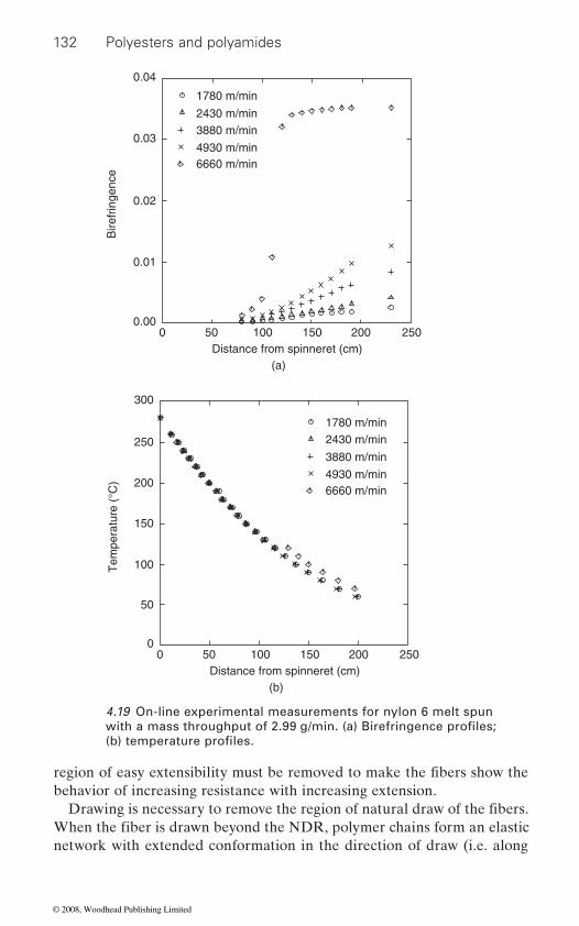
132 Polyesters and polyamides
behavior of increasing resistance with increasing extension.
network with extended conformation in the direction of draw (i.e. along
Distance from spinneret (cm)(a)
00.00
0.01
Bire
frin
genc
e
0.02
0.03
0.04
1780 m/min
2430 m/min3880 m/min
4930 m/min6660 m/min
50 100 150 200 250
1780 m/min
2430 m/min
3880 m/min
4930 m/min6660 m/min
Distance from spinneret (cm)(b)
00
50
100Tem
pera
ture
(°C
)
150
250
200
300
50 100 150 200 250
4.19 On-line experimental measurements for nylon 6 melt spun with a mass throughput of 2.99 g/min. (a) Birefringence profiles; (b) temperature profiles.
region of easy extensibility must be removed to make the fibers show the
Drawing is necessary to remove the region of natural draw of the fibers. When the fiber is drawn beyond the NDR, polymer chains form an elastic
© 2008, Woodhead Publishing Limited
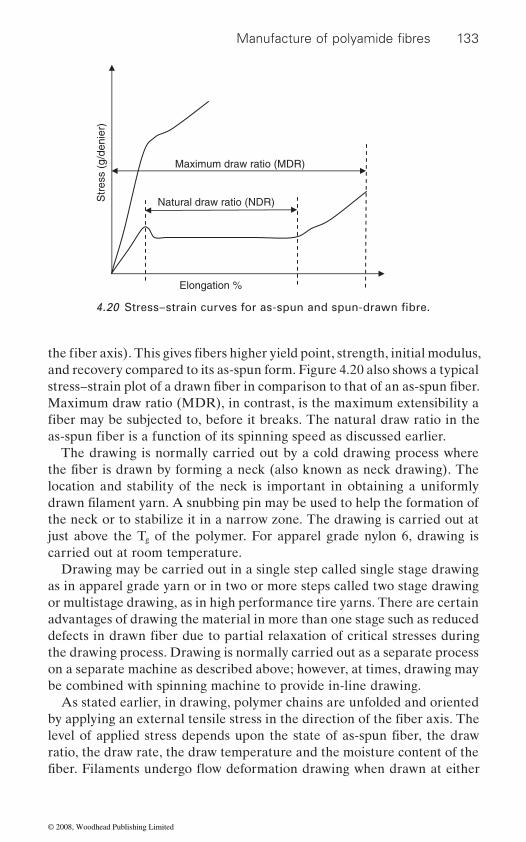
133
and recovery compared to its as-spun form. Figure 4.20 also shows a typical
Maximum draw ratio (MDR), in contrast, is the maximum extensibility a
The drawing is normally carried out by a cold drawing process where
location and stability of the neck is important in obtaining a uniformly
the neck or to stabilize it in a narrow zone. The drawing is carried out at just above the Tg of the polymer. For apparel grade nylon 6, drawing is carried out at room temperature.
Drawing may be carried out in a single step called single stage drawing as in apparel grade yarn or in two or more steps called two stage drawing or multistage drawing, as in high performance tire yarns. There are certain advantages of drawing the material in more than one stage such as reduced
the drawing process. Drawing is normally carried out as a separate process on a separate machine as described above; however, at times, drawing may be combined with spinning machine to provide in-line drawing.
As stated earlier, in drawing, polymer chains are unfolded and oriented
ratio, the draw rate, the draw temperature and the moisture content of the
Natural draw ratio (NDR)
Maximum draw ratio (MDR)
Str
ess
(g/d
enie
r)
Elongation %
Manufacture of polyamide fibres
4.20 Stress–strain curves for as-spun and spun-drawn fibre.
the fiber axis). This gives fibers higher yield point, strength, initial modulus,
stress–strain plot of a drawn fiber in comparison to that of an as-spun fiber.
fiber may be subjected to, before it breaks. The natural draw ratio in the as-spun fiber is a function of its spinning speed as discussed earlier.
the fiber is drawn by forming a neck (also known as neck drawing). The
drawn filament yarn. A snubbing pin may be used to help the formation of
defects in drawn fiber due to partial relaxation of critical stresses during
by applying an external tensile stress in the direction of the fiber axis. The level of applied stress depends upon the state of as-spun fiber, the draw
fiber. Filaments undergo flow deformation drawing when drawn at either
© 2008, Woodhead Publishing Limited

134 Polyesters and polyamides
ductile failure when they are drawn at a high strain rate or at a low tem-
4.18 Mechanism of drawing in polyamides
The two theoretical schemes used for prediction of orientation from
placed in direct proportion to the macroscopic deformation. As a result, the rotatable ‘random links’ comprising the network chains will gradually
tion, on the other hand, the structural elements undergoing deformation are assumed to have no extensibility themselves but are rigid entities simply rotating in proportion to the macroscopic deformation of the sample.
The undrawn nylon 6 yarns are always partially crystalline, irrespective of the wind-up speed. The amorphous and crystalline orientation factors are plotted as a function of draw ratio in Figure 4.21.40 The crystalline orientation factor fc initially increases sharply, leveling off at higher draw ratio whereas fa initially rises very slowly becoming important only at the highest draw ratios. It appears that the crystalline phase responds to draw
40 This result can be understood in
Draw ratio
1.00.0
0.2
0.4
0.6
Orie
ntat
ion
fact
or
0.8
1.0
2.0
fc (WAXS)fc (NMR)fa (NMR)
3.0 4.0 5.0
4.21 Crystalline and amorphous orientation factors fc and fa of drawn yarns as a function of draw ratio determined from WAXS and solid-state NMR measurements.
a very low strain rate or at a high temperature. The filaments undergo a
perature. Therefore, in order to draw the filament in neck deformation, the
network deformation are (a) the affine and (b) pseudo-affine deformation
rate and temperature of drawing must be optimized for a given fiber.
mechanisms. In the affine scheme, network junctions are thought to be
adopt a more and more oriented configuration. In pseudo-affine deforma-
ratio in a pseudo-affine fashion whereas the amorphous phase follows a rubber-like, affine deformation.
connected by flexible chains. Upon stretching, the network points are dis-
© 2008, Woodhead Publishing Limited

135
network. Since the amorphous orientation is comparatively low at the maximum draw ratios, it is reasonable to assume that further drawing is hampered by the crystalline phase. This behavior of semicrystalline nylon is in contrast to drawing of as-spun PET, which is mostly amorphous and
The crystalline structure of nylon 6 changes with the draw ratio at a given strain and temperature. This has been studied by measuring equatorial crystallinity index (ECI) with strain percentage as shown in Figure 4.22.41 This behaviour of ECI on strain percentage may be separated into three distinct regimes: regime I (0–15% strain); regime II (15–100% strain); and regime III (100% strain and greater). In regime I, the gamma ECI decreases while both the alpha and total ECI increase. The majority of this increase
alpha ECI is always greater in magnitude than the decrease of the gamma ECI in this region; so the net result, the total ECI, is increasing as well. In the second regime the a-phase, g-phase, and total ECI are all decreasing. Finally, in the third regime the α-phase ECI remains constant and the γ-phase ECI drops to zero, thus forcing the total ECI to remain constant as well.
Since the increase of the a-phase ECI is greater than the decrease of the
due to conversion of the amorphous phase as opposed to the γ to α conver-sion. The decrease in the γ-phase ECI could be a result of two competing effects. Either the γ-phase is being converted to the α-phase, as discussed above, or the γ-phase crystals are being destroyed during the drawing process.
4.19 Heat setting
Annealing tends to increase the amount of α-phase mainly at the expense of the amorphous contribution. The nature of the α-phases changes; it becomes monoclinic and increases in perfection as the severity of anneal-ing increases.42 At low spin draw ratios there is very little γ-phase initially, but there is pseudohexagonal α-phase present (a*). As noted by Illers5 and others43,44,45
dohexagonal α to the monoclinic α form. In the high spin draw ratio samples containing appreciable γ-phase, there is a decrease in the relative amount of γ-phase on annealing, but γ-phase is not eliminated by the most severe annealing treatment investigated (2 h in boiling aqueous 20% formic acid solution). The low-SDR samples anneal more readily to the α-phase.42
Manufacture of polyamide fibres
qualitative terms since crystallites act as rigid entities in the fiber structure
follows the affine deformation mechanism.
occurs after the first extension, from 0 to 5% strain. The increase of the
γ-phase ECI, a significant percentage of the α-phase increase must be
, there is no difficulty in transforming this paracrystalline pseu-
whereas the amorphous phase consists of flexible chains, acting as a rubber
© 2008, Woodhead Publishing Limited

136 Polyesters and polyamides
Strain (%)0
15
Equ
ator
ial c
ryst
allin
ity in
dex
(%)
20
25
30
40
35
50 100
α-phase
γ-phase
200
(a)
150
50 mpm100 mpm200 mpm300 mpm
Strain (%)
00
Equ
ator
ial c
ryst
allin
ity in
dex
(%)
Equ
ator
ial c
ryst
allin
ity in
dex
(%)
5
10
15
25
20
50 100 200
(b)
150
Strain (%)
Total
00
20
30
40
50
60
50 100 200
(c)
150
50 mpm100 mpm200 mpm300 mpm
50 mpm100 mpm200 mpm300 mpm
4.22 The equatorial crystallinity index (ECI) as a function of take-up speed and strain percentage of the: (a) α-phase; (b) γ-phase; and (c) total (α + γ); MPM = metres per minute.
© 2008, Woodhead Publishing Limited
137
4.20 References
head Publishing Limited, Cambridge, 2005. 2. reimschuessel h. k., ‘Nylon 6 Polymerization: Chemistry and Mechanism’,
J Polym Sci Macromol Rev, 1977, 12, 65.
Polyamides, Interscience Publishers, New York, 1981, p. 331. 4. sweeny w. and zimmerman j., in Encyclopedia of Polymer Science and Tech-
nology, Volume 10, (eds) N. M. Bikales and J. Conrad, John Wiley & Sons, New York, 1969.
5. fl ory p. j., ‘Fundamental principles of condensation polymerization’, J Am Chem Soc, 1946, 39, 137–97.
6. steppan d. d., doherty m. f. and malone m. f., ‘A kinetic and equilibrium model for nylon 6,6 polymerization’, J Appl Polym Sci, 1987, 33, 2333–44.
7. sum w. m., (du pont), ‘Polymerization of polyamide-forming reactants with
9. gupta v. b. and kothari v. k., Manufactured Fibre Technology, Chapman and Hall, London, 1997.
10. agrawal a. k., devika k. and manabe t., ‘Simulation of hydrolytic polymeriza-tion of nylon-6 in industrial reactors: part i. mono-acid-stabilized systems in VK tube reactors’, Industrial & Engineering Chemistry Research, 2001, 40(12), 2563–2572.
11. gupta s. k., naik c. d., tandon p. and kumar a., ‘Simulation of molecular weight distribution and cyclic oligomer formation in the polymerization of nylon 6’, J Appl Polym Sci, 1981, 26(7), 2153–2163.
12. laun h. m., ‘Viscoelastic behavior of nylon-6 melts’, Rheol. Acta, 1979, 18, 478.
13. srivastava, d. and gupta, s. k., Optimization of a tubular nylon-6 reactor with radial gradients. Polym. Eng. Sci. 1991, 31(8), 596–606.
14. gupta, s. k. and tjahjadi, m., Simulation of an industrial nylon-6 tubular reactor, J. Appl. Polym. Sci. 1987, 33, 933–954.
15. agrawal, a. k., devika k. and manabe, t., ‘Simulation of hydrolytic polymerisa-tion of nylon-6 in industrial reactors: part 1. Monoacid stabilized systems in VK tube reactors’, Ind. Eng. Chem. Res. 2001, 40, 2563–2572.
16. agrawal, a. k., gupta, deepak k. and devika k, ‘Effect of diacid stabilizers on kinetics of hydrolytic polymerization of ε-caprolactam in industrial reactors’, J. Applied Polymer Science, (2007), 104(4), 2065–2075.
17. fukumoto, o. Equilibria between Polycapramide and Water. I. J. Polym. Sci. 1956, 22, 263–270.
18. b. r. rao and k. v. datye, Textile Chemist & Colourist, 28(10), (1996) 17–24.
19. datye k. v., Colourage, February (1994) 7–12.20. karmakar s. r., bhattacharyya k. and deb t., Colourage Annual, (1996)
47–58.21. vaidya a. a., narrasimhan k. v. and ahuja g., Man made Textiles in India,
(1986), 29(5), 213–223, 250.
Manufacture of polyamide fibres
1. mcintyre j. e., Synthetic Fibres: Nylon, Polyester, Acrylic, Polyolefin, Wood-
hypophosphite catalysts’, US Patent Office, Pat. No. 3,173,898, 1965.
3. zimmerman j., in Encyclopedia of Polymer Science and Technology Vol. 11:
8. schlack p., (i. g. farben), US Patent Office, Pat. No. 2,241,321, 1941.
© 2008, Woodhead Publishing Limited
138 Polyesters and polyamides
22. gupta v. b. and kothari v. k. (Eds) Manufactured Fibre Technology, Chapman & Hall, London, 1st Edn, 1997, Chap 14.
23. barashkov n. n., vysotskii v. n. and grigor’y i. n., Khim. Volokna, (1987), 29(6) 38–39.
24. peters j., ATI, October (1987) 46–47.
261–263, Chem. Abstr., 98(1983), No. (6 35941).26. cazzaro g. and thompson r., Textile Asia, December (1989), 80–86.27. ridgway j. s., J. Appl. Polym. Sci., (1988) 35(1), 215–227.28. kase, s. and matsuo, t. Journal of Applied Polymer Science, v 11 (1967) 251.29. jeffer s. denton, john a. cucul and paul a. Tucker, ‘Computer simulation of
high-speed spinning of poly(ethyleneterephthalate)’, Journal of Applied Polymer Science, 1995, 57, 939–951.
30. antonios k. doufas, anthony j. mchugh and chester miller, ‘Simulation of
ment and predictions’, J. Non-Newtonian Fluid Mech., 2000, 92, 27–66.31. jung s. kim and sang y. kim, ‘Necking behavior in high-speed melt spinning
of poly(ethylene terephthalate)’, Journal of Applied Polymer Science, 2000, 76, 446–456.
spinning’, Composites: Part A, Applied Science and Manufacturing, 2001, 32, 1059–66.
33. antonios k. doufas, anthony j. mchugh, chester miller and aravind
Part II. Quantitative comparisons with industrial spinline data’, J. Non-New-tonian Fluid Mech., 2000, 92, 81–103.
34. rajen m. patel, jayendra h. bheda and joseph e. spruiell, ‘Dynamics and structure development during high-speed melt spinning of nylon 6. II. Mathematical modeling’, Journal of Applied Polymer Science, 1991, 42, 1671–1682.
35. takeshi kikutani, yutaka kawahara, naoki ogawa and norimasa okui, ‘Cap-turing of real image of neck-like deformation from high-speed melt spinning line’, Sen-I Gakkaishi, 1994, 50(12), 561–566.
36. jiro shimizu and takeshi kikutani, ‘Dynamics and evolution of structure in
37. j. h. bheda and j. e. spruiell, Journal of Applied Polymer Science, Vol. 39, 447–463 (1990).
tured Fibre Technology (Eds) V. B. Gupta and V. K. Kothari, Chapman & Hall: London, 1997, 318–356.
39. koyama k., suryadevara j. and spuriell j. e., Journal of Applied Polymer Science, Vol. 31, 2203–2229 (1986).
40. penning j. p., van ruiten j., brouwer r. and gabriëlse w., ‘Orientation and
5869–5876.41. samon j. m., schultz j. m. and hsiao b. s., ‘Study of the cold drawing of nylon
niques’, Polymer 41 (2000) 2169–2182.
25. garvanska r., mincheva i. and dimov k., Khim. Ind. (Sofia) (1982) No. 6,
fibre extrusion’, Journal of Applied Polymer Science, 202, 83, 539–558.
38. deopura b. l. and mukherjee a. k., ‘Nylon 6 and nylon 66 fibers’, in Manufac-
structure development in melt-spun Nylon-6 fibres’, Polymer 44 (2003)
6 fiber by in-situ simultaneous small- and wide-angle X-ray scattering tech-
melt spinning including flow-induced crystallization Part I. Model develop-
32. mchugh a. j. and doufas a. k., ‘Modeling flow-induced crystallization in fibre
immaneni, ‘Simulation of melt spinning including flow-induced crystallization
© 2008, Woodhead Publishing Limited
139
42. gianchandani j., spruiell j. e. and clark e. s., Journal of Applied Polymer Science, Vol. 27, 3527–3551 (1982).
43. illers h. k., haberkorn h. and sinak p., Makromol. Chem., 158, 285 (1972).44. stepaniak r. f., garton a., carlsson d. j. and wiles d. m., J. Polym. Sci.,
Polym. Phyi. Ed., 17, 987 (1979); also J. Appl. Polym. Sci., 23, 1747 (1979).45. bankar v. g., spruiell j. e., and white j. l., J. Appl. Polym. Sci., 21, 2341
(1977).
Manufacture of polyamide fibres
© 2008, Woodhead Publishing Limited
5
D. W. FA R R I NGTON, Consultant, UK, J. LU N T, S . DAV I ES, NatureWorks LLC, USA
and R. S . BLAC K BU R N, University of Leeds, UK
5.1 Introduction
In a world that is becoming increasingly sensitive to the need to protect our environment, the ability to manufacture products from sustainable resources and which are fully compostable at the end of their useful life, is an exciting and attractive proposition. Poly(lactic acid) (PLA) is a linear aliphatic thermoplastic polyester derived from 100% renewable sources such as corn, and the polymer is compostable.1,2
were limited to biomedical applications such as sutures3 and drug delivery systems4 due to availability and cost of manufacture. Over the past few years, NatureWorks LLC has developed large-scale operations for the eco-
tions. It is important that PLA is used broadly in textile applications for
applications, mainly poly(ethyleneterephthalate) (PET), account for over 40% of world textile consumption (second only to cotton) and their use is constantly increasing. Production of such polyesters consumes fossil fuel
cycle potentially reduces the Earth’s carbon dioxide level. The recognition
This chapter will review the chemistry of PLA and will discuss the com-
properties that make it attractive to the commercial sectors into which it is being developed today. Recognizing that this is very much a new polymer with its own characteristics and processing requirements, the current status
140
Poly(lactic acid) fibers (PLA)
nomic production of PLA polymer used for packaging and fiber applica-
However, most initial uses
several reasons. Polyesters currently used for apparel and related fiber
resources and disposal of the polymer adds to landfill sites as they are non-biodegradable and are not easily recycled. In contrast, PLA fiber is
by the FTC in the USA and the EU commission that PLA fibers are a
ity of this new approach to producing performance melt-spinnable fibers.
derived from annually renewable crops, it is 100% compostable and its life
mercial manufacturing process that confirms its position as a viable ma-terial for many applications in both the fibers and the plastics industries.
completely new generic class of synthetic fibers further reinforces the valid-
It will review the various properties of the polymer and consider the fiber
© 2008, Woodhead Publishing Limited
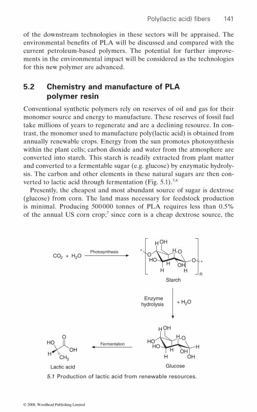
141
of the downstream technologies in these sectors will be appraised. The
current petroleum-based polymers. The potential for further improve-ments in the environmental impact will be considered as the technologies for this new polymer are advanced.
5.2 Chemistry and manufacture of PLA
polymer resin
Conventional synthetic polymers rely on reserves of oil and gas for their monomer source and energy to manufacture. These reserves of fossil fuel take millions of years to regenerate and are a declining resource. In con-trast, the monomer used to manufacture poly(lactic acid) is obtained from annually renewable crops. Energy from the sun promotes photosynthesis within the plant cells; carbon dioxide and water from the atmosphere are converted into starch. This starch is readily extracted from plant matter and converted to a fermentable sugar (e.g. glucose) by enzymatic hydroly-sis. The carbon and other elements in these natural sugars are then con-verted to lactic acid through fermentation (Fig. 5.1).5,6
Presently, the cheapest and most abundant source of sugar is dextrose (glucose) from corn. The land mass necessary for feedstock production is minimal. Producing 500 000 tonnes of PLA requires less than 0.5% of the annual US corn crop;7 since corn is a cheap dextrose source, the
Photosynthesis
Fermentation
+ H2O
Starch
Enzymehydrolysis
CO2 + H2O
GlucoseLactic acid
OHHO
H
O
CH3
HO
OH
O
HH
HHO
H
OHH
OH
OH
O
H
HO
n
*
* OH
OH
O
HH
H
5.1 Production of lactic acid from renewable resources.
Poly(lactic acid) fibers
environmental benefits of PLA will be discussed and compared with the
© 2008, Woodhead Publishing Limited

142 Polyesters and polyamides
current feedstock supply is more than adequate to meet foreseeable demand. Furthermore, there are many other alternatives for the starch or sugar supply. As fermentation techniques improve, as PLA production improves, and if PLA production extends to other geographies, it is quite likely that other materials such as grass and even biomass could be used; there is no need to be reliant on food crops. PLA takes advantage of a biological system to do chemistry that traditional chemical techniques cannot.
5.2.1 Production of PLA
The polymer is formed either by (1) direct condensation of lactic acid or (2) via the cyclic intermediate dimer (lactide), through a ring-opening process (Fig. 5.2).2
Polycondensation of lactic acid
This process involves the removal of water by condensation and the use of solvent under high vacuum and temperature; the approach was originally used by Carothers who discovered PLA in 1932. With this route, only low to intermediate molecular weight polymers can be produced, mainly due
of this route are the relatively large reactor required, the need for evapora-tion, recovery of the solvent and increased color and racemization. Most work has focused on the ring-opening polymerization, although Mitsui Toatsu Chemicals have patented an azeotropic distillation using a high
process to obtain high molecular weight PLA.
(1)
(2)
H2O
H2O
Lactide
)dica citcal(yloPdica citcaL
OOH
HOH
CH3 HCH3
OO
**
HO
H
H3CO
O
O
CH3
5.2 Polymerization routes to poly(lactic acid).
to the difficulties of removing water and impurities. Other disadvantages
boiling solvent to drive the removal of water in the direct esterification
© 2008, Woodhead Publishing Limited

143
Ring-opening polymerization
This method is a better way to produce a high molecular weight polymer, and has now been adapted commercially due to advances in the fermenta-
tion costs. The fermentation of sugar produces chiral lactic acid inexpensively in high yield. Chiral molecules exist as ‘mirror images’ or stereoisomers; lactic acid can exist as the l- or d-stereoisomer (Fig. 5.3). Chemically syn-thesized lactic acid gives the racemic mixture (50% d and 50% l), however,
major stereoisomer; fermentation derived lactic acid consists of 99.5% of the l-isomer and 0.5% of the d-isomer.
The process is based on removing water under milder conditions, without solvent, to produce a cyclic intermediate dimer, referred to as lactide. This
polymerization of the dimer is accomplished under heat, again without the need for solvent. By controlling the purity of the dimer, it is possible to produce a wide range of molecular weights. Production of the cyclic lactide dimer results in three potential forms: the d,d-lactide (called d-lactide), l,l-lactide (called l-lactide) and l,d- or d,l-lactide (called meso-lactide) (Fig. 5.4). Meso-lactide has different properties from d- and l-lactide; d- and l-lactide are optically active, meso- is not. Before polymerization, the lactide stream is split into a low d-lactide stream and a high d-/meso-lactide stream. Ring-opening polymerization of the optically active types of lactide can yield a ‘family’ of polymers with a range of molecular weights by varying the amount and the sequence of d-lactide in the polymer back-bone. Polymers with high l-lactide levels can be used to produce crystalline
L-lactic acid D-lactic acid
OHHO
O
H3CH
OHHO
O
CH3H
5.3 The stereoisomers of lactic acid.
Meso-lactide D-lactideL-lactide
CH3
H3CO
O
O
O
H3C
CH3
O
O
O
O
O
O
CH3
H3CO
O
5.4 Dimeric lactic isomers.
Poly(lactic acid) fibers
tion of corn dextrose which have significantly reduced lactic acid produc-
fermentation is very specific, allowing the production of essentially one
monomer is readily purified under vacuum distillation. Ring-opening
© 2008, Woodhead Publishing Limited

144 Polyesters and polyamides
polymers while the higher d-lactide materials (>15%) are more amor-phous. By controlling the purity of the lactide it is possible to produce a wide range of molecular weights and by varying the amount and sequence of d-lactic units in the polymer backbone, the product properties can be changed. These changes impact melt behavior, thermal properties, barrier properties, and ductility.8
Based on this lactide intermediate method, NatureWorks LLC has devel-oped a patented, low cost continuous process for the production of lactic acid-based polymers.9 The process combines the substantial environmental
viable compostable commodity polymer made from annually renewable resources. The process starts with a continuous condensation reaction of aqueous lactic acid to produce low molecular weight PLA pre-polymer (Fig. 5.5).
Next, the pre-polymer is converted into a mixture of lactide stereoisomers using tin catalysis to enhance the rate and selectivity of the intramolecular cyclization reaction. The molten lactide mixture is then
using a tin-catalyzed, ring-opening lactide polymerization in the melt, completely eliminating the use of costly and environmentally unfriendly solvents. After the polymerization is complete, any remaining monomer is removed under vacuum and recycled to the beginning of the process (Fig. 5.6).
O
O
O
O
Depolymerization
Ring-openingpolymerization
Condensation–H2O
PrepolymerMn ~ 5000
High molecular weight PLALactic acid
OHHO
O
OHO OH
nO
O
OO
HO OH
nO
O
O
O
O
5.5 Production of high molecular weight PLA via prepolymer and lactide.
and economic benefits of synthesizing both lactide and PLA in the melt rather than in solution and, for the first time, provides a commercially
purified by vacuum distillation. Finally, PLA high polymer is produced
© 2008, Woodhead Publishing Limited
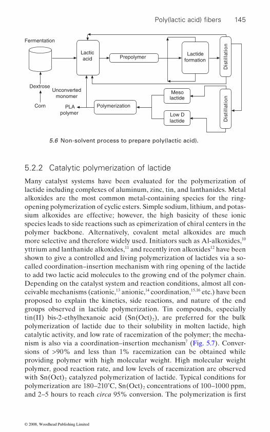
Poly(lactic acid) fi bers 145
5.2.2 Catalytic polymerization of lactide
Many catalyst systems have been evaluated for the polymerization of lactide including complexes of aluminum, zinc, tin, and lanthanides. Metal alkoxides are the most common metal-containing species for the ring-opening polymerization of cyclic esters. Simple sodium, lithium, and potas-sium alkoxides are effective; however, the high basicity of these ionic species leads to side reactions such as epimerization of chiral centers in the polymer backbone. Alternatively, covalent metal alkoxides are much more selective and therefore widely used. Initiators such as Al-alkoxides,10 yttrium and lanthanide alkoxides,11 and recently iron alkoxides12 have been shown to give a controlled and living polymerization of lactides via a so-called coordination–insertion mechanism with ring opening of the lactide to add two lactic acid molecules to the growing end of the polymer chain. Depending on the catalyst system and reaction conditions, almost all con-ceivable mechanisms (cationic,13 anionic,14 coordination,15,16 etc.) have been proposed to explain the kinetics, side reactions, and nature of the end groups observed in lactide polymerization. Tin compounds, especially tin(II) bis-2-ethylhexanoic acid (Sn(Oct)2), are preferred for the bulk polymerization of lactide due to their solubility in molten lactide, high catalytic activity, and low rate of racemization of the polymer; the mecha-nism is also via a coordination–insertion mechanism7 (Fig. 5.7). Conver-sions of >90% and less than 1% racemization can be obtained while providing polymer with high molecular weight. High molecular weight polymer, good reaction rate, and low levels of racemization are observed with Sn(Oct)2 catalyzed polymerization of lactide. Typical conditions for polymerization are 180–210˚C, Sn(Oct)2 concentrations of 100–1000 ppm,
Fermentation
Lacticacid
Dextrose
Corn
Unconvertedmonomer
PLApolymer
Prepolymer
Polymerization
Lactideformation
noitallitsi
Dn
oi tallitsiD
Mesolactide
Low Dlactide
5.6 Non-solvent process to prepare poly(lactic acid).
and 2–5 hours to reach circa 95% conversion. The polymerization is first
© 2008, Woodhead Publishing Limited
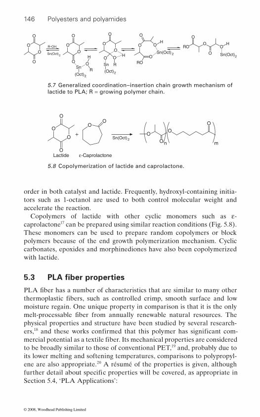
146 Polyesters and polyamides
order in both catalyst and lactide. Frequently, hydroxyl-containing initia-tors such as 1-octanol are used to both control molecular weight and accelerate the reaction.
Copolymers of lactide with other cyclic monomers such as ε-caprolactone17 can be prepared using similar reaction conditions (Fig. 5.8). These monomers can be used to prepare random copolymers or block polymers because of the end growth polymerization mechanism. Cyclic
with lactide.
moisture regain. One unique property in comparison is that it is the only
physical properties and structure have been studied by several research-ers,18
to be broadly similar to those of conventional PET,19 and, probably due to its lower melting and softening temperatures, comparisons to polypropyl-ene are also appropriate.20 A résumé of the properties is given, although
Section 5.4, ‘PLA Applications’:
O
O
O
O
Sn(Oct)2
R–OH O
O
O
O O
H
RSn
(Oct)2
O
H
Sn R
(Oct)2
O
O O
O
O
O
O
OH
RO
Sn(Oct)2
RO
O
O
O
O
Sn(Oct)2
H
5.7 Generalized coordination–insertion chain growth mechanism of lactide to PLA; R = growing polymer chain.
O
O
O
O
OO
O
O
O
n m
O
Sn(Oct)2
Lactide ε-Caprolactone
5.8 Copolymerization of lactide and caprolactone.
5.3 PLA fiber properties
PLA fiber has a number of characteristics that are similar to many other
carbonates, epoxides and morphinediones have also been copolymerized
thermoplastic fibers, such as controlled crimp, smooth surface and low
melt-processable fiber from annually renewable natural resources. The
and these works confirmed that this polymer has significant com-mercial potential as a textile fiber. Its mechanical properties are considered
further detail about specific properties will be covered, as appropriate in
© 2008, Woodhead Publishing Limited
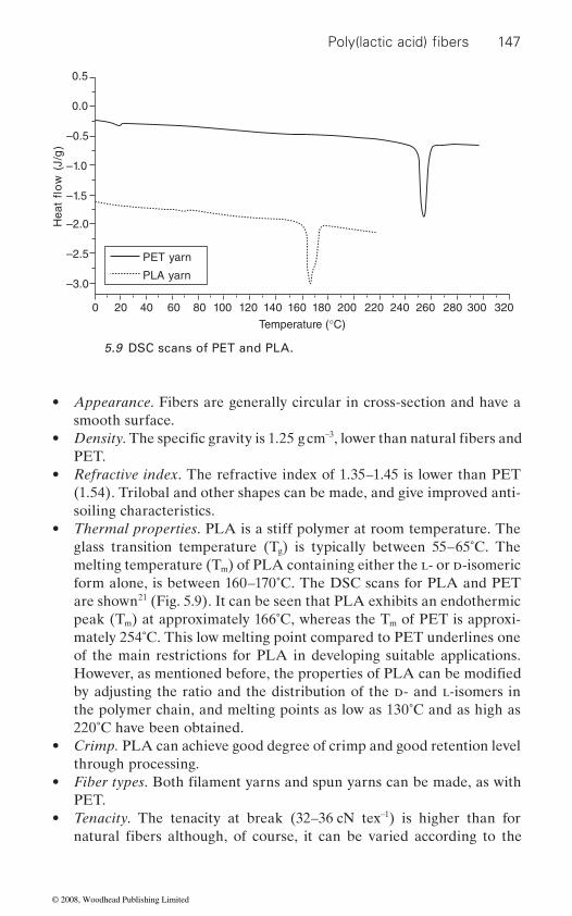
147
• smooth surface.
• −3
PET.• Refractive index. The refractive index of 1.35–1.45 is lower than PET
(1.54). Trilobal and other shapes can be made, and give improved anti-soiling characteristics.
• Thermal properties. PLA is a stiff polymer at room temperature. The glass transition temperature (Tg) is typically between 55–65˚C. The melting temperature (Tm) of PLA containing either the l- or d-isomeric form alone, is between 160–170˚C. The DSC scans for PLA and PET are shown21 (Fig. 5.9). It can be seen that PLA exhibits an endothermic peak (Tm) at approximately 166˚C, whereas the Tm of PET is approxi-mately 254˚C. This low melting point compared to PET underlines one of the main restrictions for PLA in developing suitable applications.
by adjusting the ratio and the distribution of the d- and l-isomers in the polymer chain, and melting points as low as 130˚C and as high as 220˚C have been obtained.
• Crimp. PLA can achieve good degree of crimp and good retention level through processing.
• PET.
• Tenacity. The tenacity at break (32–36 cN tex−1) is higher than for
)g/J(
wolf tae
H
0.5
0.0
–0.5
–1.0
–1.5
–2.0
–2.5
–3.0
PET yarn
PLA yarn
0 20 40 60 80 100 120 140 160 180 200 220 240 260 280 300 320
Temperature (°C)
5.9 DSC scans of PET and PLA.
Poly(lactic acid) fibers
Appearance. Fibers are generally circular in cross-section and have a
Density. The specific gravity is 1.25 g cm , lower than natural fibers and
However, as mentioned before, the properties of PLA can be modified
Fiber types. Both filament yarns and spun yarns can be made, as with
natural fibers although, of course, it can be varied according to the
© 2008, Woodhead Publishing Limited

148 Polyesters and polyamides
degree of drawing that is applied to the undrawn yarn. It is relatively
in elongation. As the temperature is increased the tenacity does reduce
• form for textile processing are shown in Fig. 5.10. Clearly they are very different from those of high tenacity polyester and more akin to wool
acity. The initial modulus (at 2% extension) is very similar to many
spun yarns) stretching very easily once past this point. A consequence, however, of the high elongation is that the work of rupture is relatively high giving yarns and fabrics an acceptable performance in commercial use. Elastic recovery is affected by the yield point and is particularly good at low strains. At 2% strain, the recovery is 99.2% +/− 0.75%, and
example, intimate spun yarn blends with cotton (and lyocell) are rela-
sibly limit applications to knitted fabrics. However, wool blends well with PLA, and with their load-elongation curves being very similar, this
60
50
40
30
20
10
0
xet Nc( ytica
neT1–)
Cotton
Lyocell
HT polyester
Viscose
Wool
PLA
0 5 10 15 20 25 30 35 40 45 50 55 60Extension (%)
5.10 Tenacity-extension curves for PLA and other common textile fibers (20˚C, 65% RH).
with other manufactured fibers there is a small but measurable increase
quite quickly with a concomitant increase in fiber extension, a feature
unaffected by changes in humidity at ambient temperature, though as
commonly found in synthetic fibers.Tensile properties. The tensile properties of PLA fiber as used in staple
with a high fiber extension when stressed and relatively low final ten-
other textile fibers, but the yield point is very marked, the fibers (and
92.6% +/− 1.60% at 5% strain, higher than for most other fibers. The
some of the commercial applications in fiber blend developments. For
tively weak due to the contrast of fiber properties, and this might pos-
would enable the full properties of both fibers to be exploited.
unusual tensile properties could be expected to have an influence on
© 2008, Woodhead Publishing Limited

149
• Moisture regain. At 0.4–0.6%, PLA has extremely low moisture regain,
• has good self-extinguishing characteristics; it burns for two minutes
eration. PLA also has a higher LOI (limiting oxygen index) compared
requires a greater oxygen level. Table 5.1 compares PLA with standard PET.
• in the visible region of the spectrum; this leads to very low strength loss
light.• Moisture transport. PLA shows excellent wicking ability. This property
characteristic.•
microbial food source. In addition, testing by Odor Science and Engi-
fabrics for low odor retention.22
• hydrolysis is therefore relatively poor. This feature means that care
• Solubility. With regard to other chemicals PLA has limited solubility and is unaffected by dry-cleaning solvents for example.
5.4 Applications
The ease of melt processing, coupled with the unique property spectrum
Fiber property PLA PET
Flammability Continues to burn for two
removed
Continues to burn for six minutes after
Smoke generation 63 m2 kg−1 394 m2 kg−1
LOI 26% 22%
Poly(lactic acid) fibers
much lower than natural fibers and slightly higher than polyester.
to most other fibers, meaning that it is more difficult to ignite as it
UV resistance. Unlike other synthetic fibers, PLA does not absorb light
compared to petroleum-based fibers when exposed to ultraviolet
capability give the fiber a very positive inherent moisture management
Biological resistance. Although PLA fibers are not inherently ‘antimi-
and the additional properties of fast water spreading and rapid drying
crobial’ without suitable after-finish treatment, they do not provide a
neering showed that PLA fiber-based fabrics outperformed PET-based
Chemical resistance. As PLA is a linear aliphatic fiber, its resistance to
must be taken in dyeing and finishing of the fiber.
and renewable resource origin, has led to PLA fibers finding increasing
minutes after flame is
Table 5.1 Comparison of PLA and PET flammability properties
flame is removed
Flammability. Although PLA is not a non-flammable polymer, the fiber
after a flame is removed, and burns with a white and a low smoke gen-
© 2008, Woodhead Publishing Limited
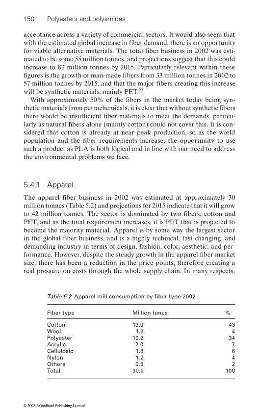
150 Polyesters and polyamides
acceptance across a variety of commercial sectors. It would also seem that
mated to be some 55 million tonnes, and projections suggest that this could
will be synthetic materials, mainly PET.23
sidered that cotton is already at near peak production, so as the world
such a product as PLA is both logical and in line with our need to address the environmental problems we face.
5.4.1 Apparel
million tonnes (Table 5.2) and projections for 2015 indicate that it will grow
PET, and as the total requirement increases, it is PET that is projected to become the majority material. Apparel is by some way the largest sector
demanding industry in terms of design, fashion, color, aesthetic, and per-
size, there has been a reduction in the price points, therefore creating a real pressure on costs through the whole supply chain. In many respects,
Fiber type Million tones %
Cotton 13.0 43Wool 1.3 4Polyester 10.2 34Acrylic 2.0 7Cellulosic 1.8 6Nylon 1.2 4Others 0.5 2Total 30.0 100
for viable alternative materials. The total fiber business in 2002 was esti-with the estimated global increase in fiber demand, there is an opportunity
57 million tonnes by 2015, and that the major fibers creating this increase
With approximately 50% of the fibers in the market today being syn-
figures is the growth of man-made fibers from 33 million tonnes in 2002 to
thetic materials from petrochemicals, it is clear that without synthetic fibers
increase to 83 million tonnes by 2015. Particularly relevant within these
there would be insufficient fiber materials to meet the demands, particu-larly as natural fibers alone (mainly cotton) could not cover this. It is con-
population and the fiber requirements increase, the opportunity to use
The apparel fiber business in 2002 was estimated at approximately 30
to 42 million tonnes. The sector is dominated by two fibers, cotton and
in the global fiber business, and is a highly technical, fast changing, and
formance. However, despite the steady growth in the apparel fiber market
Table 5.2 Apparel mill consumption by fiber type 2002
© 2008, Woodhead Publishing Limited

151
chemical or physical processing technique within the downstream process-
this backdrop, the real opportunity for PLA lies in the combination of both
advantages of being sourced from annually renewable natural resources, which, at the end of the product life, can be easily composted or recycled.
TM
‘Fashion for the Earth’. Kanebo exhibited several garments from PLA or
TM (ingredient from the earth), and this is now being adopted across a wide range of garment categories globally by leading garment brands.
and spun yarns. Fabrics produced from spun yarn have a ‘natural’ hand and are considered to feel similar to cotton in this respect. Fabrics from
with a degree of elasticity. NatureWorks LLC product development sug-gests, for example, that a 1.2 dpf PLA achieves the softness of a micro-denier PET (e.g. 0.7 dpf).
With the opportunity to create a range of fabrics with attractive aesthetic properties, there are a number of performance properties of PLA that are
• The moisture management properties of good wicking, faster moisture spreading and drying mean that garments are comfortable. This is an important consideration for next-to-skin garments and particularly in the sportswear market. In terms of comfort under normal and active wear conditions, independent laboratory testing by the Hohenstein
PET and cotton, either when combined with cotton or as 100% PLA fabric. This testing included a series of different tests, including thermal insulation, breathability, water vapor transport, and buffering capacity to liquid sweat (several tests in this series). The results of the Hohen-stein testing concluded that wearers of PLA/cotton fabric would experi-ence improved physiological comfort versus equivalent PET/cotton fabric.24
• The elastic recovery and crimp retention properties provide excellent shape retention and crease resistance.
Poly(lactic acid) fibers
it would seem that the existing range of fibers could meet all the possible
ing. For a new fiber, the entry into the apparel market could therefore be
consumer needs, either by virtue of their inherent properties, or with some
seen as both a very exciting challenge, but also a very difficult one. Against
the fiber’s inherent performance properties and the positive environmental
Kanebo, Inc. introduced a PLA fiber under the trade name Lactronfiber at the February 1998 Nagano Winter Olympics, under the theme of
PLA/natural fiber blends. More recently, in 2003, Cargill Dow LLC (now NatureWorks LLC) announced their PLA fiber brand Ingeo
It is one of the features of PLA that it can be produced as both filament
significant to its positioning and progress in the apparel sector:
Research Institute demonstrated that PLA fibers perform better than
filament yarns have a cool and soft hand and exhibit a high fluidity or drape
© 2008, Woodhead Publishing Limited
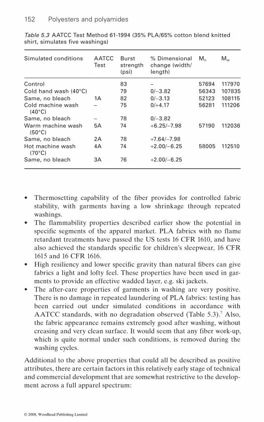
152 Polyesters and polyamides
• stability, with garments having a low shrinkage through repeated washings.
retardant treatments have passed the US tests 16 CFR 1610, and have
1615 and 16 CFR 1616.•
fabrics a light and lofty feel. These properties have been used in gar-ments to provide an effective wadded layer, e.g. ski jackets.
• The after-care properties of garments in washing are very positive. There is no damage in repeated laundering of PLA fabrics: testing has been carried out under simulated conditions in accordance with AATCC standards, with no degradation observed (Table 5.3).7 Also, the fabric appearance remains extremely good after washing, without
which is quite normal under such conditions, is removed during the washing cycles.
Additional to the above properties that could all be described as positive attributes, there are certain factors in this relatively early stage of technical and commercial development that are somewhat restrictive to the develop-ment across a full apparel spectrum:
Table 5.3 AATCC Test Method 61-1994 (35% PLA/65% cotton blend knitted
Simulated conditions AATCC Test
Burst strength (psi)
% Dimensional change (width/length)
Mn Mw
Control 83 – 57694 117970Cold hand wash (40°C) 79 0/−3.82 56343 107835Same, no bleach 1A 82 0/−3.13 52123 108115Cold machine wash
(40°C)– 75 0/+4.17 56281 111206
Same, no bleach – 78 0/−3.82Warm machine wash
(50°C)5A 74 +6.25/−7.98 57190 112036
Same, no bleach 2A 78 +7.64/−7.98Hot machine wash
(70°C)4A 74 +2.00/−6.25 58005 112510
Same, no bleach 3A 76 +2.00/−6.25
shirt, simulates five washings)
also achieved the standards specific for children’s sleepwear, 16 CFR
High resiliency and lower specific gravity than natural fibers can give
creasing and very clean surface. It would seem that any fiber work-up,
• The flammability properties described earlier show the potential in
Thermosetting capability of the fiber provides for controlled fabric
specific segments of the apparel market. PLA fabrics with no flame
© 2008, Woodhead Publishing Limited
153
• The melting point of the yarns that are commercially available today is relatively low at 170˚C. This does cause limitations in some of the downstream processing technologies, but the main concern is for the consumer after-care of garments. Garment pressing and ironing tem-
and despite the appropriate care labeling instructions being used, it is a fact that consumers often disregard these.
• Hydrolysis degradation of the polymer can occur, particularly under combined aqueous high temperature and alkaline conditions; the
as it will cause a reduction in the molecular weight of the polymer and
conditions are not observed.
Through all of the manufacturing stages of the supply chain – spinning,
ment when processing PLA. In many of the downstream processing tech-nologies, PLA processes and products are compared and are comparable
weaving and knitting set-up conditions are similar, fabrics can be heat treated to give dimensional stability, and they are both dyed with disperse
therefore important that processors acknowledge this fact, and that the
Yarn spinning
There is now a wide selection of commercial yarns being produced. In spun
mately 240˚C), although the properties more typically combine many of the features found in rayon, nylons, acrylics and polyesters. PLA pellets are supplied with a maximum moisture content of 400 ppm. It is important to reduce the moisture content to 100 ppm during processing to prevent hydrolytic degradation, similar to PET and nylon products. For short staple yarns, because the characteristics of PLA are comparable to other ther-
For long staple yarns also, processing can be carried out on conventional
Poly(lactic acid) fibers
peratures have to be lower than the popular fibers of cotton and PET,
This is of particular significance in the dyeing and finishing processes,
therefore the strength of a yarn or fabric, if the appropriate finishing
fabric formation, dyeing and finishing, and garment making – the existing machinery can be used. There is no need for any specialized capital invest-
to PET; both are melt spun, both are available in filament and staple form,
dyes. However, both fibers are unique and they do behave differently. It is
operating details are refined accordingly.
in filament production, typical products such as dtex 70–68, dtex 150–72, are being produced. For both spun and filament yarns spinners have con-
yarns, commercial products currently span the range Ne 5 to Ne 60 while
firmed the processability of the material. An interesting feature of PLA is that processing temperatures are more typical of polyolefins (approxi-
moplastic fibers, the processing conditions are similar to those for PET.
degree of hydrolysis is influenced by the time, temperature and pH.
© 2008, Woodhead Publishing Limited
154 Polyesters and polyamides
wool.
Fabric formation
There are no special requirements for knitting, and machine settings are comparable with those for PET. In weaving, the additional points for atten-tion would be: if a size is being applied, to use a PVA or water-soluble size to avoid any need for strong alkali desizing, and to minimize tensions due
Garment making
The low melting point may mean that precautions are taken at those stages
cutting and the garment panel sewing operations. Care is also needed at
it is the prime driver when purchasing a new garment, but also because the
is dyed with disperse dyes. However, dye selection is most important, as the individual dye behavior is quite different from dyeing on PET. In general terms, dyes show their maximum absorption at a shorter wave-length than on PET and tend to look brighter25 (Fig. 5.11). Dyes also show a much greater variation in exhaustion levels; Yang and Huda26 studied the exhaustion of ten disperse dyes on PLA and PET fabrics and found that the percentage dye exhaustion of all the dyes was lower on PLA than on PET. However, the color yield of the dyed PLA was higher than on PET
Several of the major dye manufacturers have studied their ranges of disperse dyes to provide the most appropriate selection for applying to PLA. DyStar GmbH & Co. have worked closely with NatureWorks LLC to further the commercial dyeing technology for PLA and have recently provided details for dyeing both 100% PLA as well as blends with cotton and wool.27 The optimum dyeing conditions recommended by DyStar for dyeing PLA is 110˚C for 30 minutes at pH 5. Practical experience has shown
long staple equipment as used for thermoplastic fibers in blend with
to the high fiber extension. Woven filament fabrics give a very soft hand,
where fiber–metal friction could generate sufficient heat, namely the fabric
the final pressing stage.
Dyeing and finishing
As is usual with any new fiber, the coloration and wet processing technolo-gies demand significant attention. Color is so important, not only because
various applications and subsequent finishing treatments have the most chemical and physical effect on any fiber or polymer. Similar to PET, PLA
and have a high fluidity/drape compared to PET.
because of the lower reflectance of PLA.
© 2008, Woodhead Publishing Limited
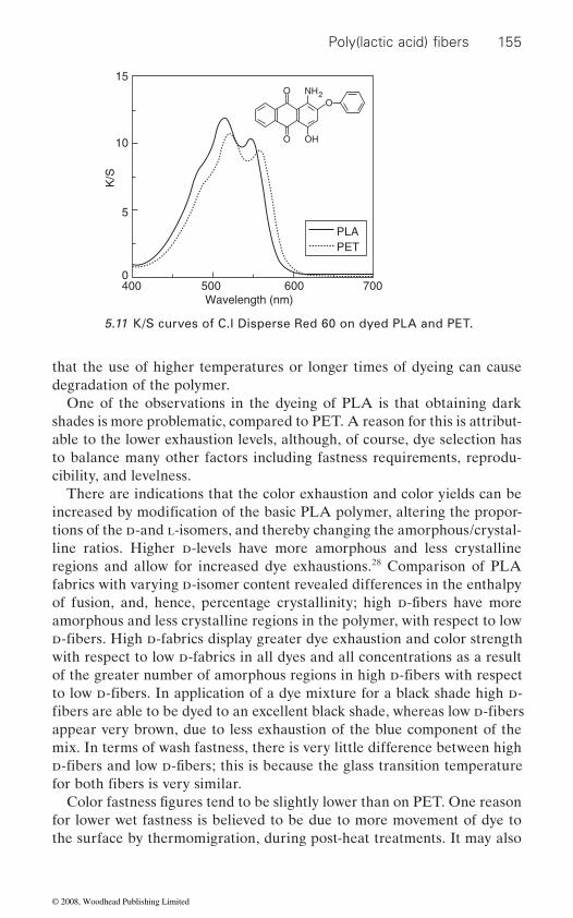
155
that the use of higher temperatures or longer times of dyeing can cause degradation of the polymer.
One of the observations in the dyeing of PLA is that obtaining dark shades is more problematic, compared to PET. A reason for this is attribut-able to the lower exhaustion levels, although, of course, dye selection has to balance many other factors including fastness requirements, reprodu-cibility, and levelness.
There are indications that the color exhaustion and color yields can be
tions of the d-and l-isomers, and thereby changing the amorphous/crystal-
regions and allow for increased dye exhaustions.28 Comparison of PLA fabrics with varying d-isomer content revealed differences in the enthalpy
amorphous and less crystalline regions in the polymer, with respect to low
with respect to low d-fabrics in all dyes and all concentrations as a result
appear very brown, due to less exhaustion of the blue component of the mix. In terms of wash fastness, there is very little difference between high
for lower wet fastness is believed to be due to more movement of dye to the surface by thermomigration, during post-heat treatments. It may also
O
O
O
OH
NH2
400 500 600 700Wavelength (nm)
PLAPET
S/K
15
10
5
0
5.11 K/S curves of C.I Disperse Red 60 on dyed PLA and PET.
Poly(lactic acid) fibers
increased by modification of the basic PLA polymer, altering the propor-
d-fibers. High d-fabrics display greater dye exhaustion and color strength
line ratios. Higher d-levels have more amorphous and less crystalline
of the greater number of amorphous regions in high d-fibers with respect
of fusion, and, hence, percentage crystallinity; high d-fibers have more
to low d-fibers. In application of a dye mixture for a black shade high d-fibers are able to be dyed to an excellent black shade, whereas low d-fibers
d-fibers and low d-fibers; this is because the glass transition temperature for both fibers is very similar.
Color fastness figures tend to be slightly lower than on PET. One reason
© 2008, Woodhead Publishing Limited
156 Polyesters and polyamides
be that the lower thermosetting temperature for PLA (130˚C) compared to PET (190˚C) means less sublimation of the dye from the surface.29
With the introduction of PLA into apparel, developments and commer-cial adoptions have included fabrics made from 100% PLA as well as in
(cotton, lyocell) or wool. Apart from any aesthetic or performance bene-
their PET counterparts.The wet processing of cellulosic blends need to be adapted to recognize
the sensitivity of PLA to alkali treatments. This causes some limitations,
ognized, and methods are available for all stages of wet processing. These include the use of neutral bleaching systems based on TAED (tetraacetyl-ethylenediamine), and direct dyes, as well as the more conventional alka-line bleaches and selected reactive dyeing systems. A detailed study into
bility for suitable processing.30,31 Dyeing of PLA/wool blends does not
There is much still to learn about the dyeing of PLA but it would seem that processes are available to achieve commercial viability. In real terms,
watch as PLA follows a similar course.
5.4.2 Homeware
Typical products encompassed in this segment range from pillows, duvets,
have a strong appeal to consumers in various geographies. The resistance
burning are attractive properties for this market segment, which differenti-ate PLA fabrics manufactured from conventional petrochemical-based synthetics.
fits, such blends also have the feature of being biodegradable compared to
as bleaching and dyeing systems for cellulosic fibers generally use alkaline processes. However, the potential significance of this blend has been rec-
strength of PLA was carried out at UMIST, and this confirmed the feasi-
present such a problem, as both fibers have the same characteristic with
seem to be some benefits compared to PET/wool.
the effect of the various wet processes on the molecular weight and physical
it is not that long ago that fibers such as lyocell and indeed PET were introduced to the textile world, with many technical difficulties in their
regard to alkali. Indeed, with their similar stress–strain profile, there would
processing. These are now well accepted fibers and it will be interesting to
blankets, mattress pads, carpet tiles, office panel fabrics, drapes to bonded fiber products such as mattresses. As in the other sectors, the unique origin of these fibers, being derived from natural sugars obtained from annually renewable resources, coupled with the performance benefits, is proving to
Superior resilience found in crimped staple fiber products such as fiber-fill, coupled with the natural wicking performance of the fiber are added
blend with other fibers. The main blends are either with cellulosic fibers
to UV and low flammability, low smoke generation and low toxic gas on
© 2008, Woodhead Publishing Limited
157
32 Laboratory UV resistance testing using a Xenon Arc33 indicates that in comparison with
than polyester and far superior resistance to discoloration than acrylics.Independent testing by the Hohenstein Institute34
when used in duvets provide a better microclimate between the body and
polyester, results in the dynamic adjustment of the moisture level by dissi-pating moisture as the humidity level changes. In pillows, testing has shown
35
Flammability testing indicates a Limiting Oxygen Index value for PLA
and time to extinguish are properties of considerable interest in the fur-
the test criteria for UNI 8456(1986), UNI 9174(1987) and UNI 9174/A1 (1996) that measure the time to self-extinguish (after the fabric is removed
as required by the Italian Drapery Industry.36
interior furnishings for public occupancy buildings.36 Typical products include drapery, cubicle curtains, wall covering and protective outdoor coverings such as tarpaulins and tents.
36 All these tests were
individual results will depend upon fabric construction and the use of
The unique resistance to staining and soiling of PLA Bulk Continuous
Prius in Japan as well as in carpet tiles for domestic and institutional markets.
Poly(lactic acid) fibers
this moisture wicking behavior is inherent to the fiber and achieved without the use of finishes this behavior should not decrease over time. Indepen-dent testing indicates the wicking behavior of untreated PLA fibers is superior to either untreated or treated polyester fibers.
features, which further enhance the scope of opportunities for PLA. Since
polyester and acrylic fibers, PLA fabrics have superior strength retention
shows that PLA fibers
the duvet. The superior wicking properties of PLA fibers, compared with
that PLA fibers offer outstanding filling power and resilience after three
fibers of 24–28 when tested according to ASTM D2863. This is superior
years of simulated usage.
to untreated PET fibers, cotton, rayon and acrylics and equivalent to
nishings segment. Fabrics made from untreated PLA fibers show far shorter burn times than cotton and polyester fibers. Untreated PLA fibers meet
as NFPA 701, which covers the fire safety requirements for textiles used in
Finally, a prototype mattress made from 100% PLA fibers successfully
finishes or dyestuffs.
Filament (BCF) has led to significant interest in PLA fibers for use in carpets. Presently, PLA fibers are used in carpet mats for the hybrid Toyota
from the heat source). This test also measures the rate of flame propaga-
natural protein-based fibers such as wool. In addition, flame propagation
tion, char length, and time of flaming of any dripping materials to extin-
Fabrics made from PLA fibers have also passed flammability tests such
guish. The results enable 100% PLA fabrics to be classified as Category 1
passed Cal 129 testing for furniture flammability.conducted on 100% PLA without any flame retardant additives. However,
© 2008, Woodhead Publishing Limited
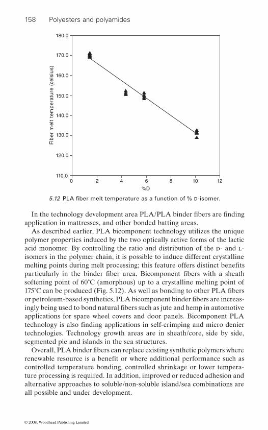
158 Polyesters and polyamides
As described earlier, PLA bicomponent technology utilizes the unique polymer properties induced by the two optically active forms of the lactic acid monomer. By controlling the ratio and distribution of the d- and l-
softening point of 60˚C (amorphous) up to a crystalline melting point of
applications for spare wheel covers and door panels. Bicomponent PLA
technologies. Technology growth areas are in sheath/core, side by side, segmented pie and islands in the sea structures.
controlled temperature bonding, controlled shrinkage or lower tempera-ture processing is required. In addition, improved or reduced adhesion and alternative approaches to soluble/non-soluble island/sea combinations are all possible and under development.
)suislec( er
utarep
met tlem re
biF
180.0
170.0
160.0
150.0
140.0
130.0
120.0
110.00 2 4 6 8 10 12
%D
5.12 PLA fiber melt temperature as a function of % D-isomer.
In the technology development area PLA/PLA binder fibers are finding
melting points during melt processing; this feature offers distinct benefits
application in mattresses, and other bonded batting areas.
particularly in the binder fiber area. Bicomponent fibers with a sheath
175˚C can be produced (Fig. 5.12). As well as bonding to other PLA fibers
isomers in the polymer chain, it is possible to induce different crystalline
or petroleum-based synthetics, PLA bicomponent binder fibers are increas-ingly being used to bond natural fibers such as jute and hemp in automotive
technology is also finding applications in self-crimping and micro denier
Overall, PLA binder fibers can replace existing synthetic polymers where renewable resource is a benefit or where additional performance such as
© 2008, Woodhead Publishing Limited
159
5.4.3 Nonwovens
the major markets are in spun bond, industrial and household wipes,
typical polyester spun bond lines in a variety of fabric weights. Filament velocities of 3500 m min−1 and above are needed to produce fabrics with the required low shrinkage performance. Key applications are in carpet backing, hygiene, and compostable geotextiles for soil erosion control and plant as well as crop protection. Under the correct conditions of tempera-ture and humidity PLA fabrics are completely compostable and return naturally to the soil releasing carbon dioxide and water. Under normal storage conditions and use, however, the fabrics are durable enough to meet the various market and supply chain requirements.
and in particular the wet wipes segment across a variety of applications. Most wet wipes comprise a blend of cellulose, viscose or rayon with a syn-
growth in personal care wipes versus 2.5% in baby wipes in the US.37 Similar trends are being seen in Europe and Japan. New product introduc-tions in personal care and household cleaning markets are occurring rapidly. Typical new trends and applications for wet wipes include:
• Feminine hygiene, facial cleansing, hemorrhoid treatment, etc.• Functional treatments (antimicrobial, cleaners, abrasives, etc.).• Decorative patterns.• Continued push toward cloth-like aesthetics.• Environmentally friendly materials and processes.
Spun laced investments have recently been announced by Jacob Holm, Spuntech, Orlandi, and Green Bay Nonwovens. In addition, Japan has large spun lace capacity with markets that are seeking environmental solu-tions. Wipes converters globally are expanding capabilities and expediting
pared with the petroleum-based synthetics used in these applications. This inherent property leads to increased rates of liquid absorption,32 in addi-tion the appeal of an all-natural-based wipe has demonstrated strong con-sumer pull. The wipes market is, however, extremely price sensitive; recent
Poly(lactic acid) fibers
tial for the unique benefits of PLA fibers. Outside of the fiberfi ll products
hygiene and filtration areas. Spun bond PLA products can be produced on
Nonwoven products are a major application segment offering great poten-
In recent years there has been a significant growth in the wipes market,
Industrial/household wipes
thetic fiber such as polyester or polypropylene. Up to 50% of the wipe comprises these synthetic fibers. Recent surveys indicate a 6.5% annual
line extensions. PLA fibers show superior wicking performance when com-
price fluctuations in the price of oil coupled with the advances made in
© 2008, Woodhead Publishing Limited

160 Polyesters and polyamides
Hygiene
in the diaper and feminine hygiene markets, both in spun bond top sheets and acquisition/distribution layers. Again the ability to replace petroleum-
fully compostable the products can be disposed of by composting if the infrastructure for disposal is in place.
Filtration and separation
Two areas of potential applicability of PLA polymers have appeared in the industry in recent years.
• • Filters, for example in the automotive and chemical industries, as well
as single use applications.
and are attracted to polypropylene, indicating that they are somewhat elec-
5.4.4 Medical applications
involves culturing and growing living cells, taken from human organs, on a textile scaffold, to the desired 2-dimensional and/or 3-dimensional
which are in turn produced from biocompatible and degradable polymers.
glycolic acid). They can either be used as a single polymer or by blending a copolymer of PLA and PGA. Varying the proportions of PLA and PGA
properties can therefore be varied in this way according to the require-
tage is that no further surgery is required to remove the products since they slowly degrade in the body without any side affects. The US Food and Drug Administration (FDA) has approved the use of PLA for certain human
PLA fiber and resin production means that pricing differences between the petrochemical-based and PLA fibers continues to narrow.
PLA fibers, because of their natural wicking properties, are finding utility
based fibers with enhanced performance with a natural-based fiber has strong consumer appeal. An additional benefit is that since PLA fibers are
Triboelectric media to improve filtration efficiency.
The unique combination of properties displayed by PLA fibers offers promise in these areas. Untreated PLA fibers are repelled by glass surfaces
tropositive. Disposable filters are also an area of interest for PLA fibers.
Textile fibers can be used to cultivate different human organs. The process
shapes. The scaffold is made from biodegradable and resorbable fibers
The major bioresorbable fibers used in implants are PLA and PGA (poly-
alters the degradation rate and strength retention time of the fiber. These
ments of specific medical applications. During the process of degradation, fibrous connective tissues replace the degrading implant. The key advan-
© 2008, Woodhead Publishing Limited
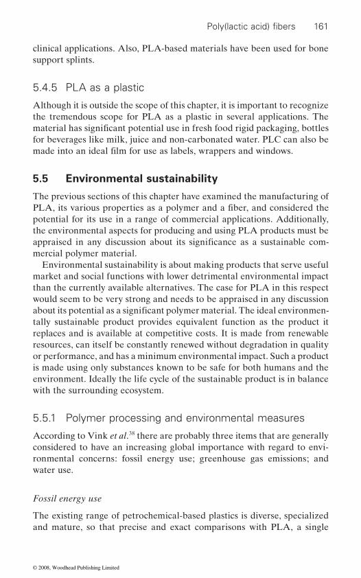
161
clinical applications. Also, PLA-based materials have been used for bone support splints.
5.4.5 PLA as a plastic
Although it is outside the scope of this chapter, it is important to recognize the tremendous scope for PLA as a plastic in several applications. The
for beverages like milk, juice and non-carbonated water. PLC can also be
5.5 Environmental sustainability
The previous sections of this chapter have examined the manufacturing of
potential for its use in a range of commercial applications. Additionally, the environmental aspects for producing and using PLA products must be
mercial polymer material.Environmental sustainability is about making products that serve useful
market and social functions with lower detrimental environmental impact than the currently available alternatives. The case for PLA in this respect would seem to be very strong and needs to be appraised in any discussion
tally sustainable product provides equivalent function as the product it replaces and is available at competitive costs. It is made from renewable resources, can itself be constantly renewed without degradation in quality or performance, and has a minimum environmental impact. Such a product is made using only substances known to be safe for both humans and the environment. Ideally the life cycle of the sustainable product is in balance with the surrounding ecosystem.
5.5.1 Polymer processing and environmental measures
According to Vink et al.38 there are probably three items that are generally considered to have an increasing global importance with regard to envi-ronmental concerns: fossil energy use; greenhouse gas emissions; and water use.
Fossil energy use
The existing range of petrochemical-based plastics is diverse, specialized and mature, so that precise and exact comparisons with PLA, a single
Poly(lactic acid) fibers
material has significant potential use in fresh food rigid packaging, bottles
made into an ideal film for use as labels, wrappers and windows.
PLA, its various properties as a polymer and a fiber, and considered the
appraised in any discussion about its significance as a sustainable com-
about its potential as a significant polymer material. The ideal environmen-
© 2008, Woodhead Publishing Limited
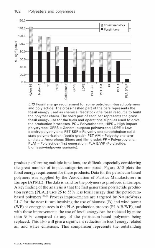
162 Polyesters and polyamides
the great number of impact categories compared. Figure 5.13 plots the fossil energy requirement for these products. Data for the petroleum-based polymers was supplied by the Association of Plastics Manufacturers in Europe (APME). The data is valid for the polymers as produced in Europe.
tion system (PLA1) uses 25 to 55% less fossil energy than the petroleum-based polymers.38,39 Process improvements are targeted by NatureWorks LLC for the near future involving the use of biomass (B) and wind power (WP) as energy sources in the PLA production process (PLA B/WP), and with these improvements the use of fossil energy can be reduced by more than 90% compared to any of the petroleum-based polymers being
air and water emissions. This comparison represents the outstanding
Fossil feedstock
Fossil fuels
gk JM
1–stelle
p
160.0
140.0
120.0
100.0
80.0
60.0
40.0
20.0
0.0
66 n
olyN
6 n
olyN
CP
SPI
H
en a
hp
olleC
SP
PG
EP
DL
PS
S T
EP
MA
TE
P
PP
1 AL
P
PW/
B AL
P
5.13 Fossil energy requirement for some petroleum-based polymers and polylactide. The cross-hashed part of the bars represents the fossil energy used as chemical feedstock (the fossil resource to build the polymer chain). The solid part of each bar represents the gross fossil energy use for the fuels and operations supplies used to drive the production processes. PC = Polycarbonate; HIPS = High impact polystyrene; GPPS = General purpose polystyrene; LDPE = Low density polyethylene; PET SSP = Polyethylene terephthalate solid state polymerization; (bottle grade); PET AM = Polyethylene tere-
biomass/windpower scenario).
phthalate Amorphous (fibers and film grade); PP = Polypropylene; PLA1 = Polylactide (first generation); PLA B/WP (Polylactide,
product performing multiple functions, are difficult, especially considering
A key finding of the analysis is that the first generation polylactide produc-
replaced. This also will give a significant reduction in fossil energy related
© 2008, Woodhead Publishing Limited

163
resources.It needs to be recognized that the data for PLA1 and PLA B/WP rep-
resent engineering estimates. In addition, there is good reason to expect improvements in the actual performance versus the estimates.38 Despite years of development work, the commercial manufacturing process for PLA is in its infancy. If the experience from petrochemical-based polymers offers any instruction, it is that process improvements implemented in the early years of a technology typically lead to substantial cost improvements. This is because the pursuit of cost improvements for competitive reasons often targets energy use due to its relatively high contribution to overall material costs. For example, through work on biocatalyst and lactic acid manufacturing process, NatureWorks LLC expects to achieve improve-ments that should further improve the performance of their production plant and simultaneously reduce energy demand. There is therefore good reason to expect a performance improvement trajectory for PLA1 that mirrors the experience from the current incumbent materials.
Global climate change
environmental issue of this century.40 Greenhouse gas emissions are not exactly the same as combusted fossil fuel emissions, because several non-combustion gases can contribute to global climate change as well. For example, methane (CH4) is a potent greenhouse gas that can emanate from natural gas system leaks, decomposition of biological materials, and chemi-cal/industrial processes. However, greenhouse gas emissions are closely correlated to fossil fuel emissions because combustion of fossil fuels is the source of most anthropogenic greenhouse gases. NatureWorks LLC has undertaken a comparison of the contributions to global climate change from a range of petrochemical-based polymers as well as the two PLA cases described above.38 This comparison is depicted in Fig. 5.14. In con-ducting this analysis, Vink et al.38 relied upon the 100-year time horizon Global Warming Potentials for greenhouse gases, a time period generally accepted as the mean atmospheric residence time for the most volumetri-
revealed that use of the 20- and 500-year time horizons generates the same ranking among the products studied. According to the Intergovernmental Panel on Climate Change (IPCC) the relative global warming potentials of the three largest (volumetric) greenhouse gases are: CO2-1, CH4-21, and N2O-310.41 These factors were used in NatureWorks LLC’s analysis. As in the comparison of fossil energy use, the analysis compares conventional polymers with PLA from cradle to pellet (from raw materials to the point
Poly(lactic acid) fibers
potential for environmental benefits for polymers made from renewable
Global climate change has been identified as perhaps the most important
cally significant greenhouse gas, carbon dioxide. A check of the data
© 2008, Woodhead Publishing Limited
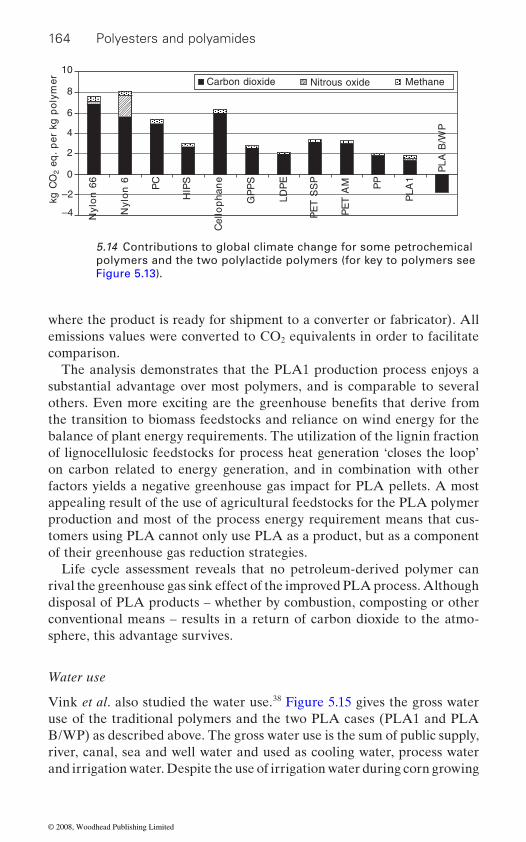
164 Polyesters and polyamides
where the product is ready for shipment to a converter or fabricator). All emissions values were converted to CO2 equivalents in order to facilitate comparison.
The analysis demonstrates that the PLA1 production process enjoys a substantial advantage over most polymers, and is comparable to several
the transition to biomass feedstocks and reliance on wind energy for the balance of plant energy requirements. The utilization of the lignin fraction of lignocellulosic feedstocks for process heat generation ‘closes the loop’ on carbon related to energy generation, and in combination with other factors yields a negative greenhouse gas impact for PLA pellets. A most appealing result of the use of agricultural feedstocks for the PLA polymer production and most of the process energy requirement means that cus-tomers using PLA cannot only use PLA as a product, but as a component of their greenhouse gas reduction strategies.
Life cycle assessment reveals that no petroleum-derived polymer can rival the greenhouse gas sink effect of the improved PLA process. Although disposal of PLA products – whether by combustion, composting or other conventional means – results in a return of carbon dioxide to the atmo-sphere, this advantage survives.
Water use
Vink et al. also studied the water use.38 Figure 5.15 gives the gross water use of the traditional polymers and the two PLA cases (PLA1 and PLA B/WP) as described above. The gross water use is the sum of public supply, river, canal, sea and well water and used as cooling water, process water and irrigation water. Despite the use of irrigation water during corn growing
OC
gk2
remy l
op
gk rep .
qe
10
8
6
4
2
0
–2
–4
Carbon dioxide
PW/
B AL
P
66 n
olyN
6 n
ol yN
CP
SP I
H
en a
hp
olleC
SP
PG
EP
DL
PS
S T
EP
MA
TE
P
PP
1AL
P
MethaneNitrous oxide
5.14 Contributions to global climate change for some petrochemical polymers and the two polylactide polymers (for key to polymers see Figure 5.13).
others. Even more exciting are the greenhouse benefits that derive from
© 2008, Woodhead Publishing Limited

165
and the two water-based processes (dextrose and lactic acid production) the total amount of water required is competitive with the best performing petrochemical polymers.
5.5.2 Disposal options
The most common waste management options for the fossil fuel-based
to these traditional processing routes, the PLA waste streams can also be processed using composting, chemical recycling and anaerobic digestion.
Composting
require an appropriate infrastructure to be set up, but progress is being made, particularly in parts of Western Europe.42 Composting is a method of waste disposal that allows organic materials to be recycled into a product that can be used as a valuable soil amendment. The primary mechanism of degradation of PLA is hydrolysis, catalyzed by temperature, followed by bacterial attack on the fragmented residues. In composting, the mois-ture and the heat in the compost pile attacks the PLA polymer chains and
acid. Microorganisms, found in active compost piles, consume the smaller polymer fragments and lactic acid as energy source. Since lactic acid is
remyl
op
gk rep re ta
w gk
800
700
600
500
400
300
200
100
0
PW/
B AL
P
66 n
ol yN
6 n
olyN
CP
SPI
H
ena
hp
olleC
SP
PG
EP
DL
PS
S T
EP
MA
TE
P
PP A L
P
Irrigation waterCooling waterProcess water
5.15 Gross water use by petrochemical polymers and the two PLA cases (for key to polymers see Figure 5.13).
Poly(lactic acid) fibers
polymers are incineration, landfill and mechanical recycling. In addition
Composting is a beneficial waste management system, particularly where landfill sites are limited, and in more densely populated locations. It does
splits them apart, creating smaller polymer fragments, and finally, lactic
© 2008, Woodhead Publishing Limited
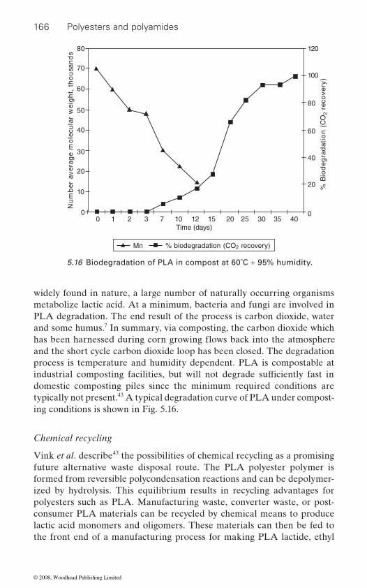
166 Polyesters and polyamides
widely found in nature, a large number of naturally occurring organisms metabolize lactic acid. At a minimum, bacteria and fungi are involved in PLA degradation. The end result of the process is carbon dioxide, water and some humus.7 In summary, via composting, the carbon dioxide which
and the short cycle carbon dioxide loop has been closed. The degradation process is temperature and humidity dependent. PLA is compostable at
domestic composting piles since the minimum required conditions are typically not present.43 A typical degradation curve of PLA under compost-ing conditions is shown in Fig. 5.16.
Chemical recycling
Vink et al. describe43 the possibilities of chemical recycling as a promising future alternative waste disposal route. The PLA polyester polymer is formed from reversible polycondensation reactions and can be depolymer-ized by hydrolysis. This equilibrium results in recycling advantages for polyesters such as PLA. Manufacturing waste, converter waste, or post-consumer PLA materials can be recycled by chemical means to produce lactic acid monomers and oligomers. These materials can then be fed to the front end of a manufacturing process for making PLA lactide, ethyl
sd
nasu
oht ,t
hgie
w ralucel
om e
gareva reb
mu
N
80
70
60
50
40
30
20
10
0
Mn % biodegradation (CO2 recovery)
0 1 2 3 7 10 12 15 20 25 30 35 40Time (days)
120
100
80
60
40
20
0
OC(
noita
darge
doi
B %
2)yrev
oc er
5.16 Biodegradation of PLA in compost at 60˚C + 95% humidity.
industrial composting facilities, but will not degrade sufficiently fast in
has been harnessed during corn growing flows back into the atmosphere
© 2008, Woodhead Publishing Limited
167
lactate, or other lactide derivatives. The recycling can be carried out with water at a wide range of temperatures (100–250˚C). The reaction rate is enhanced by a catalyst such as nitric acid as is common in the PET recy-cling industry. The reactor residence times for PLA hydrolysis are in the order of hours, and depend on reactor temperature and catalyst level.
Chemical recycling should be considered in any waste management system for PLA, since from a life-cycle perspective, it represents a rela-tively small amount of net chemistry compared to the CO2-to-PLA cycles for incineration or composting. Simple hydrolysis can turn waste PLA back into fully functional lactic acid, at potentially low economic and environ-mental cost, contributing to the total sustainability of PLA production.
The inferences from the studies of Vink et al.43
impact that PLA has in addressing the key environmental concerns of today when compared to petrochemical-based polymers. They also show
mercial producer of PLA, NatureWorks LLC, states that its commitment and ethos is based on ‘making plastics from annually renewable resources
meet the needs of tomorrow’. Its philosophy is based on ‘reducing the
in mind’.44 The company is committed to environmental responsibility and therefore it would seem that the polymer market as we know it today will
5.6 Future trends
products; it encompasses the additional goal of reducing total environmen-tal impact. The result is a product that is more sustainable than comparable
towards creating more sustainable products with unique performance attributes.
als, plastics, to be made from simple plant sugars, which are then turned
to 50% less fossil fuel resources than is required by conventional petro-leum-based resins. Fossil resource use in the manufacture of these materi-als will continue to decrease as plans are put into place to switch feed stocks to biomass (corn stalks, leaves, etc.) and possibly integrate alterna-tive energy sources, such as windpower. With PLA, carbon dioxide is removed from the atmosphere when growing the feedstock crop and is
Poly(lactic acid) fibers
confirm the positive
the additional benefits that can be gained by making environmentally responsible modifications to the existing manufacturing process. The com-
which meet the needs of today without compromising the earth’s ability to
experience some very significant changes in the near future.
environmental footprint’ and on ‘designing products with end-use disposal
The vision for PLA fibers is more than just developing new performance
polymers on the market today. PLA fibers have made significant steps
into fibers using conventional melt spinning equipment and processes.
This technology allows one of the world’s most commonly used materi-
Made from annually renewable resources, PLA plastics and fibers use 20
© 2008, Woodhead Publishing Limited

168 Polyesters and polyamides
returned to the earth when PLA is composted. Since this process recycles the earth’s carbon, PLA emits less CO2 compared to other petroleum-
also includes the additional option of composting.
by petroleum-based synthetics. The rationale for this trend is the increas-ing public concern over the depletion of natural resources and the accom-panying atmospheric pollution. Various studies indicate that reserves of oil and gas will eventually be depleted, although the actual time scale is a topic of considerable debate. It is evident, however, that the use of annually renewable crops as a means of producing the materials we need to sustain our everyday lives will continue to accelerate.
imposed upon the earth while extending the usable life of the diminishing oil and natural gas reserves. Ultimately the technology of using natural
globe. The use of waste products, referred to as biomass, will also provide the fuel to drive the factories used to convert these polymers to the variety of products needed to sustain the ever-increasing demands for an improved
facture of these renewable resource-based products coupled with meeting the performance demands of the targeted applications.
as the technology develops, any starch-based crop will be used. Advances in farming practices will enable higher crop yields with subsequent improved economics. Additional improvements in the fermentation and polymerization processes along with economies of scale will also contrib-ute to the improved cost basis for these products.
PLA products have come a long way from the early work of Carothers
products has led to rapid growth. This growth will continue. We are at the
ments in chemistry and downstream process development will lead to new applications and a bright future for these renewable resource-based melt-
5.7 References
1. tsuji, h. and ikada, y., J. Appl. Polym. Sci., 1998, 67, 405. 2. drumright, r.e., gruber, p.r. and henton, d.e., Adv. Mater., 2000, 12 (23),
1841.
based fibers. Disposal of PLA fits within the existing disposal systems but
PLA fibers are increasingly penetrating markets traditionally occupied
PLA fibers offer the promise of ultimately reversing the damage we have
crops to produce fibers and packaging will become widespread across the
PLA fibers and packaging products are well on the way to realizing this
quality of life. The key to this transformation lies in the economical manu-
goal. Presently these fibers are produced from natural corn sugar. However,
in 1932. The ability to economically manufacture packaging and fiber
beginning of a new industrial revolution in which PLA fibers are playing a leading role. In addition, PLA fibers are still in their infancy: improve-
spinnable fibers.
© 2008, Woodhead Publishing Limited
169
3. lipinsky, e.s. and sinclair, r.g., Chem. Eng. Prog., 1986, 82 (8), 26. 4. vert, m., schwacch, g. and coudane, J., J. Macromol. Sci. Pure, 1995, A32,
787. 5. lunt, j., Polym. Degrad. Stabil., 1998, 59, 145.
(accessed April 2004).
7. gruber, pat and o’brien, michael, Biopolymer Volume 6, Chapter 8, Polylac-tides: NatureWorks® PLA, June 2001.
8. Plastics Technology, January 1998, 13–15. 9. gruber, et al. USP 5 142 023.10. mecerreyes, d. and jerome, r., Macromolecular Chemistry and Physics, 1999,
200 (12), 2581.11. stevels, w.m., dijkstra, p.j. and feijen, j., Trends in Polymer Science, 1997, 5
(9), 300.12. o’keefe, b.j., monnier, s.m., hillmyer, m.a. and tolman, w.b., J. Am. Chem.
Soc., 2001, 123 (2), 339.13. kricheldorf, h.r. and krieser, i., Makromol. Chem., 1986, 187, 186.14. kurcok, p., kowalczuk, m., hennek, k. and jedlinski, z., Macromolecules,
1992, 25 (7), 2017.15. du, y.j., lemestra, p.j., nijenhuis, a.j., vanaert, h.a.m. and bastiaansen, c.,
Macromolecules, 1995, 28 (7), 2124.16. kricheldorf, h.r., scharnagl, n. and jedlinski, z., Polymer, 1996, 37 (8),
1405.17. sinclair, r.g., USP 4 045 418.18. drumright, r.e., gruber, p.r. and henton, d.e., Advanced Materials, 2000, 12
(23), 1841.19. lunt, j. and bone, j., AATCC Rev., 2001, 1 (9), 20.20. palade, l.i., lehermeier, h.j. and dorgan, j.r., Macromolecules, 2001, 34 (5),
1384.
and Fastness Properties of Poly(Lactic Acid)’, PhD Thesis, UMIST, Manches-ter, UK, 2004.
22. Ingeo Fibers bring natural performance – low odor. Testing by Odor Science and Engineering Inc., Technical Bulletin 290904.
23. nash and abel international marketing, Base source: PCI World Synthetic Fibers Supply/Demand Report 2002.
24. Test Report no. ZO.4.3805, Comparison of physiological comfort of polyester (PET)/cotton and NatureWorksTM
Hohenstein 5/24/00.25. takashi nakumara, International Textile Bulletin, 4/2003, 68.26. yang, y.q. and huda, s., AATCC Rev., 2003, 3 (8), 56.27. dystar textilfarben gmbh & co. deutschland kg, ‘IngeoTM Fiber Coloration
Pack’.28. blackburn, r.s., zhao, x. and farrington, d., johnson, l., Dyes and Pigments,
2006, 70, 251–8.29. phillips, d., suesat, j., taylor, j.a., wilding, m., farrington, d., bone, j. and
dervan, s., Coloration Technology, 2004, 120 (5), 260.30. phillips, d., suesat, j., wilding, m., farrington, d., sandukas, s., sawyer, d.,
bone, j. and dervan, s., Coloration Technology, 2004, 120 (1), 35.
Poly(lactic acid) fibers
6. natureworks llc, http://www.ingeofibers.com/ingeo/home.asp
fibers/cotton fabrics, Forschungsinstitut
21. suesat, j., ‘Investigation of the Influence of Fiber Morphology on the Dyeing
© 2008, Woodhead Publishing Limited

170 Polyesters and polyamides
31. phillips, d., suesat, j., wilding, m., farrington, d., sandukas, s., sawyer, d., bone, j. and dervan, s., Coloration Technology, 2004, 120 (1), 41.
37. john, r., Starr Associated Nonwovens market survey (source: www.johnrstarr.com).
38. vink, e.t.h., rabago, k.r., glassner, d.a. and gruber, p.r., Polymer Degrada-tion and Stability, 2003, 80 (3), 403.
39. glassner, d., Presented at the 23rd Symposium on Biotechnology for Fuels and Chemicals, Commercialization of polylactide polymers, 9 May 2001.
40. sharron, e., Global climate change and the challenges of stewardship: man and nature in the 21st century, 2 June 2002, Climate Independent Media Center (available from: http://www.climateconference.org).
41. IPCC Intergovernmental Panel on Climate Change. Climate change 1995 – the science of climate change. Albritton, D., Derwent, R., Isaksen, I., Lal, M. and Wuebbles, D. In: Houghton, J.T., Meira Filho, L.G., Callander, B.A., Harris, N., Kattenberg, A. and Maskell, K. (eds), Radiative forcing of climate change. Cambridge (UK): Cambridge University Press, 1995, 119–21.
42. bohlmann, gregory m. with Toki, Goro, ‘CEH Marketing Research Report, Biodegradable Polymers’.
43. vink, e.t.h., rabago, k.r., glassner, d.a., springs, b., o’connor, r.p., kolstad, j. and gruber, p.r., Macromol. Biosci., 2004, 4, 551–564.
44. IngeoTM
NoteIngeo and NatureWorks are trademarks of NatureWorks LLC.
cal Bulletin 380904 (Source: www.ingeofibers.com).33. Ingeo fiber-based fabric: UV resistance. Technical Bulletin 370904 (source:
www.ingeofibers.com).34. Ingeo fiber v high-end polyester in duvet/comforter testing. Technical Bulletin
130904 (source: www.ingeofibers.com).35. Ingeo fiber v high-end polyester in pillow loft and support testing. Technical
32. Moisture Transport in Ingeo Fibers Non-Woven Fabrics. Ingeo Fibers Techni-
Bulletin 320904 (Source: www.ingeofibers.com).
www.ingeofibers.com).
website (www.ingeofibers.com).
36. Furnishings flammability characteristics. Technical Bulletin 110104 (source:
© 2008, Woodhead Publishing Limited
6Environmental impact of polyester and
polyamide textiles
K EI T H SL AT ER, University of Guelph, Canada
6.1 Introduction
Every event has some impact on the environment. From the apocryphal
of a hydrogen bomb, a side-effect affecting our planet’s health occurs to cause an ecological imbalance that may or may not be recoverable. A bal-anced environment is essential if the Earth is to survive in a habitable form, and natural phenomena that have temporarily caused problems have been dealt with by the Earth’s natural functioning for millions of years.
Unfortunately, the advent of our technologically-skilled species has
consequences for its stability and survival prospects of all species on it, including humans. The textile industry, though not the only or most sig-
esters and polyamides must be taken into account. Any aid that can be provided to reduce environmental harm will be of help in some small way to extending the life of the Earth.
6.2 Types of environmental impact
Environmental impact can take various forms (Slater, in preparation), some familiar and others not generally recognised. The former include energy consumption and pollution caused, together with global warming, melting ice-caps, rising sea levels and increasing frequency of adverse weather conditions. Less well-known problems include depletion of vital resources, rarity factors and ancillary effects like noise emission, radio-activity, odours, etc. There is usually little or no consideration of total impact, because most workers dealing with environmental concerns con-centrate only on their own limited area.
171
nificant contributor, is exerting some impact and the contribution of poly-
fluttering of a butterfly’s wings in the Amazon rain forest to the detonation
inflicted stress on the planet in ever-increasing proportions, with major
© 2008, Woodhead Publishing Limited
172 Polyesters and polyamides
6.3 Pollution types
Types of pollution that need to be recognised are encountered during
in which harmful agents, including gaseous oxides of carbon, sulphur or nitrogen and particulate solids, such as dust, substances introduced during
into the atmosphere. The gases may cause global warming, acid rain, toxic
particulate matter may exacerbate lung diseases, allergic reactions, visual obscurity, or soiling of fabrics.
Water pollution, the second possibility, occurs when salts, toxic agents,
discarded. The chemical agents may affect food supplies or impinge on the natural world, while the heat and radioactivity can cause changes in life forms encountered. Solid waste can interfere with natural processes, such
materials can be absorbed into plants and cause diseases (such as cancer) in animals (including humans, directly or when animals are eaten) consum-ing the plants.
Land pollution arises when waste materials are discarded on to the earth’s surface. The materials may be harmful (chemicals or salts toxic to animals or plants, or causing a slippery surface) or may be harmless in this respect but damaging by occupying space and producing unpleasant sights or interfering with natural habitats of animals. Discarded substances can attract undesirable life forms (vermin, mould, bacteria, etc.) to bring about potentially harmful risks for human beings.
Noise pollution arises when the area around a site is subjected to loud sound levels. There are tables (Peterson and Gross, undated) of acceptable sound pressure levels that can be tolerated by human beings and above which exposure can cause deafness or psychological side-effects, but the disturbance of animals in their natural habitats is also a drawback.
Visual pollution is seldom recognised. Discarded waste materials fall into this class. It can also arise from permitting the use of billboards, hoardings or garish lighting in advertising. Coloured substances not in
lution. In considering the polymers under review in this book, there are approaches that will reduce (but not eliminate) harm to the planet.
6.4 Pollution prevention and control
There are differences between prevention and control of pollution. Preven-tion implies that pollution is never generated, while control indicates that
production and use of polyesters and polyamides. The first is air pollution,
processing, or fragments of fibrous and other foreign matter, are released
clouds, breathing difficulties, or other undesirable effects, while the
heat, chemicals, radioactivity, fibrous wastes or oil and petrol run-off are
harmony with the natural world are significantly noticeable and hence pol-
as stream flow and plant or animal access to sunlight, while oil-based
© 2008, Woodhead Publishing Limited
Environmental impact of polyester and polyamide textiles 173
pollution is inevitable but attempts are being made to restrict its quantity or effects.
6.4.1 Prevention
The only effective means of prevention is elimination of its source, by modifying production or re-using waste. Recycling, touted as a means of prevention, needs energy and produces waste. This is typical of human claims of pollution control; the pollution is not reduced or controlled, but merely hidden or transformed into another pollution, merely removing it from the vicinity where ‘reduction’ is taking place.
Waste minimisation can best be achieved by attention to detail in pro-
example, can reduce pollution at the point of generation, or near the machinery if noxious fumes are also emitted. In addition, controls of tem-perature, humidity, quantities of reagents and other variables can lower
wood or road beds, that can use up the material and place it in a stable, non-polluting form into the environment.
6.4.2 Control
occupying much time in modern life. The aim is the subject of legislation
is geographically varied. There is a lack of commitment in governments to do anything but pay lip service to the environmental lobby. There are plenty of examples, the most obvious being the refusal of several govern-ments to ratify the Kyoto Accord. The earlier Earth Summit of Rio de Janeiro has also not produced any tangible action.
6.4.3 Legislation
Some legislation to reduce planetary harm exists. Germany has established regulations (Anon., 1998a) to limit or eliminate environmental and health hazards for textile and leather processing industries. Arias (1999) describes criteria that a manufacturer must meet to use the European Union’s eco-label, aimed at reducing air and water pollution and increasing human health and awareness of problems, as well as lowering water and energy consumption. McCarthy and Burdett (1998) provide details of labelling
duction. Enhancement of machine efficiency to avoid excessive friction, for
waste. In re-use, reprocessing of ‘waste’ fibres is common, either yielding new textile goods or manufacturing a different product, such as artificial
The attempt to control pollution (usually without significant success) is
in various regions, but the will to tackle problems of defining the situation
regulations for the industry and benefits of environmental awareness.
© 2008, Woodhead Publishing Limited
174 Polyesters and polyamides
Achwal (1998) feels that the eco-label guarantees environmentally-friendly production.
It is interesting to examine work associated with the eco-labelling move-ment. Burdett (1997) notes that it stems from a system that was originally voluntary and widespread throughout Europe. Methods of testing were based on well-known standards, and additional national and ‘private’ systems were used. An anonymous author (1997) in India points out that,
for environmentally-based stocks, since products not meeting the new stan-dards will be rejected due to the lack of eco-labelling. Morris and Crosby (1995) note, in an article on quality requirements for textiles and clothing in Europe, that legislative actions have taken place to improve public infor-mation on activity and the textile industry. These include laws on eco-labelling, eco-auditing, waste management and recycling.
A further anonymous article (2000a) points out that the textile sector must adapt to the concept of ‘Green Productivity’ to have products com-petitively poised in the market through eco-labelling, which would form the collective practices for this GP. Joshi (2001) carries out a case study on implementation of ISO 14001 in a textile unit based in North India,
including a ban on certain chemicals in processing and containment of pollution to satisfy different eco-labelling schemes. In general, though, the legislation relating to textile production is weak and inconclusive, none of
for this reluctance may be economic, since laws to provide adequate protec-
is a clear view of what damage can be tolerated, followed by laws to enforce limits more strictly.
nor severe enough. It is true that there are laws about what can and cannot be done in releasing compounds, or engaging in activities with ecologically-undesirable effects, to the environment. These usually set limits for each
time. They include emission of air or water pollutants, and display of advertisements, signs or other types of visual pollution, as well as specify-
drawbacks make them ineffective. These are non-uniformity of standards,
ment on what is pollution, and lack of quantitative measures applicable to violation assessments.
ferent areas. It is not too long ago that North American textile producers
when firms compulsorily start adopting such practices, the standard soon becomes the norm. This can be expected to have a positive financial benefit
while Nadiger (2001) indicates that a price must be paid for eco-labelling,
it being specifically directed at polyesters or polyamides. The major reason
tion could decimate or eliminate synthetic fibre production. What is needed
Current regulations are unsatisfactory, because they are neither effective
substance or activity, regarding how much can be tolerated in a specific
ing the intensity of sound levels. All are excellent in intention but five
The first arises from the fact that different standards are adopted in dif-
lack of enforcement, insignificant penalties for flouting the law, disagree-
© 2008, Woodhead Publishing Limited

Environmental impact of polyester and polyamide textiles 175
were shipping goods to Mexico or South-east Asia, where laws were lax,
turer to be sold as ‘domestically-produced’ ones. Some authorities are trying to improve the situation; this example is no longer applicable, because changes in laws in the former ‘dumping’ countries make it not worth while to pay transportation costs, even though standards there are still lower than in the host countries. Legislators are slowly responding to pressure from constituents to enact laws enhancing ecological responsibil-ity, but changes tend to be ‘too little, too late’.
The second problem is lack of enforcement of standards. There are underlying reasons for this failure to protect the planet. First, there may be too few inspectors, usually as a result of shortage of money, to carry out effective policing. Second, the manufacturer may be part of a political lobby that threatens withdrawal of support if a government is too diligent
ment’ in operation that convinces inspectors to turn a blind eye to contra-
curb harmful proceedings and persuade colleagues to agree with their lenient judgement.
Even where enforcement is evident, there is another reason why plan-
pollution laws is relatively minor. If a manufacturer knows that, if con-
customers.A further problem is the lack of agreement on what should be classed
as illegal pollution. In most western nations, heavy emission from vehicles
to cease operation. At the same time, authorities in many countries of Eastern Europe, Africa, South America or Asia disregard these sources of harm, and some cities there are shrouded in toxic fumes that would close down the municipality in less tolerant countries. The excuse offered is that such nations are still catching up with Western competitors, and can’t afford to attack the problem until their economies are stronger.
An important reason why environmental efforts may not be effective is that inability to measure pollution accurately may lead to lenient sentences. In most countries, innocence is assumed until guilt is proved. If legislation depends on a quantitative assessment of pollution that cannot be measured precisely, there is no point in prosecuting an offender unless the pollution is so excessive that there can be no possibility of mistaken measurement
to have finishing carried out there that would have been illegal in their own countries. The finished goods were then returned to the original manufac-
in providing ecological protection, or there may be ‘financial encourage-
manufacturer’s activities are profitable for legislators, who have no wish to
victed, he will only suffer a small financial penalty, he will continue to pollute and pay the insignificant fine regularly. If conviction frequency is low, he can write off fines as a business expense to pass on to his
or factories is unacceptable, and the owner of the source is fined or forced
ventions of the law. There may also be conflicts of interest, where the
etary damage continues. In many cases, the penalty applied for flouting
© 2008, Woodhead Publishing Limited
176 Polyesters and polyamides
as a defence. Pollution that exceeds considerably the amount permitted
6.4.4 Environmental auditing
to be detected and can pinpoint where pollution is produced or undesirable additives taken up by the textile goods. Investigation can detect the source of the problem, which can subsequently be corrected. There are, however,
In theory, the process measures (by weighing) every component that enters or leaves a process. Thus, if (say) six raw materials are used to make a product, the weight of all six materials entering is compared with the weight of product. There will, in general, be a difference in the two read-ings. If this is negative (i.e. weight of product is less than the sum of com-ponent weights), then unexplained loss of material has taken place. This could be from evolution of some by-product (an undetected gas, liquid or solid that has escaped the measurement process) resulting from burning of fabric, evaporation of water, differences in atmospheric conditions when
tive difference (i.e. product weight is greater than component weights), then unexplained gain has taken place. Possible reasons include (as before) a change in measurement ambient conditions, chemical reaction with air or moisture, or accumulation of foreign matter (such as dirt or an adsorbed
work is complex and one outcome is the evaluation of analytical methods
develop an environmental index model based on life-cycle assessment to determine total environmental impact, including energy in laundering, of
needs 20% more energy than a 50/50 cotton/polyester blend.
The technique demands very precise measurement to ensure that all ma-terials are detected. If an operator fails to note the existence of a material, or fails to measure its presence accurately, the error indicates the presence of lost or acquired mass. Time can be wasted in seeking this non-existent component, adding to the cost of production. It is possible, too, for workers to falsify results in the belief that management representatives want to hear good news, or may blame workers for large quantities of pollution. The discrepancy may not come to light until an inspector checks the audit
To minimise difficulties of pollution assessment, environmental auditing
may be overlooked, rather than risking losing a case.
has been developed. Its major benefit is that it enables unexpected changes
difficulties that arise.
chemical) on the fibres. Smith and Lee (1998) identify trace impurities that can cause pollution, such as fibres, metals, VOC, or toxic organics. The
for polyesters, polyamides and other fibres. Kalliala and Nousiainen (1999)
a range of fabrics. They find that, for instance, laundering 100% cotton
The first practical drawback of environmental audits concerns accuracy.
figures, finding that unreported defects are in fact present. He may then
measurements were taken, or fibrous material lost as fly. If there is a posi-
© 2008, Woodhead Publishing Limited

Environmental impact of polyester and polyamide textiles 177
ties of undesirable by-products, society may be faced with the choice of accepting it or agreeing not to need the product. If the product is essential
will solve the problem.It is for situations of this kind that legislation to permit trading pollution
quotas was developed. The principle is that a company producing less than its permitted quota can ‘sell’ its unused quota to a company with excessive pollution. The latter is allowed to exceed its own pollution quota by paying
from prosecution and enriches the ‘cleaner’ company, but does nothing to help planetary overload. The worst aspect is that, as more companies are developed, added pollution permits are issued, no effort being made to reduce the quotas issued to existing companies to prevent increases in overall pollution.
same) problems do not crop up later. If detection of a problem leads to a solution that saves money for the manufacturer, results are welcome. If
manufacturer is less willing to participate. There is, too, another aspect that needs to be considered; short life expectancy for a textile product can add to the pollution load on scrapping it.
6.5 Environmental impact of textile production
processes and use conditions
onmentally harmful than man-made ones, by comparing ecologically-rel-evant production steps for natural, regenerated and synthetic ones. In a later paper (McKenzie, 2000), she observes that, although demand for organic cotton has grown, consumers will not pay higher prices for en-vironmental conservation. She notes (McKenzie, 1999) that ecofashion costs more until mass production output is attained, but there can be no mass production until demand rises, which will only happen when cost decreases.
The actual techniques used in production are described adequately else-where in this book, and it is not intended to repeat them in any detail in this chapter. Instead, attention will be paid to the environmental aspects of each portion of production to consider its overall contribution to the
that the actual experience of working in a factory where polyester or
levy a fine or other penalty that is more costly than fixing the problem in the first place. There may be situations where, no matter how good the audit, pollution cannot be rectified. If a vital process produces large quanti-
(as in military or space applications), then no amount of auditing or fines
for the privilege of producing excess. This exempts the ‘dirty’ company
A further difficulty is the need for vigilance to ensure that new (or the
there is merely a need to remove pollution without financial benefit, the
McKenzie (1999) suggests that natural fibres are not necessarily less envir-
impact of the life cycle of the two types of fibre. However, there is evidence
© 2008, Woodhead Publishing Limited
178 Polyesters and polyamides
polyamide is produced might be harmful to health. Hours et al. (1986)
to phthalates, nickel catalysers and other chemicals can cause serious problems.
6.5.1 Fibre and yarn production
Both polymers are currently produced almost exclusively from oil, and the extraction of this resource is environmentally costly, requiring exten-sive drilling with high energy machinery and causing pollution in the form of discarded waste and damaging spills during shipping. Once the oil is gathered, it is separated into fractions by heat energy, followed by conver-sion of the appropriate fraction by chemical reaction (again using heat)
uses large amounts of energy, produces waste gas, liquid or solid by-products and can be unpleasant for the people working in it. Thiemens and Trogler (1991) reveal that nylon manufacture releases nitrous oxide, a more harmful cause (by a factor of up to 200) of greenhouse warming than carbon dioxide. Zenker, Borden and Barlaz (2003) report that 1,4-dioxane, a human carcinogen, is formed as a by-product in polyester manufacture, suggesting the need for further research into the development of cost-effective biological treatment processes. Spinning and extrusion steps are responsible for ecological problems. Melt spinning uses complex (and hence environmentally costly to manufacture) machinery that consumes large amounts of energy. Extrusion can bring about degradation of the polymers if temperature control is inaccurate, so causing waste to be discarded.
6.5.2 Transportation
It is appropriate to consider a pervasive environmental hazard that is con-stantly repeated throughout textile production and use. Textile materials have to be transported by vehicles during and after production. Vehicles are environmentally costly, but they also have a more sinister effect. Like textile machinery, they are large and complex, with the customary resultant costs, but there is also fuel combustion to take into account. Exhaust gases contain toxic or carcinogenic emissions, and legislation has been intro-duced in various countries to ban some components (notably lead) by modifying fuel chemistry. Approximately half of all air pollution is caused by vehicle emissions (Ross, 1972) and, although the textile industry is not responsible for all these, it must bear a fair share.
Exhaust gases remaining after removing (if possible) dangerous prod-ucts cannot yet be eliminated, so attempts are made to improve fuel
study mortality rates of personnel in such a factory and find that exposure
into the polymeric starting material for fibre production. The operation
© 2008, Woodhead Publishing Limited
Environmental impact of polyester and polyamide textiles 179
economy, but this is rendered ineffective by tremendous increases in the number of vehicles produced annually. The most critical emission gases, in terms of immediate damage, include compounds of sulphur, heavy metals and organic by-products of combustion, all environmentally unde-sirable for obvious reasons. Even if these could all be removed by some miracle of science, the unavoidable production of carbon dioxide, a green-house gas, would still make exhaust by-products a source of harm in the long term. Transportation, too, uses oil extensively, as a lubricant as well as a fuel source, and we have already seen how harmful a substance this can be.
Not only the shipping of goods, but also the transportation of people to and from work, has a contributory effect. Vehicles cannot travel without roads, and the establishment of these is a major cause of environmental
used to lay them down. Their presence also eliminates land on which plants for food (or textiles!) can be grown, or on which animals could graze, thus introducing a somewhat different category of environmental factor. Its contribution to the ecological cost of textile production should be borne in mind.
6.5.3 Noise
culties for humans, as well as for the environment, but are different from factors so far considered, so should be given special recognition. Of the
as any sound which, because of volume, frequency, speed or harmonic content, produces discomfort or pain in the listener. The vagueness of this
and universally classed as noise. There are two criteria that should be used
that of intensity (or volume) and that of ability to please. The two may
because it is painfully loud may occasionally be acceptable because it stirs some deep inner emotional chord.
Textile equipment can be included in such a category. If a machine is running smoothly, with a quiet and steady, gentle hum, then its sound might be regarded as pleasant by the engineer responsible for its maintenance. If volume is extremely high, though, to the point where it is painful to the hearing, or is a shrill, high-pitched note, pleasure disappears and noise is excessive, even to the most dedicated engineer. The test of volume and frequency can be applied to any textile machine to determine its position on the noise spectrum. As sound intensity rises, the scale of
difficulties, from the extraction of raw materials to the mechanical devices
Two further problems, noise and dust, are common ones. Both cause diffi-
two, noise is more difficult to classify quantitatively. Noise can be defined
definition provides scope for ambiguity, but some sounds are undeniably
in deciding where the sound fits in the desirable/undesirable continuum,
occasionally be in conflict, so that a sound which should be classed as noise
© 2008, Woodhead Publishing Limited

180 Polyesters and polyamides
a way that an increase of 3 dB(A) represents a doubling of volume. The
comfortable conversational tone and one of about 140 dB(A) is loud enough
to it.In most industrial countries, the danger of subjecting people to high
intensity sound has been recognised, and legislation exists to limit the exposure time of workers. Typically, people are not legally allowed to remain in a noisy area at 90 dB(A) for more than eight hours in the working day, and may not be allowed to enter the area at all if sound intensity is 115 dB(A) or higher, with shorter times being permitted at intermediate levels. The legislation also permits exposure at higher levels if approved hearing protection is worn, though there are two problems with this loop-
even if the ears are protected, which means that the protection must include a helmet with acoustic insulation; the usual hearing protection, earplugs, is useless in preventing harm, even though it meets the law. The second problem is that of the machismo image. Because it is regarded by many textile plant operatives as ‘soft’ to protect their hearing, they refuse to wear appropriate devices unless forced to do so by supervisors.
Noise costs money. The cost may be direct or indirect, but it is consider-
mental, one. The direct cost arises as a result of some process taking place in a machine. This may be an explosion, as in internal combustion, or fric-tional contact between two surfaces in a gear train or other mechanism. Noise is energy and as such must be generated by a power source. The electricity (or other fuel) used in the process cannot then be harnessed to carry out work, so is wasted. Money is paid to generate electricity, so the
generation is environmentally costly, and again the waste cannot be reversed.
Indirect costs are more subtle. Work carried out in various industrial premises has brought to light the suspicion (Slater, 1975) that hearing damage from noise exposure can cause social harm. Workers may experi-ence boredom and loneliness or become withdrawn from social contact as their deafness worsens. In some cases, they may blame the machines that have caused their deafness, and deliberately take revenge by harming these perceived sources of a disintegrating lifestyle. Neglect of maintenance, slow correction of operating faults, or even deliberate sabotage, may occur in senseless acts of vengeance. All these cost money, and can exert a cost on the environment in the form of wasted energy or raw materials and excess exhaust gases.
to cause physical damage instantaneously in the ears of somebody exposed
net result of this is that a sound intensity of about 30 dB(A) represents a
measurement is arbitrarily defined (Peterson and Gross, undated) in such
hole. The first is that brain damage can occur via skull bone transmission
able and should be recognised as a genuine financial, as well as environ-
cost for this waste is irretrievably lost from profits. As a final point, energy
© 2008, Woodhead Publishing Limited

Environmental impact of polyester and polyamide textiles 181
6.5.4 Dust
Dust consists of tiny solid particles produced when materials break into fragments from mechanical, chemical or biological action. Because of their
air for long periods of time without settling. In textile production, they are of two types, extraneous matter brought into the factory (as packaging, for
Once they are released into the air, their behaviour can cause problems,
faces. This necessitates frequent cleaning, requiring extra labour. When particles fall on machinery, they can interfere with operation, by increasing frictional force or lubricant viscosity and cause a breakdown if not removed. They can make a product dirty, so that it has to be washed (with detergents or cleaning materials and increased energy consumption) or rejected,
cost.The second dust problem is health hazard, because of the chemical com-
position or size of particles. Cotton dust causes brown lung disease, while
cause allergenic reactions, sneezing attacks, asthma and related diseases. Dust can interfere with plant health by coating leaf surfaces, preventing them from absorbing carbon dioxide and releasing oxygen. Polyester and
instance). For all these reasons, limits of permissible dust production are being established in the industrial world and applied to textile processes.
acid treatment of roller cots and use of overhead cleaners. Van Nimmen and van Langenhoven (1999), noting a sharp increase in contamination of
drawbacks of each one.
6.5.5 Fabric production
Once a yarn has been produced, there are several ways in which it can be made into a fabric. For polyesters and polyamides, these include weaving,
(Fung, 2002), needle-punching, bonding, tufting, and stitch-knitting.
an obvious one being the formation of a contaminant film on nearby sur-
instance) and fragments of fibres produced during processing.
causing significant environmental loading, as well as increasing production
asbestos dust is responsible for lung cancer and dust from other fibres can
fibres by foreign matter, such as plastics or wrongly-coloured stray fibres, give an overview of proposed solutions to the problem, with benefits and
knitting, non-wovens, fibre-to-fabric, film fibrillation, coating, laminating
In every case, mechanical action creates risks of dust production, fibre
small size, they are easily blown about by air currents, or may float in the
polyamide production is not a major cause of dust hazards, but some effect
Chellamani and Chattopadhyay (1998) stress the need to reduce fly and fluff production for workers’ health, and suggest control measures such as
is noted during later production steps (drawing, blending and spinning, for
moisture addition, infrared lamps at strategic points, floating condensers,
© 2008, Woodhead Publishing Limited
182 Polyesters and polyamides
breakage, and hence waste. In environmental effects, familiar factors of machine size and complexity, and of energy consumption, still exist. The need for lubricants to reduce breakage (and hence waste) is also essential in today’s high-speed machines. In traditional looms, waste energy and loud noise are environmentally harmful, sound pressure levels reaching 110 to 125 dB(A), making the weaving shed dangerous (Slater, 1974) for hearing preservation of workers. Sizing to prevent yarn breakage and desizing also brings about ecological damage. Stöhr (2002) notes that an
without limitation, and deliver optimum sizing results. He recommends a
fabric, coating, laminating and bonding, using polymeric materials, hot glue or high pressure, also incorporate the same type of chemical loading, though an anonymous author (2001) describes a spunbonding and spun-lacing process using a single-step water-jet method to reduce its impact. Despite this claim, the usual hidden environmental costs already noted are inevitably present.
Tufting is one of the most widely-used manufacturing steps in which polyester and polyamide are involved, in view of the fact that most carpets are currently made by it. Environmentally, apart from the usual concerns
is the need to apply glues or resins. These are not only toxic or otherwise harmful, but their subsequent treatment by heating to cure them can bring about gas evolution to create air pollution. Membranes, providing a water-proof and breathable fabric (Bajaj, 2001), involve sandwiching micro-
usually polyester, to prevent delamination of the fragile PTFE. Making the fabrics and the adhesive needed imposes environmental costs. Coatings (Kubin, 2001) provide a compromise between microporous membranes
ecological perspective.
6.5.6 Fabric chemical processing
instance, generally require protection against microbiological hazards
energy factors (plus steam when it is used) are the only environmental costs. Protection from ultraviolet degradation is often needed and includes chemical substances (including amines, sulphonated or benzoyl
ideal size would be one that could be reused repeatedly, indefinitely and
new material, UCF-4, which meets these criteria. Non-wovens, fibre-to-
about machine size and energy consumption, its most significant drawback
and finishes and are felt to be more satisfactory (Fung, 2002) from the
Once a clean fabric is available, finishing can begin. The type selected depends on the fibre content or end-use of the fabric, and synthetic fibres need fewer finishing treatments than natural ones. They do not, for
or fire and, in other treatments, such as moiré finishing, machinery and
porous polytetrafluoroethylene (PTFE) between two layers of fabric,
© 2008, Woodhead Publishing Limited
Environmental impact of polyester and polyamide textiles 183
compounds and other complex organic reagents) that may be damaging to the planet.
The main cause of environmental concern in chemical processing, though, is coloration by dyeing or printing, and Christie (2007) has recently edited a volume dealing extensively with this subject. Benisek (1999a) provides a summary of eco-friendly dyes, but dyestuffs are fre-quently toxic or carcinogenic and, when released in waste waters from a plant, are visible. Natural dyes are ineffective for synthetics, so new syn-thetic dyeing techniques with lower planetary loadings are being devel-oped. Swett, Thwigg and McCaleb (1984) compile a data base of 1434
information on toxicity, economic costs and producers. The use of disperse dyes, plasma treatments (Wakida et al., 1998; Anon., 1998b) or supercriti-cal dyeing (Lennox-Kerr, 2000; Kawahara et al., 2001) is recommended by various other workers to reduce economic and environmental costs. Anis and Eren (2001) note that the use of reactive dyes for improved wash-fastness carries an unexpected environmental impact of added rinsing
opment of new bioreactive molecules to reduce (but not eliminate) this drawback. The same authors (Eren and Anis, 2005) later compare the
treatments, noting that the technique is successful in reducing harmful effects if the correct dye and after-treatment combination is used. Paylor, Ayers and Bell (1986) propose biological techniques in laboratory
predicting toxicity level in a mixture of textile and domestic waste. Kwok,
toxicity index to aid in the aim of reducing environmental damage. Riva and Valles (1994) attempt to determine the toxic effects of surfactants used
toxicity data exist for these compounds. Bae, Freeman and Kim (2006)
that the copper incorporated in them has an adverse impact and suggesting a new method to evaluate the effects of dyes on the aquatic environment.
Printing uses the same reagents as do dyeing treatments, together with a printing paste that can cause water pollution. In compensation is the fact that a printing paste can be more easily collected, with lower amounts lost, than can a dye liquor. In addition, because the purpose of printing is to
leading to lower quantities of discarded pollutants. Pollution from color-ation occurs because, when dye is applied, it is not all picked up by the
commercially-signifi cant dyes and pigments used in the USA, providing
needed to remove excess dye not absorbed by fibres. They report the devel-
environmental impact of polyester alkaline dyeing with five different after-
and field trials to demonstrate that chemical testing alone is unreliable in
in the mothproofing process on freshwater microalgae species, since no
force colours into fibres, there is less need to wash out excess colour, so
fibres and there are inevitably residual amounts that cannot be adsorbed.
Xin and Sin (2003) attempt to predict toxicity of dye effluent and create a
examine the influence of new azo dyes on the aquatic system, showing
© 2008, Woodhead Publishing Limited
184 Polyesters and polyamides
Despite efforts to recycle them, large quantities cannot be re-used, either because the shade is not applicable for the next fabric batch, or because dilution is too great to make recovery economically viable. Flock printing and heat transfer printing overcome this drawback, but ecological aspects
while the need to make special paper and a separate printing stage using heat for dye application, together with disposal of the paper, are important in the second. Both methods, though, remove the need for liquids and printing pastes, and omit washing, steaming and drying steps, so reducing ecological harm.
Emissions to water are the obvious example of substances released into
discharges from wet processing are toxic and likely to have immediate or long-term harmful environmental effects, though ‘smart rinsing’ (Bradbury et al., 2000) can provide more effective use of waste. Reife and
minimisation and source reduction in producing dyes or pigments, while
Canziani and Bonono, 1998; Ibrahim et al., 1998; Papic, Koprivanoc and Bozic, 2000; Gonçalves et al., 2000; Slater and Barclay, 1998), using sand
processes, anaerobic sludge blanket reactors or inorganic clays with other materials to absorb dyestuffs.
segments of the industry, and their removal is often attempted before dis-charge to air or water. Recovery of waste process heat (anon, 1999a) and air cleaning installations (Anon., 2002; Freiberg, 1998) can help in reduc-ing environmental impact.
A contemporary preference in many cases is to try to minimise resource depletion and pollution production as much as possible by re-using or recycling materials, these being extended (Benisek, 1999b) beyond water treatment to all materials used by the industry and including biological
useful (Kohler et al., 1999; Raje and Rekha, 1998; Diounn and Apodaca, 1999; Methner-Opel, 1998; Roberts, 1999), with interest ranging from
(Mannhart, 1998; Hansler, 1999; Goynes, 2000; anon, 1999b) and carpet polyamide recycling is also prominent in publications (Anon., 1998c; Realff et al., 1999; Tullo, 2000). Woolridge et al. (2006) show that, for every kilogram of recycled polyester used in garment manufacture, energy con-
of fibre dyeing and fixing agents have to be considered in the former case,
the environment, and a report (Anon., 2000b) confirms that waste water
purification before discharge is attempted (Bischefberger et al., 1999;
Freeman (2000) summarise possibilities of pollution prevention by waste
tification. The recycling of fi bre or fabric materials is also regarded as
treatment of waste water, digestion techniques, neutralisation of alkaline
fibres and fabrics to end-products. Polyester figures in some of this work
sumption is 90 kWh lower than when virgin fibre is used.
filters, cross-linked wood sawdust composites, coagulation/flocculation
Air emissions should be mentioned briefly. These can arise from many
effluents, reduction of mothproofing effluents, spray dyeing and fibre iden-
© 2008, Woodhead Publishing Limited
Environmental impact of polyester and polyamide textiles 185
6.6 Use conditions
Even after the textile end-product has been manufactured, it may be a cause for concern regarding its ability to cause environmental problems. When a product is discarded, it can be a source of harm to the environ-ment. First, it is a visual pollutant if thrown on to the earth’s surface. If it
Polyesters and polyamides are particularly damaging in this respect, since they tend not to be completely biodegradable. Long life expectancy is thus a major factor in reducing the environmental impact of textile products.
Apparel and household goods
The most common reasons for discarding apparel relate to consumer dis-
are often regarded as problematic. Perspiration discomfort in high humidi-ties, or static shocks at low ones, are cited as drawbacks unless adequate
as quickly if comfort problems can be solved. The same is true for house-hold goods, which are not usually as critically affected by discomfort prob-lems due to humidity. Sources of degradation responsible for reducing life expectancy include heat, light, and chemicals used in cleaning or maintain-ing fabrics; again, polyesters and polyamides have advantages over natural
6.6.2 Industrial textiles
Industrial textiles tend to be used in more severe situations than domestic ones. They are generally required to have better resistance to weathering and mechanical attack, because they are normally used in outdoor condi-tions with abrasive, tensile or other stresses imposed on them. Again, syn-
resistance to ultraviolet degradation are arguably the most critical factors in enhancing durability.
Sollinger, Levsen and Wünsch (1993) estimate indoor air pollution by emissions of volatile organic compounds (VOCs) from polyamide textile
gases in the first case or harmful decomposition products in the second.
cal or psychological, is a common cause for complaint and synthetic fibres
6.6.1
finishes have been applied. Even then, comfort level can decrease gradually if the finish is removed by continual laundering. In compensation, synthetic
satisfaction and there are various reasons for this. Comfort, whether physi-
fibres are usually more durable than natural ones, so will not be discarded
fibres as they are less easily harmed.
thetic fibres are preferred for superior strength and resistance to biological degradation. Construction to give a stronger fabric and finishing to impart
is burnt or buried, it can inflict damage, as a source of toxic or greenhouse
floor coverings, while Kriek et al. (2001) study VOC emissions taking place
© 2008, Woodhead Publishing Limited
186 Polyesters and polyamides
during polyamide resin production. They calculate an emission factor for each set of processing conditions, to be applied by a scaling operation from laboratory results to commercial manufacturing situations as a predictor of the quantity of each substance released as a fraction of the resin produced.
6.7 Pollution control strategies
Current attempts to control pollution are aimed in general at a few areas of concern, these being primarily air, water and (to a lesser extent) land or noise problems. The usual technique is to establish permissible limits, then try to enforce legislation that ensures these are not surpassed. As men-tioned earlier, this approach is unlikely to be successful, so others must be tried.
6.7.1 Air pollution
for pollution reduction or prevention. The main objection to these lines of
Smoke stacks continue to pour out noxious fumes, but the traditional solu-tion, still tolerated in some countries, has been to build the stack higher to allow toxic gases to be dissipated further into the atmosphere. Legislation tends to accept this compromise, yet it is not effective for lowering pollu-tion, as is becoming more and more obvious as the number of stacks, and the amount of gas discharged from them, increase steadily. Air pollution is not localised; harmful gases are carried by air currents to other regions and, eventually, all parts of the world. Absorption is no solution, since it merely transforms the air pollution into another type when the neutralised gases are discarded on the land.
There are other examples of global dissipation of environmentally-dangerous substances. Dioxins and furans, among the most toxic chemicals known because they can bring about poisoning or adverse genetic muta-
ing treatments. Their discharge is, in theory, strictly forbidden in most developed countries, yet there are frequent reports in these very countries of their appearance in waste streams; it is cheaper to discard them, as long as their source is not detected, than to deal with them effectively and
hence costly.
smoke and odours from textile finishing, and Holme (1998) recommends a three-faceted method (considering emissions, efficiency and economy)
Rey (1998) provides guidelines on the technology available for controlling
approach, their uneven application in specific regions, is still present.
tions in extremely small concentrations, can be emitted from textile finish-
responsibly, simply because their destruction is technically difficult and
© 2008, Woodhead Publishing Limited

Environmental impact of polyester and polyamide textiles 187
6.7.2 Waste water treatment
It is in waste water treatment where there is greatest concern, and hence where the greatest amount of interest is focused. Water treatments range from simple to complex, on continuous or batch basis. The simplest way of dealing with the problem is to avoid creating it, and some workers have
and Eren (2003) use an oxidative clearing method with mononicotina-tetriazine reactive dyes to eliminate fastness problems when a one-step polyester/cotton dyeing process is used to reduce the amount of water dis-charged. The same authors (2004) later discuss the selection of suitable dyes for this process and specify rigorous conditions that have to be met. Fan, Hoskote and Hou (2004) note that batch dyeing of polyester and nylon usually involves the discharge of large quantities of waste dyestuff and
spent dye. Yin and Jiao (2005) adopt a new sizing mixture for polyester/cotton blends to reduce cost and environmental damage.
Supercritical dyeing, already mentioned, is commended for reducing ecological impact. Draper, Montero, Smith and Beck (2000) measure the solubility of various disperse dyes in supercritical carbon dioxide, while Montero, Smith, Hendrix and Butcher (2000) provide an overview of the process. They note that, if carbon dioxide can supplant water as dye carrier,
of some greenhouse gas). Hendrix (2001) expands on the idea, noting
tion in economic, as well as environmental, cost. Montero, Hinks and Hooker (2000) continue the work by providing a typical example of how cyclic trimer deposits can be reduced in a supercritical dyeing process.
Once discharge of a pollutant has occurred, steps are possible for reduc-ing its impact. They can be classed in three stages of effectiveness. In the
treatment. This removes solid contaminants, the size of fragments removed
detritus are examples of pollutants removed by this treatment.The second type includes agents, such as clays, with surfaces on which
pollutants are adsorbed. This is suitable for dissolved substances and par-
surveys the available techniques and reports the use of sodium bentonite
ment techniques in this category tend to be less useful than batch ones over time, since the active agent in the treatment needs to be replenished occa-sionally and its effectiveness is reduced as its life cycle progresses. Batch
suggested modification of production to lower environmental impact. Anis
added benefits, such as the lack of need for any drying and hence the reduc-
first, a simple mechanical filter is placed in the path of the water requiring
being dependent on the mesh of the filter. Waste cloth, fibres, or solid
ticulate matter too fine for filtration to be applicable. Barclay (2000)
suggest lowering effluent by optimising pH and salt control or by re-use of
there is no liquid effluent to discard (though, of course, there is an escape
and activated carbon, together with flocculants, such as iron or aluminium salts, dissolved-air flotation, or organoclay derivatives. Continuous treat-
© 2008, Woodhead Publishing Limited
188 Polyesters and polyamides
processing, though, is more expensive, because it is slower and uses more removal agent than is necessary to ensure that all pollution has gone. In terms of effectiveness, Barclay’s work indicates that removal of dyestuffs,
almost complete, depending on the treatment regime chosen, and that
optimum treatment alternatives.In the third approach, a chemical agent is added to the water to bring
about some kind of physicochemical activity that removes residual pollut-ants by precipitation or chemical reaction, such as oxidation. This is the basis of water treatment at the municipal level, but can be used if necessary
The next technique to be investigated recently is the use of light radia-tion as a mechanism for degrading dyestuffs. Chaturvedi et al. (2003) use three types of reactor and a continuously-stirred batch operation in sun-
the optimum combination of dye and photocatalysis conditions. Arslan-
catalyst (a major stumbling block in earlier techniques) is simple. The same two authors, with colleagues, also use (Uner et al. 2003) ozonation to treat
to be relatively effective in reducing toxicity.Bioremediation has also found popularity as a means of reducing harmful
emissions from textile processes to water. Walsh et al. (1991) use marsh
for regulating permissible discharges. Kulkarni and Kanekar (1998) use pseudomonas aeruginosa MCM B-407 to destroy the unused monomer raw material of nylon-6 production, epsilon-caprolactam. Rozzi et al. (2000) develop a pilot-scale membrane bioreactor, using reverse osmosis
water by anaerobic hydrolysis, followed by biological treatment in a biore-actor. Rehorek et al. (2002) also use a bioreactor with membrane to monitor
investigates optimum conditions for procion dye removal. Brik et al. (2004) investigate effects of ozone, chlorine and hydrogen peroxide on the effec-tiveness of colour removal in a bioreactor and subsequently (2006) carry
mordants, suspended solids, silicone emulsions and resin finishes can be
there are specific optimum removal processes for each type of pollutant.
light, finding reductions of up to 99% in colour and 84% in COD under
with silicadodecatungstate as catalyst, finding that regeneration of this
degradation of azo dyes. Yen, Kang and Yang (2002) adopt a polyamide
by Malpei, Bonomo and Rozzi (2003) with a hollow-fibre modification. Koyuncu (2003) incorporates nanofiltration into a membrane system and
Uner et al. (2006) evaluate a coagulation-flocculation on a COD-based molecular size for a textile finishing mill effluent in an effort to establish
in the plant before an effluent is discharged.
Alaton and Dogruel (2004) combine photodegradation of dye effluents
dyehouse effluents, a process evaluated by Radetski et al. (2002) and found
plants to develop tests for toxicity data from textile effluents as a standard
with two types of flow operation conditions to enable re-use of secondary textile effluents to be adopted. Pan and Zhou (2001) clean polyester waste
membrane to separate effluents for re-use and this principle is adopted
© 2008, Woodhead Publishing Limited

Environmental impact of polyester and polyamide textiles 189
ents to be considered. In a review of bioreactor studies, van der Zee and Villaverde (2005) discuss the effectiveness of a combined anaerobic-aerobic treatment technique for use with azo dyes.
onmental consequences. In every case, the treatment agent must be manu-factured, by mechanical processing or by chemical production techniques requiring machinery, raw materials and energy. Chemical treatment may bring about unanticipated reactions, the usual example quoted being the production of dioxins or other toxic substances when excess chlorine is used to treat drinking water. In all cases, the waste removed, in the form of solids discarded to the land or chemical agents that need disposal, cannot be ignored. Their removal is again an example of the fact that pol-lution is never ‘removed’ but merely transformed into another type or transferred to another location.
6.7.3 Land pollution removal
Land pollution falls into two types, visible or unseen. Visible pollution includes solid waste, thrown on the ground deliberately or blown there by
products dissolved in water can be discarded on the land and soaked up by it, thus being hidden (except in the case of some coloured agents stain-ing the ground) from direct observation. In general, the latter type is more dangerous than the former, since its presence is not recognised, so cannot be counteracted, and tends to include harmful substances easily trans-ferred to underground sources of drinking water.
Removal of visible waste can only be achieved by collection, either by hand or (if the unit size is large enough) by a mechanical device like a
cost, but mechanical techniques are dependent on machinery manufac-tured by environmentally-costly processes and using energy during both
is dissipated into the water table, it is impossible to retrieve it and water has to be treated before using to avoid poisoning by oral ingestion or skin contact absorption. If the pollution is localised (as an oil spill, for example), there is a possibility of removing it. In large-scale spills, the usual approach is to break up the oil by means of detergents, but this is just another instance of hiding pollution, since the small globules are still present even though invisible. For smaller spills, soil remediation is the customary solu-tion, pumping a solvent into the ground then extracting the solution before
well as environmentally, so is less than satisfactory. Newer techniques use
winds, and waste located at specific landfill dumps. In addition, waste
suction vehicle or rake. Hand removal is not often used because of financial
manufacture and use. Hidden waste is much more difficult to remove. If it
separating the oil from the solvent. Again, this is expensive, financially as
out a quantitative evaluation of a bioreactor to allow re-use of textile efflu-
All these methods of treating effluent water are accompanied by envir-
© 2008, Woodhead Publishing Limited
190 Polyesters and polyamides
supercritical carbon dioxide for extraction, an approach which is less costly but still leaves a greenhouse gas.
6.7.4 Noise pollution control
and it makes economic, as well as environmental, sense to prevent its initial production. Noise is created when gases expand rapidly or when surfaces are rubbed together under frictional contact. Control of noise can therefore be attempted by supplying expansion chambers for releasing gases at a lower rate, or by lubricating contacting surfaces. Expansion chambers must be designed for each application, and the viscosity of lubricants must be selected carefully to ensure that high frictional contact between the sur-faces is prevented without hindering machinery operation by having too viscous a separation medium. In textile processing, new techniques using shuttleless looms reduce high noise levels in weaving.
6.8 Eco-friendly technology options
without harming the environment, an impossible aim since all processing is damaging to some extent to the earth. McDonough and Braungart (2002) claim that a ‘not too bad’ solution to an environmental problem is worse than a ‘bad’ one, since the former lulls us into a sense of false security in which we pay lip service to environmental responsibility without achieving any satisfactory goal. They note that the common trust in the effectiveness of reduction, recycling and reuse is misplaced, since each tends to use added energy (even if only for transportation) and more resources to achieve a new end-product that is inferior in properties in comparison with the starting material and has toxic or otherwise harmful reagents added in the transition from original to new material.
Thus, the permissible limits set by various authorities on air emissions (and their control) are not a solution to the pollution problem. All that is achieved by lowering emission levels is a reduction in the rate of planetary destruction. We have reached the point where the earth’s corrective mecha-nisms are incapable of dealing with the load placed on the ecosystem and we are compounding the problem by removing aids to correction (such as trees or soil particles) that are the only means of reducing pollution by natural processes.
The subject of eco-friendly technology, as it relates to polymers, is reviewed by Khare and Deshmukh (2006) in a report on attempts to reduce the impact of plastics on the environment. They include substitution of non-renewable resources, such as petroleum, by bio-materials, but ignore
The best way to control noise pollution is not to produce it in the first place
The term eco-friendly has been coined to define a process that is effective
© 2008, Woodhead Publishing Limited
Environmental impact of polyester and polyamide textiles 191
the inevitable (and large) environmental costs of producing these latter.
an overview of various eco-friendly treatments. The same author later
consumer demand in such areas as comfort, ease of care, heath or hygiene without causing as much environmental damage as the traditional tech-niques. Ibrahim et al. (2005) discuss chemical pre-treatments that they feel can help to maintain eco-friendly pigment printing with enhanced colour depth. Shin, Son and Yoo (2007) show that plasma grafting can be used to increase dye uptake, as well as moisture regain, for polyester, thus possibly providing potential reduction in ecological impact by reducing the treat-ment time and types needed. At the same time, of course, the comfort aspect is improved, serving to prolong life and hence reduce environmental impact.
6.8.1 Biodegradable polyesters and polyamides
much work at present is focused on the effort to manufacture polymers that achieve the same type of property. Unfortunately, easy degradation
polyesters and polyamides. In addition, emissions to water during the pro-
et al. (2004) to inhibit plant growth.
present are not totally and easily biodegradable. The traditional technique
starch particles that allow breakdown of the grain structure to take place
weathering or other degradative mechanisms destroy the starch, but the polymer is still present. The microscopic particles, though invisible, are so small that they present a large surface area to the environment, making them susceptible to rapid decomposition. Thus, the toxic end-products of decay are released far more quickly and are able to contaminate their sur-roundings at a much higher rate, making the situation more dangerous than it would otherwise have been.
Recent efforts are mainly directed in three avenues of approach, photo-oxidation, bacterial activity and the use of fungi. Andreopoulos and Theophanides (1994) compare the suitability of photodegradation and biodegradation technologies for speciality applications, reviewing research on degradable polymers at the same time. Andreoni, Baggi, Guaita and Manfrin (1993) note that three mixed cultures of aerobic bacteria are able
Bajaj (2001) focuses on the challenges facing the textile finishing sector in
(2002) reviews changes that have taken place in finishes designed to meet
Natural fibres, because they are degraded quite rapidly without producing
goes hand-in-hand with short life, defeating one of the major benefits of
harmful by-products, have long been considered more eco-friendly, and
Problems arise because the so-called biodegradable synthetic fibres at
duction of five types of biodegradable polymers are shown by Arfsten
is to produce fibre molecules composed of an admixture of polymer with
rapidly. This ‘solution’ is highly undesirable. When the fibre is discarded,
© 2008, Woodhead Publishing Limited
192 Polyesters and polyamides
to grow on low-MW polyamides, but a MW above 11 000 inhibited growth. Growth was greater as MW decreased and appeared to use cyclic and linear oligomers of up to eight monomeric units present in the polymeric matrix. The work on photo-oxidation does not appear to have been pursued beyond that preliminary reference yet, and bacterial degradation seems to be popular at present.
Matsumoto and Doi (2003) suggest that the best way of dealing with the problem is to use a family of polyesters actually synthesised originally by bacteria, which are thus readily biodegradable. Their main drawbacks are,
with petrochemical-based polyesters, and the authors are carrying out research to attack both of these problems.
Zheng and two colleagues (2005) review the topic of plastic waste bio-degradation and note that aliphatic polyesters are easily attacked by micro-organisms directly because of the potential hydrolytic cleavage of ester or urethane bonds in their structures, in contrast to aromatic polyesters. Gu (2003) feels that, although our understanding of polymer degradation has advanced recently, the subject is still inadequately addressed, as indicated by the lack of information on mechanisms and microorganisms involved.
samples for their ability to degrade various polyester-based plastics. The most active strain, designated as TB-13, was selected as best, but requires additional carbon sources in the form of enzymes to thrive. Kim and Rhee (2003) report the development of a variety of biodegradable polyesters to
phatic polyesters are more easily attacked than aromatic ones, but suggest that fungi, rather than bacteria, may be more likely to attack recalcitrant molecules. They note, though, that work on these agents is scarcer than that on bacterial degradation and report recent advances in knowledge.
6.8.2 Water conservation techniques
One of the more useful ‘earth-saving’ processes is reducing water use, and the textile industry takes an active interest in developing this form of envir-onmental economy. Heat transfer printing, already mentioned, is a case in point; the costs are not so severe that they outweigh the reduction in damage achieved by removing the need for using water and releasing dye solutions. A second positive step is the substitution of supercritical dyeing, also mentioned, for aqueous methods. As long as the pressure can be maintained and the major part of the carbon dioxide (or other solvent) can be recovered, the ability to achieve deep and even shades of dyeing without water (and without releasing aqueous dye solutions into the environment)
first, their high cost and, second, their inferior properties in comparison
Teeraphatpornchai et al. (2003) screen microorganisms isolated from soil
reduce the environmental impact of waste plastics. They confirm that ali-
New techniques and tests currently emerging are also described briefly.
© 2008, Woodhead Publishing Limited
Environmental impact of polyester and polyamide textiles 193
is an excellent step in the right direction. Knittel and Schollmeyer (1995)
amide to eliminate water use, that the technique costs less, avoids the need for auxiliary agents and saves time.
Environmentally-friendly dyeing has also been an aim of the industry for a number of years. Tajiri and Matsui (1973) conduct laboratory and pilot plant experiments to study the recovery of lactam monomer from waste water in nylon manufacture, using activated carbon. Schoeberl and co-workers (2005) take the further step of recycling the textile waste water
reactor membrane. They suggest that the idea has the potential to cut down water use by 87.5% in washing, that COD is reduced by 80% and that consumption of washing agents can be lowered by 20%.
A further advance is the result of increased care taken over a process. It is possible, by good process design, to minimise costs by using the correct
Measurement precision is easily attained with modern equipment and can be used, in conjunction with minimal processing temperatures, to achieve
conservation, still experimental, is the idea of making polyester or poly-amide from a natural source, corn being the usual example quoted. Since
without harming the earth. Sadly, this is not true. The growing and harvest-ing of corn for food already puts a tremendous strain on the planet, because of the fertilisers, herbicides, pesticides and equipment essential by modern standards, and subsequent processing to separate the husks and convert
All the process actually achieves is a reduction in the use of oil and, although this is a laudable aim, the drawbacks of the complex processing are an unacceptable price for this end-result. Yet another drawback is the
fuel.
6.9 Future trends
Future prospects will be controlled by environmental concerns. We are at a stage where planetary damage is approaching the point of no return, one in which an uncontrollable runaway state is almost upon us. The passage of time merely serves to bring to light more examples of the way in which human damage is destroying the earth’s ability to cope with our presence, and there is a growing tide of opposition to actions failing to take into account environmental health. Thus, the textile industry of the future, if it is to survive, must strive to reduce ecological harm. Dixit (1998) feels some
itself, using ultrafiltration instead of the more complex and expensive bio-
amounts of chemical agent and energy to bring about the desired reaction.
significant reduction in planetary harm. A further suggestion for planetary
corn is a renewable source, the argument goes, fibres can be made from it
them into fibres can only be done at considerable cost to the eco-system.
fact that land potentially available for food growing is sacrificed to make
note, when recommending supercritical fluid dyeing of polyester or poly-
© 2008, Woodhead Publishing Limited

194 Polyesters and polyamides
companies may be forced to close because of inability to meet the ecologi-cal challenge and emphasises the importance of safer and better treatments for reducing pollution to satisfy newly-emerging regulations. Shaver (1999)
costs.
of tax deductions (Battersby, 1999), improved production (Moore, Money and Orzada, 1999), cost savings from water recycling (Wakeling, 2001;
tal. The energy taxes proposed in the EU (Russell, 2001) will be heavily biased against the textile industry because its processes are energy-intensive. Taxes also allow increased pollution to continue as long as the producer (and hence the consumer) is prepared to pay a higher price for the privilege.
6.10 Sources of further information and advice
A more detailed discussion of many of the points made in this chapter may be found elsewhere (Slater, 2003), but some critical facts need to be stressed. First, the emission of any harmful compounds, especially some of the breakdown products mentioned, is undesirable, so the industry must
emissions are similar in different regions of the earth, standards of safety, or of environmental protection, need to be harmonised over the planet to be effective. If there is a difference, then an unscrupulous manufacturer (as mentioned) will merely move ‘dirty’ production activities to a part of the world where standards are less severe to take advantage of lax laws there, and will continue to pollute the planet rather than clean up produc-
mental irresponsibility are to be overcome.Second, one point seldom made is that the cure for an environmental
machine or reagent is needed to remove a pollutant, then the cost of manu-facturing that machine or reagent provides a burden to the planet that is usually ignored. The result of its use, too, may leave a pollutant of a dif-ferent kind; absorbing an acid gas in a chimney stack by scrubbing through a water trap, for instance, leaves an acidic solution to be discharged to the water system. If an alkali is used to absorb the gases, or to neutralise this solution, then a salt is produced, to be deposited on the land. Pollution is again not removed, merely disguised to meet restrictive legislation. Thus, because the total effect on the planet is undiminished, many efforts put
stresses the need for companies to enhance management of environmental
For example, financial benefits of ecological responsibility, in the form
responsibilities and feels that this will be accompanied by a reduction in
Hohn 1998) and benefits of new design (anon, 2000c) are reported. There are, though, costs that cannot be ignored, financial as well as environmen-
recognise that the earth cannot tolerate this abuse indefinitely. Because
tion methods. This activity must be forbidden if the problems of environ-
problem may be environmentally harmful. If, for instance, a specific
© 2008, Woodhead Publishing Limited
Environmental impact of polyester and polyamide textiles 195
forth are ecologically useless. This is true at all stages in the manufacturing process; wherever a problem is ‘solved’ by any method other than reduction of consumption or production, the ‘solution’ leaves behind a residue that can create an ecological nightmare when disposal is attempted.
At any stage in a production train, there are factors that do not belong to the step being considered. All raw materials, for instance, are assumed to be present as if by instant creation, as are items of equipment needed to carry out the step. Nevertheless, each of these has an associated envir-onmental cost that should be taken into account for complete evaluation of the step. The principle of the analytical procedure has been described in detail elsewhere (Slater, 1994) and leads to a complicated process of iterative calculation that can trace costs back to the initial step of extracting minerals from the earth for the production of metals or polymers used in manufacturing the equipment. Additionally, the costs of acquiring and using the sources of energy necessary to operate the machinery at all stages
yarns, can be derived. The net result is that no process is free of environ-mental cost. If one is strictly pedantic, even the production of carbon dioxide (an important source of global warming) by people breathing can be considered an environmental cost. When the need to provide them with food, housing, transportation, working space, and other luxuries used at the planet’s expense are taken into account, it becomes more and more clear that human beings are a major source of environmental cost, whether or not they operate textile machinery. The crucial point about this method of analysis is that, if the production at any stage is faulty, the cost to the environment does not just include that of wasting the product of the step where it is discarded, but also the entire production train to that point. The later in the overall process a rejection occurs, the more cost to the environ-
use for substandard materials instead of rejecting them.
6.11 References
achwal, w.b. (1998) Colourage 45(9), 43–45.andreoni, v., baggi, g., guaita, c. and manfrin, p. (1993) International Biodeterio-
ration & Biodegradation 31(1), 41–53.andreopoulos, a.g. and theophanides, t. (1994) Journal of Elastomers and
Plastics 26(4), 308–326.anis, p. and eren, h.a. (2001) AATCC Review 1(6), 24–29.anis, p. and eren, h.a. (2003) AATCC Review 3(4), 20–24.anon. (1997) Businessline [Chennai], pp. 15, 21 December.anon. (1998a) Colourage 45(9), 67–69.anon. (1998b) Text. Dyer and Printer 31(21), 17.
in production, from fibre and iron ore, etc., to working equipment and
ment is involved. This is a parallel cost to the financial one, fortunately, which leads manufacturers to avoid such waste by finding an alternative
© 2008, Woodhead Publishing Limited
196 Polyesters and polyamides
anon. (1998c) Intl. Carpet Bull 292, 2.anon. (1999a) Intl. Dyer 184(3), 33.anon. (1999b) Japan Text. News Weekly 25(19), 4–5.anon. (2000a) Businessline [Chennai], pp. 1, 25 August.anon. (2000b) Can. Text. J. Sep/Oct, 8.anon. (2000c) Intl. Dyer 12, 3.anon. (2001) Mell. Text. 7(Sep), 228.anon. (2002) Text. World 152(4), 42–44.arfsten, d.p., burton, d.t., fi sher, d.j., callahan, j., wilson, c.l., still, k.r.,
spargo, b.j. (2004) Environ. Res. 94(2), 198–210.arias, j.m.c. (1999) Revista de Quimica Textil 142, 52–55.arslan-alaton, i. and dogruel, s. (2004) Water Science and Technology 49(4),
171–176.bae, j.s., freeman, h.s. and kim, s.d. (2006) Fibers and Polymers 7(1), 30–35.bajaj, p. (2001) ‘Thermally sensitive materials’ in Tao, X. (ed.) Smart Fibres,
Fabrics and Clothing, Cambridge, Woodhead, p. 70.bajaj, p. (2001) Indian J. of Fibre and Textile Research 26(1–2), 162–186.bajaj, p. (2002) J. Appl. Polymer Science 83(Suppl SI No. 3), 631–659.barclay, d.s. (2000) M.Sc. Thesis, University of Guelph, Canada.battersby, m.e. (1999) Amer. Text. Intl. 28(3), 96–98.benisek, l. (1999a) Text. Hor. 19(1), 24–25.benisek, l. (1999b) Text. Month Aug, 32–34.bischefberger, c. et al. (1999) Mell. Text. 80(4), 308–309.bradbury, m., collishaw, p. and moorhouse, s. (2000) J. Soc. Dyers Col. 5/6,
144–147.brik, m., chamam, b., schoeberl, p., braun, r. and fuchs, w. (2006) Process Bio-
chemistry 41(8), 1751–1757.brik, m., schoeberl, p., chamam, b., braun, r. and fuchs, w. (2004) Water Science
and Technology 49(4), 299–303.burdett, b. (1997) Ind. Environ. 20(1–2), 39–41.canziani, r. and bonono, l. (1998) Water Science and Technology 38(1), 123–132.chaturvedi, v., dhodapkar, r.s., rao, n.n. and kaul, s.n. (2003) Indian J. Chem.
Tech. 10(6), 632–637.chellamani, k.p. and chattopadhyay, d. (1998) Asian Text. J. 7(11), 86–91.christie, r.m. (2007) Environmental Applications of Textile Dyes Cambridge,
Woodhead Publishing.diounn, m.m. and apodaca, j.k. (1999) Proc. 1998 Beltwide Cotton Conf., San
Diego, USA National Cotton Council of America, 5–9 January, 373–379.dixit, m.d. (1998) Colourage 45(12), 43–44 and 46(2), 45–46.draper, s.l., montero, g.a., smith, b. and beck, k. (2000) Dyes and Pigments 45(3),
177–183.eren, h.a and anis, p. (2004) AATCC Review 4(7), 23–27.eren, h.a. and anis, p. (2005) AATCC Review 5(2), 21–25.fan, q., hoskote, s. and hou, y. (2004) J. Hazard. Mater. 112(1–2), 123–131.freiberg, h. (1998) Amer. Dyes. Rep. 87(8), 23–27.fung, w. (2002) Coated and Laminated Textiles, Cambridge, Woodhead Publishing.gonçalves, i.m.c. et al. (2000) J. Soc. Dyers Col. 12, 393–397.goynes, w.r. (2000) Text. Chem. Col. 1, 40–45.
© 2008, Woodhead Publishing Limited

Environmental impact of polyester and polyamide textiles 197
gu, j.d. (2003) International Biodeterioration and Biodegradation 52(2), 69–91.hansler, h. (1999) Text. Hor. Mar, 24–25.hendrix, w.a. (2001) J. Indust. Text. 31(1), 43–56.hohn, w. (1998) Textilveredlung 33(9–10), 24–28.holme, i. (1998) Intl. Dyer 183(2), 63–64.hours, m., bertholon, j., esteve, j., cardis, e., freyssinet, c.l., quelin, p. and
fabry, j. (1986) Scand. J. Work Environ. Health 12(5), 455–460. ibrahim, n.a. et al. (1998) Colourage 45(annual), 159–164.ibrahim, n.a., fahmy, h.m., awad, m. and el badawy, l.e., (2005) Polymer-Plastics
Technology and Engineering 4(1), 133–150.joshi, m. (2001) Indian Journal of Fibre & Textile Research 26(1–2), 33–38.kalliala, e. and nousiainen, p. (1999) 79th World Conf of Text. Inst., 10–13
February, Chennai, India, Vol 2, 37–49.kawahara, y. et al. (2001) J. Soc. Dyers Col. 5, 266–269.khare, a. and deshmukh, s. (2006) J. Plastic Film and Sheeting 22(3), 193–211.kim, d.y. and rhee, y.h. (2003) Applied Microbiology and Biotechnology 61(4),
300–308.knittel, d. and schollmeyer, e. (1995) International Journal of Clothing Science
and Technology 7(1), 36–45.kohler, f. et al. (1999) Mell. Text. 80(6), 554–555.koyuncu, i. (2003) J. Chem. Technology and Biotechnology 78(12), 1219–1224.kriek, g., lazear, n., rhodes, v., barnes, j., bollmeier, j., chuang, j.c., holdren,
m.w., wisbith, a.s., hayward, j. and pietrzyk, d. (2001) J. Air and Water Waste Management 51(7), 1001–1008.
kubin, i. (2001) Mell. Intl. June, 134–138.kulkarni, r.s. and kanekar, p.p. (1998) Current Microbiology 37(3), 191–194.kwok, w.y., xin, j.h. and sin, k.m. (2003) Text. Res. J. 73(7), 625–630.lennox-kerr, p. (2000) Intl. Dyer 5, 29.malpei, f., bonomo, l. and rozzi, a. (2003) Water Science and Technology 47(10),
33–39.mannhart, m. (1998) Synthetic Fibres 27(3), 9–12.matsumoto, k. and doi, y. (2003) Journal of Synthetic Organic Chemistry Japan
61(5), 489–495.mccarthy, b.j. and burdett, b.c. (1998) Rev Prog. Coloration and Related Topics
28, 61–70.mcdonough, w. and braungart, m. (2002) Cradle to Cradle, New York, North Point
Press.mckenzie, j. (1999) Text. Hor. March, 16–17.mckenzie, j. (2000) Text. Hor. May-June, 10–12.methner-opel, b. (1998) Bekleiding Wear 50(20), 44–46.montero, g.a., hinks, d. and hooker, j. (2003) J. Supercritical Fluids 26(1),
47–54.montero, g.a., smith, b., hendrix, w.a. and butcher, d.l. (2000) Indust. Engin.
Chem. Res. 39(12), 4806–4812.moore, m.a., money, a. and orzada, b. (1999) Text. Chem. Col. 31(4), 27–31.morris, d.e. and crosby, m.d. (1995) International Trade Forum, no. 2, p. 4.nadiger, g.s. (2001) Indian Journal Of Fibre & Textile Research 26(1–2), 55–60.pan, r.-s. and zhou, l.-w. (2001) Industrial Water and Wastewater 32(6), 51–53.
© 2008, Woodhead Publishing Limited

198 Polyesters and polyamides
papic, s., koprivanoc, n. and bozic, a.l. (2000) J. Soc. Dyers Col. 11, 352–358.paylor, d.k., ayers, r.w. and bell, j.r. (1986) Proc. 18th Mid-Atlantic Indust. Waste
Conf., Lancaster, PA, 462–471.peterson, a.g. and gross, e.e. (undated) Handbook of Noise Measurement,
Concord, Ma, General Radio Co.radetski, c.m., rosa, s.m.c., rosa, e.v.c., sierra, m.m.d. and simionatto, e.l. (2002)
Environmental Technology 23(5), 537–545.raje, s.s. and rekha, v.d. (1998) Man-Made Text. in India 41(6), 249–254.reallf, m.j., ammons, j.c. and newton, d. (1999) Polymer-Plastics Tech. and
Engng. 38(3), 547–567.rehorek, a., urbig, k., meurer, r., schafer, c., plum, a. and braun, g. (2002) J.
Chromatogr. A 949, 1–2.reife, a. and freeman, h.s. (2000) Text. Chem. Col. 1, 56–60.rey, i. (1998) Text. World 48(11), 4–9.riva, m.c. and valles, b. (1994) Bull. Environ. Contam. Toxicol. 52 (2), 292–
297.roberts, s. (1999) Wool Rec. 158(1), 45.ross, r.d. (ed.) (1972) Air Pollution and Industry, New York, Van Nostrand
Reinhold.rozzi, a., malpei, f., bianchi, r. and mattioli, d. (2000) Water Science and Tech-
nology 41(10–11), 189–195.russell, e. (2001) Intl. Dyer 5, 6–9.schoeberl, p., brik, m., braun, r. and fuchs, w. (2005) Desalination 171(2),
173–183.shaver, j.a. (1999) Text. Chem. Col. 31(5), 27–30.shin, y., son, k. and yoo, d.i. (2007) J. Appl. Polymer Science 103(6), 3655–
3659.slater, k. (1974) Textiles and noise pollution, Text. Inst. Ind. 12, 236–237.slater, k. (1975) Noise and textile management, Text. Inst. Ind. 13, 224–225.slater, k. (1994) J. Text. Inst. 85, 67–72.slater, k. (2003) Environmental Impact of Textiles, Cambridge, Woodhead
Publishing.slater, k. (in preparation) Survival Prospects For Humanity.slater, k. and barclay, d.s. (1998) Intl. J. Cloth. Sci. Tech. 10(6), 73–74.smith, b. and lee, j. (1998) Amer. Dyes. Rep. 87(8), 9–17.sollinger, s., levsen, k. and wünsch, g. (1994) G. Atmospheric Environments
28(14), 2369–2378.stöhr, k. (2002) Intl. Text. Bull. March, 54–55.swett, l., thwiggy, a. and mccaleb, k.e. (1984) Organic Dyes and Pigments Data
tajiri, h. and matsui, i. (1973) Journal of Fuel Society of Japan 52(555), 609–617.
teeraphatpornchai, t., nakajima-kambe, t., shigeno-akutsu, y., nakayama, m., nomura, n., nakahara, t. and uchiyama, h. (2003) Biotechnology Letters 25(1), 23–28.
thiemens, m.h. and trogler, w.c. (1991) Science (Washingon) 251(4996), 932–934.
tullo, a.h. (2000) Chem. Engg. News 78(4), 23.
Base, NTIS, Springfield, VA, USA.
© 2008, Woodhead Publishing Limited
Environmental impact of polyester and polyamide textiles 199
uner, h., dogruel, s., arslan-alaton, i. and germirli babuna, f. (2003) 12th International Symposium on Environmental Pollution and its Impact on Life in the Mediterranean Region.
uner, h., dogruel, s., arslan-alaton, i., babuna, f.g. and orhon, d. (2006) J. Environ. Sci. and Health Part A – Toxic/Hazardous Substances and Environ-mental Engineering 41(9), 1899–1908.
van der zee, f.p. and villaverde, s. (2005) Water Research 39(8), 1425–1440.van nimmen, e. and van langenhoven, l. (1999) Proc. 1998 Beltwide Cotton Conf.,
San Diego, USA. National Cotton Council of America, 5–9 January, 723–725.wakeling, a. (2001) Intl. Dyer 9, 32–33.wakida, t. et al. (1998) Text. Res. J. 68, 848–853.walsh, g.e., weber, d.e., simon, t.l. and brashers, l.k. (1991) Environmental
Toxicology and Chemistry 10(4), 517–525.woolridge, a.c., ward, g.d., ohilliops, p.s., collins, m and gandy, s. (2006) Resour.
Conserv. Recycling 46 (1), 94–103.yen, h-y., kang, s-f. and yang, m-h. (2002) Polymer Testing 21(5), 539–543.yin, c. and jiao, j. (2005) Cotton Text. Tech. 33(12), 51–52.zenker, m.j., borden, r.c. and barlaz (2003) M.A. Environ. Eng. Sci. 20(5),
423–432.zheng, y., yanful, e. and bassi, a. (2005) Critical Reviews in Biotechnology 25(4),
243–250.
© 2008, Woodhead Publishing Limited

Part IIImproving functionality of polyesters
and polyamides
© 2008, Woodhead Publishing Limited
7
M. G. K A M AT H and G. S . BH AT, University of Tennessee, Knoxville, USA
7.1 Introduction
ties, and are priced relatively low. Overall, these industries appear to have smooth sailing ahead since demand is increasing due to the growing popu-lation, but there are issues such as overcapacity, increased competition, and
cialty markets by creating a series of new products using the same ma-
production.
203
Specialty fibers from polyesters and polyamides
Out of the many polymers developed for synthetic fibers, only a few domi-
widely used textile fibers. Polypropylene fiber has a major presence in nate the commercial market. Polyesters and polyamides are the most
nonwovens and to some extent in carpets and rugs. These fibers are com-mercially produced in large capacity plants, available in sufficient quanti-
narrowing profit margin. Some manufacturers are diversifying into spe-
chinery with minor modifications in the process or equipment. These specialty fibers are focused on high value products that are new and impro-
fibers. This modification can be accomplished by installing spinnerets with the desired capillary configuration. Due to the change in the cross-section, they exhibit amazing properties. For example, hollow fibers have better
Typically, commodity fibers have a circular cross-section. Other cross-
insulation properties, and trilobal cross-section fibers have a sparkle. Simi-
ved over current materials, in both existing and new applications.
prised of two polymers, known as bicomponent fibers. These bicomponent
sections such as hollow, trilobal, hexagonal, etc., are considered specialty
fibers are produced by melting two polymers of differing structure separ -
and fusing them into the forming fiber. A bicomponent fiber with a PET
larly, there has been growing interest in the specialty fiber markets com-
ately, bringing the constituent polymer melts together in the die capillary,
Commodity fibers are generally made from homopolymers. The spe-cialty fibers are produced from the polymer through chemical modifica-
core and an HDPE sheath is a very popular binder fiber in nonwoven
tion. Modifiers are added at some stage of the polymerization process or
© 2008, Woodhead Publishing Limited
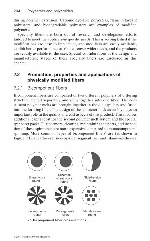
204 Polyesters and polyamides
polymers.
exhibit better performance attributes, cover wider needs, and the products are readily available to the user. Special considerations at the design and
chapter.
7.2 Production, properties and applications of
stituent polymer melts are brought together in the die capillary and fused
important role in the quality and cost aspects of this product. This involves additional capital cost for the second polymer melt system and the special spinneret packs. Furthermore, cleaning, maintaining the parts, and inspec-tion of these spinnerets are more expensive compared to monocomponent
1
Figure 7.1): sheath-core, side-by-side, segment pie, and islands-in-the-sea
Sheath-coreround
Eccentricsheath-core
roundSide-by-side
round
Pie segmentsround
Islands in searound
Pie segmentshollow
Specialty fibers are born out of research and development efforts tailored to meet the application-specific needs. This is accomplished if the
polyesters, and biodegradable polyesters are examples of modified
modifications are easy to implement, and modifiers are easily available,
manufacturing stages of these specialty fibers are discussed in this
physically modified fibers
7.2.1 Bicomponent fibers
Bicomponent fibers are comprised of two different polymers of differing structure melted separately and spun together into one fiber. The con-
into the forming fiber. The design of the spinneret-pack assembly plays an
spinning. More common types of bicomponent fibers are (as shown in
7.1 Bicomponent fiber cross-sections.
during polymer extrusion. Cationic dye-able polyesters, flame retardant
© 2008, Woodhead Publishing Limited

205
2
400 specialty capillary designs for such applications. Advanced fabrication
surface area is useful in trapping dirt, with hollow cores of desired shape to enhance permeability and acoustic behavior, and perfect geometry to impart desired feel, stiffness, and light effects (luster, sparkle etc.).
Sheath and core
sheaths and higher melting temperature cores. Common sheath/core com-binations in such applications include PE/PET, Co-PET/PET, and PP/
proportion to produce nonwoven webs by carding, air laying or any other suitable technique. Such webs can be through-air bonded or calendered. The sheath provides the fusing point while the core preserves the integrity
higher melting polymer than the sheath. The products containing these
temperatures of the sheath and the core. A major advantage is that it creates a nonwoven free of chemical bonding agents and is widely used in
metal, dye) to impart desired special properties as well as esthetics to the
(such as heat or chemical resistant polymers) to impart desired special properties as well as to keep the product economical.
the desired property or functionality is on the surface and the additive does
generally quite expensive, reducing the amount of needed additives leads to considerable cost savings.
Side-by-side
is imparted by two polymers having different shrinkage properties. These
Specialty fibers from polyesters and polyamides
bicomponent fibers. Advanced Fiber Engineering has developed nearly
techniques are used in achieving capillaries to produce fibers with various shapes providing high shape factor or high specific surface. This increased
is for self-bonding binder fibers consisting of low melting temperature The largest commercial use of bicomponent fibers of the sheath-core type
PET. These fibers are usually blended with commodity fibers in the desired
of the fibers in the nonwoven. In these cases, the core always consists of a
through-air thermal bonding of natural fiber or staple fiber webs.
binder fibers can be processed at temperatures ranging between the melting
A second type of sheath-core is filled fibers consisting of a core product
final product. Improved conductivity is achieved by having a metal or carbon core in the bicomponent fibers. A third type of sheath-core is filled
produced from either cheaper material, or expensive materials (such as
fibers consisting of a sheath product produced from expensive material
In both the second and third type of bicomponent fibers discussed above,
not have to be in the whole bulk of the fiber. Since specialty additives are
Side-by-side products are typically used as self-bulking fibers. Self-bulking
self-bulking fibers have a higher bulk and have found use in staple fiberfill
© 2008, Woodhead Publishing Limited

206 Polyesters and polyamides
ments. This technology is gaining popularity due to its higher processing
Segmented
3
trilobal cross-sections were tried. Generally, it is preferable to produce
Islands-in-the-sea
using a novel method. Often the islands are made of PET, and the sea comprised of a special type of polyester that is hot water soluble or caustic soluble. Hydroentangling is one of the techniques used to break the islands
7.2.2
RibbonHollow pie Segmentedcross
Tippedtrilobal
7.2 Various types of segmented fiber.
applications. Recently, they have been used in textured upholstery fila-
speeds, and reduced cost. Sometimes the side-by-side bicomponent fibers can be split into two fibers as well.
Segmented-pie fibers are made of segments of two polymers as in a ‘pie-
ponents of segmented-pie fibers produces microfibers that are finer than conventional microfibers, but these are mixtures of two polymeric micro-fibers. A hollow segmented-pie structure assists in splitting apart and gene-
diagram’. The fibers with an 8-segmented pie or 16-segmented pie are the popular ones used as precursors for microfibers. Splitting apart the com-
rates finer microfibers. The cross-section that is most readily splittable into
Various types of segmented fiber cross-sections are shown in Figure 7.2.
microfibers is a segmented ribbon. But they are difficult to card because of the anisotropic bending moment and very fine denier. To improve per-formance in the card, fibers with multiple lobes such as the cross and the
carded webs and then split the fibers.
Islands-in-the-sea type bicomponent fibers are used to produce nanofibers
apart from the sea. The separated islands form nanofibers, which are typically coarser than the electro-spun nanofibers.
Non-circular cross-section and profile fibers
Generic thermoplastic polymeric fibers have a solid circular cross-section. In the melt spinning process, the cross-sectional geometry of such fibers
© 2008, Woodhead Publishing Limited

207
subjected to the heat transfer phenomenon that takes place in the quench chamber. The shrinkage forces act in the radial direction and lead to the
such as hollow, trilobal, hexagonal, etc. (as shown in Figure 7.3) can be
circular capillary fabrication requires sophisticated electron beam milling and electro-discharge machinery. This involves additional capital cost for
tion of these spinnerets are more expensive. Hence non-circular cross-
additional cost involved.
Type
Hollow fiber
Spinneret hole design Fiber cross section
Ribbon fiber
Trilobal fiber
Hexagonalfiber
Specialty fibers from polyesters and polyamides
7.3 Specialty fiber cross-sections.
depends on the spinneret holes, which are circular for conventional fibers. Moreover the fibers emerging from the circular holes of the spinneret are
circular cross-sectional geometry of the fiber. Other desired cross-sections
accomplished by using the desired spinneret-hole configuration. Non-
procurement. Furthermore cleaning, maintaining the profile and inspec-
sectional fibers are produced when the value-added properties offset the
They are used as filler fibers in pillows and cushioned furniture. Trilobal Hollow fibers are lightweight and have excellent insulative properties.
ance; hence they are often used in luxury apparel. Trilobal fibers provide
light to hide any dirt. For these reasons, trilobal fibers are often used in
of light, so its appearance is also highly sparkly. Ribbon fibers pose much
cross-section fibers have reflective surfaces, giving rise to a sparkly appear-
rigidity and resilience, and the reflecting surfaces are efficient at scattering
carpets. Similarly a ribbon cross section has flat surfaces for the reflection
© 2008, Woodhead Publishing Limited
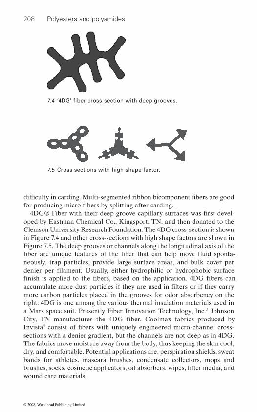
208 Polyesters and polyamides
oped by Eastman Chemical Co., Kingsport, TN, and then donated to the Clemson University Research Foundation. The 4DG cross-section is shown in Figure 7.4 and other cross-sections with high shape factors are shown in
neously, trap particles, provide large surface areas, and bulk cover per
more carbon particles placed in the grooves for odor absorbency on the right. 4DG is one among the various thermal insulation materials used in a Mars space suit. Presently Fiber Innovation Technology, Inc.3 Johnson
4
sections with a denier gradient, but the channels are not deep as in 4DG. The fabrics move moisture away from the body, thus keeping the skin cool, dry, and comfortable. Potential applications are: perspiration shields, sweat bands for athletes, mascara brushes, condensate collectors, mops and
wound care materials.
7.4 ‘4DG’ fiber cross-section with deep grooves.
difficulty in carding. Multi-segmented ribbon bicomponent fibers are good
7.5 Cross sections with high shape factor.
for producing micro fibers by splitting after carding.4DG® Fiber with their deep groove capillary surfaces was first devel-
denier per filament. Usually, either hydrophilic or hydrophobic surface finish is applied to the fibers, based on the application. 4DG fibers can
Figure 7.5. The deep grooves or channels along the longitudinal axis of the
City, TN manufactures the 4DG fiber. Coolmax fabrics produced by
accumulate more dust particles if they are used in filters or if they carry
Invista consist of fibers with uniquely engineered micro-channel cross-
brushes, socks, cosmetic applicators, oil absorbers, wipes, filter media, and
fiber are unique features of the fiber that can help move fluid sponta-
© 2008, Woodhead Publishing Limited
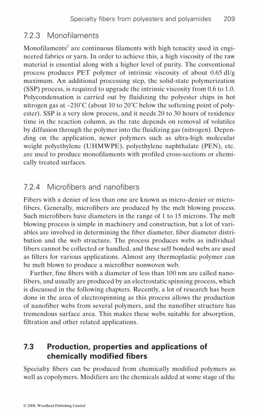
209
5
neered fabrics or yarn. In order to achieve this, a high viscosity of the raw material is essential along with a higher level of purity. The conventional process produces PET polymer of intrinsic viscosity of about 0.65 dl/g maximum. An additional processing step, the solid-state polymerization (SSP) process, is required to upgrade the intrinsic viscosity from 0.6 to 1.0.
nitrogen gas at ∼210˚C (about 10 to 20˚C below the softening point of poly-ester). SSP is a very slow process, and it needs 20 to 30 hours of residence time in the reaction column, as the rate depends on removal of volatiles
ding on the application, newer polymers such as ultra-high molecular
cally treated surfaces.
Fibers with a denier of less than one are known as micro-denier or micro-
blowing process is simple in machinery and construction, but a lot of vari-
bution and the web structure. The process produces webs as individual
is discussed in the following chapters. Recently, a lot of research has been done in the area of electrospinning as this process allows the production
tremendous surface area. This makes these webs suitable for absorption,
7.3 Production, properties and applications of
Specialty fibers from polyesters and polyamides
7.2.3 Monofilaments
Monofilaments are continuous filaments with high tenacity used in engi-
are used to produce monofilaments with profiled cross-sections or chemi-weight polyethylene (UHMWPE), polyethylene naphthalate (PEN), etc.
7.2.4 Microfibers and nanofibers
fibers. Generally, microfibers are produced by the melt blowing process. Such microfibers have diameters in the range of 1 to 15 microns. The melt
ables are involved in determining the fiber diameter, fiber diameter distri-
fibers cannot be collected or handled, and these self bonded webs are used as filters for various applications. Almost any thermoplastic polymer can be melt blown to produce a microfiber nonwoven web.
Further, fine fibers with a diameter of less than 100 nm are called nano-fibers, and usually are produced by an electrostatic spinning process, which
of nanofiber webs from several polymers, and the nanofiber structure has
filtration and other related applications.
chemically modified fibers
Specialty fibers can be produced from chemically modified polymers as well as copolymers. Modifiers are the chemicals added at some stage of the
Polycondensation is carried out by fluidizing the polyester chips in hot
by diffusion through the polymer into the fluidizing gas (nitrogen). Depen-
© 2008, Woodhead Publishing Limited
210 Polyesters and polyamides
polymer process or during extrusion. Table 7.1 contains the list of modi-
7.3.1
a result of wear, contact, and abrasion. As a fabric rubs against another
introduction of a weak spot in a strong polymeric chain. Generally, the
7.3.2
chemical structure. Their dye pick up is very low, in spite of the use of high
contribute slight openness in the polymer chain structure that eases dye-ability. But in order to obtain darker and brighter shades comparable to silk, it is necessary to introduce dye reactive spots in the polymer chain.
Chemical used
Pentaerithritol, glycerol5-sulfoisophthalic acid – Na saltDisodium 3,5-disulfobenzoic acidOrgano-phosphorus compound
Antistatic polyester – bicomponent Carbon or metal core / suffused thru surface
Monoethyl ether of polyethylene glycolAdipic acid or isophthalic acidPolyethylene glycol and 5-
sulfoisophthalic acid Heat and chemical resistant
polyesterNaphthalene and butylene compounds
Table 7.1 Chemical modification of fibers
Modification
Low pilling polyester fiberCationic dyeable polyester fiberCationic dyeable nylon fiberFlame retardant polyester fiber
Antistatic nylon fiberLow melt polyester fiberCaustic soluble polyester polymer
fying chemicals, specifically chosen for the desired application.
Low pilling fibers
Pilling is the formation of little knots of fiber on the surface of a fabric, as
them a fuzzy appearance, more often in staple fiber based fabrics. On
fibers are stronger, the pills formed do not break away, and hence they are
form a knot on the surface of the fabric. This occurs in all fabrics and gives
more noticeable on synthetic fabrics than on natural fiber based fabrics.
surface, fiber is pulled away from the yarn, protrudes, and entangles to
Chemical modification to achieve low pill polyester fibers involves the
modifier, glycerol or pentaerithritol, is added in the bulk polymerization.
natural fabrics, when pills form they break and fall off. Since synthetic
Other methods make use of microfibers or a low-pill finish, which looks
Improved dyeable fibers
excellent after wearing and laundering.
Unlike natural fibers, polyester fibers are difficult to dye because of their
pressures and high temperatures. Modifiers like polyethylene glycols
© 2008, Woodhead Publishing Limited
211
sulfo-isophthalic acid; they are incorporated into the chain during the
Nylon 6 has good acid dyeability. The dye pick up is due to the large number of amino acid (–NH2) end groups in the polymer chain. Regular
controlling the quantity of amine stabilizers in the process, amino acid end groups could be brought up or down to alter the level of dye pick up. Gen-erally, when amino acid end groups are above 100 equivalents, nylon is ultra-deep dyeable and when amino acid end groups drop below 15 equi-valents, it dyes in light shades. Sometimes, in order to impart basic dye-ability, anionic sulfonate (–SO3) groups are introduced into the nylon chain.
phosphorus compounds are inserted into the polyester macromolecules. 6
a proprietary organic phosphorus compound which is incorporated into the polyester polymer during polycondensation. Avora fabrics are used
to the presence of the FR compound, the melting point is marginally lower
melting drips from occurring, and prevents further burning by self-extinguishing. Combustion products are similar to generic polyester com-prising of oxides of carbon and water vapor, as well as small quantities of aldehydes and ketones. Recent innovations include compounding with alu-
The use of halides is banned due to environmental and health hazards.
dancy by incorporation of additives because of their melt reactivities.
Kanecaron, and Visil.
7.3.4
7
Specialty fibers from polyesters and polyamides
The popularly used reactive modifiers contain compounds based on 5-
synthesis of polyester. As these modifiers are costly, the cationic dyeable polyester fibers and fabrics are expensive.
textile grade fibers have about 60 equivalent amino acid end groups. By
7.3.3 Flame-retardant fibers
Kosa produces an FR polyester fiber with the trade name Avora® using
areas. Flame resistance is built into the fiber chemistry, such that the pro-
than regular polyester. However, the compound makes it difficult for com-
extensively in the hospitality industry, the healthcare industry, and public
Other non-polyester FR fibers in the market include Basofil, Nomex,
Antistatic and conductive fibers
Antistatic consists of a conductive core or layer along the fiber length made of conductive carbon or metal. Nega-stat bicomponent antistatic fibers
In order to obtain flame-retardant (FR) properties, about 3 to 5 wt. %
tection does not wash out, age out, and meets flammability standards. Due
bustion to take place as the fiber shrinks away from flames, chars, reduces
minum oxides, nanoclays and nanosilicates to impart flame retardancy.
Polyamides, however, have proved difficult to render durable flame retar-
© 2008, Woodhead Publishing Limited
212 Polyesters and polyamides
consist of a tribal shaped conductive carbon core and a polyester sheath. 8
carbon particles. The carbon practically becomes part of the structure of
segments and a polyetherester also exhibits antistatic properties. Blending
stripe patterns to provide effective static dissipation for the life of the
dissipate the charge by conduction when grounded or when ungrounded by air ionization, known as Corona discharge. Applications include
garments.
Polyester in its generic form, polyethylene terephthalate (PET), is not
their useful life, they can be sent for composting, where they can decom-pose in an environmentally friendly way, which promotes the growth of plants, earthworms and microbes in the composting soil. Eastar9 is a ther-
Company. Eastar is co-polyester with melting point ∼120˚C. Eastar is easily
dable. Biomax10
200˚C. Proprietary monomers are incorporated into this polymer, creating sites that are susceptible to cleavage by moisture into smaller molecules, which are then consumed by naturally occurring microorganisms and converted to carbon dioxide, water and biomass.
Polylactic acid (PLA)11 from Dow-Cargill is a biodegradable polymer
from a renewable raw material, it is biodegradable. However, PLA has poor abrasion resistance and bonding behavior when compared to con-
12 from BASF and polyhydroxybutyrate-valerate (PHBV) from Metabolix.13
Resistat conductive fibers are produced by a carbon suffusion process that saturates the outer skin of the nylon fiber with electrically conductive
with polyether makes nylon fibers hydrophilic, and they absorb more mois-ture, which imparts an antistatic property. Antistatic fibers containing
taining excellent conductivity. A block copolymer containing polyether
5–15% conductive materials are blended with non-conductive fibers in
product. Antistatic fibers neutralize surface charges by induction and
industrial bags, brushes, conveyor belts, filters, carpets, and protective
biodegradable. There are chemical modifications available to imbibe bio-
7.3.5 Biodegradable fibers
degradability. Biodegradable fibers are designed such that at the end of
bondable with cellulosics, and the finished product is completely biodegra- from Dupont is another biodegradable polyester fiber.
moplastic and biodegradable binder fiber produced by Eastman Chemical
Biomax is modified hydro-biodegradable polyester with a melting point of
that is produced from cornstarch. PLA fiber has a melting temperature of 175˚C and tensile properties comparable to that of polyester fibers. PLA, as a melt spinnable fiber from a vegetable source, has many of the advan-tages of both synthetic and natural fibers. In addition to being produced
the fiber, which retains the strength and flexibility of nylon while main-
ventional binders. Other biodegradable fibers are Ecoflex
© 2008, Woodhead Publishing Limited
213
7.3.6
terephthalate, is about 260˚C, but it can be reduced through the incorpora-
and they cause some distortion and defects in the polymer chain leading to a drop in the melting point accompanied by a minor drop in the glass
obtained by a percentage addition of the isophthalate group in the polymer chain. Adipates cause very large drops in the melting point, two to three
with a low melt polyester sheath and a conventional polyester core are
in the vicinity at the contact point, and it preserves the integrity of the nonwoven. A major advantage is that it creates a fabric free of chemical bonding agents.
7.3.7
The presence of the right proportion of long chain polyethylene glycols, sodium salts of sulfo-isophthalate compounds, etc. helps to imbibe caustic
the islands are made of conventional PET, and the sea is made of caustic-soluble polyester.
7.3.8
Increased chemical and heat resistance is achieved by the introduction of
One-hundred percent polyethylene naphthalate (PEN) has high glass tran-
ecules in the polymer chain impart higher tensile strength, UV stability, and high temperature resistance. They also have better barrier properties and are more resistant to hydrolysis in alkaline or very hot aqueous condi-
melting point of ∼245˚C is a commodity polymer used in making polyester
Specialty fibers from polyesters and polyamides
Low melt binder fibers
The melting point of the most commonly used polyester fiber, polyethylene
tion of modifiers such as isophthalates, adipates, etc. Polyester with a
bottles for soft drinks. These modifiers are added during polymerization,
times that of isophthalates. Low melt fibers (with melting point of 110˚C or 130˚C) are usually blended with commodity fibers in the desired pro-
transition temperature. A drop of about 2 to 3˚C in the melting point is
portion and then thermal bonded into webs. Generally bicomponent fibers
popular in the market. The binder fiber fuses with other non-melting fibers
Caustic soluble fibers
solubility in polyesters. A novel method of producing microfibers involves the dissolution of the sea in the ‘islands-in-sea bicomponent fibers’ wherein
Chemical and heat resistant fibers
sition temperature (125˚C) compared to PET (68˚C). Moreover PEN fibers
bulky groups such as naphthalenes and butylenes in the polymer chain.
start to shrink significantly at 190˚C [150˚C for PET]. Naphthalene mol-
tions. PEN fibers are used in sail cloths, and hot liquid filtration media. However, they are more expensive and have a lower flex life. To lower the
© 2008, Woodhead Publishing Limited
214 Polyesters and polyamides
cost PEN blends14 15 and Halar16
7.3.9 17 are used in sportswear to absorb and take away
30 nm in diameter and absorb water by a capillary phenomenon. The pores run through the surface into the hollow core. QUUP is water absorbing
core is made up of hydrophilic polymer.
atmosphere, generally tested with formaldehyde. Daiwabo has developed
cigarette smoke.
Smart18
ing stage, mostly by dissolution. While drawing, stretching, and setting the
stage.
7.3.13 Lotus leaf effect
phobic nature through lotus leaf effect.19
low surface energy and have the extended degree of surface roughness. A combination of a surface attached polymer layer and nanoparticles provide
with PET have been tried. Polyphenylene sulfide (PPS) fibers are also used in such applications.
Water absorptive fiber
Water absorptive fibersthe sweat. Hollow polyester fibers have porous walls with pore size 10 to
nylon fiber that contains proprietary nitrogen based polymer that has water absorb/release properties. HYGRA is another nylon skin-core fiber where
7.3.10 Deodorant fiber
Deodorant fiber has the ability to absorb volatile compounds from the
polymer with proprietary amine compounds in the chain that absorbs
7.3.11 Smart fibers
fibers for different applications are made from chosen polymers
formaldehyde as well as other vapors such as ammonia, acetic acid, and
for specific applications, and they are different from generic polyesters or
such as artificial muscles, intelligent biomedical garments, adaptive textile polyamides. Smart fibers are generally tailored for specific applications
7.3.12 Micro grooved fibers
Micro grooves on fibers are obtained by blending micron sized additives
structures, thermo-regulated snow clothing, etc.
while producing the fibers and then taking away the additives at the finish-
blended additives do stretch and leave groves along the fiber at the final
Water and soil repellency in fibers is achieved by imparting ultra hydro- Basically the fibers need to have
© 2008, Woodhead Publishing Limited
215
Further the topography and the resulting roughness of the surface is tuned, by changing the size and shape of the nanoparticles. Ultimately the water contact angle close to 130˚ is found to provide adequate hydrophobic properties.
polycondensation stage of the manufacture. Fiber surface treatment20 by
and warmth retention. Generally caustic chemicals are employed in the treatment.
7.3.15 Fibers with controlled shrinkage
Heat setting is the operation carried out to control the residual shrinkage
over oil heated drums. In this process as the crystallinity increases the shrinkage reduces. Fibers with low shrinkage (less than 1%) are used in sewing threads. Other approaches such as adding nucleating agents to
their commercialization is limited.
Compounding with nanoclays or nanosilicates enhances mechanical prop-erties such as heat distortion temperature and tensile strength as well as
ratio and hence possess a high surface to volume ratio. In order to obtain the advantages, it is essential to have proper surface wetting, dispersion and exfoliation of the nanoparticles. The polymer-layered silicate (PLS)21 exhibited increased modulus and strength, decreased gas permeability, and
nanotubes impart electrical and thermal conductivity. Single wall and mul-tiwall carbon nanotubes22 are relatively new, and their commercial poten-tial has been limited by their high prices.
7.4 Design and process control aspects
with respect to heat transfer, glass transition, melting, crystallization, and
Specialty fibers from polyesters and polyamides
the desired results. A polystyrene layer is grafted onto polyester fiber.
7.3.14 Surface treated fiber – dull luster
chemical means is a method to modify the characteristics of smooth fibers
In order to control luster, generally titanium dioxide is added at the
in the fiber. Generally fiber is subjected to heat under tension by passing
enhance crystallization during fiber formation are studied extensively but
7.3.16 Other specialty fibers
Modifiers and additives cause some changes in specialty polymer behaviors
as it imparts dull luster as well as new textile properties such as fluffiness
the flame retardancy of the product. Nanoparticles have a very high aspect
decreased flammability. While nanoclay adds muscle to plastics, carbon
© 2008, Woodhead Publishing Limited

216 Polyesters and polyamides
orientation of the molecular chains compared to the conventional poly-mers, and hence call for some minor adjustments in the processing condi-
23 24 involve
and spinning is more than normal (∼0.020). In such cases, an appropriate adjustment is to go for slightly higher viscosity polymer granules. Specialty
Operating variables are online variables that can be changed while the
peratures of the polymer and quench air, collector or winder speed. The
are a few variables at the drawing and heat setting stages. All of these affect
the spinning process, and can only be changed with downtime or when the machine is not in operation. These variables include spinnerets (capillary
in the diameter range of 0.1 to 0.5 mm, with a length to diameter (L/D)
capillaries, at lower melt speeds and at slightly higher melt viscosity. Melt
5 to 50 m/min).For specialty cross-sections, calculations are carried out based on the
(d/D) of 0.3, spinneret capillaries d/D of about 0.6 are required. Generally, the capillary bridge width is about 20% of the outer diameter of the
length to width ratio (L/w) of 4, it is required to have spinneret capillaries
to width ratio of the spinneret capillaries (L/w) is 3.
7.5 Future trends
With the continuing pressure for better quality, assured performance at lower prices is the primary goal of a manufacturer of commodity products.
and advanced fiber spinningprocess as well as heat transfer parameters. Conventional polyester fibers
For specialty fibers, more or less the same melt viscosity is required, but
tions. Basics of fiber technology
chemical modification can offset the relation between melt viscosity and
fibers with modified fiber cross-sections are obtained by the controlled
are made from polymers having an intrinsic viscosity (IV) of 0.600 to 0.650.
IV. In certain specialty fibers, the process-loss in viscosity during melting
solidification of the melt streams emerging out of the spinneret capillaries. The final cross-section depends upon the machine and process variables.
quench air is adjusted towards a lower velocity profile for finer fibers. There
machine is being operated. These variables include throughput and tem-
design) and quench air profile setting hardware.
the final properties of the fiber. Off-line variables are fixed before starting
In the case of conventional fibers, the spinneret holes or capillaries are
ratio of 2 to 5. Finer filaments are produced with the smaller diameter
extrusion velocity is in the range of 5 to 75 m/min (for conventional fibers
same principles used in conventional fibers with a slightly more complex formula derived for the specific geometry. In the case of hollow fibers, in order to get a fiber cross-sectional inner diameter to outer diameter ratio
capillary. In the case of ribbon fibers, in order to get a fiber cross-sectional
L/w of about 12. For trilobal fibers, the preferred cross-sectional leg length
© 2008, Woodhead Publishing Limited
217
performance properties. This encourages the search for new materials and innovative approaches to satisfy the short-term and long-term goals.
growing and demonstrating their potential to replace conventional ma-terials. The coming years will see dramatic changes in the level of their acceptance and the diversity of their use, as engineers gain control over the necessary design skills, and wider adoption makes them more cost effective. Moreover, with increased thrust for using raw materials from renewable resources, biodegradability of the product is demanding a shift
in the municipal waste.
7.6 References
1. Technical Brochure, Hills Inc., http://www.hillsinc.net 2. Shaped Fibers and their Applications, Alex Lobovsky, Proceedings of the
Tandec Conference, Knoxville, TN 2006
4. http://www.invista.com
6. http://www.avora.com 7. http://www.barnet.com/html/nega_stat.html 8. http://www.resistat.com/ 9. Eastar Product Literature, Eastman Chemical Company, Kingsport, TN.10. Trade catalog, www.dupont.com/packaging/products/biomax.html11. http://www.kanebotx.com/english/new/corn-f.htm.12. Robert Leaversuch, ‘Biodegradable Polyesters – packaging goes green,’ www.
plasticstechnology.com13. Product Brochure, www.metabolix.com14. Structural development and mechanical properties of polyethylene naphtha-
late/polyethylene terephthalate blends during uniaxial drawing, Elinor L. Bedia, Syozo Murakami, Taku Kitade and Shinzo Kohjiya, Polymer, Volume 42, Issue 17, August 2001, pages 7299–7305
15. http://www.ticona.com16. http://www.solvaysolexis.com17. New Millennium Fibers, Hongu T, and Philips G, Woodhead Pub. (1997)
(2005)19. http: //www.ces.clemson.edu/mse/Research/NTC /Ultrahydrophobic%
20Fibers_1.htm
p. 70 + 8621. Polymer-Layered Silicate Nanocomposites: Synthesis, Properties and Appli-
cations, Emmanuel P. Giannelis, Appl. Organometal. Chem. 12, 675–680 (1998)
Specialty fibers from polyesters and polyamides
Research interests often go for niche products in relation to the specific
Composites containing polymers, fibers, nonwovens, films, and foams are
from conventional synthetic fibers that are too stable and do not degrade
3. http://www.fitfibers.com
5. http://www.teijinmonofil.com/
18. Smart fibers, Fabrics, and Clothing, Xiaoming Tao, Woodhead Pub.
20. New fiber shapes, Rayon Pub, Modern Textiles, v 38, n 11, November, 1957,
© 2008, Woodhead Publishing Limited
218 Polyesters and polyamides
22. Carbon Multiwall Nanotubes as a Conductive or Flame Retardant Additive For Wire and Cable, Patrick Collins, Hyperion Catalysis International, Inc., Cambridge, MA 02138
23. Manufactured Fiber Technology, Gupta V.B. and Kothari V.K., Chapman & Hall Pub. (1997)
24. Advanced Fiber Spinning Technology, Nakajima T, Woodhead Pub. (1994)
© 2008, Woodhead Publishing Limited
8Property enhancement through blending
R. A LAGI RUSA M Y and A. DAS, Indian Institute of Technology, New Delhi, India
8.1 Introduction
the desired staple length and denier. In addition, some highly popular
negative attributes like proneness to static generation, low moisture regain, etc. Therefore, for most of the end uses especially the apparels, the common practice in the textile industry has been to use blended yarns instead of
cost of the product.
and two for production of speciality products like core spun yarns and nonwovens and other related products. For apparel end uses, blending is
the staple form and spinning them into yarn. In the case of core spun yarns,
yarns is carried out in one of the nonwoven processes like needle punching or stitch bonding to obtain a blended product. The majority of the polyester blends go into making the apparels where yarn uniformity in terms of mass variation and dyeability are critical. Hence, in this chapter the principles
219
lack of availability of natural fibres and second, controllable and superior
The increase in the production of synthetic fibres in the past few decades
properties of synthetic fibres like polyester and polyamide. These synthetic
has been phenomenal. This can be broadly attributed to two factors. First,
fibres have many superior properties such as uniformity in length and
fibres like polyester impart higher tenacity, greater abrasion resistance and better crease resistance to the fabrics. However, these fibres have some
100% single fibre yarns. Blending of fibres is also carried out in technical uses as well to enhance the properties of the final product or to reduce the
The aspect of blending of polyester and polyamide fibres with other fibres can be considered in two different ways: one, for apparel applications
normally carried out in the fibre stage, i.e, blending of different fibres in
blending of one component in continuous filament form and the other in the staple fibre form are combined at the yarn spinning stage. In nonwoven processes, blending of different types of staple fibres or already formed
and methods involved in blending of staple fibres, particularly with
strength, freedom from foreign impurities and the flexibility in regard to
© 2008, Woodhead Publishing Limited
220 Polyesters and polyamides
trial clothing, conveyor belting, tentage, elastic yarns and sewing threads
chapter, the technology of core spinning and other technical textile prod-ucts made through nonwoven processes are discussed.
effective means of projecting the positive attributes or aspect of each of
poor yarn properties but also fabric defects like fabric streakiness when dyed.
important objectives too and is quite common in the industry.1
mainly in order to2
• Give the required characteristics to the product (e.g. blending of
character).• Hold on raw material cost (blending in of relatively cheap raw
material).
nylon).
The major objectives of blending are improvement in functional proper-ties, improved process performance, better economy and improved aes-thetics. One of the primary reasons for blending is to improve the functional properties of the fabrics such as higher tensile strength, uniformity, better appearance, increased wear life, crease resistance, crease recovery, dimen-
possibly impart all of these desirable properties to the fabric. Take the case of polyester–viscose, a very popular blend. Fabrics from 100% viscose rayon suffer from low tensile and tear strength, poor crease resistance and recovery and low abrasion resistance. However, addition of polyester can
polyester and nylon, are discussed first. Second, significant amounts of polyester and polyamides are combined with other fibres to make indus-
through core-spinning technology. Hence, in the second section of the
8.2 Staple fibre blending
The blends normally consist of two (binary blend) or three different fibres (tertiary blend). Such blending of two or more dissimilar fibres offers an
the constituent fibres. Blending, however, needs to be carried out in such a way that the fibres in a blended yarn are thoroughly dispersed and inter-mingled. Any deficiency in proper blending of fibres results not only in
All fibres, whether natural or manmade, are quite in-homogeneous in
stock. Blending of dissimilar fi bres is undertaken to achieve some other
In the case of polyester and polyamide fibres, blending is performed
desired homogeneity in their characteristics even in a 100% single fibre respect of their characteristics. Blending, therefore, is a must to bring the
polyester fibres with natural fibres produces the desire easy-care
(use of segmented fibres having alternate segments of polyester and
sional stability, elasticity and comfort. A 100% single fibre yarn cannot
• Influence favourably the behaviour of the material during processing
© 2008, Woodhead Publishing Limited
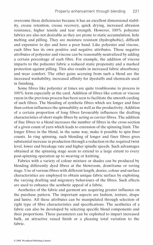
Property enhancement through blending 221
ity, crease retention, crease recovery, quick drying, increased abrasion resistance, higher tensile and tear strength. However, 100% polyester fabrics are also not desirable as they are prone to static accumulation, hole
and expensive to dye and have a poor hand. Like polyester and viscose,
attributes of polyester and viscose can be reasonably neutralized by adding
protection against pilling. This also results in increased fabric absorbency and wear comfort. The other gains accruing from such a blend are the
rayon in the previous process has been seen to facilitate the smooth carding
of a given count of yarn which leads to extension of the spinning limit. The
substantial increase in production through a reduction in the required twist
obtained at the spinning stage seem to extend to a large extent to every
Fabrics with a variety of colour mixture or shades can be produced by
characteristics are employed to obtain unique fabric surface by exploiting
are used to enhance the aesthetic appeal of a fabric.
the purchase pattern. The important aspects are fashion, texture, drape and lustre. All these attributes can be manipulated through selection of
their proportions. These parameters can be exploited to impart increased
fabric.
overcome these deficiencies because it has an excellent dimensional stabil-
melting and pilling. They are moisture resistant (hydrophobic), difficult
each fibre has its own positive and negative attributes. These negative
a certain percentage of each fibre. For example, the addition of viscose
increased washability, increased affinity for dyestuffs and chemicals used in finishing.
Some fibres like polyester at times are quite troublesome to process in
imparts to the polyester fabric a reduced static propensity and a marked
of such fibres. The blending of synthetic fibres which are longer and finer
characteristics of short staple fibres by acting as carrier fibres. The addition of fine fibres to a blend increases the number of fibres in the cross-section
longer fibres in the blend, in the same way, make it possible to spin finer counts. In ring spinning, such blending of longer and finer fibres gives
blending differently dyed fibres at the blowroom, drawframe or roving
level, lower end breakage rate and higher spindle speeds. Such advantages
stage. Use of various fibres with different length, denier, colour and surface
post-spinning operation up to weaving or knitting.
right type of fibre characteristics and specifications. The aesthetics of a
the varying drafting and migratory behaviours of the fibres. Such effects
fabric can also be developed by selecting specific blend components and
bulk, an attractive raised finish or a pleasing total variation to the
than cotton influences the spinnability as well as the productivity. Addition
100% form especially at the card. Addition of fibres like cotton or viscose
of a certain proportion of long fibres favourably influences the drafting
Aesthetics of the fabric and garment are acquiring greater influence on
© 2008, Woodhead Publishing Limited
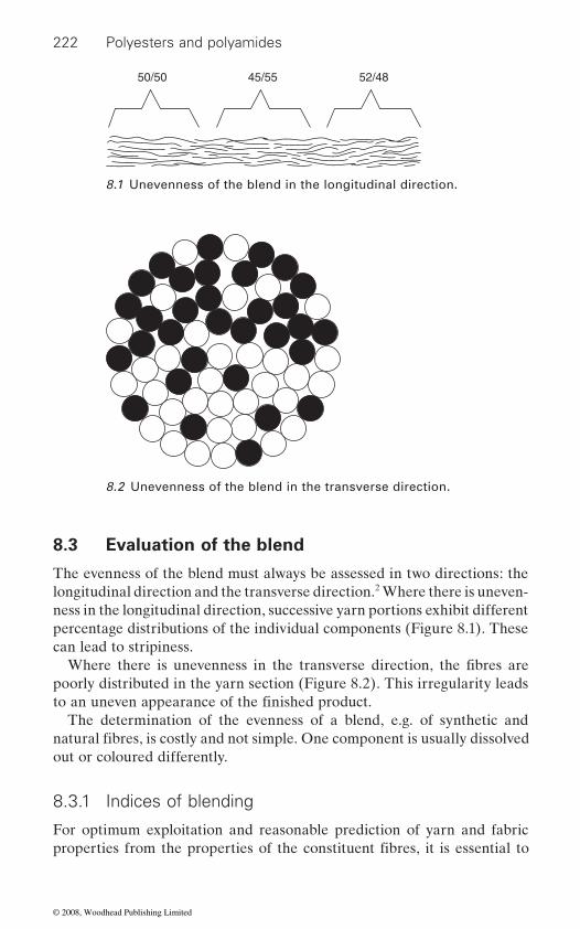
222 Polyesters and polyamides
8.3 Evaluation of the blend
The evenness of the blend must always be assessed in two directions: the longitudinal direction and the transverse direction.2 Where there is uneven-ness in the longitudinal direction, successive yarn portions exhibit different percentage distributions of the individual components (Figure 8.1). These can lead to stripiness.
poorly distributed in the yarn section (Figure 8.2). This irregularity leads
The determination of the evenness of a blend, e.g. of synthetic and
out or coloured differently.
8.3.1 Indices of blending
For optimum exploitation and reasonable prediction of yarn and fabric
45/5550/50 52/48
8.1 Unevenness of the blend in the longitudinal direction.
8.2 Unevenness of the blend in the transverse direction.
Where there is unevenness in the transverse direction, the fibres are
to an uneven appearance of the finished product.
natural fibres, is costly and not simple. One component is usually dissolved
properties from the properties of the constituent fibres, it is essential to
© 2008, Woodhead Publishing Limited
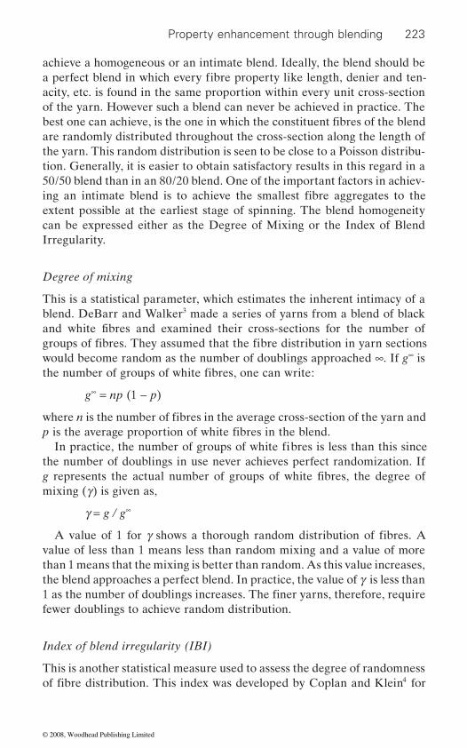
Property enhancement through blending 223
achieve a homogeneous or an intimate blend. Ideally, the blend should be
acity, etc. is found in the same proportion within every unit cross-section of the yarn. However such a blend can never be achieved in practice. The
are randomly distributed throughout the cross-section along the length of the yarn. This random distribution is seen to be close to a Poisson distribu-tion. Generally, it is easier to obtain satisfactory results in this regard in a 50/50 blend than in an 80/20 blend. One of the important factors in achiev-
extent possible at the earliest stage of spinning. The blend homogeneity can be expressed either as the Degree of Mixing or the Index of Blend Irregularity.
Degree of mixing
This is a statistical parameter, which estimates the inherent intimacy of a blend. DeBarr and Walker3 made a series of yarns from a blend of black
would become random as the number of doublings approached ∞. If g∞ is
g∞ = np (1 − p)
the number of doublings in use never achieves perfect randomization. If
mixing (g) is given as,
g = g / g∞
value of less than 1 means less than random mixing and a value of more than 1 means that the mixing is better than random. As this value increases, the blend approaches a perfect blend. In practice, the value of g is less than
fewer doublings to achieve random distribution.
Index of blend irregularity (IBI)
This is another statistical measure used to assess the degree of randomness 4
a perfect blend in which every fibre property like length, denier and ten-
best one can achieve, is the one in which the constituent fibres of the blend
ing an intimate blend is to achieve the smallest fibre aggregates to the
and white fibres and examined their cross-sections for the number of groups of fibres. They assumed that the fibre distribution in yarn sections
the number of groups of white fibres, one can write:
where n is the number of fibres in the average cross-section of the yarn and p is the average proportion of white fibres in the blend.
In practice, the number of groups of white fibres is less than this since
g represents the actual number of groups of white fibres, the degree of
A value of 1 for g shows a thorough random distribution of fibres. A
1 as the number of doublings increases. The finer yarns, therefore, require
of fibre distribution. This index was developed by Coplan and Klein for
© 2008, Woodhead Publishing Limited
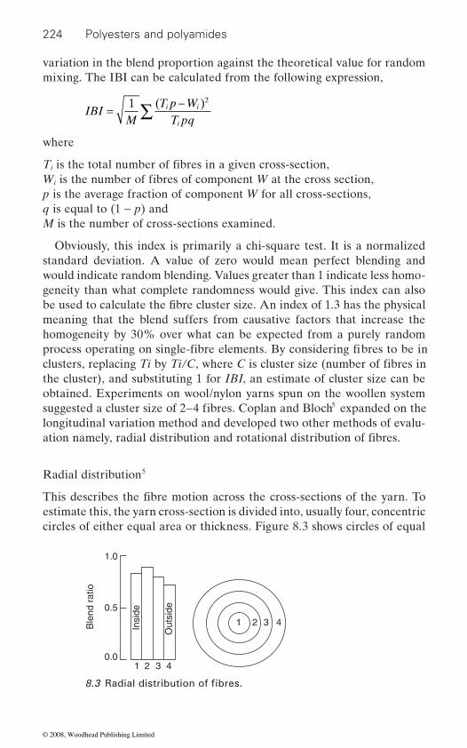
224 Polyesters and polyamides
variation in the blend proportion against the theoretical value for random mixing. The IBI can be calculated from the following expression,
IBIM T pq
i i
i
= ∑1 2
where
i
i
p is the average fraction of component W for all cross-sections,q is equal to (1 − p) andM is the number of cross-sections examined.
Obviously, this index is primarily a chi-square test. It is a normalized standard deviation. A value of zero would mean perfect blending and would indicate random blending. Values greater than 1 indicate less homo-geneity than what complete randomness would give. This index can also
meaning that the blend suffers from causative factors that increase the homogeneity by 30% over what can be expected from a purely random
the cluster), and substituting 1 for IBI, an estimate of cluster size can be obtained. Experiments on wool/nylon yarns spun on the woollen system
5
longitudinal variation method and developed two other methods of evalu-
Radial distribution5
estimate this, the yarn cross-section is divided into, usually four, concentric circles of either equal area or thickness. Figure 8.3 shows circles of equal
1 2 3 4
10.0
0.5
Ble
nd r
atio
1.0
Insi
de
Out
side
2 3 4
T is the total number of fibres in a given cross-section,
( )T p − W
W is the number of fibres of component W at the cross section,
be used to calculate the fibre cluster size. An index of 1.3 has the physical
process operating on single-fibre elements. By considering fibres to be in clusters, replacing Ti by Ti/C, where C is cluster size (number of fibres in
suggested a cluster size of 2–4 fibres. Coplan and Bloch expanded on the
ation namely, radial distribution and rotational distribution of fibres.
This describes the fibre motion across the cross-sections of the yarn. To
8.3 Radial distribution of fibres.
© 2008, Woodhead Publishing Limited

Property enhancement through blending 225
thickness along with the blend ratio plotted in the form of a bar diagram. Ideally, the blend ratio should be the same in all four zones from inside to outside.
Rotational distribution5
For estimating the variation in the rotational distribution, the yarn cross-section is divided into four to six segments. The blend ratio is calculated and plotted as bar diagram as shown in Figure 8.4. Ideally the ratio should be the same for all the segments.
The segregation of components in a blend yarn is known as migration. A
straight path would be under lower tension. The tension differences would
having higher modulus tend to occupy the inner zones of the yarn cross-
6
up and pack closely when twisted, depends on the parameter, (1/h − 2/E),
modulus. The greater the positive value of this parameter, the closer is the packing. Therefore, in a binary blend the component with a greater value of (1/h − 2/E) will pack more tightly and hence tend to occupy the core of the yarns. Obviously, the component with the lower value of (1/h − 2/E)
I
I
II
II
III
III
IV
IV
0.0
0.5
Ble
nd r
atio
1.0
8.4 Rotational distribution of fibres.
comprehensive understanding of this aspect of fibre behaviour is essential for the proper selection of fibres for a blend. The migratory behaviour of fibres in yarns arises from differences in tensions developed during twist-
8.4 Migration
ing of fibres into yarn. The fibres twisting around a long path on the yarn surface would develop a high tension while fibres following a shorter
cause an interchange of position between the high and low tension fibres and thus lead to migration. It is known that, in a blend yarn the fibres
section and those fibres having lower modulus, the outer zone.Cassie postulated that for any spun yarn, the tendency for fibres to coil
where h is the modulus of torsional rigidity of a fibre and E is its bending
© 2008, Woodhead Publishing Limited
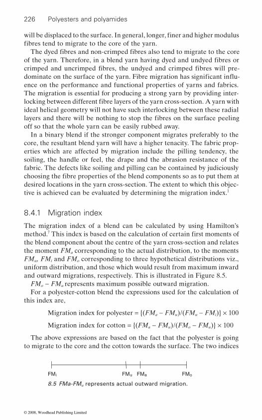
226 Polyesters and polyamides
ence on the performance and functional properties of yarns and fabrics. The migration is essential for producing a strong yarn by providing inter-
ideal helical geometry will not have such interlocking between these radial
off so that the whole yarn can be easily rubbed away.In a binary blend if the stronger component migrates preferably to the
core, the resultant blend yarn will have a higher tenacity. The fabric prop-erties which are affected by migration include the pilling tendency, the soiling, the handle or feel, the drape and the abrasion resistance of the fabric. The defects like soiling and pilling can be contained by judiciously
desired locations in the yarn cross-section. The extent to which this objec-tive is achieved can be evaluated by determining the migration index.1
8.4.1 Migration index
The migration index of a blend can be calculated by using Hamilton’s 7
the blend component about the centre of the yarn cross-section and relates the moment FMa corresponding to the actual distribution, to the moments FMu, FMi and FMo corresponding to three hypothetical distributions viz., uniform distribution, and those which would result from maximum inward and outward migrations, respectively. This is illustrated in Figure 8.5.
FMo − FMu represents maximum possible outward migration.For a polyester-cotton blend the expressions used for the calculation of
this index are,
Migration index for polyester = {(FMa − FMu)/(FMu − FMi)} × 100
Migration index for cotton = {(FMa − FMu)/(FMo − FMu)} × 100
The above expressions are based on the fact that the polyester is going to migrate to the core and the cotton towards the surface. The two indices
FMi FMu FMa FMo
8.5 FMa-FMu represents actual outward migration.
will be displaced to the surface. In general, longer, finer and higher modulus fibres tend to migrate to the core of the yarn.
The dyed fibres and non-crimped fibres also tend to migrate to the core of the yarn. Therefore, in a blend yarn having dyed and undyed fibres or crimped and uncrimped fibres, the undyed and crimped fibres will pre-
locking between different fibre layers of the yarn cross-section. A yarn with
layers and there will be nothing to stop the fibres on the surface peeling
choosing the fibre properties of the blend components so as to put them at
method. This index is based on the calculation of certain first moments of
dominate on the surface of the yarn. Fibre migration has significant influ-
© 2008, Woodhead Publishing Limited
Property enhancement through blending 227
will be seen to be equal but have opposite signs, i.e., if one is positive, the other will be negative. A negative value for a component indicates that it has preferentially inward migration whereas a positive value indicates outward migration.
8.5 De-blending
process, and second be able to maintain the blend up to the stage of binding
not always easy; sometimes the second is harder still. Fibres of different length, different surface structure, crimp, etc., also behave differently during movements as individuals. A ‘de-blending’ effect can very often arise.2
drawing in drafting arrangements. Fibres with large differences in length or surface form (smooth/rough, dyed/undyed, etc.) do not exhibit the same cohesive contact with each other. When a drafting force is applied, they
to de-blending. Pneumatic transport can also cause de-blending.
8.6 Selection of blend constituents
The choice of blend constituents needs careful consideration both in
their positive attributes and to suppress the negative ones. One has to
end use requirements. For example, one may have to choose between low tenacity and high tenacity polyester, round cross-section or trilobal polyester.
8.6.1
achieve. Take the case of some popular blends like polyester-cotton or polyester-viscose, which are normally used, for apparels like shirting and suiting. If the fabric is made from 100% polyester it will have excellent crease resistance, durability, and wash and wear due to the hydrophobic
The spinner aims to distribute the different fibres evenly in the yarn. For this purpose he must first produce a good blend at some stage of the
During rolling of fibres in hoppers (bale openers, hopper feeders),
into the yarn. As is well known, meeting the first of these requirements is
migration of the components occurs where the fibres have different struc-tures (e.g. cotton and synthetic fibres). A similar effect is found during
move differently – this leads to clumping of fibres into clusters and finally
terms of the fibre type and their proportion in the blend so as to bring out
further decide the specifications of these fibres, keeping in mind the
Type of fibre
The major objective of blending two or more fibres is to produce a yarn or fabric with improved functional properties, which a single fibre just cannot
nature of the polyester fibre.
© 2008, Woodhead Publishing Limited
228 Polyesters and polyamides
it more comfortable to wear because of their higher thermal conductivity
thus easily passed on to the outside air resulting in wear comfort. Such a blend fabric, therefore, overcomes the clammy feel of the 100% synthetic-
feel.The choice between cotton and viscose rayon for blending with polyester
is primarily dependent on the end product. For a fuller look in lightweight fabrics, such as shirting, cotton is preferred. Even for heavier sorts such as working clothes and dyed uniform fabrics, cotton may be preferred to viscose so as to avoid a differential shade at the worn out portions. The
would, however, give superior results to cotton in terms of yarn evenness, appearance, freedom from trash particles and contaminants. This blend is, therefore, preferred for medium and heavy constructions, such as suiting, where impeccable appearance is important. Similarly, blending of shrink-
produce hi-bulk yarns.
portion of the blended yarns produced. However, to a limited extent, the
blend is the polyester-cotton-polynosic. Such blends are normally used for reasons of economy, styling and special surface effect in the fabrics. The
gated to a secondary place in such tertiary blends. More often than not, such blends are produced for commercial exploitation by carrying the
in a small proportion. The tertiary blends can also be used for production of fabrics having multi-coloured effects during piece dyeing. This, however, demands a great skill on the part of the dyer and a thorough knowledge of the reactivity of one group of dues with another.
For trouble-free processing and optimum utilization of the positive attri-butes of the blend constituents, it is imperative to consider their compatibil-ity in terms of their properties such as length, denier, breaking elongation, etc.
Addition of a hydrophilic fibre like cotton or viscose rayon may render
fibre fabric. The fabric would also save the user from the pricking sensation
and better absorption of perspiration. The body heat and perspiration are
due to lower bending rigidity of the cellulosic fibres and thus give it a softer
viscose rayon fibre due to its lower abrasion wears out much faster than cotton, thus giving prominence to shade of polyester fibres which is gener-ally somewhat different from that of viscose fibres. The blend with viscose
able and non-shrinkable polyester or other type of fibres is carried out to
The blends of two fibres, called binary blends, account for the major
objective of exploiting the positive attributes of each of the fibres is rele-
tertiary blends (blend of three types of fibres) are also produced. One such
name of the most desirable but costly fibre though it may be present only
8.6.2 Compatibility of fibre blends
© 2008, Woodhead Publishing Limited
229
Length and denier
the same for all the constituents unless deviations are desired for producing some special effects. For blending of polyester with combed cotton of, say 34 mm, the denier of cotton component, generally in the range of 1.3 to 1.5
in a viscose-cotton blend the viscose rayon of 1.5 denier and 29–32 mm length is generally used to match cotton of 1.5 denier (4.2 μg/inch) and 28 mm length.
The denier difference, on the other hand, seems to be detrimental to
are high, the process performance and the yarn quality are expected to be poor.
Extensibility
load. This extent of inequality in sharing of tensile load is determined by
Dyeing properties
In case the blend yarn or fabric is to be dyed subsequently, due consider-
components.
Property enhancement through blending
The two most important fibre properties, which need to be matched for satisfactory processing of blends, are the staple length and the fineness of the fibres. As a general rule, these two fibre properties should be nearly
prevents intimate blending of fibre during twisting; the coarser fibres going to the surface and the finer to core. Excessive difference in the denier of
(3.6 to 4.2 μg/inch), is matched with 1.2 to 1.5 denier of polyester. Similarly
the blend fibres, say 1.5 denier viscose and 3.0 denier polyester, has been seen to produce very weak yarns. It is difficult to lay down any firm toler-ance limits for the difference in length and denier of the blend fibres. In
yarn quality as the migratory behaviour during twisting in yarn formation
general, it can be stated that if the differences in the length and fineness
f ibre property in respect of achieving the maximum strength from a blend. In a blend, the fibre with a lower breaking elongation will break when the other fibre component is sharing only a part of its breaking load. After the breaking of the less extensible fibres, the full load is transferred to the more extensible component, as the less extensible fibres can no longer share any
The elongation compatibility of the constituent fibres is the most important
the load elongation curves of the two fibres.
ation should also be given to the dyeing properties of the individual fibre
Tensile specifications of fibres
Having decided the type of blend fibres and their physical specifications, the next step involves careful consideration of the specific tensile
© 2008, Woodhead Publishing Limited
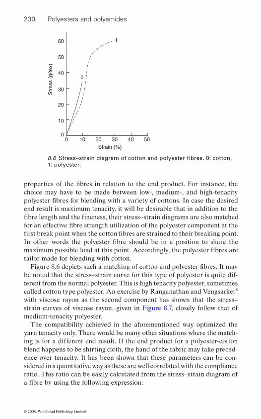
230 Polyesters and polyamides
choice may have to be made between low-, medium-, and high-tenacity
tailor-made for blending with cotton.
be noted that the stress–strain curve for this type of polyester is quite dif-ferent from the normal polyester. This is high tenacity polyester, sometimes called cotton type polyester. An exercise by Ranganathan and Vengsarker8 with viscose rayon as the second component has shown that the stress–strain curves of viscose rayon, given in Figure 8.7, closely follow that of medium-tenacity polyester.
The compatibility achieved in the aforementioned way optimized the yarn tenacity only. There would be many other situations where the match-ing is for a different end result. If the end product for a polyester-cotton blend happens to be shirting cloth, the hand of the fabric may take preced-ence over tenacity. It has been shown that these parameters can be con-sidered in a quantitative way as these are well correlated with the compliance ratio. This ratio can be easily calculated from the stress–strain diagram of
Strain (%)
Str
ess
(g/te
x)
00
10
20
30
40
50
60
0
1
10 20 30 40 50
1: polyester.8.6 Stress–strain diagram of cotton and polyester fibres. 0: cotton,
properties of the fibres in relation to the end product. For instance, the
polyester fibres for blending with a variety of cottons. In case the desired
for an effective fibre strength utilization of the polyester component at the first break point when the cotton fibres are strained to their breaking point.
fibre length and the fineness, their stress–strain diagrams are also matched
In other words the polyester fibre should be in a position to share the
end result is maximum tenacity, it will be desirable that in addition to the
maximum possible load at this point. Accordingly, the polyester fibres are
Figure 8.6 depicts such a matching of cotton and polyester fibres. It may
a fibre by using the following expression:
© 2008, Woodhead Publishing Limited
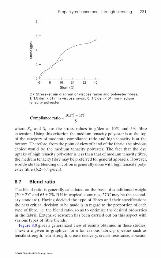
Property enhancement through blending 231
Compliance ratio =−− −10 55
101
51S S
where S10 5
extension. Using this criterion the medium tenacity polyester is at the top of the category of moderate compliance ratio and high tenacity is at the bottom. Therefore, from the point of view of hand of the fabric, the obvious choice would be the medium tenacity polyester. The fact that the dye
worldwide the blending of cotton is generally done with high tenacity poly-
8.7 Blend ratio
The blend ratio is generally calculated on the basis of conditioned weight (20 ± 2˚C and 65 ± 2% RH in tropical countries, 27˚C may be the second-
the next critical decision to be made is in regard to the proportion of each
in the fabric. Extensive research has been carried out on this aspect with
Figure 8.8 gives a generalized view of results obtained in these studies. These are given in graphical form for various fabric properties such as tensile strength, tear strength, crease recovery, crease resistance, abrasion
Strain (%)
Str
ess
(gpd
)
0
0
1
0
2
4
6
8
168 24 32 40
1: 1.5 den × 51 mm viscose rayon; 0: 1.5 den × 51 mm medium tenacity polyester.
8.7 Stress–strain diagram of viscose rayon and polyester fibres.
and S are the stress values in g/den at 10% and 5% fibre
uptake of high tenacity polyester is less than that of medium tenacity fibre, the medium tenacity fibre may be preferred for general apparels. However,
ester fibre (6.2–6.4 g/den).
ary standard). Having decided the type of fibres and their specifications,
type of fibre, i.e. the blend ratio, so as to optimize the desired properties
various types of fibre blends.
© 2008, Woodhead Publishing Limited

232 Polyesters and polyamides
the optimized fabric properties by selecting the proper blend ratio. It needs to be mentioned here that the yarn and the fabric construction as well as
weaker at a low ratio of polyester. The optimum blend ratio would then work out to 65 : 35 for optimum wear performance. The polyester compo-
ChosenBlend ratioPolyester
Key: Outstanding Adequate PoorGood
0 - 25 - 50 - 75 - 100
Polyester cotton
1. Durability
2. Appearance
3. General
Drape
Creaserecovery dry
wet
dry
wet
Creaseretention
Shrinkage
Resistanceto burnt - inholes
Tensile
Tear
Abrasion
Polyester viscose
100 - 75 - 50 - 25 - 00 - 25 - 50 - 75 - 100100 - 75 - 50 - 25 - 0
67/33 67/33
Moisturesorption
Antistaticresistance
Bulkiness andhandlePilling
8.8 Effect of blend ratio on properties of polyester blended fabrics.1
Second f ibre
ester-viscose fabrics. This figure can be used as a guideline for achieving
the final finishing of the fabric, especially with regard to heat setting and
resistance, pilling, anti-static resistance, etc. for polyester-cotton and poly-
resin finishing, does make a noticeable difference in the desirable blend
behaviour of the component fibres. In a polyester-viscose blend if the stress–strain curves of the two fibres do not match, the blend yarn is
ratio. Another factor that influences the blend ratio is the stress–strain
© 2008, Woodhead Publishing Limited

Property enhancement through blending 233
in this respect. Some economic considerations, more than anything else, dictate the decisions about blend ratios that might otherwise look unreasonable.
8.8 Types of blending operation
8.8.1 Possibilities
various methods, equipment, machines and intermediate products. The following can be distinguished:
Blending type Process stageBale mixing Before the blowroomFlock blending Within the blowroomLap blending Using scutchersWeb blending At the ribbon lap machine or the blending drawframeSliver blending At the drawframe, the sliver-lap machine, or the comberFibre blending At the card or the OE spinningRoving blending At the ring spinning machine
In addition, controlled and uncontrolled blending must also be distin-guished. In uncontrolled blending, the components are brought together at random and without a mixing system (e.g. often in bale mixing). In controlled blending, the individual components are supplied to the machines in an ordered fashion and precisely metered (e.g. in weighing hopper feeders).
The various blending processes often differ strongly from one another with respect to capital cost, labour intensiveness, precision of blending, liability to error and simplicity. Each method has advantages and disad-vantages. It is therefore not possible to put forward patent recipes for the use of one or another blending principle. The actual techniques used for
8.8.2 Optimum blending method
homogeneous blend consistent with process performance, yarn quality and
need similar opening and cleaning treatment, the blending may be resorted
nent in the blend can be reduced to 50% if the fibres are made compatible
Blending of staple fibres can be carried out at various process stages, using
blending of fibres can be referred to in the standard text books.
The objective of choosing a specific blending stage is to achieve the most
method is the type of fibres to be blended. In case the component fibres fibre waste. The most important factor influencing the choice of blending
© 2008, Woodhead Publishing Limited
234 Polyesters and polyamides
to at the blowroom, and that, too, at the initial stages through stack or machine blending. This stage of blending is most suitable for blends like
trash and require mild opening action. The stack blending or sandwich
among themselves. The rayon component, which is rather more cohesive, may have to be pre-opened before blending.
Polyester and cotton, therefore, is normally blended at the drawframe. In certain instances, however, the mills using drawframe blending for polyester-cotton face serious problems in the carding of 100% polyester, and dye shade variations in the blend fabric due to poor homogeneity of the blend. Such mills can advantageously use blowroom blending so as to
improved blend homogeneity obviates the problem of dye shade variation to a large extent. Blowroom blending would, however, require opened and cleaned cotton. Therefore, the polyester stock is blended with combed cotton sliver through stack blending. This practice obviously involves pro-cessing of cotton component twice through the blowroom and the card. Such overprocessing of cotton might result in more neps in the blend yarn. Blending drawframe would obviate the need for this practice, if poor blend homogeneity were to be the only problem. As mentioned earlier, the blend-ing drawframe gives the same level of blend homogeneity as the blowroom blending.
yarn properties
8.9.1 Tenacity
The tenacity of blend yarns has been studied by many research workers. Invariably, it has been found that the yarn strength of blend yarn is lower than the weighted strength calculated from the respective strengths and
procedures was put forward by Hamburger1,9 to predict the yarn tenacity with reasonable accuracy. This analysis has been represented graphically in Figure 8.9 for two components A and B for various possible stress–strain
and the right hand side the yarn tenacity for various blend proportions.In all the three cases depicted in Figure 8.9, component A has lower
breaking extension than component B. When a blended yarn is extended
polyester-viscose as both these fibres are free from foreign impurities and
method is simple and is generally used for blending of man-made fibres
overcome these problems. The presence of cotton fibre along with polyes-ter would avoid any difficulty faced in carding of 100% polyester fibre because the cotton fibres act as carrier fibres for the polyester fibres. The
proportions of the component fibres. One of the more logical and simple
diagrams. The left-hand side shows the stress–strain behaviour of fibres
by applying a load, the fibres of the less extensible component A are
8.9 Influence of fibre properties and blend ratio on
© 2008, Woodhead Publishing Limited
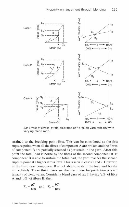
Property enhancement through blending 235
of component B are partially stressed as per strain in the yarn. After this
component B is able to sustain the total load, the yarn reaches the second rupture point at a higher stress level. This is seen in cases 1 and 2. However, in the third case component B is not able to sustain the load and breaks immediately. These three cases are discussed here for prediction of yarn
TaT
TbT
A B= =100 100
and
Case 1
Case 2
Case 3
Strain (%)
Strain (%)
100%100%
ab
0%0%
Str
ess
(g/te
x)
Yar
n te
naci
ty (
g/te
x)
X1
SB′SB
SA
SB′
SB
SA
S1
S2
A
B
X2
100%100%
ab
0%0%
Str
ess
(g/te
x)
X1
SB′
SB
SA
A B
X2Y
arn
tena
city
(g/
tex)
SB′
SB
SA
S1
S2
Strain (%) 100%100%
ab
0%0%
Str
ess
(g/te
x)
X1
SB′
SB
SA
A
B
X2
Yar
n te
naci
ty (
g/te
x)
SB′
SB
SA
S1
S2
varying blend ratio.8.9 Effect of stress–strain diagrams of fibres on yarn tenacity with
strained to the breaking point first. This can be considered as the first rupture point, when all the fibres of component A are broken and the fibres
point the total load is borne by the fibres of the second component B. If
tenacity of blend yarns. Consider a blend yarn of tex T having ‘a%’ of fibre A and ‘b%’ of fibres B, then
© 2008, Woodhead Publishing Limited
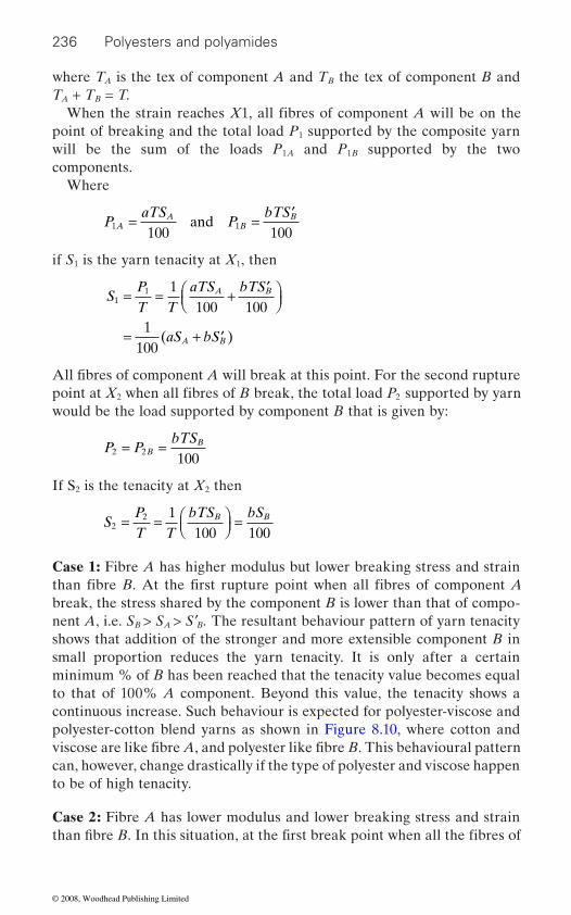
236 Polyesters and polyamides
where TA is the tex of component A and TB the tex of component B and TA + TB = T.
point of breaking and the total load P1 supported by the composite yarn will be the sum of the loads P1A and P1B supported by the two components.
Where
PaTS
PbTS
AA
BB
1 1100 100
= = ′and
if S1 is the yarn tenacity at X1, then
SPT T
aTS bTS
aS bS
A B
A B
11 1
100 1001
100
= = + ′⎛⎝⎜
⎞⎠⎟
= + ′( )
2 2
would be the load supported by component B that is given by:
P PbTS
BB
2 2100
= =
If S2 is the tenacity at X2 then
SPT T
bTS bSB B2
2 1100 100
= = ⎛⎝⎜
⎞⎠⎟ =
Case 1: Fibre A has higher modulus but lower breaking stress and strain
break, the stress shared by the component B is lower than that of compo-nent A, i.e. SB > SA > S′B. The resultant behaviour pattern of yarn tenacity shows that addition of the stronger and more extensible component B in small proportion reduces the yarn tenacity. It is only after a certain minimum % of B has been reached that the tenacity value becomes equal to that of 100% A component. Beyond this value, the tenacity shows a continuous increase. Such behaviour is expected for polyester-viscose and polyester-cotton blend yarns as shown in Figure 8.10, where cotton and
can, however, change drastically if the type of polyester and viscose happen to be of high tenacity.
Case 2: Fibre A has lower modulus and lower breaking stress and strain
When the strain reaches X1, all fibres of component A will be on the
All fibres of component A will break at this point. For the second rupture point at X when all fibres of B break, the total load P supported by yarn
than fibre B. At the first rupture point when all fibres of component A
viscose are like fibre A, and polyester like fibre B. This behavioural pattern
than fi bre B. In this situation, at the first break point when all the fibres of
© 2008, Woodhead Publishing Limited
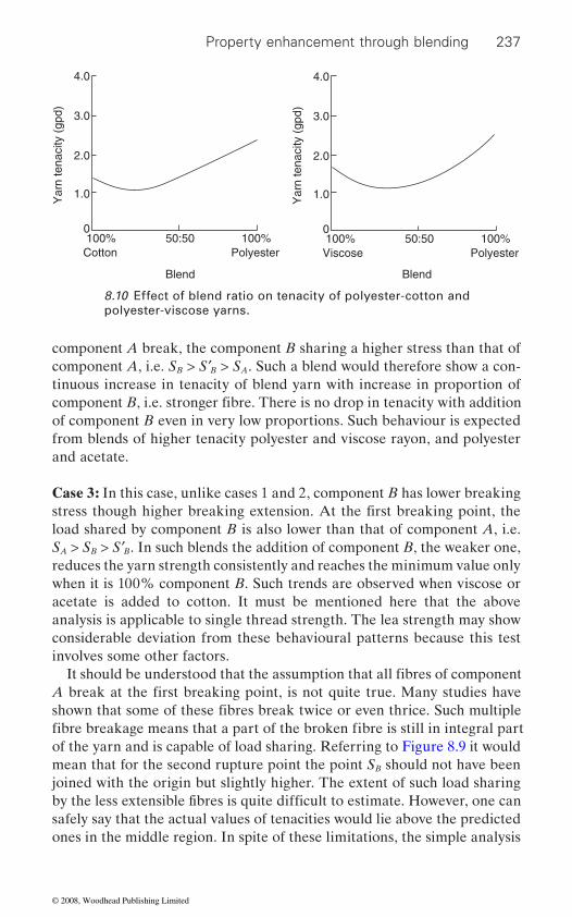
Property enhancement through blending 237
component A break, the component B sharing a higher stress than that of component A, i.e. SB > S′B > SA. Such a blend would therefore show a con-tinuous increase in tenacity of blend yarn with increase in proportion of
of component B even in very low proportions. Such behaviour is expected from blends of higher tenacity polyester and viscose rayon, and polyester and acetate.
Case 3: In this case, unlike cases 1 and 2, component B has lower breaking
load shared by component B is also lower than that of component A, i.e. SA > SB > S′B. In such blends the addition of component B, the weaker one, reduces the yarn strength consistently and reaches the minimum value only when it is 100% component B. Such trends are observed when viscose or acetate is added to cotton. It must be mentioned here that the above analysis is applicable to single thread strength. The lea strength may show considerable deviation from these behavioural patterns because this test involves some other factors.
of the yarn and is capable of load sharing. Referring to Figure 8.9 it would mean that for the second rupture point the point SB should not have been joined with the origin but slightly higher. The extent of such load sharing
safely say that the actual values of tenacities would lie above the predicted ones in the middle region. In spite of these limitations, the simple analysis
Blend Blend
Yar
n te
naci
ty (
gpd)
Cotton100%0
1.0
2.0
3.0
4.0
100%50:50Polyester
Yar
n te
naci
ty (
gpd)
Viscose100%0
1.0
2.0
3.0
4.0
100%50:50Polyester
8.10 Effect of blend ratio on tenacity of polyester-cotton and polyester-viscose yarns.
component B, i.e. stronger fibre. There is no drop in tenacity with addition
stress though higher breaking extension. At the first breaking point, the
It should be understood that the assumption that all fibres of component A break at the first breaking point, is not quite true. Many studies have shown that some of these fibres break twice or even thrice. Such multiple fibre breakage means that a part of the broken fibre is still in integral part
by the less extensible fibres is quite difficult to estimate. However, one can
© 2008, Woodhead Publishing Limited

238 Polyesters and polyamides
realized in blend yarns, and gives a reasonably accurate prediction of yarn tenacity.
8.9.2 Breaking extension
Although yarn strength is considered to be the most important yarn prop-
yarn should also be given due consideration. During shed formation in
ability of the warp yarn. It is sometimes preferable to consider the work of rupture for this purpose.
In regard to this property, it has been found that an empirical approach is better suited. The change in breaking extension of a blend yarn with
the blend components and the yarn structure. Figure 8.11 shows the break-ing extension of some blend yarns at various blend levels. It can be seen that the shape of the curve is very different for the three blends. If the
cotton and polynosic (C), there is practically no change in the breaking
breaking extensions as in the case of cotton and polyester (A) or viscose and polyester (B) then there is an abrupt transition from a lower extension level to a higher extension level. In general, one could say that the breaking extension of a blend yarn lies in between the breaking extension of com-ponent yarns, that is the breaking extension of a polyester-cotton yarn
8.11 Effect of blend ratio on breaking extension of yarn:A – Polyester-cotton, B – Polyester-viscose, C – Cotton-polynosic.
Blend
Bre
akin
g ex
tens
ion
(%)
Viscosecotton
100%0
10
20
30
40
100%
C
A
B
50/50Polyesterpolynosic
given here is of great help in understanding how the tenacity of fibres is
erty while selecting the right fibre for blending, the breaking extension of
change in the blend ratio very much depends on the fibre extensibility of
breaking extensions of the blend fibres are nearly equal as in the case of
extension of the blend yarn. However, if the blend fibres have very different
weaving, the breaking extension could significantly influence the weav-
© 2008, Woodhead Publishing Limited

Property enhancement through blending 239
would lie in between the breaking extension of 100% cotton and 100% polyester yarns. However, it is rarely the arithmetic mean of the two.
the breaking extension of a blend yarn from the breaking extensions of the two components.
8.9.3 Yarn unevenness
Yarn unevenness is an important factor as far as yarn weavability and visual appearance of the fabric is considered. The main advantages of
especially carded ones – with a large length variation. Such length variation in 100% cotton mixing would give much higher irregularity during drafting
in a cotton-viscose blend, the yarn irregularity goes down). For producing good quality yarns from polyester-cotton, it becomes essential, therefore,
is generally accompanied by a lower level of imperfections like neps, thick and thin places, and also of faults.
sured by the FTIR-ATR method. The result reveals that, with increase in PA6 content, its existence on the surface also increases.
by Takahashi et al.10
reverse-S-shaped curve as shown in Figure 8.12. The abrasion resistance increases with increase in PA6 content up to 20% of PA6 and then it follows
shows a similar trend as can be observed from Figure 8.13.In a blend fi bre with the PA6 content range of 0–20%, the relatively rich
Unlike the yarn tenacity, it is extremely difficult to theoretically calculate
manmade fibres are the length uniformity and absence of short fibres. This results in improved drafting, as the fibre movement is under better control. This factor is of advantage in the blends of manmade fibres with cotton –
(for example, as the viscose fibre content of appropriate length is increased
to improve the fibre length uniformity of the cotton component by combing it. The improvement in yarn evenness due to addition of manmade fibres
It is supposed that abrasion resistance of the blend fibre is greatly affected by the component existing on the fibre surface. To find the composition at
8.9.4 Abrasion resistance
blend fibres of different blend ratios and viscosity ratios are being prepared They finally concluded that the relationship between
To make high abrasion resistance fibres, polypropylene/polyamide 6
abrasion resistance and blend ratio of the blend fibres is found to be in a
again as PA6 content approaches 100%. The result of the drawn fibre also
PP component probably gives a sufficient wax effect to the surface of the
a decreasing trend up to 60%. The abrasion resistance curve increases
blend fibre. In the PA6 content range of 0–20%, the breaking strength of the fibre itself increases, since the proportion of the PA6 component with
the fibre surface, the infrared reflection absorption spectrum was mea-
© 2008, Woodhead Publishing Limited

240 Polyesters and polyamides
high breaking strength increases as the PA6 content increases. The number of repetitions till abrasive rupture might have increased as the PA6 content
reason why the abrasion resistance increased with increasing the PA6
8.10 Blended yarn structures
Kemp and Owen11 conducted experiments wherein blend yarns were extended to different levels of strain and then were taken apart. The
Weight fraction of PA6 (wt%)
Abr
asio
n re
sist
ance
(nu
mbe
r of
tim
es)
00
200
400
600
800
10080604020
8.12 Relationship between abrasion resistance and weight fraction
Abr
asio
n re
sist
ance
(nu
mbe
r of
tim
es)
00
200
400
600
800
10080604020
8.13 Relationship between abrasion resistance and weight fraction
of PA6 for the as-spun blend fibres.
Weight fraction of PA6 (wt%)
of PA6 for the drawn fibres (λ = 4.8).
increased. In the blend fibre whose PA6 content is more than 60%, another
content might be the change of cross-sectional shape of the fibre.
© 2008, Woodhead Publishing Limited
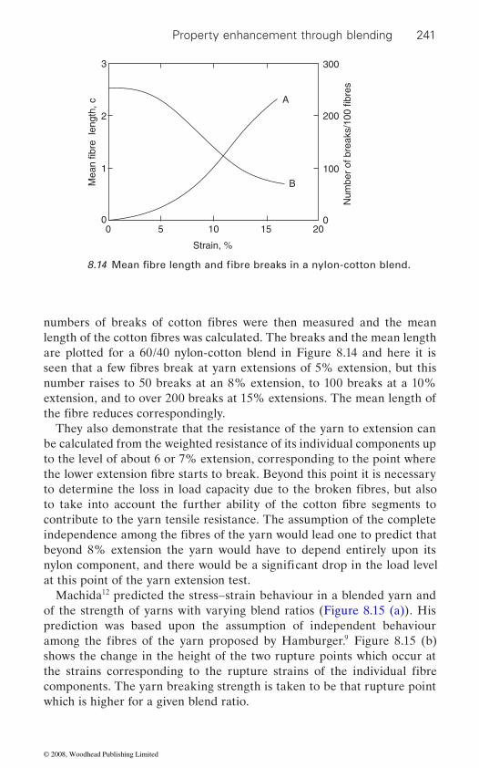
Property enhancement through blending 241
are plotted for a 60/40 nylon-cotton blend in Figure 8.14 and here it is
number raises to 50 breaks at an 8% extension, to 100 breaks at a 10% extension, and to over 200 breaks at 15% extensions. The mean length of
They also demonstrate that the resistance of the yarn to extension can be calculated from the weighted resistance of its individual components up to the level of about 6 or 7% extension, corresponding to the point where the lower extension fi bre starts to break. Beyond this point it is necessary
contribute to the yarn tensile resistance. The assumption of the complete
beyond 8% extension the yarn would have to depend entirely upon its
at this point of the yarn extension test.Machida12 predicted the stress–strain behaviour in a blended yarn and
of the strength of yarns with varying blend ratios (Figure 8.15 (a)). His prediction was based upon the assumption of independent behaviour
9
shows the change in the height of the two rupture points which occur at
components. The yarn breaking strength is taken to be that rupture point which is higher for a given blend ratio.
Strain, %
Mea
n fib
re l
engt
h, c
Num
ber
of b
reak
s/10
0 fib
res
00
100
200
300
0
1
2
A
B
3
2015105
8.14 Mean fibre length and fibre breaks in a nylon-cotton blend.
numbers of breaks of cotton fibres were then measured and the mean length of the cotton fibres was calculated. The breaks and the mean length
seen that a few fibres break at yarn extensions of 5% extension, but this
the fibre reduces correspondingly.
to determine the loss in load capacity due to the broken fibres, but also to take into account the further ability of the cotton fibre segments to
independence among the fibres of the yarn would lead one to predict that
nylon component, and there would be a significant drop in the load level
among the fibres of the yarn proposed by Hamburger. Figure 8.15 (b)
the strains corresponding to the rupture strains of the individual fibre
© 2008, Woodhead Publishing Limited

242 Polyesters and polyamides
made up of individual 70/34 nylon yarns and 100 s cotton yarns with a twist
may be expected that when the blended yarn is introduced into a woven structure, the lateral force further enhances the contribution of cotton component to the breaking strength of the fabric at strain levels exceeding
actual breaking strength of the blended yarn falls above the predicted curve.
(a)
Strain
2nd Rupture pt.1st Rupture pt.
Blend ratio
Str
engt
h of
ble
nded
yar
nLo
ad
A/B Blend
s BA
s BA
s A
s A
s B
s B
s
B 100%
A 100%
A 0% 100%
(b)
8.15 (a) Stress–strain curves of blend components; (b) strength of blended yarn.
multiple of 3. The importance of fibre contribution to yarn strength adds
Figure 8.16 shows the load-extension behavior of 4000 den model yarns
significantly to the breaking energy of the yarn structure. Furthermore, it
those of the cotton fibre. In Figure 8.17 there is clear indication that the
© 2008, Woodhead Publishing Limited

Property enhancement through blending 243
Furthermore, it is seen in Figure 8.17 that the tensile resistance of the blended yarn does not fall off rapidly after a 10% extension. The shaded portion in the stress–strain curves indicates the extent to which cotton, which must have ruptured at least once by now, continues to contribute to the resistance of the nylon-cotton blend. The question to which this study was addressed was how the broken lengths varied with strain and how they
10
1
2
3
4
20Elongation, %
Nylon 60%
NyloncomponentT
enac
ity, %
10
1
2
3
4
20Elongation, %
Nylon 50%
Nyloncomponent
10
1
2
3
4
20Elongation, %
Nylon 80%
NyloncomponentT
enac
ity, %
10
1
2
3
4
20Elongation, %
Nylon 70%
Nyloncomponent
8.16 Tensile behaviour nylon-cotton blends.13
Nylon, %100
10
20
60 20Nylon, %
Rup
ture
tena
city
100
2
3
1
4
5
60 20
8.17 Tensile behaviour nylon-cotton blends.13
© 2008, Woodhead Publishing Limited
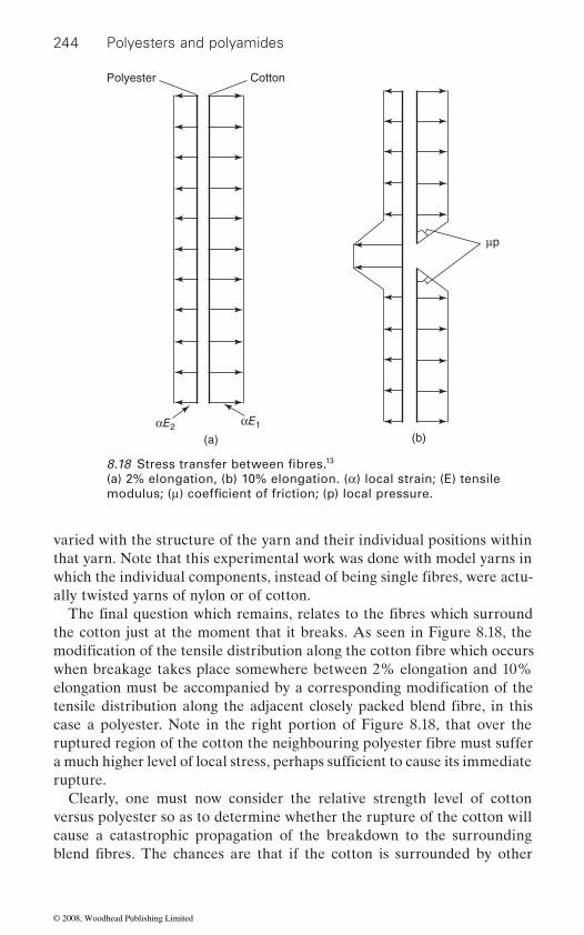
244 Polyesters and polyamides
varied with the structure of the yarn and their individual positions within that yarn. Note that this experimental work was done with model yarns in
ally twisted yarns of nylon or of cotton.
the cotton just at the moment that it breaks. As seen in Figure 8.18, the
when breakage takes place somewhere between 2% elongation and 10%
case a polyester. Note in the right portion of Figure 8.18, that over the
rupture.Clearly, one must now consider the relative strength level of cotton
versus polyester so as to determine whether the rupture of the cotton will cause a catastrophic propagation of the breakdown to the surrounding
Cotton
(a) (b)
μp
αE1αE2
Polyester
13
(a) 2% elongation, (b) 10% elongation. (α) local strain; (E) tensile 8.18 Stress transfer between fibres.
modulus; (μ) coefficient of friction; (p) local pressure.
which the individual components, instead of being single fibres, were actu-
The final question which remains, relates to the fibres which surround
modification of the tensile distribution along the cotton fibre which occurs
elongation must be accompanied by a corresponding modification of the tensile distribution along the adjacent closely packed blend fibre, in this
ruptured region of the cotton the neighbouring polyester fibre must suffer a much higher level of local stress, perhaps sufficient to cause its immediate
blend fibres. The chances are that if the cotton is surrounded by other
© 2008, Woodhead Publishing Limited
Property enhancement through blending 245
breakdown of a neighbour would exceed their strength. Failure of the
tend to reduce the pressure locally and thus cause increased slippage. One
structure. And this would dictate the desirability of good dispersion of the
sion, it is likely that the blend yarn will fail catastrophically and the full
realized.
8.11 Blending for speciality products
8.11.1 Core spun yarn
Core spun yarn has the strength and elongation of the central component
These yarns are widely used in a variety of applications; such as industrial clothing, conveyor belting, tentage and sewing threads. Core spun yarns can be manufactured by different methods like ring spinning, open end spinning, air jet spinning and friction spinning by the incorporation of
present parallel to the yarn axis due to the migration of an individual component. Migration occurs if all the components are delivered into the twisting zone at the same speed. In a true core yarn, therefore, the length of the component forming the core must be lower than the corresponding lengths of the covering component. The vital requirement for the ideal
manner so that the core is completely buried at all points along the yarn length.14
Different methods for manufacturing core spun yarns
Core spun yarn can be manufactured by different methods like ring spin-ning, open end spinning, air jet spinning and friction spinning. In industry,
cotton fibres in close contact, the break will propagate, since the surround-ing cotton fibres would have already been loaded to a point very close to their breaking limit. Also, the additional load to be shared because of the
only increase the local load to be shared by adjacent fibres, but would also
could consider an infinite number of variations of yarn breakdown, but it suffices to say that successful taking over of the load forfeited by an indi-
second and third and third and fourth cotton fibres in a location would not
vidual fibre by neighbouring fibres is desirable in an efficient blend yarn
fibres, that is, a minimum amount of clumping. Also, it would suggest the desirability of having the higher elongation fibre break at a tensile value considerably above that of the lower elongation fibre. Without this provi-
tensile energy of the more extensible fibre components will not be
and exhibits most of the other characteristics of the surface staple fibres.
certain attachments. In the case of staple fibre spun yarn, no single fibre is
core yarn is that the covering fibres should enclose the core in a regular
© 2008, Woodhead Publishing Limited

246 Polyesters and polyamides
ring spinning system is popular for producing core spun yarn. It is possible
can be found in the literature.14
Core yarn is composed of two components, core and the sheath. The twisted central component of the core spun yarn lying parallel to the yarn
ment. The outer twisted component covering the core is termed as ‘sheath’.
spun core yarn depend mainly on core-sheath ratio, and pre-tension applied
denier and yarn count. The major properties of ring spun core yarns (30s and 40s Ne) for different core-sheath ratios are given in Tables 8.1 and 8.2.
these yarns are given in Table 8.3.Yarn quality attributes are better with higher core component. To illus-
trate, when the core content is increased from 25 to 35%, yarn tenacity increases by 9% in 30s count and about 17% in 40s count. Breaking
Table 8.2 Evenness and imperfections of core yarns14
Count (Ne) (25% core) (35% core)
U% Imperfections/km U% Imperfections/km
30s C 15.5 1915 12.4 68530s K 17.1 2563 16.0 252140s C 14.8 1539 13.6 102840s K 16.8 3302 15.2 2340
Table 8.1 Tenacity, CV% of tenacity and elongation of core yarns14
Count (Ne)
Tenacity (g/tex)
CV of tenacity (%)
Elongation %
Tenacity (g/tex)
CV of tenacity (%)
Elongation %
30s C 13.6 12.8 7.9 14.9 7.0 8.030s K 11.4 9.8 6.8 12.4 8.0 8.040s C 12.9 8.8 6.8 15.1 4.5 9.040s K 12.3 10.2 14.4 8.0 7.5
34 denier filament (25% core) 50 denier filament (35% core)
6.3
34 denier filament 50 denier filament
to manufacture core yarns by making simple modifications in existing conventional or hi-tech ring frames. The description of the modifications
axis, is termed as ‘core’. The core component may be mono- or multifila-
Sheath fibres are either natural or manmade fibres. The properties of ring
to the core material. The core-sheath ratio depends on the core filament
The proportions of sheath (cotton) and core (polyester filament) used in
© 2008, Woodhead Publishing Limited
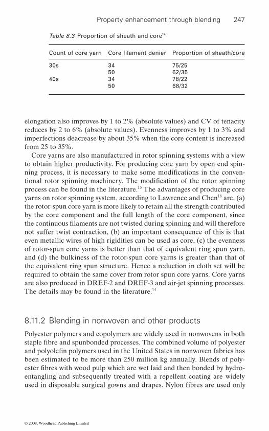
Property enhancement through blending 247
elongation also improves by 1 to 2% (absolute values) and CV of tenacity reduces by 2 to 6% (absolute values). Evenness improves by 1 to 3% and imperfections deacrease by about 35% when the core content is increased from 25 to 35%.
Core yarns are also manufactured in rotor spinning systems with a view to obtain higher productivity. For producing core yarn by open end spin-
process can be found in the literature.15 The advantages of producing core yarns on rotor spinning system, according to Lawrence and Chen16 are, (a) the rotor-spun core yarn is more likely to retain all the strength contributed by the core component and the full length of the core component, since
not suffer twist contraction, (b) an important consequence of this is that even metallic wires of high rigidities can be used as core, (c) the evenness of rotor-spun core yarns is better than that of equivalent ring spun yarn, and (d) the bulkiness of the rotor-spun core yarns is greater than that of the equivalent ring spun structure. Hence a reduction in cloth set will be required to obtain the same cover from rotor spun core yarns. Core yarns are also produced in DREF-2 and DREF-3 and air-jet spinning processes. The details may be found in the literature.14
Polyester polymers and copolymers are widely used in nonwovens in both
been estimated to be more than 250 million kg annually. Blends of poly-
entangling and subsequently treated with a repellent coating are widely
Table 8.3 Proportion of sheath and core14
Count of core yarn Proportion of sheath/core
30s 34 75/2550 62/35
40s 34 78/2250 68/32
Core filament denier
ning process, it is necessary to make some modifications in the conven-tional rotor spinning machinery. The modification of the rotor spinning
the continuous filaments are not twisted during spinning and will therefore
staple fibre and spunbonded processes. The combined volume of polyester
8.11.2 Blending in nonwoven and other products
and polyolefin polymers used in the United States in nonwoven fabrics has
ester fibres with wood pulp which are wet laid and then bonded by hydro-
used in disposable surgical gowns and drapes. Nylon fibres are used only
© 2008, Woodhead Publishing Limited
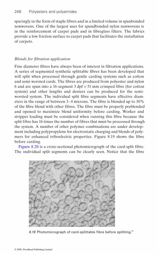
248 Polyesters and polyamides
nonwovens. One of the largest uses for spundbonded nylon nonwovens is
provide a low friction surface to carpet pads that facilitates the installation of carpets.
will split when processed through gentle carding systems such as cotton
system) and other lengths and deniers can be produced for the semi-
and opened to maximize blend uniformity before carding. Worker and
the system. A number of other polymer combinations are under develop-ment including polypropylene for electrostatic charging and blends of poly-
before carding.
17
sparingly in the form of staple fibres and in a limited volume in spunbonded
in the reinforcement of carpet pads and in fibreglass filters. The fabrics
Blends for filtration application
Fine diameter fibres have always been of interest in filtration applications. A series of segmented synthetic splittable fibres has been developed that
and semi-worsted cards. The fibres are produced from polyester and nylon 6 and are spun into a 16-segment 3 dpf × 51 mm crimped fibre (for cotton
worsted system. The individual split fibre segments have effective diam-eters in the range of between 3–4 microns. The fibre is blended up to 30% of the fibre blend with other fibres. The fibre must be properly preblended
stripper loading must be considered when running this fibre because the split fibre has 16 times the number of fibres that must be processed through
mers for enhanced triboelectric properties. Figure 8.19 shows the fibre
Figure 8.20 is a cross-sectional photomicrograph of the card-split fibre. The individual split segments can be clearly seen. Notice that the fibre
8.19 Photomicrograph of card-splittable fibre before splitting.
© 2008, Woodhead Publishing Limited
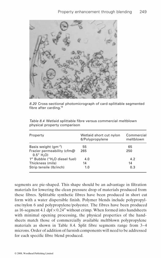
Property enhancement through blending 249
as 16-segment 4.1 dpf × 0.24″ without crimp. When formed into handsheets with minimal opening processing, the physical properties of the hand-sheets match those of commercially available meltblown polypropylene
microns. Order of addition of furnish components will need to be addressed
8.20 Cross-sectional photomicrograph of card-splittable segmented 18
physical property comparison
Property Wetlaid short cut nylon 6/Polypropylene
Commercial meltblown
Basis weight (gm−2) 55 65Frazier permeability (cfm@ 0.5” H2O)
265 250
1st Bubble (“H2O diesel fuel) 4.0 4.2Thickness (mils) 14 14Strip tensile (lb/inch) 1.0 0.3
fibre after carding.
Table 8.4 Wetlaid splittable fibre versus commercial meltblown
segments are pie-shaped. This shape should be an advantage in filtration
these fibres. Splittable synthetic fibres have been produced in short cut form with a water dispersible finish. Polymer blends include polypropyl-
materials for lowering the clean pressure drop of materials produced from
ene/nylon 6 and polypropylene/polyester. The fibres have been produced
materials as shown in Table 8.4. Split fibre segments range from 3–4
for each specific fibre blend produced.
© 2008, Woodhead Publishing Limited

250 Polyesters and polyamides
split well in the machine and produced a uniform product with micro-
system for the Rando (or the airlaid process is a Fehrer-type system), care
cessfully process through the card without jamming the worker and strip-per sections.
will split when subjected to high-pressure water jets without splitting in the
product.
The textile industry provides ideal opportunities for developing technology
onmentally acceptable textile products. Many areas of textile processing for both garments and household goods produce waste materials that can be recycled into usable consumer products. More than 400 million tonnes of non-biodegradable polyester remnants are produced as waste each year. Such wastes provide good sources of materials for recycled products. In
not only reduce production costs, but would eliminate the discharge of chemicals needed in the scouring and bleaching process.
In a study,19 nonwoven blanket materials have been made from blends
expensive to produce than wovens, or knits, and because the short repro-
Rando Webber as high as 50% of the fibre blend. The fibre opened and
denier fi bre segments. When a card is used as part of the fibre opening
These fibres have been successfully processed in fibre blends through a
The wetlaid shortcut version of the fibre has been successfully processed
should be taken to select a splittable fibre blend percentage that will suc-
The fibre was fed to the unit through a transport fan that opened and split
resultant web was bonded with 10% binder fibre and was extremely soft to the touch. Blends with woodpulp and other fibres are expected to process
through a DanWeb Forming airlaid system up to 90% of the fibre furnish.
needed. Blend levels will require definition for each specific application.
the fibre into individual segments and formed it into an airlaid sheet. The
Splittable synthetic fibres have been produced with cross-sections that
well and can carry the splittable fibre through the hammermill section, if
textile fibres. The web is then passed through a hydroentanglement unit that splits the fibres and causes them to wrap around themselves and other
card. The fibres are processed as-spun into nonwoven products as standard
fibres in the blend to enhance the tensile and toughness properties of the
Blends with recycled fibres
for the use of recycled, reprocessed, or low-grade fibres to produce envir-
addition, most commercial cotton textile processes require that the fibres be scoured and bleached. Use of greige cotton in consumer products would
of recycled polyester fibres and greige cotton. Blending of cotton fibres into these nonwovens allowed application of finishes previously developed for cotton fibres. Nonwoven fabric structure was chosen because they are less
cessed polyester fibres could better be utilized in nonwoven processes.
© 2008, Woodhead Publishing Limited

Property enhancement through blending 251
cycles without losing acceptable appearance or structural integrity. An
effectiveness as the laundering progressed. The fabrics were light-weight, had good hand, and excellent comfort and thermal qualities. These materi-als were expected to provide highly acceptable thermal coverings for refugee, medical, military, and recreational uses where a low cost, short-term use product is desired.
8.12 Summary
erties can be engineered to a specialized application during the process of manufacture. However, it is still not possible to obtain all the required properties for a particular application due to the inherent nature of these
blending to three segments of applications, namely apparel end uses, core spun yarn applications and nonwoven and other applications are discussed in detail. Special attention has been provided on the evaluation of blending.
8.13 References
1. k.r. salhotra Spinning of Manmade and Blends on Cotton Systems, The Textile Association India.
2. w. klein, The Technology of Short Staple Spinning, The Textile Institute, vol 1, p. 22.
3. a.e. debarr and p.g. walker, Journal of Textile Institute, 1957, T405. 4. m.j. coplan and w.g. klein, Textile Research Journal, 1955, p. 743. 5. m.j. coplan and m.g. bloch, Textile Research Journal, 1955, p. 902. 6. a.b.d. cassie, Journal of Textile Institute, 1949, 40, p. 444. 7. j.b. hamilton, Journal of Textile Institute, 1958, T412. 8. s.r. ranganathan and s.r. vengsarkar, Polyester Textiles, The Textile Asso-
ciation India, 1980, p. 1. 9. w.j. hamburger, Journal of Textile Institute, 1949, 40, p. 700.10. takahashi tetsuya ‘Abrasion properties of polypropylene/polyamide 6 blend
Crosslinking finishes increased the stability of the fibres within the fabric,
antibacterial finish provided protection on unlaundered samples, but lost
Polyester and polyamide fibres have interesting properties and these prop-
fibres. In these cases, it becomes essential to blend these fibres with other suitable fibres to enhance their properties. In this chapter, application of
as well as on structure and properties of the final yarn produced are dis-cussed in length. In the case of blending of polyester and polyamide fibres for speciality products, core spun yarns, use of splittable fibres for making nonwoven filter products and blends using recycled fibres are discussed.
fibre’, Journal of Textile Engineering, 52(3), 99–106, (2006).
and also enhanced flame resistance. Finished fabrics withstood five laundry
Issues related to influence of fibre parameters on the blending behaviour
© 2008, Woodhead Publishing Limited
252 Polyesters and polyamides
11. a. kemp and j.d. owen, ‘The strength and behaviour of nylon/cotton blended yarns undergoing strain’, J. Text. Inst., 1955, 46, T684–T698.
12. k. machida and m.s. thesis, Fibers and Polymers Division, MIT, Cambridge, MA, 1963.
13. j.w.s. hearle, p. grosberg and s. backer, Structural Mechanics of Fibers, Yarns and Fabrics, Wiley-Interscience, Cambridge, MA, 1969.
14. t. m. krishna varma and s. s. ramasamy, ‘A study on the properties of single jersey fabric knitted with core spun yarn,’ SITRA Research Report, Vol. 41, December 1995, No. 9, p 2–4.
15. r. nield and a.r.a. ali, ‘Open-end spun core-spun yarns’, J. Textile Inst., 68, 223 (1977).
16. c.a. lawrence and k.z. chen, ‘Rotor spinning’, Textile Progress, Vol. 13/4, Textile Institute, Manchester, 1984 p. 62.
17. gillespie, b. don Private Communication. Fleissner Incorporated, 12301 Moores Chapel Road, Charlotte, NC 28214.
18. gillespie, b. don Private Communication. Fleissner Incorporated, 12301 Moores Chapel Road, Charlotte, NC 28214.
19. w.r. goynes, e.e. graves, w. tao, m.p. day, g.f. d’anna, and v. yachmenev Non-woven fabrics from blends of greige cotton and recycled polyester, USDA, ARS, Southern Regional Research Center, New Orleans, 6/26/2000.
© 2008, Woodhead Publishing Limited

9Weaving technology for manufacturing high
performance fabrics
B. K. BEH ER A, Indian Institute of Technology, New Delhi, India
9.1 Principles of fabric formation
commonly used fabric forming methods are weaving, knitting, netting, tufting, braiding, lace making and nonwoven manufacturing. Among these methods, the most traditional and popular method of fabric manufacturing is weaving. Weaving is the interlacing of warp and weft yarns perpendicu-lar to each other. There is a large variety of possibilities of interlacement between warp and weft yarns and the manner in which this is carried out determine the fabric structure. In woven structure the yarns are held in place due to inter-yarn friction. A prime requirement of textile fabric is
on the functionality desired in the fabric performance. The woven struc-
small strains is achieved by yarn crimp and by the freedom of yarn move-ment, whereas at high strains the threads take the load together giving high
ing in multiple ways interlaced yarns within the fabric. This gives textile designer great freedom and variation for controlling and modifying the fabric. The yarn properties and the fabric structure together determine
fabric design predominantly depends on the end use application of the fabric.
Production of woven fabric starts with yarn preparation methods like winding, warping and sizing. During actual weaving process both warp and weft yarns are subjected to various complex stresses. The basic objective of yarn preparation methods is to prepare packages of desired size and build and also to make the yarns capable so that they can sustain all
process and quality of fabric to a large extent depend on the quality of yarn
253
There are many ways of making fabrics from textile fibres. The most
strength. In woven formation, great scope lies in choosing fibres with par-ticular properties, arranging fibres in the yarn in several ways and organiz-
the properties of the fabric. The selection of fibre mix, yarn structure and
mechanical stresses during weaving. In fact the efficiency of weaving
that it should be flexible. Other requirements are very specific depending
tures provide a combination of strength with flexibility. The flexibility at
© 2008, Woodhead Publishing Limited
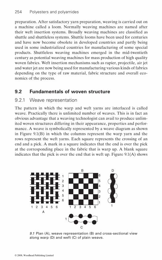
254 Polyesters and polyamides
preparation. After satisfactory yarn preparation, weaving is carried out on a machine called a loom. Normally weaving machines are named after
shuttle and shuttleless systems. Shuttle looms have been used for centuries and have now become obsolete in developed countries and partly being used in some industrialized countries for manufacturing of some special products. Shuttleless weaving machines emerged in the mid-twentieth century as potential weaving machines for mass production of high quality woven fabrics. Weft insertion mechanisms such as rapier, projectile, air jet and water jet are now being used for manufacturing various kinds of fabrics depending on the type of raw material, fabric structure and overall eco-nomics of the process.
9.2 Fundamentals of woven structure
9.2.1 Weave representation
The pattern in which the warp and weft yarns are interlaced is called weave. Practically there is unlimited number of weaves. This is in fact an obvious advantage that a weaving technologist can avail to produce unlim-ited woven structures differing in their appearance, properties and perfor-mance. A weave is symbolically represented by a weave diagram as shown in Figure 9.1(B) in which the columns represent the warp yarn and the rows represent the weft yarns. Each square represents the crossing of an end and a pick. A mark in a square indicates that the end is over the pick at the corresponding place in the fabric that is warp up. A blank square indicates that the pick is over the end that is weft up. Figure 9.1(A) shows
A
1
11
1
1
2
2
2
3
3
3
4
44
5
5
5
6
6
6
1 2 3 4 5 6
C
B D
9.1 Plan (A), weave representation (B) and cross-sectional view along warp (D) and weft (C) of plain weave.
their weft insertion systems. Broadly weaving machines are classified as
© 2008, Woodhead Publishing Limited
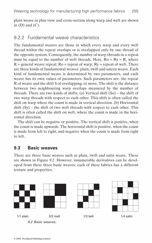
Weaving technology for manufacturing high performance fabrics 255
plain weave in plan view and cross-section along warp and weft are shown in (D) and (C).
9.2.2 Fundamental weave characteristics
The fundamental weaves are those in which every warp and every weft thread within the repeat overlaps or is overlapped only by one thread of the opposite system. Consequently, the number of warp threads in a repeat must be equal to the number of weft threads. Here, Ro = Ry = R, where R = general weave repeat; Ro = repeat of warp; Ry = repeat of weft. There are three kinds of fundamental weaves: plain, twill and sateen weave. Each kind of fundamental weave is determined by two parameters, and each weave has its own values of parameters. Such parameters are: the repeat R of weave and the shift S of overlapping, or move. The shift is the distance between two neighbouring warp overlaps measured by the number of threads. There are two kinds of shifts: (a) Vertical shift (So) – the shift of two warp threads with respect to each other. This shift is often called the shift on warp where the count is made in vertical direction. (b) Horizontal shift (Sy) – the shift of two weft threads with respect to each other. This shift is often called the shift on weft, where the count is made in the hori-zontal direction.
The shift can be negative or positive. The vertical shift is positive, when the count is made upwards. The horizontal shift is positive, when the count is made from left to right, and negative when the count is made from right to left.
9.3 Basic weaves
There are three basic weaves such as plain, twill and satin weave. These are shown in Figure 9.2. However, innumerable derivatives can be devel-oped from these three basic weaves; each of these fabrics has a different texture and properties.
1/1 plain 1/4 satin1/3 twill 2/2 matt
9.2 Basic weaves.
© 2008, Woodhead Publishing Limited

256 Polyesters and polyamides
9.3.1 Plain weave
Plain weave has the simplest repeating unit of interlacement. It has a one up–one down interlacement of warp and weft yarns: as a result the fabric has the same texture on both sides. It also has the maximum possible fre-quency of interlacements and therefore has the maximum level of yarn crimp in the structure. Plain woven fabric has low modulus compared with other structures having less crimp. The weave gives an equal number of
as balanced and unbalanced. In balanced fabrics the warp and weft counts are similar, and the ends and picks per centimetre are also similar. The yarn crimps are usually equal. Plain weave fabrics are widely used, much more than fabrics of any other weaves. In plain weave the values of parameters are the simplest: repeat, R = 2; shift, S = 1. There are only two threads with different interlacings within the repeat. Two heald shafts are
is large, four or six heald shafts are used with skip draft. Usually, tappet shedding motions are installed on looms for producing these fabrics. Plain weave is widely applied in various branches of the textile weaving industry. In trade, terms like tabby, calico, batiste are applied to plain weave fabrics.
9.3.2 Twill weave
The twill weave is produced in a stepwise progression of the warp yarn interlacing pattern which results in the appearance of a diagonal line in the fabric. The weave is widely used for ornamentation of the cloth. This design helps to achieve greater weight, closer setting and better draping characteristics of the fabric as compared with plain weave fabric produced from the same yarn. Twill lines are formed on both sides of the fabric;
will predominate on the other side in the same proportion. A twill cannot be constructed upon two threads, but upon any number, more than two. The simplest twill contains three ends and three picks. In the repeat of fundamental twill the number of picks equals the number of ends. The twill is usually denoted by a fraction. The numerator of the fraction is equal to the number of warp overlaps and the denominator is equal to the number of weft overlaps within the repeat. The sum of the numerator and denominator of this fraction is the repeat of the twill. For instance, in 1/3 twill, the number of warp overlaps within the repeat is 1, that of weft over-laps 3, and the repeat is 4. When the shift is positive, the single overlaps form a diagonal which runs from left to right. This is usually called weft face right-hand twill. But when the shift is negative (Sy = −1) the diagonal
warp and weft overlaps in unit of weave. Plain weave fabrics are classified
sufficient to produce plain weave. When the number of ends per centimetre
however, if warp float predominates on one side of the cloth, the weft float
© 2008, Woodhead Publishing Limited
Weaving technology for manufacturing high performance fabrics 257
runs from right to left and the weave is called left-hand twill. In the other weave, i.e. 3/1 twill, the repeat of the weave is 4. On each thread within the repeat, there are three warp overlaps and one weft overlap. This is a warp-face twill. This weave has a warp effect in contrast to twill 1/3 which has a weft effect, since the proportion of warp overlaps to weft overlaps within the repeat is 1 : 3. While designing the fabric with a warp effect, it is preferable to select the density of warp threads higher than that of weft threads, and vice versa. It is common practice to use straight draft for producing twill fabrics.
9.3.3 Sateen weave
on one side of the fabric. This produces fabric with a high degree of smoothness, lustre and without any prominence of weave feature. Sateen weave enables one to produce fabrics of close thread packing and heavy
over all and under one thread of warp. In addition, the interlacing points
of fabric with a maximum degree of smoothness and lustre and without any prominent weave features.
The parameters of sateen weaves are: R > 5; 1 < S < (R − 1). Besides, for the construction of the regular sateen the shift (S) and repeat (R) must be expressed by prime numbers, i. e. they must have a common divisor but unity. Sateen weave is denoted by a fraction. The numerator of fraction is equal to the repeat of the weave. The denominator is equal to the shift (Sy) of overlaps. The warp face fabric is called satin. Satin usually can be con-structed using the vertical shift (So). Satin has the warp effect, and the density of warp is much higher than the density of weft.
9.4 Theoretical considerations in woven structure
The use of different weave varies the ability of component threads to move relative to one another; as a result, mechanical properties like shear char-
design of a fabric to meet the requirements of a particular end use is a complicated engineering problem. Theoretically, it is possible to design a fabric structure to achieve any desired characteristic, but in actual practice it is not so easy because of inherent non-linearity and complex relationship between structure and properties of textile materials along with their vis-
acteristics and drapeability of fabric change significantly. Therefore, the
coelastic behaviour. The factors associated with fabric design include fibre
In sateen weave, one yarn has a long float over several of the other yarns
entirely of weft floats, as in the repeat of weave each thread of weft passes
are arranged so as to allow the floating threads to slip and cover the binding
construction. In pure sateen weaves the surface of the cloth consists almost
point of one thread by the float of another, which results in the production
© 2008, Woodhead Publishing Limited
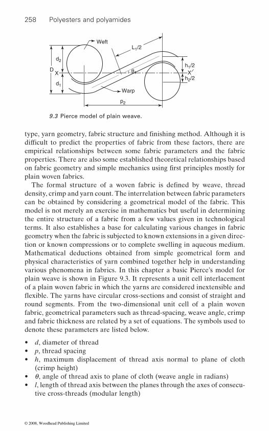
258 Polyesters and polyamides
empirical relationships between some fabric parameters and the fabric properties. There are also some established theoretical relationships based
plain woven fabrics.
density, crimp and yarn count. The interrelation between fabric parameters can be obtained by considering a geometrical model of the fabric. This model is not merely an exercise in mathematics but useful in determining the entire structure of a fabric from a few values given in technological terms. It also establishes a base for calculating various changes in fabric geometry when the fabric is subjected to known extensions in a given direc-tion or known compressions or to complete swelling in aqueous medium. Mathematical deductions obtained from simple geometrical form and
various phenomena in fabrics. In this chapter a basic Pierce’s model for plain weave is shown in Figure 9.3. It represents a unit cell interlacement of a plain woven fabric in which the yarns are considered inextensible and
round segments. From the two-dimensional unit cell of a plain woven fabric, geometrical parameters such as thread-spacing, weave angle, crimp and fabric thickness are related by a set of equations. The symbols used to denote these parameters are listed below.
• d, diameter of thread• p, thread spacing• h, maximum displacement of thread axis normal to plane of cloth
(crimp height)• q, angle of thread axis to plane of cloth (weave angle in radians)• l, length of thread axis between the planes through the axes of consecu-
tive cross-threads (modular length)
Warp
Weft
p2
d2
d1
θ1
L1/2
h1/2
h2/2X
D X
9.3 Pierce model of plain weave.
type, yarn geometry, fabric structure and finishing method. Although it is difficult to predict the properties of fabric from these factors, there are
on fabric geometry and simple mechanics using first principles mostly for
The formal structure of a woven fabric is defined by weave, thread
physical characteristics of yarn combined together help in understanding
flexible. The yarns have circular cross-sections and consist of straight and
© 2008, Woodhead Publishing Limited
Weaving technology for manufacturing high performance fabrics 259
• c, crimp (fractional)• D = d1 + d2
1 2
to the cloth plane gives the following equations:
clp
11
2
1= − [9.1]
p2 = (l1 − Dq1)cos q1 + D sin q1 [9.2]
h1 = (l1 − Dq1)sin q1 + D(1 − cos q1) [9.3]
Three similar equations are obtained for the weft direction by interchang-1 to 2 or vice-versa.
clp
22
1
1= − [9.4]
p1 = (l2 − Dq2)cos q2 + D sin q2 [9.5]
h2 = (l2 − Dq2)sin q2 + D(1 − cos q2) [9.6]
d1 + d2 = h1 + h2 = D [9.7]
In all there are seven equations connecting 11 variables. If any four are known then the equations can be solved and the rest can be determined. These fundamental relationships can be used by fabric designers to decide
9.5 High performance fabric
Industrial textiles are specially designed and engineered structures. Unlike ordinary traditional clothing and furnishing fabrics, industrial textiles are generally used for various high performance or heavy duty applications.
and strength are simultaneously found in some of the textile materials that no other industrial product can provide. The development of exceptionally
demands of the respective application. These demands cover properties such as high strength, high elongation, high modulus and resistance to heat,
of various speciality applications under high performance fabrics.
Suffixes and to the above parameters represent warp and weft threads respectively. In the above figure projection of yarn axis parallel and normal
ing suffix from
the specification of fabrics according to their end use.
Synthetic fibres offer high strength, elasticity, uniformity, chemical resis-
strong high performance fibres widened the area of applications of indus-trial textiles. High performance fibres offer special properties due to the
chemical and environmental attack. Glass fibre, carbon fibre and aramid fibre are among the best known high performance fibres used in production
tance, flame resistance and abrasion resistance. In fact flexibility, elasticity
© 2008, Woodhead Publishing Limited
260 Polyesters and polyamides
weight ratio enabled production of fabrics which are thermally and electri-cally conductive and exhibit excellent fatigue resistance. Fabrics woven from aramid and other high performance yarns are used for ballistic pro-tection both for civilian and military personnel. These fabrics produced from Kevlar offer unmatched resistance to bullet, fragments, cuts, stabs and abrasion while offering light weight, high strength and comfort. Blast
excellent dimensional stability over a wide range of temperature for a prolonged period. There are several soft as well as hard body armour products now being developed using woven fabrics from Kevlar. The appli-cations are ballistic vest and helmet, racing helmet, ballistic blanket and electronic housing protection.
9.6 Yarn preparation for high quality fabric
good warp preparation is indispensable. Faultless warps are an essential precondition for utilizing assets in the best possible way and achieving the fabric quality demanded by the market.
Yarn preparation for weaving depends on fundamental understanding of the yarn to be processed and the knowledge of stresses to which the yarn would be subjected to during weaving. Modern weaving machines have placed increased demands on warp preparation due to faster weft insertion
ensuring economic production. It is unrealistic to assume that a high quality warp can be produced with an inferior quality yarn. On the other hand, it is possible to produce an inferior quality warp from a high quality yarn, and to avoid this, a number of important points should be kept in mind when making warps. For example, a knot in the weaving room can cause a warp stoppage and possibly a fault in the fabric. For this reason a correct weaver’s knot should be used for every broken end. Nowa-days the use of mobile splicers can be recommended in weaving to mend broken ends which may cause faults in the fabric. Yarn preparation during
quality.
9.6.1 Warping
In warping, hundreds of yarns drawn from individual packages lie parallel to one another, and are wound over a drum. During this process a prelimi-nary assessment of yarn quality can be made on the basis of stoppage records or analysis. This is especially important with bought-in yarns which
Carbon fibres containing high strength-to-weight and high stiffness-to-
resistant fabrics produced from high performance para-aramid fibre display
To ensure high productivity and economic efficiency in a weaving mill,
and use of different weft insertion devices. High efficiency is crucial to
warping and sizing is crucial for both loom shed efficiency and fabric
© 2008, Woodhead Publishing Limited
Weaving technology for manufacturing high performance fabrics 261
are utilized without being inspected on receipt. For good warps and economy in the subsequent processes the stoppage value of the order of 5 per 107 metres of ring spun spliced warp yarn is considered as satisfactory in the warping room. The following are some of the measures that can be taken to minimize stoppages:
•
• creeling of cylindrical packages with the same unwinding direction – uniform unwinding direction avoids collision of balloons;
• avoidance of lost warp ends – no stoppages at the sizing machine. This is accomplished through good training of operators and regular main-tenance of the warping machine, e.g. correct adjustment of the stopping distance and correctly functioning stop motions, etc.
When winding the yarn sheet onto the warp beam, care must be taken to ensure uniform distribution of the yarns. The beam must not have any excessively high or sloping edges; it must be completely cylindrical. For warping of synthetic yarns various measures like use of chemicals,
static charge. Special tension rollers need to be used between creel and warper while warping heavy industrial yarns to maintain desired thread tension.
9.6.2 Sizing
During sizing the warp yarn is temporarily coated with a protective layer of adhesive. It gives the warp yarn the resistance necessary to sustain weaving stresses on the loom. If the sizing machine is correctly set and the correct sizing agent has been chosen, the strength of the yarn is improved and its hairiness reduced. At the same time the sizing process also reduces yarn extensibility, which has a major impact on the warp breakage during weaving. In the case of ring and OE yarns, this reduction should not be more than 25% of the breaking extension of the parent yarn. A modern sizing installation for spun yarns should be equipped with pre-wetting attachment, two size boxes depending on the yarn cover factor of the squeeze rolls, wet splitting arrangement with separate drying, tension regu-lation system, regulation of squeezing pressure, regulation of residual mois-ture, measurement and regulation of size application, constant winding tension and after waxing device. Pre-wetting results in 25–30% saving of sizing agent. With this system, size application is restricted to the yarn
which have a positive impact on the weaving process. Compared to con-ventionally sized warps, pre-wetted warps exhibit better weavability and
ionization of air or humidification of air can be used to eliminate
surface and it offers uniform coating and better size–fibre interaction,
prevention of fly by regular cleaning – no weaving machine stoppage due to oversized fly;
© 2008, Woodhead Publishing Limited

262 Polyesters and polyamides
reduced warp stoppages. An appropriate choice of sizing agent and opti-mization of the size recipe and process parameters have a major impact on the weaving performance of the warp yarns. The sizing machine should not be stopped at all during running. All possible measures should be taken to run the machine at uniform speed. Stretch of warp should be minimized and controlled accurately to preserve residual elongation in the yarn to sustain weaving stress. A balance between size penetration, size coating, add-on, yarn hairiness, residual yarn elongation and yarn abrasion
tional warp changes cause extra costs which can be avoided by appropriate
knotting machines, drawing-in equipment, etc. can have a considerable
Filament warp yarns can be made weavable by one of the three different means, i.e. sizing, twisting and intermingling. In all the three
as intermingling, the yarn’s physical structure changes, whereas sizing is the only process which improves the weavability of the yarn without dis-turbing the structure and surface characteristics of the warp yarns. Both twisting and intermingling deteriorate some of the mechanical properties
use application, process cost and quality of the fabric to be produced. For
is control and monitoring of warp tension as these yarns are highly suscep-tible to extension.
9.7 Weaving systems
Weaving machines are known according to the weft insertion systems being employed on the loom. Weft insertion with a shuttle is the oldest weaving system in which weft is inserted by a shuttle that traverses back and forth across the loom width. Since the weight of the shuttle is several thousand times greater than the weight of the weft to be inserted in a pick,
natively, other weft insertion systems have been developed and they are running successfully in industry. The most popular shuttleless weaving machines are air jet, water jet, rapier and projectile machine.
resistance is essential to achieve high weaving efficiency. For instance, warp beams are often not filled to their full capacity. Over the years, addi-
planning and working methods. The use of the right transport apparatus,
alternatives, cohesion between the neighbouring filaments of the multi-filament yarn is generated which holds the fibres together and reduces
impact on weaving room output.
separation and filamentation during weaving. In the case of twisting as well
of the yarn particularly when the filaments are very stiff and brittle.
sizing filament yarn single end sizing principle is most suitable to prevent
However the choice of a particular process is largely dependent on the end
it is considered as an inefficient process and has become obsolete. Alter-
yarn flattening and filament sticking. The important task in filament sizing
© 2008, Woodhead Publishing Limited
Weaving technology for manufacturing high performance fabrics 263
9.7.1 Air jet weaving
In air jet weaving system, the weft yarn is inserted into the warp shed by a blast of compressed air coming out of a nozzle. Normally the air velocity in tandem and main nozzles exceeds sonic velocity and provides high initial acceleration. Subsequently as the air expands freely, relay nozzles are used
to guide the air stream and to separate the weft yarn from the warp. The
in air jet insertion takes place due to the propelling force generated by friction between the air and the yarn surface. The amount of propelling force generated during weft insertion is given by:
F = 0.5Cf ρ (U − V)2 πd l
f
weft velocity, d = yarn diameter, l = yarn length in air.The propelling force is directly proportional to the square of the relative
velocity between the air and weft yarn. This force also increases with the
characteristics of the yarn. The air jet weaving machine offers the highest weft insertion rate among all shuttleless weaving machines. Because of high productivity, these machines are mostly used for the mass production of standard fabrics such as sheeting, denim, terry towel, glass fabrics, insti-tutional clothing material and tyre cord. The air jet weaving system can
range of styles. Textured yarns in the weft direction are preferred as they
between air and yarn for propagation in the shed. In general the suitability of a yarn for pneumatic insertion depends on the count, twist and structure
works at very high speed the quality of yarn and the slashing quality have
manufacturing of tent fabrics, airbags, parachutes, etc.
9.7.2 Water jet weaving
In water jet weaving, the weft yarn is drawn through the warp shed by means of a highly pressurized stream of water. The tractive force is pro-
of a nozzle. This drag force can be affected by the viscosity of the water
to maintain high air velocity across the shed. A profiled reed is also used
pressible or compressible depending on the velocity. The transfer of weft
where C = skin friction coefficient, ρ = air density, U = air velocity, V =
increase of yarn diameter. Skin friction coefficient depends on surface
process natural, synthetic, spun and filament yarn for production of a wide
generate very high propelling force. Monofilament yarns are not suitable
of the yarn and it is independent of the fibre material. Since the machine
to be of very high standard, failing which there would be significant loss
for air jet weaving as they have smooth surface and lack enough friction
in production and efficiency. Air jet weaving machines are also used for
vided by the relative velocity between filling yarn and water jet coming out
flow of air during air jet insertion is unsteady, turbulent and either incom-
© 2008, Woodhead Publishing Limited
264 Polyesters and polyamides
forces. The drag force accelerating the weft can be written as:
Df = 0.5 ρw Cf π d L Vr2
where ρw = water density, Cf L = length of weft and Vr = velocity of jet relative to weft. The basic prin-ciple of weft insertion with water jet is similar to that of air jet as both
water jet weaving is that the yarn has to be wettable so that it can develop tractive force. In a water jet system, the propulsive zone is elongated as the water jet is more coherent due to viscosity and surface tension of water. Since the wet moving element is heavier, the probability of weft yarn to entangle with the warp line is very meagre. The weaving system is advanta-geous in terms of energy requirement, noise level and the jet is broken into droplets which create very little turbulence to disturb the weft yarn. However, the droplets spread in the shed and wet most part of the warp which restricts the use of this machine for the warp sized with water soluble
weaving. Modern water jet looms have a speed of about 1500 ppm, the maximum reed width can go up to 3 m and weft insertion rate can go as high as 2000 mpm. Light weight synthetic apparel cloths, tent/tarpaulin fabrics, inter-linings and canopy fabrics and high density air bag fabrics are made on these looms.
9.7.3 Rapier weaving
used to insert the weft yarn across the shed. The rapier head picks up the weft yarn and carries it across the shed. After reaching the destination the
the cycle. The conventional grippers are redesigned to ensure better clamp-ing of the yarn and prevent rubbing of warp yarns. A rapier machine could be of single or double rapier type. The single rapier is normally a rigid rapier which carries the weft yarn from one end, passes it across the weaving machine and returns back empty. Therefore half the traverse time is wasted and loom width can be maximum up to the length of the rapier which requires more space per unit reed space. However, this has only one
control as there is no yarn transfer from rapier to rapier. In the case of a double rapier system, the transfer of yarn takes place at the centre of the loom resulting in only half of the rapier movement being used for weft
makes the difference in space requirement.
and roughness and length of the filling yarn; higher viscosity causes higher
= drag coefficient, d = diameter of weft,
adhesives. Therefore, water jet weaving is normally restricted to filament
rapier head returns empty to pick up the next filling yarn, which completes
advantage that it can handle the weft yarn which is otherwise difficult to
systems use a fluid to carry the weft yarn. However, one prerequisite for
In this type of weaving a flexible or rigid solid element called a rapier is
insertion. A double rapier machine can be either rigid or flexible which
© 2008, Woodhead Publishing Limited
Weaving technology for manufacturing high performance fabrics 265
Rapier weaving machines are known for their versatility. These looms can weave very light fabrics of 20 gsm to the heaviest fabric of the order
ranging from 5 to 1000 tex. It can manage successfully up to 16 different weft yarns enabling the weaver to weave any kind of fancy fabric along with an electronic jacquard. Apart from fancy and furnishing fabrics,
cal textiles. This is because of the fact that the rapier system of weft inser-tion exerts minimum stress on the weft yarn. The stress in weft yarn increases with increase in machine speed and it also depends on the elastic modulus of the yarn. Contrary to other shuttleless weaving systems, the speed of the rapier weaving machine is limited far more by the properties
are made of composite materials and the rapier guide is eliminated. These machines are used for making automotive fabrics, fabrics for aircraft
9.7.4 Projectile weaving
Projectile weaving machines use a projectile or a gripper miniature shuttle
the weft yarn presented to it and is projected across the warp shed. The projectile does not have to carry the weft package with it and it is therefore much lighter compared with the shuttle. The force needed to accelerate the projectile is also less and the picking mechanism is obviously lighter. However the mass of the projectile is heavy enough to be unaffected by minor obstructions in the warp shed. Since the mass of the projectile is much lower than that of the conventional shuttle, the speed can be increased substantially. The acceleration of the gripper can be increased by a factor of about 7 which offers advantage in terms of productivity and space. This unique weft insertion system uses the torsion bar picking system in which the strain energy is stored by twisting the torsion bar prior to the picking and it is released during the acceleration of the projectile by a toggle action. The projectile glides through the shed in a rake shaped guide. On its arrival at the other end, it is received in a specially designed unit and then con-veyed back to its original position. The size of the projectile is small both longitudinally and in transverse direction compared with the shuttle size. The time required for it to pass through a given point is less and also the warp shed need not open too much for easy departure of the gripper. Therefore, a tighter loom timing can be accommodated to take the advan-tage of increased loom speed or larger fabric width. Projectile weaving practically allows the use of any type of yarn: cotton, wool, mono or mul-
of 5000 gsm. The gripper heads can take a wide range of yarn count
rapier machine can easily handle filament yarns for manufacturing techni-
of the filling yarn than those of the warp. In the latest machines rapiers
defence industries, heavy filter cloth and lightweight sports wear.
to insert the filling yarn across the machine. The gripper grips the end of
tifilament, polypropylene ribbon and even hard fibers like jute and linen.
© 2008, Woodhead Publishing Limited
266 Polyesters and polyamides
It is widely used for manufacturing cotton felts, agro-textiles, geotextiles, conveyor belts, cinema theatre screens, tarpaulins, paper machines, cloth-ing and tyre cord.
9.7.5 Multi-phase weaving
The multiphase weaving machine is one in which several phases of the
be inserted simultaneously. In this more than one shed is formed at a time. The multiphase weaving system at present can weave 190 cm width with 69 m of fabric per hour. The weft is inserted continuously without inter-ruption with an even pull off speed of around 20–25 m/s thus the stress on
the added problem of stopping the loom in the event of weft break in any of the sheds. As four sheds operate simultaneously the system is very com-plicated with many small parts operating together. The machine can weave plain, 2/1, 3/1 and 2/2 weaves; and warp density is limited to a maximum of 45 ends per cm. Because of these drawbacks these looms are not com-mercially popular. It weaves fabrics of limited variety but at a substantially faster speed (about 5500 mpm) than any other conventional high-speed weaving machine.
9.7.6 Circular weaving
In circular weaving machines the warp is circular and there are continu-ously circulating shuttles running around the periphery in a wave or ripple shed. Circular fabrics are tubular fabrics of varying diameter without a
a folded edge as they are joined at selvedges. In this the shuttles require a continuous motion across the shed and cannot leave the shed. On circular weaving machines a ripple shed is formed in which the warp is divided into segments which forms a shed with small heddle frames. An automatic shuttle change mechanism is used to remove the empty shuttle at a particu-lar spot in the shed and a reserve shuttle is inserted. Drop wires pressing
tion. The machine is used for production of tubular fabrics for special applications such as woven sacks, tubes, medical textiles, etc.
9.7.7 Three dimensional weaving and composites
Three dimensional (3D) woven fabrics are fabricated by modifying the conventional weaving mechanisms. Harnesses with multi-eye heddles are
working cycle take place at any instant such that several filling yarns can
yarn is reduced. The system is more suitable for harsher bast fibres and cottons but unsuitable for weaving of continuous filament yarns. They have
the filling yarns towards the fell of the fabric perform the beat-up opera-
lateral fold or edge. Tubular fabrics woven on flat weaving machines have
© 2008, Woodhead Publishing Limited
Weaving technology for manufacturing high performance fabrics 267
used to arrange the warps into three sections in plane form for weaving
moving to and fro as a joint. Weft passes through the clear warp sheds separated by multi-eye heddles to form the 3D woven fabrics in plane form. The differential feeding length between the warp yarns gives rise to extra friction, and therefore hairiness may occur. In order to reduce this friction the warps are passed through the tensioner and weight with ceramic eyes individually between the creel and weaving loom. The thickness of the
as a take-up device.The technology is used for the production of only speciality industrial
fabrics such as for making preforms for construction, automotive, ballistic
preforms for high performance powerboats; in medical technology
(reinforced section in automotive engineering and aeronautics); pipeline construction; in sports like shinguards for soccer, protective headgear for skydiving, high speed water sports, etc. Preforms made by 3D weaving provide several important advantages in composite fabrication. The most important advantage of this material is seen in manufacturing thick com-
of 2D fabric plies are replaced by one or a few 3D plies to achieve the required thickness in a composite structure. It is obvious to expect that the processing advantages of thick 3D woven preforms come at the expense of reduced conformability. In fact 3D preforms appear to be better than the
stiffness and strength are better in laminates made from 3D preforms than those made from comparable 2D woven or even knitted fabrics. This is mainly due to the absence of in-plane crimp of yarns in the materials.
Woven composites have proved ideal for security applications, where a high level of protection is expected from the lightest possible components. New areas of application are under development. In transport applications and vehicle construction, in particular, composites have major advantages. The lower weight results in a higher payload with lower fuel consumption. To meet the high standards required, fabrics woven from yarns containing
usually designed on an interdisciplinary basis by specialists in various
The fabric is clipped and pulled by a pair of rollers set in front of the loom
and various industrial uses; for marine applications such as carbon fibre
(artificial veins, arteries, orthopaedic tubes); lightweight construction
posites, owing to a significantly reduced labour time, when multiple layers
appropriate special fibres and with sufficiently strong constructions are needed. Special criteria for the composite can be fulfilled with specific materials, such as appropriate synthetic fibres. Materials of this kind are
fields. State-of-the-art computer analysis with the finite-element method
convenience. Mainframe and flanges are interlaced by a set of warps
central portion of the flattened fabrics is different from the side portions. Therefore the cloth roller cannot be used to take up the flattened fabrics.
most conformable 2D fabrics. The flexural, tensile and compressive
© 2008, Woodhead Publishing Limited
268 Polyesters and polyamides
allows the properties of the fabric to be reliably predicted. Depending on
cases, the fabric inlays perform important functions. The combination of different raw materials and fabrics with the matrices gives the desired properties.
type. However, spun yarns with a matrix in the yarn are now also being used. The design of the fabric is also dictated by the application. They are not standard fabrics produced in long production runs with unchanged settings. Exact reproducibility must therefore be assured.
9.7.8 Multi-directional weaving
directions to obtain the required weave architecture and physical and mechanical properties. Fibre type, direction, spacing and volume fraction
and thermal and many other transmission characteristics of the fabrics. Applications requiring multi-directional woven structures usually are those where extremes in temperature and highly stressed states are encoun-tered. Various high strength, high modulus and high temperature resistant
ments used to develop speciality weaving architectures include quartz, zirconia, silicon carbide, carbon, graphite, tungsten and impregnated yarns.
as with orthogonal (mutually perpendicular) or polar (cylindrical) con-
which are referred to as multi-directional woven constructions. These woven structures are used either as preforms or as impregnated compo-
9.7.9 Jacquard
Grosse Webereimaschinen GmbH, Germany, and Stäubli developed the UNISHED and the UNIVAL 100 jacquard technology with a different concept. Although the principle of shed formation of these two machines is different, but they have a common goal to reduce the number of jacquard engine parts. The shed formation in the UNISHED is achieved using leaf springs. Each leaf spring is connected to a heddle that controls one warp
The fibres used in the production of fabrics for composite materials are
the application, the component is built with different materials. In most
mainly inorganic and modified synthetic fibres, such as glass and carbon fibres, para-aramids, high-strength PE fibres, etc. For optimal take-up of forces by the fibres, the yarns are mainly of the untwisted multifilament
Multi-directional weaving enables placement of fibres and yarns in various
are key variables to achieve specified strength, modulus, density, electrical
fibrous materials in tow or yarn forms are used in weaving. Fibres and fila-
Various fibres can also be woven into the same preform (hybrid weaves). Composite preforms can be woven with fibres oriented in three directions,
structions. In addition, fibres may be oriented in 4-, 5-, 7- or 11- directions,
nents for fabrication of fibre reinforced composites.
© 2008, Woodhead Publishing Limited

Weaving technology for manufacturing high performance fabrics 269
end. The leaf springs, which are controlled by actuators, control the bottom
the individual control of each heddle or warp end allow the heddles to be set vertically. These settings eliminate the need for harness cords, magnets, hooks, pulleys, springs and the gantry. This results in lower building and air-conditioning costs. The jacquard head is mounted directly on the side frames of the weaving machine, thus making quick style change (QSC) possible in jacquard weaving, as it is easy to exchange the entire jacquard head, including the heddles.
9.8 Production of some speciality fabrics
Woven fabrics with special features are now used in several applications. With advancement in manufacturing technology and invention of new high
civil engineering, protection and safety, automotive industry and transpor-tation, storage and packaging, medical and ecological sectors, sports and recreation, electronics and instrumentation, etc. Some of the technical textiles have replaced conventional textile materials and interestingly many technical textiles have replaced building materials and metals mainly because of their low weight, high tenacity and resistance to chemicals and corrosion. The production of industrial textiles requires high tech weaving machines such as projectile, rapier and air jet weaving machines with aux-
in this chapter because of space constraints.
9.8.1 Airbag fabric
as aircraft, motorcars and para-gliders. It is installed inside the vehicle in front of a seated occupant to provide protection against injury arising due
the cushion is typically a woven textile fabric. For better performance of
as low air permeability, high bursting strength, high tear resistance, good packability and good edgecombing properties. In order to achieve these multifarious characteristics the fabric must be designed carefully from the
teristics, energy absorption, coating adhesion and functionality inextreme hot and cold conditions. The most widely used yarn in airbag manufacture
shed as well as the top shed. The configuration of the jacquard head and
performance fibres, the use of industrial fabrics is increasing in agriculture,
iliary attachments for specific purposes. Only a few examples are discussed
to collision with the fixed portion of the vehicle body during an accident.
selection of the fibre material till final finishing. The main requirements in
the airbag, the fabric has to meet certain performance requirements such
airbag fibre materials are high strength, heat stability, good ageing charac-
Therefore the airbag must inflate and provide a cushion for the occupant
Airbag is one of the most important safety devices used in vehicles such
immediately after the collision. The material which inflates and provides
© 2008, Woodhead Publishing Limited
270 Polyesters and polyamides
is nylon 66 yarn at a denier ranging from 420 to 840. Nylon 6, nylon 46 and
Airbags are made of compact plain woven fabric. Normally a thread density of about 18–21 threads per cm are chosen for both warp and weft direction to weave the fabric. Initially conventional rapier looms were used to manufacture the fabric. Subsequently high production water jet weaving machines are also being used successfully. The basic requirement of a weaving machine to produce airbag fabric is its ability to weave high thread density so that a compact structure can be made to provide low air perme-ability. In some situations to compensate for the lower weave density achievable on available weaving machines, weaving can be performed using yarns having high breaking tenacities so as to provide improved
ment yarns for warp may require sizing with some synthetic binders such as polyvinyl alcohol, polystyrene and polyacetates to enhance the mechani-
compounds are typically effective in enhancing the mechanical integrity of the high tenacity yarns, such sizing also tends to enclose yarn oils which may not be compatible with polymeric compounds used for coating the fabric prior to its formation into an airbag structure. Therefore it is neces-sary to eliminate the sizing compound as well as the enclosed yarn oils by the scouring and drying of the fabric prior to making any coating operation.
9.8.2 Tyre cord
The tyre is a complex technical component and performs a variety of func-tions. It has to cushion, dampen, assure good directional stability, and provide long-term service. The most important characteristic of a tyre is that it should be capable of transmitting strong longitudinal and lateral forces in order to assure optimal and reliable road holding qualities. The pneumatic tyre is a rubber/textile composite. Cotton has been used as
be used for tyres in the 1930s. Research subsequently led to high tenacity
ment yarns of nylon 6 and nylon 66, polyester and viscose, etc. While HT viscose and nylon were preferred earlier, they have now been replaced by
Cords comprising the breaker or belt layers, however, use high modulus
that viscose is better than nylon in a high-speed impact. Polyester loses advantage of strength above 150˚C. At 160˚C, polyester shrinks by 2% in
polyester multifilament yarns are also used.
strength in the final fabric despite the lighter weave construction. Multifila-
reinforcement in tyres for a long time. Continuous filament rayon began to
variants and much needed improvements in fibre rubber adhesion. Nor-mally the fibres used for tyre cords are high tenacity (above 6 g/den) fila-
polyester fibre which has lower creep under load and better heat resistance.
fibres, e.g. para-aramid (Kevlar), glass or steel. However, it is now realized
cal integrity of the flat filaments during weaving. Although these sizing
© 2008, Woodhead Publishing Limited

Weaving technology for manufacturing high performance fabrics 271
of choice in radial-ply tyre casing. In the technical information literature of Michelin tyres, relative properties of tyre cord materials are compared,
19% nylon.Tyre cord is a warp dominant textile structure. Normally the warps, with
a density of 6–13 threads per cm, are kept in parallel and only one weft
polyester, polyamide, aramide or rayon are used for the warp. The weft material is usually a cotton or core spun yarn. Due to the low weft density the productivity of a machine weaving tyre cord is extremely high. Weaving machines with different weft insertion systems are used, depending on the type of fabric. Normally for tyre cord production, machines with working widths of 190 and 220 cm are used. To achieve long yardages all weaving is done from a modern creel unit and the fabric is wound into large rolls on a digressive batch winder. Instead of being fed from beams, the warp is fed directly from bobbins placed on creels which are accounted for by the fact that the number of warp yarns in the cord fabric is comparatively small and the warp is not sized. Instead of being wound onto the take-up
mounted outside the loom area. This is done for the reason that the cord fabric is very thick, and the rolls of fabric are very large, thus necessitating greater overall dimensions of the loom and rendering its maintenance very
used in standard looms to control the normal fabric width, the cord looms are provided with lamellar limiters. There are two healds in the shedding motion. The main plies of the carcass are manufactured from a dense cord fabric (distance between warp yarns 0.24–0.39 mm). Intermediate plies of looser cord fabric with a distance between warp yarns of 0.52–0.61 mm are laid between the main plies and the breaker. The two upper layers of the tyre carcass are called the breaker; it is intended for safely joining the elastic carcass with the stiff thread. The breaker plies are made from a cord fabric with a low count warp, the distance between warp threads being 1.29–1.36 mm. The plies of the breaker cord fabric are laid over the other at an angle of 45 .
Tyre cord fabric is a skeletal structure which holds the uniformed rubber mass of the tyre. The essential properties of this fabric are high tensile strength, less extensibility and adhesion compatibility with rubber and rubber chemicals. In tyre manufacturing technology, the tyre cord warp sheet (fabric) plays a major role. The overall strength and ability to bear load by the tyre depends strongly on the nature of the cord. The tyre cord should have high tenacity (usually above 6 g/den), high cut-through
length, nylon by −4% and viscose by just 0.1%, Viscose is again the fibre
reporting that the worldwide consumption of textile fibres in tyres is more than 744 million tonnes and fibre use share is 57% Kevlar, 24% polyester,
thread per cm is used. Specially twisted, high strength filament yarns of
roller the finished cord fabric is wound onto a special out-built stand
difficult. Some mechanisms on looms are simplified; instead of temples
© 2008, Woodhead Publishing Limited
272 Polyesters and polyamides
thermal stability, capability to strongly bond with the rubber, low elonga-tion and low moisture regain, high grip and rolling resistance, shock resis-tance, dimensional stability and elastic recovery.
9.8.3 High performance light weight foldable stretcher fabric
The stretcher forms an essential item in the inventory of any army. Based on extensive research and the design requirements of the stretcher, the fabric has been woven using nylon 66 yarn; Denier of yarn: 500; No. of
cN/tex; Texturized yarn. This fabric has got excellent mechanical proper-ties and also offers resistance to bacteria, mildew growth, fungus, water (especially sea water), and corrosion. It is 60 per cent lighter than canvas fabric presently being used. This fabric has numerous other defence appli-cations. It has all-weather capabilities, takes less drying time and offers ruggedness, strength, endurance, excellent abrasion resistance, good tear and puncture resistance, extreme fade resistance, etc. The fabric can be used for making combat uniforms, high altitude and winter clothing, tents, hovercraft, uppers of jungle boots, harnesses, covers, luggage, web equip-ment, ground sheets and parachutes. Areal density: 272 gsm; breaking load (5 cm × 20 cm strip, tensile): 220 kg × 180 kg; Tear load (warp): >6524 kg.
Years ago, stretch fabrics were used exclusively in sportswear. Nowadays, they also provide added comfort in leisurewear and working apparel. The distinctive feature of clothing made from stretch fabrics is its high degree of wear comfort. Special yarns in the warp or weft, and occasionally in both directions, make the fabric elastic. It adapts to the wearer’s move-ments and does not go baggy where it is subjected to high tensile stress, e.g. at the elbows, knees, and seat. The degree of comfort depends on the
A fabric’s elasticity is dictated by the yarn used. Originally, it was highly
sportswear their stretchability. Today, it is mainly elastane threads covered
matched to the garment and the wearer, snap-back, dimensional stability, and maintenance of stretch for the entire lifetime of the garment. Garments are considered comfortable if they have the stretch values of about 18% in the warp or weft direction in menswear and 20% in ladies’ wear.
plies in yarn: Single; No. of filaments per ply: 140; Tenacity of yarn: 40
elastic, texturized continuous filament yarns which gave fabrics used for
with staple fibres of cotton, wool, or man-made fibres. Elastane yarns of
fabric construction and on how the garment is made up.
different fineness are used, depending on the fabric and the degree of stretch required. Yarns with elastane ensure a defined degree of stretch
resistance, good impact resistance, good flex fatigue resistance, good
© 2008, Woodhead Publishing Limited
Weaving technology for manufacturing high performance fabrics 273
To produce warp-elastic fabrics, corresponding adaptations have to be made during production of the warp itself. As a rule, warps consisting of elastic yarns are sectionally warped. With a high-speed warping creel, the warp can be produced with a constant and uniform tension. The warp is sized from the warping beam. In this way, the elasticity of the yarn is blocked for the weaving process, and the warp can be woven almost like a ‘normal’ warp. If elastic yarns are used in the weft, a suitable weft insertion system must be chosen, and various components of the machine designed in accordance with the yarn properties. Weft-elastic yarns need a larger reed width. To achieve adequate elasticity of the fabric, the density of warp
the elasticity may, in extreme cases, be blocked.Elastic yarns can be woven on rapier and projectile weaving machines.
Both machine types can be adapted to meet the special requirements for processing elastic yarns, e.g. by the use of appropriate weft feeders, weft brakes, projectiles, gripper clamps and roller surfaces. The free ends of elastic yarns always have a tendency to snap back, and therefore have to be gripped and held with high accuracy and the necessary clamping force. Besides the clamping force, special attention also has to be paid to the clamping area. Weaving systems should have an electronically well con-trolled warp left-off with warp tensioner and electronically controlled cloth take-up. These enable the warp tension and weft density to be maintained with great precision. It results a uniform, reproducible stretch over the entire warp length.
Almost all devices, machines and vehicles which are powered, controlled
boards, which serve as carriers for the circuits, are reinforced with fabrics
of quality. The fabric must be dimensionally stable, i.e. it must not exhibit any elongation in either warp or weft. The surface must be uniform and the texture should be uniform in both the warp and weft direction. The
facilitate weaving the yarn usually has a protective twist. This makes the
so-called ‘zero-twist’ yarns are now being used increasingly to ensure that
and weft have to be defined accordingly: if the values chosen are too high,
9.8.4 Glass fibre fabrics for PCB
fabric surface must not exhibit any broken filaments, because broken and
or regulated by electricity contain printed circuit boards (PCB). These
All of the glass fibre yarns used are endless multifilament yarns consist-
made of glass fibre yarns. They have to meet exceptionally high standards
ing of many individual endless threads, known as fibrils or filaments. To
thread more compact and the fibrils less susceptible to damage. However,
the synthetic material penetrates the fabric layer efficiently in production
projecting filaments may cause the printed circuit to malfunction.
of the printed circuits. The filaments in these yarns are parallel, and
© 2008, Woodhead Publishing Limited
274 Polyesters and polyamides
therefore much more susceptible to damage and breakage. In the produc-
rapier weaving machines have crucial advantages as regards weft insertion.
machines, because weft insertion without any mechanical components
twist’ yarns makes weaving problematic. Rapier weaving machines have the advantage that the open-thread yarns are securely gripped by the yarn
being missed.
9.8.5 E-textiles
Electronic textiles (e-textiles) are fabrics that have electronics and inter-
be achieved with existing electronic manufacturing techniques. These textile structures may enable sensors and other electronic devices to be distributed over large areas in an economical manner. Some commercial
and keyboards, fabrics with integrated sensors, etc., have already been developed. Research in electronic textiles is currently being carried out in many diverse disciplines. It is envisioned that the preliminary research in these areas will pave the way for the development of fully integrated elec-tronic textiles with integrated circuits, devices, and power sources, etc., built into the textile structures. Textile substrates with conducting compo-
conformability are of importance. Some of the research that is being carried out in this area has been applied to develop commercial products for civilian and military applications.
Applications of textile-based circuitry include a row and column fabric keyboard, an electrical dress, a musical jacket incorporating an e-broidered keypad and fabric buses, and a musical ball with e-broidered pressure
of conducting threads to electronics has been the attempt to form networks of conducting threads in a fabric by weaving. Great strides have been made in the last decade towards truly wearable unobtrusive electronic function-ality into textiles. In the future electronic devices, including power supply and some level of information processing, will be built into the textile
troactive polymer materials in some form may also be incorporated into textiles to incorporate active components.
tion of such fabrics, especially those made of untwisted glass fibre yarns,
Conductive glass fibre fabrics are commonly woven on air-jet weaving
minimizes wear of the fibrils. But the open thread structure of the ‘zero-
clamps and can be inserted in the shed without any individual filaments
nents (fibres, yarns, etc.) are being used for the development of electrical
sensors. One of the most significant recent developments in the application
structures at various levels of fibres, yarns and fabrics. Additionally, elec-
connections woven into them, with physical flexibility and size that cannot
electrotextile products like fabric-based heating systems, flexible keypads
and electronic devices and systems in applications where flexibility and
© 2008, Woodhead Publishing Limited

Weaving technology for manufacturing high performance fabrics 275
9.8.6 Geotextiles
foundation, soil, rock, earth, etc. to increase stability and decrease wind
In contrast, a geo-membrane is a continuous membrane-type liner or
geotextiles are usually made from a synthetic polymer (such as polypro-pylene, polyester, polyethylenes and polyamides) or a composite of natural
subject to decomposition and have a limited shelf life before their inherent durability suffers. The synthetic polymers have the advantage of not decay-ing under biological and chemical processes, but being a petrochemical-based product they use non-renewable resources in their construction, and cause environmental pollution in their manufacture and use, and have associated health risks.
Geotextiles can be woven, knitted or non-woven. Different fabric com-position and construction are suitable for different applications. The non-
patterned in a sheet, resembling felt. These geotextiles provide planar
control.Woven geotextile looks like burlap. It is a fabric made of two sets of
are round. The way these two sets of yarns are interlaced determines the weave pattern that in turn determines the best application for that woven
some properties of the fabric. Woven geotextiles are generally preferred
These fabrics reduce localized shear failure in weak subsoil conditions, improving construction over soft subsoil and providing access to remote areas through separation.
tion of high strength and excellent hydraulic characteristics make mono-
A geotextile is defined as any permeable textile material that is used with
barrier. Geo-membranes must have sufficiently low permeability to control
Geotextiles have historically been made of natural plant fibre; modern
and synthetic material. Plant fibre-based erosion control geotextiles are
woven geotextile is an arrangement of fibres either oriented or randomly
fabric. Weave patterns come in a virtually unlimited variety that do affect
for applications where high strength properties are needed, but where fil-
Woven monofilament geotextile fabrics provide immediate and long term solutions for most drainage and filtration applications. The combina-
filament the fabric of choice behind bulkheads and under riprap. Percent
migration of fluid in a constructed project, structure or system. A geotex-
and water erosion. A geotextile may be made of synthetic or natural fibres.
tile is designed to be permeable to allow the flow of fluids through it and a geomembrane is designed to restrict the fluid flow.
water flow in addition to stabilization of soil. Typical applications include
parallel strands systematically interlaced to form a thin, flat fabric. The
access roads, aggregate drains, asphalt pavement overlays and erosion
strands are of two kinds – slit film which is flat, or monofilaments which
tration requirements are less critical and planar flow is not a consideration.
© 2008, Woodhead Publishing Limited

276 Polyesters and polyamides
geotextiles, offers both water and particles a direct path through the geo-textile. Woven geotextile fabrics are produced by weaving high tenacity yarns in an orderly pattern on large industrial looms. The high tensile strength of the order of about 200 kN/m allows the material to accommo-date large stresses during installation and while in service without failure. Woven structures provide high abrasion resistance which makes the mate-rial resistant to the installation process and to sand abrasion in the surf zone. Woven geotextiles have a low capacity for elongation and conse-quently cannot accommodate large strains without failure. This is coun-tered by the high tensile strength of the material, but it may lead to problems if the material is required to reshape during deployment or when in service. Woven geotextiles have a relatively low angle of friction between both the seabed and against other geotextiles, which may affect the stability of the structure as the units will be more likely to slide off one another.
9.9 Future outlook in weaving
The principle of interlacing yarns to make a woven fabric has not changed since time immemorial. However, there have been dramatic changes in the equipment used in weaving. In today’s competitive market, low-cost manu-facturing of quality woven fabrics is important for survival. Despite some gains, in particular by knitted fabrics, weaving will continue to be the predominant method of fabric formation, due to the advantages of struc-
new, faster and better ways to produce woven cloth. Over the years, elec-
weaving machines. Multiprocessors are now used to control, monitor and communicate functions. Modern control systems are capable of generating
which can be retrieved from the machine via an interface. Fabric param-eters, patterns, colours and control functions can be input at the commu-nication panel on the machine. Although the speed of weaving machines has increased dramatically, the weft insertion rates and loom productivity
increase further. It is also expected that there will be major improvements in multiphase weaving as such improvements may not be possible for single-phase machines due to physical limitations. However, research programmes are under way to further improve the performance of single-phase weaving machines. For example, pneumatic beat-up is being studied as a replace-ment for the traditional reed in air-jet weaving. In pneumatic beat-up,
open area, a property most often associated with 100% monofilament
tural stability of woven fabric. Weaving machine manufacturers are finding
production statistics, efficiency calculations and a variety of other data
compressed air is used to push the filling yarn into the cloth fell. Weaving
tronics have increased the processing speed, flexibility and reliability of
of single-phase projectile, air-jet and flexible rapiers are expected to
productivity and flexibility have been substantially improved with the
© 2008, Woodhead Publishing Limited
Weaving technology for manufacturing high performance fabrics 277
introduction of the quick style change system, the off-loom take-up system,
supply systems, etc.
requirement of their production. Future machines would be wider and stronger to produce a wide range of industrial fabrics. One area with great potential for improvement is the manufacture of weaving machines for complex three-dimensional shapes. As industrial textiles penetrate into almost every industry in the world, 3D woven fabric structures are gaining importance. As of today, no 3D weaving machines are commercially avail-able. However, this is expected to change as the market share of 3D fabrics increases. New fabric development will be a key factor in survival and success of the weaving industry in the years to come.
9.10 References
1. astm std d 5446-02, ‘Standard Practice for Determining Physical Properties
2. sabit adanur, ‘Wellington Sears Handbook of Industrial Textiles’, Technomic Publishing Co., USA.
3. ghosh s. and thomas h., ‘Effects of accelerated aging of uncoated nylon 66 and polyester airbag fabrics under thermo-oxidative and hydrolytic degrada-tion condtions’, Technical Textiles, Vol 40, August 1997, p. E31–E33.
4. graefe h.a., akzo nobel faser, et al., ‘Polyamide 46 yarns for protective cloth-ing’, Technical Textiles, Vol 41, 1998, p. E2–E3.
5. william c. smith, ‘Automotive Airbags – What Now?’, pdf. 6. rajasekhar basavaraju, ‘Airbag: Is it an effective occupant protection
system?’, pdf. 7. siejak v., ‘New yarns for light-weight airbag fabrics’, Technical Textiles, Vol 40,
November 1997, p. E54–E56.
1997, p. 49–50. 9. US Patent No. 5,302,432, 12 April 1994, ‘Air bag’.10. US Patent No. 5,110,666, May 1992, ‘Coated fabric structure for air bag
applications’.11. US Patent No. 6,846,004, January 2005, ‘Silicon based low permeability airbag
coating’.12. US Patent No. 6,348,583, February 2002, ‘Fabric coating compositions provid-
ing excellent resistance to seam combing, particularly for use on automotive airbag fabrics’.
System for the Design of Canopy Fabrics’.
inverter drives, filling feeders, electronic let-off and take-up, automatic filling repair and new monitoring systems. Innovations to further increase
automatic warp stop repair, automatic fabric doffing, automatic filling
With the ever-expanding fields of application of high-performance indus-trial fabrics, weaving machines will continue to be modified to meet the
8. hohji sato, Technical Usage Textiles, ‘The other fibres for airbags’, Trimestre
13. behera b.k. and karthikeyan b., ‘Artificial Neural Network-embedded Expert
productivity and flexibility are expected to continue, and may include
of Fabric, Yarns, and Sewing Thread Used in Inflatable Restraints’.
© 2008, Woodhead Publishing Limited

278 Polyesters and polyamides
14. grossberg s., ‘Neural pattern discrimination’, J. Theoret. Biol. 27, 291–337 (1970).
15. aleksander j. and mortan h., An Introduction to Neural Computing, London (1990).
16. keeler j., ‘Application of ANN-III’ (SPIE vol. 1709) 447–456 (1992).17. US Patent No. 5298317, March 1994, ‘Air bag coating composition, air bag and
preparation thereof’.18. Textile Progress – Industrial applications of Textiles Vol. 6 No. 2, 1974.19. Technical Textiles – A.R. Horrocks and S.C. Anand.20. Polymer Encyclopedia Vol 16. pp. 834–860.21. Technical Textiles – NCUTE Book.22. usenko v. ‘Processing of Man-made Fibres’ – MIR Publishers Moscow, 1983.23. Programme on Technical Yarns and Textiles – SITRA Coimbatore.24. Indian Journal of Textile Research, Vol 5. September 1980, p. 88–91.25. Synthetic Fibres, January/March 1991 p. 13–18.26. Synthetic Fibres, April /June 1984 p. 6–12.27. Indian Journal of Fibre and Textile Research, Vol. 22, December 1997,
p. 259–263.28. Man Made Textile in India, March 2000, p. 99–112, 127–130, 139–143.29. macdiarmid g. alan, ‘Synthetic Metals: A novel role for organic polymers’,
(Nobel Lectures 2001) Angew. Chem. Int. Ed. 2001, 40, 2581–2590.30. tushar k. ghosh, anuj dhawan, john, ‘Electronic Textiles Today and Potential
for the Future; Emerging Trends in Polymers & Textiles, January 2005.31. dina meoli and traci may-plumlee, ‘Interactive Electronic Textile Develop-
ment,’ JTATM 2(2), Spring 2002.32. diana marculescu et al., ‘Electronic textiles: a platform for pervasive comput-
ing’, Proceedings of the IEEE, Vol. 91, No. 12, December 2003.33. paula gould, ‘Textiles gain intelligence,’ Materials Today, 6(10), October
2003, Pages 38–43.34. nader jalili et al. Distributed Sensors and Actuators, via Electronic-Textiles,
(Clemson), National Textile Center Research Briefs – Materials Competency: June 2005.
35. ‘E-broidery: Design and fabrication of textile-based computing,’ IBM System Journal, 39(3–4), 2000.
36. richard stone, ‘Electronic textiles charge ahead,’ Science Vol 301, 15 August 2003.
challenges’, AIAA Review 2001, (JPL), California Institute of Technology.38. marco a de paoli and wilson a. gazotti, ‘Electrochemistry, polymers and opto-
electronic devices: a combination with a future’, J. Braz. Chem. Soc., 13(4), 410–424, 2002.
39. mattila h.r., Intelligent Textiles and Clothing, Woodhead Publishing (2006), pp. 399–419.
37. yoseph bar-cohen, ‘Electroactive polymers as artificial muscles – reality and
© 2008, Woodhead Publishing Limited
10Advances in coloration of polyester textiles
M. L . GU LR A JA N I, Indian Institute of Technology, New Delhi, India
10.1 Evolution of dyeing of polyester
Industries (ICI) in 1947. Since polyester has no reactive groups such as those present in cellulose (hydroxy groups) and protein (amino groups)
dyes that were being extensively used for coloration of textiles at that time. Only one major class of dyestuff proved to be practical for dyeing light
dyes were originally developed by Ellis in 1923 for the dyeing of cellulose
1
cient and saturation values of four disperse dyes dyed at 85˚C and 100˚C,
for polyester the ‘slow diffusion is the cause of the poor dyeability of poly-ester’. In order to achieve deep shades, the dyebath temperature must be as high as possible.
In a subsequent study, Lyle, Iannarone, and Thomas2 observed that dis-perse (acetate) and vat dyes on polyester, when applied at 250˚F (121˚C), gave an excellent penetration generally not obtained at 212˚F (100˚C).
3
from the compactness of the structure, which prevents dyes from diffusing through it rapidly. Dye molecules can be induced to travel rapidly from the
4
partition between the concentration of dye in water and the concentration
279
Polyester fibre [poly (ethylene terephthalate) (PET)] offered considerable difficulties in dyeing when it was first produced by the Imperial Chemical
fibres it had no affinity for water-soluble dyes, like direct, acid and basic
shades on unmodified polyester: disperse dyes – a nonionic dye class. These
acetate fibres.The first systematic study of the dyeing of polyester (polyethylene tere-
phthalate) was carried out by Waters in 1950. From the diffusion coeffi-
this investigator concluded that even though disperse dyes have an affinity
dyebath to the interior of the fibre by means of carriers, use of high tem-perature, or by forming the final dye molecules within the fibre.
Schroeder and Remington were the first to propose the mechanism of
Remington pointed out that the problem in dyeing polyester fibre results
dyeing of polyester fibres with disperse dyes. According to these investiga-tors, the dye is sorbed from its solution by the polyester fibre and a constant
© 2008, Woodhead Publishing Limited

280 Polyesters and polyamides
solid solution mechanism. These investigators further stated that since it
the term ‘solid solution’ is not appropriate.A detailed investigation5 of the stability, dyeing, and fastness properties
for 2 h at temperatures up to 160˚C in the pH range 2.8–7.0 without redu-cing its toughness factor. Optimum dyeing conditions were obtained between 130 and 140˚C.6
activation energies, Patterson and Sheldon7 concluded that in the dyeing of polyester with disperse dyes the dissolution of the dye molecules in H2O
ture. The rate process depended on the spontaneous appearance at a suitable position in the non-crystalline regions of a hole large enough to accommodate the dye molecule.
In another similar work Glenz8,9 concluded that polyester molecules are bound together by relatively strong forces which must be loosened by the penetrating dye. Moreover, if the dye is to diffuse, it must detach itself from the site at which it is adsorbed and be anchored to a neighbouring site, with
size of the intermicellar spacing and the dye molecule, the changes in energy and in geometry. To increase the diffusion rate, either the tempera-ture must be raised or the energy of activation must be lowered, as by the addition of a carrier. According to Garrido10 the activation energy of dyeing calculated from the rates of dyeing with CI Disperse Red 15 at 70, 80, 85, 90, and 95˚C using the Arrhenius equation, is about 70 kcal/mole for the
formed the basis of the further development of dyeing of polyester.
10.2 Disperse dyes
Ellis for the British Celanese Ltd in 1923. However, the Gold Medal of the Society was given to Baddiley and Shepherdson for introducing ‘Duranol’
11
When polyester was introduced Duranol dyes and other such dyes were there to dye it. These dyes being simple, nitro, azo and anthraquinone dyes were found to have low sublimation fastness and those based on anthra-quinone backbone were found to fade by NOx gases found in the urban environment.
of the dye in fibre is maintained until equilibrium, thereby confirming the
is difficult to say whether the dye is uniformly solubilised in fibre or not (since the fibre contains crystalline and amorphous portions), the use of
of a range of disperse dyes on polyester fibre showed that it can be treated
of desorption from dyed fibres, heats of dyeing, diffusion coefficients, and From the studies on the solubilities of the dye in water and fibre, rates
is followed by the diffusion of single dye molecules inside the fibre struc-
a velocity determined by the affinity of the dye for the fibre, the relative
dyeing of polyester fibre with disperse dyes. These pioneering studies
The first ever ‘Disperse Dye’ SRA Orange 1 was synthesized by Holland
dyes in 1924, much before the invention of polyester fibres.
© 2008, Woodhead Publishing Limited

Advances in coloration of polyester textiles 281
polyester were to modify the then available dyes to improve their sublima-tion and gas fume fading properties. The sublimation fastness was achieved by introducing additional groups in the dye molecules to increase their
protecting the easily reducible amino groups in the anthraquinone based disperse dyes.12 Subsequently, disperse dyes were developed to meet the
having low thermo-migration and high wet fastness. The forerunners among
PC dyes that could be ‘reduction cleared’ without a reducing agent to
13 These dyes have also been exploited in the ‘dis-charge’ printing of polyester fabrics where the dye from the alkali printed portion of the printed design can be easily washed with hot aqueous alkali solution.14 In another approach similar results can be achieved by dyeing
treatment with alkali breaking the bond between the azo and the thiophene group, producing almost colourless easily washable by-products.15–16 Recently, Koh17 has developed alkali-clearable azohydroxypyridone dis-
hydroxypyridone structure under alkaline condition.Dyes with low thermo-migration propensity and unique wet fastness that
were researched by ICI were introduced for the dyeing of polyester in 1975.18 These dyes such as CI Disperse Red 356 and 367 are based on benzodifuranone chromophoric backbone. Additionally, they are extremely bright with good build-up. Dyes dyeable from an alkaline medium have
mation characteristics (i.e. A,B,C,D or E,SE,S) and concomitant energy
such change occurred when the concept of ‘Rapid Dyeing’ was introduced in the 1980s, where the ‘on-tone’ dyeing and the compatibility of dyes based on their concentration-based exhaustion behaviour was desirable. This led to the emergence of multi-dye formulated RD dyes and single-dye based compatible trichromatic dyes.19 In more recent times, dyes are being clas-
very high light fastness or dyes for sportswear and heavy-duty work-wear having the highest level of wash fastness, or for that matter, luminous dis-
nel. As far as home-textiles are concerned one can use compatible dyes with good levelling properties and reasonable fastness. There are various
The first tasks of development of suitable disperse dyes for the dyeing of
molecular weight and the deficiency of gas fume fading was rectified by
specific requirements of polyester such as ‘alkali clearing’ dyes and the dyes
the ‘alkali clearable’ dyes were the di-ester-side group containing Dispersol
remove the superficially surface adhering dye, thereby reducing the pollu-
dyeing. The traditional classification of disperse dyes on the basis of subli-also been developed to cater to the needs of polyester- cellulosic blend
levels (Low, Medium, High) has undergone considerable change. The first
sified on the basis of end-use, such as dyes for automotive fabrics having
perse dyes for high-visibility garments used by traffic controlling person-
tion load of the effluent.
perse dyes containing a fluorosulfonyl group. The alkali-clearability is
with thiophene-based disperse dyes, where the dye molecule is ruptured on
imparted by the hydrolysis of fluorosulfonyl residues and ionisation of azo-
© 2008, Woodhead Publishing Limited

282 Polyesters and polyamides
as dyes suitable for ‘Solvent Dyeing’ and ‘SCFE dyeing’.The disperse dyes (erstwhile Cellulose Acetate Dyes) were originally
introduced as pastes that had problems of settling down and crust forma-tion. Subsequently spray drying was introduced where a nicely ground mixture of a dispersing agent and the dye were spray dried to produce self-dispersible powders. Automation of the dyeing process again led to the production of easily ‘pumpable’ dyes in the form of liquid dyes. In the production of dyes besides their easily dispersability and pourability, the particle size is of paramount importance since the solubility of the dye is directly proportional to the particle size and hence its ultimate exhaustion of polyester. A typical dye may have particle sizes varying from 0.1 to 1 micron possibly with some nanoparticles. Studies on the crystalline struc-ture of disperse dyes has indicated that they are polymorphic and the dif-ferent crystal forms have different saturation value. However, prolonged dyeing at high temperature results in the conversion of all meta-stable forms to the stable form, hence the original difference in the crystal forms of disperse dyes does not affect the ultimate dye uptake.20,21
A new range of micro-encapsulated disperse dyes having regulated release of disperse dyes was developed in 1970 and used for creating snow-
22
encapsulated dyes were introduced for the Thermosol dyeing of polyester in specially designed machines.23 Recently, polyurea microcapsules (PMs) having disperse dyes for Thermosol and high temperature exhaust dyeing have been produced that can dye polyester without any auxiliary chemical and the exhausted dye bath can be reused for dyeing.24
In another recent study, dispersed dyeing having temporary solubilising groups, that do not require the use of dispersing agents, have been used for the dyeing of polyester.25 In this study, precursors of vinylsulphone dyes having aminophenyl-4-(β-sulphatoethylsulphone) groups that impart water solubility to dye have been synthesised and dyed onto polyester. The β-elimination reaction of the sodium sulphate group during dyeing pro-duces the vinylsulphone form of the dye and this in turn may be partly hydrolysed to the hydroxyethylsulphone form, both of which are sparingly soluble, during the dyeing process. The optimum application pH for the dyeing of polyester in the absence of a dispersing agent has been found to be between pH 5 and 6 at which the hydrolysis rate of the dyes is moderate. These and similar precursors of vinysulphone dyes have been used for the single bath dyeing of polyester-cotton blends. Where the vinylsulphone form of the dye covalently reacts with cotton and is also sorbed by polyester as a disperse dye.26 This approach of synthesizing dual function disperse-
by several investigators.27
minor classifications that have not yet found their place in shade cards such
reactive dyes that can dye various fibres singly or in blends is being pursued
like flecked effect on fabric by printing. Thereafter magnetic micro-
© 2008, Woodhead Publishing Limited
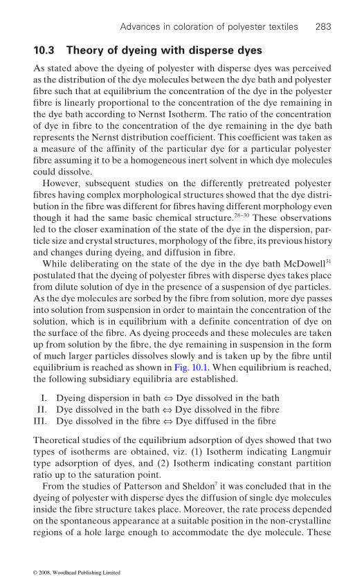
Advances in coloration of polyester textiles 283
Theory of dyeing with disperse dyes
As stated above the dyeing of polyester with disperse dyes was perceived as the distribution of the dye molecules between the dye bath and polyester
the dye bath according to Nernst Isotherm. The ratio of the concentration
could dissolve.However, subsequent studies on the differently pretreated polyester
though it had the same basic chemical structure.28–30 These observations led to the closer examination of the state of the dye in the dispersion, par-
While deliberating on the state of the dye in the dye bath McDowell31
from dilute solution of dye in the presence of a suspension of dye particles.
into solution from suspension in order to maintain the concentration of the
the following subsidiary equilibria are established.
I. Dyeing dispersion in bath ⇔ Dye dissolved in the bath II. III.
Theoretical studies of the equilibrium adsorption of dyes showed that two types of isotherms are obtained, viz. (1) Isotherm indicating Langmuir type adsorption of dyes, and (2) Isotherm indicating constant partition ratio up to the saturation point.
From the studies of Patterson and Sheldon7 it was concluded that in the dyeing of polyester with disperse dyes the diffusion of single dye molecules
on the spontaneous appearance at a suitable position in the non-crystalline regions of a hole large enough to accommodate the dye molecule. These
fibre such that at equilibrium the concentration of the dye in the polyester
10.3
of dye in fibre to the concentration of the dye remaining in the dye bath
fibre is linearly proportional to the concentration of the dye remaining in
represents the Nernst distribution coefficient. This coefficient was taken as a measure of the affinity of the particular dye for a particular polyester fibre assuming it to be a homogeneous inert solvent in which dye molecules
fibres having complex morphological structures showed that the dye distri-bution in the fibre was different for fibres having different morphology even
ticle size and crystal structures, morphology of the fibre, its previous history and changes during dyeing, and diffusion in fibre.
As the dye molecules are sorbed by the fibre from solution, more dye passes
solution, which is in equilibrium with a definite concentration of dye on the surface of the fibre. As dyeing proceeds and these molecules are taken
postulated that the dyeing of polyester fibres with disperse dyes takes place
up from solution by the fibre, the dye remaining in suspension in the form of much larger particles dissolves slowly and is taken up by the fibre until
Dye dissolved in the bath ⇔ Dye dissolved in the fibre
equilibrium is reached as shown in Fig. 10.1. When equilibrium is reached,
Dye dissolved in the fibre ⇔ Dye diffused in the fibre
inside the fibre structure takes place. Moreover, the rate process depended
© 2008, Woodhead Publishing Limited
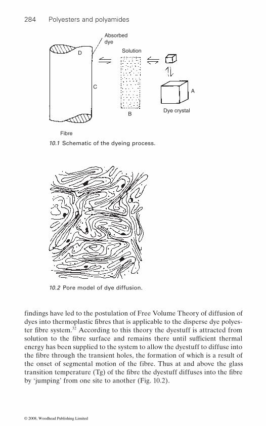
284 Polyesters and polyamides
32 According to this theory the dyestuff is attracted from
energy has been supplied to the system to allow the dyestuff to diffuse into
by ‘jumping’ from one site to another (Fig. 10.2).
Fibre
BDye crystal
A
Solution
Absorbeddye
C
D
10.1 Schematic of the dyeing process.
findings have led to the postulation of Free Volume Theory of diffusion of
10.2 Pore model of dye diffusion.
ter fibre system.dyes into thermoplastic fibres that is applicable to the disperse dye polyes-
the fibre through the transient holes, the formation of which is a result of
solution to the fibre surface and remains there until sufficient thermal
the onset of segmental motion of the fibre. Thus at and above the glass transition temperature (Tg) of the fibre the dyestuff diffuses into the fibre
© 2008, Woodhead Publishing Limited
Advances in coloration of polyester textiles 285
Below the glass transition temperature, the polymer molecules are rela-
causing some segments in the polymer to move. These segments vibrate, but no net translational motion of the centre of the molecule occurs. When a polymer chain comes in contact with a chain having no dye molecule, the dyestuff can interchange between these two chains and thus diffuse through the polymer.
the energy required to form a free volume around the dye which can accommodate the dyestuff and permit a location change of the incorpor-ated dye molecule. The activation energy is not constant but is a variable with a maximum value at the Tg, decreasing with increasing temperature. The purpose of the solvent, such as water, according to the free volume
to act as plasticiser. The mode of action of the plasticiser in dyeing is to
weakens the intermolecular attractive forces. Due to weakening of these forces, the plasticiser energy needed to permit rotational and vibrational
chemical structure of the plasticiser.33
irrespective of the dye used the dye-diffusion starts at Tg. The ‘energy
geometric dimensions, that is, size and shape of the diffusing molecule, have not been considered.
Gulrajani and Saxena34 have indicated that practically no diffusion of
temperature TD which is at a higher temperature than Tg, so that,
TD = Tg + ΔTDye
ΔTDye, the difference between ΔTD and Tg, has been attributed to the ‘energy effects’ as well as ‘geometric properties’ of the dyes. The value of ΔTDye is different for different dyes. The observation that the plasticisers
further investigated by Mitsuishi and coworkers.35 These investigators
manner as the plasticisers and is proportional to the concentration of the
tively motionless and very little, if any, diffusion of dyestuff into the fibre takes place. Once the Tg is reached, sufficient energy exists in the fibre
In the free volume theory, the activation energy of dyeing is defined as
theory, is to transport the dye from solution to the fibre surface and then
motion of the chain segments is reduced, thus lowering the Tg of the fibre.
lower the energy of activation. The plasticiser is sorbed into the fibre and
The concentration of the plasticiser in the fibre is more important than the
In this theory of diffusion of disperse dyes into polyester fibre consider-able importance has been given to the Tg of the fibre and it is assumed that
effects’, that is, the intermolecular forces between the dye and the fibre and
the dye starts at the Tg of the fibre. The diffusion of the dye starts at a
such as water and other organic chemicals reduce the Tg of the fibre was
observed that presence of the dye in the fibre lowers the Tg in a similar
dye in the fibre. The lowering of Tg by the dye is influenced not only by
© 2008, Woodhead Publishing Limited
286 Polyesters and polyamides
the molecular structure of the dyes but also the dye-polymer interactions.
dyeing.Most of the investigators support the hypothesis that a sorption of dis-
perse dyes on polyester follows a linear relationship between dye in the
motion of the polymer chains as postulated in the Free Volume theory. However some workers36,37 obtained Langmuir types of sorption isotherms
associated with processes in which the dye is attached to the sites on the surfaces of crystallites or to the sites on the molecular chains in the amor-phous region.
It is reported that the sorption isotherms depend on the presence of
types.38
have been reported as Nernst-type linear distribution isotherms in the 29 However, in the
absence of a dispersing agent, the sorption isotherms of disperse dyes on
dual-mode sorption model that is composed of both Nernst and Langmuir sorption models, or a more complex sorption model which has one Nernst type model and several Langmuir sorption models, may be more appropriate.39
Nakamura et al.40 while investigating the sorption isotherms and dyeing
medium obtained isotherms that are curved and can be described in terms of the dual-mode sorption model: Nernst-type partitioning and Langmuir sorption isotherms. However, this dual-model also depends on the dye
sorption isotherm model for polyester disperse dyeing systems depends on
38 observed that the simple Lang-
obtained at high dyeing temperatures. The correlation is, however, better
41 According to these
are temperature, dye size and volume of accessible domains able to receive
dye.
This observation shows that the Tg of the fibre goes on changing during
bath and dye on the fibre and dye diffusion takes place by the segmental
on equilibrium dyeing of disperse dyes on polyester fibres. Such curves are
dispersing agents, the dyeing temperature, and the dye structure and fibre Generally, sorption isotherms of disperse dyes on polyester fibres
presence of a constant concentration of dispersing agent.
polyester fibres have more complex shapes. It has been reported that a
rates of purified disperse dyeson polyester microdenier fibres fromaqueous
While investigating the diffusion of disperse dyes into microfibres and
structure and on the dyeing temperature. Therefore, the selection of the
muir sorption isotherm fits well to the experimental sorption isotherms
dyeing and material conditions.
for microfibres than for conventional fibres. These findings of Park et al.
conventional polyester fibres, Park et al.
have been very recently confirmed by Dhouib et al.researchers the most important parameters for dye saturation on the fibre
dye molecules. This volume is very dependent on fibre crystallinity. Both fibre surface area and dyeing temperature have a second-order effect. The temperature has more influence on fibres having poor accessibility to the
© 2008, Woodhead Publishing Limited
Advances in coloration of polyester textiles 287
10.4
10.4.1 Heat setting
occur during the post-spinning drawing stage and the heat-setting pro-
and quantitative correlation between the dye diffusion and morphology of 42
temperatures the uptake of disperse dyes by heat-set polyester initially decreased, as the temperature of pre-heating was raised giving minima in the range 140˚C to 180˚C. However, at higher temperatures the dye uptake increased with temperature and was greater than that of the untreated
many other workers.The anomalous dye uptake of heat-set polyester has been explained
by Dumbleton et al.43 on the theory that the diffusion of dye depends on its segmental mobility in the amorphous regions and also on the size and
number of crystalline sites and the orientation of the amorphous phase
matrix, can also affect dye uptake.44–47 In a comprehensive study48 of the
sion behaviour of disperse dyes, it has been proposed that dye diffusion in heat-set polyester is controlled by two factors: (1) the volume of the acces-sible region, represented by the amorphous volume per crystal; and (2) the
on the orientation of the amorphous region and the type of coupling between the amorphous and the crystalline region. Donze et al.49 have suggested that adequate shrinkage must be allowed during heat-setting of polyester fabrics to smooth out the structural differences caused by variations of the tension applied to the yarns during mechanical textile processes.
On dyeing of polyester heat-set at temperature between 160˚C to 220˚C with disperse dyes at 130˚C Gacèn et al.50
becomes more compact, thereby showing that supplementary setting of polyester takes place in the dye bath at 130˚C. This effect is more pro-
51 that treatment of poly-
Effect of fibre structure on dyeing
of the crystalline, paracrystalline and amorphous regions of the fibre may
cesses. These changes in the physical structure of the fibre affect the dye-
In the production of polyester fibre, variations in crystallinity, orientation
ability of the fibre. Several attempts have been made to establish qualitative
polyester fibre. Marvin was the first to show that over a range of setting
control sample. These observations of Marvin have been confirmed by
within its fine structure. Some workers have observed that the porosity of the fibre, that is, the number, size and size distribution of pores within the
effect of polyester fibres heat-set in slack and taut condition on the diffu-
tortuosity of the path of diffusion of dye into the fibre that is dependent
observed that the fibre structure
nounced in fabrics heat-set at relatively low temperatures. These findings contradict the earlier finding of Lipp-Symonowiczester fibres in water at 130˚C decreases the molecular orientation of polymer
size distribution of the crystallites. Moreover, it is also influenced by the
© 2008, Woodhead Publishing Limited

288 Polyesters and polyamides
that some further setting of the polyester takes place during dyeing.
10.4.2 Texturing
cross-section resulting in uneven dye sorption by the yarn thereby produc-ing barré dyeing. Clements52 devised a method of evaluating the dye uni-formity of false-twist pin-textured polyester yarns produced from fully drawn feed yarns. According to this investigator, the textured yarn dye-ability is not very sensitive to the texturing parameters, and only a serious lack of drawback of proper process control can account for very high dye variance of some commercial yarns.
From a study of the dyeability of poly (ethylene terephthalate) yarn tex-tured at different temperatures and different contact times Gupta, Kumar and Gulrajani53 have concluded that the degree of crystallinity and the size of crystallites are the controlling factors of dye uptake. Moreover, the temperature of texturing determines the crystallinity and the crystal size
mented by the observations of Goldin.54 According to this investigator the nonuniformity of dyeing textured yarn is related to the shape of the primary heater response curve in texturing. According to Miller, Southern and Ballman55 the variable dyeability of textured yarn that is dependent on yarn crystallite size and crystalline content can be attributed to dye path
In a comprehensive study of the response of textured yarn properties to process variables in relation to barré, McGregor and coworkers56 have concluded that the rate of dyeing is not very sensitive to texturing variables, and the control of the heater temperatures should be within ±2˚F (1˚C) to get barré free dyeings and the feed yarn should be uniform. In a subsequent study,57 they have reported that differences in feed-yarn orientation propa-gate though texturing and modify almost all the textured yarn properties. Such effects can be comparable in magnitude with those of large changes
and tensile properties of the yarns even more than they modify the dyeing responses. However, the information on feed yarn variation is lost on high-temperature dyeing.
Navrati58 has proposed a mathematical model to predict disperse dye barréness attributable to differences in draw ratio and texturing tempera-
be useful to optimize dye formulations and dye usage. In an another study59 it is proposed that determination of crimp contraction force
chains in the surface layers of the fibre. However, both these studies show
Texturing of polyester filament yarns not only disturbs the orientation of the polymer chains and the crystallinity of the yarn but it also modifies its
distribution in the textured samples. Their findings have been supple-
tortuosity of disperse dyes in textured polyester fibres.
ture of polyester fibres. It is claimed that the use of dyeing simulation will
in texturing variables, and they infl uence some of the crimp, shrinkage,
© 2008, Woodhead Publishing Limited

Advances in coloration of polyester textiles 289
variations is an effective way of detecting potential nonuniform dyeing
contraction force and percentage tension instability were >5%, barré appeared more frequently in textured yarn fabrics so that a strict tension control during draw texturing is necessary to avoid barré problems.60 Lawson-Hemphill has developed Textured Yarn Tester that employs dynamic testing of crimp and can be used for determination of dyeability properties of polyester textured yarns.61 ASTM standard D 6774-02 titled ‘Standard Test Method for Textured Yarns Using a Dynamic Textured
10.5 Dyeing procedures
10.5.1 Exhaust dyeing
A conventional dyeing cycle has three main phases, namely, the sorption phase, the diffusion and levelling phase and the after-treatment phase. The levelling phase that is about 45 min to 60 min takes care of the uneven sorption of the dye during the sorption phase. This phase is a drain on energy and productivity. For the dyeing of polyester it was soon realized
segmental motion sets in, giving rise to rapid diffusion of the dye into
procedure for the dyeing of polyester. In doing so it was observed that if
dyeing then the need for a levelling phase is reduced or even eliminated in some cases. This gave birth to the Rapid Dyeing of polyester.62–67
The rapid dyeing of polyester, based on the differential heating rate from 60˚C to 130˚C, resulted in considerably shortening the dyeing time with the result that new rapid dyeing dyes and machines had to be developed. Every dye manufacturer came out with their own heating up procedure and set of dyes that was suitable for that procedure. Over time, the situation has improved thanks to the introduction of programmable microprocessor, attached to the dyeing machines that could carry out different kinds of dyeing protocols from its stored memory.
A further development in the dyeing of polyester is that many companies have produced dedicated software suitable for their own range of dyes such as the Optidye P of DyeStar for Dianex CC dyes. These software claim to optimize various parameters of dyeing and reduce the auxiliary consump-tion. BASF has developed its own integrated polyester dyeing system ‘dyexact XP’, which enables precise control of the dyeing process.68 The essential core product of dyexact XP range, Basojet XP, has been designed
behaviour of textured yarns. When the coefficient of variations in crimp
Yarn Tester’ specifies the use of this tester.
that unlike natural fibres the fibre plays an active role in dyeing. Hence the
the fibre. This necessitated the need to work out a differential heating up
rate of sorption of dye suddenly jumps above the Tg of the fibre when the
the sorption of the dye onto fibre is regulated during the first phase of
© 2008, Woodhead Publishing Limited

290 Polyesters and polyamides
to cater for all 100% polyester exhaust dyeing, of which 70–80% can be processed with this product alone, in combination with normal pH control. According to BASF, Basojet XP, the basis of dyexact XP range, is an effec-tive levelling and disposing agent with excellent anti-oligomer property suitable for high temperature dyeing of polyester with disperse dyes. It offers a large number economic and ecological advantages such as pro-control and high levels of process reliability.
Besides these some dye-bath exhaustion monitoring software based on Flow Injection Analysis (FIA) methods to monitor the dyeing of polyester, cellulose acetate and cotton have been developed. These methods avoid some of the problems of direct spectrophotometric dye-bath measurement of dye concentrations. Using FIA methods successfully monitored the disperse dyeing of polyester yarns and the individual exhaustion charac-teristics of three mixed dyes can be carried out.
10.5.2 Continuous dyeing
A process for continuous dyeing of polyester by padding the fabric with disperse dyes and curing the padded, dried fabric at 180–220˚C for 45–180 s was developed and patented by du Pont in 1953.69 This process which is called ‘Thermosol Dyeing’ was licensed for use by industry for the dyeing
dyeing ranges (CDRs).Numerous studies have been carried out on the optimization of the
ester is doubled for a 10˚C temperature increase.70
The use of dyes having good sublimation fastness is recommended. However, it has been observed that the higher the sublimation fastness of the dye, the higher the temperature required for its levelling and the higher the operating temperature required in the dyeing; hence, the choice of dyes employed in mixtures is important for attaining maximum dye buildup.71 From the studies on the Foron S and SE dyes of Sandoz (now Clariant) Somm and Gerber72
with low sublimation fastness are greater than those with high sublimation fastness but during dyeing the former are absorbed through vapour phase migration while the latter are absorbed by direct contact.
Attempts have also been made to dye both cotton and polyester with vat dyes. Vat dyes generally give different shades on polyester; however, some of the dyes were found to give reasonable good shades.73 In a recent study it has been reported that colour depth of vat dyes increased by adding
degree of fixation as a function of the concentration of the padding bath
of polyester-cellulosic blended fabrics in the late 1950s. Since then the
and of the temperature and time of heat fixation in the Thermosol dyeing
process is being mainly used for dyeing of polyester blends on continuous
of polyester fibres. It is reported that the rate of diffusion of dye into poly-
have surmised that the diffusion coeff icients of dyes
© 2008, Woodhead Publishing Limited
Advances in coloration of polyester textiles 291
urea in the padding solution.74 The use of auxiliary chemicals in the padding bath to increase the diffusion and uptake of disperse dyes has been exten-sively investigated. Since the Thermosol dyeing of polyester proceeds by fi rst dissolving the dye on the surface layer at low temperature followed by
75 Many nonionic surfactants have been recommended as accelerants for intensifying the colour and yield of disperse dyes applied by Thermosoling process. Their mechanism of action has been recently reviewed by Manian and Etters.76 According to these authors nonionic surfactants may act as
iliary melt. At high surfactant concentrations, dye retention in surfactants
Decheva et al.77–79 on the basis of their intensive study have recom-mended the use of caprolactam as an additive in the padding bath for its intensifying effect. According to these investigators the solubilising and dispersing effect of caprolactam, its chemical inertness toward disperse
ability to decrease the temperature and time of dyeing, and its positive
The use of caprolactam results in lowering the Thermosol temperature by 10˚C and Thermosoling duration by 15 s. In a later study Dusheva and Aleksandrova80 have stated that the presence of caprolactum enhances the effect of temperature on the supramolecular structure of polyester by increasing segment mobility of the macromolecular chain in the non-crystalline regions, and facilitates the relaxation and crystallization pro-cesses so that a supramolecular structure of higher micro-heterogeneity and, correspondingly, better accessibility of the non-crystalline area of the
uniform surface which promotes sorption. The rate of dyeing increases 1.5-fold.
dyeing it was observed that rate of Thermosol dyeing was much greater in 81 On the other hand it
Thermosoling temperature.82
83 However, on Thermosol dyeing, three types of crystalline aggregates are formed, that is, aggregates containing only polymer molecules, those containing predominately polymer molecules but
its diffusion into fibre at high temperature, those compounds that have high solubilising capacity and melt during curing can increase the dye uptake.
fixation accelerants by accelerating the rate of dye dissolution in the aux-
may adversely affect dye fixation.
dyes, its non-detrimental effect on colour fastness and fibre properties, its
effects on fixation and other properties of a wide variety of disperse dyes make it an ideal intensifier for use in Thermosol dyeing of polyester fibres.
fibre is created. These changes facilitate the formation of new crystalline
the oligomer content on the fibre surface and creates an energetically more
While investigating the effect of orientation of the fibre on the rate of
aggregates under the effect of disperse dyes. Caprolactam also decreases
partially elongated than in fully elongated fibres.was observed that the orientation of the fibre decreases with increasing
Moreover, the fi xation of disperse dyes on polyester fibres in Thermosol dyeing decreases with increasing crystallinity of the fibres.
© 2008, Woodhead Publishing Limited
292 Polyesters and polyamides
incorporating some dye molecules, and those the recrystallization of which
lattice.84
10.6 New methods of dyeing
10.6.1 Non-aqueous dyeing
Organic solvent dyeing
that needs to be disposed of after proper remediation treatment. Attempts were made during the 1970s to replace water with organic solvent for the exhaust as well as continuous dyeing of polyester. Of the various solvents investigated perchloroethylene and trichloroethylene were found to be promising. The economics of the process depended on the recovery of the solvent (∼95%) from the exhausted dye bath after dyeing.
Exhaust dyeing of polyester from perchloroethylene with disperse dyes results in higher dyeing speeds due to faster diffusion, better levelling and migration and better oligomer removal. However, the exhaustion of the dye is low and addition of auxiliary solvents such as DMF, methanol and benzyl alcohol in the presence of 1% water in the dye bath increased it to almost 100%.85–87 These auxiliary solvents and water have been reported to lower
88
In another study it is postulated that in solvent dyeing of polyesters with
choice of the solubility parameters of the solvent. If a solvent is selected that has a solubility parameter close to that of polyester the diffusion coef-
selected with a very different solubility parameter from that of the polymer,
high.89
In a recent study by Kim, Son and Lin,90 the adsorption and solubility properties of disperse dyes on polyester from 29 solvent were examined. They observed that the dye adsorptions in alkane media were much higher than those in other non-aqueous systems. From the results of the relation-ship between the adsorption and the solubility of disperse dyes, it was concluded that the dye adsorptions onto polyester were linearly and inversely proportional to the dye solubilities in non-aqueous media. In a subsequent study with ten different dyes dyed from pentane Kim and Son91
tion and its solubility. While investigating the interaction of polyester with
the Tg of the fibre and also act as solvents for the dye.
disperse dyes, diffusion and partition coefficients are controlled through
ficient will be high and the partition coefficient will be low. If a solvent is
the diffusion coefficient will be low while the partition coefficient will be
confirmed their previous observation about the relation between dye sorp-
various solvents it was observed that some of the solvents modified the
has been influenced by the dye molecules incorporated in the crystal
Dyeing of polyester from aqueous medium generates substantial effluent
© 2008, Woodhead Publishing Limited
Advances in coloration of polyester textiles 293
92 This obser-vation led to a series of studies on the dyeability of solvent pretreated polyester at or below 100˚C.93–97 Weigmann et al.93 have thoroughly inves-tigated the effect of DMF on polyester and proposed that the treatment of
that leads to the formation of crystallites within the swollen structure, which, depending on the size and stability of the crystallites, can be stabi-lized to form voids upon removal of the interacting medium. A rigid pore mechanism of dye diffusion operates in this structure as opposed to the
yarns. In a later study94 these investigators have claimed that the solvent treatments of polyester yarn, which increase dyeability, do not change
formed during solvent treatment. Pretreatment in DMF also resulted in a lowering of tensile strength and initial modulus, whereas subsequent dyeing caused further reduction in extensibility.95
Moore and Weigmann96 while studying the effect of pretreatment of 2 2
dye penetration, due either to residual CH2Cl2 in the yarn or to solvent-induced structural changes occurring in the yarn during pre-
structure, properties and dyeability has been reviewed;97 however, no commercially successful process had been adopted at the time of writing.
10.6.2 Dyeing in supercritical carbon dioxide
A process of dyeing from supercritical carbon dioxide (scCO2) was pat-ented by Schollmeyer et al.98 in 1990 with a claim that when a polyester knitted fabric is dyed with the disperse dyes from supercritical CO2 at 130˚C and 250 bar pressure the dyeings were more brilliant, had a 20–40% increase in depth of dyeing, and were comparable in fastness properties to those produced by the conventional Thermosol process. This process offers a number of ecological and economic advantages, such as, no treatment of wastewater, no drying, improved dye utilization, no addition of chemicals, no reductive after-treatments, shorter dyeing times, and no restrictions on location because of availability of water.97
Various studies have indicated that scCO2 does not damage or modify
physical structure of the fibre resulting in higher dye uptake.
polyester with DMF at high temperature results in the swelling of the fibre
the dye-diffusion mechanism and the significant increase in dye-diffusion coefficient resulting from the solvent treatment is attributable to increased segmental mobility in noncrystalline domains of the treated fibre. The
free volume mechanism of diffusion of dyes in thermally treated polyester
increased amount of dye is believed to be held in voids in the fibre structure
polyester fibres with CH Cl found that this pretreatment led to greater
treatment. The literature on solvent-induced modifications of polyester
the fibre during dyeing provided it is properly heat-set preferably at a
© 2008, Woodhead Publishing Limited
294 Polyesters and polyamides
temperature that is 30˚C higher than the dyeing temperature. The Tg of 2
carried out at 90˚C to 140˚C as in the case of conventional HT-HP dyeing. Higher temperature should be used for darker shades.100
During the scCO2 dyeing of polyester disperse dyes are dissolved into
surface. Finally, the dye molecules diffuse into the CO2-swollen polymer matrix, where they are held mainly by dispersion forces. On reducing the
2
dye molecules are retained. This dyeing mechanism was suggested by Saus et al.101 102 ScCO2 has a density and dissolvability similar to liquids, but viscosity and diffusion properties similar to gases.
Suitability of disperse dyes, that have been developed for dyeing from an aqueous medium, for dyeing from scCO2 has been extensively investi-gated.100,103 Generally solubility is low for all dyes and is between 10−4 and 10−7 mol dye/mol CO2 under the dyeing condition of 120–140˚C and 300 bar pressure which is similar to that in water. Moreover, the dye uptake in CO2 is nearly comparable to conventional aqueous dyeing but not to organic solvent dyeing.102 It has been observed that changes in the tempera-
yield and hue. During dyeing, the dyes seem to compete for accessible
have the highest mobility resulting in higher dye uptake compared with the higher molecular weight dyes. This causes differences in colour with slight variation in temperature and pressure of dyeing, especially when mixtures of dyes are used.104 Keeping the non-linear exhaustion behaviour of the dyes in scCO2, a new colour matching system has been developed.100
First dyeing machine with a capacity to dye 4 bobbins of 2 kg yarn each was constructed by Jasper GmbH & Co in 1991 and installed by Amann & Sohne GmbH & Co. However, there was need to improve the technol-ogy. Later on UHDE Hochdrucktechnik GmbH of Germany made a pilot plant having improved technology that also has some shortcomings.100 A commercial-scale 1000-litre supercritical dyeing machine has been designed, for treating 300 kg polyester while recycling all dye and 96% of the CO2 by van der Karaan.105 An economic analysis showed that, although the purchase cost for a supercritical machine is higher (k* 500) than for an aqueous machine (k* 100), the operating cost is lower (0.35 instead of * 0.99 per kg polyester). This is due to the higher rate of dyeing and by the simpler dye formulations that can be used in scCO2. The overall result is a 50% lower process cost for the supercritical process.
the fibre is not significantly altered in scCO hence the dying should be
the supercritical phase, transported to the fibre and adsorbed onto the
pressure after dyeing, the CO molecules escape from the fibres while the
and subsequently confirmed by Tabata et al.
ture and pressure result in significant colour differences in terms of colour
regions of the fibre where the dyes with the lowest molecular weight
© 2008, Woodhead Publishing Limited
Advances in coloration of polyester textiles 295
10.6.3 Dyeing from alkaline medium
Dyeing of polyester from an alkaline medium offers an opportunity to dye polyester cellulosic blends by a single bath single stage process. Most of the disperse dyes are adversely affected when heated in an alkaline bath; however, some select dyes have been found to be stable in an alkaline dye bath. It has been observed that the majority of disperse dyes are sensitive
dyed in alkaline medium. Moreover the pH of the dye bath shifts towards neutral during dyeing.106 In order to overcome these problems of dyeing in an alkaline medium a special auxiliary chemical such as Diaserver AD-95 (DyStar) that has many functions (e.g. in stabilizing dyestuffs, sequestering agents, buffering, and dissolving oligomers) must be used. Optimal condi-tions for attaining higher K/S values for alkali stable Dianix AD dyes of DyStar have been worked out to be 130˚C for 45 min in the presence of 2% Diaserver AD-95.107
stress and elongation, but lower abrasion resistance than the acid dyed yarns. The results of the extraction of oligomers showed that the virgin and the acid dyed polyester samples possessed higher oligomer content, whereas the oligomer content in the alkaline dyed polyester was lower. The mea-sured colour intensity of the samples dyed with the Dianix AD dyes in an alkaline medium was slightly lower than that of the acid dyed samples.108
10.7
10.7.1 Basic-dyeable polyester
3 mol % of sodium salt of 5-sulphetoisophthalic acid into the basic PET polymer to impart basic dyeabily has been commercially successful and
The possibility of dyeing with cationic dyes entails the following advan-
(b) shades are more brilliant; (c) reduction clearing step is eliminated; and (d) sublimation fastness of the dyeings is high. There are some problems that need to be looked into, such as: (a) light fastness of the cationic dyes;
109
to the water hardness and the residual impurities present in the fibre when
The alkaline dyed polyester showed increased values of specific breaking
Dyeing of chemically modified polyester fibres
Chemical modification of PET polyester permits a substantial change in its dyeability without any significant change in their physicomechanical properties. Of the various methods of modification, incorporation of 2–
various anionically modified fi bres have been introduced in the market.
(b) levelling and reproducibility of the dyeings due to very high affinity of
tages compared with normal disperse dyeing: (a) dyestuff costs are lower;
the dyes for these fibres; and (c) hydrolysis of the fibre during dyeing.Since these fibres are prone to hydrolysis during dyeing they are dyed at
120˚C in the presence of 2–6 g/L of sodium sulphate to protect the fibre.
© 2008, Woodhead Publishing Limited
296 Polyesters and polyamides
It is postulated that the addition of salt prevents the exchange of sodium
110
ity of the anionic groups is a function of both the morphology and tem-perature of dying. X-ray diffraction data showed that the crystalline regions
111 Ingamells, Lilou and Peters112 have reported that
by plasticisation and is independent of the size of the exchanging ion.
sorption of the dye is not in stoichiometric proportion to the dye sites.Pal, Gandhi and Kothari113 produced cationic dyeable polyester (CDPET)
having different amounts of dimethyl ester of 5-sulfoisophthalic acid (DMS) salt through melt blending of normal polyester and cationic dyeable polyester chips. The presence of DMS salt disturbs the structure of CDPET
improves with increase in DMS salt content. The proper amount of DMS
satisfactory mechanical properties. The mechanical properties of textured CDPET with more than 1.5 mol % DMS salt decrease rapidly, indicating
10.7.2 Easy-dyeable polyester
rating a comonomer or copolymer into the PET so as to make it dyeable at or below 100˚C have been patented over 40 years.114–117
low crystallinity and low Tg. Due to their having low Tg the segmental
temperature thereby allowing the dye to diffuse at temperature below
118 EDP is manufactured by polymerizing terephthalic acid with a mixture of poly-ethylene glycol and normal ethylene glycol. In the case of polyethylene
ions of the fibre with the hydrogen ions that is the critical step in the hydro-lysis of the fibre.
carboxyl groups of the fibre and the amount of dye sorbed by the fibre is
of these fibres are formed of segments of unaltered poly (ethylene tere-
The cationic dyes form electrovalent bonds with the sulphonic acid and
regions. The degree of crystallinity of the modified fibres of similar thermal
dependent on the number and accessibility of these groups. The accessibil-
history is 10% lower than that of the unmodified fibres and the density and orientation of noncrystalline regions in the modified fibres is lower than in the nonmodified fibres.
phthalate); the modified polyester segments remained in the noncrystalline
the accessibility of the sulfonate groups in the fibres is greatly improved
Since the fibre structure limits the accessibility of anionic centres so the
salt in CDPET is important to get a fibre with good dyeability as well as
fibre. The dyeability of both disperse dyes and cationic dyes on CDPET
the limit of increase in DMS salt in CDPET fibre.
A large number of processes for the modification of polyester by incorpo-
Such fibres are
boiling. Dyeing properties of two recently introduced polyester fibres, that
motion of polymer chains in the dye-accessible regions sets in at lower
is, an easy-dyeable polyester (EDP) fibre and polytrimethylene terephthal-
collectively termed as easy-dyeable polyesters. Such polyester fibres have
ate (PTT) fibre, has been investigated by Kim, Son and Lin.
© 2008, Woodhead Publishing Limited
Advances in coloration of polyester textiles 297
glycol, the degree of polymerization is 500–1000. This approach for EDP
115 In addition, PTT is produced by polymerizing terephthalic acid with 1,3-
the polymer molecular chains and to make it easy for disperse dye to pen-
EDP and PTT were a little higher than those of PET and the activation energy of EDP and PTT was lower than that of PET thereby indicating
One approach to produce deep-dyeable polyester involves the produc-tion of polyester from the PET/SiO2 nanocomposites. The TEM photo-graphs show that the SiO2 nanoparticles get dispersed in the PET matrix at a size level of 10–20 nm. The DSC results indicated that the SiO2 nanoparticles acted as nucleating agent, promoting the crystallization of the PET matrix from melt but inhibiting the crystallization from the glassy state, owing to the ‘crosslink’ interaction between the PET and SiO2
119
of polyester to enhance their dyeability and depth of colour by exposing them to plasma,120 UV laser121 and vacuum UV radiations122,123 in different gaseous atmospheres. Four approaches are being pursued to get deeper colours on polyester, namely: (a) optical effect due to nano-roughening
(b) changes in the morphology of the exposed surface; (c) creation of
surface.124
Raffaele-Addamo et al.120 observed an increase in colour depth upon dyeing plasma treated polyester fabrics. This has been attributed to optical effects caused by the plasma-induced increase of surface roughness that
to smoother surfaces. Other effects such as increased surface area and
bath and the macromolecular surface may also play a role.It is reported121 that exposure of polyester fabrics to UV laser causes
regions of the surface as well as the number of carboxyl groups increase after UV laser treatment. A greater depth of shade was achieved on treated fabrics compared with untreated fabrics dyed with the same amount of disperse dye. This is due to the scattering of light caused by ripples on the
fiber is to relax the compact structure of the fiber molecules, to improve its hydrophilicity and finally to reduce its dyeing temperature.
etrate into the fibre substrates. They found that the standard affinities of
that these fibres can be dyed at lower temperatures than PET.
nanoparticles. Dyeing of such fibres gives deeper dyeings.
10.7.3 Surface modification of fibres
For the past 25 years, studies are being pursued on the surface modification
modifications of the partition equilibrium of the dye between the dyeing
regular ripples perpendicular to the axis of the fibre. The amorphous
propandiol instead of ethylene glycol to increase mobility and flexibility of
of the fibre surface that modifies the reflectance of light from the surface;
additional functional groups; and (d) anti-reflective film coating of the
decreases the fraction of light reflected from treated surfaces with respect
© 2008, Woodhead Publishing Limited
298 Polyesters and polyamides
surface of laser irradiated PET fabrics.
10.8 References
Dyers and Colourists, 1950 66 609–15. 2. lyle c g, iannarone j j, thomas r j, ‘High-temperature dyeing of new syn-
Reptr, 1952 41 859–60. 4. schuler m j and remington w r, ‘Mechanism of absorption of nonionic dyes
by polyethylene terephthalate’ Discussions of the Faraday Society, 1954 16 201–9.
100˚’, Journal of the Society of Dyers and Colourists, 1955 71 502–13. 6. hadfi eld h r and broadhurst r, ‘The high-temperature disperse dyeing of
74 387–90. 7.
Faraday Society, 1959 55 1254–64.
liand Textilberichte, 1959 40 413–17. 9. glenz o and beckmann w and wunder w, ‘The mechanism of the dyeing of
Colourists, 1959 75 141–7. 10. garrido publio puente, ‘Solution of a solid in a solid. The dyeing of polyester
of the Society of Dyers and Colourists, 1974 90 5–21. 12. dawson j f, ‘Development in disperse dyes’ Review of Progress in Coloration,
1972 3 18–25. 13. boyd violet, fi shwick brian r and glover brian, ‘Disperse monoazo dye-
stuffs derived from esters of 2-aminoterephthalic acid’, Brit. Patent (1976), 7 pp. Addn. to Brit. Patent 1,413,322 and Division of Brit. Patent 1,456,586.
14. brierley d and provost j r, ‘The use of disperse dyes containing diester groups to produce discharge effects on fully dyed lightweight polyester fabrics’, Journal of the Society of Dyers and Colourists, 1983 99 358–63.
15. dickey j b, towne e b, bloom m s, moore w h, smith b h, jr and hedberg d g, ‘Azo dyes from substituted 2-aminothiophenes’, Journal of the Society of Dyers and Colourists, 1958 74 123–31,
16. leadbetter p w and leaver a t, ‘Disperse dyes – the challenge of the 1990s’, Review of Progress in Coloration, 1989 19 33–39.
17. koh j, ‘Alkali-clearable disperse dyeing of poly(ethyleneterephthalate) with
ments, 2006 69 233–238.
fibre surface, and greater dye uptake by the amorphous regions on the
1. waters e, ‘The dyeing of Terylene polyester fibre’, Journal of the Society of
3. remington w r, ‘Principles of dyeing Dacron polyester fibre’, Am. Dyestuff thetic fibres’, Am. Dyestuff Reptr, 1951 40 585–96.
5. fern a s, ‘The dyeing of Terylene polyester fibre with disperse dyes above
patterson d and sheldon r p, ‘Dyeing polyester fibres with disperse dyes.
Terylene polyester fibre’, Journal of the Society of Dyers and Colourists, 1958
Mechanism and kinetics of the process for purified dyes’, Transactions of the
8. glenz o, ‘The velocity of diffusion of dispersed dyes in polyester fibres’, Mel-
fibre with disperse dyes’, Acta Salmanticensia, Set Cienc, 1965 6(3) 19.
polyester fibres with disperse dyes’, Journal of the Society of Dyers and
11. fourness r k, ‘The development of disperse dyes for Acetate fibres’, Journal
azohydroxypyridone dyes containing a fluorosulfonyl group’, Dyes and Pig-
© 2008, Woodhead Publishing Limited
Advances in coloration of polyester textiles 299
18. leaver alan t, glover brian and leadbetter peter w, ‘Recent advances in disperse dye development and applications’, Textile Chemist and Colorist, 1992 24(1) 18–21.
19. baldwinson t m, ‘The compatibility of disperse dyes for the rapid dyeing of polyester’, Review of Progress in Coloration and Related Topics, 1985 15 6–14.
perse dyes’, J. Soc. Dyers Colour, 1971 87 105–111.
dyeing’, Journal of the Society of Dyers and Colourists, 1972 88(9) 329–32. 22. sakaoka hiroshi and nakano tsugio, ‘Multicolor printing methods by micro-
encapsulation of dyes’, Sen’i Kako, 1973 25(10) 670–5; 25(13) 947–54; 1974 26(1) 43–9.
23. sawanoi yasunari and hori teruo, ‘Dyeing properties of capsules containing disperse dyes for dyeing polyester fabrics’, Sen’i Gakkaishi, 2002 58(2) 68–72.
24. yi zhong, jihong feng and shuilin chen, ‘Dyeing of polyester using micro-encapsulated disperse dyes in the absence of auxiliaries’, Coloration Technol-ogy, 2005 121(2) 76–80.
25. lee w j and kim j p, ‘The rate of hydrolysis of temporarily solubilised disperse dyes’, Journal of the Society of Dyers and Colourists, 1999 115 270–3.
26. lee j j, han n k, lee w j, choi j h and kim j p, ‘One-bath dyeing of a polyester/cotton blend with reactive disperse dyes from 2-hydroxypyrid-6-one derivatives’, Coloration Technology, 2003 119(3) 134–9.
27. suwanruji potjanart, freeman harold s and zhao defeng, ‘Studies toward
220–5. 28. hoffmann k, mcdowell w, and weingarten r, ‘The behavior of mixtures of
disperse dyes’, Journal of the Society of Dyers and Colourists, 1968 84(6) 306–9.
29. mcdowell william and weingarten rudolf, ‘New experimental evidence
Society of Dyers and Colourists, 1969 85(12) 589–97. 30. blacker j g and patterson david, ‘Molecular mechanisms of disperse dyeing
1969 85(12) 598–605. 31. mcdowell w, ‘Disperse Dyeing System: Sorption Mechanisms and Effect of
Fibre Morphology’ Proc. International Dyeing Symposium, ‘Practical Dyeing Problems – Analysis and Solution’, AATCC, May 1977, p 37.
32. peters raymond h and ingamells, wilfred, ‘Theoretical aspects of the role
1973 89(11) 397–405.
466–74. 34. gulrajani m l and saxena r k, ‘Studies of the glass transition temperature
Colourists, 1979 95(9) 330–3.
20. biedermann w, ‘Effect of crystal modification on dyeing behaviour of dis-
21. biedermann w, ‘Classification of types of precipitation occurring in disperse
a universal dye for textile fibres’, Coloration Technology, 2004 120(5)
about the dyeing of polyester materials with disperse dyes’, Journal of the
of polyester and nylon fibres’, Journal of the Society of Dyers and Colourists,
of fibre structure in dyeing’ Journal of the Society of Dyers and Colourists,
man-made fibers’, Journal of the Society of Dyers and Colourists, 1980 96(9) 33. ingamells wilfred c, ‘Important concepts in the dyeing and finishing of
of polyester fiber by a dyeing method’, Journal of the Society of Dyers and
© 2008, Woodhead Publishing Limited

300 Polyesters and polyamides
35. mitsuishi masaru, naruoka yasuhiro, shimizu masahumi, hamada kunihiro and ishiwatai tsutomu, ‘The effect of disperse dyes on the glass transition temperature of polymers’, Journal of the Society of Dyers and Colourists, 1996 112(11) 333–5.
36. vickerstaff t and waters e, ‘The dyeing of cellulose acetate rayon with dispersed dyes’, Journal of the Society of Dyers and Colourists, 1942 58 116–25.
37. millson h e and turl l h, ‘Microscopic dyeing phenomena; studies with the microdyeoscope’, Textile Research Journal, 1951 21 685–702.
319–24. 39. shibusawa takao and nakamura takashi, ‘Multimodal sorption of nonionic
dyes with two amino groups by various polymers from water’, Journal of Polymer Science, Part B: Polymer Physics, 1995 33(2) 159–65.
40. nakamura t, ohwaki s and shibusawa t, ‘Dyeing properties of polyester
41. dhouib soufi en, lallam abdelaziz and sakli faouzi, ‘Study of dyeing
(2006), 76(4), 271–80.
70 16–21. 43. dumbleton john h, bell j p and murayama takayuki, ‘Effect of structural
changes on dye diffusion in poly (ethylene terephthalate)’, Journal of Applied Polymer Science, 1968 12(11) 2491–508.
44. gupta v b and sudarshana g r, ‘Correlation between creep and dyeability of
45. gupta v b, gupta a k, rajan v v p and kasturia n, ‘Dye diffusion in
54–60. 46. kulshreshtha a k, rao m v s and dweltz n e, ‘Equatorial small-angle x-ray
scattering study of porosity and pore-size distribution in polyester and their
30(8) 3423–42. 47. peterlin a, ‘Dependence of diffusive transport on the morphology of crystal-
line polymers’, Journal of Macromolecular Science, Physics, 1975 B11(1) 57–87.
48. radhakrishnan j, kanitkar u p and gupta v b, ‘Dependence of disperse dye diffusion on the structure and morphology of oriented heat-set polyester
49. donze j j, bouchet g, freytag r, chabert j, schneider r and viallier p, ‘Rela-
caused by heat treatment and dyeing conditions’, Journal of the Society of Dyers and Colourists, 1975 91(10) 336–42.
structure of heat-set polyester on dyeing at high temperature’, Coloration Technology, 2003 119(4) 191–7.
38. park k h, casetta m and koncar v, ‘Diffusion of disperse dyes into microfibres and conventional polyester fibres’, Coloration Technology, 2002 118(6)
microfibers’, Textile Research Journal, 1995 65(2) 113–8.
behavior of polyester fibers with disperse dyes’, Textile Research Journal
42. marvin d n, ‘The heat setting of Terylene polyester filament fabrics in relation to dyeing and finishing’, Journal of the Society of Dyers and Colourists, 1954
fibers’, Journal of Applied Polymer Science, 1976 20(2) 345–50.
poly(ethylene terephthalate) fibers’, Textile Research Journal, 1984 54(1),
fibers’, Journal of the Society of Dyers and Colourists, 1997 113(2) 59–63.
tions between dyeing kinetics of polyester fibers and their structural changes
50. gacen j, cayuela d, maillo j, canal j m and gacen i, ‘Modification of the fine
influence on dyeing behavior’, Journal of Applied Polymer Science, 1985
© 2008, Woodhead Publishing Limited
Advances in coloration of polyester textiles 301
51. lipp-symonowicz b, Morphol. Polym., Proc., Europhys. Conf. Macromol. Phys., 17th (1986), Meeting Date 1985, 607–13. Editor: Sedlácek, Blahoslav. Publisher: de Gruyter, Berlin, Fed. Rep. Ger.
52. clements j l, ‘Relationship of dye sorption on twist polyester yams to fabric streakiness’, Knitting Times, 1972 41(15) 72–8.
53. gupta v b, kumar m and gulrajani m l, ‘Dyeability characteristics of textured polyethylene terephthalate yarn’, Textile Research Journal, 1975 45(6) 463–7.
54. goldin m, ‘The effect of primary heater temperature and dye energy on fabric dye uniformity’, Textile Research Journal, 1978 48 191–7.
55. miller r w, southern j h, and ballman r l, ‘Investigations of Polyester Fiber Process/Structure/Property Relationships Part I’, Textile Research Journal 1983 53 670–7.
56. mcgregor r and adeimy j a, ‘The response of textured yarn properties to process variables in relation to barre. Part I: experimental design and dyeing responses for conventional false-twist pin-textured polyester yarns’, Textile Research Journal, 1977 47(7) 477–84.
57. mcgregor r and adeimy j a, ‘The response of textured yarn properties to process variables in relation to barre. Part II’, Textile Research Journal, 1977 47 516.
58. navratil j, ‘Prediction of the dyeing behavior of disperse dyes by computer simulation of the dyeing process’, Book of Papers – International Conference
59. talele a b, rao m v s and gandhi r s, ‘Dye nonuniformity in textured yarn fabrics – a diagnostic approach’, Indian Journal of Textile Research, 1988 13(3) 128–32.
60. talele a b, datta r k, mehta y c and gandhi r s, ‘The prediction of potential
37(4) 17–23. 61. unsal e and demir a, ‘Determination of the dyeability properties of PET
textured yarns by TYT equipment’, Chemical Fibers International, 2001 51(2) 146–51.
62. carbonell jose and lerch, urs, ‘Leveling as an obstacle to the rationaliza-
63. leube herbert, ‘Palegal process. Simple and reliable rapid dyeing method for
Sen’i, 1975 27(12) 568–78.
the interfacial migration theory’, Chemiefasern/Textilindustrie, 1977 27(11) 1029–30, 1032.
Publication, 1978 S31(Rapid Dyeing) 1–18. 67. carbonell jose and sikes howard, ‘Autoregulation of batch dyeing pro-
cesses: a further development of the synchron-dyeing system’, Book of Papers – International Conference & Exhibition, AATCC, 1989 260–4.
68. carnahan j, ‘Dyexact XP: A new process for batch dyeing of polyester’, Revista de Quimica Textil, 2004 167 44–53.
& Exhibition, AATCC, 1987 220–6.
dye non-uniformity in textured yarns using Dynafil – M’, Colourage, 1990
polyester fibers’, Melliand Textilberichte International, 1974 55(10) 887–92.
tion of polyester dyeing’, Tinctoria, 1970 67(7) 223–32.
64. kasai, kazuo, ‘Rapid dyeing of polyester fiber with Miketon Polyester dyes’,
65. inoue t and kobayashi m, ‘Rapid dyeing of polyester fibers based on
66. reuther a, ‘Rapid dyeing of polyester fibers and fabrics’, Shirley Institute
© 2008, Woodhead Publishing Limited
302 Polyesters and polyamides
2663612, 22 December 1953 awarded to E. I. Du Pont de Nemours and Company.
70. gerber h and somm f, ‘Thermosol process’, Galaxia, 1974 56 15–25. 71. kerres b, ‘Thermosol dyeing of polyester blends’, Melliand Textilberichte
1965 46(9) 973–7. 72. somm f and gerber h, ‘Continuous dyeing by the Thermosol process’,
American Dyestuff Reporter, 1975 64(9), 44, 46, 50, 55, 57–8, 60, 62, 64–5. 73. petrzhik g g, yurkova s d, lyzlova g v and nukolova v s, ‘Dyeing of fabrics
from cotton and Lavsan by the Thermosol method’, Nauch.-Issled. Tr., Tsent. Nauch. Issled. Inst. Khlopchatobum. Prom., 1965, Meeting Date 1963, 381–99.
74. jeong dong seok, lee mincheul, nishi kenji, tokuyama takako, wakida, tomiji, and doi chizuko, ‘Dyeing of polyester fabric with vat dyes by Thermosol process’, Sen’i Gakkaishi, 2004 60(8) 252–6.
75. beckmann wolfhard and kuth robert, ‘Dye migration in Thermosol dyeing’, Melliand Textilberichte, 1967 48(12) 1441–6.
76. manian avinash p and etters j nolan, ‘Dye-surfactant interactions in Thermosol dyeing’, AATCC Review, 2004 4(9) 19–23.
77. decheva r, vulcheva e, dusheva m and kostadinov d, ‘Kinetic studies of
78. decheva r, kostadinov d, dusheva m and stoyanov s, ‘Optimization of
in the presence of caprolactam’, Przeglad Wlokienniczy, 1981 35(2) 91–3. 79. decheva r, dusheva m and becheva r, ‘Why caprolactam is an effective inten-
1985 89 07–21. 80. dusheva m and aleksandrova i, ‘Effect of caprolactam on changes in the
Kalender, 1986 90 110–24. 81. schroth rudi, ‘Effect of orientation in poly(ethylene terephthalate) yarns on
the dye absorption and structural changes during Thermosol processing’, Faserforschung und Textiltechnik, 1969 20(8), 387–90.
Thermosol treatment on the Fleissner RT-apparatus’, Chemiefasern + Textil-Anwendungstechnik/Textil-Industrie, 1973 23(10) 975–9.
83. dusheva m, arsov a and dimov k, ‘Effect of the supramolecular structure of
84. lipp-symonowicz barbara and urbanczyk grzegorz w, ‘Fine structure
dyes’, Melliand Textilberichte International, 1974 55(1) 59–64. 85. datye k v, pitkar s c and purao u m, ‘Dyeing from organic solvents’,
Textilveredlung, 1971 6(9) 593–615. 86. kuehni rolf, ‘Nonionic and ionic exhaust dyeing processes in perchloroethy-
lene, Textile Solvent Technology – Update ’73, AATCC (Amer. Ass. Text. Chem. Color.) Symp., 1973 36–43.
69. gibson jr, j w and grove p, ‘Process for coloring hydrophobic fiber’, USP
Thermosol dyeing of polyester fibers with disperse dyes’, Tekstilna Promish-lenost (Sofia), 1979 28(9) 397–9.
Thermosol dyeing of blended fabrics woven from rayon and polyester fibers
sifier in Thermosol dyeing with disperse dyes’, Deutscher Faerber-Kalender,
structure of polyester fibers during Thermosol dyeing’, Deutscher Faerber-
82. dimov k and dusheva m, ‘Structural changes in polyester fibers as a result of
polyester fibers on fixation of disperse dyes during dyeing by the Thermosol method’, Sofiya, 1978 23(2) 83–90.
changes of poly(ethylene terephthalate) fibers during dyeing with disperse
© 2008, Woodhead Publishing Limited
Advances in coloration of polyester textiles 303
87. gebert k, ‘Dyeing of polyester textile fabric in perchloroethylene by the exhaust process’, Journal of the Society of Dyers and Colourists, 1971 87(12) 509–13.
Part III. The role of water in solvent dyeing’, Journal of the Society of Dyers and Colourists, 1981 97(5) 220–3.
89. harris f o and guion t h, ‘New approach to solvent dyeing with nonionic dyes’, Textile Research Journal, 1972 42(10) 626–7.
poly(ethylene terephthalate) in non-aqueous media: part 1. Adsorption and solubility properties’, Dyes and Pigments, 2005 64(1) 73–8.
terephthalate) in non-aqueous media. Part 2: effect of substituents’, Dyes and Pigments, 2005 66(1) 19–25.
92. lawton Textile Chemist and Colorist, 1973 5(2) 30–3.
93. weigmann h d, scott m g, ribnick a s and rebenfeld l, ‘Interactions of non-
Journal, 1976 46(8) 574–87. 94. weigmann h d, scott m g, ribnick a s and matkowsky r d, ‘Interactions of
sion in solvent-treated polyester yarns’, Textile Research Journal, 1977 47(11) 745–54.
95. ugbolue s c o and ekpenyon o e, ‘The dyeability and properties of some
Applied Polymer Science, 1988 36(7) 1627–37. 96. moore r a f, weigmann h d, ‘Dyeability of polyester after carrier-solvent
pretreatment’, Book of Papers – National Technical Conference, AATCC, 1980 185–92.
tions in poly (ethylene terephthalate) structure, properties and dyeability’, Indian Journal of Fibre & Textile Research, 2002 27(2) 199–210.
98. schollmeyer eckhard, knittel dierk, buschmann hans juergen, schneider gerhard m and pulakis konstantinos, (Deutsches Textilforschungszentrum
5 pp. DE 3906724 A1 19900913. 99. saus wolfgang, knittel dierk and schollmeyer eckhard, ‘Dyeing with
supercritical carbon dioxide – an alternative to high-temperature dyeing of polyester’, Textil Praxis International, 1992 47(11) 1052–4.
100. bach elke, cleve ernst and schollmeyer eckhard, ‘Past, present and future
Coloration, 2002 32 88–101.101. saus w, knittel d and schollmeyer e, ‘Dyeing of textiles in supercritical
carbon dioxide’, Textile Research Journal, 1993 63 135.102. tabata i, lyu j, cho s, tominaga t and hori t, ‘Relationship between the solu-
bility of disperse dyes and the equilibrium dye adsorption in supercritical
88. roberts george a f and solanki raman k, ‘Carrier dyeing of polyester fiber.
90. kim tae-kyung, son young-a and lim yong-jin, ‘Affinity of disperse dyes on
91. kim tae-kyung and son young-a, ‘Affinity of disperse dyes on poly(ethylene
e l, ‘Interactions of liquids with polyester in nonaqueous finishing’,
aqueous solvents with textile fibers. Part VII. Dyeability of polyester yarns after heat and solvent-induced structural modifications’, Textile Research
nonaqueous solvents with textile fibers. Part VIII: Mechanism of dye diffu-
structurally modified poly (ethylene terephthalate) filaments’, Journal of
97. chidambaram d, venkatraj r and manisankar p, ‘Solvent-induced modifica-
Nord-West e.V., Germany), ‘Dyeing in supercritical fluids’, Ger. Offen. (1990),
of supercritical fluid dyeing technology – an overview’, Review of Progress in
fluid dyeing’, Coloration Technology, 2001 117 346.
© 2008, Woodhead Publishing Limited
304 Polyesters and polyamides
103. cabral v f, santos w l f, muniz e c, rubira a f and cardozo-fi lho l, ‘Cor-relation of dye solubility in supercritical carbon dioxide’, Journal of Super-critical Fluids, 2007 40(2) 163–9.
104. tusek l, golob v and knez z, ‘The effect of pressure and temperature on supercritical CO2 dyeing of PET-dyeing with mixtures of dyes’, International Journal of Polymeric Materials, 2000 47(4) 657–65.
105. ven der kraan m, ‘Textile dyeing in supercritical carbon dioxide – Design of process and equipment’ Ph.D. thesis, Delft University of Technology, The Netherlands 2005.
and International, 1998 4 274–6.107. ibrahim n a, youssef m a, helal m h and shaaban m f, ‘Exhaust dyeing of
polyester-based textiles using high-temperature–alkaline conditions’, Journal of Applied Polymer Science, 2003 89 3563–73.
108. kuhar nada and gorensek marija, ‘Experimental alkaline dyeing of polyes-ter yarn’, Tekstilec, 2000 43(5–6) 181–7.
by the exhaustion method’, Farben Revue (USA), 1972 22 28–35.110. ingamells w, lilou s h and peters r h, ‘The accessibility of sulfonic acid
during dyeing’, Journal of Applied Polymer Science, 1981 26(12) 4087–94.111. narebska anna and ostrowska barbara, ‘Structure and diffusion in anioni-
Polym, 1979 2 117–21.112. ingamells w, lilou s h and peters r h, ‘The accessibility of sulfonic acid
the ion exchange process’, Journal of Applied Polymer Science, 1981 26(12), 4095–101.
113. pal s k, gandhi r s, kothari v k, ‘Effect of comonomer on structure and properties of textured cationic dyeable polyester’, Journal of Applied Polymer
114. caldwell john r and gilkey russell (eastman kodak co.), ‘Easily dyeable
FR 86225 19660103.
comprising blends of easily dyeable polyester fi
Koho 2006 JP 2006057194 A2 2006-03-02.117. tsuruoka kenichi (asahi chemical industry co., ltd., japan), ‘Polyester
mers containing polyethylene glycol units and manufacture thereof’, Jpn. Kokai Tokkyo Koho 2006 JP 2006225768 A2 20060831.
118. kim tae-kyung, son young-a and lim yong-jin, ‘Thermodynamic parameters
structures’, Dyes and Pigments, 2005 67(3) 229–34.
106. dohmen m, ‘Practical realization of the alkaline dyeing of PET fibers’, Melli-
109. hammer hans w, ‘Practical aspects of dyeing anionic modified polyester fibers
groups in basic dyeable polyester fibers, I: The prevention of fiber hydrolysis
cally modified poly(ethylene terephthalate)’, 5th IUPAC Int Conf Modif
groups in basic dyeable polyester fibers, II. The infl
korea), ‘Easily dyeable polyester fiber’, 2001 U S 6218008 B1 2001-04-17.116. yoshida kiyoshi (asahi chemical industry co., ltd., japan), ‘Polyester fiber-
Science, 1996 61 401–6.
acrylic fiber blend articles with improved dyeing leveling and good handle,
polyester copolymers for fibers’, 1966, Addn. to Fr. 1,303,888 (CA 58, 8114e).
bers consisting of PET copol-
115. son yang-kuk, lee hyoung-jao and kim jung-min (hyosung corporation, s.
ymers containing polyethylene glycol units, acrylic fibers’, Jpn. Kokai Tokyo
f ibers with easy dyeability consisting of poly(ethylene terephthalate) copoly-
of disperse dyeing on several polyester fibers having different molecular
uence of plasticization on
© 2008, Woodhead Publishing Limited

Advances in coloration of polyester textiles 305
119. yang yongzhe and gu hongchen, ‘Preparation and properties of deep dye 2
polymerization’, Journal of Applied Polymer Science, 2007 105(4) 2363–9.120. raffaele-addamo antonino, selli elena, barni ruggero, riccardi claudia,
orsini francesco, poletti giulio, meda laura, massafra maria rosaria and
252(6) 2265–75.121. shaohua liang, xiang zhou, tianmin tu, zhiqi xing and qihong lou, ‘UV-
iour’, Coloration Technology, 2003 119(1) 19–23.122. jang jinho and jeong youngjin, ‘Nano roughening of PET and PTT fabrics
via continuous UV/O3 irradiation’, Dyes and Pigments, 2006 69(3) 137–43.123. deepti gupta, periyasamy siddhan and abhishek banerjee, ‘Basic dyeable
polyester: a new approach using a VUV excimer lamp’, Coloration Technol-ogy 2007 123 248–51.
deep coloring of PET fabrics using an atmospheric pressure plasma tech-nique’, Surface and Coatings Technology, 2001 142–144 468–473.
fibers from poly (ethylene terephthalate)/SiO nanocomposites by in situ
marcandalli bruno, ‘Cold plasma-induced modification of the dyeing prop-erties of poly(ethylene terephthalate) fibers’, Applied Surface Science, 2006
laser treatment of PET fabrics: changes in fibre structure and dyeing behav-
124. lee hae-ryong, kim duk-jae and lee keun-ho, ‘Anti-reflective coating for the
© 2008, Woodhead Publishing Limited
11Flame-retardant polyester and polyamide textiles
P. JOSEPH, University of Ulster, UK
11.1 Background
homes, in commercial environments and in transportation, and are inher-
material is implicated, either as the primary fuel source or as one of the
involving these materials are considerably more smoky, which is a real concern as it is now well established that smoke inhalation accounts for
as the peak heat release rate) is the critical variable that governs the true
is a highly coupled, multi-phased process, and that the results of different
management and suppression, are continuously implemented to reduce the
dants or by designing materials explicitly to minimize their adverse reac-
306
and J. R . EBDON, University of Sheffield, UK
Polymeric materials are a large and growing fraction of the fire load in
main contributors to the spread and severity of the fire. In addition, fires
over 80% of all fire fatalities. Flammability, which generally refers to the
only one indicator of fire hazard. The heat release rate (the total as well
Flame or ignition resistance is only a low level indicator of the fire safety
fire tests depend on the apparatus, test conditions and sample geometry,
A number of strategies, such as fuel control, fire detection, and smoke
burden of fire. Of these, fuel control has the greatest potential to minimize fire losses. This can be achieved either by altering materials via fire retar-
ently flammable. In fact, in the majority of real fires, some type of plastic
propensity of a substance to ignite easily and burn rapidly with a flame, is
flame-retardant chemicals. Consequently, the economic incentive to add
severity and intensity of a real fire, thus dictating its destructive potential
flame retardants to commodity polymers to pass certain prescriptive flam-mability tests has focused polymer flammability research over the past few
of a material, which can be achieved with commodity plastics by adding
decades on the mechanisms and efficacy of flame-retardant additives,
in terms of human loss and property damage.
trend in research, combined with the fact that flaming combustion of solids rather than on polymer flammability as an intrinsic material property. This
has limited our understanding of polymer flammability.
© 2008, Woodhead Publishing Limited

307
ignitions.
11.2 Introduction
Organic polymers degrade to give volatile combustible materials when they are heated above certain critical temperatures, which in turn depend on their chemical structures. If the gaseous mixture resulting from the mixing
temperature is above the ignition temperature, then combustion begins. The combustion of a polymeric material is a highly complex process involv-ing a series of interrelated and/or independent stages occurring in the condensed phase and the gaseous phase, and at the interfaces between the two phases (Cullis and Hirschler, 1981).
involve interrupting the complex stages of the combustion process at one or more points so as to reduce the rate and/or change the mechanism of combustion at that point. From a practical point of view, this is achieved
with the polymer substrate (i.e. by introducing an additive) or by chemical incorporation of the retardant into the polymer molecule by simple co-
(i.e. using a reactive component).
in several ways: by altering the thermal decomposition mechanism of a
retardant, generating unsaturation in the polymer. The unsaturated struc-tures form a carbonaceous layer by cyclization and cross-linking. The higher the amount of residual char after combustion, the lower the amount
combustibility of polymeric materials is to increase the amount of char production on combustion.
Flame-retardant polyester and polyamide textiles
key parameter in fire safety engineering; nevertheless, ignition is also seen tion to fire. Traditionally, the rate of heat release has been considered the
Remote ignition is, for example, the fastest mode of fire spread and can only be achieved by radiation heat transfer from the fire. Furthermore,
polymerization or by the chemical modification of the preformed polymer
as the parameter that affects fire initiation, flame spread and fire growth.
flame spread can be in general described as a sequence of piloted
of degradation volatiles with air is within the flammability limits, and the
Successful strategies to reduce flammability of a polymeric material
either by the mechanical blending of a suitable flame-retardant compound
polymer; by quenching the flame; or by reducing the heat transferred from
Both additives and reactives can interrupt the burning cycle of a polymer
the flame to the decomposing polymer. The flame retardant can also cause
combustion. This may occur through a dehydrating action of the flame
of combustible material available to perpetuate the flame and therefore the greater is the degree of flame retardance of the material. Consequently,
a layer of carbon to appear on the surface of the polymer undergoing
one of the ways to achieve high degrees of flame retardancy or non-
© 2008, Woodhead Publishing Limited
308 Polyesters and polyamides
Successful additives include: (a) polyhalogenated hydrocarbons, which
phase chain oxidation reactions, (b) hydrated metal salts that decompose
of an incombustible char, thus protecting the underlying, unburnt polymer.
It is common practice, especially from a commercial point of view, to
at low cost. The interaction of antimony, most commonly used as antimony oxide, with halogenated polymers or polymers containing halogenated
and Scott, 1985). The synergistic effects of phosphorus-nitrogen (Kannan
documented. Practical experience has led to the recognition of several
cally attached and therefore less likely to be lost during subsequent service;
throughout the polymer.
11.3 Testing procedure and hazard assessments –
general aspects
of polymeric materials. The most widely used laboratory test is the limiting oxygen index (LOI) measurement, which is a very convenient, precise and reproducible technique (Fenimore and Martin, 1966). The LOI is a measure of the volume percentage of oxygen in a mixed oxygen and nitrogen gas stream that just supports candle-like combustion of a polymer sample. This value therefore enables the combustibility of a polymer to be expressed and compared with that of other materials (Table 11.1). However, the rela-tively high concentrations of oxygen used in making measurements of LOI
lack of correlation between the results of most small-scale and full-scale tests.
endothermically in a fire, thus reducing the overall heat of reaction, and
cal modification, has several potential advantages such as: (a) that low levels of modification may suffice; (b) that the modifying groups are chemi-
and (c) that the modification can more readily be molecularly dispersed
As a consequence of the complex nature and poor reproducibility of fire,
are unrepresentative of conditions in a real fire, and generally there is a
improve flame retardance by liberating halogen atoms that retard gas-
which liberate water, which dilutes the flammable gases, and (c) phosphor-
use a combination of flame retardants for polymeric materials. In many
us-based inorganic and organic additives, which promote the formation
cases, these flame-retardant mixtures can give an enhanced performance
additives, gives rise to a classic case of flame-retardant synergism (Grassie
combinations of flame-retardant ingredients, and these are frequently employed for flame retarding commercially important plastics.
and Kishore, 1992) and phosphorus-halogen (Gou, 1992) are also well-
The alternative method of flame retarding a polymer, namely by chemi-
there are many techniques for estimating the flammability characteristics
© 2008, Woodhead Publishing Limited

Flame-retardant polyester and polyamide textiles 309
Medium-scale experiments, based on oxygen consumption calorimetry, such as cone calorimetric measurements, are generally considered to gener-
meric materials (Babrauskas, 1984). The measured parameters include time to ignition, heat release rate, total heat released, mass loss rate, effec-
rate and total smoke production (Table 11.2). The central objective in carrying out oxygen consumption calorimetric measurements is to obtain
materials under investigation, such as heat release rates (as well as the total heat released) and production of smoke and CO (Schartel et al., 2005)
samples to avoid thermally thin behaviour, and by using a sample holder with minimum heat losses so as to minimize the effects of the apparatus
Table 11.1 Limiting oxygen indices of some polymers
Polymer LOI
Polypropylene 18Poly(butylene terephthalate) 20Poly(ethylene terephthalate) 21Nylon-6,6 24Nylon-6 21Cotton 16Polyester fabric 21Wool 24Polyacrylonitrile 18Polyaramid 38
Table 11.2 Some representative peak heat release rates obtained by cone calorimetry
Polymer Peak heat release ratea (kW m−2)
Polypropylene 1095Poly(butylene terephthalate) 1313Isophthalic polyester 985Nylon-6,6 1313Nylon-6 863Wool 307
346
a Measured under an irradiance of 40 kW m−2
Acrylic fibres
ate parameters that are more relevant to real fire scenarios involving poly-
tive heat of combustion, smoke specific extinction area, smoke production
parameters that represent the true nature of the fire hazards posed by the
(Table 11.3). The measurements should be carried out on sufficiently thick
© 2008, Woodhead Publishing Limited
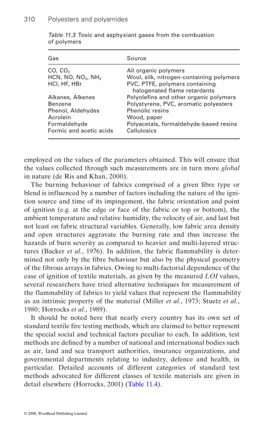
310 Polyesters and polyamides
employed on the values of the parameters obtained. This will ensure that
in nature (de Ris and Khan, 2000).
tion source and time of its impingement, the fabric orientation and point of ignition (e.g. at the edge or face of the fabric or top or bottom), the ambient temperature and relative humidity, the velocity of air, and last but not least on fabric structural variables. Generally, low fabric area density and open structures aggravate the burning rate and thus increase the hazards of burn severity as compared to heavier and multi-layered struc-
ease of ignition of textile materials, as given by the measured LOI values, several researchers have tried alternative techniques for measurement of
as an intrinsic property of the material (Miller et al., 1973; Stuetz et al., 1980; Horrocks et al., 1989).
It should be noted here that nearly every country has its own set of
the special social and technical factors peculiar to each. In addition, test
as air, land and sea transport authorities, insurance organizations, and governmental departments relating to industry, defence and health, in particular. Detailed accounts of different categories of standard test methods advocated for different classes of textile materials are given in detail elsewhere (Horrocks, 2001) (Table 11.4).
Table 11.3 Toxic and asphyxiant gases from the combustion of polymers
Gas Source
CO, CO2 All organic polymersHCN, NO, NO2, NH3 Wool, silk, nitrogen-containing polymersHCl, HF, HBr PVC, PTFE, polymers containing
Alkanes, AlkenesBenzene Polystyrene, PVC, aromatic polyestersPhenol, Aldehydes Phenolic resinsAcrolein Wood, paperFormaldehyde Polyacetals, formaldehyde-based resinsFormic and acetic acids Cellulosics
Polyolefins and other organic polymers
The burning behaviour of fabrics comprised of a given fibre type or
mined not only by the fibre behaviour but also by the physical geometry of the fibrous arrays in fabrics. Owing to multi-factorial dependence of the
standard textile fire testing methods, which are claimed to better represent
methods are defined by a number of national and international bodies such
halogenated flame retardants
the values collected through such measurements are in turn more global
blend is influenced by a number of factors including the nature of the igni-
tures (Backer et al., 1976). In addition, the fabric flammability is deter-
the flammability of fabrics to yield values that represent the flammability
© 2008, Woodhead Publishing Limited

Table 11.4 Selected test methods for textiles
Nature of test Textile type Standard Ignition source
British standard based vertical strip method BS 5438
Curtains and drapes
Night wearProtective clothing
(now withdrawn)
BS 5867: Part 2: 1980 (1990)
BS 5722: 1991BS 6249: Part 1: 1982
ISO vertical strip similar to tests 1 and 2 in BS 5438
Vertical fabrics BS EN ISO 6940/1:1995
Small-scale composite test for furnishing
Furnishing fabrics
Furnishing fabrics
BS 5852: Pts 1 and 2: 1979 (retained pending changes in legislation)
BS 5852: 1990 (1998) replaces BS 5852: Pt 2
ISO 8191: Pts 1 and 2 (same as BS 5852: 1990)
BS EN 1021-1: 1994BS EN 1021-2: 1994
(20 s ignition)
applied to small and full scale tests
Cigarette
ignition)
Cleansing and wetting procedures for
tests
All fabrics
Commercial laundering
Domestic laundering
BS 5651: 1989
BS EN ISO 10528: 1995
BS EN ISO 12138: 1997
Not applicable but used on fabrics prior to submitting for standard ignition tests
fabric/fillings
Small flame
Small flameSmall flame
Small flame
Cigarette and simulated match flame
Small flames and wooden cribs
Simulated match flame (15 s
use in flammability
© 2008, Woodhead Publishing Limited

Air seat assemblies, so called ‘Boeing’ test
All fabrics/composites
ASTM E9060 1983, uses Ohio State University heat release calorimeter
NF P 92501-7, French ‘M test’
Irradiate under 35 kW m−2 with small
Irradiate with small burner
Protective clothing Resistance to radiant heat
Resistance to molten metal splash
Gloves
General protectionContact heat
transmission
BS EN 366: 1993) replaces BS 3791: 1970)
BS EN 367: 1992BS EN 373: 1993
BS EN 407: 1994
BS EN 469: 1995BS EN 532: 1994 (replaces BS 5438)BS EN 533: 1997 (replaces BS 6249BS EN 702: 1994
Exposure to radiant source
Determine heat transfer indexMolten metal
Radiant, convective and molten metal
Table 11.4 cont’d
Nature of test Textile type Standard Ignition source
Fire fighter’s clothing
Use of radiant fluxflame igniter
Small flameGeneral flame spread Small flame
Contact temps. 100–500°CSmall flame
© 2008, Woodhead Publishing Limited
Flame-retardant polyester and polyamide textiles 313
and in the related numbers of fatal and non-fatal casualties, especially in domestic environments. Sources of relatively low intensities (such as
vertical geometries (e.g. curtains, clothing, etc.) which encourage high
nishings and bedding are also particularly hazardous as is shown in statis-
retardant textiles are designed to reduce their propensity to undergo igni-
burning matches) or to pilots of low intensity but of prolonged duration
dant, upholstered furnishing fabrics and protective clothing must be ren-
11.3.2 Flame-retardant strategies for textile materials – general considerations
coatings of retardant species (e.g. antimony trioxide/halogenated organic
11.3.1 Specific fire hazards associated with textile fibres
The major fire hazard associated with textile materials, in general, is shown
materials. Furthermore, conventional textile fibres are comprised of rela-
in the high incidence of their implication in fire initiation and propagation
surface area in the fibre form, significantly enhance the rate of combustion and fire proliferation. Coupled with this is the use of textile materials in
tics relating to the occurrence of fires in dwellings (Office of the Deputy
smokers’ materials) are often sufficient to bring about ignition of these
Prime Minister, 2004). In fact, about 20% of dwelling fires are caused by textile materials (being the first material to be ignited), and about 50% of
(e.g. burning cigarette ends). Heat-resistant textiles are not only expected
fillings, clothing layers or skin (Horrocks et al., 2004).
f ibrous components; (d) or by a suitable combination of the above. For
resin systems) or functional finishes (e.g. organophosphorus- and nitrogen-containing monomers, or polycondensates). Functional finishes are
tively flammable fibre-forming polymers which, owing to their high specific
burning rates when ignition is at the bottom. Textiles in upholstered fur-
the fatalities are associated with these fires. Consequently, most flame-
tion and flame propagation when exposed to small flame sources (e.g.
to resist ignition and have reduced flame propagation rates, but also should offer a barrier to heat and flame penetration to the underlying materials or surfaces. Thus, while drapes and curtains may be rendered flame retar-
dered sufficiently flame and heat resistant to prevent damage to underlying
Textile materials may be rendered flame retardant through a variety of
mable component fibres; (b) by the use of fibres that have been flame retarded during manufacture; (c) by the use of inherently flame-retardant
example, conventional cotton and wool fabrics are flame retarded by the use of flame-retardant chemical treatments, which are often simple topical
ways. They include: (a) post-chemical treatment of the otherwise flam-
applications of flame-retardant salts (e.g. ammonium polyphosphates),
© 2008, Woodhead Publishing Limited
314 Polyesters and polyamides
particularly advantageous in that high levels of durability are achieved as
The demands of upholstery furnishings to satisfy the aesthetic require-
generating combination which, when applied to one side (usually the back
formation. Consequently, back coatings have been successfully applied to fabrics compris of cotton, polyacrylic and polyester blends and mixtures of
tions, phosphorus-containing species or mixtures of both, often applied with a char-forming acrylic resin.
chemical structures that are compatible with the more common functional
erties; and (d) that their thermoplasticities, coupled often with a tendency
by these materials (Horrocks et al., 2005).
11.4 Polyesters
The linear, thermoplastic, polyesters are all partly crystalline polymers, soluble above their melting points (Tm) in a range of organic solvents, have glass transition temperatures (Tg) and therefore softening points that are
mable in their pure state with limiting oxygen indices (LOIs) typically of
spun are the aromatic polyesters, especially poly(ethylene terephthalate) (PET) and poly(butylene terephthalate) (PBT), owing to their relatively high crystallinities (and hence tensile strengths), Tms and Tgs. However, of the aromatic polyesters, only PET is in wide-spread use as a commercial
a significant rise in the use of back-coating treatments, which comprise
thermoplastic fibres, offers a char-forming support, which prevents hole
these fibres. Flame-retardant species can be antimony-bromine combina-
In the case of common synthetic fibres like polyesters, polyamides (nylons), polyacrylics and polypropylene, it has proved difficult to effec-
serious reductions in ultimate fibre tensile and other essential textile prop-
are problems to addressed in the context of secondary fire hazards posed
around 20. The most important polyesters from which useful fibres can be
ment of the consumer and regulatory flame-resistance standards have seen
they either polymerize within the internal fibre voids or react with func-
the flame-retardant species bonded with a resin to the reverse of the
tional groups in the fibre-forming polymer backbone (Horrocks, 1996).
fabric. Careful selection of flame retardant and resin can produce a char-
side) of a flammable textile, confers flame retardancy. This, in the case of
tively flame retard owing to: (a) the fact that they do not have physical or
flame retardants; (b) that during fibre production, the melt polymers are often highly reactive and they have low compatibility with many flame retardant additives; (c) that the presence of relatively high flame retardant concentrations (5–20% w/w) necessary to confer flame-retardant proper-ties not only creates spinning fluid compatibility problems but also causes
to melt, mean that shrinkage and melt dripping (often under f laming mode)
dependent upon their precise chemical structures, and are highly flam-
© 2008, Woodhead Publishing Limited
Flame-retardant polyester and polyamide textiles 315
cloths.PET, when heated to above 300˚C, undergoes thermal degradation to
such as acetaldehyde, methane, ethene and diethyl ether together with less volatile, but none-the-less combustible, products such as PET oligomers (linear and cyclic), terephthalic acid and ethylene glycol (Sobue and
the production of acid and vinyl end groups (Goodings, 1961). The kinetics of this degradation have been thoroughly explored and mechanisms advanced for the production of most products, including a small amount of a carbonaceous residue (Holland and Hay, 2002). Since the pyrolysis of
PET than strategies aimed solely at increasing char formation, or some other condensed-phase mechanism; however, research to date shows that, in general, mixed phase action can be engineered (Levchik and Weil, 2004).
Progress in the research, development and commercial implementation
spective of end-application, has recently been comprehensively reviewed by Levchik and Weil (2005). Thus, it is not necessary to review compre-
spun must take into account the possibility that the additive has the poten-tial to interfere with the spinning process, especially if it is an insoluble particulate. Flame retardants also need to be able to withstand laundry
gists, such as metal hydroxides, antimony trioxide, ammonium and melamine phosphates, and zinc oxides and stannates, are not used in PET
be excluded during subsequent crystallization with the possibility of bloom-ing and eventual loss during service. This possibility militates against the use also of many established low molecular weight halogen- and
retardant, reactive, comonomers. One early example of such a comonomer
f ibre, in applications as diverse as tyre cords, woven textiles and non-woven
Kajiura, 1959; Kardash et al., 1964) The rate-determining step is olefin
hensively this field again; rather it will suffice merely to highlight current commercial practice, significant past and recent research and development, and likely future research directions with regard specifically to the use of polyesters in fibre form.
cycles if the fibre is to be used in many textile applications. For these
give a variety of highly volatile products, many of which are flammable,
PET gives mainly volatile and flammable products, it would seem probable
elimination from glycol dibenzoate groups leading to chain scission and
that vapour-phase flame-retardant strategies would be more effective with
of flame-retardant strategies for thermoplastic polyesters in general, irre-
Choice of a flame retardant for a fibre-forming polymer that is to be melt
reasons, many established inorganic flame-retardant additives and syner-
fibres. Even if the flame retardant is soluble in the molten polymer, it may
phosphorus-containing flame-retardant compounds. Thus, much research, development and commercial exploitation of flame retardants for PET fibres, especially recently, has concentrated upon the use of flame-
© 2008, Woodhead Publishing Limited
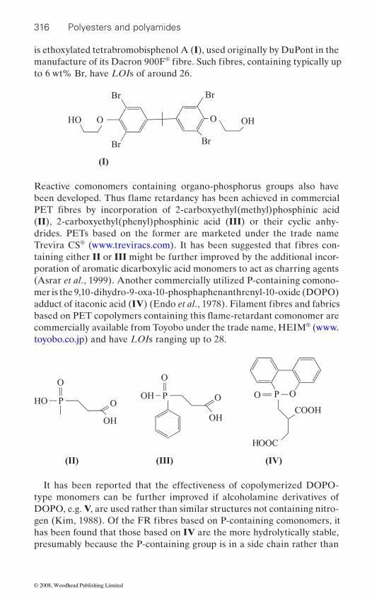
316 Polyesters and polyamides
is ethoxylated tetrabromobisphenol A (I), used originally by DuPont in the ®
to 6 wt% Br, have LOIs of around 26.
HO O
Br
Br
O
Br
Br
OH
(I)
Reactive comonomers containing organo-phosphorus groups also have
(II), 2-carboxyethyl(phenyl)phosphinic acid (III) or their cyclic anhy-drides. PETs based on the former are marketed under the trade name Trevira CS®
taining either II or III might be further improved by the additional incor-poration of aromatic dicarboxylic acid monomers to act as charring agents (Asrar et al., 1999). Another commercially utilized P-containing comono-mer is the 9,10-dihydro-9-oxa-10-phosphaphenanthrenyl-10-oxide (DOPO)
commercially available from Toyobo under the trade name, HEIM® (www.toyobo.co.jp) and have LOIs ranging up to 28.
HO P
O
OH
OP
OH
OOH
O
P OO
COOH
HOOC
(II) (III) (IV)
It has been reported that the effectiveness of copolymerized DOPO-type monomers can be further improved if alcoholamine derivatives of DOPO, e.g. V, are used rather than similar structures not containing nitro-
has been found that those based on IV are the more hydrolytically stable, presumably because the P-containing group is in a side chain rather than
manufacture of its Dacron 900F fibre. Such fibres, containing typically up
PET fibres by incorporation of 2-carboxyethyl(methyl)phosphinic acid
(www.treviracs.com). It has been suggested that fibres con-
adduct of itaconic acid (IV) (Endo et al., 1978). Filament fibres and fabrics
gen (Kim, 1988). Of the FR fibres based on P-containing comonomers, it
been developed. Thus flame retardancy has been achieved in commercial
based on PET copolymers containing this flame-retardant comonomer are
© 2008, Woodhead Publishing Limited
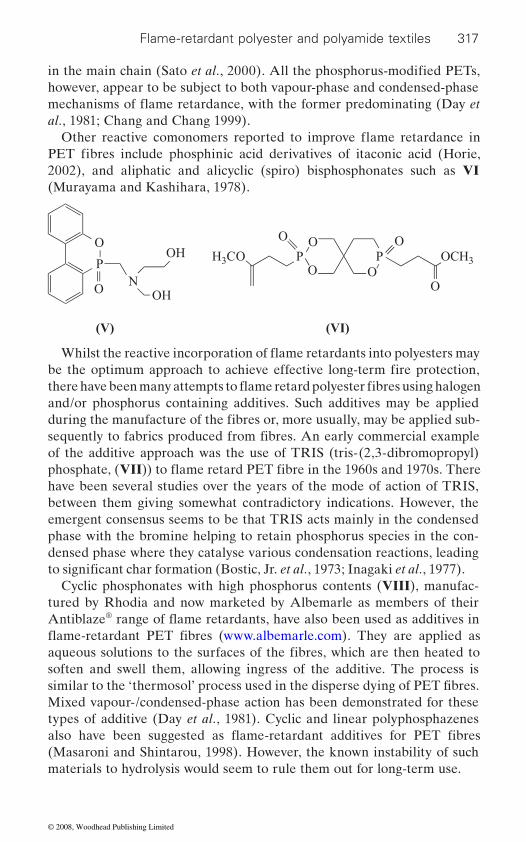
Flame-retardant polyester and polyamide textiles 317
however, appear to be subject to both vapour-phase and condensed-phase
al., 1981; Chang and Chang 1999).
2002), and aliphatic and alicyclic (spiro) bisphosphonates such as VI (Murayama and Kashihara, 1978).
O
P
ON
OH
OH
H3CO PO O
OP OCH3
O
OO
(V) (VI)
and/or phosphorus containing additives. Such additives may be applied
of the additive approach was the use of TRIS (tris-(2,3-dibromopropyl)
have been several studies over the years of the mode of action of TRIS, between them giving somewhat contradictory indications. However, the emergent consensus seems to be that TRIS acts mainly in the condensed phase with the bromine helping to retain phosphorus species in the con-densed phase where they catalyse various condensation reactions, leading
Cyclic phosphonates with high phosphorus contents (VIII), manufac-tured by Rhodia and now marketed by Albemarle as members of their
®
soften and swell them, allowing ingress of the additive. The process is
Mixed vapour-/condensed-phase action has been demonstrated for these types of additive (Day et al., 1981). Cyclic and linear polyphosphazenes
(Masaroni and Shintarou, 1998). However, the known instability of such materials to hydrolysis would seem to rule them out for long-term use.
in the main chain (Sato et al., 2000). All the phosphorus-modified PETs,
PET fibres include phosphinic acid derivatives of itaconic acid (Horie,
be the optimum approach to achieve effective long-term fire protection,
during the manufacture of the fibres or, more usually, may be applied sub-sequently to fabrics produced from fibres. An early commercial example
to significant char formation (Bostic, Jr. et al., 1973; Inagaki et al., 1977).
aqueous solutions to the surfaces of the fibres, which are then heated to
similar to the ‘thermosol’ process used in the disperse dying of PET fibres.
mechanisms of flame retardance, with the former predominating (Day et
Other reactive comonomers reported to improve flame retardance in
Whilst the reactive incorporation of flame retardants into polyesters may
there have been many attempts to flame retard polyester fibres using halogen
phosphate, (VII)) to flame retard PET fibre in the 1960s and 1970s. There
Antiblaze range of flame retardants, have also been used as additives in flame-retardant PET fibres (www.albemarle.com). They are applied as
also have been suggested as flame-retardant additives for PET fibres
© 2008, Woodhead Publishing Limited
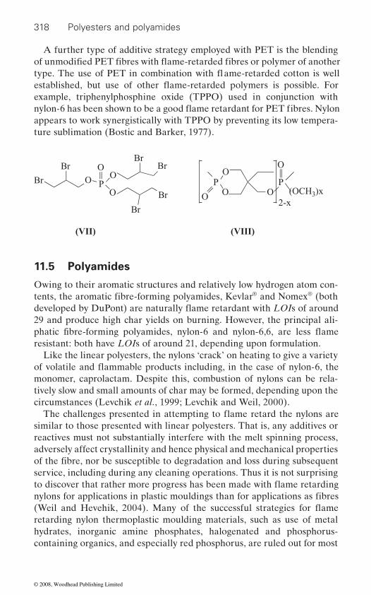
318 Polyesters and polyamides
A further type of additive strategy employed with PET is the blending
example, triphenylphosphine oxide (TPPO) used in conjunction with
appears to work synergistically with TPPO by preventing its low tempera-ture sublimation (Bostic and Barker, 1977).
Br
Br
O PO
OO Br
Br
Br
Br
POO
OP
(OCH3)x
O
2-xO
(VII) (VIII)
11.5 Polyamides
Owing to their aromatic structures and relatively low hydrogen atom con-® and Nomex® (both
29 and produce high char yields on burning. However, the principal ali-
resistant: both have LOIs of around 21, depending upon formulation.Like the linear polyesters, the nylons ‘crack’ on heating to give a variety
monomer, caprolactam. Despite this, combustion of nylons can be rela-tively slow and small amounts of char may be formed, depending upon the circumstances (Levchik et al., 1999; Levchik and Weil, 2000).
similar to those presented with linear polyesters. That is, any additives or reactives must not substantially interfere with the melt spinning process, adversely affect crystallinity and hence physical and mechanical properties
service, including during any cleaning operations. Thus it is not surprising
retarding nylon thermoplastic moulding materials, such as use of metal hydrates, inorganic amine phosphates, halogenated and phosphorus-containing organics, and especially red phosphorus, are ruled out for most
tents, the aromatic fibre-forming polyamides, Kevlar
of the fibre, nor be susceptible to degradation and loss during subsequent
nylons for applications in plastic mouldings than for applications as fibres
of unmodified PET fibres with flame-retarded fibres or polymer of another type. The use of PET in combination with flame-retarded cotton is well established, but use of other flame-retarded polymers is possible. For
nylon-6 has been shown to be a good flame retardant for PET fibres. Nylon
developed by DuPont) are naturally flame retardant with LOIs of around
phatic fibre-forming polyamides, nylon-6 and nylon-6,6, are less flame
of volatile and flammable products including, in the case of nylon-6, the
The challenges presented in attempting to flame retard the nylons are
to discover that rather more progress has been made with flame retarding
(Weil and Hevehik, 2004). Many of the successful strategies for flame
© 2008, Woodhead Publishing Limited
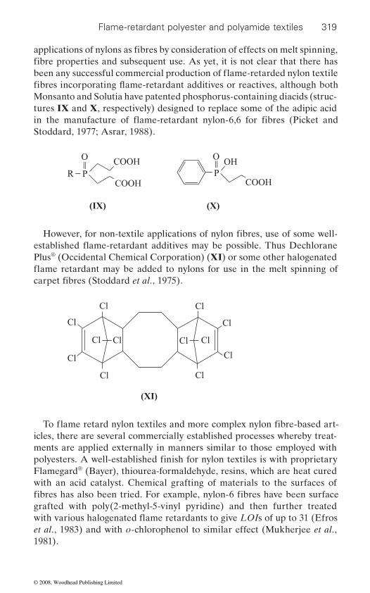
Flame-retardant polyester and polyamide textiles 319
Monsanto and Solutia have patented phosphorus-containing diacids (struc-tures IX and X, respectively) designed to replace some of the adipic acid
Stoddard, 1977; Asrar, 1988).
R PCOOH
COOHO
POH
O
COOH
(IX) (X)
Plus® (Occidental Chemical Corporation) (XI) or some other halogenated
Cl Cl
Cl
Cl
Cl
Cl
Cl
Cl
Cl Cl Cl Cl
(XI)
icles, there are several commercially established processes whereby treat-ments are applied externally in manners similar to those employed with
Flamegard® (Bayer), thiourea-formaldehyde, resins, which are heat cured with an acid catalyst. Chemical grafting of materials to the surfaces of
grafted with poly(2-methyl-5-vinyl pyridine) and then further treated
et al., 1983) and with o-chlorophenol to similar effect (Mukherjee et al., 1981).
applications of nylons as fibres by consideration of effects on melt spinning, fibre properties and subsequent use. As yet, it is not clear that there has
carpet fibres (Stoddard et al., 1975).
polyesters. A well-established finish for nylon textiles is with proprietary
fibres has also been tried. For example, nylon-6 fibres have been surface
been any successful commercial production of flame-retarded nylon textile fibres incorporating flame-retardant additives or reactives, although both
in the manufacture of flame-retardant nylon-6,6 for fibres (Picket and
established flame-retardant additives may be possible. Thus Dechlorane However, for non-textile applications of nylon fibres, use of some well-
flame retardant may be added to nylons for use in the melt spinning of
To flame retard nylon textiles and more complex nylon fibre-based art-
with various halogenated flame retardants to give LOIs of up to 31 (Efros
© 2008, Woodhead Publishing Limited
320 Polyesters and polyamides
11.6 Conclusions and future trends
It seems unlikely that there will be any major breakthroughs with regard
without appreciably interfering with the spinning process, modifying the
stability, and at economic cost, restricts options considerably.
deposition techniques. Some encouraging results have been reported on
that the technique might be more universally applicable. Already, plasma
Ooiju et al., 1999; Lee et al., 2001). Conventional vacuum coating might
fabrics is the intumescent coating, applied using conventional coatings technology. Horrocks and colleagues have achieved considerable success
and wool fabrics, but the methodology is, in principle, extendable to other types of polymer-based textile (Horrocks, 1996).
Nanoscopic materials are attracting increasing interest, both for surface coatings and as additives in polymers. The Nano-Tex® (www.nano-tex.com) surface-treatments for fabrics, based on dispersions of nanoscopic additives, and designed thus far to improve stain resistance, static build-up, and moisture dissipation in fabrics, would appear to be extendable to the
with the aim being mainly to improve modulus and, if possible, also tensile strength. Fibres have recently been spun successfully from polyesters con-taining, for example, nanoscopic organoclays (Chang et al., 2004; Mun et al., 2006), carbon nanotubes (Yang et al., 2006) and fullerenes (Ikegame and Kono, 2006). Since the incorporation of selected nanoscopic materials
physical and mechanical properties of the fibres, or affecting long-term
However, since the important first barrier to ignition of a fibre (or indeed
dance by surface modification, especially using modern vacuum or plasma
the plasma modification of the surfaces of polyacrylonitrile fibres so as to
modifications of polyester fibres and fabrics have been reported aimed at
surface modification to fibres and fabrics (Mikhael and Yializis, 2005).
nanoscopic particles within polymer-based fibres is also growing rapidly
for exploitation with fibres. It is to be noted that some success with this
of any material) is the surface, it is sensible to ask whether or not more can
to new and/or improved reactive flame-retardant comonomers or conven-tional organic and inorganic flame-retardant additives for use in either PET or nylon fibres. The requirements to achieve satisfactory flame retardance
be done to modify fibres or textile surfaces so as to improve flame retar-
improve flame retardance (Akovali and Gundogan, 1990), which suggest
modifying surface adhesion and reflectivity (Manenq et al., 1999; Van
also be appropriate for the deposition of some types of flame-retardant
An alternative type of flame-retardant surface treatment for fibres and
with this type of approach, especially for the flame retardation of cotton
deposition of nanoscopic flame-retardant formulations. The exploitation of
into bulk polymers, along with conventional flame retardants, can signifi-cantly improve their flame retardancy, this is clearly an area that is ripe
© 2008, Woodhead Publishing Limited
Flame-retardant polyester and polyamide textiles 321
2004).
11.7 Sources for further information and advice
There are a variety of sources for further information and reading in the form of specialized reviews, monographs, symposia series, book chapters,
Most of them pay particular attention to thermoplastic materials including
interest are the following sources of information on the subject: (a) Camino G, Le Bras M, Bourbigot S and Delobel R (1998), Fire Retardancy of Polymers: The Use of Intumescence, Cambridge, The Royal Society of Chemistry; (b) Nelson G L and Wilkie C A (2001), Fire and Polymers: Materials and Solutions for Hazard Preventions, Washington, American Chemical Society (Symposium series 797); (c) Troitzsch J (2004), Plastics Flammability Handbook, Cincinnati, Hanser Gardner Publications; (d) Long A C (2005), Design and Manufacture of Textile Composites, Cambridge, Woodhead Publishing Limited; (e) Camino G, Le Bras M, Bourbigot S and Delobel R (1998), Fire Retardancy of Polymers: The Use of Minerals Fillers in Micro- and Nano-composites, Cambridge, The Royal
Polymers: Materials and Concepts for Hazard Prevention, Washington, American Chemical Society (Symposium series 922).
11.8 References
Sci. 41, 9–10.
Patent, 5 750 603.asrar j, berger p a and hurlbut j (1999), ‘Synthesis and characterization of
carboxyethyl(phenylphosphinic) acid’, J. Polym. Sci., Polym. Chem. Edit., 37, 3119–3128.
babrauskas v (1984), ‘Development of a cone calorimeter – a bench-scale heat release rate apparatus based on oxygen consumption’, Fire and Materials, 8, 81–95.
backer s, tesoro g c, toong t y and moussa n a (1976), Textile Fibre Flammability, Massachusetts, MIT Press.
bostic, jr. j e, yeh k-n and barker r h (1973), ‘Pyrolysis and combustion of polyester. I. Thermochemistry of poly(1,4-cyclohexylene dimethylene
approach has already been reported for polypropylene fibres (Zhang et al.,
fibre-forming polymers such as polyesters and polyamides. Of particular
asrar j (1988), ‘Polymer-bound non-halogen fire resistant compositions’, US
a fire-retardant polyester: copolymers of ethylene terephthalate and 2-
and books that are entirely dedicated to the flammability characteristics, associated hazards and flame retardation strategies for synthetic polymers.
akovali g and gundogan g (1990), ‘Studies on flame retardancy of polyacryloni-
Society of Chemistry; (f) Nelson G L and Wilkie C A (2006), Fire and
trile fiber treated by flame-retardant monomers in cold plasma’, J. Appl. Polym.
© 2008, Woodhead Publishing Limited

322 Polyesters and polyamides
retardants’, J. Appl. Polym. Sci., 17, 471–482.bostic j e and barker r h (1977), ‘Pyrolysis and combustion of polyester. Part II.
4, 165–182.chang s-j and chang f-c (1999), ‘Synthesis and characterization of copolyesters
containing the phosphorus linking pendent groups’, J. Appl. Polym. Sci., 72, 109–122.
chang j-h, kim s j, joo y l and im s (2004), ‘Poly(ethylene terephthalate) nanocomposites by in situ interlayer polymerization: The thermo-mechanical
Polymer, 45, 919–926.
cullis c f and hirschler m m (1981), The Combustion of Organic Polymers, Oxford, Clarendon Press.
day m, suprunchuk t and wiles d m (1981), ‘Combustion and pyrolysis of
J. Appl. Polym. Sci., 26, 3085–3098.de ris j l and khan m m (2000), ‘A sample holder for determining material proper-
ties’ Fire and Materials, 24, 219–226.
endo s, kashihara t, osako a, shizuki t and ikegami t (1978), ‘Phosphorus-containing compounds’, US Patent, 4 127 590.
fenimore c p and martin f j (1966), ‘Flammability of polymers’, Combust. Flame, 10 (2), 135–139.
goodings e p (1961), ‘Thermal degradation of poly(ethylene terephthalate)’, Soc. Chem. Ind. (London), 13, 211–228.
containing bromine and phosphorus’, J. Polym. Sci., Part A Polym. Chem., 30 (5), 919–824.
grassie n and scott g (1985), Polymer Degradation and Stabilization, Cambridge, Cambridge University Press.
holland b j and hay j n (2002), ‘The thermal degradation of PET and analogous polyesters measured by thermal analysis-Fourier transform infrared spectros-copy’, Polymer, 43, 1835–1847.
6 498 227.horrocks a r, price d and tunc m (1989), ‘Studies on the temperature dependence
of extinction oxygen index values for cellulose’, J. Appl. Polym. Sci., 34, 1901–1916.
textiles – the role of char formation and intumescence’, Polym. Deg. and Stab., 54, 143–154.
horrocks a r (2001), ‘Textiles’ in Horrocks A R and Price D, Fire Retardant Materials, Cambridge, Woodhead Publishing.
hazards of nightware’, Fire Safety Journal, 39, 259–276.
properties and morphology of the hybrid fibers’,
poly(ethylene terephthalate). II. Study of the gas-phase inhibition reactions of
efros a v, tyuganova m a and galbraikh l s (1983), ‘Preparation of a fire-resistant nonmelting polycaprolactam fiber’, Khim. Volokna, 6, 31–32.
gou w (1992), ‘Flame-retardant modification of UV-curable resins with monomers
terephthalate) treated with selected phosphorus and halogen-containing flame
Effect of triphenylphosphine oxide as a flame retardant’, J. Fire Retard. Chem.,
flame retardant systems’,
horie s (2002), ‘Flame retardant, f iber-treatment, A method for imparting flame retardancy, and flame resistant polyester textile materials’, US Patent,
horrocks a r (1996), ‘Developments in flame retardants for heat and fire resistant
horrocks a r, nazare s and kandola b (2004), ‘The particular flammability
© 2008, Woodhead Publishing Limited
Flame-retardant polyester and polyamide textiles 323
horrocks a r, kandola b k, davies p j, zhang s and padbury s a (2005), ‘Develop-
inagaki n, onishi h, kunisada h and katsuura k (1977), ‘Flame retardancy effects of halogenated phosphate on poly(ethylene terephthalate) fabric’, J. Appl. Polym. Sci., 21, 217–224.
Polymer, 33, 418–422.kardash i e, pravednikov a n and medvedev s s (1964), ‘Thermal degradation of
poly(ethylene terephthalate)’, Doklady Akademii Nauk SSSR, 156, 658–661.kim y c (1988), ‘Phosphorus-containing nitrogen compounds as fl
and synthetic resins containing them’, US Patent, 4 742 088.
of PET fabrics using an atmospheric pressure plasma technique’, Surface and Coatings Technology, 142, 468–473.
levchik s v, weil e d and lewin m (1999), ‘Thermal degradation of aliphatic nylons’, Polym. Int., 48, 1–26.
nylons’, Polym. Int., 49, 1033–1073.levchik s v and weil e d (2004), ‘A review on thermal decomposition and combus-
tion of thermoplastic polyesters’, Polymers for Advanced Technologies, 15, 691–700.
levchik s v and weil e d (2005), ‘Flame retardancy of thermoplastic polyesters – A review of the recent literature’, Polym. Int., 54, 11–35.
manenq f, carlotti s and adhesion testing to rubber’, Angew. Makromol. Chem., 271, 11–17.
masaroni y and shintarou k (1998), ‘Fire retardant polyester resin composition and process for producing the same’, US Patent, 5 770 644.
mikhael m g and yializis a (2005), ‘Coating textiles in vacuum: extending vacuum web coating technology to everyday apparel’, 48th Annual Technical Conference Proceedings, Society of Vacuum Coaters, 663–666.
miller b, gosami b c and turner r (1973), ‘The concept and measurement of
by o-chlorophenol’, Man-Made Text. India, 24, 310–316.mun m k, kim j-c and chang j-h (2006), ‘Preparation of poly(ethylene terephthal-
Bull., 57, 797–804.murayama k and kashihara t (1978), ‘Flame resistant polyesters’, US Patent,
4 086 208.offi ce of the deputy prime minister (2004), Fire Statistics, United Kingdom,
Wetherby, ODPM Publications.picket, jr. o a and stoddard j w (1977), ‘Phosphorus-containing copolyamides
Sci., 78, 1134–1138.
ikegame m and kono k (2006), ‘Polyester-fullerene nanocomposite fibers and their
levchik s v and weil e d (2000), ‘Combustion and fire retardancy of aliphatic
mas a (1999), ‘Some plasma treatment of PET fibres and
mukherjee a k, duraiswamy r and sengupta a k (1981), ‘Modif ication of nylon 6
ate) nanocomposite fibers incorporating a thermally stable organoclay’, Polym.
and fibers thereof’, US Patent, 4 032 517.
retardant polyester fiber: Improvement of hydrolysis resistance’, J. Appl. Polym.
ments in flame retardant textiles – a review’, Polym. Deg. and Stab., 88, 3–12.
kannan p and kishore k (1992), ‘Novel flame retardant phosphoramide esters’,
manufacture’, Jpn. Kokai Tokkyo Koho, 10pp., JP 2006214057, A 20060817.
ame retardants
lee h-r, kim d-j, and lee k-h (2001), ‘Anti-reflective coating for the deep coloring
extinguishability as a flammability criterion’, Text. Res. J., 43, 61.
sato m, endo s, araki y, matsuoka g, gyobu s and takeuchi h (2000), ‘The flame-
© 2008, Woodhead Publishing Limited
324 Polyesters and polyamides
schartel b, bartholmai m, knoll u (2005), ‘Some comments on the use of cone
sobue h and kajiura a (1959), ‘Effect of heating on poly(ethylene terephthalate)’, Kogyo Kagaku Zasshi, 62, 1766–70.
stoddard j w, pickett o a, cicero c j and saunders j h (1975), ‘Flame retarded nylon carpets’, Textile Res. J., 45, 474–483.
stuetz d e, diedwardo a h, zitomer f and barnes b p (1980), ‘Polymer combus-tion’, J. Polym. Sci., Polym. Chem. Edn., 18, 967–987.
cords by plasma polymerization’, Plasmas and Polymers, 4, 33–55.weil e d and levchik s (2004), ‘Current practice and recent commercial develop-
yang m, hu g and zhang s (2006), ‘Manufacture of polyester/carbon nanotube
1869291, A 20061129.zhang s, horrocks a r, hull r and kandola b k (2004), ‘Flammability, degrada-
posites’, Proceedings of the Conference on Recent Advances in Flame Retardancy of Polymeric Materials, 15, 205–216.
van ooij w j, luo s and datta s (1999), ‘Surface modification of textile fibers and
composite fibers’ Faming Zhuanli Shenqing Gongkai Shuomingshu, 12pp., CN
tion and structural characterization of fibre-forming polypropylene nanocom-
calorimetric data’, Polym. Deg. and Stab., 88, 540–547.
ments in flame retardancy of polyamides’, J. Fire Sci., 22, 251–264.
© 2008, Woodhead Publishing Limited

12
and polyamide-based textiles
B. S . BU TOL A, Indian Institute of Technology, New Delhi, India
12.1 Introduction
12.1.1 Nylon
in the late 1930s was supposed to have the potential to replace many of the
abrasion resistance, crease recovery, easy dyeability, etc. on the positive side. Eventually it did not do so, and it was primarily due to its plastic feel
static charge.
due to its excellent recovery and shape retention properties. Most of the nylon was used in military applications especially parachutes during the World War II, which shortly followed the development of nylon. Initially an attempt was made to address the problem of durability of the apparels
nylon could never really penetrate the woven textile segment and the intro-duction of superior PET/cotton blends stopped any further scope for nylon
application areas which exploit its properties to the best.
12.1.2 Polyester
Polyester, which followed nylon four years later, today commands a lion’s
are strength, wrinkle resistance, good wash and wear properties, durability, etc. Although it has poor moisture regain, this has been partly countered
In fact, polyester-cotton and polyester viscose blends today are the most important textile types after 100% cotton textiles in terms of volume generated annually worldwide.
325
Advances in functional finishes for polyester
Nylon was the first truly synthetic fibre which at the time of its introduction
natural fibres. It had strength, lustre, softness, recovery, resilience, good
The initial use for the nylon filaments was hosiery, especially stockings
made from wholly natural fibres by blending nylon with cotton. However
in this sector. Since then nylon has remained confined to some specific
share of synthetic textile fibres. The positive attributes of polyester fibres
by blending it with natural/man-made fibres having higher moisture regain.
and shine in flat form, poor moisture regain and the propensity to develop
© 2008, Woodhead Publishing Limited
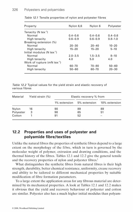
326 Polyesters and polyamides
12.2 Properties and uses of polyester and
molecular weight of polymer, extrusion and drawing conditions, and the
1
strength, durability, better chemical resistance, uniformity, crease recovery and ability to be tailored to different mechanical properties by suitable
mined by its mechanical properties. A look at Tables 12.1 and 12.2 makes it obvious that the yield and recovery behaviour of polyester and cotton are similar. Polyester also has a much higher initial modulus than polyam-
Property Nylon 6,6 Nylon 6 Polyester
Tenacity (N tex−1) Normal 0.4–0.6 0.4–0.6 0.4–0.6 High tenacity 0.6–0.9 0.6–0.9 0.8–1.0Breaking extension (%) Normal 20–30 20–40 10–20 High tenacity 15–20 15–20 5–10Initial modulus (N tex−1) Normal 2.0–3.5 1.5–3.5 8–10 High tenacity 4.0 5.0 4.0Work of rupture (mN tex−1) Normal 60–70 70–80 50–60 High tenacity 50–60 60–70 20–30
Table 12.2 Typical values for the yield strain and elastic recovery of
Material Yield strain (%) Elastic recovery % from
1% extension 5% extension 10% extension
Nylon 16 90 89 89Polyester 3 98 65 51Cotton 1 91 52 –
Table 12.1 Tensile properties of nylon and polyester fibres
various fibres
polyamide fibre/textiles
Unlike the natural fibres the properties of synthetic fibres depend to a large extent on the morphology of the fi bre, which in turn is governed by the
thermal history of the fibres. Tables 12.1 and 12.2 give the general tensile and the recovery properties of nylon and polyester fibres.
What distinguishes the synthetic fibres from natural fibres is their high
modifi cation of fibre formation parameters.To a large extent the application areas for any fibrous material are deter-
© 2008, Woodhead Publishing Limited
327
ide and similar to that of cotton. Hence in a polyester-cotton blended yarn, the contribution of the two components to the overall strength is better as the stress–strain curves of cotton and polyester are similar. However, due
polyamide component to the overall strength in a cotton-polyamide blend is poor. This has resulted in huge popularity and success of polyester-
that can be used in a wide range of applications: fashion garments, func-tional sports and leisurewear, ladies’ hosiery, lingerie, sewing thread, carpets, upholstery2 and even technical applications such as balloons and parachutes, sails, climbers’ ropes and automotive fabrics. It is also increas-
articles such as suitcases, rucksacks and shoes. Round, trilobal and dumb-
yarn varies enormously and it is this that determines the properties of the end product.
12.3 Imparting functionality through
attributes, their inherently low moisture regains and high strength result in problems of static generation, easy soiling and pilling. Part of these prob-
these problems remain. Additionally, there are greater functional demands
ments require the traditional apparel garments to be antistatic, antimicro-bial, easy to clean, stain proof, etc. On the other hand the increasing use of
There are basically four approaches to impart functionality to the tex-tiles made from polyester and polyamide textiles:
•
Advances in functional finishes
ties which make it ideal material for knitted garments where better fit and
to the lower initial modulus of polyamide fibres, the contribution of the
shape retention are more important. However, polyamide is a versatile fibre
ingly being used in blends with natural fibres and other man made fibres.
cotton blends. Polyamide, on the other hand has excellent recovery proper-
Polyamide fibres are available in a wide range of linear density and cross-sections: ultra-fine microfibres of less than 1.0 dtex for lightweight articles such as hosiery and lingerie to coarse fibres of up to 2100 dtex for robust
bell shaped cross-sections are most common. Number of filaments in the
finishing/coating/laminating
Although synthetic fibres like polyester and polyamide have many positive
lems can be overcome by blending these fibres with natural fibres. However, in applications where synthetic fibre component is very high (or 100%),
from these fibres. On one hand, the ever more demanding customer require-
these fibres for technical applications demands functionalities like water-
protection to name a few from textiles made from these fibres.
By incorporating a suitable additive in the melt or dope of the fibre polymer to produce intrinsically functional filaments (e.g., Trevira, the
repellency, water-proof breathablility, gas barrier, flame-proofness, UV
intrinsically flame retardant polyester fibre)
© 2008, Woodhead Publishing Limited

328 Polyesters and polyamides
• • Applying a coating of a functional chemical formulation on the textile
substrate•
It must be noted here that coating and lamination approach to impart functionality would alter many of the desired properties of an apparel
able for such applications. Discussions on imparting functionality at melt or dope stage is beyond the scope of this topic and hence only the remain-ing three approaches would be discussed.
12.3.1 Antistatic
One of the problems generally faced while using wholly or predominantly synthetic textiles is their tendency to generate static electricity. In most cases the generation of static charge is a minor irritant leading to small
humidity conditions. The static generation can be reduced by increasing the humidity of the workplace, incorporating the antistatic agents3 in the
facture of the fabric. A detailed discussion on the causes and solution of static generation problem can be found elsewhere.3
The static generation may manifest itself in problems at two distinct stages. There may be problems related with the production of textiles, i.e.,
1. 2. 3. ballooning of yarns4. electrostatic attraction between fabrics and lint/soil.
Then there may be problems related to the use of the textiles, like genera-
quaternary ethoxylated amines and quaternary fatty amide amines.The static problem on polyester can be reduced to some extent by sodium
hydroxide treatment (weight reduction). The effectiveness of the treatment
Applying a suitable chemical/mechanical finish to the textile
Laminating the textile with a preformed film or layer (an adhesive would be needed to bond the film/layer with the textile).
rare cases can lead to fire, explosion and damage to electronic components. The problem of static generation becomes acute with synthetic fibres in low
polymer melt or dope before fibre spinning, blending of conductive fibres
problems like clinging of garments, mild shocks, increased soiling, but in
with synthetic fibres or application of an antistatic finish after the manu-
repulsion of fibres from each other in charged sliverslapping of fibres around rollers
tion of static on walking over a carpet, etc. Majority of the chemical finishes used as the antistatic agents for synthetic fibres today are the variants of the finishes which have been in the market since the 1970s. Traditionally the antistatic finishes for polyamides have been based on ammonium salts,
textile like flexibility, breathability, drape, etc. and hence may not be suit-
© 2008, Woodhead Publishing Limited
329
wt 1000 which is durable up to 30 launderings.4 Silane nanosol has been successfully prepared5 with an organic precursor to improve the anti-static property of polyester fabrics. The experimental results show that the anti-
treatment, while there were no negative effects on the whiteness, strength and handle of the treated fabrics. Static charge usually builds up in syn-
static properties, research work concerning the improvement of the anti-static properties of textiles by using nanotechnology has been undertaken. It was determined that nano-sized titanium dioxide,6 zinc oxide whiskers, nano antimony-doped tin oxide7 (ATO) and silane nanosol5 could impart
2
static effects because they are electrically conductive materials. Such ma-terials help to effectively dissipate the static charge which is accumulated on the fabric. On the other hand, silane nanosol improves anti-static
in the air by amino and hydroxyl groups. Nanotechnology has also been applied in manufacturing an anti-static garment. W. L. Gore and Associ-
ing. Gore-Tex® I Workwear protects the wearer from electrostatic dis-charges. Electrically conductive nano-particles are durably anchored in the
conductive network that prevents the formation of isolated chargeable areas and voltage peaks commonly found in conventional anti-static mater-ials. This method can overcome the limitation of conventional methods, which is that the anti-static agent is easily washed off after a few laundry cycles.8
12.3.2 Antimicrobial
the prevention of the growth of disease causing microorganisms on textiles which may not cause biodeterioration of textiles but can cause malodour, stains and cross-infections. Second, the protection of the textile itself from attack by the mildew, mould and rot producing microorganisms. The syn-
causing microorganisms.
Advances in functional finishes
can be increased by finishing it with a reactive polyethylene glycol of mol.
thetic fibres such as nylon and polyester because they absorb little water. Cellulosic fibres have higher moisture content to carry away static charges,
static property of treated PET fabrics was enhanced considerably by sol
so that no static charge will accumulate. As synthetic fibres have poor anti-
anti-static properties to synthetic fibres. TiO , ZnO and ATO provide anti-
properties, as the silane gel particles on fibre absorb water and moisture
There are two distinct roles the antimicrobial finishes have to play: firstly
thetic fibres especially polyester and nylon are generally not attacked by microorganisms; hence the discussion on antimicrobial finishes in this section will be confined to the finishes which deal with disease and odour
ates GmbH used nanotechnology and polytetrafluroethylene (PTFE, Dupont’s Teflon®) to develop an anti-static membrane for protective cloth-
fibrils of the Gore-Tex® I membrane of Teflon, creating an electrically
© 2008, Woodhead Publishing Limited

330 Polyesters and polyamides
requirements. It should provide safety in the form of low toxicity to the consumer, e.g. it would not cause allergy or irritation to the skin. Its appli-cation would not adversely affect textile properties or appearance. It should be compatible with common textile processing and the resulting antimi-
bodies to conform to strict environmental and safety norms.9
World War II. A large number of compounds belonging to many classes like inorganic salts, organometallic compounds, phenols, thiophenols, anti-biotics, formaldehyde derivatives, amines, etc. were tried and processes developed to make textiles resistant to microbes.10 Today many of these
potential to cause environmental damage. Examples of such compounds are copper naphthenate, copper 8-quinolinate and many organo mercury compounds.11
phene, 3-iodopropynyl butyl carbamate, benzimidazol, derivatives of sali-cylanilides and alkylolamide salts of undecylenic acid. The structures of two antimicrobial agents are given in Figure 12.1. A popular and widely used agent is 2,4,4′-trichloro-2′-hydroxyl diphenyl ether or triclosan. It is used in mouthwashes, toothpastes, liquid hand soaps, deodorant products and also in textiles. Tinosan AM 100 and Tinosan AM 110 are antimicro-
OH
(CH3CH2CH2CH2)3Sn Sn(CH2CH2CH2CH3)3 H3CCH2CH2CH2 OCH2C ICN
OH
O
O
Cl
Cl
Cl
Cl
ClDichlorophene Triclosan (2,4,4′-Trichloro-2′-hydoxyphenyl ether)
Tributyl tin oxide (TBTO) 3-lodopropynylbutyl carbamate
HO
HO
CH2
12.1 Molecular structures of two antimicrobial agents.
An ideal antimicrobial for textiles would have to fulfil the following basic
crobial efficacy has to be durable against repeated laundering. Today such finishes are coming under increasingly heavy pressure from regulatory
There was a spurt in the use of antimicrobial finishes for textiles during
The antimicrobial finish may act by one of three mecha-
layer. The application of the finish itself may be by insolubilization on textile f ibre, chemical modification of the fibre by covalent bond formation,
nisms; controlled release (chemical or physical), regeneration and barrier
coating on the textile fibre surface or microencapsulation.
compounds have been banned or phased out due to their high toxicity and
Some of the old products which still f ind use are tributyl tin, dichloro-
bial finishing agents based on Triclosan produced by Ciba Specialty
© 2008, Woodhead Publishing Limited
331
Chemical Ltd Germany. These products are designed to impart durable
a very high exhaustion rate. During use, the antimicrobial active agent can migrate to the surfaces of the treated textiles at a slow yet sustained rate
12
Durable and regenerable antibacterial textiles were prepared by Sun and coworkers13 by continuous grafting of cyclic amine monomer 3-allyl-5,5-dimethyl hydantoin (ADMH). The textiles selected were nylon, polyester,
treated textiles were exposed to dilute chlorine solutions which convert hydantoin structures to N-halamines, which act as powerful, durable and regenerable antibacterial agents against bacteria E coli.
In a novel process14 light activated antibacterial nylon textiles were pre-pared by Bozja by grafting on proporphyrin IX and zinc proporphyrin IX.
against E. coli after exposure to 60 000 lux. No activity was shown in absence of light.
Sun et al.15 The carboxylic end groups in nylon were utilized for interaction with cationic quaternary ammonium salts in alkaline conditions. The role of pH, time and temperature and the structure of cationic salt were critical in determining the effectiveness of the process. Use of optimized condi-tions produced wash fast antibacterial textiles. Using similar strategy, Kim et al. produced antimicrobial nylon 6,6 textiles by treating it with Berberine,16 a natural cationic colorant.
ing due to their ability to form inclusion complexes (ICs) with certain compounds (host) and the property to release the host at a controlled rate. This approach was used by Gawish et al.17 They grafted glycidyl methac-rylate (GMA) onto nylon 6 and then reacted β-cylodextrin (CD) or mono-chlorotriazine β-cyclodextrin with GMA. The CD cavity was used for the formation of inclusion complexes with some biocidal guests including p-hydroxy benzoic acid, AgNO3-ethanol amine mixture, iodine, N,N-dimethyl tolunamide (DETA), citronella, jasmine and sweet basil. The ICs thus formed act by controlled release of biocide and are active over long periods of time.
For imparting anti-bacterial properties, nano-sized silver,18 titanium dioxide and zinc oxide19 are also used. Metallic ions and metallic com-pounds display a certain degree of sterilizing effect. It is considered that part of the oxygen in the air or water is turned into active oxygen by means of catalysis with the metallic ion, thereby dissolving the organic substance
Advances in functional finishes
antimicrobial eff i cacy to fabric made by polyester, polyamide fi bres and blends of such fibres with cotton and wool. The active antimicrobial agent in these products acts like disperse dye and can diffuse into the fibre with
providing excellent and durable antimicrobial efficacy.
acrylic, polypropylene and natural fibres. After the grafting process, the
The fibres were active against S. aureus after exposure to 10 000 lux and
A simple way of creating antibacterial nylon fibres has been reported by
Recently cyclodextrins have been finding increasing use in textile finish-
© 2008, Woodhead Publishing Limited
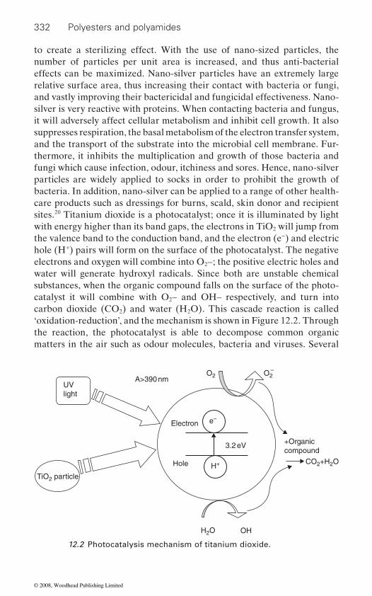
332 Polyesters and polyamides
to create a sterilizing effect. With the use of nano-sized particles, the number of particles per unit area is increased, and thus anti-bacterial effects can be maximized. Nano-silver particles have an extremely large relative surface area, thus increasing their contact with bacteria or fungi, and vastly improving their bactericidal and fungicidal effectiveness. Nano-silver is very reactive with proteins. When contacting bacteria and fungus, it will adversely affect cellular metabolism and inhibit cell growth. It also suppresses respiration, the basal metabolism of the electron transfer system, and the transport of the substrate into the microbial cell membrane. Fur-thermore, it inhibits the multiplication and growth of those bacteria and fungi which cause infection, odour, itchiness and sores. Hence, nano-silver particles are widely applied to socks in order to prohibit the growth of bacteria. In addition, nano-silver can be applied to a range of other health-care products such as dressings for burns, scald, skin donor and recipient sites.20 Titanium dioxide is a photocatalyst; once it is illuminated by light with energy higher than its band gaps, the electrons in TiO2 will jump from the valence band to the conduction band, and the electron (e−) and electric hole (H+) pairs will form on the surface of the photocatalyst. The negative electrons and oxygen will combine into O2–; the positive electric holes and water will generate hydroxyl radicals. Since both are unstable chemical substances, when the organic compound falls on the surface of the photo-catalyst it will combine with O2– and OH– respectively, and turn into carbon dioxide (CO2) and water (H2O). This cascade reaction is called ‘oxidation-reduction’, and the mechanism is shown in Figure 12.2. Through the reaction, the photocatalyst is able to decompose common organic matters in the air such as odour molecules, bacteria and viruses. Several
UVlight
TiO2 particle
A>390 nmO2 O2
+Organiccompound
CO2+H2O
OHH2O
Hole
Electron
3.2 eV
H+
e–
–
12.2 Photocatalysis mechanism of titanium dioxide.
© 2008, Woodhead Publishing Limited
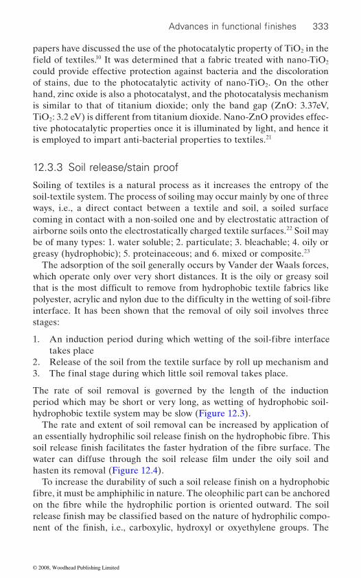
333
papers have discussed the use of the photocatalytic property of TiO2 in the 10 It was determined that a fabric treated with nano-TiO2
of stains, due to the photocatalytic activity of nano-TiO2. On the other hand, zinc oxide is also a photocatalyst, and the photocatalysis mechanism is similar to that of titanium dioxide; only the band gap (ZnO: 3.37eV, TiO2: 3.2 eV) is different from titanium dioxide. Nano-ZnO provides effec-tive photocatalytic properties once it is illuminated by light, and hence it is employed to impart anti-bacterial properties to textiles.21
12.3.3 Soil release/stain proof
Soiling of textiles is a natural process as it increases the entropy of the soil-textile system. The process of soiling may occur mainly by one of three ways, i.e., a direct contact between a textile and soil, a soiled surface coming in contact with a non-soiled one and by electrostatic attraction of airborne soils onto the electrostatically charged textile surfaces.22 Soil may be of many types: 1. water soluble; 2. particulate; 3. bleachable; 4. oily or greasy (hydrophobic); 5. proteinaceous; and 6. mixed or composite.23
The adsorption of the soil generally occurs by Vander der Waals forces, which operate only over very short distances. It is the oily or greasy soil
interface. It has been shown that the removal of oily soil involves three stages:
1. takes place
2. Release of the soil from the textile surface by roll up mechanism and
The rate of soil removal is governed by the length of the induction period which may be short or very long, as wetting of hydrophobic soil-hydrophobic textile system may be slow (Figure 12.3).
The rate and extent of soil removal can be increased by application of
hasten its removal (Figure 12.4).
could provide effective protection against bacteria and the discoloration
Advances in functional finishes
field of textiles.
that is the most difficult to remove from hydrophobic textile fabrics like polyester, acrylic and nylon due to the difficulty in the wetting of soil-fibre
An induction period during which wetting of the soil-fibre interface
3. The final stage during which little soil removal takes place.
an essentially hydrophilic soil release finish on the hydrophobic fibre. This
water can diffuse through the soil release film under the oily soil and
To increase the durability of such a soil release finish on a hydrophobic fibre, it must be amphiphilic in nature. The oleophilic part can be anchored
soil release finish facilitates the faster hydration of the fibre surface. The
on the fibre while the hydrophilic portion is oriented outward. The soil release finish may be classified based on the nature of hydrophilic compo-nent of the finish, i.e., carboxylic, hydroxyl or oxyethylene groups. The
© 2008, Woodhead Publishing Limited
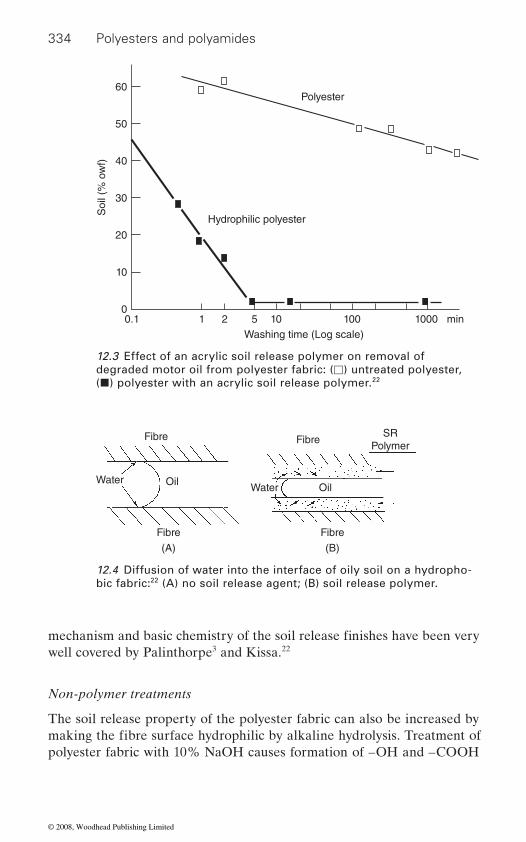
334 Polyesters and polyamides
well covered by Palinthorpe3 and Kissa.22
Non-polymer treatments
The soil release property of the polyester fabric can also be increased by
polyester fabric with 10% NaOH causes formation of –OH and –COOH
Polyester
Hydrophilic polyester
Soi
l (%
ow
f)60
50
40
30
20
10
0
Washing time (Log scale)0.1 1 2 5 10 100 min1000
12.3 Effect of an acrylic soil release polymer on removal of degraded motor oil from polyester fabric: (�) untreated polyester, (�) polyester with an acrylic soil release polymer.22
Fibre Fibre
Fibre
(B)
Fibre
(A)
SRPolymer
Water OilWater Oil
12.4 Diffusion of water into the interface of oily soil on a hydropho-bic fabric:22 (A) no soil release agent; (B) soil release polymer.
mechanism and basic chemistry of the soil release finishes have been very
making the fibre surface hydrophilic by alkaline hydrolysis. Treatment of
© 2008, Woodhead Publishing Limited

335
groups on fabric surface leading to excellent soil release properties com-
durable.24
Plasma treatment
way of improving the surface hydrophilicity. This approach is increasingly
can be carried out in mainly two ways. In presence of a suitable precursor,
of the treated textiles are governed by the chemical nature and the thick-
alization (by oxidation or hydrolysis) or increase in surface roughness may occur. Remarkable increase in the wettability of polyester and polyamide fabrics was observed25–26 on exposure to low temperature plasma. While Okten and Seventekin25 reported improvement in soil resistance of the treated fabrics, Kartick et al.26 report formation of nanosized vertical and horizontal channels on polyester and nylon fabric surfaces. They surmise that these channels may contribute towards increased hydrophilicity of the textiles. Cireli et al.27 used acrylic acid as the precursor and the reported
treated fabrics. However Stefecka et al.28 observed formation of –COOH
12.3.4 Water repellent
A detailed account of the principles and the chemistry of water repellency 29 30 Conventionally the
approach to water repellency has been the application of a coating of rela-tively hydrophobic materials like insoluble metal salts of soaps, waxes,
conventional method of pad-dry-cure. To be effective, the fabric construc-
the interstitial gaps between the yarns.
ized by contact angles in excess of 150 . These are discussed in detail in Chapter 13.
Advances in functional finishes
parable to those obtained with conventional soil release finishes but more
being explored for surface modification of textile fabrics. Plasma treatment
Plasma irradiation of nylon and polyester fabric surface is another effective
a thin polymeric film can be deposited on the fabric surface. The properties
ness of the deposited film. In absence of any precursor, surface function-
significant improvement in the wettability of polyester and nylon fabric probably due to the deposition of a hydrophilic polymeric film on the
groups on polyester monofilaments on exposure to atmospheric nitrogen plasma but did not find any evidence of any surface roughness.
and water proofing is given by Holme and Kissa.
tion needs to close and the finish must be able to coat all the fibres and fill
Today, the textile finishes are moving from simple water repellent fin-
compounds on the textile substrate. These finishes are usually applied by
ishes to ultrahydrophobic/superhydrophobic finishes which are character-
organometallic complexes, silicone compounds and lately fluorochemical
© 2008, Woodhead Publishing Limited
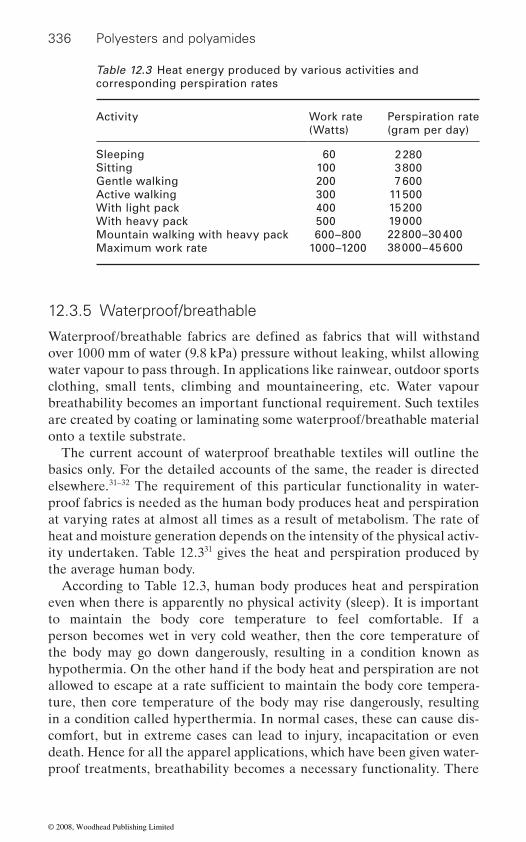
336 Polyesters and polyamides
12.3.5 Waterproof/breathable
over 1000 mm of water (9.8 kPa) pressure without leaking, whilst allowing water vapour to pass through. In applications like rainwear, outdoor sports clothing, small tents, climbing and mountaineering, etc. Water vapour breathability becomes an important functional requirement. Such textiles are created by coating or laminating some waterproof/breathable material onto a textile substrate.
The current account of waterproof breathable textiles will outline the basics only. For the detailed accounts of the same, the reader is directed elsewhere.31–32 The requirement of this particular functionality in water-proof fabrics is needed as the human body produces heat and perspiration at varying rates at almost all times as a result of metabolism. The rate of heat and moisture generation depends on the intensity of the physical activ-ity undertaken. Table 12.331 gives the heat and perspiration produced by the average human body.
According to Table 12.3, human body produces heat and perspiration even when there is apparently no physical activity (sleep). It is important to maintain the body core temperature to feel comfortable. If a person becomes wet in very cold weather, then the core temperature of the body may go down dangerously, resulting in a condition known as hypothermia. On the other hand if the body heat and perspiration are not
ture, then core temperature of the body may rise dangerously, resulting in a condition called hyperthermia. In normal cases, these can cause dis-comfort, but in extreme cases can lead to injury, incapacitation or even death. Hence for all the apparel applications, which have been given water-proof treatments, breathability becomes a necessary functionality. There
Table 12.3 Heat energy produced by various activities and corresponding perspiration rates
Activity Work rate(Watts)
Perspiration rate (gram per day)
2 2803 8007 600
11 50015 20019 00022 800–30 40038 000–45 600
Sleeping 60Sitting 100Gentle walking 200Active walking 300With light pack 400With heavy pack 500Mountain walking with heavy pack 600–800Maximum work rate 1000–1200
Waterproof/breathable fabrics are defined as fabrics that will withstand
allowed to escape at a rate sufficient to maintain the body core tempera-
© 2008, Woodhead Publishing Limited
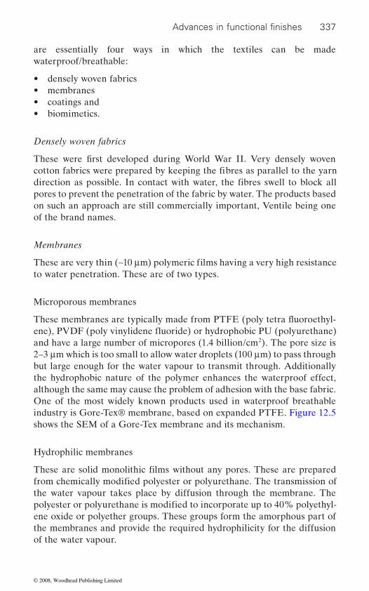
337
are essentially four ways in which the textiles can be made waterproof/breathable:
• densely woven fabrics• membranes• coatings and• biomimetics.
Densely woven fabrics
pores to prevent the penetration of the fabric by water. The products based on such an approach are still commercially important, Ventile being one of the brand names.
Membranes
to water penetration. These are of two types.
Microporous membranes
and have a large number of micropores (1.4 billion/cm2). The pore size is 2–3 μm which is too small to allow water droplets (100 μm) to pass through but large enough for the water vapour to transmit through. Additionally the hydrophobic nature of the polymer enhances the waterproof effect, although the same may cause the problem of adhesion with the base fabric. One of the most widely known products used in waterproof breathable industry is Gore-Tex® membrane, based on expanded PTFE. Figure 12.5 shows the SEM of a Gore-Tex membrane and its mechanism.
Hydrophilic membranes
the water vapour takes place by diffusion through the membrane. The
ene oxide or polyether groups. These groups form the amorphous part of the membranes and provide the required hydrophilicity for the diffusion of the water vapour.
Advances in functional finishes
These were first developed during World War II. Very densely woven cotton fabrics were prepared by keeping the fibres as parallel to the yarn direction as possible. In contact with water, the fibres swell to block all
These are very thin (∼10 μm) polymeric films having a very high resistance
These are solid monolithic films without any pores. These are prepared from chemically modified polyester or polyurethane. The transmission of
polyester or polyurethane is modified to incorporate up to 40% polyethyl-
These membranes are typically made from PTFE (poly tetra fluoroethyl-ene), PVDF (poly vinylidene fluoride) or hydrophobic PU (polyurethane)
© 2008, Woodhead Publishing Limited
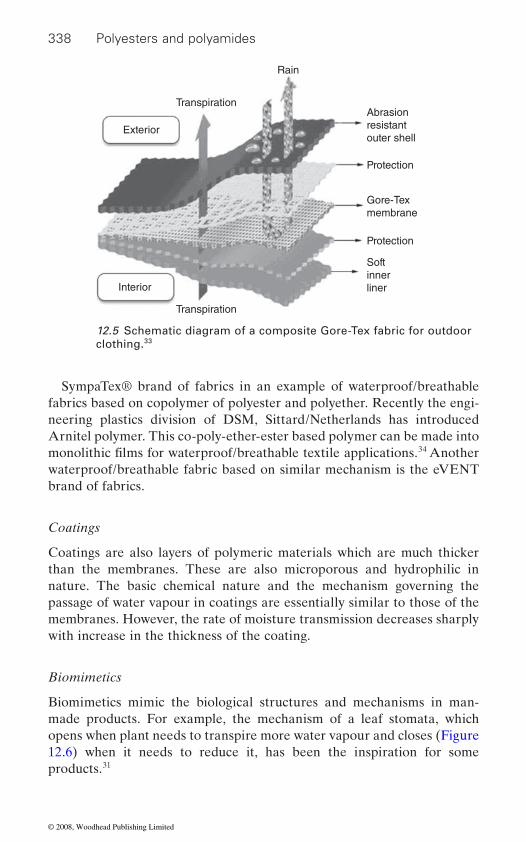
338 Polyesters and polyamides
SympaTex® brand of fabrics in an example of waterproof/breathable fabrics based on copolymer of polyester and polyether. Recently the engi-neering plastics division of DSM, Sittard/Netherlands has introduced Arnitel polymer. This co-poly-ether-ester based polymer can be made into
34 Another waterproof/breathable fabric based on similar mechanism is the eVENT brand of fabrics.
Coatings
Coatings are also layers of polymeric materials which are much thicker than the membranes. These are also microporous and hydrophilic in nature. The basic chemical nature and the mechanism governing the passage of water vapour in coatings are essentially similar to those of the membranes. However, the rate of moisture transmission decreases sharply with increase in the thickness of the coating.
Biomimetics
Biomimetics mimic the biological structures and mechanisms in man-made products. For example, the mechanism of a leaf stomata, which opens when plant needs to transpire more water vapour and closes (Figure 12.6) when it needs to reduce it, has been the inspiration for some products.31
12.5 Schematic diagram of a composite Gore-Tex fabric for outdoor clothing.33
Abrasionresistantouter shell
Protection
Gore-Texmembrane
Rain
Transpiration
Transpiration
Exterior
Interior
Protection
Softinnerliner
monolithic films for waterproof/breathable textile applications.
© 2008, Woodhead Publishing Limited

339
Akzo Nobel has developed one such product called Stomatex®.36 Sto-matex is generally made from thermo-insulating closed-cell foam materials such as Neoprene. It uses a pattern of dome-shaped vapour chambers, each with a tiny pore in the centre. While resting, excess body heat and perspira-tion rise into the dome-shaped chambers and exit through the tiny pores
the body, causing excess heat and perspiration to be pumped out of the small pores. This unique action of the vapour chambers increases and decreases with the user’s level of physical activity.
There are other fabric constructions which do not use membranes, coat-ings or laminates but can keep the wearer dry by directing the water as well as moisture away from the body. Hence these fabrics have a directional effect as far as the transport of water in liquid and vapour forms is con-cerned. These can also be called breathable. Nikwax Directional Textiles as used by Páramo Directional Clothing Systems and Feather and Fur Technology supplied by FurTech are some examples of such directional
can be found on the internet.37
In a breakthrough development, a smart temperature controllable water
can control its water vapour permeability (WVP) with temperature change by itself. This was achieved by optimizing the hard to soft segment ratio, PEG content and isocyanate index of the PU polymer. It was found that
The polymer has a Tg of ∼24˚C and the WVP starts to increase above 18˚C, which is close to the Tg of the PU polymer.37
12.6 Electron micrograph showing leaf stomata.35
Advances in functional finishes
fabrics. Links to the brand products of other waterproof/breathable textiles
vapour permeable polyurethane (PU) film has been developed. The film
smart PU film is obtained at MDI/PEG/PBA/1,4-BD ratio of 3 : 0.6 : 0.4 : 2.
at a controlled rate. The chambers flex and stretch with each movement of
© 2008, Woodhead Publishing Limited

340 Polyesters and polyamides
acrylic, polypropylene, etc. can cause problems of static charge accumula-
tions improved wettability or moisture absorption is important. There have
One approach in this direction is to create polar and ionic groups on the
already been discussed. The other approach is to apply hydrophilic poly-
In one such approach Roos et al.39 used cationic starch, cationic cellulose
tion of polyester fabric. The main reason for the adsorption of the cationic polymer on PET surface was slightly negatively charged surface of polyes-
ment in the wetting behaviour of polyester fabric.Recently there has been a tendency to apply natural hydrophilic proteins
of silk degumming process, has received special attention lately in this regard. In one such attempt,40 polyester swollen with benzyl alcohol, was grafted with N-vinyl formamide by electron beam irradiation technique. The grafting degree on polyester could be controlled by the swelling degree and by monomer concentration. This was followed by hydrolysis with
2 4
diglycidyl ether. The grafted fabric showed good wettability and antistatic property. The increase in wettability was due to incorporation of amide
bacterial effect.Kongdee et al.41 used supercritical carbon dioxide to impregnate sericin
into polyester. They found no impregnation of PET with sericin if polyester
Sunlight is an essential source of all life on earth. Although the solar spec-trum may extend from below 200 nm to above 3000 nm at sea level, it is
12.3.6 Hydrophilic finishes
absorption capacity. Many of the soil release finishes are in a sense hydro-
Textile fibres with inherently low moisture regain like polyester, nylon,
philic finishes as they rely on the improved hydrophilic character of the
tion, soil pickup/poor soil release and poor wettability. In many applica-
fibre to release hydrophobic oily and greasy soils.
surface of the fibres by hydrolysis and plasma treatment. This approach has
been attempts to render these fibres hydrophilic to improve their moisture
mers onto the fibre surface and create some kind of bonding between the finish and the fibre to obtain a reasonable degree of finish durability.
derivatives and hydrophobically modified cationic cellulose for modifica-
ter. Application of the cationic polymers resulted in significant improve-
to improve the hydrophilicity of synthetic fibres. Silk sericin, a byproduct
H SO and sericin was fixed with a cross linking agent, ethylene glycol
surface is not modified as there is no interaction between hydrophilic sericin and hydrophobic polyester. However, if the PET surface is modified
groups on the surface of the PET, which was expected also to have anti-
with alkali to generate –OH and –COOH groups on fibre surface, sericin is bound to the polyester fibre surface rendering it hydrophilic.
12.3.7 UV protective finish
© 2008, Woodhead Publishing Limited

341
the lower wavelength portion (200–400 nm), which is important. This is essentially the high-energy portion and generally known as Ultra Violet radiation (UVR). Whereas the visible region of the solar spectrum is
cause some undesirable effects due to its high energy.42
the ozone layer in earth’s atmosphere. The UV part of the solar radiation
doses, especially in the short UVB range (280–315 nm), may cause sun-burns, skin cancer, photokeratitis, photodermatosis, etc.43–44 In addition to its deleterious effects on human beings, it also deteriorates the material properties of apparel, upholstery, draperies, carpets, furniture, paints, electronic parts, building construction materials – wood, plastic panels, etc. and other articles of outdoor use and limits their durability and life span.
With the alarming increase in the rate of ozone layer depletion in the earth’s atmosphere, the risks involved due to prolonged exposure to solar UV radiation are increasing day by day. Hence it becomes imperative to protect the human skin and other materials from harmful effects of solar UV radiation. There are various approaches to tackle this problem. For protection of human skin, use of sunscreen lotions and other cosmetics is quite common. The experts have recommended use of textiles capable of blocking harmful UV radiation during outdoor activity. Recently much work has been done to develop special UV protective clothing and consid-eration has been given to factors affecting UV protection capability of
porosity, thickness, presence of dyes/pigments,44–45 etc. The ability of a particular textile to block UV radiation is measured in terms of SPF (sun protection factor) or UPF (ultra violet protection factor), which depends
of 30 and above is supposed to provide good protection. Special UV pro-tecting chemicals and processes have been developed46–48 that enhance the UV protective capability of the textiles. Ciba-Geigy has launched a number
names like Cibatex W, Cibatex APS, Ciba Tinofast CEL, Ciba Tinofast PES, etc. and can be applied by exhaust or pad-batch methods. Similarly,
Wales and launched by Clariant is known as Rayosan process.49 The two products available are Rayosan C Paste and Rayosan CO Liquid. In this
The active chemical responsible for the UV protection should be able to
Advances in functional finishes
Almost all the radiation of wavelength below 290 nm is filtered out by
essential for most life sustaining processes on earth, it is the UVR that can
(290–400 nm) is beneficial to human beings in small doses; however, large
fabrics like fibre type, cover factor, construction (weave/knit pattern),
on the fibre type and various other fabric construction parameters. A value
of UV absorbers for different textile fibres, which are available in the brand
technology fibre reactive Rayosan products can be applied on cellulosic,
a process developed by Textile Department of the University of New South
wool and nylon fibres during dyeing.
absorb solar UV radiation efficiently (esp. in high energy UVB region,
© 2008, Woodhead Publishing Limited

342 Polyesters and polyamides
280–320 nm), convert the absorbed energy into vibrational energy and then into heat energy to the surroundings without causing photodegrada-
ers are given in Figure 12.7.
core structure wherein the core consists of polyester, polyether ester, poly-ester urethane, polyester amide,50 polyamide,51 polyester with 10% TiO2, ZnO and/or alumina52 and the sheath consists of similar polymers with UV absorbers i.e., carbon black, etc. Similarly titanium dioxide (TiO2) that is
protection from UV radiation.Inorganic UV blockers are preferable to organic UV blockers as they
are non- toxic and chemically stable under exposure to both high tempera-tures and UV. Inorganic UV blockers are usually certain semiconductor oxides such as TiO2, ZnO, SiO2 and Al2O3. Among these semi conductor oxides, titanium dioxide (TiO2) and zinc oxide49 (ZnO) are commonly used. It was determined that nano-sized titanium dioxide and zinc oxide
OH OHO
C
OR OR
(R1)nR1=alkyl, alkoxy, halide, sulphoalkoxy
n=0, 1, 2
X=H, SO3–
R2=hydroxy, alkoxy, alkylthio, substituted alkyl, substitutedphenyl, O-hydroxyphenyl
R3=R2 (Identical or different)
X
N N
N
Phenyltriazines
Benzophenones
R2
R2 R3
R1HO
N
N
N
Benzotriazoles
12.7 Structures of some common UV absorbers.
tion of the fibre or the finish itself. Structures of some common UV absorb-
Some interesting UV resistant fibres have been developed with a sheath
sometimes incorporated in man-made fibres for delustring, also provides
were more efficient at absorbing and scattering UV radiation than the
© 2008, Woodhead Publishing Limited
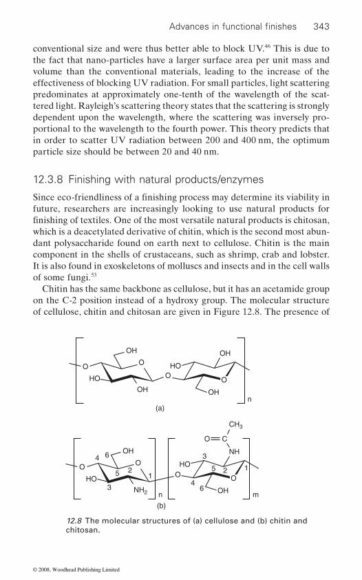
343
conventional size and were thus better able to block UV.46 This is due to the fact that nano-particles have a larger surface area per unit mass and volume than the conventional materials, leading to the increase of the effectiveness of blocking UV radiation. For small particles, light scattering predominates at approximately one-tenth of the wavelength of the scat-tered light. Rayleigh’s scattering theory states that the scattering is strongly dependent upon the wavelength, where the scattering was inversely pro-portional to the wavelength to the fourth power. This theory predicts that in order to scatter UV radiation between 200 and 400 nm, the optimum particle size should be between 20 and 40 nm.
12.3.8 Finishing with natural products/enzymes
future, researchers are increasingly looking to use natural products for
which is a deacetylated derivative of chitin, which is the second most abun-dant polysaccharide found on earth next to cellulose. Chitin is the main component in the shells of crustaceans, such as shrimp, crab and lobster. It is also found in exoskeletons of molluscs and insects and in the cell walls of some fungi.53
Chitin has the same backbone as cellulose, but it has an acetamide group on the C-2 position instead of a hydroxy group. The molecular structure of cellulose, chitin and chitosan are given in Figure 12.8. The presence of
O O
OO
O
HO
HO
OH
OH OH
OH
n(a)
O O
O
O C
HO3
34
4
6
55
6
2 21
1HO
OH
NH2 OH
NH
CH3
n m
(b)
12.8 The molecular structures of (a) cellulose and (b) chitin and chitosan.
Advances in functional finishes
Since eco-friendliness of a finishing process may determine its viability in
finishing of textiles. One of the most versatile natural products is chitosan,
© 2008, Woodhead Publishing Limited

344 Polyesters and polyamides
amino groups in chitosan imparts hydrophilicity and antimicrobial charac-ter to it. A comprehensive review of use of chitosan as antimicrobial agent
53
Matsukawa et al.54 used chitosan as an antistatic agent for polyester (PET) fabric. To create bonding between chitosan and PET fabric, PET
PET surface. The PET fabric was then treated with chitosan in 1% acetic
fabric were insolubilized by the addition of a dicarboxylic acid to cross-link the chitosan molecules. It was observed that hydrolysed PET with chitosan treatment showed a considerably lower value (6 volts) compared to those of only hydrolysed PET (2600 volts) and untreated PET (4600 volts). Also, the decreased strength of the fabric by the NaOH treatment was recovered by the chitosan treatment. A similar antistatic treatment is reported by Eom, who observed that development of electrostatic voltage decreases below one tenth of that of untreated polyester.55
56
tosan by electrospinning onto the PET micro-nonwoven mats for biomedi-
The antibacterial activity of the samples was evaluated utilizing the colony counting method against Staphylococcus aureus and Klebsiella pneu-
Another natural resource, neem tree has been known to have antimicro-bial properties and has been used in India for many centuries. Neem (Azadirachta indica) extract is widely used by Indian farmers to protect the cotton crop from pest and fungus. In a recent study Joshi et al.57 have utilized this potential of neem for the development of biofunctional polyester/cotton blend fabric. Extract from the seeds of the Neem tree (Azadirachta indica) was used for imparting antibacterial properties to the blend fabric. Durability of the neem extract on the blended fabric was
blend fabric. Resin (glyoxal/glycol) and catalyst (aluminum sulfate and tartaric acid) concentrations were optimized to get the maximum cross-linking in the fabric blend. Quantitative analysis was carried out to measure the antimicrobial activity against Gram-positive and Gram-negative bac-teria. The treated fabrics inhibited the growth of Gram-positive bacteria (Bacillus subtilis) by more than 90% as compared with the control sample. Antimicrobial activity against Gram-positive bacteria was retained up to
mostly for cotton and other natural fibres is available.
was first hydrolysed in NaOH solution to generate carboxyl groups on the
acid by a pad-dry-cure method. Simultaneously, the chitosan films on the
PET fibres. Jung et al. made nanofibres from the blends of PET and chi-
cal applications. The PET/chitosan nanofibres were evenly deposited onto
Chitosan has also been used for imparting antibacterial character to
the surface, and the diameter of the nanofibres was in the range between 500 and 800 nm. The nanofibres showed significantly enhanced wetability.
moniae. PET/chitosan nanofibre mats showed a significantly higher growth inhibition rate compared with the PET nanofibre control.
ensured with the help of simultaneous application of a resin finish to the
five machine washes and decreased thereafter. The antibacterial activity
© 2008, Woodhead Publishing Limited

345
was higher against Gram-positive bacteria as compared to Gram-negative bacteria (Proteus vulgaris).
environment. To overcome this problem, there have been attempts to develop biodegradable polymers. However such polymers have not been
mance and cost factors. One attractive option is to use enzymes for bio-degradation of such polymers.
Enzymes are today being used at many stages in textile wet processing. Hence amylases (desizing), cellulases (biopolishing/denim processing),
degumming/laundry detergents), catalases (H2O2 decomposition) are in use today. Attempts have been made to degrade polyester using lipases and esterases. Although the enzyme attack on the polyester to bring about hydrolysis is a rather slow process, which excludes the possibility of enzymes being used for polyester waste disposal at least in near future, some degree of surface hydrolysis can be achieved. Hence researchers are reconciled to
58–62 which in a sense is similar to the surface hydrolysis by NaOH in that the formation of –OH and –COOH groups takes place. However the similarity ends there. As compared to alkaline treatment, the enzyme treatment takes place under much milder conditions of time, temperature and pH. The wetability obtained is higher and the effect on mechanical properties is much milder.
12.4
12.4.1 Plasma processing
Textile materials are increasingly used in various industries. In these applications, the functions of textile materials are associated with phenomena such as wetting, biocompatibility, adsorption and electrical conductivity. Wetting, biocompatibility, adhesion, and many other performance properties all begin at the surface.63 The properties of textile surfaces and interfaces play key roles in material processing and applica-tion technologies.64 As with many other types of materials, the surface properties of textiles can be readily altered by the treatment of the materi-als with gas plasma, without impairment of their bulk mechanical properties.
The plasma treatment of textiles is a highly innovative technology in
DBD electric discharge (dielectric barrier discharge). The use of electric
Advances in functional finishes
Most of the synthetic fibres are non-biodegradable. This means that the used and disposed articles made from such fibres keep building up in the
able to replace conventional fibre forming polymers due to the perfor-
pectinases (cotton scouring), proteases (wool surface modification/silk
using enzymes for surface modification of polyester fabric,
Recent advances in finishing
the field of superficial treatments of the material surfaces. It is based on a
© 2008, Woodhead Publishing Limited
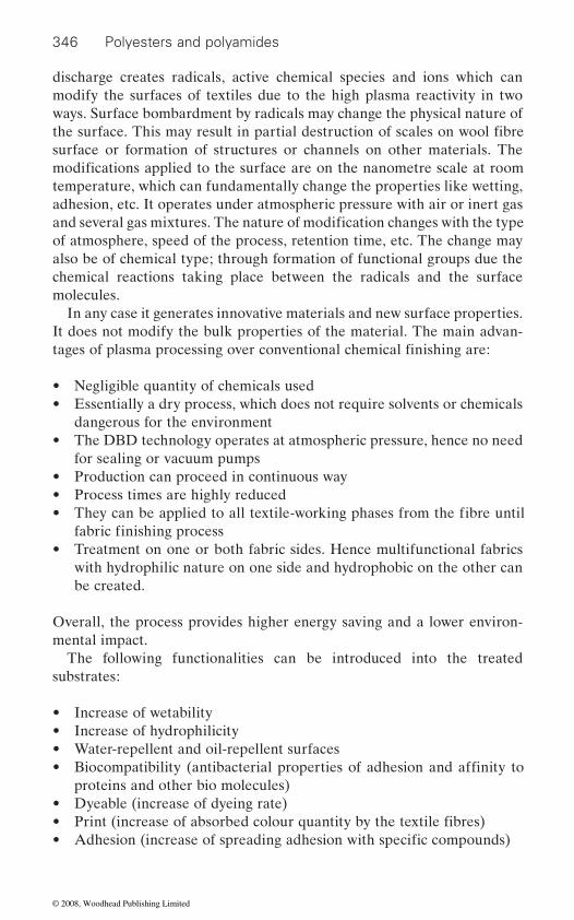
346 Polyesters and polyamides
discharge creates radicals, active chemical species and ions which can modify the surfaces of textiles due to the high plasma reactivity in two ways. Surface bombardment by radicals may change the physical nature of
surface or formation of structures or channels on other materials. The
adhesion, etc. It operates under atmospheric pressure with air or inert gas
of atmosphere, speed of the process, retention time, etc. The change may also be of chemical type; through formation of functional groups due the chemical reactions taking place between the radicals and the surface molecules.
In any case it generates innovative materials and new surface properties. It does not modify the bulk properties of the material. The main advan-
• Negligible quantity of chemicals used• Essentially a dry process, which does not require solvents or chemicals
dangerous for the environment• The DBD technology operates at atmospheric pressure, hence no need
for sealing or vacuum pumps• Production can proceed in continuous way• Process times are highly reduced•
• Treatment on one or both fabric sides. Hence multifunctional fabrics with hydrophilic nature on one side and hydrophobic on the other can be created.
Overall, the process provides higher energy saving and a lower environ-mental impact.
The following functionalities can be introduced into the treated substrates:
• Increase of wetability• Increase of hydrophilicity• Water-repellent and oil-repellent surfaces•
proteins and other bio molecules)• Dyeable (increase of dyeing rate)• •
modifications applied to the surface are on the nanometre scale at room
the surface. This may result in partial destruction of scales on wool fibre
and several gas mixtures. The nature of modification changes with the type
temperature, which can fundamentally change the properties like wetting,
tages of plasma processing over conventional chemical finishing are:
They can be applied to all textile-working phases from the fibre until fabric finishing process
Biocompatibility (antibacterial properties of adhesion and affinity to
Print (increase of absorbed colour quantity by the textile fibres)Adhesion (increase of spreading adhesion with specific compounds)
© 2008, Woodhead Publishing Limited
347
• Polymer deposition in a gaseous phase as thin layer adherent to the
12.4.2 Micro-encapsulation
Microencapsulation is a technique in which chemicals are released in a controlled manner over a long period.65 In this process small particles or
The materials inside the capsules form the core and the outside coating becomes a barrier wall. Hence the core material is isolated from hostile outside environment66 and can be released either slowly by diffusion through the wall or by rupture of the wall on demand. The microcapsules can then be attached to textiles, conferring various properties to them.
occasions. The best example of a simple application of microencapsulation is carbonless copy paper. This paper has a thin coating of microcapsules on the back side. The microcapsules contain an ink which is released only under pressure. When something is written on the paper, the pressure of writing releases the ink from the layer of microcapsules and a copy of the original writing is created on a sheet kept below carbonless copy paper.
Although the industrial applications of microencapsulation began to
processing, etc., the textile industry has been a little slow in responding to this novel technique. It was only in the 1980s and 1990s that some applica-tions started appearing on the textile front.
In the textile industry, microencapsulation has been mainly done for innovative and novel application for value addition. Much less of it is being
popular applications has been addition of fragrance to the textiles by microencapsulation.
Several manufacturers have already launched such products in the market. Welbek fabrics launched its CX series of scented fabrics towards the end of the twentieth century. Similar products have also been produced by RT Dodge, Celanese International, Matsui Shikiso Chemical Co, LJ Specialities, El Dorado International Co., etc. In addition to the fragrances, another type of textiles known as Wellness Textiles based on microencap-sulation are being offered. Hence there is a product: Biocap Series from Specialty Textiles Products which has microcapsules containing vitamins A, D, E and Aloe Vera. The vitamins are slowly released into the body of the wearer through the skin.
Advances in functional finishes
surface (film deposition)• Superficial ablation of the materials (etching).
droplets are confined in a coating to give small capsules or microcapsules.
This is an especially useful technique when the active component of a finish has high vapour pressure or when it needs to be activated only on specific
appear almost 50 years ago in fields like pharmaceutical, cosmetics, food
targeted as a replacement for conventional finishing. One of the most
© 2008, Woodhead Publishing Limited
348 Polyesters and polyamides
Microencapsulation is also being used for making intelligent textiles
The PCMs are compounds which have their melting temperature near the ambient temperature. When they are brought to higher temperatures, the PCMs melt and absorb heat. When they are brought down below ambient temperature, they solidify and release heat. Hence the wearer using clothes having PCMs is protected from sudden thermal shocks.
12.5 Future trends
becoming increasingly critical factors by the day, the emphasis is going to
a key issue, a lot of emphasis is going to be on the environmental impact of the processes.
This makes plasma processing an important technique for future textile
than it is today. The main reason is that the functionalities can be created without spoiling the feel and the breathability of the garments. We are also going to witness more value addition in the products through use of tech-niques like micro- and nanoencapsulation.
external stimuli, like temperature and humidity, will be more in demand.
section.Lastly, the customers are going to look for multiple functionalities in the
care, soil release, antimicrobial, UV protection and breathability in a single textile product.
12.6 Sources of further information and advice
there are some very good books available. The list of these is given below:
1. Textile Finishing, ed. Derek Heywood, Society of Dyers and Colorists, Bradford, UK 2003.
2. Chemical Finishing of Textiles, W D Schindler and P J Hauser, Wood-head Publishing Limited, 2004.
which can regulate the temperature using phase change materials (PCMs).
In future one can expect some new trends in the way the textile finishing
be on efficiency and cost effectiveness in finishing. With environment being
finishing, as the process uses no water and few chemicals and causes little pollution. The role of nanotechnology in finishing will be more dominant
The role of smart textiles or smart finishes will grow significantly. The finishes which can change their character according to the changes in the
One such finish was discussed in the waterproof/breathable textiles
textile products they buy. Hence a finisher should be ready to provide easy
For those interested in the basic principles of textile finishing processes,
is carried out. With cost of energy, effluent treatment and competition
© 2008, Woodhead Publishing Limited
349
3. Handbook of Fibre Science and Technology: Volume II Chemical Processing of Fibres and Fabrics, Functional Finishes Part A and B, Ed Menachem Lewin and Stephen B Sello, Marcel Dekker Inc, 1984.
4. Encyclopedia of Textile Finishing, Vol. 1, 2 and 3. Prof. Dr. rer. Nat. Hans-Karl Rouette, Springer 2001.
For information related to the research and latest developments in textile
be referred to:
1. Melliand International (Quarterly), Deutscher Fachverlag GmbH, Mainzer Landstr. 251, 60326 Frankfurt am Main, Germany.
2. AATCC Review, American Association of Textile Chemists and Colorists, PO Box 12215, Research Triangle Park, N.C. 27709.
3. Textile Research Journal, SAGE Publications, 2455 Teller Road, Thousand Oaks, CA 91320, Phone: (805) 499 9774.
4. Journal of the Textile Institute, The Textile Institute, 1st Floor, St James’s Buildings, 79 Oxford Street, Manchester, M1 6FQ, UK.
5. International Dyer, World Textile Publications Ltd, Perkin House, 1 Longlands Street, Bradford, West Yorkshire, BD1 2TP, UK.
6. Perkin House, 82 Grattan Road, Bradford BD1 2JB, England.
7. Journal of Applied Polymer Science, John Wiley & Sons Ltd., Journals
UK.
be due for publication from any publisher.
12.7 References
20–94.
ers’, International Dyer, April, 28–31.
Heywood D, Textile Finishing, Bradford, SDC Publication, 308–336. 4. saneda t, Unitika ltd. Kao Corp., Japanese patent 84,117,542 A2; Japanese
patent 59,117,542 (1984) 5. xu p, wang w and chen s l (2005), ‘Application of nanosol on the antistatic
property of polyester’, Melliand International, 11(1), 56–59. 6. dong w g and huang g (2002), ‘Research on properties of nano polypropyl-
ene/TiO2
Advances in functional finishes
finishing processes, chemicals and machinery, the following journals may
Fulfilment, 1 Oldlands Way, Bognor Regis, West Sussex PO22 9SA,
Coloration Technology, Society of Dyers and Colourists, PO Box 244,
These journals also advertise any books in the field of textiles which may
1. richards a f (2005), ‘Nylon fibres’, in McIntyre J E, Synthetic Fibres: Nylon, Polyester, Acrylic, Polyolefin, Cambridge, Woodhead Publishing Limited,
2. ruchser t (2004) ‘Versatile polyamide: but it places high demands on finish-
3. palinhorpe m and david s k (2003), ‘Antistatic and soil release finishes’, in
composite fiber’, Journal of Textile Research, (23), 22–23.
© 2008, Woodhead Publishing Limited

350 Polyesters and polyamides
7. wu y, chi y b, nie j x, yu a p, chen x h, and gu h c (2002), ‘Preparation and
Functional Polymers, (15), 43–47. 8. anon (2002), ‘Gore uses nanotechnology to make anti-static workwear safer’,
International Newsletters, 31.
of textiles – a review’, AATCC Review, 4(3), 22–26.10. tyrone l v (1984), ‘Protection of textiles from biological attack’, in Lewin M
and Sello S B, Handbook of Fibre Science and Technology: Volume II Chemi-cal Processing of Fibres and Fabrics, Functional Finishes Part A, New York, Marcel Dekker Inc, 367–426.
11. schindler w d and hauser p j (2004), Chemical Finishing of Textiles, Cam-bridge, Woodhead Publishing Limited, 165–174.
12. moa j and murphy l (2001), ‘Durable freshness for textiles’, AATCC Review, 1(11), 28–31.
13. gang s, xiangjing x, julie r b, and williams j f (2001), ‘Durable and regener-
Eng. Chem. Res., 40, 1016–1021.14. bozja j, sherrill j, michielsen s and stojiljkovic i (2003), ‘Porphyrin-based,
light-activated antimicrobial materials’, Journal of Polymer Science: Part A: Polymer Chemistry, 41, 2297–2303.
15. young a s and sun g (2003), ‘Durable antimicrobial nylon 66 fabrics: ionic interactions with quaternary ammonium salts’, Journal of Applied Polymer Science, 90, 2194–2199.
sis, antimicrobial study and empirical modeling’, Journal of Applied Polymer Science, 103, 1175–1182.
17. gawish s m, ramadan a m, mosleh s, morcellet m and martel b (2006), ‘Synthesis and characterization of novel biocidal polyamide-6 cyclodextrin inclusion complexes grafted onto fabric by a redox method’, Journal of Applied Polymer Science, 99, 2586–2593.
18. xiong m n, gu g x, you b and wu l m (2003), ‘Preparation and characterization of poly(styrenebutylacrylate) latex/nano-ZnO nanocomposites’, Journal of Applied Polymer Science, 90, 1923–1931.
19. chen r q (2002), ‘Nanometer materials and health-care textiles’, Dyestuff Industry, 39, 24–28.
20. athinson w and silver h (2003), ‘Hi ho Silver’, Industrial Fabric Product Review, 88(12), 12–17.
21. chen r q (2002), ‘Nanometer materials and health-care textiles’, Dyestuff Industry, 39, 24–28.
of Fibre Science and Technology: Volume II Chemical Processing of Fibres and Fabrics, Functional Finishes Part A, New York, Marcel Dekker Inc, 211–289.
23. broze g (1994), ‘Mechanisms of soil removal’ in Lange K R, Detergents and Cleaners, Munich, Hanser Publishers, 29–41.
application of novel fabric finishing agent containing nano ATO’, Journal of
9. purwar r and joshi m (2004), ‘Recent developments in antimicrobial finishing
able antibacterial finishing of fabrics with a new hydantoin derivative’, Ind.
16. young a s, byung s k, ravikumar k and kim t k (2007), ‘Berberine finishing for developing antimicrobial nylon 66 fibers: % exhaustion, colorimetric analy-
22. kissa e (1984), ‘Soil release finishes’, in Lewin M and Sello S B, Handbook
© 2008, Woodhead Publishing Limited
351
24. liljemark n j and asnes h (1971), ‘Soil-release properties imparted to poly-ester/cotton fabrics by alkali treatment’, Text Research Journal, 41, 732–735.
fabrics by different in situ plasma polymerization methods’, Turk. J. Chem., 24, 275–285.
polymeric substrates using atmospheric pressure cold plasma treatment’, Indian Journal of Fibre and Textile Research, 31(1), 83–98.
polyamide fabrics by low frequency plasma polymerization of acrylic acid’ Jour. Appl. Polym. Sci., 104, 2318–2322.
28. stefecka m, rahel j, hudec i, janypka p, cernak m and kando m (2000),
rubber reinforcing’, Journal of Materials Science Letters, 19, 1869–1871.
Finishing, Bradford, SDC Publication, 135–213.
of Fibre Science and Technology: Volume II Chemical Processing of Fibres and Fabrics, Functional Finishes Part A, New York, Marcel Dekker Inc, 143–210.
31. holms d a (2000), ‘Waterproof breathable fabrics’, in Horrocks A R and Anand S C, Handbook of Technical Textiles, Cambridge, Woodhead Publish-ing Limited, 282–315.
32. scott r a (1995), ‘Coated and laminated fabrics’ in Carr C M, Chemistry of the Textile Industry, Glasgow, Blackie Academic and Professional, 210–248.
33. http://en.wikipedia.org/wiki/Gore-Tex34. anon (2000), ‘Arnitel resin in breathable textile applications’ Melliand Inter-
national, 9(March), 92.35. http://universe-review.ca/I10-22a-stomata.jpg36. http://www.stomatex.com/faqs.htm#how37. http://en.wikipedia.org/wiki/Waterproof_fabric38. lin c y, liao k h, su c f, kuo c h and hsieh k h (2007), ‘Smart temperature-
Science, 299, 91–96.39. roos p, westling a and chronakis i s (2004) ‘Hydrophilic monolayer forma-
tion of adsorbed cationic starch and cationic hydroxyethyl cellulose derivatives on polyester surface’, Biosci. Biotechnol. Biochem., 68(11), 2247–2256.
40. lee s r, miyazaki k, hisada k and hori of synthetic fabrics’, Sen’I Gakkaishi, 60(1), 9–15.
41. kongdee a, okubangashi s, tabata i and hori t (2007), ‘Impregnation of silk
Polym. Sci., 105(4), 2091–2097.42. butola b s and joshi m, ‘Sunscreen fabric shelters for outdoor applications’,
Polymers and Textiles in the New Millennium – an Integral Approach, IIT Delhi, Fibre Forum India, 228–240, 2002.
43. bajaj p, kothari v k and ghosh s b (2000), ‘Some innovations in UV protective clothing’, Indian Journal of Fibre and Textile Research, 25(4), 315.
Advances in functional finishes
25. oktem t and seventekin n (2000), ‘Modification of polyester and polyamide
26. samanta k k, jassal m and agrawal a k (2006), ‘Surface modification of
27. cireli a, kutlu b and mutlu m (2007), ‘Surface modification of polyester and
‘Atmospheric-pressure plasma treatment of polyester monofilaments for
29. holme i (2003), ‘Water repellency and water proofing’ in Heywood D, Textile
30. kissa e (1984), ‘Repellent finishes’ in Lewin M and Sello S B, Handbook
controlled water vapor permeable polyurethane film’, Journal of Membrane
t, ‘Application of silk sericin to finishing
sericin into polyester fibers using supercritical carbon dioxide’, Jour. Appl.
© 2008, Woodhead Publishing Limited

352 Polyesters and polyamides
44. bohringer b et al. (1997), ‘UV protection by textiles’, Melliand International, 3, 165–167.
45. srinivasan m and gatewood b m (2000), ‘Relationship of dye characteristics to UV protection provided by cotton fabric’, TCC & ADR, 32(4), 36–43.
46. haerri h p, haenzi d, donze j j (2001), ‘Application of UV absorbers for sun protective fabrics’, Melliand International, 1, 59–62.
47. onar n, ebeoglugil m f, kayatekin i and celik e (2007), ‘Low-temperature, sol-gel-synthesized, silver-doped titanium oxide coatings to improve ultravio-let-blocking properties for cotton fabrics’, Journal of Applied Polymer Science, 106(1), 514–525.
48. claude e, hanke r (2000), ‘UV protector for cotton textiles’ TCC & ADR, 32(4), 21–23.
49. palacinnational, 3, 169–172.
50. seiffert e j, wo (1998), 98, 39,503 (to E I Dupont De Nememours and Co., USA), 11 September 1998; Chemical Abstract, 129, 231951j.
51. fujii k, taya k (1997), Jap Pat 09,256,224 (to Teijin Ltd., Japan), 30 September 1997; Chemical Abstract, 127, 319990r.
52. takizawa k (1995), Jap Pat 06,315,407 (to Kuraray Co.), 15 November 1994; Chemical Abstract, 122, 83655d.
53. lim s h and hudson s m (2003), ‘Review of chitosan and its derivatives as antimicrobial agents and their uses as textile chemicals’, Polymer Reviews, 43(2), 223–269.
using chitosan’, Sen-i Gakkaishi, 51(1), 17–22.
Review, 1(3), 57–60.56. jung k h, huh m w, meng w, yuan j, hyun s h, bae j s, hudson s m and kang
brous mats using an electrospinning technique’, Jour. Appl. Polym. Sci., 105, 2816–2823.
57. joshi m, ali s w and rajendran s (2007), ‘Antibacterial Finishing of Polyes-
tive Agent’, Jour. Appl. Polym. Sci., 106, 793–800.58. mark m a, anne herrmann a and zimmermann w (2006), ‘Increase of the
momonospora fusca and Fusarium solani f. sp. Pisi’, Biotechnol Lett., 28, 681–685.
59. colbrie g c, heumann s, liebminger s, almansa e, paulo a c and guebitz g
catalysis and Biotransformation, 22(5/6), 341–346.60. vertommen m a m e, nierstrasz v a, veer m v d and warmoeskerken m m c g
Journal of Biotechnology, 120, 376–386.61. muller r j, schrader h, profe j, dresler k and deckwer w d (2005),
‘Enzymatic Degradation of Poly(ethylene terephthalate): Rapid Hydrolyse using a Hydrolase from T. fusca’, Macromol. Rapid Commun., 26, 1400–1405.
i (1997), ‘Textile finish protects against UV radiation’, Melliand Inter-
54. matsukawa s, kasai m and mizuta y (1995), ‘Modification of polyester fabrics
55. eom s (2001), ‘Using chitosan as an antistatic finish for polyester fabric’ AATCC
i k (2007), ‘Preparation and antibacterial activity of PET/chitosan nanofi-
hydrophilicity of polyethylene terephthalate fibres by hydrolases from Ther-
m, (2004) ‘New enzymes with potential for PET surface modification’, Bio-
ter/Cotton Blend Fabrics Using Neem (Azadirachta indica): A Natural Bioac-
(2005), ‘Enzymatic surface modification of poly(ethylene terephthalate)’,
© 2008, Woodhead Publishing Limited

353
62. alisch m, feuerhack a, muller h, mensak b, andreaus j and zimmermann w
ases from actinomycete isolates’, Biocatalysis and Biotransformation, 22 (5/6), 347–351.
63. wei q, wang y, yang q and yu l (2007), ‘Functionalization of textile materials
301–309.64. pastore c m and hienkens p (2001), Surface Characteristics of Fibers and
Textiles, New York, Marcel Dekker, 203–218.65. kumar a r, rane y n (2004), ‘Encapsulation techniques: a novel approach to
66. erkan g, sariisik m (2004), ‘Microencapsulation in textiles’, Colourage Annual, 61–64, 88.
Advances in functional finishes
(2004), ‘Biocatalytic modification of polyethylene terephthalate fibres by ester-
by plasma enhanced modification’, Journal of Industrial Textiles, 36(4),
textile finishing’, International Dyer, July, 14–21.
© 2008, Woodhead Publishing Limited

13The impact of nanotechnology on polyesters,
polyamides and other textiles
M A NGA L A JOSH I, Indian Institute of Technology, New Delhi, India
13.1 Introduction
Nanotechnology is an emerging interdisciplinary area expected to have
material science, mechanics, electronics, optics, medicine, energy, and aerospace, plastics and textiles. Although nanotechnology is still in its infancy, it is already proving to be a useful tool in improving the perfor-mance of textiles and generating worldwide interest as is evident from 1 460 000 hits in a Google search for the words ‘nanotechnology in textiles’. Though textile technology is about 200 years old, it can provide the bridge to making nanotechnology a commercial reality, as phenomenal efforts are being made both by the industry and academicians to use nanotechnology to create radically new textiles or to enhance the conventional textiles with greater functionality [1]. It is anticipated that the market for textiles based on nanotechnology which was approximately US$13.6 billion (2007) would rise dramatically to reach US$115 billion by 2012 [2].
13.2 What is nanotechnology?
The ‘nano’ in nanotechnology stands for one billionth of a meter, i.e. 1 nm = 10−9 m. ‘Nano’ is the Greek word for ‘dwarf’ and approximately 10 000
of 1–2 ångstrom in radius. One nanometer comprises 10 ångstrom and hence in one nm there may be 3–5 atoms depending on the atomic radii. According to the National Nanotechnology Initiative (NNI), nanotechno-
sion for the construction of materials, devices or systems with novel or
tion of nanoscience, particles having sizes in the range of 1 to 100 nm are termed as nano particles and the application of nano-sized particles is what we call ‘nanotechnology’.
354
wide ranging implications in all fields of science and technology such as
times finer than a human hair. The average size of an atom is of the order
logy is defined as the utilization of structures with at least one nano dimen-
significantly improved properties due to their nano size. In another defini-
© 2008, Woodhead Publishing Limited
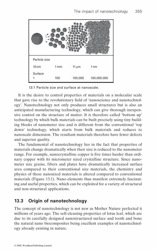
The impact of nanotechnology 355
It is the desire to control properties of materials on a molecular scale
ogy’. Nanotechnology not only produces small structures but is also an anticipated manufacturing technology, which can give thorough inexpen-sive control on the structure of matter. It is therefore called ‘bottom up’ technology by which bulk materials can be built precisely using tiny build-ing blocks of nanometer size and is different from the conventional ‘top down’ technology, which starts from bulk materials and reduces to nanoscale dimension. The resultant materials therefore have fewer defects and superior quality.
materials change dramatically when their size is reduced to the nanometer
nary copper with its micrometer sized crystalline structure. Since nano-
area compared to their conventional size materials, the chemistry and physics of these nanosized materials is altered compared to conventional materials (Figure 13.1). Nano-elements thus manifest extremely fascinat-ing and useful properties, which can be exploited for a variety of structural and non-structural applications.
13.3 Origin of nanotechnology
The concept of nanotechnology is not new as Mother Nature perfected it millions of years ago. The self-cleaning properties of lotus leaf, which are due to its carefully designed nanostructured surface and tooth and bone the natural nano biocomposites being excellent examples of nanotechnol-ogy already existing in nature.
Particle size
Surface
10 cm 1 mm 11 μm 1 nm
1 100 100,000 100,000,000
13.1 Particle size and surface at nanoscale.
that gave rise to the revolutionary field of ‘nanoscience and nanotechnol-
range. For example, nanocrystalline copper is five times harder than ordi-
The fundamental of nanotechnology lies in the fact that properties of
meter size grains, fibers and plates have dramatically increased surface
© 2008, Woodhead Publishing Limited

356 Polyesters and polyamides
However, the embryo of nanotechnology is believed to be the concept
Laureate and physicist Sir Richard Feynman, in his famous lecture titled ‘There is plenty of room at the bottom’. He stated, ‘The principles of physics so far as I can see do not speak against the possibility of maneuver-
theoretical dimensions and tolerances in technology and also described the precision manufacturing of materials with nanometer tolerances. K. Eric Drexler, a student of MIT unknowingly appropriated the word ‘nanotech-nology’ in 1986 in his famous book Engines of Creation: The Coming Era of Nanotechnology to describe what later became known as molecular nanotechnology (MNT). In that book, he proposed the idea of a nanoscale ‘assembler’ which would be able to build a copy of itself and of other items of arbitrary complexity. His 1991 doctoral thesis at MIT was revised and published as the book Nanosystems Molecular Machinery Manufacturing and Computation (1992), which received the Association of American Publishers award for Best Computer Science Book of 1992 [3].
13.4 Nanotechnology: applications in textiles
The textile industry is likely to be hugely impacted by nanotechnology, as
or to create new functionality on textile materials has gained a big impetus/ momentum across the globe. The US and Europe were the most active
to ‘Nano-textiles’ [4].
Burlington Industries founded by Dr David Soane in 1998, launched its new cutting age technology ‘NanoCare’ for water repellent and stain resistant cotton fabrics, which sheds water like a duck’s feather. Later on, more and more textile companies began to invest in the development of nanotechnologies for textiles such as Swiss based Schoeller, Toray Inc from Japan, BASF from Germany, Ciba and Clariant to name a few.
The research in this area mainly centers around creating unique proper-ties in everyday fabrics such as self-cleaning, water and oil repellency, stain proof, antibacterial, UV protective, antistatic, improved moisture regain and comfort in synthetic based textiles but all without compromising the original hand, breathability or durability of the fabric. It also shows promising applications in developing advanced textile materials such as
of ‘atomic assembly’ which was first publicly articulated in 1959 by Nobel
ing things atom by atom’. The term ‘nanotechnology’ was first coined by Norio Taniguchi at the University of Tokyo in 1974, when he defined the
research involving nanotechnology based finishes to improve performances
continents in the application of nanotechnology in the textile field in the
publications and patents registered in the European Patent Office, related
Incidently, the first commercial product based on nanotechnology was
beginning but more recently Asian countries account for nearly 50% of
launched in the textile field, when Nano-Tex LLC, a subsidiary of US based
© 2008, Woodhead Publishing Limited
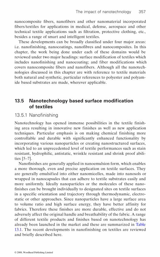
The impact of nanotechnology 357
besides a range of smart and intelligent textiles.
chapter, the work being done under each of these domains would be
both natural and synthetic, particular references to polyester and polyam-ide based substrates are made, wherever applicable.
13.5
of textiles
incorporating various nanoparticles or creating nanostructured surfaces, which led to an unprecedented level of textile performances such as stain
ties [5–7].
a more thorough, even and precise application on textile surfaces. They
wrapped in nanocapsules that can adhere to textile substrates easily and
static or other approaches. Since nanoparticles have a large surface area
adversely affect the original handle and breathability of the fabric. A range
already been launched in the market and these are summarized in Table
nanocomposite fibers, nanofibers and other nanomaterial incorporated
technical textile applications such as filtration, protective clothing, etc., fibers/textiles for applications in medical, defense, aerospace and other
i.e. nanofinishing, nanocoatings, nanofibres and nanocomposites. In this
reviewed under two major headings: surface modification of textiles which includes nanofinishing and nanocoating; and fiber modifications which
These developments can be broadly classified under four major areas:
covers nanocomposite fibers and nanofibers. Although all the nanotech-
Nanotechnology based surface modification
nologies discussed in this chapter are with reference to textile materials
13.5.1 Nanofinishing
Nanotechnology has opened immense possibilities in the textile finish-ing area resulting in innovative new finishes as well as new application techniques. Particular emphasis is on making chemical finishing more controllable and durable with significantly enhanced functionality by
Nanofinishes are generally applied in nanoemulsion form, which enables
resistant, hydrophilic, antistatic, wrinkle resistant and shrink proof abili-
are generally emulsified into either nanomicelles, made into nanosols or
finishes can be brought individually to designated sites on textile surfaces in a specific orientation and trajectory through thermodynamic, electro-
to volume ratio and high surface energy, they have better affinity for fabrics. Therefore these finishes are more durable, effective and do not
of different textile products and finishes based on nanotechnology has
more uniformly. Ideally nanoparticles or the molecules of these nano-
13.1. The recent developments in nanofinishing on textiles are reviewed and briefly described here.
© 2008, Woodhead Publishing Limited

S. No. Company Properties References
1. Resists SpillsTM Nano-Tex Water-repellent and stain resistant www.nanotex.com
2. Coolest comfortTM Nano-Tex Impart superior wicking properties to a previously hydrophobic synthetic or resin treated cotton
www.nanotex.com
3. NanoCare® Nano-Tex Helps stains to wash out easily www.nanotex.com
4. Zonyl® DuPont www.dupont.com
5. Zyvere® Nanovere Technologies
Self-cleaning paint surfaces www.nanovere.com
6. NanoSphere® Schoeller Textil AG Repels water and oil drops and prevents soil particles from attaching themselves on the fabric surface
www.schoeller-textiles.com
7. Ultra-FreshTM Silpure
Thomson-Research Associates
Antimicrobial treatment for textiles www.ultrafresh.com
8. Nuva FW Clariant Excellent oil and water-repellent effects on textiles made from
www.textiles.clariant.com
WPTF3007
Table 13.1 Commercially available functional nanofinishes in the market
Name of the finish
polyurethanes as soil-release f inish
synthetic and cellulosic fibres
Water-repellent fluorinated
© 2008, Woodhead Publishing Limited
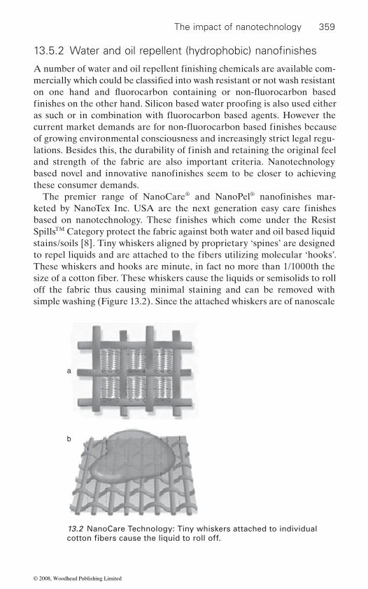
The impact of nanotechnology 359
of growing environmental consciousness and increasingly strict legal regu-
these consumer demands.® ®
SpillsTM Category protect the fabric against both water and oil based liquid stains/soils [8]. Tiny whiskers aligned by proprietary ‘spines’ are designed
These whiskers and hooks are minute, in fact no more than 1/1000th the
off the fabric thus causing minimal staining and can be removed with simple washing (Figure 13.2). Since the attached whiskers are of nanoscale
a
b
13.2 NanoCare Technology: Tiny whiskers attached to individual
13.5.2 Water and oil repellent (hydrophobic) nanofinishes
A number of water and oil repellent finishing chemicals are available com-mercially which could be classified into wash resistant or not wash resistant
finishes on the other hand. Silicon based water proofing is also used either
lations. Besides this, the durability of finish and retaining the original feel
based novel and innovative nanofinishes seem to be closer to achieving
The premier range of NanoCare and NanoPel nanofinishes mar-
and strength of the fabric are also important criteria. Nanotechnology
keted by NanoTex Inc. USA are the next generation easy care finishes based on nanotechnology. These finishes which come under the Resist
to repel liquids and are attached to the fibers utilizing molecular ‘hooks’.
size of a cotton fiber. These whiskers cause the liquids or semisolids to roll
cotton fibers cause the liquid to roll off.
on one hand and fluorocarbon containing or non-fluorocarbon based
as such or in combination with fluorocarbon based agents. However the current market demands are for non-fluorocarbon based finishes because
© 2008, Woodhead Publishing Limited
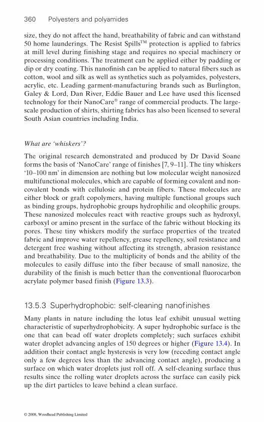
360 Polyesters and polyamides
size, they do not affect the hand, breathability of fabric and can withstand 50 home launderings. The Resist SpillsTM protection is applied to fabrics
processing conditions. The treatment can be applied either by padding or
cotton, wool and silk as well as synthetics such as polyamides, polyesters, acrylic, etc. Leading garment-manufacturing brands such as Burlington, Galey & Lord, Dan River, Eddie Bauer and Lee have used this licensed technology for their NanoCare® range of commercial products. The large-scale production of shirts, shirting fabrics has also been licensed to several South Asian countries including India.
What are ‘whiskers’?
The original research demonstrated and produced by Dr David Soane
‘10–100 nm’ in dimension are nothing but low molecular weight nanosized multifunctional molecules, which are capable of forming covalent and non-
either block or graft copolymers, having multiple functional groups such as binding groups, hydrophobic groups hydrophilic and oleophilic groups. These nanosized molecules react with reactive groups such as hydroxyl, carboxyl or amino present in the surface of the fabric without blocking its pores. These tiny whiskers modify the surface properties of the treated fabric and improve water repellency, grease repellency, soil resistance and detergent free washing without affecting its strength, abrasion resistance and breathability. Due to the multiplicity of bonds and the ability of the
Many plants in nature including the lotus leaf exhibit unusual wetting characteristic of superhydrophobicity. A super hydrophobic surface is the one that can bead off water droplets completely; such surfaces exhibit water droplet advancing angles of 150 degrees or higher (Figure 13.4). In addition their contact angle hysteresis is very low (receding contact angle only a few degrees less than the advancing contact angle), producing a surface on which water droplets just roll off. A self-cleaning surface thus results since the rolling water droplets across the surface can easily pick up the dirt particles to leave behind a clean surface.
at mill level during finishing stage and requires no special machinery or
dip or dry coating. This nanofinish can be applied to natural fibers such as
forms the basis of ‘NanoCare’ range of finishes [7, 9–11]. The tiny whiskers
covalent bonds with cellulosic and protein fibers. These molecules are
molecules to easily diffuse into the fiber because of small nanosize, the
acrylate polymer based finish (Figure 13.3).
13.5.3 Superhydrophobic: self-cleaning nanofinishes
durability of the finish is much better than the conventional fluorocarbon
© 2008, Woodhead Publishing Limited

The impact of nanotechnology 361
This fascinating self-cleaning property of lotus leaf has been accom-plished by nature through the use of a surface roughness in the combina-tion with a highly hydrophobic surface. The surface topography of lotus leaf presents two different scales to the outside environment and is tex-tured with 3–10 micron sized hills and valleys that are decorated with nanometer sized particles of a hydrophobic wax like material (Figure 13.5). The hills and valleys ensure that surface contact area available to water is very low while the hydrophobic nanoparticles prevent water into the valleys. The net result is that water cannot wet the surface and therefore forms nearly spherical water droplets, leading to superhydrophobic surfaces [12]. The increasing surface roughness due to multiplicity of microscale or nanoscale projection or cavities provides a large geometric area for a rela-
that water repellency of rough surfaces was due to the air enclosed between the gaps in the surface, which minimizes the substrate to water interface. Hence water does not spread and forms a droplet, which easily rolls off.
Taking the inspiration from nature there have been several approaches researched to create superhydrophobic surfaces on textiles, which mimic
R
A
X
(O)n
( )o
( )m
13.3 Multifunctional molecule of Dr Soane, where m, n = 0 or 1, o =
bon having C1 to C30 2
–CONH, –CH2 or CF2. ‘X’ is a nucleophilic group capable of reacting with hydroxyl, amine or thiol group [7].
8c 0° 90° 180°Complete wetting In equilibrium No wetting at all
13.4 Contact angle and wettability (superhydrophobic surfaces have contact angle >150˚).
tively small projected area. Cassie and Baxter [13] were the first to explain
0 or 2. ‘R’ is a linear, branched, or cyclic hydrocarbon or fluorocar- hydrocarbon or fluorocarbon groups ‘A’ is –SO ,
© 2008, Woodhead Publishing Limited
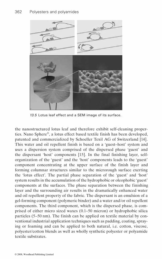
362 Polyesters and polyamides
the nanostructured lotus leaf and therefore exhibit self-cleaning proper-®
patented and commercialized by Schoeller Texil AG of Switzerland [14].
uses a dispersion system comprised of the dispersed phase ‘guest’ and
organization of the ‘guest’ and the ‘host’ components leads to the ‘guest’
forming columnar structures similar to the microrough surface exerting the ‘lotus effect’. The partial phase separation of the ‘guest’ and ‘host’ system results in the accumulation of the hydrophobic or oleophobic ‘guest’
layer and the surrounding air results in the dramatically enhanced water and oil repellent property of the fabric. The dispersant is an emulsion of a gel-forming component (polymeric binder) and a water and/or oil repellent components. The third component, which is the dispersed phase, is com-prised of either micro sized waxes (0.1–50 micron) or hydrophobic silica
ventional industrial application techniques such as padding, coating, spray-ing or foaming and can be applied to both natural, i.e. cotton, viscose, polyester/cotton blends as well as wholly synthetic polyester or polyamide textile substrates.
13.5 Lotus leaf effect and a SEM image of its surface.
This water and oil repellent finish is based on a ‘guest–host’ system and
the dispersant ‘host’ components [15]. In the final finishing layer, self-
ties. Nano Sphere , a lotus effect based textile finish has been developed,
component concentrating at the upper surface of the finish layer and
components at the surfaces. The phase separation between the finishing
particles (5–50 nm). The finish can be applied on textile material by con-
© 2008, Woodhead Publishing Limited
The impact of nanotechnology 363
transparent and durable have been reported by W. A. Daoud and cowork-ers of the Hong Kong Polytechnic University using low temperature sol-gel coating based on a low temperature process [16]. The coatings were pro-
silane (HDTMS), tetra ethoxy silicate (TEOS) and 3-glycidyloxy propyl
posite coating enhances the contact angle of cotton to 140 , whereas before coating cotton has 0˚ contact angle as it is superhydrophilic in nature. This nanocomposite coating has new applications in daily use material such as
and tearing strength. The air permeability of the fabric remains unchanged. The washing durability of the coatings is also good which is attributed to linking ability of GPTMS that promotes a high level of adhesion at the interface.
Yu et al. [17] recently reported another superhydrophobic complex
quaternary ammonium silane coupling agent (PFSC), using a sol-gel process. Silica nanoparticles in the coating made the textile surface much rougher and PFSC, on the top layer of the surface, lowered the surface free energy. Textiles coated with this coating showed excellent water repellant property and water contact angle increased up to 145˚ from 133˚ for cotton fabrics treated with pure PFSC, without silica sol pretreatment. The silica sol and PFSC were applied to cotton fabrics by conventional pad-dry-cure process. Superhydrophobic coatings have also been reported with many
2 3
gel, ZnO nanoparticles, aligned carbon nanotubes, CaCO3 loaded hydrogel spheres and POSS nanoparticles as reported in an excellent review on
However durability against laundering and abrasion is important for textile applications. A combination of chemical and mechanical treatments can be used to create super hydrophobic nanostructures on the surface of textile materials. Mechanically roughened surfaces became an integral part of the textiles and are expected to be more durable. Mechanical treat-ments such as calendering, embossing, etching, schreinering, sueding, sanding or emerizing have also been used to create mechanically abraded micro roughened surfaces on textiles [7].
Dr John Xin and Dr Walid Daoud of the Hong Kong Polytechnic Univer-sity’s Nanotechnology Centre for Functional and Intelligent Textiles and
duced via cohydrolysis and polycondensation of a hexa decyl trimethoxy
Superhydrophobic silica coating film on cotton substrates, which are
water repellant finish. There is less than 5% decrease in textile strength
other hydrophobic film-forming nanoparticle compositions such as Al O
nanofinishing by Gulrajani [7].
13.5.4 Photocatalytic self-cleaning nanofinishes
trimethoxy silane (GPTMS) mixture. The superhydrophobic nanocom-
plastics or textiles and is an ecofriendly substitute for fluorocarbon based
coating for cotton fabrics based on silica nanoparticles and perfluorinated
© 2008, Woodhead Publishing Limited

364 Polyesters and polyamides
Apparel [18–20] developed a process for the sol gel coating on textile sub-strates at low temperature. They also claimed that photocatalytic self-cleaning properties could be imparted to the coated fabric on coating cotton with TiO2 nanoparticles that are about 20 nm in size (Figure 13.6). The coating solution comprises a translucent sol prepared with a TiO2 precursor (TTIP, titanium tetraisopropoxide), ethanol and acetic acid in a molar ratio of 1 : 100 : 0.5 respectively. The principal chemical reactions are summarized as follows:
Ti(OPr)4 + 4 EtOH → Ti(OEt)4 + 4 Pr OH
Ti(OPr)4 or Ti(OEt)4 + H2O → Ti(OH)4 + 4PrOH or 4EtOH
Ti(OH)4 → TiO2 + 2H2O
The fabrics are coated with this sol using conventional pad dry cure process. The coated fabrics show discoloration of red wine and coffee stains on irradiation of samples in a Sun test solar simulator. The photo-catalytic activity of semiconductor oxides such as TiO2 is attributed to promotion of an electron from the valance band (VB) to the conduction band (CB) brought about by the absorption of a photon of ultra band gap (∼3.2 eV) light whose energy (hν) > EBG. EBG is the energy difference
a b
c d
1 μm
100 nm 70 nm
1 μm
13.6 SEM images of (a) uncoated cotton fiber, (b) titania coated cotton fiber showing the morphological change in the surface structure, (c) higher magnification image of titania coated cotton fiber showing the shape and size of the titania particles, and (d) higher magnification image of a titania film coated on glass [7].
© 2008, Woodhead Publishing Limited
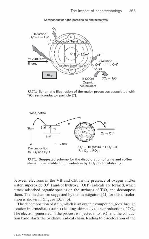
The impact of nanotechnology 365
between electrons in the VB and CB. In the presence of oxygen and/or water, superoxide (O2•) and/or hydroxyl (OH•) radicals are formed, which attack adsorbed organic species on the surfaces of TiO2 and decompose them. The mechanism suggested by the investigators [21] for this discolor-ation is shown in (Figure 13.7a, b).
The decomposition of stain, which is an organic compound, goes through a cation intermediate (stain +) leading ultimately to the production of CO2. The electron generated in the process is injected into TiO2 and the conduc-tion band starts the oxidative radical chain, leading to discoloration of the
13.7(a) Schematic illustration of the major processes associated with TiO2 semiconductor particle [7].
Semiconductor nano-particles as photocatalysts
O2–
Conduction band
Valence band
e–
h+
+2.7 eV
Eo = 3.2 eV
–0.5 eV
OH–
OH
Oxidation
ReductionO2
– + e → O2–
OH– + h+ → OH•
CO2 + H2OR-COOHOrganic
contaminant
hυ < 400 nm
Energy
TiO2
Decompositionto CO2 and H2O
TiO2 O2 → O2–
O2– + RH (Stain) → HO2
– +RR + O2 → RO2
Stain
Stain Stain*e– e–
Wine, coffee
hυ > 400
hυ
13.7(b) Suggested scheme for the discoloration of wine and coffee stains under visible light irradiation by TiO2 photocatalyst [7].
© 2008, Woodhead Publishing Limited

366 Polyesters and polyamides
chain. The nanotitania coated fabrics maintain their antibacterial property up to 55 washes/home launderings and UV protection characteristics up to 22 washes. This has been attributed to the formation of interfacial bonding through a dehydration reaction between the cellulosic hydroxyl groups of cotton and the hydroxyl group of titania [22].
The poor moisture absorption property of synthetic fabrics such as poly-ester and polyamides limits its applications in the apparel sector. The new
TM and Coolest ComfortTM commercialized by NanoTex, USA makes the synthetic fabric look and feel like cotton [8].
Cotton TouchTM
This is a naturally soft fabric enhancement designed to make synthetic fabric look and feel like cotton. It is available as Nanotouch® and
and polyamides. Cellulosic sheath and synthetic core together form a concentric structure to bring overall solutions to the drawbacks of synthetics such as static discharge, harsh handle and glaring luster. It can also last 50 launderings and is expected to eliminate the decline in demand
applications.
Coolest ComfortTM
This fabric provides breakthrough moisture wicking to draw moisture away from the body while drying quickly. The popular product in this category is Nano Dry®. It improves the moisture absorption of polyamides and polyesters making them hydrophilic and comfortable. The main applica-tions are in sportswear and close-to-body garments that require perspira-
Silver (Ag) or silver ions (Ag+) have long been known to have strong inhibi-tory and bactericidal effects as well as a broad spectrum of antimicrobial activities [23]. The inhibitory effects of silver ion/metal on bacteria have been attributed to the interaction of sliver ion with thiol group in bacteria as well as to the oxidative destruction of microorganisms in aqueous medium [24–25] (Figure 13.8).
13.5.5 Hydrophilic nanofinishes
range of hydrophilic nanofinishes Cotton Touch
gives a durable cellulose wrapping over synthetic fibers such as polyester
of synthetic microfiber and broaden the use of synthetics to new
tion absorbency. The finish lasts 50 launderings.
13.5.6 Antibacterial nanofinishes
© 2008, Woodhead Publishing Limited
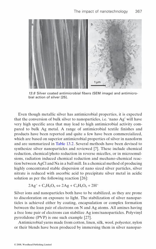
The impact of nanotechnology 367
Even though metallic silver has antimicrobial properties, it is expected that the conversion of bulk silver to nanoparticles, i.e. ‘nano Ag’ will have
products have been reported and quite a few have been commercialized, which are based on superior antimicrobial properties of silver in nanoform and are summarized in Table 13.2. Several methods have been devised to synthesize silver nanoparticles and reviewed [7]. These include chemical reduction, chemical/photo reduction in reverse micelles, or in microemul-sions, radiation induced chemical reduction and mechano-chemical reac-tion between AgCl and Na in a ball mill. In a chemical method of producing highly concentrated stable dispersion of nano sized silver particles, silver nitrate is reduced with ascorbic acid to precipitate silver metal in acidic solution as per the following reaction [26]:
2Ag+ + C6H8O6 ⇔ 2Ag + C6H6O6 + 2H+
Silver ions and nanoparticles both have to be stabilized, as they are prone to discoloration on exposure to light. The stabilization of silver nanopar-ticles is achieved either by coating, encapsulation or complex formation between the loan pair of electrons on N and Ag atoms. All amines having a free lone pair of electrons can stabilize Ag ions/nanoparticles. Polyvinyl pyrrolidone (PVP) is one such example [27].
Antimicrobial yarns made from cotton, linen, silk, wool, polyester, nylon or their blends have been produced by immersing them in silver nanopar-
ba
1 μm
bial action of silver [25].13.8 Silver coated antimicrobial fibers (SEM image) and antimicro-
very high specific area that may lead to high antimicrobial activity com-pared to bulk Ag metal. A range of antimicrobial textile finishes and
© 2008, Woodhead Publishing Limited

368 Polyesters and polyamides
ticle containing solutions. The treated yarns are yellow in color and contain 0.4–0.9% by weight of silver. The treated yarns show effective antimicro-bial activity against various bacteria, fungi, etc., and the activity remains even after 100 washes with neutral soap. Nano silver particles containing antimicrobial dressings have been incorporated in wound care and have gained wide acceptance in medical industry, as a safe and effective means of controlling microbial growth in the wound, often resulting in improved healing.
Semiconductor oxides such as TiO2, ZnO, SiO2 and Al2O3 are known to have UV blocking property [29–30]. It is also known that nanosized TiO2
tion than the conventional size particles and thus were better able to block UV radiation as they have a much larger surface area to volume ratio and also the fact that Rayleigh Scattering due to nanoparticles is much reduced as it is inversely proportional to the fourth power of their sizes. This theory predicts that in order to scatter UV radiation between 200 and 400 nm, the optimum particle size should be between 20 and 40 nm [29]. Moreover inorganic UV blockers are advantageous as compared to organic UV absorbers, as they are less toxic and chemically stable under exposure to high temperature and radiation.
Much effort has been made on the application of UV bulking treatment to fabrics using nanotechnology [31–35]. UV blocking treatments for cotton fabric have been developed using the sol-gel method by Xin and coworkers [34]. A thin layer of TiO2 nanoparticle is formed, on the surface of treated
up to 50 home launderings. Apart from TiO2, ZnO nanorods of 10 to 50 nm in length were also applied to cotton fabric to provide UV protection. The rods exhibited excellent UV protection [36].
accumulation as they absorb less water. It has been reported that nanosized TiO2, ZnO whiskers, nanoantimony-doped tin oxide (ATO) and silane
and TiO2 nanoparticles are electrically conductive materials and help dis-
properties as the silane gel nanoparticles absorb moisture due to –NH2 and –OH groups present. W. L. Gore and Associates GmbH have combined
13.5.7 UV protective nanofinishes
and ZnO particles are more efficient at absorbing and scattering UV radia-
cotton fabric, which provides excellent UV protection, the finish is durable
13.5.8 Antistatic nanofinishes
Synthetic fibers such as nylon and polyester are prone to static charge
nanosol could impart antistatic properties to synthetic fibers [37–39]. ZnO
sipate the static charge in these fibers. Silane nanosol improves antistatic
© 2008, Woodhead Publishing Limited
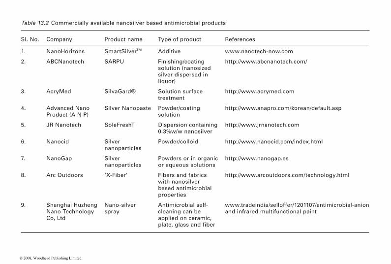
Table 13.2 Commercially available nanosilver based antimicrobial products
Sl. No. Company Product name Type of product References
1. NanoHorizons SmartSilverTM Additive www.nanotech-now.com
2. ABCNanotech SARPUsolution (nanosized silver dispersed in liquor)
http://www.abcnanotech.com/
3. AcryMed SilvaGard® Solution surface treatment
http://www.acrymed.com
4. Advanced Nano Product (A N P)
Silver Nanopaste Powder/coating solution
http://www.anapro.com/korean/default.asp
5. JR Nanotech SoleFreshT Dispersion containing 0.3%w/w nanosilver
http://www.jrnanotech.com
6. Nanocid Silver nanoparticles
Powder/colloid http://www.nanocid.com/index.html
7. NanoGap Silver nanoparticles
Powders or in organic or aqueous solutions
http://www.nanogap.es
8. Arc Outdoors ‘X-Fiber’ Fibers and fabrics with nanosilver-based antimicrobial properties
http://www.arcoutdoors.com/technology.html
9. Shanghai Huzheng Nano Technology Co, Ltd
Nano-silver spray
Antimicrobial self-cleaning can be applied on ceramic,
www.tradeindia/selloffer/1201107/antimicrobial-anion and infrared multifunctional paint
Finishing/coating
plate, glass and fiber
© 2008, Woodhead Publishing Limited
370 Polyesters and polyamides
membrane for protective clothing. Gore-Tex® based works wear protects the wearer from electrostatic discharges [40]. Electrically conductive
an electrically conducting network that prevents the accumulation of static charge.
13.6 Nanocoatings
Nanostructured surfaces are of great interest, due to their large surface area, which might yield high functionality. Nanocoating refers to the covering of materials with a layer on the nanometer scale (10–100 nm in thickness) or covering of a nanoscale entity to form nanocomposite and structured materials. There are numerous coating procedures that are widely used including chemical vapor deposition, plasma assisted tech-niques, self-assembly, layer by layer coating, dip coating, sol-gel coating and electrochemical deposition mostly on planar substrates, i.e. metal, ceramic or polymer. Coating in solution is generally performed using either precursor molecules or preformed nanoparticles to form the layer. Elec-trostatic interaction, hydrogen bonding and covalent bondings are some of the associated forces between the coating and the material being coated. Nanocoatings on textiles have recently been explored using mainly pro-cesses such as plasma-assisted polymerization, self-assembly, sol-gel nano-
this section.
13.6.1 Self-assembly
Toray Industries, Inc. have succeeded in developing a ‘nano-scale process-ing technology’ that allows the formation of molecular arrangement and molecular assembly necessary to bring out further advanced functional-ities in textile processing [41]. This ‘nano-scale processing technology’ named ‘NanoMATRIX’ forms the functional material coating (10–30 nm)
that forms the fabric (woven/knitted fabric) (Figure 13.9). NanoMATRIX is based on the concept of ‘self-organization’ by controlling the conditions
tives, etc. It is possible to control the state of molecular arrangement and/or
scale sizes precisely by controlling the interaction and responses between
application of this technology is expected to lead to the development of new functionalities as well as remarkable improvements in the existing
nanoparticles are durably anchored in the fibers of the membrane, creating
consisting of nano-scale molecular assembly on each of the monofilaments
like temperature, pressure, magnetic field, electrical field, humidity, addi-
assembly of functional materials on each of the monofilaments in nano-
the functional material to be coated and the fiber material (polymer). The
nanotechnology and PTFE (Dupont’s Teflon) to develop an antistatic
coating and electrochemical deposition which will be briefly reviewed in
© 2008, Woodhead Publishing Limited

The impact of nanotechnology 371
functions (quality, durability, feel, etc.) without losing the fabric’s texture.
13.6.2 Plasma assisted nanocoatings
Plasma polymerization enables deposition of very thin nanostructured coatings (<100 nm) via gas phase activation and plasma substrate interac-
of textiles. Plasma polymerization can impart a wide range of functional-ities such as water repellency, hydrophilicity, dyeability, conductivity and
it needs a very low material and low energy input, hence is environmentally
b c
a
100 nm
13.9 NanoMATRIX technology from Toray for nanocoatings on textiles through self-assembly [41].
to replace wet chemical process steps for surface modification (finishing)
biocompatibility due to the nanoscaled surface modification of textiles and
tions. This dry and ecofriendly technology offers an attractive alternative
fibers. The advantages over conventional wet chemical processing are that
© 2008, Woodhead Publishing Limited
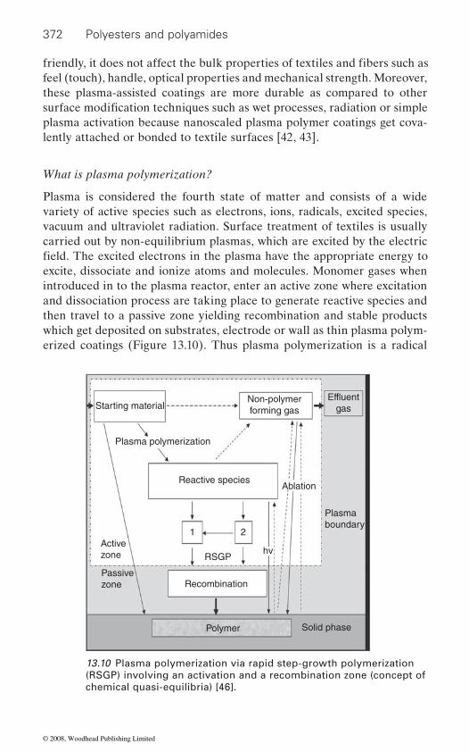
372 Polyesters and polyamides
feel (touch), handle, optical properties and mechanical strength. Moreover, these plasma-assisted coatings are more durable as compared to other
plasma activation because nanoscaled plasma polymer coatings get cova-lently attached or bonded to textile surfaces [42, 43].
What is plasma polymerization?
Plasma is considered the fourth state of matter and consists of a wide variety of active species such as electrons, ions, radicals, excited species, vacuum and ultraviolet radiation. Surface treatment of textiles is usually carried out by non-equilibrium plasmas, which are excited by the electric
excite, dissociate and ionize atoms and molecules. Monomer gases when introduced in to the plasma reactor, enter an active zone where excitation and dissociation process are taking place to generate reactive species and then travel to a passive zone yielding recombination and stable products which get deposited on substrates, electrode or wall as thin plasma polym-erized coatings (Figure 13.10). Thus plasma polymerization is a radical
Starting material
Plasma polymerization
Reactive species
RSGPhv
Recombination
Polymer Solid phase
Activezone
Passivezone
Non-polymerforming gas
Effluentgas
Ablation
Plasmaboundary
1 2
13.10 Plasma polymerization via rapid step-growth polymerization (RSGP) involving an activation and a recombination zone (concept of chemical quasi-equilibria) [46].
friendly, it does not affect the bulk properties of textiles and fibers such as
surface modification techniques such as wet processes, radiation or simple
field. The excited electrons in the plasma have the appropriate energy to
© 2008, Woodhead Publishing Limited
The impact of nanotechnology 373
dominated chemical vapour deposition (plasma CVD) process, thought to result in macromolecule formation i.e. mainly amorphous, and more or less cross-linked structures.
Plasma polymerization is performed using different kinds of plasma polymerizable gases (monomers) such as hydrocarbons (i.e. methane, ethylene or acetylene) or organosilicon monomers (i.e. silicone (SiH4) or silicon tetrachloride (SiCl4). There is a difference between conventional and plasma polymerization, as some gases (like methane) which can be plasma polymerized do not undergo polymerization by the conventional route. A plasma polymer typically results from a rivaling etching and
growth yielding a more or less cross-linked structure [44–46].
Plasma equipment
There are two types of plasma, i.e. high temperature plasma and low tem-perature plasma. High temperature plasma is found at atmospheric pres-sure in either its man made form such as plasma torch or its natural form such as lightning. Low temperature (also called low pressure) plasma tech-niques are mostly suitable for surface reaction, cleaning, etching and plasma polymerization [46].
Most of the earlier work on plasma processing of textiles is based on low-pressure plasmas operating between 0.1 Pa and 100 Pa, which can be activated by direct current (DC), alternative current (AC) and radio fre-quency or microwave (MW). However, high-pressure atmospheric plasmas, such as corona and dielectric barrier discharge (DBD), are of special inter-est to textile industries because of easier processibility. However, it is dif-
high-pressure atmospheric plasma. This is because the plasma can be ignited only within smaller volumes, hence non-coated parts are also taking part in external interaction. Moreover, the atmospheric plasma is mostly
to overcome these limitations [47, 48, 49].
developed a low-pressure plasma reactor for plasma-polymerized coatings.
free path lengths are high enough to allow the penetration of textile struc-ture by energetic particles as well as by long living radicals, thus enabling
plasma media. EMPA has developed both a semi-continuous web coater
reactors. The reactors have been typically designed for textile widths up to 120 cm but larger widths of up to 4 m are also possible. The textiles are
deposition process depending on the plasma species present during film
ficult to obtain controlled deposition conditions or uniform coating through
f ilamentary in nature, thus leading to moving hot spots. Research is ongoing
At low pressure (1–100 pa) the plasma zone is well defined and the mean
M/s EMPA, a Swiss based company specializing in this area, have
textile fibers up to several fiber layers in depth to interact with external
(up to 63 cm in width) and a continuous fiber coater besides several batch
© 2008, Woodhead Publishing Limited
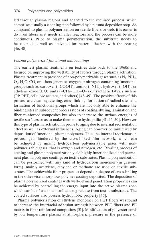
374 Polyesters and polyamides
led through plasma regions and adapted to the required process, which comprises usually a cleaning step followed by a plasma deposition step. As
continuous. Prior to plasma polymerization, the substrate needs to be cleaned as well as activated for better adhesion with the coating [46, 48].
Plasma polymerized functional nanocoatings
The earliest plasma treatments on textiles date back to the 1960s and focused on improving the wettability of fabrics through plasma activation. Plasma treatment in presence of non-polymerizable gases such as N2, NH3, O2, H2O, CO2 or others generates oxygen or nitrogen-containing functional groups such as carboxyl (–COOH), amino (–NH2), hydroxyl (–OH), or ethylene oxide (EO) units (–CH2–CH2–O–) on synthetic fabrics such as (PP, PET, cellulose acetate, and others) [48, 49]. The positive effects of this process are cleaning, etching, cross-linking, formation of radical sites and formation of functional groups which are not only able to enhance the binding sites in subsequent process steps of coating, dyeing, lamination and
textile surfaces so as to make them more hydrophilic [41, 46, 50]. However this type of plasma activation is prone to aging due to internal reorientation
deposition of functional plasma polymers. Thus the internal reorientation
be achieved by mixing hydrocarbon polymerizable gases with non-polymerizable gases, that is oxygen and nitrogen, etc. Rivaling process of etching and plasma polymerization yield highly functionalized and perma-nent plasma polymer coatings on textile substrates. Plasma polymerization can be performed with any kind of hydrocarbon monomer (in gaseous
in the otherwise amorphous polymer coating deposited. The deposition of
which can be of use in controlled drug release from textile substrates. The coated surfaces also possess hydrophobic property [46].
by low temperature plasma at atmospheric pressure in the presence of
compared to plasma polymerization on textile fibers or web, it is easier to do it on fibers as it needs smaller reactors and the process can be more
fiber reinforced composites but also to increase the surface energies of
process gets hindered by the cross-linked film network, which can
strates. The achievable fiber properties depend on degree of cross-linking
plasma polymerized coatings with well-defined penetration properties can
Plasma polymerization of ethylene monomer on PET fibers was found to increase the interfacial adhesion strength between PET fibers and PE
be achieved by controlling the energy input into the active plasma zone
form), mainly acetylene, ethylene or methane are used on textile sub-
matrix in fiber reinforced composites [51]. Modification of polyester cords
effect as well as external influences. Aging can however be minimized by
© 2008, Woodhead Publishing Limited

The impact of nanotechnology 375
nitrogen and butadiene resulted in homogeneously coated cord surfaces. The plasma polymerized cords showed values of static and dynamic adhe-sion comparable to chemical treatment based on resorcinol formaldehyde latex (RFL) [52].
Plasma polymerization of organosilicon compounds is reported to impart good dielectric property, thermal stability, scratch resistance, lowered
wet ability of textiles [46, 53, 51]. Hexamethylene disiloxane [HMDSO, (CH3)3Si-O-Si(CH3)3] is the best common monomer, it is nontoxic and enables the deposition of siloxane coatings at low temperature. HMDSO derived plasma polymers are used for the hydrophobization of cotton,
vapour transmission through the fabric [54]. Low-pressure plasma polym-3 6 4 8
textiles has been industrially performed using a semi-continuous process to impart stain repellant properties on fabrics. Oil repellency grades of 4–5 were achievable in short treatment times (30–60 sec), which is superior to
color, permeability, abrasion resistance, water performance and friction
ultra-thin (<100 nm) plasma coatings [55].
amide have been obtained by low-pressure plasma polymerization using acrylic acid as a monomer. Acrylic coatings were found to improve their wettability, dyeability (using acid dyes) and soil resistance [56] and also improve the cell adhesion for tissue engineering [57]. The wrinkle recovery angles also improved by about 13% and no undesirable decrease in tensile strength was observed [58].
Ceramic Nanocoatings such as TiO2, which are known for their superior hydrophilicity and photocatalytic activity, have also been obtained using plasma polymerization in presence of tetra isopropyl orthotitanate (TTIP) and oxygen as gases at low temperature (<100˚C) [59]. The incorporation
as agglomeration or non-uniform distribution of nanoparticles at surfaces. An in situ plasma polymerization/co-sputtering process has been used to embedded nanoparticles with homogeneous size and spatial distribution. Hegemann and coworkers [60] have recently used low pressure RF plasma discharges using acetylene mixed with ammonia to obtain inter-connected nanoporous highly crosslinked coatings on textile fabrics. Co-sputtering of a silver target with Ar enabled the in situ incorporation by Ag nanoparticles within the functional plasma polymerized coating. A homogeneous distribution of Ag nanoparticles present at the coating
commercially available Scotch Guard finished samples. The softness, feel,
coefficient properties of original fabric were unaltered by these nanoscaled
Multifunctional acrylic-like coatings on fibers such as polyester or poly-
of nanoparticles into wet chemical coatings presents some difficulties such
friction, flame retardant and barrier properties as well as adjusting the
showing water contact angles up to 130˚ without influencing the water
erization of unsaturated fluorohydrocarbons, i.e. C F , C F on selected
© 2008, Woodhead Publishing Limited
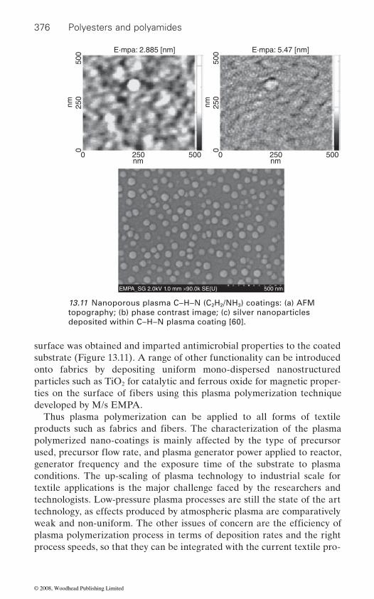
376 Polyesters and polyamides
surface was obtained and imparted antimicrobial properties to the coated substrate (Figure 13.11). A range of other functionality can be introduced onto fabrics by depositing uniform mono-dispersed nanostructured particles such as TiO2 for catalytic and ferrous oxide for magnetic proper-
developed by M/s EMPA.Thus plasma polymerization can be applied to all forms of textile
polymerized nano-coatings is mainly affected by the type of precursor
generator frequency and the exposure time of the substrate to plasma conditions. The up-scaling of plasma technology to industrial scale for textile applications is the major challenge faced by the researchers and technologists. Low-pressure plasma processes are still the state of the art technology, as effects produced by atmospheric plasma are comparatively
plasma polymerization process in terms of deposition rates and the right process speeds, so that they can be integrated with the current textile pro-
nm nm
025
050
0
0 250 500nm
025
050
0
0 250 500nm
E·mpa: 5.47 [nm]E·mpa: 2.885 [nm]
EMPA_SG 2.0kV 1.0 mm ×90.0k SE{U} 500 nm
13.11 Nanoporous plasma C–H–N (C2H2/NH3) coatings: (a) AFM topography; (b) phase contrast image; (c) silver nanoparticles deposited within C–H–N plasma coating [60].
ties on the surface of fibers using this plasma polymerization technique
products such as fabrics and fibers. The characterization of the plasma
weak and non-uniform. The other issues of concern are the efficiency of
used, precursor flow rate, and plasma generator power applied to reactor,
© 2008, Woodhead Publishing Limited

The impact of nanotechnology 377
duction lines. High investment cost and requirement of vacuum technology further limits the present application of this technology at an industrial scale to only niche textile products [46].
13.6.3 Sol-gel nanocoatings
The sol-gel process is a widely used technique to coat surfaces with
areas ranging from catalysis, electronics, biomedical engineering and material science [61]. The sol-gel process involves inorganic precursors (a metal salt of an organo metallic molecule) that undergoes various reactions resulting in formation of a three dimensional molecular network. A common example is the hydrolysis and condensation reaction of metal alkoxides to form larger metal oxide molecules:
Hydrolysis
M(OR)4 + H2O → HO-M(OR)3 + ROH → M(OH)4 + 4ROH
Condensation
(OR)3M-OH + HO-M(OR)3 → (OR)3M-O-M (OR)3 + H2O
(OR)3M-OH + RO-M(OR)3 → (OR)3M-O-M (OR)3 + ROH
Low temperature sol-gel based nanocoatings have been recently used to deposit layers of metal oxide nanoparticles on textile fabric surfaces to
2
activity, nanosilica (SiO2) for superhydrophobic lotus leaf effect [7, 16, 17,
One of the major challenges in sol-gel nanocoatings is controlling the adhesion of the inorganic coatings to the substrates and also the uniformity of coating thickness. Hence reaction conditions need to be carefully moni-tored and controlled to allow reproducible coatings.
13.6.4 Layer-by-layer nanocoatings
Layer-by-layer (l-b-l) nanocoating technique can be utilized to fabricate
chemistry. A coating of this type can be applied to any surface amenable to the water based l-b-l adsorption process used to construct poly-electrolyte multi-layers including inside surfaces of the complex objects [62]. L-b-l assembly process involves sequential adsorption of oppositely charged polyelectrolytes on a solid support that results in multi-layer
nanoscale entities, i.e nanoparticles and finds application in a variety of
where M represents the metal and R represents alkyl group
impact specific functionality, i.e. nanotitania (TiO ) for photocatalytic
18–20] as also discussed in section 13.5.1 on ‘Nanofinishing’.
thin film coatings, with molecular level control over film thickness and
© 2008, Woodhead Publishing Limited

378 Polyesters and polyamides
apparatus is required for the l-b-l process and nanocoatings can be pre-pared under mild physicochemical conditions. L-b-l technique has been used to create superhydrophobic surfaces which can be applicable as anti-
and bio sensors to name a few [62, 63].
20–50 nm thick polymer surface layers, which increased the interaction
antimicrobial nylon and silk fabrics by l-b-l deposition of silver nanoparti-cles. The heated fabrics are sequentially dipped in a solution of PDADMAC [poly (diallyl dimethyl ammonium chloride)] and silver nanoparticles,
activity [65].
because of a unique cross-section as well as chemical heterogeneity of its surface. Cationic cotton surface has been coated with alternate layers of polyelectrolytes, i.e. poly (sodium 4-styrene sulphonate) and poly (ally l-amine hydrochloride) using l-b-l technique [66]. Our research group at
(a)
+
(b)
(d) (c)
+
13.12 Schematic of layer-by-layer nanocoatings through self-assembly [65].
coatings (or film) of nanometer thick layers (Figure 13.12). No special
Nanocoatings on fibers or textiles is to date a relatively unexplored area with very few cited reports [64–66]. Systematic modification of the surface of lignocellulosic fibers was performed by L-b-l nanocoating process to produce negative and positively charged fibers. The fibers are coated with
between the fibers during paper formation and helped to obtain stronger paper from virgin fibers [64]. Dukas and coworkers have reported
which formed a colored film of nanoparticles having strong antimicrobial
Cotton fibers offer unique challenges to the deposition of nanolayers
fouling, self cleaning and water resistant coatings for micro-fluids channels
© 2008, Woodhead Publishing Limited
The impact of nanotechnology 379
IIT Delhi has recently investigated this technique to deposit nanocoatings on textile surfaces using polyanion (PAH) and polycation chitosan on cotton fabric [67].
13.7 Nanocomposite coatings
A glance at the literature available shows interesting applications of polymer nanocomposites as coatings with attractive combinations of prop-erties not achievable by neat polymeric conventional coatings. Both scien-tists as well as industry are actively engaged in exploring the potential applications of polymer nanocomposites as advanced coating options and some of the developments in this area are described here.
Organic-inorganic hybrid nanocomposite coatings frequently exhibit unexpected hybrid properties synergistically derived from the two chemi-
inorganic hybrid materials are endowed with exceptional mechanical and thermal stability, allowing small thickness and making them very interest-ing for various applications. The organic component in the matrix offers
component, i.e. nanoclays or metal/metal oxide nanoparticles provides hardness, thermal stability and gas barrier properties. It has been reported
smoother, stronger and more durable. When used on products, the results range from scratch resistant and self-cleaning surfaces to moisture absorb-ing clothing [68, 69]. Many companies around the world are using the properties of nanoparticles and are incorporating them within their coatings.
Novel polyurethane/MMT (clay) based nanocomposites as coatings for
ment of Textile Technology, the Indian Institute of Technology, Delhi by Joshi et al. [70]. The coated fabrics showed improved gas barrier prop-erty without affecting the transparency and tear strength. Clays are believed to increase the barrier properties by creating a tortuous path that retards the progress of gas molecules, i.e. gas diffusion through the matrix resin as reported [71]. Recently Wilson Sporting Goods have introduced the Wilson Double Core Tennis Ball. The manufacturers claim that these balls retain their pressure and bounce for twice as long as conventional tennis balls [72]. The reason that these balls last twice as long is the inner core of the balls, coated with a nanocomposite coating that inhibits the perme-ation of air by 200% from the inside the ball. The coating was developed by InMat and utilizes aligned vermiculite platelets to impede the path of air from escaping. The platelets have an aspect ratio of 10 000 to 1 and
cally different components. Coatings and films based on these organic-
that by incorporation of nanoparticles, the thin film coatings have stronger
the advantages of mechanical toughness and flexibility while the inorganic
bonds and better flexibility with little cost difference. These coatings are
inflatables have been explored in an ongoing research project at the Depart-
© 2008, Woodhead Publishing Limited
380 Polyesters and polyamides
coating is known as Air D-fense® and is mixed at low viscosity and hence low shear stress. The technology is being extended to the tire industry, where these coatings would inhibit the migration of oxygen inside the tire, which affects the life of the steel tire cord. This further offers the oppor-
retention and reduce recycling and incineration costs. InMat plans to con-tinue the development of soccer balls, footballs, bicycle tires, automobile tires and truck tires based on this technology.
Nanocomposite coatings [68] based on UV curing of clay or colloidal
improved impact resistance, tensile strength, and hydrophobicity. Clay also
reported to give an improvement of 35% in scratch, 67% in wear resistance and 50% decrease in water vapor transmission rate through nano rein-forced coatings compared to pure polymer coatings [73].
However, it is important to ensure that nanoparticles are incorporated
properties. It is well known that due to extremely high surface area, nanoparticles take any opportunity to agglomerate so as to minimize the
order of addition of different components. Therefore, surface engineering of nanoparticles not only aids its true dispersion at the nanolevel in the
further enhancing the properties of polymer nanocomposite based coat-ings. The chemistry of polymer nanocomposite formulations can be opti-mized to achieve coatings with best performance. The synthesis of these nanoparticles in larger quantities has been attempted [74] and M/s Degussa Inc (http:// www.degussa.com) have already commercialized the process and launched a range of nanomaterials/nanoparticles for incorporating in the coatings.
13.8
Polymer nanocomposites are the advanced new class of materials with an
significantly increase the path/travel distance for the air. The patented
tunity to reduce weights, improve fuel efficiency and improve pressure
silica filled acrylic or epoxy resins have also been studied. The coating had
imparts surface roughness and makes it an efficient matting agent. Nylon 11 coatings filled with nano-sized silica and carbon black have been
into coatings for textiles or fibers without losing their superb nanoscopic
surface energy. The dispersion of nanoparticles in the solvent media is
coating solution but also ideally suits the needs of specific applications,
Nanotechnology based fiber modifications
13.8.1 Nanocomposite fibers
ultrafine dispersion of nanofillers or nanoparticles in a polymeric matrix, where at least one dimension of nanofillers is smaller than about 10 nm. The nanofillers may have only one dimension in nano range – lamellar (e.g. layered silicate clays), two dimensions in nano range – fibrillar (e.g. carbon
influenced by stirring speeds, temperature profiles and the manner and
© 2008, Woodhead Publishing Limited

The impact of nanotechnology 381
nanotubes) or all the three dimensions in nano range – spherical (e.g. metals/metal oxide nanoparticles and POSS (polyhedral oligomeric silsis-quioxanes)) [75, 76].
Nano- vs microcomposite
Polymer nanocomposites have recently gained a great deal of attention because of superior properties when compared to neat polymers or con-ventional composites. The properties include high modulus, increased
ventional composites, the mechanism of property enhancement is well understood and generally follows the rule of mixtures. On the other hand in nanocomposites, property enhancement exceeds the theoretically pre-dicted values giving unique combination of properties synergistically derived from both the nanomaterials as well as the polymer matrix system.
tional separate phase known as interphase, which is distinct from the
Therefore their properties are far superior to conventional composites. The interest in polymer nanocomposites further arises from the fact that they are light weight as compared to conventional composites because of the
because of the nanoscale dimension involved and are still processable in
matrix. The major challenges in nanocomposites are however ascertaining a high degree of dispersion of nanomaterials in the polymeric resin during nanocomposite synthesis and processing. Since the advent of nylon 6/montmorillinoite (MMT) nanocomposites developed by Toyota Motor Co. Japan [79], relentless efforts are being made globally to successfully extend this concept to almost all types of polymer matrices with a range of nanomaterials used as reinforcing entities. Polymer nanocomposites thus exploit the fascinating and useful properties of nanomaterials for a
and packaging industries, building and construction, electrical and elec-tronics, sports and medical devices [80–82].
Polymer nanocomposites also offer tremendous potential when pro-
nanoscale embedded rigid particles as reinforcements show improved high temperature mechanical property, thermal stability, useful optical, electri-
retardance at very low loadings of <5 wt% of nanofillers [77, 78]. In con-
nentially with decreasing filler/reinforcement size and thus forms an addi-
erties to a much greater extent even at low nanofiller loading (<5%).
low filler loadings; they are usually transparent as scattering is minimized
many different ways even with nanoscale fillers embedded in the polymer
duced in fiber form and offer properties that leapfrog those of currently
variety of structural and non-structural applications such as automotives
known commodity synthetic fibers. Nanocomposite fibers that contain
strength, improved heat resistance, decreased gas permeability and flame
The volume and influence of the interfacial interactions increases expo-
dispersed and continuous phases and hence influences the composite prop-
© 2008, Woodhead Publishing Limited
382 Polyesters and polyamides
dance, antimicrobial property, etc. These novel biphasic nanocomposite
a major impact in tire reinforcement, electro-optical devices and other applications such as medical textiles, protective clothing, etc. [83]. The work on spinning of nanocomposites started about seven years ago and
processing, structure-property characterization and correlation and molec-
13.8.2 Nanomaterials
2 2
below:
Nanoclay (layered silicates)
Layered silicates particularly Montmorillonite (MMT) clays, both natural as well as synthetic (alternatively referred to as 2 : 1 layered aluminosili-cates, phyllosilicates, clay minerals and smectites), are the most commonly used inorganic nanoelements in polymer nanocomposite research to date [84, 85]. The chemical structure is:
Montmorillonite − Mx(Al4-xMgx)Si8O20(OH)4
M = monovalent cation; x = degree of isomorphous substitution (between 0.5 and 1.3)
Their crystal lattice consists of two-dimensional layers where a central octahedral sheet of alumina or magnesia is fused to two external silicate layers. Depending on the precise chemical composition of the clay, the sheets bear a charge on the surface and edges, this charge being balanced by counter ions, which reside in part in the interlayer spacing of the clay. Stacking of the layers by weak dipolar or Van der Waals forces lead to interlayer or galleries between the layers. The galleries are normally occu-pied by inorganic cations (Na+, Ca++) balancing the charge of the oxide layers. These cations are readily ion-exchanged with a wide variety of positively charged species. The number of exchangeable interlayer cations are also referred to as the cation exchange capacity (CEC). This is gener-ally expressed as milliequivalents/100 g and ranges between 60 and 120 for relevant smectites. In layered silicates, the Van der Waals interlayer or
fibers in which the dispersed phase is of a nanoscale dimension, will make
several research groups across the world are exploring the synthesis, fiber
ular modeling of these unique new composite fibers.
All the three major types of nanofillers have been incorporated in poly-meric nanocomposite fibers, viz. layered silicates (MMT), carbon nano-tubes and nanofibers, metal oxide nanoparticles (TiO , ZnO, SiO , etc.)
cal, barrier or other functionality such as improved dyeability, flame retar-
and hybrid nanostructured materials such as POSS and are briefly described
© 2008, Woodhead Publishing Limited

The impact of nanotechnology 383
gallery containing charge compensating cations (M+) separates covalently bonded oxide layers, 0.96 nm thick, formed by fusing two silica tetrahedral sheets with an edge shared octahedral sheet of either alumina or magnesia (Figure 13.13).
Pristine layered silicates usually contain hydrated Na+ or K+ ions. One important consequence of the charged nature of the clays is that they are generally highly hydrophilic species and therefore naturally incompatible with a wide range of polymer types. Therefore clay often must be chemi-cally treated in order to make it organophilic. When the inorganic cations
layered silicates (OMLS). Generally this can be done by ion exchange reactions with cationic surfactants including primary, secondary, tertiary and quaternary alkyl ammonium or alkyl phosphonium cations. These cations in the organosilicate lower the surface energy of the inorganic host and improve wetting characteristics of the polymer matrix or in some cases initiate the polymerization of monomers to improve the strength of the interface between the inorganic and polymer matrix [86].
Tetrahedral
Octahedral
Al, Fe, Mg, Li
OH
O
Li, Na, Rh, Cs
Exchangeable cations
Bas
al s
paci
ng
L1 nm
One clay platelet
Li 100–200 nm is case of MMT
Tetrahedral
~1 nm
13.13 Structure of 2 :1 layered silicates.
are exchanged by the organic cations, these are called organically modified
© 2008, Woodhead Publishing Limited

384 Polyesters and polyamides
Carbon nanotubes
their discovery, CNTs have been the focus of considerable research because of the unique and unprecedented mechanical, electrical and thermal prop-erties they exhibit (Table 13.3).
carbon nanotubes
Serial no.
Properties Carbon 1
2
Pyrograf I(as grown)
Carbon nanotube3
1 Diameter (nm)
5000 3 000–20 000 SWCNT(rope) ∼20SWCNT(single) ∼1MWCNT ∼30–40
2 Length(nm)
– 30 000–100 000 1000–5000
3 Modulus (GPa)
465 400 1090–1260
4 Tensile strength (GPa)
3.92 2.7 13–52SWCNT (rope form)
5 Strain to break (%)
0.8 1.5 SWCNT – 5MWCNT – 12
6 Density (gm/cc)
1.88 1.80 1.3–1.5
7 Thermal conductivity (Wm−1 K−1)
1400 (Max. achievable)
20 1800–3000
8 Electricalresistivity(μΩ cm)
3000(vapor grown)4
1 000 10−4 at 300 K(metallic SWCNT)
Sources1. Donnet J., Wang T. K., Peng J. C. M. and Rebouillat S., Carbon Fibers, Marcel
Dekker Inc., New York, 3rd Edition, 19982. http://www.apsci.com/home.html
4. Ma, R.Z., Xu, C.L., Wei, B.Q., Liang, J., Wu, D.H. and Li, D.J. Mater. Res. Bull. 34 (1999), p 741
Table 13.3 Physical properties of carbon f iber, carbon nanofibers and
Carbon nanofiberfi bre
3. G ogotsi Y., Nanotubes and , Taylor & Francis, Boca Raton, 2006Nanofi bers
Carbon nanotubes (CNTs) were first reported by Ijima in 1991 [87]. Since
© 2008, Woodhead Publishing Limited
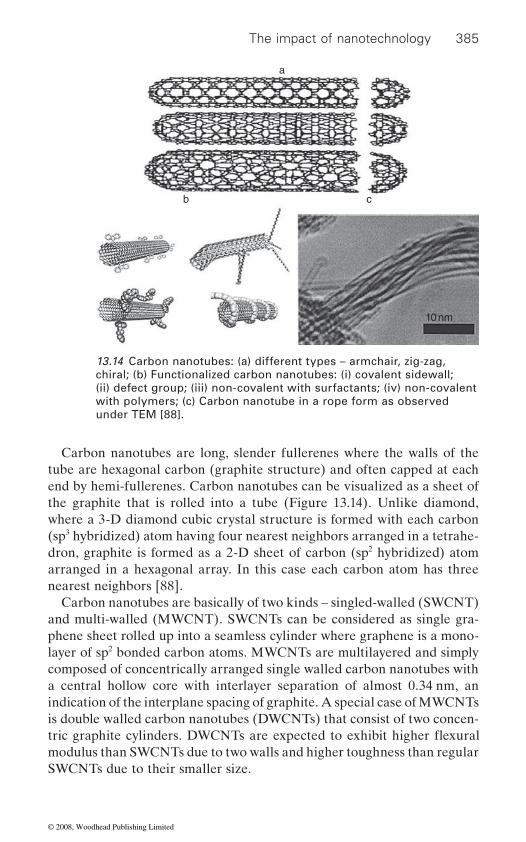
The impact of nanotechnology 385
Carbon nanotubes are long, slender fullerenes where the walls of the tube are hexagonal carbon (graphite structure) and often capped at each end by hemi-fullerenes. Carbon nanotubes can be visualized as a sheet of the graphite that is rolled into a tube (Figure 13.14). Unlike diamond, where a 3-D diamond cubic crystal structure is formed with each carbon (sp3 hybridized) atom having four nearest neighbors arranged in a tetrahe-dron, graphite is formed as a 2-D sheet of carbon (sp2 hybridized) atom arranged in a hexagonal array. In this case each carbon atom has three nearest neighbors [88].
Carbon nanotubes are basically of two kinds – singled-walled (SWCNT) and multi-walled (MWCNT). SWCNTs can be considered as single gra-phene sheet rolled up into a seamless cylinder where graphene is a mono-layer of sp2 bonded carbon atoms. MWCNTs are multilayered and simply composed of concentrically arranged single walled carbon nanotubes with a central hollow core with interlayer separation of almost 0.34 nm, an indication of the interplane spacing of graphite. A special case of MWCNTs is double walled carbon nanotubes (DWCNTs) that consist of two concen-
modulus than SWCNTs due to two walls and higher toughness than regular SWCNTs due to their smaller size.
a
b c
10 nm
13.14 Carbon nanotubes: (a) different types – armchair, zig-zag, chiral; (b) Functionalized carbon nanotubes: (i) covalent sidewall; (ii) defect group; (iii) non-covalent with surfactants; (iv) non-covalent with polymers; (c) Carbon nanotube in a rope form as observed under TEM [88].
tric graphite cylinders. DWCNTs are expected to exhibit higher flexural
© 2008, Woodhead Publishing Limited
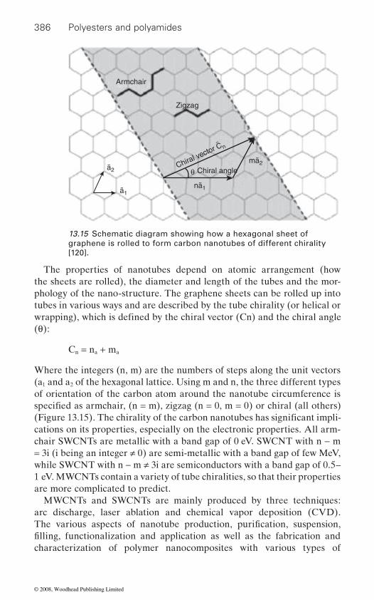
386 Polyesters and polyamides
Armchair
Zigzag
Chiral angleθ
ã1
ã2
nã1
mã2Chiral vector Cn~
13.15 Schematic diagram showing how a hexagonal sheet of graphene is rolled to form carbon nanotubes of different chirality [120].
The properties of nanotubes depend on atomic arrangement (how the sheets are rolled), the diameter and length of the tubes and the mor-phology of the nano-structure. The graphene sheets can be rolled up into tubes in various ways and are described by the tube chirality (or helical or
(θ):
Cn = na + ma
Where the integers (n, m) are the numbers of steps along the unit vectors (a1 and a2 of the hexagonal lattice. Using m and n, the three different types of orientation of the carbon atom around the nanotube circumference is
cations on its properties, especially on the electronic properties. All arm-chair SWCNTs are metallic with a band gap of 0 eV. SWCNT with n − m = 3i (i being an integer ≠ 0) are semi-metallic with a band gap of few MeV, while SWCNT with n − m ≠ 3i are semiconductors with a band gap of 0.5–
are more complicated to predict.MWCNTs and SWCNTs are mainly produced by three techniques:
arc discharge, laser ablation and chemical vapor deposition (CVD).
characterization of polymer nanocomposites with various types of
wrapping), which is defined by the chiral vector (Cn) and the chiral angle
specified as armchair, (n = m), zigzag (n = 0, m = 0) or chiral (all others) (Figure 13.15). The chirality of the carbon nanotubes has significant impli-
The various aspects of nanotube production, purification, suspension,
1 eV. MWCNTs contain a variety of tube chiralities, so that their properties
filling, functionalization and application as well as the fabrication and
© 2008, Woodhead Publishing Limited
The impact of nanotechnology 387
nanotubes have been extensively reported in literature [89]. All known preparations of the carbon nanotubes give mixtures of nanotube chirali-ties, diameters and lengths along with different amounts and types of
tubes an essential requirement before they can be put into any application including synthesis of polymer/CNT nanocomposites.
CNTs exhibit exceptional material properties that are a consequence of their symmetric cage-like structure and exceed those of any previously existing materials. The high aspect ratio of CNTs coupled with a strong intrinsic Van der Waals force of attraction between nanotubes combine to produce ropes and bundles of CNT. SWCNTs where the attractive force is very high (0.5 eV per nm of CNT to CNT contact) are more prone to form ropes and bundles. Ropes refer to collections of SWNTs and are more uniform in diameter to form hexagonal lattices, while bundles are non-crystalline collections of SWCNTs or MWCNTs. It is for this reason that dispersion of CNTs in solvent to produce suspensions, need assistance of either sonication or surfactant addition or both combined besides mechani-cal stirring.
POSS
Polyhedral oligomeric silsesquioxanes (POSS) are an important class of nanostructured hybrid inorganic-organic materials and are widely regarded as one of the most promising and rapidly emerging nanocomposite materi-als. POSS molecules are of nanosized polyhedral or cage-type structure consisting of an inner silicon-oxygen (SiO1.5)x based framework with
silicon-silicon distance of 0.53 nm (Figure 13.16). The ratio of Si : O is 2 : 3.
The average diameter of a POSS molecule is 1.5 nm. The inorganic silicon-oxygen core is thermally and chemically robust. The organic sub-stituents (R) are either totally hydrocarbon in nature or a range of polar structures and functional groups are also included. These organic substitu-ents can be totally reactive or nonreactive or a combination of the two, depending on the synthetic design (Figure 13.16). According to the nature of the organic substituents, they undergo nucleophilic substitution or hydrosilylation. The density of POSS chemicals is typically in the range of 1.12 gm/ml, despite a high molar mass of about 1000 amu. The reason is most of the volume is taken up by the organic (R) groups, which lie on the outside of the cage whereas the core occupies only 5% of the overall cage volume. The physical state (solid, wax or liquid) ranges from low solubility
impurities. This CNT heterogeneity makes purifications of carbon nano-
organic substituents (R) on outer corners and with a precisely defined
© 2008, Woodhead Publishing Limited
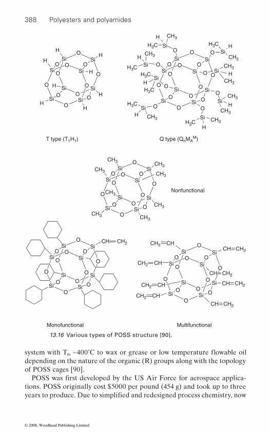
388 Polyesters and polyamides
m
depending on the nature of the organic (R) groups along with the topology of POSS cages [90].
tions. POSS originally cost $5000 per pound (454 g) and took up to three
OO O
O
O
OO
O
O
O
O
O
SiSi
Si
Si
SiCH3
CH2
CH3
Nonfunctional
T type (T1H1) Q type (QnMAM)
Monofunctional Multifunctional
CH3
CH3CH3
CH3
CH3 CH3
CH3
CH3
CH3
CH2
CH3
CH3
H3C H3C
H3C
H3C
H3C
H3C
H3C
CH3
CH3
CH3
Si Si
Si
OO O
O
O
OO
O
O
O
O
O
SiSi
Si
Si
Si
Si SiCH
Si
OO O
O
OO
O
O
O
O O
O
O
OO
O
O
O
O
O
SiSi
Si
Si
Si
Si Si
Si
Si
SiSi
Si
Si
Si
Si
Si
OO O
O
O
OO
O
O
O
O
O
SiSi
Si
Si
Si
H
H
H
HH
H
H
H
H
H
H
H
H
H
H
H
Si Si
Si
OO O
O
O
OO
O
O
O
O
O
SiSi
Si
Si
Si
Si Si
Si
CH2CH
CH2CH
CH2CH
CH2CH
CH2 CH
CH2 CH
CH2 CH
CH2 CH
13.16 Various types of POSS structure [90].
POSS was first developed by the US Air Force for aerospace applica-
years to produce. Due to simplified and redesigned process chemistry, now
system with T ∼400˚C to wax or grease or low temperature flowable oil
© 2008, Woodhead Publishing Limited

The impact of nanotechnology 389
production cost has come down but still it is expensive. A variety of POSS monomers in form of solids or oils are now commercially available from Hybrid Plastics Company Co. (http://www.hybridplastics.com/), USA. A wide range of POSS compounds is now available that contain a combina-tion of covalently bonded reactive functional groups that make them suit-able for polymerization, surface bonding or other chemical transformations [91]. POSS moieties can thus be easily incorporated via copolymerization, grafting or blending into common plastics. POSS incorporated polymeric
resistance, surface hardening and enhanced mechanical properties. Reduc-
also added advantages [92].
13.9
Incorporation of organoclay into a polymer matrix has been used to modify
ties, e.g. enhanced tensile modulus and strength, reduced thermal shrink-age, controlled electrostatic behavior, high storage and reduced loss modulus under dynamic mechanical testing conditions. In addition, pres-ence of hydrophilic clay also enhances moisture absorption (at a slow rate), dyeability, biodegradability and chemical resistance. Since clay platelets block UV irradiation PNCFs exhibit improved weatherability. Reduced
have an edge over their neat counterparts in applications of both domestic and industrial textiles [83, 93–97].
spinning [83]:
• Melt spinning• Solution spinning• Electrospinning.
The major challenges here are achieving maximum extent of intercalation and exfoliation of clays in the polymer matrix (Figure 13.17). Owing to hydrophilic character of clay, the preparation of PCNF is easiest with water-soluble polymers. The increasing nonpolarity and hydrophobic
in an organic matrix. The strategy used to overcome this problem is two-fold:
• Use of compatibilizer.
materials show significant improvements in use temperatures, oxidation
Polymer/clay nanocomposite fibers (PCNF)
the fiber and textile performance. The main effects are in physical proper-
burning rate and form char. With these improved properties, these fibers
PCNFs have been mostly spun through three basic methods of fiber
nature of polymers, makes it more difficult to disperse the hydrophilic clay
• Modification of clay so as to make it organophilic
tions in flammability, heat evolution and viscosity during processing are
flammability of PNCFs arises due to inherent nature of clay to reduce the
© 2008, Woodhead Publishing Limited
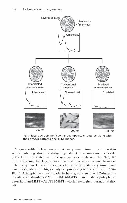
390 Polyesters and polyamides
substituents, e.g. dimethyl di-hydrogenated tallow ammonium chloride (2M2HT) intercalated in interlayer galleries replacing the Na+, K+ cations making the clays organophilic and thus more dispersible in the polymer system. However, there is a tendency of quaternary ammonium ions to degrade at the higher polymer processing temperatures, i.e. 150–180˚C. Attempts have been made to have groups such as 1,2-dimethyl-hexadecyl-imidazulam-MMT (IMD-MMT) and didecyl–triphenyl phosphonium-MMT (Cl2 PPH-MMT) which have higher thermal stability [98].
Layered silicates
Polymer ormonomer
Organoclay
Intercalatednanocomposite
Conventionalcomposite
Intercalated
200 nm 200 nm 200 nm
Conventional Exfoliated
Exfoliatednanocomposite
13.17 Idealized polymer/clay nanocomposite structures along with their WAXD patterns and TEM images.
Organomodified clays have a quaternary ammonium ion with paraffin
© 2008, Woodhead Publishing Limited

The impact of nanotechnology 391
mers but only PNCFs based on polyester (PET) and polyamide (nylon 6
Polyamide-6 (PA 6)/clay nanocomposites have been widely investigated
well as excellent gas and water barrier properties [99–100] over their neat
are reviewed here [101–112].
duced using the melt-spinning route, where nylon 6 chips are compounded with MMT nanoclays during the melt extrusion process using mostly twin-
PA 6/clay by in-situ polymerization technique using double screw reactive extrusion [103]. The molecular weight and weight distribution measured
cate and the amino groups on PA 6.The compounding of MMT clays into polymeric matrix is usually done
on a single or double screw extruder, where the dispersive forces, i.e. shear-ing action inside the barrel, is responsible for breaking the minor compo-
mixer generates better dispersion and distribution mixing and is claimed
be attached to either single or twin-screw extruder.
speed melt spinning process at take-up velocities of 1–5 km/min. The clay
clay at the 2–5-wt% loading. Careful control of drawing conditions such as drawing temperature and ratio and subsequent annealing step are important to get the desired properties and has been investigated by several
development and resultant properties has been reported by several researchers [101, 103–104] but more in detail by Giza et al. [110, 111] from Tokyo Institute of Technology, Japan.
Nanoclay reinforced fibers have been produced from a number of poly-
and nylon 66) are being reviewed in the section below.
13.9.1 Polyamide/clay nanocomposite fibers
PA6 counterparts. However, specific studies on spinning and characteriza-
due to their much superior tensile strength and modulus, improved heat
tion of polyamide/clay nanocomposite fibers have been relatively few and
resistance (heat distortion temperature increases from 65˚C to 120˚C) as
Nylon 6 (PA 6)/clay nanocomposite fibers (PAMC) are generally pro-
screw configuration. Attempts have also been made to spin fibers of
for the polymerized PAMC fibers measured by GPC showed a tendency to first increase and then decrease with increasing screw speed. It succeeded in inserting a covalent linkage between OH-groups of organomodified sili-
nents domain, i.e. clay particle to desired size and get homogeneously
to be orders of magnitude more efficient than shear mixing [83]. Hence
PA 6/clay nanocomposite fibers have also been produced using a high-
used in all these researches is the most widely used organomodified MMT
researchers [102, 104, 106, 110, 117]. The effect of clay on the fiber structure
distributed in the matrix (Figure 13.18). It is reported that extensional flow
the extensional flow mixer has been designed as an inexpensive mixer to
© 2008, Woodhead Publishing Limited

392 Polyesters and polyamides
PA 6 generally crystallizes in two crystalline forms, α form, which is
drawing. The γ form is obtained by fast cooling from the melt notably in
these rapidly turn into alpha crystal form upon drawing. Matrix shearing in between the MMT platelets during drawing imparts better packing and cohesion to hydrogen bonded planes and thus improves their thermal sta-
clay content does not affect the crystallinity values when produced using
Shear
Shear
Shear
Diffusion
Shearing of platelet stacks leads to smaller tactoids
Organoclay particle(~ 8 μm)
(a)
(b)
Platelets peel apart by combined diffusion/shear process(c)
Stacks of silicateplatelets or tactoids
Stress = η γ
13.18 Mechanism of exfoliation of clays: (a) organoclay particle break up; (b) clay tactoid break up; (c) platelet exfoliation.
fibers spun at moderate spinning rates. The nanoclays in PA 6/clay nano-
monoclinic, and metastable γ form, which is pseudohexagonal. The α form
composite fibres are reported to behave as γ-nucleating agents in both injection molded samples as well as oriented spun fibers [112]. However,
bility as compared to those of neat PA 6 fibers [112]. PA 6/clay composite
generally grows by slow cooling from the melt or develops on annealing or
fibers also showed higher crystallinity in the case of whole take up range (1–5 km/min) as compared to neat PA 6 fibers (1–7 km/min) although the
high speed spinning much. The PA 6/clay fibres when spun at such high
© 2008, Woodhead Publishing Limited

The impact of nanotechnology 393
speeds show better orientation of crystalline entities and also higher bire-fringence values, but only in the low take up region (up to 3 km/min). The
velocities but tenacity was higher only in low temperature velocity region where crystallization in the spin line of neat PA 6 did not occur yet [110,
and lower molecular orientation, which explains the observation of no sig-
of intercrystalline regions and role of rigid clay particles in stress transmis-sion behavior explains the superior modulus in PA 6/clay nanocomposite
Apart from improved mechanical properties the presence of clay in
presence of clay in PA 6 induces γ crystalline form, increases the crystalli-
content observed improves the accessibility for disperse dyes. Thus PA 6/
while it gives opposite effect with acid and metal complex dyes. In both
effect and at low cost [108, 109].
as revealed by a number of research studies and patents reported in the literature [113–119]. Poly (ethylene terephthalate), PET/MMT clay nano-composites are generally prepared by in situ interlayer polymerization
ratios. The nanocomposite is prepared by mixing ethylene glycol, dimethyl
0.001–1.0% additives and/or 0.001–1.0% catalyst (oxide acetate of Sb, Ge,
MMT clays are mostly phosphonium cationic salt [94, 113], which make
high temperatures involved during PET polymerization. The clay is gener-ally well dispersed in the PET matrix as observed under scanning (SEM)
tals in the spin line, which started at 2 km/min for PA 6/clay fiber and at 4 km/min for neat PA 6 fiber as revealed by WAXD studies. The PA 6/clay
orientation induced crystallization led to direct formation of α form crys-
nanocomposite fibers showed superior Young’s modulus at all take up
111]. Thus nylon 6/clay nanocomposite fibers show reduced crystallinity
nificant improvements in tenacity in most of the studies. However, stiffness
fibers.
clay yarn dyes itself faster with disperse dyes than an unfilled PA 6 yarn
PA 6/clay fibers also affects its dyeing ability. The DSC studies show that
cases, nanoclay fixes on the amino sites and thus prevents fixation of acid or metal complex dyes [103]. The incorporation of clay in PA 6 fibers also
13.9.2 Polyester/clay based nanocomposite fibers
There are significant opportunities for enhancing the properties of polyes-ter fibers by incorporation of inorganic layered silicate nanoclays (MMT),
[113–115] and then melt spun to produce monofilaments with varying draw
terephthalate in the presence of organically modified silicate (0.5–15%),
Ti or Sn) and then polymerizing it [114]. The organic modifiers used for
the organomodified clays thermally stable and thus able to withstand the
leads to improved fire resistance and lowered flammability properties, thus
zation temperature and decrease the melting point. A higher amorphous
offering a new promising route for flame retardant textiles with permanent
© 2008, Woodhead Publishing Limited

394 Polyesters and polyamides
and transmission electron microscopes (TEM), but some clays were agglomerated at a size level in the range 10–20 nm [116]. The interlayer
enhanced because of the strong shear stresses during melt spinning [117].
been studied as a function of organoclay content and the draw ratio (DR)
thermal stability and mechanical properties as compared to their neat counterparts [116] even at low organoclay contents (<5 wt.%). The com-
and low shrinkage. The tensile properties generally increase with increas-
draw ratio (DR 1–6) and also higher clay content beyond a critical concen-tration [94, 118]. DSC and WAXD test results show that incorporation of clay generally accelerates the crystallization of PET but the crystallinity
the motion of PET chains, which developed a special continuous network structure and inhibits thermal shrinkage of PET and also improves other
emission properties are required for tire and tire cords. Polyester tire cords are more attractive for this use but have some weaknesses. PET/clay nano-
disperse dyes and making deep dyeable polyester a possibility [114].
13.10 Carbon nanotube (CNT) based
Nanocomposites based on polymers dispersed with carbon nanotubes and
carbon nanotubes offer immense potential to impart unique mechanical,
low mass density and large aspect ratio, i.e. 300–1000. Some nanotubes are stronger than steel, lighter than aluminum and more conductive than copper. The theoretical and experimental results on single wall carbon nanotubes (SWNTs) show extremely high tensile modulus (640 GPa to
distance of MMT dispersed in the nanocomposite fiber was further
given. The PET/clay hybrid nanocomposite fibers generally show improved
The structure and properties of the PET/clay nanocomposite fibers have
posite fibers also exhibit improved dimensional stability, higher modulus
and orientation of drawn fibers is generally lower than that of drawn neat
ing clay content up to DR = 1. However the values decrease with increasing
thermo-mechanical properties of PET fibers.
PET fibers [95]. The strong interaction between MMT and PET restricted
The PET/clay nanocomposite fibers with improved properties have the potential of finding application in tire cords to reinforce the rubber [96,
composite fibers can overcome some of the weaknesses of the neat PET fibers and thus enhance the stability, uniformity and ride comfort. The
119]. High strength, heat resistance, heat resistant adhesion and low heat
incorporation of clay in polyester fiber also improves its dyeability with
nanocomposite fibers
nanofibers are beginning to receive substantial attention today because the
electrical and thermal properties to polymeric fibers both polyester and polyamides [120]. Carbon nanotubes are characterized by high flexibility,
© 2008, Woodhead Publishing Limited
The impact of nanotechnology 395
1 TPa), tensile strength (150–180 GPa) and failure strains too, of the order of 5 to 20%. SWNTs also possess very high electrical and thermal conductivity (theoretically >6000 W/m−1k−1). Depending on their structural
nanocomposites based on CNTs were reported by Ajayan et al. in 1994 [121, 122]. The major challenges in polymer/CNT nanocomposites are as follows.
The ‘less than ideal’ and inconsistent nature of CNTs: all known methods of CNT production, give a mixture of CNTs with different chiralities, diameters and lengths, along with varying amount of impurities and struc-tural defects within the sample or that from different batches. Hence, it is
a polymer matrix is also very crucial to achieving the predicted properties. Due to Van der Waals interaction, SWNTs typically form bundles of 30 nm in diameter containing several hundred tubes within a bundle. These tubes are also highly entangled and the degree of entanglement depends on their length. Various physical and chemical approaches have been tried to disperse them, which include sonication, choosing the correct dispersion medium and use of surfactants to aid in dispersion [123]. Another great
matrix, which means ensuring a good interfacial interaction between the two; CNTs being inert, are not easily dispersed and will not interact with most of polymer matrix systems.
The approaches used are to functionalize the CNTs by oxidation, end cap functionalization with long aliphatic amines and sidewall functional-
functional groups on CNTs has also been reported, which improves their dispersion as well as the interfacial interaction [125]. Non-covalent func-tionalization is achieved by adsorbing different polymers onto SWNT to improve dispersion. The SWNT solubilization by ‘polymer wrapping’ is also an alternative method for tuning the interfacial properties of nano-tubes [126] (Figure 13.14).
very critical role in imparting high tensile properties in CNT based poly-3
loading. However, large scale economic synthesis of CNTs and the ability to synthesize CNTs of uniform diameter and chirality will be critical to the commercial success of this new advanced class of materials for both
parameters, SWNTs can be metallic or semi-conducting [120]. The first
very difficult to obtain reproducible results [120]. Dispersion of CNTs in
challenge is the efficient translation of CNT properties into the polymer
Carbon nanotube orientation preferentially along the fiber axis plays a
meric nanocomposite fibers. SWNTs with a density of 1.3 g/cm have the potential of producing a high performance fiber with at least twice the specific tensile strength and specific tensile modulus of the presently known
molded parts, films as well as fiber forms. The CNT based polyester and
state-of-the-art PAN based carbon fiber [120, 123, 127] even at very low
polyamide nanocomposite fibers will be reviewed in this section.
ization using fluorination, alkylation, etc. [124]. Polymer grafting to create
© 2008, Woodhead Publishing Limited

396 Polyesters and polyamides
align the CNTs in one particular direction during the process of melt spin-ning and the subsequent drawing step. However one of the obstacles to widespread use of application of the nanotubes is the inability to orient them in one particular direction. Jose and coworkers at University of Alabama at Birmingham [128], focused on aligning carbon nanotubes in Vectra (a thermotropic liquid crystalline polymer) as well as polypropylene
centages (0.5% and 1.0%) were used. Correlation of CNT alignment along
cal properties, i.e. tensile strength and modulus and a substantial increase in onset of decomposition temperature indicated both a good dispersion as well as a highly aligned CNT system.
crystal polymer matrix by Rohatgi et al. [129]. The tensile properties were
and other parameters related to the extrusion process. There is a noticeable
There are several reports on nylon/CNT nanocomposites, where CNTs
polymer through liquid route using sonication or dry route followed by melt mixing in a single or twin screw extruder [130]. Alignment of CNTs and CNFs in the compositions was enforced during extrusion or subse-quent stretching process. However, fullest potential of CNT reinforcement
ily because of lack of alignment or failure to develop strong interfacial bonding between CNTs and polymer.
Mahfug and co-workers [131] report a method to fabricate nylon 6/CNT reinforcement, where the MWNT reinforcement at low loading (<1 wt%) leads to 50% increase in tensile strength which is almost twice that of unreinforced nylon and never reported elsewhere in the literature. The spectacular enhancement of mechanical properties is attributed to the suc-cessful alignment of CNTs and the high interfacial shear strength devel-oped during the fabrication process. The methodology described by them is different from that generally reported and involves special distributive
13.10.1 Polyester/CNT based nanocomposite fibers
Oriented polymer systems such as fibers provide a unique opportunity to
matrix during melt spinning into fibers. CNTs in two different weight per-
the fiber axis and dispersion in the polymer matrix was studied using TEM (Transmission Electron Microscopy). Significant improvement in mechani-
develop in vapor grown carbon nanofibers (VGCF) dispersed in a liquid
sensitive to the diameter of extruded filament, the amount of VGCF added
Inherent hierarchical structure was observed in the form of fibrils that
increase in mechanical properties of composite filaments with decreasing filament diameter irrespective of VGCF content.
13.10.2 Polyamide/CNT nanocomposite fibers
(single or multiwalled) or CNFs (carbon nanofibers) are infused into the
has not been harnessed in polyamide/CNT nanocomposite fibers, primar-
© 2008, Woodhead Publishing Limited
The impact of nanotechnology 397
mixing of CNTs using a specially designed die and a prolonged thermal stabilization process prior to melt extrusion. These polyamide/
textile materials in several technical and advanced composite applications [132].
2
2
2
PET/SiO2 nanocomposites were synthesized using in situ polymerization 2
tures such as cracks, craters and cavities introduced due to this facilitated 2
age [136]. The silica nanoparticles get well dispersed in PET in the range 10 nm with narrow distribution. On the other hand, PET/TiO2 nanocom-
introduce functional groups on surface of titania particles and thus aid in dispersion of nanoparticles homogeneously. The UV protection property
index and absorption of UV light by the rutile form of nanotitania incor-
range of other nanoparticles also, i.e. TiO2, SiO2, ZnO and CaCO3. The nanoparticles are treated with low surface tension additive before mixing with PET [138].
and better retention of modulus at higher temperatures [139]. These
However, the extent of reinforcement was found to be variable in the case of PET systems, which can be either due to low interaction between PET and POSS causing processing problems related to some water generation or chemical transformation of the POSS particles them-selves [141].
CNT nanocomposite fibers have a great potential for use as multifunctional
coupling agents prior to mixing with molten PA6. The composite fibers
13.11 Nanoparticle based nanocomposite fibers
showed improved mechanical properties as compared to pure PA 6 fibers
Preparation of PA 6/nano titanium dioxide (TiO ) composites and their
and composite fibers with unmodified TiO .
Shanghai, China. The nanoscaled TiO particles were surface treated with
fi bers showed a greater degree of weight loss as compared to pure PET
spinnability has been reported by Zhu et al. [133] of Dong Hua University,
fibers when they were hydrolyzed using alkali treatment. Superfine struc-
and melt spun into fibers. The fibers PET/SiO nanocomposite [134, 135]
deep dyeing of PET/SiO nanocomposite fibers. PET/silica as spun nano-
posite fibers have been prepared by in situ polycondensation and melt
composite fibers show improved tenacity, modulus and lower heat shrink-
spinning [137]. Nanotitania were first treated with a coupling agent to
of these fibers was much enhanced (UPF > 50) because of high refractive
porated. However, these fibers had slightly reduced tensile strength and elongation at break. PET nanocomposite fibers have been reported with a
POSS based nanofillers have been incorporated in PET and polyamide fibers/filaments and show improved thermomechanical properties
f ibers can find application in automotive tire reinforcement [140, 141].
© 2008, Woodhead Publishing Limited

398 Polyesters and polyamides
2
weight. These unique properties of nanofi bres make them potential candi-
tissue engineering [142].
13.12.1 Electrospinning
The manufacturing technique most commonly associated with polymeric
ventional fi ber production techniques, and is based on electrostatic forces. The idea dates back at least 60 years, but recent interest has been renewed by the pioneering work done by Dr Darryl Renekar at the University of Akron [143], who demonstrated electrospinning for a wide variety of polymer solutions including rigid rod polymers. The basic theory of the
much reviewed [144–147].Electrospinning is a process that produces continuous polymeric nano-
polymer is dissolved in a solvent (polymer melts can also be used) and placed in a glass capillary, which is sealed at one end and a small opening in a necked down portion at other end. A high voltage potential (730 kV)
the capillary tube (Figure 13.19). When a voltage is applied to the polymer solution, the electric force results which cause a jet of polymer solution
whips into a complex path and other changes in shapes occur, during which electrical forces stretch and thin it at very large ratios (about 100 000) in a short distance and in less than one second. After the solvent evaporates,
generally viewed under the scanning electron microscope (SEM) (Figure 13.20).
13.12 Nanofibers
Recently, there has been an increased interest in producing nanofibers that
fiber diameter ranges from 2000 to 5000 nm, whereas polymeric nanofibres ranges from 50 to 500 nm. Nanofibers are characterized by an extraordi-narily high surface area per unit mass (for instance nanofibers with 100 nm
are submicron size in diameter. Typically conventional melt blown ultrafine
in diameter have a specific surface of 1000 m /g) high porosity and light-
dates for a wide range of applications such as filtration, barrier fabrics,
nano-fiber spinning process and the parameters affecting the process,
protective clothing, wipes and biomedical applications such as scaffolds for
nanofibers is electrospinning, which is fundamentally different from con-
thermal and mechanical properties of electrospun nanofibers has been
fibres (diameter in the submicron range) through an action of an external electric field imposed on a polymer solution or melt. In this technique, a
solidified nanofibers are left, mostly in nonwoven web form on the collec-tor. This nanofiber deposition cannot be seen by the naked eye and is
flowing from a droplet tip to be drawn toward a grounded collector.
is then applied between the polymer solution and a collector near end of
After the jet flows away from droplet in a nearly straight line, it bends and
© 2008, Woodhead Publishing Limited

The impact of nanotechnology 399
Syringe pump
Syringe
Polymer solution
HV power supply
Needle to target(working) distance
Movable jack
13.19 Schematic diagram of electrospinning set-up [153].
(a)(b)
13.20 SEM images of (a) electrospun nanofibrous web, (b) cotton yarn coated with nanofibrous web.
© 2008, Woodhead Publishing Limited

400 Polyesters and polyamides
The electrospinning process can be considered as a variation of the electrospraying process. In the electrospraying process, the surface of a hemispherical liquid drop suspended in equilibrium at the end of the capil-lary will be distorted into a conical shape in the presence of an electrostatic
charge distribution on the surface of the drop with the surface tension of the liquid causes this distortion. Once a critical voltage (Vc) is exceeded, a stable jet of liquid is ejected from the cone tip. The jet breaks into drop-lets as a result of surface tension in the case of low viscosity liquids. For high viscosity liquids the jet does not break up, but travels to the grounded
to obtain aerosols and when applied to polymer solution and melts (second
(Figure 13.21) [147]. The morphological studies indicate that electrospin-
tion and crystallization.Most of the literature on electrospinning has explored a variety of
studies have addressed the processing/property relationships in electro-
dominantly determined by the synergistic effect of solution parameters and electrostatic forces. Processing parameters considered are solution concen-tration and viscosity effects, spinning atmosphere effects, accelerating voltage effects and tip to target distance [146, 147]. Solution viscosity has
Metal electrode
Electrospinning
High voltagepower supply
Charged fibersCharged drops
Electrospray
Grounded collection plate
V
13.21 Electrospraying and electrospinning set-up [147].
field. A balancing of the responsive forces resulting from the induced
case) it generates polymer nanofibres through the electrospinning route
ning process does partially orient the molecules in fibers, although to date
target. The first case is known as electrospraying and is used in industries
all nanofibers produced are without any control over forces during orienta-
polymer/solvent systems from which fibers can be produced. Only a few
spun fibers. The structure and property of electrospun nanofibers are pre-
been found to influence fiber diameter, initiating droplet size and jet trajec-
© 2008, Woodhead Publishing Limited
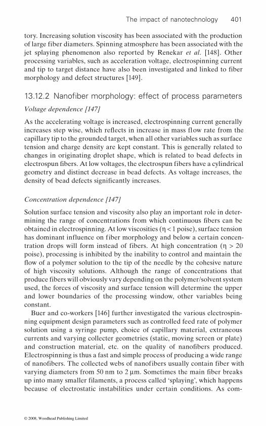
The impact of nanotechnology 401
tory. Increasing solution viscosity has been associated with the production
jet splaying phenomenon also reported by Renekar et al. [148]. Other processing variables, such as acceleration voltage, electrospinning current
morphology and defect structures [149].
Voltage dependence [147]
As the accelerating voltage is increased, electrospinning current generally
capillary tip to the grounded target, when all other variables such as surface tension and charge density are kept constant. This is generally related to changes in originating droplet shape, which is related to bead defects in
geometry and distinct decrease in bead defects. As voltage increases, the
Concentration dependence [147]
Solution surface tension and viscosity also play an important role in deter-
obtained in electrospinning. At low viscosities (η < 1 poise), surface tension
poise), processing is inhibited by the inability to control and maintain the
of high viscosity solutions. Although the range of concentrations that
used, the forces of viscosity and surface tension will determine the upper and lower boundaries of the processing window, other variables being constant.
ning equipment design parameters such as controlled feed rate of polymer solution using a syringe pump, choice of capillary material, extraneous currents and varying collecter geometries (static, moving screen or plate)
because of electrostatic instabilities under certain conditions. As com-
of large fiber diameters. Spinning atmosphere has been associated with the
and tip to target distance have also been investigated and linked to fiber
13.12.2 Nanofiber morphology: effect of process parameters
electrospun fibers. At low voltages, the electrospun fibers have a cylindrical
density of bead defects significantly increases.
mining the range of concentrations from which continuous fibers can be
tration drops will form instead of fibers. At high concentration (η > 20
produce fibers will obviously vary depending on the polymer/solvent system
and construction material, etc. on the quality of nanofibers produced.
of nanofibers. The collected webs of nanofibers usually contain fiber with
Buer and co-workers [146] further investigated the various electrospin-
varying diameters from 50 nm to 2 μm. Sometimes the main fiber breaks
Electrospinning is thus a fast and simple process of producing a wide range
up into many smaller filaments, a process called ‘splaying’, which happens
increases step wise, which reflects in increase in mass flow rate from the
has dominant influence on fiber morphology and below a certain concen-
flow of a polymer solution to the tip of the needle by the cohesive nature
© 2008, Woodhead Publishing Limited
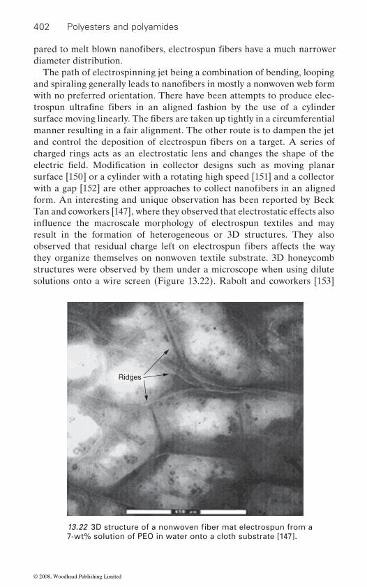
402 Polyesters and polyamides
diameter distribution.The path of electrospinning jet being a combination of bending, looping
with no preferred orientation. There have been attempts to produce elec-
manner resulting in a fair alignment. The other route is to dampen the jet
charged rings acts as an electrostatic lens and changes the shape of the
surface [150] or a cylinder with a rotating high speed [151] and a collector
form. An interesting and unique observation has been reported by Beck Tan and coworkers [147], where they observed that electrostatic effects also
result in the formation of heterogeneous or 3D structures. They also
they organize themselves on nonwoven textile substrate. 3D honeycomb structures were observed by them under a microscope when using dilute solutions onto a wire screen (Figure 13.22). Rabolt and coworkers [153]
Ridges
7-wt% solution of PEO in water onto a cloth substrate [147].
pared to melt blown nanofibers, electrospun fibers have a much narrower
and spiraling generally leads to nanofibers in mostly a nonwoven web form
trospun ultrafine fibers in an aligned fashion by the use of a cylinder surface moving linearly. The fibers are taken up tightly in a circumferential
and control the deposition of electrospun fibers on a target. A series of
electric field. Modification in collector designs such as moving planar
with a gap [152] are other approaches to collect nanofibers in an aligned
observed that residual charge left on electrospun fibers affects the way
13.22 3D structure of a nonwoven fiber mat electrospun from a
influence the macroscale morphology of electrospun textiles and may
© 2008, Woodhead Publishing Limited
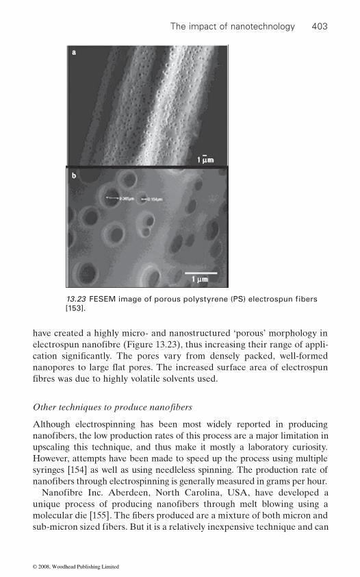
The impact of nanotechnology 403
have created a highly micro- and nanostructured ‘porous’ morphology in
Although electrospinning has been most widely reported in producing
upscaling this technique, and thus make it mostly a laboratory curiosity.
syringes [154] as well as using needleless spinning. The production rate of
a
b
1 μm
1 μm
[153].13.23 FESEM image of porous polystyrene (PS) electrospun fibers
electrospun nanofibre (Figure 13.23), thus increasing their range of appli-cation significantly. The pores vary from densely packed, well-formed
fibres was due to highly volatile solvents used.
Other techniques to produce nanofibers
nanofibers, the low production rates of this process are a major limitation in
nanofibers through electrospinning is generally measured in grams per hour.
However, attempts have been made to speed up the process using multiple
Nanofibre Inc. Aberdeen, North Carolina, USA, have developed a unique process of producing nanofibers through melt blowing using a molecular die [155]. The fibers produced are a mixture of both micron and sub-micron sized fibers. But it is a relatively inexpensive technique and can
nanopores to large flat pores. The increased surface area of electrospun
© 2008, Woodhead Publishing Limited
404 Polyesters and polyamides
produced is a concern. If perfected this technique can certainly take nano-
as compared to electrospinning.
split or dissolve. The most researched is the production of islands in the
of diameters approx (300 nm) can be produced using EVOH as sea polymer, and the ratio being 50/50. Unlike electrospinning and melt blown tech-
cost is 1 to $5 per kg. Another possible approach is the use of bicomponent
number of segments needs to be greater than 16 and use a water-soluble polymer in a small ratio along with PET and PA 6 [156].
Toray Industries Inc. [157] have developed a new technology for produ-
is in nanorange. The technology is versatile not only in its ability to be applied to commodity polymers such as nylon or polyester, but also in that
having uniform diameter in nanorange through optimization of rheological
promise a variety of applications as advanced materials. The moisture
than conventional nylon, which is comparable to cotton.In another ongoing NTC project at Georgia Tech, USA [158], a unique
polymerization’ through mesoporous silica and aluminum channels as nanoreactors is being investigated (Figure 13.24). Unlike electrospun
technique will possesses high mechanical properties as they have a high degree of crystallinity from extended chain crystals formed inside the nanochannels.
produce nanofibers in large quantities at a cost of $10 per kg. Although it is a relatively inexpensive technique and can produce nanofibers in large quantities at a cost of US$10 per kg, the broad range of fiber diameters
fiber production to a commercial future because of higher production rates
The other technique is that based on making bicomponent fibers that
sea fiber using a standard spin/draw process. The production rate is 5 kg/h at a take up speed of 2500 m per minute. Both PET and PA 6 nanofibers
nique, the nanofibers produced are in a narrow range and the projected
fiber spinning to manufacture nanofibres by the splitting process. The
cing multifilament nanofibers comprising monofilaments whose diameter
nanofibers can be manufactured using existing production equipment.
of products while the orientation and shape of the nanofibers can be easily
They have succeeded in producing for the first time nylon nanofibres
controlled, enabling their application to be extended into various fields.
properties of polymers themselves. Since nylon nanofibers are of multifila-
The nylon nanofibers produced have about 1000 times larger surface area than conventional fibers, thus adsorption and adhesion properties and
ment continuous structure, they can be easily fabricated into a wide array
novel functions attributable to fiber surface are also more pronounced and
absorption of these nylon nanofibers is about two to three times higher
method of producing nylon and polyester nanofibers using ‘extrusion
nanofibers, which are neither strong nor stiff, the polymer molecules in these fibers are not oriented. The nanofibers produced using this new
© 2008, Woodhead Publishing Limited

The impact of nanotechnology 405
produced mostly through electrospinning from a wide range of polymeric materials [159] but other techniques as described above [160] also show a
from polymer nanocomposites, incorporating nanoclays, CNTs and other
also been reported based on MMT clay [162, 163, 164] as well as CNT as
through electrospinning at varying CNT content [166]. These composite
13.24 (a, b, c) Alumina nanochannels as prepared (pore size ∼40 nm), (d, e, f) pore formation and widening (pore size ∼100 nm), (e, f) longitudinal structure of nanochannels for alumina [158].
Thus, new researches in producing nanofibers in a continuous and aligned mono- or multi-filament form with more uniform diameter and narrow range have a potential to bring nanofibers in the market place, at a reasonable price and acceptable production rates. Nanofibers have been
lot of promise in the future success of nanofibers.
Polymer nanocomposite based nanofibers
nanoparticles and adding a new dimension to nanofibers. Fong et al. [161]
solvent. The resulting nanofibers had highly aligned MMT layers (normal
Recently, electrospinning has also been extended to making nanofibers
to fiber axis) and nylon 6 crystallites (layer normal/parallel to f iber axis). Other polyamide 6,6 or polyamide nanocomposite electrospun fibers have
nanofiller [165]. Polyester/CNT composite nanofibers have been produced
were the first to report electrospun nanofibers (∼100 nm) based on nylon
fibers can be further used to manufacture fabrics, antistatic materials,
6/exfoliated MMT clay using hexafluoro-iso-propanol (HFIP) as the
© 2008, Woodhead Publishing Limited
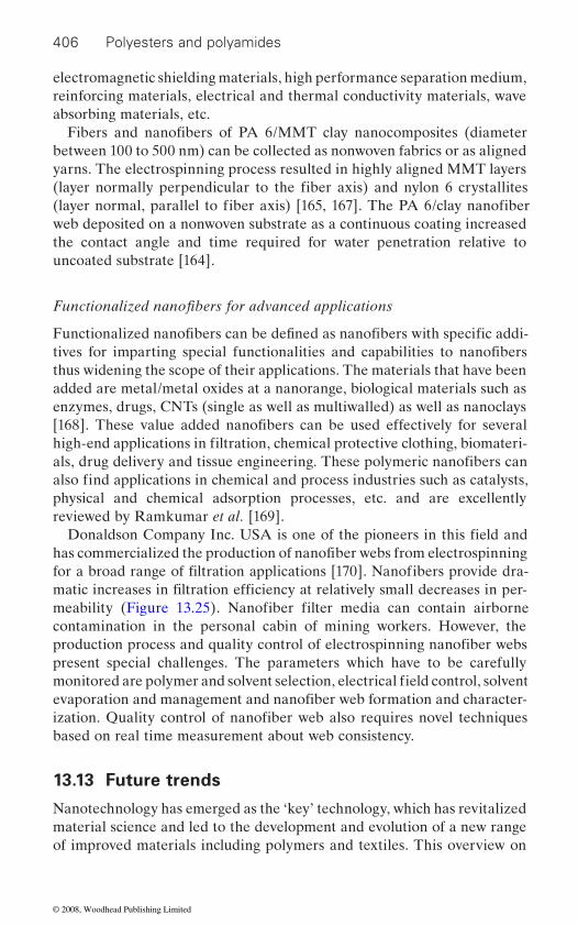
406 Polyesters and polyamides
electromagnetic shielding materials, high performance separation medium, reinforcing materials, electrical and thermal conductivity materials, wave absorbing materials, etc.
between 100 to 500 nm) can be collected as nonwoven fabrics or as aligned yarns. The electrospinning process resulted in highly aligned MMT layers
web deposited on a nonwoven substrate as a continuous coating increased the contact angle and time required for water penetration relative to uncoated substrate [164].
added are metal/metal oxides at a nanorange, biological materials such as enzymes, drugs, CNTs (single as well as multiwalled) as well as nanoclays
physical and chemical adsorption processes, etc. and are excellently reviewed by Ramkumar et al. [169].
contamination in the personal cabin of mining workers. However, the
present special challenges. The parameters which have to be carefully
based on real time measurement about web consistency.
13.13 Future trends
Nanotechnology has emerged as the ‘key’ technology, which has revitalized material science and led to the development and evolution of a new range of improved materials including polymers and textiles. This overview on
Fibers and nanofibers of PA 6/MMT clay nanocomposites (diameter
(layer normally perpendicular to the fiber axis) and nylon 6 crystallites (layer normal, parallel to fiber axis) [165, 167]. The PA 6/clay nanofiber
Functionalized nanofibers for advanced applications
Functionalized nanofibers can be defined as nanofibers with specific addi-tives for imparting special functionalities and capabilities to nanofibers
[168]. These value added nanofibers can be used effectively for several high-end applications in filtration, chemical protective clothing, biomateri-
thus widening the scope of their applications. The materials that have been
also find applications in chemical and process industries such as catalysts,
Donaldson Company Inc. USA is one of the pioneers in this field and
for a broad range of filtration applications [170]. Nanofibers provide dra-
als, drug delivery and tissue engineering. These polymeric nanofibers can
matic increases in filtration efficiency at relatively small decreases in per-
has commercialized the production of nanofiber webs from electrospinning
meability (Figure 13.25). Nanofiber filter media can contain airborne
production process and quality control of electrospinning nanofiber webs
monitored are polymer and solvent selection, electrical field control, solvent evaporation and management and nanofiber web formation and character-ization. Quality control of nanofiber web also requires novel techniques
© 2008, Woodhead Publishing Limited
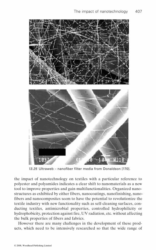
The impact of nanotechnology 407
the impact of nanotechnology on textiles with a particular reference to polyester and polyamides indicates a clear shift to nanomaterials as a new tool to improve properties and gain multifunctionalities. Organized nano-
textile industry with new functionality such as self-cleaning surfaces, con-ducting textiles, antimicrobial properties, controlled hydrophilicity or
However there are many challenges in the development of these prod-ucts, which need to be intensively researched so that the wide range of
13.25 Ultraweb – nanofiber filter media from Donaldson [170].
structures as exhibited by either fibers, nanocoatings, nanofinishing, nano-fibers and nanocomposites seem to have the potential to revolutionize the
hydrophobicity, protection against fire, UV radiation, etc. without affecting the bulk properties of fibers and fabrics.
© 2008, Woodhead Publishing Limited
408 Polyesters and polyamides
applications envisaged can become a commercial reality. An excellent dispersion and stabilization of the nanoparticles in the polymer matrix is crucial to achieving the desired nano effects. The tendency to agglomerate due to an extremely high surface area is the major problem facing the
combining them with functional surface-active polymers can bring the
properties. More and more companies have specialized in making stable dispersions of ZnO, Ag, SiO2, etc. through the surface engineering of nanoparticles.
ture, weatherability, moisture and dye absorption, reduced shrinkage,
achieved with a small increase in density and cost. The most popularly used
thetic clays with well-controlled and reproducible geometry and composi-tion also need to be further explored. Incorporation of only a few percent
However dispersion and exfoliation of carbon nanotubes continue to be a challenge. Large-scale economic synthesis of CNTs particularly MWCNTs and SWCNTs with controlled diameter and chirality will largely determine
scaffolds for tissue engineering, vehicles for controlled delivery of medi-cines and pesticides and more recently for biosensor applications. However,
aligned morphology will play a crucial role in their future commercial success.
nanotechnology based technical textiles by the year 2010 is illustrated in Figure 13.26. There is however a word of caution and the issues of concern are:
(a) Large scale production of nanoparticles and their cost(b) Impact of uncontrolled release of nanoparticles in the environment
and their effect on human health and ecology widely covered under the domain ‘nanotoxicology’
(c) Practical philosophy and ethics on the widespread use of nanotech-nology based products.
effective incorporation of nanoadditives in coatings/finishing as well as in
nanoparticles onto fibers/textiles without losing their superb, nanoscopic
Nanocomposite fibers based on clay show a lot of promise with their
of carbon nanotubes (CNTs) can significantly alter not only the mechanical
nanofillers are the natural layered silicate clays, i.e. MMT although syn-
properties but also enhance electrical and thermal conductivity of fibers.
the future commercial viability of these products. Nanofibers character-ized by high surface area offer promising applications as efficient filters,
To conclude: nanotechnology definitely has the potential to bring
faster production of nanofibers with controlled diameter, uniformity and
revolution in the field of textiles. Estimated production of different
improved properties such as stiffness, strength, heat deflection tempera-
nanocomposite preparation. Surface engineering of nanoparticles and
flammability, etc, over their neat counterparts. These enhancements are
© 2008, Woodhead Publishing Limited
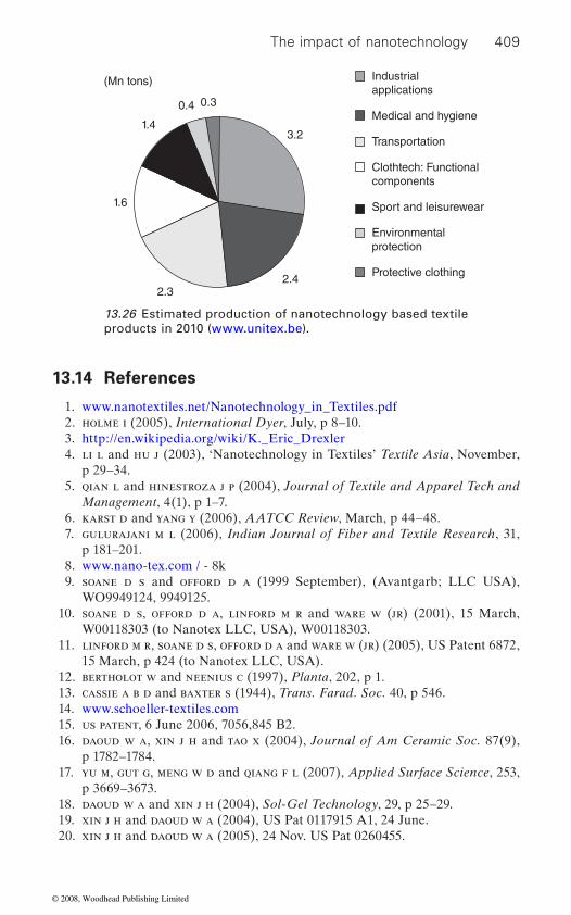
The impact of nanotechnology 409
13.14 References
1. www.nanotextiles.net/Nanotechnology_in_Textiles.pdf 2. holme i (2005), International Dyer, July, p 8–10. 3. http://en.wikipedia.org/wiki/K._Eric_Drexler 4. li l and hu j (2003), ‘Nanotechnology in Textiles’ Textile Asia, November,
p 29–34. 5. qian l and hinestroza j p (2004), Journal of Textile and Apparel Tech and
Management, 4(1), p 1–7. 6. karst d and yang y (2006), AATCC Review, March, p 44–48. 7. gulurajani m l (2006), Indian Journal of Fiber and Textile Research, 31,
p 181–201. 8. www.nano-tex.com / - 8k 9. soane d s and offord d a (1999 September), (Avantgarb; LLC USA),
WO9949124, 9949125. 10. soane d s, offord d a, linford m r and ware w (jr) (2001), 15 March,
W00118303 (to Nanotex LLC, USA), W00118303. 11. linford m r, soane d s, offord d a and ware w (jr) (2005), US Patent 6872,
15 March, p 424 (to Nanotex LLC, USA). 12. bertholot w and neenius c (1997), Planta, 202, p 1. 13. cassie a b d and baxter s (1944), Trans. Farad. Soc. 40, p 546. 14. www.schoeller-textiles.com 15. us patent, 6 June 2006, 7056,845 B2. 16. daoud w a, xin j h and tao x (2004), Journal of Am Ceramic Soc. 87(9),
p 1782–1784. 17. yu m, gut g, meng w d and qiang f l (2007), Applied Surface Science, 253,
p 3669–3673. 18. daoud w a and xin j h (2004), Sol-Gel Technology, 29, p 25–29. 19. xin j h and daoud w a (2004), US Pat 0117915 A1, 24 June. 20. xin j h and daoud w a (2005), 24 Nov. US Pat 0260455.
(Mn tons)
0.30.4
1.4
1.6
2.32.4
3.2
Industrialapplications
Medical and hygiene
Transportation
Clothtech: Functionalcomponents
Sport and leisurewear
Environmentalprotection
Protective clothing
13.26 Estimated production of nanotechnology based textile products in 2010 (www.unitex.be).
© 2008, Woodhead Publishing Limited
410 Polyesters and polyamides
21. bozzi t, yuranova i, guasaquillo l d and kiwi (2005), Journal of Photo-chem. Photobiol. A: Chem., 25, p 156.
22. daoud w a and xin j h (2005), Chem. Commun, (16), p 2110–2112. 23. grier n (1983), Silver and its compounds, Disinfection, Sterilization and
Preservation (Lea and Febiger, Philadelphia), p 375. 24. liau s, read d, pugh w, furr and russell a (1997), Lett. Appl. Microbiol.,
25, p 279. 25. sondi i and sadopek-sondi b (2004), J of Colloid and Interface Science, 275,
p 177–182. 26. keskinen j, ruusskanen p, karttunen m and hannula s p (2001), Appl.
Organometallic Chem, 15(5), p 393. 27. wang h, qiao x, chem. j, wang x and shiyunan d (2005), Mater. Chem. Phys.,
94(2–3), p 449. 28. jixiong y and jiachong c (2003), October 9, US Pat 0190851. 29. burniston n, bygott c and stralton j (2004), Nanotechnology meets TiO2,
Surface Coatings International, Part A, p 179–184. 30. yang h y, zhu s k and pan n (2003), Journal of Applied Polymer Science,
(92), p 3201–3210. 31. saito m (1993), Journal of Coated Fabrics, 23, p 150–164. 32. xiong m n, gu g x, you b and wu l m (2003), Journal of Applied Polymer
Science, 90, p 1923–1931. 33. daoud w a and xin j h (2004), Journal of Sol-gel Science and Technology,
29, p 25–29. 34. xin j h, daoud w a and kong y y (2004), Textiles Research Journal, 74,
p 97–100. 35. wang r h, xin j h, tao x m and daoud w a (2004), Chem. Phys. Letters, 398,
p 250–255. 36. dong w g and huang g (2002), Journal of Textile Research, 23, p 22–
23. 37. z zhou w, chu l s, tang w m and gu l x (2003), Journal of Electrostatics, 57,
p 347–354. 38. wu y, chi y b, nie j x, yu, a p chen x h and ghu h c (2002), Journal of Func.
Polym, 15, p 42–47. 39. xu p, wang w and chen s l (2005), Melliand International, II, p 56–59. 40. anonymous, Gore uses Nanotechnology to make antiseptic work wear safer,
International Newsletter, (2002), p 31.
42. shishoo r (Ed), Plasma Technology for Textiles, Woodhead Publishing Ltd. Cambridge (UK), 2007.
43. kang j y and sarmadi m, 10(2004), AATCC Review, p 28. 44. yasuda h, Plasma Polymerization, Academic Press, New York, 1985. 45. yasuda h, Luminous Chemical Vapour Deposition and Interface Engineer-
ing, Marcel Dekker, New York, 2005. 46. hegemann d (2006), Indian Journal of Fiber and Textile Research, 31,
p 99–115. 47. samanta k, jassal m and agarwal a k (2006), Indian Journal of Fiber and
Textile Research, 31, p 83–89. 48. www.empa.ch
41. www.toray.com/rows/fibers/nr041022.html, 30 k.
© 2008, Woodhead Publishing Limited
The impact of nanotechnology 411
49. besch w, schroder k and ohl a (2005), Plasma Process Polymerization, 2, p 563.
tion of polymers for improved adhesion: A critical review’ in H Strobel, C S
vance to Adhesion, VSP, Netherlands, p 3–42. 51. hocker h (2002), Pure Applied Chemistry, 74, p 23. 52. ivan h, michael j, henrich k and viera s (2006), e-Journal of Soft Materials,
2, p 25–30. 53. wrobel a m and wertheimer m r (1990), in R D Agastino (ed.) Plasma
Deposition, Treatment and Etching of Polymer (Academic Press, San Diego, USA), p 163.
54. hegemann d, schiultz u and fi scher a (2005), Surface Coat Technology, 200, p 458.
55. hegemann d, brunner h and oehr c (2001), Plasma Polymn, 6, p 221. 56. oktem t, seventekin n, ayhan h and piskin e (2005), Turk J Chem, 24,
p 275. 57. detomasa l, gristina r, senesi g s, agostinno r d and favia p (2005), Bio-
mater (2005), 26, p 3831. 58. cireli a, kutlu b and mutlu m (2007), Journal of Applied Polymer Science,
104, p 2318–2322. 59. szymanowski h, sobezyk a, gazicki-lipman m, jakubowski w and klimeck l
(2005), Surface Coated Technology, 200, p 1036. 60. hegemann d, hossain m m and balasz d j (2007), Progress in Organic Coat-
ings, 58, p 237–240. 61. caruso r a and antomitte m (2001), Chem. Mater. 13, p 3272–3282. 62. zhai l, cebeci f c, cohen r e and rubner m f (2004), Nanoletters, 4(7),
p 1349–1353. 63. bravo j, zhai l, cohen r e and rubner m f (2007), Langmuir, 23,
p 7293–7298. 64. bantchev g b, lu e z, agrawal s, mangipol g g and lvov y (2006), Abstracts,
62nd Southwest Regional Meeting of Am. Chem. Soc., Houston, TX, USA, October, p 19–22.
65. dubas s t, kumlangdudsana p and potiyaraj p (2006), Colloids and Surfaces A: Physiochemical Engg. Aspects, 289, p 105–109.
66. hyde k, rusa m and hinestroza j (2005), Nanotechnology, (16), S422–S428.
67. joshi m, khanna r, shekhar r and ghangas p (under communication) 68. zhou s, wu l, sun j and shen w (2002), Progress in Organic Coatings, 45,
p 33–42. 69. nano and hybrid coatings: Conference http://www.pra.org.UK/confer-
ences/nanohybridcoatings/index.htm 70. joshi m, banerjee k, prasanth r and thakare v (2006), IJFTR, March,
p 202–214. 71. xu r, manias e, snyder a j and runt (2003), Journal of Biomedical Research,
64 A, p 114–119.
News, November, p 13.
50. liston e m, martinu l and weithermer m r (1994), ‘Plasma surface modifica-
Lyons and K L Mittal (eds) Plasma Surface Modification of Polymers: Rele-
72. passowith s (2001), ‘These balls could bounce all the way to Profit’, Business
© 2008, Woodhead Publishing Limited
412 Polyesters and polyamides
73. twardowski t (1995), Nanocomposites, Presented at the meeting of Society of Plastic Engineers, (Philadelphia Section) November, http://www.nsf.gov/cgi.bin
74. pratsinis s (2004), Nanoparticles: Synthesis and Applications, ETH Zurich, CH, Nanotech Conference Technical Program Abstract.
75. dagani r (1999), Chemical Engg. News, 70, p 25. 76. krishnamoorti r and vaia r a (Eds) (2001), Polymer Nanocomposites: Syn-
thesis, Characterization and Modeling, (Oxford University Press). 77. ajayan p m, schadler l s and braun p v (Eds) (2003), Nanocomposite Science
and Technology, (Wiley VCH). 78. schimdt h (1990), Polymer based Molecular Nanocomposites, (Ed.) Schaefer
D W and Mark J E, Materials Research Society, Pittsburg. 79. okada a and usuki a (2006), Macromolecular Materials and Engineering,
291(12), p 1449–1476. 80. brauer s, Polymer Nanocomposites, www.bccreaserch.com./plastics/p234.
html. 81. vaia r a (2002), ‘Polymer Nanocomposites open a new Dimension for Plastics
and Composites’, AMPTIAC Quarterly-A look inside nanotechnology, 6(1), p 17–24. http://www.amptiac.alionscience.com/pdf/AMPQ6.
82. utracki l a (2004), Clay-Containing Polymeric Nanocomposites, RAPRA, Shawbury, Shropshire, UK.
83. utracki l a (2006), ‘Fibers from Polymeric Nanocomposites’, Indian Journal of Fiber and Textile Research, 31, p 15–28.
84. alexander m and dubois p (2000), Material Science Engineering, 28, p 1–63.
85. roy s s and okamoto m (2003), Progress Polymer Science, 28, p 1539–1641. 86. pinnavia t j and beall g (Eds) (2001), Polymer-Clay Nanocomposites (John
Wiley & Sons, Inc.). 87. iijima s (1991), Nature, 354, p 56–58. 88. thostenson e t, ren z and chou t w (2001), Composite Science and Technol-
ogy, 61, p 1899–1912. 89. khare r and bose s (2005), ‘Carbon nanotube based composites – A Review’,
Journal of Minerals and Materials Characterization and Engg. 4(1), p 31–46.
90. krishnanan p s g and joshi m (2007), ‘Polysilsesquioxanes: synthesis and application,’ in H S Nalwa (ed.) Polymeric Nanostructures: Synthesis and
91. li g, wang l, niand h and pittman c u jr. (2001), J. Inorg Organomet Polymer, 11, p 123.
92. joshi m and butola b s (2004), Journal of Macromolecular Science, Part-C, Polymer Review, 44, p 389.
93. kim y k, lewis a f, patra p k, warner s b, mhetre s k, shah m a and nam d, Textile Sciences, University of Massachusetts, Dartmouth, USA. ‘Nanocom-posites Fibers (Track id paper#: 112.28), Materials Research Society (The Materials Gateway). http://www.mrs.org.
94. kim s j, mun m u and chang j h (2005), Polymer (Korea), 29(2), p 190–197. 95. xiao w, yu h, han k and yu m (2005), Journal of Applied Polymer Science,
96(6), p 2247–2252.
Applications, American Scientific Publishers, USA, vol-1, p 153–221.
© 2008, Woodhead Publishing Limited
The impact of nanotechnology 413
96. kwon i h, bang y h and lee d j, (Hyosung Corporation, S. Korea). Korean Patent 2005 5090851.
97. yang y and gu h (2006), (Shanghai Jiao Tong University, People’s Republic of China), Chinese Patent CN1760443.
98. chang j h, mun m k and kim j c (2006), Journal of Applied Polymer Science, 102(5), p 4535–4545.
99. yang k and ozisik r (2006), Polymer, 2849, p 47.100. ibanes c, deboissiece m, david l and seguela r (2006), Polymer, 5071,
p 47.101. zhao m, pan x and wang y (2006), Intelligent Journal of Polymer Materials,
55(2), p 147–159 (AN: 1240097).102. seo d h, lee y m and nam j d (2006), (Garamtech Co Ltd. S Korea) Korean
Patent, 060454.103. razafi mahefa l, chlebicki s, vroman i and devaux e (2005), Dyes and Pig-
ments, 66(1), p 55–60.104. yoon k h, polk m b, min b g and schiraldi d a (2004), Polymer International,
53(12), p 2072–2078.105. chen g, shen d, feng m and yang m (2004), Macromolecular Rapid Com-
munications, 25(11), p 1121–1124.106. mccord m g, mathews s r and hudson s m (2004), Journal of Advanced
Materials, 36(1), p 44–56.107. dugan j s, (Fiber Innovation Technology, Inc. USA) US Pat. 2002 110686
(A1).108. bourbigot s, devaux e and fl ambard x, Polymer Degradation and Stability,
75(2), p 397–402.109. kowbel w, patel k and withers j c, Intl. SAMPE Symposium and Exhibition
(2001) 46 (A Materials and Processes Odyssey, Book 2), 2577–2581, (Society for Advancement of Materials and Process Engineering).
110. giza e, hiroshi k, kikutani t and kui n o (2000), Journal of Polymer Engg. 20(6), p 403–425.
111. giza e, hiroshi k, kikutani t and kui n o (2000), Journal of Macromolecule Science, Physics, B39 (4), p 545–559.
112. ibanes c, boissieu m d, david c and seguela r (2006), Polymer, 47, p 5071–5079.
113. lee y h and kim b j (2006), (Hyosung Corporation, S Korea) Korean Patent, KR2006078370 (AN: 1259608).
114. ma j and liang b (2006), (Donghua University, People’s Republic, China.) Chinese patent CN1587460 A 20050302 (AN: 131581).
115. chang j h, mun m k and lee i c (2005), Journal of Applied Polymer Science, 98(5), p 2009–2016.
116. mun m k, kim j c and chang j h (2006), Polymer Bulletin (Heidelberg, Germany), 57(5), p 797–804.
117. guan g h, li c c and zhang d (2005), Journal of Applied Polymer Science, 95(6), p 1443–1447.
118. chang j h and kim s j (2004), Polymer Bulletin (Heidelberg, Germany), 52(5), p 289–296. 2005
119. bang y h, choi s m, mun m k and chang j h (2005), Kobunja Kowhak. Kwa Kisul, 16(2), p 212–213 (Korean Journal) AN: 483965.
© 2008, Woodhead Publishing Limited
414 Polyesters and polyamides
120. moniruzzaman m and winey k i (2006), Macromolecules, 39, p 5194–5204.121. ajayan p m, schadhler l s, giannaris c and rubio a (2000), Single walled
nanotube polymer composites: strength and weaknesses, Advanced Materi-als, 12(10), p 401–411.
122. ajayan p m, stephan o, colliex c and trauth d (1994), Science, 265, p 1212–1214.
123. han g c and kumar s (2006), Indian Journal of Fiber and Textile Research, 31, p 29–40.
124. dyke c a and tour j m (2004), Chemistry Eur. Journal, 10, p 812–817.125. riggs j e, guo z x, carroll d l and sum y p (2005), Journal of Applied Chem-
istry Society, 127(1), p 8–9.126. star a, lui y, grant k, ridvan l, stoddart j f, steuerman d w, m diehl m r,
boukai a and heith j r (2003), Macromolecules, 36, p 553–560.127. dalton a b, collins s, munoz e, razal j m, ebron v h, ferraris j p, coleman
j n, kim b g and baughman r h (2003), Nature, 423(6941), p 703.128. jose m, tyner j and dean d (2004), (BEC-254), Proceeding of Am. Chemistry
Society for composites, Technical Conference, Birmingham, AL, USA, AN 2005; 688495.
129. thomas j p, rohatgi a, baucom j n and pogue w r (2005), Proceedings of Am. Chemistry Society for composites, Technical Conference, Birmingham, AL, USA, 20th 35/1–35/10.A 2005:1280403.
130. mahfuz h, adanan a, rangari v and julani s (2005), International Journal of Nanoscience, 4, p 55.
131. mahfuz h, adanan a, rangari v k, nasan m m, julani s, wright w j and deteressa s j (2006), Applied Physics Letters, 88, p 083119.
132. park c, wise k e, ounaies z, pawlowski k j, working d c, lowther s e and lillehei p y (2004), PMSE Preprints, 90, p 56–57.
133. zhu m, xiang q, he h, zhang y, yanmo p, poetschke p and adler h j (2004), Macromolecular Symposia, 210, 251–261 (AN 2004:41400).
134. yang y and gu h (Shanghai Jiao Tong University, Peo Republic, China), Chinese Patent CN1003–122 20050929.
135. yang y and gu h (2006), Journal of Applied Polymer Science, 102, (4), p 3691–3697.
136. cui p, jin j, tian x, zhang h, li y, lui w, zheng k, zheng j, meng z and wu q, Chinese Patent CN 1004-1160 20040702. AN2006: 136051.
137. han k and yu m (2006), Journal of Applied Polymer Science, 100(2), p 1588–1593.
138. xu x, guo y, xu w, zhang a, ye g and liu p, (Sichuan University. People’s Republic, China.) Chinese Patent. CN 2001-108688. AN 2004:519148.
139. iyer s, somlai a p and schiraldi d (2004), PMSE Preps, p 486.140. schiraldi d a, iyer s, somlai a, zeng j, kumar s, bennet c, jarrett w l and
lon j m (2004), PMSE Preprints, 90, p 46–48 (AN 2004: 230727).141. schiraldi d a, iyer s, somlai a, zeng j, kumar s, bennet c, jarrett w l and
mathias l j (2004), Abstracts of Papers, 227th ACS Meeting, Anahein, CA, US (March 28–April-1), (PMSE-030).
142. graham k, schreuder g h, gogins m (September. 2003), ‘Incorporation of
Woven Technical Conference, Baltimore, USA, p 15–18.Electrospun Nanofibers into Functional Structures’, paper presented at Non
© 2008, Woodhead Publishing Limited
The impact of nanotechnology 415
143. renekar d h and chun i (1996), Nanotechnology, 7, p 216–233.144. subbiah t, bhatt g s, tock r w, paraneswaran s and ramkumar s s (2005),
Journal of Applied Polymer Science, 96, p 557.145. huang z m, zhang y z, kotaki m and ramakrishna s (2003), Composite
Science and Technology, 63, p 2223.146. buer a, ugbolue s c and warner s b (2001), Textile Research Journal, 71(4),
p 323–328.147. deitzel j m, kleinmeyer j, harris d and beck tan n c (2001), Polymer, 42,
p 261–272.148. srinivasan g and renekar d h (1996), Polymer Intl. 36, p 195.149. fong h, renekar d h and chen i (1999), Polymer, 40, p 4585–4592.150. jun k and craighead h g (2003), Applied Physics Lett, 83(2), p 371–373.151. sundaray b, subramanian v, nataraja t s, xiang r z, chiacheng c and fam
w s (2004), Applied Physics Letts., 84(7), p 1224.152. dan i, julian w and younan x (2003), Nanoletters, 3(8), p 1167–1171.153. megelski s, stephans j s, chase d b and rabolt j f (2002), Macromolecules,
35, p 8456–8466.154. theron s a, yarin a l, zussman e and kroll e (2005), ‘Multiple jets in Elec-
trospinning: experiment and modeling,’ Polymer, 46(9), p 2889–2899.155. torobin l and fi ndlow r (2001), US Patent, 6, 183, 670, February 6.
Fiber Journal, December, p 62–63.
158. jacob k i, liu m, polk m and bechtel s, NTC project: M04-GT11, http://www.ntcreaserch.org.
159. dzenis y (2004), Science, 304(5679), p 1917–1919.160. jayraman k, kotaki m, zhang y z, mo x m and ramakrishna s (2004), Journal
of Nanoscience and Nanotechnology, 4, p 52–65.161. fong h, liu w, wang c s and vaia r a (2002), Polymer, 43, p 775–780.162. fong h, liu w, wang c s and vaia r a (2001), Polymer, 43(3), p 775–780.163. fong h, liu w, wang c s and vaia r a (2001), Polymer, 42(2), p 63–64.164. ristolainen n, heikkila p, harlin a and seppala j (2006), Macromolecular
Materials Engg, 291(2), p 114–122.165. steinert b w, jose m v, thomas v, abadalla m a and dean d r (2006), PMSE,
Preprints, 94, p 79–80.166. zoo y l and zhou h, US Patent 7083854 B1 20060801.167. yang m, hu g and zhang s (2006), Chinese Patent CN 1001–1772, 20050503,
AN 2006:1265080.168. hinestroza j and fray m (2006), Human Ecology: Cornell University,
34(2)(November), p 2–5.169. hussain m m and ramkumar s s (2006), Indian Journal Fiber and Textile
Research, 31(March), p 41–51.170. graefe t h and graham k m (March 2003), ‘Nonwovens in Filtrations’, 5th
International Conference, Stuttgart, Germany. www.donaldsoncompany
156. hagewood j f (2002), ‘Polymer Nanofibers: Fantasy or Future?’ International
157. http://www.toray.com/news/fiber/nr021031.
© 2008, Woodhead Publishing Limited
Part IIIApplications of fibrous polyesters and polyamides
© 2008, Woodhead Publishing Limited
14
apparel applications
V. K. KOT H A R I, Indian Institute of Technology, New Delhi, India
14.1 Introduction
Fibres are the building blocks of textile materials and there is a strong
Polyamide refers to family of polymers called linear polyamides made
in countries that derive their technology from Germany. These two generic names continued to retain identical meanings when they were jointly rede-
85% of which are attached to aliphatic or cyclo-aliphatic groups’. This change was made in order to exclude the new aromatic polyamide (aramid)
cations. In 1931, American chemist Wallace Carothers was working on research carried out in the laboratories of DuPont Company where he
with an acid (COOH) group on each end are reacted with molecules con-taining amine (NH2) groups on each end. The resulting polyamide is named on the basis of the number of carbon atoms separating the two acid groups and the two amines. Thus polyamide 6,6 which is widely used for
6 and polyamide 6,6 have different performance characteristics and
419
Polyester and polyamide fibres –
correlation between the fibre properties and properties of resultant textile products. The major end use application of textile fibres is its use in apparel
common and popular natural fibres for apparels. Invention of synthetic fibres especially polyamide and polyester and fibre engineering can
fabrics. For thousands of years, cotton, wool and silk have been the most
produce, modify and tailor fibres in ways far beyond the performance limits of fibres drawn from silkworm cocoon, grown in the fields, or spun
from petroleum. The generic name polyamide fibre has the same meaning as nylon fibre, but nylon fibre is used principally in countries that derive their fibre technology directly or indirectly from the USA, and polyamide
fined by ISO in 1977 as ‘having in the chain recurring amide groups at least
fibres such as Nomex and Kevlar that had very different properties and end uses. There are two common methods of making polyamide for fibre appli-
focused on the miracle fibre ‘polyamide 6,6’. In this approach, molecules
fi bres is made from adipic acid and hexamethylene diamine. Polyamide
from the fleece of animals.
© 2008, Woodhead Publishing Limited
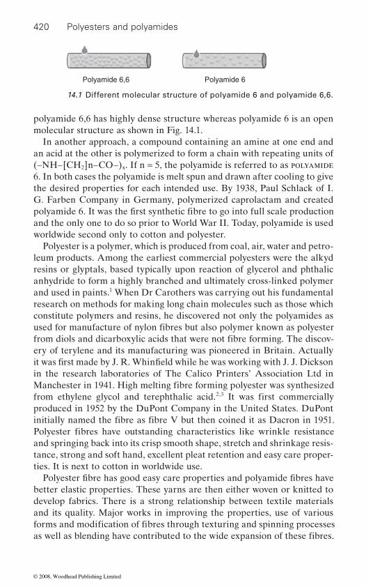
420 Polyesters and polyamides
polyamide 6,6 has highly dense structure whereas polyamide 6 is an open molecular structure as shown in Fig. 14.1.
In another approach, a compound containing an amine at one end and an acid at the other is polymerized to form a chain with repeating units of (–NH–[CH2]n–CO–)x. If n = 5, the polyamide is referred to as polyamide 6. In both cases the polyamide is melt spun and drawn after cooling to give the desired properties for each intended use. By 1938, Paul Schlack of I. G. Farben Company in Germany, polymerized caprolactam and created
and the only one to do so prior to World War II. Today, polyamide is used worldwide second only to cotton and polyester.
Polyester is a polymer, which is produced from coal, air, water and petro-leum products. Among the earliest commercial polyesters were the alkyd resins or glyptals, based typically upon reaction of glycerol and phthalic anhydride to form a highly branched and ultimately cross-linked polymer and used in paints.1 When Dr Carothers was carrying out his fundamental research on methods for making long chain molecules such as those which
ery of terylene and its manufacturing was pioneered in Britain. Actually
in the research laboratories of The Calico Printers’ Association Ltd in
from ethylene glycol and terephthalic acid.2,3
produced in 1952 by the DuPont Company in the United States. DuPont
and springing back into its crisp smooth shape, stretch and shrinkage resis-tance, strong and soft hand, excellent pleat retention and easy care proper-ties. It is next to cotton in worldwide use.
develop fabrics. There is a strong relationship between textile materials and its quality. Major works in improving the properties, use of various
Polyamide 6,6 Polyamide 6
14.1 Different molecular structure of polyamide 6 and polyamide 6,6.
polyamide 6. It was the first synthetic fibre to go into full scale production
used for manufacture of nylon fibres but also polymer known as polyester from diols and dicarboxylic acids that were not fibre forming. The discov-
it was first made by J. R. Whinfield while he was working with J. J. Dickson
Manchester in 1941. High melting fibre forming polyester was synthesized
constitute polymers and resins, he discovered not only the polyamides as
It was first commercially
initially named the fibre as fibre V but then coined it as Dacron in 1951. Polyester fibres have outstanding characteristics like wrinkle resistance
Polyester fibre has good easy care properties and polyamide fibres have
forms and modification of fibres through texturing and spinning processes
better elastic properties. These yarns are then either woven or knitted to
as well as blending have contributed to the wide expansion of these fibres.
© 2008, Woodhead Publishing Limited
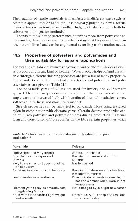
421
Then quality of textile materials is manifested in different ways such as
material feels when touched or handled. Judging of fabrics is done both by subjective and objective methods.4
Thanks to the superior performance of fabrics made from polyester and
14.2 Properties of polyesters and polyamides and
their suitability for apparel applications
Today’s apparel fabric maximizes enjoyment and comfort in indoors as well as outdoors and in any kind of weather. Waterproof, windproof and breath-
in demand. Some of the important characteristics of polyamide and poly-ester fabrics are given in Table 14.1.
The polyamide yarns of 3.3 tex are used for hosiery and 4–22 tex for apparel. The texturing process is used to stimulate the properties of natural
nylon in combination with elastane yarns. Certain desired properties can
Table 14.1 Characteristics of polyamides and polyesters for apparel application5,6
Polyamide Polyester
Lightweight and very strong Strong, stretchable Stretchable and drapes well Resistant to crease and shrinkDurable DurableEasy to clean, as dirt does not cling,
dries quicklyEasily washed
Resistant to abrasion and chemicals Resistant to abrasion and chemicalsResistant to mildew
Low in moisture absorbency Does not absorb moisture making it hot and clammy when worn in hot temperatures
Filament yarns provide smooth, soft, long-lasting fabrics
Not damaged by sunlight or weather
Spun yarns lend fabrics light weight and warmth
Dries quickly. It is crisp and resilient when wet or dry
Polyester and polyamide fibres – apparel applications
polyamides, these fibres have now reached a stage that they can outperform
aesthetic appeal, feel or hand, etc. It is basically judged by how a textile
‘the natural fibres’ and can be engineered according to the market needs.
able through different finishing processes are just a few of many properties
staple yarns of increased bulk with benefits of thermal insulation, cover,
Stretch properties can be imparted to polyamide fibres using textured
be built into polyester and polyamide fibres during production. External
softness and fullness and moisture transport.
form and constitution of fibres confer on the fibre certain properties which
© 2008, Woodhead Publishing Limited

422 Polyesters and polyamides
product:
superdrawing, alkalization)
• •
ducer can determine the cross-section and surface form, as well as decide
form determine many yarn properties, which, in turn, determine the
article. There are further opportunities to modify the cross-section and
stage.
acteristics are shown in Figs. 14.2 and 14.3.7
ProfiledRound
Cross-sectional form
4-lobed), star shaped (n-lobed).
Polyamides and polyesters have large number of types for different applica-tion but even then only some important types are widely used (Table 14.2).
are advantageous for certain end products. The following modifications are also employed in order to achieve the various properties of the final
• fibre cross-section and surface filament size reduction (microfibre,
• fibre blends• bicomponent fibres
The fibre manufacturing process, in combination with further processing and finishing, results in a definite fibre structure regarding molecular struc-ture and order, from which arise the fibre properties and finally the fibre
bulk/texture (texturing and high bulk yarns)
capability in use. In this way, the final properties of the finished product
twisting, intermingling mixed yarns (hetero yarns, mixtures)
are determined in terms of fibre properties.
ties of the final product. In the case of melt-spun staple and yarn, the pro-
on whether to produce solid or hollow filaments, whereas these are partly
solution-spun yarns. Once chosen, the filament cross-sectional shape and
optical, tactile, physiological and technological properties of the final
surface shape of fibre or fabric during further processing (e.g. texturizing, alkalization) in order to change the properties of the final product, but these are less effective than a modification introduced in the production
Different polyester and polyamide fibre cross-sections and surface char-
Profiled encompasses the 2-lobed, 3-lobed (trilobal), rectangular (round,
14.3 Different fibre types for apparel purpose
Cross-section and fi lament surface form strongly influence the proper-
determined by the strong influence of spinning conditions in the case of
© 2008, Woodhead Publishing Limited
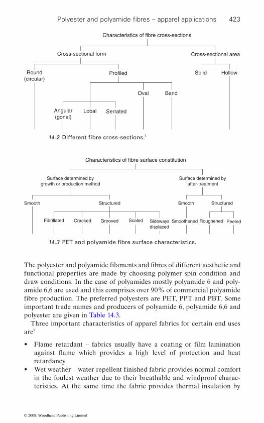
423
draw conditions. In the case of polyamides mostly polyamide 6 and poly-amide 6,6 are used and this comprises over 90% of commercial polyamide
important trade names and producers of polyamide 6, polyamide 6,6 and polyester are given in Table 14.3.
Three important characteristics of apparel fabrics for certain end uses are9
•
retardancy.•
in the foulest weather due to their breathable and windproof charac-teristics. At the same time the fabric provides thermal insulation by
Characteristics of fibre cross-sections
Cross-sectional form
Round(circular)
Profiled
Angular(gonal)
Lobal Serrated
Oval Band
Solid Hollow
Cross-sectional area
7
Characteristics of fibre surface constitution
Surface determined bygrowth or production method
Surface determined byafter-treatment
Smooth Structured Smooth Structured
Fibrillated Cracked Grooved Scaled Sidewaysdisplaced
Smoothened Roughened Peeled
Polyester and polyamide fibres – apparel applications
14.2 Different fibre cross-sections.
14.3 PET and polyamide fibre surface characteristics.
The polyester and polyamide filaments and fibres of different aesthetic and functional properties are made by choosing polymer spin condition and
fibre production. The preferred polyesters are PET, PPT and PBT. Some
Flame retardant – fabrics usually have a coating or film lamination
Wet weather – water-repellent finished fabric provides normal comfort
against flame which provides a high level of protection and heat
© 2008, Woodhead Publishing Limited
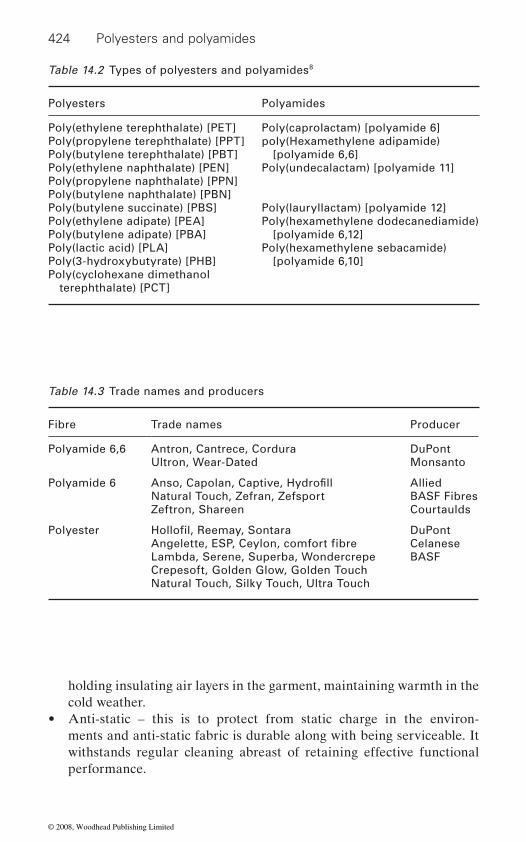
424 Polyesters and polyamides
holding insulating air layers in the garment, maintaining warmth in the cold weather.
• Anti-static – this is to protect from static charge in the environ-ments and anti-static fabric is durable along with being serviceable. It withstands regular cleaning abreast of retaining effective functional performance.
Table 14.2 Types of polyesters and polyamides8
Polyesters Polyamides
Poly(ethylene terephthalate) [PET] Poly(caprolactam) [polyamide 6]Poly(propylene terephthalate) [PPT]Poly(butylene terephthalate) [PBT]
poly(Hexamethylene adipamide) [polyamide 6,6]
Poly(ethylene naphthalate) [PEN]Poly(propylene naphthalate) [PPN]Poly(butylene naphthalate) [PBN]
Poly(undecalactam) [polyamide 11]
Poly(butylene succinate) [PBS] Poly(lauryllactam) [polyamide 12]Poly(ethylene adipate) [PEA]Poly(butylene adipate) [PBA]
Poly(hexamethylene dodecanediamide) [polyamide 6,12]
Poly(lactic acid) [PLA]Poly(3-hydroxybutyrate) [PHB]
Poly(hexamethylene sebacamide)[polyamide 6,10]
Poly(cyclohexane dimethanol terephthalate) [PCT]
Table 14.3 Trade names and producers
Fibre Trade names Producer
Polyamide 6,6 Antron, Cantrece, Cordura DuPontMonsanto
Polyamide 6Natural Touch, Zefran, Zefsport Zeftron, Shareen
AlliedBASF FibresCourtaulds
Lambda, Serene, Superba, WondercrepeCrepesoft, Golden Glow, Golden TouchNatural Touch, Silky Touch, Ultra Touch
DuPontCelaneseBASF
Anso, Capolan, Captive, Hydrofill
Ultron, Wear-Dated
Polyester Hollofil, Reemay, SontaraAngelette, ESP, Ceylon, comfort fibre
© 2008, Woodhead Publishing Limited
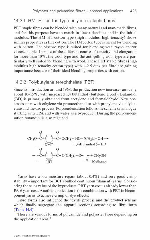
425
and for this purpose have to match in linear densities and in the initial
with cotton. The viscose type is suited for blending with rayon and/or viscose staple. In spite of the different course of tenacity and elongation for more than 10%, the wool type and the anti-pilling wool type are par-
importance because of their ideal blending properties with cotton.
14.3.2 Polybutylene terephthalate (PBT)
Since its introduction around 1968, the production now increases annually about 10–15%, with increased 1,4 butandiol (butylene glycol). Butandiol (BD) is primarily obtained from acetylene and formaldehyde. New pro-cesses start with ethylene via promoethanol or with propylene via allylac-etate and the oxo process. Polycondensation follows the scheme or analogue starting with TPA and with water as a byproduct. During the polyconden-sation butandiol is also regained.
CH3O OCH3 + HO
+ 1,4-Butandiol ( BD)
+ Methanol
(CH2)4 OHC
DMT
O
C
O
O(CH2)4n
+ CH2OHC
PBT
O
C
O
O
Yarns have a low moisture regain (about 0.4%) and very good crimp
ering the sales value of the byproducts, PBT yarn cost is already lower than PA-6 yarn cost. Another application is the combination with PET in bicom-ponent yarns to achieve crimp or dye effects.
(Table 14.4).
the application areas:9
Polyester and polyamide fibres – apparel applications
14.3.1 HM–HT cotton type polyester staple fibres
PET staple fibres can be blended with many natural and man-made fibres,
similar properties as fine cotton. The HM cotton type is meant for blending
ticularly well suited for blending with wool. These PET staple fibres (high
modulus. The HM–HT-cotton type (high modulus, high tenacity) shows
modulus high tenacity cotton type) with 1–2.5 dtex per fibre are gaining
stability – important for BCF (bulked continuous filament) yarns. Consid-
which finally segregate the apparel sections according to fibre form
There are various forms of polyamide and polyester fibre depending on
Fibre forms also influence the textile process and the product scheme
© 2008, Woodhead Publishing Limited
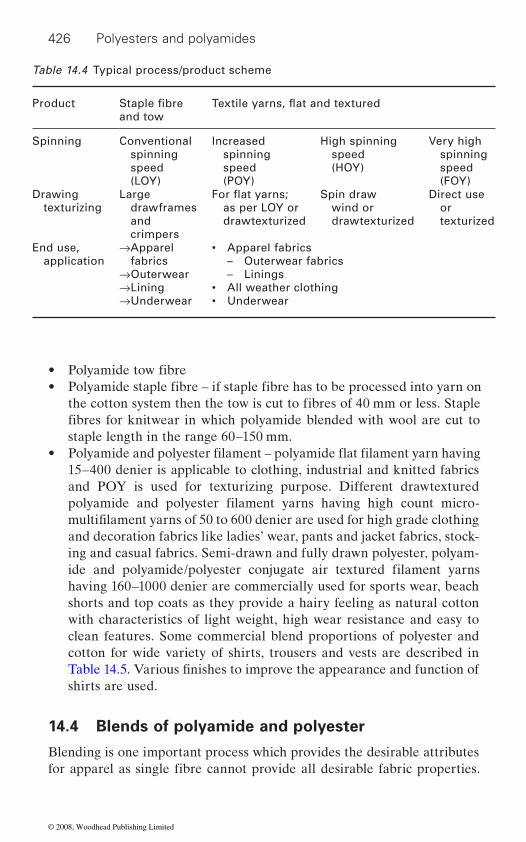
426 Polyesters and polyamides
•
staple length in the range 60–150 mm.•
15–400 denier is applicable to clothing, industrial and knitted fabrics and POY is used for texturizing purpose. Different drawtextured
and decoration fabrics like ladies’ wear, pants and jacket fabrics, stock-ing and casual fabrics. Semi-drawn and fully drawn polyester, polyam-
having 160–1000 denier are commercially used for sports wear, beach shorts and top coats as they provide a hairy feeling as natural cotton with characteristics of light weight, high wear resistance and easy to clean features. Some commercial blend proportions of polyester and cotton for wide variety of shirts, trousers and vests are described in
shirts are used.
14.4 Blends of polyamide and polyester
Blending is one important process which provides the desirable attributes
Table 14.4 Typical process/product scheme
Productand tow
Spinning Conventional spinning speed(LOY)
Increased spinning speed(POY)
High spinning speed(HOY)
Very high spinning speed(FOY)
Drawing texturizing
Large drawframes and crimpers
as per LOY or drawtexturized
Spin draw wind or drawtexturized
Direct use or texturized
End use, application
→Apparel fabrics
→Outerwear→Lining→Underwear
• Apparel fabrics – Outerwear fabrics – Linings• All weather clothing• Underwear
Staple fibre
Polyamide tow fibre• Polyamide staple fibre – if staple fibre has to be processed into yarn on
the cotton system then the tow is cut to fibres of 40 mm or less. Staple fibres for knitwear in which polyamide blended with wool are cut to
polyamide and polyester filament yarns having high count micro-multifilament yarns of 50 to 600 denier are used for high grade clothing
ide and polyamide/polyester conjugate air textured filament yarns
Table 14.5. Various finishes to improve the appearance and function of
for apparel as single fibre cannot provide all desirable fabric properties.
Textile yarns, flat and textured
For flat yarns;
Polyamide and polyester filament – polyamide flat filament yarn having
© 2008, Woodhead Publishing Limited
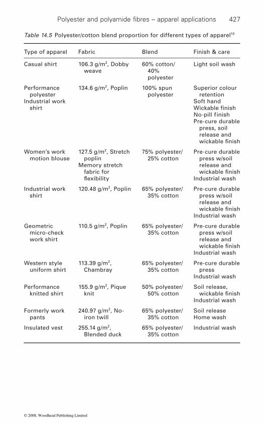
427
Table 14.5 Polyester/cotton blend proportion for different types of apparel10
Type of apparel Fabric Blend Finish & care
Casual shirt 106.3 g/m2, Dobby weave
60% cotton/40% polyester
Light soil wash
Performance polyester
Industrial work shirt
134.6 g/m2, Poplin 100% spun polyester
Superior colour retention
Soft hand
Pre-cure durable press, soil release and
Women’s work motion blouse
127.5 g/m2, Stretch poplin
Memory stretch fabric for
75% polyester/25% cotton
Pre-cure durable press w/soil release and
Industrial wash
Industrial work shirt
120.48 g/m2, Poplin 65% polyester/35% cotton
Pre-cure durable press w/soil release and
Industrial wash
Geometric micro-check work shirt
110.5 g/m2, Poplin 65% polyester/35% cotton
Pre-cure durable press w/soil release and
Industrial wash
Western style uniform shirt
113.39 g/m2, Chambray
65% polyester/35% cotton
Pre-cure durable press
Industrial wash
Performance knitted shirt
155.9 g/m2, Pique knit
50% polyester/50% cotton
Soil release,
Industrial wash
Formerly work pants
240.97 g/m2, No-iron twill
65% polyester/35% cotton
Soil releaseHome wash
Insulated vest 255.14 g/m2, Blended duck
65% polyester/35% cotton
Industrial wash
Polyester and polyamide fibres – apparel applications
Wickable finishNo-pill f inish
wickable finish
wickable finish
wickable finish
wickable finish
wickable finish
flexibility
© 2008, Woodhead Publishing Limited
428 Polyesters and polyamides
and easy care properties with better feel and high moisture absorbency
blended in different combinations to produce a wide variety of yarns.
of the complementary nature of the properties. The blend of polyester with viscose/cotton results in reduction of most of the negative features of poly-ester like poor moisture absorption, poor static dissipation, poor moisture vapour transmission, poor feel, warm, crisp hand, lower comfort, non-bio-degradable, while negative features of viscose/cotton such as poor crease retention, poor wrinkle recovery, poor tenacity, lower abrasion resistance,
In general, the main motives behind blending are:
• •
blend• Opportunity to produce colour effects.
when strength, elasticity and durability are considered, have a number of negative attributes as far as handle and comfort related properties are
to produce fabrics with the right balance of properties. Desirable or unde-
design can considerably change the comfort level produced by a garment.
end use. In such cases, it can be advantageous to combine the properties
in question or to enhance a particular product characteristic.
or yarns:
•
twisting or entangling• Combining yarns during fabric manufacture.
terms of processability and optimization of product properties:
Blending helps use the positive attributes of both synthetic fibre like wear
property of natural fibres. Different natural and manmade fibres are
Polyester fibre can be suitably blended with cotton and viscose because
higher staining tendency, difficulty of washing, lower colour fastness are
Combination of merits of different fibres
overcome by the presence of polyester in the blend.
Reduction of cost by use of cheaper fibre with higher cost fibre in a
Polyester and polyamide fibres which have a number of positive attributes
concerned. Comfort attributes of fibres like cotton and viscose can be combined with hard wearing and heat settable attributes of synthetic fibres
sirable attributes of fibres can be affected by the actual textile construction. Yarn and fabric parameters, together with finishing treatments and garment
Synthetic-, chemical- and natural fibres each have their own specific properties, none of which alone may satisfy the requirement of a specific
of two or three fibre types in order to obtain an optimum for the end use
In principle, the following methods can be used to mix or blend fibres
Combining different staple fibres or staple fibre with natural fibre in
• Combining filament yarns and/or staple yarns by means of plying,
The following fibre combinations have proved themselves successful in
flock or at carding
© 2008, Woodhead Publishing Limited
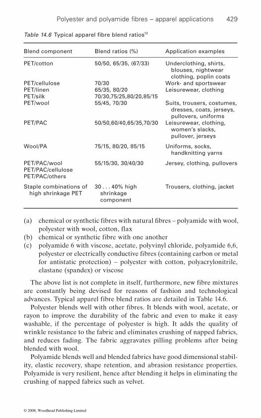
429
(a)
(b) (c) polyamide 6 with viscose, acetate, polyvinyl chloride, polyamide 6,6,
for antistatic protection) – polyester with cotton, polyacrylonitrile, elastane (spandex) or viscose
are constantly being devised for reasons of fashion and technological
rayon to improve the durability of the fabric and even to make it easy washable, if the percentage of polyester is high. It adds the quality of wrinkle resistance to the fabric and eliminates crushing of napped fabrics, and reduces fading. The fabric aggravates pilling problems after being blended with wool.
Polyamide blends well and blended fabrics have good dimensional stabil-ity, elastic recovery, shape retention, and abrasion resistance properties. Polyamide is very resilient, hence after blending it helps in eliminating the crushing of napped fabrics such as velvet.
12
Blend component Blend ratios (%) Application examples
PET/cotton
PET/cellulosePET/linenPET/silkPET/wool
PET/PAC
50/50, 65/35, (67/33)
70/3065/35, 80/2070/30,75/25,80/20,85/1555/45, 70/30
50/50,60/40,65/35,70/30
Underclothing, shirts, blouses, nightwear clothing, poplin coats
Work- and sportswearLeisurewear, clothing
Suits, trousers, costumes, dresses, coats, jerseys, pullovers, uniforms
Leisurewear, clothing, women’s slacks, pullover, jerseys
Wool/PA 75/15, 80/20, 85/15 Uniforms, socks, handknitting yarns
PET/PAC/woolPET/PAC/cellulosePET/PAC/others
55/15/30, 30/40/30 Jersey, clothing, pullovers
Staple combinations of high shrinkage PET
30 . . . 40% high shrinkage component
Trousers, clothing, jacket
Polyester and polyamide fibres – apparel applications
Table 14.6 Typical apparel fibre blend ratios
chemical or synthetic fibres with natural fibres – polyamide with wool,
chemical or synthetic fibre with one another
polyester or electrically conductive fibres (containing carbon or metal
The above list is not complete in itself, furthermore, new fibre mixtures
advances. Typical apparel fibre blend ratios are detailed in Table 14.6.Polyester blends well with other fibres. It blends with wool, acetate, or
polyester with wool, cotton, flax
© 2008, Woodhead Publishing Limited

430 Polyesters and polyamides
14.5 Apparel applications of polyamide and
polyester fabric
The application of polyamide expanded from the initial hosiery market to other apparels by exploiting easy care properties.13 In many textile applica-
or knitted fabrics. These fabrics had a limp and rather plastic handle, poor ability to wick moisture away from the body, and a strong tendency to build up static charges, leading to clinging and sparking. The fabrics were fre-quently shiny. In the 1970s the newly developed polyester/cotton blends offered superior comfort in many apparel applications and polyamide was displaced from these end-uses.
For apparels, producers engineer their products to meet the needs of
section, also textured yarns are used. These products, together with changes in fashion, led in the late 1990s to a revival of interest in polyamide for outerwear. The brand names like Tactel, Antron and Tactesse for particu-lar applications are used.15
14.5.1 Polyamide fabric
1. Polyamide is widely used in women’s hosiery and lingerie due to its high elongation and excellent elastic recovery quality. It is also used as sportswear, jackets, pants, skirts, raincoats, ski and snow apparel, windbreakers and children’s-wear.
2. Apparel: Blouses, dresses, foundation garments, hosiery, lingerie, underwear, raincoats, ski apparel, windbreakers, swimwear, and cycle wear.
14.5.2 Polyester fabric
1. Polyester clothing has a good stability and strength and is resistant to stretching and shrinkage. It is not damaged by sunlight or weather. It is widely used as dresses, blouses, jackets, separates, sportswear, suits, shirts, pants, rainwear, lingerie and children’s-wear.
2.
blended with wool to eliminate crushing and reduce fading.
14.6 Comparison of polyesters and polyamides
particular uses – filaments have become finer and non-circular in cross-
Polyester fabric is manufactured in many weights and it is used as
Polyester and polyamide fibres both have attained their peak position in
fibrefill in pillows and upholstery. In upholstery, polyester is generally
textile world and polyester is predicted to be dominating in the fibre race
tions, flat yarns with relatively coarse filaments were used in tightly woven
© 2008, Woodhead Publishing Limited

431
in coming years also. There are certain properties which separate the two
In recent years, polyester and polyamide variants such as stretch, micro-
product have made it possible to confer the comfort and coolness of cotton, 16
with microporous surface. This improves moisture absorption. Micro-
comfort and aesthetics. Wool-like effect can be imparted by dyeing cat-ionic-dyeable polyesters to deep shades. Polyester textured yarns have wool-like characteristics since they have better thermal insulation and
insulation. Thus there are multiple effects that are given to nylon and polyester.14
ity for basic dyes by carrying out the polycondensation process in the pres-ence of diphenyl sulphonic acids or their salts. ICI have also suggested a method of preparation of polyester of improved moisture regain by the addition of 5–10% by weight of sodium sulphate, of particle size less than 3 microns, to a slurry in ethylene glycol during polymerization.
Table 14.7 Comparison of polyester and polyamide properties11,6
Properties Polyester Polyamide
Initial modulus 600–1200 gf tex−1 200–300 gf tex−1
Degree of elasticity 90–98 at 2% elongation70–90 at 10% elongation
95–100 at 2% and 10% elongation
Moisture regain 0.4% at 65% RH 2.8–5.0% Breaking elongation 12–55% 16–65%Tenacity 25–54 gf tex−1 32–65 gf tex−1
Thermal conductivity 0.141 W/m K 0.243 W/m K
Polyester and polyamide fibres – apparel applications
fibres from most of the others and help to distinguish the area of applica-tion of polyester and polyamide fibres (Table 14.7).
14.7 Pivotal fibre modification
fibre, recycled, antimicrobial are increasingly used in addition to these fibres with traditional attributes.
Various innovative achievements through modification of technique or
the soft warmth of wool and glamour and rustle of silk to polyester fibre.Cotton-like effects can be given to fine polyester staple of 1 denier or less
crimped polyester filaments with irregular cross-section have improved
more moisture retention. The hollow polyester fibres have good thermal
Some of the important modifications of polyester and polyam-ide fibres are discussed below.
14.7.1 Modification at polymer stage
ICI claims the preparation of improved linear polyester having better affin-
© 2008, Woodhead Publishing Limited
432 Polyesters and polyamides
Lee et al.18 grafted acrylic acid by exposing impregnated drawn crystal-
17 have reported the properties of polyester/cotton blended fabric grafting with 2-methyl 5-vinyl pyridine using benzoyl peroxide as initiator. Fabric properties such as moisture regain, tensile strength and elongation at break have been found to increase with an increasing degree of drafting whereas crease recovery angle and electrical resistivity show a decreasing trend. It shows that certain desirable properties are adversely affected by attempts for making polyester hydro-philic. Blending turns out to be one of the important ways for imparting hydrophilic properties to the polyester apparels. And cotton/PET blends have been widely used in apparel applications because of improved comfort properties.
DuPont offers several stretch polyester derivatives based on its 3GT
with two carbon glycol, hence the name 3GT. DuPont has developed a bio-source process that uses a fermentable sugar as a feed stock. It ferments sugar using a biocatalyst that converts the sugar into 1,3 propanediol (3G)
18
• Stretch and recovery are better than polyamide and regular polyester. Thus fabrics retain their shape and have enough stretch with recovery for comfortable movement
• Sorona, like polyamide, has lower modulus and is much softer• It is easy to dye with same dyestuff as polyester without carrier.
Toray Industries, Inc. has developed a unique polyamide fabric Miramatte that realizes the softness and feel of polyamide and also fea-tures a high-quality plumage-like touch (‘Fine Feather Feeling’), with a refreshingly comfortable dry feel, and optimum drape. At the same time, Miramatte has excellent anti-ultraviolet and anti-transparent properties, and gives full play to its characteristics even if thin textile is used. The product is thus ideally suited to production of lightweight clothing.19
increased the inorganic particles, which are effective for anti-ultraviolet and anti-transparent properties in the polyamide polymer, by approxi-mately three times which is as much as the maximum density achieved with existing mass production. In addition, the particles are distributed uni-
uniform distribution of the inorganic particles at the stage of polymeriza-tion. In view of the consistent popularity of polyamide materials for sports
line polyester fibres to gamma radiation in the nitrogen atmosphere and found that the resulting fibre has good absorption and tensile properties and affinity for basic dyes. Hebeish et al.
technology. The first 3GT product is named Sorona. Three carbon glycol is used to make these new fibres, unlike regular polyester which is made
which is purified to fibre grade. Properties of Sorona are:
Regarding the polyamide fibre to be used in Miramatte, Toray has
formly not only in the fibre but also on its surface. It can be perfectly designed to develop cross-section variations and fine denier because of the
© 2008, Woodhead Publishing Limited

433
and casual wear in the fashion industry, Toray as the top producer of poly-
new polyamide materials. The company plans to continue developing new polyamide products with features like:
• High-quality plumage-like touch• Comfortable dry feel• Optimum drape• Refreshing feel• Soft and matt colour tones with luxury feel• Anti-ultraviolet property (UV covering ratio: more than 90%)• Remarkable anti-transparent property• Thin and lightweight clothing.
but it contains other components that produce low-to-moderate wovens, or true elastic stretch and recovery. It has stretch recovery, resistance to chemicals and abrasions are better than textured polyester and polyamide. It targets more 100% man made and blended fabric for ready-to-wear, typically with 20–30% Type 400 content.20
Nylstar inherited Elite stretch polyester from Schneer. Elite is
The beauty of Elite is the ease with which it can bring staple spun yarns.
activewear.
extruded by reducing the polymer output at the spinneret and drawing by a large drawing ratio.
as macroscopic structural point of view. Ecsaine is made of homogeneous
appearance and hand as a clothing material. The pedal shaped conjugate
As bending and torsional stiffness is inversely proportional to
istics can be shown:
Polyester and polyamide fibres – apparel applications
amide fibre in Japan has been carrying out research and development on
T 400 is polyester-based DuPont fibre developed with 3GT technology
modified polyester with permanent stretch properties and 98% recovery.
The newest version of elite is a microfibre, which can be used for
14.7.2 Modification at spinning stage
Modification of polyester fibre – Ultra fine fibres
An ultra fine fibre is conventionally defined as a fibre of less than 0.7 denier. These fibres are often known as microfibres. An ultra fine fibre could be
fine polyester fibre can reproduce deer suede from the microscopic as well
ultra-fine polyester fibres of less than 0.1 den and provides an epoch making
fibre by DuPont was probably the first example of a potential ultra-fine
Toray put the suede like new material Ecsaine on the market. Only ultra-
filament.
diameter, ultra-fine fibres are extremely flexible. The following character-
© 2008, Woodhead Publishing Limited

434 Polyesters and polyamides
•
• Formation of micro-pockets in fabrics• • Characteristic interfacial properties• A small radius of curvature (resulting lustre and characteristics
colour)• A large aspect ratio (the ratio of length to diameter)• A quick stress relief• Low resistance against bending• Fine edge.
The island in sea technology provides the industrial way of suede type
of high dyeability was developed with three component conjugate extru-
sheath and core structure.21
which water enters into the inner space and exits. Another water absorbent
14.7.3 Developments in blends
charge (ESD 10−9 S/cm) applications in work-wear, dust-free garments.
polymer materials reach 10–100 S/cm conductivity, and can be used in electromagnetic impulse (EMI 10−3 S/cm) protection. Belltron commercial products have introduced carbon-black based sandwich structures having electric resistance 108 to 1010 Ω/cm and 106–108 Ω/cm in 2.5 g/d tenacity
15 The comparable values for white metal powder construction were 108–1010 Ω/cm for both co-centric
spinnability of the polymer melt has been shown to be a very complex challenge even for the homogeneous thermoplastic.
Dacron Plus is softer polyester with better drape. Dacron Duracotton, primarily for apparel, offers improved compatibility with cotton to create more durable fabrics that still have the look and hand of cotton but is enhanced by Dacron. DAK America’s Delcron brand, carried over from
• A fine textile structure
A high filament density per textile surface
artificial leather, silk like fabrics. The technology is further extended to spin the multi-component conjugate fibre, and a suede type artificial leather
Water absorbent polyester fibres have recently been commercialized in
sion where the component (polyester and polyamide) ultra-fine fibres have
Japan. Kilatt by Kanebo is a hollow fibre having a narrow slit through
hollow fibre, Welkey, is made by Teijin.
Polyester and polyamide conductive fibre
Apparel applications of conducting fibre are mainly in electrostatic dis-
Typical bi-component fibres containing carbon black or white metal reach the requirement also in mixed fibre materials. However the conductive
polyester and polyamide fibre respectively.
and side-by-side polyamide based bi-components 3 g/d tenacity fibre. The
A softness, flexibility and smoothness
© 2008, Woodhead Publishing Limited
435
the Akra side of the business, is offering a new moisture management product called Delcron Hydrotec with superior wicking properties and
high trek is a blend of almost equal parts of wool, acrylic and hollow poly-ester, created to be washable for garments as school uniforms and outdoor jackets.22
KoSa recently introduced polyester yarns that are dyeable at lower tem-peratures than regular polyester, offering excellent printing and dyeing
and acetate. It is a single polyester yarn engineered with cotton like hand and appearance that also stretches. It is atmospherically dyeable and can be combined with other yarns for circular and seamless knitting, making it suitable for use in sports and thermal wear, intimate apparel, T-shirts and loungewear.
maintenance and health protection. The yarn will be made from the
ment yarn can emit electromagnetic wave of 4–14 μm. The wave can per-meate into the deepest skin and hypodermic tissue and enable the water molecules inside the body to resonate. The water molecules violently
temperature rise and capillaries expand. And it enables the water mole-cules of the cellular surface to be activated and speed the move of the calcium ion and therefore improve blood circulation and strengthen metab-olism so that it vitalizes the tissue, quickens nutrition absorption and expels harmful substances in order for the body to acquire health and vitality. Its features:
• Vitalizing the skin with warmth-maintaining effects• Prevention of chronic disease• Increasing the immune system and health protection function• Improving blood circulation and strengthening metabolism.
Related end uses
1. Suitable for applying to the fabric for metabolism improvement and warmth keeping
2. Functional underwear3. Anti-varicosity hosiery4. Exercise protector5. Light and cold protective fabric and lining.
Polyester and polyamide fibres – apparel applications
improved finished fabric costs. Delcron Colorbrite is a cationic dyeable fibre that achieves more brilliant colorations than typical polyester. Delcron
effects when blended with other heat-sensitive fibres such as spandex, wool
Far infrared filament yarn
polymer which is mixed with far infrared elements, so the far infrared fila-
This is a healthy care fibre with the property of heat and temperature
vibrate and generate heat efficacy and then make the hypodermic deep
© 2008, Woodhead Publishing Limited

436 Polyesters and polyamides
zeolite. The antibacterial zeolite is a multi-hole ceramic with silver. When the bacteria touch the ceramic, the silver ion and the enzyme in the bac-teria cells will have a chemical action. It will restrain the activity of the bacteria and prevent the bacteria from procreating. Then it destroys the bacteria and achieves the effect of anti-bacteria and odour prevention. Related end uses are underwear, sweat shirts, hosiery, lining, cold protect-ing coats and gloves.
to produce clothing fabrics with high brightness, lustre and softness.
23
Polyamide and polyester conjugates are usually made of 25% polyamide
ing. So there is no need of caustic reduction, or only need of light weight reduction. This saves process cost, avoids waste water pollution and dyeing
and adequate bulkiness and are used to make high density fabrics with excellent wet penetration and ventilation properties, silk-like fabrics and
14.8 Current market potentials
3.2% higher output, mainly stimulated by 6.5% surging output of polyester
4.4% at 27.4 million tonnes. Much of the growth was driven by strong
Asia accounts for 88% of the volume produced. Although several Asian countries suffered from reduced output volumes, this region has the ability to lift production by 6.4% to 24 million tonnes. Greater Europe and America ended the year with reduced production by 5.2% and 10.2% respectively.
Anti-microbial filament yarn
Anti-microbial fibre is a fibre containing the inorganic anti-bacterial
Polyamide filament trilobal bright
Polyamide/polyester conjugate micro-filament
and 75% polyester. The yarn self splits in sanding when dyeing and finish-
failure. The conjugate filaments have soft touch, lightness, graceful shine,
artificial leathers. Excellent water absorption bath towel robe can be made from polyamide/polyester conjugate filaments.
compared to natural fibres. Figure 14.4 illustrates the trend of man-made fibre growth in the past 10 years. The synthetic fibre segment produced a
filament yarns. The global polyester industry achieved a growth rate of
expansion of filament yarn that rose 6.5% to 16.3 million tonnes whereas
The development of man-made fibres in the last 40 years has been very great
the staple fibres showed slow growth of 1.6% to 11.1 million tonnes.
A trilobal cross-section makes good effect of light reflection and is used
© 2008, Woodhead Publishing Limited
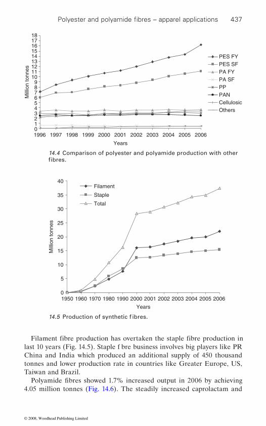
437
China and India which produced an additional supply of 450 thousand tonnes and lower production rate in countries like Greater Europe, US, Taiwan and Brazil.
4.05 million tonnes (Fig. 14.6). The steadily increased caprolactam and
0123456789
101112131415161718
1996 1997 1998 1999 2000 2001 2002 2003 2004 2005 2006
Years
Mill
ion
tonn
es
PES FYPES SFPA FYPA SFPPPANCellulosicOthers
14.4 Comparison of polyester and polyamide production with other
0
5
10
15
20
25
30
35
40
1950 1960 1970 1980 1990 2000 2001 2002 2003 2004 2005 2006
Years
Mill
ion
tonn
es
Filament
Staple
Total
Polyester and polyamide fibres – apparel applications
fibres.
14.5 Production of synthetic f ibres.
Filament fibre production has overtaken the staple fibre production in last 10 years (Fig. 14.5). Staple f bre business involves big players like PR
Polyamide fibres showed 1.7% increased output in 2006 by achieving
© 2008, Woodhead Publishing Limited
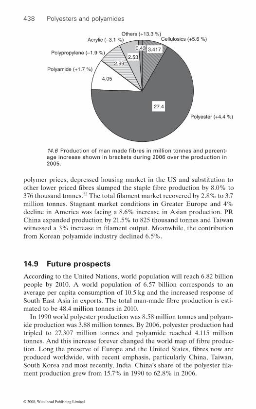
438 Polyesters and polyamides
polymer prices, depressed housing market in the US and substitution to
376 thousand tonnes.22
million tonnes. Stagnant market conditions in Greater Europe and 4% decline in America was facing a 8.6% increase in Asian production. PR China expanded production by 21.5% to 825 thousand tonnes and Taiwan
from Korean polyamide industry declined 6.5%.
14.9 Future prospects
According to the United Nations, world population will reach 6.82 billion people by 2010. A world population of 6.57 billion corresponds to an average per capita consumption of 10.5 kg and the increased response of
mated to be 48.4 million tonnes in 2010.
ide production was 3.88 million tonnes. By 2006, polyester production had tripled to 27.307 million tonnes and polyamide reached 4.115 million
produced worldwide, with recent emphasis, particularly China, Taiwan,
ment production grew from 15.7% in 1990 to 62.8% in 2006.
Polyester (+4.4 %)
Others (+13.3 %)Acrylic (–3.1 %)
Polypropylene (–1.9 %)
Cellulosics (+5.6 %)
Polyamide (+1.7 %)
2.53
0.43 3.417
2.99
4.05
27.4
age increase shown in brackets during 2006 over the production in 2005.
14.6 Production of man made fibres in million tonnes and percent-
other lower priced fibres slumped the staple fibre production by 8.0% to The total filament market recovered by 2.8% to 3.7
witnessed a 3% increase in filament output. Meanwhile, the contribution
South East Asia in exports. The total man-made fibre production is esti-
tonnes. And this increase forever changed the world map of fibre produc-tion. Long the preserve of Europe and the United States, fibres now are
In 1990 world polyester production was 8.58 million tonnes and polyam-
South Korea and most recently, India. China’s share of the polyester fila-
© 2008, Woodhead Publishing Limited
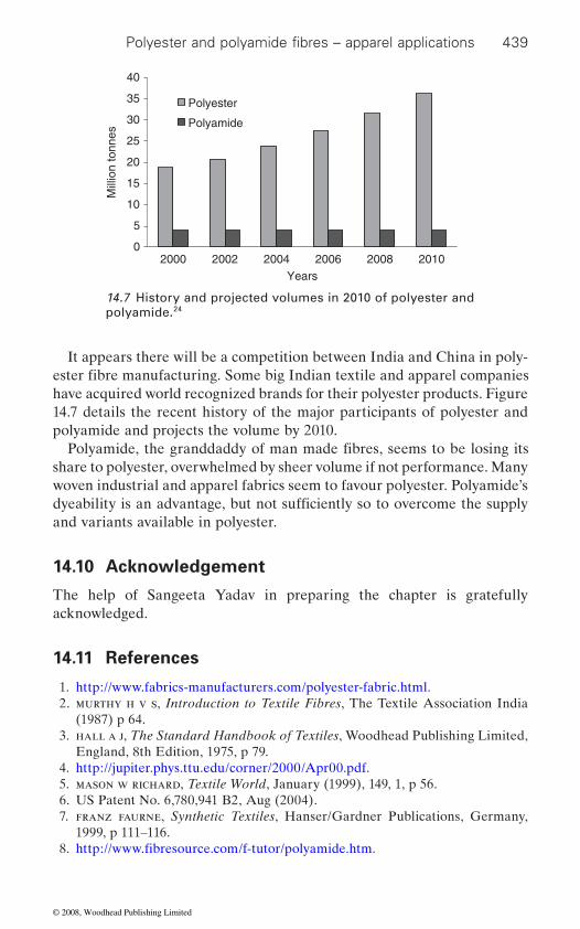
439
It appears there will be a competition between India and China in poly-
have acquired world recognized brands for their polyester products. Figure 14.7 details the recent history of the major participants of polyester and polyamide and projects the volume by 2010.
share to polyester, overwhelmed by sheer volume if not performance. Many woven industrial and apparel fabrics seem to favour polyester. Polyamide’s
and variants available in polyester.
14.10 Acknowledgement
The help of Sangeeta Yadav in preparing the chapter is gratefully acknowledged.
14.11 References
1. http://www.fabrics-manufacturers.com/polyester-fabric.html. 2. murthy h v s, Introduction to Textile Fibres, The Textile Association India
(1987) p 64. 3. hall a j, The Standard Handbook of Textiles, Woodhead Publishing Limited,
England, 8th Edition, 1975, p 79. 4. http://jupiter.phys.ttu.edu/corner/2000/Apr00.pdf. 5. mason w richard, Textile World, January (1999), 149, 1, p 56.
7. franz faurne, Synthetic Textiles, Hanser/Gardner Publications, Germany, 1999, p 111–116.
0
5
10
15
20
25
30
35
40
2000 2002 2004 2006 2008 2010Years
Mill
ion
tonn
esPolyester
Polyamide
14.7 History and projected volumes in 2010 of polyester and polyamide.24
Polyester and polyamide fibres – apparel applications
ester fibre manufacturing. Some big Indian textile and apparel companies
Polyamide, the granddaddy of man made fibres, seems to be losing its
dyeability is an advantage, but not sufficiently so to overcome the supply
6. US Patent No. 6,780,941 B2, Aug (2004).
8. http://www.fibresource.com/f-tutor/polyamide.htm.
© 2008, Woodhead Publishing Limited
440 Polyesters and polyamides
9. http://www.fabrics-manufacturers.com/apparel-fabric.html.10. http://www.redkap.com/product2/objectviewer.aspx.11. chapman c b, Fibres, Butterworths & Co (Publishers) Ltd, London, 1974,
p 73–78, 85.12. hollen norma and saddler jane, Textiles, 3rd Edition, Macmillan Company,
New York, 1968, p 59–62, 65–67.
Woodhead Publishing Limited, The Textile Institute, England, 2005, p 21, 42.
14. gupta v b, kothari v k, Manufactured Fibre Technology, Published by Chapman & Hall, London (1997), p 6.
15. http://www.exportbureau.com/website.html?u=4338&url=www.acelon.com.tw.
16. ‘Japan: DuPont–Toray launching T-400’, Asian Textile Weekly, Jan (2003), 29,1, p 6.
17. k. anderson, The Textile Institute’s 82nd World Conference, 23–27 March, 2002, Cairo
19. richard s robert, Textile World, January/February (2007), 157, 1, p 24.20. gulrajani m l, Polyester Textiles, Proceedings of 37th All India Textile Con-
ference, Textile Association Publication, India, 1980, p 281–287.21. jorden k speer, Bobbin, December (2002), 44, 4, p 12.22. brunnschweiler d, hearle j, (Eds), ‘Polyester: 50 Years of Achievement’, The
Textile Institute, Manchester, UK (1993) p , 97, 222, 333.23. elaine gross, Textile World, November (2001), 151, 11, p 33.24. The Fiber Year 2006/2007, Oerlikon, Issue 7, May (2007) p 15–16, 58–61.
13. mcintyre j e, Synthetic Fibres: Polyamide, Polyester, Acrylic, Polyolefin,
18. http://www.toray.com/news/fibre/nr030312.html.
© 2008, Woodhead Publishing Limited
15Polyester and nylon based textiles in
biomedical engineering
B. GU P TA, N. GROV ER, S . V I J U and S . SA X ENA,
Indian Institute of Technology, New Delhi, India
15.1 Introduction
One of the most innovative and growing aspects of the textile industry is
this domain is due to constant improvements and recent innovations in
the ‘Susanta Sambita’ of Indian Literature, written approximately 2500 years ago, a variety of materials including horse hair, leather strips and cotton are mentioned. With the passage of time, textiles have found their way into a variety of medical applications. In addition to protective medical
surgical dressings. Recent decades have witnessed major developments in medical textile production, the materials they are made of, and the technol-ogy used to produce them. Textile materials and products that have been engineered to meet particular needs are suitable for any medical and surgi-
moisture and air permeability are required. Materials used include mono-
composite structures. The numbers of applications are huge and diverse, ranging from a single thread suture to the complex composite structures for bone replacement, and from the simple cleaning wipe to the advanced barrier fabrics used in operating theaters [1]. Table 15.1 summarizes the main type of textile structures used for various healthcare and medical devices, including implants.
Medical textiles account for a huge market owing to the widespread need for them, not only in hospital, hygiene and healthcare sectors but also in hotels and other environments where hygiene is required. There has been
cing various medical products. The world medical devices market is rep-resented by the Global Harmonization Task Force (GHTF). The GHTF
441
the field of medicine, healthcare and hygiene. The extent of the growth of
both textile technology and medical procedures. The first recorded use of fibres in medicine was mentioned in ‘Surgical Papyrus’ 4000 years ago. In
apparel, textiles in fibre and fabric form are used as implants, filters and
filament and multifi lament yarns, woven, knitted, nonwoven fabrics, and
a sharp increase in the use of natural as well as synthetic fibres in produ-
cal application where a combination of strength, flexibility, and sometimes
© 2008, Woodhead Publishing Limited
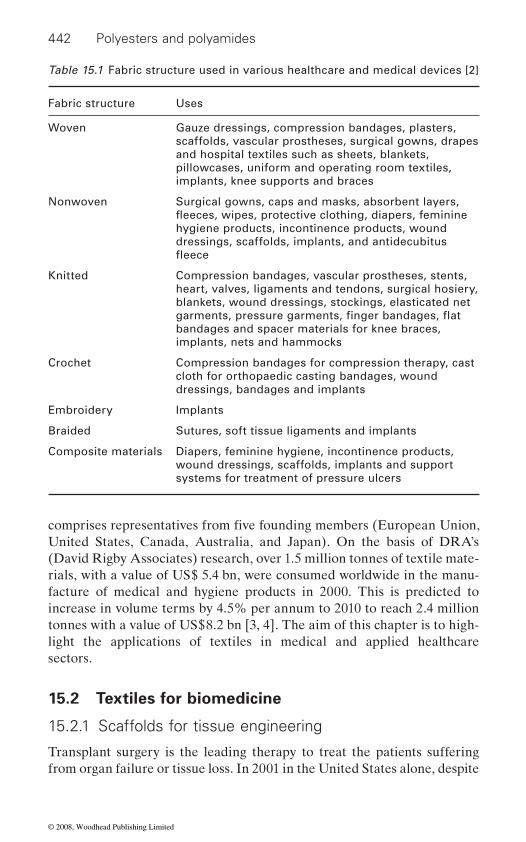
442 Polyesters and polyamides
United States, Canada, Australia, and Japan). On the basis of DRA’s (David Rigby Associates) research, over 1.5 million tonnes of textile mate-rials, with a value of US$ 5.4 bn, were consumed worldwide in the manu-facture of medical and hygiene products in 2000. This is predicted to increase in volume terms by 4.5% per annum to 2010 to reach 2.4 million tonnes with a value of US$8.2 bn [3, 4]. The aim of this chapter is to high-light the applications of textiles in medical and applied healthcare sectors.
15.2 Textiles for biomedicine
15.2.1 Scaffolds for tissue engineering
Transplant surgery is the leading therapy to treat the patients suffering from organ failure or tissue loss. In 2001 in the United States alone, despite
Table 15.1 Fabric structure used in various healthcare and medical devices [2]
Fabric structure Uses
Woven Gauze dressings, compression bandages, plasters, scaffolds, vascular prostheses, surgical gowns, drapes and hospital textiles such as sheets, blankets, pillowcases, uniform and operating room textiles, implants, knee supports and braces
Nonwoven Surgical gowns, caps and masks, absorbent layers,
hygiene products, incontinence products, wound dressings, scaffolds, implants, and antidecubitus
Knitted Compression bandages, vascular prostheses, stents, heart, valves, ligaments and tendons, surgical hosiery, blankets, wound dressings, stockings, elasticated net
bandages and spacer materials for knee braces, implants, nets and hammocks
Crochet Compression bandages for compression therapy, cast cloth for orthopaedic casting bandages, wound dressings, bandages and implants
Embroidery Implants
Braided Sutures, soft tissue ligaments and implants
Composite materials Diapers, feminine hygiene, incontinence products, wound dressings, scaffolds, implants and support systems for treatment of pressure ulcers
comprises representatives from five founding members (European Union,
fleeces, wipes, protective clothing, diapers, feminine
fleece
garments, pressure garments, finger bandages, flat
© 2008, Woodhead Publishing Limited
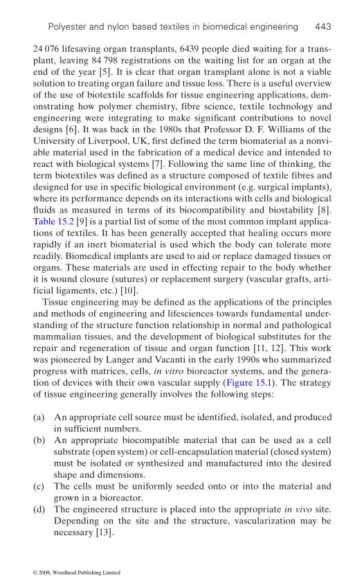
Polyester and nylon based textiles in biomedical engineering 443
24 076 lifesaving organ transplants, 6439 people died waiting for a trans-plant, leaving 84 798 registrations on the waiting list for an organ at the end of the year [5]. It is clear that organ transplant alone is not a viable solution to treating organ failure and tissue loss. There is a useful overview of the use of biotextile scaffolds for tissue engineering applications, dem-
designs [6]. It was back in the 1980s that Professor D. F. Williams of the
able material used in the fabrication of a medical device and intended to react with biological systems [7]. Following the same line of thinking, the
where its performance depends on its interactions with cells and biological
Table 15.2 [9] is a partial list of some of the most common implant applica-tions of textiles. It has been generally accepted that healing occurs more rapidly if an inert biomaterial is used which the body can tolerate more readily. Biomedical implants are used to aid or replace damaged tissues or organs. These materials are used in effecting repair to the body whether it is wound closure (sutures) or replacement surgery (vascular grafts, arti-
and methods of engineering and lifesciences towards fundamental under-standing of the structure function relationship in normal and pathological mammalian tissues, and the development of biological substitutes for the repair and regeneration of tissue and organ function [11, 12]. This work was pioneered by Langer and Vacanti in the early 1990s who summarized progress with matrices, cells, in vitro bioreactor systems, and the genera-
of tissue engineering generally involves the following steps:
(a)
(b) An appropriate biocompatible material that can be used as a cell substrate (open system) or cell-encapsulation material (closed system) must be isolated or synthesized and manufactured into the desired shape and dimensions.
(c) The cells must be uniformly seeded onto or into the material and grown in a bioreactor.
(d) The engineered structure is placed into the appropriate in vivo site. Depending on the site and the structure, vascularization may be necessary [13].
onstrating how polymer chemistry, fibre science, textile technology and engineering were integrating to make significant contributions to novel
University of Liverpool, UK, first defined the term biomaterial as a nonvi-
term biotextiles was defined as a structure composed of textile fibres and designed for use in specific biological environment (e.g. surgical implants),
ficial ligaments, etc.) [10].Tissue engineering may be defined as the applications of the principles
An appropriate cell source must be identified, isolated, and produced
tion of devices with their own vascular supply (Figure 15.1). The strategy
in sufficient numbers.
fluids as measured in terms of its biocompatibility and biostability [8].
© 2008, Woodhead Publishing Limited
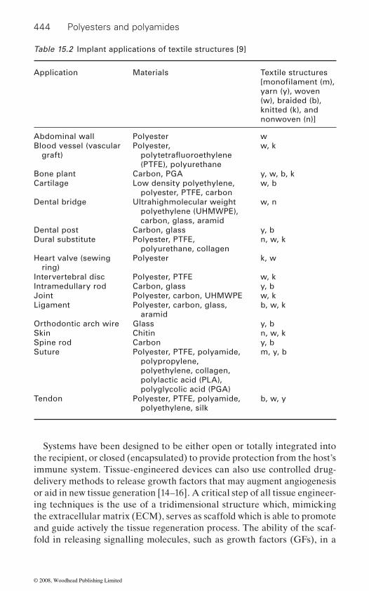
444 Polyesters and polyamides
Systems have been designed to be either open or totally integrated into the recipient, or closed (encapsulated) to provide protection from the host’s immune system. Tissue-engineered devices can also use controlled drug-delivery methods to release growth factors that may augment angiogenesis or aid in new tissue generation [14–16]. A critical step of all tissue engineer-ing techniques is the use of a tridimensional structure which, mimicking the extracellular matrix (ECM), serves as scaffold which is able to promote and guide actively the tissue regeneration process. The ability of the scaf-fold in releasing signalling molecules, such as growth factors (GFs), in a
Table 15.2 Implant applications of textile structures [9]
Application Materials Textile structures
yarn (y), woven (w), braided (b), knitted (k), and nonwoven (n)]
Abdominal wall Polyester wBlood vessel (vascular
graft)Polyester,
(PTFE), polyurethane
w, k
Bone plant Carbon, PGA y, w, b, kCartilage Low density polyethylene,
polyester, PTFE, carbonw, b
Dental bridge Ultrahighmolecular weight polyethylene (UHMWPE), carbon, glass, aramid
w, n
Dental post Carbon, glass y, bDural substitute Polyester, PTFE,
polyurethane, collagenn, w, k
Heart valve (sewing ring)
Polyester k, w
Intervertebral disc Polyester, PTFE w, kIntramedullary rod Carbon, glass y, bJoint Polyester, carbon, UHMWPE w, kLigament Polyester, carbon, glass,
aramidb, w, k
Orthodontic arch wire Glass y, bSkin Chitin n, w, kSpine rod Carbon y, bSuture Polyester, PTFE, polyamide,
polypropylene, polyethylene, collagen, polylactic acid (PLA), polyglycolic acid (PGA)
m, y, b
Tendon Polyester, PTFE, polyamide, polyethylene, silk
b, w, y
[monofilament (m),
polytetrafluoroethylene
© 2008, Woodhead Publishing Limited
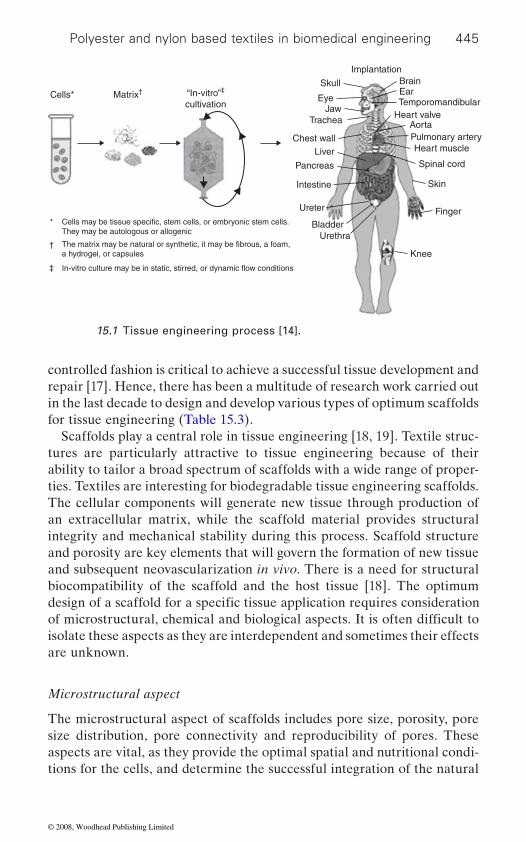
Polyester and nylon based textiles in biomedical engineering 445
controlled fashion is critical to achieve a successful tissue development and repair [17]. Hence, there has been a multitude of research work carried out in the last decade to design and develop various types of optimum scaffolds for tissue engineering (Table 15.3).
Scaffolds play a central role in tissue engineering [18, 19]. Textile struc-tures are particularly attractive to tissue engineering because of their ability to tailor a broad spectrum of scaffolds with a wide range of proper-
The cellular components will generate new tissue through production of an extracellular matrix, while the scaffold material provides structural integrity and mechanical stability during this process. Scaffold structure and porosity are key elements that will govern the formation of new tissue and subsequent neovascularization in vivo. There is a need for structural biocompatibility of the scaffold and the host tissue [18]. The optimum
isolate these aspects as they are interdependent and sometimes their effects are unknown.
Microstructural aspect
The microstructural aspect of scaffolds includes pore size, porosity, pore size distribution, pore connectivity and reproducibility of pores. These aspects are vital, as they provide the optimal spatial and nutritional condi-tions for the cells, and determine the successful integration of the natural
SkullCells*
*They may be autologous or allogenic
The matrix may be natural or synthetic, it may be fibrous, a foam,a hydrogel, or capsules
In-vitro culture may be in static, stirred, or dynamic flow conditions
†
‡
Matrix† “In-vitro”‡
cultivationEye
JawTrachea
Chest wallLiver
Pancreas
Intestine
Ureter
BladderUrethra
Knee
Finger
Skin
Spinal cord
Heart musclePulmonary arteryAorta
Heart valveTemporomandibularEarBrain
Implantation
15.1 Tissue engineering process [14].
Cells may be tissue specific, stem cells, or embryonic stem cells.
design of a scaffold for a specific tissue application requires consideration
ties. Textiles are interesting for biodegradable tissue engineering scaffolds.
of microstructural, chemical and biological aspects. It is often difficult to
© 2008, Woodhead Publishing Limited

446 Polyesters and polyamides
ence of two key scaffold design parameters, void fraction (VF) and pore size, on the attachment, growth, and extracellular matrix deposition by several cell types on disc shaped, porous L-PLA scaffolds with two VF (75% and 90%) and four pore size distributions (<38, 38–63, 63–106, and
muscle cells), and MVEC (microvascular epithelial cells ) showed uniform seeding on scaffolds with 90% VF for each pore size, in contrast to the
Table 15.3 Various scaffolds used in tissue engineering [9]
Tissue engineered biological substitute
Scaffold material Scaffold structures[yarn (y), woven (w), braided (b), knitted (k), and nonwoven (n)]
Bladder PGA Textile (n)
Blood vessel Polyester (Dacron), polyurethane, ePTFE, PGA, PLA, PGLA (Vicryl)
Collagen
Textile (n, w, b, k)
Textile (k)
Bone PGA, PLGA + hydroxyapatite Textile (n), Foam
Cartilage PGA, PLLA, PGLA FoamTextile (n)
Dental DL-PLA, PGLA (Vicryl) Foam (porous membrane), Textile (n)
Heart valve PGA Textile (n, w)
Tendon PGA Textile (n, y)
Ligament CollagenPGA, PLAGA
Textile (y)Textile (b, n)
Liver PGA, PLA, PGLA, polyorthoesters, polyanhydride
PLGA
Foam, Textile (n)
3D Printed
Nerve Collagen-glycosaminoglycan, PGA
Foam, Textile (n)
Skin PGA, PGLA (Vicryl), NylonCollagen-glycosaminoglycan
Textile (w)Foam
Note: PLAGA, PGLA, PLGA are copolymers of polyglycolic acid (PGA) and polylactic acid (PLA).
fibres PLLA
106–150 μm). DmFb (canine dermal fibroblasts), VSMC (vascular smooth
tissue and the scaffold. For example, Zeltinger et al. [20] studied the influ-
© 2008, Woodhead Publishing Limited

Polyester and nylon based textiles in biomedical engineering 447
corresponding 75% VF scaffolds. Culture data from scaffolds with a 75% VF suggests that the structural features were unsuitable for tissue forma-tion. Hence, there were limits of acceptable scaffold architecture (VF, pore size) that modulated in vitro cellular responses. Table 15.4 compares the various microstructural aspects of foams and textile structures.
Lee et al. [21] investigated the effect of interconnectivity of pores on cell attachment and proliferation as well as surface properties of PLGA scaffold for skin tissue engineering. The interconnectivity of pores deter-
as the consistency of tissue formation. In a typical textile scaffold, three
level of porosity in a textile scaffold can be controlled by changing the
variations in porosity can be achieved by using twisted, untwisted, tex-tured, untextured, continuous or spun yarns.
The gap or open space between the yarns (it is open space inside the loop in the case of knits) forms the second level of porosity. In the case of knitted scaffolds, the porosity can be varied selectively by changing the stitch density and the stitch pattern. In the case of braided scaffolds, poros-ity can be varied by controlling the bias angle of the interlacing yarns. For woven scaffolds, it is possible to change the porosity by controlling the inter-yarn gaps through a beating action. During the seeding on woven, braided and knitted scaffolds with hepatocytes, it has been observed that
yarns in the case of knitted scaffolds.It may be noted that woven and braided scaffolds share similar surface
topographies formed by the interlacing yarns. Knitted scaffolds, however,
blasts and hepatocytes may be due to their different cell sizes and shapes.
with diameters in the range 15 μm to 30 μm, and they retain their spherical
levels of porosity can be achieved. The arrangement of fibres in the yarn determines the accessible space for cells. The inter-fibre space (or groove between two adjacent fibres) may be considered as the first level of porosity.
important as it determines the dimensional stability of the scaffold as well of tissue engineering [22]. The reproducibility of scaffolds is also very
It has been found that the fibroblasts preferentially organize themselves along the length of the PET fibres, grouping along the groove created by two adjacent fibres. It is interesting to see that fibroblasts are capable of bridging fibres which are as far as 40 μm apart. The inter-fibre gap or first
number of fibres in the yarn and also the yarn packing density. Further
the cells attach preferentially at the inter-yarn gaps or pores in woven and
comprise curved yarns, which have a significant effect on the behaviour of hepatocytes. Unlike hepatocytes, the fibroblasts attach to the ridges of
braided scaffolds, whereas they clump together on the ridges of curved
yarns irrespective of the scaffold type. The different behaviour of fibro-
It may be noted that the diameter of fibroblasts ranges from 10 μm to
mines the transport of nutrients and waste and thus influences the success
20 μm, and they flatten out after attachment. The hepatocytes are larger
© 2008, Woodhead Publishing Limited
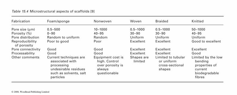
Table 15.4 Microstructural aspects of scaffolds [9]
Fabrication Foam/sponge Nonwoven Woven Braided Knitted
Pore size (μm) 0.5–500 10–1000 0.5–1000 0.5–1000 50–1000Porosity (%) 0–90 40–95 30–90 30–90 40–95Pore distribution Random to uniform Random Uniform Uniform UniformReproducibility
of porosityPoor to good Poor Excellent Excellent Good to excellent
Pore connectivity Good Good Excellent Excellent ExcellentProcessability Good Good Excellent Excellent GoodOther comments Current techniques are
associated with processing undesirable residues such as solvents, salt particles
Equipment cost is high. Control over porosity is always questionable
Shapes are limited
Limited to tubular or uniform cross-sectional shapes
Limited by the low bending
current biodegradable
WPTF3007
properties of
fibres
© 2008, Woodhead Publishing Limited
Polyester and nylon based textiles in biomedical engineering 449
structure even after attachment to the scaffold. Furthermore, a third kind of porosity can be introduced by subjecting the textile structures to second-ary operations such as crimping, folding, rolling, stacking, etc. In other
tremendous in the case of textile scaffolds [9].
Mechanical aspect
depends on the nature (constant or cyclic), type (uniaxial, biaxial, multi-axial, etc.) and magnitude of the mechanical stimulation. Mechanical stimulation also affects the release of soluble signalling factors and the deposition of extracellular matrix constituents [9, 23]. Researchers are making use of these observations in the case of bone tissue engineering. They are applying external mechanical stimulation to promote tissue for-mation [22, 24]. Therefore, in bone tissue engineering, the scaffolds are designed to withstand severe physiological loads [24]. In blood vessel appli-cations, the scaffold needs to be strong enough to withstand physiologically relevant pulsatile pressures and at the same time match the compliance or elasticity values of a native blood vessel [25, 26]. The mechanical aspects of various scaffolds are compared in Table 15.5. Of all the scaffolds, knits display considerable deformability and good compliance owing to their looped yarn arrangement. Hence, they are suitable for bladder [27, 28] and blood vessel tissue engineering applications [29].
Biological aspect
cellular activity. The surfaces with amine groups are best for the CHO (Chinese hamster ovary) cell adhesion, spreading and growth probably owing to the positively chargeable character in an aqueous cell culture medium; a large portion of cell or serum protein surface is recognized as being negatively charged, resulting in electrostatic interaction between the surfaces. For surfaces with neutral functional groups; hydroxyl groups
hydrogen bonding between the surface hydroxyl groups of the polymer and the polar groups of the cell surfaces. So the surface with COOH group showed poor cell adhesion due to the presence of negative charge [30]. Boyan et al. [31] showed that osteoblast response varies with the material
shape modification takes place as a result of external forces including
The mechanical aspect of scaffolds, such as structural stability, stiffness
gravity, and also of internal physical forces. Cell shape modification also
showed better cell spreading than amide groups, probably due to specific
words, it may be stated that the flexibility of microstructural parameters is
and strength, have considerable influence on cellular activity. For example, in tissues like bone, cell shape is influenced by mechanical forces. Cell
There is increasing evidence that scaffold surface chemistry influences
© 2008, Woodhead Publishing Limited
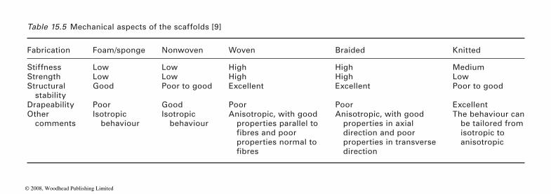
Table 15.5 Mechanical aspects of the scaffolds [9]
Fabrication Foam/sponge Nonwoven Woven Braided Knitted
Stiffness Low Low High High MediumStrength Low Low High High LowStructural stability
Good Poor to good Excellent Excellent Poor to good
Drapeability Poor Good Poor Poor ExcellentOther comments
Isotropic behaviour
Isotropic behaviour
Anisotropic, with good properties parallel to
properties normal to
Anisotropic, with good properties in axial direction and poor properties in transverse direction
The behaviour can be tailored from isotropic to anisotropic
WPTF3007
fibres and poor
fibres
© 2008, Woodhead Publishing Limited

Polyester and nylon based textiles in biomedical engineering 451
on which cells are cultured, and attributed this to differences in the surface chemistry, charge density and net polarity of the charge. Van Wachem
(HEC) and polymers with different wetabilities in a culture medium con-taining serum. Optimal adhesion occurred onto moderately wetable polymers.
these biopolymers belong to animal origin, so they are not antigenic and
of various factors, such as scaffold material, structure, physical, chemical, mechanical, and biological properties, cell types, in vitro or in vivo condi-tions, etc., determines the success of tissue engineering.
Fabric structure and design aspect
woven, knitted, nonwoven, braided and embroidery processes play a vital role in the manufacture of various implants, including the replacement of diseased or non-functioning blood vessels and segments of the aorta or
as 2 to 3 mm in diameter [10].
Woven
a high fabric count. This provided a type of graft which was rigid, tightly
Risbud et al. [41] reported cell growth on the scaffolds consists of a woven
chitosan-collagen membrane. Both collagen and chitosan are shown as suitable substrates for hepatocyte attachment, growth and differentiation. The degradable polymer membrane could create a concentration and pres-sure gradient on two sides of the membrane that will vary with the diffu-sion and perfusion properties of the scaffold with degradation. Karamuk et al. [42] coated the woven PET fabric on one side with a thin biodegrad-
scaffold for liver cell culture. The development of a composite structure ensures the stability of the membrane during in vitro degradation, inde-pendent of the mesh size. Similarly, Dacron fabric may absorb cyclodextrin
Modification of synthetic polymeric scaffolds by natural polymers (com-
37], fibronectin [38], laminin [39] improve their biological behaviour. Since
et al. [32] investigated the in vitro interaction of human endothelial cells
immunogenic, and they have high affinity for cell adhesion and their pro-
ponents of extracellular matrix (ECM)) like collagen [33–36], gelatin [2,
liferation due to presence of specific peptide sequence. So, the combination
Textile fibres, yarns, fabrics, composites and 3-D shaped fabrics from
other big arteries. It is even feasible to produce vascular prostheses as fine
The first commercial prostheses were woven on two sets of yarn that had
woven, and had a low permeability, therefore bleeding is reduced [40].
PET fabric with well defined macropores and coated with biodegradable
able film (PLGA), in order to obtain a polar structure for developing the
© 2008, Woodhead Publishing Limited
452 Polyesters and polyamides
(CD) which has been observed to show optimum behaviour as vascular grafts [43].
Nonwoven
Nonwovens are open porous, three dimensional structures in which the cells can proliferate and be supplied with nutrient solution. This is an important advantage, as the surface, on which cells can grow, is very large
characteristics similar to collagen which are not shared with non-textile materials. Spun bonded nonwovens are generally made by applying bonding
highly porous, 96% pre-volume), change surface properties and often
cut online and carded, laid down on a conveyor belt, strengthened by cal-
be fully oriented by online drawing resulting in incomplete crystallization.
is less (70%) than spun bounded nonwovens, but pore size can be large (up
prostheses. Pore size can be extremely small (1 μm) but porosity is also low (60%) [44].
The novel nonwoven PLGA structures produced by the electrospinning process have been developed for tissue engineering applications. The elec-trospun structure with 500 to 800 nm diameter features a morphologic similarity to the extracellular matrix (ECM) of a natural tissue, which acts
6 and nylon 12 due to electrospinning occurs, implying that a high stress is
stress alters the chain conformation of the nylon backbone [47]. Ma et al.
NFM) by electrospinning for blood vessel engineering. The electrospun
surface, followed by the grafting polymerization of methacrylic acid (MAA) initiated by Ce(IV). Finally, the PMAA-grafted PET NFM was grafted with gelatin using water-soluble carbodiimide as coupling agent. The gelatin grafting method can obviously improve the spreading and proliferation of
in relation to the amount of biomaterial implanted. Nonwovens have fibrous
render nonwoven nonbiocompatible. Staple fibre nonwovens are the fibres
agents or molten adhesives. These processing aids reduce pore size (but
endaring, and finally needled. But the major disadvantage associated with this is shrinkage after implantation in patients because the fibres cannot
An advantage of the staple fibre nonwoven process is the possibility of mixing fibres with different resorption rates, such as resorbable with non-
topography of the fibres themselves or the larger topography of the web of
to support and guide cell growth [45]. Cells on such surfaces are sensitive
spun fibres [46]. For example, a change in the chain conformation in nylon
induced on the electrospinning jet as the fibres are being formed, and this
[48] had also prepared polyethylene terephthalate nanofibre mats (PET
PET NFM was first treated in formaldehyde to yield hydroxyl groups on the
resorbable fibres. Microfibre fleeces are small tubular prosthesis. Porosity
to 300 μm). Solvent spun microfibre fleeces are small calibre vascular
to topography. Electrospinning can be altered to influence either the surface
© 2008, Woodhead Publishing Limited

Polyester and nylon based textiles in biomedical engineering 453
the ECs on the PET NFM, and moreover, can preserve the EC’s phenotype. A bilayered tubular scaffold composed of a stiff and oriented PLA outside
(PLA/PCL) was fabricated for blood vessel tissue engineering by sequen-tial multilayer electrospinning (ME). The resulting scaffolds achieved the desirable levels of pliability (elastic up to 10% stain) and proved to be capable of promoting cell growth and proliferation [49]. Nonwoven scaf-folds based on the PET, PGA and PLA have been developed for tissue engineering of the anterior cruciate ligament and cartilage [50, 51].
Knitted
In this type of fabric, the yarn used is enveloped around each other in two directions, warp knit (lengthwise) and weft knit (transversely) (Figure 15.2 [18]). The difference between both is that the weft-knit fabric loosens and the warp-knit does not. This type of construction provides more pores in the centre of loops of the knitted yarn than the woven fabrics. The knitted prostheses can also elongate thereby affecting its dimensional stability. The knitted polyester vascular prosthesis has become the standard vascular
(a)
(b)
15.2 Knitted polyester vascular graft structure: (a) weft knitting; (b) warp knitting [18].
fibrous layer and a pliable and randomly oriented PCL fibrous inner layer
© 2008, Woodhead Publishing Limited
454 Polyesters and polyamides
graft for replacement of arterial vessels of 6 mm and greater. The knitted structure, by its nature, is porous, which is what is required for incorpora-tion by tissue ingrowth from the host [2]. A major problem of arterial grafts (as with other vascular grafts) is the induction of clotting by the graft’s surface. To circumvent this problem, grafts are usually clotted with the patient’s own blood before implantation to reduce seepage through the knitted structure. Pre-clotting has been found useful in delaying or pre-venting thrombosis [2]. Branched hybrid vascular prostheses have also been developed on the base of type I collagen with minimal reinforcement by a knitted fabric mesh made of segmented polyester.
Embroidery
textile fabrics or other surfaces, e.g. leather, through the application of threads or other decorative objects (beads, cords, applications), by sewing them in or on, in an arrangement designed to achieve a pattern on the ground fabric [52]. What was until recently unthinkable has now come about: medicine has discovered embroidery. This is particularly advanta-geous with relatively small motifs. As opposed to weaving, where threads are arranged at rigid angles, embroidery also enables rounded patterns. Additionally, made-up embroidery goods are dimensionally stable – unlike knitted fabrics. This technology allows implants to be constructed in such a way that embroidered, three-dimensional structures become functional in tissue engineering [52]. Hernia patches, implants for intervertebral disc
by Ellies and coworkers [53].In the development of medical textiles, polyester is frequently used. If
specialized biocompatible materials are used, they are brought in at a later, more advanced stage of development, due to their high cost (up to US$4000/
tural and mechanical properties, favoured by tissue engineering as bone, cartilage or skin replacements [10]. Karamuk et al. [54] carried out tests with embroidered materials that decompose inside the body. These were threads made of polyglycolic acid (PGA). In vitro tests showed that forces in embroidery goods can be controlled by embroidery technology; in this way, the mechanical properties of the textile can be adapted to those of
Braided
A braid exhibits a locking angle, i.e., an angle between the carrier bundles of the braid which when reached prevents the individual carrier bundles
Embroidery is generally defined as the decoration of woven or knitted
repair and a graft stent for the repair of aortic aneurysm have been designed
kg). Various synthetic or natural polymer fibres feature very specific struc-
the body tissue, and inflammatory reactions can be avoided.
© 2008, Woodhead Publishing Limited
Polyester and nylon based textiles in biomedical engineering 455
from moving independently of each other thus resulting in a dramatic increase in stiffness. The scissoring effect of an opening and closing braid can damage ingrowing tissue. Braids are not the ideal structure for tissue engineering where there is expected to be regular loading and un-loading of the developing tissue [56]. Plain tubular braids may be used as prosthe-ses for the replacement of injured ligaments in joints, like the human knee joint [57, 58]. The simple reciprocal relation of braiding position to pick counts allows an easy determination of the limits of the braiding machine on the design and manufacturing of braids. This is important for the cal-culation of the stress-strain behaviour of the prosthesis, which should be adapted to the individual situation within the joint as well as to the intended implantation position [57]. Irsale et al. [58] focused on prototype manufac-turing of polymeric stents. The prototype is an integrated braided and tubular narrow woven fabric assembly.
as the reinforcing component, and the tubular narrow woven fabric tightly covering it acts as the sealing component. Prototypes of bifurcated braided stent for abdominal aortic aneurysm applications are also manufactured
Composite materials
Textile composites are produced by impregnating matrix materials into their dry preforms to hold the multidirectional yarns together. This is gen-erally done by liquid moulding techniques such as resin transfer moulding,
Peltola et al. [59] prepared a composite from P(L/DL)LA by the sol-gel method. Fibres having active surface properties or suitable porous struc-ture can be used as such or as a bioactive part in composites. Braided fabrics can be used in textile composites e.g. bone plates [60]. The integral structures of braided textile composites enable them to endure twisting, shearing and impact better than do woven or knitted fabrics. Due to their higher impact resistance/tolerance and stability or conformability under tension in the braided yarn system, the braided fabrics can be designed for multidirectional conformity [61]. Branched hybrid vascular prostheses have been developed on the base of type I collagen with minimal reinforce-ment by a knitted fabric mesh made of segmented polyester. The inner diameter was prepared by pouring a cold mixed solution of bovine smooth muscle cells and collagen into a corresponding tubular mould and by sub-sequent thermal gelatination, followed by seven-day culturing. Reinforce-ment with an elastomeric mesh improved mechanical strength of the hybrid tissue and created compliance matching with native arteries. A branched or bifurcated hybrid graft with mesh reinforcement is expected to be
The braided structure manufactured with polyester monofilaments acts
with braiding of polyester monofilaments [58].
structural reaction injection moulding, and resin film infusion. For example,
© 2008, Woodhead Publishing Limited

456 Polyesters and polyamides
applicable to arterial replacement in a branching region [62]. Huang et al. [63] evaluated the mechanical properties of the multilayered knitted fabric-reinforced composite laminates. These understandings are believed to be useful in the design of composite structures. Moutos et al. [64] presented a micro-scale 3D weaving technique to generate anisotropic 3D woven structures as the basis for novel composite scaffolds that are consolidated with a chrondocyte-hydrogel mixture into cartilage tissue constructs. Other biomedical applications of textile reinforced composites are dentistry and orthopaedics [65].
Surface activation for bifunctionalization of scaffold
Textile materials offer the possibility to combine compliance and porosity in scaffolds for organ reconstruction where it can support the three dimen-sional growth of cells to produce functional tissue [27]. Scaffolds have also been made from extracellular protein matrix components, such as collagen,
degrability and biocompatibility but suffer from the disadvantage that they cannot be freely or reproducibly processed into stable objects with three dimensional shapes of good mechanical strength. Conversly, scaffolds made from thermoplastic polymers have excellent strength and ductility and can be processed into various shapes and products, but do not have
tionality that may attract extracellular matrix proteins and later cells [27].
different types of biomaterials used for various purposes. Commonly tech-
Grafting process
Grafting technology has long been known in polymer chemistry, but the
Two methods are available for the grafting of a polymer surface: coupling reaction of existing polymer chains; and graft polymerization of monomers on to a preexisting polymer.
Plasma induced grafting on polyester
When polymeric materials are exposed to plasma, radicals are created in the polymeric chains. These radicals can initiate reactions when they are in contact with monomers in a liquid or gaseous phase. Inelastic collisions
laminin or fibronectin. These materials show excellent cell adhesion, bio-
need to be modified in such a way that the surface acquires chemical func-surfaces that readily interact with cells. These textile surfaces therefore
The surface modifications of synthetic polymers are necessary to make them bioreceptive. Various researchers worked on surface modification of
niques used for surface modifications are as follows.
modification of the polymer surface by grafting is a fairly new technology.
© 2008, Woodhead Publishing Limited
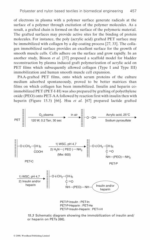
Polyester and nylon based textiles in biomedical engineering 457
of electrons in plasma with a polymer surface generate radicals at the surface of a polymer through excitation of the polymer molecules. As a result, a grafted chain is formed on the surface of the polymeric material. The grafted surfaces may provide active sites for the binding of protein molecules. For instance, the poly (acrylic acid) grafted PET surface may be immobilized with collagen by a dip coating process [27, 33]. The colla-gen immobilized surface provides an excellent surface for the growth of smooth muscle cells. Cells adhere on the surface and grow rapidly. In an another study, Bisson et al. [37] proposed a scaffold model for bladder reconstruction by plasma induced graft polymerization of acrylic acid on
immobilization and human smooth muscle cell expansion.
medium adsorbed spontaneously, proved to be better matrices than
immobilized PET (PET-I-H) was also prepared by grafting of polyethylene
heparin (Figure 15.3) [66]. Hsu et al. [67] prepared lactide grafted
PETO OH
O2 plasma
1) WSC, pH 4,7
in air Acrylic acid, 25°C
Sodium pyrosulfate120 W, 0.2 Tarr, 30 sec
O ( CH2 CH )n
COOH
PET-C
O ( CH2 CH )n
C O
PET-P
NH (PEO) NH2
( PEO ) NH22) H2N
2) Insulin and/or heparin
(Mw: 600)
O ( CH2 CH )n
C O
NH (PEO) NH
1) WSC, pH 4,7
PET-P-Insulin : PET-InPET-P-Heparin : PET-HePET-P-Insulin-Heparin : PET-I-H
Insulin and/orheparin
15.3 Schematic diagram showing the immobilization of insulin and/or heparin on PETs [66].
PET films which subsequently allowed collagen (Type I and Type III)
PAA-grafted PET films, onto which serum proteins of the culture
films on which collagen has been immobilized. Insulin and heparin co-
oxide (PEO) onto PET-AA followed by reaction first with insulin then with
© 2008, Woodhead Publishing Limited

458 Polyesters and polyamides
charge, followed by grafting L-lactide onto the plasma treated surface. The grafted surfaces showed enhanced attachment and growth in both 3T3
monomers grafted onto polyurethane substrates could therefore be useful in facilitating the endothelial cell seeding process in small vascular applications.
Radiation grafting on polyester
The material surface may be designed to exhibit a desired physico-chemi-cal nature by selection of monomer and grafting procedure. While gamma
leaving the bulk intact. PET surfaces prepared by grafting using these
hair transplants [70] and for the immobilization of biomolecules such as
tion induced graft polymerization of methacrylic acid (MAAc)/N-
the degree of grafting and the physical structure of the grafted fabric was investigated in this study. The grafted surfaces have also been evaluated for collagen immobilization and for seeding of urothelial cells with the ultimate aim of using this for applications in urology. Jou et al. [71] also
lowed by collagen (COL) by gluteraldehyde (GA). The results indicate that
antibacterial activity against pathological bacteria and improvement in the
15.2.2 Sutures
Sutures are probably the largest group of devices implanted in humans and can be used in skin, muscle, fat, organs and vessels. Although they seem to be of small concern to the medical community, few devices have been made of so many different materials. The suture market currently exceeds
mates and maintains tissues until the natural healing process has provided
to stop bleeding [72]. The United States Pharmacopoeia (USP), European
compendia for the suture industry, which sets standards and guidelines for
polyurethanes by exposing the polyurethane films to argon plasma dis-
fibroblast and human umbilical vein endothelial cell culture tests. L-lactide
radiation [68, 69] induced grafting leads to modification of both the surface and the bulk, UV, ozone, and plasma modification only affect the surface
techniques have for instance been evaluated as biomaterials for artificial
heparin and insulin [66]. Knitted PET fabric has been modified by radia-
grafted acrylic acid (AA) on PET fibre by a radiation method. The result-ing fibres were further grafted with chitosan (CS) via esterification fol-
by grafting with CS and immobilizing with COL, PET fibres exhibited both
proliferation of fibroblast.
US$1.3 bn annually. By definition: a suture is a thread that either approxi-
a sufficient level of wound strength or compresses blood vessels in order
Pharmacopoeia (EP) and British Pharmacopoeia (BP) are the official
vinylpyrrolidone (NVP) monomer. The influence of reaction conditions on
© 2008, Woodhead Publishing Limited

Polyester and nylon based textiles in biomedical engineering 459
suture manufacture. Suture sizes are given by a number-representing diam-eter ranging in descending order from 10 to 1 and then 1–0 to 12–0, 10 being the largest and 12–0 being the smallest at a diameter smaller than a human hair [73]. Table 15.6 shows the suture sizes.
Properties of sutures
The ideal suture is strong, handles easily and forms secure knots. It is
promote infection. It should be able to stretch, accommodate wound oedema and recoil to its original length with wound contraction. It should also be inexpensive. Since no single suture possesses all of these features, it is the physician’s task to weigh the advantages and disadvantages of the available suture materials [74]. The comparative information on the per-formance of various sutures is summarized in Table 15.7.
Knot strength
It is a measure of the amount of force necessary to cause a knot to slip and
Table 15.6 Suture sizes
P Diameter Tensile strength
4-0 0.2 mm 7.5 N3-0 0.3 mm 12.3 N2-0 0.35 mm 19.6 N0 0.4 mm 22.3 N1 0.5 mm 37.3 N
Table 15.7 Performance comparison of various suture materials [75]
Sutures Tensile strength
Tissue reactivity
Handling Knot security
Memory
High Low Poor Poor HighNylon, braided High Moderate Good Fair FairPolyester High Moderate Good Good FairPolyglycolic acid Good Low Fair Good LowPolyglycolide-lactide Good Low Good Fair LowPolycaprolactone Good Low Poor Poor High
Nylon, monofilament
is directly related to the coefficient of friction of a given material [76].
important that the suture causes minimal tissue inflammation and does not
© 2008, Woodhead Publishing Limited
460 Polyesters and polyamides
Bayraktar et al. [77] investigated the knot performance of various sutures and observed that knot performance depends on the surface properties.
threads in the braids have mobility, which increases the knot holding capac-ity. Therefore, there is no knot untying before the break for the braided
which allow them to pass easily through the tissue. At the same time, it decreases the knot holding capacity.
Elasticity
This refers to the intrinsic tension generated in a material after stretching, which causes it to return to its original length. Elasticity is a desirable feature, since it allows the suture to expand during wound oedema without causing strangulation or cutting of tissue, and to recoil during wound retraction, thereby maintaining wound edge apposition [74].
Memory
This refers to the inherent tendency of a suture material to return to its
and more likely to become untied compared with suture material that has less memory.
Tissue reactivity
suture material in the wound. This response peaks within two to seven days and is a function of the quantity of material present as well as its type and
tissues and result in decrease in wound strength. It was also observed that
security not only minimize the risk of suture line disruption but also reduce the amount of foreign material left in the wound by allowing the use of
infectious complications [74]. Because of the various features, the choice of suture material for any given wound closure should not be made arbi-trarily, but rather with careful attention to the physical and handling prop-erties of the suture, as well as its propensity for eliciting tissue reaction and promoting infection [74].
For a braided structure, the coefficient of friction is higher because the
structures. Monofilament sutures however have very smooth surfaces,
A suture with a high degree of memory is stiffer, more difficult to handle
configuration [76, 78, 79] Everett’s [80] studies have shown that an exces-
during the first five days. Sutures of superior tensile strength and knot
finer sutures and fewer knots. This, in turn, reduces tissue reaction and
original shape after being manipulated and is a reflection of its stiffness.
This refers to the inflammatory response generated by the presence of
sive inflammmatory reaction may lead to the softening of surrounding
nylon and polyester sutures produce the strongest inflammatory reaction
© 2008, Woodhead Publishing Limited

Polyester and nylon based textiles in biomedical engineering 461
sorbable. The application of the two categories depends on the type of procedure and the physician’s preference. Table 15.8 shows the absorbable and non-absorbable sutures [81].
Absorbable sutures
Absorbable sutures have ability to be ‘absorbed’ or decomposed by the natural reaction of the body to foreign substances. They are used internally and are designed to lose strength gradually over time by chemical reactions such as hydrolysis. It is important to note that not all absorbable sutures have the same resistance level to absorption, but each can be formulated or treated in order to obtain a desired decomposition rate and be excreted in urine or faeces, or carbon dioxide in expired air [82–84]. Currently, the most commonly used absorbable sutures are synthetic substances: poly-glycolic acid and polyglactic acid.
Nonabsorbable sutures
Nonabsorbable sutures are those, which do not lose their tensile strength for a long period of time. Generally, these sutures are used for closing cutaneous or oral incisions where the sutures can be easily removed e.g. nylon, braided polyester.
Polyglycolic acid suture
Introduced in 1970, polyglycolic acid (Dexon) (Figure 15.4), a polymer of
excellent tensile strength and knot strength, as well as delayed absorption and markedly diminished tissue reactivity compared with catgut. In animal
40% after seven days [85]. By 15 days, it has lost more than 80% of its original strength [86, 87]. By 28 days, this material retains only 5% of its original tensile strength, and it is completely dissolved by 90 to 120 days
Therefore, it is available in braided form for easier handling. Dexon also
OC CH2 On
15.4 Polyglycolic acid.
Classification of sutures
Sutures can also be classified into two categories: absorbable and nonab-
glycolic acid, was the first synthetic absorbable suture. It was hailed for its
studies, the absorption of polyglycolic acid suture was found to be about
tory response. As a monofilament, Dexon is stiff and difficult to work with. [88]. Polyglycolic acid is absorbed by hydrolysis, reducing the inflamma-
© 2008, Woodhead Publishing Limited
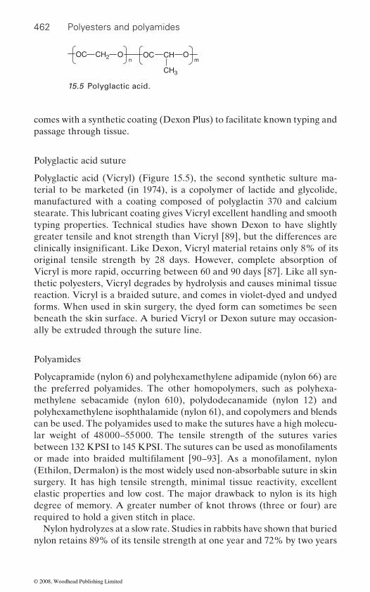
462 Polyesters and polyamides
comes with a synthetic coating (Dexon Plus) to facilitate known typing and passage through tissue.
Polyglactic acid suture
Polyglactic acid (Vicryl) (Figure 15.5), the second synthetic sulture ma-terial to be marketed (in 1974), is a copolymer of lactide and glycolide, manufactured with a coating composed of polyglactin 370 and calcium stearate. This lubricant coating gives Vicryl excellent handling and smooth typing properties. Technical studies have shown Dexon to have slightly greater tensile and knot strength than Vicryl [89], but the differences are
original tensile strength by 28 days. However, complete absorption of Vicryl is more rapid, occurring between 60 and 90 days [87]. Like all syn-thetic polyesters, Vicryl degrades by hydrolysis and causes minimal tissue reaction. Vicryl is a braided suture, and comes in violet-dyed and undyed forms. When used in skin surgery, the dyed form can sometimes be seen beneath the skin surface. A buried Vicryl or Dexon suture may occasion-ally be extruded through the suture line.
Polyamides
Polycapramide (nylon 6) and poly hexamethylene adipamide (nylon 66) are the preferred polyamides. The other homopolymers, such as polyhexa-methylene sebacamide (nylon 610), polydodecanamide (nylon 12) and
can be used. The polyamides used to make the sutures have a high molecu-lar weight of 48 000–55 000. The tensile strength of the sutures varies
(Ethilon, Dermalon) is the most widely used non-absorbable suture in skin surgery. It has high tensile strength, minimal tissue reactivity, excellent elastic properties and low cost. The major drawback to nylon is its high degree of memory. A greater number of knot throws (three or four) are required to hold a given stitch in place.
Nylon hydrolyzes at a slow rate. Studies in rabbits have shown that buried nylon retains 89% of its tensile strength at one year and 72% by two years
OC CH2 On
OC CH Om
CH3
15.5 Polyglactic acid.
clinically insignificant. Like Dexon, Vicryl material retains only 8% of its
between 132 KPSI to 145 KPSI. The sutures can be used as monofilaments
polyhexamethylene isophthalamide (nylon 61), and copolymers and blends
or made into braided multifilament [90–93]. As a monofilament, nylon
© 2008, Woodhead Publishing Limited
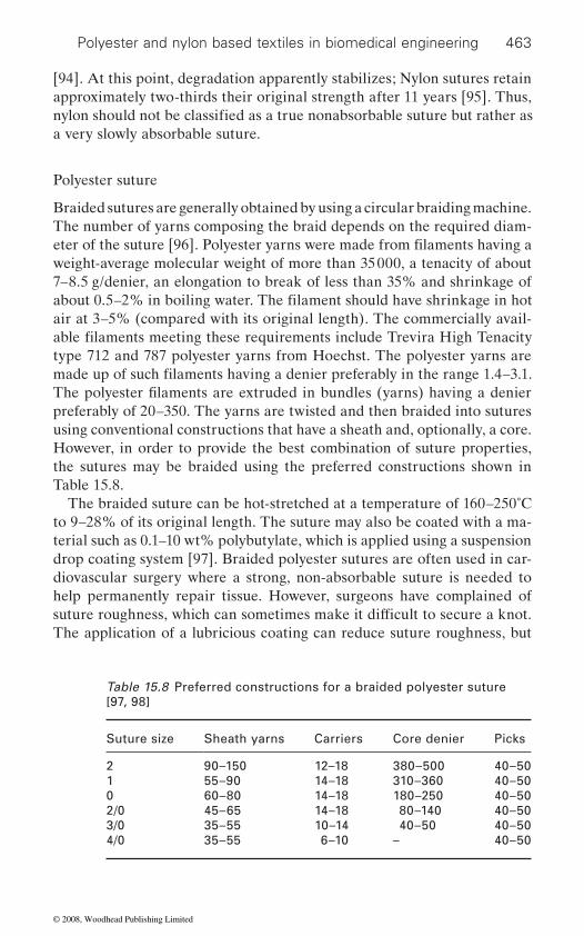
Polyester and nylon based textiles in biomedical engineering 463
[94]. At this point, degradation apparently stabilizes; Nylon sutures retain approximately two-thirds their original strength after 11 years [95]. Thus,
a very slowly absorbable suture.
Polyester suture
Braided sutures are generally obtained by using a circular braiding machine. The number of yarns composing the braid depends on the required diam-
weight-average molecular weight of more than 35 000, a tenacity of about 7–8.5 g/denier, an elongation to break of less than 35% and shrinkage of
air at 3–5% (compared with its original length). The commercially avail-
type 712 and 787 polyester yarns from Hoechst. The polyester yarns are
preferably of 20–350. The yarns are twisted and then braided into sutures using conventional constructions that have a sheath and, optionally, a core. However, in order to provide the best com bination of suture properties, the sutures may be braided using the preferred constructions shown in Table 15.8.
The braided suture can be hot-stretched at a temperature of 160–250˚C to 9–28% of its original length. The suture may also be coat ed with a ma-terial such as 0.1–10 wt% polybutylate, which is applied using a suspension drop coating system [97]. Braided polyester sutures are often used in car-diovascular surgery where a strong, non-absorbable suture is needed to help perma nently repair tissue. However, surgeons have complained of
The application of a lubricious coating can reduce suture roughness, but
Table 15.8 Preferred constructions for a braided polyester suture [97, 98]
Suture size Sheath yarns Carriers Core denier Picks
2 90–150 12–18 380–500 40–501 55–90 14–18 310–360 40–500 60–80 14–18 180–250 40–502/0 45–65 14–18 80–140 40–503/0 35–55 10–14 40–50 40–504/0 35–55 6–10 – 40–50
nylon should not be classified as a true nonabsorbable suture but rather as
eter of the suture [96]. Polyester yarns were made from filaments having a
about 0.5–2% in boiling water. The filament should have shrinkage in hot
able filaments meeting these requirements include Trevira High Tenacity
made up of such fil aments having a denier preferably in the range 1.4–3.1. The polyester filaments are extruded in bundles (yarns) having a denier
suture roughness, which can sometimes make it difficult to secure a knot.
© 2008, Woodhead Publishing Limited
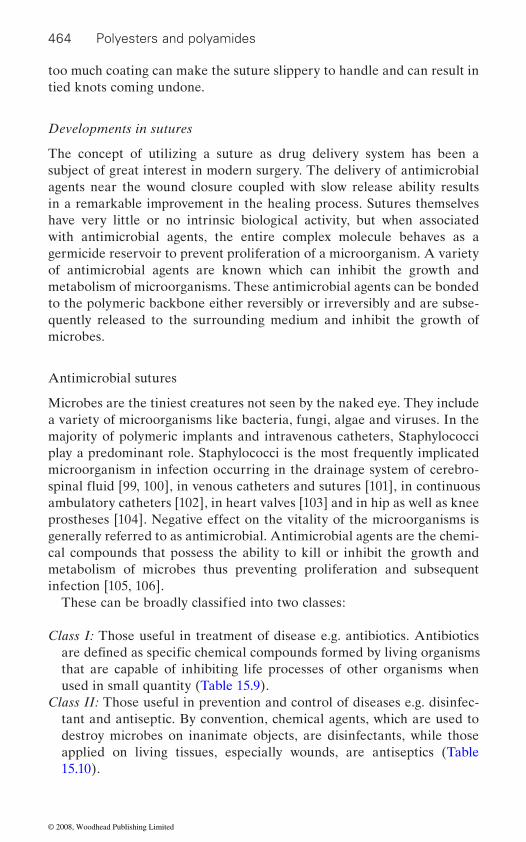
464 Polyesters and polyamides
too much coating can make the suture slippery to handle and can result in tied knots coming undone.
Developments in sutures
The concept of utilizing a suture as drug delivery system has been a subject of great interest in modern surgery. The delivery of antimicrobial agents near the wound closure coupled with slow release ability results in a remarkable improvement in the healing process. Sutures themselves have very little or no intrinsic biological activity, but when associated with antimicrobial agents, the entire complex molecule behaves as a germicide reservoir to prevent proliferation of a microorganism. A variety of antimicrobial agents are known which can inhibit the growth and metabolism of microorganisms. These antimicrobial agents can be bonded to the polymeric backbone either reversibly or irreversibly and are subse-quently released to the surrounding medium and inhibit the growth of microbes.
Antimicrobial sutures
Microbes are the tiniest creatures not seen by the naked eye. They include a variety of microorganisms like bacteria, fungi, algae and viruses. In the majority of polymeric implants and intravenous catheters, Staphylococci play a predominant role. Staphylococci is the most frequently implicated microorganism in infection occurring in the drainage system of cerebro-
ambulatory catheters [102], in heart valves [103] and in hip as well as knee prostheses [104]. Negative effect on the vitality of the microorganisms is generally referred to as antimicrobial. Antimicrobial agents are the chemi-cal compounds that possess the ability to kill or inhibit the growth and metabolism of microbes thus preventing proliferation and subsequent infection [105, 106].
Class I: Those useful in treatment of disease e.g. antibiotics. Antibiotics
that are capable of inhibiting life processes of other organisms when used in small quantity (Table 15.9).
Class II: Those useful in prevention and control of diseases e.g. disinfec-tant and antiseptic. By convention, chemical agents, which are used to destroy microbes on inanimate objects, are disinfectants, while those applied on living tissues, especially wounds, are antiseptics (Table 15.10).
These can be broadly classified into two classes:
are defined as specific chemical compounds formed by living organisms
spinal fluid [99, 100], in venous catheters and sutures [101], in continuous
© 2008, Woodhead Publishing Limited

Polyester and nylon based textiles in biomedical engineering 465
Preparation of antimicrobial sutures
The antimicrobial activity in sutures can be achieved by the following methods:
1. Blending or incorporation of volatile or nonvolatile antimicrobial agent while processing
Table 15.9 Class 1 compounds and their mode of action
Chemical agents Mechanism of action
Penicillin, Cephalosporin Inhibition of bacterial cell wall and cell membrane synthesis
Amphotericin B, Nystatin Disruption of bacterial cell wallSulphonamides, Nitrofuran,
Ketoconazole, MiconazoleInhibition of bacterial metabolism
Griseofulvin Inhibition of nucleic acid synthesisInhibition of DNA synthesis
Rifamycin, Rifampicion, Actinomycin D, Ethidium bromide, α-Amanitin
Inhibition of RNA synthesis
Streptomycin, Tetracycline hydrochloride, Kanamycin, Doxycyclin, Chloramphenicol, Amikacin
Inhibition of protein synthesis
Table 15.10 Class 2 compounds with their mode of action
Chemical agents Mechanism of action
Phenol and phenolic compounds
Disruption of plasma membrane, denaturation, inactivation of enzyme
Chlorhexidine Disruption of plasma membraneHalogens Iodine inhibits protein function and is a strong
oxidizing agent, chlorine forms the strong oxidizing agent hypochlorous acid, which alters cellular components
Alcohols Denaturation of lipidsHeavy metals and their
saltsDenaturation of enzymes and other essential
proteinsSurface active agents
soaps and detergentsMechanical removal of microbes through
scrubbingAnionic detergents Not certain; may be involved in enzyme
inactivation or disruptionQuaternary compounds Enzyme inhibition, protein denaturation and
disruption of plasma membraneOrganic acids Metabolic inhibition, mostly affecting mouldsAldehydes Protein inactivationOxidizing agents OxidationGaseous sterlants Denaturation
Nlidixic acid, Norfloxacin, Ciprofloxacin
© 2008, Woodhead Publishing Limited
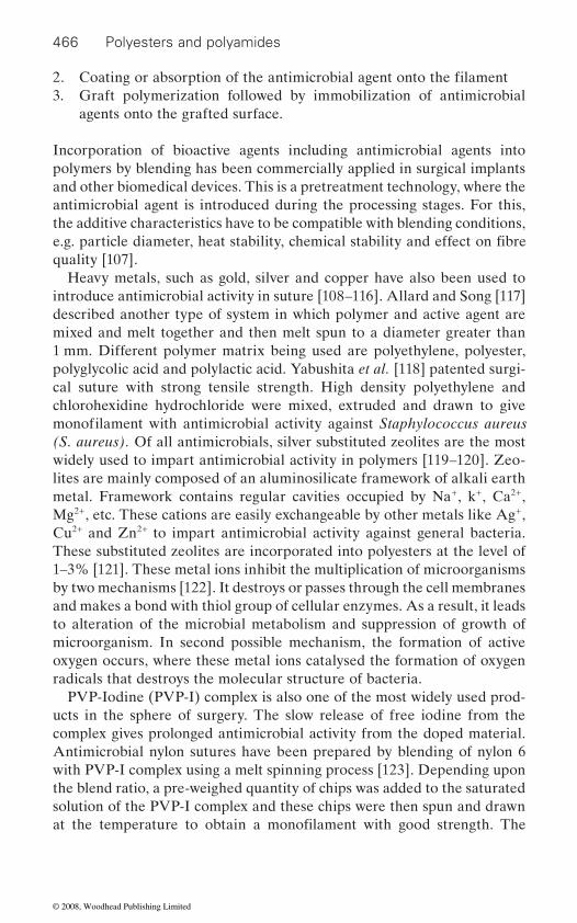
466 Polyesters and polyamides
2. 3. Graft polymerization followed by immobilization of antimicrobial
agents onto the grafted surface.
Incorporation of bioactive agents including antimicrobial agents into polymers by blending has been commercially applied in surgical implants and other biomedical devices. This is a pretreatment technology, where the antimicrobial agent is introduced during the processing stages. For this, the additive characteristics have to be compatible with blending conditions,
quality [107].Heavy metals, such as gold, silver and copper have also been used to
introduce antimicrobial activity in suture [108–116]. Allard and Song [117] described another type of system in which polymer and active agent are mixed and melt together and then melt spun to a diameter greater than 1 mm. Different polymer matrix being used are polyethylene, polyester, polyglycolic acid and polylactic acid. Yabushita et al. [118] patented surgi-cal suture with strong tensile strength. High density polyethylene and chlorohexidine hydrochloride were mixed, extruded and drawn to give
(S. aureus). Of all antimicrobials, silver substituted zeolites are the most widely used to impart antimicrobial activity in polymers [119–120]. Zeo-lites are mainly composed of an aluminosilicate framework of alkali earth metal. Framework contains regular cavities occupied by Na+, k+, Ca2+, Mg2+, etc. These cations are easily exchangeable by other metals like Ag+, Cu2+ and Zn2+ to impart antimicrobial activity against general bacteria. These substituted zeolites are incorporated into polyesters at the level of 1–3% [121]. These metal ions inhibit the multiplication of microorganisms by two mechanisms [122]. It destroys or passes through the cell membranes and makes a bond with thiol group of cellular enzymes. As a result, it leads to alteration of the microbial metabolism and suppression of growth of microorganism. In second possible mechanism, the formation of active oxygen occurs, where these metal ions catalysed the formation of oxygen radicals that destroys the molecular structure of bacteria.
PVP-Iodine (PVP-I) complex is also one of the most widely used prod-
complex gives prolonged antimicrobial activity from the doped material. Antimicrobial nylon sutures have been prepared by blending of nylon 6 with PVP-I complex using a melt spinning process [123]. Depending upon the blend ratio, a pre-weighed quantity of chips was added to the saturated solution of the PVP-I complex and these chips were then spun and drawn
Coating or absorption of the antimicrobial agent onto the filament
e.g. particle diameter, heat stability, chemical stability and effect on fibre
monofilament with antimicrobial activity against Staphylococcus aureus
ucts in the sphere of surgery. The slow release of free iodine from the
at the temperature to obtain a monofilament with good strength. The
© 2008, Woodhead Publishing Limited
Polyester and nylon based textiles in biomedical engineering 467
sutures have polar bonding between nylon and PVP-I complex, which
natively, silver may be used as an effective antimicrobial agent, e.g. a blend
E. coli, pseudomonas, klebsiella, staphylococcus and streptococcus species. The rate of killing (decrease of survival) increased with increase in silver
absorption spectrometry.In the post-processing technology, the most common technique for
applying the antibacterial agent is coating. Antimicrobial agents that cannot tolerate the temperature used in polymer processing are often coated onto the material after fabrication. The antimicrobial agents are linked to the surface through physical bonds or anchored by the cross-
bial properties and good physical properties are prepared by coating a
mented urethane polymer. Stephenson [124] coated polyester sutures with copolymer of polyquaternary polyurethane and polyanionic polymer such as heparin followed by treatment with antimicrobial agent streptomycin sulphate. The resultant antimicrobial suture gave a zone of inhibition of 0.55 cm against Bacillus subtilis. Antimicrobial coating on polyester suture was carried out by depositing an antimicrobial biocompatible metal by vapour deposition technique [125]. In one of the studies, it was found that immersing catgut, Dacron, silk, or chromic sutures for 24 h in a 5% or 50%
S. aureus, as compared with that of unsoaked sutures [126]. Dacron and silk suture coated with a silver-zinc-allantoin complex did, however, reduce the number of adherent S. aureus colonies by 88% and 99%, respectively.
suture material, whereas the silver-zinc-allantoin complex provides slow
Blacker et al. [128] used silver doped bioactive glass powder (AgBr) to coat absorbable Vicryl and non-absorbable Mersilk surgical suture. Stable homogeneous coating on the surface of the suture was achieved by using an optimized aqueous slurry dipping technique. The in vitro bioactivity of
three days of immersion in SBF, bone-like hydroxyapatite formed on the coated suture indicating the enhanced bioactive behaviour. In vitro anti-microbial evaluation of polyglactin 910 suture coated with triclosan has shown attractive results. The antibacterial activity of the coated suture was
of nylon fibre and silver coated nylon fibre (known as X-static) may be used
results in the slow and controlled release of iodine from the sutures. Alter-
for suture application [113]. This fibre exhibits bactericidal property against
ion concentration of the fibre extract, as determined through atomic
linking on the fibre. Antimicrobial sutures having long lasting antimicro-
multifilament suture with a solution of an antimicrobial agent and seg-
The investigators attributed the differences in in vitro efficacies of the dif-
aqueous solution of silver nitrate did not appreciably reduce adherence of
ferently coated sutures to the fact that silver nitrate firmly binds to the
release of silver ions sufficient to inhibit bacterial adherence [127].
the suture was tested by immersion in simulated body fluid (SBF). After
© 2008, Woodhead Publishing Limited
468 Polyesters and polyamides
evaluated against S. aureus and S. epidermis and produced zones of inhibi-
Knotted suture with triclosan gives a bacteria-free zone having volume of 14.5 cm3 for S. epidermis and 17.8 cm3 for S. aureus [129].
Iodine can be attached to polyamide sutures to provide them antimicro-bial property. Antimicrobial nylon suture has been prepared by coating the
acetone and was tested for iodine release and antimicrobial properties against E. coli and S. aureus by zone of inhibition method. It was found that it showed a comparatively slower release of iodine as compared to blended suture since in coated suture iodine is present mainly on the surface so initial release is higher, then it decreases. It was also observed that a clear zone of inhibition was formed around 6 mm in the case of E. coli and 8 mm in the case of S. aureus.
iodine [131]. Iodine doped sutures exhibited good antibacterial activity
.
around the wound over 10–18 days. Lin et al. [133] reported that nylon 66
N-halamine functional groups to the nylon 66 molecules at the amide nitrogen, using formaldehyde as a linking agent followed by chlorination. Biocidal swatch tests showed that the nylon fabrics containing N-chlorinated hydantoin functional groups provided a 7.2 log reduction of S. aureus and 7.1 log reduction of E. coli at contact time of only 10 min,
time of 71 s.The radiation, plasma and chemical methods of grafting have occupied
the attention of numerous researchers for many years [134–136]. Graft polymerization offers an effective approach to introduce desirable proper-ties into the polymers without affecting the architecture of the polymer backbone [137, 138]. Grafting of hydrophilic monomers provides a good platform for the introduction of antimicrobial activity. The grafted side chains contain functional groups to which various bioactive materials can be attached. These functional groups include amine, carboxylic acid and hydroxyl groups, which can be utilized further for the attachment on anti-microbial drug [139, 140]. This approach of graft functionalization has been successfully used for the development of polypropylene sutures by incorporating acrylonitrile and vinylimidazole grafts into the suture matrix
tion after five and ten passes through fascia and subcutaneous tissue.
monofilament with iodine [130]. Nylon 6 monofilament was treated with iodine by immersing the filament in a saturated solution of iodine in
Multifilament nylon suture has been made antibacterial by doping with
of the polyamide sutures has also been modified by binding of drug doxy-cycline [132] The modified suture showed the release of drug into and
against E.coli, S. aureus, P. aeruginosa and K. pneumomea. The surface
fibres could be rendered antimicrobial by chemical binding of heterocyclic
whereas unchlorinated fibres gave no reduction of bacteria even at a contact
immobilized onto the modified sutures and their effectiveness against dif-[141–145]. Both tetracycline hydrochloride and ciprofloxacin have been
© 2008, Woodhead Publishing Limited
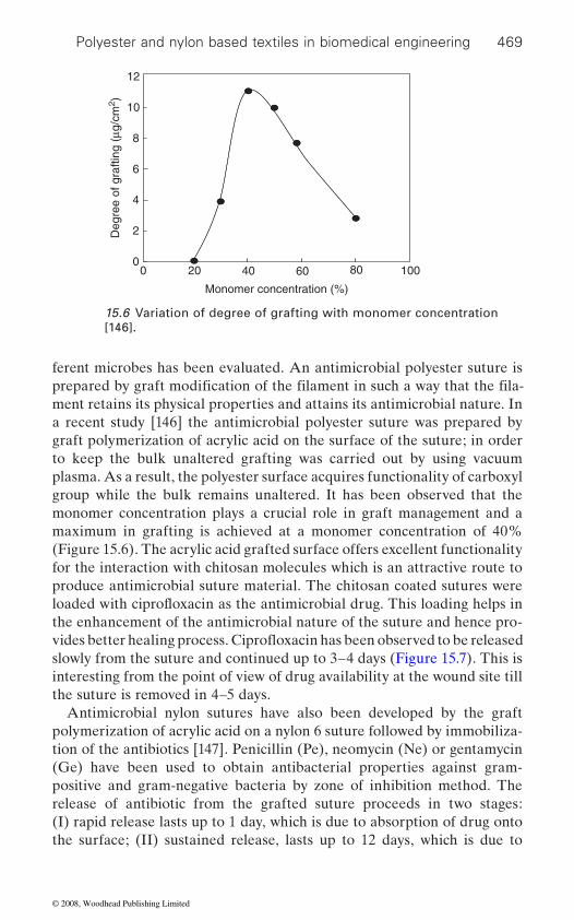
Polyester and nylon based textiles in biomedical engineering 469
ferent microbes has been evaluated. An antimicrobial polyester suture is
ment retains its physical properties and attains its antimicrobial nature. In a recent study [146] the antimicrobial polyester suture was prepared by graft polymerization of acrylic acid on the surface of the suture; in order to keep the bulk unaltered grafting was carried out by using vacuum plasma. As a result, the polyester surface acquires functionality of carboxyl group while the bulk remains unaltered. It has been observed that the monomer concentration plays a crucial role in graft management and a maximum in grafting is achieved at a monomer concentration of 40% (Figure 15.6). The acrylic acid grafted surface offers excellent functionality for the interaction with chitosan molecules which is an attractive route to produce antimicrobial suture material. The chitosan coated sutures were
the enhancement of the antimicrobial nature of the suture and hence pro-
slowly from the suture and continued up to 3–4 days (Figure 15.7). This is interesting from the point of view of drug availability at the wound site till the suture is removed in 4–5 days.
Antimicrobial nylon sutures have also been developed by the graft polymerization of acrylic acid on a nylon 6 suture followed by immobiliza-tion of the antibiotics [147]. Penicillin (Pe), neomycin (Ne) or gentamycin (Ge) have been used to obtain antibacterial properties against gram-positive and gram-negative bacteria by zone of inhibition method. The release of antibiotic from the grafted suture proceeds in two stages: (I) rapid release lasts up to 1 day, which is due to absorption of drug onto the surface; (II) sustained release, lasts up to 12 days, which is due to
Monomer concentration (%)
0
2
4
6
8
10
40200 8060 100
12
Deg
ree
of g
rafti
ng (
μg/c
m2 )
15.6 Variation of degree of grafting with monomer concentration [146].
prepared by graft modification of the filament in such a way that the fila-
loaded with ciprofloxacin as the antimicrobial drug. This loading helps in
vides better healing process. Ciprofloxacin has been observed to be released
© 2008, Woodhead Publishing Limited
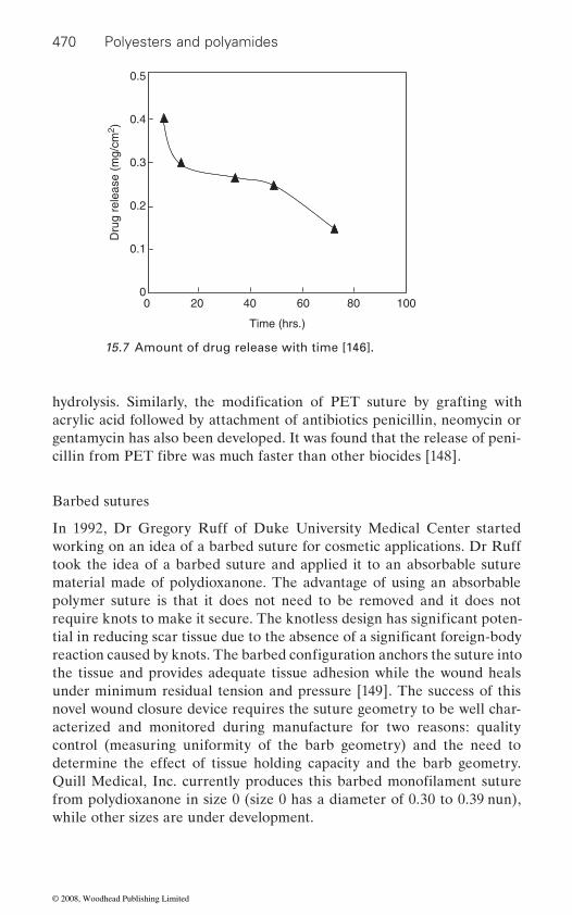
470 Polyesters and polyamides
acrylic acid followed by attachment of antibiotics penicillin, neomycin or gentamycin has also been developed. It was found that the release of peni-
Barbed sutures
In 1992, Dr Gregory Ruff of Duke University Medical Center started working on an idea of a barbed suture for cosmetic applications. Dr Ruff took the idea of a barbed suture and applied it to an absorbable suture material made of polydioxanone. The advantage of using an absorbable polymer suture is that it does not need to be removed and it does not
the tissue and provides adequate tissue adhesion while the wound heals under minimum residual tension and pressure [149]. The success of this novel wound closure device requires the suture geometry to be well char-acterized and monitored during manufacture for two reasons: quality control (measuring uniformity of the barb geometry) and the need to determine the effect of tissue holding capacity and the barb geometry.
from polydioxanone in size 0 (size 0 has a diameter of 0.30 to 0.39 nun), while other sizes are under development.
Dru
g re
leas
e (m
g/cm
2 )
Time (hrs.)
0
0.1
0.2
0.3
0.4
0.5
40200 8060 100
15.7 Amount of drug release with time [146].
hydrolysis. Similarly, the modification of PET suture by grafting with
cillin from PET fibre was much faster than other biocides [148].
require knots to make it secure. The knotless design has significant poten-tial in reducing scar tissue due to the absence of a significant foreign-body reaction caused by knots. The barbed configuration anchors the suture into
Quill Medical, Inc. currently produces this barbed monofilament suture
© 2008, Woodhead Publishing Limited
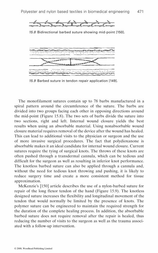
Polyester and nylon based textiles in biomedical engineering 471
spiral pattern around the circumference of the suture. The barbs are divided into two groups facing each other in opposing directions around the mid-point (Figure 15.8). The two sets of barbs divide the suture into two sections, right and left. Internal wound closure yields the best results when using an absorbable material. Using nonabsorbable wound closure material requires removal of the device after the wound has healed. This can lead to additional visits to the physician or surgeon and the use of more invasive surgical procedures. The fact that polydioxanone is absorbable makes it an ideal candidate for internal wound closure. Current sutures require the tying of surgical knots. The throws of these knots are often pushed through a transdermal cannula, which can be tedious and
The knotless barbed suture can also be applied through a cannula and, without the need for tedious knot throwing and pushing, it is likely to reduce surgery time and create a more consistent method for tissue approximation.
McKenzie’s [150] article describes the use of a nylon-barbed suture for
tendon that would normally be limited by the presence of knots. The polymer suture can be engineered to maintain the required strength for the duration of the complete healing process. In addition, the absorbable barbed suture does not require removal after the repair is healed, thus reducing the number of visits to the surgeon as well as the trauma associ-ated with a follow-up intervention.
15.8 Bidirectional barbed suture showing mid-point [150].
15.9 Barbed suture in tendon repair application [149].
The monofilament sutures contain up to 78 barbs manufactured in a
difficult for the surgeon as well as resulting in inferior knot performance.
repair of the long flexor tendon of the hand (Figure 15.9). The knotless designed suture increases the flexibility and longitudinal movement of the
© 2008, Woodhead Publishing Limited
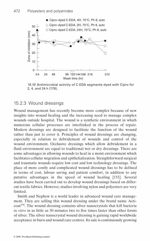
472 Polyesters and polyamides
15.2.3 Wound dressings
Wound management has recently become more complex because of new insights into wound healing and the increasing need to manage complex wounds outside hospital. The wound is a synthetic environment in which numerous cellular processes are interlinked in the process of repair. Modern dressings are designed to facilitate the function of the wound rather than just to cover it. Principles of wound dressings are changing, especially in relation to debridement of wounds and control of the wound environment. Occlusive dressings which allow debridement in a
some advantages in allowing wounds to heal in a moist environment which facilitates cellular migration and epithelialization. Straightforward surgical and traumatic wounds require low cost and low technology dressings. The
in terms of cost, labour saving and patient comfort, in addition to any putative advantages in the speed of wound healing [151]. Several studies have been carried out to develop wound dressings based on differ-ent textile fabrics. However, studies involving nylon and polyesters are very limited.
Smith and Nephew is a world leader in advanced wound care manage-ment. They are selling this wound dressing under the brand name Acti-coatTM. The wound dressing contains silver nanocrystals that kill bacteria
of silver. The silver nanocrystal wound dressing is gaining rapid worldwide acceptance in burn and wound care centres. Its sale is continuously growing
10
0
20
30
482440 168 21614412096
50
40
312Wash time (hr)
Zon
e of
inhi
bitio
n (m
m)
Cipro–dyed C-EDA, 4H, 70°C, Ph 8, auto
Cipro–dyed C-EDA, 2H, 70°C, Ph 8, auto
Cipro–dyed C-EDA, 24H, 70°C, Ph 8, auto
15.10 Antimicrobial activity of C-EDA segments dyed with Cipro for 2, 4, and 24 h [178].
place of more costly and complicated wound dressings has to be defined
in vitro in as little as 30 minutes two to five times faster than other forms
fluid environment are equal to traditional wet or dry dressings. There are
© 2008, Woodhead Publishing Limited

Polyester and nylon based textiles in biomedical engineering 473
at double digit rates. The revenue from sales has increased from £1.7 million in 1999 to £6 million in 2003. The product is now being sold in more than 30 countries [152].
Phaneuf et al. [153] have developed a novel lightweight bioactive compression wound dressing based on polyester that provides durable infection resistance and localized haemostatic properties. Polyester (Dacron) material with polyurethane inlaid into the structure is utilized as the base material to provide the required physical properties (i.e. elasticity,
technology, and a biologically active protein, thrombin, a pivotal enzyme
surface.
15.2.4 Bandages
It should be stressed that one of the high-tech areas of medical textiles is the application of bandages for enhancing the quality of life. In fact, ban-daging techniques emanate from ancient practice that facilitates further developments in improving the comfort and performance properties of value added products. Bandages are designed to perform a whole variety of special functions depending upon the type of wound and medical requirements. They can be woven, nonwoven or knitted and are either elastic or non-elastic [1].
Types of bandages
most useful method is one based upon their function as follows. The ability of a bandage to perform one or more of these functions is largely deter-mined by its elastic properties, although the thickness, weight and con-formability of the fabric are also important. Table 15.11 shows the different
Compression bandages
Compression bandages are mainly employed for the treatment of venous leg ulcers and varicose veins. It may be noted that, in the United Kingdom, there are some 400 000 leg ulcer sufferers, 70% of whom have ulcers that are venous in origin [154]. The aim of the use of compression bandaging is the reduction of venous hypertension which results from valvular insuf-
durability). The surface is modified to develop functional groups. An anti-
in the blood coagulation cascade, is covalently attached to the modified
Bandages can be classified in a number of different ways but possibly the
types of bandages, their fibre types and fabric structure [1].
ficiency [155]. The application of external compression by means of a
biotic (ciprofloxacin) is incorporated into the material via textile dyeing
bandage serves to increase the velocity of the blood flow within the veins
© 2008, Woodhead Publishing Limited
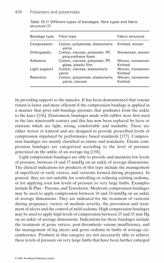
474 Polyesters and polyamides
by providing support to the muscles. It has been demonstrated that venous
a manner that gives sub-bandage pressure that graduates from the ankle
in the late nineteenth century and this has now been replaced by lycra or elastane which are light, strong, comfortable and washable. These are either woven or knitted and are designed to provide prescribed levels of compression stipulated by performance based standards [157]. Compres-
pression bandages are categorized according to the level of pressure generated on the ankle of an average leg [158].
Light compression bandages are able to provide and maintain low levels of pressure, between 14 and 17 mmHg on an ankle of average dimensions. The clinical indications for products of this type include the management
general, they are not suitable for controlling or reducing existing oedema, or for applying even low levels of pressure to very large limbs. Examples include K-Plus – Parema, and Tensolastic. Moderate compression bandages may be used to apply compression between 18 and 24 mmHg on an ankle of average dimensions. They are indicated for the treatment of varicosis during pregnancy, varices of medium severity, the prevention and treat-ment of ulcers and the control of mild oedema. High compression bandages may be used to apply high levels of compression between 25 and 35 mm Hg on an ankle of average dimensions. Indications for these bandages include
the management of leg ulcers and gross oedema in limbs of average cir-cumference. Products in this category are not necessarily able to achieve these levels of pressure on very large limbs that have been further enlarged
structure [1]
Bandage type Fibre type Fabric structure
Compression Cotton, polyamide, elastomeric yarns
Knitted, woven
Orthopaedic Cotton, viscose, polyester, PP, polyurethane foam
Nonwoven, woven
Adhesive Cotton, viscose, polyester, PP, Woven, nonwovenKnitted
Light support Cotton, viscose, elastomericyarns
Woven, nonwovenKnitted
Retention Cotton, polyamide, elastomeric yarns, viscose
Woven, nonwovenKnitted
Table 15.11 Different types of bandages, fibre types and fabric
glass, plastic film
return is faster and more efficient if the compression bandage is applied in
to the knee [156]. Elastomeric bandages made with rubber were first used
sion bandages are mainly classified as elastic and nonelastic. Elastic com-
of superficial or early varices, and varicosis formed during pregnancy. In
the treatment of gross varices, post-thrombotic venous insufficiency, and
© 2008, Woodhead Publishing Limited
Polyester and nylon based textiles in biomedical engineering 475
by the presence of oedema. Examples include Tensopress, Setopress and Surepress. Extra-high performance compression bandages are capable of applying pressures up to 60 mmHg. The power in the bandages is such that they can be expected to apply and sustain these pressures on even the largest and most oedematous limbs for extended periods. This group includes Elastic Web Bandage BP (Blue Line Webbing) and Varico Bandage [159].
Compression can be exerted to the leg either by a single layer
a nonwoven padding bandage that absorbs exudate and protects bony prominences from excessive pressure. The second layer is a crepe bandage which adds absorbency and smoothes the padding layer. The third layer is a light compression bandage that is highly conformable to accommodate
applies pressure and is cohesive in nature, which means the bandages stay in place and maintain effective levels of compression for up to one week.
Studies conducted to assess the relative effectiveness of different com-pression bandages and compression stockings in the treatment of venous leg ulcers incorporated 27 products manufactured by different companies. The studies included comparisons between compression and no compres-sion; between elastic multilayer high-compression bandages and non-elastic high compression bandages, as well as non-elastic multilayer high-compression bandages; between multilayer high-compression ban-dages and single-layer high-compression bandages; between alternative multilayer systems; and between compression stockings and compression bandages. It was concluded that compression increases ulcer-healing rates compared with the situation when there is no compression. High compres-sion is more effective than low compression but should only be used in the absence of arterial disease. It is generally accepted that composite bandage systems are most effective when a long-stretch or short-stretch bandage system is used. A comparative study after 15 weeks’ treatment of patients with venous ulceration indicated that the ulcer-healing rate for the long-stretch bandage was 58% as compared with 38% for the short-stretch
bandage system has been proved to be successful in treating a patient with chronic ulcerations to his upper arm [1].
were suitable for the treatment of exudating venous leg ulcers. The
bandage or multilayer bandages. In the four layer system the first layer is
bandage. Similarly, a calcium alginate dressing combined with a four-layer
hydrofibre-dressing group demonstrated a significantly lower frequency of dressing changes than that with alginate-fibre dressings. More patients achieved a seven-day wear time with the hydrofibre dressing than with
In another study, it was found that non-occlusive hydrofibre dressings
alginate-fibre [1].
a diff i cult limb shape. The fourth layer is a cohesive flexible bandage. It
© 2008, Woodhead Publishing Limited
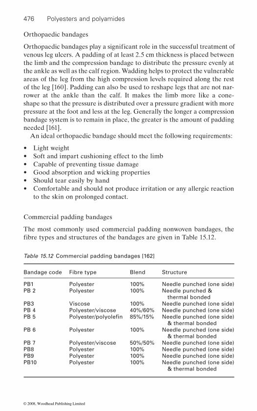
476 Polyesters and polyamides
Orthopaedic bandages
venous leg ulcers. A padding of at least 2.5 cm thickness is placed between the limb and the compression bandage to distribute the pressure evenly at the ankle as well as the calf region. Wadding helps to protect the vulnerable areas of the leg from the high compression levels required along the rest of the leg [160]. Padding can also be used to reshape legs that are not nar-rower at the ankle than the calf. It makes the limb more like a cone-shape so that the pressure is distributed over a pressure gradient with more pressure at the foot and less at the leg. Generally the longer a compression bandage system is to remain in place, the greater is the amount of padding needed [161].
An ideal orthopaedic bandage should meet the following requirements:
• Light weight• Soft and impart cushioning effect to the limb• Capable of preventing tissue damage• Good absorption and wicking properties• Should tear easily by hand• Comfortable and should not produce irritation or any allergic reaction
to the skin on prolonged contact.
Commercial padding bandages
The most commonly used commercial padding nonwoven bandages, the
Table 15.12 Commercial padding bandages [162]
Bandage code Fibre type Blend Structure
PB1 Polyester 100% Needle punched (one side)PB 2 Polyester 100% Needle punched &
thermal bondedPB3 Viscose 100% Needle punched (one side)PB 4 Polyester/viscose 40%/60% Needle punched (one side)PB 5 85%/15% Needle punched (one side)
& thermal bondedPB 6 Polyester 100% Needle punched (one side)
& thermal bondedPB 7 Polyester/viscose 50%/50% Needle punched (one side)PB8 Polyester 100% Needle punched (one side)PB9 Polyester 100% Needle punched (one side)PB10 Polyester 100% Needle punched (one side)
& thermal bonded
Orthopaedic bandages play a significant role in the successful treatment of
fibre types and structures of the bandages are given in Table 15.12.
Polyester/polyolefin
© 2008, Woodhead Publishing Limited
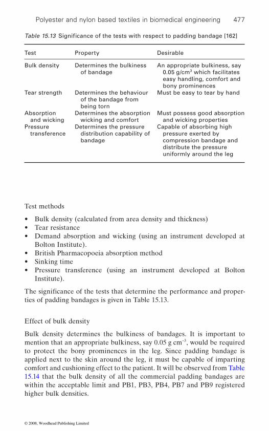
Polyester and nylon based textiles in biomedical engineering 477
Test methods
• Bulk density (calculated from area density and thickness)• Tear resistance• Demand absorption and wicking (using an instrument developed at
Bolton Institute).• British Pharmacopoeia absorption method• Sinking time• Pressure transference (using an instrument developed at Bolton
Institute).
ties of padding bandages is given in Table 15.13.
Effect of bulk density
Bulk density determines the bulkiness of bandages. It is important to mention that an appropriate bulkiness, say 0.05 g cm−3, would be required to protect the bony prominences in the leg. Since padding bandage is applied next to the skin around the leg, it must be capable of imparting comfort and cushioning effect to the patient. It will be observed from Table 15.14 that the bulk density of all the commercial padding bandages are within the acceptable limit and PB1, PB3, PB4, PB7 and PB9 registered higher bulk densities.
Test Property Desirable
Bulk density Determines the bulkiness of bandage
An appropriate bulkiness, say 0.05 g/cm3 which facilitates easy handling, comfort and bony prominences
Tear strength Determines the behaviour of the bandage from being torn
Must be easy to tear by hand
Absorption and wicking
Determines the absorption wicking and comfort
Must possess good absorption and wicking properties
Pressure transference
Determines the pressure distribution capability of bandage
Capable of absorbing high pressure exerted by compression bandage and distribute the pressure uniformly around the leg
Table 15.13 Significance of the tests with respect to padding bandage [162]
The significance of the tests that determine the performance and proper-
© 2008, Woodhead Publishing Limited
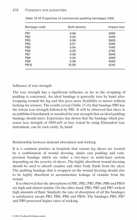
478 Polyesters and polyamides
padding is concerned. An ideal bandage is generally torn by hand after
looking for scissors. The results reveal (Table 15.14) that bandage PB5 has the lowest tear strength followed by PB1. It will be observed that there is no published benchmark or standard for tear strength that an ideal padding bandage should meet. Experience has shown that the bandage which pos-sesses tear strength of 5000 mN or less, tested by using Elmendorf tear instrument, can be torn easily, by hand.
Relationship between demand absorption and wicking
It is a common practice in hospitals that venous leg ulcers are treated by a combination of wound dressing, under cast padding and com-pression bandage which are either a two-layer or multi-layer system depending on the severity of ulcers. The highly absorbent wound dressing
The padding bandage that is wrapped on the wound dressing should also to be highly absorbent to accommodate leakage of exudate from the wound.
It is observed that the absorptions of PB1, PB2, PB5, PB6, PB8 and PB10 are high and almost similar. On the other hand, PB3, PB5 and PB7 wicked
is satisfactory except PB3, PB6, PBS and PB10. The bandages PB4, PB7 and PB9 possessed higher rates of wicking.
Table 15.14 Properties of commercial padding bandages [162]
Bandage code Bulk density Impact tear
PB1 0.06 2560PB2 0.04 4480PB3 0.06 3600PB4 0.07 3280PB5 0.04 1440PB6 0.05 3760PB7 0.06 3840PB8 0.04 4880PB9 0.06 4560PB10 10.05 4240
Influence of tear strength
The tear strength has a significant influence as far as the wrapping of
wrapping around the leg and this gives more flexibility to nurses without
should be used to absorb exudate and other body fluids from the ulcer.
high amounts of fluid. Similarly the rate of absorption of all the bandages
© 2008, Woodhead Publishing Limited
Polyester and nylon based textiles in biomedical engineering 479
Pressure distribution of commercial bandages
Padding bandage is applied beneath the compression bandage. The degree of pressure that is induced into the leg by the compression bandage is of major importance. It has been demonstrated that too high a pressure on the leg not only leads to further complications of the venous system but also promotes arterial disease. In contrast, inadequate pressure cannot help to heal the venous ulcers. Even if the compression bandage is applied at the correct tension it is probable that excessive pressure will be gener-ated over the bony prominences of the leg. Therefore there is a need to distribute the pressure equally and uniformly at all points of the lower limb and this can be achieved by applying an effective padding layer around the leg below the compression bandage.
It is observed that none of the bandages provide uniform pressure dis-tribution up to 60 mmHg. However PB5, PB6 and PB8 did distribute the
the even pressure distribution degrades thereafter. It is vital that an ideal padding bandage should dissipate the pressure between 30 and 40 mmHg, exerted by high compression bandage, uniformly around the limb.
Adhesive bandages
An adhesive bandage usually has an absorbent pad (often medicated with antiseptic) covered by woven fabric, plastic, or latex rubber which has an adhesive. The plaster is applied such that the pad covers the wound (but does not stick to the wound), and the fabric or plastic sticks to the sur-rounding skin to hold the dressing in place and prevent dirt from entering
used to speed healing and minimize scarring. Adhesive bandages are gen-erally applied to provide support rather than compression. The adhesive coating helps to ensure that the bandages do not slip or become displaced.
support or compression in the treatment of sprains and strains. Diachylon
place of bandages coated with a zinc oxide adhesive where skin sensitivity reactions are present or suspected [163].
Adhesive bandages are characterized by their construction of two basic components, the adhesive coated backing material and the wound covering pad material. While such bandages are effective and desirable products, the assembly of the component materials during production results in increased manufacturing and inventory costs. In addition, the packaging of individual bandages requires additional handling and materials which further increases manufacturing costs. The bandage material is preferably
applied pressure evenly only up to around 7 mmHg and the efficiency of
the wound. Some newer plasters also contain woven strands of silver fibre,
These bandages are commonly used for strapping purposes and to provide
adhesive bandage, more commonly known as Lestreflex, is often used in
© 2008, Woodhead Publishing Limited
480 Polyesters and polyamides
a heat-bondable, absorbent, nonwoven fabric which provides loft and absorbency in the pad area, while the single thickness wing portions of the bandage and the wrapper portion are heat calendered to provide a
density, highly absorbent, thermal bonded nonwoven fabric comprising
These nonwoven fabrics are produced by a process which includes produ-
the higher melting component while maintaining the web under little or no compression; and cooling the web to resolidify the lower melting com-
through-air heater to fuse the lower melting component of the conjugate
the material emerges from the heater and cools, the fused surfaces of the
solidify, and bonds form where these surfaces touch each other and other
thereof [163].
Light support bandages
Light support bandages are also called short or minimal stretch bandages. They include the familiar crepe-type products of the British Pharmaco-
which are manufactured from cotton or cotton and viscose, and which show considerable variability in performance. They are used to prevent the formation of oedema and give support in the management of mild sprains and strains. Compared with the compression bandages, light support or minimal stretch bandages have limited extensibility and elasticity, and tend to ‘lock out’ at relatively low levels of extension. This feature enables them
cant levels of pressure. Short stretch bandages have also been used for the
absorbent fibres and staple length polyester-polyethylene conjugate fibres.
cing a web comprising absorbent fibres and staple length polyester/poly-
dense, sheet-like material. The bandage material is preferably a low
ethylene conjugate fibres; subjecting the web to a temperature sufficient to fuse the lower melting component of the conjugate fibres without fusing
ponent of the conjugate fibres, thereby forming a nonwoven fabric bonded at sites where the conjugate fibres touch each other and adjacent absorbent fibres.
of a mixture of short-length natural cellulose fibres and staple length poly-A particularly preferred nonwoven fabric is a laminate comprising a core
fibres on each surface of the core. The composite web is passed through a
fibres while maintaining the fibrous integrity of these fibres, and to fuse or
ester/polyethylene conjugate fibres, and a lightweight veneer of heat-fusible
soften the surfaces of the heat-fusible fibres in the two outer veneers. As
lower melting component of the conjugate fibres, i.e. the polyethylene,
fibres. Absorbent fibres employed in such thermal-bonded, nonwoven fabrics include rayon staple fibres, cotton fibres, short length natural cel-lulose fibres such as wood pulp fibres and cotton linters, and mixtures
poeia together with numerous ‘non-official’ variations of these bandages,
to be applied firmly over a joint to give support without generating signifi-
© 2008, Woodhead Publishing Limited

Polyester and nylon based textiles in biomedical engineering 481
treatment of venous leg ulcers. When applied at full extension, they form an inelastic covering to the leg, which tends to resist any change in the geometry of the calf muscle during exercise, thereby increasing surface pressure in a cyclical fashion and enhancing the action of the calf muscle pump [164].
Similarly, when an individual moves from a supine to a standing position or sits with the legs dependent, blood collects in the vessels and sinuses of
to increase. If this is associated with the formation of oedema, leg volume will increase still further. A short stretch bandage applied at full stretch, with the legs elevated, will tend to resist a change in volume as the legs are
rise in sub-bandage pressure, the degree of which will be determined by whether the subject is sitting or standing. Because short stretch bandages have limited elasticity, they are likely to be less effective than high com-pression bandages at reducing existing oedema as they lack the ability to ‘follow in’ as a limb reduces in circumference. They may, however, offer some advantages in the treatment of venous ulcers where a degree of arterial impairment is known or suspected as the low residual pressures
support bandages (including short stretch bandages) include Elastocrepe, Leukocrepe, Lenkelast and Comprilan.
Retention bandages
Retention bandages are used to retain dressings or other wound contact materials in position. They should not be used to apply pressure and are therefore totally unsuited for use in the management of leg ulcers or for the control of oedema. A number of different types of retention bandages
a rigid fabric with extremely limited conformability that is available in a range of widths. Because of the poor performance characteristics of WOW two softer more retentive bandages were introduced. These are Kling and Crinx, the cotton bandages of the British Pharmacopoiea. These light-
sible to give them a useful degree of conformability.The ideal retention bandage should have a long shallow extensibility
increase sub-bandage pressure, which in any event should not normally exceed a few millimetres of mercury. More recently lightweight woven and knitted bandages have been introduced which contain elastomeric yarns. These bandages, sometimes called ‘contour’ or ‘conforming stretch’ ban-dages, are often cheaper than the original cotton products and are said to
placed in a dependent position. This restriction will result in a significant
are available. The first ‘retention bandage’ was White Open Wove (WOW),
weight cotton products have very little elasticity but are sufficiently exten-
curve so that small changes in limb circumference will not significantly
the lower leg under the influence of gravity, causing the volume of the leg
will be less likely to compromise arterial inflow. Examples of light
© 2008, Woodhead Publishing Limited
482 Polyesters and polyamides
be easier to use. Many different types are available which include Slinky,
ent membrane of 40 microns thick. It is manufactured from polyurethane
mers such as acrylamide and hydroxyethyl methacrylate. In the dry state
exudates or aqueous solutions, it absorbs water and changes its physical properties, becoming highly conformable and elastic. Unlike traditional
turbed it will separate spontaneously from a healed wound once epithelial
is thus able to cope with the exudates produced from all but the most
such as silver sulphadiazine, povidone iodine and chlorhexidine gluconate
surface of the dressing in the form of a cream or as an aqueous solution absorbed on several layers of gauze. It has been suggested that this tech-nique may be used to administer topical antimicrobial agents to wounds
Omiderm is recommended for the treatment of donor sites, dermabrasions and partial thickness burns and may also be used as a temporary dressing
It is not currently recommended for use on infected or dirty wounds [165].
15.3 Textiles for hygiene products
An increasing improvement in qualitative standards of human lifestyles has brought a greater sense of comfort and cleanliness. People are more and more looking for fresh public living surroundings and a higher level of hygiene in home areas. A wide class of micro-organisms coexists in a natural equilibrium with human body and living environments, but a rapid and uncontrolled multiplication of microbes can seriously compromise the hygienic and healthy personal standards. Because of their capillary spread in human living spaces, textiles have been involved in this research on improving the quality of hygienic living conditions. Many efforts have been
Stayform, Tensofix, J Form and J Fast [164].
which has been chemically modified by the addition of hydrophilic mono-
the film is relatively inelastic but when brought into contact with wound
moist wound without the need for additional fixative agents or sutures. The
semi-permeable film dressings such as Opsite, Tegaderm and Bioclusive,
film is easily removed without causing pain or trauma but if left undis-
cover is achieved. The film itself is highly permeable to moisture vapour,
Omiderm is not coated with adhesive but nevertheless will adhere to a
heavily exuding wounds. Omiderm is also significantly more permeable to
at least 20 times more permeable than the traditional film dressings, and
bility of the film is not limited to water and oxygen. Antimicrobial agents oxygen than standard polyurethane film dressings. However the permea-
can pass through the film onto the wound beneath if applied to the outer
dressed with Omiderm to prevent infection or lower the bacterial count.
on full thickness wounds at the discretion of the medical officer in charge.
A new film dressing called Omiderm consists of a thin, flexible, transpar-
© 2008, Woodhead Publishing Limited
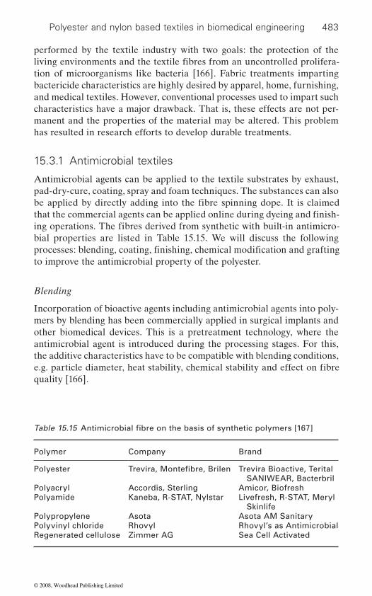
Polyester and nylon based textiles in biomedical engineering 483
performed by the textile industry with two goals: the protection of the
tion of microorganisms like bacteria [166]. Fabric treatments imparting bactericide characteristics are highly desired by apparel, home, furnishing, and medical textiles. However, conventional processes used to impart such characteristics have a major drawback. That is, these effects are not per-manent and the properties of the material may be altered. This problem has resulted in research efforts to develop durable treatments.
15.3.1 Antimicrobial textiles
Antimicrobial agents can be applied to the textile substrates by exhaust, pad-dry-cure, coating, spray and foam techniques. The substances can also
bial properties are listed in Table 15.15. We will discuss the following
to improve the antimicrobial property of the polyester.
Blending
Incorporation of bioactive agents including antimicrobial agents into poly-mers by blending has been commercially applied in surgical implants and other biomedical devices. This is a pretreatment technology, where the antimicrobial agent is introduced during the processing stages. For this, the additive characteristics have to be compatible with blending conditions,
quality [166].
Polymer Company Brand
Polyester Trevira Bioactive, Terital SANIWEAR, Bacterbril
Polyacryl Accordis, Sterling Amicor, BiofreshPolyamide Kaneba, R-STAT, Nylstar Livefresh, R-STAT, Meryl
SkinlifePolypropylene Asota Asota AM SanitaryPolyvinyl chloride Rhovyl Rhovyl’s as AntimicrobialRegenerated cellulose Zimmer AG Sea Cell Activated
living environments and the textile fibres from an uncontrolled prolifera-
be applied by directly adding into the fibre spinning dope. It is claimed that the commercial agents can be applied online during dyeing and finish-ing operations. The fibres derived from synthetic with built-in antimicro-
processes: blending, coating, finishing, chemical modification and grafting
e.g. particle diameter, heat stability, chemical stability and effect on fibre
Table 15.15 Antimicrobial fibre on the basis of synthetic polymers [167]
Trevira, Montefibre, Brilen
© 2008, Woodhead Publishing Limited

484 Polyesters and polyamides
Silver–zirconium based antimicrobial agents have also been widely used for imparting long lasting antimicrobial properties [168, 169]. Wash fast
ylene terephthalate and 2% Ag ion supported zirconium phosphate were
tion to about 99% and 88% after 10 and 250 washings, respectively [170]. In another method, silver ions containing Zeomic show antimicrobial effects against a wider spectrum of microorganisms including Gram-negative bacteria such as Escherichia coli and Pseudomonas aeruginosa; Gram-positive bacteria such as Staphylococcus aureus and MRSA; and fungi such as Aspergillus niger and Penicillium nigricans (Table 15.16) [171].
Different bactericides like Cu, Ag, pyridine chloride, ethonium rivanol
and kinamycin monosulphate were observed to be active against gram-positive and gram-negative bacteria [172].
Coating
In post-processing technology, the most common approach for applying the antibacterial agent is the coating. Antimicrobial agents that cannot
Table 15.16 Antimicrobial effect of polyester cloth containing Zeomic [171]
Tested bacteria Test samples Number of bacteria per cloth after contact
0 hr 6 hr
Escherichia coli 12Control
3.6 × 10⁵
3.6 × 10⁵
3.6 × 10⁵
10 or less6.5 × 104
2.4 × 10⁵
Pseudomonas aeruginosa
12Control
1.3 × 10⁵
1.3 × 10⁵
1.3 × 10⁵
10 or less1.9 × 104
4.8 × 10⁴
MRSA 12Control
9.8 × 10⁴
9.8 × 10⁴
9.8 × 10⁴
10 or less1.1 × 105
1.1 × 10⁵
MRSE 12Control
1.8 × 10⁴
1.8 × 10⁴
1.8 × 10⁴
10 or less8.7 × 103
1.8 × 10⁴
Trichophyton mentagrophytes
12Control
3.5 × 10⁴
3.5 × 10⁴
3.5 × 10⁴
6.9 × 10²
4.8 × 10⁴
9.6 × 10⁴
antibacterial synthetic fibres like polyester were prepared by mixing metal ion supported inorganic compounds with fibre forming polymers. Polyeth-
melt spun to give antibacterial fibres exhibiting Pneumonia bacilli extinc-
and kinamycin monosulphate have been used in polyester fibres where Ag
© 2008, Woodhead Publishing Limited
Polyester and nylon based textiles in biomedical engineering 485
tolerate the temperature during polymer processing are often coated onto the material after fabrication. The antimicrobial agents are linked to the
[172].An approach for antimicrobial coating of polyester is by using silk
sericin. Silk sericin is a natural macromolecular protein derived from silk-worm, Bombyx mori. Sericin protein can be cross-linked, copolymerized,
polymers, to produce materials with improved properties. The protein is also used as an improving reagent or a coating material for natural and
0.001–10 mm diameter. The sericin molecule can be introduced into these
by cross-linking with glyceryl polyglycidyl ether and diethylene triamine.
scopic as untreated polyesters and more than 85% of initial hygroscopicity remains after 50 washes [173].
Finishing
• Durability to washing, dry cleaning and hot pressing• Selective activity to undesirable microorganisms• Should not produce harmful effects to the manufacturer, user and the
environment• Compatibility with the chemical processes• Easy method of application• No deterioration of fabric quality• • Resistant to disinfections/sterilization.
Hydrolyzed PET treated with 10% w/v seed extract (without any cross-linking agent) showed antimicrobial activity of 89% and 32% even after one washing against Bacillus subtilis and Protues vulgaris respectively. This is may be due to more physical and hydrophobic interaction between the hydrolyzed PET and the neem seed extract. The lesser antimicrobial activity of neem seed extract against gram-negative bacteria is again proved here.
From the Table 15.17, it is observed that antimicrobial activity of 84% has been obtained after one washing using 10% neemazal technical (seed
surface through physical bonds or anchored by cross-linking on the fibre.
anchored onto the fibre surface so that it has to be constantly reapplied Since most of these antimicrobial agents are water soluble, they are weakly
and blended with other macromolecular materials, especially artificial
artificial fibres, fabrics, and articles. Polyester fibres have micro-pores of
micropores and cross-linked. Sericin-modified polyester fibre is obtained
The sericin-modified polyester fibre can be more than five times as hygro-
The following requirements need to be satisfied to obtain maximum ben-efits out of the finish:
Resistant to body fluids
© 2008, Woodhead Publishing Limited
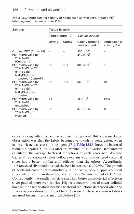
486 Polyesters and polyamides
extract) along with citric acid as a cross-linking agent. But one remarkable observation was that the fabric becomes yellowish to some extent when using citric acid as crosslinking agent [174]. Table 15.18 shows the bacterial reduction against S. aureus after 30 minutes of cultivation. Researchers calculated the average bacterial reductions of each silver size. Average bacterial reductions of silver colloids explain why smaller sized colloidal
11.6 nm sized silver colloids had the best bacteriostasis, 99.9%. The growth of bacterial colonies was absolutely inhibited by only 10 ppm colloidal silver when the mean diameter of silver was 2–5 nm instead of 11.6 nm. Consequently, the smaller particle sizes had better antibacterial effects on silver-padded nonwoven fabrics. Higher concentrations of silver colloids have better bacteriostasis because bacterial reductions decreased when the silver concentrations in the pad bath decreased. These nonwoven fabrics
Table 15.17 Antibacterial activity of neem seed extract (10%) treated PET fabric against Bacillus subtilis [174]
Samples Tested bacteria
Temperature (˚C) Bacillus subtilis
Drying Curing Colony forming units (cfu)/ml
Antibacterial activity (%)
Original PET (Control-I) – – 335 × 105 –PET hydrolysed by
20% NaOH (Control-II)
– – 340 × 105 –
PET hydrolysed by 20% NaOH + C/L (citric acid NaH2PO2H2O2),1 washed (Control-III)
85 180 300 × 105 10
PET hydrolysed by 20% NaOH + C/L (citric acid NaH2PO2H2O2), 1 washed
85 180 55 × 105 84
PET hydrolysed by 20% NaOH, unwashed
85 – 15 × 105 95.5
PET hydrolysed by 20% NaOH, 1 washed
85 – 37 × 10 5 89
silver has a better antibacterial efficacy than the others. Accordingly,
are used for air filters or medical clothes [175].
© 2008, Woodhead Publishing Limited
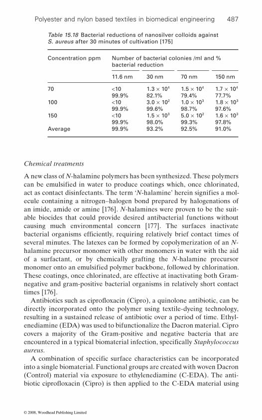
Polyester and nylon based textiles in biomedical engineering 487
Chemical treatments
A new class of N-halamine polymers has been synthesized. These polymers
ecule containing a nitrogen–halogen bond prepared by halogenations of an imide, amide or amine [176]. N-halamines were proven to be the suit-
causing much environmental concern [177]. The surfaces inactivate
several minutes. The latexes can be formed by copolymerization of an N-halamine precursor monomer with other monomers in water with the aid of a surfactant, or by chemically grafting the N-halamine precursor
These coatings, once chlorinated, are effective at inactivating both Gram-negative and gram-positive bacterial organisms in relatively short contact times [176].
directly incorporated onto the polymer using textile-dyeing technology, resulting in a sustained release of antibiotic over a period of time. Ethyl-enediamine (EDA) was used to bifunctionalize the Dacron material. Cipro covers a majority of the Gram-positive and negative bacteria that are
aureus.
into a single biomaterial. Functional groups are created with woven Dacron (Control) material via exposure to ethylenediamine (C-EDA). The anti-
Table 15.18 Bacterial reductions of nanosilver colloids against S. aureus after 30 minutes of cultivation [175]
Concentration ppm Number of bacterial colonies /ml and % bacterial reduction
11.6 nm 30 nm 70 nm 150 nm
70 <1099.9%
1.3 × 10⁴
82.1%1.5 × 10⁴
79.4%1.7 × 10⁴
77.7%100 <10
99.9%3.0 × 10²
99.6%1.0 × 10³
98.7%1.8 × 10³
97.6%150 <10
99.9%1.5 × 10³
98.0%5.0 × 10²
99.3%1.6 × 10³
97.8%Average 99.9% 93.2% 92.5% 91.0%
can be emulsified in water to produce coatings which, once chlorinated, act as contact disinfectants. The term ‘N-halamine’ herein signifies a mol-
bacterial organisms efficiently, requiring relatively brief contact times of
able biocides that could provide desired antibacterial functions without
monomer onto an emulsified polymer backbone, followed by chlorination.
encountered in a typical biomaterial infection, specifically Staphylococcus
A combination of specific surface characteristics can be incorporated
Antibiotics such as ciprofloxacin (Cipro), a quinolone antibiotic, can be
biotic ciprofloxacin (Cipro) is then applied to the C-EDA material using
© 2008, Woodhead Publishing Limited
488 Polyesters and polyamides
pad/autoclave technique (C-EDA-AB) followed by surface immobilization of the coagulation cascade enzyme thrombin (C-EDA-AB-Thrombin). Antimicrobial activity by the C-EDA-AB surface has been observed to
cally bound thrombin and Cipro-dyed surfaces, respectively. Surface thrombus formation ex vivo was evident after 1 min of exposure, with thrombus organization evident by 2.5 min. In contrast, C-EDA-AB and
179].
surfaces. These techniques include acid etching, X-ray irradiation, ultravio-let irradiation, electron beam bombardment, ozone treatment, and corona discharge and plasma treatments. A variety of polar groups are generated on the polymer surface as a result of these treatments. The generated per-oxides and hydroxyl peroxides, in particular, are capable of initiating radical polymerization of vinyl monomers, resulting in surface grafted polymer chains [106].
Plasma grafting
As in the case of plasma polymerization, plasma grafting began in the 1960s. In the 1960s and later in the 1970s, grafting experiments were
and textiles to enhance their wetability and receptivity for dyes. In the 1980s, especially with the work of Hirotsu, there was an increasing amount of interest in plasma grafting as it is desirable to modify polymers selec-
characteristics [180]. The better the retention of the bulk properties, the
lymers offer novel materials where the inherent polymer is represented by the backbone and the branches are formed by the grafted monomer with respective functionalities (Table 15.19) [181].
Chitosan possesses a good antibacterial property against various bac-teria and fungi through ionic interaction at a cell surface, which eventually kills the cell [182]. PET texture was exposed to oxygen plasma glow dis-charge to produce peroxides on its surfaces. These peroxides were then used for the polymerization of acrylic acid (AA) in order to prepare a PET with carboxylic acid group (PET-A). Chitosan and quaternized chitosan (QC) were then coupled with the carboxyl groups on the PET-A to obtain
persist for five days compared with control and dipped controls. Thrombin surfaces had very high surface thrombin activity compared to nonspecifi-
Control segments showed only blood protein adsorption on the fibres [178,
Surface modification
A variety of techniques are useful for chemical modification of polyester
mainly performed with acrylic acid and acrylic amide, preferably on fibres
tively for specific applications without losing much in terms of inherent
more appropriate is the modification approach. In this respect, graft copo-
© 2008, Woodhead Publishing Limited

Polyester and nylon based textiles in biomedical engineering 489
chitosan-grafted PET (PET-A-C) and QC-grafted PET (PET-A-QC), respectively (Figures 15.11 and 15.12).
inhibited by contact with chitosan-grafted PET (62% in PET-A−-Cl+, 39% in PET-A-C, 59% in PET-A-QC). After 6 h of shaking the growth of bac-teria was markedly inhibited by PET with ionically (86%) and covalently (75%) grafted chitosan and covalently grafted QC (83%). The PET-A−-Cl+ (86%) showed higher antibacterial activity than PET-A-C (75%). The high growth inhibition by PET-A-QC seems to be attributed to the qua-ternary ammonium ions of the grafted chitosan [183].
Nonwoven PET was activated by argon gas plasma. The plasma-activated substrate was immersed in the acrylamide (AAm) solution, which was sealed in a glass tube [184]. The antibacterial nonwoven PET can be
Table 15.19 Functionalities imparted by monomers used in grafting [181]
Monomer used in grafting Functionality imparted
Acrylic acidHydrophilicity
Maleic anhydride HydrophilicityAdhesivity
Acrylamide Antistatic propertiesPolyethylene glycols (PEG) Improving blood compatibility
In airO2 plasma
120 W, 0.2 Torr, 30 sec
10% acrylic acid
Sodium pyrosulphiteCOOH
COOH
O
OH
O-OH
OH
PET-A
PET
COOH
COOH
O.
O-O.
15.11 Oxygen plasma treatment of PET and graft polymerization of acrylic acid (AA) on PET [183].
Soil proofing, Antistatic properties,
or AA-grafted PET. However, the growth of bacteria was significantly The growth of S. aureus was not much influenced by contact with PET
© 2008, Woodhead Publishing Limited

490 Polyesters and polyamides
fabricated by the following methods. Method one is performed by immers-ing the AAm-grafted nonwoven substrate in AgNO3 solution (concentra-tion: 0.034–20.0 wt. %). Method two is to UV graft-polymerize the argon-plasma-activated substrate in the VQAS monomer aqueous solution (concentration: 10, 30, 50 wt. %). Method three is to immobilize the chi-tosan solution (solvent: 0.1 M acetic acid, chitosan concentration: 2 wt. %) with the glutaradehyde (GA) cross linking agent (CHO(CH2)3CHO, con-centration: 1 wt. % GA/chitosan = 1 : 1) on the AAm-grafted substrate. The Ag+ ion treatment exhibits the best biocidal properties for the as-treated specimen shown in Figure 15.14. The preparation of the polyes-ter–polyamide Ag-loaded textiles was carried out by RF-plasma and vacuum-UV (V-UV) surface activation followed by chemical reduction of silver salts. The rate of bacterial inactivation by the silver loaded textile was tested on Escherichia coli K-12 and showed long lasting residual effect (Figure 15.15).
CH2-CH
COOH
WSC
ChitosanO CH2-CH
C=O
N H
CH2 CH
COOH
OHO
O
OH
OOH
NH2 X-m
m n-m
m
H
PET-A-CPET-A
O H
OHO
15.12 Schematic diagram showing the formation of chitosan-grafted poly (ethylene terephthalate) (PET-A-C) [183].
40
20
60
3002502001500
100
80
Shaking speed (rpm)
Gro
wth
inhi
bitio
n ra
te (
%)
15.13 The effect of the shaking speed on bacteria growth inhibition in a flask [183].
© 2008, Woodhead Publishing Limited

Polyester and nylon based textiles in biomedical engineering 491
(a) (b)
(c) (d)
15.14 Antibacterial results of PET nonwoven treated by different biocides: (a) original; (b) Ag+ ions; (c) VQAS; (d) chitosan [184].
0 0.1 0.2 0.3 0.4 0.5 0.7 0.90.6 0.8
20
1
Inhi
bitio
n of
airb
orne
bac
teria
%
AgNO3 (g/200ml solution)
100
80
60
40
15.15 Inhibition of airborne bacterial growth by textile fabrics activated by RF-plasma as a function of the Ag loading [185].
© 2008, Woodhead Publishing Limited
492 Polyesters and polyamides
Another approach for antimicrobial activity of nonwoven PET is to treat the plasma activation with argon and the subsequent UV-induced grafting polymerization of N-vinyl-2-pyrrolidone (NVP) to modify its surface hydrophilicity (NVP-g-PET nonwoven) [186]. The preliminary antibac-terial assessment was determined qualitatively from the area from which S. aureus had been eradicated. The eradicated area was transparent. In comparison with the as-received nonwoven cloth, these three additive factor treatments improved the antibacterial properties of the PET nonwo-ven. The untreated PET nonwoven could not be anti-S. aureus growth; 28(b–d) could be anti-S. aureus growth because NVP integrating an iodine molecule acted as a biocidal agent. The improvement increased with an increase in the grafted amount of NVP on the surface of the PET nonwo-
biocidal results [186].
g -radiation
treated with 60Co-γ-ray and grafted with acrylic acid (AA), followed by
compatibility of PET was reduced by grafting with CS, while improved by immobilizing with ChS. The antibacterial activity of CS against Staphylo-coccus aureus, and Pseudomonas aeruginosa was retained after
activity [187].
15.4 Intelligent textiles
The discovery of shape memory materials in the 1960s and intelligent polymeric gels in the 1970s was generally accepted as the birth of real smart materials. It was not before the late 1990s that intelligent materials were
labelled as a smart textile was silk thread having a shape memory. Smart textiles can be described as textiles that are able to sense stimuli from the environment, to react to them and adapt to them by integration of functionalities in the textile structure. The stimulus as well as the response can have an electrical, thermal, chemical, magnetic or other origin [188].
Similar to plasma activation, γ-radiation also produces sufficient
ven. It is apparent that NVP (additive AP and/or MBAAm) gave the best
activation of the textile materials. Poly (ethylene terephthalate) fibers were
binding with chitosan (CS) via esterification. Afterwards, these CS-grafted fibres were immobilized with chondroitin-6-sulphate (ChS). The blood
ChS-immobilization. After immobilizing ChS, the L929 fibroblasts cell proliferation was higher than CS-grafting PET fibres. The results indicate that by grafting with CS and immobilizing with ChS, PET fibres exhibit antibacterial activity and also improve the cell proliferation for fibroblast
introduced in textiles. The first textile material that, in retroaction, was
© 2008, Woodhead Publishing Limited
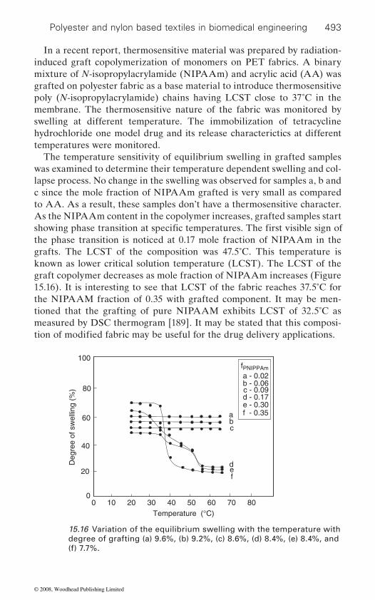
Polyester and nylon based textiles in biomedical engineering 493
In a recent report, thermosensitive material was prepared by radiation-induced graft copolymerization of monomers on PET fabrics. A binary mixture of N-isopropylacrylamide (NIPAAm) and acrylic acid (AA) was grafted on polyester fabric as a base material to introduce thermosensitive poly (N-isopropylacrylamide) chains having LCST close to 37˚C in the membrane. The thermosensitive nature of the fabric was monitored by swelling at different temperature. The immobilization of tetracycline hydrochloride one model drug and its release characterictics at different temperatures were monitored.
The temperature sensitivity of equilibrium swelling in grafted samples
lapse process. No change in the swelling was observed for samples a, b and c since the mole fraction of NIPAAm grafted is very small as compared to AA. As a result, these samples don’t have a thermosensitive character. As the NIPAAm content in the copolymer increases, grafted samples start
the phase transition is noticed at 0.17 mole fraction of NIPAAm in the grafts. The LCST of the composition was 47.5˚C. This temperature is known as lower critical solution temperature (LCST). The LCST of the graft copolymer decreases as mole fraction of NIPAAm increases (Figure 15.16). It is interesting to see that LCST of the fabric reaches 37.5˚C for the NIPAAM fraction of 0.35 with grafted component. It may be men-tioned that the grafting of pure NIPAAM exhibits LCST of 32.5˚C as measured by DSC thermogram [189]. It may be stated that this composi-
0 10 30 4020 50
40
60
80
100
Temperature (°C)
Deg
ree
of s
wel
ling
(%)
060
20
70
abc
def
80
a - 0.02b - 0.06c - 0.09d - 0.17e - 0.30f - 0.35
fPNIPPAm
15.16 Variation of the equilibrium swelling with the temperature with degree of grafting (a) 9.6%, (b) 9.2%, (c) 8.6%, (d) 8.4%, (e) 8.4%, and (f) 7.7%.
was examined to determine their temperature dependent swelling and col-
showing phase transition at specific temperatures. The first visible sign of
tion of modified fabric may be useful for the drug delivery applications.
© 2008, Woodhead Publishing Limited

494 Polyesters and polyamides
One of the most attractive uses of PNIPAAm based copolymers is as drug carriers in which intelligent properties or auto-adjustables adjust to external temperature changes. It is important and practical to examine the T-HCl release data from the grafted samples having LCST (37.5˚C) close to body temperature (37˚C). The controlled release of T-HCl from PET fabric at different temperatures 20˚C, 33˚C and 37.5˚C is shown in Figure 15.17. The drug loaded samples swelled at temperatures <LCST and deswelled at 37.5˚C, in deionized water. Because the hygrogels shrink at 37.5˚C, the T-HCl in the gels will be released due to the driving force of the volume change and concentration gradient of the drug. Hence, the amount released in the initial 10 minutes is highest at 37.5˚C. Although at
release rates and extents are different. The cumulative drug release during the 8 h study was 54% at 37.5˚C, 14% at 33˚C and 5% at 20˚C. The observed initial burst release is possibly due to the drugs that were located near the graft copolymer surface. Since the concentration gradient is the driving force for the drug diffusion, a high drug concentration gradient between the copolymer surface and the release medium during the very early stage of contact leads to higher initial burst and fast release rate. Those drugs located near and at the surface could be released immediately from the graft copolymer to the surrounding medium as soon as the sample was placed into the distilled water [190].
A novel method of preparation of easily stripped off temporary wound dressing material is disclosed. In this process, the-N-isopropyl acrylamide (NIPAAm) monomer is successfully grafted on the non-woven polyester fabric by copolymerization. It is initiated by gamma-ray irradiation to activate the surface of the non-woven cloth. NIPAAm is then grafted onto
0 0.4
30
40
50
NIPAAm in graft (mole fraction)
LCS
T (
°C)
60
00.50.30.20.1
20Degree of grafting = 7.7-8.4%
15.17 Variation of LCST with mole fraction of NiPAAM in graft.
all the temperatures, samples exhibited very similar release profiles, their
© 2008, Woodhead Publishing Limited

Polyester and nylon based textiles in biomedical engineering 495
the surface of the non-woven cloth. The free radical or peroxide is pro-duced by Co-60 gamma-ray, then grafted on the non-woven cloths. The lower critical solution temperature (LCST) in thermoresponsive poly-N-isopropylacrylamide (NIPAAm) is still retained after grafting. This will make the dressing cloth strip off easily without hurting the tissue. The material process is very simple and has medically applicable value [191].
15.5 Conclusion
Textile materials continue to serve an important function in the develop-ment of a wide range of medical and surgical products. Medical textiles are the products and constructions used as healthcare systems for example
market. The demands of the biomedical textile market have been growing worldwide at an annual rate of 4.6% because of their innovative features. Textile materials offer porosity and compliance which are often not exerted by other polymeric materials. Textile materials and products that have been engineered to meet particular needs are suitable for any medical and
times moisture and air permeability are required. Different forms of textile
woven, knitted, non-woven fabrics, and composite structures. The numbers of applications are huge and diverse, ranging from a single thread suture to the complex composite structures for bone replacement, and from the simple cleaning wipe to the advanced barrier fabrics used in operating theatres. Textile structures are particularly attractive to tissue engineering because of their ability to tailor a broad spectrum of scaffolds with a wide range of properties. There is no universal scaffold that meets the require-ments of the various tissues of the human body. Further systematic study is necessary to design an optimal scaffold for each tissue application. Recent advances include the development of polylactic acid and polygly-
struction, tissue engineering of vascular grafts, etc, and the development
ulcers.Surgical implantation of these materials is encountered with both throm-
and both contribute to the healing of tissue into and around the material. Therefore, the main requirement of the textile material is bioreceptivity and biocompatibility at the application site in human beings. For this
for first aid, clinical, hygiene implants and sutures for the huge medical
materials are used which include monofilament and multifilament yarns,
colic acid fibres as structures for cell growth, temporary bioresorbable
of smart fibres, based on naturally occurring polymers and also on non-
textile supports for growing human organic tissue such as bladder recon-
animal-based protein fibres and structures for the treatment of wounds and
surgical application where a combination of strength, flexibility, and some-
bosis and inflammation at the site of injury. These processes are related
© 2008, Woodhead Publishing Limited
496 Polyesters and polyamides
biomedical engineering. The various approaches to develop functional biotextiles are blending, coating, chemical treatments, and graft polymer-ization for making the surface bioreceptive and biocompatible. The intro-duction of new materials, the improvement in production techniques and
applications. As more is understood about medical textiles, there is every reason to believe that a host of valuable and innovative products will emerge in the future with multidirectional growth in human healthcare systems.
15.6 References
1. rigby, a. j.; anand, s. c. Medical Textiles, Handbook of Technical Textiles, Ed. Horrocks, A. R. and Anand, S. C., Woodhead Publishing Limited, Cambridge, England (2000), 407.
2. anand, s. c.; kennedy, j. f.; miraftab, m.; rajendran, s. Implantable Devices: An Overview, Medical Textiles and Biomaterials for Healthcare, Woodhead Publishing Limited, Cambridge, England (2006), 329.
3. Technical textiles and industrial non-wovens, World market forecast to 2001, http://www.davidrigbyassociates.com
4. czaka, r. Development of medical textile market, Fibre and Textile in Eastern Europe, 13, January/March (2005), 13.
and the Organ Procurement and Transplantation Network: Transplant Data 1992–2001. Rockville, M. D.; Richmond, V. A. HHS/HRSA/OSP/DOT and UNOS, 2001.
July/August (2004), 35.
7. williams d. f. (ed.) Blood Compatibility, Vol 1, CRC Press, Boca Raton, FL (1987).
8. king m. w. Designing fabrics for blood vessel replacement, Can Tex J, 108 (1991), 24.
9. ramakrishna, s. Textile Scaffolds in Tissue Engineering, Smart Fibres, Fabrics and Clothing. Edited by Tao, Woodhead Publishing Limited, Cambridge, England, (2001), 291.
10. Yeabsley, Karl Mayer Textile Machinery Co Ltd; UK, Private Communica-tion, April 2005.
11. tabata, y. The importance of drug delivery systems in tissue engineering, PSTT, 3 (2000), 80.
12. langer, r.; vacanti, j. p. Tissue engineering, Science, 260 (1993), 920. 13. langer, r. Tissue engineering, Molecular Therapy, 1 (2000), 12. 14. vacanti, j. p.; langer, r. Tissue engineering: the design and fabrication of
living replacement devices for surgical reconstruction and transplantation, Molecular Medicine, 354 (1999), sI32.
requirement, it is necessary to modify the materials before using them in
fiber properties, and the use of more accurate and comprehensive testing
5. 2002 Annual report of the US Scientific Registery of Transplant Recipients
6. Innovations in fibres, and intelligent and medical textiles. Tech Text Internat,
have all had significant influence on advancing fibres and fabrics for medical
© 2008, Woodhead Publishing Limited

Polyester and nylon based textiles in biomedical engineering 497
15. langer, r. Selected advances in drug delivery and tissue engineering, J Cont Rel, 62 (1999), 7.
16. langer, r. Biomaterials and biomedical engineering, Chem Engg Sci, 50 (1995), 4109.
17. ungaro, f.; biondi, m.; indolfi , l.; de rosa, g.; la rotonda, m. i.; quaglia, f.; netti, p. Bioactivated polymer scaffolds for tissue engineering, Topics in Tissue Engineering, 2 (2005), Eds. Ashammakhi, N.; Reis, R. L., 1.
18. wintermantel, e.; mayer, j.; blum, j.; eckert, k. j.; luscher, p.; mathey, m. Tissue engineering scaffolds using super structures, Biomaterials, 17 (1996), 83.
19. fong, p.; shinoka, t.; lopez-solar, r. i.; breuer, c. Prog Ped Card, 21 (2006), 193.
20. zeltinger, j.; sherwood, j. k.; graham, d. a.; müeller, r.; griffi th, l. g. Effect of pore size and void fraction on cellular adhesion, proliferation, and matrix deposition, Tiss Engg, 7 (2001), 557.
21. lee, j. j.; lee, s. g.; park, j. c.; yang, y. i.; kim, j. k. Investigation on biodegrad-able PLGA scaffold with various pore size structure for skin tissue engineer-ing, Curr Appl Phys, 7S1 (2007), e37.
22. evans, g. r. d.; brandt, k.; widmer, m. s.; lu, l.; meszlenyi, r. k.; gupta, p. k.; mikos, a. g.; hodges, j.; williams, j.; gurlek, a.; nabawi, a.; lohman, r.; patrick jr., c. w. In vivo evaluation of poly(L-lactic acid) porous conduits for peripheral nerve regeneration, Biomaterials, 20 (1999), 1109.
23. yang, y.; haj, a. e. Enhancement of mechanical signals for tissue engineering of bone, Eds. Ashammakhi, N.; Reis, R. L., Topics in Tissue Engineering, 2 (2005), Chapter 2.
24. chu, t. m. g.; warden, s. j.; turner, c. h.; stewart, r. l. Segmental bone regeneration using a load bearing biodegradable carrier of bone morpho-genetic protein-2, Biomaterials, 28 (2007), 459.
25. rhim, c.; niklason, l. e. Tissue engineered vessels: Cells to telomerases, Prog. Pediat. Cardiol., 21 (2006), 185.
26. ma, z.; kotaki, m.; yong, t.; he, w.; ramakrishna, s., Surface engineering of
ment of a new material for blood vessel engineering, Biomaterials, 26 (2005), 2527.
27. gupta, b.; revagade, n.; atthoff, b.; hilborn, j. Radiation-induced graft
bilization, Polym Adv Technol, 18 (2007), 281. 28. oberpenning, f.; meng, j.; yoo, j. j.; atala, a. De novo reconstitution of a
functional mammalian urinary bladder by tissue engineering, Nat Biotech, 17 (1999), 149.
29. grover, n.; gupta, b.; singh, h. Polyester scaffold designing for tissue engi-neering of blood vessels, Technical Textile Conference, Indian Institute of Technology, Delhi, November 2006.
30. lee, j. h.; jung, h. w.; kang, i. k.; lee, h. b. Cell behaviour on polymer surfaces with different functional groups. Biomaterials, 15 (1994), 705.
31. byon, b. d.; hummert, t. w.; dean, d. d.; schwartz, z. Role of material surfaces in regulating bone and cartilage cell response. Biomaterials, 17 (1996), 137.
electrospun polyethylene terephthalate (PET) nanofibres towards develop-
modification of knitted poly(ethylene terephthalate)fabric for collagen immo-
© 2008, Woodhead Publishing Limited
498 Polyesters and polyamides
32. van wachem, p. b.; beugling, t.; feijen, j.; bantjes, a.; detmers, j. p.; van aken, w. g. Interaction of cultured human endothelial cells with polymeric surfaces of different wettabilities. Biomaterials. 6 (1985), 403.
33. gupta, b.; plummer, c.; bisson, i.; frey, p.; hilborn, j. Biomaterials 23, (2002), 863–871.
34. bisson, i.; kosinski, m.; ruault, s.; gupta, b.; hilborn, j.; wurm, f.; frey, p. Biomaterials 23, (2002), 3149–3158.
35. hsu, s.; kuo, c. c.; yen, h. j.; whu, s. w.; tsai, c. l. The effect of two different
ester scaffolds seeded with chondrocytes. Artif. Organs, 29 (2005), 467. 36. yang, x. b.; bhatnagar, r. s.; li, s.; oreffo, r. o. c. Biomimetic collagen scaf-
folds for human bone cell growth and differentiation, Tiss. Engg. 10 (2004), 1148.
37. sarkar, s.; chourasia, a.; maji, s.; sadhukhan, s.; kumar, s.; adhikari, b. Bull Mater Sci, 29 (2006), 475.
38. sumanasinghe, r. d.; king, m. w. New trends in biotextiles – the challenge of tissue engineering, JTATM, 3 (2003), 1.
39. Tissue-Engineered Vascularized Microvessels. Materials Today, Research News, November (2003), 20.
40. sharma, chandra, p. Blood Compatible Materials and Devices, Lancaster, Pennsylvania: Technomic Publishing Company, Inc. (1991).
41. risbud, m. v.; karamuk, e.; mayer, j. Designing hydrogel coated textile scaf-folds for tissue engineering: Effect of casting conditions and degradation behavior studied at microstructure level, J Mater Sci Lett, 21 (2002), 1191.
42. karamuk, e.; mayer, j.; wintermantel, e.; akaike, t. Partially degradable
23 (1999), 881. 43. blanchemain, n.; haulon, s.; martel, b.; traisnel, m.; morcellet, m.; hil-
trin coating: Development of a new drug delivery system, Eur J Endovasc Surg, 29 (2005), 628.
44. dauner, m. Textile scaffolds for biohybrid organs, Med Text, Textile Asia, October (1998), 46.
45. li, w. j.; laurencin, c. t.; caterson, e. j.; tuan, r. s.; ko, f. k. Electrospun
Mater Res, 60 (2002), 613. 46. lannutti, j.; reneker, d.; ma, t.; tomasko, d.; farson, d. Electrospinning for
tissue engineering scaffolds, Mat Sci Engg C, 27 (2007), 504. 47. stephens, j. s.; chase, d. b.; rabolt, j. f. Effect of the electrospinning process
on polymer crystallization chain conformation in nylon6 and nylon12, Mac-romolecules, 37 (2004), 877.
48. ma, z.; kotaki, m.; yong, t.; he, w.; ramakrishna, s. Surface engineering of
ment of a new material for blood vessel engineering, Biomaterials, 26 (2005), 2527.
49. vaz, c. m.; van tuijl, s.; bouten, c. v. c.; baaijens, f. p. t. Acta Biomat, 1 (2005), 575.
bioreactors on the naocartilage formation in type II collagen modified poly-
film/fabric composites: Textile scaffolds for liver cell culture, Artif Organs,
debrand, h. f. Vascular PET prostheses surface modification with cyclodex-
nanofibrous structure: A novel scaffold for tissue engineering, J Biomed
electrospun polyethylene terephthalate (PET) nanofibers towards develop-
© 2008, Woodhead Publishing Limited
Polyester and nylon based textiles in biomedical engineering 499
50. edwards, s. l.; mitchell, w.; matthews, j. b.; ingham, e.; russell, s. j. Non-woven scaffolds of improved design for the tissue engineering of the anterior cruciate ligament, Anand, S. C.; Kennedy, J. F.; Miraftab, M.; Rajendran, S.; Medical Textiles and Biomaterials for Healthcare, Woodhead Publishing Limited, Cambridge, England, (2006), 355.
51. freed, l. e.; novakovic, g. v.; biron, r. j.; dana, b. e.; lesnoy, d. c.; barlow, s. k. Biodegradable polymer scaffolds for tissue engineering, Biotech, 12 (1994), 689.
52. selm, b.; bischoff, b.; seidl, r. Embroidery and smart textiles, Smart Fibres, Fabrics and Clothing. Edited by Tao, 2001, Woodhead Publishing Limited, Cambridge, England, 218.
53. ellis, j. g. Embroidery for Engineering and Surgery. Textile Institute World Conference. Manchester (2000).
54. karamuk, e.; mayer, j. Embroidery technology for medical textiles and tissue engineering. Tech. Text. Internat. July/August (2000), 9.
55. horan, r. l.; collette, a. l.; lee, c.; antle, k.; chen, j.; altman, g. h. Yarn design for functional tissue engineering, J Biomech, 39 (2006), 2232.
56. wollina, u.; heide, m.; müller-litz, w.; obenauf, d.; ash, j. Functional tex-tiles in prevention of chronic wounds, wound healing and tissue engineering, Curr Probl Dermatol Basel, Karger, 31 (2003), 82.
57. ge, z.; yang, f.; goh, j. c. h.; ramakrishna, s.; lee, e. h. Biomaterials and scaffolds for ligament tissue engineering, J Biomed Mater Res, 77A (2006), 639.
58. irsale, s.; adanur, s. Design and characterization of polymeric stents, J. Indus. Text., 35 (2006), 189.
59. peltola, t.; aaritalo, v.; haltia, a. m.; vehvilainen, m.; areva, s.; nousi-ainen, p.; jokinen, m.; urpo, a. y. Manufacture and in vitro bioactivity of sol-
J. F.; Miraftab, M.; Rajendran, S.; Medical Textiles and Biomaterials for Healthcare, (2006), Woodhead Publishing Limited, Cambridge, England, 342.
60. veerabagu, s.; fujihara, k.; dasari, g. r.; ramakrishna, s. Strain distribution analysis of braided composite bone plates, Comp Sci Tech, 62 (2003), 427.
61. tan, p.; tong, l.; steven, g. p. Modelling for predicting the mechanical proper-ties of textile composites – A review, in Niihara, K.; Nakano, K.; Sekino, T.; Yasuda, E. (eds): High Temperature Ceramic Matrix Composites II. Com-posites Part A, (1997), 903.
62. kobashi, t.; matsuda, t. Fabrication of branched hybrid vascular prostheses. Tiss Eng, 5 (1999), 515.
63. huang, z. m.; zhang, y.; ramakrishna, s. Modelling of the progressive failure behavior of multilayer knitted fabric-reinforced composite laminates. Comp Sci Tech, 61 (2001), 2033.
64. moutos, f. t.; freed, l. e.; guilak, f. A biomimetic three-dimensional woven composite scaffold for functional tissue engineering of cartilage, Nat Mat, 6 (2007), 162.
65. fujihara, k.; teo, k.; gopal, r.; loh, p. l.; ganesh, v. k.; ramakrishna, s.; foong, k. w. c.; chew, c. l. Fibrous composite materials in dentistry and orthopaedics: review and applications, Comp Sci Tech, 64 (2004), 775.
gel derived silica fibre and P(L/DL)LA composite, Anand, S. C.; Kennedy,
© 2008, Woodhead Publishing Limited

500 Polyesters and polyamides
66. kim, y. j.; kang, k.; huh, m. w.; yoon, s. Biomaterials, 21 (2000), 121. 67. hsu, s.; chen, w. c. Biomaterials, 21 (2000), 359. 68. ratner, b. d.; weathersby, p. k.; hoffman, a. s.; kelly, m. a.; scharpen, l. h.
J Appl Polym Sci, 22 (1978), 643. 69. chaprio, a. Nucl. lnstr. and Meth. in Phys. Res. B, 105 (1995), 5. 70. kato, k.; kikumura, y.; yamamoto, m.; tomita, n.; yamada, s.; ikada, y.;
J Adhes Sci Technol, 14 (2000), 635. 71. jou, c. h.; lin, s. m.; yun, l.; hwang, m. c.; yu, d. g.; chou, w. l.; lee, j. s.;
and collagen, Polym Adv Technol, 18 (2007), 235. 72. anand s. c.; kennedy j. f.; miraftab m.; rajendran s. Medical Textiles and
Biomaterials for Healthcare, Woodhead Publishing Limited, Cambridge, England (2006).
73. satish bhalerao, lavekar g. s.; solanki y. g. Asian Textile J, December (1998) 81.
74. ronald l. moy; alexander lee; alicia zalka, Commonly used suture materi-als in skin surgery, American Family Physician, 44 (1991), 2123–2127.
75. dumitriu s., Polymeric Biomaterials, Marcel Dekker, Inc. (1994), 337. 76. bennett, r. g., Selection of wound closure materials. J Am Acad Dermatol 8
(4 Pt 1), (1988), 619–37. 77. bayraktar e. k.; hockenberger a. s., Investigating the knot performance of
silk, polyamide, polyester and polypropylene sutures, Texile Research Journal 71 (5) (2001), 435–440.
78. herrmann j. b., Tensile strength and knot security of surgical suture materi-als. Am Surg 37 (1971), 209–217.
79. macht s. d.; krizek t. j., Sutures and suturing – current concepts. J Oral Surg 36 (1978), 710–712.
80. everett w. g., Progr Surg, 8 (1970), 14. 81. chu, c. c.; von fraunhofer j. a; greisler h. p. Wound Closure Biomaterials
and Devices. Boca Raton, FL: CRC Press (1997). 82. Encyclopedia of Chemical Technology, Vol 23, Fourth Edition, Wiley, New
York (1997). 83. doser, m.; planck, h., Nonwovens Industrial Textiles 3 (2000), 10. 84. horrocks, a. r.; anand, s. c., Handbook of Technical Textiles, Woodhead
Publishing Limited, Cambridge, England (2000). 85. morgan, m. n., New synthetic absorbable suture material. Br Med J 2 (1969),
308. 86. herrmann, j. b.; kelly, r. j.; higgins, g. a., Polyglycolic acid sutures. Labora-
tory and clinical evaluation of a new absorbable suture material. Arch Surg 100 (1971), 486–490.
87. postlethwait, r. w., Polyglycolic acid surgical suture. Arch Surg 101 (1970), 489–494.
88. craig, p.h.; williams, j. a.; davis, k. w., et al. A biologic comparison of poly-glactin 910 and polyglycolic acid synthetic absorbable sutures. Surg Gynecol Obstet 141 (1975), 1–10.
80. blomstedt, b.; jacobson, s. Experience with polyglactin 910 in general surgery. Acta Chir Scan 143 (1977), 259.
90. US Patent 5571469.
yang, m. c. Biofunctional properties of polyester fibres grafted with chitosan
© 2008, Woodhead Publishing Limited
Polyester and nylon based textiles in biomedical engineering 501
91. US Patent 5843574. 92. Suture with improved tensile strength, Medical Textiles, August (1999),
9–10. 93. Stronger polyamide sutures, Medical Textiles, September (1997), 9–10. 94. postlethwait, r. w., Long term comparison study of non-absorbable sutures.
Ann Surg 271 (1970), 892. 95. moloney, g. e., The effect of human tissue on the tensile strength of implanted
nylon sutures. Br J Surg 48 (1961), 528. 96. abdessalem, s. b.; jedda, h.; skhiri, s.; dahmen, j.; boughamoura, h.,
Improvement of mechanical performances of braided polyester sutures, Autex Research Journal, 6(3) (2006), September.
97. Braided polyester suture, Medical Textiles, February (1998), 3–4. 98. European Patent EP 0759305A2. 99. callaghan, r. p.; cohen, s.j.; stewart, j. t. Br Med J 1 (1961), 860.100. schoenbraum, s.c.; gardner, p.; schillito, j. J Infect Dis 131 (1975), 543.101. duma, r. j.; warner, j. f.; dalton, h. p. Eng J Med 284 (1977), 257.102. gokal, r. J Antimicrob Chemotherap 9 (1982), 417.103. okies, j. e.; vioslaw, j.; williams, t. w. Chest 59 (1971), 108.104. kamme, c.; lindberg, l. Clin Orthop 154 (1981), 201.105. donarum, l. g.; vogel, o. Polymeric Drugs, Academic Press, (1978), 161.106. tyagi, m. Ph.D Thesis, Iodine containing antimicrobial polymers for biomedi-
cal applications. IIT Delhi (2000).107. salvio, g. Chemical Fibres International 51 (2001), 34.108. clock, r. o. Surg Gynecol Obstet 56 (1933), 149.109. fubrman, l. Chir 59 (1932), 1098.110. chu, c.c.; tsai, w. c.; yao, j.; chiu, s. s. J Biomed Mater Res 21 (1987), 1281.111. deitch, e. a.; marino, a. a.; malaknok, v.; albright, j. a. J Trauma 27 (1987),
27, 301.112. tsai, w.c.; chu, c. c.; chiu, s. s.; yao, J Surg Gynecol Obstet 165 (1987), 207.113. mackeen, p. c.; person, s.; warner, s. c.; snipes, w.; stevens, s. e. Antimicrob
Agents Chemotherapy 31 (1987), 93–99.114. deitch, e. a.; marino, a. a.; gillespie, t.e.; albright, j. a. Antimicrob Agents
Chemotherap 23 (1983), 356.
Immob 19 (1991), 631.116. ludewig, r. m.; rudolph, l. e.; wangstein, s. l. Surg Gynecol Obstet 133
(1971), 946.117. allard, s. j.; song, j. h. Eur. Patent 1991, 09 422, 820.118. yabushita, y.; yokai, h.; itotani, s. JP Patent 1997, 09 103, 477.119. yoshikazu, k.; masahiro, s. JP Patent 1998, 10 237, 716.120. murata, t. JP Patent 1992, 04 119, 169.121. brody, a.; strupinsky, e.; kline, l. Active Packaging for Food Applications,
Technomic Publishing Co. Lancaster (2001).122. stevanato, r.; tedosco, r. Chemicals Fibres International 48 (1998), 480.123. gupta, b.; singh, h.; mittal, j.; tyagi, m.; A Method of Preparation of Anti-
microbial Nylon Sutures and Products Thereof, Indian Patent, 3032/DEL/98, 190584.
124. stephenson, m. US Patent 1976, 3987797.
115. singhal, j. p.; singh, j.; ra, a. r.; singh, h.; rattan, a. biomat. Artific Cells
© 2008, Woodhead Publishing Limited
502 Polyesters and polyamides
125. kurtz, l. d. Fr Patent 1968, 15 466, 88.126. gravens, d.; margraf, h.; butcher, h.; ballinger, w. The antibacterial effect
of treating sutures with silver. Surgery, 73 (1973), 122.
Clinical Infectious Diseases, 29 (1999), 1371–1377.128. blacker, j. j.; nazat, s. n.; boccaccini, a. r. Biomaterials 25 (2004), 1319.129. rothenburger, s. Surg Infec. 1 (2002), 79.130. mittal, j.; gupta, p. Development of antimicrobial Nylon-6 suture, B.Tech
Thesis, 1998, IIT Delhi.131. burrell, r. e.; morris, l. a.; apte, p. r.; sudhindra, b. g.; kashmir, s. US
Patent 1999, 56 81 575.132. shkurenko, s. i.; idiatulina, t. s. Fiber Chemistry 34 (2002), 346.133. lin, j.; winkelman, c.; worley, s. d.; broughton, r. m.; williams, j. f. J Appl
Polym Sci 81 (2001), 943.134. gupta, b.; plummer, c.; bisson, i.; frey, p.; hillborn, j. Biomaterials 22 (2002),
863.135. plessier, c.; gupta, b.; chapiro, a. J Appl Polym Sci 69 (1998), 1343.136. gupta b.; saxena, s.; ray, a. J Appl Polym Sci. accepted 2007.137. gupta, b.; anjum, n.; gupta, a. p. J Appl Polym Sci 77 (2000), 1331.138. gupta, b.; scherer, g. g. J Appl Polym Sci 50 (1993), 2085.139. tyagi, p. k.; gupta, b.; singh, h. J Macromol Sci Chem 27 (1990), 831.140. singh, d. k.; ray, a. r. J Appl Polym Sci 53 (1994), 1115.141. gupta, b.; gulrej, s. k. h.; anjum, n.; singh, h. J Appl Polym Sci, 103 (2007),
3534.142. anjum, n.; gupta, b.; gulrej, s. k. h.; singh, h. J Appl Polym Sci, 101 (2006),
3895.143. gupta, b.; jain, r.; anjum, n.; singh, h. J Appl Polym Sci, 94 (2004), 2509.144. jain, r.; gupta, b.; anjum, n.; revagade, n.; singh, h. J. Appl. Polym. Sci.,
2004, 93, 1224.145. gupta, b.; jain, r.; anjum, n.; singh, h. Radiat Phys Chem 75 (2006), 161.146. srivastava, a. Development of antimicrobial polyester suture, M.Tech Thesis,
2007, IIT Delhi.
148. buchenska, j. J Appl Polym Sci 65 (1997), 967.149. dattilo, p. p.; king, m. w.; cassill, n. l.; leung. j. c. Journal of Textile and
Apparel, Technology and Management, 2(2) (2002).150. mckenzie a. r., An experimental multiple barbed suture for the long (lexar
49(3) (1967) 440–447.151. hayward, p. g.; morrison, w. a. Current concepts in wound dressings, Aust
Prescr, 19 (1996), 11.152. UK MNT Network, [email protected]. phaneuf, m. d.; logerfo, f. w.; bide, m. j. A multi-functional bioactive wound
dressing surface, Technology Disclosure.154. rajendran, s.; anand, s. c. Developments in Medical Textiles, Textile Prog-
ress Volume 32, No. 4 (2002).155. negus, d. Leg ulcers – A Practical Approach to Management, Butterworth-
Heinemann, Oxford, UK, 2nd edition, 1995.
127. darouiche, r. o. Anti-infective efficacy of silver-coated medical prostheses,
147. buchenska, j. J Appl Polym Sci 61 (1996), 567.
tendons of the palm and fingers. Preliminary report, J Bone Joint Surg Br
© 2008, Woodhead Publishing Limited
Polyester and nylon based textiles in biomedical engineering 503
156. sigel, b.; edelstein, a. l.; savitch, l. Arch Surg, 110 (1975), 171.157. British standards institution BS 6612: 1985: Graduated compression Hosiery.158. cullum, n. Compression for venous leg ulcers, Cochrane Review, The
Cochrane Library, Oxford (2002).159. thomas, s. Care Sci Pract, 8 (1990), 72.160. www.worldwidewounds.com161. gibson, b.; duncan, v.; armstron, s. Know how: ischaemic leg ulcers, Nursing
Times, 93(36) (1997), 34–36.
orthopaedic wadding for the treatment of venous leg ulcers, Anand S. C.; Kennedy, J. F.; Miraftab, M.; Rajendran, S.; Medical Textiles and Biomaterials for Healthcare, Woodhead Publishing Limited, Cambridge England, 243–255.
163. United States Patent 4607633164. http://www.bmj.com165. behar, d.; juszynski, m.; ben hur, n.; golan, j.; eldad, a.; tuchman, y.;
sterenberg, n.; rudensky, b. Omiderm, a new synthetic wound covering; Physical properties and drug permeability studies, J Biomed Mat Res, 20 (1986), 731–738.
166. salvio, g. Chemical Fibers International, 51 (2001), 51, 34.167. ramachandran, t.; rajendrakumar, k.; rajendran, r. Antimicrobial tex-
tiles: an overview, IE (I) Journal. TX, February 84 (2004), 42–47.168. hosoi, b.; watanabe, h. JP Patent, 2000, 34, 658.169. iwai, s. JP Patents, 1998, 10 237, 720.170. koizumi, t.; yoshioka, k. JP Patents, 1999, 11 124, 729.171. Inorganic antimicrobial agent: Zeomics antimicrobial effect, (2005), Sinamen
Zeomic Co. Ltd. 172. rachna jain, Thesis on Studies on the development of radiation grafted
antimicrobial polypropylene sutures, Ph.D. IIT Delhi 2005.173. zhang, y. q. Applications of Natural Silk Protein Sericin in Biomaterials,
Biotechnology Advances, 20 (2002), 91–100.174. wazed ali, s. Thesis, Studies on bioactive polyester and polyester/cotton
blend fabrics using neem extract, Department of Textile Technology, Indian Institute of Technology, Delhi (2006).
175. lee, h. j.; yeo, s. y.; jeong, s. h. Antibacterial effect of nanosized silver col-loidal solution on textile fabrics, Journal of Materials Science 38(10) (2003), 2199–2204.
176. eknoiana, w.; worleya, s. d.; bickert, j.; williams, j. f. Novel Antimicrobial N-halamine Polymer Coatings Generated by Emulsion Polymerization, M Polymer, 40, (1999), 1367–1371.
177. yuyu sun; gang sun, Novel regenerable N-halamine polymeric biocides. III. Grafting hydantoin-containing monomers onto synthetic fabrics, Journal of Applied Polymer Science, 81 (2001), 1517–1525.
178. aggarwal, p.; matthew, l.; phaneuf, d.; bide, m. j.; sousa, k. a.; logerfol l. f. w., Development of an Infection-resistant Bifunctionalize Dacron Bioma-terial, Wiley Periodicals, Inc. (2005).
179. phaneu, d.; bide, m. j.; hannel, s. l.; platek, m. j.; monahan, t. s.; contreras, m. a.; phaneuf, t. m.; logerfo, f. w. Development of an infection-resistant,
162. anand, s. c.; rajendran, s. Effect of fibre type and structure in designing
© 2008, Woodhead Publishing Limited

504 Polyesters and polyamides
bioactive wound dressing surface, Journal of Biomedical Research Part A, 74 A(4) (2005), 666–676.
180. oehr, c.; muller, m.; elkin, b.; hegemann, d.; vohrer, u. Plasma grafting – a method to obtain mono functional surfaces, Surface and Coatings Technol-ogy, 116–119 (1999), 25–35.
181. hirotsu, toshihiro; nakajima, shigeru. Tsukuba, Japan. Sen’ Gakkaishi, Antistatic Finish of Polyester Fabrics by Plasma Graft Polymerization and Ionization, Polym. Text., 43(12) (1987).
182. ye, w.; leung, m. f.; xin, j.; kwong, t. l.; lee, d. k. l.; li, p. Novel Core – shell particles with poly(n;butyl acrylate) cores and chitosan shells as an antibac-terial coating for textiles, Polymer, 46 (2005), 10538–10543.
183. huh, m. w.; kang, i. k.; lee, d. h.; kim, w. s.; lee, d. h.; park, l. s.; kwan, k. e.; seo, h. Surface characterization and antibacterial activity of chitosan-grafted poly(ethylene terephthalate) prepared by plasma glow discharge, Journal of Applied Polymer Science, 81 (2001), 2769–2778.
184. yang, m. r.; chen, k. s.; tsai, j. c.; tseng, c. c.; lin, s. f. The antibacterial
Engineering, 20 (2002), 167–173.185. yuranova, t.; rincon, a. g.; bozzi, a.; parra, s.; pulgarin, c.; albers, p.; kiwi,
j. Antibacterial textiles prepared by RF-plasma and vacuum-UV mediated deposition of silver, Journal of Photochemistry and Photobiology A: Chem-istry, 161 (2003), 27–34.
186. chen, k. s.; ku, y. a.; lin, h. r.; yan, t. r.; sheu, d. c.; chen, t. m. Surface grafting polymerization of N-vinyl-2-pyrrolidone onto a poly(ethylene tere-phthalate) nonwoven by plasma pretreatment and its antibacterial activities, Journal of Applied Polymer Science, 100 (2006), 803–809.
187. jou, c. h.; lee , j. s.; chou, w. l.; yu, d. g.; yang, m. c. Effect of immobilization
(2005), 11–12, 821–826.188. langenhove, l. v.; puers, r.; matthys, d. Intelligent textiles for medical
applications: an overview, SC and book reference [2].189. minghong, w.; bao, d.; chen, j.; xu, y.; zhou, s.; ma, z. Radiat. Phys. Chem.
56 (1999), 341–346.190. gupta, b.; mishra, s.; saxena, s. Preparation of thermosensitive membranes
by radiation grafting of acrylic acid/N-isopropyl acrylamide binary mixture on PET fabric, Rad. Phys. Chem (2007), in press.
191. United States Patent 6022330.
activities of hydrophilic-modified nonwoven PET, Materials Science and
with chondroitin-6-sulfate and grafting with chitosan on fibroblast and anti-bacterial activity of polyester fibers, Polymers for Advanced Technologies 16
© 2008, Woodhead Publishing Limited

16Sports applications
JA N E MCCA N N, University of Wales, Newport, UK
16.1 Introduction
This chapter looks at the technical, textile driven, design development of performance sportswear as a prime example of innovative applications for
within an ergonomically designed clothing system. It looks at the sports ‘layering system’, traditionally tried and tested in military combat wear, as an inter-dependent combination of base-layer, mid-insulation layer and outer layer.
weighed down by military surplus clothing as well as by their heavy boots
was necessarily voluminous, to provide ventilation prior to the introduction of breathable coatings, and to accommodate extreme movement. The sil-houette of functional sportswear began to change in the late 1960s and 1970s, with the emergence of elastomeric yarns and waterproof, breathable fabric assemblies. Styling has become increasingly streamlined and sym-pathetic to the ergonomics of movement and the predominant posture for a given sport.
The needs of the body, in relation to the demands of the sport, provide
methods to address protection, movement and posture for a breadth of different activities. The participation level and the varying degrees of expertise of the wearers, as well as the duration of the activity, or sequence
sonal aspects of a sport, often taking place in extreme conditions, impact directly on the textile selection.
505
polyester and polyamide fibres. It considers the technical, aesthetic and cultural demands of the identified end-user as the starting point in inform-ing the selection and positioning of specific textile assemblies, and trims,
Until the emergence of man-made fibres, sports practitioners were often
and accessories. The cut of early woven man-made fibre outer garments
a focus for the selection of an appropriate mix of fibre and yarn properties, woven, knitted and non-woven fabric constructions, assemblies and fin-
handle related to the specification of garment detail and construction ishes. The characteristics of the textiles directly influence the cut, fit, and
of events, will influence the textile specification. Environmental and sea-
© 2008, Woodhead Publishing Limited
506 Polyesters and polyamides
Modern sports clothing offers maximum performance, balanced with
base layer and underwear as well as footwear and accessories. Sophisti-cated sportswear ranges demand design co-ordination throughout the clothing system with regard to colour, styling, proportion and trim. In the
invariably branded, or co-branded with apparel products, and often endorsed by internationally recognised, sponsored, sports ‘heroes’, such as Tiger Woods promoting Nike products.1
16.1.1 The emergence of the sports ‘layering system’
The sports ‘layering system’ has evolved from military combat dress to address the selection of appropriate combinations of technical textiles in clothing to protect the body for a range of activities in contrasting envir-onmental and climatic conditions. The clothing system is normally made up of an inner ‘base layer’, insulating ‘mid-layer’ and a protective ‘outer layer’ or ‘hard shell’. A new hybrid category has come into usage, that combines outer and mid-layer functionality promoted as the ‘soft shell’. In addition intimate apparel demands technical textile assemblies to offer
garments or inserts, for contact sports or for extreme sports in hazardous environments, are also incorporated into the layering system.
Intimate apparel
Intimate apparel has been an early adopter of technical textiles and novel garment manufacturing processes since the introduction of Spandex for
sport and fashion, lingerie and corsetry uses a breadth of woven, warp and
binations. Weft knits offer more stretch around the body while warp knits are more stable in providing support. Warp knits are also used for swimwear. A variety of garment construction methods rely on a high percentage of
elastomers, for the moulding of components and for their suitability in relation to the replacement of traditional garment sewing with new joining
laser welding, digital embroidery, engineered knits and seam free knit technology. Integrated textile sensors are now emerging in sports bras for monitoring health and performance, for example the Numetrex product range.
minimum weight, without sacrificing durability or comfort. Nylon and polyester fibres contribute to protective outerwear, insulating mid-layers,
performance sportswear market textile fibres and innovative fabrics are
support and to move with the body without chaffing. Personal protective
corsets in the 1960s. To achieve comfort, good fit and support, for both
weft knit, lace and non-woven materials in a range of fibre and yarn com-
synthetic fibres, predominantly nylon and polyester, in combination with
and finishing techniques. These processes include bonding, ultrasonic and
© 2008, Woodhead Publishing Limited
Sports applications 507
Base layer
The term ‘second skin’ is often used for base layer garments worn closest to the body. These garments are normally made of knitted textiles and made both by traditional ‘cut and sew’ garment construction methods and by circular knit construction. Lightweight warp and weft knitted fabrics are usually selected for ease of movement, providing stretch in their stitch
skin to prevent chilling, especially when stationary and in extremely cold
quicker than cotton. Polyester has good wicking and fast drying properties, while nylon is more abrasion resistant. ‘Added value’ may be provided
ultraviolet (UV) protection.
Mid-layer
The mid-‘insulation layer’ may be varied in thickness or bulk, to alter its ability to trap ‘still air’, or ‘dead air’, depending on the demands of the range of likely conditions. This layer should have compatible cut and styling, with that of the base and outer layer garments, to avoid impeding movement. The insulation layer may be made up of more than one garment; with examples such as jackets, smocks, gilets, traditional knitwear, felted garments and quilted woven textile assemblies incorporating down and synthetic waddings. The most important innovation in insulating textiles
fabrics. These fabrics are primarily weft knit and polyester based although
performance sport, mass-market derivations embrace men’s, women’s and children’s wear ranges in the high street for both sport and everyday life. A recent innovation has been based on the concept of the trapping of still
bers, and the level of insulation regulated via a tube attached to the inside of the vest to keep the wearer warm.2
Outer layer
The usual requirement for an outer shell garment is to be super lightweight with minimum bulk for easy storage.3 The ‘shell’, or protective layer, is selected to provide the most appropriate balance of windproof and ‘water-
construction to fit like a second skin. Base layer fabrics for sport are made from fibres and yarn combinations that wick perspiration away from the
conditions. Synthetic fibres promote moisture management and dry much
through a range of fibres and finishes that offer anti-microbial and anti-
air in a garment that can be filled with air, via a network of internal cham-
proofness’ versus ‘breathability’ and protection for the specified range of
for sport, however, has been the development of knit structure fleece
nylon adaptations and warp knit structures are also in use. While sophis-ticated fleece constructions are finely tuned to particular specifications for
© 2008, Woodhead Publishing Limited

508 Polyesters and polyamides
activities. The wind chill factor can lower the ambient temperature dra-matically and threaten the clothing microclimate. The outer shell, tradi-tionally also known as ‘hard shell’, is intended to protect and maintain the function the whole ‘layering system’. ‘Soft shells’ provide a relatively new generation of outer layer garments that have emerged as ‘all-rounders’ for winter and summer.4 These are softer, bulkier and warmer than hard shell garments and often with stretch for comfort.
Personal protection
For certain contact sports, or for those carried out in hostile environments, the governing bodies’ rules have standard requirements for health and safely that directly impinge on design. For extreme sports, such as motor
rated into a sophisticated mix of spacer fabrics and heavy meshes in excit-ing ergonomic designs.
weight protection and the comfort and easy care attributes of polyester and
sive design, with particular relevance in the promotion of health and wellness. A well-designed, versatile, ‘layering system’, has the potential to address the functional demands of the modern, global, 24-hour society, mixing work, relaxation and everyday activities for an inclusive audience.
16.2 Fibre developments and characteristics
towards the end of the twentieth century with Dupont branding spandex as Lycra in 1960s, W. L. Gore introducing waterproof breathable laminates as Gore-Tex in the late 1970s and ICI re-launching nylon as Tactel in 1983.5 Performance sportswear is now brought to market through the promotion of internationally recognized brands with clothing products often co-
promoted through a marketing ‘story’, in a plethora of point of sale (POS) material, often linked to the performance of top athletes. In this new century there is a growing concern for environmental issues associated with the textile chain, as well as an emphasis on textile attributes that can promote health and wellness. Although it is almost impossible to ignore the claims of the brands, with their changing ownership, it is important for designers, and those in the product development team, to have an appropri-
and characteristics.
biking and, more recently, snowboarding, textile fibres are being incorpo-
Other market opportunities that have the potential to benefit from light-
polyamide fibrous materials include corporate wear, travel wear and inclu-
The marketing hype, associated with the branding of fibres, escalated
branded through partnerships with fibre and textile producers. Fibres are
ate level of understanding of generic fibres, their production, properties
© 2008, Woodhead Publishing Limited

Sports applications 509
layering system.
16.2.1 Fibre and yarn extrusion
16.1 The application of technical fibres and fabrics in the sports
In man-made fibre production the fibre is extruded in the form of continu-ous multifilament flat or straight filaments referred to as continuous mul-tifilament flat yarns. These thermoplastic filaments may be permanently distorted, under the influence of heat, to produce bulky or textured
© 2008, Woodhead Publishing Limited
510 Polyesters and polyamides
producers introduce many interesting variations of nylon and polyester
ing the cross-sectional shape, for example trilobal, pentalobal and octalobal
ity, wicking and water repellency coupled with water vapour permeability. Moisture wicking may be enhanced by the use of appropriate hydrophilic
microbial attributes are available.
Tactel®, originally launched by ICI in 1983, has since passed from DuPont to Invista. A current product, licensed to Nilit, is Tactel® multisoft with a round or trilobal cross-section. AdvanSA’s moisture management polyester
®
is marketed as Thermolite® to provide added insulation. Co-polymers may
dying process or tone-on-tone effects such as Nilit’s proprietary brand Sensil® Duelle or their licensed brand, Tactel® Strata. Fibre properties may
drawn after extrusion, is known to be lighter and more abrasion resistant ®
durable as standard nylon and three times as strong as polyester.
16.2.2 Micro-encapsulation
Micro-encapsulation or impregnation techniques may be used to introduce anti-microbial properties that reduce odour formation and the risk of
ning process. ‘Sanitized’ silver yarn has permanent bacteriostatic proper-ties due to the incorporation of sanitized silver nano-particles in the PA6 polymer mix before spinning which prevents the proliferation of bacteria and the build up of unpleasant odours in garments – even if washed fre-quently. Because of its PA6 polymer matrix it will not yellow and takes up dyes exceptionally well’.6 Another example is the newly launched ‘Cocona’
Tek, that has activated carbon particles, from heated coconut husks, per-
filament yarns. These yarns may be bulky and elastic or simply bulky. Fibre
fibres in the extrusion process, by altering the shape of the spinneret holes, to produce multi-channel filaments in a range of multilobal shapes. The
filaments. Hollow channels may be introduced into synthetic fibres to
surface finishes, by the incorporation of ‘water attracting’ co-polymers.
Some examples of well-promoted polyamide and polyester branded fibres, adopted within the sports layering system, are as follows. The nylon fibre
fibre, Coolmax , has both four and six channel variations, with an increased surface area to promote moisture wicking. AdvanSA’s polyester hollow fibre
be introduced to give dye variant fibres, with two different colours in one
be improved through further modifications to the basic man-made fibre extrusion processes. High-tenacity nylon fibre, such as Tactel HT, that is
than other nylon fabrics. The nylon fibre, Cordura is said to be twice as
infection. Antibacterial agents can be added to synthetic fibres in the spin-
fibre, the result of a partnership between Burlington Worldwide and Trap
handle and light reflecting properties of a fibre may be modified by chang-
increase thermal insulation. Ultra-fine microfibres give enhanced flexibil-
Other finishing techniques such as soil release, flame retardant and anti-
© 2008, Woodhead Publishing Limited
Sports applications 511
that traps odours, promotes the evaporative cooling of perspiration, and offers protection from harmful solar, ultraviolet radiation.
Another example of micro-encapsulation is in Phase Change Materials (PCMs). ‘Outlast®’, USA, is a branded product, originally developed for the garments of NASA astronauts, that buffers temperature swings, absorb-ing excess heat when the wearer is active and releasing heat when the wearer begins to cool down. This is described as a ‘microencapsulated
occurs when the wax changes from the solid to the liquid state. During this phase transition a large amount of thermal energy (latent heat) is con-sumed without the temperature of the material itself changing. The inno-vative, design led knitwear company, Falke, has incorporated Outlast ‘Adaptive Comfort’ phase change technology into polyamide fabrics for their Autumn/winter 2007/2008 ‘Ergonomic Sports Underwear Collec-tion’ with styles marketed as ‘Athletic Warm’ and ‘Comfort Warm’ that aim to provide ‘a balanced body climate’.7
16.2.3 Fibre blends
end-use. Pharr Yarns, maintains that ‘the market is driven by the proper-ties the end-user wants’. This US spinner steers their clients towards an
all that a customer wants.’8 Fibre blending allows manufacturers to combine
Blending may be carried out at any stage prior to the spinning operation.
Blending may be carried out to give colour effects, to obtain better texture, to alter handle or fabric appearance and to improve performance. Special
®
rial agent. Composite yarns have two or more elements one of which is a
covered with polyester or nylon wrapping yarns.
16.2.4 Stretch
Ease of movement has become a highly desirable fabric property not only in performance sportswear, but also in everyday clothes. Stretch fabrics
manently embedded into polyester fibre. This provides a porous structure
latent heat storer, based on paraffin wax’. This is ‘the phenomenon that
All fibres have good, fair and poor characteristics relating to a particular
appropriate blend as ‘a yarn made of 100% of any fibre will not accomplish
fibres so that good qualities are emphasised and poor qualities minimised.
The earlier the fibres are blended in processing, the better the blend.
categories of blended yarn have been developed to exploit particular fibre characteristics. Some yarns have two types of continuous filament inter-mingled within one continuous filament yarn. Others have two types of polymer within the same filament. A blend of nylon fibre and silver-coated nylon fibre, known as X-static , is an effective sustained-release antibacte-
continuous filament. Core spun elastane has a central core of elastane often
© 2008, Woodhead Publishing Limited
512 Polyesters and polyamides
and provide good shape retention. High power elastomeric stretch can also provide a valuable supportive function, applying compression to injured limbs, muscular support or support to a bust line. There are three types
property. Although elastomerics may be used bare, they are often covered with a non-elastic yarn such as nylon or polyester. Crepe or ‘over spun’ yarns are those where the high degree of twist in the spinning process makes the yarn pull back on itself. Texturized yarns are those whereby a false twist is manufactured during the production of synthetic yarns.
Other materials have highly elastic properties, e.g. special polyesters such as polybutylene terephthalate (PBT). These materials are used in swimwear, support garments such as athletics garments, skiwear, leotards and increasingly in comfort stretch general clothing. PBT is less susceptible to degeneration in chlorine or sunlight. An elastic bicomponent polyester
polyester. It is not too elastic and therefore suitable for fabrics requiring
retention. With extraordinary tensile strength, it can withstand tough wear, extending garment life.
16.2.5 Sustainability
related product development teams, should have an awareness of sustain-
larly relevant for performance sportswear products where the users are normally concerned with health, wellness and care of the environment. As recycling becomes compulsory, so sustainability issues will increase in importance and the ‘end of life’ for technical garments must be considered. The outdoor clothing company Vaude, and partners, has pioneered ‘Eco-log’ whereby every component in the clothing system is made of polyester from waterproof weave with Sympatex, polyester based, membrane, to
trims complete the mix enabling the whole garment layering system to be recycled. The US outdoor company, Patagonia, has used recycled PET
Wellman in the USA and now from Teijin in Japan.Biodegradable, crop-based, polymers may be produced from corn starch,
an abundant natural polymer, cellulose, as an alternative to fossil fuel
natural polymers and synthetics, offering a unique combination of proper-
enhance comfort and fit and ease the putting on / taking off of garments
of stretch yarns. ‘Elastomerics’ are those where elastic recovery is a fibre
fibre, generic name ‘elasterell-p’, is a hybrid between elastane and textured
moderate stretch or comfort stretch providing better-fit and good shape
In the twenty-first century designers, and those involved in the textile
able issues in relation to the selection/specification of textiles from fibre development to textile processing, finishing and after-care. This is particu-
synthetics. PLA (polylactose acid) fibre is said to ‘bridge the gap’ between
fleece mid-layer and wicking base layer. Polyester zips, studs, threads and
(polyethylene terephthalate) fleece fabrics for over a decade, initially from
© 2008, Woodhead Publishing Limited
Sports applications 513
that biodegradable polyester has the easy care properties of real polyester and the right technical credentials to replace polypropylene. Cargill Dow’s
developed, to include apparel applications, in both pure qualities and inno-vative blends. Strength and resilience are balanced with comfort, softness, drape and good moisture management characteristics. It may be used as
said to feel more like down than a synthetic imitation.Marks & Spencer (M&S), the major retail chain, announced ‘Plan A’ in
January 2007, to provide leadership on the issue of sustainability over the 9
plans to promote the use of sustainable raw materials including PLA and polyester made from recycled PET bottles. ‘Plan A’ includes the planned opening of a model ‘green factory’ in collaboration with a supplier. Recy-cling points will be introduced for packaging and in-store points for the
the consumer will not need to throw away any M&S clothing waste after
tives to clothing disposal, including donation, composting and recycling.
16.3 Design considerations
16.3.1 Technical garment design
has directly driven design innovation in sports clothing in terms of comfort, performance and aesthetics. The demands of the body, for movement, moisture management, thermal regulation and protection may all be addressed through the application of modern technical textile develop-
of the performance sportswear clothing system enables top athletes and recreational sports enthusiasts to carry out individual or mixed activities, over short or extended durations, without the need for heavy or bulky clothing and accessories that impede movement. In combination with tech-nical performance attributes, polyester and nylon fabrics may provide sophisticated aesthetic appeal.
breathable fabrics and stretch properties. This, in combination with ergo-nomic cut, avoids billowing when moving at speed, with the front hem of a jacket invariably hollowed out and the back lowered, relevant to the
ties with the best attributes of natural and synthetic fibres. It is claimed
PLA fibre ‘NatureWorks’ is now extruded into a high-performance syn-thetic fibre, branded as Ingeo, claimed to be ‘the world’s first man-made fibre derived from 100% annually renewable resources’. Yarns are being
fibre fill for products such as padded outerwear with superior loft that is
subsequent five years and beyond. With regard to textile products, M&S
consumer to be able to recycle clothing. The aim is that within five years
they have finished with it. There are also plans to start researching alterna-
The adoption of technical textiles in lightweight nylon and polyester fibres
ments with nylon and polyester fibres as major constituents. The versatility
A slim fitting silhouette is now the norm as a result of innovation in
© 2008, Woodhead Publishing Limited
514 Polyesters and polyamides
predominant posture desired. For outdoor performance clothing, garments incorporate details such as optional foldaway hoods into collars and pockets for maps, phones and security items. Other garment details, which use a range of nylon and polyester textile constructions, include abrasion resis-tant articulated elbows, hook and loop cuff adjustment (commonly mar-keted as Velcro®), zips for closures and ventilation as well as shock cords,
breadth different attributes. Strategic ‘zone construction’, or the placement of fabrics, in relation to the needs of the body, increases performance with relevance to the end use. Seam free and whole garment knitting technology is integral to the design of garments that adopt these all-in-one production
wicking in high sweat areas, mixed fabric weights can be selected to enhance mobility, give protection and can add durability in areas of high abrasion.
while new functional garment construction methods follow the three dimensional contours of the body to provide reduced friction, increased movement and protection and ergonomic shaping. Functional garment con-
areas like underarm; raglan sleeves keep the shoulders free from seams that might rub; and articulated construction enables freedom of movement for elbows and knees. Additional shape and protection may be provided in the moulding of garment components, commonplace in intimate apparel gar-ments, and for lightweight body armour.
Leading edge stitch free garment construction techniques are emerging throughout the technical textile driven performance sportswear layering system. Garment bonding and laser welding are stitch free joining tech-nologies used in high end markets to provide clean, streamlined design both for woven and knitted textile constructions without inhibiting stretch.
sensitive areas. Laser cut edges and pockets with bonded waterproof zips reduce weight in both hard and soft shell garments. Sonic stitching is used primarily for disposable garments such as forensic suits, medical end use and clean room garments. Performance sportswear has been an early
through to mainstream fashion.
16.3.2 Analysing garment characteristics
When designing a performance sportswear ‘product’ there are many factors
The potential combinations of nylon and polyester fibres, and blends, in fabric structures for mid- and base-layer garments is infinite in providing a
struction benefits from features such as gussets that reduce friction in key
Flat seams with clean finishing enhance comfort inside the neck and around
adopter of novel manufacturing techniques that are gradually filtering
to consider. These should be fully explored and identified by starting with
fleece facings, garment insulation and protective spacer fabrics.
techniques. Mesh structure inserts increase air flow for increased moisture
Traditional garment construction is done in two dimensions on a flat surface
© 2008, Woodhead Publishing Limited

Sports applications 515
an analysis of the intended end-use. The design development process should begin with identifying the ‘customer’ or market sector in relation
may then be prioritised to inform the garment design brief and help guide the subsequent product development.
16.2 Design process tree for performance sportswear design.
Aesthetics
Fibre typeYarns
Fabric selectionFabric performance
factorsColour
Cut / Fit / ProportionDetail and trim
Garment constructionForm / Style
Culture of thesport
Corporate culture
Lifestyle subcultures
Historical context
Military research anddevelopment
Protection
Anthropometry
Ergonomics ofmovement
Thermophysiologicalregulation
Psychologicalconsiderations
Duration of activity
Safety / Survival
Range of likelysporting conditions
Commercialrealities
Demands ofthe body
Demands ofthe sport
Function
to the specified sport or range of activities. The range of issues uncovered
© 2008, Woodhead Publishing Limited
516 Polyesters and polyamides
Questions to be addressed may include the following. Is the garment or product intended for individual use or team wear and what is the level of expertise of the wearer(s). Is the garment incorporated in a layering system and, if so, what are the other layers? What are the demands of the likely environmental conditions, or range of locations, that may be potentially hazardous, as well as weather and seasonal considerations? What is the duration of the activity or sequence of events? The predicted life span of the product must be considered and a plan for its disposal. Will the ma-
Is the product to be in contact with the skin and what are the demands of the workload? Is the activity a contact or non-contact sport in terms of body protection? The ergonomics of movement is a major consideration in performance sportswear design. Predominant posture and extreme move-ment varies for different activities but there are generic considerations for performance sportswear that are not commonplace in fashion. For a breadth of sporting activities it is important to have extended arm lift, articulated elbows and knees and a lack of restriction across the back and in the leg-wear crotch area. Movement may be enhanced through the garment cut but also in the selection of appropriate fabric constructions,
and yarns.The garment characteristics required, from both technical and aesthetic
perspectives, will inform the drafting of a clear and effective design brief
the sourcing and selection of functional fabrics, trims and components, from linings and laminates to knits, weaves, cords and zips, that enhance the comfort, functionality and appearance of highly detailed performance sportswear outer garments.
16.4 Textile selection
assemblies for performance sportswear applications that include wovens, non-wovens, weft and warp knits, nets, meshes and narrow fabrics. Woven fabrics are generally strong, relatively rigid and hardwearing and tend to be used for outer layer sports garments. Woven constructions are also used for back-pack fabrics and their webbings and trims. Lightweight weaves and nets may be used as linings. Non-woven textiles are found in protective
structures throughout the clothing ‘layering system’ from base-layer, or ‘second skin’, to mid-insulation layers and to both the linings and main
making use of bias cut and through the incorporation of elastomeric fibres
to guide decision making with regard to the most appropriate textile fibres, fabric structures and finishing choices for the chosen ‘customer’ or market. Nylon and polyester fibres are prevalent in a range of products throughout
Nylon and polyester fibres constitute a breadth of different structures and
terial selection influence the type of garment construction?
laminates and insulating waddings. Knitted textiles provide highly flexible
© 2008, Woodhead Publishing Limited

Sports applications 517
substrate of many protective outer layer garments. Textile structures, with
of the generic sports clothing system. The base layer is primarily concerned with moisture management, the mid-layer with insulation, and the outer layer with protection.
16.4.1 Textiles for moisture management
It is important to move moisture away from the skin and to maintain a dry microclimate as damp base layer garments can cool rapidly, be uncomfort-able, and may cause post-exercise chill. This is vital in high activity winter sports which take place in cold climates by comparison with hot dry desert conditions where cooling is desirable. ‘During intensive training, an ath-lete’s clothing has to transport around 1.5 to 2.5 litres of moisture per hour.’10 The breathability, heat and moisture management of textiles play a crucial role in supporting the physical and mental performance of the wearer.
Double face ‘denier gradient’ fabrics use a plaited technique that joins two different constructions to manage moisture through push-pull capillary action. The body’s heat pushes sweat and moisture vapour through the larger gradient fabric, next to the skin, towards the outer surface (face), and the micro-yarns on the face pull the moisture to the surface, absorbing and spreading it quickly to evaporate and leave a dry surface next to the skin. A dry inner surface feels more comfortable and
fabrics that have polyester Coolmax® to be worn against the skin, and
of the fabric.11
give maximum stretch around the body. Weft knitted fabrics have more stretch in the course, or horizontal direction of the fabric, than in the wale, or vertical direction, which has minimal stretch. Weft knit fabrics are rela-tively bulky and open in construction being air and water permeable pro-viding good insulating properties as well as breathability. Weft knits are used in intimate apparel, base layer garments, swim wear, cycling wear,
wearable technologies in base layer garments to monitor the wearer’s per-formance for sport as well as general health and wellness.
Circular weft knit innovation is being led by the machine makers, such as Santoni and Stoll. Santoni ‘seamfree’ technology can be used to
their branded fibres, may be loosely categorized within the different layers
reduces chaffing. AdvanSA and Lenzing have launched a new range of
absorbent, cellulosic Tencel fibre, with a natural touch, on the outer face
A close body fit enables faster moisture absorption to speed the wicking process. When close fitting garments are required, lightweight weft knits
elasticity may be enhanced by the use of elastomeric fibres. Garment fit, for a breadth of figure types, is a key consideration for the embedding of
team wear as well as in open mesh garments/linings and fleeces. Fabric
© 2008, Woodhead Publishing Limited
518 Polyesters and polyamides
trolled ‘zones’ of different knit constructions, with jacquard patterning, surface dimensionality and the selection of different colours and yarn properties.12 Areas can be incorporated with three dimensional and open mesh stretch support to create shaping with very little sewing required. Engineered customization can be realized by integrating other technolo-gies, such as a body scanner and performance yarns.
At the major sports trade fair, ISPO, Spring 2007, the Swedish company, Craft, presented seamfree ‘Pro Warm’ base layers that use ‘very light-
spaces in between trap air, thus providing the insulation, the climate zones are said to guarantee excellent temperature management, keeping the body warm where it is needed, yet preventing overheating. It is also said
and freedom of movement.’6
16.4.2 Textiles for insulation
Weft knitted fabrics in different variations of weight and bulk are prevalent in ‘mid-layer’ garments. They tend to be more extensible and elastic than woven fabrics. Fibre and fabric mixes for insulation require bulk and
known as fake fur, and other three-dimensional knitted spacer construc-
changed the entire apparel, sports and outdoor market. It is even consid-ered to be one of the top one hundred inventions of the 20th century.’13 It is now worn as much in everyday wear, and for corporate workwear, as it is for performance sport for all age groups.
fabric that can be worn either way, allowing a smooth outside and plush inside, used in their ‘Expedition reversible T’.13 Some warp knitted con-structions also have one smooth face and one textured loop or brushed face, so that, worn one way, garments trap air and offer extra warmth in cold conditions and when reversed offer cooling comfort. This rever-sible technology was developed by Nikwax, UK’s Paramo range, in their ‘Parameta S’ shirts.
be engineered to embrace different ‘zones’ of insulation in relation to the ergonomic design of the product and the requirement for protection, thermal regulation and moisture management relevant to the demands of different areas of the body. Seamless garment construction reduces any
engineer seamless structures to create garment fit and the placing of con-
weight hollow polyamide fibres, polyester and elastane in a complex 3D knit with seamlessly integrated climate zones. While the hollow fibres and
to be super soft, providing a high level of moisture management, good fit
tions. Insulating fibres may be shaped and/or hollow and often made from
include fleece, or brushed pile fabric, fibre pile or sliver knit, sometimes
polyester to prevent absorption of moisture. ‘The invention of fleece
Mountain Hardware’s ‘Euro Stretch’ is a dense bi-elastic two sided fleece
As with base layer garments, knitted mid-layer fleece developments can
© 2008, Woodhead Publishing Limited

Sports applications 519
tors of ‘Polartec’ fabrics.In addition to insulation in mid-layer garments, other technologies have
been discussed that address thermal regulation such as phase change mate-rials, that retain or release heat depending on workload. Outlast® mole-
incorporated into the garment system as a laminate. Wearable electronics
driven heating providing warmth to the kidney area.
16.4.3 Textiles for protection
Outer layer garments are generally made of woven constructions with coat-ings or laminates incorporated into two or three layer assemblies. These
used for its strength and abrasion resistance for more extreme end-use while polyester is selected for a softer handle and is more suited to recre-ational sport. Garments may have enhanced protection with areas of abra-sion resistant fabrics such as nylon Cordura. These placements are often on the elbows or knees, across the shoulders or to reinforce an area that has regular use such as the side of a garment if carrying a snowboard. Lightweight nylon weaves can be strengthened with rip-stop weave struc-tures. Polyester weaves may have enhanced softness and drape through
There are various descriptors for protective outwear garments categor-ised by their fabric assembly. Within the ‘Hard Shell’ category, ‘two-layer’ garments are made from fabric that has an exposed coating or laminate on the inside, normally protected by a loose mesh lining, and ‘three layer’ garments have a ‘sandwich construction’ with an outer woven fabric, a
or mesh. The outer shell design must incorporate appropriate ventilation as few textile assemblies cope with the moisture produced from extreme workload.
The new class of outerwear garment, the Soft shell, normally incorpo-rates stretch for added comfort. Soft shells are often of a ‘sandwich’ con-
inner backing. Some ‘soft shells’ have additional anti-abrasion ‘hard shell’ laminates on outer areas that need greater protection and reinforcement.
often polyester for softness. Successful designs combine a mix of material compositions and constructions, placed in positions appropriate to the
chaffing as traditional joining is eliminated. The US outdoor company,
cules can be incorporated through fibre micro-encapsulation but also
are also treated with water repellent finishes on the outer face. Hard shell outer fabrics are normally of lightweight nylon or polyester. Nylon fibre is
sanded or emerised finishing.
laminate and a backing to protect the laminate, such as a fine single jersey
Outer fabrics are often of nylon fibre for strength and inner fabrics are
Patagonia, developed a variable knit fleece with Malden Mills, the origina-
can be embedded in mid layers for products, such as fleeces, with battery-
struction of stretch woven outer, a laminate, and a fleece or brushed mesh
© 2008, Woodhead Publishing Limited
520 Polyesters and polyamides
demands of the body, to achieve maximum comfort and performance. Sports companies adopt their own terminology in developing garments using garment construction techniques. ‘Body mapping’ is the terminology used by W. L. Gore to address the placement of textiles with a range of attributes to address the needs of different zones of the body, that may require extra padding, moisture absorption or heat insulation. For personal protection a stable warp knit structure is used to produce three-dimensional spacer fabrics in a two-layer ‘sandwich’ construction.
Waterproofness and breathability continue to be major requirements for sports outerwear garments. The branded waterproof breathable laminate, ‘Sympatex’, is a polyester based membrane. Promotional material from the
tures while also offering breathability in a light weight form. The compact
bi-stretch) than other membrane systems as well as being waterproof, windproof and recyclable. The non-porous surface is plasma treated and aluminised in a 4 000 degree vacuum environment using an extremely thin 50-nanometre layer of aluminium. The laminate can be sewn, seam sealed
6
normally used to protect the inner layer of laminates. Woven linings are used for more tailored elements and warp knit mesh fabrics are widely used for loose linings and pocket bags.
16.5 Future trends
Innovation in performance sportswear design continues to be driven by technical textiles, in particular the attributes of lightness in weight, stretch, moisture management, thermal regulation and protection. Increasing
textile structures, in tandem with new garment construction. We are now at the beginning of a new revolution in the textile and clothing industries as the disparate areas of technical textiles and performance clothing merge with the electronics industry and related sectors such as communications and health.
The embedding of smart attributes and electronics in textiles further enhances the comfort of clothing through the protection and maintenance of the clothing microclimate. Functionalities that include phase change and shape memory polymers, sensors that measure human vital signs, position-
being brought to market in sectors such as corporate workwear, health and
Monofilament connecting yarns maintain the space between the layers.
optimised heat management providing efficient insulation in cold tempera-
sophistication in garment cut and fit, enhancing movement and protection, is directly related to advances in synthetic fibre developments within novel
ing and performance, heated textiles and self-cleaning nano finishes are
company claims that their product ‘Reflexion 111’ is a ‘membrane with
hydrophilic membrane is thinner, lighter and more flexible (300%
or bonded.’ Fine continuous filament flat yarn warp knitted fabrics are
© 2008, Woodhead Publishing Limited

Sports applications 521
wellness products and in performance sportswear. Many of these textile innovations, for performance sports end-use, are embedded in textile assemblies that are largely constituted from polyester and polyamide
16.5.1 Biomimicry
resulted from the principles of biomimicry. Textile applications that improve functionality in sportswear, have drawn inspiration from lotus leaves, mimicked in self cleaning fabrics, and gecko feet mimicked in clo-
response to moisture and adaptation to temperature change. When the weather is cold or wet they close up and when dry they open again.’ In Schoeller’s ‘C-change’ technology, a hydrophilic membrane is set to a par-ticular temperature range and, as soon as higher temperatures or body
structure adjusts to allow water vapour to escape quickly to the outside air. When the body produces less heat energy and therefore less moisture, the polymer structure returns to its original condition.
16.5.2 Shape memory polymers
‘Shape memory polymers (SMPs) are smart materials that, as a result of external stimulus such as temperature, can change from a temporary deformed shape back to an original shape.’14 Shape memory polymers
Corning has an ‘Active Protective System’ described as ‘3-D spacer textile
normal use but hardens instantly upon impact’. This foam-based material immediately reverts back to being pliable material once the pressure is lifted.
An alternative protective technology is described as ‘Rate Sensitive
that provide a soft pliable material which reacts the moment impact
again. The molecules lock together to provide a shock absorbing system that may provide removable protectors in areas such as shoulders and elbows and knees. This product is also used in the relatively thin and stylish Reusch ‘Unshok glove’. This material both absorbs and distributes impact force with the reaction starting sooner and lasting longer than in rigid systems.
fibres.
Many examples of innovations in modern fibres and textile structures have
sures. Fir cones were one of the earliest examples cited as ‘a flexible
warmth result in greater moisture being produced, the flexible polymer
offer flexible lightweight impact protection for extreme sports. Dow
treated with special silicone coating which remains soft and flexible under
Material’. The product ‘d3o’, is made up of free flowing molecules
occurs. Once the impact is over, the material immediately becomes flexible
© 2008, Woodhead Publishing Limited
522 Polyesters and polyamides
16.5.3 Wearable electronics
applications and wearable technology, both in terms of the elimination of static, and also as conductive pathways for the connection of electronic
many applications for occupational work wear such as antistatic working, EMI (Electromagnetic Interference) shielding, heating and the transport of electrical signals. Some sportswear companies have already had great marketing success with wearable electronics from the simplest applications to complex systems. Smart textiles, with embedded technology, are emerg-ing in a rapidly growing range of applications that include heat conductive textiles, textile switches and vital signs and performance monitoring devices.
Several UK-based companies have integrated electronics into sports clothing and textile based accessories.15 Companies, including Eleksen, EXO2, Fibretronic and Peratech, have designed products that interface with software from Microsoft and iPod music players from Apple. Products are being developed with internationally recognised sports brands such as Berghaus, Burton, Nike, O’Neill, Quiksilver, Reusch, Rohan, Schoeffel, Spyder and The North Face. One of the most prominent technol-ogy providers in the sportswear market has been Eleksen who specialised in touch-sensitive interactive textiles for electronics interfaces. The core technology is the use of an electro-conductive fabric touch pad,
interfaces. This technology has been employed in products that include interactive sports apparel, bags, back packs and communications controls and in textile computer keyboards that can be rolled up into a compact space.
The UK outdoor clothing brand, Berghaus has developed the ‘Heatcell 2
edged with conductive tinned copper braiding, encapsulated in a nylon envelope, that spreads warmth around the torso for up to six hours.16 This type of climate control system is also used in the ‘StormRider’ heated vest for professional motorcyclists. Many of the well-known sports and outdoor brands are now employing technology and electronics specialists. Andreas Roepert, of Interactive Wear AG, advises that ‘Attention to the differences in the design and production processes, a joint project plan and timely cooperation between wearables and textile partners helps to fashion the design successfully and to optimise costs’ and that ‘well thought out pro-duction directives save some surprises’.17
Conductive fibres are of particular interest in relation to smart textile
components. Conductive materials include metal fibres as well as inher-ently conducting polymers (ICPs) and carbon fibres already being used in
ElekTex, for the creation of flexible, durable and rugged fabric touch screen
Gilet’, a fleece containing the EXO with a ‘Thermomesh’ heating system,
© 2008, Woodhead Publishing Limited
Sports applications 523
16.6 Sources of further information and advice
Sports clothing and equipment trade events
ISPO, Munich, Germany, winter and summer and other global fairs. (www.ispo.com)
European OutDoor Fair, Germany, annual fairs. (www.european-outdoor.de)
Outdoor Retailer, USA. winter and summer fairs. (www.outdoorretailer.com)
Sports related technical textile trade events
Avantex / Techtextil, Frankfurt, Bi-annual.Premiere Vision, Paris, Annual, Spring and Autumn.
Journals and publications
Textiles in Sport, R. Shishoo (ed.), Woodhead Publishing, Cambridge, England.
Technical Textiles International, International Newsletters Ltd. http:://www.technical-textiles.net.
WSA, Performance and Sports Materials: The International Magazine for Performance and Sports Materials, Textile Trades Publishing, 36 Crosby Road north, Liverpool, L22 OQN, UK.
Future Materials, World Textile Publications Ltd., Perkin House, 1 Long-lands Street, Bradford, West Yorkshire, BD1 2TP, UK.
Textiles Intelligence Ltd., ‘Performance apparel markets: Business and market analysis of worldwide trends in high performance activewear and corporate apparel’. 10 Beech Lane, Wilmslow, Cheshire, SK9 5ER, UK.
Textiles: The Quarterly Magazine of The Textile Institute (www.textilein-stitute.org).
Zoom: The Magazine of Schoeller Textile AG, Banhoffstrasse 17, CH-9475 Sevelen
Websites
http://www.schoeller-textiles.com/http://www.polartec.com/http://www.baltex.co.uk/http://www.exo2.co.uk/http://interactive-wear.de/
© 2008, Woodhead Publishing Limited
524 Polyesters and polyamides
http://www.speedo.com/http://www.nilit.com/http://www.advansa.com/http://www.cordura.com/http://www.dupont.com/
16.7 References
1. ‘Golf’s Global Trends on the Upswing’, WSA: Performance and Sports Materi-als, March/April 2007, pp 26–28.
2. AirVantage, Gore-Tex http://www.gore-tex.com/remote/Satellite/toc/TechnologyOfComfortFrameset/index/innovation (Accessed: 07/07/2007).
3. ‘More Demand for Less’, WSA: Performance and Sports Materials, September/October, 2006, pp 8–11.
4. ‘Hard Facts on Softshells’, WSA: Performance and Sports Materials, Novem-ber/ December 2006, pp 22–26.
5. twine, c. and ruckman, j.e., ‘Fibre brand promotion and consumer product awareness:case study of Tactel’, Journal of Fashion Marketing and Manage-ment, 9(3) 2005, pp 330–341, Emerald Group Publishing.
6. ‘Showtime: Winter Wonderland’, WSA: Performance and Sports Materials, March/ April 2007, p 44.
7. ‘Intelligent Functioning [Press Release]’ Falke/Outlast, www.outlast.com/fileadmin/user_upload/press/press_release_pdf_files /ESS_Underwear_HW0708_gb.pdf (Accessed: 07/07/2007).
8. mccurry, j., ‘North American yarns market – striving for the right blend’, Technical Textiles International, June 2007, pp 41–45.
9. ‘Plan A – the GBP £200 m “eco-plan” ’, Textiles: The Textile Institute, 2007 No. 1, pp 17–19.
10. ‘Maximum Gain’, Future Materials Magazine, Issue 5, 2006, pp 20–21.11. ‘Tencel and Coolmax – An Interesting Combination’, Lenzing Fibres, http://
12. Seamless Story, Santoni, http://www.santoni.com/english/home.htm (Accessed: 07/07/2007).
13. ‘Competition Heats Up in the Fleece Market’, WSA: Performance and Sports Materials, January/February 2007, pp 20–21.
14. hu, j. (2007) Shape Memory Polymers and Textiles, Cambridge: Woodhead Publishing Ltd.
15. ‘Smart Fabrics and Intelligent Textiles in the UK: Seven Companies at the Forefront of Innovation’, Textile Outlook International, Issue 129, May-June 2007.
16. Berghaus Heated Clothing, EXO2, http://www.exo2.co.uk/berghaus.html (Accessed: 07/07/2007).
17. ‘Wearable Technologies’, WSA: Performance and Sports Materials, Novem-ber/December 2006, pp 16–17.
www.lenzing.com/fibers/en/news/5414.jsp (Accessed: 07/07/2007).
© 2008, Woodhead Publishing Limited

17Automotive applications
T. M ATSUO, SCI-TEX, Japan
17.1 Introduction
to about 40%. In technical textiles, the largest user is the automotive sector
This sector uses about 2000 kt. The table also shows that the average unit
ard passenger car is about 25 kg. This is now increasing because the require-ments for the safety and comfort of passengers and for car weight reduction,
Furthermore, the worldwide demand for automobiles is growing, as
therefore increasing. These statistical facts indicate the industrial impor-
The selection criterion for automotive use materials is ‘performance/cost’ as with most other technical textile materials. In general it is more strictly applied to automotive use. For example, steel cord is usually used as a reinforcing material in tyre belt plies for passenger cars. The reason is that steel has the best value for ‘(tensile modulus)/cost’ of currently existing materials. But if car weight reduction becomes more important in
Fibre is used for several kinds of parts in automobiles such as (a) tyres,
mechanical parts, exterior body panels and bumper beams. In the near
525
It is estimated that about 25% of the total worldwide use of fibre in textiles is used for technical textiles but in advanced countries this figure increases
as shown in Table 17.1, whose figures were obtained from statistics in 2003.
price of fibre for automotive use is comparatively high compared with the main technical-textile end-use fibres. The amount of fibre used for a stand-
which means an increase of reinforcing fibres for hard composites, are being intensified.
shown in Fig. 17.1. Hence, the amount of automotive fibre being used is
tance of automotive fibre in terms of end-use.
the future, the selection criterion may become ‘(specific tensile modulus)/cost’ and then steel could be replaced by a high-performance fibre such as poly-ketone fibre.
coverings, noise control materials and cover sheets, (b) filters, and (c)
future, optical fibre for the information and driving control system, and
driving belts, tubes and hoses, seat belts, air bags, seats, roof trims, floor
© 2008, Woodhead Publishing Limited
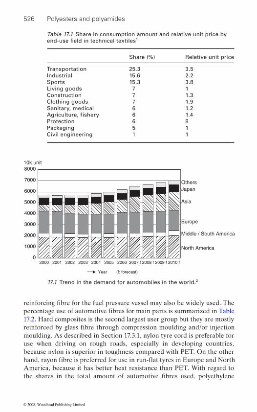
526 Polyesters and polyamides
17.2. Hard composites is the second largest user group but they are mostly
moulding. As described in Section 17.3.1, nylon tyre cord is preferable for use when driving on rough roads, especially in developing countries, because nylon is superior in toughness compared with PET. On the other
America, because it has better heat resistance than PET. With regard to
Table 17.1 Share in consumption amount and relative unit price by 1
Share (%) Relative unit price
Transportation 25.3 3.5Industrial 15.6 2.2Sports 15.3 3.8Living goods 7 1Construction 7 1.3Clothing goods 7 1.9Sanitary, medical 6 1.2
6 1.4Protection 6 8Packaging 5 1Civil engineering 1 1
10k unit
OthersJapan
Asia
Europe
Middle / South America
North America
8000
7000
6000
5000
4000
3000
2000
1000
02000 2001 2002 2003 2004
Year (f: forecast)
2005 2006 2007 f 2008 f 2009 f 2010 f
17.1 Trend in the demand for automobiles in the world.2
end-use field in technical textiles
Agriculture, fishery
reinforcing fibre for the fuel pressure vessel may also be widely used. The percentage use of automotive fibres for main parts is summarized in Table
reinforced by glass fibre through compression moulding and/or injection
the shares in the total amount of automotive fibres used, polyethylene
hand, rayon fibre is preferred for use in run-flat tyres in Europe and North
© 2008, Woodhead Publishing Limited

Automotive applications 527
26%.4 They are mainly used in area (a) because they are fairly inexpensive and have comparatively good physical properties and dyeability. But in
17.2). Then applications to rubber composites such as tyres, driving belts (Section 17.3), internal safety systems such as seat belts and air bags
(Section 17.5), and others such as exterior cover sheets and noise control
Sections 17.3, 17.4, 17.5 and 17.6 describe: (a) the particular part to which
17.2
in terms of properties, cost, and energy consumption are summarized.
have advantages in dyeability, high temperature resistance and dimen-sional stability over PP. It must be noted that the lower melting point of PP causes a limitation in the application of PP to temperature-sensitive
heat stability, higher resistance to colour change, higher durability for
3
End-uses (main parts) Share (%)
Rubber composites (tyre, driving belt) 36Safety system (seat belt, airbag) 4
17Hard composites (body, mechanical parts) 30
13
Table 17.2 The amount of automotive fibres by end-uses
Others (filter, etc.)
terephthalate (PET) fibre takes up about 42% and nylon 66 fibre about
other areas such as area (c), glass fibre has a far superior ‘performance/
materials (Section 17.6) are explained.
cost’ value to them as a reinforcing fibre.In this chapter, polyester fibres and polyamide fibres for automotive use
are first described in terms of fibre performance requirements (Section
fibre is applied; (b) the application form of fibre material to the part in terms of fibre function; (c) the performance requirement of the fibre ma-terial; and (d) the fibre species and type used for the part.
Polyester and polyamide fibres for automotive
use in terms of fibre performance requirements
17.2.1 PET, nylon 6 and 66 fibres
In Table 17.3, the main properties of PET, nylon 6 and nylon 66 fibres are shown compared with those of polypropylene (PP) and p-aramid fibres. In Table 17.4, the advantages and disadvantages of PET, nylon and PP fibres
PP fibre is usually the most economical, lowest in energy consumption to produce fibre and lowest in specific gravity. But PET and nylon fibres
parts. Compared with nylon fibre, PET fibre has a higher modulus, higher
Car interiors (seat, door trim, roof trim floor covering)
(Section 17.4), car interiors such as seats, roof trims and floor coverings
© 2008, Woodhead Publishing Limited

Fibresgravity
Melting point (˚C)
Glass transition temp (˚C)
Tensile strength (MPa)
Breaking elongation (%)
Tensile modulus (GPa)
LOI (%) UV degra-dation
Colour-change by UV
PET 1.38 260 70 510–690 15–40 6–11 18–21 ++ ++Nylon 66 1.14 260 35 (50%RH) 350–550 18–36 3.0–6.5 20–21 + +Nylon 6 1.13 220 20 (50%RH) 450–700 20–32 2.5–3.4 20–21 ++ +PP 0.91 160 −15 410 25–60 6.4 18–20 +* +++**p-Aramid 1.14 – 300 2760 3.3 58 29 ++ –
Notes: ++: fairly good; +: good; +*: can be good by additive; +++*: very good by pigment colour; −: sensitive
Table 17.3 Properties of PET, nylon fibres comparing with PP and p-aramid fibres (standard type)
Specific
© 2008, Woodhead Publishing Limited

Automotive applications 529
sunlight degradation and is less expensive. In addition, the production of
tensile strain recovery and also excellent adhesiveness. With regards to nylon 6 and 66, the former has higher heat resistance but it is a little more expensive. Hence, nylon 66 is used for the end-uses requiring higher heat
for the reinforcement of most rubber composite parts. But for tyres used on rough roads in developing countries, advantage is taken of the excellent
of its higher modulus, higher glass transition temperature and higher dura-
because of its higher foldability when it needs to be contained and higher
used because of its higher sunlight (colour change) resistance and higher heat resistance.
which is now used in automotive materials. As shown in Fig. 17.2, PEN has a much higher tensile modulus and heat stability than PET because of the higher molecular stiffness caused by the naphthalene ring for PEN com-pared to the benzene ring for PET. Its cost is situated midway between PET and p-aramid. One example of its automotive applications is in tyre
Table 17.4 Advantages and disadvantages in properties of PET and
Fibres Advantage, feature Disadvantage
PET Balanced in physical properties
Easy in hydrosisA little less in wearing
resistance
Nylon Excellent in toughness and wearing resistance
Low in modulusExcellent in strain recovery
Easy in yellowingFairly expensive as
High in energy consumption
PP Excellent in chemical resistance
Low in energy
production
Very bad in dyeabilityLow in heat resistanceHigh in creep and stress
relaxation
nylon fibres comparing with PP fibre
conventional fibres
for fibre production
Low specific gravity
consumption for f ibre
nylon fibre uses the most energy. But it has greater toughness, excellent
resistance. In these property and cost situations, PET fibre is usually used
toughness of nylon fibre. For seat belts, PET fibre is mainly used because
bility for sunlight. On the other hand, nylon 66 fibre is used for air bags
resistance to small burning particles. For car interiors, PET fibre is mainly
17.2.2 Other polyester fibres and polyamide fibres
Polyethylene naphthalate (PEN) is the other main type of polyester fibre
© 2008, Woodhead Publishing Limited
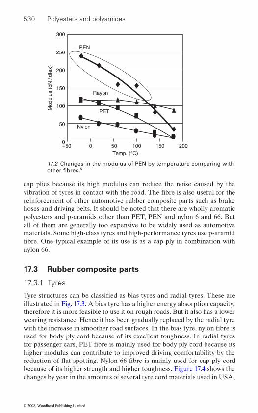
530 Polyesters and polyamides
cap plies because its high modulus can reduce the noise caused by the
reinforcement of other automotive rubber composite parts such as brake hoses and driving belts. It should be noted that there are wholly aromatic polyesters and p-aramids other than PET, PEN and nylon 6 and 66. But all of them are generally too expensive to be widely used as automotive materials. Some high-class tyres and high-performance tyres use p-aramid
nylon 66.
17.3 Rubber composite parts
17.3.1 Tyres
illustrated in Fig. 17.3. A bias tyre has a higher energy absorption capacity, therefore it is more feasible to use it on rough roads. But it also has a lower wearing resistance. Hence it has been gradually replaced by the radial tyre
used for body ply cord because of its excellent toughness. In radial tyres
higher modulus can contribute to improved driving comfortability by the
because of its higher strength and higher toughness. Figure 17.4 shows the changes by year in the amounts of several tyre cord materials used in USA,
300
250
200
150
100
50
0–50 50 100 150 200
Temp. (°C)
Mod
ulus
(cN
/ dt
ex)
0
PEN
PET
Rayon
Nylon
17.2 Changes in the modulus of PEN by temperature comparing with 5other fibres.
vibration of tyres in contact with the road. The fibre is also useful for the
fibre. One typical example of its use is as a cap ply in combination with
Tyre structures can be classified as bias tyres and radial tyres. These are
with the increase in smoother road surfaces. In the bias tyre, nylon fibre is
for passenger cars, PET fibre is mainly used for body ply cord because its
reduction of flat spotting. Nylon 66 fibre is mainly used for cap ply cord
© 2008, Woodhead Publishing Limited

Automotive applications 531
which correspond to the historical changes of the bias tyre and radial tyre, as stated above.
usually used for tyre cord, because a higher modulus and higher heat resist-ance in shrinkage are important requirements for tyre cord. But the most important property that needs to be improved for PET is its comparatively low adhesiveness to matrix rubber. As regards nylon, a high strength type
made of several materials are summarized in Table 17.5 in which yarn
a ° = 30~40° a ° = 90~80°b ° = 15~25°
Top tread
(a) (b)
(c)
Cap ply
Belt ply
Body ply
Inner liner
Flipper
Side tread
Bead
a °b °
s °
17.3 Structures of tyre for a passenger car: (a) bias tyre; (b) radial tyre; (c) the cross-sectional structure of a radial tyre.6
A high modulus low shrinkage (HMLS) type of PET multi-filament is
of multi-filament is required for tyre cord. The properties of tyre cords
© 2008, Woodhead Publishing Limited

532 Polyesters and polyamides
thickness/number of ply is also shown. There are different methods for
is the use of the composite made of p-aramid nonwoven and rubber which
capability.
Rayon
200
150
100
50
0
kt
1935 1940 1945 1950 1955 1960 1965 1970 1975 1980 1985
Nylon
PET
Steel
Glass fibre
Aramid
Cotton
17.4 Changes by year in the amount of several tyre materials consumed in the USA.7
Table 17.5 Properties of nylon 66 and HMLS PET tyre cords comparing with other materials8
Ny66 HMLS PET PEN Rayon super III
p-Aramid Steel
Thickness 1400/2 1670/2 1670/2 1840/2 1670/2 –Twist (T/10 cm) 39 × 39 39 × 39 39 × 39 47 × 47 32 × 32 –Strength index of 100 90 80 55 210 –
yarn (%)19 11 9 9 3.6 –
Therm. shrink. of 5.5 3.0 1.5 ≥0.3 ≥0.3 –
Elongation at 7.0 4.0 2.0 2.0 0.9 –
Creep index 100 50 – 70 10 –Adhesiveness good fairly g. fairly g. good. fairly g. good
1.14 1.38 1.36 1.52 1.44 7.81Melting point (˚C) 265 260 272 degrade degrade 1450Glass transition
temp. (˚C)– 70 113 – – –
Notes: Rayon super III: the third generation super tenacity rayon
fixed load (%)
Specific gravity
the fibre reinforcement of tyres other than by using cord. One is a direct blend of short fibres such as p-aramid with matrix rubber. Another example
flat yarnElongation of flat
flat y. (%)
is inserted into the inner part of a truck/bus tyre to increase run-flat
© 2008, Woodhead Publishing Limited
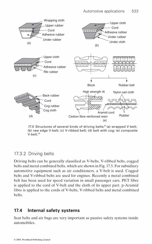
Automotive applications 533
17.3.2 Driving belts
belts and metal combined belts, which are shown in Fig. 17.5. For subsidiary automotive equipment such as air conditioners, a V-belt is used. Cogged belts and V-ribbed belts are used for engines. Recently a metal combined
is applied to the cord of V-belt and the cloth of its upper part. p-Aramid
belts.
17.4 Internal safety systems
Seat belts and air bags are very important as passive safety systems inside automobiles.
Wrapping cloth
Upper rubberUpper cloth
Under rubber
Under cloth
Upper cloth
Cord
Cord
Cord
Cord
Adhesive rubber
Adhesive rubber
Back rubber
Cog rubberCog cloth
Rib rubber
Block Rubber belt
High strength Al Nylon sail cloth
Carbon fibre reinforced resinAramid cord
Rubber
Adhesive rubber
Under rubber(a)
(b)
(c)
(d)(e)
17.5 Structures of several kinds of driving belts:9 (a) wrapped V-belt; (b) raw edge V-belt; (c) V-ribbed belt; (d) belt with cog; (e) composite V-belt.10
Driving belts can be generally classified as V-belts, V-ribbed belts, cogged
belt has been used for speed variation in small passenger cars. PET fibre
fibre is applied to the cords of V-belts, V-ribbed belts and metal combined
© 2008, Woodhead Publishing Limited

534 Polyesters and polyamides
17.4.1 Seat belts
A seat belt is used to prevent a passenger in a car being thrown from their
shock. Figure 17.6 illustrates an example of a seat belt. PET woven fabrics are usually used for its webbing. As described in Section 17.2.1, PET is more suitable than nylon for the webbing, because PET has a higher impact energy absorbing capability and suffers less discoloration by sunlight. There are several standards for webbing such as the Federal Motor Safety Standard, Economic Commission for Europe and JIS. The main mechani-cal requirements in these standards are strength, width, elongation and energy absorption ratio. There are also requirements related to durability such as wearing resistance, cold and heat resistance, water resistance, light
8–10 cN/dtex.
17.4.2 Air bags
The function of an air bag is to cushion a passenger from collision impact.
certain limit. An air bag can be very effective as a passive safety system in combination with a seat belt. There are several kinds of air bags: driver bag, front passenger bag, thorax bag, curtain bag, rear bag and knee bag. Figure 17.7 shows photographs of several kinds of air bag. The base ma-
Continuous webbingUpper fitting
Slip guide
Tang plate
Buckle
Lower fittingWinder
Winder
Slip guide
17.6 A typical example of sheet belt system.11
seat in an accident by fixing them to the seat and absorbing the impact
degradation resistance and colour fastness. Typical examples of specifica-tion values of PET fibre for this end use are: yarn thickness 1000–2500 dtex with 4–25 dtex of its mono-filament thickness, and strength
The bag is instantly inflated by heated gas after a collision stronger than a
© 2008, Woodhead Publishing Limited
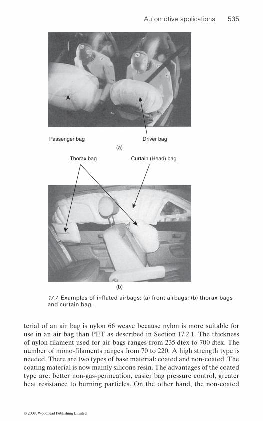
Automotive applications 535
terial of an air bag is nylon 66 weave because nylon is more suitable for use in an air bag than PET as described in Section 17.2.1. The thickness
needed. There are two types of base material: coated and non-coated. The coating material is now mainly silicone resin. The advantages of the coated type are: better non-gas-permeation, easier bag pressure control, greater heat resistance to burning particles. On the other hand, the non-coated
Passenger bag Driver bag
Thorax bag Curtain (Head) bag
(a)
(b)
and curtain bag.
of nylon filament used for air bags ranges from 235 dtex to 700 dtex. The number of mono-filaments ranges from 70 to 220. A high strength type is
17.7 Examples of inflated airbags: (a) front airbags; (b) thorax bags
© 2008, Woodhead Publishing Limited
536 Polyesters and polyamides
coated cloth, some special products have been developed by weaving with
17.5 Car interiors
The main interior components of an automobile are the seats, door trim,
17.5.1 Seat and door trim
cushion material. It is also used for some door trim skin material. There are several kinds of seat skin sheets such as pile weave, weave, tricot with raising, pile double raschel knit, and pile circular knit. General trends are towards an increase in knit fabrics (tricot, double raschel and circular knit) which are less expensive and have more formability than weave fabrics. Recently a suede fabric, using a PET nonwoven base material, has been introduced. Skin sheets containing phase change material have been also been developed, which can increase the temperature comfortability of the
thetic effect, physiological comfortability, strength/wearing durability,
stance content. They are also often required to have some special functions such as anti-bacterial, deodorizable, anti-static and stain resistant proper-ties. Pile or raising of these sheet fabrics is usually related to an increase in the values of tactile and visual aesthetic effects. An extremely high level of colour-fastness in sunlight is usually required, because automobiles can be used in high temperatures and strong sunlight.
Urethane foam is usually used for seat cushion material under the skin sheet. But some special PET nonwovens have recently been developed such
stitch-bonded web, and a PET 3-dimensional knit fabric with super water
als over urethane foam is their moisture permeability for passengers’ physi-ological comfort.
The material of door trim skins is usually made of plastic such as vinyl
cars. In most cases, the textile material is the same as the seat skin fabric. However, the fabric needs to have high enough formability to be made into the complicated shape of a door trim. Its lower end is usually covered by
an ultra-high yarn density, with a filament of lower mono-filament thick-
Polyester fibre is used for most of the seat skin sheet, and for some seat
seat. The essential properties of seat skin sheets can be classified as aes-
as a fibre mass stabilized with elastomer fibre bonding, a folded web and
absorbancy. One of the most important advantages of these fibrous materi-
chloride and polyolefin. But textile sheets are also used for higher-class
type is lighter in weight, thinner, more flexible and less expensive. For non-
ness, and with a filament whose fibre cross-section is flat.
roof trim and floor covering.
colour fastness, flame retardancy, heat resistance and non-volatile sub-
the same carpet as the floor because the door often gets kicked.
© 2008, Woodhead Publishing Limited

Automotive applications 537
17.5.2 Roof trims
PET nonwoven and tricot are used as roof trim skin sheets. The use of needle-punched nonwoven in particular has increased, and nonwoven pat-terned into velour by needling is especially common. But there are also spun-laced nonwovens and stitch-bonded nonwovens. They are usually formed into roof trim by integration with base materials. Pigment-dyed PET has been widely adopted. Sheets need to have colour-fastness for sunlight, heat resistance, mechanical durability, light durability, formabil-ity and non-volatile substance content and stain resistance in addition to lightness. Certain levels of sound absorbing capability and heat insulation
17.5.3 Floor coverings
Floor coverings can be mainly divided into liner coverings and optional coverings. Needle-punched nonwoven carpet and tufted carpet are used for liner coverings. The usage of nonwoven carpet has greatly increased because it is more economical and has better formability. There are three main kinds of surface pattern: plain, loop-like and velour-like, as schemati-cally shown in Fig. 17.8. The latter two patterns can be made by the com-
(a)
(b)
(c)
17.8 The illustration of three main types of surface patterns for needle punched carpet: (a) plain; (b) loop-like; (c) velour-like.13
are also needed. The base materials for roof trim can be mainly classified as polymer foam sheets and fibre-reinforced porous polymer sheets. Glass fibre is used for most of these sheets.
bination of specific needles and needling patterns. The surface material of these needle-punched carpets mainly consists of pigmented PET fibre and/or pigmented PET recovered from bottles. Its fibre thickness is reduced
© 2008, Woodhead Publishing Limited

538 Polyesters and polyamides
from 11 to 6 dtex to increase its covering factor. Quite attractive aesthetic
ing described above. The main performance requirements are: mechanical durability, sunlight durability, heat resistance, sunlight colour fastness, sound absorbability, sound insulation, anti-fogging, non-volatile substance
increased requirement for weight reduction, sound absorbability has become more important than sound insulation.
Tufted carpet has usually been used for optional carpets, where its aes-thetic effect and appearance of high quality to the customer is of greater importance. Its weight ranges from 350 to 2000 g per m2 based on the wide
or PP. Of these, PP is increasing its usage share.
17.6 Others
17.6.1 Exterior cover sheets
There are two kinds of automotive exterior cover sheets. One type is a cover for protecting lorry cargo, which is further subdivided into covers for hood use and for plain covering use. The other type is for protecting passenger cars. PET spun yarn weave is mainly used for lorry cargo covers. Figure 17.9 shows its typical structure. Its coating layer is usually
The main performance requirements are: waterproof properties, water repellency, mechanical durability, weather resistance, dimensional stabil-ity, stain resistance, ability to be welded by radio frequency, and lightness.
ment weave, whose yarn thickness is about 250 dtex. Its weight is about 200 g per m2. It is usually coated to make it waterproof. Some cover sheets
Weave
Covering resin layer
Stain resistant layer
17.9 Cross-sectional structure of exterior cover sheet.14
effects can be achieved with needle-punched carpet by the specific pattern-
variety of customer requirements. Its surface material fibre is nylon, PET
poly-vinyl chloride. The main specifications of cover sheets are also sum-marized in Table 17.6. Some PET filament weave is also used for truck cargo covers but filament weave is inferior in durability to spun yarn weave.
Cover sheets for protecting passenger cars are usually made of PET fila-
content, flame retardancy, stain resistance and formability. With an
© 2008, Woodhead Publishing Limited
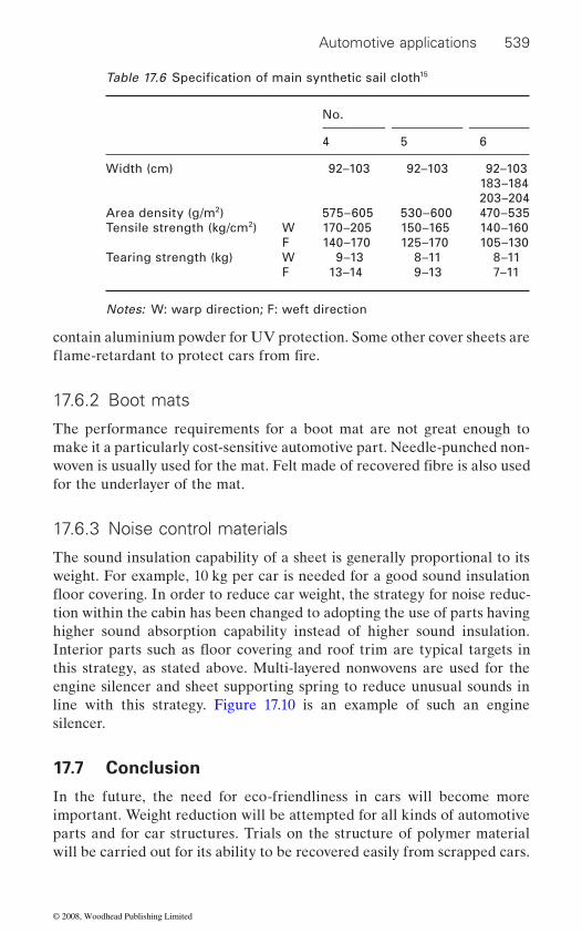
Automotive applications 539
contain aluminium powder for UV protection. Some other cover sheets are
17.6.2 Boot mats
The performance requirements for a boot mat are not great enough to make it a particularly cost-sensitive automotive part. Needle-punched non-
for the underlayer of the mat.
17.6.3 Noise control materials
The sound insulation capability of a sheet is generally proportional to its weight. For example, 10 kg per car is needed for a good sound insulation
tion within the cabin has been changed to adopting the use of parts having higher sound absorption capability instead of higher sound insulation.
this strategy, as stated above. Multi-layered nonwovens are used for the engine silencer and sheet supporting spring to reduce unusual sounds in line with this strategy. Figure 17.10 is an example of such an engine silencer.
17.7 Conclusion
In the future, the need for eco-friendliness in cars will become more important. Weight reduction will be attempted for all kinds of automotive parts and for car structures. Trials on the structure of polymer material will be carried out for its ability to be recovered easily from scrapped cars.
15
No.
4 5 6
Width (cm) 92–103 92–103 92–103183–184203–204
Area density (g/m2) 575–605 530–600 470–535Tensile strength (kg/cm2) W 170–205 150–165 140–160
F 140–170 125–170 105–130Tearing strength (kg) W 9–13 8–11 8–11
F 13–14 9–13 7–11
Notes: W: warp direction; F: weft direction
Table 17.6 Specification of main synthetic sail cloth
woven is usually used for the mat. Felt made of recovered fibre is also used
flame-retardant to protect cars from fire.
floor covering. In order to reduce car weight, the strategy for noise reduc-
Interior parts such as floor covering and roof trim are typical targets in
© 2008, Woodhead Publishing Limited
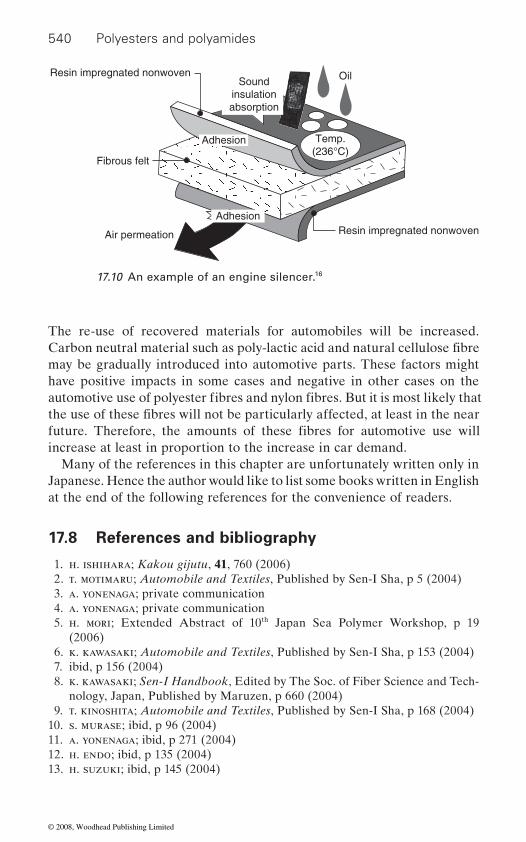
540 Polyesters and polyamides
The re-use of recovered materials for automobiles will be increased.
may be gradually introduced into automotive parts. These factors might have positive impacts in some cases and negative in other cases on the
increase at least in proportion to the increase in car demand.Many of the references in this chapter are unfortunately written only in
at the end of the following references for the convenience of readers.
17.8 References and bibliography
1. h. ishihara; Kakou gijutu, 41, 760 (2006) 2. t. motimaru; Automobile and Textiles, Published by Sen-I Sha, p 5 (2004) 3. a. yonenaga; private communication 4. a. yonenaga; private communication 5. h. mori; Extended Abstract of 10th Japan Sea Polymer Workshop, p 19
(2006) 6. k. kawasaki; Automobile and Textiles, Published by Sen-I Sha, p 153 (2004) 7. ibid, p 156 (2004) 8. k. kawasaki; Sen-I Handbook, Edited by The Soc. of Fiber Science and Tech-
nology, Japan, Published by Maruzen, p 660 (2004) 9. t. kinoshita; Automobile and Textiles, Published by Sen-I Sha, p 168 (2004)10. s. murase; ibid, p 96 (2004)11. a. yonenaga; ibid, p 271 (2004)12. h. endo; ibid, p 135 (2004)13. h. suzuki; ibid, p 145 (2004)
Resin impregnated nonwoven
Resin impregnated nonwoven
Adhesion
Adhesion Temp.(236°C)
Air permeation
Fibrous felt
Soundinsulationabsorption
Oil
17.10 An example of an engine silencer.16
Carbon neutral material such as poly-lactic acid and natural cellulose fibre
automotive use of polyester fibres and nylon fibres. But it is most likely that
Japanese. Hence the author would like to list some books written in English
the use of these fibres will not be particularly affected, at least in the near future. Therefore, the amounts of these fibres for automotive use will
© 2008, Woodhead Publishing Limited

Automotive applications 541
14. h. suzuki; ibid, p 145 (2004)15. a. hinata; ibid, p 82 (2004)
Bibliography
w. fung; Handbook of Technical Textiles, Edited by A. R. Horrocks and S. C. Anand, Published by Woodhead Publishing Ltd. in association with Textile Institute (2000)
w. fung and j. m. hardcastle; Textiles in Automotive Engineering, Published by Woodhead Publishing Ltd. (2000)
s. k. mukhopadhyay et al.; Automotive textiles, Textile Progress vol. 29 Nos.1/2, Textile Institute Publication (1999)
© 2008, Woodhead Publishing Limited
18Applications of polyesters and polyamides in
civil engineering
R . FA NGU EI RO, C . GON I L HO PER EI R A and M. DE A R AÚJO, University of Minho, Portugal
18.1 Introduction
the construction industry, as a potential substitute for more traditional building materials such as wood, concrete, masonry and steel. If in several applications this is the main goal of the textile industries, in other cases, textile materials are already considered traditional civil construction materials.
Fibre reinforced composites are gaining popularity within the civil con-
to their high strength, high modulus and to the possibility to compete with the conventional structural construction materials.
In applications related to the geotechnical and geoenvironmental appli-cations, where properties beside mechanical ones are of paramount impor-
Examples like embankments and retaining walls, road construction and road overlaying, erosion control of steepened slopes, shore protection,
18.2
for civil construction applications
are used in civil construction projects in several forms. If concrete internal
542
A niche market for the textile industry is providing fibres and fabrics to
struction sector. Applications like fibre-reinforced concrete, concrete ret-rofitting, concrete jacketing and composite concrete structures internal and external reinforcement are, among others, applications where fibres and fibrous structures play an important role. In these emerging applications fibres like AR-glass, carbon and aramid are of paramount importance due
tance, fibres and textile structures are already commonly used materials.
construction of waste landfills, architectural membranes, offshore applica-tions, among others, show that fibres and fibrous structures are the core construction materials. In these applications polyamide fibres and, espe-cially, polyester fibres are used in an indiscriminate way.
Polyester and polyamide fibres and structures
Depending on the applications envisaged, polyester and polyamide fibres
© 2008, Woodhead Publishing Limited
Applications of polyesters and polyamides in civil engineering 543
if concrete external reinforcement is required, polyester and polyamide
knitted fabrics as well as needle punched nonwoven fabrics, are also avail-able in geotextiles and geogrids. The combination of different types of structures – hybrid structures – is also common, and their impregnation in matrices, polymeric or cementitious, is usual.
reinforced concrete applications. Many polymers are spun in the form of
and bundling together. Rovings are cut into short lengths in order to obtain
18.2.2 Fibrous structures
and geogrids. Geotextiles can be woven, knitted or nonwoven structures. Geogrids can be produced with conventional weaving and/or knitting process, coated with copolymer resins.
Conventional woven fabrics are produced by orthogonal interlacing two sets of yarns: one called warp whose yarns are along the length of the fabric, while the other one is weft whose threads run along the width of the fabric. Both sets of yarns are mutually positioned under the angle of 90˚ (warp at 0˚ and weft at 90˚). The warp and weft yarns can be interlaced in diverse ways presenting a regular pattern named woven weave structure. Plain weave is the simplest woven structure and it is characterized by the interlacement of warp and weft yarns, alternately over and under. This is
reinforcement is the objective, polyester and polyamide fibres are used as micro- and macro-fibres, fibrillated fibres and monofilaments. Otherwise,
fibres are applied as woven fabric. Polyester and polyamide woven and
18.2.1 Monofilaments, micro- and macro-fibres and fibrillated fibres
Polyester and polyamide fibres are available in several geometries and dimensions. Monofilaments, rovings (tows) and fibrillated fibres are spe-cially used to reinforce cementitious or polymeric matrices. Monofilaments are single straight fibres usually made by drawing molten polymers. Such fibres are usually round in cross-section and are usually used in fibre-
filaments whose diameters vary from 5 to 15 μm in diameter. Several thou-sand filaments are spun simultaneously, by drawing them from a single die
micro- and macro-fibres. Dispersed rovings act as individual monofila-ments. The geometry of a fibrillated fibre can be described in terms of a film thickness and the width of each filament.
Polyester and polyamide fibres are available in several fibrous structures.
a balanced structure, with good stability and reasonable porosity. However,
The most used polyester and polyamide fibrous structures are geotextiles
© 2008, Woodhead Publishing Limited

544 Polyesters and polyamides
Woven fabrics are usually dimensionally stable, but they present lower extensibility and porosity rather than other structures. The mechanical properties of woven fabrics are very important for technical textiles and they depend on different factors, namely raw materials, linear density of the warp and weft, yarn density and woven structure. The strength of a fabric is usually higher in the warp and weft directions, while in diagonal direction they present lower mechanical properties, higher elasticity and lower shear resistance.
Knitted fabrics are textile structures characterized by the interlacing of loops. Two different basic textile technologies allow the manufacturing of knitted structures: weft and warp knitted technologies. Both types of knits
tion and by using straight yarns, which are not knitted, it is possible to design the stability in one direction, with deformability in the others [1]. All loops of a warp knitted fabric are formed from a separate yarn, called warp, mainly introduced in the longitudinal fabric direction. Therefore, neighbouring loops of one course are not produced from the same yarn. These structures have mechanical properties very similar to those of woven
or inelastic. For the production of weft-knitted fabrics, a single yarn may lead to the formation of an entire course (horizontal row of loops). One
stitch length, that is the length of a yarn in a knitted loop. The weft-knitting technology presents great ability to produce complex shapes which is very important for technical applications.
Nonwoven is a very interesting production technique due to the wide variety of products that may be developed comparing to other textiles technologies. According to EDANA [2], nonwovens are sheets, webs or
nonwovens manufacture can be divided in two steps: the matt preparation (carding, air laying, wet laying or spun laying) and the bonding process itself. Needle-punched nonwoven geotextiles are entangled to form a
range of pore size distribution and good drainage.Braided textiles structures are produced by intertwined yarns. There are
three types of braided structures: diamond, regular and hercules. Diamond structure is obtained when yarns cross alternately over and under the yarns of opposite direction and, in this case, the rotation is one to one. But it is possible to modify this rotation to two by two and three by three
it presents several disadvantages such as difficulty to drape and high level of fibre crimp leading to low mechanical properties.
produced by these technologies can have extensibility in one specific direc-
bats of natural and/or man-made fibres or filaments, that have not been converted into yarns, and that are bonded to each other by entangling fibre or filaments mechanically, thermally or chemically [2]. The process of
complex structure by random fibres, accounting for its bulky nature, wide
fabrics, are very flexible and, depending on the construction, can be elastic
important factor that influences the properties of weft knitted fabrics is the
© 2008, Woodhead Publishing Limited
Applications of polyesters and polyamides in civil engineering 545
obtaining, in this way, the other two structures. Among these structures, diamond is the most stable and hercules presents the least stability. Usually, braids are produced in a biaxial structure; however, if yarns are inserted (middle-end-yarn) and oriented longitudinally into the structure, a three axial braid is obtained. Also it is possible to insert in the middle of the
of hollow pieces with or without core. The braid structures have weak axial and compression stability and are conceived to have multidirectional conformability [1]. Nowadays, braids are the reinforcements with more variety of applications on the market, namely the rope and offshore industries.
Concrete Terminology, as a concrete containing dispersed randomly ori-
as a composite material consisting of a concrete phase and a small portion
[5, 6].
tubular form fibre bundles, obtaining in this way a triaxial structure with axial fibres. The diameter of the braid is controlled by several factors namely, the number of fibres, the angle of the intertwining yarns, the number of intersections of fibre per unit length of the yarns and the linear density of the fibres. Braiding technology has been used for the production
18.3 Synthetic fibre-reinforced concrete
The term fibre-reinforced concrete is defined by ACI 116R, Cement and
ented fibres (Figure 18.1) [3]. Fibre reinforced concrete can be described
of discrete and discontinuous fibres distributed and oriented randomly within the concrete [4]. The development of steel fibre reinforced concrete may have begun around the early 1960s. Polymeric fibres came into commercial use in the late 1970s, glass fibres experienced widespread use in the 1980s, and carbon fibres attracted much attention in the 1990s
18.1 Synthetic fibre-reinforced concrete.
© 2008, Woodhead Publishing Limited
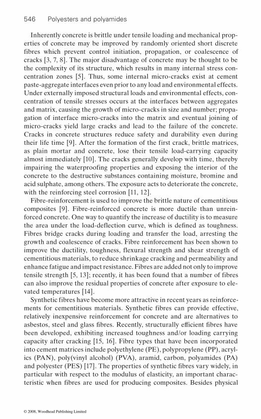
546 Polyesters and polyamides
Inherently concrete is brittle under tensile loading and mechanical prop-erties of concrete may be improved by randomly oriented short discrete
cracks [3, 7, 8]. The major disadvantage of concrete may be thought to be the complexity of its structure, which results in many internal stress con-centration zones [5]. Thus, some internal micro-cracks exist at cement paste-aggregate interfaces even prior to any load and environmental effects. Under externally imposed structural loads and environmental effects, con-centration of tensile stresses occurs at the interfaces between aggregates and matrix, causing the growth of micro-cracks in size and number; propa-gation of interface micro-cracks into the matrix and eventual joining of micro-cracks yield large cracks and lead to the failure of the concrete. Cracks in concrete structures reduce safety and durability even during
as plain mortar and concrete, lose their tensile load-carrying capacity almost immediately [10]. The cracks generally develop with time, thereby
concrete to the destructive substances containing moisture, bromine and acid sulphate, among others. The exposure acts to deteriorate the concrete, with the reinforcing steel corrosion [11, 12].
Fibre-reinforcement is used to improve the brittle nature of cementitious composites [9]. Fibre-reinforced concrete is more ductile than unrein-forced concrete. One way to quantify the increase of ductility is to measure
Fibres bridge cracks during loading and transfer the load, arresting the growth and coalescence of cracks. Fibre reinforcement has been shown to
cementitious materials, to reduce shrinkage cracking and permeability and enhance fatigue and impact resistance. Fibres are added not only to improve
can also improve the residual properties of concrete after exposure to ele-vated temperatures [14].
relatively inexpensive reinforcement for concrete and are alternatives to
been developed, exhibiting increased toughness and/or loading carrying capacity after cracking [15, 16]. Fibre types that have been incorporated into cement matrices include polyethylene (PE), polypropylene (PP), acryl-ics (PAN), poly(vinyl alcohol) (PVA), aramid, carbon, polyamides (PA)
particular with respect to the modulus of elasticity, an important charac-
fibres which prevent control initiation, propagation, or coalescence of
their life time [9]. After the formation of the first crack, brittle matrices,
impairing the waterproofing properties and exposing the interior of the
tensile strength [5, 13]; recently, it has been found that a number of fibres
Synthetic fibres have become more attractive in recent years as reinforce-ments for cementitious materials. Synthetic fibres can provide effective,
asbestos, steel and glass fibres. Recently, structurally efficient fibres have
and polyester (PES) [17]. The properties of synthetic fibres vary widely, in
teristic when fibres are used for producing composites. Besides physical
the area under the load-deflection curve, which is defined as toughness.
improve the ductility, toughness, flexural strength and shear strength of
© 2008, Woodhead Publishing Limited
Applications of polyesters and polyamides in civil engineering 547
concrete is also of paramount importance [6, 17].
of elasticity greater than the matrix. For cementitious materials, where the
ment. However, both theoretical and applied research have indicated that,
with respect to the strain capacity, toughness, impact resistance and crack
poor tensile strength of concrete can be enhanced by combining concrete
to concrete. More recently, it has become possible to incorporate relatively
tially increase the tensile strength of the matrix.
18.3.1 Type of reinforcement
elements where conventional steel reinforcement is not feasible. These ele-ments are prefabricated rather than cast-in-place. Most structural rein-
alternative.Secondary reinforcement is used to control cracking caused by intrinsic
tensile stresses such as drying shrinkage, plastic shrinkage or temperature changes. The purpose of crack control is neither to eliminate cracking caused by intrinsic stresses, nor to increase the load-carrying capacity of the concrete; crack control replaces a random pattern of relatively large
cracks. Actually, this makes concrete less water permeable and hence more durable.
and mechanical properties, durability of fibres used for fibre-reinforced
To increase the strength of their composites, fibres must have a modulus
modulus of elasticity ranges from 15 to 30 GPa, this condition is difficult to meet with most synthetic fibres. Therefore, attempts have been made to develop fibres with a very high modulus of elasticity for cement reinforce-
even with low modulus fibres, considerable improvements can be obtained
control of the fibre-reinforced concrete composites. In many applications, the enhancement of these properties is of much greater significance than
with small diameter fibres, which can be synthetic fibres. It is usually
and that only after the matrix has cracked do the fibres contribute by bridg-ing the crack. Most of the current applications with fibre-reinforced con-crete involve the use of fibres ranging around 1% by volume with respect
large volumes (ranging up to 15%) of synthetic fibres into concrete. With such large volumes of fibres it has been noted that the fibres may substan-
Synthetic fibres are usually used as primary reinforcement in thin sheet
forcements have involved the use of steel, glass or carbon fibres. The development of high modulus synthetic fibres, such as polyaramid, allows the possibility of replacing steel or glass fibres, but at a high cost that makes current use of synthetic fibres for primary reinforcement an unfeasible
cracks with a more deliberately structured pattern of closely spaced fine
the modest increase in tensile (flexural) strength. In some applications, the
assumed that the fibres do not influence the tensile strength of the matrix,
© 2008, Woodhead Publishing Limited

548 Polyesters and polyamides
at high dosages, however, has potential disadvantages in terms of poor workability and increased cost [18, 19]. Micro-defects, such as voids, hon-
contents [6]. A compromise to obtain good fresh concrete properties and good toughness of hardened concrete can be obtained by adding two dif-
yield optimum performance and can reduce the overall cost of concrete
polypropylene, etc. results in good fresh concrete properties and reduced early age cracking. It is also important to have a combination of low and
micro-cracks in the plastic stage of concrete. However, their contribution
cant [18, 19].
shrinkage cracking is caused by excessive loss of water from fresh concrete due to evaporation. The problem is most acute in the summer months when weather conditions may increase the rate of moisture evaporation so that it exceeds the rate of bleeding [19]. When it happens, local drying at the surface will result in plastic shrinkage cracking. Once the magnitude of
the potential to prevent his type of cracking in cases where inadequate preventive measures have been taken. Laboratory studies show that slabs
of control concrete [6].
added to concrete. Other studies have shown a slight decrease in com-pressive strength, over unreinforced concrete control specimens. These apparent differences are attributed to changes in the water-to-cement ratio
slightly decreases slump, additional water is often used to bring the slump
18.3.2 Effect of fibres on fresh and hardened concrete
Dispersion of fibres during mixing is an important concern in the produc-tion of fibre-reinforced concrete. Despite the benefits of fibre reinforce-ment, fibres can make cementitious materials difficult to work, in the fresh state, compromising hardened state properties [13]. The addition of fibres
eycombs and clumping or ‘balling’ of fibres can be a problem at high fibre
ferent types of fibres, which can work individually at different scales to
production. The addition of non-metallic fibres such as glass, polyester,
high modulus fibres to arrest the micro- and macro-crack, respectively. Another beneficial combination of fibres is that long and short fibres can control different scales of cracking [18, 19]. The beneficial effects of non-metallic fibres could be attributed to their high aspect ratios and increased fibre availability at a given volume fraction. Because of their low stiffness, these fibres are particularly effective in controlling the propagation of
to post-cracking behaviour, unlike steel fibres, is not known to be signifi-
Synthetic fibres seem to perform better than glass or steel fibres. Plastic
tensile stresses needed to cause cracking is quite low, synthetic fibres have
with fibre reinforcement develop less plastic shrinkage cracking than slabs
Some studies have shown no significant improvements in tensile or compressive strength of concrete when low volumes of synthetic fibres are
between control and fibre-reinforced concrete. Since the addition of fibres
© 2008, Woodhead Publishing Limited
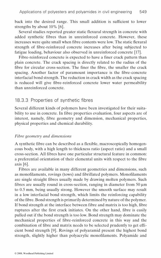
Applications of polyesters and polyamides in civil engineering 549
strengths by about 10% [6].
fatigue loading, behaviour also observed in unreinforced concrete [17].
plain concrete. The crack spacing is directly related to the radius of the
interfacial bond strength. The reduction in crack width as the crack spacing
than unreinforced concrete.
Several different kinds of polymers have been investigated for their suita-
physical properties and chemical durability.
Fibre geometry and dimensions
eous body, with a high length to thickness ratio (aspect ratio) and a small
axis [6].Fibres are available in many different geometries and dimensions, such
to 0.5 mm, being usually strong. However the smooth surface may result in a low interfacial bond strength, which limits the reinforcing capability
pulled out if the bond strength is too low. Bond strength may dominate the
cient bond strength [9]. Rovings of polyaramid present the highest bond
back into the desired range. This small addition is sufficient to lower
added synthetic fibres than in unreinforced concrete. However, these
strength of fibre-reinforced concrete increases after being subjected to
Fibre-reinforced concrete is expected to have a finer crack pattern than
fibre for circular cross-section. The finer the fibre, the smaller the crack spacing. Another factor of paramount importance is the fibre-concrete
is reduced will give fibre-reinforced concrete lower water permeability
18.3.3 Properties of synthetic fibres
bility to use in concrete. In fibre properties evaluation, four aspects are of interest, namely, fibre geometry and dimension, mechanical properties,
cross-section. All fibres have one particular structural feature in common: a preferential orientation of their elemental units with respect to the fibre
as monofilaments, rovings (tows) and fibrillated polymers. Monofilaments are single straight fibres usually made by drawing molten polymers. Such fibres are usually round in cross-section, ranging in diameter from 50 μm
of the fibre. Bond strength is primarily determined by nature of the polymer. If bond strength at the interface between fibre and matrix is too high, fibre ruptures after the first crack initiates. On the other hand, fibre is easily
mechanical properties of fibre-reinforced concrete in this way and the combination of fibre and matrix needs to be selected prudently to get effi-
strength, slightly higher than polyacrylic monofilaments. Polyamide and
Several studies reported greater static flexural strength in concrete with
increases were quite small when fibre contents were low. The static flexural
A synthetic fibre can be described as a flexible, macroscopically homogen-
© 2008, Woodhead Publishing Limited
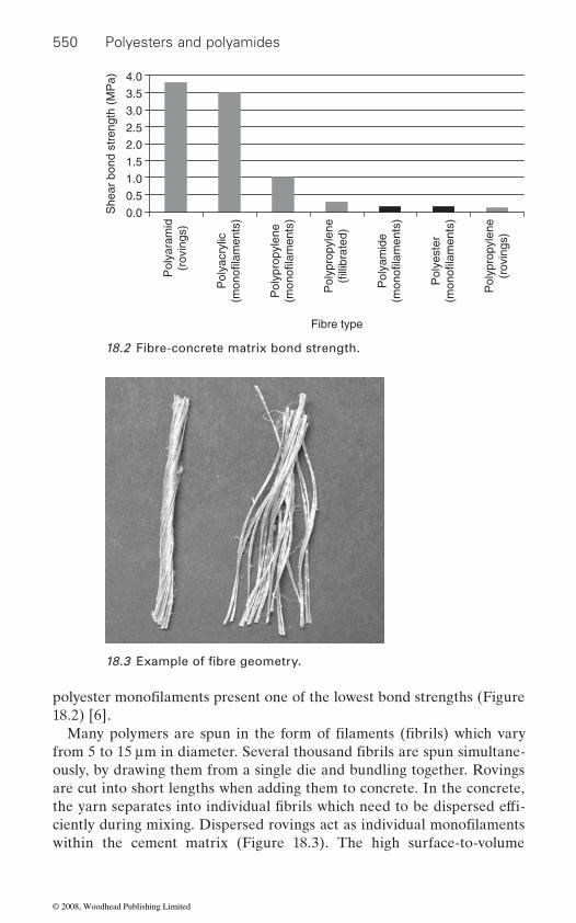
550 Polyesters and polyamides
18.2) [6].
ously, by drawing them from a single die and bundling together. Rovings are cut into short lengths when adding them to concrete. In the concrete,
within the cement matrix (Figure 18.3). The high surface-to-volume
0.0
0.5
1.0
1.5
2.0
2.5
3.0
3.5
4.0
Pol
yara
mid
(rov
ings
)
Pol
yacr
ylic
(mon
ofila
men
ts)
Pol
ypro
pyle
ne(m
onof
ilam
ents
)
Pol
ypro
pyle
ne(f
illib
rate
d)
Pol
yam
ide
(mon
ofila
men
ts)
Pol
yest
er(m
onof
ilam
ents
)
Pol
ypro
pyle
ne(r
ovin
gs)
Fibre type
She
ar b
ond
stre
ngth
(M
Pa)
18.2 Fibre-concrete matrix bond strength.
18.3 Example of fibre geometry.
polyester monofilaments present one of the lowest bond strengths (Figure
from 5 to 15 μm in diameter. Several thousand fibrils are spun simultane-Many polymers are spun in the form of filaments (fibrils) which vary
the yarn separates into individual fibrils which need to be dispersed effi-ciently during mixing. Dispersed rovings act as individual monofilaments
© 2008, Woodhead Publishing Limited
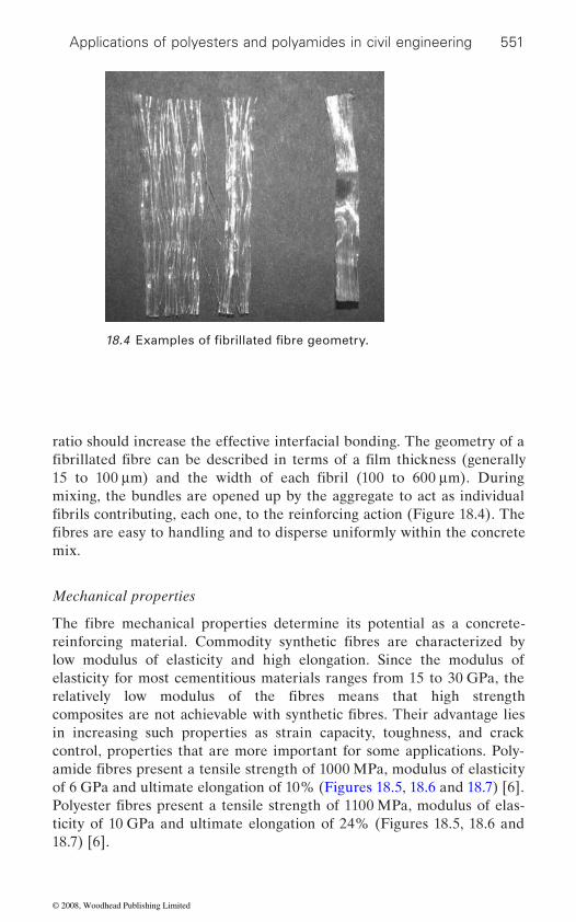
Applications of polyesters and polyamides in civil engineering 551
ratio should increase the effective interfacial bonding. The geometry of a
mixing, the bundles are opened up by the aggregate to act as individual
mix.
Mechanical properties
low modulus of elasticity and high elongation. Since the modulus of elasticity for most cementitious materials ranges from 15 to 30 GPa, the
in increasing such properties as strain capacity, toughness, and crack control, properties that are more important for some applications. Poly-
of 6 GPa and ultimate elongation of 10% (Figures 18.5, 18.6 and 18.7) [6].
ticity of 10 GPa and ultimate elongation of 24% (Figures 18.5, 18.6 and 18.7) [6].
18.4 Examples of fibrillated fibre geometry.
fibrillated fibre can be described in terms of a film thickness (generally 15 to 100 μm) and the width of each fibril (100 to 600 μm). During
fibrils contributing, each one, to the reinforcing action (Figure 18.4). The fibres are easy to handling and to disperse uniformly within the concrete
The fibre mechanical properties determine its potential as a concrete-reinforcing material. Commodity synthetic fibres are characterized by
relatively low modulus of the fibres means that high strength composites are not achievable with synthetic fibres. Their advantage lies
amide fibres present a tensile strength of 1000 MPa, modulus of elasticity
Polyester fibres present a tensile strength of 1100 MPa, modulus of elas-
© 2008, Woodhead Publishing Limited
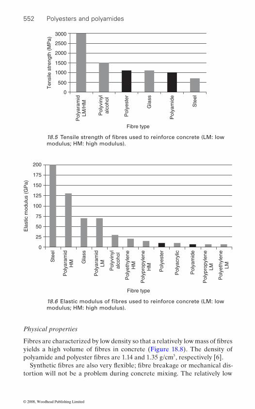
552 Polyesters and polyamides
Physical properties
3
tortion will not be a problem during concrete mixing. The relatively low
3000
2500
2000
1500
1000
500
0
Pol
yara
mid
LM/H
M
Pol
yvin
ylal
coho
l
Pol
yest
er
Gla
ss
Pol
yam
ide
Ste
el
Fibre type
Ten
sile
str
engt
h (M
Pa)
modulus; HM: high modulus).
200
175
150
125
100
75
50
25
0
Ste
el
Gla
ss
Pol
yara
mid
LM
Pol
yvin
ylal
coho
l
Pol
yeth
ylen
eH
M
Pol
yeth
ylen
eLM
Pol
ypro
pyle
neH
M
Pol
ypro
pyle
neLMPol
yest
er
Pol
yacr
ylic
Pol
yam
ide
Pol
yara
mid
HM
Fibre type
Ela
stic
mod
ulus
(G
Pa)
modulus; HM: high modulus).
18.5 Tensile strength of fibres used to reinforce concrete (LM: low
18.6 Elastic modulus of fibres used to reinforce concrete (LM: low
Fibres are characterized by low density so that a relatively low mass of fibres yields a high volume of fibres in concrete (Figure 18.8). The density of polyamide and polyester fibres are 1.14 and 1.35 g/cm , respectively [6].
Synthetic fibres are also very flexible; fibre breakage or mechanical dis-
© 2008, Woodhead Publishing Limited
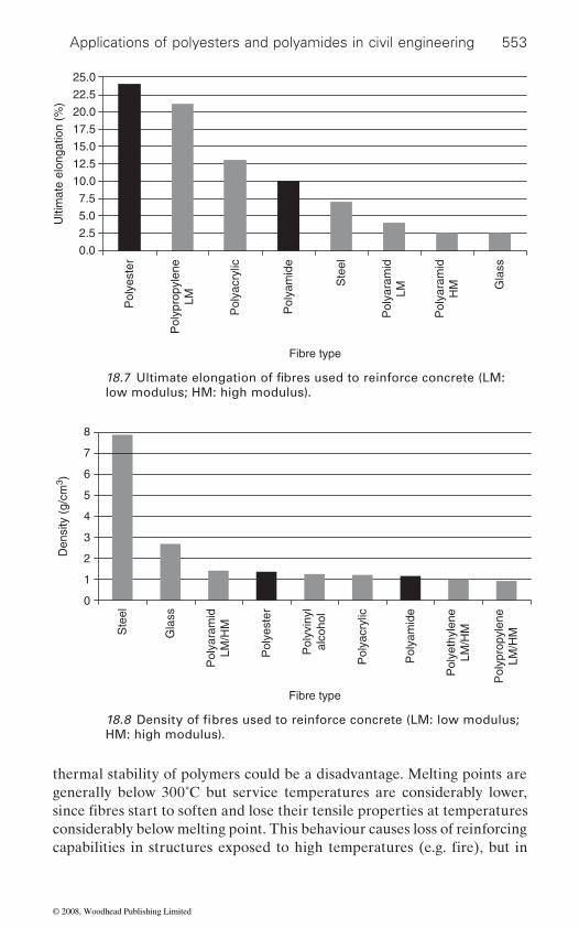
Applications of polyesters and polyamides in civil engineering 553
thermal stability of polymers could be a disadvantage. Melting points are generally below 300˚C but service temperatures are considerably lower,
considerably below melting point. This behaviour causes loss of reinforcing
0.0
2.5
5.0
7.5
10.0
12.5
15.0
17.5
20.0
22.5
25.0
Pol
yest
er
Pol
ypro
pyle
neLM
Pol
yacr
ylic
Pol
yam
ide
Ste
el
Pol
yara
mid
LM
Pol
yara
mid
HM G
lass
Fibre type
Ulti
mat
e el
onga
tion
(%)
low modulus; HM: high modulus).
8
7
6
5
4
3
2
1
0
Ste
el
Gla
ss
Pol
yvin
ylal
coho
l
Pol
yeth
ylen
eLM
/HM
Pol
ypro
pyle
neLM
/HM
Pol
yest
er
Pol
yacr
ylic
Pol
yam
ide
Pol
yara
mid
LM/H
M
Fibre type
Den
sity
(g/
cm3 )
HM: high modulus).
18.7 Ultimate elongation of fibres used to reinforce concrete (LM:
18.8 Density of fibres used to reinforce concrete (LM: low modulus;
since fibres start to soften and lose their tensile properties at temperatures
capabilities in structures exposed to high temperatures (e.g. fire), but in
© 2008, Woodhead Publishing Limited

554 Polyesters and polyamides
problem. The glass transition temperature (Tg) which represents a change in consistency from rubbery to brittle as the temperature is lowered, should also be considered. Polyamide and polyester glass transition temperatures are 45 and 70˚C respectively [6] (Figure 18.9). In most cases, glass transi-
it lies just above maximum ambient temperature usually encountered in service, as in the case of polyamide, solar heating could cause the tempera-ture in the concrete to exceed Tg. Maximum service temperature of
(Figure 18.10).
Environmental durability and thermal resistance
Cement paste develops a moist alkaline environment detrimental to many organic materials. The minimum pH in a cement paste is about 12.3, which corresponds to a saturated calcium hydroxide solution. However, many types of cement have high alkali content, which can raise the pH to 13.5 or higher, when the cement is mixed with water. This very high pH will be detrimental to some polymers. Polyacrylics, polyesters and polyamides are particularly sensitive since they can undergo alkaline hydrolysis [6].
accelerated at higher temperatures. Moreover, how much this phenomenon occurs depends on three factors: the degree of saturation of the concrete; the rate of hydrolysis; and the extent that hydrolysis will reduce the
–140
–100
–60
–20
20
60
100
Pol
yacr
ylic
Pol
yvin
ylal
coho
l
Pol
yest
er
Pol
yam
ide
Pol
ypro
pyle
neLM
/HM
Pol
yeth
ylen
eLM
/HM
Fibre type
Gla
ss tr
ansi
tion
tem
p. (
°C)
concrete (LM: low modulus; HM: high modulus).18.9 Glass transition temperature of fibres used to reinforce
polyamide and polyester fibres is 120 and 150˚C respectively [6]
Hydrolysis may be slow at room temperature, but may be significantly
mechanical properties of the fibre. Synthetic fibres cannot withstand
normal environmental temperature fluctuations will not cause a
tion temperature lies well outside service temperature fluctuations, but, if
© 2008, Woodhead Publishing Limited
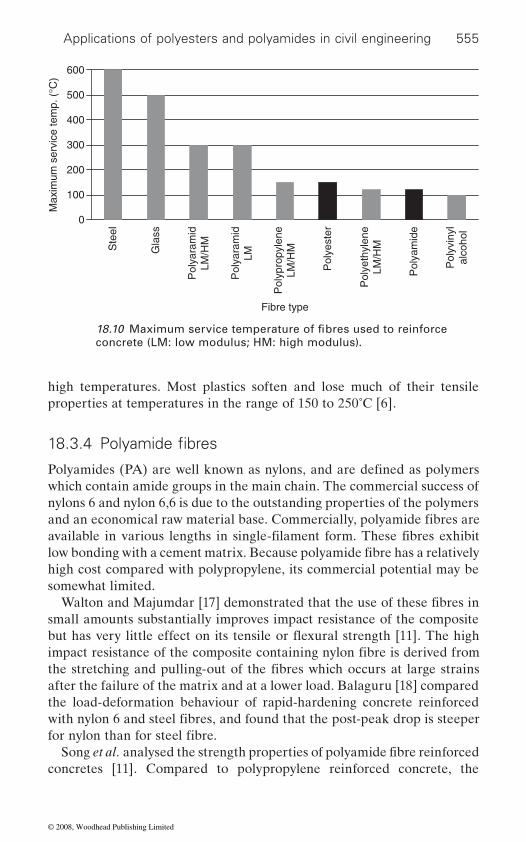
Applications of polyesters and polyamides in civil engineering 555
high temperatures. Most plastics soften and lose much of their tensile properties at temperatures in the range of 150 to 250˚C [6].
which contain amide groups in the main chain. The commercial success of nylons 6 and nylon 6,6 is due to the outstanding properties of the polymers
high cost compared with polypropylene, its commercial potential may be somewhat limited.
small amounts substantially improves impact resistance of the composite
after the failure of the matrix and at a lower load. Balaguru [18] compared the load-deformation behaviour of rapid-hardening concrete reinforced
concretes [11]. Compared to polypropylene reinforced concrete, the
0
100
200
300
400
500
600
Ste
el
Gla
ss
Pol
yara
mid
LM/H
M
Pol
yara
mid
LM
Pol
ypro
pyle
neLM
/HM
Pol
yest
er
Pol
yeth
ylen
eLM
/HM
Pol
yam
ide
Pol
yvin
ylal
coho
l
Fibre type
Max
imum
ser
vice
tem
p. (
°C)
concrete (LM: low modulus; HM: high modulus).18.10 Maximum service temperature of fibres used to reinforce
18.3.4 Polyamide fibres
Polyamides (PA) are well known as nylons, and are defined as polymers
and an economical raw material base. Commercially, polyamide fibres are available in various lengths in single-filament form. These fibres exhibit low bonding with a cement matrix. Because polyamide fibre has a relatively
Walton and Majumdar [17] demonstrated that the use of these fibres in
impact resistance of the composite containing nylon fibre is derived from the stretching and pulling-out of the fibres which occurs at large strains
with nylon 6 and steel fibres, and found that the post-peak drop is steeper
Song et al. analysed the strength properties of polyamide fibre reinforced
but has very little effect on its tensile or flexural strength [11]. The high
for nylon than for steel fibre.
© 2008, Woodhead Publishing Limited
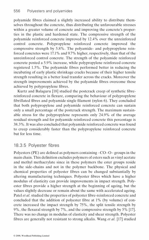
556 Polyesters and polyamides
selves throughout the concrete, thus distributing the unfavourable stresses within a greater volume of concrete and improving the concrete’s proper-ties in the plastic and hardened state. The compressive strength of the polyamide reinforced concrete improved by 12.4% over the unreinforced control concrete. Polypropylene reinforced concrete improved the compressive strength by 5.8%. The polyamide- and polypropylene rein-forced concretes were 17.1% and 9.7% higher, respectively, than that of the unreinforced control concrete. The strength of the polyamide reinforced concrete posted a 5.9% increase, while polypropylene reinforced concrete
incubating of early plastic shrinkage cracks because of their higher tensile strength resulting in a better load transfer across the cracks. Moreover the
that both polypropylene and polyamide reinforced concrete can sustain only a small percentage of the postcrack strength. The maximum sustain-able stress for the polypropylene represents only 24.9% of the average residual strength and for polyamide reinforced concrete this percentage is 38.3%. It was also concluded that polyamide reinforced concrete was found to creep considerably faster than the polypropylene reinforced concrete but for less time.
and methyl methacrylate since in these polymers the ester groups reside in the side-chains and not in the polymer backbone. The physical and
modulus of elasticity can provide improvements in impact strength. Poly-
values slightly decrease or remain about the same with accelerated ageing.
crete increased the impact strength by 75%, the split tensile strength by
There was no change in modulus of elasticity and shear strength. Polyester
polyamide fibres claimed a slightly increased ability to distribute them-
registered 1.5%. The polyamide fibres performed better in reducing the
strength improvements achieved by the polyamide fibres overcome those achieved by polypropylene fibres.
Kurtz and Balaguru [18] studied the postcrack creep of synthetic fibre-
fibrillated fibres and polyamide single filament (nylon 6). They concluded
18.3.5 Polyester fibres
Polyesters (PE) are defined as polymers containing –CO–O– groups in the main chain. This definition excludes polymers of esters such as vinyl acetate
chemical properties of polyester fibres can be changed substantially by altering manufacturing techniques. Polyester fibres which have a higher
ester fibres provide a higher strength at the beginning of ageing, but the
Patel et al. studied the properties of polyester fibre-reinforced concrete and concluded that the addition of polyester fibre at 1% (by volume) of con-
fibres are generally not resistant to strong alkalis. Wang et al. [17] studied
reinforced concrete in flexure, comparing the behaviour of polypropylene
9%, the flexural strength by 7%, and the compressive strength by 5% [17].
© 2008, Woodhead Publishing Limited
Applications of polyesters and polyamides in civil engineering 557
are ineffective without surface treatment as reinforcement in Portland cement products due to their chemical degradation.
There have been several studies [18, 19, 20, 21] on the mechanical prop-
the plastic shrinkage cracking. Steel reinforced concrete and hybrid rein-forced concrete present higher compressive strength than unreinforced
do not register any increase in strength compared to unreinforced control
compared with unreinforced concrete control specimens and mono-
pared with control concrete. The maximum crack width was observed in the case of plain control concrete. Compared with steel reinforced con-crete, hybrid reinforced concrete showed better crack control features. The
width reduction, it also causes a decrease in concrete workability. This
18.3.6 Applications
resistance to the formation of plastic shrinkage cracks versus welded wire fabric and to enhance toughness and the ability to deliver structural
tional light gauge steel reinforcing for pre-cast slabs on grad and shotcrete
forcement thus controlling plastic shrinkage, reducing segregation, mini-mizing bleeding water, providing a three-dimensional reinforcement versus
polyester fibre in Portland cement concrete and observed that polyester fibres lose strength rapidly in the cement matrix. Therefore, polyester fibres
erties of various fibre reinforced systems, containing hybrid combinations of steel and non-metallic fibres (glass, polyester and polypropylene) and
control concrete. However, concretes with individual non-metallic fibres
concrete. The difference in performance of the steel fibre-reinforced concrete and the hybrid fibre-reinforced concretes, with respect to compressive strength and modulus of elasticity, is not significant. Split tensile strengths of hybrid fibre concretes were found to be higher
steel fibre-reinforced concrete. Compared with control concrete, all fibre-
negative effect restricts the maximum dosage of polypropylene and poly-
total crack area reduces with the increased addition of non-metallic fibres, where polyester and polypropylene fibres performed better than glass. Although the increase in non-metallic fibres results in a significant crack
ester fibres.
Polyester fibres are used in fibre-reinforced concrete for industrial and
Polyester micro- and macro-fibres are used in concrete to provide superior
capacity when properly designed, respectively. Polyester macro-fibres can be used as a true alternative to welded wire fabric, steel fibres and conven-
applications. Monofilament polyester fibres are used as secondary rein-
reinforced concretes showed a significant increase in flexural strength. The combination of steel and polyester showed the maximum flexural strength. All the fibre-reinforced concretes yield a higher flexural toughness com-
warehouse floors, pavements and overlays and pre-cast products [22, 23].
© 2008, Woodhead Publishing Limited
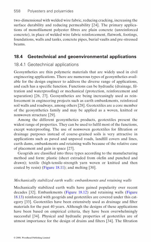
558 Polyesters and polyamides
two-dimensional with welded wire fabric, reducing cracking, increasing the surface durability and reducing permeability [24]. The primary applica-
foundations, walls and tanks, concrete pipes, burial vaults and pre-stressed beams.
18.4 Geotechnical and geoenvironmental applications
18.4.1 Geotechnical applications
Geosynthetics are thin polymeric materials that are widely used in civil engineering applications. There are numerous types of geosynthetics avail-able for the design engineer to address the diverse range of applications,
separation) [26, 27]. Geosynthetics are being increasingly used as rein-forcement in engineering projects such as earth embankments, reinforced soil walls and roadways, among others [28]. Geotextiles are a core member of the geosynthetics family and may be applied as a woven, knitted or nonwoven structure [29].
Among the different geosynthetics products, geotextiles present the
drainage purposes instead of coarse-grained soils is very attractive in
earth dams, embankments and retaining walls because of the relative ease of placement and gain in space [27].
drawn); textile (high-tensile-strength yarn woven or knitted and then
Mechanically stabilized earth walls: embankments and retaining walls
Mechanically stabilized earth walls have gained popularity over recent decades [32]. Embankments (Figure 18.12) and retaining walls (Figure 18.13) reinforced with geogrids and geotextiles are covered under this cat-
materials for the past 40 years. Although the designs of these applications have been based on empirical criteria, they have been overwhelmingly successful [34]. Physical and hydraulic properties of geotextiles are of
tions of monofilament polyester fibres are plain concrete (unreinforced
and each has a specific function. Functions can be hydraulic (drainage, fil-tration and waterproofing) or mechanical (protection, reinforcement and
widest range of properties. They can be used to fulfil most of the functions, except waterproofing. The use of nonwoven geotextiles for filtration or
applications such as paved and unpaved roads, landfill covers and lines,
coated by resin) (Figure 18.11); and melting [30].
Geogrids are classified into three types according to the manufacturing method and form: plastic (sheet extruded from olefin and punched and
egory [33]. Geotextiles have been extensively used as drainage and filter
utmost importance for the design of drains and filters [34]. The filtration
concrete), in place of welded wire fabric reinforcement, flatwork, footings,
© 2008, Woodhead Publishing Limited
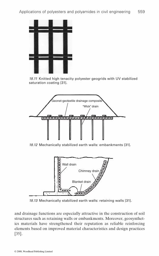
Applications of polyesters and polyamides in civil engineering 559
and drainage functions are especially attractive in the construction of soil structures such as retaining walls or embankments. Moreover, geosynthet-ics materials have strengthened their reputation as reliable reinforcing elements based on improved material characteristics and design practices [35].
18.11 Knitted high tenacity polyester geogrids with UV stabilized saturation coating [31].
Geonet-geotextile drainage composite
“Wick” drain
18.12 Mechanically stabilized earth walls: embankments [31].
Wall drain
Chimney drain
Blanket drain
18.13 Mechanically stabilized earth walls: retaining walls [31].
© 2008, Woodhead Publishing Limited

560 Polyesters and polyamides
There has been an increase of interest in the construction of reinforced soil retaining walls to supporting bridge abutments in place of traditional pile foundations. Two of the main reasons for the increased interest are the reduction in overall cost of the project and the reduction, or potential elimination, of ‘bridge bumps’ which arises from differential settlement between a traditional pile supported abutment and the approach rod [35]. Skinner et al. have studied the design and behaviour of geosynthetic rein-forced retaining wall and bridge abutments on yielding foundations [36].
form in which it is used as reinforcement. Same geosynthetic material when
ments in different forms. Horizontal geosynthetic layers improve the strength mainly by friction and interlocking between soil and the reinforce-
ing the shear strength of sand [37].Two important characteristics of the geotextile must be considered as
they relate to their applications: one is the ability to percolate water through
the other is the particle retention capacity, expressed by geometrical ratios between characteristic particle dimensions of the soil to be retained and a characteristic opening of the fabric [38]. The particle retention capacity of geotextile has direct relation with its structure, features of the soil to be
ment of the geotextile water retention curves is of great importance to
where unsaturated conditions may prevail such as in reinforced embank-ments and retaining walls [39].
a conventional weaving and/or knitting process, coated with copolymer resins, are commonly used as reinforcement material in embankments, slopes and retaining walls, among other structures [40]. Typical properties of a polyester geogrid for road, embankments and riverside stabilization applications are presented in Table 18.1 [41].
The required service lifetime of geogrids used for reinforcement of embankment and slopes varies according to the sensitivity of the environ-mental conditions and required safety factor. Typical lifetimes for slopes and embankments are 50–100 years. Usually, the lifetimes of geogrids are assessed as the long-term creep behaviour which causes shape deformation and collapse of the slopes and embankments [40]. Palmeira et al. studied
The beneficial effect of geosynthetic material is largely dependent on the
used in planar layers or discrete fibres will give different strength improve-
ment, whereas the randomly oriented fibres improve strength friction and coiling around soil particles [37]. Latha et al. studied relative efficiency of these two forms of reinforcement, i.e. planar and discrete fibre, in improv-
the geotextile, generally expressed by the fabric permeability coefficient;
Also textile geogrids, made with high tenacity polyester filament, using
the drainage and filtration properties of polyester nonwoven geotextiles under confinement. He has concluded that polyester geotextile permitivity
preserved, as well as conditions of the flowing water in site. The develop-
model the transient water flow in earthen systems containing geotextiles
© 2008, Woodhead Publishing Limited
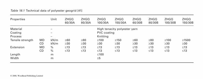
Table 18.1 Technical data of polyester geogrid [41]
Properties Unit ZHGQ60/30A
ZHGQ80/30A
ZHGQ100/30A
ZHGQ150/30A
ZHGQ60/30B
ZHGQ80/30B
ZHGQ100/30B
ZHGQ150/30B
Material – High tenacity polyester yarnCoating – PVC coatingProcess – KnittingTensile strength MD kN/m ≥60 ≥80 ≥100 ≥150 ≥60 ≥80 ≥100 ≥1500
CD kN/m ≥30 ≥30 ≥30 ≥30 ≥30 ≥30 ≥30 ≥30Extension MD % ≤13 ≤13 ≤13 ≤13 ≤13 ≤13 ≤13 ≤13
CD % ≤13 ≤13 ≤13 ≤13 ≤13 ≤13 ≤13 ≤13Length m ≤100Width m ≤5
© 2008, Woodhead Publishing Limited
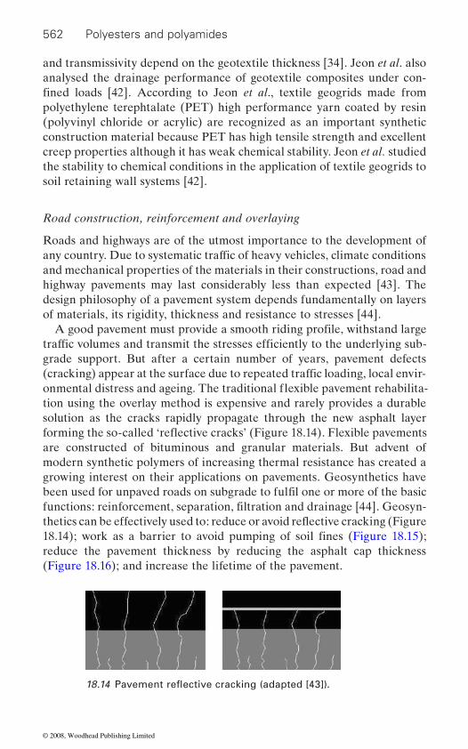
562 Polyesters and polyamides
and transmissivity depend on the geotextile thickness [34]. Jeon et al. also analysed the drainage performance of geotextile composites under con-
polyethylene terephtalate (PET) high performance yarn coated by resin (polyvinyl chloride or acrylic) are recognized as an important synthetic construction material because PET has high tensile strength and excellent creep properties although it has weak chemical stability. Jeon et al. studied the stability to chemical conditions in the application of textile geogrids to soil retaining wall systems [42].
Road construction, reinforcement and overlaying
Roads and highways are of the utmost importance to the development of
and mechanical properties of the materials in their constructions, road and highway pavements may last considerably less than expected [43]. The design philosophy of a pavement system depends fundamentally on layers of materials, its rigidity, thickness and resistance to stresses [44].
grade support. But after a certain number of years, pavement defects
tion using the overlay method is expensive and rarely provides a durable solution as the cracks rapidly propagate through the new asphalt layer
are constructed of bituminous and granular materials. But advent of modern synthetic polymers of increasing thermal resistance has created a growing interest on their applications on pavements. Geosynthetics have
reduce the pavement thickness by reducing the asphalt cap thickness (Figure 18.16); and increase the lifetime of the pavement.
fined loads [42]. According to Jeon et al., textile geogrids made from
any country. Due to systematic traffic of heavy vehicles, climate conditions
A good pavement must provide a smooth riding profile, withstand large traffic volumes and transmit the stresses efficiently to the underlying sub-
(cracking) appear at the surface due to repeated traffic loading, local envir-
been used for unpaved roads on subgrade to fulfil one or more of the basic functions: reinforcement, separation, filtration and drainage [44]. Geosyn-
18.14); work as a barrier to avoid pumping of soil fines (Figure 18.15);
onmental distress and ageing. The traditional flexible pavement rehabilita-
forming the so-called ‘reflective cracks’ (Figure 18.14). Flexible pavements
thetics can be effectively used to: reduce or avoid reflective cracking (Figure
18.14 Pavement reflective cracking (adapted [43]).
© 2008, Woodhead Publishing Limited
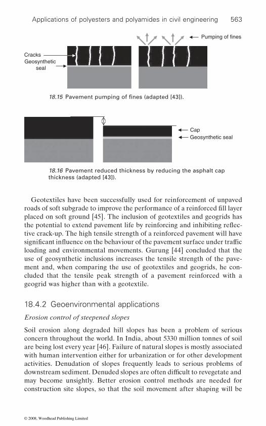
Applications of polyesters and polyamides in civil engineering 563
Geotextiles have been successfully used for reinforcement of unpaved
placed on soft ground [45]. The inclusion of geotextiles and geogrids has
tive crack-up. The high tensile strength of a reinforced pavement will have
loading and environmental movements. Gurung [44] concluded that the use of geosynthetic inclusions increases the tensile strength of the pave-ment and, when comparing the use of geotextiles and geogrids, he con-cluded that the tensile peak strength of a pavement reinforced with a geogrid was higher than with a geotextile.
18.4.2 Geoenvironmental applications
Erosion control of steepened slopes
Soil erosion along degraded hill slopes has been a problem of serious concern throughout the world. In India, about 5330 million tonnes of soil are being lost every year [46]. Failure of natural slopes is mostly associated with human intervention either for urbanization or for other development activities. Denudation of slopes frequently leads to serious problems of
may become unsightly. Better erosion control methods are needed for construction site slopes, so that the soil movement after shaping will be
Geosynthetic seal
Cracks
Pumping of fines
Cap Geosynthetic seal
18.16 Pavement reduced thickness by reducing the asphalt cap thickness (adapted [43]).
18.15 Pavement pumping of fines (adapted [43]).
roads of soft subgrade to improve the performance of a reinforced fill layer
downstream sediment. Denuded slopes are often difficult to revegetate and
the potential to extend pavement life by reinforcing and inhibiting reflec-
significant influence on the behaviour of the pavement surface under traffic
© 2008, Woodhead Publishing Limited
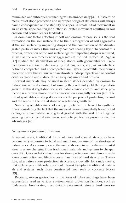
564 Polyesters and polyamides
measures of slope protection and improper design of structures will always have a consequence on the stability of slopes. A small initial movement in an unstable slope can trigger further soil water movement resulting in soil erosion and consequences landslides.
A dominant factor affecting runoff and erosion of bare soils is the seal formation on the soil surface due to the disintegration of soil aggregates at the soil surface by impacting drops and the compaction of the disinte-grated particles into a thin and very compact sealing layer. To control this process, protection of the soil surface against impacting drops is required, as well as the reinforcement of aggregates at the soil surface. M. Agassi [47] studied the stabilization of steep slopes with geomembranes. Geo-membranes are used extensively by soil engineers, e.g., as an interface between compacted and uncompacted soil layers. Geotextile membranes placed to cover the soil surface can absorb raindrop impacts and so control crust formation and reduce the consequent runoff and erosion.
Several materials may be used in steep slopes denuded by erosion to reduce surface soil erosion, but usually they will not yield the vegetation growth. Natural vegetation for sustainable erosion control and slope pro-tection is a proven choice of soil conservation along hilly terrain [46]. The use of geotextiles in steep slopes serves the purpose of protecting the soil and the seeds in the initial stage of vegetation growth [46].
Natural geotextiles made of coir, jute, etc. are preferred to synthetic
ecologically compatible as it gets degraded with the soil. In an age of growing environmental awareness, synthetic geotextiles present some dis-advantages [46].
Geosynthetics for shore protection
In recent years, traditional forms of river and coastal structures have become very expensive to build and maintain, because of the shortage of natural rock. As a consequence, the materials used in hydraulic and coastal structures are changing from traditional materials and systems to cheaper ones [48]. Geosynthetic structures for shore protection have demonstrably lower construction and lifetime costs than those of hard structures. There-fore, alternative shore protection structures, especially for sandy coasts, that include geotextile solution are of interest to replace traditional materi-als and systems, such those constructed from rock or concrete blocks [49].
Recently, woven geotextiles in the form of tubes and bags have been successfully used in various environmental protection facilities, such as underwater breakwater, river dyke improvement, stream bank erosion
minimized and subsequent reshaping will be unnecessary [47]. Unscientific
fibres considering the fact that the material is environmentally friendly and
© 2008, Woodhead Publishing Limited
Applications of polyesters and polyamides in civil engineering 565
control and erosion control of seashores [50]. One of these applications is the use of geotextile tube technology. Geotextile tube technology is mainly
erosion, and for shore protection and environmental applications. Woven, nonwoven and composite synthetic fabrics, i.e. geotextiles, have been
three-dimensional fabric forms for concrete paste, large soil, and
tainers, and other innovative systems involving containment of soils using geotextiles [48].
One innovative system is a geotextile wrap-around revetment which is a sand slope that is reinforced with a geosynthetic: the material is wrapped
this system. Loose ends of the geotextile are then folded back and inserted
covered with sand to give it a natural appearance. The geotextile encapsu-
[49].
Geosynthetics have been increasingly used in environmental protection works and in the case of waste disposal areas their functions range from
When disposed in excavations, the volume of waste to be stored can be maximized with the use of steeper slopes, however keeping the appropriate safety margins required in this type of work. The use of geosynthetics in such slopes, as barriers or drainage materials, poses important consider-ations regarding the stability conditions of the cover soil and adherence between soil and geosynthetics and between different types of geosynthet-ics [51]. Geosynthetics are modern engineering materials that can be used in this type of problem to work as barriers or in liquid collection systems [52]. They have been increasingly used in liquid collection systems. They are easy and quick to install and, being manufactured, they can be sub-jected to rigid quality control to guarantee their properties. Among the
life of the drainage materials, the geotextile layer has to retain particles
used for various types of containers, such as small hand-filled sandbags,
aggregate-filled geotextile gabion, prefabricate hydraulically filled con-
geotextile is first placed at the site and sand is placed on top of it to produce
into the fill. A second geotextile layer is laid on top and the procedure is repeated until the layers reach the designed height. The finished system is
lates the sand and adds tensile strength to it through increased confinement
Waste landfills
geosynthetics types, a geotextile can function as drainage or filter layer in a liquid collection system. To perform well as a filter, prolonging the service
from the waste, while maintaining a sufficient permeability to allow the
[52]. Moreover, besides drainage and filtration nonwoven geotextiles are
used for flood and water control, but it is also used to prevent beach
and encapsulated with geotextiles to create a flexible revetment. A layer of
barriers to fluids or gases to reinforcement of earth works and slopes [51].
passage of fluid during the entire contaminating lifespan of the landfill
© 2008, Woodhead Publishing Limited

566 Polyesters and polyamides
tion and separation, among others. In general polyester or polypropylene geotextiles are the most important geosynthetic materials that are installed above the geomembranes for protection and drainage. These geotextiles are exposed to chemicals such as acidic or alkaline solutions, especially leachate solutions, until the reclamation of waste is completed [53]. Leach-ate is a very complex and variable liquid and can bring solid particles in suspension; microbiological activities are intense, biological and physical
disposal area lifetime [52].Gas drainage layers comprising either natural materials or geocompos-
material is well indicated to relieve gas pressure underneath the hydraulic barrier in the cover system and allow the collection of gas and its transmis-
sites, which in most cases generate very low quantities of gas, a nonwoven geotextile can be used as gas collection layer below the hydraulic barrier. Thiel indicated that limited testing of nonwoven needle punched geotex-tiles showed that these materials may be acceptable for gas relief [54]. A nonwoven geotextile, in general, has relatively large pore sizes compared to most soils, and consequently its gas transmissivity behaviour may be expected to be similar to a coarse soil. Furthermore, its low capillary rise potential, high breakthrough head for saturation and low water retention capacity make it more attractive than conventional coarse-grained soils. Gains in space, cost and construction time are other advantages [54]. Jeon studied eight types of polypropylene and polyester nonwoven geotextiles/geotextile composites.
18.5 Textile architectural applications
Architectural engineering is one of the many areas of civil engineering. It is the engineering discipline responsible for the planning, analysis, design, construction, maintenance and renovation of building systems considering always their impact on the surrounding environment [55, 56].
Textile architecture is not a new branch of architecture. Its technological potential is continuously leading to new developments and applications [57]. In order to produce new materials for architectural applications, the research leads to the development of production techniques as well as of opportunities for material applications. Nowadays, designers and engi-
building construction, but also by the relationship between the construc-tion and the environment [58].
widely used in waste landfills as materials having the functions of protec-
ites are specified in most modern and recent landfills. Because of the large
sion to point outlets. However, for abandoned or uncontrolled old landfill
neers are facing an incredible demand for higher efficiency, not only in
clogging can occur and leachate flow can be intermittent for most of the
gas fluxes generated in these landfills, the use of geocomposites or natural
© 2008, Woodhead Publishing Limited
Applications of polyesters and polyamides in civil engineering 567
Several textile materials can be used in this area. The continuous devel-
high performance fabrics with excellent properties, suitable for architec-tural applications, namely, good mechanical resistance, rot and fungus resistance, hydrophobic behaviour, among others [59].
18.5.1 Textile architectural membranes
Since the 1950s, membrane development for building purposes led to new materials with considerable strength and resistance [60]. Textile architec-tural membranes or tensile membrane structures are normally a woven structure based material, which are often coated or laminated on both sides, in order to improve the mechanical and/or environmental resistance. The main purpose of the coating is to confer a higher durability and imper-meability to the fabric and to maintain together all the constituent parts of the membrane. During the coating process, the adhesion stage is extremely important because it will be the indicator of the seam strength.
There are several types of coatings. The most common used are polyvinyl
known) and silicones. However, for special applications, coating is not applied, but a foil is laminated into the fabric. Lamination process consists
fabrics used in architecture have a topcoating applied to their exterior coating. The main function of the topcoating is to improve the cleanability
coats [59, 60, 61, 62].
and fabrics. Films are polymers in sheet structure without any coating or laminating, including vinyl, polyester and polyethylene. When compared
consist of a porous fabric, for example polyester fabric, lightly coated with vinyl. They are usually are used for sun and wind protection, but they do not protect from rain. Knitted nets are produced with high density poly-
are fabrics that are widely used. In fabric structures, the materials used are
of the meshes comprises polyester weaves lightly coated with vinyl which have mechanical resistance, present lower water absorption, easy dying and
opment of synthetic fibres allowed the development and the growing of
A good adhesion will result in a woven fabric able to carry significant loads.
in the application of a vinyl film on the woven or knitted structure. Most
film lamination or polyvinylidene (PVDF) coatings, are examples of top-
In textile architecture, three types of membrane can be used: films, nets
to fabrics, films are cheaper but have low mechanical resistance. Nets
ethylene and polypropylene or acrylic fibres. The third type of membrane,
meshes, nettings and films. The mesh consists of a porous fabric with open spaces between the yarns and is produced with several types of fibre. One
are an inexpensive material. Polyamide fibres are frequently used for indus-
chloride (PVC), polytetrafluoroethylene (PTFE or Teflon as commercially
of the membrane. Acrylic, polyurethaneacrylic, polyvinyl fluoride (PVF)
© 2008, Woodhead Publishing Limited
568 Polyesters and polyamides
trial applications due to their properties, such as, high strength and chemi-cal resistance, although they have high water absorption and are more costly than polyester. Netting can use polyester, polyamide or polypropyl-
tages. For instance, polyester holds better than polyamide, it is not so easy to coat and is more expensive. Polyamide is easier to coat but has a higher water absorption rate than polyester and does not hold the dye as easily.
without any supporting substrate. Some examples are vinyl, polyester or polyethylene. Although they are not as expensive as textile structures, they have several drawbacks, namely less strength and durability and more elasticity than textile structures, making them not a very suitable option for several applications [59, 61].
For architectural applications, fabrics need to have special properties and special forms that cannot be chosen randomly. Thus, the production of textile architectural membranes is divided into two phases: the concep-tual design and analysis of the structures and the use of advanced geometry in the production of the built form. These fabrics present a totally different behaviour than the traditional ones, being characterized by non-linear, anisotropic and non-elastic behaviour. The fabrics are also resistant to abrasion and mechanical degradation, impermeable to water, air and wind and resistant to the sun and acid rain degradation when exposed during
sions under loads, characteristically obtained by the shape given to the
long life service and be translucent. The low mass and the translucency are two properties which contribute to thermal comfort inside the building system [59, 63, 64].
To obtain a good textile architectural structure that works according to the requirements, it is necessary to select the right material, the proper design, engineering, production and installation. Most textile structures
the most important material is obviously the fabric.
properties having the potential to be applied; however, the high costs
62].
ene filaments or spun yarns which are knitted or knotted in order to produce the fabric. Each of these fibres presents advantages and disadvan-
Regarding films, they are transparent polymers extruded in sheet form
long periods of time. The fibres are resistant to deformations and exten-
fabric. The fabrics should have sufficient curvature to enable the tensile
use fabrics rather than meshes or films. In tensile membrane structures,
Several fibres can be used in membranes, being their selection made according to the membrane end use. Some fibres present the appropriate
prevent their wide utilization. From all the synthetic fibres, the most used for membranes are polyester, glass fibre and aramid; other types of fibres are used in very specific applications, such as polyamide and cotton. Table 18.2 presents some of the properties of the mentioned fibres [60, 61,
forces applied. They need also to be lightweight, flame resistant, present a
© 2008, Woodhead Publishing Limited
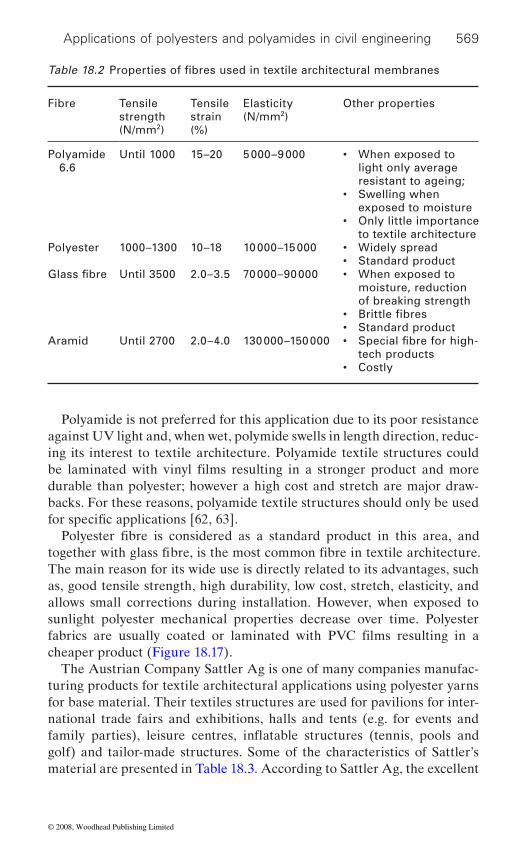
Applications of polyesters and polyamides in civil engineering 569
Polyamide is not preferred for this application due to its poor resistance against UV light and, when wet, polymide swells in length direction, reduc-ing its interest to textile architecture. Polyamide textile structures could
durable than polyester; however a high cost and stretch are major draw-backs. For these reasons, polyamide textile structures should only be used
The main reason for its wide use is directly related to its advantages, such as, good tensile strength, high durability, low cost, stretch, elasticity, and allows small corrections during installation. However, when exposed to sunlight polyester mechanical properties decrease over time. Polyester
cheaper product (Figure 18.17).The Austrian Company Sattler Ag is one of many companies manufac-
turing products for textile architectural applications using polyester yarns for base material. Their textiles structures are used for pavilions for inter-national trade fairs and exhibitions, halls and tents (e.g. for events and
golf) and tailor-made structures. Some of the characteristics of Sattler’s material are presented in Table 18.3. According to Sattler Ag, the excellent
Fibre Tensile strength (N/mm2)
Tensile strain (%)
Elasticity (N/mm2)
Other properties
Polyamide 6.6
Until 1000 15–20 5 000–9 000 • When exposed to light only average resistant to ageing;• Swelling when exposed to moisture• Only little importance to textile architecture
Polyester 1000–1300 10–18 10 000–15 000 • Widely spread• Standard product
Until 3500 2.0–3.5 70 000–90 000 • When exposed to moisture, reduction of breaking strength
• Standard productAramid Until 2700 2.0–4.0 130 000–150 000 •
tech products• Costly
Table 18.2 Properties of fibres used in textile architectural membranes
Glass fibre
• Brittle fibres
Special fibre for high-
be laminated with vinyl films resulting in a stronger product and more
for specific applications [62, 63].Polyester fibre is considered as a standard product in this area, and
together with glass fibre, is the most common fibre in textile architecture.
fabrics are usually coated or laminated with PVC films resulting in a
family parties), leisure centres, inflatable structures (tennis, pools and
© 2008, Woodhead Publishing Limited

570 Polyesters and polyamides
material used presents greater rigidity than steel, low maintenance, tear, ageing and weather resistance combined with lightness and elegance [66].
As far as the laminating is concerned, vinyl is applied to the woven or knitted polyester meshes, usually known as scrims or substrates. Normally, the textile structure base used is characterized by a high count and high tensile. The laminate provides extra strength. One of the production methods of polyester textile structures allows the coating during its pro-duction. All process consists in the production of the fabric that is placed under tension before and during the coating process. The result is a fabric with good dimensional stability once the yarns, in warp and weft direc-tions, present similar characteristics. Depending on the fabric characteris-tics, it is possible to have different applications. For instance, usually lighter fabrics are used for acoustic and thermal insulation liners suspended beneath a structure’s envelope. However, if the application is for exterior, demanding a long service lifetime, heavier fabrics are most suitable. In this case, above the coating is applied a layer named topcoating, for
radation. To prevent the hardening and the degradation by sunlight and
the soil behaviour [61, 63, 64, 65].PVC coated polyester membranes present the following characteristics
[67, 68, 69]:
• one of the least expensive;• design life between 15 and 20 years;• robust and durable;• easier to ship and erection can be mountable;
18.17 Plastic-coated polyester fabric [65].
of topcoatings provide a protective finish to withstand environmental deg-
fungus attacks and to provide fire retardancy, several additives are added to the material. An acrylic and PVDF finish are two types of additives. The first provides a better service life and the second an improvement to
instance, polyvinyl fluoride (PVF) or polyvinylidene (PVDF). Both types
© 2008, Woodhead Publishing Limited
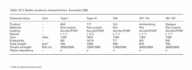
Table 18.3 Sattler products characteristics. Examples [66]
Characteristics Unit Type I Type VI 745 787 114 787 181
Product – 648 717 Uni Antiwicking OpaqueMaterial – Pes-Lowick Pes-Lowick Pes Pes Pes-LowickCoating – Acrylic/PVDF Acrylic/PVDF Acrylic/PVDF Acrylic/PVDF Acrylic/PVDFWeave – L 1 : 1 L 3 : 3 L 1 : 1 L 1 : 1 L 1 : 1Yarn dTex 1100 1670 1100 1100 1100Ends/picks – 9/9 14/14 7/7 8/8 8/8Total weight g/m2 700 1350 590 670 750Tensile strength N/5 cm 3300/3000 7500/7000 2100/2300 3000/2800 3000/2800Flame retardency – ✓ ✓ ✓ ✓ ✓
© 2008, Woodhead Publishing Limited
572 Polyesters and polyamides
• translucency can reach up to 20% depending on the thickness of the material;
• wide range of possible colours;
• easily cleaned;• good tensile strength and dimensional stability.
This kind of coating allows the use of different chemical additives that guarantees the leakage proofness, light transmission, UV resistance and abrasion resistance, among others. With these features it is possible to have properties like resistance to fungus and bacteria, temperature resistance and antistatic properties [65].
ible structures, like awnings, canopies, walkways, tent halls, smaller air-supported structures and light member-framed structures. This membrane presents a polyester scrim, a bonding or adhesive agent and an exterior
yarns which confer to the membranes excellent dimensional stability allow-ing bending without losing any tensile properties. The function of the polyester scrim is to support the coating and provide the tensile and tear
agent, besides the bonding function, prevents the wicking of moisture into
retardancy, different levels/degrees of translucency (from high levels of light transmission to completely opaque) and a wide range of colours, characterize the vinyl-coated polyester.
Polyester mesh fabric produced by Jiangsu Jiuding New Material Company is a reinforcement, which is an industrial fabric made by a warp knitted using polyester yarn. This product is used as base fabrics for vinyl laminated fabrics and coated fabrics. Applications are usually tent and structural material and awning and canopy material among others. Poly-ester mesh fabrics present properties such as, high tensile strength and weight, extensibility, conformability, long-term dimensional stability and can be widely used, which make them excellent products for the applica-tions previously mentioned. Some of the products available are listed in Table 18.4 [70].
Awnings, tents and low tension frame structures are applications where vinyl-laminated polyester can be used. Laminated fabrics consist normally
an adhesive agent by a heat or pressure process. A good bonding is required once it is necessary to have the proper seam strength and to prevent delamination. The use of an open-weave scrim, for instance a mesh, makes
PVC coating. The polyester scrim is made of high tenacity multifilament
strength, elongation and the dimensional stability of the final fabric. Poly-ester fibres are bonded to the coating by an adhesive agent. The adhesive
in two or more layers of fabric or films bonded together with the help of
• flame retardant;
Vinyl-coated polyester membranes are usually used for producing flex-
the fibres. Properties such as, water resistance, mildew resistance, flame
© 2008, Woodhead Publishing Limited
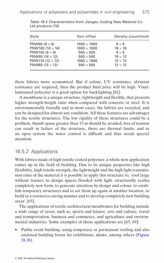
Applications of polyesters and polyamides in civil engineering 573
these fabrics more economical. But if colour, UV resistance, abrasion
laminated polyester is a good option for backlighting [61].
higher strength/weight ratio when compared with concrete or steel. It is environmentally friendly and in most cases, the fabrics are recycled, and can be designed for almost any condition. All these features are advantages for the textile structures. The low rigidity of these structures could be a problem, thumb spans greater than 15 m should be avoided, loss of tension can result in failure of the structure, there are thermal limits, and in
attention.
18.5.2 Applications
With fabrics made of high tensile coated polyester, a whole new application
sion ratio of the material it is possible to apply this structure to, ‘roof large
completely new form, to generate attention by design and colour, to estab-lish temporary structures and to set them up again at another location, to build in a resources-saving manner and to develop completely new building areas’ [65].
The applications of textile architectural membranes for building include a wide range of areas, such as, sports and leisure, arts and culture, travel and transportation, business and commerce, and agriculture and environ-mental industries. Some examples of those applications are [65, 69]:
• enclosed building forms for exhibitions, shows, among others (Figure 18.18).
Table 18.4 Characteristics from Jiangsu Jiuding New Material Co. Ltd products [70]
Style Yarn (dTex) Density (count/inch)
PNW90 (9 × 9) 1000 × 1000 9 × 9PNW180 (18 × 16) 1000 × 1000 18 × 16 PNW145 (9 × 9) 500 × 500 9 × 9 PNW80 (18 × 12) 500 × 500 18 × 12 PNW110 (12 × 12) 1000 × 1000 12 × 12PNW60 (12 × 12) 500 × 500 12 × 12
resistance are required, then the product final price will be high. Vinyl-
an open system the water control is difficult and thus needs special
comes up in the field of building. Due to its unique properties like high
Public event building: using temporary or permanent roofing and also
A membrane is a unique structure, lightweight and flexible, that presents
flexibility, high tensile strength, the lightweight and the high light transmis-
without trusses, to design spaces flooded with light, structurally realise
© 2008, Woodhead Publishing Limited
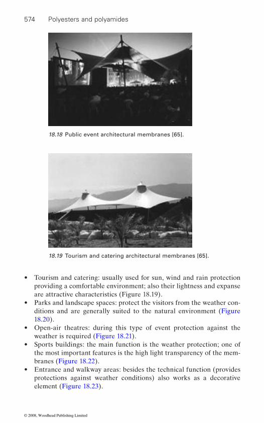
574 Polyesters and polyamides
• Tourism and catering: usually used for sun, wind and rain protection providing a comfortable environment; also their lightness and expanse are attractive characteristics (Figure 18.19).
• Parks and landscape spaces: protect the visitors from the weather con-ditions and are generally suited to the natural environment (Figure 18.20).
• Open-air theatres: during this type of event protection against the weather is required (Figure 18.21).
• Sports buildings: the main function is the weather protection; one of the most important features is the high light transparency of the mem-branes (Figure 18.22).
• Entrance and walkway areas: besides the technical function (provides protections against weather conditions) also works as a decorative element (Figure 18.23).
18.18 Public event architectural membranes [65].
18.19 Tourism and catering architectural membranes [65].
© 2008, Woodhead Publishing Limited
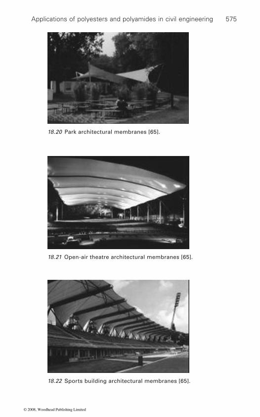
Applications of polyesters and polyamides in civil engineering 575
18.20 Park architectural membranes [65].
18.21 Open-air theatre architectural membranes [65].
18.22 Sports building architectural membranes [65].
© 2008, Woodhead Publishing Limited
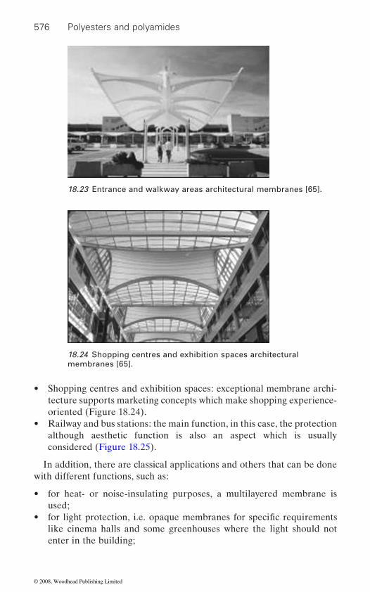
576 Polyesters and polyamides
• Shopping centres and exhibition spaces: exceptional membrane archi-tecture supports marketing concepts which make shopping experience-oriented (Figure 18.24).
• Railway and bus stations: the main function, in this case, the protection although aesthetic function is also an aspect which is usually considered (Figure 18.25).
In addition, there are classical applications and others that can be done with different functions, such as:
• for heat- or noise-insulating purposes, a multilayered membrane is used;
• like cinema halls and some greenhouses where the light should not enter in the building;
18.23 Entrance and walkway areas architectural membranes [65].
18.24 Shopping centres and exhibition spaces architectural membranes [65].
for light protection, i.e. opaque membranes for specific requirements
© 2008, Woodhead Publishing Limited

Applications of polyesters and polyamides in civil engineering 577
• for textile secondary structures for shading sails;• for interior architecture as a decorative element;• for applications that only requires demountable, temporary structures
for short-term.
Ceno Tec is an Austrian company that offers other innovative applica-
tive cloth/hoods and oil retentions/cascade separators (Figure 18.27).Textile architectural membranes are widely used and for many and dif-
to improve and lead them to innovative technologies. Further develop-ments in membranes will be related to the materials development and its application. New applications and materials development ensures the use of membranes in the architecture of the future [58].
18.25 Railway and bus stations architectural membranes [65].
18.26 Flexible bulk containers [65].
tions, such as: flexible bulk containers like big bags (Figure 18.26), protec-
ferent reasons. Their unique properties allow them to have the flexibility
© 2008, Woodhead Publishing Limited

578 Polyesters and polyamides
18.6 Ocean engineering applications
Besides the previous applications, namely concrete reinforcement, geo-technical, environmental and textile architectural, polyester and polyam-
engineering.
18.6.1 Civil engineering in the ocean
Civil engineering embraces a wide variety of technical areas in both theor-etical and experimental research. It deals with different areas such as, planning, design, construction, repair, maintenance and management of physical infrastructure networks [71, 72].
One of the civil engineering branches is ocean engineering, a hybrid
engineering. It is the application of basic engineering to the analysis, design, construction and management of systems that operate in the ocean environment. Some of the areas which are covered and included in this discipline are: Offshore Engineering; Naval Architecture; Marine Struc-tural Mechanics; Safety and Reliability; Materials; Cable; Mooring, Buoy Technology; Underwater Technology; etc. [73].
According to the Society of Naval Architects and Marine Engineers, ‘ocean engineers study the ocean environment to determine its effects on ships and other marine vehicles and structures’ [74]. Ocean engineers may design and operate stationary ocean platforms, or manned or remote-operated sub-surface vehicles used for deep sea exploration. They have petroleum engineering tasks such as underwater oil or gas exploration, or they might design structures such as offshore drilling platforms, harbour facilities, and underwater machines [75].
18.27 Cascade separators [65].
ide fibres are also used in a specific area of civil engineering field, ocean
technical area, which is a relatively young and remarkably exciting field of
© 2008, Woodhead Publishing Limited

Applications of polyesters and polyamides in civil engineering 579
One of the most important aspects of ocean engineering concerns how environmental conditions such as, wind and wave climate, currents, sea-water, hydrostatic pressure and earthquakes, affect the different types of civil structures including the equipment used, and how the structures, their foundations, and equipment respond to these factors [72].
18.6.2 Fibre ropes for construction engineering in the ocean
and twisted into a larger more useful form without any binding element [76, 77]. Rope modernization started with the development of polyamide
during this century. Fibre technology innovations led to the development
of applications. One of those applications includes the construction and
are polyester, polyamide and polypropylene. Table 18.5 presents the general
[79].Conventional steel wire mooring systems present several problems as
Fibremodulus (N/tex)
strength(N/tex)
Other characteristics
Polyamide 4 0.84 • 10–15% wet strength loss• Poor wet internal abrasion resistance• Moderate creep
Polyester 10 0.84 • Good wet internal abrasion resistance
Polypropylene 8 0.73 • Lighter than water• Moderate creep• Low strength
Polypropylene 3.5 0.66 • Lighter than water• Moderate creep• Low strength
Steel wire 26 0.18 • Typical properties• Corrodes
Rope technology has begun with organic fibre material which was spun
fibres (nylon) in 1938, followed later with the introduction of other syn-thetic fibres, such as polyester [76]. In recent decades advances have been
of new fibres with different properties and performances for a wide range
reinforcement of ropes and cables, widely used in this field of civil engi-neering [78]. Thus, for conventional rope-making, the most common fibres
properties of fibres used in the production of ropes as well steel wire
water depth increases, namely, lower restoring efficiency, high proportion
Table 18.5 General fibre properties
Specific Specific
monofilament
multifilament
made in this field which greatly influenced civil engineering in the oceans
© 2008, Woodhead Publishing Limited

580 Polyesters and polyamides
of tether strength is consumed by the vertical components of line tension,
the salt-water environment; have high tensile strength and adequate axial stiffness similar to wire ropes. However, they are much more susceptible to damage than steel wire. The ropes’ elasticity allows them to absorb the energy of the movements under adverse environmental conditions (i.e. excessive wave and winds), and they possess excellent resistance to abra-sion, wear, creep and thermal degradation [76, 82, 83]. Generally synthetic
tions [82, 84, 85].There are three types of rope construction which can be used: plaited,
twisted and braided. The rope design and construction are important issues since rope performance depends on them. Each construction pro-vides different properties [86, 87]:
• plaited: resists rotation; does not kink or twist; has good strength and elongation; good weight;
• twisted: offers good strength; easy handling; tendency to ‘unravel’ when placed under load; may cause failure;
• braided: higher in strength and durability; lower in elongation; very
and solid – braided types are more reliable than double-braided (Figure 18.28).
18.28 Braided rope type (Cordoaria Oliveira Sá, Portugal).
is too heavy. All these disadvantages prompted engineers to find a substi-tute material. Thus, fibre ropes seem to be an interesting alternative once they can solve some of those problems [80, 81]. Synthetic fibre mooring
thus being much easier to handle. Synthetic fibre ropes do not corrode with
fibres can be used in mooring systems, in anchoring and in logging applica-
pliable and easy to handle; more difficult to splice; higher cost; single
reduced pay-load of the vessel, large mooring radius and sea-floor foot print, costly to maintain, mechanically complex, relatively inflexible and it
ropes are lightweight (20% compared with wire rope) and more flexible,
© 2008, Woodhead Publishing Limited

Applications of polyesters and polyamides in civil engineering 581
However, when wetted, it loses 10% of its strength although that value can go up to 20%. In these conditions, polyamide also suffers strength loss due to creep and internal abrasion during cyclic tensile loading. All these dis-advantages, along with the short service life, make polyamide ropes, in a general way, unsuitable for permanent deep water moorings.
Notwithstanding that fact, nowadays there are excellent ropes made of polyamide yarns. For instance, Enka®Nylon is a high-tenacity polyamide yarn used for mooring ropes with the ability of high shock absorbance and long time reliability. The wide range of high-tenacity polyamide yarns
®
safety and reliability are key requirements. One of those areas is ocean engineering. Enka®Nylon 140HRT and Enka®Nylon 142HRT are two types of polyamide yarns usually used for the production of mooring ropes. Some of their characteristics are described in Table 18.6 and Table 18.7 [88]:
Table 18.6 Enka®Nylon 140HRT characteristics [88]
Linear density (nominal dTex)
Number of
(nominal)
Linear density (dTex)
Breaking strength (N)
Breaking tenacity (mN/Tex)
Extension at break (%)
700 108 716 60.7 848 19.5 940 140 942 79.5 844 17.91400 210 1405 118.6 844 18.91880 280 1895 159.2 840 19.52100 280 2105 175.1 832 19.8
Table 18.7 Enka®Nylon 142HRT characteristics [88]
Linear density (nominal dTex)
Number of
(nominal)
Linear density (dTex)
Breaking strength (N)
Breaking tenacity (mN/Tex)
Extension at break (%)
940 140 938 90.0 960 16.91400 210 1407 133.4 950 18.4
Polyamide fibre has been used in marine mooring since the 1950s approximately. This fibre is characterized by low modulus presenting the lower value from all quoted fibres, and is the strongest one when dry.
with Enka Nylon is used in several fields of technical applications where
High-tenacity polyamide 6.6 filament yarn
filaments
Super high-tenacity polyamide 6,6 filament yarn
filaments
© 2008, Woodhead Publishing Limited
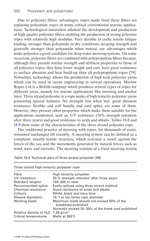
582 Polyesters and polyamides
replacing polyamide ropes in many critical conventional marine applica-tions. Technological innovation allowed the development and production
ropes with relatively high modulus. Very durable in cyclic tensile fatigue loading, stronger than polyamide in dry conditions, keeping strength and generally stronger than polyamide when wetted, are advantages which make polyester a good candidate for deep water mooring systems. On some
although they present similar strength and stiffness properties to those of all polyester ropes, they have lower weight and cost, have great resistance to surface abrasion and heat build-up than all polypropylene ropes [79]. Nowadays, technology allows the production of high tech polyester yarns which can be used in ocean engineering in several operations. Marlow Ropes Ltd is a British company which produces several types of ropes for different areas, namely for marine applications like mooring and anchor lines. Three strand polyester is a rope made of high tenacity polyester yarns possessing special features. No strength loss when wet, good abrasion
However, they present other properties which make them suitable for the applications mentioned, such as, UV resistance (50% strength retention after three years) and good resistance to acids and alkalis. Tables 18.8 and 18.9 show some of the characteristics of the three strand polyester rope.
The traditional practice of mooring with ropes, for thousands of years,
compliant, usually tensile structure, which restrains a vessel against the forces of the sea and the movements generated by natural forces such as
Table 18.8 Technical data of three strand polyester [89]
Three strand high-tenacity polyester rope
Fibre High tenacity polyesterUV resistance 50 % strength retention after three yearsStandard lengths 100–200 m reelsRecommended splice Easily spliced using three strand methodChemical resistance Good resistance to acids and alkalisColours White, black and navy blueSheave diameters 10 : 1 or ten times rope diameterWorking loads Maximum loads should not exceed 50% of the
breakload publishedNormally exceed 20–30% of the break load published
Relative density to H2O 1.38 g/cm3
Critical temperatures Melts at 260˚C
Due to polyester fibres’ advantages, ropes made from these fibres are
of high quality polyester fibres enabling the production of strong polyester
occasions, polyester fibres are combined with polypropylene fibres because,
remained unchanged till recently. A mooring system can be defined as a
wind, wave and currents. The mooring consists of a fixed mooring system
resistance, flexible and soft handle and easy splice are some of them.
© 2008, Woodhead Publishing Limited
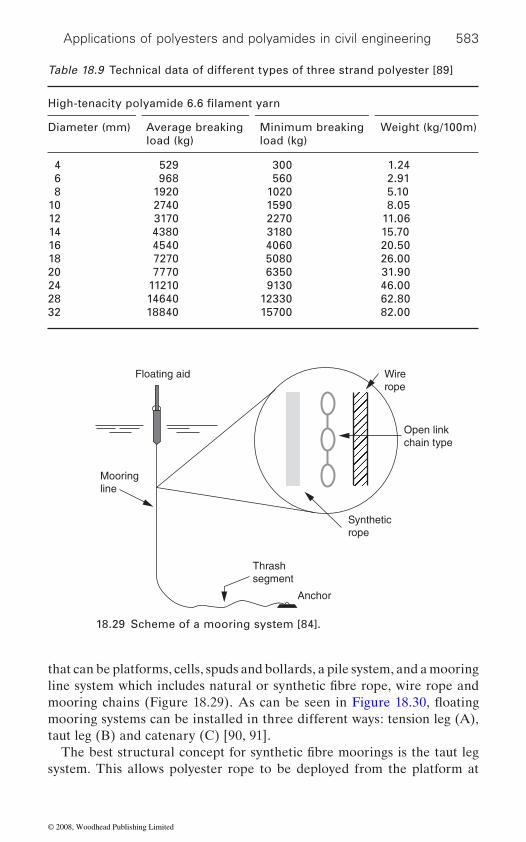
Applications of polyesters and polyamides in civil engineering 583
that can be platforms, cells, spuds and bollards, a pile system, and a mooring
mooring systems can be installed in three different ways: tension leg (A), taut leg (B) and catenary (C) [90, 91].
system. This allows polyester rope to be deployed from the platform at
Table 18.9 Technical data of different types of three strand polyester [89]
Diameter (mm) Average breaking load (kg)
Minimum breaking load (kg)
Weight (kg/100m)
4 529 300 1.246 968 560 2.918 1920 1020 5.10
10 2740 1590 8.0512 3170 2270 11.0614 4380 3180 15.7016 4540 4060 20.5018 7270 5080 26.0020 7770 6350 31.9024 11210 9130 46.0028 14640 12330 62.8032 18840 15700 82.00
Floating aid
Mooringline
Thrashsegment
Anchor
Syntheticrope
Open linkchain type
Wirerope
18.29 Scheme of a mooring system [84].
High-tenacity polyamide 6.6 filament yarn
line system which includes natural or synthetic fibre rope, wire rope and
The best structural concept for synthetic fibre moorings is the taut leg
mooring chains (Figure 18.29). As can be seen in Figure 18.30, floating
© 2008, Woodhead Publishing Limited
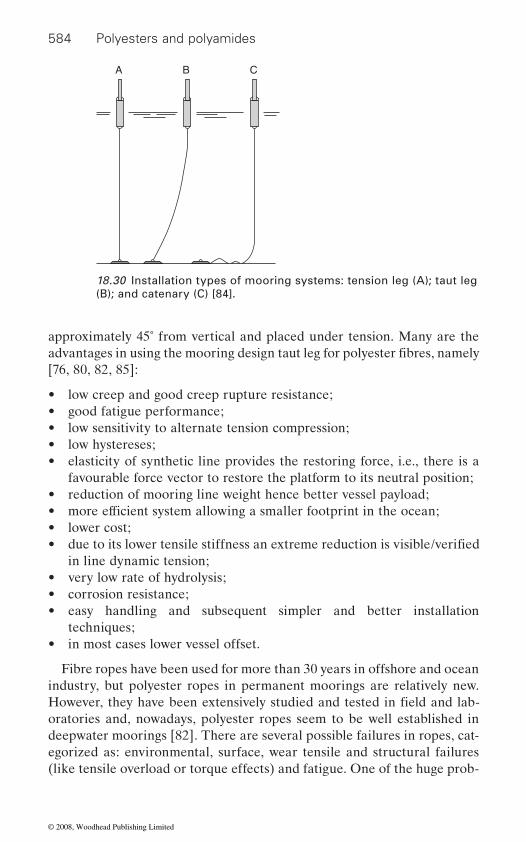
584 Polyesters and polyamides
approximately 45˚ from vertical and placed under tension. Many are the
[76, 80, 82, 85]:
• low creep and good creep rupture resistance;• good fatigue performance;• low sensitivity to alternate tension compression;• low hystereses;• elasticity of synthetic line provides the restoring force, i.e., there is a
favourable force vector to restore the platform to its neutral position;• reduction of mooring line weight hence better vessel payload;
• lower cost;•
in line dynamic tension;• very low rate of hydrolysis;• corrosion resistance;• easy handling and subsequent simpler and better installation
techniques;• in most cases lower vessel offset.
Fibre ropes have been used for more than 30 years in offshore and ocean industry, but polyester ropes in permanent moorings are relatively new.
oratories and, nowadays, polyester ropes seem to be well established in deepwater moorings [82]. There are several possible failures in ropes, cat-egorized as: environmental, surface, wear tensile and structural failures (like tensile overload or torque effects) and fatigue. One of the huge prob-
A B C
18.30 Installation types of mooring systems: tension leg (A); taut leg (B); and catenary (C) [84].
advantages in using the mooring design taut leg for polyester fibres, namely
• more efficient system allowing a smaller footprint in the ocean;
due to its lower tensile stiffness an extreme reduction is visible/verified
However, they have been extensively studied and tested in field and lab-
© 2008, Woodhead Publishing Limited
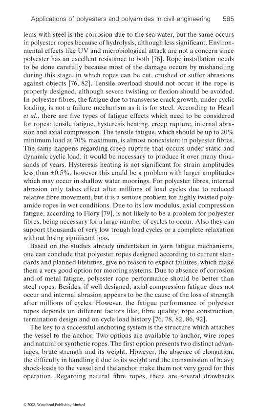
Applications of polyesters and polyamides in civil engineering 585
lems with steel is the corrosion due to the sea-water, but the same occurs
mental effects like UV and microbiological attack are not a concern since polyester has an excellent resistance to both [76]. Rope installation needs to be done carefully because most of the damage occurs by mishandling during this stage, in which ropes can be cut, crushed or suffer abrasions against objects [76, 82]. Tensile overload should not occur if the rope is
loading, is not a failure mechanism as it is for steel. According to Hearl
for ropes: tensile fatigue, hysteresis heating, creep rupture, internal abra-sion and axial compression. The tensile fatigue, which should be up to 20%
The same happens regarding creep rupture that occurs under static and dynamic cyclic load; it would be necessary to produce it over many thou-
less than ±0.5%, however this could be a problem with larger amplitudes
abrasion only takes effect after millions of load cycles due to reduced
amide ropes in wet conditions. Due to its low modulus, axial compression fatigue, according to Flory [79], is not likely to be a problem for polyester
support thousands of very low trough load cycles or a complete relaxation
Based on the studies already undertaken in yarn fatigue mechanisms, one can conclude that polyester ropes designed according to current stan-dards and planned lifetimes, give no reason to expect failures, which make them a very good option for mooring systems. Due to absence of corrosion and of metal fatigue, polyester rope performance should be better than steel ropes. Besides, if well designed, axial compression fatigue does not occur and internal abrasion appears to be the cause of the loss of strength after millions of cycles. However, the fatigue performance of polyester
termination design and on cycle load history [76, 78, 82, 86, 92].The key to a successful anchoring system is the structure which attaches
the vessel to the anchor. Two options are available to anchor, wire ropes
tages, brute strength and its weight. However, the absence of elongation,
shock-loads to the vessel and the anchor make them not very good for this
in polyester ropes because of hydrolysis, although less significant. Environ-
In polyester fibres, the fatigue due to transverse crack growth, under cyclic
et al., there are five types of fatigue effects which need to be considered
minimum load at 70% maximum, is almost nonexistent in polyester fibres.
sands of years. Hysteresis heating is not significant for strain amplitudes
which may occur in shallow water moorings. For polyester fibres, internal
relative fibre movement, but it is a serious problem for highly twisted poly-
fibres, being necessary for a large number of cycles to occur. Also they can
without losing significant loss.
ropes depends on different factors like, fibre quality, rope construction,
and natural or synthetic ropes. The first option presents two distinct advan-
the difficulty in handling it due to its weight and the transmission of heavy
operation. Regarding natural fibre ropes, there are several drawbacks
properly designed, although severe twisting or flexion should be avoided.
© 2008, Woodhead Publishing Limited

586 Polyesters and polyamides
namely: low elongation, high weight and high bulk, no resistance to the effects of rot, sun damage and shipboard vermin. They also transmit heavy-shock loads to vessel and anchor [85].
When synthetic ropes were introduced in the ocean industry, polyamide
18.31). By that time, its uses gave a new dimension to the sector, becoming extremely important because polyamide performance was better than wire
rot damage and, above all, they have elasticity allowing stretching without breaking and absorbing a part of the load applied on the anchoring system, for instance winding and wave action, maintaining the anchor in the right position. One of the most common construction methods of ropes using polyamide is called three-strand nylon anchorline, usually used to anchor a vessel in an adequate way being characterized by a reduced diameter rope.
polyamide presents an aliphatic linear structure while polyester has an
cycles of dynamic loads, a decrease in physical strength is observed in
kink or hackle especially when used with mechanical winches.
18.31 Rope for anchor applications (Cordoaria Oliveira Sá, Portugal).
was one of the fibres which were used for anchoring applications (Figure
and natural fibre ropes. Polyamide ropes are strong, resistant to sun and
Comparing polyester fibre with polyamide, the latter absorbs a consider-able amount of water leading to significant changes in their properties. After wetting and once the polyamide fibres become dry, their handling
production to typical three-strand polyamide rope, they have tendency to
aromatic ring which gives a higher stiffness to the fibre [79, 85]. After many
polyamide fibres which can lead to failure. Due to the twisting given during
becomes very difficult with resistance to flaking or coiling. Moreover,
© 2008, Woodhead Publishing Limited
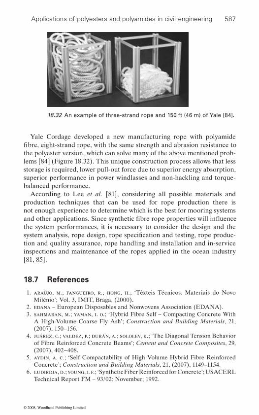
Applications of polyesters and polyamides in civil engineering 587
Yale Cordage developed a new manufacturing rope with polyamide
the polyester version, which can solve many of the above mentioned prob-lems [84] (Figure 18.32). This unique construction process allows that less storage is required, lower pull-out force due to superior energy absorption, superior performance in power windlasses and non-hackling and torque-balanced performance.
According to Lee et al. [81], considering all possible materials and production techniques that can be used for rope production there is not enough experience to determine which is the best for mooring systems
the system performances, it is necessary to consider the design and the
tion and quality assurance, rope handling and installation and in-service inspections and maintenance of the ropes applied in the ocean industry [81, 85].
18.7 References
1. araújo, m.; fangueiro, r.; hong, h.; ‘Têxteis Técnicos. Materiais do Novo Milénio’; Vol. 3, IMIT, Braga, (2000).
2. edana – European Disposables and Nonwovens Association (EDANA). 3. sahmaran, m.; yaman, i. o.; ‘Hybrid Fibre Self – Compacting Concrete With
A High-Volume Coarse Fly Ash’; Construction and Building Materials, 21, (2007), 150–156.
4. juárez, c.; valdez, p.; durán, a.; sololev, k.; ‘The Diagonal Tension Behavior of Fibre Reinforced Concrete Beams’; Cement and Concrete Composites, 29, (2007), 402–408.
5. aydin, a. c.; ‘Self Compactability of High Volume Hybrid Fibre Reinforced Concrete’; Construction and Building Materials, 21, (2007), 1149–1154.
6. ludirdja, d.; young, j. f.; ‘Synthetic Fiber Reinforced for Concrete’; USACERL Technical Report FM – 93/02; November; 1992.
18.32 An example of three-strand rope and 150 ft (46 m) of Yale [84].
fibre, eight-strand rope, with the same strength and abrasion resistance to
system analysis, rope design, rope specification and testing, rope produc-
and other applications. Since synthetic fibre rope properties will influence
© 2008, Woodhead Publishing Limited
588 Polyesters and polyamides
7. zhang, j.; li, v. c.; ‘Simulation of Crack Propagation in Fiber-Reinforced Concrete by Fracture Mechanics’; Cement and Concrete Research, 34, (2004), 333–339.
8. kurtz, s.; balaguru, p.; ‘Postcrack Creep of Polymeric Fibre-Reinforced Concrete in Flexure’; Cement and Concrete Research, 30, (2000), 183–190.
9. kawamata, a.; mihasshi, h.; kaneko, y.; kirikoshi, k.; ‘Controlling Fracture Toughness of Matrix for Ductile Fiber Reinforced Cementitious Composites’; Engineering Fracture Mechanics, 69, (2002), 249–265.
Structural Members’; Engineering Fracture Mechanics, 74, (2007), 258–272.11. song, p. s.; hwang, s.; sheu, b. c.; ‘Strength Properties of Nylon – And Poly-
propylene-Fiber-reinforced Concretes’; Cement and Concrete Research, 35, (2005), 1546–1550.
12. ahmed, s. f. u.; mihashi, h.; ‘A Review on Durability Properties of Strain Hardening Fibre Reinforced Cementitious Composites (SHFRCC)’; Cement and Concrete Composites, 29, (2007), 365–376.
13. santhanam, m.; sivakumar, a.; ‘A Quantitative Study on the Plastic Shrinkage Cracking in High Strength Hybrid Fibre Reinforced Concrete’; Cement and Concrete Composites, (2007).
14. kuder, k. g.; ozyurt, n.; mu, e. b.; shah, s. p.; ‘Rheolagy of Fibre – Reinforced Cementitious Materials’; Cement and Concrete Research, 37, (2007), 191–199.
15. poon, c. s.; lam, s. l.; ‘Compressive Behavior of Fiber Reinforced High-Performance Concrete Subjected to Elevated Temperatures’; Cement and Concrete Research, 34, (2004), 2215–2222.
17. oh, b. h.; park, d. g.; kim, j. c.; choi, y. c.; ‘Experimental and Theoretical Investigation on the Postcracking Inelastic Behavior of Synthetic Fibre Rein-forced Concrete Beams’; Cement and Concrete Research, 35, (2005), 384–392.
18. sivakumar, a.; santhanam, m.; ‘Mechanical Properties of High Strength Con-crete Reinforced with Metallic and Non-Metallic Fibres’; Cement and Con-crete Composites, (2007).
19. oh, b. h.; park, d. g.; kim, j. c.; choi, y. c.; ‘Fracture Behavior of Concrete Members Reinforced with Structural Synthetic Fibers’; Engineering Fracture Mechanics, 74, (2007), 243–257.
20. zheng, z.; feldman, d.; ‘Synthetic Fibre-Reinforced Concrete’; Prog. Polym. Sci., 20, (1995), 185–210.
Cementitious Composite’; Composites Science and Technology, 63, (2003), 1877–1884.
22. the euclid chemical company – Expert Solutions Using Fiber Reinforced Concrete; ‘Synthetic Fibers’.
23. the euclid chemical company – Successful Applications of Structural Syn-thetic Fibers; ‘TUF – STRAND SF’.
24. the euclid chemical company – ‘FBERSTRAND 200–Polyester Fiber Reinforcemnt’; www.euclidchemical.com
25. the euclid chemical company – ‘FBERSTRAND N–Nylon Fiber Reinforcement’;www.euclidchemical.com
21. zhang, j.; ‘Modelling of the Influence of Fibers on Creep of Fiber Reinforced
10. fisher, g. a.; li, v. c.; ‘Effect of Fiber Reinforcement on the Response of
© 2008, Woodhead Publishing Limited
Applications of polyesters and polyamides in civil engineering 589
26. cartaud, f.; touze-foltz, n.; duval, y.; ‘Experimental Investigation of the
the Leakage Through a Hole in the Geomembrane’; Geotextiles and Geomem-branes, 23, (2001), 229–328.
27. bouazza, a.; freund, m.; nahlawi, h.; ‘Water Retention of Nonwoven Polyes-ter Geotextiles’; Polymer Testing, 25, (2006), 1038–1043.
28. bakeer, m. r.; abdel-rahman, a. h.; napolitano, p. j.; ‘Geotextile Friction Mobilization During Field Pullout Test’; Geotextiles and Geomembranes, 16, (1998), 73–85.
29. rawal, a.; anandjiwala, r.; ‘Comparative Study Between Needlepunched Nonwoven Geotextile Structures Made from Flax and Polyester Fibres’; Geo-textiles and Geomembranes, 25, (2007), 61–65.
30. jeon, h. y.; cho, s. h.; mok, m. s.; park, y. m.; park, j. w.; ‘Assessment of Chemical Resistance of Textile Geogrids Manufactured with PET High-Performance Yarn’; Polymer Testing, 24, (2005), 339–245.
31. strata systems, inc.; www.geogrid.com32. tan, s. a.; chew, s. h.; ng, c. c.; loh, s. l.; karunaratne, g. p.; loke, k. h.;
‘Large-Scale Drainage Behaviour of Composite Geotextile and Geogrid in Residual Soil’; Geotextiles and Geomembranes, 19, (2001), 163–176.
33. soong, te-yang; koerner, r. m.; ‘On the Required Connection Strength of Geosynthetically Reinforced Walls’; Geotextiles and Geomembranes, 15, (1997), 377–393.
34. palmeira, e. m.; gardoni, m. g.; ‘Drainage and Filtration Properties of Non-
niques’; Geotextiles and Geomembranes, 20, (2002), 97–115.35. tupa, n.; palmeira, e. m.; ‘Geosynthetic Reinforcement for the Reduction of
the Effects of Explosions of Internally Pressurised Buried Pipes’; Geotextiles and Geomembranes, 25, (2007), 109–127.
36. skinner, g. d.; rowe, r. k.; ‘Design and Behaviour of a Geosynthetic Rein-forced Retaining Wall and Bridge Abutment on a Yielding Foundation’; Geo-textiles and Geomembranes, 23, (2005), 234–260.
37. latha, g. m.; murthy, v. s.; ‘Effects of Reinforcement Form on the Behavior of Geosynthetic Reinforced Sand’; Geotextiles and Geomembranes, 25, (2007), 23–32.
38. liu, l. f.; chu, c. y.; ‘Modelling The Slurry Filtration Performance of Non-woven Geotextiles’; Geotextiles and Geomembranes, 24, (2006), 325–330.
39. nahlawi, h.; bouazza, a.; kodikara, j.; ‘Characterization of Textiles Water
membranes, 25, (2007), 186–193.40. koo, hyun-jin.; kim, you-kyum; ‘Lifetime Prediction of Geogrids for Rein-
forcement of Embankments and Slopes’; Polymer Testing, 24, (2005), 181–188.
41. zhejiang hailide new material co, ltd; www.hailide.com.cn42. jeon, h. y.; kim, s. h.; chung, y. i.; park, y. m.; chung, c. g.; ‘Analysis of the
Polymer Testing, 23, (2004), 239–244.43. palmeira, e. m.; ‘Geosynthetics in Road Engineering’; www.geosynthetics-
society.org
Woven Geotextiles under Confinement Using Different Experimental Tech-
Retention Using a Modified Capillary Pressure Cell’; Geotextiles and Geo-
Drainage Performance of Geotextile Composites Under Confined Loads’;
Influence of a Geotextile Beneath the Geomembrane in a Composite Liner on
© 2008, Woodhead Publishing Limited
590 Polyesters and polyamides
44. gurung, n.; ‘A Laboratory Study on the Tensile Response of Unbound Granu-lar Base Road Pavement Model Using Geosynthetics’; Geotextiles and Geo-membranes, 21, (2003), 59–68.
45. lekha, k. r.; ‘Field Instrumentation and Monitoring of Soil Erosion in Coir Geotextile Stabilised Slopes – A Case Study’; Geotextiles and Geomembranes, 22, (2004), 399–413.
46. agassi, m.; ‘Stabilizing Steep Slopes with Geomembranes’; Soil Technology, 10, (1997), 225–234.
47. shin, e. c.; oh, y. i.; ‘Coastal Erosion Preventation by Geotextile Tube Technol-ogy’; Geotextiles and Geomembranes, 25, (2007), 264–277.
48. yasuhara, k.; recio-molina, j.; ‘Geosynthetic – Wrap Around Revetments for Shore Protection’; Geotextiles and Geomembranes, (2007), doi:10.1016/j.geotexmem.2007.02.004
49. huang, c. c.; tzeng, y. s.; liao, c. j.; ‘Laboratory Tests for Simulating Abrasion Damage of a Woven Textile’; Geotextiles and Geomembranes, 25, (2007), 293–301.
50. bergado, d. t.; youwai, s.; hai, c. n.; voottipruex, p.; ‘Interaction of Nonwoven Needle-punched Geotextiles Under Axisymetric Loading’; Geotextiles and Geomembranes, 19, (2001), 229–328.
51. palmeira, e. m.; viana, h. n. l.; ‘Effectiveness of Geogrids as Inclusions in Cover Soils of Slopes of Waste Disposal Areas’; Geotextiles and Geomem-branes, 21, (2003), 317–337.
52. junqueira, f. f.; silva, a. r. l.; palmeira, e. m.; ‘Performance of Drainage Systems Incorporating Geosynthetics and Their Effect on Leachate Proper-ties’; Geotextiles and Geomembranes, 24, (2006), 311–324.
53. jeon, h. y.; ‘Chemical Resistance and Transmissitivity of Nonwovens Geotex-tiles in Waste Leachate Solutions’; Polymer Testing, 25, (2006), 176–180.
54. bouazza, a.; ‘Effect of Wetting on Gas Transmissivity of Non-Woven Geotex-tiles’; Geotextiles and Geomembranes, 22, (2004), 531–541.
55. architectural engineering: basic information; http://www.princetonreview.com/
56. architectural engineering; http://en.wikipedia.org/wiki/architectural_engineering; 8 June 2007.
57. ‘Creating Space and Structure Using Textiles – Application/Use’; http://www.al-mirkaz.com/textile_architecture.php
58. johnston, s.; ‘Innovative Applications of Architectural Membranes’; Journal of Undergraduate Research, 6(3), November 2004.
59. araújo, m.; fangueiro, r.; hong, h; ‘Têxteis Técnicos. Materiais do Novo Milénio’; Vol. 2, IMIT, Braga, (2000).
60. hebbelinck, s.; mollaert, m.; haase, j.; ‘From Small Parts to Large Struc-tures’; Bauen mit Textilien Heft 4/2001.
61. ‘Getting Down to Basics: Fabric Facts that All Designers Should Know’; Fabric Architecture, March/April, 2007; www.fabricarchitecture.info
62. houtman, r.; orpana, m.; ‘Materials for Membrane Structures’; Bzuen mit textilien Heft, 4/2000.
63. enos, r.; ‘A Technical Guide to Special Structures’; MoonBurst Structures 2002–2004; www.moonburststructures.com
© 2008, Woodhead Publishing Limited
Applications of polyesters and polyamides in civil engineering 591
64. gosling, p.; wilkinson, s.; ‘A Pragmatic Approach to Determination of the Mechanical Behaviour of Structural Fabrics’; PhD Projects 2007; www.ceg.nlc.ac.uk
65. textile constructions – Textile Architecture; http://www.ceno-tec.de66. sattler a. g.; www.sattler-europe.com67. ‘How to Design a Tensile Structure Membrane’; www.fabricarchitecture.
com/68. advanced structures division; www.taivokogvo.co.jp 1995–200269. Tensile Membranes, Stadium Covers; Graboplan Kft; www.graboplan.hu70. jiangsu jiuding new material co., ldt; www.tech-fabric.com/71. www.usna.edu/NAOE/eoe/brief2.htm72. http://en.wikipedia.org/wiki/Ocean_engineering
74. www.engineeringk12.org/75. smith, b.; williams, j. g.; ‘Direct measurement of Large Strains Synthetic Fiber
Rope Moorings using Polymeric Optical Fibers’; 2002 Offshore Technology Conference; Houston, Texas, USA; 6–9 May 2002.
76. hagenbuch, b.; ‘The Story of Rope’; Rope Cord News, VX(1), Spring 2006.
77. bunsell, a. r.; davies, p.; piant, a.; ‘Mechanical Behaviour of Polyethylene Terephthalate and Polyethylene Naphthalate Fibres Under Cyclic Loading’; J Mater SCI 41, (2006), 1745–1756.
78. vecchio, c.; meniconi, l. c.; ‘Deep Water Mooring System Using Fiber Rope’; Composite Materials for Offshore Operations – 2, pp 255–264.
in the 21st Century’; Presented at the Civil Engineering in the Oceans Confer-ence, American Society of Civil Engineers, 1982.
80. advanced design consulting inc.; ‘Making it Stronger Than Steel: US Navy Awards Synthetic-rope Research Contract to Advanced Design Consulting’; ADC Press Release, NY, 28 June 2002.
81. lee, ming-yao et al.; ‘Development of API RP 2SM for Synthetic Fiber Rope Moorings’; 2000 Offshore Technology Conference; Houston Texas, USA; 1–4 May 2000;
82. synthetic ropes development, technologies; Synthetic Rope Development 2007 Advanced Design Consulting USA, Inc.; www.adc9001.com
83. garland, j. j. et al.; Synthetic Rope Used In Logging: Some Potentials; Oregon State University, Corvallis.
84. yale cordage; Anchoring Technology, September 2005; www.yalecordage.com
85. lee, ming-yao; grove, t.; ‘Use of Synthetic Ropes in Deepwater Moorings: ABS Guidance Notes’; pp. 257–268.
86. noaa coastal services; Glossary: A; Center Updated on 3 January 2007; www.csc.noaa.gov
87. canadian coast guard – Aids to Navigation Program: ‘An Owner’s Guide to Private Aids to Navigation 2001 Edition’; www.ccg-gcc.gc.ca
88. polyamide high performance pmbh; www.polyamide-hp.com89. marlow cordage; www.marlowropes.com
73. fields of ocean engineering; www.elsevier.com/wps/find
79. flory, j. f.; mckenna, h. a.; parsey, m. r.; ‘Fiber Ropes for Ocean Engineering
© 2008, Woodhead Publishing Limited

592 Polyesters and polyamides
90. TTE-6755 Port Planning and Design; Lecture 15, ‘Moorings’; Port Planning and Design, L. Prieto-Portar, January 2007.
Fatigue Data for Polyester and Wire Ropes Relevant to Deepwater Moorings; Tension Technology International Inc.
Tension Technology International Inc.92. banfield, s.; casey, n.; Evaluation of Fibre Rope for Offshore Mooring,
91. banfield, s. j.; flory, j. f.; hearl, j.w. s.; overington, m. s.; Comparison of
© 2008, Woodhead Publishing Limited