Embed Size (px)
DESCRIPTION
PNMSj ver. 1.20.xxxOperation Manual
Citation preview
NWD-102888-13E
P ASOLINK
N ETWORK
M ANAGEMENT
S YSTEM
NEC CorporationCopyright © 2012
PNMS (Java version)Operation Manual
Version 1.20.xxx.xxx

NWD-102888
- - i
Table of Contents
TABLE OF CONTENTS.............................................................................................................................. I
1. INTRODUCTION ................................................................................................................................... 1
1.1. Document Objectives....................................................................................................................... 1
1.2. Document Warranty........................................................................................................................ 1
2. GENERAL CONCEPTS......................................................................................................................... 2
2.1. About PNMSj................................................................................................................................... 2
2.2. Definitions and Concepts ................................................................................................................ 2
2.3. PNMSj Main Window..................................................................................................................... 3
3. PNMSJ OPERATION............................................................................................................................. 9
3.1. Launching PNMSj and Login......................................................................................................... 9
3.2. PNMSj Main Window................................................................................................................... 11
3.3. Logout............................................................................................................................................. 14
3.4. Shutting down PNMSj................................................................................................................... 15
3.5. Changing the User Password........................................................................................................ 18
3.6. Setting Security Options ............................................................................................................... 19
3.7. PNMSj Properties.......................................................................................................................... 37
3.8. Element Properties ........................................................................................................................ 57
3.9. Backup............................................................................................................................................ 67
3.10. Restore ............................................................................................................................................ 68
3.11. Monitoring Network Element List ............................................................................................... 70
3.12. Client List ....................................................................................................................................... 90
3.13. PNMSj Network Map.................................................................................................................... 94
3.14. Editing Network Map and Symbol on Group Map .................................................................... 99
3.15. Setting Group Properties in Edit mode ..................................................................................... 110
3.16. Setting Network Element Properties in Edit mode................................................................... 114
3.17. Editing Network Map and Symbols in the Connection View .................................................. 115
3.18. Setting Region Properties in Edit mode..................................................................................... 117
3.19. Setting Network Properties in Edit mode.................................................................................. 119
3.20. Setting Subnet Properties in Edit mode..................................................................................... 121
3.21. Setting Network Element Properties in Edit mode................................................................... 123
3.22. Link Summary of Network Elements ........................................................................................ 131
3.23. Get All Data.................................................................................................................................. 134
3.24. Diagnostics.................................................................................................................................... 134
3.25. Highlighting NEs.......................................................................................................................... 137
3.26. Monitoring Active Alarms .......................................................................................................... 140
3.27. Viewing Alarm History ............................................................................................................... 149

NWD-102888
- - ii
3.28. Viewing Event Log....................................................................................................................... 154
3.29. Viewing Event Log History......................................................................................................... 158
3.30. Filter.............................................................................................................................................. 163
3.31. Filter Selection ............................................................................................................................. 167
3.32. Search ........................................................................................................................................... 168
3.33. Link Performance History Data................................................................................................. 178
3.34. Network Setting window ............................................................................................................. 183
3.35. Updating Network Configuration .............................................................................................. 184
3.36. Auto Discovery............................................................................................................................. 194
3.37. Inventory List............................................................................................................................... 208
3.38. Download Program Files............................................................................................................. 212
3.39. History Data Explorer................................................................................................................. 219
3.40. PNMSj Management ................................................................................................................... 225
3.41. License import ............................................................................................................................. 226
3.42. Software Key List ........................................................................................................................ 232
3.43. Upgrade Software Key ................................................................................................................ 234
3.44. Time Zone Setting........................................................................................................................ 238
APPENDIX A: CLIENT PNMSJ OPERATION ................................................................................... 243
APPENDIX B: HOW TO WRITE THE BATCH FILE FOR WINDOWS OS .................................. 247
APPENDIX C: DIRECTLY ACTIVATING LINK SUMMARY FROM JWS .................................. 248
APPENDIX D: ACTIVATING CLIENT WITHOUT USING LOGIN WINDOW............................ 252
APPENDIX E: SYNCHRONIZING NE NAMES AFTER UPDATE NETWORKCONFIGURATION 255
APPENDIX F: REGARDING TCP, UDP USED BY PNMSJ SERVER ............................................. 256
APPENDIX G: DETAIL ITEMS DISPLAYED IN SOFTWARE KEY LIST.................................... 258
NWD-102888
- - 1
1. INTRODUCTION This manual describes how to use the PASOLINK Network Management System Java version (PNMSj) to manage NEC PASOLINK / 5000S fixed point-to-point wireless access system networks. This manual is organized as follows:
General Concepts
PNMSj Operations
In order to complete all of the procedures in this manual, you will need to be able to use Windows OS to:
View, search, and edit files.
Run application programs
Using Windows OS resources.
1.1. Document Objectives
This operation manual explains how to use the PNMSj including all functions and features. It is intended to only be used for PNMSj on Windows OS platforms.
For information about installing PNMSj, please refer to the PNMSj Installation Manual.
Although equipment configuration is described to some extent in this manual, only basic information about PASOLINK / 5000S wireless network configuration is provided. For detailed PASOLINK / 5000S wireless equipment configuration please see the appropriate PASOLINK Operation Manual, PASOLINK+ Instruction Manual or 5000S SDH Instruction Manual.
The PNMSj operation involved in creating or modifying network configurations is also described in this manual. An overview of common PASOLINK / 5000S wireless network topology is presented. For details, please refer to the Network Configuration Tool Operation Manual.
1.2. Document Warranty
1. The information contained in this document is subject to change without prior notice.
2. The PNMSj / PNMTj screenshots in this manual are only examples. Screens will vary
according to equipment configurations, equipment operation modes, settings /
parameters, PNMSj / PNMTj application program version, etc. Screens shown in this
manual are current at the time of publication, and may differ slightly from the actual
windows of your PNMSj / PNMTj.
3. To use this manual you need a sound understanding of the restrictions, limitations and
precautions involved in operating the equipment properly. Always refer to the
equipment manual to ensure its proper operation.
NWD-102888
- - 2
2. GENERAL CONCEPTS This chapter aims to familiarize you with the underlying PNMSj concepts. It includes a brief introduction of PNMSj and a section on navigating within the windows and maps. By the end of the chapter you should be able to navigate the PNMSj windows and maps smoothly as well as have an understanding how the PNMSj works.
The Simple Network Management Protocol (SNMP) is used in the PNMSj to manage the PASOLINK / 5000S radio network. The manual assumes that the reader is already familiar with the protocol and therefore does not describe it in detail.
2.1. About PNMSj
The PASOLINK Network Management System provides easy-to-use monitoring, control, configuration and management of PASOLINK / 5000S wireless networks. You can use PNMSj to do the following:
Monitor PASOLINK / 5000S wireless equipment status.
Control and configure PASOLINK / 5000S wireless equipment.
Collect Link Performance data.
Update PASOLINK / 5000S wireless network configuration data.
Export an Inventory List (license required).
Program File (F/W) Manages integrated downloads (en bloc)
SNMP communication with Upper Level (parent) Manager (license required).
2.2. Definitions and Concepts
This section provides an overview of key concepts that will help you understand how PNMSj works. It includes brief descriptions of the PASOLINK wireless network model, and definitions of symbols, maps and sub-maps.
2.2.1. PNMSj Manager and Agents
PNMSj uses the SNMP manager / agent model to manage PASOLINK / 5000S wireless networks.
The SNMP manager in the system is the PNMSj. It manages all operations, for controlling and monitoring the agent systems.
The SNMP agent in the system is the PASOLINK Management Card (PMC) – the Control module (CTRL) is integrated in each PASOLINK series IDU. The PMC / CTRL contains the necessary software applications for managing the network as prompted by the PNMSj. For 5000S it is known as a Local Monitoring System (LMS).
The PNMSj communicates with the PMC / CTRL through an IP network (WAN or LAN).
NWD-102888
- - 3
2.3. PNMSj Main Window
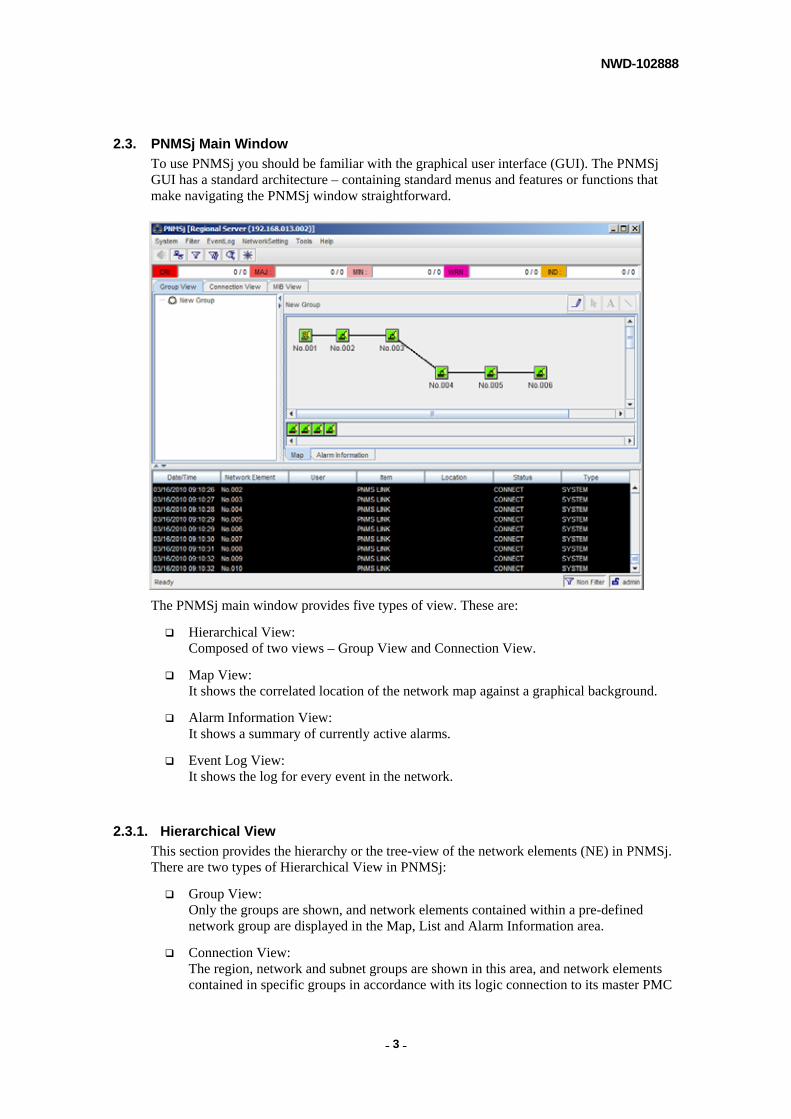
To use PNMSj you should be familiar with the graphical user interface (GUI). The PNMSj GUI has a standard architecture – containing standard menus and features or functions that make navigating the PNMSj window straightforward.
The PNMSj main window provides five types of view. These are:
Hierarchical View: Composed of two views – Group View and Connection View.
Map View: It shows the correlated location of the network map against a graphical background.
Alarm Information View: It shows a summary of currently active alarms.
Event Log View: It shows the log for every event in the network.
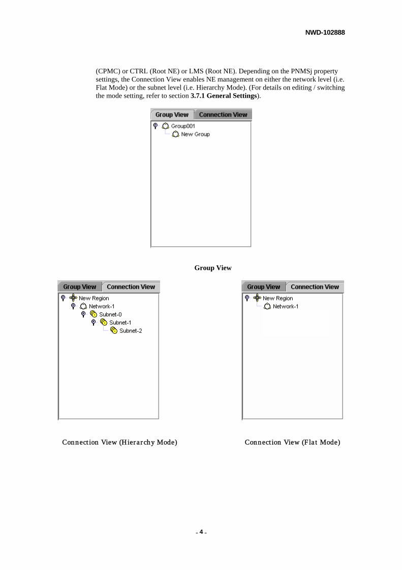
2.3.1. Hierarchical View
This section provides the hierarchy or the tree-view of the network elements (NE) in PNMSj. There are two types of Hierarchical View in PNMSj:
Group View: Only the groups are shown, and network elements contained within a pre-defined network group are displayed in the Map, List and Alarm Information area.
Connection View: The region, network and subnet groups are shown in this area, and network elements contained in specific groups in accordance with its logic connection to its master PMC
NWD-102888
- - 4
(CPMC) or CTRL (Root NE) or LMS (Root NE). Depending on the PNMSj property settings, the Connection View enables NE management on either the network level (i.e. Flat Mode) or the subnet level (i.e. Hierarchy Mode). (For details on editing / switching the mode setting, refer to section 3.7.1 General Settings).
Group View
Connection View (Hierarchy Mode) Connection View (Flat Mode)
NWD-102888
- - 5
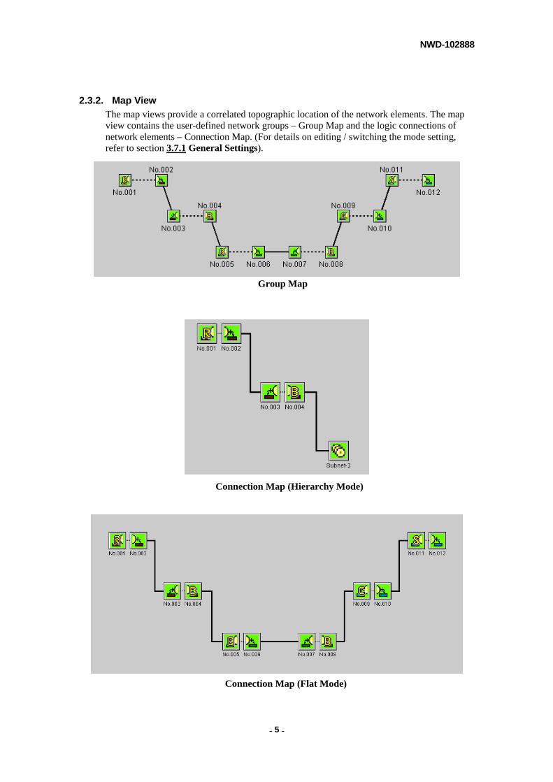
2.3.2. Map View
The map views provide a correlated topographic location of the network elements. The map view contains the user-defined network groups – Group Map and the logic connections of network elements – Connection Map. (For details on editing / switching the mode setting, refer to section 3.7.1 General Settings).
Group Map
Connection Map (Hierarchy Mode)
Connection Map (Flat Mode)
NWD-102888
- - 6
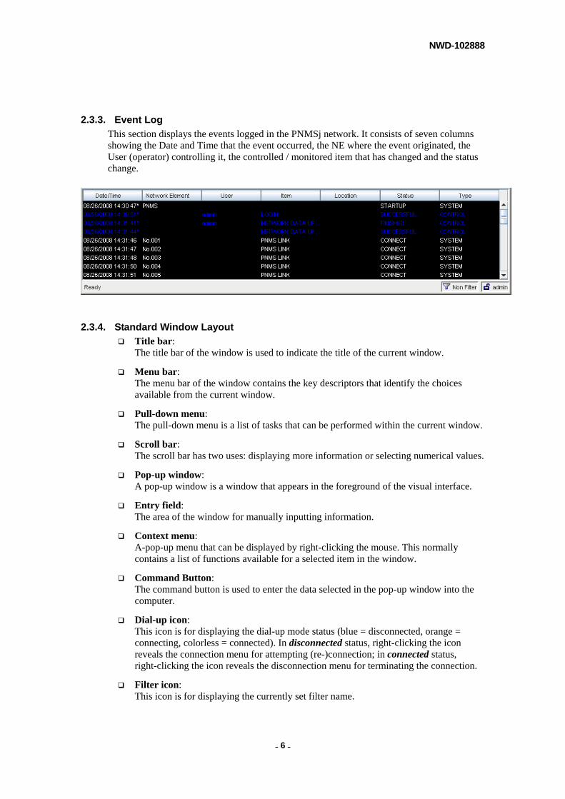
2.3.3. Event Log
This section displays the events logged in the PNMSj network. It consists of seven columns showing the Date and Time that the event occurred, the NE where the event originated, the User (operator) controlling it, the controlled / monitored item that has changed and the status change.
2.3.4. Standard Window Layout
Title bar: The title bar of the window is used to indicate the title of the current window.
Menu bar: The menu bar of the window contains the key descriptors that identify the choices available from the current window.
Pull-down menu: The pull-down menu is a list of tasks that can be performed within the current window.
Scroll bar: The scroll bar has two uses: displaying more information or selecting numerical values.
Pop-up window: A pop-up window is a window that appears in the foreground of the visual interface.
Entry field: The area of the window for manually inputting information.
Context menu: A-pop-up menu that can be displayed by right-clicking the mouse. This normally contains a list of functions available for a selected item in the window.
Command Button: The command button is used to enter the data selected in the pop-up window into the computer.
Dial-up icon: This icon is for displaying the dial-up mode status (blue = disconnected, orange = connecting, colorless = connected). In disconnected status, right-clicking the icon reveals the connection menu for attempting (re-)connection; in connected status, right-clicking the icon reveals the disconnection menu for terminating the connection.
Filter icon: This icon is for displaying the currently set filter name.

NWD-102888
- - 7
Login icon: This icon is for displaying the currently logged in user name.
Update Network icon: This icon indicates that the Update Network Configuration wizard is running (in the background). To bring the wizard to the foreground, simply click the icon.
Network Setting icon This icon indicates that the Network Setting tool (Update, Connection Management Network, Connection Management NE, Equipment Type Registration, NE Registration, Import MIB window) is running (in the background). While scanning a Network Element, the icon rotates. To bring the respective Update, Connection Management Network, Connection Management NE, Equipment Type Registration, NE Registration, Import MIB to the foreground, double click the icon accordingly.
Edit Mode icon: This icon indicates that the selected view (Group View or Connection View) is in Edit Mode.
2.3.5. Related Documents
Related Documents
PNMTj Operation Manual – describes operating procedures for each type of PASOLINK / 5000S equipment. The Link Summary of the PNMSj is the same as for the PNMTj application function. To avoid redundancy, Link Summary operations are not described in detail in this manual. Please refer to the PNMTj (LCT) manual for Link Summary operation details.
NOTE
The monitored and controlled parameters (items) are different for each type of equipment.
PASOLINK V3 Operation Manual
PASOLINK V4 Operation Manual
MIU Operation Manual
PASOLINK+ STM-1 Operation Manual
PASOLINK+ PDH Operation Manual
PASOLINK Mx Operation Manual
PASOLINK NEO Operation Manual
PASOLINK NEO CPV Operation Manual
5000S Operation Manual
PASOLINK NEO NODAL Operation Manual
PASOLINK NEO/a Operation Manual
PASOLINK NEO HP Operation Manual
NWD-102888
- - 8
NOTE
Operation manual for each type of equipment can be accessed through the help menu.
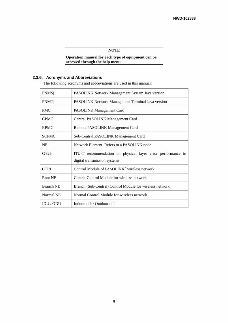
2.3.6. Acronyms and Abbreviations
The following acronyms and abbreviations are used in this manual:
PNMSj PASOLINK Network Management System Java version
PNMTj PASOLINK Network Management Terminal Java version
PMC PASOLINK Management Card
CPMC Central PASOLINK Management Card
RPMC Remote PASOLINK Management Card
SCPMC Sub-Central PASOLINK Management Card
NE Network Element. Refers to a PASOLINK node.
G.826 ITU-T recommendation on physical layer error performance in
digital transmission systems
CTRL Control Module of PASOLINK+ wireless network
Root NE Central Control Module for wireless network
Branch NE Branch (Sub-Central) Control Module for wireless network
Normal NE Normal Control Module for wireless network
IDU / ODU Indoor unit / Outdoor unit
NWD-102888
- - 9
3. PNMSj OPERATION PNMSj enables the operator to display alarms and status of all PASOLINK / 5000S equipment connected to the network. It also allows operators to have centralized control. Moreover, it provides a link performance monitoring capability based on Recommendation ITU-T G.826.
This chapter contains the procedures for operating the PNMSj.
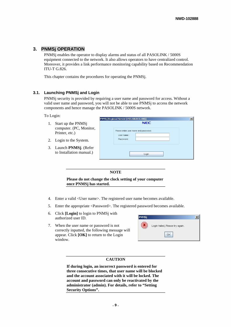
3.1. Launching PNMSj and Login
PNMSj security is provided by requiring a user name and password for access. Without a valid user name and password, you will not be able to use PNMSj to access the network components and hence manage the PASOLINK / 5000S network.
To Login:
1. Start up the PNMSj computer. (PC, Monitor, Printer, etc.)
2. Login to the System.
3. Launch PNMSj. (Refer to Installation manual.)
NOTE
Please do not change the clock setting of your computer once PNMSj has started.
4. Enter a valid <User name>. The registered user name becomes available.
5. Enter the appropriate <Password>. The registered password becomes available.
6. Click [Login] to login to PNMSj with authorized user ID.
7. When the user name or password is not correctly inputted, the following message will appear. Click [OK] to return to the Login window.
CAUTION
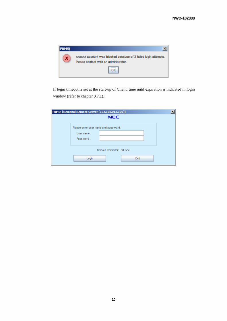
If during login, an incorrect password is entered for three consecutive times, that user name will be blocked and the account associated with it will be locked. The account and password can only be reactivated by the administrator (admin). For details, refer to “Setting Security Options”.
NWD-102888
- - 10
If login timeout is set at the start-up of Client, time until expiration is indicated in login
window (refer to chapter 3.7.1).)
NWD-102888
- - 11
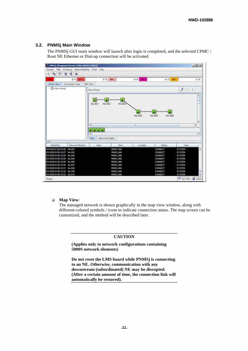
3.2. PNMSj Main Window
The PNMSj GUI main window will launch after login is completed, and the selected CPMC / Root NE Ethernet or Dial-up connection will be activated.
Map View: The managed network is shown graphically in the map view window, along with different-colored symbols / icons to indicate connection status. The map screen can be customized, and the method will be described later.
CAUTION
(Applies only to network configurations containing 5000S network elements) Do not reset the LMS board while PNMSj is connecting to an NE. Otherwise, communication with any downstream (subordinated) NE may be disrupted. (After a certain amount of time, the connection link will automatically be restored).
NWD-102888
- - 12
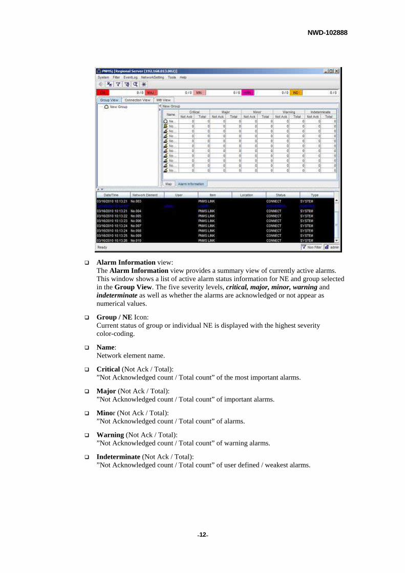
Alarm Information view: The Alarm Information view provides a summary view of currently active alarms. This window shows a list of active alarm status information for NE and group selected in the Group View. The five severity levels, critical, major, minor, warning and indeterminate as well as whether the alarms are acknowledged or not appear as numerical values.
Group / NE Icon: Current status of group or individual NE is displayed with the highest severity color-coding.
Name: Network element name.
Critical (Not Ack / Total): ”Not Acknowledged count / Total count” of the most important alarms.
Major (Not Ack / Total): ”Not Acknowledged count / Total count” of important alarms.
Minor (Not Ack / Total): ”Not Acknowledged count / Total count” of alarms.
Warning (Not Ack / Total): ”Not Acknowledged count / Total count” of warning alarms.
Indeterminate (Not Ack / Total): ”Not Acknowledged count / Total count” of user defined / weakest alarms.
NWD-102888
- - 13
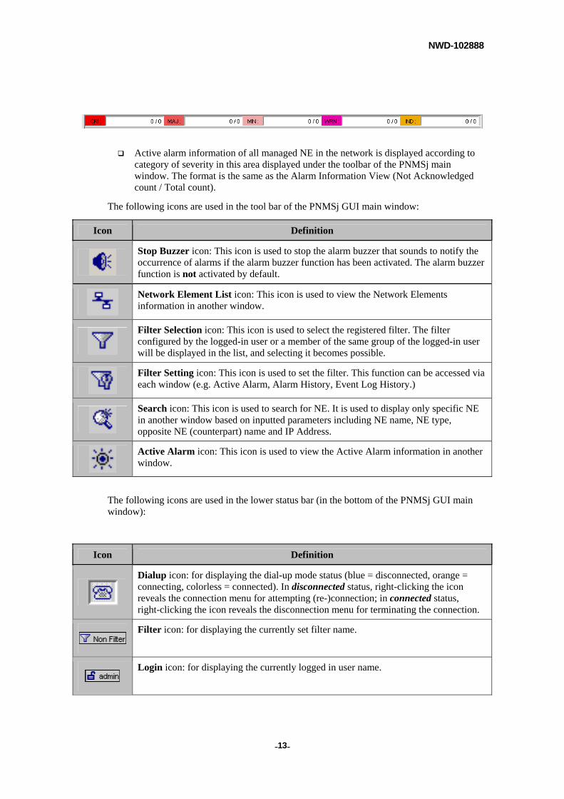
Active alarm information of all managed NE in the network is displayed according to category of severity in this area displayed under the toolbar of the PNMSj main window. The format is the same as the Alarm Information View (Not Acknowledged count / Total count).
The following icons are used in the tool bar of the PNMSj GUI main window:
Icon Definition
Stop Buzzer icon: This icon is used to stop the alarm buzzer that sounds to notify the occurrence of alarms if the alarm buzzer function has been activated. The alarm buzzer function is not activated by default.
Network Element List icon: This icon is used to view the Network Elements information in another window.
Filter Selection icon: This icon is used to select the registered filter. The filter configured by the logged-in user or a member of the same group of the logged-in user will be displayed in the list, and selecting it becomes possible.
Filter Setting icon: This icon is used to set the filter. This function can be accessed via each window (e.g. Active Alarm, Alarm History, Event Log History.)
Search icon: This icon is used to search for NE. It is used to display only specific NE in another window based on inputted parameters including NE name, NE type, opposite NE (counterpart) name and IP Address.
Active Alarm icon: This icon is used to view the Active Alarm information in another window.
The following icons are used in the lower status bar (in the bottom of the PNMSj GUI main window):
Icon Definition
Dialup icon: for displaying the dial-up mode status (blue = disconnected, orange = connecting, colorless = connected). In disconnected status, right-clicking the icon reveals the connection menu for attempting (re-)connection; in connected status, right-clicking the icon reveals the disconnection menu for terminating the connection.
Filter icon: for displaying the currently set filter name.
Login icon: for displaying the currently logged in user name.
NWD-102888
- - 14
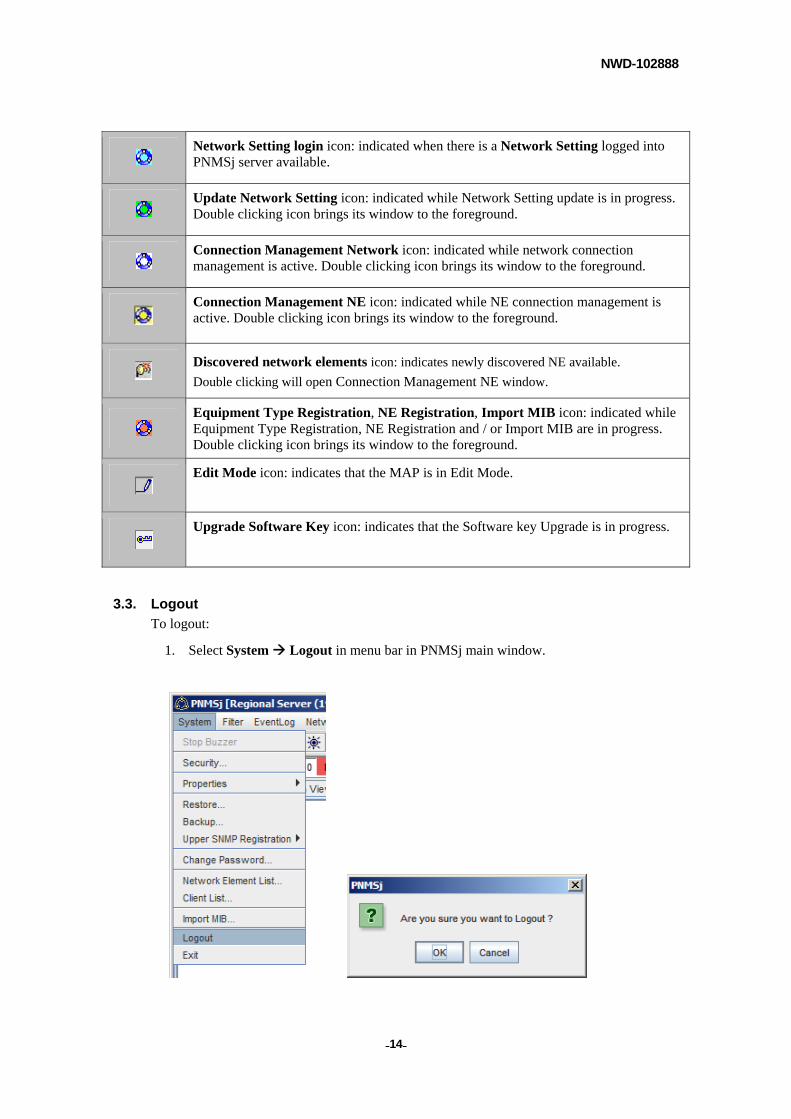
Network Setting login icon: indicated when there is a Network Setting logged into PNMSj server available.
Update Network Setting icon: indicated while Network Setting update is in progress. Double clicking icon brings its window to the foreground.
Connection Management Network icon: indicated while network connection management is active. Double clicking icon brings its window to the foreground.
Connection Management NE icon: indicated while NE connection management is active. Double clicking icon brings its window to the foreground.
Discovered network elements icon: indicates newly discovered NE available.
Double clicking will open Connection Management NE window.
Equipment Type Registration, NE Registration, Import MIB icon: indicated while Equipment Type Registration, NE Registration and / or Import MIB are in progress. Double clicking icon brings its window to the foreground.
Edit Mode icon: indicates that the MAP is in Edit Mode.
Upgrade Software Key icon: indicates that the Software key Upgrade is in progress.
3.3. Logout
To logout:
1. Select System Logout in menu bar in PNMSj main window.
NWD-102888
- - 15
2. Select Logout in the window that appears.
3. Click [OK] to logout.
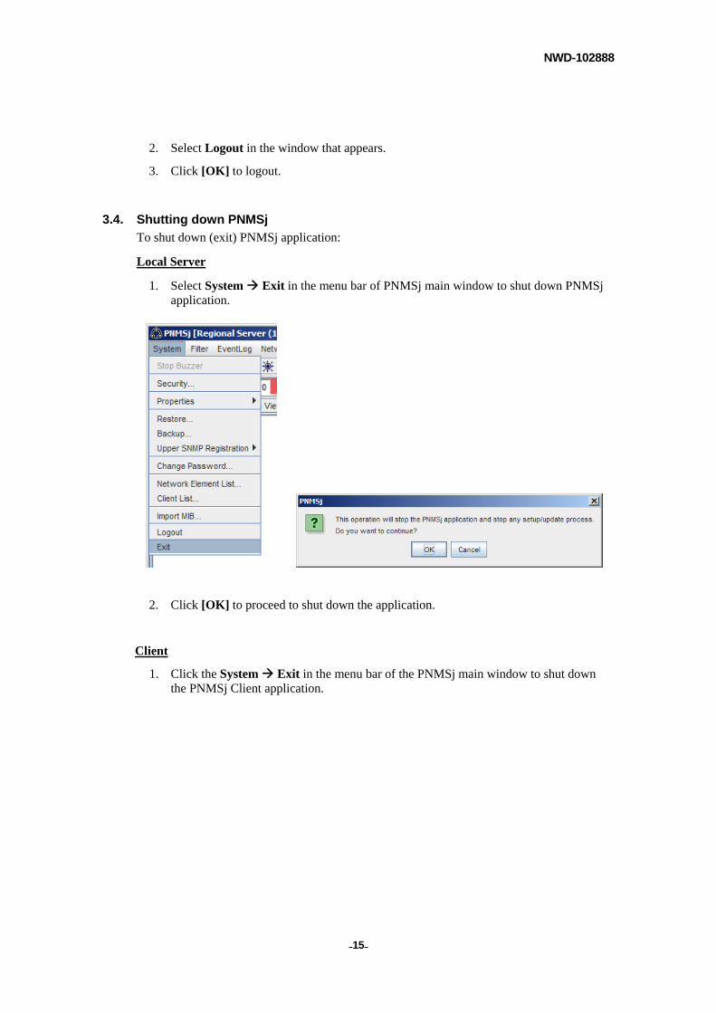
3.4. Shutting down PNMSj
To shut down (exit) PNMSj application:
Local Server
1. Select System Exit in the menu bar of PNMSj main window to shut down PNMSj application.
2. Click [OK] to proceed to shut down the application.
Client
1. Click the System Exit in the menu bar of the PNMSj main window to shut down the PNMSj Client application.
NWD-102888
- - 16
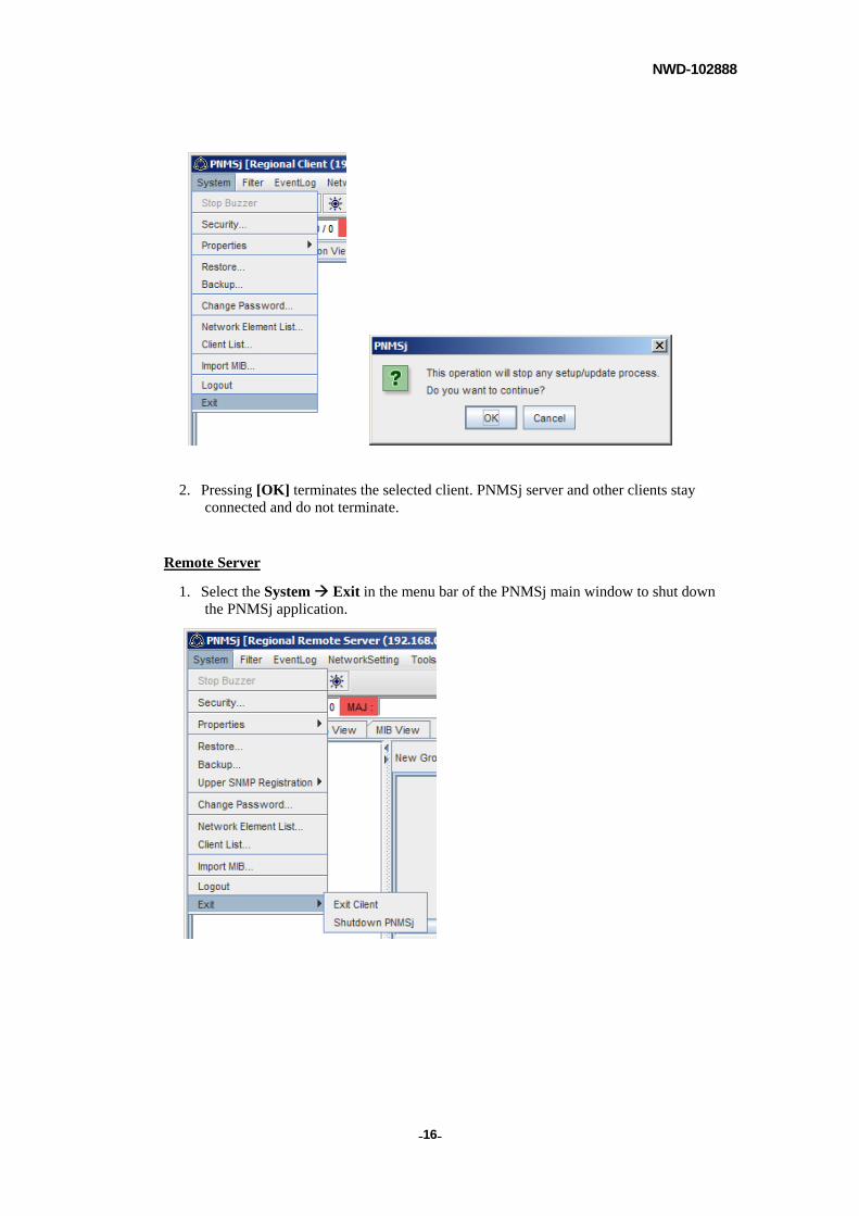
2. Pressing [OK] terminates the selected client. PNMSj server and other clients stay
connected and do not terminate.
Remote Server
1. Select the System Exit in the menu bar of the PNMSj main window to shut down the PNMSj application.
NWD-102888
- - 17
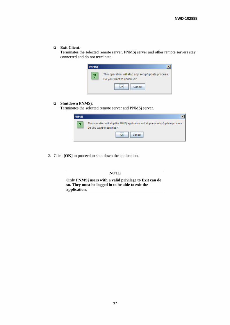
Exit Client: Terminates the selected remote server. PNMSj server and other remote servers stay connected and do not terminate.
Shutdown PNMSj: Terminates the selected remote server and PNMSj server.
2. Click [OK] to proceed to shut down the application.
NOTE
Only PNMSj users with a valid privilege to Exit can do so. They must be logged in to be able to exit the application.
NWD-102888
- - 18
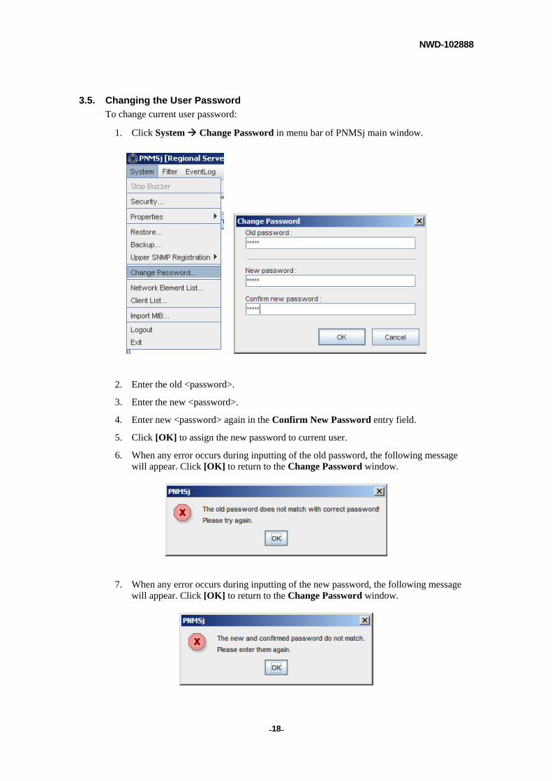
3.5. Changing the User Password
To change current user password:
1. Click System Change Password in menu bar of PNMSj main window.
2. Enter the old <password>.
3. Enter the new <password>.
4. Enter new <password> again in the Confirm New Password entry field.
5. Click [OK] to assign the new password to current user.
6. When any error occurs during inputting of the old password, the following message will appear. Click [OK] to return to the Change Password window.
7. When any error occurs during inputting of the new password, the following message will appear. Click [OK] to return to the Change Password window.
NWD-102888
- - 19
3.6. Setting Security Options
To protect the network and network management system from unauthorized access or modifications, the access privileges are assigned to the groups rather than to the individual user. Users will have the privilege granted to the group to which they belong.
The control of network elements can be customized and made available to specific groups. This allows the administrator a high-flexibility of assigning not only the PNMSj functions but also the control and management of individual NE.
Moreover, users and groups created in PNMSj exist only internally in PNMSj and do not correspond to Windows users or groups.
Group and / or User information set up here can be saved in a file by Export function. Also with Import function, security options set up in other PNMSj can be read in. However, these Export / Import functions are not applicable to any security options placed on NEs (applies to security options on PNMSj functions). Furthermore, because files readout by Export function are in a unique format of its own, those can not be edited.
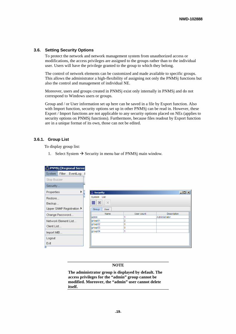
3.6.1. Group List
To display group list:
1. Select System Security in menu bar of PNMSj main window.
NOTE
The administrator group is displayed by default. The access privileges for the “admin” group cannot be modified. Moreover, the “admin” user cannot delete itself.
NWD-102888
- - 20
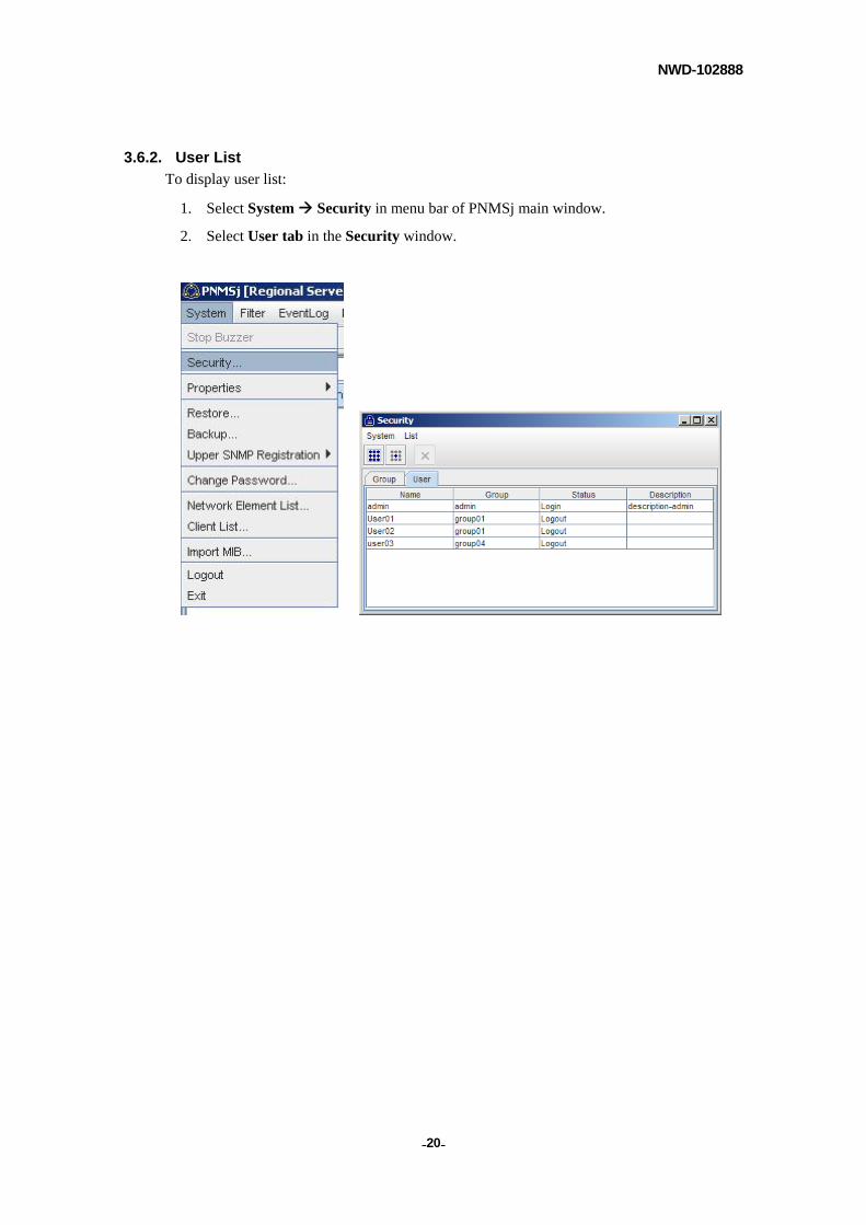
3.6.2. User List
To display user list:
1. Select System Security in menu bar of PNMSj main window.
2. Select User tab in the Security window.
NWD-102888
- - 21
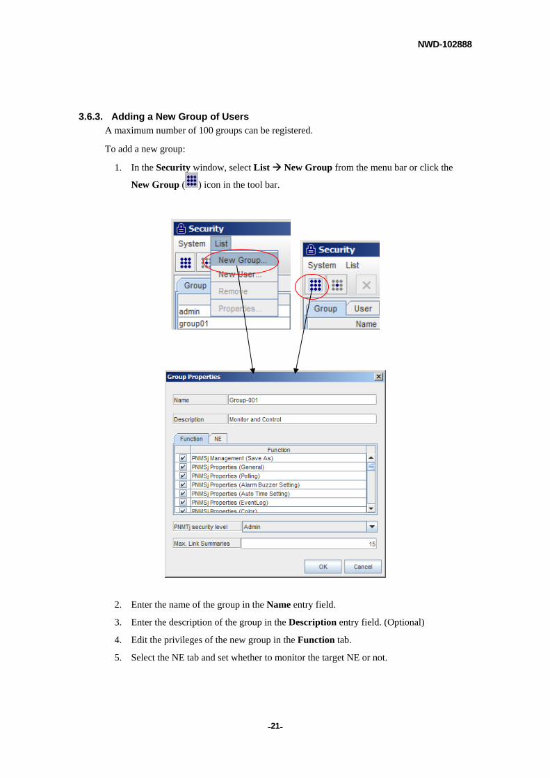
3.6.3. Adding a New Group of Users
A maximum number of 100 groups can be registered.
To add a new group:
1. In the Security window, select List New Group from the menu bar or click the
New Group ( ) icon in the tool bar.
2. Enter the name of the group in the Name entry field.
3. Enter the description of the group in the Description entry field. (Optional)
4. Edit the privileges of the new group in the Function tab.
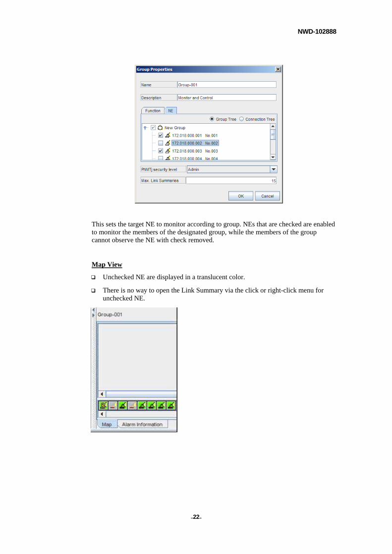
5. Select the NE tab and set whether to monitor the target NE or not.
NWD-102888
- - 22
This sets the target NE to monitor according to group. NEs that are checked are enabled to monitor the members of the designated group, while the members of the group cannot observe the NE with check removed.
Map View
Unchecked NE are displayed in a translucent color.
There is no way to open the Link Summary via the click or right-click menu for unchecked NE.
NWD-102888
- - 23
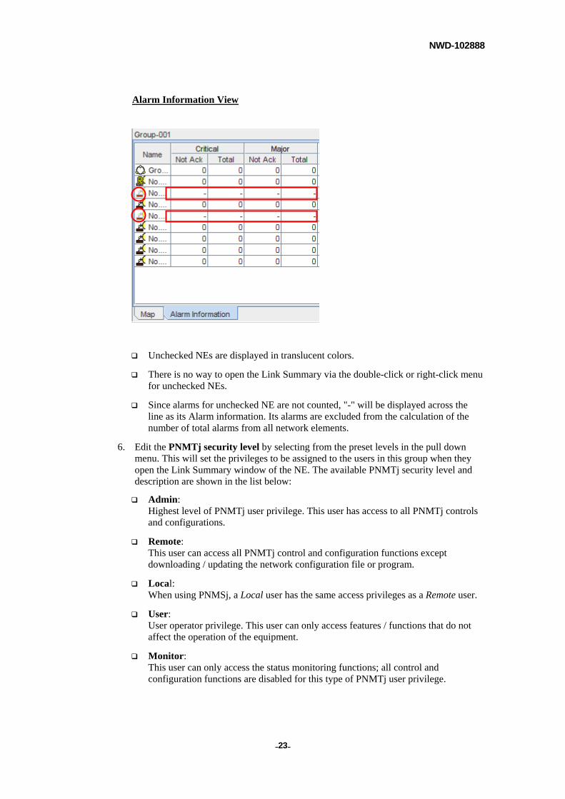
Alarm Information View
Unchecked NEs are displayed in translucent colors.
There is no way to open the Link Summary via the double-click or right-click menu for unchecked NEs.
Since alarms for unchecked NE are not counted, "-" will be displayed across the line as its Alarm information. Its alarms are excluded from the calculation of the number of total alarms from all network elements.
6. Edit the PNMTj security level by selecting from the preset levels in the pull down menu. This will set the privileges to be assigned to the users in this group when they open the Link Summary window of the NE. The available PNMTj security level and description are shown in the list below:
Admin: Highest level of PNMTj user privilege. This user has access to all PNMTj controls and configurations.
Remote: This user can access all PNMTj control and configuration functions except downloading / updating the network configuration file or program.
Local: When using PNMSj, a Local user has the same access privileges as a Remote user.
User: User operator privilege. This user can only access features / functions that do not affect the operation of the equipment.
Monitor: This user can only access the status monitoring functions; all control and configuration functions are disabled for this type of PNMTj user privilege.

NWD-102888
- - 24
NOTE
In the PNMTj security level, Remote and Local are already defined for the existing group names. Both have the same access privilege for using PNMSj.
7. Input the quantity of Max. Link Summaries
Max. Link Summaries: The number of Link Summaries that the user can open at the same time is set. The quantity is set for each Group that the user belongs to. (minimum quantity: 1; maximum quantity: the Max Client number as defined by the License).
NOTE
Because iPASOLINK is launched by LCT, it is excluded as the figure in MaxLinkSummaries.
8. Click [OK] button to complete the addition of the new group.
3.6.4. Group Privileges
This feature allows higher flexibility in terms of security for the Administrator. Privileges differ in the extent of access to specific Network Groups and Network Elements and in the extent of control and configuration initiation.
Privilege settings include:
Function – defines the functions available for the group.
Network Element - defines the NE that can be controlled by the group.
NOTE
All network elements can be monitored / viewed regardless of the defined privilege. However, a group will not be able to control an NE that has not been assigned to them.

NWD-102888
- - 25
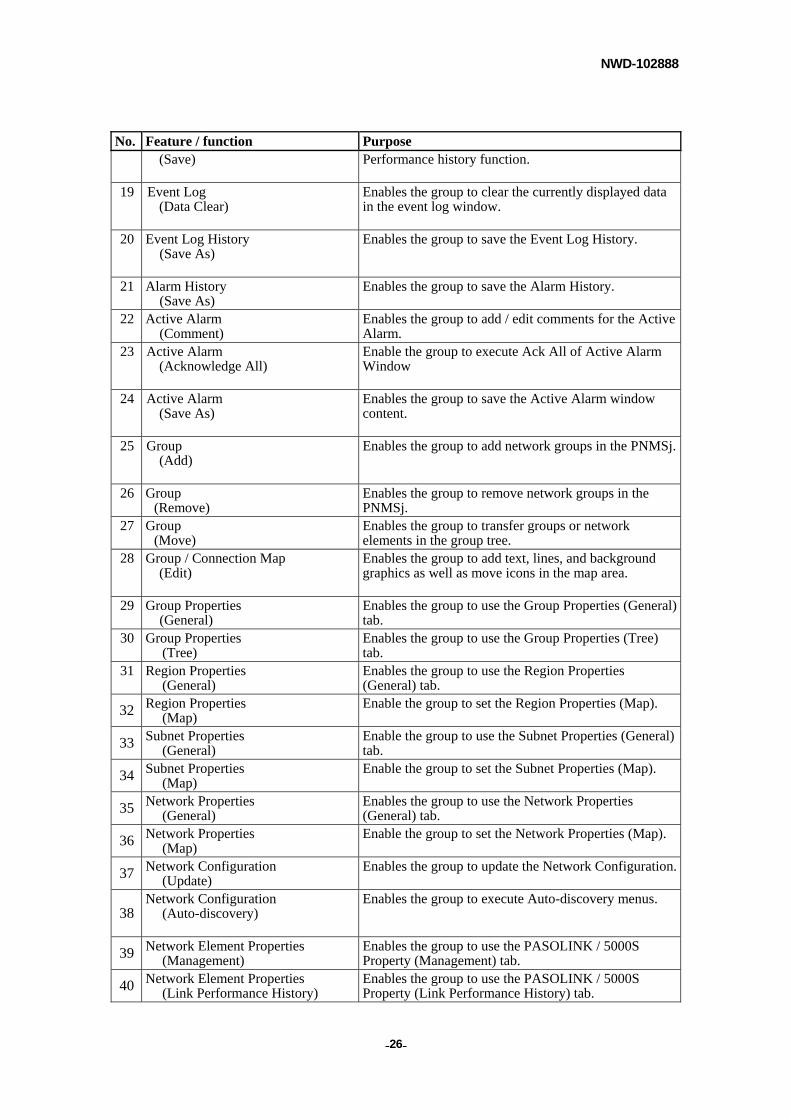
The table below defines the available functions that can be assigned to each group:
Function Table
No. Feature / function Purpose 1 PNMSj Management
(Save As) Enables the group to save the PNMSj Management window content.
2 PNMSj Properties (General)
Enables the group to set the Connection View Mode.
3 PNMSj Properties (Polling)
Enables the group to use the Region Properties (Polling) Tab.
4 PNMSj Properties (Alarm Buzzer Setting)
Enables the group to set the alarm buzzer function.
5 PNMSj Properties (Auto Time Setting)
Enables the group to set the automatic time synchronization between the PNMSj and the NEs.
6 PNMSj Properties (Event Log)
Enables the group to save Event log automatically or specify how many days to retain it.
7 PNMSj Properties (Color)
Enables the group to set the Color-coding for Event Log and Status for each Severity degree.
8 PNMSj Properties (Backup)
Enables the group to configure Backup settings.
9 PNMSj Properties (PNMSj Management)
Enables the group to configure PNMSj Management (polling time and thresholds for hardware monitor) settings.
10 PNMSj Properties (Other Equipment)
Enables the group to periodically obtain statuses for all other equipment.
11 PNMSj Properties
(iPASOLINK – SNMP) Enables the group to set the setup privileges for SNMPv2c which is allocated under iPASOLINK in PNMSj Properties window.
12 PNMSj Properties
(iPASOLINK – FTP) Enables the group to set the setup privileges for FTP which is allocated under iPASOLINK in PNMSj Properties window.
13 PNMSj Properties
(iPASOLINK – LCT Setting) Enables the group to set the setup privileges for LCT Setting which is located within iPASOLINK tree in PNMSj Properties window.
14 PNMSj Properties
(iPASOLINK – LCT Security) Enables the group to set the setup privileges for LCT Security which is located within iPASOLINK tree in PNMSj Properties window.
15 Software Key Setting (Save)
Enables the group to configure Software Key settings.
16 Severity Setting Enables the group to set the Severity according to each property / item for PNMSj.
17 Inventory Setting (Save)
Enables the group to set the Inventory tool’s save feature.
18 Link Performance History Setting Enables the group to set the save function of the Link
NWD-102888
- - 26
No. Feature / function Purpose (Save) Performance history function.
19 Event Log (Data Clear)
Enables the group to clear the currently displayed data in the event log window.
20 Event Log History (Save As)
Enables the group to save the Event Log History.
21 Alarm History (Save As)
Enables the group to save the Alarm History.
22 Active Alarm (Comment)
Enables the group to add / edit comments for the Active Alarm.
23 Active Alarm (Acknowledge All)
Enable the group to execute Ack All of Active Alarm Window
24 Active Alarm (Save As)
Enables the group to save the Active Alarm window content.
25 Group (Add)
Enables the group to add network groups in the PNMSj.
26 Group (Remove)
Enables the group to remove network groups in the PNMSj.
27 Group (Move)
Enables the group to transfer groups or network elements in the group tree.
28 Group / Connection Map (Edit)
Enables the group to add text, lines, and background graphics as well as move icons in the map area.
29 Group Properties (General)
Enables the group to use the Group Properties (General) tab.
30 Group Properties (Tree)
Enables the group to use the Group Properties (Tree) tab.
31 Region Properties (General)
Enables the group to use the Region Properties (General) tab.
32 Region Properties (Map)
Enable the group to set the Region Properties (Map).
33 Subnet Properties (General)
Enable the group to use the Subnet Properties (General) tab.
34 Subnet Properties (Map)
Enable the group to set the Subnet Properties (Map).
35 Network Properties (General)
Enables the group to use the Network Properties (General) tab.
36 Network Properties (Map)
Enable the group to set the Network Properties (Map).
37 Network Configuration (Update)
Enables the group to update the Network Configuration.
38 Network Configuration
(Auto-discovery)
Enables the group to execute Auto-discovery menus.
39 Network Element Properties (Management)
Enables the group to use the PASOLINK / 5000S Property (Management) tab.
40 Network Element Properties (Link Performance History)
Enables the group to use the PASOLINK / 5000S Property (Link Performance History) tab.

NWD-102888
- - 27
No. Feature / function Purpose
41 Network Element Properties (Software Key)
Enables the group to use the PASOLINK / 5000S Property (Software Key) tab.
42 Network Element Properties (Inventory)
Enables the group to use the PASOLINK / 5000S Property (Inventory) tab.
43 Network Element List (Save As)
Enables the group to save the Network Element List.
44 PNMSj Security Setting Enables the group to edit, add and remove new groups and users.
45 Restore Enables the group to restore data. 46 Backup Enables the group to Backup.
47 Upper SNMP Registration Enables the group to register the Upper SNMP manager.
48 Help License Enables the group to view and import Licenses. 49 Client List Enables the group to open the Client List window.
50 Software Key List Enables the group to open the Software Key List window.
51 Upgrade Software Key File Enables the group to setup menu for automatic
Download / Update of Software Key.
52 Download Program Files Enable the group to execute Download Program Files dialog.
53 Time Zone Setting Enable the group to execute Time Zone Setting dialog.
54 Other Equipment Enables the group to add other equipments or set up monitoring information.
55 PNMSj Server Exit Enables the group to close the PNMSj application.
PNMSj Local Server can be terminated from the Remote Server.
56 Client List (Disconnect)
The right to forcibly disconnect individual users is authorized via the Client List.
57 Connection Check Enables the group to use the Connection Check function.
58 MIB View (Import MIB)
Enables the group to import MIB file with the use of MIB View.
59 MIB View (Get)
Get button in MIB View becomes available for the group.
60 MIB View (Set)
Set button in MIB View becomes available for the group.
NOTE
You will need to logout once to save the new privilege settings.
NWD-102888
- - 28
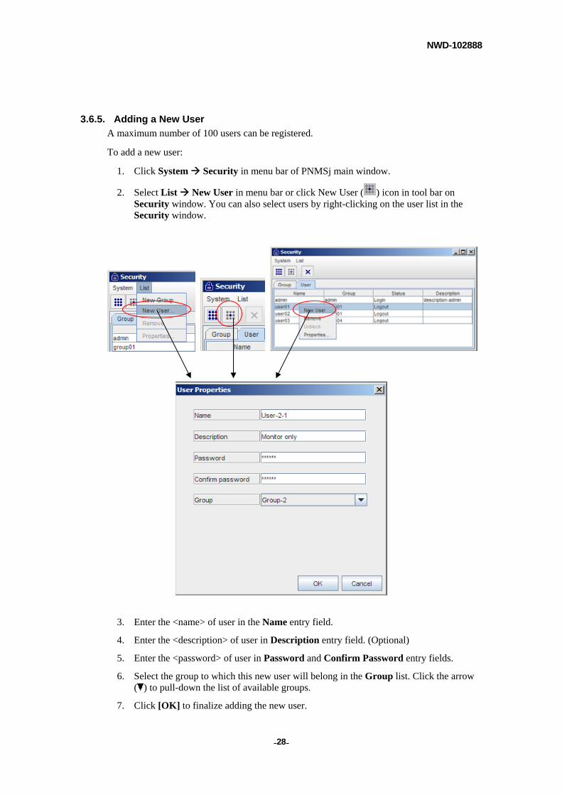
3.6.5. Adding a New User
A maximum number of 100 users can be registered.
To add a new user:
1. Click System Security in menu bar of PNMSj main window.
2. Select List New User in menu bar or click New User ( ) icon in tool bar on Security window. You can also select users by right-clicking on the user list in the Security window.
3. Enter the <name> of user in the Name entry field.
4. Enter the <description> of user in Description entry field. (Optional)
5. Enter the <password> of user in Password and Confirm Password entry fields.
6. Select the group to which this new user will belong in the Group list. Click the arrow ( ) to pull-down the list of available groups.
7. Click [OK] to finalize adding the new user.
NWD-102888
- - 29
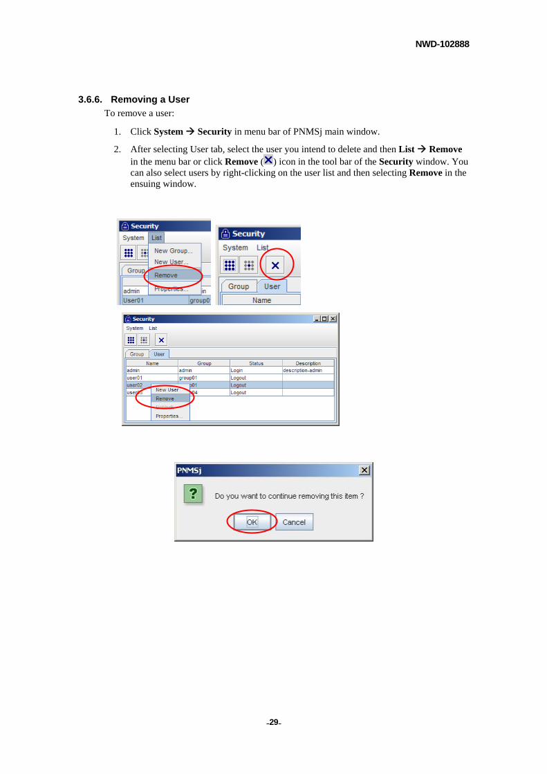
3.6.6. Removing a User
To remove a user:
1. Click System Security in menu bar of PNMSj main window.
2. After selecting User tab, select the user you intend to delete and then List Remove in the menu bar or click Remove ( ) icon in the tool bar of the Security window. You can also select users by right-clicking on the user list and then selecting Remove in the ensuing window.
NWD-102888
- - 30
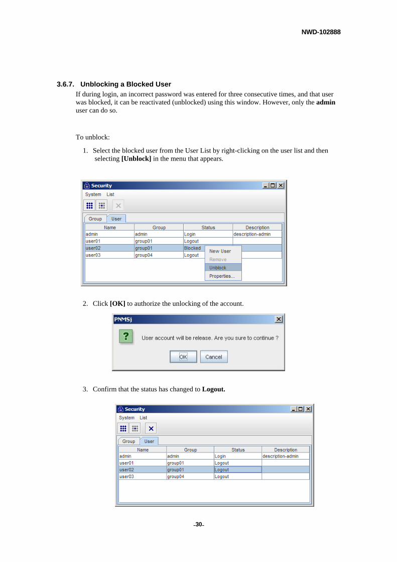
3.6.7. Unblocking a Blocked User
If during login, an incorrect password was entered for three consecutive times, and that user was blocked, it can be reactivated (unblocked) using this window. However, only the admin user can do so.
To unblock:
1. Select the blocked user from the User List by right-clicking on the user list and then selecting [Unblock] in the menu that appears.
2. Click [OK] to authorize the unlocking of the account.
3. Confirm that the status has changed to Logout.
NWD-102888
- - 31
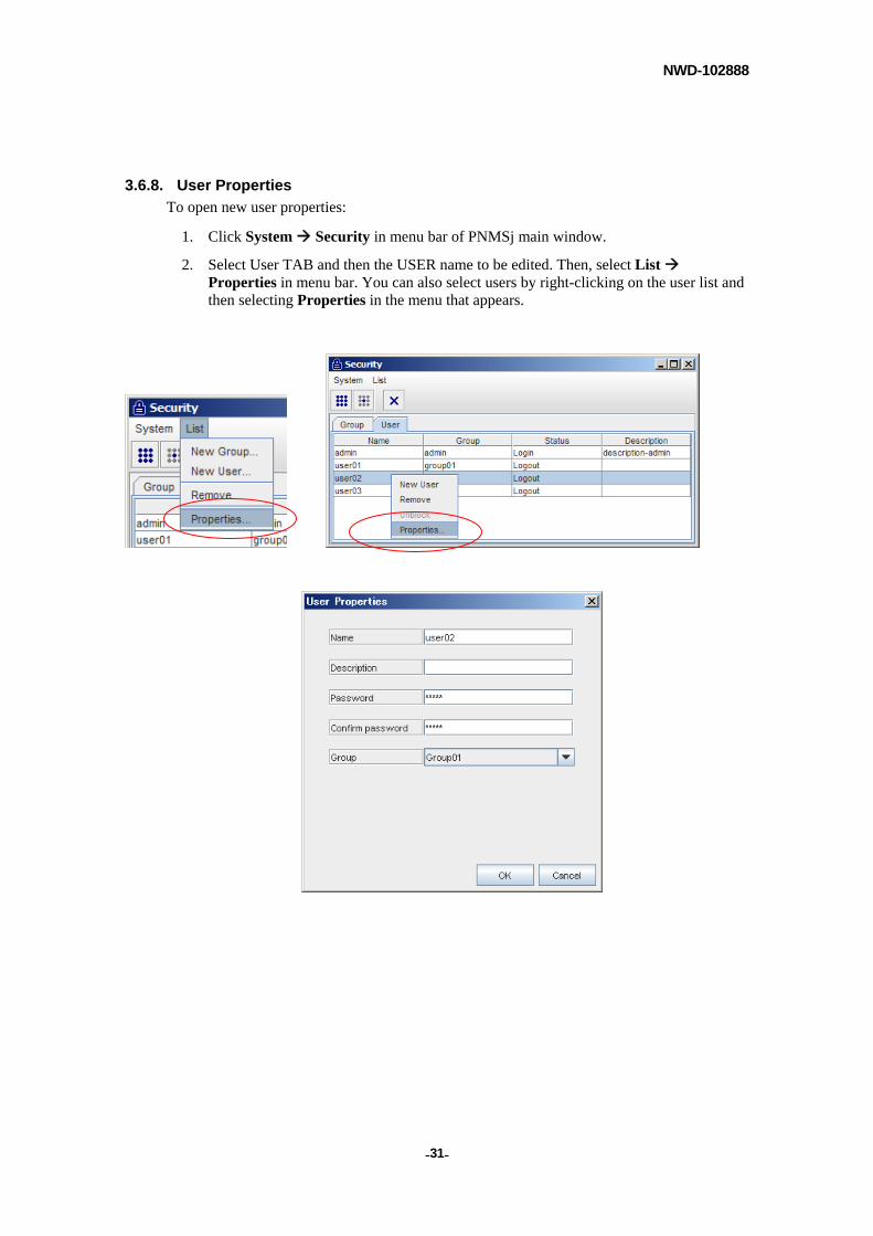
3.6.8. User Properties
To open new user properties:
1. Click System Security in menu bar of PNMSj main window.
2. Select User TAB and then the USER name to be edited. Then, select List Properties in menu bar. You can also select users by right-clicking on the user list and then selecting Properties in the menu that appears.
NWD-102888
- - 32
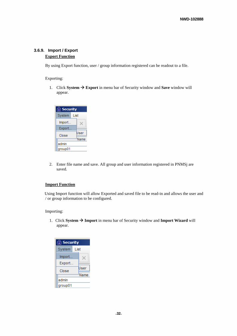
3.6.9. Import / Export
Export Function
By using Export function, user / group information registered can be readout to a file.
Exporting:
1. Click System Export in menu bar of Security window and Save window will appear.
2. Enter file name and save. All group and user information registered in PNMSj are saved.
Import Function
Using Import function will allow Exported and saved file to be read-in and allows the user and / or group information to be configured.
Importing:
1. Click System Import in menu bar of Security window and Import Wizard will appear.
NWD-102888
- - 33
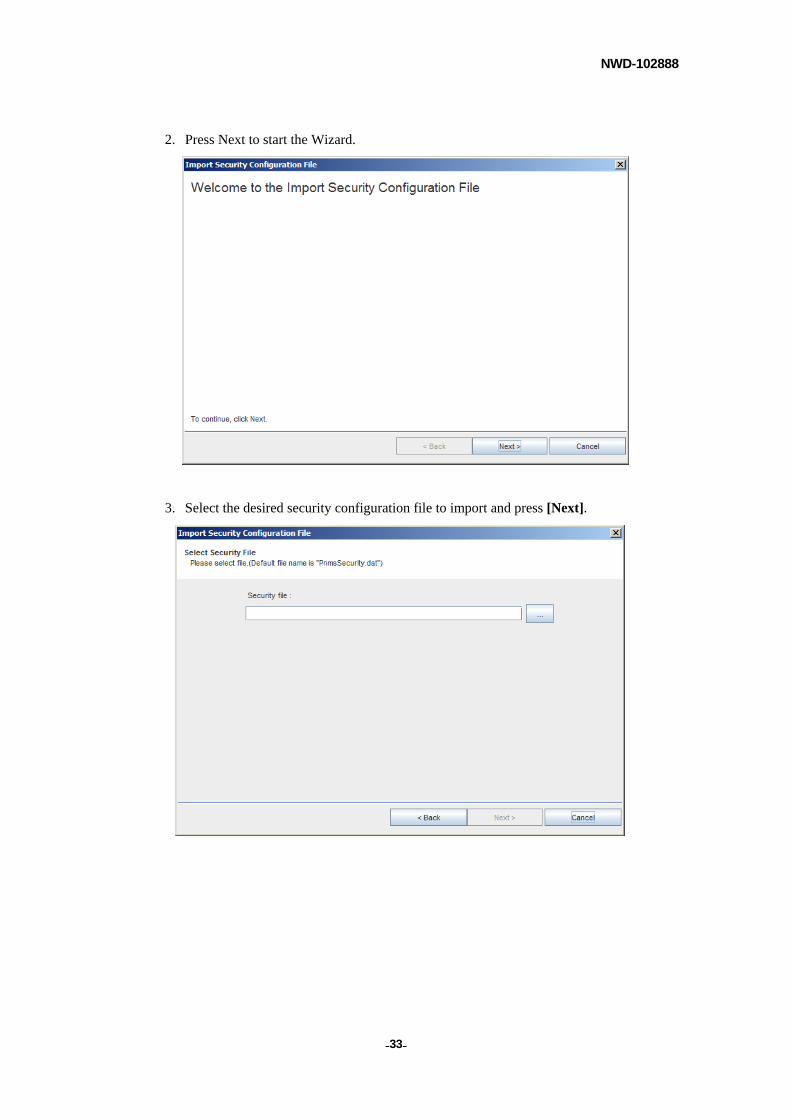
2. Press Next to start the Wizard.
3. Select the desired security configuration file to import and press [Next].
NWD-102888
- - 34
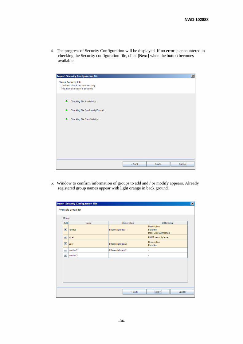
4. The progress of Security Configuration will be displayed. If no error is encountered in checking the Security configuration file, click [Next] when the button becomes available.
5. Window to confirm information of groups to add and / or modify appears. Already registered group names appear with light orange in back ground.
NWD-102888
- - 35
Here are the explanations for each column.
Add:
Check off the boxes of desired groups to be added.
Name:
Indicates the group name.
Description:
Describes each group.
Differential:
IF group having the same name as the one in existing groups is detected, differences between those groups are described.
When [Next] button is pressed, confirmation message appears if any checked off groups end up overwriting existing groups and cannot proceed to next window unless accepted.
NOTE
If possible number of additional groups to register is exceeded, [Next] button cannot be selected.
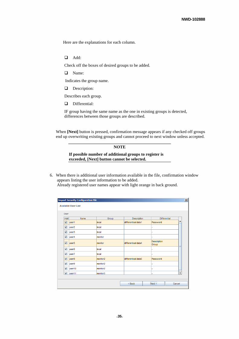
6. When there is additional user information available in the file, confirmation window appears listing the user information to be added. Already registered user names appear with light orange in back ground.
NWD-102888
- - 36
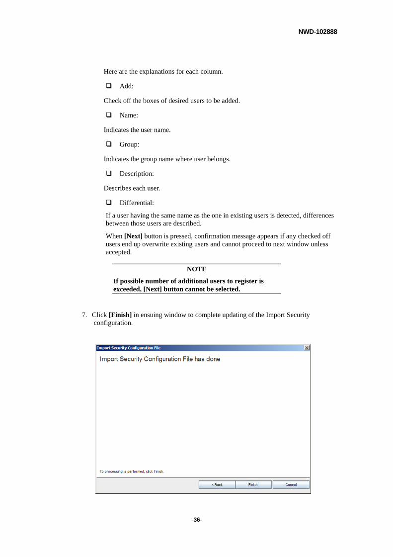
Here are the explanations for each column.
Add:
Check off the boxes of desired users to be added.
Name:
Indicates the user name.
Group:
Indicates the group name where user belongs.
Description:
Describes each user.
Differential:
If a user having the same name as the one in existing users is detected, differences between those users are described.
When [Next] button is pressed, confirmation message appears if any checked off users end up overwrite existing users and cannot proceed to next window unless accepted.
NOTE
If possible number of additional users to register is exceeded, [Next] button cannot be selected.
7. Click [Finish] in ensuing window to complete updating of the Import Security configuration.
NWD-102888
- - 37
3.7. PNMSj Properties
3.7.1. General Setting
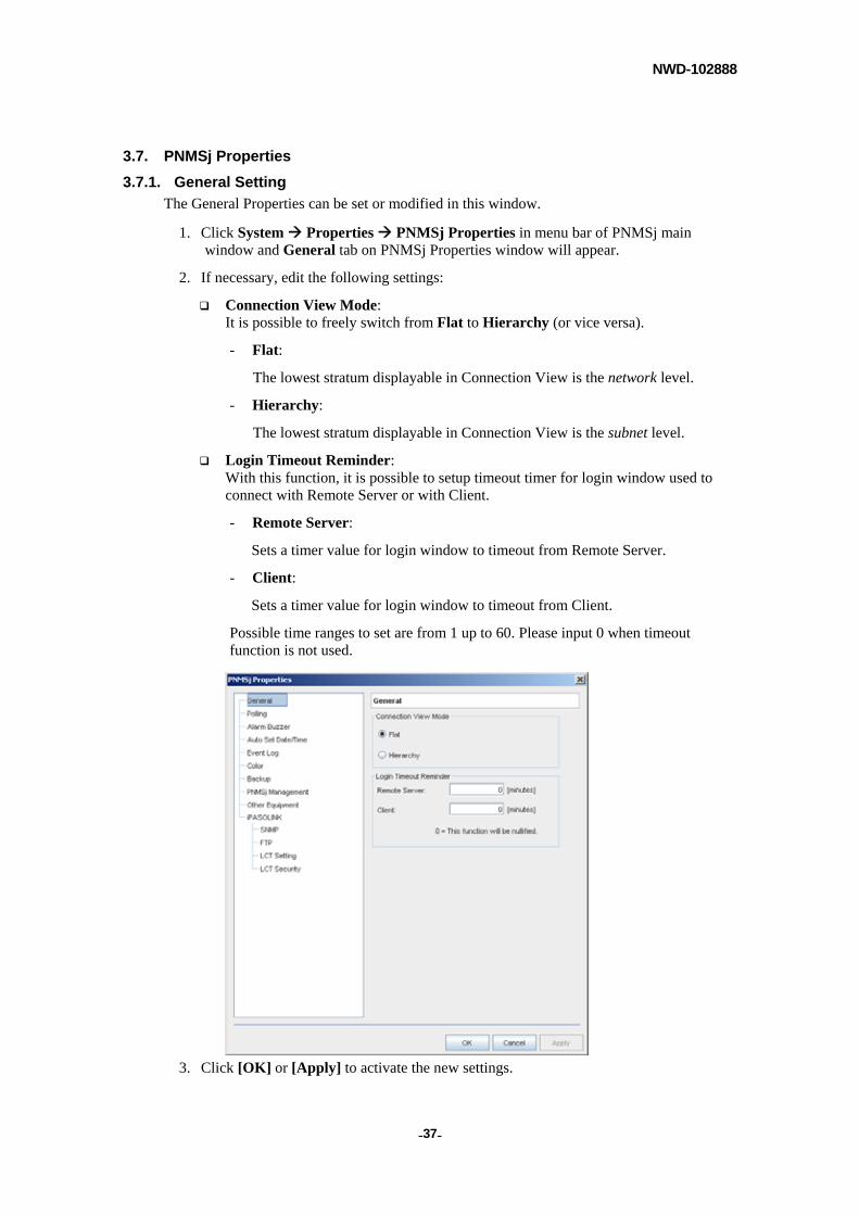
The General Properties can be set or modified in this window.
1. Click System Properties PNMSj Properties in menu bar of PNMSj main window and General tab on PNMSj Properties window will appear.
2. If necessary, edit the following settings:
Connection View Mode: It is possible to freely switch from Flat to Hierarchy (or vice versa).
- Flat:
The lowest stratum displayable in Connection View is the network level.
- Hierarchy:
The lowest stratum displayable in Connection View is the subnet level.
Login Timeout Reminder: With this function, it is possible to setup timeout timer for login window used to connect with Remote Server or with Client.
- Remote Server:
Sets a timer value for login window to timeout from Remote Server.
- Client:
Sets a timer value for login window to timeout from Client.
Possible time ranges to set are from 1 up to 60. Please input 0 when timeout function is not used.
3. Click [OK] or [Apply] to activate the new settings.
NWD-102888
- - 38
3.7.2. Polling Time Setting
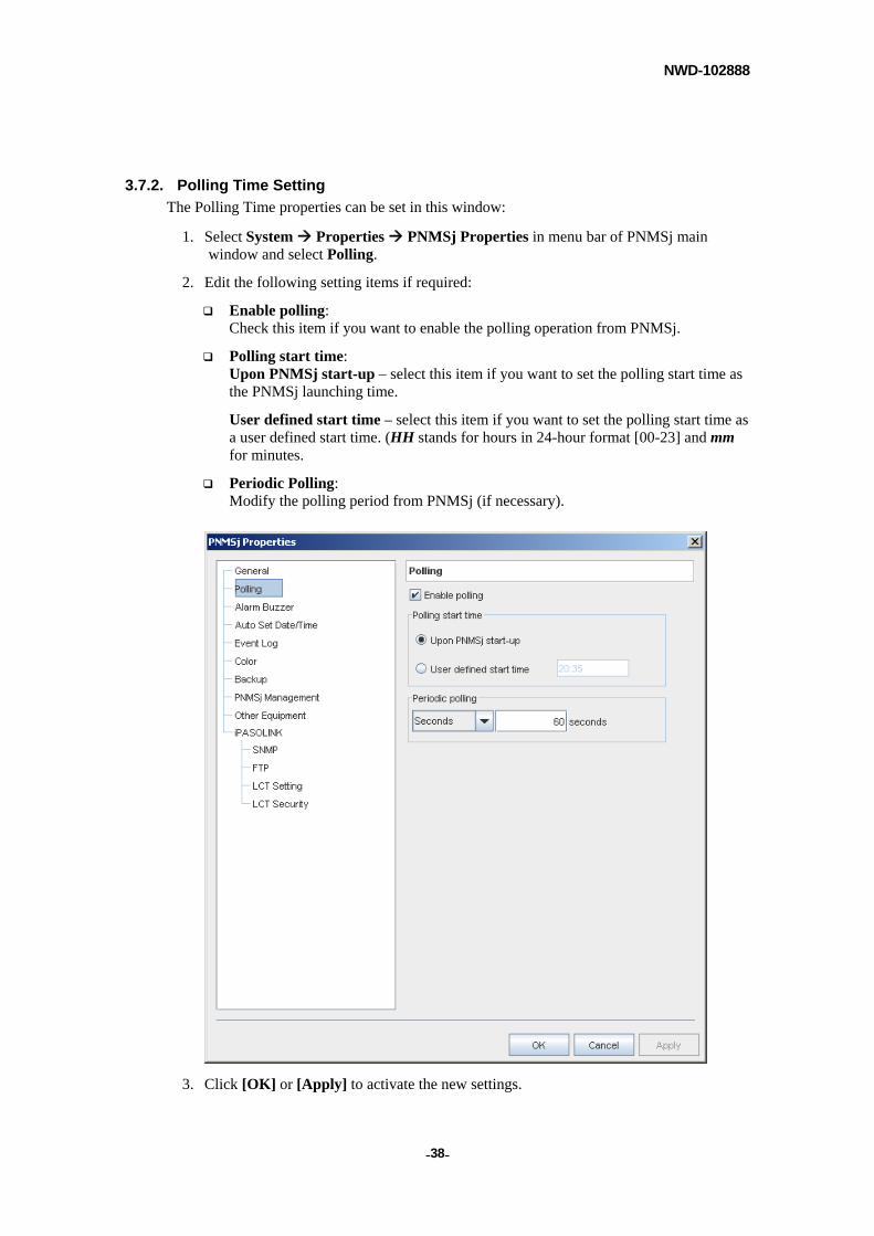
The Polling Time properties can be set in this window:
1. Select System Properties PNMSj Properties in menu bar of PNMSj main window and select Polling.
2. Edit the following setting items if required:
Enable polling: Check this item if you want to enable the polling operation from PNMSj.
Polling start time: Upon PNMSj start-up – select this item if you want to set the polling start time as the PNMSj launching time.
User defined start time – select this item if you want to set the polling start time as a user defined start time. (HH stands for hours in 24-hour format [00-23] and mm for minutes.
Periodic Polling: Modify the polling period from PNMSj (if necessary).
3. Click [OK] or [Apply] to activate the new settings.
NWD-102888
- - 39
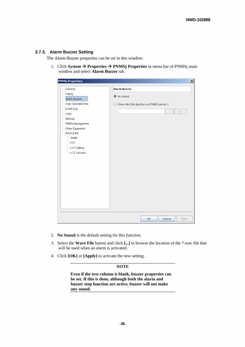
3.7.3. Alarm Buzzer Setting
The Alarm Buzzer properties can be set in this window:
1. Click System Properties PNMSj Properties in menu bar of PNMSj main window and select Alarm Buzzer tab.
2. No Sound is the default setting for this function.
3. Select the Wave File button and click [...] to browse the location of the *.wav file that will be used when an alarm is activated.
4. Click [OK] or [Apply] to activate the new setting.
NOTE
Even if the text column is blank, buzzer properties can be set. If this is done, although both the alarm and buzzer stop function are active, buzzer will not make any sound.
NWD-102888
- - 40
3.7.4. Buzzer Stop Setting
An alarm buzzer sounds to notify the occurrence of an alarm if the alarm buzzer function is activated. The alarm buzzer function is not activated by default.
To stop the alarm buzzer:
(1) Click Stop Buzzer ( ) icon in tool bar of PNMSj main window. Whenever an alarm occurs again even if the buzzer is released once, the Tool Bar icon and System Stop Buzzer function are enabled.
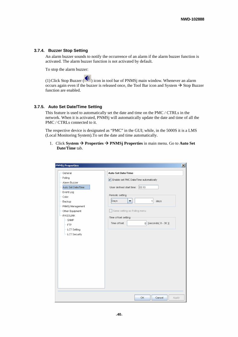
3.7.5. Auto Set Date/Time Setting
This feature is used to automatically set the date and time on the PMC / CTRLs in the network. When it is activated, PNMSj will automatically update the date and time of all the PMC / CTRLs connected to it.
The respective device is designated as “PMC” in the GUI; while, in the 5000S it is a LMS (Local Monitoring System).To set the date and time automatically.
1. Click System Properties PNMSj Properties in main menu. Go to Auto Set Date/Time tab.

NWD-102888
- - 41
2. Check the Enable set PMC Date/Time automatically box if you want to enable this feature.
3. Set the User defined start time where in the PNMSj will automatically start the Date/Time setting. Enter the time in the HH: mm format (HH stands for hours in 24-hour format [00-23] and mm for minutes).
4. Set the unit (days or hours) and value for interval time to execute the Date/Time setting from PNMSj to PMC (or CTRL) in the Periodic setting section.
5. Check the Same setting as Polling menu box if you want to set the same start time and setting period as the polling menu. It is not possible to select a Seconds differs from the polling setting.
6. When the NE time delay is considerable, be sure to set Time offset setting. (Normally, setting zero (0) should be no problem).
7. Click [OK] or [Apply] to activate the new setting.
NWD-102888
- - 42
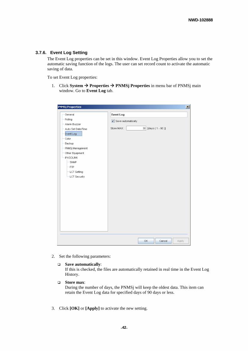
3.7.6. Event Log Setting
The Event Log properties can be set in this window. Event Log Properties allow you to set the automatic saving function of the logs. The user can set record count to activate the automatic saving of data.
To set Event Log properties:
1. Click System Properties PNMSj Properties in menu bar of PNMSj main window. Go to Event Log tab.
2. Set the following parameters:
Save automatically: If this is checked, the files are automatically retained in real time in the Event Log History.
Store max: During the number of days, the PNMSj will keep the oldest data. This item can retain the Event Log data for specified days of 90 days or less.
3. Click [OK] or [Apply] to activate the new setting.
NWD-102888
- - 43
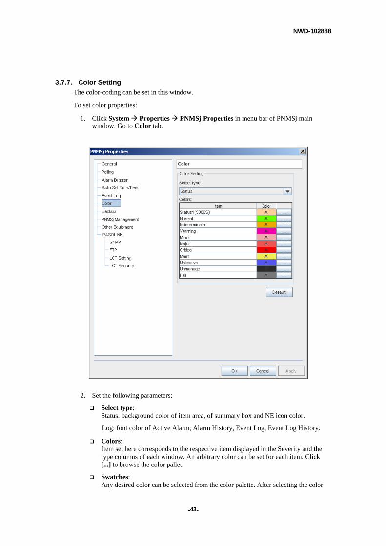
3.7.7. Color Setting
The color-coding can be set in this window.
To set color properties:
1. Click System Properties PNMSj Properties in menu bar of PNMSj main window. Go to Color tab.
2. Set the following parameters:
Select type: Status: background color of item area, of summary box and NE icon color.
Log: font color of Active Alarm, Alarm History, Event Log, Event Log History.
Colors: Item set here corresponds to the respective item displayed in the Severity and the type columns of each window. An arbitrary color can be set for each item. Click [...] to browse the color pallet.
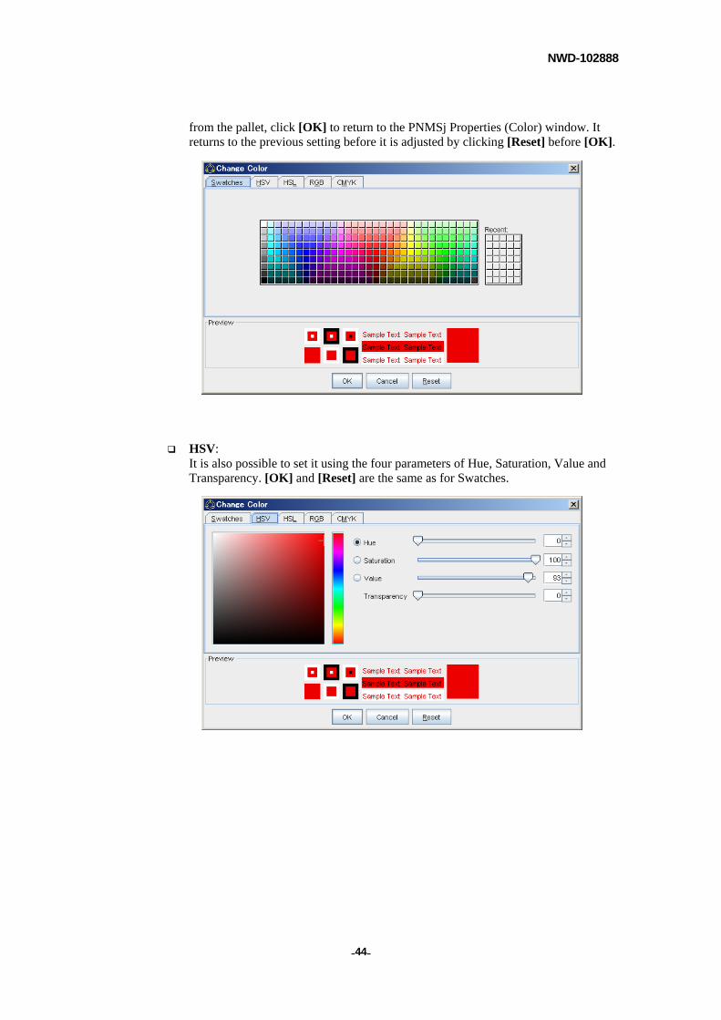
Swatches: Any desired color can be selected from the color palette. After selecting the color
NWD-102888
- - 44
from the pallet, click [OK] to return to the PNMSj Properties (Color) window. It returns to the previous setting before it is adjusted by clicking [Reset] before [OK].
HSV: It is also possible to set it using the four parameters of Hue, Saturation, Value and Transparency. [OK] and [Reset] are the same as for Swatches.
NWD-102888
- - 45
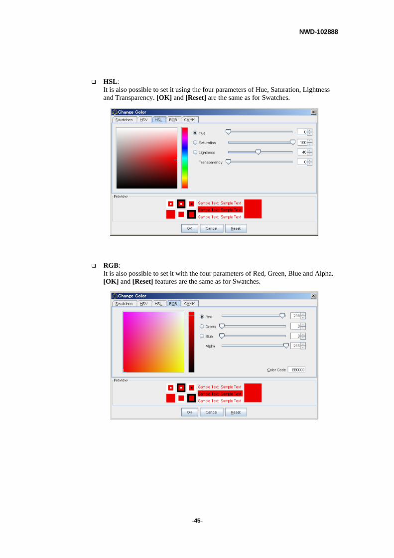
HSL: It is also possible to set it using the four parameters of Hue, Saturation, Lightness and Transparency. [OK] and [Reset] are the same as for Swatches.
RGB: It is also possible to set it with the four parameters of Red, Green, Blue and Alpha. [OK] and [Reset] features are the same as for Swatches.
NWD-102888
- - 46
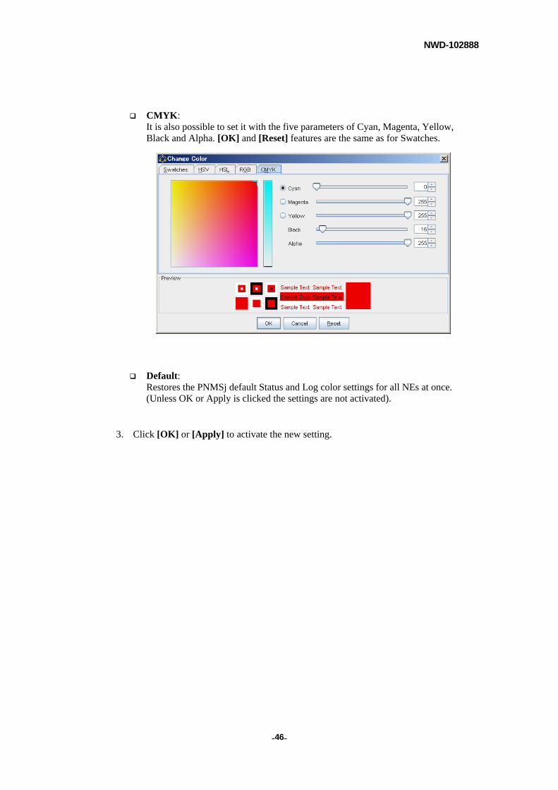
CMYK: It is also possible to set it with the five parameters of Cyan, Magenta, Yellow, Black and Alpha. [OK] and [Reset] features are the same as for Swatches.
Default: Restores the PNMSj default Status and Log color settings for all NEs at once. (Unless OK or Apply is clicked the settings are not activated).
3. Click [OK] or [Apply] to activate the new setting.
NWD-102888
- - 47
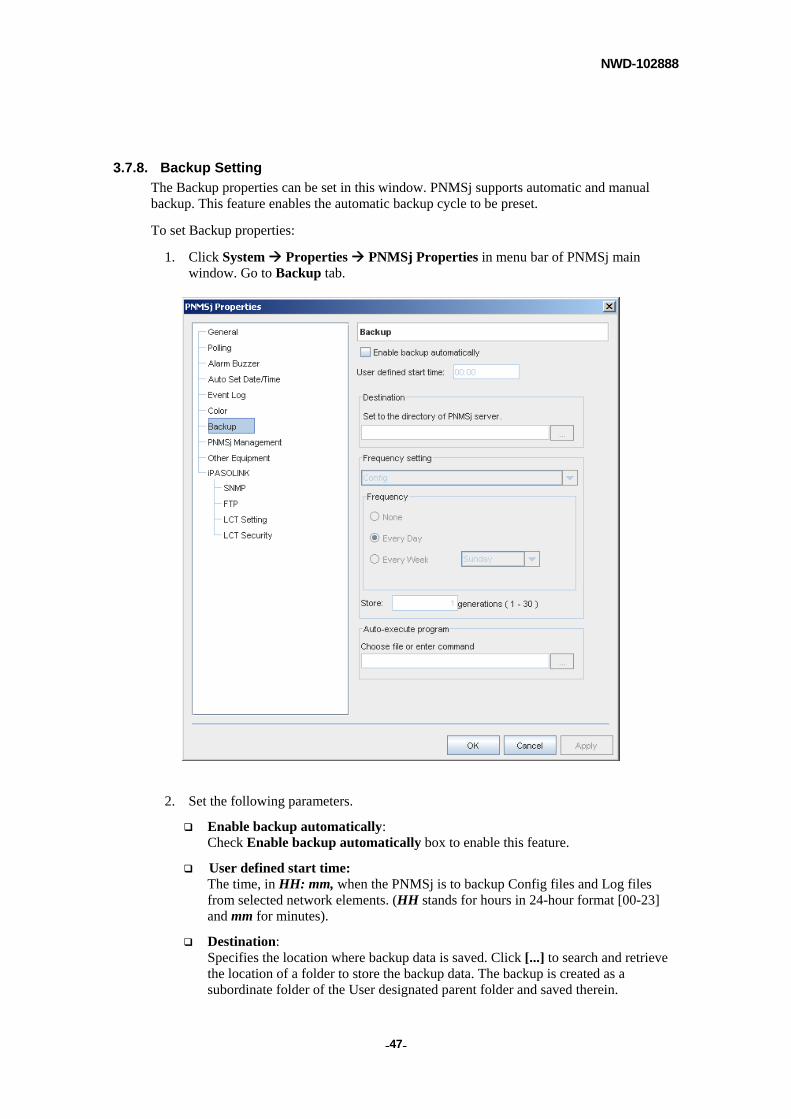
3.7.8. Backup Setting
The Backup properties can be set in this window. PNMSj supports automatic and manual backup. This feature enables the automatic backup cycle to be preset.
To set Backup properties:
1. Click System Properties PNMSj Properties in menu bar of PNMSj main window. Go to Backup tab.
2. Set the following parameters.
Enable backup automatically: Check Enable backup automatically box to enable this feature.
User defined start time: The time, in HH: mm, when the PNMSj is to backup Config files and Log files from selected network elements. (HH stands for hours in 24-hour format [00-23] and mm for minutes).
Destination: Specifies the location where backup data is saved. Click [...] to search and retrieve the location of a folder to store the backup data. The backup is created as a subordinate folder of the User designated parent folder and saved therein.

NWD-102888
- - 48
Frequency setting: Either Config or Log / Pmon / Inventory / Software Key can be selected. Selecting Config enables the setting of the time frame (i.e. frequency) in which the Config directory is to be periodically backed up. Likewise, selecting Log / Pmon / Inventory / Software Key enables the same thing to be done for Log / Pmon / Inventory / Software Key.
- None: No Backup is done.
- Every Day: Data backup is done daily at the designated time.
- Every Week: Data backup is done weekly on the designated weekday.
Store: Sets the number of data generations to retain (store). It is separately set with Config and Log / Pmon / Inventory / Software Key Backup.
Auto-execute program: After the Backup files have been completely retrieved, input the respective command(s) you wish to execute. When the command line contains blank spaces, enclose the command line with quotation marks (“).
3. Click [OK] or [Apply] to activate the new setting.
NOTE
If data is concurrently backed up so that the destination for daily and weekly backup coincide, the initial contents of the specified folder are overwritten by default. To avoid this, it is necessary to manually save to another folder for the next backup.
NOTE
Refer to Appendix B when you create the batch file (BAT) on Windows OS.
NWD-102888
- - 49
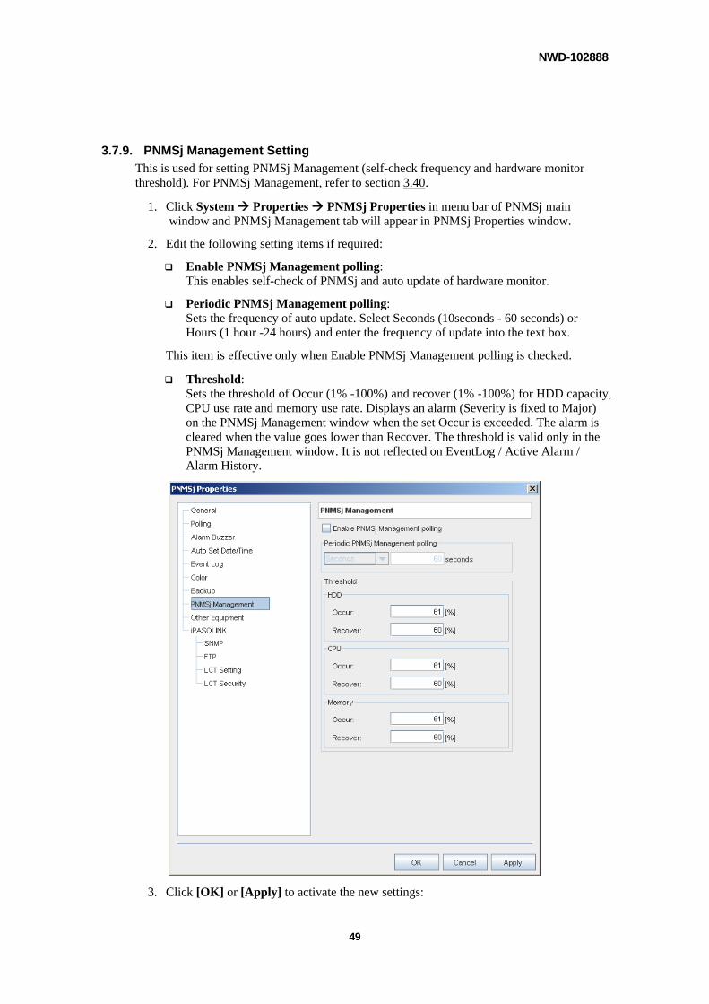
3.7.9. PNMSj Management Setting
This is used for setting PNMSj Management (self-check frequency and hardware monitor threshold). For PNMSj Management, refer to section 3.40.
1. Click System Properties PNMSj Properties in menu bar of PNMSj main window and PNMSj Management tab will appear in PNMSj Properties window.
2. Edit the following setting items if required:
Enable PNMSj Management polling: This enables self-check of PNMSj and auto update of hardware monitor.
Periodic PNMSj Management polling: Sets the frequency of auto update. Select Seconds (10seconds - 60 seconds) or Hours (1 hour -24 hours) and enter the frequency of update into the text box.
This item is effective only when Enable PNMSj Management polling is checked.
Threshold: Sets the threshold of Occur (1% -100%) and recover (1% -100%) for HDD capacity, CPU use rate and memory use rate. Displays an alarm (Severity is fixed to Major) on the PNMSj Management window when the set Occur is exceeded. The alarm is cleared when the value goes lower than Recover. The threshold is valid only in the PNMSj Management window. It is not reflected on EventLog / Active Alarm / Alarm History.
3. Click [OK] or [Apply] to activate the new settings:
NWD-102888
- - 50
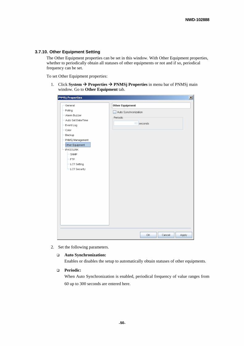
3.7.10. Other Equipment Setting
The Other Equipment properties can be set in this window. With Other Equipment properties, whether to periodically obtain all statuses of other equipments or not and if so, periodical frequency can be set.
To set Other Equipment properties:
1. Click System Properties PNMSj Properties in menu bar of PNMSj main window. Go to Other Equipment tab.
2. Set the following parameters.
Auto Synchronization:
Enables or disables the setup to automatically obtain statuses of other equipments.
Periodic:
When Auto Synchronization is enabled, periodical frequency of value ranges from
60 up to 300 seconds are entered here.
NWD-102888
- - 51
3.7.11. iPASOLINK Setting
Necessary setups to connect with iPASOLINK equipments are explained along with
explanation of monitoring / control setups.
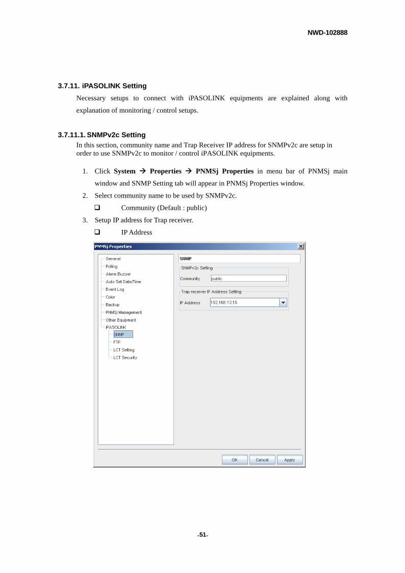
3.7.11.1. SNMPv2c Setting
In this section, community name and Trap Receiver IP address for SNMPv2c are setup in order to use SNMPv2c to monitor / control iPASOLINK equipments.
1. Click System Properties PNMSj Properties in menu bar of PNMSj main
window and SNMP Setting tab will appear in PNMSj Properties window.
2. Select community name to be used by SNMPv2c.
Community (Default : public)
3. Setup IP address for Trap receiver.
IP Address
NWD-102888
- - 52
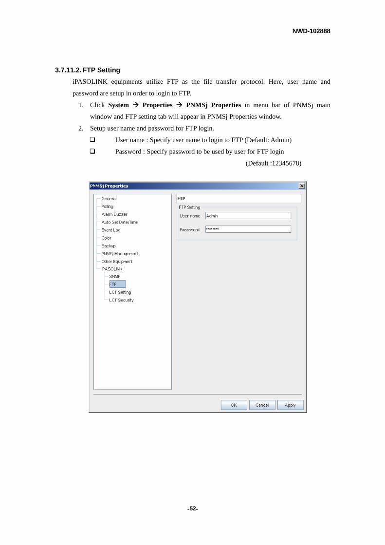
3.7.11.2. FTP Setting
iPASOLINK equipments utilize FTP as the file transfer protocol. Here, user name and
password are setup in order to login to FTP.
1. Click System Properties PNMSj Properties in menu bar of PNMSj main
window and FTP setting tab will appear in PNMSj Properties window.
2. Setup user name and password for FTP login.
User name : Specify user name to login to FTP (Default: Admin)
Password : Specify password to be used by user for FTP login
(Default :12345678)
NWD-102888
- - 53
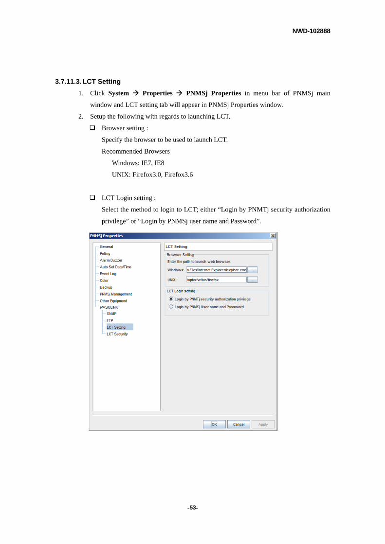
3.7.11.3. LCT Setting
1. Click System Properties PNMSj Properties in menu bar of PNMSj main
window and LCT setting tab will appear in PNMSj Properties window.
2. Setup the following with regards to launching LCT.
Browser setting :
Specify the browser to be used to launch LCT.
Recommended Browsers
Windows: IE7, IE8
UNIX: Firefox3.0, Firefox3.6
LCT Login setting :
Select the method to login to LCT; either “Login by PNMTj security authorization
privilege” or “Login by PNMSj user name and Password”.

NWD-102888
- - 54
NOTE
If selected to login by PNMSj user name, same user registration as that of PNMSj user is needed in LCT.
Following are the characters allowed to be used for user name and password.
- Upper and lower case alphabets (A-Z, a-z)
- Numeric characters (0-9)
- Hyphen (’-’)
- Underscore (’_’)
However, please note that the password can not begin with a hyphen (’-’).
NOTE
If NE does not support login by PNMSj user name, login by PNMTj security authorization privilege need to be selected for login regardless of setups.

NWD-102888
- - 55
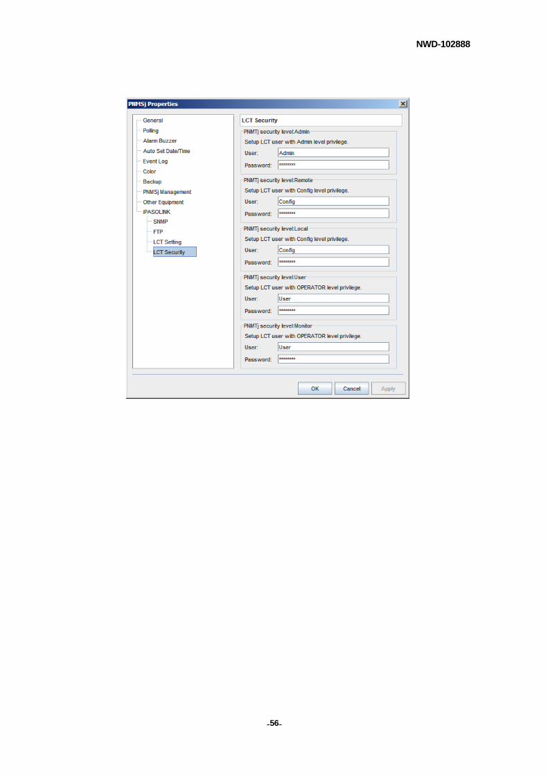
3.7.11.4. LCT Security Setting
Change LCT user name / password used to login to LCT when LCT is called from iPASOLINK series, LCT user name and password are changed separately for each PNMTj security level.
1. Click System Properties PNMSj Properties in menu bar of PNMSj main
window and LCT Security setting tab will appear in PNMSj Properties window.
2. User name and password used to login to LCT are set separately for each PNMTj
security level.
LCT Login User Name / Password (Sorted by PNMTj Security Level)
PNMTj Security level LCT Privilege Level LCT Login User Name* Password*
Admin Admin Admin 12345678
Remote Config Config 87654321
Local Config Config 87654321
User OPERATOR User 87654321
Monitor OPERATOR User 87654321
*LCT login user names / passwords are the default values of NE.
NOTE
Please set the same LCT login user names and passwords for all iPASOLINK equipments. Individual setup cannot be made.
Along with any changes made to LCT login user names or passwords for NE, also change default values in this window.
NWD-102888
- - 56
NWD-102888
- - 57
3.8. Element Properties
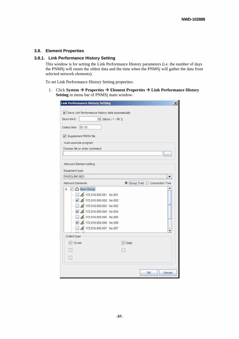
3.8.1. Link Performance History Setting
This window is for setting the Link Performance History parameters (i.e. the number of days the PNMSj will retain the oldest data and the time when the PNMSj will gather the data from selected network elements).
To set Link Performance History Setting properties:
1. Click System Properties Element Properties Link Performance History Setting in menu bar of PNMSj main window.

NWD-102888
- - 58
2. Set the following parameters.
Save Link Performance History data automatically:
Enables or disables the auto save of Link Performance History.
Store MAX:
For the set number of days, the PNMSj will retain the oldest data. This enables the
Link Performance History data for any specified number of days (up to 90 days
maximum) to be retained.
Collect time:
The time, in HH: mm, when the PNMSj is to collect the link performance data from
selected network elements. (HH stands for hours in 24-hour format [00-23] and mm
for minutes.)
Supplement PMON file:
By default, when this option is unchecked, the PNMSj collects only the previous
day's PMON. In cases where PMON collection is unreliable due to DCN or
connection problems, the PNMSj can be programmed to collect all available
PMON on the NE (previous day's PMON and all other available PMON data) by
checking the "Supplement PMON file" option.
Auto-execute program:
After the Performance History files have been completely retrieved, input the
respective command(s) you wish to execute. When the command line contains
blank spaces, enclose the command line with quotation marks (“).
Equipment Type:
Type of equipment will be listed.
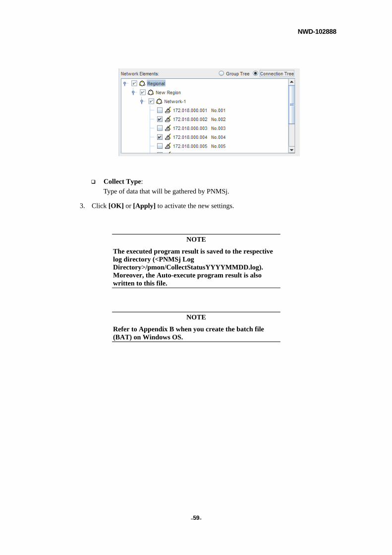
Network Elements:
Link performance data will be collected for the network elements that are selected
and checked.
By selecting between Group Tree and Connection Tree radio button, display can be
switched freely from one to the other.
Group Tree – For the type of Network Element selected in Equipment Type,
display is made available in units of group or NE and can be selected for further
setups.
Connection Tree – For the type of Network Element selected in Equipment Type,
display is made available in units of Region, Network or NE and can be selected for
further setups.
NWD-102888
- - 59
Collect Type:
Type of data that will be gathered by PNMSj.
3. Click [OK] or [Apply] to activate the new settings.
NOTE
The executed program result is saved to the respective log directory (<PNMSj Log Directory>/pmon/CollectStatusYYYYMMDD.log). Moreover, the Auto-execute program result is also written to this file.
NOTE
Refer to Appendix B when you create the batch file (BAT) on Windows OS.
NWD-102888
- - 60
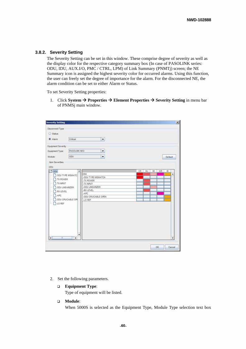
3.8.2. Severity Setting
The Severity Setting can be set in this window. These comprise degree of severity as well as the display color for the respective category summary box (In case of PASOLINK series: ODU, IDU, AUX.I/O, PMC / CTRL, LPM) of Link Summary (PNMTj) screen; the NE Summary icon is assigned the highest severity color for occurred alarms. Using this function, the user can freely set the degree of importance for the alarm. For the disconnected NE, the alarm condition can be set to either Alarm or Status.
To set Severity Setting properties:
1. Click System Properties Element Properties Severity Setting in menu bar of PNMSj main window.
2. Set the following parameters.
Equipment Type:
Type of equipment will be listed.
Module:
When 5000S is selected as the Equipment Type, Module Type selection text box

NWD-102888
- - 61
becomes available. Because fairly large selections of modules can be mounted onto
5000S, selecting module here will narrow down the alarm items that will appear in
the following Item Severities text box for easier selection of severity. Then, only
the alarm items related to the selected module will appear in the Item Severities box
for selection.
Default:
Default button will restore Severity setups of all equipment types and modules back
to the default values.
Item Severities:
Within the Item Severities block, explanation is given below with left hand side as
Tree View and right hand side as Severity setup section.
Tree view – All items subject to alarm, within the Module selected in Module box,
are displayed in a tree view format. Select desired items to setup severities and
details for each are set in Severity setup section.
Severity setup – Item selected in Tree view appears in the 1st row and, from the 2nd
row on, all statuses or alarms allocated underneath that item are listed. For each
item, severity is set by pressing the button in desired severity column. However,
please note that if Critical is selected as severity for an item in the 1st row, all other
items under its hierarchy are also set at Critical. (For example, if Critical is selected
for ODU, all items contained within such as INPUT LOSS and BP OUTPUT LOSS
are automatically set at Critical as well.) Color displayed for each severity can be
set by previously mentioned Color Setting of PNMSj Properties.
NOTE
LCT is used to setup equipment Severity for iPASOLINK equipments.
NWD-102888
- - 62
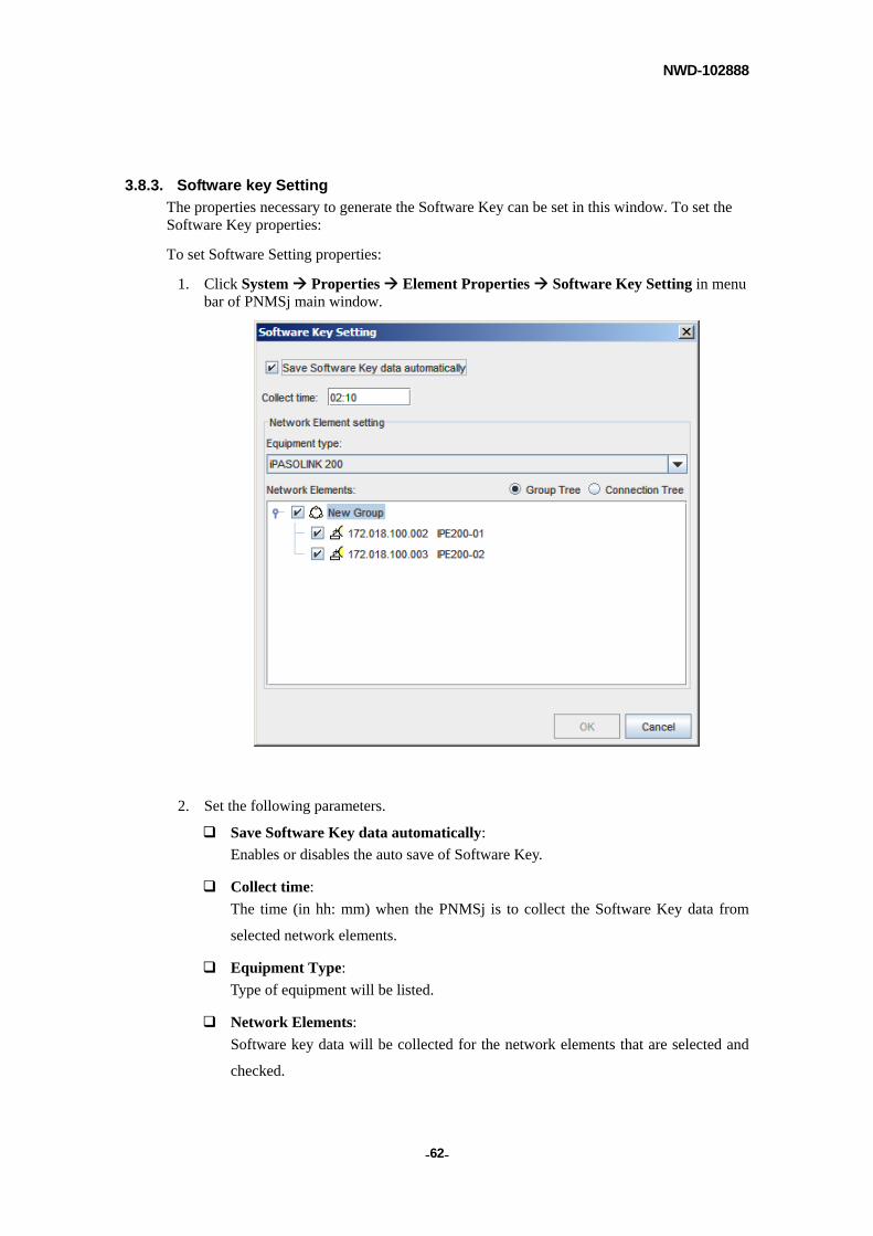
3.8.3. Software key Setting
The properties necessary to generate the Software Key can be set in this window. To set the Software Key properties:
To set Software Setting properties:
1. Click System Properties Element Properties Software Key Setting in menu bar of PNMSj main window.
2. Set the following parameters.
Save Software Key data automatically:
Enables or disables the auto save of Software Key.
Collect time:
The time (in hh: mm) when the PNMSj is to collect the Software Key data from
selected network elements.
Equipment Type:
Type of equipment will be listed.
Network Elements:
Software key data will be collected for the network elements that are selected and
checked.
NWD-102888
- - 63
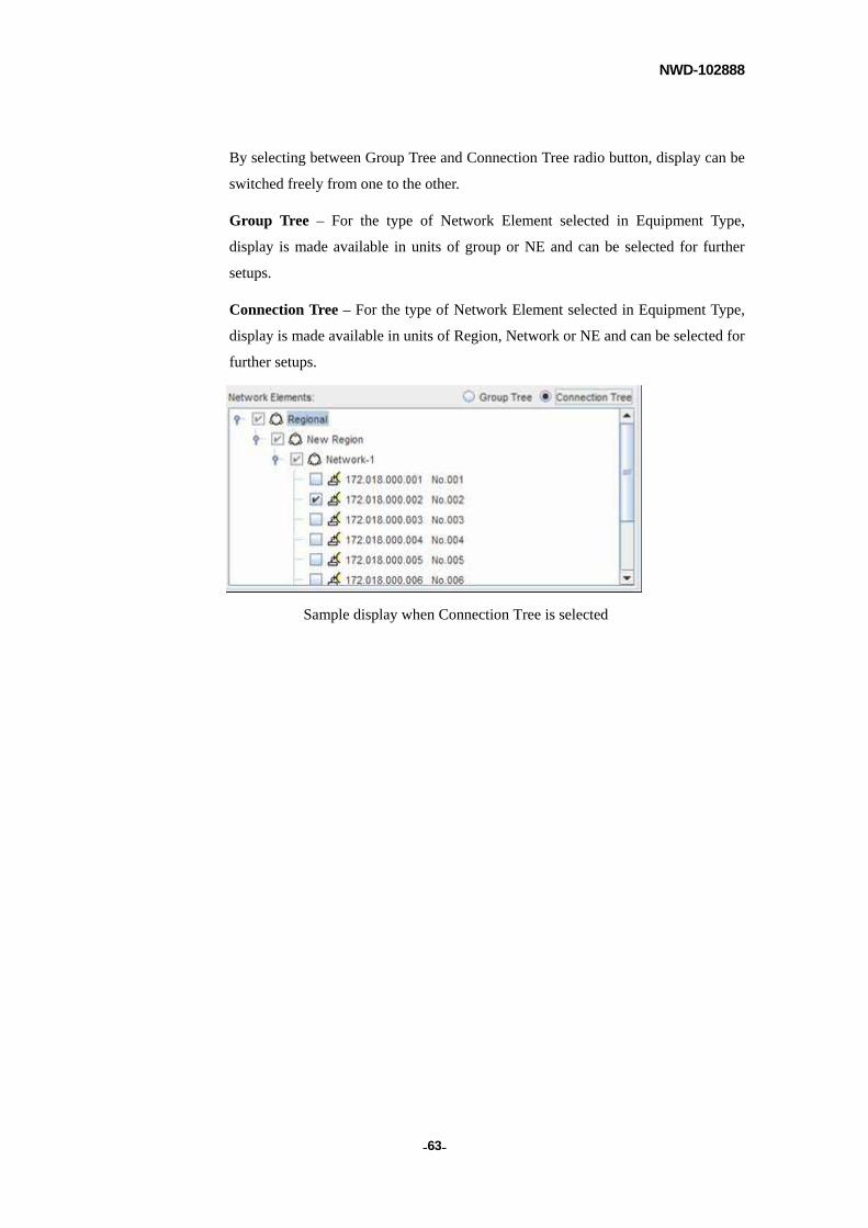
By selecting between Group Tree and Connection Tree radio button, display can be
switched freely from one to the other.
Group Tree – For the type of Network Element selected in Equipment Type,
display is made available in units of group or NE and can be selected for further
setups.
Connection Tree – For the type of Network Element selected in Equipment Type,
display is made available in units of Region, Network or NE and can be selected for
further setups.
Sample display when Connection Tree is selected
NWD-102888
- - 64
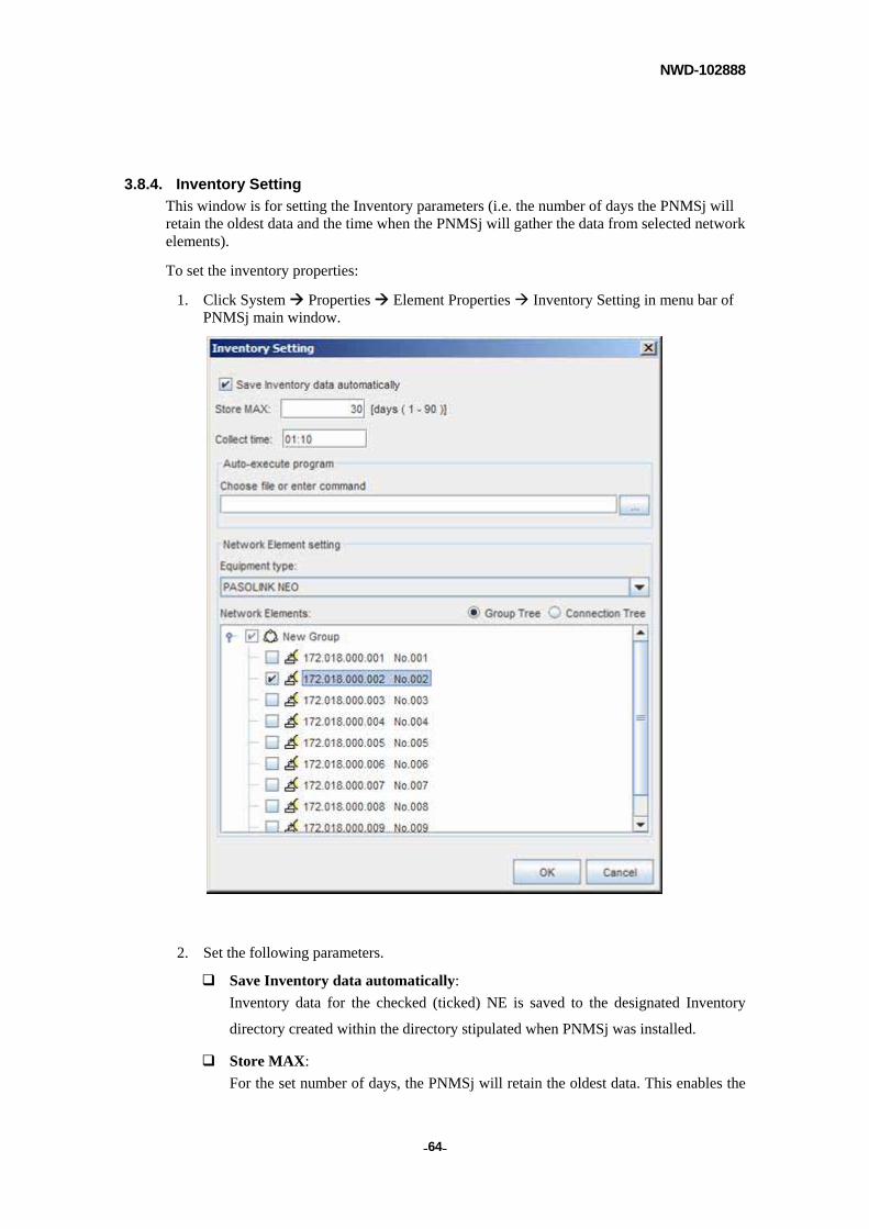
3.8.4. Inventory Setting
This window is for setting the Inventory parameters (i.e. the number of days the PNMSj will retain the oldest data and the time when the PNMSj will gather the data from selected network elements).
To set the inventory properties:
1. Click System Properties Element Properties Inventory Setting in menu bar of PNMSj main window.
2. Set the following parameters.
Save Inventory data automatically:
Inventory data for the checked (ticked) NE is saved to the designated Inventory
directory created within the directory stipulated when PNMSj was installed.
Store MAX:
For the set number of days, the PNMSj will retain the oldest data. This enables the
NWD-102888
- - 65
Inventory data for any specified number of days (up to 90 days maximum) to be
retained.
Collect time:
The time, in HH: mm, when the PNMSj is to save the link inventory data from
selected network elements (HH stands for hours in 24-hour format [00-23] and mm
for minutes).
Equipment Type:
Type of equipment will be listed.
Auto-execute program:
After the Inventory files have been completely retrieved, input the respective
command(s) you wish to execute. When the command line contains blank spaces,
enclose the command line with quotation marks (“).
Network Elements:
Inventory data will be collected for the network elements that are selected and
checked.
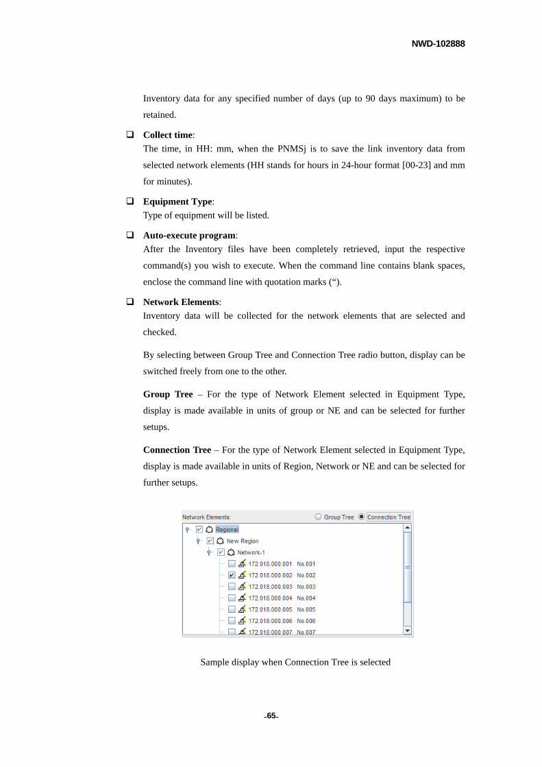
By selecting between Group Tree and Connection Tree radio button, display can be
switched freely from one to the other.
Group Tree – For the type of Network Element selected in Equipment Type,
display is made available in units of group or NE and can be selected for further
setups.
Connection Tree – For the type of Network Element selected in Equipment Type,
display is made available in units of Region, Network or NE and can be selected for
further setups.
Sample display when Connection Tree is selected

NWD-102888
- - 66
NOTE
The executed program result is saved to the respective log directory (<PNMSj Log Directory>/Inventory/YYYYMMDD.log). Moreover, the Auto-execute program result is also written to this file.
NWD-102888
- - 67
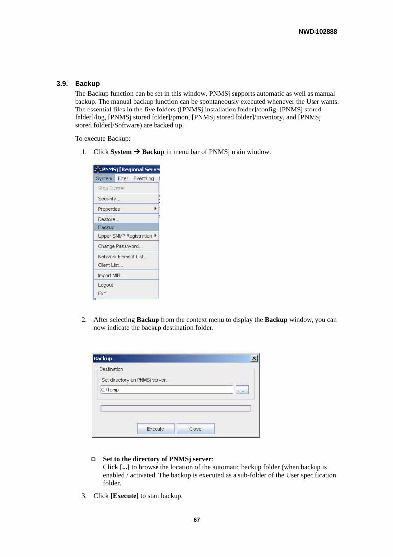
3.9. Backup
The Backup function can be set in this window. PNMSj supports automatic as well as manual backup. The manual backup function can be spontaneously executed whenever the User wants. The essential files in the five folders ([PNMSj installation folder]/config, [PNMSj stored folder]/log, [PNMSj stored folder]/pmon, [PNMSj stored folder]/inventory, and [PNMSj stored folder]/Software) are backed up.
To execute Backup:
1. Click System Backup in menu bar of PNMSj main window.
2. After selecting Backup from the context menu to display the Backup window, you can now indicate the backup destination folder.
Set to the directory of PNMSj server: Click [...] to browse the location of the automatic backup folder (when backup is enabled / activated. The backup is executed as a sub-folder of the User specification folder.
3. Click [Execute] to start backup.
NWD-102888
- - 68
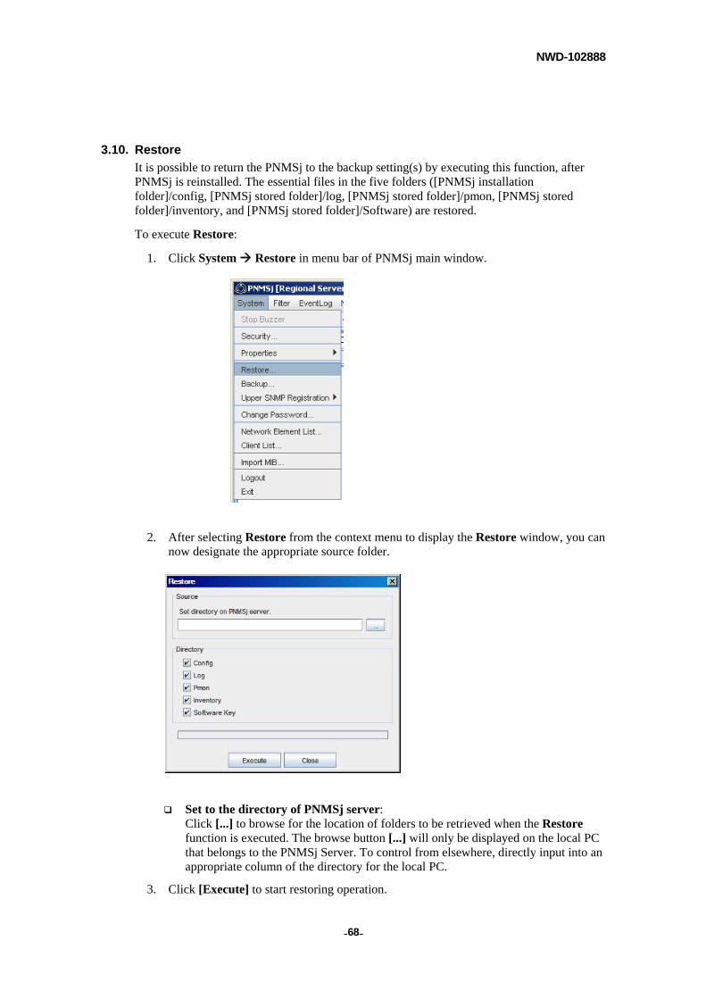
3.10. Restore
It is possible to return the PNMSj to the backup setting(s) by executing this function, after PNMSj is reinstalled. The essential files in the five folders ([PNMSj installation folder]/config, [PNMSj stored folder]/log, [PNMSj stored folder]/pmon, [PNMSj stored folder]/inventory, and [PNMSj stored folder]/Software) are restored.
To execute Restore:
1. Click System Restore in menu bar of PNMSj main window.
2. After selecting Restore from the context menu to display the Restore window, you can now designate the appropriate source folder.
Set to the directory of PNMSj server: Click [...] to browse for the location of folders to be retrieved when the Restore function is executed. The browse button [...] will only be displayed on the local PC that belongs to the PNMSj Server. To control from elsewhere, directly input into an appropriate column of the directory for the local PC.
3. Click [Execute] to start restoring operation.

NWD-102888
- - 69
NOTE
You will have to restart PNMSj after executing Restore to make PNMSj available for saving restored data.
NOTE
Please indicate a path one hierarchical level higher than these folders. (This would be /backup if you so indicated at the time of backup).
NOTE
To restore backup data from previous version prior to 1.20.001.xxx, take the check mark off from Software Key folder.
NWD-102888
- - 70
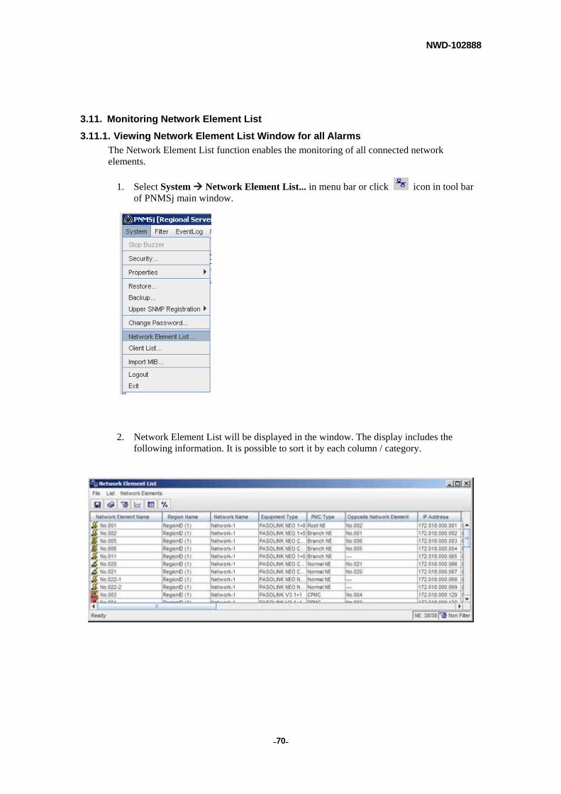
3.11. Monitoring Network Element List
3.11.1. Viewing Network Element List Window for all Alarms
The Network Element List function enables the monitoring of all connected network elements.
1. Select System Network Element List... in menu bar or click icon in tool bar of PNMSj main window.
2. Network Element List will be displayed in the window. The display includes the following information. It is possible to sort it by each column / category.
NWD-102888
- - 71
Network Element Name: NE name.
Region Name: The name of the region to which the respective NE belongs.
Network Name: The name of the network to which the respective NE belongs.
NWD-102888
- - 72
Equipment Type:
Type of equipment and redundancy.
For 5000S, the text "5000S" and the Station Type are displayed.
PMC Type:
The PMC type of the respective NE (i.e. CPMC, SCMPC, RPMC, Root NE, Bridge NE, or Normal NE) .
For PASOLINK V3, PASOLINK V4, MIU network elements
- CPMC: Central NE in Network.
- SCPMC: Central NE in Subnet.
- RPMC: NE that are neither CPMC nor SCPMC (i.e. Remote PMC).
For PASOLINK+ STM-1, PASOLINK+ PDH, PASOLINK Mx, PASOLINK NEO series, iPASOLINK series, 5000S network elements
- Root NE: Uppermost NE in Network.
- Branch NE: Uppermost NE in Subnet.
- Normal NE: Non-root NE / non-branch NE.
Opposite Network Element: Designated name of the Network Element’s opposite wireless station (counterpart).
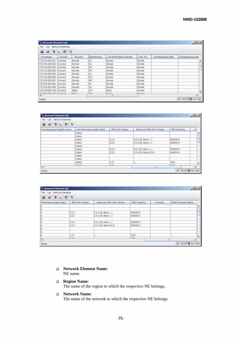
IP Address: The IP address set for the NE. When there are multiple IP addresses (e.g. for Root NE, Branch NE, CPMC, SCPMC) only the primary IP address is displayed.
Connect: The current connection status is displayed for each NE. These are as follows:
Displayed either as: Unmanage, Disconnect, Connect
Severity: The current status of each NE is displayed according to severity type. These are as follows:
Displayed either as: Critical, Major, Minor, Warning, Indeterminate, Normal or --- (when no data is obtained).
Maintenance: The current status of each NE is displayed according to Maintenance status. These are as follows:
Displayed either as: On, Off or --- (when no data is obtained).
Link Performance Monitor: Link Performance Monitor displays a summary of the Link Performance Monitor related alarms that occurred: Critical, Major, Minor, Warning, Indeterminate, Normal or --- (when no data is obtained)
AUX. I/O: AUX. I/O displays a summary of the AUX. I/O related alarms that occurred: Critical, Major, Minor, Warning, Indeterminate, Normal or --- (when no data is obtained)
NWD-102888
- - 73
Commissioning Data: The NE Commissioning Date and any relevant remarks are displayed (The Commissioning Data input via the NE Properties window appears here).
Commissioning Data(RX Level): The RX Level and any relevant remarks are displayed. (The Commissioning Data [RX Level] input via the NE Property window appears here).
Link Performance Data Collect: The Link Performance History collection setting (Collect or Don’t Collect) for the selected NE is displayed. As long as one type of data is set to be collected, Collect will be displayed.
PMC S/W (software) Version: For PASOLINK V3, PASOLINK V4, MIU network elements The software version of the PMC is displayed.
For PASOLINK+ STM-1, PASOLINK+ PDH network elements In 1+0 configurations, the software version of the IDU is displayed. In 1+1 configurations, the software version of the SW unit is displayed.
For PASOLINK Mx network elements The control (CTRL) software version is displayed
For PASOLINK NEO series, iPASOLINK series network elements The CTRL firmware (F/W) version for the current bank is displayed
For 5000S network elements The LMS firmware (F/W) version for the current bank is displayed.
Backward PMC S/W (software) Version: For PASOLINK V3, PASOLINK V4, MIU network elements The backward software version of the PMC is displayed.
For PASOLINK+ STM-1, PASOLINK+ PDH network elements In 1+0 configurations, the backward software version of the IDU is displayed. In 1+1 configurations, the backward software version of the SW unit is displayed.
For PASOLINK Mx network elements The backward control (CTRL) software version is displayed
For PASOLINK NEO series network elements The backward CTRL firmware (F/W) version for the current bank is displayed. Downloaded F/W version is displayed within parenthesis. This is not displayed when there is no downloaded version available.
For iPASOLINK series network elements The backward CTRL firmware (F/W) version for the current bank is displayed. Downloaded F/W version is displayed within parenthesis.
For 5000S network elements The backward LMS firmware (F/W) version for the current bank is displayed. Downloaded F/W version is displayed within parenthesis. This is not displayed when there is no downloaded version available.
PMC Serial No.:
For PASOLINK V3, PASOLINK V4, MIU network elements The serial number of the PMC is displayed.
NWD-102888
- - 74
For PASOLINK+ STM-1, PASOLINK+ PDH, PASOLINK Mx network elements In 1+0 configurations, the serial number of the IDU is displayed. In 1+1 configurations, the serial number of the SW unit is displayed.
For PASOLINK NEO series, iPASOLINK series network elements The CTRL serial number is displayed.
For 5000S network elements The LMS serial number is displayed.
Comment: Any comments input in the NE Properties window are displayed.
PNMTj Connect Status: The display indicates the type of NE to PNMTj connection: Local (dialup) / Opposite (dialup via opposite NE) / Remote (connection other than Local / Opposite)
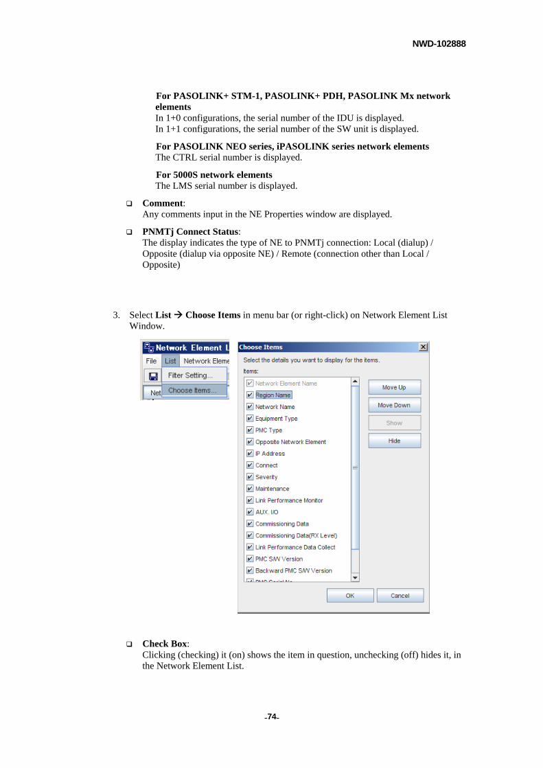
3. Select List Choose Items in menu bar (or right-click) on Network Element List Window.
Check Box: Clicking (checking) it (on) shows the item in question, unchecking (off) hides it, in the Network Element List.
NWD-102888
- - 75
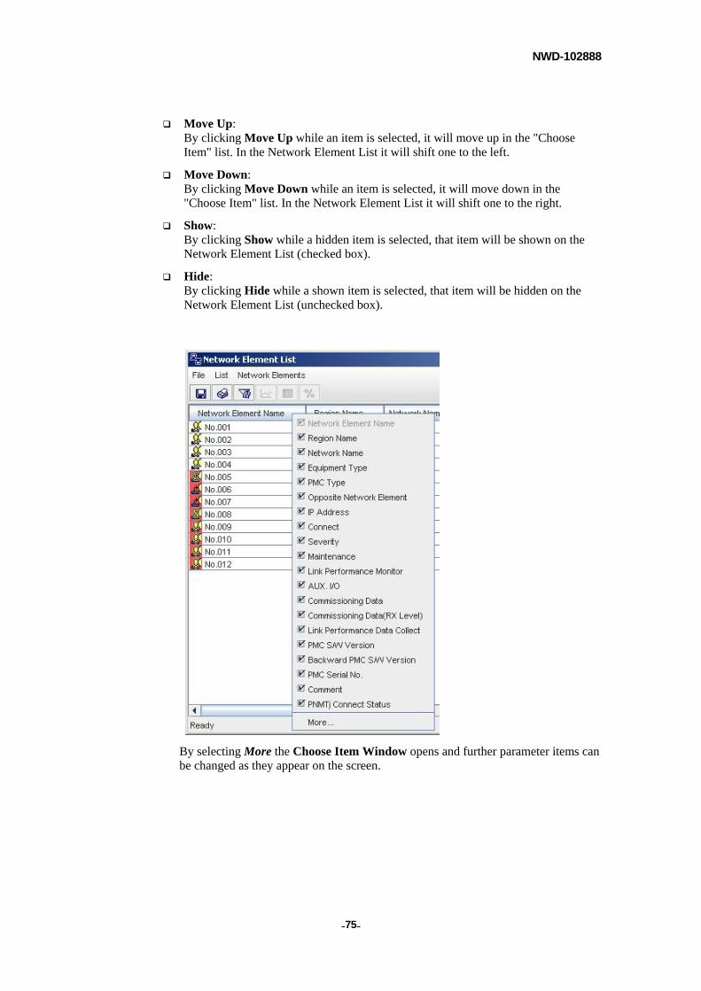
Move Up: By clicking Move Up while an item is selected, it will move up in the "Choose Item" list. In the Network Element List it will shift one to the left.
Move Down: By clicking Move Down while an item is selected, it will move down in the "Choose Item" list. In the Network Element List it will shift one to the right.
Show: By clicking Show while a hidden item is selected, that item will be shown on the Network Element List (checked box).
Hide: By clicking Hide while a shown item is selected, that item will be hidden on the Network Element List (unchecked box).
By selecting More the Choose Item Window opens and further parameter items can be changed as they appear on the screen.
NWD-102888
- - 76
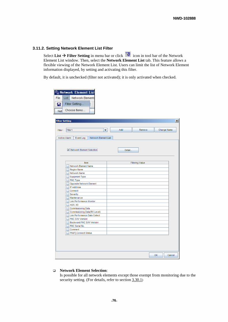
3.11.2. Setting Network Element List Filter
Select List Filter Setting in menu bar or click icon in tool bar of the Network Element List window. Then, select the Network Element List tab. This feature allows a flexible viewing of the Network Element List. Users can limit the list of Network Element information displayed, by setting and activating this filter.
By default, it is unchecked (filter not activated); it is only activated when checked.
Network Element Selection: Is possible for all network elements except those exempt from monitoring due to the security setting. (For details, refer to section 3.30.1)
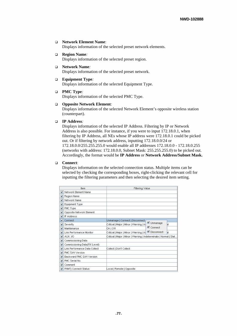
NWD-102888
- - 77
Network Element Name: Displays information of the selected preset network elements.
Region Name: Displays information of the selected preset region.
Network Name: Displays information of the selected preset network.
Equipment Type: Displays information of the selected Equipment Type.
PMC Type: Displays information of the selected PMC Type.
Opposite Network Element: Displays information of the selected Network Element’s opposite wireless station (counterpart).
IP Address: Displays information of the selected IP Address. Filtering by IP or Network Address is also possible. For instance, if you were to input 172.18.0.1, when filtering by IP Address, all NEs whose IP address were 172.18.0.1 could be picked out. Or if filtering by network address, inputting 172.18.0.0/24 or 172.18.0.0/255.255.255.0 would enable all IP addresses 172.18.0.0 - 172.18.0.255 (networks with address: 172.18.0.0, Subnet Mask: 255.255.255.0) to be picked out. Accordingly, the format would be IP Address or Network Address/Subnet Mask.
Connect: Displays information on the selected connection status. Multiple items can be selected by checking the corresponding boxes, right-clicking the relevant cell for inputting the filtering parameters and then selecting the desired item setting.
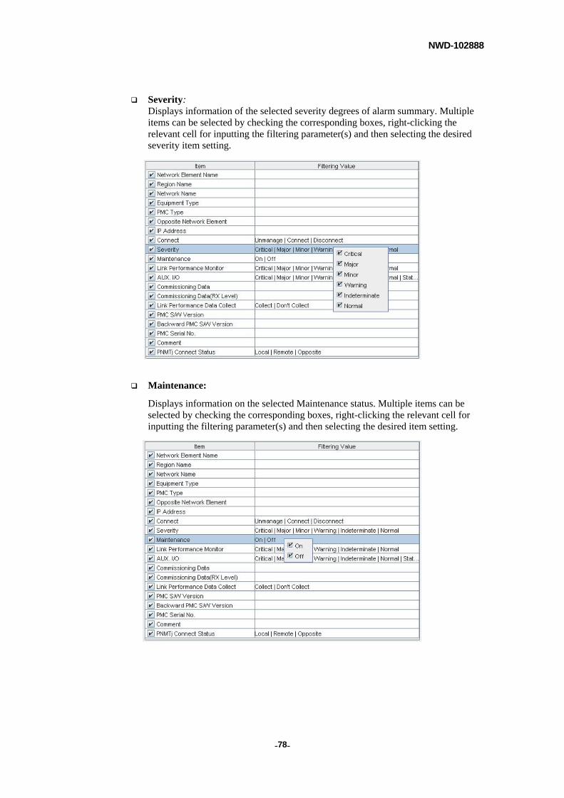
NWD-102888
- - 78
Severity: Displays information of the selected severity degrees of alarm summary. Multiple items can be selected by checking the corresponding boxes, right-clicking the relevant cell for inputting the filtering parameter(s) and then selecting the desired severity item setting.
Maintenance:
Displays information on the selected Maintenance status. Multiple items can be selected by checking the corresponding boxes, right-clicking the relevant cell for inputting the filtering parameter(s) and then selecting the desired item setting.
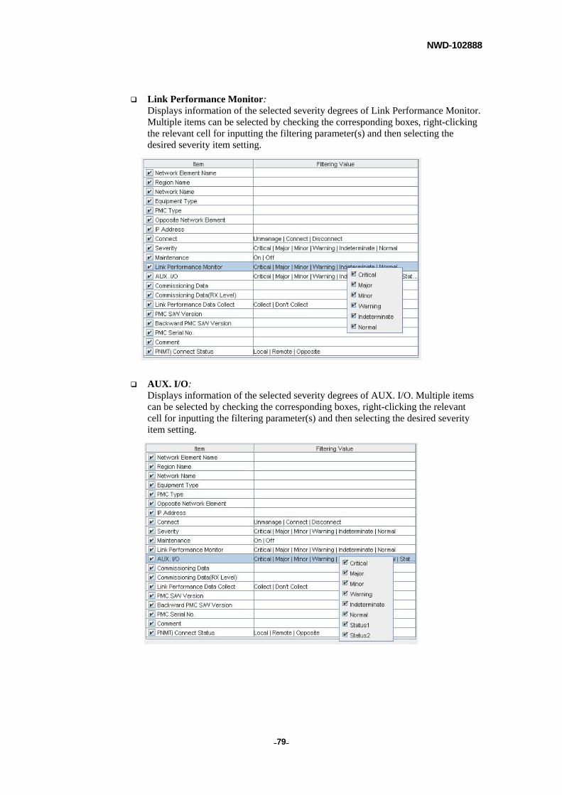
NWD-102888
- - 79
Link Performance Monitor: Displays information of the selected severity degrees of Link Performance Monitor. Multiple items can be selected by checking the corresponding boxes, right-clicking the relevant cell for inputting the filtering parameter(s) and then selecting the desired severity item setting.
AUX. I/O: Displays information of the selected severity degrees of AUX. I/O. Multiple items can be selected by checking the corresponding boxes, right-clicking the relevant cell for inputting the filtering parameter(s) and then selecting the desired severity item setting.
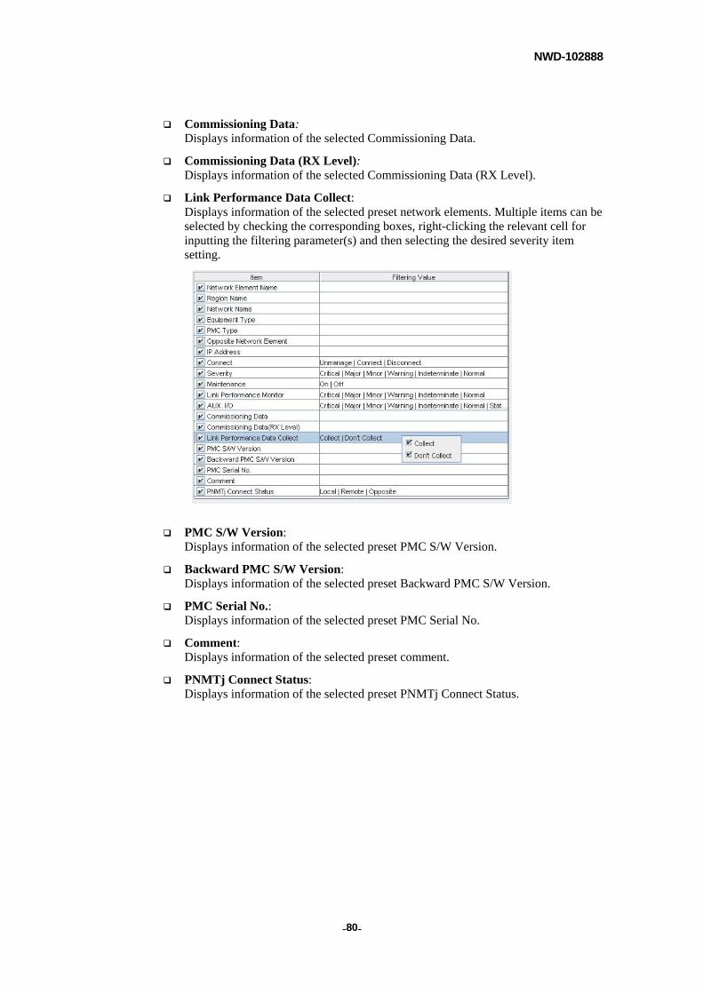
NWD-102888
- - 80
Commissioning Data: Displays information of the selected Commissioning Data.
Commissioning Data (RX Level): Displays information of the selected Commissioning Data (RX Level).
Link Performance Data Collect: Displays information of the selected preset network elements. Multiple items can be selected by checking the corresponding boxes, right-clicking the relevant cell for inputting the filtering parameter(s) and then selecting the desired severity item setting.
PMC S/W Version: Displays information of the selected preset PMC S/W Version.
Backward PMC S/W Version: Displays information of the selected preset Backward PMC S/W Version.
PMC Serial No.: Displays information of the selected preset PMC Serial No.
Comment: Displays information of the selected preset comment.
PNMTj Connect Status: Displays information of the selected preset PNMTj Connect Status.
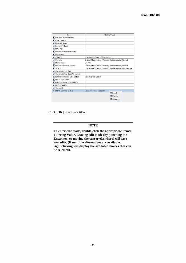
NWD-102888
- - 81
Click [OK] to activate filter.
NOTE
To enter edit mode, double-click the appropriate item’s Filtering Value. Leaving edit mode (by punching the Enter key, or moving the cursor elsewhere) will save any edits. (If multiple alternatives are available, right-clicking will display the available choices that can be selected).
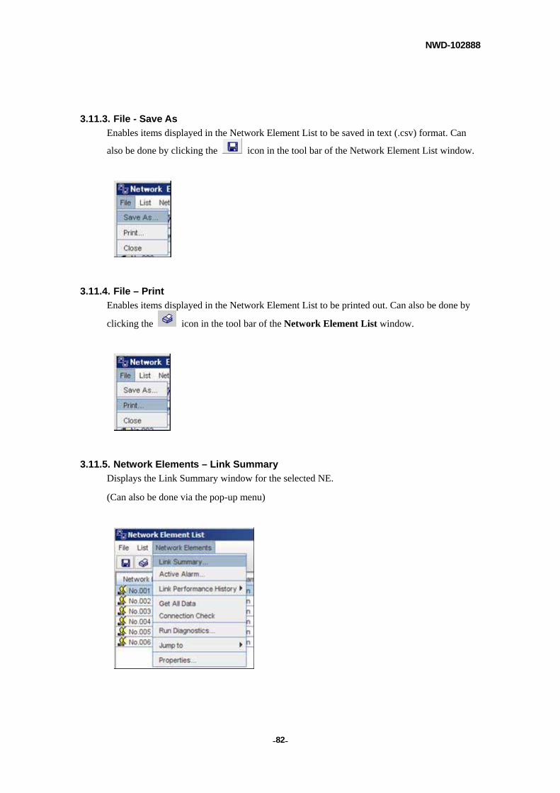
NWD-102888
- - 82
3.11.3. File - Save As
Enables items displayed in the Network Element List to be saved in text (.csv) format. Can
also be done by clicking the icon in the tool bar of the Network Element List window.
3.11.4. File – Print
Enables items displayed in the Network Element List to be printed out. Can also be done by
clicking the icon in the tool bar of the Network Element List window.
3.11.5. Network Elements – Link Summary
Displays the Link Summary window for the selected NE.
(Can also be done via the pop-up menu)
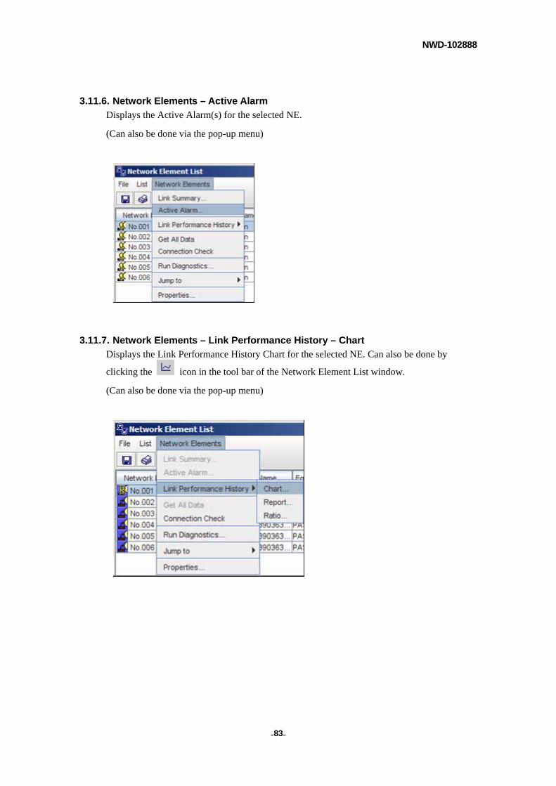
NWD-102888
- - 83
3.11.6. Network Elements – Active Alarm
Displays the Active Alarm(s) for the selected NE.
(Can also be done via the pop-up menu)
3.11.7. Network Elements – Link Performance History – Chart
Displays the Link Performance History Chart for the selected NE. Can also be done by
clicking the icon in the tool bar of the Network Element List window.
(Can also be done via the pop-up menu)
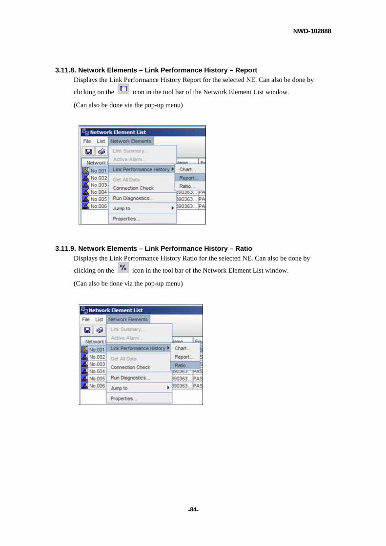
NWD-102888
- - 84
3.11.8. Network Elements – Link Performance History – Report
Displays the Link Performance History Report for the selected NE. Can also be done by
clicking on the icon in the tool bar of the Network Element List window.
(Can also be done via the pop-up menu)
3.11.9. Network Elements – Link Performance History – Ratio
Displays the Link Performance History Ratio for the selected NE. Can also be done by
clicking on the icon in the tool bar of the Network Element List window.
(Can also be done via the pop-up menu)
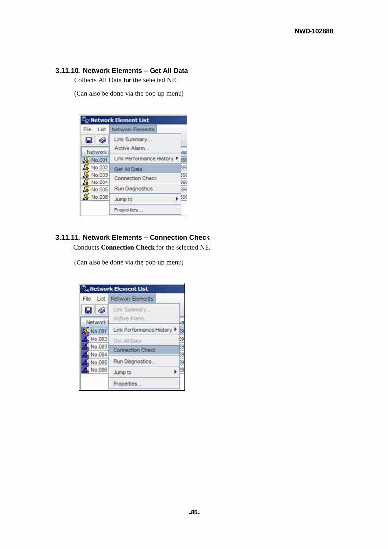
NWD-102888
- - 85
3.11.10. Network Elements – Get All Data
Collects All Data for the selected NE.
(Can also be done via the pop-up menu)
3.11.11. Network Elements – Connection Check
Conducts Connection Check for the selected NE.
(Can also be done via the pop-up menu)
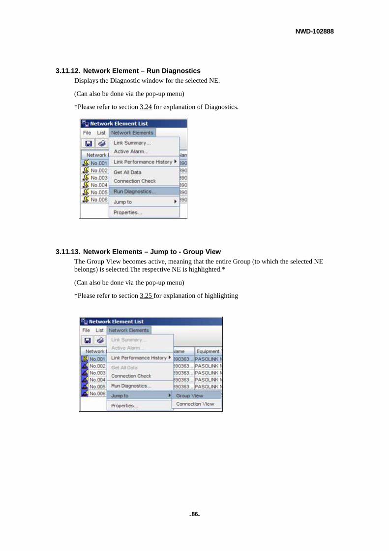
NWD-102888
- - 86
3.11.12. Network Element – Run Diagnostics
Displays the Diagnostic window for the selected NE.
(Can also be done via the pop-up menu)
*Please refer to section 3.24 for explanation of Diagnostics.
3.11.13. Network Elements – Jump to - Group View
The Group View becomes active, meaning that the entire Group (to which the selected NE belongs) is selected.The respective NE is highlighted.*
(Can also be done via the pop-up menu)
*Please refer to section 3.25 for explanation of highlighting
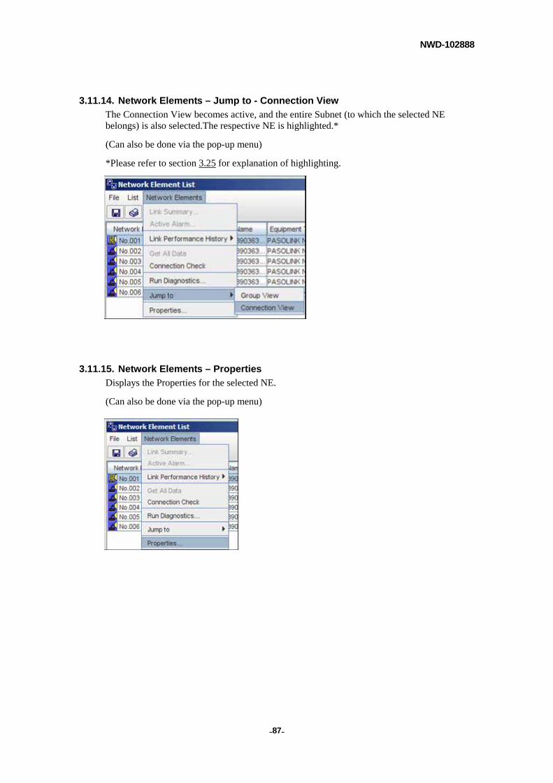
NWD-102888
- - 87
3.11.14. Network Elements – Jump to - Connection View
The Connection View becomes active, and the entire Subnet (to which the selected NE belongs) is also selected.The respective NE is highlighted.*
(Can also be done via the pop-up menu)
*Please refer to section 3.25 for explanation of highlighting.
3.11.15. Network Elements – Properties
Displays the Properties for the selected NE.
(Can also be done via the pop-up menu)
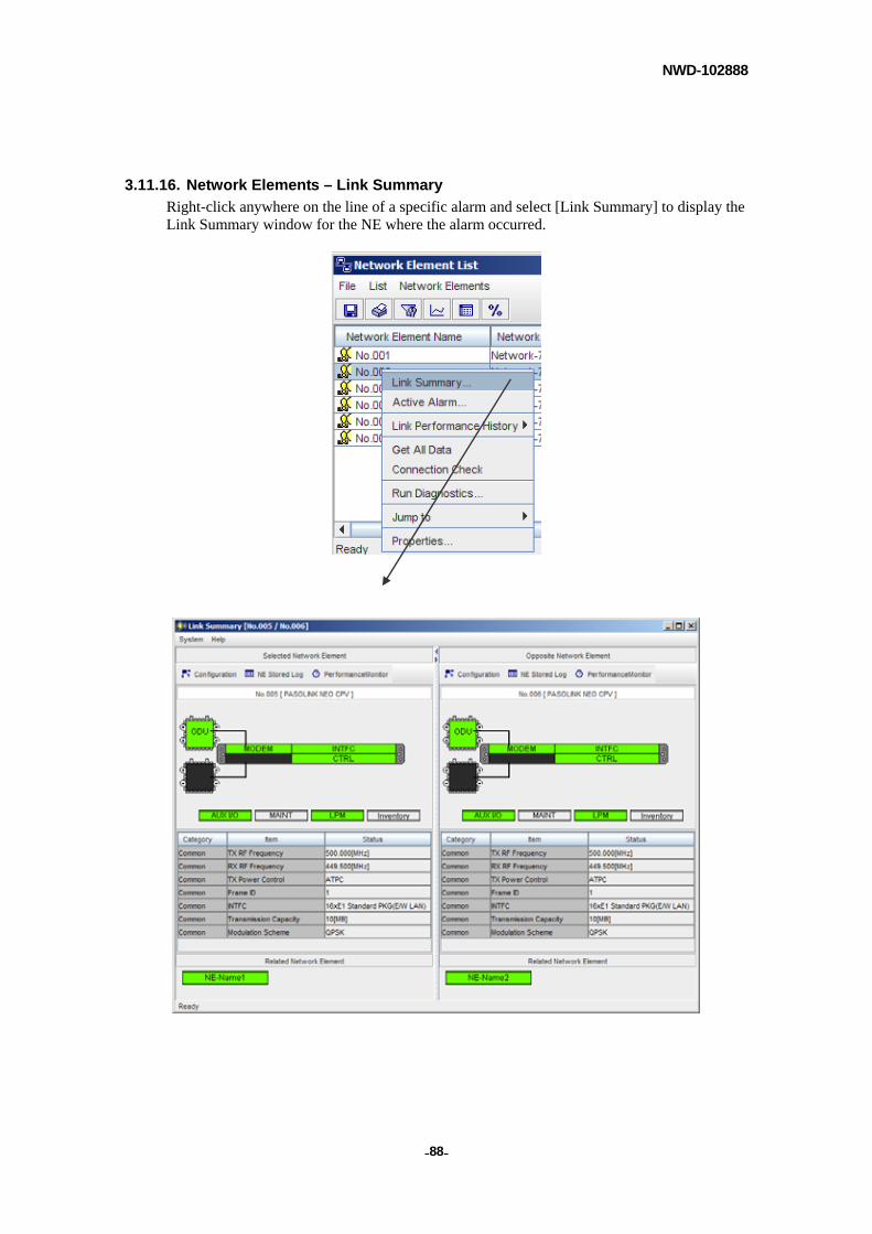
NWD-102888
- - 88
3.11.16. Network Elements – Link Summary
Right-click anywhere on the line of a specific alarm and select [Link Summary] to display the Link Summary window for the NE where the alarm occurred.
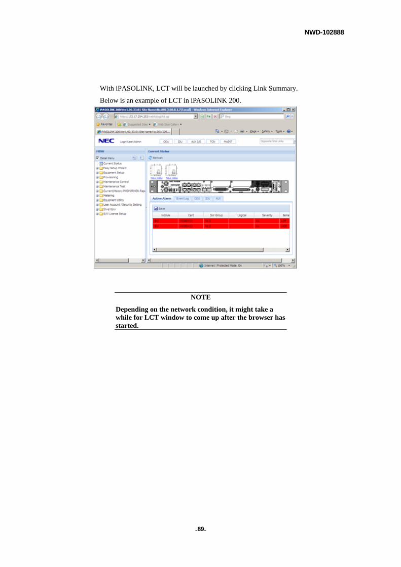
NWD-102888
- - 89
With iPASOLINK, LCT will be launched by clicking Link Summary.
Below is an example of LCT in iPASOLINK 200.
NOTE
Depending on the network condition, it might take a while for LCT window to come up after the browser has started.
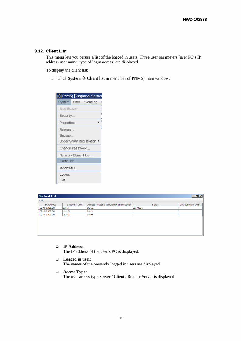
NWD-102888
- - 90
3.12. Client List
This menu lets you peruse a list of the logged in users. Three user parameters (user PC’s IP address user name, type of login access) are displayed.
To display the client list:
1. Click System Client list in menu bar of PNMSj main window.
IP Address: The IP address of the user’s PC is displayed.
Logged in user: The names of the presently logged in users are displayed.
Access Type: The user access type Server / Client / Remote Server is displayed.

NWD-102888
- - 91
Status:
Indicates which status (if any) of the following, the user is operating in.
- Edit Mode (refer to sections, 3.14 3.17)
- Update Network Configuration (refer to section3.34)
- Find NE (refer to section 3.36.1)
- Newly connected NE (refer to section 3.36.2)
- Time Zone Setting (refer to section 3.44)
Link Summary Count: Displays the user’s currently open Link Summary quantity. (The maximum permissible Link Summary quantity setting is described in Chapter 3.6.3)
NOTE
Client PNMSj or Remote Server access is only possible in conjunction with the appropriate license. Please contact NEC to obtain the license.
NOTE
When using Java Wave Start, any Client PNMSj is deemed to be connected to the Server PNMSj, even though the Clients are logged out. When some Clients are not used, they should be shut down.
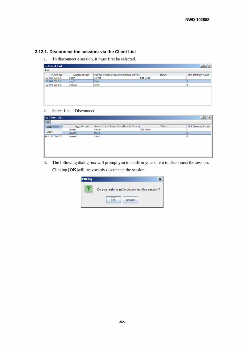
NWD-102888
- - 92
3.12.1. Disconnect the session: via the Client List
1. To disconnect a session, it must first be selected.
2. Select List – Disconnect
3. The following dialog box will prompt you to confirm your intent to disconnect the session.
Clicking [OK]will irrevocably disconnect the session
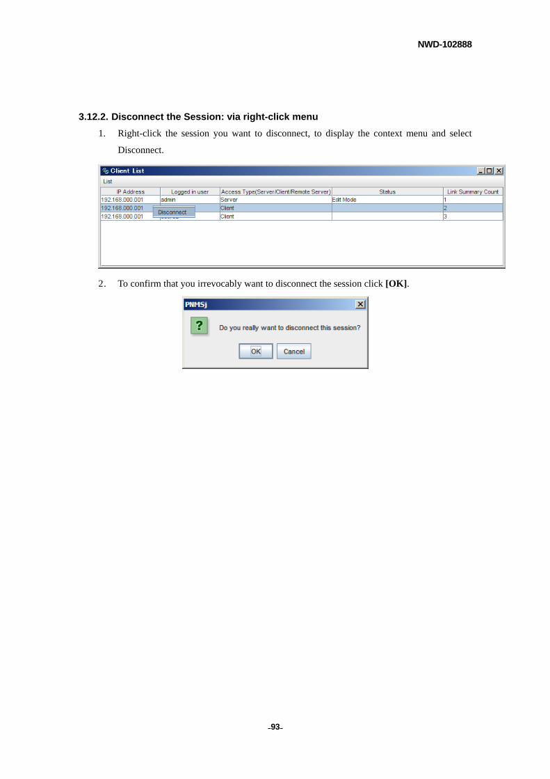
NWD-102888
- - 93
3.12.2. Disconnect the Session: via right-click menu
1. Right-click the session you want to disconnect, to display the context menu and select
Disconnect.
2. To confirm that you irrevocably want to disconnect the session click [OK].
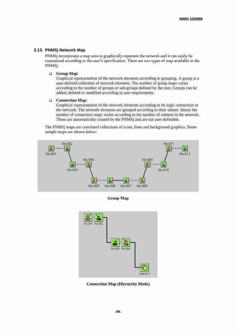
NWD-102888
- - 94
3.13. PNMSj Network Map
PNMSj incorporates a map area to graphically represent the network and it can easily be customized according to the user’s specification. There are two types of map available in the PNMSj:
Group Map: Graphical representation of the network elements according to grouping. A group is a user-defined collection of network elements. The number of group maps varies according to the number of groups or sub-groups defined by the user. Groups can be added, deleted or modified according to user requirements.
Connection Map: Graphical representation of the network elements according to its logic connection to the network. The network elements are grouped according to their subnet. Hence the number of connection maps varies according to the number of subnets in the network. These are automatically created by the PNMSj and are not user-definable.
The PNMSj maps are correlated collections of icons, lines and background graphics. Some sample maps are shown below:
Group Map
Connection Map (Hierarchy Mode)
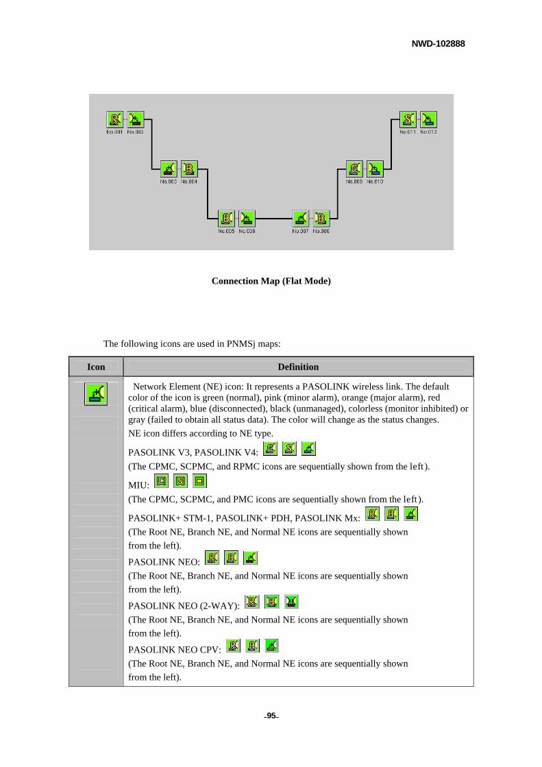
NWD-102888
- - 95
Connection Map (Flat Mode)
The following icons are used in PNMSj maps:
Icon Definition
Network Element (NE) icon: It represents a PASOLINK wireless link. The default color of the icon is green (normal), pink (minor alarm), orange (major alarm), red (critical alarm), blue (disconnected), black (unmanaged), colorless (monitor inhibited) or gray (failed to obtain all status data). The color will change as the status changes.
NE icon differs according to NE type.
PASOLINK V3, PASOLINK V4:
(The CPMC, SCPMC, and RPMC icons are sequentially shown from the left).
MIU:
(The CPMC, SCPMC, and PMC icons are sequentially shown from the left).
PASOLINK+ STM-1, PASOLINK+ PDH, PASOLINK Mx:
(The Root NE, Branch NE, and Normal NE icons are sequentially shown
from the left).
PASOLINK NEO:
(The Root NE, Branch NE, and Normal NE icons are sequentially shown
from the left).
PASOLINK NEO (2-WAY):
(The Root NE, Branch NE, and Normal NE icons are sequentially shown
from the left).
PASOLINK NEO CPV:
(The Root NE, Branch NE, and Normal NE icons are sequentially shown
from the left).
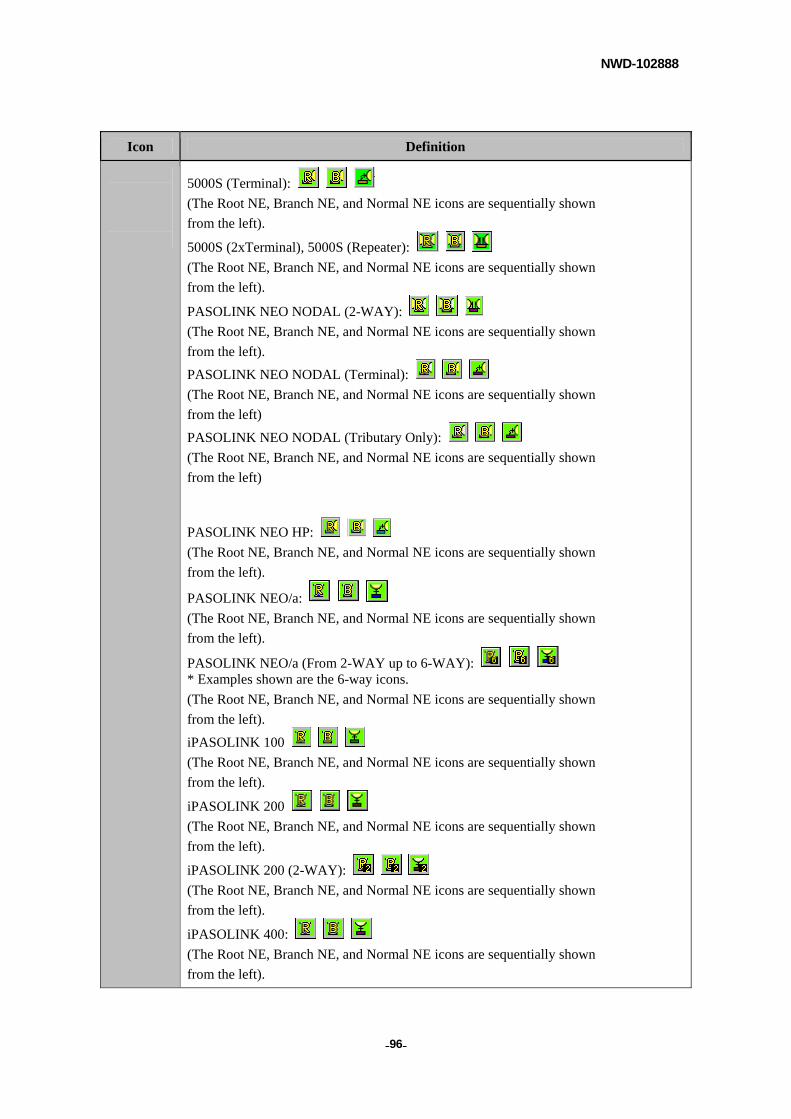
NWD-102888
- - 96
Icon Definition
5000S (Terminal):
(The Root NE, Branch NE, and Normal NE icons are sequentially shown
from the left).
5000S (2xTerminal), 5000S (Repeater):
(The Root NE, Branch NE, and Normal NE icons are sequentially shown
from the left).
PASOLINK NEO NODAL (2-WAY):
(The Root NE, Branch NE, and Normal NE icons are sequentially shown
from the left).
PASOLINK NEO NODAL (Terminal):
(The Root NE, Branch NE, and Normal NE icons are sequentially shown
from the left)
PASOLINK NEO NODAL (Tributary Only):
(The Root NE, Branch NE, and Normal NE icons are sequentially shown
from the left)
PASOLINK NEO HP:
(The Root NE, Branch NE, and Normal NE icons are sequentially shown
from the left).
PASOLINK NEO/a:
(The Root NE, Branch NE, and Normal NE icons are sequentially shown
from the left).
PASOLINK NEO/a (From 2-WAY up to 6-WAY): * Examples shown are the 6-way icons.
(The Root NE, Branch NE, and Normal NE icons are sequentially shown
from the left).
iPASOLINK 100
(The Root NE, Branch NE, and Normal NE icons are sequentially shown
from the left).
iPASOLINK 200
(The Root NE, Branch NE, and Normal NE icons are sequentially shown
from the left).
iPASOLINK 200 (2-WAY):
(The Root NE, Branch NE, and Normal NE icons are sequentially shown
from the left).
iPASOLINK 400:
(The Root NE, Branch NE, and Normal NE icons are sequentially shown
from the left).
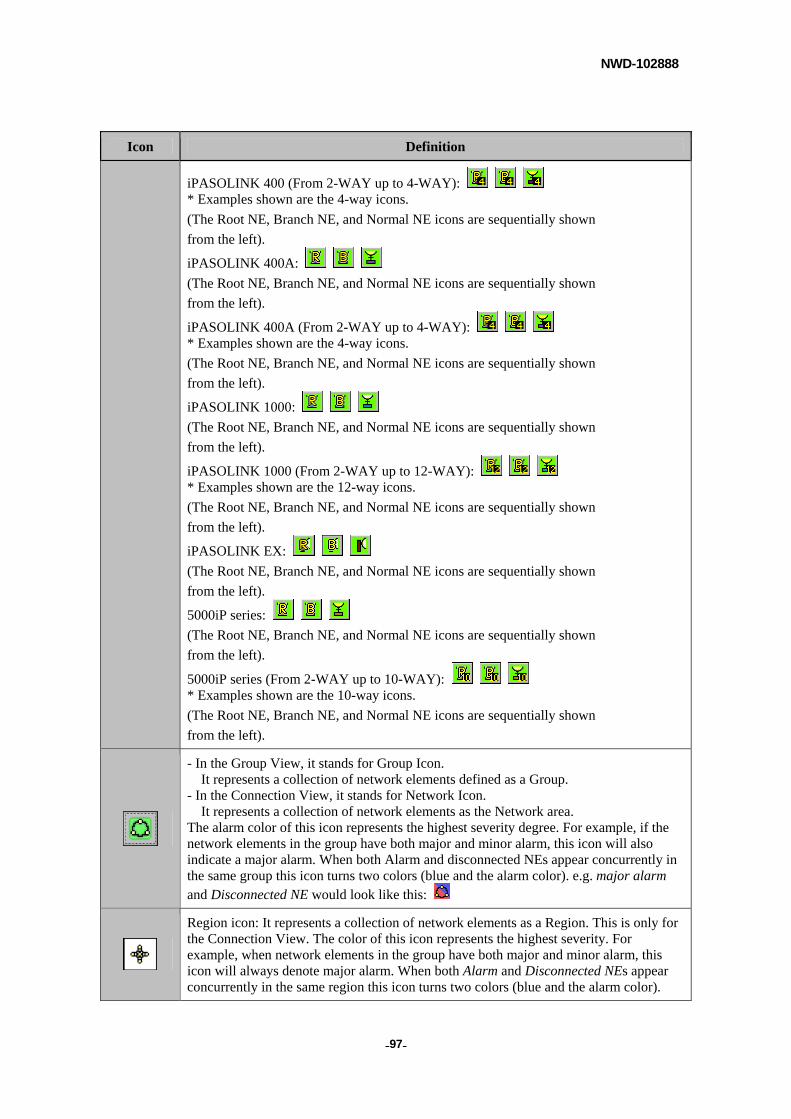
NWD-102888
- - 97
Icon Definition
iPASOLINK 400 (From 2-WAY up to 4-WAY): * Examples shown are the 4-way icons.
(The Root NE, Branch NE, and Normal NE icons are sequentially shown
from the left).
iPASOLINK 400A:
(The Root NE, Branch NE, and Normal NE icons are sequentially shown
from the left).
iPASOLINK 400A (From 2-WAY up to 4-WAY): * Examples shown are the 4-way icons.
(The Root NE, Branch NE, and Normal NE icons are sequentially shown
from the left).
iPASOLINK 1000:
(The Root NE, Branch NE, and Normal NE icons are sequentially shown
from the left).
iPASOLINK 1000 (From 2-WAY up to 12-WAY): * Examples shown are the 12-way icons.
(The Root NE, Branch NE, and Normal NE icons are sequentially shown
from the left).
iPASOLINK EX:
(The Root NE, Branch NE, and Normal NE icons are sequentially shown
from the left).
5000iP series:
(The Root NE, Branch NE, and Normal NE icons are sequentially shown
from the left).
5000iP series (From 2-WAY up to 10-WAY): * Examples shown are the 10-way icons.
(The Root NE, Branch NE, and Normal NE icons are sequentially shown
from the left).
- In the Group View, it stands for Group Icon. It represents a collection of network elements defined as a Group.
- In the Connection View, it stands for Network Icon. It represents a collection of network elements as the Network area.
The alarm color of this icon represents the highest severity degree. For example, if the network elements in the group have both major and minor alarm, this icon will also indicate a major alarm. When both Alarm and disconnected NEs appear concurrently in the same group this icon turns two colors (blue and the alarm color). e.g. major alarm and Disconnected NE would look like this:
Region icon: It represents a collection of network elements as a Region. This is only for the Connection View. The color of this icon represents the highest severity. For example, when network elements in the group have both major and minor alarm, this icon will always denote major alarm. When both Alarm and Disconnected NEs appear concurrently in the same region this icon turns two colors (blue and the alarm color).
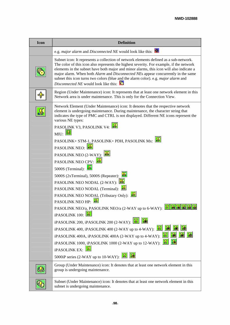
NWD-102888
- - 98
Icon Definition
e.g. major alarm and Disconnected NE would look like this:
Subnet icon: It represents a collection of network elements defined as a sub-network. The color of this icon also represents the highest severity. For example, if the network elements in the subnet have both major and minor alarms, this icon will also indicate a major alarm. When both Alarm and Disconnected NEs appear concurrently in the same subnet this icon turns two colors (blue and the alarm color). e.g. major alarm and Disconnected NE would look like this:
Region (Under Maintenance) icon: It represents that at least one network element in this Network area is under maintenance. This is only for the Connection View.
Network Element (Under Maintenance) icon: It denotes that the respective network element is undergoing maintenance. During maintenance, the character string that indicates the type of PMC and CTRL is not displayed. Different NE icons represent the various NE types:
PASOLINK V3, PASOLINK V4:
MIU:
PASOLINK+ STM-1, PASOLINK+ PDH, PASOLINK Mx:
PASOLINK NEO:
PASOLINK NEO (2-WAY):
PASOLINK NEO CPV:
5000S (Terminal):
5000S (2xTerminal), 5000S (Repeater):
PASOLINK NEO NODAL (2-WAY):
PASOLINK NEO NODAL (Terminal):
PASOLINK NEO NODAL (Tributary Only):
PASOLINK NEO HP:
PASOLINK NEO/a, PASOLINK NEO/a (2-WAY up to 6-WAY):
iPASOLINK 100:
iPASOLINK 200, iPASOLINK 200 (2-WAY):
iPASOLINK 400, iPASOLINK 400 (2-WAY up to 4-WAY):
iPASOLINK 400A, iPASOLINK 400A (2-WAY up to 4-WAY):
iPASOLINK 1000, iPASOLINK 1000 (2-WAY up to 12-WAY):
iPASOLINK EX:
5000iP series (2-WAY up to 10-WAY):
Group (Under Maintenance) icon: It denotes that at least one network element in this group is undergoing maintenance.
Subnet (Under Maintenance) icon: It denotes that at least one network element in this subnet is undergoing maintenance.
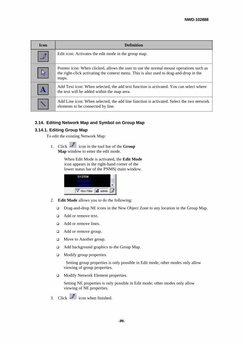
NWD-102888
- - 99
Icon Definition
Edit icon: Activates the edit mode in the group map.
Pointer icon: When clicked, allows the user to use the normal mouse operations such as the right-click activating the context menu. This is also used to drag-and-drop in the maps.
Add Text icon: When selected, the add text function is activated. You can select where the text will be added within the map area.
Add Line icon: When selected, the add line function is activated. Select the two network elements to be connected by line.
3.14. Editing Network Map and Symbol on Group Map
3.14.1. Editing Group Map
To edit the existing Network Map:
1. Click icon in the tool bar of the Group Map window to enter the edit mode.
When Edit Mode is activated, the Edit Mode icon appears in the right-hand corner of the lower status bar of the PNMSj main window.
2. Edit Mode allows you to do the following:
Drag-and-drop NE icons in the New Object Zone to any location in the Group Map.
Add or remove text.
Add or remove lines.
Add or remove group.
Move to Another group.
Add background graphics to the Group Map.
Modify group properties.
Setting group properties is only possible in Edit mode; other modes only allow viewing of group properties.
Modify Network Element properties.
Setting NE properties is only possible in Edit mode; other modes only allow viewing of NE properties.
3. Click icon when finished.
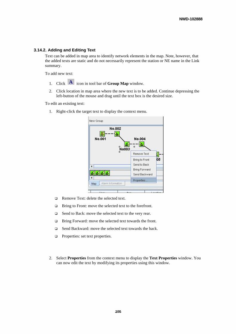
NWD-102888
- - 100
3.14.2. Adding and Editing Text
Text can be added in map area to identify network elements in the map. Note, however, that the added texts are static and do not necessarily represent the station or NE name in the Link summary.
To add new text:
1. Click icon in tool bar of Group Map window.
2. Click location in map area where the new text is to be added. Continue depressing the left-button of the mouse and drag until the text box is the desired size.
To edit an existing text:
1. Right-click the target text to display the context menu.
Remove Text: delete the selected text.
Bring to Front: move the selected text to the forefront.
Send to Back: move the selected text to the very rear.
Bring Forward: move the selected text towards the front.
Send Backward: move the selected text towards the back.
Properties: set text properties.
2. Select Properties from the context menu to display the Text Properties window. You can now edit the text by modifying its properties using this window.
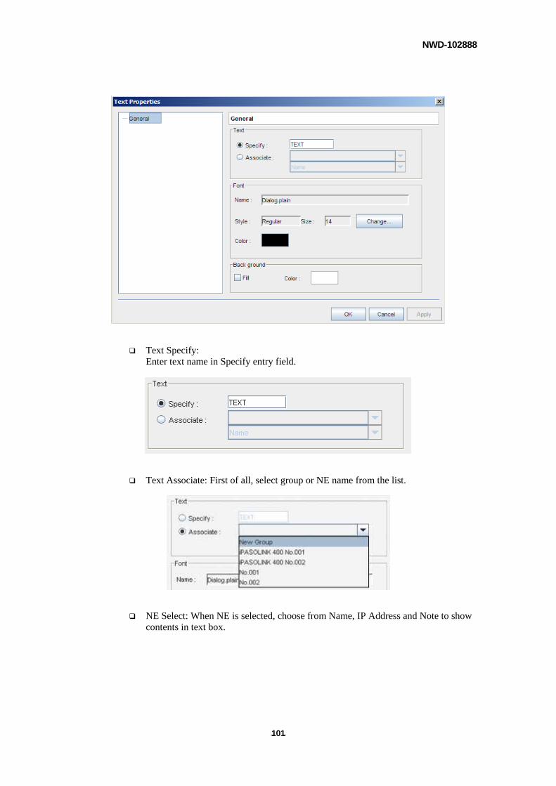
NWD-102888
- - 101
Text Specify: Enter text name in Specify entry field.
Text Associate: First of all, select group or NE name from the list.
NE Select: When NE is selected, choose from Name, IP Address and Note to show contents in text box.
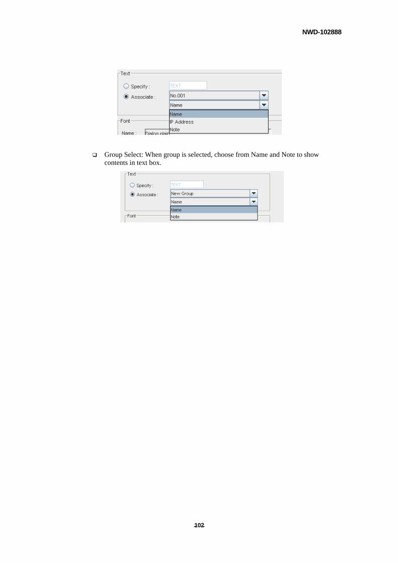
NWD-102888
- - 102
Group Select: When group is selected, choose from Name and Note to show contents in text box.
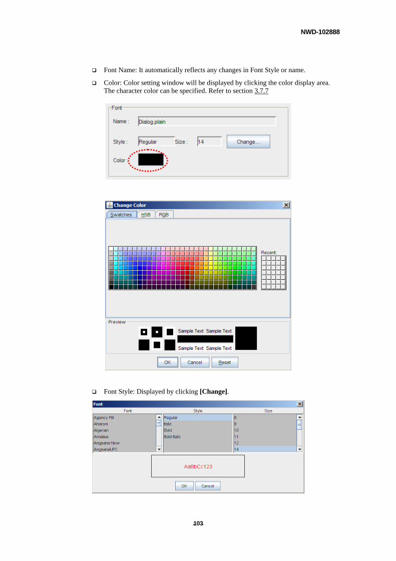
NWD-102888
- - 103
Font Name: It automatically reflects any changes in Font Style or name.
Color: Color setting window will be displayed by clicking the color display area. The character color can be specified. Refer to section 3.7.7
Font Style: Displayed by clicking [Change].
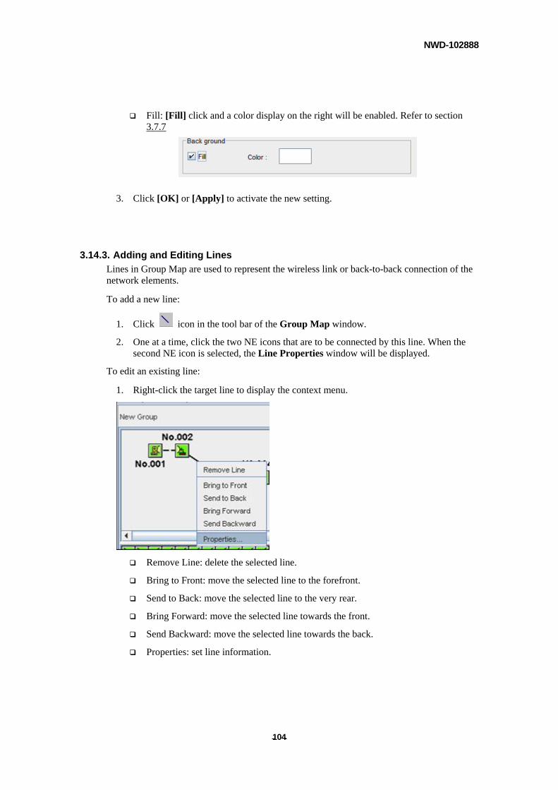
NWD-102888
- - 104
Fill: [Fill] click and a color display on the right will be enabled. Refer to section 3.7.7
3. Click [OK] or [Apply] to activate the new setting.
3.14.3. Adding and Editing Lines
Lines in Group Map are used to represent the wireless link or back-to-back connection of the network elements.
To add a new line:
1. Click icon in the tool bar of the Group Map window.
2. One at a time, click the two NE icons that are to be connected by this line. When the second NE icon is selected, the Line Properties window will be displayed.
To edit an existing line:
1. Right-click the target line to display the context menu.
Remove Line: delete the selected line.
Bring to Front: move the selected line to the forefront.
Send to Back: move the selected line to the very rear.
Bring Forward: move the selected line towards the front.
Send Backward: move the selected line towards the back.
Properties: set line information.
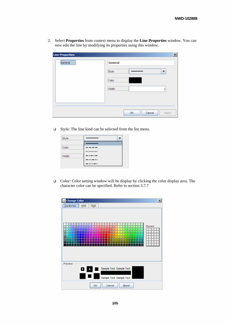
NWD-102888
- - 105
2. Select Properties from context menu to display the Line Properties window. You can now edit the line by modifying its properties using this window.
Style: The line kind can be selected from the list menu.
Color: Color setting window will be display by clicking the color display area. The character color can be specified. Refer to section 3.7.7
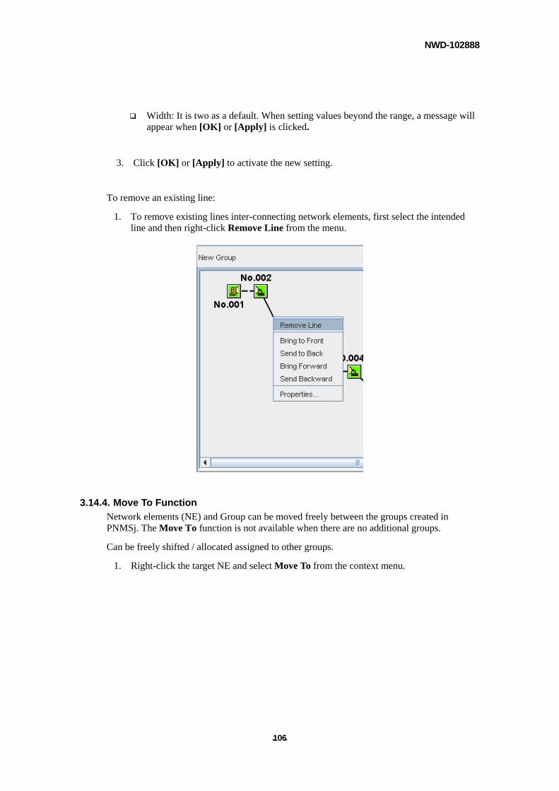
NWD-102888
- - 106
Width: It is two as a default. When setting values beyond the range, a message will appear when [OK] or [Apply] is clicked.
3. Click [OK] or [Apply] to activate the new setting.
To remove an existing line:
1. To remove existing lines inter-connecting network elements, first select the intended line and then right-click Remove Line from the menu.
3.14.4. Move To Function
Network elements (NE) and Group can be moved freely between the groups created in PNMSj. The Move To function is not available when there are no additional groups.
Can be freely shifted / allocated assigned to other groups.
1. Right-click the target NE and select Move To from the context menu.
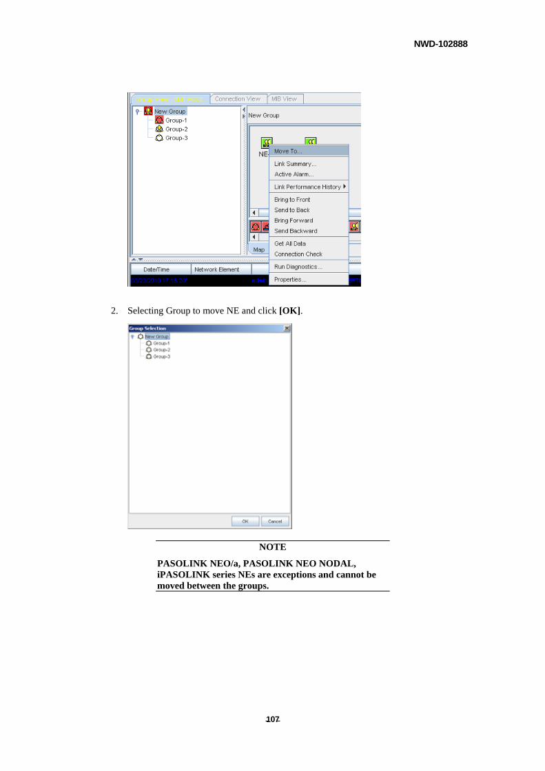
NWD-102888
- - 107
2. Selecting Group to move NE and click [OK].
NOTE
PASOLINK NEO/a, PASOLINK NEO NODAL, iPASOLINK series NEs are exceptions and cannot be moved between the groups.
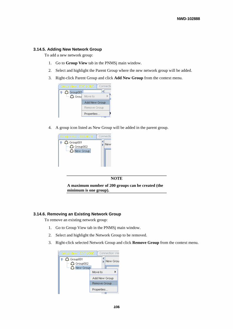
NWD-102888
- - 108
3.14.5. Adding New Network Group
To add a new network group:
1. Go to Group View tab in the PNMSj main window.
2. Select and highlight the Parent Group where the new network group will be added.
3. Right-click Parent Group and click Add New Group from the context menu.
4. A group icon listed as New Group will be added in the parent group.
NOTE
A maximum number of 200 groups can be created (the minimum is one group).
3.14.6. Removing an Existing Network Group
To remove an existing network group:
1. Go to Group View tab in the PNMSj main window.
2. Select and highlight the Network Group to be removed.
3. Right-click selected Network Group and click Remove Group from the context menu.
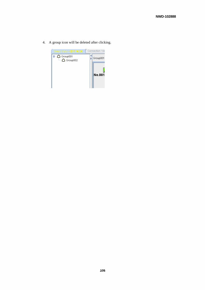
NWD-102888
- - 109
4. A group icon will be deleted after clicking.
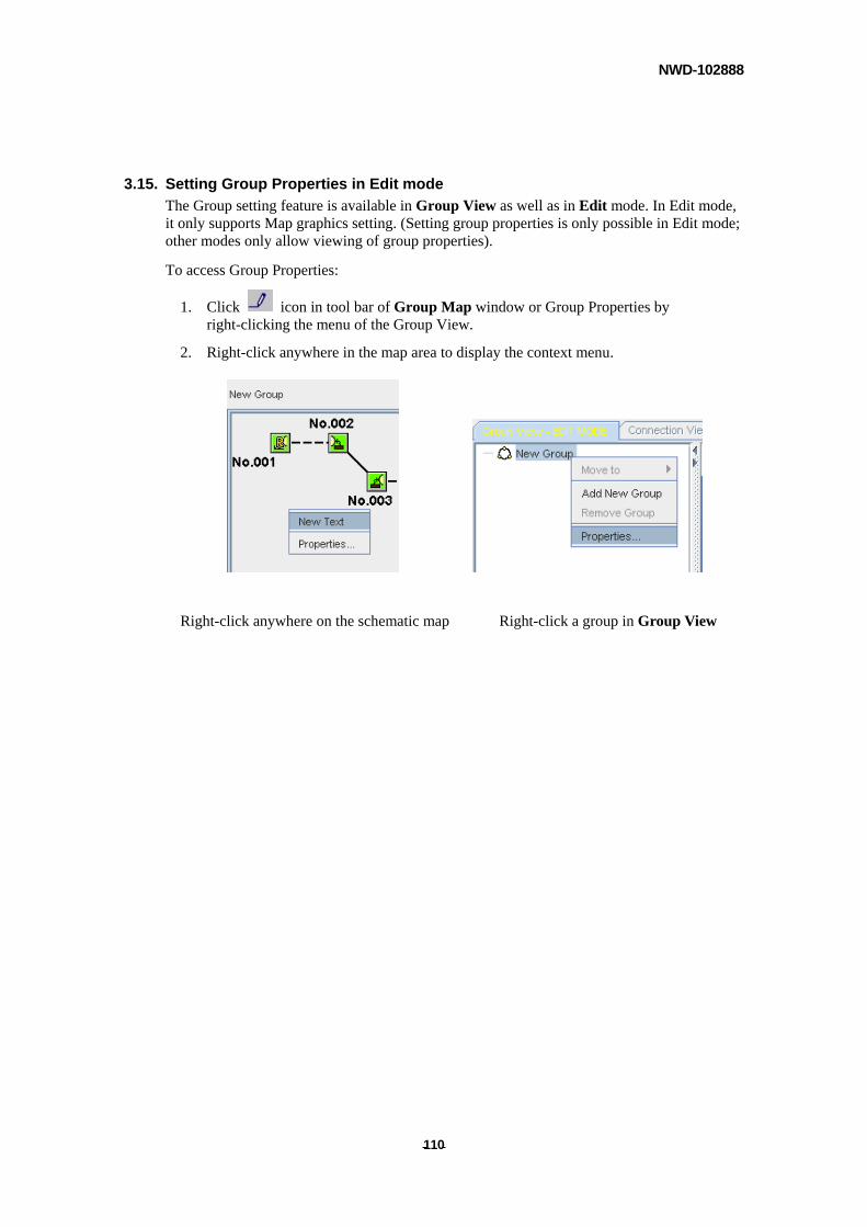
NWD-102888
- - 110
3.15. Setting Group Properties in Edit mode
The Group setting feature is available in Group View as well as in Edit mode. In Edit mode, it only supports Map graphics setting. (Setting group properties is only possible in Edit mode; other modes only allow viewing of group properties).
To access Group Properties:
1. Click icon in tool bar of Group Map window or Group Properties by right-clicking the menu of the Group View.
2. Right-click anywhere in the map area to display the context menu.
Right-click anywhere on the schematic map Right-click a group in Group View
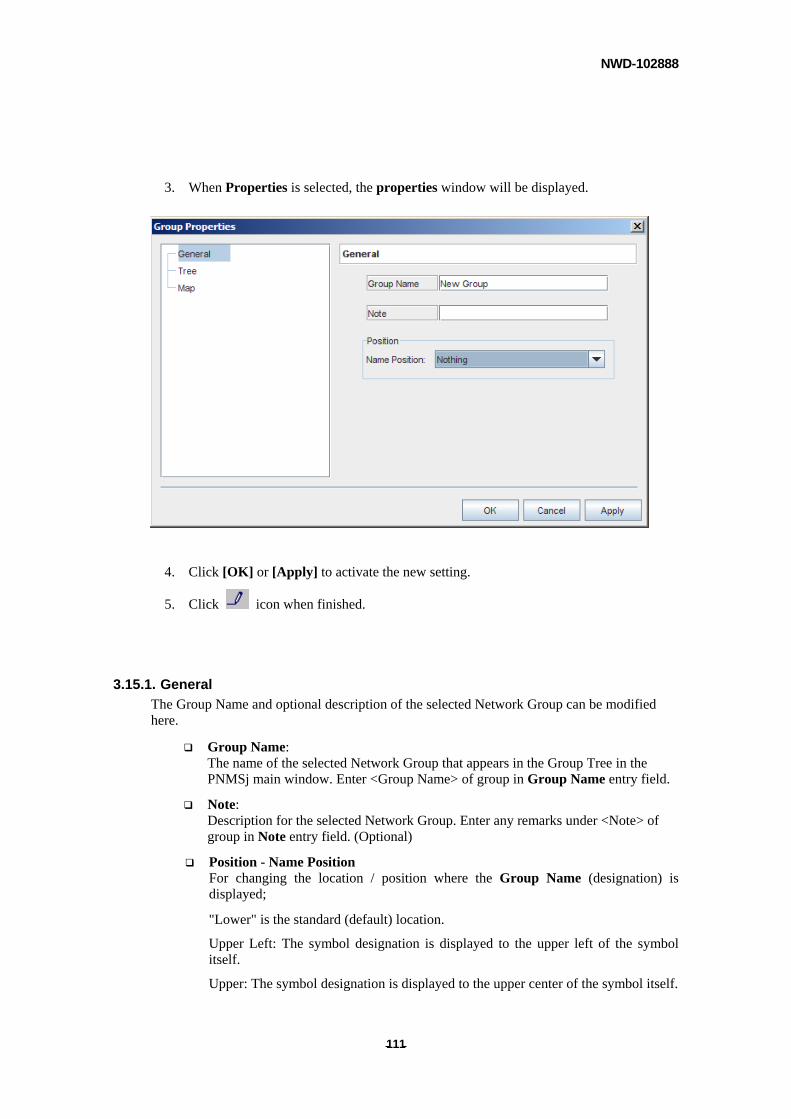
NWD-102888
- - 111
3. When Properties is selected, the properties window will be displayed.
4. Click [OK] or [Apply] to activate the new setting.
5. Click icon when finished.
3.15.1. General
The Group Name and optional description of the selected Network Group can be modified here.
Group Name: The name of the selected Network Group that appears in the Group Tree in the PNMSj main window. Enter <Group Name> of group in Group Name entry field.
Note: Description for the selected Network Group. Enter any remarks under <Note> of group in Note entry field. (Optional)
Position - Name Position For changing the location / position where the Group Name (designation) is displayed;
"Lower" is the standard (default) location.
Upper Left: The symbol designation is displayed to the upper left of the symbol itself.
Upper: The symbol designation is displayed to the upper center of the symbol itself.
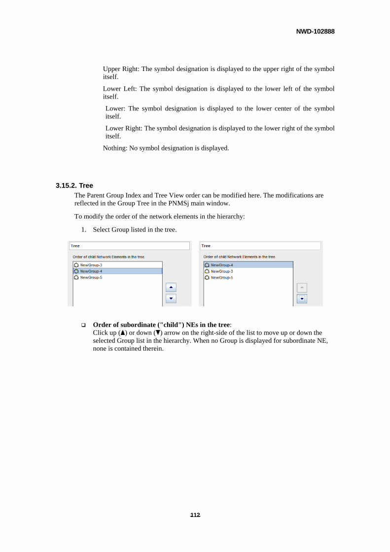
NWD-102888
- - 112
Upper Right: The symbol designation is displayed to the upper right of the symbol itself.
Lower Left: The symbol designation is displayed to the lower left of the symbol itself.
Lower: The symbol designation is displayed to the lower center of the symbol itself.
Lower Right: The symbol designation is displayed to the lower right of the symbol itself.
Nothing: No symbol designation is displayed.
3.15.2. Tree
The Parent Group Index and Tree View order can be modified here. The modifications are reflected in the Group Tree in the PNMSj main window.
To modify the order of the network elements in the hierarchy:
1. Select Group listed in the tree.
Order of subordinate ("child") NEs in the tree:
Click up ( ) or down ( ) arrow on the right-side of the list to move up or down the selected Group list in the hierarchy. When no Group is displayed for subordinate NE, none is contained therein.
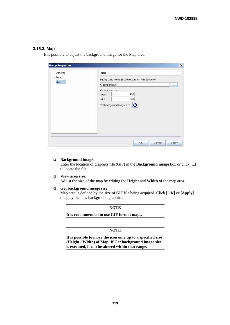
NWD-102888
- - 113
3.15.3. Map
It is possible to adjust the background image for the Map area.
Background image: Enter the location of graphics file (GIF) in the Background image box or click [...] to locate the file.
View area size: Adjust the size of the map by editing the Height and Width of the map area.
Get background image size: Map area is defined by the size of GIF file being acquired. Click [OK] or [Apply] to apply the new background graphics.
NOTE
It is recommended to use GIF format maps.
NOTE
It is possible to move the icon only up to a specified size (Height / Width) of Map. If Get background image size is executed, it can be altered within that range.
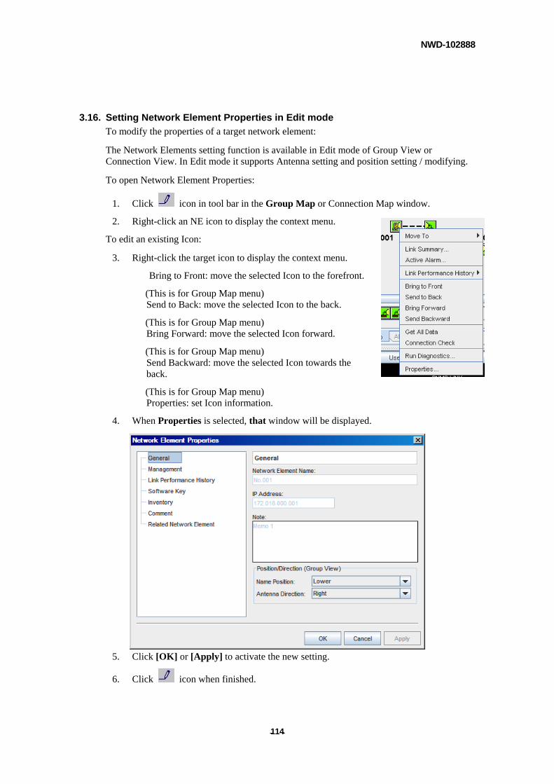
NWD-102888
- - 114
3.16. Setting Network Element Properties in Edit mode
To modify the properties of a target network element:
The Network Elements setting function is available in Edit mode of Group View or Connection View. In Edit mode it supports Antenna setting and position setting / modifying.
To open Network Element Properties:
1. Click icon in tool bar in the Group Map or Connection Map window.
2. Right-click an NE icon to display the context menu.
To edit an existing Icon:
3. Right-click the target icon to display the context menu.
Bring to Front: move the selected Icon to the forefront.
(This is for Group Map menu) Send to Back: move the selected Icon to the back.
(This is for Group Map menu) Bring Forward: move the selected Icon forward.
(This is for Group Map menu) Send Backward: move the selected Icon towards the back.
(This is for Group Map menu) Properties: set Icon information.
4. When Properties is selected, that window will be displayed.
5. Click [OK] or [Apply] to activate the new setting.
6. Click icon when finished.
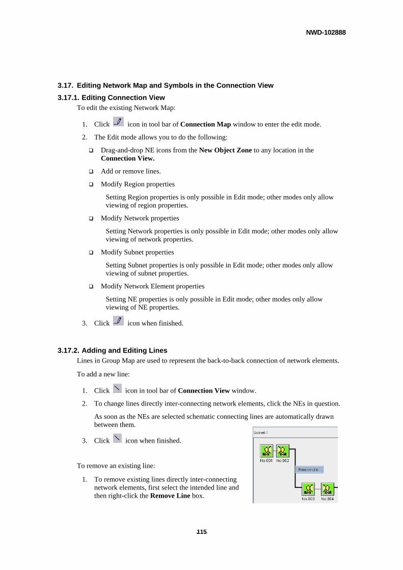
NWD-102888
- - 115
3.17. Editing Network Map and Symbols in the Connection View
3.17.1. Editing Connection View
To edit the existing Network Map:
1. Click icon in tool bar of Connection Map window to enter the edit mode.
2. The Edit mode allows you to do the following:
Drag-and-drop NE icons from the New Object Zone to any location in the Connection View.
Add or remove lines.
Modify Region properties
Setting Region properties is only possible in Edit mode; other modes only allow viewing of region properties.
Modify Network properties
Setting Network properties is only possible in Edit mode; other modes only allow viewing of network properties.
Modify Subnet properties
Setting Subnet properties is only possible in Edit mode; other modes only allow viewing of subnet properties.
Modify Network Element properties
Setting NE properties is only possible in Edit mode; other modes only allow viewing of NE properties.
3. Click icon when finished.
3.17.2. Adding and Editing Lines
Lines in Group Map are used to represent the back-to-back connection of network elements.
To add a new line:
1. Click icon in tool bar of Connection View window.
2. To change lines directly inter-connecting network elements, click the NEs in question.
As soon as the NEs are selected schematic connecting lines are automatically drawn between them.
3. Click icon when finished.
To remove an existing line:
1. To remove existing lines directly inter-connecting network elements, first select the intended line and then right-click the Remove Line box.

NWD-102888
- - 116
Note: If the Auto-discovery feature reveals the actual network to differ from the map, the lines should be edited to accurately reflect the actual NE configuration. Attempting to use the Auto-discovery feature for other purposes is liable to cause detection errors.
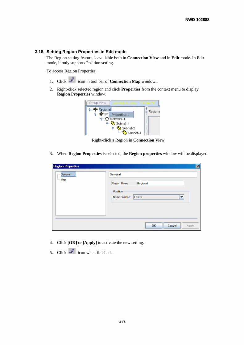
NWD-102888
- - 117
3.18. Setting Region Properties in Edit mode
The Region setting feature is available both in Connection View and in Edit mode. In Edit mode, it only supports Position setting.
To access Region Properties:
1. Click icon in tool bar of Connection Map window.
2. Right-click selected region and click Properties from the context menu to display Region Properties window.
Right-click a Region in Connection View
3. When Region Properties is selected, the Region properties window will be displayed.
4. Click [OK] or [Apply] to activate the new setting.
5. Click icon when finished.
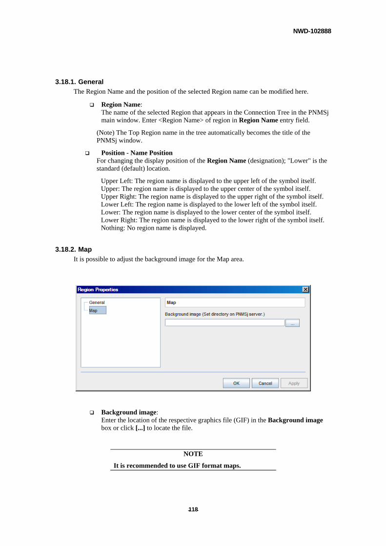
NWD-102888
- - 118
3.18.1. General
The Region Name and the position of the selected Region name can be modified here.
Region Name: The name of the selected Region that appears in the Connection Tree in the PNMSj main window. Enter <Region Name> of region in Region Name entry field.
(Note) The Top Region name in the tree automatically becomes the title of the PNMSj window.
Position - Name Position For changing the display position of the Region Name (designation); "Lower" is the standard (default) location.
Upper Left: The region name is displayed to the upper left of the symbol itself. Upper: The region name is displayed to the upper center of the symbol itself. Upper Right: The region name is displayed to the upper right of the symbol itself. Lower Left: The region name is displayed to the lower left of the symbol itself. Lower: The region name is displayed to the lower center of the symbol itself. Lower Right: The region name is displayed to the lower right of the symbol itself. Nothing: No region name is displayed.
3.18.2. Map
It is possible to adjust the background image for the Map area.
Background image: Enter the location of the respective graphics file (GIF) in the Background image box or click [...] to locate the file.
NOTE
It is recommended to use GIF format maps.
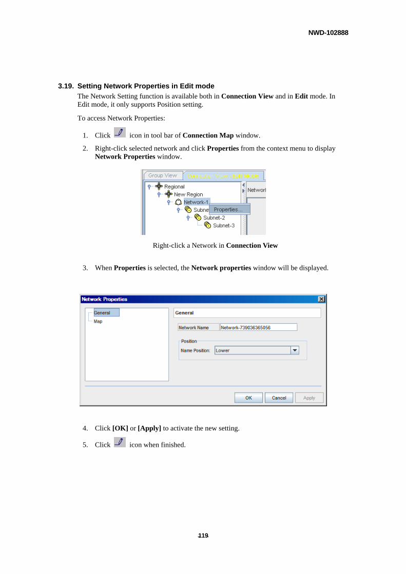
NWD-102888
- - 119
3.19. Setting Network Properties in Edit mode
The Network Setting function is available both in Connection View and in Edit mode. In Edit mode, it only supports Position setting.
To access Network Properties:
1. Click icon in tool bar of Connection Map window.
2. Right-click selected network and click Properties from the context menu to display Network Properties window.
Right-click a Network in Connection View
3. When Properties is selected, the Network properties window will be displayed.
4. Click [OK] or [Apply] to activate the new setting.
5. Click icon when finished.
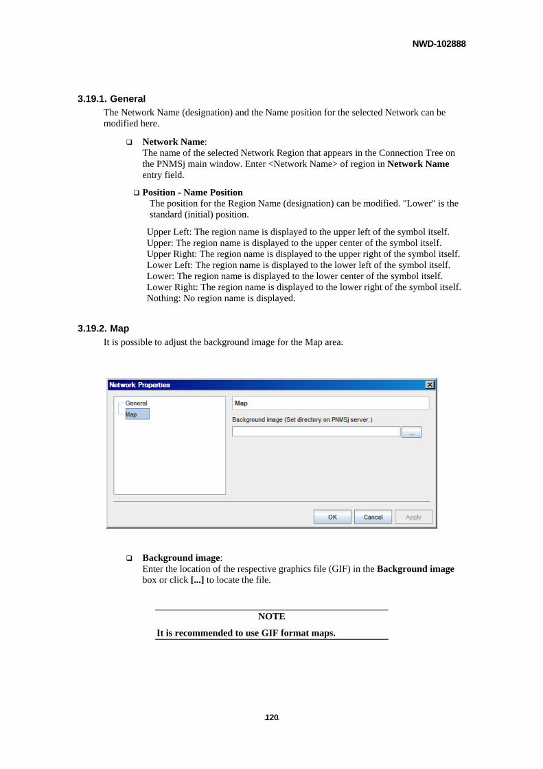
NWD-102888
- - 120
3.19.1. General
The Network Name (designation) and the Name position for the selected Network can be modified here.
Network Name: The name of the selected Network Region that appears in the Connection Tree on the PNMSj main window. Enter <Network Name> of region in Network Name entry field.
Position - Name Position The position for the Region Name (designation) can be modified. "Lower" is the standard (initial) position.
Upper Left: The region name is displayed to the upper left of the symbol itself. Upper: The region name is displayed to the upper center of the symbol itself. Upper Right: The region name is displayed to the upper right of the symbol itself. Lower Left: The region name is displayed to the lower left of the symbol itself. Lower: The region name is displayed to the lower center of the symbol itself. Lower Right: The region name is displayed to the lower right of the symbol itself. Nothing: No region name is displayed.
3.19.2. Map
It is possible to adjust the background image for the Map area.
Background image: Enter the location of the respective graphics file (GIF) in the Background image box or click [...] to locate the file.
NOTE
It is recommended to use GIF format maps.
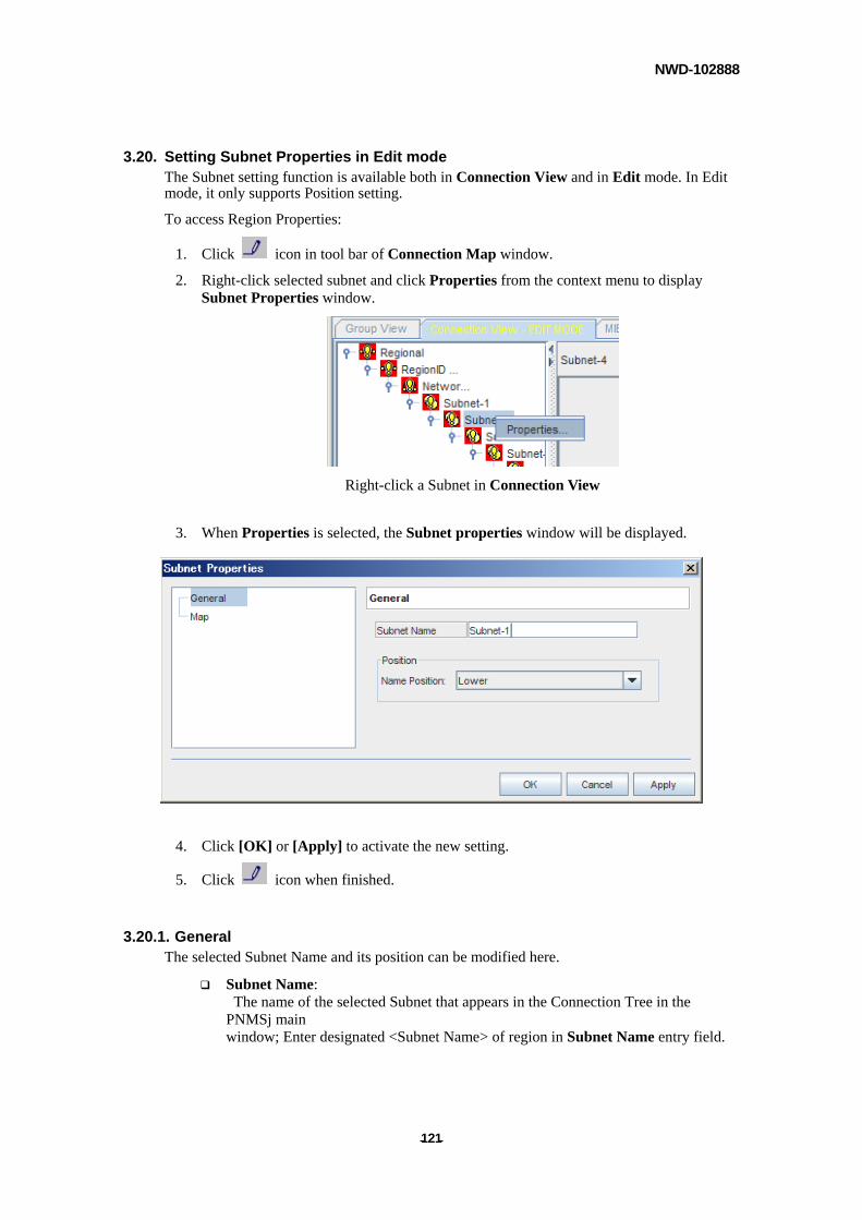
NWD-102888
- - 121
3.20. Setting Subnet Properties in Edit mode The Subnet setting function is available both in Connection View and in Edit mode. In Edit mode, it only supports Position setting.
To access Region Properties:
1. Click icon in tool bar of Connection Map window.
2. Right-click selected subnet and click Properties from the context menu to display Subnet Properties window.
Right-click a Subnet in Connection View
3. When Properties is selected, the Subnet properties window will be displayed.
4. Click [OK] or [Apply] to activate the new setting.
5. Click icon when finished.
3.20.1. General The selected Subnet Name and its position can be modified here.
Subnet Name: The name of the selected Subnet that appears in the Connection Tree in the PNMSj main window; Enter designated <Subnet Name> of region in Subnet Name entry field.
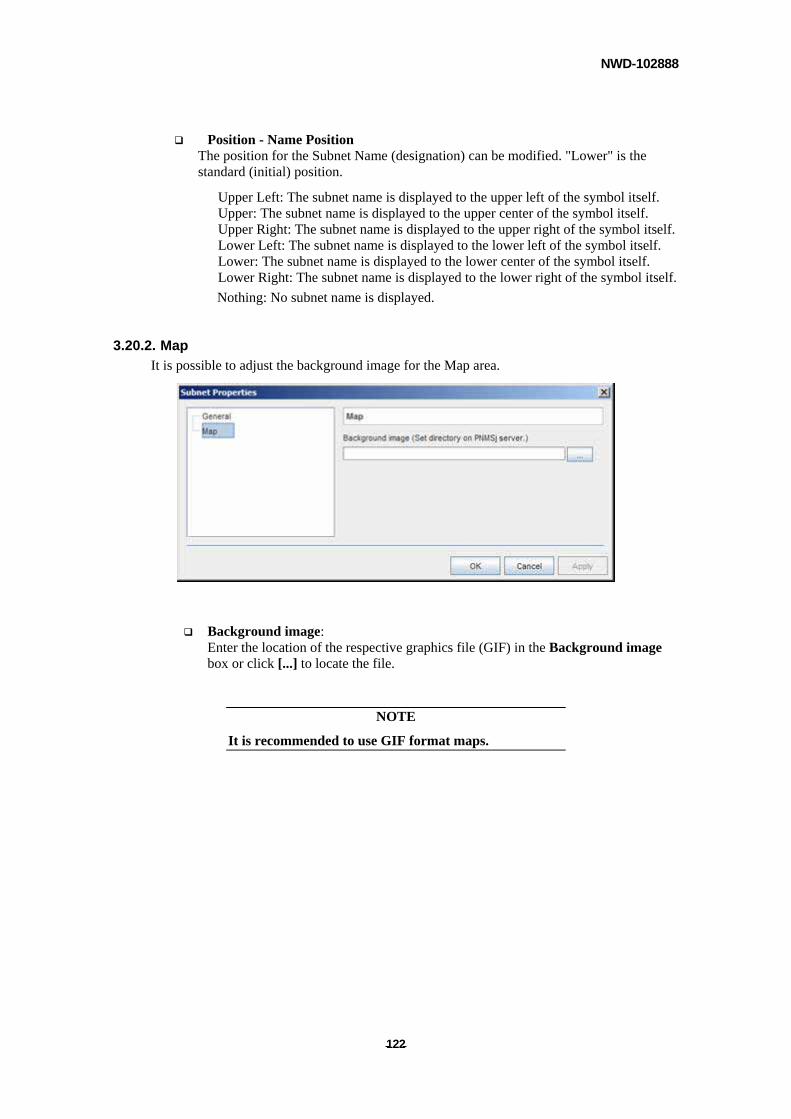
NWD-102888
- - 122
Position - Name Position The position for the Subnet Name (designation) can be modified. "Lower" is the standard (initial) position.
Upper Left: The subnet name is displayed to the upper left of the symbol itself. Upper: The subnet name is displayed to the upper center of the symbol itself. Upper Right: The subnet name is displayed to the upper right of the symbol itself. Lower Left: The subnet name is displayed to the lower left of the symbol itself. Lower: The subnet name is displayed to the lower center of the symbol itself. Lower Right: The subnet name is displayed to the lower right of the symbol itself.
Nothing: No subnet name is displayed.
3.20.2. Map
It is possible to adjust the background image for the Map area.
Background image: Enter the location of the respective graphics file (GIF) in the Background image box or click [...] to locate the file.
NOTE
It is recommended to use GIF format maps.
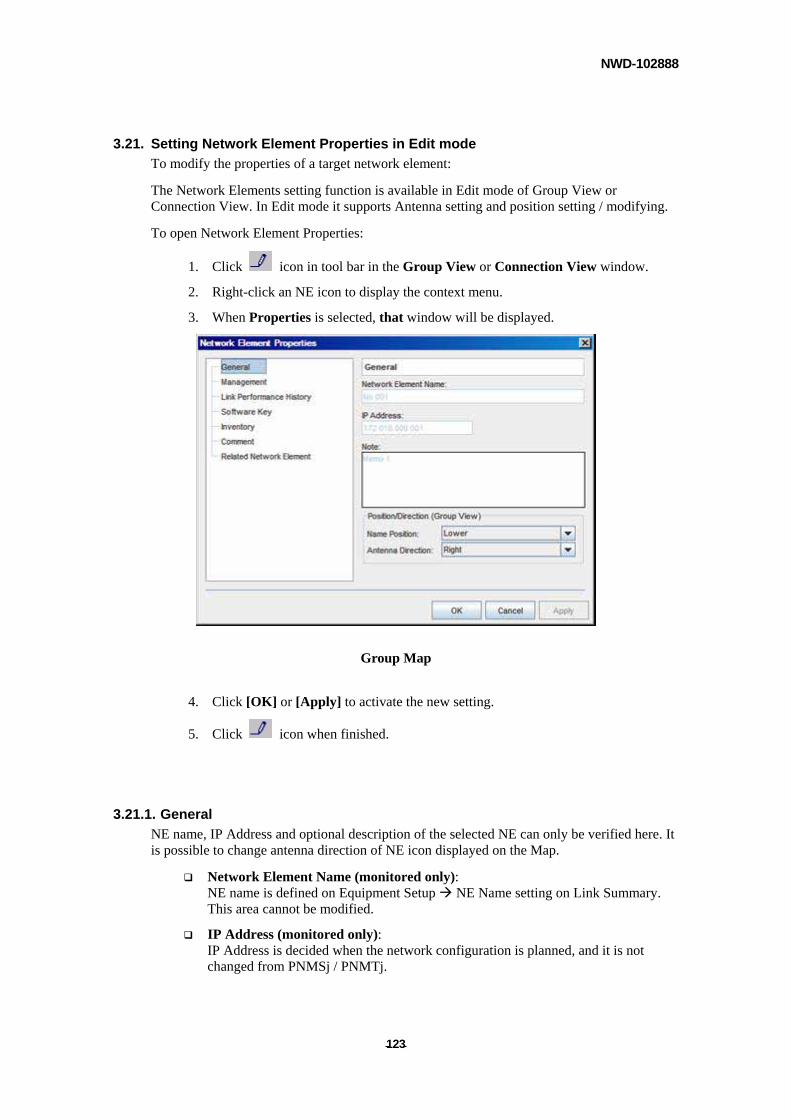
NWD-102888
- - 123
3.21. Setting Network Element Properties in Edit mode
To modify the properties of a target network element:
The Network Elements setting function is available in Edit mode of Group View or Connection View. In Edit mode it supports Antenna setting and position setting / modifying.
To open Network Element Properties:
1. Click icon in tool bar in the Group View or Connection View window.
2. Right-click an NE icon to display the context menu.
3. When Properties is selected, that window will be displayed.
Group Map
4. Click [OK] or [Apply] to activate the new setting.
5. Click icon when finished.
3.21.1. General
NE name, IP Address and optional description of the selected NE can only be verified here. It is possible to change antenna direction of NE icon displayed on the Map.
Network Element Name (monitored only): NE name is defined on Equipment Setup NE Name setting on Link Summary. This area cannot be modified.
IP Address (monitored only): IP Address is decided when the network configuration is planned, and it is not changed from PNMSj / PNMTj.
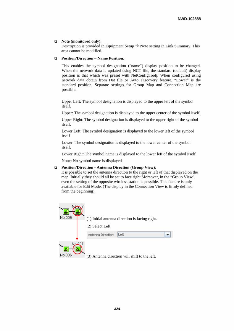
NWD-102888
- - 124
Note (monitored only): Description is provided in Equipment Setup Note setting in Link Summary. This area cannot be modified.
Position/Direction – Name Position:
This enables the symbol designation ("name") display position to be changed. When the network data is updated using NCT file, the standard (default) display position is that which was preset with NetConfigToolj. When configured using network data obtain from Dat file or Auto Discovery feature, “Lower” is the standard position. Separate settings for Group Map and Connection Map are possible.
Upper Left: The symbol designation is displayed to the upper left of the symbol itself.
Upper: The symbol designation is displayed to the upper center of the symbol itself.
Upper Right: The symbol designation is displayed to the upper right of the symbol itself.
Lower Left: The symbol designation is displayed to the lower left of the symbol itself.
Lower: The symbol designation is displayed to the lower center of the symbol itself.
Lower Right: The symbol name is displayed to the lower left of the symbol itself.
None: No symbol name is displayed
Position/Direction - Antenna Direction (Group View): It is possible to set the antenna direction to the right or left of that displayed on the map. Initially they should all be set to face right Moreover, in the “Group View”, even the setting of the opposite wireless station is possible. This feature is only available for Edit Mode. (The display in the Connection View is firmly defined from the beginning).
(1) Initial antenna direction is facing right.
(2) Select Left.
(3) Antenna direction will shift to the left.
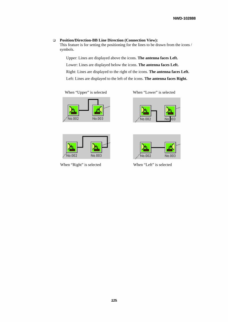
NWD-102888
- - 125
Position/Direction-BB Line Direction (Connection View): This feature is for setting the positioning for the lines to be drawn from the icons / symbols.
Upper: Lines are displayed above the icons. The antenna faces Left.
Lower: Lines are displayed below the icons. The antenna faces Left.
Right: Lines are displayed to the right of the icons. The antenna faces Left.
Left: Lines are displayed to the left of the icons. The antenna faces Right.
When “Upper” is selected When “Lower” is selected
When “Right” is selected When “Left” is selected
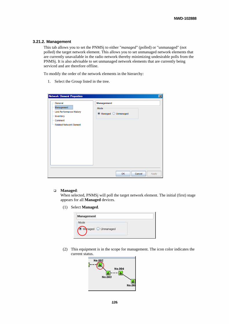
NWD-102888
- - 126
3.21.2. Management
This tab allows you to set the PNMSj to either "managed" (polled) or "unmanaged" (not polled) the target network element. This allows you to set unmanaged network elements that are currently unavailable in the radio network thereby minimizing undesirable polls from the PNMSj. It is also advisable to set unmanaged network elements that are currently being serviced and are therefore offline.
To modify the order of the network elements in the hierarchy:
1. Select the Group listed in the tree.
Managed: When selected, PNMSj will poll the target network element. The initial (first) stage appears for all Managed devices.
(1) Select Managed.
(2) This equipment is in the scope for management. The icon color indicates the current status.
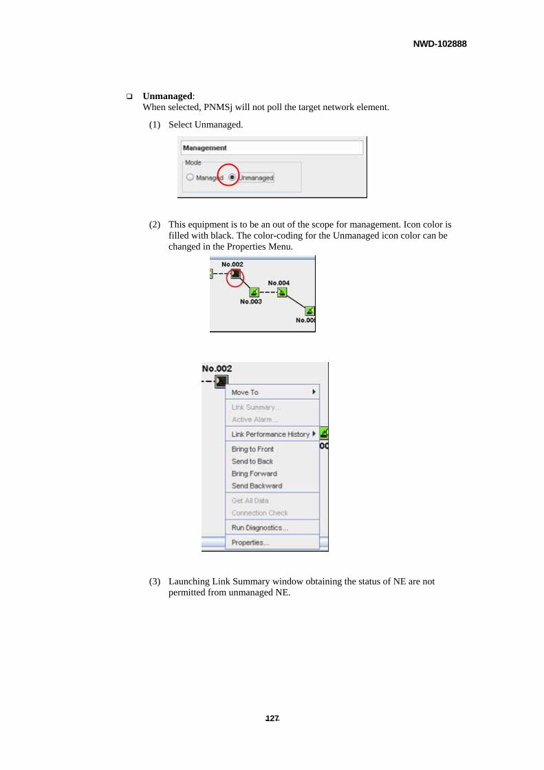
NWD-102888
- - 127
Unmanaged: When selected, PNMSj will not poll the target network element.
(1) Select Unmanaged.
(2) This equipment is to be an out of the scope for management. Icon color is filled with black. The color-coding for the Unmanaged icon color can be changed in the Properties Menu.
(3) Launching Link Summary window obtaining the status of NE are not permitted from unmanaged NE.
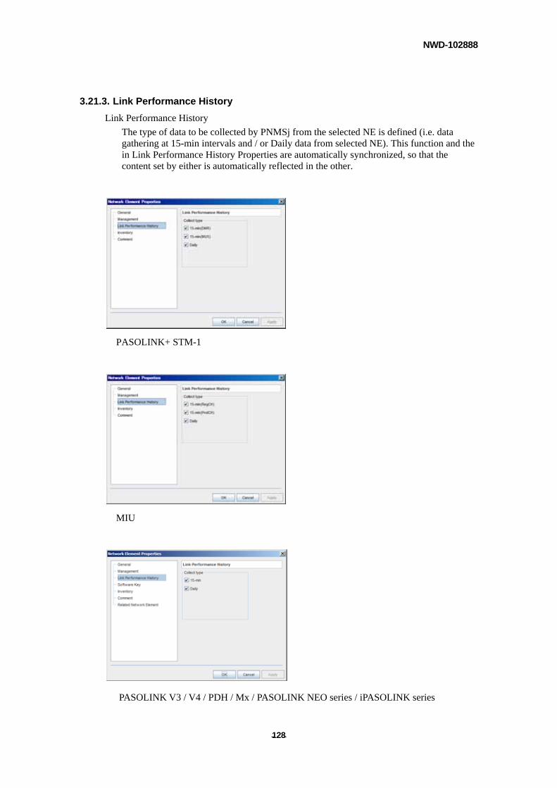
NWD-102888
- - 128
3.21.3. Link Performance History
Link Performance History
The type of data to be collected by PNMSj from the selected NE is defined (i.e. data gathering at 15-min intervals and / or Daily data from selected NE). This function and the in Link Performance History Properties are automatically synchronized, so that the content set by either is automatically reflected in the other.
PASOLINK+ STM-1
MIU
PASOLINK V3 / V4 / PDH / Mx / PASOLINK NEO series / iPASOLINK series
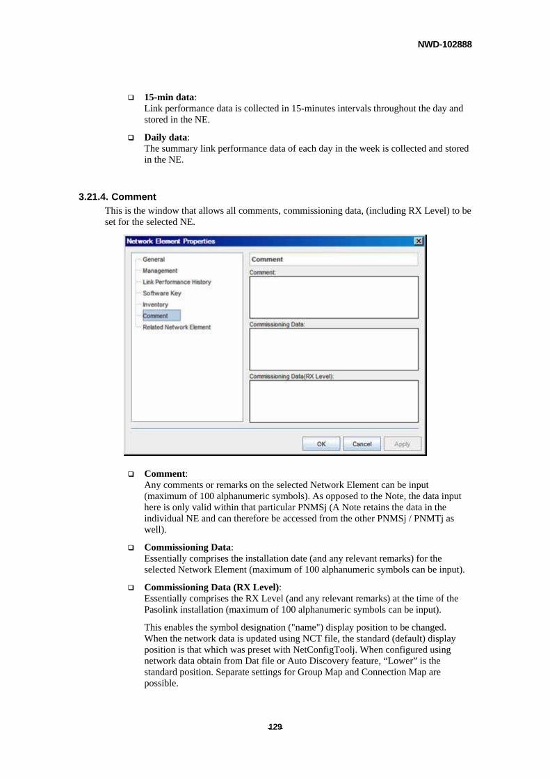
NWD-102888
- - 129
15-min data: Link performance data is collected in 15-minutes intervals throughout the day and stored in the NE.
Daily data: The summary link performance data of each day in the week is collected and stored in the NE.
3.21.4. Comment
This is the window that allows all comments, commissioning data, (including RX Level) to be set for the selected NE.
Comment: Any comments or remarks on the selected Network Element can be input (maximum of 100 alphanumeric symbols). As opposed to the Note, the data input here is only valid within that particular PNMSj (A Note retains the data in the individual NE and can therefore be accessed from the other PNMSj / PNMTj as well).
Commissioning Data: Essentially comprises the installation date (and any relevant remarks) for the selected Network Element (maximum of 100 alphanumeric symbols can be input).
Commissioning Data (RX Level): Essentially comprises the RX Level (and any relevant remarks) at the time of the Pasolink installation (maximum of 100 alphanumeric symbols can be input).
This enables the symbol designation ("name") display position to be changed. When the network data is updated using NCT file, the standard (default) display position is that which was preset with NetConfigToolj. When configured using network data obtain from Dat file or Auto Discovery feature, “Lower” is the standard position. Separate settings for Group Map and Connection Map are possible.
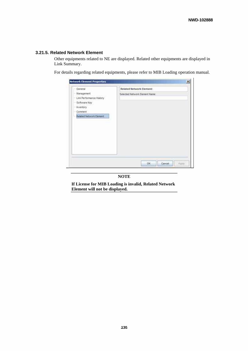
NWD-102888
- - 130
3.21.5. Related Network Element
Other equipments related to NE are displayed. Related other equipments are displayed in Link Summary.
For details regarding related equipments, please refer to MIB Loading operation manual.
NOTE
If License for MIB Loading is invalid, Related Network Element will not be displayed.
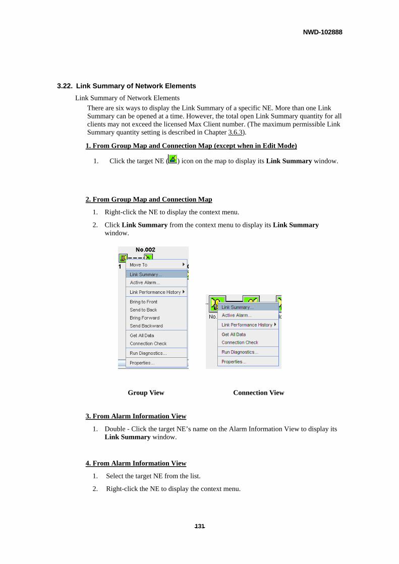
NWD-102888
- - 131
3.22. Link Summary of Network Elements
Link Summary of Network Elements
There are six ways to display the Link Summary of a specific NE. More than one Link Summary can be opened at a time. However, the total open Link Summary quantity for all clients may not exceed the licensed Max Client number. (The maximum permissible Link Summary quantity setting is described in Chapter 3.6.3).
1. From Group Map and Connection Map (except when in Edit Mode)
1. Click the target NE ( ) icon on the map to display its Link Summary window.
2. From Group Map and Connection Map
1. Right-click the NE to display the context menu.
2. Click Link Summary from the context menu to display its Link Summary window.
Group View Connection View
3. From Alarm Information View
1. Double - Click the target NE’s name on the Alarm Information View to display its Link Summary window.
4. From Alarm Information View
1. Select the target NE from the list.
2. Right-click the NE to display the context menu.
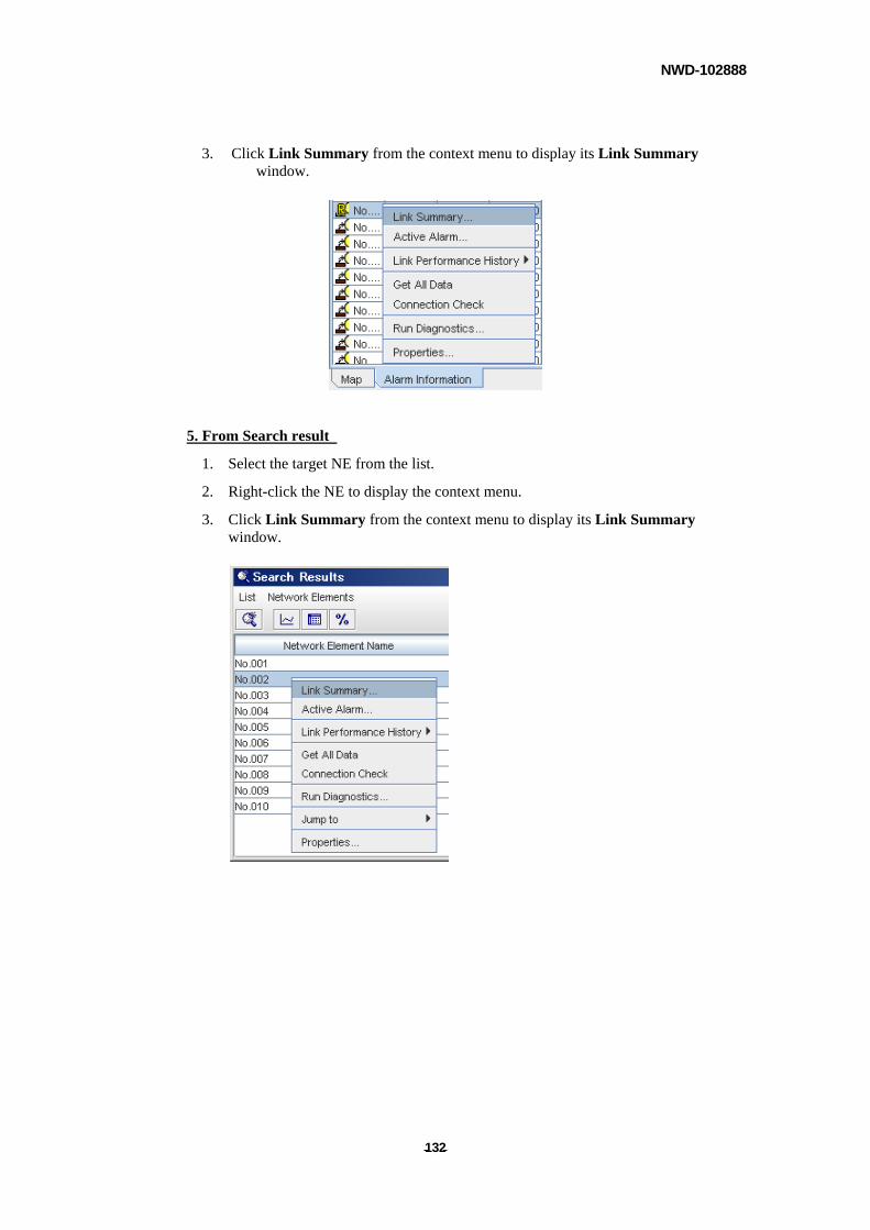
NWD-102888
- - 132
3. Click Link Summary from the context menu to display its Link Summary window.
5. From Search result
1. Select the target NE from the list.
2. Right-click the NE to display the context menu.
3. Click Link Summary from the context menu to display its Link Summary window.
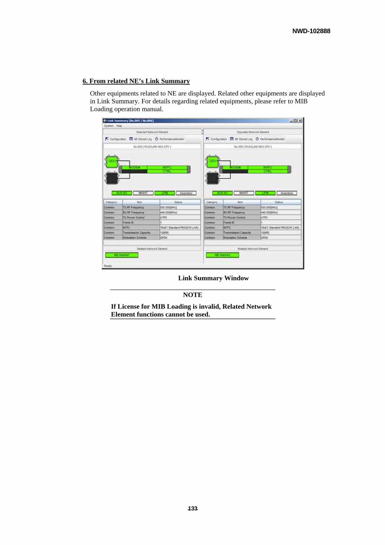
NWD-102888
- - 133
6. From related NE’s Link Summary
Other equipments related to NE are displayed. Related other equipments are displayed in Link Summary. For details regarding related equipments, please refer to MIB Loading operation manual.
Link Summary Window
NOTE
If License for MIB Loading is invalid, Related Network Element functions cannot be used.
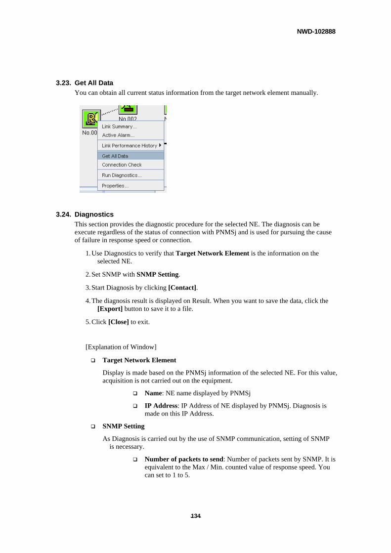
NWD-102888
- - 134
3.23. Get All Data
You can obtain all current status information from the target network element manually.
3.24. Diagnostics
This section provides the diagnostic procedure for the selected NE. The diagnosis can be execute regardless of the status of connection with PNMSj and is used for pursuing the cause of failure in response speed or connection.
1. Use Diagnostics to verify that Target Network Element is the information on the selected NE.
2. Set SNMP with SNMP Setting.
3. Start Diagnosis by clicking [Contact].
4. The diagnosis result is displayed on Result. When you want to save the data, click the [Export] button to save it to a file.
5. Click [Close] to exit.
[Explanation of Window]
Target Network Element
Display is made based on the PNMSj information of the selected NE. For this value, acquisition is not carried out on the equipment.
Name: NE name displayed by PNMSj
IP Address: IP Address of NE displayed by PNMSj. Diagnosis is made on this IP Address.
SNMP Setting
As Diagnosis is carried out by the use of SNMP communication, setting of SNMP is necessary.
Number of packets to send: Number of packets sent by SNMP. It is equivalent to the Max / Min. counted value of response speed. You can set to 1 to 5.
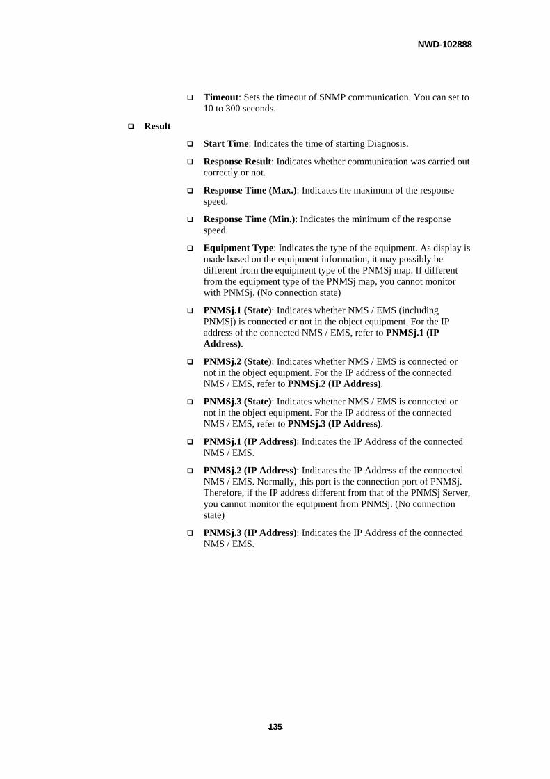
NWD-102888
- - 135
Timeout: Sets the timeout of SNMP communication. You can set to 10 to 300 seconds.
Result
Start Time: Indicates the time of starting Diagnosis.
Response Result: Indicates whether communication was carried out correctly or not.
Response Time (Max.): Indicates the maximum of the response speed.
Response Time (Min.): Indicates the minimum of the response speed.
Equipment Type: Indicates the type of the equipment. As display is made based on the equipment information, it may possibly be different from the equipment type of the PNMSj map. If different from the equipment type of the PNMSj map, you cannot monitor with PNMSj. (No connection state)
PNMSj.1 (State): Indicates whether NMS / EMS (including PNMSj) is connected or not in the object equipment. For the IP address of the connected NMS / EMS, refer to PNMSj.1 (IP Address).
PNMSj.2 (State): Indicates whether NMS / EMS is connected or not in the object equipment. For the IP address of the connected NMS / EMS, refer to PNMSj.2 (IP Address).
PNMSj.3 (State): Indicates whether NMS / EMS is connected or not in the object equipment. For the IP address of the connected NMS / EMS, refer to PNMSj.3 (IP Address).
PNMSj.1 (IP Address): Indicates the IP Address of the connected NMS / EMS.
PNMSj.2 (IP Address): Indicates the IP Address of the connected NMS / EMS. Normally, this port is the connection port of PNMSj. Therefore, if the IP address different from that of the PNMSj Server, you cannot monitor the equipment from PNMSj. (No connection state)
PNMSj.3 (IP Address): Indicates the IP Address of the connected NMS / EMS.
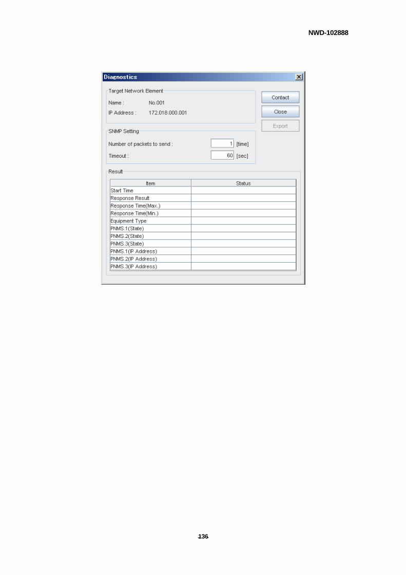
NWD-102888
- - 136
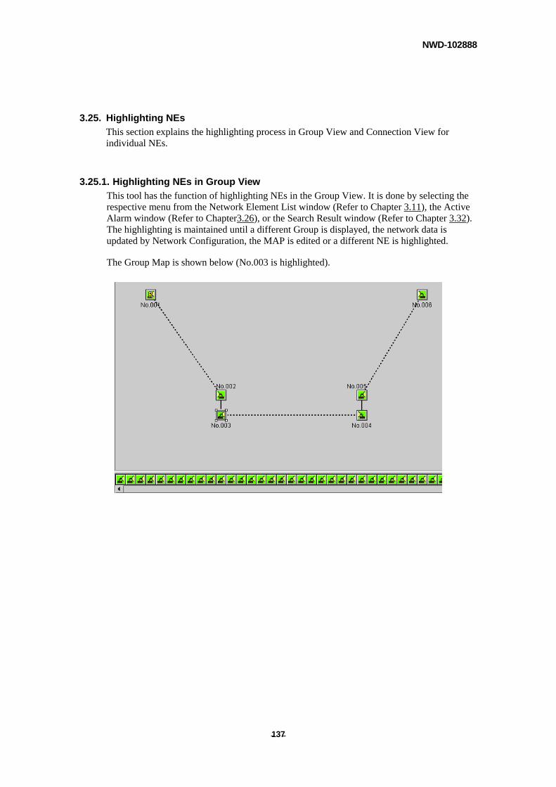
NWD-102888
- - 137
3.25. Highlighting NEs
This section explains the highlighting process in Group View and Connection View for individual NEs.
3.25.1. Highlighting NEs in Group View
This tool has the function of highlighting NEs in the Group View. It is done by selecting the respective menu from the Network Element List window (Refer to Chapter 3.11), the Active Alarm window (Refer to Chapter3.26), or the Search Result window (Refer to Chapter 3.32). The highlighting is maintained until a different Group is displayed, the network data is updated by Network Configuration, the MAP is edited or a different NE is highlighted.
The Group Map is shown below (No.003 is highlighted).
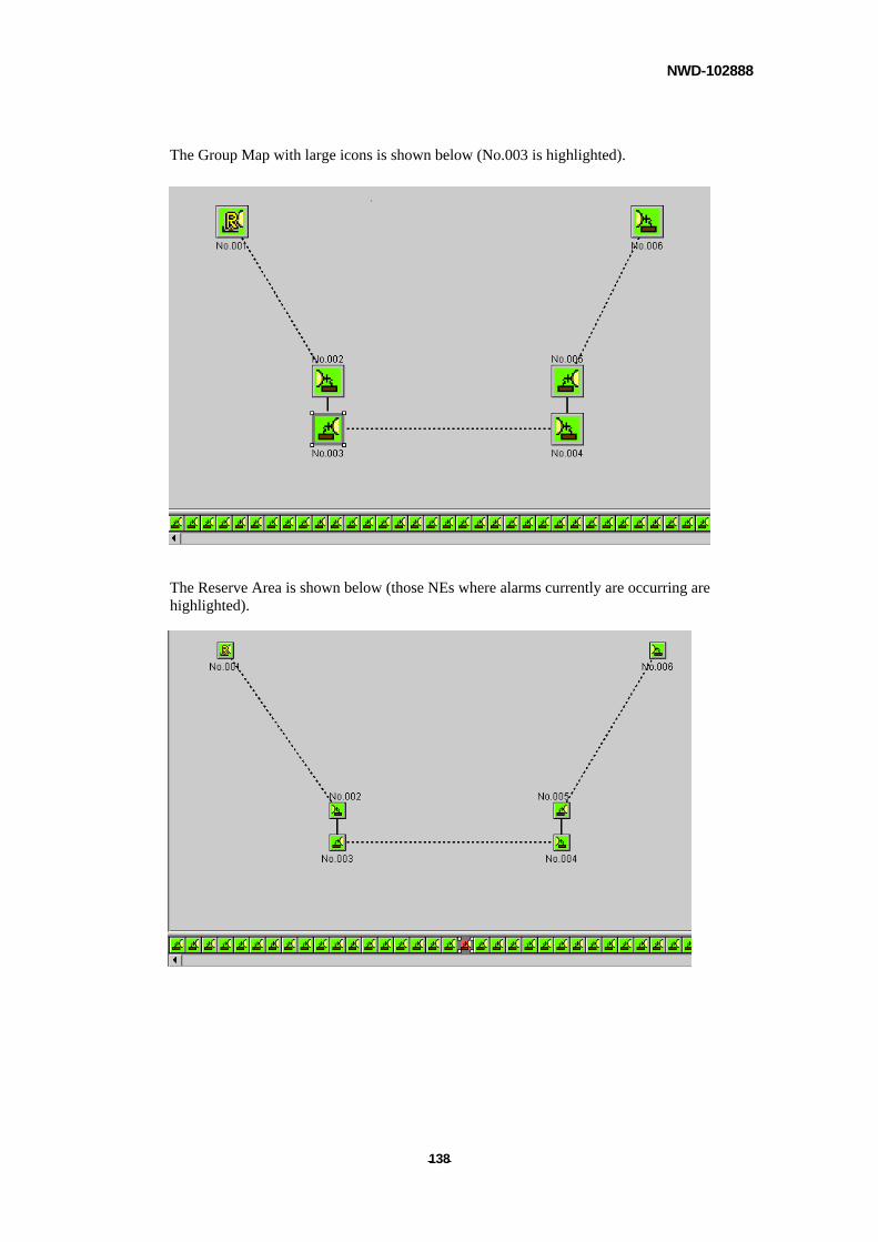
NWD-102888
- - 138
The Group Map with large icons is shown below (No.003 is highlighted).
The Reserve Area is shown below (those NEs where alarms currently are occurring are highlighted).
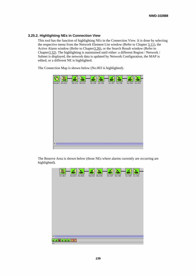
NWD-102888
- - 139
3.25.2. Highlighting NEs in Connection View
This tool has the function of highlighting NEs in the Connection View. It is done by selecting the respective menu from the Network Element List window (Refer to Chapter 3.11), the Active Alarm window (Refer to Chapter3.26), or the Search Result window (Refer to Chapter3.32). The highlighting is maintained until either: a different Region / Network / Subnet is displayed, the network data is updated by Network Configuration, the MAP is edited, or a different NE is highlighted.
The Connection Map is shown below (No.003 is highlighted).
The Reserve Area is shown below (those NEs where alarms currently are occurring are highlighted).
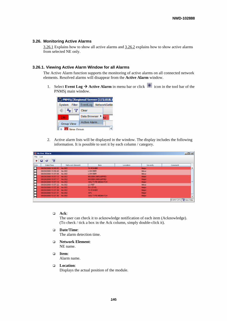
NWD-102888
- - 140
3.26. Monitoring Active Alarms
3.26.1 Explains how to show all active alarms and 3.26.2 explains how to show active alarms from selected NE only.
3.26.1. Viewing Active Alarm Window for all Alarms
The Active Alarm function supports the monitoring of active alarms on all connected network elements. Resolved alarms will disappear from the Active Alarm window.
1. Select Event Log Active Alarm in menu bar or click icon in the tool bar of the PNMSj main window.
2. Active alarm lists will be displayed in the window. The display includes the following information. It is possible to sort it by each column / category.
Ack: The user can check it to acknowledge notification of each item (Acknowledge). (To check / tick a box in the Ack column, simply double-click it).
Date/Time: The alarm detection time.
Network Element: NE name.
Item: Alarm name.
Location: Displays the actual position of the module.
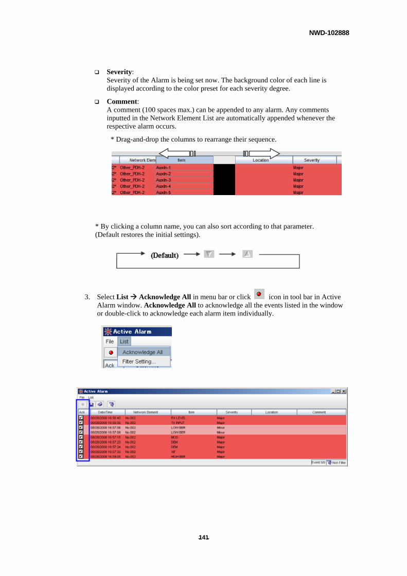
NWD-102888
- - 141
Severity: Severity of the Alarm is being set now. The background color of each line is displayed according to the color preset for each severity degree.
Comment: A comment (100 spaces max.) can be appended to any alarm. Any comments inputted in the Network Element List are automatically appended whenever the respective alarm occurs.
* Drag-and-drop the columns to rearrange their sequence.
* By clicking a column name, you can also sort according to that parameter. (Default restores the initial settings).
3. Select List Acknowledge All in menu bar or click icon in tool bar in Active Alarm window. Acknowledge All to acknowledge all the events listed in the window or double-click to acknowledge each alarm item individually.
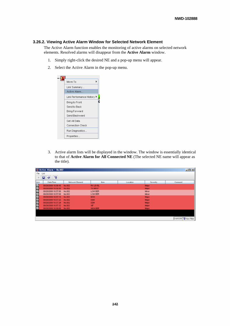
NWD-102888
- - 142
3.26.2. Viewing Active Alarm Window for Selected Network Element
The Active Alarm function enables the monitoring of active alarms on selected network elements. Resolved alarms will disappear from the Active Alarm window.
1. Simply right-click the desired NE and a pop-up menu will appear.
2. Select the Active Alarm in the pop-up menu.
3. Active alarm lists will be displayed in the window. The window is essentially identical to that of Active Alarm for All Connected NE (The selected NE name will appear as the title).
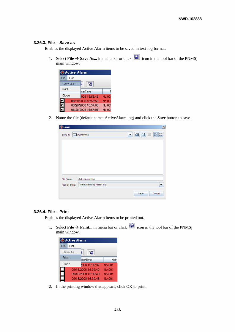
NWD-102888
- - 143
3.26.3. File – Save as
Enables the displayed Active Alarm items to be saved in text-log format.
1. Select File Save As... in menu bar or click icon in the tool bar of the PNMSj main window.
2. Name the file (default name: ActiveAlarm.log) and click the Save button to save.
3.26.4. File – Print
Enables the displayed Active Alarm items to be printed out.
1. Select File Print... in menu bar or click icon in the tool bar of the PNMSj main window.
2. In the printing window that appears, click OK to print.
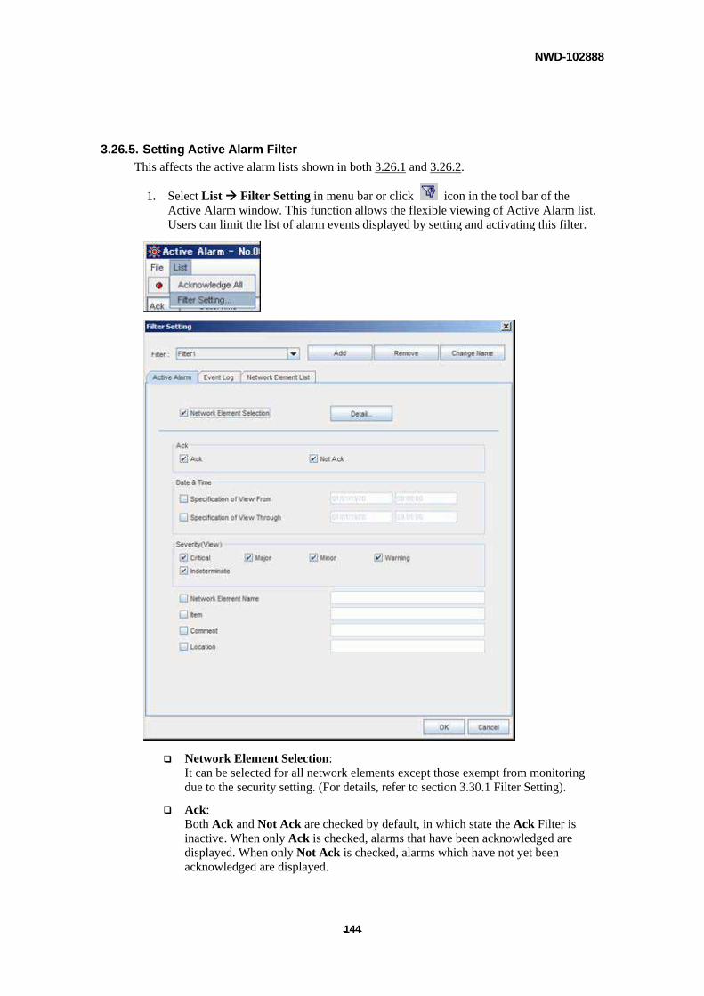
NWD-102888
- - 144
3.26.5. Setting Active Alarm Filter
This affects the active alarm lists shown in both 3.26.1 and 3.26.2.
1. Select List Filter Setting in menu bar or click icon in the tool bar of the Active Alarm window. This function allows the flexible viewing of Active Alarm list. Users can limit the list of alarm events displayed by setting and activating this filter.
Network Element Selection: It can be selected for all network elements except those exempt from monitoring due to the security setting. (For details, refer to section 3.30.1 Filter Setting).
Ack: Both Ack and Not Ack are checked by default, in which state the Ack Filter is inactive. When only Ack is checked, alarms that have been acknowledged are displayed. When only Not Ack is checked, alarms which have not yet been acknowledged are displayed.

NWD-102888
- - 145
Date & Time (Specification of View From...): Displays alarms resolved after the preset time.
Date & Time (Specification of View Through...): Displays alarms resolved before the preset time.
Severity (View): Displays alarms of the preset severity degrees.
Network Element Name: Displays alarms of the selected preset network elements.
Item: Displays alarms (items) of the selected preset types.
Comment:
Displays Comments of the selected preset types.
Location:
Displays Location of the selected preset types.
2. Click [OK] to activate filter.
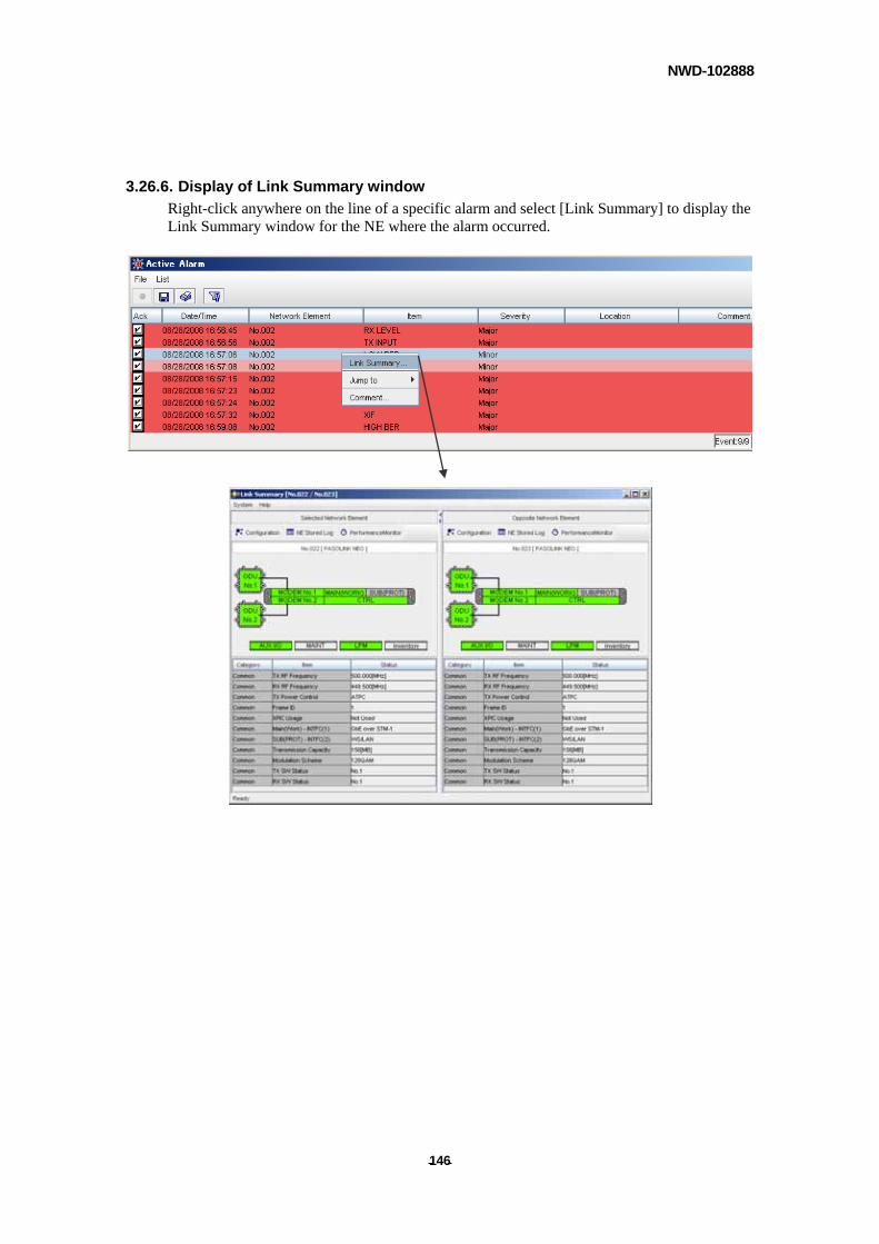
NWD-102888
- - 146
3.26.6. Display of Link Summary window
Right-click anywhere on the line of a specific alarm and select [Link Summary] to display the Link Summary window for the NE where the alarm occurred.
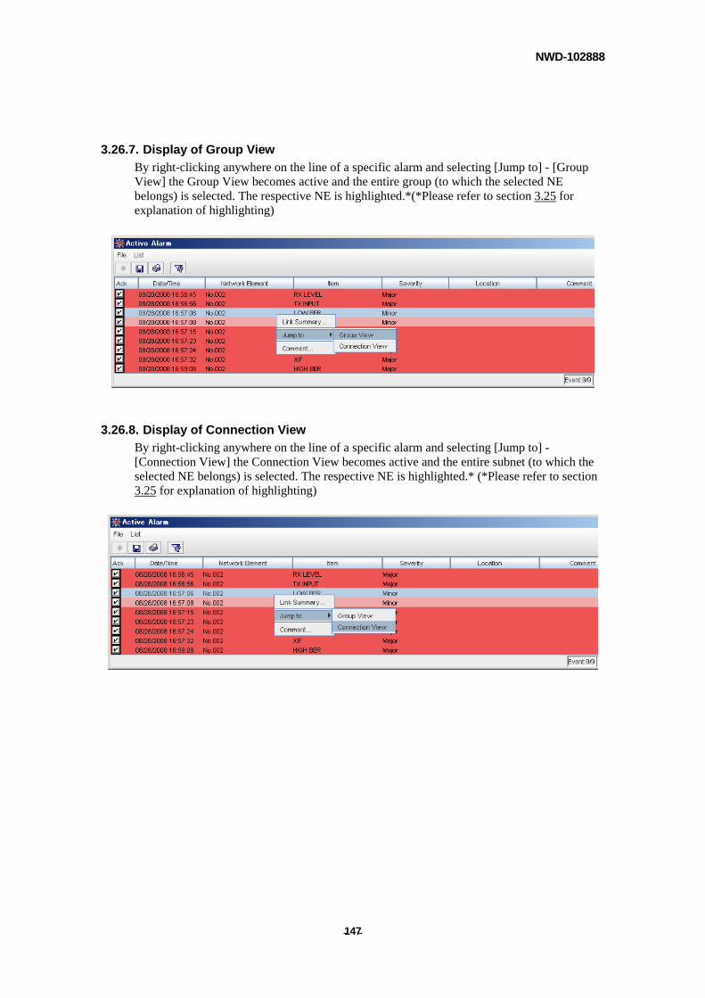
NWD-102888
- - 147
3.26.7. Display of Group View
By right-clicking anywhere on the line of a specific alarm and selecting [Jump to] - [Group View] the Group View becomes active and the entire group (to which the selected NE belongs) is selected. The respective NE is highlighted.*(*Please refer to section 3.25 for explanation of highlighting)
3.26.8. Display of Connection View
By right-clicking anywhere on the line of a specific alarm and selecting [Jump to] - [Connection View] the Connection View becomes active and the entire subnet (to which the selected NE belongs) is selected. The respective NE is highlighted.* (*Please refer to section 3.25 for explanation of highlighting)
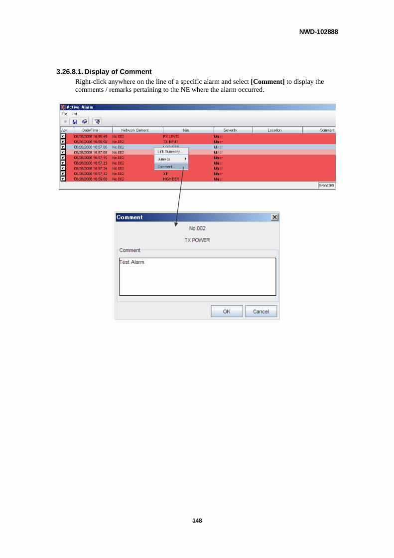
NWD-102888
- - 148
3.26.8.1. Display of Comment
Right-click anywhere on the line of a specific alarm and select [Comment] to display the comments / remarks pertaining to the NE where the alarm occurred.
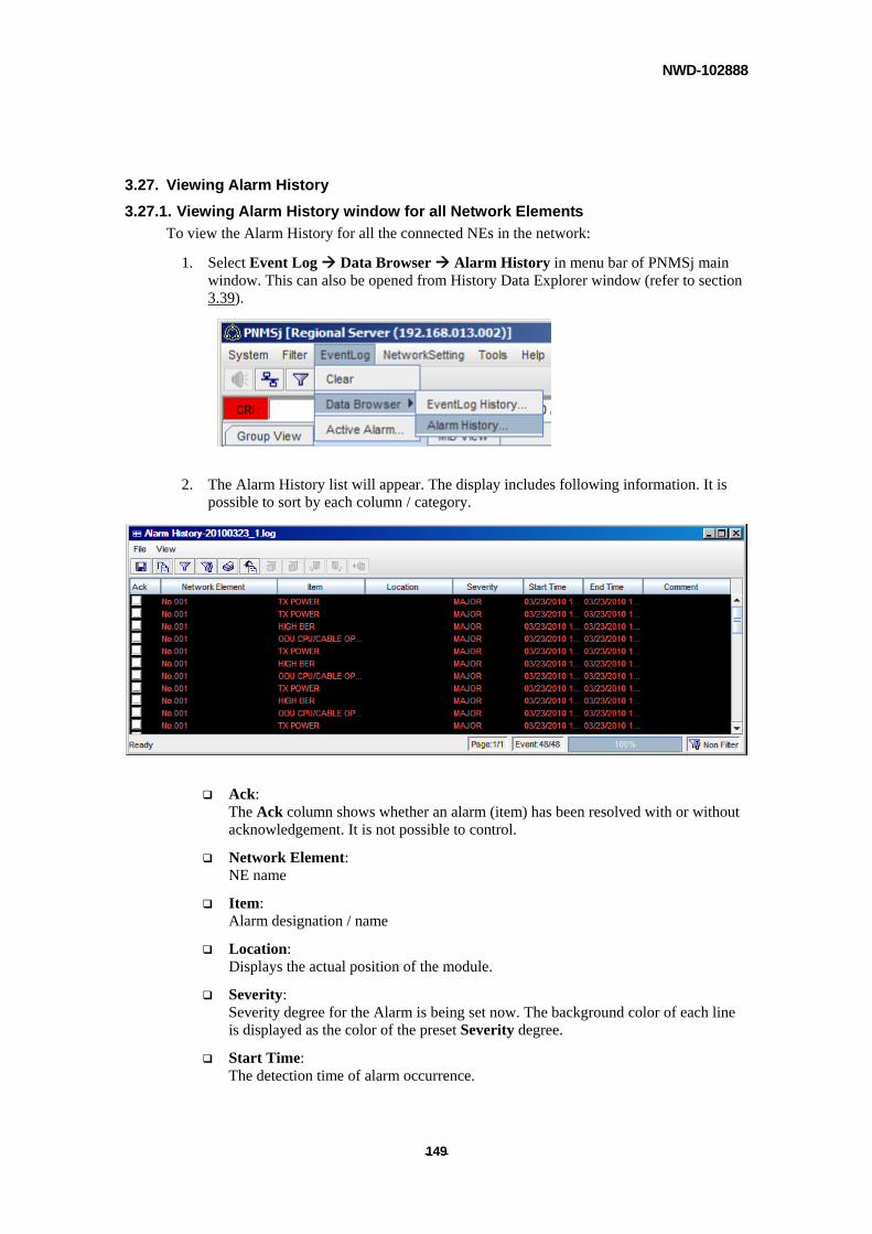
NWD-102888
- - 149
3.27. Viewing Alarm History
3.27.1. Viewing Alarm History window for all Network Elements
To view the Alarm History for all the connected NEs in the network:
1. Select Event Log Data Browser Alarm History in menu bar of PNMSj main window. This can also be opened from History Data Explorer window (refer to section 3.39).
2. The Alarm History list will appear. The display includes following information. It is possible to sort by each column / category.
Ack: The Ack column shows whether an alarm (item) has been resolved with or without acknowledgement. It is not possible to control.
Network Element: NE name
Item: Alarm designation / name
Location: Displays the actual position of the module.
Severity: Severity degree for the Alarm is being set now. The background color of each line is displayed as the color of the preset Severity degree.
Start Time: The detection time of alarm occurrence.
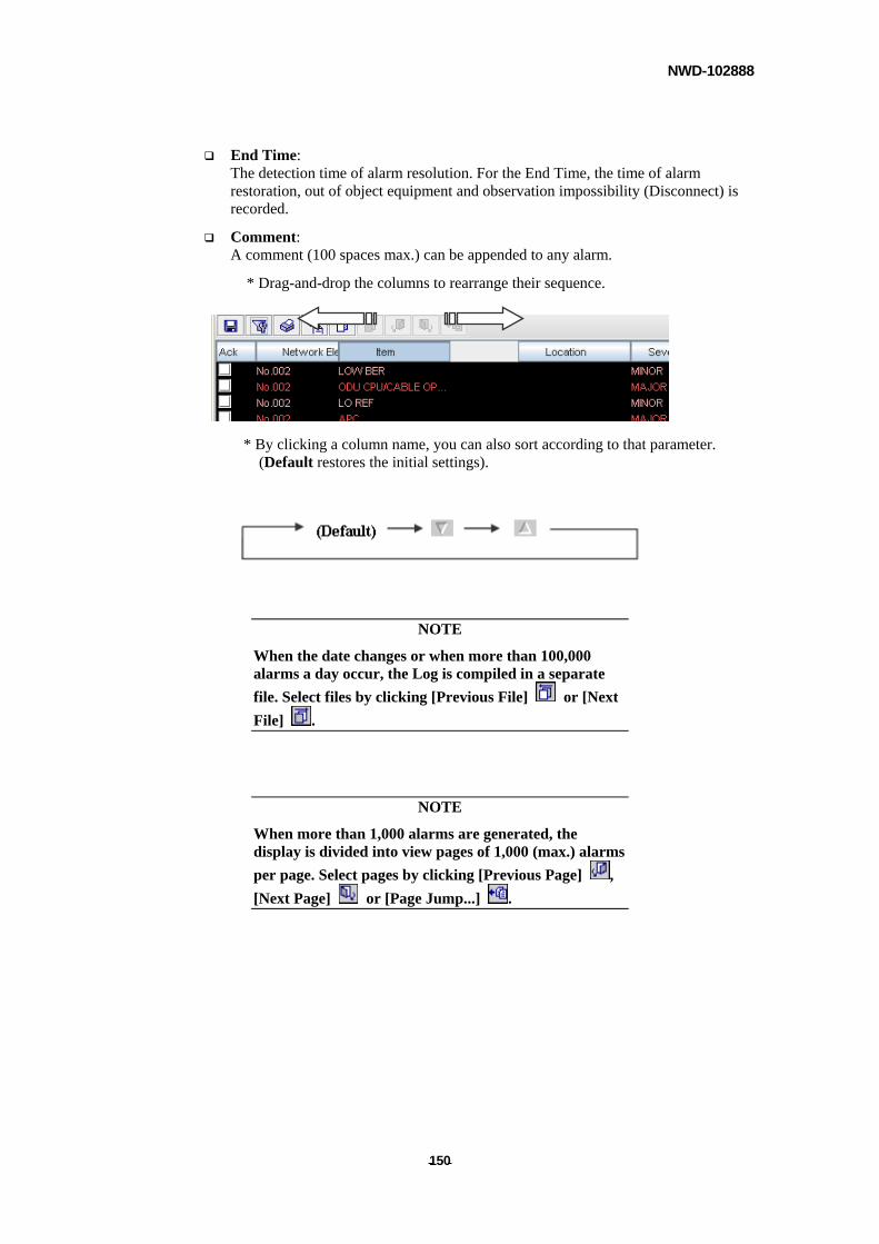
NWD-102888
- - 150
End Time: The detection time of alarm resolution. For the End Time, the time of alarm restoration, out of object equipment and observation impossibility (Disconnect) is recorded.
Comment: A comment (100 spaces max.) can be appended to any alarm.
* Drag-and-drop the columns to rearrange their sequence.
* By clicking a column name, you can also sort according to that parameter. (Default restores the initial settings).
NOTE
When the date changes or when more than 100,000 alarms a day occur, the Log is compiled in a separate
file. Select files by clicking [Previous File] or [Next
File] .
NOTE
When more than 1,000 alarms are generated, the display is divided into view pages of 1,000 (max.) alarms
per page. Select pages by clicking [Previous Page] ,
[Next Page] or [Page Jump...] .
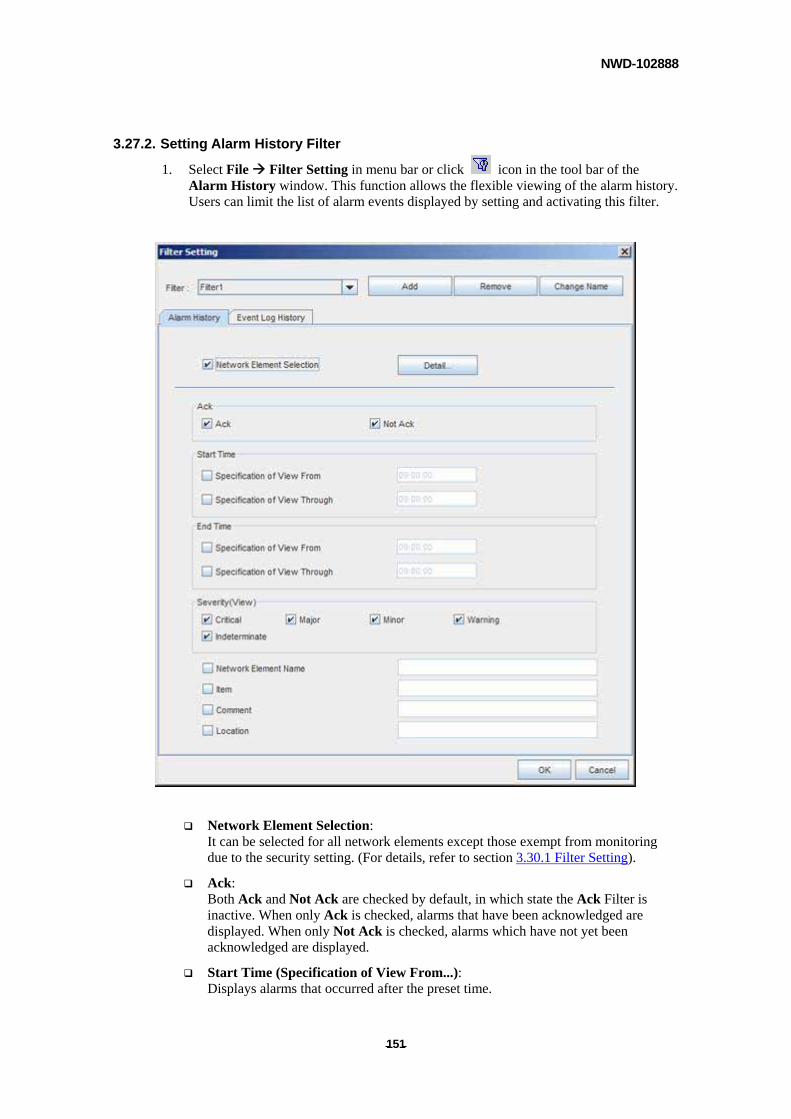
NWD-102888
- - 151
3.27.2. Setting Alarm History Filter
1. Select File Filter Setting in menu bar or click icon in the tool bar of the Alarm History window. This function allows the flexible viewing of the alarm history. Users can limit the list of alarm events displayed by setting and activating this filter.
Network Element Selection: It can be selected for all network elements except those exempt from monitoring due to the security setting. (For details, refer to section 3.30.1 Filter Setting).
Ack: Both Ack and Not Ack are checked by default, in which state the Ack Filter is inactive. When only Ack is checked, alarms that have been acknowledged are displayed. When only Not Ack is checked, alarms which have not yet been acknowledged are displayed.
Start Time (Specification of View From...): Displays alarms that occurred after the preset time.

NWD-102888
- - 152
Start Time (Specification of View Through...): Displays alarms occurred before the preset time.
End Time (Specification of View From...): Displays alarms resolved after the preset time.
End Time (Specification of View Through...): Displays alarms resolved before the preset time.
Severity (View): Displays alarms of the selected preset severity degrees.
Network Element Name: Displays alarms of the selected preset network element.
Item: Displays alarms (items) of the selected preset types.
Comment: Displays Comments of the selected preset types.
Location:
Displays Location of the selected preset types.
2. Click [OK] to activate filter.
NOTE
To set filters for Active Alarm, Event Log and Network Element List, please refer to chapter 3.30.
3.27.3. File – Open
Enables the Alarm History File to be directly accessed / opened. The file is saved / stored in the <PNMSj Stored Directory>/log/alarm. When PNMSj is remote controlled (by remote server or client), this feature becomes available by copying the Alarm History File to the controlling PC.
3.27.4. File – Save As
Enables items displayed in the Alarm History window to be saved in text (.csv) format. Can
also be done by clicking the icon in the tool bar of the Alarm History window.
Note: Do NOT save to <PNMSj Stored Directory>/log/alarm, otherwise, the Alarm History, Previous File, and Next File features may not function properly.
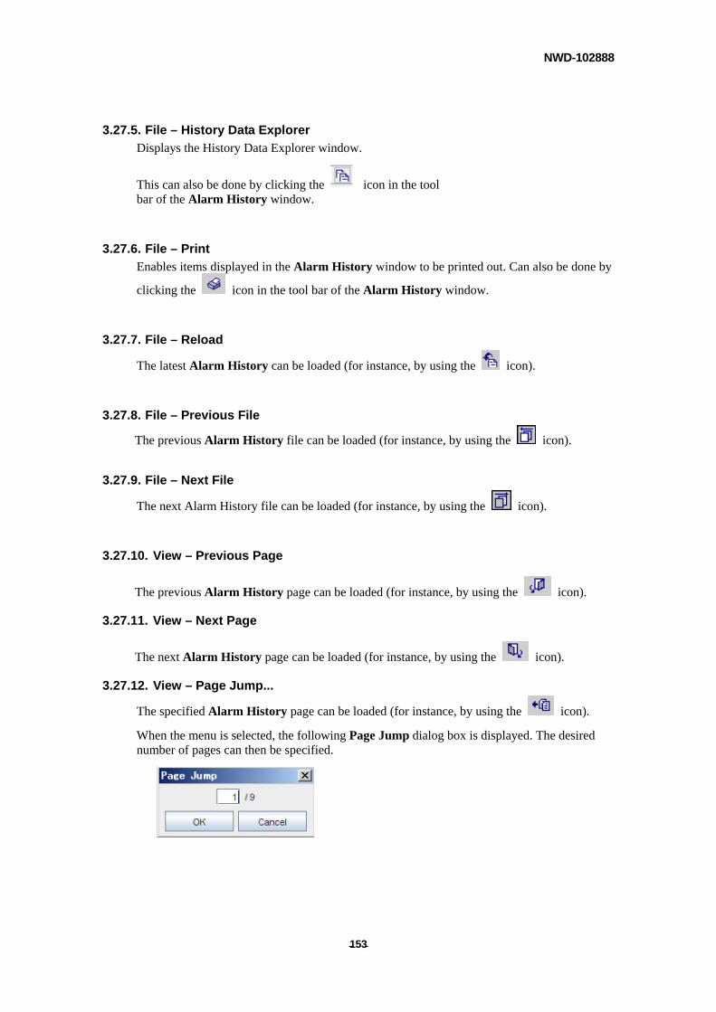
NWD-102888
- - 153
3.27.5. File – History Data Explorer
Displays the History Data Explorer window.
This can also be done by clicking the icon in the tool bar of the Alarm History window.
3.27.6. File – Print
Enables items displayed in the Alarm History window to be printed out. Can also be done by
clicking the icon in the tool bar of the Alarm History window.
3.27.7. File – Reload
The latest Alarm History can be loaded (for instance, by using the icon).
3.27.8. File – Previous File
The previous Alarm History file can be loaded (for instance, by using the icon).
3.27.9. File – Next File
The next Alarm History file can be loaded (for instance, by using the icon).
3.27.10. View – Previous Page
The previous Alarm History page can be loaded (for instance, by using the icon).
3.27.11. View – Next Page
The next Alarm History page can be loaded (for instance, by using the icon).
3.27.12. View – Page Jump...
The specified Alarm History page can be loaded (for instance, by using the icon).
When the menu is selected, the following Page Jump dialog box is displayed. The desired number of pages can then be specified.
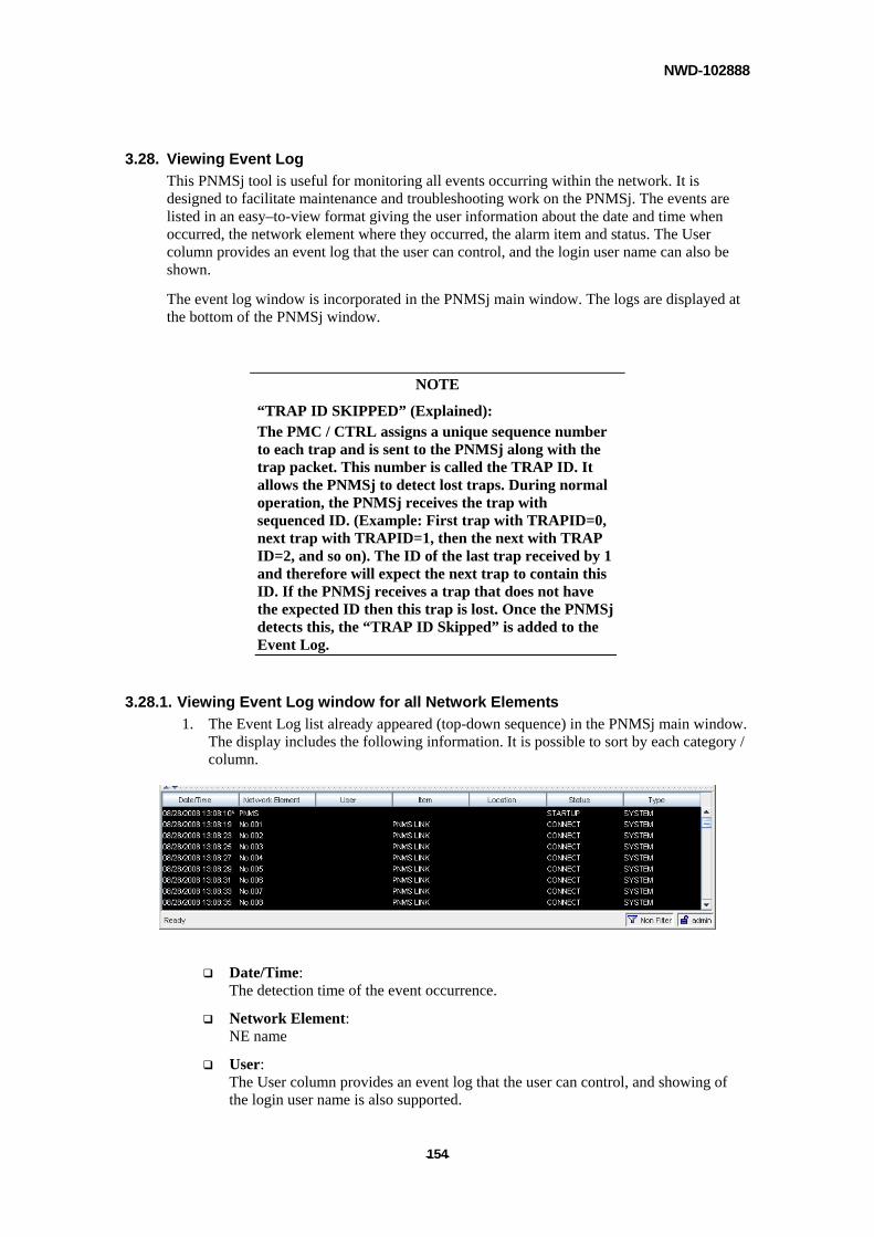
NWD-102888
- - 154
3.28. Viewing Event Log
This PNMSj tool is useful for monitoring all events occurring within the network. It is designed to facilitate maintenance and troubleshooting work on the PNMSj. The events are listed in an easy–to-view format giving the user information about the date and time when occurred, the network element where they occurred, the alarm item and status. The User column provides an event log that the user can control, and the login user name can also be shown.
The event log window is incorporated in the PNMSj main window. The logs are displayed at the bottom of the PNMSj window.
NOTE
“TRAP ID SKIPPED” (Explained): The PMC / CTRL assigns a unique sequence number to each trap and is sent to the PNMSj along with the trap packet. This number is called the TRAP ID. It allows the PNMSj to detect lost traps. During normal operation, the PNMSj receives the trap with sequenced ID. (Example: First trap with TRAPID=0, next trap with TRAPID=1, then the next with TRAP ID=2, and so on). The ID of the last trap received by 1 and therefore will expect the next trap to contain this ID. If the PNMSj receives a trap that does not have the expected ID then this trap is lost. Once the PNMSj detects this, the “TRAP ID Skipped” is added to the Event Log.
3.28.1. Viewing Event Log window for all Network Elements
1. The Event Log list already appeared (top-down sequence) in the PNMSj main window. The display includes the following information. It is possible to sort by each category / column.
Date/Time: The detection time of the event occurrence.
Network Element: NE name
User: The User column provides an event log that the user can control, and showing of the login user name is also supported.
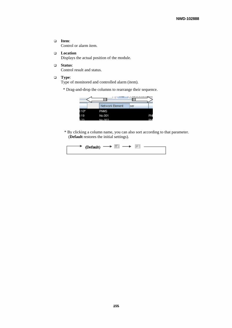
NWD-102888
- - 155
Item: Control or alarm item.
Location Displays the actual position of the module.
Status: Control result and status.
Type: Type of monitored and controlled alarm (item).
* Drag-and-drop the columns to rearrange their sequence.
* By clicking a column name, you can also sort according to that parameter. (Default restores the initial settings).
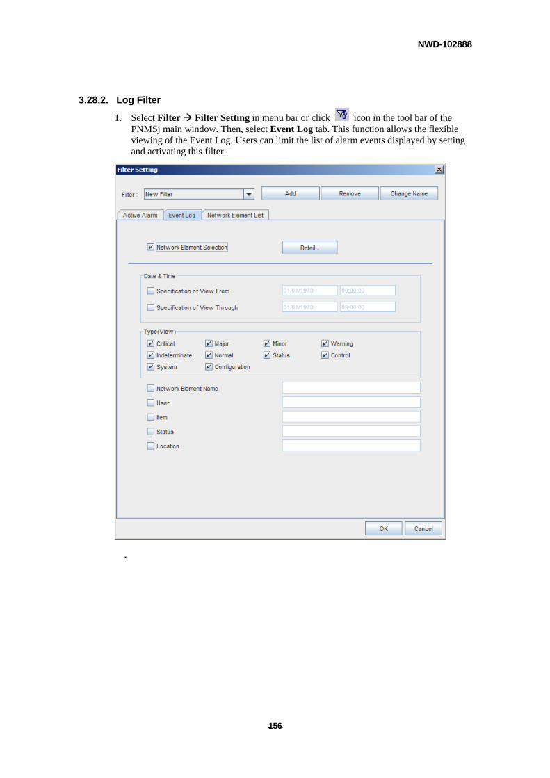
NWD-102888
- - 156
3.28.2. Log Filter
1. Select Filter Filter Setting in menu bar or click icon in the tool bar of the PNMSj main window. Then, select Event Log tab. This function allows the flexible viewing of the Event Log. Users can limit the list of alarm events displayed by setting and activating this filter.

NWD-102888
- - 157
Network Element Selection:
It can be selected for all network elements except those exempt from monitoring due to the security setting. (For details, refer to section 3.30.1Filter Setting)
Date & Time (Specification of View From...): Displays events resolved after the preset time.
Date & Time (Specification of View Through...): Displays events resolved before the preset time.
Type (View): Displays events of the preset types of parameters (condition).
Network Element Name: Displays events of the selected preset network elements.
User: Displays events occurred during the specific user’s logged in time.
Item: Displays events of the selected preset alarm (item).
Status: Displays events of the selected preset status.
Location Displays events of the selected preset location.
2. Click [OK] to activate filter.
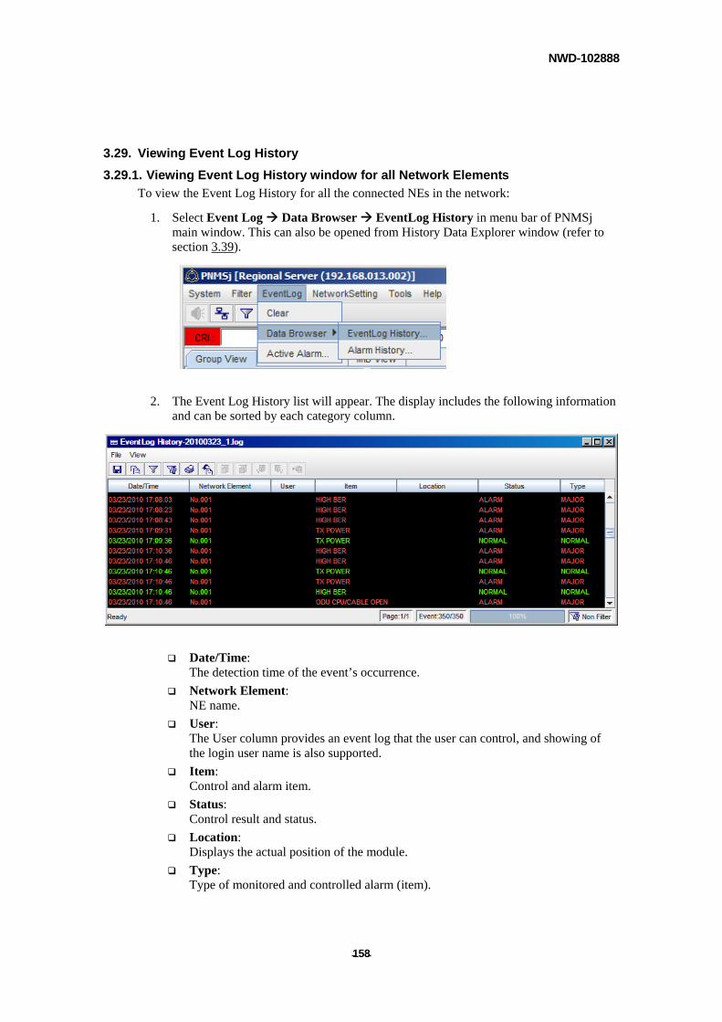
NWD-102888
- - 158
3.29. Viewing Event Log History
3.29.1. Viewing Event Log History window for all Network Elements
To view the Event Log History for all the connected NEs in the network:
1. Select Event Log Data Browser EventLog History in menu bar of PNMSj main window. This can also be opened from History Data Explorer window (refer to section 3.39).
2. The Event Log History list will appear. The display includes the following information and can be sorted by each category column.
Date/Time: The detection time of the event’s occurrence.
Network Element: NE name.
User: The User column provides an event log that the user can control, and showing of the login user name is also supported.
Item: Control and alarm item.
Status: Control result and status.
Location: Displays the actual position of the module.
Type: Type of monitored and controlled alarm (item).
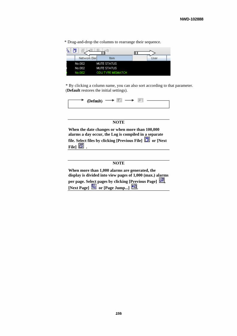
NWD-102888
- - 159
* Drag-and-drop the columns to rearrange their sequence.
* By clicking a column name, you can also sort according to that parameter. (Default restores the initial settings).
NOTE
When the date changes or when more than 100,000 alarms a day occur, the Log is compiled in a separate
file. Select files by clicking [Previous File] or [Next
File] .
NOTE
When more than 1,000 alarms are generated, the display is divided into view pages of 1,000 (max.) alarms
per page. Select pages by clicking [Previous Page] ,
[Next Page] or [Page Jump...] .
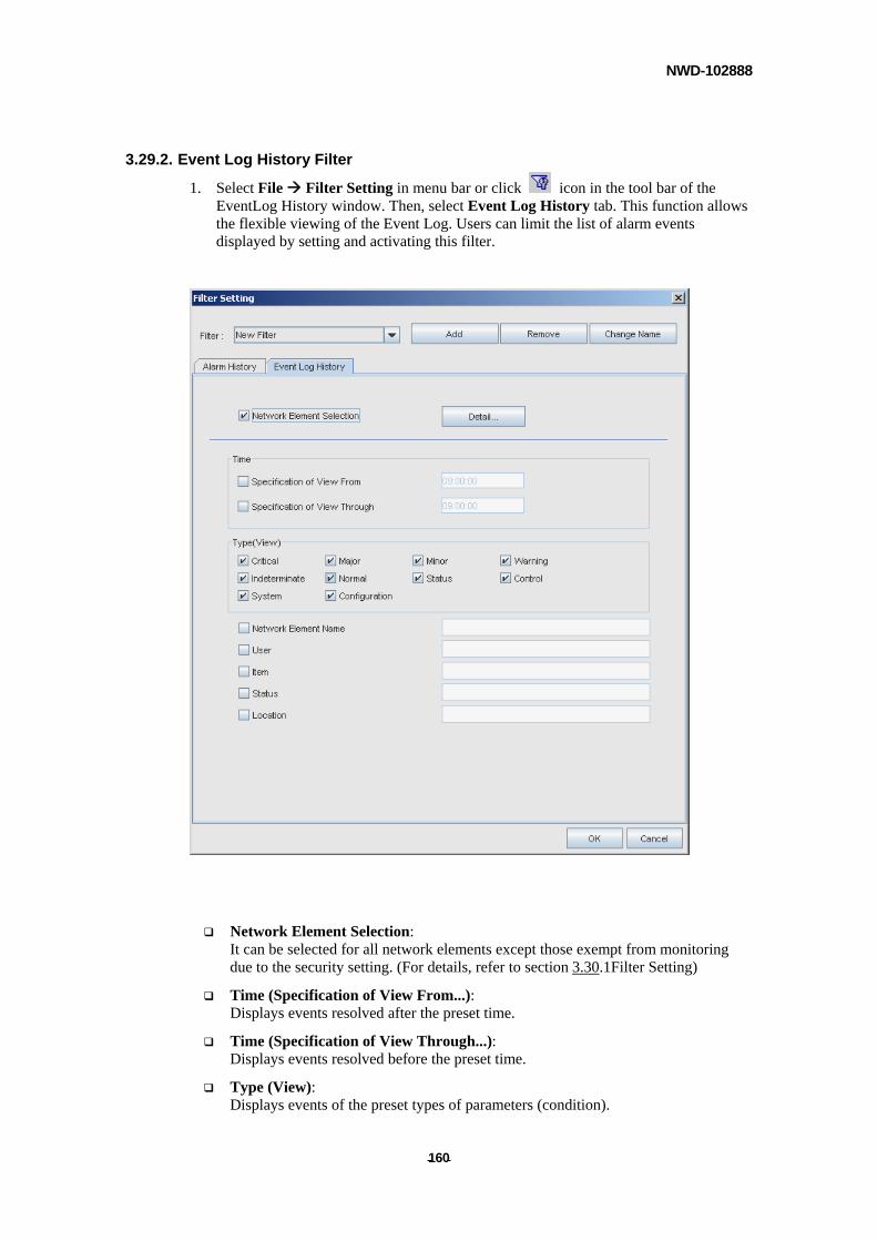
NWD-102888
- - 160
3.29.2. Event Log History Filter
1. Select File Filter Setting in menu bar or click icon in the tool bar of the EventLog History window. Then, select Event Log History tab. This function allows the flexible viewing of the Event Log. Users can limit the list of alarm events displayed by setting and activating this filter.
Network Element Selection: It can be selected for all network elements except those exempt from monitoring due to the security setting. (For details, refer to section 3.30.1Filter Setting)
Time (Specification of View From...): Displays events resolved after the preset time.
Time (Specification of View Through...): Displays events resolved before the preset time.
Type (View): Displays events of the preset types of parameters (condition).

NWD-102888
- - 161
Network Element Name: Displays events of the selected preset network elements.
User: Displays events occurred during the specific user’s logged in time.
Item: Displays events of the selected preset alarm (item).
Status: Displays events of the selected preset status.
Location: Displays events of the selected preset location.
2. Click [OK] to activate filter.
3.29.3. File – Open
Enables the Event Log File to be directly accessed / opened. The file is saved / stored in the <PNMSj Stored Directory>/log/log. When PNMSj is remote controlled (by remote server or client), this feature becomes available by copying the Event Log History File to the controlling PC.
3.29.4. File – Save As
Enables items displayed in the Event Log History Window to be saved in text (.csv) format.
Can also be done by clicking the icon in the tool bar of the Event Log History window.
NOTE
Do not save this file by overwriting <PNMSj Stored Directory>/log/log. By doing so will disrupt Event Log History from being displayed correctly.
3.29.5. File – History Data Explorer
Displays the History Data Explorer window.
This can also be done by clicking the icon in the tool bar of the Event Log History window.
3.29.6. File – Print
Enables items displayed in the Event Log History window to be printed out. Can also be
done by clicking the icon in the tool bar of the Event Log History window.
3.29.7. File – Reload
The latest Event Log History can be loaded (for instance, by using the icon).
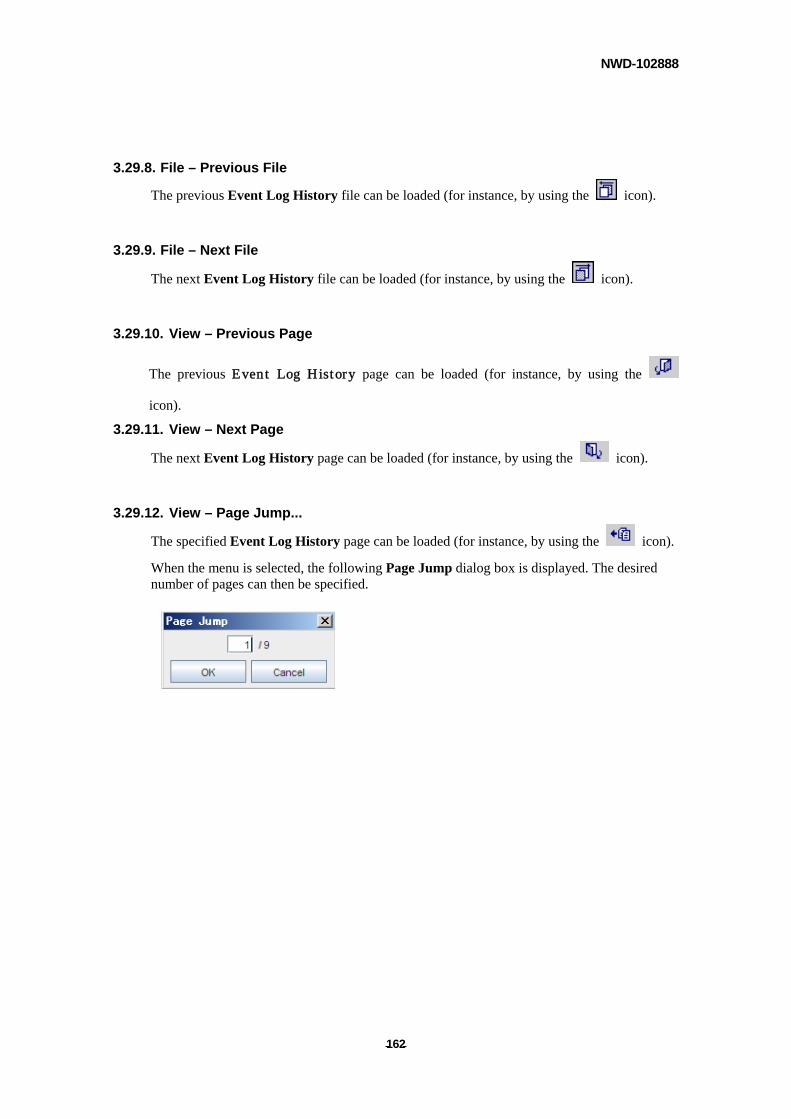
NWD-102888
- - 162
3.29.8. File – Previous File
The previous Event Log History file can be loaded (for instance, by using the icon).
3.29.9. File – Next File
The next Event Log History file can be loaded (for instance, by using the icon).
3.29.10. View – Previous Page
The previous Event Log History page can be loaded (for instance, by using the
icon).
3.29.11. View – Next Page
The next Event Log History page can be loaded (for instance, by using the icon).
3.29.12. View – Page Jump...
The specified Event Log History page can be loaded (for instance, by using the icon).
When the menu is selected, the following Page Jump dialog box is displayed. The desired number of pages can then be specified.
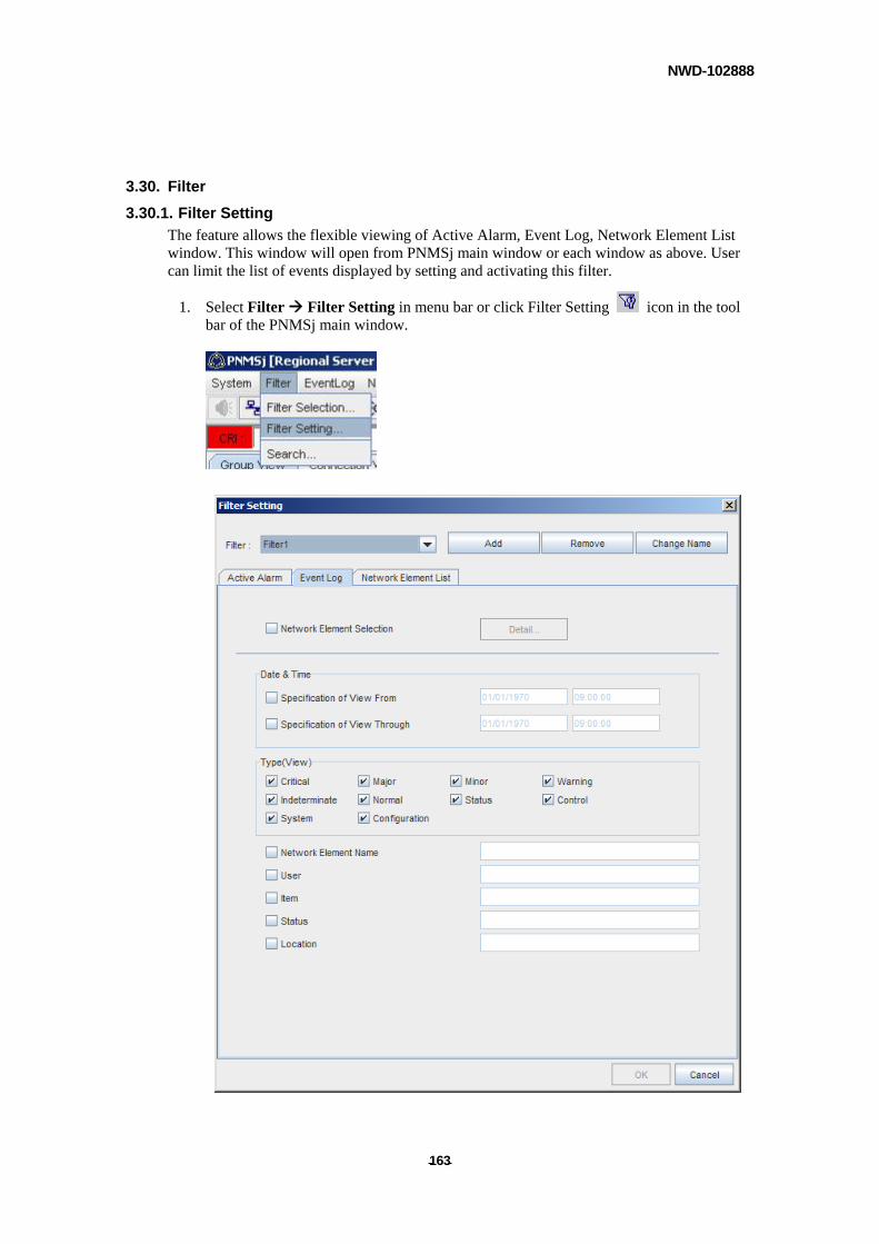
NWD-102888
- - 163
3.30. Filter
3.30.1. Filter Setting
The feature allows the flexible viewing of Active Alarm, Event Log, Network Element List window. This window will open from PNMSj main window or each window as above. User can limit the list of events displayed by setting and activating this filter.
1. Select Filter Filter Setting in menu bar or click Filter Setting icon in the tool bar of the PNMSj main window.
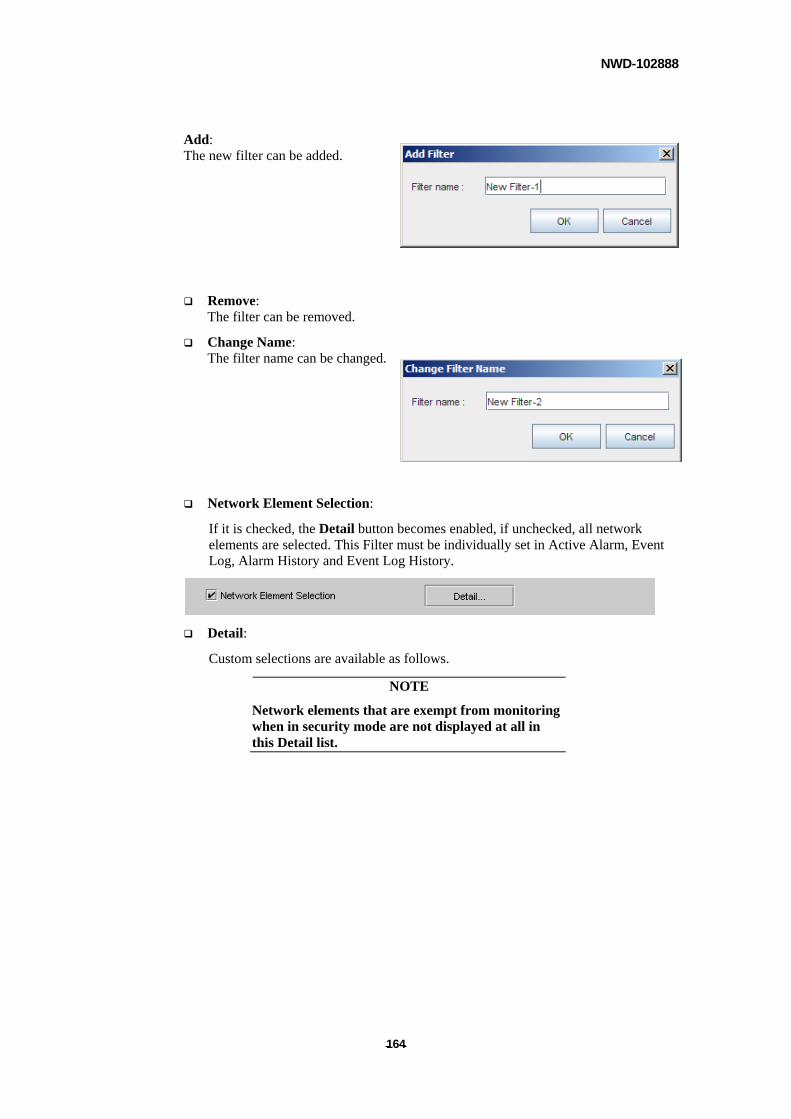
NWD-102888
- - 164
Add: The new filter can be added.
Remove: The filter can be removed.
Change Name: The filter name can be changed.
Network Element Selection:
If it is checked, the Detail button becomes enabled, if unchecked, all network elements are selected. This Filter must be individually set in Active Alarm, Event Log, Alarm History and Event Log History.
Detail:
Custom selections are available as follows.
NOTE
Network elements that are exempt from monitoring when in security mode are not displayed at all in this Detail list.
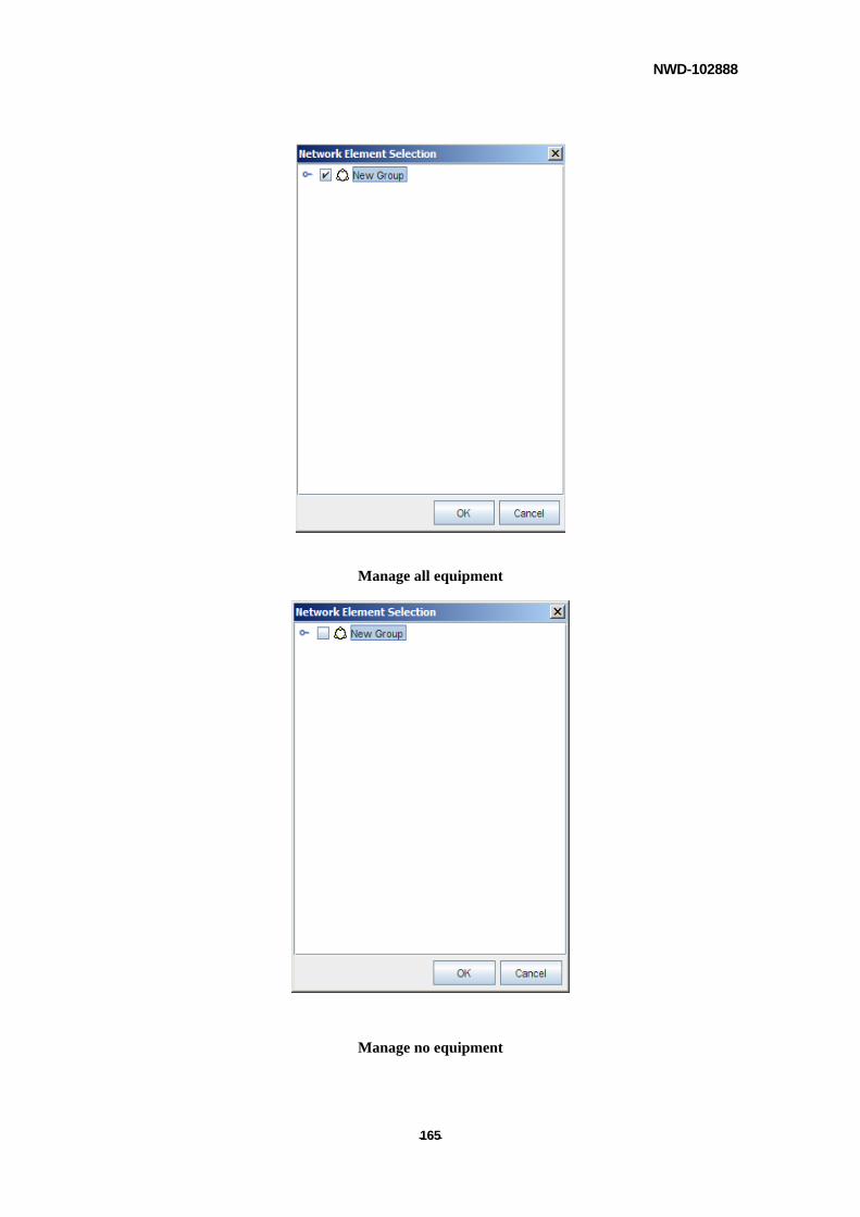
NWD-102888
- - 165
Manage all equipment
Manage no equipment
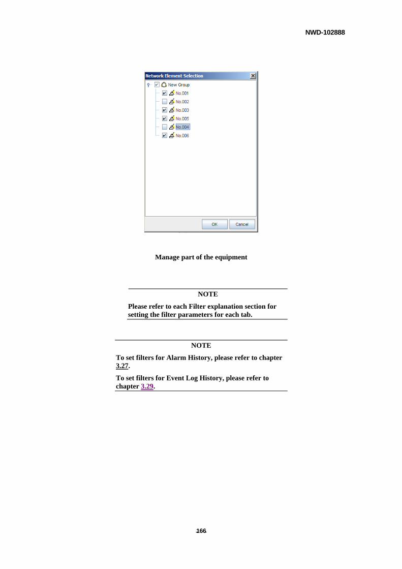
NWD-102888
- - 166
Manage part of the equipment
NOTE
Please refer to each Filter explanation section for setting the filter parameters for each tab.
NOTE
To set filters for Alarm History, please refer to chapter 3.27.
To set filters for Event Log History, please refer to chapter 3.29.
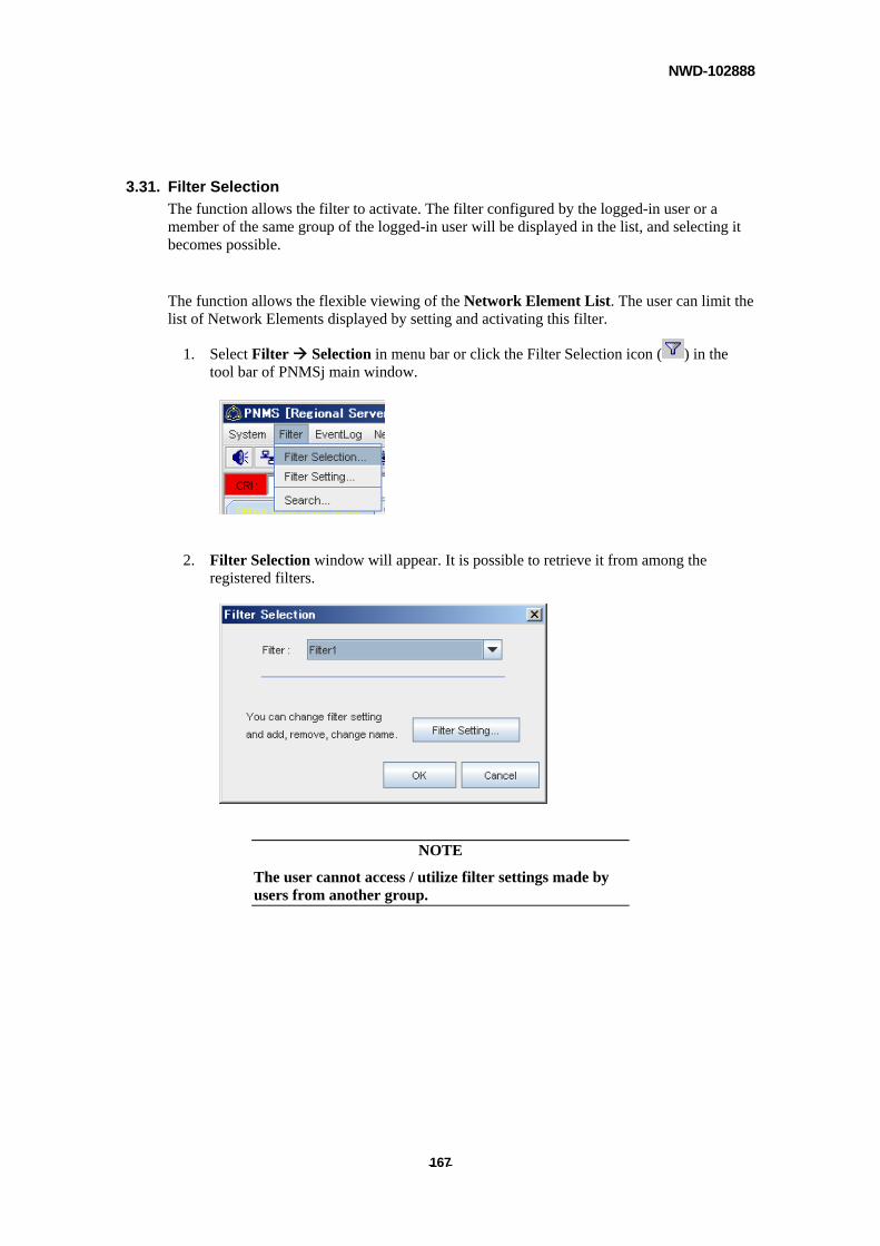
NWD-102888
- - 167
3.31. Filter Selection
The function allows the filter to activate. The filter configured by the logged-in user or a member of the same group of the logged-in user will be displayed in the list, and selecting it becomes possible.
The function allows the flexible viewing of the Network Element List. The user can limit the list of Network Elements displayed by setting and activating this filter.
1. Select Filter Selection in menu bar or click the Filter Selection icon ( ) in the tool bar of PNMSj main window.
2. Filter Selection window will appear. It is possible to retrieve it from among the registered filters.
NOTE
The user cannot access / utilize filter settings made by users from another group.
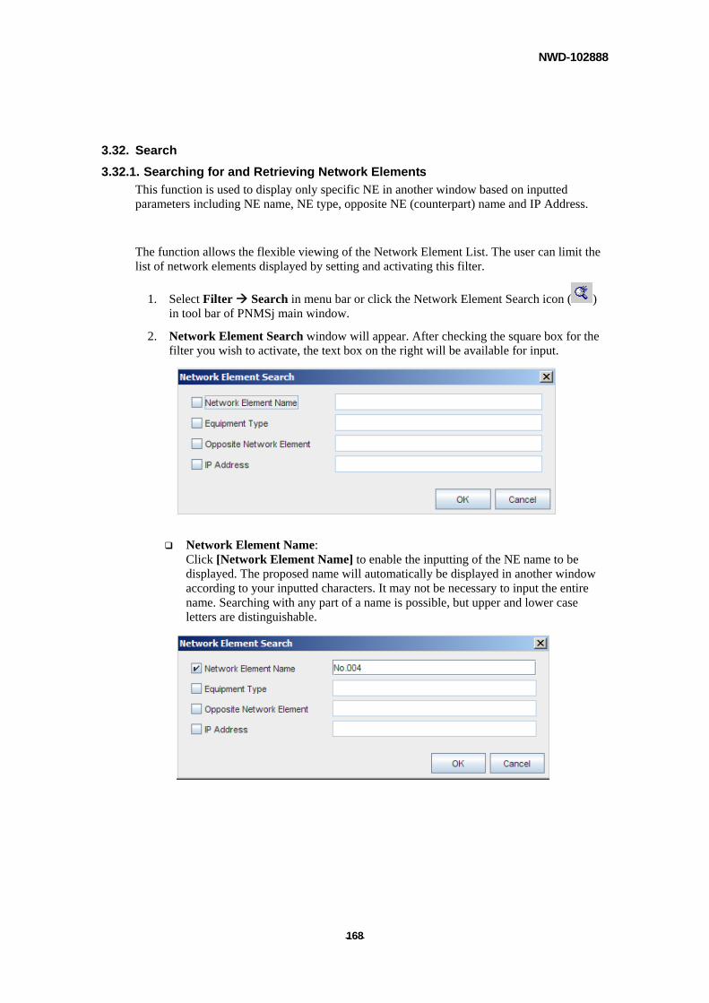
NWD-102888
- - 168
3.32. Search
3.32.1. Searching for and Retrieving Network Elements
This function is used to display only specific NE in another window based on inputted parameters including NE name, NE type, opposite NE (counterpart) name and IP Address.
The function allows the flexible viewing of the Network Element List. The user can limit the list of network elements displayed by setting and activating this filter.
1. Select Filter Search in menu bar or click the Network Element Search icon ( ) in tool bar of PNMSj main window.
2. Network Element Search window will appear. After checking the square box for the filter you wish to activate, the text box on the right will be available for input.
Network Element Name: Click [Network Element Name] to enable the inputting of the NE name to be displayed. The proposed name will automatically be displayed in another window according to your inputted characters. It may not be necessary to input the entire name. Searching with any part of a name is possible, but upper and lower case letters are distinguishable.
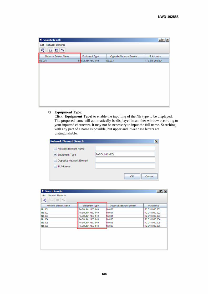
NWD-102888
- - 169
Equipment Type: Click [Equipment Type] to enable the inputting of the NE type to be displayed. The proposed name will automatically be displayed in another window according to your inputted characters. It may not be necessary to input the full name. Searching with any part of a name is possible, but upper and lower case letters are distinguishable.
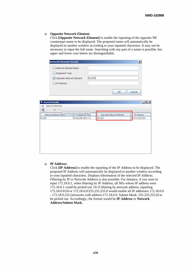
NWD-102888
- - 170
Opposite Network Element: Click [Opposite Network Element] to enable the inputting of the opposite NE counterpart name to be displayed. The proposed name will automatically be displayed in another window according to your inputted characters. It may not be necessary to input the full name. Searching with any part of a name is possible, but upper and lower case letters are distinguishable.
IP Address: Click [IP Address] to enable the inputting of the IP Address to be displayed. The proposed IP Address will automatically be displayed in another window according to your inputted characters. Displays information of the selected IP Address. Filtering by IP or Network Address is also possible. For instance, if you were to input 172.18.0.1, when filtering by IP Address, all NEs whose IP address were 172.18.0.1 could be picked out. Or if filtering by network address, inputting 172.18.0.0/24 or 172.18.0.0/255.255.255.0 would enable all IP addresses 172.18.0.0 - 172.18.0.255 (networks with address:172.18.0.0, Subnet Mask: 255.255.255.0) to be picked out. Accordingly, the format would be IP Address or Network Address/Subnet Mask.
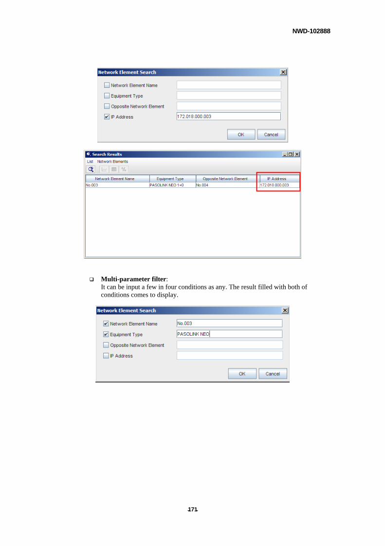
NWD-102888
- - 171
Multi-parameter filter: It can be input a few in four conditions as any. The result filled with both of conditions comes to display.
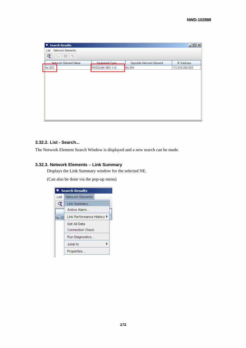
NWD-102888
- - 172
3.32.2. List - Search...
The Network Element Search Window is displayed and a new search can be made.
3.32.3. Network Elements – Link Summary
Displays the Link Summary window for the selected NE.
(Can also be done via the pop-up menu)
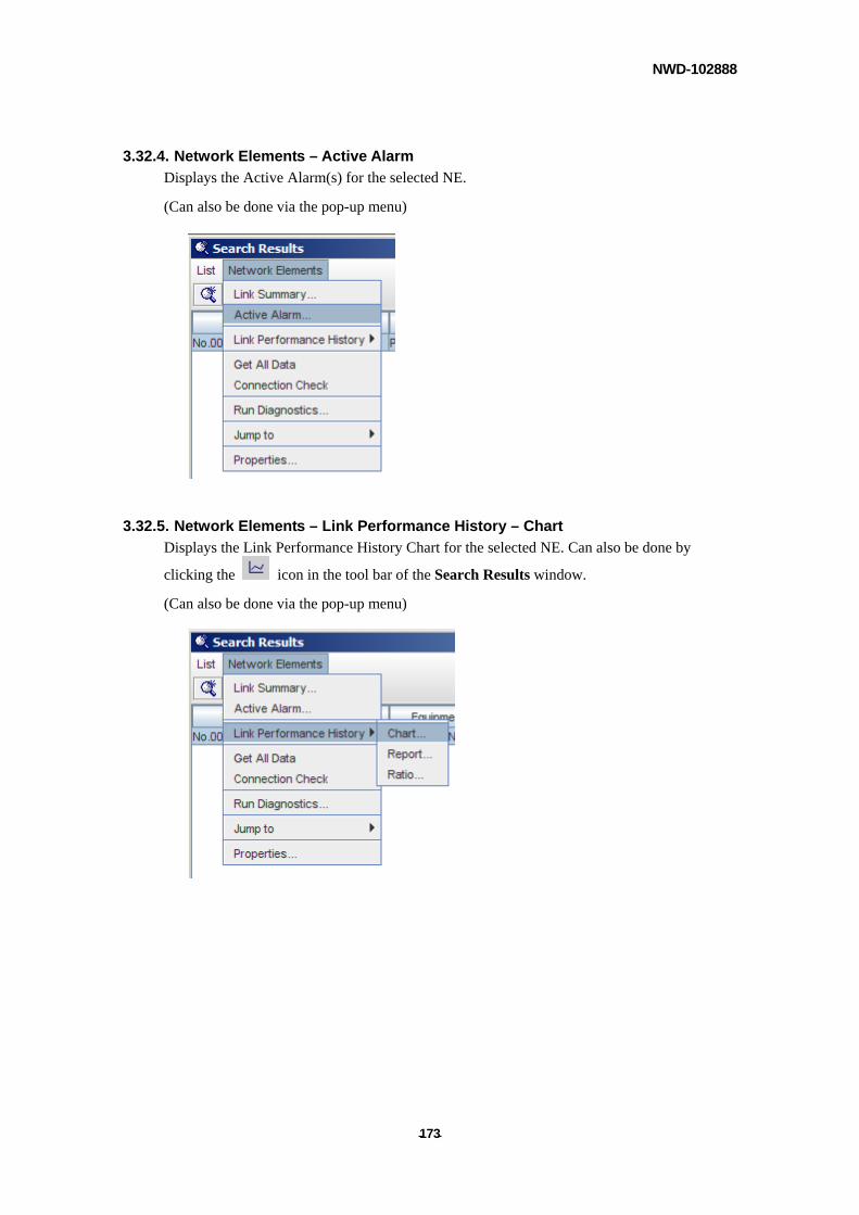
NWD-102888
- - 173
3.32.4. Network Elements – Active Alarm
Displays the Active Alarm(s) for the selected NE.
(Can also be done via the pop-up menu)
3.32.5. Network Elements – Link Performance History – Chart
Displays the Link Performance History Chart for the selected NE. Can also be done by
clicking the icon in the tool bar of the Search Results window.
(Can also be done via the pop-up menu)
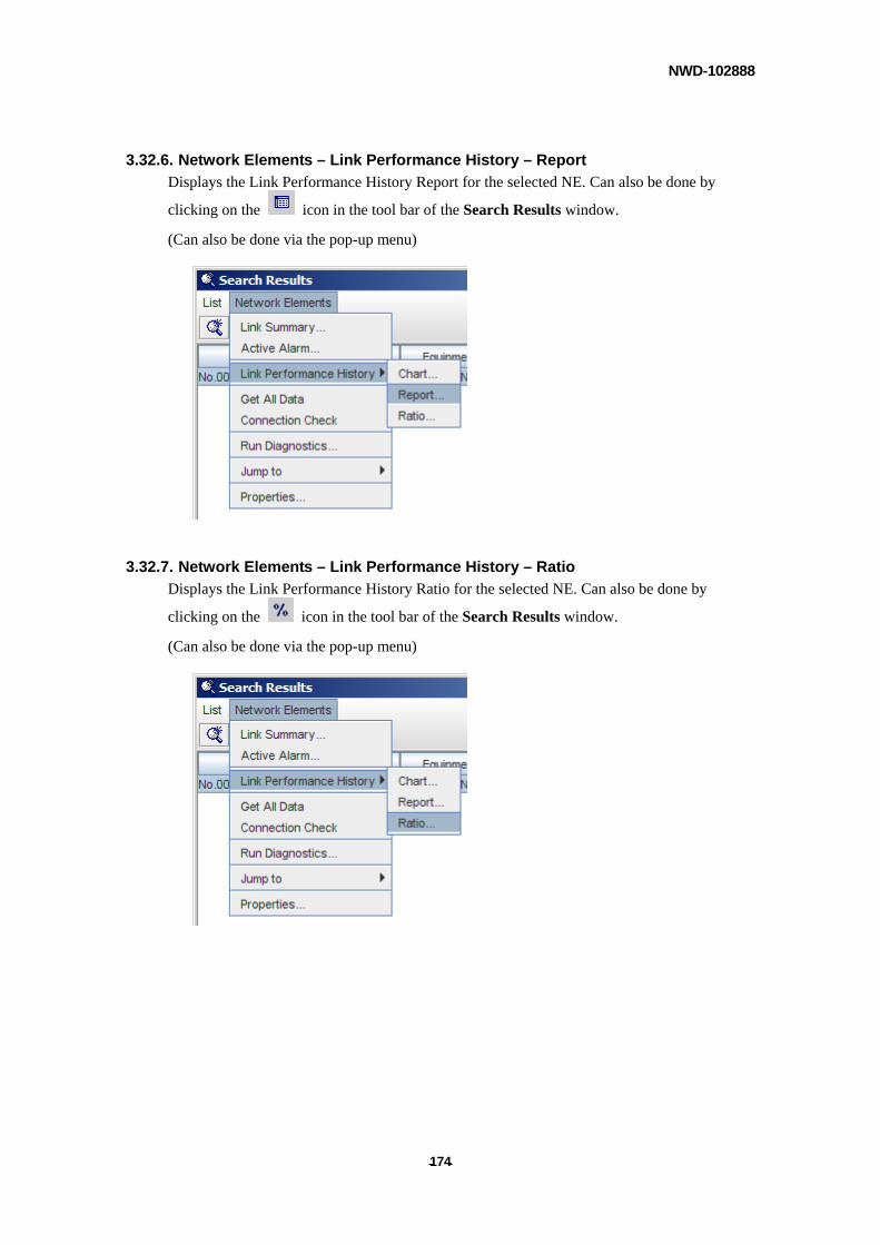
NWD-102888
- - 174
3.32.6. Network Elements – Link Performance History – Report
Displays the Link Performance History Report for the selected NE. Can also be done by
clicking on the icon in the tool bar of the Search Results window.
(Can also be done via the pop-up menu)
3.32.7. Network Elements – Link Performance History – Ratio
Displays the Link Performance History Ratio for the selected NE. Can also be done by
clicking on the icon in the tool bar of the Search Results window.
(Can also be done via the pop-up menu)
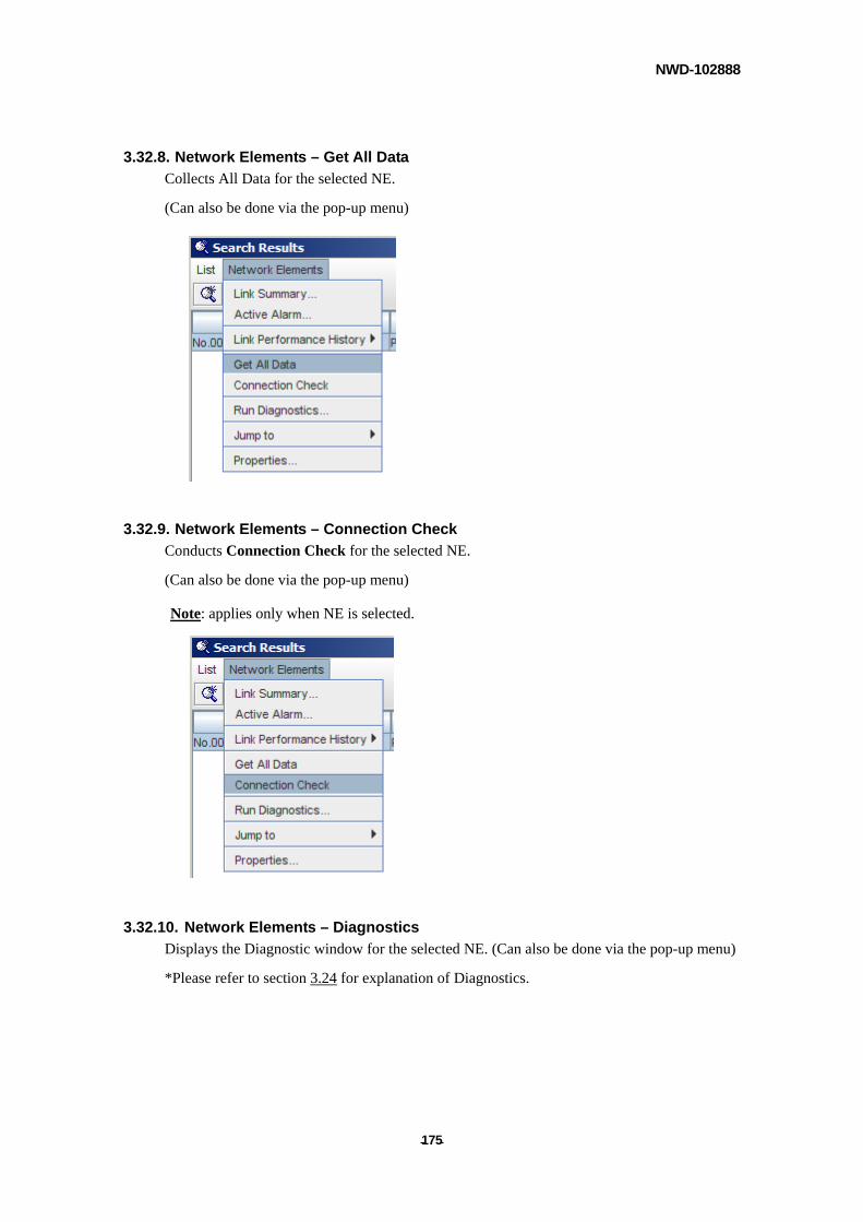
NWD-102888
- - 175
3.32.8. Network Elements – Get All Data
Collects All Data for the selected NE.
(Can also be done via the pop-up menu)
3.32.9. Network Elements – Connection Check
Conducts Connection Check for the selected NE.
(Can also be done via the pop-up menu)
Note: applies only when NE is selected.
3.32.10. Network Elements – Diagnostics
Displays the Diagnostic window for the selected NE. (Can also be done via the pop-up menu)
*Please refer to section 3.24 for explanation of Diagnostics.
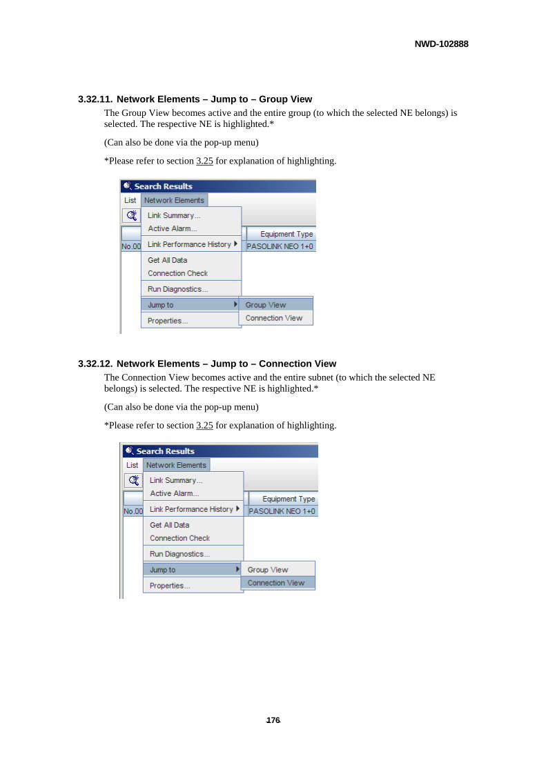
NWD-102888
- - 176
3.32.11. Network Elements – Jump to – Group View
The Group View becomes active and the entire group (to which the selected NE belongs) is selected. The respective NE is highlighted.*
(Can also be done via the pop-up menu)
*Please refer to section 3.25 for explanation of highlighting.
3.32.12. Network Elements – Jump to – Connection View
The Connection View becomes active and the entire subnet (to which the selected NE belongs) is selected. The respective NE is highlighted.*
(Can also be done via the pop-up menu)
*Please refer to section 3.25 for explanation of highlighting.
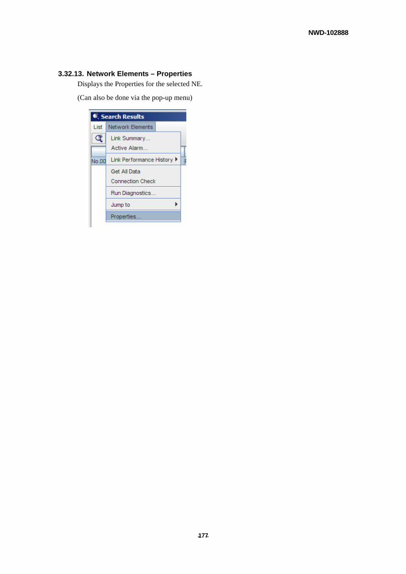
NWD-102888
- - 177
3.32.13. Network Elements – Properties
Displays the Properties for the selected NE.
(Can also be done via the pop-up menu)
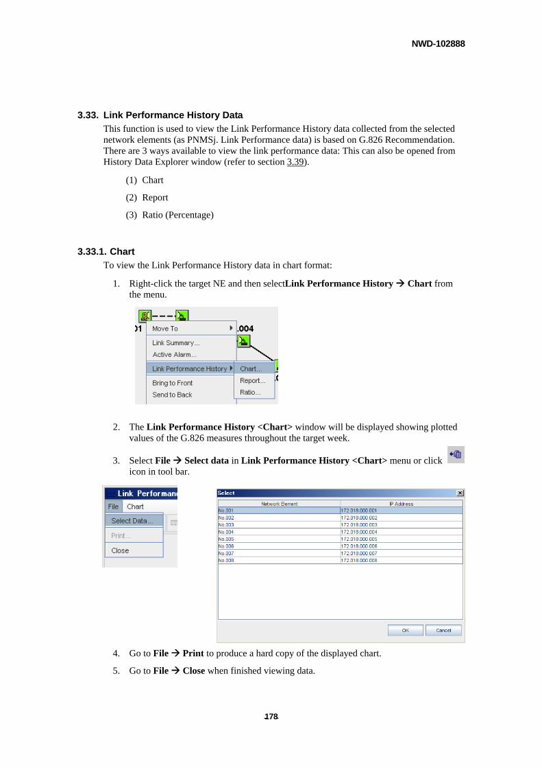
NWD-102888
- - 178
3.33. Link Performance History Data
This function is used to view the Link Performance History data collected from the selected network elements (as PNMSj. Link Performance data) is based on G.826 Recommendation. There are 3 ways available to view the link performance data: This can also be opened from History Data Explorer window (refer to section 3.39).
(1) Chart
(2) Report
(3) Ratio (Percentage)
3.33.1. Chart
To view the Link Performance History data in chart format:
1. Right-click the target NE and then selectLink Performance History Chart from the menu.
2. The Link Performance History <Chart> window will be displayed showing plotted values of the G.826 measures throughout the target week.
3. Select File Select data in Link Performance History <Chart> menu or click icon in tool bar.
4. Go to File Print to produce a hard copy of the displayed chart.
5. Go to File Close when finished viewing data.
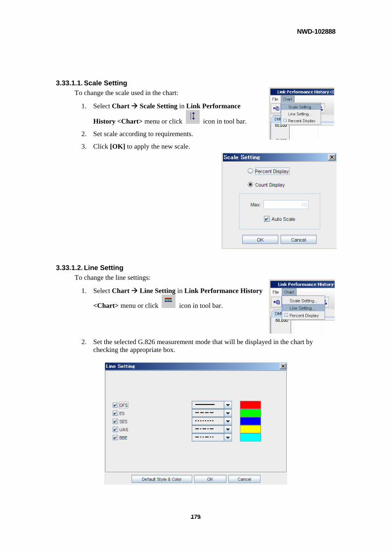
NWD-102888
- - 179
3.33.1.1. Scale Setting
To change the scale used in the chart:
1. Select Chart Scale Setting in Link Performance
History <Chart> menu or click icon in tool bar.
2. Set scale according to requirements.
3. Click [OK] to apply the new scale.
3.33.1.2. Line Setting
To change the line settings:
1. Select Chart Line Setting in Link Performance History
<Chart> menu or click icon in tool bar.
2. Set the selected G.826 measurement mode that will be displayed in the chart by checking the appropriate box.
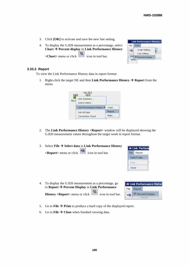
NWD-102888
- - 180
3. Click [OK] to activate and save the new line setting.
4. To display the G.826 measurement as a percentage, select Chart Percent display in Link Performance History
<Chart> menu or click icon in tool bar.
3.33.2. Report
To view the Link Performance History data in report format:
1. Right-click the target NE and then Link Performance History Report from the menu.
2. The Link Performance History <Report> window will be displayed showing the
G.826 measurement values throughout the target week in report format.
3. Select File Select data in Link Performance History
<Report> menu or click icon in tool bar.
4. To display the G.826 measurement as a percentage, go to Report Percent Display in Link Performance
History <Report> menu or click icon in tool bar.
5. Go to File Print to produce a hard copy of the displayed report.
6. Go to File Close when finished viewing data.
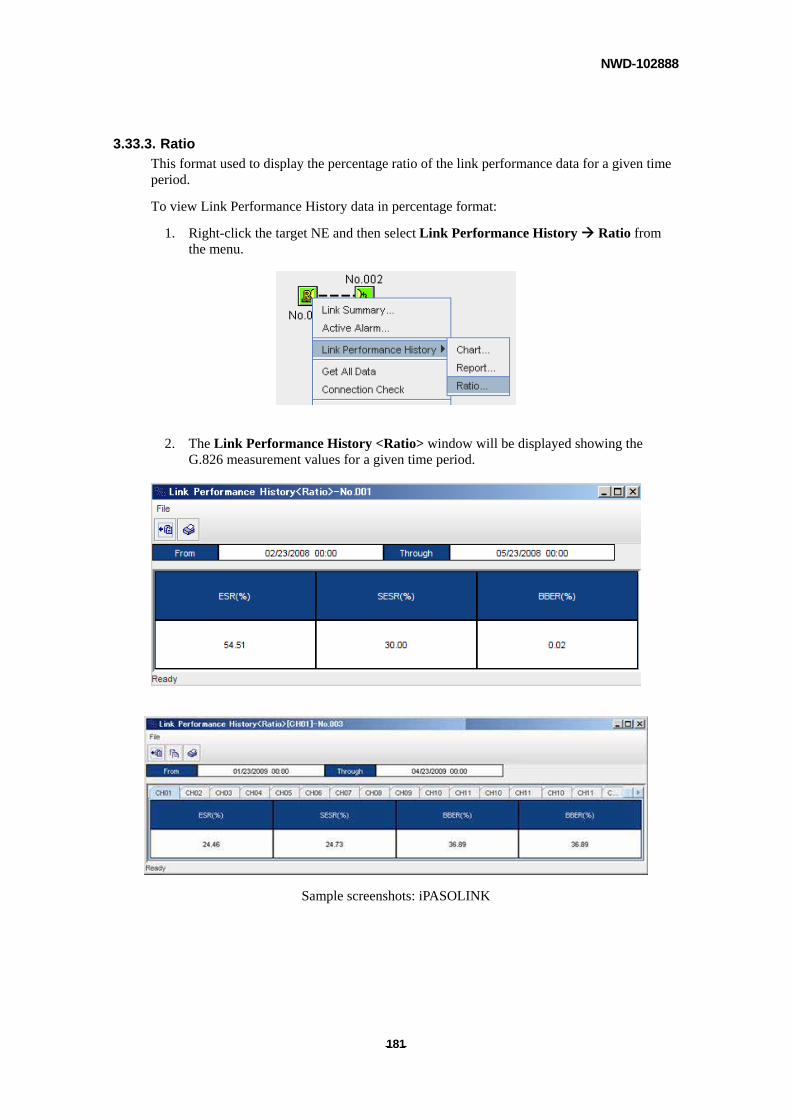
NWD-102888
- - 181
3.33.3. Ratio
This format used to display the percentage ratio of the link performance data for a given time period.
To view Link Performance History data in percentage format:
1. Right-click the target NE and then select Link Performance History Ratio from the menu.
2. The Link Performance History <Ratio> window will be displayed showing the G.826 measurement values for a given time period.
Sample screenshots: iPASOLINK
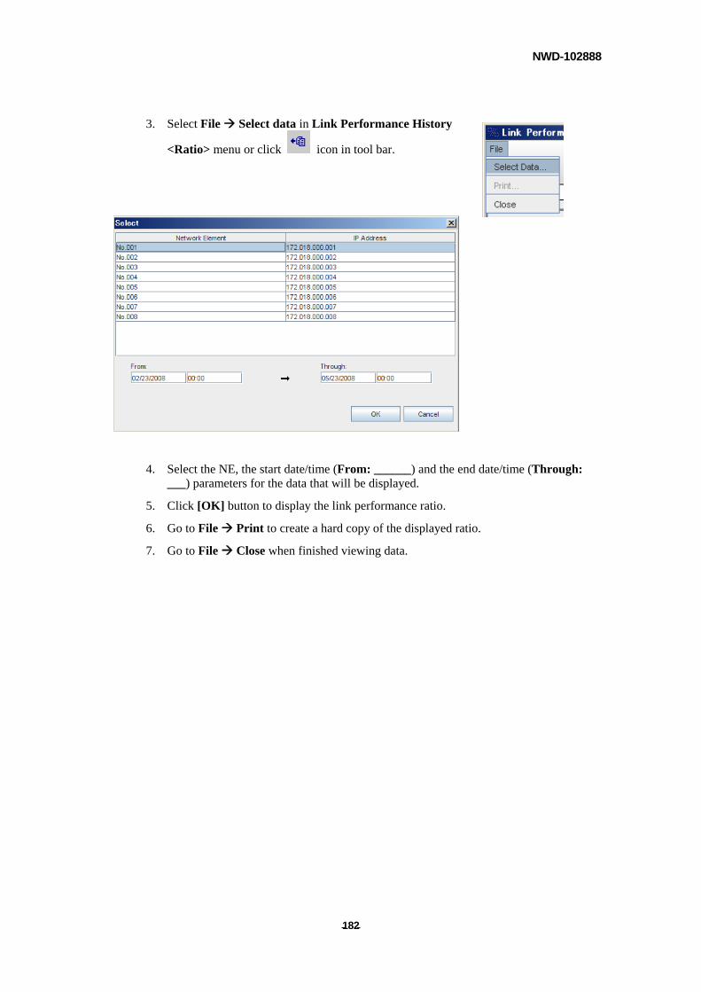
NWD-102888
- - 182
3. Select File Select data in Link Performance History
<Ratio> menu or click icon in tool bar.
4. Select the NE, the start date/time (From: ______) and the end date/time (Through:
___) parameters for the data that will be displayed.
5. Click [OK] button to display the link performance ratio.
6. Go to File Print to create a hard copy of the displayed ratio.
7. Go to File Close when finished viewing data.
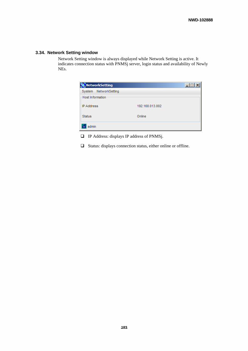
NWD-102888
- - 183
3.34. Network Setting window
Network Setting window is always displayed while Network Setting is active. It indicates connection status with PNMSj server, login status and availability of Newly NEs.
IP Address: displays IP address of PNMSj.
Status: displays connection status, either online or offline.
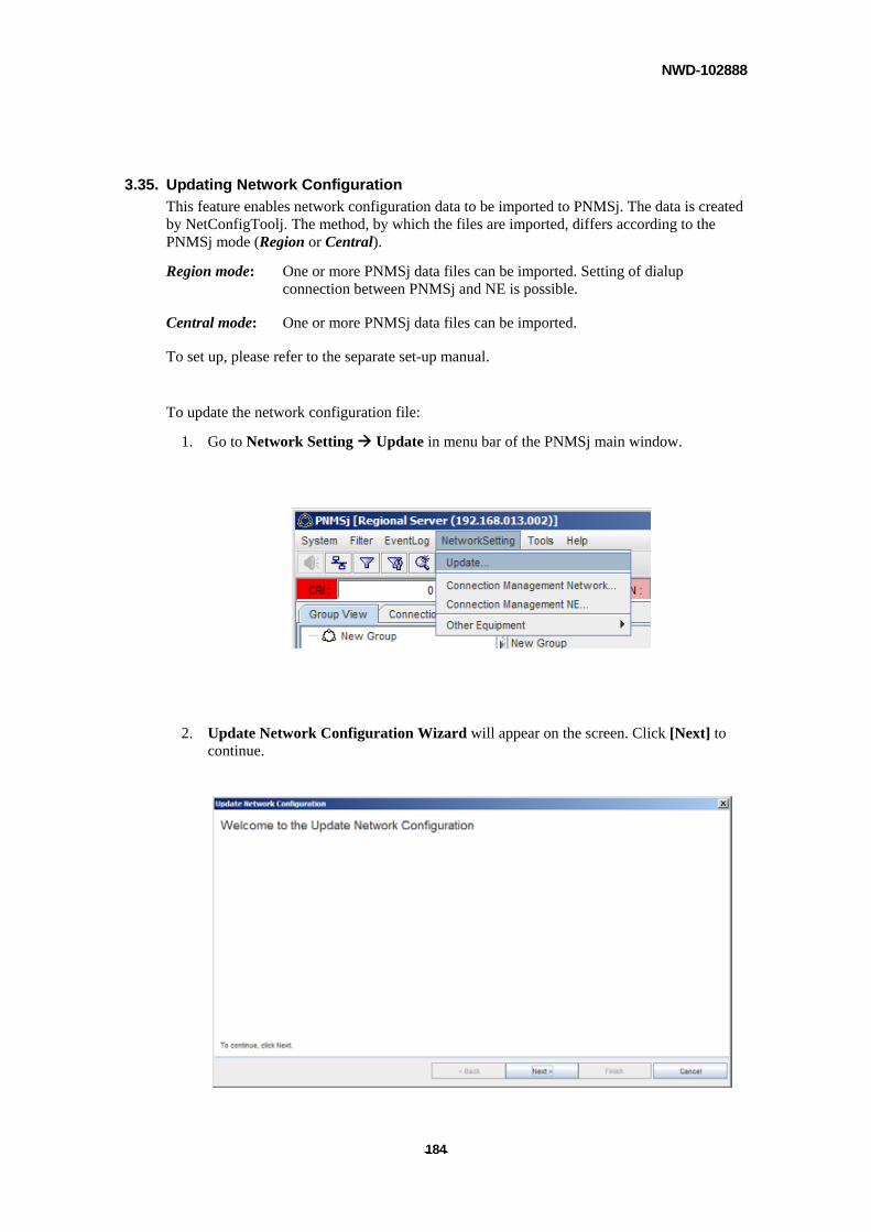
NWD-102888
- - 184
3.35. Updating Network Configuration
This feature enables network configuration data to be imported to PNMSj. The data is created by NetConfigToolj. The method, by which the files are imported, differs according to the PNMSj mode (Region or Central).
Region mode: One or more PNMSj data files can be imported. Setting of dialup connection between PNMSj and NE is possible.
Central mode: One or more PNMSj data files can be imported.
To set up, please refer to the separate set-up manual.
To update the network configuration file:
1. Go to Network Setting Update in menu bar of the PNMSj main window.
2. Update Network Configuration Wizard will appear on the screen. Click [Next] to continue.
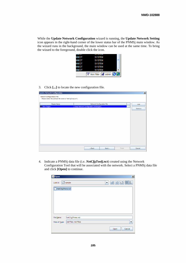
NWD-102888
- - 185
While the Update Network Configuration wizard is running, the Update Network Setting icon appears in the right-hand corner of the lower status bar of the PNMSj main window. As the wizard runs in the background, the main window can be used at the same time. To bring the wizard to the foreground, double click the icon.
3. Click [...] to locate the new configuration file.
4. Indicate a PNMSj data file (i.e. NetCfgToolj.nct) created using the Network Configuration Tool that will be associated with the network. Select a PNMSj data file and click [Open] to continue.
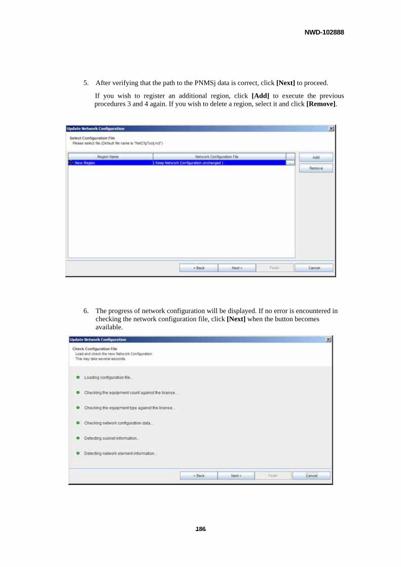
NWD-102888
- - 186
5. After verifying that the path to the PNMSj data is correct, click [Next] to proceed.
If you wish to register an additional region, click [Add] to execute the previous procedures 3 and 4 again. If you wish to delete a region, select it and click [Remove].
6. The progress of network configuration will be displayed. If no error is encountered in checking the network configuration file, click [Next] when the button becomes available.
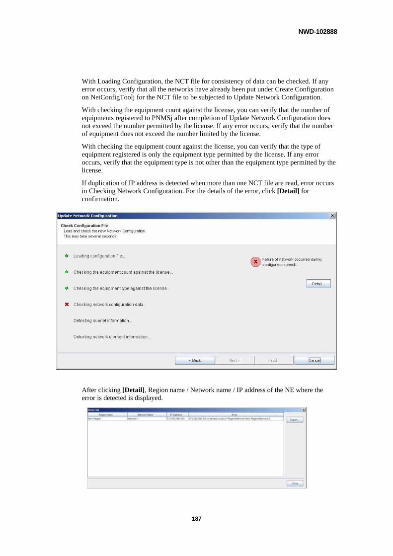
NWD-102888
- - 187
With Loading Configuration, the NCT file for consistency of data can be checked. If any error occurs, verify that all the networks have already been put under Create Configuration on NetConfigToolj for the NCT file to be subjected to Update Network Configuration.
With checking the equipment count against the license, you can verify that the number of equipments registered to PNMSj after completion of Update Network Configuration does not exceed the number permitted by the license. If any error occurs, verify that the number of equipment does not exceed the number limited by the license.
With checking the equipment count against the license, you can verify that the type of equipment registered is only the equipment type permitted by the license. If any error occurs, verify that the equipment type is not other than the equipment type permitted by the license.
If duplication of IP address is detected when more than one NCT file are read, error occurs in Checking Network Configuration. For the details of the error, click [Detail] for confirmation.
After clicking [Detail], Region name / Network name / IP address of the NE where the error is detected is displayed.
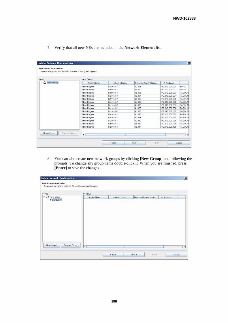
NWD-102888
- - 188
7. Verify that all new NEs are included in the Network Element list.
8. You can also create new network groups by clicking [New Group] and following the prompts. To change any group name double-click it. When you are finished, press [Enter] to save the changes.
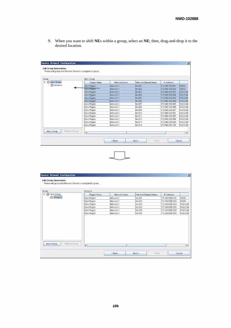
NWD-102888
- - 189
9. When you want to shift NEs within a group, select an NE; then, drag-and-drop it to the desired location.
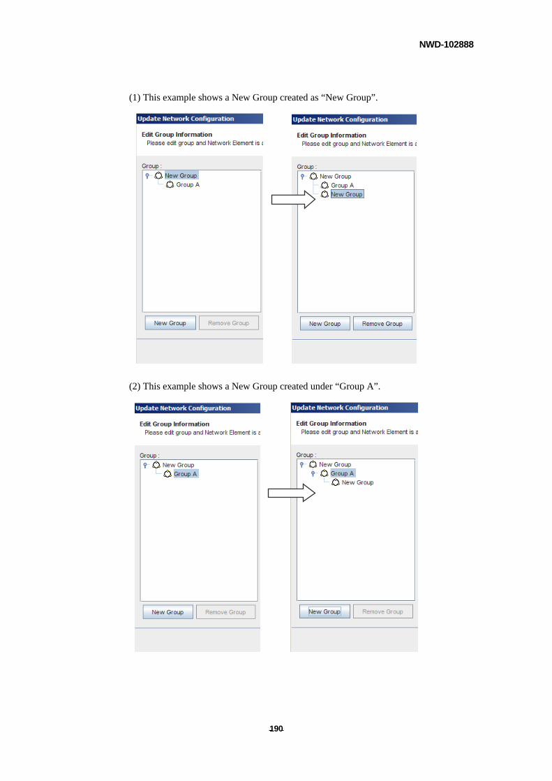
NWD-102888
- - 190
(1) This example shows a New Group created as “New Group”.
(2) This example shows a New Group created under “Group A”.
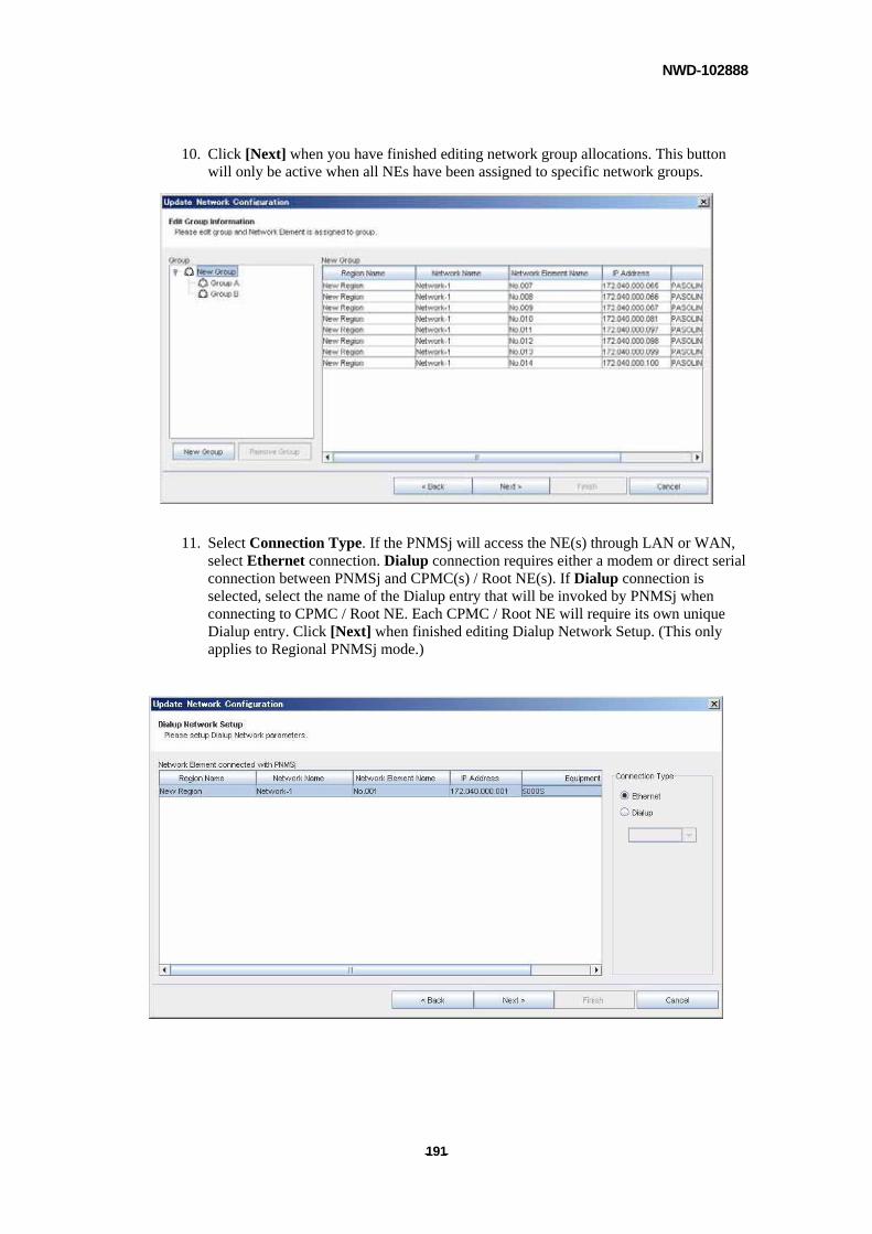
NWD-102888
- - 191
10. Click [Next] when you have finished editing network group allocations. This button will only be active when all NEs have been assigned to specific network groups.
11. Select Connection Type. If the PNMSj will access the NE(s) through LAN or WAN, select Ethernet connection. Dialup connection requires either a modem or direct serial connection between PNMSj and CPMC(s) / Root NE(s). If Dialup connection is selected, select the name of the Dialup entry that will be invoked by PNMSj when connecting to CPMC / Root NE. Each CPMC / Root NE will require its own unique Dialup entry. Click [Next] when finished editing Dialup Network Setup. (This only applies to Regional PNMSj mode.)
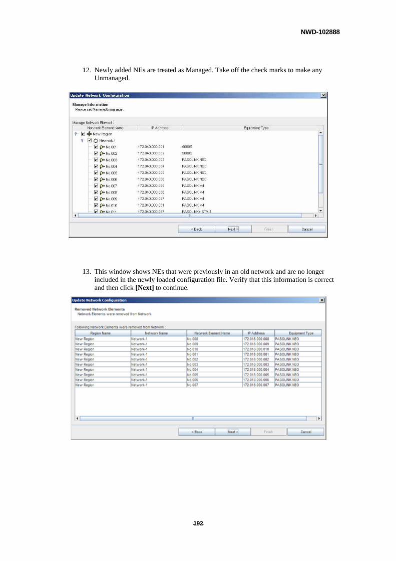
NWD-102888
- - 192
12. Newly added NEs are treated as Managed. Take off the check marks to make any Unmanaged.
13. This window shows NEs that were previously in an old network and are no longer included in the newly loaded configuration file. Verify that this information is correct and then click [Next] to continue.
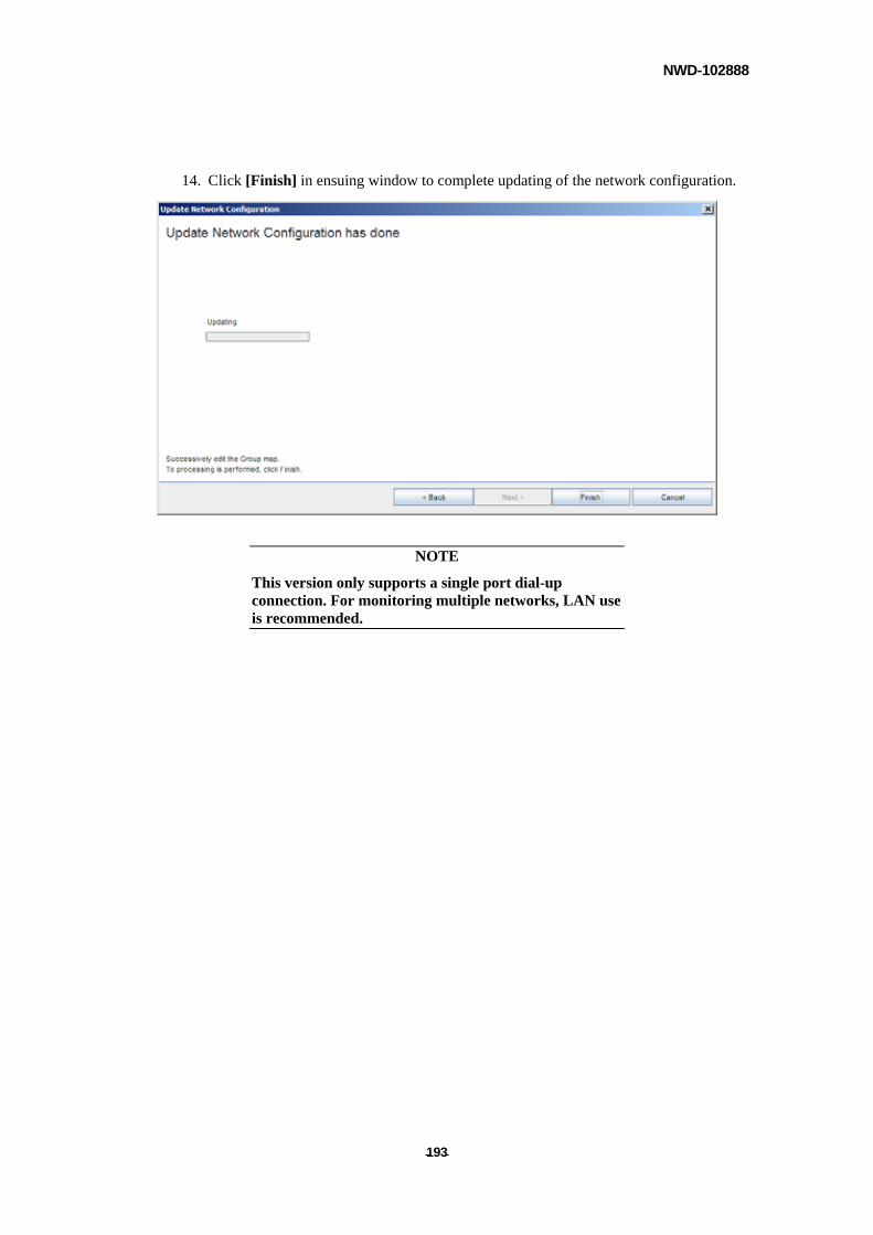
NWD-102888
- - 193
14. Click [Finish] in ensuing window to complete updating of the network configuration.
NOTE
This version only supports a single port dial-up connection. For monitoring multiple networks, LAN use is recommended.
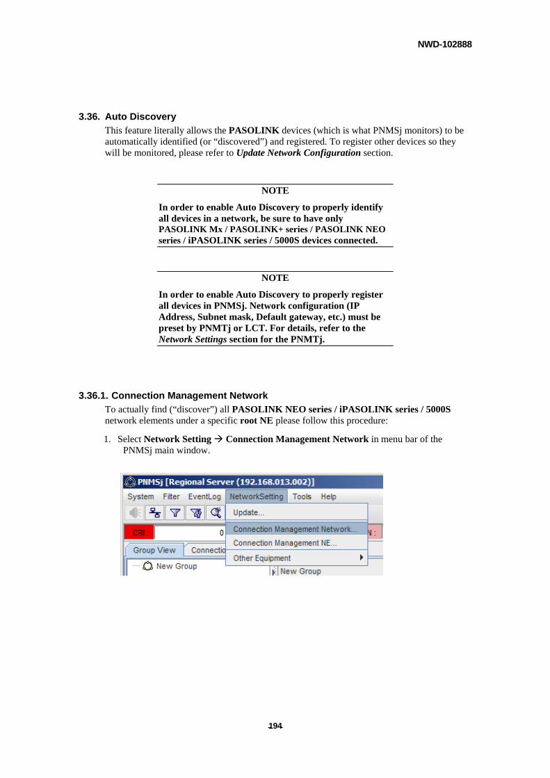
NWD-102888
- - 194
3.36. Auto Discovery
This feature literally allows the PASOLINK devices (which is what PNMSj monitors) to be automatically identified (or “discovered”) and registered. To register other devices so they will be monitored, please refer to Update Network Configuration section.
NOTE
In order to enable Auto Discovery to properly identify all devices in a network, be sure to have only PASOLINK Mx / PASOLINK+ series / PASOLINK NEO series / iPASOLINK series / 5000S devices connected.
NOTE
In order to enable Auto Discovery to properly register all devices in PNMSj. Network configuration (IP Address, Subnet mask, Default gateway, etc.) must be preset by PNMTj or LCT. For details, refer to the Network Settings section for the PNMTj.
3.36.1. Connection Management Network
To actually find (“discover”) all PASOLINK NEO series / iPASOLINK series / 5000S network elements under a specific root NE please follow this procedure:
1. Select Network Setting Connection Management Network in menu bar of the PNMSj main window.
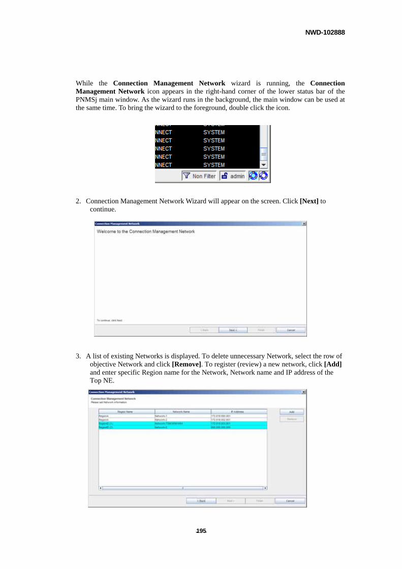
NWD-102888
- - 195
While the Connection Management Network wizard is running, the Connection Management Network icon appears in the right-hand corner of the lower status bar of the PNMSj main window. As the wizard runs in the background, the main window can be used at the same time. To bring the wizard to the foreground, double click the icon.
2. Connection Management Network Wizard will appear on the screen. Click [Next] to continue.
3. A list of existing Networks is displayed. To delete unnecessary Network, select the row of
objective Network and click [Remove]. To register (review) a new network, click [Add] and enter specific Region name for the Network, Network name and IP address of the Top NE.
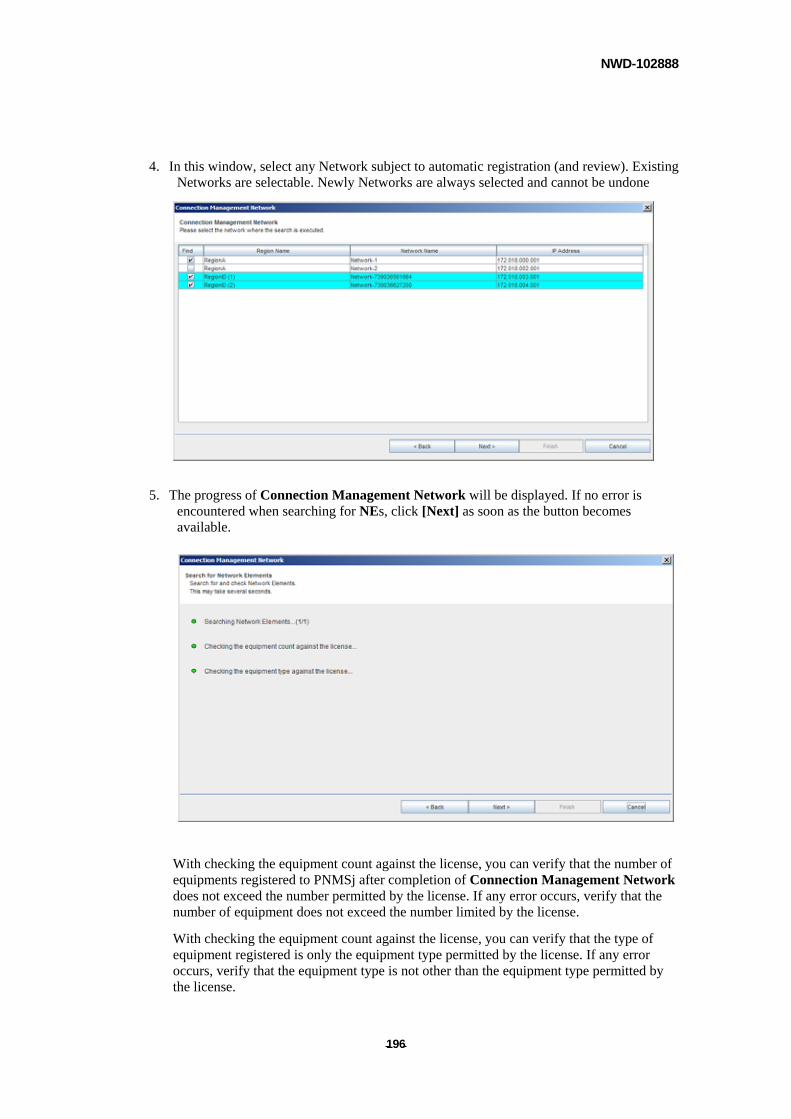
NWD-102888
- - 196
4. In this window, select any Network subject to automatic registration (and review). Existing Networks are selectable. Newly Networks are always selected and cannot be undone
5. The progress of Connection Management Network will be displayed. If no error is encountered when searching for NEs, click [Next] as soon as the button becomes available.
With checking the equipment count against the license, you can verify that the number of equipments registered to PNMSj after completion of Connection Management Network does not exceed the number permitted by the license. If any error occurs, verify that the number of equipment does not exceed the number limited by the license.
With checking the equipment count against the license, you can verify that the type of equipment registered is only the equipment type permitted by the license. If any error occurs, verify that the equipment type is not other than the equipment type permitted by the license.
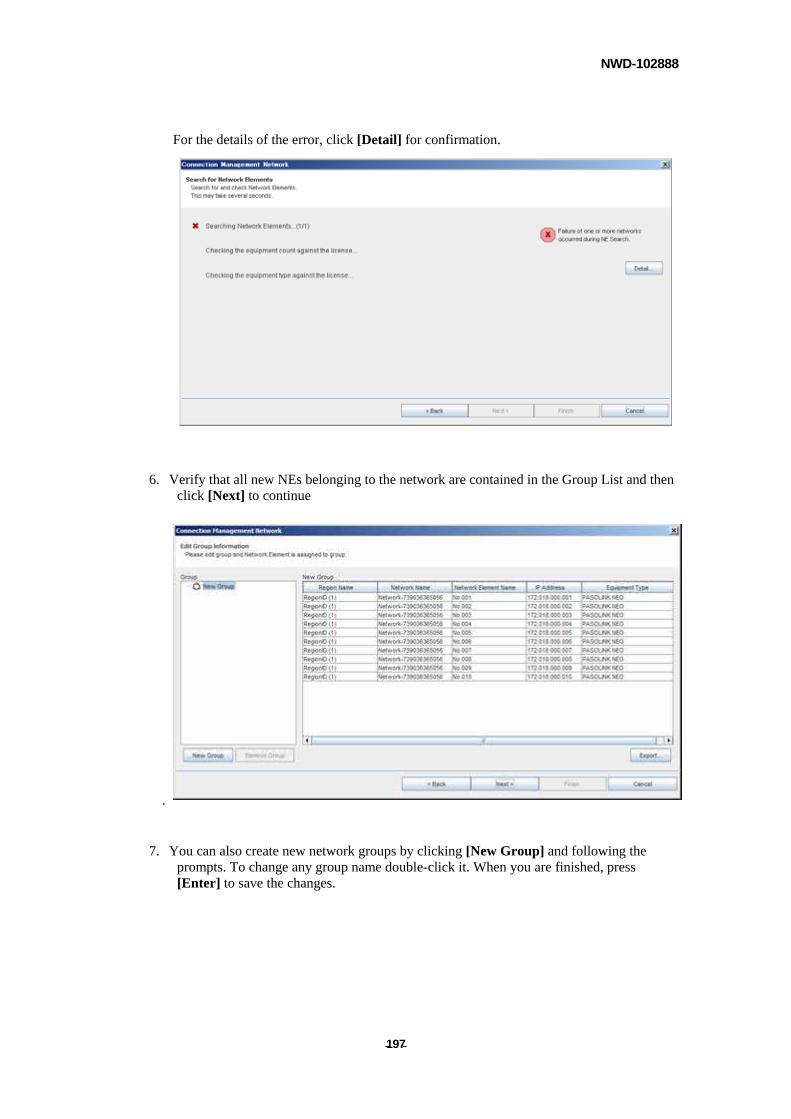
NWD-102888
- - 197
For the details of the error, click [Detail] for confirmation.
6. Verify that all new NEs belonging to the network are contained in the Group List and then click [Next] to continue
.
7. You can also create new network groups by clicking [New Group] and following the prompts. To change any group name double-click it. When you are finished, press [Enter] to save the changes.
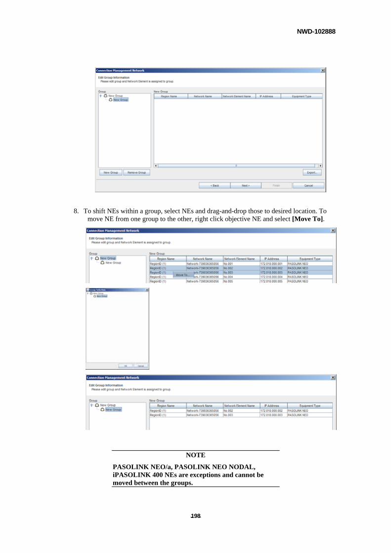
NWD-102888
- - 198
8. To shift NEs within a group, select NEs and drag-and-drop those to desired location. To move NE from one group to the other, right click objective NE and select [Move To].
NOTE
PASOLINK NEO/a, PASOLINK NEO NODAL, iPASOLINK 400 NEs are exceptions and cannot be moved between the groups.
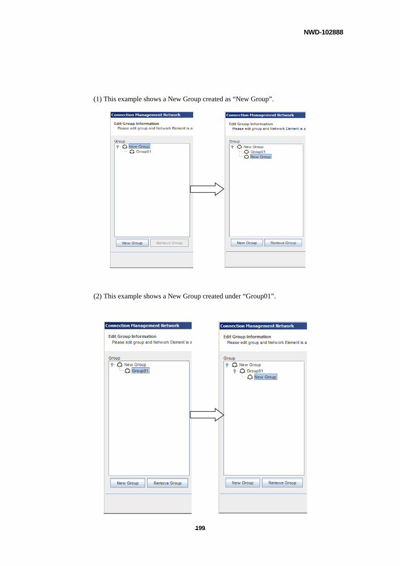
NWD-102888
- - 199
(1) This example shows a New Group created as “New Group”.
(2) This example shows a New Group created under “Group01”.
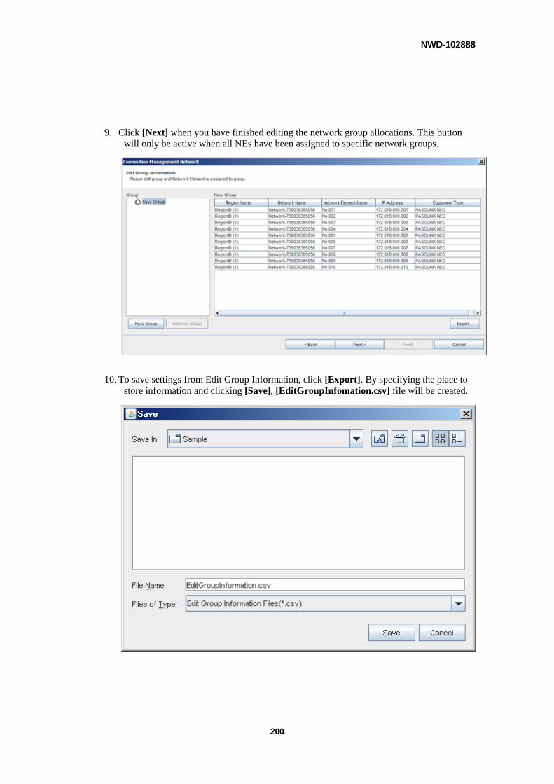
NWD-102888
- - 200
9. Click [Next] when you have finished editing the network group allocations. This button will only be active when all NEs have been assigned to specific network groups.
10. To save settings from Edit Group Information, click [Export]. By specifying the place to store information and clicking [Save], [EditGroupInfomation.csv] file will be created.
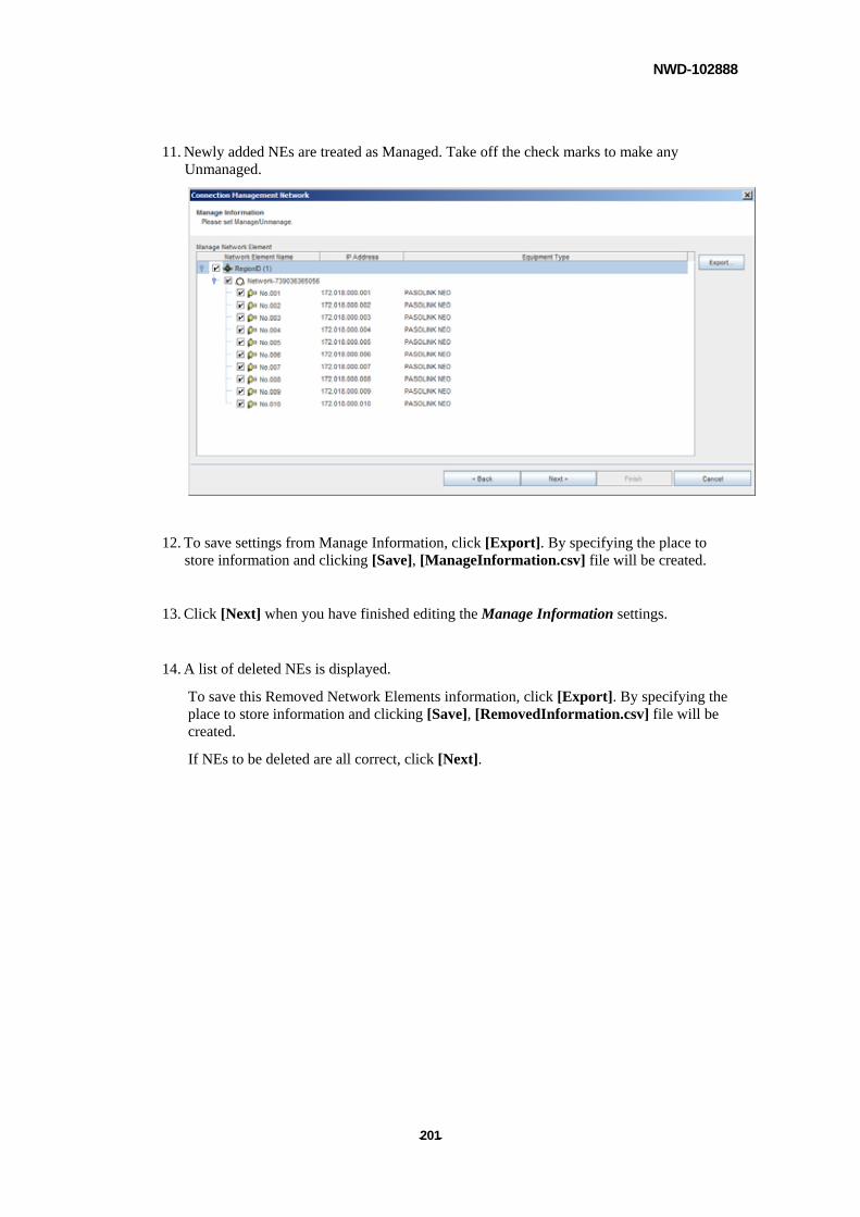
NWD-102888
- - 201
11. Newly added NEs are treated as Managed. Take off the check marks to make any Unmanaged.
12. To save settings from Manage Information, click [Export]. By specifying the place to store information and clicking [Save], [ManageInformation.csv] file will be created.
13. Click [Next] when you have finished editing the Manage Information settings.
14. A list of deleted NEs is displayed.
To save this Removed Network Elements information, click [Export]. By specifying the place to store information and clicking [Save], [RemovedInformation.csv] file will be created.
If NEs to be deleted are all correct, click [Next].
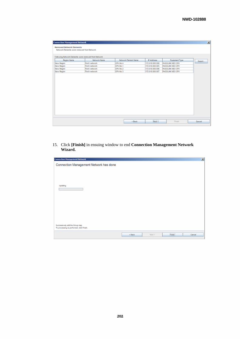
NWD-102888
- - 202
15. Click [Finish] in ensuing window to end Connection Management Network Wizard.
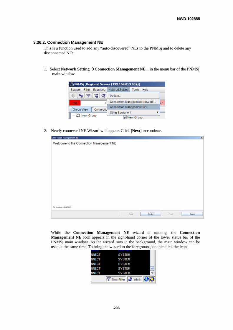
NWD-102888
- - 203
3.36.2. Connection Management NE
This is a function used to add any “auto-discovered” NEs to the PNMSj and to delete any disconnected NEs.
1. Select Network Setting Connection Management NE... in the menu bar of the PNMSj
main window.
2. Newly connected NE Wizard will appear. Click [Next] to continue.
While the Connection Management NE wizard is running, the Connection Management NE icon appears in the right-hand corner of the lower status bar of the PNMSj main window. As the wizard runs in the background, the main window can be used at the same time. To bring the wizard to the foreground, double click the icon.
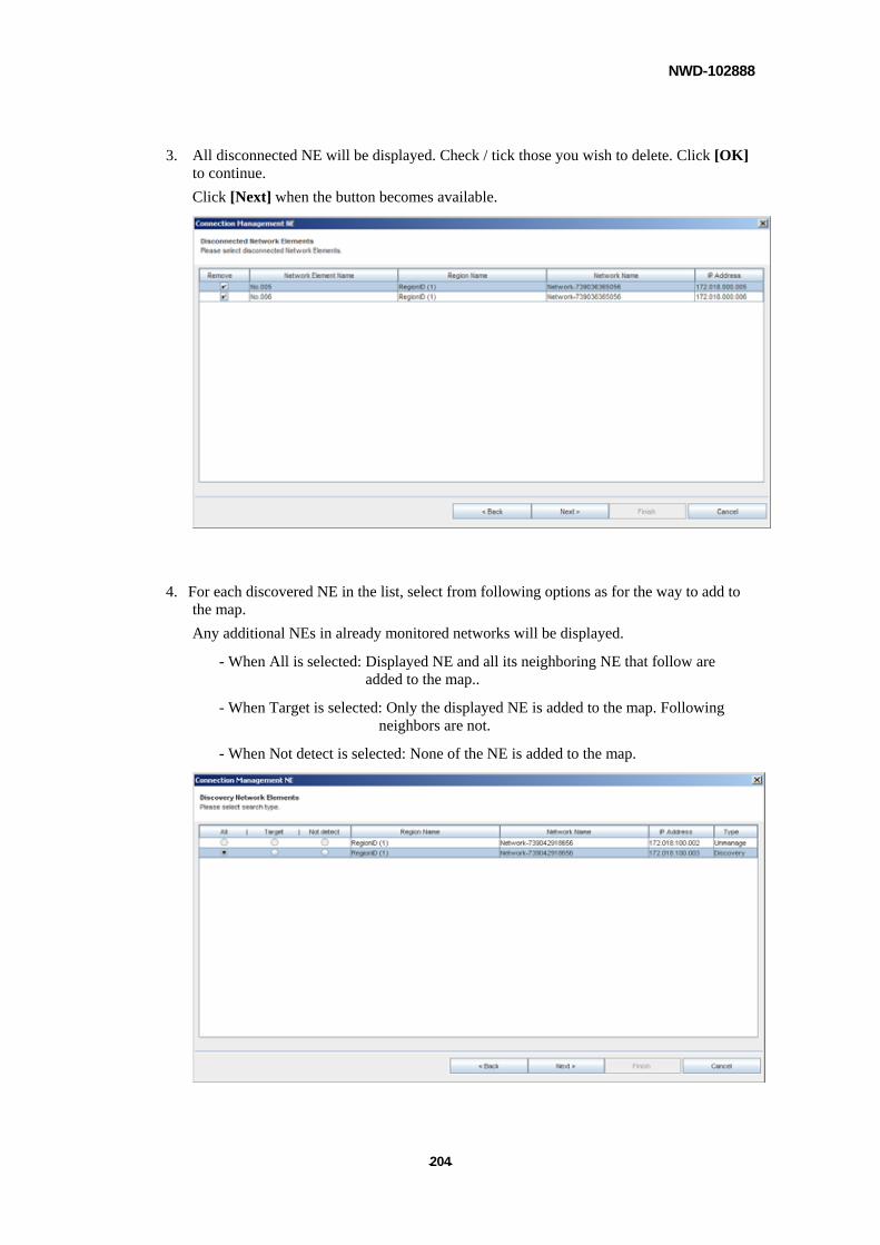
NWD-102888
- - 204
3. All disconnected NE will be displayed. Check / tick those you wish to delete. Click [OK] to continue.
Click [Next] when the button becomes available.
4. For each discovered NE in the list, select from following options as for the way to add to the map.
Any additional NEs in already monitored networks will be displayed.
- When All is selected: Displayed NE and all its neighboring NE that follow are added to the map..
- When Target is selected: Only the displayed NE is added to the map. Following neighbors are not.
- When Not detect is selected: None of the NE is added to the map.
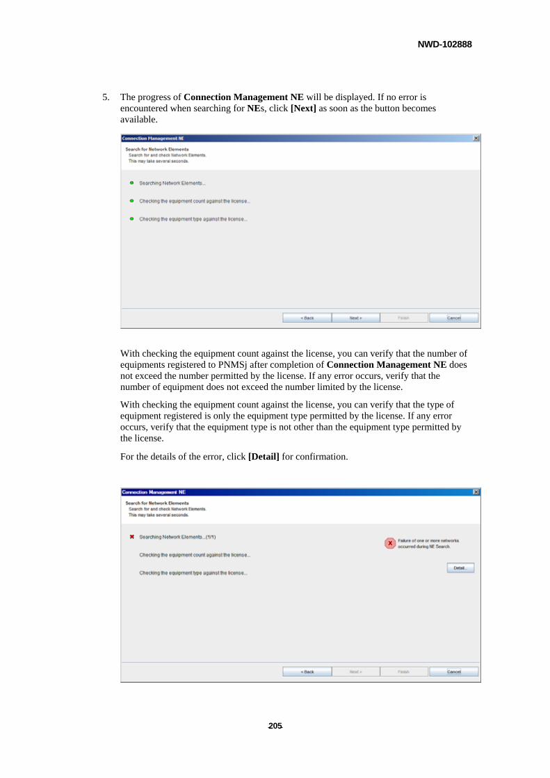
NWD-102888
- - 205
5. The progress of Connection Management NE will be displayed. If no error is encountered when searching for NEs, click [Next] as soon as the button becomes available.
With checking the equipment count against the license, you can verify that the number of equipments registered to PNMSj after completion of Connection Management NE does not exceed the number permitted by the license. If any error occurs, verify that the number of equipment does not exceed the number limited by the license.
With checking the equipment count against the license, you can verify that the type of equipment registered is only the equipment type permitted by the license. If any error occurs, verify that the equipment type is not other than the equipment type permitted by the license.
For the details of the error, click [Detail] for confirmation.
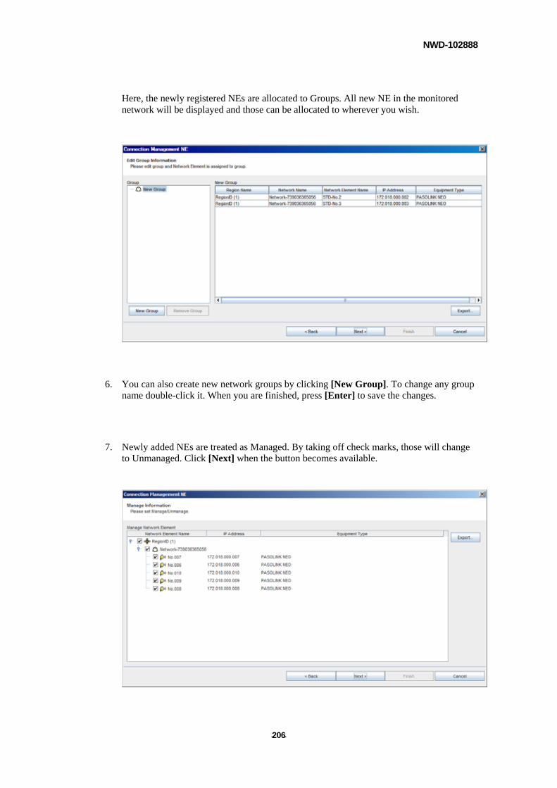
NWD-102888
- - 206
Here, the newly registered NEs are allocated to Groups. All new NE in the monitored network will be displayed and those can be allocated to wherever you wish.
6. You can also create new network groups by clicking [New Group]. To change any group
name double-click it. When you are finished, press [Enter] to save the changes.
7. Newly added NEs are treated as Managed. By taking off check marks, those will change to Unmanaged. Click [Next] when the button becomes available.
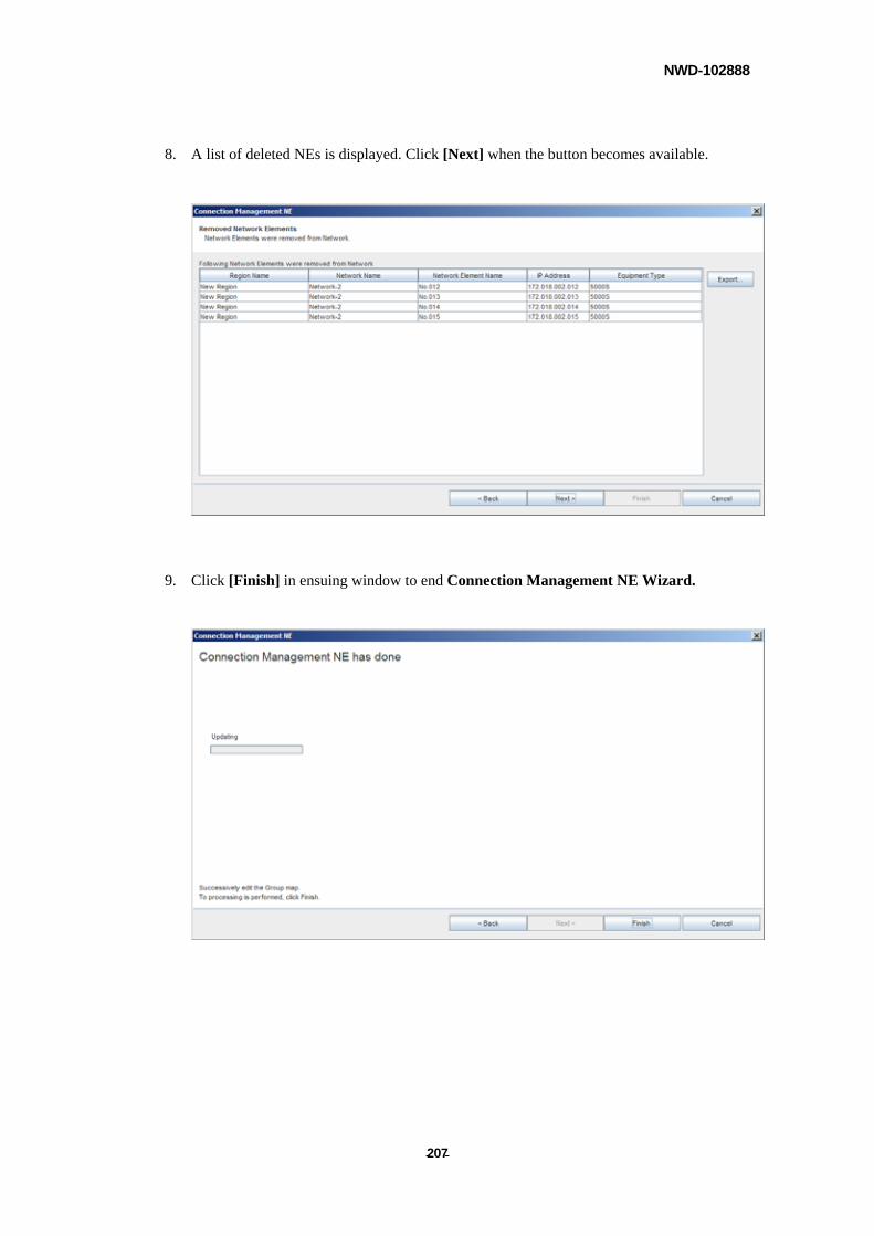
NWD-102888
- - 207
8. A list of deleted NEs is displayed. Click [Next] when the button becomes available.
9. Click [Finish] in ensuing window to end Connection Management NE Wizard.
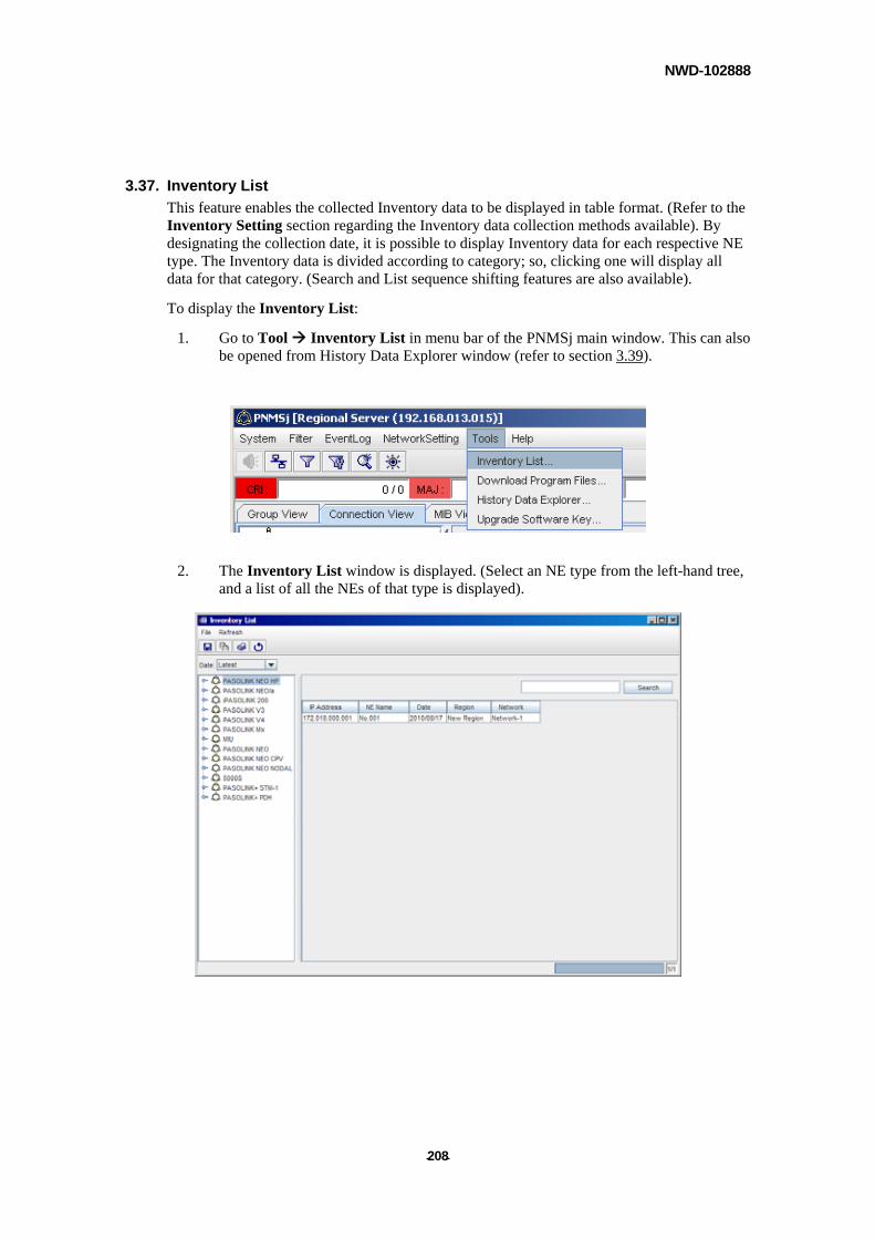
NWD-102888
- - 208
3.37. Inventory List
This feature enables the collected Inventory data to be displayed in table format. (Refer to the Inventory Setting section regarding the Inventory data collection methods available). By designating the collection date, it is possible to display Inventory data for each respective NE type. The Inventory data is divided according to category; so, clicking one will display all data for that category. (Search and List sequence shifting features are also available).
To display the Inventory List:
1. Go to Tool Inventory List in menu bar of the PNMSj main window. This can also be opened from History Data Explorer window (refer to section 3.39).
2. The Inventory List window is displayed. (Select an NE type from the left-hand tree,
and a list of all the NEs of that type is displayed).
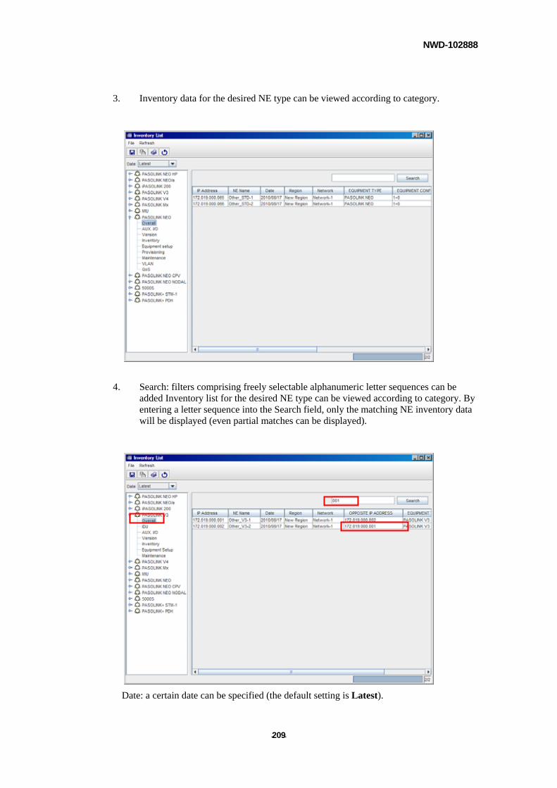
NWD-102888
- - 209
3. Inventory data for the desired NE type can be viewed according to category.
4. Search: filters comprising freely selectable alphanumeric letter sequences can be added Inventory list for the desired NE type can be viewed according to category. By entering a letter sequence into the Search field, only the matching NE inventory data will be displayed (even partial matches can be displayed).
Date: a certain date can be specified (the default setting is Latest).
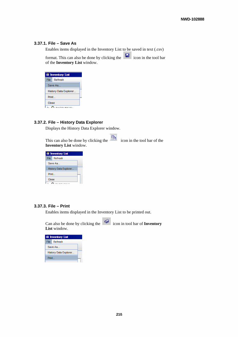
NWD-102888
- - 210
3.37.1. File – Save As
Enables items displayed in the Inventory List to be saved in text (.csv)
format. This can also be done by clicking the icon in the tool bar of the Inventory List window.
3.37.2. File – History Data Explorer
Displays the History Data Explorer window.
This can also be done by clicking the icon in the tool bar of the Inventory List window.
3.37.3. File – Print
Enables items displayed in the Inventory List to be printed out.
Can also be done by clicking the icon in tool bar of Inventory List window.
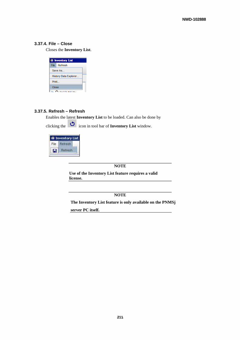
NWD-102888
- - 211
3.37.4. File – Close
Closes the Inventory List.
3.37.5. Refresh – Refresh
Enables the latest Inventory List to be loaded. Can also be done by
clicking the icon in tool bar of Inventory List window.
NOTE
Use of the Inventory List feature requires a valid license.
NOTE
The Inventory List feature is only available on the PNMSj
server PC itself.
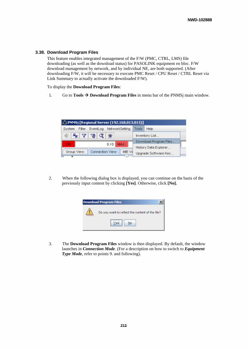
NWD-102888
- - 212
3.38. Download Program Files
This feature enables integrated management of the F/W (PMC, CTRL, LMS) file downloading (as well as the download status) for PASOLINK equipment en bloc. F/W download management by network, and by individual NE, are both supported. (After downloading F/W, it will be necessary to execute PMC Reset / CPU Reset / CTRL Reset via Link Summary to actually activate the downloaded F/W).
To display the Download Program Files:
1. Go to Tools Download Program Files in menu bar of the PNMSj main window.
2. When the following dialog box is displayed, you can continue on the basis of the
previously input content by clicking [Yes]. Otherwise, click [No].
3. The Download Program Files window is then displayed. By default, the window
launches in Connection Mode. (For a description on how to switch to Equipment Type Mode, refer to points 9. and following).
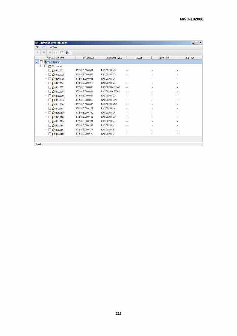
NWD-102888
- - 213

NWD-102888
- - 214
[Item designation]
Network Element: NE are displayed in a tree diagram respectively according to their Region / Network / NE designations. By checking the appropriate box (ON / OFF) Program Files are designated to be downloaded (or not).
IP Address: Displays the IP address corresponding to the respective Network Element.
Equipment Type: Displays the equipment type the respective Network Element.
Result: Displays the final status of the Program File download for the respective NE.
Start Time: Displays the time when Program File download commenced (for the respective NE).
End Time: Displays the time when Program File download ended (for respective NE).
4. Select [File] – [Properties] to stipulate where the respective Program File to be downloaded to the individual NE is to be saved.
5. If you intend to individually control each NE (View-Equipment Type Mode), refer to the explanation following point 9.
The following are the controls according to Region / Network (View - Connection Mode):
[For Connection Mode]
6. Select the NEs to which the program is to be downloaded. NE can be selected individually, according to network, or according to region.
7. The NE download sequence can be changed by Region, Network (within same region), or by individual NE (within the same network).
8. If your settings are now complete, proceed to point 11.
[For Equipment Type Mode]
9. You can switch from Connection Mode to Equipment Type Mode, using the View icon in the toolbar.
10. The Download Program Files window will be displayed in Equipment Type Mode.
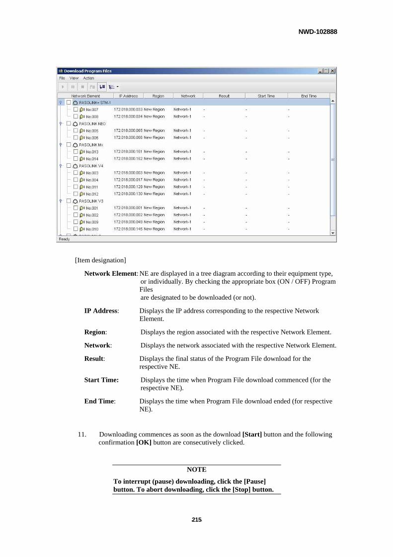
NWD-102888
- - 215
[Item designation]
Network Element: NE are displayed in a tree diagram according to their equipment type, or individually. By checking the appropriate box (ON / OFF) Program Files are designated to be downloaded (or not).
IP Address: Displays the IP address corresponding to the respective Network Element.
Region: Displays the region associated with the respective Network Element.
Network: Displays the network associated with the respective Network Element.
Result: Displays the final status of the Program File download for the respective NE.
Start Time: Displays the time when Program File download commenced (for the respective NE).
End Time: Displays the time when Program File download ended (for respective NE).
11. Downloading commences as soon as the download [Start] button and the following confirmation [OK] button are consecutively clicked.
NOTE
To interrupt (pause) downloading, click the [Pause] button. To abort downloading, click the [Stop] button.
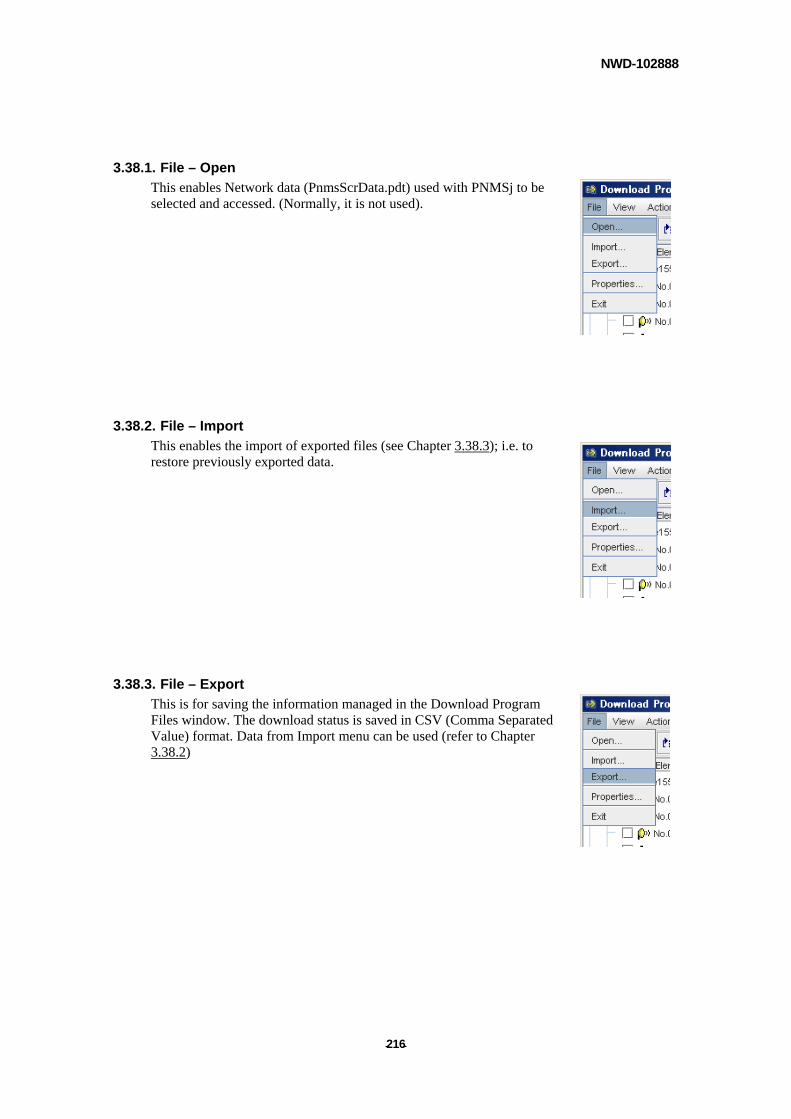
NWD-102888
- - 216
3.38.1. File – Open
This enables Network data (PnmsScrData.pdt) used with PNMSj to be selected and accessed. (Normally, it is not used).
3.38.2. File – Import
This enables the import of exported files (see Chapter 3.38.3); i.e. to restore previously exported data.
3.38.3. File – Export
This is for saving the information managed in the Download Program Files window. The download status is saved in CSV (Comma Separated Value) format. Data from Import menu can be used (refer to Chapter 3.38.2)
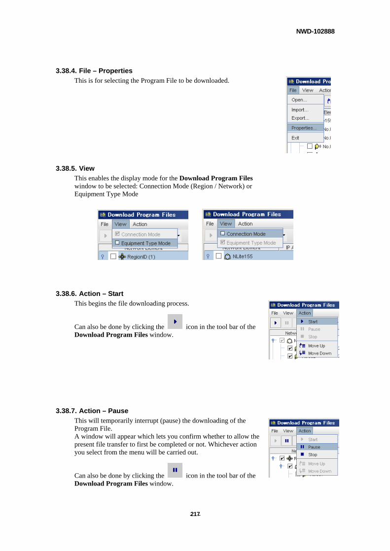
NWD-102888
- - 217
3.38.4. File – Properties
This is for selecting the Program File to be downloaded.
3.38.5. View
This enables the display mode for the Download Program Files window to be selected: Connection Mode (Region / Network) or Equipment Type Mode
3.38.6. Action – Start
This begins the file downloading process.
Can also be done by clicking the icon in the tool bar of the Download Program Files window.
3.38.7. Action – Pause
This will temporarily interrupt (pause) the downloading of the Program File. A window will appear which lets you confirm whether to allow the present file transfer to first be completed or not. Whichever action you select from the menu will be carried out.
Can also be done by clicking the icon in the tool bar of the Download Program Files window.
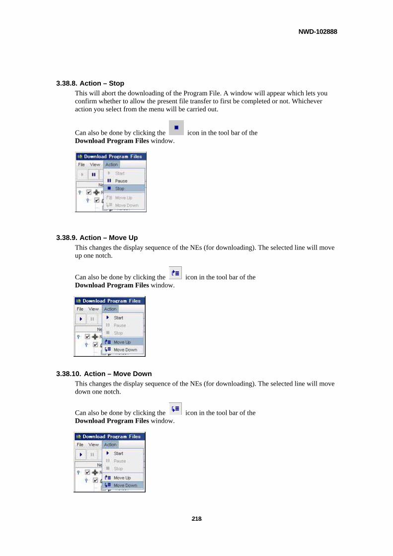
NWD-102888
- - 218
3.38.8. Action – Stop
This will abort the downloading of the Program File. A window will appear which lets you confirm whether to allow the present file transfer to first be completed or not. Whichever action you select from the menu will be carried out.
Can also be done by clicking the icon in the tool bar of the Download Program Files window.
3.38.9. Action – Move Up
This changes the display sequence of the NEs (for downloading). The selected line will move up one notch.
Can also be done by clicking the icon in the tool bar of the Download Program Files window.
3.38.10. Action – Move Down
This changes the display sequence of the NEs (for downloading). The selected line will move down one notch.
Can also be done by clicking the icon in the tool bar of the Download Program Files window.
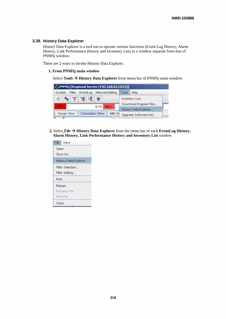
NWD-102888
- - 219
3.39. History Data Explorer
History Data Explorer is a tool use to operate various functions (Event Log History, Alarm History, Link Performance History and Inventory List) in a window separate from that of PNMSj window.
There are 2 ways to invoke History Data Explorer.
1. From PNMSj main window
Select Tools History Data Explorer from menu bar of PNMSj main window.
2. Select File History Data Explorer from the menu bar of each EventLog History, Alarm History, Link Performance History and Inventory List window.
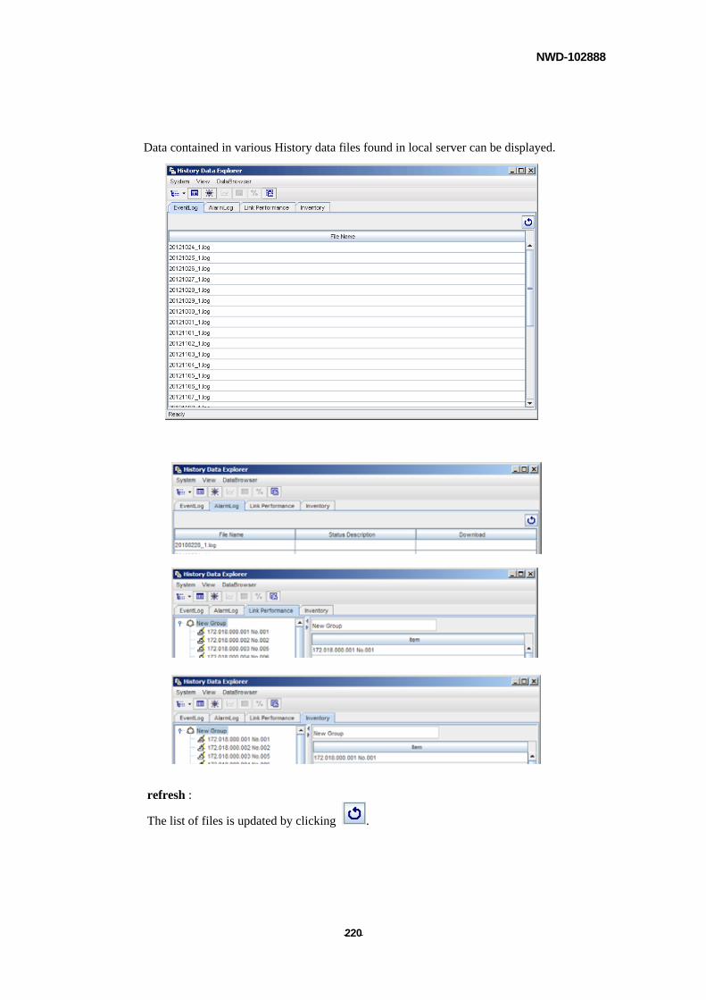
NWD-102888
- - 220
Data contained in various History data files found in local server can be displayed.
refresh :
The list of files is updated by clicking .
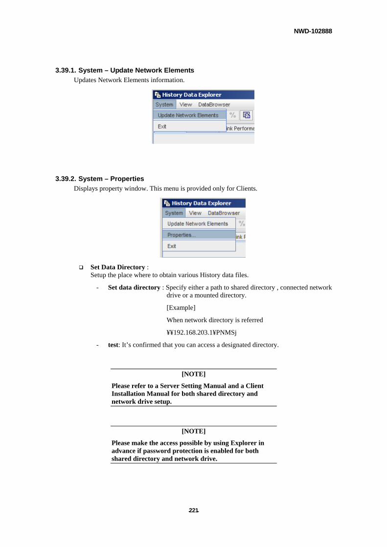
NWD-102888
- - 221
3.39.1. System – Update Network Elements
Updates Network Elements information.
3.39.2. System – Properties
Displays property window. This menu is provided only for Clients.
Set Data Directory : Setup the place where to obtain various History data files.
- Set data directory : Specify either a path to shared directory , connected network drive or a mounted directory.
[Example]
When network directory is referred
¥¥192.168.203.1¥PNMSj
- test: It’s confirmed that you can access a designated directory.
[NOTE]
Please refer to a Server Setting Manual and a Client Installation Manual for both shared directory and network drive setup.
[NOTE]
Please make the access possible by using Explorer in advance if password protection is enabled for both shared directory and network drive.
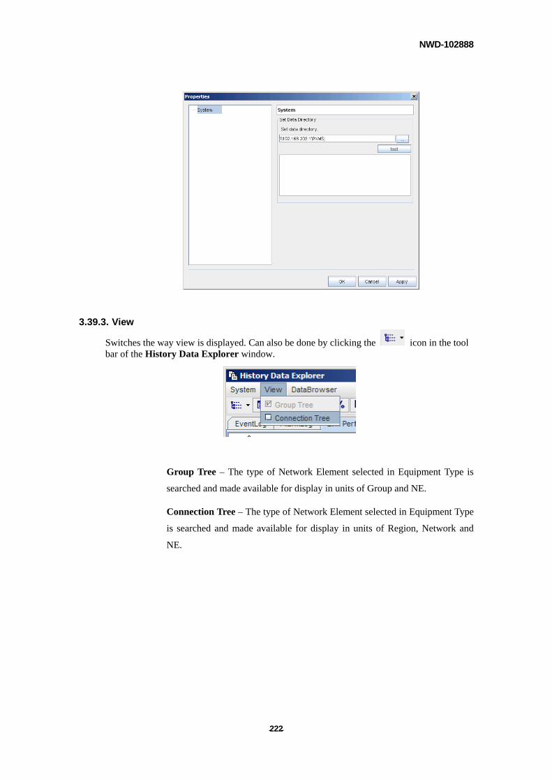
NWD-102888
- - 222
3.39.3. View
Switches the way view is displayed. Can also be done by clicking the icon in the tool bar of the History Data Explorer window.
Group Tree – The type of Network Element selected in Equipment Type is
searched and made available for display in units of Group and NE.
Connection Tree – The type of Network Element selected in Equipment Type
is searched and made available for display in units of Region, Network and
NE.
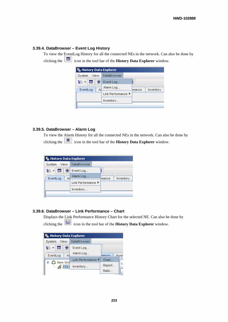
NWD-102888
- - 223
3.39.4. DataBrowser – Event Log History
To view the EventLog History for all the connected NEs in the network. Can also be done by
clicking the icon in the tool bar of the History Data Explorer window.
3.39.5. DataBrowser – Alarm Log
To view the Alarm History for all the connected NEs in the network. Can also be done by
clicking the icon in the tool bar of the History Data Explorer window.
3.39.6. DataBrowser – Link Performance – Chart
Displays the Link Performance History Chart for the selected NE. Can also be done by
clicking the icon in the tool bar of the History Data Explorer window.
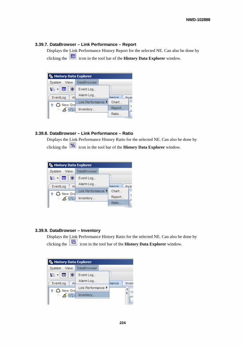
NWD-102888
- - 224
3.39.7. DataBrowser – Link Performance – Report
Displays the Link Performance History Report for the selected NE. Can also be done by
clicking the icon in the tool bar of the History Data Explorer window.
3.39.8. DataBrowser – Link Performance – Ratio
Displays the Link Performance History Ratio for the selected NE. Can also be done by
clicking the icon in the tool bar of the History Data Explorer window.
3.39.9. DataBrowser – Inventory
Displays the Link Performance History Ratio for the selected NE. Can also be done by
clicking the icon in the tool bar of the History Data Explorer window.
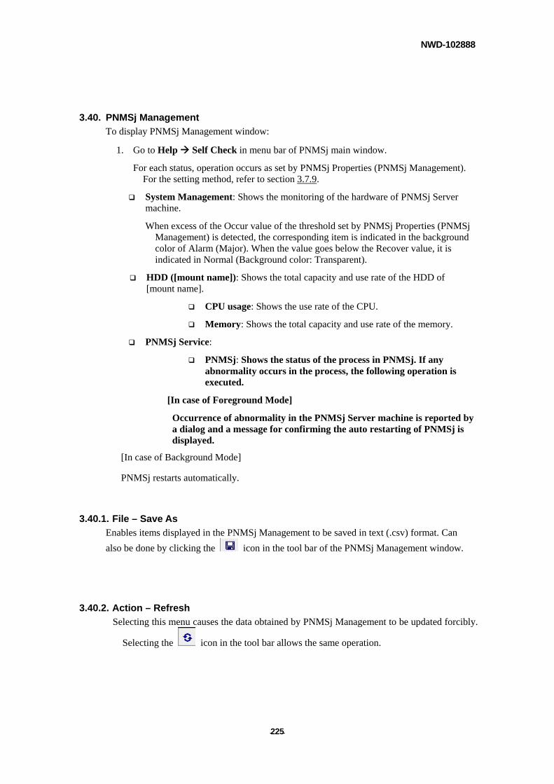
NWD-102888
- - 225
3.40. PNMSj Management
To display PNMSj Management window:
1. Go to Help Self Check in menu bar of PNMSj main window.
For each status, operation occurs as set by PNMSj Properties (PNMSj Management). For the setting method, refer to section 3.7.9.
System Management: Shows the monitoring of the hardware of PNMSj Server machine.
When excess of the Occur value of the threshold set by PNMSj Properties (PNMSj Management) is detected, the corresponding item is indicated in the background color of Alarm (Major). When the value goes below the Recover value, it is indicated in Normal (Background color: Transparent).
HDD ([mount name]): Shows the total capacity and use rate of the HDD of [mount name].
CPU usage: Shows the use rate of the CPU.
Memory: Shows the total capacity and use rate of the memory.
PNMSj Service:
PNMSj: Shows the status of the process in PNMSj. If any abnormality occurs in the process, the following operation is executed.
[In case of Foreground Mode]
Occurrence of abnormality in the PNMSj Server machine is reported by a dialog and a message for confirming the auto restarting of PNMSj is displayed.
[In case of Background Mode]
PNMSj restarts automatically.
3.40.1. File – Save As
Enables items displayed in the PNMSj Management to be saved in text (.csv) format. Can
also be done by clicking the icon in the tool bar of the PNMSj Management window.
3.40.2. Action – Refresh
Selecting this menu causes the data obtained by PNMSj Management to be updated forcibly.
Selecting the icon in the tool bar allows the same operation.
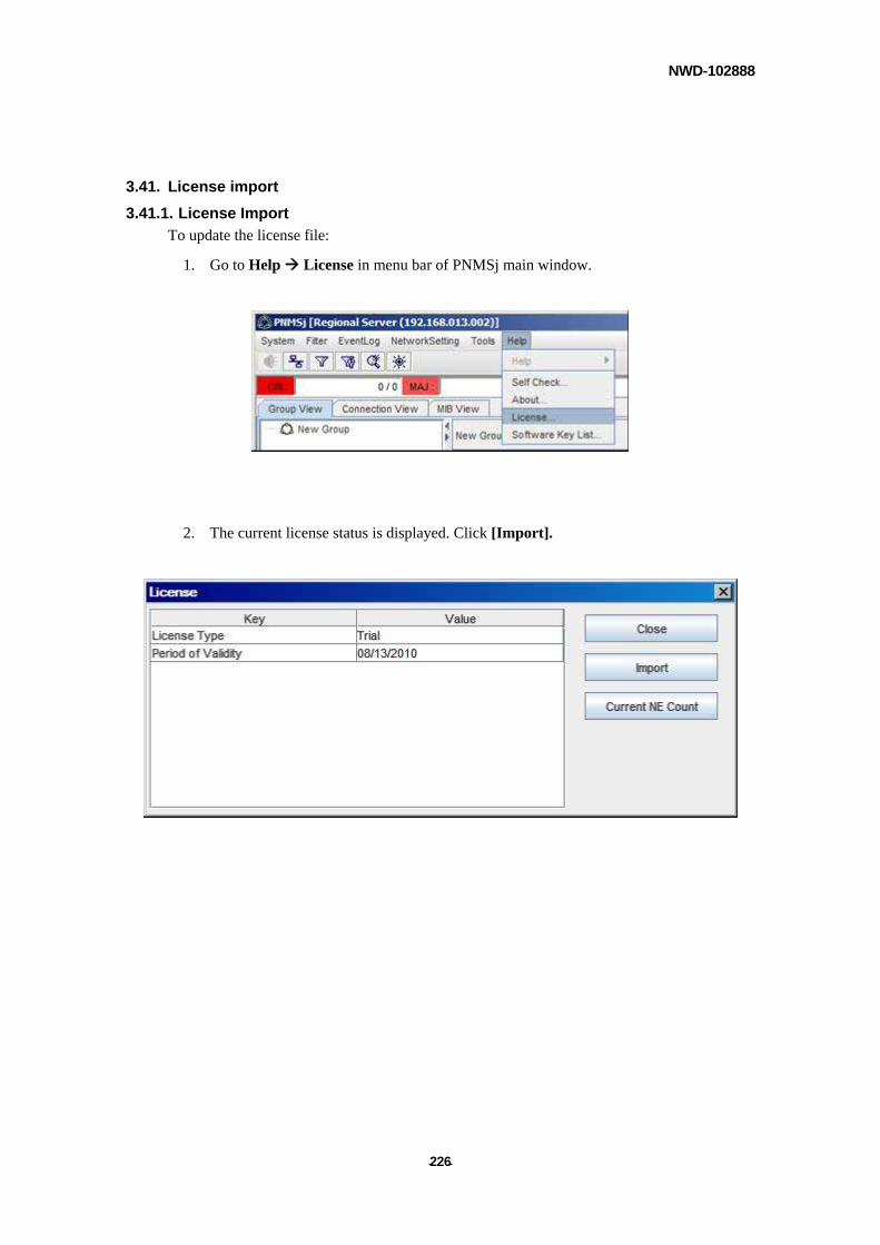
NWD-102888
- - 226
3.41. License import
3.41.1. License Import
To update the license file:
1. Go to Help License in menu bar of PNMSj main window.
2. The current license status is displayed. Click [Import].
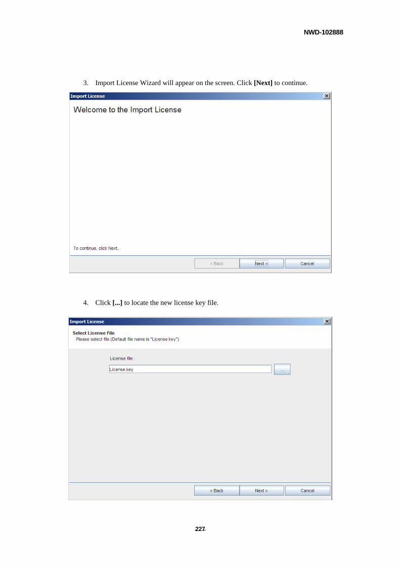
NWD-102888
- - 227
3. Import License Wizard will appear on the screen. Click [Next] to continue.
4. Click [...] to locate the new license key file.
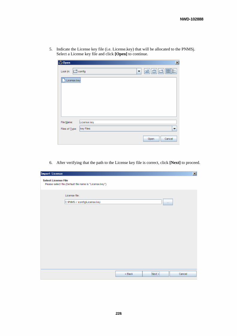
NWD-102888
- - 228
5. Indicate the License key file (i.e. License.key) that will be allocated to the PNMSj. Select a License key file and click [Open] to continue.
6. After verifying that the path to the License key file is correct, click [Next] to proceed.
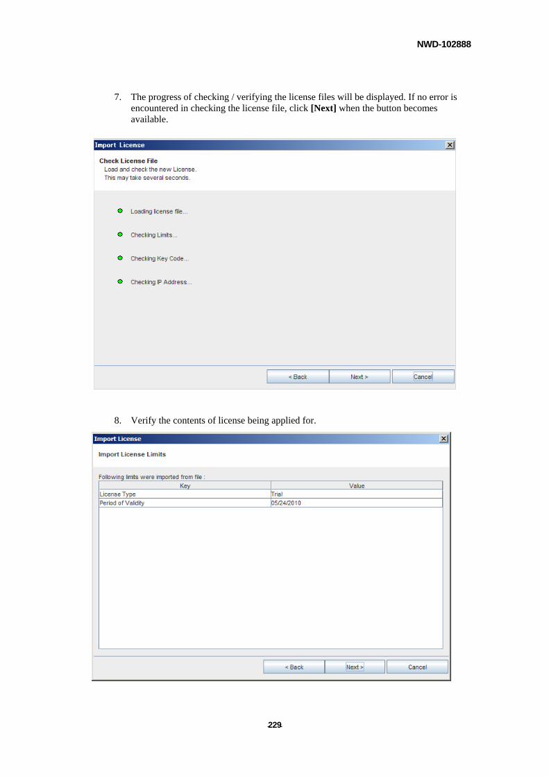
NWD-102888
- - 229
7. The progress of checking / verifying the license files will be displayed. If no error is encountered in checking the license file, click [Next] when the button becomes available.
8. Verify the contents of license being applied for.
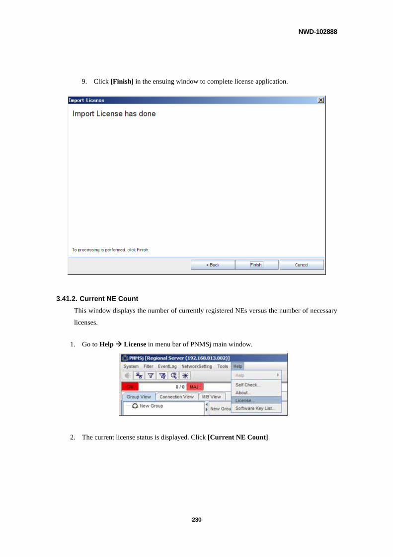
NWD-102888
- - 230
9. Click [Finish] in the ensuing window to complete license application.
3.41.2. Current NE Count
This window displays the number of currently registered NEs versus the number of necessary
licenses.
1. Go to Help License in menu bar of PNMSj main window.
2. The current license status is displayed. Click [Current NE Count]
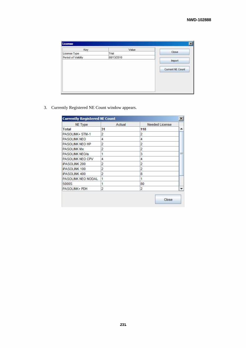
NWD-102888
- - 231
3. Currently Registered NE Count window appears.
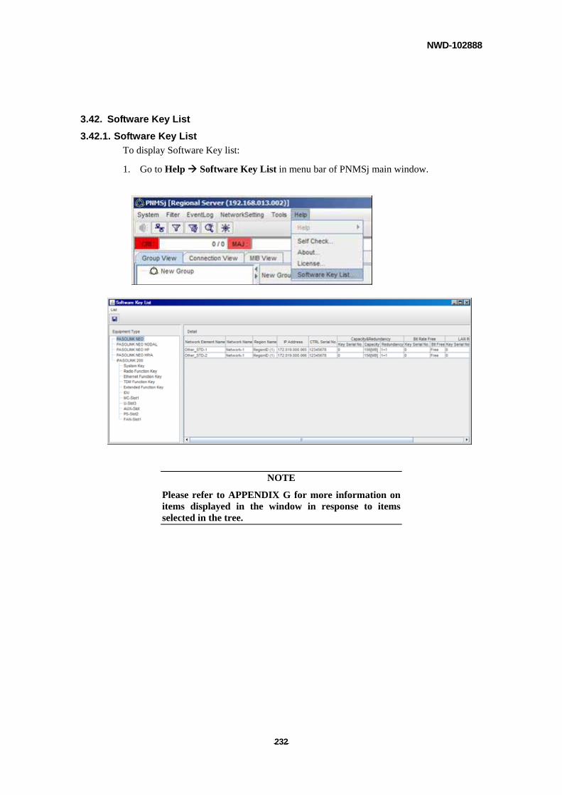
NWD-102888
- - 232
3.42. Software Key List
3.42.1. Software Key List
To display Software Key list:
1. Go to Help Software Key List in menu bar of PNMSj main window.
NOTE
Please refer to APPENDIX G for more information on items displayed in the window in response to items selected in the tree.
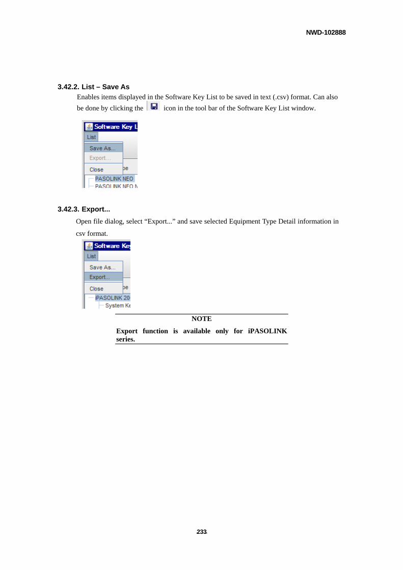
NWD-102888
- - 233
3.42.2. List – Save As
Enables items displayed in the Software Key List to be saved in text (.csv) format. Can also
be done by clicking the icon in the tool bar of the Software Key List window.
3.42.3. Export...
Open file dialog, select “Export...” and save selected Equipment Type Detail information in
csv format.
NOTE
Export function is available only for iPASOLINK series.
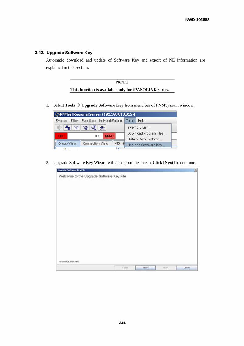
NWD-102888
- - 234
3.43. Upgrade Software Key
Automatic download and update of Software Key and export of NE information are
explained in this section.
NOTE
This function is available only for iPASOLINK series.
1. Select Tools Upgrade Software Key from menu bar of PNMSj main window.
2. Upgrade Software Key Wizard will appear on the screen. Click [Next] to continue.
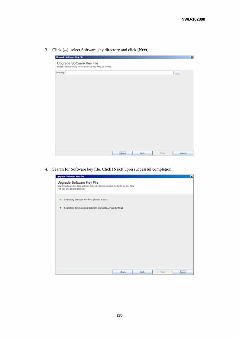
NWD-102888
- - 235
3. Click [...], select Software key directory and click [Next].
4. Search for Software key file. Click [Next] upon successful completion.
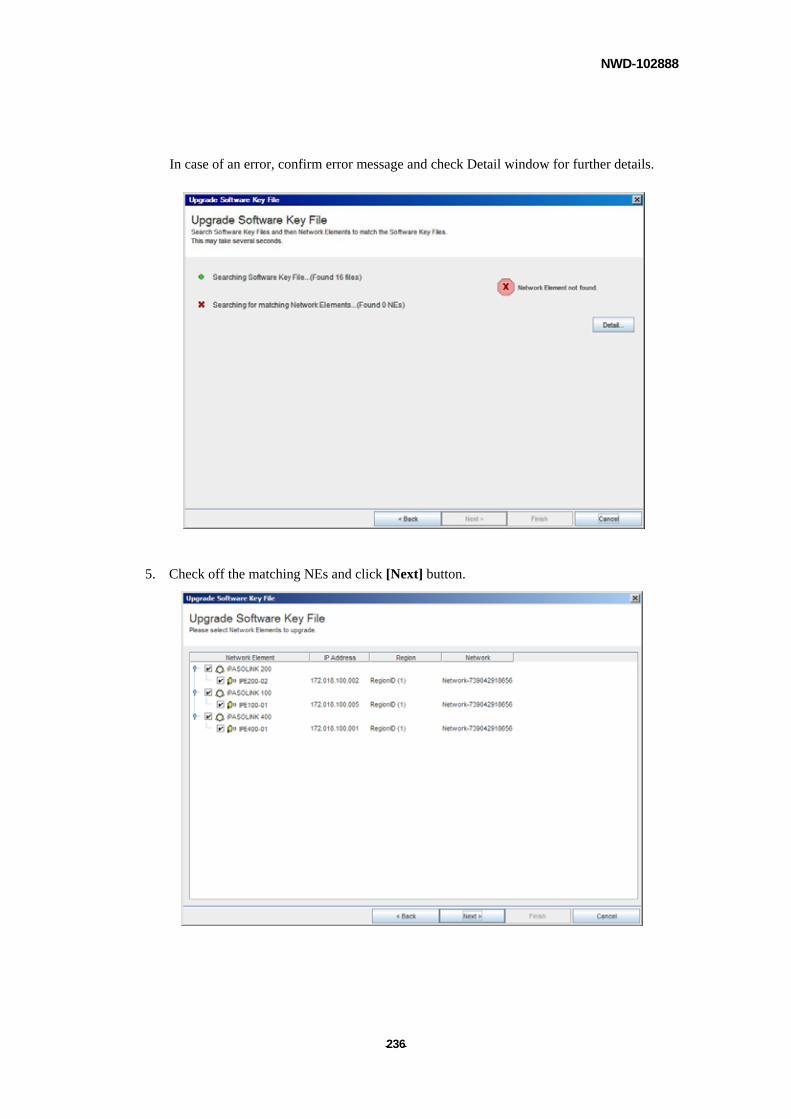
NWD-102888
- - 236
In case of an error, confirm error message and check Detail window for further details.
5. Check off the matching NEs and click [Next] button.
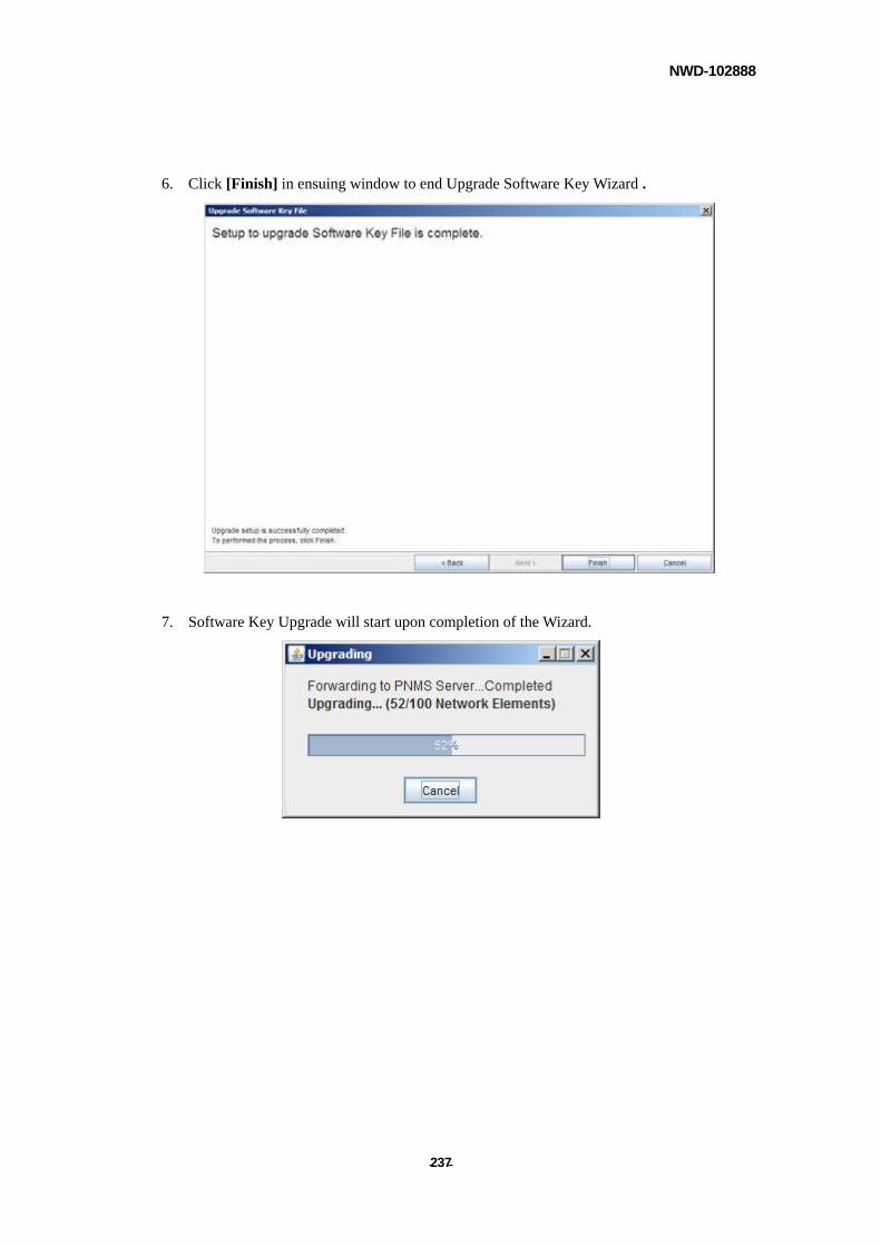
NWD-102888
- - 237
6. Click [Finish] in ensuing window to end Upgrade Software Key Wizard .
7. Software Key Upgrade will start upon completion of the Wizard.
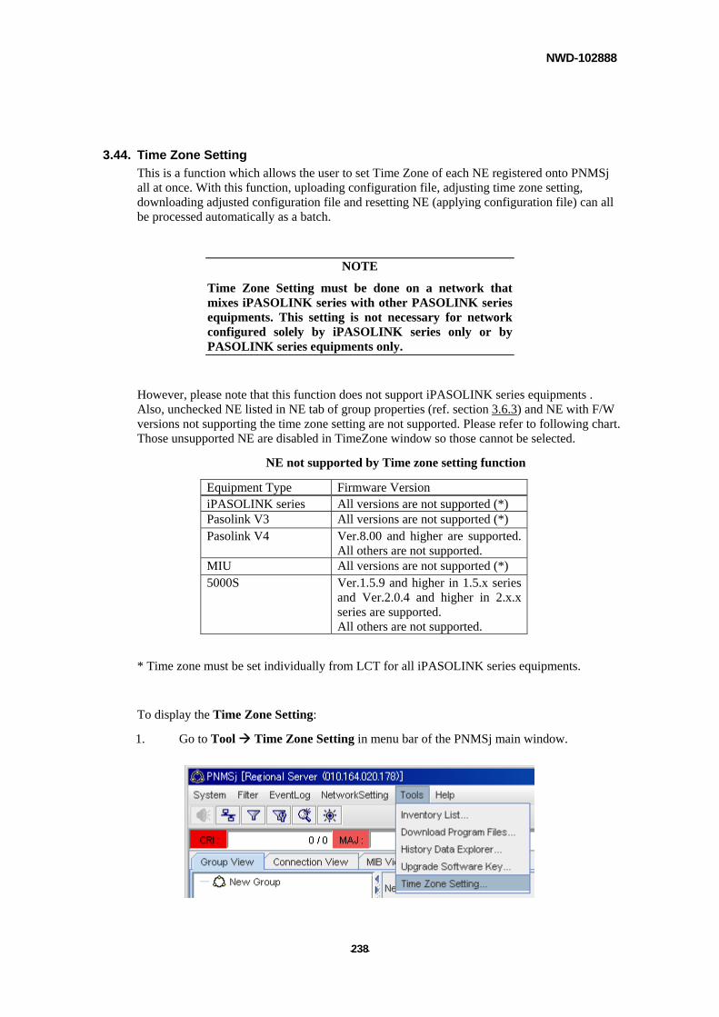
NWD-102888
- - 238
3.44. Time Zone Setting
This is a function which allows the user to set Time Zone of each NE registered onto PNMSj all at once. With this function, uploading configuration file, adjusting time zone setting, downloading adjusted configuration file and resetting NE (applying configuration file) can all be processed automatically as a batch.
NOTE
Time Zone Setting must be done on a network that mixes iPASOLINK series with other PASOLINK series equipments. This setting is not necessary for network configured solely by iPASOLINK series only or by PASOLINK series equipments only.
However, please note that this function does not support iPASOLINK series equipments . Also, unchecked NE listed in NE tab of group properties (ref. section 3.6.3) and NE with F/W versions not supporting the time zone setting are not supported. Please refer to following chart. Those unsupported NE are disabled in TimeZone window so those cannot be selected.
NE not supported by Time zone setting function
Equipment Type Firmware Version iPASOLINK series All versions are not supported (*) Pasolink V3 All versions are not supported (*) Pasolink V4 Ver.8.00 and higher are supported.
All others are not supported. MIU All versions are not supported (*) 5000S Ver.1.5.9 and higher in 1.5.x series
and Ver.2.0.4 and higher in 2.x.x series are supported. All others are not supported.
* Time zone must be set individually from LCT for all iPASOLINK series equipments.
To display the Time Zone Setting:
1. Go to Tool Time Zone Setting in menu bar of the PNMSj main window.
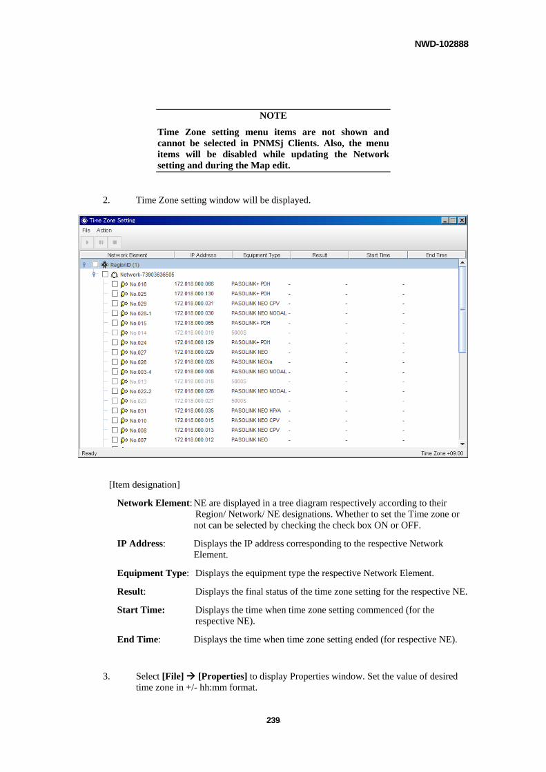
NWD-102888
- - 239
NOTE
Time Zone setting menu items are not shown and cannot be selected in PNMSj Clients. Also, the menu items will be disabled while updating the Network setting and during the Map edit.
2. Time Zone setting window will be displayed.
[Item designation]
Network Element: NE are displayed in a tree diagram respectively according to their Region/ Network/ NE designations. Whether to set the Time zone or not can be selected by checking the check box ON or OFF.
IP Address: Displays the IP address corresponding to the respective Network Element.
Equipment Type: Displays the equipment type the respective Network Element.
Result: Displays the final status of the time zone setting for the respective NE.
Start Time: Displays the time when time zone setting commenced (for the respective NE).
End Time: Displays the time when time zone setting ended (for respective NE).
3. Select [File] [Properties] to display Properties window. Set the value of desired time zone in +/- hh:mm format.
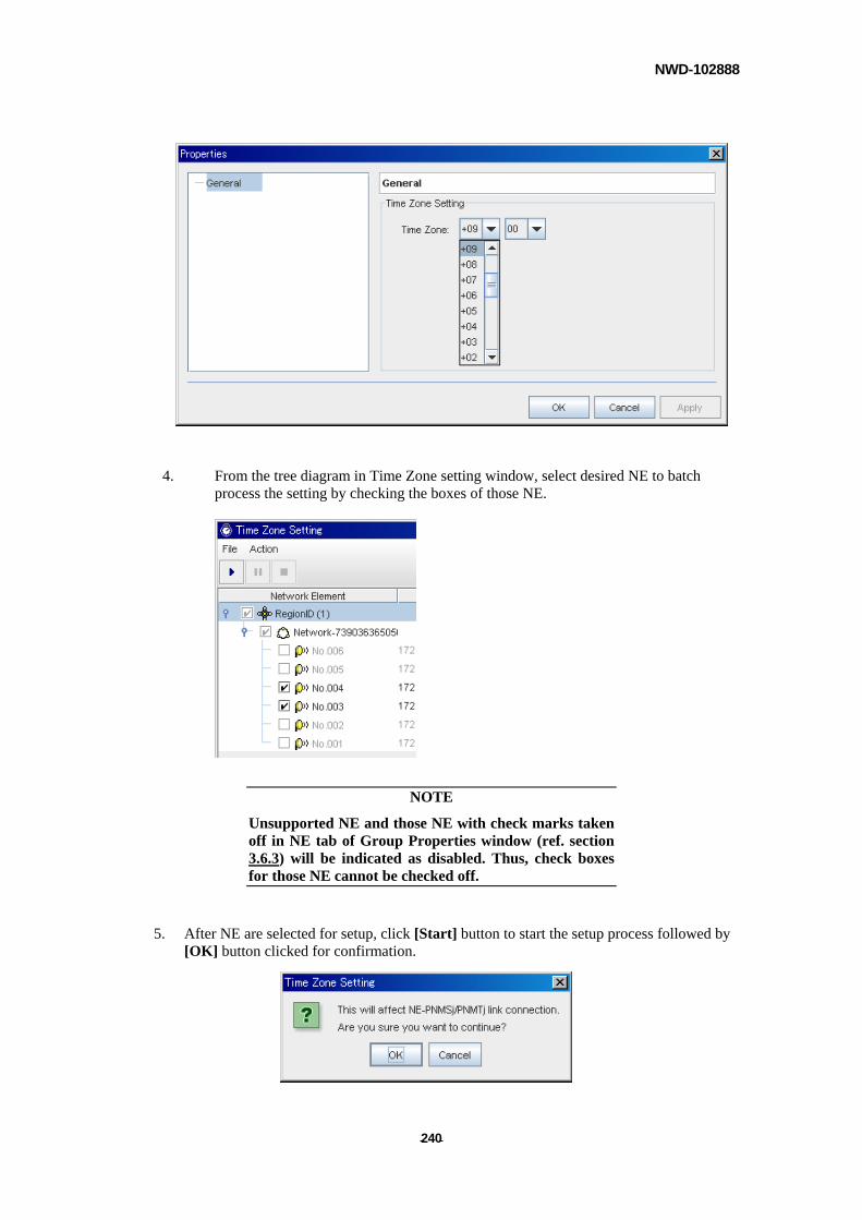
NWD-102888
- - 240
4. From the tree diagram in Time Zone setting window, select desired NE to batch process the setting by checking the boxes of those NE.
NOTE
Unsupported NE and those NE with check marks taken off in NE tab of Group Properties window (ref. section 3.6.3) will be indicated as disabled. Thus, check boxes for those NE cannot be checked off.
5. After NE are selected for setup, click [Start] button to start the setup process followed by [OK] button clicked for confirmation.
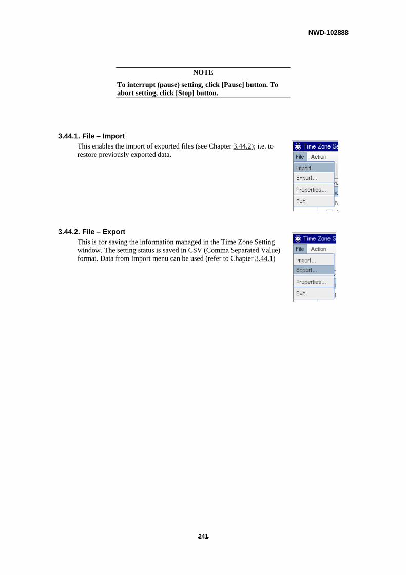
NWD-102888
- - 241
NOTE
To interrupt (pause) setting, click [Pause] button. To abort setting, click [Stop] button.
3.44.1. File – Import
This enables the import of exported files (see Chapter 3.44.2); i.e. to restore previously exported data.
3.44.2. File – Export
This is for saving the information managed in the Time Zone Setting window. The setting status is saved in CSV (Comma Separated Value) format. Data from Import menu can be used (refer to Chapter 3.44.1)
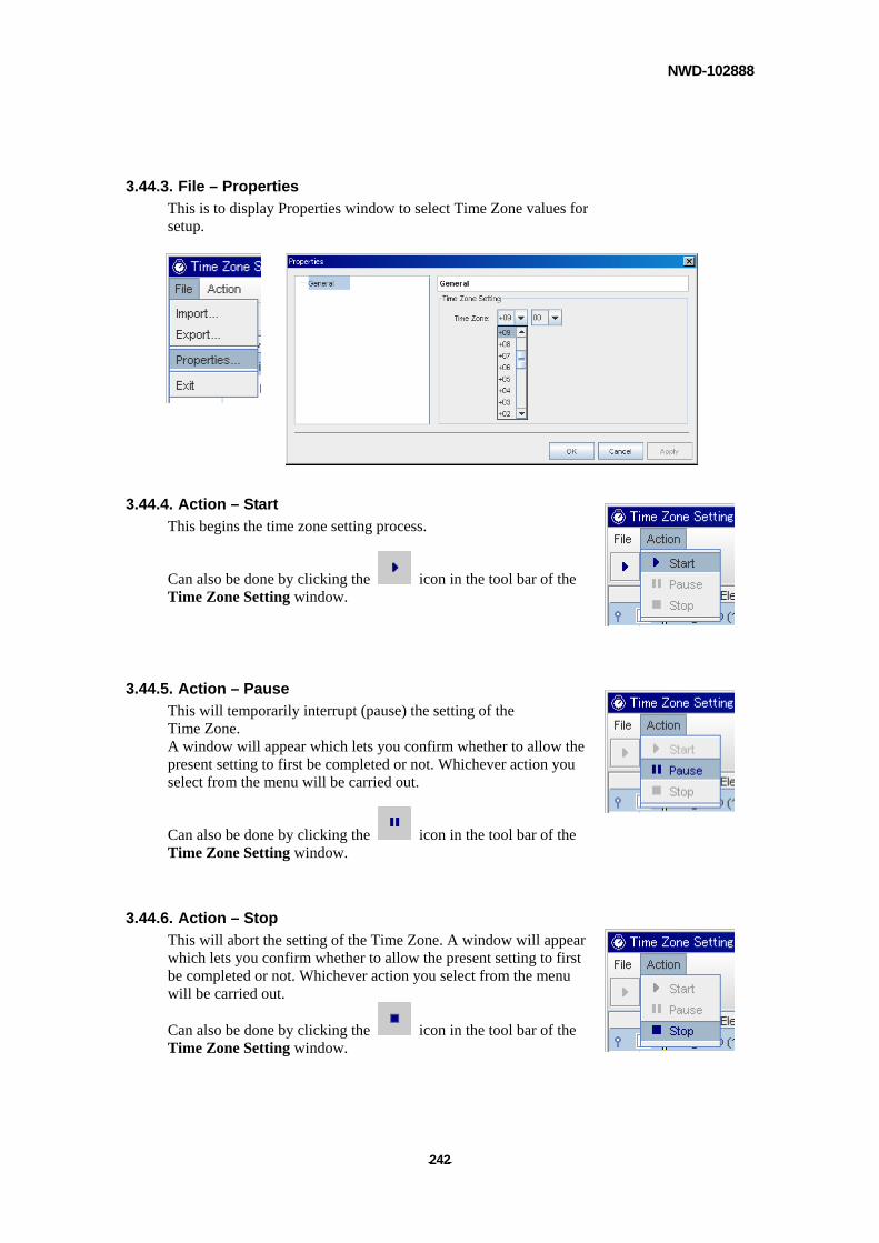
NWD-102888
- - 242
3.44.3. File – Properties
This is to display Properties window to select Time Zone values for setup.
3.44.4. Action – Start
This begins the time zone setting process.
Can also be done by clicking the icon in the tool bar of the Time Zone Setting window.
3.44.5. Action – Pause
This will temporarily interrupt (pause) the setting of the Time Zone. A window will appear which lets you confirm whether to allow the present setting to first be completed or not. Whichever action you select from the menu will be carried out.
Can also be done by clicking the icon in the tool bar of the Time Zone Setting window.
3.44.6. Action – Stop
This will abort the setting of the Time Zone. A window will appear which lets you confirm whether to allow the present setting to first be completed or not. Whichever action you select from the menu will be carried out.
Can also be done by clicking the icon in the tool bar of the Time Zone Setting window.
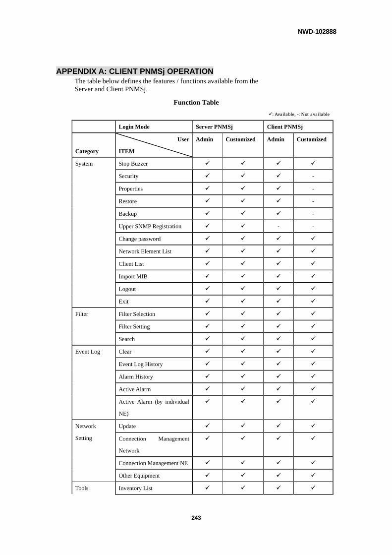
NWD-102888
- - 243
APPENDIX A: CLIENT PNMSj OPERATION The table below defines the features / functions available from the Server and Client PNMSj.
Function Table
: Available, -: Not available
Login Mode Server PNMSj Client PNMSj
Category
User
ITEM
Admin Customized Admin Customized
Stop Buzzer
Security -
Properties -
Restore -
Backup -
Upper SNMP Registration - -
Change password
Network Element List
Client List
Import MIB
Logout
System
Exit
Filter Selection
Filter Setting
Filter
Search
Clear
Event Log History
Alarm History
Active Alarm
Event Log
Active Alarm (by individual
NE)
Update
Connection Management
Network
Connection Management NE
Network
Setting
Other Equipment
Tools Inventory List
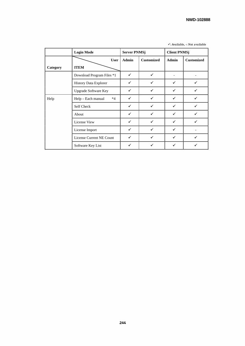
NWD-102888
- - 244
: Available, -: Not available
Login Mode Server PNMSj Client PNMSj
Category
User
ITEM
Admin Customized Admin Customized
Download Program Files *1 - -
History Data Explorer
Upgrade Software Key
Help Help – Each manual *4
Self Check
About
License View
License Import -
License Current NE Count
Software Key List
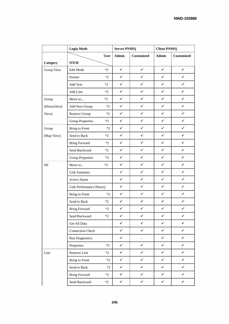
NWD-102888
- - 245
Login Mode Server PNMSj Client PNMSj
Category
User
ITEM
Admin Customized Admin Customized
Group View Edit Mode *2
Pointer *2
Add Text *2
Add Line *2
Group Move to... *2
(Hierarchical Add New Group *2
View) Remove Group *2
Group Properties *3
Group Bring to Front *2
(Map View) Send to Back *2
Bring Forward *2
Send Backward *2
Group Properties *3
NE Move to... *2
Link Summary
Active Alarm
Link Performance History
Bring to Front *2
Send to Back *2
Bring Forward *2
Send Backward *2
Get All Data
Connection Check
Run Diagnostics -
Properties *3
Line Remove Line *2
Bring to Front *2
Send to Back *2
Bring Forward *2
Send Backward *2

NWD-102888
- - 246
Properties *3
Connection
View
Edit Mode
Pointer *2
Add Line *2
Region Region Properties *3
Network Network Properties *3
Subnet Subnet Properties *3
NE Link Summary
Active Alarm
Link Performance History
Get All Data
Connection Check
Run Diagnostics -
Properties *3
Line Remove Line *2
*1 Only on PNMSj Server PC.
*2 Only in Edit Mode.
*3 Setting properties is only possible in Edit mode
*4 Installing Acrobat Reader in Client is necessary.
NOTE
There is a possibility that the PNMSj client connection to the PNMSj server may be disrupted when the PNMSj server is busy.

NWD-102888
- - 247
APPENDIX B: HOW TO WRITE THE BATCH FILE FOR WINDOWS OS PNMSj cannot execute the batch file on Windows OS when the batch file doesn't have the following lines.
1. The batch file must start with the "@echo off" string. 2. The batch file must end with the "end" string.
[Example]
@echo off
COMMAND LINE 1
COMMAND LINE 2
COMMAND LINE 3
COMMAND LINE 4
end
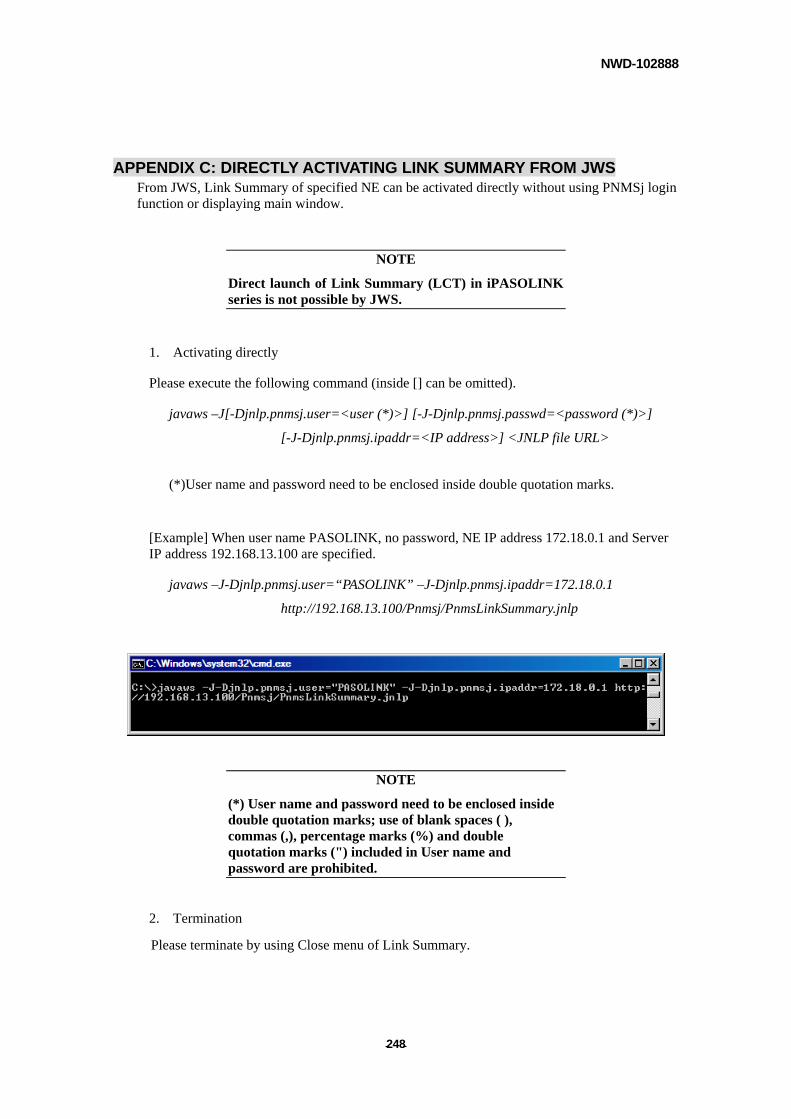
NWD-102888
- - 248
APPENDIX C: DIRECTLY ACTIVATING LINK SUMMARY FROM JWS From JWS, Link Summary of specified NE can be activated directly without using PNMSj login function or displaying main window.
NOTE
Direct launch of Link Summary (LCT) in iPASOLINK series is not possible by JWS.
1. Activating directly
Please execute the following command (inside [] can be omitted).
javaws –J[-Djnlp.pnmsj.user=<user (*)>] [-J-Djnlp.pnmsj.passwd=<password (*)>]
[-J-Djnlp.pnmsj.ipaddr=<IP address>] <JNLP file URL>
(*)User name and password need to be enclosed inside double quotation marks.
[Example] When user name PASOLINK, no password, NE IP address 172.18.0.1 and Server IP address 192.168.13.100 are specified.
javaws –J-Djnlp.pnmsj.user=“PASOLINK” –J-Djnlp.pnmsj.ipaddr=172.18.0.1
http://192.168.13.100/Pnmsj/PnmsLinkSummary.jnlp
NOTE
(*) User name and password need to be enclosed inside double quotation marks; use of blank spaces ( ), commas (,), percentage marks (%) and double quotation marks (") included in User name and password are prohibited.
2. Termination
Please terminate by using Close menu of Link Summary.
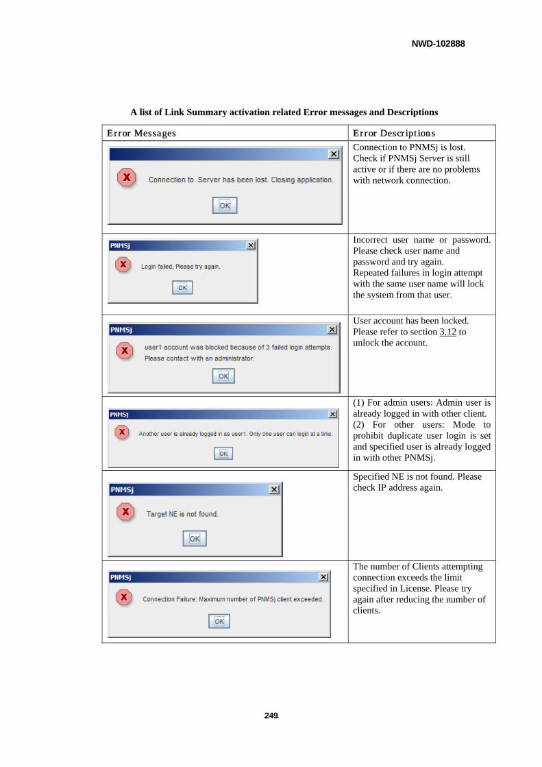
NWD-102888
- - 249
A list of Link Summary activation related Error messages and Descriptions
Error Messages Error Descriptions
Connection to PNMSj is lost. Check if PNMSj Server is still active or if there are no problems with network connection.
Incorrect user name or password. Please check user name and password and try again. Repeated failures in login attempt with the same user name will lock the system from that user.
User account has been locked. Please refer to section 3.12 to unlock the account.
(1) For admin users: Admin user is already logged in with other client. (2) For other users: Mode to prohibit duplicate user login is set and specified user is already logged in with other PNMSj.
Specified NE is not found. Please check IP address again.
The number of Clients attempting connection exceeds the limit specified in License. Please try again after reducing the number of clients.
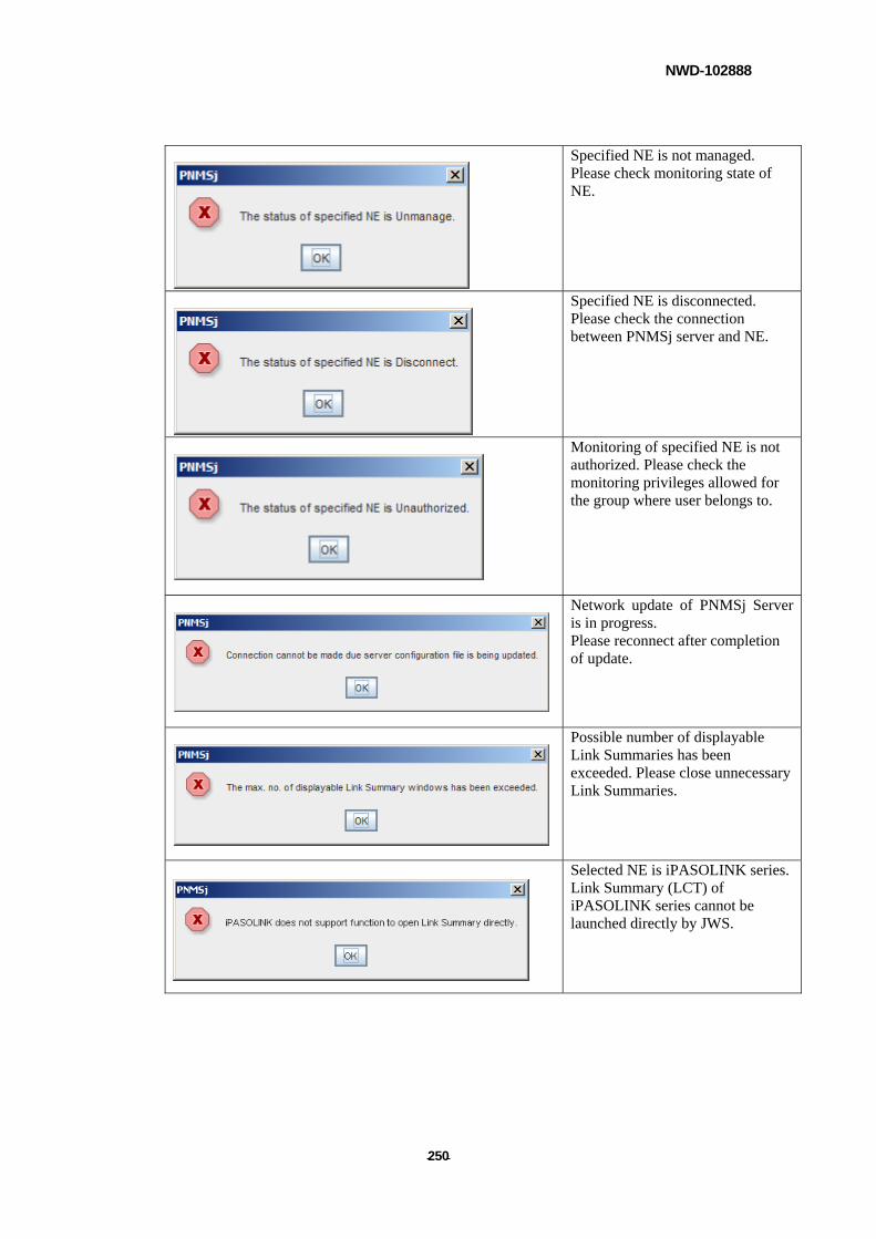
NWD-102888
- - 250
Specified NE is not managed. Please check monitoring state of NE.
Specified NE is disconnected. Please check the connection between PNMSj server and NE.
Monitoring of specified NE is not authorized. Please check the monitoring privileges allowed for the group where user belongs to.
Network update of PNMSj Server is in progress. Please reconnect after completion of update.
Possible number of displayable Link Summaries has been exceeded. Please close unnecessary Link Summaries.
Selected NE is iPASOLINK series. Link Summary (LCT) of iPASOLINK series cannot be launched directly by JWS.
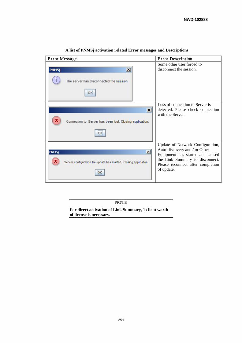
NWD-102888
- - 251
A list of PNMSj activation related Error messages and Descriptions
Error Message Error Description Some other user forced to
disconnect the session.
Loss of connection to Server is detected. Please check connection with the Server.
Update of Network Configuration, Auto-discovery and / or Other Equipment has started and caused the Link Summary to disconnect. Please reconnect after completion of update.
NOTE
For direct activation of Link Summary, 1 client worth of license is necessary.
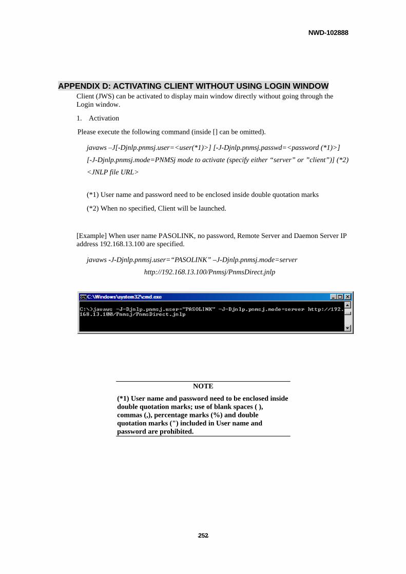
NWD-102888
- - 252
APPENDIX D: ACTIVATING CLIENT WITHOUT USING LOGIN WINDOW Client (JWS) can be activated to display main window directly without going through the Login window.
1. Activation
Please execute the following command (inside [] can be omitted).
javaws –J[-Djnlp.pnmsj.user=<user(*1)>] [-J-Djnlp.pnmsj.passwd=<password (*1)>]
[-J-Djnlp.pnmsj.mode=PNMSj mode to activate (specify either “server” or ”client”)] (*2)
<JNLP file URL>
(*1) User name and password need to be enclosed inside double quotation marks
(*2) When no specified, Client will be launched.
[Example] When user name PASOLINK, no password, Remote Server and Daemon Server IP address 192.168.13.100 are specified.
javaws -J-Djnlp.pnmsj.user=“PASOLINK” –J-Djnlp.pnmsj.mode=server
http://192.168.13.100/Pnmsj/PnmsDirect.jnlp
NOTE
(*1) User name and password need to be enclosed inside double quotation marks; use of blank spaces ( ), commas (,), percentage marks (%) and double quotation marks (") included in User name and password are prohibited.
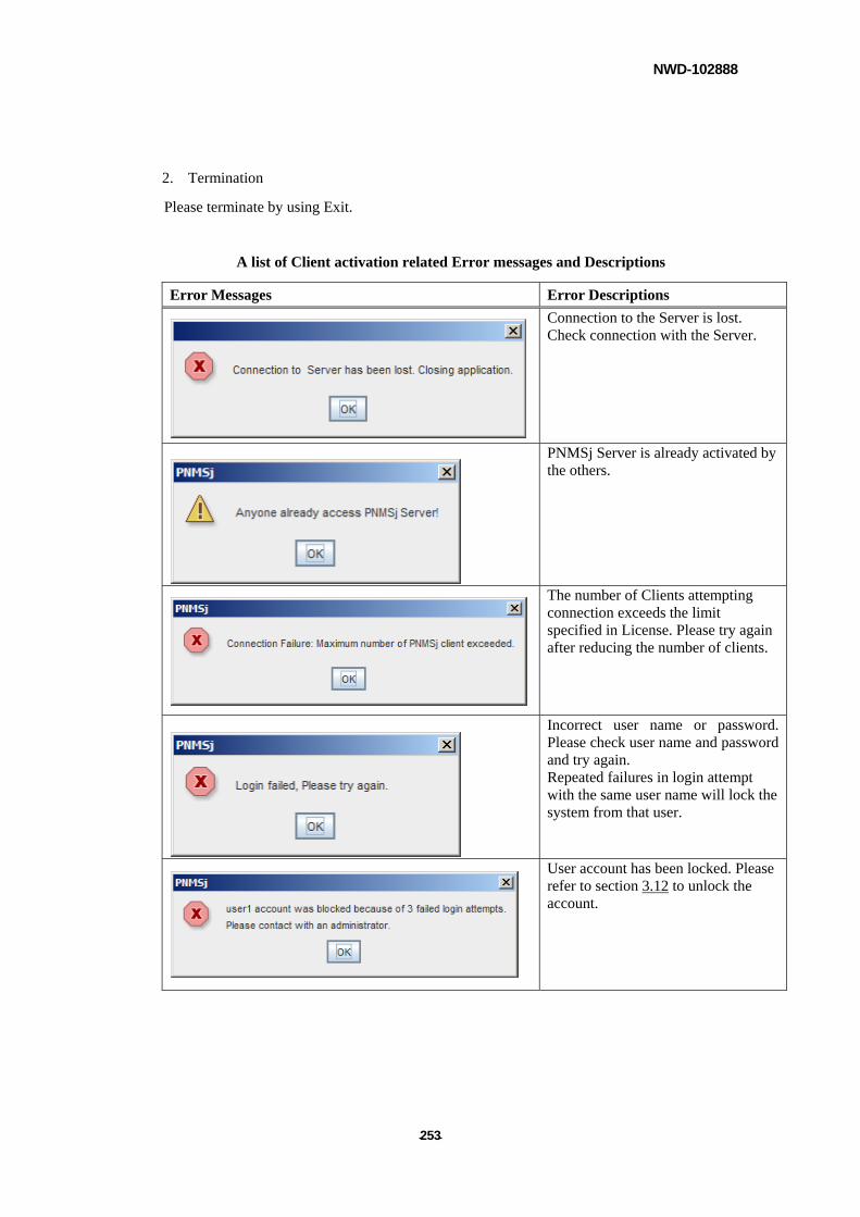
NWD-102888
- - 253
2. Termination
Please terminate by using Exit.
A list of Client activation related Error messages and Descriptions
Error Messages Error Descriptions
Connection to the Server is lost. Check connection with the Server.
PNMSj Server is already activated by the others.
The number of Clients attempting connection exceeds the limit specified in License. Please try again after reducing the number of clients.
Incorrect user name or password. Please check user name and password and try again. Repeated failures in login attempt with the same user name will lock the system from that user.
User account has been locked. Please refer to section 3.12 to unlock the account.
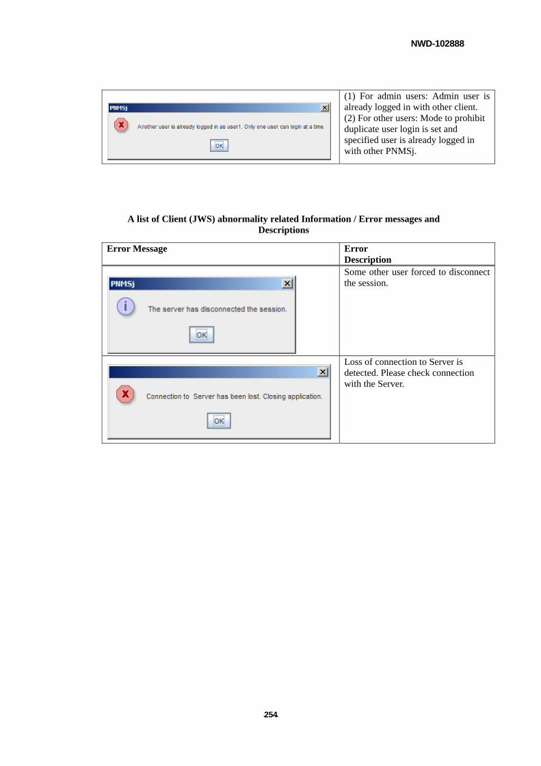
NWD-102888
- - 254
(1) For admin users: Admin user is already logged in with other client. (2) For other users: Mode to prohibit duplicate user login is set and specified user is already logged in with other PNMSj.
A list of Client (JWS) abnormality related Information / Error messages and Descriptions
Error Message Error Description
Some other user forced to disconnect the session.
Loss of connection to Server is detected. Please check connection with the Server.
NWD-102888
- - 255
APPENDIX E: SYNCHRONIZING NE NAMES AFTER UPDATE
NETWORKCONFIGURATION
For the Name of NE with no changes to its IP address and NE type during Update Network
Configuration, if its NE name kept in NCT file and the name kept in PNMSj differ, following is the
way to let the Name kept in PNMSj override the other. (As a usual rule, information kept in NCT
files prevail.)
Setup Method
Open PNMS.properties file and change the value of PriorityNeName in PNMS section.
[Before the change]
---------------------------
[PNMS]
PriorityNeName=0
---------------------------
[After the change]
---------------------------
[PNMS]
PriorityNeName=0
---------------------------
See below for set values and explanation.
0: Priority over NCT
For the Name of NE with no changes to its IP address and NE type but its NE name in
PNMSj differ from the one in NCT file, the name is changed according to NCT file.
1: Priority over PNMSj
For the Name of NE with no changes to its IP address and NE type but its NE name in
PNMSj differ from the one in NCT file, the name in PNMSj is adopted and will not
change to the one in NCT file.
Rebooting PNMSj is necessary to reflect any changes made to setting by above process.
NWD-102888
- - 256
APPENDIX F: REGARDING TCP, UDP USED BY PNMSJ SERVER With PNMSj, following TCP and UDP ports are used.
- Connection between PNMSj Server and NEs
(1) PNMSj will connect with NE using port listed below as the Destination Port. (Source
Port is unfixed.)
TFTP (UDP / 69), SNMP (UDP / 161) Relationship between Source Port and
Destination Port will reverse in response.
(2) NE will connect with PNMSj using port listed below as the Destination Port. (Source
Port is unfixed.)SNMP TRAP (UDP / 162)
- Connection between PNMSj Server and Client
(1) Client will connect with PNMSj Server using port listed below as Destination Port.
(Source Port is unfixed.) As for RMI, while Destination Port at the time of connection is
fixed, because of RMI specification, it will take an unspecified value between
1024-65535 to establish a connection for the first time. From then, that value is fixed.
HTTP (TCP / 80), RMI (at connection TCP / 1099, then TCP / 1024-65535)
Relationship between Source Port and Destination Portwill reverse in response.
- Connection between PNMSj Server and upper SNMP Manager
(1) Upper SNMP Manager will connect with PNMSj server using port listed below as
Destination Port. (Source Port is unfixed.) SNMP (UDP / 161) Relationship between
Source Port and Destination Port will reverse in response.
(2) PNMSj Server will connect with upper SNMP Manager using port listed below as the
Destination Port. (Source Port is unfixed.) SNMP TRAP (UDP / 162)

NWD-102888
- - 257
- Connection between PNMSj Server and PNMSql
(1) Client will connect with PNMSj Server using port listed below as the Destination Port.
(Source Port is unfixed.) As for RMI, while Destination Port at the time of connection is
fixed, because of RMI specification, it will take an unspecified value between
1024-65535 to establish a connection for the first time. From then, that value is fixed.
RMI (at connection TCP / 1099, then TCP / 1024-65535) Relationship between Source
Port and Destination Port will reverse in response.
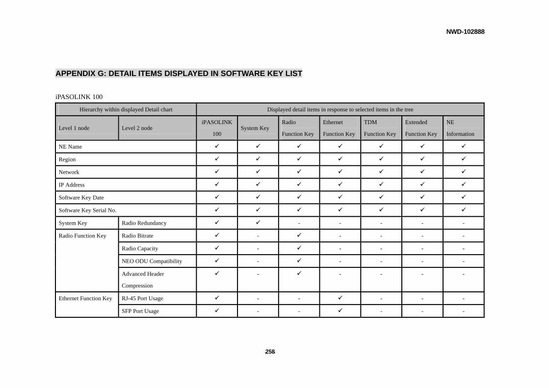
NWD-102888
- - 258
APPENDIX G: DETAIL ITEMS DISPLAYED IN SOFTWARE KEY LIST
iPASOLINK 100
Hierarchy within displayed Detail chart Displayed detail items in response to selected items in the tree
Level 1 node Level 2 node iPASOLINK
100 System Key
Radio
Function Key
Ethernet
Function Key
TDM
Function Key
Extended
Function Key
NE
Information
NE Name
Region
Network
IP Address
Software Key Date
Software Key Serial No.
System Key Radio Redundancy - - - - -
Radio Function Key Radio Bitrate - - - - -
Radio Capacity - - - - -
NEO ODU Compatibility - - - - -
Advanced Header
Compression
- - - - -
Ethernet Function Key RJ-45 Port Usage - - - - -
SFP Port Usage - - - - -
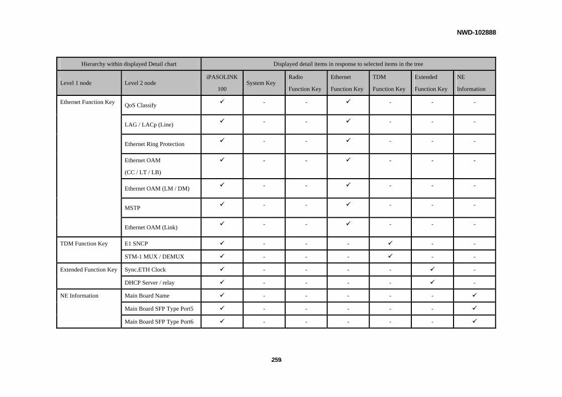
NWD-102888
- - 259
Hierarchy within displayed Detail chart Displayed detail items in response to selected items in the tree
Level 1 node Level 2 node iPASOLINK
100 System Key
Radio
Function Key
Ethernet
Function Key
TDM
Function Key
Extended
Function Key
NE
Information
Ethernet Function Key QoS Classify - - - - -
LAG / LACp (Line) - - - - -
Ethernet Ring Protection - - - - -
Ethernet OAM
(CC / LT / LB)
- - - - -
Ethernet OAM (LM / DM) - - - - -
MSTP - - - - -
Ethernet OAM (Link) - - - - -
TDM Function Key E1 SNCP - - - - -
STM-1 MUX / DEMUX - - - - -
Extended Function Key Sync.ETH Clock - - - - -
DHCP Server / relay - - - - -
NE Information Main Board Name - - - - -
Main Board SFP Type Port5 - - - - -
Main Board SFP Type Port6 - - - - -
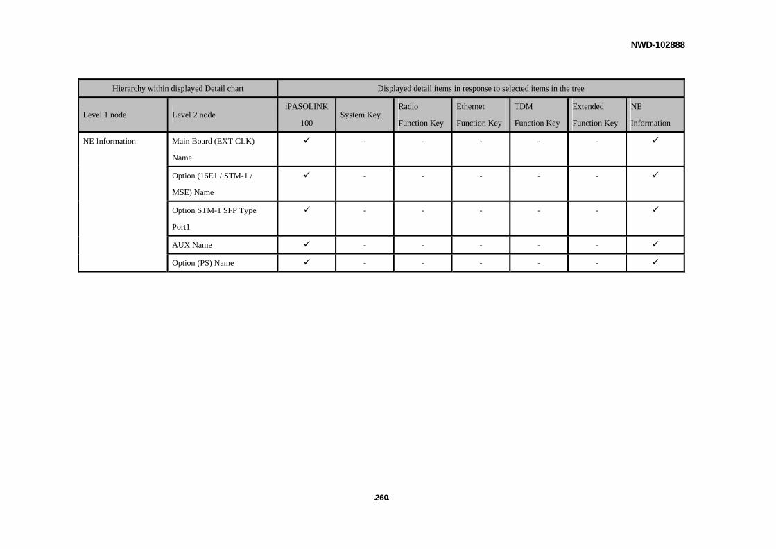
NWD-102888
- - 260
Hierarchy within displayed Detail chart Displayed detail items in response to selected items in the tree
Level 1 node Level 2 node iPASOLINK
100 System Key
Radio
Function Key
Ethernet
Function Key
TDM
Function Key
Extended
Function Key
NE
Information
NE Information Main Board (EXT CLK)
Name
- - - - -
Option (16E1 / STM-1 /
MSE) Name
- - - - -
Option STM-1 SFP Type
Port1
- - - - -
AUX Name - - - - -
Option (PS) Name - - - - -
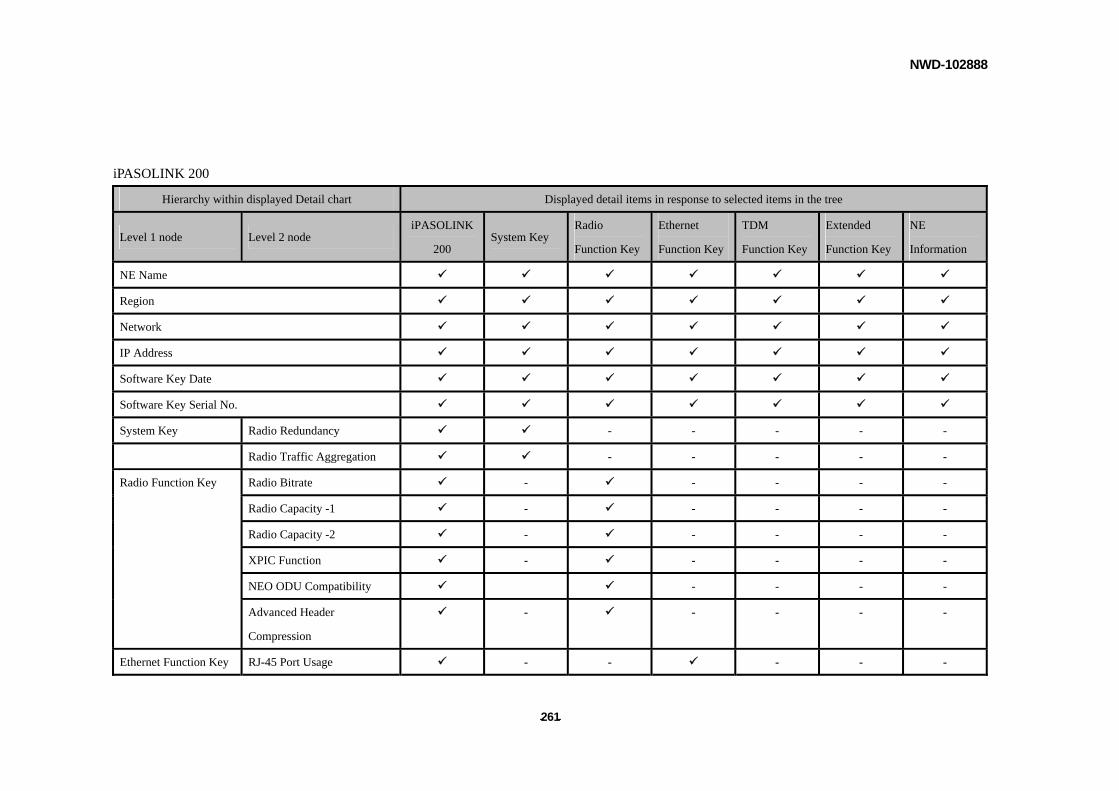
NWD-102888
- - 261
iPASOLINK 200
Hierarchy within displayed Detail chart Displayed detail items in response to selected items in the tree
Level 1 node Level 2 node iPASOLINK
200 System Key
Radio
Function Key
Ethernet
Function Key
TDM
Function Key
Extended
Function Key
NE
Information
NE Name
Region
Network
IP Address
Software Key Date
Software Key Serial No.
System Key Radio Redundancy - - - - -
Radio Traffic Aggregation - - - - -
Radio Bitrate - - - - -
Radio Capacity -1 - - - - -
Radio Capacity -2 - - - - -
XPIC Function - - - - -
Radio Function Key
NEO ODU Compatibility - - - -
Advanced Header
Compression
- - - - -
Ethernet Function Key RJ-45 Port Usage - - - - -
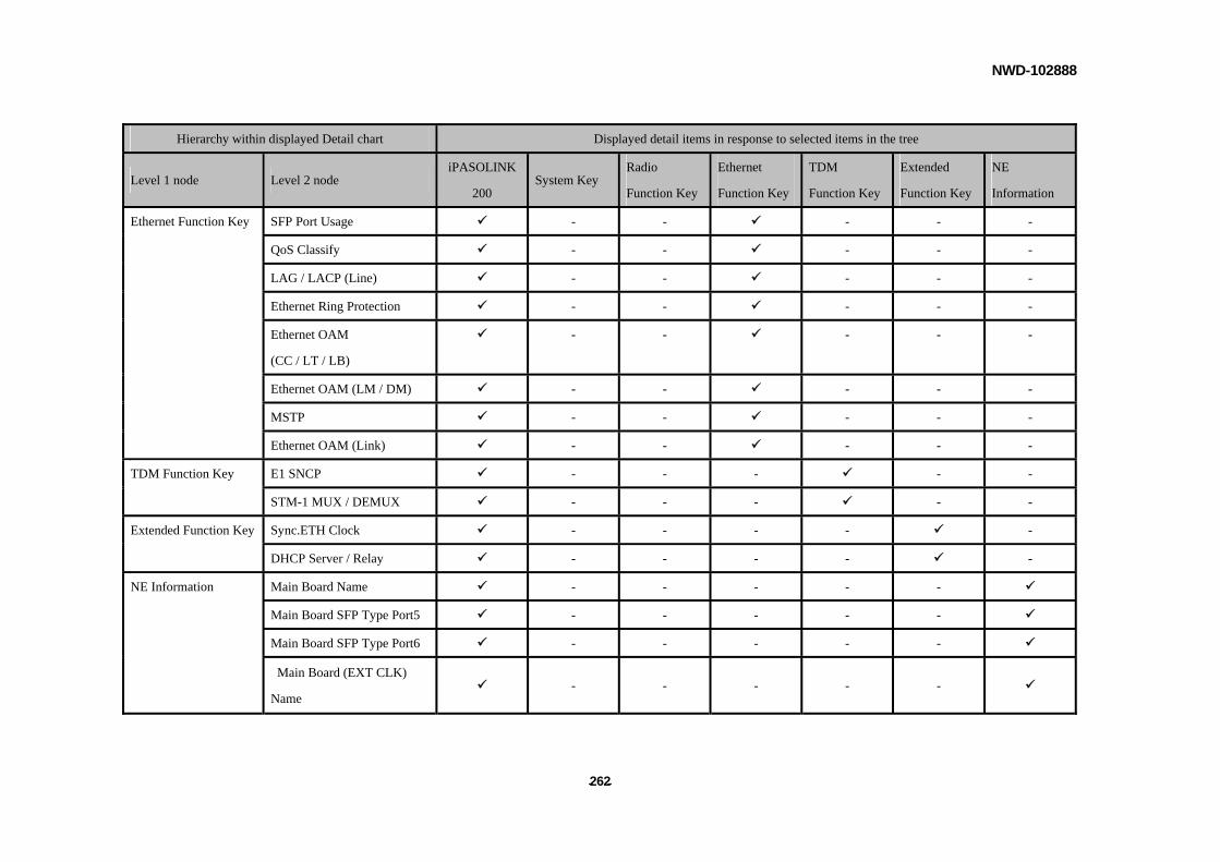
NWD-102888
- - 262
Hierarchy within displayed Detail chart Displayed detail items in response to selected items in the tree
Level 1 node Level 2 node iPASOLINK
200 System Key
Radio
Function Key
Ethernet
Function Key
TDM
Function Key
Extended
Function Key
NE
Information
Ethernet Function Key SFP Port Usage - - - - -
QoS Classify - - - - -
LAG / LACP (Line) - - - - -
Ethernet Ring Protection - - - - -
Ethernet OAM
(CC / LT / LB)
- - - - -
Ethernet OAM (LM / DM) - - - - -
MSTP - - - - -
Ethernet OAM (Link) - - - - -
E1 SNCP - - - - - TDM Function Key
STM-1 MUX / DEMUX - - - - -
Extended Function Key Sync.ETH Clock - - - - -
DHCP Server / Relay - - - - -
Main Board Name - - - - -
Main Board SFP Type Port5 - - - - -
Main Board SFP Type Port6 - - - - -
NE Information
Main Board (EXT CLK)
Name - - - - -
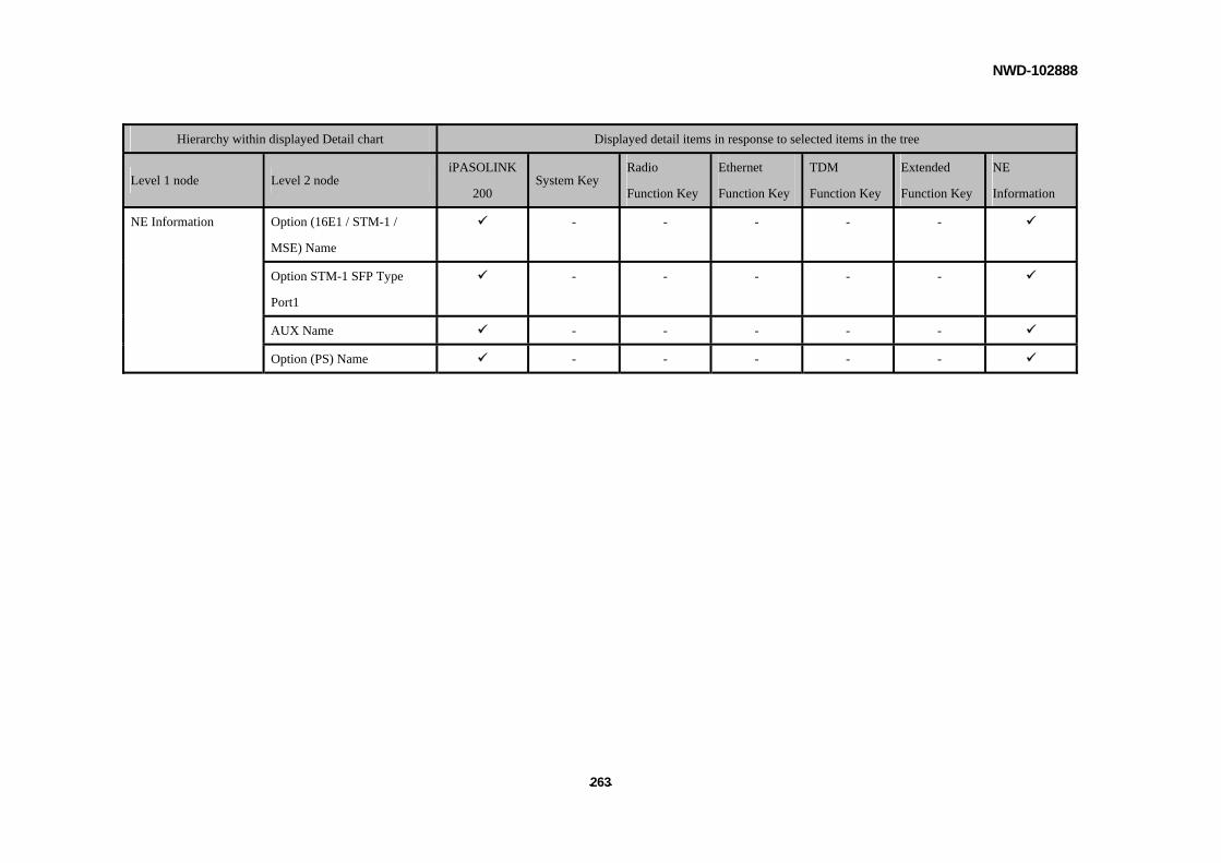
NWD-102888
- - 263
Hierarchy within displayed Detail chart Displayed detail items in response to selected items in the tree
Level 1 node Level 2 node iPASOLINK
200 System Key
Radio
Function Key
Ethernet
Function Key
TDM
Function Key
Extended
Function Key
NE
Information
Option (16E1 / STM-1 /
MSE) Name
- - - - -
Option STM-1 SFP Type
Port1
- - - - -
AUX Name - - - - -
NE Information
Option (PS) Name - - - - -

NWD-102888
- - 264
iPASOLINK 400
Hierarchy within displayed Detail chart Displayed detail items in response to selected items in the tree
Level 1 node Level 2 node iPASOLINK
400 System Key
Radio
Function
Key
Ethernet
Function
Key
TDM
Function
Key
Extended
Function
Key
NE
Information
NE Name
Region
Network
IP Address
Software Key Date
Software Key Serial No.
System Key Radio Redundancy - - - - -
Radio Traffic Aggregation - - - - -
Radio Function Key Radio Bitrate - - - - -
High Moduration - - - - -
Radio Capacity -1 - - - - -
Radio Capacity -2 - - - - -
Radio Capacity -3 - - - - -
Radio Capacity -4 - - - - -
XPIC Function - - - - -

NWD-102888
- - 265
Hierarchy within displayed Detail chart Displayed detail items in response to selected items in the tree
Level 1 node Level 2 node iPASOLINK
400 System Key
Radio
Function
Key
Ethernet
Function
Key
TDM
Function
Key
Extended
Function
Key
NE
Information
Radio Function Key NEO ODU Compatibility - - - - -
Advanced Header Compression - - - - -
Ethernet Function Key RJ-45 Port Usage - - - - -
SFP Port Usage - - - - -
SFP Port Usage (Option-1) - - - - -
SFP Port Usage (Option-2) - - - - -
SFP Port Usage (Option-3) - - - - -
SFP Port Usage (Option-4) - - - - -
Additional VLAN Table - - - - -
QoS Classify - - - - -
LAG / LACP (Line) - - - - -
Ethernet Ring Protection - - - - -
Ethernet OAM (CC / LT / LB) - - - - -
Ethernet OAM (LM / DM) - - - - -
MSTP - - - - -
Ethernet OAM (Link) - - - - -
TDM Function Key E1 SNCP - - - - -

NWD-102888
- - 266
Hierarchy within displayed Detail chart Displayed detail items in response to selected items in the tree
Level 1 node Level 2 node iPASOLINK
400 System Key
Radio
Function
Key
Ethernet
Function
Key
TDM
Function
Key
Extended
Function
Key
NE
Information
TDM Function Key STM-1 APS Protection - - - - -
STM-1 MUX / DEMUX - - - - -
Extended Function Key Sync.ETH Clock - - - - -
IEEE 1588v2 Boundary Clock - - - - -
Additional MSE E1 - - - - -
DHCP Server / Relay - - - - -
NE Information Main Card Name - - - - -
Main Card SFP Type Port3 - - - - -
Main Card SFP Type Port4 - - - - -
Main Card (EXT CLK) Name - - - - -
Slot01 Card Name - - - - -
Slot01 SFP Type - - - - -
Slot01 SFP Type - - - - -
Slot02 Card Name - - - - -
Slot02 SFP Type - - - - -
Slot02 SFP Type - - - - -
Slot03 Card Name - - - - -
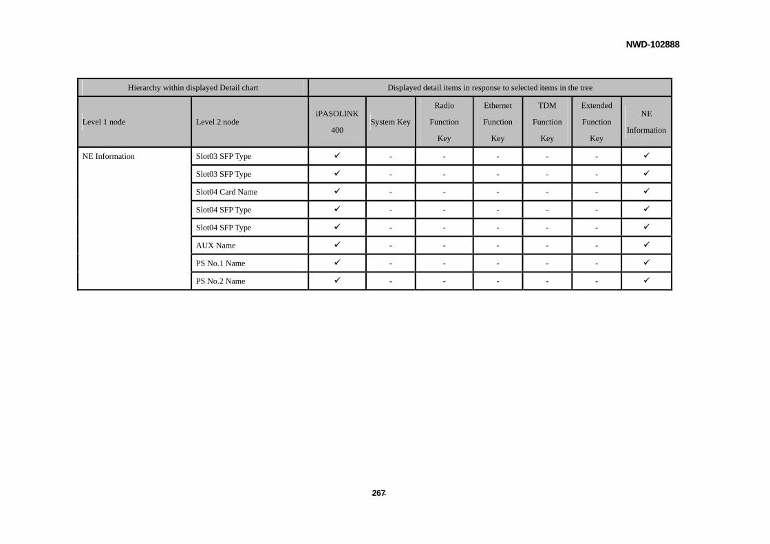
NWD-102888
- - 267
Hierarchy within displayed Detail chart Displayed detail items in response to selected items in the tree
Level 1 node Level 2 node iPASOLINK
400 System Key
Radio
Function
Key
Ethernet
Function
Key
TDM
Function
Key
Extended
Function
Key
NE
Information
NE Information Slot03 SFP Type - - - - -
Slot03 SFP Type - - - - -
Slot04 Card Name - - - - -
Slot04 SFP Type - - - - -
Slot04 SFP Type - - - - -
AUX Name - - - - -
PS No.1 Name - - - - -
PS No.2 Name - - - - -
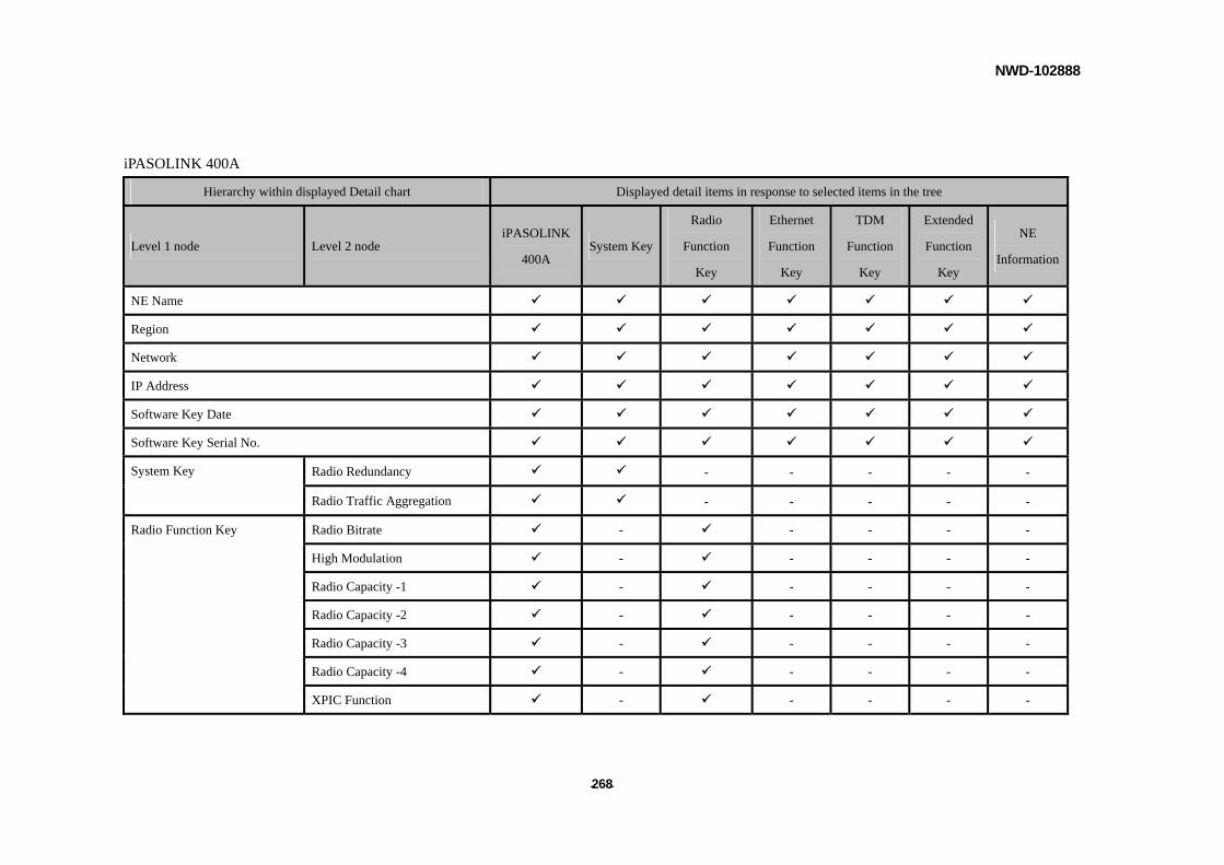
NWD-102888
- - 268
iPASOLINK 400A
Hierarchy within displayed Detail chart Displayed detail items in response to selected items in the tree
Level 1 node Level 2 node iPASOLINK
400A System Key
Radio
Function
Key
Ethernet
Function
Key
TDM
Function
Key
Extended
Function
Key
NE
Information
NE Name
Region
Network
IP Address
Software Key Date
Software Key Serial No.
Radio Redundancy - - - - - System Key
Radio Traffic Aggregation - - - - -
Radio Function Key Radio Bitrate - - - - -
High Modulation - - - - -
Radio Capacity -1 - - - - -
Radio Capacity -2 - - - - -
Radio Capacity -3 - - - - -
Radio Capacity -4 - - - - -
XPIC Function - - - - -
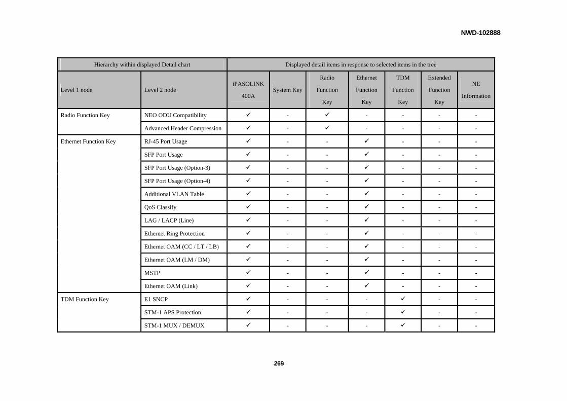
NWD-102888
- - 269
Hierarchy within displayed Detail chart Displayed detail items in response to selected items in the tree
Level 1 node Level 2 node iPASOLINK
400A System Key
Radio
Function
Key
Ethernet
Function
Key
TDM
Function
Key
Extended
Function
Key
NE
Information
NEO ODU Compatibility - - - - - Radio Function Key
Advanced Header Compression - - - - -
Ethernet Function Key RJ-45 Port Usage - - - - -
SFP Port Usage - - - - -
SFP Port Usage (Option-3) - - - - -
SFP Port Usage (Option-4) - - - - -
Additional VLAN Table - - - - -
QoS Classify - - - - -
LAG / LACP (Line) - - - - -
Ethernet Ring Protection - - - - -
Ethernet OAM (CC / LT / LB) - - - - -
Ethernet OAM (LM / DM) - - - - -
MSTP - - - - -
Ethernet OAM (Link) - - - - -
TDM Function Key E1 SNCP - - - - -
STM-1 APS Protection - - - - -
STM-1 MUX / DEMUX - - - - -
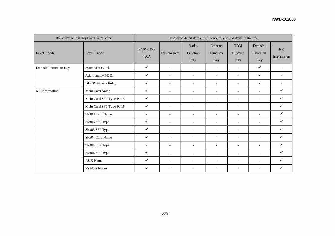
NWD-102888
- - 270
Hierarchy within displayed Detail chart Displayed detail items in response to selected items in the tree
Level 1 node Level 2 node iPASOLINK
400A System Key
Radio
Function
Key
Ethernet
Function
Key
TDM
Function
Key
Extended
Function
Key
NE
Information
Extended Function Key Sync.ETH Clock - - - - -
Additional MSE E1 - - - - -
DHCP Server / Relay - - - - -
NE Information Main Card Name - - - - -
Main Card SFP Type Port5 - - - - -
Main Card SFP Type Port6 - - - - -
Slot03 Card Name - - - - -
Slot03 SFP Type - - - - -
Slot03 SFP Type - - - - -
Slot04 Card Name - - - - -
Slot04 SFP Type - - - - -
Slot04 SFP Type - - - - -
AUX Name - - - - -
PS No.2 Name - - - - -

NWD-102888
- - 271
iPASOLINK 1000
Hierarchy within displayed Detail chart Displayed detail items in response to selected items in the tree
Level 1 node Level 2 node iPASOLINK
1000 System Key
Radio
Function
Key
Ethernet
Function
Key
TDM
Function
Key
Extended
Function
Key
NE
Information
NE Name
Region
Network
IP Address
Software Key Date
Software Key Serial No.
Radio Redundancy - - - - - System Key
Radio Traffic Aggregation - - - - -
Radio Function Key Radio Bitrate - - - - -
High Modulation - - - - -
Radio Capacity -01 - - - - -
Radio Capacity -02 - - - - -
Radio Capacity -03 - - - - -
Radio Capacity -04 - - - - -
Radio Capacity -05 - - - - -
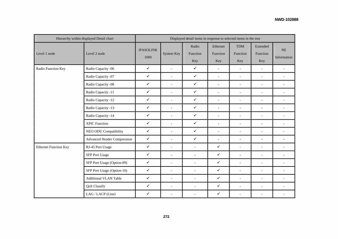
NWD-102888
- - 272
Hierarchy within displayed Detail chart Displayed detail items in response to selected items in the tree
Level 1 node Level 2 node iPASOLINK
1000 System Key
Radio
Function
Key
Ethernet
Function
Key
TDM
Function
Key
Extended
Function
Key
NE
Information
Radio Capacity -06 - - - - -
Radio Capacity -07 - - - - -
Radio Capacity -08 - - - - -
Radio Capacity -11 - - - - -
Radio Capacity -12 - - - - -
Radio Capacity -13 - - - - -
Radio Capacity -14 - - - - -
XPIC Function - - - - -
Radio Function Key
NEO ODU Compatibility - - - - -
Advanced Header Compression - - - - -
Ethernet Function Key RJ-45 Port Usage - - - - -
SFP Port Usage - - - - -
SFP Port Usage (Option-09) - - - - -
SFP Port Usage (Option-10) - - - - -
Additional VLAN Table - - - - -
QoS Classify - - - - -
LAG / LACP (Line) - - - - -
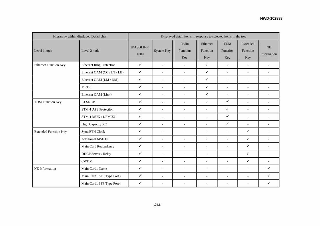
NWD-102888
- - 273
Hierarchy within displayed Detail chart Displayed detail items in response to selected items in the tree
Level 1 node Level 2 node iPASOLINK
1000 System Key
Radio
Function
Key
Ethernet
Function
Key
TDM
Function
Key
Extended
Function
Key
NE
Information
Ethernet Ring Protection - - - - - Ethernet Function Key
Ethernet OAM (CC / LT / LB) - - - - -
Ethernet OAM (LM / DM) - - - - -
MSTP - - - - -
Ethernet OAM (Link) - - - - -
TDM Function Key E1 SNCP - - - - -
STM-1 APS Protection - - - - -
STM-1 MUX / DEMUX - - - - -
High Capacity XC - - - - -
Extended Function Key Sync.ETH Clock - - - - -
Additional MSE E1 - - - - -
Main Card Redundancy - - - - -
DHCP Server / Relay - - - - -
CWDM - - - - -
NE Information Main Card1 Name - - - - -
Main Card1 SFP Type Port3 - - - - -
Main Card1 SFP Type Port4 - - - - -

NWD-102888
- - 274
Hierarchy within displayed Detail chart Displayed detail items in response to selected items in the tree
Level 1 node Level 2 node iPASOLINK
1000 System Key
Radio
Function
Key
Ethernet
Function
Key
TDM
Function
Key
Extended
Function
Key
NE
Information
NE Information Main Card2 Name - - - - -
Main Card2 SFP Type Port3 - - - - -
Main Card2 SFP Type Port4 - - - - -
Term Card Name - - - - -
Main Card1 (EXT CLK) Name - - - - -
Main Card2 (EXT CLK) Name - - - - -
Slot01 Card Name - - - - -
Slot01 SFP Type - - - - -
Slot01 SFP Type - - - - -
Slot02 Card Name - - - - -
Slot02 SFP Type - - - - -
Slot02 SFP Type - - - - -
Slot03 Card Name - - - - -
Slot03 SFP Type - - - - -
Slot03 SFP Type - - - - -
Slot04 Card Name - - - - -
Slot04 SFP Type - - - - -

NWD-102888
- - 275
Hierarchy within displayed Detail chart Displayed detail items in response to selected items in the tree
Level 1 node Level 2 node iPASOLINK
1000 System Key
Radio
Function
Key
Ethernet
Function
Key
TDM
Function
Key
Extended
Function
Key
NE
Information
NE Information Slot04 SFP Type - - - - -
Slot05 Card Name - - - - -
Slot05 SFP Type - - - - -
Slot05 SFP Type - - - - -
Slot06 Card Name - - - - -
Slot06 SFP Type - - - - -
Slot06 SFP Type - - - - -
Slot07 Card Name - - - - -
Slot07 SFP Type - - - - -
Slot07 SFP Type - - - - -
Slot08 Card Name - - - - -
Slot08 SFP Type - - - - -
Slot08 SFP Type - - - - -
Slot09 Card Name - - - - -
Slot09 SFP Type - - - - -
Slot09 SFP Type - - - - -
Slot10 Card Name - - - - -
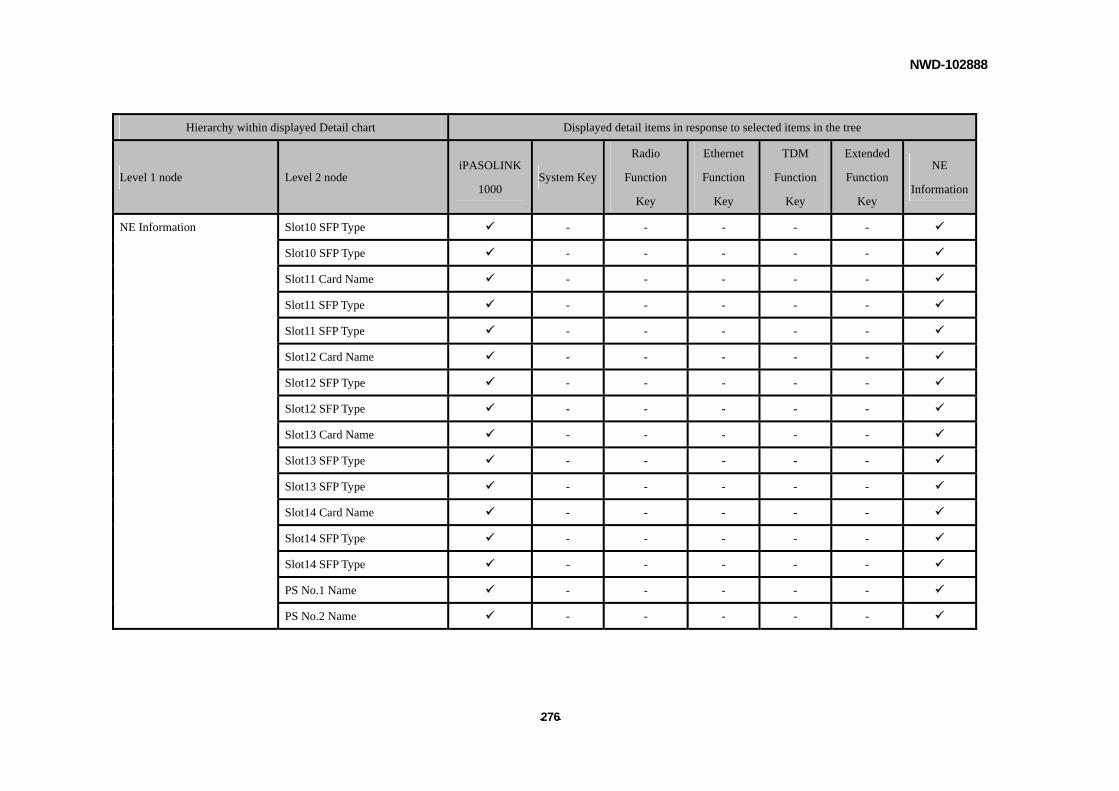
NWD-102888
- - 276
Hierarchy within displayed Detail chart Displayed detail items in response to selected items in the tree
Level 1 node Level 2 node iPASOLINK
1000 System Key
Radio
Function
Key
Ethernet
Function
Key
TDM
Function
Key
Extended
Function
Key
NE
Information
NE Information Slot10 SFP Type - - - - -
Slot10 SFP Type - - - - -
Slot11 Card Name - - - - -
Slot11 SFP Type - - - - -
Slot11 SFP Type - - - - -
Slot12 Card Name - - - - -
Slot12 SFP Type - - - - -
Slot12 SFP Type - - - - -
Slot13 Card Name - - - - -
Slot13 SFP Type - - - - -
Slot13 SFP Type - - - - -
Slot14 Card Name - - - - -
Slot14 SFP Type - - - - -
Slot14 SFP Type - - - - -
PS No.1 Name - - - - -
PS No.2 Name - - - - -
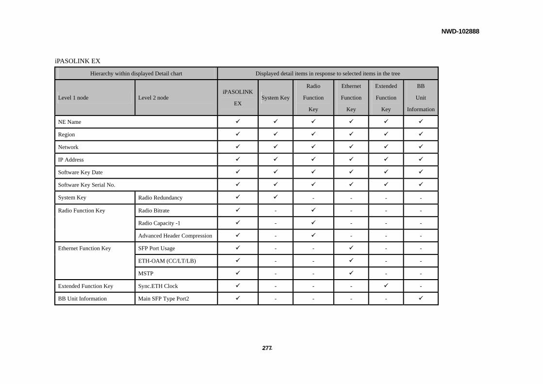
NWD-102888
- - 277
iPASOLINK EX
Hierarchy within displayed Detail chart Displayed detail items in response to selected items in the tree
Level 1 node Level 2 node iPASOLINK
EX System Key
Radio
Function
Key
Ethernet
Function
Key
Extended
Function
Key
BB
Unit
Information
NE Name
Region
Network
IP Address
Software Key Date
Software Key Serial No.
System Key Radio Redundancy - - - -
Radio Function Key Radio Bitrate - - - -
Radio Capacity -1 - - - -
Advanced Header Compression - - - -
Ethernet Function Key SFP Port Usage - - - -
ETH-OAM (CC/LT/LB) - - - -
MSTP - - - -
Extended Function Key Sync.ETH Clock - - - -
BB Unit Information Main SFP Type Port2 - - - -
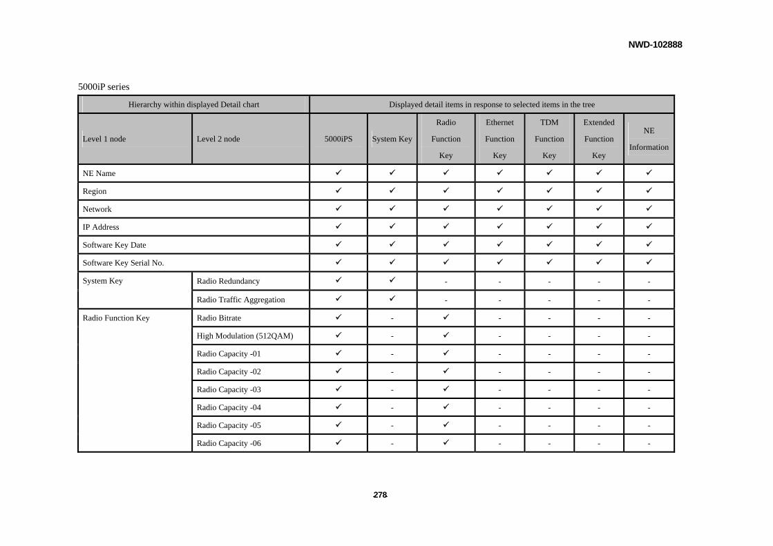
NWD-102888
- - 278
5000iP series
Hierarchy within displayed Detail chart Displayed detail items in response to selected items in the tree
Level 1 node Level 2 node 5000iPS System Key
Radio
Function
Key
Ethernet
Function
Key
TDM
Function
Key
Extended
Function
Key
NE
Information
NE Name
Region
Network
IP Address
Software Key Date
Software Key Serial No.
Radio Redundancy - - - - - System Key
Radio Traffic Aggregation - - - - -
Radio Function Key Radio Bitrate - - - - -
High Modulation (512QAM) - - - - -
Radio Capacity -01 - - - - -
Radio Capacity -02 - - - - -
Radio Capacity -03 - - - - -
Radio Capacity -04 - - - - -
Radio Capacity -05 - - - - -
Radio Capacity -06 - - - - -

NWD-102888
- - 279
Hierarchy within displayed Detail chart Displayed detail items in response to selected items in the tree
Level 1 node Level 2 node 5000iPS System Key
Radio
Function
Key
Ethernet
Function
Key
TDM
Function
Key
Extended
Function
Key
NE
Information
Radio Capacity -07 - - - - -
Radio Capacity -08 - - - - -
Radio Capacity -11 - - - - -
Radio Capacity -12 - - - - -
Radio Capacity -13 - - - - -
Radio Capacity -14 - - - - -
Radio Function Key
XPIC Function - - - - -
QPSK Option (QPSK-32QAM) - - - - -
Ethernet Function Key RJ-45 Port Usage - - - - -
SFP Port Usage - - - - -
SFP Port Usage (Option-09) - - - - -
SFP Port Usage (Option-10) - - - - -
Additional VLAN Table - - - - -
QoS Classify - - - - -
LAG / LACP (Line) - - - - -
Ethernet Ring Protection - - - - -
Ethernet OAM (CC / LT / LB) - - - - -
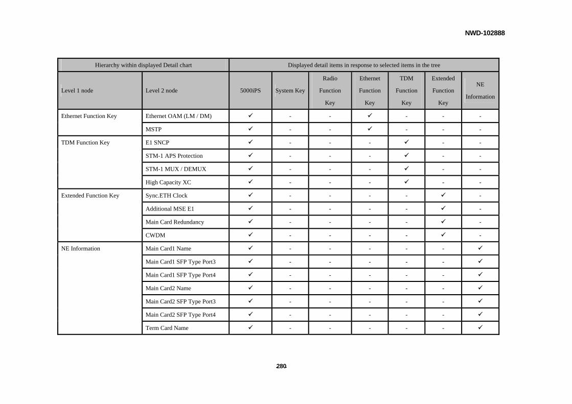
NWD-102888
- - 280
Hierarchy within displayed Detail chart Displayed detail items in response to selected items in the tree
Level 1 node Level 2 node 5000iPS System Key
Radio
Function
Key
Ethernet
Function
Key
TDM
Function
Key
Extended
Function
Key
NE
Information
Ethernet Function Key Ethernet OAM (LM / DM) - - - - -
MSTP - - - - -
TDM Function Key E1 SNCP - - - - -
STM-1 APS Protection - - - - -
STM-1 MUX / DEMUX - - - - -
High Capacity XC - - - - -
Extended Function Key Sync.ETH Clock - - - - -
Additional MSE E1 - - - - -
Main Card Redundancy - - - - -
CWDM - - - - -
NE Information Main Card1 Name - - - - -
Main Card1 SFP Type Port3 - - - - -
Main Card1 SFP Type Port4 - - - - -
Main Card2 Name - - - - -
Main Card2 SFP Type Port3 - - - - -
Main Card2 SFP Type Port4 - - - - -
Term Card Name - - - - -
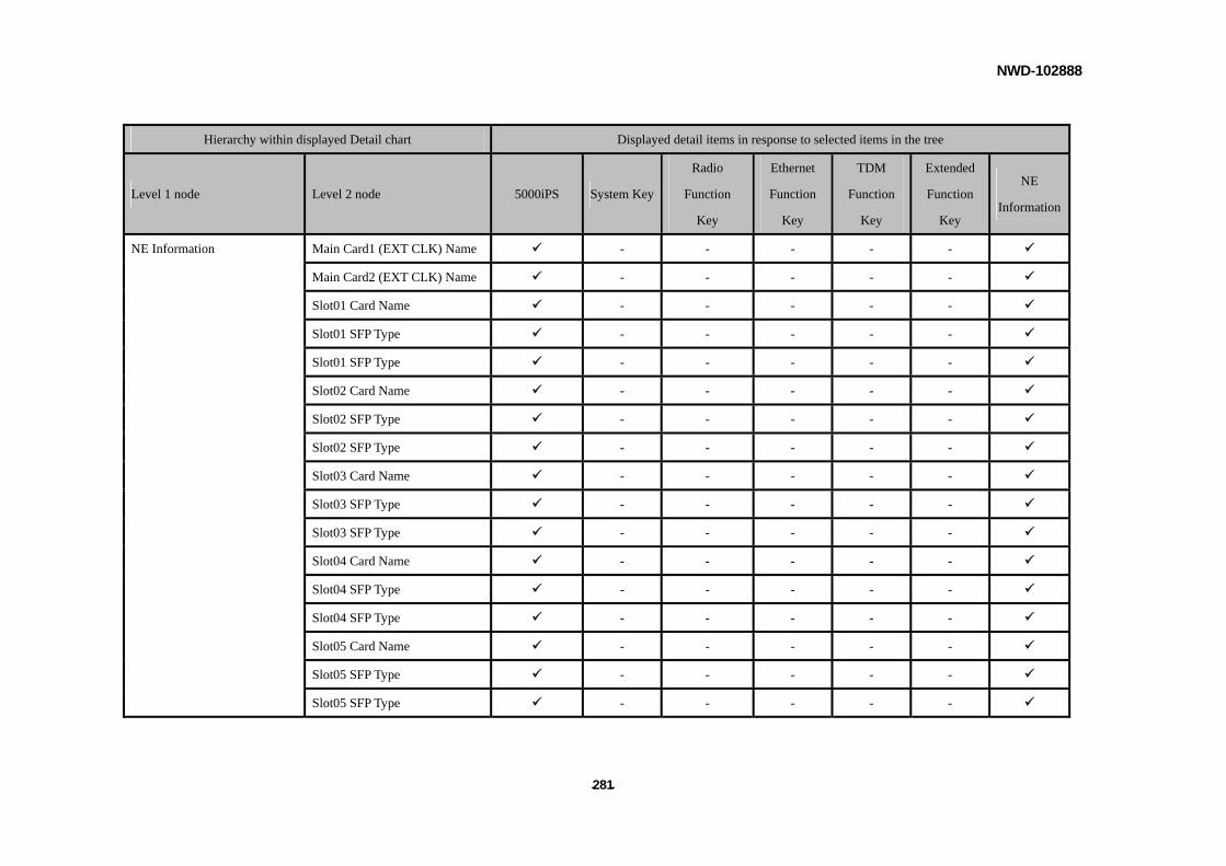
NWD-102888
- - 281
Hierarchy within displayed Detail chart Displayed detail items in response to selected items in the tree
Level 1 node Level 2 node 5000iPS System Key
Radio
Function
Key
Ethernet
Function
Key
TDM
Function
Key
Extended
Function
Key
NE
Information
NE Information Main Card1 (EXT CLK) Name - - - - -
Main Card2 (EXT CLK) Name - - - - -
Slot01 Card Name - - - - -
Slot01 SFP Type - - - - -
Slot01 SFP Type - - - - -
Slot02 Card Name - - - - -
Slot02 SFP Type - - - - -
Slot02 SFP Type - - - - -
Slot03 Card Name - - - - -
Slot03 SFP Type - - - - -
Slot03 SFP Type - - - - -
Slot04 Card Name - - - - -
Slot04 SFP Type - - - - -
Slot04 SFP Type - - - - -
Slot05 Card Name - - - - -
Slot05 SFP Type - - - - -
Slot05 SFP Type - - - - -
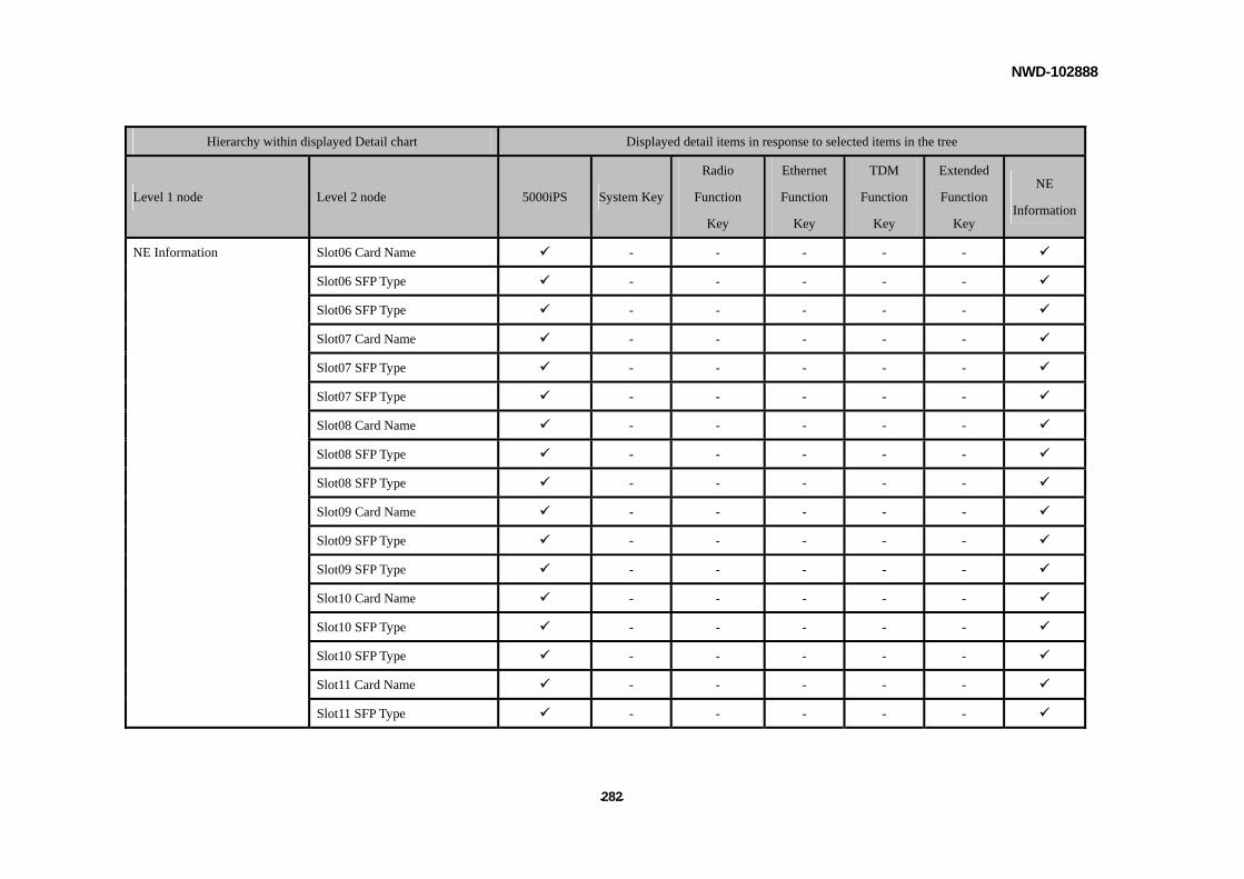
NWD-102888
- - 282
Hierarchy within displayed Detail chart Displayed detail items in response to selected items in the tree
Level 1 node Level 2 node 5000iPS System Key
Radio
Function
Key
Ethernet
Function
Key
TDM
Function
Key
Extended
Function
Key
NE
Information
NE Information Slot06 Card Name - - - - -
Slot06 SFP Type - - - - -
Slot06 SFP Type - - - - -
Slot07 Card Name - - - - -
Slot07 SFP Type - - - - -
Slot07 SFP Type - - - - -
Slot08 Card Name - - - - -
Slot08 SFP Type - - - - -
Slot08 SFP Type - - - - -
Slot09 Card Name - - - - -
Slot09 SFP Type - - - - -
Slot09 SFP Type - - - - -
Slot10 Card Name - - - - -
Slot10 SFP Type - - - - -
Slot10 SFP Type - - - - -
Slot11 Card Name - - - - -
Slot11 SFP Type - - - - -
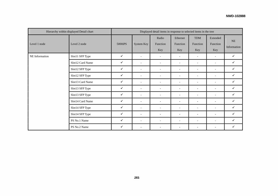
NWD-102888
- - 283
Hierarchy within displayed Detail chart Displayed detail items in response to selected items in the tree
Level 1 node Level 2 node 5000iPS System Key
Radio
Function
Key
Ethernet
Function
Key
TDM
Function
Key
Extended
Function
Key
NE
Information
NE Information Slot11 SFP Type - - - - -
Slot12 Card Name - - - - -
Slot12 SFP Type - - - - -
Slot12 SFP Type - - - - -
Slot13 Card Name - - - - -
Slot13 SFP Type - - - - -
Slot13 SFP Type - - - - -
Slot14 Card Name - - - - -
Slot14 SFP Type - - - - -
Slot14 SFP Type - - - - -
PS No.1 Name - - - - -
PS No.2 Name - - - - -
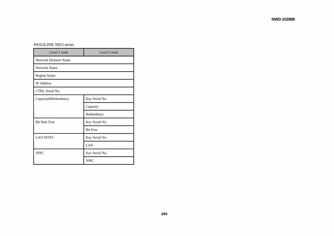
NWD-102888
- - 284
PASOLINK NEO series
Level 1 node Level 2 node
Network Element Name
Network Name
Region Name
IP Address
CTRL Serial No.
Key Serial No.
Capacity
Capacity&Redundancy
Redundancy
Key Serial No. Bit Rate Free
Bit Free
Key Serial No. LAN INTFC
LAN
Key Serial No. XPIC
XPIC