Embed Size (px)
Citation preview
®
2-Leg and 4-Leg QuickBolt™Towers
Installation Manual
PNEG-2115Version 2.0
Date: 10-15-19
PNEG-2115

All information, illustrations, photos, and specifications in this manual are based on the latestinformation available at the time of publication. The right is reserved to make changes at anytime without notice.
2 PNEG-2115 2-Leg and 4-Leg Towers
ContentsChapter 1 Safety Precautions ....................................................................................................................5
Safety Guidelines ........................................................................................................................5Cautionary Symbol Definitions......................................................................................................6Safety Precautions ......................................................................................................................7Safety Sign-off Sheet.................................................................................................................12
Chapter 2 General Information ................................................................................................................13Overview ..................................................................................................................................13Required Specifications .............................................................................................................13Hole Preparation .......................................................................................................................13Anchor Washers........................................................................................................................14Top Tower Beams......................................................................................................................15Bin Guy Kit for 2-Leg Towers ......................................................................................................16Seal Plate Kit ............................................................................................................................17Tower Erection ..........................................................................................................................17
Chapter 3 Hardware Requirements..........................................................................................................19Chapter 4 2-Leg Towers...........................................................................................................................23
2-Leg Tower Layout ...................................................................................................................23Assembling the 2-Leg Tower Section (Chevron Bracing) ..............................................................24Assembling the 2-Leg Tower Section (Warren Bracing) ................................................................26Stacking the 2-Leg Tower Section ..............................................................................................28
Chapter 5 4-Leg Towers...........................................................................................................................314-Leg Tower Layout ...................................................................................................................31Assembling the 4-Leg Tower Section (Chevron Bracing) ..............................................................32Assembling the 4-Leg Tower Section (Angle Braced) ...................................................................34Assembling the 4-Leg Tower Section (Warren Bracing) ................................................................36Assembling the 4-Leg Tower Section (Chevron and Warren Bracing) ............................................38Stacking the 4-Leg Tower Section ..............................................................................................40Limited Warranty — N.A. Grain Products ................................................................................43
PNEG-2115 2-Leg and 4-Leg Towers 3
NOTES
4 PNEG-2115 2-Leg and 4-Leg Towers
1 Safety PrecautionsTopics Covered in this Chapter
▪ Safety Guidelines▪ Cautionary Symbol Definitions▪ Safety Precautions▪ Safety Sign-off Sheet
Safety GuidelinesSafety guidelines are general-to-specific safety rules that must be followed at all times. This manual iswritten to help you understand safe operating procedures and problems that can be encountered by theoperator and other personnel when using this equipment. Read and save these instructions.
As owner or operator, you are responsible for understanding the requirements, hazards, and precautionsthat exist and to inform others as required. Unqualified persons must stay out of the work area at alltimes.
Alterations must not be made to the equipment. Alterations can produce dangerous situations resulting inSERIOUS INJURYor DEATH.
This equipment must be installed in accordance with the current installation codes and applicable regula-tions, which must be carefully followed in all cases. Authorities having jurisdiction must be consultedbefore installations are made.
When necessary, you must consider the installation location relative to electrical, fuel and water utilities.
Personnel operating or working around equipment must read this manual. This manual must be deliveredwith equipment to its owner. Failure to read this manual and its safety instructions is a misuse of theequipment.
ST-0001–4
PNEG-2115 2-Leg and 4-Leg Towers 5
Chapter 1: Safety Precautions
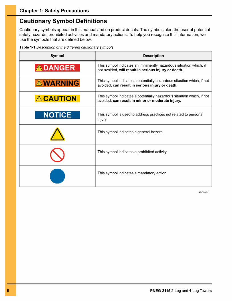
Cautionary Symbol DefinitionsCautionary symbols appear in this manual and on product decals. The symbols alert the user of potentialsafety hazards, prohibited activities and mandatory actions. To help you recognize this information, weuse the symbols that are defined below.
Table 1-1 Description of the different cautionary symbols
Symbol Description
This symbol indicates an imminently hazardous situation which, ifnot avoided, will result in serious injury or death.
This symbol indicates a potentially hazardous situation which, if notavoided, can result in serious injury or death.
This symbol indicates a potentially hazardous situation which, if notavoided, can result in minor or moderate injury.
This symbol is used to address practices not related to personalinjury.
This symbol indicates a general hazard.
This symbol indicates a prohibited activity.
This symbol indicates a mandatory action.
ST-0005–2
6 PNEG-2115 2-Leg and 4-Leg Towers
Chapter 1: Safety Precautions
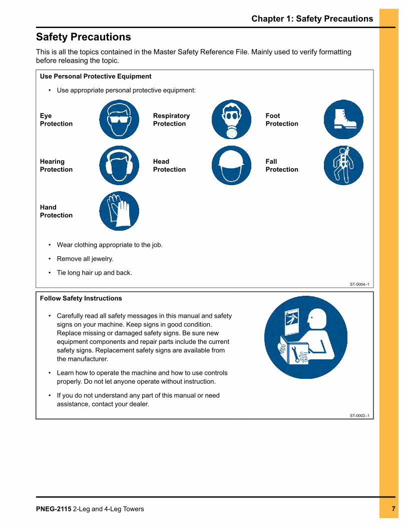
Safety PrecautionsThis is all the topics contained in the Master Safety Reference File. Mainly used to verify formattingbefore releasing the topic.
Use Personal Protective Equipment
• Use appropriate personal protective equipment:
EyeProtection
RespiratoryProtection
FootProtection
HearingProtection
HeadProtection
FallProtection
HandProtection
• Wear clothing appropriate to the job.
• Remove all jewelry.
• Tie long hair up and back.ST-0004–1
Follow Safety Instructions
• Carefully read all safety messages in this manual and safetysigns on your machine. Keep signs in good condition.Replace missing or damaged safety signs. Be sure newequipment components and repair parts include the currentsafety signs. Replacement safety signs are available fromthe manufacturer.
• Learn how to operate the machine and how to use controlsproperly. Do not let anyone operate without instruction.
• If you do not understand any part of this manual or needassistance, contact your dealer.
ST-0002–1
PNEG-2115 2-Leg and 4-Leg Towers 7
Chapter 1: Safety Precautions
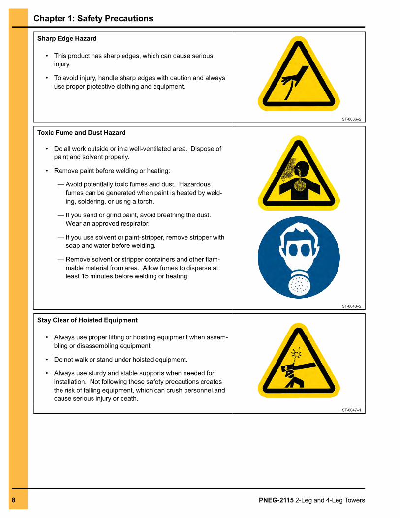
Sharp Edge Hazard
• This product has sharp edges, which can cause seriousinjury.
• To avoid injury, handle sharp edges with caution and alwaysuse proper protective clothing and equipment.
ST-0036–2
Toxic Fume and Dust Hazard
• Do all work outside or in a well-ventilated area. Dispose ofpaint and solvent properly.
• Remove paint before welding or heating:
— Avoid potentially toxic fumes and dust. Hazardousfumes can be generated when paint is heated by weld-ing, soldering, or using a torch.
— If you sand or grind paint, avoid breathing the dust.Wear an approved respirator.
— If you use solvent or paint-stripper, remove stripper withsoap and water before welding.
— Remove solvent or stripper containers and other flam-mable material from area. Allow fumes to disperse atleast 15 minutes before welding or heating
ST-0043–2
Stay Clear of Hoisted Equipment
• Always use proper lifting or hoisting equipment when assem-bling or disassembling equipment
• Do not walk or stand under hoisted equipment.
• Always use sturdy and stable supports when needed forinstallation. Not following these safety precautions createsthe risk of falling equipment, which can crush personnel andcause serious injury or death.
ST-0047–1
8 PNEG-2115 2-Leg and 4-Leg Towers
Chapter 1: Safety Precautions
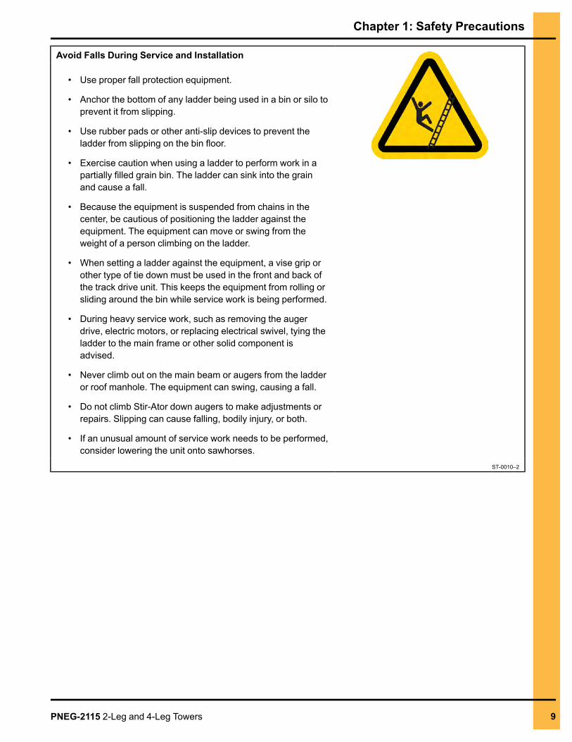
Avoid Falls During Service and Installation
• Use proper fall protection equipment.
• Anchor the bottom of any ladder being used in a bin or silo toprevent it from slipping.
• Use rubber pads or other anti-slip devices to prevent theladder from slipping on the bin floor.
• Exercise caution when using a ladder to perform work in apartially filled grain bin. The ladder can sink into the grainand cause a fall.
• Because the equipment is suspended from chains in thecenter, be cautious of positioning the ladder against theequipment. The equipment can move or swing from theweight of a person climbing on the ladder.
• When setting a ladder against the equipment, a vise grip orother type of tie down must be used in the front and back ofthe track drive unit. This keeps the equipment from rolling orsliding around the bin while service work is being performed.
• During heavy service work, such as removing the augerdrive, electric motors, or replacing electrical swivel, tying theladder to the main frame or other solid component isadvised.
• Never climb out on the main beam or augers from the ladderor roof manhole. The equipment can swing, causing a fall.
• Do not climb Stir-Ator down augers to make adjustments orrepairs. Slipping can cause falling, bodily injury, or both.
• If an unusual amount of service work needs to be performed,consider lowering the unit onto sawhorses.
ST-0010–2
PNEG-2115 2-Leg and 4-Leg Towers 9
Chapter 1: Safety Precautions
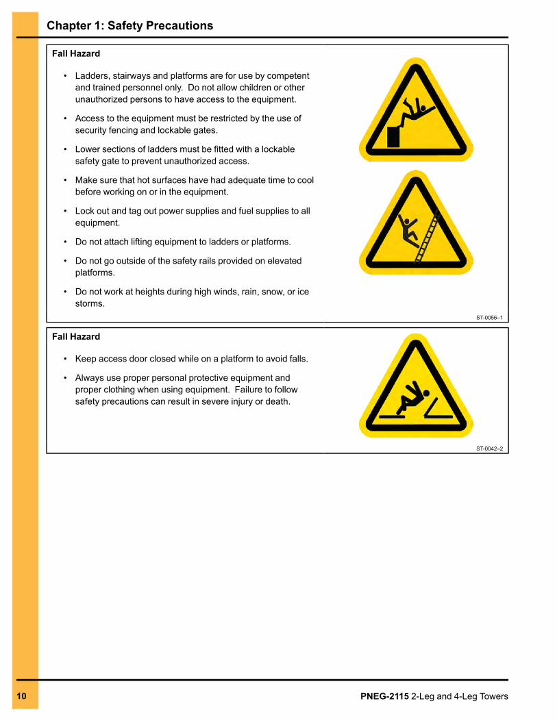
Fall Hazard
• Ladders, stairways and platforms are for use by competentand trained personnel only. Do not allow children or otherunauthorized persons to have access to the equipment.
• Access to the equipment must be restricted by the use ofsecurity fencing and lockable gates.
• Lower sections of ladders must be fitted with a lockablesafety gate to prevent unauthorized access.
• Make sure that hot surfaces have had adequate time to coolbefore working on or in the equipment.
• Lock out and tag out power supplies and fuel supplies to allequipment.
• Do not attach lifting equipment to ladders or platforms.
• Do not go outside of the safety rails provided on elevatedplatforms.
• Do not work at heights during high winds, rain, snow, or icestorms.
ST-0056–1
Fall Hazard
• Keep access door closed while on a platform to avoid falls.
• Always use proper personal protective equipment andproper clothing when using equipment. Failure to followsafety precautions can result in severe injury or death.
ST-0042–2
10 PNEG-2115 2-Leg and 4-Leg Towers
Chapter 1: Safety Precautions
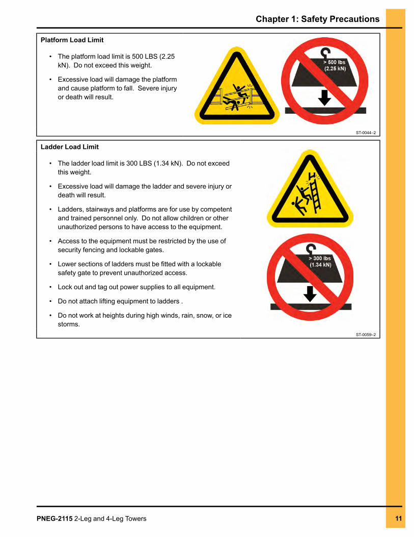
Platform Load Limit
• The platform load limit is 500 LBS (2.25kN). Do not exceed this weight.
• Excessive load will damage the platformand cause platform to fall. Severe injuryor death will result.
ST-0044–2
Ladder Load Limit
• The ladder load limit is 300 LBS (1.34 kN). Do not exceedthis weight.
• Excessive load will damage the ladder and severe injury ordeath will result.
• Ladders, stairways and platforms are for use by competentand trained personnel only. Do not allow children or otherunauthorized persons to have access to the equipment.
• Access to the equipment must be restricted by the use ofsecurity fencing and lockable gates.
• Lower sections of ladders must be fitted with a lockablesafety gate to prevent unauthorized access.
• Lock out and tag out power supplies to all equipment.
• Do not attach lifting equipment to ladders .
• Do not work at heights during high winds, rain, snow, or icestorms.
ST-0059–2
PNEG-2115 2-Leg and 4-Leg Towers 11
Chapter 1: Safety Precautions
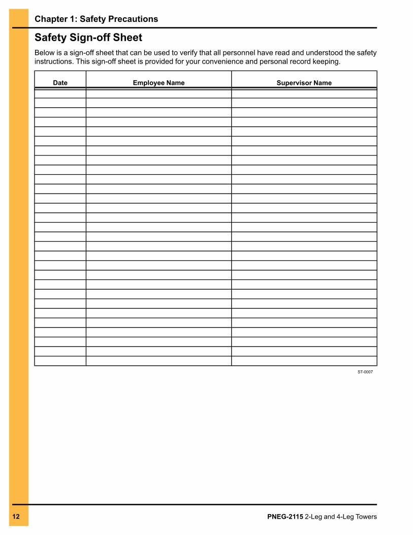
Safety Sign-off SheetBelow is a sign-off sheet that can be used to verify that all personnel have read and understood the safetyinstructions. This sign-off sheet is provided for your convenience and personal record keeping.
Date Employee Name Supervisor Name
ST-0007
12 PNEG-2115 2-Leg and 4-Leg Towers
2 General InformationTopics Covered in this Chapter
▪ Overview▪ Required Specifications▪ Hole Preparation▪ Anchor Washers▪ Top Tower Beams▪ Bin Guy Kit for 2-Leg Towers▪ Seal Plate Kit▪ Tower Erection
Overview1. All A325 bolts in splice connections are to be tightened by the turn-of-the-nut method. Bracing boltsare to be “snug-tight” only.
2. All GSI provided steel is hot dipped galvanized per ASTM-123A/123M.
3. No bridge members can be removed at any time unless it was designed for it. Drawings will showexact layout of members and how they are to be installed.
4. No tower members can be removed at any time unless it was designed for it. Drawings will showexact layout of members and how they are to be installed.
Required Specifications1. Steel W sections are ASTM A992, A709 or A572 Grade 50.
2. Steel channels, angles and S sections are ASTM A36.
3. Steel HSS is ASTM A500 GR B, 46 KSI.
4. All structural bolts are A325 unless otherwise specified.
5. All field welds are 3/16 in. (0.48 cm) min. size fillet weld E60XX or E70XX.
6. All grade 8 bolts are to be installed in snug-tight condition.
Hole Preparation1. Since GSI steels are galvanized, bolt holes may be smaller than the requirement due to the build upof galvanizing around the holes.
2. The bolt holes are usually 1/16” greater than the bolts in diameter.
3. The holes may be deburred so that the bolt can be inserted through the holes.
PNEG-2115 2-Leg and 4-Leg Towers 13
Chapter 2: General Information
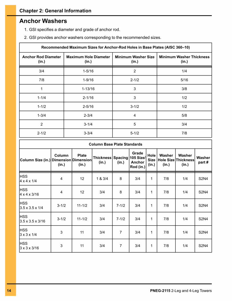
Anchor Washers1. GSI specifies a diameter and grade of anchor rod.
2. GSI provides anchor washers corresponding to the recommended sizes.
Recommended Maximum Sizes for Anchor-Rod Holes in Base Plates (AISC 360–10)
Anchor Rod Diameter(in.)
Maximum Hole Diameter(in.)
Minimum Washer Size(in.)
Minimum Washer Thickness(in.)
3/4 1-5/16 2 1/4
7/8 1-9/16 2-1/2 5/16
1 1-13/16 3 3/8
1-1/4 2-1/16 3 1/2
1-1/2 2-5/16 3-1/2 1/2
1-3/4 2-3/4 4 5/8
2 3-1/4 5 3/4
2-1/2 3-3/4 5-1/2 7/8
Column Base Plate Standards
Column Size (in.)Column
Dimension(in.)
PlateDimension
(in.)
Thickness(in.)
Spacing(in.)
Grade105 Size/AnchorRod (in.)
HoleSize(in.)
WasherHole Size
(in.)
WasherThickness
(in.)
Washerpart #
HSS4 x 4 x 1/4 4 12 1 & 3/4 8 3/4 1 7/8 1/4 S2N4
HSS4 x 4 x 3/16 4 12 3/4 8 3/4 1 7/8 1/4 S2N4
HSS3.5 x 3.5 x 1/4 3-1/2 11-1/2 3/4 7-1/2 3/4 1 7/8 1/4 S2N4
HSS3.5 x 3.5 x 3/16 3-1/2 11-1/2 3/4 7-1/2 3/4 1 7/8 1/4 S2N4
HSS3 x 3 x 1/4 3 11 3/4 7 3/4 1 7/8 1/4 S2N4
HSS3 x 3 x 3/16 3 11 3/4 7 3/4 1 7/8 1/4 S2N4
14 PNEG-2115 2-Leg and 4-Leg Towers
Chapter 2: General Information
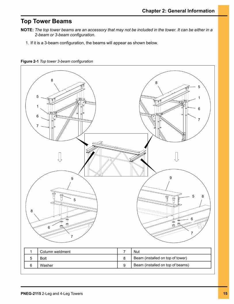
Top Tower BeamsNOTE: The top tower beams are an accessory that may not be included in the tower. It can be either in a
2-beam or 3-beam configuration.
1. If it is a 3-beam configuration, the beams will appear as shown below.
Figure 2-1 Top tower 3-beam configuration
1 Column weldment 7 Nut
5 Bolt 8 Beam (installed on top of tower)
6 Washer 9 Beam (installed on top of beams)
PNEG-2115 2-Leg and 4-Leg Towers 15
Chapter 2: General Information
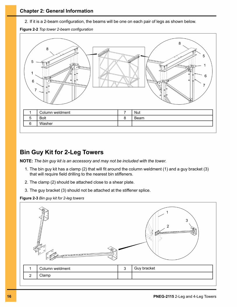
2. If it is a 2-beam configuration, the beams will be one on each pair of legs as shown below.
Figure 2-2 Top tower 2-beam configuration
1 Column weldment 7 Nut5 Bolt 8 Beam6 Washer
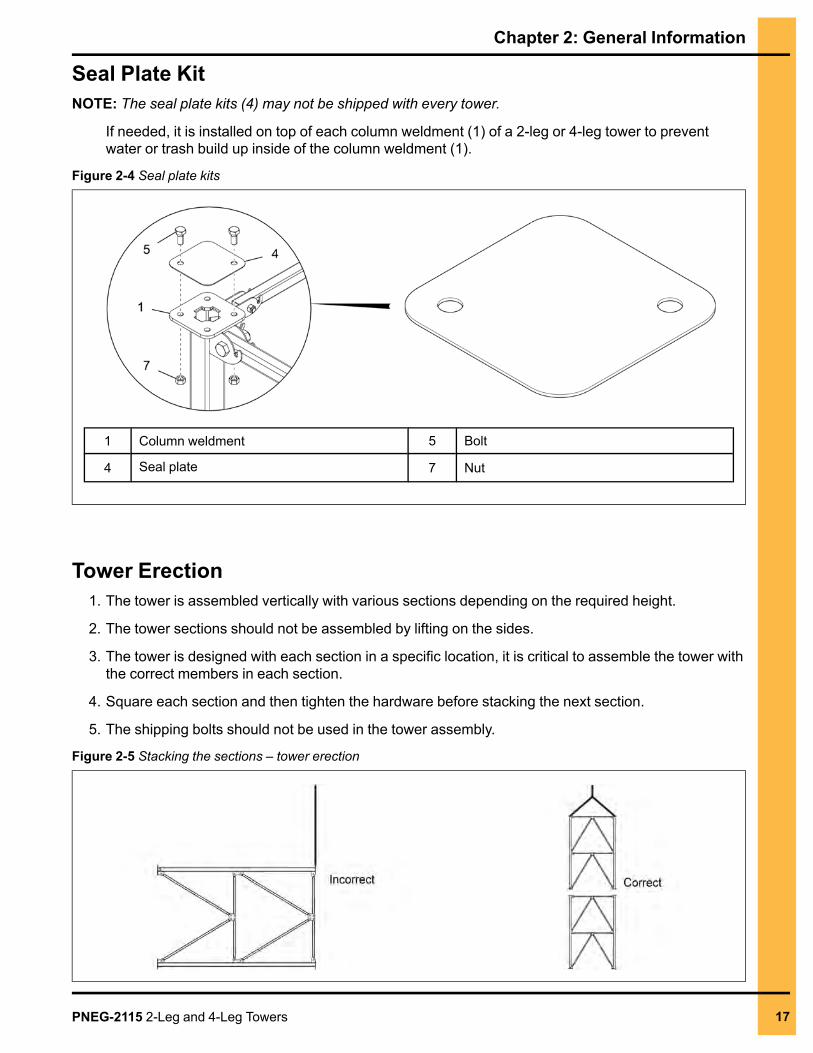
Bin Guy Kit for 2-Leg TowersNOTE: The bin guy kit is an accessory and may not be included with the tower.
1. The bin guy kit has a clamp (2) that will fit around the column weldment (1) and a guy bracket (3)that will require field drilling to the nearest bin stiffeners.
2. The clamp (2) should be attached close to a shear plate.
3. The guy bracket (3) should not be attached at the stiffener splice.
Figure 2-3 Bin guy kit for 2-leg towers
1 Column weldment 3 Guy bracket
2 Clamp
16 PNEG-2115 2-Leg and 4-Leg Towers
Chapter 2: General Information
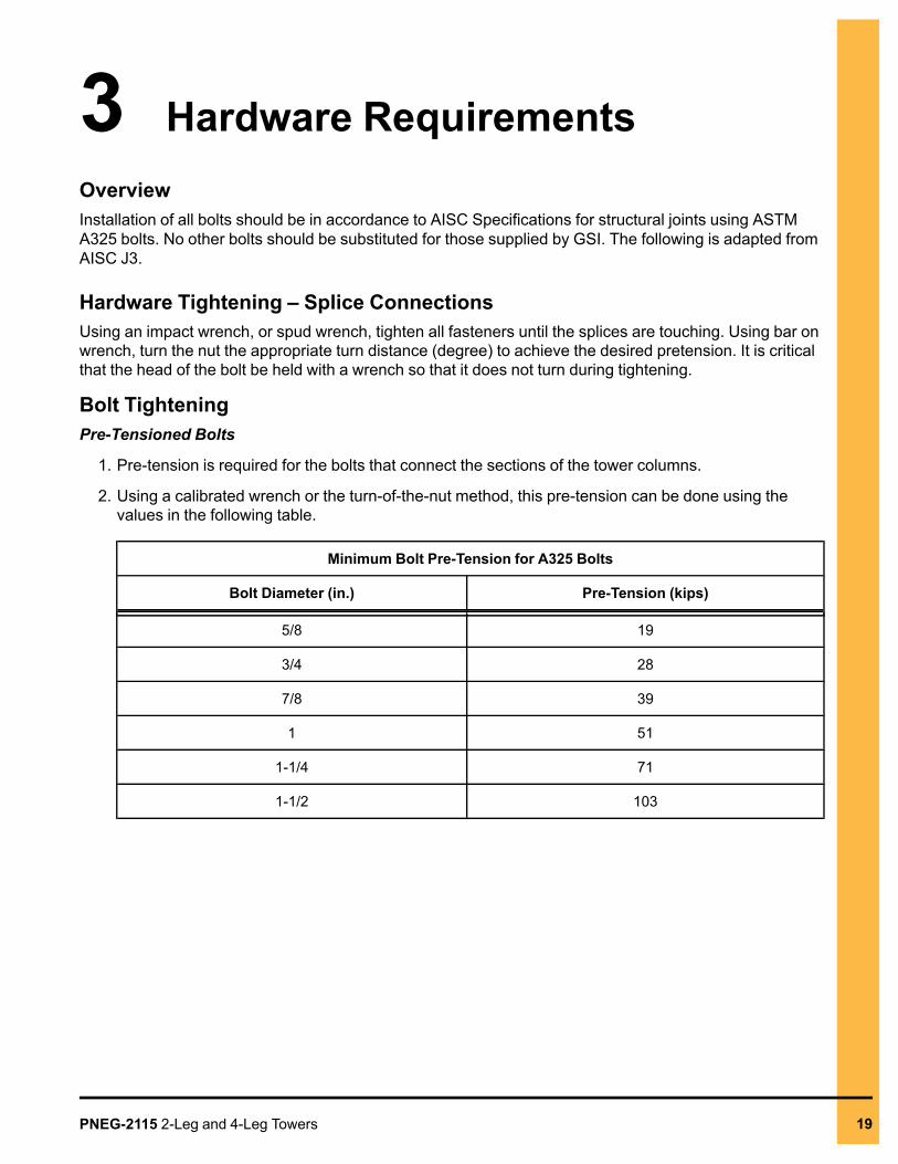
Seal Plate KitNOTE: The seal plate kits (4) may not be shipped with every tower.
If needed, it is installed on top of each column weldment (1) of a 2-leg or 4-leg tower to preventwater or trash build up inside of the column weldment (1).
Figure 2-4 Seal plate kits
1 Column weldment 5 Bolt
4 Seal plate 7 Nut
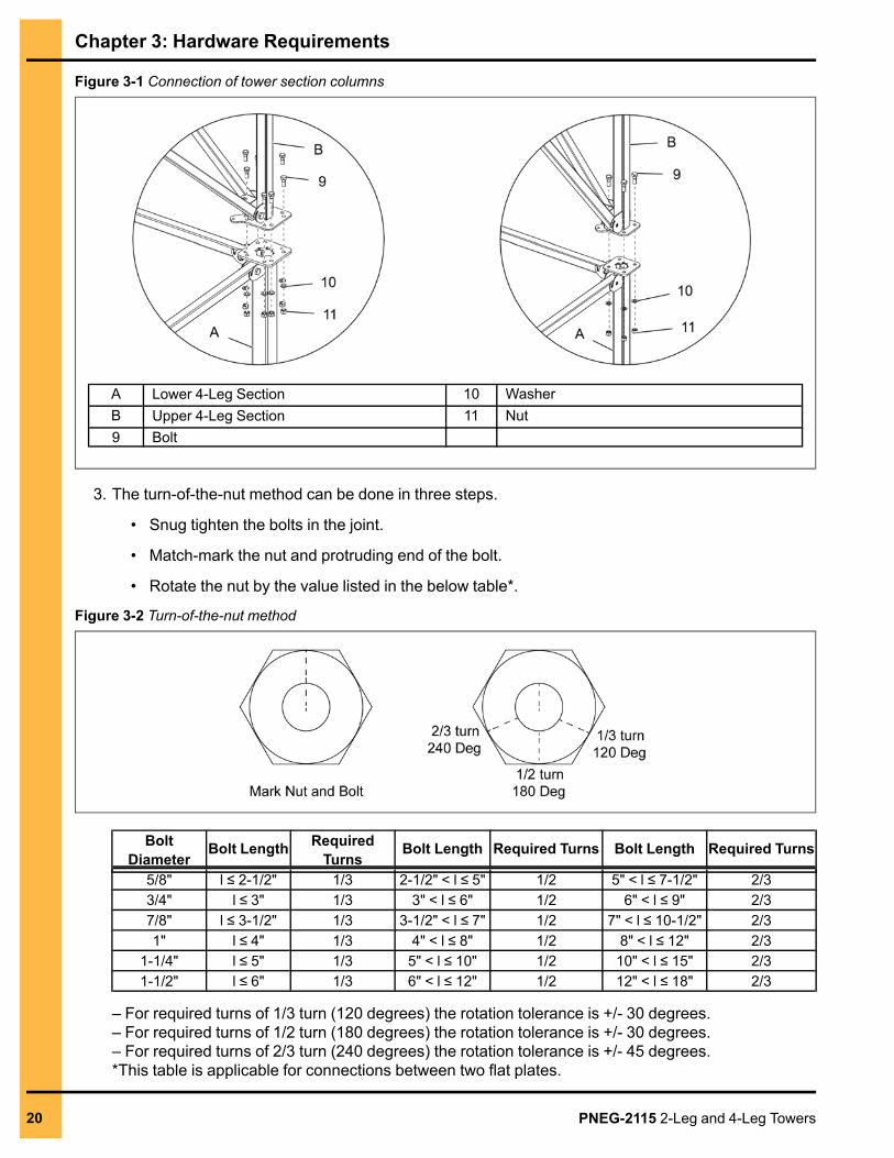
Tower Erection1. The tower is assembled vertically with various sections depending on the required height.
2. The tower sections should not be assembled by lifting on the sides.
3. The tower is designed with each section in a specific location, it is critical to assemble the tower withthe correct members in each section.
4. Square each section and then tighten the hardware before stacking the next section.
5. The shipping bolts should not be used in the tower assembly.
Figure 2-5 Stacking the sections – tower erection
PNEG-2115 2-Leg and 4-Leg Towers 17

NOTES
18 PNEG-2115 2-Leg and 4-Leg Towers
3 Hardware RequirementsOverviewInstallation of all bolts should be in accordance to AISC Specifications for structural joints using ASTMA325 bolts. No other bolts should be substituted for those supplied by GSI. The following is adapted fromAISC J3.
Hardware Tightening – Splice ConnectionsUsing an impact wrench, or spud wrench, tighten all fasteners until the splices are touching. Using bar onwrench, turn the nut the appropriate turn distance (degree) to achieve the desired pretension. It is criticalthat the head of the bolt be held with a wrench so that it does not turn during tightening.
Bolt TighteningPre-Tensioned Bolts
1. Pre-tension is required for the bolts that connect the sections of the tower columns.
2. Using a calibrated wrench or the turn-of-the-nut method, this pre-tension can be done using thevalues in the following table.
Minimum Bolt Pre-Tension for A325 Bolts
Bolt Diameter (in.) Pre-Tension (kips)
5/8 19
3/4 28
7/8 39
1 51
1-1/4 71
1-1/2 103
PNEG-2115 2-Leg and 4-Leg Towers 19
Chapter 3: Hardware Requirements
Figure 3-1 Connection of tower section columns
A Lower 4-Leg Section 10 WasherB Upper 4-Leg Section 11 Nut9 Bolt
3. The turn-of-the-nut method can be done in three steps.
• Snug tighten the bolts in the joint.
• Match-mark the nut and protruding end of the bolt.
• Rotate the nut by the value listed in the below table*.
Figure 3-2 Turn-of-the-nut method
BoltDiameter
Bolt Length RequiredTurns
Bolt Length Required Turns Bolt Length Required Turns
5/8" l ≤ 2-1/2" 1/3 2-1/2" < l ≤ 5" 1/2 5" < l ≤ 7-1/2" 2/33/4" l ≤ 3" 1/3 3" < l ≤ 6" 1/2 6" < l ≤ 9" 2/37/8" l ≤ 3-1/2" 1/3 3-1/2" < l ≤ 7" 1/2 7" < l ≤ 10-1/2" 2/31" l ≤ 4" 1/3 4" < l ≤ 8" 1/2 8" < l ≤ 12" 2/3
1-1/4" l ≤ 5" 1/3 5" < l ≤ 10" 1/2 10" < l ≤ 15" 2/31-1/2" l ≤ 6" 1/3 6" < l ≤ 12" 1/2 12" < l ≤ 18" 2/3
– For required turns of 1/3 turn (120 degrees) the rotation tolerance is +/- 30 degrees.– For required turns of 1/2 turn (180 degrees) the rotation tolerance is +/- 30 degrees.– For required turns of 2/3 turn (240 degrees) the rotation tolerance is +/- 45 degrees.*This table is applicable for connections between two flat plates.
20 PNEG-2115 2-Leg and 4-Leg Towers
Chapter 3: Hardware Requirements
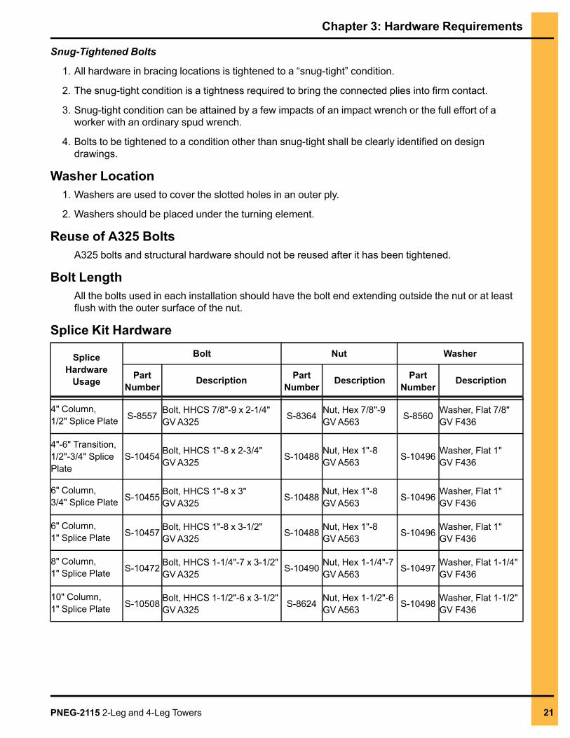
Snug-Tightened Bolts
1. All hardware in bracing locations is tightened to a “snug-tight” condition.
2. The snug-tight condition is a tightness required to bring the connected plies into firm contact.
3. Snug-tight condition can be attained by a few impacts of an impact wrench or the full effort of aworker with an ordinary spud wrench.
4. Bolts to be tightened to a condition other than snug-tight shall be clearly identified on designdrawings.
Washer Location1. Washers are used to cover the slotted holes in an outer ply.
2. Washers should be placed under the turning element.
Reuse of A325 BoltsA325 bolts and structural hardware should not be reused after it has been tightened.
Bolt LengthAll the bolts used in each installation should have the bolt end extending outside the nut or at leastflush with the outer surface of the nut.
Splice Kit Hardware
SpliceHardware
Usage
Bolt Nut Washer
PartNumber
Description PartNumber
Description PartNumber
Description
4" Column,1/2" Splice Plate S-8557 Bolt, HHCS 7/8"-9 x 2-1/4"GVA325 S-8364 Nut, Hex 7/8"-9GVA563 S-8560 Washer, Flat 7/8"GV F436
4"-6" Transition,1/2"-3/4" SplicePlate
S-10454 Bolt, HHCS 1"-8 x 2-3/4"GVA325 S-10488 Nut, Hex 1"-8GVA563 S-10496 Washer, Flat 1"GV F436
6" Column,3/4" Splice Plate S-10455 Bolt, HHCS 1"-8 x 3"GVA325 S-10488 Nut, Hex 1"-8GVA563 S-10496 Washer, Flat 1"GV F436
6" Column,1" Splice Plate S-10457 Bolt, HHCS 1"-8 x 3-1/2"GVA325 S-10488 Nut, Hex 1"-8GVA563 S-10496 Washer, Flat 1"GV F436
8" Column,1" Splice Plate S-10472 Bolt, HHCS 1-1/4"-7 x 3-1/2"GVA325 S-10490 Nut, Hex 1-1/4"-7GVA563 S-10497 Washer, Flat 1-1/4"GV F436
10" Column,1" Splice Plate S-10508 Bolt, HHCS 1-1/2"-6 x 3-1/2"GVA325 S-8624 Nut, Hex 1-1/2"-6GVA563 S-10498 Washer, Flat 1-1/2"GV F436
PNEG-2115 2-Leg and 4-Leg Towers 21
Chapter 3: Hardware Requirements
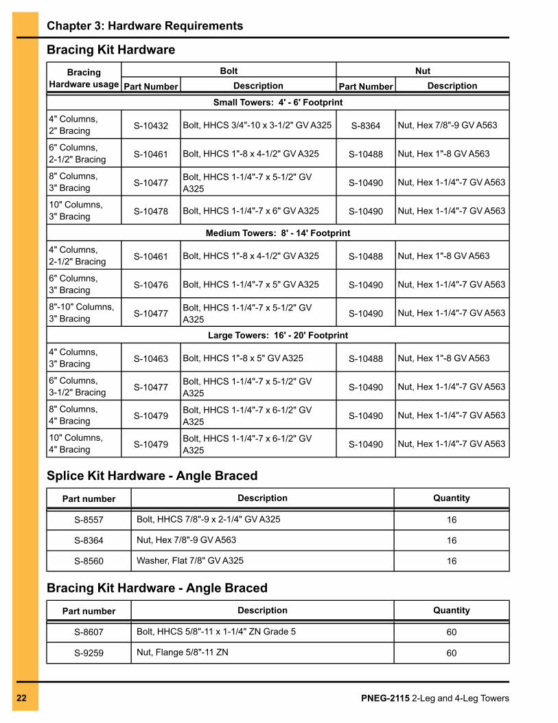
Bracing Kit HardwareBracing
Hardware usageBolt Nut
Part Number Description Part Number Description
Small Towers: 4' - 6' Footprint
4" Columns,2" Bracing S-10432 Bolt, HHCS 3/4"-10 x 3-1/2" GVA325 S-8364 Nut, Hex 7/8"-9 GVA563
6" Columns,2-1/2" Bracing S-10461 Bolt, HHCS 1"-8 x 4-1/2" GVA325 S-10488 Nut, Hex 1"-8 GVA563
8" Columns,3" Bracing S-10477 Bolt, HHCS 1-1/4"-7 x 5-1/2" GV
A325 S-10490 Nut, Hex 1-1/4"-7 GVA563
10" Columns,3" Bracing S-10478 Bolt, HHCS 1-1/4"-7 x 6" GVA325 S-10490 Nut, Hex 1-1/4"-7 GVA563
Medium Towers: 8' - 14' Footprint
4" Columns,2-1/2" Bracing S-10461 Bolt, HHCS 1"-8 x 4-1/2" GVA325 S-10488 Nut, Hex 1"-8 GVA563
6" Columns,3" Bracing S-10476 Bolt, HHCS 1-1/4"-7 x 5" GVA325 S-10490 Nut, Hex 1-1/4"-7 GVA563
8"-10" Columns,3" Bracing S-10477 Bolt, HHCS 1-1/4"-7 x 5-1/2" GV
A325 S-10490 Nut, Hex 1-1/4"-7 GVA563
Large Towers: 16' - 20' Footprint
4" Columns,3" Bracing S-10463 Bolt, HHCS 1"-8 x 5" GVA325 S-10488 Nut, Hex 1"-8 GVA563
6" Columns,3-1/2" Bracing S-10477 Bolt, HHCS 1-1/4"-7 x 5-1/2" GV
A325 S-10490 Nut, Hex 1-1/4"-7 GVA563
8" Columns,4" Bracing S-10479 Bolt, HHCS 1-1/4"-7 x 6-1/2" GV
A325 S-10490 Nut, Hex 1-1/4"-7 GVA563
10" Columns,4" Bracing S-10479 Bolt, HHCS 1-1/4"-7 x 6-1/2" GV
A325 S-10490 Nut, Hex 1-1/4"-7 GVA563
Splice Kit Hardware - Angle BracedPart number Description Quantity
S-8557 Bolt, HHCS 7/8"-9 x 2-1/4" GVA325 16
S-8364 Nut, Hex 7/8"-9 GVA563 16
S-8560 Washer, Flat 7/8" GVA325 16
Bracing Kit Hardware - Angle BracedPart number Description Quantity
S-8607 Bolt, HHCS 5/8"-11 x 1-1/4" ZN Grade 5 60
S-9259 Nut, Flange 5/8"-11 ZN 60
22 PNEG-2115 2-Leg and 4-Leg Towers
4 2-Leg TowersTopics Covered in this Chapter
▪ 2-Leg Tower Layout▪ Assembling the 2-Leg Tower Section (Chevron Bracing)▪ Assembling the 2-Leg Tower Section (Warren Bracing)▪ Stacking the 2-Leg Tower Section
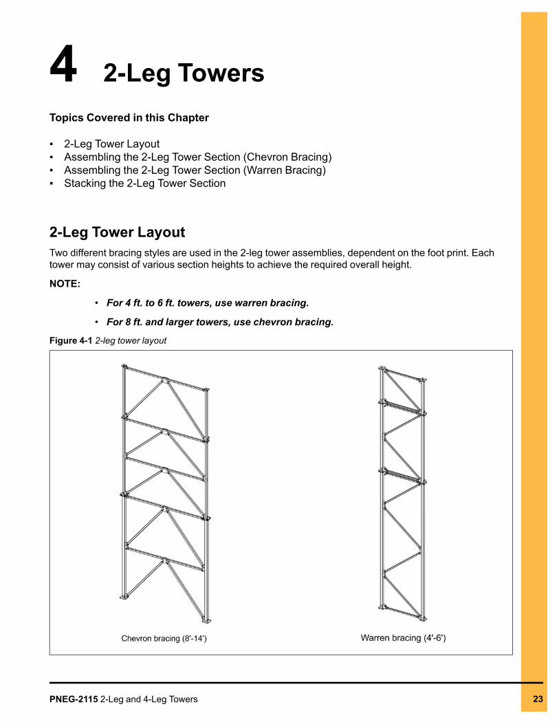
2-Leg Tower LayoutTwo different bracing styles are used in the 2-leg tower assemblies, dependent on the foot print. Eachtower may consist of various section heights to achieve the required overall height.
NOTE:
• For 4 ft. to 6 ft. towers, use warren bracing.
• For 8 ft. and larger towers, use chevron bracing.
Figure 4-1 2-leg tower layout
PNEG-2115 2-Leg and 4-Leg Towers 23
Chapter 4: 2-Leg Towers
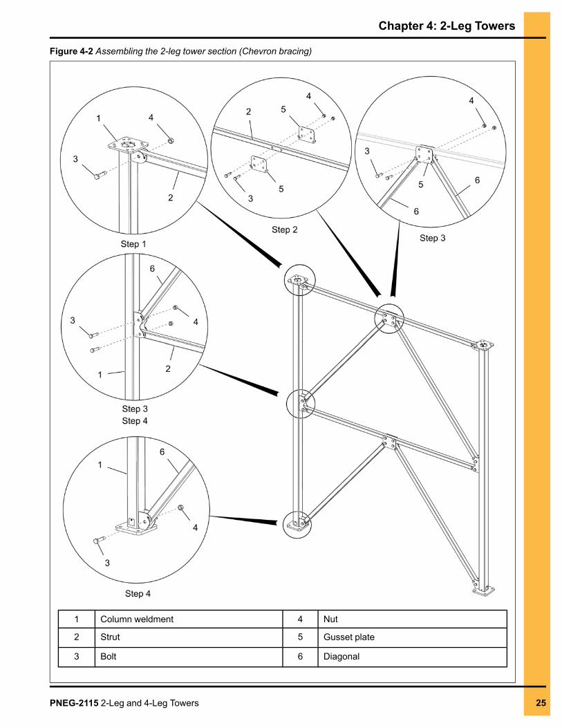
Assembling the 2-Leg Tower Section (Chevron Bracing)The following assembly procedure can be used for any section with 2-bays of chevron bracing. A similarprocedure can be used for assembling the different bay layouts of chevron braced 2-leg tower sections.
What You Should KnowAssemble the struts and diagonals from the top to the bottom of each section. Square the tower sectionand tighten all hardware before stacking.
1. Insert the strut (2) between the shear plates located at the top of the column weldments (1) andconnect them using bolts (3) and nuts (4).
2. Assemble the two gusset plates (5) to the strut (2) using bolts (3) and nuts (4).
3. Assemble the two diagonals (6), aligning the top of each diagonal to the gusset plates (5) and thebottoms to each column weldment (1) using bolts (3) and nuts (4).
4. Repeat the previous steps to assemble the remaining strut (2), gusset plates (5) and diagonals (6)to complete the 2-leg tower section.
5. If the section has only 1-bay (10 ft. or shorter), ignore the above step (step-4) for assembly.
NOTE: The small diameter holes in the struts (2) and diagonals (6) are used to align the tubes withthe column weldments (1) and do not require a bolt.
24 PNEG-2115 2-Leg and 4-Leg Towers
Chapter 4: 2-Leg Towers
Figure 4-2 Assembling the 2-leg tower section (Chevron bracing)
1 Column weldment 4 Nut
2 Strut 5 Gusset plate
3 Bolt 6 Diagonal
PNEG-2115 2-Leg and 4-Leg Towers 25
Chapter 4: 2-Leg Towers
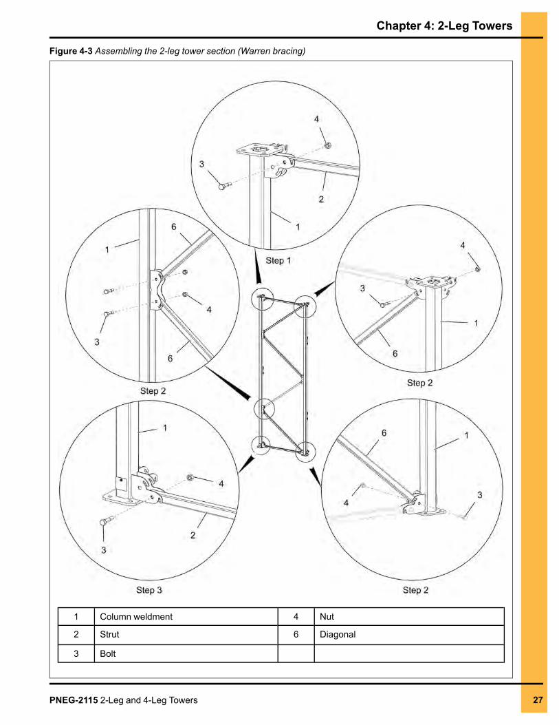
Assembling the 2-Leg Tower Section (Warren Bracing)The following assembly procedure can be used for any section with 4-bays of warren bracing. A similarprocedure can be used for assembling the different bay layouts of warren braced 2-leg tower sections.
What You Should KnowAssemble the struts and diagonals from the top to the bottom of each section. Square the tower sectionand tighten all hardware before stacking.
1. Insert the strut (2) between the shear plates located at the top of the column weldments (1) andconnect them using bolts (3) and nuts (4).
2. Assemble the diagonals (6) to the shear plates in alternating directions, from the top to the bottombetween the column weldments (1) using bolts (3) and nuts (4).
3. Insert the bottom strut (2) into the shear plates located at the bottom of the column weldments (1)and connect them using bolts (3) and nuts (4) to complete the 2-leg tower section.
NOTE: The small diameter holes in the struts (2) and diagonals (6) are used to align the tubes withthe column weldments (1) and do not require a bolt.
26 PNEG-2115 2-Leg and 4-Leg Towers
Chapter 4: 2-Leg Towers
Figure 4-3 Assembling the 2-leg tower section (Warren bracing)
1 Column weldment 4 Nut
2 Strut 6 Diagonal
3 Bolt
PNEG-2115 2-Leg and 4-Leg Towers 27
Chapter 4: 2-Leg Towers
Stacking the 2-Leg Tower SectionThe following is the general procedure for stacking sections of a 2-leg tower.
Before You BeginAssemble all the required 2-leg tower sections on the ground. Square each section and tighten allhardware before stacking.
DANGER
Follow all safety procedures when hoisting equipment. Wear hard hats and makesure everyone is clear of the working area.
1. Hoist the first 2-leg section (A) and place on the foundation anchors.
NOTE: After the section has been anchored to the foundation, tighten all the anchor hardware.
2. Hoist the next 2-leg section (B) onto the previous 2-leg section (A) and install using bolts (9),washers (10) and nuts (11).
NOTE: After the section has been stacked to the previous section, tighten all the splice hardware.
3. Repeat the previous step to continue installing the remaining 2-leg tower sections until the correctelevation is reached.
4. If required, attach sealing plates or top tower beams on the top of the columns of the last 2-legsection and tighten all the splice hardware. See Seal Plate Kit, page 17 for sealing plates or TopTower Beams, page 15 for top tower beams.
NOTE: Seal plate kits are not included in the column bundle and may not be required.
IMPORTANT: When stacking a 2-leg warren braced tower, it is critical that the sections be stackedso the bracing appears continuous. It means that the diagonal should always connectwhere another diagonal comes in right above or below.
NOTE: 2-Leg towers are not self-supporting and must be guyed to a structure capable of supportingthe horizontal loads from the tower. Guying locations and spacing on the tower depends onthe tower and is specified in order-specific drawings. Typically, the 2-Leg tower should besupported every 20 ft. and within 20 ft. from the top of the tower unless otherwise noted.
28 PNEG-2115 2-Leg and 4-Leg Towers
Chapter 4: 2-Leg Towers
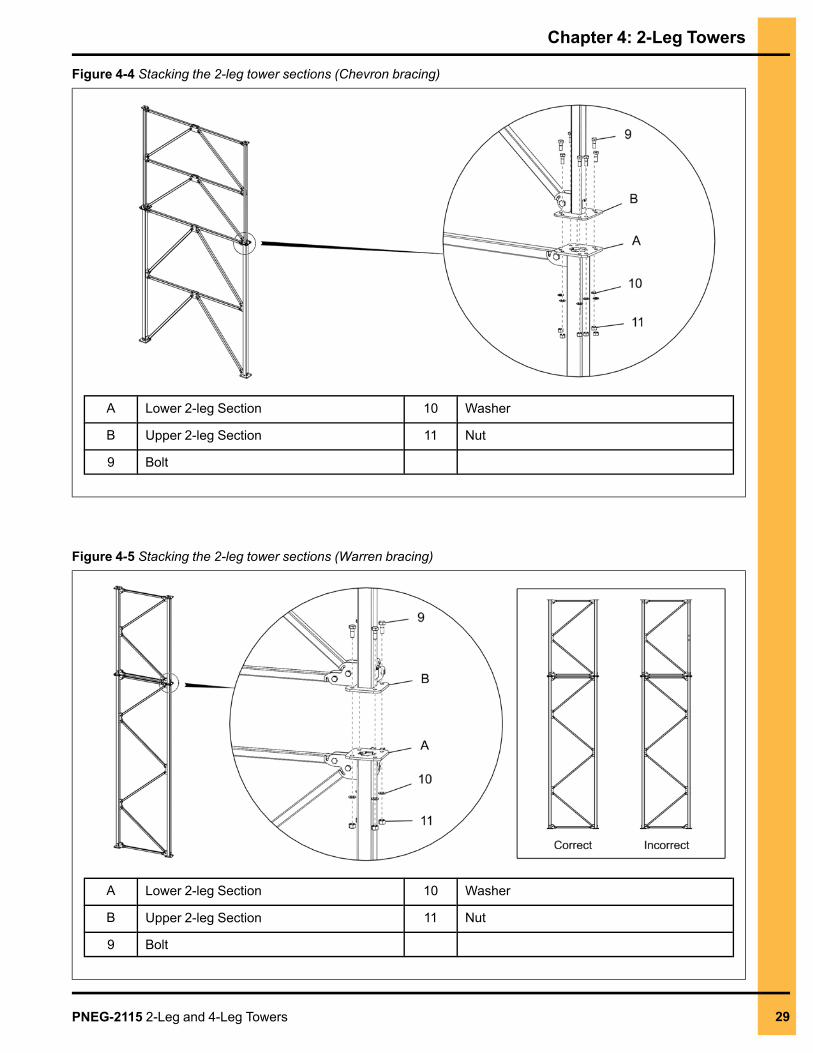
Figure 4-4 Stacking the 2-leg tower sections (Chevron bracing)
A Lower 2-leg Section 10 Washer
B Upper 2-leg Section 11 Nut
9 Bolt
Figure 4-5 Stacking the 2-leg tower sections (Warren bracing)
A Lower 2-leg Section 10 Washer
B Upper 2-leg Section 11 Nut
9 Bolt
PNEG-2115 2-Leg and 4-Leg Towers 29
NOTES
30 PNEG-2115 2-Leg and 4-Leg Towers
5 4-Leg TowersTopics Covered in this Chapter
▪ 4-Leg Tower Layout▪ Assembling the 4-Leg Tower Section (Chevron Bracing)▪ Assembling the 4-Leg Tower Section (Angle Braced)▪ Assembling the 4-Leg Tower Section (Warren Bracing)▪ Assembling the 4-Leg Tower Section (Chevron and Warren Bracing)▪ Stacking the 4-Leg Tower Section
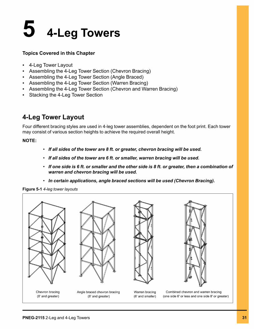
4-Leg Tower LayoutFour different bracing styles are used in 4-leg tower assemblies, dependent on the foot print. Each towermay consist of various section heights to achieve the required overall height.
NOTE:
• If all sides of the tower are 8 ft. or greater, chevron bracing will be used.
• If all sides of the tower are 6 ft. or smaller, warren bracing will be used.
• If one side is 6 ft. or smaller and the other side is 8 ft. or greater, then a combination ofwarren and chevron bracing will be used.
• In certain applications, angle braced sections will be used (Chevron Bracing).
Figure 5-1 4-leg tower layouts
PNEG-2115 2-Leg and 4-Leg Towers 31
Chapter 5: 4-Leg Towers
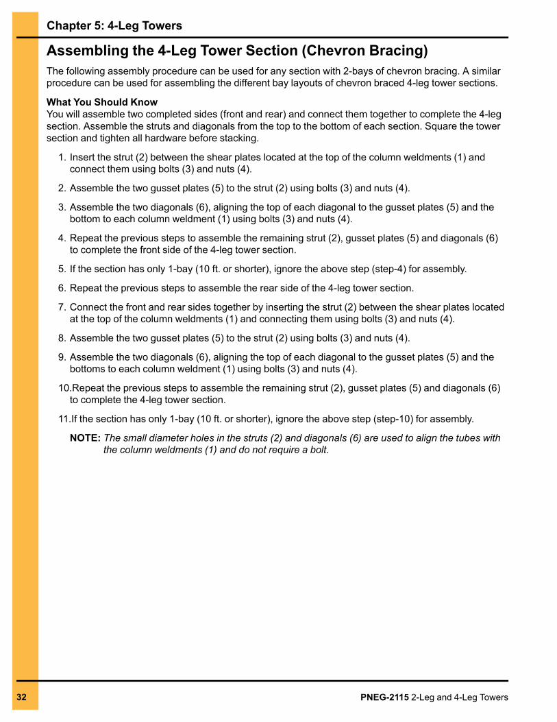
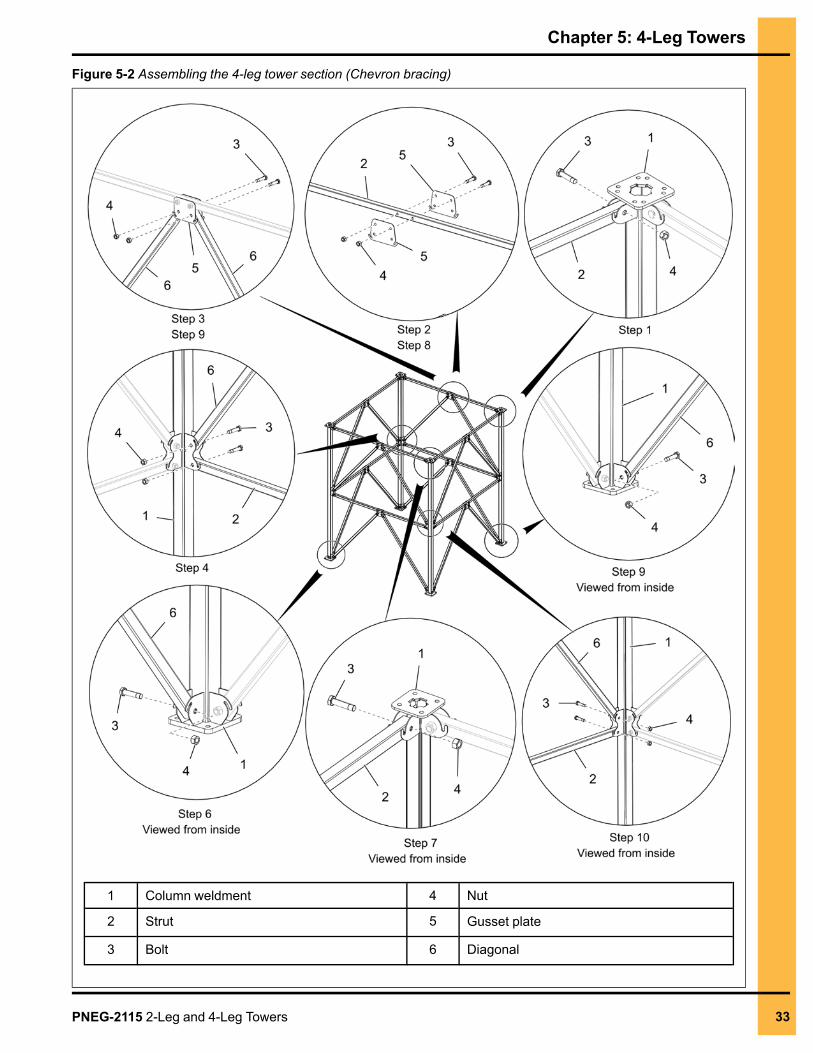
Assembling the 4-Leg Tower Section (Chevron Bracing)The following assembly procedure can be used for any section with 2-bays of chevron bracing. A similarprocedure can be used for assembling the different bay layouts of chevron braced 4-leg tower sections.
What You Should KnowYou will assemble two completed sides (front and rear) and connect them together to complete the 4-legsection. Assemble the struts and diagonals from the top to the bottom of each section. Square the towersection and tighten all hardware before stacking.
1. Insert the strut (2) between the shear plates located at the top of the column weldments (1) andconnect them using bolts (3) and nuts (4).
2. Assemble the two gusset plates (5) to the strut (2) using bolts (3) and nuts (4).
3. Assemble the two diagonals (6), aligning the top of each diagonal to the gusset plates (5) and thebottom to each column weldment (1) using bolts (3) and nuts (4).
4. Repeat the previous steps to assemble the remaining strut (2), gusset plates (5) and diagonals (6)to complete the front side of the 4-leg tower section.
5. If the section has only 1-bay (10 ft. or shorter), ignore the above step (step-4) for assembly.
6. Repeat the previous steps to assemble the rear side of the 4-leg tower section.
7. Connect the front and rear sides together by inserting the strut (2) between the shear plates locatedat the top of the column weldments (1) and connecting them using bolts (3) and nuts (4).
8. Assemble the two gusset plates (5) to the strut (2) using bolts (3) and nuts (4).
9. Assemble the two diagonals (6), aligning the top of each diagonal to the gusset plates (5) and thebottoms to each column weldment (1) using bolts (3) and nuts (4).
10.Repeat the previous steps to assemble the remaining strut (2), gusset plates (5) and diagonals (6)to complete the 4-leg tower section.
11.If the section has only 1-bay (10 ft. or shorter), ignore the above step (step-10) for assembly.
NOTE: The small diameter holes in the struts (2) and diagonals (6) are used to align the tubes withthe column weldments (1) and do not require a bolt.
32 PNEG-2115 2-Leg and 4-Leg Towers
Chapter 5: 4-Leg Towers
Figure 5-2 Assembling the 4-leg tower section (Chevron bracing)
1 Column weldment 4 Nut
2 Strut 5 Gusset plate
3 Bolt 6 Diagonal
PNEG-2115 2-Leg and 4-Leg Towers 33
Chapter 5: 4-Leg Towers
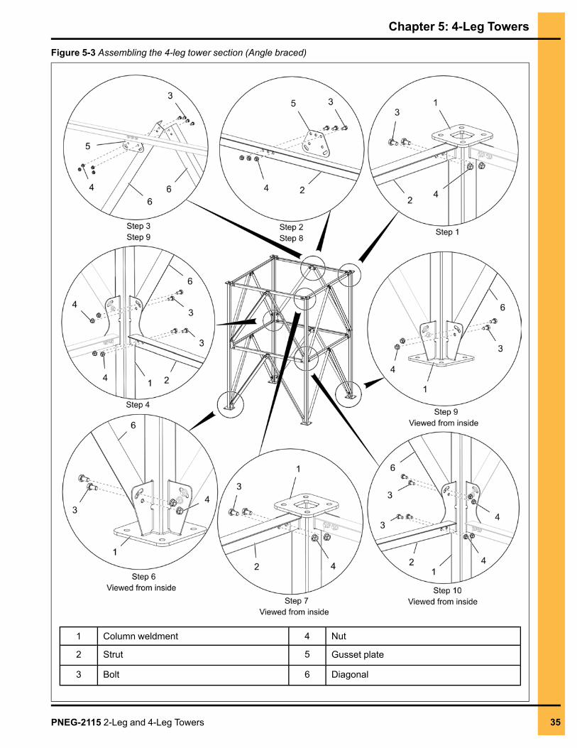
Assembling the 4-Leg Tower Section (Angle Braced)The following assembly procedure can be used for any section with 2-bays of angle braced towers. Asimilar procedure can be used for assembling the different bay layouts of angle braced 4-leg towersections.
What You Should KnowYou will assemble two completed sides (front and rear) and connect them together to complete the 4-legsection. Assemble the struts and diagonals from the top to the bottom of each section. Square the towersection and tighten all hardware before stacking.
1. Assemble the strut (2) to the shear plates located at the top of the column weldments (1) andconnect them using bolts (3) and nuts (4).
2. Assemble the two gusset plates (5) to the strut (2) using bolts (3) and nuts (4).
3. Assemble the two diagonals (6), aligning the top of each diagonal to the gusset plates (5) and thebottom to each column weldment (1) using bolts (3) and nuts (4).
4. Repeat the previous steps to assemble the remaining strut (2), gusset plates (5) and diagonals (6)to complete the front side of the 4-leg tower section.
5. If the section has only 1-bay (10 ft. or shorter), ignore the above step (step-4) for assembly.
6. Repeat the previous steps to assemble the rear side of the 4-leg tower section.
7. Connect the front and rear sides together by installing the strut (2) to the shear plates located at thetop of the column weldments (1) and connecting them using bolts (3) and nuts (4).
8. Assemble the two gusset plates (5) to the strut (2) using bolts (3) and nuts (4).
9. Assemble the two diagonals (6), aligning the top of each diagonal to the gusset plates (5) and thebottoms to each column weldment (1) using bolts (3) and nuts (4).
10.Repeat the previous steps to assemble the remaining strut (2), gusset plates (5) and diagonals (6)to complete the 4-leg tower section.
11.If the section has only 1-bay (10 ft. or shorter), ignore the above step (step-10) for assembly.
NOTE: Always assemble the struts (2) and diagonals (6) to the outside of the shear plates in thecolumn weldments (1).
34 PNEG-2115 2-Leg and 4-Leg Towers
Chapter 5: 4-Leg Towers
Figure 5-3 Assembling the 4-leg tower section (Angle braced)
1 Column weldment 4 Nut
2 Strut 5 Gusset plate
3 Bolt 6 Diagonal
PNEG-2115 2-Leg and 4-Leg Towers 35
Chapter 5: 4-Leg Towers
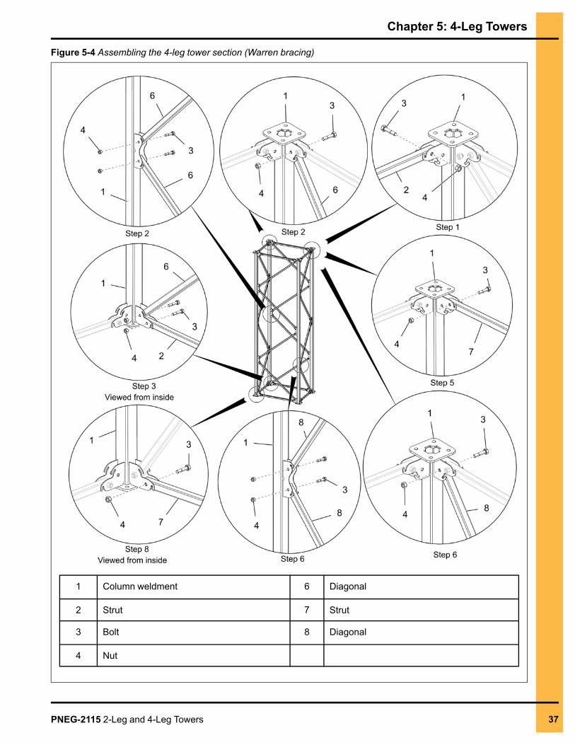
Assembling the 4-Leg Tower Section (Warren Bracing)The following assembly procedure can be used for any section with warren bracing that may have 1, 2 or4-bays. A similar procedure can be used for assembling the different bay layouts of warren braced4-leg tower sections.
What You Should KnowYou will assemble two completed sides (front and rear) and connect them together to complete the 4-legsection. Assemble the struts and diagonals from the top to the bottom of each section. Square the towersection and tighten all hardware before stacking.
1. Insert the strut (2) between the shear plates located at the top of the column weldments (1) andconnect them using bolts (3) and nuts (4).
2. Assemble the diagonals (6) to the shear plates in alternating directions, from the top to the bottombetween the column weldments (1) using bolts (3) and nuts (4).
3. Insert the bottom strut (2) into the shear plates located at the bottom of the column weldments (1)and connect them using bolts (3) and nuts (4) to complete the front side of 4-leg tower section.
4. Repeat the previous steps to assemble the rear side of 4-leg tower section.
NOTE: Make sure to assemble the diagonals (6) in the rear side at the opposite direction to the firstside.
5. Connect the front and rear side sections by inserting the strut (7) between the shear plates locatedat the top of the column weldments (1) and connecting them using bolts (3) and nuts (4).
6. Assemble the diagonals (8) to the shear plates in alternating directions, from the top to the bottombetween the column weldments (1) using bolts (3) and nuts (4).
7. Insert the bottom strut (7) into the shear plates located at the bottom of the column weldments (1)and connect them using bolts (3) and nuts (4) to complete the third side of the 4-leg tower section.
8. Repeat the previous steps for assembling the last side to complete the 4-leg tower section.
NOTE:
a. Make sure to assemble the diagonals (8) in the last side at the opposite direction to thethird side.
b. The small diameter holes in the struts (2 and 7) and diagonals (6 and 8) are used to alignthe tubes with the column weldments (1) and do not require a bolt.
36 PNEG-2115 2-Leg and 4-Leg Towers
Chapter 5: 4-Leg Towers
Figure 5-4 Assembling the 4-leg tower section (Warren bracing)
1 Column weldment 6 Diagonal
2 Strut 7 Strut
3 Bolt 8 Diagonal
4 Nut
PNEG-2115 2-Leg and 4-Leg Towers 37
Chapter 5: 4-Leg Towers
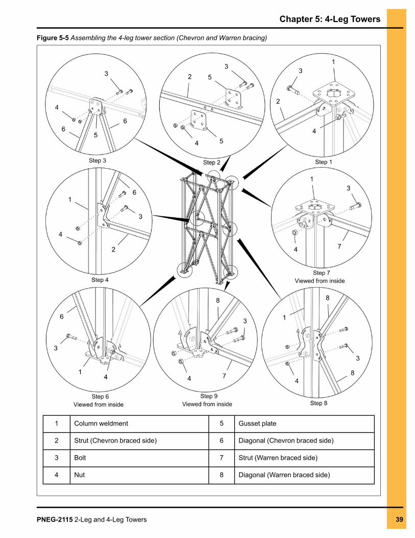
Assembling the 4-Leg Tower Section (Chevron and WarrenBracing)The following assembly procedure can be used for any section with 2-bays of chevron and 4-bays ofwarren bracing. A similar procedure can be used for assembling the different bay layouts of chevron andwarren bracing 4-leg tower sections.
What You Should KnowYou will assemble two completed sides (front and rear) and connect them together to complete the 4-legsection. Assemble the struts and diagonals from the top to the bottom of each section. Square the towersection and tighten all hardware before stacking.
Assembling the Chevron Braced Sides
1. Insert the strut (2) between the shear plates located at the top of the column weldments (1) andconnect them using bolts (3) and nuts (4).
2. Assemble the two gusset plates (5) to the strut (2) using bolts (3) and nuts (4).
3. Assemble the two diagonals (6), aligning the top of each diagonal to the gusset plates (5) and thebottom to each column weldment (1) using bolts (3) and nuts (4).
4. Repeat the previous steps to assemble the remaining strut (2), gusset plates (5) and diagonals (6)to complete the front side of the 4-leg tower section.
5. If the section has only 1-bay (10 ft. or shorter), ignore the above step (step-4) for assembly.
6. Repeat the previous steps to assemble the rear side of the 4-leg tower section.
Assembling the Warren Braced Sides
7. Connect the front and rear sides by inserting the strut (7) between the shear plates located at thetop of the column weldments (1) and connecting them using bolts (3) and nuts (4).
8. Assemble the diagonals (8) to the shear plates in alternating directions, from the top to the bottombetween the column weldments (1) using bolts (3) and nuts (4).
9. Insert the bottom strut (7) into the shear plates located at the bottom of the column weldments (1)and connect them using bolts (3) and nuts (4) to complete the third side of 4-leg tower section.
10.Repeat the above steps for assembling the last side to complete the 4-leg tower section.
NOTE:
a. Make sure to assemble the diagonals (6) in the last side at the opposite direction to thethird side.
b. The small diameter holes in the struts (2 and 7) and diagonals (6 and 8) are used to alignthe tubes with the column weldments (1) and do not require a bolt.
38 PNEG-2115 2-Leg and 4-Leg Towers
Chapter 5: 4-Leg Towers
Figure 5-5 Assembling the 4-leg tower section (Chevron and Warren bracing)
1 Column weldment 5 Gusset plate
2 Strut (Chevron braced side) 6 Diagonal (Chevron braced side)
3 Bolt 7 Strut (Warren braced side)
4 Nut 8 Diagonal (Warren braced side)
PNEG-2115 2-Leg and 4-Leg Towers 39
Chapter 5: 4-Leg Towers
Stacking the 4-Leg Tower SectionThe following is a general procedure for stacking sections of a 4-leg tower.
Before You BeginAssemble all the required 4-leg tower sections on the ground. Square each section and tighten allhardware before stacking.
DANGER
Follow all safety procedures when hoisting equipment. Wear hard hats and makesure everyone is clear of the working area.
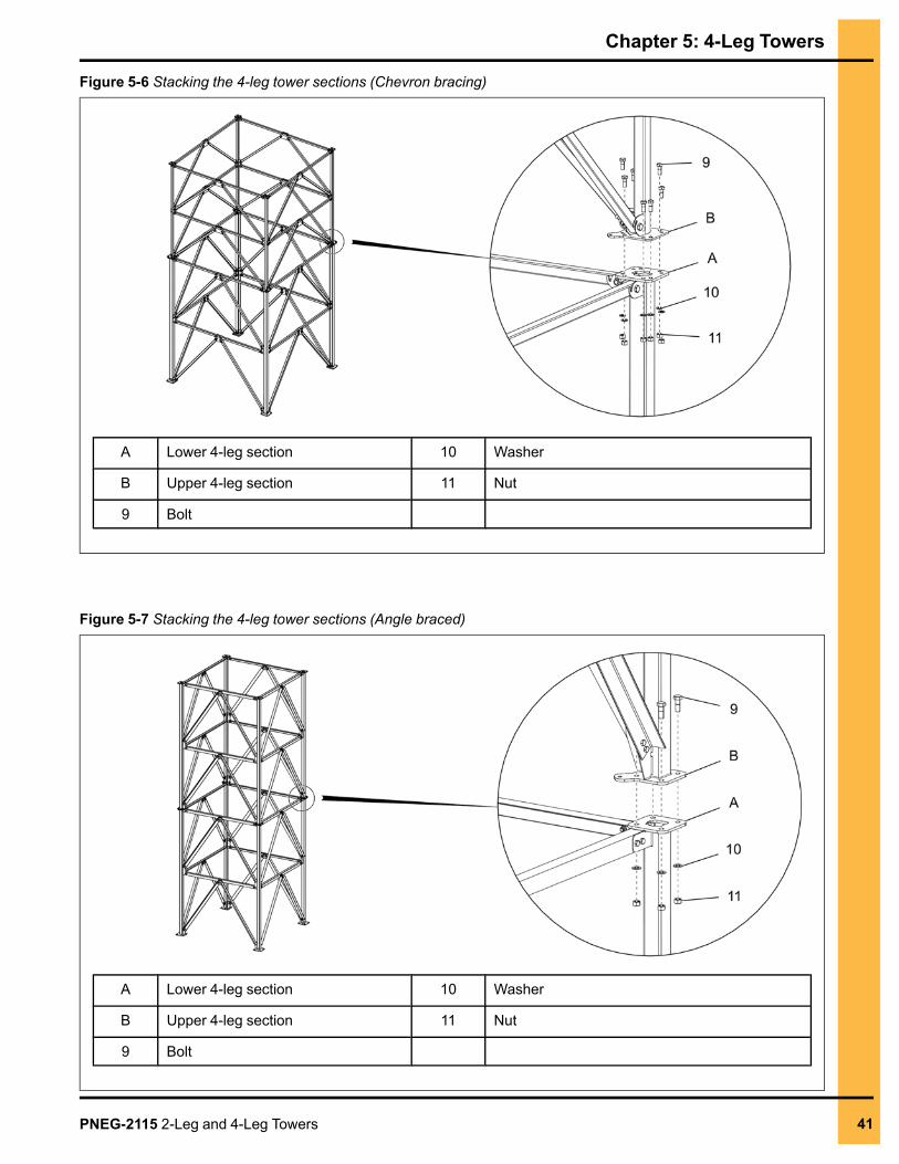
1. Hoist the first 4-leg section (A) and place on the foundation anchors.
NOTE: After the section has been anchored to the foundation, tighten all the anchor hardware.
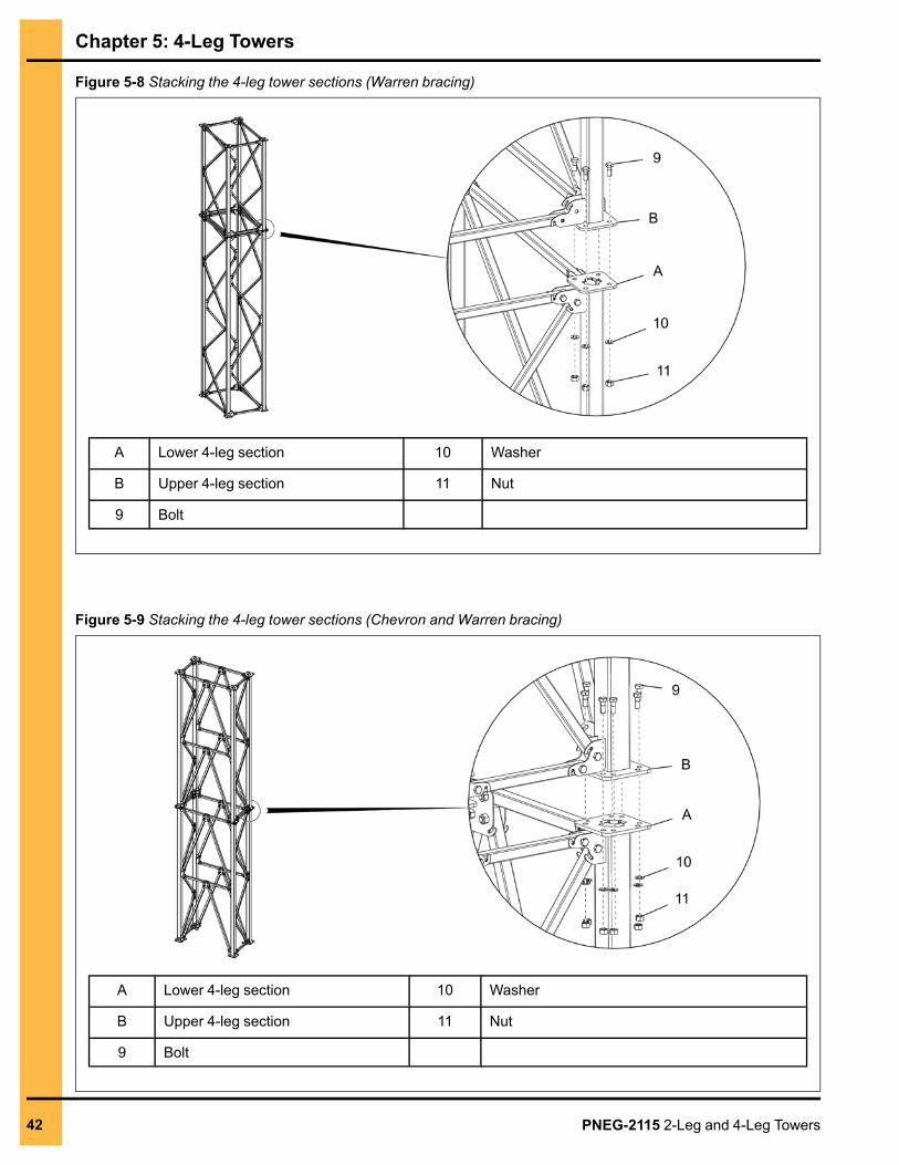
2. Hoist the next 4-leg section (B) onto the previous 4-leg section (A) and install using bolts (9),washers (10) and nuts (11).
NOTE: After the section has been stacked to the previous section, tighten all the splice hardware.
3. Repeat the previous step to continue installing the remaining 4-leg tower sections until the correctelevation is reached.
4. If required, attach sealing plates or top tower beams on the top of the columns of the last 4-legsection and tighten all the splice hardware. See Seal Plate Kit, page 17 for sealing plates or TopTower Beams, page 15 for top tower beams.
NOTE: Seal plate kits are not included in the column bundle and may not be required.
40 PNEG-2115 2-Leg and 4-Leg Towers
Chapter 5: 4-Leg Towers
Figure 5-6 Stacking the 4-leg tower sections (Chevron bracing)
A Lower 4-leg section 10 Washer
B Upper 4-leg section 11 Nut
9 Bolt
Figure 5-7 Stacking the 4-leg tower sections (Angle braced)
A Lower 4-leg section 10 Washer
B Upper 4-leg section 11 Nut
9 Bolt
PNEG-2115 2-Leg and 4-Leg Towers 41
Chapter 5: 4-Leg Towers
Figure 5-8 Stacking the 4-leg tower sections (Warren bracing)
A Lower 4-leg section 10 Washer
B Upper 4-leg section 11 Nut
9 Bolt
Figure 5-9 Stacking the 4-leg tower sections (Chevron and Warren bracing)
A Lower 4-leg section 10 Washer
B Upper 4-leg section 11 Nut
9 Bolt
42 PNEG-2115 2-Leg and 4-Leg Towers
Chapter 5: 4-Leg Towers
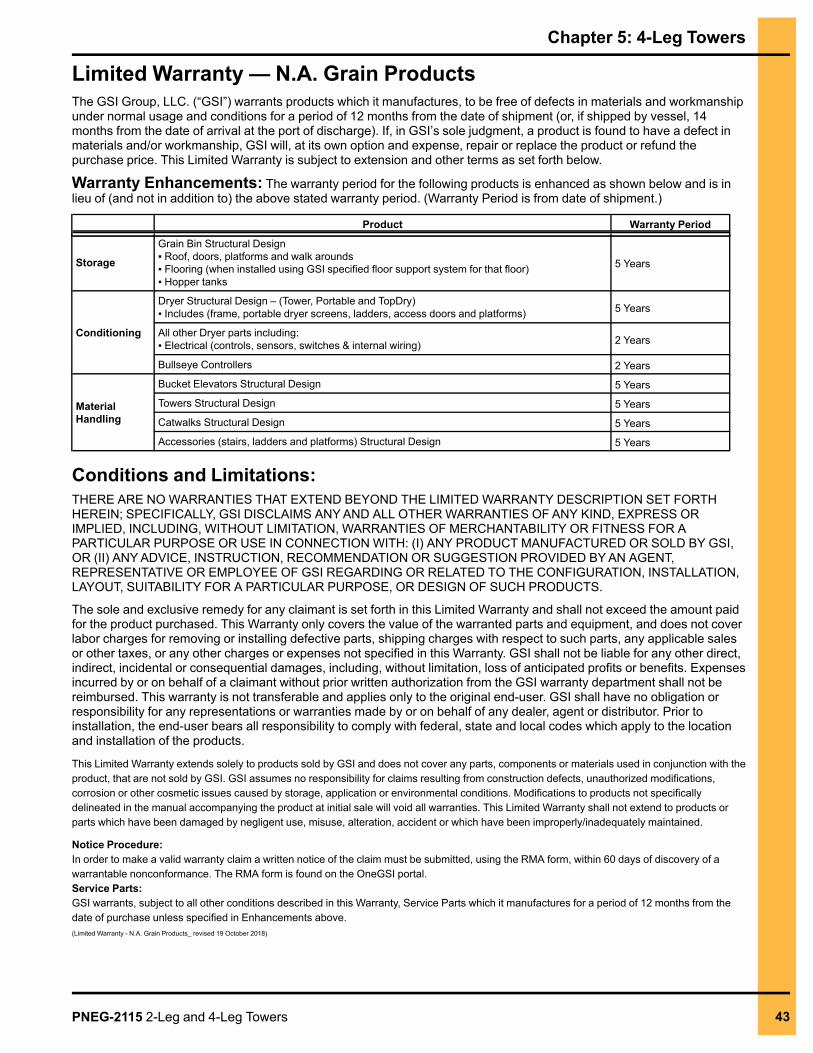
Limited Warranty — N.A. Grain ProductsThe GSI Group, LLC. (“GSI”) warrants products which it manufactures, to be free of defects in materials and workmanshipunder normal usage and conditions for a period of 12 months from the date of shipment (or, if shipped by vessel, 14months from the date of arrival at the port of discharge). If, in GSI’s sole judgment, a product is found to have a defect inmaterials and/or workmanship, GSI will, at its own option and expense, repair or replace the product or refund thepurchase price. This Limited Warranty is subject to extension and other terms as set forth below.
Warranty Enhancements: The warranty period for the following products is enhanced as shown below and is inlieu of (and not in addition to) the above stated warranty period. (Warranty Period is from date of shipment.)
Product Warranty Period
Storage
Grain Bin Structural Design▪ Roof, doors, platforms and walk arounds▪ Flooring (when installed using GSI specified floor support system for that floor)▪ Hopper tanks
5 Years
Conditioning
Dryer Structural Design – (Tower, Portable and TopDry)▪ Includes (frame, portable dryer screens, ladders, access doors and platforms) 5 Years
All other Dryer parts including:▪ Electrical (controls, sensors, switches & internal wiring) 2 Years
Bullseye Controllers 2 Years
MaterialHandling
Bucket Elevators Structural Design 5 Years
Towers Structural Design 5 Years
Catwalks Structural Design 5 Years
Accessories (stairs, ladders and platforms) Structural Design 5 Years
Conditions and Limitations:THERE ARE NOWARRANTIES THAT EXTEND BEYOND THE LIMITED WARRANTY DESCRIPTION SET FORTHHEREIN; SPECIFICALLY, GSI DISCLAIMS ANYAND ALL OTHERWARRANTIES OFANY KIND, EXPRESS ORIMPLIED, INCLUDING, WITHOUT LIMITATION, WARRANTIES OF MERCHANTABILITY OR FITNESS FOR APARTICULAR PURPOSE OR USE IN CONNECTION WITH: (I) ANY PRODUCT MANUFACTURED OR SOLD BY GSI,OR (II) ANYADVICE, INSTRUCTION, RECOMMENDATION OR SUGGESTION PROVIDED BYAN AGENT,REPRESENTATIVE OR EMPLOYEE OF GSI REGARDING OR RELATED TO THE CONFIGURATION, INSTALLATION,LAYOUT, SUITABILITY FOR A PARTICULAR PURPOSE, OR DESIGN OF SUCH PRODUCTS.
The sole and exclusive remedy for any claimant is set forth in this Limited Warranty and shall not exceed the amount paidfor the product purchased. This Warranty only covers the value of the warranted parts and equipment, and does not coverlabor charges for removing or installing defective parts, shipping charges with respect to such parts, any applicable salesor other taxes, or any other charges or expenses not specified in this Warranty. GSI shall not be liable for any other direct,indirect, incidental or consequential damages, including, without limitation, loss of anticipated profits or benefits. Expensesincurred by or on behalf of a claimant without prior written authorization from the GSI warranty department shall not bereimbursed. This warranty is not transferable and applies only to the original end-user. GSI shall have no obligation orresponsibility for any representations or warranties made by or on behalf of any dealer, agent or distributor. Prior toinstallation, the end-user bears all responsibility to comply with federal, state and local codes which apply to the locationand installation of the products.
This Limited Warranty extends solely to products sold by GSI and does not cover any parts, components or materials used in conjunction with theproduct, that are not sold by GSI. GSI assumes no responsibility for claims resulting from construction defects, unauthorized modifications,corrosion or other cosmetic issues caused by storage, application or environmental conditions. Modifications to products not specificallydelineated in the manual accompanying the product at initial sale will void all warranties. This Limited Warranty shall not extend to products orparts which have been damaged by negligent use, misuse, alteration, accident or which have been improperly/inadequately maintained.
Notice Procedure:In order to make a valid warranty claim a written notice of the claim must be submitted, using the RMA form, within 60 days of discovery of awarrantable nonconformance. The RMA form is found on the OneGSI portal.Service Parts:GSI warrants, subject to all other conditions described in this Warranty, Service Parts which it manufactures for a period of 12 months from thedate of purchase unless specified in Enhancements above.(Limited Warranty - N.A. Grain Products_ revised 19 October 2018)
PNEG-2115 2-Leg and 4-Leg Towers 43

This equipment shall be installed in accordance withthe current installation codes and applicable
regulationswhich should be carefully followed in allcases. Authorities having jurisdiction should be
consulted before installations are made.
1004 E. Illinois St.Assumption, IL 62510-0020
Phone: 1-217-226-4421Fax: 1-217-226-4420
www.gsiag.com
Copyright © 2019 by The GSI Group, LLCPrinted in the USA CN #344605