Embed Size (px)
Citation preview
Plena VAS configurationConfiguration Software
en Software manual

Table of contents
1 About this manual 51.1 Manual purpose 51.2 Digital document 51.3 Intended audience 51.4 Related documentation 51.5 Alerts and notice signs 51.6 Copyright and disclaimer 61.7 Document history 6
2 System overview 72.1 Scope of delivery 72.2 Product view 7
3 Getting started 83.1 PC requirements 83.2 Installation 83.3 Connection 113.4 Start 11
4 Configuration 134.1 System 144.1.1 Number of routers 144.1.2 Number of call stations 144.1.3 Number of call station keypads 144.1.4 EMG call station enable 144.1.5 Number of RC panels 154.1.6 Number of RCP extensions 154.1.7 3-wire local volume control 154.1.8 Digital message control only controls business messages 154.1.9 EMG all call 154.1.10 Alternating broadcasting 154.1.11 Message is stopped when trigger is released 154.1.12 Enable Soft Triggers (RS232) 164.1.13 Buttons 164.2 Zones 174.2.1 Rename zones 174.2.2 Zone Group 184.3 Supervision 194.3.1 Input supervision 194.3.2 Line supervision 204.3.3 Short circuit check 204.3.4 Network 204.3.5 Call / EMG 204.3.6 Spare 204.3.7 Ground short 214.3.8 Mains 214.3.9 Battery 214.3.10 Message 214.3.11 EMG mic 214.3.12 RC panel audio 21
Plena VAS configuration Table of Contents | en 3
Bosch Security Systems B.V. Software manual 2013.07 | V1.0 |

4.3.13 Buttons 214.4 Select wave files 224.4.1 About wave files 224.4.2 Add wave files 234.4.3 Listen to wave files 234.4.4 Remove wave files 234.5 Edit templates 244.5.1 Create a template 244.6 Edit messages 294.6.1 Create a message 294.6.2 Listen to messages 314.6.3 Rename messages 314.6.4 Delete a message 324.6.5 About mergeable messages 324.6.6 Create a mergeable message 324.7 Action programming 364.7.1 Main Controller 374.7.2 Router 414.7.3 Call Station 424.8 Save configuration file 444.9 Open configuration file 454.10 Modify password 464.11 Upload configuration 474.12 Upload messages and configuration 484.13 Download messages and configuration 48
5 Troubleshooting 49
4 en | Table of Contents Plena VAS configuration
2013.07 | V1.0 | Software manual Bosch Security Systems B.V.

About this manualPlease read this manual carefully before installing and operating the Plena Voice Alarm Systemconfiguration software and retain it for future reference.
Manual purposeThe purpose of this manual is to provide information required for configuring and operatingthe Plena Voice Alarm System configuration software.
Digital documentThe software manual is available as a digital document in the Adobe Portable DocumentFormat (PDF).Refer to the product related information on www.boschsecurity.com document updates.
Intended audienceThis manual is intended for installers of voice alarm systems. To operate the configurationsoftware, knowledge of the Microsoft Windows operating system and voice alarm systems isrequired.
Related documentationThe following related document is available:– Plena Voice Alarm System Operation Manual.
Alerts and notice signsFour types of signs can be used in this manual. The type is closely related to the effect thatmay be caused if it is not observed. These signs - from least severe effect to most severeeffect - are:
Notice!
Containing additional information. Usually, not observing a ‘notice’ does not result in damage
to the equipment or personal injuries.
!
Caution!
The equipment or the property can be damaged, or persons can be lightly injured if the alert
is not observed.
!Warning!
The equipment or the property can be seriously damaged, or persons can be severely injured
if the alert is not observed.
Danger!
Not observing the alert can lead to severe injuries or death.
1
1.1
1.2
1.3
1.4
1.5
Plena VAS configuration About this manual | en 5
Bosch Security Systems B.V. Software manual 2013.07 | V1.0 |
Copyright and disclaimerAll rights reserved. No part of this document may be reproduced or transmitted in any form byany means, electronic, mechanical, photocopying, recording, or otherwise, without the priorwritten permission of the publisher. For information on getting permission for reprints andexcerpts, contact Bosch Security Systems B.V..The content and illustrations are subject to change without prior notice.
Document history
Release date Documentation version Reason
2013.07.11 V1.0 – 1st edition
1.6
1.7
6 en | About this manual Plena VAS configuration
2013.07 | V1.0 | Software manual Bosch Security Systems B.V.
System overviewThe configuration software is a front-end program providing graphical user interface (refer toProduct view, page 7). The front-end represents the various configuration items in separateproperty sheets, making it easy to, step‑by‑step, configure your Plena Voice Alarm System. The Plena Voice Alarm System system controller forms the heart of a Plena Voice AlarmSystem. The controller centrally stores, manages and distributes emergency calls, businesscalls and background music (BGM). A Plena Voice Alarm System may be configured, using allavailable units of the Plena product line, including one or more routers, call stations and callstation extension keypads, to simultaneously serve and manage loudspeaker zones. A Plena Voice Alarm System can be configured from a PC running the configuration software.
Scope of deliveryThe configuration software could be downloaded from the Plena Voice Alarm Systemcontroller software download tab on www.boschsecurity.com.
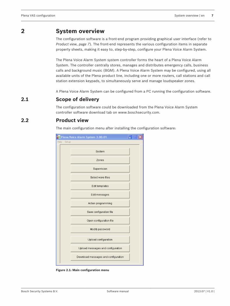
Product viewThe main configuration menu after installing the configuration software:
Figure 2.1: Main configuration menu
2
2.1
2.2
Plena VAS configuration System overview | en 7
Bosch Security Systems B.V. Software manual 2013.07 | V1.0 |
Getting startedThis section describes how to install the configuration software, connect a PC to the PlenaVoice Alarm System controller (LBB 1990/00), start the software and provides informationabout the user interface (main configuration menu).
PC requirementsThe configuration software can be installed on any PC running the Microsoft Windows 2000,Windows XP SP3, Windows Vista, Windows 7 and Windows 8 operating system. Make surethat the PC is working correctly and free of viruses before installing the software. Usingembedded operating systems is not recommended.
Notice!
Be sure that you use a user account with full Windows administration rights before starting
software installation.
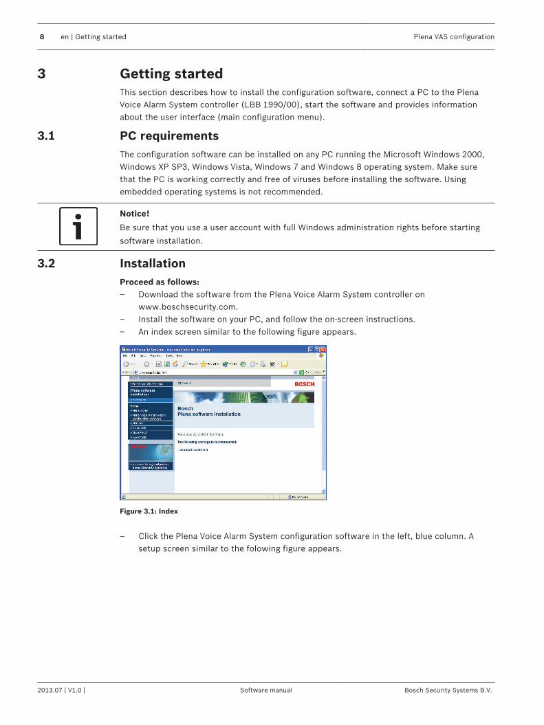
InstallationProceed as follows:– Download the software from the Plena Voice Alarm System controller on
www.boschsecurity.com.– Install the software on your PC, and follow the on‑screen instructions.– An index screen similar to the following figure appears.
Figure 3.1: Index
– Click the Plena Voice Alarm System configuration software in the left, blue column. A
setup screen similar to the folowing figure appears.
3
3.1
3.2
8 en | Getting started Plena VAS configuration
2013.07 | V1.0 | Software manual Bosch Security Systems B.V.
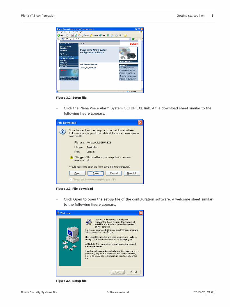
Figure 3.2: Setup file
– Click the Plena Voice Alarm System_SETUP.EXE link. A file download sheet similar to the
following figure appears.
Figure 3.3: File download
– Click Open to open the set-up file of the configuration software. A welcome sheet similar
to the following figure appears.
Figure 3.4: Setup file
Plena VAS configuration Getting started | en 9
Bosch Security Systems B.V. Software manual 2013.07 | V1.0 |

1. Click Next and follow the on‑screen instructions.2. Restart the PC to complete the software installation process.
10 en | Getting started Plena VAS configuration
2013.07 | V1.0 | Software manual Bosch Security Systems B.V.
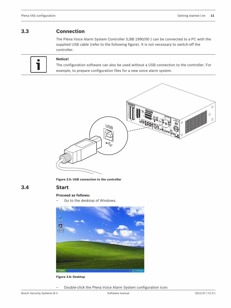
ConnectionThe Plena Voice Alarm System Controller (LBB 1990/00 ) can be connected to a PC with thesupplied USB cable (refer to the following figure). It is not necessary to switch-off thecontroller.
Notice!
The configuration software can also be used without a USB connection to the controller. For
example, to prepare configuration files for a new voice alarm system.
COM
NCNO
10k10k
Trigger input/24V DC out
Business
Emergency
NC
TRG2
Override/Trigger Output
AUX
L
R
PC
DigitalMessageMonitoringSpeaker
Remote Control Panel
ImpedanceCalibration
In
Phantom power
Z1
Z2
Z3
Z4
Z5
Z6
ExtBoosterIn
DC In
100V
0
TRG 1
IntBooster
Out
24V
EMG
Fault
Call
External Booster
Out
CD/Tuner
SEL1SEL0FirmwareUpgrade
MonitorAPR modeSupervision2ch operation
Off
On
USB
VoxSpeech filter
Mic/Line
Vox
Rated input power:760VALine fuseT6.3L250V for230V AC
T10L250V for115V AC
115V~230V~
Apparatus deliveredConnected for 230V~
Power
Router
WarningThis apparatus must be earthed
100V
0
100V
0
100V
0
100V
0
100V
0
100V
0
24V
70V
Z1
Z2
Z3
Z4
Z5
Z6
GND
Fireman's panel
1 2 3 4 5 6
1 2 3 4 5 61 2 3 4 5 6
Off
On
Off
On
Call stationFor service only
GND
24VDC out
VOXSwitch
VOX Switch
1 2 3 4 5 6
NC
COMNO
NC
COMNO
NC
COMNO
100V
0
Call out
100V
0
100V
0
100V
0
100V
0
100V
0
100V
0
Z2
Z3
Z4
Z5
Z6
Z1
A
B
NO
24VDC out
24V
1 Channel2 Channel
Int BoosterExt Booster
BGM/Spare
N.C./Spare
Call
BGM/Call
Volume Override
100V
1
2
1
2
USB
Figure 3.5: USB connection to the controller
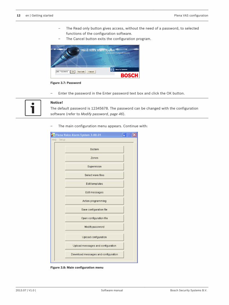
StartProceed as follows:– Go to the desktop of Windows.
Figure 3.6: Desktop
– Double-click the Plena Voice Alarm System configuration icon:
3.3
3.4
Plena VAS configuration Getting started | en 11
Bosch Security Systems B.V. Software manual 2013.07 | V1.0 |
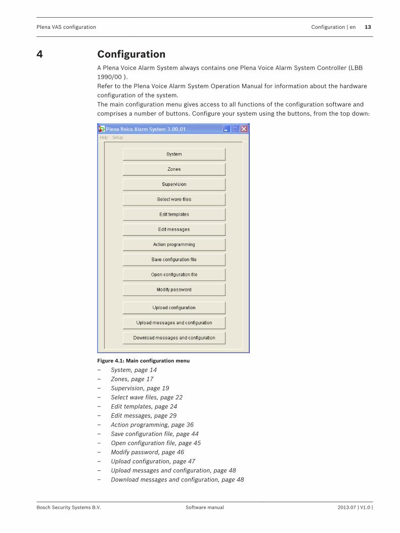
– The Read only button gives access, without the need of a password, to selectedfunctions of the configuration software.
– The Cancel button exits the configuration program.
Figure 3.7: Password
– Enter the password in the Enter password text box and click the OK button.
Notice!
The default password is 12345678. The password can be changed with the configuration
software (refer to Modify password, page 46).
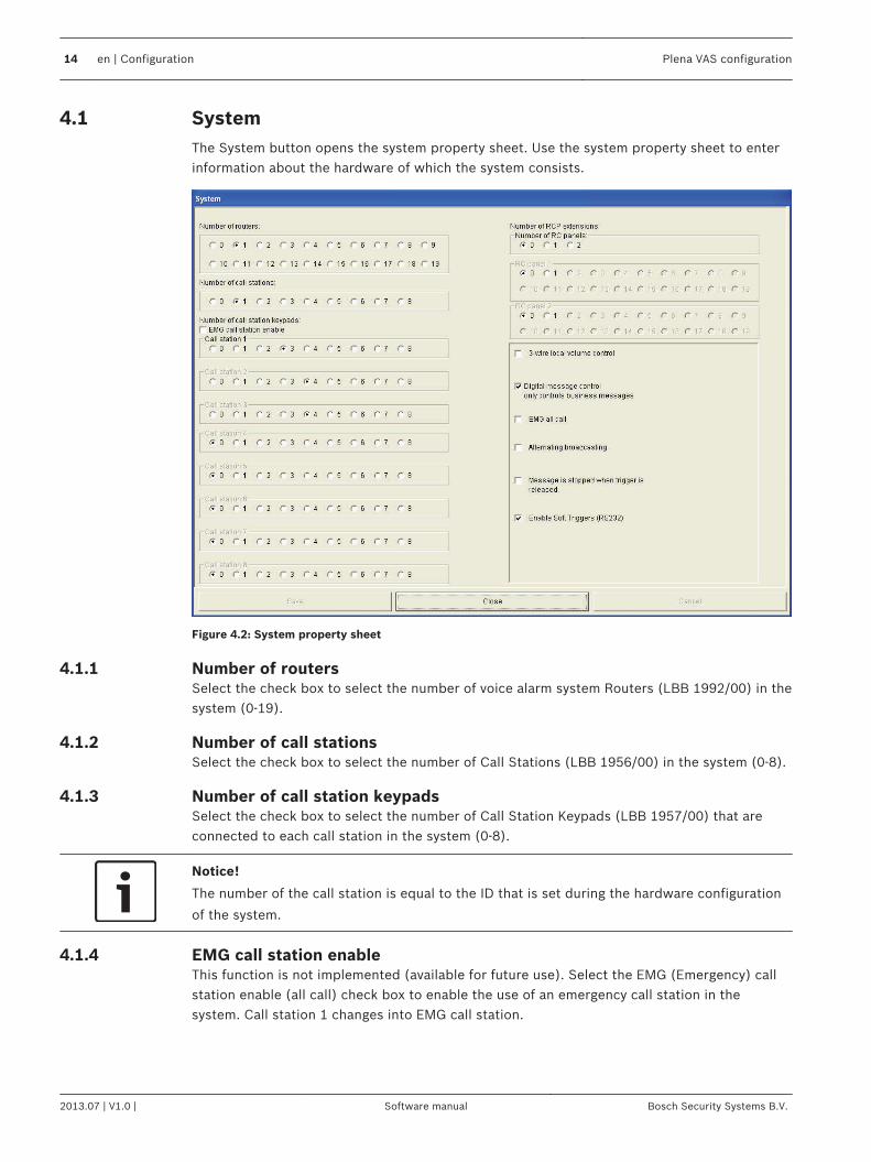
– The main configuration menu appears. Continue with:
Figure 3.8: Main configuration menu
12 en | Getting started Plena VAS configuration
2013.07 | V1.0 | Software manual Bosch Security Systems B.V.
ConfigurationA Plena Voice Alarm System always contains one Plena Voice Alarm System Controller (LBB1990/00 ).Refer to the Plena Voice Alarm System Operation Manual for information about the hardwareconfiguration of the system.The main configuration menu gives access to all functions of the configuration software andcomprises a number of buttons. Configure your system using the buttons, from the top down:
Figure 4.1: Main configuration menu
– System, page 14– Zones, page 17– Supervision, page 19– Select wave files, page 22– Edit templates, page 24– Edit messages, page 29– Action programming, page 36– Save configuration file, page 44– Open configuration file, page 45– Modify password, page 46– Upload configuration, page 47– Upload messages and configuration, page 48– Download messages and configuration, page 48
4
Plena VAS configuration Configuration | en 13
Bosch Security Systems B.V. Software manual 2013.07 | V1.0 |
SystemThe System button opens the system property sheet. Use the system property sheet to enterinformation about the hardware of which the system consists.
Figure 4.2: System property sheet
Number of routersSelect the check box to select the number of voice alarm system Routers (LBB 1992/00) in thesystem (0‑19).
Number of call stationsSelect the check box to select the number of Call Stations (LBB 1956/00) in the system (0‑8).
Number of call station keypadsSelect the check box to select the number of Call Station Keypads (LBB 1957/00) that areconnected to each call station in the system (0‑8).
Notice!
The number of the call station is equal to the ID that is set during the hardware configuration
of the system.
EMG call station enableThis function is not implemented (available for future use). Select the EMG (Emergency) callstation enable (all call) check box to enable the use of an emergency call station in thesystem. Call station 1 changes into EMG call station.
4.1
4.1.1
4.1.2
4.1.3
4.1.4
14 en | Configuration Plena VAS configuration
2013.07 | V1.0 | Software manual Bosch Security Systems B.V.
Number of RC panelsSelect the check box to select the number of remote controls (LBB 1995/00, LBB 1996/00and LBB 1997/00) used in the system (0‑2).
Number of RCP extensionsSelect the check box to select the number of remote control extensions (LBB1998/00 andLBB1999/00) that are connected to each remote control panel used in the system (0‑19).
3-wire local volume controlSelect the check box if the system uses 3‑wire volume override. If the system uses 4‑wirevolume override, make sure that the 3‑wire local volume control check box is cleared.
Digital message control only controls business messagesSelect the check box when the digital-message volume-control on the voice alarm systemcontroller rear panel controls the sound volume for business messages only, and not foremergency messages.
EMG all callSelect the check box if the Fireman must only be able to initiate all zones calls. Therefore thevoice alarm system controller and the remote control disables all zone buttons on the frontpanel.
Alternating broadcastingSelect the check box to enable two or more none mergeable messages of equal priority eachto be broadcast to a different zone or zone group. When disabled the messages will all bebroadcast to the combined zones or zone groups of the messages.
Notice!
When alternating broadcasting is used, it is not possible to add or delete zones while a call is
being broadcast. Routing by configuration only.
Message is stopped when trigger is releasedSelect the check box to stop the message as soon the trigger is released.
4.1.5
4.1.6
4.1.7
4.1.8
4.1.9
4.1.10
4.1.11
Plena VAS configuration Configuration | en 15
Bosch Security Systems B.V. Software manual 2013.07 | V1.0 |
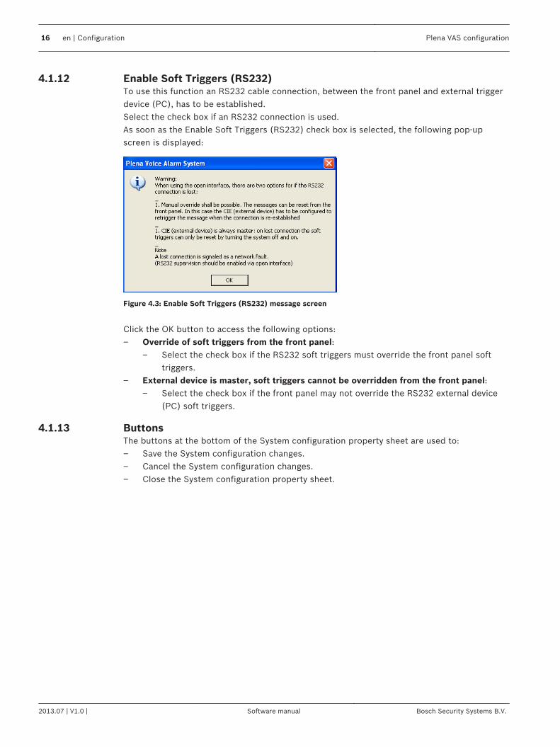
Enable Soft Triggers (RS232)To use this function an RS232 cable connection, between the front panel and external triggerdevice (PC), has to be established.Select the check box if an RS232 connection is used.As soon as the Enable Soft Triggers (RS232) check box is selected, the following pop-upscreen is displayed:
Figure 4.3: Enable Soft Triggers (RS232) message screen
Click the OK button to access the following options:– Override of soft triggers from the front panel:
– Select the check box if the RS232 soft triggers must override the front panel softtriggers.
– External device is master, soft triggers cannot be overridden from the front panel:– Select the check box if the front panel may not override the RS232 external device
(PC) soft triggers.
ButtonsThe buttons at the bottom of the System configuration property sheet are used to:– Save the System configuration changes.– Cancel the System configuration changes.– Close the System configuration property sheet.
4.1.12
4.1.13
16 en | Configuration Plena VAS configuration
2013.07 | V1.0 | Software manual Bosch Security Systems B.V.
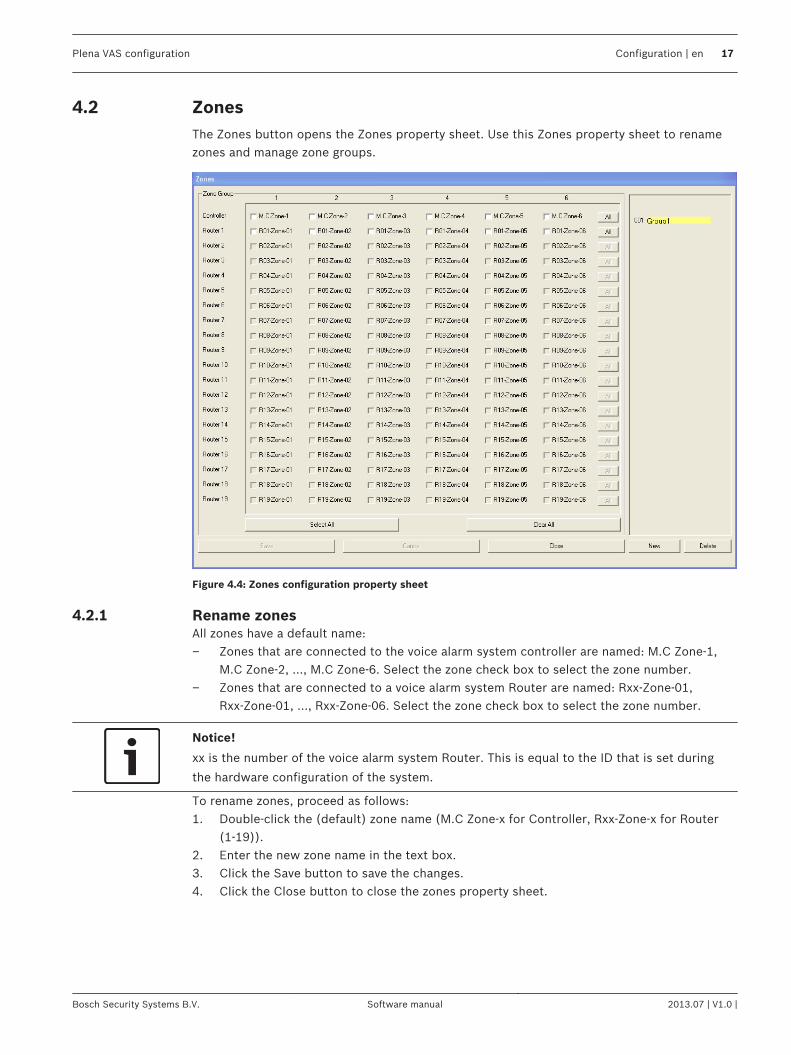
ZonesThe Zones button opens the Zones property sheet. Use this Zones property sheet to renamezones and manage zone groups.
Figure 4.4: Zones configuration property sheet
Rename zonesAll zones have a default name:– Zones that are connected to the voice alarm system controller are named: M.C Zone‑1,
M.C Zone‑2, ..., M.C Zone‑6. Select the zone check box to select the zone number.– Zones that are connected to a voice alarm system Router are named: Rxx‑Zone‑01,
Rxx‑Zone‑01, ..., Rxx‑Zone‑06. Select the zone check box to select the zone number.
Notice!
xx is the number of the voice alarm system Router. This is equal to the ID that is set during
the hardware configuration of the system.
To rename zones, proceed as follows:1. Double-click the (default) zone name (M.C Zone‑x for Controller, Rxx‑Zone‑x for Router
(1‑19)).2. Enter the new zone name in the text box.3. Click the Save button to save the changes.4. Click the Close button to close the zones property sheet.
4.2
4.2.1
Plena VAS configuration Configuration | en 17
Bosch Security Systems B.V. Software manual 2013.07 | V1.0 |
Zone GroupZone Group combines related zones and makes it possible to select multiple zones at thesame time. For example; in a hotel, the following zones could be added to the zone groupFloors: Floor1, Floor2, Floor3 etc. To add a New Zone Group, proceed as follows:1. Click the New button.
– A new zone GroupX (default) will be added to the zone group list.– If applicable, double-click the GroupX zone group name and enter the new zone
group name (e.g. Floor1) in the text box.2. Select each Zone check box that must be added to the zone group:
– The All button select all zones of a unit.– The Select All button select all zones in the system.– The Clear All button clears all zones in the system.
3. Click the Save button to save the changes.4. Click the Close button to close the zones property sheet. To Rename a Zone Group, proceed as follows:1. Double-click the zone group name (e.g GroupX) that must be renamed.
– Enter the new zone group name in the text box (e.g. Floor2).2. Click the Save button to save the changes.3. Click the Close button to close the zones property sheet. To Delete a Zone Group, proceed as follows:1. Select the zone group that must be deleted from the list in the zone group section.
– By selection, the zone group text becomes yellow.2. Click the Delete button to delete the zone group.3. Click the Save button to save the changes.4. Click the Close button to close the zones property sheet.
Notice!
The zones themselves are not deleted from the system.
4.2.2
18 en | Configuration Plena VAS configuration
2013.07 | V1.0 | Software manual Bosch Security Systems B.V.
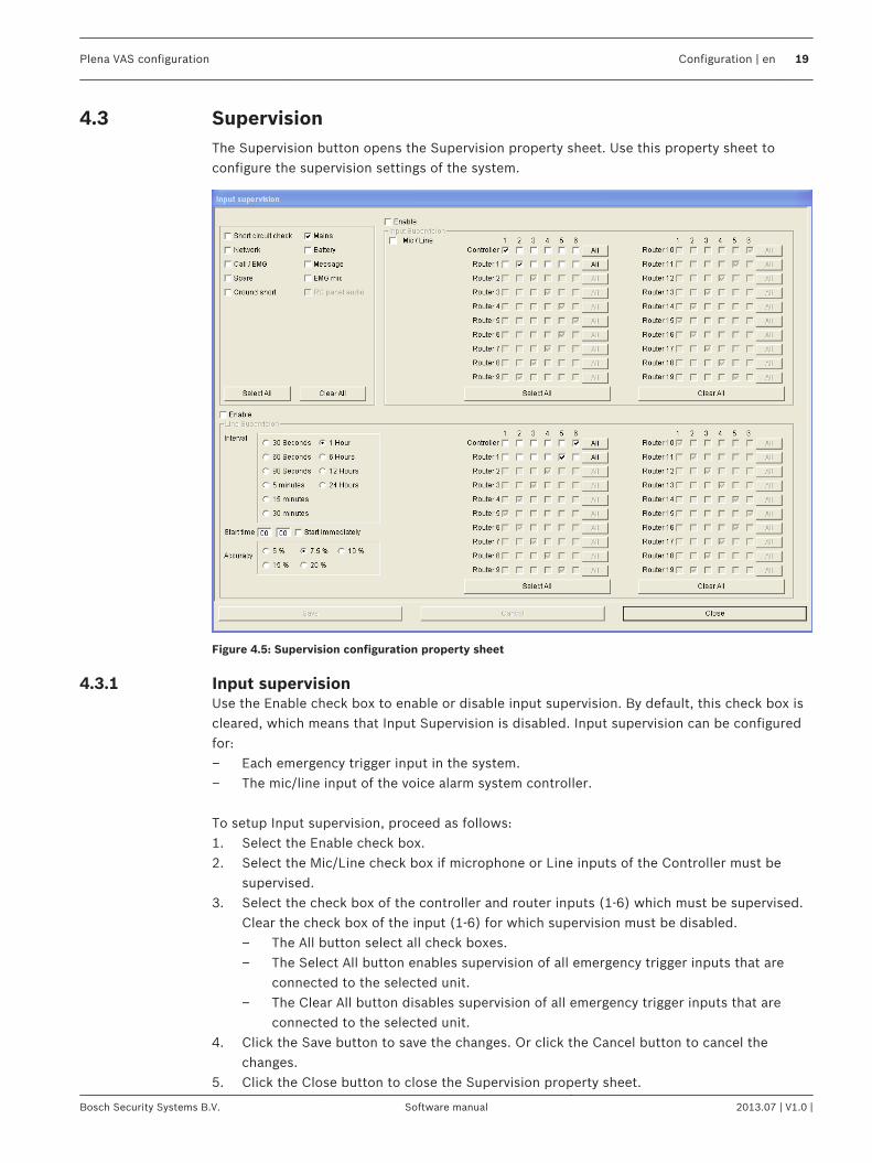
SupervisionThe Supervision button opens the Supervision property sheet. Use this property sheet toconfigure the supervision settings of the system.
Figure 4.5: Supervision configuration property sheet
Input supervisionUse the Enable check box to enable or disable input supervision. By default, this check box iscleared, which means that Input Supervision is disabled. Input supervision can be configuredfor:– Each emergency trigger input in the system.– The mic/line input of the voice alarm system controller. To setup Input supervision, proceed as follows:1. Select the Enable check box.2. Select the Mic/Line check box if microphone or Line inputs of the Controller must be
supervised.3. Select the check box of the controller and router inputs (1-6) which must be supervised.
Clear the check box of the input (1‑6) for which supervision must be disabled.– The All button select all check boxes.– The Select All button enables supervision of all emergency trigger inputs that are
connected to the selected unit.– The Clear All button disables supervision of all emergency trigger inputs that are
connected to the selected unit.4. Click the Save button to save the changes. Or click the Cancel button to cancel the
changes.5. Click the Close button to close the Supervision property sheet.
4.3
4.3.1
Plena VAS configuration Configuration | en 19
Bosch Security Systems B.V. Software manual 2013.07 | V1.0 |
Line supervisionUse the Enable check box to enable or disable line supervision. By default, this check box isselected, which means that Line Supervision is enabled. Line supervision is carried out byImpedance supervision. The interval and accuracy of the impedance supervision can beconfigured. To setup Line supervision, proceed as follows:1. Select the Enable check box (if not selected yet).2. Select the interval time between two successive impedance checks from the Interval
check box (30 seconds, 60 seconds, 90 seconds, 5 min, 15 min, 30 min, 1 hour, 5 hours,10 hours, 24 hours).
3. Enter the Start time at which the line supervision must be started. Or:– Select the Start immediately check box if line supervision must be started
automatically.4. Select the accuracy of the impedance measurement from the check box (5%, 7.5%, 10%,
15% or 20%).
Notice!
If EOL (End Of Line) supervision is used with a unit, impedance measurement is turned off for
that unit.
5. Select each controller and router check box of the outputs that must be supervised:– The All button select all check boxes.– The Select All button select all check boxes.– The Clear All button clears all check boxes.
6. Click the Save button to save the changes. Or click the Cancel button to cancel thechanges.
7. Click the Close button to close the Supervision property sheet.
Short circuit checkUse the Short circuit check box to enable or disable the short circuit check of the system. Bydefault, this check box is selected. If a loudspeaker line has a short circuit, the line is isolated.
NetworkUse the Network check box to enable or disable supervision of the network. The Network inthis case is the data communication with all configured routers, RC panels, extensions to theRC panels and the audio connections to the routers.By default, this check box is cleared, which means that supervision of the network is disabled.
Call / EMGUse the Call / EMG check box to enable or disable supervision of the call power amplifier. Bydefault, this check box is selected, which means that supervision of the call power amplifier isenabled.
SpareUse the Spare check box to enable or disable supervision of the spare power amplifier. Bydefault, this check box is selected, which means that supervision of the spare power amplifieris enabled.
4.3.2
4.3.3
4.3.4
4.3.5
4.3.6
20 en | Configuration Plena VAS configuration
2013.07 | V1.0 | Software manual Bosch Security Systems B.V.
Ground shortUse the Ground short check box to enable or disable ground short supervision. By defaultground short is selected (enabled) to detect a short to ground of the loudspeaker lines. Thesystem still functions.
MainsUse the Mains check box to enable or disable mains power supervision. By default, this checkbox is selected, which means that mains power supervision is enabled.
BatteryUse the Battery check box to enable or disable battery supervision. By default, this check boxis selected, which means that battery supervision is enabled.
MessageUse the Message check box to enable or disable message supervision. By default, this checkbox is selected, which means that message supervision is enabled.
EMG micUse the EMG mic check box to enable or disable supervision of the hand-held emergencymicrophone that is connected to the voice alarm system controller and the RCs. By default,this check box is selected, which means that the emergency microphone is enabled.
RC panel audioSupervises the audio BUS between the Remote Control and the Controller. By default, thischeck box is selected, which means that the Remote Control panel audio is enabled.
ButtonsThe buttons at the bottom of the Supervision configuration property sheet are used to:– Select All check boxes.– Clear All check boxes.– Save the Supervision configuration changes.– Cancel the Supervision configuration changes.– Close the Supervision configuration property sheet.
4.3.7
4.3.8
4.3.9
4.3.10
4.3.11
4.3.12
4.3.13
Plena VAS configuration Configuration | en 21
Bosch Security Systems B.V. Software manual 2013.07 | V1.0 |
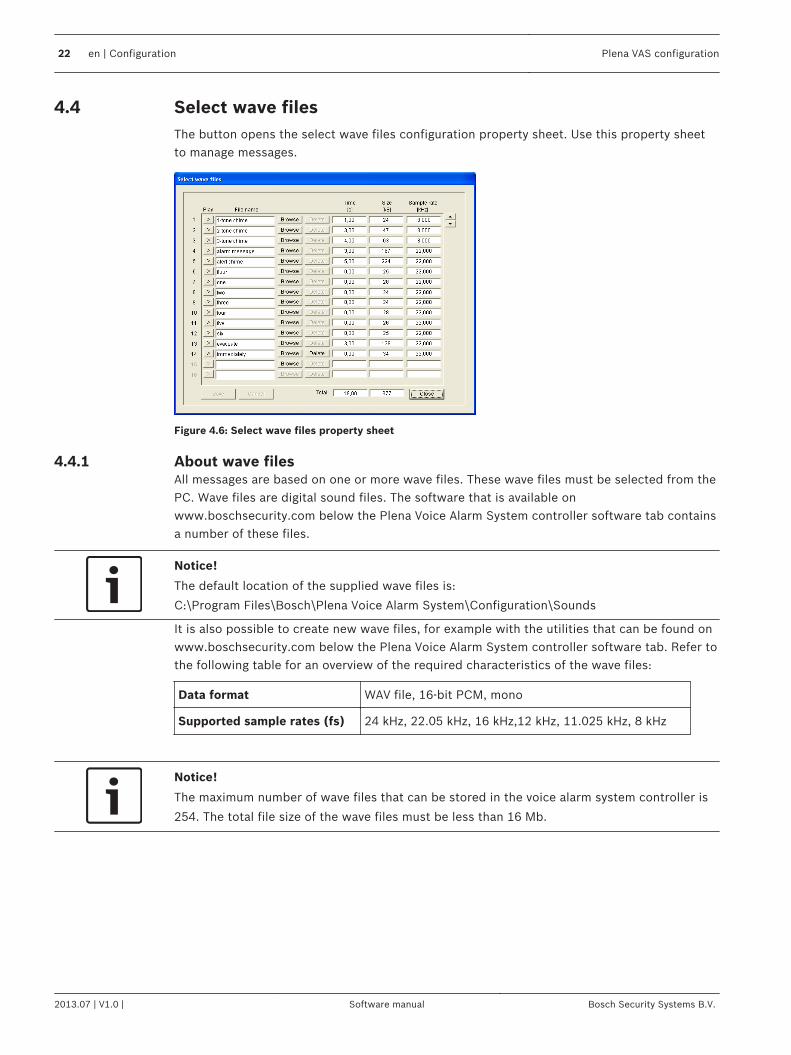
Select wave filesThe button opens the select wave files configuration property sheet. Use this property sheetto manage messages.
Figure 4.6: Select wave files property sheet
About wave filesAll messages are based on one or more wave files. These wave files must be selected from thePC. Wave files are digital sound files. The software that is available onwww.boschsecurity.com below the Plena Voice Alarm System controller software tab containsa number of these files.
Notice!
The default location of the supplied wave files is:
C:\Program Files\Bosch\Plena Voice Alarm System\Configuration\Sounds
It is also possible to create new wave files, for example with the utilities that can be found onwww.boschsecurity.com below the Plena Voice Alarm System controller software tab. Refer tothe following table for an overview of the required characteristics of the wave files:
Data format WAV file, 16-bit PCM, mono
Supported sample rates (fs) 24 kHz, 22.05 kHz, 16 kHz,12 kHz, 11.025 kHz, 8 kHz
Notice!
The maximum number of wave files that can be stored in the voice alarm system controller is
254. The total file size of the wave files must be less than 16 Mb.
4.4
4.4.1
22 en | Configuration Plena VAS configuration
2013.07 | V1.0 | Software manual Bosch Security Systems B.V.
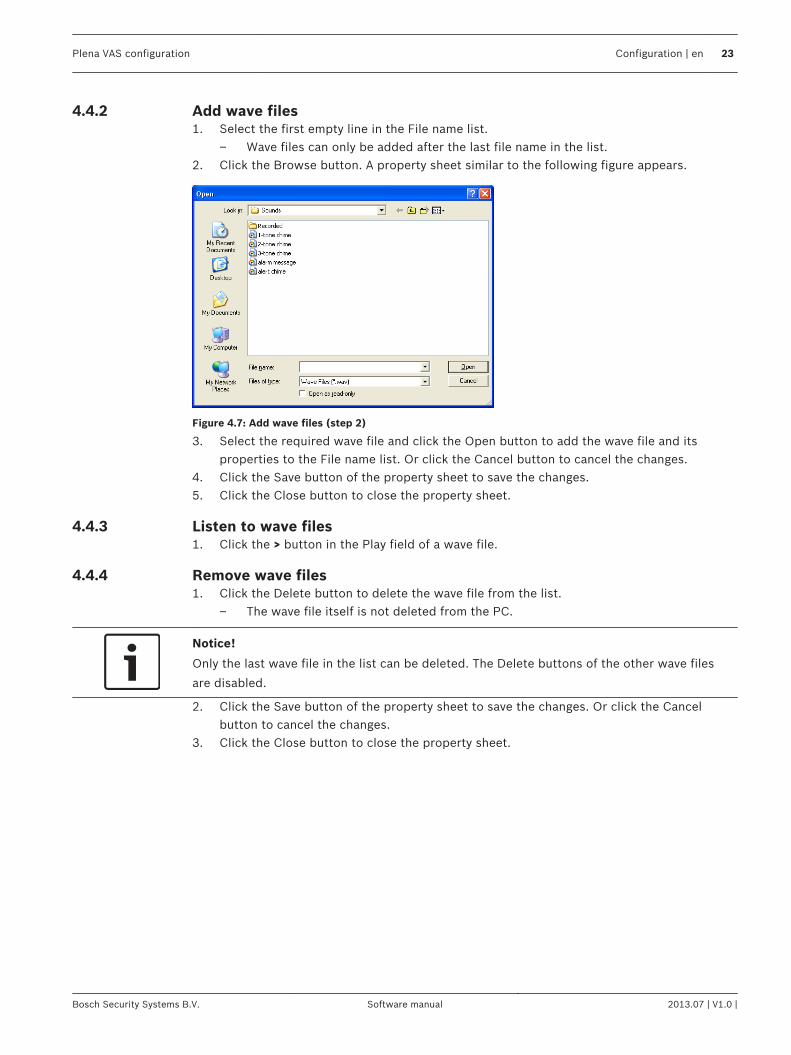
Add wave files1. Select the first empty line in the File name list.
– Wave files can only be added after the last file name in the list.2. Click the Browse button. A property sheet similar to the following figure appears.
Figure 4.7: Add wave files (step 2)
3. Select the required wave file and click the Open button to add the wave file and itsproperties to the File name list. Or click the Cancel button to cancel the changes.
4. Click the Save button of the property sheet to save the changes.5. Click the Close button to close the property sheet.
Listen to wave files1. Click the > button in the Play field of a wave file.
Remove wave files1. Click the Delete button to delete the wave file from the list.
– The wave file itself is not deleted from the PC.
Notice!
Only the last wave file in the list can be deleted. The Delete buttons of the other wave files
are disabled.
2. Click the Save button of the property sheet to save the changes. Or click the Cancelbutton to cancel the changes.
3. Click the Close button to close the property sheet.
4.4.2
4.4.3
4.4.4
Plena VAS configuration Configuration | en 23
Bosch Security Systems B.V. Software manual 2013.07 | V1.0 |
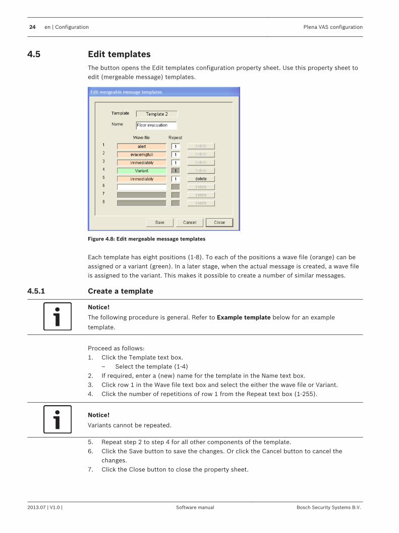
Edit templatesThe button opens the Edit templates configuration property sheet. Use this property sheet toedit (mergeable message) templates.
Figure 4.8: Edit mergeable message templates
Each template has eight positions (1‑8). To each of the positions a wave file (orange) can beassigned or a variant (green). In a later stage, when the actual message is created, a wave fileis assigned to the variant. This makes it possible to create a number of similar messages.
Create a template
Notice!
The following procedure is general. Refer to Example template below for an example
template.
Proceed as follows:1. Click the Template text box.
– Select the template (1‑4)2. If required, enter a (new) name for the template in the Name text box.3. Click row 1 in the Wave file text box and select the either the wave file or Variant.4. Click the number of repetitions of row 1 from the Repeat text box (1‑255).
Notice!
Variants cannot be repeated.
5. Repeat step 2 to step 4 for all other components of the template.6. Click the Save button to save the changes. Or click the Cancel button to cancel the
changes.7. Click the Close button to close the property sheet.
4.5
4.5.1
24 en | Configuration Plena VAS configuration
2013.07 | V1.0 | Software manual Bosch Security Systems B.V.
Example templateIn this example, a template is created that is used for evacuation messages for the floors ofthe visitors’ wing in a hotel. The template components are:– An alert chime to attract the attention. The name of the wave file that contains the alert
chime is alert chime in this example.– Speech: ‘Due to an emergency, it is necessary to evacuate’. The name of the wave file
that contains the speech is evacuate in this example.– Speech: ‘Floor’. The name of the wave file that contains the speech is floor in this
example.– Speech that contains the number of the floor. As this is different for each floor, this
component is a Variant that is not defined until the creation of the actual message (referto Create a message, page 29).
– Speech: ‘Immediately’. The name of the wave file that contains the speech is immediatelyin this example.
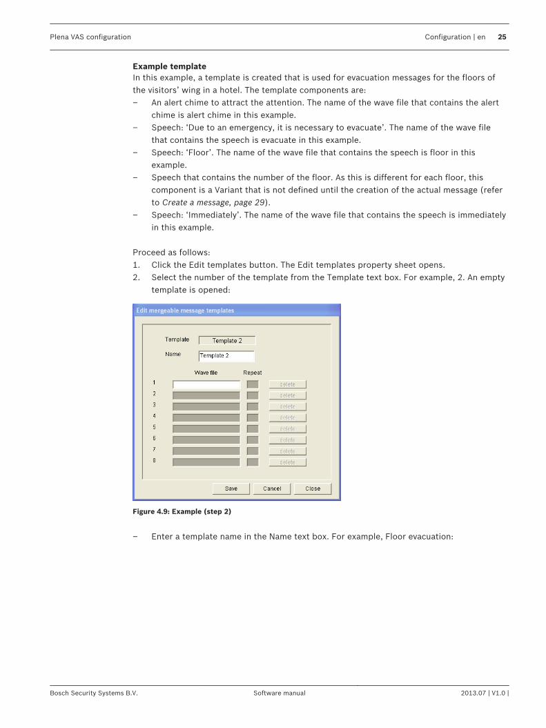
Proceed as follows:1. Click the Edit templates button. The Edit templates property sheet opens.2. Select the number of the template from the Template text box. For example, 2. An empty
template is opened:
Figure 4.9: Example (step 2)
– Enter a template name in the Name text box. For example, Floor evacuation:
Plena VAS configuration Configuration | en 25
Bosch Security Systems B.V. Software manual 2013.07 | V1.0 |
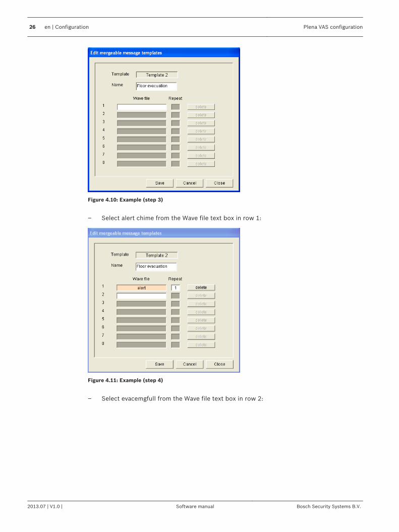
Figure 4.10: Example (step 3)
– Select alert chime from the Wave file text box in row 1:
Figure 4.11: Example (step 4)
– Select evacemgfull from the Wave file text box in row 2:
26 en | Configuration Plena VAS configuration
2013.07 | V1.0 | Software manual Bosch Security Systems B.V.
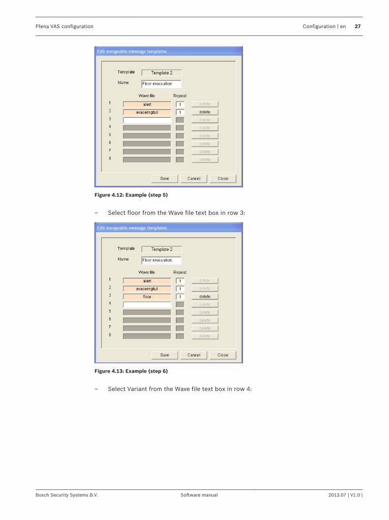
Figure 4.12: Example (step 5)
– Select floor from the Wave file text box in row 3:
Figure 4.13: Example (step 6)
– Select Variant from the Wave file text box in row 4:
Plena VAS configuration Configuration | en 27
Bosch Security Systems B.V. Software manual 2013.07 | V1.0 |
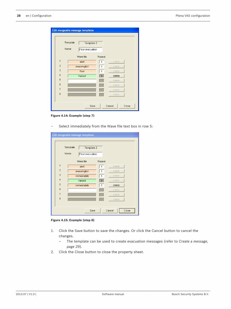
Figure 4.14: Example (step 7)
– Select immediately from the Wave file text box in row 5:
Figure 4.15: Example (step 8)
1. Click the Save button to save the changes. Or click the Cancel button to cancel the
changes.– The template can be used to create evacuation messages (refer to Create a message,
page 29).2. Click the Close button to close the property sheet.
28 en | Configuration Plena VAS configuration
2013.07 | V1.0 | Software manual Bosch Security Systems B.V.

Edit messagesThe button opens the Edit messages configuration property sheet. Use this property sheet toedit message.
Figure 4.16: Edit messages property sheet
Each message can have up to 8 components (1‑8). To each of the positions a wave file can beassigned. It is also possible to create a mergeable message that is based on a template. Whena message is based on a template, wave files can only be assigned to the Variant componentsof the template. The other components of a mergeable message are fixed and defined by thetemplate in this case.
Create a message
Notice!
The following procedure does not describe how to create a mergeable message. Refer to
Create a mergeable message, page 32 for information about creating mergeable messages.
Proceed as follows:1. Click the New button. A property sheet similar to the following figure appears.
Figure 4.17: Create a message (step 1)
– Enter the name in the text box (for example, Announcements) and click the OK button.
4.6
4.6.1
Plena VAS configuration Configuration | en 29
Bosch Security Systems B.V. Software manual 2013.07 | V1.0 |
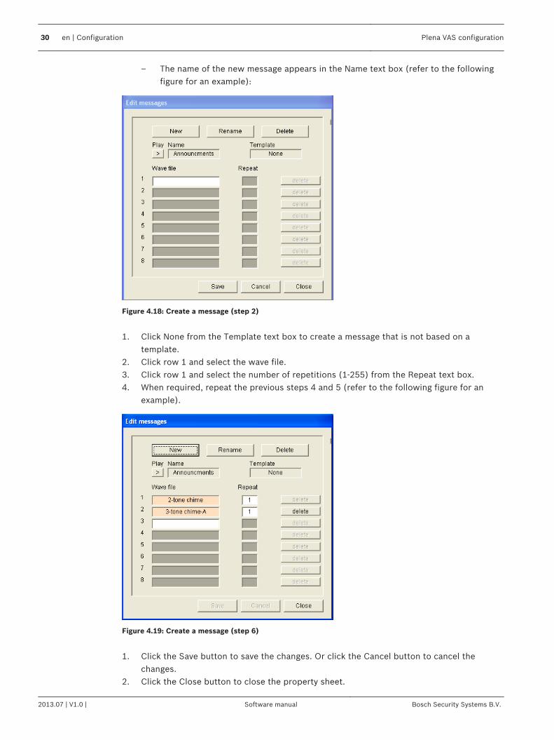
– The name of the new message appears in the Name text box (refer to the followingfigure for an example):
Figure 4.18: Create a message (step 2)
1. Click None from the Template text box to create a message that is not based on a
template.2. Click row 1 and select the wave file.3. Click row 1 and select the number of repetitions (1‑255) from the Repeat text box.4. When required, repeat the previous steps 4 and 5 (refer to the following figure for an
example).
Figure 4.19: Create a message (step 6)
1. Click the Save button to save the changes. Or click the Cancel button to cancel the
changes.2. Click the Close button to close the property sheet.
30 en | Configuration Plena VAS configuration
2013.07 | V1.0 | Software manual Bosch Security Systems B.V.
Listen to messages1. Click the > (Play) button.
Rename messages
!
Caution!
Do not change the name of a message after you have completed the action programming.
Instead, delete the message.
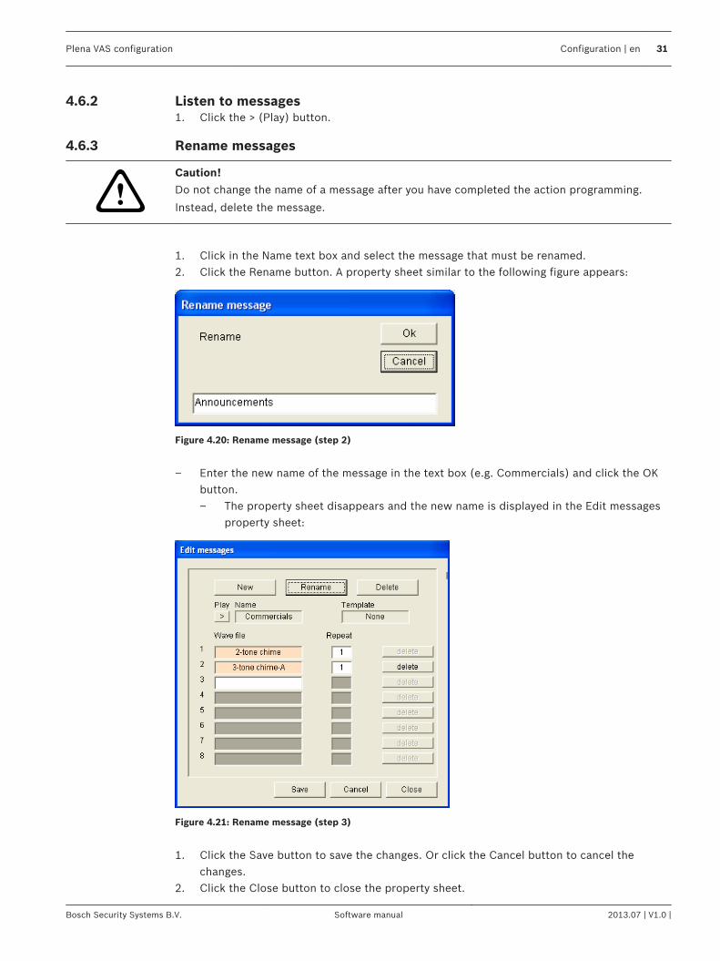
1. Click in the Name text box and select the message that must be renamed.2. Click the Rename button. A property sheet similar to the following figure appears:
Figure 4.20: Rename message (step 2)
– Enter the new name of the message in the text box (e.g. Commercials) and click the OK
button.– The property sheet disappears and the new name is displayed in the Edit messages
property sheet:
Figure 4.21: Rename message (step 3)
1. Click the Save button to save the changes. Or click the Cancel button to cancel the
changes.2. Click the Close button to close the property sheet.
4.6.2
4.6.3
Plena VAS configuration Configuration | en 31
Bosch Security Systems B.V. Software manual 2013.07 | V1.0 |
Delete a message1. Select the message that must be deleted from the Name text box.2. Click the Delete button and confirm with yes.
About mergeable messagesA special type of message is a mergeable message (refer to Create a mergeable message, page32 for an example). When two or more calls are started that are based on the samemergeable message template and have the same priority, the calls are merged. The youngestcall will not stop the oldest call in this case. With the configuration software, 4 differentmergeable message templates can be created.
Create a mergeable message
Notice!
The following procedure is general. Refer to Example mergeable message below for an
example.
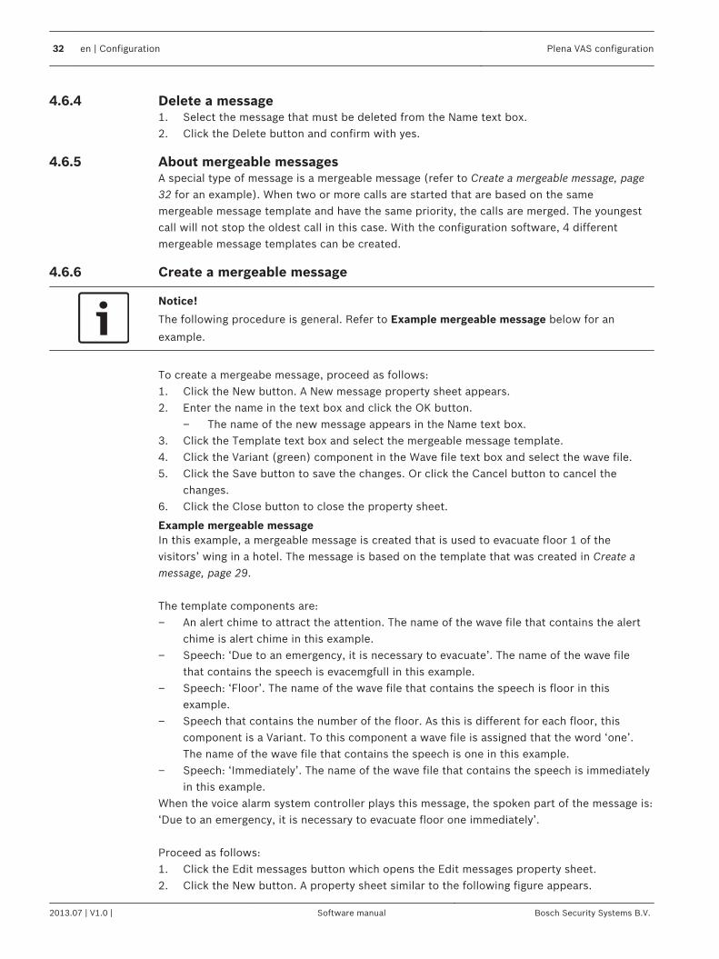
To create a mergeabe message, proceed as follows:1. Click the New button. A New message property sheet appears.2. Enter the name in the text box and click the OK button.
– The name of the new message appears in the Name text box.3. Click the Template text box and select the mergeable message template.4. Click the Variant (green) component in the Wave file text box and select the wave file.5. Click the Save button to save the changes. Or click the Cancel button to cancel the
changes.6. Click the Close button to close the property sheet.
Example mergeable messageIn this example, a mergeable message is created that is used to evacuate floor 1 of thevisitors’ wing in a hotel. The message is based on the template that was created in Create amessage, page 29. The template components are:– An alert chime to attract the attention. The name of the wave file that contains the alert
chime is alert chime in this example.– Speech: ‘Due to an emergency, it is necessary to evacuate’. The name of the wave file
that contains the speech is evacemgfull in this example.– Speech: ‘Floor’. The name of the wave file that contains the speech is floor in this
example.– Speech that contains the number of the floor. As this is different for each floor, this
component is a Variant. To this component a wave file is assigned that the word ‘one’.The name of the wave file that contains the speech is one in this example.
– Speech: ‘Immediately’. The name of the wave file that contains the speech is immediatelyin this example.
When the voice alarm system controller plays this message, the spoken part of the message is:‘Due to an emergency, it is necessary to evacuate floor one immediately’. Proceed as follows:1. Click the Edit messages button which opens the Edit messages property sheet.2. Click the New button. A property sheet similar to the following figure appears.
4.6.4
4.6.5
4.6.6
32 en | Configuration Plena VAS configuration
2013.07 | V1.0 | Software manual Bosch Security Systems B.V.
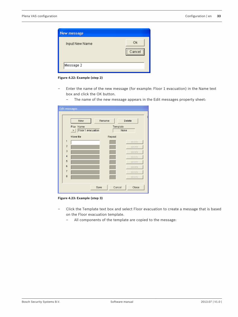
Figure 4.22: Example (step 2)
– Enter the name of the new message (for example: Floor 1 evacuation) in the Name text
box and click the OK button.– The name of the new message appears in the Edit messages property sheet:
Figure 4.23: Example (step 3)
– Click the Template text box and select Floor evacuation to create a message that is based
on the Floor evacuation template.– All components of the template are copied to the message:
Plena VAS configuration Configuration | en 33
Bosch Security Systems B.V. Software manual 2013.07 | V1.0 |
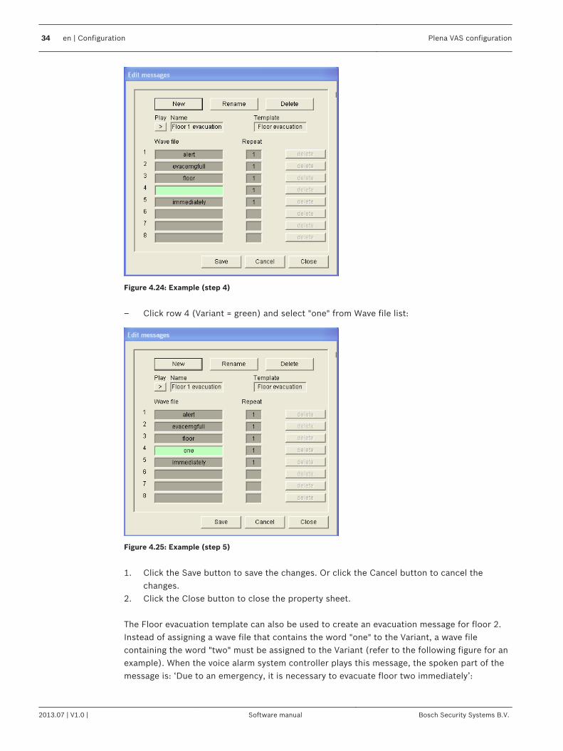
Figure 4.24: Example (step 4)
– Click row 4 (Variant = green) and select "one" from Wave file list:
Figure 4.25: Example (step 5)
1. Click the Save button to save the changes. Or click the Cancel button to cancel the
changes.2. Click the Close button to close the property sheet. The Floor evacuation template can also be used to create an evacuation message for floor 2.Instead of assigning a wave file that contains the word "one" to the Variant, a wave filecontaining the word "two" must be assigned to the Variant (refer to the following figure for anexample). When the voice alarm system controller plays this message, the spoken part of themessage is: ‘Due to an emergency, it is necessary to evacuate floor two immediately’:
34 en | Configuration Plena VAS configuration
2013.07 | V1.0 | Software manual Bosch Security Systems B.V.
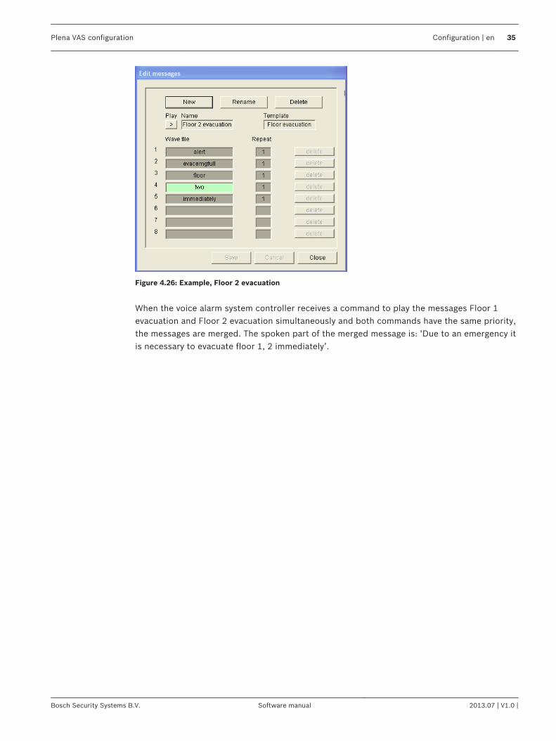
Figure 4.26: Example, Floor 2 evacuation
When the voice alarm system controller receives a command to play the messages Floor 1evacuation and Floor 2 evacuation simultaneously and both commands have the same priority,the messages are merged. The spoken part of the merged message is: ‘Due to an emergency itis necessary to evacuate floor 1, 2 immediately’.
Plena VAS configuration Configuration | en 35
Bosch Security Systems B.V. Software manual 2013.07 | V1.0 |
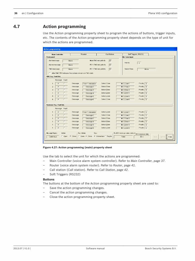
Action programmingUse the Action programming property sheet to program the actions of buttons, trigger inputs,etc. The contents of the Action programming property sheet depends on the type of unit forwhich the actions are programmed.
Figure 4.27: Action programming (main) property sheet
Use the tab to select the unit for which the actions are programmed:– Main Controller (voice alarm system controller). Refer to Main Controller, page 37.– Router (voice alarm system router). Refer to Router, page 41.– Call station (Call station). Refer to Call Station, page 42.– Soft Triggers (RS232)
ButtonsThe buttons at the bottom of the Action programming property sheet are used to:– Save the action programming changes.– Cancel the action programming changes.– Close the action programming property sheet.
4.7
36 en | Configuration Plena VAS configuration
2013.07 | V1.0 | Software manual Bosch Security Systems B.V.
Main ControllerUse the four sections to select the items for which the actions are programmed:– Front panel. Refer to Front panel following.– EMG Trg. / Fault Det. (Emergency trigger inputs / Fault detection). Refer to EMG
Trg / Fault Det. Following.– Business Trg. / Fault Det. (Business trigger inputs / Fault detection). Refer to Business
Trg / Fault Dedt. Following.– Mic / Line input. Refer to Mic / Line input following.
Notice!
During emergency state:
An intermittent beep will sound on the Controller and Remote Controls until the emergency
state is acknowledged.
The Emergency state indicators on the Controller, Remote Controls and Call Stations will light
up.
The emergency contact on the Controller and Remote Controls will be activated.
Business calls and background music are not available.
Unless EMG All Call is enabled in the configuration, zone selection can be modified using the
zone selection buttons on the Controller, Routers and Remote Controls.
An Alarm, Alert or Speech call can be started on the Controller or Remote Control.
Front panelIn this section, the message and prioritiy of the emergency triggers of the voice alarm systemcontroller can be programmed: Proceed as follows:1. Select the Main Controller tab.2. Select the message to be activated by the Alert message button on the front panel of the
voice alarm system controller in the Alert message text box.3. Select the message to be activated by the Alarm message button on the front panel of the
voice alarm system controller in the Alarm message text box.4. Select the message to be activated by the emergency button on the front panel of the
voice alarm system controller from the EMG message text box.5. Select the Main EMG mic priority level to set the priority level for the microphone of the
voice alarm system controller. The priorities 17, 18 and 19 can be set.6. Select the RC 1 EMG mic priority to set the priority level for the microphone for remote
control 1. The priorities 17, 18 and 19 can be set.7. Select the RC 2 EMG mic priority to set the priority level for the remote control 2. The
priorities 17, 18 and 19 can be set.8. Select the After EMG TRG release the system remains in EMG state check box to keep the
system in an emergency state until a reset. Clearing the check box will stop theemergency state as soon the trigger is released.
9. Click the Save button to save the changes. Or click the Cancel button to cancel thechanges.
10. Click the Close button to close the property sheet.
4.7.1
Plena VAS configuration Configuration | en 37
Bosch Security Systems B.V. Software manual 2013.07 | V1.0 |
EMG Trg. / Fault Det.In this section, the actions of the emergency triggers of the voice alarm system controller canbe programmed.
Message trigger settingsEach trigger is programmed with individual settings via the Message, Select Zone and Prioritytext boxes. Proceed as follows for each emergency trigger (EMG Trig.) input:1. Select Message for input 1.2. Select the pre-recorded message in the Message text box to play when input 1 is
activated.3. Select the zones to where the message plays in the Select Zone text box for input 1.4. Select the priority of the message in the Priority text box for input 1.5. If applicable, repeat the steps 1 to 4 for the inputs 2 to 6.6. Click the Save button to save the changes. Or click the Cancel button to cancel the
changes.7. Click the Close button to close the property sheet.
Fault detection settingsProceed as follows:1. Select Fault for input 1.2. Click the Fault Type text box and select the fault type:
– EOL. Select the zones in the Zone text box.– Amplifier fault. Select the amplifier type in the Amplifier text box.– Charger fault. Select either mains or battery in the Fault indicate text box.– Other. The input LED is turned on. The RC system fault LED is turned on.
3. If applicable, repeat the steps 1 and 2 for the inputs 2 to 6.4. Click the Save button to save the changes. Or click the Cancel button to cancel the
changes.5. Click the Close button to close the property sheet.
Notice!
For EOL setting: Set the Fault Type to EOL, select the Zone that has the EOL Supervision, set
Action to Open and set Type to Momentary.
General settings– Message Repeat– Action– Fault Action– Type– Pre EMG Message announcement– EMG message delay Proceed as follows:1. Click the Message Repeat text box and select the number of times all messages must be
repeated.– Select continuous or a specific number (1-254).
2. Select Action to set the condition when a trigger is made active:
38 en | Configuration Plena VAS configuration
2013.07 | V1.0 | Software manual Bosch Security Systems B.V.
– Open: the trigger is made active when the circuit is open.– Close: the trigger is made active when the circuit is closed.
3. Select Fault Action to set the condition when a fault trigger is made active:– Open: the trigger is made active when the circuit is open.– Close: the trigger is made active when the circuit is closed.
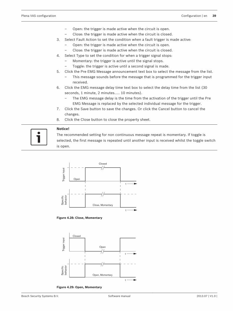
4. Select Type to set the condition for when a trigger signal stops:– Momentary: the trigger is active until the signal stops.– Toggle: the trigger is active until a second signal is made.
5. Click the Pre EMG Message announcement text box to select the message from the list.– This message sounds before the message that is programmed for the trigger input
received.6. Click the EMG message delay time text box to select the delay time from the list (30
seconds, 1 minute, 2 minutes..... 10 minutes).– The EMG message delay is the time from the activation of the trigger until the Pre
EMG Message is replaced by the selected individual message for the trigger.7. Click the Save button to save the changes. Or click the Cancel button to cancel the
changes.8. Click the Close button to close the property sheet.
Notice!
The recommended setting for non continuous message repeat is momentary. If toggle is
selected, the first message is repeated until another input is received whilst the toggle switch
is open.
Trig
ger i
nput
�S
peci
fic b
ehav
ior
t
t
Open
Closed
Close, Momentary
Figure 4.28: Close, Momentary
t
Closed
Open
Trig
ger i
nput
Spe
cific
be
havi
or
t
Open, Momentary
Figure 4.29: Open, Momentary
Plena VAS configuration Configuration | en 39
Bosch Security Systems B.V. Software manual 2013.07 | V1.0 |
t
t
Open
Closed
Trig
ger i
nput
Spe
cific
beh
avio
r
Close, Toggle
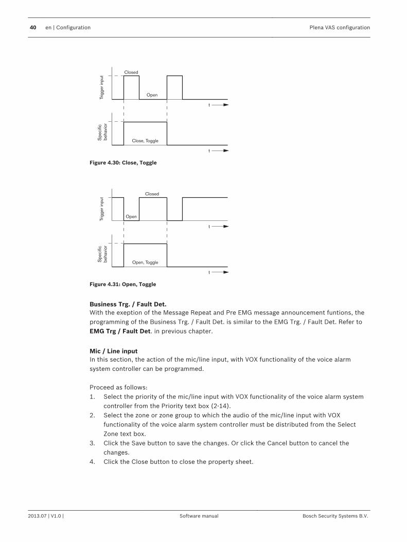
Figure 4.30: Close, Toggle
t
t
Closed
Open
Trig
ger i
nput
Spe
cific
beha
vior
Open, Toggle
Figure 4.31: Open, Toggle
Business Trg. / Fault Det.With the exeption of the Message Repeat and Pre EMG message announcement funtions, theprogramming of the Business Trg. / Fault Det. is similar to the EMG Trg. / Fault Det. Refer toEMG Trg / Fault Det. in previous chapter.
Mic / Line inputIn this section, the action of the mic/line input, with VOX functionality of the voice alarmsystem controller can be programmed. Proceed as follows:1. Select the priority of the mic/line input with VOX functionality of the voice alarm system
controller from the Priority text box (2-14).2. Select the zone or zone group to which the audio of the mic/line input with VOX
functionality of the voice alarm system controller must be distributed from the SelectZone text box.
3. Click the Save button to save the changes. Or click the Cancel button to cancel thechanges.
4. Click the Close button to close the property sheet.
40 en | Configuration Plena VAS configuration
2013.07 | V1.0 | Software manual Bosch Security Systems B.V.
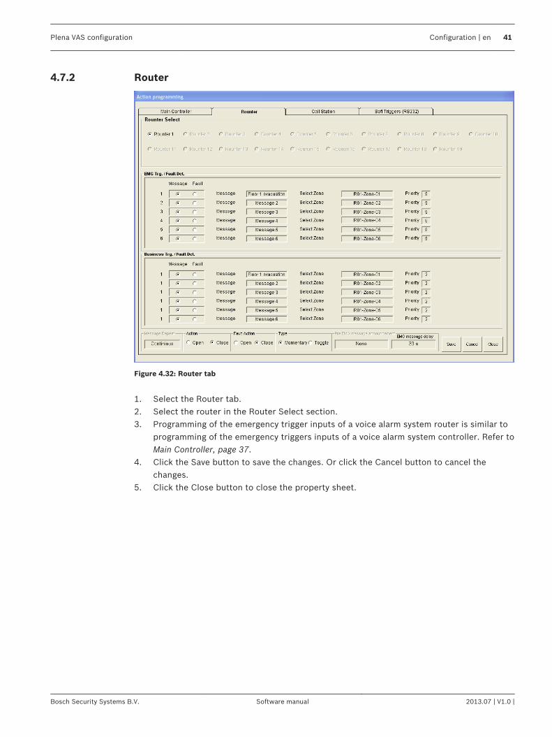
Router
Figure 4.32: Router tab
1. Select the Router tab.2. Select the router in the Router Select section.3. Programming of the emergency trigger inputs of a voice alarm system router is similar to
programming of the emergency triggers inputs of a voice alarm system controller. Refer toMain Controller, page 37.
4. Click the Save button to save the changes. Or click the Cancel button to cancel thechanges.
5. Click the Close button to close the property sheet.
4.7.2
Plena VAS configuration Configuration | en 41
Bosch Security Systems B.V. Software manual 2013.07 | V1.0 |
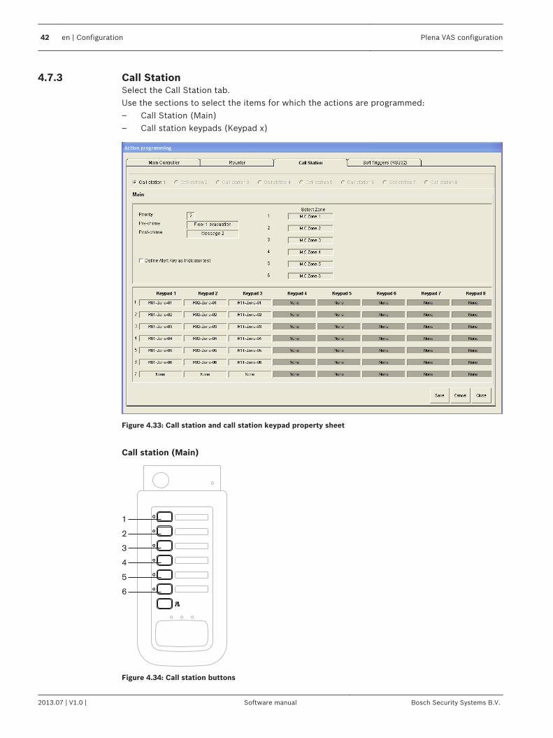
Call StationSelect the Call Station tab.Use the sections to select the items for which the actions are programmed:– Call Station (Main)– Call station keypads (Keypad x)
Figure 4.33: Call station and call station keypad property sheet
Call station (Main)
Plena
1
2
3
4
5
6
Figure 4.34: Call station buttons
4.7.3
42 en | Configuration Plena VAS configuration
2013.07 | V1.0 | Software manual Bosch Security Systems B.V.

Proceed as follows:1. Select the priority that is assigned to the messages by the calls station from the Priority
text box.2. Select the message or chime that is played at the start of the call from the Pre-chime text
box.3. Select the message or chime that is played at the end of the call from the Post-chime text
box.
Notice!
The remaining zone selection button on the call station selects all zones of the system.
4. Click the Save button to save the changes. Or click the Cancel button to cancel thechanges.
5. Click the Close button to close the property sheet.
Call station Keypad (Keypad x)
Plena
1
2
3
4
5
6
7
Figure 4.35: Keypad buttons
Proceed as follows:1. Assign zones to the zone selection buttons of the call station keypad by clicking the
Keypad x text box (1‑7) and select the zone or zone group.2. Click the Save button to save the changes. Or click the Cancel button to cancel the
changes.3. Click the Close button to close the property sheet.
Plena VAS configuration Configuration | en 43
Bosch Security Systems B.V. Software manual 2013.07 | V1.0 |
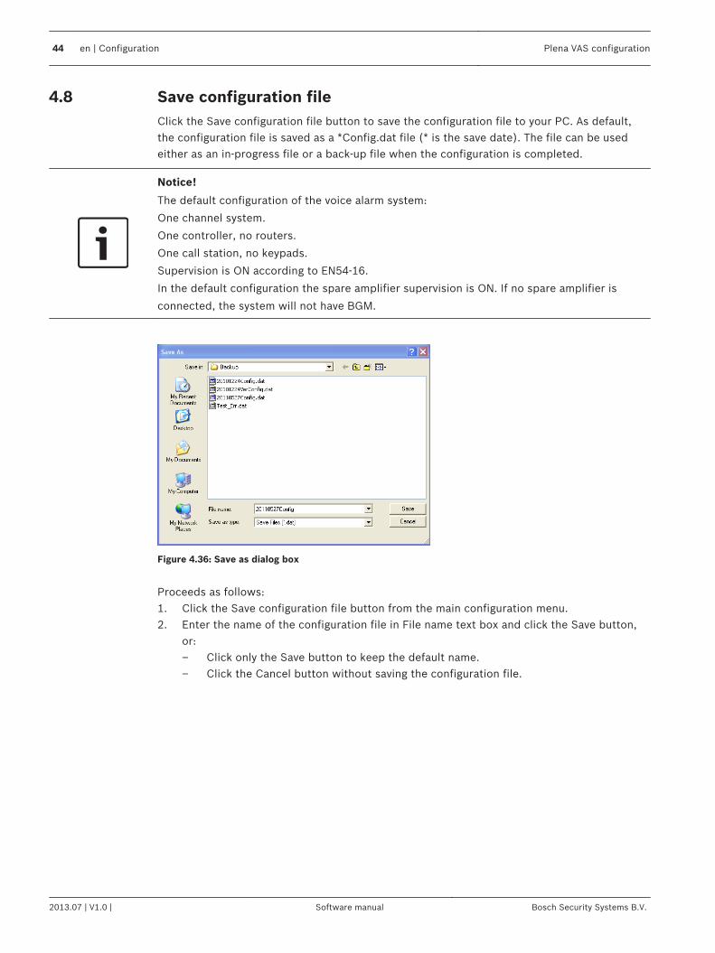
Save configuration fileClick the Save configuration file button to save the configuration file to your PC. As default,the configuration file is saved as a *Config.dat file (* is the save date). The file can be usedeither as an in-progress file or a back-up file when the configuration is completed.
Notice!
The default configuration of the voice alarm system:
One channel system.
One controller, no routers.
One call station, no keypads.
Supervision is ON according to EN54‑16.
In the default configuration the spare amplifier supervision is ON. If no spare amplifier is
connected, the system will not have BGM.
Figure 4.36: Save as dialog box
Proceeds as follows:1. Click the Save configuration file button from the main configuration menu.2. Enter the name of the configuration file in File name text box and click the Save button,
or:– Click only the Save button to keep the default name.– Click the Cancel button without saving the configuration file.
4.8
44 en | Configuration Plena VAS configuration
2013.07 | V1.0 | Software manual Bosch Security Systems B.V.
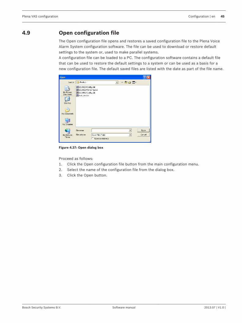
Open configuration fileThe Open configuration file opens and restores a saved configuration file to the Plena VoiceAlarm System configuration software. The file can be used to download or restore defaultsettings to the system or, used to make parallel systems.A configuration file can be loaded to a PC. The configuration software contains a default filethat can be used to restore the default settings to a system or can be used as a basis for anew configuration file. The default saved files are listed with the date as part of the file name.
Figure 4.37: Open dialog box
Proceed as follows:1. Click the Open configuration file button from the main configuration menu.2. Select the name of the configuration file from the dialog box.3. Click the Open button.
4.9
Plena VAS configuration Configuration | en 45
Bosch Security Systems B.V. Software manual 2013.07 | V1.0 |
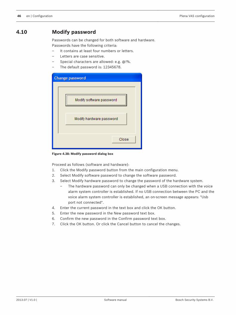
Modify passwordPasswords can be changed for both software and hardware.Passwords have the following criteria:– It contains at least four numbers or letters.– Letters are case sensitive.– Special characters are allowed: e.g. @!%.– The default password is: 12345678.
Figure 4.38: Modify password dialog box
Proceed as follows (software and hardware):1. Click the Modify password button from the main configuration menu.2. Select Modify software password to change the software password.3. Select Modify hardware password to change the password of the hardware system.
– The hardware password can only be changed when a USB connection with the voicealarm system controller is established. If no USB connection between the PC and thevoice alarm system controller is established, an on-screen message appears: "Usbport not connected".
4. Enter the current password in the text box and click the OK button.5. Enter the new password in the New password text box.6. Confirm the new password in the Confirm password text box.7. Click the OK button. Or click the Cancel button to cancel the changes.
4.10
46 en | Configuration Plena VAS configuration
2013.07 | V1.0 | Software manual Bosch Security Systems B.V.

Upload configurationThe configuration file must be uploaded to the system before it has effect.– The upload configuration option is fast and takes a few seconds to complete. Only the
configuration settings are loaded to the system.If only the settings have been changed since the last upload, it is better to select the Uploadconfiguration. Download the configuration file from the voice alarm system if an existingconfiguration file is needed and the original is not available. Proceed as follows:1. Click the Upload configuration button from the main configuration menu:
– If no USB connection between the PC and the voice alarm system controller isestablished, an on-screen message appears: "Usb port not connected".
2. The hardware password dialog box opens. Enter the hardware password.3. The version dialog box appears (refer to the following figure, for an example).
– Select the Modify hardware password check box if you want to modify the password.4. Click the OK button. Or click the Cancel button to cancel the changes.
Figure 4.39: Version dialog box (example)
– The configuration file Uploading dialog box appears:
Figure 4.40: Upload dialog box (part 1)
4.11
Plena VAS configuration Configuration | en 47
Bosch Security Systems B.V. Software manual 2013.07 | V1.0 |
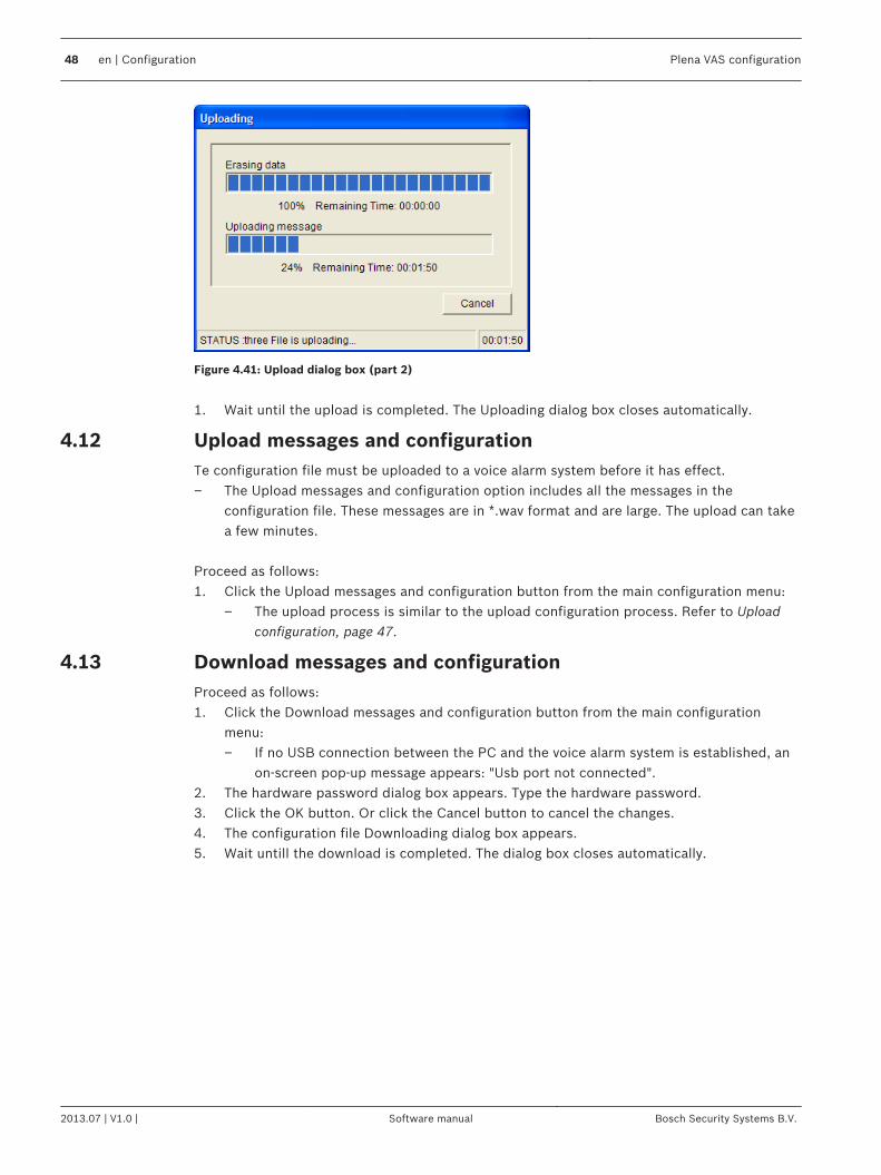
Figure 4.41: Upload dialog box (part 2)
1. Wait until the upload is completed. The Uploading dialog box closes automatically.
Upload messages and configurationTe configuration file must be uploaded to a voice alarm system before it has effect.– The Upload messages and configuration option includes all the messages in the
configuration file. These messages are in *.wav format and are large. The upload can takea few minutes.
Proceed as follows:1. Click the Upload messages and configuration button from the main configuration menu:
– The upload process is similar to the upload configuration process. Refer to Uploadconfiguration, page 47.
Download messages and configurationProceed as follows:1. Click the Download messages and configuration button from the main configuration
menu:– If no USB connection between the PC and the voice alarm system is established, an
on-screen pop-up message appears: "Usb port not connected".2. The hardware password dialog box appears. Type the hardware password.3. Click the OK button. Or click the Cancel button to cancel the changes.4. The configuration file Downloading dialog box appears.5. Wait untill the download is completed. The dialog box closes automatically.
4.12
4.13
48 en | Configuration Plena VAS configuration
2013.07 | V1.0 | Software manual Bosch Security Systems B.V.
TroubleshootingThis troubleshooting section has been created to help you with problems you may beexperiencing with installing or loading the Plena Voice Alarm System configuration software.
Unable to install the Plena Voice Alarm System configuration software?– The following is only valid when using a CD‑ROM:
– Verify if the CD is readable by reading the files on the drive.– If the CD attempts to auto‑play, you may need to right‑click the drive and click
Explore to browse the drive.– If the CD reads fine with no errors, verify your PC meets the minimum requirements
of the configuration software. If your PC does not have enough disk drive space ordoes not meet the requirements, the configuration software will not install.
– Make sure that the configuration software is compatible with the version of operatingsystem you have on your PC.
Error during installation?– Verify your PC meets the requirements of the configuration software.
– For example, if your PC runs out of disk space during the installation, this wouldcause an error during the installation.
– Make sure that the configuration software is compatible with the version of operatingsystem you have on your PC.
– Make sure that the configuration software is compatible with the hardware version andsoftware version of the voice alarm system.
– If used, verify the CD is clean and contains no significant scratches.
The configuration software does not load or has an error when it attempts to load– Verify if updates are available of the configuration software.
– In some cases the configuration software may require an update before it can besuccessfully run on your PC.
– Make sure all other programs are closed when you run the configuration software.– If the configuration software successfully runs after closing all other programs, it's
possible that the configuration software may have issues with other programs.– Make sure the PC has been rebooted at least once after the configuration software has
been installed.
5
Plena VAS configuration Troubleshooting | en 49
Bosch Security Systems B.V. Software manual 2013.07 | V1.0 |


Bosch Security Systems B.V.
Torenallee 49
5617 BA Eindhoven
The Netherlands
www.boschsecurity.com
© Bosch Security Systems B.V., 2013