Embed Size (px)
Citation preview
Plena VAS configurationConfiguration Software
en Software manual

Plena VAS configuration Table of Contents | en 3
Bosch Security Systems B.V. Software manual 9992 141 1038x (2.16.04-R2) | V1.0 | 2011.08
Table of Contents
1 Short Information 51.1 Purpose 51.2 Digital document 51.3 Intended audience 51.4 Related documentation 51.5 Alerts and notice signs 5
2 System overview 62.1 Scope of delivery 62.2 Product view 6
3 Getting started 73.1 System requirements 73.2 Installation 73.3 Connection 93.4 Start 9
4 Configuration 114.1 System 124.1.1 Number of routers 124.1.2 Number of call stations 124.1.3 Number of call station keypads 124.1.4 EMG call station enable 134.1.5 Number of RC panels 134.1.6 Number of RCP extensions 134.1.7 3-wire local volume control 134.1.8 Digital message control only controls business messages 134.1.9 EMG all call 134.1.10 Alternating broadcasting 134.1.11 Message is stopped when trigger is released 134.1.12 Enable Soft Triggers (RS232) 144.1.13 Buttons 144.2 Zones 154.2.1 Rename zones 154.2.2 Zone Group 164.3 Supervision 184.3.1 Line supervision 194.3.2 Input supervision 204.3.3 Short circuit check 204.3.4 Network 204.3.5 Call / EMG 204.3.6 Spare 214.3.7 Ground short 214.3.8 Mains 214.3.9 Battery 214.3.10 Message 21
4 en | Table of Contents Plena VAS configuration
9992 141 1038x (2.16.04-R2) | V1.0 | 2011.08 Software manual Bosch Security Systems B.V.
4.3.11 EMG mic 214.3.12 RC panel audio 214.3.13 Buttons 214.4 Messages 224.4.1 About wave files 224.4.2 About mergeable messages 224.4.3 Select wave files 234.4.4 Edit templates 244.4.5 Edit messages 294.5 Action programming 354.5.1 Controller 354.5.2 Router 414.5.3 Call station x 414.6 Save configuration file 434.7 Open configuration file 444.8 Modify password 454.9 Upload configuration 464.10 Upload messages and configuration 474.11 Download messages and configuration 47
5 Troubleshooting 48
Plena VAS configuration Short Information | en 5
Bosch Security Systems B.V. Software manual 9992 141 1038x (2.16.04-R2) | V1.0 | 2011.08
1 Short Information
1.1 PurposeThe purpose of the software manual is to provide information that is required to install and use the Plena Voice Alarm System configuration software.
1.2 Digital documentThe software manual is also available as a digital document in the Adobe Portable Document Format (PDF). References to sections and chapters in this digital document contain hyperlinks to the referenced location. The illustrations in this manual may differ from reality.Refer to the product related information on www.boschsecuritysystems.com for document updates.
1.3 Intended audienceThe software manual is intended for installers of voice alarm systems. To operate the configuration software, knowledge of the Microsoft Windows operating system and voice alarm systems is required.
1.4 Related documentationThe following related document is available:– Plena Voice Alarm System Installation and Operation Manual (9922 141 1037x).
1.5 Alerts and notice signsFour types of alerts can be used in this manual. The alert type is closely related to the effect that may be caused if it is not observed. These alerts - from least severe effect to most severe effect - are:
NOTICE! Alert containing additional information. Usually, not observing a ‘notice’ does not result in damage to the equipment or personal injuries.
CAUTION! The equipment or the property can be damaged, or persons can be lightly injured if the alert is not observed.
WARNING! The equipment or the property can be seriously damaged, or persons can be severely injured if the alert is not observed.
DANGER! Not observing the alert can lead to severe injuries or death.
6 en | System overview Plena VAS configuration
9992 141 1038x (2.16.04-R2) | V1.0 | 2011.08 Software manual Bosch Security Systems B.V.
2 System overviewThe configuration software is a front-end program providing graphical user interface (refer to Section 2.2 Product view). The front-end represents the various configuration items in separate property sheets, making it easy to, step-by-step, configure your Plena voice alarm system.
The Plena voice alarm system controller forms the heart of a Plena voice alarm system. The controller centrally stores, manages and distributes emergency calls, business calls and background music (BGM). A Plena voice alarm system may be configured, using all available units of the Plena product line, including one or more routers, call stations and call station extension keypads, to simultaneously serve and manage loudspeaker zones.
A Plena voice alarm system can be configured from a PC running the configuration software.
2.1 Scope of deliveryThe configuration software is provided on a CD-ROM. Find the CD-ROM enclosed in the cardboard box of the Plena voice alarm system controller.
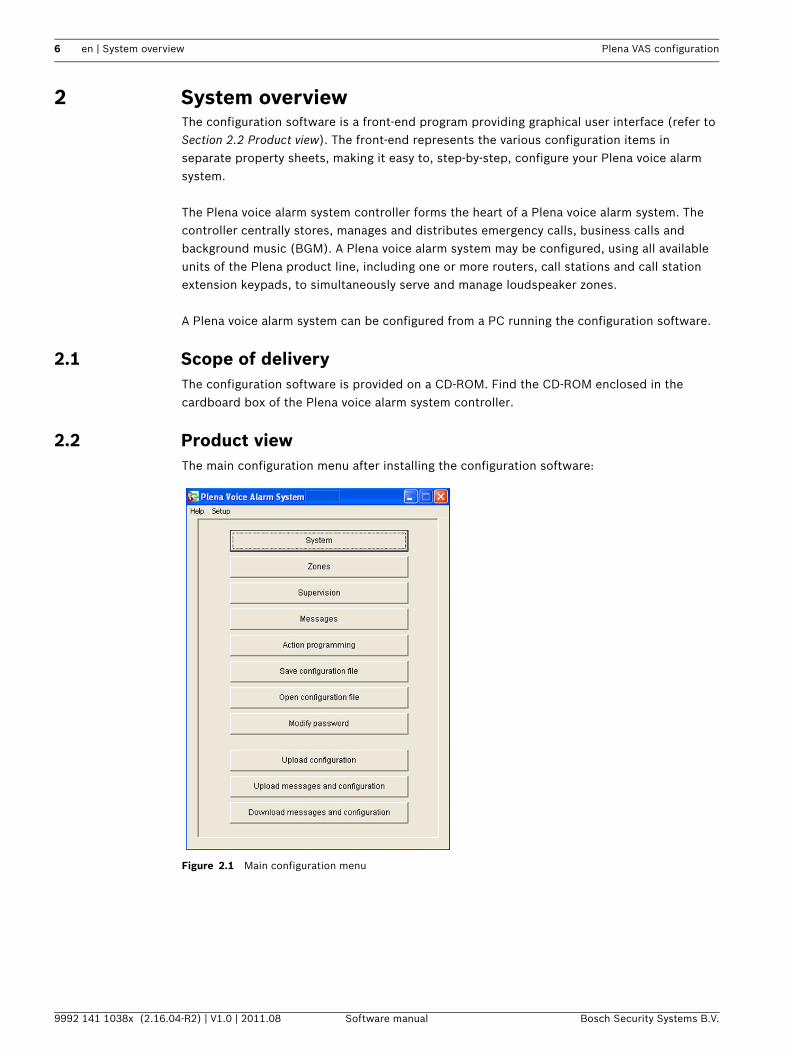
2.2 Product viewThe main configuration menu after installing the configuration software:
Figure 2.1 Main configuration menu
Plena VAS configuration Getting started | en 7
Bosch Security Systems B.V. Software manual 9992 141 1038x (2.16.04-R2) | V1.0 | 2011.08
3 Getting startedThis section describes how to install the configuration software, connect a PC to the Plena voice alarm system controller (LBB1990/00), start the software and provides information about the user interface (main configuration menu).
3.1 System requirementsThe configuration software can be installed on any PC running the Microsoft Windows 2000 or Microsoft Windows XP operating system. Make sure that the PC is working correctly and free of viruses before installing the software.
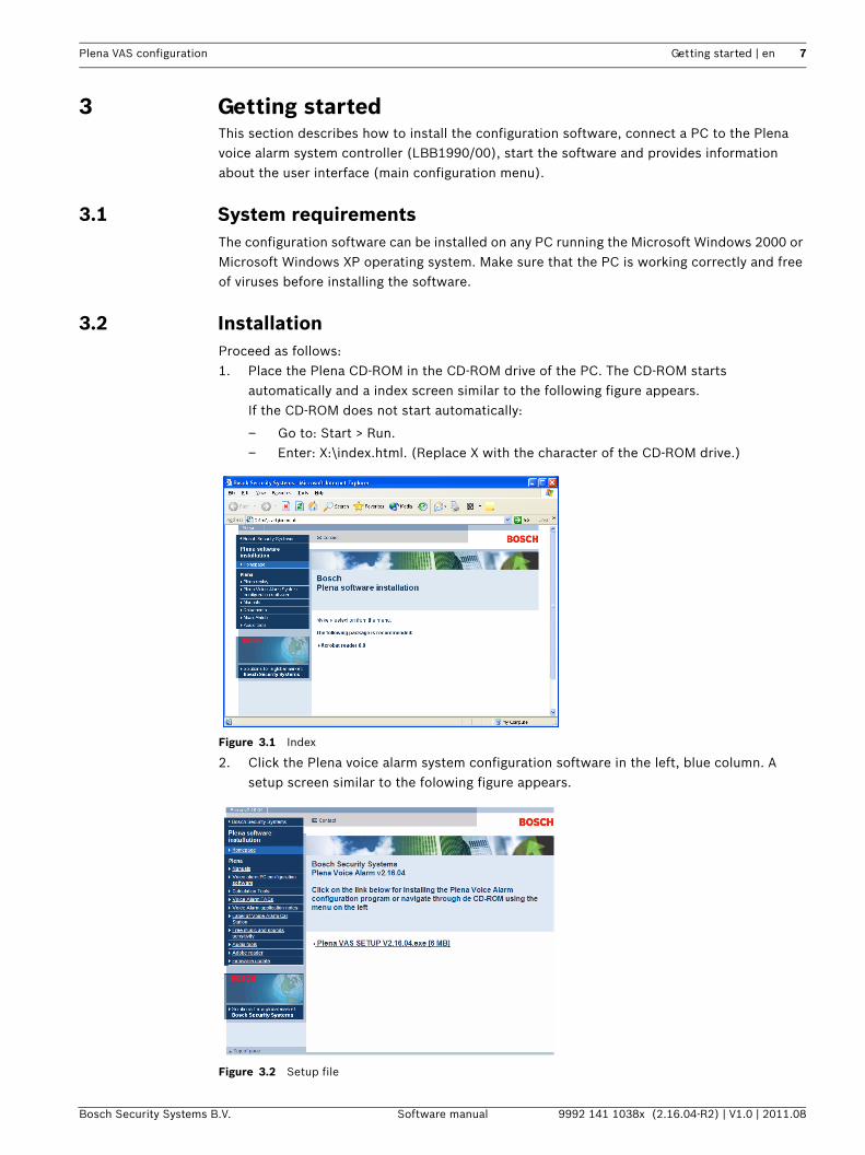
3.2 InstallationProceed as follows:1. Place the Plena CD-ROM in the CD-ROM drive of the PC. The CD-ROM starts
automatically and a index screen similar to the following figure appears.If the CD-ROM does not start automatically:
– Go to: Start > Run.– Enter: X:\index.html. (Replace X with the character of the CD-ROM drive.)
Figure 3.1 Index
2. Click the Plena voice alarm system configuration software in the left, blue column. A setup screen similar to the folowing figure appears.
Figure 3.2 Setup file
8 en | Getting started Plena VAS configuration
9992 141 1038x (2.16.04-R2) | V1.0 | 2011.08 Software manual Bosch Security Systems B.V.
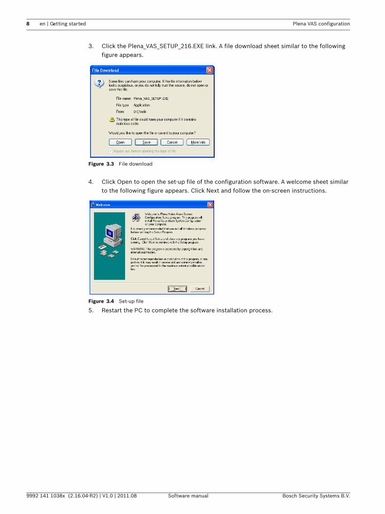
3. Click the Plena_VAS_SETUP_216.EXE link. A file download sheet similar to the following figure appears.
Figure 3.3 File download
4. Click Open to open the set-up file of the configuration software. A welcome sheet similar to the following figure appears. Click Next and follow the on-screen instructions.
Figure 3.4 Set-up file
5. Restart the PC to complete the software installation process.
Plena VAS configuration Getting started | en 9
Bosch Security Systems B.V. Software manual 9992 141 1038x (2.16.04-R2) | V1.0 | 2011.08
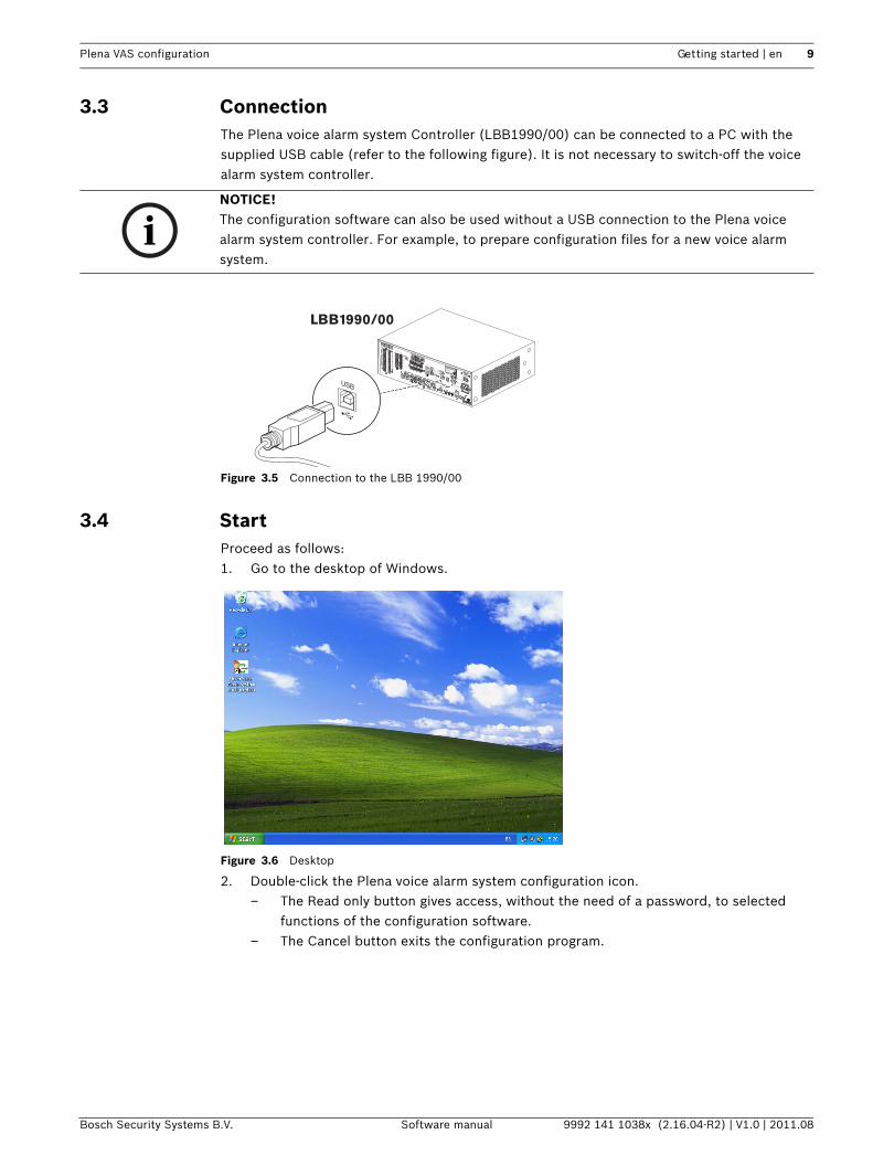
3.3 ConnectionThe Plena voice alarm system Controller (LBB1990/00) can be connected to a PC with the supplied USB cable (refer to the following figure). It is not necessary to switch-off the voice alarm system controller.
Figure 3.5 Connection to the LBB 1990/00
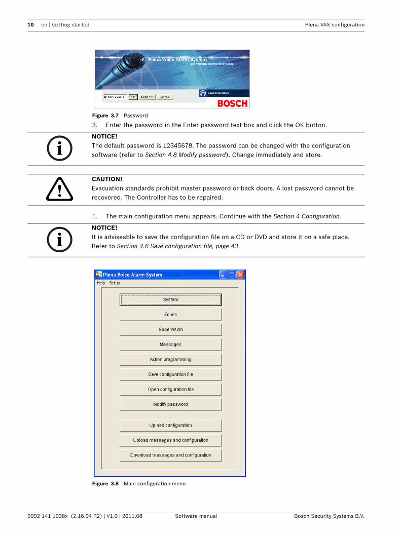
3.4 StartProceed as follows:1. Go to the desktop of Windows.
Figure 3.6 Desktop
2. Double-click the Plena voice alarm system configuration icon.– The Read only button gives access, without the need of a password, to selected
functions of the configuration software.– The Cancel button exits the configuration program.
NOTICE! The configuration software can also be used without a USB connection to the Plena voice alarm system controller. For example, to prepare configuration files for a new voice alarm system.
COM
NCNO
10k10k
Trigger input/24V DC out
Business
Emergency
NC
TRG2
Override/Trigger Output
AUX
L
R
PC
DigitalMessageMonitoringSpeaker
Remote Control Panel
ImpedanceCalibration
In
LBB 1990/00 8900 199 00001
Plena Voice Alarm Controller
Max. output power 360W
Rated output power 240W
115-230V~, 50/60HzS/N.
Design & QualityThe Netherlands
N663
Phantom power
Z1
Z2
Z3
Z4
Z5
Z6
ExtBoosterIn
DC In
100V
0
TRG 1
IntBooster
Out
24V
EMG
Fault
Call
External Booster
Out
CD/Tuner
SEL1SEL0FirmwareUpgrade
MonitorAPR modeSupervision2ch operationLBB1994
Off
On
USB
VoxSpeech filterMic/Line
Vox
LBB1994
Rated input power:760VALine fuseT6.3L250V for230V AC
T10L250V for115V AC
115V~230V~
Apparatus deliveredConnected for 230V~
Power
Router
WarningThis apparatus must be earthed
100V
0
100V
0
100V
0
100V
0
100V
0
100V
0
24V70V
Z1
Z2
Z3
Z4
Z5
Z6
GND
Fireman's panel
1 2 3 4 5 61 2 3 4 5 6
1 2 3 4 5 6
Off
On
Off
On
Call stationFor service only
GND
24VDC out
VOXSwitch
VOX Switch
1 2 3 4 5 6
NCCOMNO
NCCOMNO
NCCOMNO
100V
0
Call out
100V
0
100V
0
100V
0
100V
0
100V
0
100V
0
Z2
Z3
Z4
Z5
Z6
Z1
A
B
NO
24VDC out
24V
1 Channel2 Channel
Int BoosterExt Booster
BGM/Spare
N.C./Spare
Call
BGM/Call
Volume Override
100V
Mad
ein
Chi
na
1
2
1
2
USB
LBB1990/00
10 en | Getting started Plena VAS configuration
9992 141 1038x (2.16.04-R2) | V1.0 | 2011.08 Software manual Bosch Security Systems B.V.
Figure 3.7 Password
3. Enter the password in the Enter password text box and click the OK button.
1. The main configuration menu appears. Continue with the Section 4 Configuration.
Figure 3.8 Main configuration menu
NOTICE! The default password is 12345678. The password can be changed with the configuration software (refer to Section 4.8 Modify password). Change immediately and store.
CAUTION! Evacuation standards prohibit master password or back doors. A lost password cannot be recovered. The Controller has to be repaired.
NOTICE! It is adviseable to save the configuration file on a CD or DVD and store it on a safe place.Refer to Section 4.6 Save configuration file, page 43.
Plena VAS configuration Configuration | en 11
Bosch Security Systems B.V. Software manual 9992 141 1038x (2.16.04-R2) | V1.0 | 2011.08
4 ConfigurationA Plena voice alarm system always contains one Plena voice alarm system Controller (LBB1990/00). It is not possible to change the number of the voice alarm system controller with the configuration software.
The main configuration menu gives access to all functions of the configuration software.
Refer to the Plena voice alarm system Installation and Operation Manual (9922 141 1037x) for information about the hardware configuration of the system.
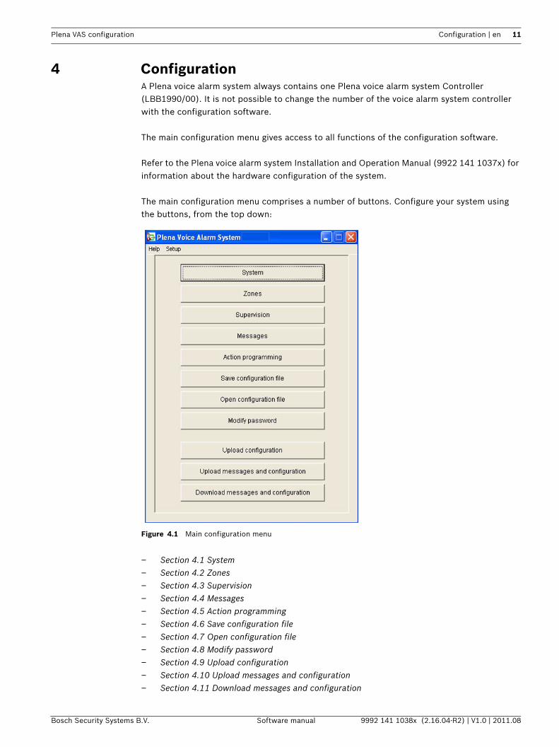
The main configuration menu comprises a number of buttons. Configure your system using the buttons, from the top down:
Figure 4.1 Main configuration menu
– Section 4.1 System– Section 4.2 Zones– Section 4.3 Supervision– Section 4.4 Messages– Section 4.5 Action programming– Section 4.6 Save configuration file– Section 4.7 Open configuration file– Section 4.8 Modify password– Section 4.9 Upload configuration– Section 4.10 Upload messages and configuration– Section 4.11 Download messages and configuration
12 en | Configuration Plena VAS configuration
9992 141 1038x (2.16.04-R2) | V1.0 | 2011.08 Software manual Bosch Security Systems B.V.
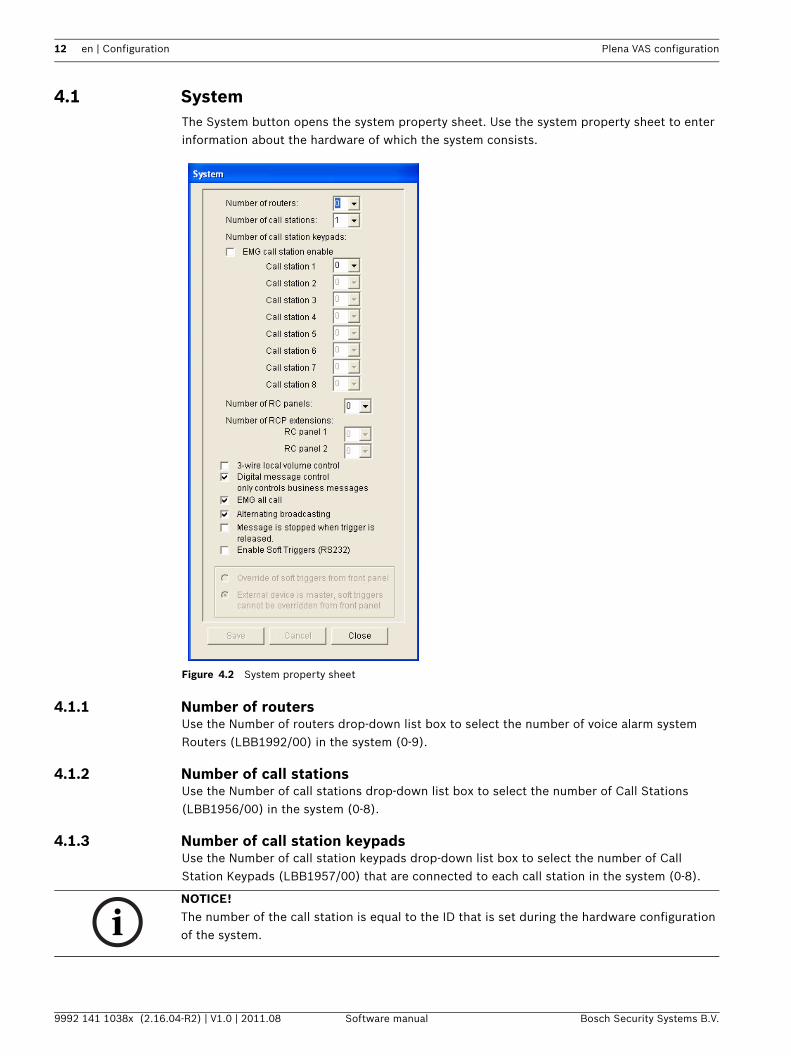
4.1 SystemThe System button opens the system property sheet. Use the system property sheet to enter information about the hardware of which the system consists.
Figure 4.2 System property sheet
4.1.1 Number of routersUse the Number of routers drop-down list box to select the number of voice alarm system Routers (LBB1992/00) in the system (0-9).
4.1.2 Number of call stationsUse the Number of call stations drop-down list box to select the number of Call Stations (LBB1956/00) in the system (0-8).
4.1.3 Number of call station keypadsUse the Number of call station keypads drop-down list box to select the number of Call Station Keypads (LBB1957/00) that are connected to each call station in the system (0-8).
NOTICE! The number of the call station is equal to the ID that is set during the hardware configuration of the system.
Plena VAS configuration Configuration | en 13
Bosch Security Systems B.V. Software manual 9992 141 1038x (2.16.04-R2) | V1.0 | 2011.08
4.1.4 EMG call station enableThis function is not implemented (available for future use). Select the EMG (Emergency) call station enable (all call) check box to enable the use of an emergency call station in the system. Call station 1 changes into EMG call station.
4.1.5 Number of RC panelsUse the Number of RC panels drop-down list box to select the number of remote controls (LBB1995/00, LBB1996/00 and LBB1997/00) used in the system (0-2).
4.1.6 Number of RCP extensionsUse the Number of RCP extensions drop-down list box to select the number of remote control extensions (LBB1998/00 and LBB1999/00) that are connected to each remote control panel used in the system (0-9).
4.1.7 3-wire local volume controlSelect the 3-wire local volume control check box if the system uses 3-wire volume override. If the system uses 4-wire volume override, make sure that the 3-wire local volume control check box is cleared.
4.1.8 Digital message control only controls business messagesSelect the Digital message control only controls business messages check box when the digital-message volume-control on the voice alarm system controller rear panel controls the sound volume for business messages only, and not for emergency messages.
4.1.9 EMG all callSelect the EMG all call check box if the Fireman must only be able to initiate all zones calls. Therefore the voice alarm system controller and the remote control disables all zone buttons on the front panel.
4.1.10 Alternating broadcastingSelect the Alternating broadcast check box to enable two or more none mergeable messages of equal priority each to be broadcast to a different zone or zone group. When disabled, only the first message will be broadcast.
4.1.11 Message is stopped when trigger is releasedSelect the Message is stopped when trigger is released check box to stop the message as soon as the trigger is released. Otherwise the message is completed, then stopped.
NOTICE! When alternating broadcasting is used, it is not possible to add or delete zones while a call is being broadcast. Routing by configuration only.
14 en | Configuration Plena VAS configuration
9992 141 1038x (2.16.04-R2) | V1.0 | 2011.08 Software manual Bosch Security Systems B.V.
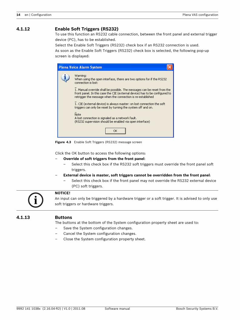
4.1.12 Enable Soft Triggers (RS232)To use this function an RS232 cable connection, between the front panel and external trigger device (PC), has to be established.Select the Enable Soft Triggers (RS232) check box if an RS232 connection is used.As soon as the Enable Soft Triggers (RS232) check box is selected, the following pop-up screen is displayed:
Figure 4.3 Enable Soft Triggers (RS232) message screen
Click the OK button to access the following options:– Override of soft triggers from the front panel:
– Select this check box if the RS232 soft triggers must override the front panel soft triggers.
– External device is master, soft triggers cannot be overridden from the front panel:– Select this check box if the front panel may not override the RS232 external device
(PC) soft triggers.
4.1.13 ButtonsThe buttons at the bottom of the System configuration property sheet are used to:– Save the System configuration changes.– Cancel the System configuration changes.– Close the System configuration property sheet.
NOTICE! An input can only be triggered by a hardware trigger or a soft trigger. It is advised to only use soft triggers or hardware triggers.
Plena VAS configuration Configuration | en 15
Bosch Security Systems B.V. Software manual 9992 141 1038x (2.16.04-R2) | V1.0 | 2011.08
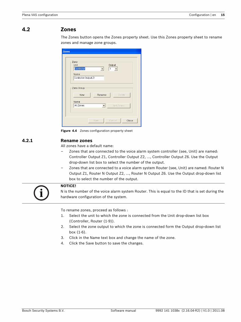
4.2 ZonesThe Zones button opens the Zones property sheet. Use this Zones property sheet to rename zones and manage zone groups.
Figure 4.4 Zones configuration property sheet
4.2.1 Rename zonesAll zones have a default name:– Zones that are connected to the voice alarm system controller (see, Unit) are named:
Controller Output Z1, Controller Output Z2, ..., Controller Output Z6. Use the Output drop-down list box to select the number of the output.
– Zones that are connected to a voice alarm system Router (see, Unit) are named: Router N Output Z1, Router N Output Z2, ..., Router N Output Z6. Use the Output drop-down list box to select the number of the output.
To rename zones, proceed as follows :1. Select the unit to which the zone is connected from the Unit drop-down list box
(Controller, Router (1-9)).2. Select the zone output to which the zone is connected form the Output drop-down list
box (1-6).3. Click in the Name text box and change the name of the zone.4. Click the Save button to save the changes.
NOTICE! N is the number of the voice alarm system Router. This is equal to the ID that is set during the hardware configuration of the system.
16 en | Configuration Plena VAS configuration
9992 141 1038x (2.16.04-R2) | V1.0 | 2011.08 Software manual Bosch Security Systems B.V.
4.2.2 Zone GroupZone Group combines related zones and makes it possible to select multiple zones at the same time. For example; in a hotel, the following zones could be added to the zone group Floors: Floor1, Floor2, Floor3 etc.
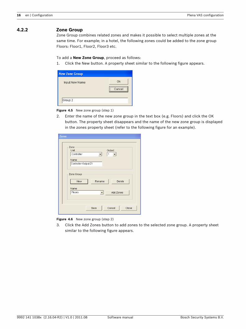
To add a New Zone Group, proceed as follows:1. Click the New button. A property sheet similar to the following figure appears.
Figure 4.5 New zone group (step 1)
2. Enter the name of the new zone group in the text box (e.g. Floors) and click the OK button. The property sheet disappears and the name of the new zone group is displayed in the zones property sheet (refer to the following figure for an example).
Figure 4.6 New zone group (step 2)
3. Click the Add Zones button to add zones to the selected zone group. A property sheet similar to the following figure appears.
Plena VAS configuration Configuration | en 17
Bosch Security Systems B.V. Software manual 9992 141 1038x (2.16.04-R2) | V1.0 | 2011.08
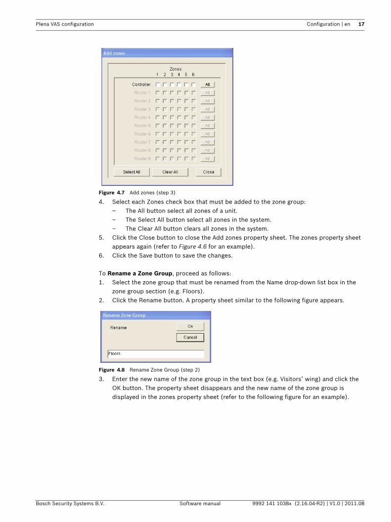
Figure 4.7 Add zones (step 3)
4. Select each Zones check box that must be added to the zone group:– The All button select all zones of a unit.– The Select All button select all zones in the system.– The Clear All button clears all zones in the system.
5. Click the Close button to close the Add zones property sheet. The zones property sheet appears again (refer to Figure 4.6 for an example).
6. Click the Save button to save the changes.
To Rename a Zone Group, proceed as follows:1. Select the zone group that must be renamed from the Name drop-down list box in the
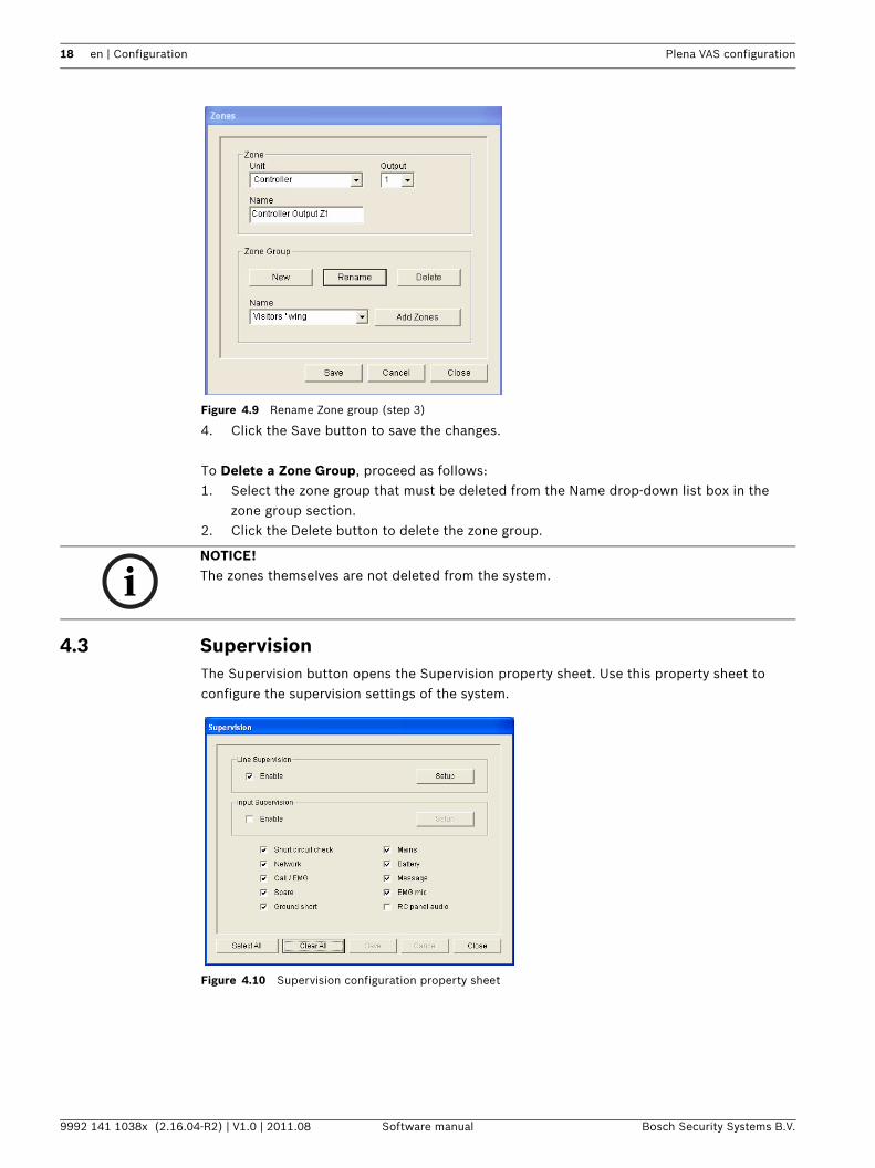
zone group section (e.g. Floors).2. Click the Rename button. A property sheet similar to the following figure appears.
Figure 4.8 Rename Zone Group (step 2)
3. Enter the new name of the zone group in the text box (e.g. Visitors’ wing) and click the OK button. The property sheet disappears and the new name of the zone group is displayed in the zones property sheet (refer to the following figure for an example).
18 en | Configuration Plena VAS configuration
9992 141 1038x (2.16.04-R2) | V1.0 | 2011.08 Software manual Bosch Security Systems B.V.
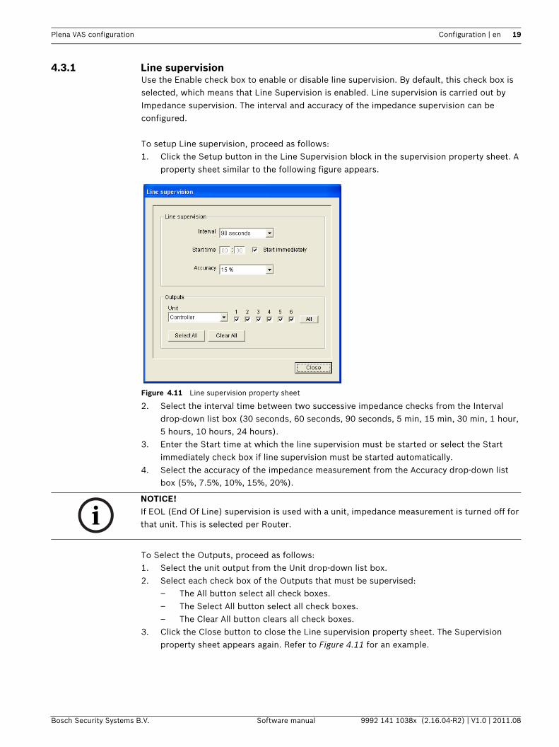
Figure 4.9 Rename Zone group (step 3)
4. Click the Save button to save the changes.
To Delete a Zone Group, proceed as follows:1. Select the zone group that must be deleted from the Name drop-down list box in the
zone group section.2. Click the Delete button to delete the zone group.
4.3 SupervisionThe Supervision button opens the Supervision property sheet. Use this property sheet to configure the supervision settings of the system.
Figure 4.10 Supervision configuration property sheet
NOTICE! The zones themselves are not deleted from the system.
Plena VAS configuration Configuration | en 19
Bosch Security Systems B.V. Software manual 9992 141 1038x (2.16.04-R2) | V1.0 | 2011.08
4.3.1 Line supervisionUse the Enable check box to enable or disable line supervision. By default, this check box is selected, which means that Line Supervision is enabled. Line supervision is carried out by Impedance supervision. The interval and accuracy of the impedance supervision can be configured.
To setup Line supervision, proceed as follows:1. Click the Setup button in the Line Supervision block in the supervision property sheet. A
property sheet similar to the following figure appears.
Figure 4.11 Line supervision property sheet
2. Select the interval time between two successive impedance checks from the Interval drop-down list box (30 seconds, 60 seconds, 90 seconds, 5 min, 15 min, 30 min, 1 hour, 5 hours, 10 hours, 24 hours).
3. Enter the Start time at which the line supervision must be started or select the Start immediately check box if line supervision must be started automatically.
4. Select the accuracy of the impedance measurement from the Accuracy drop-down list box (5%, 7.5%, 10%, 15%, 20%).
To Select the Outputs, proceed as follows:1. Select the unit output from the Unit drop-down list box.2. Select each check box of the Outputs that must be supervised:
– The All button select all check boxes.– The Select All button select all check boxes.– The Clear All button clears all check boxes.
3. Click the Close button to close the Line supervision property sheet. The Supervision property sheet appears again. Refer to Figure 4.11 for an example.
NOTICE! If EOL (End Of Line) supervision is used with a unit, impedance measurement is turned off for that unit. This is selected per Router.
20 en | Configuration Plena VAS configuration
9992 141 1038x (2.16.04-R2) | V1.0 | 2011.08 Software manual Bosch Security Systems B.V.
4.3.2 Input supervisionUse the Enable check box to enable or disable input supervision. By default, this check box is not selected, which means that Input Supervision is disabled. Input supervision can be configured for:– Each emergency trigger input in the system.– The mic/line input of the voice alarm system controller.
To Setup input supervision, proceed as follows:1. Click the Setup button in the Input Supervision section of the Supervision property
sheet. A property sheet similar to the following figure appears.
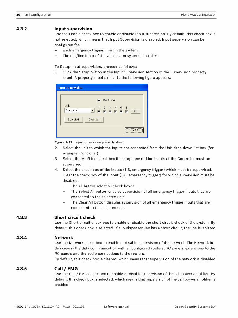
Figure 4.12 Input supervision property sheet
2. Select the unit to which the inputs are connected from the Unit drop-down list box (for example: Controller).
3. Select the Mic/Line check box if microphone or Line inputs of the Controller must be supervised.
4. Select the check box of the inputs (1-6, emergency trigger) which must be supervised. Clear the check box of the input (1-6, emergency trigger) for which supervision must be disabled.– The All button select all check boxes.– The Select All button enables supervision of all emergency trigger inputs that are
connected to the selected unit.– The Clear All button disables supervision of all emergency trigger inputs that are
connected to the selected unit.
4.3.3 Short circuit checkUse the Short circuit check box to enable or disable the short circuit check of the system. By default, this check box is selected. If a loudspeaker line has a short circuit, the line is isolated.
4.3.4 NetworkUse the Network check box to enable or disable supervision of the network. The Network in this case is the data communication with all configured routers, RC panels, extensions to the RC panels and the audio connections to the routers.By default, this check box is cleared, which means that supervision of the network is disabled.
4.3.5 Call / EMGUse the Call / EMG check box to enable or disable supervision of the call power amplifier. By default, this check box is selected, which means that supervision of the call power amplifier is enabled.
Plena VAS configuration Configuration | en 21
Bosch Security Systems B.V. Software manual 9992 141 1038x (2.16.04-R2) | V1.0 | 2011.08
4.3.6 SpareUse the Spare check box to enable or disable supervision of the spare power amplifier. By default, this check box is selected, which means that supervision of the spare power amplifier is enabled.
4.3.7 Ground shortUse the Ground short check box to enable or disable ground short supervision. By default ground short is selected (enabled) to detect a short to ground of the loudspeaker lines. The system still functions.
4.3.8 MainsUse the Mains check box to enable or disable mains power supervision. By default, this check box is selected, which means that mains power supervision is enabled.
4.3.9 BatteryUse the Battery check box to enable or disable battery supervision. By default, this check box is selected, which means that battery supervision is enabled.
4.3.10 MessageUse the Message check box to enable or disable message supervision. By default, this check box is selected, which means that message supervision is enabled.
4.3.11 EMG micUse the EMG mic check box to enable or disable supervision of the hand-held emergency microphone that is connected to the voice alarm system controller and the RCs. By default, this check box is selected, which means that the emergency microphone is enabled.
4.3.12 RC panel audioSupervises the audio BUS between the Remote Control and the Controller. By default, this check box is selected, which means that the Remote Control panel audio is enabled.
4.3.13 ButtonsThe buttons at the bottom of the Supervision configuration property sheet are used to:– Select All check boxes.– Clear All check boxes.– Save the Supervision configuration changes.– Cancel the Supervision configuration changes.– Close the Supervision configuration property sheet.
22 en | Configuration Plena VAS configuration
9992 141 1038x (2.16.04-R2) | V1.0 | 2011.08 Software manual Bosch Security Systems B.V.
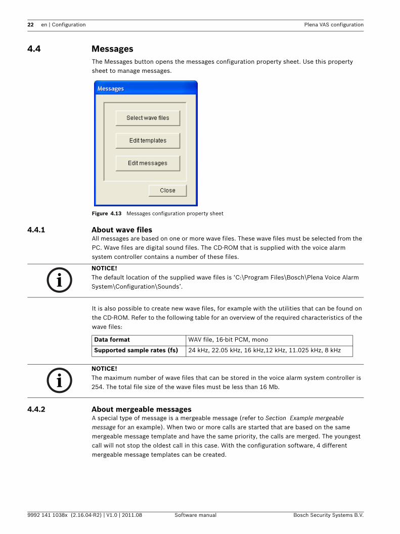
4.4 MessagesThe Messages button opens the messages configuration property sheet. Use this property sheet to manage messages.
Figure 4.13 Messages configuration property sheet
4.4.1 About wave filesAll messages are based on one or more wave files. These wave files must be selected from the PC. Wave files are digital sound files. The CD-ROM that is supplied with the voice alarm system controller contains a number of these files.
It is also possible to create new wave files, for example with the utilities that can be found on the CD-ROM. Refer to the following table for an overview of the required characteristics of the wave files:
4.4.2 About mergeable messagesA special type of message is a mergeable message (refer to Section Example mergeable message for an example). When two or more calls are started that are based on the same mergeable message template and have the same priority, the calls are merged. The youngest call will not stop the oldest call in this case. With the configuration software, 4 different mergeable message templates can be created.
NOTICE! The default location of the supplied wave files is ‘C:\Program Files\Bosch\Plena Voice Alarm System\Configuration\Sounds’.
Data format WAV file, 16-bit PCM, mono
Supported sample rates (fs) 24 kHz, 22.05 kHz, 16 kHz,12 kHz, 11.025 kHz, 8 kHz
NOTICE! The maximum number of wave files that can be stored in the voice alarm system controller is 254. The total file size of the wave files must be less than 16 Mb.
Plena VAS configuration Configuration | en 23
Bosch Security Systems B.V. Software manual 9992 141 1038x (2.16.04-R2) | V1.0 | 2011.08
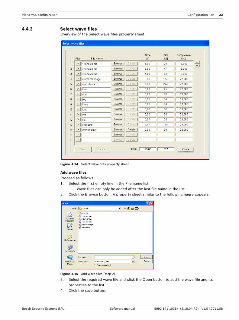
4.4.3 Select wave filesOverview of the Select wave files property sheet.
Figure 4.14 Select wave files property sheet
Add wave filesProceed as follows:1. Select the first empty line in the File name list.
– Wave files can only be added after the last file name in the list.2. Click the Browse button. A property sheet similar to the following figure appears.
Figure 4.15 Add wave files (step 2)
3. Select the required wave file and click the Open button to add the wave file and its properties to the list.
4. Click the save button.
24 en | Configuration Plena VAS configuration
9992 141 1038x (2.16.04-R2) | V1.0 | 2011.08 Software manual Bosch Security Systems B.V.
Listen to wave filesProceed as follows:1. Click the > button in the Play field of a wave file.
Remove wave filesProceed as follows:1. Click the Delete button to delete the wave file from the list.
– The wave file itself is not deleted from the PC.
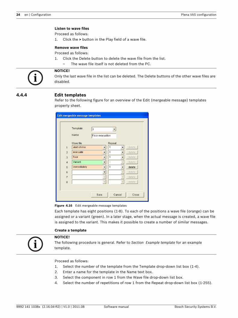
4.4.4 Edit templatesRefer to the following figure for an overview of the Edit (mergeable message) templates property sheet.
Figure 4.16 Edit mergeable message templates
Each template has eight positions (1-8). To each of the positions a wave file (orange) can be assigned or a variant (green). In a later stage, when the actual message is created, a wave file is assigned to the variant. This makes it possible to create a number of similar messages.
Create a template
Proceed as follows:1. Select the number of the template from the Template drop-down list box (1-4).2. Enter a name for the template in the Name text box.3. Select the component in row 1 from the Wave file drop-down list box.4. Select the number of repetitions of row 1 from the Repeat drop-down list box (1-255).
NOTICE! Only the last wave file in the list can be deleted. The Delete buttons of the other wave files are disabled.
NOTICE! The following procedure is general. Refer to Section Example template for an example template.
Plena VAS configuration Configuration | en 25
Bosch Security Systems B.V. Software manual 9992 141 1038x (2.16.04-R2) | V1.0 | 2011.08
5. Repeat step 2 to step 4 for all other components of the template.6. Click the Save button to save the changes.
Example templateIn this example, a template is created that is used for evacuation messages for the floors of the visitors’ wing in a hotel. The template components are:– An alert chime to attract the attention. The name of the wave file that contains the alert
chime is alert chime in this example.– Speech: ‘Due to an emergency, it is necessary to evacuate’. The name of the wave file
that contains the speech is evacuate in this example.– Speech: ‘Floor’. The name of the wave file that contains the speech is floor in this
example.– Speech that contains the number of the floor. As this is different for each floor, this
component is a Variant that is not defined until the creation of the actual message (refer to Section Example mergeable message).
– Speech: ‘Immediately’. The name of the wave file that contains the speech is immediately in this example.
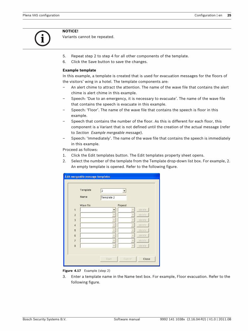
Proceed as follows:1. Click the Edit templates button. The Edit templates property sheet opens.2. Select the number of the template from the Template drop-down list box. For example, 2.
An empty template is opened. Refer to the following figure.
Figure 4.17 Example (step 2)
3. Enter a template name in the Name text box. For example, Floor evacuation. Refer to the following figure.
NOTICE! Variants cannot be repeated.
26 en | Configuration Plena VAS configuration
9992 141 1038x (2.16.04-R2) | V1.0 | 2011.08 Software manual Bosch Security Systems B.V.
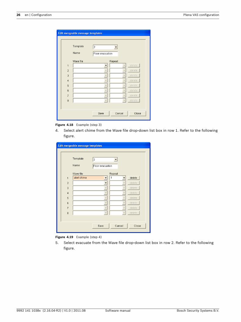
Figure 4.18 Example (step 3)
4. Select alert chime from the Wave file drop-down list box in row 1. Refer to the following figure.
Figure 4.19 Example (step 4)
5. Select evacuate from the Wave file drop-down list box in row 2. Refer to the following figure.
Plena VAS configuration Configuration | en 27
Bosch Security Systems B.V. Software manual 9992 141 1038x (2.16.04-R2) | V1.0 | 2011.08
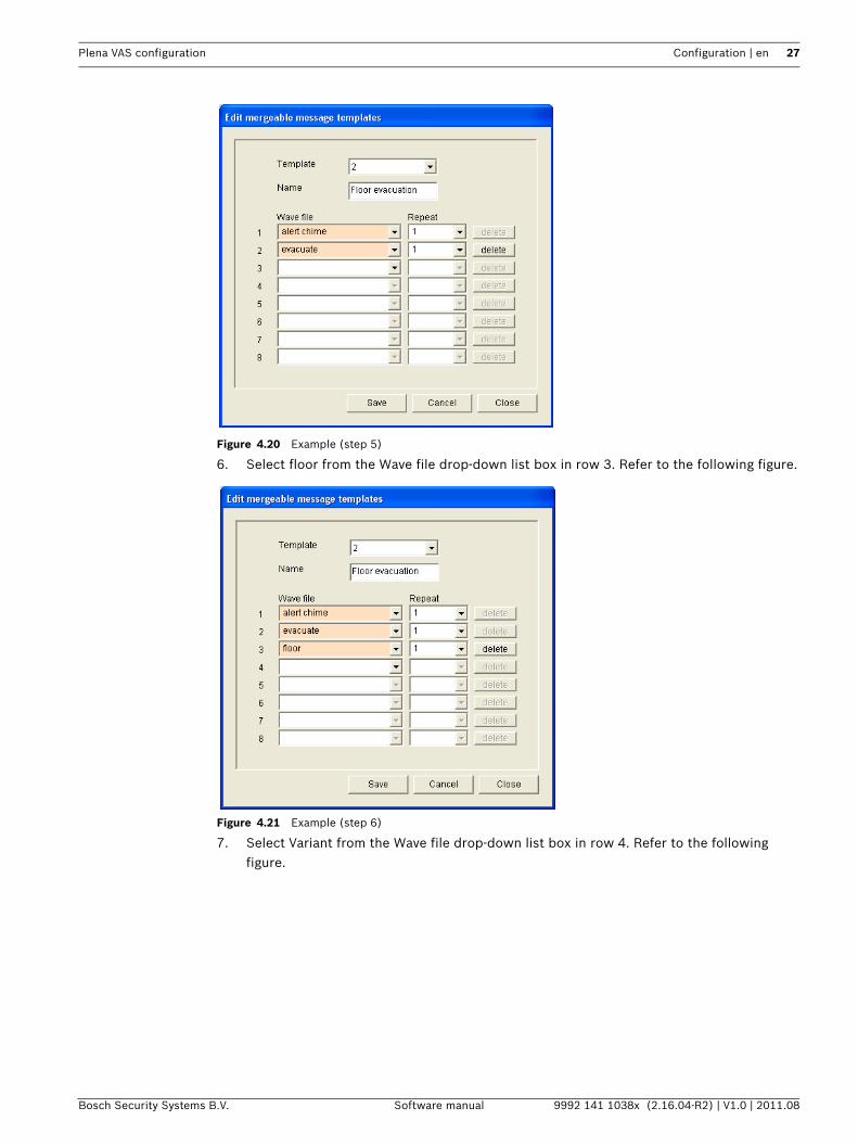
Figure 4.20 Example (step 5)
6. Select floor from the Wave file drop-down list box in row 3. Refer to the following figure.
Figure 4.21 Example (step 6)
7. Select Variant from the Wave file drop-down list box in row 4. Refer to the following figure.
28 en | Configuration Plena VAS configuration
9992 141 1038x (2.16.04-R2) | V1.0 | 2011.08 Software manual Bosch Security Systems B.V.
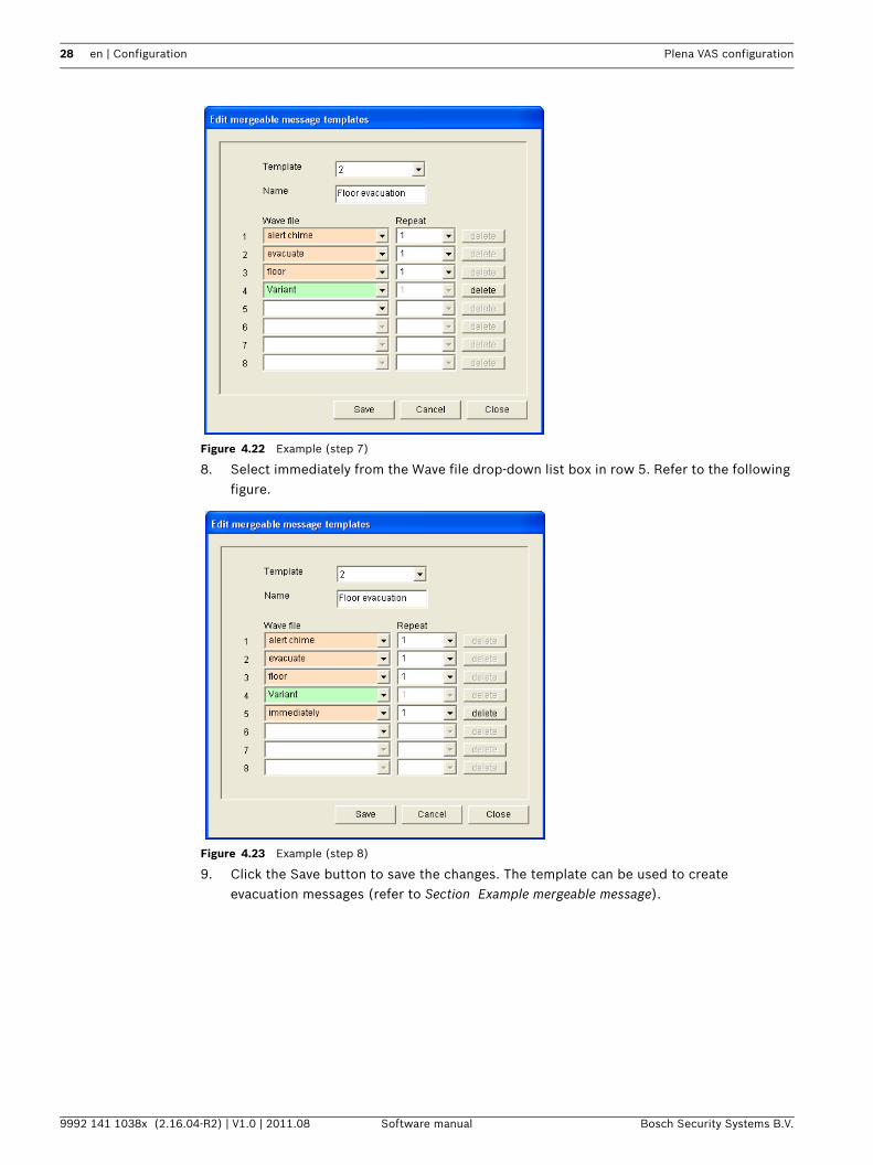
Figure 4.22 Example (step 7)
8. Select immediately from the Wave file drop-down list box in row 5. Refer to the following figure.
Figure 4.23 Example (step 8)
9. Click the Save button to save the changes. The template can be used to create evacuation messages (refer to Section Example mergeable message).
Plena VAS configuration Configuration | en 29
Bosch Security Systems B.V. Software manual 9992 141 1038x (2.16.04-R2) | V1.0 | 2011.08
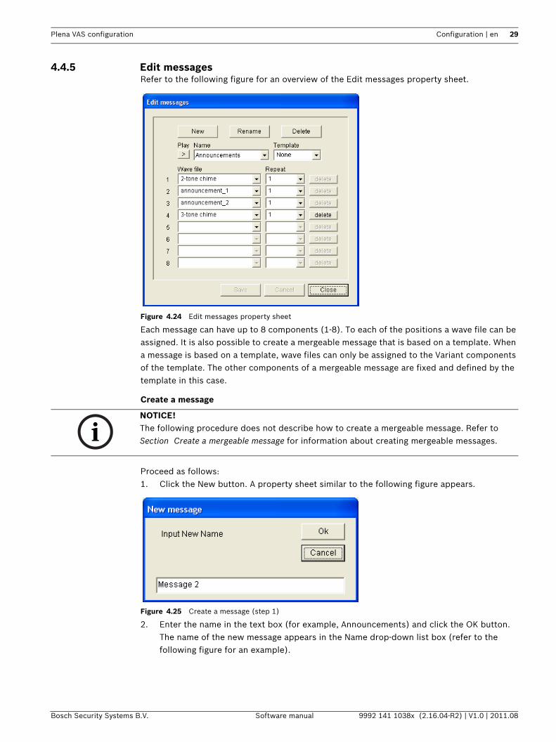
4.4.5 Edit messagesRefer to the following figure for an overview of the Edit messages property sheet.
Figure 4.24 Edit messages property sheet
Each message can have up to 8 components (1-8). To each of the positions a wave file can be assigned. It is also possible to create a mergeable message that is based on a template. When a message is based on a template, wave files can only be assigned to the Variant components of the template. The other components of a mergeable message are fixed and defined by the template in this case.
Create a message
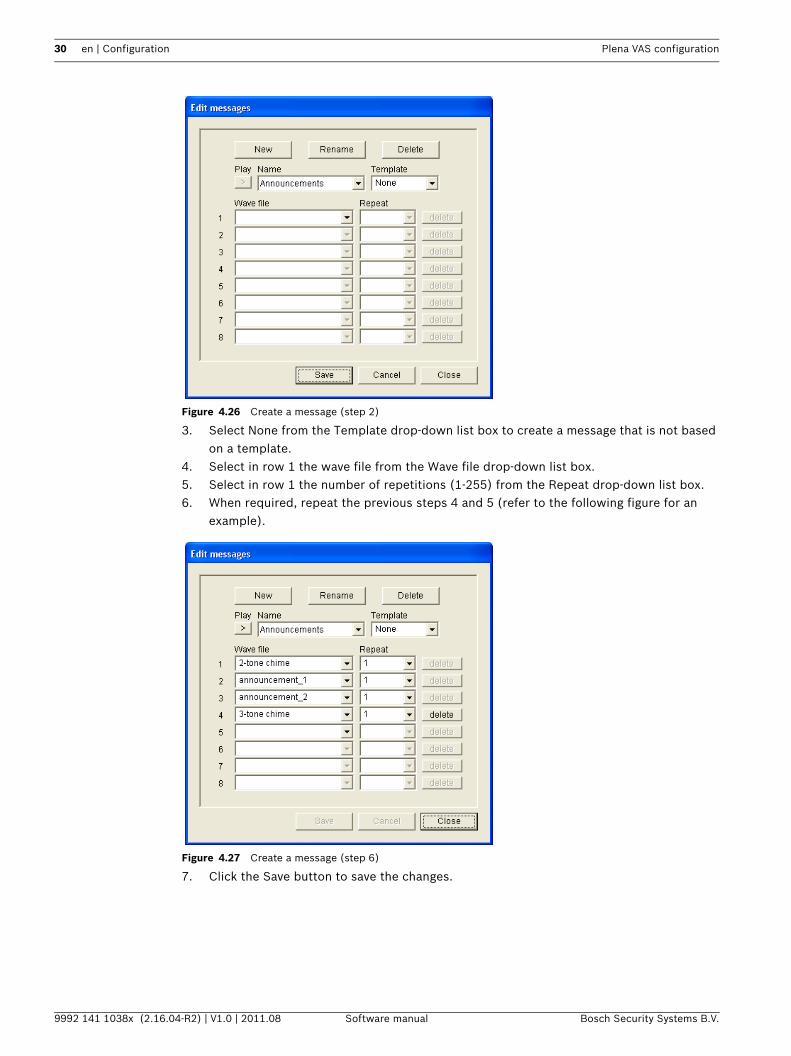
Proceed as follows:1. Click the New button. A property sheet similar to the following figure appears.
Figure 4.25 Create a message (step 1)
2. Enter the name in the text box (for example, Announcements) and click the OK button. The name of the new message appears in the Name drop-down list box (refer to the following figure for an example).
NOTICE! The following procedure does not describe how to create a mergeable message. Refer to Section Create a mergeable message for information about creating mergeable messages.
30 en | Configuration Plena VAS configuration
9992 141 1038x (2.16.04-R2) | V1.0 | 2011.08 Software manual Bosch Security Systems B.V.
Figure 4.26 Create a message (step 2)
3. Select None from the Template drop-down list box to create a message that is not based on a template.
4. Select in row 1 the wave file from the Wave file drop-down list box.5. Select in row 1 the number of repetitions (1-255) from the Repeat drop-down list box.6. When required, repeat the previous steps 4 and 5 (refer to the following figure for an
example).
Figure 4.27 Create a message (step 6)
7. Click the Save button to save the changes.
Plena VAS configuration Configuration | en 31
Bosch Security Systems B.V. Software manual 9992 141 1038x (2.16.04-R2) | V1.0 | 2011.08
Create a mergeable message
To create a mergeabe message, proceed as follows:1. Click the New button. A New message property sheet appears.2. Enter the name in the text box and click the OK button. The name of the new message
appears in the Name drop-down list box (refer to the following figure for an example).3. Select the mergeable message template from the Template drop-down list box.4. Attach wave files to the Variant components of the template. These have green Wave file
fields.5. Click the Save button to save the changes.
Example mergeable messageIn this example, a mergeable message is created that is used to evacuate floor 1 of the visitors’ wing in a hotel. The message is based on the template that was created in the previous chapter.
The template components are:– An alert chime to attract the attention. The name of the wave file that contains the alert
chime is alert chime in this example.– Speech: ‘Due to an emergency, it is necessary to evacuate’. The name of the wave file
that contains the speech is evacuate in this example.– Speech: ‘Floor’. The name of the wave file that contains the speech is floor in this
example.– Speech that contains the number of the floor. As this is different for each floor, this
component is a Variant. To this component a wave file is assigned that contains the word ‘one’. The name of the wave file that contains the speech is one in this example.
– Speech: ‘Immediately’. The name of the wave file that contains the speech is immediately in this example.
When the voice alarm system controller plays this message, the spoken part of the message is: ‘Due to an emergency, it is necessary to evacuate floor one immediately’.
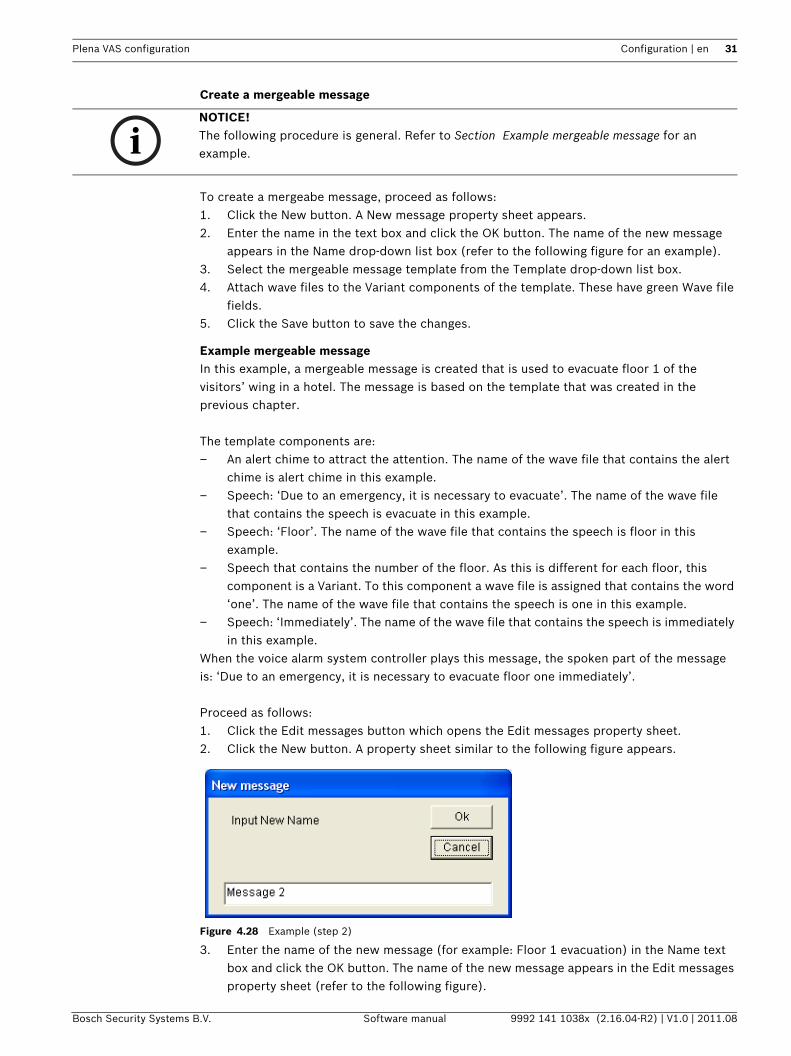
Proceed as follows:1. Click the Edit messages button which opens the Edit messages property sheet.2. Click the New button. A property sheet similar to the following figure appears.
Figure 4.28 Example (step 2)
3. Enter the name of the new message (for example: Floor 1 evacuation) in the Name text box and click the OK button. The name of the new message appears in the Edit messages property sheet (refer to the following figure).
NOTICE! The following procedure is general. Refer to Section Example mergeable message for an example.
32 en | Configuration Plena VAS configuration
9992 141 1038x (2.16.04-R2) | V1.0 | 2011.08 Software manual Bosch Security Systems B.V.
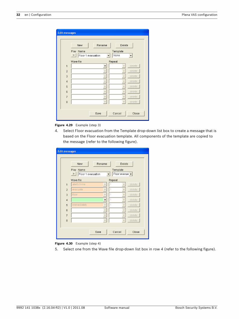
Figure 4.29 Example (step 3)
4. Select Floor evacuation from the Template drop-down list box to create a message that is based on the Floor evacuation template. All components of the template are copied to the message (refer to the following figure).
Figure 4.30 Example (step 4)
5. Select one from the Wave file drop-down list box in row 4 (refer to the following figure).
Plena VAS configuration Configuration | en 33
Bosch Security Systems B.V. Software manual 9992 141 1038x (2.16.04-R2) | V1.0 | 2011.08
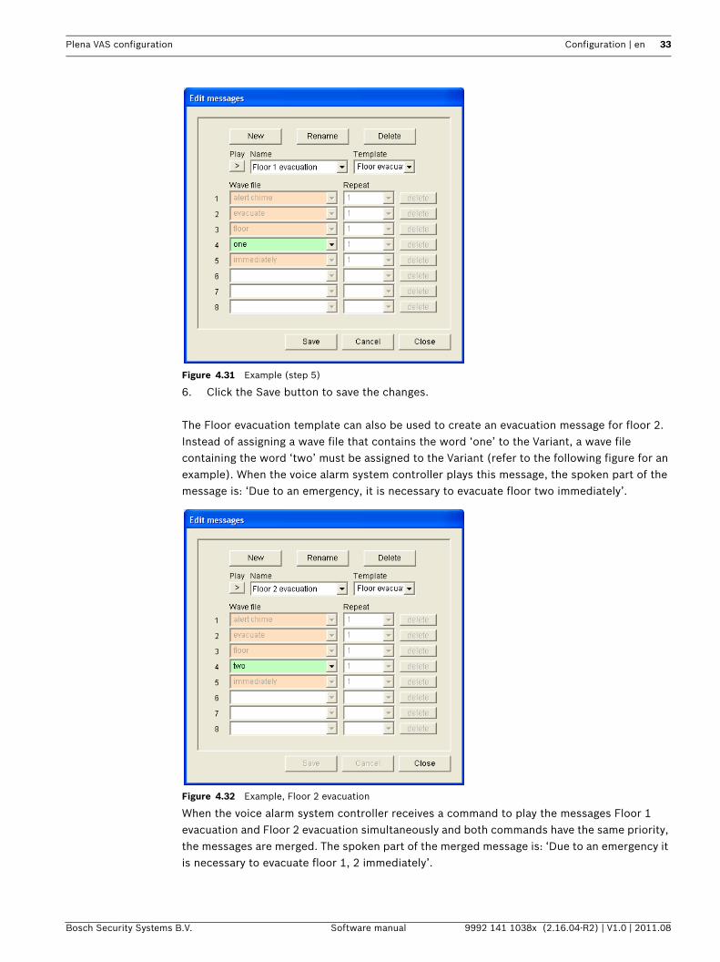
Figure 4.31 Example (step 5)
6. Click the Save button to save the changes.
The Floor evacuation template can also be used to create an evacuation message for floor 2. Instead of assigning a wave file that contains the word ‘one’ to the Variant, a wave file containing the word ‘two’ must be assigned to the Variant (refer to the following figure for an example). When the voice alarm system controller plays this message, the spoken part of the message is: ‘Due to an emergency, it is necessary to evacuate floor two immediately’.
Figure 4.32 Example, Floor 2 evacuation
When the voice alarm system controller receives a command to play the messages Floor 1 evacuation and Floor 2 evacuation simultaneously and both commands have the same priority, the messages are merged. The spoken part of the merged message is: ‘Due to an emergency it is necessary to evacuate floor 1, 2 immediately’.
34 en | Configuration Plena VAS configuration
9992 141 1038x (2.16.04-R2) | V1.0 | 2011.08 Software manual Bosch Security Systems B.V.
Listen to messagesProceed as follows:1. Click the > (Play) button.
Delete messagesProceed as follows:1. Select the message that must be deleted from the Name drop-down list box.2. Click the Delete button and confirm with yes.
Rename messages
Proceed as follows:1. Select the message from the Name drop-down list box that must be renamed.2. Click the Rename button. A property sheet similar to the following figure appears.
Figure 4.33 Rename message (step 2)
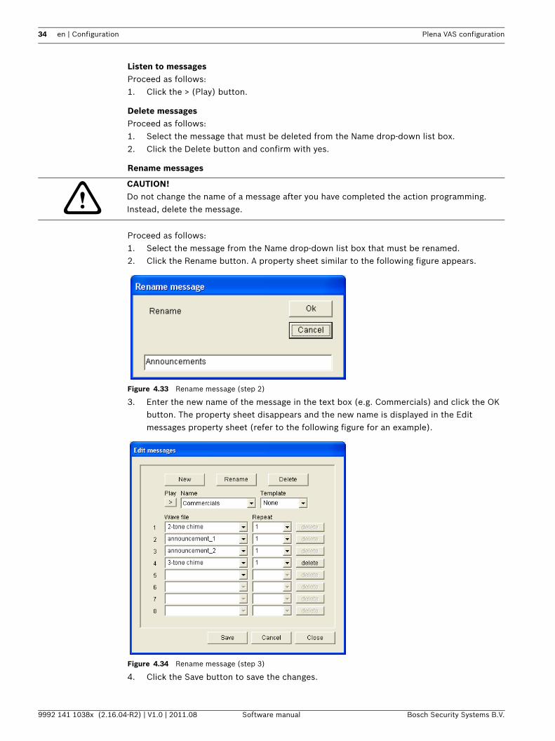
3. Enter the new name of the message in the text box (e.g. Commercials) and click the OK button. The property sheet disappears and the new name is displayed in the Edit messages property sheet (refer to the following figure for an example).
Figure 4.34 Rename message (step 3)
4. Click the Save button to save the changes.
CAUTION! Do not change the name of a message after you have completed the action programming. Instead, delete the message.
Plena VAS configuration Configuration | en 35
Bosch Security Systems B.V. Software manual 9992 141 1038x (2.16.04-R2) | V1.0 | 2011.08
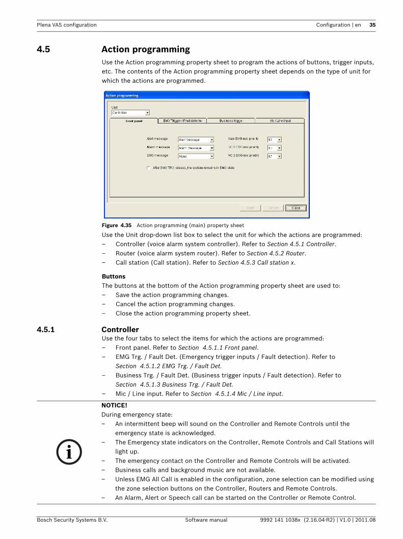
4.5 Action programmingUse the Action programming property sheet to program the actions of buttons, trigger inputs, etc. The contents of the Action programming property sheet depends on the type of unit for which the actions are programmed.
Figure 4.35 Action programming (main) property sheet
Use the Unit drop-down list box to select the unit for which the actions are programmed:– Controller (voice alarm system controller). Refer to Section 4.5.1 Controller.– Router (voice alarm system router). Refer to Section 4.5.2 Router.– Call station (Call station). Refer to Section 4.5.3 Call station x.
ButtonsThe buttons at the bottom of the Action programming property sheet are used to:– Save the action programming changes.– Cancel the action programming changes.– Close the action programming property sheet.
4.5.1 ControllerUse the four tabs to select the items for which the actions are programmed:– Front panel. Refer to Section 4.5.1.1 Front panel.– EMG Trg. / Fault Det. (Emergency trigger inputs / Fault detection). Refer to
Section 4.5.1.2 EMG Trg. / Fault Det.– Business Trg. / Fault Det. (Business trigger inputs / Fault detection). Refer to
Section 4.5.1.3 Business Trg. / Fault Det.– Mic / Line input. Refer to Section 4.5.1.4 Mic / Line input.
NOTICE! During emergency state:– An intermittent beep will sound on the Controller and Remote Controls until the
emergency state is acknowledged.– The Emergency state indicators on the Controller, Remote Controls and Call Stations will
light up.– The emergency contact on the Controller and Remote Controls will be activated.– Business calls and background music are not available.– Unless EMG All Call is enabled in the configuration, zone selection can be modified using
the zone selection buttons on the Controller, Routers and Remote Controls.– An Alarm, Alert or Speech call can be started on the Controller or Remote Control.
36 en | Configuration Plena VAS configuration
9992 141 1038x (2.16.04-R2) | V1.0 | 2011.08 Software manual Bosch Security Systems B.V.
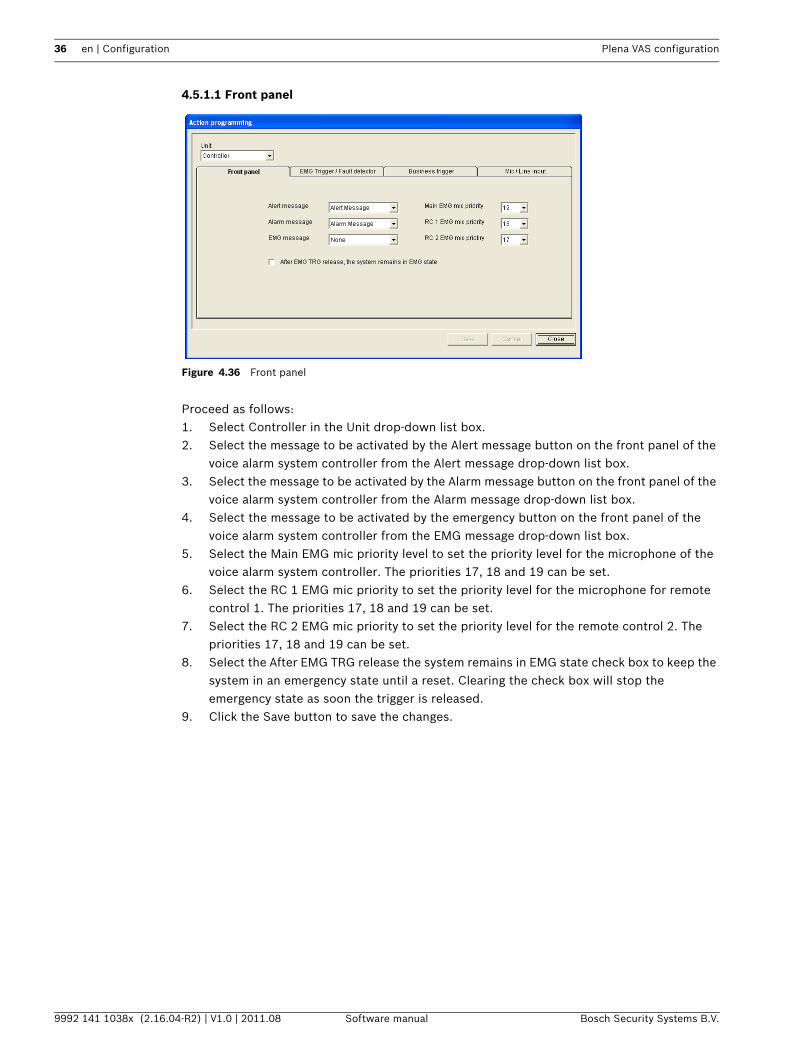
4.5.1.1 Front panel
Figure 4.36 Front panel
Proceed as follows:1. Select Controller in the Unit drop-down list box.2. Select the message to be activated by the Alert message button on the front panel of the
voice alarm system controller from the Alert message drop-down list box.3. Select the message to be activated by the Alarm message button on the front panel of the
voice alarm system controller from the Alarm message drop-down list box.4. Select the message to be activated by the emergency button on the front panel of the
voice alarm system controller from the EMG message drop-down list box.5. Select the Main EMG mic priority level to set the priority level for the microphone of the
voice alarm system controller. The priorities 17, 18 and 19 can be set.6. Select the RC 1 EMG mic priority to set the priority level for the microphone for remote
control 1. The priorities 17, 18 and 19 can be set.7. Select the RC 2 EMG mic priority to set the priority level for the remote control 2. The
priorities 17, 18 and 19 can be set.8. Select the After EMG TRG release the system remains in EMG state check box to keep the
system in an emergency state until a reset. Clearing the check box will stop the emergency state as soon the trigger is released.
9. Click the Save button to save the changes.
Plena VAS configuration Configuration | en 37
Bosch Security Systems B.V. Software manual 9992 141 1038x (2.16.04-R2) | V1.0 | 2011.08
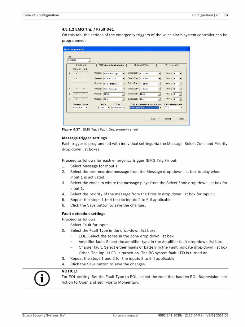
4.5.1.2 EMG Trg. / Fault Det.On this tab, the actions of the emergency triggers of the voice alarm system controller can be programmed:
Figure 4.37 EMG Trg. / Fault Det. property sheet
Message trigger settingsEach trigger is programmed with individual settings via the Message, Select Zone and Priority drop-down list boxes.
Proceed as follows for each emergency trigger (EMG Trig.) input:1. Select Message for input 1.2. Select the pre-recorded message from the Message drop-down list box to play when
input 1 is activated.3. Select the zones to where the message plays from the Select Zone drop-down list box for
input 1.4. Select the priority of the message from the Priority drop-down list box for input 1.5. Repeat the steps 1 to 4 for the inputs 2 to 6 if applicable.6. Click the Save button to save the changes.
Fault detection settingsProceed as follows:1. Select Fault for input 1.2. Select the Fault Type in the drop-down list box:
– EOL. Select the zones in the Zone drop-down list box.– Amplifier fault. Select the amplifier type in the Amplifier fault drop-down list box.– Charger fault. Select either mains or battery in the Fault indicate drop-down list box.– Other. The input LED is turned on. The RC system fault LED is turned on.
3. Repeat the steps 1 and 2 for the inputs 2 to 6 if applicable.4. Click the Save button to save the changes.
NOTICE! For EOL setting: Set the Fault Type to EOL, select the zone that has the EOL Supervision, set Action to Open and set Type to Momentary.
38 en | Configuration Plena VAS configuration
9992 141 1038x (2.16.04-R2) | V1.0 | 2011.08 Software manual Bosch Security Systems B.V.
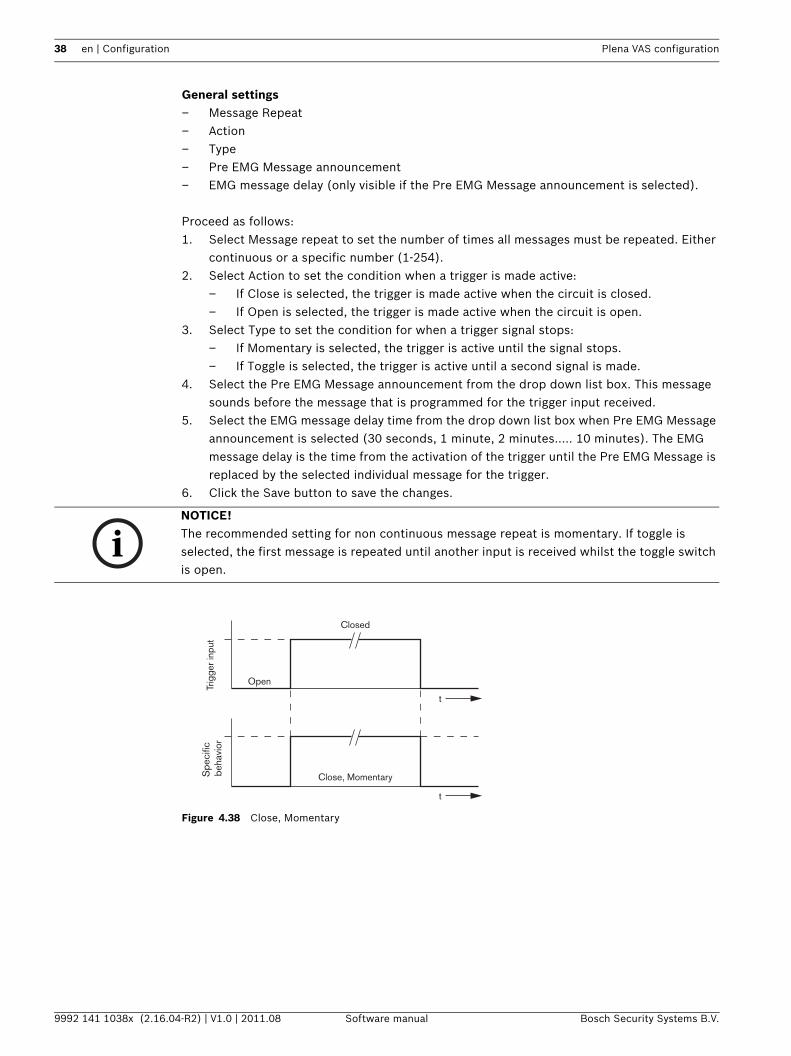
General settings– Message Repeat– Action– Type– Pre EMG Message announcement– EMG message delay (only visible if the Pre EMG Message announcement is selected).
Proceed as follows:1. Select Message repeat to set the number of times all messages must be repeated. Either
continuous or a specific number (1-254).2. Select Action to set the condition when a trigger is made active:
– If Close is selected, the trigger is made active when the circuit is closed.– If Open is selected, the trigger is made active when the circuit is open.
3. Select Type to set the condition for when a trigger signal stops:– If Momentary is selected, the trigger is active until the signal stops.– If Toggle is selected, the trigger is active until a second signal is made.
4. Select the Pre EMG Message announcement from the drop down list box. This message sounds before the message that is programmed for the trigger input received.
5. Select the EMG message delay time from the drop down list box when Pre EMG Message announcement is selected (30 seconds, 1 minute, 2 minutes..... 10 minutes). The EMG message delay is the time from the activation of the trigger until the Pre EMG Message is replaced by the selected individual message for the trigger.
6. Click the Save button to save the changes.
Figure 4.38 Close, Momentary
NOTICE! The recommended setting for non continuous message repeat is momentary. If toggle is selected, the first message is repeated until another input is received whilst the toggle switch is open.
Trig
ger i
nput
Spe
cific
beh
avio
r
t
t
Open
Closed
Close, Momentary
Plena VAS configuration Configuration | en 39
Bosch Security Systems B.V. Software manual 9992 141 1038x (2.16.04-R2) | V1.0 | 2011.08
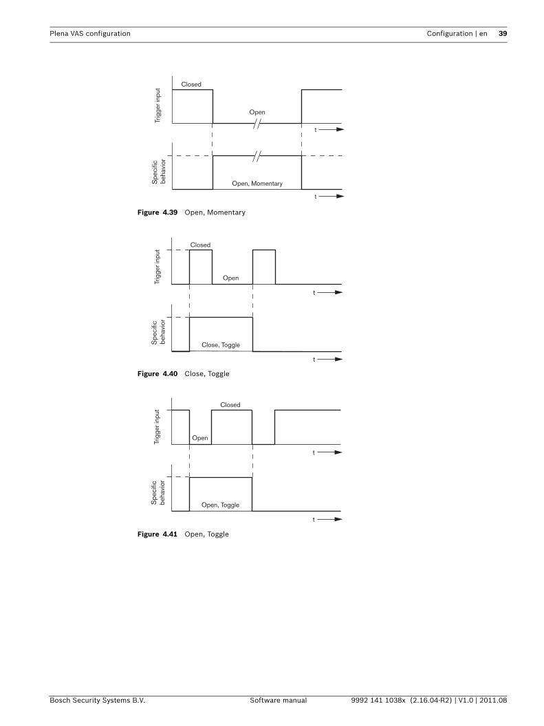
Figure 4.39 Open, Momentary
Figure 4.40 Close, Toggle
Figure 4.41 Open, Toggle
t
Closed
Open
Trig
ger i
nput
Spe
cific
be
havi
or
t
Open, Momentary
t
t
Open
Closed
Trig
ger i
nput
Spe
cific
beh
avio
r
Close, Toggle
t
t
Closed
Open
Trig
ger i
nput
Spe
cific
beha
vior
Open, Toggle
40 en | Configuration Plena VAS configuration
9992 141 1038x (2.16.04-R2) | V1.0 | 2011.08 Software manual Bosch Security Systems B.V.
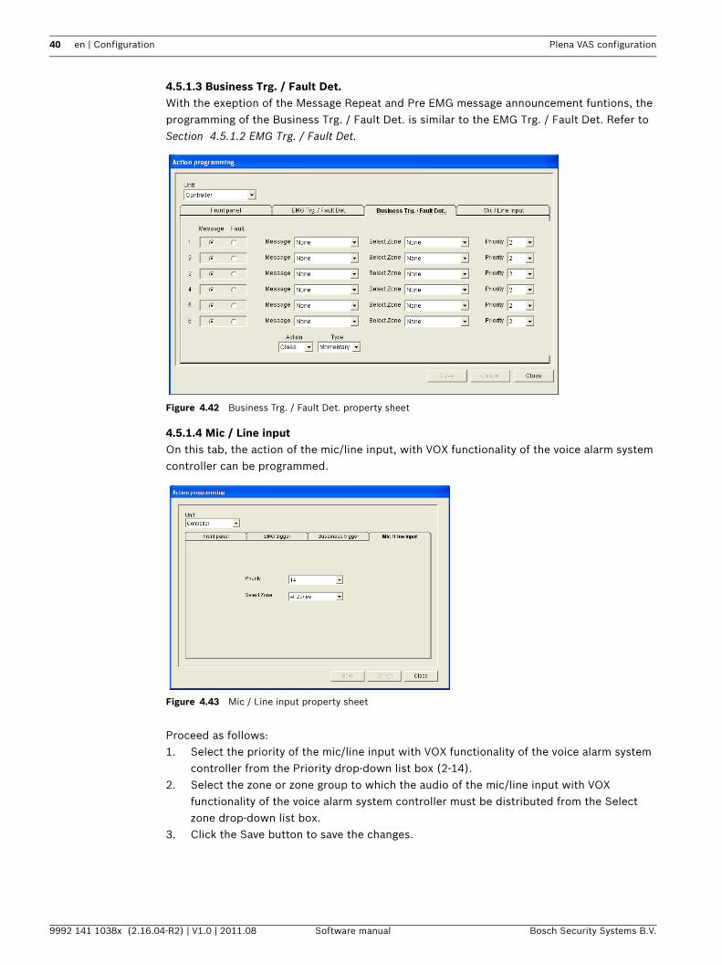
4.5.1.3 Business Trg. / Fault Det.With the exeption of the Message Repeat and Pre EMG message announcement funtions, the programming of the Business Trg. / Fault Det. is similar to the EMG Trg. / Fault Det. Refer to Section 4.5.1.2 EMG Trg. / Fault Det.
Figure 4.42 Business Trg. / Fault Det. property sheet
4.5.1.4 Mic / Line inputOn this tab, the action of the mic/line input, with VOX functionality of the voice alarm system controller can be programmed.
Figure 4.43 Mic / Line input property sheet
Proceed as follows:1. Select the priority of the mic/line input with VOX functionality of the voice alarm system
controller from the Priority drop-down list box (2-14).2. Select the zone or zone group to which the audio of the mic/line input with VOX
functionality of the voice alarm system controller must be distributed from the Select zone drop-down list box.
3. Click the Save button to save the changes.
Plena VAS configuration Configuration | en 41
Bosch Security Systems B.V. Software manual 9992 141 1038x (2.16.04-R2) | V1.0 | 2011.08
4.5.2 RouterSelect Router in the Unit drop-down list box.– Programming of the emergency trigger inputs of a voice alarm system router is similar to
programming of the emergency triggers inputs of a voice alarm system controller. Refer to Section 4.5.1 Controller.
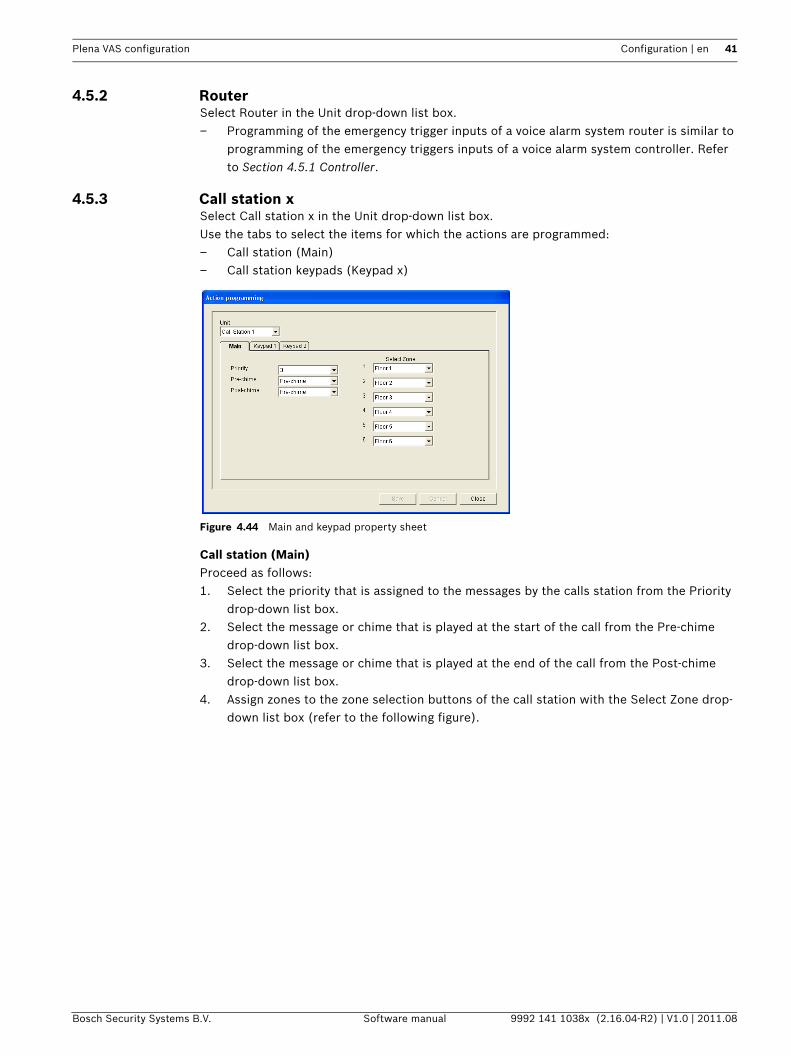
4.5.3 Call station xSelect Call station x in the Unit drop-down list box.Use the tabs to select the items for which the actions are programmed:– Call station (Main)– Call station keypads (Keypad x)
Figure 4.44 Main and keypad property sheet
Call station (Main)Proceed as follows:1. Select the priority that is assigned to the messages by the calls station from the Priority
drop-down list box.2. Select the message or chime that is played at the start of the call from the Pre-chime
drop-down list box.3. Select the message or chime that is played at the end of the call from the Post-chime
drop-down list box.4. Assign zones to the zone selection buttons of the call station with the Select Zone drop-
down list box (refer to the following figure).
42 en | Configuration Plena VAS configuration
9992 141 1038x (2.16.04-R2) | V1.0 | 2011.08 Software manual Bosch Security Systems B.V.
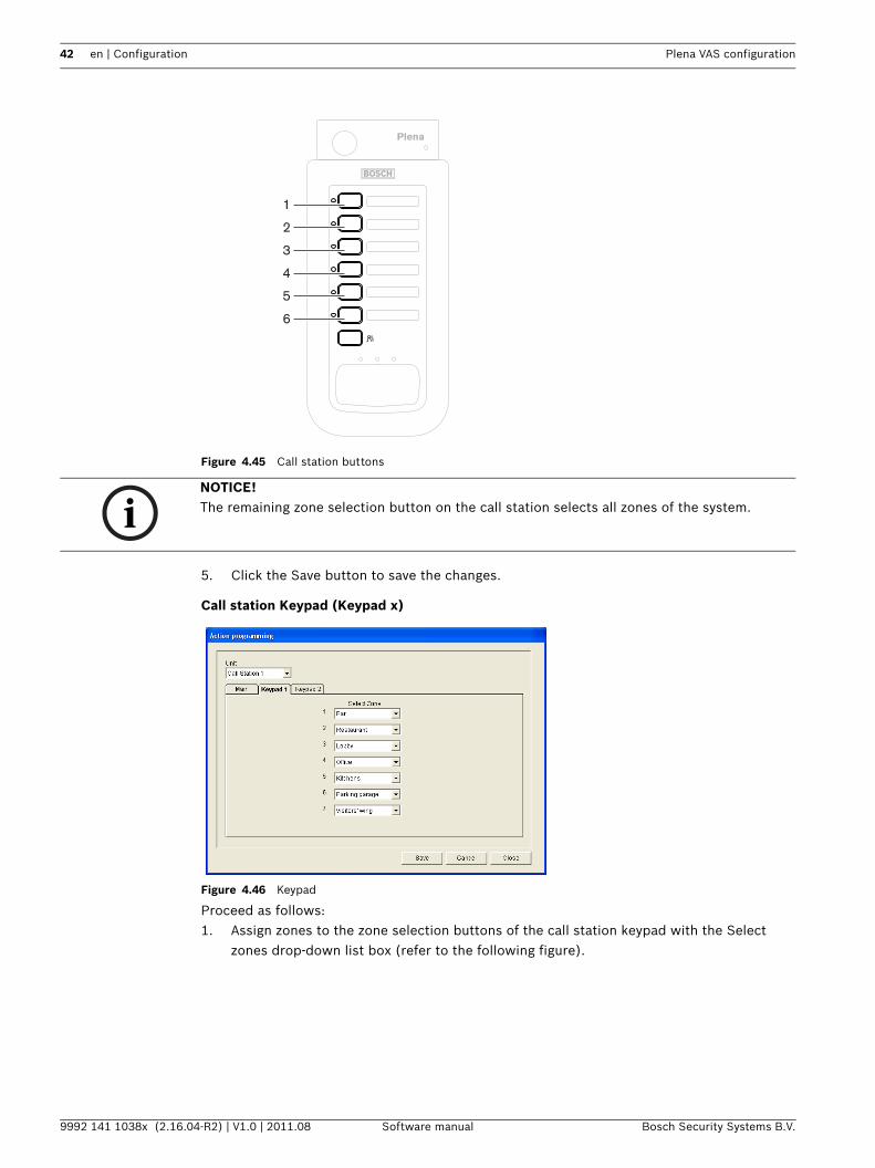
Figure 4.45 Call station buttons
5. Click the Save button to save the changes.
Call station Keypad (Keypad x)
Figure 4.46 Keypad
Proceed as follows:1. Assign zones to the zone selection buttons of the call station keypad with the Select
zones drop-down list box (refer to the following figure).
Plena
1
2
3
4
5
6
NOTICE! The remaining zone selection button on the call station selects all zones of the system.
Plena VAS configuration Configuration | en 43
Bosch Security Systems B.V. Software manual 9992 141 1038x (2.16.04-R2) | V1.0 | 2011.08
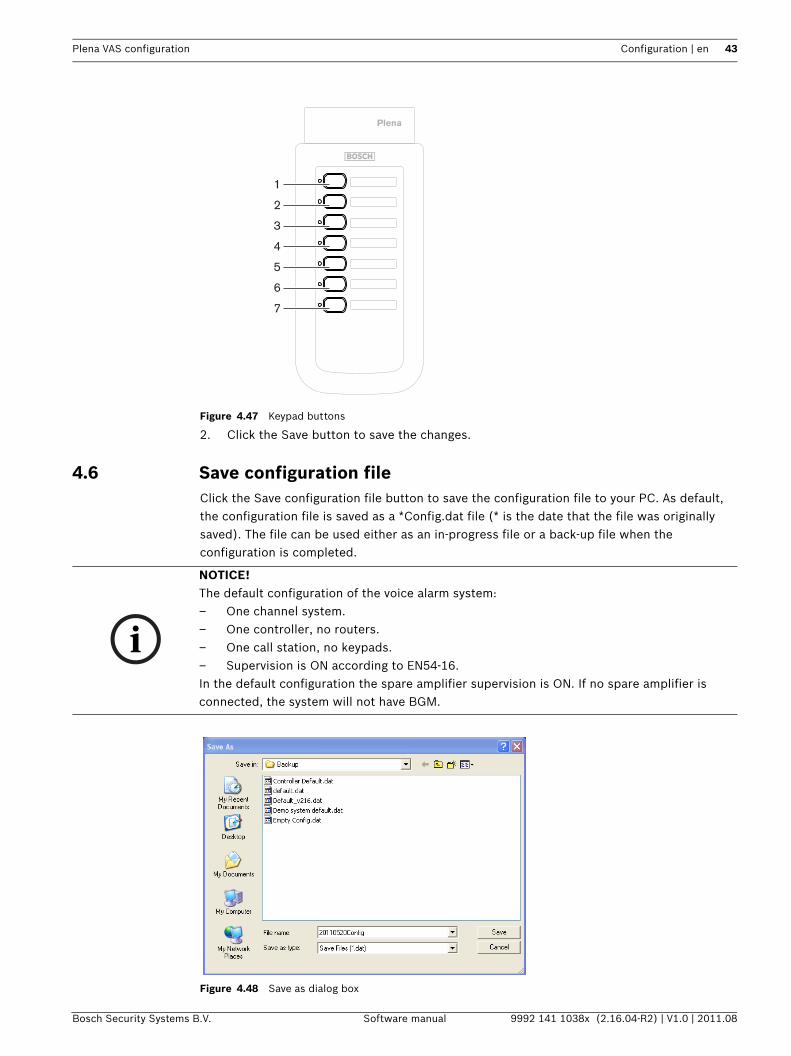
Figure 4.47 Keypad buttons
2. Click the Save button to save the changes.
4.6 Save configuration fileClick the Save configuration file button to save the configuration file to your PC. As default, the configuration file is saved as a *Config.dat file (* is the date that the file was originally saved). The file can be used either as an in-progress file or a back-up file when the configuration is completed.
Figure 4.48 Save as dialog box
Plena
1
2
3
4
5
6
7
NOTICE! The default configuration of the voice alarm system:– One channel system.– One controller, no routers.– One call station, no keypads.– Supervision is ON according to EN54-16.In the default configuration the spare amplifier supervision is ON. If no spare amplifier is connected, the system will not have BGM.
44 en | Configuration Plena VAS configuration
9992 141 1038x (2.16.04-R2) | V1.0 | 2011.08 Software manual Bosch Security Systems B.V.
Proceeds as follows:1. Click the Save configuration file button from the main configuration menu.2. Enter the name of the configuration file in File name text box, or click the Save button to
keep the default name.
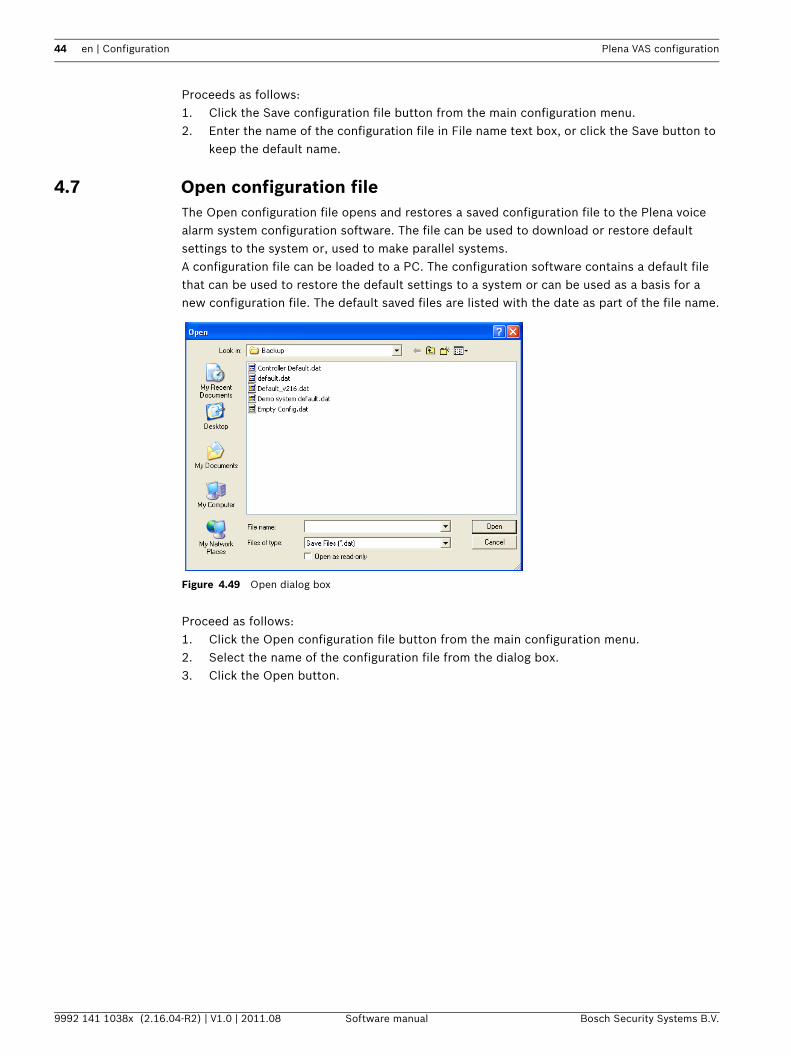
4.7 Open configuration fileThe Open configuration file opens and restores a saved configuration file to the Plena voice alarm system configuration software. The file can be used to download or restore default settings to the system or, used to make parallel systems.A configuration file can be loaded to a PC. The configuration software contains a default file that can be used to restore the default settings to a system or can be used as a basis for a new configuration file. The default saved files are listed with the date as part of the file name.
Figure 4.49 Open dialog box
Proceed as follows:1. Click the Open configuration file button from the main configuration menu.2. Select the name of the configuration file from the dialog box.3. Click the Open button.
Plena VAS configuration Configuration | en 45
Bosch Security Systems B.V. Software manual 9992 141 1038x (2.16.04-R2) | V1.0 | 2011.08
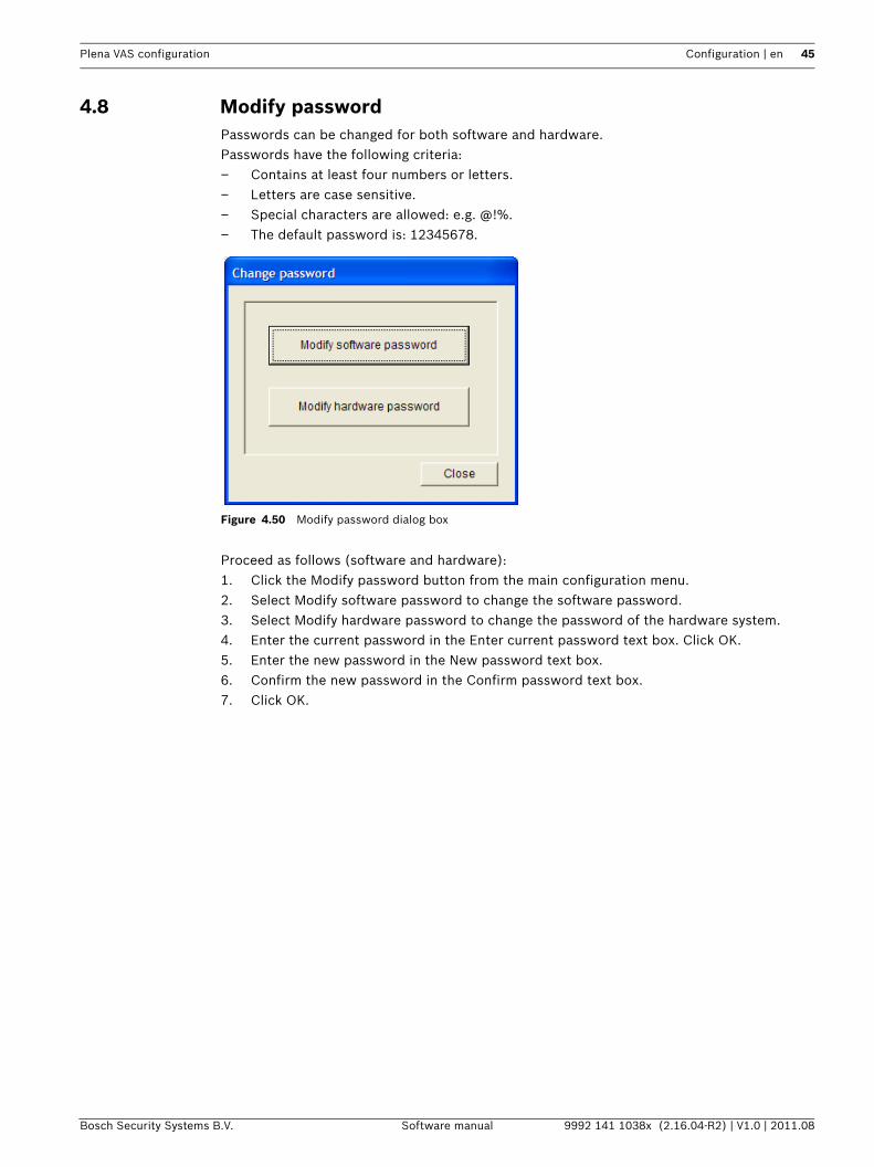
4.8 Modify passwordPasswords can be changed for both software and hardware.Passwords have the following criteria:– Contains at least four numbers or letters.– Letters are case sensitive.– Special characters are allowed: e.g. @!%.– The default password is: 12345678.
Figure 4.50 Modify password dialog box
Proceed as follows (software and hardware):1. Click the Modify password button from the main configuration menu.2. Select Modify software password to change the software password.3. Select Modify hardware password to change the password of the hardware system.4. Enter the current password in the Enter current password text box. Click OK.5. Enter the new password in the New password text box.6. Confirm the new password in the Confirm password text box.7. Click OK.
46 en | Configuration Plena VAS configuration
9992 141 1038x (2.16.04-R2) | V1.0 | 2011.08 Software manual Bosch Security Systems B.V.
4.9 Upload configurationThe configuration file must be uploaded to the system before it has effect.– The upload configuration option is fast and takes a few seconds to complete. Only the
configuration settings are loaded to the system.If only the settings have been changed since the last upload, it is better to select the Upload configuration. Download the configuration file from the voice alarm system if an existing configuration file is needed and the original is not available.
Proceed as follows:1. Click the Upload configuration button from the main configuration menu:
– If no USB connection between the PC and the voice alarm system is established, an on-screen message appears: "Usb port not connected".
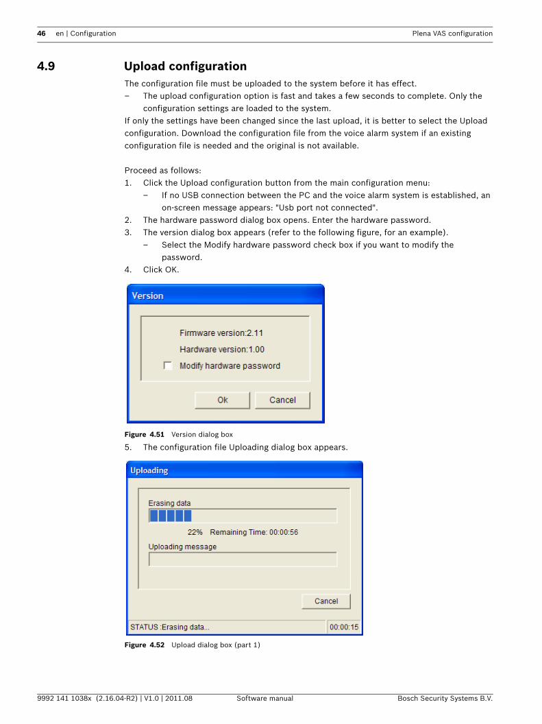
2. The hardware password dialog box opens. Enter the hardware password.3. The version dialog box appears (refer to the following figure, for an example).
– Select the Modify hardware password check box if you want to modify the password.
4. Click OK.
Figure 4.51 Version dialog box
5. The configuration file Uploading dialog box appears.
Figure 4.52 Upload dialog box (part 1)
Plena VAS configuration Configuration | en 47
Bosch Security Systems B.V. Software manual 9992 141 1038x (2.16.04-R2) | V1.0 | 2011.08
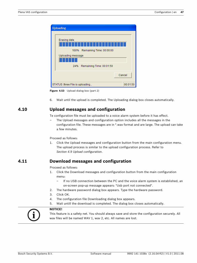
Figure 4.53 Upload dialog box (part 2)
6. Wait until the upload is completed. The Uploading dialog box closes automatically.
4.10 Upload messages and configurationTe configuration file must be uploaded to a voice alarm system before it has effect.– The Upload messages and configuration option includes all the messages in the
configuration file. These messages are in *.wav format and are large. The upload can take a few minutes.
Proceed as follows:1. Click the Upload messages and configuration button from the main configuration menu.
The upload process is similar to the upload configuration process. Refer to Section 4.9 Upload configuration.
4.11 Download messages and configurationProceed as follows:1. Click the Download messages and configuration button from the main configuration
menu:– If no USB connection between the PC and the voice alarm system is established, an
on-screen pop-up message appears: "Usb port not connected".2. The hardware password dialog box appears. Type the hardware password.3. Click OK.4. The configuration file Downloading dialog box appears.5. Wait untill the download is completed. The dialog box closes automatically.
NOTICE! This feature is a safety net. You should always save and store the configuration securely. All wav files will be named WAV 1, wav 2, etc. All names are lost.
48 en | Troubleshooting Plena VAS configuration
9992 141 1038x (2.16.04-R2) | V1.0 | 2011.08 Software manual Bosch Security Systems B.V.
5 TroubleshootingThis troubleshooting section has been created to help you with problems you may be experiencing with installing or loading the Plena configuration software.
Unable to install the Plena configuration software?– Verify if the CD is readable by reading the files on the drive.
– If the CD attempts to autoplay, you may need to right-click the drive and click Explore to browse the drive.
– If the CD reads fine with no errors, verify your PC meets the minimum requirements of the configuration software. If your PC does not have enough disk drive space or does not meet the requirements, the configuration software will not install.
– Make sure that the configuration software is compatible with the version of operating system you have on your PC.
Error during installation?– Verify your PC meets the requirements of the configuration software.
– For example, if your PC runs out of disk space during the installation, this would cause an error during the installation.
– Make sure that the configuration software is compatible with the version of operating system you have on your PC.
– Make sure that the configuration software is compatible with the hardware version and software version of the voice alarm system.
– Verify the CD is clean and contains no significant scratches.
The configuration software does not load or has an error when it attempts to load– Verify if updates are available of the configuration software.
– In some cases the configuration software may require an update before it can be successfully run on your PC.
– Make sure all other programs are closed when you run the configuration software. – If the configuration software successfully runs after closing all other programs, it's
possible that the configuration software may have issues with other programs.– Make sure the PC has been rebooted at least once after the configuration software has
been installed.

Bosch Security Systems B.V.Kapittelweg 104827 HG BredaThe Netherlandswww.boschsecurity.com© Bosch Security Systems B.V., 2011