Embed Size (px)
Citation preview

Pipe Flow Wizard help page 1www.pipeflow.co.uk
CONTENTS
2Overview . . . . . . . . . . . . . . . . . . . . . . . 3Single / Four page layout . . . . . . . . . . . 3Pressure Drop Calculation . . . . . . . . . . 4Flow Rate Calculation . . . . . . . . . . . . . 4Internal Diameter Calculation . . . . . . . 5Pipe Length Calculation . . . . . . . . . . . . 6Internal roughness of pipe . . . . . . . . . . 6Internal diameter of pipe . . . . . . . . . . . 7Fittings on the pipe . . . . . . . . . . . . . . . 8Change the fluid data . . . . . . . . . . . . . 9Change the gas data . . . . . . . . . . . . . . 9Gas data at other temperatures . . . . . .
10Viscosity and Density units . . . . . . . . . 11Metric and Imperial unit choice . . . . . . 11Calculations for gas flow . . . . . . . . . . . 11Weight of flow . . . . . . . . . . . . . . . . . . .
12Max. velocity recommendations . . . . . 12Save calculation data . . . . . . . . . . . . . 12Load calculation data . . . . . . . . . . . . . . 13Copy data to clipboard . . . . . . . . . . . . . 13Copy screen to clipboard . . . . . . . . . . . 13Print a calculation screen . . . . . . . . . . 14Pressure drop theory . . . . . . . . . . . . . . 14Friction Factors . . . . . . . . . . . . . . . . . . 14Reynold's Numbers . . . . . . . . . . . . . . . 15Effect of Relative roughness . . . . . . . . 15Friction Factor Chart . . . . . . . . . . . . . . 16Calculate fluid head . . . . . . . . . . . . . . . 16Calculate fittings head loss . . . . . . . . . 16Calculate total pressure loss . . . . . . . . 17Program Registration . . . . . . . . . . . . . . 18Moving Pipe Flow Wizard . . . . . . . . . .
Pipe Flow Wizard help page 2
Back to contents . . . .
www.pipeflow.co.uk
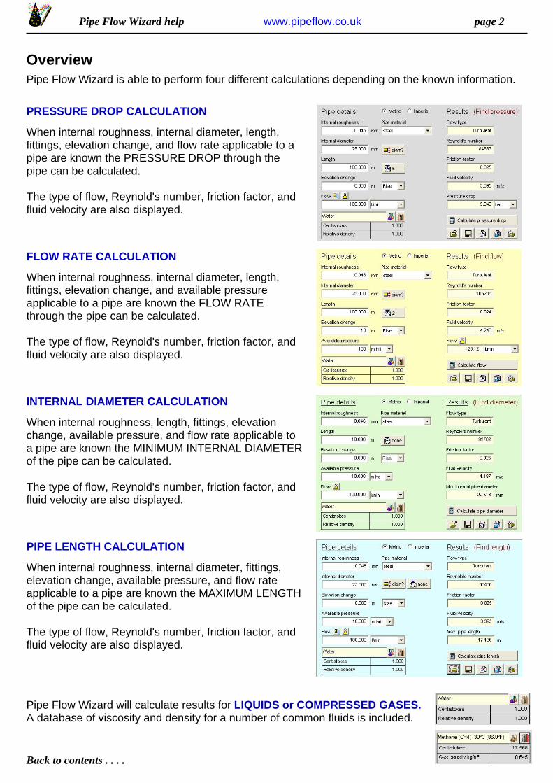
OverviewPipe Flow Wizard is able to perform four different calculations depending on the known information.
PRESSURE DROP CALCULATION
When internal roughness, internal diameter, length,fittings, elevation change, and flow rate applicable to apipe are known the PRESSURE DROP through thepipe can be calculated.
The type of flow, Reynold's number, friction factor, andfluid velocity are also displayed.
FLOW RATE CALCULATION
When internal roughness, internal diameter, length,fittings, elevation change, and available pressureapplicable to a pipe are known the FLOW RATEthrough the pipe can be calculated.
The type of flow, Reynold's number, friction factor, andfluid velocity are also displayed.
INTERNAL DIAMETER CALCULATION
When internal roughness, length, fittings, elevationchange, available pressure, and flow rate applicable toa pipe are known the MINIMUM INTERNAL DIAMETERof the pipe can be calculated.
The type of flow, Reynold's number, friction factor, andfluid velocity are also displayed.
PIPE LENGTH CALCULATION
When internal roughness, internal diameter, fittings,elevation change, available pressure, and flow rateapplicable to a pipe are known the MAXIMUM LENGTHof the pipe can be calculated.
The type of flow, Reynold's number, friction factor, andfluid velocity are also displayed.
Pipe Flow Wizard will calculate results for LIQUIDS or COMPRESSED GASES.A database of viscosity and density for a number of common fluids is included.
Pipe Flow Wizard help page 3
Back to contents . . . .
www.pipeflow.co.uk
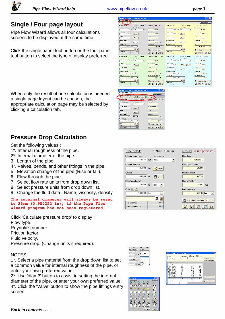
Single / Four page layoutPipe Flow Wizard allows all four calculationsscreens to be displayed at the same time.
Click the single panel tool button or the four paneltool button to select the type of display preferred.
When only the result of one calculation is neededa single page layout can be chosen, theappropriate calculation page may be selected byclicking a calculation tab.
Pressure Drop CalculationSet the following values :1*. Internal roughness of the pipe.2*. Internal diameter of the pipe.3 . Length of the pipe.4*. Valves, bends, and other fittings in the pipe.5 . Elevation change of the pipe (Rise or fall).6 . Flow through the pipe.7 . Select flow rate units from drop down list.8 . Select pressure units from drop down list.9 . Change the fluid data : Name, viscosity, densityThe internal diameter will always be resetto 25mm (0.984252 in), if the Pipe FlowWizard program has not been registered.
Click 'Calculate pressure drop' to display :Flow type.Reynold's number.Friction factor.Fluid velocity.Pressure drop. (Change units if required).
NOTES:1*. Select a pipe material from the drop down list to seta common value for internal roughness of the pipe, orenter your own preferred value.2*. Use 'diam?' button to assist in setting the internaldiameter of the pipe, or enter your own preferred value.4*. Click the 'Valve' button to show the pipe fittings entryscreen.

Pipe Flow Wizard help page 4
Back to contents . . . .
www.pipeflow.co.uk
Flow Rate CalculationSet the following values :1*. Internal roughness of the pipe.2*. Internal diameter of the pipe.3 . Length of the pipe.4*. Valves, bends, and other fittings in the pipe.5 . Elevation change of the pipe (Rise or fall).6 . Available pressure at inlet of the pipe.7 . Select pressure units from drop down list.8 . Select flow rate units from drop down list.9 . Change the fluid data : Name, viscosity, densityThe internal diameter will always be resetto 25mm (0.984252 in), if the Pipe FlowWizard program has not been registered.
Click 'Calculate flow' to display :Flow type.Reynold's number.Friction factor.Fluid velocity.Flow rate. (Change units if required).
NOTES:1*. Select a pipe material from the drop down list to seta common value for internal roughness of the pipe, orenter your own prefered value.2*. Use 'diam?' button to assist in setting the internaldiameter of the pipe, or enter your own preferred value.4*. Click the 'Valve' button to show the pipe fittings entryscreen.
Internal Diameter CalculationSet the following values :1*. Internal roughness of the pipe.2 . Length of the pipe.3*. Valves, bends, and other fittings in the pipe.4 . Elevation change of the pipe (Rise or fall).5 . Available pressure at inlet of the pipe.6 . Select pressure units from drop down list.7 . Flow through the pipe.8 . Select flow rate units from drop down list.9 . Change the fluid data : Name, viscosity, densityThe pipe length will always be reset to10.000 m (32.808 ft), if the Pipe FlowWizard program has not been registered.
Click 'Calculate pipe diameter' to display :Flow type.Reynold's number.Friction factor.Fluid velocity.Minimum internal pipe diameter.
Pipe Flow Wizard help page 5
Back to contents . . . .
www.pipeflow.co.uk
Internal Diameter Calculation (cont.)NOTES:1*. Select a pipe material from the drop down list to seta common value for internal roughness of the pipe, orenter your own preferred value.3*. Click the 'Valve' button to show the pipe fittings entryscreen.
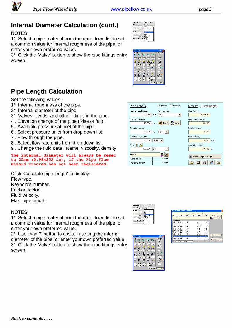
Pipe Length CalculationSet the following values :1*. Internal roughness of the pipe.2*. Internal diameter of the pipe.3*. Valves, bends, and other fittings in the pipe.4 . Elevation change of the pipe (Rise or fall).5 . Available pressure at inlet of the pipe.6 . Select pressure units from drop down list.7 . Flow through the pipe.8 . Select flow rate units from drop down list.9 . Change the fluid data : Name, viscosity, densityThe internal diameter will always be resetto 25mm (0.984252 in), if the Pipe FlowWizard program has not been registered.
Click 'Calculate pipe length' to display :Flow type.Reynold's number.Friction factor.Fluid velocity.Max. pipe length.
NOTES:1*. Select a pipe material from the drop down list to seta common value for internal roughness of the pipe, orenter your own preferred value.2*. Use 'diam?' button to assist in setting the internaldiameter of the pipe, or enter your own preferred value.3*. Click the 'Valve' button to show the pipe fittings entryscreen.
Pipe Flow Wizard help page 6
Back to contents . . . .
www.pipeflow.co.uk
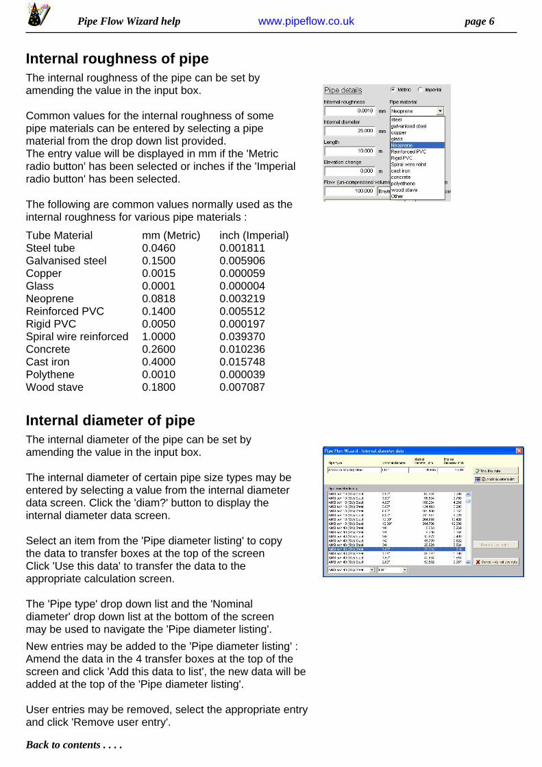
Internal roughness of pipeThe internal roughness of the pipe can be set byamending the value in the input box.
Common values for the internal roughness of somepipe materials can be entered by selecting a pipematerial from the drop down list provided.The entry value will be displayed in mm if the 'Metricradio button' has been selected or inches if the 'Imperialradio button' has been selected.
The following are common values normally used as theinternal roughness for various pipe materials :
Tube MaterialSteel tubeGalvanised steelCopperGlassNeopreneReinforced PVCRigid PVCSpiral wire reinforcedConcreteCast ironPolytheneWood stave
mm (Metric)0.04600.15000.00150.00010.08180.14000.00501.00000.26000.40000.00100.1800
inch (Imperial)0.0018110.0059060.0000590.0000040.0032190.0055120.0001970.0393700.0102360.0157480.0000390.007087
Internal diameter of pipeThe internal diameter of the pipe can be set byamending the value in the input box.
The internal diameter of certain pipe size types may beentered by selecting a value from the internal diameterdata screen. Click the 'diam?' button to display theinternal diameter data screen.
Select an item from the 'Pipe diameter listing' to copythe data to transfer boxes at the top of the screenClick 'Use this data' to transfer the data to theappropriate calculation screen.
The 'Pipe type' drop down list and the 'Nominaldiameter' drop down list at the bottom of the screenmay be used to navigate the 'Pipe diameter listing'.
New entries may be added to the 'Pipe diameter listing' :Amend the data in the 4 transfer boxes at the top of thescreen and click 'Add this data to list', the new data will beadded at the top of the 'Pipe diameter listing'.
User entries may be removed, select the appropriate entryand click 'Remove user entry'.
Pipe Flow Wizard help page 7
Back to contents . . . .
www.pipeflow.co.uk
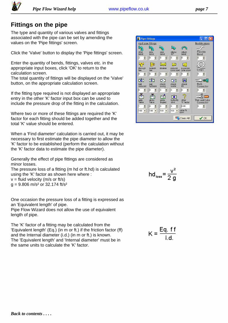
Fittings on the pipeThe type and quantity of various valves and fittingsassociated with the pipe can be set by amending thevalues on the 'Pipe fittings' screen.
Click the 'Valve' button to display the 'Pipe fittings' screen.
Enter the quantity of bends, fittings, valves etc. in theappropriate input boxes, click 'OK' to return to thecalculation screen.The total quantity of fittings will be displayed on the 'Valve'button, on the appropriate calculation screen.
If the fitting type required is not displayed an appropriateentry in the other 'K' factor input box can be used toinclude the pressure drop of the fitting in the calculation.
Where two or more of these fittings are required the 'K'factor for each fitting should be added together and thetotal 'K' value should be entered.
When a 'Find diameter' calculation is carried out, it may benecessary to first estimate the pipe diameter to allow the'K' factor to be established (perform the calculation withoutthe 'K' factor data to estimate the pipe diameter).
Generally the effect of pipe fittings are considered asminor losses.The pressure loss of a fitting (m hd or ft.hd) is calculatedusing the 'K' factor as shown here where :v = fluid velocity (m/s or ft/s)g = 9.806 m/s² or 32.174 ft/s²
One occasion the pressure loss of a fitting is expressed asan 'Equivalent length' of pipe.Pipe Flow Wizard does not allow the use of equivalentlength of pipe.
The 'K' factor of a fitting may be calculated from the'Equivalent length' (Eq.) (in m or ft.) if the friction factor (ff)and the Internal diameter (i.d.) (in m or ft.) is known.The 'Equivalent length' and 'Internal diameter' must be inthe same units to calculate the 'K' factor.
Pipe Flow Wizard help page 8
Back to contents . . . .
www.pipeflow.co.uk
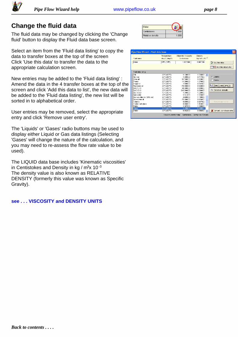
Change the fluid dataThe fluid data may be changed by clicking the 'Changefluid' button to display the Fluid data base screen.
Select an item from the 'Fluid data listing' to copy thedata to transfer boxes at the top of the screenClick 'Use this data' to transfer the data to theappropriate calculation screen.
New entries may be added to the 'Fluid data listing' :Amend the data in the 4 transfer boxes at the top of thescreen and click 'Add this data to list', the new data willbe added to the 'Fluid data listing', the new list will besorted in to alphabetical order.
User entries may be removed, select the appropriateentry and click 'Remove user entry'.
The 'Liquids' or 'Gases' radio buttons may be used todisplay either Liquid or Gas data listings (Selecting'Gases' will change the nature of the calculation, andyou may need to re-assess the flow rate value to beused).
The LIQUID data base includes 'Kinematic viscosities'in Centistokes and Density in kg / m x 10 The density value is also known as RELATIVEDENSITY (formerly this value was known as SpecificGravity).
3 -3
see . . . VISCOSITY and DENSITY UNITS
Pipe Flow Wizard help page 9
Back to contents . . . .
www.pipeflow.co.uk
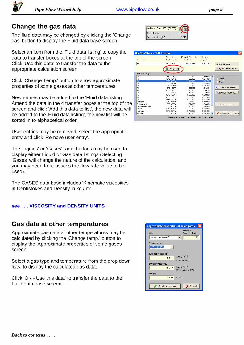
Change the gas dataThe fluid data may be changed by clicking the 'Changegas' button to display the Fluid data base screen.
Select an item from the 'Fluid data listing' to copy thedata to transfer boxes at the top of the screenClick 'Use this data' to transfer the data to theappropriate calculation screen.
Click 'Change Temp.' button to show approximateproperties of some gases at other temperatures.
New entries may be added to the 'Fluid data listing' :Amend the data in the 4 transfer boxes at the top of thescreen and click 'Add this data to list', the new data willbe added to the 'Fluid data listing', the new list will besorted in to alphabetical order.
User entries may be removed, select the appropriateentry and click 'Remove user entry'.
The 'Liquids' or 'Gases' radio buttons may be used todisplay either Liquid or Gas data listings (Selecting'Gases' will change the nature of the calculation, andyou may need to re-assess the flow rate value to beused).
The GASES data base includes 'Kinematic viscosities'in Centistokes and Density in kg / m 3
see . . . VISCOSITY and DENSITY UNITS
Gas data at other temperaturesApproximate gas data at other temperatures may becalculated by clicking the 'Change temp.' button todisplay the 'Approximate properties of some gases'screen.
Select a gas type and temperature from the drop downlists, to display the calculated gas data.
Click 'OK - Use this data' to transfer the data to theFluid data base screen.

Pipe Flow Wizard help page 10
Back to contents . . . .
www.pipeflow.co.uk
Viscosity and Density unitsDensity p
p = kg/m 3
Water @ 20°C has a density of 998 kg/m 3
0.998 kg/m 3or x 10 -3 (Relative Density)
p = slugs/ft 3
Water @ 70°F has a density of 1.93 Slugs/ft 3 Note: Slug = weight/g slug = lb/(32.174 ft • s )2
Dynamic Viscosity µ
µ = Pa • s 1.00 Pa • s = 10 Poise = 1000 CentipoiseWater @ 20°C has a viscosity of 1.00 x 10 -3 Pa • s
0.001000 Pa • sor
1.00 Centipoiseor
µ = lb • s / ft 2
Water @ 70°F has a viscosity of 2.04 x 10 -5 lb •s/ft2
1.000 lb •s/ft2
= 47880.26 Centipoise
Kinematic Viscosity v
v = m /s2 1.00 m /s = 10000 Stokes = 1000000 Centistokes2
Water @ 20°C has a viscosity of 1.004 x 10 -6 m /s2
0.010040 Stokesor
1.004000 Centistokesor
v = ft /s2 1.00 ft /s = 929.034116 Stokes = 92903.4116 Centistokes2
Water @ 70°F has a viscosity of 10.5900 x 10 -6 ft /s2
1.05900 x 10 -5 ft /s2or
0.00983847 Stokesor
0.98384713 Centistokesor
Kinematic Viscosity and Dynamic Viscosity Relationship
Kinematic Viscosity = Dynamic Viscosity / Density v = µ / p
Centistokes = Centipoise / Density
Example: µ = Pa • s Substitution : Pa = N / m 2
and . . . . . . N = kg • m / s 2
therefore µ = Pa • s = kg / (m • s)
p = kg/m 3
Kinematic Viscosity = v = µ / p = (kg / (m • s) x 10-3) / (kg / m )= m / s x 103 2 -6
Example: µ = lb • s / ft 2
p = Slugs / ft3 (Note : Slug = lb / (32.174 ft • s )2
p = Slugs / ft = (lb / ft ) / 32.174 ft • s 3 3 2 = (( lb / 32.174 ) • s ) / ft2 4
Kinematic Viscosity = v = µ / p = ( lb • s / ft ) / (Slugs / ft )2 3 = (( lb • s / ft ) / ( lb • s )) • ft2 2 4 = ( ft / ft ) • ( s / s ) = ft / s4 2 2 2
Pipe Flow Wizard help page 11
Back to contents . . . .
www.pipeflow.co.uk
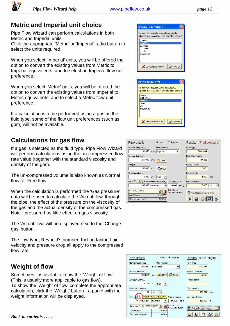
Metric and Imperial unit choicePipe Flow Wizard can perform calculations in bothMetric and Imperial units.Click the appropriate 'Metric' or 'Imperial' radio button toselect the units required.
When you select 'Imperial' units, you will be offered theoption to convert the existing values from Metric toImperial equivalents, and to select an Imperial flow unitpreference.
When you select 'Metric' units, you will be offered theoption to convert the existing values from Imperial toMetric equivalents, and to select a Metric flow unitpreference.
If a calculation is to be performed using a gas as thefluid type, some of the flow unit preferences (such asgpm) will not be available.
Calculations for gas flowIf a gas is selected as the fluid type, Pipe Flow Wizardwill perform calculations using the un-compressed flowrate value (together with the standard viscosity anddensity of the gas).
The un-compressed volume is also known as Normalflow, or Free flow.
When the calculation is performed the 'Gas pressure'data will be used to calculate the 'Actual flow' throughthe pipe, the effect of the pressure on the viscosity ofthe gas and the actual density of the compressed gas.Note : pressure has little effect on gas viscosity.
The 'Actual flow' will be displayed next to the 'Changegas' button.
The flow type, Reynold's number, friction factor, fluidvelocity and pressure drop all apply to the compressedflow rate.
Weight of flowSometimes it is useful to know the 'Weight of flow' (This is usually more applicable to gas flow).To show the 'Weight of flow' complete the appropriatecalculation, click the 'Weight' button - a panel with theweight information will be displayed.

Pipe Flow Wizard help page 12
Back to contents . . . .
www.pipeflow.co.uk
Max. velocity recommendationsOn occasion it may be necessary to choose a flow ratewhich does not exceed a certain velocity.
An example : It is sometimes recommended that themaximum velocity for compressed air distribution is 6 m/s (20 ft/s).
To assist with determining flow rate for these 'Maximumvelocity' instances Pipe Flow Wizard incorporates a flowrate calculator which uses the current internal diameterand a fluid velocity to calculate a flow rate.
A flow calculator button is provided on the 'FindPressure' and 'Find Length' screens.
Save calculation dataThe data associated with a particular calculation maybe saved to a file.
Pipe Flow wizard uses file extensions PW1, PW2, PW3and PW4 to differentiate between the different types ofcalculation.
To save the data to a file - use the 'Save File' toolbutton on the current calculation screen.
Calculation data can only be savedif the Pipe Flow Wizard program hasbeen registered.
Load calculation dataData associated with a particular calculation may beloaded from a file. (Which has been saved using PipeFlow Wizard).
Pipe Flow wizard uses file extensions PW1, PW2, PW3and PW4 to differentiate between the different types ofcalculation.
To load the data from a file - use the 'Open File' toolbutton on the required calculation screen.
Calculation data can only be loadedif the Pipe Flow Wizard program hasbeen registered.

Pipe Flow Wizard help page 13
Back to contents . . . .
www.pipeflow.co.uk
Copy data to clipboardThe results of a particular calculation may be copied tothe clipboard.The data will be copied in tab delimited format (suitablefor a paste operation into an Excel spreadsheet).
The 'Pipe details' and the 'Calculation Results' (if any)will be included in the copy operation.
To copy the data - use the 'Copy text to clipboard' toolbutton on the required calculation screen.
Copy functions can only be used ifthe Pipe Flow Wizard program hasbeen registered.
Copy screen to clipboardAn image of a particular calculation screen may becopied to the clipboard.The image may be pasted into a word processor or intoan Excel spreadsheet.
To copy the calculation image - use the 'Copy image toclipboard' tool button on the required calculation screen.
Copy functions can only be used ifthe Pipe Flow Wizard program hasbeen registered.
Print a calculation screenAn image of a particular calculation screen may beprinted.
To print the calculation image - use the 'Print screen'tool button on the required calculation screen.
Print functions can only be used ifthe Pipe Flow Wizard program hasbeen registered.

Pipe Flow Wizard help page 14
Back to contents . . . .
www.pipeflow.co.uk
Pressure drop theoryFluids in motion are subjected to various resistance's, which are due to friction.Friction may occur between the fluid & the pipe work, but friction also occurs within the fluid as sliding between adjacent layers of fluid takes place.The friction within the fluid is due to the fluid's viscosity.
When fluids have a high viscosity, the speed of flow tends to be low, and resistance to flow becomes almost totally dependant on the viscosity of the fluid, this condition is known as 'Laminar flow'.
Fluids which have a low viscosity are usually moved at higher velocities, the flowcharacteristics change, small eddy currents occur within the flow, & the friction between the pipe work and the fluid becomes a factor to be considered.
This type of flow is know as 'Turbulent flow'.It is generally accepted that the 'changeover' point for these two types of flow, in acircular pipe, occurs when the Reynolds number (Re) is approximately 2300.
i.e.Laminar flow ( Re less than 2300)Turbulent flow ( Re greater than 2300)
It follows that the friction factor for these two types of flow must be calculated, usingdifferent formula's.Many formula's have been developed to model the flow of fluids.The use of Colebrook's formula, Darcy & Weisbach's formula, & Reynolds numbers all contribute to determine the friction factors within a fluid & it's boundary layers.
Friction FactorsBefore the pipework losses can be established, the friction factor must becalculated.The friction factor will be dependant on the pipe size, inner roughness of the pipe,flow velocity and fluid viscosity.
The flow condition, whether 'Turbulent' or not, will determine the method used tocalculate the friction factor.The starting point must be to find the fluid's viscosity.This will be the factor that has most effect on the pipework losses.
The fluid velocity is used in the Reynold's number calculation.
Reynold's NumbersReynold's numbers (Re) describe the relationship between a fluid's velocity, thepipe size and the fluid's KINEMATIC viscosity.
Fluid velocity x Internal pipe diameterReynold's number =
Kinematic viscosity
NOTE : KINEMATIC viscosity (not Dynamic viscosity) must be used to calculate Reynold's Numbers
see . . . VISCOSITY and DENSITY UNITS
Pipe Flow Wizard help page 15
Back to contents . . . .
www.pipeflow.co.uk
Effect of Relative roughnessThe inner roughness of the pipe can create eddy currents.This increases the friction between the pipe wall and the fluid.The relative roughness of the inside of the pipe is used in determining the frictionfactor to be used.
Inside pipe roughnessRelative roughness =
Inside pipe diameter
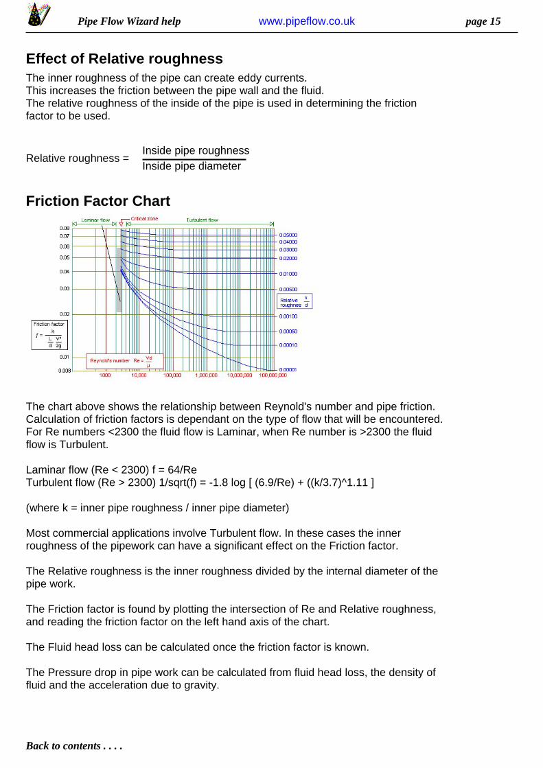
Friction Factor Chart
The chart above shows the relationship between Reynold's number and pipe friction.Calculation of friction factors is dependant on the type of flow that will be encountered.For Re numbers <2300 the fluid flow is Laminar, when Re number is >2300 the fluidflow is Turbulent.
Laminar flow (Re < 2300) f = 64/ReTurbulent flow (Re > 2300) 1/sqrt(f) = -1.8 log [ (6.9/Re) + ((k/3.7)^1.11 ]
(where k = inner pipe roughness / inner pipe diameter)
Most commercial applications involve Turbulent flow. In these cases the innerroughness of the pipework can have a significant effect on the Friction factor.
The Relative roughness is the inner roughness divided by the internal diameter of thepipe work.
The Friction factor is found by plotting the intersection of Re and Relative roughness,and reading the friction factor on the left hand axis of the chart.
The Fluid head loss can be calculated once the friction factor is known.
The Pressure drop in pipe work can be calculated from fluid head loss, the density offluid and the acceleration due to gravity.
Pipe Flow Wizard help page 16
Back to contents . . . .
www.pipeflow.co.uk
Calculate fluid headFluid head resistance can be calculated from h = f (L/d) x (v ²/2g)
whereh = head loss (m)f = friction factorL = length of pipe work (m)d = inner dia of pipe work (m)v = velocity of fluid (m/s)g = acceleration due to gravity (m/s ²)
Calculate fittings head lossThe fluid head resistance through various pipe work fittings can be calculatedwhen the 'K' factor of the fitting is known. Manufacturers of pipe work fittings &valves publish 'K' factors for their products.
Usually a particular type of fitting from various manufacturers have similar 'K'factors, therefore this computer program tends to use average 'K' factor values.
Fluid head loss of these fitting can be calculated from h = total 'K' x v ² / 2g
whereh = head loss (m)total 'K' = total of 'K' factors for each fittingv = velocity of fluid (m/s)g = acceleration due to gravity (m/s ²)
Note: If the pipework involves different pipe sizes, this calculation must be carriedout separately for each pipe size, using the appropriate velocity within that pipesection.
The 'K' value of entry & exit points can be taken as 0.8 and 1.0 respectively tocalculate the head loss attributable to these features.
Calculate total pressure lossThe total fluid head resistance may be used to calculate the pressure required toovercome the resistance to fluid flow.
Pd = h x p x g / 100000
wherePd = pressure drop (bar)h = head loss (m)p = fluid density (kg/m³)g = acceleration due to gravity (m/s ²)
Finally, the fluid is most likely to exit into atmospheric pressure. The differencebetween the pressure on the fluid surface during storage & the atmosphericpressure must be taken into account in determining the pressure drop to beovercome by a pump.This difference in pressure may be positive (assisting fluid flow) or negative(resisting fluid flow).

Pipe Flow Wizard help page 17
Back to contents . . . .
www.pipeflow.co.uk
Program RegistrationThe Pipe Flow Wizard program must be registered toallow the 'Change Fluid', 'Save', 'Open', 'Copy toclipboard' and 'Print' functions to operate.
The registration process is easy :
1. Visit to purchase a registration token.www.pipeflow.co.uk
2. Obtain the Product Code from the softwareinstallation - this code is shown on the 'Terms of use'screen.
3. Use the registration token and the Product Code fromthe software installation, to obtain your RegistrationCode from the 'www.pipeflow.co.uk' website.
4. Read 'Pipe Flow Wizard - Terms of use' and click the'Register program' menu option to display the 'Userregistration' entry form.
5. Enter your Registration code and click RegisterProgram.
6. Pipe Flow Wizard is now registered and fullyoperational.
Pipe Flow Wizard help page 18
Back to contents . . . .
www.pipeflow.co.uk
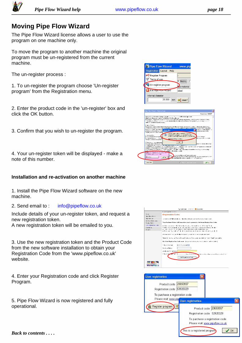
Moving Pipe Flow WizardThe Pipe Flow Wizard license allows a user to use theprogram on one machine only.
To move the program to another machine the originalprogram must be un-registered from the currentmachine.
The un-register process :
1. To un-register the program choose 'Un-registerprogram' from the Registration menu.
2. Enter the product code in the 'un-register' box andclick the OK button.
3. Confirm that you wish to un-register the program.
4. Your un-register token will be displayed - make anote of this number.
Installation and re-activation on another machine
1. Install the Pipe Flow Wizard software on the newmachine.
2. Send email to : [email protected]
Include details of your un-register token, and request anew registration token.A new registration token will be emailed to you.
3. Use the new registration token and the Product Codefrom the new software installation to obtain yourRegistration Code from the 'www.pipeflow.co.uk'website.
4. Enter your Registration code and click RegisterProgram.
5. Pipe Flow Wizard is now registered and fullyoperational.