Embed Size (px)
Citation preview

Abstract—This paper includes three main parts. The first part is
about a Quadrotor as a type of unmanned vehicles. The second part includes its mathematical model and controlling with PID controller. The last part consists of some in flight and on ground testing. For the aforesaid processes first of all a Quadrotor has been built. The Quadrotor is designed within the Anadolu University which is the unique university because of its own airport. The design has some problems such as slow vibration speed, long response time and big movements in roll axes so some controlling applications have been developed. After ensuring its stabile flight, some sensor tests have been carried out to develop its control mechanism.
Keywords—Flight control, PID controller, UAV.
I. INTRODUCTION ince eras when people and flying creatures lived together, the act of flying has aroused the curiosity in the human
mind. Such being the case, aviation sector becomes one of the fast-growing sectors along with technology. When analyzing the history of aviation, it is seen that air vehicles have ranged from balloon to unmanned aerial vehicles that is, they have varied greatly. This variation led the formation of air power concept which is of greatly importance in terms of defense industry over time. The governments recognize the importance of the air power has considerably invested in this field. Thanks to these investments, many features of the vehicle such as technical parameter, control algorithm, and maneuverability etc. have developed and increased. Accompany these, when the literature is analyzed, it is seen that the studies on this field have increased. For theoretical models of Quadrotor aerodynamics to be analyzed by using helicopter momentum and blade element theory [1], for an unknown parameter belongs to Quadrotor to be identified with the help of Unscented Kalman Filter [2], for adaptation to unknown payloads and robustness to disturbances to be achieved [3], for the method aiming at solved problems resulted from dynamic characteristics of a Quadrotor to be proposed [4], the design of
The supported by Anadolu University Research Projects Committee
(Project No. 1208F130) is gratefully acknowledged. G. Gol is with the Avionics Department, Anadolu University, Eskisehir,
26470 TURKEY (e-mail: [email protected]). N. F. Bayraktar is with the Avionics Department, Anadolu University,
Eskisehir, 26470 TURKEY (e-mail: [email protected]). E. Kiyak is with the Avionics Department, Anadolu University, Eskisehir,
26470 TURKEY (corresponding author to provide phone: +90 222 335 05 80/6879; fax: +90 222 322 16 19; e-mail: [email protected]).
nonlinear modeling of Quadrotor and obtaining its mathematical model [5], Quadrotor performance and design of a PID controller for stabilization of the dominant decoupled pitch and roll models [6], for Quadrotor propellers to allow to tilt [7], for coaxial Quadrotor to be designed [8], for aerodynamic and mechanical model of UAV constructed from carbon composite material to be designed [9], for the nonlinear dynamic model of a Quadrotor and its controlling to be examined [10], developing a cascade control method for superheated processes [11], for the architecture of a Quadrotor and analyzes the dynamic model of it [12], an implementation of computer vision to hold a Quadrotor via a low-cost, consumer-grade, video system [13], using sliding mode disturbance observer approach for designing a robust flight controller [14], designing a controller making use of the block control technique for trajectory tracking of a Quadrotor [15], presentation nonlinear robust control method for solving the problems on path following [16], proposing attitude control strategy based on variable structure control theory [17], capable of attitude estimation and stabilization of unmanned aerial vehicle [18], analyzing the attitude control of a rigid body [19], Quadrotor flight in terms of vision-based obstacle avoidance [20], using genetic algorithms in PID controlling [21], simulation and the remote control of UAV [22], PID parameters self-tuning fuzzy control [23], an adaptive PID Control Approach [24], and lateral dynamic modeling and robust controlling of UAV [25] can be given as examples of the studies. When comparing the above mentioned studies, this paper focuses construction and balance stability of Quadrotor and obtaining some control parameters of the rotors.
II. QUADROTOR The point on air vehicles reached in recent times is design
of unmanned air vehicle (UAV). UAV have lots of important advantages. First of all, errors arise from human factor are minimized. This is of great significance in terms of reducing crashes. And also, it enables the possibility to saving space so they can be produce smaller sizes. Small sizes contribute high performance maneuverability, wide range of use, ease of control and command. Because unmanned vehicles have such features, they become one of the most engaging areas.
UAV divide into some categories and have many different types. One of them is multi-copters. They can be termed as tricopter, Quadrotor, hexacopter, octocopter according to their rotor’s number.
PID Controlling of the Quadrotor and Sensor Performance Tests
G. Gol, N. F. Bayraktar and E. Kiyak
S
INTERNATIONAL JOURNAL OF CIRCUITS, SYSTEMS AND SIGNAL PROCESSING Volume 8, 2014
ISSN: 1998-4464 266

In this paper Quadrotor which has four rotors, capable of vertical take-off and landing and the type of rotary wing aircraft has been dealt with in some several ways. Its principle of flying is similar to helicopter. There is a significance difference between them. Whereas the swivel action is blocked via tail rotor in helicopter, it is blocked for pairs of rotors to be controlled in the opposite direction.
III. MATHEMATICAL MODEL AND PID CONTROL Mathematical model is the first step for the designing a
Quadrotor. It includes aerodynamic and mathematical equations and the equations at issue are described according to the axes. The axes are shown in Fig. 1.
Fig. 1 The axes used for modelling a Quadrotor
Control of Quadrotor is carried out replacing the propeller turns using the axes and the parameters shown in Fig. 1. The parameters are from F1 to F4 represent forces of thrust and ψ, Ɵ, and ɸ represent angles of roll, pitch, and yaw. These turns generate forces of momentum and torque for maneuverability. Additionally, many controlling method are used for stability of the Quadrotor. One of them is PID controller which describes the functions applied the error of the system. It names derive from the first letter of the words proportional, integral, and derivative. All functions affect different factor belongs to the whole system. Proportional controller symbolized with coefficient of Kp improves the accuracy of the static and dynamic response of the system. Integrator controller symbolized with coefficient of Ki increases the amount of static accuracy dynamic response by waiving. Derivative controller symbolized with coefficient of Kd is increases or improves the dynamic response. The important point is for the appropriate parameters to be calculated and all parameters are in relation each other shown in (1) and (2).
Ki = Kp / Ti (1) Kd = Kp * Td (2)
Ti parameter shown in Eq. 1 refers to reset time and Td
parameter shown in (2) refers to how many times Kp multiplied in the minutes that is response speed of the system. In this sense, mathematical definition of the PID controller is given as follows:
PID = Kp + Ki /s + Kd*s (3) PID=Kp + Kp/Ti*s + Kp*Td*s (4)
In Fig. 2, it is shown that application of PID controller
covers the parameters to a system.
Fig. 2 Applying the PID controller to the system
The PID controller is a combination of PD and PI controllers. It can be used to improve the steady state error and the system transient response. It is popular for industrial application. In this study, PID controller will be used. The parameters of PID controller are found by trial and error.
IV. TESTING IMU SENSORS AND CONTROL OF STABILIZATION This part of the paper includes some IMU sensor testing and
controlling stabilization with PID controller. The testing divides into two categories as on ground and in flight mode. Aims of the testing to determine the operate performance of the sensors and obtained effectively operated controller.
First of all, initial values and the problems in this situation are of great importance. In this sense, the initial values of the Quadrotor have shown in Fig. 3.
Fig. 3 Initial values of the Quadrotor
There is important point on angle of pitch. Because we are not in sea level, its value is 7.080 on artificial horizon indicator. Also it is seen that initial value of yaw angle is 84.240 and roll angle is -0.390. Additionally signal of “+” refers to right or up, signal of “-” refers to left or down in the figures.
That the sensors of Quadrotor react as in Fig. 3 on the flat ground and its set values not to be equal to 0 cause loss of
INTERNATIONAL JOURNAL OF CIRCUITS, SYSTEMS AND SIGNAL PROCESSING Volume 8, 2014
ISSN: 1998-4464 267

balance during its flight. One of the calibrations which are done for the Ardupilot control card is about afore said subjects. When the Quadrotor is on the flat ground, all bars must be show center and the aircraft symbol must be in the artificial horizon, thus the positioning of the Quadrotor is considered to be reference point and the calibration of level is carried out shown in Fig. 4.
Fig. 4 Calibration of level
A. On Ground Testing Aim of this testing part is comparing with desired level and
response of sensors during the Quadrotor is on ground mode. And desired values have applied to the system via remote control device.
In first testing, it is desired that angle of roll is increased 5.10 positive directions and this command has applied to the system. The result of this command is shown in Fig. 5.
Fig. 5 Results of the roll angle alteration
It is demonstrated that the angle has reduced from -0.390 to -5.610 so it is increased 5.220. It means steady state error is 2.35 %. It has been measured the response of the Quadrotor’ roll motion on the system. Additionally, it has been observed that the noises and deviations reveal in sensor measurements are minimized with PID controller. When the data are not processed with the controller, it is determined that +/- 7 degrees of deviation from the required values in the sensor data. The deviations have been reduced to +/- 2 degrees by using the PID controller.
In second testing, it is desired that angle of roll is reduced 90 in negative direction and this command has applied to the system. The result of this command is shown in Fig. 6.
Fig. 6 Results of the roll angle alteration in negative direction
It is demonstrated that the angle has reduced from 7.080 to -2.050 so it is increased 9.130. It means steady state error is 1.44 %.
In third testing, it is desired that angle of pitch is increased 7.60 and this command has applied to the system. The result of this command is shown in Fig. 7.
Fig. 7 Results of the pitch angle alteration
It is demonstrated that the angle has increased from 7.080 to 14.770 so it is increased 7.690. It means that steady state error is 1.18 %.
The fourth testing is different from the abovementioned ones in terms of types of sensor used. The data of this measurement have obtained with barometrical pressure sensor which integrated to IMU. The command has been applied to system is increasing angle of pitch 20.10 negative direction. And the result of this command is shown in Fig. 8.
Fig. 8 Results of the pitch angle alteration in negative direction
INTERNATIONAL JOURNAL OF CIRCUITS, SYSTEMS AND SIGNAL PROCESSING Volume 8, 2014
ISSN: 1998-4464 268
It is demonstrated that the angle has reduced from 7.080 to – 13.260 so it is increased 20.340. It means steady state error is 1.19 %. Through the on-screen sensor data, it has been determined that the PID controller works correctly or not. When the logical errors on the sensor data are detected, the algorithm has been changed. Additionally, through the all afore said information, each states of the Quadrotor can be monitored in real time so the flights and performance of the Quadrotor can be monitored and analyzed in real time.
B. In Flight Performance Aim of this testing part is comparing with desired level and
response of sensors during the Quadrotor is in flight mode. And desired values have applied to the system via remote control device.
The testing has been carried out is about GPS. For this testing, approximately 3 m altitude has been gained to the Quadrotor. This can be seen in the Fig. 9 as the value of “alt” parameter.
Fig. 9 Result of GPS testing
The data obtained in this situation has been compared with the original data. As a result of this comparing, it follows that
the data obtained are true. C. Control of Stabilization
In this part of the paper includes some PID control applications and these applications have been carried out to remove or minimizing some undesired situations.
PID controller damps noise and deviation of data received from the sensor and control card processor outputs. The gain parameters of the proportional, integral and derivative have been set for damping the derivation as soon as possible and achieving the set condition. These gain parameters can be automatically tuned with MATLAB program shown in but this process has been delayed to achieve desired value, thus the gain parameters have been tuned manually by way of trial. At this stage the process is applied according to the Table 1.
Table 1. Relation between gain parameters
Rise time
Over shoot
Settling time
S-s error Stability
Kp D I SC D Degrade
Ki D I I E Degrade
Kd MC D D - Improve if small
D: Decrease; MC: Minor change; I: Increase; SC: Small Change; E: Eliminate
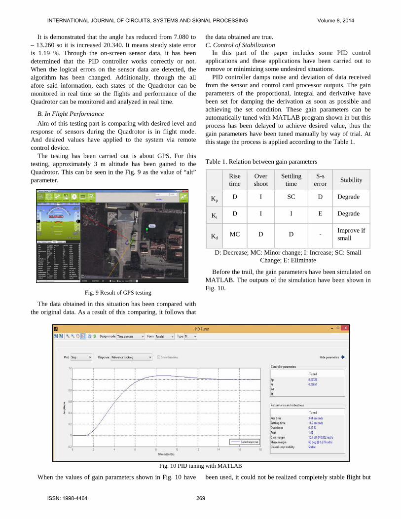
Before the trail, the gain parameters have been simulated on MATLAB. The outputs of the simulation have been shown in Fig. 10.
Fig. 10 PID tuning with MATLAB
When the values of gain parameters shown in Fig. 10 have been used, it could not be realized completely stable flight but
INTERNATIONAL JOURNAL OF CIRCUITS, SYSTEMS AND SIGNAL PROCESSING Volume 8, 2014
ISSN: 1998-4464 269

the Quadrotor has been stably flight parallel to the surface by tuning the gain parameters obtained with MATLAB simulation. It has been observed that the new values of the
gain parameters achieve the system to the desired setpoint shown in Fig. 11.
Fig. 11 Tracking reference value
In Fig. 11, red signal refers to applied signal and blue one refers to signal damps the error in other words it enables that the system achieve the setpoint. In short, it is aimed to prevent disturbance with PID control. In this wise, disturbances have been tracked by using the method of ISA-PID via PID
controller as shown Fig. 12. This flight simulation has been used for tracking data from sensors in the ground control station. This tracking means that values of the disturbances can be monitored in real time.
Fig. 12 Tracking of disturbance
Fig. 12 reveals that the disturbances have successfully been removed. The initial values of the PID parameters have been demonstrated in Fig. 13.
INTERNATIONAL JOURNAL OF CIRCUITS, SYSTEMS AND SIGNAL PROCESSING Volume 8, 2014
ISSN: 1998-4464 270
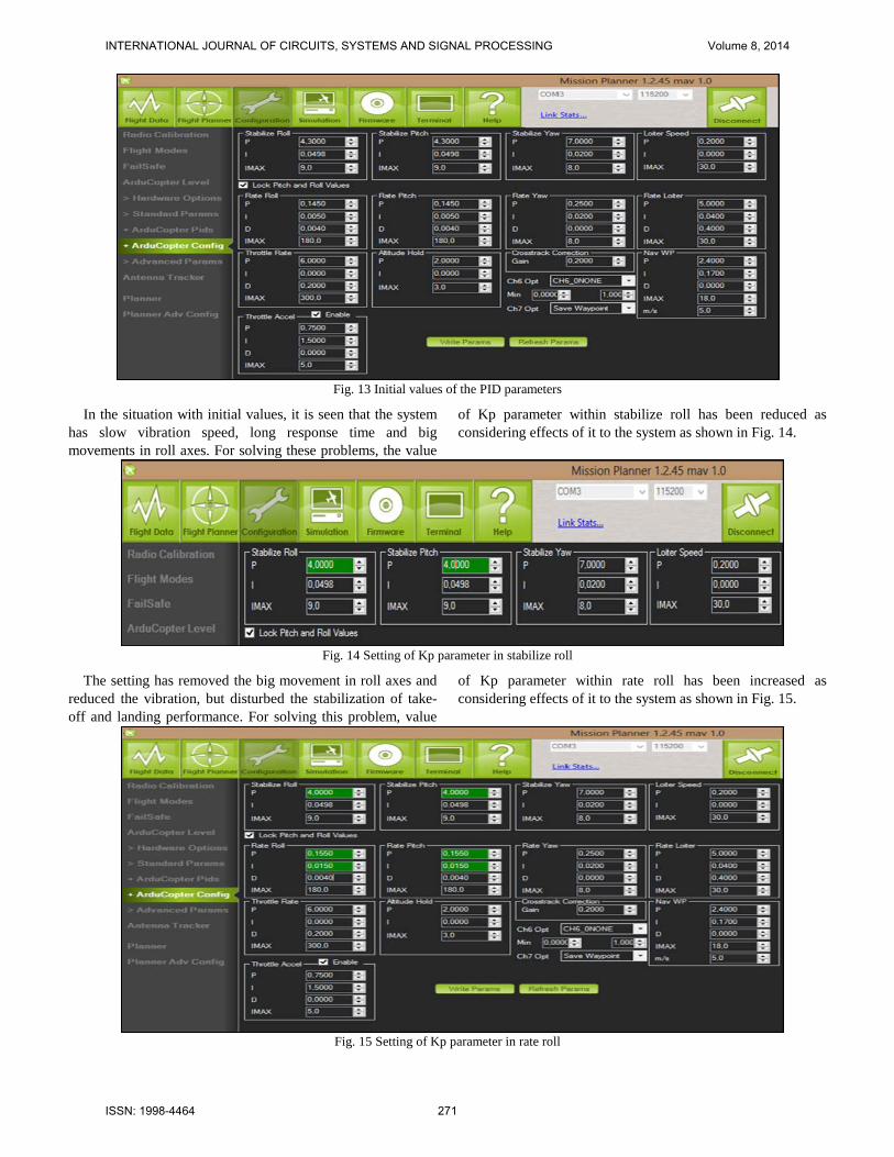
Fig. 13 Initial values of the PID parameters
In the situation with initial values, it is seen that the system has slow vibration speed, long response time and big movements in roll axes. For solving these problems, the value
of Kp parameter within stabilize roll has been reduced as considering effects of it to the system as shown in Fig. 14.
Fig. 14 Setting of Kp parameter in stabilize roll
The setting has removed the big movement in roll axes and reduced the vibration, but disturbed the stabilization of take-off and landing performance. For solving this problem, value
of Kp parameter within rate roll has been increased as considering effects of it to the system as shown in Fig. 15.
Fig. 15 Setting of Kp parameter in rate roll
INTERNATIONAL JOURNAL OF CIRCUITS, SYSTEMS AND SIGNAL PROCESSING Volume 8, 2014
ISSN: 1998-4464 271
The setting shown in Fig. 15 has provided stabilization and minimizing the vibration. Also response to disturbance effects has been eliminated. During flight mode, red data refers to roll motion, blue data refers to pitch motion and green one refers to
yaw motion as shown in Fig. 16. These data have been obtained from the gyro and the accelerometer and transmitted to ground computer in real time. This situation enables to analyze these data after the flights.
Fig. 16 Data belong to Roll, Pitch, and Yaw motion
D. Autopilot System For autopilot mode many tests have been carried out. One of
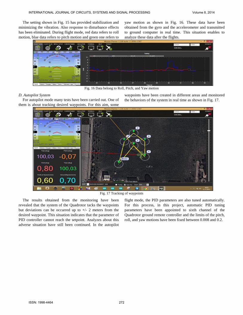
them is about tracking desired waypoints. For this aim, some
waypoints have been created in different areas and monitored the behaviors of the system in real time as shown in Fig. 17.
Fig. 17 Tracking of waypoints
The results obtained from the monitoring have been revealed that the system of the Quadrotor tacks the waypoints but deviations can be occurred up to +/- 2 meters from the desired waypoint. This situation indicates that the parameter of PID controller cannot reach the setpoint. Analyzes about this adverse situation have still been continued. In the autopilot
flight mode, the PID parameters are also tuned automatically. For this process, in this project, automatic PID tuning parameters have been appointed to sixth channel of the Quadrotor ground remote controller and the limits of the pitch, roll, and yaw motions have been fixed between 0.008 and 0.2.
INTERNATIONAL JOURNAL OF CIRCUITS, SYSTEMS AND SIGNAL PROCESSING Volume 8, 2014
ISSN: 1998-4464 272

Fig. 18 Autopilot flight mode in 3D
Fig. 19 Automatic flight in Google Earth
Movements belong to autopilot flight mode of the Quadrotor can be monitored via Google Earth program in 3D. Fig. 18 and Fig. 19 show that the Quadrotor’s movements in autopilot flight mode.
The green line refers to motion area during the automatic flight mode. The flight has been carried out in many different altitude ranges as seen in the figures. Additionally, area
appears in the Fig. 18 and Fig. 19 belongs to Faculty of Aeronautics and Astronautics of Anadolu University. All flight tests of the designed Quadrotor have carried out in this area and the Anadolu Airport within the university as shown in Fig. 20. That the university has own airport has made it the unique university.
INTERNATIONAL JOURNAL OF CIRCUITS, SYSTEMS AND SIGNAL PROCESSING Volume 8, 2014
ISSN: 1998-4464 273

Fig. 20 Anadolu Airport
V. RESULTS When building a Quadrotor, working of sensor and control
system are of great importance for operating performance of it so this paper has been dealt with in this context.
The testing carried out are about the sensors integrated in IMU. From these sensors the data relative to angle of pitch and roll has only been tested. The testing about angle of roll shown in Fig. 4 and Fig. 5 has set forth that the steady state error changes between 1.440 % and 2.350 %. These value are in acceptable limits, so it can be said that the sensors operate accurately and sensitively. The testing about angle of pitch shown in Fig. 6 and Fig. 7 has set forth that the steady state error changes between 1.180 % and 1.190 %. These value are in acceptable limits and they can be dismiss according to its field of use, so it can be said that the sensors operate accurately and extremely precise. Other application is validating GPS data. For these validations, the altitude has been gain to the Quadrotor and desired data has been obtained as shown in Fig. 8. After that, the data has been compared with original values. From this comparing, it follows that GPS data can be obtained correctly.
The last applications are about setting the parameters of PID controller. For this aim, first of all initial values and the problems in this situation has been defined as shown in Fig. 9. After that, for solving these problem, the values of the parameters has been set as shown in Fig. 10 and Fig. 11. Finally the settings to be provided desired situation has been achieved.
The achievements set forth that the Quadrotor operate effectively and can be used in variable tasks.
VI. CONCLUSION The developments and especially nano-technology have
provided opportunities for dimensions and components of the vehicles to be produced much smaller sizes. And also, vehicles can be produced faster and higher processing capacity when
comparing with those of the past. Quadrotor is one of such vehicles and analyzed in this paper in terms of working operate and controlling.
When considering the paper as a whole, it follows that the Quadrotor has been built successfully. Also result section sets forth that undesired situations has been removed and minimized with PID controller by setting its parameters. These settings are indicator that effects of a controller designed successfully provide the system with many advantages. Moreover, this paper is the first study to be carried out in Anadolu University in this field. In this sense, it becomes an example for succeeding studies to be fulfilled in both the university and others.
ACKNOWLEDGMENT The supported by Anadolu University Research Projects
Committee (Project No. 1208F130) is gratefully acknowledged.
REFERENCES [1] G. M. Hoffmann, H. Huang, S. L. Waslander, C. J. Tomlin, “Precision
flight control for a multi-vehicle Quadrotor helicopter testbed”, Control Engineering Practice, pp. 1023– 1036, 2011.
[2] N. Abas, A. Legowo, R. Akmeliawati, “Parameter Identification of an Autonomous Quadrotor”, 4th International Conference on Mechatronics (ICOM), Kuala Lumpur, Malaysia, 17-19 May, 2011.
[3] C. Nicol, C. J. B. Macnab, “A. Ramirez-Serrano, Robust adaptive control of a Quadrotor helicopter”, Mechatronics, pp. 927–938, 2011.
[4] J. Wu, H. Peng, Q. Chen, “RBF-ARX Model-Based Modeling and Control of Quadrotor”, IEEE International Conference on Control Applications, Yokohama, Japan, September 8-10, 2010.
[5] S. K. Phang, C. Cai, B. M. Chen, T. H. Lee, “Design and Mathematical Modeling of a 4-Standard-Propeller (4SP) Quadrotor”, 10th World Congress on Intelligent Control and Automation (WCICA), Beijing, China, July 6-8, 2012.
[6] P. Pounds, R. Mahony, P. Corke, “Modelling and control of a large Quadrotor robot”, Control Engineering Practice, pp. 691–699, 2011.
[7] M. Ryll, H. H. Bulthoff, P. R. Giordano, “Modeling and Control of a Quadrotor UAV with Tilting Propellers”, IEEE International Conference on Robotics and Automation, Saint Paul, Minnesota, USA, May 14-18, 2012.
INTERNATIONAL JOURNAL OF CIRCUITS, SYSTEMS AND SIGNAL PROCESSING Volume 8, 2014
ISSN: 1998-4464 274

[8] G. B. Raharja, K. G. Beom, Y Kwangjoon, “Design and Implementation of Coaxial Quadrotor for an Autonomous Outdoor Flight”, The 8th International Conference on Ubiquitous Robots and Ambient Intelligence (URAI), Songdo Conventi, Incheon, Korea, Nov. 23-26, 2011.
[9] E. Cetinsoy, S. Dikyar, C. Hancer, K. T. Oner, E. Sirimoglu, M. Unel, M. F. Aksit, “Design and construction of a novel quad tilt-wing UAV”, Mechatronics, pp. 723-745, 2012.
[10] Y. Yali, S. Feng, W. Yuanxi, “Controller Design of Quadrotor Aerial Robot”, Physics Procedia, pp. 1254 – 1260, 2012.
[11] J. Zhang, F. Zhang, M. Ren, G. Hou, F. Fang, “Cascade control of super-heated steam temperature with neuro-PID controller”, ISA Transaction, pp. 778–785, 2012.
[12] J. Li, Y. Li, “Dynamic Analysis and PID Control for a Quadrotor”, IEEE International Conference on Mechatronics and Automation, Beijing, China, 7-10, 2011.
[13] M. Bošnak, D. Matko, S. Blažič, “Quadrocopter control using an on-board video system with off-board processing”, Robotics and Autonomous System, pp. 657-667, 2012.
[14] L. Besnarda, Y. B. Shtesselb, B. Landrum, “Quadrotor vehicle control via sliding mode controller driven by sliding mode disturbance observer”, Journal of the Franklin Institute, pp. 658-594, 2012.
[15] L. Luque-Vegan, B. Castillo-Toledo, A. G. Loukianov, “Robust block second order sliding mode control for a Quadrotor”, Journal of the Franklin Institute, pp. 719–739, 2012.
[16] G. V. Raffo, M. G. Ortega, F. R. Rubio, “An integral predictive/nonlinear H1 control structure for a Quadrotor helicopter”, Automatica, pp. 29-39, 2012.
[17] Y. Yang, J. Wu, W. Zheng, “Variable Structure Attitude Control for an UAV with Parameter Uncertainty and External Disturbance”, Procedia Engineering, pp. 408 – 415, 2012.
[18] K.Y. Chee, Z.W. Zhong, “Control, navigation and collision avoidance for an unmanned aerial vehicle”, Sensors and Actuators, pp. 66-76, 2013.
[19] J. F. Guerrero-Castellanos, N. Marchand, A. Hably, S. Lesecq, J. Delamare, “Bounded attitude control of rigid bodies: Real-timeexperimentation to a Quadrotor mini-helicopter”, Control Engineering Practice, pp. 790 797, 2011.
[20] A. Eresen, N. Imamoglu, M. O. Efe, “Autonomous Quadrotor flight with vision-based obstacle avoidance in virtual environment”, Expert Systems with Applications, pp. 894-905, 2012.
[21] M. Seyedkazemi, “Designing Optimal PID controller with Genetic Algorithm In view of controller location in the plant”, Proceedings of the 7th WSEAS International Conference on Signal Processing, Robotics And Automation (ISPRA '08), 2008.
[22] A. Sanna, B. Pralio, “Simulation and Control of Mini UAVs”, Proceedings of the 5th WSEAS Int. Conf. on Simulation, Modeling And Optimization, pp. 129-135, 2005.
[23] M. Foltin, J. Murgaš, I. Sekaj, “A new Adaptive PID Control Approach Based on Closed-Loop Response Recognition”, Proceedings of the 7th WSEAS International Conference on Automation & Information, pp. 156-160, 2006.
[24] L. Hongling, J. Chuanwen, Z. Yan, “A Design of PID Parameters Self-tuning Fuzzy Control System and Its Incorporation with Practical Realization on PLC”, Proceedings of the 6th WSEAS International Conference on Robotics, Control and Manufacturing Technology, pp. 76-80, 2006.
[25] K. Turkoglu, E. M. Jafarov, “Lateral Dynamic Modeling of Hezarfen Unmanned Aerial Vehicle (UAV) and H Loop Shaping Robust Control System Design”, Proceedings of the 10th WSEAS International Conference on SYSTEMS, pp. 369-374, 2006.
INTERNATIONAL JOURNAL OF CIRCUITS, SYSTEMS AND SIGNAL PROCESSING Volume 8, 2014
ISSN: 1998-4464 275