Embed Size (px)
Citation preview
.
1
PHYSIOLOGY OF SPEECH AND ITS CONSIDERATION IN PROSTHODONTICS
PRESENTED BYDr Vishnu Soni
CONTENTS
• Introduction
• Mechanism of speech production
• Components of speech
• Classification of speech
• Role of speech during denture construction
• Speech tests
• Speech problems associated with cleft palate
• Conclusion
• references
INTRODUCTION
• Speech is defined as the use of systematized vocalization to express verbal symbols or words (Sheridan 1964)
• Speech is very sophisticated autonomous and unconscious activity.
• In a matured human it is a learned habitual neuromuscular pattern which makes use of anatomical structures designed primarily for respiration and deglutition
MECHANISM OF SPEECH PRODUCTION
• Normal speech depends on proper functioning of 5 essential mechanisms:
1. The motor-lungs and associated muscles that supply the air.
2. The vibrator-vocal cord that gives pitch to the tone.
3. The resonator-consists of oral,nasal,pharyngeal cavity and paranasal sinuses.
4. The articulators-lip tounge palate and teeth.
5. The initiator-motor areas of the brain
COMPONENTS OF SPEECH
Kantner and west divided speech into following components
respiration
phonation
resonance
Speech articulation
audition
Neurological function
RESPIRATION
• The movement of the air in the inspiratory and expiratory places is essential to production of sound
• During speech inhalation is accomplished very rapidly and accounts for only 10% of total respiratory volume
• Exhalation is regulated by muscle forces according to air supply necessary for the desired sentence length during connected speech

.
2
PHONATION
• During speech the breath stream from the lungs courses through the trachea and into the larynx where the sound is produced by vibration of vocal cords
• Disturbances in this system may adversely affect the action of the vocal cords and cause disorders of voice production
RESONATION
• It takes place in the oral nasal and pharyngeal cavities which are the prime resonating chambers.
• Tone resulting from vocal cords is modified by these cavities.
• Cranial and facial cavities also add some some resonance to the speech.
• The nasal cavity is used as the primary resonating chamber for only three English sounds M, N, ‘ng’. All other sounds depend on oral cavity for the resonance.
• The choice of the chamber is made by the placement of soft palate. When it contracts against the pharyngeal wall the oral cavity becomes the resonating chamber and when it contracts against the tongue, the nasal cavity becomes the resonating chamber. A rapid continuous movement of the soft palate takes place during speech.
SPEECH ARTICULATION
• It is defined as the production of individual sounds in connected discourse.
• It is accomplished by the teeth, tongue, lips, palate which break up the sound as the air stream emerges.
• The air column, which is selectively vibrated as it passes through the vocal cords, moves through the pharynx to the oral and nasal cavities and radiates outward and yet this cannot be termed as speech.
• The speech articulation is the process where the sounds which are produced form a meaningful elements of speech by movement of palate, mandible, teeth, tongue and lips.
AUDITION
• The quality of speech is mainly dependent on the process of audition
• Distortions in speech articulation and voice quality may be associated with reductions in hearing activity.
NEUROLOGICAL FUNCTION
• Speech involves mechanisms which are complexly integrated, either sequentially or simultaneously by the central nervous system the integration of these signals into speech requires neuromuscular coordination at the peripheral level as well as brain function.
• Speech production includes large numbers and sequences of innate and learned motor function.
.
3
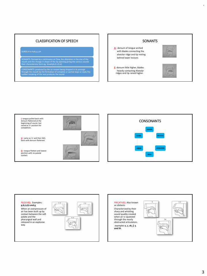
CLASSIFICATION OF SPEECH
SURDS:H in huh,s,z,sh
SONANTS: Formed by a continuous air flow, the alteration in the size of the mouth and the change in shape of the lip opening giving the various sounds their characteristic form eg. Vovels(A,E,I,O,U)
CONSONANTS: produced by the air stream being stopped in its passage through the mouth by the formation of complete or partial stops or seals.The sudden breaking of the seal produces the sound
SONANTS
A : dorsum of tongue arched
with blades connecting the
alveolar ridge and tip resting
behind lower incisors
E: dorsum little higher, blades
heavily contacting Alveolar ridges and tip raised higher.
I: tongue pulled back with dorsum flattened at the beginning of sound, but raised to ‘e’ position for completion.
U : same as ‘e’ and then falls back with dorsum flattened.
O : tongue flattest and lowest position with no palatal contact.
CONSONANTS
PLOSIVES
FRICATIVES
AFFRICATIVES
NASAL
LIQUID
GLIDES
PLOSIVES: Examples: p,b,t,d,k and g
When an overpressure of air has been built up by contact between the soft palate and the pharyngeal wall and released in an explosive way.
FRICATIVES: Also known as sibilants
Characterized by their sharp and whistling sound quality created when air is squeezed through the nearly obstructed articulators.
examples-s, z, sh, f, v, and th.
.
4
AFFRICATIVES: A mix between plosive and fricative consonants.
Examples: ch and j
NASAL:
Produced without oral exit of air.
Examples: m n and ng.
LIQUID:
• As the name implies, these consonants are produced without friction
• Example: r
GLIDES:
• Sounds that are characterized by a gradually changing articulator shape.
• Example: w and y.
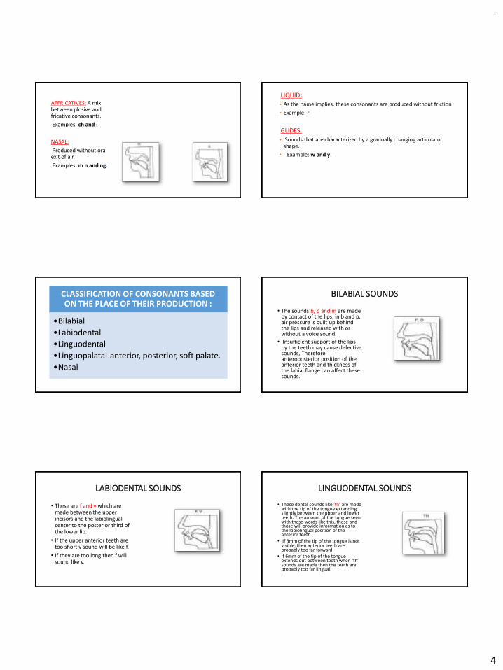
CLASSIFICATION OF CONSONANTS BASED ON THE PLACE OF THEIR PRODUCTION :
•Bilabial
•Labiodental
•Linguodental
•Linguopalatal-anterior, posterior, soft palate.
•Nasal
BILABIAL SOUNDS
• The sounds b, p and m are made by contact of the lips, in b and p, air pressure is built up behind the lips and released with or without a voice sound.
• Insufficient support of the lips by the teeth may cause defective sounds, Therefore anteroposterior position of the anterior teeth and thickness of the labial flange can affect these sounds.
LABIODENTAL SOUNDS
• These are f and v which are made between the upper incisors and the labiolingual center to the posterior third of the lower lip.
• If the upper anterior teeth are too short v sound will be like f.
• If they are too long then f will sound like v.
LINGUODENTAL SOUNDS
• These dental sounds like ‘th’ are made with the tip of the tongue extending slightly between the upper and lower teeth. The amount of the tongue seen with these words like this, these and those will provide information as to the labiolingual position of the anterior teeth.
• If 3mm of the tip of the tongue is not visible, then anterior teeth are probably too far forward.
• If 6mm of the tip of the tongue extends out between teeth when ‘th’ sounds are made then the teeth are probably too far lingual.
.
5
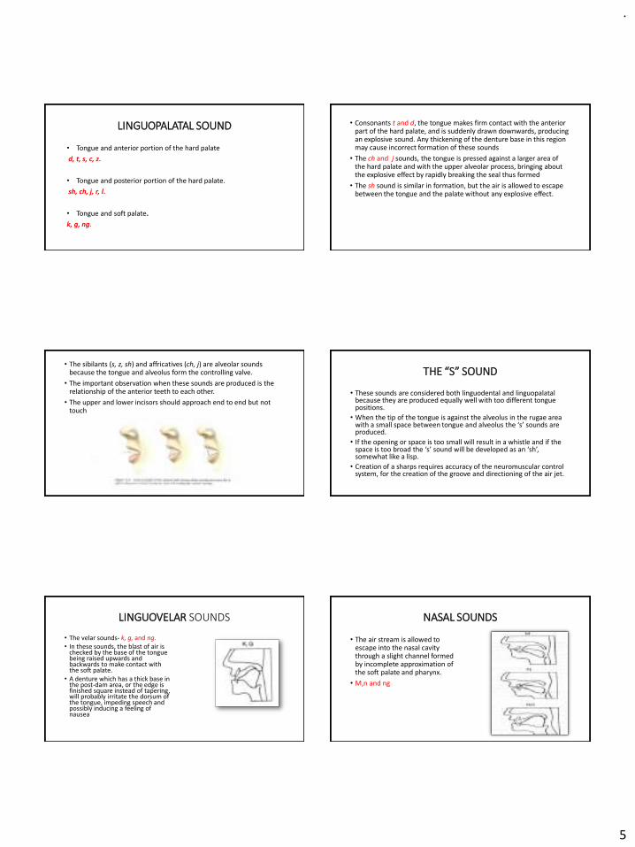
LINGUOPALATAL SOUND
• Tongue and anterior portion of the hard palate
d, t, s, c, z.
• Tongue and posterior portion of the hard palate.
sh, ch, j, r, l.
• Tongue and soft palate.
k, g, ng.
• Consonants t and d, the tongue makes firm contact with the anterior part of the hard palate, and is suddenly drawn downwards, producing an explosive sound. Any thickening of the denture base in this region may cause incorrect formation of these sounds
• The ch and j sounds, the tongue is pressed against a larger area of the hard palate and with the upper alveolar process, bringing about the explosive effect by rapidly breaking the seal thus formed
• The sh sound is similar in formation, but the air is allowed to escape between the tongue and the palate without any explosive effect.
• The sibilants (s, z, sh) and affricatives (ch, j) are alveolar sounds because the tongue and alveolus form the controlling valve.
• The important observation when these sounds are produced is the relationship of the anterior teeth to each other.
• The upper and lower incisors should approach end to end but not touch
THE “S” SOUND
• These sounds are considered both linguodental and linguopalatalbecause they are produced equally well with too different tongue positions.
• When the tip of the tongue is against the alveolus in the rugae area with a small space between tongue and alveolus the ‘s’ sounds are produced.
• If the opening or space is too small will result in a whistle and if the space is too broad the ‘s’ sound will be developed as an ‘sh’, somewhat like a lisp.
• Creation of a sharps requires accuracy of the neuromuscular control system, for the creation of the groove and directioning of the air jet.
LINGUOVELAR SOUNDS
• The velar sounds- k, g, and ng.• In these sounds, the blast of air is
checked by the base of the tongue being raised upwards and backwards to make contact with the soft palate.
• A denture which has a thick base in the post-dam area, or the edge is finished square instead of tapering, will probably irritate the dorsum of the tongue, impeding speech and possibly inducing a feeling of nausea
NASAL SOUNDS
• The air stream is allowed to escape into the nasal cavity through a slight channel formed by incomplete approximation of the soft palate and pharynx.
• M,n and ng
.
6
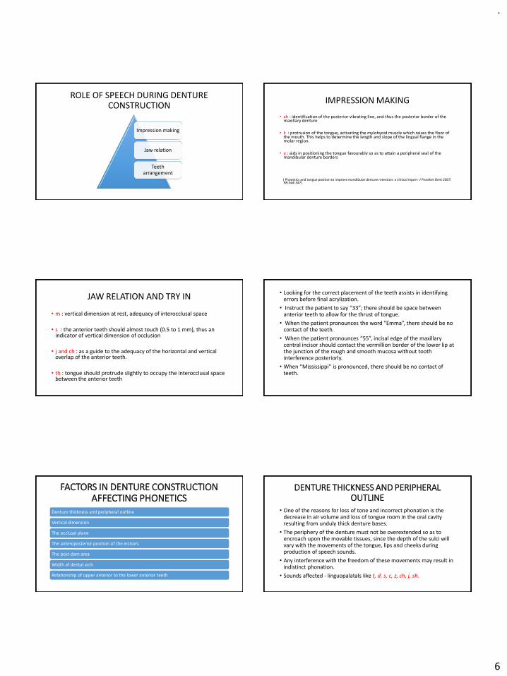
ROLE OF SPEECH DURING DENTURE CONSTRUCTION
Impression making
Jaw relation
Teeth arrangement
IMPRESSION MAKING
• ah : identification of the posterior vibrating line, and thus the posterior border of the maxillary denture
• k : protrusion of the tongue, activating the mylohyoid muscle which raises the floor of the mouth. This helps to determine the length and slope of the lingual flange in the molar region.
• e : aids in positioning the tongue favourably so as to attain a peripheral seal of the mandibular denture borders
( Phonetics and tongue position to improve mandibular denture retention: a clinical report- J Prosthet Dent 2007; 98:344-347)
JAW RELATION AND TRY IN
• m : vertical dimension at rest, adequacy of interocclusal space
• s : the anterior teeth should almost touch (0.5 to 1 mm), thus an indicator of vertical dimension of occlusion
• j and ch : as a guide to the adequacy of the horizontal and vertical overlap of the anterior teeth.
• th : tongue should protrude slightly to occupy the interocclusal space between the anterior teeth
• Looking for the correct placement of the teeth assists in identifying errors before final acrylization.
• Instruct the patient to say “33”; there should be space between anterior teeth to allow for the thrust of tongue.
• When the patient pronounces the word “Emma”, there should be no contact of the teeth.
• When the patient pronounces “55”, incisal edge of the maxillary central incisor should contact the vermillion border of the lower lip at the junction of the rough and smooth mucosa without tooth interference posteriorly.
• When “Mississippi” is pronounced, there should be no contact of teeth.
FACTORS IN DENTURE CONSTRUCTION AFFECTING PHONETICS
Denture thickness and peripheral outline
Vertical dimension
The occlusal plane
The anteroposterior position of the incisors
The post-dam area
Width of dental arch
Relationship of upper anterior to the lower anterior teeth
DENTURE THICKNESS AND PERIPHERAL OUTLINE
• One of the reasons for loss of tone and incorrect phonation is the decrease in air volume and loss of tongue room in the oral cavity resulting from unduly thick denture bases.
• The periphery of the denture must not be overextended so as to encroach upon the movable tissues, since the depth of the sulci will vary with the movements of the tongue, lips and cheeks during production of speech sounds.
• Any interference with the freedom of these movements may result in indistinct phonation.
• Sounds affected - linguopalatals like t, d, s, c, z, ch, j, sh.

.
7
VERTICAL DIMENSION
• The formation of the bilabial sounds p, b, and m require that the lips make contact to check the air stream.
• The lip contact in m is passive. Used as an aid in obtaining the correct vertical height
• A strained appearance during lip contact, or the inability to make contact, indicates that the record rims are occluding prematurely.
• With the sibilant sounds c,s,z,ch,j the teeth come very close together but do not touch.
• If the vertical dimension is excessive, the dentures will actually make contact as these consonants are formed and the patient will most likely complain of ‘clicking teeth’.
THE OCCLUSAL PLANE
• The labiodental sounds f, v and ph are produced by the air stream being stopped and then released when the lower lip breaks contact with the incisal edges of the upper anterior teeth.
• If the occlusal plane is set too high, the correct positioning of the lower lip may be difficult.
• If the plane is set too low, the lip will overlap the labial surfaces of the upper teeth to a greater extent than is required for normal phonation and the sound might be affected.
ANTEROPOSTERIOR POSITION OF THE INCISORS
• Labiodental sounds: f,v,ph
• Incisors are placed too far palatally, the contact of the lower lip with the incisal and labial surfaces of the upper incisors may be difficult, as the lip will tend to pass outside the teeth.
• Linguopalatal sounds : s,c,z
• Tip of the tongue makes slight contact with the upper and lower incisors:
• Incisors are placed too far back, this will result in a lisp due to the tongue making contact with the teeth prematurely
THE POST-DAM AREA
• Errors of construction in this region involve the vowels i and e, and the linguovelar consonants k, g and ng.
• These sounds necessitate contact between the tongue and soft palate: the upper denture base should be kept thin, and the posterior border should merge into the soft tissue in order to avoid irritating the dorsum of the tongue.
• If the post-dam seal is inadequate, the denture may become unseated during the production of plosive sounds, requiring the sudden repositioning of the tongue to control and stabilize the denture
WIDTH OF DENTAL ARCH
• If the teeth are set to an arch that is too narrow, the tongue will be cramped; thus affecting the size and shape of the air channel.
• Results in faulty phonation of consonants such as s, c, t, d, m, n and h where the lateral margins of the tongue make contact with the palatal surfaces of the upper posterior teeth.
• Tip of the tongue, in vowel sounds lies on the floor of the mouth either in contact with or close to the lingual surfaces of the lower anterior teeth and gums.
• The lower anterior teeth should be set so as not to impede the tongue positioning for these sounds, i.e. they should not be set lingual to the alveolar ridge.
SPEECH TESTS
• The phonetic aspect of denture construction deserves equalconsideration with esthetics and mechanics and should be checked atthe time of the waxed try in when it is possible to alter palatal contourto accommodate speech articulation.
• First test is of random speech and is best accomplished by engaging the patient in conversation and obtaining a subjective speech
• The second test is that of specific speech sounds. This is best accomplished by having the patient pronounce six or eight words containing the sound and then combining these words into a sentence.
• In the third test, the patient is asked to read a short paragraph containing an abundance of s, sh, and ch sounds.

.
8
METHODS FOR SPEECH ANALYSIS
• Based on a spectrogram recorded by a sonograph during the uttering of different phrases.
• Thus, an objective opinion of the performance of certain sounds may be achieved.
PERCEPTUAL/
ACOUSTIC ANALYSIS
• Ultrasonics, x-ray mapping, cineradiography, optoelectronic articulatory movement tracking,& electropalatography.
• Useful tool for assessment of tongue contact positions and movements.
KINEMATIC METHODS
ELECTROPALATOGRAPHY
EQUIPMENT:
• 60-80 contact electrodes inserted in individually made acrylic plates.
• EPG main unit.
• Computer.
• Mapping of the tongue movements by the contacted and uncontacted area.
PALATOGRAMS
“Palatograms are the areas of
tongue contact for a given
sound displayed on an artificial
palate through a medium of
non scented talcum powder.”
/t/ sound
COMMUNICATION PROBLEMS ASSOCIATED WITH CLEFT PALATE
Clefts of the lip and palate affect speech in two major ways:
1. The voice quality becomes deviant, and the articulation is impaired.
2. The voice quality is that of excessive nasality.
• They have more trouble with the plosives, fricatives and affricatives
• Voiced sounds seem to be easier than the unvoiced ones, but the consonants present considerable difficulty.
• The distortion errors are primarily due to nasal emission, the person snorting the sounds out of his nose.
SPEECH EVALUATION FOLLOWING OBTURATOR PLACEMENT
• The prosthodontist may require the assistance of a speech pathologist.• Cleft palate patients will invariably require speech therapy • Patients often exhibit hypernasality• The obturator is adjusted to the point where the patient can produce a
clear “p” and a sustained “f” or “s” sound without emission of air through the nose
• Several authors suggested that the sustained pressure required for the “s” phoneme may be a reliable method of evaluating the effectiveness of the obturator.
• Whereas greater intraoral pressure may be required for stop-plosives, such as “p”, the sustained pressure required for “s” mitigates the compensatory elevation of the tongue to assist with closure.
.
9
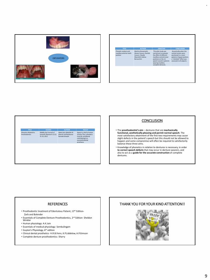
OBTURATORS
TITLE AUTHOR OBJECTIVE CONCLUSION
Phonetic analysis and maxillary anterior tooth position
Martina Giovannetti, Alessio Casucci, Daniele Casucci, Claudia Mazzitelli, Andrea Borracchini
This pilot study was carried out to evaluate the effect of different maxillary central incisor positions on the /s/ speech sound in patients wearing maxillary complete dentures.
Acoustically, when the central incisors were positioned in a more palatal or lingual position, a “whistled” effect was assessed in all subjects.
TITLE SOURCE AUTHOR RESULT
Phonetics Related to Prosthodontics
Middle-East Journal of Scientific Research 12 (1): 31-35, 2012
Abdul-Aziz Abdullah Al Kheraif and RavikumarRamakrishnaiah
Speech is vital to human activity. Thus, phonetics must be considered contributing to a successful dental prosthesis.
CONCLUSION
• The prosthodontist’s aim – dentures that are mechanically functional, aesthetically pleasing and permit normal speech. The most satisfactory attainment of the first two requirements may cause slight defects in the patient’s speech but this should not be allowed to happen and some compromise will often be required to satisfactorily balance these three aims.
• Knowledge of phonetics in relation to dentures is necessary, in order to correct speech defects that may occur in denture wearers, and also to act as a guide for the accurate construction of complete dentures.
REFERENCES
• Prosthodontic treatment of Edentulous Patient, 12th Edition-
Zarb and Bolender
• Essentials of Complete Denture Prosthodontics, 2nd Edition- Sheldon Winkler
• Human physiology: A.K.Jain
• Essentials of medical physiology: Sembulingam
• Guyton’s Physiology, 6th edition
• Clinical dental prosthetics- H.R.B.Fenn, K.P.Liddelow, A.P.Gimson
• Complete denture prosthodontics: Sharry
THANK YOU FOR YOUR KIND ATTENTION!!
.
1
RPD
Dr Vishnu Soni
❖ INTRODUCTION
❖ IMPRESSION
❖ IMPRESSION TRAYS
❖TRAYS USED IN RPD IMPRESSION PROCEDURE
❖ FACTORS INFLUENCING THE CHOICE OF IMPRESSION MATERIAL
❖ IMPRESSION MATERIALS USED-OVERVIEW
❖ RPD IMPRESSION Vs COMPLETE DENTURE IMPRESSION
❖ PRIMARY IMPRESSION
➢ OBJECTIVES
❖ PROCEDURE
➢ PATIENT MANAGEMENT
➢ CONTROL OF SALIVA
➢ PRECAUTIONS TO BE TAKEN FOR “ GAGGERS ”
➢ EXAMINATION OF IMPRESSION
➢ REASONS FOR REJECTING AN IMPRESSION
❖ FINAL IMPRESSION METHODS
❖ McLEAN’S TECHNIQUE
❖ HINDEL’S TECHNIQUE
❖ SELECTIVE PRESSURE TECHNIQUE
❖ FUNCTIONAL RELINING TECHNIQUE
❖ FLUID WAX TECHNIQUE
❖ ALTERED CAST TECHNIQUE
MODIFICATION
❖ REVIEW OF LITERATURE
❖ CONCLUSION
❖ REFERENCES
INTRODUCTION
Sensitive to technique and material procedures.
Not a passive activity.
Impression material accomplishes the task
operator is merely an observer.
Combined effort event accomplished by:
Operator
basic fundamental knowledge of all aspects of the impression procedures
Intra oral condition of the patient.
The position of the patient.
The size and position of the tray.
The selection of the material and technique.
Patient’s actions and facial muscle activity.
.
2
Impression
➢ A negative likeness or copy in reverse of the surface of an object ; imprint of teeth and adjacent structures for use in dentistry. GPT – 8
Partial denture impression
➢ A negative likeness of a part or all of a partially edentulous arch - GPT – 8
➢ An impression of partially edentulous arch must record accurately the anatomic formof teeth and surrounding tissues. Unless the cast upon which the prosthesis is to be constructed is an exact replica of mouth, the prosthesis can’t be expected to fit.
Properly made and accurate cast can be obtained only from an accurate impression.
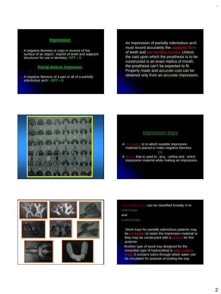
Impression trays
A receptacle in to which suitable impression material is placed to make negative likeness
ORA device that is used to carry, confine and control
impression material while making an impression.
Impression trays can be classified broadly in to stock trays
and custom trays
Stock trays for partially edentulous patients may be perforated to retain the impression material or they may be constructed with a rimlock for this purpose. Another type of stock tray designed for the reversible type of hydrocolloid is water cooled trays. It contains tubes through which water can be circulated for purpose of cooling the tray.
.
3
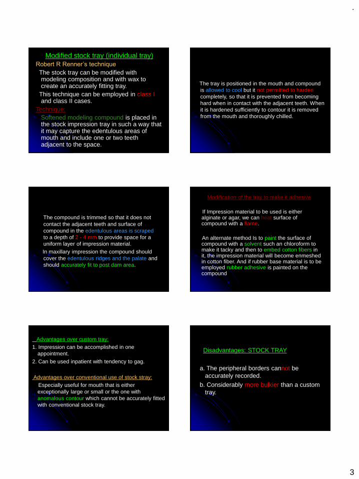
Modified stock tray (individual tray)Robert R Renner’s technique
The stock tray can be modified with modeling composition and with wax to create an accurately fitting tray.
This technique can be employed in class Iand class II cases.
Technique:Softened modeling compound is placed in the stock impression tray in such a way that it may capture the edentulous areas of mouth and include one or two teeth adjacent to the space.
The tray is positioned in the mouth and compound is allowed to cool but it not permitted to hardencompletely, so that it is prevented from becoming hard when in contact with the adjacent teeth. When it is hardened sufficiently to contour it is removed from the mouth and thoroughly chilled.
The compound is trimmed so that it does not contact the adjacent teeth and surface of compound in the edentulous areas is scrapedto a depth of 2 - 4 mm to provide space for a uniform layer of impression material. In maxillary impression the compound should cover the edentulous ridges and the palate and should accurately fit to post dam area.
Modification of the tray to make it adhesive
If Impression material to be used is either alginate or agar, we can heat surface of compound with a flame.
An alternate method Is to paint the surface of compound with a solvent such an chloroform to make it tacky and then to embed cotton fibers in it, the impression material will become enmeshed in cotton fiber. And if rubber base material is to be employed rubber adhesive is painted on the compound
Advantages over custom tray:1. Impression can be accomplished in one
appointment.
2. Can be used inpatient with tendency to gag.
Advantages over conventional use of stock stray:Especially useful for mouth that is either exceptionally large or small or the one with anomalous contour which cannot be accurately fitted with conventional stock tray.
Disadvantages: STOCK TRAY
a. The peripheral borders cannot be accurately recorded.
b. Considerably more bulkier than a custom tray.
.
4
Custom impression trays:
a. Peripheral borders can be precisely recorded in the impression
b. Thickness of impression material can be controlled. This is important consideration when using rubber base type material, which should not exceed thickness of 2-4 mm because a section thicker than this is subject to distortion.
C. Well fitted tray will better support the impression in the palate, then avoiding even present danger of material slumping in vital areas.
Custom trays are sometimes needed for mouths that are abnormally or of unusual configuration.
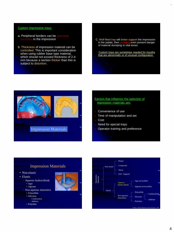
Impression Materials
Factors that influence the selection of impression materials are:
➢ Convenience of use
➢ Time of manipulation and set➢ Cost
➢ Need for special trays
➢ Operator training and preference
Impression Materials
• Non-elastic• Elastic
– Aqueous hydrocolloids• Agar• Alginate
– Non-aqueous elastomers• Polysulfide• Silicones
– Condensation– Addition
• Polyether
Impr
essi
on
Mat
eria
ls
Non-elastic
Elastic
Aqueous Hydrocolloids
Non-aqueous Elastomers
Polysulfide
Silicones
Polyether
Condensation
Addition
Agar (reversible)
Alginate (irreversible)
Plaster
Compound
ZnO - Eugenol
Waxes
O’Brien Dental Materials & their Selection 1997
.
5
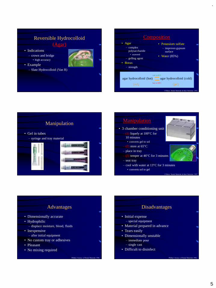
Reversible Hydrocolloid (Agar)
• Indications– crown and bridge
• high accuracy
• Example– Slate Hydrocolloid (Van R)
Composition• Agar
– complex polysaccharide
• seaweed
– gelling agent
• Borax– strength
• Potassium sulfate– improves gypsum
surface
• Water (85%)
agar hydrocolloid (hot) agar hydrocolloid (cold)
(sol) (gel)
cool to 43 C
heat to 100 C
O’Brien Dental Materials & their Selection 1997
Manipulation
• Gel in tubes– syringe and tray material
Manipulation
• 3 chamber conditioning unit– (1) liquefy at 100C for
10 minutes• converts gel to sol
– (2) store at 65C
– place in tray
– (3) temper at 46C for 3 minutes
– seat tray
– cool with water at 13C for 3 minutes• converts sol to gel
O’Brien Dental Materials & their Selection 1997
Advantages
• Dimensionally accurate• Hydrophilic
– displace moisture, blood, fluids
• Inexpensive– after initial equipment
• No custom tray or adhesives• Pleasant• No mixing required
Phillip’s Science of Dental Materials 1996
Disadvantages
• Initial expense– special equipment
• Material prepared in advance• Tears easily• Dimensionally unstable
– immediate pour– single cast
• Difficult to disinfect
Phillip’s Science of Dental Materials 1996
.
6
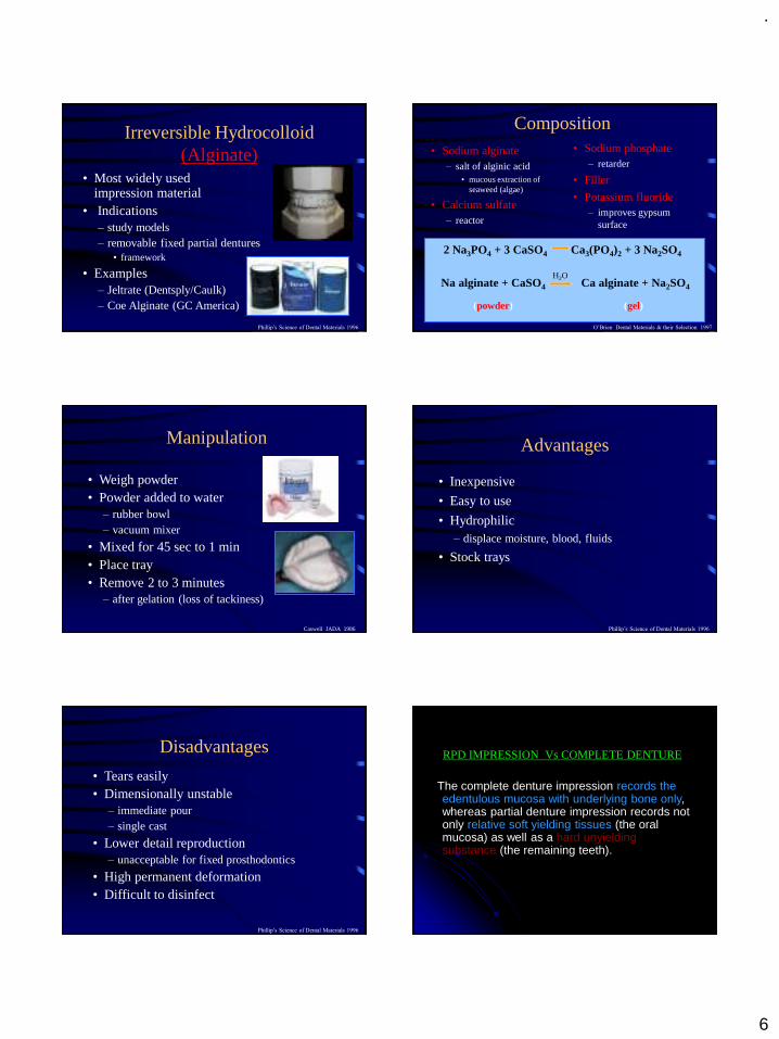
Irreversible Hydrocolloid (Alginate)
• Most widely used impression material
• Indications– study models– removable fixed partial dentures
• framework
• Examples– Jeltrate (Dentsply/Caulk)– Coe Alginate (GC America)
Phillip’s Science of Dental Materials 1996
Composition• Sodium alginate
– salt of alginic acid• mucous extraction of
seaweed (algae)
• Calcium sulfate– reactor
• Sodium phosphate– retarder
• Filler
• Potassium fluoride– improves gypsum
surface
2 Na3PO4 + 3 CaSO4 Ca3(PO4)2 + 3 Na2SO4
Na alginate + CaSO4 Ca alginate + Na2SO4
(powder) (gel)
H2O
O’Brien Dental Materials & their Selection 1997
Manipulation
• Weigh powder• Powder added to water
– rubber bowl– vacuum mixer
• Mixed for 45 sec to 1 min• Place tray• Remove 2 to 3 minutes
– after gelation (loss of tackiness)
Caswell JADA 1986
Advantages
• Inexpensive
• Easy to use
• Hydrophilic– displace moisture, blood, fluids
• Stock trays
Phillip’s Science of Dental Materials 1996
Disadvantages
• Tears easily• Dimensionally unstable
– immediate pour – single cast
• Lower detail reproduction– unacceptable for fixed prosthodontics
• High permanent deformation• Difficult to disinfect
Phillip’s Science of Dental Materials 1996
RPD IMPRESSION Vs COMPLETE DENTURE
The complete denture impression records the edentulous mucosa with underlying bone only, whereas partial denture impression records not only relative soft yielding tissues (the oral mucosa) as well as a hard unyielding substance (the remaining teeth).
.
7
Removable partial denture impression need to record the teeth that are irregular in contour as well as varying in their vertical relations to occlusal plane. The chosen impression material must be capable of recording the tissue contours as accurately as possible without distortion, which occurs as impression is withdrawn.
PRIMARY IMPRESSION
Objectives:
To obtain an impression of all the standing teeth and denture - supporting tissues of each jaw from which study casts may be prepared.
The purpose of the study casts are:
To enable special trays and occlusion rims to be constructed if necessary.
To examine the occlusion in detail on an articulator.
By use of a surveyor, to plan the path of insertion of the proposed denture, arrive at a tentative design and plan any mouth preparation.
Checking Maxillary Tray For Correct Size
Checking Mandibular Tray for Correct Size
Control of Gagging
It is usually a mistake to make too big an issue over the making of impressions. The dentist definitely should not bring up the subject of gagging. The dentist should ask whether the patient has had impression made previously. If this is to be the patient‘s first experience a brief description of the procedure should be given.
That the material to be used has the consistency of thick whipped cream and that is sets up to a rubber consistency in several minutes, is usually all the explanation that is necessary. The dentist should proceed in confident, efficient manner. Dentist usually encounter more problems with gagging when they are in initial stages of dental practice and approach the making the impressions with unsure and nervous demeanor.
.
8
Procedures that will help prevent Gagging
Seating the patient in an upright position with the occlusal plane with the floor
correcting the maxillary tray with modeling plasticand leaving sufficient unrelieved modeling plastic at the posterior borders that positive contact can be maintained against the posterior palate during the setting of the alginate.
Not overfilling the tray with alginate.
Seating the posterior part of the tray first and then rotating the tray into position thereby forcing excess alginate in an anterior direction rather than out of the posterior border of the tray.
Asking the patient to keep the eyes open during the impression procedure This usually reduces the patient tension.
Asking the patient to breath through the nose.
Asking the patient to keep eyes focused on some small object.
Giving all instructions to the patient in a firm controlled manner.
Having the patient use astringent mouth rinseand cold water rinses before the impression is made. The use of an anesthetic spray is usually contraindicated because it will cause numbnessof the tongue and palate and may contribute to the urge to gag.
Most gagging problems are psychologic rather than physical, and confidence in the dentist will help eliminate many of them.
Control of Saliva
Alginate has a tendency to stick to teeth that are too dry. Therefore the teeth should not be air dried before making an impression. However, excessive amounts of saliva, particularly of the thick mucous type, will displace the alginate impression material and will contribute to an inaccurate impression.
The saliva can be controlled for most patients by having the patient rinse cold water and then packing the mouth with 2x2 inch gauze that has been unfolded to form a strip of 2-inch gauze. In the maxillary arch one gauze strip is placed in the right buccal vestibule and another in the left vestibule.
The patient can be asked to lightly hold a third piece of gauze in the palate. Because too much force by the patient may displace the tissue to be recorded in the impression, the dentist may prefer to wipe the palatal area just before making the impression.

.
9
In the mandibular arch one gauze strip is placed in each of the buccal vestibules and another is placed in the linguoalveolar sulcusby having the patient raise the tongue, placing the gauze in the sulcus, and then having the patient relax the tongue to hold the gauze in position. The gauze is removed immediately before the impression is made.
A few patients secrete an excessive amount of thick mucinous saliva from the palatal salivary glands. This heavy saliva displaces the alginate and results in an inaccurate and rough surface to the impression.
These patients should be instructed to rinse with an astringent mouth rinse. The 2x2 inch sponges dampened in warm water should be used to place pressure over the posterior palate in an attempt to milk the glands.
This is followed by an ice water rinse immediately before the impression is made.
In rare instances the patient will secrete such copious amounts of saliva that impression making becomes extremely difficult if not impossible.
The use of an antisialagogues in combination with mouth rinse and gauze packs effectively controls this salivation. A 15 mg propantheline bromide (pro-banthine) tablet taken 30 minutes beforethe impression appointment will also help control the excessive salivation.
These drugs should never be prescribed in the presence of medical contraindications such as glaucoma, cardiac conditions in which any increase in the heart rate is to be avoided.
Mixing Impression Material
Alginate may be mixed by hand spatulation, mechanical spatulation, or mechanical spatulation under vacuum.
The objective is to obtain a smooth, bubble-free mix of alginate. In hand spatulation a measured amount of distilled water at approximately 22 °C is placed in a rubber mixing bowl The pre-weighed alginate powder is sifted from its container into the water.

.
10
The mixing should begin slowly using a stiff, broad - bladed spatula.When the powder is thoroughly wet, the speed of the spatulation should be increased The spatula should crush the material against the sides of the bowl to ensure that the material is completely mixed. The spatulation should continue for a minimum of 45 seconds.
The strength of the gel can be reduced to 50 % if the mixing is not complete. Insufficient spatulation can result in failure of the ingredients to dissolve sufficiently. Then the chemical reaction of changing from sol to gel will not proceed uniformly throughout the mass of alginate. An incompletely spatulated mix will appear lumpy and granular and will have numerous areas of trapped air.
Complete spatulation will result in a smooth, creamy mixture. The mixing should be completed by wiping the alginate against the side of the bowl with the spatula to remove any trapped air. The most consistent method of making a smooth, bubble- free mix is mechanical spatulation under vacuum.
The pre-weighed powder is added to the pre-measured water in the mechanical mixing bowl .The powder is thoroughly incorporated into water by hand spatulation. The mix is then mechanically spatulated under 20 pounds of vacuum for 15 seconds.
Longer spatulation will result in a greatly reduced setting time of the alginate and could affect the strength of the gel.
Loading the Impression Tray
Small increments of the impression material should be placed in the tray and forced under the rim lock. Placing too large a portion of alginate at one time increases the possibility of trapping air The tray should be filled to the level with the flanges of the tray.
Overfilling should be avoided.
.
11
Making the Impression
The mandibular impression is made first because it usually entails less patient discomfort Patient confidence is increasedwhen an impression has been successfully completed while holding the tray with the left hand the dentist uses the right hand to remove the gauze pads from the patient’s
mouth.
The syringe is used to inject the impression material over the occlusal surface of the teeth and into the vestibular and alveolingual sulcus areas. The impression material will remain in place if the tissues are fairly dry. A tendency for the alginate to form a ball and not remain where placed indicates that the tissues are too moist and that voids are likely to be present in the impression.
There is not enough time to repack the mouth before gelation begins, so the impression procedure should be completed. The impression should be carefully inspected and if voids are present in critical areas, the impression procedure should be repeated. Packing the mouth with more or larger gauze pads and avoiding removal of the gauze until ready to apply the alginate will usually prevent this problem.
The layer of alginate applied with the syringe should be 3 to 4 mm thick; If it is too thin, the heat of the tissues of the oral cavity may cause the material to set before the tray is seated, resulting in a layered impression.
The fingers of the left hand that are retracting the right cheeks should depress the lower lip to provide good visibility. When the tray is correctly lined up over the teeth, the patient is asked to protrude the tongue. The tray is carefully seated so that its flanges are below the gingival margins of the teeth.
The tray should not be over seatedbecause this could result in the cusps of the teeth contacting the tray, causing an inaccurate impression. Great care must be exercised in seating the tray if the patient has mandibular tori or other exostoses, or the making of this impression can be a very painful experience for the patient.
.
12
As the tray is being seated, the cheeks are pulled out to prevent the trapping of buccal tissues under the tray. The patient is asked to keep the tip of the tongue in contact with the upper surface of the tray during the gelation of the impression material.
The dentist must maintain the position of the tray during the entire gelation period. This can be accomplished most conveniently and effectively by placing the forefinger of each hand on the top of the tray in the premolar area and by placing the thumbs under the patient ‘s chin.
The dentist through tactile sense can maintain an even amount of pressure on the tray even if the patient swallows or opens or closes the mouth. Any movement of the tray during the gelation period will result in an inaccurate impression.
Allowing the patient or the assistant to hold the tray or leaving the patient unattended must be avoided.
Within 3 to 4 minutes the alginate should be set.
For maxillary impression, the patients is prepared by using the rinses and placing the gauzes pads described for making the mandibular impression. While holding the loaded tray with the left hand the dentist uses the right hand to remove the gauze pads.
Alginate is injected onto the occlusal surfaces and in all vestibular areas as for the mandibular arch. In addition, a fairly large amount should be wiped onto the palate. Failure to accomplish this step will usually result in an impression with a large void in the palatal area.
The loaded maxillary tray is grasped by the thumb and forefinger of the right hand. As the right posterior flange of the impression tray stretches the right corner of the mouth, the dentist ‘s left arm should
be behind the patient’s head and headrest
so that the thumb and index finger may grasp the left corner of the mouth and distend it slightly to allow the impression tray to enter the mouth in a straight line.
.
13
No attempt should be made to seat the tray until the tray is in its correct anteroposterior position. Once the tray is in the mouth, the thumb and forefinger of the left hand should raise the upper lip to allow the dentist to see the relationship between the labial flange of the tray and the anterior teeth or the residual ridge.
The tray must be centered and properly aligned. This position can best be verified by looking at the patient ‘s face from
above and observing the position of the handle of the tray.
It should protrude straight from the center of the mouth. After the proper position has been verified the tray is seated by using the fingers of both hands over the premolar areas. As the tray is being seated the cheeks must be lifted outward and upward to prevent the buccal tissues from being trapped under the flanges of the tray.
The lip must also be lifted up and out to allow good visibility and to avoid trapping the lip between the flanges of the tray and the anterior teeth. Care must be taken not to over seat the tray to avoid. contact between the tray and cusp tips of incisal edge of the teeth.
The tray should be stabilized throughout the set of the impression material by keeping light pressure over the premolar areas on both sides of the arch The alginate should set in 3 to 4 minutes.
Effect of movement of tray:
Gelation of alginate occurs by a chemical reaction. When mixed with water, the sodium alginate and calcium sulfate in the powder react to form a lattice work of fibrils of insoluble calcium alginate. The heat of the oral tissues accelerates the chemical reaction, causing the alginate next to the tissues to gel first .

.
14
If the dentist exerts pressure or allows the tray to move during gelation of the remainder of the alginate, internal stresses are created that can distort the impression as it is removed from the mouth.
Removal of Impression from Mouth:
Clinically, the initial set of alginates is determined by a loss of surface tackiness. The impression should be left in the mouth for an additional 2 to 3 minutes to allow the development of additional strength. Early removal of the weak alginate may lead to unnecessary tearing of the impression.
The gel strength doubles during the first 4-minutes after initial gelation. No further strengthening is found after that time. In fact, Impression is left in the mouth for 5 minutes rather than the recommended 2 to 3 minutes after initial gelation exhibits definite distortion.
Most alginates improve their elasticity with time, providing a better opportunity for accurate reproduction of undercuts. Impressions removed too early after initial gelation produce a rough surface of the poured cast. These data indicate the alginate impressions should not be removed from the mouth for at least 2 to 3 minutes after initial gelation.
There are two reliable methods of determining thecorrect time for removal of the impression
1. A timer can be used to measure the 2 to 3 minute period after initial gelation or
2. A small mound of the original mix of alginate can be placed on a glass or metal surface; when this alginate will fracture cleanly with finger pressure, the impression is ready to be removed from the mouth.
Reasons for Rejecting Impression
The following are specific reasons for rejecting andrepeating an impression:
1. Bubbles or voids in and around rest preparations.
2. Contact of cusp with the tray, especially when the teeth are involved in the frame work design.
3. Show through between teeth and modeling plastic or modeling plastic and hard palate (if the tray has been modified for an alginate impression)

.
15
4. Voids or bubbles in palatal vault when palatal major connectors are to be constructed.
5. Peripheral underextension when a denture base has been designed and a corrected cast impression is not planned.
6. Interproximal tearing of the impression material when coverage of those teeth has been designed.
7. Lack of detail on the impression surface.
8. Any doubt as to the accuracy of the impression.
Impression Methods:
There are basically two dual impression techniques. The physiologic, or functional, impression technique records the ridge portion by placing an occlusal load on the impression tray as the impression is being made.
The underlying s tissues will be displaced because displacement will normally occur under function. The physiologic impression techniques that discussed are as follows: Mc Lean’s
and Hindel’s methods, the functional relining method, and the fluid wax method.
The selected pressure impression technique not only equalizes the support between the abutment teeth and the soft tissue, but has the added advantage of directing the force to the portions of the ridge that are most capable of withstanding the force.
This is accomplished by providing relief in the impression tray in selected areas and permitting the impression to be recorded.
.
16
In those areas of the tray where relief was not provided (the buccal shelf of the mandibular ridge and the buccal slope and crest of the maxillary ridge), greater displacement of the underlying mucosa will occur.
In both the fluid wax functional impression technique and the selected pressure technique an impression of the displaced edentulous ridge is made by using an impression tray attached to the frame work, and the master cast is altered to accommodate the new ridge impression.
For this reason the technique is often referred to as the “Altered cast impression technique” or the “corrected cast impression technique”.
The advantage of the difference in terminology is doubtful, and the descriptive terms minimally displaced refer to the situation that has responded favorably and excessively “displaced” to that which responds unfavorably are used.
The need for physiologic impressions was first recognized by McLean and others
They realized the need of recording the tissues of the residual ridge that would eventually support a distal extension denture base in the functional or supporting form and then relating this functional impression to the remainder of the arch by means of a second impression.
.
17
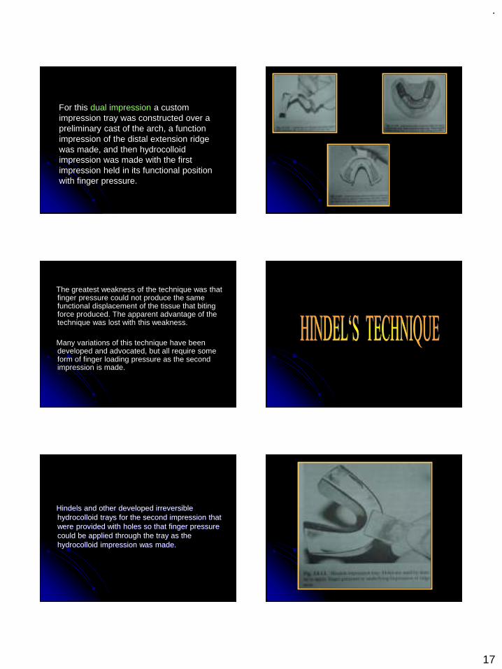
For this dual impression a custom impression tray was constructed over a preliminary cast of the arch, a function impression of the distal extension ridge was made, and then hydrocolloid impression was made with the first impression held in its functional position with finger pressure.
The greatest weakness of the technique was that finger pressure could not produce the same functional displacement of the tissue that biting force produced. The apparent advantage of the technique was lost with this weakness.
Many variations of this technique have been developed and advocated, but all require some form of finger loading pressure as the second impression is made.
Hindels and other developed irreversible hydrocolloid trays for the second impression that were provided with holes so that finger pressure could be applied through the tray as the hydrocolloid impression was made.

.
18
The main change that Hindels introduced to McLean ‘s original technique was that
the impression of the edentulous ridge was not made under pressure but was an anatomic impression of the ridge at rest made with a free flowing zinc oxide eugenol paste.
As the hydrocolloid second impression was being made, however, finger pressure was applied through the holes in the tray to the anatomic impression. The pressure had to be maintained until the alginate was completely set. The two were related to each other, however, as if masticating forces were taking place on the denture base.
The main purpose of these techniques was to relate an impression of the edentulous ridge to the teeth under a form of functional loading.
A disadvantage of these techniques was that if the action of the retentive clasps of the partial denture is sufficient to maintain the denture base in relation to the soft tissues in the displaced or functional form, interruption of blood circulation would ensue, with possible adverse soft tissue reaction and resorption of the underlying bone.
If the action of the retentive clasps was not sufficient to maintain that functional relationship of the denture base to the soft tissue, when the partial denture was in the mouth at rest, the partial denture would be slightly occlusal to the position it would assume when occlusal force was applied.
.
19
This means that each time the patient ‘s
teeth came together, the remaining natural teeth should contact only after the mucosa had been displaced to the position at which the impression was made. This early or premature contact of the artificial teeth is objectionable to many patients.
Most methods of obtaining a physiologic impression for support of a distal extension denture base accomplish the impression procedure before completion of the denture, usually following the construction of the framework. It is possible, however, to obtain the same results after the partial denture has been completed. The technique is referred to as a functional reline. It consists of adding a new surface to the inner, or tissue, side of the denture base.
The procedure may be accomplished before the insertion of the partial denture, or it may be done at a later date f because of bone resorption, the denture base no longer fits the ridge adequately.
Although the functional reline has many advantages, and fir correcting the fit of denture base that has been worn for a period of time is essential, it does present many difficulties.
The main problems that arise are caused by failure to maintain the correct relationship between the framework and the abutment teeth during the impression procedure and failure to maintain accurate occlusal contact following the reline.
The procedures for relining and rebasing an existing removable partial denture are discussed in detail.
The functional reline discussed here is that done to a completed partial denture before initial insertion for the purpose of perfecting the fit of the denture base to the residual ridge.
The partial denture is constructed on the cast made from a single impression, usually with irreversible hydrocolloid. This is an anatomic impression, and no attempt is made to alter it or produce a functional impression of the edentulous ridge.

.
20
To allow room for the impression material between the denture base and the ridge, space must be provided. One of the most accurate methods of ensuring uniform space for the impression is to adapt a soft metal spacer over the ridge on the cast before processing the denture base. After processing, the metal is removed leaving an even space between the base and the edentulous ridge.
The portion of the technique that introduces the greatest hazard is the making of the reline impression. The patient must maintain the mouth in a partially open position while the border molding and impression are being accomplished because:
1.The border tissues, cheek, and tongue are thus best controlled and
2.The relationship between the partial denture frame work and the teeth must be observed.
The functional reline method of improving the fit of the denture base to the residual ridge, although fraught with potential danger, has the advantage that the amount of soft tissue displacement can be controlled by the amount of relief given to the modeling plastic before the final impression is made. The greater the relief the less will be the tissue displacement.

.
21
The fluid wax impression may be used to make a reline impression for an existing partial denture or to correct the distal extension edentulous ridge portion of the original master cast.
OBJECTIVES
To obtain maximum extension of the peripheral borders of the denture base while not interfering with the function of movable border tissues.
To record the stress bearing areas of the ridges in their functional form.
To record non pressure bearing areas in their anatomic form.
The fluid wax impression is made with the open mouth technique so that there is less danger of over displacement of ridge tissue by occlusal or vertical forces.
The term fluid wax is used to denote waxes that are firm at room temperature and have the ability to flow at mouth temperature.
The most frequently used fluid waxes are Iowa wax, developed by Dr.Smith at the University of Iowa, and Korrecta Wax no 4, developed by Dr. 0. C. and S. G Applegateat the Universities of Michigan and Detroit, respectively.
Korrecta wax no. 4 is slightly more fluidthan Iowa wax.
.
22
The key to the use of fluid wax lies in two areas: space and time.
Space refers to the amount of relief provided between the impression tray and the edentulous ridge. :1 to 2 mm is desired.
Each time the tray is introduced into the mouth, it must remain in place 5 to 7 minutes to allow the wax to flow and to prevent buildup of pressure under the tray with resulting distortion or displacement of the tissue.
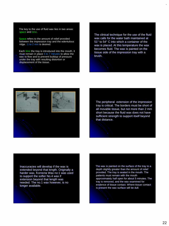
The clinical technique for the use of the fluid wax calls for the water bath maintained at 51° to 54° C into which a container of the wax is placed. At this temperature the wax becomes fluid. The wax is painted on the tissue side of the impression tray with a brush.
The peripheral extension of the impression tray is critical. The borders must be short of all movable tissue, but not more than 2 mm short because the fluid wax does not have sufficient strength to support itself beyond that distance.
Inaccuracies will develop if the wax is extended beyond that length. Originally a harder wax, Korrecta Wax no:1 was used to support the softer No.4 wax if extension beyond that length was needed. The no.1 wax however, is no longer available.
The wax is painted on the surface of the tray to a depth slightly greater than the amount of relief provided. The tray is seated in the mouth. The patients must remain with the mouth approximately half open for about 5 minutes. The tray is removed, and the wax examined for evidence of tissue contact. Where tissue contact is present the wax surface will be dull.

.
23
If needed additional wax is painted on those areas not in contact with the tissue. The tray must remain in the mouth a minimum of 5 minutes after each addition of wax. The peripheral extensions are developed by tissue movements by the patient. For the buccal and distobuccal extension in a mandibular impression the patient must move to a wide- open-mouth position. This will activate the buccinator muscle and pterygomandibular raphe and produce the desired border anatomy.
For the proper lingual extension for a mandibular impression the patient must thrust the tongue into the cheek opposite the side of the arch being border molded. The distolingual extension is obtained by having the patient press the tongue forward against the lingual surface of the anterior teeth.
These movements must be repeated a number of times after the impression has been in the mouth long enough for the wax to have softened sufficiently to flow.
When the impression evidences complete tissue contact and when the anatomy of the limiting border structure is evident, the impression should be replaced in the mouth for 12 minutes. This final time to be certain that the wax has completely flowed and released any pressure that may be present.
The finished impression must be handled carefully and the new cast poured as soon as possible because the wax is fragile and subject to distortion.

.
24
The fluid wax impression technique can produce an accurate impression if the technique is properly executed The procedure is time consuming, but if the time periods are not followed accurately, an impression with excessive tissue displacement will result.
Corrected cast
Technique
1. Fashioning custom acrylic resin impression tray to retention lattice work of removable partial denture.
2. Developing denture base impression on these trays.
3. Removing edentulous ridge from master cast.4. Securing framework with developed bases to
master cast.5. Pouring the impression with dental stone.
Modifications:Variation of altered cast technique by Robert. P
Renner
After the fit of framework has been refined intra orally, the border of residual ridge are outlined on master cast. A small residual ridge are outlined on master cast. A small segment of bone plate wax is warmed over Bunsen burner and adapted to penciled outline. The wax will act as shim / space between residual ridge and custom tray.
.
25
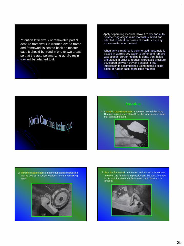
Retention latticework of removable partial denture framework is warmed over a frame and framework is seated back on master cast. It should be freed in one or two areas so that the auto polymerizing acrylic resin tray will be adapted to it.
Apply separating medium, allow it to dry and auto polymerizing acrylic resin material is mixed and adapted to edentulous area of master cast, any excess material is trimmed.
When acrylic material is polymerized, assembly is placed in warm slurry water to soften and remove wax spacer. Border molding is done. Vent holes are placed in order to reduce hydrostatic pressure developed between tray and tissues. Final impression is accomplished using metallic oxide paste or rubber base impression material.
Procedure
1. A metallic paste impression is received in the laboratory. Remove impression material from the framework in areas that contact the teeth.
2. Trim the master cast so that the functional impression can be poured in correct relationship to the remaining teeth.
3. Seat the framework on the cast, and inspect it for contactbetween the functional impression and the cast. If contact is present, the cast must be trimmed until clearance is present.
.
26
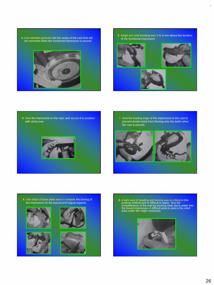
4. Cut retention grooves into the areas of the cast that will be corrected when the functional impression is poured
5. Adapt and seal beading wax 2 to 3 mm above the borders of the functional impression
6. Seat the framework on the cast, and secure it in position with sticky wax
7. Seal the leading edge of the impression to the cast to prevent dental stone from flowing onto the teeth when the cast is poured.
8. Use strips of base plate wax to compete the boxing of the impression on the buccal and lingual aspects
9. A tight seal of beading and boxing wax is critical in this pouring method and is difficult to attain. Test the completeness of the seal by pouring clear slurry water into the boxed impression. A difficult area to seal is the relief area under the major connector.

.
27
10. Place the cast and impression in clear slurry water to soak for 4 to 5 minutes in preparation for pouring the corrected cast.
11. Measure and mix the improved dental stone. Pour the boxed impression by adding small increments of stone and using light vibration. Sufficient stone must be used to support the heel of the cast.
12. Remove the boxing and luting materials from the corrected cast. Shape the cast on a model trimmer.
13. Soften the impression material in warm water, and remove the framework and impression tray from the corrected cast.
14. Burn the impression tray off the framework and place it on the cast. Smooth the land area of the cast, and the corrected cast procedures is complete.
AN ALTERED CAST PROCEDURETO IMPROVE TISSUE SUPPORT FOR
REMOVABLE PARTIAL DENTURES- R J. LEUPOLD, F J. KRATOCHVIL : JPD 1965(15), 4, 672- 678
.
28
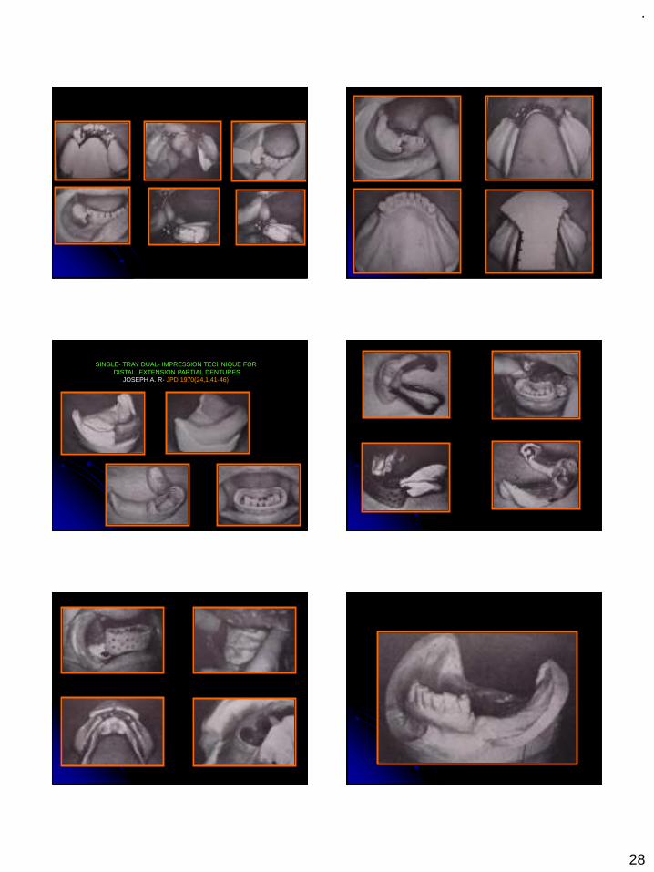
SINGLE- TRAY DUAL- IMPRESSION TECHNIQUE FOR DISTAL EXTENSION PARTIAL DENTURES
JOSEPH A. R- JPD 1970(24,1,41-46)

.
29
IMPRESSION TECHNIQUE FOR MAXILLARYREMOVABLE PARTIAL DENTURES
- C D. LEACH & T E. DONOVAN JPD 1983 (50)2,283-285
AN ALTERED CAST IMPRESSION TECHNIQUE THAT ELIMINATES CONVENTIONAL CAST DISSECTING & IMPRESSSION BOXING
-M S. CHEN AND et al - JPD 1987 (57) 4, 471-474
.
30
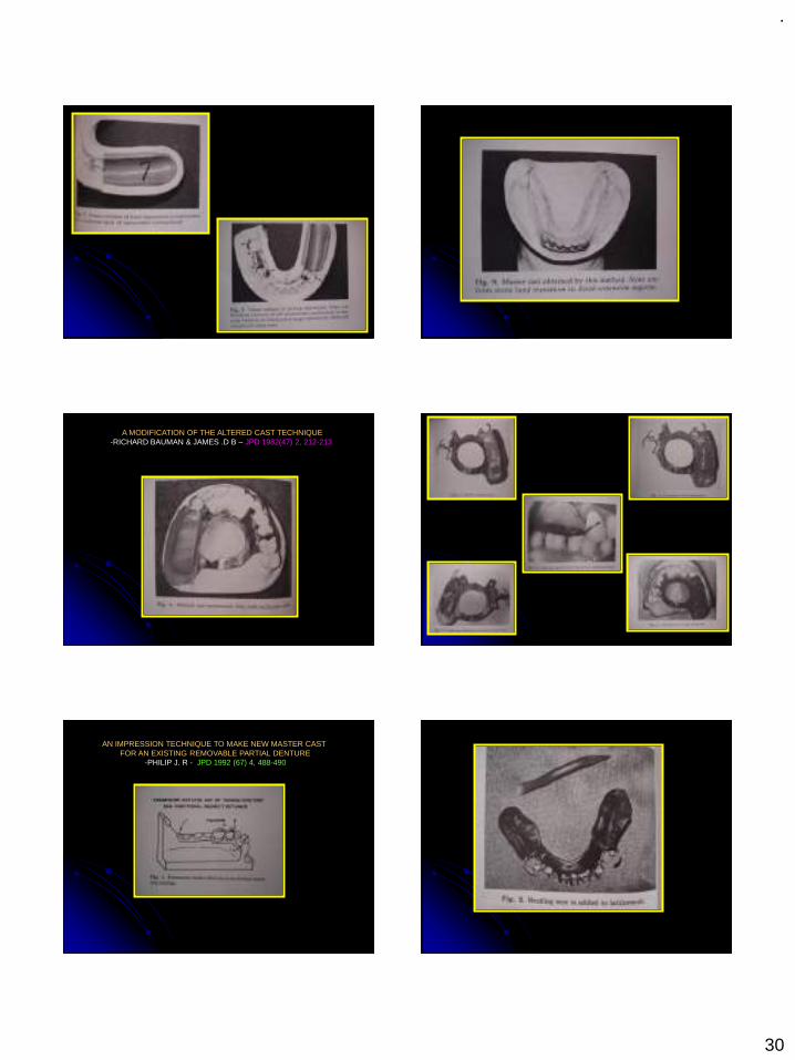
A MODIFICATION OF THE ALTERED CAST TECHNIQUE-RICHARD BAUMAN & JAMES .D B – JPD 1982(47) 2, 212-213
AN IMPRESSION TECHNIQUE TO MAKE NEW MASTER CAST FOR AN EXISTING REMOVABLE PARTIAL DENTURE
-PHILIP J. R - JPD 1992 (67) 4, 488-490
.
31
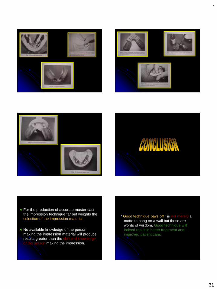
For the production of accurate master cast the impression technique far out weights the selection of the impression material.
No available knowledge of the person making the impression material will produce results greater than the skill and knowledge of the person making the impression.
“ Good technique pays off ” is not merely a motto to hang on a wall but these are words of wisdom. Good technique will indeed result in better treatment and improved patient care.
.
32
1. Glossary of Prosthodontic Terms -8 th Edn, 2005.
2. Stewart, Rudd, Kuebker : Clinical Removable Partial Prosthodontics.
3. McGivney GP, Alan B Carr David T Brown : McCracken’s Removable Partial Dentures-11 th Edn.
4. Joseph E. Grasso, Ernest L. Miller : Removable Partial Prosthodontics.
5. Alan A. Grant, Wesley Johnson : Removable Partial Dentures.
6. F. James Kratochvil : Partial Removable Prosthodontics.
8. Robert P. Renner, Louis J. Boucher : Removable Partial Dentures.
9. Kenneth D Rudd, Morrow: Dental Lab, Procedure for Removable Partial Dentures.
10. Davenport: Color Atlas of Removable Partial Dentures.
11. Bates: Removable Denture Construction.
12. Osborne: Partial Dentures.
AN ALTERED CAST PROCEDURETO IMPROVE TISSUE SUPPORT FOR REMOVABLE PARTIAL DENTURES- R J. LEUPOLD, F J. KRATOCHVIL : JPD 1965(15), 4, 672- 678
SINGLE- TRAY DUAL- IMPRESSION TECHNIQUE FOR DISTAL EXTENSION PARTIAL DENTURESJOSEPH A. R- JPD 1970(24,1,41-46)
IMPRESSION TECHNIQUE FOR MAXILLARYREMOVABLE PARTIAL DENTURES- C D. LEACH & T E. DONOVAN JPD 1983 (50)2,283-285
AN ALTERED CAST IMPRESSION TECHNIQUE THAT ELIMINATES CONVENTIONAL CAST DISSECTING & IMPRESSSION BOXING-M S. CHEN AND et al - JPD 1987 (57) 4, 471-474
A MODIFICATION OF THE ALTERED CAST TECHNIQUE-RICHARD BAUMAN & JAMES .D B – JPD 1982(47) 2, 212-213
AN IMPRESSION TECHNIQUE TO MAKE NEW MASTER CAST FOR AN EXISTING REMOVABLE PARTIAL DENTURE-PHILIP J. R - JPD 1992 (67) 4, 488-490
.
1
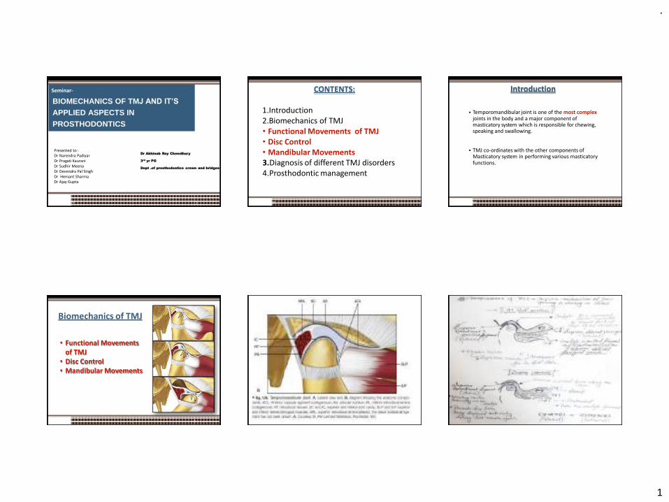
Seminar-
BIOMECHANICS OF TMJ AND IT’S
APPLIED ASPECTS IN PROSTHODONTICS
2019 1
Dr Abhinab Roy Chowdhury
3rd yr PG
Dept .of prosthodontics crown and bridges
Presented to :Dr Narendra Padiyar Dr Pragati Kaurani Dr Sudhir MeenaDr Devendra Pal SinghDr Hemant SharmaDr Ajay Gupta
CONTENTS:
2019 2
1.Introduction2.Biomechanics of TMJ• Functional Movements of TMJ• Disc Control• Mandibular Movements3.Diagnosis of different TMJ disorders4.Prosthodontic management
Introduction
▪ Temporomandibular joint is one of the most complex joints in the body and a major component of masticatory system which is responsible for chewing, speaking and swallowing.
▪ TMJ co-ordinates with the other components of Masticatory system in performing various masticatory functions.
2019 3
Biomechanics of TMJ
• Functional Movements of TMJ
• Disc Control• Mandibular Movements
4
.
2
▪ Okeson, JP. Management of
Temporomandibular Disorders and
Occlusion , 7th ed., (2003), Mosby.
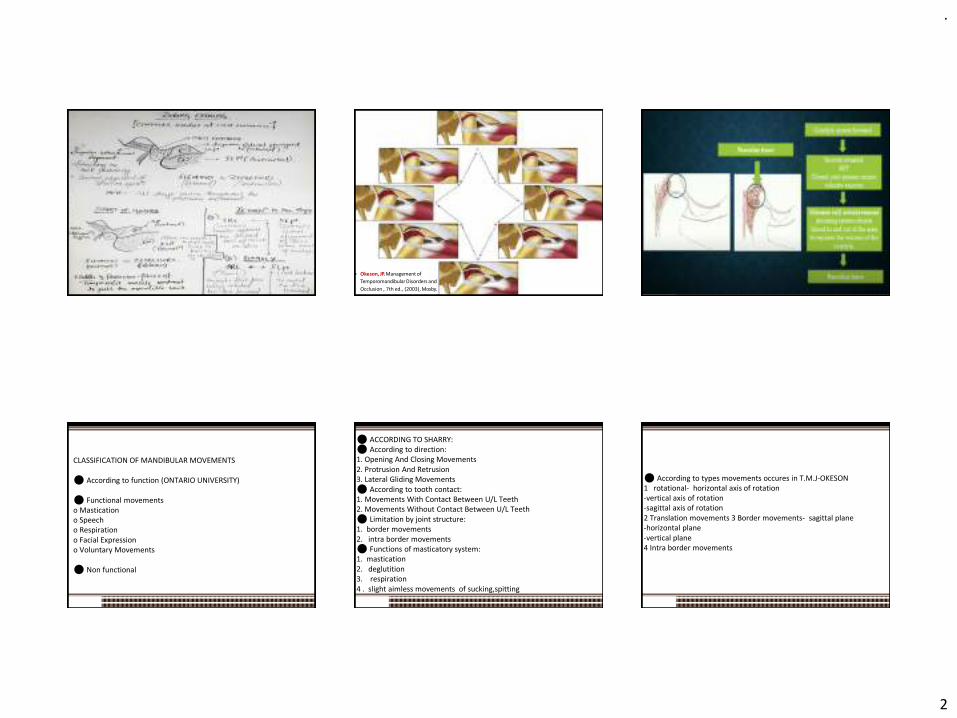
CLASSIFICATION OF MANDIBULAR MOVEMENTS
⚫ According to function (ONTARIO UNIVERSITY)
⚫ Functional movements o Mastication o Speech o Respiration o Facial Expression o Voluntary Movements
⚫ Non functional
⚫ ACCORDING TO SHARRY: ⚫ According to direction: 1. Opening And Closing Movements 2. Protrusion And Retrusion 3. Lateral Gliding Movements ⚫ According to tooth contact: 1. Movements With Contact Between U/L Teeth 2. Movements Without Contact Between U/L Teeth ⚫ Limitation by joint structure: 1. border movements 2. intra border movements ⚫ Functions of masticatory system: 1. mastication 2. deglutition 3. respiration 4 . slight aimless movements of sucking,spitting
⚫ According to types movements occures in T.M.J-OKESON 1 rotational- horizontal axis of rotation -vertical axis of rotation -sagittal axis of rotation 2 Translation movements 3 Border movements- sagittal plane -horizontal plane -vertical plane 4 Intra border movements
.
3
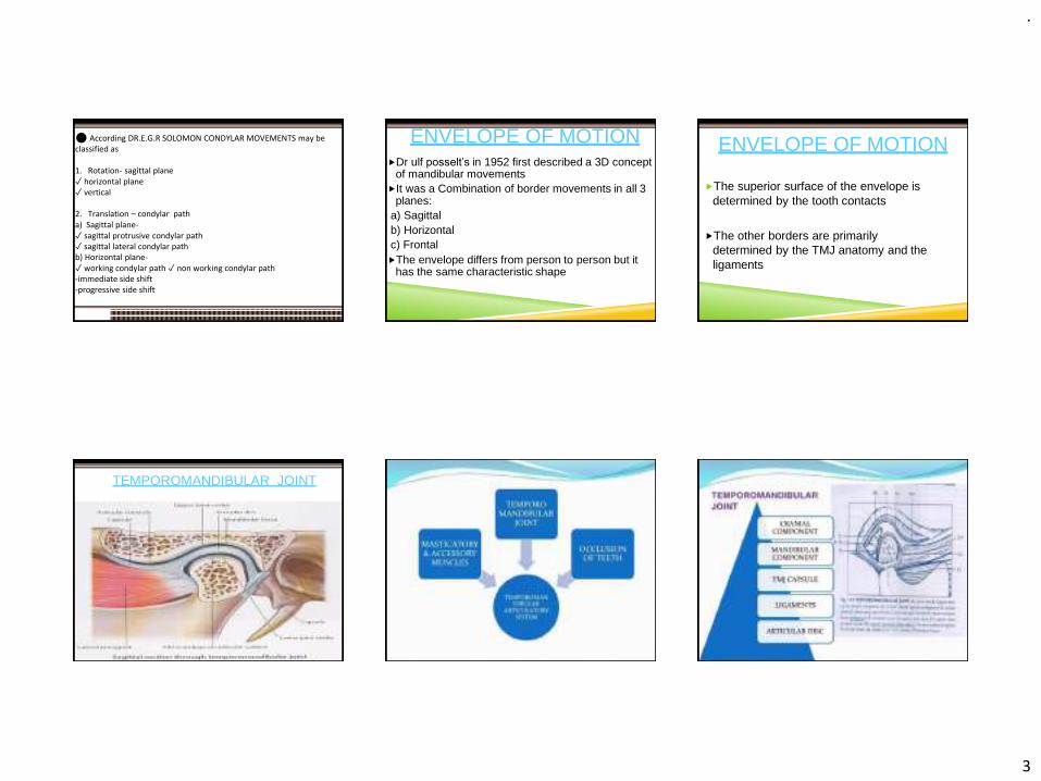
⚫ According DR.E.G.R SOLOMON CONDYLAR MOVEMENTS may be classified as
1. Rotation- sagittal plane ✓ horizontal plane ✓ vertical
2. Translation – condylar path a) Sagittal plane-✓ sagittal protrusive condylar path ✓ sagittal lateral condylar path b) Horizontal plane-✓ working condylar path ✓ non working condylar path -immediate side shift -progressive side shift
ENVELOPE OF MOTIONDr ulf posselt’s in 1952 first described a 3D concept
of mandibular movementsIt was a Combination of border movements in all 3
planes:a) Sagittalb) Horizontalc) FrontalThe envelope differs from person to person but it
has the same characteristic shape
ENVELOPE OF MOTION
The superior surface of the envelope is determined by the tooth contacts
The other borders are primarily determined by the TMJ anatomy and the ligaments
TEMPOROMANDIBULAR JOINT
.
4
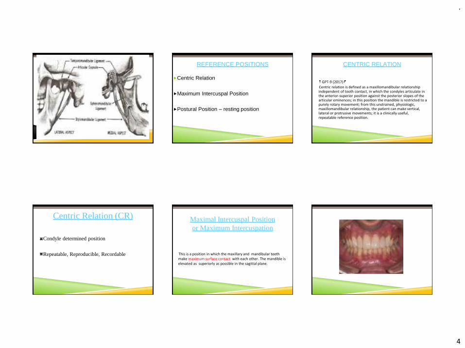
REFERENCE POSITIONS
Centric Relation
Maximum Intercuspal Position
Postural Position – resting position
CENTRIC RELATION
GPT-9 (2017)
Centric relation is defined as a maxillomandibular relationship independent of tooth contact, in which the condyles articulate in the anterior-superior position against the posterior slopes of the articular eminences; in this position the mandible is restricted to a purely rotary movement; from this unstrained, physiologic, maxillomandibular relationship, the patient can make vertical, lateral or protrusive movements; it is a clinically useful, repeatable reference position.
Centric Relation (CR)
Condyle determined position
Repeatable, Reproducible, Recordable
Maximal Intercuspal Position or Maximum Intercuspation
This is a position in which the maxillary and mandibular teeth make maximum surface contact with each other. The mandible is elevated as superiorly as possible in the sagittal plane.

.
5
MAXIMUM INTERCUSPATION (MIP)
Tooth determined position
Does not provide any information about the TMJ
In most people, MIP does not coincide with CR
MAXIMUM INTERCUSPATION
In MIP the condyle-disc assembly is anterior and inferior and/or medial or lateral or a combination of the above compared to their position in CR.
Usually the condyle-disc assemblies are ANTERIOR and INFERIOR.
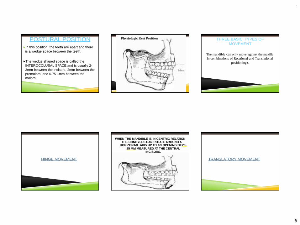
POSTURAL POSITION (PP)
Is the habitual position of the mandible when the patient is resting comfortably in the upright position and the condyles are in a neutral unstrained position in the glenoid fossae.
In this position there is an equilibrium between the forces acting on the mandible.
POSTURAL POSITION
In the POSTURAL POSITION the muscles are not totally relaxed. There is a degree of electromyographic activity.
This position is determined by the muscles and the forces of gravity.
POSTURAL POSITION
The condyles are usually anteriorly and inferiorly compared to their CR position.
This position can be sustained and it is comfortable for the patient.
.
6
POSTURAL POSITIONIn this position, the teeth are apart and there
is a wedge space between the teeth.
The wedge shaped space is called the INTEROCCLUSAL SPACE and is usually 2-3mm between the incisors, 2mm between the premolars, and 0.75-1mm between the molars.
Physiologic Rest Position
2-3mm
THREE BASIC TYPES OF MOVEMENT
The mandible can only move against the maxilla in combinations of Rotational and Translational
positioning's
HINGE MOVEMENT
WHEN THE MANDIBLE IS IN CENTRIC RELATION THE CONDYLES CAN ROTATE AROUND A
HORIZONTAL AXIS UP TO AN OPENING OF20-25 MM MEASURED AT THE CENTRAL
INCISORS.
TRANSLATORY MOVEMENT

.
7
IF OPENING OF THE MANDIBLE CONTINUES BEYOND 20-25 MM THEN TRANSLATION OF
THE MANDIBLE OCCURS.
ROTATIONAL MOVEMENT
Movement of a body around an axis
• Pure rotational movement occurs minimally in themandible
• This pure rotational movement is also referred to as hinge movement and the axis is referred to as terminal hingeaxis
PURE ROTATIONAL MOVEMENT AT TERMINAL HINGE AXIS
LATERAL MOVEMENTS (RIGHT AND LEFT DIRECTION)
1) The side to which the mandible is moving is called the WORKING SIDE
2) The side that is opposite to the working side is calledBALANCING OR NON WORKING SIDE
3) The condyle on the working side is called the WORKING OR ROTATING CONDYLE
4) The non-working condyle is called THE BALANCING OR THE ORBITING CONDYLE
MANDIBULAR LATERAL TRANSLATION
Non-Working Side
Also known as Bennett Movement and Immediate Sideshift
The first part of the lateral movement of the mandible, depicted when the medial pole of non-working condyle starts to travel down the slope of the articular eminence. The movement is exhibited as a measurement of the distance between the medial pole of the non-working condyle and the medial wall of the glenoid fossa.
0.3mm
FUNCTIONAL MOVEMENTS (OCCUR WITHIN BORDER
MOVEMENTS)Occur during functional activity of the
mandible
Are confined within the Border Movements
Begin and end in the maximum intercuspation position.

.
8
FUNCTIONAL MOVEMENTS
The chewing stroke starts at the MIP and drops downwards and forwards to the position of desire opening.
It returns in a straighter pathway slightly posterior.
BORDER MOVEMENTS
The mandibular movements are limited by ligaments, the articular surfaces of the TMJ, and the morphology and alignment of the teeth. The outer range of movement is reproducible and called border movements.
PANTOGRAPH APPARATUSThe device has a stylus that marks on special paper placed in all 3 planes of reference at the
same time. Distinct markings are produced that are transferable to a fully adjustable articulator.
Recording Paper
PANTOGRAPHIC TRACING TRANSFER TO FULLY ADJUSTABLE ARTICULATOR
Tracing plates receive markings on
paper during movements of the
mandible. The articulator is set by
“tracing” the
movement recorded on the patient.
PANTOGRAPHIC TRACINGS
Sagittal Plate
Horizontal Plate
Tracings are captured and depicted in each plane of reference.
Horizontal Plate
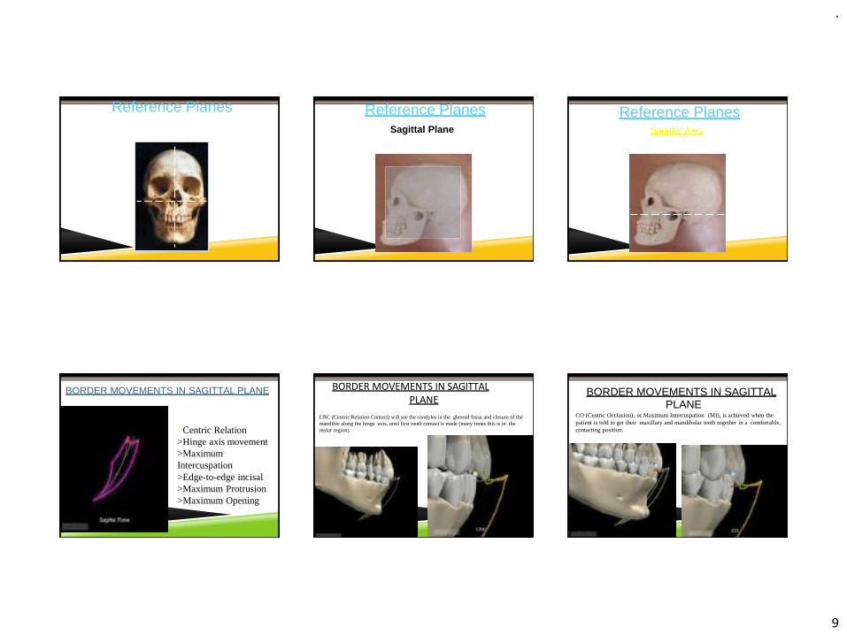
REFERENCE PLANESThree-dimensional description of the Mandibular & Maxillary positioning
.
9
Also known as Axes of Rotation
Reference Planes Reference PlanesSagittal Plane
Also known as a side view.
Reference PlanesSagittal Axis
BORDER MOVEMENTS IN SAGITTAL PLANE
Items of interest:>Centric Relation>Hinge axis movement>Maximum Intercuspation>Edge-to-edge incisal>Maximum Protrusion>Maximum Opening
BORDER MOVEMENTS IN SAGITTAL PLANE
CRC (Centric Relation Contact) will see the condyles in the glenoid fossa and closure of the mandible along the hinge axis, until first tooth contact is made (many times this is in the molar region).
BORDER MOVEMENTS IN SAGITTALPLANE
CO (Centric Occlusion), or Maximum Intercuspation (MI), is achieved when the patient is told to get their maxillary and mandibular teeth together in a comfortable, contacting position.

.
10
BORDER MOVEMENTS IN SAGITTAL PLANE
The mandible will open along the hinge axis, with thecondyles rotating within the glenoid fossa. The rotational movement will terminate at the Terminal Hinge Axis Position.
BORDER MOVEMENTS IN SAGITTAL PLANE
The Terminal HingeAxis is the rotational movement that occurs from CR to the Terminal Hinge Axis position.The condyles are rotating completely within the glenoidfossa. It is a reproducible and consistentmovement.
BORDER MOVEMENTS IN SAGITTAL PLANE
Maximum Opening displays the most inferior position of the mandible, after the patient is instructed to open their mouth as wide as theycan.
BORDER MOVEMENTS IN SAGITTAL PLANE
Maximum Protrusion depicts complete contact with the teeth as the mandible is completelyprotruded, anteriorly. It is the most anterior of the positions, when viewed from the sagittalplane.
BORDER MOVEMENTS IN SAGITTAL PLANE
Edge-to-Edge contact of Maxillary and Mandibular Incisors.
Mandible is protruded forward from MI,maintaining some type of tooth contact throughout.
BORDER MOVEMENTS IN SAGITTAL PLANE
Protruded contact of Maxillary and Mandibular Incisors. Mandible iscontinuing to protrude forward from Edge-to-Edge Incisal, maintaining some type of tooth contact throughout.

.
11
BORDER MOVEMENTS IN SAGITTAL PLANE
Maximum Protrusion position. The teeth are insome degree of contact (usually in Premolar-Canine area) and mandible is pushed forward as far as possible.
Border Movements in Sagittal Plane
Mandibular Opening. Going from Maximum Protrusion to Maximum Opening.
CR
MIE-T-E
MP
MO
HA
HAT
HA-MO
Legend:
RPCL
MOA
CR = Centric RelationMI = Maximum Intercuspation E-T-E = Edge to Edge IncisalMP = Maximum Protrusion Point MOA = Maximum Opening Arc MO = Maximum Opening Point HA-MO = Hinge Axis to Maximum
OpeningHAT = Hinge Axis Terminating
PointHA = Hinge AxisArc
RP = Rest Position or Postural Position of the Mandible
CL = Chewing Loop
Reference PlanesHorizontal Plane
Parallel to the Occlusal Plane or the floorHorizontal Axis
Imaginary line through both condyles
Reference PlanesBorder Movements in Horizontal
Plane
Characteristically described as a“diamond” shape.
.
12
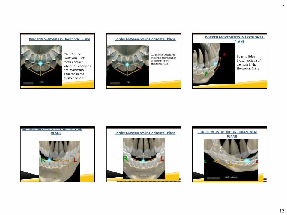
Border Movements in Horizontal Plane
CR (Centric Relation). First tooth contact when the condyles are maximally situated in the glenoid fossa.
Border Movements in Horizontal Plane
CO (Centric Occlusion). Maximum Intercuspation of the teeth in the Horizontal Plane.
BORDER MOVEMENTS IN HORIZONTAL PLANE
Edge-to-Edge Incisal position of the teeth in the Horizontal Plane.
BORDER MOVEMENTS IN HORIZONTAL PLANE Border Movements in Horizontal Plane BORDER MOVEMENTS IN HORIZONTAL
PLANE
.
13
Border Movements in Horizontal Plane
Legend:CR = Centric RelationMI = Maximum Intercuspation E-T-E = Edge to Edge Incisal MP = Maximum Protrusion ERL = Extreme Right Lateral ELL = Extreme Left Lateral RP = Rest PositionVCA = Vertical Chewing Arc HCA = Horizontal ChewingArc LLB = Left Lateral BorderRLB = Right Lateral BorderELL-MPB = Extreme Left Lateral
to Maximum Protrusion BorderERL-MPB = Extreme Right Lateral
to Maximum Protrusion Border
CRMI
VCAHCA LLB
ELL ELL-MPB
E-T-E
MP
ERL ERL-MPB
RLB
RP
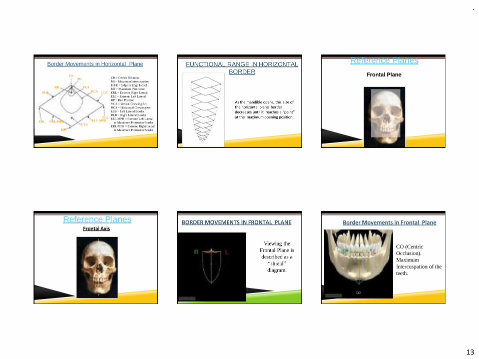
FUNCTIONAL RANGE IN HORIZONTAL BORDER
As the mandible opens, the size of the horizontal plane border decreases until it reaches a “point” at the maximum opening position.
Reference Planes
Frontal PlaneBest described by facing the patient.
Reference PlanesFrontal Axis
BORDER MOVEMENTS IN FRONTAL PLANE
Viewing the Frontal Plane is described as a
“shield”
diagram.
Border Movements in Frontal Plane
CO (Centric Occlusion). Maximum Intercuspation of the teeth.
.
14
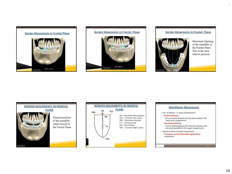
Border Movements in Frontal Plane Border Movements in Frontal Plane Border Movements in Frontal Plane
Maximum Opening of the mandible in the Frontal Plane.This is the most inferior position.
BORDER MOVEMENTS IN FRONTAL PLANE
Postural position of the mandible when viewed in the Frontal Plane.
BORDER MOVEMENTS IN FRONTAL PLANE
MO
RP
ELLMIERL
CL
Legend:MI = Maximum Intercuspation ELL = Extreme Left Lateral MO = Maximum OpeningCL = Chewing LoopRP = Rest PositionERL = Extreme Right Lateral
Mandibular Movements
84
▪ Acc. to Okeson – 2 types of Movements
–Rotational/hinge
▪ Occurs mainly between the disc and condyle in the lower joint compartment.
–Translational/sliding
▪ Occurs mainly between the articular eminence and disc (and mandible) in the upper compartment.
▪ Based on Plane of border movements:
–horizontal, vertical (frontal) & sagittal planemovements
.
15
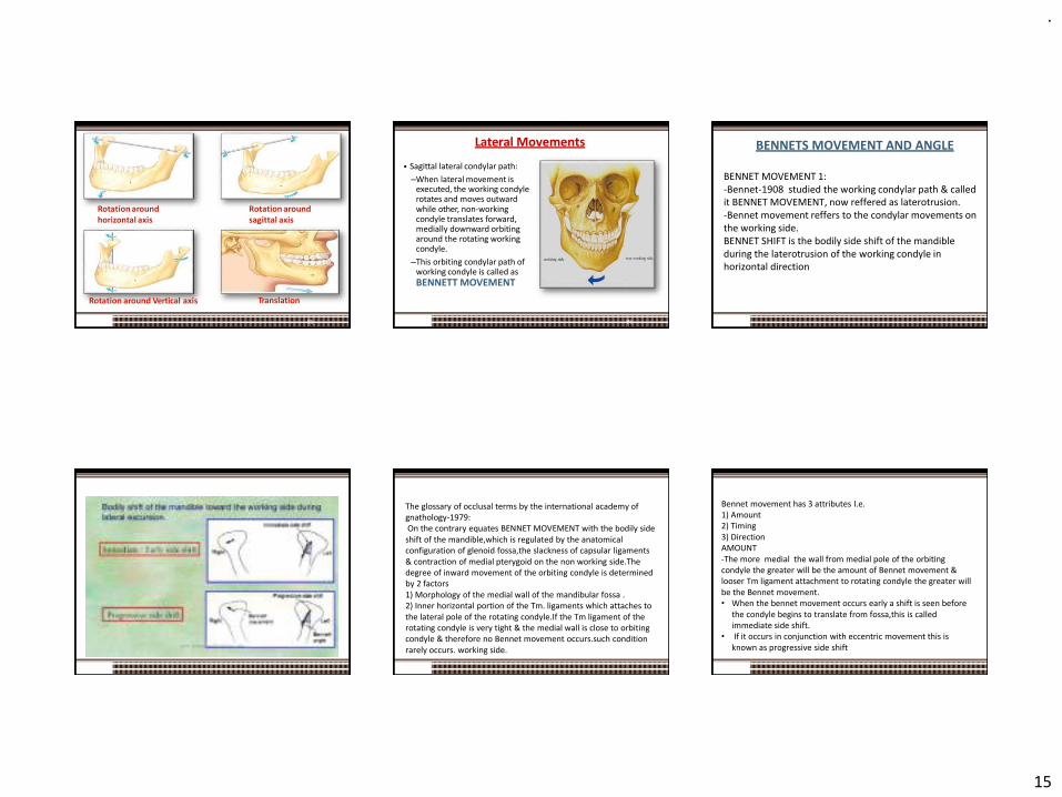
Rotation around horizontal axis
Rotation around sagittal axis
Rotation around Vertical axis Translation
85
Lateral Movements
▪ Sagittal lateral condylar path:
–When lateral movement is executed, the working condyle rotates and moves outward while other, non-working condyle translates forward, medially downward orbiting around the rotating working condyle.
–This orbiting condylar path of working condyle is called as BENNETT MOVEMENT
86
BENNETS MOVEMENT AND ANGLE
BENNET MOVEMENT 1: -Bennet-1908 studied the working condylar path & called it BENNET MOVEMENT, now reffered as laterotrusion. -Bennet movement reffers to the condylar movements on the working side. BENNET SHIFT is the bodily side shift of the mandible during the laterotrusion of the working condyle in horizontal direction
The glossary of occlusal terms by the international academy of gnathology-1979:On the contrary equates BENNET MOVEMENT with the bodily side
shift of the mandible,which is regulated by the anatomical configuration of glenoid fossa,the slackness of capsular ligaments & contraction of medial pterygoid on the non working side.Thedegree of inward movement of the orbiting condyle is determined by 2 factors 1) Morphology of the medial wall of the mandibular fossa . 2) Inner horizontal portion of the Tm. ligaments which attaches to the lateral pole of the rotating condyle.If the Tm ligament of the rotating condyle is very tight & the medial wall is close to orbiting condyle & therefore no Bennet movement occurs.such condition rarely occurs. working side.
Bennet movement has 3 attributes I.e. 1) Amount 2) Timing 3) Direction AMOUNT -The more medial the wall from medial pole of the orbiting condyle the greater will be the amount of Bennet movement & looser Tm ligament attachment to rotating condyle the greater will be the Bennet movement. • When the bennet movement occurs early a shift is seen before
the condyle begins to translate from fossa,this is called immediate side shift.
• If it occurs in conjunction with eccentric movement this is known as progressive side shift
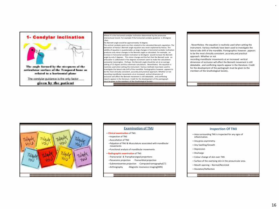
.
16
This movement can be accurately recorded by means of interocclusal records or pantographic tracings. The timing of Bennett movement varies greatly between individuals. If the lateral component comes early in the movement ,it is termed as an “ immediate” or “early” side shift. The gradual lateral component is termed as a “progressive” side shift. The direction of Bennett movement depends on joint structures and the contraction of the lateral pterygoid muscles. According to Lundeen et al 1978 the amount of lateral movement as measured in horizontal plane averages 0.75 mm with 80% of all patients having Bennett movement of 1.5 mm or less. The amount of Bennett movement is calculated from horizontal condylar settings by Hanau’s equation ,which is on the underside of the articulator. The equation is as follows Bennett angle (L) = (H/8) + 12
Where H is the horizontal condylar inclination determined by the protrusive interocclusal record. For example if the horizontal condylar guidance is 30 degree ,then the Bennett angle would be approximately 16 degree.The vertical condylar posts are then rotated to the calculated Bennett angulation. The derivation of Hanau’s Bennett angle equation was never explained by Hanau. The validity of equation is questionable ,as large changes in horizontal condylar inclination produces only minor changes in the Bennett angle as calculated. For example , an increase in horizontal condylar inclination to 50 degree would increase the Bennett angle by only 2 degrees . This minor change and the fact that the Bennett scale on articulator is caliberated in five degrees increment seem to make the calculations somewhat meaningless . Perhaps the Bennett angle should be set at an average setting of 15 drgree and thus eliminate calculations . Nevertheless the equation is routinely used when setting the instrument. Various methods have been used to investigate the lateral side shift of the mandible. Pantographics however ,appears to be the most clinically consistent ,accurate,and practical approach. Whether or not recording mandibular movements at an increased vertical dimension of occlusion will affect the Bennett movement is still debatable , and conflicting reports appear in the literature. Credit for the development of the pantograph must be given to the members of the Gnathological Society .
. Nevertheless the equation is routinely used when setting the instrument. Various methods have been used to investigate the lateral side shift of the mandible. Pantographics however ,appears to be the most clinically consistent ,accurate,and practical approach. Whether or not recording mandibular movements at an increased vertical dimension of occlusion will affect the Bennett movement is still debatable , and conflicting reports appear in the literature. Credit for the development of the pantograph must be given to the members of the Gnathological Society .
Examination of TMJ▪ Clinical examination of TMJ:
–Inspection of TMJ
–Auscultation of TMJ
–Palpation of TMJ & Musculature associated with mandibular movements
–Functional analysis of mandibular movements
▪ Radiographic examination of TMJ
–Transcranial & Transpharyngeal projections
–Panaromic projection -Transorbital projection
–Submentovertex projection -Computed tomography(CT)
–Arthrography -Magnetic resonance imaging(MRI)
2019 59
Inspection Of TMJ
96
▪ Area surrounding TMJ is inspected for any signs of inflammation.
▪ Any gross asymmetry.
▪ Any Swelling/Growth
▪ Depression
▪ Discharge
▪ Colour change of skin over TMJ
▪ Surface of the overlying skin in the preauricular area.
▪ Mouth opening – Normal/Resricted
▪ Deviation/Deflection
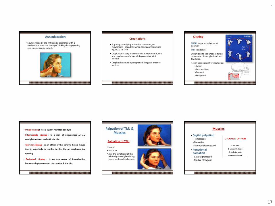
.
17
Ausculatation
▪ Sounds made by the TMJ can be examined with a stethoscope. Also the timing of clicking during opening and closure can be noted .
97
Crepitations
98
▪ A grating or scalping noise that occurs on jaw movements . Sound like when sand paper is rubbed against a surface.
▪ Crepitation is very uncommon in asymptomatic joint and may be an early sign of degenerative joint disease.
▪ Crepitus is caused by roughened, irregular anterior surface.
Clicking
CLICK- single sound of short duration
POP- loud click
Occurs due to the uncoordinated movement of condylar head andT.M.J disc.
▪ Joint clicking is differentiated as:
➢Initial
➢Intermediate
➢Terminal
➢Reciprocal
99
of the
100
▪ Initial clicking : It is a sign of retruded condyle
▪ Intermediate clicking : Is a sign of unevenness
condylar surfaces and articular disc
▪ Terminal clicking : is an effect of the condyle being moved
too far anteriorly in relation to the disc on maximum jaw
opening.
▪ Reciprocal clicking : is an expression of incordination
between displacement of the condyle & the disc.
Palpation of TMJ
• Lateral
• Posterior
• Also the synchrony of the left & right condyles during movement can be checked.
Palpation of TMJ & Muscles
101
Muscles
▪ Digital palpation–Temporalis–Masseter–Sternocleidomastoid
▪ Functionalpalpation–Lateral pterygoid–Medial pterygoid
GRADING OF PAIN
0- no pain
1- uncomfortable
2- definite pain
3- evasive action
102

.
18
Temporalis
103
Masseter
Sternocleidomastoid
104
Splenius Capitus
Trapezius
105
:nst
AX
S
Cl p•
Inferior Lateral PterygoidProtruding mandible agai resistance• STRECHES ONLY ON M
INTERCUSPATION
uperior Lateral Pterygoid: enching against owerful stroke
STRECHES ONLY ON MAX INTERCUSPATION
106
INTRACAPSULAR DISORDER OF TMJ :
▪ Can elicit pain with increase in interarticular pressure and movement.
▪ Confusing with muscle pain origin.
107
• But if clenching done on a separator – pressure doesn’t increase.To differentiate with inferior lateral Pterygoid muscle –patientt is asked to protrude and bite on a separator.
108

.
19
Functional Analysis of TMJ▪ Maximum Jaw Opening▪ The distance between the incisal edges of the upper and lower central
incisors.–Normal maximum ≥ 40mm.
–Men: 38.7- 67.2 (mean 52.8mm)–Women: 36.7 -60.4 ( mean 48.3)
–Child: 6 year mean- 44.8mm 10 year mean- 44 mm
–Lateral movement ≥ 8mm–Protrusive movements ≥ 7mm
▪ In overbite cases, this amount is added to the obtained value whereas in open bite it is subtracted.
109
▪ DEVIATION :
Because of disc derrangement in 1 or both joints
shift of jaw midline during openeing that disappear with opening
110
▪ DEFLECTION :
Restricted movement in 1 joint
Shift of midline to 1side and become greator with opening and doesn’t dissapear
Radiographic Evaluation of TMJ▪ Transcranial:
–Sagittal view of the lateral aspect of condyle and temporal component
–Displaced condylar #
–Osseous changes on lateral aspect
▪ Transpharyngeal/Infra-cranial:–Sagittalview of the medial
pole of condyle.–Erosive changes of the
condyle
111
▪ Panaromic:
–Commonly used routinely (not for TMJ), odontogenic diseases, asymmetries, extensive erosions or #
▪ Transorbital:
–Ant. view of TMJ, entire mediolateral dimension of A.E, condylar head & neck.
▪ Submentovertex(Basal):
–Facial asymmetries, condylar displacement, rotation of the mandible in horizontal plane assoc. with trauma
112
▪ Computed Tomography:
–Complete view of Osseous components of TMJ joint.
–Presence/extent of ankylosis & neoplasms.
▪ Arthrography:
–Invasive(as radio-opaque contrasting agent is injected)
–Small disk perforations & jointadhesions
113
▪ MRI (Magnetic Resonance Imaging):
–Both the soft(discal) and hard(osseous) tissues can be imaged.
–Non invasive, no radiation hazard
–Inflammation, joint effusions etc.
114

.
20
Other Diagnostic Aids
115
▪ Mandibular tracking devices
▪ Sonography
▪ Vibration analysis
▪ Thermography
▪ Electromyography
▪ Mounted casts
Six ways to verify that TMJ is healthy
▪ Is it difficult or painful to open the
mouth (e.g., yawning)?
▪ Does the jaw get stuck, locked, or go out?
▪ Is it difficult or painful to chew, talk, or use the jaws?
▪ Do the jaw joints make noises?
▪ Do the jaws often feel stiff, tight, or tired? Is there pain in or about the ears, temples, or cheeks?
116
▪ Are headaches, neck aches, ortoothaches frequent?
▪ Has there been a recent injury to the head, neck, or jaw?
▪ Have there been any recent changes inbite?
▪ Has there been previous treatment for any unexplained facial pain or a jaw joint problem?
1. SCREENING HISTORY 2. LOAD TEST
3. RANGE & PATH OF MOVEMENT
4. DOPPLER ANALYSIS
117
5. Radiographic Imaging
118
6. Anterior Deprogramming Device
Classification of diseases of TMJ/Diagnostic Classification (Acc. To Okeson)
I. Masticatory muscle disorders
– Protective co-contraction
– Local muscle soreness
– Myofascial pain
– Myospasm
– Centrally mediated myalgia
II. Temporomandibular joint (TMJ) disorders
A. Derangement of the condyle-disc complex
–1. Disc displacements
–2. Disc dislocation with reduction
–3. Disc dislocation without reduction
119
B.Structural incompatibility of the articular surfaces
1. Deviation in forma. Disc
b. Condyle
c. Fossa
2. Adhesionsa. Disc to condyle
b. Disc to fossa
3. Subluxation (hypermobility)
4. Spontaneous dislocation
C. Inflammatory disorders of the TMJ
1. Synovitis/capsulitis
2. Retrodiscitis
120
3. Arthritidesa. Osteoarthritis
b. Osteoarthrosis
c. Polyarthritides
4.Inflammatory disorders of associated structures
a. Temporal tendonitis
b.Stylomandibular ligament inflammation
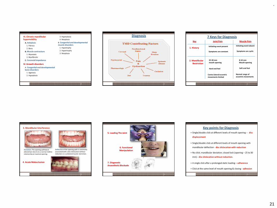
.
21
III. Chronic mandibularhypomobility
121
A. Ankylosis
1. Fibrous
2. Bony
B. Muscle contracture
1. Myostatic
2. Myofibrotic
C. Coronoid impedance
IV. Growth disorders
A. Congenital and developmental bone disorders
1. Agenesis
2. Hypoplasia
3. Hyperplasia
4. Neoplasia
B. Congenital and developmental muscle disorders
1. Hypotrophy
2. Hypertrophy
3. Neoplasia
Diagnosis
122
Key Joint Pain Muscle Pain
1. HistoryInitiating event present
Symptoms are constant
Initiating event absent
Symptoms are cyclic
2. MandibularRestriction
25-30 mmmouth opening
Hard end feel
Contra lateral eccentric movements limited
8-10 mm Mouth opening
Soft end feel
Normal range of eccentric movements
123
7 Keys for Diagnosis
3. Mandibular Interference
Deviation. The opening pathway is altered but returns to a normal midline relationship at maximal opening.
Deflection of the opening path is commonly associated with a disc dislocation without reduction or a unilateral muscle restriction.
4. Acute Malocclusion
124
5. Loading The Joint
125
6. Functional Manipulation
7. Diagnostic Anaesthetic Blockade
Key points for Diagnosis
126
▪ Single/double click at different levels of mouth opening – disc
displacement
▪ Single/double click at different levels of mouth opening with
mandibular deflection - disc dislocation with reduction
▪ No click; mandibular deviation; closed lock (opening – 25 to 30
mm) - disc dislocation without reduction.
▪ A single click after a prolonged static loading – adherence
▪ Click at the same level of mouth opening & closing - adhesion

.
22
Key points for Diagnosis
127
• Sudden thrust near to maximum opening with pre – auricular
depression – subluxation
• Inability to close the mouth (open lock) – spontaneous dislocation
• Pain in inflammatory disorders are dull & continuous accentuated
by function.
• Synovitis, capsulitis & retrodiscitis have same clinical presentation
& additional diagnostic aids are required to differentiate between
them .
▪ Frequent postural alterations in patients with different types of temporomandibular disorders. Irene A et. al.
Objective: To describe postural alterations according to the type of temporomandibular disorder (TMD).
Conclusion: TMD patients present postural changes, mainly forward head posture, pelvic tilt and high shoulder, with special involvement related to muscle and combined diagnosis.
Rev. Salud Pública. 20 (3): 384-389, 2018
128
Role of Occlusion in TMDs
TMD▪ Normal function + event > physiological tolerance symptoms.
▪ Events can be:
–Local: improperly occluding crown, Post-injection trauma after L.A, trauma from wide mouth opening, etc
–Systemic: emotional stress
▪ Physiologic tolerance: influenced by
–Local factors: occlusal instability associated with dev., genetic or iatrogenic causes
–Systemic factors: acute or chronic diseases, gender dieteffectiveness of pain modulation systems etc.
129
Occlusal interferences
Occlusal disharmony
Stresses within Stomatognathic sys.
Functional malocclusion Ability of the tissues to resist
Occlusal Dysfunction
Func. Disturbance &/or F.disorder
TMDs
overcome
2019 130
Determinants of Occlusion
2019 131
▪ The anatomy of the TMJ has effect on the mandibularmovements and tooth morphology.
▪ The paths of the condyles within the glenoid fossae, andthe locations of the rotational centers determine theocclusal morphology of teeth.
▪ These have an effect on the allowable cusp height, fossadepth along with the acceptable ridge and groovedirections.
2019 132
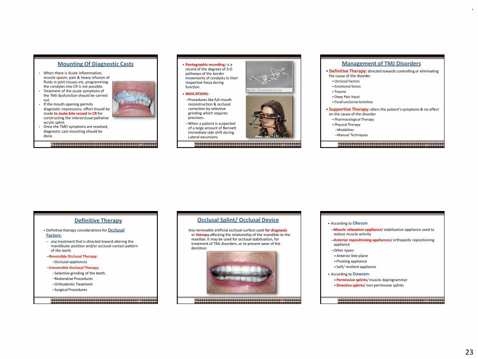
.
23
Mounting Of Diagnostic Casts
• When there is Acute inflammation, muscle spasm, pain & heavy infusion of fluids in joint tissues etc, programming the condyles into CR is not possible.
• Treatment of the acute symptoms of the TMJ dysfunction should be carried out.
• If the mouth opening permitsdiagnostic impressions, effort should be made to make bite record in CR for constructing the interocclusal palliative acrylic splint.
• Once the TMD symptoms are resolved,diagnostic cast mounting should be done.
972019
▪ Pantographic recording: is a record of the degrees of 3-D pathways of the border movements of condyles in their respective fossa during function.
▪ INDICATIONS:
–Procedures like full mouth reconstruction & occlusal correction by selective grinding which requires precision.
–When a patient is suspected of a large amount of Bennett Immediate side shift during Lateral excursions
2019 134
Management of TMJ Disorders
2019 135
▪ Definitive Therapy: directed towards controlling or eliminating the cause of the disorder.
▪ Occlusal Factors
▪ Emotional Stress
▪ Trauma
▪ Deep Pain Input
▪ ParaFunctional Activities
▪ Supportive Therapy: alters the patient’s symptoms & no effect on the cause of the disorder
▪ Pharmacological Therapy
▪ Physical Therapy
–Modalities
–Manuel Techniques
▪ Definitive therapy considerations for Occlusal Factors:
– any treatment that is directed toward altering the mandibular position and/or occlusal contact pattern of the teeth.
–Reversible Occlusal Therapy:
–Occlusal appliances
–Irreversible Occlusal Therapy:
–Selective grinding of the teeth.
–Restorative Procedures
–Orthodontic Treatment
–Surgical Procedures
100
Definitive Therapy Occlusal Splint/ Occlusal Device
Any removable artificial occlusal surface used for diagnosis or therapy affecting the relationship of the mandible to the maxillae. It may be used for occlusal stabilization, for treatment of TMJ disorders, or to prevent wear of the dentition
2019 101
▪ According to Okeson
–Muscle relaxation appliance/ stabilization appliance used to reduce muscle activity
–Anterior repositioning appliances/ orthopedic repositioning appliance
–Other types:
▪ Anterior bite plane
▪ Pivoting appliance
▪ Soft/ resilient appliance
▪ According to Dawson:
▪ Permissive splints/ muscle deprogrammer
▪ Directive splints/ non-permissive splints
138
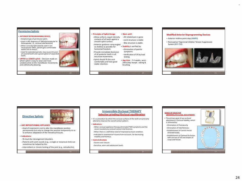
.
24
Permissive Splints
▪ ANTERIOR DEPROGRAMMING DEVICE:
–Simplest type of permissive splint.
–Used in diff. diagnosis of TMDs(Intracapsular Vs Extracapsular, i.e., occlusal interferences)
–When correctly fabricated & used in non intracapsular TMDs, patient gets comfortable within min or hrours.
–Used for extended periods, may cause intrusion of covered teeth and supraeruption of separated teeth.
▪ UPPER or LOWER splint :- Decision made on which splint is easy to wear and most unobstructive to the mandibular movements and esthetically pleasing.
139
▪ Principles of Splint Design
–Allow uniform, equal-intensity contacts of all teeth against a smooth splint surface.
–Anterior guidance ramp angled as shallow as possible for horizontal freedom.
–Provide immediate disclusion of all posterior teeth in all excursive movements.
–Splint should fit the arch comfortably and have good stable retention.
140
▪ Worn until:
–All related pain is gone
–Joint structure is stable
–Bite structure is stable
▪ Stability is verified by:
–Elimination of painful symptoms
–Verification of CR by load testing
▪ Avg time : 2-4 weeks, worn24hrs/day except : eating &brushing
Modified Anterior Deprogramming Devices
▪ Anterior midline point stop (AMPS)
▪ Nociceptive Trigeminal Inhibitor Tension Suppression System (NTI-TSS)
141
Directive Splints
▪ ANT. REPOSITIONING APPLIANCE:
–Goal of treatment is not to alter the mandibular position permanently but only to change the position temporarily so as to enhance adaptation of the retrodiscal tissues.
▪ Indications:
–To treat disc derangement disorders.
–Patients with joint sounds (e.g., a single or reciprocal click) cansometimes be helped by this.
–Intermittent or chronic locking of the joint (e.g., retrodiscitis).
142
Irreversible Occlusal THERAPY
143
Selective grinding/Occlusal equilibration
▪ It is a procedure by which the occlusal surfaces of the teeth are precisely altered to improve the overall contact pattern.
▪ Indications:
–When occlusal appliance therapy eliminated TMD symptoms and the cause revealed any occlusal contact interferences.
–When there is a definitive need of improved occlusal condition.
–Indicated in treatment of trauma from occlusion, for decreasing mobility and fremitus.
▪ Contraindications
–Severe over closure.
–Sensitive, worn and adolescent teeth.
GOALS OF SELECTIVE GRINDING/OCCLUSAL ADJUSTMENT:
▪ The primary goal of any occlusal adjustment is Occlusal stability, which is achieved by:
–Elimination of Prematurity
–Elimination of Interferences
–Establishment of Centric ForcesDirected Axially
–Establishment of Optimal Occlusion with out loss of VD and shapes of cusps and fossae.
144
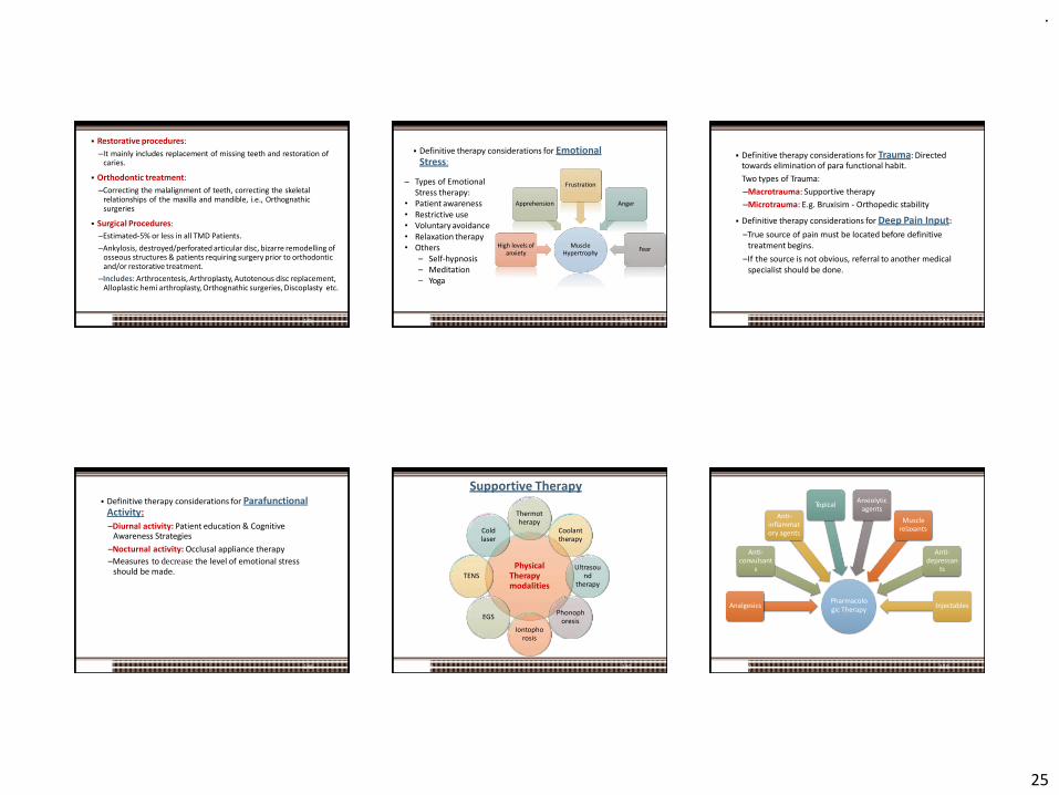
.
25
▪ Restorative procedures:
–It mainly includes replacement of missing teeth and restoration ofcaries.
▪ Orthodontic treatment:
–Correcting the malalignment of teeth, correcting the skeletalrelationships of the maxilla and mandible, i.e., Orthognathicsurgeries
▪ Surgical Procedures:
–Estimated-5% or less in all TMD Patients.
–Ankylosis, destroyed/perforated articular disc, bizarre remodelling of osseous structures & patients requiring surgery prior to orthodontic and/or restorative treatment.
–Includes: Arthrocentesis, Arthroplasty, Autotenous disc replacement, Alloplastic hemi arthroplasty, Orthognathic surgeries, Discoplasty etc.
145
▪ Definitive therapy considerations for Emotional Stress:
2019 110
Muscle Hypertrophy
High levels of anxiety
Apprehension
Frustration
Anger
Fear
– Types of Emotional Stress therapy:
• Patient awareness• Restrictive use• Voluntary avoidance• Relaxation therapy• Others
– Self-hypnosis– Meditation– Yoga
▪ Definitive therapy considerations for Trauma: Directed towards elimination of para functional habit.
Two types of Trauma:
–Macrotrauma: Supportive therapy
–Microtrauma: E.g. Bruxisim - Orthopedic stability
▪ Definitive therapy considerations for Deep Pain Input:
–True source of pain must be located before definitive treatment begins.
–If the source is not obvious, referral to another medicalspecialist should be done.
147
▪ Definitive therapy considerations for Parafunctional Activity:–Diurnal activity: Patient education & Cognitive
Awareness Strategies
–Nocturnal activity: Occlusal appliance therapy
–Measures to decrease the level of emotional stressshould be made.
148
Supportive Therapy
PhysicalTherapymodalities
Thermot herapy
Coolant therapy
Ultrasou nd
therapy
Phonoph oresis
Iontopho rosis
EGS
TENS
Cold laser
2019 149
Pharmacologic Therapy
Analgesics
Anti-convulsant
s
Anti-inflammat ory agents
TopicalAnxiolytic
agents
Muscle relaxants
Anti-depressan
ts
Injectables
2019 150
.
26
Conclusion
2019 151
▪ A thorough knowledge of TMJ & its relationship with surrounding structures is essential to fully comprehend normal anatomy & physiology, adaptive processes, dysfunction & pathology of the TMJ.
▪ Although numerous treatments have been advocated, none are universally effective for all patients all the time.
▪ A good Prosthodontic treatment bears direct relation with TM articulation since establishment of occlusion is one of the main steps in complete denture, fixed partial & removal partial dentures.
▪ Effective treatment begins with the thorough understanding of the disorder & its etiology and an appreciation of the various types of treatments is essential for effective management of the symptoms.
References
2019 152
▪ Okeson, JP. Management of Temporomandibular Disorders and Occlusion , 7th ed., (2003), Mosby.
▪ Zarb GA, Bolender CE. Prosthetic treatment for edentulous patients, Complete dentures & Implant supported prosthesis. 13th ed.
▪ Dawson PE. Functional occlusion from TMJ to smile design.3rd ed.
▪ Charles McNeill. Science and practice of occlusion.
▪ Temporomandibular disorders-diagnosis treatment and management:Weldon E. Bell (3rd ed)
▪ Neil S. Norton. Neter’s Head And Neck Anatomy For Dentistry. 2nd Ed. Philadelphia. Elsevier Inc 2012.
▪ Irene A. Espinosa de Santillana, Ariana García-Juárez, Jaime Rebollo-Vázquez y Ana K. Ustarán-Aquino. Frequent postural alterations in patients with different types of temporomandibular disorders. Rev. Salud Pública. 20 (3): 384-389, 2018.
References
2019 153
▪ Melissa E. Bender, Rosa B. Lipin, Steven L. Goudy. Development of the Pediatric Temporomandibular Joint. Oral Maxillofacial Surg Clin N Am 30 (2018) 1–9.
▪ Mohl ND, Ohrbach RK, Crow HC, Gross AJ. Devices for the diagnosis & treatment of temporomandibular disorders. Part III: Thermography,ultrasound, and electric stimulation. J Prosthet Dent 1990; 63(1):472-5.
▪ Mohl ND, McCall WD, Lund JP, Plesh O. Devices for the diagnosis & treatment of temporomandibular disorders. Part I: Introduction, Scientific evidence, and jaw tracking. J Prosthet Dent 1990; 63(1):198-201.
▪ Mohl ND, Lund JP, Widmer CG, McCall WD. Devices for the diagnosis & treatment of temporomandibular disorders. Part II: Electromyography and sonography. J Prosthet Dent 1990; 63(1):332-5.
References
154
▪ David L. Stocum & W. Eugene Roberts. Part I: Development and Physiology of the Temporomandibular Joint. # Springer Science+Business Media, LLC, part of Springer Nature 2018.
▪ Dania Tamimi, Elnaz Jalali, David Hatcher. Temporomandibular JointImaging. Radiol Clin N Am – 2017.
▪ Weiner S. Biomechanics of occlusion and the articulator. DCNA 1995:39(2):257-284.
▪ Okeson JP. Occlusion and functional disorders of the masticatorysystem. DCNA 1995:39(2):285-301.
▪ Nowlin TP, Nowlin JH. Examination and occlusal analysis of the masticatory system. DCNA 1995:39(2):379-402.
▪ World Wide Web.
2019 119
.
1
Calcium and Phosphate Metabolism
Presented by- Dr. Vishnu Soni
Contents
Introduction
Chemical structure of calciumDistribution of calcium in body
Dietary requirement of calcium
Calcium sourcesCalcium metabolism
Role of calcium
Phosphate metabolism
Role of phosphate
Clinical implications of Calcium & Phosphate metabolism-
1. Hypocalcemia
2. Hypercalcemia
3. Vitamin D deficiency - Rickets4. Congenital Hypoparathyroidism
5. Pseudo Hypoparathyroidism
6. Hyperparathyroidism7. Osteoporosis
8. Hypophoshatemia
9. Hyperphosphatemia
Introduction
Calcium phosphates are among the most widely utilized minerals in living organisms. The human body, for example, employs calcium phosphates as the inorganic component of bones and teeth.
Ref-Journal of Material Chemistry-2005,15, 3317-3325
Calcium & phosphorus ions in an appropriate and steady concentration are essential for a proper working of many of the delicate cellular mechanisms (RASMUSSEN 1972)
They form the basis of inorganic content of all hard tissues and provide rigidity to the selected frameworkTheir cellular action is to a large extent under the control of the parathyroid gland,vit D metabolite & calcitonin.
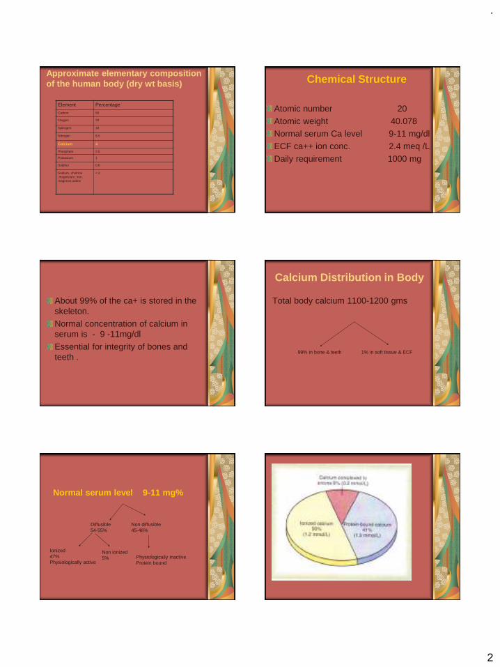
.
2
Approximate elementary composition of the human body (dry wt basis)
Element Percentage
Carbon 50
Oxygen 20
hydrogen 10
Nitrogen 8.5
Calcium 4
Phosphate 2.5
Potassium 1
Sulphur 0.8
Sodium, cholrine ,magnisium, iron, magnese,iodine
< 2
Chemical Structure
Atomic number 20
Atomic weight 40.078Normal serum Ca level 9-11 mg/dl
ECF ca++ ion conc. 2.4 meq /L
Daily requirement 1000 mg
About 99% of the ca+ is stored in the skeleton.
Normal concentration of calcium in serum is - 9 -11mg/dl
Essential for integrity of bones and teeth .
Calcium Distribution in Body
Total body calcium 1100-1200 gms
99% in bone & teeth 1% in soft tissue & ECF
Normal serum level 9-11 mg%
Non diffusible45-46%
Diffusible 54-55%
Physiologically inactiveProtein bound
Non ionized5%
Ionized47%Physiologically active

.
3
Dietary Calcium RequirementGroup Age Mg/day
Infants Birth – 6 month 400
6-12 month 600
Children 1-5 year 800
6-10 years 800-1000
Adolescent and young adult 11-24 years 1200-1500
Men 25-65 years 1000
Women 25-50 years 1000
Pregnant and lactating 1200-1500
Post menopausal Receiving estrogen 1000
Not receiving estrogen 1500
Men &women > 65 years 1500
Recommended by National Institute of Health Consensus Statement -1994Optimal Calcium Intake
Calcium needs vary throughout life
The amount of calcium a person needs to consume can change through different ages and life stages:
Babies – from 7–12 months, babies are estimated to need 600mg per day if breastfed and 700mg per day if bottle fed.
- The calcium in infant formula may not be absorbed as efficiently as that found in breast milk.
- For children aged 1–3 years, the amount needed rises to 800mg per day.
Young children – skeletal tissue is constantly growing, so young children have high calcium needs.
-Children aged 4–8 years need around 800 - 900 mg per day.
-This rises to 1,000mg per day for those aged 9–11 years.
Pre-teens and teenagers – puberty prompts a growth spurt.
-This group needs more calcium, with a recommended dietary intake of 1,300 mg per day for both boys and girls between the ages of 12 and 18 years.
Peak bone mass years – from before the onset of puberty to around the mid-20s, the skeleton increases its bone mass.
-If the skeleton is strengthened with enough calcium during these years, diseases like osteoporosis in the later years are thought to be less likely. During mid-life, women and men both need around 1,000mg per day.
Pregnant women – although a developing baby needs a lot of calcium and this is taken from the mother’s bones, most women rapidly replace this bone loss once the baby has stopped breastfeeding.
There is no additional dietary calcium requirement for pregnancy, except for the pregnant adolescent, who requires an additional 1,300mg per day of calcium to meet the requirements of both her own growth and the fetus.

.
4
The normal fetal skeleton has accreted about 30 g calcium by the end of gestation, but about 80% of the accretion occurs rapidly during the third trimester. This corresponds to a daily accretion rate of about 250–300 mg calcium by the fetal skeleton during the third trimester. The mother could theoretically meet this demand by
1. Increasing the intestinal absorption of calcium,
2. Decreasing renal calcium losses, 3. Increasing the resorption of calcium from
the maternal skeleton.
The evidence indicates that alterations in intestinal calcium absorption may be a major adaptation in the pregnant woman, with possibly some contribution of calcium from the maternal skeleton as well.
Breastfeeding women – there is no increased requirement for calcium during breastfeeding, except for the breastfeeding adolescent, who needs an additional 1,300mg per day.
The typical daily loss of calcium in breast milk has been estimated to range from 280–400 mg, although daily losses as great as 1000 mg calcium have been reported
Again, the mother could theoretically meet this demand by
1. Increasing the intestinal absorption of calcium,
2. Decreasing renal calcium losses, and3. Increasing the resorption of calcium from
the maternal skeleton.A temporary demineralization of the
skeleton seems to be the main mechanism by which lactating women meet these calcium requirements.
Elderly people –The recommended dietary intake for calcium is 1,300mg per day for women over the age of 50 years and men over the age of 70 years
As age advances, the skeleton loses calcium. Women lose more calcium from their bones in the five years around the age of menopause. However, both men and women lose bone mass as they grow older and need to ensure an adequate amount of calcium in their diet to offset these losses.While a diet high in calcium cannot reverse age-related bone loss, it can slow down the process.
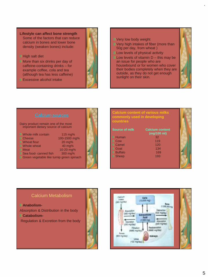
.
5
Lifestyle can affect bone strength Some of the factors that can reduce calcium in bones and lower bone density (weaken bones) include:
High salt diet
More than six drinks per day of caffeine-containing drinks – for example coffee, cola and tea (although tea has less caffeine)
Excessive alcohol intake
Very low body weight Very high intakes of fiber (more than 50g per day, from wheat ) Low levels of physical activity Low levels of vitamin D – this may be an issue for people who are housebound or for women who cover their bodies completely when they are outside, as they do not get enough sunlight on their skin.
Calcium sources
Dairy product remain one of the most important dietary source of calcium
Whole milk contain 115 mg%Cheese 100-1500 mg%Wheat flour 20 mg%Whole wheat 40 mg%Meat 10-20 mg%Sea food- canned fish 300 mg%Green vegetable like turnip green spinach
Calcium content of various milkscommonly used in developingcountries
Source of milk Calcium content (mg/100 ml)
Human 32 Cow 119Camel 120Goat 134Buffalo 169Sheep 193
Calcium Metabolism
Anabolism-Absorption & Distribution in the body
Catabolism-Regulation & Excretion from the body
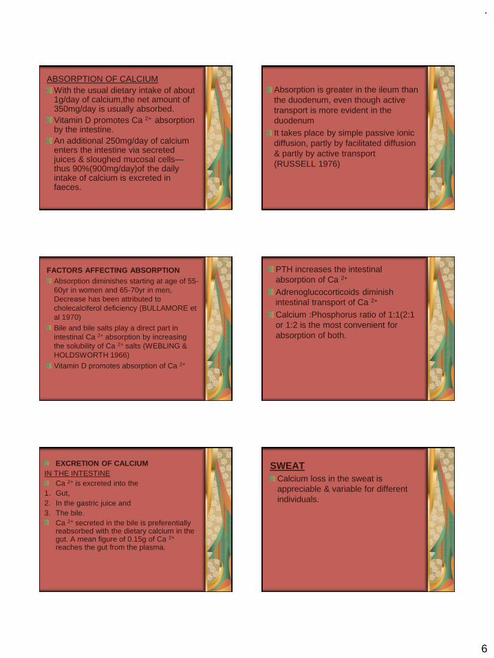
.
6
ABSORPTION OF CALCIUMWith the usual dietary intake of about 1g/day of calcium,the net amount of 350mg/day is usually absorbed.Vitamin D promotes Ca 2+ absorption by the intestine.An additional 250mg/day of calcium enters the intestine via secreted juices & sloughed mucosal cells—thus 90%(900mg/day)of the daily intake of calcium is excreted in faeces.
Absorption is greater in the ileum than the duodenum, even though active transport is more evident in the duodenumIt takes place by simple passive ionic diffusion, partly by facilitated diffusion & partly by active transport (RUSSELL 1976)
FACTORS AFFECTING ABSORPTIONAbsorption diminishes starting at age of 55-60yr in women and 65-70yr in men, Decrease has been attributed to cholecalciferol deficiency (BULLAMORE et al 1970)Bile and bile salts play a direct part in intestinal Ca 2+ absorption by increasing the solubility of Ca 2+ salts (WEBLING & HOLDSWORTH 1966)Vitamin D promotes absorption of Ca 2+
PTH increases the intestinal absorption of Ca 2+
Adrenoglucocorticoids diminish intestinal transport of Ca 2+
Calcium :Phosphorus ratio of 1:1(2:1 or 1:2 is the most convenient for absorption of both.
EXCRETION OF CALCIUMIN THE INTESTINE
Ca 2+ is excreted into the 1. Gut,2. In the gastric juice and 3. The bile.
Ca 2+ secreted in the bile is preferentially reabsorbed with the dietary calcium in the gut. A mean figure of 0.15g of Ca 2+
reaches the gut from the plasma.
SWEATCalcium loss in the sweat is appreciable & variable for different individuals.
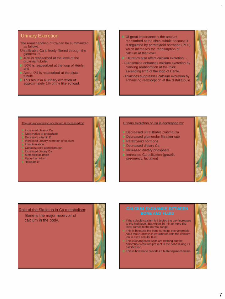
.
7
Urinary ExcretionThe renal handling of Ca can be summarized
as follows: Ultrafiltrable Ca is freely filtered through the
glomerulus. 40% is reabsorbed at the level of the proximal tubule; 50% is reabsorbed at the loop of Henle,
and About 9% is reabsorbed at the distal tubule. This result in a urinary excretion of approximately 1% of the filtered load.
Of great importance is the amount reabsorbed at the distal tubule because it is regulated by parathyroid hormone (PTH) which increases the reabsorption of calcium at that level.
Diuretics also affect calcium excretion: -- Furosemide enhances calcium excretion by
blocking reabsorption at the thick ascending limb of the loop of Henle.
-Thiazides suppresses calcium excretion by enhancing reabsorption at the distal tubule.
The urinary excretion of calcium is increased by:
Increased plasma CaDeprivation of phosphateExcessive vitamin DIncreased urinary excretion of sodiumImmobilizationCorticosteroid administrationIncreased dietary CaMetabolic acidosisHyperthyroidism"Idiopathic"
Urinary excretion of Ca is decreased by:
Decreased ultrafiltrable plasma CaDecreased glomerular filtration rateParathyroid hormoneDecreased dietary CaIncreased dietary phosphateIncreased Ca utilization (growth, pregnancy, lactation)
Role of the Skeleton in Ca metabolism:
Bone is the major reservoir of calcium in the body.
CALCIUM EXCHANGE BETWEEN BONE AND FLUID
If the soluble calcium is injected the ca+ increases to the high level. But within 30 min or more the level comes to the normal range.This is because the bone contains exchangeable salts that is always in equilibrium with the calcium ion in extra cellular fluid.This exchangeable salts are nothing but the amorphous calcium present in the bone during its calcification.This is how bone provides a buffering mechanism.

.
8
ROLE OF VITAMIN D
It has potent effect to increase calcium absorption from the intestinal tract. Stimulates synthesis of calcium binding proteins.Vitamin D is converted in different product(1-25-dihydroxy cholecalciferol) which are helpful in calcium absorption. Kidneys stimulates re absorption, reduces urinary loss increases blood level. Bone promotes deposition of calcium, stimulates mobilization of calcium from bony fluids.
Vitamin D
Vitamin D promotes intestinal absorption of Ca and phosphate.
It decrease renal excretion of Calcium & Phosphate.
Bone absorption and bone deposition
ROLE OF PARATHYROID HORMONE
It provides powerful mechanism for controlling extracellular calcium by regulating
1. Intestinal reabsorption,
2. Renal excretion and
3. Exchange between the extracellular fluid and bone of these ions.
Anatomy of the gland EFFECT OF PTH HORMONE
Effect of PTH depends on the level of calcium in the extracellular fluids. If PTH is injected in the body there will be raise in the calcium concentration of the body.Mainly PTH act by two mechanism -
1. Increase calcium absorption from bone
2. Decrease calcium excretion by kidney

.
9
1. ABSORPTION FROM BONE
Calcium absorption from the bone can be done in two ways.
1.Rapid absorption 2.Slow absorption
Rapid absorption
In case of rapid absorption when PTH is secreted in the body, studies have shown the osteoblasts and osteocytes form a system of interconnected cells that spreads all through the bone.This extensive system is called osteocytic membrane system.
Between the osteocytic membrane and the bone a small amount of fluid is there which is known as bone fluid.Now the osteocytic membrane pumps the calcium ions from the bone fluid to the extracellular fluid.When the osteocytic pumps becomes excessively activated the bone fluid calcium concentration falls even lower and calcium salts are then absorbed from the bone.This effect is called osteolysis.
Role of PTH.
SLOW ABSORPTION
PTH cause activation of the osteoclasts. They are not having receptor protein for the PTH. It is believed that activation of osteoblasts and osteocytes send a signal to osteoclasts. This activation of osteoclasts occur in two ways
1. Immediate activation of cells that havealready formed.
2. Formation of new osteoclasts.These osteoclasts cause the resorption of the bone and release of the calcium ions.
2. DECREASE CALCIUM EXCRETION BY KIDNEY
PTH also increase renal tubular reabsorption of the calcium.The increased calcium absorption occurs mainly at late distal tubules, the collecting tubules, the early collecting ducts and possibly the ascending loops of Henle.PTH increase intestinal absorption of the calcium as describe earlier with help of vitamin D.

.
10
EFFECT OF CALCITONIN
It is a hormone secreted by the thyroid gland tends to decrease the plasma calcium ions. In general has effects opposite to those of the PTH. Calcitonin secrets whenever there is a increase in the calcium concentration in the plasma.
Calcitonin decrease the calcium concentration in two ways.
1.The immediate effect is to decrease is the absorptive activities of the osteoclasts.
And the possibly decrease osteolytic effects of the osteocytic membrane.
2.The second and more prolong effect of Calcitonin is to decrease the formation of new osteoclasts. Because of this there will be less formation of osteoblasts also.
-So that overall effect is the decrease osteoblastic and osteoclastic activities.
The role of calcium-
Strengthening bones and teeth Regulating muscle functioning, such as contraction and relaxation Regulating heart functioning Blood clotting Transmission of nervous system messages Enzyme function.
References1. Review of Medical Physiology. 9’th edition, William F Ganong
2. Concise Medical Physiology. 2’nd edition Editor. Sujit K Chaudhary
3. Textbook of medical physiology by Guyton page (925-1002)4. Pathophysiology of Mineral Metabolism (Ca, P, Mg) and Skeletal
Homeostasis Beverly Williams-Cleaves5. Christopher S. Kovacs, Calcium and Bone Metabolism in Pregnancy and
Lactation, Journal of clinical endocrinology & metabolism vol 86, no 6, 2344-2348.
6. Christabel E. Fowler et al, Influence of surfactant assembly on the formation of calcium phosphate materials Journal of material chemistry, vol 15, 3317-33
7. National Institutes of HealthConsensus Development Conference StatementJune 6-8, 1994.
8. Mokogwu Ath et al, Serum Total Calcium and Inorganic Phosphate are Higher in Exclusively, Breast Fed Infants than Infants on Mixed Diet Shiraz E-Medical JournalVol. 6, No. 3 & 4, July and October 2005.
9. S.B. Baker et al, The essentials of Calcium, Magnesium & Phosphate metabolism- Basic science review, J. Critical care & Resuscitation 2002;4, 301-306.
Thank you
.
1
Dr Vishnu Soni
Introduction
The dental profession has used precision-typecastings for the most part of century. Using thelost wax technique, Taggart in 1907developed a process for making castings usedin restoration of prepared teeth. Since theprocess did not take into account all thedimensional changes associated with thecasting technique, the resultant product didexhibit some problems in terms of dimensionalaccuracy.
Definition
Casting is a fabrication process whereby a totally moltenmetal is poured into a mold cavity having a desired shape ;upon solidification, the metal assumes the shape of themold.
Classification of Dental Casting Alloys
Alloy Type Total noble metal contentHigh noble metal contains≥40 wt% Au and ≥60 wt% of
the noble metal elements (Au+Ir+Os+Pt+Rh+Ru )
Noble metal Contains ≥25 wt% of the noble metal
elements
Predominantly base metal Contains <25 wt% of the noble metal elements
Journal of American Dental Association (1984)
Classification of Alloys for All Metal Restorations , Metal Ceramic Restorations, and Frameworks for Removable Partial Dentures
Alloy Type All Metal Metal Ceramic Removable Partial Dentures
High Noble Au-Ag-Cu-Pd
Metal Ceramic alloys
Au-Pt-Pd
Au-Pd-Ag(5-12 wt% Ag)
Au-Pd (no Ag)
Au-Ag-Cu-Pd
Noble Ag-Pd-Au-Cu
Ag-Pd
Metal Ceramic alloys
Pd-Au (no Ag)
Pd-Au-Ag
Pd-Ag
Pd-Cu
Pd-Co
Pd-Ga-Ag
Ag-Pd-Au-Cu
Ag-Pd
Base Metal Pure Ti
Ti-Al-V
Ni-Cr-Mo-Be
Ni-Cr-Mo
Co-Cr-W
Al bronze
Pure Ti
Ti-Al-V
Ni-Cr-Mo-Be
Ni-Cr-Mo
Co-Cr-W
Pure Ti
Ti-Al-V
Ni-Cr-Mo-Be
Ni-Cr-Mo
Co-Cr-W
Phillips’; Science of dental material ; 10th edition
Classification Of Traditional Casting Alloys
TYPE HARDNESS USE
I Soft Single Surfaces
II Medium Inlays/Onlays
III Hard Crowns/Bridges
IV Extra Bridges & partial dentures
JADA, Leinfelder ;1997;128;37-45
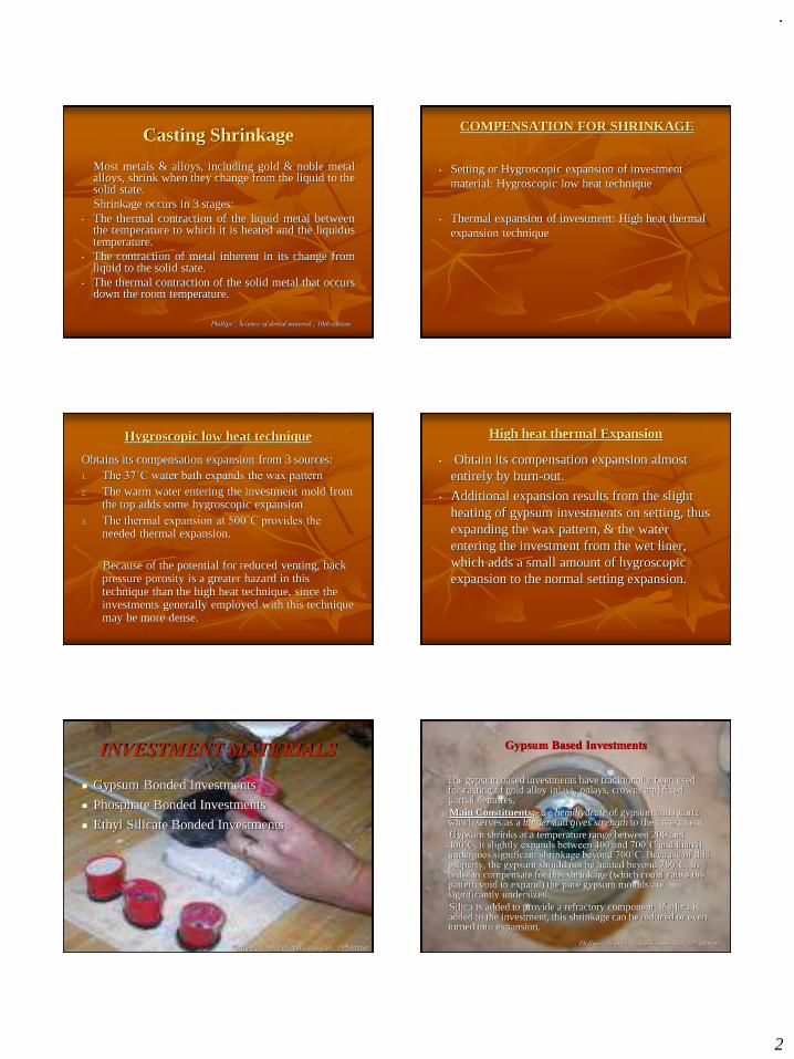
.
2
Casting Shrinkage
Most metals & alloys, including gold & noble metalalloys, shrink when they change from the liquid to thesolid state.Shrinkage occurs in 3 stages:
• The thermal contraction of the liquid metal betweenthe temperature to which it is heated and the liquidustemperature.
• The contraction of metal inherent in its change fromliquid to the solid state.
• The thermal contraction of the solid metal that occursdown the room temperature.
Phillips’; Science of dental material ; 10th edition
COMPENSATION FOR SHRINKAGE
• Setting or Hygroscopic expansion of investment material: Hygroscopic low heat technique
• Thermal expansion of investment: High heat thermal expansion technique
Hygroscopic low heat technique
Obtains its compensation expansion from 3 sources:1. The 37˚C water bath expands the wax pattern
2. The warm water entering the investment mold from the top adds some hygroscopic expansion
3. The thermal expansion at 500˚C provides the needed thermal expansion.
Because of the potential for reduced venting, back pressure porosity is a greater hazard in this technique than the high heat technique, since the investments generally employed with this technique may be more dense.
High heat thermal Expansion
• Obtain its compensation expansion almost entirely by burn-out.
• Additional expansion results from the slight heating of gypsum investments on setting, thus expanding the wax pattern, & the water entering the investment from the wet liner, which adds a small amount of hygroscopic expansion to the normal setting expansion.
INVESTMENT MATERIALS
◼ Gypsum Bonded Investments
◼ Phosphate Bonded Investments
◼ Ethyl Silicate Bonded Investments
Phillips’; Science of dental material ; 10th edition
Gypsum Based Investments
The gypsum based investments have traditionally been used for casting of gold alloy inlays, onlays, crowns and fixed partial dentures.Main Constituents:- a - hemihydrate of gypsum and quartz which serves as a binder and gives strength to the investment.Gypsum shrinks at a temperature range between 200 and 400˚C, it slightly expands between 400 and 700˚C and than it undergoes significant shrinkage beyond 700˚C. Because of this property, the gypsum should not be heated beyond 700˚C. In order to compensate for this shrinkage (which could cause the pattern void to expand) the pure gypsum moulds are significantly undersized.Silica is added to provide a refractory component. If silica is added to the investment, this shrinkage can be reduced or even turned into expansion.
Phillips’; Science of dental material ; 10th edition
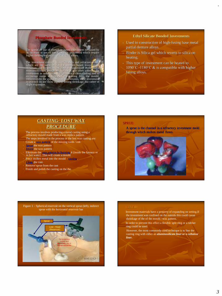
.
3
Phosphate Bonded Investments
The spread of use of phosphate based investment is caused byan increase in use of metal ceramic prosthesis, which requirehigher melting temperatures than gold alloys.
The investment consists also of binders and refractory filler,which are the same as for the gypsum based investments.However, the binder in this case is magnesium oxide and amonoammonium phosphate. Carbon is also often added to theinvestment in order to help to produce a clean casting and toencourage easier divesting of the casting from the mould.Differently to the gypsum based investments, these investmentin practice do not show signs of setting shrinkage, but rather ofslight expansion.
Phillips’; Science of dental material ; 10th edition
Ethyl Silicate Bonded Investments
• Used in construction of high-fusing base metal partial denture alloys.
• Binder is Silica gel which reverts to silica on heating.
• This type of investment can be heated to 1090˚C -1180˚C & is compatible with higher
fusing alloys.
CASTING- LOST WAX PROCEDURE
The process involves producing a metal casting using a refractory mould made from a wax replica pattern.The steps involved in the process or the lost wax casting are:
· Create a wax pattern of the missing tooth / rim· Sprue the wax pattern· Invest the wax pattern· Eliminate the wax pattern by burning it (inside the furnace or
in hot water) .This will create a mould.· Force molten metal into the mould - casting.· Clean the cast.· Remove sprue from the cast· Finish and polish the casting on the die.
:SPRUE:
A sprue is the channel in a refractory investment mold through which molten metal flows.
Figure 1 – Spherical reservoir on the vertical sprue (left), indirect sprue with the horizontal reservoir bar
Sprue
Lost - Head(Reservoir)
For preventing cavities and
porosities, due to thermal contraction
LINER:Investment materials have a property of expanding on setting.If the investment was confined on the outside this could cause shrinkage of the of the mould / wax pattern.
In order to prevent this effect a flexible split ring or a rubber ring could be used.
However, the most commonly used technique is to line the casting ring with either an aluminosilicate liner or a cellulose liner.
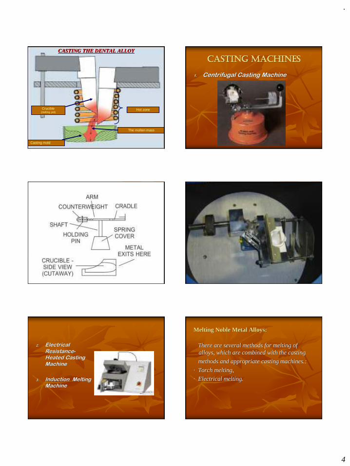
.
4
The molten mass
Hot zoneCrucible(melting pot)
Casting mold
CASTING THE DENTAL ALLOY
CASTING MACHINES
1. Centrifugal Casting Machine
2. Electrical Resistance-Heated Casting Machine
3. Induction Melting Machine
Melting Noble Metal Alloys:
There are several methods for melting of alloys, which are combined with the casting
methods and appropriate casting machines.:
· Torch melting,
· Electrical melting.
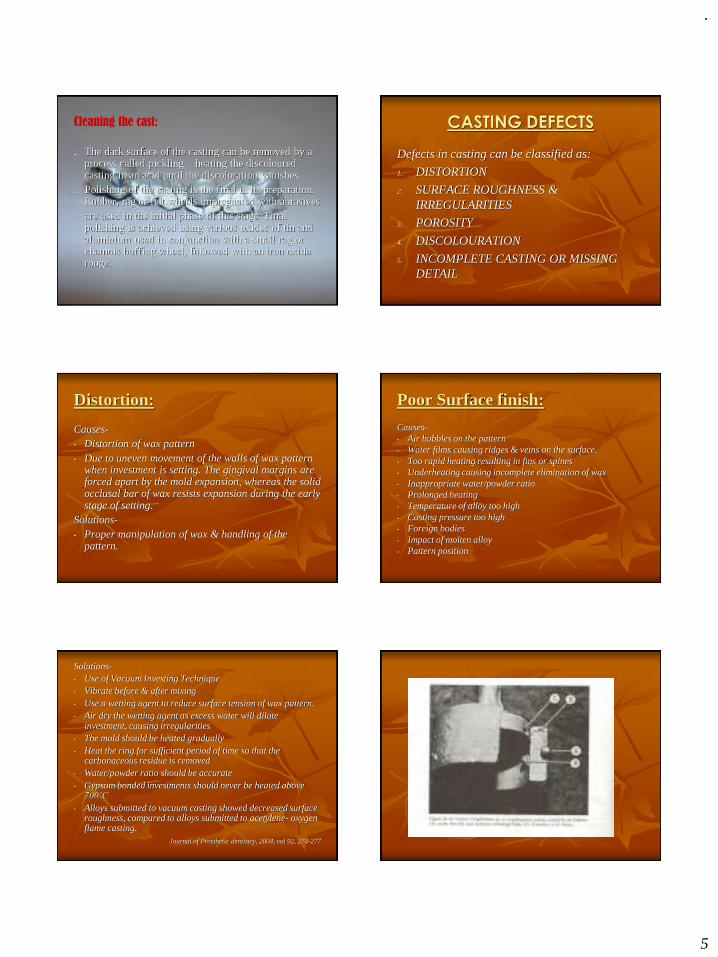
.
5
Cleaning the cast:
. The dark surface of the casting can be removed by a process called pickling – heating the discoloured casting in an acid until the discoloration vanishes.
. Polishing of the casting is the final in its preparation. Rubber, rag or felt wheels impregnated with abrasivesare used in the initial phase of this stage. Final polishing is achieved using various oxides of tin and aluminium used in conjunction with a small rag or chamois buffing wheel, followed with an iron oxide rouge.
CASTING DEFECTS
Defects in casting can be classified as:
1. DISTORTION
2. SURFACE ROUGHNESS & IRREGULARITIES
3. POROSITY
4. DISCOLOURATION
5. INCOMPLETE CASTING OR MISSING DETAIL
Distortion:
Causes-• Distortion of wax pattern• Due to uneven movement of the walls of wax pattern
when investment is setting. The gingival margins are forced apart by the mold expansion, whereas the solid occlusal bar of wax resists expansion during the early stage of setting.
Solutions-• Proper manipulation of wax & handling of the
pattern.
Poor Surface finish:
Causes-• Air bubbles on the pattern• Water films causing ridges & veins on the surface.• Too rapid heating resulting in fins or spines• Underheating causing incomplete elimination of wax• Inappropriate water/powder ratio• Prolonged heating• Temperature of alloy too high• Casting pressure too high• Foreign bodies• Impact of molten alloy• Pattern position
Solutions-• Use of Vacuum Investing Technique• Vibrate before & after mixing• Use a wetting agent to reduce surface tension of wax pattern.• Air dry the wetting agent as excess water will dilute
investment, causing irregularities• The mold should be heated gradually• Heat the ring for sufficient period of time so that the
carbonaceous residue is removed• Water/powder ratio should be accurate• Gypsum bonded investments should never be heated above
700˚C
• Alloys submitted to vacuum casting showed decreased surface roughness, compared to alloys submitted to acetylene- oxygen flame casting.
Journal of Prosthetic dentistry, 2004, vol 92, 274-277
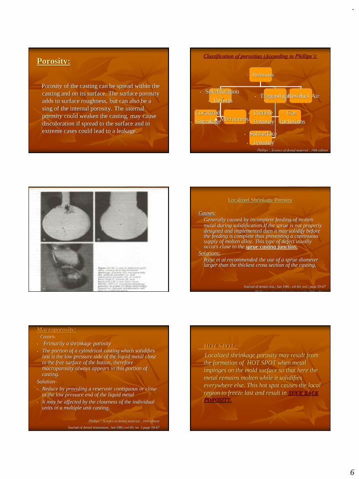
.
6
Porosity:
Porosity of the casting can be spread within the casting and on its surface. The surface porosity adds to surface roughness, but can also be a sing of the internal porosity. The internal porosity could weaken the casting, may cause discoloration if spread to the surface and in extreme cases could lead to a leakage.
Classification of porosities (According to Phillips’):
• Porosities
• Solidification
• Defects• Trapped gases• Residual Air
• Localized
• Shrinkage◼ Microporosity• Pinhole
• Porosity
• Gas
• Inclusions
• Subsurface
• PorosityPhillips’; Science of dental material ; 10th edition
Localized Shrinkage Porosity
Causes:Generally caused by incomplete feeding of molten metal during solidification.If the sprue is not properly designed and implemented then it may solidify before the feeding is complete thus preventing a continuous supply of molten alloy. This type of defect usually occurs close to the sprue-casting junction.
Solutions:Ryge et al recommended the use of a sprue diameter larger than the thickest cross section of the casting.
Journal of dental rest.; Jan 1981; vol 60; no1; page 59-67
Phillips’; science of dental materials; 10th edition
Macroporosity:Causes-
• Primarily a shrinkage porosity• The portion of a cylindrical casting which solidifies
last is the low pressure side of the liquid metal close to the free surface of the button, therefore macroporosity always appears in this portion of casting.
Solution-• Reduce by providing a reservoir contiguous or close
to the low pressure end of the liquid metal• It may be affected by the closeness of the individual
units in a multiple unit casting.
Phillips’; Science of dental material ; 10th edition
Journal of dental restoration; Jan 1981;vol 60; no. 1;page 59-67
HOT SPOT:-
Localized shrinkage porosity may result from the formation of HOT SPOT when metal impinges on the mold surface so that here the metal remains molten while it solidifies everywhere else. This hot spot causes the local region to freeze last and result in SUCK BACK POROSITY.

.
7
Solutions:
▪ Flare the point of sprue attachment
▪ Proper placement of sprue
▪ Do not use excessively long sprue
▪ Use a reservoir
▪ Reduce the mold-melt temperature differential (i.e. lower the casting temperature by about 30˚C).
Microporosity:
Microporosity is also caused by solidification shrinkage, but generally happens in fine grain alloys when the solidification is too rapid for the microvoids to segregate. This in turn is caused the mould or casting temperature being too low.
Trapped Gases
1. Pinhole Porosity
2. Gas Inclusion Porosity
• Both these porosities are related to the entrapment of gas during solidification.
• Both are characterized by a spherical contour.
• Gas inclusion porosities are much higher than pinhole porosities.
SUBSURFACE POROSITYCause-
Simultaneous nucleation of solid grains and gas bubbles at the first moment that the metal freezes at the mold walls
Solution-• Diminished by controlling the rate at which the molten metal
enters the mold • Ryge et al reported that subsurface & microporosities are
reduced by the use of a sufficiently long sprue & a melt temperature of 100˚C-150˚C above the melting point of alloy.
• According to Leinfelder et al reported that long sprues are preferable for thick castings while short sprues are beneficial for thin castings i.e. the sprue design should be related to the surface area-to-volume ratio of castings.
Journal of dental rest.; Jan 1981; vol 60; no1; page 59-67
ENTRAPPED AIR POROSITY
• Referred to as Back Pressure porosity.
• Can produce large concave depression.
Causes-
Inability of the air in the mold to escape through the pores in the investment or by the pressure gradient that displaces the air pocket toward the end of the investment via the molten sprue & button.
Journal of dental rest.; Jan 1981; vol 60; no1; page 59-67
Phillips’; science of dental materials; 10th edition

.
8
Solution-• Proper burnout• An adequate mold & casting temperature.• A sufficiently high casting pressure• Proper liquid : powder ratio.• The thickness of investment between the tip of the pattern and
the end of the ring should not be greater than 6mm.• Srickland & Sturdevant suggested that sprue design variables
have no effect on these porosities; venting, high melt temperatures, proper positioning of the pattern in the ring, choice of investment & the use of reservoir can assist in reducing or eliminating the back pressure porosities.
Journal of dental rest.; Jan 1981; vol 60; no1; page 59-67
• Phillips’; science of dental materials; 10th edition
INCOMPLETE CASTINGS
Causes-• Inadequate spruing ( sprue former too small)• Alloy not hot enough• Incomplete elimination of wax residues from the mold• Mold too cold• Ingate obstructed• Insufficient casting force
Solutions-
• Use proper size of sprue former
• Casting temperature should be higher than the liquidus temperature of alloy
• Ensure that no debris blocks the ingate
• Use adequate amount of force for casting
DISCOLOURATIONCauses-• Sulphur contamination of casting causing black
castings• Contamination with copper during pickling• Contamination with mercurySolution-• Avoid overheating of investment • Avoid use of torch flame as it contains sulphur• Avoid use of steel tongs to hold casting during
pickling• Castings should never be placed with amalgam dies
or kept on a table where amalgam scrap is present

.
9
References
• Phillips’; Science of dental materials; 10th edition.
• Journal of American Dental Association, Leinfelder ;1997
• Journal of American Dental Association: 1984
• Journal of Dental Restoration; Jan 1981; vol 60
• Journal of American Dental Association; 1993
• Journal of Prosthetic Dentistry; 1989
• Journal of Prosthetic Dentistry; 2004