Embed Size (px)
Citation preview
xiv
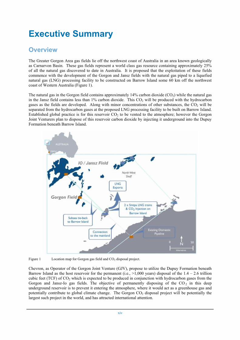
Executive Summary Overview The Greater Gorgon Area gas fields lie off the northwest coast of Australia in an area known geologically as Carnarvon Basin. These gas fields represent a world class gas resource containing approximately 25% of all the natural gas discovered to date in Australia. It is proposed that the exploitation of these fields commence with the development of the Gorgon and Jansz fields with the natural gas piped to a liquefied natural gas (LNG) processing facility to be constructed on Barrow Island some 60 km off the northwest coast of Western Australia (Figure 1).
The natural gas in the Gorgon field contains approximately 14% carbon dioxide (CO2) while the natural gas in the Jansz field contains less than 1% carbon dioxide. This CO2 will be produced with the hydrocarbon gases as the fields are developed. Along with minor concentrations of other substances, the CO2 will be separated from the hydrocarbon gases at the proposed LNG processing facility to be built on Barrow Island. Established global practice is for this reservoir CO2 to be vented to the atmosphere; however the Gorgon Joint Venturers plan to dispose of this reservoir carbon dioxide by injecting it underground into the Dupuy Formation beneath Barrow Island.
Figure 1 Location map for Gorgon gas field and CO2 disposal project.
Chevron, as Operator of the Gorgon Joint Venture (GJV), propose to utilize the Dupuy Formation beneath Barrow Island as the host reservoir for the permanent (i.e., >1,000 years) disposal of the 1.4 – 2.6 trillion cubic feet (TCF) of CO2 which is expected to be produced in conjunction with hydrocarbon gases from the Gorgon and Jansz-Io gas fields. The objective of permanently disposing of the CO 2 in this deep underground reservoir is to prevent it entering the atmosphere, where it would act as a greenhouse gas and potentially contribute to global climate change. The Gorgon CO2 disposal project will be potentially the largest such project in the world, and has attracted international attention.

xv
Highlights
As a means of fully understanding the CO2 disposal process and the associated risks, the Western Australian Department of Industry and Resources (DoIR) and the GJV agreed to regularly review the technical work for “due diligence” purposes. Consequently, DoIR is undertaking an ongoing technical appraisal of the Gorgon CO2 disposal project. When completed, the appraisal will provide technical guidance to assist the Barrow Island Act 2003 Minister in his/her assessment of the GJV’s application, under section 13 of the Act, to inject and monitor the injected CO2 in the Dupuy reservoir beneath Barrow Island.
Phases I and II of the technical appraisal were completed by Curtin University in 2003 and 2004, respectively. Innovative Carbon Technologies Pty Ltd, subsequently renamed CO2CRC Technologies Pty Ltd (CO2TECH) was commissioned by DoIR to undertake the Phase III technical appraisal. CO2TECH assembled an international Due Diligence Team to carry out this appraisal, consisting of experts with significant experience in various aspects of CO2 disposal.
The objectives for this Phase III technical assessment are to review, assess and verify the effectiveness of the following GJV plans:
• the Data Well programme to evaluate the injectivity and safety requirements of an effective injection programme in the Dupuy Formation beneath Barrow Island;
• the monitoring programme for detection of migration of the CO2 plume away from the injection site over the life of the project;
• the well remediation programme to ensure that existing wells that intersect the Dupuy Formation near the proposed injection site have been properly secured and do not pose a CO2 containment risk;
• the management plan for the remediation of CO2 seepage, should it occur, through the geological column to within 1 km of the surface.
As a basis for the Phase III technical assessment , the GJV provided CO2TECH and the Due Diligence Team with reports that were available on parts of their technical work undertaken in Phases I to III of the GJV technical review. Interaction between the Due Diligence Team and Chevron staff was facilitated through a series of four engagement sessions, held on 29-30 June, 30 August, 4-6 December, 2006 and 28 February to 2 March 2007. Copies of the presentations made by Chevron staff at the engagement sessions were provided to the Due Diligence Team.
The Phase I study concluded that the risks of CO2 geosequestration into the Dupuy Formation of Barrow Island could be managed. Phase II concluded that the target reservoir has the capacity to store the CO2 anticipated from Gorgon Project, and that the primary seal seems to be adequate for long term disposal.
This Phase III technical assessment, which ran from June 2006 to February 2008, produced four interim reports to DoIR. These interim reports were commented on shortly after submission, by both DoIR and the GJV, with the result that some of the observations and recommendations made by the Due Diligence Team have already been incorporated into future work plans of the GJV. Feedback on the interim reports provided by DoIR and GJV also improved the Due Diligence Team’s understanding of the project, and resulted in modifications to both the Final Report and certain earlier recommendations. Thus, in our view, the iterative Due Diligence process initiated by DoIR has been highly constructive and has led to a convergence of views over the way forward for the Gorgon CO2 disposal project.
The Due Diligence Team is particularly impressed with the scope and quality of work, and the amount of resources committed to the Gorgon CO2 disposal project. It appears that the preparatory work that has gone into this project significantly exceeds other comparable projects to date. Furthermore the GJV have demonstrated that many of the major requirements for CO2 disposal are satisfied. The associated risks are considered manageable through technically comprehensive plans for monitoring the migrating CO2 plume and the remediation of existing wells near the injection site. The GJV Uncertainty Management Plan is
xvi
considered to be a thorough and sound methodology, providing an excellent basis for reducing and managing subsurface uncertainties.
The Due Diligence Team concur with the GJV that additional studies are necessary as part of the Chevron Project Development and Execution Process (CPDEP) Phase IV and the Due Diligence Team have identified a series of recommendations that we consider must be addressed. This report is based on a specific scope of services, as detailed in DoIR Request Document (Request No. 206DIR0306), and should not be considered a complete technical appraisal of the feasibility for the underground disposal of CO2 from the proposed gas processing facilities on Barrow Island. It is anticipated that the Phase IV technical assessment will provide a complete appraisal of the technical feasibility of the injection project. In conclusion, at this point in time there appear to be no significant issues which may compromise the feasibility of the project, and based on the available data the Due Diligence Team believes that the overall technical assessment of the project by the GJV is sound.
GJV’s Approach to the Identification and Management of Technical Uncertainties within the Project
The GJV have developed an Uncertainty Management Plan that identifies all known subsurface uncertainties (including all risks), and evaluates the potential impact of each uncertainty on the project metrics (which are capacity, containment, injectivity, risk to assets, reservoir surveillance, cost, land use and HSE). It also generates options for reducing and managing each uncertainty, develops surveillance plans to identify if an unforecast event has occurred and describes how to manage unpredicted outcomes. The Due Diligence Team believes this is a thorough and sound methodology and, providing all the technical uncertainties within the project are identified, the Uncertainty Management Plan is an excellent basis for reducing and managing subsurface uncertainty and risk.
The GJV have undertaken a work programme to characterise the proposed disposal site and its surrounding area. This work programme includes building geological and numerical models of the disposal site, simulating the injection of CO2 into the proposed reservoir, assessing the subsurface risks and designing monitoring and remediation programmes to detect and manage un-forecast outcomes. The work programme is ongoing, continually strengthening the technical evaluation and feeding new information back into the Uncertainty Management Plan. The quality and scope of the work programme is impressive and it is expected that a thorough and comprehensive evaluation of the CO2 disposal project will be completed as part of the Chevron Project Development and Execution Process (CPDEP) before injection commences.
There are five major risks to successful injection of CO2 beneath Barrow Island:
1. insufficient capacity for CO2;
2. inadequate containment of the CO2 in the reservoir;
3. insufficient rates of injection of CO2 into the reservoir;
4. contamination of other hydrocarbon resources by migration of CO2 away from the disposal site;
5. commercial viability of the project.
The present review focuses on the first four risks. This report initially describes the target reservoir and places it in the regional context through a hydrodynamic assessment. It then deals with capacity for CO2 disposal through the assessment of data collected for the Dupuy Formation reservoir from seismic and well data. The report reviews the use of these data to build the geological, geomechanical and geochemical reservoir models together with the simulation of CO2 movement in the 1,000 years following injection. It reviews CO2 injectivity based on well tests and simulation, and then addresses the risk of CO2 contamination of hydrocarbon assets and the potential for environmental impacts of CO2 migration to the ground surface. Finally the report evaluates the monitoring and verification plans for the planned CO2 disposal project.
xvii
Only those parts of the GJV work programme that were included in the Phase III due diligence scope of services are reviewed in this report. A summary of each of these topics, presented below, is followed by our recommendations for the GJV (CPDEP) Phase IV technical work programme.
Regional Setting The assessment of geological CO2 disposal is commonly carried out at three scales referred to as regional, local and reservoir scales. A regional assessment commonly considers the general geological characteristics and hydrodynamics of a basin or sub-basin. A local assessment considers a 3-dimensional body of rock (and its contained fluids) encompassing the target disposal reservoir and surrounding domains which might have a bearing on the overall disposal integrity and containment and/or may be affected by the disposal of CO2. It commonly extends above the reservoir to the surface and below it to basement. A reservoir-scale assessment considers the portion of the sedimentary succession that defines the capacity of the reservoir, and associated barriers to CO2 migration, and is the unit which petroleum companies focus on in conventional oil and gas exploration to identify potential petroleum traps.
In the Phase III assessment by the GJV, the main focus of the assessment was on the reservoir scale. It is expected that in the Phase IV assessment, more emphasis will be placed on the local and regional scales.
Regional to Local Geology and Hydrodynamic Regimes
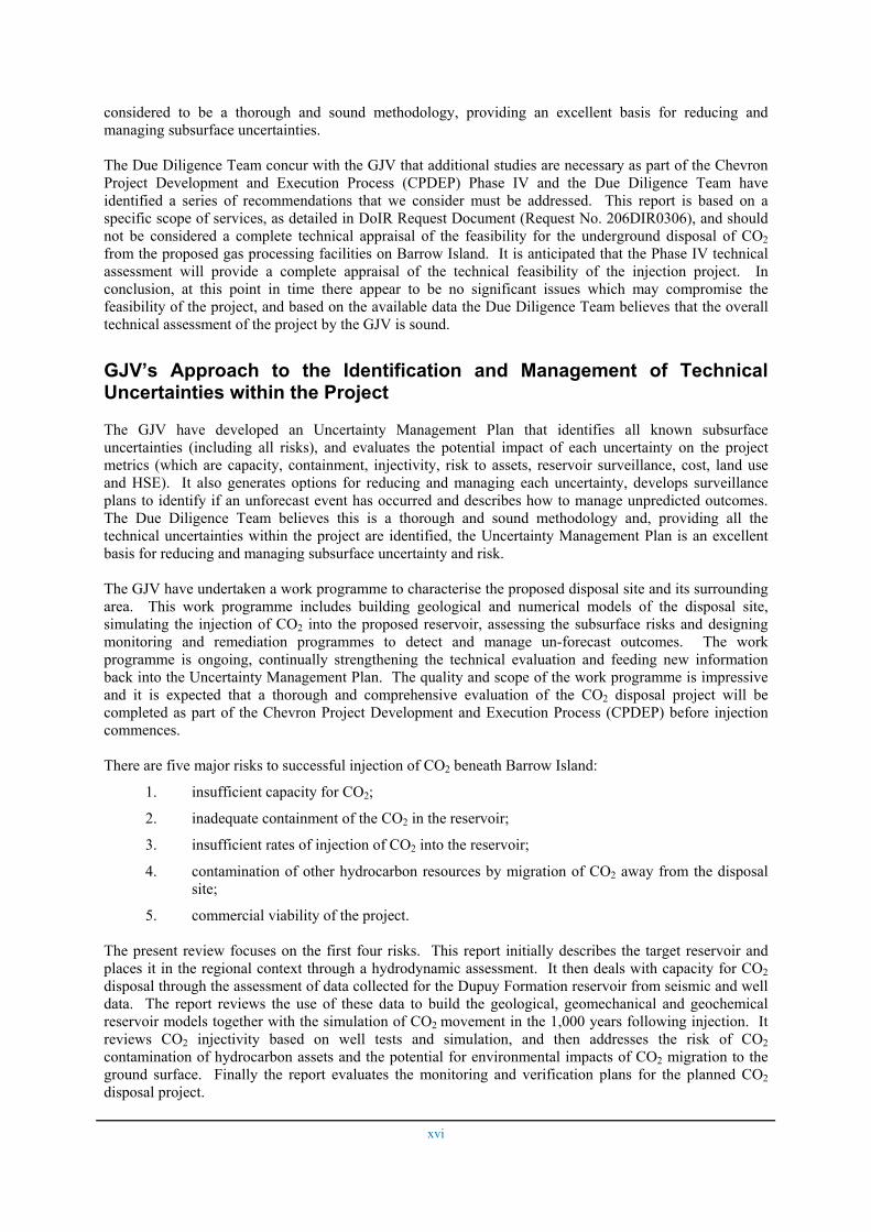
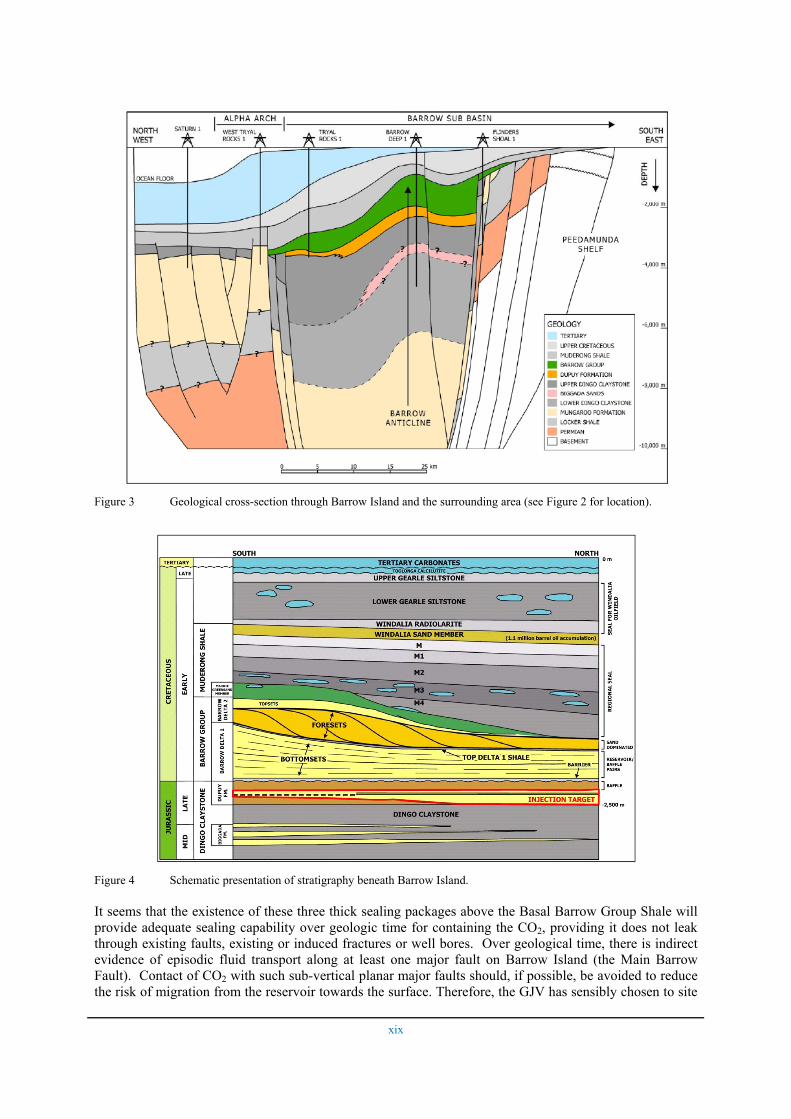
The Barrow Sub-basin (Figure 2) is a northeast-southwest trending trough (graben) within the Northern Carnarvon Basin located on the North West Shelf offshore Western Australia. The northeast-trending Rankin Platform and Alpha Arch form the north-western margin of the Barrow Sub-basin and its south-eastern limit is defined by the northeast-trending Peedamullah Shelf. To the northeast and southwest, the sub-basin abuts the Dampier (separated by a Jurassic high) and Exmouth (separated by the Alpha Arch and Yanrey Ridge) sub-basins. The transition from the shelf into the central trough is marked by the north-east trending en-echelon Flinders Fault System. Barrow Island is located on the north-northeast trending Barrow Island anticline (Figure 2 and 3).
The stratigraphy of Barrow Island is shown in Figure 4. The Jurassic Dupuy Formation is the CO2 injection target. Beneath Barrow Island, the Dupuy Formation is folded into an open anticline (Figure 3). It conformably overlies the thick marine Dingo Claystone. Directly above the Dupuy Formation lies the Barrow Group, a Cretaceous deltaic complex dominated by sandstone and mudstone. The Lower Barrow Group, the Basal Barrow Group Shale and overlying Malouet Formation (mixed sandstone/shale sets) lie unconformably on the Dupuy, and are unconformably overlain by the Flacourt Formation (sandstone-dominated sandstone/shale sets) which grades laterally into the Flag Sandstone. The thick Muderong Shale forms a regional seal and unconformably caps the Barrow Group. At the base of the Muderong Shale is the Mardie Greensand Member (an extensive marine transgressive unit of glauconitic, sandy siltstone, interbedded with siltstone and shale). The Windalia Sand Member, in the upper part of the Muderong Shale, is a locally developed sandy facies which is capped by the Windalia Radiolarite and Gearle Siltstone.
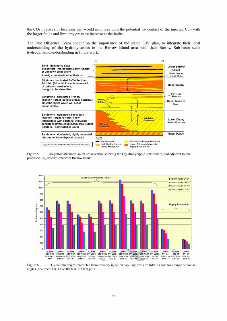
It is planned that CO2 will be injected into the Lower Dupuy and lower part of the Upper Massive Sand (below the Perforans Siltstone; Figure 5). During injection, the laterally discontinuous siltstones in the Upper Massive Sand (both above and below the Perforans Siltstone) and the Perforans Siltstone are expected to impede the vertical migration of the injected CO2. If vertically migrating CO2 reaches the top of the Upper Massive Sand, the upwards migration of the CO2 will be further slowed by fine-grained beds in the Upper Dupuy. Migrating CO2 will then encounter the Basal Barrow Group Shale, which is expected to form an effective barrier to CO2 movement from the Dupuy reservoir into the Lower Barrow Group.
xviii
Figure 2 Geological structure of the Barrow Sub-basin of the Carnarvon Basin.
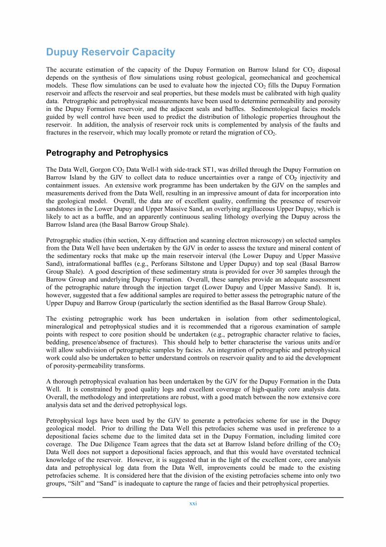
There is some debate over the competence of the primary seal (the Basal Barrow Group Shale) to prevent the upwards transport of water over long timescales, based on mixing phenomena and salinity gradients observed close to the boundary between the Lower Barrow Group and the Upper Dupuy. However, the transport of water (a single wetting phase fluid) through this barrier in response to a pressure difference between the Dupuy Formation and the Barrow Group does not mean that CO2 could also be transported through it. Indeed the mercury injection capillary pressure (MICP) results (Figure 6) indicate that this is extremely unlikely to happen unless the Basal Barrow Group Shale is breached by conductive faults or fractures along the plume migration path. Moreover, even if CO2 could breach the Basal Barrow Group Shale, further leakage through the Lower Barrow Group must contend with 160 m of discontinuous shale packages. It must then pass through 700 m of Barrow Group reservoir sands which are, in turn, overlain by the 250 to 1000 m thick Muderong shale, which has a regional sealing capacity sufficient to trap 400 – 700 m columns of natural gas in places on the North-West Shelf. Any CO2 that breached the Muderong Shale would then encounter the Windalia Radiolarite and Gearle Siltstone (several hundred metres thick), which are the sealing units for the currently producing billion-barrel oil accumulation within the Windalia Sand Member on Barrow Island.
xix
Figure 3 Geological cross-section through Barrow Island and the surrounding area (see Figure 2 for location).
Figure 4 Schematic presentation of stratigraphy beneath Barrow Island.
It seems that the existence of these three thick sealing packages above the Basal Barrow Group Shale will provide adequate sealing capability over geologic time for containing the CO2, providing it does not leak through existing faults, existing or induced fractures or well bores. Over geological time, there is indirect evidence of episodic fluid transport along at least one major fault on Barrow Island (the Main Barrow Fault). Contact of CO2 with such sub-vertical planar major faults should, if possible, be avoided to reduce the risk of migration from the reservoir towards the surface. Therefore, the GJV has sensibly chosen to site
xx
the CO2 injectors in locations that would minimize both the potential for contact of the injected CO2 with the larger faults and limit any pressure increase at the faults.
The Due Diligence Team concur on the importance of the stated GJV plan, to integrate their local understanding of the hydrodynamics in the Barrow Island area with their Barrow Sub-basin scale hydrodynamic understanding in future work.
Figure 5 Diagrammatic north-south cross section showing the key stratigraphic units within, and adjacent to, the proposed CO2 reservoir beneath Barrow Island.
Figure 6 CO2 column heights predicted from mercury injection capillary pressure (MICP) data for a range of contact angles (document G1-TE-Z-0000-REPX039.pdf).
xxi
Dupuy Reservoir Capacity The accurate estimation of the capacity of the Dupuy Formation on Barrow Island for CO2 disposal depends on the synthesis of flow simulations using robust geological, geomechanical and geochemical models. These flow simulations can be used to evaluate how the injected CO2 fills the Dupuy Formation reservoir and affects the reservoir and seal properties, but these models must be calibrated with high quality data. Petrographic and petrophysical measurements have been used to determine permeability and porosity in the Dupuy Formation reservoir, and the adjacent seals and baffles. Sedimentological facies models guided by well control have been used to predict the distribution of lithologic properties throughout the reservoir. In addition, the analysis of reservoir rock units is complemented by analysis of the faults and fractures in the reservoir, which may locally promote or retard the migration of CO2.
Petrography and Petrophysics
The Data Well, Gorgon CO2 Data Well-l with side-track ST1, was drilled through the Dupuy Formation on Barrow Island by the GJV to collect data to reduce uncertainties over a range of CO2 injectivity and containment issues. An extensive work programme has been undertaken by the GJV on the samples and measurements derived from the Data Well, resulting in an impressive amount of data for incorporation into the geological model. Overall, the data are of excellent quality, confirming the presence of reservoir sandstones in the Lower Dupuy and Upper Massive Sand, an overlying argillaceous Upper Dupuy, which is likely to act as a baffle, and an apparently continuous sealing lithology overlying the Dupuy across the Barrow Island area (the Basal Barrow Group Shale).
Petrographic studies (thin section, X-ray diffraction and scanning electron microscopy) on selected samples from the Data Well have been undertaken by the GJV in order to assess the texture and mineral content of the sedimentary rocks that make up the main reservoir interval (the Lower Dupuy and Upper Massive Sand), intraformational baffles (e.g., Perforans Siltstone and Upper Dupuy) and top seal (Basal Barrow Group Shale). A good description of these sedimentary strata is provided for over 30 samples through the Barrow Group and underlying Dupuy Formation. Overall, these samples provide an adequate assessment of the petrographic nature through the injection target (Lower Dupuy and Upper Massive Sand). It is, however, suggested that a few additional samples are required to better assess the petrographic nature of the Upper Dupuy and Barrow Group (particularly the section identified as the Basal Barrow Group Shale).
The existing petrographic work has been undertaken in isolation from other sedimentological, mineralogical and petrophysical studies and it is recommended that a rigorous examination of sample points with respect to core position should be undertaken (e.g., petrographic character relative to facies, bedding, presence/absence of fractures). This should help to better characterise the various units and/or will allow subdivision of petrographic samples by facies. An integration of petrographic and petrophysical work could also be undertaken to better understand controls on reservoir quality and to aid the development of porosity-permeability transforms.
A thorough petrophysical evaluation has been undertaken by the GJV for the Dupuy Formation in the Data Well. It is constrained by good quality logs and excellent coverage of high-quality core analysis data. Overall, the methodology and interpretations are robust, with a good match between the now extensive core analysis data set and the derived petrophysical logs.
Petrophysical logs have been used by the GJV to generate a petrofacies scheme for use in the Dupuy geological model. Prior to drilling the Data Well this petrofacies scheme was used in preference to a depositional facies scheme due to the limited data set in the Dupuy Formation, including limited core coverage. The Due Diligence Team agrees that the data set at Barrow Island before drilling of the CO2 Data Well does not support a depositional facies approach, and that this would have overstated technical knowledge of the reservoir. However, it is suggested that in the light of the excellent core, core analysis data and petrophysical log data from the Data Well, improvements could be made to the existing petrofacies scheme. It is considered here that the division of the existing petrofacies scheme into only two groups, “Silt” and “Sand” is inadequate to capture the range of facies and their petrophysical properties.

xxii
Another key outcome from the petrophysical work on the Data Well was improved computation of permeability. A flow zone indicator (FZI) flow unit approach was used by the GJV, which has significantly improved the core-based porosity-permeability transforms compared to earlier (pre-Data Well) transforms. The significant advances in understanding porosity-permeability relations could be further improved by additional integration of petrophysical, core analysis, XRD and petrographic data.
Seal/baffle quality has been qualitatively assessed using petrographic examinations. However, a better understanding of the full range of textures and mineralogies within the Dupuy and Basal Barrow Group mudstones/siltstones should be gained with the analysis of additional samples. MICP results have been presented by the GJV for a range of seal and baffle lithologies. A good spread of samples has been analysed through the top seal (Basal Barrow Group Shale), which displays good sealing potential and is generally capable of sustaining CO2 column heights in excess of 300 metres (Figure 6). These column heights are greater than those predicted to result from CO2 injection. It is understood that further samples have been submitted by the GJV for MICP analysis; including samples from the Perforans Siltstone. However, these results are not yet available. It is suggested that more work will be undertaken on the Upper Dupuy (currently only one sample) and that results from all baffles will be incorporated into the reservoir model.
Faults and Fractures
Small (< 30 m throw) normal faults and fractures observed on seismic and in core data are present in the Dupuy Formation reservoir and the Basal Barrow Group Shale seal within, and adjacent to, the predicted 1000 year CO2 plume (Figure 7). These structures have been studied using a number of techniques, including seismic reflection interpretation, Formation MicroImager (FMITM) log interpretation, geomechanical analysis, curvature analysis and fault seal potential analysis using Shale Gouge Ratios and juxtaposition.
The 2005 GorBar 3D seismic reflection survey across Barrow Island has been interpreted to a high standard and provides a robust fault data set. Five to nine faults with throws as little as 8-10 metres have been resolved in the region of the predicted 1000 year CO2 plume (Figure 7). In addition to these faults several seismic lineaments up to 7 km long also cross the predicted 1000 year plume volume. Some of these lineaments are probably faults and have the potential to influence CO2 migration. It is recommended that they should be fully interpreted and included in future reservoir simulation modelling.
Analysis of the FMI log and core from the Data Well reveal many fractures over a depth range between ~700 and 2600 m. These fractures vary in orientation and occur in the reservoir and the overlying Barrow Group. Many fractures are observed in the Lower Dupuy, while few have been recorded in the Basal Barrow Group Shale seal. Inspection of the core indicates that the fractures are mainly faults which are open or filled with mineralisation or clay. Further analysis of the core and FMI together with measurement of fractures exposed on Barrow Island could improve our understanding of: 1) fault and fracture geometries and locations (both absolute and relative to the stratigraphy) and, 2) fault permeabilities.
Information from the Data Well indicates that there are many faults and fractures in the predicted 1000 year plume volume which are too small to be resolved by the seismic data set. Integration of information from the Data Well and seismic reflection lines will provide an improved understanding of the fault and fracture systems within the reservoir. Fault information from the Data Well should, for example, be combined with seismically interpreted faults to determine the scaling properties of the fault system for inclusion in simulation models.
Pre-Data Well estimates of Shale Gouge Ratios on the Main Barrow, Plato and Godwit faults are moderate (0.3–0.6) and indicate that these faults are likely to be sealing to lateral flow of CO2. Fault permeabilities in core from the Data Well have not been measured, while the impact of faults on vertical migration of CO2 is not known. Further work is required to constrain better the vertical permeability of the faults.

xxiii
Plato fault
U22J faults
P18J fault
Main Barrow Fault
Main Godwit faultTrille
r fau
lt
Figure 7 Map showing the main faults and the predicted CO2 plume through time (extent of 1000 year plume indicated by light blue. document G1-TE-Z-0000-PRSX001).
Sedimentology
Following drilling of the Data Well and evaluation of results, there is now a series of good reservoir and seal data available for incorporation into the geological model at the proposed injection site on Barrow Island. Results from the Data Well have proven to be within the expected range for rock lithology and properties, and the horizons encountered are very close to prognosis, which is extremely encouraging. The well tie to seismic is excellent and also helps reduce uncertainty regarding the gross sedimentological framework in the area of the Gorgon CO2 disposal project.
The scope and quality of work, and the amount of resources committed to the Gorgon CO2 disposal project (as presented by Chevron during the four engagement sessions), are very impressive. It has been demonstrated that many of the major requirements for CO2 disposal are satisfied; that is, the upper injection target (Upper Massive Sand) represents a laterally extensive, moderate reservoir quality sandstone with some internal heterogeneity, good for moderating CO2 migration; it is overlain by poorer quality sandstones (Upper Dupuy), which will also slow CO2 plume migration. The top seal (Basal Barrow Group Shale) is a laterally extensive sandy mudstone with proven capability to hold back significantly more CO2 than will be injected, assuming that no migration pathways through the Basal Barrow Group Shale are provided by faults, fractures or wells.
A series of sedimentological studies on Data Well cores have been undertaken and could be extremely helpful in reducing uncertainties with regard to characterisation of the Dupuy aquifer. The depositional
xxiv
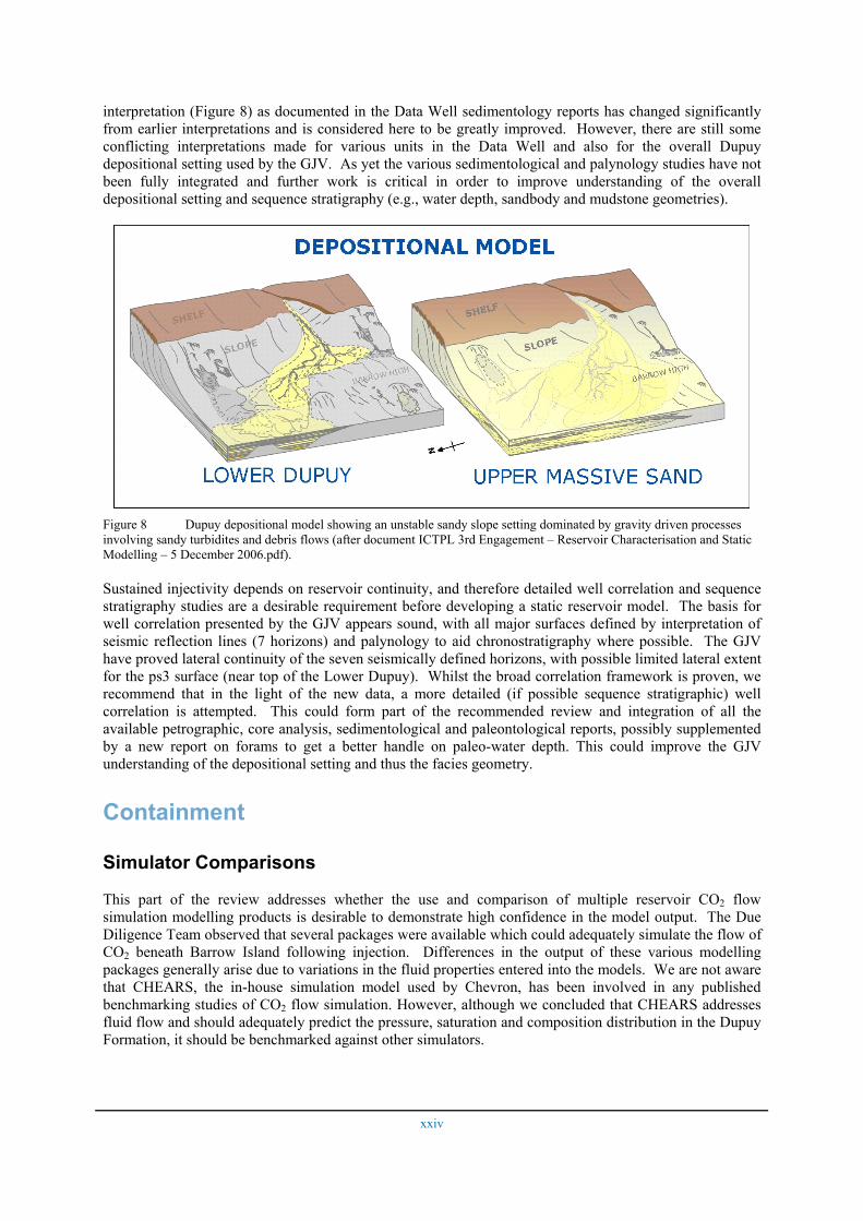
interpretation (Figure 8) as documented in the Data Well sedimentology reports has changed significantly from earlier interpretations and is considered here to be greatly improved. However, there are still some conflicting interpretations made for various units in the Data Well and also for the overall Dupuy depositional setting used by the GJV. As yet the various sedimentological and palynology studies have not been fully integrated and further work is critical in order to improve understanding of the overall depositional setting and sequence stratigraphy (e.g., water depth, sandbody and mudstone geometries).
Figure 8 Dupuy depositional model showing an unstable sandy slope setting dominated by gravity driven processes involving sandy turbidites and debris flows (after document ICTPL 3rd Engagement – Reservoir Characterisation and Static Modelling – 5 December 2006.pdf).
Sustained injectivity depends on reservoir continuity, and therefore detailed well correlation and sequence stratigraphy studies are a desirable requirement before developing a static reservoir model. The basis for well correlation presented by the GJV appears sound, with all major surfaces defined by interpretation of seismic reflection lines (7 horizons) and palynology to aid chronostratigraphy where possible. The GJV have proved lateral continuity of the seven seismically defined horizons, with possible limited lateral extent for the ps3 surface (near top of the Lower Dupuy). Whilst the broad correlation framework is proven, we recommend that in the light of the new data, a more detailed (if possible sequence stratigraphic) well correlation is attempted. This could form part of the recommended review and integration of all the available petrographic, core analysis, sedimentological and paleontological reports, possibly supplemented by a new report on forams to get a better handle on paleo-water depth. This could improve the GJV understanding of the depositional setting and thus the facies geometry.
Containment
Simulator Comparisons
This part of the review addresses whether the use and comparison of multiple reservoir CO2 flow simulation modelling products is desirable to demonstrate high confidence in the model output. The Due Diligence Team observed that several packages were available which could adequately simulate the flow of CO2 beneath Barrow Island following injection. Differences in the output of these various modelling packages generally arise due to variations in the fluid properties entered into the models. We are not aware that CHEARS, the in-house simulation model used by Chevron, has been involved in any published benchmarking studies of CO2 flow simulation. However, although we concluded that CHEARS addresses fluid flow and should adequately predict the pressure, saturation and composition distribution in the Dupuy Formation, it should be benchmarked against other simulators.
xxv
Calibration Data for the Static Model
Development of a realistic static reservoir model, describing the “earth model”, is critical before moving on to develop a dynamic model to simulate CO2 plume migration. Information from the Data Well represents a critical component of the local assessment of the Dupuy aquifer in terms of quantifying the static geological model which is a major input for the reservoir simulator. Information collected from the Data Well has already had significant input into refining the static model and will continue to do so, yet despite the excellent database and sound geological framework, there are currently limitations with the existing geological model.
The sedimentological approach used by the GJV to populate the static model was inherited from the original (pre-Data Well) two-component facies model (i.e., earth layers were defined as either sandstone or siltstone). The shape, dimensions and lateral continuity of sand and silt facies are described by variograms (i.e., models of the spatial variability of facies in the reservoir), primarily constructed using well control, regional geology and mapping of seismic reflectors.
While the two-component facies model will provide useful general information on the flow of CO2, it may not include sufficient stratigraphic detail to capture facies variations that will affect CO2 plume migration. However, the main source of concern with the existing static model is the application of the variograms. Specifically, the lack of clear justification for grouping together the Upper Massive Sand and Upper Dupuy into one variogram, and the assignment of significantly different variogram properties to the Lower Dupuy (compared to the Upper Massive Sand and Upper Dupuy). The review panel acknowledge that GJV are planning to undertake further sensitivity analysis on variograms and endorse this. It is understood, for example, that the GJV propose to examine the continuity of the Perforans Shale and its impact on containment via an alternative version of the static model. In addition to the proposed Perforans Shale sensitivity analysis understanding of the depositional environment and sedimentological facies is also considered necessary in order to input realistic variograms into the property modelling.
Fault transmissibilities are also an important factor in the static model. We are in agreement with the methodologies used to estimate across-fault transmissibilities; however, these methods should be better documented. While vertical along-fault permeabilities could prove to be important controls on the migration of CO2, no tested methodologies presently exist for incorporating such permeabilities into flow simulators and it is hoped that this deficiency in current simulation methodologies will be rectified with future advances in simulation technology.
The simulation model development appears to follow accepted petroleum industry practice, utilising local grid refinements, good vertical resolution, and flow-based upscaling. We recommend the GJV include deterministic fault leakage scenarios through different fault combinations involving vertical flow to the overlying Barrow Group, modelling different across fault transmissivities, and identifying faults as barriers/baffles to lateral flow and enhancements to vertical flow as part of their Phase IV technical work programme.
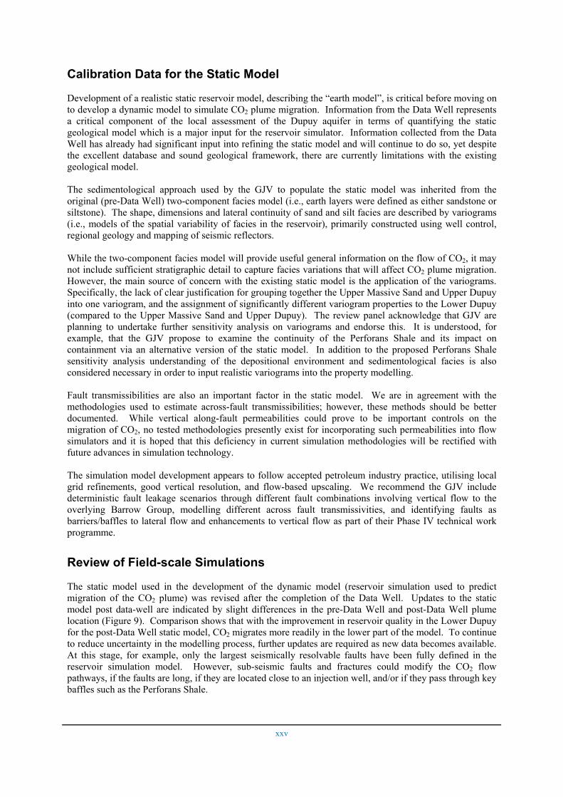
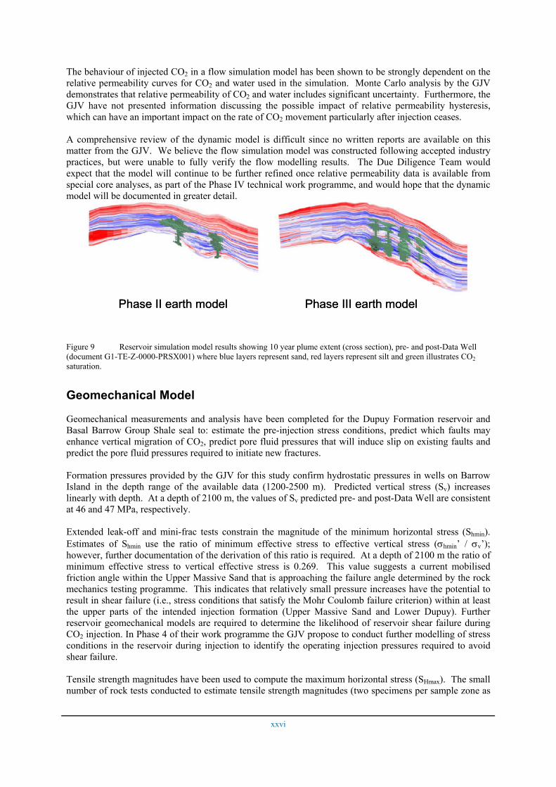
Review of Field-scale Simulations
The static model used in the development of the dynamic model (reservoir simulation used to predict migration of the CO2 plume) was revised after the completion of the Data Well. Updates to the static model post data-well are indicated by slight differences in the pre-Data Well and post-Data Well plume location (Figure 9). Comparison shows that with the improvement in reservoir quality in the Lower Dupuy for the post-Data Well static model, CO2 migrates more readily in the lower part of the model. To continue to reduce uncertainty in the modelling process, further updates are required as new data becomes available. At this stage, for example, only the largest seismically resolvable faults have been fully defined in the reservoir simulation model. However, sub-seismic faults and fractures could modify the CO2 flow pathways, if the faults are long, if they are located close to an injection well, and/or if they pass through key baffles such as the Perforans Shale.
xxvi
Phase II earth model Phase III earth modelPhase II earth model Phase III earth model
The behaviour of injected CO2 in a flow simulation model has been shown to be strongly dependent on the relative permeability curves for CO2 and water used in the simulation. Monte Carlo analysis by the GJV demonstrates that relative permeability of CO2 and water includes significant uncertainty. Furthermore, the GJV have not presented information discussing the possible impact of relative permeability hysteresis, which can have an important impact on the rate of CO2 movement particularly after injection ceases.
A comprehensive review of the dynamic model is difficult since no written reports are available on this matter from the GJV. We believe the flow simulation model was constructed following accepted industry practices, but were unable to fully verify the flow modelling results. The Due Diligence Team would expect that the model will continue to be further refined once relative permeability data is available from special core analyses, as part of the Phase IV technical work programme, and would hope that the dynamic model will be documented in greater detail.
Figure 9 Reservoir simulation model results showing 10 year plume extent (cross section), pre- and post-Data Well (document G1-TE-Z-0000-PRSX001) where blue layers represent sand, red layers represent silt and green illustrates CO2 saturation.
Geomechanical Model
Geomechanical measurements and analysis have been completed for the Dupuy Formation reservoir and Basal Barrow Group Shale seal to: estimate the pre-injection stress conditions, predict which faults may enhance vertical migration of CO2, predict pore fluid pressures that will induce slip on existing faults and predict the pore fluid pressures required to initiate new fractures.
Formation pressures provided by the GJV for this study confirm hydrostatic pressures in wells on Barrow Island in the depth range of the available data (1200-2500 m). Predicted vertical stress (Sv) increases linearly with depth. At a depth of 2100 m, the values of Sv predicted pre- and post-Data Well are consistent at 46 and 47 MPa, respectively.
Extended leak-off and mini-frac tests constrain the magnitude of the minimum horizontal stress (Shmin). Estimates of Shmin use the ratio of minimum effective stress to effective vertical stress (σhmin’ / σv’); however, further documentation of the derivation of this ratio is required. At a depth of 2100 m the ratio of minimum effective stress to vertical effective stress is 0.269. This value suggests a current mobilised friction angle within the Upper Massive Sand that is approaching the failure angle determined by the rock mechanics testing programme. This indicates that relatively small pressure increases have the potential to result in shear failure (i.e., stress conditions that satisfy the Mohr Coulomb failure criterion) within at least the upper parts of the intended injection formation (Upper Massive Sand and Lower Dupuy). Further reservoir geomechanical models are required to determine the likelihood of reservoir shear failure during CO2 injection. In Phase 4 of their work programme the GJV propose to conduct further modelling of stress conditions in the reservoir during injection to identify the operating injection pressures required to avoid shear failure.
Tensile strength magnitudes have been used to compute the maximum horizontal stress (SHmax). The small number of rock tests conducted to estimate tensile strength magnitudes (two specimens per sample zone as
xxvii
opposed to the 10 samples recommended by the American Society for Testing and Materials) suggest that the variability in tensile strength and SHmax will not be fully represented in the results.
The stress regime beneath Barrow Island is now considered more likely to be normal (Shmin < SHmax < Sv), rather than strike slip (Shmin < Sv < SHmax), with SHmax trending approximately E-W, which is consistent with the regional neotectonics. The change in interpretation of the stress regime resulted from the decrease in SHmax from pre- to post-Data Well.
The GJV should consider using Chevron’s GeoMechanical_Reservoir Simulator (GMRS) code to conduct reservoir-geomechanical simulations to better understand the stress path that will be followed during CO2 injection and use those results to conduct a series of triaxial tests to confirm the behaviour of the Dupuy Massive Sand formations. Reservoir-geomechanical simulations will also provide insight into whether the pore volume change under shear will have a positive or negative impact on injectivity.
Geomechanical Impact on Seals
Injection of CO2 has the potential to produce local and regional over-pressurisation of the reservoir and surrounding rock. Such increases of pressure decrease injectivity and effective permeability while elevating the likelihood of fracture generation and reactivation of fault slip. The possibility of local over-pressurisation occurring is dependent on a number of factors including; i) pre-injection stress conditions in the reservoir, ii) rate of injection, iii) permeability of the injection reservoir and iv) the depth of the injection point from the base of the seal.
Over-pressurisation of a reservoir into which CO2 is being injected is not desirable where it significantly reduces injectivity and produces new fractures and/or reactivation of slip on existing faults. Predictions of slip on existing faults are expressed in terms of the differential (i.e., increase relative to pre-injection) pressure that can be exerted on the reservoir or seal rocks before failure is likely. The formation of new fractures, most likely close to injection wells, can be induced by pressure and/or temperature changes arising from CO2 injection. The effect of CO2 injection on reservoir pressure, and the possible impact this may have on containment have been examined.
The differential pressure, or critical delta pressure, has been assessed by GeoMechanics International (GMI) for the Main Barrow, Godwit, Plato, Triller, P18J and U22J faults. The critical delta pressure is partly dependent on the co-efficient of friction assigned to each fault. Our analysis of the critical delta pressures presented in the GMI geomechanics report, in combination with the assumption that certain faults (i.e., Main Barrow, Godwit and Triller faults) are not predicted to intersect the CO2 plume, suggests that slip on these faults (i.e., Main Barrow, Godwit, Plato, Triller, P18J and U22J faults), induced by increases in pore pressure due to injection of CO2 beneath Barrow Island, is unlikely to elevate the risk to CO2 containment.
Rock strength measurements and analysis of the stress data indicate that fracturing initiated in the Upper Massive Sand could grow preferentially in the overlying seal. Our analysis of the stress changes expected to occur in the Upper Massive Sand during injection also suggests that shear failure (i.e., stress conditions that satisfy the Mohr Coulomb failure criterion) could occur in this unit. Continued investigation is suggested on the potential for shear failure in the reservoir and seal, and should include reservoir-geomechanical simulations to fully understand the stress changes within the reservoir and to estimate the magnitude of potential stress changes within the seals.
Operational aspects of the CO2 injection process include the limitation of bottom-hole pressure to avoid fracturing close to the injection wells, and the possible use of pressure relief wells. The GJV currently expects to have 675 psi of working pressure available when injection commences. We anticipate the impact of mechanical and thermal effects in the determination of the maximum bottom-hole pressure will come under further scrutiny. The Due Diligence Team supports the use of pressure-relief wells as a mitigation strategy and encourage the GJV to use coupled geomechanics and fluid flow simulators for the prediction of post-injection reservoir pressures.
xxviii
Geochemical Modelling
Comprehensive characterisation of formation water samples and of twelve selected rock samples from the Dupuy Formation has been documented and these data are used for the geochemical modelling of CO2/water/rock reactions during and following CO2 injection. However, there has been no attempt to relate the petrography of the rock samples used for the geochemical modelling to the petrology and facies of the reservoir. Although the geochemical modelling predicts specific outcomes for the rock samples characterised from reaction with CO2-enriched fluids, it is difficult to import these results to the reservoir model without integration of the petrology and facies work.
Dehydration of an annular region around the wellbore due to injection of a CO2 stream undersaturated with water is a potential near-wellbore issue. Such drying-out of the near-wellbore region can increase the relative permeability to CO2, decrease the absolute permeability due to salt precipitation and inhibit water-rock reactions (which may release fines and cause plugging). This process should be assessed through simulation runs and core-flood experiments.
Reactive transport modelling in the far-field Dupuy reservoir predicts porosity changes to be less than 1% over the first 100 years. Generally the accompanying permeability changes are predicted to be slight over the same time period. In the post-injection phase, between 100 and 10,000 years, the Dupuy Formation would approach a closed system with the total amount of CO2 in the reservoir fixed. During this time silicates would react and approach chemical equilibrium. This time period is important for the assessment of final trapping modes for the CO2 in the Dupuy Formation. Porosity changes over the 10,000 year time frame were predicted to be as high as 10% (in carbonate-rich rocks) but typically tended to be less than a few per cent. Even though predicted porosity changes were generally small, significant amounts of water-rock reaction occurred resulting in significant changes in water chemistry, particularly with regard to bicarbonate. These results have important implications for monitoring techniques using geochemical sampling.
Effect of Fluid Geochemistry on Seals
The GJV has a comprehensive MICP programme in place for the Data Well to evaluate the transmissivity through the primary top seal (i.e., the Basal Barrow Group Shale). As expected, the Basal Barrow Group Shale exhibited the properties of a good seal based on the samples examined (Figure 6). Consequently, the potential for existing fractures and faults that cut across the seal to leak, fracturing of the seal due to overpressuring, weakening of the seal due to permeability increases from geochemical reactions, interfacial tension effects due to the increased acidity of the formation water and leakage via wells are considered the only possible mechanisms for breaching of the Basal Barrow Group Shale. The GJV is currently performing a comprehensive core flood program to determine the impact of CO2 saturated fluid interacting at a sand/shale interface (i.e., Dupuy sands and Basal Barrow Group Shale).
The geochemical modelling was focused on predicting geochemical reactions in the Dupuy Formation and their effect on the transport properties of the reservoir. Only one sample from the Basal Barrow Group Shale primary seal was considered, and it was reacted with Dupuy Formation water. As the main thrust of the GJV geochemical reports was on short term reactions in the Dupuy reservoir, the modelling done using one Basal Barrow Group Shale primary seal sample was inadequate.
The Dupuy formation water is predicted to be very reactive with the Basal Barrow Group Shale due to its high clay fraction (approximately 40%), although the system is rock buffered because of the low porosity (<10%) of the seal. While the porosity of the Basal Barrow Group Shale is predicted to decrease only by 0.3% in the first 100 years, the changes in porosity for 1000 years and 10,000 years are not documented. Given that the modelling indicates that the clay mineral fraction will increase (decreasing permeability), then the focus for geochemical modelling should be on both the short and long term, with more emphasis on the longer time frame.
xxix
There is a tendency to treat geochemical and geomechanical effects as independent of each other. One concern is that the number of geochemical reactions predicted by the modelling (although predicted porosity changes are small), may geomechanically weaken the seal. If feasible, “chunks” of the seal should undergo geochemical autoclave experiments and the reaction products undergo geomechanical testing.
Integrity of Existing Wells
Long-term well integrity issues for the geological disposal of CO2 are currently not well understood and are an area of active research by many groups internationally. The GJV have recognized this situation in their documents ‘Technical Evaluation and Basis for Development Concept’ and ‘Uncertainty Management Plan’, and have incorporated operational and abandonment practices to accommodate these uncertainties. The strategy for abandonment of the existing 27 (pre-Data Well) wells penetrating the Dupuy Formation will be reactive. If the monitoring and surveillance plan and plume migration forecasts indicate that CO2 leakage from an existing well is imminent, plans will be developed which may include plug and abandonment operations. These operations may incorporate multiple levels of redundancy for long-term sealing. The generic cased-hole and open-hole remediation operations developed by the GJV are consistent with and generally surpass current international well abandonment approaches. For the cased-hole plug and abandon generic programme, the GJV has gone beyond operational concerns and recognised the importance of eliminating potential areas of leakage due to long term corrosion of the casing.
The GJV have, however, identified three existing wells (the Data Well, P18J and U22J) that may potentially have the greatest exposure to the CO2 plume and, it is recommended that a more comprehensive abandonment plan for these three 'at risk' wells should be adopted. The acquisition of downhole materials (casing steel and cement), during abandonement operations of these wells, and the assessment of their ageing characteristics could assist the GJV with managing the abandonment requirements of the remaining well assets on Barrow Island. This might also assist in formulating the most appropriate abandonment options for the injection and observation wells.
Injectivity Injectivity estimates depend on the reservoir model and the data that was used to develop it. The GJV have undertaken a number of studies addressing injectivity and further issues are expected to be addressed as part of their Phase IV technical work programme.
Injectivity Data Sources
Injectivity performance predictions can be made using data from routine core analysis, mini-permeameter measurements, core-flood experiments, well testing and numerical reservoir simulations. The GJV analysed 1593 core samples and collected 4518 mini-permeameter readings over a 503 m interval from the Data Well. The GJV workflow makes significant use of numerical simulation, as is accepted practice in petroleum field development, and this is considered the most appropriate tool for analyzing injectivity in heterogeneous reservoirs.
Well Tests
An injection test was conducted in the Data Well using brine as the injection fluid as opposed to CO2. This allowed the horizontal permeability of the formation to be determined with greater certainty than if CO2 had been used as an injection fluid. The GJV assessed the impact of multiphase flow on injectivity via a combination of an extensive review of published data and numerical reservoir simulation models.
The GJV faced some operational difficulties during their well testing programme (e.g., cement debris and formation material plugging pore throats). We believe that the GJV responded to these problems with appropriate modifications to their well testing programme. The results of the three drill stem tests (DSTs)
xxx
are consistent and show horizontal permeabilities of 21.7 to 28.8 mD (compared with 30-105 mD determined from routine core analysis for the same intervals). Vertical permeability was also assessed during one of these DSTs and during vertical interference tests conducted as part of the MDT programme. Several possible interpretations of these data which imply the vertical to horizontal permeability ratio (kv/kh) might range from 0.03 to 0.26 were presented. The very high skin factors required in the DST interpretations were unexpected and subsequently attributed to pore throat plugging. Although the GJV has some contingency plans to remediate skin damage, it is unclear what skin factors would be encountered in future injection wells drilled in the field and this will need to be included as an uncertainty in subsequent injectivity analyses.
Injectivity Indices
Typically injectivity is controlled by four key parameters:
• pressure, both the maximum achievable bottom hole pressure in the injection wells (to avoid fracturing the formation) and the fluid pressure in the formation;
• the absolute permeability of the formation;
• the relative permeability between the different fluids in the formation (i.e., irreducible water saturation);
• skin factor in the injection wells.
The injectivity index, which relates the injection rate to the pressure difference between the injection well and the reservoir, is best determined in heterogeneous reservoirs like the Dupuy by numerical simulation. The injectivity index is clearly affected by the maximum permissible well bore pressure in the injection well that avoids hydraulically fracturing the formation near the well. Creating a hydraulic fracture could enhance injectivity, although it is viewed as undesirable since it may create a fracture that propagates vertically upward and breaches the top seal. Thermal stresses also affect the potential to fracture the near well formation since cooling an annular region around the injection well can reduce the fracture gradient of the reservoir. The GJV have initiated studies to understand these effects on the fracture gradient, and have demonstrated that thermal effects are potentially significant.
Geomechanical factors such as the in-situ stresses, and the elastic modulus and Poisson's ratio of the reservoir formation are also shown to be important in controlling the pressure at which these rocks will fracture. While geochemical issues, such as scale formation, carbonate dissolution and fines migration may also impact injectivity, they are considered to be secondary to the above geomechanical factors.
The role of relative permeability in injectivity was assessed by the GJV using a Monte Carlo approach and indicates that relative permeability is one of the dominant uncertainties in injection predictions. While skin factor is not as significant an uncertainty, the GJV injectivity report recommends that laboratory experiments be performed to assess possible damage mechanisms.
Phase Behaviour
The main effects of CO2-H2O phase behaviour in reservoir simulation are captured via relative permeability curves. However, evaporation of pore-water into the injected CO2 near the injection well, as discussed above, could dehydrate a region close to the injection zone and the significance of these effects should be calibrated by core-flood experiments.
It is our opinion that relative permeability curves are the most important control on injectivity related to the interaction of CO2 and brine, and should be calibrated by experiment. Geochemical issues, such as fines release from dissolution of carbonates, should definitely not be ignored and could also be assessed through experiments; however the shape of the total mobility curve is more likely to control injectivity on time scales of ~20 years.
xxxi
Optimal Well Count
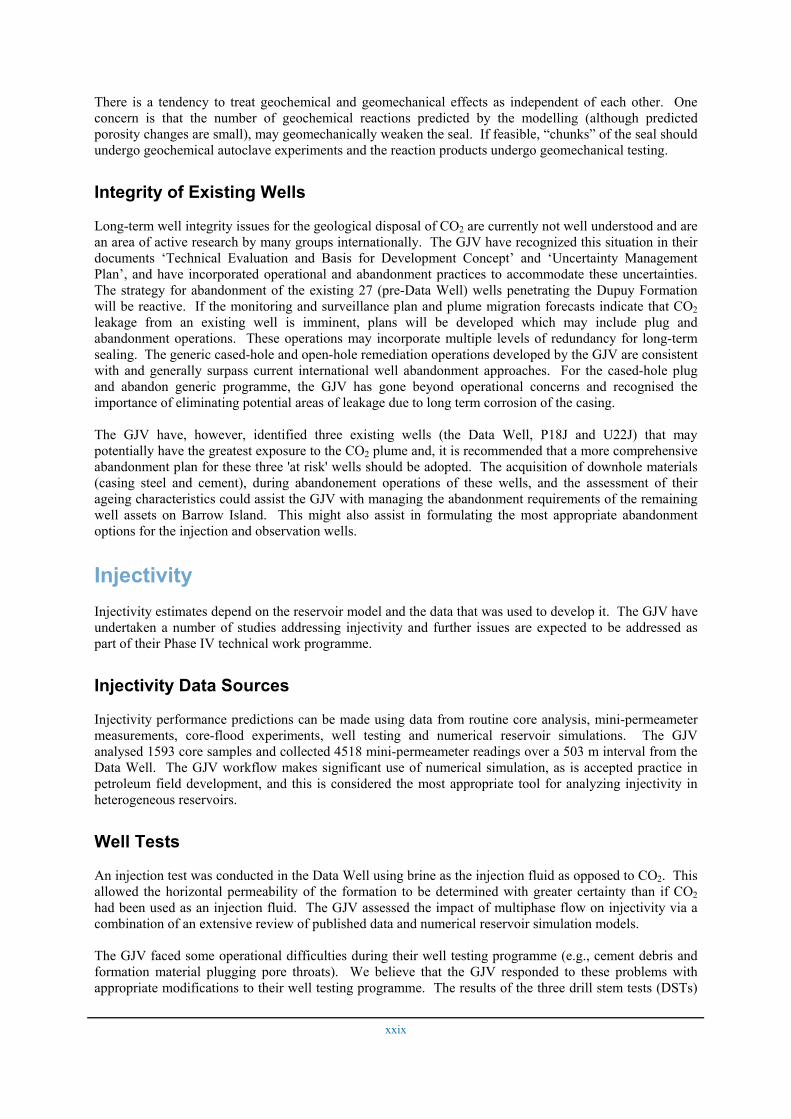
The GJV used routine core analysis as conditioning data for the static reservoir model at the Data Well location, and then calibrated the model to the injection test results in the Data Well. Reservoir simulation predictions (Figure 9) were then used to develop the set of (seven) well locations (Figure 10) ensuring that the CO2 plume would not reach the Plato and Main Barrow faults (Figure 7). The injection rates achievable in these wells will depend on the fracture gradient of the reservoir (which limits the maximum bottom-hole pressure) and is yet to be finalised (see discussion above). Until the fracture gradient (based on mechanical and thermal factors) has been established, the well locations and injectivity rates should be considered as provisional.
Well development schedules also included two surveillance wells at the project outset with two additional surveillance wells and two water production wells in year 5 of the project and two additional water production wells in year 10. It is recognized that the GJV will continue to modify these well counts and schedules to optimize the project development concept.
Figure 10 Provisional injection wells locations (document G1-TE-Z-0000-PRSX001). Top Upper Massive Sand to top Basal Dupuy isopach map (contours in metres).
Injectivity Improvements
Sustainable injectivity of CO2 into the Dupuy Formation is one of the critical areas for the GJV to ensure the successful injection of CO2 beneath Barrow Island.
To optimise the injectivity for each well, consideration must be given to: injecting at maximum regional pressure (but still safely below the fracture pressure), injecting into the highest absolute permeability zones, operating at the CO2-end of the relative permeability curve and minimizing the skin factor.If injectivity decreases unacceptably, our review supports the following:
• in the case of relatively rapid increases in downhole pressure (> 675 psi in three months), the following solutions are proposed by the GJV: – re-complete injection wells and fracture stimulate or cavity complete, – re-complete and perforate over entire interval (i.e., Upper Massive Sand, Lower Massive
Sandstone and Basal Dupuy),
xxxii
– change design for subsequent injection wells (e.g., introduce horizontal wells), – re-consider bottom-hole locations for subsequent injection wells, based on additional
knowledge of reservoir heterogeneity acquired from previous drilling, – drill additional injection wells, – complete injectors in another stratigraphic unit as well as the Dupuy Formation (e.g., Malouet
Sand) to facilitate injection at the required rate1;
• in the case of gradual increases in bottom-hole pressure due to limited pore space leading to unacceptable increase in reservoir pressure, the following solutions are proposed by the GJV; – produce water from the Dupuy Formation to offset reservoir pressure increase, – complete injectors in another stratigraphic unit as well as the Dupuy Formation (e.g., Malouet
Sand) to facilitate injection at the required rate 1,
• in the case of relatively rapid increases in downhole pressure accompanied by significant changes in formation water chemistry due to chemical reaction with the formation, the following solutions are proposed by the GJV; – workover well and acid stimulate depending on the specific change in water chemistry (e.g.,
carbonate precipitation), – re-complete injection wells and fracture stimulate or cavity complete.
The Due Diligence Team support the approach taken by the Gorgon Subsurface Development Team in designing each well to either minimise formation damage and/or to allow access to the well and if possible alternative reservoirs for remedial treatments in the event of injectivity loss.
Risk to Hydrocarbon Assets and Risk of CO2 Leakage to the Biosphere Although the injection project is designed to ensure containment of the injected CO2, there is still a risk of leakage in the short (during injection) and long (post injection) terms. This risk must be evaluated.
Contamination of Assets
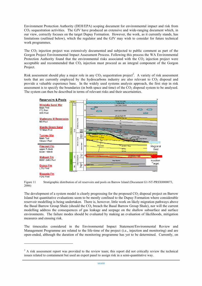
Given that Barrow Island is an operating oil field, an assessment of the potential for contamination of these assets (Figure 11), including any significant impact on remaining hydrocarbon potential, by the injected CO2 is required.
Consequently, the GJV analysed the spatial and temporal relationships of existing and undiscovered hydrocarbon assets beneath Barrow Island and adjacent parts of the North Carnarvon Basin to potential CO2 injection sites and expected CO2 migration paths. Our interpretation of the evidence presented by GJV suggests that the risk to known and any as yet undiscovered hydrocarbon assets that might result from CO2 disposal beneath Barrow Island is low. However, it is recommended that the GJV should report on how injected CO2 beneath Barrow Island could impact on the development of undiscovered Biggada Formation assets, particularly below the predicted plume extent.
Possible Environmental Impact
The Environmental Impact Statement/Environmental Review and Management Programme (EIS/ERMP) generally fulfils (qualitatively) the guidelines given in the Department for Environment and Heritage /
1 Prior to injection in any alternate reservoirs, capacity and containment would need to be demonstrated.
xxxiii
Environment Protection Authority (DEH/EPA) scoping document for environmental impact and risk from CO2 sequestration activities. The GJV have produced an extensive and wide-ranging document which, in our view, correctly focuses on the target Dupuy Formation. However, the work, as it currently stands, has limitations (outlined below), which the regulator and the GJV may wish to consider for future technical work programmes.
The CO2 injection project was extensively documented and subjected to public comment as part of the Gorgon Project Environmental Impact Assessment Process. Following this process the WA Environmental Protection Authority found that the environmental risks associated with the CO2 injection project were acceptable and recommended that CO2 injection must proceed as an integral component of the Gorgon Project.
Risk assessment should play a major role in any CO2 sequestration project2. A variety of risk assessment tools that are currently employed by the hydrocarbons industry are also relevant to CO2 disposal and provide a valuable experience base. In the widely used systems analysis approach, the first step in risk assessment is to specify the boundaries (in both space and time) of the CO2 disposal system to be analysed. The system can then be described in terms of relevant risks and their uncertainties.
Figure 11 Stratigraphic distribution of oil reservoirs and pools on Barrow Island (Document G1-NT-PRSX0000073, 2006)
The development of a system model is clearly progressing for the proposed CO2 disposal project on Barrow Island but quantitative evaluations seem to be mostly confined to the Dupuy Formation where considerable reservoir modelling is being undertaken. There is, however, little work on likely migration pathways above the Basal Barrow Group Shale (should the CO2 breach the Basal Barrow Group Shale), nor will the current modelling address the consequences of gas leakage and seepage on the shallow subsurface and surface environments. The failure modes should be evaluated by making an evaluation of likelihoods, mitigation measures and ensuing risk.
The timescales considered in the Environmental Impact Statement/Environmental Review and Management Programme are related to the life-time of the project (i.e., injection and monitoring) and are open-ended, although the duration of the monitoring programme has yet to be determined. Currently, on
2 A risk assessment report was provided to the review team; this report did not critically review the technical issues related to containment but used an expert panel to assign risk in a semi-quantitative way.
xxxiv
Barrow Island the focus is on the effects of short-term leakage during the operational phase of CO2 injection and then on the monitoring period immediately following injection. The GJV should give greater consideration to the option of examining CO2 containment failure modes over timescales of 1 to 10 years, 10 to 50 years, 50 to 100 years and 100 to 1000 years.
The planned environmental monitoring for CO2 may rely on atmospheric and soil CO2 detection only (with perhaps ‘vegetation responses’ undertaken using remote sensing) and does not include monitoring species or total ecosystem changes. Ecosystem monitoring will be particularly important for detecting rapid seepage of CO2 should it occur. Such monitoring would provide confidence that the impacts of any potential CO2 seeps could be fully assessed. No environmental monitoring of marine systems is planned in relation to disposal of CO2 beneath Barrow Island.
It should be noted that the 10Mtpa Gorgon Project (including the CO2 project) obtained State and Commonwealth Government environmental approvals in September and October 2007 respectively. The State environmental approval under the Environmental Protection Act 1986 (Ministerial Statement No. 748) has imposed conditions on the Gorgon JV relating to the CO2 injection project, which include:
• Annual Environmental Performance Reporting which requires amongst other things reporting "on the results of environmental monitoring and identified Material or Serious Environmental Harm, if any, resulting from the seepage of injected CO2 to the surface or near surface environments including those which may support subterranean fauna" (Condition 5; Schedule 3.6);
• The Gorgon JV to prepare and implement a monitoring program to satisfy the annual reporting requirements for the performance of the Carbon Dioxide Injection System (Condition 5.2 vi and Schedule 3.6).
In addition, there are other conditions such as Condition 8 which requires a Terrestrial and Subterranean Environment Monitoring Program for terrestrial facilities, which includes the CO2 injection system (as defined in the Statement). The objective of this Program is to establish a statistically valid ecological monitoring program to detect any Material or Serious Environmental Harm to the ecological elements outside of the Terrestrial Disturbance Footprint (as defined in the Statement).
The EIS/ERMP discusses the effect of elevated CO2 concentrations on humans and qualitative risk assessments for terrestrial fauna and flora for unpredicted CO2 seepages are detailed. Target receptors are also identified. As a minimum, an assessment of the possible impacts and recovery rates from CO2 exposure for key receptors should be undertaken in future technical work. A suggested approach for evaluating impacts would be to use a variety of scenarios at different points in the evolution of the injection site – from operational phase, to different post-injection periods (including worst case scenarios).
Monitoring, Measurement and Verification Having evaluated the risk of leakage in both the short and long terms through simulation, a monitoring plan has been developed to detect leakage and/or any unpredicted outcomes.
Monitoring and Surveillance Plans
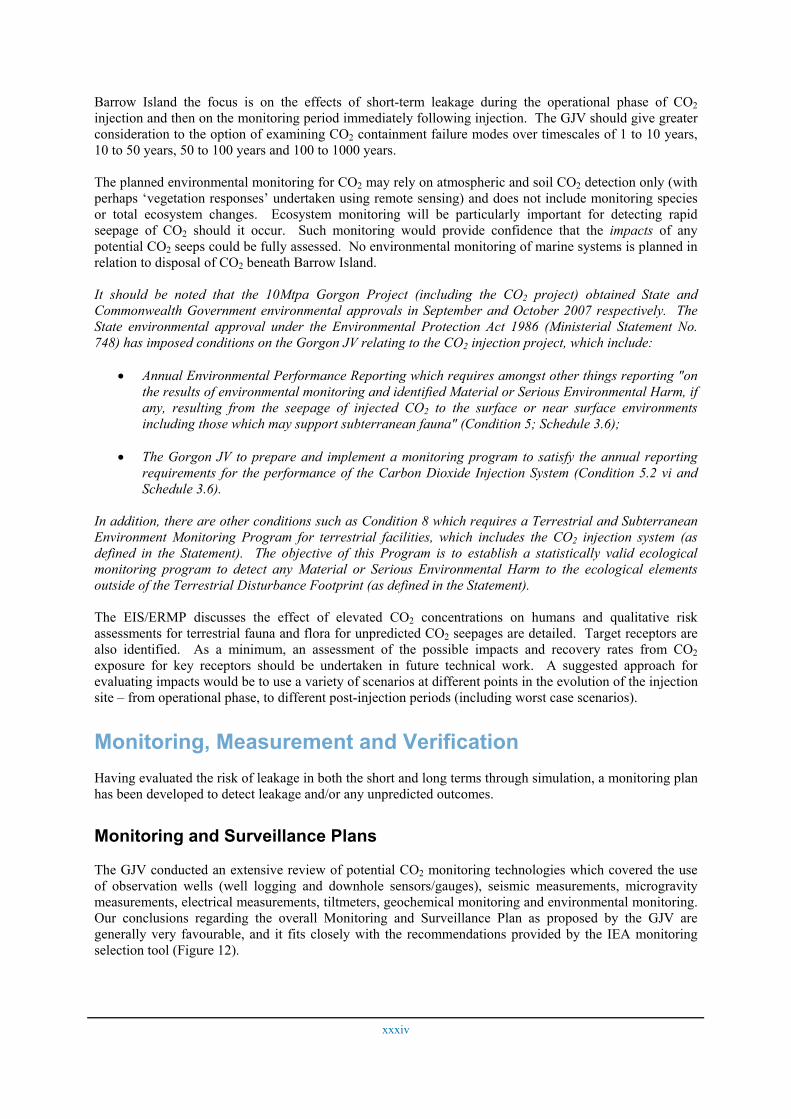
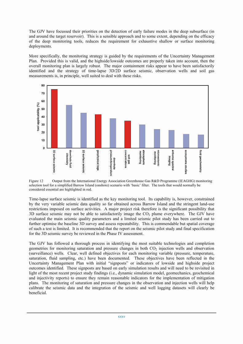
The GJV conducted an extensive review of potential CO2 monitoring technologies which covered the use of observation wells (well logging and downhole sensors/gauges), seismic measurements, microgravity measurements, electrical measurements, tiltmeters, geochemical monitoring and environmental monitoring. Our conclusions regarding the overall Monitoring and Surveillance Plan as proposed by the GJV are generally very favourable, and it fits closely with the recommendations provided by the IEA monitoring selection tool (Figure 12).
xxxv
The GJV have focussed their priorities on the detection of early failure modes in the deep subsurface (in and around the target reservoir). This is a sensible approach and to some extent, depending on the efficacy of the deep monitoring tools, reduces the requirement for exhaustive shallow or surface monitoring deployments.
More specifically, the monitoring strategy is guided by the requirements of the Uncertainty Management Plan. Provided this is valid, and the highside/lowside outcomes are properly taken into account, then the overall monitoring plan is largely robust. The major containment risks appear to have been satisfactorily identified and the strategy of time-lapse 3D/2D surface seismic, observation wells and soil gas measurements is, in principle, well suited to deal with these risks.
Figure 12 Output from the International Energy Association Greenhouse Gas R&D Programme (IEAGHG) monitoring selection tool for a simplified Barrow Island (onshore) scenario with ‘basic’ filter. The tools that would normally be considered essential are highlighted in red.
Time-lapse surface seismic is identified as the key monitoring tool. Its capability is, however, constrained by the very variable seismic data quality so far obtained across Barrow Island and the stringent land-use restrictions imposed on surface activities. A major project risk therefore is the significant possibility that 3D surface seismic may not be able to satisfactorily image the CO2 plume everywhere. The GJV have evaluated the main seismic quality parameters and a limited seismic pilot study has been carried out to further optimise the baseline 3D survey and assess repeatability. This is commendable but spatial coverage of such a test is limited. It is recommended that the report on the seismic pilot study and final specification for the 3D seismic survey be reviewed in the Phase IV assessment.
The GJV has followed a thorough process in identifying the most suitable technologies and completion geometries for monitoring saturation and pressure changes in both CO2 injection wells and observation (surveillance) wells. Clear, well defined objectives for each monitoring variable (pressure, temperature, saturation, fluid sampling, etc.) have been documented. These objectives have been reflected in the Uncertainty Management Plan with initial “signposts” or indicators of lowside and highside project outcomes identified. These signposts are based on early simulation results and will need to be revisited in light of the most recent project study findings (i.e., dynamic simulation model, geomechanics, geochemical and injectivity reports) to ensure they remain reasonable indicators for the implementation of mitigation plans. The monitoring of saturation and pressure changes in the observation and injection wells will help calibrate the seismic data and the integration of the seismic and well logging datasets will clearly be beneficial.
xxxvi
The proposed observation wells are designed such that formation fluids can be sampled at three points in the geological succession, two in the Dupuy Formation and one in the Barrow Group. However, the GJV have not included routine fluid sampling in the monitoring programme, preferring to retain it as an option to be used if the Uncertainty Management Plan indicates that it is required. Formation fluid sampling is the only direct way to fully characterise the fluids arriving at the wellbore and we consider that it would help to calibrate and confirm the log responses, a view which is supported by the use of the International Energy Associated Greenhouse Gas monitoring selection tool for Barrow Island (Figure 12).
A reconnaissance soil gas monitoring survey is also being undertaken. The report on this and the final specification for the main soil gas survey should also be reviewed in the Phase IV assessment.
Based on the available documents, the proposed monitoring schedule covers the <50 year injection period. In addition to this, a degree of post-injection monitoring will also be required to demonstrate satisfactory compliance with agreed site closure criteria.
Many CO2 injection projects (e.g., Sleipner, Weyburn, and In Salah) are associated with ‘piggy-back’ research projects that enable more complete monitoring programmes to be deployed and provide ‘value-added’ scientific benefits. It would be opportune for the GJV to consider the possibility of developing research projects in conjunction with the CO2 disposal project at Barrow Island.
Recommendations The Due Diligence Team have been impressed with the quality and scope of the work undertaken by the GJV, and the progress made during Phase III of the Gorgon CO2 injection project work programme. In addition to the work completed to date by the GJV, the Due Diligence Team has made a number of recommendations for further work. In particular, the team strongly recommend that in the future more focus is given to the local and regional geology and hydrology and that this is framed by a systems approach for risk assessment and management both during injection and after well closure. This systems approach is particularly important to validate the conclusions reached in Phase III on the secure containment of CO2. One significant result of the review is to recommend a greater integration between the range of petrographic, petrophysical, biostratigraphic, sedimentological and geochemical reports completed in Phase III. This is expected to significantly improve the conclusions from the various contractor reports and provide more accurate input to simulation modelling. More specific recommendations to improve the assessment of the Barrow Island injection site are presented below.
Ample evidence has been presented by the GJV to demonstrate that the probability of CO2 leakage from the Dupuy target reservoir is low. We concur with the GJV and strongly recommend that they proceed with their plans to integrate the local hydrodynamic data collected in Phase III with their Barrow Sub-basin model as part of the Phase IV investigation; furthermore these data should be integrated with the regional information in the published literature and assembled into a regional model The sub-basin evolution could then be history-matched before running scenario analyses of the future evolution of the basin with and without CO2 injection. It is realised that such an undertaking has implications much broader than the proposed Gorgon CO2 disposal project and would provide a framework for any additional CO2 disposal projects proposed in the future. It would therefore provide the government of Western Australia with a valuable tool to guide future policy in applying CO2 disposal to their offshore assets, and for this reason could be a project that the government of Western Australia would want to lead on behalf of the E&P companies active in Western Australia.
With regard to petrography and petrophysics we recommend that the GJV undertake further petrographic analyses, particularly within: a) the BBGS and relate this to MICP data, and b) clean sandstones in the Barrow Group and UD (i.e., high permeability streaks), and c) a clean sandstone in the Basal Dupuy. Additional petrographic work is also recommended on the seal/baffle lithologies, to include thin section, XRD and SEM analyses. It is strongly recommended that an integrated study is undertaken in order to utilise results from all studies and to assess whether the observed petrographic characteristics are typical for each stratigraphic unit. Descriptions of side-wall core samples above and below the cored interval in the
xxxvii
Data Well should also be incorporated into such an integrated report. Further reservoir quality assessment is strongly recommended using the total core analysis dataset, thin section and quantitative XRD data. More advanced petrographic analyses could also include stable isotope analysis of carbonate cements, to confirm the origin for siderite cement.
We strongly recommend that further studies are undertaken to better understand the depositional setting and the differences between different units (BD, LD, UMS, and UD). Existing sedimentology, ichnology, FMI and palynology reports, preferably with a new study of benthic foraminifera, should be integrated. It is recommended that the existing log correlations are reviewed in light of data from the Data Well. A sequence stratigraphic approach to the correlation is suggested, possibly following the development of log-facies interpretations, which should be integrated with seismic interpretations. We recommend that detailed log correlation is attempted as part of an integrated log-correlation-biostratigraphic study. Revised paleogeographic maps should be generated for each of the major intervals, and we strongly recommend that variogram parameters be reviewed, and as appropriate modified, following the recommended integrated study of depositional systems in the Dupuy and suitable analogue data. Models should be run with a range of variograms to capture uncertainties in facies, and sensitivities in the model documented. The use of planned sensitivity testing of the static model and construction of a new suite of post-Data Well static and dynamic models is endorsed. The GJV plan to obtain laboratory measurements of relative permeability and we strongly recommend that the results from special core analyses, including the assessment of dehydration, skin factor, and fines release from core-floods, be incorporated in the reservoir simulation model. We maintain that either a depositional facies scheme or a more detailed petrophysical facies scheme ought to be developed, which should result in a better understanding of the Dupuy Formation beneath Barrow Island.
Further interrogation of the flow unit transforms is strongly recommended in association with petrographic analyses and quantitative XRD results, to better define, flow zones for permeability assessment. While the GJV have indicated that this interrogation is underway, we recommend it includes further evaluation of wireline log responses, computed logs and FZI zonation in relation to thin section, SEM and XRD petrography of sandstones, seals and baffles, reservoir quality and sedimentary facies. Horizontal and vertical permeability should also be interrogated by formation, lithofacies and facies to better understand vertical permeability trends, necessary for more accurate reservoir models.
Three dimensional seismic reflection and drill-hole information indicate that faults and fractures are present in the Dupuy reservoir and the strata that overlie it. We strongly recommend that all seismically resolvable faults (including lineaments within the seismic volume considered by the Due Diligence Team to probably be faults) are interpreted to their tip lines. These interpreted faults and predicted sub-seismic faults with throws of ≥ 5m should be incorporated into the static model. In addition, a detailed analysis of fractures in all available core and FMI data (include review of differences in two FMI reports) should be undertaken. To augment existing fracture data multi-azimuth walkaways are recommended to effectively deploy some of the seismic analytical techniques outlined for fracture detection.
The choice of specific reservoir simulation codes is not considered by the Due Diligence Team to be as important as the quality of the PVT data used in the models and the quality of the underlying geological model. However, we do recommend that reservoir simulation models be calibrated by history matching of monitoring data as such data is obtained. Furthermore, the GJV are urged to consider models which are able to couple fluid flow, geomechanics and geochemistry.
Geomechanical analysis has been undertaken to determine how the Dupuy reservoir and overlying rocks will respond to the injection of CO2. To calculate critical instantaneous delta pressures, which provide information on fault stability, we strongly recommend a conservative approach is adopted and that the minimum reasonable value for fault sliding friction (e.g., 0.7) is used. Fault analysis should also include a re-examination of the potential for injection induced slip on the Main Barrow fault (including the impact of dynamic rupture processes) and a review of the impact of slip on hydrocarbon resources adjacent to the fault. To further improve understanding of how the post-injection reservoir conditions have been determined, the complete methodology for computing Shmin together with constraints used to compute the distribution of Shmin should be documented. Estimates of reservoir stress conditions should be augmented
xxxviii
by additional tensile strength testing (at least 8 additional specimens per zone should be subjected to tensile strength tests) and detailed analysis of the frictional strength of the top seal rocks. Armed with new rock strength and stress data additional geomechanical simulations of injection should be completed to further examine the resulting stress changes, and to predict fracture gradients and failure conditions in the reservoir and overlying zones. It is anticipated that estimates of the maximum bottom-hole injection pressure will have to be revisited by the GJV once all geomechanical analysis is finalised and the thermal effects are fully accounted for. We concur with the GJV's plan to use a research simulator built by Chevron for coupled fluid-flow/geomechanics simulation and support the continued analysis of pressure relief strategies.
We recommend the integration of petrology and geochemical reports, and that further geochemical modelling should be advanced to assess the mineral reactions occurring in a heterogeneous reservoir based on the facies distribution in the reservoir model. Future geochemical modelling should: a) evaluate the potential for near-field drying out of formation and model its effect on injectivity, b) assess the potential impact of geochemical reactions related to release of fines, dehydration, ion exchange, and wettability, and c) re-examine the long term trapping effects (including dissolved and mineralised phases). Predicted formation water chemistry from geochemical modelling should be useful in the improvement of observation well monitoring strategies. A strong recommendation is the commissioning of a new modelling report focused on the geochemical stability of the seals which addresses the uncertainties related to the geochemical stability of the primary seals. Geochemical modelling of the stability of seals should focus on both long (100 - 1,000 yrs) and short timeframes. If feasible, additional geomechanical testing should be completed on samples from geochemical autoclave experiments to test for "softening" of seal.
The GJV has done a thorough job at researching the current understanding of long-term well integrity issues and capturing the historical records associated with the existing 27 (pre-Data Well) wells penetrating the Dupuy Formation. We would emphasize the importance of preserving the drilling/log database for future assessment by regulators and strongly recommend that provision be included in the Well Remediation Plan for re-examination of timing of well abandonment based on updated reservoir simulations. An incremental improvement in the long-term integrity of abandoned wells is strongly recommended whereby intervals between each milled window/cement plug are completely filled with CO2 -resistant cement. The GJV should also give serious consideration to acquiring downhole samples of both the casing steel and cement prior to milling operations associated with the abandonment options of existing wells P18J and U22J. Furthermore, the Due Diligence Team strongly recommends that the GJV reconsider their plans for well construction and/or well abandonment of proposed water production wells. During the construction of injection and monitoring wells we advocate that special care be given to the placement of instrumentation (e.g., pressure gauges and capillary tubes) on the outside of casing to avoid creating a possible escape conduit via tubing connected to the wellhead.
It is important that the GJV review the drilling/operational issues leading to cement debris present in the well bore of the Data Well and identify a plan to avoid future similar problems. While we agree that high skin factors recorded in the Data Well were due to operational issues, the Due Diligence Team recommends that the injection well skin factor should be carried forward through the analysis of injectivity as a potentially significant uncertainty. The well test interpretation provided alternative estimates of kv/kh so vertical permeability should also be treated with less certainty in subsequent analysis.
The detailed assessment of risks to hydrocarbon assets undertaken by the GJV is considered robust in its conclusions. However, we recommend that the GJV should document the potential for as yet undiscovered Biggada Formation assets on Barrow Island, particularly beneath the predicted location of the CO2 plume and, if there is potential, describe how any such assets could be developed.
The focus on environmental impact and risk from CO2 sequestration activities has to date been on the Dupuy Formation. However, we strongly recommend that the GJV develop an overarching and connecting view of both the shallow subsurface and surface systems and the Dupuy Formation and that longer timescales are considered in future technical work, to allay any concerns about long-term environmental impacts. The precautionary principle should be adhered to. Environmental monitoring techniques should comprise a range of environmental methods including those examining the impact of any seepage on
xxxix
ecosystems. The GJV Ecological Monitoring Plan’s activities and methods should be incorporated into monitoring activities for the CO2 disposal project. As a minimum, it is strongly recommended that an assessment of the possible impacts and recovery rates from CO2 exposure for key receptors be undertaken in future technical work.
The overall Monitoring and Surveillance Plan as proposed by the GJV is generally very thorough with clear well-defined objectives. Time-lapse seismic is identified as the key monitoring tool and hence it is strongly recommended that the results from the seismic pilot test (including their integration into the 3D baseline survey planning process) are reviewed as part of any Phase IV due diligence. We further recommend that overall spatial repeatability should be tested by an early repeat 3D survey (~2 years after start of injection). For the proposed soil gas survey, the GJV should carefully assess the required density of sampling points, with additional sites around wells, and potentially incorporating long term flux and concentration data. It is expected that results from the soil gas pilot study and plans for the baseline soil gas monitoring survey will be reviewed as part of any Phase IV due diligence.
Since observation wells could provide the most valuable data points with respect to plume migration verification, it will be important to confirm the saturation measurements obtained from well logging programs. It is recommended that the GJV review their decision to not acquire fluid samples during saturation logging in observation wells. It is considered important that the GJV continues to review advances in technology on the most appropriate tool to measure changes in reservoir saturation and we strongly recommend that the GJV update current log modelling activities in support of the decision on which logging technology is to be used for saturation measurements. Signposts should be refined to reflect the importance of injection well pressure measurements, the process by which pressure data are used to constrain simulation models should be clarified, and the workflow for calibration (and up-scaling) of saturation logging results for simulation modelling should be described. Even though the preliminary locations of the observation wells have been chosen, it is recommended that provision be included for changes to locations of the observation wells and timing of monitor surveys as new information becomes available on the rate and direction of the migrating plume.
The Due Diligence Team believes that these recommendations can be accommodated in the GJV Phase IV technical work programme.


![[2005] WAMW 5 - dmp.wa.gov.au](https://img.pdfslide.us/doc/110x75/622d500291bca001047fa3a9/2005-wamw-5-dmpwagovau.jpg)