Embed Size (px)
Citation preview
e-ISSN: 2582-5208 International Research Journal of Modernization in Engineering Technology and Science
Volume:02/Issue:03/March-2020 www.irjmets.com
www.irjmets.com @International Research Journal of Modernization in Engineering, Technology and Science [189]
PERFORMANCE INVESTIGATION OF H∞ CONTROLLERFOR QUARTER
CAR SEMI-ACTIVE SUSPENSION SYSTEM USING SIMULINK
Mustefa Jibril*1
, Eliyas Alemayehu Tadese*2
1Msc, Dept. of Electrical & Computer Engineering, Dire Dawa Institute of Technology, Dire Dawa, Ethiopia
2Msc, Faculty of Electrical & Computer Engineering, Jimma Institute of Technology, Jimma, Ethiopia
ABSTRACT This paper affords the design and improvement of a semi-active suspension system for an automobile. The main
idea is to increase the semi-active suspension system damping vibration of the automobile body even as crossing
the bump and sine pavement on the road. This system is modelled for 1 / 4 car system after which the entire system
has been simulated usingMat lab/Simulink. It is used to physically simulate the quarter vehicle system of the
automobile and have a look at the time domain response to the road disturbances.H infinity controllers is used to
govern the damping properties of the semi-active suspension system mechanically. The system is designed in
contrast to the most of the available suspension systems using a third order hydraulic actuator. The proposed system
is compared with H2 optimal controller to test the performance of the system for the control targets suspension
deflection, body acceleration and body travel for the bump and sine road disturbances. The simulation result of this
studies reveal the efficiency of the advanced H∞controller for the quarter car semi-active suspension system.
Keywords - Quarter Car Semi-active Suspension System, H∞ Controller, H2 optimal Controller
I. INTRODUCTION
Suspension systems are labeled in to three types: Passive, Semi Active and Active suspension systems. Passive
suspension system includes an electricity dissipating detail, that's the damper, and an energy-storing detail, which is
the spring. Since these two factors cannot add electricity to the system this form of suspension structures are called
passive.
Sensors constantly display the running situations of the automobile body. Based at the alerts received via the
sensors and prescribed manipulate strategy the pressure inside the actuator is modulated to obtain progressed
experience and coping with. It need to be cited, that an active suspension system calls for outside power to function,
and that there may be additionally a large penalty in complexity, reliability, cost and weight.
Semi-active suspension is a type of automotive suspension systems that controls the damping pressure of the shock
absorber in reaction to input from the constantly varying road surfaces. It is intended to approximately implement
the active suspension with a damping force adjustable shock absorber.
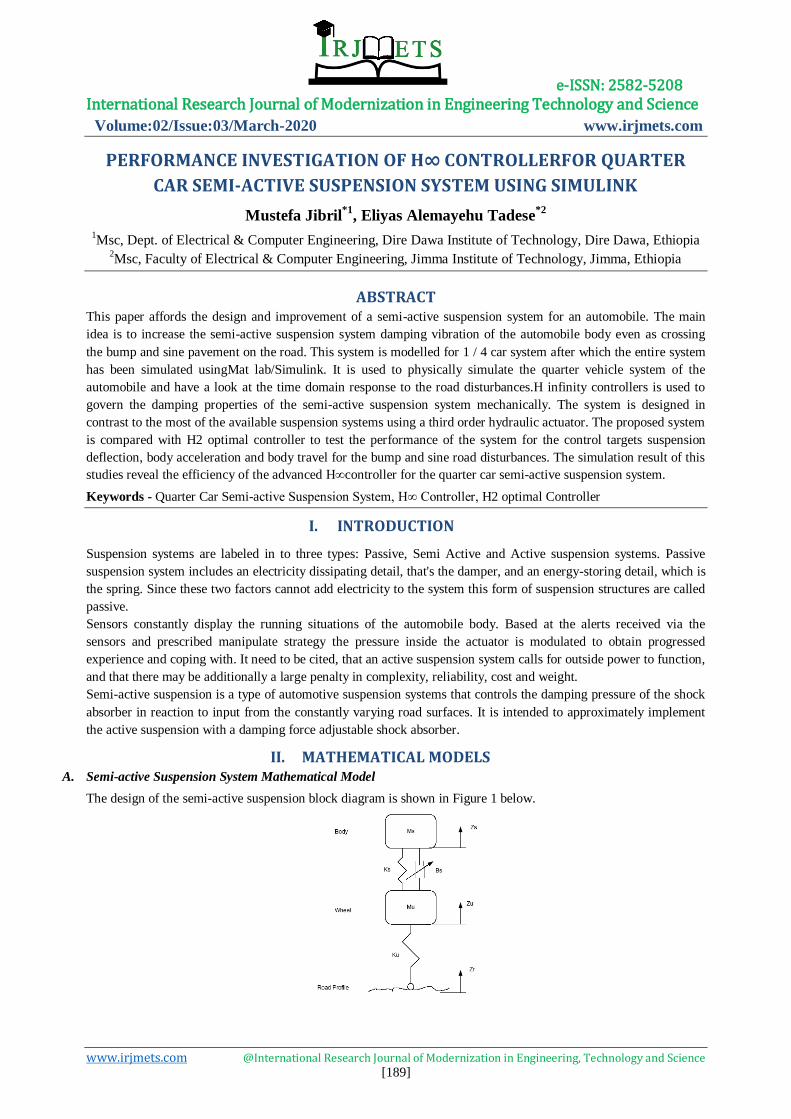
II. MATHEMATICAL MODELS A. Semi-active Suspension System Mathematical Model
The design of the semi-active suspension block diagram is shown in Figure 1 below.
e-ISSN: 2582-5208 International Research Journal of Modernization in Engineering Technology and Science
Volume:02/Issue:03/March-2020 www.irjmets.com
www.irjmets.com @International Research Journal of Modernization in Engineering, Technology and Science [190]
1s u s s u s s sK Z Z B Z Z M Z
2s u s s u s u r u u uK Z Z B Z Z K Z Z M Z
Where Zs is the position of the sprung mass, Zu is the position of the unsprung mass and Zr is the road
displacement. These equations are solved numerically using MATLAB’s dynamic system simulation software,
SIMULINK.
B. Hydraulic System Transfer Function
The hydraulic actuator system is a third order system with transfer function of the form:
3 2
53
4 25Hydraulic Actuator
s s
s
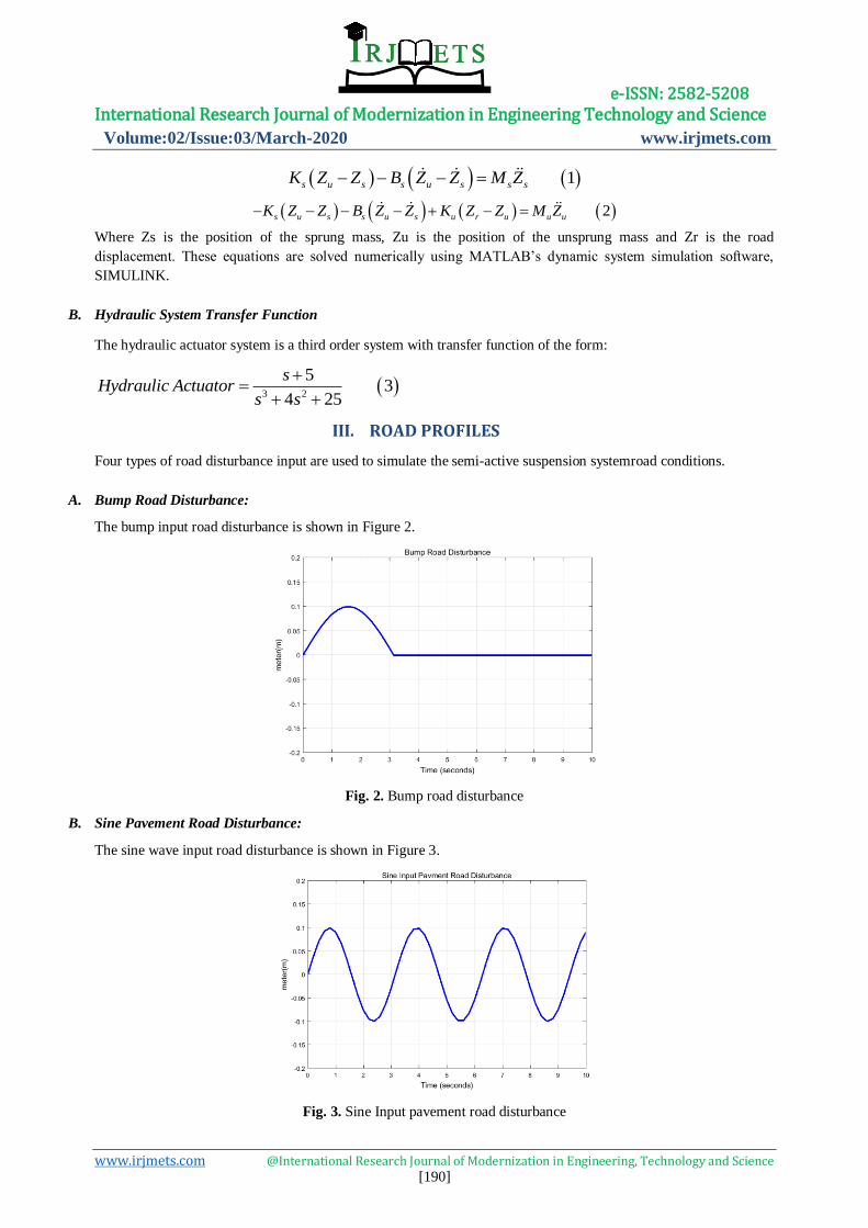
III. ROAD PROFILES
Four types of road disturbance input are used to simulate the semi-active suspension systemroad conditions.
A. Bump Road Disturbance:
The bump input road disturbance is shown in Figure 2.
Fig. 2. Bump road disturbance
B. Sine Pavement Road Disturbance:
The sine wave input road disturbance is shown in Figure 3.
Fig. 3. Sine Input pavement road disturbance
e-ISSN: 2582-5208 International Research Journal of Modernization in Engineering Technology and Science
Volume:02/Issue:03/March-2020 www.irjmets.com
www.irjmets.com @International Research Journal of Modernization in Engineering, Technology and Science [191]
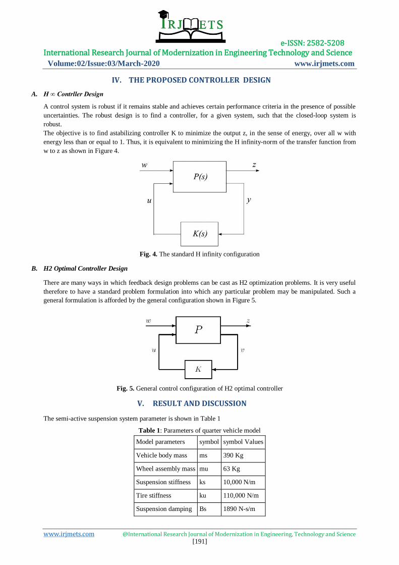
IV. THE PROPOSED CONTROLLER DESIGN
A. H ∞ Contrller Design
A control system is robust if it remains stable and achieves certain performance criteria in the presence of possible
uncertainties. The robust design is to find a controller, for a given system, such that the closed-loop system is
robust.
The objective is to find astabilizing controller K to minimize the output z, in the sense of energy, over all w with
energy less than or equal to 1. Thus, it is equivalent to minimizing the H infinity-norm of the transfer function from
w to z as shown in Figure 4.
Fig. 4. The standard H infinity configuration
B. H2 Optimal Controller Design
There are many ways in which feedback design problems can be cast as H2 optimization problems. It is very useful
therefore to have a standard problem formulation into which any particular problem may be manipulated. Such a
general formulation is afforded by the general configuration shown in Figure 5.
Fig. 5. General control configuration of H2 optimal controller
V. RESULT AND DISCUSSION
The semi-active suspension system parameter is shown in Table 1
Table 1: Parameters of quarter vehicle model
Model parameters symbol symbol Values
Vehicle body mass ms 390 Kg
Wheel assembly mass mu 63 Kg
Suspension stiffness ks 10,000 N/m
Tire stiffness ku 110,000 N/m
Suspension damping Bs 1890 N-s/m
e-ISSN: 2582-5208 International Research Journal of Modernization in Engineering Technology and Science
Volume:02/Issue:03/March-2020 www.irjmets.com
www.irjmets.com @International Research Journal of Modernization in Engineering, Technology and Science [192]
A. Simulation of the Proposed Controllers
The semi-active suspension system with H infinity and H2 optimal controllers are simulated using Matlab/Simulink
for the control targets suspension deflection, body acceleration and body travel using bump and sine pavement road
disturbances.
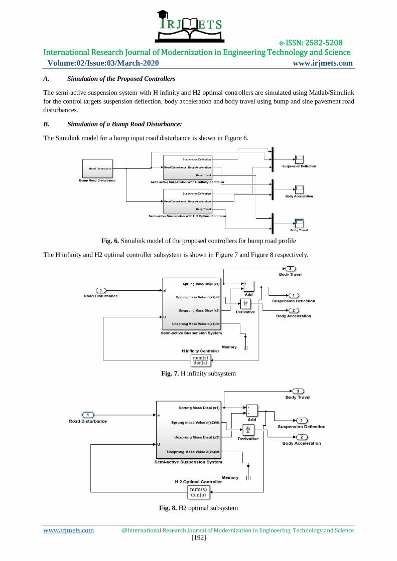
B. Simulation of a Bump Road Disturbance:
The Simulink model for a bump input road disturbance is shown in Figure 6.
Fig. 6. Simulink model of the proposed controllers for bump road profile
The H infinity and H2 optimal controller subsystem is shown in Figure 7 and Figure 8 respectively.
Fig. 7. H infinity subsystem
Fig. 8. H2 optimal subsystem
e-ISSN: 2582-5208 International Research Journal of Modernization in Engineering Technology and Science
Volume:02/Issue:03/March-2020 www.irjmets.com
www.irjmets.com @International Research Journal of Modernization in Engineering, Technology and Science [193]
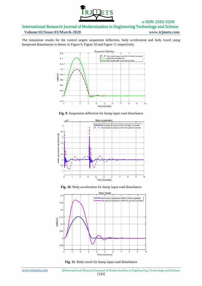
The simulation results for the control targets suspension deflection, body acceleration and body travel using
bumproad disturbances is shown in Figure 9, Figure 10 and Figure 11 respectively.
Fig. 9. Suspension deflection for bump input road disturbance
Fig. 10. Body acceleration for bump input road disturbance
Fig. 11. Body travel for bump input road disturbance
e-ISSN: 2582-5208 International Research Journal of Modernization in Engineering Technology and Science
Volume:02/Issue:03/March-2020 www.irjmets.com
www.irjmets.com @International Research Journal of Modernization in Engineering, Technology and Science [194]
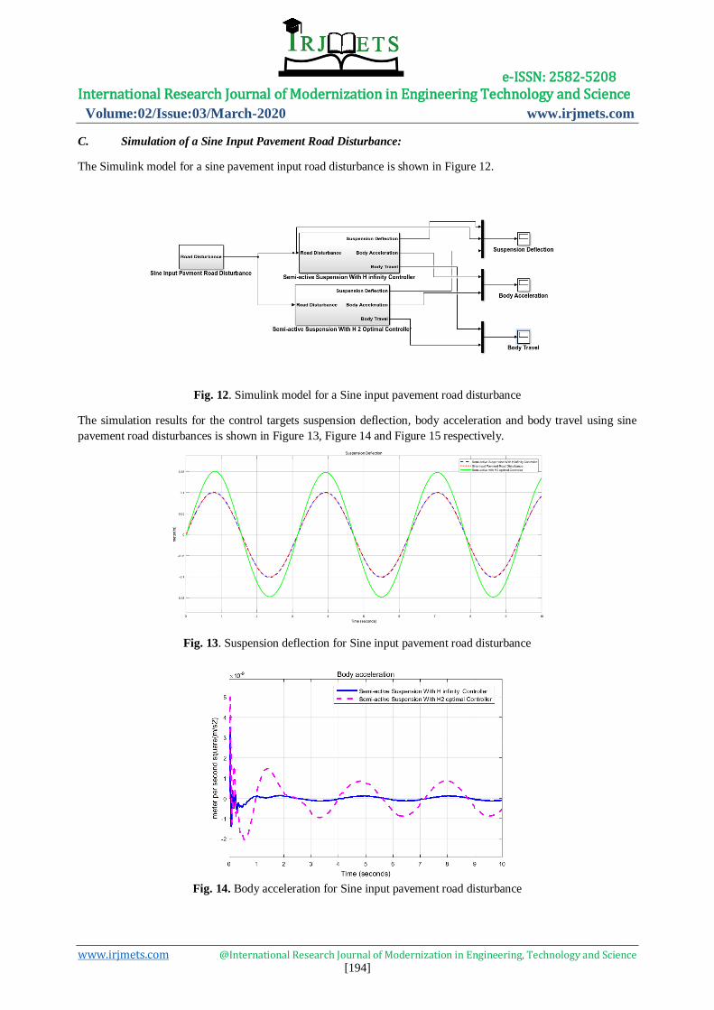
C. Simulation of a Sine Input Pavement Road Disturbance:
The Simulink model for a sine pavement input road disturbance is shown in Figure 12.
Fig. 12. Simulink model for a Sine input pavement road disturbance
The simulation results for the control targets suspension deflection, body acceleration and body travel using sine
pavement road disturbances is shown in Figure 13, Figure 14 and Figure 15 respectively.
Fig. 13. Suspension deflection for Sine input pavement road disturbance
Fig. 14. Body acceleration for Sine input pavement road disturbance
e-ISSN: 2582-5208 International Research Journal of Modernization in Engineering Technology and Science
Volume:02/Issue:03/March-2020 www.irjmets.com
www.irjmets.com @International Research Journal of Modernization in Engineering, Technology and Science [195]
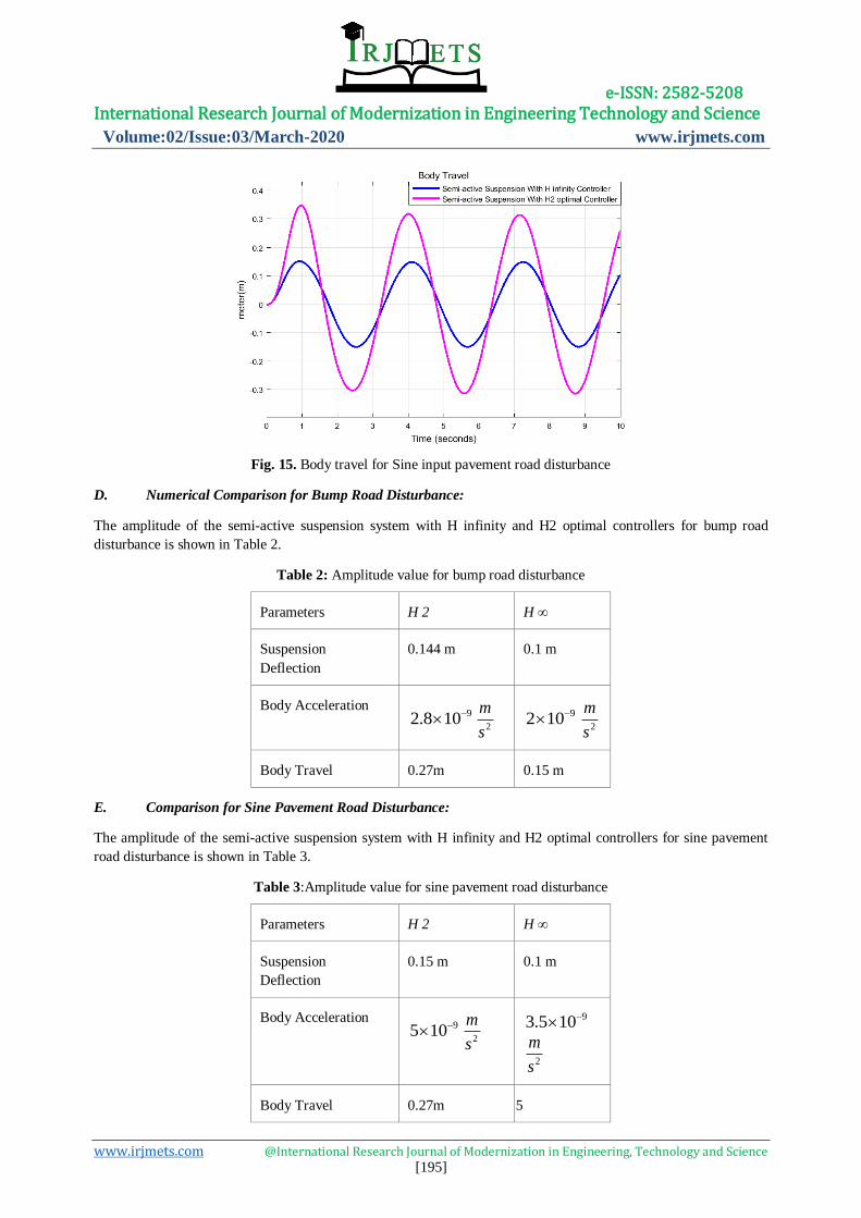
Fig. 15. Body travel for Sine input pavement road disturbance
D. Numerical Comparison for Bump Road Disturbance:
The amplitude of the semi-active suspension system with H infinity and H2 optimal controllers for bump road
disturbance is shown in Table 2.
Table 2: Amplitude value for bump road disturbance
Parameters H 2 H ∞
Suspension
Deflection
0.144 m 0.1 m
Body Acceleration 92.8 10
2
m
s
92 102
m
s
Body Travel 0.27m 0.15 m
E. Comparison for Sine Pavement Road Disturbance:
The amplitude of the semi-active suspension system with H infinity and H2 optimal controllers for sine pavement
road disturbance is shown in Table 3.
Table 3:Amplitude value for sine pavement road disturbance
Parameters H 2 H ∞
Suspension
Deflection
0.15 m 0.1 m
Body Acceleration 95 10
2
m
s
93.5 10
2
m
s
Body Travel 0.27m 0.15
e-ISSN: 2582-5208 International Research Journal of Modernization in Engineering Technology and Science
Volume:02/Issue:03/March-2020 www.irjmets.com
www.irjmets.com @International Research Journal of Modernization in Engineering, Technology and Science [196]
VI. CONCLUSION
The H infinity controller successfully controlled the semi active suspension. When compared to the semi-active
suspension system with H2 optimal controller, semi-active suspension system with H infinity controller
substantially decreased the sprung mass displacement and therefore increased ride comfort of the automobile.
Finally the simulation results prove the effectiveness of the semi-active suspension system with H infinity controller.
VII. ACKNOWLEDGMENTS
First and formost, I would like to express my deepest thanks and gratitude to Dr.Parashante and Mr.Tesfabirhan for
their invaluable advices, encouragement, continuous guidance and caring support during my journal preparation.
Last but not least, I am always indebted to my brother, Taha Jibril, my sister, Nejat Jibril and my family members
for their endless support and love throughout these years. They gave me additional motivation and determination
during my journal preparation.
VIII. REFERENCES
[1]. H Ye et al. "Comparative Study of Semi-active Suspension Based on LQR Control and H2/H infinity Multi
Objective Control" Chinese Automation Congress (CAC), 2019.
[2]. A Purohit et al. " A Review of Semi-active Control Algorithm for Magnetorhelogical (MR) Dampers" International
Journal of Research and Analytical Reviews, 2018.
[3]. F Ma et al. “Optimization Design of Semi-active Controller for In-wheel Motors Suspension" Journal of
Vibroengineering, 2018.
[4]. AS Emam et al. “Active Vibration Control of Automotive Suspension System using Fuzzy Logic Algorithm"
International Journal of Vehicle Structure & Systems (IJVSS), 2017.
[5]. JaffarSeyyedEsmaeili et al. "Load-Dependent LPV/H2 Output-feedback Control of Semi-active Suspension
Systems Equipped with MR Damper" International Journal of Vehicle Design, Vol. 68, Issue 1-3, 2017.
[6]. Y Song et al “Low Cost Adaptive Fault Tolerant Approach for Semi-active Suspension Control of High Speed
Trains" IEEE Transactions on Industrial Electronics, 2016.
[7]. Yilun Liu et al. " Mixed Skyhook and Power Driven Damper: A New Low Jerk Semi-active Suspension Control
Based on Power Flow Analysis" Journal of Dynamic Systems, Measurement and Control, 2016.
[8]. G Reina et al. " Active Vibration Absorber for Automotive Suspensions: A Theoretical Study" Journal of Heavy
Systems, 2016.
[9]. Q Guo et al. " Hybrid Control Strategy of Vehicle Semi-active Suspension Based on the Genetic Algorithm
Optimization" Journal of Metallurgical & Minning Industry, 2015.
[10]. P Li et al."Investigation on Semi-active Control of Vehicle Suspension Using Adaptive Inerter" In
Proceeding of the 31st Chinese Control Conference, 2014.