Embed Size (px)
Citation preview
®
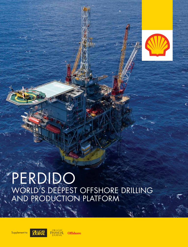
Perdido World’s deePesT oFFsHore drilling and ProducTion PlaTForm
supplement to
CustomCustomPublishingPublishing
®
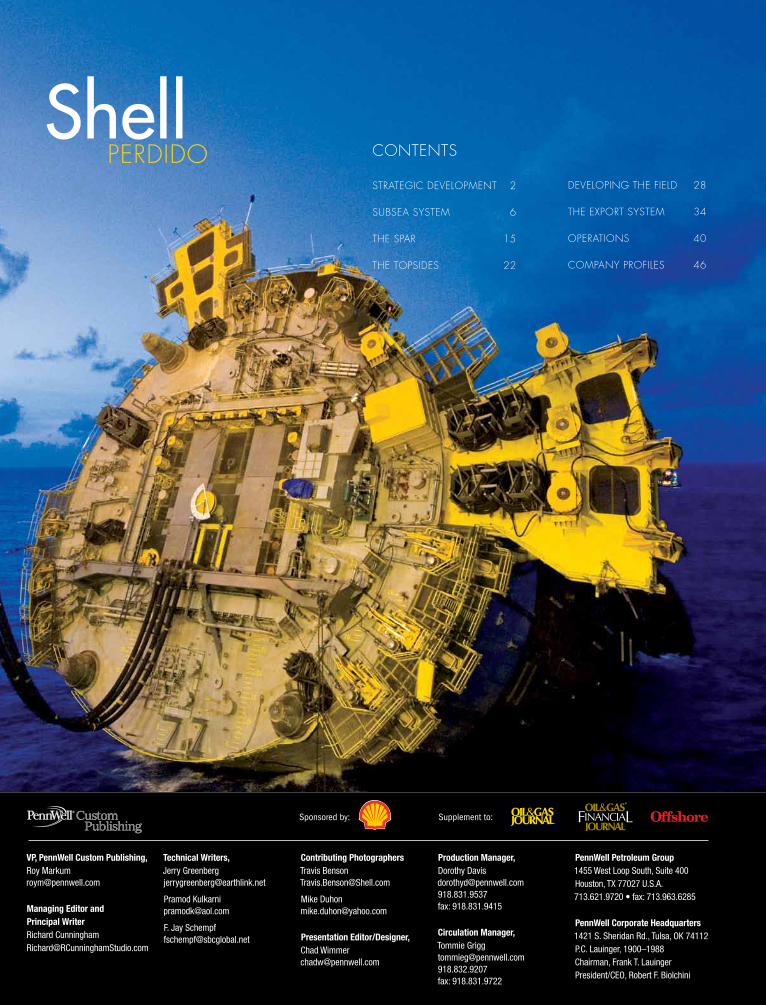
Shell PerDiDo Contents
strategiC DeveloPment 2
subsea sYstem 6
the sPar 15
the toPsiDes 22
DeveloPing the fielD 28
the exPort sYstem 34
oPerations 40
ComPanY Profiles 46
Supplement to:
VP, PennWell Custom Publishing, Roy [email protected]
Managing Editor and Principal WriterRichard Cunningham [email protected]
Technical Writers,Jerry [email protected]
Pramod [email protected]
F. Jay [email protected]
Contributing PhotographersTravis [email protected]
Mike [email protected]
Presentation Editor/Designer, Chad [email protected]
Production Manager, Dorothy [email protected]: 918.831.9415
Circulation Manager, Tommie [email protected]: 918.831.9722
PennWell Petroleum Group1455 West Loop South, Suite 400Houston, TX 77027 U.S.A.713.621.9720 • fax: 713.963.6285
PennWell Corporate Headquarters1421 S. Sheridan Rd., Tulsa, OK 74112P.C. Lauinger, 1900–1988Chairman, Frank T. LauingerPresident/CEO, Robert F. Biolchini
Sponsored by:
1
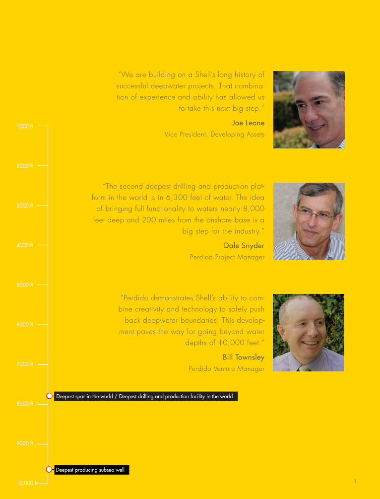
“We are building on a shell’s long history of successful deepwater projects. that combina-tion of experience and ability has allowed us
to take this next big step.”
Joe Leone vice President, Developing assets
“the second deepest drilling and production plat-form in the world is in 6,300 feet of water. the idea
of bringing full functionality to waters nearly 8,000 feet deep and 200 miles from the onshore base is a
big step for the industry.”
Dale SnyderPerdido Project manager
“Perdido demonstrates shell’s ability to com-bine creativity and technology to safely push
back deepwater boundaries. this develop-ment paves the way for going beyond water
depths of 10,000 feet.”
Bill TownsleyPerdido venture manager
1000 ft
2000 ft
3000 ft
4000 ft
5000 ft
6000 ft
7000 ft
8000 ft
9000 ft
10,000 ft
• Deepest spar in the world / Deepest drilling and production facility in the world
• Deepest producing subsea well
s h e l l P e r D i D os h e l l P e r D i D o
3
When shell acquired the ultra-deepwater leases for Perdido in 1996, the technology to develop them didn’t exist. there were other notable deepwater developments, of course. each had pushed the boundaries of technology, but in solv-ing Perdido’s many technical challenges, shell has opened new frontiers for oil and gas exploration.
the Perdido oil and gas development covers a portion of the geological formation known as the Perdido fold belt. the producing reservoirs lie within the Paleogene or lower tertiary zone, a portion of the gulf of mexico that has not been produced before. the seabed there resembles a small version of the grand Canyon, including cliffs with near verti-cal drops of up to 1,000 feet.
the hub of the Perdido development is some 200 miles due south of freeport texas. the nearest neighbor is the hoover-Diana platform, about 60 miles to the north. shell began 3D seismic surveys on Perdido in 1998. the discovery well was completed in 2002. Development drill-ing began in 2007 and is scheduled to continue through 2016.
“there is a lot of courage in this story,” says bill townsley, Perdido venture manager. “We purchased the Perdido leases in up to 10,000 feet of water at a time when the industry’s capability was barely 3,000 feet. one of our satellite well-heads will be installed at 9,627 feet.”
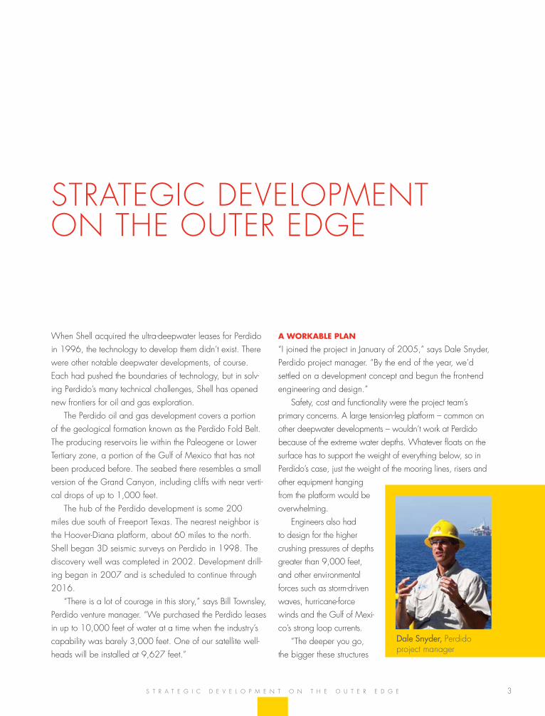
A workAble plAn
“i joined the project in January of 2005,” says Dale snyder, Perdido project manager. “by the end of the year, we’d settled on a development concept and begun the front-end engineering and design.”
safety, cost and functionality were the project team’s primary concerns. a large tension-leg platform – common on other deepwater developments – wouldn’t work at Perdido because of the extreme water depths. Whatever floats on the surface has to support the weight of everything below, so in Perdido’s case, just the weight of the mooring lines, risers and other equipment hanging from the platform would be overwhelming.
engineers also had to design for the higher crushing pressures of depths greater than 9,000 feet, and other environmental forces such as storm-driven waves, hurricane-force winds and the gulf of mexi-co’s strong loop currents.
“the deeper you go, the bigger these structures
strategiC DeveloPment on the outer eDge
s t r a t e g i C D e v e l o P m e n t o n t h e o u t e r e D g e
Dale Snyder, Perdido project manager
4
s h e l l P e r D i D o
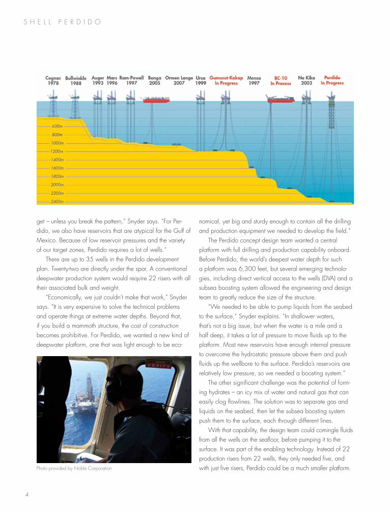
get – unless you break the pattern,” snyder says. “for Per-dido, we also have reservoirs that are atypical for the gulf of mexico. because of low reservoir pressures and the variety of our target zones, Perdido requires a lot of wells.”
there are up to 35 wells in the Perdido development plan. twenty-two are directly under the spar. a conventional deepwater production system would require 22 risers with all their associated bulk and weight.
“economically, we just couldn’t make that work,” snyder says. “it is very expensive to solve the technical problems and operate things at extreme water depths. beyond that, if you build a mammoth structure, the cost of construction becomes prohibitive. for Perdido, we wanted a new kind of deepwater platform, one that was light enough to be eco-
nomical, yet big and sturdy enough to contain all the drilling and production equipment we needed to develop the field.”
the Perdido concept design team wanted a central platform with full drilling and production capability onboard. before Perdido, the world’s deepest water depth for such a platform was 6,300 feet, but several emerging technolo-gies, including direct vertical access to the wells (Dva) and a subsea boosting system allowed the engineering and design team to greatly reduce the size of the structure.
“We needed to be able to pump liquids from the seabed to the surface,” snyder explains. “in shallower waters, that’s not a big issue, but when the water is a mile and a half deep, it takes a lot of pressure to move fluids up to the platform. most new reservoirs have enough internal pressure to overcome the hydrostatic pressure above them and push fluids up the wellbore to the surface. Perdido’s reservoirs are relatively low pressure, so we needed a boosting system.”
the other significant challenge was the potential of form-ing hydrates – an icy mix of water and natural gas that can easily clog flowlines. the solution was to separate gas and liquids on the seabed, then let the subsea boosting system push them to the surface, each through different lines.
With that capability, the design team could comingle fluids from all the wells on the seafloor, before pumping it to the surface. it was part of the enabling technology. instead of 22 production risers from 22 wells, they only needed five, and with just five risers, Perdido could be a much smaller platform. Photo provided by noble Corporation
5
TArgeT Zero
from the beginning, the safety of the workforce was a critical design element for the engineering team. no project manag-ers want to have injuries on the job, but the remoteness of the Perdido development presented some unique challenges.
“We started off in 2005 with the idea that safety was the most important thing we would do on Perdido,” snyder recalls. “We would get it right. We would be a world leader in safety, and we put tremendous effort into that.”
the design team named their safety program “target Zero.” the core concept was that if you could convince someone to work safely for just one shift, then it was possible to do the entire project that way. in mid-november, 2009, Perdido reached the milestone of 10 million man hours without a lost-time injury. even with the wide range of complex operations, high-risk activities and fabrication sites around the world, by the time Perdido reached first oil on march 31, 2010, there were still no known lost-time incidents.
“of all our accomplishments,” snyder says, “i am most proud of our safety performance. it shows the leadership and commitment of our teams to go after safety and make it the most important thing we do.”
A new fronTier
the Perdido project is remarkable for its own technical achievements, but there is an even wider significance for the petroleum industry. the Paleogene-era rock that Perdido is tapping is older and deeper that other producing formations that have made the region so prolific. other operators in the gulf have also made recent discoveries in the lower tertiary, but shell is the first to develop it.
s t r a t e g i C D e v e l o P m e n t o n t h e o u t e r e D g e
“this is a whole new regime for the gulf of mexico,” snyder says. “not only have we paved the way by solving the biggest problems of an ultra-deepwater de-velopment, it is equally important that we’ve figured out how to pro-duce from the lower tertiary. the whole industry is watching to see how we do, because many development companies see this as the next big opportunity.”
“While the project had its share of inevitable setbacks, the team’s response was outstanding, says lisa Johnson, who was the decision executive during offshore instllation. “there was always a healthy balance of support and challenge throughout the team, as well as with our Perdido partners.”
Particularly effective was an all-team meeting with the Perdido contractors. held early in the project, it allowed everyone involved to review various aspects of their work and to identify any significant conflicts.
building on A sTrong pArTnership
“i’ve dealt with a lot of partnerships in my career,” says bill townsley, Perdido Development venture manager. “the deepwater environment is no place to be arrogant about your skills. We have two experienced partners on this proj-ect, so one of the things we’ve done is to be very open and transparent with our design and planning. the cooperation between partners has helped to keep us on track and deliver this project on time.”
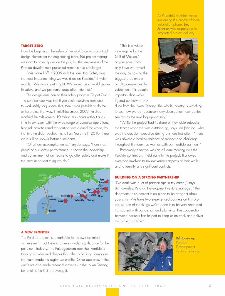
as Perdido’s decision execu-tive during the critical offshore installation phase, Lisa Johnson was responsible for integrated project delivery.
Bill Townsley, Perdido Development venture manager
s h e l l P e r D i D o
7
two related technologies make the subsea portion of the Perdido project viable: the subsea boosting system, and a surface blowout preventer for drilling and completing the di-rect vertical access subsea wells. a total of 22 wells will be drilled from the Perdido spar and another 13 will be offset wells with tiebacks to the host platform.
the final development plan may seem like an obvious solution now, but there were many questions early on, and some of the technology is being used for the first time. g. t. Ju, subsea team lead, joined the Perdido project at the beginning of 2003, almost immediately after results came in from the discovery well.
“very early in the project we recognized that with these water depths, low reservoir temperature and pressure, and the huge uncertainty of the reservoir’s deliverability, that if the project were to go forward, we had to minimize the risk,” Ju says. “We needed some sort of subsea boosting or artificial lift technology to put energy into the flow system.”
the team’s next decision was which technology to use. Was it best to put electric submersible pumps (esPs) in the wells, or better to use multiphase pumps on the riser base to move all the fluids and gas to the surface?
the Perdido development consists of three main oil-bearing reservoirs, each with distinctly different fluid properties. the oil ranges from moderately heavy to light,
with gravities from 17 to 40 degrees aPi. gas volumes at the mud line are quite large, so multiphase pumps would be too inefficient to consider. typical gas/oil ratios (gors) at Perdido range from 500 scf to 2,000 scf per barrel of oil. even if multiphase pumps could be used initially, they would become less efficient or cease to function altogether as the gors changed over time. electric submersible pumps in the wellbore were also ruled out, because of the huge cost of replacing them in the future.
Ju’s team settled on a third option, one that had never been tried before: subsea separators, plus subsea boosting pumps to get liquids to the surface.
“We’re using a two-phase separation system on the seabed, flowing gas to the surface and pumping only the liquids,” Ju says. “that gives us two advantages. one is energy efficiency, but it also extends the lives of the pumps. if the equipment is just moving liquid, it is much better than pumping a mix of liquids and gas.”
the second advantage to a two-phase system is that it
the subsea sYstem
t h e s u b s e a b o o s t i n g s Y s t e m
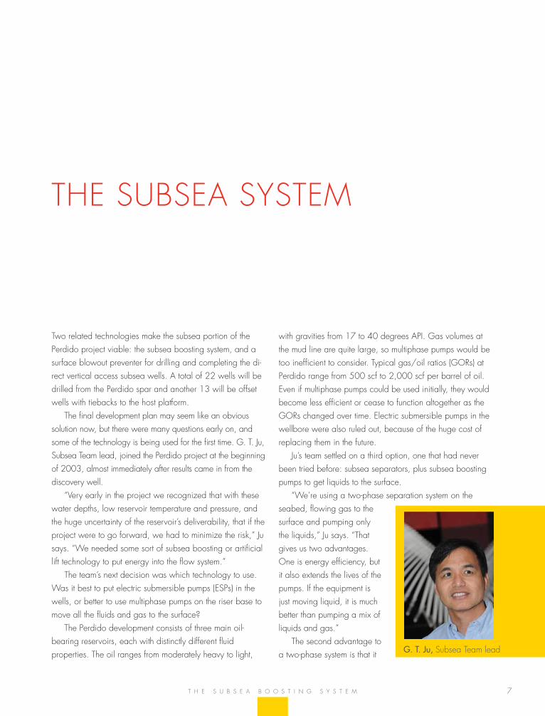
G. T. Ju, subsea team lead
8
s h e l l P e r D i D o
takes out the subsurface uncertainty. “this is a new reservoir,” Ju says. “there is no producing analog to tell us how the gas/oil ratio is likely to change over time. by separating gas from the rest of the produced fluids on the seabed, we don’t have to worry about the potential changes over the life of the reservoir, or the differences between our three main reservoirs. subsea boosting, with two-phase separation and single-phase pumping became our obvious choice.”
hArdwAre on The seAbed
the core of Perdido’s subsea boosting system (sbs) is a cluster of five vertical gas-liquid cylindrical cyclonic (glCC) separators. the body of each separator is a heavy pipe, 35 inches in diameter and 350 feet long. Production from all of the wells comingles in these vessels. the primary function of the caissons is to provide a surge volume for the separated production liquids. the passive system relies on centrifugal force to separate gas and liquids as they swirl down the outer walls of the caisson.
all but the uppermost portion of the separator is inserted into the seabed. a 1,600-horsepower electric submersible pump (esP) is deployed inside, near the bottom of the verti-cal caisson.
at the top of the separator, just above the mud line, sits a 2-story tall inlet assembly. above that, a 17-foot-long reducer brings the diameter of the pipe down to 14 inches, matching the diameter of the riser. from there, the riser extends some 7,800 feet to the Perdido spar.
each caisson’s inlet assembly connects to the host through a top-tensioned riser that contains three separate flow paths. the outer annulus of the riser carries the relatively dry gas. the middle annulus carries produced liquids, which are pushed to the surface by the power of the esP at the bottom of the separator caisson, and a small diameter pipe in the center carries liquid sent down from the surface to prime and cool the submersible pump. the 14-inch riser allows direct vertical access to the boosting pump at the bottom of the caisson.
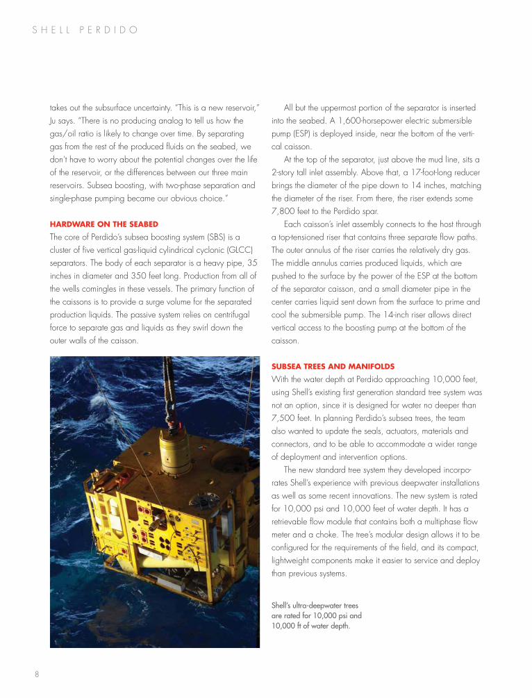
subseA Trees And mAnifolds
With the water depth at Perdido approaching 10,000 feet, using shell’s existing first generation standard tree system was not an option, since it is designed for water no deeper than 7,500 feet. in planning Perdido’s subsea trees, the team also wanted to update the seals, actuators, materials and connectors, and to be able to accommodate a wider range of deployment and intervention options.
the new standard tree system they developed incorpo-rates shell’s experience with previous deepwater installations as well as some recent innovations. the new system is rated for 10,000 psi and 10,000 feet of water depth. it has a retrievable flow module that contains both a multiphase flow meter and a choke. the tree’s modular design allows it to be configured for the requirements of the field, and its compact, lightweight components make it easier to service and deploy than previous systems.
Shell’s ultra-deepwater trees are rated for 10,000 psi and 10,000 ft of water depth.
9
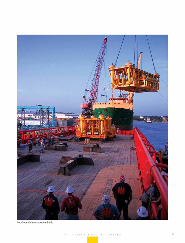
Load-out of the subsea manifolds
t h e s u b s e a b o o s t i n g s Y s t e m
10
s h e l l P e r D i D o
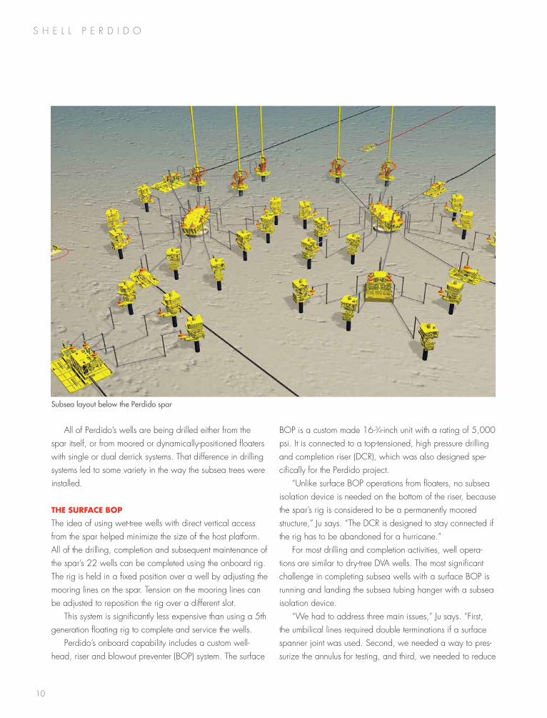
all of Perdido’s wells are being drilled either from the spar itself, or from moored or dynamically-positioned floaters with single or dual derrick systems. that difference in drilling systems led to some variety in the way the subsea trees were installed.
The surfAce bop
the idea of using wet-tree wells with direct vertical access from the spar helped minimize the size of the host platform. all of the drilling, completion and subsequent maintenance of the spar’s 22 wells can be completed using the onboard rig. the rig is held in a fixed position over a well by adjusting the mooring lines on the spar. tension on the mooring lines can be adjusted to reposition the rig over a different slot.
this system is significantly less expensive than using a 5th generation floating rig to complete and service the wells.
Perdido’s onboard capability includes a custom well-head, riser and blowout preventer (boP) system. the surface
boP is a custom made 16-3⁄4-inch unit with a rating of 5,000 psi. it is connected to a top-tensioned, high pressure drilling and completion riser (DCr), which was also designed spe-cifically for the Perdido project.
“unlike surface boP operations from floaters, no subsea isolation device is needed on the bottom of the riser, because the spar’s rig is considered to be a permanently moored structure,” Ju says. “the DCr is designed to stay connected if the rig has to be abandoned for a hurricane.”
for most drilling and completion activities, well opera-tions are similar to dry-tree Dva wells. the most significant challenge in completing subsea wells with a surface boP is running and landing the subsea tubing hanger with a subsea isolation device.
“We had to address three main issues,” Ju says. “first, the umbilical lines required double terminations if a surface spanner joint was used. second, we needed a way to pres-surize the annulus for testing, and third, we needed to reduce
Subsea layout below the Perdido spar
11
the size and weight of the conventional installation and work-over control systems (iWoCs) umbilical for this water depth.”
the Perdido solution is a hybrid configuration in which the iWoCs umbilical is replaced by two six-line flat packs for the hydraulic functions, and a single line for the electrical connection. the lines are run with the landing string, just as the control lines are run with the production tubing, so it is not necessary to have a surface spanner.
mATuring The Technology
Ju’s subsea team had a lot of confidence that their system would work, but the fact was, no one had tried it before.
“it was a major challenge,” Ju recalls. “We had to show senior management across three major oil companies, shell, bP and Chevron, that the whole investment could hinge on the success of this technology. at this very early phase, when we really didn’t have a project yet, we were asking for
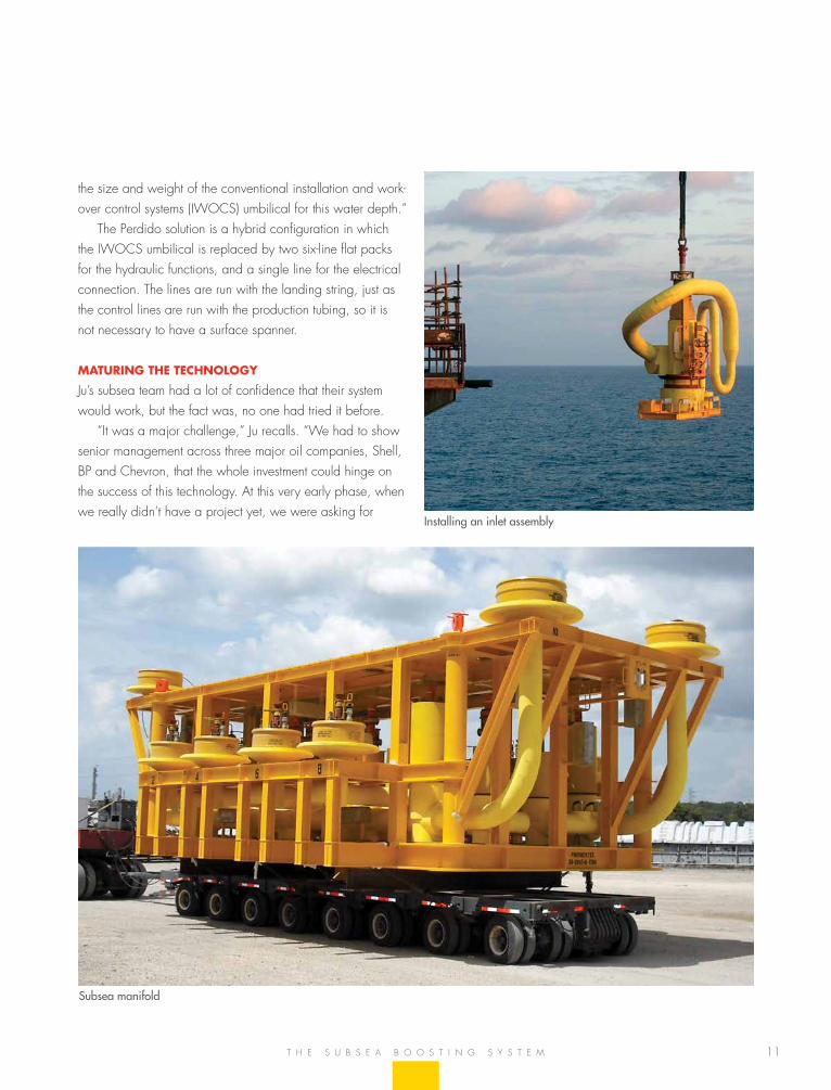
Subsea manifold
Installing an inlet assembly
t h e s u b s e a b o o s t i n g s Y s t e m
12
s h e l l P e r D i D o
partners the confidence to invest in the new technology, even without a pilot installation in the field.
“With the integration of wet-tree Dva and subsea boost-ing, we were able to reduce the diameter of the spar from 180 feet down to 118 feet,” Ju says. “that directly affected the cost of the spar and the weight of the topsides. not only were we able to mitigate the subsurface risk, we reduced the total project cost. We took some risk with new technol-ogy, but in reality, subsea boosting and separation was the enabler that allowed us to do this project.”
insTAlling The sbs
the subsea team grew to 60 people during 2008 and 2009, the peak of the installation phase. the effort – concentrated around the Perdido hub – required lots of coordination.
“We had to work between two major activities,” Ju ex-plains. “one was the installation of the spar, because some or our equipment had to go in first. the other major activity that competed with our portion of the installation was the top-sides, because we could not complete the subsea work until the topsides was in place. that made the subsea installation a two-stage process.”
several million dollars to mature the technology and convince managers that subsea boosting and separation would work.”
With a test budget approved, the subsea team devised a technology maturation process to prove that the system could function in 8,000 feet of water. a pilot test at that water depth was out of the question, so the team did the next best thing.
“We convinced the venture that subsea boosting and caissons with esPs would be a good thing to do,” Ju says. “and to demonstrate the system, we built a flow loop at shell’s gasmer research facility in houston.”
“at the gasmer facility, we built a full scale flow loop of everything that would be below the inlet assembly head,” Ju says. “We could generate 55 million scf of nitrogen and pump 30,000 barrels of mineral oil through a system to simulate the concept.”
that allowed the subsea team to see how the separator caisson worked, how the controls worked and if the system was efficient. the gasmer facility was used extensively for more than a year. Practice sessions taught operators how to run the system and how to start the electric submersible pump using additional fluid from the spar. the testing, which was completed in 2007, gave Ju’s team and managers of the Jv
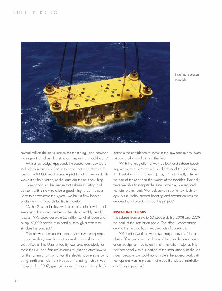
Installing a subsea
manifold
13
that became an increasing challenge during 2007 and 2008.
“We were scheduling everything around two major activi-ties. in an overheated market, you need to deliver in time, otherwise you miss the installation window. We constantly juggled the installation schedule. nothing could happen too early or too late. We had to manage the whole vendor community to deliver our equipment in time, and that became quite an art.”
unlike the spar construction, the subsea team served as the general contractor for the project manager. as such, the team itself managed its portion of the project and is-sued more than 100 purchase orders to different vendors. the largest of the purchase orders went to fmC, which provided the trees, manifolds, tie-in kits and some of the subsea boosting equipment. heerema installed the flowlines and manifold, and many smaller vendors provided other equipment and things such as chemicals and services during commissioning.
“the team effort it took to deliver such a challenging project in that kind of tight market condition was amazing,” Ju says. “We also had a great relationship with Chevron and bP. although the Jv partners were not required to contribute directly to the design and fabrication, installation or commis-sioning of the subsea equipment, they were very supportive. they came to our subsea team meetings and offered their candid opinions. it has been a constructive relationship and a very friendly working environment.”
conTinuous focus on sAfeTy
everyone who has been associated with Perdido comments on the lasting culture of safety it has fostered. those who have been with the project the longest add that the continuity of the personnel – some who were involved from the discov-ery well through final commissioning – has also contributed to the project’s success.
“i’ve had people who have been with me for six years,” Ju says, “and i have been with the project for more than seven years. our project manager, Dale snyder, set an almost impossible safety goal, but through the entire subsea construction and commissioning we had only one recordable incident. that kind of performance is impressive.”
flow AssurAnce
the inherent challenges of Perdido, including the extreme water depth, low reservoir energy and challenging project economics, meant that flow assurance was critical. to un-derstand the potential problems, the subsea team analyzed well fluid samples and conducted thermal-hydraulic studies at the onset of the project feasibility assessment. that allowed key flow-assurance considerations to be incorporated into the appraisal well campaign, then carried over into concept selection and project execution.
working in A hoT mArkeT
the Perdido development was sanctioned at the end of 2006. soon after, the oil and gas market picked up and it became difficult to get equipment and to find skilled people to work on the project.
“Quality was a major issue,” Ju says. “everybody in the industry was rushing. it was hard to get products delivered on time.”
t h e s u b s e a b o o s t i n g s Y s t e m
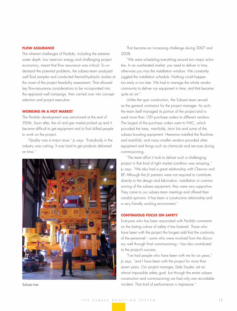
Subsea tree
s h e l l P e r D i D o
15
shell has more than 30 years of success in the design, fabrication, installation and operation of the world’s most ad-vanced deepwater systems. Perdido is shell’s first spar host drilling and production platform – a system selected because of the extreme water depths, the nature of the reservoirs and remoteness of the field.
technip was announced as the spar and mooring contractor in april 2006 and began working on a detailed design in June. an engineering, procurement and construc-tion (ePC) contract was awarded to technip usa in novem-ber 2006 for the design, fabrication and dry transport of the spar and mooring system for the Perdido development.
for efficiency in building the overall team, the spar and mooring leads for shell shared office space with technip’s project management, with integrated teams working at both companies’ offices in houston, texas. the spar fabrication site team was based at technip’s fabrication yard in Pori, finland. senior managers from both companies attended an alignment workshop in october 2006, and subsequent team-building sessions in finland and houston helped estab-lish an excellent working relationship from the start.
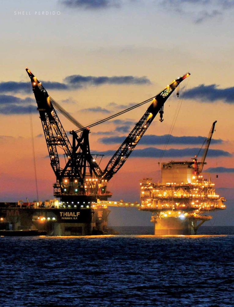
heerema marine Contractors (hmC) was named in the spring of 2006 as the primary transportation and installa-tion contractor. it was a critical step, because the finished spar and topsides would have to be designed to fit the
capacities of the available transport and installation ves-sels. to complete Perdido, shell needed two of the largest installation vessels in the world: hereema’s balder for the spar and thialf for lifting and setting the single-lift topsides. hereema’s project team, based in leiden, the netherlands, worked directly with shell’s transportation and installation team in houston.
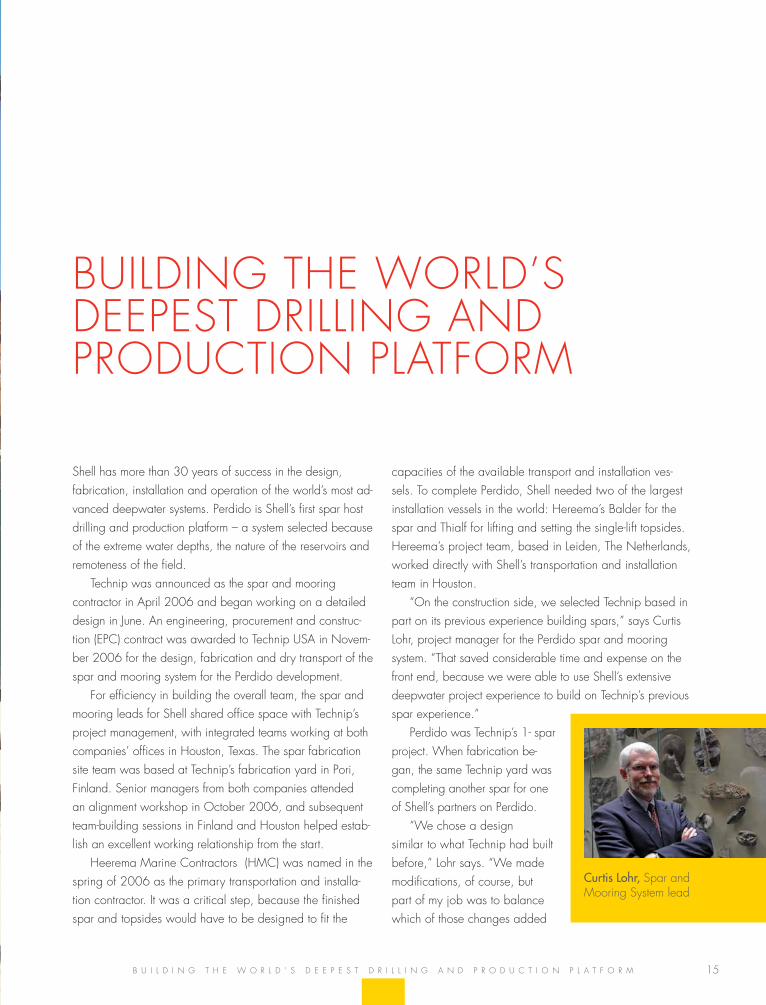
“on the construction side, we selected technip based in part on its previous experience building spars,” says Curtis lohr, project manager for the Perdido spar and mooring system. “that saved considerable time and expense on the front end, because we were able to use shell’s extensive deepwater project experience to build on technip’s previous spar experience.”
Perdido was technip’s 1- spar project. When fabrication be-gan, the same technip yard was completing another spar for one of shell’s partners on Perdido.
“We chose a design similar to what technip had built before,” lohr says. “We made modifications, of course, but part of my job was to balance which of those changes added
builDing the WorlD’s DeePest Drilling anD ProDuCtion Platform
b u i l D i n g t h e W o r l D ’ s D e e P e s t D r i l l i n g a n D P r o D u C t i o n P l a t f o r m
Curtis Lohr, spar and mooring system lead
16
s h e l l P e r D i D o
value to the project and which of them were just prefer-ences. it was also very helpful to see another spar taking shape in the yard.”
off To A good sTArT
shell team leads began working with their technip counter-parts early on to establish goals for project execution and safety. eight months before the ePC contract was awarded, shell and technip held their first team-building meeting in finland, then met there again four months later. the effort to develop working relationships at the site continued when a portion of shell’s site team moved to finland two months before the contract was awarded.
senior managers went to finland one month before the contract was awarded, again to make sure that everyone was aligned on safely delivering the project goals. shell employed a larger site team than technip had traditionally worked with, including a significant team of inspectors and safety coaches. the continual presence of the safety coaches at technip’s yard helped ensure that the priority on safety was maintained while delivering on the challenging con-struction schedule. this proactive approach included safety events and demonstrations to reinforce that safety was the top priority and that “goal zero – one shift at a time” was achievable.
the shell site team at technip grew to 14 members. al-though that’s small by shell standards, it was the largest client team that technip had ever seen.
“the key was convincing technip that we were not on site to police the work,” lohr recalls. “We were there as part-ners working toward common goals. We brought the best shell had to offer in terms of our construction and deepwater experience, and i think that the team, working together in finland and in houston, delivered a superior product.”
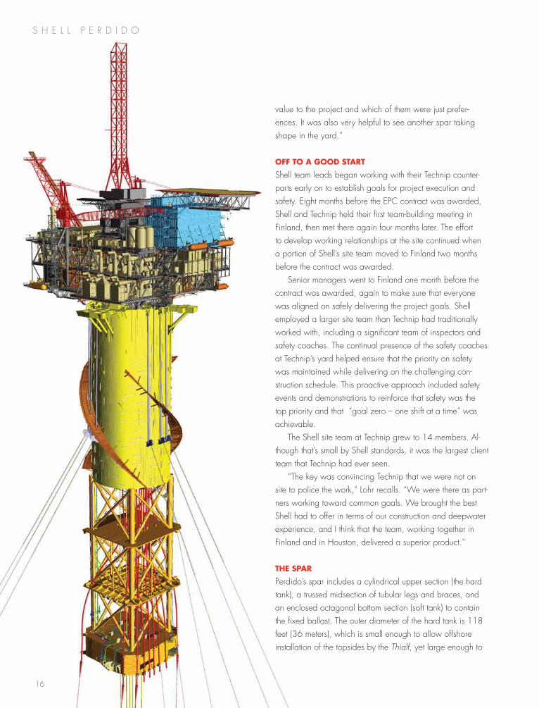
The spAr
Perdido’s spar includes a cylindrical upper section (the hard tank), a trussed midsection of tubular legs and braces, and an enclosed octagonal bottom section (soft tank) to contain the fixed ballast. the outer diameter of the hard tank is 118 feet (36 meters), which is small enough to allow offshore installation of the topsides by the Thialf, yet large enough to
17
provide the required buoyancy and to contain the platform’s various liquid storage tanks.
the spar is 555 feet (169 meters) tall, with a draft of 505 feet (154 meters) and gross weight of 20,000 tons (18,143 tonnes). strakes around the circumference of the hard tank are standard equipment on deepwater spars. strakes help keep the platform from oscillating by disrupting the flow of ocean currents around the spar.
hAnds-on mAnAgemenT in finlAnd
“one of my goals was to meet everybody who worked on the spar,” says Paul Dixon, who was part of the spar, mooring and riser design effort since 2003, and moved to finland in 2006 to oversee construction of the spar. Dixon even learned to speak the finnish language.
“there were about 1,700 people at the yard every day and i met as many of them as i could,” he says. “i wanted to talk to people and make sure they knew me. i wasn’t critical of their work, i just wanted them to know that i did not want to meet their families for the wrong reasons.”
one of the biggest challenges in building the spar was a delay in the project ahead of Perdido. the oil market was booming, so every shipyard was busy. a huge new power plant was also under construction just 60 miles south of the technip yard, so skilled workers were hard to find.
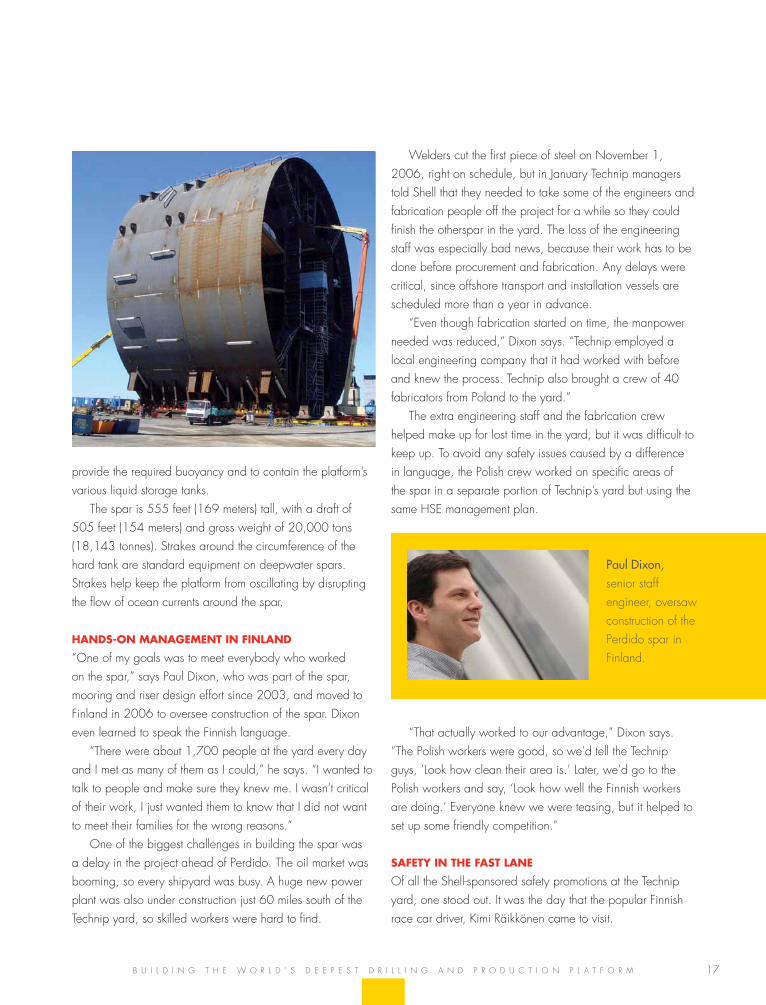
Welders cut the first piece of steel on november 1, 2006, right on schedule, but in January technip managers told shell that they needed to take some of the engineers and fabrication people off the project for a while so they could finish the otherspar in the yard. the loss of the engineering staff was especially bad news, because their work has to be done before procurement and fabrication. any delays were critical, since offshore transport and installation vessels are scheduled more than a year in advance.
“even though fabrication started on time, the manpower needed was reduced,” Dixon says. “technip employed a local engineering company that it had worked with before and knew the process. technip also brought a crew of 40 fabricators from Poland to the yard.”
the extra engineering staff and the fabrication crew helped make up for lost time in the yard, but it was difficult to keep up. to avoid any safety issues caused by a difference in language, the Polish crew worked on specific areas of the spar in a separate portion of technip’s yard but using the same hse management plan.
“that actually worked to our advantage,” Dixon says. “the Polish workers were good, so we’d tell the technip guys, ‘look how clean their area is.’ later, we’d go to the Polish workers and say, ‘look how well the finnish workers are doing.’ everyone knew we were teasing, but it helped to set up some friendly competition.”
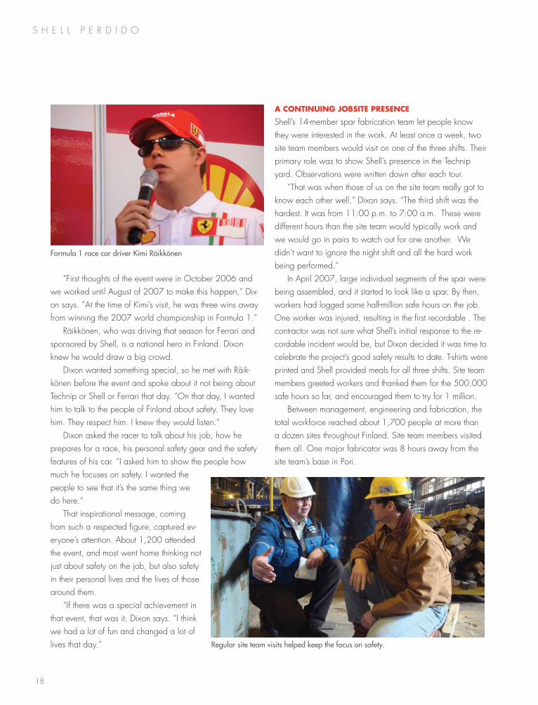
sAfeTy in The fAsT lAne
of all the shell-sponsored safety promotions at the technip yard, one stood out. it was the day that the popular finnish race car driver, Kimi räikkönen came to visit.
Paul Dixon, senior staff engineer, oversaw construction of the Perdido spar in finland.
b u i l D i n g t h e W o r l D ’ s D e e P e s t D r i l l i n g a n D P r o D u C t i o n P l a t f o r m
18
s h e l l P e r D i D o
“first thoughts of the event were in october 2006 and we worked until august of 2007 to make this happen,” Dix-on says. “at the time of Kimi’s visit, he was three wins away from winning the 2007 world championship in formula 1.”
räikkönen, who was driving that season for ferrari and sponsored by shell, is a national hero in finland. Dixon knew he would draw a big crowd.
Dixon wanted something special, so he met with räik-könen before the event and spoke about it not being about technip or shell or ferrari that day. “on that day, i wanted him to talk to the people of finland about safety. they love him. they respect him. i knew they would listen.”
Dixon asked the racer to talk about his job, how he prepares for a race, his personal safety gear and the safety features of his car. “i asked him to show the people how much he focuses on safety. i wanted the people to see that it’s the same thing we do here.”
that inspirational message, coming from such a respected figure, captured ev-eryone’s attention. about 1,200 attended the event, and most went home thinking not just about safety on the job, but also safety in their personal lives and the lives of those around them.
“if there was a special achievement in that event, that was it, Dixon says. “i think we had a lot of fun and changed a lot of lives that day.”
A conTinuing jobsiTe presence
shell’s 14-member spar fabrication team let people know they were interested in the work. at least once a week, two site team members would visit on one of the three shifts. their primary role was to show shell’s presence in the technip yard. observations were written down after each tour.
“that was when those of us on the site team really got to know each other well,” Dixon says. “the third shift was the hardest. it was from 11:00 p.m. to 7:00 a.m. these were different hours than the site team would typically work and we would go in pairs to watch out for one another. We didn’t want to ignore the night shift and all the hard work being performed.”
in april 2007, large individual segments of the spar were being assembled, and it started to look like a spar. by then, workers had logged some half-million safe hours on the job. one worker was injured, resulting in the first recordable . the contractor was not sure what shell’s initial response to the re-cordable incident would be, but Dixon decided it was time to celebrate the project’s good safety results to date. t-shirts were printed and shell provided meals for all three shifts. site team members greeted workers and thanked them for the 500,000 safe hours so far, and encouraged them to try for 1 million.
between management, engineering and fabrication, the total workforce reached about 1,700 people at more than a dozen sites throughout finland. site team members visited them all. one major fabricator was 8 hours away from the site team’s base in Pori.
Regular site team visits helped keep the focus on safety.
Formula 1 race car driver Kimi Räikkönen
19b u i l D i n g t h e W o r l D ’ s D e e P e s t D r i l l i n g a n D P r o D u C t i o n P l a t f o r m
20
s h e l l P e r D i D o
seabed by 18-foot diameter suction piles that range from 87 to 103 feet in length.
hereema’s ssCv Balder entered the Perdido field on June 20, 2008, to install the first cluster of suction piles. each pile was individually upended, lifted overboard and lowered to the seafloor, where it was oriented correctly before being allowed to penetrate the seabed under its own weight a few feet into the mud. a remotely-operated underwater vehicle (rov) was used to close the water relief valves at the top of the pile, then to apply suction until the pile reached its target penetration. the water depth of the mooring piles ranged from about 7,600 to 8,600 feet. the installation of pile P6 at 8,631 feet set a new world record for the deepest perma-nent mooring pile.
since polyester ropeis more difficult to handle in a winch, the ends of each mooring line are fitted with lengths of chain. on the seabed, ground chains and mooring shackles connect the polyester mooring lines to the suction piles. at the surface, dedicated chain jacks on the platform control tension on the lines. Perdido employs an “active” mooring system, which means that the mooring lines can be pulled in or let out to reposition the spar over drilling locations on the seabed, reaching any point within an area roughly 350 feet in diameter.
insTAlling The spAr
from ingleside to the field took two days, and from the mo-ment the spar arrived on august 10, 2008, the activity was nonstop.
all eyes were on the weather until august 18, when the spar became storm-safe with three mooring lines attached the remaining six mooring lines were installed by august 29, just in time for hurricane gustav, a storm that briefly
managers from the various subcontractors also visited the technip yard.
“We had a Contractor Day early on,” Dixon says. “We took them all around the technip yard to show them what we were doing, how we were doing it and why. then we lis-tened to what the subcontractors were doing well and why. it was the first time that had been done, and i believe that it contributed to the project’s outstanding safety record. the Perdido development has logged more than 10 million man hours without a lost-time incident. about a quarter of it came from the spar fabrication site, and i’m very proud of that.”
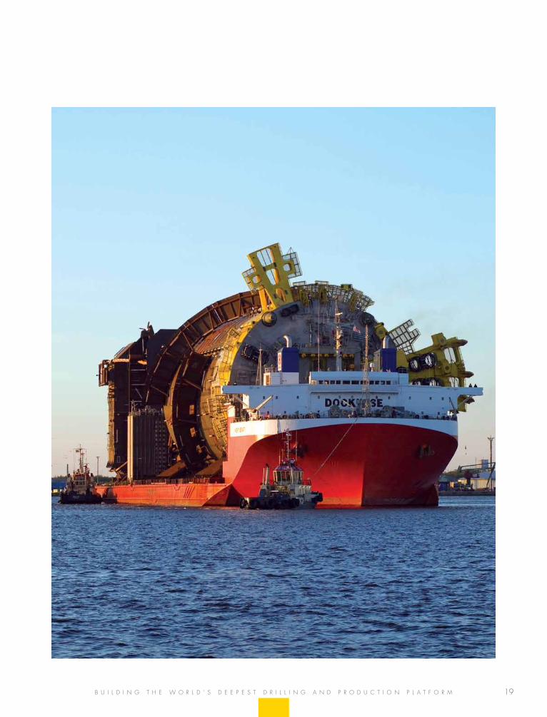
sAil-AwAy
fabrication at the technip yard continued from november 2006 until may 2008. after more than 2.3 million man hours of work without a lost-time incident, the spar was skidded aboard the semi-submersible Dockwise Mighty Servant 1 in Pori, finland on may 27 for the 8,200-mile (13,200-kilometer) dry transport to Kiewit offshore services in ingleside, texas.
“that was an emotional day,” Dixon says. “Watching the spar sail away was like watching your child go off to college.”
the spar arrived at Kiewit’s yard on June 19, 2008, for final outfitting. Kewit also built the Perdido topsides at the ingleside fabrication yard. the spar spent a month and a half at the ingleside yard in preparation for offshore installa-tion. the spar sailed from the yard on august 8 for the final 150-mile wet tow to its final location in the Perdido field.
The mooring sysTem
all of shell’s previous deepwater mooring systems have used steel mooring lines; Perdido is the first to use mooring lines that are primarily polyester. “We’ve used polyester rope before on drilling and storage structures, but this is shell’s first application for a permanent deepwater drilling and produc-tion system,” lohr says. “the 9-inch polyester lines are much lighter than steel, so our decision to use them greatly reduced the payload requirements of the floating structure.”
Perdido’s mooring system consists of nine anchor lines that average more than two miles in length. the nine taut lines are oriented in a 3x3 pattern, and are anchored to the
Bert Ulbricht, Construction lead
21
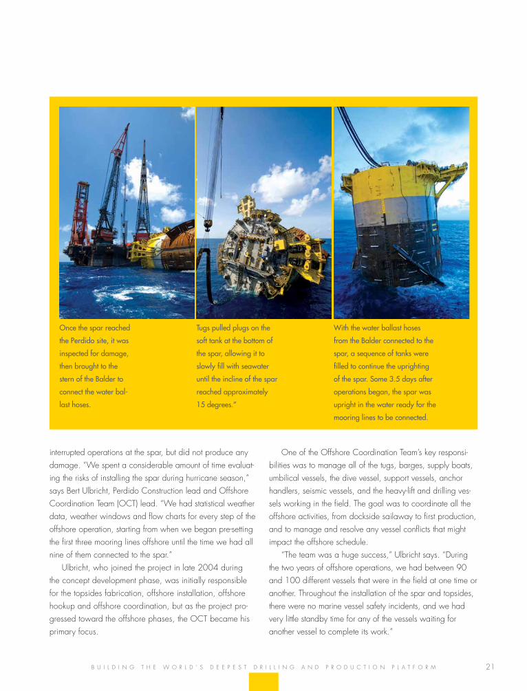
Once the spar reached
the Perdido site, it was
inspected for damage,
then brought to the
stern of the Balder to
connect the water bal-
last hoses.
Tugs pulled plugs on the
soft tank at the bottom of
the spar, allowing it to
slowly fill with seawater
until the incline of the spar
reached approximately
15 degrees.”
With the water ballast hoses
from the Balder connected to the
spar, a sequence of tanks were
filled to continue the uprighting
of the spar. Some 3.5 days after
operations began, the spar was
upright in the water ready for the
mooring lines to be connected.
b u i l D i n g t h e W o r l D ’ s D e e P e s t D r i l l i n g a n D P r o D u C t i o n P l a t f o r m
interrupted operations at the spar, but did not produce any damage. “We spent a considerable amount of time evaluat-ing the risks of installing the spar during hurricane season,” says bert ulbricht, Perdido Construction lead and offshore Coordination team (oCt) lead. “We had statistical weather data, weather windows and flow charts for every step of the offshore operation, starting from when we began pre-setting the first three mooring lines offshore until the time we had all nine of them connected to the spar.”
ulbricht, who joined the project in late 2004 during the concept development phase, was initially responsible for the topsides fabrication, offshore installation, offshore hookup and offshore coordination, but as the project pro-gressed toward the offshore phases, the oCt became his primary focus.
one of the offshore Coordination team’s key responsi-bilities was to manage all of the tugs, barges, supply boats, umbilical vessels, the dive vessel, support vessels, anchorhandlers, seismic vessels, and the heavy-lift and drilling ves-sels working in the field. the goal was to coordinate all theoffshore activities, from dockside sailaway to first production,and to manage and resolve any vessel conflicts that mightimpact the offshore schedule.
“the team was a huge success,” ulbricht says. “Duringthe two years of offshore operations, we had between 90and 100 different vessels that were in the field at one time oranother. throughout the installation of the spar and topsides,there were no marine vessel safety incidents, and we hadvery little standby time for any of the vessels waiting foranother vessel to complete its work.”
s h e l l P e r D i D o
23
the Perdido team faced a tough decision. a conventional topsides design required a series of modules that would have to be fabricated onshore, then lifted onto the spar and integrated offshore, but what if the team could constrain the design enough that it could be built and lifted in one piece?
they already knew that Perdido would be a wet tree Dva spar, and were convinced that a single-lift topsides would be safer to build and less expensive than a modular system. the trick was giving the smaller topsides all the capability it needed to produce the field.
“for a development this size we would probably need three modules, so our first big goal was to get the topsides in one piece and keep the weight under about 10,000 tons,” says topsides lead, Kurt shallenberger. “We designed the deck in 2005 to match the lift capability of heerema’s Thialf semi-submersible crane vessel (ssCv). everything we wanted to put on the Perdido spar had to fit within that box.”
that was unique. the more familiar way for engineers to work is to let the facility they’re designing grow to the size it needs to be. early weight studies suggested that Perdido’s topsides needed to be several modules. technical bench-marking studies showed that bP’s design for horn mountain had the best function-to-weight performance of any spar built so far, so with the assistance of bP, Chevron and alliance engineering, the Perdido design team evaluated horn moun-tain’s design and operating performance.
“that led us to the lightweight Perdido concept,” shallen-berger says. “We selected alliance as the engineering contrac-tor because of its previous experience with horn mountain.”
the single-lift toPsiDes
f a b r i C a t i n g t h e s i n g l e - l i f t t o P s i D e s
Kurt Shallenberger, topsides lead
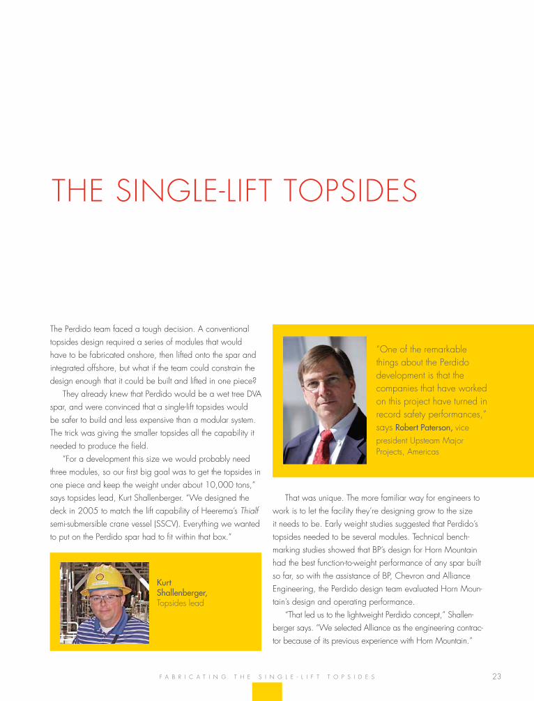
“one of the remarkable things about the Perdido development is that the companies that have worked on this project have turned in record safety performances,” says Robert Paterson, vice president upsteam major Projects, americas
24
s h e l l P e r D i D o
builT for sAfeTy
health, safety and environmental (hse) needs drove the de-sign of Perdido’s topsides. one of noticeable features is the 2.5-bar blast wall that separates the crew quarters from the drilling and processing equipment, but Perdido also has the most aggressive fire suppression and gas monitoring systems of any offshore platform. it is a reflection of how the industry in general is maturing in terms of fire and explosion protec-tion. Planning runs the gamut from how to prevent a release and ignition, to how to mitigate the impact if you do have a fire or explosion, and how best to evacuate the platform.
“industry has learned a lot, particularly since the 1988 Piper alpha fire in the north sea,” shallenberger says. “if there is a gas release, for example, we now have sophisticated models to help us understand where the gas will go. Perdido has more gas detection than any other platform, probably by a factor of five. if we were to detect gas, we can quickly depres-sure the whole facility and divert the gas to our flare system.”
the Perdido design team did extensive modeling of the onboard firefighting capability. Perdido’s twin 5,000 gpm firewater pumps and automatic foam system is the most extensive fire protection layout of any shell platform in the gulf of mexico. one revolutionary feature is that the system is automatic. rather than having a water deluge system and a supplemental foam system, both manually triggered, Perdido’s automatic fire suppression system covers the entire platform, including the heliport.
“Computer modeling also helped us determine, if there were an explosion, what kind of overpressure to expect at various points throughout the facility,” shallenberger says. “blast walls shield not only the crew quarters, but also the safety equipment, work areas and evacuation routes. there are no production offices in the process areas, and the incident Command Center is adjacent to the control room for real-time feedback. We spent a lot of time in the screening process to make sure that in this compact space, our people are well protected.”
inTegrATing The subseA sysTems
Perdido’s subsea system, which includes separation and boosting, direct vertical access wells and tiebacks to satellite wells, is a first of its kind.
“integrating those systems was one of the most complex things we’ve done on this project,” shallenberger says. “from a topsides perspective, we are looking at recovering oil and gas from a collection of low-energy reservoirs.”
the low energy reservoirs demand low boarding pres-sures to be able to flow at reasonable rates. gas flows to the surface against 460 psi, while oil is pumped from the seafloor against 160 psi at the surface. elsewhere in the gulf of mexico, deepwater wells flow on their own. on an-other platform, production might come it at 1,600 psi, which is normally enough to move fluids through the export lines to sales. since Perdido is so far from the nearest sales line and the reservoirs are low pressure to begin with, the export pres-sure from the spar is 3,200 psi.
“it takes a lot of horsepower to make that happen,” shallenberger says. “it helps that the liquids and gas are separated on the seabed. on the topsides we separate the oil and water. the gas and oil are exported via two export pipelines, and the produced water is cleaned and dis-charged overboard. We also have a waterflood, but for that we use seawater.”
fAbricATion siTes
steel and equipment for the Perdido topsides came from around the world. What designers called the box – the structure that was designed to fit the lifting capabilities of the Thailf ssCv – was built at the Kiewit yard in ingleside, texas, just across the bay from Corpus Christi. ingleside is the same facility that completed the spar in 2008. the crew quarters were built at Delta engineering on the houston ship Channel.
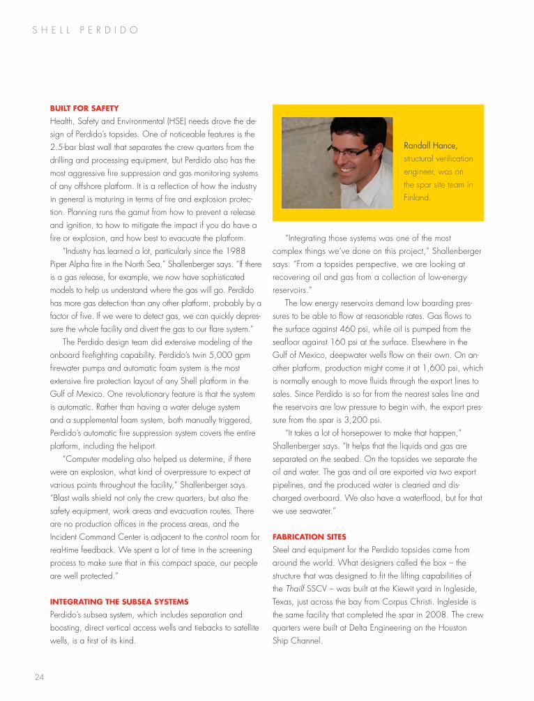
Randall Hance, structural verification engineer, was on the spar site team in finland.
25
working Through sTorms
Katrina, the most expensive hurricane in u.s. history, made landfall in southeast louisiana on august 29, 2005. much of the Perdido team, then in the early stages of design and engineering, was displaced for six months. it was the first big storm to disrupt the project, but not the last.
“When Katrina wrecked the city and shell’s offices in new orleans, we moved the Perdido team to houston,” shallenberger says. “We began the front-end engineering and design (feeD) process while we were displaced. that was a big issue for our folks, traveling back and forth, fixing our homes on the weekends and coming back to houston during the week.”
three years later, when hurricane ike made a midnight surge into galveston bay and up the houston ship Channel, it passed right over the Delta engineering (now Delcor usa) fabrication yard and Perdido’s almost-finished crew quarters. by early morning, much of galveston was under water, 90 percent of houston was without power and 100 miles of texas beaches were gone.
“after our experience with Katrina, we were prepared to deal with ike,” shallenberger says. “We knew what prob-lems the Delta yard was going to have and we responded right away. Workers were displaced. most had damage to their homes and families to care for. since the Delta yard itself was heavily damaged, workers were also concerned about their jobs. We stepped in very quickly to help Delta keep their contract labor employed.”
shell responded with food, water and fuel. shell’s emer-gency response team even brought in temporary housing and laundry facilities. that support continued for several weeks, until Delta and the rest of houston got back on its feet. fortunately, topsides construction at the Kiewit yard was far enough down the texas coast that it was not affected by hurricane ike, and even the crew quarters survived the storm in relatively good shape.
“Perdido’s living quarters, which were in the yard at the time of the storm, were not heavily damaged,” shallenberger recalls. “two days before ike made landfall, we calcu-lated that if the storm surge came up too high, our quarters building would float off of its supports. We decided to pull the doors off the bottom floor so that if the water did rise,
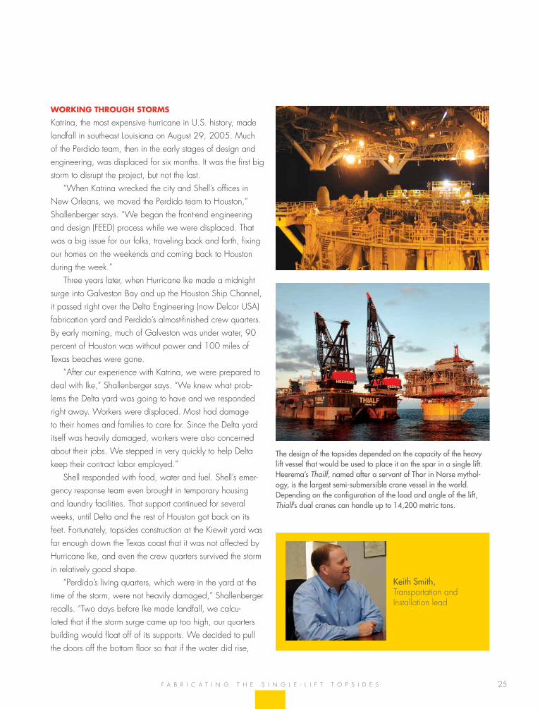
The design of the topsides depended on the capacity of the heavy lift vessel that would be used to place it on the spar in a single lift. Heerema’s Thailf, named after a servant of Thor in Norse mythol-ogy, is the largest semi-submersible crane vessel in the world. Depending on the configuration of the load and angle of the lift, Thialf’s dual cranes can handle up to 14,200 metric tons.
Keith Smith, transportation and installation lead
f a b r i C a t i n g t h e s i n g l e - l i f t t o P s i D e s
26
s h e l l P e r D i D o
humAn fAcTors And mATeriAls hAndling
as part of Perdido’s safe design, planners used 3D design tools to make things easier for people to operate, service, re-pair and move around on the platform. to advise shell’s own safety specialists, the design team called in operators with extensive offshore experience and outside experts in human factors engineering.
“every week for two to four hours, we would take a portion of the facility and walk through it in 3D,” shallenberger recalls. “We wanted to understand where things should be: what elevation to put a valve, for example, or where to put a pump and how a person might work on it safely. We made frequent adjustments so that an operator servicing a piece of equipment would not be leaning over at an awkward angle or trying to lift something that was too heavy. We made sure the equipment was as accessible as possible and easy to maintain.”
his team studied materials handling in the same way. “We looked at all the equipment and determined how often someone might have to work on it. some things you might not touch for a year, but other items, such as filters, might be replaced twice a month. We wanted those items within easy reach and the replacement parts easy to move. they can’t be too high or too low.”
if something an operator handles regularly weighs more than 50 pounds, for example, the topsides designers
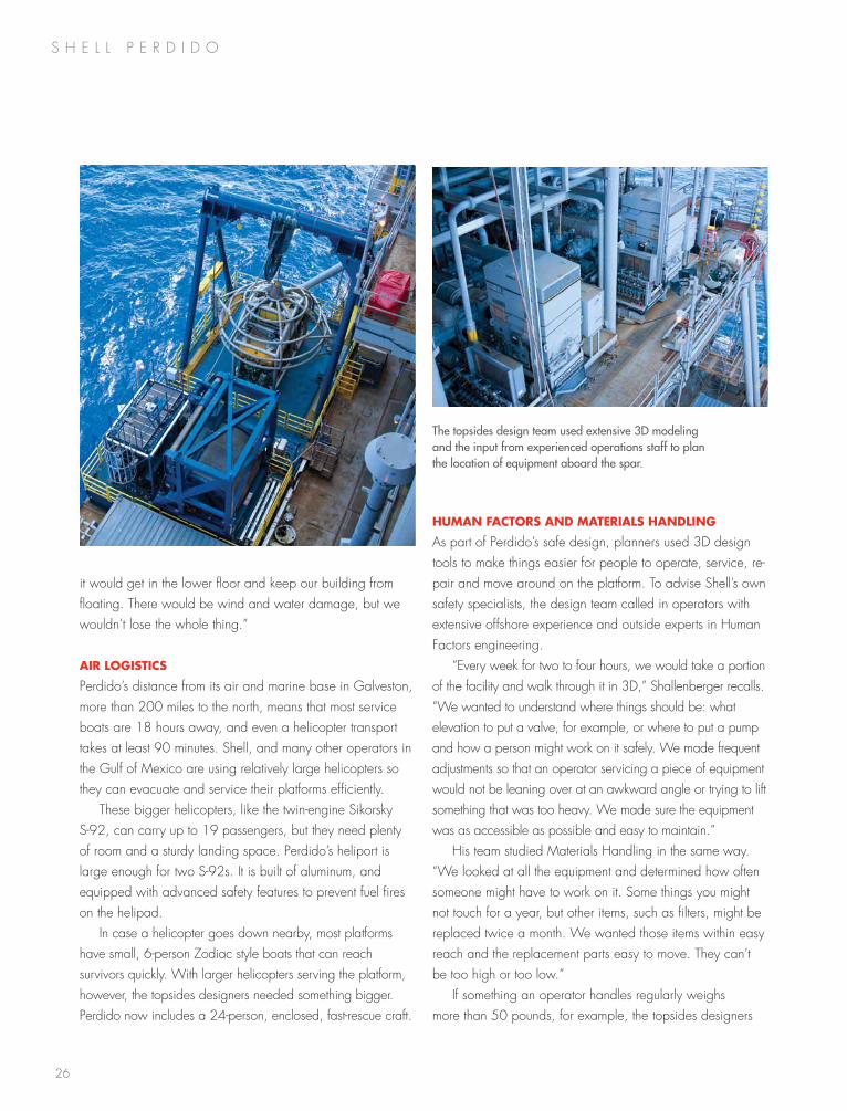
The topsides design team used extensive 3D modeling and the input from experienced operations staff to plan the location of equipment aboard the spar.
it would get in the lower floor and keep our building from floating. there would be wind and water damage, but we wouldn’t lose the whole thing.”
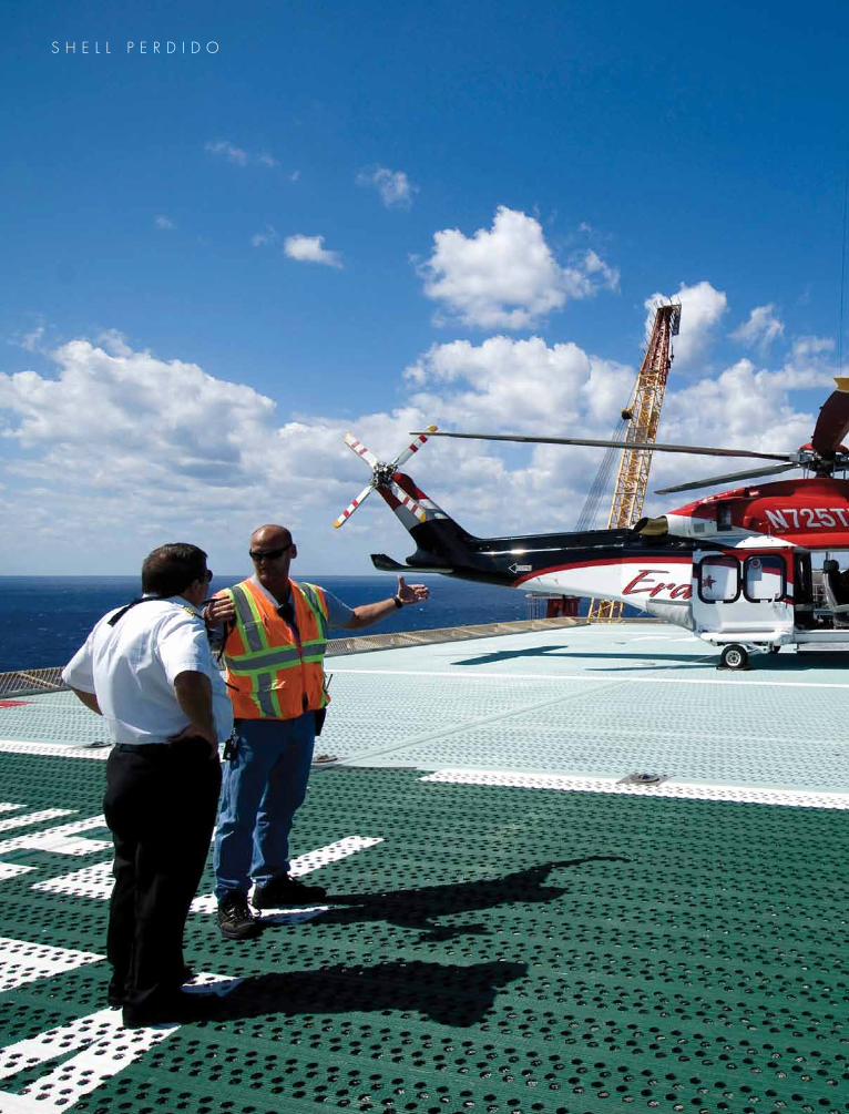
Air logisTics
Perdido’s distance from its air and marine base in galveston, more than 200 miles to the north, means that most service boats are 18 hours away, and even a helicopter transport takes at least 90 minutes. shell, and many other operators in the gulf of mexico are using relatively large helicopters so they can evacuate and service their platforms efficiently.
these bigger helicopters, like the twin-engine sikorsky s-92, can carry up to 19 passengers, but they need plenty of room and a sturdy landing space. Perdido’s heliport is large enough for two s-92s. it is built of aluminum, and equipped with advanced safety features to prevent fuel fires on the helipad.
in case a helicopter goes down nearby, most platforms have small, 6-person Zodiac style boats that can reach survivors quickly. With larger helicopters serving the platform, however, the topsides designers needed something bigger. Perdido now includes a 24-person, enclosed, fast-rescue craft.
27
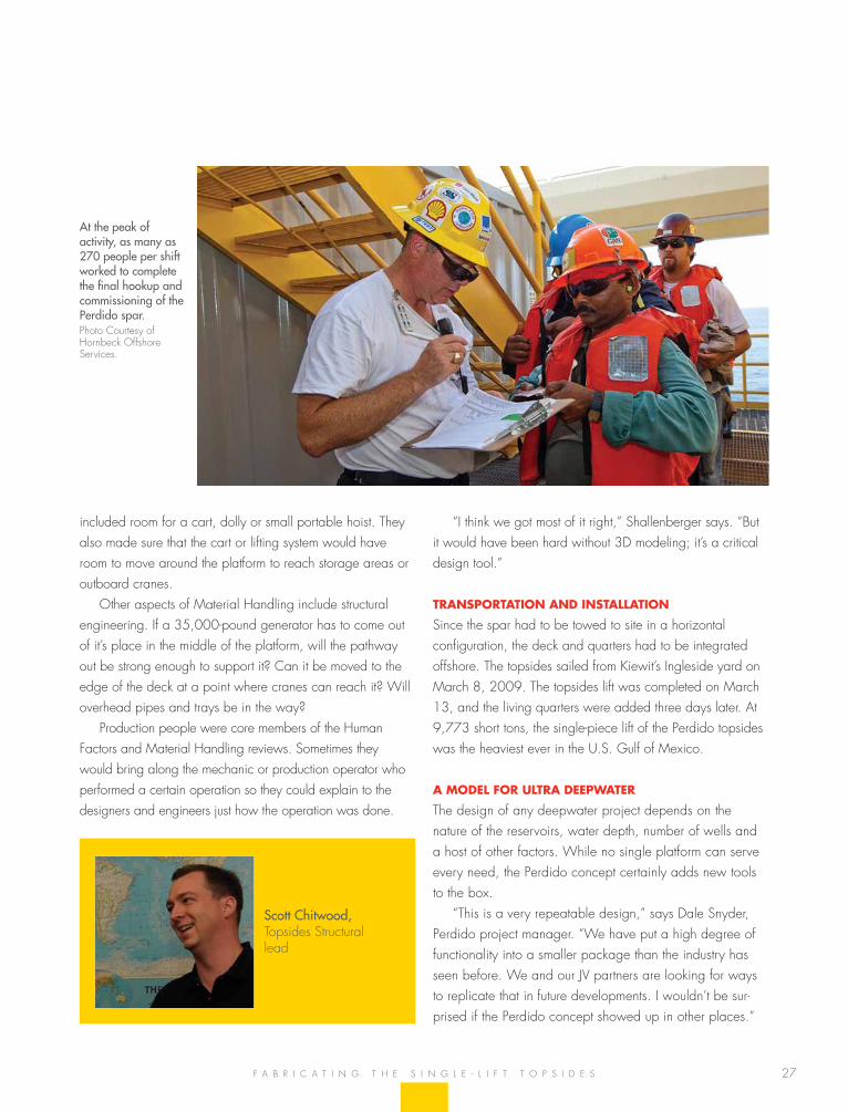
included room for a cart, dolly or small portable hoist. they also made sure that the cart or lifting system would have room to move around the platform to reach storage areas or outboard cranes.
other aspects of material handling include structural engineering. if a 35,000-pound generator has to come out of it’s place in the middle of the platform, will the pathway out be strong enough to support it? Can it be moved to the edge of the deck at a point where cranes can reach it? Will overhead pipes and trays be in the way?
Production people were core members of the human factors and material handling reviews. sometimes they would bring along the mechanic or production operator who performed a certain operation so they could explain to the designers and engineers just how the operation was done.
At the peak of activity, as many as 270 people per shift worked to complete the final hookup and commissioning of the Perdido spar. Photo Courtesy of hornbeck offshore services.
“i think we got most of it right,” shallenberger says. “but it would have been hard without 3D modeling; it’s a critical design tool.”
TrAnsporTATion And insTAllATion
since the spar had to be towed to site in a horizontal configuration, the deck and quarters had to be integrated offshore. the topsides sailed from Kiewit’s ingleside yard on march 8, 2009. the topsides lift was completed on march 13, and the living quarters were added three days later. at 9,773 short tons, the single-piece lift of the Perdido topsides was the heaviest ever in the u.s. gulf of mexico.
A model for ulTrA deepwATer
the design of any deepwater project depends on the nature of the reservoirs, water depth, number of wells and a host of other factors. While no single platform can serve every need, the Perdido concept certainly adds new tools to the box.
“this is a very repeatable design,” says Dale snyder, Perdido project manager. “We have put a high degree of functionality into a smaller package than the industry has seen before. We and our Jv partners are looking for ways to replicate that in future developments. i wouldn’t be sur-prised if the Perdido concept showed up in other places.”
Scott Chitwood, topsides structural lead
f a b r i C a t i n g t h e s i n g l e - l i f t t o P s i D e s
s h e l l P e r D i D o
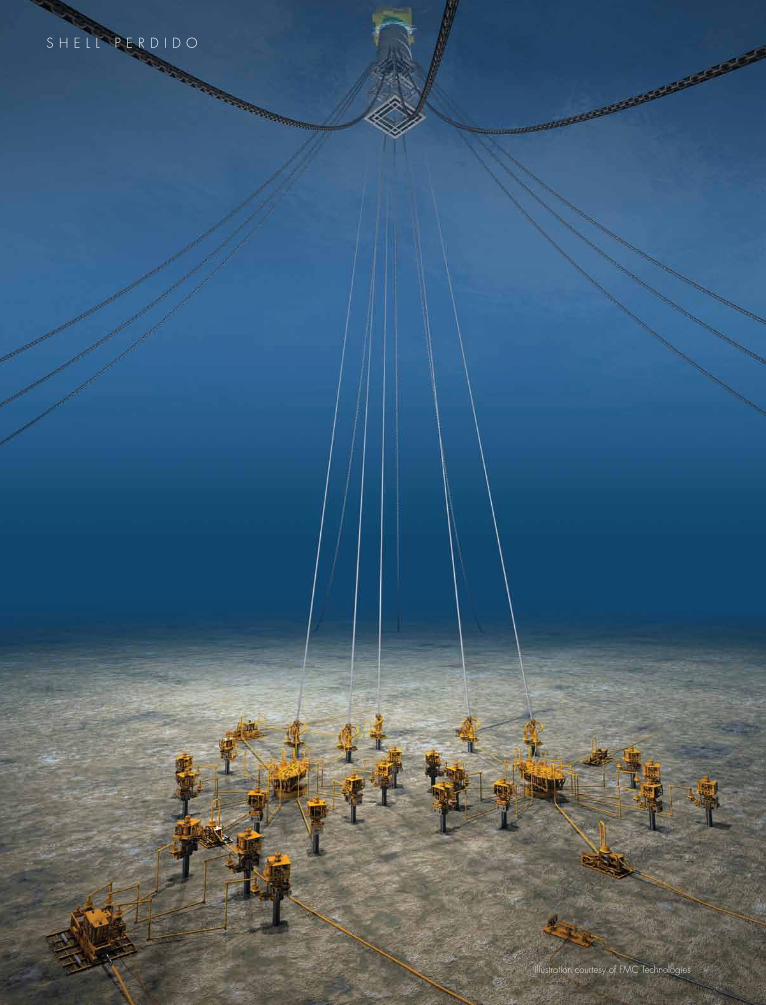
illustration courtesy of fmC technologies
29
great White, silvertip and tobago – the Perdido develop-ment’s three fields – contain many producing zones, large volumes of hydrocarbons in-place, and a considerable amount of uncertainty.
much of the oil and gas from Perdido will come from the Paleogene geological system, which includes the m. oligocene frio sds., l. eocene Wm12 sd., and the l. Paleocene Wm50 sds. together, these three reservoir zones are known as the “lower tertiary,” reservoir intervals in the gulf of mexico that no other operating company in the gulf has tapped before. some industry analysts are calling the eocene the most significant oil trend since the discovery of Prudhoe bay.
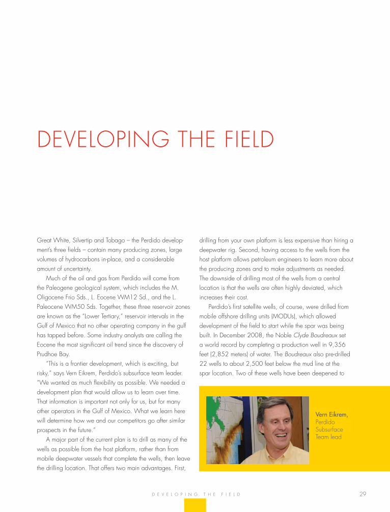
“this is a frontier development, which is exciting, but risky,” says vern eikrem, Perdido’s subsurface team leader. “We wanted as much flexibility as possible. We needed a development plan that would allow us to learn over time. that information is important not only for us, but for many other operators in the gulf of mexico. What we learn here will determine how we and our competitors go after similar prospects in the future.”
a major part of the current plan is to drill as many of the wells as possible from the host platform, rather than from mobile deepwater vessels that complete the wells, then leave the drilling location. that offers two main advantages. first,
drilling from your own platform is less expensive than hiring a deepwater rig. second, having access to the wells from the host platform allows petroleum engineers to learn more about the producing zones and to make adjustments as needed. the downside of drilling most of the wells from a central location is that the wells are often highly deviated, which increases their cost.
Perdido’s first satellite wells, of course, were drilled from mobile offshore drilling units (moDus), which allowed development of the field to start while the spar was being built. in December 2008, the noble Clyde Boudreaux set a world record by completing a production well in 9,356 feet (2,852 meters) of water. the Boudreaux also pre-drilled 22 wells to about 2,500 feet below the mud line at the spar location. two of these wells have been deepened to
D e v e l o P i n g t h e f i e l D
Vern Eikrem, Perdido subsurface team lead
DeveloPing the fielD
30
s h e l l P e r D i D o
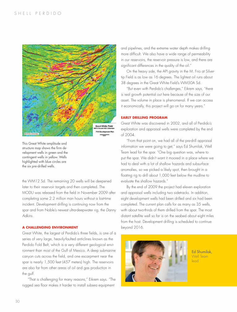
the Wm12 sd. the remaining 20 wells will be deepened later to their reservoir targets and then completed. the moDu was released from the field in november 2009 after completing some 2.2 million man hours without a lost-time incident. Development drilling is continuing now from the spar and from noble’s newest ultra-deepwater rig, the Danny Adkins.
A chAllenging environmenT
great White, the largest of Perdido’s three fields, is one of a series of very large, heavily-faulted anticlines known as the Perdido fold belt, which is a very different geological envi-ronment than most of the gulf of mexico. a deep submarine canyon cuts across the field, and one escarpment near the spar is nearly 1,500 feet (457 meters) high. the reservoirs are also far from other areas of oil and gas production in the gulf.
“that is challenging for many reasons,” eikrem says. “the rugged sea floor makes it harder to install subsea equipment
and pipelines, and the extreme water depth makes drilling more difficult. We also have a wide range of permeability in our reservoirs, the reservoir pressure is low, and there are significant differences in the quality of the oil.”
on the heavy side, the aPi gravity in the m. frio at silver-tip field is as low as 16 degrees. the lightest oil runs about 38 degrees in the great White field’s Wm50a sd.
“but even with Perdido’s challenges,” eikrem says, “there is real growth potential out here because of the size of our asset. the volume in place is phenomenal. if we can access it economically, this project will go on for many years.”
eArly drilling progrAm
great White was discovered in 2002, and all of Perdido’s exploration and appraisal wells were completed by the end of 2004.
“from that point on, we had all of the pre-drill appraisal information we were going to get,” says ed shumilak, Well team lead for the spar. “one big question was, where to put the spar. We didn’t want it moored in a place where we had to deal with a lot of shallow hazards and subsurface anomalies, so we picked a likely spot, then brought in a floating rig to drill about 1,000 feet below the mudline to evaluate the shallow hazards.”
by the end of 2009 the project had eleven exploration and appraisal wells including two sidetracks. in addition, eight development wells had been drilled and six had been completed. the current plan calls for as many as 35 wells, with about two-thirds of them drilled from the spar. the most distant satellite well so far is on the seabed about eight miles from the host. Development drilling is scheduled to continue beyond 2016.
Ed Shumilak, Well team lead
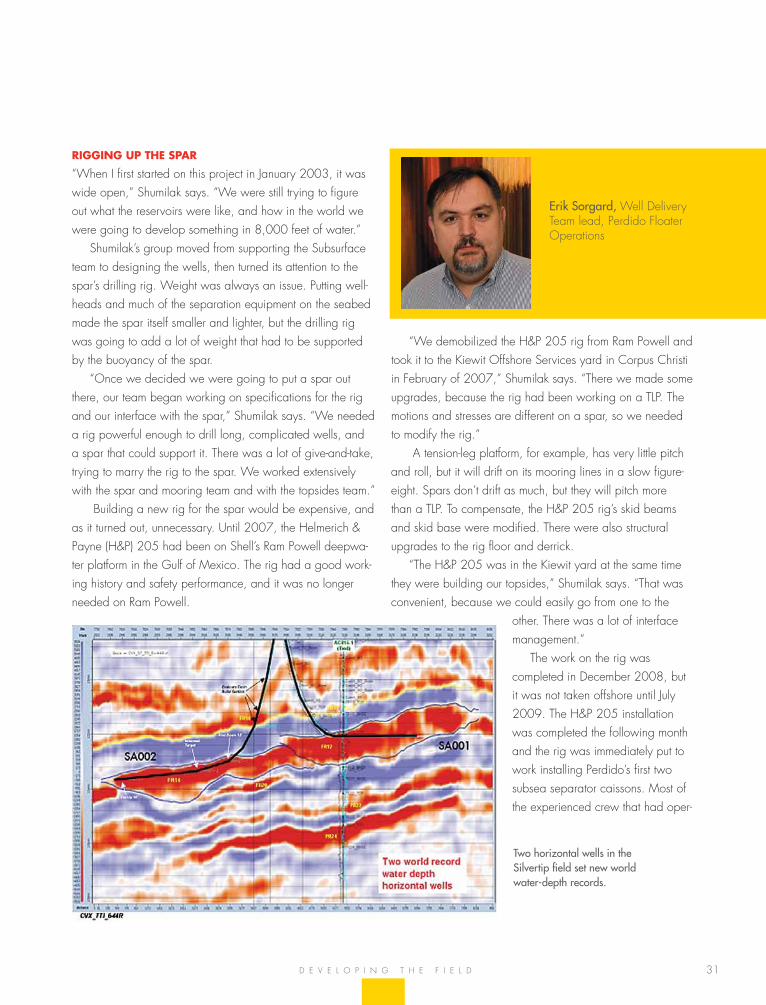
This Great White amplitude and structure map shows the firm de-velopment wells in green and the contingent wells in yellow. Wells highlighted with blue circles are the six pre-drilled wells.
31
rigging up The spAr
“When i first started on this project in January 2003, it was wide open,” shumilak says. “We were still trying to figure out what the reservoirs were like, and how in the world we were going to develop something in 8,000 feet of water.”
shumilak’s group moved from supporting the subsurface team to designing the wells, then turned its attention to the spar’s drilling rig. Weight was always an issue. Putting well-heads and much of the separation equipment on the seabed made the spar itself smaller and lighter, but the drilling rig was going to add a lot of weight that had to be supported by the buoyancy of the spar.
“once we decided we were going to put a spar out there, our team began working on specifications for the rig and our interface with the spar,” shumilak says. “We needed a rig powerful enough to drill long, complicated wells, and a spar that could support it. there was a lot of give-and-take, trying to marry the rig to the spar. We worked extensively with the spar and mooring team and with the topsides team.”
building a new rig for the spar would be expensive, and as it turned out, unnecessary. until 2007, the helmerich & Payne (h&P) 205 had been on shell’s ram Powell deepwa-ter platform in the gulf of mexico. the rig had a good work-ing history and safety performance, and it was no longer needed on ram Powell.
Two horizontal wells in the Silvertip field set new world water-depth records.
“We demobilized the h&P 205 rig from ram Powell and took it to the Kiewit offshore services yard in Corpus Christi in february of 2007,” shumilak says. “there we made some upgrades, because the rig had been working on a tlP. the motions and stresses are different on a spar, so we needed to modify the rig.”
a tension-leg platform, for example, has very little pitch and roll, but it will drift on its mooring lines in a slow figure-eight. spars don’t drift as much, but they will pitch more than a tlP. to compensate, the h&P 205 rig’s skid beams and skid base were modified. there were also structural upgrades to the rig floor and derrick.
“the h&P 205 was in the Kiewit yard at the same time they were building our topsides,” shumilak says. “that was convenient, because we could easily go from one to the
other. there was a lot of interface management.”
the work on the rig was completed in December 2008, but it was not taken offshore until July 2009. the h&P 205 installation was completed the following month and the rig was immediately put to work installing Perdido’s first two subsea separator caissons. most of the experienced crew that had oper-
D e v e l o P i n g t h e f i e l D
Erik Sorgard, Well Delivery team lead, Perdido floater operations
32
s h e l l P e r D i D o
ated the h&P 205 on ram Powell stayed with the rig and are now on the Perdido spar.
“a number of h&P’s rotating crews also work exclusively for shell, and that enhances our safety program,” shumilak adds. “even though they move from one facility to another, they know our safety culture. they know the way we work and operate, and they know our foremen and superinten-dents.”
as the rig neared completion in the Kiewit yard, for example, new crew members were brought in to work with the experienced hands. as one of the foremen said, “We’re building the safety culture here that we’re going to take offshore with us.”
one popular safety program is called, I stopped a drop! on a drilling rig that is 15 stories tall, dropped objects are a serious hazard. a forgotten tool in the derrick or any small item that vibrates loose can be deadly. as one rig hand explained, “a one-pound bolt falling from 100 feet up makes quite a dent.”
Workers who point out such hazards are rewarded, and they have the satisfaction of knowing that they may have kept someone else from getting hurt.
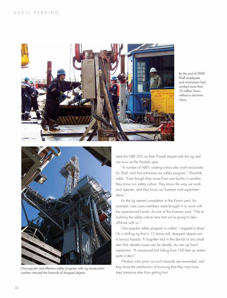
By the end of 2009, Shell employees and contractors had worked more than 10 million hours without a lost-time injury.
One popular and effective safety program with rig construction workers stressed the hazards of dropped objects.
33
sAfeTy offshore
Working offshore is inherently dangerous. the work is non-stop. People are moving equipment that weighs tons, yet the offshore safety record for the Perdido development has been outstanding.
“i give a lot of credit to the onsite leadership,” shumilak says. “Day in and day out, the shell foremen and all the site leads stressed safety. they focused on it in their pre-tour meet-ings in the morning and in all of their pre-job planning. they talked about safety again at the end of their shift. safety has been a continual theme offshore, and it really pays off.”
the way contractors managed their experienced people is a good example. anyone who was new to a particular job – regardless of his or her time in the field – was called a “short service” employee. the number of short service employees was kept to a minimum, but when anyone did fall into that category, mentors were always nearby.
An inTegrATed TeAm
from the beginning of the project through the end of 2009, Perdido’s contractors and shell employees logged more than 10 million man hours without a lost-time injury. that is just one measure of Perdido’s success. shumilak credits a strong integrated team and good management.
“one thing i’m most proud of is the integrated team we had throughout this project, and the freedom that manage-ment gave us to explore new ideas, ” he says. “We began with a whole range of possibilities and solutions, so we gathered an experienced team of civil engineers, rig folks, subsea engineers and production specialists. the interface and communication was outstanding. Without that, we couldn’t have pulled this off.”
from the beginning, the team had few constraints. if a project as bold as Perdido was going to be successful,
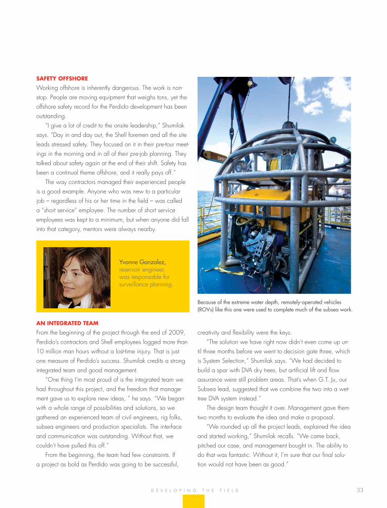
Because of the extreme water depth, remotely-operated vehicles (ROVs) like this one were used to complete much of the subsea work.
D e v e l o P i n g t h e f i e l D
Yvonne Gonzalez, reservoir engineer, was responsable for surveillance planning.
creativity and flexibility were the keys. “the solution we have right now didn’t even come up un-
til three months before we went to decision gate three, which is system selection,” shumilak says. “We had decided to build a spar with Dva dry trees, but artificial lift and flow assurance were still problem areas. that’s when g.t. Ju, our subsea lead, suggested that we combine the two into a wet-tree Dva system instead.”
the design team thought it over. management gave them two months to evaluate the idea and make a proposal.
“We rounded up all the project leads, explained the idea and started working,” shumilak recalls. “We came back, pitched our case, and management bought in. the ability to do that was fantastic. Without it, i’m sure that our final solu-tion would not have been as good.”
s h e l l P e r D i D o
35
the team charged with designing Perdido’s oil export system reviewed all their options. there were few. the Perdido spar is moored more than 60 miles south of it’s nearest deepwater neighbor. it is 140 miles from the closest shallow-water plat-form, and the distance in between covers some of the most challenging terrain in the gulf of mexico.
the gas export pipeline was routed to the seahawk Pipe-line (107 miles from Perdido), which was installed with sub-sea facilities for a future connection. the closest oil pipeline, however, had no such connection. Perdido is 77 miles from the hoover offshore oil Pipeline system, commonly called hooPs. transportation through hooPs would require the first installation of a diverless, subsea connection.
“the alternative to a hooPs subsea connection was to build a pipeline twice as long to the nearest platform on which risers could be installed,” says mike Dupré, Pipeline and flow-line lead. “taking advantage of the shorter route to hooPs would require development of a new connection concept.”
in a clear break with conventional tie-in projects, a new technique was developed that utilized a truss structure as both a foundation and reference system for the installation of the connection hardware. the foundation enabled the Perdido export connection to be fabricated onshore and reassembled on the pipeline. it was the first time that a tie-in used a common foundation and prefabricated jumper spool.
The oil exporT connecTion
in shallow water, it is not difficult to tap into a pipeline full of oil, it’s called a hot tap, but no one had tried it before in 4,500 feet of water. While the actual connection took just 17 days to complete, preparing for the job took two and a half years.
“We learned a lot in that time, and the design evolved,” Dupré says. “We applied some new tools, did plenty of 3D modeling, and practiced using rov simulators to walk through the connection. because we would be working with a pipeline that has been in service and the majority of the pipeline would still be full of oil, there was no room for error.”
in a more typical subsea repair, the pipeline would be shut down, displaced and then cut. fittings would be placed over each end, then divers or an rov would measure the
t h e e x P o r t s Y s t e m
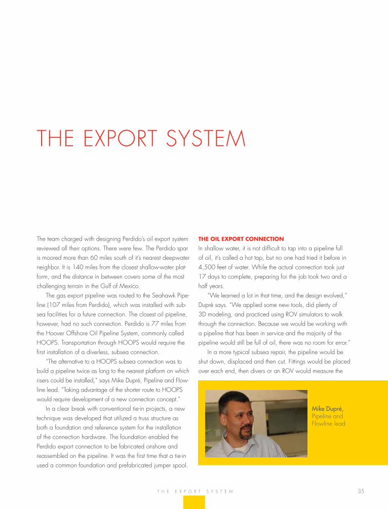
Mike Dupré, Pipeline and flowline lead
the exPort sYstem
36
s h e l l P e r D i D o
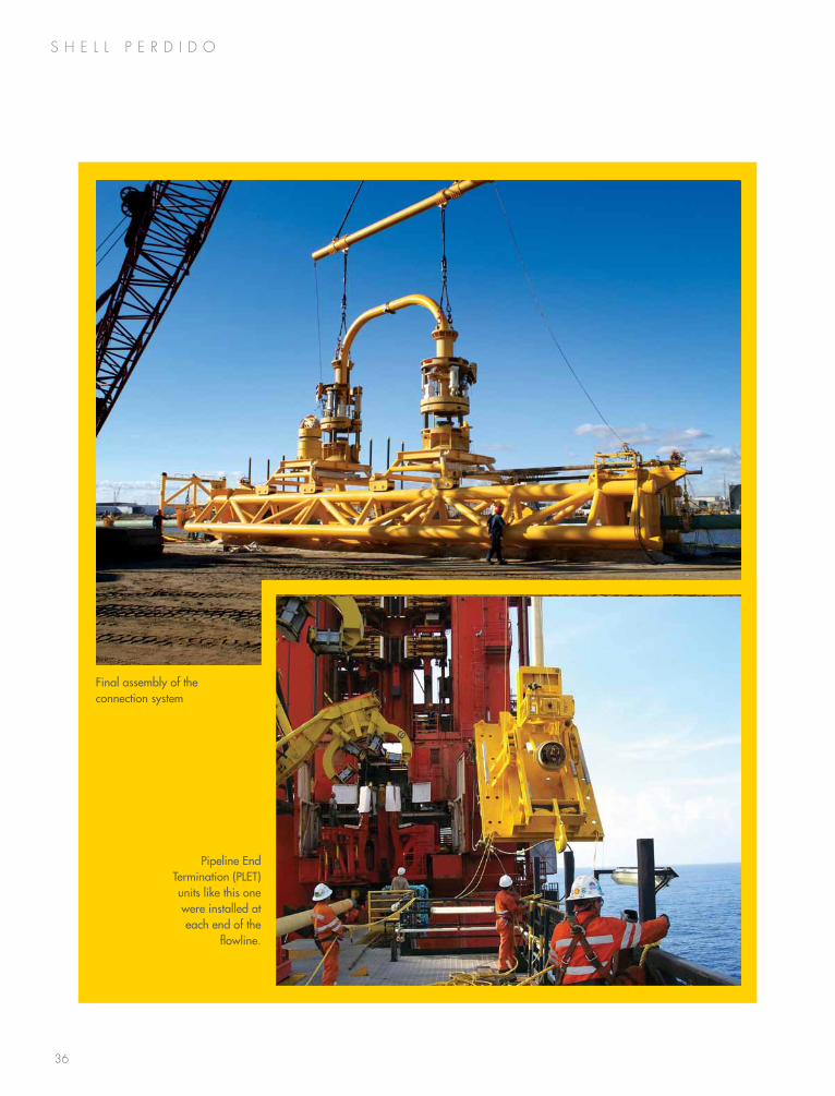
Final assembly of the connection system
Pipeline End Termination (PLET) units like this one were installed at each end of the
flowline.
37
length and orientation of the jumper needed to connect them. the jumper itself would be fabricated onshore and returned to the field for installation. the process would take up to 90 days. even if divers could work at the depth of the hooPs connection, the pipeline could not be shut down for that long.
the engineering solution was to create a single structure, a common base that could straddle the pipeline and serve as a positioning reference for tools and the placement of new hardware.
“We started with a simple, conventional design using two sleds and a jumper in between,” Dupré says. “there were certain criteria to follow. We couldn’t release any oil, of course, we could use only proven components, and we had to minimize the time the pipeline was out of service.”
another criteria was that the connection could be recon-figured in the future. Designers were looking ahead; hoover-Diana had already been producing for 10 years, so at some point, exxonmobil might want to disconnect from hooPs, and new operators in the area might need to tie in.
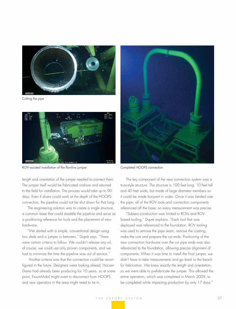
Cutting the pipe
ROV-assisted installation of the flowline jumper Completed HOOPS connection
the key component of the new connection system was a truss-style structure. the structure is 100 feet long, 10 feet tall and 40 feet wide, but made of large diameter members so it could be made buoyant in water. once it was landed over the pipe, all of the rov tools and connection components referenced off the base, so every measurement was precise.
“subsea construction was limited to rovs and rov- based tooling,” Dupré explains. “each tool that was deployed was referenced to the foundation. rov tooling was used to remove the pipe seam, remove the coating, make the cuts and prepare the cut ends. Positioning of the new connection hardware over the cut pipe ends was also referenced to the foundation, allowing precise alignment of components. When it was time to install the final jumper, we didn’t have to take measurements and go back to the beach for fabrication. We knew exactly the length and orientation, so we were able to prefabricate the jumper. this allowed the entire operation, which was completed in march 2009, to be completed while impacting production by only 17 days.”
t h e e x P o r t s Y s t e m
38
s h e l l P e r D i D o
A delicATe Touch
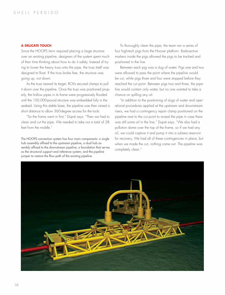
since the hooPs tie-in required placing a large structure over an existing pipeline, designers of the system spent much of their time thinking about how to do it safely. instead of try-ing to lower the heavy truss onto the pipe, the truss itself was designed to float. if the truss broke free, the structure was going up, not down.
as the truss neared its target, rovs secured clamps to pull it down over the pipeline. once the truss was positioned prop-erly, the hollow pipes in its frame were progressively flooded until the 100,000-pound structure was embedded fully in the seabed. using this stable base, the pipeline was then raised a short distance to allow 360-degree access for the tools.
“so the frame went in first,” Dupré says. “then we had to clean and cut the pipe. We needed to take out a total of 28 feet from the middle.”
The HOOPS connection system has four main components: a single hub assembly affixed to the upstream pipeline, a dual hub as-sembly affixed to the downstream pipeline, a foundation that serves as the structural support and reference system, and the pipeline jumper to restore the flow path of the existing pipeline.
to thoroughly clean the pipe, the team ran a series of four high-tech pigs from the hoover platform. radioactive markers inside the pigs allowed the pigs to be tracked and positioned in the line.
between each pig was a slug of water. Pigs one and two were allowed to pass the point where the pipeline would be cut, while pigs three and four were stopped before they reached the cut point. between pigs two and three, the pipe-line would contain only water, but no one wanted to take a chance on spilling any oil.
“in addition to the positioning of slugs of water and oper-ational procedures applied at the upstream and downstream risers, we had a contingency repair clamp positioned on the pipeline next to the cut point to re-seal the pipe in case there was still some oil in the line,” Dupré says. “We also had a pollution dome over the top of the frame, so if we had any oil, we could capture it and pump it into a subsea reservoir for recovery. We had all of these contingencies in place, but when we made the cut, nothing came out. the pipeline was completely clean.”
39
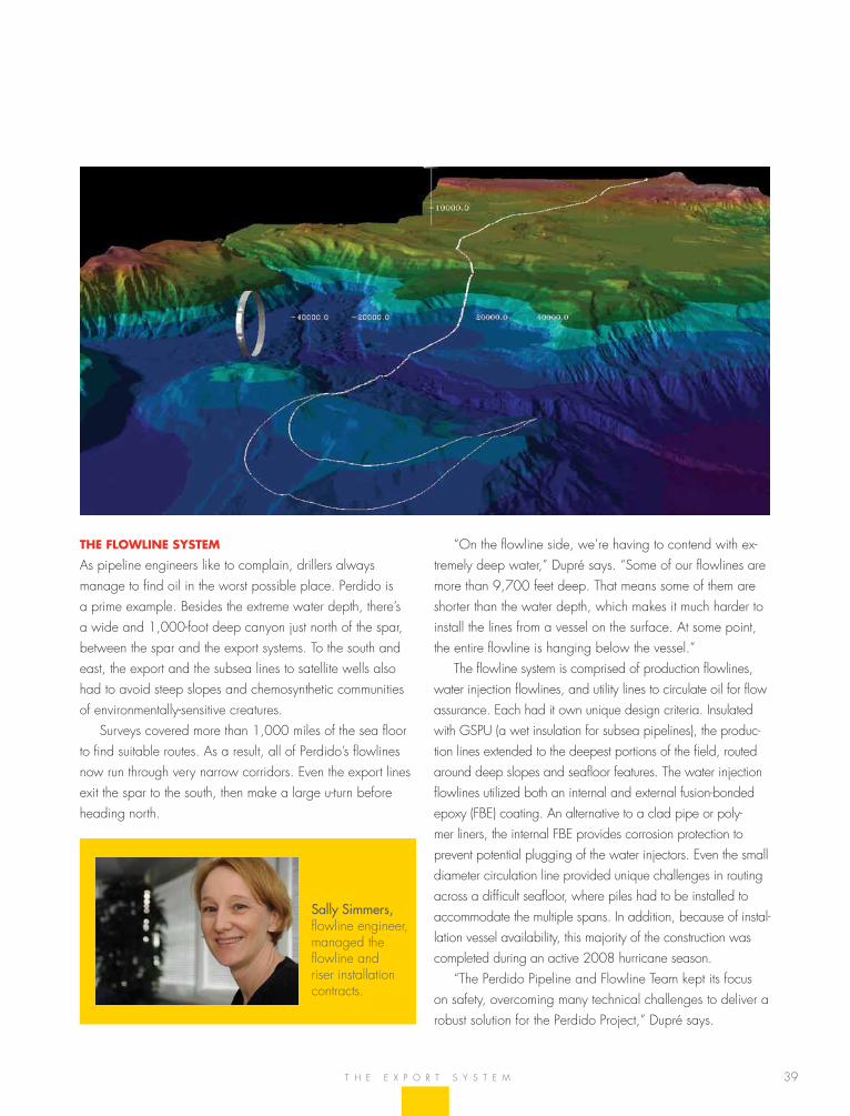
“on the flowline side, we’re having to contend with ex-tremely deep water,” Dupré says. “some of our flowlines are more than 9,700 feet deep. that means some of them are shorter than the water depth, which makes it much harder to install the lines from a vessel on the surface. at some point, the entire flowline is hanging below the vessel.”
the flowline system is comprised of production flowlines, water injection flowlines, and utility lines to circulate oil for flow assurance. each had it own unique design criteria. insulated with gsPu (a wet insulation for subsea pipelines), the produc-tion lines extended to the deepest portions of the field, routed around deep slopes and seafloor features. the water injection flowlines utilized both an internal and external fusion-bonded epoxy (fbe) coating. an alternative to a clad pipe or poly-mer liners, the internal fbe provides corrosion protection to prevent potential plugging of the water injectors. even the small diameter circulation line provided unique challenges in routing across a difficult seafloor, where piles had to be installed to accommodate the multiple spans. in addition, because of instal-lation vessel availability, this majority of the construction was completed during an active 2008 hurricane season.
“the Perdido Pipeline and flowline team kept its focus on safety, overcoming many technical challenges to deliver a robust solution for the Perdido Project,” Dupré says.
The flowline sysTem
as pipeline engineers like to complain, drillers always manage to find oil in the worst possible place. Perdido is a prime example. besides the extreme water depth, there’s a wide and 1,000-foot deep canyon just north of the spar, between the spar and the export systems. to the south and east, the export and the subsea lines to satellite wells also had to avoid steep slopes and chemosynthetic communities of environmentally-sensitive creatures.
surveys covered more than 1,000 miles of the sea floor to find suitable routes. as a result, all of Perdido’s flowlines now run through very narrow corridors. even the export lines exit the spar to the south, then make a large u-turn before heading north.
t h e e x P o r t s Y s t e m
Sally Simmers, flowline engineer, managed the flowline and riser installation contracts.
s h e l l P e r D i D o
41
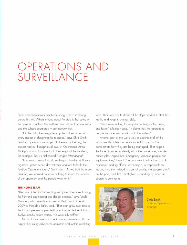
experienced operators practice running a new field long before first oil. What’s unique about Perdido is that some of the systems – such as the wet-tree direct vertical access wells and the subsea separators – are industry firsts.
“on Perdido, the design team pulled operations into every aspect of designing the topsides,” says Chris smith, Perdido operations manager. “at the end of the day, the project had our handprints all over it. operation’s arthur mcalpin was so instrumental in the design of the helideck, for example, that it’s nicknamed McAlpin International.”
“four years before first oil, we began drawing staff from eighteen upstream and downstream locations to build the Perdido operations team,” smith says. “as we built the orga-nization, we focused on team building to insure the success of our operation and the people who run it.”
The home TeAm
“the core of Perdido’s operating staff joined the project during the front-end engineering and design process,” says arnold marsden, who recently took over for bert garcia in april 2009 as Perdido’s safety lead. “that team grew over time to the full complement of people it takes to operate the platform. twelve months before startup, we were fully staffed.”
much of their time was spent running simulations, first on paper, then using advanced simulators and system modeling
tools. their job was to detail all the steps needed to start the facility and keep it running safely.
“they were looking for ways to do things safer, better, and faster,” marsden says. “in doing that, the operations people become very familiar with the system.”
another part of the work was to document all of the major health, safety and environmental risks, and to demonstrate how they are being managed. that helped the operations team identify all of the procedures, mainte-nance jobs, inspections, emergency response people and equipment they’d need. the goal was to minimize risks. a helicopter landing officer, for example, is responsible for making sure the helipad is clear of debris, that people aren’t on the pad, and that a firefighter is standing by when an aircraft is coming in.
o P e r a t i o n s a n D s u r v e i l l a n C e
oPerations anD surveillanCe
Chris Smith, Perdido operations manager
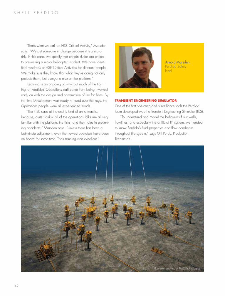
42
s h e l l P e r D i D o
“that’s what we call an hse Critical activity,” marsden says. “We put someone in charge because it is a major risk. in this case, we specify that certain duties are critical to preventing a major helicopter incident. We have identi-fied hundreds of hse Critical activities for different people. We make sure they know that what they’re doing not only protects them, but everyone else on the platform.”
learning is an ongoing activity, but much of the train-ing for Perdido’s operations staff came from being involved early on with the design and construction of the facilities. by the time Development was ready to hand over the keys, the operations people were all experienced hands.
“the hse case at the end is kind of anticlimactic, because, quite frankly, all of the operations folks are all very familiar with the platform, the risks, and their roles in prevent-ing accidents,” marsden says. “unless there has been a last-minute adjustment, even the newest operators have been on board for some time. their training was excellent.”
TrAnsienT engineering simulATor
one of the first operating and surveillance tools the Perdido team developed was the transient engineering simulator (tes).
“to understand and model the behavior of our wells, flowlines, and especially the artificial lift system, we needed to know Perdido’s fluid properties and flow conditions throughout the system,” says gill Purdy, Production technician.
illustration courtesy of fmC technologies
Arnold Marsden, Perdido safety lead
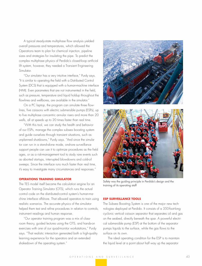
43
a typical steady-state multiphase flow analysis yielded overall pressures and temperatures, which allowed the operations team to plan for chemical injection, pipeline sizes and strategies for insulating the pipe. to predict the complex multiphase physics of Perdido’s closed-loop artificial lift system, however, they needed a transient engineering simulator.
“our simulator has a very intuitive interface,” Purdy says. “it is similar to operating the field with a Distributed Control system (DCs) that is equipped with a human-machine interface (hmi). even parameters that are not instrumented in the field, such as pressure, temperature and liquid holdup throughout the flowlines and wellbores, are available in the simulator.”
on a PC laptop, the program can simulate three flow-lines, five caissons with electric submersible pumps (esPs), up to five multiphase concentric annular risers and more than 20 wells, all at speeds up to 20 times faster than real time.
“With this tool, we can study the health and behavior of our esPs, manage the complex subsea boosting system and guide ourselves through transient situations, such as unplanned shutdowns,” Purdy says. “and since the simula-tor can run in a stand-alone mode, onshore surveillance support people can use it to optimize procedures as the field ages, or as a risk-management tool to study rare events such as aborted startups, interrupted blowdowns and cold-oil sweeps. since the interface runs much faster than real time, it’s easy to investigate many circumstances and responses.”
operATions TrAining simulATor
the tes model itself became the calculation engine for an operator training simulator (ots), which runs the actual control code on the distributed-control system’s human-ma-chine interface offshore. that allowed operators to train using realistic scenarios. the accurate physics of the simulator helped them test and refine procedures in relation to controls, instrument readings and human response.
“our operator training program was a mix of class-room theory, guided lectures using the ots, and hands-on exercises with one of our quad-monitor workstations,” Purdy says. “that realistic interaction generated both a high-quality learning experience for the operators and an extended shakedown of the operating system.”
o P e r a t i o n s a n D s u r v e i l l a n C e
esp surveillAnce Tools
the subsea boosting system is one of the major new tech-nologies deployed at Perdido. it consists of a 350-foot-long cyclonic vertical caisson separator that separates oil and gas on the seabed, directly beneath the spar. a powerful electri-cal submersible pump (esP) at the bottom of the separator pumps liquids to the surface, while the gas flows to the surface on its own.
the ideal operating condition for the esP is to maintain the liquid level at a point about half way up the separator
Safety was the guiding principle in Perdido’s design and the training of its operating staff
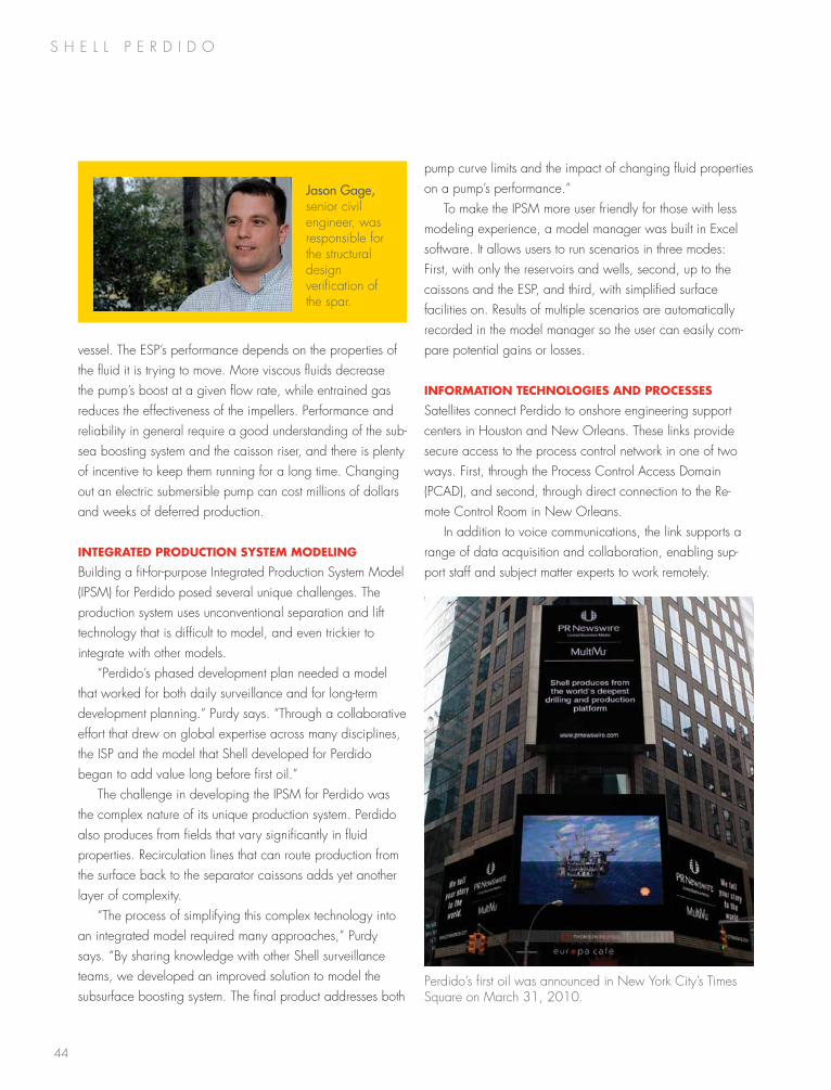
44
s h e l l P e r D i D o
pump curve limits and the impact of changing fluid properties on a pump’s performance.”
to make the iPsm more user friendly for those with less modeling experience, a model manager was built in excel software. it allows users to run scenarios in three modes: first, with only the reservoirs and wells, second, up to the caissons and the esP, and third, with simplified surface facilities on. results of multiple scenarios are automatically recorded in the model manager so the user can easily com-pare potential gains or losses.
informATion Technologies And processes
satellites connect Perdido to onshore engineering support centers in houston and new orleans. these links provide secure access to the process control network in one of two ways. first, through the Process Control access Domain (PCaD), and second, through direct connection to the re-mote Control room in new orleans.
in addition to voice communications, the link supports a range of data acquisition and collaboration, enabling sup-port staff and subject matter experts to work remotely.
vessel. the esP’s performance depends on the properties of the fluid it is trying to move. more viscous fluids decrease the pump’s boost at a given flow rate, while entrained gas reduces the effectiveness of the impellers. Performance and reliability in general require a good understanding of the sub-sea boosting system and the caisson riser, and there is plenty of incentive to keep them running for a long time. Changing out an electric submersible pump can cost millions of dollars and weeks of deferred production.
inTegrATed producTion sysTem modeling
building a fit-for-purpose integrated Production system model (iPsm) for Perdido posed several unique challenges. the production system uses unconventional separation and lift technology that is difficult to model, and even trickier to integrate with other models.
“Perdido’s phased development plan needed a model that worked for both daily surveillance and for long-term development planning.” Purdy says. “through a collaborative effort that drew on global expertise across many disciplines, the isP and the model that shell developed for Perdido began to add value long before first oil.”
the challenge in developing the iPsm for Perdido was the complex nature of its unique production system. Perdido also produces from fields that vary significantly in fluid properties. recirculation lines that can route production from the surface back to the separator caissons adds yet another layer of complexity.
“the process of simplifying this complex technology into an integrated model required many approaches,” Purdy says. “by sharing knowledge with other shell surveillance teams, we developed an improved solution to model the subsurface boosting system. the final product addresses both
Jason Gage, senior civil engineer, was responsible for the structural design verification of the spar.
Perdido’s first oil was announced in new York City’s times square on march 31, 2010.
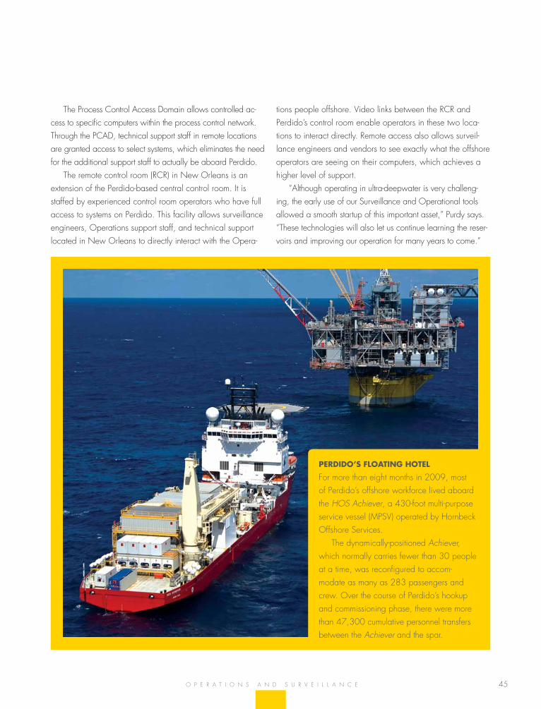
45
tions people offshore. video links between the rCr and Perdido’s control room enable operators in these two loca-tions to interact directly. remote access also allows surveil-lance engineers and vendors to see exactly what the offshore operators are seeing on their computers, which achieves a higher level of support.
“although operating in ultra-deepwater is very challeng-ing, the early use of our surveillance and operational tools allowed a smooth startup of this important asset,” Purdy says. “these technologies will also let us continue learning the reser-voirs and improving our operation for many years to come.”
the Process Control access Domain allows controlled ac-cess to specific computers within the process control network. through the PCaD, technical support staff in remote locations are granted access to select systems, which eliminates the need for the additional support staff to actually be aboard Perdido.
the remote control room (rCr) in new orleans is an extension of the Perdido-based central control room. it is staffed by experienced control room operators who have full access to systems on Perdido. this facility allows surveillance engineers, operations support staff, and technical support located in new orleans to directly interact with the opera-
o P e r a t i o n s a n D s u r v e i l l a n C e
perdido’s floATing hoTel
for more than eight months in 2009, most of Perdido’s offshore workforce lived aboard the HOS Achiever, a 430-foot multi-purpose service vessel (mPsv) operated by hornbeck offshore services.
the dynamically-positioned Achiever, which normally carries fewer than 30 people at a time, was reconfigured to accom-modate as many as 283 passengers and crew. over the course of Perdido’s hookup and commissioning phase, there were more than 47,300 cumulative personnel transfers between the Achiever and the spar.
46
COMPANY PROFILE
COMPANY PROFILE
FIshER® DIgItAL VALVEs wIth PREDICtIVE DIAgNOstICs PROVIDE OPtIMAL PERFORMANCE AND INCREAsE PROCEss sYstEM UPtIME
Emerson Process Management worked in
partnership with shell to develop and
manufacture nearly 100 custom and severe
service Fisher® digital valves. these valve
solutions cover all process control aspects
of the challenging, ultra-deepwater Perdido
platform located in the gulf of Mexico.
the Perdido platform’s central control
system utilizes Fisher digital valves with
Emerson-developed Asset Management
software (AMs™) and the AMs ValveLink™
sNAP-ON™ application to monitor the
process control equipment for optimal
performance. this unique software solution
utilizes predictive diagnostics to open a
window to the process by giving a view of
the valve’s actual position and operating
characteristics as well as diagnostics of the
entire valve assembly and instrument.
Utilizing reliable Fisher digital valves
with performance diagnostics has provided
Perdido personnel the opportunity to make
better-informed decisions, leading to increased
safety, increased availability, reduced
variability, process optimization, increased
throughput and enhanced product quality.
Emerson Process ManagementFisher Controls International LLC301 s. 1st Ave.Marshalltown, IA 50158www.emersonprocess.com/fisher
Fisher digital valves with predictive diagnostics provide Shell with the power to improve process availability and increase platform reliability.
Company Page
Alliance wood group Engineering, L.P. 47
Baker hughes 48
Emerson Process Management- 46
Federal Flange, Inc. 51
FMC 52
gE Oil and gas 54
heerema Marine Contractors 53
halliburton 56
helmerich & Payne IDC 60
hornbeck Offshore services 58
Kiewit Offshore 61
Noble Drilling 62
Oceaneering 64
schlumberger 66
technip 68
the Bayou Companies, Inc. 63
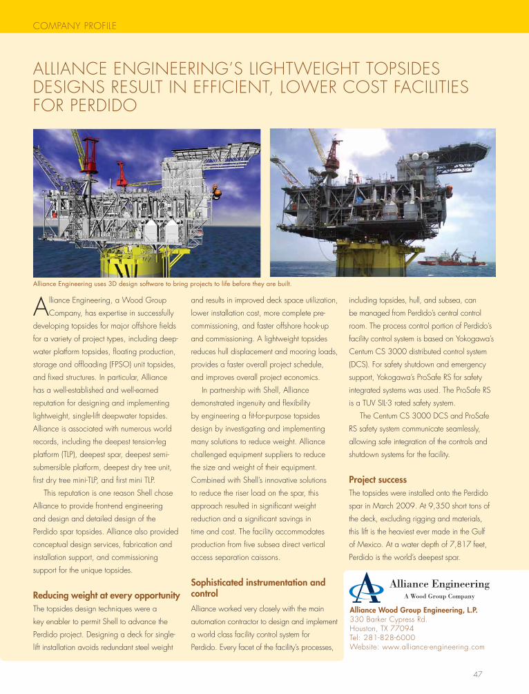
47
COMPANY PROFILE
ALLIANCE ENgINEERINg’s LIghtwEIght tOPsIDEs DEsIgNs REsULt IN EFFICIENt, LOwER COst FACILItIEs FOR PERDIDO
Alliance Engineering, a wood group
Company, has expertise in successfully
developing topsides for major offshore fields
for a variety of project types, including deep-
water platform topsides, floating production,
storage and offloading (FPsO) unit topsides,
and fixed structures. In particular, Alliance
has a well-established and well-earned
reputation for designing and implementing
lightweight, single-lift deepwater topsides.
Alliance is associated with numerous world
records, including the deepest tension-leg
platform (tLP), deepest spar, deepest semi-
submersible platform, deepest dry tree unit,
first dry tree mini-tLP, and first mini tLP.
this reputation is one reason shell chose
Alliance to provide front-end engineering
and design and detailed design of the
Perdido spar topsides. Alliance also provided
conceptual design services, fabrication and
installation support, and commissioning
support for the unique topsides.
Reducing weight at every opportunitythe topsides design techniques were a
key enabler to permit shell to advance the
Perdido project. Designing a deck for single-
lift installation avoids redundant steel weight
and results in improved deck space utilization,
lower installation cost, more complete pre-
commissioning, and faster offshore hook-up
and commissioning. A lightweight topsides
reduces hull displacement and mooring loads,
provides a faster overall project schedule,
and improves overall project economics.
In partnership with shell, Alliance
demonstrated ingenuity and flexibility
by engineering a fit-for-purpose topsides
design by investigating and implementing
many solutions to reduce weight. Alliance
challenged equipment suppliers to reduce
the size and weight of their equipment.
Combined with shell’s innovative solutions
to reduce the riser load on the spar, this
approach resulted in significant weight
reduction and a significant savings in
time and cost. the facility accommodates
production from five subsea direct vertical
access separation caissons.
Sophisticated instrumentation and control
Alliance worked very closely with the main
automation contractor to design and implement
a world class facility control system for
Perdido. Every facet of the facility’s processes,
including topsides, hull, and subsea, can
be managed from Perdido’s central control
room. the process control portion of Perdido’s
facility control system is based on Yokogawa’s
Centum Cs 3000 distributed control system
(DCs). For safety shutdown and emergency
support, Yokogawa’s Prosafe Rs for safety
integrated systems was used. the Prosafe Rs
is a tUV sIL-3 rated safety system.
the Centum Cs 3000 DCs and Prosafe
Rs safety system communicate seamlessly,
allowing safe integration of the controls and
shutdown systems for the facility.
Project successthe topsides were installed onto the Perdido
spar in March 2009. At 9,350 short tons of
the deck, excluding rigging and materials,
this lift is the heaviest ever made in the gulf
of Mexico. At a water depth of 7,817 feet,
Perdido is the world’s deepest spar.
Alliance Engineering uses 3D design software to bring projects to life before they are built.
Alliance Wood Group Engineering, L.P. 330 Barker Cypress Rd.houston, tX 77094tel: 281-828-6000website: www.alliance-engineering.com
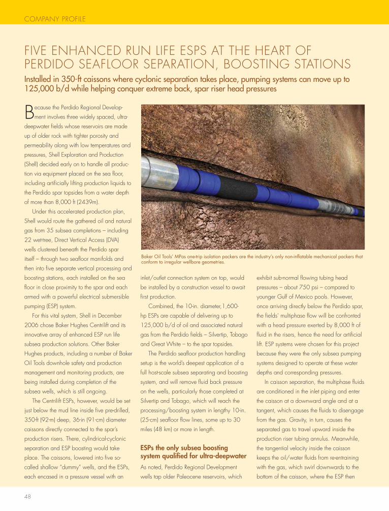
48
COMPANY PROFILE
Because the Perdido Regional Develop-
ment involves three widely spaced, ultra-
deepwater fields whose reservoirs are made
up of older rock with tighter porosity and
permeability along with low temperatures and
pressures, shell Exploration and Production
(shell) decided early on to handle all produc-
tion via equipment placed on the sea floor,
including artificially lifting production liquids to
the Perdido spar topsides from a water depth
of more than 8,000 ft (2439m).
Under this accelerated production plan,
shell would route the gathered oil and natural
gas from 35 subsea completions – including
22 wet-tree, Direct Vertical Access (DVA)
wells clustered beneath the Perdido spar
itself – through two seafloor manifolds and
then into five separate vertical processing and
boosting stations, each installed on the sea
floor in close proximity to the spar and each
armed with a powerful electrical submersible
pumping (EsP) system.
For this vital system, shell in December
2006 chose Baker hughes Centrilift and its
innovative array of enhanced EsP run life
subsea production solutions. Other Baker
hughes products, including a number of Baker
Oil tools downhole safety and production
management and monitoring products, are
being installed during completion of the
subsea wells, which is still ongoing.
the Centrilift EsPs, however, would be set
just below the mud line inside five pre-drilled,
350-ft (92-m) deep, 36-in (91-cm) diameter
caissons directly connected to the spar’s
production risers. there, cylindrical-cyclonic
separation and EsP boosting would take
place. the caissons, lowered into five so-
called shallow “dummy” wells, and the EsPs,
each encased in a pressure vessel with an
inlet/outlet connection system on top, would
be installed by a construction vessel to await
first production.
Combined, the 10-in. diameter,1,600-
hp EsPs are capable of delivering up to
125,000 b/d of oil and associated natural
gas from the Perdido fields – silvertip, tobago
and great white – to the spar topsides.
the Perdido seafloor production handling
setup is the world’s deepest application of a
full host-scale subsea separating and boosting
system, and will remove fluid back pressure
on the wells, particularly those completed at
silvertip and tobago, which will reach the
processing/boosting system in lengthy 10-in.
(25-cm) seafloor flow lines, some up to 30
miles (48 km) or more in length.
ESPs the only subsea boosting system qualified for ultra-deepwater
As noted, Perdido Regional Development
wells tap older Paleocene reservoirs, which
exhibit sub-normal flowing tubing head
pressures – about 750 psi – compared to
younger gulf of Mexico pools. however,
once arriving directly below the Perdido spar,
the fields’ multiphase flow will be confronted
with a head pressure exerted by 8,000 ft of
fluid in the risers, hence the need for artificial
lift. EsP systems were chosen for this project
because they were the only subsea pumping
systems designed to operate at these water
depths and corresponding pressures.
In caisson separation, the multiphase fluids
are conditioned in the inlet piping and enter
the caisson at a downward angle and at a
tangent, which causes the fluids to disengage
from the gas. gravity, in turn, causes the
separated gas to travel upward inside the
production riser tubing annulus. Meanwhile,
the tangential velocity inside the caisson
keeps the oil/water fluids from re-entraining
with the gas, which swirl downwards to the
bottom of the caisson, where the EsP then
FIVE ENhANCED RUN LIFE EsPs At thE hEARt OF PERDIDO sEAFLOOR sEPARAtION, BOOstINg stAtIONsInstalledin350-ftcaissonswherecyclonicseparationtakesplace,pumpingsystemscanmoveupto125,000b/dwhilehelpingconquerextremeback,sparriserheadpressures
Baker Oil Tools’ MPas one-trip isolation packers are the industry’s only non-inflatable mechanical packers that conform to irregular wellbore geometries.
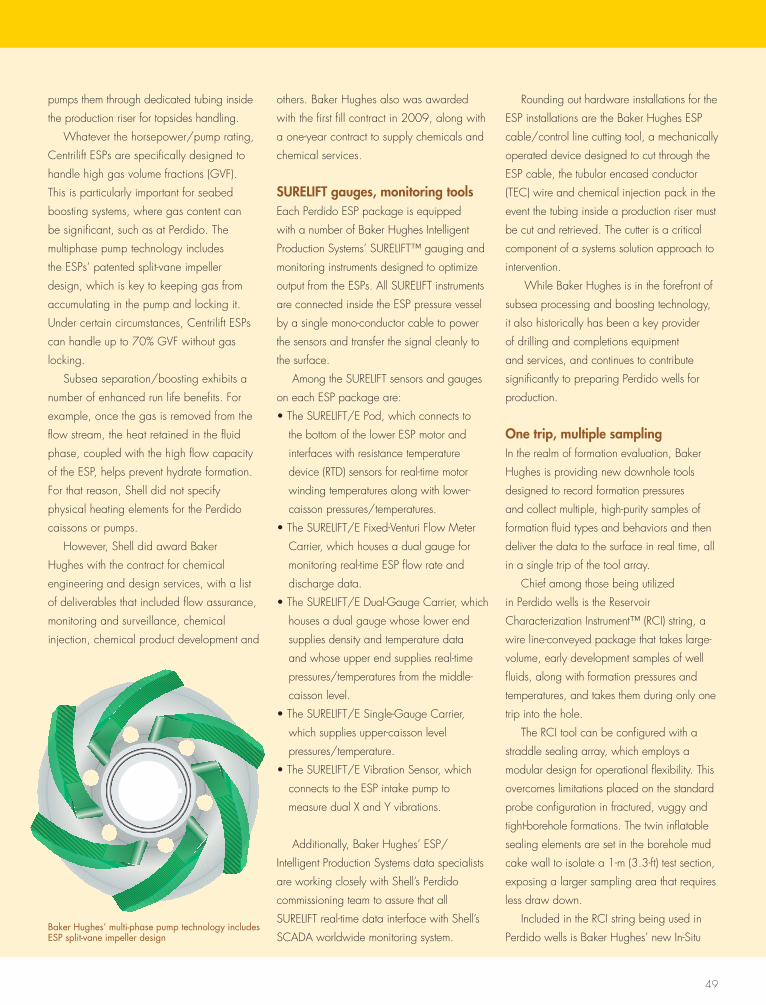
49
pumps them through dedicated tubing inside
the production riser for topsides handling.
whatever the horsepower/pump rating,
Centrilift EsPs are specifically designed to
handle high gas volume fractions (gVF).
this is particularly important for seabed
boosting systems, where gas content can
be significant, such as at Perdido. the
multiphase pump technology includes
the EsPs’ patented split-vane impeller
design, which is key to keeping gas from
accumulating in the pump and locking it.
Under certain circumstances, Centrilift EsPs
can handle up to 70% gVF without gas
locking.
subsea separation/boosting exhibits a
number of enhanced run life benefits. For
example, once the gas is removed from the
flow stream, the heat retained in the fluid
phase, coupled with the high flow capacity
of the EsP, helps prevent hydrate formation.
For that reason, shell did not specify
physical heating elements for the Perdido
caissons or pumps.
however, shell did award Baker
hughes with the contract for chemical
engineering and design services, with a list
of deliverables that included flow assurance,
monitoring and surveillance, chemical
injection, chemical product development and
others. Baker hughes also was awarded
with the first fill contract in 2009, along with
a one-year contract to supply chemicals and
chemical services.
SURELIFT gauges, monitoring toolsEach Perdido EsP package is equipped
with a number of Baker hughes Intelligent
Production systems’ sURELIFt™ gauging and
monitoring instruments designed to optimize
output from the EsPs. All sURELIFt instruments
are connected inside the EsP pressure vessel
by a single mono-conductor cable to power
the sensors and transfer the signal cleanly to
the surface.
Among the sURELIFt sensors and gauges
on each EsP package are:
• the sURELIFt/E Pod, which connects to
the bottom of the lower EsP motor and
interfaces with resistance temperature
device (RtD) sensors for real-time motor
winding temperatures along with lower-
caisson pressures/temperatures.
• the sURELIFt/E Fixed-Venturi Flow Meter
Carrier, which houses a dual gauge for
monitoring real-time EsP flow rate and
discharge data.
• the sURELIFt/E Dual-gauge Carrier, which
houses a dual gauge whose lower end
supplies density and temperature data
and whose upper end supplies real-time
pressures/temperatures from the middle-
caisson level.
• the sURELIFt/E single-gauge Carrier,
which supplies upper-caisson level
pressures/temperature.
• the sURELIFt/E Vibration sensor, which
connects to the EsP intake pump to
measure dual X and Y vibrations.
Additionally, Baker hughes’ EsP/
Intelligent Production systems data specialists
are working closely with shell’s Perdido
commissioning team to assure that all
sURELIFt real-time data interface with shell’s
sCADA worldwide monitoring system.
Rounding out hardware installations for the
EsP installations are the Baker hughes EsP
cable/control line cutting tool, a mechanically
operated device designed to cut through the
EsP cable, the tubular encased conductor
(tEC) wire and chemical injection pack in the
event the tubing inside a production riser must
be cut and retrieved. the cutter is a critical
component of a systems solution approach to
intervention.
while Baker hughes is in the forefront of
subsea processing and boosting technology,
it also historically has been a key provider
of drilling and completions equipment
and services, and continues to contribute
significantly to preparing Perdido wells for
production.
One trip, multiple samplingIn the realm of formation evaluation, Baker
hughes is providing new downhole tools
designed to record formation pressures
and collect multiple, high-purity samples of
formation fluid types and behaviors and then
deliver the data to the surface in real time, all
in a single trip of the tool array.
Chief among those being utilized
in Perdido wells is the Reservoir
Characterization Instrument™ (RCI) string, a
wire line-conveyed package that takes large-
volume, early development samples of well
fluids, along with formation pressures and
temperatures, and takes them during only one
trip into the hole.
the RCI tool can be configured with a
straddle sealing array, which employs a
modular design for operational flexibility. this
overcomes limitations placed on the standard
probe configuration in fractured, vuggy and
tight-borehole formations. the twin inflatable
sealing elements are set in the borehole mud
cake wall to isolate a 1-m (3.3-ft) test section,
exposing a larger sampling area that requires
less draw down.
Included in the RCI string being used in
Perdido wells is Baker hughes’ new In-situ Baker Hughes’ multi-phase pump technology includes ESP split-vane impeller design
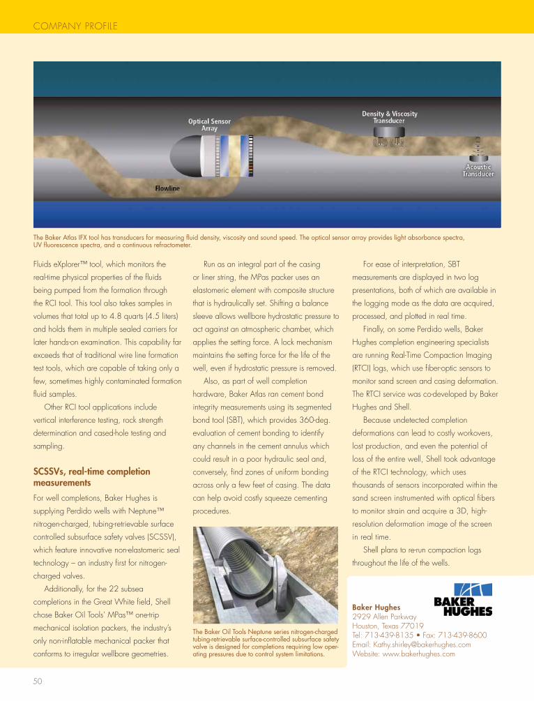
50
COMPANY PROFILE
Fluids eXplorer™ tool, which monitors the
real-time physical properties of the fluids
being pumped from the formation through
the RCI tool. this tool also takes samples in
volumes that total up to 4.8 quarts (4.5 liters)
and holds them in multiple sealed carriers for
later hands-on examination. this capability far
exceeds that of traditional wire line formation
test tools, which are capable of taking only a
few, sometimes highly contaminated formation
fluid samples.
Other RCI tool applications include
vertical interference testing, rock strength
determination and cased-hole testing and
sampling.
SCSSVs, real-time completion measurements
For well completions, Baker hughes is
supplying Perdido wells with Neptune™
nitrogen-charged, tubing-retrievable surface
controlled subsurface safety valves (sCssV),
which feature innovative non-elastomeric seal
technology – an industry first for nitrogen-
charged valves.
Additionally, for the 22 subsea
completions in the great white field, shell
chose Baker Oil tools’ MPas™ one-trip
mechanical isolation packers, the industry’s
only non-inflatable mechanical packer that
conforms to irregular wellbore geometries.
Run as an integral part of the casing
or liner string, the MPas packer uses an
elastomeric element with composite structure
that is hydraulically set. shifting a balance
sleeve allows wellbore hydrostatic pressure to
act against an atmospheric chamber, which
applies the setting force. A lock mechanism
maintains the setting force for the life of the
well, even if hydrostatic pressure is removed.
Also, as part of well completion
hardware, Baker Atlas ran cement bond
integrity measurements using its segmented
bond tool (sBt), which provides 360-deg.
evaluation of cement bonding to identify
any channels in the cement annulus which
could result in a poor hydraulic seal and,
conversely, find zones of uniform bonding
across only a few feet of casing. the data
can help avoid costly squeeze cementing
procedures.
For ease of interpretation, sBt
measurements are displayed in two log
presentations, both of which are available in
the logging mode as the data are acquired,
processed, and plotted in real time.
Finally, on some Perdido wells, Baker
hughes completion engineering specialists
are running Real-time Compaction Imaging
(RtCI) logs, which use fiber-optic sensors to
monitor sand screen and casing deformation.
the RtCI service was co-developed by Baker
hughes and shell.
Because undetected completion
deformations can lead to costly workovers,
lost production, and even the potential of
loss of the entire well, shell took advantage
of the RtCI technology, which uses
thousands of sensors incorporated within the
sand screen instrumented with optical fibers
to monitor strain and acquire a 3D, high-
resolution deformation image of the screen
in real time.
shell plans to re-run compaction logs
throughout the life of the wells.
Baker Hughes2929 Allen Parkwayhouston, texas 77019tel: 713-439-8135 • Fax: 713-439-8600Email: [email protected]: www.bakerhughes.com
The Baker Atlas IFX tool has transducers for measuring fluid density, viscosity and sound speed. The optical sensor array provides light absorbance spectra, UV fluorescence spectra, and a continuous refractometer.
COMPANY PROFILE
The Baker Oil Tools Neptune series nitrogen-charged tubing-retrievable surface-controlled subsurface safety valve is designed for completions requiring low oper-ating pressures due to control system limitations.
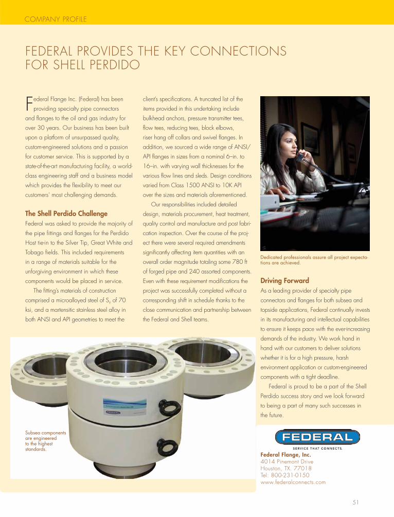
51
COMPANY PROFILE
FEDERAL PROVIDEs thE KEY CONNECtIONs FOR shELL PERDIDO
Federal Flange Inc. (Federal) has been
providing specialty pipe connectors
and flanges to the oil and gas industry for
over 30 years. Our business has been built
upon a platform of unsurpassed quality,
custom-engineered solutions and a passion
for customer service. this is supported by a
state-of-the-art manufacturing facility, a world-
class engineering staff and a business model
which provides the flexibility to meet our
customers’ most challenging demands.
The Shell Perdido ChallengeFederal was asked to provide the majority of
the pipe fittings and flanges for the Perdido
host tie-in to the silver tip, great white and
tobago fields. this included requirements
in a range of materials suitable for the
unforgiving environment in which these
components would be placed in service.
the fitting’s materials of construction
comprised a microalloyed steel of sY of 70
ksi, and a martensitic stainless steel alloy in
both ANsI and API geometries to meet the
client’s specifications. A truncated list of the
items provided in this undertaking include
bulkhead anchors, pressure transmitter tees,
flow tees, reducing tees, block elbows,
riser hang off collars and swivel flanges. In
addition, we sourced a wide range of ANsI/
API flanges in sizes from a nominal 6–in. to
16–in. with varying wall thicknesses for the
various flow lines and sleds. Design conditions
varied from Class 1500 ANsI to 10K API
over the sizes and materials aforementioned.
Our responsibilities included detailed
design, materials procurement, heat treatment,
quality control and manufacture and post fabri-
cation inspection. Over the course of the proj-
ect there were several required amendments
significantly affecting item quantities with an
overall order magnitude totaling some 780 ft
of forged pipe and 240 assorted components.
Even with these requirement modifications the
project was successfully completed without a
corresponding shift in schedule thanks to the
close communication and partnership between
the Federal and shell teams.
Driving ForwardAs a leading provider of specialty pipe
connectors and flanges for both subsea and
topside applications, Federal continually invests
in its manufacturing and intellectual capabilities
to ensure it keeps pace with the ever-increasing
demands of the industry. we work hand in
hand with our customers to deliver solutions
whether it is for a high pressure, harsh
environment application or custom-engineered
components with a tight deadline.
Federal is proud to be a part of the shell
Perdido success story and we look forward
to being a part of many such successes in
the future.
Dedicated professionals assure all project expecta-tions are achieved.
Federal Flange, Inc.4014 Pinemont Drivehouston, tX. 77018tel: 800-231-0150www.federalconnects.com
Subsea components are engineered to the highest standards.
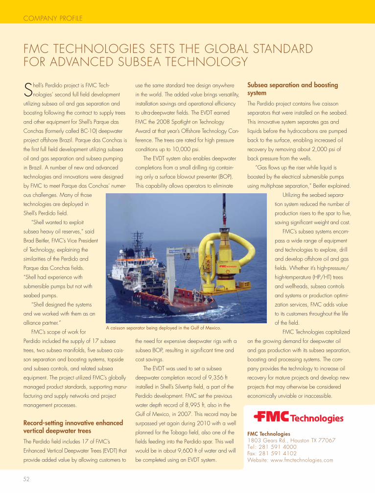
52
COMPANY PROFILE
FMC tEChNOLOgIEs sEts thE gLOBAL stANDARD FOR ADVANCED sUBsEA tEChNOLOgY
shell’s Perdido project is FMC tech-
nologies’ second full field development
utilizing subsea oil and gas separation and
boosting following the contract to supply trees
and other equipment for shell’s Parque das
Conchas (formerly called BC-10) deepwater
project offshore Brazil. Parque das Conchas is
the first full field development utilizing subsea
oil and gas separation and subsea pumping
in Brazil. A number of new and advanced
technologies and innovations were designed
by FMC to meet Parque das Conchas’ numer-
ous challenges. Many of those
technologies are deployed in
shell’s Perdido field.
“shell wanted to exploit
subsea heavy oil reserves,” said
Brad Beitler, FMC’s Vice President
of technology, explaining the
similarities of the Perdido and
Parque das Conchas fields.
“shell had experience with
submersible pumps but not with
seabed pumps.
“shell designed the systems
and we worked with them as an
alliance partner.”
FMC’s scope of work for
Perdido included the supply of 17 subsea
trees, two subsea manifolds, five subsea cais-
son separation and boosting systems, topside
and subsea controls, and related subsea
equipment. the project utilized FMC’s globally
managed product standards, supporting manu-
facturing and supply networks and project
management processes.
Record-setting innovative enhanced vertical deepwater trees
the Perdido field includes 17 of FMC’s
Enhanced Vertical Deepwater trees (EVDt) that
provide added value by allowing customers to
use the same standard tree design anywhere
in the world. the added value brings versatility,
installation savings and operational efficiency
to ultra-deepwater fields. the EVDt earned
FMC the 2008 spotlight on technology
Award at that year’s Offshore technology Con-
ference. the trees are rated for high pressure
conditions up to 10,000 psi.
the EVDt system also enables deepwater
completions from a small drilling rig contain-
ing only a surface blowout preventer (BOP).
this capability allows operators to eliminate
the need for expensive deepwater rigs with a
subsea BOP, resulting in significant time and
cost savings.
the EVDt was used to set a subsea
deepwater completion record of 9,356 ft
installed in shell’s silvertip field, a part of the
Perdido development. FMC set the previous
water depth record of 8,995 ft, also in the
gulf of Mexico, in 2007. this record may be
surpassed yet again during 2010 with a well
planned for the tobago field, also one of the
fields feeding into the Perdido spar. this well
would be in about 9,600 ft of water and will
be completed using an EVDt system.
Subsea separation and boosting system
the Perdido project contains five caisson
separators that were installed on the seabed.
this innovative system separates gas and
liquids before the hydrocarbons are pumped
back to the surface, enabling increased oil
recovery by removing about 2,000 psi of
back pressure from the wells.
“gas flows up the riser while liquid is
boosted by the electrical submersible pumps
using multiphase separation,” Beitler explained.
Utilizing the seabed separa-
tion system reduced the number of
production risers to the spar to five,
saving significant weight and cost.
FMC’s subsea systems encom-
pass a wide range of equipment
and technologies to explore, drill
and develop offshore oil and gas
fields. whether it’s high-pressure/
high-temperature (hP/ht) trees
and wellheads, subsea controls
and systems or production optimi-
zation services, FMC adds value
to its customers throughout the life
of the field.
FMC technologies capitalized
on the growing demand for deepwater oil
and gas production with its subsea separation,
boosting and processing systems. the com-
pany provides the technology to increase oil
recovery for mature projects and develop new
projects that may otherwise be considered
economically unviable or inaccessible.
A caisson separator being deployed in the Gulf of Mexico.
FMC Technologies1803 gears Rd., houston tX 77067 tel : 281 591 4000 Fax: 281 591 4102website: www.fmctechnologies.com
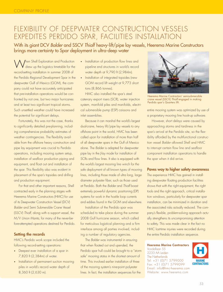
53
COMPANY PROFILE
FLEXIBILItY OF DEEPwAtER CONstRUCtION VEssELs EXPEDItEs PERDIDO sPAR, FACILItIEs INstALLAtION WithitsgiantDCVBalderandSSCVThialfheavy-lift/pipelayvessels,HeeremaMarineConstructorsbringsmorecertaintytoSpardeploymentinultra-deepwater
when shell Exploration and Production
drew up the logistics timetable for the
record-setting installation in summer 2008 of
the Perdido Regional Development spar in the
deepwater gulf of Mexico (gOM), the com-
pany could not have accurately anticipated
that pre-installation operations would be con-
fronted by not one, but two major hurricanes
and at least two significant tropical storms.
such unsettled weather could have increased
the potential for significant delays.
Fortunately, this was not the case, thanks
to significantly detailed pre-planning, includ-
ing comprehensive probability estimates of
weather contingencies. the flexibility avail-
able from the offshore heavy construction and
pipe lay equipment was crucial to Perdido
operations, including mooring system setup,
installation of seafloor production piping and
equipment, and float out and installation of
the spar. this flexibility also was evident in
placement of the spar’s topsides and drilling
and production equipment.
For that and other important reasons, shell
contracted early in the planning stages with
heerema Marine Constructors (hMC) for use
of its Deepwater Construction Vessel (DCV)
Balder and semi submersible Crane Vessel
(ssCV) Thialf, along with a support vessel, the
M/V Union Manta, for many of the never-be-
fore-attempted operations destined for Perdido.
Setting the recordshMC’s Perdido work scope included the
following record-setting operations:
• Deepest ever installation of a spar in
7,820 ft (2,384m) of water.
• Installation of permanent suction mooring
piles in world’s record water depth of
8,360 ft (2,630 m).
• Installation of production flow lines and
pipeline end structures in world’s record
water depth at 9,790 ft (2,984m).
• Installation of integrated topsides (new
gOM record lift weight at 9,773 short
tons (8,866 tonnes).
hMC also installed the spar’s steel
catenary export risers (sCR), water injection
system, manifold piles and manifolds, electri-
cal submersible pump (EsP) caissons and
inlet assemblies.
Because it can marshal the world’s largest
dual-crane, heavy lift/pipe lay vessels to any
offshore point in the world, hMC has been
called upon for installation of more than half
of all deepwater spars in the gulf of Mexico
alone. the Balder is adapted for deepwater
pipe lay in the J-lay mode for installation of
sCRs and flow lines. It also is equipped with
the world’s largest mooring line winch for the
safe deployment of all known types of mooring
lines, including those made of ultra long, large-
diameter polyester fiber, such as those used
at Perdido. Both the Balder and Thialf boast
extremely powerful dynamic positioning (DP)
systems for work in the hostile loop currents
and eddies found in the gOM and elsewhere.
Installation of the Perdido spar was
scheduled to take place during the summer
2008 gulf hurricane season, which called
for meticulous logistical planning and a firm
interface among all parties involved, includ-
ing a number of regulatory agencies.
the Balder was instrumental in ensuring
that when floated out and upended, the
Perdido spar hull could be brought to a “storm
safe” mooring status in the shortest amount of
time. this involved earlier installation of three
of the mooring system’s nine-point polyester
lines. In fact, the installation sequences for the
entire mooring system was optimized by use of
a proprietary mooring line hook-up software.
however, short delays were caused by
approaching storms and tardiness in the
spar’s arrival at the Perdido site, so the flex-
ibility afforded by the multifunctional construc-
tion vessel Balder allowed shell and hMC
to interrupt certain flow line and seafloor
component installation operations to handle
the spar when it did arrive.
Paves way to higher safety awarenessthe experience hMC has gained in install-
ing deepwater floating production facilities
shows that with the right equipment, the right
tools and the right approach, critical installa-
tion windows, particularly for deepwater spar
installation, can be minimized in duration and
the associated risks actually reduced. the com-
pany’s flexible, problem-solving approach actu-
ally strengthens its uncompromising attention
to safety. this was made clear in the fact no
hMC lost-time injuries were recorded during
the entire Perdido installation sequence.
Heerema Marine Contractors’ semisubmersible crane vessel (SSCV) Thialf engaged in making Perdido spar’s Quarters lift.
Heerema Marine ContractorsVondellaan 552233 AA Leidenthe Netherlandstel: +31 (0)71 5799000Fax: +31 (0)71 5799099Email: [email protected]: www.heerema.com
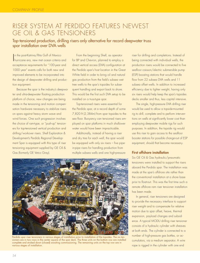
54
COMPANY PROFILE
RIsER sYstEM At PERDIDO FEAtUREs NEwEst gE OIL & gAs tENsIONERsTop-tensionedproduction,drillingrisersonlyalternativeforrecorddeepwatertrusssparinstallationoverDVAwells
In the post-Katrina/Rita gulf of Mexico
hurricane era, new met ocean criteria and
acceptance requirements for “100-year and
1000 year” events calls for both new and
improved elements to be incorporated into
the design of deepwater drilling and produc-
tion equipment.
Because the spar is the industry’s deepwa-
ter and ultra-deepwater floating production
platform of choice, new changes are being
made in the tensioning and motion compen-
sation hardware necessary to stabilize risers
on spars against heavy storm wave and
wind forces. One such progression involves
the choice of ram-type, or “push-up” tension-
ers for top-tensioned vertical production and
drilling/workover risers. shell Exploration &
Development’s Perdido Regional Develop-
ment spar is equipped with this type of riser
tensioning equipment supplied by gE Oil &
gas (formerly gE Vetco gray).
From the beginning shell, as operator
for BP and Chevron, planned to employ a
direct vertical access (DVA) configuration at
the Perdido spar’s host location in the great
white field in order to bring oil and natural
gas production from the field’s subsea wet
tree wells to the spar’s topsides for subse-
quent handling and export back to shore.
this would be the first such DVA setup to be
installed on a truss-type spar.
top-tensioned risers were essential for
the Perdido spar, at a record depth of some
7,820 ft (2,384m) from spar topsides to the
sea floor. Buoyancy can tensioned risers em-
ployed on spar platforms in much shallower
water would have been impracticable.
Additionally, instead of having a riser
and dry tree for each well, the spar would
be equipped with only six risers – five pipe-
in-pipe risers for handling production from
multiple subsea wells and one high-pressure
riser for drilling and completions. Instead of
being connected with individual wells, the
production risers would be connected to five
seafloor caisson/electric submersible pump
(EsP) boosting stations that would handle
flow from 22 subsea DVA wells and 11
subsea offset wells. In addition to increased
efficiency due to lighter weight, having only
six risers would help keep the spar’s topsides
decks smaller and thus, less capital intensive.
the single, high-pressure DVA drilling riser
would be used to allow a topside-mounted
rig to drill, complete and to perform interven-
tions on wells at significantly lower cost than
employing deepwater mobile rigs for such
purposes. In addition, the topside rig would
use this riser to gain access to the seafloor
booster stations for possible change-out of EsP
equipment, should that become necessary.
First offshore installationsix gE Oil & gas hydraulic/pneumatic
tensioners were installed to support the risers
aboard the Perdido spar. the installation was
made at the spar’s offshore site rather than
the conventional installation at a shore base
prior to float-out. this was the first time such a
remote offshore ram riser tensioner installation
has been made.
In general, riser tensioners are designed
to provide the necessary interface to support
riser weight and to compensate for relative
motion due to spar offset, heave, thermal
expansion, payload changes and subsid-
ence. A typical MODU drilling riser tensioner
consists of a hydraulic cylinder with sheaves
at both ends. the cylinder is connected to a
number of high-pressure gas bottles, or ac-
cumulators, via a medium separator. A wire
rope is rigged in the cylinder with one end
Perdido spar riser tensioners in various stages of installation prior to installation of the topsides. The six ten-sioners are in two rows in the center square of the spar deck. The three units on the bottom row are installed complete and stroked down (closed) awaiting commissioning. The remaining units on the top row are in various stages of installation.
COMPANY PROFILE
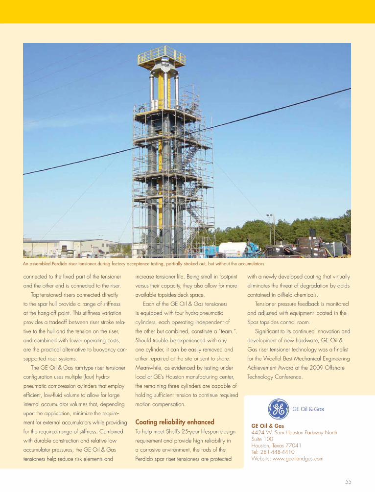
55
connected to the fixed part of the tensioner
and the other end is connected to the riser.
top-tensioned risers connected directly
to the spar hull provide a range of stiffness
at the hang-off point. this stiffness variation
provides a tradeoff between riser stroke rela-
tive to the hull and the tension on the riser,
and combined with lower operating costs,
are the practical alternative to buoyancy can-
supported riser systems.
the gE Oil & gas ram-type riser tensioner
configuration uses multiple (four) hydro-
pneumatic compression cylinders that employ
efficient, low-fluid volume to allow for large
internal accumulator volumes that, depending
upon the application, minimize the require-
ment for external accumulators while providing
for the required range of stiffness. Combined
with durable construction and relative low
accumulator pressures, the gE Oil & gas
tensioners help reduce risk elements and
increase tensioner life. Being small in footprint
versus their capacity, they also allow for more
available topsides deck space.
Each of the gE Oil & gas tensioners
is equipped with four hydro-pneumatic
cylinders, each operating independent of
the other but combined, constitute a “team.”.
should trouble be experienced with any
one cylinder, it can be easily removed and
either repaired at the site or sent to shore.
Meanwhile, as evidenced by testing under
load at gE’s houston manufacturing center,
the remaining three cylinders are capable of
holding sufficient tension to continue required
motion compensation.
Coating reliability enhancedto help meet shell’s 25-year lifespan design
requirement and provide high reliability in
a corrosive environment, the rods of the
Perdido spar riser tensioners are protected
with a newly developed coating that virtually
eliminates the threat of degradation by acids
contained in oilfield chemicals.
tensioner pressure feedback is monitored
and adjusted with equipment located in the
spar topsides control room.
significant to its continued innovation and
development of new hardware, gE Oil &
gas riser tensioner technology was a finalist
for the woelfel Best Mechanical Engineering
Achievement Award at the 2009 Offshore
technology Conference.
An assembled Perdido riser tensioner during factory acceptance testing, partially stroked out, but without the accumulators.
GE Oil & Gas4424 w. sam houston Parkway Northsuite 100houston, texas 77041tel: 281-448-4410website: www.geoilandgas.com
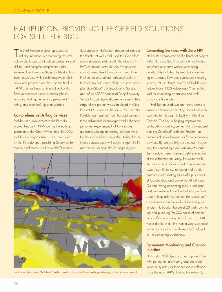
56
COMPANY PROFILE
hALLIBURtON PROVIDINg LIFE-OF-FIELD sOLUtIONs FOR shELL PERDIDO
the shell Perdido project represents an
industry milestone in overcoming the tech-
nology challenges of ultra-deep waters, subsalt
drilling, and complex completions under
extreme downhole conditions. halliburton has
been associated with shell’s deepwater gulf
of Mexico projects since the Cognac field in
1979 and has been an integral part of the
Perdido successes since its earliest phases,
providing drilling, cementing, permanent moni-
toring, and chemical injection solutions.
Comprehensive Drilling Serviceshalliburton’s involvement in the Perdido
project began in 1999 during the early ex-
ploration of the great white field. In 2006,
halliburton began drilling “batch-set” wells
for the Perdido spar, providing sperry perfor-
mance mud motors and basic LwD services.
subsequently, halliburton deepened some of
the batch- set wells and used the geo-Pilot®
rotary steerable system with the geotap®
LwD formation tester to help evaluate the
compartmentalized formations in real time.
halliburton also drilled horizontal wells in
the silvertip field using all the basic services
plus stratasteer® 3D geosteering service
and Insite ADR™ Azimuthal Deep Resistivity
sensor to optimize wellbore placement. this
stage of the project was completed in Octo-
ber 2009. Based on the value shell and the
Perdido team gained from the application of
these advanced technologies and enhanced
personnel experience, halliburton was
awarded subsequent drilling services work
for the spar and subsea wells. Drilling for the
infield subsea wells will begin in April 2010
and drilling for spar should begin in June.
Cementing Services with Zero NPThalliburton completed shell’s batch-set project
within the specified time window, delivering
maximum efficiency without sacrificing
quality. this included the installation on the
rig of a steady flow bin, continuous metering
system,150-bbl batch mixer and halliburton’s
state-of-the-art hCs Advantage™ cementing
skid for cementing operations and well
control contingencies.
halliburton used two-man crew teams to
ensure continuous cementing operations with
coordination through its facility in Alaminos
Canyon. the key to helping improve the
probability of getting cement slurry to seabed
was the Zoneseal® Isolation Process, an
automated control system for foam cementing
services. By using a fully automated nitrogen
unit, the cementing crew was able to foam
the standard type-1 cement before injection
of the unfoamed tail slurry. For some wells,
the spacer was also foamed to increase the
sweeping efficiency, reducing hydrostatic
pressure and assisting successful placement
of foamed lead and conventional tail slurry.
On inner-string cementing jobs, a drill pipe
dart was released and latched into the float
shoe to help address cement slurry residue/
contamination on the walls of the drill pipe.
In total, halliburton batch-set 23 wells by mix-
ing and pumping 96,000 sacks of cement
in an offshore environment of over 8,500-ft
water depth. In all, this was a very successful
cementing operation with zero NPt related
to the cementing operations.
Permanent Monitoring and Chemical Injection
halliburton wellDynamics has supplied shell
with permanent monitoring and chemical
injection systems for their subsea installations
since the mid-1990s. Due to the reliability Halliburton has drilled “batch-set” wells as well as horizontal wells with geosteering for the Perdido project.
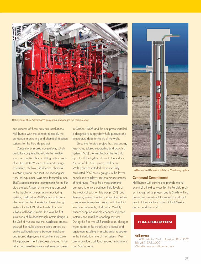
57
and success of these previous installations,
halliburton won the contract to supply the
permanent monitoring and chemical injection
systems for the Perdido project.
Conventional subsea completions, which
are to be completed from both the Perdido
spar and mobile offshore drilling units, consist
of 20 Kpsi ROC™ series dual-quartz gauge
assemblies, shallow and deep-set chemical
injection systems, and multi-line spooling ser-
vices. All equipment was manufactured to meet
shell’s specific material requirements for the Per-
dido project. As part of the systems approach
to the installation of permanent monitoring
systems, halliburton wellDynamics also sup-
plied and installed the electrical feed-through
systems for the FMC direct vertical access
subsea wellhead systems. this was the first
installation of this feed-through system design in
the gulf of Mexico and the installation process
ensured that multiple checks were carried out
on the wellhead systems between installation
and subsea deployment to confirm they were
fit for purpose. the first successful subsea instal-
lation on a satellite subsea well was completed
in October 2008 and the equipment installed
is designed to supply downhole pressure and
temperature data for the life of the wells.
since the Perdido project has low energy
reservoirs, subsea separating and boosting
systems (sBs) are installed on the Perdido
spar to lift the hydrocarbons to the surface.
As part of this sBs system, halliburton
wellDynamics installed three specially
calibrated ROC series gauges in the lower
completion to allow real-time measurements
of fluid levels. these fluid measurements
are used to ensure optimum fluid levels at
the electrical submersible pump (EsP), and
therefore, extend the life of operation before
a workover is required. Along with the fluid
level measurements, halliburton wellDy-
namics supplied multiple chemical injection
systems and multi-line spooling services.
During the first two sBs installations, changes
were made to the installation process and
equipment resulting in a substantial reduction
in the installation time of the systems. Plans
are to provide additional subsea installations
and sBs systems.
Continued Commitmenthalliburton will continue to provide the full
extent of oilfield services for the Perdido proj-
ect through all its phases and is shell’s willing
partner as we extend the search for oil and
gas to future frontiers in the gulf of Mexico
and around the world.
Halliburton’s HCS Advantage™ cementing skid aboard the Perdido Spar.
Halliburton10200 Bellaire Blvd., houston, tX 77072tel: 281.575.3000website: www.halliburton.com
Halliburton WellDynamics SBS Level Monitoring System
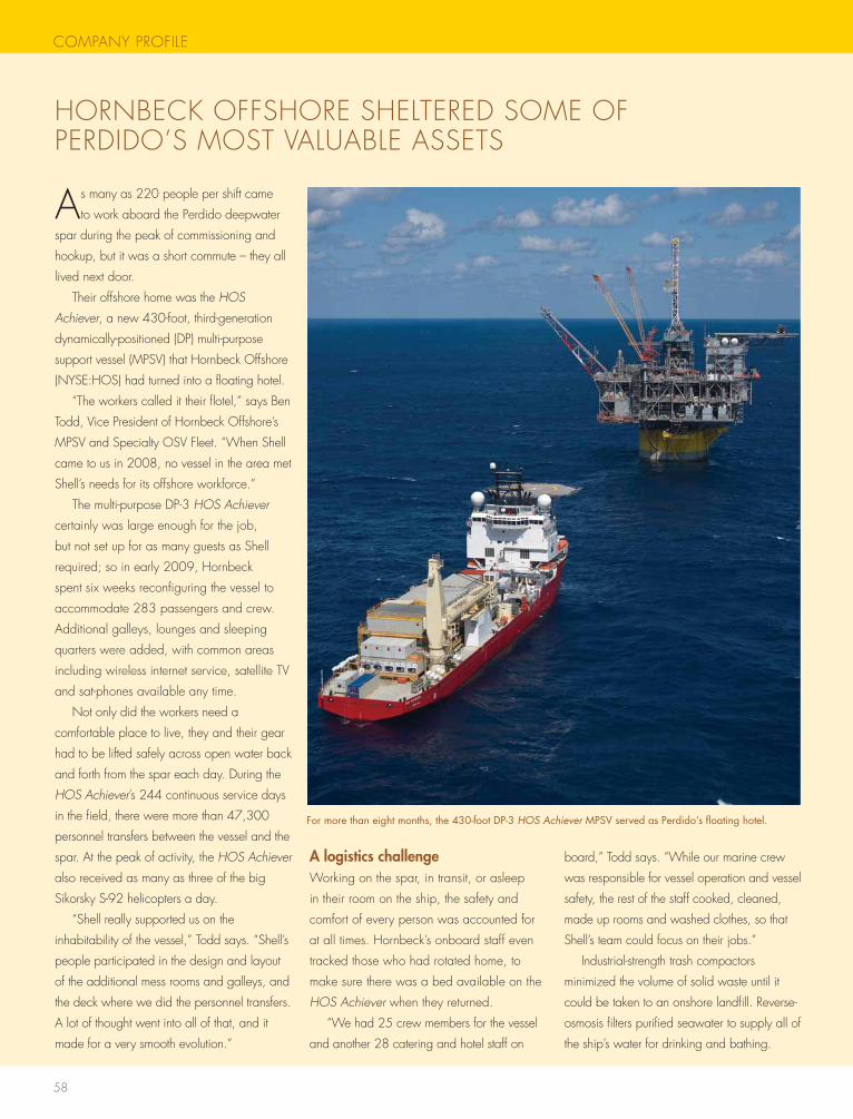
58
COMPANY PROFILE
hORNBECK OFFshORE shELtERED sOME OF PERDIDO’s MOst VALUABLE AssEts
As many as 220 people per shift came
to work aboard the Perdido deepwater
spar during the peak of commissioning and
hookup, but it was a short commute – they all
lived next door.
their offshore home was the HOS
Achiever, a new 430-foot, third-generation
dynamically-positioned (DP) multi-purpose
support vessel (MPsV) that hornbeck Offshore
(NYsE:hOs) had turned into a floating hotel.
“the workers called it their flotel,” says Ben
todd, Vice President of hornbeck Offshore’s
MPsV and specialty OsV Fleet. “when shell
came to us in 2008, no vessel in the area met
shell’s needs for its offshore workforce.”
the multi-purpose DP-3 HOS Achiever
certainly was large enough for the job,
but not set up for as many guests as shell
required; so in early 2009, hornbeck
spent six weeks reconfiguring the vessel to
accommodate 283 passengers and crew.
Additional galleys, lounges and sleeping
quarters were added, with common areas
including wireless internet service, satellite tV
and sat-phones available any time.
Not only did the workers need a
comfortable place to live, they and their gear
had to be lifted safely across open water back
and forth from the spar each day. During the
HOS Achiever’s 244 continuous service days
in the field, there were more than 47,300
personnel transfers between the vessel and the
spar. At the peak of activity, the HOS Achiever
also received as many as three of the big
sikorsky s-92 helicopters a day.
“shell really supported us on the
inhabitability of the vessel,” todd says. “shell’s
people participated in the design and layout
of the additional mess rooms and galleys, and
the deck where we did the personnel transfers.
A lot of thought went into all of that, and it
made for a very smooth evolution.”
A logistics challengeworking on the spar, in transit, or asleep
in their room on the ship, the safety and
comfort of every person was accounted for
at all times. hornbeck’s onboard staff even
tracked those who had rotated home, to
make sure there was a bed available on the
HOS Achiever when they returned.
“we had 25 crew members for the vessel
and another 28 catering and hotel staff on
board,” todd says. “while our marine crew
was responsible for vessel operation and vessel
safety, the rest of the staff cooked, cleaned,
made up rooms and washed clothes, so that
shell’s team could focus on their jobs.”
Industrial-strength trash compactors
minimized the volume of solid waste until it
could be taken to an onshore landfill. Reverse-
osmosis filters purified seawater to supply all of
the ship’s water for drinking and bathing.
For more than eight months, the 430-foot DP-3 HOS Achiever MPSV served as Perdido’s floating hotel.
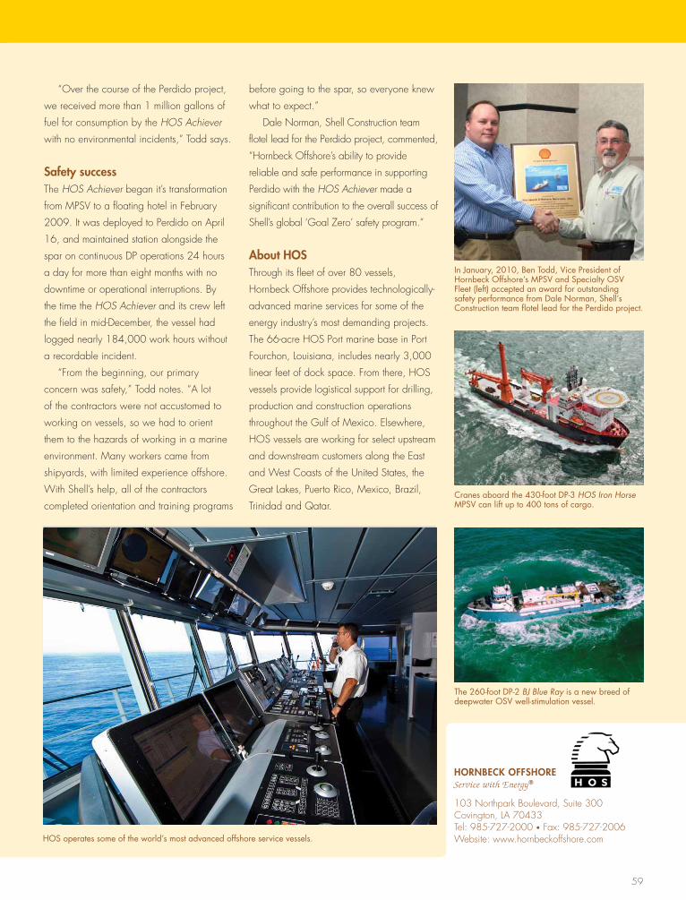
59
“Over the course of the Perdido project,
we received more than 1 million gallons of
fuel for consumption by the HOS Achiever
with no environmental incidents,” todd says.
Safety successthe HOS Achiever began it’s transformation
from MPsV to a floating hotel in February
2009. It was deployed to Perdido on April
16, and maintained station alongside the
spar on continuous DP operations 24 hours
a day for more than eight months with no
downtime or operational interruptions. By
the time the HOS Achiever and its crew left
the field in mid-December, the vessel had
logged nearly 184,000 work hours without
a recordable incident.
“From the beginning, our primary
concern was safety,” todd notes. “A lot
of the contractors were not accustomed to
working on vessels, so we had to orient
them to the hazards of working in a marine
environment. Many workers came from
shipyards, with limited experience offshore.
with shell’s help, all of the contractors
completed orientation and training programs
before going to the spar, so everyone knew
what to expect.”
Dale Norman, shell Construction team
flotel lead for the Perdido project, commented,
“hornbeck Offshore’s ability to provide
reliable and safe performance in supporting
Perdido with the HOS Achiever made a
significant contribution to the overall success of
shell’s global ‘goal Zero’ safety program.”
About HOSthrough its fleet of over 80 vessels,
hornbeck Offshore provides technologically-
advanced marine services for some of the
energy industry’s most demanding projects.
the 66-acre hOs Port marine base in Port
Fourchon, Louisiana, includes nearly 3,000
linear feet of dock space. From there, hOs
vessels provide logistical support for drilling,
production and construction operations
throughout the gulf of Mexico. Elsewhere,
hOs vessels are working for select upstream
and downstream customers along the East
and west Coasts of the United states, the
great Lakes, Puerto Rico, Mexico, Brazil,
trinidad and Qatar.
In January, 2010, Ben Todd, Vice President of Hornbeck Offshore’s MPSV and Specialty OSV Fleet (left) accepted an award for outstanding safety performance from Dale Norman, Shell’s Construction team flotel lead for the Perdido project.
HORNBECk OFFSHORE Service with Energy®
103 Northpark Boulevard, suite 300Covington, LA 70433tel: 985-727-2000 • Fax: 985-727-2006website: www.hornbeckoffshore.comHOS operates some of the world’s most advanced offshore service vessels.
The 260-foot DP-2 BJ Blue Ray is a new breed of deepwater OSV well-stimulation vessel.
Cranes aboard the 430-foot DP-3 HOS Iron Horse MPSV can lift up to 400 tons of cargo.
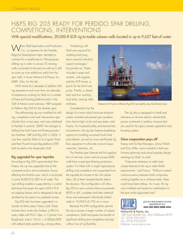
60
COMPANY PROFILE
h&Ps RIg 205 READY FOR PERDIDO sPAR DRILLINg, COMPLEtIONs, INtERVENtIONsWithspecialmodifications,20,000-ftSCRrigtotacklesubseawellslocatedinupto9,627feetofwater
when shell Exploration and Production
Co., as operator for the Perdido
Regional Development spar, decided to
contract for a small-footprint, fit-for-purpose
drilling rig in order to access 35 existing
wells connected to the spar as well as to drill
as many as nine additional wells from the
spar itself, it chose helmerich & Payne, Inc.
(h&P), tulsa, for the job.
with nearly four decades of platform drill-
ing experience and more than two decades
of experience working for shell on a number
of fixed and floating platforms both in the
gulf of Mexico and overseas, h&P assigned
its Platform Rig 205 for the Perdido spar.
the self-erecting rig was modified for drill-
ing, completions and well interventions spe-
cifically from a truss spar, and was mobilized
to Perdido in summer, 2009. No stranger to
drilling from both fixed and floating produc-
tion facilities, h&P built Rig 205 in 2002. It
was then used by shell on its Cognac fixed
and Ram Powell tension-leg platforms (tLP),
both located in the deepwater gulf.
Rig upgraded for spar topsides According to Rig 205 superintendent tom
Freeny, the rig was upgraded due to the
increased motion and acceleration forces
affecting the Perdido spar, which is anchored
in some 8,000 ft (2,383 m) of water. the
rig’s drilling module is supported by a custom
skid base that spans the spar’s 65-ft (19.8
m) capping beams and is designed to be as-
sembled by the spar’s two pedestal cranes.
Rig 205 also has been upgraded in a
number of other areas, Freeny said. these
include draw works disc brakes, a 49-1⁄2-in.
rotary table with Ps-21 slips, a “Cyclone” Iron
Roughneck, and a 16-3⁄4-in. x 5,000-psi BOP
with setback dolly positioning, among others.
“Interfacing with
shell was required for
installing and tying
down several individual
support packages,”
he pointed out. these
included a pipe rack
module, with engines
and the sCR house; a
porch for the third mud
pump, P-tanks, a diesel
tank and four auxiliary
mud tanks, among other
attributes.
Considerations for the
design of a more robust hurricane tie-down
system included anticipated spar accelera-
tions due to high winds and sea states, said
Freeny. For increased safety and environmen-
tal protection, the rig also features beefed-up
systems for handling increased hook load
and setback, as well as more user-friendly rig
floor equipment to eliminate manual torque
wrenches, hammers, etc.
the Perdido spar features the first applica-
tion of wet tree, direct vertical access (DVA)
wells from a spar-type floating production
system. It is fitted with a single high-pressure
drilling and completion riser suspended from
the topsides for access to the 34 subsea
trees, 22 of them located directly below
the structure. this configuration will allow
Rig 205 to use a surface blowout preventer
(BOP) to drill, complete and later sidetrack
those and subsequent individually drilled
wells to 19,000 ft (5,795 m) or more.
Because the DVA configuration permits
the rig to access a larger number of subsea
completions, shell anticipates the benefit of
significant drilling and completions savings
without loss of rig flexibility.
the rig also is equipped to install and
intervene on the five electric submersible
pumps contained in seafloor caissons that
are used for the spar’s subsea separation and
boosting system.
Close cooperation pays offFreeny and his Rig Managers, Jimmy welch
and tony Miller, were included in both pre-
liminary planning and actual topsides design
meetings by shell, he said.
“It became necessary to add some
unique features to the rig to meet shell’s
requirements,” said Freeny. “without constant
communications between both companies,
working together as a cohesive team, there
could have been delays. As it was, the rig
was modified and ready for mobilization to
the spar at the appointed time.”
Helmerich & Payne’s offshore Rig 205 rests tightly atop the Perdido Spar.
Helmerich & Payne, Inc.1437 south Boulder Ave., tulsa, Oklahoma 74119tel: (918) 742-5531Fax: (918) 742-0237website: www.hpinc.com
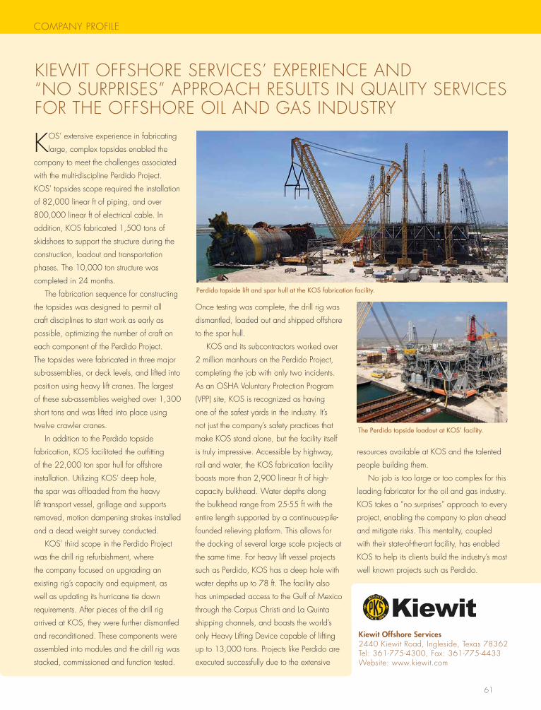
61
COMPANY PROFILE
KIEwIt OFFshORE sERVICEs’ EXPERIENCE AND “NO sURPRIsEs” APPROACh REsULts IN QUALItY sERVICEs FOR thE OFFshORE OIL AND gAs INDUstRY
KOs’ extensive experience in fabricating
large, complex topsides enabled the
company to meet the challenges associated
with the multi-discipline Perdido Project.
KOs’ topsides scope required the installation
of 82,000 linear ft of piping, and over
800,000 linear ft of electrical cable. In
addition, KOs fabricated 1,500 tons of
skidshoes to support the structure during the
construction, loadout and transportation
phases. the 10,000 ton structure was
completed in 24 months.
the fabrication sequence for constructing
the topsides was designed to permit all
craft disciplines to start work as early as
possible, optimizing the number of craft on
each component of the Perdido Project.
the topsides were fabricated in three major
sub-assemblies, or deck levels, and lifted into
position using heavy lift cranes. the largest
of these sub-assemblies weighed over 1,300
short tons and was lifted into place using
twelve crawler cranes.
In addition to the Perdido topside
fabrication, KOs facilitated the outfitting
of the 22,000 ton spar hull for offshore
installation. Utilizing KOs’ deep hole,
the spar was offloaded from the heavy
lift transport vessel, grillage and supports
removed, motion dampening strakes installed
and a dead weight survey conducted.
KOs’ third scope in the Perdido Project
was the drill rig refurbishment, where
the company focused on upgrading an
existing rig’s capacity and equipment, as
well as updating its hurricane tie down
requirements. After pieces of the drill rig
arrived at KOs, they were further dismantled
and reconditioned. these components were
assembled into modules and the drill rig was
stacked, commissioned and function tested.
Once testing was complete, the drill rig was
dismantled, loaded out and shipped offshore
to the spar hull.
KOs and its subcontractors worked over
2 million manhours on the Perdido Project,
completing the job with only two incidents.
As an OshA Voluntary Protection Program
(VPP) site, KOs is recognized as having
one of the safest yards in the industry. It’s
not just the company’s safety practices that
make KOs stand alone, but the facility itself
is truly impressive. Accessible by highway,
rail and water, the KOs fabrication facility
boasts more than 2,900 linear ft of high-
capacity bulkhead. water depths along
the bulkhead range from 25-55 ft with the
entire length supported by a continuous-pile-
founded relieving platform. this allows for
the docking of several large scale projects at
the same time. For heavy lift vessel projects
such as Perdido, KOs has a deep hole with
water depths up to 78 ft. the facility also
has unimpeded access to the gulf of Mexico
through the Corpus Christi and La Quinta
shipping channels, and boasts the world’s
only heavy Lifting Device capable of lifting
up to 13,000 tons. Projects like Perdido are
executed successfully due to the extensive
resources available at KOs and the talented
people building them.
No job is too large or too complex for this
leading fabricator for the oil and gas industry.
KOs takes a “no surprises” approach to every
project, enabling the company to plan ahead
and mitigate risks. this mentality, coupled
with their state-of-the-art facility, has enabled
KOs to help its clients build the industry’s most
well known projects such as Perdido.
Perdido topside lift and spar hull at the KOS fabrication facility.
kiewit Offshore Services2440 Kiewit Road, Ingleside, texas 78362tel: 361-775-4300, Fax: 361-775-4433website: www.kiewit.com
The Perdido topside loadout at KOS’ facility.
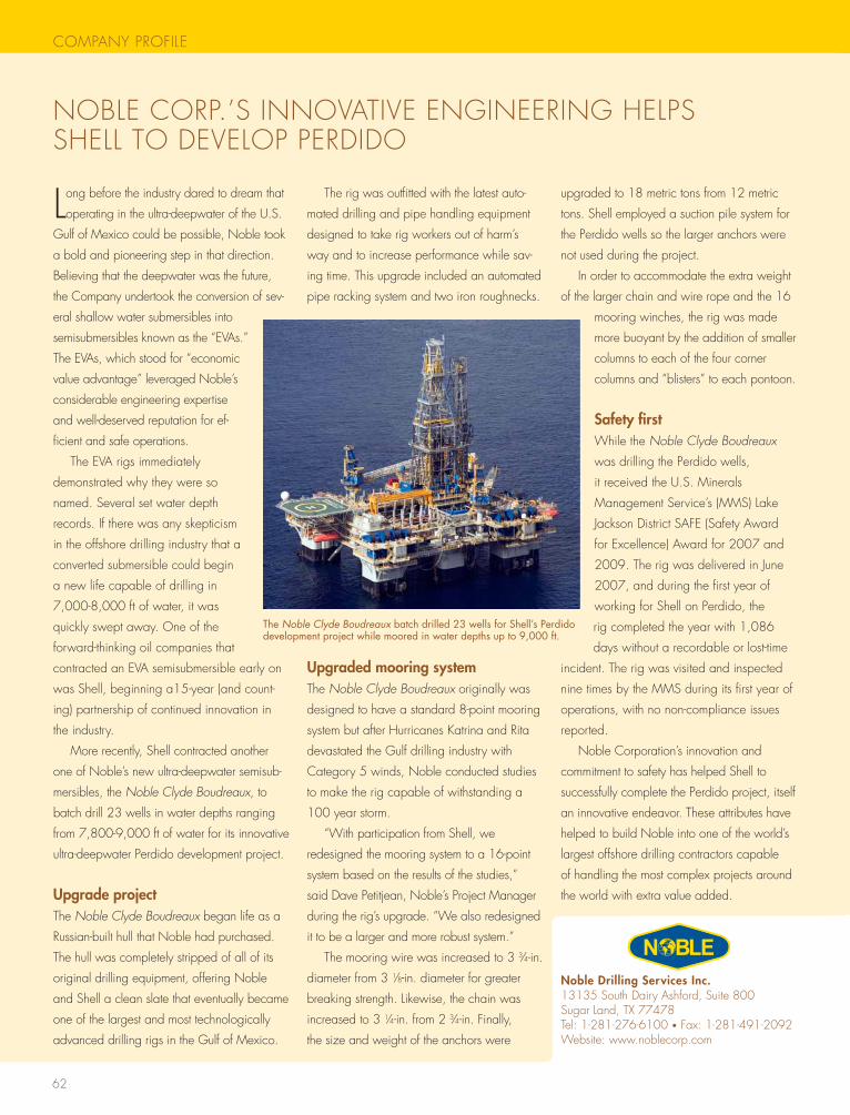
62
COMPANY PROFILE
NOBLE CORP.’s INNOVAtIVE ENgINEERINg hELPs shELL tO DEVELOP PERDIDO
Long before the industry dared to dream that
operating in the ultra-deepwater of the U.s.
gulf of Mexico could be possible, Noble took
a bold and pioneering step in that direction.
Believing that the deepwater was the future,
the Company undertook the conversion of sev-
eral shallow water submersibles into
semisubmersibles known as the “EVAs.”
the EVAs, which stood for “economic
value advantage” leveraged Noble’s
considerable engineering expertise
and well-deserved reputation for ef-
ficient and safe operations.
the EVA rigs immediately
demonstrated why they were so
named. several set water depth
records. If there was any skepticism
in the offshore drilling industry that a
converted submersible could begin
a new life capable of drilling in
7,000-8,000 ft of water, it was
quickly swept away. One of the
forward-thinking oil companies that
contracted an EVA semisubmersible early on
was shell, beginning a15-year (and count-
ing) partnership of continued innovation in
the industry.
More recently, shell contracted another
one of Noble’s new ultra-deepwater semisub-
mersibles, the Noble Clyde Boudreaux, to
batch drill 23 wells in water depths ranging
from 7,800-9,000 ft of water for its innovative
ultra-deepwater Perdido development project.
Upgrade projectthe Noble Clyde Boudreaux began life as a
Russian-built hull that Noble had purchased.
the hull was completely stripped of all of its
original drilling equipment, offering Noble
and shell a clean slate that eventually became
one of the largest and most technologically
advanced drilling rigs in the gulf of Mexico.
the rig was outfitted with the latest auto-
mated drilling and pipe handling equipment
designed to take rig workers out of harm’s
way and to increase performance while sav-
ing time. this upgrade included an automated
pipe racking system and two iron roughnecks.
Upgraded mooring systemthe Noble Clyde Boudreaux originally was
designed to have a standard 8-point mooring
system but after hurricanes Katrina and Rita
devastated the gulf drilling industry with
Category 5 winds, Noble conducted studies
to make the rig capable of withstanding a
100 year storm.
“with participation from shell, we
redesigned the mooring system to a 16-point
system based on the results of the studies,”
said Dave Petitjean, Noble’s Project Manager
during the rig’s upgrade. “we also redesigned
it to be a larger and more robust system.”
the mooring wire was increased to 3 3⁄4-in.
diameter from 3 1⁄8-in. diameter for greater
breaking strength. Likewise, the chain was
increased to 3 1⁄4-in. from 2 3⁄4-in. Finally,
the size and weight of the anchors were
upgraded to 18 metric tons from 12 metric
tons. shell employed a suction pile system for
the Perdido wells so the larger anchors were
not used during the project.
In order to accommodate the extra weight
of the larger chain and wire rope and the 16
mooring winches, the rig was made
more buoyant by the addition of smaller
columns to each of the four corner
columns and “blisters” to each pontoon.
Safety firstwhile the Noble Clyde Boudreaux
was drilling the Perdido wells,
it received the U.s. Minerals
Management service’s (MMs) Lake
Jackson District sAFE (safety Award
for Excellence) Award for 2007 and
2009. the rig was delivered in June
2007, and during the first year of
working for shell on Perdido, the
rig completed the year with 1,086
days without a recordable or lost-time
incident. the rig was visited and inspected
nine times by the MMs during its first year of
operations, with no non-compliance issues
reported.
Noble Corporation’s innovation and
commitment to safety has helped shell to
successfully complete the Perdido project, itself
an innovative endeavor. these attributes have
helped to build Noble into one of the world’s
largest offshore drilling contractors capable
of handling the most complex projects around
the world with extra value added.
The Noble Clyde Boudreaux batch drilled 23 wells for Shell’s Perdido development project while moored in water depths up to 9,000 ft.
Noble Drilling Services Inc.13135 south Dairy Ashford, suite 800sugar Land, tX 77478tel: 1-281-276-6100 • Fax: 1-281-491-2092website: www.noblecorp.com
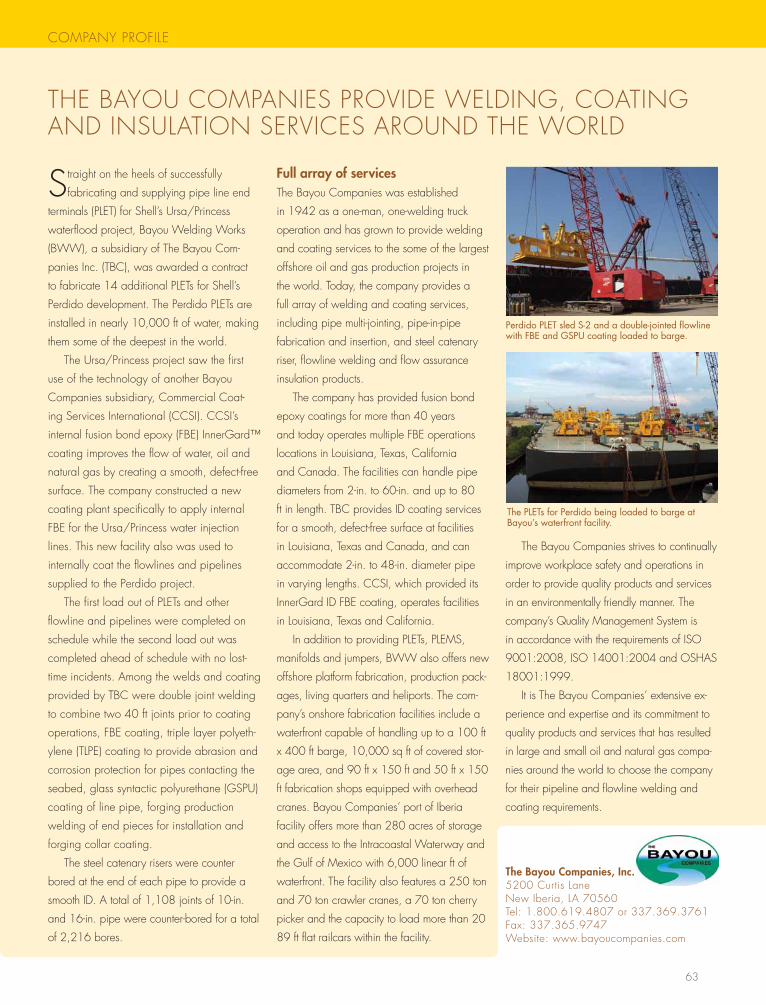
63
COMPANY PROFILE
thE BAYOU COMPANIEs PROVIDE wELDINg, COAtINg AND INsULAtION sERVICEs AROUND thE wORLD
straight on the heels of successfully
fabricating and supplying pipe line end
terminals (PLEt) for shell’s Ursa/Princess
waterflood project, Bayou welding works
(Bww), a subsidiary of the Bayou Com-
panies Inc. (tBC), was awarded a contract
to fabricate 14 additional PLEts for shell’s
Perdido development. the Perdido PLEts are
installed in nearly 10,000 ft of water, making
them some of the deepest in the world.
the Ursa/Princess project saw the first
use of the technology of another Bayou
Companies subsidiary, Commercial Coat-
ing services International (CCsI). CCsI’s
internal fusion bond epoxy (FBE) Innergard™
coating improves the flow of water, oil and
natural gas by creating a smooth, defect-free
surface. the company constructed a new
coating plant specifically to apply internal
FBE for the Ursa/Princess water injection
lines. this new facility also was used to
internally coat the flowlines and pipelines
supplied to the Perdido project.
the first load out of PLEts and other
flowline and pipelines were completed on
schedule while the second load out was
completed ahead of schedule with no lost-
time incidents. Among the welds and coating
provided by tBC were double joint welding
to combine two 40 ft joints prior to coating
operations, FBE coating, triple layer polyeth-
ylene (tLPE) coating to provide abrasion and
corrosion protection for pipes contacting the
seabed, glass syntactic polyurethane (gsPU)
coating of line pipe, forging production
welding of end pieces for installation and
forging collar coating.
the steel catenary risers were counter
bored at the end of each pipe to provide a
smooth ID. A total of 1,108 joints of 10-in.
and 16-in. pipe were counter-bored for a total
of 2,216 bores.
Full array of servicesthe Bayou Companies was established
in 1942 as a one-man, one-welding truck
operation and has grown to provide welding
and coating services to the some of the largest
offshore oil and gas production projects in
the world. today, the company provides a
full array of welding and coating services,
including pipe multi-jointing, pipe-in-pipe
fabrication and insertion, and steel catenary
riser, flowline welding and flow assurance
insulation products.
the company has provided fusion bond
epoxy coatings for more than 40 years
and today operates multiple FBE operations
locations in Louisiana, texas, California
and Canada. the facilities can handle pipe
diameters from 2-in. to 60-in. and up to 80
ft in length. tBC provides ID coating services
for a smooth, defect-free surface at facilities
in Louisiana, texas and Canada, and can
accommodate 2-in. to 48-in. diameter pipe
in varying lengths. CCsI, which provided its
Innergard ID FBE coating, operates facilities
in Louisiana, texas and California.
In addition to providing PLEts, PLEMs,
manifolds and jumpers, Bww also offers new
offshore platform fabrication, production pack-
ages, living quarters and heliports. the com-
pany’s onshore fabrication facilities include a
waterfront capable of handling up to a 100 ft
x 400 ft barge, 10,000 sq ft of covered stor-
age area, and 90 ft x 150 ft and 50 ft x 150
ft fabrication shops equipped with overhead
cranes. Bayou Companies’ port of Iberia
facility offers more than 280 acres of storage
and access to the Intracoastal waterway and
the gulf of Mexico with 6,000 linear ft of
waterfront. the facility also features a 250 ton
and 70 ton crawler cranes, a 70 ton cherry
picker and the capacity to load more than 20
89 ft flat railcars within the facility.
the Bayou Companies strives to continually
improve workplace safety and operations in
order to provide quality products and services
in an environmentally friendly manner. the
company’s Quality Management system is
in accordance with the requirements of IsO
9001:2008, IsO 14001:2004 and OshAs
18001:1999.
It is the Bayou Companies’ extensive ex-
perience and expertise and its commitment to
quality products and services that has resulted
in large and small oil and natural gas compa-
nies around the world to choose the company
for their pipeline and flowline welding and
coating requirements.
Perdido PLET sled S-2 and a double-jointed flowline with FBE and GSPU coating loaded to barge.
The Bayou Companies, Inc.5200 Curtis Lane New Iberia, LA 70560tel: 1.800.619.4807 or 337.369.3761Fax: 337.365.9747website: www.bayoucompanies.com
The PLETs for Perdido being loaded to barge at Bayou’s waterfront facility.
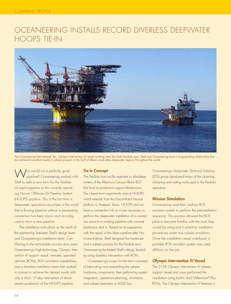
64
COMPANY PROFILE
OCEANEERINg INstALLs RECORD DIVERLEss DEEPwAtER hOOPs tIE-IN
who would cut a perfectly good
pipeline? Oceaneering worked with
shell to add a new tie-in for the Perdido
oil export pipeline to the currently operat-
ing hoover Offshore Oil Pipeline system
(hOOPs) pipeline. this is the first time in
deepwater operations anywhere in the world
that a flowing pipeline without a pre-existing
connection has been shut-in and re-config-
ured to tie-in a new pipeline.
the installation took place as the result of
the partnership between shell’s design team
and Oceaneering’s installation team. Con-
tributing to the remarkable success story were
Oceaneering’s high-technology Olympic Inter-
vention IV support vessel, remotely operated
vehicles (ROVs), ROV simulation capabilities,
and a diverless installation team that worked
in concert to achieve the desired results with
only a short, 17-day interruption of down-
stream production of the hOOPs pipeline.
Tie-in Conceptthe Perdido host facility operates in ultra-deep
waters of the Alaminos Canyon Block 857
that had no production export infrastructure.
the closest tie-in opportunity was at hOOPs,
which extends from the ExxonMobil hoover
platform to Freeport, texas. hOOPs did not
have a connection link so it was necessary to
perform the deepwater installation of a connec-
tion point to a working pipeline with minimal
production shut in. Based on its experience
with the repair of the Mars pipeline after hur-
ricane Katrina, shell designed the hardware
and a subsea process for the Perdido tie-in.
Oceaneering facilitated shell’s design feasibil-
ity using diverless intervention with ROVs.
Oceaneering’s scope for the tie-in consisted
of fabricating and assembling the subsea
hardware components, then performing system
integration, operations planning, simulation,
and subsea execution in 4500 fsw.
Oceaneering’s Deepwater technical solutions
(Dts) group developed many of the cleaning,
clamping and cutting tools used in the Perdido
operation.
Mission SimulationOceaneering used their onshore ROV
simulator system to perform the preinstallation
sequence. this process allowed the ROV
pilots to become familiar with the tools they
would be using and to practice installation
procedures under true subsea conditions.
Once the installation vessel mobilized, a
portable ROV simulator system was used
offshore on the job.
Olympic Intervention IV Vesselthe 312-ft Olympic Intervention IV subsea
support vessel and crew performed the
installation using built-in dual Millennium® Plus
ROVs. the Olympic Intervention IV features a
The Oceaneering International, Inc. Olympic Intervention IV vessel working near the Shell Peridido spar. Shell and Oceaneering have a long-standing relationship that has achieved excellent results in subsea projects in the Gulf of Mexico and other deepwater regions throughout the world.
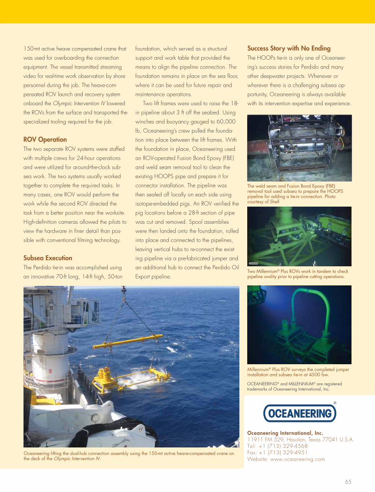
65
150-mt active heave compensated crane that
was used for overboarding the connection
equipment. the vessel transmitted streaming
video for real-time work observation by shore
personnel during the job. the heave-com-
pensated ROV launch and recovery system
onboard the Olympic Intervention IV lowered
the ROVs from the surface and transported the
specialized tooling required for the job.
ROV Operationthe two separate ROV systems were staffed
with multiple crews for 24-hour operations
and were utilized for around-the-clock sub-
sea work. the two systems usually worked
together to complete the required tasks. In
many cases, one ROV would perform the
work while the second ROV directed the
task from a better position near the worksite.
high-definition cameras allowed the pilots to
view the hardware in finer detail than pos-
sible with conventional filming technology.
Subsea Executionthe Perdido tie-in was accomplished using
an innovative 70-ft long, 14-ft high, 50-ton
foundation, which served as a structural
support and work table that provided the
means to align the pipeline connection. the
foundation remains in place on the sea floor,
where it can be used for future repair and
maintenance operations.
two lift frames were used to raise the 18-
in pipeline about 3 ft off the seabed. Using
winches and buoyancy gauged to 60,000
lb, Oceaneering’s crew pulled the founda-
tion into place between the lift frames. with
the foundation in place, Oceaneering used
an ROV-operated Fusion Bond Epoxy (FBE)
and weld seam removal tool to clean the
existing hOOPs pipe and prepare it for
connector installation. the pipeline was
then sealed off locally on each side using
isotope-embedded pigs. An ROV verified the
pig locations before a 28-ft section of pipe
was cut and removed. spool assemblies
were then landed onto the foundation, rolled
into place and connected to the pipelines,
leaving vertical hubs to re-connect the exist-
ing pipeline via a pre-fabricated jumper and
an additional hub to connect the Perdido Oil
Export pipeline.
Success Story with No Endingthe hOOPs tie-in is only one of Oceaneer-
ing’s success stories for Perdido and many
other deepwater projects. whenever or
wherever there is a challenging subsea op-
portunity, Oceaneering is always available
with its intervention expertise and experience.
Oceaneering International, Inc.11911 FM 529, houston, texas 77041 U.s.A.tel: +1 (713) 329-4568Fax: +1 (713) 329-4951website: www.oceaneering.com
Oceaneering lifting the dual-hub connection assembly using the 150-mt active heave-compensated crane on the deck of the Olympic Intervention IV.
The weld seam and Fusion Bond Epoxy (FBE) removal tool used subsea to prepare the HOOPS pipeline for adding a tie-in connection. Photo courtesy of Shell
Two Millennium® Plus ROVs work in tandem to check pipeline ovality prior to pipeline cutting operations.
Millennium® Plus ROV surveys the completed jumper installation and subsea tie-in at 4500 fsw.
OCEANEERING® and MILLENNIUM® are registered trademarks of Oceaneering International, Inc.
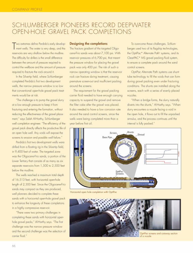
66
COMPANY PROFILE
two extremes define Perdido’s early develop-
ment wells: the water is very deep, and the
reservoirs are very shallow below the mudline.
the difficulty for drillers is the small difference
between the amount of pressure required to
control the wellbore and the amount of pressure
required to fracture the rock around it.
In the silvertip field, where schlumberger
completed Perdido’s first two development
wells, the narrow pressure window is so low
that conventional open-hole gravel pack treat-
ments would be at risk.
“the challenge is to pump the gravel slurry
at a low enough pressure to keep it from
fracturing and entering the formation, without
reducing the effectiveness of the gravel place-
ment,” says salah Al-harthy, schlumberger
well completion engineer. “the efficiency of the
gravel pack directly affects the productive life of
an open hole well. Any voids will expose the
screens to erosion and possible well failure.”
Perdido’s first two development wells were
drilled from a floating rig in the silvertip field,
in 9,400 feet of water. the targeted zone
was the Oligocene-Frio sands, a portion of the
Lower tertiary that consists of as many as six
separate reservoirs from 1,500 to 2,500 feet
below the mudline.
the wells reached a maximum total depth
of 16,513 feet, with horizontal open-hole
length of 2,300 feet. since the Oligocene-Frio
sands may compact as they are produced,
well planners decided to complete these
sands with a horizontal open-hole gravel pack
to enhance the longevity of these completions
in a highly compressive reservoir.
“there were two primary challenges in
completing these sands with horizontal open-
hole gravel packs,” Al-harthy says. “the first
challenge was the narrow pressure window
and the second challenge was the selection of
carrier fluid.”
Designing the completionsthe fracture gradient of the targeted Oligo-
cene-Frio sands was about 7,100 psi. with
reservoir pressures of 6,700 psi, that meant
the pressure window for placing the gravel
pack was only 400 psi. the risk of such a
narrow operating window is that the reservoir
rock can fracture during treatment, causing
premature screen-out and insufficient packing
around the screens.
the requirement for the gravel packing
carrier fluid needed to have enough carrying
capacity to suspend the gravel and remove
the filter cake after the gravel was placed.
It also needed to have a low corrosion rate
around the sand control screens, since the
wells were being completed more than a
year before first oil.
to overcome these challenges, schlum-
berger used two of its flagship technologies,
the OptiPac* Alternate Path† systems, and its
ClearPAC* Ms gravel packing fluid system,
to ensure a complete pack around the sand
control screens.
OptiPac Alternate Path systems use shunt-
tube technology to fill the voids that can form
during gravel packing even under fracturing
conditions. the shunts are installed along the
screens, each with a series of evenly placed
nozzles.
“when a bridge forms, the slurry naturally
diverts into the shunts,” Al-harthy says. “when
slurry encounters a nozzle facing a void in
the open hole, it flows out to fill the unpacked
annulus, and the process continues until the
interval is fully packed.”
sChLUMBERgER PIONEERs RECORD DEEPwAtER OPEN-hOLE gRAVEL PACK COMPLEtIONs
Horizontal open hole completion with OptiPac
OptiPac screens and cutaway section of a nozzle
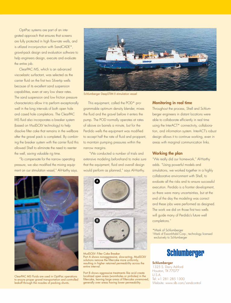
OptiPac systems are part of an inte-
grated approach that ensures that screens
are fully protected in high flow-rate wells, and
is utilized in-conjunction with sandCADE*,
gravel-pack design and evaluation software to
help engineers design, execute and evaluate
the entire job.
ClearPAC Ms, which is an advanced
viscoelastic surfactant, was selected as the
carrier fluid on the first two silvertip wells
because of its excellent sand suspension
capabilities, even at very low shear rates.
the sand suspension and low friction pressure
characteristics allow it to perform exceptionally
well in the long intervals of both open hole
and cased hole completions. the ClearPAC
Ms fluid also incorporates a breaker system
(based on MudsOLV technology) to help
dissolve filter cake that remains in the wellbore
after the gravel pack is completed. By combin-
ing the breaker system with the carrier fluid this
allowed shell to eliminate the need to reenter
the well, saving valuable rig time.
“to compensate for the narrow operating
pressure, we also modified the mixing equip-
ment on our stimulation vessel,” Al-harthy says.
this equipment, called the POD* pro-
grammable optimum density blender, mixes
the fluid and the gravel before it enters the
pump. the POD normally operates at rates
of above six barrels a minute, but for the
Perdido wells the equipment was modified
to accept half the rate of fluid and proppant,
to maintain pumping pressures within the
narrow margins.
“we conducted a number of trials and
extensive modeling beforehand to make sure
that the equipment, fluid and overall design
would perform as planned,” says Al-harthy.
Monitoring in real timethroughout the process, shell and schlum-
berger engineers in distant locations were
able to collaborate efficiently in real time
using the InterACt* connectivity, collabora-
tion, and information system. InterACt’s robust
design allows it to continue working, even in
areas with marginal communication links.
Working the plan“we really did our homework,” Al-harthy
adds. “Using powerful models and
simulations, we worked together in a highly
collaborative environment with shell, to
evaluate all the risks and to ensure successful
execution. Perdido is a frontier development,
so there were many uncertainties, but at the
end of the day the modeling was correct
and these jobs were performed as designed.
the work we did on those first two wells
will guide many of Perdido’s future well
completions.”
*Mark of schlumberger†Mark of ExxonMobil Corp.; technology licensed exclusively to schlumberger
Schlumberger1325 s. Dairy Ashfordhouston, tX 77077U.s.A.tel: +1 281 285 1300website: www.slb.com/sandcontrol
ClearPAC MS Fluids are used in OptiPac operations to ensure proper gravel transportation and controlled leakoff through the nozzles of packing shunts.
MudSOLV: Filter Cake Breaker Part A shows nonaggressive, slow-acting, MudSOLV solutions remove the filtercake more uniformly, resulting in higher retained permeability across the entire interval.
Part B shows aggressive treatments like acid create localized open areas (wormholes or pinholes) in the filtercake, leaving large areas of filtercake unremoved, generally over areas having lower permeability.
Schlumberger DeepSTIM II stimulation vessel
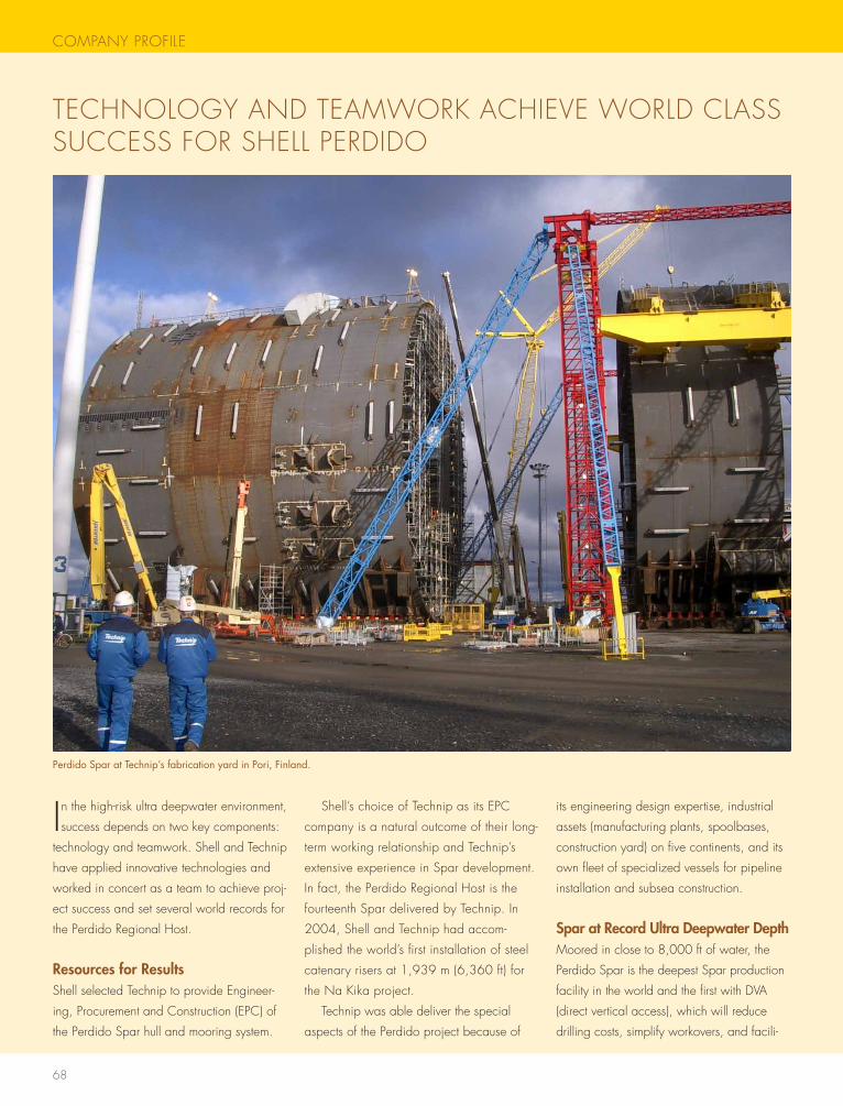
68
COMPANY PROFILE
tEChNOLOgY AND tEAMwORK AChIEVE wORLD CLAss sUCCEss FOR shELL PERDIDO
In the high-risk ultra deepwater environment,
success depends on two key components:
technology and teamwork. shell and technip
have applied innovative technologies and
worked in concert as a team to achieve proj-
ect success and set several world records for
the Perdido Regional host.
Resources for Resultsshell selected technip to provide Engineer-
ing, Procurement and Construction (EPC) of
the Perdido spar hull and mooring system.
shell’s choice of technip as its EPC
company is a natural outcome of their long-
term working relationship and technip’s
extensive experience in spar development.
In fact, the Perdido Regional host is the
fourteenth spar delivered by technip. In
2004, shell and technip had accom-
plished the world’s first installation of steel
catenary risers at 1,939 m (6,360 ft) for
the Na Kika project.
technip was able deliver the special
aspects of the Perdido project because of
its engineering design expertise, industrial
assets (manufacturing plants, spoolbases,
construction yard) on five continents, and its
own fleet of specialized vessels for pipeline
installation and subsea construction.
Spar at Record Ultra Deepwater DepthMoored in close to 8,000 ft of water, the
Perdido spar is the deepest spar production
facility in the world and the first with DVA
(direct vertical access), which will reduce
drilling costs, simplify workovers, and facili-
Perdido Spar at Technip’s fabrication yard in Pori, Finland.
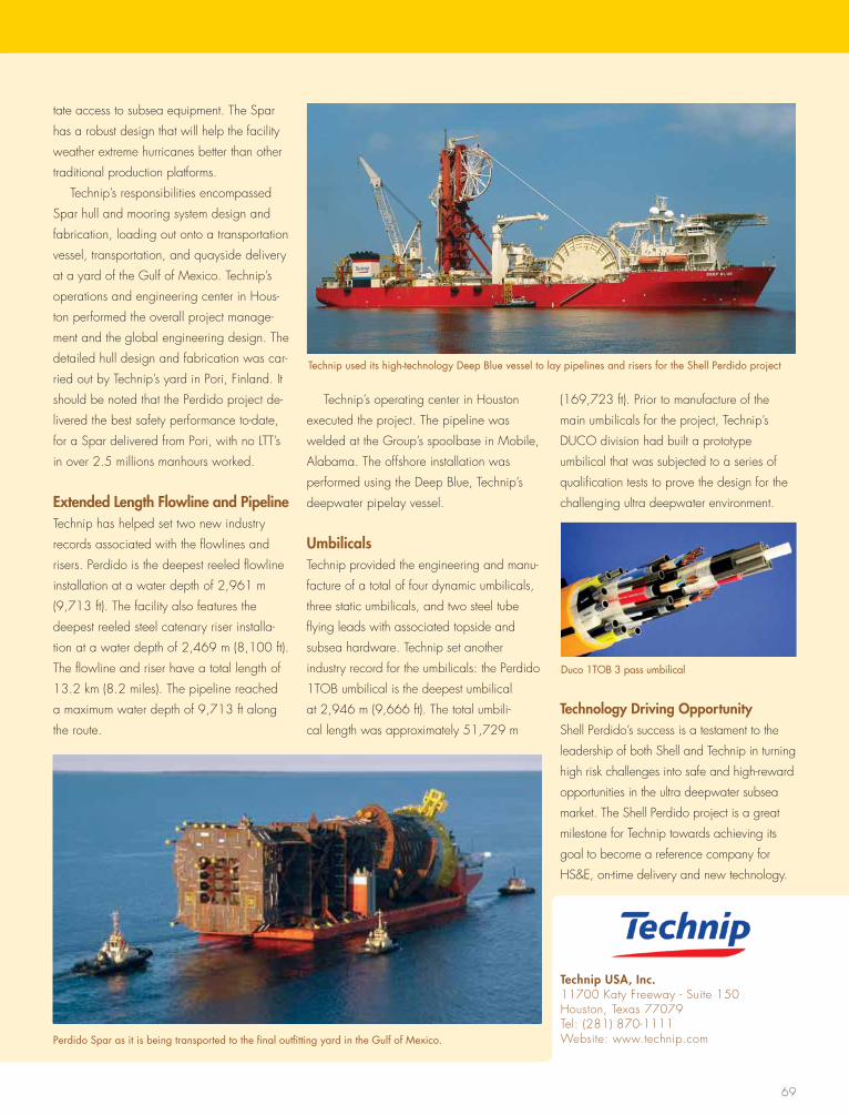
69
tate access to subsea equipment. the spar
has a robust design that will help the facility
weather extreme hurricanes better than other
traditional production platforms.
technip’s responsibilities encompassed
spar hull and mooring system design and
fabrication, loading out onto a transportation
vessel, transportation, and quayside delivery
at a yard of the gulf of Mexico. technip’s
operations and engineering center in hous-
ton performed the overall project manage-
ment and the global engineering design. the
detailed hull design and fabrication was car-
ried out by technip’s yard in Pori, Finland. It
should be noted that the Perdido project de-
livered the best safety performance to-date,
for a spar delivered from Pori, with no Ltt’s
in over 2.5 millions manhours worked.
Extended Length Flowline and Pipelinetechnip has helped set two new industry
records associated with the flowlines and
risers. Perdido is the deepest reeled flowline
installation at a water depth of 2,961 m
(9,713 ft). the facility also features the
deepest reeled steel catenary riser installa-
tion at a water depth of 2,469 m (8,100 ft).
the flowline and riser have a total length of
13.2 km (8.2 miles). the pipeline reached
a maximum water depth of 9,713 ft along
the route.
technip’s operating center in houston
executed the project. the pipeline was
welded at the group’s spoolbase in Mobile,
Alabama. the offshore installation was
performed using the Deep Blue, technip’s
deepwater pipelay vessel.
Umbilicalstechnip provided the engineering and manu-
facture of a total of four dynamic umbilicals,
three static umbilicals, and two steel tube
flying leads with associated topside and
subsea hardware. technip set another
industry record for the umbilicals: the Perdido
1tOB umbilical is the deepest umbilical
at 2,946 m (9,666 ft). the total umbili-
cal length was approximately 51,729 m
(169,723 ft). Prior to manufacture of the
main umbilicals for the project, technip’s
DUCO division had built a prototype
umbilical that was subjected to a series of
qualification tests to prove the design for the
challenging ultra deepwater environment.
Technology Driving Opportunityshell Perdido’s success is a testament to the
leadership of both shell and technip in turning
high risk challenges into safe and high-reward
opportunities in the ultra deepwater subsea
market. the shell Perdido project is a great
milestone for technip towards achieving its
goal to become a reference company for
hs&E, on-time delivery and new technology.
Technip USA, Inc.11700 Katy Freeway - suite 150houston, texas 77079tel: (281) 870-1111website: www.technip.comPerdido Spar as it is being transported to the final outfitting yard in the Gulf of Mexico.
Duco 1TOB 3 pass umbilical
Technip used its high-technology Deep Blue vessel to lay pipelines and risers for the Shell Perdido project