Embed Size (px)
Citation preview

SERVICE CENTER MANUALPISTON PUMP AIRLESS SPRAYER
Models covered inthis manual:
0406 • Form No. 0515834A
IMPORTANT - THIS MANUAL IS INTENDEDFOR AUTHORIZED SERVICE CENTERS ONLYAND SHOULD NOT BE USED FORCONSUMER REFERENCE.
SEE PAGE 4 FOR TABLE OF CONTENTSAND NEW FEATURES.
9140S9146915091709190
PF23PF30
1420162017201920
1-800-746-6595Wagner Technical Service
1770 Fernbrook Lane, Minneapolis, MN 55447
http://www.wagnerspraytech.comVisit us on the world wide web!

2
Important Safety Information • Read all safety information beforeoperating the equipment. Save these instructions
HAZARD: INJECTION INJURYA high pressure paint stream produced by thisequipment can pierce the skin and underlying tissues,leading to serious injury and possible amputation.SEE A PHYSICIAN IMMEDIATELY.DO NOT TREAT AN INJECTION INJURY AS A SIMPLE CUT!Injection can lead to amputation. See a physician immediately.The maximum operating range of the gun is 3000 PSI/207 BAR or3600 PSI/248 BAR fluid pressure depending upon gun model.
PREVENTION:• NEVER aim the gun at any part of the body. • Do not aim the gun at, or spray any person or animal.• NEVER allow any part of the body to touch the fluid stream. DO
NOT allow body to touch a leak in the fluid hose.• NEVER put your hand in front of the gun. Gloves will not provide
protection against an injection injury.• ALWAYS lock the gun trigger, shut the pump off, and release all
pressure before servicing, cleaning the tip or guard, changing tip,or leaving unattended. Pressure will not be released by turning offthe motor. The PRIME/SPRAY knob must be turned to PRIME torelieve the pressure. Refer to the PRESSURE RELIEFPROCEDURE described in the pump manual.
• ALWAYS keep the tip guard in place while spraying. The tip guardprovides some protection but is mainly a warning device.
• ALWAYS remove the spray tip before flushing or cleaning thesystem.
• Paint hose can develop leaks from wear, kinking and abuse. Aleak can inject material into the skin. Inspect the hose beforeeach use. Do not use hose to lift or pull equipment.
• NEVER use a spray gun without a working trigger lock and triggerguard in place.
• All accessories must be rated at or above 3000 PSI/207 BAR.This includes spray tips, guns, extensions, and hose.
HAZARD: HAZARDOUS VAPORSPaints, solvents, insecticides, and othermaterials can be harmful if inhaled or come incontact with the body. Vapors can cause severenausea, fainting, or poisoning.
PREVENTION:
• Use a respirator or mask if vapors can beinhaled. Read all instructions supplied withthe mask to be sure it will provide thenecessary protection.
• Wear protective eyewear.
• Wear protective clothing as required by coating manufacturer.
NOTE TO PHYSICIAN:Injection into the skin is a traumatic injury. It is important totreat the injury as soon as possible. DO NOT delay treatment toresearch toxicity. Toxicity is a concern with some coatingsinjected directly into the blood stream. Consultation with aplastic surgeon or reconstructive hand surgeon may beadvisable.
HAZARD: EXPLOSION OR FIRE Solvent and paint fumes can explode or ignite.Property damage and/or severe injury can occur.
PREVENTION:• Provide extensive exhaust and fresh air introduction to keep the air
within the spray area free from accumulation of flammable vapors.Solvent and paint fumes can explode or ignite.
• Do not spray in a confined area.
• Avoid all ignition sources such as static electricsparks, open flames, pilot lights, electricalappliances, and hot objects. Connecting ordisconnecting power cords or working lightswitches can make sparks. Paint or solventflowing through the equipment is able to result in static electricity.
• Do not smoke in spray area.
• Fire extinguisher must be present and in good working order.
• Place paint pump at least 20 feet from the spray object in a wellventilated area (add more hose if necessary). Flammable vaporsare often heavier than air. Floor area must be extremely wellventilated.
• The equipment and objects in and around the spray area must beproperly grounded to prevent static sparks.
• Keep area clean and free of paint or solvent containers, rags andother flammable materials.
• Use only conductive or grounded high pressure fluid hose. Gunmust be grounded through hose connections.
• Power cord must be connected to a grounded circuit.
• Always flush unit into a separate metal container, at low pumppressure, with spray tip removed. Hold gun firmly against side ofcontainer to ground container and prevent static sparks.
• Follow the material and solvent manufacturer's warnings andinstructions. Know the contents of the paints and solvents beingsprayed. Read all Material Safety Data Sheets (MSDS) andcontainer labels provided with the paints and solvents. Follow thepaint and solvent manufacturer’s safety instructions.
• Use extreme caution when using materials with a flashpoint below70ºF (21ºC). Flashpoint is the temperature that a fluid can produceenough vapors to ignite.
• Plastic can cause static sparks. Never hang plastic to enclose aspray area. Do not use plastic drop cloths when sprayingflammable materials.
• Use lowest possible pressure to flush equipment.
• Do not spray onto pump assembly.
HAZARD: EXPLOSION HAZARD DUE TOINCOMPATIBLE MATERIALS
Will cause property damage or severe injury.
PREVENTION:• Do not use materials containing bleach or
chlorine.• Do not use halogenated hydrocarbon solvents such as bleach,
mildewcide, methylene chloride and 1,1,1 - trichloroethane.They are not compatible with aluminum.
• Contact your coating supplier about the compatibility ofmaterial with aluminum.
To reduce the risks of fire or explosion, electrical shock and the injury to persons, read and understand all instructions included inthis manual. Be familiar with the controls and proper usage of the equipment.

3
HAZARD: GENERALCan cause severe injury or property damage.
PREVENTION:• Read all instructions and safety precautions before operating
equipment.• Follow all appropriate local, state, and national codes
governing ventilation, fire prevention, and operation. • The United States Government Safety Standards have been
adopted under the Occupational Safety and Health Act(OSHA). These standards, particularly part 1910 of theGeneral Standards and part 1926 of the ConstructionStandards should be consulted.
• Use only manufacturer authorized parts. User assumes allrisks and liabilities when using parts that do not meet theminimum specifications and safety requirements of the pumpmanufacturer.
• Before each use, check all hoses for cuts, leaks, abrasion orbulging of cover. Check for damage or movement ofcouplings. Immediately replace the hose if any of theseconditions exist. Never repair a paint hose. Replace it withanother grounded high-pressure hose.
• All hoses, swivels, guns, and accessories must be pressurerated at or above 3000 PSI/207 BAR.
• Do not spray outdoors on windy days.• Wear clothing to keep paint off skin and hair.• Do not operate or spray near children. Keep children away from
the equipment at all times.
• Do not overreach or stand on an unstable support. Keep effectivefooting and balance at all times.
• Stay alert and watch what you are doing.
• Do not operate the unit when fatigued or under the influence ofdrugs or alcohol.
Important Electrical InformationNOTE - Use only a 3-wire extension cord that has a 3-bladegrounding plug and a 3-slot receptacle that will accept the plug onthe product. Make sure your extension cord is in good condition.When using an extension cord, be sure to use one heavy enoughto carry the current your product will draw. An undersized cord willcause a drop in line voltage resulting in loss of power andoverheating. A 14 or 12 gauge cord is recommended (see chartbelow). If an extension cord is to be used outdoors, it must bemarked with the suffix W-A after the cord type designation. Forexample, a designation of SJTW-A would indicate that the cordwould be appropriate for outdoor use.
Do not use more than 100 feet of spray hose. If you need tospray further than 100 feet from your power source, usemore extension cord, not more spray hose.
Cord gauge Maximum cord length
12 150 feet
14 100 feet
IMPORTANT - THE FOLLOWING UNITS ARE PROVIDED WITH ANON-RESETABLE THERMAL OVERLOAD:
WAGNER 9140S 9146 9150SPRAYTECH APEX 1420 1620PRO FORCE PF23
IMPORTANT - THE FOLLOWING UNITS ARE PROVIDED WITHA REPLACEABLE FUSE:WAGNER 9170 9190 SPRAYTECH APEX 1720 1920 PRO FORCE PF30
• Always disconnect the motor from the power supply beforeworking on the equipment.
Grounding InstructionsThis product must be grounded. In the event of an electrical shortcircuit, grounding reduces the risk of electric shock by providing anescape wire for the electric current. This product is equipped with acord having a grounding wire with an appropriate grounding plug.The plug must be plugged into an outlet that is properly installedand grounded in accordance with all local codes and ordinances.
Improper installation of the grounding plug canresult in a risk of electric shock.If repair or replacement of the cord or plug is necessary, do notconnect the green grounding wire to either flat blade terminal. Thewire with insulation having a green outer surface with or withoutyellow stripes is the grounding wire and must be connected to thegrounding pin.Check with a qualified electrician or serviceman if the groundinginstructions are not completely understood, or if you are in doubt asto whether the product is properly grounded. Do not modify theplug provided. If the plug will not fit the outlet, have the properoutlet installed by a qualified electrician.This product is for use on a nominal 120 volt circuit and has agrounding plug that looks like the plug illustrated below. Make sure thatthe product is connected to an outlet having the same configuration asthe plug. No adapter should be used with this product.
Grounded Outlet
Grounding Pin
Cover for grounded outlet box
WARNING
The cause of the overload should be corrected beforerestarting.
Important Safety Information • Read all safety information beforeoperating the equipment. Save these instructions

4
Table of Contents / New Features
The latest models of piston pump airless sprayers havebeen designed with new features that make them differentfrom the same models in previous years. This servicemanual is intended for reference only for the modelscontaining the new features highlighted below. Form No.0512768 should be used when servicing older models.
Telescoping cart handle(cart models only)
Wire mesh inlet filter(all Apex models)
Oiler mechanism(cart models only)
Pusher stem(all Apex models)
Wire mesh inlet filter(all Pro Force models)
Pusher stem(all Pro Force models)
Telescoping cart handle(cart models only)
Wire mesh inlet filter(all Wagner models)
Oiler mechanism(cart models only)
Pusher stem(all Wagner models)
SprayTech ApexFeatures:
Pro ForceFeatures:
WagnerFeatures:
Table of ContentsSafety . . . . . . . . . . . . . . . . . . . . . . . . . . . . . . . . . . . . . . . .2-3New Features . . . . . . . . . . . . . . . . . . . . . . . . . . . . . . . . . . . .4Inlet valve assembly . . . . . . . . . . . . . . . . . . . . . . . . . . . . . . .5Yoke assembly . . . . . . . . . . . . . . . . . . . . . . . . . . . . . . . . . . .6PRIME/SPRAY valve assembly . . . . . . . . . . . . . . . . . . . . . .7Piston repair kit . . . . . . . . . . . . . . . . . . . . . . . . . . . . . . . . . . .8Pressure switch assembly . . . . . . . . . . . . . . . . . . . . . . . . . .9Transducer assembly . . . . . . . . . . . . . . . . . . . . . . . . . . . . .10Motor assembly . . . . . . . . . . . . . . . . . . . . . . . . . . . . . . .11-12Eccentric assembly . . . . . . . . . . . . . . . . . . . . . . . . . . . . . . .13Parts list . . . . . . . . . . . . . . . . . . . . . . . . . . . . . . . . . . . . .14-19Date code location . . . . . . . . . . . . . . . . . . . . . . . . . . . . . . .19
5
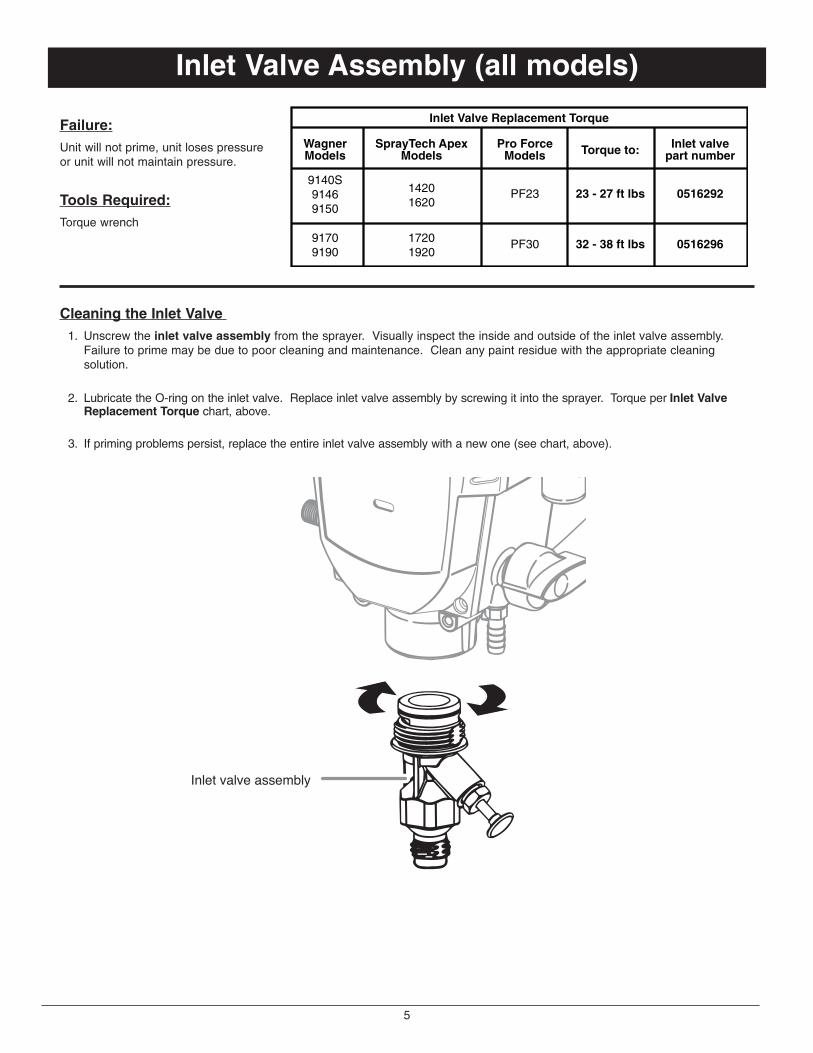
Inlet Valve Assembly (all models)
Failure:Unit will not prime, unit loses pressureor unit will not maintain pressure.
Tools Required:Torque wrench
Cleaning the Inlet Valve 1. Unscrew the inlet valve assembly from the sprayer. Visually inspect the inside and outside of the inlet valve assembly.
Failure to prime may be due to poor cleaning and maintenance. Clean any paint residue with the appropriate cleaningsolution.
2. Lubricate the O-ring on the inlet valve. Replace inlet valve assembly by screwing it into the sprayer. Torque per Inlet ValveReplacement Torque chart, above.
3. If priming problems persist, replace the entire inlet valve assembly with a new one (see chart, above).
Inlet valve assembly
Inlet Valve Replacement Torque
Torque to: Inlet valvepart number
WagnerModels
9140S91469150
SprayTech ApexModels
14201620
Pro ForceModels
PF23
91709190
17201920
PF30
23 - 27 ft lbs
32 - 38 ft lbs
0516292
0516296
6
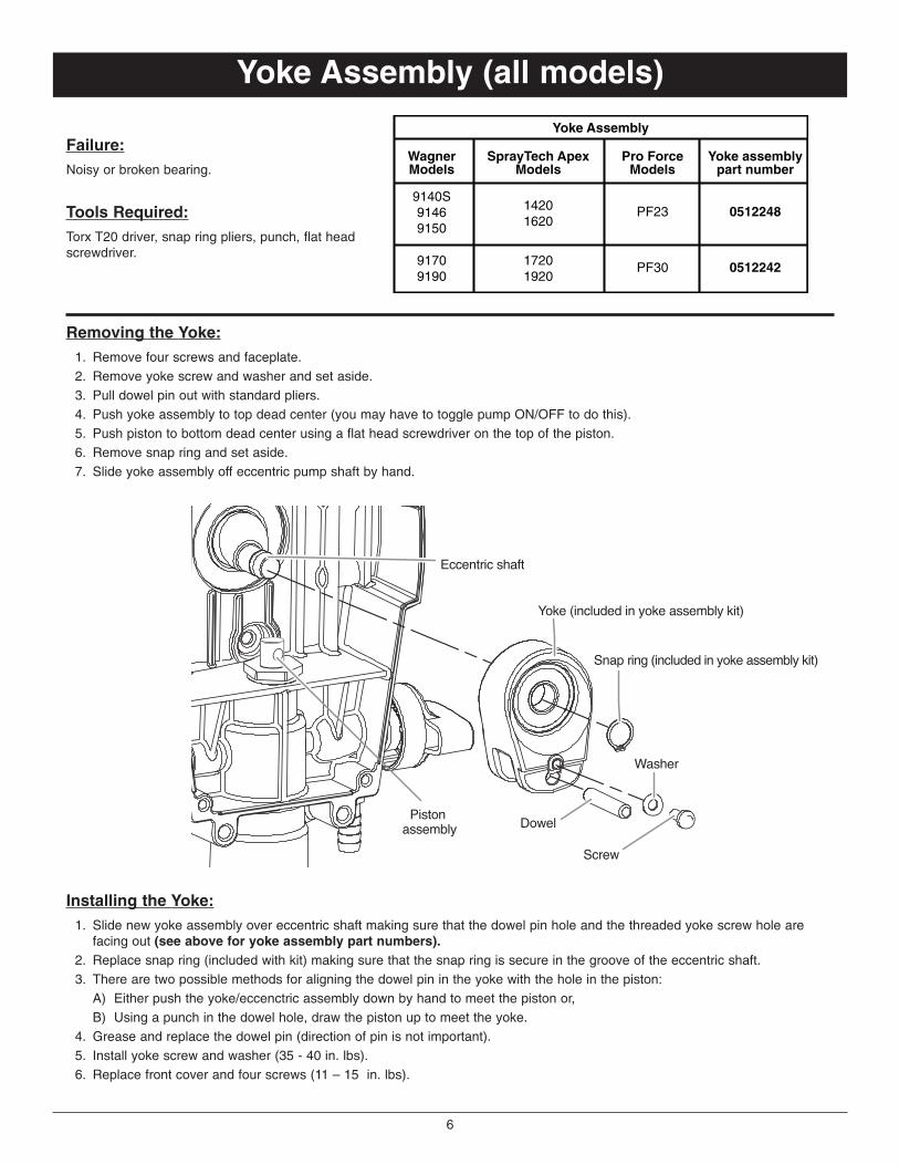
Yoke Assembly (all models)
Removing the Yoke:1. Remove four screws and faceplate.2. Remove yoke screw and washer and set aside.3. Pull dowel pin out with standard pliers.4. Push yoke assembly to top dead center (you may have to toggle pump ON/OFF to do this).5. Push piston to bottom dead center using a flat head screwdriver on the top of the piston.6. Remove snap ring and set aside.7. Slide yoke assembly off eccentric pump shaft by hand.
Installing the Yoke:1. Slide new yoke assembly over eccentric shaft making sure that the dowel pin hole and the threaded yoke screw hole are
facing out (see above for yoke assembly part numbers).2. Replace snap ring (included with kit) making sure that the snap ring is secure in the groove of the eccentric shaft.3. There are two possible methods for aligning the dowel pin in the yoke with the hole in the piston:
A) Either push the yoke/eccenctric assembly down by hand to meet the piston or,B) Using a punch in the dowel hole, draw the piston up to meet the yoke.
4. Grease and replace the dowel pin (direction of pin is not important).5. Install yoke screw and washer (35 - 40 in. lbs).6. Replace front cover and four screws (11 – 15 in. lbs).
Dowel
Screw
Washer
Snap ring (included in yoke assembly kit)
Yoke (included in yoke assembly kit)
Piston assembly
Eccentric shaft
Failure:Noisy or broken bearing.
Tools Required:Torx T20 driver, snap ring pliers, punch, flat headscrewdriver.
Yoke Assembly
Yoke assemblypart number
WagnerModels
9140S91469150
SprayTech ApexModels
14201620
Pro ForceModels
PF23
91709190
17201920
PF30
0512248
0512242

7
PRIME/SPRAY Valve Assembly (all models) Failure:Leak from valve or unit will prime but not spray.
Tools Required:Locking pliers or adjustable pliers; 7/32 hex wrench; shopgrease or petroleum jelly.
To Remove:1. Turn PRIME/SPRAY knob to PRIME to release any
pressure in the system.2. Place PRIME/SPRAY knob in SPRAY position (towards
ON/OFF switch).3. Using channel locks, grab PRIME/SPRAY knob on round
portion of knob, turn counter-clockwise, and pull assembly out.4. Use a hex wrench to remove the seat located in the
housing by turning it counter-clockwise.
SPRAY
PR
IME
Stem/Ballassembly*
Seat*
Valve housing
Spring*Star washer*
Hex nut*
Valve knob*
*included inPRIME/SPRAYvalve assembly
Retaining clip*
To Install:1. Tighten the new seat into the valve housing. Use a 7/32
inch hex wrench. Torque to 6-8 ft./lbs.2. Apply a light coating of oil around the o-ring on the new
stem/ball assembly.3. Push the stem/ball assembly into the seat in the valve
housing.4. Place the new spring and star washer around the
stem/ball assembly.5. Slide the new hex nut onto the stem of the stem/ball
assembly, thread it onto the valve housing and tightenwith a wrench. Torque the nut to 12-14 ft./lbs.
6. Apply a light coating of grease to the top of the cam.7. Slide the new cam onto the stem of the stem/ball
assembly and over the hex nut. The design of the cam
will allow the hex nut to fit inside the cam, causing thecam to lock in position.
NOTE: Position the cam on the hexnut so that the tab on the side of thecam is as close to the 6:00 positionas possible.
8. Place the new PRIME/SPRAY valveknob over the cam with the pointer onthe knob as close to the 6:00 positionas possible. Make sure the knob ispushed completely onto the cam (theknob should cover the camcompletely).
NOTE: The knob is designed to allow 90º of movementbetween the SPRAY and PRIME positions. The inside of theknob has a 90º opening in its circumference where the tabof the cam should be positioned to allow this movement.When placing the knob with the arrow in the 6:00 position,make sure that the tab on the cam is within the 90º openingon the inside of the knob. Then, make sure the knob is atthe end of its movement in the clockwise direction (this isthe SPRAY position) before continuing with this procedure.
9. Slowly turn the knob counterclockwise until the bottom ofthe knob moves out to where it is flush with the bottom ofthe cam (approximately 5–7º).
10. Using a 5/16” (8mm) nut driver, push the clip into therecessed portion of the knob with steady, even pressureuntil it stops.
NOTE - Do not hammer or wiggle the clip into position. Itwill damage the clip.
11. Check that the pressure control knob is turned to thelowest pressure setting.
12. Turn the PRIME/SPRAY knob to the SPRAY position.13. Run water through the system and check for leaks.14. Slowly turn the pressure control knob to increase the
pressure and continue to check for leaks. If there are noleaks, the unit is ready to use.
Back of PRIME/SPRAYvalve knob
90º Opening
Cam positioned with tab in
90º Opening
SP
RA
YPR
IME
Tab
Tab on cam in 6:00 position
PRIME/SPRAY Valve Assembly
PRIME/SPRAYassembly
part numberWagnerModels
9140S9146915091709190
SprayTechApex Models
1420162017201920
Pro ForceModels
PF23PF30
0278277

8
Piston Repair Kit (all models)
Failure:Unit will not prime or maintain pressure.
Tools Required:T20 Torx driver, torque wrench, flat head screwdriver, rubbermallet.
Disassembly of the Fluid Section1. Remove the suction set.2. Remove the front cover and the four screws that secure it
using a T20 Torx head driver. 3. Remove the yoke screw and washer that secures the
dowel pin. The dowel pin connects the yoke to the piston.4. Using a pliers, pull the dowel pin out.
5a. For Wagner models 9140S, 9146, and 9150:For Spray Tech Apex models 1420 and 1620:Pro Force model PF23:Rotate the pump shaft so the piston is in the top deadcenter position. This can be done by pushing on theyoke. This is required to disassemble all the parts.
5b. For Wagner models 9170 and 9190:For SprayTech Apex models 1720 and 1920:For Pro Force model PF30:Inspect the yoke assembly and piston. In order to removeall the necessary parts, the piston must not be in thebottom dead center position. If the piston is at the bottomof the stroke, install the front cover and screws, turn thepump on briefly to index the piston, unplug the unit, andrepeat step 2.
6. Unscrew and remove the inlet valve assembly. 7. Remove the piston assembly by pushing down on the
piston near the yoke. 8. Unscrew and remove the top nut using and adjustable
wrench. 9. Remove the worn seals using a flat head screwdriver or
punch. Remove the top seal from the top and the bottomseal from the bottom by pressing against the side of theseal and popping it out. Be sure not to scratch thehousing where the seals are located.
10. Clean the area where the new seals are to be installed.
Assembly of the Fluid Section1. Lubricate the new top seal with Separating Oil (P/N
0516913) or light household oil and by hand place the seal(cup side of seal down) into the top port of the housing.
2. Place a small amount of anit-seize on the threads of thetop nut. Place the top nut into the top of the housing andtighten with an adjustable wrench. This will drive the topseal into the correct position.
3. Turn the pump upside down.Lubricate the seal on thepiston/seal assembly similarto the top seal. Place thepiston/seal assembly into thebottom of the housing. Insertthe plastic insertion tool andthread into position toproperly seat the piston/seal.Thread fully until tight.Remove the insertion tool.
4. Install the new O-ring on the inlet valve assembly,lubricate with Separating Oil (P/N 0516913), thread intothe bottom (inlet) of the housing, and tighten with anadjustable wrench. This will drive the bottom seal into thecorrect position.
5. Align the piston with the yoke. Be careful not to damagethe piston.
6. Apply a lithum grease to the holes in the yoke where thedowel is inserted.
7. Install the dowel pin to connect the yoke to the piston.The piston may have to be moved up or down to do this.The inlet valve may need to be removed again to movethe piston.
8. Install the yoke screw and washer to secure the dowelpin.
9. Turn pump right side up and apply a few drops ofSeparating Oil or light household oil between the top nutand piston. This will prolong the seal life.
10. Install front cover and four (4) screws.11. Replace inlet valve. Install the suction set.
Insertiontool
Includedin pistonrepair kit
Top seal(cup down)
Top nut
Includedin pistonrepair kit
Piston/sealassembly
O-ring
NOTE - DO NOT attemptto remove the seals fromthe piston.
Inlet valve assembly
Dowel
Yoke
Screw
Washer
Piston Repair Kit
Piston repairkit part number
WagnerModels
9140S91469150
91709190
17201920
SprayTechApex Models
14201620
Pro ForceModels
PF23
PF30
0512228A
0516724
9
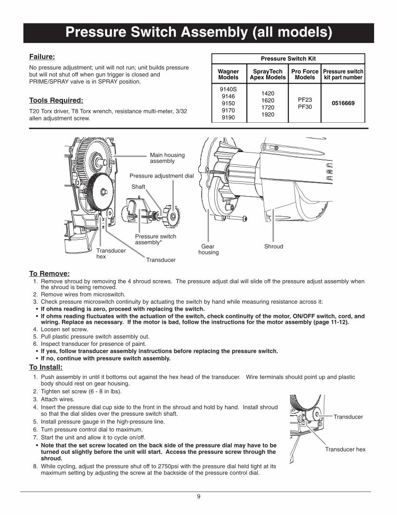
Pressure Switch Assembly (all models)
Failure:No pressure adjustment; unit will not run; unit builds pressurebut will not shut off when gun trigger is closed andPRIME/SPRAY valve is in SPRAY position.
Tools Required:T20 Torx driver, T8 Torx wrench, resistance multi-meter, 3/32allen adjustment screw.
Pressure Switch Kit
Pressure switchkit part number
WagnerModels
9140S9146915091709190
SprayTechApex Models
1420162017201920
Pro ForceModels
PF23PF30
0516669
Gear housing
Shroud
Pressure adjustment dial
Pressure switchassembly*
Transducer
Transducerhex
Shaft
Main housingassembly
To Remove:1. Remove shroud by removing the 4 shroud screws. The pressure adjust dial will slide off the pressure adjust assembly when
the shroud is being removed.2. Remove wires from microswitch.3. Check pressure microswitch continuity by actuating the switch by hand while measuring resistance across it:• If ohms reading is zero, proceed with replacing the switch.• If ohms reading fluctuates with the actuation of the switch, check continuity of the motor, ON/OFF switch, cord, and
wiring. Replace as necessary. If the motor is bad, follow the instructions for the motor assembly (page 11-12).4. Loosen set screw.5. Pull plastic pressure switch assembly out.6. Inspect transducer for presence of paint.• If yes, follow transducer assembly instructions before replacing the pressure switch.• If no, continue with pressure switch assembly.
To Install:1. Push assembly in until it bottoms out against the hex head of the transducer. Wire terminals should point up and plastic
body should rest on gear housing.2. Tighten set screw (6 - 8 in lbs).3. Attach wires.4. Insert the pressure dial cup side to the front in the shroud and hold by hand. Install shroud
so that the dial slides over the pressure switch shaft.5. Install pressure gauge in the high-pressure line.6. Turn pressure control dial to maximum.7. Start the unit and allow it to cycle on/off.• Note that the set screw located on the back side of the pressure dial may have to be
turned out slightly before the unit will start. Access the pressure screw through theshroud.
8. While cycling, adjust the pressure shut off to 2750psi with the pressure dial held tight at itsmaximum setting by adjusting the screw at the backside of the pressure control dial.
Transducer
Transducer hex

10
Transducer Assembly (all models)
Failure:Paint leaks out of weep hole and bottom of shroud.
Tools Required:3/4” (19mm) socket.
Transducer Kit
Transducer kitpart number
WagnerModels
9140S9146915091709190
SprayTechApex Models
1420162017201920
Pro ForceModels
PF23PF30 0516267
Pressure adjust dial
Transducer
Transducerhex head
Pressure switchassembly
Gear assembly Shroud
O-ring
To Remove:1. Remove shroud by removing the 4 shroud screws. 2. Loosen set screw on the pressure switch.3. Pull plastic pressure assembly out.4. Inspect transducer to verify the presence of paint.• If yes, follow transducer assembly instructions before replacing the pressure switch.• If no paint is visible, the leak must be from the piston seals or spill.
5. Unscrew the transducer hex head.6. Pull transducer assembly out.
To Install:1. Install new assembly. Make sure spring is well greased. Grease O-ring to aid in keeping transducer in place.2. Torque to 70 -75 in lbs.3. Push pressure switch assembly in until it bottoms out against the hex head of the transducer. Wire terminals should point up
and plastic body should rest on gear housing.4. Tighten set screw.5. Attach wires.6. Install shroud so that the dial slides over the pressure switch shaft.7. Install pressure gauge in the discharge high-pressure line.8. Turn pressure control dial to maximum.9. Start the unit and allow it to cycle on/off.• Note that the set screw located on the back side of the pressure dial may have to be turned out slightly before the
unit will start. Access the pressure screw through the shroud.10. While cycling, adjust the pressure shut off to 2750psi with the pressure dial held tight at its maximum setting by adjusting the
screw at the backside of the pressure control dial.

11
TitleMotor Assembly Wagner9140S 9146 9150
SprayTech Apex1420 1620
Pro ForcePF23
Failure:The unit does not run with 1) power cord plugged in; 2) ON/ OFFswitch is in ON position; 3) Pressure control dial in maximumsetting and 4) PRIME/SPRAY knob in the PRIME position.
Tools Required:Torx 25 driver, Torx T20 driver, 1/4 inch wrench or socket, smallflat head screwdriver.
Motor Assembly
Motor kitpart number
WagnerModels
9140S91469150
SprayTechApex Models
14201620
Pro ForceModels
PF23 0516293
Pump housing
Thrust washerShroudGear housing
Eccentric gear72/13 gear
Motor assembly
Pressure switch assembly
To Remove:1. Remove shroud by removing the 4 shroud screws using a Torx T20 driver. The pressure control dial will slide off the pressure
switch assembly when the shroud is being removed.2. Disconnect all wire leads including the ground wire.3. Check continuity of motor. Check resistance by attaching a probe to the white wire lead and one to the black wire lead from the
motor.• A reading of zero ohms indicates an open circuit verifying that the motor is bad.• A reading other than zero indicates a good motor.
4. If bad, proceed with motor replacement. If good, check the ON/OFF switch, pressure switch assembly, and power cord forcontinuity. Replace if bad.
5. Remove the four screws holding the gear housing to the pump housing using the Torx T25 driver.6. Pull the motor / gear assembly straight out.7. Make sure the thrust washer stays on the eccentric gear.
To Replace:1. Grease motor pinion, and place new motor / gear housing assembly back into position and secure with four screws (45 – 50 in lbs).2. Connect electrical wires, white to white, green to ground, black to pressure switch (see schematic, below).3. Insert the pressure dial with cup side
to the front in the shroud and hold byhand. Install shroud so that the dialslides over the pressure switch shaft.
4. Install four screws to secure theshroud (11 – 15 in lbs).
5. Plug unit in, turn switch on, increasepressure to start pump and confirmproper operation. ON/OFF
switch0516484
Power cord0516271
Pressure switch
Motor0516305
Wire nut
RED BLUE BLUE

12
TitleMotor Assembly Wagner9170 9190
SprayTech Apex1720 1920
Pro ForcePF30
Failure:The unit does not run with 1) power cord plugged in; 2) ON/ OFFswitch is in ON position; 3) Pressure control dial in maximumsetting and 4) PRIME/SPRAY knob in the PRIME position.
Tools Required:Torx 25 driver, Torx T20 driver, 1/4 inch wrench or socket, smallflat head screwdriver.
Motor Assembly
Motor kitpart number
WagnerModels
9170
SprayTechApex Models
1720
Pro ForceModels
PF30 0516128
9190 1920 0516129
Fuse part number
53732
9852309
Pump housing
Shroud Gear housingMotor assembly
99/13 gearEccentric gear
RelayFuse holder
Pressure switch assembly
To Remove:1. Remove shroud by removing the 4 shroud screws. 2. Remove fuse by turning gray fuse holder cap 1/8 turn counter-clockwise and inspect. Replace if necessary.3. Remove red and black motor leads from relay.4. Check continuity of motor. Check resistance by attaching a probe to the red and black motor leads.• A reading of zero ohms indicates an open circuit verifying that the motor is bad.• A reading other than zero indicates a good motor.
5. If bad, proceed with motor replacement. If good, check the on/off switch, pressure adjust pressure switch, and power cord forcontinuity. Replace if bad.
6. Disconnect green ground wire, red pressure switch wires from relay, black power wire from the fuse holder, white power cord wirefrom relay and black wire from fuse holder to relay (see schematic below).
7. Remove fuse holder from motor baffle.8. Remove the four screws holding the gear
housing to the pump housing using a TorxT25.
9. Pull the motor / gear assembly straight out.
To Replace:1. Grease motor pinion and place new motor
/ gear assembly back into position andsecure with four screws (45 – 50 in lbs).
2. Connect electrical wires (see schematic,right).
3. Insert the pressure dial with cup side tothe front in the shroud and hold by hand.Install shroud so that the dial slides overthe pressure switch shaft.
4. Install four screws to secure the shroud(11 – 15 in lbs).
5. Plug unit in, turn switch on, increasepressure to start pump and confirm properoperation.
SP2
SP4
SP5
SP3
SP1

*These units do not have a replaceable individual eccentricassembly. If an eccentric gear assembly fails on a unit listedabove, call Wagner Technical Service.
13
TitleEccentric Assembly Wagner9140S 9146 9150
SprayTech Apex1420 1620
Pro ForcePF23
Failure:Motor appears to turn normally, but he eccentric assembly does not.
Tools Required:Torx 25 driver, Torx T20 driver, 1/4 inch wrench
Eccentric Assembly
Eccentric kitpart number
WagnerModels
9140S914691509170*9190*
SprayTechApex Models
142016201720*1920*
Pro ForceModels
PF23PF30* 0512236
To Remove:1. Remove shroud by removing the 4 shroud screws. The pressure adjust dial will slide off the pressure adjust assembly when the
shroud is being removed 2. Disconnect wire leads.3. Disconnect green ground lead using the 1/4-inch socket.4. Remove the four screws holding the gear housing to the pump housing using the Torx T25 driver.5. Pull the motor / casting assembly straight out.6. Inspect gears for failure:• Motor pinion gear failed: Replace motor assembly and 72/13 tooth gear by following the motor assembly instructions
(page 9).• 13-tooth portion of the 72/13-tooth gear failed: Replace gear by following the motor assembly instructions (page 9) and
the eccentric assembly by following the instructions below.• Eccentric gear failed: Replace eccentric assembly by following the instructions below.
7. Remove the faceplate by removing the four screws with the Torx T20 driver.8. Remove the snap ring with snap ring pliers.9. Remove yoke assembly (yoke, dowel, washer and screw).
10. Slide gear and eccentric out by hand from motor side and discard.
To Install:1. Install new eccentric assembly.2. Slide yoke onto the eccentric shaft.3. Add snap ring, this will ensure that the assembly is installed
completely.4. Verify that the thrust washer is installed on the back side of the
gear (eccentric gear only).5. Add gear lube grease or similar to 72/13-tooth gear assembly
and eccentric plastic gear. Excess grease in pump housingcan also be used.
6. Place the motor / gear assembly back into position and securewith four screws (torque to 45-50 in lbs).
7. Connect electrical wires, green to ground, (see schematic onpage 11).
8. Insert the pressure dial cup side to the front in the shroud andhold by hand. Install shroud so that the dial slides over thepressure switch shaft.
9. Install four screws to secure the shroud.10. Plug unit in, turn switch on, pressure switch to maximum.
Pump housing
Thrust washer*ShroudGear housing
Eccentric gear* Yoke Snap ring
Washer
Dowel Screw
72/13 gearMotor assembly
Pressure switch assembly
*included ineccentricassembly
DowelScrew
Washer
Snap ring
Yoke
Piston assembly
Eccentric shaft

14
TitleParts List Wagner9140S 9146 9150
SprayTech Apex1420 1620
Pro ForcePF23
Item Part # Description Quantity1 9805251 Shroud screw (8 - 32 X 1/2)..............................................................................................................42 9805252 Gear housing screw (10 - 24 X 1 1/4) ..............................................................................................43 0516293 Motor assembly ................................................................................................................................14 0516216 72 - 13 Gear assembly......................................................................................................................15 0516236 Eccentric gear assembly ..................................................................................................................16 0278277 PRIME/SPRAY valve assembly (other side of main housing assembly) ..........................................17 0512242 Yoke / snap ring assembly ................................................................................................................18 9822608 Washer, flat ......................................................................................................................................19 0293395 Yoke screw (8 - 32 X 3/8 TAP)..........................................................................................................110 9832105 Dowel pin ..........................................................................................................................................111 0516272 ON/OFF switch, no power cord (9140, 1420) ..................................................................................1
0521903 ON/OFF switch and power cord (9150, 1620) ..................................................................................112 05045 Hose fitting ........................................................................................................................................113 0516292 Inlet valve assembly..........................................................................................................................114 0516267 Transducer kit....................................................................................................................................115 0516669 Pressure switch assembly ................................................................................................................116 0512334 Pressure control dial ........................................................................................................................117 0516456 Shroud ..............................................................................................................................................1
13141516
17
1 2 3 4 5 6 7
8
1011
12
9

15
TitleParts List Wagner9170 9190
SprayTech Apex1720 1920
Pro ForcePF30
Item Part # Description Quantity1 9805251 Shroud screw (8 - 32 X 1/2)..............................................................................................................42 9805252 Gear housing screw (10 - 24 X 1 1/4) ..............................................................................................43 0516128 Motor assembly (9170, 1720, PF30) ................................................................................................1
0516129 Motor assembly (9190, 1920) ..........................................................................................................14 0512213 99 - 17 Gear assembly......................................................................................................................15 0278277 PRIME/SPRAY valve assembly ........................................................................................................16 0512242 Yoke / snap ring assembly ................................................................................................................17 9822608 Washer, flat ......................................................................................................................................18 0293395 Yoke screw (8 - 32 X 3/8 TAP)..........................................................................................................19 9830103 Dowel pin ..........................................................................................................................................110 0521904 ON/OFF switch and power cord (9170) ............................................................................................1
0521905 ON/OFF switch and power cord (1720, PF30) ................................................................................10521906 ON/OFF switch and power cord (9190, 1920) ..................................................................................1
11 05045 Hose fitting ........................................................................................................................................112 0516296 Inlet valve assembly..........................................................................................................................113 0516267 Transducer kit....................................................................................................................................114 0516669 Pressure switch assembly (9170, 1720, PF30) ................................................................................1
0512245 Pressure switch assembly (9190, 1920) ..........................................................................................115 0512334 Pressure control dial ........................................................................................................................116 0512352 Shroud ..............................................................................................................................................1
10
11
12
16
13
4 531 26
7
9 8
1415

16
TitleParts List (all Wagner models)
Item Part # Description Quantity1 0512336 Stand assembly (9140S) ..................................................................................................................12 0512405 Face plate (9140S)............................................................................................................................13 9885546 Plug ..................................................................................................................................................44 0516516 Hose bracket (9146, 9150, 9170) ....................................................................................................1
0516517 Hose bracket (9190)..........................................................................................................................15 9805228 Pail bracket bolt ................................................................................................................................26 0516581 Oiler cap (all cart units) ....................................................................................................................17 0516650 Pail bracket ......................................................................................................................................18 0519200 Face plate (all cart units) ..................................................................................................................19 0516287 Cart assembly (9146, 9150)..............................................................................................................1
0516288 Cart assembly (9170)........................................................................................................................10516289 Cart assembly (9190)........................................................................................................................1
10 0278369 Wheel (9146, 9150) ..........................................................................................................................20278370 Wheel (9170) ....................................................................................................................................20278373 Wheel (9190) ....................................................................................................................................2
11 9890113 Wheel cap (9146, 9150, 9170)..........................................................................................................29890104 Wheel cap (9190)..............................................................................................................................2
12 0516498 Cap....................................................................................................................................................113 0516505 Cap....................................................................................................................................................1
1
2
7
4
6
3
9
10
11
8
1213
5

17
TitleParts List (all SprayTech Apex models)
Item Part # Description Quantity1 0512336 Stand assembly (1420) ....................................................................................................................12 0512455 Face plate (1420) ..............................................................................................................................13 9885546 Plug ..................................................................................................................................................44 0516516 Hose bracket (1620, 1720) ..............................................................................................................1
0516517 Hose bracket (1920)..........................................................................................................................15 0516581 Oiler cap............................................................................................................................................16 0516650 Pail bracket ......................................................................................................................................17 9805228 Pail bracket bolt ................................................................................................................................28 0516722 Face plate with oiler (1620) ..............................................................................................................1
0516723 Face plate with oiler (1720, 1920) ....................................................................................................19 0516287 Cart assembly (1620)........................................................................................................................1
0516288 Cart assembly (1720)........................................................................................................................10516289 Cart assembly (1920)........................................................................................................................1
10 0278369 Wheel (1620) ....................................................................................................................................20278370 Wheel (1720) ....................................................................................................................................20278373 Wheel (1920) ....................................................................................................................................2
11 9890113 Wheel cap (1620, 1720)....................................................................................................................29890104 Wheel cap (1920)..............................................................................................................................2
12 0516498 Cap....................................................................................................................................................113 0516505 Cap....................................................................................................................................................1
5
2
1
3
9
8
10
11
12
4
6 7
13
18
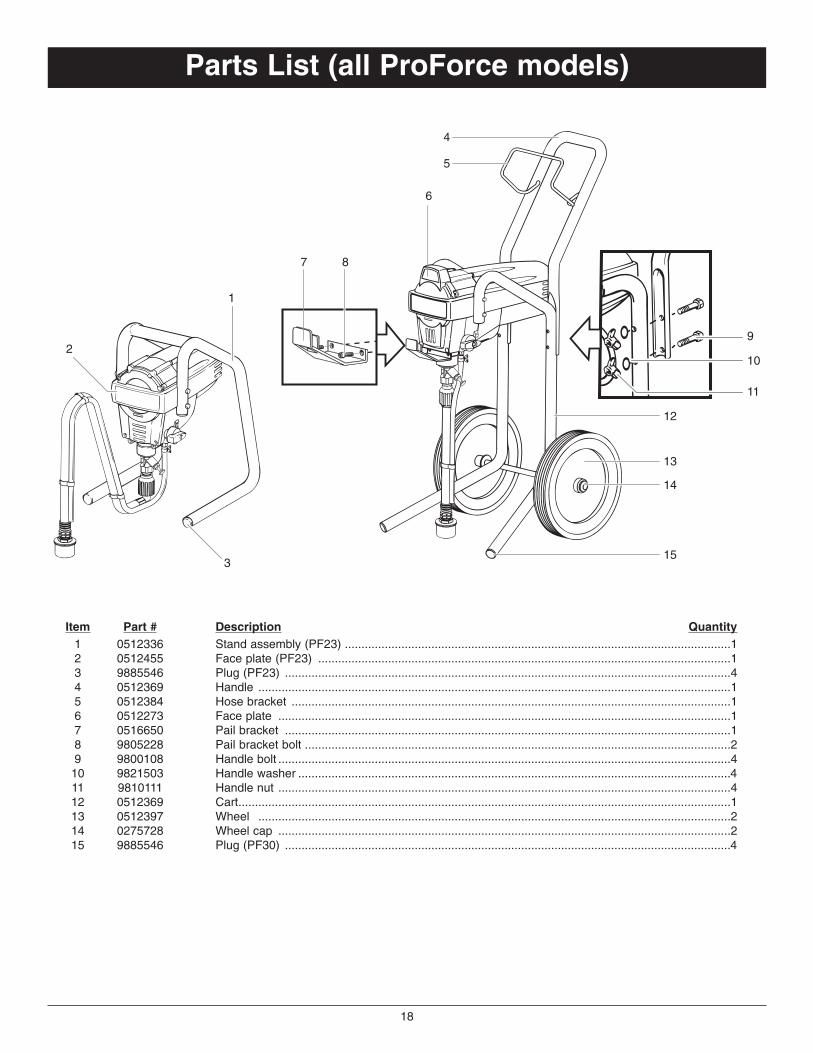
TitleParts List (all ProForce models)
Item Part # Description Quantity1 0512336 Stand assembly (PF23) ....................................................................................................................12 0512455 Face plate (PF23) ............................................................................................................................13 9885546 Plug (PF23) ......................................................................................................................................44 0512369 Handle ..............................................................................................................................................15 0512384 Hose bracket ....................................................................................................................................16 0512273 Face plate ........................................................................................................................................17 0516650 Pail bracket ......................................................................................................................................18 9805228 Pail bracket bolt ................................................................................................................................29 9800108 Handle bolt ........................................................................................................................................410 9821503 Handle washer ..................................................................................................................................411 9810111 Handle nut ........................................................................................................................................412 0512369 Cart....................................................................................................................................................113 0512397 Wheel ..............................................................................................................................................214 0275728 Wheel cap ........................................................................................................................................215 9885546 Plug (PF30) ......................................................................................................................................4
1
2
3
5
6
4
8
14
15
13
12
7
9
10
11

19
TitleParts List (suction set)
Item Part # Description Quantity1 0516219 Suction set (all stand models) ..........................................................................................................1
0516278 Suction set (all cart models)..............................................................................................................12 0512389 Return tube (all cart models) ............................................................................................................13 0512390 Clip ....................................................................................................................................................14 0516284 Inlet filter............................................................................................................................................15 0327226 Squeeze clip......................................................................................................................................16 9885553 Return tube fitting..............................................................................................................................1
1
2
3
4
5
6
Date Code Location (all models)
Date code location

NOTES