Embed Size (px)
Citation preview

312537GENElectric Airless Sprayers
- For Portable Airless Spraying of Architectural Coatings and Paints. For professional use only. Not for use in explosive atmospheres.-
3300 psi (22.8 MPa, 227 bar) Maximum Working Pressure
IMPORTANT SAFETY INSTRUCTIONSRead all warnings and instructions in this manual. Save these instructions.
ASM Zip-Spray™ 2700 Plus 110V: 247558ASM Zip-Spray™ 2700 Plus 240V: 247565ASM Zip-Spray™ 3100 Plus 110V: 247559ASM AllPro Mach 8600 Plus 110V: 247561ASM AllPro Mach 11000 Plus 110V: 247562ASM H2900 Plus 110V: 247564ASM H2900 Plus 240V: 247563
Repair and Parts
ti13450a
Related Manuals
312538
312363 (English)312364 (Spanish)312365 (French)
310643

Table of Contents
2 312537G
Table of ContentsTable of Contents . . . . . . . . . . . . . . . . . . . . . . . . . . 2Warnings . . . . . . . . . . . . . . . . . . . . . . . . . . . . . . . . . 3Component Identification and Function . . . . . . . . 7General Repair Information . . . . . . . . . . . . . . . . . . 8
Pressure Relief Procedure . . . . . . . . . . . . . . . . . 8Grounding . . . . . . . . . . . . . . . . . . . . . . . . . . . . . . . . 9Troubleshooting . . . . . . . . . . . . . . . . . . . . . . . . . . . 10
Mechanical/Fluid Flow . . . . . . . . . . . . . . . . . . . . 10Electrical . . . . . . . . . . . . . . . . . . . . . . . . . . . . . . 12
Pressure Control Board . . . . . . . . . . . . . . . . . . . . 19100 - 120 Vac North American and Japan/Taiwan
Motor Control Board . . . . . . . . . . . . . . . . . . 19240 Vac Motor Control Board . . . . . . . . . . . . . . 22240 Vac Filter Board . . . . . . . . . . . . . . . . . . . . . 24110 Vac U.K. Motor Control Board . . . . . . . . . . 25110 Vac U.K. Filter Board . . . . . . . . . . . . . . . . . 27Pressure Adjust Potentiometer . . . . . . . . . . . . . 29Pressure Control Transducer . . . . . . . . . . . . . . 30
Drive and Bearing Housing Replacement . . . . . . 32Disassembly . . . . . . . . . . . . . . . . . . . . . . . . . . . 32Assembly . . . . . . . . . . . . . . . . . . . . . . . . . . . . . . 32
Motor Replacement . . . . . . . . . . . . . . . . . . . . . . . . 34Removal . . . . . . . . . . . . . . . . . . . . . . . . . . . . . . 34Installation . . . . . . . . . . . . . . . . . . . . . . . . . . . . . 34
Displacement Pump Replacement for 695/795 . . 36Removal . . . . . . . . . . . . . . . . . . . . . . . . . . . . . . 36Installation . . . . . . . . . . . . . . . . . . . . . . . . . . . . . 37
Displacement Pump Replacement 1095/1595/Mark V 38Removal . . . . . . . . . . . . . . . . . . . . . . . . . . . . . . 38Installation . . . . . . . . . . . . . . . . . . . . . . . . . . . . . 39
Notes . . . . . . . . . . . . . . . . . . . . . . . . . . . . . . . . . . . . 41Parts (Series A and B) . . . . . . . . . . . . . . . . . . . . . . 42
Parts List (Series A and B) . . . . . . . . . . . . . . . . 43Parts (Series A) . . . . . . . . . . . . . . . . . . . . . . . . . . . 44
Parts List (Series A) . . . . . . . . . . . . . . . . . . . . . 45Parts (Series B) . . . . . . . . . . . . . . . . . . . . . . . . . . . 46
Parts List (Series B) . . . . . . . . . . . . . . . . . . . . . 47Wiring Diagrams (Series A) . . . . . . . . . . . . . . . . . . 48
Wiring Diagram . . . . . . . . . . . . . . . . . . . . . . . . . 49Wiring Diagram (Series B) . . . . . . . . . . . . . . . . . . . 50
Wiring Diagram . . . . . . . . . . . . . . . . . . . . . . . . . 51Wiring Diagram . . . . . . . . . . . . . . . . . . . . . . . . . 52Models: 247563, 247565 Series B . . . . . . . . . . 52
Notes . . . . . . . . . . . . . . . . . . . . . . . . . . . . . . . . . . . . 53ASM Standard Warranty . . . . . . . . . . . . . . . . . . . . 54

Warnings
312537G 3
WarningsThe following warnings are for the setup, use, grounding, maintenance, and repair of this equipment. The exclama-tion point symbol alerts you to a general warning and the hazard symbols refer to procedure-specific risks. When these symbols appear in the body of this manual, refer back to these Warnings. Product-specific hazard symbols and warnings not covered in this section may appear throughout the body of this manual where applicable.
WARNINGWARNINGWARNINGWARNINGGROUNDING This product must be grounded. In the event of an electrical short circuit, grounding reduces the risk of electric shock by providing an escape wire for the electric current. This product is equipped with a cord having a grounding wire with an appropriate grounding plug. The plug must be plugged into an outlet that is properly installed and grounded in accordance with all local codes and ordinances.
• Improper installation of the grounding plug is able to result in a risk of electric shock.
• When repair or replacement of the cord or plug is required, do not connect the grounding wire to either flat blade terminal.
• The wire with insulation having an outer surface that is green with or without yellow stripes is the grounding wire.
• Check with a qualified electrician or serviceman when the grounding instructions are not completely understood, or when in doubt as to whether the product is properly grounded.
• Do not modify the plug provided; if it does not fit the outlet, have the proper outlet installed by a qualified electrician.
• This product is for use on a nominal 120V circuit and has a grounding plug similar to the plug illustrated in the figure below.
• Only connect the product to an outlet having the same configuration as the plug.
• Do not use an adapter with this product.
Extension Cords:
• Use only a 3-wire extension cord that has a 3-blade grounding plug and a 3-slot receptacle that accepts the plug on the product.
• Make sure your extension cord is not damaged. If an extension cord is necessary, use 12 AWG
(2.5 mm2) minimum to carry the current that the product draws.
• An undersized cord results in a drop in line voltage and loss of power and overheating.

Warnings
4 312537G
WARNINGWARNINGWARNINGWARNINGFIRE AND EXPLOSION HAZARDFlammable fumes, such as solvent and paint fumes, in work area can ignite or explode. To help prevent fire and explosion:
• Do not spray flammable or combustible materials near an open flame or sources of ignition such as cigarettes, motors, and electrical equipment.
• Paint or solvent flowing through the equipment is able to result in static electricity. Static electricity creates a risk of fire or explosion in the presence of paint or solvent fumes. All parts of the spray system, including the pump, hose assembly, spray gun, and objects in and around the spray area shall be properly grounded to protect against static discharge and sparks. Use Graco conductive or grounded high-pressure airless paint sprayer hoses.
• Do not clean with materials having flash points lower than 70° F (21° C). Use water-based material or mineral spirits-type material only. For complete information about your fluid, request the MSDS from the fluid distributor or retailer.
• Verify that all containers and collection systems are grounded to prevent static discharge.
• Connect to a grounded outlet and use grounded extensions cords. Do not use a 3-to-2 adapter.
• Do not use a paint or a solvent containing halogenated hydrocarbons.
• Keep spray area well-ventilated. Keep a good supply of fresh air moving through the area. Keep pump assembly in a well ventilated area. Do not spray pump assembly.
• Do not smoke in the spray area.
• Do not operate light switches, engines, or similar spark producing products in the spray area.
• Keep area clean and free of paint or solvent containers, rags, and other flammable materials.
• Know the contents of the paints and solvents being sprayed. Read all Material Safety Data Sheets (MSDS) and container labels provided with the paints and solvents. Follow the paint and solvents manufacturer’s safety instructions.
• Fire extinguisher equipment shall be present and working.
• Sprayer generates sparks. When flammable liquid is used in or near the sprayer or for flushing or cleaning, keep sprayer at least 20 feet (6 m) away from explosive vapors.
ELECTRIC SHOCK HAZARDThis equipment must be grounded. Improper grounding, setup, or usage of the system can cause electric shock.
• Turn off and disconnect power cord before servicing equipment.
• Use only grounded electrical outlets.
• Use only 3-wire extension cords.
• Ensure ground prongs are intact on power and extension cords.
• Do not expose to rain. Store indoors.

Warnings
312537G 5
WARNINGWARNINGWARNINGWARNINGSKIN INJECTION HAZARDDo not aim the gun at, or spray any person or animal.• Keep hands and other body parts away from the discharge. For example, do not try to stop leaks with
any part of the body.
• Always use the nozzle tip guard. Do not spray without nozzle tip guard in place.
• Use Graco nozzle tips.
• Use caution when cleaning and changing nozzle tips. In the case where the nozzle tip clogs while spraying, follow the Pressure Relief Procedure for turning off the unit and relieving the pressure before removing the nozzle tip to clean.
• Do not leave the unit energized or under pressure while unattended. When the unit is not in use, turn off the unit and follow the Pressure Relief Procedure for turning off the unit.
• High-pressure spray is able to inject toxins into the body and cause serious bodily injury. In the event that injection occurs, get immediate surgical treatment.
• Check hoses and parts for signs of damage. Replace any damaged hoses or parts.
• This system is capable of producing 3300 psi. Use Graco replacement parts or accessories that are rated a minimum of 3300 psi.
• Always engage the trigger lock when not spraying. Verify the trigger lock is functioning properly.
• Verify that all connections are secure before operating the unit.
• Know how to stop the unit and bleed pressure quickly. Be thoroughly familiar with the controls.
EQUIPMENT MISUSE HAZARDMisuse can cause death or serious injury.
• Always wear appropriate gloves, eye protection, and a respirator or mask when painting.
• Do not operate or spray near children. Keep children away from equipment at all times.
• Do not overreach or stand on an unstable support. Keep effective footing and balance at all times.
• Stay alert and watch what you are doing.
• Do not leave the unit energized or under pressure while unattended. When the unit is not in use, turn off the unit and follow the Pressure Relief Procedure for turning off the unit.
• Do not operate the unit when fatigued or under the influence of drugs or alcohol.
• Do not kink or over-bend the hose.
• Do not expose the hose to temperatures or to pressures in excess of those specified by Graco.
• Do not use the hose as a strength member to pull or lift the equipment.
PRESSURIZED ALUMINUM PARTS HAZARDUse of fluids that are incompatible with aluminum in pressurized equipment can cause serious chemical reaction and equipment rupture. Failure to follow this warning can result in death, serious injury, or property damage.
• Do not use 1,1,1-trichloroethane, methylene chloride, other halogenated hydrocarbon solvents or fluids containing such solvents.
• Many other fluids may contain chemicals that can react with aluminum. Contact your material supplier for compatibility.

Warnings
6 312537G
WARNINGWARNINGWARNINGWARNINGMOVING PARTS HAZARDMoving parts can pinch, cut or amputate fingers and other body parts.
• Keep clear of moving parts.
• Do not operate equipment with protective guards or covers removed.
• Pressurized equipment can start without warning. Before checking, moving, or servicing equipment, follow the Pressure Relief Procedure and disconnect all power sources.
PERSONAL PROTECTIVE EQUIPMENTYou must wear appropriate protective equipment when operating, servicing, or when in the operating area of the equipment to help protect you from serious injury, including eye injury, hearing loss, inhalation of toxic fumes, and burns. This equipment includes but is not limited to:
• Protective eyewear, and hearing protection.
• Respirators, protective clothing, and gloves as recommended by the fluid and solvent manufacturer.

Component Identification and Function
312537G 7
Component Identification and Function
English1 Premium Digital Display
2 ON/OFF switch
3 Pressure control
4 Prime / Spray valve
5 Filter
6 AutoClean2™
7 Siphon tube
8 Pump
9 Bearing Housing / ProConnect™
10 Fluid Outlet
11 Drain tube
12 Trigger Lock
13 Model/serial tag
14 WatchDog™ Switch (not Mark V)
1.
2.
3.
4.
5. 6. 7. 8.
9.
10.
11.
12.
13.14.
ti13451a

General Repair Information
8 312537G
General Repair Information
Pressure Relief Procedure
1. Turn pressure control knob to zero.
2. Turn ON/OFF switch to OFF.
3. Unplug power supply cord.
4. Hold metal part of gun firmly to grounded metal pail. Trigger gun to relieve pressure.
5. Lock gun safety latch.
6. Open prime valve. Leave prime valve open until ready to spray again.
If suspected that spray tip or hose is completelyclogged, or that pressure has not been fully re-lieved after following steps above, VERYSLOWLY loosen tip guard retaining nut or hoseend coupling to relieve pressure gradually,then loosen completely. Then clear tip or hoseobstruction.
1. Keep all screws, nuts, washers, gaskets, and electrical fittings removed during repair procedures. These parts are not normally provided with replacement assemblies.
2. Test repair after problem is corrected.
3. If sprayer does not operate properly, review repair procedure to verify procedure was done correctly. If necessary, see Troubleshooting, page 10, for other possible solutions.
System pressure must be manually relieved to pre-vent system from starting or spraying accidentally.Fluid under high pressure can be injected throughskin and cause serious injury. To reduce risk of in-jury from injection, splashing fluid, or moving parts,follow Pressure Relief Procedure whenever you:• are instructed to relieve pressure• stop spraying• check or service any system equipment• install or clean spray tip
NOTICE
To reduce risk of pressure control malfunction:
• Use needle-nose pliers to disconnect wire. Never pull on wire, pull on connector.
• Mate wire connectors properly. Center flat blade of insulated male connector in female connector.
• Route wires carefully to avoid interference with other connections of pressure control. Do not pinch wires between cover and control box.
To reduce risk of serious injury, including electricshock, do not touch moving or electrical parts withfingers or tools while testing repair. Shut off and un-plug sprayer when inspection is complete. Install allcovers, guards, gaskets, screws, washers andshroud before operating sprayer.
Grounding
312537G 9
Grounding
1. Ultra Max II 695, 795 and 1095 100-200 Vac models require a 50/60 Hz, 15A circuit with a grounding receptacle. Ultra Max II 1595/Mark V 120 Vac models require a 50/60 Hz 20A circuit with a grounding receptacle; 220-240 Vac models require a 50/60 Hz, 10A circuit with a grounding receptacle.
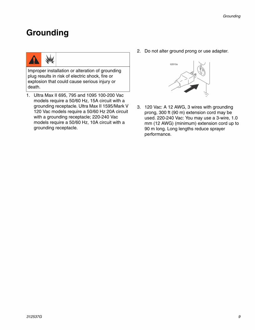
2. Do not alter ground prong or use adapter.
3. 120 Vac: A 12 AWG, 3 wires with grounding prong, 300 ft (90 m) extension cord may be used. 220-240 Vac: You may use a 3-wire, 1.0 mm (12 AWG) (minimum) extension cord up to 90 m long. Long lengths reduce sprayer performance.
Improper installation or alteration of grounding plug results in risk of electric shock, fire or explosion that could cause serious injury or death.
ti2810a
Troubleshooting
10 312537G
Troubleshooting
Mechanical/Fluid Flow
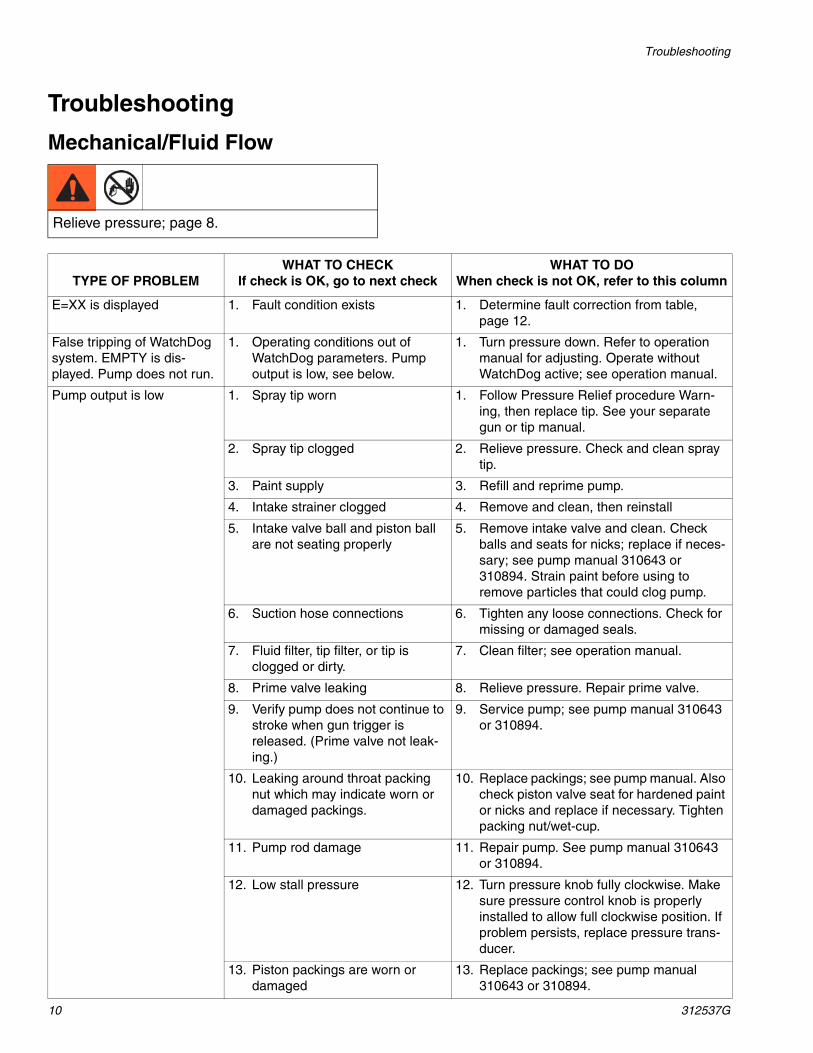
Relieve pressure; page 8.
TYPE OF PROBLEMWHAT TO CHECK
If check is OK, go to next checkWHAT TO DO
When check is not OK, refer to this column
E=XX is displayed 1. Fault condition exists 1. Determine fault correction from table, page 12.
False tripping of WatchDog system. EMPTY is dis-played. Pump does not run.
1. Operating conditions out of WatchDog parameters. Pump output is low, see below.
1. Turn pressure down. Refer to operation manual for adjusting. Operate without WatchDog active; see operation manual.
Pump output is low 1. Spray tip worn 1. Follow Pressure Relief procedure Warn-ing, then replace tip. See your separate gun or tip manual.
2. Spray tip clogged 2. Relieve pressure. Check and clean spray tip.
3. Paint supply 3. Refill and reprime pump.
4. Intake strainer clogged 4. Remove and clean, then reinstall
5. Intake valve ball and piston ball are not seating properly
5. Remove intake valve and clean. Check balls and seats for nicks; replace if neces-sary; see pump manual 310643 or 310894. Strain paint before using to remove particles that could clog pump.
6. Suction hose connections 6. Tighten any loose connections. Check for missing or damaged seals.
7. Fluid filter, tip filter, or tip is clogged or dirty.
7. Clean filter; see operation manual.
8. Prime valve leaking 8. Relieve pressure. Repair prime valve.
9. Verify pump does not continue to stroke when gun trigger is released. (Prime valve not leak-ing.)
9. Service pump; see pump manual 310643 or 310894.
10. Leaking around throat packing nut which may indicate worn or damaged packings.
10. Replace packings; see pump manual. Also check piston valve seat for hardened paint or nicks and replace if necessary. Tighten packing nut/wet-cup.
11. Pump rod damage 11. Repair pump. See pump manual 310643 or 310894.
12. Low stall pressure 12. Turn pressure knob fully clockwise. Make sure pressure control knob is properly installed to allow full clockwise position. If problem persists, replace pressure trans-ducer.
13. Piston packings are worn or damaged
13. Replace packings; see pump manual 310643 or 310894.

Troubleshooting
312537G 11
Pump output is low 14. O-ring in pump is worn or dam-aged
14. Replace o-ring; see pump manual 310643 or 310894.
15. Intake valve ball is packed with material
15. Clean intake valve; see pump manual 310643 or 310894.
16. Pressure setting is too low 16. Increase pressure; see pump manual 310643 or 310894.
17. Large pressure drop in hose with heavy materials
17. Use larger diameter hose and/or reduce overall length of hose. Use of more than 100 ft of 1/4 in. hose significantly reduces performance of sprayer. Use 3/8 in. hose for optimum performance (50 ft minimum).
Motor runs but pump does not stroke
1. Displacement pump pin (32) damaged or missing; see pump manual 310643 or 310894.
1. Replace pump pin if missing. Be sure retainer spring (31) is fully in groove all around connecting rod; see pump manual 310643 or 310894.
2. Connecting rod assembly (43) damaged; see pump manual 310643 or 310894.
2. Replace connecting rod assembly; see pump manual 310643 or 310894.
3. Gears or drive housing dam-aged, page 32.
3. Inspect drive housing assembly and gears for damage and replace if necessary; see pump manual 310643 or 310894.
Excessive paint leakage into throat packing nut
1. Throat packing nut is loose 1. Remove throat packing nut spacer. Tighten throat packing nut just enough to stop leakage.
2. Throat packings are worn or damaged
2. Replace packings; see pump manual 310643 or 310894.
3. Displacement rod is worn or damaged
3. Replace rod; see pump manual 310643 or 310894.
Fluid is spitting from gun 1. Air in pump or hose 1. Check and tighten all fluid connections. Reduce engine speed and cycle pump as slowly as possible during priming.
2. Tip is partially clogged 2. Clear tip; see tip guard manual 309640.
3. Fluid supply is low or empty 3. Refill fluid supply. Prime pump; see pump manual 310643 or 310894. Check fluid supply often to prevent running pump dry.
Pump is difficult to prime 1. Air in pump or hose 1. Check and tighten all fluid connections. Reduce engine speed and cycle pump as slowly as possible during priming.
2. Intake valve is leaking 2. Clean intake valve. Be sure ball seat is not nicked or worn and that ball seats well. Reassemble valve.
3. Pump packings are worn 3. Replace pump packings; see pump man-ual 310643 or 310894.
4. Paint is too thick 4. Thin the paint according to the supplier’s recommendations.
No display, sprayer operates 1. Display is damaged or has bad connection
1. Check connections. Replace display.
TYPE OF PROBLEMWHAT TO CHECK
If check is OK, go to next checkWHAT TO DO
When check is not OK, refer to this column

Troubleshooting
12 312537G
Electrical
Symptom: Sprayer does not run or stops running.
• Plug sprayer into correct voltage, grounded outlet
• Set power switch OFF for 30 seconds and then ON again. This ensures sprayer is in normal run mode.
• Turn pressure control knob clockwise 1/2 turn
• View digital display
WARNINGTo avoid electrical shock or moving parts hazards whencovers are removed for troubleshooting, wait 30 secondsafter unplugging power cord for stored electricity to dissi-pate. Keep clear of electrical and moving parts duringtroubleshooting procedures.
If no digital display is available, use controlboard status light to troubleshoot prob-lems: Turn ON/OFF switch OFF, removecontrol cover and then turn power backON. Observe status light. Blinking LED to-tal count equals digital error code i.e., twoblinks equals E=02.
Relieve pressure; page 8.
TYPE OF PROBLEM WHAT TO CHECK HOW TO CHECK
Sprayer does not run at all See flow chart, page 18.
Digital display is blank
Control board status light never lights
Sprayer does not run at all Check transducer or transducer connections
1. Make sure there is no pressure in the system (see Pressure Relief, page 8). Check fluid path for clogs, such as clogged filter.
2. Use airless paint spray hose with no metal braid 1/4 in. x 50 ft minimum. Smaller hose or metal braid hose may result in high-pressure spikes.
3. Set sprayer to OFF and disconnect power to sprayer.
4. Check transducer and connections to control board.
5. Disconnect transducer from control board socket. Check that transducer and control board contacts are clean and secure.
6. Reconnect transducer to control board socket. Connect power, set sprayer ON and control knob 1/2 turn clockwise. If sprayer does not run properly, set sprayer to OFF and go to next step.
7. Install new transducer. Connect power, set sprayer ON and control knob 1/2 turn clockwise. Replace control board if sprayer does not run properly.
Digital display shows E=02
Control board status light blinks 2 times repeatedly

Troubleshooting
312537G 13
Sprayer does not run at all Check transducer or transducer connections (control board is not detecting a pressure signal).
1. Set sprayer to OFF and disconnect power to sprayer.
2. Check transducer and connections to control board.
3. Disconnect transducer from control board socket. Check to see if transducer and control board contacts are clean and secure.
4. Reconnect transducer to control board socket. Connect power, set sprayer ON and control knob to 1/2 turn clockwise. If sprayer does not run, set sprayer to OFF and go to next step.
5. Connect a confirmed working transducer to control board socket.
6. Set sprayer ON and control knob to 1/2 turn clockwise. If sprayer runs, install new transducer. Replace control board if sprayer does not run.
7. Check transducer resistance with ohmmeter (less than 9k ohm between red and black wires and 3-6k ohm between green and yellow wires).
Digital display shows E=03
Control board status light blinks 3 times repeatedly
TYPE OF PROBLEM WHAT TO CHECK HOW TO CHECK

Troubleshooting
14 312537G
Sprayer does not run at all Control is commanding motor to run but motor shaft does not rotate. Possibly locked rotor condition, an open connection exists between motor and control, there is a problem with motor or control board, or motor amp draw is excessive.
1. Remove pump and try to run sprayer. If motor runs, check for locked or frozen pump or drive train. If sprayer does not run, continue to step 2.
2. Set sprayer to OFF and disconnect power to sprayer.
3. Disconnect motor connector(s) from control board socket(s). Check that motor connector and control board contacts are clean and secure. If contacts are clean and secure, continue to step 4.
4. Set sprayer to OFF and spin motor fan 1/2 turn. Restart sprayer. If sprayer runs, replace control board. If sprayer does not run, continue to step 5.
5. Perform Spin Test: Test at large 4-pin motor field connector. Disconnect fluid pump from sprayer. Test motor by placing a jumper across pins 1 & 2. Rotate motor fan at about 2 revolutions per second. A cogging resistance to motion should be felt at the fan. The motor should be replaced if no resistance is felt. Repeat for pin combinations 1 & 3 and 2 & 3. Pin 4 (the green wire) is not used in this test. If all spin test is positive, continue to step 6.
Digital display shows E=05
Control board status light blinks 5 times repeatedly
TYPE OF PROBLEM WHAT TO CHECK HOW TO CHECK
Green Blue Red Black
Green Blue Red Black
Green Blue Red Black
STEP 1:
STEP 2:
STEP 3:

Troubleshooting
312537G 15
Sprayer does not run at all Control is commanding motor to run but motor shaft does not rotate. Possibly locked rotor condition, an open connection exists between motor and control, there is a problem with motor or control board, or motor amp draw is excessive.
6. Perform Field Short Test: Test at large 4-pin motor field connector. There should not be continuity from pin 4, the ground wire, and any of the remaining 3 pins. If motor field connector tests fail, replace motor.
7. Check Motor Thermal Switch: Unplug thermal wires. Set meter to ohms. Meter should read the proper resistance for each model (see table below).
Digital display shows E=05
Control board status light blinks 5 times repeatedly
TYPE OF PROBLEM WHAT TO CHECK HOW TO CHECK
Resistance Table:
695 0 ohms
795 2k ohms
1095 3.9k ohms
MARK V 3.9k ohms
-
100k ohm
ti13140a

Troubleshooting
16 312537G
Sprayer does not run at all Allow sprayer to cool. If sprayer runs when cool, correct cause of overheating. Keep sprayer in cooler location with good ventilation. Make sure motor air intake is not blocked. If sprayer still does not run, follow Step 1.
NOTE: Motor must be cooled down for the test.
1. Check thermal device connector (yellow wires) at control board.
2. Disconnect thermal device connector from control board socket. Make sure contacts are clean and secure.
3. Measure resistance of the thermal device. If reading is not correct, replace motor.
Check Motor Thermal Switch: Unplug thermal wires. Set meter to ohms. Meter should read the proper resistance for each model (see table below).
4. Reconnect thermal device connector to control board socket. Connect power, turn sprayer ON and control knob 1/2 turn clockwise. If sprayer does not run, replace control board.
Digital display shows E=06
Control board status light blinks 6 times repeatedly
Sprayer does not run at all Check the connections. Control is not receiving a motor position sensor signal
1. Turn power OFF.
2. Disconnect motor position sensor and inspect for damage at connectors.
3. Reconnect sensor.
4. Turn power ON. If error continues, replace motor.
Digital display shows E=09
Control board status light blinks 9 times repeatedly
Sprayer does not run at all Check to see if control board is over heating.
1. Make sure motor air intake is not blocked.
2. Make sure fan has not failed.
3. Make sure control board is properly connected to back plate and that conductive thermal paste is used on power components.
4. Replace control board.
5. Replace motor.
Digital display shows E=10
Control board status light blinks 10 times repeatedly
TYPE OF PROBLEM WHAT TO CHECK HOW TO CHECK
Resistance Table:
695 0 ohms
795 2k ohms
1095 3.9k ohms
MARK V 3.9k ohms
-
100k ohm
ti13140a

Troubleshooting
312537G 17
Sprayer Will Not Shut Off1. Relieve Pressure, page 8. Leave prime valve open
and power switch OFF.2. Remove control box cover so the control board
status light can be viewed if available.
Troubleshooting Procedure
Plumb pressure gauge into paint hose, plug sprayer in, and turn power switch ON. Does sprayer reach or ex-
ceed its maximum pressure?
Unplug the transducer from control board. Does motor stop running?
Bad transducer. Replace and test with a new one.
Replace the control board.
Mechanical problem: See the proper fluid pump manual for the sprayer for further trouble shooting procedures.
NO
NO
YES
YES

Troubleshooting
18 312537G
Sprayer Will Not Run(See following page for steps)
Remove control box cover. Turn sprayer ON. Observe control board status light on control board (see page 12).
No light
Once Normal operation
Light on Continuously
Control board commanding motor to run
Flashing See Error Code section for further troubleshooting
Connect a test transducer to the board. Does the
motor run?
Replace potentiometer.
Pressure switch.
See Step 3. Is the proper reading pres-ent through the ther-mal switch wires?.
Replace the ON/OFF switch.
See step 4. Does the motor run?
See Step 1. Do you have over 100 AC volts?
See Step 2. Do you have over 100 AC volts?
Repair or replace
power cord.
If motor is hot, let cool and re-test. If Step 4 still shows incor-rect resistance, replace motor.
The motor has a defective thermal device.
Replace the transducer
Replace the control board.
YES
YES
YES
NO
NO
NONO
YES
YES
NO
Pressure Control Board
312537G 19
Pressure Control Board
100 - 120 Vac North American and Japan/Taiwan Motor Control Board
Removal
1. Remove four screws (38) and cover (96).
2. Disconnect display connector (A) from motor control board.
3. Remove bottom two screws (39) and allow control panel (68) to hang down freely.
4. Disconnect control board power lead(s) (D) from ON/OFF switch (33) and motor control board (52).
5. Disconnect potentiometer connector (C) from motor control board.
6. Disconnect WatchDog (49) switch connector (X) from motor control board.
7. Disconnect 15/20A switch (178) (1595 model only).
8. Disconnect transducer connector (E) from motor control board.
9. Disconnect motor connectors (F, G, and H) from motor control board.
10. Remove motor shroud. Disconnect and remove wiring from baffle.
11. Remove nut and screw (88) and disconnect ground wire (87). Disconnect coil connector (Y). Remove coil (81).
12. Remove top two screws (39) and control box (61).
13. Remove six screws (27), two screws (102) and control board.
Installation
1. Use Acetone or equivalent solvent to thoroughly remove thermal paste from the pockets of the Powerbar.
2. Apply thermal compound:
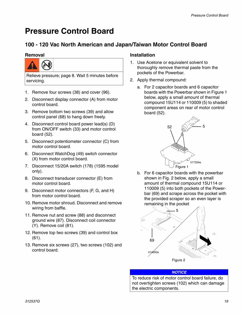
a. For 2 capacitor boards and 6 capacitor boards with the Powerbar shown in Figure 1 below, apply a small amount of thermal compound 15U114 or 110009 (5) to shaded component areas on rear of motor control board (52).
b. For 6 capacitor boards with the powerbar shown in Fig. 2 below, apply a small amount of thermal compound 15U114 or 110009 (5) into both pockets of the Power-bar (69) and scrape across the pocket with the provided scraper so an even layer is remaining in the pocket
Relieve pressure; page 8. Wait 5 minutes before servicing.
NOTICETo reduce risk of motor control board failure, do not overtighten screws (102) which can damage the electric components.
552
ti17334a
Figure 1
5
69
Figure 2
ti14693a

Pressure Control Board
20 312537G
3. Install two screws (102), six screws (27) and motor control board.
4. Install and torque two screws (102) to values in illustration. Install motor control board (52) with six screws (27). Torque to 9-11 in-lb (1.02 - 1.24 N•m).
5. Connect motor connectors, (F, G and H) to motor control board.
6. Reconnect and install wiring in baffle. Install motor shroud.
7. Install control box (61) with top two screws (39).
8. Install coil (81) and tighten screw and nut (88). Tighten ground wire screw (87) and coil connector (Y).
9. Connect transducer connector (E) to motor control board.
10. Connect 15/20A switch (178) (1595 model only).
11. Connect motor control board power lead(s) (D) to ON/OFF switch (33).
12. Connect WatchDog (49) switch connector (X) to motor control board.
13. Connect potentiometer connector (C) to motor control board.
14. Install control panel (68) with two screws (39).
15. Connect display connector (A) to motor control board.
16. Install cover (96) with four screws (38).

Pressure Control Board
312537G 21
��������
���
100 - 120 VacNorth Americanand Japan/Taiwan
Tighten 2 screws to 14-17 in-lb
40E
AC
F
E
20
86
52
B
102
67
C82
6882
11534
39
39
38
96
A61
69
33 D
178
49
49
X
Y
88
88
8781
ti12994b
27
F H
G

Pressure Control Board
22 312537G
240 Vac Motor Control BoardRemoval
1. Remove all four screws (38) and cover (96).
2. Disconnect display connector (A) from motor control board (52).
3. Remove bottom two screws (39). disconnect potentiometer connector (C) from motor control board (52). Disconnect power cord connectors (D) and filter board connectors (J) from ON/OFF switch (33) and remove control panel (68).
4. Disconnect WatchDog switch connector (X) from motor control board.
5. Disconnect motor control board power connectors (K) from filter board (146).
6. Remove top two screws (39) and control box (61).
7. Disconnect transducer connector (E) from motor control board.
8. Disconnect motor connectors (F, G and H) from motor control board.
9. Remove motor shroud disconnect and remove wiring from baffle.
10. Remove six screws (27), two screws (102) and motor control board.
Installation
1. Use Acetone or equivalent solvent to thoroughly remove thermal paste from the pockets of the Powerbar.
2. Apply thermal compound:
a. For 2 capacitor boards and 6 capacitor boards with the Powerbar shown in Figure 1 below, apply a small amount of thermal compound 15U114 or 110009 (5) to shaded component areas on rear of motor control board (52).
b. For 6 capacitor boards with the powerbar shown in Fig. 2 below, apply a small amount of thermal compound 15U114 or 110009 (5) into both pockets of the Power-bar (69) and scrape across the pocket with the provided scraper so an even layer is remaining in the pocket
Relieve pressure; page 8. Wait 5 minutes before servicing.
NOTICETo reduce risk of motor control board failure, do not overtighten screws (102) which can damage the electric components.
552
ti17334a
Figure 1
5
69
Figure 2ti14693a

Pressure Control Board
312537G 23
3. Install two screws (102), six screws (27), and control board.
4. Install and torque two screws (102) to values in illustration on page 24. Install motor control board (52) with six screws (27). Torque to 9-11 in-lb (1.02 - 1.24 N•m).
5. Connect motor connectors (F, G and H) to motor control board.
6. Reconnect wiring and install onto baffle. Install motor shroud.
7. Connect transducer connector (E) to motor control board.
8. Connect motor control board power connectors (K) to filter board (146).
9. Install control box (61) with top two screws (39).
10. Connect filter board power connectors (J) and power cord connectors (D) to ON/OFF switch (33).
11. Connect potentiometer connector (C) to motor control board.
12. Connect WatchDog switch (X) to motor control board.
13. Install control panel (68) with two screws (39).
14. Connect display connector (A) to motor control board (52).
15. Install cover (96) with four screws (38).

Pressure Control Board
24 312537G
240 Vac Filter Board
Removal
1. Remove four screws (38) and cover (96).
2. Disconnect display connector (A) from motor control board (52).
3. Remove bottom two screws (39). disconnect potentiometer connector (C) from motor control board (52). Disconnect power cord connectors (D) and filter board connectors (J) from ON/OFF switch (33) and remove control panel (68).
4. Disconnect WatchDog switch connector (X) from motor control board.
5. Disconnect motor control board power connectors (K) from filter board (146).
6. Remove four screws (163) from filter board (146).
Installation
1. Install filter board (146) with four screws (163).
2. Connect motor control board power connectors (K) to filter board (146).
3. Connect filter board power connectors (J) to top two terminals of ON/OFF switch (33) and power cord connectors (D) to bottom two terminals of ON/OFF switch.
4. Connect potentiometer connector (C) to motor control board (52).
5. Connect WatchDog switch (X) to motor control board.
6. Install control panel (68) with two screws (39).
7. Connect display connector (A) to motor control board (52).
8. Install cover (96) with four screws (38).
Relieve pressure; page 8.
� �
240 Vac
96
38
39
115
33J
A163
14661 K
82
C
C
E80
A
20
67
E
5227
34
8268
X
39
ti12995b
Tighten 2 screwsto 14-17 in-lb (1.58-1.92 N•
F HG
102
69

Pressure Control Board
312537G 25
110 Vac U.K. Motor Control BoardRemoval
1. Remove four screws (38) and cover (96).
2. Disconnect display connector (A) from motor control board.
3. Remove bottom two screws (39) and allow control panel (68) to hang down freely.
4. Disconnect control board power lead(s) (D) from ON/OFF switch (33) and motor control board (52).
5. Disconnect potentiometer connector (C) from motor control board.
6. Disconnect WatchDog (49) switch connector (X) from motor control board.
7. Disconnect 15/20A switch (178) (1595 model only).
8. Disconnect transducer connector (E) from motor control board.
9. Disconnect motor connectors (F, G, and H) from motor control board.
10. Remove motor shroud. Disconnect and remove wiring from baffle.
11. Remove nut and screw (88) and disconnect ground wire (87). Disconnect coil connector (Y). Remove coil (81).
12. Remove top two screws (39) and control box (61).
13. Remove six screws (27), two screws (102) and control board.
Installation
1. Use Acetone or equivalent solvent to thoroughly remove thermal paste from the pockets of the Powerbar.
2. Apply thermal compound:
a. For 2 capacitor boards and 6 capacitor boards with the Powerbar shown in Figure 1 below, apply a small amount of thermal compound 15U114 or 110009 (5) to shaded component areas on rear of motor control board (52).
b. For 6 capacitor boards with the powerbar shown in Fig. 2 below, apply a small amount of thermal compound 15U114 or 110009 (5) into both pockets of the Power-bar (69) and scrape across the pocket with the provided scraper so an even layer is remaining in the pocket
Relieve pressure; page 8.
NOTICETo reduce risk of motor control board failure, do not overtighten screws (102) which can damage the electric components.
552
ti17334a
Figure 1
5
69
Figure 2ti14693a

Pressure Control Board
26 312537G
3. Install two screws (102), six screws (27) and motor control board.
4. Install and torque two screws (102) to values in illustration. Install motor control board (52) with six screws (27). Torque to 9-11 in-lb (1.02 - 1.24 N•m).
5. Connect motor connectors, (F, G and H) to motor control board.
6. Reconnect and install wiring in baffle. Install motor shroud.
7. Install control box (61) with top two screws (39).
8. Install coil (81) and tighten screw and nut (88). Tighten ground wire screw (87) and coil connector (Y).
9. Connect transducer connector (E) to motor control board.
10. Connect 15/20A switch (178) (1595 model only).
11. Connect motor control board power lead(s) (D) to ON/OFF switch (33).
12. Connect WatchDog (49) switch connector (X) to motor control board.
13. Connect potentiometer connector (C) to motor control board.
14. Install control panel (68) with two screws (39).
15. Connect display connector (A) to motor control board.
16. Install cover (96) with four screws (38).

Pressure Control Board
312537G 27
110 Vac U.K. Filter Board
Removal
1. Remove four screws (38) and cover (96).
2. Disconnect display connector (A) from motor control board (52).
3. Remove bottom two screws (39). Disconnect potentiometer connector (C) from motor control board (52). Disconnect filter board connector (J) and power cord connector (D) from ON/OFF switch (33). Remove control panel (68).
4. Disconnect motor board control power connectors (K) from filter board (146). Disconnect filter connector (L) from power cord connector (L).
5. Remove four screws (163) from filter board (146).
Installation
1. Connect motor control board power connectors (K) to filter board (146). Connect filter connector (L) to power cord connector (L).
2. Install filter board (146) with four screws (163).
3. Connect filter board power connector (J) and power cord connector (D) to ON/OFF switch (33).
4. Connect potentiometer connector (C) to motor control board (52).
5. Install control panel (68) with two screws (39).
6. Connect display connector (A) to motor control board (52).
7. Install cover (96) with four screws (38).
Relieve pressure; page 8. Wait 5 minutes beforeservicing.

Pressure Control Board
28 312537G
� �
39
110 Vac U.K.
61
A
96
38
39
68
34
11582
82
163
E
2080
67
E
102
C
52
27
D
Tighten 2 screwsto 14-17 in-lb (1.58-1.92 N•
33
146
X
J
ti12996b
69
F H
G

Pressure Control Board
312537G 29
Pressure Adjust Potentiometer
Removal
1. Remove four screws (38) and cover (96).
2. Disconnect potentiometer connector (C) from motor control board (95).
3. Remove pressure control knob (34) with a hex wrench.
4. Remove gasket (115), nut and potentiometer (82) from control panel (68).
Installation
1. Install gasket (115), nut and potentiometer (82) on control panel (68). Torque nut to 30-35 in-lb (3.38 - 3.95 N•m).
2. Install pressure control knob (34): Check pressure control knob alignment to potentiometer shaft. Turn shaft fully clockwise and attach knob in full ON position with a hex wrench.
3. Connect potentiometer connector (C) to motor control board.
4. Install cover (96) with four screws (38).
Relieve pressure; page 8. Wait 5 minutes before servicing.
96
38 ti13493a
C
95
ti12997a
ti7258a34
68
82
115
82
ti12998a
68
82
115
82
ti12998a
ti7258a34
C
95
ti12997a
96
38 ti13493a
Pressure Control Board
30 312537G
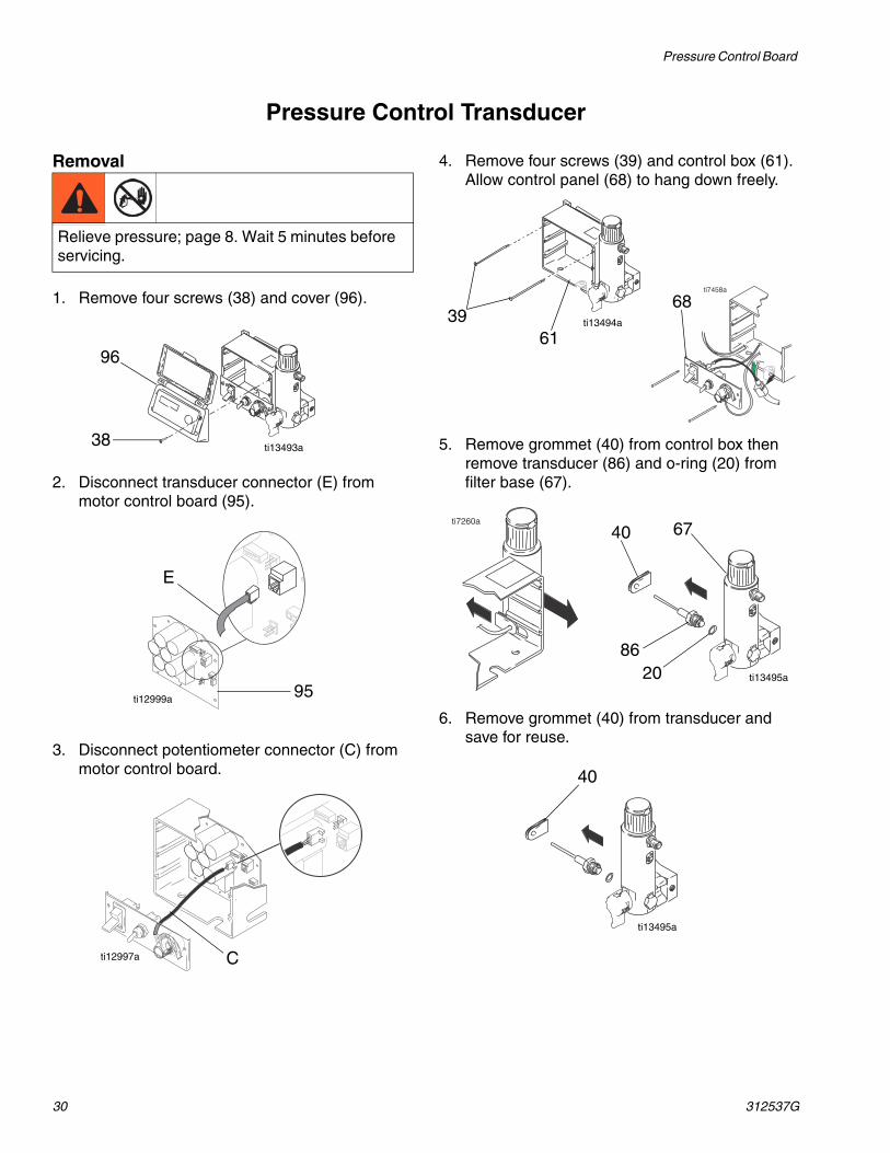
Pressure Control Transducer
Removal
1. Remove four screws (38) and cover (96).
2. Disconnect transducer connector (E) from motor control board (95).
3. Disconnect potentiometer connector (C) from motor control board.
4. Remove four screws (39) and control box (61). Allow control panel (68) to hang down freely.
5. Remove grommet (40) from control box then remove transducer (86) and o-ring (20) from filter base (67).
6. Remove grommet (40) from transducer and save for reuse.
Relieve pressure; page 8. Wait 5 minutes before servicing.
38
96
ti13493a
E
95ti12999a
Cti12997a
ti7458a
3961
68ti13494a
67
8620
ti7260a
40
ti13495a
40
ti13495a

Pressure Control Board
312537G 31
Installation
1. Install o-ring (20) and transducer (86) in filter base (67). Torque to 35-45 ft-lb (47-61 N•m). Install grommet onto transducer (86) and transducer into control box.
2. Connect transducer connector (E) to motor control board (95).
3. Install control box (61) and control panel (68) with four screws (39).
4. Connect potentiometer connector (C) to motor control board.
5. Install cover (96) with four screws (38).
ti7447a
40 67
20
86
ti13496a
E
95
ti12999a
ti7458a
3961
68
ti13494a
C
ti12997a
38
96
ti13493a

Drive and Bearing Housing Replacement
32 312537G
Drive and Bearing Housing Replacement
Disassembly
1. Remove screw (31), two nuts (24), pail hanger (55) and pump rod cover (108).
2. Remove pump (91); see Displacement Pump Replacement, page 36 (695/795) page 38 (1095/1595/Mark V).
3. Remove two screws (158) and shroud (72).
4. Remove four screws (31) and front cover (51).
5. Remove four screws (14) and washers (12) to remove bearing housing (83) and connecting rod (85).
6. Remove five screws (6) and pull drive housing (90) off motor (84).
AssemblyMake sure gear (89) and thrust washers (28, 30, 90a, 36; see page 29) are in place. Brush grease onto gear teeth.
1. Push drive housing (90) onto motor (84) and install with five screws (6). Torque to 190-210 in-lb (21-23 N•m).
2. Install bearing housing (83) with four screws (14) and washers (12). Torque to 25-30 ft-lb (34-40 N•m).
3. Install front cover (51) with four screws (31).
4. Install shroud (72) with two screws (158).
5. Install pump (91); see Displacement Pump Replacement, page 36 (695/795) page 38 (1095/1595/Mark V).
6. Install pump rod cover (108) and pail hanger (55) with screw (31) and two nuts (24).
NOTICE
Do not drop gear cluster (89) when removing drive housing (90). Gear cluster may stay engaged in motor front end bell or drive housing.
Relieve pressure; page 8.

Drive and Bearing Housing Replacement
312537G 33
158
55
2431
72
91
108
51
141283
85
6
90
84
31
ti13000a

Motor Replacement
34 312537G
Motor Replacement
Removal
1. Remove pump (91); see Displacement Pump Replacement, page 36 (695/795) page 38 (1095/1595/Mark V).
2. Remove drive housing (90); see Drive Housing Replacement, page 32.
3. Remove shroud (58).
4. Remove four screws (38) and control cover (96).
5. Remove bottom two screws (39) and allow control panel (68) to hang down freely.
6. Disconnect all three motor connectors from motor control board (52).
7. Disconnect motor leads.
8. Remove top two screws (39) and control housing (61).
9. Remove strain relief (29) from motor wires and power bar plate (69).
10. Remove motor wires from baffle 278075 and remove baffle.
11. Remove two screws (23) and nuts (19) on side opposite control.
12. Loosen two nuts (19) on side near control and remove motor (84) from cart frame (62).
Installation1. Slide new motor (84) under two screws (23) in
cart frame (62) near control.
2. Install two screws (23) and nuts (19) on motor side opposite control.
3. Install baffle and connect motor wires.
4. Tighten all four screws (23) and nuts (19). torque nuts to 115-135 in-lb (13-15 N•m).
5. Install strain relief (29) onto motor wires and into power bar plate (69).
6. Install control housing (61) with top two screws (39).
7. Connect motor leads.
8. Connect all three motor connectors to motor control board (52).
9. Install control panel (68) with two screws (39).
10. Install control cover (96) with four screws (38).
11. Install drive housing (90); see Drive Housing Replacement, page 32.
12. Install pump (91); see Displacement Pump Replacement, page 36 (695/795) page 38 (1095/1595/Mark V).
Relieve pressure; page 8.
NOTICE
Do not drop gear cluster (89) when removing drive housing (90). Gear cluster may stay engaged in motor front end bell or drive housing.

Motor Replacement
312537G 35
15858
84
1936
90a
28
8930
90
6
51 158
121431
23
19
6839
96
61
91
90 6
12
14
62
ti13001a

Displacement Pump Replacement for 695/795
36 312537G
Displacement Pump Replacement for 695/795See pump manual 310643 or 310894 for pump repair instructions.
See manual 311362, 311363, or 311364 for applicable sprayer part number references.
Removal
1. Flush pump.
2. Remove screw (31) and slide pump rod shield (108) forward.
3. Cycle pump in JOG mode until pump pin (44) is in position to be removed. Turn power switch
OFF and unplug power cord. Push up retaining ring (43) and push pump pin out.
4. Remove suction tube (76), hose (94) and any washers and o-rings.
5. Loosen pump jam nut (56). Unscrew pump.
Relieve pressure; page 8.
ti7170a 108
31
ti7168a
43
44
ti7167a
94
7656

Displacement Pump Replacement for 695/795
312537G 37
Installation
1. Extend pump piston rod 1.5 in. Apply grease to top of pump rod at (A) or inside connecting rod.
2. Install pump pin (44). Verify retaining spring (43) is in groove of connecting rod (85).
3. Push pump up until pump threads engage.
4. Screw in pump until threads are flush with drive housing opening. Align pump outlet to back.
5. Install washers, o-rings and suction tube (76) and hose (94).
6. Screw jam nut (56) up onto pump until nut stops. Tighten jam nut by hand, then tap 1/8 to 1/4 turn with a 20 oz (maximum) hammer to approximately 75± 5 ft-lb (102 N•m).
7. Install pump rod shield (108) with screw (31).
8. Fill packing nut with Pump Defender™ until fluid flows onto top of seal.
If pump pin works loose, parts could break off due to force of pumping action. Parts could project through the air and result in serious injury or property damage.
NOTICE
If the pump jam nut loosens during operation, the threads of the drive housing will be damaged.
ti7171a
A
1.5 in.
ti7169a

Displacement Pump Replacement 1095/1595/Mark V
38 312537G
Displacement Pump Replacement 1095/1595/Mark V
Removal1. Flush pump.
2. Stop pump with piston rod in its lowest position.
3. Do Pressure Relief, page 8.
4. Separate drain hose from sprayer.
5. Disconnect paint hose from pump.
6. Raise latch lock. Push latch open.
7. Ratchet open pump door.
a. Ratchet pump door forward.
b. Twist latch u-bolt out of pump door recess.c. Place u-bolt on pump door outer edge.d. If pump door is stuck, do steps e, f, and 8,
otherwise go to step 9.e. Twist latch u-bolt back from pump door
outer edge.
f. Place u-bolt on pump door protrusion.
Read Skin Injection Hazard; page 5.
ti7326a
ti6300a
ti6369a
ti6370a
ti6373a
ti6374a
ti6375a

Displacement Pump Replacement 1095/1595/Mark V
312537G 39
8. Ratchet pump door forward.
9. Open pump door.
10. Pull out pump pin and place in pin holder.
Installation1. Adjust piston rod with pin holder to pull out
piston rod. Tap piston rod on hard surface to push in piston rod.
2. Push pump collar flush with bearing housing ledge to be able to close pump door.
3. Slide pump into connecting rod. Push pump pin until it is fully retained.NOTE: Pin will snap into position.
ti6377a
ti7331a
ti7327a
ti6325a
ti5492a
ti7328a
ti6378a

Displacement Pump Replacement 1095/1595/Mark V
40 312537G
4. Close pump door and rotate latch into position. Do not tighten latch.
5. Rotate pump to align with paint hose. Connect paint hose and hand tighten to 70 in-lb.
6. Tighten latch and rotate latch lock into locked position.
7. Attach drain hose to sprayer.
8. Fill pump with Pump Defender™ until fluid flows onto top of seal.
ti7329ati6313a
ti6299a
ti6204a
TI6312a
ti7330a
ti5493a

Notes
312537G 41
Notes

Parts (Series A and B)
42 312537G
Parts (Series A and B)
11
8
22
10 62
17
1923
18
99
127
28
152
89
2830
94
153
109
76
129
48
87
93
41
24
117
43
83
44
85
12
55
95
10877
14
31
168
51
6
6
9090a
3684
123
126
124
58 72
37
91
56
See page 21.
•
•
•
ti10896b
167
170
71
•
160

Parts (Series A and B)
312537G 43
Parts List (Series A and B)
Ref. Part No. Description Qty6 15C753 SCREW, mach, torx, hex 58 15E891 CLIP, retaining 210 156306 WASHER, flat 211* WHEEL, pneumatic
119420 Models: 247558, 247559, 247561, 247562, 247565
2
121296 Models: 247563, 247564 212 106115 WASH, lock, spring 414 110141 SCREW, cap, socket hd 417 CAP, leg
15C871 Models: 247558, 247559, 247561, 247562, 247565
2
277091 Models: 247563, 247564 218 109032 SCREW, mach, pnh 419 112746 NUT, hex, flanged 822 116038 WASHER, wave spring 223 110963 SCREW, cap, flng hd 224 112746 NUT, hex 228 114672 WASHER, thrust 230 114699 WASHER, thrust 131 118444 SCREW, machine, hex washer hd 436 116191 WASHER, thrust 137 100057 SCREW, cap, hex hd 441 162453 FITTING, (1/4 NPSM x 1/4 NPT) 143 176817 SPRING, retaining 144 176818 PIN, str, hdls 148 189920 STRAINER, (1-11 1/2 NPSM) 151 277185 COVER, drive, plastic 155 16C457 HANGER, pail 156 192723 NUT, retaining 158 SHIELD, motor, painted 1
276928 Models: 247558, 247561, 247563, 247564, 247565
1
276931 Models: 247559, 247562 162 288605 FRAME, cart 171 LABEL, front
15R257 Models: 247558, 247565 115R259 Model: 247559 115R226 Model: 247561 115R228 Model: 247562 1
72 LABEL, side15R258 Models: 247558, 247565 115R260 Model: 247559 115R227 Model: 247561 115R229 Model: 247562 115R416 Models: 247563, 247564 1
76 248214 TUBE, intake (includes 109) 177 278204 CLIP, spring 179 245651 FLUID, starter kit (not shown) 183 246709 HOUSING, bearing
(includes 55, 24)1
84 MOTOR, electric289579 Models: 247558, 247561, 247564
Series A1
289580 Models: 247559, 247562 Series A 1
289581 Models: 247563, 247565 Series A 1257535 Models: 247558, 247561, 247564,
247559, 247562 Series B1
257538 Models: 247563, 247565 Series B 185 241008 ROD, connecting (includes 43) 187 DEFLECTOR, threaded
241920 Models: 247558, 247559, 247561, 247562, 247565
1
287614 Models: 247563, 247564 189 287289 GEAR, combination;
includes 28, 301
90 HOUSING, drive, M1;includes 6, 36, 90a
287283 Models: 247558, 247561, 247563,247564, 247565
1
287284 Models: 247559, 247562 190a 107089 WASHER, race, thrust 191 248204 PUMP, displacement
(includes 109)1
93 HOSE, return line (includes 87)244240 Models: 247558, 247559, 247561,
247562, 2475651
287668 Models: 247563, 247564 194 15R559 HOSE, coupled, 1/4 x 15.75 195 114000 SCREW, control housing 199 287489 HANDLE, cart 1108 15C859 SHIELD, pump rod 1109 118494 PACKING, o-ring 1117 187437 LABEL, torque 1123 276980 GROMMET, cover 2124 119 250 SCREW, shoulder, hex, washer 2126 15D088 FAN, motor 1127 115477 SCREW, mach, torx, pan, hd 1128▲ 222385 TAG, WARNING (not shown) 1129 HSE1450 HOSE, cpld, 1/4 in. x 50 ft.
Models: 247558, 247559, 247561, 247562, 247563, 247564, 247565
1
153 289316 GUN, contractorModels: 247558, 247559, 247561, 247562, 247563, 247564, 247565
1
152 288899 SHELF, PEM assembly 1160 124172 WASHER, retaining, Nylon, 10-32 1167 15R611 LABEL, shroud, top
Models: 247563, 2475641
168 15R612 LABEL, frontModels: 247563, 247564
1
170 15R617 LABEL, crownModels: 247563, 247564
1
171 278075 BAFFLE 1
▲ Extra Danger and Warning tags and labels available free.* 253132 KIT, repair, tube
Ref. Part No. Description Qty

Parts (Series A)
44 312537G
Parts (Series A)
15
13
35
715 113
669
74
92
6742
42
149
150
73
125
86
80a & b80
81
21
50
20
40
139
134b
134a
137
39
33
34115
82
82
68
38
96
75b
75a
27
27
131
52
59 61
70
118
2923
149
26
150
148
122
114
•
ti10900a
132
69
65
169•
75c

Parts (Series A)
312537G 45
Parts List (Series A)
Ref. Part No. Description Qty7 100721 PLUG, pipe 19 117285 PACKING, o-ring 113 C19817 SCREW, cap, socket 315 107505 PACKING, o-ring 220 111457 PACKING, o-ring 221 15C972 PIN, grooved 123 110963 SCREW, cap, flng 226 114391 SCREW, grounding 127 113045 SCREW, sems, mach, phillips 629 15D087 GROMMET 133 SWITCH, rocker
15C979 Models: 247558, 247559, 247561, 247562, 247564
1
15D527 Models: 247563, 247565 134 KNOB, potentiometer
116167 Models: 247558, 247559, 247561, 247562, 247565
1
15F537 Models: 247563, 247564 135 105510 WASHER, lock, spring 338 116252 SCREW, #10 taptite phillips 439 112381 SCREW, mach, pan hd 440 15D033 GROMMET, transducer 142 164672 NIPPLE, adapter 147 186620 LABEL, symbol, ground 150 HANDLE
15C780 Models: 247558, 247559, 247561, 247562, 247565
1
15F536 Models: 247563, 247564 152 CONTROL, board
(includes 27, 102)289577 Models: 247558, 247559, 247561,
247562, 2475641
289578 Models: 247563, 247565 159▲ LABEL, warning
15D523 Models: 247558, 247559, 247561, 247562
1
243301 Models: 247563, 247564, 247565 160▲ LABEL, warning
195833 Models: 247558, 247559, 247561, 247562
1
195792 Model: 247565 1195793 Models: 247563, 247564 1
61 BOX, control15G953 Models: 247558, 247559, 247561,
2475621
15D431 Models: 247563, 247564, 247565 165 LABEL, ctrl, box cover
15R261 Models: 247558, 247559, 247565 115R239 Models: 247561, 247562 1
66 287285 CAP, filter (includes 9, 74) 167 15C838 BASE, filter 1
68 15C947 PANEL, control 169 15C840 PLATE, power bar 170 15D036 GASKET, control box 173 248314 PLUG, Autoclean (includes 125) 174 15C766 TUBE, diffusion 1
75 CORD, power75a 15H064 Models: 247558, 247559, 247561,
2475621
75b 15D530 Model: 247564 175c 15D529 Models: 247563, 247565 180 235014 VALVE, prime (includes 80a, 80b) 180a 277364 GASKET, seat, valve80b 15E022 SEAT, valve81 224807 BASE, valve 182 256219 POTENTIOMETER, assembly 186 244984 TRANSDUCER, pressure control
(includes 20)1
92 FILTER, fluid 1244071 30 mesh 1244067 60 mesh, original equipment 1244068 100 mesh 1244069 200 mesh
96 277110 COVER, control 1101 15D160 STUD, board 5102 114420 SCREW, mach, pmh, sems 2113 15F844 SPACER, manifold 1114 104813 PLUG, pipe 1115 15C973 GASKET 1118 116793 FITTING, hydraulic 1122 115478 SCREW, mach torx/slt 1125 15D541 SEAL, washer 1132 FILTER, board
248219 Model: 247564 1248220 Models: 247563, 247565 1
134 CORD SET, adapter134a 242001 Model: 247563 1134b 242005 Model: 247565 1137 RETAINER, plug, adapter
195551 Models: 247563, 247565 1139 CORD SET, Italy, Denmark,
Switzerland287121 Model: 247563 1
148 287943 KIT, repair, coil (includes Nut & Screw)
1
169 15F506 LABEL, side, controlModels: 247563, 247564
1
▲ Extra Danger and Warning tags and labels available free.
Ref. Part No. Description Qty

Parts (Series B)
46 312537G
Parts (Series B)
15
13
35
715 113
669
74
92
6742
42
149
150
73
125
86
80a & b80
81
21
50
20
40
139
134b
134a
137
39
33
34 115
82
82
68
38
96
75b
75a
27
131
52
59 61
70
118
2923
149
26
150
148
122
114
•
ti14148a
132
69
65
169•
75c
101

Parts (Series B)
312537G 47
Parts List (Series B)
Ref. Part No. Description Qty7 100721 PLUG, pipe 19 117285 PACKING, o-ring 113 C19817 SCREW, cap, socket 315 107505 PACKING, o-ring 220 111457 PACKING, o-ring 221 15C972 PIN, grooved 123 110963 SCREW, cap, flng 226 114391 SCREW, grounding 127 113045 SCREW, sems, mach, phillips 629 15V996 GROMMET 133 SWITCH, rocker
15C979 Models: 247558, 247559, 247561, 247562, 247564
1
15D527 Models: 247563, 247565 134 KNOB, potentiometer
116167 Models: 247558, 247559, 247561, 247562, 247565
1
15F537 Models: 247563, 247564 135 105510 WASHER, lock, spring 338 116252 SCREW, #10 taptite phillips 439 112381 SCREW, mach, pan hd 440 15D033 GROMMET, transducer 142 164672 NIPPLE, adapter 147 186620 LABEL, symbol, ground 150 HANDLE
15V591 Models: 247558, 247559, 247561, 247562, 247565
1
52 CONTROL, board (includes 27, 102)
258964 Models: 247558, 247559, 247561, 247562, 247564
1
258965 Models: 247563, 247565 159▲ LABEL, warning
15D523 Models: 247558, 247559, 247561, 247562
1
243301 Models: 247563, 247564, 247565 160▲ LABEL, warning
195833 Models: 247558, 247559, 247561, 247562
1
195792 Model: 247565 1195793 Models: 247563, 247564 1
61 BOX, control15G953 Models: 247558, 247559, 247561,
2475621
15D431 Models: 247563, 247564, 247565 165 LABEL, ctrl, box cover
15R261 Models: 247558, 247559, 247565 115R239 Models: 247561, 247562 1
66 287285 CAP, filter (includes 9, 74) 1
67 15C838 BASE, filter 168 15C947 PANEL, control 169 15V937 PLATE, power bar 170 15D036 GASKET, control box 173 248314 PLUG, Autoclean (includes 125) 174 15C766 TUBE, diffusion 175 CORD, power75a 15H064 Models: 247558, 247559, 247561,
2475621
75b 15D530 Model: 247564 175c 15D529 Models: 247563, 247565 180 24B156 VALVE, prime (includes 80a, 80b) 1
GASKET, seat, valveSEAT, valve
81 24A382 BASE, valve 182 256219 POTENTIOMETER, assembly 186 244984 TRANSDUCER, pressure control
(includes 20)1
92 FILTER, fluid 1244071 30 mesh 1244067 60 mesh, original equipment 1244068 100 mesh 1244069 200 mesh
96 277110 COVER, control 1101 15V938 STUD, board 6102 114420 SCREW, mach, pmh, sems 1113 15F844 SPACER, manifold 1114 104813 PLUG, pipe 1115 15C973 GASKET 1118 116793 FITTING, hydraulic 1122 115478 SCREW, mach torx/slt 1125 15D541 SEAL, washer 1132 FILTER, board
248219 Model: 247564 1257905 Models: 247563, 247565 1
134 CORD SET, adapter134a 242001 Model: 247563 1134b 242005 Model: 247565 1137 RETAINER, plug, adapter
195551 Models: 247563, 247565 1139 CORD SET, Italy, Denmark,
Switzerland287121 Model: 247563 1
148 287943 KIT, repair, coil (includes Nut & Screw)
1
169 15F506 LABEL, side, controlModels: 247563, 247564
1
▲ Extra Danger and Warning tags and labels available free.
Ref. Part No. Description Qty

Wiring Diagrams (Series A)
48 312537G
Wiring Diagrams (Series A)Models 247558, 247559, 247561, 247562 Series A
ti12980a
Potentiometer
ON/OFF Switch
Power Plug
PressureTransducer
Motor
Black +
white
green/ground
green/ground ti10898a
ti7374b
Model: 247564 Series A
Wiring Diagrams (Series A)
312537G 49
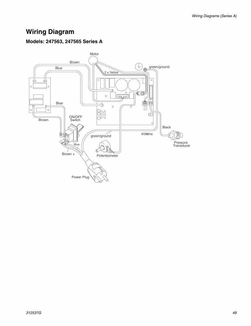
Wiring DiagramModels: 247563, 247565 Series A
ti10901a
Potentiometer
Black
ON/OFF Switch
2 x Yellow
Power Plug
PressureTransducer
Motor
Brown +
Blue
green/ground
green/ground
Brown
Blue
Blue
Brown
ti10901a

Wiring Diagram (Series B)
50 312537G
Wiring Diagram (Series B)Models 247558, 247559, 247561, 247562 Series B
�����������������
�� ����������
����������
������
�����
�������� ���
�����
�������� ���
������������
�����
�����
���������
��������������
������������
��
����������
ti14159b

Wiring Diagram (Series B)
312537G 51
Wiring DiagramModel: 247564 Series B
�����
�����������������
�� ����������
����������
�����
�������� ���
������������
���������
��������������
������������
����� ����
����
�� ��
�� ���
����
��
����������
ti14161a

Wiring Diagram (Series B)
52 312537G
Wiring Diagram
Models: 247563, 247565 Series B
�����
�����������������
�� ����������
����������
�����
�������� ���
������������
���������
��������������
������������
����� ����
����
�� ��
�� ���
����
��
����������
ti14160b

Notes
312537G 53
Notes

All written and visual data contained in this document reflects the latest product information available at the time of publication. Graco reserves the right to make changes at any time without notice.
For patent information, see www.graco.com/patents. Original instructions. This manual contains English. MM 312537
AGRACO INC. AND SUBSIDIARIES • P.O. BOX 1441 • MINNEAPOLIS MN 55440-1441 • USA
Copyright 2007, Graco Inc. All Graco manufacturing locations are registered to ISO 9001.www.asmcompany.comRevised January 2013
ASM Standard WarrantyASM warrants all equipment referenced in this document which is manufactured by ASM and bearing its name to be free from defects in material and workmanship on the date of sale by an authorized ASM distributor to the original purchaser for use. With the exception of any special, extended, or limited warranty published by ASM, ASM will, for a period of twelve months from the date of sale, repair or replace any part of the equipment determined by ASM to be defective. This warranty applies only when the equipment is installed, operated and maintained in accordance with ASM’s written recommendations.
This warranty does not cover, and ASM shall not be liable for general wear and tear, or any malfunction, damage or wear caused by faulty installation, misapplication, abrasion, corrosion, inadequate or improper maintenance, negligence, accident, tampering, or substitution of non–ASM component parts. Nor shall ASM be liable for malfunction, damage or wear caused by the incompatibility of ASM equipment with structures, accessories, equipment or materials not supplied by ASM, or the improper design, manufacture, installation, operation or maintenance of structures, accessories, equipment or materials not supplied by ASM.
This warranty is conditioned upon the prepaid return of the equipment claimed to be defective to an authorized ASM distributor for verification of the claimed defect. If the claimed defect is verified, ASM will repair or replace free of charge any defective parts. The equipment will be returned to the original purchaser transportation prepaid. If inspection of the equipment does not disclose any defect in material or workmanship, repairs will be made at a reasonable charge, which charges may include the costs of parts, labor, and transportation.
THIS WARRANTY IS EXCLUSIVE, AND IS IN LIEU OF ANY OTHER WARRANTIES, EXPRESS OR IMPLIED, INCLUDING BUT NOT LIMITED TO WARRANTY OF MERCHANTABILITY OR WARRANTY OF FITNESS FOR A PARTICULAR PURPOSE.
ASM’s sole obligation and buyer’s sole remedy for any breach of warranty shall be as set forth above. The buyer agrees that no other remedy (including, but not limited to, incidental or consequential damages for lost profits, lost sales, injury to person or property, or any other incidental or consequential loss) shall be available.
ASM MAKES NO WARRANTY, AND DISCLAIMS ALL IMPLIED WARRANTIES OF MERCHANTABILITY AND FITNESS FOR A PARTICULAR PURPOSE, IN CONNECTION WITH ACCESSORIES, EQUIPMENT, MATERIALS OR COMPONENTS SOLD BUT NOT MANUFACTURED BY ASM. These items sold, but not manufactured by ASM (such as electric motors, switches, hose, etc.), are subject to the warranty, if any, of their manufacturer. ASM will provide purchaser with reasonable assistance in making any claim for breach of these warranties.
In no event will ASM be liable for indirect, incidental, special or consequential damages resulting from ASM supplying equipment hereunder, or the furnishing, performance, or use of any products or other goods sold hereto, whether due to a breach of contract, breach of warranty, the negligence of ASM, or otherwise.
FOR ASM BRAZILIAN/CANADIAN/COLUMBIAN CUSTOMERSThe Parties acknowledge that they have required that the present document, as well as all documents, notices and legal proceedings entered into, given or instituted pursuant hereto or relating directly or indirectly hereto, be drawn up in English.
ASM InformationFor the latest information about ASM products, visit www.asmcompany.com.
TO PLACE AN ORDER, contact your ASM distributor or call 1-800-854-4025 to identify the nearest distributor.